st1-sum-fc - flow computer - Controls Warehouse
73
ST1-SUM-FC FLOW COMPUTER 990264 10/07/13
-
Upload
khangminh22 -
Category
Documents
-
view
0 -
download
0
Transcript of st1-sum-fc - flow computer - Controls Warehouse

ST1-SUM-FCFlow Computer
990264 10/07/13

SAFETY INSTRUCTIONSThe following instructions must be observed.
• This instrument was designed and is checked in accordance with regulations in force EN 60950 (“Safety of information technology equipment, including electrical business equipment”).
A hazardous situation may occur if this instrument is not used for its intended purpose or is used incorrectly. Please note operating instructions provided in this manual.
• The instrument must be installed, operated and maintained by personnel who have been properly trained. Personnel must read and understand this manual prior to installation and operation of the instrument.
• This instrument is internally fused. Replace the internal fuse with the following specified type and rating only: Input Power Recommended Fuse 115 VAC 160 mA slow blow fuse 230 VAC 80 mA slow blow fuse 12-24 VDC 800 mA slow blow fuse
Disconnect power supply before replacing fuse!
• The manufacturer assumes no liability for damage caused by incorrect use of the instrument or for modifications or changes made to the instrument.
Symbols Used On Unit Number Symbol Publication Description 1 IEC 417, No. 5031 Direct current
2 IEC 417, No. 5172 Equipment protected throughout by DOUBLE INSULATION or REINFORCED INSULATION (equivalent to Class II of IEC 536–see annex H)
3 ISO 3864, No. B.3.1 Caution (refer to accompanying documents)
Technical Improvements• The manufacturer reserves the right to modify technical data without prior notice.
Proprietary Notice
The information contained in this publication is derived in part from proprietary and patent data. This information has been prepared for the expressed purpose of assisting operating and maintenance personnel in the efficient use of the instrument described herein. Publication of this information does not convey any rights to use or reproduce it or to use for any purpose other than in connection with the installation, operation and maintenance of the equipment described herein.
Copyright 1999Printed in USA. All Rights Reserved.
WARNING!This instrument contains electronic components that are susceptible to damage by static electricity. Proper handling* procedures must be observed during the removal, installation, or handling of internal circuit boards or devices.
*Handling Procedure
1. Power to unit must be removed.
2. Personnel must be grounded, via wrist strap or other safe, suitable means, before any printed circuit board or other internal device is installed, removed or adjusted.
3. Printed circuit boards must be transported in a conductive bag or other conductive container. Boards must not be removed from protective enclosure until the immediate time of installation. Removed boards must be placed immediately in protective container for transport, storage, or return to factory.
Comments
This instrument is not unique in its content of ESD (electrostatic discharge) sensitive components. Most modern elec-tronic designs contain components that utilize metal oxide technology (NMOS, CMOS, etc.). Experience has proven that even small amounts of static electricity can damage or destroy these devices. Damaged components, even though they appear to function properly, may exhibit early failure.

72
ST1-SUM-FC Flow Computer
1. DESCRIPTION 1.1 Unit Description ......................................................................................................1 1.2 Unit Features ..........................................................................................................1 1.3 Specifications .........................................................................................................22. INSTALLATION 2.1 General Mounting Hints .........................................................................................6 2.2 Mounting Diagrams ................................................................................................63. APPLICATIONS 3.1 Sum Liquid Volume ................................................................................................7 3.2 Sum Corrected Liquid Volume ...............................................................................8 3.3 Sum Liquid Mass ....................................................................................................9 4. WIRING 4.1 Typical Wiring .......................................................................................................10 4.2 Wiring In Hazardous Areas ..................................................................................115. UNIT OPERATION 5.1 Front Panel Operation Concept for Run Mode .....................................................12 5.2 General Operation ................................................................................................13 5.3 Ratemeter/Totalizer Operation .............................................................................13 5.3.1 Password Protection for Rate/Total mode ............................................13 5.3.2 Relay Operation in Rate/Total mode .....................................................13 5.3.3 Pulse Output in Rate/Total mode ..........................................................13 5.3.4 Analog Output in Rate/Total mode ........................................................13 5.3.5 RS-232 Serial Port Operation in Rate/Total mode ...............................14 5.3.6 RS-485 Serial Port Operation in Rate/Total mode ...............................14 6. PROGRAMMING 6.1 Front Panel Operation Concept for Program Mode .............................................15 6.2 Setup Menus ........................................................................................................16 6.3 Setup Sub-Menus ................................................................................................17 6.3.1 SELECT FLOW EQUATION ................................................................17 6.3.2 SETUP INDICATORS (Total) ................................................................17 6.3.3 SETUP INDICATORS (Density) ............................................................17 6.3.4 SETUP INDICATORS (Rate) ................................................................18 6.3.5 SETUP INDICATORS (Temperature) ...................................................18 6.3.6 SETUP FLOW INPUT ..........................................................................19 6.3.7 SETUP AUX1 INPUT ...........................................................................21 6.3.8 SETUP AUX2 INPUT ...........................................................................22 6.3.9 SET FLUID PROPERTIES ..................................................................23 6.3.10 SETUP PULSE OUTPUT ...................................................................24 6.3.11 SETUP ANALOG OUTPUT .................................................................24 6.3.12 SETUP RELAYS ................................................................................25 6.3.13 SETUP CONTROL INPUTS .............................................................. 27 6.3.14 SETUP REALTIME CLOCK(Time)......................................................28 6.3.15 SETUP REALTIME CLOCK(Date) ......................................................28 6.3.16 SERIAL USAGE (RS-232/485) ...........................................................29 6.3.17 SERIAL USAGE (Modem Options) .....................................................29 6.3.18 SET DATALOG/PRINT(Configure) .....................................................30 6.3.19 SET DATALOG/PRINT (Select_list) ....................................................31 6.3.20 ADMINISTRATIVE SETUP ................................................................31 6.3.21 SETUP NETWORK CARD ................................................................327. PRINCIPLE OF OPERATION 7.1 General ................................................................................................................33 7.2 Flow Equations .....................................................................................................33 7.3 Calculating the Expansion Factor ........................................................................36 7.4 Computation of Viscosity Coef. A and B ...............................................................37 7.5 Linearization Table ...............................................................................................38 7.5.1 Linearization Table General Information ...............................................38 7.5.2 Linearization Table for Pulse Inputs ......................................................38 7.5.3 Linearization Table Interpolation ...........................................................38 7.6 Universal Viscosity Curve (UVC) .........................................................................38 7.7 Strouhal Roshko Curve (StRo) .............................................................................38
CONTENTS
i

73
ST1-SUM-FC Flow Computer
CONTENTS
ii
8. TEST, SERVICE and MAINTENANCE 8.1 Test Menus ...........................................................................................................39 8.2 Test Sub-Menus ...................................................................................................40 8.2.1 Audit Trail ..............................................................................................40 8.2.2 Error History ..........................................................................................40 8.2.3 Print System Setup ...............................................................................40 8.2.4 Keypad test ...........................................................................................41 8.2.5 Display test ...........................................................................................41 8.2.6 Calibrate Aux1 0mA ..............................................................................42 8.2.7 Calibrate Aux1 20mA ............................................................................42 8.2.8 Calibrate Aux2 0mA ..............................................................................43 8.2.9 Calibrate Aux2 20mA ............................................................................43 8.2.10 Calibrate Thermistor: 100 Ohms .........................................................44 8.2.11 Calibrate Thermistor: Open .................................................................44 8.2.12 Calibrate Aux2 0V ...............................................................................45 8.2.13 Calibrate Aux2 10V .............................................................................45 8.2.14 Calibrate 100 ohm RTD ......................................................................45 8.2.15 Calibrate 4mA Out ..............................................................................46 8.2.16 Calibrate 20mA Out ...........................................................................46 8.2.17 Analog In Test .....................................................................................46 8.2.18 Pulse input test ...................................................................................47 8.2.19 Analog out test ....................................................................................47 8.2.20 Excitation out test ...............................................................................47 8.2.21 Pulse out test ......................................................................................48 8.2.22 Relay test ...........................................................................................48 8.2.23 Control input test .................................................................................48 8.2.24 Battery Voltage test .............................................................................49 8.2.25 Data logger utility ...............................................................................49 8.3 Internal Fuse Replacement ..................................................................................509. RS-232 SERIAL PORT 9.1 RS-232 Serial Port Description ............................................................................51 9.2 Instrument Setup by PC Over Serial Port ...........................................................51 9.3 Operation of Serial Communication Port with Printers .........................................51 9.4 ST1-SUM-FC RS-232 Port Pinout .......................................................................5110. RS-485 SERIAL PORT 10.1 RS-485 Serial Port Description ..........................................................................52 10.2 General .............................................................................................................52 10.3 Operation of Serial Communication Port with PC ..............................................52 10.4 ST1-SUM-FC RS-485 Port Pinout .....................................................................5211. FLOW COMPUTER SETUP SOFTWARE 11.1 System Requirements ........................................................................................53 11.2 Cable and Wiring Requirements ........................................................................53 11.3 Installation for Windows™ ..................................................................................53 11.4 Using the Flow Computer Setup Software .........................................................54 11.5 File Tab ...............................................................................................................54 11.6 Setup Tab ...........................................................................................................54 11.7 View Tab .............................................................................................................55 11.8 Misc. Tab ............................................................................................................5512. GLOSSARY OF TERMS 12 Glossary Of Terms ................................................................................................5713. DIAGNOSIS AND TROUBLESHOOTING 13.1 Response of ST1-SUM-FC on Error or Alarm: ...................................................60 13.2 Diagnosis Flow Chart and Troubleshooting .......................................................61 13.3 Error & Warning Messages: ...............................................................................62 13.3.1 Sensor/Process Alarms ......................................................................62 13.3.2 Self Test Alarms ..................................................................................63
APPENDIX A (FLUID PROPERTIES TABLE) .....................................................................64APPENDIX B (Setup Menus) ..............................................................................................65 APPENDIX C (RS485 Modbus RTU Protocol) ....................................................................66
1
ST1-SUM-FC Flow Computer
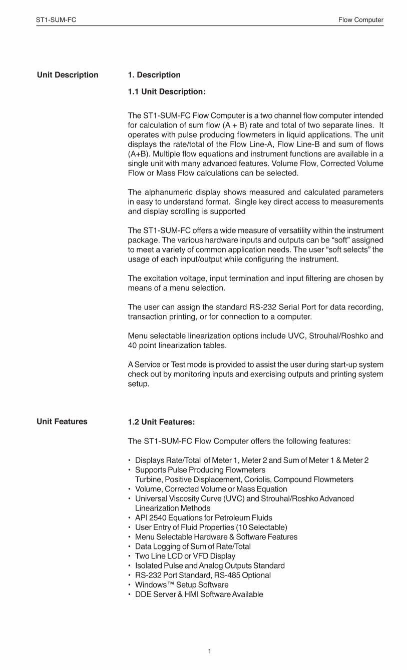
Unit Description 1. Description
1.1 Unit Description:
The ST1-SUM-FC Flow Computer is a two channel flow computer intended for calculation of sum flow (A + B) rate and total of two separate lines. It operates with pulse producing flowmeters in liquid applications. The unit displays the rate/total of the Flow Line-A, Flow Line-B and sum of flows (A+B). Multiple flow equations and instrument functions are available in a single unit with many advanced features. Volume Flow, Corrected Volume Flow or Mass Flow calculations can be selected.
The alphanumeric display shows measured and calculated parameters in easy to understand format. Single key direct access to measurements and display scrolling is supported
The ST1-SUM-FC offers a wide measure of versatility within the instrument package. The various hardware inputs and outputs can be “soft” assigned to meet a variety of common application needs. The user “soft selects” the usage of each input/output while configuring the instrument.
The excitation voltage, input termination and input filtering are chosen by means of a menu selection.
The user can assign the standard RS-232 Serial Port for data recording, transaction printing, or for connection to a computer.
Menu selectable linearization options include UVC, Strouhal/Roshko and 40 point linearization tables.
A Service or Test mode is provided to assist the user during start-up system check out by monitoring inputs and exercising outputs and printing system setup.
1.2 Unit Features:
The ST1-SUM-FC Flow Computer offers the following features:
• Displays Rate/Total of Meter 1, Meter 2 and Sum of Meter 1 & Meter 2 • Supports Pulse Producing Flowmeters
Turbine, Positive Displacement, Coriolis, Compound Flowmeters• Volume, Corrected Volume or Mass Equation• Universal Viscosity Curve (UVC) and Strouhal/Roshko Advanced
Linearization Methods• API 2540 Equations for Petroleum Fluids• User Entry of Fluid Properties (10 Selectable)• Menu Selectable Hardware & Software Features• Data Logging of Sum of Rate/Total• Two Line LCD or VFD Display• Isolated Pulse and Analog Outputs Standard• RS-232 Port Standard, RS-485 Optional• Windows™ Setup Software• DDE Server & HMI Software Available
Unit Features

2
ST1-SUM-FC Flow Computer
1.3 Specifications:Specifications:Flow Meters and Computations
Meter Types: Supports pulse producing meters including: vortex, single rotor turbine, magnetic, PD flowmeter, Coriolis and compound flowmetersLinearization: 40 point table, UVC table or Strouhal/RoshkoComputations: Volume, Corrected Volume & MassFluid Computations: Density, Temperature, Viscosity in individual lines when needed
EnvironmentalOperating Temperature: 0°C to +50°CStorage Temperature: -40°C to +85 CHumidity : 0-95% Non-condensingMaterials: U.L. approved
Approvals: CE Compliant, UL/CUL ListedDisplay
Type: 2 lines of 20 characters, Blue VFD or Backlit LCDCharacter Size: 0.2” nominalUser programmable label descriptors and units of measure
KeypadKeypad Type: Membrane Keypad with 16 keysKeypad Rating: Sealed to NEMA 4X
EnclosureSize: See DimensionsDepth behind panel: 6.5” including mating connectorType: DINMaterials: Plastic, UL94V-0, Flame retardantBezel: Textured per matt finish
Fluid TypesGeneral Purpose, User entry of fluid properties for up to 10 fluids.
Real Time ClockThe ST1-SUM-FC is equipped with a battery backed real time clock with display of time and date.Format: 12 or 24 hour time display Day, Month, Year date display
Excitation VoltageMenu Selectable: 5, 12 or 24 VDC @ 100 mA (fault protected with self resetting fuse) DC powered units have limited selections.
Relay OutputsThe relay outputs are menu assignable to (Individually for each relay) Low Rate Alarm (sum of rate or sum of total), Hi Rate Alarm (sum of rate or sum of total), Temperature, Density or General purpose warning (security). Number of relays: 2 (4 optional)Contact Style: Form C contactsContact Ratings: 5 amp, 240 VAC or 30 VDCCapabilities: Alarm Delay, Setpoint, Hysteresis, Duration
Power InputThe factory equipped power option is internally fused. An internal line to line filter capacitor and MOV are provided for added transient suppression.
110 VAC Power: 85 to 127 Vrms, 50/60 Hz 220 VAC Power: 170 to 276 Vrms, 50/60 Hz DC Power: 12 VDC (10 to 14 VDC) 24 VDC (14 to 28 VDC)Power Consumption: AC: 11.0 VA (11W) DC: 300 mA max.
Flow Inputs:Pulse Inputs:
Number of Flow Inputs: 2Input Impedance: 10 KΩ nominalPullup Resistance: 10 KΩ to 5 VDC (menu selectable)Pull Down Resistance: 10 KΩ to commonTrigger Level: (menu selectable) High Level Input Logic On: 3 to 30 VDC Logic Off: 0 to 1 VDC Low Level Input (mag pickup) Sensitivity: 10 mV or 100 mV Minimum Count Speed: Menu selectable: 1-99 secondsMaximum Count Speed: Menu Selectable: 40Hz, 3000Hz or 20 kHzOvervoltage Protection: 50 VDC
Control InputsSwitch Inputs are menu selectable for Reset, Lock, Inhibit, Alarm Acknowledge, Print, or Not Used.Control Input SpecificationsNumber of Control Inputs: 3Input Scan Rate: 10 scans per secondLogic 1: 4 - 30 VDCLogic 0: 0 - 0.8 VDCInput Impedance: 100 KΩControl Activation: Positive Edge or Pos. Level based on product
definition for switch usage.

3
ST1-SUM-FC Flow Computer
Auxiliary / Compensation InputsThe auxiliary/compensation inputs are menu selectable for meter 1 temperature, meter 2 temperature or not used. These inputs are used for the compensated inputs when performing compensated flow calculations. They can also be used as a general purpose input for display and alarming.Number of inputs: 2
Operation: Ratiometric Accuracy: 0.02% FS at 20° CBasic Measurement Resolution: 16 bitUpdate Rate: 1 update/sec minimumAutomatic Fault detection: Signal Over-range/under-range Current Loop Broken Fault mode to user defined default settings
Fault Protection: Reverse Polarity: No ill effects Over-Voltage Limit (Voltage Input): 50 VDC
Available Input Ranges Current (Two): 4-20 mA, 0-20 mA RTD: (One) 100 Ohm DIN RTD Standard Three Wire Thermistor (One) - Consult Factory
Isolated Analog OutputThe analog output is menu assignable to correspond to the Sum Rate/Total, Temperature, Density.Type: Isolated Current SourcingAvailable Ranges: 4-20 mA, 0-20 mAResolution: 12 bitAccuracy: 0.05% FS at 20° CUpdate Rate: 1 update/sec minimumTemperature Drift: Less than 200 ppm/CMaximum Load: 1000 ohms (at nominal line
voltage)Compliance Effect: Less than .05% Span60 Hz rejection: 40 dB minimumCalibration: Operator assisted Learn ModeAveraging: User entry of damping constant to
cause a smooth control action
Isolated Pulse outputThe isolated pulse output is menu assignable to Sum Total.Pulse Output Form: Photo MOS RelayMaximum On Current: 100 mAMaximum Off Voltage: 30 VDCSaturation Voltage: 1.0 VDCMaximum Off Current: 0.1 mAPulse Duration: 10 mSec or 100 mSec (user selectable)Pulse output buffer: 256Fault Protection Reverse polarity: Shunt Diode
Serial CommunicationThe serial port can be used for printing, data recording, and/or communication with a computer.RS-232: Device ID: 01-99 Baud Rates: 300, 600, 1200, 2400, 4800, 9600,
19200 Parity: None, Odd, Even Handshaking: None, Software, Hardware Print Setup: Configurable print list and formattingRS-485: (optional 2nd COM port) Device ID: 01-247 Baud Rates: 2400, 4800, 9600, 19200 Parity: None, Odd, Even Protocol: Modbus RTU (Half Duplex)
Setup CD CapabilitiesCapabilities include: View Live Results Configure unit, Upload and Download to unit, Load and Save to file, Print Setup,
Data Logging CapabilitiesCapabilities: Permits unit to automatically gather data dur-
ing use.Data Log List: User selectable: includes Meter1/Meter2
Temperatures, Meter 1/Meter 2 Density, Me-ter 1/Meter 2 Viscosity, Meter 1, Meter 2 and Sum Ratemeters/Totalizers, Grand Totalizer, Time and Date, Fluid, Setpoint 1 & 2, Fre-quency 1 & 2, K-Factor 1 & 2.
Data Log Event Trigger: selectable: includes interval, time of day,
front key, external contactData Log Format: selectable: Printer format, Database CSV
formatData Transmission: Selectable: Output may be transmitted im-
mediately or held in data log for later pollingRemote Request Capabilities include: Send data log, clear data log
External Modem Support Capabilities:Compatibility: Hayes CompatiblePolling Capabilities: Answers incoming calls, responds to re-
quests for information of actionCall Out Capabilities: Can initiate call on user selectable event
condition, or upon errorError Handling: Supports multiple retry, automatic disconnect
upon loss of line or remote inactivity

4
ST1-SUM-FC Flow Computer
Operating Mode The Flow Computer can be thought of as making a series of measurements of the Flow1 and Flow2 flow and temperature sensors and then performing calculations to arrive at a result(s) which is then updated periodically on the display. The analog output, the pulse output, and the alarm relays are also updated. The cycle then repeats itself.
Step 1: Update the measurements of input signals-Raw Input Measurements are made at each input using equations based on input signal type selected. The system notes the “out of range” input signal as an alarm condition. The unit alternates between Flow1 and Flow2 measurements.
Step 2: Compute the Flowing Fluid Parameters-The temperature, viscosity, and density equations are computed as needed based on the flow equation and input usage selected by the user.
Step 3 : Compute the Volumetric Flow-Uncompensated flow is the term given to the flow in volume units. The value is computed based on the flowmeter input type selected and augmented by any performance enhancing linearization that has been specified by the user.
Step 4: Compute the Corrected Volume Flow at Reference Conditions-
In the case of a corrected volume flow calculation, the Flow1, Flow2 and Sum corrected volume flows are computed as required by the selected compensation equation.
Step 5 : Compute the Mass Flow-All required information is now available to compute the Flow1, Flow2 and Sum mass flow rates as volume flow times reference density.
Step 6: Check Flow Alarms-The flow alarm functions have been assigned to either the Sum flow rate or temperatures during the setup of the instrument. A comparison is now made by comparing the current flow rates against the specified hi and low limits.
Step 7: Compute the Analog Output-This Sum flow rate or Sum total value is now used to compute the analog output.
Step 8: Compute the individual Flow Totals by Summation-
A flow total increment is computed for each totalizer. The totalizer format also includes provisions for total rollover.
Step 9: Total Preset Comparisons-The Sum total associated with a preset function is then compared against the corresponding preset value and any required control actions taken.
Step 10: Pulse Output Service-The pulse output is next updated by scaling the Sum total increment which has just been determined by the pulse output scaler and summing it to any residual pulse output amount.
Step 11: Update Display and Printer Output-The instrument finally runs a task to update the various table entries associated with the front panel display and serial outputs.
Setup Mode The setup mode is password protected by means of numeric operator and supervisor lock out codes established by the user. In addition, a secret, manufacturers numeric unlock entry sequence is available. A jumper on Control Input 3 can also prevent access.
The system also provides a minimum implementation of an “audit trail” which tracks significant setup changes to the unit. This feature is increasingly being found of benefit to users or simply required by Weights and Measurement Officials in systems used in commerce, trade, or “custody transfer” applications.
A software program is also available which runs on a PC using a RS-232 Serial for connection to the Flow Computer. Illustrative examples may be downloaded in this manner.
The setup mode has numerous subgrouping of parameters needed for flow calculations. There is a well conceived hierarchy to the setup parameter list. Selections made at the beginning of the setup affect offerings further down in the lists.
In the setup mode, the flow computer activates the correct setup variables based on the instrument configuration, the flow equation, and the hardware selections made for the compensation transmitter type, the flow transmitter type, and meter enhancements (linearization) options selected. All required setup parameters are enabled. All setup parameters not required are suppressed.
A help line prompt is provided for each entry. In addition a help message is available which may be accessed by depressing the “HELP” key.
Also note that in the setup mode are parameter selections which have preassigned industry standard values. The unit will assume these values unless they are modified by the user.
Most of the process input variables have available a “default” or emergency value which must be entered. These are the values that the unit assumes when a malfunction is determined to have occurred on the corresponding input.
It is possible to enter in a nominal constant value for temperature or density by placing the desired nominal value into both the lo and hi values. This is also a convenience when performing bench top tests without simulators.

5
ST1-SUM-FC Flow Computer
Maintenance (Test) Mode:The Maintenance Mode of the ST1-SUM-FC is the Test and Calibration Mode for the device. This mode provides a number of specialized utilities required for factory calibration, instrument checkout on start-up, and periodic calibration documentation.
A supervisor password is required to gain access to this specialized mode of operation. Normally quality, calibration, and maintenance personnel will find this mode of operation very useful. It is also useful for factory testing.
Many of these tests may be used during start-up of a new system. Inputs signals may be read, and output signals may be exercised to verify the electrical interconnects before the entire system is put on line.
The following action items may be performed in the Maintenance Mode:
Print Calibration/Maintenance ReportExamine Audit TrailPerform Keypad CheckoutPerform Display CheckoutPerform Pulse Input CheckoutPerform Pulse Output CheckoutPerform Control Input CheckoutPerform Relay Output CheckoutPerform Analog Input CheckoutPerform Analog Output CheckoutCalibrate Analog Inputs using the Learn FeatureCalibrate Analog Output using the Learn FeatureBattery CheckDatalog Printing and Clearing
Note that a calibration of the analog input/output will advance the audit trail counters since it effects the accuracy of the system.
RS-232 Serial PortThe ST1-SUM-FC has a general purpose RS-232 Port which may be used for any one of the following purposes:
Transaction Printing Periodic Printing of Datalog Print Internal Datalog Remote Metering by Modem (optional) Computer Communication Link Configuration by Computer Print System Setup Print Calibration/Malfunction History Remote Control
Instrument Setup by PC’s over Serial PortA Setup program is provided with the ST1-SUM-FC that enables the user to rapidly configure the ST1-SUM-FC using a Personnel Computer. Included nn the setup software are common instrument applications which may be used as a starting point for your application. This permits the user to have an excellent starting point and helps speed the user through the instrument setup.
Operation of Serial Communication Port with Printers
ST1-SUM-FC’s RS-232 channel supports a number of operating modes. One of these modes is intended to support operation with a printer in metering applications requiring transaction printing, data logging, and/or printing of calibration and maintenance reports.
For transaction printing, the user defines the items to be included in the printed document. The user can also select what initiates the transaction print generated as part of the setup of the instrument. The transaction document may be initiated via a front panel key depression, a remote contact closure.
In data logging, the user defines the items to be included in each data log as a print list. The user can also select when or how often he wishes a data log to be made. This is done during the setup of the instrument as either a time of day or as a time interval between logging.
The system setup and maintenance report lists all the instrument setup parameters and usage for the current instrument configuration. In addition, the Audit trail information is presented along with a status report listing any observed malfunctions which have not been corrected.
The user initiates the printing of this report at a designated point in the menu by pressing the print key on the front panel.
Operation of Serial Port with Modems (optional)The ST1-SUM-FC RS-232 channel supports a number of operating modes. One of these modes is intended to support operation with a modem in remote metering applications.
An external modem is intentionally being used with the ST1-SUM-FC. This permits use with the variety of modem standards worldwide while avoiding the specialized approvals required for equipment that is deemed to fall under the category of telecommunication equipment.
In the modem mode, the ST1-SUM-FC is assumed to be operating in a remote metering role. The ST1-SUM-FC will support key items in the Hayes Compatible “AT” Command Set. In this role, the ST1-SUM-FC will have the following special abilities:0. Monitor the modem status as a task of the
system1. Instruct the modem to answer an incoming call
ATA2. Respond to the calling modem at the programmed
baud rate and protocol3. Terminate the telephone connection in event the
connection is lost.
In addition, the ST1-SUM-FC is capable of initiating a call to a designated telephone number in the event of a metering malfunction. Consult factory for additional details on remote metering software.

6
ST1-SUM-FC Flow Computer
2. Installation2.1 General Mounting Hints:
The ST1-SUM-FC Flow Computer should be located in an area with a clean, dry atmosphere which is relatively free of shock and vibration. The unit is installed in a 5.43" (138mm) wide by 2.68" (68mm) high panel cutout. (see Mounting Dimensions) To mount the Flow Computer, proceed as follows:
a. Prepare the panel opening.b. Slide the unit through the panel cutout until the it touches the panel.c. Install the screws (provided) in the mounting bracket and slip the bracket
over the rear of the case until it snaps in place.d. Tighten the screws firmly to attach the bezel to the panel. 3 in. lb. of
torque must be applied and the bezel must be parallel to the panel.
Termination Connectors:Minimum Wire Gauge: 22 AWGMaximum Wire Gauge: 14 AWGVoltage/current limits are limited by unit specifications.
Permanently Connected Equipment:UL 3101-1, Section 6.12.2.1 specifies that:
• A switch or circuit breaker shall be included in the building installation;
• It shall be in close proximity to the equipment and within easy reach of the OPERATOR;
• It shall be marked as the disconnecting device for the equipment.
Ensure that the switch or circuit breaker chosen is suitable for the power requirements of the unit.
2.2 Mounting Diagrams:
General Mounting Hints
Mounting Procedure
NOTE:
Bezel Adaptor Instructions:
To provide protection type IP65/NEMA 4X, the unit has to be mounted with the be-zel adaptor and the gasket (supplied with the mounting kit). The bezel has to be glued to the unit with silicon (see Figure below)
Bezel adaptorGasket
Panel
Mounting bracket
IP65/NEMA 4X:seal with silicon!
Flow Computer
Flow ComputerBezel Adaptor
Gasket
Mounting BracketMounting Bracket
Standard Mounting Bezel Kit Mounting
Dimensions
Dotted Line Shows Optional Bezel Kit
PanelCutout
5.43(138)
2.68(68)
Dimensions are in inches (mm)
5.67 (144)
2.83(72)
3.43(87)
6.18
6.15(156) 0.5
(13)0.28 (7.2)
0.4 (10)

7
ST1-SUM-FC Flow Computer
3. Applications
3.1 Sum Liquid Volume
Measurements:Flowmeter sensors measure the actual volume in the Flow1 and Flow2 liquid lines. A temperature sensor can also be installed to correct for UVC or STRO linearization of turbine flowmeters. Coriolis flowmeters will typically use this equation for mass flow as well.
Calculations:• Volume flow is calculated using the flowmeter frequency output and the
user entered K-Factor. Sum Flow = Flow1 + Flow2
Output Results:• Display Results Flow1, Flow2, Sum Flow Rates, Sum Total, Resettable Totals, Non-Resettable Totals• Analog Output Sum Rate or Sum Total• Pulse Output Sum Total• Relay Outputs Sum Rate or Sum Total Alarms
Applications:The Flow Computer can monitor actual the sum volume flow and total of any liquid. (Common applications include mixing manifolds and compound flowmeters) Flow alarms are provided via relays and datalogging is available via analog (4-20mA) and serial outputs.
Sum Liquid Volume
Pulse Input; Average K-Factor
input frequency • time scale factor Flow1 or Flow2 Volume Flow = K-Factor
Sum Flow = Flow1 + Flow2
Sum Liquid VolumeIllustration
Calculations
STOP
START 5
0 –F4
F3CLEAR
•
MENU
ENTERHELP
F14
PRE 13
RATE2
TOTAL1
GRAND6
SCROLL7
PRE 28
F29
Flowmeter 1
Temperature 1Transmitter(optional)
Flow 1
T1
Flowmeter 2
Temperature 2Transmitter(optional)
Flow 2
T2

8
ST1-SUM-FC Flow Computer
3.2 Sum Corrected Liquid Volume
Measurements:Flowmeter sensors measure the actual volume in two separate liquid lines. A temperature sensor is installed to correct for liquid thermal fluid expansion in each line as well as optional UVC or STRO linearization of turbine flowmeters.
Calculations:• Flow1 and Flow2 Corrected Volume at a base or reference condition
is calculated using the respective flow and temperature inputs as well as the thermal fluid expansion coefficient stored in the flow computer. Use the "SET FLUID PROPERTIES" submenu to define reference temperature and density values for standard conditions.
Sum Flow = Flow1 + Flow2
Output Results:• Display Results Flow1, Flow2, Sum Corrected Flow Rates, Resettable Totals, Non-Resettable Totals, Temperatures, Densities• Analog Output Sum Corrected Rate or Total• Pulse Output Sum Corrected Total• Relay Outputs Sum Corrected Rate , Total or Temperature Alarms
Applications:Monitoring corrected volume flow and total of any liquid. (Common applications include mixing manifolds and compound flowmeters) Flow alarms are provided via relays and datalogging is available via analog (4-20mA) and serial outputs.
Sum CorrectedLiquid Volume
Flow1 and Flow2 Volume Flows
As calculated in section 3.1
Corrected Volume Flow (Temp. Transmitter)
Flow1/Flow2 Corrected Vol. Flow = vol. flow * (1 - Therm.Exp.Coef. *(Tf-Tref))2
(See also API 2540 equation)
Sum Corrected Flow = Flow1 Corrected Flow + Flow2 Corrected Flow
Calculations
Sum CorrectedLiquid VolumeIllustration
STOP
START 5
0 –F4
F3CLEAR
•
MENU
ENTERHELP
F14
PRE 13
RATE2
TOTAL1
GRAND6
SCROLL7
PRE 28
F29
Flowmeter 1
Temperature 1Transmitter
Flow 1
T1
Flowmeter 2
Temperature 2Transmitter
Flow 2
T2

9
ST1-SUM-FC Flow Computer
3.3 Sum Liquid Mass
Measurements:Flow1 and Flow2 actual volumes are measured by the respective flow element. Flow1 and Flow2 temperatures are measured by the Flow1 and Flow2 temperature transmitters.
Calculations:• The density and mass flow are measured directly or calculated using the
reference density and the thermal expansion coefficient of the liquid as well as optional UVC or STRO linearization of turbine flowmeters (see "SET FLUID PROPERTIES" submenu)
Output Results:• Display Results Flow1, Flow2, Sum Mass Flow Rates, Resettable Totals, Non-Resettable Totals, Temperatures, Densities• Analog Output Sum Mass Rate, Total• Pulse Output Sum Mass Total• Relay Outputs Sum Mass Flow Rate, Total, Temperature or Alarms
Applications:Monitoring of the sum mass flow and total of any liquid. (Common applications include mixing manifolds and compound flowmeters). Flow alarms are provided via relays and datalogging is available via analog (4-20mA) and serial outputs.
Sum Liquid Mass
Sum Liquid MassIllustration
Flow1 and Flow2 Volume Flows
As calculated in section 3.1
Mass Flow
Sum Mass Flow = (Flow1 volume flow * Flow1 density) + (Flow2 volume flow * Flow2 density)
Calculations
STOP
START 5
0 –F4
F3CLEAR
•
MENU
ENTERHELP
F14
PRE 13
RATE2
TOTAL1
GRAND6
SCROLL7
PRE 28
F29
Flowmeter 1
Temp/Dens1Transmitter
Flow 1
T1/D1
Flowmeter 2
Temp/Dens 2Transmitter
Flow 2
T2/D2
10
ST1-SUM-FC Flow Computer
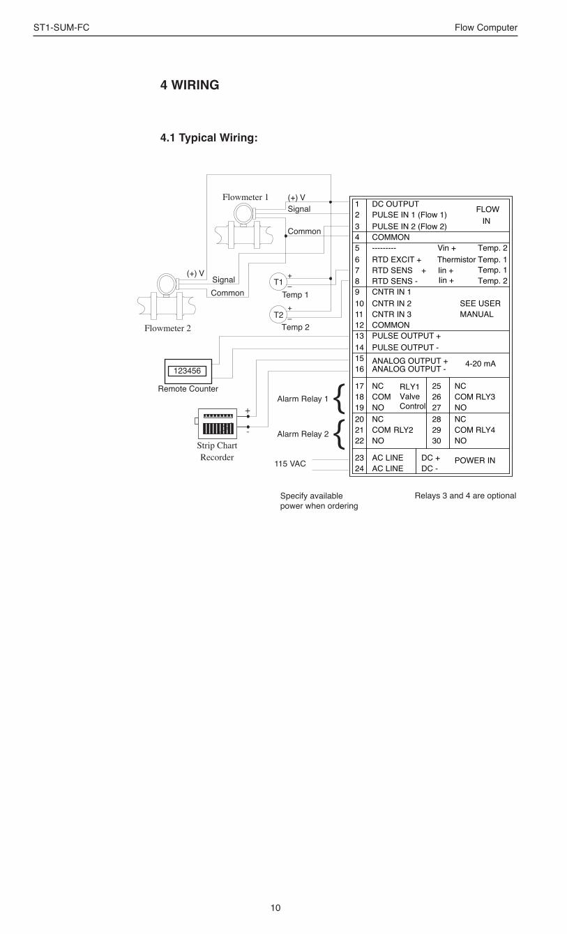
4 WIRING
4.1 Typical Wiring:
115 VAC
Alarm Relay 1
Alarm Relay 2Strip ChartRecorder
-
+
Flowmeter 1 (+) VSignal
Common
Flowmeter 2
(+) VSignalCommon
123456
Remote Counter
T2
T1Temp 1
Temp 2
+–
+–
13 PULSE OUTPUT +PULSE OUTPUT -
ANALOG OUTPUT -ANALOG OUTPUT +
RLY1Valve Control
RLY2
AC LINEAC LINE24
18 COM19202122
23
NONCCOMNO
141516
17 NC
POWER INDC -
4-20 mA
COM RLY3
COM RLY4
2627282930
NONC
NO
DC +
25 NC
PULSE IN 1 (Flow 1) PULSE IN 2 (Flow 2)
DC OUTPUT
COMMON
RTD EXCIT +RTD SENSRTD SENS -CNTR IN 1CNTR IN 2CNTR IN 3COMMON
---------
89101112
234567
1
SEE USERMANUAL
Iin ++
Vin +
INFLOW
Temp. 2Temp. 1Temp. 1Temp. 2
Thermistor Iin +
Specify available power when ordering
Relays 3 and 4 are optional

11
ST1-SUM-FC Flow Computer
4.2 Wiring In Hazardous Areas:
Examples using MLT787S+ Barrier
Hazardous Area Safe Area(4-20mA Transmitter)
4-20T
–
+ 1 2
4 3 28V
Diode
1
4
7
24V Out
4-20mASupply Temp.
4-20mA In
Common
Flow1 Temperature Input(4-20mA Transmitter)
Hazardous Area Safe Area(4-20mA Transmitter)
4-20T
–
+ 1 2
4 3 28V
Diode
1
4
8
24V Out
4-20mAReturn Temp.
4-20mA In
Common
Flow2 Temperature Input(4-20mA Transmitter)

12
ST1-SUM-FC Flow Computer
5. UNIT OPERATION
5.1 Front Panel Operation Concept for Run Mode
The ST1-SUM-FC is fully programmable through the front panel. Please re-view the following usage summary before attempting to use the instrument.
HELPOn-line help is provided to assist the operator in using this product. The help is available during RUN and SETUP modes simply by pressing the HELP key. The HELP key is used to enter decimals when entering numeric values.
SELECT FLUIDPress F1 and ENTER. Press the ∆ ∇ keys to view fluid name. Press ENTER to select fluid.
FUNCTION KEYSIn the RUN mode, several keys have a special, direct access feature, to display an item of interest (i.e. RATE, TOTAL, etc.). Press the key to view your choice. These keys and the F1, F2 & F3 keys allow the operator to view more than one piece of information. Slowly pressing these keys additional times will display additional information. Example: Rate Key shows Sum Rate, Flow1 Rate, Flow2 Rate.
CLEARING TOTALIZERSTo clear the totals, you must press the TOTAL Function Key quickly 4 times until you see a display called "CLEAR TOTAL". Then press CLEAR to reset Sum, Flow1 and Flow2 totals. You will be asked to verify this action. The operator will be prompted to enter password if the unit is locked.
CLEARING GRAND TOTALSTo clear the grand totals, you must press the GRAND Function Key quickly 4 times until you see a display called "CLEAR GRAND TOTAL". Then press CLEAR to reset Sum, Flow1 and Flow2 grand totals. You will be asked to verify this action. The supervisor will be prompted to enter the supervisor password if the unit is locked.
PRESET KEYSIn the RUN mode, PRE 1 & PRE 2 keys are used to view and/or change the preset setpoints. To view the Presets, simply press the desired Preset key. Rapidly press the Preset keys 3 times, then press the Clear key for direct editing of the preset setpoints.
SCROLLRapidly press the Scroll key three times to setup a display list.Press the CLEAR key to remove old scroll list.Press the function key F3 for the item you wish to addUse the ∆ ∇ keys to assign the line or to remove the selection.
PRINTThe PRINT key is used to print on demand. When the F3 Print key is pressed, a user defined list of data (Sum TOTAL, Sum RATE, PRE 1, etc.) is sent to the RS-232 port. A timed message of "PRINTING" will be displayed to acknowledge the print request.
MENU KEYThe MENU key is used to enter the Setup and Test modes. Press the MENU key to enter the Setup and Test modes. (See section 6 for Setup mode, section 8 for Test mode). The MENU key is also used as "escape" in Setup and Test Programming. Pressing the MENU key while programming in the Sub-Menu groups will backup the display to that Sub-Menu group heading. Pressing the MENU key while viewing the Sub-Menu groups will backup the display to the Top Level Menu.
ACKNOWLEDGING ALARMSMost alarm messages are self-clearing. Press the ENTER key to acknowledge and clear alarms. NOTE: Some keys and functions are password protected. Enter the password to gain
access. The passwords are factory set as follows: Operator = 0 Supervisor = 2000
Alarms in the Alarm Error History will reassert themselves when power is cycled. Clear the alarm history to prevent this from happening once all problems are solved.
How To Use On-Line Help
How To Select Fluid
How To Use Function Keys
How To Clear The Sum Total, Flow1 Total, Flow2 Total
How To Clear The Sum Grand Total, Flow1 Grand Total, Flow2 Grand Total
How To Enter Presets
How To Create a Scroll List
How To Use The F3 Print Key
How To Use The Menu Key
How To Acknowledge Alarms
STOP
START 5
0 –F4
F3CLEAR
•
MENU
ENTERHELP
F14
PRE 13
RATE2
TOTAL1
GRAND6
SCROLL7
PRE 28
F29

13
ST1-SUM-FC Flow Computer
5.2 General Operation
The unit can display: Sum Rate, Sum Total, Sum Grand Total, Flow1 and Flow2 Rates, Flow1 and Flow2 Totals, Flow1 and Flow2 Temperatures/Densities/Viscosities, Presets and Time of Day. In addition, input frequencies, computed K-factors and viscosities can be observed. The Flow1 and Flow2 Temperatures and Densities can be displayed even if you are using the Volumetric Flow Equation (a Temperature sensor must be installed). The unit can perform Mass or Corrected Volume equations using a temperature sensor (these equations can be computed without Temp sensors by using user defined default values). If only one temperature is being used that value will be assigned for both the Flow1 and Flow2 lines.
5.3 Ratemeter/Totalizer Operation
The Ratemeter/Totalizer mode is used primarily to monitor Sum flowrate and Sum accumulated total. The relays can be used to trigger flow, total or temperature alarms.
5.3.1 Password Protection for Rate/Total mode
After an Operator and/or Supervisor Password is entered in the setup mode (see section 6.4.23, ADMINISTRATIVE SETUP submenu), the unit will be locked. The unit will prompt the user for the password when trying to perform the following functions:
Clear TotalClear Grand TotalEnter MenuEdit Preset 1 (PRE 1 Key) Edit Preset 2 (PRE 2 Key)
The Supervisor password should be reserved for supervisors. The Supervisor password will allow access to restricted areas of the Setup and Test menus.
5.3.2 Relay Operation in Rate/Total mode
Up to four relays are available (two standard) for alarm outputs. The relays can be assigned to trip according to Sum rate, Sum total or alarms. The relays can be programmed for low or high alarms.Preset 1 (RLY1) and Preset 2 (RLY2) are easily accessible by pressing the PRE 1 or PRE 2 key on the front panel. Preset 3 and Preset 4 are accessible only through the setup menu. Relays 3 and 4 can be used for temperature alarms and general system alarms.
5.3.3 Pulse Output in Rate/Total mode
The isolated pulse output (open collector) is menu assignable to Sum Total or None. The total will be implied by the Flow Equation selected: Volume, Corrected Volume or Mass. The pulse output duration can be set for 10mS (50 Hz max) or 100mS (5 Hz max). A pulse output scale factor (pulse value) can be set to scale the pulse output. The pulse output is ideal for connecting to remote totalizers or other devices such as a PLC. See section 1.3 for electrical specifications.
5.3.4 Analog Output in Rate/Total mode
The analog output is menu assignable to correspond to the Sum Volume Rate, Sum Corrected Volume Rate or Sum Mass Rate, Sum Volume Total or Sum Corrected Volume Total or Sum Mass Total, Flow1 Temperature or Computed Flow1 Density. The analog output is ideal for "trend" tracking using strip chart recorders or other devices.
GeneralOperation
Rate/TotalOperation
Password Protection(Rate/Total mode)
Relay Operation(Rate/Total mode)
Pulse Output(Rate/Total mode)
Analog Output(Rate/Total mode)

14
ST1-SUM-FC Flow Computer
5.3.5 RS-232 Serial Port Operation in Rate/Total mode
The RS-232 serial port can be used for programming (using the Setup Program) or for communicating to printers and computers in the Operating Mode (Run Mode).
PC Communications:The Setup Program also allows the user to query the unit for operating status such as Sum Flow Rate, Sum Flow Total, Temperature, Density, Presets, etc.
Operation of RS-232 Serial Port with Printers:Transaction PrintingFor transaction printing, the user defines the items to be included in the printed document (see section 6.3.20 SET DATA OUTPUT, Select_list). The transaction document can be initiated by pressing the F3 PRINT key or by a remote contact closure on Control Input 3.
Data LoggingIn data logging, the user defines the items to be included in each data log (see section 6.3.20 SET PRINTER OUTPUT, Select_list). The user can also select when (time of day) or how often (print interval) the data log is to be made (see section 6.3.19 SET PRINTER OUTPUT, Configure). Data logs can also be initiated using the F3 print key or control input.
System Setup and Maintenance ReportThe system setup and maintenance report lists all of the instrument setup parameters and usage for the current instrument configuration. The audit trail information and a status report is also printed. This report is initiated in the Test menu (see section 8.2.3 PRINT SYSTEM SETUP).
RS-232 Serial Port(Rate/Total mode)
5.3.6 RS-485 Serial Port (optional)
RS-485 Port Description:The optional RS-485 card utilizes Modbus RTU protocol to access a variety of process parameters and totalizers. The Relays can be controlled via Modbus. In addition, action routines (such as totalizer reset) can be executed. For further information, contact factory and request RS-485 Protocol manual.
Operation of Serial Communication Port with PCThe ST1-SUM-FC's RS-485 channel supports a number of Modbus RTU commands. Modbus RTU drivers are available for a variety of Man Machine Interface software for IBM compatible PC's.The user reads and writes information from/to the RS-485 using the Modbus RTU register and coil commands. The ST1-SUM-FC then responds to these information and command requests. Process variables and totalizers are read in register pairs in IEEE 32 bit floating point format. Time and date are read as a series of integer register values. Alarms are individually read as coils. Action routines are initiated by writing to coils.
RS-485 Serial Port(Rate/Total mode)

15
ST1-SUM-FC Flow Computer
6. PROGRAMMING
6.1 Front Panel Operation Concept for Program Mode
The ST1-SUM-FC is fully programmable through the front panel. Please review the following usage summary before attempting to use the instru-ment. Refer to Appendix B as an aid in locating individual sub-menus.
Setup Mode:
MODE CHANGESPressing the MENU key will offer selections of RUN, SETUP, TEST. RUN is the normal operating mode for the instrument. SETUP offers various sub-menus used for instrument setup. TEST offers various sub-menus for Test, Calibration and System Start-up.
Submenu GROUP NAVIGATIONUse the UP and DOWN arrow keys to navigate up and down through the Sub-Menu groups when in the SETUP or TEST mode. Press the ENTER key to enter a desired setup or test Sub-Menu group.
SELECTION OF ITEMDuring setup, the unit will often offer multiple choices for a given topic. The topic prompt appears on the top line of the display. The choices are shown on the lower line of the display. To select an item, press the key beneath the desired choice. The selected choice will blink. Press the ENTER key to accept the selected choice.
NUMERIC ENTRYThe keys labeled "0 - 9", "–", ".", CLEAR and ENTER are used to enter numerical values. A leading 0 will assume that you intend to enter a minus "–" sign. Press the CLEAR key to clear the existing value and to enable editing.
TEXT CHARACTER ENTRYSome setup items (i.e. Descriptors, Units Label) require the user to enter text characters. Press CLEAR to enable editing. The UP and DOWN arrow keys are used to scroll through the available character sets for each individual character. Press the ENTER key to accept the character and advance to the next character until all characters needed for the label have been entered.
How To Make Mode Changes
How To Navigate Through Sub-Menu Groups
How To Select Program Choices
How To Enter Numeric Values
How To Enter Text Characters
STOP
START 5
0 –F4
F3CLEAR
•
MENU
ENTERHELP
F14
PRE 13
RATE2
TOTAL1
GRAND6
SCROLL7
PRE 28
F29

16
ST1-SUM-FC Flow Computer
6.2 Setup Menus
6.2.1Top Level Setup Menu
Menus Display Notes
6.2.2Submenu Groups
SELECT OPERATE STATE Run Setup Test
SELECT FLOW EQUATION
SETUP INDICATORS
SETUP FLOW INPUT
SETUP AUX1 INPUT(Flow1 Temp)
SETUP AUX2 INPUT (Flow2 Temp)
SET FLUID PROPERTIES
SETUP PULSE OUTPUT
SETUP ANALOG OUTPUT
SETUP RELAYS
SETUP CONTROL INPUTS
SETUP REALTIME CLOCK
SERIAL USAGE
SETUP DATALOG/PRINT
ADMINISTRATIVE SETUP
SETUP NETWORK CARD
Select Setup to enter the instrument setup routine.
Refer to Page 17 for Details.
Refer to Pages 17-18 for Details.
Refer to Pages 19-20 for Details.
Refer to Page 21 for Details.
Refer to Pages 22 for Details.
Refer to Pages 23 for Details.
Refer to Page 24 for Details.
Refer to Pages 24 for Details.
Refer to Pages 25-26 for Details.
Refer to Page 27 for Details.
Refer to Page 28 for Details.
Refer to Page 29 for Details.
Refer to Pages 30-31 for Details.
Refer to Pages 31 for Details.
Refer to Page 32 for Details.*
MENU
* Optional Menu only appears if option is installed

17
ST1-SUM-FC Flow Computer
Sub-menus Display Notes
Press ENTER to enter Select Flow Equation submenus.
Press ENTER when desired flow equation is flashing.
Press ENTER when desired density extraction method is flashing.
Press ENTER to begin setup of the Indicators
Press ENTER when Total is flashing to configure the Totalizer Indicators
Enter the desired Total Descriptor
Enter the desired Volume Units Label for the Totalizer.
Select the desired Total Decimal Place.0-3 decimal places allowed.
Press ENTER when Dens is flashing to configure the Density Indicators.
Enter the desired Density Descriptor.
Enter the desired Mass Units Label for Density.
Select the desired Density Decimal Place.0-6 decimal places allowed.
Enter the default density setting.
6.3.3SETUP INDICATORS(Density)
SELECT FLOW EQUATION
SELECT FLOW EQUATION Volume Mass Cor/Vol
DENS EXTRACT METHOD Therm_Coef API_2540
Advance To SETUP INDICATORS (Total)
SETUP INDICATORS
SETUP INDICATORS Total Dens Rate Temp
TOTAL DESCRIPTOR TOTAL
VOLUME UNITS gal
TOT DEC PLACES (0-3) 0
Advance To SETUP INDICATORS
(Density)
SETUP INDICATORS Total Dens Rate Temp
DENSITY DESCRIPTOR DENS
MASS UNITS lbs
DENS DEC PLACES(0-6) 4
DENSITY DEFAULT1 lbs/g
Advance To SETUP INDICATORS (Rate)
6.3.2SETUP INDICATORS(Total)
6.3.1SELECT FLOW EQUATION
6.3 Setup Sub-Menus

18
ST1-SUM-FC Flow Computer
Sub-menus Display Notes
6.3.5SETUP INDICATORS(Temperature)
Press ENTER when Rate is flashing to configure the Ratemeter Indicators
Select the desired Rate Time Base.
Enter the desired Descriptor for the Ratemeter.
Select the desired Rate Decimal Place.0-3 decimal places allowed.
Enter desired Rate Averaging Filter for Flow1/Flow2 rates.
Enter desired Percent of Change for Quick Update. If the current Flow1/Flow2 flowrate deviates by an amount greater than the percentage value entered, the Rate Averaging is restarted with new value.
Press ENTER when Temp is flashing to configure the Temperature Indicators.
Enter the desired Temperature Descriptor.
Enter the desired Temperature Scale.
Select the desired Temperature Decimal Place. 0-3 decimal places allowed.
Enter the default temperature
SETUP INDICATORS Total Dens Rate Temp
RATE TIME BASE Sec Min Hour Day
RATE DESCRIPTOR RATE
RATE DEC PLACES(0-3)2
RATE AVG FILTER0
QUICK UPDATE %1
Advance To SETUP INDICATORS
(Temperature)
SETUP INDICATORS Total Dens Rate Temp
TEMP DESCRIPTORTEMP
TEMPERATURE SCALEDeg_C Deg_F
TEMP DEC PLACES(0-3)1
TEMPERATURE DEFAULT60 F
Advance To SETUP FLOW INPUT
6.3.4SETUP INDICATORS(Rate)

19
ST1-SUM-FC Flow Computer
6.3.6SETUP FLOW INPUT
SETUP FLOW INPUT
EXCITATION VOLTAGE5v 12v 24v
PULSE TRIGGER LEVEL10mV 100mV 2.5V
LOW PASS FILTER40Hz 3KHz 20KHz
INPUT TERMINATIONPullup Pulldown None
MAX WINDOW (1-99)1 sec
K_FACTOR TYPEAvgK LinTbl UVC StRo
AVERAGE KA-FACTOR####### P/gal
AVERAGE KB-FACTOR####### P/gal
CHANGE TABLE A No Yes
LINEAR TABLE KAFre01:######## Hz
LINEAR TABLE KAKA--01:####### P/gal
CHANGE TABLE A No Yes
LINEAR TABLE KAFre01:######## Hz
LINEAR TABLE KAKA--01:####### P/gal
LINEAR TABLE KAFre01:######## Hz/ck
LINEAR TABLE KAKA--01:####### P/gal
LINEAR TABLE KBFre01:######## Hz/ck
LINEAR TABLE KBKB--01:####### P/gal
Continued On Next Page
Press ENTER to begin setup of Flow Input.
Select the desired Excitation Voltage. NOTE: DC models do not support the 24V selection.
Select the desired Input Pulse Trigger Level.
Select the desired Low Pass Filter.(Max. Count Speed).
Select the proper input termination.
Enter the desired Maximum Sample Window Time (1-99 sec).
Enter the desired K-Factor Type. See side note.
If Avg selected, Enter the desired Average K-Factor (KA for Flow1).
Enter the desired Average K-Factor (KB for Flow2).
If LinTbl selected, Select YES to change that tableEnter the desired frequency/ K-Factor pair (in ascending order of Hz) for each point in the Linearization Table. (Table A = Flow1)NOTE: Enter 0 for Fre value of any point (other
than Fre01) to exit the routine and use only the values entered up to that point.
Enter the desired frequency/ K-Factor pair (in ascending order of Hz) for each point in the Linearization Table. (Table B = Flow2)
NOTE: Enter 0 for Fre value of any point (other than Fre01) to exit the routine and use only the values entered up to that point.
If UVC selected, Select YES to change that tableEnter the desired Hz/ck/ K-Factor pair (in ascending order of Hz/ck) for each point in the Linearization Table. (Table A = Flow1)NOTE: Enter 0 for Hz/ckvalue of any point
(other than Hz/ck01) to exit the routine and use the values entered up to that point.
Enter the desired Hz/ck/ K-Factor pair (in ascending order of Hz/ck) for each point in the Linearization Table. (Table B = Flow2)NOTE: Enter 0 for Hz/ck value of any point
(other than Hz/ck01) to exit the routine and use the values entered up to that point.
Submenus Display Notes
NOTE:AvgK = Average K-FactorLinTbl = Linearization
TableUVC = Universal Vis-
cosity CurveStRo = Strouhal Ro-
shko Curve
20
ST1-SUM-FC Flow Computer
Sub-menus Display Notes
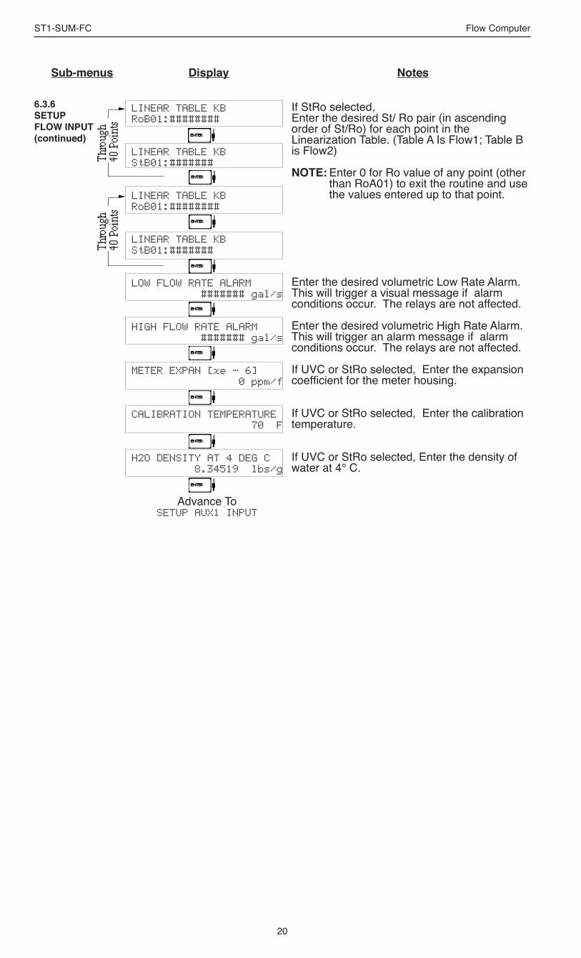
If StRo selected, Enter the desired St/ Ro pair (in ascending order of St/Ro) for each point in the Linearization Table. (Table A Is Flow1; Table B is Flow2)
NOTE: Enter 0 for Ro value of any point (other than RoA01) to exit the routine and use the values entered up to that point.
Enter the desired volumetric Low Rate Alarm. This will trigger a visual message if alarm conditions occur. The relays are not affected.
Enter the desired volumetric High Rate Alarm. This will trigger an alarm message if alarm conditions occur. The relays are not affected.
If UVC or StRo selected, Enter the expansion coefficient for the meter housing.
If UVC or StRo selected, Enter the calibration temperature.
If UVC or StRo selected, Enter the density of water at 4° C.
LINEAR TABLE KBRoB01:########
LINEAR TABLE KBStB01:#######
LINEAR TABLE KBRoB01:########
LINEAR TABLE KBStB01:#######
LOW FLOW RATE ALARM ####### gal/s
HIGH FLOW RATE ALARM####### gal/s
METER EXPAN [xe - 6]0 ppm/f
CALIBRATION TEMPERATURE70 F
H2O DENSITY AT 4 DEG C8.34519 lbs/g
Advance To SETUP AUX1 INPUT
6.3.6SETUP FLOW INPUT(continued)
21
ST1-SUM-FC Flow Computer
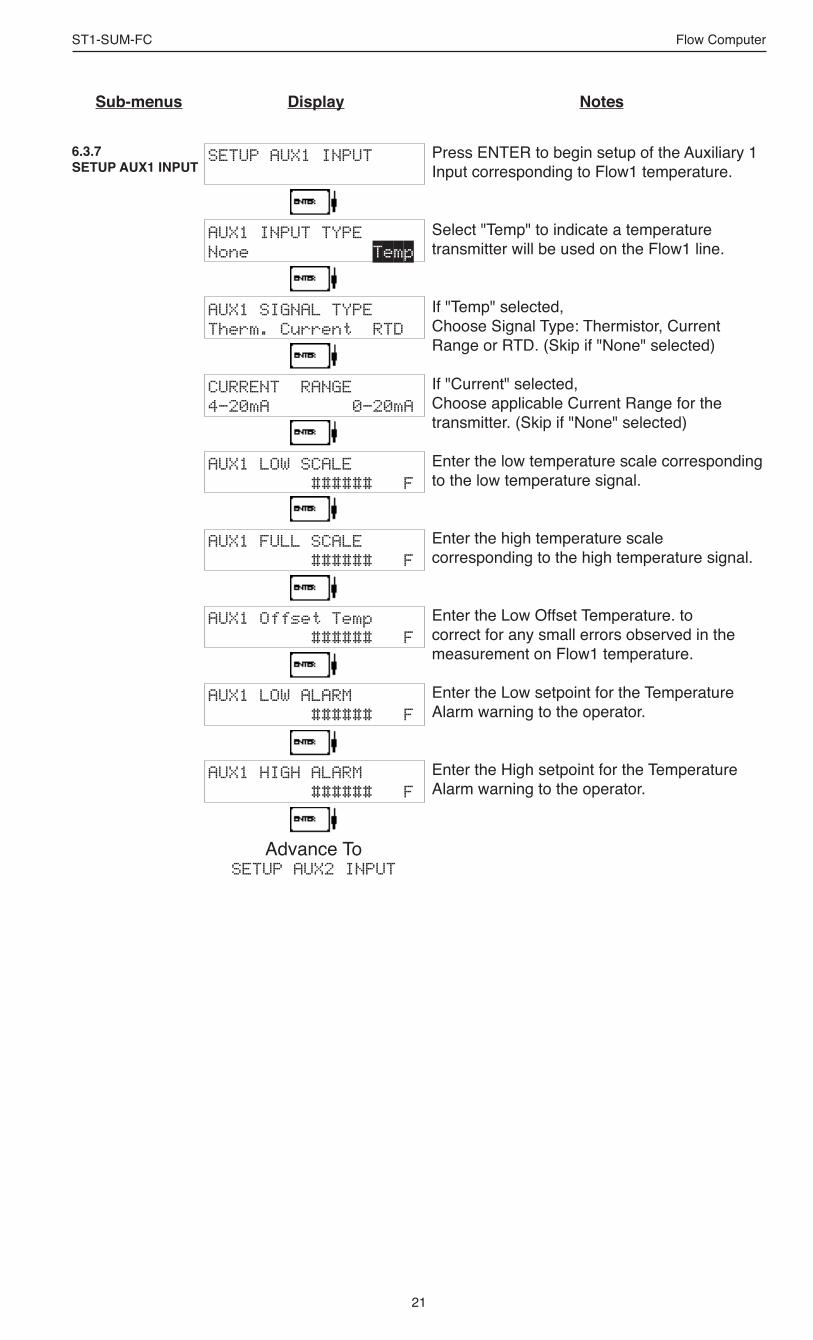
6.3.7SETUP AUX1 INPUT
SETUP AUX1 INPUT
AUX1 INPUT TYPENone Temp
AUX1 SIGNAL TYPETherm. Current RTD
CURRENT RANGE4-20mA 0-20mA
AUX1 LOW SCALE ###### F
AUX1 FULL SCALE ###### F
AUX1 Offset Temp ###### F
AUX1 LOW ALARM ###### F
AUX1 HIGH ALARM ###### F
Advance To SETUP AUX2 INPUT
Press ENTER to begin setup of the Auxiliary 1 Input corresponding to Flow1 temperature.
Select "Temp" to indicate a temperature transmitter will be used on the Flow1 line.
If "Temp" selected,Choose Signal Type: Thermistor, Current Range or RTD. (Skip if "None" selected)
If "Current" selected,Choose applicable Current Range for the transmitter. (Skip if "None" selected)
Enter the low temperature scale corresponding to the low temperature signal.
Enter the high temperature scale corresponding to the high temperature signal.
Enter the Low Offset Temperature. to correct for any small errors observed in the measurement on Flow1 temperature.
Enter the Low setpoint for the Temperature Alarm warning to the operator.
Enter the High setpoint for the Temperature Alarm warning to the operator.
Sub-menus Display Notes
22
ST1-SUM-FC Flow Computer
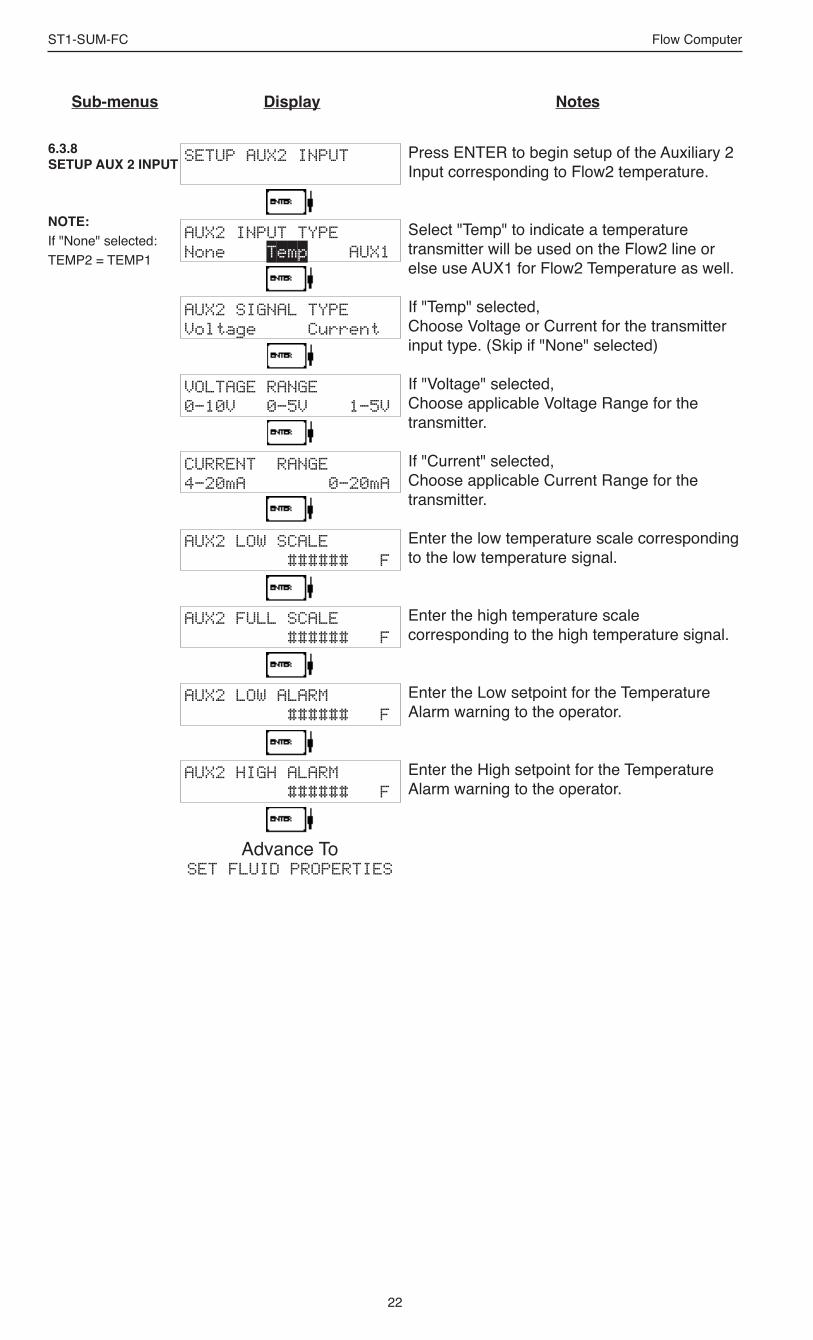
6.3.8SETUP AUX 2 INPUT
Sub-menus Display Notes
SETUP AUX2 INPUT
AUX2 INPUT TYPENone Temp AUX1
AUX2 SIGNAL TYPEVoltage Current
VOLTAGE RANGE0-10V 0-5V 1-5V
CURRENT RANGE4-20mA 0-20mA
AUX2 LOW SCALE ###### F
AUX2 FULL SCALE ###### F
AUX2 LOW ALARM ###### F
AUX2 HIGH ALARM ###### F
Advance To SET FLUID PROPERTIES
Press ENTER to begin setup of the Auxiliary 2 Input corresponding to Flow2 temperature.
Select "Temp" to indicate a temperature transmitter will be used on the Flow2 line or else use AUX1 for Flow2 Temperature as well.
If "Temp" selected,Choose Voltage or Current for the transmitter input type. (Skip if "None" selected)
If "Voltage" selected,Choose applicable Voltage Range for the transmitter.
If "Current" selected,Choose applicable Current Range for the transmitter.
Enter the low temperature scale corresponding to the low temperature signal.
Enter the high temperature scale corresponding to the high temperature signal.
Enter the Low setpoint for the Temperature Alarm warning to the operator.
Enter the High setpoint for the Temperature Alarm warning to the operator.
NOTE:If "None" selected: TEMP2 = TEMP1

23
ST1-SUM-FC Flow Computer
Sub-menus Display Notes
6.3.9SET FLUID PROPERTIES
SET FLUID PROPERTIES
FLUID NUMBER (0-9)0
FLUID NAME Generic #0
REF. DENSITY ###### lbs/g
REF. TEMPERATURE ###### F
EXPAN. FACTOR [xe-6] ########
VISCOSITY COEF. A 0.000
VISCOSITY COEF. B 0.000
Advance To SETUP PULSE OUTPUT
Press ENTER at this prompt to Set Fluid Properties.
Up to 10 Fluid types may be stored in the unit. Select the number of the desired fluid to edit.
Shows name and number of fluid selected. Enter the desired name using the up/down arrow keys.
Enter the Reference Density. This is used in the calculation of density when you have a temp transmitter and used for corrected flow calculation if you have a density transmitter.
Enter the Reference Temperature.
Enter the proper Fluid Expansion Factor.(If Temp Compensated for Mass or Corrected Volume) See Section 7.3, Calculating the Fluid Expansion Factor.
Enter the Viscosity A Coefficient. See section 7.4, Computation of Viscosity Coef. A and B.
Enter the Viscosity B Coefficient. See section 7.4, Computation of Viscosity Coef. A and B.
NOTE: The propertire for several common fluids are listed in Appendix A. These are also included in the setup software.
24
ST1-SUM-FC Flow Computer
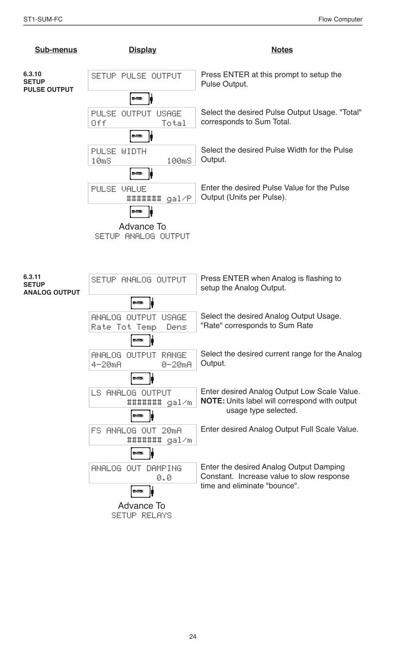
6.3.11SETUP ANALOG OUTPUT
6.3.10SETUP PULSE OUTPUT
Sub-menus Display Notes
Press ENTER at this prompt to setup the Pulse Output.
Select the desired Pulse Output Usage. "Total" corresponds to Sum Total.
Select the desired Pulse Width for the Pulse Output.
Enter the desired Pulse Value for the Pulse Output (Units per Pulse).
SETUP PULSE OUTPUT
PULSE OUTPUT USAGEOff Total
PULSE WIDTH10mS 100mS
PULSE VALUE ####### gal/P
Advance To SETUP ANALOG OUTPUT
SETUP ANALOG OUTPUT
ANALOG OUTPUT USAGERate Tot Temp Dens
ANALOG OUTPUT RANGE4-20mA 0-20mA
LS ANALOG OUTPUT ####### gal/m
FS ANALOG OUT 20mA####### gal/m
ANALOG OUT DAMPING 0.0
Advance To SETUP RELAYS
Press ENTER when Analog is flashing to setup the Analog Output.
Select the desired Analog Output Usage. "Rate" corresponds to Sum Rate
Select the desired current range for the Analog Output.
Enter desired Analog Output Low Scale Value.NOTE: Units label will correspond with output
usage type selected.
Enter desired Analog Output Full Scale Value.
Enter the desired Analog Output Damping Constant. Increase value to slow response time and eliminate "bounce".

25
ST1-SUM-FC Flow Computer
SETUP RELAYSRly1 Rly2 Rly3 Rly4
RELAY 1 USAGERATE TOTAL NA
RELAY 1 DELAY sec 0
RELAY 1 MODELO_ALARM HI_ALARM
RELAY 1 DURATION#####
RELAY 1 SETPOINT####### gal
RELAY 1 HYSTERESIS##### gal/m
Advance To SETUP RELAYS 3, 4
Sub-menus Display Notes
6.3.12SETUP RELAYS(Relay 1 & Relay 2)
Select the desired Relay for setup.(Relays 3 & 4 Optional)
If Relay 1 or Relay 2 Selected,Select Sum Rate, Sum Total or Not Assigned.
If Rate selected, enter desired relay activation delay value.
Select the desired Relay Activation.Low: Relay activates when Sum reading is
below setpoint.High: Relay activates when Sum reading is
above setpoint.If Sum Total Selected, Enter desired Relay Duration for Alarm. "0" will latch Alarm indefinitely.
Enter the desired Setpoint. The Setpoint can be edited in run mode using the PRE 1 key (PRE 2 key for Relay 2).
If Sum Rate, selected, Enter desired Relay Hysteresis.

26
ST1-SUM-FC Flow Computer
6.3.12 (Continued)SETUP RELAYS(Relay 3 & Relay 4)
SETUP RELAYSRly1 Rly2 Rly3 Rly4
RELAY 3 USAGERate Total Aux NA
RELAY 4 USAGERate Tot Aux Alrm NA
ASSIGN AUX CHANNEL AUX 1 AUX 2
RELAY 3 DELAY sec 0
RELAY 3 MODELO_ALARM HI_ALARM
RELAY 3 DURATION#####
RELAY 3 SETPOINT####### gal
RELAY 3 HYSTERESIS##### gal/m
Advance To SETUP CONTROL INPUTS
Select the desired Relay for setup.(Relays 3 & 4 Optional)
If Relay 3 Selected,Choose Rate, Total, Aux or NA.
If Relay 4 Selected,Choose Rate, Total, Aux, Alrm or NA.
If Aux selected, enter desired auxilliary channel.
If Rate / Aux selected, enter desired relay activation delay value.
Select the desired Relay Activation for Rate/Aux.Low: Relay activates when Sum reading is
below setpoint.High: Relay activates when Sum reading is
above setpoint.If Sum Total Selected, Enter desired Relay Duration.
Enter the desired Setpoint.
If Sum Rate, selected, Enter desired Relay Hysteresis.
NOTE: Settings for Relays 3
& 4 may be entered even if relays are not supplied. The settings will still trig-ger display alarms.
Sub-menus Display Notes
RELAY NOTES & CONSIDERATIONS
1. Relay activation is based on the computed readings not the displayed value. Therefore the display damping factor will not affect the relay response time. The RELAY DELAY feature allows the user to enter a time delay for relay activation. This feature is very useful in applications where short over/under range conditions are not considered alarm conditions.
2. Setting the relays to NA (Not Assigned), will allow the relay activation to be controlled via the RS-232 Serial and/or RS-485 Modbus ports.
3. Relay 3 and Relay 4 settings may be used to trigger display alarm conditions to the operator even if the relays are not supplied.

27
ST1-SUM-FC Flow Computer
Sub-menus Display Notes
6.3.13SETUP CONTROL INPUTS
Press Enter to begin setup of the Control Inputs.
Select the desired Control Input for setup.
If Control Input 1 Selected,Select Inhibit Total or NA (Not Assigned).
If Control Input 2 Selected,Select Reset Total or NA (Not Assigned).
If Control Input 3 Selected,Select Prn (Print), Ack (acknowledge alarm), KeyLk (Keylock) or NA (Not Assigned). ACK will acknowledge and clear alarms and warning messages. The Alarm History is NOT cleared.
Note: Alarms may reassert themselves if alarm conditions are still present.
SETUP CONTROL INPUTS
SETUP CONTROL INPUTSInput1 Input2 Input3
CONTROL INPUT1 USAGEINHIBIT_TOTAL NA
CONTROL INPUT2 USAGERESET_TOTAL NA
CONTROL INPUT3 USAGEPrn Ack KeyLk NA
Advance To SETUP REALTIME CLOCK

28
ST1-SUM-FC Flow Computer
Press Enter to begin setup of the Realtime Clock.
Select Time to set the time.
Select 24Hr or 12Hr clock
If 12Hr Clock,Enter AM or PM
Enter time of day.
Select Date to enter the date.
Enter the date. (Month, Day, Last two digits of Year)
SETUP REALTIME CLOCK
SETUP REALTIME CLOCKTime Date
CLOCK TYPE24HR 12HR
SELECT CLOCK AM/PMAM PM
TIME OF DAY HH:MM:SS ##:##:##
Advance To SETUP REALTIME CLOCK
(Date)
SETUP REALTIME CLOCKTime Date
DATE: MONTH,DAY,YEAR ##/##/####
Advance To SERIAL USAGE
6.3.15SETUP REALTIME CLOCK(Date)
Sub-menus Display Notes
6.3.14SETUP REALTIME CLOCK(Time)

29
ST1-SUM-FC Flow Computer
Sub-menus Display Notes
6.3.16SERIAL USAGE(RS-232/485)
SERIAL USAGE
SERIAL HARDWARERS232 RS485
DEVICE ID ##
BAUD RATE300 600 1200 <more>
BAUD RATE2400 4800 9600 19200
PARITYNone Odd Even
HANDSHAKINGNone Softwre Hardwre
DEVICE LINE FEED<CR> <CR+LF>
MODEM OPTIONSNo Yes
MODEM INIT MASTERNo Yes
MODEM AUTO ANSWERNo Yes
CALL OUT DAY OF WEEK 1
CALL OUT TIME ##:##:##
Continued on Next Page
Press Enter to begin setup of the Serial Port.
Select Serial Hardware type for standard port. Select RS485 only on special order. (See SETUP NETWORK CARD for RS485 Modbus option)
Select the Device ID.
Select the desired Baud Rate.
(If <more> selected)
Select the desired Parity.
Set the Handshake.
Choose end of line termination. Only choose <CR> if your external device automatically assigns a line feed for every <CR> carriage return.
Select "Yes" if the serial port will be used to control a modem.
Select "Yes" to have the unit engage in a configuration conversation with the modem onpower up .
If "YES" selected for Modem Init Master, choose the desired Modem Auto Answer mode.
Enter the day of the week to perform Call Out transmission. (0 = daily, 1 - 7 = Mon - Sun)
Enter the time of day to perform Call Out transmission. (HH:MM:SS)
6.3.17SERIAL USAGE(Modem Options)

30
ST1-SUM-FC Flow Computer
CALL ON ERROR/ALARMNo Yes
CALL OUT PHONE # 0
NUMBER OF REDIALS 0
HANGUP IF 2MIN INACTNo Yes
Advance To SETUP DATALOG/PRINT
SETUP DATALOG/PRINT
SETUP DATALOG/PRINTConfig Select_list
OUTPUT FORMATPrinter Term Dbase
PAGE LENGTH [99 max] 99
TOP MARGIN [99 max] 3
DATALOG ONLYNo Yes
PRINT TIME HH:MM:SS 00:00:00
PRINT INTERVAL 00:00:00
ENABLE PRINT KEYNO YES
CLEAR TOTAL IF PRINTNO YES
Advance To SETUP DATALOG/PRINT
(Select_list)
Select "Yes" to have the unit perform a Call Out transmission upon error/alarm condition.
Call Out Phone Number to be dialed for "Call Out Time" or "Print On Error/Alarm". (Up to 20 digits with "." used to pause between digits)
Enter the number of redials to be performed on call out time if busy or no answer (error/alarm tries until connected).
Select "Yes" to perform hangup if there is inactivity for more than 2 minutes.
Press Enter to setup the Datalog/Print information.
Select Config to configure the Datalog/Print information.
Select the type of Output Format.
Enter the desired Page Length.If Printer selected above.
Enter the desired Top Margin.If Printer selected above.
Select Yes to record events to the datalogger only. Events will not be sent to the serial port.
Enter Print Time, printer will print at this time every day. Enter 00:00:00 to inhibit print time.
Enter Print Interval, Enter 00:00:00 to inhibit print interval..
Select YES to enable Print Key.Select NO to disable Print Key
Select Yes to clear the total after printing. This feature is useful for recording totals, then clearing totals automatically after log or printout has been completed.
6.3.18SETUP DATALOG/PRINT(Configure)
Sub-menus Display Notes
6.3.17SERIAL USAGE(Modem Options)(continued)

31
ST1-SUM-FC Flow Computer
Sub-menus Display Notes
ADMINISTRATIVE SETUP
TAG NUMBERFT XXXX
OPERATOR PASSWORD****
SUPERVISOR PASSWORD****
SOFTWARE VERSIONvxx.xx
PRODUCT ORDER CODE ST1SUMFCxxxxxxx
UNIT SERIAL NUMBER 00000
SENSOR SERIAL NUMBER 00000
DISPLAY NEW ERR ONLYNo Yes
Advance To INSTRUMENT TYPE
Press Enter to begin Administrative Setup.
Use the up and down arrow keys to define the tag number.
Enter Operator Password. (Factory Set to 0)
Enter Supervisor Password, if logged in as supervisor. (Factory Set to 2000)
This display is used to show the software version of the installed software.
This display is used to show the product order code (model number).
This display is used to show the unit's serial number.
This display is used to show the sensor's serial number.
If yes is selected, an error message will only appear once until acknowledged by user.
Advance to Network Card only if a Network Card is installed.
6.3.20ADMINISTRATIVE SETUP
6.3.19SETUP DATALOG/PRINT (Select_list)
Press enter to begin Setup Datalog/Print routine.
Press enter when Select_list is selected to setup print list.
Use Up and Down arrow keys to view list status.Press the Print or function key for the items that you wish to add or remove from the list. Items marked with Yes will be added to the list, items marked with No will be removed from the list.
S_ corresponds to SumThe Select Print List Information display shows the current possible Datalog size.
SET DATALOG/PRINT
SET DATALOG/PRINTConfig Select_list
PRINT LIST ITEMSFLUID YES
PRINT LIST ITEMSTIME YES
PRINT LIST ITEMSTOT1 YES
PRINT LIST ITEMSDataLog size =00455
Advance To ADMINISTRATIVE SETUP
List Items:FLUIDTIMETOT1RATESTOT2GRND1TEMP1DENS1PRE1PRE2PRE3PRE4FREQ1FREQ2KA-FKB-FTEMP2DENS2RATE1RATE2TOTSGRND2GRNDS

32
ST1-SUM-FC Flow Computer
6.3.21SETUP NETWORK CARD(optional)
SETUP NETWORK CARD
SELECT NTW PROTOCOLModbusRTU
NETWORK DEVICE ID 1
BAUD RATE2400 4800 9600 19200
PARITYNone Odd Even
Advance To INSTRUMENT TYPE
Press Enter to setup Network Card
Select desired Network Protocol.
Enter the device address on network (00-255).
Select the desired Baud Rate.
Select the desired Parity.

33
ST1-SUM-FC Flow Computer
7. Principle Of Operation
7.1 General:
The ST1-SUM-FC Flow Computer uses several internal calculations to compute the Sum compensated flow based on specific data input. Several computations are performed to arrive at the uncompensated flow, Flow1 and Flow2 temperatures, density and viscosity. This information is then used to compute the Corrected Volume Flow or Mass Flow.
Note concerning Fluid InformationThe user will be prompted for Fluid Information during the setup of the instrument. The unit can store the fluid properties for up to 10 different fluids at one time. See also Appendix A for common fluid properties for liquids.
7.2 Flow Equations:
Input Temperature Computation:
General Case Tf1 = [% input span • (temp FS - Temp low scale)] + temp low scale Tf 2= [% input span • (temp FS - Temp low scale)] + temp low scale
Fluid Properties:
Liquid Generic Case liquid density1 = reference density • (1 - (Therm. Exp. Coef. x 1e-6 (Tf-Tref))2
liquid density2 = reference density • (1 - (Therm. Exp. Coef. x 1e-6 (Tf-Tref))2
Liquid API Case liquid density1 = reference density • (VCF API2540) liquid density2 = reference density • (VCF API2540)
Where: Tf1 = Flow1 Temperature via AUX 1 Tf2 = Flow2 Temperature via AUX 2 NOTE: If AUX2 Usage = AUX1; TF2 = TF1
Liquid Density1 = Computed density at Flow1 Temperature from AUX1 Liquid Density2 = Computed density at Flow2 Temperature from AUX2 NOTE: If AUX2 Usage = AUX1; Liquid Density2 = Liquid Density1
NOTE: If both AUX1 and AUX2 Usage = NONE: TF2 = TF1 = Default Temperature
General Operation
Flow Equations
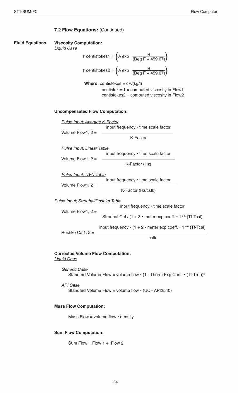
34
ST1-SUM-FC Flow Computer
7.2 Flow Equations: (Continued)
Fluid Equations Viscosity Computation:Liquid Case
Uncompensated Flow Computation:
Pulse Input; Average K-Factor input frequency • time scale factor Volume Flow1, 2 = K-Factor
Pulse Input; Linear Table input frequency • time scale factor Volume Flow1, 2 = K-Factor (Hz)
Pulse Input; UVC Table input frequency • time scale factor Volume Flow1, 2 = K-Factor (Hz/cstk)
Pulse Input; Strouhal/Roshko Table input frequency • time scale factor Volume Flow1, 2 = Strouhal Cal / (1 + 3 • meter exp coeff. • 1 e-6 (Tf-Tcal)
input frequency • (1 + 2 • meter exp coeff. • 1 e-6 (Tf-Tcal) Roshko Cal1, 2 = cstk
input frequency • time scale factorCorrected Volume Flow Computation:Liquid Case
Generic Case Standard Volume Flow = volume flow • (1 - Therm.Exp.Coef. • (Tf-Tref))2
API Case Standard Volume Flow = volume flow • (UCF API2540)
Mass Flow Computation:
Mass Flow = volume flow • density
Sum Flow Computation:
Sum Flow = Flow 1 + Flow 2
† centistokes2 = A exp B(Deg F + 459.67)( )
† centistokes1 = A exp B(Deg F + 459.67)( )
Where: centistokes = cP/(kg/l)centistokes1 = computed viscosity in Flow1centistokes2 = computed viscosity in Flow2

35
ST1-SUM-FC Flow Computer
7.2 Flow Equations: (Continued)
Flow Equations
The above information was obtained from "Flow Measurement Engineering Handbook, 3rd Edition" by Richard W Miller.
API 2540 Expansion Factor Equation
1. Select the values for K0 and K1 for the fluid group to be measured
2. Convert the base reference density for your fluid into the corresponding density units of kg/m3
3. Solve for αb using equation above
4. C = αb • 1,000,000

36
ST1-SUM-FC Flow Computer
7.3 Calculating the Fluid Expansion Factor for Generic Case
The liquid density is a function of the flowing temperature for many fluids. This unit solves an equation which represents this physical property of the fluid.The information which the unit uses to describe the fluid is entered by the user in the following variables: Reference Temperature, Reference Density, Fluid Expansion Factor. Values for common fluids are listed in Appendix A for the generic case.This information is available for many fluids in one or more of the following forms: Fluid Specific Gravity vs. Temp. Table Specific Gravity vs. Temp. Graph Fluid Density vs. Temp. Table Fluid Density vs. Temp. GraphBegin by obtaining one of the fluid properties for the fluid you are using from available manufacturers information or Engineering Handbooks. In some cases this information is listed on the Material Safety Data Sheet for the fluid. Two temperature-specific gravity pairs will be required to compute the temperature coefficient.The reference temperature is simply chosen by the user. Common reference temperatures are 60° F or 15° C.The reference temperature should be chosen so that it is in the application temperature range. i.e. application temperature range -10 to 120° F, reference temperature of 60° F chosen.Enter the reference temperature you have chosen at this point.The reference specific gravity corresponds to the fluid SPECIFIC GRAVITY at the reference temperature chosen.You may convert the fluid density information to specific gravity if it is in units other than specific gravity. Use EQ1.
EQ1. Spec.Grav. = Density of Fluid / Density of Water
Given the reference temperature, reference specific gravity, a second temp. and a second Spec.Grav., the Expansion Factor (C Factor) can be computed as follows:
EQ2. Used for Liquid Mass and Corrected Volume Equations
1 - (Spec.Grav.2 / Ref.Spec.Grav.)Temp.2 - Ref.Temp
√[ ] x 1,000,000C =
Given the reference temperature, reference density, a second temp. and a second density, the Expansion Factor (C Factor) can be computed as follows:
EQ3. Used for Liquid Mass and Corrected Volume Equations
C = Fluid Expansion Factor
Calculating Expansion Factor
Expansion FactorEquations
1 - (Dens.2 / Ref.Dens.)Temp.2 - Ref.Temp√[ ] x 1,000,000C =

37
ST1-SUM-FC Flow Computer
7.4 Computation of Viscosity Coef. A and B
The flow computer solves a generic equation which computes the viscosity in cstk as a function of temperature. Two parameters must be entered for this calculation to be performed. These are the setup parameters Viscosity Coef. A and Viscosity Coef. B. A table listing these values for common fluids is available in Appendix A.
Alternately, if your intended fluid is not listed, the Viscosity Coef. A and B can be derived from two known temperature/viscosity pairs. Begin by obtaining this information for you intended fluid. Convert these known points to units of Degrees F and centistoke (cstk)
The information is now in a suitable form to compute the Viscosity Coef. A and Viscosity Coef. B using the following equation based on the fluid state.
For a liquid, A and B are computed as follows:
(T1 + 459.67) • (T2 + 459.67) • ln [ cstk1/cstk2] B = —————————————————————— (T2 + 459.67) - (T1 + 459.67)
cstk1 A = ——————————— exp [ B / ( T1 + 459.67) ]
cP • Density of Water at 4°C NOTE: cS = —————————————— Density of Fluid at Flowing Conditions
Computation of Viscosity Coef. A & B

38
ST1-SUM-FC Flow Computer
7.5 Linearization Table
7.5.1 Linearization Table General InformationThe Linearization Table is used when the flow input device gives a nonlinear input signal. The unit uses up to 40 different points, as entered by the operator, to form a curve for linearizing the input signal. Notes:1) A minimum of three points must be set up.
2) If "0" is entered for the frequency of any point other than point 1, the Flow Computer assumes there are no more points above the points that preceded them. The display will advance to the next setup prompt.
3) If the input frequency is above the highest or below the lowest frequency programmed, the unit will use the last known point for the K factor in computing the resulting actual flow. 4) Frequencies, Hz/Cstks or Roshko numbers should be entered in ascending order.
7.5.2 Linearization Table for Pulse InputsThe linearization table for pulse inputs programming is quite simple when values of frequency and K factors are known. The Flow Computer asks for 40 different frequencies (Freq) and 40 corresponding K factors (K). It then uses this data to determine what the actual volume flow rate is for any given input frequency on the respective flowmeter. Usually the necessary data is provided with the flowmeter.
7.5.3 Linearization Table InterpolationThe Linearization Table routine uses the entered data to determine the K factor for any given input frequency or input flow signal. This is done by taking the closest data points above and below the input signal, then using those points to interpolate the K factor, then calculating the uncompensated volume flow from the data. Below are the formulas.
Parameters:Determine closest point above input signalsignal = X, K factor (correction factor) = KA
Determine closest point below input signalsignal = Y, K factor (correction factor) = KB
Let input signal = H, unknown K factor (correction factor) = KN
To find KN use this formula:
7.6 Universal Viscosity Curve (UVC)A Universal Viscosity Curve is a presentation of the calibration of a turbine flowmeter's K-Factor as a function of the Hz/cstks. It is used to represent the combined effects of flowrate and viscosity on the calibration of the flowmeter. It is entered as a table of point pairs in ascending order of Hz/cstks.
7.7 Strouhal Roshko Curve (StRo)A Strouhal Roshko Curve is a presentation of the calibration of a turbine flow-meter's calibration as a table or curve of Strouhal number as a function of Roshko number. It is used to represent the combined effects of flowrate, flow-ing temperature and viscosity on the calibration of the turbine flowmeter. It is entered as a table of point pairs in ascending order of Roshko numbers.
KAKAKNKB
Y H XInput
K fa
ctor
Linearization TableGeneral Information
Linearization Table(Pulse Inputs)
Linearization TableInterpolation
Universal Viscosity Curve
Strouhal Roshko Curve

39
ST1-SUM-FC Flow Computer
SELECT OPERATE STATE Run Setup Test
Audit Trail
Error history
Print System Setup
Keypad Test
Display test
Calibrate
Analog In Test
Pulse input test
Analog out test
Excitation out test
Pulse out test
Relay Test
Control inputs test
Battery Voltage Test
Data logger utility
8.1 Test Menus
8. Test, Service and Maintenance
Menus Display Notes
8.1.1TOP LEVEL TEST MENUS
Select Test to enter the instrument test & calibration routine.NOTE: Supervisor (Service) password
required to gain access to this mode.
Refer to Page 40 for Details.
Refer to Page 40 for Details.
Refer to Page 40 for Details.
Refer to Page 41 Details.
Refer to Page 41 for Details.
Refer to Pages 42-46 for Details.
Refer to Page 46 Details.
Refer to Page 47 for Details.
Refer to Page 47 for Details.
Refer to Page 47 for Details.
Refer to Page 48 for Details.
Refer to Page 48 for Details.
Refer to Page 48 for Details.
Refer to Page 49 for Details.
Refer to Page 49 for Details.
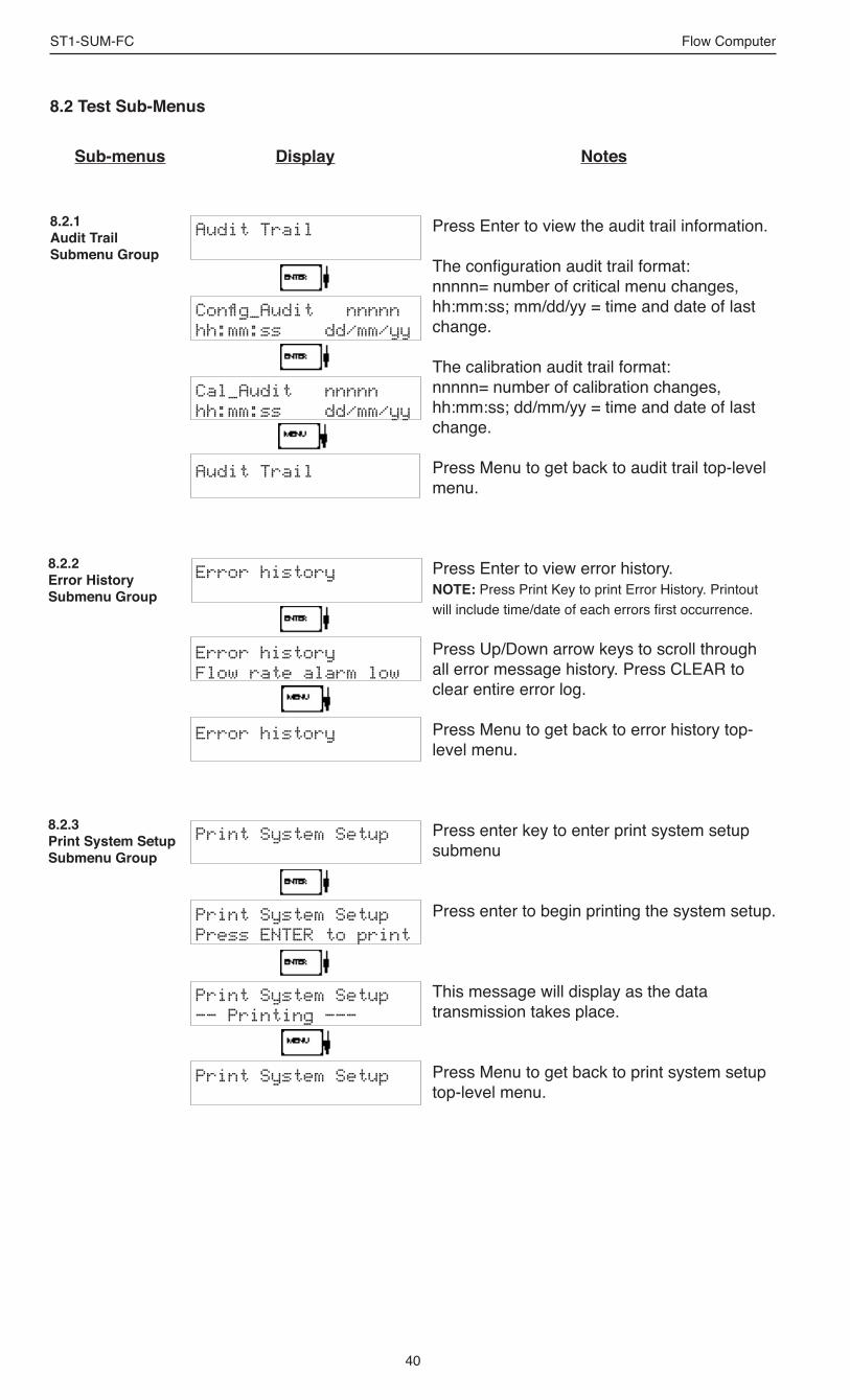
40
ST1-SUM-FC Flow Computer
8.2 Test Sub-Menus
Display NotesSub-menus
Audit Trail
Config_Audit nnnnnhh:mm:ss dd/mm/yy
Cal_Audit nnnnnhh:mm:ss dd/mm/yy
Audit Trail
Error history
Error historyFlow rate alarm low
Error history
Print System Setup
Print System SetupPress ENTER to print
Print System Setup—— Printing ——-
Print System Setup
Press Enter to view the audit trail information.
The configuration audit trail format: nnnnn= number of critical menu changes, hh:mm:ss; mm/dd/yy = time and date of last change.
The calibration audit trail format: nnnnn= number of calibration changes, hh:mm:ss; dd/mm/yy = time and date of last change.
Press Menu to get back to audit trail top-level menu.
Press Enter to view error history.NOTE: Press Print Key to print Error History. Printout will include time/date of each errors first occurrence.
Press Up/Down arrow keys to scroll through all error message history. Press CLEAR to clear entire error log.
Press Menu to get back to error history top-level menu.
Press enter key to enter print system setup submenu
Press enter to begin printing the system setup.
This message will display as the data transmission takes place.
Press Menu to get back to print system setup top-level menu.
8.2.1Audit TrailSubmenu Group
8.2.2Error HistorySubmenu Group
8.2.3Print System SetupSubmenu Group

41
ST1-SUM-FC Flow Computer
Sub-menus Display Notes
8.2.4Keypad testSubmenu Group
8.2.5Display testSubmenu Group
Keypad test
Keypad testKey pressed—> ENT
Keypad test
Display test
0000000000000000000000000000000000000000
Display test
Press Enter to enter keypad test
Press the various keys and the display will show the key that was pressed. Press Menu to exit the test
Press Menu to get back to Keypad test top-level menu.
Press Enter to enter display test.
Upon pressing enter, each digit on the display will scroll 0-9 then A-Z. Press menu to exit the test.
Press Menu to get back to Display test top-level menu.

42
ST1-SUM-FC Flow Computer
Sub-menus Display Notes
ALL UNITS ARE CALIBRATED AT THE FACTORY PRIOR TO SHIPMENTCAUTION: This unit must be calibrated using precision and calibrated equipment.
Equipment needed is as follows: Frequency Generator, Digital Multimeter, Precision Current/Voltage Source, Oscilloscope, Frequency Counter.
Calibrate
Calibrate Aux1: 0mAIin=TB1-7 GND=TB1-4
Calibrate Aux1: 0mACALIBRATING ——
Calibrate Aux1: 0mA *** DONE ***
Calibrate Aux1: 0mAIin=TB1-7 GND=TB1-4
Calibrate Aux1: 20mAIin=TB1-7 GND=TB1-4
Calibrate Aux1: 20mA 0 CALIBRATING ——
Calibrate Aux1: 20mA *** DONE ***
Calibrate Aux1: 20mAIin=TB1-7 GND=TB1-4
Advance to Calibrate Aux2: 0mA
CalibrationSubmenu Group
8.2.6Calibrate Aux1: 0mASubmenu Group
Press Enter to begin the calibration routine. (Please note the caution above)
Connect Current Source (+) TB1-7, (-) TB1-4. Input 0mA and press Enter.
This message is displayed during calibration.
This message is displayed when the 0mA calibration is finished.
The display will automatically return to the Calibrate Aux1 0mA submenu. Press the Down arrow key to advance to the Aux1 20mA calibration.
Connect Current Source (+) TB1-7, (-) TB1-4. Input 20mA and press Enter.
This message is displayed during calibration.
This message is displayed when the 20mA calibration is finished.
The display will automatically return to the Calibrate Aux1 20mA submenu. Press the Down arrow key to advance to the Aux2 0mA calibration.
8.2.7Calibrate Aux1: 20mASubmenu Group
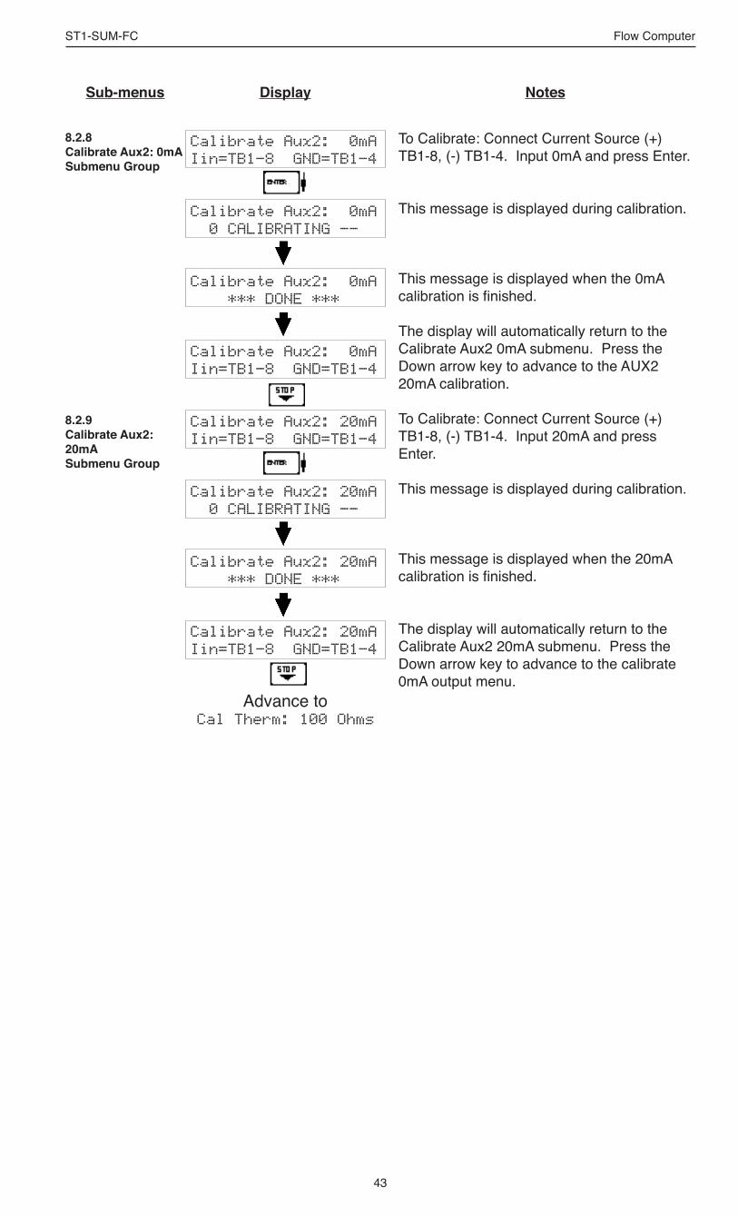
43
ST1-SUM-FC Flow Computer
Sub-menus Display Notes
8.2.8Calibrate Aux2: 0mASubmenu Group
8.2.9Calibrate Aux2: 20mASubmenu Group
Calibrate Aux2: 0mAIin=TB1-8 GND=TB1-4
Calibrate Aux2: 0mA 0 CALIBRATING ——
Calibrate Aux2: 0mA *** DONE ***
Calibrate Aux2: 0mAIin=TB1-8 GND=TB1-4
Calibrate Aux2: 20mAIin=TB1-8 GND=TB1-4
Calibrate Aux2: 20mA 0 CALIBRATING ——
Calibrate Aux2: 20mA *** DONE ***
Calibrate Aux2: 20mAIin=TB1-8 GND=TB1-4
Advance to Cal Therm: 100 Ohms
To Calibrate: Connect Current Source (+) TB1-8, (-) TB1-4. Input 0mA and press Enter.
This message is displayed during calibration.
This message is displayed when the 0mA calibration is finished.
The display will automatically return to the Calibrate Aux2 0mA submenu. Press the Down arrow key to advance to the AUX2 20mA calibration.
To Calibrate: Connect Current Source (+) TB1-8, (-) TB1-4. Input 20mA and press Enter.
This message is displayed during calibration.
This message is displayed when the 20mA calibration is finished.
The display will automatically return to the Calibrate Aux2 20mA submenu. Press the Down arrow key to advance to the calibrate 0mA output menu.

44
ST1-SUM-FC Flow Computer
Cal Therm: 100 OhmsTherm TB1-6 to TB1-4
Cal Therm: 100 Ohms 0 CALIBRATING ——
Cal Therm: 100 Ohms *** DONE ***
Cal Therm: 100 OhmsTherm TB1-6 to TB1-4
Advance to Cal Therm: Open
To Calibrate: Place a 100 ohm 0.1% resistor between TB1-6 and TB1-4. Press enter to calibrate.
This message is displayed during calibration.
This message is displayed when the calibration is finished.
The display will automatically return to the Cal Therm: 100 Ohms top-level menu. Press the Down arrow key to advance to the Thermistor Open calibration.
8.2.10Cal Therm: 100 OhmsSubmenu Group
Cal Therm: OpenTherm TB1-6 to TB1-4
Cal Therm: Open 0 CALIBRATING ——
Cal Therm: Open *** DONE ***
Cal Therm: OpenTherm TB1-6 to TB1-4
Advance to Calibrate Aux2: 0V
To Calibrate: Remove the 100Ω 0.1% resistor from TB1-6 and TB1-4 and leave open. Press enter to calibrate.
This message is displayed during calibration.
This message is displayed when the calibration is finished.
The display will automatically return to the Cal Therm Open top-level menu. Press the Down arrow key to advance to the Aux2: 0V calibration.
8.2.11Cal Therm: OpenSubmenu Group
Sub-menus Display Notes
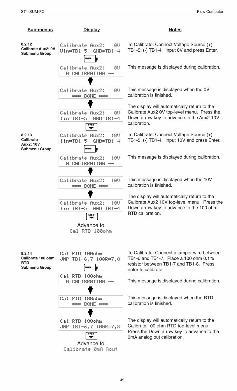
45
ST1-SUM-FC Flow Computer
8.2.12Calibrate Aux2: 0VSubmenu Group
Calibrate Aux2: 0VVin=TB1-5 GND=TB1-4
Calibrate Aux2: 0V 0 CALIBRATING ——
Calibrate Aux2: 0V *** DONE ***
Calibrate Aux2: 0VIin=TB1-5 GND=TB1-4
Calibrate Aux2: 10VIin=TB1-5 GND=TB1-4
Calibrate Aux2: 10V 0 CALIBRATING ——
Calibrate Aux2: 10V *** DONE ***
Calibrate Aux2: 10VIin=TB1-5 GND=TB1-4
Advance to Cal RTD 100ohm
Cal RTD 100ohm JMP TB1-6,7 100R=7,8
Cal RTD 100ohm 0 CALIBRATING ——
Cal RTD 100ohm *** DONE ***
Cal RTD 100ohm JMP TB1-6,7 100R=7,8
Advance to Calibrate 0mA Aout
8.2.13Calibrate Aux2: 10VSubmenu Group
To Calibrate: Connect Voltage Source (+) TB1-5, (-) TB1-4. Input 0V and press Enter.
This message is displayed during calibration.
This message is displayed when the 0V calibration is finished.
The display will automatically return to the Calibrate Aux2 0V top-level menu. Press the Down arrow key to advance to the Aux2 10V calibration.
To Calibrate: Connect Voltage Source (+) TB1-5, (-) TB1-4. Input 10V and press Enter.
This message is displayed during calibration.
This message is displayed when the 10V calibration is finished.
The display will automatically return to the Calibrate Aux2 10V top-level menu. Press the Down arrow key to advance to the 100 ohm RTD calibration.
To Calibrate: Connect a jumper wire between TB1-6 and TB1-7, Place a 100 ohm 0.1% resistor between TB1-7 and TB1-8. Press enter to calibrate.
This message is displayed during calibration.
This message is displayed when the RTD calibration is finished.
The display will automatically return to the Calibrate 100 ohm RTD top-level menu. Press the Down arrow key to advance to the 0mA analog out calibration.
8.2.14Calibrate 100 ohm RTDSubmenu Group
Sub-menus Display Notes

46
ST1-SUM-FC Flow Computer
Sub-menus Display Notes
8.2.15Calibrate 0mA AoutSubmenu Group
8.2.16Calibrate 20mA AoutSubmenu Group
Calibrate 0mA Aout+ TB1-15 - TB1-16
Calibrate 0mA AoutEnter mA: 0.00000
Calibrate 0mA Aout+ TB1-15 - TB1-16
Calibrate 20mA Aout+ TB1-15 - TB1-16
Calibrate 20mA outEnter mA: 20.00000
Calibrate 20mA Aout+ TB1-15 - TB1-16
Calibrate
Analog In Test
Analog In Test mAT7:00.000 T8:00.000
Analog In Test
Connect ammeter to (+) TB1-15, (-) TB1-16. Press enter.
To trim 0mA analog output: Press CLEAR to enable editing and enter a small negative number (i.e. -0.100) to force a display reading, then clear and enter small quantity measured on your meter.The display will return to Calibrate 0mA out. Press the down arrow key to advance to the 20mA analog out or repeat above if necessary.
Connect ammeter to (+) TB1-15, (-) TB1-16. Press enter.
To trim 20mA analog output: Press CLEAR to enable editing and enter the current reading that is on the ammeter display. Press enter.
The display will automatically return to the Calibrate 20mA Aout submenu. Calibration is complete.
Press the Menu key to go back to Calibrate top-level menu.
Press enter to test the analog inputs.
To check current input accuracy: Use TB1-4 as Reference Ground, input 0-20mA to TB1-7 and/or TB1-8. Display should show current being input. Use ammeter to verify input. Use Up/Down arrow keys to check other inputs.
Press Menu key to return to Analog In Test top-level menu.
8.2.17Analog In TestSubmenu Group
NOTE:Press the ∆ ∇ keys for additional analog input tests for RTD, Thermistor, and Voltage on terminal 5. Connect only one signal type at a time based on the Analog Input test being performed.

47
ST1-SUM-FC Flow Computer
Sub-menus Display Notes
Pulse input test
Pulse input testTrigger level 2.5V
Pulse input testcount speed 3kHz
Pulse input testF1: 0 F2: 0
Pulse input test
Analog out test
Analog out test*0 4 10 15 20 mA
Analog out test
Excitation out test
Excitation out test*5v 12v 24v
Excitation out test
Press Enter key to test the pulse input.
Use the Up/Down arrow keys to select the appropriate trigger level.
Use the Up/Down arrow keys to select the appropriate frequency range.
To check Pulse input accuracy at the above settings: Use TB1-4 as reference ground, input a frequency on TB1-2 and/or TB1-3. The display should show frequency being input. Use a frequency counter to verify input.
Press Menu key to return to Pulse input test top-level menu.
Press Enter to test the analog output.
To simulate analog output: Connect an ammeter to (+) TB1-15, (-) TB1-16. Press the key under the desired setting to move the asterisk (*). The unit should output the selected current.
Press Menu key to return to Analog out test top-level menu.
Press Enter to test the excitation output.
To test the excitation output: Connect a voltmeter to (+) TB1-1, (-) TB1-4. Press the key under the desired setting to move the asterisk (*). The unit should output the selected voltage.
Press Menu key to return to Excitation out test top-level menu.
8.2.18Pulse input testSubmenu Group
8.2.19Analog out testSubmenu Group
8.2.20Excitation out testSubmenu Group
2.5V10mV100mV
40Hz3KHz20kHz

48
ST1-SUM-FC Flow Computer
Sub-menus Display Notes
Pulse out test
Pulse out test*0Hz 1Hz 10Hz 20Hz
Pulse out test
Relay Test
Rly1 Rly2 Rly3 Rly4 Off Off Off Off
Relay Test
Control inputs test
TB1-9 TB1-10 TB1-11 Off Off Off
Control inputs test
8.2.21Pulse out testSubmenu Group
Press Enter key to test the pulse output.
To simulate a frequency on the pulse output: Connect a frequency counter to (+)TB1-13, (-)TB1-14. Press the key under the desired setting to move the asterisk (*). The unit should output the selected frequency.
Press Menu key to return to Pulse out test top-level menu.
Press Enter to test the relays.
To manually control the relay outputs: Press the key under the desired relay to toggle the relays On/Off. Use an ohmmeter to check the relay contacts.
Press Menu key to return to Relay Test top-level menu.
Press Enter to test the control inputs.
To check the control inputs: Use TB1-12 as reference, input a positive 3-30 VDC signal to TB1-9, TB1-10 and/or TB1-11, The Display will show ON when input is active, OFF when inactive.
Press Menu key to return to control input test top-level menu.
8.2.22Relay testSubmenu Group
8.2.23Control input testSubmenu Group

49
ST1-SUM-FC Flow Computer
Battery Voltage Test
Battery Voltage Test3.312 Volts
Battery Voltage Test
Data logger utility
Data logger utilityLog 10 958 Max
Data logger utilityLog 00001 PRT CLR
Data logger utility
8.2.24Battery Voltage testSubmenu Group
8.2.25Data logger utilitySubmenu Group
Press Enter key to view the battery voltage.
The display will show the battery voltage.Replace battery at 2.5 VDC or below.
Press Menu key to return to battery voltage test top-level menu.
Press Enter to use data logger utility.
The displays shows the number of Data Logs.Press the Down arrow key to advance to PRT (print) or CLR (clear).
Press F3 PRINT key to output data logger logs to printer, Press CLEAR key to clear the data logger contents.
Press Menu key to return to Data logger utility top-level menu.
Sub-menus Display Notes

50
ST1-SUM-FC Flow Computer
Screws(4 places)
fig.1 fig.2
8.3 Internal Fuse Replacement
Instructions:1. Make sure you follow proper E.S.D. Precautions. All persons performing this
replacement must follow proper grounding procedures.2. Turn the power to the unit off.3. Disconnect the two piece connector rear terminal block, leaving all connections in place.4. Remove the unit from the panel.5. Remove the four machine screws (see fig. 1) which hold the two sections of the case
together.6. The rear section of the case should detach from the rest of the case. It may be
necessary two cut the wiring label along the joint where the two sections connect. With the rear section of the case removed the fuse will be exposed (located near the rear terminal, AC connection).
7. Locate the Fuse F1 (see fig. 2) and unplug the fuse from its socket. 8. Insert the new fuse into the socket. Insure that the pins are fully inserted and straight.9. Reassemble the case and install the four machine screws which join the two sections of
the case.10. Reinstall the unit into the panel.11. Reconnect the rear terminal block.12. Turn the unit back on.
Fuse Specifications: 110 VAC Power: 160mA/250V, TD Wickman 19372-030-k or equivalent 220 VAC Power: 80mA/250V, TD Wickman 19372-026-k or equivalent 12/24 VDC Power: 800mA/250V, TD Wickman 19374-046-k or equivalent
FUSE
fuse
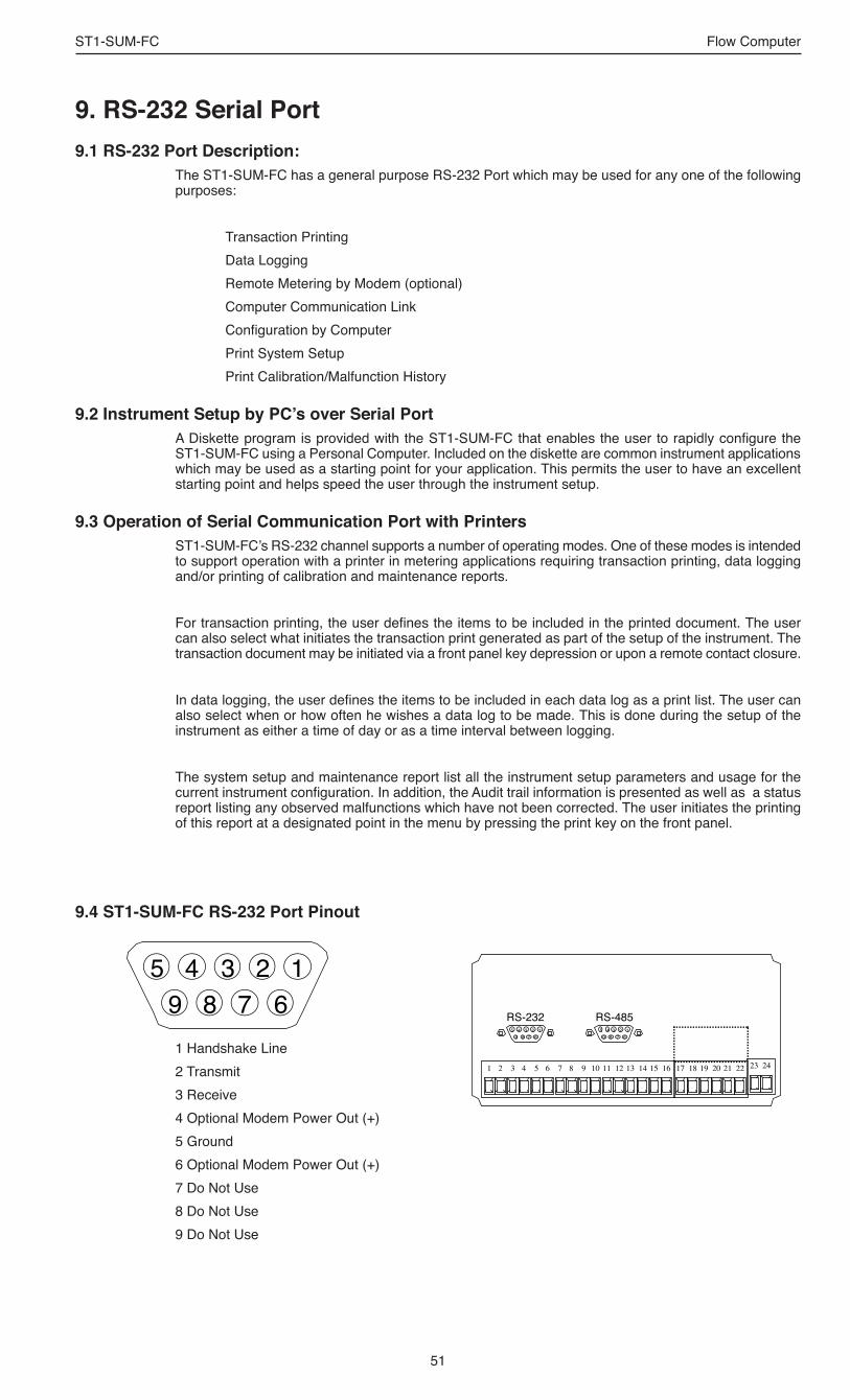
51
ST1-SUM-FC Flow Computer
9. RS-232 Serial Port9.1 RS-232 Port Description:
The ST1-SUM-FC has a general purpose RS-232 Port which may be used for any one of the following purposes:
Transaction Printing Data Logging Remote Metering by Modem (optional) Computer Communication Link Configuration by Computer Print System Setup Print Calibration/Malfunction History
9.2 Instrument Setup by PC’s over Serial PortA Diskette program is provided with the ST1-SUM-FC that enables the user to rapidly configure the ST1-SUM-FC using a Personal Computer. Included on the diskette are common instrument applications which may be used as a starting point for your application. This permits the user to have an excellent starting point and helps speed the user through the instrument setup.
9.3 Operation of Serial Communication Port with Printers ST1-SUM-FC’s RS-232 channel supports a number of operating modes. One of these modes is intended to support operation with a printer in metering applications requiring transaction printing, data logging and/or printing of calibration and maintenance reports.
For transaction printing, the user defines the items to be included in the printed document. The user can also select what initiates the transaction print generated as part of the setup of the instrument. The transaction document may be initiated via a front panel key depression or upon a remote contact closure.
In data logging, the user defines the items to be included in each data log as a print list. The user can also select when or how often he wishes a data log to be made. This is done during the setup of the instrument as either a time of day or as a time interval between logging.
The system setup and maintenance report list all the instrument setup parameters and usage for the current instrument configuration. In addition, the Audit trail information is presented as well as a status report listing any observed malfunctions which have not been corrected. The user initiates the printing of this report at a designated point in the menu by pressing the print key on the front panel.
9.4 ST1-SUM-FC RS-232 Port Pinout
123456789
1 Handshake Line2 Transmit3 Receive4 Optional Modem Power Out (+)5 Ground6 Optional Modem Power Out (+)7 Do Not Use8 Do Not Use9 Do Not Use
1 2 3 4 5 6 7 8 9 10 11 12 13 14 15 16 17 18 19 20 21 22 23 24
123456789
123456789
RS-232 RS-485
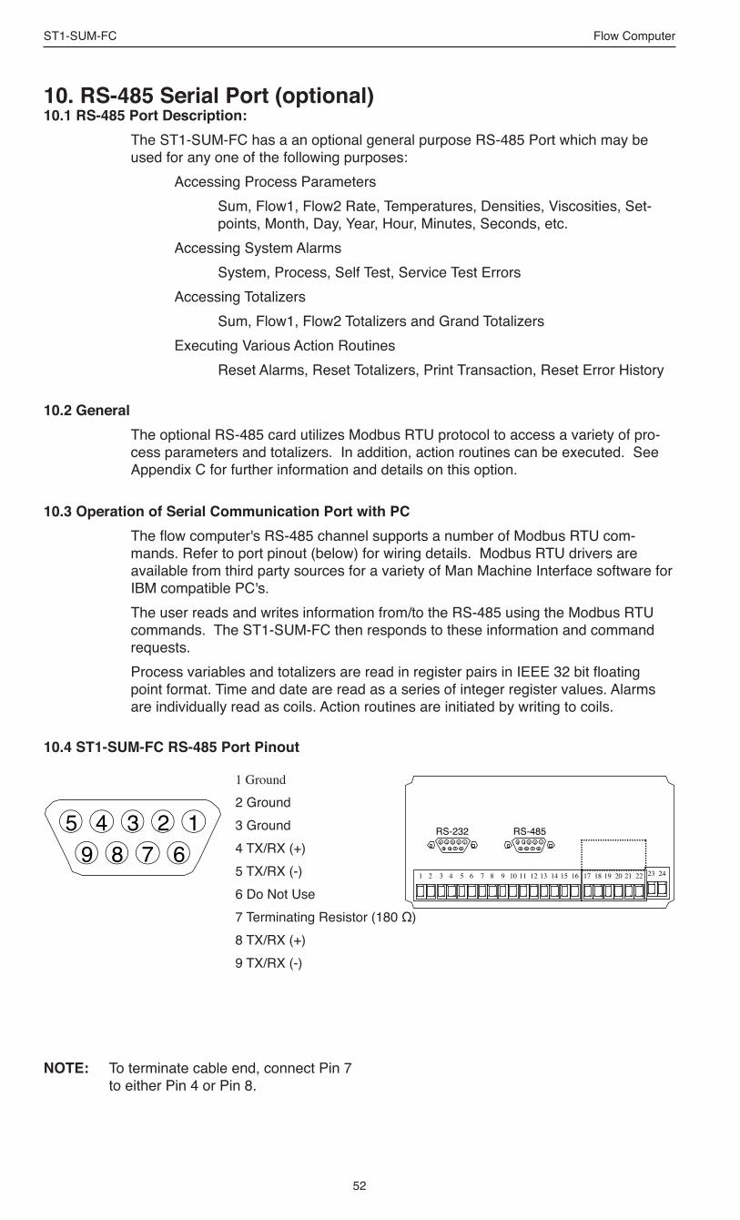
52
ST1-SUM-FC Flow Computer
10. RS-485 Serial Port (optional)10.1 RS-485 Port Description:
The ST1-SUM-FC has a an optional general purpose RS-485 Port which may be used for any one of the following purposes: Accessing Process Parameters Sum, Flow1, Flow2 Rate, Temperatures, Densities, Viscosities, Set-
points, Month, Day, Year, Hour, Minutes, Seconds, etc. Accessing System Alarms System, Process, Self Test, Service Test Errors Accessing Totalizers Sum, Flow1, Flow2 Totalizers and Grand Totalizers Executing Various Action Routines Reset Alarms, Reset Totalizers, Print Transaction, Reset Error History
10.2 GeneralThe optional RS-485 card utilizes Modbus RTU protocol to access a variety of pro-cess parameters and totalizers. In addition, action routines can be executed. See Appendix C for further information and details on this option.
10.3 Operation of Serial Communication Port with PCThe flow computer's RS-485 channel supports a number of Modbus RTU com-mands. Refer to port pinout (below) for wiring details. Modbus RTU drivers are available from third party sources for a variety of Man Machine Interface software for IBM compatible PC's.The user reads and writes information from/to the RS-485 using the Modbus RTU commands. The ST1-SUM-FC then responds to these information and command requests. Process variables and totalizers are read in register pairs in IEEE 32 bit floating point format. Time and date are read as a series of integer register values. Alarms are individually read as coils. Action routines are initiated by writing to coils.
10.4 ST1-SUM-FC RS-485 Port Pinout
1Ground
2 Ground3 Ground4 TX/RX (+)5 TX/RX (-)6 Do Not Use7 Terminating Resistor (180 Ω)8 TX/RX (+)9 TX/RX (-)
123456789
1 2 3 4 5 6 7 8 9 10 11 12 13 14 15 16 17 18 19 20 21 22 23 24
123456789
123456789
RS-232 RS-485
NOTE: To terminate cable end, connect Pin 7 to either Pin 4 or Pin 8.

53
ST1-SUM-FC Flow Computer
11. Flow Computer Setup SoftwareThe ST1-SUM-FC setup program provides for configuring, monitoring and controlling a ST1-SUM-FC unit over the RS-232 link.Sample applications are stored in disk files. The setup program calls these Templates. You can store the setup from the program’s memory to either the ST1-SUM-FC (Downloading the file) or to a disk file (Saving the file) for later usage. Similarly you can load the setup in program memory from either a disk file (Opening a file) or from the ST1-SUM-FC unit (Uploading a file).The program can monitor outputs from the unit while it is running. The program can reset alarms and totalizers.For assistance there are mini-helps at the bottom of each screen in the program. There is also context sensitive help available for each screen accessible by pressing the F1 key.
11.1 System Requirements:IBM PC or compatible with 386 or higher class microprocessor4 MB RAM3 MB free disk spaceVGA or higher color monitor at 640 x 480Microsoft® Windows 95™ up through Vista 32Communication Port - RS-232 mapped to COM 1-9RS-232 Cable or compatible RS232 to USB converter
11.2 Cable and Wiring Requirements:The serial communication port on your PC is either a 25 pin or 9 pin connector. No cabling is supplied with the setup software. A cable must be purchased separately or made by the user. It is recommended to purchase a cable which matches the available communication port on you PC and a 9 pin male connection for the ST1-SUM-FC serial port.
11.3 Installation for Windows 95™ or higherThe Setup Software includes an installation program which installs the software to your hard drive. The setup software my be supplied on a CD or downloaded from the KEP website.Insert Setup CD in CD drive. NOTE: For Windows 95™ Click the Start button, select Run and proceed
as follows:Type the floppy drive letter followed by a colon (:) and a backslash (\), and the word setup. For Example: a:\setupFollow the instructions on your screen.In most cases the program will perform an auto-install once the CD is inserted in the drive. Note that the program needs to be run as an administrator on some Windows operating systems.

54
ST1-SUM-FC Flow Computer
11.4 Using the Flow Computer Setup SoftwareThe setup software window consists of several menu “Tabs”. Each tab is organized into groups containing various configuration and/or monitoring functions. To view the tab windows, simply click on the tab. The previous tab window will be hidden as the new tab window is brought to the foreground.
11.5 File TabThe File Tab has three sections. Any of the options on this tab can also be accessed from the File submenu.The Template Section provides for opening and saving templates. The Save and Save As buttons provide the standard Windows functionality for dealing with files. The Open button is used to open existing templates or files.There are two additional menu items available only from the pull down File menu: Open existing file and Templates. The Open existing file, option allows for creating custom templates using one of the existing template in memory as the starting point. Assign a new name for this new template. The template will be saved under this new name. The Open Template option will bring up a list of predefined templates that can be loaded into the program. These predefined templates are useful as a starting point when defining custom templates. A typical scenario using the setup program would be the following: • Open up a predefined template from the supplied list • Choose ‘Save As’ to save this to a new file name • Proceed to customize the template by making any changes that are needed • Save the setup to disk (if you want to reuse this template) • Download the template to an attached unit.The Communications with ST1-SUM-FC Section allows the user to upload the setup from the unit or download the setup to the unit.The Print (report) Section allows the user to: 1. Configure the current Windows printer through the Select Printer option. 2. Print a Maintenance Report through the PC's printer using the Print
Maintenance option. 3. Print the current setup through the PC's printer using Print Setup option.
11.6 Setup TabThe Setup tab is where majority of the ST1-SUM-FC instrument setup modifications are done. The Setup tab is divided into five sections.
System Section: Flow Equation, Indicators Input Section: Flow, Fluid, Aux 1 & 2 (Compensation Inputs 1 & 2), Control Inputs Output Section: Pulse, Currents Relay Section: Relays 1, 2, 3, 4 Other Settings Section: Administration, Communication, Serial Usage,
Datalog Printing, Time ClockNOTE: Many setup items are enabled or disabled depending on previous setup
selections, It is important to work your way through the above list in the order shown. Be sure to verify your selections when you are through programming to insure that no settings were changed automatically.

55
ST1-SUM-FC Flow Computer
11.7 View TabThe View Tab screen allows for viewing selected group items on the PC in a similar format as shown on the unit display. Data from the following groups can be viewed in the List of Values section: Process Parameters (i.e. rate, temperature)Totalizers (i.e. total, grand total)Error LogSoftware Version
The setup software assumes the current setup has been uploaded from the flow computer into the PC. It is important that the setup program and the ST1-SUM-FC unit are using the same setup information at all times or the data will be inconsistent. It is best to upload or download the setup before using this feature.To start the viewer, first check the boxes of items to view and then click the start button. The data will appear in the appropriate sections and will be continuously updated. The refresh rate is dependent on the number of items that are being viewed and the baud rate of the connection. Data in the List of Values section can be collapsed by clicking on the ‘minus’ sign in front of the group title. The data can be expanded by clicking on the ‘plus’ sign in front of the group title. If a group is collapsed and data in the group changes on refresh, the group will automatically expand. Changing the view items requires stopping the current viewing, checking the new selections and then restarting the viewer. If communication errors occur while reading data from the ST1-SUM-FC device, the word ‘Error’ will appear in place of the actual value. If the connection to the ST1-SUM-FC is lost, the viewer will time out with a message saying the device is not responding.The viewer will attempt to communicate with the ST1-SUM-FC device matching the device ID set in the communications screen. If you are having trouble establishing communication, compare settings for the PC and the flow computer. Also verify the connections between the PC and flow computer.
11.8 Misc. TabThis tab has three sections: Tools, Actions and Options.The tools section contains various system administration activities such as creating/modifying the initial sign-on screen.Create Sign-on and Create Print Header
The Actions section is used to send commands to the ST1-SUM-FC unit. Reset Totalizers, Reset Alarms, Reset Alarm History
The Options section has the following selections:Network Card SetupAdditional capabilities may be provided in the future.NOTE: Future options appear as disabled buttons on the screen.

56
ST1-SUM-FC Flow Computer
Acknowledge & Clear Alarms Acknowledgeisusedtoclearalarmrelaysandremoveanyvisualalarmmessagesfromthedisplay.Intherun
mode,presstheENTERkeyoractivateCONTROLINPUT3(ifsetforACK)tomomentarilyclearalarmsandalarmmessages.Alarmswillreassertthemselvesifalarmconditionsarestillpresent.
Analog Output Theanalogsignal(4-20mA)thatisgeneratedbytheST1-SUM-FC.ItcancorrespondtotheSumFlowRateor
Total.Thisoutputisusedprimarilyfortransmissionofprocessinformationtoremotesystems.
Audit Trail Theaudittrailisusedtotrackthenumberofchangesmadetotheunitssetupprogram.
Baud Rate Thespeedofserialcommunicationtransmissions,expressedinbitspersecond.
Calibration Temperature Thetemperatureatwhichaflowsensorwascalibratedonatestfluid.
C-Factor(FluidExpansionFactor) Aparameterinaflowequationwhichisusedtodescribetherelationshipbetweendensityorvolumeand
temperaturechanges.
Corrected Volume Flow Theequivalentlyvolumeatareferencetemperatureconditionwhichinvolvesthemeasurementofliquidvolume
flowusingaflowsensorandtemperaturesensortocompensateforthermalexpansion.
Custody Transfer WeightsandMeasuremeteringcodesoftenspecifyseveralrequirementsforinstrumentsandmechanismsto
preventandtrackchangesinthesetupofaninstrumentwhichmaybeusedinthecommercialsaleofgoods.TheST1-SUM-FCtrackschangesviatheAuditTrail.
Data Logger Thecapturingofinformationforlateruseandthemechanismforspecifyingtheconditionswhereacaptureshould
bemade.
DC Output / Excitation Voltage Anon-boardDCpowersupplyusedtopowerperipheralsensors.TheST1-SUM-FCoffersexcitationvoltagesof
5VDC,12VDCor24VDCwhenpoweredbyACvoltage.
Default Value Thevaluetobeusedbytheinstrumentifasensorfailureoroutofranchsignalisdetected.
Expansion Factor SeeC-Factor
Flow Alarm Avisualindicationthatthevolumetricflowrateisaboveorbelowtheflowalarmsetpointspecifiedbytheuser.
Flow Equation Arecognizedrelationshipbetweentheprocessparametersforflow,temperature,pressureanddensityusedinflow
measurements.
Follow, Alarm Alarmrelayswhicharenonlatchingandwhoseoutputstateisbasedsolelyonthecomparisonofthecurrent
processvalueandthealarmsetpoint(trippoint).
12. Glossary Of Terms

57
ST1-SUM-FC Flow Computer
Function Key Akeyonapush-buttonpanelorkeyboard(whosefunctionisdescribedbythekeylabel)usedtoperforman
instrumentfunctionorspecialroutine.
Handshake Ameansofcontrollingtheinformationflowbetweentwopiecesofequipmenttopreventthesendingdevicefrom
transmittinginformationataratefasterthanwhatcanbeacceptedbythereceiver.
Hysteresis Therelayhysteresisisa"deadband"settingwhichallowstherelaytoremainenergizedforagivenamountbelow
thesetpoint.Thisisusedtopreventrelaychatterwhentheprocessvalueisnearthesetpointvalue. Example:IfthePresetissetat100,andthehysteresisissetat10,therelaywillenergizewhentherate,tempor
dens.reaches100,therelaywillremainenergizeduntilthereadingfallsbelow90. Input Termination Inputsignallinesondigitalinputsoftenrequirepulluporpulldownresistorconfigurationstooperateproperly
withdifferentsensorconfigurations.TheST1-SUM-FCcontainssuchresistorsandmaybeenabledviathesetupmenu.
Inhibit Totalizer "Inhibit Total"isaControlInput1settingthatisusedtostopthetotalization.Ifenabled,avoltageleveloncontrol
input1willinhibitthetotalaslongasthevoltageispresent.Thisfeatureisusefulduringmeterprovingandinapplicationsthatprovideasensortosignaltheflowcomputerwhenfluidispresent.
K-Factor Ascalingfactorderivedfromthepulsesproducedbyaflowmeteroutput,expressedinpulsesperunit(i.e.pulses/
gallon)
Limit Setpoint Analarmtrippointsettingwhichspecifiesthevalueormagnitudeofaprocessparameternecessarytoactivatean
alarmindicatororcontrolrelay.
Linear Flowmeter Aflowmeasurementdevicewhoseoutputisproportionaltoflow.
Linearization Themathematicalcorrectionofanonlineardevice.TheST1-SUM-FCusesalinearizationTablewhichismadeup
ofinput/outputvaluesandmakesinterpolationsofthetabletoarriveata"linearized"measurement.
LinTbl AbbreviationforLinearizationTable.
Low Pass Filter Alowpassfilterpasseslowinputfrequencieswhileblockinghighfrequencies.IntheST1-SUM-FC,thisisthe
maximuminputcountspeedtobeencounteredinanapplication.Itisexpressedincountspersecond(Hz).
Mass Flow MassFlowisinferredbythevolumetricflowanddensity(orimplieddensity)ofafluid.
Max Window
12. Glossary Of Terms (Continued)

58
ST1-SUM-FC Flow Computer
Themax.windowtimesetsthemaximumsampletime(1to99sec)fortheratemeter. Meter Expansion Coef. Acoefficientinanequationwhichmaybeusedtocorrectforchangesinflowmeterhousingdimensionalchanges
withtemperature. Modem Init Master The"ModemInitMaster"menuallowstheusertoselectwhethertheunitwillengageinaconfiguration
conversationwiththemodemonpoweruporimpartnosetupinformationtothemodemanduseit"asis".Formostusersitisrecommendedtochoose"yes"for"ModemInitMaster".
Parity Amethodfordetectingerrorsintransmissionsofserialcommunicationsdata.
Preset AsetpointusedtotriggertherelayoutputsoftheST1-SUM-FC.
Print Interval TheprintintervalallowstheST1-SUM-FCtotransmitinformationtotheserialportatselectabletimeintervals.
Private Code Anoperatorpasswordcodewhichauthorizeschangestothesetupoftheinstrumentbutblocksaccesstothe
Service/Calibration/Testmode.TheprivatecodealsoblockstheclearingoftheGrandTotal.
Process Parameters AnysensorinformationwhichhasbeenscaledtoengineeringunitsincludingFlow,TemperatureandDensity.
Pulldown(InputTermination) Theterminationofaninputatwhichtheinputispulleddowntogroundthrougharesistor.Inputsthatare
terminatedbythismethodneedtobedrivenhighwithapositivevoltagepulse.
Pullup (InputTermination) Theterminationofaninputatwhichtheinputispulleduptoapositivevoltagethrougharesistor.Inputsthatare
terminatedbythismethodneedtobepulledlowwithasinkingcurrentorcontacttoground.
Pulse Output ThepulseoutputoftheST1-SUM-FCisavailableforremoteaccumulationoftheSumtotalorsenttoperipheral
devices,suchasaPLC.TheoutputcanbescaledusingthePulseOutputScalingConstant.
Quick Update % Thisfeatureisusedtodisabletherateaveragingfilterwhenasignificantchangeintheflowrateoccurs.Theuser
canenterthepercentofchangeneededtobedetectedtodisabletheaveragingfeature.Thisisespeciallyusefulduringstart-upandshutdownofflow.
Rate Averaging Filter Therateaveragingfilterisusedtostabilizefluctuatingratedisplays.Highersettingsprovidemoreaveragingfora
morestabledisplay.Derivedfromtheequation:
12. Glossary Of Terms (Continued)

59
ST1-SUM-FC Flow Computer
(OLD DATA x "Avg. Filter" + NEW DATA) ("Avg. Filter" + 1) Ratemeter Anydeviceusedtodisplaythespeedofaprocess.TheratemeterintheST1-SUM-FCdisplaysflowrate.
Ref. Dens. AbbreviationforReferenceDensity.Thisisthefluiddensityatreferenceconditionsoftemperature.
Ref. Temp. AbbreviationforReferenceTemperature.Thisrepresentsthebaseorreferenceconditiontowhichcorrectedflow
willbecomputed.
Roshko Aparameterdefinedas:Ro= f•temperaturecorrection cstk
STP Reference Theusersdesiredpressureand/ortemperaturetobeconsideredasthereferenceconditioninthecomputationof
fluidpropertiesorcorrectedvolumeconditions.
Strouhal AcalibrationparameterdefinedastemperaturecorrectedK-factorforaturbineflowmeter.
Time Constant Adampingfactorforanaveragingfilterfortheanalogoutput.(seealsoRateAveragingFilter)
Totalizer Anydevicewhichaccumulatesanddisplaysatotalcount.
UVC AbbreviationforUniversalViscosityCurve.Apresentationofthecombinedflowrate/viscositycalibrationfora
turbineflowmeter.
VFD AbbreviationforVacuumFluorescentDisplay
Visc Coef AbbreviationforViscosityCoefficient.Oneormorecoefficientsinanequationusedtodescribetheviscosityasa
functionoftemperatureforafluid.
Volume Flow Themeasurementofvolumetricflow.
12. Glossary Of Terms (Continued)

60
ST1-SUM-FC Flow Computer
13. Diagnosis and Troubleshooting
13.1 Response of ST1-SUM-FC on Error or Alarm:
TYPE OF ERROR DESCRIPTION
Sensor/Process Alarms Er rors de tec ted due to sensor failure or process alarm conditions
Self Test Errors Errors detected during self test.
System Alarms Errors detected due to system failure
Error and warning indications which occur during operation are indicated in the RUN mode alternately with the measured values. The ST1-SUM-FC Flow Computer has three types of error:
Some alarms are self clearing. Other alarms require the user to acknowledge and clear the alarm. Press the ENTER button to acknowledged and clear alarms. Alarms may reassert themselves if the alarm condition is still present.
NOTE: A historical error alarm log is available in the "Test Mode".
The following descriptions suggest possible causes and corrective actions for each alarm message.

61
ST1-SUM-FC Flow Computer
13.2 Diagnosis Flow Chart and Troubleshooting
Is there an input power supply voltage across Terminals 23 and 24? No
Yes
Check the connections according to the circuit diagrams.Check junction box fuses.
Is the Display BacklightVisible? No
Yes
Check/Replace internal fuse. If fuse is OK, Factory Service Required.
Is there a black bar across the display? Yes
No
Does the display alternate between blank and sign on message? Yes
No
Does the display show an error message?
Yes
No
See section 12.3 for cause and remedy.
No system or process errors present.
Are the Display Characters Visible? No
Yes
The display may not be visible with ambient temperatures below -10 °CAllow the instrument to warm up.Contact factory if necessary
Check line voltage. If voltage is OK,Factory Service Required.
Check line voltage. If voltage is OK,Factory Service Required.
All instruments undergo various stages of quality control during produc-tion. The last of these stages is a complete calibration carried out on state-of-the-art calibration rigs.
A summary of possible causes is given below to help you identify faults.

62
ST1-SUM-FC Flow Computer
Cause
Displayed when totalizer rolls over
4-20 mA Input current at aux input smaller than 3.5 mA:• Faulty Wiring• Transmitter not set to "4-20
mA"• Transmitter defective
Pulse counter overflowed. The totalizer may have lost counts.
Calculated pulse frequency too large:• Pulse width setting too long• Larger pulse scaler needed
Limit value exceeded.
The setup expects modem usage and a modem is not responding.
Abnormal program execution has occurred. Problem was self diagnosed and logged.
Unit was operated with an input power level lower than safe operating range for an extended period of time.
13.3 Error & Warning Messages:
Remedy
Acknowledge Rollover,Remedy not required
• Check wiring • Check function of
sensor
• Report error to factory
• Check application conditions
• Check wiring
• Adjust pulse value• Adjust pulse width• Check process
conditions
• Check application if necessary
• Check limit value• Adjust the limit
value if required
• Check setup for proper baud rate, parity, etc.
• Check modem connection and cycle power to the unit.
• Replace modem
• Report error to factory
• Check data in unit. Totalizer may have inaccuracies
• Investigate brownout cause.
Error/Warning Message
TOTALIZER ROLLOVER
AUX INPUT TOO LOW!
RATE OVERFLOW ERROR
PULSE OUT OVERFLOW
FLOW RATE 1 LOW ALARMFLOW RATE 1 HIGH ALARM
FLOW RATE 2 LOW ALARMFLOW RATE 2 HIGH ALARM
SUM FLOW RATE LOW ALARMSUM FLOW RATE HIGH ALARM
TEMP 1 LOW ALARMTEMP 1 HIGH ALARM
TEMP 2 LOW ALARMTEMP 2 HIGH ALARM
MODEM NOT PRESENT
SOFTWARE ERROR RESET
EXTENDED PFI LOCKUP
13.3.1Sensor/Process Alarms

63
ST1-SUM-FC Flow Computer
13.3 Error & Warning Messages: (Continued)
Cause
Analog input signal of the auxiliary input exceeded by more than 3%:• Sensor overranged• Incorrect full scale setting
of transmitter• Function error in
transmitter or faulty wiring
Battery voltage too low
Fault in analog/digital converter
The correct time/date is no longer shown
Calibration constants have been corrupted
The units setup has been corrupted
Remedy
• Check analog signal range
• Check the application conditions
• Check wiring
• Replace Battery• Consult Factory for
service information
• Unit may self correct, Press ENTER to acknowledge & clear alarm
• If error reasserts, factory service is required
• Re-enter time and date.
• If error occurs again contact factory
• Report error to factory
• Report error to factory
Error/Warning Message
AUX INPUT TOO HIGH!
BATTERY LOW WARNING
A to D NOT CONVERTING
TIME CLOCK ERROR
CAL CHECKSUM ERROR
SETUP CHECKSUM ERROR
13.3.2Self Test Alarms

64
ST1-SUM-FC Flow Computer
Appendix A
Fluid Properties Table
LIQUID FLUID REF. REF. COEFF. OF LIQ.VISC. VISCOSITY BY DENSITY TEMP. (ºF) EXPANSION ANDREDE’s ANDREDE’s (lb./gal) (e-6 format) EQUATION EQUATION COEFF. “A” COEFF. “B”
AIR 7.2947 -317.8 1626.2 0.172 0 AMMONIA 5.6996 -28.2 570.4 0.00157 2228.25 ARGON 11.6172 -302.6 1486.1 0.011291 511.34 CO2 8.735 -10.0 1260.9 0.000001 5305.44 METHANE 3.5404 -258.7 1052.3 0.006819 526.08 NATURAL GAS 3.5404 -258.7 1052.3 0.006819 526.08 NITROGEN 6.7438 -320.4 1491.7 0.006524 434.94 OXYGEN 9.5208 -297.4 1345.8 0.019773 340.29 PROPANE 4.2344 60 717.8 0.009969 1267.35 Nx-19 3.5404 -258.7 1052.3 0.006819 526.08 GASOLINE 6.2572 60 370.3 0.045617 1432.26 KEROSENE 6.9243 60 268.1 0.004378 3245.78 No. 2 FUEL 7.8843 60 88.5 0.000453 4946.15 WATER 8.3389 60 101.5 0.001969 3315.61
GAS
FLUID REF. REF. REF. Z Z FACTOR AT VISCOSITY BY VISCOSITY BY DENSITY TEMP. (ºF) FACTOR 100 PSIA ANDREDE’s ANDREDE’s (lb./ft3) (14.696 PSIA) and 60°F EQUATION EQUATION COEFF. “A” COEFF. “B”
AIR 0.076 60 1 0.997 0.000138 0.775522 AMMONIA 0.045 60 1 0.955 0.000013 1.05951 ARGON 0.105 60 1 0.995 0.00021 0.750757 CO2 0.116 60 1 0.954 0.000049 0.91136 METHANE 0.042 60 1 0.970 0.000018 1.015892 NAT. GAS 0.0456 60 1 0.970 0.000018 1.015892 NITROGEN 0.074 60 1 0.998 0.000202 0.7128734 OXYGEN 0.084 60 1 0.995 0.000169 0.761811 PROPANE 0.116 60 1 0.870 0.00002 0.952092 Nx-19 0.0456 60 1 0.97 0.000018 1.015892
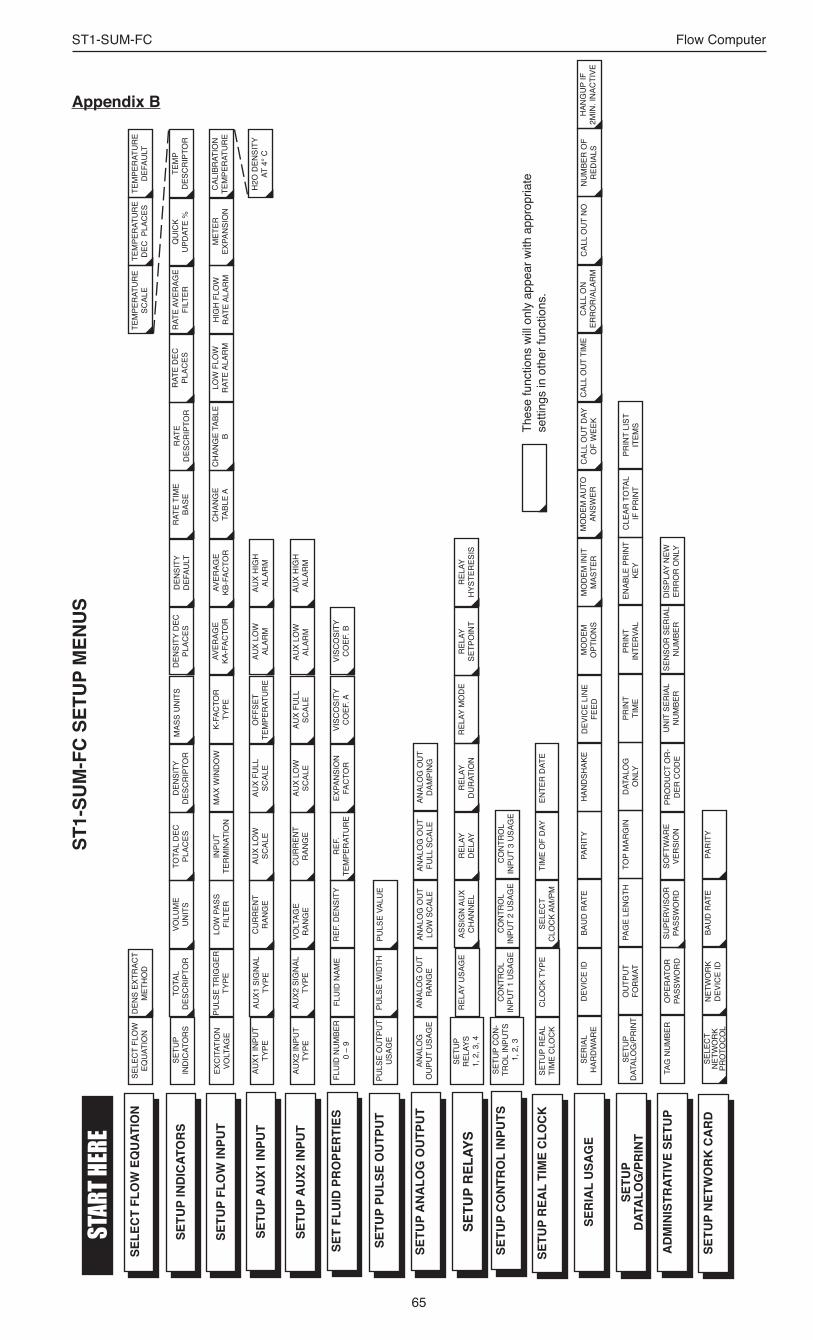
65
ST1-SUM-FC Flow Computer
Appendix B
CU
RR
ENT
RAN
GE
OFF
SET
TEM
PER
ATU
RE
AUX
LOW
SC
ALE
AUX
HIG
H
ALAR
MAU
X FU
LL
SCAL
E
VOLU
ME
UN
ITS
TOTA
L D
EC
PLAC
ESD
ENSI
TY
DES
CR
IPTO
RM
ASS
UN
ITS
DEN
SITY
DEC
PL
ACES
DEN
SITY
D
EFAU
LTR
ATE
TIM
E
BASE
RAT
E D
ESC
RIP
TOR
RAT
E D
EC
PLAC
ESR
ATE
AVER
AGE
FILT
ERQ
UIC
K U
PDAT
E %
TEM
P D
ESC
RIP
TOR
TEM
PER
ATU
RE
SCAL
E
PULS
E TR
IGG
ER
TYPE
LOW
PAS
S FI
LTER
INPU
T TE
RM
INAT
ION
M
AX W
IND
OW
K-FA
CTO
R
TYPE
AVER
AGE
KA-F
ACTO
R
REF
. DEN
SITY
REF
. TE
MPE
RAT
UR
EEX
PAN
SIO
N
FAC
TOR
BAU
D R
ATE
PAR
ITY
HAN
DSH
AKE
DEV
ICE
LIN
E FE
ED
SUPE
RVIS
OR
PA
SSW
OR
DSO
FTW
ARE
VER
SIO
NPR
OD
UC
T O
R-
DER
CO
DE
UN
IT S
ERIA
LN
UM
BER
SEN
SOR
SER
IAL
NU
MBE
RD
ISPL
AY N
EW
ERR
OR
ON
LY
ST1-
SUM
-FC
SET
UP
MEN
US
Thes
e fu
nctio
ns w
ill on
ly a
ppea
r with
app
ropr
iate
se
tting
s in
oth
er fu
nctio
ns.
REL
AYD
UR
ATIO
NAS
SIG
N A
UX
CH
ANN
ELR
ELAY
SE
TPO
INT
REL
AY
DEL
AYR
ELAY
H
YSTE
RES
ISR
ELAY
MO
DE
ENTE
R D
ATE
SELE
CT
CLO
CK
AM/P
MTI
ME
OF
DAY
MO
DEM
O
PTIO
NS
MO
DEM
INIT
M
ASTE
RC
ALL
ON
ER
RO
R/A
LAR
MN
UM
BER
OF
RED
IALS
HAN
GU
P IF
2M
IN. I
NAC
TIVE
MO
DEM
AU
TO
ANSW
ERC
ALL
OU
T N
OC
ALL
OU
T D
AY
OF
WEE
K
TEM
PER
ATU
RE
DEC
PLA
CES
AVER
AGE
KB-F
ACTO
R
TEM
PER
ATU
RE
DEF
AULT
CH
ANG
E TA
BLE
AC
HAN
GE
TABL
E B
LOW
FLO
W
RAT
E AL
ARM
HIG
H F
LOW
R
ATE
ALAR
MM
ETER
EX
PAN
SIO
NC
ALIB
RAT
ION
TE
MPE
RAT
UR
E
VOLT
AGE
RAN
GE
AUX
LOW
SC
ALE
AUX
FULL
SC
ALE
AUX
LOW
AL
ARM
CU
RR
ENT
RAN
GE
AUX
HIG
H
ALAR
M
VISC
OSI
TY
CO
EF. A
VISC
OSI
TY
CO
EF. B
PULS
E VA
LUE
ANAL
OG
OU
T LO
W S
CAL
EAN
ALO
G O
UT
FULL
SC
ALE
ANAL
OG
OU
T D
AMPI
NG
ANAL
OG
OU
T R
ANG
E
CO
NTR
OL
INPU
T 2
USA
GE
CO
NTR
OL
INPU
T 3
USA
GE
CAL
L O
UT
TIM
E
PAG
E LE
NG
THTO
P M
ARG
INC
LEAR
TO
TAL
IF P
RIN
TPR
INT
LIST
IT
EMS
DAT
ALO
G
ON
LYPR
INT
TIM
EPR
INT
INTE
RVAL
ENAB
LE P
RIN
T KE
Y
AUX
LOW
AL
ARM
BAU
D R
ATE
PAR
ITY
AUX1
INPU
T TY
PESE
TUP
AU
X1 IN
PUT
AUX1
SIG
NAL
TY
PE
SETU
P
IND
ICAT
OR
STO
TAL
DES
CR
IPTO
R
EXC
ITAT
ION
VO
LTAG
E
SELE
CT
FLO
W
EQU
ATIO
N
FLU
ID N
UM
BER
0 –
9FL
UID
NAM
E
SER
IAL
HAR
DW
ARE
DEV
ICE
ID
TAG
NU
MBE
RO
PER
ATO
R
PASS
WO
RD
AD
MIN
ISTR
ATIV
E SE
TUP
SER
IAL
USA
GE
SETU
P PU
LSE
OU
TPU
T
SET
FLU
ID P
RO
PER
TIES
SETU
P FL
OW
INPU
T
SETU
P IN
DIC
ATO
RS
SELE
CT
FLO
W E
QU
ATIO
N
SETU
PR
ELAY
S1,
2, 3
, 4R
ELAY
USA
GE
SETU
P R
ELAY
S
SETU
P R
EAL
TIM
E C
LOC
KSE
TUP
REA
L TI
ME
CLO
CK
STAR
T HER
E
AUX2
INPU
T TY
PESE
TUP
AU
X2 IN
PUT
AUX2
SIG
NAL
TY
PE
PULS
E O
UTP
UT
USA
GE
PULS
E W
IDTH
ANAL
OG
O
UPU
T U
SAG
ESE
TUP
AN
ALO
G O
UTP
UT
CO
NTR
OL
INPU
T 1
USA
GE
SETU
P C
ON
TRO
L IN
PUTS
SETU
P C
ON
-TR
OL
INPU
TS
1, 2
, 3
CLO
CK
TYPE
SETU
P D
ATAL
OG
/PR
INT
OU
TPU
T FO
RM
ATSE
TUP
DAT
ALO
G/P
RIN
T
SELE
CT
NET
WO
RK
PRO
TOC
OL
NET
WO
RK
DEV
ICE
IDSE
TUP
NET
WO
RK
CA
RD
DEN
S EX
TRAC
T M
ETH
OD
H2O
DEN
SITY
AT 4
° C

66
ST1-SUM-FC Flow Computer
Introducing ST1-SUM-FC with RS-485 & Modbus RTU Protocol
When the ST1-SUM-FC is equipped with the RS-485 communication option, the protocol it uses is the Modbus RTU protocol. This protocol defines a message structure that hosts and clients will recognize and use on the RS-485 network over which they communicate. It describes the process a master device (PC compatible) uses to request access to another device (ST1-SUM-FC), how it will respond to requests from the other devices, and how errors will be detected and reported. It establishes a common format for the layout and contents of message fields.
During communications on a Modbus RTU network, the protocol determines how each ST1-SUM-FC will know its device address, recognize a message addressed to it, determine the kind of action to be taken, and extract any data or other information contained in the message. If a reply is required, the ST1-SUM-FC will construct the reply message and send it using Modbus RTU protocol.
RTU ModeThe ST1-SUM-FC with RS-485 communications option supports the Modbus RTU (Remote Terminal Unit) mode only. The Modbus ASCII mode is not supported. The main advantage of the RTU mode is that its greater character density allows better data throughput than ASCII for the same baud rate. The Modbus RTU uses a Master-Slave Query-Response Cycle in which the ST1-SUM-FC is the slave device.
Control FunctionsThe ST1-SUM-FC with RS-485 communications option supports the following function codes:
CODE NAME DESCRIPTION 01 Read Coil Status Read a single coil 03 Read Holding Register Read a range of holding registers 05 Force Single Coil Forces a single coil (0x reference) to either ON or OFF 06 Preset Single Register Presets a value into a single holding register (4x reference) 15 Force Multiple Coil Forces each coil (0x reference) in a sequence of coils to either ON
or OFF 16 Preset Multiple Registers Presets values into a sequence of holding registers (4x reference)
Appendix C - RS485 Modbus RTU Protocol

67
ST1-SUM-FC Flow Computer
ST1-SUM-FC RS-485 Port Pinout (recommended mating connector: DB-9M)
1 Ground2Ground3Ground4TX/RX(+)5TX/RX(-)6DoNotUse7TerminatingResistor(180Ω)8TX/RX(+)(spareinternallyconnectedto4)9TX/RX(-)(spareinternallyconnectedto5)
ST1-SUM-FC RS-485 Port Pinout (Terminal Block Option)
1 Common2TX/RX(+)3TX/RX(-)4TerminatingResistor(180Ω)
Installation OverviewA two wire RS-485 may be multidropped up to 4000 ft. and up to 32 units may be chained together. A RS-485 to RS-232 interface adapter is required at the PC. An optically isolated type is recommended. Suitable wiring should be selected based on anticipated electrical interference. Terminators should be used to help improve the quality of electronic signals sent over the RS-485 wires. The RS-485 chain should be terminat-ed at the beginning (RS-485 adaptor) and at the last device in the RS-485 chain and nowhere else. On the ST1-SUM-FC this is accomplished by connecting a jumper from terminal 7 to terminal 4 or 8 at the RS-485 port when DB-9 connector is used. Place jumper between terminals 2 and 4 when the terminal block option is used. If lightning protection is required, a suitable surge protector should be used.
For additional information, refer to the technical requirements of EIA-485, interface adaptor user manual and the communication software user manual
ST1-SUM-FC Communication Setup MenuThe setup menu allows Modbus RTU Protocol communications parameters of: Device ID, Baud Rate, and Parity to be selected to match the parameters of your RS-485 network. Each ST1-SUM-FC must have it’s own Device ID and the same Baud Rate and Parity setting.
123456789
1 2 3 4 5 6 7 8 9 10 11 12 13 14 15 16 17 18 19 20 21 22 23 24
123456789
123456789
RS-232 RS-485
1 2 3 4
1 2 3 4 5 6 7 8 9 10 11 12 13 14 15 16 17 18 19 20 21 22 23 24
123456789
RS-232RS-485
Appendix C - RS485 Modbus RTU Protocol

68
ST1-SUM-FC Flow Computer
Register Usage (each register is 2 bytes)
ST1-SUM-FC Data Register Data Type AccessSum Flow Rate * Reg 40001 & 40002 Float ReadSum Total * Reg 40005 & 40006 Float ReadSum Grand Total * Reg 40007 & 40008 Float ReadTemperature 1 Reg 40009 & 40010 Float ReadDensity 1 Reg 40011 & 40012 Float ReadPreset 1 Reg 40013 & 40014 Float Read/WritePreset 2 Reg 40015 & 40016 Float Read/WritePreset 3 Reg 40017 & 40018 Float Read/WritePreset 4 Reg 40019 & 40020 Float Read/WriteYear Reg 40021 Integer ReadMonth Reg 40022 Integer ReadDay Reg 40023 Integer ReadHours Reg 40024 Integer ReadMinutes Reg 40025 Integer ReadSeconds Reg 40026 Integer ReadViscosity 1 Reg 40027 & 40028 Float ReadTransaction Number Reg 40029 Integer ReadUnused Reg 40030 _ _Unused Reg 40031 & 40032 _ _Unused Reg 40033 & 40034 _ _Unused Reg 40035 & 40036 _ _Pulse Input 1 Frequency Reg 40037 & 40038 Float ReadPulse Input 2 Frequency Reg 40039 & 40040 Float ReadKA Factor Reg 40041 & 40042 Float ReadKB Factor Reg 40043 & 40044 Float ReadFluid Number Reg 40045 Integer Read/WriteUnused Reg 40046 _ _Temperature 2 Reg 40047 & 40048 Float _Density 2 Reg 40049 & 40050 Float _Viscosity 2 Reg 40051 & 40052 Float _Rate 1 Reg 40053 & 40054 Float _Rate 2 Reg 40055 & 40056 Float _Total 1 Reg 40057 & 40058 Float _Grand Total 1 Reg 40059 & 40060 Float _Total 2 Reg 40061 & 40062 Float _Grand Total 2 Reg 40063 & 40064 Float _
* Parameters are active only when the instrument is configured for these calculations.NOTE: The Float data type follows the IEEE format for a 32 bit float.
COIL USAGE (each coil is 1 bit)
ST1-SUM-FC Data Coil Data Type AccessError-Pulse Out Overflow Coil 00001 bit ReadAlarm-Flow Rate Alarm Low Volume Rate Coil 00002 bit ReadAlarm-Flow Rate Alarm High Volume Rate Coil 00003 bit ReadAlarm-Temp Alarm Low 1 Coil 00004 bit ReadAlarm-Temp Alarm High 1 Coil 00005 bit ReadAlarm-Temp Alarm Low 2 Coil 00008 – –Alarm-Temp Alarm High 2 Coil 00009 – –Unused Coil 00010 – –Unused Coil 00011 – –Unused Coil 00012 – – Coil 00013 – –
Register & Coil Usage
Appendix C - RS485 Modbus RTU Protocol

69
ST1-SUM-FC Flow Computer
ST1-SUM-FC Data Coil Data Type AccessReserved Coil 00014 bit ReadError-Software Error Reset Coil 00015 bit ReadError-Extended PFI Lockup Coil 00016 bit ReadUnused Coil 00017 – –Unused Coil 00018 – –Error-Cal Checksum Error Coil 00019 bit ReadError-Modem Not Found Coil 00020 bit ReadError-Setup Checksum Error Coil 00021 bit ReadError-Rate Overflow Error Coil 00022 bit ReadError-A to D Not Converting Coil 00023 bit ReadError-Aux Input Too Low Coil 00024 bit ReadError-Aux Input Too High Coil 00025 bit ReadError-Flow Input Too Low Coil 00026 bit ReadError-Flow Input Too High Coil 00027 bit ReadReserved Coil 00028 bit ReadError-RTD Out Of Range Coil 00029 bit ReadWarning-Battery Low Warning Coil 00030 bit ReadError-Time Clock Error Coil 00031 bit ReadWarning-Totalizer Rollover Coil 00032 bit ReadCommand-Reset Total Coil 00033 bit Read/WriteCommand-Reset Errors Coil 00034 bit Read/WriteCommand-Print Command Coil 00035 bit Read/WriteStatus-Instrument Type Rate/Total or Batch Coil 00036 bit ReadReserved Coil 00037 bit Read/WriteReserved Coil 00038 bit Read/WriteReserved Coil 00039 bit Read/WriteReserved Coil 00040 bit ReadReserved Coil 00041 bit ReadReserved Coil 00042 bit ReadCommand-Relay 1 Command** Coil 00043 bit Read/WriteCommand-Relay 2 Command** Coil 00044 bit Read/WriteCommand-Relay 3 Command** Coil 00045 bit Read/WriteCommand-Relay 4 Command** Coil 00046 bit Read/WriteStatus-Relay 1 Status Coil 00047 bit ReadStatus-Relay 2 Status Coil 00048 bit ReadStatus-Relay 3 Status Coil 00049 bit ReadStatus-Relay 4 Status Coil 00050 bit ReadStatus-Control 1 Status Coil 00051 bit ReadStatus-Control 2 Status Coil 00052 bit ReadStatus-Control 3 Status Coil 00053 bit ReadUnused Coil 00054 – –Unused Coil 00055 – –Unused Coil 00056 – –Unused Coil 00057 – –Unused Coil 00058 – –Unused Coil 00059 – –Unused Coil 00060 – –Unused Coil 00061 – –Unused Coil 00062 – –Unused Coil 00063 – –Unused Coil 00064 – –
** Relay commands are only active if relays have been configured for “NA” (not assigned) in the setup menus.
Register & Coil Usage (continued)
Appendix C - RS485 Modbus RTU Protocol