CMS 50/63/71 Electric Cylinders / Catalogs / 2009-06 - SEW ...
164
Drive Technology \ Drive Automation \ System Integration \ Services Catalog Servo Technology CMS50/63/71 Electric Cylinder Edition 06/2009 16621611 / EN
-
Upload
khangminh22 -
Category
Documents
-
view
1 -
download
0
Transcript of CMS 50/63/71 Electric Cylinders / Catalogs / 2009-06 - SEW ...

Drive Technology \ Drive Automation \ System Integration \ Services
Catalog
Servo Technology CMS50/63/71 Electric Cylinder
Edition 06/2009 16621611 / EN

SEW-EURODRIVE—Driving the world

Content
1 Introduction ....................................................................................................... 51.1 The SEW-EURODRIVE Group of Companies.......................................... 51.2 Products and systems from SEW-EURODRIVE....................................... 61.3 Copyright................................................................................................... 71.4 Additional documentation.......................................................................... 81.5 Structure of the safety notes ..................................................................... 8
2 Product Description and Overview of Types................................................. 92.1 Product Description................................................................................... 92.2 Size ......................................................................................................... 102.3 Overview of benefits ............................................................................... 112.4 Areas of application ................................................................................ 112.5 Functional description ............................................................................. 122.6 Operating principle of the recirculating ball screw
and planetary roller screw drive ............................................................. 142.7 Comparison of electric cylinders ............................................................. 152.8 Nameplate, unit designation ................................................................... 172.9 Designs ................................................................................................... 21
3 Project Planning.............................................................................................. 413.1 Project planning procedure ..................................................................... 413.2 Service life of bearings and threaded spindles ....................................... 433.3 Calculation example for CMS71L with 10 mm spindle pitch ................... 453.4 Calculation example for service life of spindles and bearings ................ 51
4 Technical Data................................................................................................. 544.1 Rated data .............................................................................................. 544.2 Derating for increased ambient temperatures......................................... 544.3 Operating temperatures .......................................................................... 544.4 Key to the data tables ............................................................................. 554.5 General features ..................................................................................... 554.6 CMS50 .................................................................................................... 564.7 CMS63 .................................................................................................... 574.8 CMS71 .................................................................................................... 594.9 Brake....................................................................................................... 604.10 BP/BS brakes.......................................................................................... 614.11 BMV brake control system ...................................................................... 624.12 Encoder systems .................................................................................... 634.13 Switching equipment and safeguards of the motor series ...................... 644.14 Scope of delivery .................................................................................... 654.15 CMS50S mounting dimensions............................................................... 664.16 CMS63S/M mounting dimensions........................................................... 714.17 CMS71L mounting dimensions ............................................................... 754.18 Additional feature – Ventilation ............................................................... 794.19 Mechanical stroke limiting....................................................................... 814.20 Mounting situation at customer site ........................................................ 824.21 Torque/speed characteristic curves ........................................................ 914.22 Dynamic limit torque ............................................................................... 934.23 Thermal limit torque ................................................................................ 954.24 MOVIDRIVE® assignment table ........................................................... 1004.25 MOVIAXIS® assignment table .............................................................. 102
Catalog – CMS50/63/71 Electric Cylinder 3

Content
4
5 Prefabricated Cables .................................................................................... 1045.1 Description ............................................................................................ 1045.2 Dimensioning the cable cross section................................................... 1055.3 Assignment table for cables and CMS electric cylinders ...................... 1065.4 Structure of the prefabricated cables for CMS electric cylinders .......... 1075.5 Power cable .......................................................................................... 1095.6 Encoder cables ..................................................................................... 1135.7 Mating connector combination .............................................................. 1185.8 Forced cooling fan cable....................................................................... 1205.9 Cable specifications for CMS power cables.......................................... 1225.10 Cable specifications for encoder cables ............................................... 1265.11 Cable specification of forced cooling fan cables for CMS motors......... 128
6 Design and Operating Notes........................................................................ 1306.1 General maintenance work ................................................................... 1306.2 Lubrication of screw drive ..................................................................... 1306.3 Lubricant for recirculating ball screws and
planetary roller screw drives ................................................................. 1326.4 Relubrication interval ............................................................................ 1336.5 Lubricator – only for size CMS71L........................................................ 1356.6 Sealing air ............................................................................................. 1386.7 Filter ventilation not part of delivery from SEW – only CMS71 ............. 139
7 Address Directory ......................................................................................... 1408 Index............................................................................................................... 160
Catalog – CMS50/63/71 Electric Cylinder

1The SEW-EURODRIVE Group of CompaniesIntroduction
Catalog1 Introduction1.1 The SEW-EURODRIVE Group of CompaniesGlobal presence
Driving the world with innovative drive solutions for all branches and for every applica-tion. Products and systems from SEW-EURODRIVE are used in a multitude of applica-tions worldwide. These include the automotive, building materials, food and beverageas well as metal-processing industries. The decision to use drive technology made bySEW-EURODRIVE stands for reliability regarding both, functionality and investment.We are represented in the most important branches of industry all over the world: Withtwelve manufacturing plants and 66 assembly plants in 46 countries and our compre-hensive range of services, which we consider an integrative service adequately continu-ing our commitment to outstanding quality.
Always the right driveThe SEW-EURODRIVE modular concept offers millions of combinations. This wide se-lection enables you to choose the correct drive for all applications, each based on therequired speed and torque range, space available and the ambient conditions. Gearunits and gearmotors offering a unique and finely tuned performance range and the besteconomic prerequisites to face your drive challenges.The gearmotors are powered by MOVITRAC® frequency inverters, MOVIDRIVE® in-verters and MOVIAXIS® multi-axis servo inverters, a combination that blends perfectlywith the existing SEW-EURODRIVE program. As in the case for mechanical systems,the development, production and assembly is also carried out completely by SEW-EURODRIVE. In combination with our drive electronics, these drives will provide the ut-most in flexibility.Products of the servo drive system, such as low backlash servo gear units, compact ser-vomotors or MOVIAXIS® multi-axis servo inverters provide precision and dynamics.From single-axis or multi-axis applications all the way to synchronized process sequenc-es, servo drive systems by SEW-EURODRIVE offer a flexible and customized imple-mentation of your application.For economical, decentralized installations, SEW-EURODRIVE offers components fromits decentralized drive system, such as MOVIMOT®, the gearmotor with integrated fre-quency inverter or MOVI-SWITCH®, the gearmotor with integrated switching and pro-tection function. SEW-EURODRIVE hybrid cables have been designed specifically toensure cost-effective solutions, independent of the philosophy behind or the size of thesystem. The latest developments from SEW-EURODRIVE: MOVITRANS® – systemcomponents for contactless energy transfer, MOVIPRO® - the decentralized drive con-trol and MOVIFIT® – the new decentralized intelligence.Power, quality and sturdy design combined in one standard product: With high torquelevels, industrial gear units from SEW-EURODRIVE realize major movements. Themodular concept will once again provide optimum adaptation of industrial gear units tomeet a wide range of different applications.
Your ideal partnerIts global presence, extensive product range and broad spectrum of services makeSEW-EURODRIVE the ideal partner for the machinery and plant construction industrywhen it comes to providing drive systems for demanding applications in all branches ofindustries and applications.
Catalog – CMS50/63/71 Electric Cylinder
5
6
1 roducts and systems from SEW-EURODRIVEtroduction
1.2 Products and systems from SEW-EURODRIVEThe products and systems from SEW-EURODRIVE are divided into 4 product groups.These 4 product groups are:1. Gearmotors and frequency inverters2. Servo drive systems3. Decentralized drive systems4. Industrial gear units
Products and systems used in several group applications are listed in a separate group"Products and systems covering several product groups". Consult the following tablesto locate the products and systems included in the respective product group:
1. Gearmotors and frequency inverters
Gear units/gearmotors Motors Frequency inverters
• Helical gear units/helical gearmotors
• Parallel shaft helical gear units/parallel shaft helical gearmotors
• Helical-bevel gear units/heli-cal-bevel gearmotors
• Helical-worm gear units/heli-cal-worm gearmotors
• Spiroplan¨ right-angle gear-motors
• Drives for electrified monorail systems
• Geared torque motors• Pole-changing gearmotors• Variable speed gear
units/variable speed gearmo-tors
• Aseptic gearmotors• ATEX compliant gear
units/gearmotors• ATEX compliant variable
speed gear units/variable speed gearmotors
• Asynchronous AC motors/AC brakemotors
• Multi-speed AC motors / AC brakemotors
• Energy-efficient motors• Explosion-proof AC
motors/AC brakemotors• Torque motors• Single-phase motors/single-
phase brakemotors• Asynchronous linear motors
• MOVITRAC® frequency inverters
• MOVIDRIVE® inverters• Control, technology and com-
munication options for invert-ers
2. Servo drive systems
Servo gear units / servo gear-motors
Servomotors Servo drive inverters/servo inverters
• Low backlash servo planetary gear units/planetary gearmo-tors
• Low backlash helical-bevel servo gear units / helical-bevel gearmotors
• Explosion-proof servo gear units / servo gearmotors
• Asynchronous servomo-tors/servo brakemotors
• Synchronous servomo-tors/servo brakemotors
• Explosion-proof servomo-tors/servo brakemotors
• Electric cylinders• Synchronous linear motors
• MOVIDRIVE® servo inverters• MOVIAXIS® multi-axis servo
inverters• Control, technology and com-
munication options for servo drive inverters and servo inverters
PIn
Catalog – CMS50/63/71 Electric Cylinder

1CopyrightIntroduction
In addition to products and systems, SEW-EURODRIVE offers a comprehensive rangeof services. These include:• Technical consulting• Application software• Seminars and training• Extensive technical documentation• International customer service
Visit our homepage at→ www.sew-eurodrive.comThe website provides comprehensive information and services.
1.3 Copyright© 2009 – SEW-EURODRIVE. All rights reserved. Copyright law prohibits the unauthor-ized duplication, modification, distribution, and use of this document, in whole or in part.
3. Decentralized drive systems
Decentralized drives Communication and installa-tion
Contactless energy transfer
• MOVIMOT® gearmotors with integrated frequency inverter
• MOVIMOT® motors/brakemo-tors with integrated frequency inverter
• MOVI-SWITCH® gearmotors with integrated switching and protection function
• MOVI-SWITCH® motors/brakemotors with inte-grated switching and protec-tion function
• Explosion-proof MOVIMOT® and MOVI-SWITCH® gear-motors
• Fieldbus interfaces• Field distributors for decen-
tralized installation• MOVIFIT® product range
– MOVIFIT®-MC to control MOVIMOT® drives
– MOVIFIT®-SC with inte-grated electronic motor switch
– MOVIFIT®-FC with inte-grated frequency inverter
• MOVITRANS® system– Stationary components
for energy supply– Mobile components for
energy consumption– Line cables and installa-
tion material
4. Industrial gear units
• Helical gear units • Helical-bevel gear units• Planetary gear units
Products and systems covering several product groups
• Operator terminals• MOVI-PLC® drive-based control system
Catalog – CMS50/63/71 Electric Cylinder
7
8
1 dditional documentationtroduction
1.4 Additional documentationIn addition to this catalog, the following documentation provides further informationabout the electric cylinder:• Operating instructions for the CMS electric cylinder• MOVIDRIVE® B system manual• MOVIAXIS® system manual • 'Plug Connectors and Pre-Fabricated Cables' system description• CAD data • 'Drive Engineering –Practical Implementation: Servo technology'• DVD E-learning Electric Cylinder• Flyer
1.5 Structure of the safety notesThe safety notes in this catalog are designed as follows:
Pictogram Signal word Meaning Consequences if disregarded
STOP Possible damage to property Damage to the drive system or its environment
INFORMATIONUseful information or tip.Simplifies the handling of the drive system.
AIn
Catalog – CMS50/63/71 Electric Cylinder

2Product DescriptionProduct Description and Overview of Types
2 Product Description and Overview of Types2.1 Product Description
Applications with linear movement place high demands on the travel profile. Conven-tional solutions consisting of pneumatic and hydraulic cylinders will quickly reach theirsystem limits in terms of performance. The connection of the electric cylinders to the inverters from SEW-EURODRIVE resultsin intelligent drive systems offering a high degree of flexibility and positioning accuracy,new options in programming, power control and diagnostic functions. These translateinto new and reliable concepts that can be integrated into a variety of production pro-cesses.The electric cylinders of the CMS series are precise, powerful, and fast. When combinedwith drive electronics from SEW-EURODRIVE, they form economical, energy-efficientdrive solutions that ensure a high level of process reliability in system operation and areeasy to integrate into existing automation systems.
Catalog – CMS50/63/71 Electric Cylinder
9
10
2 izeroduct Description and Overview of Types
2.2 SizeSEW-EURODRIVE offers three product variants for electric cylinders:
2.2.1 CMS50S
2.2.2 CMS63S/M
2.2.3 CMS71L
64907AXX
64908AXX
64889AXX
SP
Catalog – CMS50/63/71 Electric Cylinder

2Overview of benefitsProduct Description and Overview of Types
2.3 Overview of benefitsMechatronic systems are becoming ever more prevalent in all branches of industry, re-placing older technology that requires more maintenance and expense. Replacing apneumatic cylinder with an electric cylinder offers many benefits for the user, includinglower production costs and increased productivity and quality.• Intelligent drive system offering a high degree of flexibility (positioning, programming,
power control, diagnostic options)• Save on costs for compressed air (for pneumatic) • Easy integration into automation processes• Simple installation and mounting (pipes do not have to be laid)• Reduction in noise emission due to controlled acceleration (protects mechanical
components)• Simple integration in automation processes due to connection to all commercial bus
systems:PROFIBUS, INTERBUS, INTERBUS LWL, DeviceNet, CAN, CANopen
2.4 Areas of applicationAll applications that place demands on the travel profile, such as• Torque dampening• Different force profiles• Maximum acceleration speeds• Travelling to more than two positions The electric cylinder can be used in the following areas:• Metal processing machines• Wood processing machines• Handling systems• Printing machines• Plastic manufacturing and processing machines• Food-processing machines
Catalog – CMS50/63/71 Electric Cylinder
11
12
2 unctional descriptionroduct Description and Overview of Types
2.5 Functional description2.5.1 General information
Synchronous servomotors of the SEW CM-CMP motor series are used as the basis forthe CMS electric cylinder series. The service life of the electric cylinders (threaded spindle and bearings) must be takeninto account, as it depends on the load cycle and travel cycle. The electric cylinders areequipped with a resolver that serves as a speed and position encoder. The absolute en-coder (HIPERFACE® encoder) is available as an option. In connection with a servo con-troller, you can freely define acceleration, velocity, position and force profiles.The repeat accuracy is 5/100 mm (0.002 in), if force and temperature are constant. Theelectric cylinders are available with or without brakes (holding brake only). The motor isavailable with plug connector only (no terminal box). The connector type CMP motor se-ries is used (for resolver, HIPERFACE® encoder and power).
2.5.2 CMS50SA CMP50S servomotor is used for the drive. An add-on component, comprising a screwdrive and guide, is flanged onto the unit. All components and options of the motor, ex-cept the flanged end shield and the rotor (due to the larger bearing), are adopted fromthe CMP.As standard, the drive is adapted to the customer’s application through the flanged endshield on the drive side of the motor. The rotor turns the threaded spindle while the nutremains fixed. The nut is routed in an aluminum extruded housing via T-slot nuts.The nut and piston rod are connected to each other. The piston rod has a smooth, high-quality corrosion-proof surface and is sealed using a wiper with guide ring. The jointhead is connected to the piston rod. The spindle nut has a lubricant reservoir, which ex-tends the relubrication interval. The relubrication can also be carried out by a greasingnipple.
2.5.3 CMS63S/MA CMS63S/M servomotor is used for the drive. An add-on component, comprising ascrew drive and guide, is flanged onto the unit. All components and options of the motor,except the flanged end shield and the rotor (due to the larger bearing), are adopted fromthe CMP.As standard, the drive is adapted to the customer’s application through the flanged endshield on the drive side of the motor. The rotor turns the threaded spindle while the nutremains fixed. The nut is routed in an aluminum extruded housing via T-slot nuts.The nut and piston rod are connected to each other. The piston rod has a smooth, high-quality corrosion-proof surface and is sealed with a sealing system. The joint head isconnected to the piston rod. An oil bath lubrication system supplies the bearing points,threaded spindle and seals with lubricant.
INFORMATIONThe CMS63S/M series with stroke lengths of 400 mm and 600 mm will be available asof the 4th quarter 2009.
FP
Catalog – CMS50/63/71 Electric Cylinder

2Functional descriptionProduct Description and Overview of Types
2.5.4 CMS71LSynchronous servomotors of the SEW CM-CMP motor series are used as the basis forthe CMS71L electric cylinder series.The rotors are designed as a hollow shaft. The spindle nut of the recirculating ball screwor planetary roller screw drive is attached to the rotor. Depending on the direction of themotor rotation, the threaded spindle is moved out of or in to the rotor. The threaded spin-dle must be prevented from turning, so that the rotary motion of the rotor (spindle nut) istransformed into a linear motion. The threaded spindle is protected from "heavy" con-tamination by a bellows.
Catalog – CMS50/63/71 Electric Cylinder
13
14
2 perating principle of the recirculating ball screw and planetary roller screw roduct Description and Overview of Types
2.6 Operating principle of the recirculating ball screw and planetary roller screw drive
We differentiate between the two following threaded spindle types for electric cylinders:
2.6.1 Recirculating ball screw (KGT)The recirculating ball screw is used in the CMS50S, CM63S/M and CMS71L electriccylinders.
The recirculating ball screw transfers the load from the threaded spindle to the nut viaball bearings (power transmission by ball bearings).
2.6.2 Planetary roller screw drive (PGT)The planetary roller screw drive is used in the CM63S/M, CMS71L electric cylinders.Preferred application areas:• Low feed rate and high force• Unfavorable operating conditions such as pressing
The planetary roller screw drive transfers the load from the threaded spindle to the nutvia the convex thread edges of rollers (power transmission by planetary rollers).
59566AXX
59565AXX
OP
Catalog – CMS50/63/71 Electric Cylinder

2Comparison of electric cylindersProduct Description and Overview of Types
2.7 Comparison of electric cylinders2.7.1 Peak feed thrust Fmax
The following figure shows an overview of the peak feed thrust Fmax of the electriccylinders:
65168AXX
Fmax = 5.3 kN
Fmax = 10 kN
Fmax = 20 kN
CMS50S CMS63S/M CMS71L
Catalog – CMS50/63/71 Electric Cylinder
15
16
2 omparison of electric cylindersroduct Description and Overview of Types
m/s]
2.7.2 Maximum speed vmax.
The following figure shows an overview of the maximum feed thrust against the maxi-mum speed nepk of the electric cylinders.
65167AEN
vmax
70
150
300
200
(600+400)
200
350
0.25 0.375 0.45 0.5 [
= 4500 p = 5 mm / KGT
= 4500 p = 5 mm / KGT
= 2500 p = 5 mm / KGT
= 4500 p = 6 mm / KGT
= 4500 p = 6 mm / KGT
= 4500 p = 6 mm / KGT
= 3000 p = 10 mm / KGT
= 3000 p= 6 mm / KGT
= 2000 p = 6 mm / KGT
CMS50S
CMS63S/M
CMS71L
Stroke length [mm]
Max. feed rate0.30.20
200
nepk
nepk
nepk
nepk
nepk
nepk
nepk
nepk
nepk
= 3000 p = 5 mm / PGTnepk
= 4500 p = 5 mm / PGTnepk
*
m-1
m-1
m-1
m-1
m-1
m-1
m-1
m-1
m-1
m-1
m-1
= 4500 p = 5 mm / PGTnepk m-1
100
p = Spindle pitch
nepk = max. permitted speed
KGT = Recirculating ball screw
PGT = Planetary roller screw drive
* = Stroke lengths 400 mm and 600 mm will be available as of the 4th quarter 2009.
CP
Catalog – CMS50/63/71 Electric Cylinder

2Nameplate, unit designationProduct Description and Overview of Types
2.8 Nameplate, unit designation2.8.1 Nameplate
Each electric cylinder has a nameplate that provides important information. The follow-ing figure shows an example of a nameplate.
Example
64905AXX
Type Motor type
No. Serial number
Mo Standstill torque (thermal continuous torque at low speeds)
I0 Standstill current
Fpk Peak feed force
Imax Maximum permitted motor current
IP Degree of protection
U Sys Motor voltage
°C Ambient temperature range
Isol. cl. Thermal class
nN Rated speed
ne pk Maximum mechanically permitted speed
kg Weight
Brake Rated voltage of brake/braking torque
Spindle Spindle type
P Spindle pitch
Stroke Stroke length
Lubricant
P m
Mo
CMS71L/BS/TF/AS1H/SB101.12345678.01.0001.06
76646 Bruchsal/Germany
0594 927 0 Made in GermanyUmrichterbetrieb
MotorFpkU SysnNBremseSpindel
NmkNVr/minVbr
lolmax
˚Cne pk
AA
r/minNmmm/r
3 ~ IEC60034Permanentmagnete
lPIso.KL.
kg
45155 (F)17.0
6.225.0-20...+403000
1910
9.5174003000
24KGT
Fuchs RENOLIT CX-TOM15Hub 200
Catalog – CMS50/63/71 Electric Cylinder
17
18
2 ameplate, unit designationroduct Description and Overview of Types
2.8.2 Unit designationThe following characteristic unit data can be read from the unit designation of the electriccylinder:
Example: CMS50S electric cylinder
CMS 50S /BP /KY /RH1M /SB1
Plug connector:/SM1 = Motor/SB1 = Brakemotor
Encoder system:/RH1M = resolver, 2-pole/AS1H = Absolute encoder (HIPERFACE®, multi-turn)/ES1H = Absolute encoder (HIPERFACE®, single-turn)/AK0H = Absolute encoder (HIPERFACE®, multi-turn)
Motor protection/temperature measuring:/TF = temperature sensor (positive coefficient thermistoror PTC resistor)/TH = Thermostat (bimetallic switch)/KY1) = KTY84-130-Sensor
Brake:/BP = CMS50S, 24 V holding brake/BP = CMS63S/M, 24 V holding brake/BS = CMS71L, 24 V holding brake
Size: 50S63S / 63M71L
Type:CMS = Electric cylinder
1) CMS50 and CMS63 are only available with KTY
NP
Catalog – CMS50/63/71 Electric Cylinder

2Nameplate, unit designationProduct Description and Overview of Types
2.8.3 StandardsThe electric cylinders from SEW-EURODRIVE conform to the relevant standards andregulations, in particular to:• CE• UL (optional)• CSA (optional)• VDE
2.8.4 Storage conditionsElectric cylinders are treated with an anti-corrosion agent as standard.The motor parts are protected against corrosion for two years when stored in unopenedoriginal packaging (with Vario lubrication system one year → battery life).
Observe the following storage conditions for CMS electric cylinders:• Store CMS electric cylinders indoors• Keep storage area clean and dry.• Maintain a storage temperature between -10 °C and +70 °C• Relative humidity should not exceed 95 %• Original packaging must be free from damages
2.8.5 Coating• The standard color is RAL 9005 black• Optional surface protection
Catalog – CMS50/63/71 Electric Cylinder
19
20
2 ameplate, unit designationroduct Description and Overview of Types
2.8.6 Surface protectionIn addition to standard surface protection, electric cylinders also available with surfaceprotection OS1 to OS4. The special procedure "Z" is also available. The special proce-dure "Z" means that large surface recesses are sprayed with a rubber filling prior topainting.
Surface protection
Layers Regular coat thick-ness [μm]
Suitable forVariant 11) Variant 21)
Standard • 1 × dip primer• 1 x one-component top coat 70
• Normal ambient conditions• Relative humidity below 90 %• Max. surface temperature
120 °C• Corrosivity category C12)
OS1
• 1 × dip primer• 1 × two-component base
coat• 1 × two-component top
coat
• 1 × dip primer• 1 × two-component high-
solid top coat120 - 180
• low environmental impact• Relative humidity max. 95%• Max. surface temperature
120 °C• Corrosivity category C22)
OS2
• 1 × dip primer• 1 × two-component high-
solid base coat• 1 × two-component base
coat• 1 × two-component top
coat
• 1 × dip primer• 1 × two-component high-
solid base coat• 1 × two-component high-
solid top coat
160 - 250
• Medium environmental impact• Relative humidity up to 100 %• Max. surface temperature
120 °C• Corrosivity category C32)
OS3
• 1 × dip primer• 1 × two-component high-
solid base coat• 2 × two-component base
coat• 1 × two-component top
coat
• 1 × dip primer• 1 × two-component high-
solid base coat• 1 × two-component base
coat• 1 × two-component high-
solid top coat
210 - 320
• High environmental impact• Relative humidity up to 100 %• Max. surface temperature
120 °C• Corrosivity category C42)
OS4
• 1 × dip primer• 2 × two-component epoxy
base coat• 2 × two-component top
coat
• 1 × dip primer• 2 × two-component epoxy
base coat• 1 × two-component high-
solid top coat
260 - 380
• Very high environmental impact• Relative humidity up to 100 %• Max. surface temperature
120 °C• Corrosivity category C5-12)
1) The variant used currently depends on the color of the top coating.2) in accordance with DIN EN ISO 12944-2
NP
Catalog – CMS50/63/71 Electric Cylinder
2DesignsProduct Description and Overview of Types
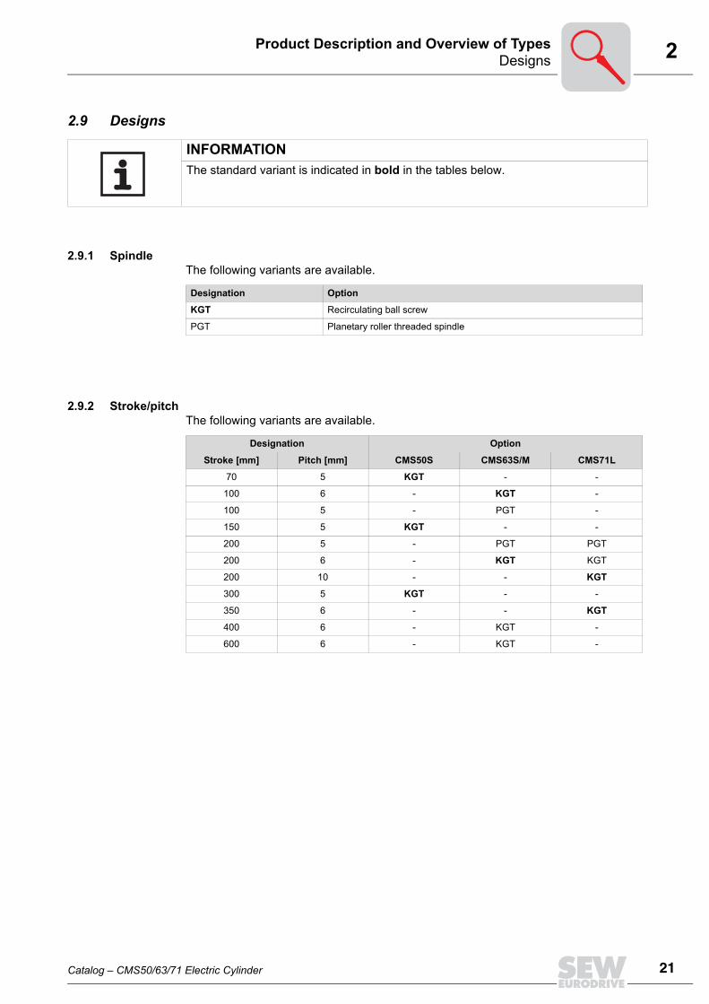
2.9 Designs
2.9.1 SpindleThe following variants are available.
2.9.2 Stroke/pitchThe following variants are available.
INFORMATIONThe standard variant is indicated in bold in the tables below.
Designation Option
KGT Recirculating ball screw
PGT Planetary roller threaded spindle
Designation Option
Stroke [mm] Pitch [mm] CMS50S CMS63S/M CMS71L
70 5 KGT - -
100 6 - KGT -
100 5 - PGT -
150 5 KGT - -
200 5 - PGT PGT
200 6 - KGT KGT
200 10 - - KGT
300 5 KGT - -
350 6 - - KGT
400 6 - KGT -
600 6 - KGT -
Catalog – CMS50/63/71 Electric Cylinder
21
22
2 esignsroduct Description and Overview of Types
2.9.3 Connector positionThe following connector positions are available.
Designation Standard
270/T
Position adjustable
Positions of the adjustable connectors (example) [1] Delivery status
Designation Option
270/R Radial position
[1]
[1]
DP
Catalog – CMS50/63/71 Electric Cylinder

2DesignsProduct Description and Overview of Types
t
2.9.4 CMS50SA-side mounting/B-side mounting
The following variants for A-side mounting/B-side mounting are available.
CMS50S
A-side mounting B-side mounting
Designation Standard Designation Standard
KG 16 FA1)
1) The fit bolts for mounting the flange or pivot bearing are included. If no mounting option is selected, four fibolts are included with each CMS.
Designation Option
FA 21)
SA1)
FSA1)
x4
Catalog – CMS50/63/71 Electric Cylinder
23
24
2 esignsroduct Description and Overview of Types
Position of CMS50S mount-on componentsThe following table shows the positions of the mount-on components: Note the follow-ing:
INFORMATION• The standard position of the mount-on components is 270°. This is based on the ba-
sic connector position of 270°.• The A-side endshield and the cover disc can only be rotated together.
65029AEN
270°
180°
180°
180°
180°
90° 0°
Connector position (basis)
Mount-on pos. B-side (A endshield)
Lubricant point
Mount-on pos. A-side
Mount-on pos. B-side (Cover disk)
270°
270°
270°
270°
DP
Catalog – CMS50/63/71 Electric Cylinder

2DesignsProduct Description and Overview of Types
Order example 1: The figure shows the CMS50 electric cylinder with connector position 0°:
The following order information is required:
65523AEN
Connector position 0°
65030AEN
180°
180°
180°
270°
180°
Connector pos. 270° (basis)
Mount-on pos. B-side (A endshield)
Lubricant point
Mount-on pos. A-side
Mount-on pos. B-side (cover disk)
Catalog – CMS50/63/71 Electric Cylinder
25
26
2 esignsroduct Description and Overview of Types
Order example 2: The figure shows the CMS50 electric cylinder with connector position 90°:
The following order information is required:
65524AEN
Connector position 90°
65035AEN
90°
180°
270°
270°
Connector position (basis)
Mount-on pos. B-side (A endshield)
Lubrication point
Mount-on pos. A-side
Mount-on pos. B-side (cover disk)
270°
DP
Catalog – CMS50/63/71 Electric Cylinder

2DesignsProduct Description and Overview of Types
Order example 3: The figure shows the CMS50 electric cylinder with connector position 180°:
The following order information is required:
65525AEN
Connector position 180°
65036AEN
0°
180°
270°
180°
Connector pos. (basis)
Mount-on pos. B-side (A endshield)
Lubrication point
Mount-on pos. A-side
Mount-on pos. B-side (cover disk)
180°
Catalog – CMS50/63/71 Electric Cylinder
27
28
2 esignsroduct Description and Overview of Types
Forced cooling fan (additional option)
CMS50S
Designation Option
VR DC 24 V
DP
Catalog – CMS50/63/71 Electric Cylinder

2DesignsProduct Description and Overview of Types
-
2.9.5 CMS63S/MA-side mounting/B-side mounting
The following design variants for A-side mounting/B-side mounting are available.
CMS63S/M
A-side mounting B-side mounting
Designation Standard Designation Standard
KG 20 FA1)
1) The machine screws and dowel pins for mounting the flange or pivot bearing are included. If no mounting option is selected, four machine screws and dowel pins are included with each CMS.
Designation Option
SA1)
FSA1)
x4 x4
Catalog – CMS50/63/71 Electric Cylinder
29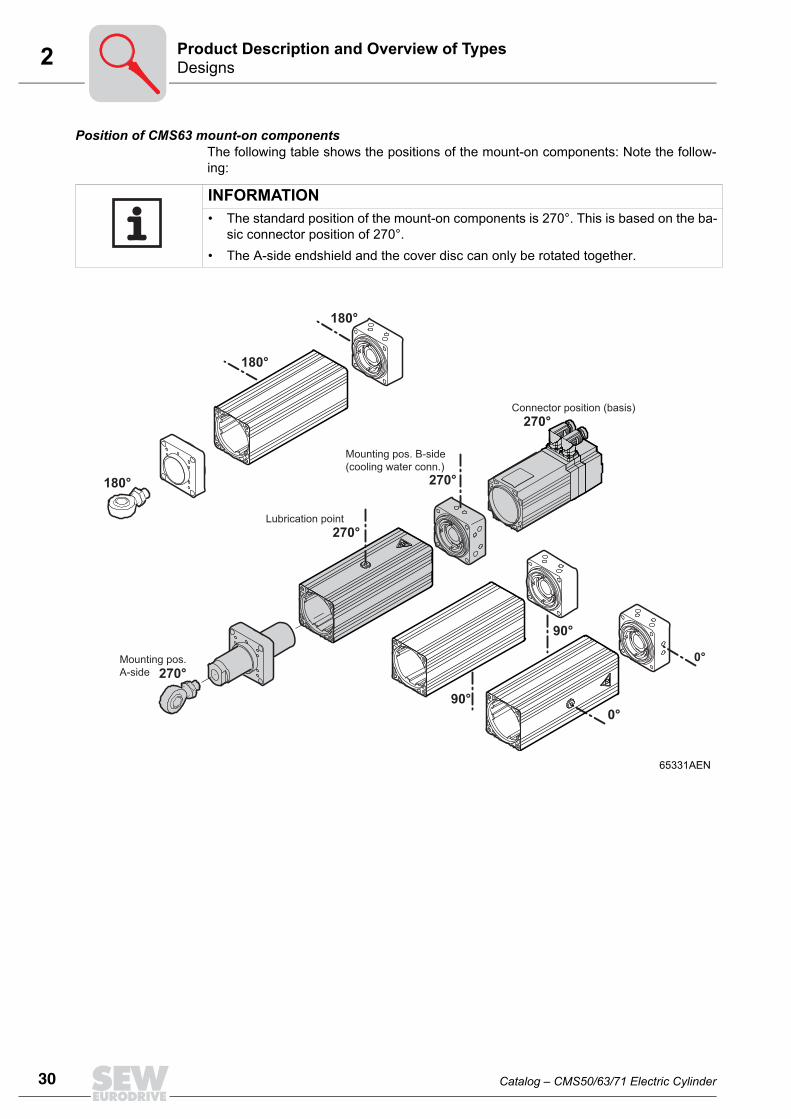
30
2 esignsroduct Description and Overview of Types
Position of CMS63 mount-on componentsThe following table shows the positions of the mount-on components: Note the follow-ing:
INFORMATION• The standard position of the mount-on components is 270°. This is based on the ba-
sic connector position of 270°.• The A-side endshield and the cover disc can only be rotated together.
65331AEN
270°
180°
180°
180°
90°
90°
0°
0°
Connector position (basis)
Mounting pos. B-side (cooling water conn.)
Lubrication point
Mounting pos. A-side
270°
270°
270°
DP
Catalog – CMS50/63/71 Electric Cylinder

2DesignsProduct Description and Overview of Types
Order example 1:The figure shows the CMS63 electric cylinder with connector position 0°:
The following order information is required:
65520AEN
Connector position 0°
Cooling water connection 270°
65333AEN
270°
180°
180°
180°
Lubrication point
Mountin pos. A-side
Mounting pos. B-side (cooling water conn.)
Connector pos. 270° (basis)
Catalog – CMS50/63/71 Electric Cylinder
31
32
2 esignsroduct Description and Overview of Types
Order example 2:The figure shows the CMS63 electric cylinder with connector position 90°:
The following order information is required:
65521AEN
Connector position 90°
Cooling water connection 270°
65335AEN
270°
270°
Lubrication point
Mounting pos. A-side
Mounting pos. B-side(cooling water connection)
Connector pos. 270° (basis)
90°
90°
DP
Catalog – CMS50/63/71 Electric Cylinder

2DesignsProduct Description and Overview of Types
Order example 3:The figure shows the CMS63 electric cylinder with connector position 180°:
The following order information is required:
65522AEN
Connector position 180°
Cooling water connection 270°
65337AEN
180°
270°
Lubrication point
Mounting pos. A-side
Mounting pos. B-side(cooling water conn.)
Connector pos. 270° (basis)
0°
0°
Catalog – CMS50/63/71 Electric Cylinder
33
34
2 esignsroduct Description and Overview of Types
Forced cooling fan (additional option)
CMS63M/L
Designation Option
VR DC 24 V
DP
Catalog – CMS50/63/71 Electric Cylinder

2DesignsProduct Description and Overview of Types
2.9.6 CMS71LA-side mounting / B-side mounting
The following variants for A-side mounting / B-side mounting are available.
CMS71L
A-side mounting B-side mounting
Designation Standard Designation Standard
SG 32 SG 32
Designation Option Designation Option
KG 32 KG 32
Catalog – CMS50/63/71 Electric Cylinder
35
36
2 esignsroduct Description and Overview of Types
Position of CMS71L mount-on componentsThe following table shows the positions of the mount-on components: Note the follow-ing:
INFORMATION• The standard position of the mount-on components is 270°. This is based on the ba-
sic connector position of 270°.• The A-side endshield and the cover disc can only be rotated together.
65196AEN
180°
180°
180°
180°
270°
270°
270°
270°
90°
90°
0°
0°
270°
Mounting pos. A-side
Sealing air connection
Lubrication point
Connector position (basis)
Mounting pos. B-side
DP
Catalog – CMS50/63/71 Electric Cylinder

2DesignsProduct Description and Overview of Types
Order example 1:The figure shows the CMS71 electric cylinder with connector position 0°:
The following order information is required:
65526AEN
Connector position 0°
65349AEN
180°
180°
180°
180°
270°
Mounting pos. A-side
Sealing air connection
Lubrication point
Connector position (basis)
Mounting pos. B-side
Catalog – CMS50/63/71 Electric Cylinder
37
38
2 esignsroduct Description and Overview of Types
Order example 2:The figure shows the CMS71 electric cylinder with connector position 90°:
The following order information is required:
65527AEN
Connector position 90°
65350AEN
270°
270°
270°
90°
90°
Mounting pos. A-side
Sealing air connection
Lubrication point
Connector position (basis)
Mounting pos. B-side
DP
Catalog – CMS50/63/71 Electric Cylinder

2DesignsProduct Description and Overview of Types
Order example 3:The figure shows the CMS71 electric cylinder with connector position 180°:
The following order information is required:
65348AEN
Connector position 180°
65351AEN
180°
180°
270°
Mounting pos. A-side
Sealing air connection
Lubrication point
Connector position (basis)
Mounting pos. B-side
0°
0°
Catalog – CMS50/63/71 Electric Cylinder
39
40
2 esignsroduct Description and Overview of Types
Lubricator (additional option)The following variants are available.
Bellows ventilation (additional option)The following variants are available.
CM71L
Designation Option
SV Star Vario
ST Star Control Time
SI Star Control Impuls
CM71L
Designation Option
Available Without closing plug
None
With closing plug"Caution: Bellows ventilation is closed. Ensure ventilation via sealing air connection."
DP
Catalog – CMS50/63/71 Electric Cylinder

3Project planning procedureProject Planning
3 Project PlanningCheck the following before beginning project planning:• Ambient conditions• Installation conditions (overhung loads and flexural torques not permitted)• Check the positioning accuracy (5/100 mm)
3.1 Project planning procedureThe following flow diagram illustrates the project planning procedure for an electriccylinder. Further information can be found in the subsequent sections.
Catalog – CMS50/63/71 Electric Cylinder
41
42
3 roject planning procedureroject Planning
e n
64138AEN
no
yes
no
Start of project planning
Determine the mechanical plant data:- Moved masses- Friction coefficient of bearings- Travel distance- Any existing processing forces- Ambient conditions (temperature, dirt, etc.)
Determine the kinematic requirements:
Travel cycle known?Calculating the
travel cylce on the basis of knownplant data possible?
Calculate the travel cycle with the resulting data:- Acceleration/deceleration- Speed- Travel times/waiting times
Estimate the relativecyclic duration factor
Determine existing forces bydetermining the torque - Max. required feed force release force - Effectively required force
(Mstat MDyn MspindleFmax
Feff
)
F Fmax < max electric cylinder
Determine the mean speed n
Determine the operating pointConsider the thermal limit curveof the electric cylinder
Operating point below or max. at the thermal limit curve Feff n,
Select the controller on the basis of the max. force (see assignment table in the CMS catalog)
9550loadtBrDYN
tn_BrnMP η××
=
Calculate the peak brake force
Select the braking resistor from the "Assignment tablbraking resistor - inverter" via the maximum and meabraking power
Select further components, such as encoder interfaceand fieldbus cards, if applicable, etc.
Calculate the mean brake force
Z
nt_Brt_BrBr t
tnP...PP ×++
= 1
END
no
yes
no
Electric cylinder too small
PP
Catalog – CMS50/63/71 Electric Cylinder

3Service life of bearings and threaded spindlesProject Planning
3.2 Service life of bearings and threaded spindlesThe table shows the dynamic load rating [C] of the spindle and bearings.
3.2.1 Threaded spindleService life (L) in revolutions
Average load (FM):
Service life (Lh) in hours:
C = Dynamic load rating of the spindles and bearings in [N]
Motor type Spindle Bearing
CMS50S With KGT 5 mm pitch 9000 20000
CMS63S/M With KGT 6 mm pitch 34000 39000
CMS63S/M With PGT 5 mm pitch 29000 39000
CMS71L With KGT 10 mm pitch 55000 60000
CMS71L With KGT 6 mm pitch 44000 60000
CMS71L With PGT 5 mm pitch 44000 60000
LCFM
= Service life [revolutions]= Dynamic load rating [N]= Average load [N]
6
3
10
1,1⎟⎟⎠
⎞⎜⎜⎝
⎛=
MF
CL
x
x
F1...Fnq1...qnKA
= Feed thrust in travel section [N]= Proportion of time in % of the travel section= Service factor
Working method KA service factor
Constant movement 1.0
Moderate shock loads 1.25
Medium shock loads 1.5
3323
213
1 100....
100100n
nM
qFqFqFF ×++×+×= AK×
LhLLm
= Service life [hours]= Service life [revolutions]= Average speed [min-1]
60×=
mh n
LL
Catalog – CMS50/63/71 Electric Cylinder
43
44
3 ervice life of bearings and threaded spindlesroject Planning
BearingService life (L) in revolutions
Service life (Lh) in hours:
LCFM
= Service life [hours]= Dynamic load rating [N]= Average load [N]
6
3
10⎟⎟⎠
⎞⎜⎜⎝
⎛=
MF
CL
x
x
1.25
LhLLm
= Service life [hours]= Service life [revolutions]= Average speed [min-1]
60×=
mh n
LL
SP
Catalog – CMS50/63/71 Electric Cylinder

3Calculation example for CMS71L with 10 mm spindle pitchProject Planning
3.3 Calculation example for CMS71L with 10 mm spindle pitchIn the following example, only the upward stroke is taken into account.Customer information:
Use a CMS71L electric lift cylinder with a ball screw (KGT) and brake. The KGT has anefficiency of h = 0.92 and a spindle pitch of p = 10 mm.
Maximum velocity vmax ≤ 0.25 m/sTravel time tstroke 0.850 sRest period tP 7.15 sWeight m 500 kgTravel distance s 150 mm
60178AXX
S1 S2 S3
V
tt4t3t2 t1
Vmax
0.25 s 0.35 s 0.25 s 7.15 s
Catalog – CMS50/63/71 Electric Cylinder
45
46
3 alculation example for CMS71L with 10 mm spindle pitchroject Planning
Calculation of the maximum speed:
Calculation of the mean speed:
Calculation of the maximum acceleration:
Calculation of the stroke distance for travel section s1:
vnp
= Velocity= Speed= Spindle pitch
min11500min60125125
01.025.0
=×=== sssm
sm
pvn =
tn
= Time= Speed
min1
5.112
15.725.035.025.0
25.075035.0150025.0min1
750
4321
44332211
=
+++
×+×+×
+++
×+×+×+×=
ssss
sss
tttt
tntntntnn
=n min1
min1
avmaxt1
= Acceleration= Maximum velocity= Time
2
1
max1
25.0
25.0
s
m
s
sm
t
a ===v
s1at1
= Travel section = Acceleration= Time
( ) mmmssm
tas 3 .310313.025.0121
2
1 2
2
2
11 ==××=××=
CP
Catalog – CMS50/63/71 Electric Cylinder

3Calculation example for CMS71L with 10 mm spindle pitchProject Planning
Calculation of the stroke distance for travel section s2:
Calculation of the stroke distance for travel section s3:
Checking the stroke distance:
Calculating the forces and torques:Static
s2at2
= Travel section = Acceleration= Time
mmmssm
tvs 5 .850875.035.025.02max2
==×=×=
s3at3
= Travel section = Acceleration= Time
( ) mmmssm
tas 3.310313.025.0121
2
1 2
22
33==××=××=
sgesamts1s2s3
= Total travel section= 1. Travel section= 2. Travel section= 3. Travel section
mmmmmmmmssssGesamt
1.1503.315.873 .31321
=++=++=
FMpη
= Force= Torque= Spindle pitch= Efficiency of threaded spindle
MstatFphmg
= Static torque= Force= Spindle pitch= Efficiency of threaded spindle= Mass= Gravitational acceleration
×××
=p
MF
2 πη
( ) smkgpgmpFMstat
81.95002
2=
××=××=
×××= ηπ 2 × π ×2 ×× ηπ
0.01 m
0.928.49 Nm
Catalog – CMS50/63/71 Electric Cylinder
47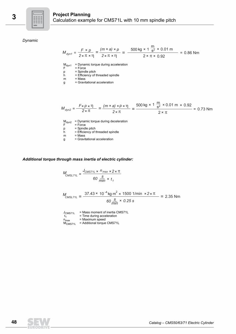
48
3 alculation example for CMS71L with 10 mm spindle pitchroject Planning
Dynamic
Additional torque through mass inertia of electric cylinder:
Mdyn1Fphmg
= Dynamic torque during acceleration= Force= Spindle pitch = Efficiency of threaded spindle= Mass= Gravitational acceleration
Mdyn2Fphmg
= Dynamic torque during deceleration= Force= Spindle pitch= Efficiency of threaded spindle= Mass= Gravitational acceleration
( ) sm
kgpampFMdyn11500
22
=××
=××
=××
×= ηπ 2 × π ×2 ×× ηπ0.01 m
0.920.86 Nm
( ) smkgpampFMdyn2
15002
2=
××=
××=××
×=ηπ 2 × π
×2× π
0.01 m 0.920.73 Nm
×η
JCMS71L t1nmaxMCMS71L
= Mass moment of inertia CMS71L= Time during acceleration= Maximum speed= Additional torque CMS71L
mkg
MCMSL71L
37.43-4×
=
=2× π
10
n ×maxJCMS71L ×
60min
s× t
1
2× 1500 1/min 2× π×
60min
s × 0.25 s
= 2.35 NmM
CMSL71L
CP
Catalog – CMS50/63/71 Electric Cylinder

3Calculation example for CMS71L with 10 mm spindle pitchProject Planning
Maximum torque:
Peak feed thrust:
Maximum torque in the individual travel sections:
Travel section s1 = Mmax1 = 11.7 NmTravel section s2 = Mstat = 8.49 NmMaximum torque in travel section s3:
Mmax1MstatMdyn1MCMS71L
= Maximum torque= Static torque= Dynamic torque in travel section 1= Torque through mass inertia of electric cylinder CMS71L
CMS71Ldyn1statMMMM ++=
max1
M =max1
8.49 Nm + 0.86 Nm + 2.35 Nm = 11.7 Nm
Fmax1Mmax1p
= Maximum force= Maximum torque= Spindle pitch
pM
F 22max1 =××=
××=
πmax1 11.7 Nm π0.01 m
7351.3 N
Mmax2MstatMdyn2MCMS71L
= Maximum dynamic torque in travel section 3= Static torque= Dynamic torque in travel section 3= Torque through electric cylinder CMS71L
CMS71Ldyn2statMMMM --=
max2
M =
max28.49 Nm - 0.73 Nm - 2.35 Nm = 5.41 Nm
Catalog – CMS50/63/71 Electric Cylinder
49
50
3 alculation example for CMS71L with 10 mm spindle pitchroject Planning
Checking the holding torque in travel section s4 that the brake must deliver:
Brake holding torque MB1 = 19 Nm ≥ 7.18 Nm
Calculation of effective utilization:Torque:
Effective force:
Checking the results with the system limits of CMS71L:
Operating point (Feff = 1822 N and average speed = 112.5 1/min) below the thermal limitcharacteristic curve, see table in section 4.23.4 Peak feed thrust Fmax. CMS71L = 17000 N ≥ Fmax application = 7351 N
MhaltenFphmg
= Holding torque= Weight= Spindle pitch= Efficiency of spindle= Mass= Gravitational acceleration
( ) smkgpgmpF
Mhalten9.81500
22
=××
=××
=××
×=
ηπ 2 × π
×2× π
0.01 m 0.927.18 Nm
× η
Mefft1-4Mmax1MstatMmax2
= Effective torque= Parts in the individual travel sections= Maximum dynamic torque in travel section 1= Static torque= Maximum dynamic torque in travel section 3
=Meff
t1
2 M
max1
t1
t2
t3 +
+
+
× t2
2 M
stat× + t
3
2 M×
max2
t4+
=Meff
0.25 s x (11.7 Nm) + 0.35 s x (8.49 Nm) + 0.25 s x (5.41 Nm) 2 2 2
0.25 s + 0.35 s + 0.25 s + 7.15 s= 2.9 Nm
FeffMeffpmg
= Effective force= Effective torque= Spindle pitch= Mass= Gravitational acceleration
pM
F 22eff = ××=
××=
πeff 2.9 Nm π0.01 m 1822 N
CP
Catalog – CMS50/63/71 Electric Cylinder

3Calculation example for service life of spindles and bearingsProject Planning
3.4 Calculation example for service life of spindles and bearingsThe table shows the dynamic load rating [C] of the spindle and bearings.
3.4.1 Example: Customer requires service life of spindles and bearings of approximately 5 years
Calculation of the feed thrusts in the individual travel sections:
Proportion of time in the individual travel sections:
Dynamic load rating of the spindles and bearings in [N]
Motor type Spindle Bearing
CMS50S With KGT 5 mm pitch 9000 20000
CMS63S/M With KGT 6 mm pitch 34000 39000
CMS63S/M With PGT 5 mm pitch 29000 39000
CMS71L With KGT 10 mm pitch 55000 60000
CMS71L With KGT 6 mm pitch 44000 60000
CMS71L With PGT 5 mm pitch 44000 60000
FMmax1MstatMmax2p
= Force in the individual travel sections= Maximum torque travel section 1= Static torque travel section 2= Maximum torque travel section 3= Spindle pitch
pM
F 221 =××=
××=
πmax1 11.7 Nm π0.01 m
7351.3 N
pM
F 222 =××=
××=
πstat 8.49 Nm π0.01 m
5334 N
pM
F 223 =××=
××=
πmax2 5.41 Nm π0.01 m
3399 N
q1t1tges
= Proportion of time in the individual travel sections:= Time in the individual travel sections = Total time
stq 0.031 s
8 s0.251
1 ==tges
=
stq 0.044 s
8 s0.352
2 ==tges
=
stq 0.031 s
8 s0.253
3 ==tges
=
t1
t2
t3
=tges
t4
+ + +
= 0.25 s + 0.35 s + 0.25 s + 7.15 s = 8 s tges
100 %
Catalog – CMS50/63/71 Electric Cylinder
51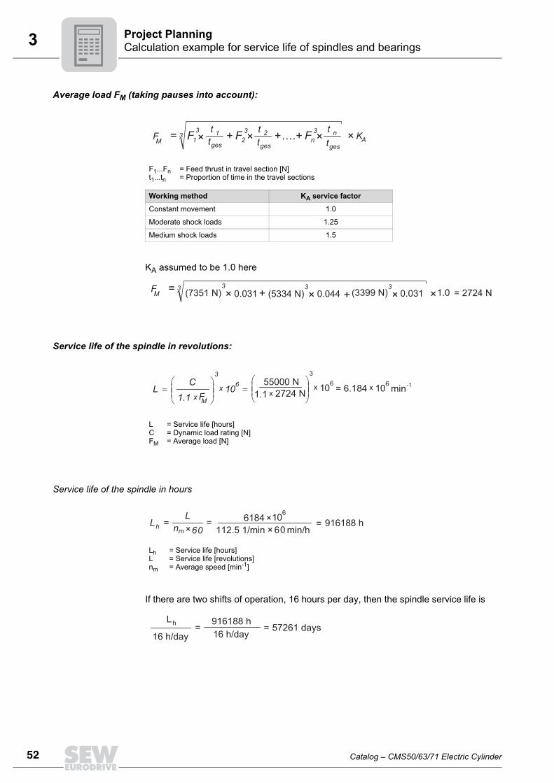
52
3 alculation example for service life of spindles and bearingsroject Planning
Average load FM (taking pauses into account):
KA assumed to be 1.0 here
Service life of the spindle in revolutions:
Service life of the spindle in hours
If there are two shifts of operation, 16 hours per day, then the spindle service life is
F1...Fnt1...tn
= Feed thrust in travel section [N]= Proportion of time in the travel sections
Working method KA service factor
Constant movement 1.0
Moderate shock loads 1.25
Medium shock loads 1.5
3323
213
1 .... nnM
tFtFtFF ×++×+×=tgestgestges
AK×
3 3MF ++= (7351 N) × 0.031
3(5334 N) × 0.044
3(3399 N) × 0.031 = 2724 N×1.0
LCFM
= Service life [hours]= Dynamic load rating [N]= Average load [N]
63
10 ⎟⎟
⎠
⎞⎜⎜⎝
⎛
=
MFC
Lx
x1.1
63
10⎟⎟⎠
⎞⎜⎜⎝
⎛=
55000 Nx
x1.1 2724 N = 6.184 610x min-1
LhLnm
= Service life [hours]= Service life [revolutions]= Average speed [min-1]
60×=
mh n
LL = 6184×
610112.5 1/min 60× min/h
= 916188 h
=hL 916188 h=
16 h/day 16 h/day57261 days
CP
Catalog – CMS50/63/71 Electric Cylinder

3Calculation example for service life of spindles and bearingsProject Planning
Service life of the bearing in revolutions:
Service life of the bearing in hours
If there are two shifts of operation, 16 hours per day, then the service life is
LCFM
= Service life [hours]= Dynamic load rating [N]= Average load [N]
63
10 ⎟⎟
⎠
⎞⎜⎜⎝
⎛
=
MFC
Lx
x1.25
63
10⎟⎟⎠
⎞⎜⎜⎝
⎛=
60000 Nx
x1.25 2724 N = 5472 610x revolutions
LhLnm
= Service life [hours]= Service life [revolutions]= Average speed [min-1]
60×=
mh n
LL =
5472×6
10
112.5 1/min 60× min/h= 810667 h
=hL 810667 h =16 h/day 16 h/day
50667 days
Catalog – CMS50/63/71 Electric Cylinder
53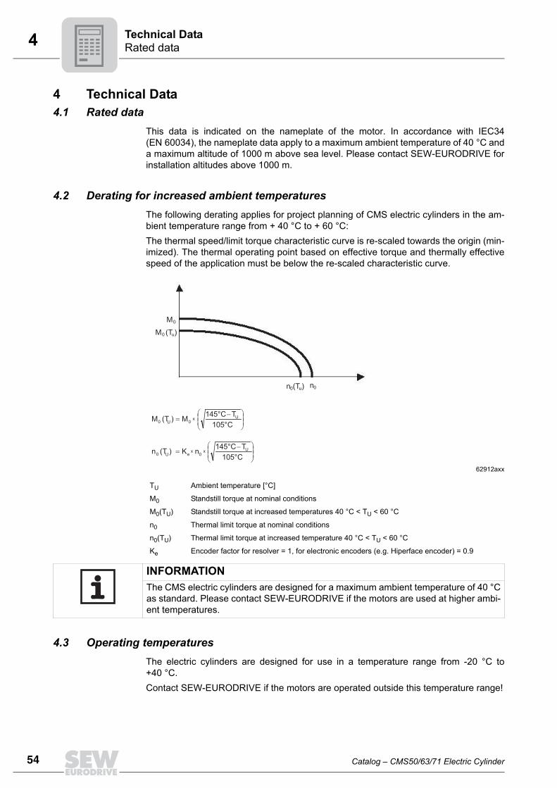
54
4 ated dataechnical Data
4 Technical Data4.1 Rated data
This data is indicated on the nameplate of the motor. In accordance with IEC34(EN 60034), the nameplate data apply to a maximum ambient temperature of 40 °C anda maximum altitude of 1000 m above sea level. Please contact SEW-EURODRIVE forinstallation altitudes above 1000 m.
4.2 Derating for increased ambient temperaturesThe following derating applies for project planning of CMS electric cylinders in the am-bient temperature range from + 40 °C to + 60 °C:The thermal speed/limit torque characteristic curve is re-scaled towards the origin (min-imized). The thermal operating point based on effective torque and thermally effectivespeed of the application must be below the re-scaled characteristic curve.
4.3 Operating temperaturesThe electric cylinders are designed for use in a temperature range from -20 °C to+40 °C.Contact SEW-EURODRIVE if the motors are operated outside this temperature range!
62912axx
TU Ambient temperature [°C]
M0 Standstill torque at nominal conditions
M0(TU) Standstill torque at increased temperatures 40 °C < TU < 60 °C
n0 Thermal limit torque at nominal conditions
n0(TU) Thermal limit torque at increased temperature 40 °C < TU < 60 °C
Ke Encoder factor for resolver = 1, for electronic encoders (e.g. Hiperface encoder) = 0.9
M0
M0 (Tu)
n0n0(Tu)
⎟⎟⎠
⎞⎜⎜⎝
⎛ −=
105°C
145°C TMM (T )0 0
x UU
⎟⎟⎠
⎞⎜⎜⎝
⎛ −=
105°C
145°C TKn (T )0 e
x UU
n0x
INFORMATIONThe CMS electric cylinders are designed for a maximum ambient temperature of 40 °Cas standard. Please contact SEW-EURODRIVE if the motors are used at higher ambi-ent temperatures.
RT
Catalog – CMS50/63/71 Electric Cylinder

4Key to the data tablesTechnical Data
4.4 Key to the data tablesThe following table lists the short symbols used in the "Technical Data" tables.
4.5 General features
nN Rated speed
nepk Maximum mechanically permitted speed
M0 Standstill torque (thermal continuous torque at low speeds)
I0 Standstill current
Mpk Maximum limit torque
Imax Maximum current
Jmot Mass moment of inertia without brake1)
1) For the complete motor and spindle
Jbmot Mass moment of inertia with brake1)
Jzusatz Additional mass moment of inertia without brake2)
2) For project planning with the SEW Workbench
Jbzusatz Additional mass moment of inertia with brake2)
MB Braking torque
L1 Inductivity between connection phase and star point
R1 Resistance between connection phase and star point
Up0kalt Internal voltage at 1000 rpm
P Spindle pitch
D Nominal spindle diameter
F Maximum permanent feed force
Fpk Peak feed force 3)
3) Depending on max. amplifier current, dynamic or static load of spindle; prior to project planning with ma-ximum force please contact SEW-EURODRIVE.
m Weight, variant without brake
mbmot Weight, variant with brake
Design
Thermal class F (155 °C)
Ambient temperature -20 °C to +40 °C
Noise levels / EN 60034 Below specified value
Vibration class "B" to EN60034-14
Positioning accuracy (repetition accuracy) at constant force and temperature ±0.05 mm
Catalog – CMS50/63/71 Electric Cylinder
55
56
4 MS50echnical Data
mbmot
g]
6.47.18.46.47.18.46.47.18.4
4.6 CMS504.6.1 Features
4.6.2 CMS50 technical data
Design Standard Optional
Degree of protection IP65
Motor protection KTY
Mounting position Any
Cooling Natural convection VR forced cooling fan
Lubrication Via housing bore, with taper greasing nipple DIN 71412-A
Spindle protection Smooth piston rod with sealing system
STOPStroke length 300 mm → nepk = 2500 min-1 (max. mechanical speed)Stroke lengths 70 and 150 mm → nepk = 4500 min-1 (max. mechanical speed)
Spindle nN Stroke length
M0 I0 Mpk Imax Jmot Jbmot Jzusatz Jbzusatz MB L1 R1 Up0kalt F Fpk m
DxP [min-1] [mm] [Nm]
[A] [Nm] [A] [kgcm2] [Nm] [mH] [Ω] [V] [kN] [k
50S KGT15x5
300070
1.3 0.96 5.2 5.10.54 0.6 0.12 0.12
4.3 71 22.49 86 1.2 5.35.8
150 0.56 0.62 0.14 0.14 6.5300 0.61 0.67 0.19 0.19 7.8
450070
1.3 1.32 5.2 7.00.54 0.6 0.12 0.12
4.3 37 11.61 62 1.2 5.35.8
150 0.56 0.62 0.14 0.14 6.5300 0.61 0.67 0.19 0.19 7.8
600070
1.3 1.7 5.2 9.00.54 0.6 0.12 0.12
4.3 22.5 7.11 48.5 1.2 5.35.8
150 0.56 0.62 0.14 0.14 6.5300 0.61 0.67 0.19 0.19 7.8
CT
Catalog – CMS50/63/71 Electric Cylinder

4CMS63Technical Data
mbmot
kg]
10.512--
10.512--
10.512--
10.512
10.512
10.512
4.7 CMS634.7.1 Features
4.7.2 CMS63 technical data
Design Standard Optional
Degree of protection IP65
Motor protection KTY
Mounting position See chapter 4.21.2
Cooling Natural convection VR forced cooling fan/water cooling
Lubrication Oil bath lubrication
Spindle protection Smooth piston rod with sealing system
STOPStroke lengths 100, 200, 400 and 600 mm → nepk = 4500 min-1 (max. mechanicalspeed)
Spindle nN Stroke length
M0 I0 Mpk Imax Jmot Jbmot Jzusatz Jbzusatz MB L1 R1 Up0kalt F Fpk m
DxP [min-1] [mm] [Nm]
[A] [Nm] [A] [kgcm2] [Nm] [mH] [Ω] [V] [kN] [
63S
KGT25x6
3000
100
2.9 2.15 11.1 12.9
1.92 2.26 0.77 0.77
9.3 36.5 6.79 902.4 10
9.5200 2.24 2.58 1.09 1.09 11400 - - - -
- --
600 - - - - -
4500
100
2.9 3.05 11.1 18.3
1.92 2.26 0.77 0.77
9.3 18.3 3.34 642.4 10
9.5200 2.24 2.58 1.09 1.09 11400 - - - -
- --
600 - - - - -
6000
100
2.9 3.9 11.1 23.4
1.92 2.26 0.77 0.77
9.3 11.2 2.1 502.4 10
9.5200 2.24 2.58 1.09 1.09 11400 - - - -
- --
600 - - - - -
PGT20x5
3000100
2.9 2.15 11.1 12.91.69 2.03 0.54 0.54
9.3 36.5 6.79 90 2.8 109.5
200 1.81 2.15 0.66 0.66 11
4500100
2.9 3.05 11.1 18.31.69 2.03 0.54 0.54
9.3 18.3 3.34 64 2.8 109.5
200 1.81 2.15 0.66 0.66 11
6000100
2.9 3.9 11.1 23.41.69 2.03 0.54 0.54
9.3 11.2 2.1 50 2.8 109.5
200 1.81 2.15 0.66 0.66 11
Catalog – CMS50/63/71 Electric Cylinder
57
58
4 MS63echnical Data
mbmot
[kg]
1213.5
--
1213.5
--
1213.5
--
1213.512
13.512
13.5
Spindle nN Stroke length
M0 I0 Mpk Imax Jmot Jbmot Jzusatz Jbzusatz MB L1 R1 Up0kalt F Fpk m
DxP [min-1] [mm] [Nm]
[A] [Nm] [A] [kgcm2] [Nm] [mH] [Ω] [V] [kN]
63M
KGT25x6
3000
100
5.3 3.6 11.11) (21.4)
7.92) (21.6)
2.69 3.03 0.77 0.77
9.3 22 3.56 1004.1 10
11200 3.01 3.35 1.09 1.09 12.5400 - - - -
- --
600 - - - - -
4500
100
5.3 5.4 11.11) (21.4)
11.92) (32.4)
2.69 3.03 0.77 0.77
9.3 9.8 1.48 674.1 10
11200 3.01 3.35 1.09 1.09 12.5400 - - - -
- --
600 - - - - -
6000
100
5.3 6.9 11.11) (21.4)
15.22) (41.4)
2.69 3.03 0.77 0.77
9.3 5.9 0.92 524.1 10
11200 3.01 3.35 1.09 1.09 12.5400 - - - -
- --
600 - - - - -
PGT20x5
3000100
5.3 3.6 11.11) (21.4)
7.92) (21.6)
2.46 2.8 0.54 0.549.3 22 3.56 100 5.2 10
11200 2.58 2.92 0.66 0.66 12.5
4500100
5.3 5.4 11.11) (21.4)
11.92) (32.4)
2.46 2.8 0.54 0.549.3 9.8 1.48 67 5.2 10
11200 2.58 2.92 0.66 0.66 12.5
6000100
5.3 6.9 11.11) (21.4)
15.22) (41.4)
2.46 2.8 0.54 0.549.3 5.9 0.92 52 5.2 10
11200 2.58 2.92 0.66 0.66 12.5
1) Max. permitted torque2) Max. permitted current
CT
Catalog – CMS50/63/71 Electric Cylinder

4CMS71Technical Data
t
4.8 CMS714.8.1 Features
4.8.2 CMS71 technical data
Design Standard Optional
Degree of protection IP45 (IP65)1)
Motor protection TF KTY/TH
Mounting position Any
Cooling Natural convection
Lubrication Fixed lubrication point with taper greasing nipple DIN 71412-A Lubricator chapter 6.5
Spindle protection Bellows
1) For electrical components
STOPStroke length 200 mm → nepk = 3000 min-1 (max. mechanical speed)Stroke length 350 mm → nepk = 2000 min-1 (max. mechanical speed)
Spindle nNStroke length M0 I0 Mpk Imax Jmot Jbmot Jzusatz Jbzusatz MB L1 R1 Up0kalt F Fpk m mbmo
DxP [min-1] [mm] [Nm] [A] [Nm] [A] [kgcm2] [Nm] [mH] [Ω] [V] [kN] [kg]
71L
KGT 32x6
2000
200 9.5 4.2 22.11) (31.4)
9.22) (16.8) 32.5 37.5 23.3 26.6 19 24 2.5 151 6.7 20 19 20
350 9.5 4.2 16.61) (31.4)
7.32) (16.8) 45.3 50.3 36.1 39.4 19 24 2.5 151 6.7 153) 25 26
3000200 9.5 6.2 22.11)
(31.4)13.62) (25) 32.5 37.5 23.3 26.6 19 11 1.12 102 6.7 20 19 20
350 9.5 6.2 16.61) (31.4)
10.82) (25) 45.3 50.3 36.1 39.4 19 11 1.12 102 6.7 153) 25 26
4500200 9.5 9.6 22.11)
(31.4)21.12) (38) 32.5 37.5 23.3 26.6 19 4.5 0.5 65 6.7 20 19 20
350 9.5 9.6 16.61) (31.4)
16.82) (38) 45.3 50.3 36.1 39.4 19 4.5 0.5 65 6.7 153) 25 26
KGT 32x10
2000 200 9.5 4.2 31.4 16.8 32.5 37.5 23.3 26.6 19 24 2.5 151 3.6 17 19 203000 200 9.5 6.2 31.4 25 32.5 37.5 23.3 26.6 19 11 1.12 102 3.6 17 19 204500 200 9.5 9.6 31.4 38 32.5 37.5 23.3 26.6 19 4.5 0.5 65 3.6 17 19 20
PGT 24x5
2000 200 9.5 4.2 24.41) (31.4)
10.52) (16.8) 32.5 37.5 23.3 26.6 19 24 2.5 151 7.2 20 19 20
3000 200 9.5 6.2 24.41) (31.4)
15.52) (25) 32.5 37.5 23.3 26.6 19 11 1.12 102 7.2 20 19 20
4500 200 9.5 9.6 24.41) (31.4)
242) (38) 32.5 37.5 23.3 26.6 19 4.5 0.5 65 7.2 20 19 20
1) Max. permitted torque2) Max. permitted current3) In case of tensile loads, a peak feed force Fpk of 20 kN is possible
Catalog – CMS50/63/71 Electric Cylinder
59
60
4 rakeechnical Data
4.9 BrakeThe standard voltage supply of the brakes is 24 V DC and they operate with a constantbraking torque. The brakes cannot be retrofitted and operate without brake rectifier orbrake control unit. Observe the maximum currents of the brakes when connecting them(see table in chapter 4.10). The overvoltage protection must be implemented by the cus-tomer, for example using varistors.The brake can be used at all speeds.The brake is released electrically. The brake is applied when the voltage is switched off.
The mechanical brake is not used as service brake but as emergency brake or holdingbrake for general machine standstill. Observe the notes in the relevant operating instructions for servo controllers concerningthe switching sequence of motor enable and brake control during standard operation.
STOPThe brake will not function if the polarity is incorrect. Make sure the polarity is correct.
STOPComply with the applicable regulations issued by the relevant employer’s liability insur-ance association regarding phase failure protection and the associated circuit/circuitmodification!
INFORMATIONIn view of the DC voltage to be switched and the high level of current load, it is essentialto use either special brake contactors or AC contactors with contacts in utilization cat-egory AC-3 to EN 60947-4-1.
BT
Catalog – CMS50/63/71 Electric Cylinder

4BP/BS brakesTechnical Data
4.10 BP/BS brakesThe following table lists the technical data of the brakes.
Motor type Brake typeVN R I P MB t1 t2
[VDC] [Ω] [A] [W] [Nm] [10-3 s] [10-3 s]CMS50S BP04
24
56.5 0.42 10.2 4.3 60 15CMS63S
BP09 35 0.67 16 9.3 60 15CMS63MCMS71L BS2 34 0.71 17 19 120 120
MB = Braking torque
P = Power consumption of the coil
t1 = Response time
t2 = Application time
I = Operating current 20 °C
R = Coil resistance
VN = Nominal voltage
INFORMATIONCustomer installations are not taken into account for the response and applicationtimes of the brakes in the above tables.
Catalog – CMS50/63/71 Electric Cylinder
61
62
4 MV brake control systemechnical Data
4.11 BMV brake control systemThe brakes for the CMS electric cylinders can be controlled via the BMV brake relay asan option.In every application, the BP holding brake can be controlled via the BMV brake relay ora customer relay with varistor overvoltage protection. If the system complies with the specifications for direct brake control, a BP brake canalso be controlled directly via the brake output of a MOVIAXIS® servo inverter.
Brake control system BMV
Dimension drawing
65518axx
[1] External 24 V voltage supply for the brake
[2] Servo inverter brake output
D
C
B
A
3
1
4
BMV
1 2 3 4 13 14 15
SB1
K12
+ -24 VDC24 VDC
[1] [2]
01645BXX
[1] Support rail mounting EN 50022-35-7.5
15
14
13
4
3
2
1
BM. ...
75
5 68
1)
22.5
91.5
BT
Catalog – CMS50/63/71 Electric Cylinder

4Encoder systemsTechnical Data
4.12 Encoder systemsThe following encoder systems are used for the CMS50S, CMS63S/M and CMS71Lelectric cylinders.
4.12.1 Resolver
4.12.2 HIPERFACE® encoder/ES1H, /AS1H, /AKOH
SEW-EURODRIVE offers HIPERFACE® encoders as an alternative to the resolver.
Part number for RH1M 0199 031 4
Number of poles 2
Primary Rotor
Input voltage 7 V
Input frequency 7 kHz
Reduction ratio ± 10 % 0.5
Phase shift ± 5° +13°
Input impedance ± 15% 130 + j120 Ω
Output impedance ± 15% 200 + j270 Ω
Input resistance ± 10% 82 Ω
Output resistance ± 10% 68 Ω
Max. electrical fault ± 6’
Temperature range -55 °C to +150 °C
Type ES1H AS1H AK0HCMS50S / CMS63S/M 1333 217 1 1333 212 0
0199 583 9 CMS71L 1332 860 3 1332 858 1Supply voltage DC 7 - 8 - 12 V polarity reversal protectedMax. current consumption 140 mA 120 mACut-off frequency 200 kHz 26 kHzPulses (sine cycles) per revolution 1024 128
Output amplitude per track 0.9 - 1.1 VSS sin/cos 0.8 - 1.1 VSS sin/cosSingle-turn resolution 32768 increments/revolution (15 bit) 4096 increments/revolution (15 bit)Multi-turn resolution - 4096 revolutions (12 bits)Transmission protocol HIPERFACE®
Serial data output Driver to EIA RS-485Vibration resistance (10-2000 Hz) ≤ 200 m/s2 (DIN IEC 68-2-6) ≤ 100 m/s2 (DIN IEC 68-2-6)Maximum speed 12000 min-1 9000 min-1
Connection 12-pin round connector Temperature range -20 °C to +110 °C
Catalog – CMS50/63/71 Electric Cylinder
63
64
4 witching equipment and safeguards of the motor seriesechnical Data
4.13 Switching equipment and safeguards of the motor series4.13.1 Protective measures
Synchronous servomotors must be protected against overloads and short circuits. Install the motors with sufficient space for air to cool them. The surface temperature may be in excess of 100 °C during operation in accordancewith thermal classification F. Therefore, measures to prevent inadvertent contact are es-sential.The motors are equipped with temperature detection to protect the motor windingagainst overheating.
CMS50/63 The temperature is measured using the KTY84-130 temperature sensors, which are in-stalled as standard. The correct model must be activated in the servo inverter to enablethermal motor protection (I2t, effective current monitoring). For information on the pro-cedure, refer to the documentation of the servo inverter.
4.13.2 EMC measuresSEW-EURODRIVE synchronous servomotors are components for installation in ma-chinery and systems. The designer of the machine or system is responsible for comply-ing with the EMC Directive 89/336/EEC.
Routing brake cables
The brake and power cables may only be routed together if either the brake cable or thepower cable is shielded. We recommend that you use prefabricated cables, seechapter 5.
Notes on the encoder connec-tion
Observe the following instructions when connecting an encoder:• Use a shielded cable with twisted pair conductors only.• Connect the shield to the PE potential on both ends over a large surface area.
Thermal motor protection
The cables can only be routed together if either the KTY cable or the power cable isshielded. We recommend that you use prefabricated cables, see chapter 5.
ST
Catalog – CMS50/63/71 Electric Cylinder

4Scope of deliveryTechnical Data
4.14 Scope of delivery
4.14.1 CMS50S• Electric cylinder with smooth piston rod • 4 fit bolts included• Plug connector• Various optional connecting parts (fixed mount-on components, pivot bearings)
4.14.2 CMS50S / CMS63S/M• Electric cylinder with smooth piston rod • Prepared for flange mounting, 4 screws and 4 pins included• Plug connector• Various optional connecting parts (fixed mount-on components, pivot bearings)
4.14.3 CMS71L• Electric cylinder with assembled threaded spindle and bellows• Mechanical connecting parts with plain bearing bush (rod end bearing, optional car-
dan joint)• Fixed lubrication connection option (optional preassembled lubrication device)• Plug connector
INFORMATION• The delivery of the electric cylinder with recirculating ball screw (KGT) takes
3 weeks.• The delivery time for electric cylinders with planetary roller screw drive (PGT)
is 8 weeks.
Catalog – CMS50/63/71 Electric Cylinder
65
66
4 MS50S mounting dimensionsechnical Data
66
73
25
4.15 CMS50S mounting dimensions4.15.1 Mounting dimensions for a stroke length of 70 mm
Each CMS50 comes with an accessory bag (with 4 fit bolts) for flange or pivot bearingmounting.
156.57±0.02
42 ±
0.02
16853.5
R21
Ø 1
6H7
65
39.517
38
48
109
3015
25
82.2
69.2
77 67
24.530
(118
.7)
36.5
/RH1M
134 mm CMS50S/M74±0.1
23 /ES1H/AS1H/AK0H
/VR
M16
18
M86
Ø 10 H7
Closing plug for lubrication pointTaper greasing nipple DIN71412-A Connector, signal
max. 270° adjustable
210
-0.1
2
64.5
14 Connector, powermax. 270° adjustable
72
60.5
Detail Z
4
15.6
32Ø
max.6
2
Detail Z
Hub 70 ±1
Lubrication position35
163 mm CMS50S/BP
Accessory bag (SEW part number: 1333 4204)
Weight: 0.1 kg
10f9
16
7 16 13
M8
4x
CT
Catalog – CMS50/63/71 Electric Cylinder

4CMS50S mounting dimensionsTechnical Data
66
73
5
4.15.2 Mounting dimensions for a stroke length of 150 mm
Each CMS50 comes with an accessory bag (with 4 fit bolts) for flange or pivot bearingmounting.
65684AEN
236.57±0.02
42 ±
0.02
24853.5
R21
Ø 1
6H7
65
39.517
38
48
109
3015
2582
.2
69.2
77 67
24.530
(118
.7)
36.5
/RH1M
74±0.1
23 /ES1H/AS1H/AK0H
/VR
M16
18
M86Ø 10 H7
Closing plug for lubricating pointTaper grease nipple DIN71412-A Connector, signal
max. 270° adjustable
210
-0.1
2
104.5
14 Connector, powermax. 270° adjustable
72
60.5
2
Detail Z
4
15.6
32Ø
max.6
2
Detail Z
Hub 150 ±1
75Lubrication position
134 mm CMS50S/M 163 mm CMS50S/BP
Accessory bag (SEW part number: 1333 4204)
Weight: 0.1 kg
10f9
16
7 16 13
M8
4x
Catalog – CMS50/63/71 Electric Cylinder
67
68
4 MS50S mounting dimensionsechnical Data
85AEN
66
73
5
4.15.3 Mounting dimensions for a stroke length of 300 mm
Each CMS50 comes with an accessory bag (with 4 fit bolts) for flange or pivot bearingmounting.
656
386.57±0.02
42 ±
0.02
39853.5
R21
Ø 1
6H7
65
39.517
38
48
109
3015
2582
.2
69.2
77 67
24.530
(118
.7)
36.5
/RH1M
74±0.1
23 /ES1H/AS1H/AK0H
/VR
M16
18
M86Ø 10 H7
Closing plug for lubricating pointTaper grease nipple DIN71412-A Connector, signal
max. 270° adjustable
210
-0.1
2
179.5
14 Connector, powermax. 270° adjustable
72
60.5
2
Detail Z
4
15.6
32Ø
max.6
2
Detail Z
Hub 300 ±1
150Lubrication position
134 mm CMS50S/M 163 mm CMS50S/BP
Accessory bag (SEW part number: 1333 4204)
Weight: 0.1 kg
10f9
16
7 16 13
M8
4x
CT
Catalog – CMS50/63/71 Electric Cylinder

4CMS50S mounting dimensionsTechnical Data
4.15.4 Additional mounting optionsFlange mounting The following 3 figures show the mounting options for the electric cylinder. This should
be attached to a mounting surface with the gray-shaded mount-on components. Themount-on components can be mounted in 90° steps.
The flange mounting kit consists of the following parts:
65534AEN
94±0
.1
38.5
±0.1
90
38.5
74
114
2x fit bolt (tightening torque 12 m)ISO 7379 10x16-12.9 (M8)
Possible mounting variants:front and center
2x hex head screws DIN EN ISO 4014 M8x70
M8
10
72 ±0.1
Mountabe in 4x 90° steps Mountable in 4x 90°
steps
180°
270°
0°
90°
Flange mounting kit (SEW part no.: 1333 3305)
Weight: 0.65 kg
2x
4x
2x
Catalog – CMS50/63/71 Electric Cylinder
69
70
4 MS50S mounting dimensionsechnical Data
Pivot bearing mountingThe following figure shows the mounting option for the electric cylinder. This should beattached to a mounting surface with the gray-shaded mount-on components.
To mount the pivot bearing as shown, you will need the following parts:
65533AEN
Pivot bearing mounting kit (SEW part no.: 1333 3313)
Flange mounting kit (SEW part no.: 1333 3305)
Weight: 0.23 kg Weight: 0.65 kg
74
20
2x fit bolt (tightening torque 12 Nm) ISO 7379 10x16-12.9 (M8)
2x bolt Ø 16f6
2x hex head screwDIN EN ISO 4014 M8x70
114
154
M8 10
72 ±0.1
134
±0.1
2x 2x
4x
2x
CT
Catalog – CMS50/63/71 Electric Cylinder

4CMS63S/M mounting dimensionsTechnical Data
4.16 CMS63S/M mounting dimensions4.16.1 Mounting dimensions for a stroke length of 100 mm
Each CMS63 comes with an accessory bag for flange or pivot bearing mounting.
65690AEN
14 ±0.0310 ±0.1
20
Cooling water connection
32±0
.03
50±0
.1
19283.5
3.4
88
56.5
±0.
1
56.5 ±0.1
M20
x1.5
SW
36
25 0
-0.1
2
M12
12 2xG1/8
89 ±
0.1
10Ø 8H7
20
3216
25
8976
34
46
138
69
84 74
24.532 26 /ES1H
/AS1H/AK0H
/VR
102
74
25
Detail Z
Stroke 100 ±1
Ø 20
H7
R25
Detail Z
Ø50
1040.5
Ø58
f7
Connector, signal max. 270° adjustable
max. 270° adjustable
(133
)44
89 ±0.1
/RH1M
M6x16
/19
192 mm CMS63S/BP 163.5 mm CMS63S
214 mm CMS63M 242.5 mm CMSM/BP
Connector, power
Accessory bag (SEW part number: 1652 1137)
Weight: 0.15 kg4x4x
Catalog – CMS50/63/71 Electric Cylinder
71
72
4 MS63S/M mounting dimensionsechnical Data
4.16.2 Mounting dimensions for a stroke length of 200 mm
Each CMS63 comes with an accessory bag for flange or pivot bearing mounting.
65716ADE
14 ±0.0310 ±0.1
20
Cooling water connection
32±0
.03
50±0
.1
29283.5
3.4
88
56.5
±0.
1
56.5 ±0.1
M20
x1.5
SW
36
25 0
-0.1
2
M12
12 2xG1/8
89 ±
0.1
10Ø 8H7
20
3216
258976
34
46
138
69
84 74
24.532 26 /ES1H
/AS1H/AK0H
/VR
102
74
25
Detail Z
Stroke 200 ±1
Ø 20
H7
R25
Detail Z
Ø50
1040.5
Ø58
f7
Connector, signal max. 270° adjustable
Connector, powermax. 270° adjustable
(133
)44
89 ±0.1
/RH1M
M6x16
/19
192 mm CMS63S/BP 163.5 mm CMS63S
214 mm CMS63M 242.5 mm CMSM/BP
Accessory bag (SEW part number: 1652 1137)
Weight: 0.15 kg4x4x
CT
Catalog – CMS50/63/71 Electric Cylinder

4CMS63S/M mounting dimensionsTechnical Data
4.16.3 Additional mounting optionsFlange mounting The following figure shows the mounting option for the electric cylinder. This should be
attached to a mounting surface with the gray-shaded mount-on components. Themount-on components can be mounted in 90° steps.
The flange mounting kit consists of the following parts:
64892AEN
Flange mounting kit (SEW part no.: 1652 1102)
Weight: 3.5 kg
120
94 ±0.1
M12 16
95
47.5
±0.
1
2x parallel pin ISO8734 8x20 2x hex head screw ISO4014-M12x100
2x hex head screw ISO4762-M12x20
111
±0.1
89
133
Can be mounted in 4x90° steps
2x
4x
2x
Catalog – CMS50/63/71 Electric Cylinder
73
74
4 MS63S/M mounting dimensionsechnical Data
Pivot bearing mountingThe following figure shows the mounting option for the electric cylinder. This should beattached to a mounting surface with the gray-shaded mount-on components.
To mount the pivot bearing as shown, you will need the following parts:
64900AEN
154
±0.1
176
132
22
bolt Ø 22f7
Can be mounted in 4x90° steps
120
94 ±0.1
M12 16
95
47.5
±0.
1
Insert the thrust washer with the slide surface towards the motor.
Pivot bearing mounting kit (SEW part no.: 1652 1129)
Flange mounting kit (SEW part no.: 1652 1102)
Weight: 0.9 kg Weight: 3.5 kg
2x2x
2x
4x
2x
CT
Catalog – CMS50/63/71 Electric Cylinder

4CMS71L mounting dimensionsTechnical Data
4.17 CMS71L mounting dimensions
4.17.1 Mounting dimensions of CMS71L/B/RH1M (resolver) for a stroke length of 200 mm
INFORMATIONThe CMS71L electric cylinder variants with or without brake, with A-side cardan joint orwith rigid rod end bearing have the same mounting dimensions. In the variant withB-side cardan joint, the distance between the two fastening bolts is 7 mm longer.
64920AEN
63
3911
6
117
155
Ø 32H9
46.5
Lubricator (optional)
R34 +2 0
598+2 0
37
Signal connector
Connector max. 270° adjustable Lubricating point G1/4Taper grease nipple DIN 71412-A
Sealing air connection G1/8
Power connector
85
209.
5
74
7
300
-0.1
A-side mounting (optional)Cardan joint
55 79
42
54 98
12x45°
Ø 3
2H9
B-side mounting (optional)Bearing cover with cardan joint
544+2 0
Nominal stroke 200Excessive stroke ± 1 mm
(to mech. stop)
72.762
300
-0.1
47
(744 extended)
537+2 0 (737 extended)
Ø
Ø
Additional length
Catalog – CMS50/63/71 Electric Cylinder
75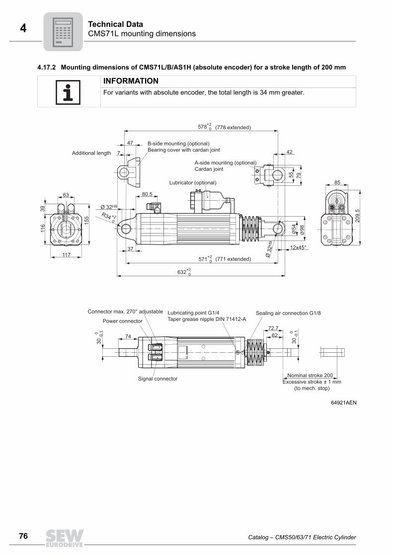
76
4 MS71L mounting dimensionsechnical Data
4.17.2 Mounting dimensions of CMS71L/B/AS1H (absolute encoder) for a stroke length of 200 mm
INFORMATIONFor variants with absolute encoder, the total length is 34 mm greater.
64921AEN
63
3911
6
117
155
Ø 32H9
80.5
Lubricator (optional)
R34 +2 0
632+2 0
37
Signal connector
Connector max. 270° adjustable Lubricating point G1/4Taper grease nipple DIN 71412-A
Sealing air connection G1/8Power connector
85
209.
5
7
55 79
42
54 98
12x45°
Ø 3
2H9
578+2 0
Nominal stroke 200Excessive stroke ± 1 mm
(to mech. stop)
72.762
300
-0.1
47
(778 extended)
571+2 0 (771 extended)
Ø
Ø
Additional length
300
-0.1
74
A-side mounting (optional)Cardan joint
B-side mounting (optional)Bearing cover with cardan joint
CT
Catalog – CMS50/63/71 Electric Cylinder

4CMS71L mounting dimensionsTechnical Data
038AEN
209.
5
4.17.3 Mounting dimensions of CMS71L/B/RH1M (resolver) for a stroke length of 350 mm
65
Ø 9
8
37 46.5
Ø 3
2H9
R34 +2
0
12x45°
Ø 3
2H9
Ø 5
4
Signal connector
Connector max. 270° adjustable Lubricating point G1/4Taper grease nipple DIN 71412-A Sealing air connection G1/8
Power connector 72.7
Nominal stroke 350Excessive stroke ± 1 mm
(to mech. stop)
7462
300
-0.1
300
-0.1
777 +2 0
63
3911
6
117
155
85
716+2 0 (1066 extended)
Lubricator (optional)
7
55 79
42
723+2 0
47
(1073 extended)
Additional length A-side mounting (optional)Cardan joint
B-side mounting (optional)Bearing cover with cardan joint
Catalog – CMS50/63/71 Electric Cylinder
77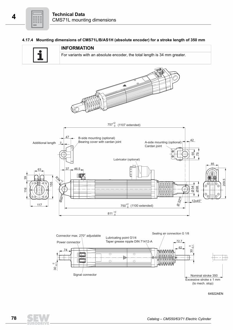
78
4 MS71L mounting dimensionsechnical Data
2AEN
209.
5
0mm
4.17.4 Mounting dimensions of CMS71L/B/AS1H (absolute encoder) for a stroke length of 350 mm
INFORMATIONFor variants with an absolute encoder, the total length is 34 mm greater.
6492
63
3911
6
117
155
Lubricator (optional)85
811 +2 0
37
54 98ØØ
12x45°
Ø 3
2H9
72.7
62
Sealing air connection G 1/8
74 300
-0.1
Nominal stroke 35Excessive stroke ± 1
(to mech. stop)
Lubricating point G1/4Taper grease nipple DIN 71412-A
Connector max. 270° adjustable
Power connector
Signal connector
300
-0.1
7
55 79
42
757+2 0
47
(1107 extended)
Additional length
750+2 0 (1100 extended)
46.5
Ø32
H9
R34 +2
0
A-side mounting (optional)Cardan joint
B-side mounting (optional)Bearing cover with cardan joint
CT
Catalog – CMS50/63/71 Electric Cylinder

4Additional feature – VentilationTechnical Data
4.18 Additional feature – Ventilation4.18.1 Forced cooling fan/VR CMS50/63 electric cylinders can be equipped with a forced cooling fan if required. The
VR forced cooling fan is available for DC 24 V.
Switched-mode power supply UWU52A
The AC voltage type includes a VR forced cooling fan and the UWU52A switched-modepower supply.Input: AC 110 - 240 V; 1.04 – 0.63 A; 50/60 HzOutput: DC 24 V; 2.5 A (40 °C); 2.0 A (55 °C)Connection: Screw terminals 0.2 – 2.5 mm2, separableDegree of protection: IP20; attachment to EN 60715 TH35 support rail in the controlcabinetPart number: 0188 181 7
Forced cooling fan, cpl.
Forced cooling fan type VRMotor size CMS50S CMS63S/MSupply voltage DC 24 V± 10 % 24 V± 10 %Current consumption DC 0.15 A 0.25 APower consumption 3.5 W 6.0 WAir discharge rate 56 m3/h 80 m3/hAmbient temperature -20 °C to +60 °CDegree of protection IP54 / IP55Electrical connection Plug connectorMax. cable cross section 3 x 1 mm2
Inner diameter of the cable gland 7 mm
59049AXX
76
38111
101
Forced cooling fan for motor type Part number
CMS50 1332 8697
CMS63 1332 7569
Catalog – CMS50/63/71 Electric Cylinder
79
80
4 dditional feature – Ventilationechnical Data
Retrofit set for CMS50S/63S/M
The forced cooling fan retrofit set is supplied as follows:• Forced cooling fan, cpl.• Accessory bag
Electrical connection
The VR forced cooling fan is only available for 24 V DC voltage. • DC 24 V ± 20 %• Plug connector connection• Maximum connection cross section 2 x 1 mm2
• Pg7 cable gland with 7 mm inside diameter
INFORMATIONThe forced cooling fan retrofit set for the motors CMS50S/63S/M may only be mountedby staff authorized by SEW-EURODRIVE.
Retrofit set Part number
CMS50S VR kit 1333 2414
Cmpl. forced cooling fan for CMS50
Machine screw M4x8-Tx-ST-A2F
Lock washer
Housing cover CMS50 / AS1H / ES1H / RH1M
Screw
Washer
Housing cover seal for CMS50
CMS63S/M VR kit 1333 2422
Cmpl. forced cooling fan for CMS63
Machine screw M4x8-Tx-ST-A2F
Lock washer
Housing cover CMS63 / AS1H / ES1H / RH1M
Screw
Washer
Housing cover seal for CM63
50990AXX
Connector contact Connection
1 24 V +
2 0 V
1
2-
+DC 24 V
AT
Catalog – CMS50/63/71 Electric Cylinder

4Mechanical stroke limitingTechnical Data
4.19 Mechanical stroke limiting
The mechanical limiting elements built-in by the customer must be able to absorb thereactive forces and kinetic energy that is created when the end position stops arereached in order to prevent the maximum permitted feed thrust of the electric cylinderfrom being exceeded. This requires soft, damping elements. Their purpose is to absorbthe energy and then limit the end position mechanically. As a rule, you should use cush-ioning or shock absorbers that are dimensioned accordingly.
4.19.1 Mechanical stroke limiting
Calculating the effective stroke
The effective stroke can be calculated as follows: Heff = A - T - 2 x SorHeff = HCMS - 2 x SHeff < HCMS
STOPThe customer must limit the stroke of the electric cylinder by providing for appropriatemeasures in the extended and retracted position, e.g. by using limit stops, cushioningor shock absorbers.
STOPThe rated stroke length (HCMS), e.g. CMS71L stroke 200 mm, is only available in limit-ed form for the customer application because safety distances (S) to the limit stops re-strict the effective stroke (Heff).
[Heff] Effective stroke [A] Distance between limit stops
[HCMS] Rated stroke CMS [T] Partial width
[S] Safety distance [M] Weight
M SS
AT
Hef
f
Catalog – CMS50/63/71 Electric Cylinder
81
82
4 ounting situation at customer siteechnical Data
4.20 Mounting situation at customer site4.20.1 Mounting notes for CMS50/CMS63
• Attachment only on the output side of the piston rod is permitted only for the CMStypes
– CMS50S with 70 mm stroke– CMS63S with 100 mm stroke
with/without brake.
• No overhung loads on the drive
65731AXX
61369AEN
Pivot bearing
MT
Catalog – CMS50/63/71 Electric Cylinder

4Mounting situation at customer siteTechnical Data
• No statically redundant mounting. When using a pivot bearing, do not use additionalattachments.
• Joint must be free to move; do not clamp in place.
• No overhung loads on the drive
61372AEN
61371AXX
61379AXX
Pivot bearing
Catalog – CMS50/63/71 Electric Cylinder
83
84
4 ounting situation at customer siteechnical Data
• Do not induce loads and torques via joints.
• Do not offset the installed components.
• Do not induce torque loads over the piston rod.
61374AXX
61376AXX
61377AXX
M
F
F
M
M
MT
Catalog – CMS50/63/71 Electric Cylinder

4Mounting situation at customer siteTechnical Data
4.20.2 Mounting situation and stroke range of CMS63When mounting the electric cylinder, note that the spindle nut is not lubricated in caseof incorrect stroke setting. For short working strokes, the end position of the spindle nut[2] must be lower than half the stroke length.
The electric cylinder may not be mounted with the piston rod at the bottom.
65737AXX
[1] Piston rod
[2] Spindle nut
[3] Oil
65738AXX
A
A
A
[1]
[2]
[3]
Catalog – CMS50/63/71 Electric Cylinder
85
86
4 ounting situation at customer siteechnical Data
4.20.3 Installation notes CMS71L• No overhung loads on the drive
• No additional fastenings or supports (statically redundant)
• Joints must be free to move; do not clamp in place.
61173AXX
61174AXX
61175AXX
MT
Catalog – CMS50/63/71 Electric Cylinder

4Mounting situation at customer siteTechnical Data
• Do not induce loads and torques via joints.
• Do not offset from the mounting position; see installation tolerances in the followingchapters.
• Install so that the unit is not subject to torque (torsion).
61176AXX
61177AXX
61178AXX
M M
F
F
Catalog – CMS50/63/71 Electric Cylinder
87
88
4 ounting situation at customer siteechnical Data
• For horizontal mounting position with lubricant option: position lubricant on the sideor bottom. If this mounting situation cannot be avoided, contact SEW-EURODRIVE.
61504AXX
INFORMATIONIn case of high thermal loads, dissipated heat can affect the lubricant properties.
MT
Catalog – CMS50/63/71 Electric Cylinder

4Mounting situation at customer siteTechnical Data
4.20.4 Tolerances for mounting the CMS50S at the customer siteThe following figure describes the mounting situation for both mounting sides of thedrive.
4.20.5 Tolerances for mounting the CMS63S/M at the customer siteThe following figure describes the mounting situation for both mounting sides of thedrive.
61542AXX
21+0
.1
0
Ø16h7
3°3°
0.2 A
A
0.02C± 0.2
Ra
0.4
0.1 A
0.1 A
65190AXX
25+0
.1
0
Ø 20h7
0.2 A
3°3°
A
0.02C± 0.2R
a 0.
4
0.1 A
0.1 A
Catalog – CMS50/63/71 Electric Cylinder
89
90
4 ounting situation at customer siteechnical Data
4.20.6 Tolerances for mounting the CMS71L at the customer siteThe following figure describes the mounting situation for both mounting sides of thedrive.
Standard
Note the following points:
Cardan joint
Note the following points:
65381AXX
[1][2]
CMS electric cylinderCustomer supplied parts
Ø32h7
30+0
.1
30+0
.1
B A
C
Ra
0.4
Ø32h7
Ra
0.4
0.02 [1]
[2][2]
0.1 A
0.05 AC± 0.2
0.02
INFORMATION• Max. axial offset between A-B ± 0.2 mm • The parts supplied by the customer must meet the requirements described above.• If mounting tolerances cannot be complied with, contact SEW-EURODRIVE. An
electric cylinder with a cardan joint may fit the mounting situation.
61543AXX
C
3°3°
±0.5
31
INFORMATION• * With a cardan joint ± 3° possible• Max. axial offset between A-B ± 0.5 mm
MT
Catalog – CMS50/63/71 Electric Cylinder
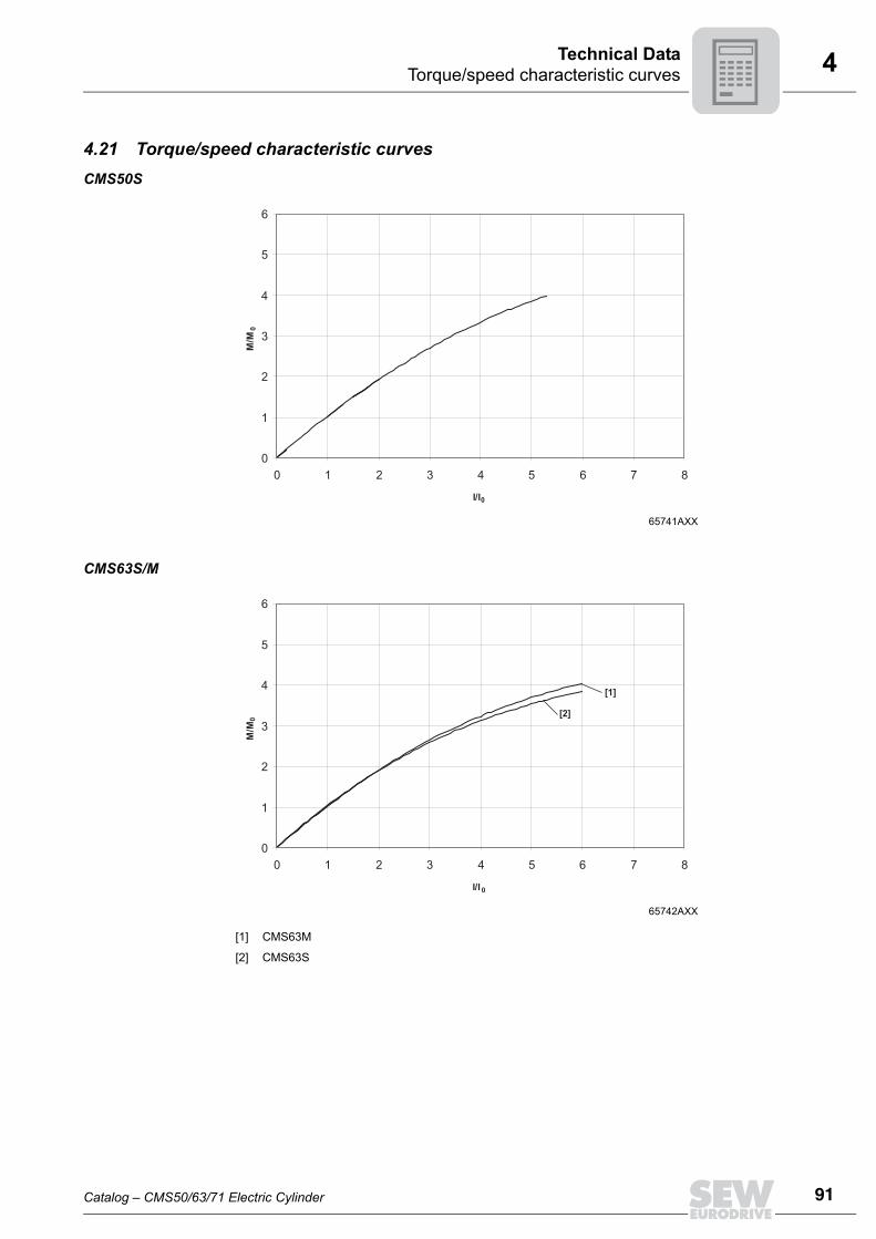
4Torque/speed characteristic curvesTechnical Data
4.21 Torque/speed characteristic curvesCMS50S
CMS63S/M
65741AXX
0
1
2
3
4
5
6
0 1 2 3 4 5 6 7 8
I/I
M/M
0
0
65742AXX
[1] CMS63M
[2] CMS63S
0
1
2
3
4
5
6
0 1 2 3 4 5 6 7 8
I/I
M/M
0
0
[1]
[2]
Catalog – CMS50/63/71 Electric Cylinder
91
92
4 orque/speed characteristic curvesechnical Data
CMS71
65742AXX
0
0.5
1
1.5
2
2.5
3
3.5
4
4.5
0 1 2 3 4 5 6
M/M
0
I/I0
TT
Catalog – CMS50/63/71 Electric Cylinder

4Dynamic limit torqueTechnical Data
4.22 Dynamic limit torque4.22.1 CMS50S
4.22.2 CMS63S
61404AXX
[1] Rated speed 3000 min-1
[2] Rated speed 4500 min-1
[3] Rated speed 6000 min-1
0
1
2
3
4
5
0 1000 2000 3000 4000 5000
n [min-1]
M [N
m] [2]
[1]
[3]
65744AXXx
[1] Rated speed 3000 min-1
[2] Rated speed 4500 min-1
[2] Rated speed 6000 min-1
0
2
4
6
8
10
0 1000 2000 3000 4000 5000 6000 7000
[2]
n [min-1]
M[N
m]
[1]
[3]
Catalog – CMS50/63/71 Electric Cylinder
93
94
4 ynamic limit torqueechnical Data
000000
4.22.3 CMS63M
4.22.4 CMS71L
65745AXXx
[1] Rated speed 3000 min-1
[2] Rated speed 4500 min-1
[2] Rated speed 6000 min-1
0
5
15
20
25
0 1000 2000 3000 4000 5000
[2][1]
n [min-1]
M[N
m] 11.1
[6]
65839AXX
[1] KGT / pitch 10 / stroke 200 mm / Fmax = 17 kN
[2] KGT / pitch 6 / stroke 200 mm / Fmax = 20 kN
[3] KGT / pitch 6 / stroke 350 mm / Fmax = 15 kN
[4] KGT / pitch 5 / stroke 200 mm / Fmax = 20 kN
0
5
10
35
0 100015002250
203045
333500750
66710001500
133320003000
166725003750
n [min-1]
M[N
m]
24.422.1
16.6
31.4 [1]
[4][2]
[3]
DT
Catalog – CMS50/63/71 Electric Cylinder

4Thermal limit torqueTechnical Data
Effe
ctiv
e m
otor
torq
ue [N
m]
4.23 Thermal limit torque4.23.1 CMS50S Spindle type KGT15x5, pitch 5 mm/revolution
65729AEN
[1] 20 °C ambient temperature
[2] 40 °C ambient temperature
0
200
400
600
800
1000
1200
1400
0 200 400 600 800 1000 1200 1400 1600 1800 2000 2200
[1]
[2]
Thermally permitted feed force
0.0
0.16
0.32
0.48
0.64
0.8
0.96
1.12
Perm
itted
effe
ctiv
e fe
ed fo
rce
[N]
0.0830 0.166Average velocity [m/s]
-1
5
Average speed [min ]
Catalog – CMS50/63/71 Electric Cylinder
95
96
4 hermal limit torqueechnical Data
4.23.2 CMS63SSpindle type KGT25x6, pitch 6 mm/revolution
65688AEN
[1] Water cooling, 20 °C ambient temperature
[2] Water cooling, 40 °C ambient temperature
[3] 20 °C ambient temperature
[4] 40 °C ambient temperature
0.00.20.40.60.81.01.21.41.61.82.02.22.42.62.83.03.2
N
500
1000
1500
2000
2500
3000
3500
0 5 500 1000 1500 2000 2500
Effe
ctiv
e fe
ed fo
rce
[N]
Thermally permitted feed forceAverage velocity [m/s]
[1]
[4]
[3]
[2]
Effe
ctiv
e m
otor
torq
ue [N
m]
-1 Average speed [min ]
0.1 0.15 0.2 0.05 0 0.25
TT
Catalog – CMS50/63/71 Electric Cylinder

4Thermal limit torqueTechnical Data
4.23.3 CMS63MSpindle type KGT25x6, pitch 6 mm/revolution
65693AEN
[1] Water cooling, 20 °C ambient temperature
[2] Water cooling, 40 °C ambient temperature
[3] 20 °C ambient temperature
[4] 40 °C ambient temperature
0.00.40.81.21.62.02.42.83.23.64.04.44.85.25.6
N
1000
2000
3000
4000
5000
6000
0 500 1000 1500 2000 2500
Effe
ctiv
e fe
ed fo
rce
[N]
Thermally permitted feed force
0.1 0.15 0.2 0.05 0 0.25 m/s
[1]
[4]
[2]
[3]
5
Effe
ctiv
e m
otor
torq
ue [N
m]
Average speed [min ]-1
Average velocity [m/s]
Catalog – CMS50/63/71 Electric Cylinder
97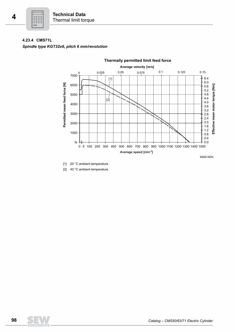
98
4 hermal limit torqueechnical Data
4.23.4 CMS71L Spindle type KGT32x6, pitch 6 mm/revolution
65691AEN
[1] 20 °C ambient temperature
[2] 40 °C ambient temperature
0.00.40.81.21.62.02.42.83.23.64.04.44.85.25.66.06.4
N
1000
2000
3000
4000
5000
6000
7000
0 100 200 300 400 500 600 700 800 900 1000 1100 1200 1300 1400 1500
0.05 0.025 0.1 0.15 0.075 0.125
Perm
itted
mea
n fe
ed fo
rce
[N]
Thermally permitted limit feed forceAverage velocity [m/s]
[1]
[2]
Effe
ctiv
e m
ean
mot
or to
rque
[Nm
]
0
Average speed [min ]
5-1
TT
Catalog – CMS50/63/71 Electric Cylinder

4Thermal limit torqueTechnical Data
Spindle type KGT32x10, pitch 10 mm/revolution
Spindle type PGT25x5, pitch 5 mm/revolution
60348AEN
0
500
1000
1500
2000
2500
3000
3500
4000
4500
0 200 400 600 800 1000 1200 1400
[1]
[2]
0.1 0.2
Effe
ctiv
e m
otor
torq
ue [N
m]
0.0
0.8
1.6
2.4
3.2
4.0
4.8
5.6
6.4
Perm
itted
effe
ctiv
e fe
ed fo
rce
[N]
Mean feed rate [m/s]
0.03 0.06 0.13 0.16 0.23 0.25
Average speed [min ]-1
5
[1] 20 °C ambient temperature [2] 40 °C ambient temperature
60196AEN
500
1500
2500
3500
4500
5500
6500
7500
8000
0 200 400 600 800 1000 1200 1400 1500
0.016
[1][2]
Mean feed rate [m/s]
0.033 0.05 0.066 0.083 0.1 0.117 0.12
Perm
itted
effe
ctiv
e fe
ed fo
rce
[N]
0.4
1.2
2.0
2.8
3.6
4.4
5.2
6.0
6.4
Effe
ctiv
e m
otor
torq
ue [N
m]
Average speed [min ]-1
5
[1] 20 °C ambient temperature [2] 40 °C ambient temperature
Catalog – CMS50/63/71 Electric Cylinder
99
100
4 OVIDRIVE® assignment tableechnical Data
4.24 MOVIDRIVE® assignment tableThe electric cylinders can be operated in conjunction with the MOVIDRIVE® MDX61Bservo inverter from SEW-EURODRIVE.
4.24.1 CMS50SOverview of combinations for CMS50S with KGT spindle – Spindle pitch 5 mm
4.24.2 CMS63S/MOverview of combinations for CMS63S with KGT spindle – Spindle pitch 6 mm
Overview of combinations for CMS63M with KGT spindle – Spindle pitch 6 mm
Rated speed MOVIDRIVE® MDX61B 400 V system voltage peak forces
[min-1] 0005 0008 0011 0014 0015 0022 0030 0040 0055 0075 0110 0150
3000 5000 5300 5300 5300 5300 - - - - - - -
4500 3900 4600 5300 5300 5300 - - - - - - -
6000 2600 3150 4050 5250 3950 5300 -- - - - - -
Rated speed MOVIDRIVE® MDX61B 400 V system voltage peak forces
[min-1] 0005 0008 0011 0014 0015 0022 0030 0040 0055 0075 0110 0150
3000 4900 5600 6880 8200 6700 8300 9500 100001)
1) Only permitted with current limit
- - - -
4500 3600 4241 5278 6410 5090 6600 7728 9330 10462 - - -
6000 1828 2139 2742 3656 2742 3770 4798 6512 8568 100001) - -
Rated speed MOVIDRIVE® MDX61B 400 V system voltage peak forces
[min-1] 0005 0008 0011 0014 0015 0022 0030 0040 0055 0075 0110 0150
3000 5660 6690 8390 10461 8200 10650 - - - - - -
4500 3676 4400 5840 7350 5655 7540 9330 100001)
1) Only permitted with current limit
- - - -
6000 1992 2390 2988 3984 2988 4108 5229 7096 9337 100001) - -
MT
Catalog – CMS50/63/71 Electric Cylinder

4MOVIDRIVE® assignment tableTechnical Data
Overview of combinations for CMS63S with PGT spindle – Spindle pitch 5 mm
Overview of combinations for CMS63M with PGT spindle – Spindle pitch 5 mm
4.24.3 CMS71LOverview of combinations for CMS71L with PGT spindle – Spindle pitch 5 mm
Overview of combinations for CMS71L with KGT spindle – Spindle pitch 6 mm
Overview of combinations for CMS71L with KGT spindle – Spindle pitch 10 mm
Rated speed MOVIDRIVE® MDX61B 400 V system voltage peak forces
[min-1] 0005 0008 0011 0014 0015 0022 0030 0040 0055 0075 0110 0150
3000 3460 4152 5190 6920 5190 7136 9082 100001)
1) Only permitted with current limit
- -
4500 2439 2926 3658 4878 3658 5030 6402 8689 100001) - -
6000 1900 2290 2861 3815 2861 3934 5007 6796 8941 100001) - -
Rated speed MOVIDRIVE® MDX61B 400 V system voltage peak forces
[min-1] 0005 0008 0011 0014 0015 0022 0030 0040 0055 0075 0110 0150
3000 3984 4780 5976 7968 5976 8217 100001)
1) Only permitted with current limit
- - - - -
4500 2656 3187 3984 5312 3984 5478 6972 9462 100001) - - -
6000 2078 2494 3117 4157 3117 4287 5456 7405 9743 100001) - -
Rated speed MOVIDRIVE® MDX61B 400 V system voltage peak forces
[min-1] 0005 0008 0011 0014 0015 0022 0030 0040 0055 0075 0110 0150
2000 - 100001)
1) Only permitted with current limit
13600 17300 13200 17800 20000 20000 20000 20000 - -
3000 - - 9300 11900 9000 12300 15500 20000 20000 20000 - -
4500 - - - - - 8000 10100 13700 17700 20000 - -
Rated speed MOVIDRIVE® MDX61B 400 V system voltage peak forces
[min-1] 0005 0008 0011 0014 0015 0022 0030 0040 0055 0075 0110 0150
2000 7040 8450 10900 14090 10560 14530 18490 20000 20000 20000 20000 -
3000 4735 5680 7330 9470 7100 9760 12429 16850 20000 20000 20000 -
4500 3110 3738 4828 6230 4670 6420 8177 11097 14600 18690 20000 -
Rated speed MOVIDRIVE® MDX61B 400 V system voltage peak forces
[1/min] 0005 0008 0011 0014 0015 0022 0030 0040 0055 0075 0110 0150
2000 - 6100 7800 100001)
1) Only permitted with current limit
7600 10200 12700 16000 17000 17000 17000 -
3000 - - 5300 6800 5200 7100 8900 11800 14800 17000 17000 -
4500 - - - - - 4600 5800 7900 10200 12700 17000 -
Catalog – CMS50/63/71 Electric Cylinder
101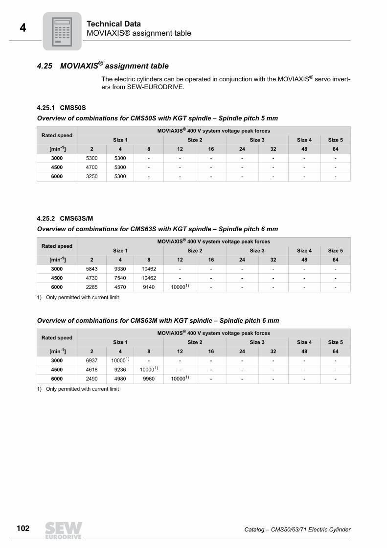
102
4 OVIAXIS® assignment tableechnical Data
4.25 MOVIAXIS® assignment tableThe electric cylinders can be operated in conjunction with the MOVIAXIS® servo invert-ers from SEW-EURODRIVE.
4.25.1 CMS50SOverview of combinations for CMS50S with KGT spindle – Spindle pitch 5 mm
4.25.2 CMS63S/MOverview of combinations for CMS63S with KGT spindle – Spindle pitch 6 mm
Overview of combinations for CMS63M with KGT spindle – Spindle pitch 6 mm
Rated speedMOVIAXIS® 400 V system voltage peak forces
Size 1 Size 2 Size 3 Size 4 Size 5
[min-1] 2 4 8 12 16 24 32 48 64
3000 5300 5300 - - - - - - -
4500 4700 5300 - - - - - - -
6000 3250 5300 - - - - - - -
Rated speedMOVIAXIS® 400 V system voltage peak forces
Size 1 Size 2 Size 3 Size 4 Size 5
[min-1] 2 4 8 12 16 24 32 48 64
3000 5843 9330 10462 - - - - - -
4500 4730 7540 10462 - - - - - -
6000 2285 4570 9140 100001)
1) Only permitted with current limit
- - - - -
Rated speedMOVIAXIS® 400 V system voltage peak forces
Size 1 Size 2 Size 3 Size 4 Size 5
[min-1] 2 4 8 12 16 24 32 48 64
3000 6937 100001)
1) Only permitted with current limit
- - - - - - -
4500 4618 9236 100001) - - - - - -
6000 2490 4980 9960 100001) - - - - -
MT
Catalog – CMS50/63/71 Electric Cylinder

4MOVIAXIS® assignment tableTechnical Data
Overview of combinations for CMS63S with PGT spindle – Spindle pitch 5 mm
Overview of combinations for CMS63M with PGT spindle – Spindle pitch 5 mm
4.25.3 CMS71LOverview of combinations for CMS71L with PGT spindle – Spindle pitch 5 mm
Overview of combinations for CMS71L with KGT spindle – Spindle pitch 6 mm
Overview of combinations for CMS71L with KGT spindle – Spindle pitch 10 mm
Rated speedMOVIAXIS® 400 V system voltage peak forces
Size 1 Size 2 Size 3 Size 4 Size 5
[min-1] 2 4 8 12 16 24 32 48 64
3000 4325 8650 100001) - - - - - -
4500 3048 6097 100001) - - - - - -
6000 2384 4768 9537 100001)
1) Only permitted with current limit
- - - - -
Rated speedMOVIAXIS® 400 V system voltage peak forces
Size 1 Size 2 Size 3 Size 4 Size 5
[min-1] 2 4 8 12 16 24 32 48 64
3000 4980 9960 100001)
1) Only permitted with current limit
- - - - - -
4500 3320 6640 100001) - - - - - -
6000 2598 5196 10393 100001) - - - - -
Rated speedMOVIAXIS® 400 V system voltage peak forces
Size 1 Size 2 Size 3 Size 4 Size 5
[min-1] 2 4 8 12 16 24 32 48 64
2000 11000 20000 20000 - - - - - -
3000 7400 14900 20000 - - - - - -
4500 4800 9800 18800 20000 - - - - -
Rated speedMOVIAXIS® 400 V system voltage peak forces
Size 1 Size 2 Size 3 Size 4 Size 5
[min-1] 2 4 8 12 16 24 32 48 64
2000 8800 17615 20000 - - - - - -
3000 5910 11830 20000 - - - - - -
4500 3890 7787 15570 20000 - - - - -
Rated speedMOVIAXIS® 400 V system voltage peak forces
Size 1 Size 2 Size 3 Size 4 Size 5
[min-1] 2 4 8 12 16 24 32 48 64
2000 6300 12000 17000 - - - - - -
3000 4200 8600 15400 17000 - - - - -
4500 2700 5600 10800 15000 17000 - - - -
Catalog – CMS50/63/71 Electric Cylinder
103
104
5 escriptionrefabricated Cables
5 Prefabricated Cables5.1 Description
SEW-EURODRIVE offers pre-fabricated cables with plugs for straightforward and reli-able motor connection. Cable and contact are connected using the crimp technique. The following cables areavailable in 1 m steps:• Motor cable• Brakemotor cable• Cable for resolver/motor protection• Cable for absolute encoder/motor protection• Forced cooling fan cable
Prefabricated cables are divided into:• Power cables (motor cable, brakemotor cable, extension cable) • feedback cables (resolver cable, encoder cable, extension cable).
Preselection of cablesPrefabricated cables were preselected by SEW-EURODRIVE according to the standardEN 60204. The routing types "fixed installation" and "cable carrier installation" were con-sidered. Using other standards for the machine construction can result in diverging cross sec-tions.
DP
Catalog – CMS50/63/71 Electric Cylinder
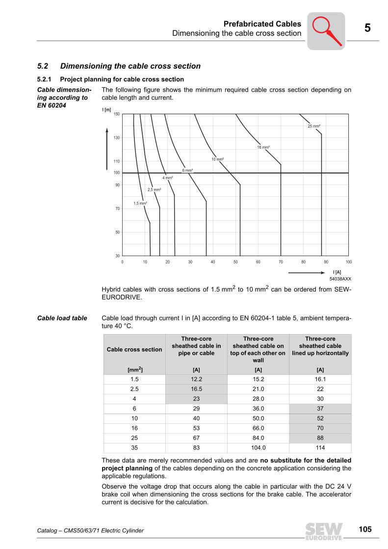
5Dimensioning the cable cross sectionPrefabricated Cables
5.2 Dimensioning the cable cross section5.2.1 Project planning for cable cross sectionCable dimension-ing according to EN 60204
The following figure shows the minimum required cable cross section depending oncable length and current.
Hybrid cables with cross sections of 1.5 mm2 to 10 mm2 can be ordered from SEW-EURODRIVE.
Cable load table Cable load through current I in [A] according to EN 60204-1 table 5, ambient tempera-ture 40 °C.
These data are merely recommended values and are no substitute for the detailedproject planning of the cables depending on the concrete application considering theapplicable regulations.Observe the voltage drop that occurs along the cable in particular with the DC 24 Vbrake coil when dimensioning the cross sections for the brake cable. The acceleratorcurrent is decisive for the calculation.
54038AXX
30
50
70
90
110
130
150
0 10 20 30 40 50 60 70 80 90 100
1,5 mm²
2,5 mm²
4 mm²
6 mm²
10 mm²
16 mm²
25 mm²
I [A]
l [m]
100
Cable cross section
Three-core sheathed cable in
pipe or cable
Three-core sheathed cable on
top of each other on wall
Three-core sheathed cable
lined up horizontally
[mm2] [A] [A] [A]
1.5 12.2 15.2 16.1
2.5 16.5 21.0 22
4 23 28.0 30
6 29 36.0 37
10 40 50.0 52
16 53 66.0 70
25 67 84.0 88
35 83 104.0 114
Catalog – CMS50/63/71 Electric Cylinder
105
106
5 ssignment table for cables and CMS electric cylindersrefabricated Cables
5.3 Assignment table for cables and CMS electric cylinders5.3.1 Servomotors/servo brakemotors
The following table is used to select power cables for CMS electric cylinders with 400 Vsystem voltage.The values in the following table are based on the values with a gray background in the"cable load table" on the previous page.The part numbers refer to the smallest connector that can be used:• 1.5 mm2 - 4 mm2: S.1
Type Speed To cable lengths
Cable part no.Core cross
section
To cable lengths
Cable part no.Core cross
sectionFixed
installation
Cable car-rier instal-
lation
Fixed installa-
tion
Cable car-rier instal-
lation
[min-1] [m]Stand-alone motor
Stand-alone motor
[mm2] [m] Brake-motor
Brake-motor [mm2]
CMS50S 3000 100 05904544 05906245 1.5 100 13354345 13354388 1.5
CMS50S 4500 100 05904544 05906245 1.5 100 13354345 13354388 1.5
CMS50S 6000 100 05904544 05906245 1.5 100 13354345 13354388 1.5
CMS63S 3000 100 05904544 05906245 1.5 100 13354345 13354388 1.5
CMS63S 4500 100 05904544 05906245 1.5 100 13354345 13354388 1.5
CMS63S 6000 100 05904544 05906245 1.5 100 13354345 13354388 1.5
CMS63M 3000 100 05904544 05906245 1.5 100 13354345 13354388 1.5
CMS63M 4500 100 05904544 05906245 1.5 100 13354345 13354388 1.5
CMS63M 6000 100 05904544 05906245 1.5 100 13354345 13354388 1.5
CMS71L 2000 100 05904544 05906245 1.5 100 13354345 13354388 1.5
CMS71L 3000 100 05904544 05906245 1.5 100 13354345 13354388 1.5
CMS71L 4500 100 05904544 05906245 1.5 100 13354345 13354388 1.5
AP
Catalog – CMS50/63/71 Electric Cylinder

5Structure of the prefabricated cables for CMS electric cylindersPrefabricated Cables
5.4 Structure of the prefabricated cables for CMS electric cylinders5.4.1 Motor cable/brakemotor cable
Motor side The power cables on the motor side consist of an 8-pin plug connector and socket con-tacts.The shield is connected in the connector housing according to EMC requirements. Allplug connectors seal the plug on the cable end with a lamellar seal and ensure cablerelief according to EN 61884.
Prefabrication on inverter end
The individual cable cores of the motor and brakemotor cables are exposed and theshield is prepared for connection in the control cabinet. The cable for the inverter endstill has to be prefabricated. The loose parts required are supplied with the cable in aseparate bag.
Loose parts The following loose parts are supplied in accordance with the core cross sections forconnection to the power terminals on the inverter:
54069AXX
[1][2][3][4]
[5]
[6]
Connector: Intercontec BSTA 078SEW-EURODRIVE logo printed on cableNameplateLine length ≤ 10 m: Tolerance +200 mm.Line length ≥ 10 m: Tolerance +2%.Permitted line length according to the technical documents.Pre-fabricated cable end for inverter.Required loose parts are supplied with the cable.Shielding pulled back approx. 20 mm +5 mm.
X
[1]
[2]
500 ±5 [3]
[4]
[5]
[6]
Bag no. Content
1 4 x conductor end sleeves 1.5 mm2, insulated4 x M6 U-shaped cable lugs 1.5 mm2
2 4 x conductor end sleeves 2.5 mm2, insulated4 x M6 U-shaped cable lugs 2.5 mm2
3 4 x conductor end sleeves 4 mm2, insulated4 x M6 U-shaped cable lugs 4 mm2
Catalog – CMS50/63/71 Electric Cylinder
107
108
5 tructure of the prefabricated cables for CMS electric cylindersrefabricated Cables
5.4.2 Feedback cable
Motor side A 12-pin EMC signal plug connector from Intercontec with socket contacts is used onthe motor end for RH.M / AS1H / ES1H. The shield is connected in the connector hous-ing according to EMC requirements. All plug connectors seal the plug on the cable endwith a lamellar seal.
Prefabrication on inverter end
A commercial D-sub EMC connector with pin contacts is used on the inverter end. A9-pin or 15-pin connector matching the inverter is used.
Hybrid cables The outer cable sheath on the motor and inverter end bears a nameplate with part num-ber and logo of the prefabricated cable manufacturer. The ordered length and permittedtolerance are interrelated as follows:• Line length ≤ 10 m: Tolerance 200 mm.• Line length ≥ 10 m: + 2 % tolerance.
54635AXX
[1][2][3][4]
[5]
Connector: Intercontec ASTA Printed on connector: SEW-EURODRIVENameplateLine length ≤ 10 m: Tolerance +200 mmLine length ≥ 10 m: Tolerance +2%Permitted line length according to the technical documents.D-sub plug
[1]
[2]
[4]
[5]
[3]
X
Y
INFORMATIONRefer to the system manual of the inverter for determining the maximum cable length.Make sure that an EMC-compliant environment is maintained during project planning.
SP
Catalog – CMS50/63/71 Electric Cylinder

5Power cablePrefabricated Cables
5.5 Power cable5.5.1 Motor cableCMS motor cable
CMS motor cable types
Pin assignment of the CMS motor cable
54619AXX
X
Plug connector type Number of cores and line cross section Part number Installation
SM 11 4 × 1.5 mm2 0590 4544 Fixed installation
SM 11 4 × 1.5 mm2 0590 6245 Cable carrierinstallation
SM12 4 × 2.5 mm2 0590 4552 Fixed installation
SM12 4 × 2.5 mm2 0590 6253 Cable carrierinstallation
SM14 4 × 4 mm2 0590 4560 Fixed installation
SM14 4 × 4 mm2 0590 4803 Cable carrierinstallation
Plug connector view X Pin Cable core color Assigned Extra
BSTA 078 1 (BK) Black U
Bag of loose parts
2 (GN/YE) Green/Yellow PE
3 (BK) Black star
4 (BK) Black V
W1
V1
U1
PE
1
2
3
4
D
C
A
B
Catalog – CMS50/63/71 Electric Cylinder
109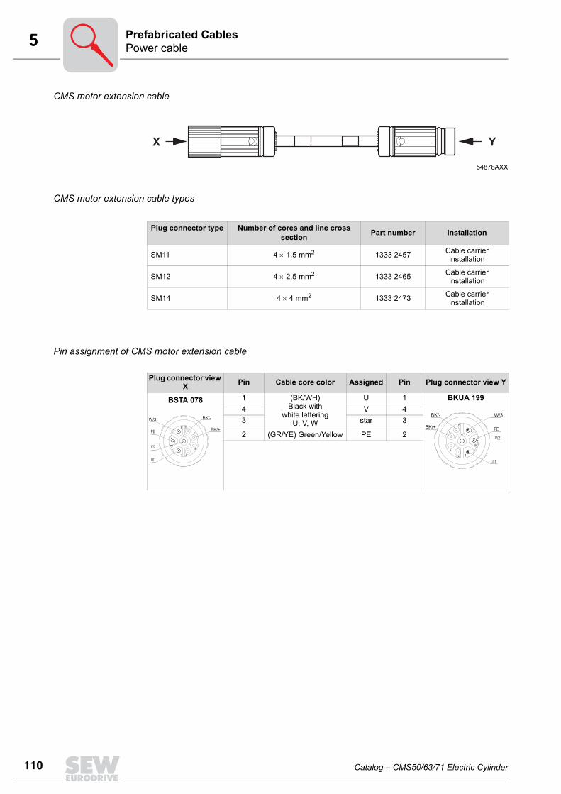
110
5 ower cablerefabricated Cables
CMS motor extension cable
CMS motor extension cable types
Pin assignment of CMS motor extension cable
54878AXX
X Y
Plug connector type Number of cores and line cross section Part number Installation
SM11 4 × 1.5 mm2 1333 2457 Cable carrierinstallation
SM12 4 × 2.5 mm2 1333 2465 Cable carrierinstallation
SM14 4 × 4 mm2 1333 2473 Cable carrierinstallation
Plug connector view X Pin Cable core color Assigned Pin Plug connector view Y
BSTA 078 1 (BK/WH)Black with
white letteringU, V, W
U 1 BKUA 1994 V 43 star 3
2 (GR/YE) Green/Yellow PE 2V/2
U/1
PE
1
2
3
4
D
C
A
B
W/3 BK/-
BK/+
V/2
U/1
PE
1
2
34
D
C
A
B
W/3 BK/-
BK/+
PP
Catalog – CMS50/63/71 Electric Cylinder

5Power cablePrefabricated Cables
5.5.2 Brakemotor cableCMS brakemotor cable
CMS brakemotor cable types
Pin assignment of CMS brakemotor cable
54620AXX
500 ±
5
X
Plug connector type Number of cores and line cross section Part number Installation
SB 11 4 × 1.5 mm2 + 2 × 1 mm2 1335 4345 Fixed installation
SB 11 4 × 1.5 mm2 + 2 × 1 mm2 1335 4388 Cable carrierinstallation
SB12 4 × 2.5 mm2 + 2 × 1 mm2 1335 4353 Fixed installation
SB12 4 × 2.5 mm2 + 2 × 1 mm2 1335 4396 Cable carrierinstallation
SB14 4 × 4 mm2 + 2 × 1 mm2 1335 4361 Fixed installation
SB14 4 × 4 mm2 + 2 × 1 mm2 1342 1603 Cable carrierinstallation
Plug connector view X Pin Cable core color Assigned Extra
BSTA 078 1(BK/WH) Black with
white lettering U, V, W
U
Bag of loose parts
4 V
3 star
2 (GN/YE) Green/Yellow PE
A - n. c.
B - 2.
C (BK/WH) Black with white lettering
1
D 3
W1
PE
V1
U1
BK/+
BK/-
1
2
3
4
D
C
B
A
INFORMATIONThe current part numbers are derived from the previous part numbers of the DS56 mo-tor. You can continue to use the old numbers, but note the deviating assignment of thecontacts C and D.The polarity of the connection is irrelevant for the BP brake. For the BS brake of theCMS71L, the polarity must be correct.
Catalog – CMS50/63/71 Electric Cylinder
111
112
5 ower cablerefabricated Cables
CMS brakemotor extension cable
CMS brakemotor extension cable types
Pin assignment of the CMS brakemotor extension cable
54878AXX
X Y
Plug connector type Number of cores and line cross section Part number Installation
SB11 4 × 1.5 mm2 + 2 × 1 mm2 1333 2481 Cable carrierinstallation
SM12 4 × 2.5 mm2 + 2 × 1 mm2 1333 2503 Cable carrierinstallation
SM14 4 × 4 mm2 + 2 × 1 mm2 1333 2511 Cable carrierinstallation
Plug connector view X Pin Cable core color Assigned Pin Plug connector view Y
BSTA 078 1 (BK/WH)Black with
white letteringU, V, W
U 1 BKUA 1994 V 43 star 3
2 (GN/YE) Green/Yellow PE 2A - n. c. AB - 2. BC (BK/WH) Black with
white lettering1 C
D 3 D
V/2
U/1
PE
1
2
3
4
D
C
A
B
W/3 BK/-
BK/+
V/2
U/1
PE
1
2
34
D
C
A
B
W/3 BK/-
BK/+
INFORMATIONThe current part numbers are derived from the previous part numbers of the DS56 mo-tor. You can continue to use the old numbers, but note the deviating assignment of thecontacts C and D.The polarity of the connection is irrelevant for the BP brake. For the BS brake of theCMS71L, the polarity must be correct.
PP
Catalog – CMS50/63/71 Electric Cylinder

5Encoder cablesPrefabricated Cables
5.6 Encoder cables5.6.1 ResolverResolver cable RH.M for MOVIDRIVE® MDX60B/61B
Resolver cable types RH.M for MOVIDRIVE® MDX60B/61B
Pin assignment for resolver cable RH.M for MOVIDRIVE® MDX60B/61B
54704AXX
X
Y
Type Number of cores and line cross section Part number Installation
CMS 5 × 2 × 0.25 mm2 0199 4875 Fixed installation
CMS 5 × 2 × 0.25 mm2 0199 3194 Cable carrier installation
Motor connection side MOVIDRIVE®B connection
Plug connector view X Pin no. Description Cable core color Description Pin no. Plug connec-
tor view Y
ASTA 021FR
198 921 9
12-pin with socket contacts
1 R1 (reference +) (PK) Pink R1 (reference +) 3
D-sub
9-pin
2 R2 (reference -) (GY) Gray R2 (reference -) 8
3 S1 (cosine +) (RD) Red S1 (cosine +) 2
4 S3 (cosine -) (BU) Blue S3 (cosine -) 7
5 S2 (sine +) (YE) Yellow S2 (sine +) 1
6 S4 (sine -) (GN) Green S4 (sine -) 6
7 n. c. - - -
8 n. c. - - -
9 TF/KTY + (BN) Brown/(VT) Violet1) TF (KTY+) 9
10 TF/KTY - (WH) White/(BK) Black1) TF/KTY - 5
11 n. c. - - -
12 n. c. - n. c. 4
1) Double assignment to increase cross section
98 1
2
10
11
E12
3
45
6
7
59
61
Catalog – CMS50/63/71 Electric Cylinder
113
114
5 ncoder cablesrefabricated Cables
RH.M resolver cable for MOVIAXIS® MX
RH.M resolver cable tables for MOVIAXIS® MX
Pin assignment of RH.M resolver cable for MOVIAXIS® MX
All connectors are shown with view onto the pins.
54629AXX
X
Y
Type Number of cores and line cross section Part number Installation
CMS 5 × 2 × 0.25 mm2 1332 7429 Fixed installation
CMS 5 × 2 × 0.25 mm2 1332 7437 Cable carrier installation
Motor connection side Connection MOVIAXIS® MXPlug connector
view X Pin no. Description Cable core color Description Pin no. Plug connec-tor view Y
ASTA 021FR
198 921 9
12-pin with socket contacts
1 R1 (reference +) (PK) Pink R1 (reference +) 5
D-sub
15-pin
2 R2 (reference -) (GY) Gray R2 (reference -) 133 S1 (cosine +) (RD) Red S1 (cosine +) 24 S3 (cosine -) (BU) Blue S3 (cosine -) 105 S2 (sine +) (YE) Yellow S2 (sine +) 16 S4 (sine -) (GN) Green S4 (sine -) 97 n. c. - n. c. 38 n. c. - n. c. 49 TF/KTY + (BN) Brown/(VT) Violet1) TF/KTY + 14
10 TF/KTY - (WH) White/(BK) Black1) TF/KTY - 611 n. c. - n. c. 712 n. c. - n. c. 8
- - n. c. 11- - n. c. 12- - n. c. 15
1) Double assignment to increase cross section
98 1
2
10
11
E12
3
45
6
7
815
91
EP
Catalog – CMS50/63/71 Electric Cylinder

5Encoder cablesPrefabricated Cables
Extension cable for RH.M resolver
Extension cable types for RH.M resolver
Pin assignment of extension cable for resolver RH.M
The extension cable has the same pin assignment as all other contacts.
54630AXX
X Y
Type Number of cores and line cross section Part number Installation
CMS 5 × 2 × 0.25 mm2 0199 5421 Fixed installation
CMS 5 × 2 × 0.25 mm2 0199 5413 Cable carrier installation
Plug connector view X Pin no. Description Cable core color Description Pin no. Plug connector
view Y
ASTA 021FR
198 673 2
12-pin with socket contacts
1 R1 (reference +)
(PK) Pink R1 (reference +)
1
AKUA 020MR
199 647 9
12-pin with pin contacts
2 R1 (reference -) (GY) Gray R1 (reference -) 2
3 S1 (cosine +) (RD) Red S1 (cosine +) 3
4 S3 (cosine -) (BU) Blue S3 (cosine -) 4
5 S2 (sine +) (YE) Yellow S2 (sine +) 5
6 S4 (sine -) (GN) Green S4 (sine -) 6
7 n. c. - n. c. 7
8 n. c. - n. c. 8
9 TF/KTY + (BN) Brown/(VT) Violet1) TF/KTY + 9
10 TF/KTY - (WH) White/(BK) Black1) TF/KTY - 10
11 n. c. - n. c. 11
12 n. c. - n. c. 12
1) Double assignment to increase cross section
98 1
2
10
11
E12
3
45
6
7
P
Catalog – CMS50/63/71 Electric Cylinder
115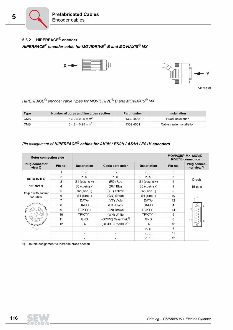
116
5 ncoder cablesrefabricated Cables
5.6.2 HIPERFACE® encoderHIPERFACE® encoder cable for MOVIDRIVE® B and MOVIAXIS® MX
HIPERFACE® encoder cable types for MOVIDRIVE® B and MOVIAXIS® MX
Pin assignment of HIPERFACE® cables for AK0H / EK0H / AS1H / ES1H encoders
54629AXX
X
Y
Type Number of cores and line cross section Part number Installation
CMS 6 × 2 × 0.25 mm2 1332 4535 Fixed installation
CMS 6 × 2 × 0.25 mm2 1332 4551 Cable carrier installation
Motor connection side MOVIAXIS® MX, MOVID-RIVE®B connection
Plug connector view X Pin no. Description Cable core color Description Pin no. Plug connec-
tor view Y
ASTA 021FR
198 921 9
12-pin with socket contacts
1 n. c. n. c. n. c. 3
D-sub
15-pole
2 n. c. n. c. n. c. 53 S1 (cosine +) (RD) Red S1 (cosine +) 14 S3 (cosine -) (BU) Blue S3 (cosine -) 95 S2 (sine +) (YE) Yellow S2 (sine +) 26 S4 (sine -) (GN) Green S4 (sine -) 107 DATA- (VT) Violet DATA- 128 DATA+ (BK) Black DATA+ 49 TF/KTY + (BN) Brown TF/KTY + 14
10 TF/KTY - (WH) White TF/KTY - 611 GND (GY/PK) Gray/Pink1) GND 812 Us (RD/BU) Red/Blue1) Us 15
- - n. c. 7- - n. c. 11- - n. c. 13
1) Double assignment to increase cross section
98 1
2
10
11
E12
3
45
6
7
815
91
EP
Catalog – CMS50/63/71 Electric Cylinder

5Encoder cablesPrefabricated Cables
Extension cable for HIPERFACE® AK0H / EK0H / AS1H / ES1H encoders
Extension cable types for HIPERFACE® AK0H / EK0H / AS1H / ES1H encoders
Pin assignment for extension cables for HIPERFACE® AK0H / EK0H / AS1H / ES1H encoders
The extension cable has the same pin assignment as all other contacts.
54634AXX
X Y
Type Number of cores and line cross section Part number Installation
CMS 6 × 2 × 0.25 mm2 0199 5391 Fixed installation
CMS 6 × 2 × 0.25 mm2 0199 5405 Cable carrier installation
Plug connector view X Pin no. Description Cable core color Description Pin no. Plug connector
view Y
ASTA 021FR
198 673 2
12-pin with socket contacts
1 n. c. - n. c. 1
AKUA 020MR
199 647 9
12-pin with pin contacts
2 n. c. - n. c. 2
3 S1 (cosine +) (RD) Red S1 (cosine +) 3
4 S3 (cosine -) (BU) Blue S3 (cosine -) 4
5 S2 (sine +) (YE) Yellow S2 (sine +) 5
6 S4 (sine -) (GN) Green S4 (sine -) 6
7 DATA- (VT) Violet DATA- 7
8 DATA+ (BK) Black DATA+ 8
9 TF/KTY + (BN) Brown TF/KTY + 9
10 TF/KTY - (WH) White TF/KTY - 10
11 GND (GY/PK) Gray/Pink / (PK) Pink GND 11
12 Us (RD/BU) Red/Blue / (GY) Gray Us 12
98 1
2
10
11
E12
3
45
6
7P
Catalog – CMS50/63/71 Electric Cylinder
117
118
5 ating connector combinationrefabricated Cables
5.7 Mating connector combination5.7.1 Power cable
* The complete connector service pack always includes the following parts:• Power connector• Insulation inserts• Socket contacts
Cable type Connec-tor type
Cable cross section Part number
[mm2] Prefabricated cables
Replacement power connector*
Fixed installation
Motor cable
SM11 4 x 1.5 mm2 0590 4544 0198 6740
SM12 4 x 2.5 mm2 0590 4552 0198 6740
SM14 4 x 4 mm2 0590 4560 0199 1639
SM11 4 x 1.5 mm2 (SpeedTEC) - 1335 4698
SM12 4 x 2.5 mm2 (SpeedTEC) - 1335 4698
SM14 4 x 4 mm2 (SpeedTEC) - 1335 4264
Brakemotor cable1)
1) BP brake: 3-core cable, only 2 cores are used
SB11 4 x 1.5 mm2 + 2 x 1 mm2 1335 4345 0198 6740
SB12 4 x 2.5 mm2 + 2 x 1 mm2 1335 4353 0198 6740
SB14 4 x 4 mm2 + 2 x 1 mm2 1335 4361 0199 1639
SB11 4 x 1.5 mm2 + 2 x 1 mm2 (SpeedTec) - 1335 4698
SB12 4 x 2.5 mm2 + 2 x 1 mm2 (SpeedTec) - 1335 4698
SB14 4 x 4 mm2 + 2 x 1 mm2 (SpeedTec) - 1335 4264
Cable carrier installation
Motor cable
SM11 4 x 1.5 mm2 0590 6245 0198 6740
SM12 4 x 2.5 mm2 0590 6253 0198 9197
SM14 4 x 4 mm2 0590 4803 0199 1639
SM11 4 x 1.5 mm2 (SpeedTec) - 1335 4698
SM12 4 x 2.5 mm2 (SpeedTec) - 1335 4256
SM14 4 x 4 mm2 (SpeedTec) - 1335 4264
Brakemotor cable1)
SB11 4 x 1.5 mm2 + 2 x 1 mm2 1335 4388 0198 9197
SB12 4 x 2.5 mm2 + 2 x 1 mm2 1335 4396 0198 9197
SB14 4 x 4 mm2 + 2 x 1 mm2 1342 1603 0199 1639
SB11 4 x 1.5 mm2 + 2 x 1 mm2 (SpeedTec) - 1335 4256
SB12 4 x 2.5 mm2 + 2 x 1 mm2 (SpeedTec) - 1335 4256
SM14 4 x 4 mm2 + 2 x 1 mm2 (SpeedTec) - 1335 4264
MP
Catalog – CMS50/63/71 Electric Cylinder

5Mating connector combinationPrefabricated Cables
5.7.2 Encoder cable
* The complete connector service pack always includes the following parts:• Power connector• Insulation inserts• Socket contacts
Cable type Cable cross-section [mm2] FI type
Part number
Prefabricated cables
Replacement signal connector*
Fixed installation
Resolver cable
5 x 2 x 0.25 mm2 MOVIDRIVE® 0199 48750198 6732
MOVIAXIS® 1332 7429
5 x 2 x 0.25 mm2 (SpeedTec)
MOVIDRIVE® -1644 7115
MOVIAXIS® -
Cable carrier installation
5 x 2 x 0.25 mm2 MOVIDRIVE® 0199 31940198 6732
MOVIAXIS® 1332 7437
5 x 2 x 0.25 mm2 (SpeedTec)
MOVIDRIVE® -1644 7115
MOVIAXIS® -
Fixed installation
Hiperface cable
6 x 2 x 0.25 mm2 MOVIDRIVE® / MOVIAXIS® 1332 4535 0198 6732
6 x 2 x 0.25 mm2 (SpeedTec)
MOVIDRIVE® / MOVIAXIS® - 1644 7115
Cable carrier installation
6 x 2 x 0.25 mm2 MOVIDRIVE® / MOVIAXIS® 1332 4551 0198 6732
6 x 2 x 0.25 mm2 (SpeedTec)
MOVIDRIVE® / MOVIAXIS® - 1644 7115
Catalog – CMS50/63/71 Electric Cylinder
119
120
5 orced cooling fan cablerefabricated Cables
5.8 Forced cooling fan cableCable for motors with VR forced cooling fan
Cable types for motors with VR forced cooling fan
Pin assignment of cables for motors with VR forced cooling fan
Alternative connector for cable for the VR forced cooling fanSignal plug connector with socket contacts (complete)
54649AXX
[1][2][3][4]
Connector: STAK 200Printed on connector: SEW-EURODRIVENameplateLine length ≤ 5 m: Tolerance +200 mmLine length ≥ 5 m: Tolerance +2%Permitted line length according to the technical documents.
[4]
[1] [2] [3][3]
X
Type Cross section Installation Part number
CMS3 × 1 mm2 (AWG 18)
Fixed installation 0198 6341
CMS Cable carrier installation 0199 560X
STAK 200 plug connector view X Pin Core
identification Assigned Pin Connection type
Connector with two socket contacts
1 Digit 1 24 V + Cut-off, length ca. 250 mm
Conductor end sleeves2 Digit 2 0 V
Type Cross sections that can be connected
Installation Part number
VR 3 x 1 mm2 (AWG 18) Fixed installation / cable car-rier installation 0198 4985
FP
Catalog – CMS50/63/71 Electric Cylinder

5Forced cooling fan cablePrefabricated Cables
Extension cable for motors with VR forced cooling fan
Extension cable types for motors with VR forced cooling fan
Pin assignment of extension cables for motors with VR forced cooling fan
The extension cable has the same pin assignment as all other contacts.
Alternative connector for cable for the VR forced cooling fanSignal plug connector with pin contacts (complete)
54646AXX
[1][2][3][4]
[5]
Connector: STAS 200Printed on connector: SEW-EURODRIVENameplateLine length ≤ 5 m: Tolerance +200 mmLine length ≥ 5 m: Tolerance +2%Permitted line length according to the technical documents.Socket: STAK 200
X Y
[4]
[1] [2] [5][3] [3]
Type Cross section Installation Part number
CMS3 × 1 mm2 (AWG 18)
Fixed installation 0199 5618
CMS Cable carrier installation 0199 5626
STAS 200 plug connector view X Pin Core
identification Assigned Pin STAK 200 connection type view Y
Connector with two pin contacts
1 Digit 1 24 V + 1 Connector with two socket contacts2 Digit 2 0 V 2
Type Cross sections that can be connected Part no.
VR 3 x 1 mm2 0198 5693
Catalog – CMS50/63/71 Electric Cylinder
121
122
5 able specifications for CMS power cablesrefabricated Cables
5.9 Cable specifications for CMS power cables5.9.1 Fixed installationMotor cable
Installation Fixed
Cable cross sections 4 x 1.5 mm2 4 x 2.5 mm2 4 x 4 mm2 4 x 6 mm2 4 x 10 mm2
(AWG 16) (AWG 14) (AWG 12) (AWG 10) (AWG 8)
Manufacturer HELUKABEL
Manufacturer designation LI9YCY
Operating voltage U0 / U AC [V] 600 / 1000
Temperature range [°C] Fixed installation -40 to +80
Max. temperature [°C] +80
Min. bending radius [mm] 45 55 65 73 85
Diameter D [mm] 9.0 ±0.2 11 ±0.2 13 ±0.2 14.3 ±0.3 17.0 ±0.6
Core identification BK with lettering WH + GN/YE
Sheath color Orange, similar to RAL 2003
Approval(s) DESINA/VDE/UL
Capacitance core/shielding [nF/km] 110 110 118 125 125
Capacitance core / core [nF/km] 70 70 75 80 80
Halogen-free no
silicon-free yes
CFC-free yes
Inner insulation (core) PP
Outer insulation (sheath) PVC
Flame-retardant/self-extinguishing no
Conductor material Cu
Shielding Tinned Cu
Weight (cable) [kg/km] 134 202 262 332 601
CP
Catalog – CMS50/63/71 Electric Cylinder

5Cable specifications for CMS power cablesPrefabricated Cables
Brakemotor cable
Installation Fixed
Cable cross sections 4 x 1.5 mm2 (AWG 16)
+ 3 x 1 mm2
(AWG 18)
4 x 2.5 mm2
(AWG 14) +
3 x 1 mm2
(AWG 18)
4 x 4 mm2
(AWG 12)+
3 x 1 mm2
(AWG 18)
4 x 6 mm2
(AWG 10)+
3 x 1.5 mm2
(AWG 16)
4 x 10 mm2
(AWG 8)+
3 x 1.5 mm2
(AWG 16)
Manufacturer HELUKABEL
Manufacturer designation LI9YCY
Operating voltage U0 / U AC [V] 600 / 1000
Temperature range [°C] Fixed installation: -40 to +80
Max. temperature [°C] +80
Min. bending radius [mm] 60 68 75 85 100
Diameter D [mm] 11.8 ±0.4 13.4 ±0.4 15.0 ±0.5 17.0 ±0.6 20.0 ±1.0
Core identification BK with lettering WH + GN/YE
Sheath color Orange similar to RAL 2003
Approval(s) DESINA/VDE/UL
Capacitance core/shielding [nF/km] 105 105 110 115 120
Capacitance core / core [nF/km] 60 60 70 75 78
Halogen-free no
silicon-free yes
CFC-free yes
Inner insulation (core) PP
Outer insulation (sheath) PVC
Flame-retardant/self-extinguishing yes
Conductor material Cu
Shielding Tinned Cu
Weight (cable) [kg/km] 229 292 393 542 938
Catalog – CMS50/63/71 Electric Cylinder
123
124
5 able specifications for CMS power cablesrefabricated Cables
5.9.2 Cable carrier installationMotor cable
Installation Cable-carrier
Cable cross sections 4 x 1.5 mm2 4 x 2.5 mm2 4 x 4 mm2 4 x 6 mm2 4 x 10 mm2
(AWG 16) (AWG 14) (AWG 12) (AWG 10) (AWG 8)
Manufacturer Nexans
Manufacturer designation PSL(LC)C11Y-J 4 x - mm2 PSL11YC11Y-J 4 x - mm2
Operating voltage U0 / U AC [V] 600 / 1000
Temperature range [°C] -20 to +60
Max. temperature [°C] +90 (on conductor)
Min. bending radius [mm] 134 140 135 155 180
Diameter D [mm] 12.8 +0.6 / -0.7
15.7 ±0.3 13.2 ±0.4 15.4 ±0.4 17.8 ±0.5
Maximum acceleration [m/s2] 20
Max. velocity [m/min] 200 at max. travel distance of 5 m
Core identification BK with lettering WH + GN/YE
Sheath color Orange similar to RAL 2003
Approval(s) DESINA/VDE/UL/cRUus
Capacitance core/shielding [nF/km] 95 95 170 170 170
Capacitance core / core [nF/km] 65 65 95 95 95
Halogen-free yes
silicon-free yes
CFC-free yes
Inner insulation (core) Polyolefin TPM
Outer insulation (sheath) TPU (PUR)
Flame-retardant/self-extinguishing yes
Conductor material E-Cu blank
Shielding Braided tinned Cu shield (optically covered > 85 %)
Weight (cable) [kg/km] 249 373 311 426 644
Min. bending cycles ≥ 5 million
CP
Catalog – CMS50/63/71 Electric Cylinder

5Cable specifications for CMS power cablesPrefabricated Cables
Brakemotor cable
Installation Cable-carrier
Cable cross sections 4 x 1.5 mm2 (AWG 16)
+ 3 x 1 mm2
(AWG 18)
4 x 2.5 mm2
(AWG 14) +
3 x 1 mm2
(AWG 18)
4 x 4 mm2
(AWG 12)+
3 x 1 mm2
(AWG 18)
4 x 6 mm2
(AWG 10)+
3 x 1.5 mm2
(AWG 16)
4 x 10 mm2
(AWG 8)+
3 x 1.5 mm2
(AWG 16)
Manufacturer Nexans
Manufacturer designation PSL(LC)C11Y-J 4x... +3A.../C PSL11YC11Y-J 4x... +3A.../C
Operating voltage U0 / U AC [V] 600 / 1000
Temperature range [°C] -20 to +60
Max. temperature [°C] +90 (conductor)
Min. bending radius [mm] 159 170 155 175 200
Diameter D [mm] 15.0 ±0.9 16.5 ±0.7 15.3 ±0.5 17.4 ±0.5 20.5 ±0.5
Maximum acceleration [m/s2] 20
Max. velocity [m/min] 200 at max. travel distance of 5 m
Core identification BK with lettering WH + GN/YE
Sheath color Orange similar to RAL 2003
Approval(s) DESINA/VDE/UL/cRUus
Capacitance core/shielding [nF/km] 105 105 170 170 170
Capacitance core / core [nF/km] 65 65 95 95 95
Halogen-free yes
silicon-free yes
CFC-free yes
Inner insulation (cable) TPM
Outer insulation (sheath) Polyolefin TPU (PUR)
Flame-retardant/self-extinguishing yes
Conductor material E-Cu blank
Shielding Braided tinned Cu shield (optically covered > 85 %)
Weight (cable) [kg/km] 335 433 396 522 730
Min. bending cycles ≥ 5 million
Catalog – CMS50/63/71 Electric Cylinder
125
126
5 able specifications for encoder cablesrefabricated Cables
5.10 Cable specifications for encoder cables5.10.1 Fixed installation of feedback cables
Accessory designation AS1H / ES1H / AK0H RH.M Cable cross sections 6 x 2 x 0.25 mm2 5 x 2 x 0.25 mm2
Manufacturer HELUKABELManufacturer designation LI9YCYOperating voltage V0 / V AC [V] 230 / 350Temperature range [°C] Fixed installation -40 to +80Max. temperature [°C] + 80Min. bending radius [mm] 43 36.5Diameter D [mm] 8.6 ±0.2 7.3 ±0.2Core identification DIN 47 100Sheath color Green, similar to RAL 6018Approval(s) DESINA/VDE/ Capacitance core/shielding [nF/km] 110Capacitance core / core [nF/km] 70Halogen-free noSilicone-free yesCFC-free yesInner insulation (core) PPOuter insulation (sheath) PVCFlame-retardant/ self-extinguishing
no
Conductor material Cu blankShielding Braided tinned CuWeight (cable) [kg/km] 107 78
CP
Catalog – CMS50/63/71 Electric Cylinder

5Cable specifications for encoder cablesPrefabricated Cables
5.10.2 Cable carrier installation of feedback cables
Accessory designation AS1H / ES1H / AK0H RH.M Cable cross sections 6 x 2 x 0.25 mm2 5 x 2 x 0.25 mm2
Manufacturer NexansManufacturer designation SSL18YC11Y 6 x 2 x 0.25/ SSL11YC11Y 5 x 2 x 0.25Operating voltage V0 / V AC [V] 300Temperature range [°C] -20 to +60Max. temperature [°C] +90 (on conductor)Min. bending radius [mm] 100 95Diameter D [mm] 9.8 ±0.2 9.5 ±0.2Maximum acceleration [m/s2] 20Max. velocity [m/min] 200Core identification WH/BN, GN/YE, GY/PK, BU/RD,
BK/VT, GY-PK/RD-BUWH/BN, GN/YE, GY/PK,
BU/RD, BK/VTSheath color Green similar to RAL 6018Approval(s) DESINA/VDE/ Capacitance core/shielding [nF/km] 100Capacitance core / core [nF/km] 55Halogen-free yesSilicone-free yesCFC-free yes
Table continued on next pageInner insulation (core) PPOuter insulation (sheath) TPE-UFlame-retardant/ self-extinguishing
yes
Conductor material E-Cu blankShielding Braided tinned CuWeight [kg/km] 130 120Min. bending cycles ≥ 5 million
Catalog – CMS50/63/71 Electric Cylinder
127
128
5 able specification of forced cooling fan cables for CMS motorsrefabricated Cables
5.11 Cable specification of forced cooling fan cables for CMS motors5.11.1 Fixed installation of the forced cooling fan cable
Accessory designation VRCable cross sections 3 x 1 mm2
Manufacturer LappManufacturer designation Ölflex 110 ClassicOperating voltage V0 / V AC [V] 300 / 500Temperature range [°C] -30 to +70Max. temperature [°C] + 70Min. bending radius [mm] 24Diameter D [mm] 6.0 ±0.3Core identification VDE 0293Sheath color Silver gray, RAL 7001Approval(s) VDECapacitance core/shielding [nF/km] -Capacitance core/core [nF/km] -Halogen-free noSilicone-free yesCFC-free yesInner insulation (core) PVCOuter insulation (sheath) PVCFlame-retardant/self-extinguishing noConductor material Cu blankShielding -Weight (cable) [kg/km] 65
CP
Catalog – CMS50/63/71 Electric Cylinder
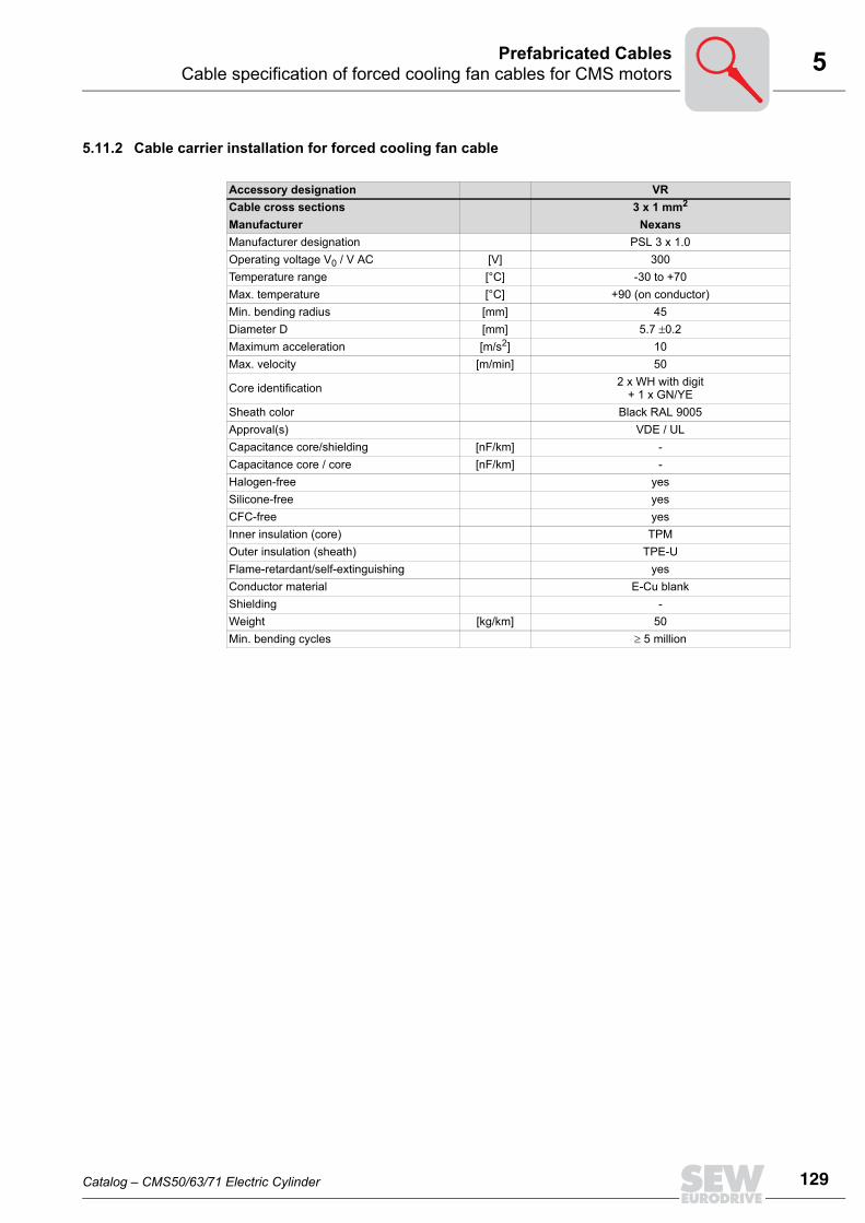
5Cable specification of forced cooling fan cables for CMS motorsPrefabricated Cables
5.11.2 Cable carrier installation for forced cooling fan cable
Accessory designation VRCable cross sections 3 x 1 mm2
Manufacturer NexansManufacturer designation PSL 3 x 1.0Operating voltage V0 / V AC [V] 300Temperature range [°C] -30 to +70Max. temperature [°C] +90 (on conductor)Min. bending radius [mm] 45Diameter D [mm] 5.7 ±0.2Maximum acceleration [m/s2] 10Max. velocity [m/min] 50
Core identification 2 x WH with digit + 1 x GN/YE
Sheath color Black RAL 9005Approval(s) VDE / ULCapacitance core/shielding [nF/km] -Capacitance core / core [nF/km] -Halogen-free yesSilicone-free yesCFC-free yesInner insulation (core) TPMOuter insulation (sheath) TPE-UFlame-retardant/self-extinguishing yesConductor material E-Cu blankShielding -Weight [kg/km] 50Min. bending cycles ≥ 5 million
Catalog – CMS50/63/71 Electric Cylinder
129
130
6 eneral maintenance workesign and Operating Notes
6 Design and Operating Notes6.1 General maintenance work
The electric cylinder is maintenance-free except for the threaded spindles. Replace de-fective parts, if possible. Remove any traces of dirt, chips, dust, etc. from the bellows (only CMS71L) with a softcloth.Note that mobile cables are subject to wear. They have to be checked for externalchanges on a regular basis.
6.2 Lubrication of screw driveThere may be a loss of lubricant between the nut and spindle in threaded spindles. Lu-bricants also decrease in quality and effectiveness with age and wear. This means lu-brication is required at regular intervals.Lubrication for screw drives has to be specified accurately in terms of type, quantity andrelubrication intervals. These factors are dependent on• Load• Velocity• Cyclic duration factor• Type of screw drive (recirculating ball screw or planetary roller screw drive)• Ambient temperature• Pollution degree caused by dust, humidity, etc.
Continuous relubrication (e.g. by connection to the lubrication system, see section 6.5)is generally preferable to relubrication at intervals.Relubrication at intervals is especially not recommended for planetary roller screws,which can require about 2.5 times more lubricant than recirculating ball screws.
INFORMATIONThe following information is intended as recommendation. It is not intended to replaceindividual project planning for every application.
GD
Catalog – CMS50/63/71 Electric Cylinder

6Lubrication of screw driveDesign and Operating Notes
6.2.1 General information
6.2.2 Size CMS50SA taper greasing nipple DIN71412 [1] for manual relubrication with a grease gun is in-stalled as standard on the spindle nut in the inside of the motor. You can access thegreasing nipple by way of screw plugs [1]; slowly move the drive until the lubricant posi-tion is visible (see section 4.15).
6.2.3 Size CMS63S/MThe CMS63 is equipped with oil bath lubrication that requires very little maintenance. Oillevel check, filling and draining via screw plug [1].
6.2.4 Size CMS71LA taper greasing nipple DIN71412 [1] for manual relubrication with a grease gun is in-stalled as standard on the motor.
INFORMATIONThe lubricating grease discharged into the electric cylinder accumulates in the insideof the drive. Used lubricant must be removed from the inside of the motor after fiveyears at the latest. Service work must be performed by SEW employees only. Duringservice work, the spindle must be removed from the unit and the old lubricant removedfrom the spindle’s surface.
65049AXX
[1]
65050AXX
[1]
65051AXX
[1]
Catalog – CMS50/63/71 Electric Cylinder
131
132
6 ubricant for recirculating ball screws and planetary roller screw drivesesign and Operating Notes
6.3 Lubricant for recirculating ball screws and planetary roller screw drivesCMS electric cylinders are filled with the lubricant Fuchs RENOLIT CX-TOM15 as stan-dard at the plant. It is used for recirculating ball screws and planetary roller screws.
The lubricating grease Renolit CX-TOM15 of the company Fuchs can be ordered fromSEW in a 400 g cartridge (DIN1284) under part no. 03207196.
The cartridge is suitable for grease guns in line with DIN1283 with adapter piece forDIN71412 grease nipples.
INFORMATIONOnly relubricate electric cylinders with the following lubricant: Fuchs RENOLIT CX-TOM15
65762AXX
65763AXX
LD
Catalog – CMS50/63/71 Electric Cylinder

6Relubrication intervaDesign and Operating Notes
6.4 Relubrication interval
6.4.1 CMS50S with ball screw (KGT):Example CMS50S, 5 mm (0.2 in)/spindle pitch revolution
• 0.15 m travel distance• Average traveling velocity 0.15 m/s • 1300 N load
Relubrication Relubrication quantity 1 cm3
• After a travel distance of 200 kmor• 20 million revolutions of the threaded spindle nut
STOP• The drive must generally be relubricated once a year.• The following information only applies to the application examples described.• Always use the appropriate amount of lubricant for the individual application.• If insufficient lubricant is applied, the lubricant film is disrupted and the service life
thereby reduced.• Excessive lubrication increases friction and results in heat generation.• When relubricating the drive, always pay attention to cleanliness.• There should be no dirt in the lubricant.• Wipe the greasing nipple with a cloth before applying the grease gun.• Make sure there is no trapped air in the lubricant or lubricant supply lines.
Catalog – CMS50/63/71 Electric Cylinder
l
133
134
6 elubrication intervalesign and Operating Notes
6.4.2 CMS71L with ball screw (KGT):Example CMS71L, 10 mm (0.2 in)/spindle pitch revolution
• 0.2 m travel distance• Average traveling velocity 0.2 m/s • 4000 N load
Permanent relubrication
0.8 cm3/100 km = 0.008 cm3/1 km
Relubrication intervals
Relubrication quantity 2 cm3
• After a travel distance of 250 kmor• 25 million revolutions of the threaded spindle nut
6.4.3 CMS71L with planetary roller screw drive (PGT):Example CMS71L, 5 mm (0.2 in)/spindle pitch revolution
• 0.2 m travel distance• Average traveling velocity 0.2 m/s • 4000 N load
Permanent relu-brication
2 cm3/100 km = 0.02 cm3/1 km
Relubrication interval (not recommended)
Relubrication quantity 2.5 cm3
• After a travel distance of 50 kmor• 10 million revolutions of the threaded spindle
RD
Catalog – CMS50/63/71 Electric Cylinder

6Lubricator – only for size CMS71LDesign and Operating Notes
6.5 Lubricator – only for size CMS71LOn request, the electric cylinder size CMS71L can be equipped with a lubricator. Thethreaded spindle nut is relubricated continuously with this option. The lubricator comprises a drive unit with an electric motor, which is supplied with powereither with a set of batteries (Vario lubrication system) or with 24 V and function moni-toring (Control lubrication system). This motor drains the lubricant container [1] via aplunger. The Control lubrication system is connected to a customer control device via acable (length 5 m, included in scope of delivery).The threaded elbow joints [3] are mounted, filled with lubricant and vented at the pro-duction plant.
61515AXX
[1] Lubricant container[2] Retaining clip[3] Threaded elbow joint
[1][2]
[3]
INFORMATIONThe time between lubrications is set to one year at the production plant and is sufficientfor normal applications. For cases with high annual operating time, e.g. 24 operating hours per day, consultSEW-EURODRIVE.
Catalog – CMS50/63/71 Electric Cylinder
135
136
6 ubricator – only for size CMS71Lesign and Operating Notes
6.5.1 Lubricator variantsStar Vario (SV) The Star Vario lubricator is powered by batteries, independent of the operating status of
the electric cylinder. When the electric cylinder is started up, the Star Vario lubricatormust be activated separately. Activate the lubricator by turning the rotary switch to theON position. After activation, the lubricator continuously supplies the set lubricantquantity.Star Vario divides the content of the lubricant container into several smaller dispensingcycles within the operating period. The factory setting of the lubricator is to dispense avolume of 60 cm3 over a period of 12 months.
Star Control Time (ST)The Star Control Time lubricator is connected to the voltage supply or controller via ca-ble. The lubricator continuously supplies the set lubricant quantity when the supplyvoltage (24 V) is connected. The status (function, fill level) of the lubricator can bemonitored via the controller. Star Control Time divides the content of the lubricant container into several smaller dis-pensing cycles within the operating period. The factory setting of the lubricator is to dis-pense a volume of 0.69 cm3 over a period of 100 operating hours.
Star Control Impulse (SI)The Star Control Impulse lubricator is connected to the voltage supply or controller viacable. The lubricator dispenses the set lubricant quantity in one amount when the sup-ply voltage (24 V) is connected. To dispense another amount of lubricant, the voltagemust be interrupted and connected again. The status (function, fill level) of the lubrica-tor can be monitored via the controller. The factory setting of the lubricator is to dispensea volume of 0.26 cm3 per impulse.
LD
Catalog – CMS50/63/71 Electric Cylinder
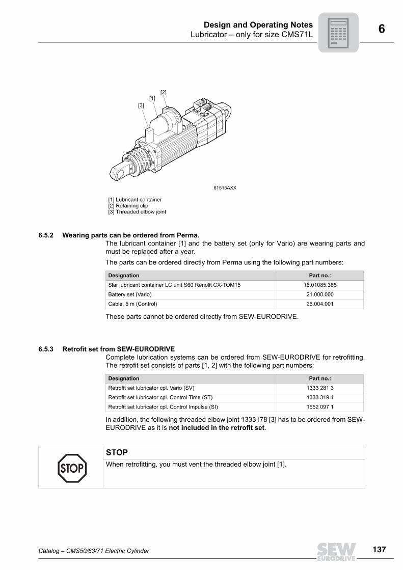
6Lubricator – only for size CMS71LDesign and Operating Notes
6.5.2 Wearing parts can be ordered from Perma.The lubricant container [1] and the battery set (only for Vario) are wearing parts andmust be replaced after a year.The parts can be ordered directly from Perma using the following part numbers:
These parts cannot be ordered directly from SEW-EURODRIVE.
6.5.3 Retrofit set from SEW-EURODRIVEComplete lubrication systems can be ordered from SEW-EURODRIVE for retrofitting.The retrofit set consists of parts [1, 2] with the following part numbers:
In addition, the following threaded elbow joint 1333178 [3] has to be ordered from SEW-EURODRIVE as it is not included in the retrofit set.
61515AXX
[1] Lubricant container[2] Retaining clip[3] Threaded elbow joint
[1][2]
[3]
Designation Part no.:
Star lubricant container LC unit S60 Renolit CX-TOM15 16.01085.385
Battery set (Vario) 21.000.000
Cable, 5 m (Control) 26.004.001
Designation Part no.:
Retrofit set lubricator cpl. Vario (SV) 1333 281 3
Retrofit set lubricator cpl. Control Time (ST) 1333 319 4
Retrofit set lubricator cpl. Control Impulse (SI) 1652 097 1
STOPWhen retrofitting, you must vent the threaded elbow joint [1].
Catalog – CMS50/63/71 Electric Cylinder
137
138
6 ealing airesign and Operating Notes
6.6 Sealing airAt the factory, the drive is equipped with a sealing air connection [1] thread G1/8 as stan-dard. Because of this, the electric cylinder can especially be used in dusty environments.To do this, the space within the bellows [2] can be placed under slight positive pressure(max. 0.5 bar ) The positive pressure prevents dust, etc., from entering into the motor.
The required compressed air volume flow (Vsealing air) depends on the travel velocity (v)of the screw drive.
This ensures that sufficient pressurized air flows in during extension and that no nega-tive pressure develops in the space [2].The pressurized air must be dry and free of oil, according to DIN-ISO 8573-1 class 3(common in pressurized air systems).
61004AXX
[1] Sealing air connection[2] Bellows
Vsealing air ≥ 300 vVolume flow Vsealing air [liters/min]
Travel speed v [m/s]
[1] [2]
SD
Catalog – CMS50/63/71 Electric Cylinder

6Filter ventilation not part of delivery from SEW – only CMS71Design and Operating Notes
6.7 Filter ventilation not part of delivery from SEW – only CMS71If the electric cylinder is used in dusty environments, you must make sure that no dustis sucked in through the vent [4] of the bellows in the joint during the lifting motion. There are two possibilities to do so:• Sealing air (see chapter 6.6)• Filter ventilation (no compressed air required)
For this purpose, a suitable filter [2] is installed at the sealing air connection [1] with G1/8thread. If there is not enough space, the filter can be connected to the electric cylindervia a hose [3]. Max. hose length 1 m, inner diameter > 9 mm.We recommend a filter of the company Argo-Hytos (http://www.argo-hytos.com), typeL1.0807-11. This is an inexpensive filter that is used to vent hydraulic containers of con-struction machines.It safely keeps back dust particles < 3 μm under very low pressure. Other filters, suchas pneumatic mufflers, sintered metal filters, etc., may not be used.In addition to this, the default ventilation via the joint must be sealed. The sealed jointcan be ordered under 'Option without bellows ventilation' or retrofitted using 2 x sealingelement [4], SEW part no. 13342093. Older versions are sealed with rubber.
65764AXX
[1] Sealing air connection[2] Filter[3] Hose[4] Sealing element[5] Joint
[2]
[1]
[3]
[4][5]
Catalog – CMS50/63/71 Electric Cylinder
139
140
7 Address DirectoryGermany
HeadquartersProductionSales
Bruchsal SEW-EURODRIVE GmbH & Co KGErnst-Blickle-Straße 42 D-76646 BruchsalP.O. BoxPostfach 3023 • D-76642 Bruchsal
Tel. +49 7251 75-0Fax +49 7251 75-1970http://[email protected]
Production Graben SEW-EURODRIVE GmbH & Co KGErnst-Blickle-Straße 1 D-76676 Graben-NeudorfP.O. BoxPostfach 1220 • D-76671 Graben-Neudorf
Tel. +49 7251 75-0Fax +49 7251 75-2970
Östringen SEW-EURODRIVE Östringen GmbHFranz-Gurk-Straße 2 D-76684 ÖstringenP.O. BoxPostfach 1174 • D-76677 Östringen
Tel. +49 7253 92540Fax +49 7253 [email protected]
Service Competence Center
Central SEW-EURODRIVE GmbH & Co KGErnst-Blickle-Straße 1 D-76676 Graben-Neudorf
Tel. +49 7251 75-1710Fax +49 7251 [email protected]
North SEW-EURODRIVE GmbH & Co KGAlte Ricklinger Straße 40-42 D-30823 Garbsen (near Hannover)
Tel. +49 5137 8798-30Fax +49 5137 [email protected]
East SEW-EURODRIVE GmbH & Co KGDänkritzer Weg 1D-08393 Meerane (near Zwickau)
Tel. +49 3764 7606-0Fax +49 3764 [email protected]
South SEW-EURODRIVE GmbH & Co KGDomagkstraße 5D-85551 Kirchheim (near München)
Tel. +49 89 909552-10Fax +49 89 [email protected]
West SEW-EURODRIVE GmbH & Co KGSiemensstraße 1D-40764 Langenfeld (near Düsseldorf)
Tel. +49 2173 8507-30Fax +49 2173 [email protected]
Electronics SEW-EURODRIVE GmbH & Co KGErnst-Blickle-Straße 42 D-76646 Bruchsal
Tel. +49 7251 75-1780Fax +49 7251 [email protected]
Drive Service Hotline / 24 Hour Service +49 180 5 SEWHELP+49 180 5 7394357
Technical Offices Augsburg SEW-EURODRIVE GmbH & Co KGAugust-Wessels-Straße 29D-86156 Augsburg
Tel. +49 821 22779-10Fax +49 821 [email protected]
Berlin SEW-EURODRIVE GmbH & Co KGLilienthalstraße 3a D-12529 Schönefeld
Tel. +49 306331131-0Fax +49 [email protected]
Bodensee SEW-EURODRIVE GmbH & Co KGBurgbergring 91D-88662 Überlingen
Tel. +49 7551 9226-30Fax +49 7551 [email protected]
Bremen SEW-EURODRIVE GmbH & Co KGBornstr.19 ... 22 D-28195 Bremen
Tel. +49 421 33918-10Fax +49 421 [email protected]
Dortmund SEW-EURODRIVE GmbH & Co KGHildastraße 10D-44145 Dortmund
Tel. +49 231 912050-10Fax +49 231 [email protected]
Dresden SEW-EURODRIVE GmbH & Co KGHauptstraße 32 D-01445 Radebeul
Tel. +49 351 26338-0Fax +49 351 [email protected]
11/2009

Erfurt SEW-EURODRIVE GmbH & Co KGDubliner Straße 12D-99091 Erfurt
Tel. +49 361 21709-70Fax +49 361 [email protected]
Güstrow SEW-EURODRIVE GmbH & Co KGAm Gewerbegrund 3D-18273 GüstrowP.O. BoxPostfach 1216 • D-18262 Güstrow
Tel. +49 3843 8557-80Fax +49 3843 [email protected]
Hamburg SEW-EURODRIVE GmbH & Co KGBramfelder Straße 119 D-22305 Hamburg
Tel. +49 40 298109-60Fax +49 40 [email protected]
Hannover/Garbsen
SEW-EURODRIVE GmbH & Co KGAlte Ricklinger Str.40-42 D-30823 GarbsenP.O. BoxPostfach 1104 53 • D-30804 Garbsen
Tel. +49 5137 8798-10Fax +49 5137 [email protected]
Heilbronn SEW-EURODRIVE GmbH & Co KGZeppelinstraße 7 D-74357 Bönnigheim
Tel. +49 7143 8738-0Fax +49 7143 [email protected]
Herford SEW-EURODRIVE GmbH & Co KGRadewiger Straße 21 D-32052 HerfordP.O. BoxPostfach 4108 • D-32025 Herford
Tel. +49 5221 9141-0Fax +49 5221 [email protected]
Karlsruhe SEW-EURODRIVE GmbH & Co KGEttlinger Weg 2 D-76467 Bietigheim P.O. BoxPostfach 43 • D-76463 Bietigheim
Tel. +49 7245 9190-10Fax +49 7245 [email protected]
Kassel SEW-EURODRIVE GmbH & Co KGLange Straße 14D-34253 Lohfelden
Tel. +49 561 95144-80Fax +49 561 [email protected]
Koblenz SEW-EURODRIVE GmbH & Co KGBahnstraße 17a D-56743 Mendig
Tel. +49 2652 9713-30Fax +49 2652 [email protected]
Lahr SEW-EURODRIVE GmbH & Co KG Europastraße 3/1D-77933 Lahr / Schwarzwald
Tel. +49 7821 90999-60Fax +49 7821 [email protected]
Langenfeld SEW-EURODRIVE GmbH & Co KG Siemensstraße 1 D-40764 Langenfeld
Tel. +49 2173 8507-10Fax +49 2173 [email protected]
Magdeburg SEW-EURODRIVE GmbH & Co KGBreiteweg 53D-39179 Barleben
Tel. +49 39203 7577-1Fax +49 39203 [email protected]
Mannheim SEW-EURODRIVE GmbH & Co KGRadeberger Straße 2 D-68309 Mannheim
Tel. +49 621 71683-10Fax +49 621 [email protected]
München SEW-EURODRIVE GmbH & Co KG Domagkstraße 5 D-85551 Kirchheim
Tel. +49 89 90955-110Fax +49 89 [email protected]
Münster SEW-EURODRIVE GmbH & Co KGHafenplatz 4D-48155 Münster
Tel. +49 251 41475-11Fax +49 251 [email protected]
Nürnberg SEW-EURODRIVE GmbH & Co KGPlattenäckerweg 6 D-90455 Nürnberg
Tel. +49 911 98884-50Fax +49 911 [email protected]
Germany
11/2009 141

142
Regensburg SEW-EURODRIVE GmbH & Co KGIm Gewerbepark A15 D-93059 Regensburg
Tel. +49 941 46668-68Fax +49 941 [email protected]
Rhein-Main SEW-EURODRIVE GmbH & Co KGNiederstedter Weg 5 D-61348 Bad Homburg
Tel. +49 6172 9617-0Fax +49 6172 [email protected]
Stuttgart SEW-EURODRIVE GmbH & Co KGFriedrich-List-Straße 46D-70771 Leinfelden-Echterdingen
Tel. +49 711 16072-0Fax +49 711 [email protected]
Ulm SEW-EURODRIVE GmbH & Co KGDieselstraße 14 D-89160 Dornstadt
Tel. +49 7348 9885-0 Fax +49 7348 [email protected]
Würzburg SEW-EURODRIVE GmbH & Co KGNürnbergerstraße 118D-97076 Würzburg-Lengfeld
Tel. +49 931 27886-60Fax +49 931 [email protected]
Zwickau / Meerane
SEW-EURODRIVE GmbH & Co KG Dänkritzer Weg1 D-08393 Meerane
Tel. +49 3764 7606-0Fax +49 3764 [email protected]
France
ProductionSalesService
Haguenau SEW-USOCOME 48-54 route de Soufflenheim B. P. 20185F-67506 Haguenau Cedex
Tel. +33 3 88 73 67 00 Fax +33 3 88 73 66 00http://[email protected]
Production Forbach SEW-EUROCOME Zone Industrielle Technopôle Forbach SudB. P. 30269F-57604 Forbach Cedex
Tel. +33 3 87 29 38 00
AssemblySalesService
Bordeaux SEW-USOCOME Parc d'activités de Magellan62 avenue de Magellan - B. P. 182F-33607 Pessac Cedex
Tel. +33 5 57 26 39 00Fax +33 5 57 26 39 09
Lyon SEW-USOCOME Parc d'Affaires RooseveltRue Jacques TatiF-69120 Vaulx en Velin
Tel. +33 4 72 15 37 00Fax +33 4 72 15 37 15
Paris SEW-USOCOME Zone industrielle 2 rue Denis Papin F-77390 Verneuil I'Etang
Tel. +33 1 64 42 40 80Fax +33 1 64 42 40 88
Technical Offices Alsace SEW-USOCOME1 rue Auguste GasserF-68360 Soultz
Tel. +33 3 89 74 51 62Fax +33 3 89 76 58 71
Aquitaine / Charentes
SEW-USOCOMEParc d'activités de Magellan 62 avenue de Magellan B. P. 182F-33607 Pessac Cedex
Tel. +33 5 57 26 39 00Fax +33 5 57 26 39 09
Auvergne / Limousin
SEW-USOCOME27 avenue du ColombierF-19150 Laguenne
Tel. +33 5 55 20 12 10Fax +33 5 55 20 12 11
Basse-Normandie
SEW-USOCOME5 rue de la LimareF-14250 Brouay
Tel. +33 2 31 37 92 86Fax +33 2 31 74 68 15
Germany
11/2009

Bourgogne SEW-USOCOME10 rue de la PosteF-71350 Saint Loup Géanges
Tel. +33 3 85 49 92 18Fax +33 3 85 49 92 19
Bretagne SEW-USOCOMELe bois FoucaudF-44270 Saint Même Le Tenu
Tel. +33 2 28 21 12 52Fax +33 2 28 21 12 84
Centre / Poitou SEW-USOCOME18 avenue André AmpèreAppartement 14F-37540 Saint Cyr sur Loire
Tel. +33 2 47 41 33 23Fax +33 2 47 41 34 03
Champagne-Ardenne
SEW-USOCOMEImpasse des OuisesF-10120 Saint André les Vergers
Tel. +33 3 25 79 63 24Fax +33 3 25 79 63 25
Franche-Comté SEW-USOCOME5 route de BesançonMaison BF-25870 Devecey
Tel. +33 3 81 60 20 47Fax +33 3 81 87 75 93
Ile-de-France est / Somme
SEW-USOCOME45 rue des CinellesF-77700 Bailly Romainvilliers
Tel. +33 1 64 17 02 47Fax +33 1 64 17 66 49
Ile-de-France nord / Picardie
SEW-USOCOME25bis rue KléberF-92300 Levallois Perret
Tel. +33 1 41 05 92 74Fax +33 1 41 05 92 75
Ile-de-France sud
SEW-USOCOME6 chemin des BergersLieu-dit MarchaisF-91410 Roinville sous Dourdan
Tel. +33 1 60 81 10 56Fax +33 1 60 81 10 57
Lorraine / Alsace nord
SEW-USOCOME1 rue de la ForêtF-54250 Champigneulles
Tel. +33 3 83 96 28 04Fax +33 3 83 96 28 07
Midi-Pyrénées / Roussillon
SEW-USOCOME179 route de GrazacF-31190 Caujac
Tel. +33 5 61 08 15 85Fax +33 5 61 08 16 44
Nord-Pas de Calais
SEW-USOCOME209 route d’HesdigneulF-62360 Hesdin l’Abbé
Tel. +33 3 21 10 86 86Fax +33 3 21 10 86 87
Paris / Ile-de-France ouest
SEW-USOCOME42 avenue Jean JaurèsF-78580 Maule
Tel. +33 1 30 90 89 86Fax +33 1 30 90 93 15
Pays de la Loire SEW-USOCOME4 rue des ChâtaigniersF-44830 Brains
Tel. +33 2 51 70 54 04Fax +33 2 51 70 54 05
Provence-Alpes-Côte d’Azur
SEW-USOCOMERésidence Les Hespérides Bât. B267 boulevard des AlpesF-13012 Marseille
Tel. +33 4 91 18 00 11Fax +33 4 91 18 00 12
Rhône-Alpes est SEW-USOCOMEMontée de la GarenneF-26750 Génissieux
Tel. +33 4 75 05 65 95Fax +33 4 75 05 65 96
Rhône-Alpes nord
SEW-USOCOMEParc d'Affaires RooseveltRue Jacques TatiF-69120 Vaulx en Velin
Tel. +33 4 72 15 37 03Fax +33 4 72 15 37 15
France
11/2009 143

144
Rhône-Alpes ouest
SEW-USOCOMEParc d'Affaires RooseveltRue Jacques TatiF-69120 Vaulx en Velin
Tel. +33 4 72 15 37 04Fax +33 4 72 15 37 15
Algeria
Sales Alger Réducom 16, rue des Frères ZaghnounBellevue El-Harrach16200 Alger
Tel. +213 21 8222-84Fax +213 21 [email protected]
Argentina
AssemblySalesService
Buenos Aires SEW EURODRIVE ARGENTINA S.A.Centro Industrial Garin, Lote 35Ruta Panamericana Km 37,51619 Garin
Tel. +54 3327 4572-84Fax +54 3327 [email protected]://www.sew-eurodrive.com.ar
Australia
AssemblySalesService
Melbourne SEW-EURODRIVE PTY. LTD.27 Beverage DriveTullamarine, Victoria 3043
Tel. +61 3 9933-1000Fax +61 3 9933-1003http://[email protected]
Sydney SEW-EURODRIVE PTY. LTD.9, Sleigh Place, Wetherill Park New South Wales, 2164
Tel. +61 2 9725-9900Fax +61 2 [email protected]
SalesService
Adelaide SEW-EURODRIVE PTY. LTD. 9C Park WayMawson Lakes, SA 5095
Tel. +61 8 8161 4000Fax +61 8 8161 [email protected]
Brisbane SEW-EURODRIVE PTY.LTD.1 /34 Collinsvale St Rocklea, Queensland, 4106
Tel. +61 7 3276 5100Fax +61 7 3276 [email protected]
Perth SEW-EURODRIVE PTY. LTD. 105 Robinson Avenue Belmont, W.A. 6104
Tel. +61 8 9478-2688Fax +61 8 [email protected]
Technical Office Townsville SEW-EURODRIVE PTY. LTD.12 Leyland StreetGarbutt, QLD 4814
Tel. +61 7 4779 4333Fax +61 7 4779 [email protected]
Austria
AssemblySalesService
Wien SEW-EURODRIVE Ges.m.b.H. Richard-Strauss-Strasse 24A-1230 Wien
Tel. +43 1 617 55 00-0Fax +43 1 617 55 00-30http://[email protected]
Technical Offices Linz SEW-EURODRIVE Ges.m.b.H. Reuchlinstr. 6/3A-4020 Linz
Tel. +43 732 655 109-0Fax +43 732 655 [email protected]
Graz SEW-EURODRIVE Ges.m.b.H.Grabenstraße 231A-8045 Graz
Tel. +43 316 685 756-0Fax +43 316 685 [email protected]
Dornbirn SEW-EURODRIVE Ges.m.b.H.Lustenauerstraße 27/1A-6850 Dornbirn
Tel. +43 5572 3799-0Fax +43 5572 3725 [email protected]
Bangladesh
Sales Dhaka Jainex Industrial and Engineering LtdB 12 Apon NibashEast NasirabadBangladesh
Tel. +880 1713103502Fax +880 31 [email protected]
France
11/2009

Belarus
Sales Minsk SEW-EURODRIVE BYRybalkoStr. 26BY-220033 Minsk
Tel.+375 (17) 298 38 50Fax +375 (17) 29838 [email protected]
Belgium
AssemblySalesService
Brüssel SEW Caron-VectorAvenue Eiffel 5B-1300 Wavre
Tel. +32 10 231-311Fax +32 10 231-336http://[email protected]
Service Competence Center
Industrial Gears SEW Caron-VectorRue de Parc Industriel, 31BE-6900 Marche-en-Famenne
Tel. +32 84 219-878Fax +32 84 219-879http://[email protected]
Antwerp SEW Caron-VectorGlasstraat, 19BE-2170 Merksem
Tel. +32 3 64 19 333Fax +32 3 64 19 336http://[email protected]
Brazil
ProductionSalesService
Sao Paulo SEW-EURODRIVE Brasil Ltda.Avenida Amâncio Gaiolli, 152 - Rodovia Presidente Dutra Km 208Guarulhos - 07251-250 - SPSAT - SEW ATENDE - 0800 7700496
Tel. +55 11 2489-9133Fax +55 11 2480-3328http://[email protected]
Bulgaria
Sales Sofia BEVER-DRIVE GmbHBogdanovetz Str.1BG-1606 Sofia
Tel. +359 2 9151160Fax +359 2 [email protected]
Cameroon
Sales Douala Electro-ServicesRue Drouot AkwaB.P. 2024Douala
Tel. +237 33 431137Fax +237 33 431137
Canada
AssemblySalesService
Toronto SEW-EURODRIVE CO. OF CANADA LTD. 210 Walker Drive Bramalea, ON L6T 3W1
Tel. +1 905 791-1553Fax +1 905 791-2999http://www.sew-eurodrive.cal.watson@sew- eurodrive.ca
Vancouver SEW-EURODRIVE CO. OF CANADA LTD.Tilbury Industrial Park7188 Honeyman Street Delta, BC V4G 1G1
Tel. +1 604 946-5535Fax +1 604 946-2513b.wake@sew- eurodrive.ca
Montreal SEW-EURODRIVE CO. OF CANADA LTD.2555 Rue Leger Lasalle, PQ H8N 2V9
Tel. +1 514 367-1124Fax +1 514 367-3677a.peluso@sew- eurodrive.ca
Additional addresses for service in Canada provided on request!
Chile
AssemblySalesService
Santiago de Chile
SEW-EURODRIVE CHILE LTDA.Las Encinas 1295Parque Industrial Valle GrandeLAMPARCH-Santiago de ChileP.O. BoxCasilla 23 Correo Quilicura - Santiago - Chile
Tel. +56 2 75770-00Fax +56 2 75770-01http://[email protected]
11/2009
145
146
China
ProductionAssemblySalesService
Tianjin SEW-EURODRIVE (Tianjin) Co., Ltd.No. 46, 7th Avenue, TEDATianjin 300457
Tel. +86 22 25322612Fax +86 22 [email protected]://www.sew-eurodrive.cn
AssemblySalesService
Suzhou SEW-EURODRIVE (Suzhou) Co., Ltd.333, Suhong Middle RoadSuzhou Industrial ParkJiangsu Province, 215021
Tel. +86 512 62581781Fax +86 512 [email protected]
Guangzhou SEW-EURODRIVE (Guangzhou) Co., Ltd.No. 9, JunDa RoadEast Section of GETDDGuangzhou 510530
Tel. +86 20 82267890Fax +86 20 [email protected]
Shenyang SEW-EURODRIVE (Shenyang) Co., Ltd.10A-2, 6th RoadShenyang Economic Technological Development AreaShenyang, 110141
Tel. +86 24 25382538Fax +86 24 [email protected]
Wuhan SEW-EURODRIVE (Wuhan) Co., Ltd.10A-2, 6th RoadNo. 59, the 4th Quanli Road, WEDA430056 Wuhan
Tel. +86 27 84478398Fax +86 27 84478388
Xi'An SEW-EURODRIVE (Xi'An) Co., Ltd.No. 12 Jinye 2nd RoadXi'An High-Technology Industrial Development ZoneXi'An 710065
Tel. +86 29 88241718Fax +86 29 [email protected]
Colombia
AssemblySalesService
Bogotá SEW-EURODRIVE COLOMBIA LTDA. Calle 22 No. 132-60Bodega 6, Manzana BSantafé de Bogotá
Tel. +57 1 54750-50Fax +57 1 54750-44http://[email protected]
Croatia
SalesService
Zagreb KOMPEKS d. o. o.PIT Erdödy 4 IIHR 10 000 Zagreb
Tel. +385 1 4613-158Fax +385 1 [email protected]
Czech Republic
Sales Praha SEW-EURODRIVE CZ S.R.O.Business Centrum Praha Lužná 591CZ-16000 Praha 6 - Vokovice
Tel. +420 255 709 601Fax +420 220 121 237http://[email protected]
Technical Offices Brno SEW-EURODRIVE CZ S.R.O.Křenová 52CZ -60200 Brno
Tel. +420 543 256 151 +420 543 256 163Fax +420 543 256 845
Hradec Králové SEW-EURODRIVE CZ S.R.O.Čechova 498CZ-50202 Hradec Králové
Tel. +420 495 510 141Fax +420 495 521 313
Plzeň SEW-EURODRIVE CZ S.R.O.Areal KRPA a.s.Zahradni 173/2CZ-32600 Plzeň
Tel. +420 378 775 300Fax +420 377 970 710
Ostrava SEW-EURODRIVE CZ S.R.O.Studenská 6202/17CZ-708 00 Ostrava-Poruba
Tel. +420 738 339 044Mobile +420 724 889 965
11/2009

Klatovy SEW-EURODRIVE CZ S.R.O.Technická kancelář KlatovyDomažlická 800CZ-33901 Klatovy
Tel. +420 376 310 729Fax +420 376 310 725
Denmark
AssemblySalesService
Kopenhagen SEW-EURODRIVEA/SGeminivej 28-30DK-2670 Greve
Tel. +45 43 9585-00Fax +45 43 9585-09http://[email protected]
Egypt
SalesService
Cairo Copam Egypt for Engineering & Agencies33 EI Hegaz ST, Heliopolis, Cairo
Tel. +20 2 22566-299 + 1 23143088Fax +20 2 22594-757http://www.copam-egypt.com/ [email protected]
Service Sharjah Copam Middle East (FZC) Sharjah Airport International Free ZoneP.O. Box 120709SharjahUnited Arabian Emirates
Tel. +971 6 5578-488Fax +971 6 [email protected]
Estonia
Sales Tallin ALAS-KUUL ASReti tee 4EE-75301 Peetri küla, Rae vald, Harjumaa
Tel. +372 6593230Fax +372 [email protected]
Finland
AssemblySalesService
Lahti SEW-EURODRIVE OYVesimäentie 4FIN-15860 Hollola 2
Tel. +358 201 589-300Fax +358 3 [email protected]://www.sew-eurodrive.fi
Technical Offices Helsinki SEW-EURODRIVE OYLuutnantintie 5FIN-00410 Helsinki
Tel. +358 201 589-300Fax + 358 9 [email protected]
Vaasa SEW-EURODRIVE OYHietasaarenkatu 18FIN-65100 Vaasa
Tel. +358 201 589-300Fax +358 6 [email protected]
Rovaniemi SEW-EURODRIVE OYValtakatu 4 AFIN-96100 Rovaniemi
Tel. +358 201 589-300Fax +358 201 [email protected]
ProductionAssembly
Karkkila SEW Industrial Gears OyValurinkatu 6, PL 8FI-03600 Karkkila, 03601 Karkkila
Tel. +358 201 589-300Fax +358 201 [email protected]://www.sew-eurodrive.fi
Gabon
Sales Libreville ESG Electro Services GabunFeu Rouge Lalala1889 LibrevilleGabun
Tel. +241 741059Fax +241 741059
Great Britain
AssemblySalesService
Normanton SEW-EURODRIVE Ltd.Beckbridge Industrial Estate P.O. Box No.1GB-Normanton, West- Yorkshire WF6 1QR
Tel. +44 1924 893-855Fax +44 1924 893-702http://[email protected]
Czech Republic
11/2009
147
148
Technical Offices London SEW-EURODRIVE Ltd.764 Finchely Road, Temple FortuneGB-London N.W.11 7TH
Tel. +44 20 8458-8949Fax +44 20 8458-7417
Midlands SEW-EURODRIVE Ltd.5 Sugar Brook court,Aston Road,Bromsgrove, WorcsB60 3EX
Tel. +44 1527 877-319Fax +44 1527 575-245
Scotland SEW-EURODRIVE Ltd.Scottish OfficeNo 37 Enterprise HouseSpringkerse Business ParkGB-Stirling FK7 7UF Scotland
Tel. +44 17 8647-8730Fax +44 17 8645-0223
Northern Ireland Heyn Engineering (NI) Ltd.1 Corry Place,Belfast, BT3 9AH
Tel. +44 02890350022Fax +44 [email protected]://www.heyn.co.uk
Greece
SalesService
Athen Christ. Boznos & Son S.A.12, Mavromichali StreetP.O. Box 80136, GR-18545 Piraeus
Tel. +30 2 1042 251-34 Fax +30 2 1042 251-59http://[email protected]
Technical Office Thessaloniki Christ. Boznos & Son S.A.Asklipiou 26562 24 Evosmos, Thessaloniki
Tel. +30 2 310 7054-00Fax +30 2 310 [email protected]
Hong Kong
AssemblySalesService
Hong Kong SEW-EURODRIVE LTD.Unit No. 801-806, 8th FloorHong Leong Industrial ComplexNo. 4, Wang Kwong Road Kowloon, Hong Kong
Tel. +852 36902200Fax +852 [email protected]
Hungary
SalesService
Budapest SEW-EURODRIVE Kft.H-1037 BudapestKunigunda u. 18
Tel. +36 1 437 06-58Fax +36 1 437 [email protected]
Iceland
Sales Reykjavik Vélaverk ehf.Bolholti 8, 3h.IS - 105 Reykjavik
Tel. +354 568 3536Fax +354 568 [email protected]
India
Registered OfficeAssemblySalesService
Vadodara SEW-EURODRIVE India Private LimitedPlot No. 4, GIDCPOR Ramangamdi • Vadodara - 391 243Gujarat
Tel. +91 265 3045200, +91 265 2831086Fax +91 265 3045300, +91 265 2831087http://[email protected]@seweurodriveindia.com
AssemblySalesService
Chennai SEW-EURODRIVE India Private LimitedPlot No. K3/1, Sipcot Industrial Park Phase IIMambakkam VillageSriperumbudur - 602105Kancheepuram Dist, Tamil Nadu
Tel. +91 44 37188888Fax +91 44 [email protected]
Great Britain
11/2009

Technical Offices Ahmedabad SEW-EURODRIVE India Private Limited306, Shaan office complex, Behind Sakar-IV,Ellisebridge, Ashram RoadAhmedabad – Gujarat
Tel. +91 79 40072067/68Fax +91 79 [email protected]
Bengaluru SEW-EURODRIVE India Private Limited308, Prestige Centre Point7, Edward RoadBengaluru - 560052 - Karnataka
Tel. +91 80 22266565Fax +91 80 [email protected]@seweurodriveindia.com
Chandigarh SEW EURODRIVE India Private LimitedSujit Kumar MishraH.No.5464/3 Modern Housing ComplexManimajraChandigarh -160101
Tel. +91 9878469579Fax +91 [email protected]
Chennai SEW-EURODRIVE India Private Limited2nd Floor, Josmans Complex,No. 5, McNichols Road,ChetpetChennai - 600031 - Tamil Nadu
Tel. +91 44 42849813Fax +91 44 [email protected]@seweurodriveindia.com
Coimbatore SEW-EURODRIVE India Private LimitedOffice No 60Arpee Centre (Opp Annapoorna Hotel)420 N, NSR Road, Saibaba ColonyCoimbatore 641 0111 - Tamil Nadu
Tel. +91 422 2455420Fax +91 422 [email protected]@seweurodriveindia.com
Cuttack SEW-EURODRIVE India Private LimitedPlot No.- 1764,Nuasahi, NayapalliBhubaneswar-12Orissa
Tel. +91 [email protected]
Hyderabad SEW-EURODRIVE India Private Limited408, 4th Floor, Meridian PlaceGreen Park RoadAmerpeetHyderabad - 500016 - Andhra Pradesh
Tel. +91 40 23414698Fax +91 40 [email protected]@seweurodriveindia.com
Jamshedpur SEW-EURODRIVE India Private LimitedFlat No.: B/2, B.S. ApartmentRoad No.: 4, Contractor’s area,BistupurJamshedpur 831 001 - Chhattisgarh
Tel. +91 [email protected]
Kolkata SEW EURODRIVE India Private Limited2nd floor, Room No. 35Chowringhee Court55, Chowringhee RoadKolkata - 700 071 - West Bengal
Tel. +91 33 22827457Fax +91 33 [email protected]@seweurodriveindia.com
Lucknow SEW-EURODRIVE India Private Limited69, Shiv Vihar ColonyVikas Nagar-5Lucknow 226022 - Uttar Pradesh
Tel. +91 [email protected]
Madgaon SEW-EURODRIVE India Private LimitedFlat No.-G1, Shivas-Laxmi Prasad Co-Operative Housing Society,Padmanarayan Estate,Near Jivottaam Math,Gagole Madgao, Goa - 403 602
India
11/2009
149
150
Mumbai SEW-EURODRIVE India Private Limited312 A, 3rd Floor, Acme Plaza, J.B. Nagar,Andheri Kurla Road, Andheri (E)Mumbai - 400059 - Maharashtra
Tel. +91 22 28348440Fax +91 22 [email protected]@seweurodriveindia.com
New Delhi SEW-EURODRIVE India Private Limited418-419, Suneja Tower-1District Centre, Janak PuriNew Delhi 110 058
Tel. +91 11 25544111Fax +91 11 [email protected]@seweurodriveindia.com
Pune SEW-EURODRIVE India Private LimitedLunawat Prism 4th floor, S. No. 148,Neena Co-Operative Housing Society, Paud Road,Pune 411038 - Maharashtra
Tel. +91 20 25380730 / 735Fax +91 20 [email protected]@seweurodriveindia.com
Raipur SEW-EURODRIVE India Private LimitedA-42, Ashoka Millenium Complex,Ring Road-1,Raipur 492 001 - Chhattisgarh
Tel. +91 771 4090765Fax +91 771 [email protected]
Indonesia
Represented by Singapore SEW-EURODRIVE PTE. LTD. No 9, Tuas Drive 2 Jurong Industrial Estate Singapore 638644
Tel. +65 68621701Fax +65 68612827http://[email protected]
Ireland
SalesService
Dublin Alperton Engineering Ltd. 48 Moyle RoadDublin Industrial EstateGlasnevin, Dublin 11
Tel. +353 1 830-6277Fax +353 1 [email protected]://www.alperton.ie
Israel
Sales Tel-Aviv Liraz Handasa Ltd. Ahofer Str 34B / 22858858 Holon
Tel. +972 3 5599511Fax +972 3 5599512http://[email protected]
Italy
AssemblySalesService
Milano SEW-EURODRIVE di R. Blickle & Co.s.a.s.Via Bernini,14 I-20020 Solaro (Milano)
Tel. +39 02 96 9801Fax +39 02 96 799781http://[email protected]
Technical Offices Bologna SEW-EURODRIVE di R. Blickle & Co.s.a.s. Via della Grafica, 47I-40064 Ozzano dell'Emilia (Bo)
Tel. +39 051 65-23-801Fax +39 051 796-595
Caserta SEW-EURODRIVE di R. Blickle & Co.s.a.s. Viale Carlo III Km. 23,300I-81020 S. Nicola la Strada (Caserta)
Tel. +39 0823 219011Fax +39 0823 421414
Pescara SEW-EURODRIVE di R. Blickle & Co.s.a.s. Viale Europa,132I-65010 Villa Raspa di Spoltore (PE)
Tel. +39 085 41-59-427Fax +39 085 41-59-643
Torino SEW-EURODRIVE di R. Blickle & Co.s.a.s. Filiale Torinoc.so Unione Sovietica 612/15 - int. CI-10135 Torino
Tel. +39 011 3473780Fax +39 011 3473783
Verona SEW-EURODRIVE di R. Blickle & Co.s.a.s. Via P. Sgulmero, 27/AI-37132 Verona
Tel. +39 045 89-239-11Fax +39 045 97-6079
India
11/2009

Ivory Coast
Sales Abidjan SICASte industrielle et commerciale pour l'Afrique165, Bld de MarseilleB.P. 2323, Abidjan 08
Tel. +225 2579-44Fax +225 2584-36
Japan
AssemblySalesService
Iwata SEW-EURODRIVE JAPAN CO., LTD 250-1, Shimoman-no,IwataShizuoka 438-0818
Tel. +81 538 373811Fax +81 538 373814http://[email protected]
Technical Offices Fukuoka SEW-EURODRIVE JAPAN CO., LTD.C-go, 5th-floor, Yakuin-Hiruzu-Bldg. 1-5-11, Yakuin, Chuo-kuFukuoka, 810-0022
Tel. +81 92 713-6955Fax +81 92 [email protected]
Osaka SEW-EURODRIVE JAPAN CO., LTD. Higobashi Shimizu Bldg. 10th flor1-3-7 Tosabori, Nishi-kuOsaka, 550-0001
Tel. +81 6 6444--8330Fax +81 6 [email protected]
Tokyo SEW-EURODRIVE JAPAN CO., LTD.Omarimon Yusen Bldg. 13th floor3-23-5 Nishinbashi, Minato-kuTokyo 105-0003
Tel. +81 3 3239-0469Fax +81 3 [email protected]
Korea
AssemblySalesService
Ansan-City SEW-EURODRIVE KOREA CO., LTD. B 601-4, Banweol Industrial Estate 1048-4, Shingil-DongAnsan 425-120
Tel. +82 31 492-8051Fax +82 31 492-8056http://[email protected]
Busan SEW-EURODRIVE KOREA Co., Ltd.No. 1720 - 11, Songjeong - dongGangseo-kuBusan 618-270
Tel. +82 51 832-0204Fax +82 51 [email protected]
Technical Offices Daegu SEW-EURODRIVE KOREA Co., Ltd.No.1108 Sungan officetel87-36, Duryu 2-dong, Dalseo-kuDaegu 704-712
Tel. +82 53 650-7111Fax +82 53 650-7112
DaeJeon SEW-EURODRIVE KOREA Co., Ltd.No. 1502, Hongin officetel536-9, Bongmyung-dong, Yusung-kuDaejeon 305-301
Tel. +82 42 828-6461Fax +82 42 828-6463
Kwangju SEW-EURODRIVE KOREA Co., Ltd. 4fl., Dae-Myeong B/D 96-16 Unam-dong, Buk-kuKwangju 500-170
Tel. +82 62 511-9172Fax +82 62 511-9174
Seoul SEW-EURODRIVE KOREA Co., Ltd. No.504 Sunkyung officetel 106-4 Kuro 6-dong, Kuro-kuSeoul 152-054
Tel. +82 2 862-8051Fax +82 2 862-8199
Latvia
Sales Riga SIA Alas-KuulKatlakalna 11CLV-1073 Riga
Tel. +371 7139253Fax +371 7139386http://[email protected]
11/2009
151
152
Lebanon
Sales Beirut Gabriel Acar & Fils sarlB. P. 80484Bourj Hammoud, Beirut
Tel. +961 1 4947-86 +961 1 4982-72+961 3 2745-39Fax +961 1 4949-71 [email protected]
Beirut Middle East Drives S.A.L. (offshore)Sin El Fil.B. P. 55-378Beirut
Tel. +961 1 494 786Fax +961 1 494 [email protected]
Lithuania
Sales Alytus UAB IrsevaNaujoji 19LT-62175 Alytus
Tel. +370 315 79204Fax +370 315 [email protected]://www.sew-eurodrive.lt
Luxembourg
AssemblySalesService
Brüssel CARON-VECTOR S.A.Avenue Eiffel 5B-1300 Wavre
Tel. +32 10 231-311Fax +32 10 231-336http://[email protected]
Malaysia
AssemblySalesService
Johore SEW-EURODRIVE SDN BHD No. 95, Jalan Seroja 39, Taman Johor Jaya81000 Johor Bahru, JohorWest Malaysia
Tel. +60 7 3549409Fax +60 7 [email protected]
Technical Offices Kota Kinabalu SEW-EURODRIVE Sdn Bhd (Kota Kinabalu Branch) Lot No. 2,1st Floor, Inanam BaruPhase III, Miles 5.1 /2, Jalan Tuaran, Inanam89350 Kota KinabaluSabah, Malaysia
Tel. +60 88 424792Fax +60 88 424807
Kuala Lumpur SEW-EURODRIVE Sdn. Bhd. No. 2, Jalan Anggerik Mokara 31/46 Kota Kemuning Seksyen 3140460 Shah AlamSelangor Darul Ehsan
Tel. +60 3 5229633Fax +60 3 [email protected]
Kuching SEW-EURODRIVE Sdn. Bhd. Lot 268, Section 9 KTLDLorong 9, Jalan Satok93400 Kuching, SarawakEast Malaysia
Tel. +60 82 232380Fax +60 82 242380
Penang SEW-EURODRIVE Sdn. Bhd.No. 38, Jalan Bawal Kimsar Garden13700 Prai, Penang
Tel. +60 4 3999349Fax +60 4 [email protected]
Mauritania
Sales Zouérate AFRICOM - SARLEn Face Marché DumezP.B. 88Zouérate
Tel. +222 54 40134Fax +222 54 [email protected]
11/2009

Mexico
AssemblySalesService
Quéretaro SEW-EURODRIVE MEXICO SA DE CVSEM-981118-M93Tequisquiapan No. 102Parque Industrial QuéretaroC.P. 76220Quéretaro, México
Tel. +52 442 1030-300Fax +52 442 1030-301http://[email protected]
Morocco
Sales Casablanca Afit5, rue Emir AbdelkaderMA 20300 Casablanca
Tel. +212 522618372Fax +212 [email protected]
Netherlands
AssemblySalesService
Rotterdam VECTOR Aandrijftechniek B.V. Industrieweg 175 NL-3044 AS RotterdamPostbus 10085NL-3004 AB Rotterdam
Tel. +31 10 4463-700Fax +31 10 4155-552http://[email protected]
VECTOR Aandrijftechniek B.V. Gelderhorst 10NL-7207 BH ZutphenIndustrieterrein de Revelhorst
Tel. +31 575 57 44 94Fax +31 575 57 24 [email protected]
VECTOR Aandrijftechniek B.V. Mercuriusweg 8ANL-5971 LX Grubbenvorst
Tel. +31 77 36 61 873Fax +31 77 36 62 [email protected]
VECTOR Aandrijftechniek B.V. Weberstraat 74NL-1446 VV PurmerendIndustrieterrein "De Baanstee"
Tel. +31 299 66 63 38Fax +31 299 47 60 [email protected]
New Zealand
AssemblySalesService
Auckland SEW-EURODRIVE NEW ZEALAND LTD. P.O. Box 58-428 82 Greenmount driveEast Tamaki Auckland
Tel. +64 9 2745627Fax +64 9 2740165http://[email protected]
Christchurch SEW-EURODRIVE NEW ZEALAND LTD. 10 Settlers Crescent, FerrymeadChristchurch
Tel. +64 3 384-6251Fax +64 3 [email protected]
Technical Office Palmerston North
SEW-EURODRIVE NEW ZEALAND LTD. C/-Grant Shearman, RD 5, Aronui RoadPalmerston North
Tel. +64 6 355-2165Fax +64 6 [email protected]
Norway
AssemblySalesService
Moss SEW-EURODRIVE A/SSolgaard skog 71N-1599 Moss
Tel. +47 69 24 10 20Fax +47 69 24 10 40http://[email protected]
Peru
AssemblySalesService
Lima SEW DEL PERU MOTORES REDUCTORES S.A.C.Los Calderos, 120-124Urbanizacion Industrial Vulcano, ATE, Lima
Tel. +51 1 3495280Fax +51 1 3493002http://[email protected]
11/2009
153
154
Philippines
Represented by Singapore SEW-EURODRIVE PTE. LTD. No 9, Tuas Drive 2 Jurong Industrial Estate Singapore 638644
Tel. +65 68621701Fax +65 68612827http://[email protected]
Poland
AssemblySalesService
Lodz SEW-EURODRIVE Polska Sp.z.o.o.ul. Techniczna 5 PL-92-518 Łódź
Tel. +48 42 676 53 00Fax +48 42 676 53 45http://[email protected]
24 Hour Service Tel. +48 602 739 739(+48 602 SEW SEW)
Technical Office Tychy SEW-EURODRIVE Polska Sp.z.o.o.ul. Nad Jeziorem 87PL-43-100 Tychy
Tel. +48 32 32 32 610Fax +48 32 32 32 649
Bydgoszcz SEW-EURODRIVE Polska Sp.z.o.o.ul. Fordońska 246PL-85-959 Bydgoszcz
Tel. +48 52 3606590Fax +48 52 3606591
Poznan SEW-EURODRIVE Polska Sp.z.o.o.ul. Romana Maya 1PL-61-371 Poznań
Tel. +48 61 8741640Fax +48 61 8741641
Szczecinek SEW-EURODRIVE Polska Sp.z.o.o.ul. Mickiewicza 2 pok. 36PL-78-400 Szczecinek
Tel. +48 94 3728820Fax +48 94 3728821
Portugal
AssemblySalesService
Coimbra SEW-EURODRIVE, LDA.Apartado 15 P-3050-901 Mealhada
Tel. +351 231 20 9670Fax +351 231 20 3685http://[email protected]
Technical Offices Lisboa SEW-EURODRIVE, LDA.Núcleo Empresarial I de São Julião do TojalRua de Entremuros, 54Fracção IP-2660-533 São Julião do Tojal
Tel. +351 21 958-0198Fax +351 21 [email protected]
Porto SEW-EURODRIVE, LDA.Av. 25 de Abril, 684440-502 Valongo
Tel. +351 229 350 383Fax +351 229 350 384MobilTel. +351 9 [email protected]
Romania
SalesService
Bucureşti Sialco Trading SRL str. Madrid nr.4 011785 Bucuresti
Tel. +40 21 230-1328Fax +40 21 230-7170 [email protected]
Russia
AssemblySalesService
St. Petersburg ZAO SEW-EURODRIVE P.O. Box 36 195220 St. Petersburg Russia
Tel. +7 812 3332522 +7 812 5357142Fax +7 812 3332523http://[email protected]
Technical Office Yekaterinburg ZAO SEW-EURODRIVE Kominterna Str. 16Office 614RUS-620078 Ekaterinburg
Tel. +7 343 310 3977Fax +7 343 310 [email protected]
11/2009

Irkutsk ZAO SEW-EURODRIVE 5-Armii Str., 31RUS-664011 Irkutsk
Tel. +7 3952 25 5880Fax +7 3952 25 [email protected]
Moskau ZAO SEW-EURODRIVE RUS-107023 Moskau
Tel. +7 495 9337090Fax +7 495 [email protected]
Novosibirsk ZAO SEW-EURODRIVEpr. K Marksa, d.30RUS-630087 Novosibirsk
Tel. +7 383 3350200Fax +7 383 [email protected]
Togliatti ZAO SEW-EURODRIVESportivnaya Str. 4B, office 2Samarskaya obl.RUS-445057 Togliatti
Tel. +7 8482 710529Fax +7 8482 810590
Senegal
Sales Dakar SENEMECA Mécanique GénéraleKm 8, Route de Rufisque B.P. 3251, Dakar
Tel. +221 338 494 770Fax +221 338 494 [email protected]
Serbia
Sales Beograd DIPAR d.o.o.Ustanicka 128aPC Košum, IV floorSCG-11000 Beograd
Tel. +381 11 347 3244 / +381 11 288 0393Fax +381 11 347 [email protected]
Singapore
AssemblySalesService
Singapore SEW-EURODRIVE PTE. LTD. No 9, Tuas Drive 2 Jurong Industrial Estate Singapore 638644
Tel. +65 68621701Fax +65 68612827http://[email protected]
Slovakia
Sales Bratislava SEW-Eurodrive SK s.r.o.Rybničná 40SK-831 06 Bratislava
Tel. +421 2 33595 202Fax +421 2 33595 [email protected]://www.sew-eurodrive.sk
Žilina SEW-Eurodrive SK s.r.o.Industry Park - PChZulica M.R.Štefánika 71SK-010 01 Žilina
Tel. +421 41 700 2513Fax +421 41 700 [email protected]
Banská Bystrica SEW-Eurodrive SK s.r.o.Rudlovská cesta 85SK-974 11 Banská Bystrica
Tel. +421 48 414 6564Fax +421 48 414 [email protected]
Košice SEW-Eurodrive SK s.r.o.Slovenská ulica 26SK-040 01 Košice
Tel. +421 55 671 2245Fax +421 55 671 [email protected]
Slovenia
SalesService
Celje Pakman - Pogonska Tehnika d.o.o.UI. XIV. divizije 14SLO - 3000 Celje
Tel. +386 3 490 83-20Fax +386 3 490 [email protected]
Russia
11/2009
155
156
South Africa
AssemblySalesService
Johannesburg SEW-EURODRIVE (PROPRIETARY) LIMITEDEurodrive House Cnr. Adcock Ingram and Aerodrome RoadsAeroton Ext. 2Johannesburg 2013P.O.Box 90004Bertsham 2013
Tel. +27 11 248-7000Fax +27 11 494-3104http://[email protected]
Cape Town SEW-EURODRIVE (PROPRIETARY) LIMITED Rainbow ParkCnr. Racecourse & Omuramba RoadMontague GardensCape TownP.O.Box 36556Chempet 7442 Cape Town
Tel. +27 21 552-9820Fax +27 21 552-9830Telex 576 [email protected]
Durban SEW-EURODRIVE (PROPRIETARY) LIMITED2 Monaco PlacePinetownDurbanP.O. Box 10433, Ashwood 3605
Tel. +27 31 700-3451Fax +27 31 [email protected]
Nelspruit SEW-EURODRIVE (PTY) LTD.7 Christie CrescentVintoniaP.O.Box 1942Nelspruit 1200
Tel. +27 13 752-8007Fax +27 13 [email protected]
Technical Offices Port Elizabeth SEW-EURODRIVE PTY LTD.8 Ruan Access ParkOld Cape RoadGreenbushes6000 Port Elizabeth
Tel. +27 41 3722246Fax +27 41 [email protected]
Richards Bay SEW-EURODRIVE PTY LTD.103 Bulion BlvdRichards BayP.O. Box 458Richards Bay, 3900
Tel. +27 35 797-3805Fax +27 35 [email protected]
Spain
AssemblySalesService
Bilbao SEW-EURODRIVE ESPAÑA, S.L. Parque Tecnológico, Edificio, 302E-48170 Zamudio (Vizcaya)
Tel. +34 94 43184-70Fax +34 94 43184-71http://[email protected]
Technical Offices Barcelona Delegación Barcelona Avenida Francesc Maciá 40-44 Oficina 4.2 E-08208 Sabadell (Barcelona)
Tel. +34 93 7162200Fax +34 93 7233007
Lugo Delegación NoroesteApartado, 1003E-27080 Lugo
Tel. +34 639 403348Fax +34 982 202934
Madrid Delegación MadridGran Via. 48-2° A-D E-28220 Majadahonda (Madrid)
Tel. +34 91 6342250Fax +34 91 6340899
Seville MEBPólogono Calonge, C/A Nave 2 - CE-41.077 Sevilla
Tel. +34 954 356 361Fax +34 954 356 [email protected]
Valencia MEBMúsico Andreu i Piqueres, 4E-46.900 Torrente (Valencia)
Tel. +34 961 565 493Fax +34 961 566 [email protected]
11/2009
Sri Lanka
Sales Colombo SM International (Pte) Ltd254, Galle Raod Colombo 4, Sri Lanka
Tel. +94 1 2584887Fax +94 1 2582981
Sweden
AssemblySalesService
Jönköping SEW-EURODRIVE ABGnejsvägen 6-8S-55303 JönköpingBox 3100 S-55003 Jönköping
Tel. +46 36 3442 00Fax +46 36 3442 80http://[email protected]
Sales Göteborg SEW-EURODRIVE ABGustaf Werners gata 8 S-42132 Västra Frölunda
Tel. +46 31 70968 80Fax +46 31 70968 [email protected]
Stockholm SEW-EURODRIVE AB Björkholmsvägen 10 S-14146 Huddinge
Tel. +46 8 44986 80Fax +46 8 44986 [email protected]
Malmö SEW-EURODRIVE AB Borrgatan 5S-21124 Malmö
Tel. +46 40 68064 80Fax +46 40 68064 [email protected]
Skellefteå SEW-EURODRIVE AB Trädgårdsgatan 8S-93131 Skellefteå
Tel. +46 910 7153 80Fax +46 910 7153 [email protected]
Switzerland
AssemblySalesService
Basel Alfred lmhof A.G.Jurastrasse 10 CH-4142 Münchenstein bei Basel
Tel. +41 61 417 1717Fax +41 61 417 1700http://[email protected]
Technical Offices Rhaetian Switzerland
André Gerber Es PerreyresCH-1436 Chamblon
Tel. +41 24 445 3850Fax +41 24 445 4887
Bern / Solothurn Rudolf BühlerMuntersweg 5CH-2540 Grenchen
Tel. +41 32 652 2339Fax +41 32 652 2331
Central Switzerland and Ticino
Beat Lütolf Baumacher 11CH-6244 Nebikon
Tel. +41 62 756 4780Fax +41 62 756 4786
Central Switzerland, Aargau
Armin PfisterStierenweidCH-4950 Huttwill, BE
Tel. +41 62 962 54 55Fax +41 62 962 54 56
Zürich, Ticino Gian-Michele MulettaFischerstrasse 61CH-8132 Egg bei Zürich
Tel. +41 44 994 81 15Fax +41 44 994 81 16
Bodensee and East Switzerland
Markus KünzleEichweg 4CH-9403 Goldach
Tel. +41 71 845 2808Fax +41 71 845 2809
Taiwan (R.O.C.)
Sales Nan Tou Ting Shou Trading Co., Ltd.No. 55 Kung Yeh N. RoadIndustrial DistrictNan Tou 540
Tel. +886 49 255353Fax +886 49 257878
Taipei Ting Shou Trading Co., Ltd. 6F-3, No. 267, Sec. 2 Tung Hwa South Road, Taipei
Tel. +886 2 27383535 Fax +886 2 27368268Telex 27 [email protected]
11/2009
157
158
Thailand
AssemblySalesService
Chonburi SEW-EURODRIVE (Thailand) Ltd.700/456, Moo.7, DonhuarohMuang Chonburi 20000
Tel. +66 38 454281Fax +66 38 [email protected]
Technical Offices Bangkok SEW-EURODRIVE (Thailand) Ltd.6th floor, TPS Building1023, Phattanakarn RoadSuanluangBangkok,10250
Tel. +66 2 7178149Fax +66 2 [email protected]
Hadyai SEW-EURODRIVE (Thailand) Ltd.Hadyai Country Home Condominium59/101 Soi.17/1Rachas-Utid Road. Hadyai, Songkhla 90110
Tel. +66 74 359441Fax +66 74 [email protected]
Khonkaen SEW-EURODRIVE (Thailand) Ltd.4th Floor, Kaow-U-HA MOTOR Bldg,359/2, Mitraphab Road.Muang DistrictKhonkaen 40000
Tel. +66 43 225745Fax +66 43 [email protected]
Tunisia
Sales Tunis T. M.S. Technic Marketing ServiceZone Industrielle Mghira 2Lot No. 392082 Fouchana
Tel. +216 71 4340-64 + 71 4320-29Fax +216 71 [email protected]
Turkey
AssemblySalesService
Istanbul SEW-EURODRIVE Hareket Sistemleri San. ve Tic. Ltd. Sti. Bagdat Cad. Koruma Cikmazi No. 3 TR-34846 Maltepe ISTANBUL
Tel. +90 216 4419163 / 4419164Fax +90 216 3055867http://[email protected]
Technical Offices Adana SEW-EURODRIVE Hareket Sistemleri San. ve Tic. Ltd. Sti.Kizilay Caddesi 8 Sokak No6 Daðtekin Is Merkezi Kat 4 Daire 2TR-01170 SEYHAN / ADANA
Tel. +90 322 359 94 15Fax +90 322 359 94 16
Ankara SEW-EURODRIVE Hareket Sistemleri San. ve Tic. Ltd. Sti.Özcelik Is Merkezi, 14. Sok, No. 4/42TR-06370 Ostim/Ankara
Tel. +90 312 385 33 90Fax +90 312 385 32 58
Bursa SEW-EURODRIVE Hareket Sistemleri San. ve Tic. Ltd. Sti.Üçevler Mah. Bayraktepe Sok.Akay İş Merkezi Kat:3 No: 7/6TR Nilüfer/Bursa
Tel. +90 224 443 45 60Fax +90 224 443 45 58
Izmir SEW-EURODRIVE Hareket Sistemleri San. ve Tic. Ltd. Sti. 1203/11 Sok. No. 4/613Hasan Atli Is MerkeziTR-35110 Yenisehir-İzmir
Tel. +90 232 469 62 64Fax +90 232 433 61 05
Ukraine
SalesService
Dnepropetrovsk SEW-EURODRIVEStr. Rabochaja 23-B, Office 40949008 Dnepropetrovsk
Tel. +380 56 370 3211Fax +380 56 372 2078http://[email protected]
11/2009

Sales Kiev SEW-EURODRIVE GmbHS. Oleynika str. 2102068 Kiev
Tel. +380 44 503 95 77Fax +380 44 503 95 [email protected]
Donetsk SEW-EURODRIVE GmbH25th anniversary of RKKA av. 1-B, of. 805Donetsk 83000
Tel. +380 62 38 80 545Fax +380 62 38 80 [email protected]
Uruguay
Sales Montevideo SEW-EURODRIVE Uruguay, S. A.Jose Serrato 3569 Esqina CorumbeCP 12000 Montevideo
Tel. +598 2 21181-89Fax +598 2 [email protected]
USA
ProductionAssemblySalesServiceCorporate Offices
Southeast Region
SEW-EURODRIVE INC. 1295 Old Spartanburg Highway P.O. Box 518Lyman, S.C. 29365
Tel. +1 864 439-7537Fax Sales +1 864 439-7830Fax Manufacturing +1 864 439-9948Fax Assembly +1 864 439-0566Fax Confidential/HR +1 864 949-5557http://[email protected]
AssemblySalesService
Northeast Region
SEW-EURODRIVE INC. Pureland Ind. Complex 2107 High Hill Road, P.O. Box 481Bridgeport, New Jersey 08014
Tel. +1 856 467-2277Fax +1 856 [email protected]
Midwest Region SEW-EURODRIVE INC.2001 West Main Street Troy, Ohio 45373
Tel. +1 937 335-0036Fax +1 937 [email protected]
Southwest Region
SEW-EURODRIVE INC.3950 Platinum Way Dallas, Texas 75237
Tel. +1 214 330-4824Fax +1 214 [email protected]
Western Region SEW-EURODRIVE INC. 30599 San Antonio St.Hayward, CA 94544
Tel. +1 510 487-3560Fax +1 510 [email protected]
Additional addresses for service in the USA provided on request!
Venezuela
AssemblySalesService
Valencia SEW-EURODRIVE Venezuela S.A.Av. Norte Sur No. 3, Galpon 84-319Zona Industrial Municipal NorteValencia, Estado Carabobo
Tel. +58 241 832-9804Fax +58 241 838-6275http://[email protected]@cantv.net
Ukraine
11/2009
159
8
160
8
160
8 IndexAAmbient temperature ..........................................54Areas of application ............................................11
BBrake ...................................................................60Brake control system
BMV ..............................................................62Brake control system BMV ..................................62
CCable for forced cooling fan ..............................120Cable specifications for encoder cables ...........126Cable specifications for power cables ...............122Cables ...............................................................104Calculation example ............................................45Cardan joint .........................................................90CMS50S mounting dimensions ...........................66CMS63S/M mounting dimensions .......................71CMS71L mounting dimensions ...........................75Coating ................................................................19Connection of encoder ........................................64
DDesign variants ...................................................10
CMS50S .......................................................23CMS50S A-side mounting /
B-side mounting ...............................23CMS50S Forced cooling fan .........................28CMS63S/Forced cooling fan .........................34CMS63S/M A-side mounting/
B-side mounting ...............................29CMS71L ........................................................35CMS71L A-side mounting /
B-side mounting ...............................35CMS71L lubricator ........................................40Connector position ........................................22Position of CMS50S mount-on
components .....................................24Position of CMS63S/M mount-on
components .....................................30Position of CMS71L mount-on
components .....................................36Spindle ..........................................................21Stroke ...........................................................21
Designs ...............................................................21Dimensioning the cable cross section ...............105Documentation, additional ....................................8Dynamic limit torque ...........................................93
EElectrical connection ...........................................80Encoder cable for CMP servomotors ................113Encoder connection ............................................64Encoder system ..................................................63
FFan ................................................................... 128
Switched-mode power supply UWU52A ...... 79Forced cooling fan .............................................. 79Functional description ........................................ 12
IIncreased ambient temperature ......................... 54Inspection ......................................................... 130
KKGT .................................................................... 14
LLubricant .......................................................... 132Lubrication of screw drive ................................ 130Lubricator ................................................... 40, 135
MMaintenance ..................................................... 130Mating connector combination ......................... 118Maximum speed ................................................. 16Motor protection, thermal ................................... 64Mounting dimensions CMS50S .......................... 66Mounting dimensions CMS63S/M ...................... 71Mounting dimensions CMS71L .......................... 75Mounting geometry CMS71L ............................. 90Mounting notes ................................................... 82Mounting situation .............................................. 82MOVIAXIS® assignment table ......................... 102MOVIDRIVE® assignment table ....................... 100
NNameplate .......................................................... 17
OOperating temperatures of the motor ................. 54Order example
CMS50S ...................................................... 25CMS63S/M .................................................. 31CMS71L ....................................................... 37
Overview of benefits ........................................... 11
PPeak feed thrust ................................................. 15PGT .................................................................... 14Planetary roller screw drive ................................ 14Power cable ..................................................... 109Product description .............................................. 9Product groups ..................................................... 6Product variant ................................................... 10Project planning ................................................. 41
RRated data .......................................................... 54Recirculating ball screw ..................................... 14Retrofit set .......................................................... 80
Katalog – Industriegetriebe Baureihe MC...Catalog – CMS50/63/71 Electric Cylinder

8 Index
SSafeguards of the motor series ...........................64Scope of delivery ................................................65SEW-EURODRIVE
Group of companies .......................................5Products .........................................................6Systems ..........................................................6
Size .....................................................................10Standards ............................................................19Storage conditions ..............................................19Stroke limiting .....................................................81Surface protection ...............................................20Switched-mode power supply UWU51A .............79Switching equipment of the motor series ............64
TTechnical data .....................................................54
Brake ............................................................60Brake BP ......................................................61CMS50S .......................................................56CMS63 ..........................................................57CMS71L ........................................................59Encoder system ............................................63
Thermal limit torque ............................................95Thermal motor protection ....................................64Tolerances for mounting the CMS50S at the customer site .............................................89Tolerances for mounting the CMS63S/M at the customer site .............................................89Tolerances for mounting the CMS71L at the customer site .............................................90Torque/speed characteristic curves ....................91
UUnit designation ..................................................18
VVentilation ...........................................................40
Catalog – CMS50/63/71 Electric Cylinder 161


SEW-EURODRIVE—Driving the world
SEW-EURODRIVEDriving the world
www.sew-eurodrive.com
SEW-EURODRIVE GmbH & Co KGP.O. Box 302376642 Bruchsal/GermanyPhone +49 7251 75-0Fax +49 7251 [email protected]