P-X Series - SEW-EURODRIVE
136
*21915989_0515* Drive Technology \ Drive Automation \ System Integration \ Services Catalog Industrial Gear Units P-X Series Torque Classes from 100 kNm to 500 kNm Edition 05/2015 21915989/EN
-
Upload
khangminh22 -
Category
Documents
-
view
1 -
download
0
Transcript of P-X Series - SEW-EURODRIVE

*21915989_0515*Drive Technology \ Drive Automation \ System Integration \ Services
Catalog
Industrial Gear UnitsP-X SeriesTorque Classes from 100 kNm to 500 kNm
Edition 05/2015 21915989/EN

SEW-EURODRIVE—Driving the world

Table of contents
Catalog – P-X Series 3
Table of contents1 Introduction............................................................................................................................... 5
1.1 The SEW-EURODRIVE group of companies ................................................................. 51.2 Products and systems from SEW-EURODRIVE............................................................. 61.3 Product names and trademarks...................................................................................... 91.4 Copyright......................................................................................................................... 9
2 Product description ............................................................................................................... 102.1 Design features............................................................................................................. 112.2 Overview of advantages ............................................................................................... 112.3 Application areas .......................................................................................................... 112.4 General information ...................................................................................................... 112.5 Sizes and torques ......................................................................................................... 142.6 Basic designs................................................................................................................ 142.7 Type designation........................................................................................................... 152.8 Nameplate .................................................................................................................... 162.9 Mounting positions ....................................................................................................... 172.10 Mounting position of the primary gear unit.................................................................... 232.11 Directions of rotation dependencies.............................................................................. 242.12 Sealing system.............................................................................................................. 252.13 Storage and transport conditions .................................................................................. 262.14 Corrosion and surface protection.................................................................................. 28
3 Project planning for gear units.............................................................................................. 303.1 Project planning procedure ........................................................................................... 303.2 Selection example......................................................................................................... 46
4 Options and accessories ....................................................................................................... 514.1 Torque arm ................................................................................................................... 524.2 Backstop ....................................................................................................................... 544.3 Foot-mounted design .................................................................................................... 554.4 Fan................................................................................................................................ 554.5 Motor adapter................................................................................................................ 55
5 Lubrication, oil heater and cooling....................................................................................... 575.1 General information on selecting the oil........................................................................ 575.2 Permitted lubricants ...................................................................................................... 585.3 Lubricant fill quantities .................................................................................................. 645.4 Sealing greases / rolling bearing greases..................................................................... 655.5 Lubrication type............................................................................................................. 655.6 Oil filling ........................................................................................................................ 665.7 Oil level check and gear unit venting ............................................................................ 665.8 Oil drain......................................................................................................................... 675.9 Oil drain valve ............................................................................................................... 685.10 Oil heater ...................................................................................................................... 695.11 Water cooling cartridge ................................................................................................. 73
6 Condition monitoring ............................................................................................................. 796.1 Temperature sensor PT100 .......................................................................................... 79
2191
5989
/EN
– 0
5/20
15

Table of contents
Catalog – P-X Series4
6.2 Temperature switch /NTB ............................................................................................. 806.3 Temperature switch /TSK ............................................................................................. 826.4 Diagnostic unit DUO10A (Oil aging) ............................................................................. 83
7 Design and operating notes .................................................................................................. 857.1 Screws included in the delivery..................................................................................... 857.2 Output shaft as hollow shaft with shrink disk ................................................................ 86
8 Important information on selection tables and dimension drawings................................ 878.1 Selection tables............................................................................................................. 878.2 Dimension sheets ......................................................................................................... 88
9 Selection tables ...................................................................................................................... 89
10 Dimension sheets................................................................................................................... 96
11 Options dimension sheets................................................................................................... 10711.1 Oil heater /OH [mm] .................................................................................................... 10711.2 Oil drain valve ODV / Oil dipstick OD [mm]................................................................. 10811.3 Backstop /BS [mm] ..................................................................................................... 10911.4 IEC motor adapter [mm].............................................................................................. 11011.5 NEMA motor adapter [inch]......................................................................................... 111
Index ...................................................................................................................................... 112
12 Address Directory ................................................................................................................ 114
2191
5989
/EN
– 0
5/20
15
1IntroductionThe SEW-EURODRIVE group of companies
Catalog – P-X Series 5
1 Introduction1.1 The SEW-EURODRIVE group of companies1.1.1 Global presence
Driving the world – with innovative drive solutions for all industries and for every ap-plication. Products and systems from SEW‑EURODRIVE are used all over the world.Be it in the automotive, building materials, food and beverage or metal-processing in-dustry: The decision to use drive technology "made by SEW‑EURODRIVE" stands forreliability for both functionality and investment.We are represented in the most important branches of industry all over the world: with14 manufacturing plants and 79 Drive Technology Centers worldwide as well as ourcustomer support, which we consider an integrative service that continues our commit-ment to outstanding quality.
1.1.2 Always the right driveThe SEW‑EURODRIVE modular concept offers millions of combinations. This wideselection enables you to choose the correct drive for all applications, each based onthe required speed and torque range, available space, and ambient conditions. Gearunits and gearmotors offering a unique and finely tuned performance range and thebest economic prerequisites to meet your drive requirements.The modular DR.. motor series includes the energy-efficient motor types IE1 to IE4and was designed and constructed with all worldwide requirements for energy effi-ciency classes in mind. The DR.. motor easily meets the requirements for approvaland certification in all relevant countries. The energy-efficient drives achieve thehighest efficiency in combination with SEW‑EURODRIVE gear units.The gearmotors are electronically enhanced by MOVITRAC® frequency inverters,MOVIDRIVE® drive inverters, and MOVIAXIS® multi-axis servo inverters – a combina-tion that blends perfectly with the existing SEW‑EURODRIVE program. As is the casewith the mechanical systems, all development, production, and assembly is carried outentirely by SEW‑EURODRIVE. In combination with our drive electronics, these drivesprovide the utmost in flexibility.Products of the servo drive system, such as low backlash servo gear units, compactservomotors, or MOVIAXIS® multi-axis servo inverters ensure precision and dynamics.From single-axis or multi-axis applications to synchronized process sequences, servodrive systems from SEW-EURODRIVE enable flexible and customized implementationof your applications.For economical, decentralized installations, SEW‑EURODRIVE offers componentsfrom its decentralized drive system, such as MOVIMOT®, the gearmotor with integ-rated frequency inverter, or MOVI-SWITCH®, the gearmotor with integrated switchingand protection function. SEW‑EURODRIVE has developed hybrid cables to providecost-effective functional solutions, irrespective of the system philosophy or scope. Thelatest developments from SEW-EURODRIVE: DRC.. electronic motor, MOVIGEAR®
mechatronic drive system, MOVIFIT® decentralized drive controller, MOVIPRO® de-centralized drive, positioning, and application controller, as well as MOVITRANS® sys-tem components for contactless energy transfer.Power, quality, and robustness combined in a single standard product: withSEW‑EURODRIVE, powerful movements are delivered by industrial gear units withhigh torques. The modular concept once again ensures optimum adaptation of indus-trial gear units to meet a wide range of different applications.
2191
5989
/EN
– 0
5/20
15
1

1 IntroductionProducts and systems from SEW-EURODRIVE
Catalog – P-X Series6
1.1.3 Your ideal partnerIts global presence, extensive product range and broad spectrum of services makeSEW‑EURODRIVE the ideal partner for the machinery and plant construction industrywhen it comes to providing drive systems for demanding drive tasks in all industriesand applications.
1.2 Products and systems from SEW-EURODRIVEThe products and systems by SEW‑EURODRIVE are divided into the followingproduct groups:• Industrial gear units• Gearmotors and frequency inverters• Servo drive systems• Decentralized drive systems• MAXOLUTION®
Products and systems used in applications of several groups are listed in a separategroup entitled "products and systems covering several product groups". Consult thefollowing tables to locate the products and systems included in the respective productgroup:
Industrial gear units• X, MC, ML series helical and bevel-helical gear units• P002 – 102 series planetary gear units• XP130 – 250 series planetary gear units• P.X.. series planetary bevel-helical gear units• Application solutions with connections
– Girth gears– Swing base– Gearmotor– Motor– Coupling– Brake– Lubrication systemFor conveyor drives, bucket conveyors, agitators, cooling towers, crane systems, and much more
2191
5989
/EN
– 0
5/20
15

1IntroductionProducts and systems from SEW-EURODRIVE
Catalog – P-X Series 7
Gearmotors and frequency invertersGear units / gearmotors Motors Frequency inverters• Helical gear units / gearmotors• Parallel-shaft helical gear
units / parallel-shaft helicalgearmotors
• Helical-bevel gear units / gear-motors
• Helical-worm gear units / hel-ical-worm gearmotors
• SPIROPLAN® right-angle gear-motors
• Drives for electrified monorailsystems
• Geared torque motors• Pole-changing gearmotors• Variable-speed gear units /
variable-speed gearmotors• Aseptic gearmotors• Explosion-proof gear units/
gearmotors• Explosion-proof variable-speed
gear units / variable-speedgearmotors
• Asynchronous AC motors / ACbrakemotors
• Pole-changing AC motors / ACbrakemotors
• Energy-efficient motors• Explosion-proof AC motors /
AC brakemotors• Torque motors• Single-phase motors / brake-
motors• Asynchronous linear motors
• MOVITRAC® frequency invert-ers
• MOVI4R-U® frequency invert-ers
• MOVIDRIVE® drive inverters• Control, technology and com-
munication options for invert-ers
Servo drive systemsServo gear units / gearmotors Servomotors Servo drive inverters / servo in-
verters• Low backlash planetary servo
gear units / planetary gearmo-tors
• Low backlash helical-bevelservo gear units / helical-bevelgear units
• R, F, K, S, W gear units / gear-motors
• Explosion-proof servo gearunits / servo gearmotors
• Asynchronous servomotors /servo brakemotors
• Synchronous servomotors /• Explosion-proof servomotors /
servo brakemotors• Synchronous linear motors
• MOVIDRIVE® servo drive in-verters
• MOVIAXIS® multi-axis servoinverter
• Control, technology and com-munication options for servodrive inverters and servo in-verters
2191
5989
/EN
– 0
5/20
15
1

1 IntroductionProducts and systems from SEW-EURODRIVE
Catalog – P-X Series8
Decentralized drive systemsDecentralized drives Communication and installation Contactless energy transfer• DRC.. electronic motors /
MOVIGEAR® mechatronicdrive systems– DBC – Direct Binary Com-
munication– DAC – Direct AS-Interface
Communication– DSC – Direct SBus Com-
munication– SNI – Single Line Network
Installation• MOVIMOT® gearmotors with
integrated frequency inverter• MOVIMOT® motors / brakemo-
tors with integrated frequencyinverter
• MOVI‑SWITCH® gearmotorswith integrated switching andprotection functions
• MOVI‑SWITCH® motors /brakemotors with integratedswitching and protection func-tion
• Explosion-proof MOVIMOT®
and MOVI‑SWITCH® gearmo-tors
• Fieldbus interfaces• Field distributors for decentral-
ized installation• MOVIFIT® product range
– MOVIFIT® FDC for con-trolling MOVIGEAR® andDRC.. drive units
– MOVIFIT® MC for con-trolling MOVIMOT® drives
– MOVIFIT® SC with integ-rated electronic motorswitch
– MOVIFIT® FC with integ-rated frequency inverter
• MOVIPRO® product range– MOVIPRO® SDC decentral-
ized drive and positioningcontrol
• MOVITRANS® system– Stationary components for
energy supply– Mobile components for en-
ergy consumption– Line cables and installation
material
MAXOLUTION®
• MAXOLUTION® packages for predefined application solutions• MAXOLUTION® systems for customer-specific system solutions and plants
Products and systems covering several product groups• Operator panels• MOVI‑PLC® drive-based control system• Components of the type "functional safety"• Diagnostic units
In addition to products and systems, SEW‑EURODRIVE offers a comprehensiverange of services. These include:• Technical consulting• User software• Seminars and training• Extensive technical documentation• Worldwide customer serviceVisit our website at 21
9159
89/E
N –
05/
2015

1IntroductionProduct names and trademarks
Catalog – P-X Series 9
→ www.sew-eurodrive.comThe website provides comprehensive information and services.
1.3 Product names and trademarksAll product names included in this documentation are trademarks or registered trade-marks of the respective titleholders.
1.4 CopyrightCopyright © 2015 – All rights reserved.Copyright law prohibits the unauthorized duplication, modification, distribution, anduse of this document, in whole or in part.
2191
5989
/EN
– 0
5/20
15
1

2 Product description
Catalog – P-X Series10
2 Product descriptionThe P‑X gear unit is a combination of• P.. series planetary gear unit output stage• X.. series primary gear unit bevel-helical gear unit• Mount-on components: Motor, coupling, and motor adapterThere are 7 sizes of P-X series gear units with rated torques from 100,170 Nm to500,000 Nm.The following figure shows a sample combination of a planetary gear unit with torquearm, a primary gear unit, motor adapter, and a motor.
[1]
[2]
[3]
[4]
[5]
13861088779
[1] Planetary gear unit [4] Motor[2] X.. series bevel-helical gear unit [5] Torque arm design[3] Motor adapter
2191
5989
/EN
– 0
5/20
15
2Product description Design features
Catalog – P-X Series 11
2.1 Design featuresPlanetary gear units• Can transmit high torques• Are very compact• Offer a high degree of torsional rigidityPrimary gear units• Offer a large variance on the input side• Are variable in the gear reduction range
2.2 Overview of advantages• Optimally matched units• Large range of options thanks to the SEW‑EURODRIVE modular concept• Standardized units, which means excellent price/performance ratio and short deliv-
ery times
2.3 Application areasP-X gear units are mainly used in applications that require high performance and hightorques.For example:• For industrial systems such as bucket wheel drives, shredders, wooden board sys-
tems• For conveyor belts, e.g. apron conveyors
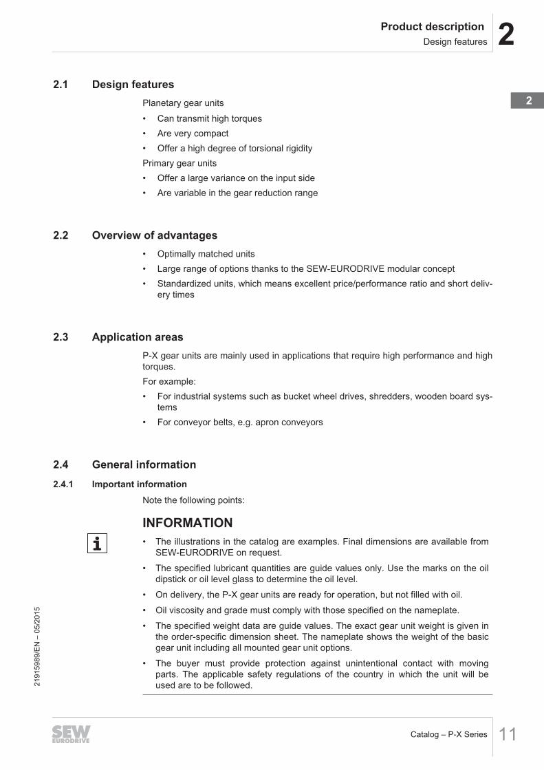
2.4 General information2.4.1 Important information
Note the following points:
INFORMATION• The illustrations in the catalog are examples. Final dimensions are available from
SEW‑EURODRIVE on request.• The specified lubricant quantities are guide values only. Use the marks on the oil
dipstick or oil level glass to determine the oil level.• On delivery, the P-X gear units are ready for operation, but not filled with oil.• Oil viscosity and grade must comply with those specified on the nameplate.• The specified weight data are guide values. The exact gear unit weight is given in
the order-specific dimension sheet. The nameplate shows the weight of the basicgear unit including all mounted gear unit options.
• The buyer must provide protection against unintentional contact with movingparts. The applicable safety regulations of the country in which the unit will beused are to be followed.21
9159
89/E
N –
05/
2015
2

2 Product description General information
Catalog – P-X Series12
2.4.2 Power and torqueThe power and torque values listed in the catalogs apply to standard design andstandard lubrication of the gear units under normal ambient conditions.Please note that the motor power shown in the selection tables for gear units is sub-ject to selection. However, the output torque and the desired output speed are essen-tial for the application and need to be checked.
2.4.3 SpeedsThe quoted output speeds of the gear units are recommended values. You can calcu-late the rated output speed based on the rated motor speed and the gear unit ratio.Please note that the actual output speed depends on the motor load and the supplysystem conditions.
2.4.4 NoiseThe noise levels of all gear units and motors (brakemotors) are well within the max-imum permitted noise levels set forth in ISO 8579-1 for gear units and EN 60034 formotors.
2.4.5 PaintingGear units and motors are painted in "blue gray"/RAL 7031 as per DIN 1843 as stand-ard. Special paint coatings are available on request.
2.4.6 Weight information
INFORMATIONPlease note that all weights shown in the catalog exclude the oil fill because the lub-ricant fill quantity depends on the mounting position.
2.4.7 Air admission and accessibilityThe gear units must be mounted on the driven machine in such a way that both axiallyand radially there is enough space left for unimpeded air admission and for the pur-poses of maintenance of the brake. Please also refer to the notes in the motor dimen-sion sheets.
2.4.8 BrakemotorsOn request, motors and gearmotors can be supplied with an integrated mechanicalbrake. The SEW‑EURODRIVE brake is an electromagnetic disk brake with a DC coilthat releases electrically and brakes using spring force. Due to its operating principle,the brake is applied if the power fails. It meets the basic safety requirements. Thebrake can also be released mechanically if equipped with manual brake release. Forthis purpose, the brake is supplied with either a hand lever with automatic reset or anadjustable set screw. The brake is controlled by a brake controller that is either in-stalled in the motor wiring space or in the control cabinet.A characteristic feature of the brakes is their extremely short design. The brake end-shield is a part of both the motor and the brake. The integrated construction of theSEW‑EURODRIVE brakemotor permits particularly compact and sturdy solutions. 21
9159
89/E
N –
05/
2015

2Product description General information
Catalog – P-X Series 13
2.4.9 International marketsUpon request, we deliver motors with connection requirements according to CSA andNEMA guidelines (UL listed).For the Japanese market, we offer motors conforming to JIS standard. Contact yoursales representative to assist you in such cases.
2191
5989
/EN
– 0
5/20
15
2

2 Product description Sizes and torques
Catalog – P-X Series14
2.5 Sizes and torquesThe nominal output torque ratings are listed in the table below.
Size Mn2 [Nm]P.042 100 170
P.052 124 060
P.062 185 660
P.072 245 660
P.082 359 400
P.092 423 000
P.102 500 000
2.6 Basic designsThe following designs of P-X gear units are available as standard:Other designs are available on request.
13861111947
PHF..X..Planetary bevel-helical gear unit inflange-mounted design with hollow shaftand shrink disk
13861146763
PF..X..Planetary bevel-helical gear unit inflange-mounted design with solid shaftand key
2191
5989
/EN
– 0
5/20
15

2Product description Type designation
Catalog – P-X Series 15
2.7 Type designationThe type designation is set up as follows:
PHF042 /T X2KP110/HP/FP.. P.. series planetary gear unit
PH.. Foot-mounted design, hollow shaft with shrink disk
PF.. Flange-mounted design, solid shaft
PHF.. Flange-mounted design, hollow shaft with shrink disk
042 Size
/T Torque arm
X2KP X series bevel-helical gear unit
110 Size
/HP Housing for planetary gear unit
/F Flange-mounted design
2191
5989
/EN
– 0
5/20
15
2

2 Product description Nameplate
Catalog – P-X Series16
2.8 Nameplate 2.8.1 P-X gear unit series
The following example shows the structure of the nameplate.
SEW-EURODRIVE Bruchsal / Germany
Type
Nr. 1
PK1
MK2
n1
n2
Made in Germany
i
FS
PM
°C
kW
kg YearWeight
kW
Nm
1/min
1/min
PHF042/T X2KP110
34.98
50000
1477
6.5
CLP 320 Mineral Oil
2015565
0...30
37
2.00
01.7167312345.0001
226
IM M1
Ta
~ 95 L
9007212064450315
Type Type designationNo. 1 Serial number
PK1 [kW] Operating power on the input shaft (HSS)
MK2 [Nm] Gear unit output torque
n1 [1/min] Input speed (HSS)
n2 [1/min] Output speed (LSS)
i Exact gear unit ratio
FS Service factor
PM [kW] Nominal motor power
Ta [°C] Approved temperature range
IM Mounting position
Weight [kg] Weight of the gear unit
Year Year of manufacture
Oil grade and viscosity class / oil quantity
2191
5989
/EN
– 0
5/20
15

2Product description Mounting positions
Catalog – P-X Series 17
2.9 Mounting positions 2.9.1 Standard mounting position
The mounting position defines the spatial orientation of the gear unit housing and isdesignated M1...M6. Standard mounting position is M1.
M2
M3
M4
M6 M1
M5
13861140107
INFORMATIONContact SEW‑EURODRIVE in case of a mounting position deviating from M1.
2191
5989
/EN
– 0
5/20
15
2

2 Product description Mounting positions
Catalog – P-X Series18
2.9.2 Fixed and variable pivoted mounting positionsMounting positions deviating from the standard are differentiated between fixed andvariable pivoted mounting positions.
INFORMATION• Fixed and variable pivoted mounting positions are only possible after consultation
with SEW‑EURODRIVE. Observe the order documents, such as the dimensionsheet.
• Fixed and variable pivoted mounting positions might involve restrictions concern-ing accessories and technical data. Also, delivery times might be longer. ContactSEW‑EURODRIVE.
+
+
0°
M2
M4
M6
M1
M5
+
+
14442483979
2191
5989
/EN
– 0
5/20
15

2Product description Mounting positions
Catalog – P-X Series 19
Fixed pivoted mounting position
Definition:
Gear units with fixed pivoted mounting position have a fixed mounting position that dif-fers from the standard.This means the gear unit does not change its mounting position during operation.
Example:
The type designation is set up as follows:
M1 = Initial mounting position
M5 = Pivoting direction
9° = Fixed pivoting anglePivoted from mounting position M1 to M5 by 9°
This results in the following fixed pivoted mounting position:
0°
M1
M5
+
M1-M5/9°
9°
9007213705011339
2191
5989
/EN
– 0
5/20
15
2

2 Product description Mounting positions
Catalog – P-X Series20
Variable pivoted mounting position
Definition:
Gear units with variable pivoted mounting position can change the mounting positionvariably during operation within the specified max./min. range.
Example:
The gear unit is operated in variable pivoted mounting position M1 to M2 = 9° and M1to M4 = 12°.
-9°+12°
0°
0°
M2
M4
M1
14457396107
The largest pivoting angle determines the positive pivoting direction (12° > 9°). In thisexample, this is 12° towards M4.Pivoted from M1 to M4 by +12°
2191
5989
/EN
– 0
5/20
15

2Product description Mounting positions
Catalog – P-X Series 21
Pivoted from M1 to M2 by -9°
0°
M2
M4
M1
M1
M1-M4/12°
+12°
0°
M1-M2/9°
-9°
0°
14457419019
The type designation for this example is:
M1-M4/–9°...12°
M1 = Initial mounting position
M4 = Pivoting direction
12° = pivoted from M1 to M4 by 12°
-9° = pivoted from M1 to M2 by 9° (= pivoted from M1 to M4 by -9°)
2191
5989
/EN
– 0
5/20
15
2

2 Product description Mounting positions
Catalog – P-X Series22
Combination of fixed and variable pivoted mounting positionsFixed and variable pivoted mounting positions can be combined.
Example:
The following example shows a combination of fixed and variable pivoted mountingposition.
M1-M4/9° (fixed pivoted mounting position)
M1 = Initial mounting position
M4 = Pivoting direction
9° = Fixed pivoting angle
M1-M6/–9°...12° (variable pivoted mounting position)
M1 = Initial mounting position
M6 = Pivoting direction
12° = 12° from M1 to M6
-9° = 9° from M1 to M5 (= -9° from M1 to M6)
All final positions have to be specified if the mounting position of the gear unit deviatesfrom standard mounting positions in several directions. Fixed and variable final posi-tions can be combined.Example of a gear unit based on mounting position M1 that is tilted by ±10° around thetransverse axis during operation and is mounted in a fixed angle of 15° around the lon-gitudinal axis:M1 - M2/10°/V - M4/10°/V - M5/15°/F
2191
5989
/EN
– 0
5/20
15

2Product description Mounting position of the primary gear unit
Catalog – P-X Series 23
2.10 Mounting position of the primary gear unitAs standard, the primary gear unit can be mounted in the mounting positions 0° and180°.The mounting positions are shown in the following table.
Primary gear unit mounting position 0°
13900311947
Primary gear unit mounting position 180 °
13900315275
INFORMATIONIn case of deviating mounting positions of the primary gear unit of 90° (lower inputshaft) and 270° (upper input shaft) contact SEW‑EURODRIVE. In this case differentaccessories are available.
2191
5989
/EN
– 0
5/20
15
2
2 Product description Directions of rotation dependencies
Catalog – P-X Series24
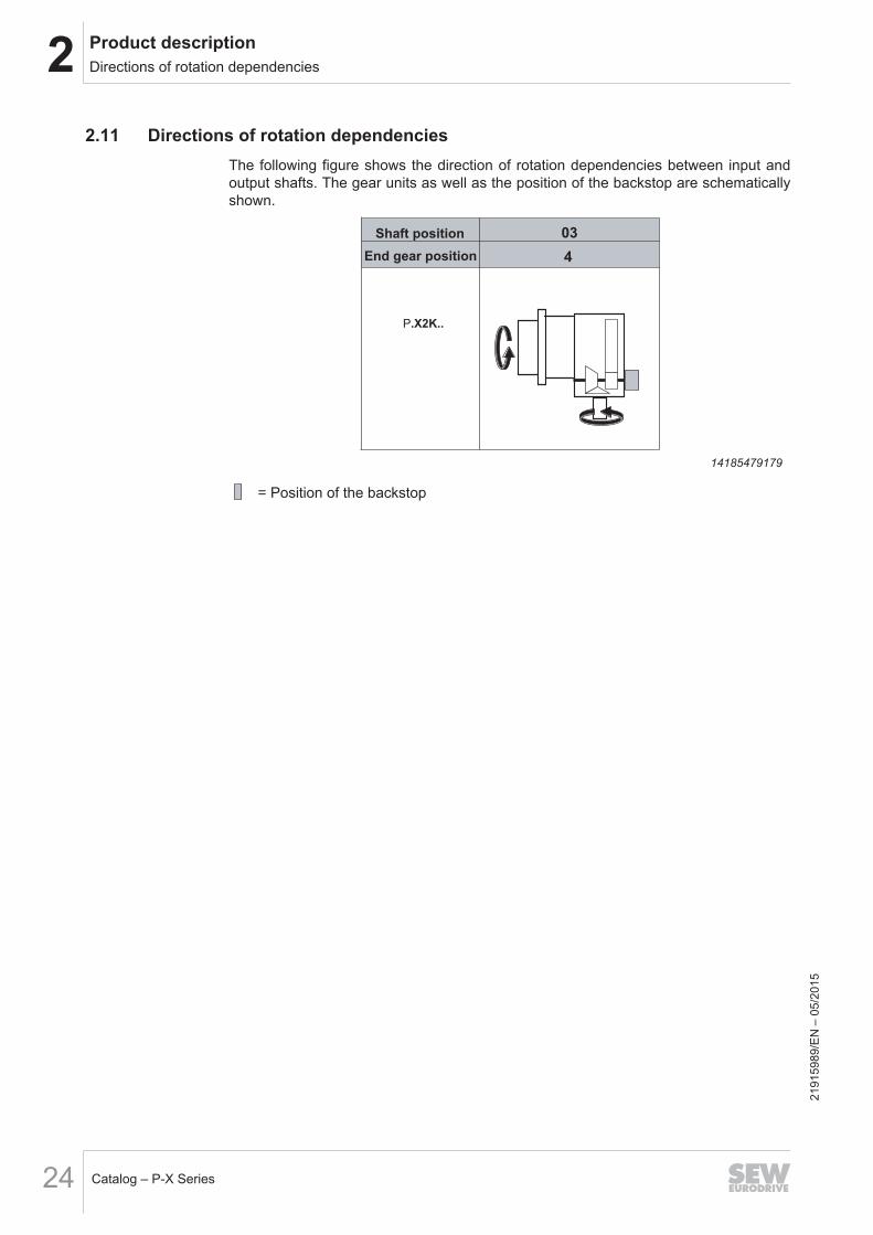
2.11 Directions of rotation dependenciesThe following figure shows the direction of rotation dependencies between input andoutput shafts. The gear units as well as the position of the backstop are schematicallyshown.
4
P.X2K..
Shaft position
End gear position
03
14185479179
= Position of the backstop
2191
5989
/EN
– 0
5/20
15

2Product description Sealing system
Catalog – P-X Series 25
2.12 Sealing system2.12.1 Input shaft
Standard Dust-proof Dust-proofRegreasable
Radial labyrinth seal(Taconite)
RegreasableSingle oil seal with dust protectionlip
Single oil seal with dust protectioncover
Double oil seal with dust protectioncover
Single oil seal with radial labyrinth seal
• Normal environment • Medium dust load withabrasive particles
• High dust load with ab-rasive particles
• Very high dust load withabrasive particles
[1][1]
[1] [1]
[1] Optional with oil seal sleeve
2.12.2 Output shaft
Seal Design
Sealing with 1 oil sealOptional 2 oil seals on a hardened sleeve
Sealing with lubricated labyrinth seal plus 1 oil seal (regreas-able) on a hardened sleeve
2191
5989
/EN
– 0
5/20
15
2

2 Product description Storage and transport conditions
Catalog – P-X Series26
2.13 Storage and transport conditionsThe gear units can be provided with the following protection and packaging types de-pending on the storage and transport conditions.
2.13.1 Internal conservation
Standard corrosion protectionAfter the test run, the test oil fill is drained out of the gear unit. The remaining oil filmprotects the gear unit against corrosion for a limited period of time.
Long-term corrosion protectionAfter the test run, the test oil fill is drained out of the gear unit and the interior space isfilled with a vapor phase inhibitor. The breather filter is replaced by a screw plug andenclosed with the gear unit.
2.13.2 Exterior corrosion protectionThe following measures are taken for exterior corrosion protection:• Anti-corrosion agent is applied to bare, non-painted functional surfaces of shafts,
flanges, mounting and foot surfaces of the housing. Remove it only using an ap-propriate solvent which is not harmful to the oil seal.
• Small spare parts and loose pieces, such as bolts, nuts, etc., are packed in corro-sion protection plastic bags (VCI corrosion protection bags).
• Threaded holes and blind holes are covered by plastic plugs.
INFORMATION• If the gear unit is stored longer than six months, regularly check the protective
coating of unpainted areas as well as the paint coating. Areas in which the pro-tective coating and/or painting has been damaged may have to be repainted.
2.13.3 Packaging
Standard packagingThe gear unit is delivered on a pallet, securely attached and without cover.Use: Transportation by land
Long-term packagingThe gear unit is delivered in a wooden box that is also appropriate for sea transport.Use: Sea transport and/or for long-term storage
2191
5989
/EN
– 0
5/20
15

2Product description Storage and transport conditions
Catalog – P-X Series 27
2.13.4 Storage conditions
INFORMATION• During storage up to startup, the gear unit must be stored in a shock-free manner
to prevent damage to the rolling bearing races!• The output shaft must be rotated at least one full rotation every 6 months so that
the position of the rolling elements in the bearings of the input and output shaftschanges.
• The gear units are delivered without oil; different protection systems are requireddepending on the storage period and storage conditions as shown in the table be-low.
Corrosion protection+ packaging
Storage location Storage duration
Standard corrosion pro-tection
+Standard packaging
Under roof and enclosed at constant temperatureand atmospheric humidity (5 °C < ϑ < 60 °C,
< 50% relative humidity).No sudden temperature fluctuations. Controlledventilation with filter (free from dust and dirt). No
aggressive vapors, no shocks.
Max. 6 months with intactsurface protection.
Long-term corrosionprotection
+Standard packaging
Under roof and enclosed at constant temperatureand atmospheric humidity (5 °C < ϑ < 60 °C,
< 50% relative humidity).No sudden temperature fluctuations. Controlledventilation with filter (free from dust and dirt). No
aggressive vapors, no shocks.
Max. 3 years with regular in-spection and checking for in-
tactness.
Long-term corrosionprotection
+Long-term packaging
With roof, protected against rain and shocks. Max. 3 years with regular in-spection and checking for in-
tactness.
INFORMATIONIf stored in tropical zones, provide for sufficient protection against insect damage.Contact SEW‑EURODRIVE for differing requirements.
2191
5989
/EN
– 0
5/20
15
2

2 Product description Corrosion and surface protection
Catalog – P-X Series28
2.14 Corrosion and surface protection2.14.1 General
SEW‑EURODRIVE offers various optional protective measures for operation of motorsand gear units under special environmental conditions.These preventive measures comprise two groups:• Corrosion protection KS for motors• Surface protection OS for motors and gear unitsFor motors, optimum protection is offered by a combination of corrosion protection KSand surface protection OS.
2.14.2 KS corrosion protectionKS corrosion protection for motors comprises the following measures:• All retaining screws that are loosened during operation are made of stainless steel.• The nameplates are made of stainless steel.• Various motor parts are coated with a finishing varnish.• The flange contact surfaces and shaft ends are treated with a temporary anti-cor-
rosion agent.• Additional measures for brakemotors.A sticker labeled "KORROSIONSSCHUTZ" (corrosion protection) on the fan guard in-dicates that special treatment has been applied.Motors with a forced cooling fan and motors with a spread-shaft encoder (ES..) cannotbe supplied with corrosion protection KS.
2191
5989
/EN
– 0
5/20
15

2Product description Corrosion and surface protection
Catalog – P-X Series 29
2.14.3 OS surface protectionGear units are available with surface protection OS1, OS2, and OS3.The following table provides an overview of coating and surface protection systems.
SEW design OS1Low environmental impact
OS2Medium environmental impact
OS3High environmental impact
Used as surface protectionwith typical ambient condi-tionsCorrosion categoriesDIN EN ISO 12944-2
Suited for environments prone tocondensation and atmosphereswith low humidity or contamination,such as outdoor applications underroof or with protection, unheatedbuildings where condensation canbuild up.According to corrosivity category:C2 (low)
Suited for environments with highhumidity or moderate atmosphericcontamination, such as applica-tions outdoors subject to directweathering.According to corrosivity category:C3 (moderate)
Suitable for environments with highhumidity and occasionally severeatmospheric and chemical contam-ination. Occasionally acidic orcaustic wet cleaning. Also for ap-plications in coastal areas withmoderate salt load.According to corrosivity category:C4 (high)
Sample applications • Systems in saw mills• Agitators and mixers
• Applications in gravel plants• Cable cars
• Port cranes• Sewage treatment plants• Mining applications
Condensation testISO 6270
120 h 120 h 240 h
Salt spray test ISO 7253 – 240 h 480 hTop coat color1) RAL 7031 RAL 7031 RAL 7031Color according to RAL Yes Yes YesUncoated parts: shaft end/flanges
Water and hand perspiration repelling rust preventive applied at the factory for external preservation
1) Standard color
INFORMATIONSheet metal parts (e.g. protection covers) are painted in RAL 1003.Special surface protection is also available, please contact SEW‑EURODRIVE.
2191
5989
/EN
– 0
5/20
15
2

3 Project planning for gear unitsProject planning procedure
Catalog – P-X Series30
3 Project planning for gear units3.1 Project planning procedure
Calculating the required
nominal gear unit torque
Selecting the nominal gear unit torque
Checking external additional forces
Checking peak load conditions
Checking thermal rating
M , , n i,
F ,F , F
M
M
M MK2 2
Smin F Start
N2
N2
K2 max K2 perm
η
<
Inquiry
Step 5
Selecting gear unit combination
Checking i tot
Step 6
Step 8
Step 10
Step 9
Selecting lubricant
Step 11
Selecting accessories
Step 12
Technical information for quotation
Step 13
Step 1
Filling in the drive selection sheet
Step 2
Calculating the basic data
Step 3
Selecting the application factors
Step 4
Selecting nominal motor power
PM
Step 7
1428497921121
9159
89/E
N –
05/
2015

3Project planning for gear unitsProject planning procedure
Catalog – P-X Series 31
3.1.1 Step 1: Drive selection data:1. Machine on LSS (normally a driven machine)
1.3 Ambient temperature [°C] [...]
normal min.
1.5 Gear unit installation [X]
Small space (va ≥ 0.5 m/s)
Large spaces and halls (va ≥ 1.4 m/s)
Outdoors with sun protection (va ≥ 3 m/s)
1.6 Ambient conditions [X]
Normal
Dusty
Damp
Corrosive
Dry
1.4 Installation altitude [m] [...]
max.
2. Load characteristics
2.1 Required speed n [1/min] [...]
2.2 Operating power on HSS P [kW] [...]
2.3 Operating torque on LSS M [kNm] [...]
2.4 Frequency of load peaks (M or P ) [...]
normal min. max.
per hour
2.5 Number of startups per hour [...]
Startups
2.7 Direction of rotation under load (LSS) [X]
CW rotation
CCW rotation
Both directions of rotation
Reversible
2.8 Operating time/day [X]
< 3 hours
3 – 10 hours
> 10 hours
2.9 Backstop required [X]
No
Yes
2.10 Exact load cycle attached [X]
No
Yes
3. Machine on HSS (normally a drive machine)
3.1 Type: [X]
AC motor AC motor/inverter DC motor
Hydraulic motor Servomotor
3.2 Motor power P [kW] [...]
3.4 Nominal motor torque M [Nm] [...] 3.5 Input speed n [1/min] [...]
3.6 If electric motor: [X] [...]
IEC
NEMA
Motor size (IEC or NEMA code):
3.7 Motor mounting position [X] [...]
B3
B5
V1
Other:
normal min. max.
2
K1
K2
K1 max.K2 max.
M
M 1
normal min. max.
normal min. max.
normal min. max. normal min.
max.
1.1 Area of application/industry [...]
1.2 Application [...]
3.3 Motor speed n [1/min] [...]
normal min.
max.
M
Key: [...] = Values to be filled in
[X] = Mark your selection with
2.6 Service life [X]
Infinite fatigue strength (gearing acc. to DIN 3990)
Defined service life [h]
14279026827
2191
5989
/EN
– 0
5/20
15
3

3 Project planning for gear unitsProject planning procedure
Catalog – P-X Series32
4.1 Mounting position [X]
M1
M2
M3
0° 180°
M4
M5
M6
M2
M3
M4
M6 M1
M5
4.2 Mounting positions for primary gear unit [X]
4.0 Gear unit requirements
14279084043
2191
5989
/EN
– 0
5/20
15
3Project planning for gear unitsProject planning procedure
Catalog – P-X Series 33
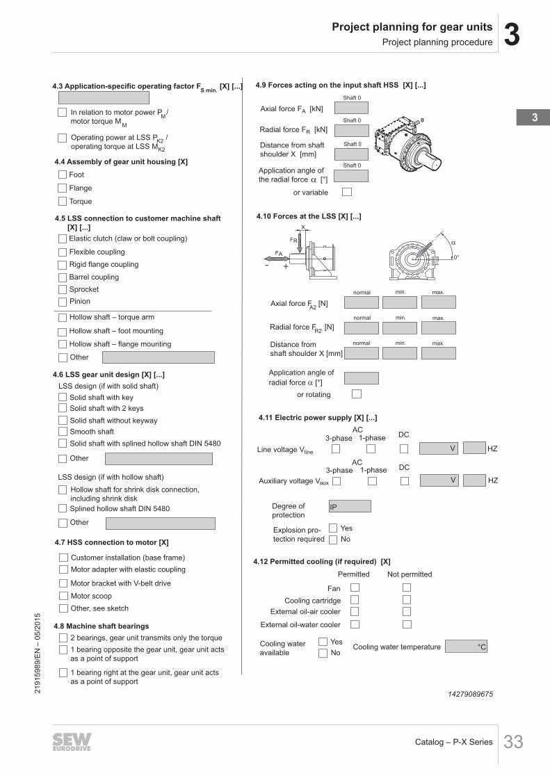
0
4.3 Application-specific operating factor F [X] [...]
Foot
Flange
Torque
4.5 LSS connection to customer machine shaft
[X] [...]
Elastic clutch (claw or bolt coupling)
Flexible coupling
Rigid flange coupling
Barrel coupling
Sprocket
4.4 Assembly of gear unit housing [X]
4.6 LSS gear unit design [X] [...]
LSS design (if with solid shaft)
4.11 Electric power supply [X] [...]
In relation to motor power P /
motor torque M
Operating power at LSS P /
operating torque at LSS M
Solid shaft with key
Other
LSS design (if with hollow shaft)
Other
Hollow shaft for shrink disk connection,
including shrink disk
Pinion
Hollow shaft – torque arm
Hollow shaft – foot mounting
Hollow shaft – flange mounting
Other
Line voltage V
3-phase 1-phaseAC
DC
V
Auxiliary voltage V
3-phase 1-phaseAC
DC
V
HZ
Degree of
protectionIP
Explosion pro-
tection required
Yes
No
HZ
S min.
K2
K2
M
M
line
aux
Solid shaft without keyway
Solid shaft with splined hollow shaft DIN 5480
Splined hollow shaft DIN 5480
4.8 Machine shaft bearings
2 bearings, gear unit transmits only the torque
1 bearing opposite the gear unit, gear unit acts
as a point of support
1 bearing right at the gear unit, gear unit acts
as a point of support
4.10 Forces at the LSS [X] [...]
normal min. max.
Axial force F [N]
Radial force F [N]
Distance from
shaft shoulder X [mm]
Application angle of
radial force α [°]
normal min. max.
normal min. max.
or rotating
A2
R2
4.7 HSS connection to motor [X]
Customer installation (base frame)
Motor adapter with elastic coupling
Motor bracket with V-belt drive
Motor scoop
Other, see sketch
α
0°FA
- +
X
FR
4.12 Permitted cooling (if required) [X]
Fan
External oil-air cooler
External oil-water cooler
Not permittedPermitted
Cooling water
available
Yes
No
Cooling cartridge
Cooling water temperature °C
4.9 Forces acting on the input shaft HSS [X] [...]
Shaft 0
Axial force FA [kN]
Radial force FR [kN]
Distance from shaft
shoulder X [mm]
Application angle of
the radial force [°]
or variable
Shaft 0
Shaft 0
Shaft 0
Solid shaft with 2 keys
Smooth shaft
142790896752191
5989
/EN
– 0
5/20
15
3

3 Project planning for gear unitsProject planning procedure
Catalog – P-X Series34
3.1.2 Step 2: Calculating the basic data – MK2, n2, i, η
Constant torque P=
K1MK2
ηx
n2
9550xNote: if is not known -> = P
K1P
K1P
M[Nm]
MK2 = Operating torque at LSSPK1 = Required operating power at HSS [kW]n2 = Output speed (LSS) 1/min
Gear ratioi =
n
n
1
2
n1 = Input speed (HSS) min-1
n2 = Output speed (LSS) min-1
Efficiency – η η = f (i; gear unit type)The efficiency of the gear unit is mainly determined by the gearing and bearingfriction as well by churning losses. For the calculation, a guide value of 96% isused.
3.1.3 Step 3: Selecting application factors
Application-specific service factor FS min
Peak load factor FF
Startup factor FStart
FS min – application-specific service factorThe application-specific service factor Fs considers the typical load behavior with re-gard to the driven machine.Recommended values with reference to• Area of Application• Type of driven machine• Operating time / dayare given in the following table.
INFORMATIONThese tables apply only to gear units driven by electric motors. For other types ofdrive motors, the following correction values apply:
• Combustion engines with four or more cylinders: FS min (selection table) + 0.25• Combustion engines with one to three cylinders: FS min (selection table) + 0.5
INFORMATIONIn the event of deviations from the typical load behavior, please consultSEW‑EURODRIVE.
2191
5989
/EN
– 0
5/20
15

3Project planning for gear unitsProject planning procedure
Catalog – P-X Series 35
Area of Application Type of application(driven machine)
Application-specific service factor FS minOperating period / day
Gearing with infinite fatigue strength (referring toDIN 3990)
< 3 h 3-10 h > 10 hWaste water treatment Impeller aerator - 1.80 2.00
Thickeners 1.15 1.25 1.50Vacuum filters 1.15 1.30 1.50Collector 1.15 1.25 1.50Screw pump - 1.30 1.50Brush aerators - - 2.00
Mining Crushers 1.55 1.75 2.00Screens and shakers 1.55 1.75 2.00Slewing drives - 1.55 1.80Bucket-wheel excavator - mining 1) 2.00* 2.30*Bucket-wheel excavator - bulk material 1) 1.70 1.70
Energy Frequency inverters - 1.80 2.00Water wheels (low speed) - - 1.70Water turbines - - 1)
Conveyors Bucket elevators - 1.40 1.50Vertical conveyors – other - 1.50 1.80Belt conveyors ≤ 100 kW 1.15 1.25 1.40Belt conveyors > 100 kW 1.15 1.30 1.50Apron feeders - 1.25 1.50Screw feeders 1.15 1.25 1.50Shakers, screens 1.55 1.75 2.00Escalators 1.25 1.25 1.50Passenger elevators 1) 1) 1)
Rubber and plastic in-dustry
Extruders (plastic) - 1.40 1.60Extruders (rubber) - 1.50 1.80Rubber rollers (2 in a row) 1.55 1.75 2.00Rubber rollers (3 in a row) - 1.50 1.75Heating rollers 1.35 1.50 1.75Calender - 1.65 1.65Mills 1.55 1.75 2.00Mixing rollers 1) 1) 1)Slab rollers 1.55 1.75 2.00Refiners 1.55 1.75 2.00Tire machines 1) 1) 1)
Timber industry Timber industry 1) 1) 1)Cranes Cranes and hoists 2) 2) 2)Food industry Crushers and mills - - 1.75
Beet slicers - 1.25 1.50Drying drums - 1.25 1.50
1) Contact SEW‑EURODRIVE2) Please contact SEW‑EURODRIVE; dimensioning according to FEM1001* only after customer consultation
2191
5989
/EN
– 0
5/20
15
3

3 Project planning for gear unitsProject planning procedure
Catalog – P-X Series36
Area of Application Type of application(driven machine)
Application-specific service factor FS minOperating period / day
Gearing with infinite fatigue strength (referring toDIN 3990)
< 3 h 3-10 h > 10 hMetal production andprocessing
Winder - 1.60 1.75Cutting rollers 1.55 1.75 2.00Table conveyors, single drives 1) 1) 1)Table conveyors, group drives 1) 1) 1)Table conveyors, reciprocating 1) 1) 1)Wire drawing machines 1.35 1.50 1.75Rollers 1) 1) 1)
Mills and drums Cooling and drying drums - 1.50 1.60Rotary kilns - - 2.00Ball mills - - 2.00Coal mills - 1.50 1.75
Pulp and paper industry Debarking drums and machines 1.55 1.80 -Rolls (pick-up, wire drive, wire suction) - 1.80 2.00Drying cylinders (rolling bearings) - 1.80 2.00Calenders (rolling bearings) - 1.80 2.00Filters (pressure and vacuum) - 1.80 2.00Beaters and chippers 1.55 1.75 2.00Jordan mills - 1.50 1.75Presses (bark, felt, glue, suction) - - 1.75Reels - - 1.75Pulpers 1) 1) 1)Washer filters - - 1.50Yankee cylinders (dryers) 1) 1) 1)
Pumps Centrifugal pumps 1.15 1.35 1.45Reciprocating pumps (single-cylinder) 1.35 1.50 1.80Reciprocating pumps (multi-cylinder) 1.20 1.40 1.50Screw pumps - 1.25 1.50Rotary pumps (gear pump, vane pump) - - 1.25
Agitators and mixers Agitators for liquids 1.00 1.25 1.50Agitators for liquids (variable density) 1.20 1.50 1.65Agitators for solids (non-uniform material) 1.40 1.60 1.70Agitators for solids (uniform material) - 1.35 1.40Concrete mixers - 1.50 1.50
Cable cars Material ropeways - 1.40 1.50Aerial tramways - 1) 1)Surface lifts 1) 1) 1)Continuous aerial tramways 1) 1) 1)Funicular railways 1) 1) 1)
Fans Heat exchangers 1.50 1.50 1.50Dry cooling tower - - 2.00Wet cooling towers 2.00 2.00 2.00Blowers (axial and radial) 1.50 1.50 1.50
Compressors Reciprocating compressors - 1.80 1.90Radial compressors - 1.40 1.50Screw-type compressors - 1.50 1.75
1) Contact SEW‑EURODRIVE
2191
5989
/EN
– 0
5/20
15

3Project planning for gear unitsProject planning procedure
Catalog – P-X Series 37
Peak load factor – FF
The peak load factor FF takes account of the overload capacity of the gearing and therotating parts.
Planetary gear unit type/sizePeak load factor – FF
Frequency of peak load per hour1...5 6...20 21...40 41...80 81...160 > 160
Output shaft as solid shaftP042...P102 1 1.2 1.3 1.5 1.75 2.0
Hollow shaft with shrink disk connec-tion P042...P102 1.1 1.2 1.3 1.5 1.75 2.0
Startup factor – FStart
The startup factor Fstart takes account of the overload caused by startup.Startup mode Startup factor – FStart
Direct 3.0Soft start 1.8
Frequency inverter 1.5 to 2.01)
Star/delta 1.3Hydraulic coupling without delay chamber 2.0
Hydraulic coupling with delay chamber 1.61) Depending on settings
3.1.4 Step 4: Calculating the required nominal gear unit torque MN2
Constant load direction – constant torque:MN2 ≥ MK2 × FS min [Nm]MN2MK2FS min
= Nominal gear unit torque [Nm]= Operating torque at LSS [Nm]= Application-specific service factor
Reversing load direction – constant torque:MN2 ≥ MK2 × FS min × 1.43 [Nm]MN2MK2FS min
= Nominal gear unit torque [Nm]= Operating torque at LSS [Nm]= Application-specific service factor
3.1.5 Step 5: Selecting the nominal gear unit torque MN2
Size MN2 [Nm] MN2 Lim [Nm]P.042 100 170 200 340P.052 124 060 248 120P.062 185 660 371 320P.072 245 660 491 320P.082 359 400 718 800P.092 423 000 846 000P.102 500 000 1 000 000
2191
5989
/EN
– 0
5/20
15
3

3 Project planning for gear unitsProject planning procedure
Catalog – P-X Series38
3.1.6 Step 6: Selecting the gear unit combinationThe selection of the gear unit combination is based on the nominal gear unit torqueMN2 according to the speed/power overview tables in chapter "Selection tables".The selection table guide on the foldout page of the catalog can be used to quicklylocate the speed/power overview table and to make a preliminary selection of the gearunit size.If the input speed n1 < 1000 min-1, the value for 1000 min-1 can be used for MN2.For input speeds n1 > 1800 min-1, contact SEW‑EURODRIVE.The following figure shows the structure of the selection tables.
P.042 X2K. n1 = 1000 min-1
100 kNm
PTH [kW] M1
20 °C 40 °C
Designation itot n2 [min-1] PN1 [kW] + +
P.042 X2KP110 159
178
202*
226*
6,3
5,6
5
4,4
69
61
54
48
55
55
53
52
76
76
72
71
)
37
37
37
53
54
52
51
[1] [2] [3] [4] [8] [9] [10][7][6] [5]
9007213977371659[1] Gear unit designation[2] Input speed (HSS)[3] Total gear unit ratio (rounded)[4] Output speed (LSS)[5] Nominal gear unit torque[6] Nominal gear unit powerThermal rating at 20 °C ambient temperature, mounting position M1[7] without fan[8] With fan in motor adapterThermal rating at 40 °C ambient temperature, mounting position M1[9] without fan[10] With fan in motor adapter) Contact SEW‑EURODRIVE* X2K. primary gear units have a gear ratio iN ≥10
3.1.7 Step 7: Selecting the nominal motor power PM
P =PK2
M ηPK1≥ [kW]
PMPK1PK2η
= Nominal motor power [kW]= Operating power at HSS [kW]= Operating power at LSS [kW]= Efficiency
2191
5989
/EN
– 0
5/20
15

3Project planning for gear unitsProject planning procedure
Catalog – P-X Series 39
3.1.8 Step 8: Checking the peak load conditions MK2 per; MK2max
Permitted peak output torque MK2 per:
M =K2 per
MN2 Lim
FF
[Nm]
MK2 perMN2 LimFF
= Permitted peak output torque [Nm]= Limited nominal gear unit torque [Nm]= Peak load factor
Calculating the peak load MK2 max:
M =K2 max
P x 9550 M
n2
[Nm]x Fstart*
x η
MK2 maxPMFstartn2η
= Peak output torque [Nm]= Nominal motor power [kW]= Startup factor= Output speed [min-1]= Efficiency
* If Fstart is not specified, take the startup factors from the table on "Startup factor –Fstart".Checking the gear unit selection:MK2 max ≤ MK2 per
2191
5989
/EN
– 0
5/20
15
3

3 Project planning for gear unitsProject planning procedure
Catalog – P-X Series40
3.1.9 Step 9: Checking the thermal rating – PT
The thermal rating PT of a gear unit is the power that a gear unit can transmit withoutexceeding a certain oil temperature.The thermal rating PT depends on the following factors:• Ambient temperature• Air circulation and sunlight exposure at the installation site• Installation altitude• Heat conduction to the foundation at the installation site• Gear unit type, size and gear ratio• Type of gear unit external cooling• Type of gear unit lubrication• Lubricant type• Cyclic duration factorFor the following ambient conditions, the thermal rating can be directly read from theselection tables:• Ambient temperature 20 °C to 40 °C• Installation in a large hall (air velocity ≥ 1.4 m/s)• Self-cooling or cooling with fan in motor adapter• Foundation as steel support structure• Installation altitude < 1000 m above sea level
INFORMATION• For other ambient temperatures and types of lubricants, you can calculate the
thermal rating PT using the temperature factor fT and the lubrication factor fL. Theresulting calculation results are approximate values. Please contactSEW‑EURODRIVE to determine the exact values.
• Sufficient protection from direct sunlight is absolutely necessary when installedoutdoors. If the gear unit cannot be protected from direct sunlight, the thermal cal-culation must take the sunlight [kW/m2] into account.
Thermal rating PTH of the gear unit [kW] for the following lubrication types and mount-ing position M1 is given in the chapter "Selection tables"). The thermal rating for othercombinations can be determined using factors.P
Tf1
[kW]xPTH
fT
x=
PT = thermal rating of the gear unit [kW]PTH = Nominal thermal rating of the gear unit [kW]. The values in the chapter "Selection tables" depend
on type of cooling, mounting position and lubrication type.f1 = Altitude factorfT = Temperature factor
Altitude factor f1
The following table lists the altitude factor f1
Altitude factor Altitude H [m above sea level]up to 999 1000 - 2000 2000 - 3000 3000 - 4000 4000 - 5000
f1 1.00 0.95 0.91 0.87 0.83 2191
5989
/EN
– 0
5/20
15

3Project planning for gear unitsProject planning procedure
Catalog – P-X Series 41
Temperature factors fT
The following table shows the temperature factor fT depending on the lubrication type,ambient temperature, and cooling option.
Temperature factor fT
• without additional coolingor
• with fan
Lubrication typeAmbient temperature [°C]
10 20 30 40 50Splash lubrication 1.15 1 0.85 0.7 0.55
When PT < 1/3 x PN1, contact SEW‑EURODRIVEPT = Thermal rating of the gear unit [kW]PN1 = Nominal gear unit power
The gear unit's thermal rating must be at least as large as the operating power on theinput shaft [HSS].
PK1
PT
≤
PT = Thermal rating of the gear unit [kW]PK1 = Operating power at HSS [kW]
2191
5989
/EN
– 0
5/20
15
3

3 Project planning for gear unitsProject planning procedure
Catalog – P-X Series42
3.1.10 Step 10: Checking the external additional forces
Influences and dependencies:The permitted additional forces depend on the following factors:• Existing service factor of the gear unit with respect to the selection data• Required bearing service life• Direction of the axial force (from or towards gear unit)• Application angle of the radial load (rotating or at a specific position)• Point of force application• Ratio between radial and axial load• Gear unit mounting
Determining the overhung loadIf no overhung loads are specified, they can be determined by approximation as fol-lows. An important factor for determining the resulting overhung load is the type oftransmission element mounted to the shaft end. The following transmission elementfactors fZ must be considered for various transmission elements.Transmission element Transmission element factor fZ CommentsGears 1.15 < 17 teethSprockets 1.40 < 13 teethSprockets 1.25 < 20 teethNarrow V-belt pulleys 1.75 Influence of pre-tensioningFlat belt pulleys 2.50 Influence of pre-tensioningToothed belt pulleys 1.50 Influence of pre-tensioning
The overhung load exerted on the motor or gear shaft is calculated as follows:
=MdF
R[N]
X 2000
d0
x fz
FR = Overhung load [N]Md = Torque [Nm]d0 = Mean diameter of the installed transmission element in [mm]fZ = Transmission element factor
Permitted overhung loadThe basis for determining the permitted overhung loads in the roller bearing calcula-tion is the nominal bearing service life L10h (according to ISO 281).For special operating conditions, the permitted overhung loads can be determined onthe basis of the modified service life Lnmh on request.For applications with defined service life, the permitted overhung loads have been cal-culated based on an adapted shaft safety. The values can thus be reduced.
Overhung load on outputThe permitted overhung loads FR per for solid shaft gear units can be calculated exactly.The force values relate to the force application in the center of the shaft end for solidshafts and to the gear unit flange contact point for hollow shafts. In planetary gearunits, the force application angle and direction of rotation do not influence the permit-ted values as there are no inner forces from the gear unit acting on the output bearing.
2191
5989
/EN
– 0
5/20
15
3Project planning for gear unitsProject planning procedure
Catalog – P-X Series 43
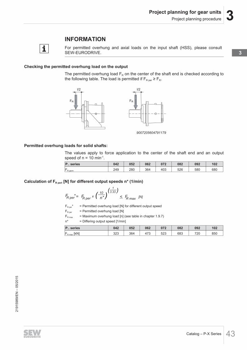
INFORMATIONFor permitted overhung and axial loads on the input shaft (HSS), please consultSEW‑EURODRIVE.
Checking the permitted overhung load on the outputThe permitted overhung load FR on the center of the shaft end is checked according tothe following table. The load is permitted if FR per ≥ FR.
l/2
FR
l/2
FR
9007205604791179
Permitted overhung loads for solid shafts:The values apply to force application to the center of the shaft end and an outputspeed of n = 10 min-1.P.. series 042 052 062 072 082 092 102FR perm 249 280 364 403 526 580 680
Calculation of FR perI [N] for different output speeds n* (1/min)
=FR per [N]F
R perx
10
n*( )
1
3.33( )
< FR max
*
FR per* = Permitted overhung load [N] for different output speedFR per = Permitted overhung load [N]FR max = Maximum overhung load [n] (see table in chapter 1.9.7)n* = Differing output speed [1/min]
P.. series 042 052 062 072 082 092 102FR max [kN] 323 364 473 523 683 720 850
2191
5989
/EN
– 0
5/20
15
3

3 Project planning for gear unitsProject planning procedure
Catalog – P-X Series44
CommentFR ≤ FR per* ≤ FR max
However, if FR per* > FR max, you will have to check: FR ≤ FR max
Conversion of permitted overhung load on the output for force application away from the center ofthe shaft end
l
X
FR per (x)
9007205604800651
Size a b lP.042 268 229 300P.052 283 260 350P.062 308 287 400P.072 334 291 400P.082 377 321 450P.092 445 343 450P.102 473 375 550
Calculation of off-center force application:
=FR per
(X) FR per
x (a + b)
(a + b )*< F
R max[N]
b* = (b - l/2) + x [mm]FR per(x) = Permitted overhung load [N] of the off-center force applicationFR per = Permitted overhung load [N]FR max = Maximum overhung load [N]
CommentFR ≤ FR perm (x) ≤ FR max
However, if FR perm (x) > FR max, you will have to check: FR ≤ FR max
Permitted axial forceFor applications with axial loads, consult SEW‑EURODRIVE.
INFORMATION• Please consult SEW‑EURODRIVE if you use the PH.. design in combination with
overhung forces, or the PHF.. variant with flange mounting.• If only an axial load but no additional overhung load act on the output shaft, it is
necessary that you contact SEW‑EURODRIVE.
2191
5989
/EN
– 0
5/20
15

3Project planning for gear unitsProject planning procedure
Catalog – P-X Series 45
3.1.11 Step 11: Selecting the optional equipment/accessories
P.. • Oil drain valve• Breather valve• Torque arm• Flange-mounted design
X2K.. • Motor adapter• Fan• Backstop• PT100 temperature sensor• Shaft end pump
3.1.12 Step 12: Selecting the lubricantLubricants can be chosen according to the lubricant table.Output speeds n2 < 1.0 min-1:We recommend using MOBIL SHC XMP 460 synthetic lubricant in conjunction withfluorocarbon rubber oil seals to ensure lubricating properties at low output speeds.
3.1.13 Step 13: Technical specifications
PHF042 /T X2KP110/HP/FPHF.. Flange-mounted design, hollow shaft with shrink disk
042 Size
/T Torque arm
X2KP X series bevel-helical gear unit
110 Size
/HP Housing for planetary gear unit
/F Flange-mounted design
2191
5989
/EN
– 0
5/20
15
3

3 Project planning for gear unitsSelection example
Catalog – P-X Series46
3.2 Selection example3.2.1 Step 1: Drive selection data
• Application: Apron feeders• Bevel-helical planetary gear unit (mounting position M1)• Output shaft: Hollow shaft with shrink disk and torque arm• Required output speed n2 = 4.0 min-1
• Required operating power at LSS PK2 = 75 kW• 4 pole motor, frequency inverter operation• Input speed n1 = 1500 min-1
• Operating period: 12 hours per day• Cyclic duration factor: 100% cdf, 10 starts per hour• Outdoors, dusty environment• Ambient temperature = 0 °C...40 °C• Installation altitude H = 800 m• No axial or radial forces acting on the output shaft• Motor mounting with IEC motor adapter
2191
5989
/EN
– 0
5/20
15

3Project planning for gear unitsSelection example
Catalog – P-X Series 47
3.2.2 Step 2: Calculating the basic data MK2, i, ηOperating torque on LSS:
M =K2
x 9 550n
2
[Nm]P
K2
MK2PK2n2
= Operating torque at LSS [Nm]= Operating power at LSS [kW]= Output speed (LSS) [min-1]
MK2
75 kW x 9 550
4 min= = 179 063 Nm
-1
Required gear ratio:
i =n
n
1
2
=1 500
4= 375 min -1
min -1
n1n2
= Input speed (HSS) [min-1]= Output speed (LSS) [min-1]
Efficiency:η = 0.96
3.2.3 Step 3: Selecting the application factors FS min, FF, FStart
Application-specific service factor FS min
Application: Apron feeder t > 10 h → FS min = 1.5Peak load factor FF
Hollow shaft with shrink diskLoad per hour → FF = 1.2Startup factor Fstart
Motor in frequency inverter operation → FStart = 1.7t = Daily operating period
3.2.4 Step 4: Calculating the required nominal output torque MN2
Constant direction of the load – constant torque:MN2 ≥ MK2 × FS min= 179 062.5 Nm × 1,5 = 268 594 NmMN2MK2FS min
= Nominal torque [Nm]= Operating torque at LSS [Nm]= application-specific service factor
2191
5989
/EN
– 0
5/20
15
3

3 Project planning for gear unitsSelection example
Catalog – P-X Series48
3.2.5 Step 5: Selecting the nominal gear unit torque MN2
MN2 > 268 594 NmSize MN2 [Nm] MN2 Lim [Nm]
P.042 100 170 200 340P.052 124 060 248 120P.062 185 660 371 320P.072 245 660 491 320P.082 359 400 718 800P.092 423 000 846 000P.102 500 000 1 000 000
• Select the gear unit size: P.082
3.2.6 Step 6: Selecting the gear unit combination
P.082 X2KP150 164
176
208*
222*
254*
272*
304
326
385*
413*
471*
504*
9,1
8,5
7,2
6,8
5,9
5,5
4,9
4,6
3,9
3,6
3,2
3,0
359
335
283
265
234
219
194
181
153
143
126
118
116
118
120
120
119
119
110
111
112
112
110
110
194
194
187
186
179
178
178
178
171
170
164
163
61
64
74
75
78
79
63
65
71
72
74
74
124
126
127
127
126
126
118
118
118
118
116
116
P.082 X2K. n1 = 1500 min-1
359 400 Nm
PTH [kW] M1
20 °C 40 °C
Designation itot n2 [min-1] PN1 [kW] + +
9007213999388683
• Select the gear unit combination: PHF082 X2KP150• Total gear ratio itot = 385 (required = 375 → ok)
3.2.7 Step 7: Selecting the motor power PM
P =PK2
M ηPK1≥ kW=
75 kW0.96
= 78
PMPK2PM
= Nominal motor power [kW]= Operating power at LSS [kW]= Nominal motor power [kW]
Motor selection → PM = 90 [kW]
2191
5989
/EN
– 0
5/20
15

3Project planning for gear unitsSelection example
Catalog – P-X Series 49
3.2.8 Step 8: Checking the peak load conditions MK2 max < MK2 per
Permitted peak output torque MK2 per:
M =K2 per
MN2 Lim
FF
= 718 800 Nm
1.2= 599 000 Nm
MK2 perMN2 LimFF
= Permitted peak output torque [Nm]= limited nominal gear unit torque [Nm]= Peak load factor
Calculating the peak load MK2 max:P
=M
MK2 max n
2
9 550x 90 kW x 9 550
4 min= 350 676 Nm=
ηx x 0.96x Fstart x 1.7
-1
MK2 maxPMFStart
= Peak output torque [Nm]= Motor power [kW]= Startup factor
Checking the gear unit selection:MK2 max ≤ MK2 per → OKMK2 maxMK2 per
= Peak output torque= Permitted peak output torque
2191
5989
/EN
– 0
5/20
15
3

3 Project planning for gear unitsSelection example
Catalog – P-X Series50
3.2.9 Step 9: Checking the thermal rating
PT f
1xP
TH= 71 kW x 1.00 x 0.7 = 50 kWf
T x=
f1 = 1.0 see installation altitude 800 m (Altitude factor f1)fT = 0.7 see ambient temperature with splash lubrication without additional cooling(Temperature factors fT)PTPTHf1fT
= Thermal rating [kW]= Nominal thermal rating [kW]= Altitude factor= Temperature factor
The operating power PK1 must not exceed the thermal rating PT – (PK1 ≤ PT). Additionalcooling is required if PK1 > PT
50 kW < 78 kW→ Thermal rating not sufficient at 40 °C without additional coolingCheck the thermal rating with cooling.P
T f1
xPTH
= 118 kW x 1.00 x 0.7 = 87 kWfT
x=
PK1 > PT
78 kW < 87 kW→ Thermal rating sufficient at 40 °C with a fan in motor adapter.
3.2.10 Step 10: Checking the external additional forcesThere are no external additional forces → OK.
3.2.11 Step 11: Selecting the lubricantAs n2 = 4.0 min-1 (n2 > 1.0-1), you can choose the lubricants according to the lubricanttable (see chapter 5.3.2).
3.2.12 Step 12: Technical specifications
PHF082 /T X2K150/HP/FPHF.. Flange-mounted design, hollow shaft with shrink disk
082 Size
/T Torque arm
X2KP X series bevel-helical gear unit
150 Size
/HP Housing for planetary gear unit
/F Flange-mounted design
2191
5989
/EN
– 0
5/20
15

4Options and accessories
Catalog – P-X Series 51
4 Options and accessoriesThe following additional options are available. Contact SEW‑EURODRIVE if you re-quire options.• ATEX design• Double-sided torque arm• Output shaft types
– Splined hollow shaft according to DIN 5480• Output shaft (LSS) sealing system
– Labyrinth seal• External oil-water cooler and oil-air cooler• Shaft end pump• Water cooling cartridge• Axial and radial fan
2191
5989
/EN
– 0
5/20
15
4

4 Options and accessoriesTorque arm
Catalog – P-X Series52
4.1 Torque armThe torque arm can be enclosed in the delivery or can be mounted according to cus-tomer requirements.The retaining screws are included in the delivery.The position of the torque arm is determined as looking onto the output shaft (mount-ing position 0°, 90°, 180°, 270°).
INFORMATIONDifferent mounting positions are possible depending on the angle division (number ofretaining screws).
The following figure shows an example of the mounting position of the torque arm.
0°
270°
180°
90°
9007205555743883
2191
5989
/EN
– 0
5/20
15

4Options and accessoriesTorque arm
Catalog – P-X Series 53
4.1.1 Single-sided torque armThe reaction torque to the gear unit output torque is absorbed by the torque arm fix-ture via lever arm A. The illustration shows an example of absorption in a welded con-struction with design dimensions. Two supporting plates with the suggested dimen-sions are welded onto the customer's structure. Once the gear unit has been moun-ted, a connecting cover plate is welded onto the two supporting plates. The force act-ing on the support is the gear unit torque divided by the length of the lever arm A. Thereaction force acts on the gear unit and customer bearings.The following figure shows a sample torque arm.
E
E
E - E
A
9007205607915019
Weights
Size Weight [kg]P.042 93
P.052 102
P.062 183
P.072 317
P.082 420
P.092 440
P.102 510
2191
5989
/EN
– 0
5/20
15
4

4 Options and accessoriesBackstop
Catalog – P-X Series54
4.2 BackstopThe purpose of a backstop [1] is to prevent unwanted directions of rotation. During op-eration, the backstop permits rotation in only one specified direction of rotation.The backstop functions by using centrifugal lift-off sprags. Once the lift-off speed isreached, the sprags completely lift off from the contact surface of the outer ring. Thebackstop is lubricated with gear oil.
[1]
[2]
[2]
CCW
CW
14645541643
The direction of rotation is specified as viewed onto the output shaft (LSS)• CW = Clockwise rotation• CCW = Counterclockwise rotationThe permitted direction of rotation [2] is indicated on the housing.Contact SEW‑EURODRIVE for differing requirements.The backstop might wear off when operated below lift-off speed.In the following cases always contact SEW‑EURODRIVE for specifying the mainten-ance intervals:• Input speed rates n1 < 950 min-1
• or any of the following gear unit designs:
n1 [min-1] Size950 ... 1150 X2K100..170 iN ≥ 10
n1 = Input speed (HSS) iN = Nominal gear unit ratio
INFORMATIONX2K primary gear units with a gear unit ratio iN ≥ 10 are marked with * in the chapter"Selection tables".
2191
5989
/EN
– 0
5/20
15

4Options and accessoriesFoot-mounted design
Catalog – P-X Series 55
4.3 Foot-mounted designThe gear unit is also available in foot-mounted design.Please contact SEW‑EURODRIVE.
4.4 FanA fan may be installed in the motor adapter to raise the thermal rating or when the am-bient conditions change after gear unit startup. The direction of rotation of the gearunit does not influence the operation of the fan.
4.5 Motor adapterMotor adapters are available for mounting• IEC (B5) motors of sizes 200 to 355• NEMA ("C" face) motors of sizes 324 to 449Observe the following information:
INFORMATION• The gear unit must be mounted in such a way that liquids cannot enter the motor
adapter (HSS end) and accumulate there. Otherwise, the oil seal can be dam-aged, and subsequent damage can create a possible ignition source.
• An elastic claw coupling is included in the delivery of the motor adapter.• All motor adapters can have a fan installed.• For additional information, refer to the motor adapter dimension sheets.
The following figure shows an example of the motor adapter [1] connected to the gearunit:
[1]
14273472011
2191
5989
/EN
– 0
5/20
15
4

4 Options and accessoriesMotor adapter
Catalog – P-X Series56
4.5.1 Max. permitted motor weightWhen mounting a motor at the gear unit the approved maximum motor weight in re-gard to the motor adapter size must be verified.
INFORMATION• The maximally permitted motor weight may not be exceeded.• In case of a deviating mounting position, contact SEW‑EURODRIVE.
2. Maximum motor weight depending on motor adapter sizeThe following maximum loads on the motor adapter must not be exceeded.
X
GM
[2]
[1]
9007199611271819[1] Center of gravity of the motor X = Distance from the center of gravity[2] Motor adapter GM = Weight of the mounted motor
INFORMATIONThe table only applies to stationary applications. For mobile applications (e.g. traveldrives), consult SEW‑EURODRIVE.
Motor adapter GM XIEC NEMA [kg] [mm]
100/112 182/184 60 190132 213/215 110 230
160/180 254/286 220 310200 324 280 340225 326 400 420
250 / 280 364 - 405 820 480315S-L 444 - 449 1450 680
315 2000 740355 2500 740
The maximum permitted weight GM must be linearly reduced if the centroidal distanceX is increased. GM cannot be increased if the centroidal distance is reduced.
2191
5989
/EN
– 0
5/20
15

5Lubrication, oil heater and coolingGeneral information on selecting the oil
Catalog – P-X Series 57
5 Lubrication, oil heater and cooling5.1 General information on selecting the oil
Unless a special arrangement is made, SEW‑EURODRIVE supplies drives without oilfill.
INFORMATIONThis means the gear unit must be filled with the correct oil grade and quantity beforestartup. You find the corresponding information on the nameplate of the gear unit.
The following tables provide an overview of mineral and synthetic oils.
5.1.1 Mineral oil
StandardsLubrication oils are divided into ISO VG viscosity classes according to ISO 3448 andDIN 51519.
ISOclass
ISO 6743-6designation
DIN 51517-3designation
AGMA 9005-D94designation
150 ISO-L-CKC 150 DIN 51517-CLP 150 AGMA 4 EP
220 ISO-L-CKC 220 DIN 51517-CLP 220 AGMA 5 EP
320 ISO-L-CKC 320 DIN 51517-CLP 320 AGMA 6 EP
460 ISO-L-CKC 460 DIN 51517-CLP 460 AGMA 7 EP
680 ISO-L-CKC 680 DIN 51517-CLP 680 AGMA 8 EP
5.1.2 Synthetic oil
StandardsLubrication oils are divided into ISO VG viscosity classes according to ISO 3448 andDIN 51519.
ISOclass
ISO 6743-6designation
DIN 51519designation
AGMA 9005-D94designation
150 ISO-L-CKT 150 CLP HC 150 AGMA 4 EP
220 ISO-L-CKT 220 CLP HC 220 AGMA 5 EP
320 ISO-L-CKT 320 CLP HC 320 AGMA 6 EP
460 ISO-L-CKT 460 CLP HC 460 AGMA 7 EP
680 ISO-L-CKT 680 CLP HC 680 AGMA 8 EP
In addition to having the required viscosity, the oil must fulfill the following criteria:• CLP oils according to DIN 51517-3• Micro-pitting test according to FVA, FV no. 54/ I-IV, GFT class high, damage force
level >10If synthetic oil is used, SEW‑EURODRIVE recommends polyalphaolefin-based oil(CLP HC).21
9159
89/E
N –
05/
2015
5

5 Lubrication, oil heater and coolingPermitted lubricants
Catalog – P-X Series58
INFORMATIONIf required, a cooling system must be used or the oil change interval must beshortened (see chapter "Lubricant change intervals" in the "Helical and Bevel-HelicalX.. Series Gear Units" operating instructions).Observe the operating temperature of the gear unit when specifying the oil change in-tervals.
5.2 Permitted lubricantsThis chapter describes the permitted lubricants and the permitted temperatures for in-dustrial gear units from SEW‑EURODRIVE.
INFORMATION• The standard for viscosity and oil grade is the type of oil that is specified by
SEW‑EURODRIVE in the order (see order confirmation and nameplate).• Contact SEW‑EURODRIVE if you use bio and food grade lubricants or polyglycol
oils.• Check the compatibility of the greases and oils used.• The tables contain the lubricants approved by SEW‑EURODRIVE.• Oils of the same viscosity class from different manufacturers do not have the
same characteristics. In particular, the minimum permitted oil bath temperaturesare manufacturer-specific. These temperatures are specified in the lubricanttables.
• The minimum permitted oil bath temperatures depend on the lubrication typeused. These temperatures are specified in the lubricant tables. The values corres-pond to the maximum viscosity of the individual lubricants.
• The values specified in the lubricant tables apply as of the time of printing of thisdocument. The data of the lubricants are subject to dynamic change on the part ofthe lubricant manufacturers. For the latest information about the lubricants, visit:www.sew-eurodrive.de/lubricants
2191
5989
/EN
– 0
5/20
15

5Lubrication, oil heater and coolingPermitted lubricants
Catalog – P-X Series 59
5.2.1 Structure of the tables and abbreviations
S0 S0
S0 S0
S0 S0
Optigear
BM 150
Alpha
SP 150
VG 150 1)
VG 320
DIN (ISO)
API
ISO,SAE
NLGI
CLP
VG 220Alpha
SP 220Optigear
BM 220
Alpha
SP 320Optigear
BM 320
-10
+5
+15
+85
-15
0
+10
+75
-20
-5
+5
+65
-20
-5
+5
+65
-15
0
+10
+75
-10
+5
+15
+80
[1]
[2]
9007217174587531
[1] Viscosity class[2] Lubricant type
Abbreviations
Icons DesignationCLP = Mineral oil
CLP HC = Synthetic polyalphaolefin (PAO)
E = Ester-based oil
= Mineral lubricant
= Synthetic lubricant
= Lubricant for the food industry (NSF H1-compliant)
OilOil
= Biodegradable oil (lubricant for agriculture, forestry, and water man-agement)
1) = Lubricants may only be used if service factor Fs ≥ 1.3
2191
5989
/EN
– 0
5/20
15
5

5 Lubrication, oil heater and coolingPermitted lubricants
Catalog – P-X Series60
5.2.2 Explanation of the various lubricants
SEW070040013
-20
-5
+5
xyz
+65
[5]
[1]
[2]
[3]
[4]
[6]
[7]
18014416413363467
[1] Lowest cold start temperature in °C for splash lubrication*[2] Lowest cold start temperature in °C for drives with pumps up to a max. oil vis-
cosity of 5000 cSt*[3] Lowest cold start temperature in °C for drives with pumps up to a max. oil vis-
cosity of 2000 cSt*[4] Trade name[5] Manufacturer[6] Highest oil bath temperature in °C. MUST NOT BE EXCEEDED.[7] Approvals
*In case of low temperatures, the oil must be heated to the specified minimum temper-ature, for example by using an oil heater. The maximally permitted oil viscosity perpump type is specified in the following chapter.
5.2.3 Explanation of the oil supply systems and the oil viscosityThe following pressure lubrications are designed for an oil viscosity of 2000 cSt:• Motor pump for pressure lubrication /ONP• Motor pump incl. air cooler for pressure lubrication /OAP• Motor pump incl. water cooler for pressure lubrication /OWPThe shaft end pumps are designed for an oil viscosity of 5000 cSt.
2191
5989
/EN
– 0
5/20
15

5Lubrication, oil heater and coolingPermitted lubricants
Catalog – P-X Series 61
5.2.4 Lubricant tablesThe lubricant table is valid when this document is printed. Please refer to www.sew-eurodrive.de/lubricants for the latest version of the table.
Klü
be
ro
il
GE
M 1
-15
0 N
Klü
be
ro
il
GE
M 1
-22
0 N
Klü
be
ro
il
GE
M 1
-32
0 N
Klü
be
ro
il
GE
M 1
-46
0 N
Klü
be
ro
il
GE
M 1
-68
0 N
S0
S0
S0
S0
S0
S0
S0
S0
S0
S0
S0
S0
SEW070030013
S0
S0
S0
S0
S0
S0
S0
S0
S0
S0
S0
S0
S0
S0
S0
S0
S0
S0
S0
S0
S0
S0
S0
S0
S0
Op
tige
ar
BM
15
0
Alp
ha
SP
15
0
VG
15
0 1
)
VG
32
0
DIN
(ISO
)
AP
I
ISO
,SA
E
NL
GI
CL
P
VG
22
0
VG
46
0
VG
10
00
VG
68
0
0
+15
+25
0
+15
+25
0
+15
+25
0
+15
+25
0
+15
+25
+9
0+
90
Alp
ha
SP
22
0
Op
tige
ar
BM
22
0
Alp
ha
SP
32
0
Op
tige
ar
BM
32
0
Alp
ha
SP
68
0
S0
+5
+20
+30
+9
0
Op
tige
ar
BM
10
00
Op
tige
ar
BM
68
0
-5
+10
+20
+9
0
-10
+5
+15
+8
5
-15
0
+10
+7
5
-20
-5
+5
+6
5
-20
-5
+5
+6
5
-20
-5
+5
+6
5
-20
-5
+5
+6
5
-20
-5
+5
+6
5
-20
-5
+5
+6
5
-20
-5
+5
+6
5
-15
0
+10
+7
5
-15
0
+10
+7
5
-15
0
+10
+7
5
-15
0
+10
+7
5
-15
0
+10
+7
5
-15
0
+10
+7
5
-15
0
+10
+7
5
-15
0
+10
+7
5
-10
+5
+15
+8
0
-10
+5
+15
+8
0
-10
+5
+15
+8
0
-10
+5
+15
+8
0
-10
+5
+15
+8
0
-10
+5
+15
+8
0
-10
+5
+15
+8
0
Op
tige
ar
BM
46
0
-5
+10
+20
+9
0
-5
+10
+20
+9
0
-5
+10
+20
+9
0
-5
+10
+20
+9
0
-5
+10
+20
+9
0
-5
+10
+20
+9
0
-5
+10
+20
+9
0
-5
+10
+20
+9
0
Alp
ha
SP
46
0
+9
0+
90
Re
no
lin
CL
P 1
50
Plu
s
Re
no
lin
CL
P 2
20
Plu
s
Re
no
lin
CL
P 3
20
Plu
s
Re
no
lin
Hig
hG
ea
r 1
50
Re
no
lin
Hig
hG
ea
r 2
20
Re
no
lin
Hig
hG
ea
r 3
20
Re
no
lin
Hig
hG
ea
r 4
60
Re
no
lin
CL
P 4
60
Plu
s
Re
no
lin
Hig
hG
ea
r 6
80
Mo
bilg
ea
r 6
00
XP
68
0
SEW070030013
Mo
bilg
ea
r 6
00
XP
46
0
Re
no
lin
CL
P 6
80
Plu
s
+9
0
0
+15
+25
+9
0
0
+15
+25
+9
0
0
+15
+25
+9
0
SEW070030013
SEW070030013
SEW070030013
Mo
bilg
ea
r 6
00
XP
15
0
Mo
bilg
ea
r 6
00
XP
22
0
Mo
bilg
ea
r 6
00
XP
32
0
Sh
ell O
ma
la
Oil F
22
0
-10
+5
+15
+8
0
Sh
ell O
ma
la
Oil F
32
0
Sh
ell O
ma
la
Oil F
46
0
Me
ro
pa
15
0
Me
ro
pa
22
0
Me
ro
pa
32
0
Me
ro
pa
46
0
Me
ro
pa
68
0
Ca
rte
r E
P 2
20
Ca
rte
r E
P 3
20
Ca
rte
r E
P 4
60
Ca
rte
r E
P 6
80
Mobil®
TO
T A
L
Sh
ll
e
FUCHS
TE
XA
CO
LUBRICATION
179094272112191
5989
/EN
– 0
5/20
15
5

5 Lubrication, oil heater and coolingPermitted lubricants
Catalog – P-X Series62
The lubricant table is valid when this document is printed. Please refer to www.sew-eurodrive.de/lubricants for the latest version of the table.
Klü
be
rs
yn
th
GE
M 4
-15
0 N
Klü
be
rs
yn
th
GE
M 4
-22
0 N
Klü
be
rs
yn
th
GE
M 4
-32
0 N
Klü
be
rs
yn
th
GE
M 4
-46
0 N
Klü
be
rs
yn
th
GE
M 4
-68
0 N
Om
ala
S4
GX
68
0
S0
S0
S0
S0
S0
S0
S0
S0
S0
S0
S0
S0
S0
S0
S0
S0
S0
S0
S0
S0
S0
S0
S0
S0
S0
S0
S0
S0
S0
S0
S0
S0
S0
S0
S0
S0
S0
Alp
ha
sy
n
EP
15
0
Op
tig
ea
r
Sy
nth
eti
c X
15
0
VG
15
0 1
)
VG
68
1)
VG
32
1)
VG
32
0
DIN
(IS
O)
AP
I
ISO
,SA
E
NL
GI
CL
P H
C
VG
22
0
VG
46
0
VG
10
00
VG
68
0
-10
+10
+25
-10
+10
+25
-5 +10
+25
-10
+10
+25
+11
0
Op
tig
ea
r
Sy
nth
eti
c X
22
0
Alp
ha
sy
n
EP
22
0
Op
tig
ea
r
Sy
nth
eti
c X
32
0
Alp
ha
sy
n
EP
32
0
Op
tig
ea
r
Sy
nth
eti
c X
68
0
-15
+5
+15
+1
00
-20
0
+10
+9
0
-25
-5 +5
+8
0
-25
-10
0
+7
0
-30
-10
0
+7
0
-30
-10
+0
+7
0
-30
-10
0
+7
5
-25
-10
0
70
Klü
be
rs
yn
th
GE
M 4
-68
N
S0
-35
-20
-10
+5
0
-25
-10
0
+7
0
-25
-5 +5
+8
0
-25
-5 +5
+8
0
-20
0
+10
+7
5
-25
-5 0
+8
5
-25
-5 +5
+8
0
-25
-5 +5
+8
0
-25
-5 +5
+8
0
-25
-5 +5
+8
5
-20
0
+10
+9
0
-20
0
+10
+9
0
-15
0
+15
+8
5
-20
0
+10
+9
5
-20
0
+10
+9
5
-20
0
+10
+9
0
-20
0
+10
+9
0
Alp
ha
sy
n
EP
46
0
-15
+5
+15
+1
00
-15
+5
+15
+1
00
-10
+5
+20
+9
5
-15
+5
+15
+1
05
-15
+5
+20
+1
05
-15
+5
+15
+1
00
-15
+5
+15
+1
00
-15
+5
+15
+1
05
Op
tig
ea
r
Sy
nth
eti
c X
46
0
+11
0+
11
0
Ren
olin
Un
isy
n C
LP
150
-35
-20
-10
+5
0
Ren
olin
Un
isy
n C
LP
68
Ren
olin
Un
isy
n C
LP
220
Ren
olin
Un
isy
n C
LP
320
Hig
hG
ea
r
Sy
nth
22
0
Hig
hG
ea
r
Sy
nth
32
0
Hig
hG
ea
r
Sy
nth
46
0
Ren
olin
Un
isy
n C
LP
460
Hig
hG
ea
r
Sy
nth
68
0
S0
-20
0
+15
+11
0
S0
Ren
olin
Un
isy
n C
LP
680
+11
0
S0
-10
+15
+30
+11
0
S0
-10
+15
+30
+11
0
S0
0
+20
+30
Klü
be
rs
yn
th
EG
4-1
00
0
+11
0
S0
-15
+10
+25
+11
0
-10
+10
+25
+11
0
-10
+10
+25
+11
0
-10
+10
+25
+11
0
S0
S0
S0
-35
-15
-5
+7
5
S0
-40
-25
-15
+5
0
S0
-40
-30
-25
+3
0
S0
-30
-10
+5
+8
5
S0
-25
-5 +10
+9
5
S0
Om
ala
S4
GX
22
0
S0
-30
-10
0
+7
5
Om
ala
S4
GX
15
0
S0
-40
-20
-10
+5
0
Om
ala
S4
GX
68
-20
0
+10
+9
5
Om
ala
S4
GX
32
0
Om
ala
S4
GX
46
0
Ca
rte
r
SH
68
0
Ca
rte
r
SH
22
0
Ca
rte
r
SH
15
0
Ca
rte
r
SH
32
0
Ca
rte
r
SH
46
0
Pin
na
cle
EP
22
0
Pin
na
cle
EP
15
0
Pin
na
cle
EP
32
0
Pin
na
cle
EP
46
0
S0
-35
-15
-5
+7
5
SH
C 6
30
SH
C 6
29
SH
C 6
26
SH
C 6
24
SH
C 6
32
SH
C 6
34
SH
C 6
36
SH
C 6
39
SH
C G
ea
r 2
20
SH
C G
ea
r 1
50
SH
C G
ea
r 3
20
SH
C G
ea
r 4
60
SH
C G
ea
r 6
80
SH
C G
ea
r 1
00
0
Mobil®
TO
T A
L
Sh
ll
e
FUCHS
TE
XA
CO
LUBRICATION
17909421835 2191
5989
/EN
– 0
5/20
15

5Lubrication, oil heater and coolingPermitted lubricants
Catalog – P-X Series 63
The lubricant table is valid when this document is printed. Please refer to www.sew-eurodrive.de/lubricants for the latest version of the table.
Klü
be
ro
il
4U
H1
-68
N
Klü
be
ro
il
4U
H1
-22
0 N
Klü
be
ro
il
4U
H1
-46
0 N
Klü
be
rb
io
CA
2-4
60
S0
S0
S0
S0
S0
S0
S0
S0
Op
tileb
HY
68
VG
68
1)
VG
46
0 1
)
DIN
(ISO
)
AP
I
ISO
,SA
E
NL
GI
CL
P H
C
NS
F H
1
E
VG
22
0 1
)
VG
46
0
Op
tileb
GT
22
0
Op
tileb
GT
46
0
-15
+5
+20
+9
5
-25
-5
+5
+7
5
-40
-25
-15
+4
5
-35
-20
-10
+4
5
-25
-5
+5
+7
5
-15
+5
+15
+9
5
S0
S0
S0
Ca
ss
ida
Flu
id H
F 6
8
Ca
ss
ida
Flu
id G
L 2
20
Ca
ss
ida
Flu
id G
L 4
60
-15
+5
+20
+9
0
-20
-5
+5
+7
5
-35
-20
-10
+4
5
-15
+5
+15
+9
5
-15
+5
+15
+9
5
Pla
nto
ge
ar
46
0 S
FUCHS
LUBRICATION
17909432587
2191
5989
/EN
– 0
5/20
15
5

5 Lubrication, oil heater and coolingLubricant fill quantities
Catalog – P-X Series64
5.3 Lubricant fill quantitiesThe specified lubricant fill quantities are guide values and apply only to the gear unitwithout mount-on components such as the oil supply system. The precise value variesdepending on the gear ratio and the number of stages.
INFORMATION• P-X gear units are supplied without lubricant!• For pivoted mounting positions adhere to the lubricant fill quantity on the name-
plates.• For variable pivoted mounting positions adhere to the control mounting position on
the additional nameplate "Oil control angle".• The required oil quantity depends on the mark on the oil dipstick.
The following table shows the lubricant quantities for splash lubrication.
X2K.. P042 P052 P062 P072 P082 P092 P102itot 155-
285≥285-550
155-285
≥285-550
155-285
≥285-550
155-285
≥285-550
155-285
≥285-550
155-285
≥285-550
155-285
≥285-550
110 27 27 - 29 - - - - - - - - - -
130 - - 36 - 43 43 - 47 - - - - - -
150 - - - - - - 63 - 74 74 - 84 93
170 - - - - - - - - - 111 - 119 -
2191
5989
/EN
– 0
5/20
15

5Lubrication, oil heater and coolingSealing greases / rolling bearing greases
Catalog – P-X Series 65
5.4 Sealing greases / rolling bearing greasesThe table shows the greases recommended by SEW‑EURODRIVE for an operatingtemperature of –40 °C to 100 °C.
Manufacturer Grease GroupFuchs Renolit CX TOM 15 OEM1) Group 1
BP Energrease LS-EP 2
Castrol Longtime PD 2
Castrol Spheerol EP 2
Klüber Centoplex EP2
Klüber Petamo GHY 133 N
Kuwait Q8 Rembrandt EP2
Mobil Mobilux EP 2
Shell Gadus S2 V220 2
Texaco Mulifak EP2
Total Multis EP 2
Castrol Obeen FS1) Group 2
Fuchs Plantogel 21) Group 31) Grease used by the factory should be preferred.
INFORMATION• The greases may only be replaced within the same group. It is not permitted to
mix different groups.• If a customer wants to use a grease that is not listed in the table, the customer
has to make sure that it is suitable for the intended application.
5.5 Lubrication typeSplash lubrication is the standard lubrication type.The mark on the oil dipstick is decisive for filling of the gear unit. Gearing and bearingparts that are not immersed in the oil bath are lubricated by splashing oil.For other mounting positions than the mounting position M1 oil bath lubrication mightbe necessary. Please contact SEW‑EURODRIVE in such cases.
2191
5989
/EN
– 0
5/20
15
5

5 Lubrication, oil heater and coolingOil filling
Catalog – P-X Series66
5.6 Oil fillingOil filling can be performed either via the oil dipstick bores [1] on the primary gear unitor via the breather [2] on the planetary gear unit.
[1]
[2]
13861204619
5.7 Oil level check and gear unit ventingDue to the shared oil chamber, the oil level check is performed via oil dipstick [1] atthe upper inspection cover of the primary gear unit depending on the mounting posi-tion. The gear unit venting [2] is performed at the planetary gear unit.As standard, oil dipstick [1] and breather [2] are made of steel. They are availablemade of plastic or stainless steel as an option.
[1]
[2]
13861204619
2191
5989
/EN
– 0
5/20
15

5Lubrication, oil heater and coolingOil drain
Catalog – P-X Series 67
5.8 Oil drainAs standard, the oil drain is performed via the oil drain valve [1] at the primary gearunit.In case a complete oil drain is required, additional screw plugs [2] at the planetarygear unit or the primary gear unit [3] can be used.These screw plugs are also available in magnetic design as an option.As an alternative, an additional oil drain valve can be attached to the planetary gearunit instead of the screw plug [2].
INFORMATIONThe position of the oil drain can change at pivoted mounting positions. Please contactSEW‑EURODRIVE in this case.
[1]
[2][3]
13886291851
2191
5989
/EN
– 0
5/20
15
5

5 Lubrication, oil heater and coolingOil drain valve
Catalog – P-X Series68
5.9 Oil drain valveIn addition to the standard oil drain plug, SEW‑EURODRIVE offers the oil drain valveoption. Observe the variants that are described below.
5.9.1 Position of the oil drain valveThe following figure shows the installation options of the oil drain valve at the planet-ary gear unit.
Std.R
L
13888372363
Std = StandardR = RightL = Left
5.9.2 Position of the leverThe following figure shows the possible positions of the lever.
[Std] [S]
13350041611
Std = StandardS = On the side
2191
5989
/EN
– 0
5/20
15
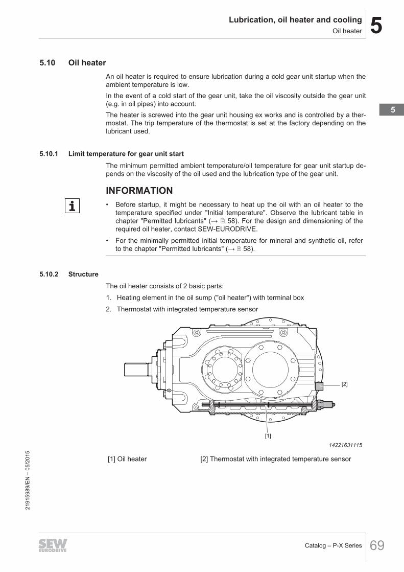
5Lubrication, oil heater and coolingOil heater
Catalog – P-X Series 69
5.10 Oil heaterAn oil heater is required to ensure lubrication during a cold gear unit startup when theambient temperature is low.In the event of a cold start of the gear unit, take the oil viscosity outside the gear unit(e.g. in oil pipes) into account.The heater is screwed into the gear unit housing ex works and is controlled by a ther-mostat. The trip temperature of the thermostat is set at the factory depending on thelubricant used.
5.10.1 Limit temperature for gear unit startThe minimum permitted ambient temperature/oil temperature for gear unit startup de-pends on the viscosity of the oil used and the lubrication type of the gear unit.
INFORMATION• Before startup, it might be necessary to heat up the oil with an oil heater to the
temperature specified under "Initial temperature". Observe the lubricant table inchapter "Permitted lubricants" (→ 2 58). For the design and dimensioning of therequired oil heater, contact SEW‑EURODRIVE.
• For the minimally permitted initial temperature for mineral and synthetic oil, referto the chapter "Permitted lubricants" (→ 2 58).
5.10.2 StructureThe oil heater consists of 2 basic parts:1. Heating element in the oil sump ("oil heater") with terminal box2. Thermostat with integrated temperature sensor
[1]
[2]
14221631115
[1] Oil heater [2] Thermostat with integrated temperature sensor
2191
5989
/EN
– 0
5/20
15
5

5 Lubrication, oil heater and coolingOil heater
Catalog – P-X Series70
INFORMATION• To prevent damage, it is essential that the heating elements are fully immersed in
the oil sump.• The position of the thermostat varies with design and mounting position of the
gear unit.• Not all combinations of accessory options might be possible depending on the
mounting position, gear unit size, and lubrication type. ContactSEW‑EURODRIVE.
• To keep the gear unit startup temperature, the thermostat can be energized con-tinuously. The heating process can take several hours.
• To reduce heating times, an additional heating element (OH-F) can be installed atthe mounting flange. The connected load is specified in chapter "Connectionpower" (→ 2 71).
• For dimensions of the heating elements, see chapter "Oil heater /OH[mm]" (→ 2 107).
5.10.3 Information on the function of the oil heater
• The trip point of the oil heater thermostat is factory-set to a temperature of about5 K above the respective initial temperature for gear unit startup, see chapter Limittemperature for gear unit start.At this temperature, see table "Minimum permitted initial temperature for gear unitstart" in chapter Limit temperature for gear unit start, the thermostat disables theoil heater. Only then can the gear unit be started. The thermostat activates the oilheater again once the temperature is about 5 K below the trip point.
• In order to prevent the oil from burning, the heating elements of the heater have amaximum surface load. This is why the heating process for cold gear unit oil cantake between one and several hours. The exact duration of the heating processbefore the start varies depending on the gear unit size, type, mounting position, oilquantity, and ambient temperature.
• Thermostat and oil heater are installed and ready for operation. Prior to startup,wire them properly and connect them to the current supply.
• Contact SEW‑EURODRIVE if another oil viscosity class is used or if ambient tem-peratures fall below the specified limit temperature.
2191
5989
/EN
– 0
5/20
15

5Lubrication, oil heater and coolingOil heater
Catalog – P-X Series 71
5.10.4 Connection powerThe table shows the power of the heating elements that may be installed.
Peripheral Conditions: Tamb = -20 °C; Mounting position M1 (Splash lubrication)
Size Heating element PInst[W]
Heating over 4h[K]
Max. heating[K]
P042 X2K1101 OH 550 15.3 18.52 OH-F + OH 250 + 550 22.2 26.9
P052 X2K1101 OH 550 14.1 17.62 OH-F + OH 250 + 550 20.6 25.6
P052 X2K1301 OH 680 15 18.62 OH-F + OH 250 + 680 20.5 25.4
P062 X2K1301 OH 680 12.5 16.12 OH-F + OH 250 + 680 17.6 22
P072 X2K1301 OH 680 10.8 14.52 OH-F + OH 250 + 680 14.7 19.8
P072 X2K1501 OH 800 11.3 15.62 OH-F + OH 700 + 800 21.2 29.3
P082 X2K1501 OH 800 9.7 142 OH-F + OH 700 + 800 18.2 16.3
P092 X2K1501 OH 800 8.5 12.92 OH-F + OH 700 + 800 16 24.3
P102 X2K1501 OH 800 7.4 11.72 OH-F + OH 700 + 800 13.8 21.9
P092 X2K1701 OH 940 8.6 12.72 OH-F + OH 780 + 940 15.6 23.2
P102 X2K1701 OH 940 7.5 11.62 OH-F + OH 780 + 940 13.8 21.3
Pinst = Power of the installed heaterOH = Oil heater in the gear unitOH-F = Oil heater in the flange
2191
5989
/EN
– 0
5/20
15
5

5 Lubrication, oil heater and coolingOil heater
Catalog – P-X Series72
5.10.5 Limit temperature for gear unit startThe minimum permitted ambient temperature/oil temperature for gear unit startup de-pends on the viscosity of the oil used and the lubrication type of the gear unit.
INFORMATION• Before startup, it might be necessary to heat up the oil with an oil heater to the
temperature specified under "Initial temperature". Observe the lubricant table inchapter "Permitted lubricants" (→ 2 58). For the design and dimensioning of therequired oil heater, contact SEW‑EURODRIVE.
• For the minimally permitted initial temperature for mineral and synthetic oil, referto the chapter "Permitted lubricants" (→ 2 58).
2191
5989
/EN
– 0
5/20
15

5Lubrication, oil heater and coolingWater cooling cartridge
Catalog – P-X Series 73
5.11 Water cooling cartridgeThe water cooling cartridge can be installed above or beneath the oil level. The waterconnection must be installed by the user.The amount of heat that can be dissipated depends on the intake temperature and theflow rate of the cooling medium that flows through the unit.The data given in the technical specifications must be observed.
5.11.1 Structure
[1][3] [5][4] [2]
[3] [4] [5]
14460603019
[1] Cooling pipes[2] Tube plate with adapter piece[3] Return[4] Supply[5] Assembly opening for optional water cooling cartridge
The water cooling cartridge consists of 3 main parts:• Cooling pipes (CuNi alloy)• Tube plate (brass)• Connection piece (brass; gray cast iron; steel)For connection to the cooling circuit, the following 2 bores with• pipe thread G1/4" for sizes X110 – X170are available. The piping is not included in the delivery.Gear units with water cooling cartridge are delivered completely assembled.Water cooling cartridges can be retrofitted to a certain extent. ContactSEW‑EURODRIVE.
INFORMATIONThe possible use as well as the maximum number of water cooling cartridges de-pends among others from the gear unit size, mounting position, end gear position,and lubrication type. Not all combinations of accessory options might be possible de-pending on the mounting position and mounting surface. Contact SEW‑EURODRIVE.
2191
5989
/EN
– 0
5/20
15
5

5 Lubrication, oil heater and coolingWater cooling cartridge
Catalog – P-X Series74
5.11.2 Notes on connection and operationThe required cooling water flow rate depends on the following characteristics:• Gear unit size• Mounting position• Lubrication typeThe cooling water quantity has to be dimensioned individually for each cooling cart-ridge.
Size/Connection Max. cooling water flow rate[l/min]
X2K110/X2K130 – G1’’ 12
X2K150/X2K170 – G1 1/4’’ 15
INFORMATIONThe cooling circuit must be connected in parallel for gear units with several watercooling cartridges.
INFORMATIONContact SEW‑EURODRIVE in the following cases:• When selecting the water cooling cartridges• When special cooling media are used (then the cooling capacity of the water cool-
ing cartridge changes).• When aggressive cooling media are used, such as brackish water or salt water.
2191
5989
/EN
– 0
5/20
15

5Lubrication, oil heater and coolingWater cooling cartridge
Catalog – P-X Series 75
5.11.3 Requirements on the water quality
INFORMATIONSpecial measures have to be taken when using sea water or brackish water. ContactSEW‑EURODRIVE.
The following requirements on the water quality are recommendations. In exceptionalcases, certain concentrations of substances of content might cause unforeseen reac-tions.The quality of the water as well as its substances are important factors for assessingthe cooling water available for water cooling cartridges. The water quality is determ-ined by the water hardness and the pH value of the water.
Water hardnessWater hardness is defined by the amount of hardeners (carbonates and bicarbonates)in the water. Hardeners accumulate on the surface of the water cooling cartridge inparticular at high temperatures and in this way impair the performance. Take these de-posits into account when selecting the water cooling cartridge for extremely hard wa-ter.The following table shows the classification of German degrees of hardness to waterquality °dH:
Degree of hardness1) Water quality
0 – 5 °dH Very soft water
5 – 10 °dH Soft water
10 – 20 °dH Medium hard water
20 – 30 °dH Hard water
> 30 °dH Very hard water1) 10 mg/l of hardener corresponds to 1 °dH
2191
5989
/EN
– 0
5/20
15
5

5 Lubrication, oil heater and coolingWater cooling cartridge
Catalog – P-X Series76
pH value• The water cooling cartridge partially consists of a copper and nickel alloy, to which
the following applies:→ Corrosion problems when pH value < 6
• With alkaline water:→ Corrosion problems when water hardness < 6°dH.Smaller values can cause corrosion due to free carbonic acid.The following table describes the classification of the water quality based on thepH value:
pH Value Water quality
4.5 Very acidic
4.5 – 6.0 Acidic
6.0 – 6.8 Slightly acidic
7.0 Neutral
7.2 – 7.7 Slightly alkaline
7.7 – 8.2 Alkaline
8.2 Very alkaline
2191
5989
/EN
– 0
5/20
15

5Lubrication, oil heater and coolingWater cooling cartridge
Catalog – P-X Series 77
Cooling water assessment based on water substancesThe following table provides an overview of the resistance of copper pipes againstsubstances in non-potable water.Assessment criterion Approximate concentration [mg/l] Evaluation
CuNi10Fe1MnpH Value < 6 0
6 to 9 +> 9 0
Chloride up to 1000 +> 1000 + (< 25000 mg/l)
Sulfate up to 70 +70 to 300 +
> 300 + (< 25000 mg/l)Nitrate up to 100 +
> 100 0Free (aggressive) carbonic acid up to 20 +
20 to 50 0> 50 –
Oxygen up to 2 +> 2 +
Ammonium up to 2 +2 to 20 +> 20 –
Iron (dissolved) up to 10 0> 10 –
Manganese (dissolved) up to 1 0> 1 –
Free chlorine up to 5 permanently < 0.5 mg/l> 5 intermittently < 3.0 mg/l
Sulfide 0Ammonia + (< 15 mg/l)
Key+ = usually good resistivity0 = corrosion problems can occur in particular if several factors are assessed with 0– = we advise against use
2191
5989
/EN
– 0
5/20
15
5

5 Lubrication, oil heater and coolingWater cooling cartridge
Catalog – P-X Series78
Types of cooling water/characteristicsNote the following conditions:
Industrial water
• Usually untreated water (no drinking water)• Often very contaminated• A water analysis is necessary for assessment• Copper, brass and steel are very resistant against industrial water
Stream water and river water
• We recommend using copper brass pipes• Cast iron parts must be protected against corrosion by suitable coating• Usually untreated water (no drinking water)• Often very contaminated• A water analysis is necessary for assessment
2191
5989
/EN
– 0
5/20
15
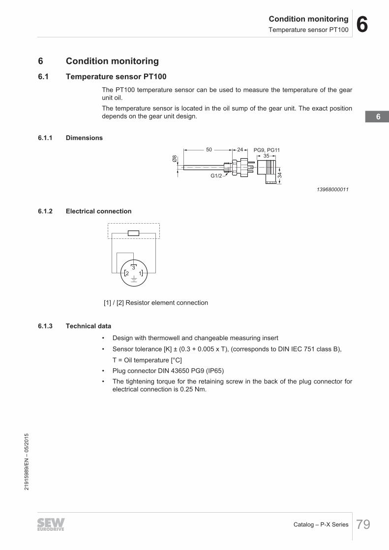
6Condition monitoringTemperature sensor PT100
Catalog – P-X Series 79
6 Condition monitoring6.1 Temperature sensor PT100
The PT100 temperature sensor can be used to measure the temperature of the gearunit oil.The temperature sensor is located in the oil sump of the gear unit. The exact positiondepends on the gear unit design.
6.1.1 Dimensions24
Ø8
G1/2
35PG9, PG11
34
50
13968000011
6.1.2 Electrical connection
3
2 1
[1] / [2] Resistor element connection
6.1.3 Technical data
• Design with thermowell and changeable measuring insert• Sensor tolerance [K] ± (0.3 + 0.005 x T), (corresponds to DIN IEC 751 class B),
T = Oil temperature [°C]• Plug connector DIN 43650 PG9 (IP65)• The tightening torque for the retaining screw in the back of the plug connector for
electrical connection is 0.25 Nm.
2191
5989
/EN
– 0
5/20
15
6

6 Condition monitoringTemperature switch /NTB
Catalog – P-X Series80
6.2 Temperature switch /NTBA temperature switch with preset switching temperatures of 70, 80, 90 or 100 °C isused for monitoring the gear unit oil temperature.For various functions, the temperature switch is also used as limit value switch, for ex-ample• a pre-warning
or• a main alarm for switching off the main motor.To guarantee a long service life and functioning under all conditions, it is recommen-ded to use a relay in the power circuit instead of a direct connection through the tem-perature switch.The temperature switch is located in the oil sump of the gear unit. The exact positiondepends on the gear unit type and shaft position.
6.2.1 Dimensions
51
70
171.5
Ø 2
6.8
14
G1/2"
9007199621265931
6.2.2 Electrical connectionTo guarantee a long service life and trouble-free functioning, we recommend that youuse a relay in the power circuit instead of a direct connection through the temperatureswitch.
[1]
[2]
[3]
366532491
[1][3] NC contact (without vacuum)[2] Grounding terminal 6.3 x 0.8
2191
5989
/EN
– 0
5/20
15

6Condition monitoringTemperature switch /NTB
Catalog – P-X Series 81
6.2.3 Technical data
• Trigger temperature: 70°C, 80°C, 90°C, 100°C ± 5°C• Contact capacity: 10 A - AC 240 V• Plug connector: DIN EN 175301-803 PG9 (IP65)• The tightening torque for the retaining screw in the back of the plug connector for
electrical connection is 0.25 Nm
2191
5989
/EN
– 0
5/20
15
6

6 Condition monitoringTemperature switch /TSK
Catalog – P-X Series82
6.3 Temperature switch /TSKThe TSK temperature switch is used with oil supply systems for circulation cooling. Itis provided with 2 fixed trip points of 60 °C and 90 °C for controlling and monitoring thesystem.The temperature switch is integrated into the circuit of the oil supply system as follows:• Activation of the cooling system once the oil temperature reaches 60 °C• Warning signal or disconnection of the gear unit when the oil temperature exceeds
90 °C (usually a sign of malfunction in the oil supply system)To guarantee a long service life and functioning under all conditions, using a relay inthe power circuit is recommended instead of a direct connection through the temperat-ure switch.The temperature switch is located in the oil sump of the gear unit. The exact positiondepends on the gear unit type and shaft position.
6.3.1 Dimensions57
16
L=80
Ø20
G3/4
SW36
893872779
6.3.2 Electrical connectionTo guarantee a long service life and trouble-free functioning, we recommend that youuse a relay in the power circuit instead of a direct connection through the temperatureswitch.
TKS 60 °C
1 2
3
PE
TKS 90 °C
27021598658101131
[1][2] Switch 60 °C NO contact[1][3] Switch 90 °C NC contactPE Grounding terminal
2191
5989
/EN
– 0
5/20
15

6Condition monitoringDiagnostic unit DUO10A (Oil aging)
Catalog – P-X Series 83
6.3.3 Technical data
• Switching temperatures: 60 °C and 90 °C• Contact capacity: 2 A - AC 240 V• Plug connector: DIN EN 175301-803 PG11 (IP65)• The tightening torque for the retaining screw in the back of the plug connector for
electrical connection is 0.25 Nm
6.4 Diagnostic unit DUO10A (Oil aging)The DUO10A diagnostic unit was developed for timely planning of oil changes.The diagnostic unit consists of a PT100 temperature sensor and an evaluation unit.The temperature sensor installed in the gear unit measures the present gear unit oiltemperature. The diagnostic unit calculates the estimated remaining service life for thegear unit oil based on the measured oil temperature. This calculated value is continu-ously shown on the display of the evaluation unit; when needed, the display can bechanged to the current gear unit oil temperature.The oil types used by SEW are recorded in the evaluation unit, wherein a type of oilapproved by SEW‑EURODRIVE can be customized.Oil grades:
Oil type Designation Limit temperatureMineral oil CLP/ Bio oil OIL1 100 °C
Synthetic oil CLPHC/CLP-PAO
OIL2 130 °C
Polyglycol oil CLPPG OIL3 130 °C
Food grade oil OIL4 100 °C
Customer-specific OIL5 Default setting = OIL1
4 switching outputs (NC/NO contact) with the following functions are available to con-nect the evaluation unit:• Early warning:
Is set to a few days before expiration of the remaining service life. The number ofdays can be set directly on the evaluation unit.
• Main alarm:Is set when the estimated remaining service life reaches zero.
• Limit temperature:Shows when the permitted oil temperature has been exceeded.
• Ready for operation:Displays errors in the wiring and recognizable faults in the evaluation unit.
INFORMATIONFurther information about the evaluation unit and accessories is found the "DUO10ADiagnostic Unit" manual, part no. 11473428.
2191
5989
/EN
– 0
5/20
15
6

6 Condition monitoringDiagnostic unit DUO10A (Oil aging)
Catalog – P-X Series84
6.4.1 Dimensions
48
60
94
∅34
16,5
G½ M12x1
M12x1
8977554699
6.4.2 Mounting examples
24 V DC
[1]
14359718923
[1] DUO10A diagnostic unit
2191
5989
/EN
– 0
5/20
15

7Design and operating notesScrews included in the delivery
Catalog – P-X Series 85
7 Design and operating notes7.1 Screws included in the delivery
For the following gear unit designs, the screws are included in the delivery:• Gear unit with torque arm
13888369035
Not included in the delivery:• Set of wrenches• Torque wrench• Mounting device• Compensation elements (shims, spacer rings), if necessary• Fasteners for input and output elements• Lubricant e.g. NOCO® fluid from SEW‑EURODRIVE• Aids for assembly/disassembly onto the machine shaft• Fasteners for the gear unit base• Connection screws for flange-mounted gear units
13888365707
2191
5989
/EN
– 0
5/20
15
7

7 Design and operating notesOutput shaft as hollow shaft with shrink disk
Catalog – P-X Series86
7.2 Output shaft as hollow shaft with shrink diskTo guarantee a complete torque transmission from the gear unit to the machine shaft,observe the following procedure during construction and assembly.Push the gear unit onto the machine shaft until the contact surfaces [1] touch.
[1]
[1]
11980869643
2191
5989
/EN
– 0
5/20
15

8Important information on selection tables and dimension drawingsSelection tables
Catalog – P-X Series 87
8 Important information on selection tables and dimensiondrawings
The following pages contain important information for chapters 10 and 11.
INFORMATIONUnless specified otherwise, all dimensions are given in mm.
8.1 Selection tables
INFORMATIONThe selection tables show possible gear unit combinations. Different gear ratioranges and options are possible. X.. series gear units are used as primary gear unitin this case. Please contact SEW‑EURODRIVE.
The following figure shows the structure of the selection tables.
P.042 X2K. n1 = 1000 min-1
100 kNm
PTH [kW] M1
20 °C 40 °C
Designation itot n2 [min-1] PN1 [kW] + +
P.042 X2KP110 159
178
202*
226*
6,3
5,6
5
4,4
69
61
54
48
55
55
53
52
76
76
72
71
)
37
37
37
53
54
52
51
[1] [2] [3] [4] [8] [9] [10][7][6] [5]
9007213977371659
[1] Gear unit designation
[2] Input speed (HSS)
[3] Total gear unit ratio (rounded)
[4] Output speed (LSS)
[5] Nominal gear unit torque
[6] Nominal gear unit power
Thermal rating at 20 °C ambient temperature, mounting position M1[7] without fan
[8] With fan in motor adapter
Thermal rating at 40 °C ambient temperature, mounting position M1[9] without fan
[10] With fan in motor adapter
) Contact SEW‑EURODRIVE
* X2K. primary gear units have a gear ratio iN ≥10
2191
5989
/EN
– 0
5/20
15
8

8 Important information on selection tables and dimension drawingsDimension sheets
Catalog – P-X Series88
8.2 Dimension sheets8.2.1 Scope of delivery
= Standard parts supplied by SEW‑EURODRIVE.
= Standard parts not supplied by SEW‑EURODRIVE.
8.2.2 Tolerances
KeysKeys: according to DIN 6885 (domed type A)
SplineSplined shaft according to DIN 5480
8.2.3 Dimensions of motors and planetary gear units
Motor optionsThe motor dimensions can change when installing motor options. Refer to the dimen-sion drawings of the motor options.
Special designsThe dimensions of the terminal box on special designs such as KS, CSA, VIK, lowvoltage or voltage changeover may deviate from the standard dimensions.
EN 50347European standard EN 50347 became effective in August 2001. This standard adoptsthe dimension designations for three-phase AC motors for sizes 56 to 315M andflange sizes 65 to 740 from the IEC 72-1 standard.The new dimension designations given in EN 50347 / IEC 72-1 are used for the di-mensions in question in the dimension tables of the dimensions sheets.
2191
5989
/EN
– 0
5/20
15

9Selection tables
Catalog – P-X Series 89
9 Selection tablesP.042 X2K. n1 = 1000 min-1 100170 Nm
PTH [kW] M120 °C 40 °C
Designation itot n2 [min-1] PN1 [kW] + +
P.042 X2KP110 159178202*226*246*276*310348393*440*480*538*
6.35.65.04.44.13.63.22.92.52.32.11.9
696154484540353128252321
555553524950494948474445
767672716767676864636060
353737373535323333333232
535452514848484846464344
P.042X2K. n1 = 1200 min-1 100170 NmP.042 X2KP110 159
178202*226*246*276*310348393*440*480*538*
7.56.75.95.34.94.33.93.43.12.72.52.2
837465585448423833302825
525453525050474848474545
787976757171707068676363
303234353435282931313031
535453535051474848474546
P.042 X2K. n1 = 1500 min-1 100170 NmP.042 X2KP110 159
178202*226*246*276*310348393*440*480*538*
9.48.47.46.66.15.44.84.33.83.43.12.8
1039281736760534742373531
444750515050404245454545
808180797576727272716868
182128293031182026272728
485154545253444548484748
P.042 X2K. n1 = 1800 min-1 100170 NmP.042 X2KP110 159
178202*226*246*276*310348393*440*480*538*
11.310.18.98.07.36.55.85.24.64.13.83.3
12411198878172645750454137
313544454647303241414243
778082827979697174737171
))
19212425))
18202223
404351525253373946474748
2191
5989
/EN
– 0
5/20
15
9

9 Selection tables
Catalog – P-X Series90
P.052 X2K. n1 = 1000 min-1 124060 NmPTH [kW] M1
20 °C 40 °C
Designation itot n2 [min-1] PN1 [kW] + +
P.052 X2KP130 160182200227*248*281*
6.35.55.04.44.03.6
857468605549
626262646060
929189898382
343638403939
606061625958
P.052 X2KP110 310348393*440*480*538*
3.22.92.52.32.11.9
443935312925
535351504848
737369686464
353636363434
525250494747
P.052 X2K. n1 = 1200 min-1 124060 NmP.052 X2KP130 160
182200227*248*281*
7.56.66.05.34.84.3
1028981726659
535458605858
919291928786
202430333435
535558615959
P.052 X2KP110 310348393*440*480*538*
3.93.43.12.72.52.2
524741373431
515352514949
767673726868
313234343334
525352514949
P.052 X2K. n1 = 1500 min-1 124060 NmP.052 X2KP130 160
182200227*248*281*
9.48.27.56.66.05.3
127112102908373
303446505152
838591949190
)))
172325
364051545657
P.052 X2KP110 310348393*440*480*538*
4.84.33.83.43.12.8
665852464338
454750504949
787977767373
212329303031
495053535151
P.052 X2K. n1 = 1800 min-1 124060 NmP.052 X2KP130 160
182200227*248*281*
11.39.99.07.97.36.4
1521341221079988
))
28334043
667085899091
))))))
))
38434951
P.052 X2KP110 310348393*440*480*538*
5.85.24.64.13.83.3
797062555146
353745464647
777980797777
))
22232526
424551525252
2191
5989
/EN
– 0
5/20
15

9Selection tables
Catalog – P-X Series 91
P.062 X2K. n1 = 1000 min-1 185660 NmPTH [kW] M1
20 °C 40 °C
Designation itot n2 [min-1] PN1 [kW] + +
P.062 X2KP130 160182200227*248*281*312354390443*483*548*
6.35.55.04.44.03.63.22.82.62.32.11.8
127111101898373655752464237
787877787272707069706665
1121111061079997
1009995968988
464849514949434345464444
767675767170686867686463
P.062 X2K. n1 = 1200 min-1 185660 NmP.062 X2KP130 160
182200227*248*281*312354390443*483*548*
7.56.66.05.34.84.33.83.43.12.72.52.2
1521341221079988786962555145
707174767372636466686565
11311211011110410310210199
1009493
343743454546323439414142
717274777372646567696666
P.062 X2K. n1 = 1500 min-1 185660 NmP.062 X2KP130 160
182200227*248*281*312354390443*483*548*
9.48.27.56.66.05.34.84.23.83.43.12.7
190167152134124109988678696456
495363676768475058616161
1091101141151101099899
10310410098
))
26313537))
26293334
565969737273535563656565
P.062 X2K. n1 = 1800 min-1 185660 NmP.062 X2KP130 160
182200227*248*281*312354390443*483*548*
11.39.99.07.97.36.45.85.14.64.13.73.3
22820118216114913111710394827667
132247525860192545485355
9599
1121161131138790
101103103102
))))
2023))))
2023
303758636869323755586263
2191
5989
/EN
– 0
5/20
15
9

9 Selection tables
Catalog – P-X Series92
P.072 X2K. n1 = 1000 min-1 245660 NmPTH [kW] M1
20 °C 40 °C
Designation itot n2 [min-1] PN1 [kW] + +
P.072 X2KP150 162174206*220*251*269*
6.25.74.94.54.03.7
166154130122108101
112112106106102101
157155144143136135
747573737171
1091091041039999
P.072 X2KP130 303344378430*469*532*
3.32.92.62.32.11.9
897871625851
858482827776
118117112112104102
545455565454
838280807574
P.072 X2K. n1 = 1200 min-1 245660 NmP.072 X2KP150 162
174206*220*251*269*
7.46.95.85.54.84.5
199185156146130121
109109106106103103
163162154152145144
676870717171
110110107107104104
P.072 X2KP130 303344378430*469*532*
4.03.53.22.82.62.3
1069485756961
798081827877
122120117118110108
444650525151
808081837877
P.072 X2K. n1 = 1500 min-1 245660 NmP.072 X2KP150 162
174206*220*251*269*
9.38.67.36.86.05.6
248231195183162151
98100103104103103
167167163162157156
505262636667
106107109110109109
P.072 X2KP130 303344378430*469*532*
5.04.44.03.53.22.8
133117106948776
636674767575
121121122123117116
202437414344
707279828080
P.072 X2K. n1 = 1800 min-1 245600 NmP.072 X2KP150 162
174206*220*251*269*
11.110.38.78.27.26.7
298278234220194181
80839597
100100
166168168168166165
212649515960
9598
108109111112
P.072 X2KP130 303344378430*469*532*
5.95.24.84.23.83.4
15914012811210492
374361656869
113114124126122121
))
17233232
515672767878
2191
5989
/EN
– 0
5/20
15

9Selection tables
Catalog – P-X Series 93
P.082 X2K. n1 = 1000 min-1 359400 NmPTH [kW] M1
20 °C 40 °C
Designation itot n2 [min-1] PN1 [kW] + +
P.082 X2KP150 164176208*222*254*272*304326385*413*471*504*
6.15.74.84.53.93.73.33.12.62.42.12.0
239223189177156146129120102958479
129129122121116115118118112111106105
178177164163154152162161150148141139
868784858282818178787675
126126119119113112115115109108104103
P.082 X2K. n1 = 1200 min-1 359400 NmP.082 X2KP150 164
176208*222*254*272*304326385*413*471*504*
7.36.85.85.44.74.43.93.73.12.92.52.4
28726822621218717515514512211410194
126127123123119118117117113113109108
187186174173165163171170160158151149
798082828282767777777676
127128123123119119118118114113109109
P.082 X2K. n1 = 1500 min-1 359400 NmP.082 X2KP150 164
176208*222*254*272*304326385*413*471*504*
9.18.57.26.85.95.54.94.63.93.63.23.0
359335283265234219194181153143126118
116118120120119119110111112112110110
194194187186179178178178171170164163
616474757879636571727474
124126127127126126118118118118116116
P.082 X2K. n1 = 1800 min-1 359400 NmP.082 X2KP150 164
176208*222*254*272*304326385*413*471*504*
11.010.28.78.17.16.65.95.54.74.43.83.6
431401340318281262232217184171152142
9710111211411711798
100107108109109
194196195195191190181182180179175174
323860637172434662636969
114117127128129130112114120120120120
2191
5989
/EN
– 0
5/20
15
9

9 Selection tables
Catalog – P-X Series94
P.092 X2K. n1 = 1000 min-1 423000 NmPTH [kW] M1
20 °C 40 °C
Designation itot n2 [min-1] PN1 [kW] + +
P.092 X2KP170 160179198223*242*272*
6.35.65.14.54.13.7
289258233207193172
165165165165157155
236234230226212209
104106110111108108
160161161161153152
P.092 X2KP150 318340403*431*492*527*
3.12.92.52.32.01.9
1451361151079589
131130122122116115
177176163161153151
909086868383
127127120119113112
P.092 X2K. n1 = 1200 min-1 423000 NmP.092 X2KP170 160
179198223*242*272*
7.56.76.15.45.04.4
346310280249231206
155157161162157156
241241241238226222
8791
100102103104
156158162163158157
P.092 X2KP150 318340403*431*492*527*
3.83.53.02.82.42.3
174163138129114106
130130125124120119
188186174173164163
868686868484
131131125125120119
P.092 X2K. n1 = 1500 min-1 423000 NmP.092 X2KP170 160
179198223*242*272*
9.48.47.66.76.25.5
433387350311289257
128133147150152153
239242248248240239
455576819194
139145158160161162
P.092 X2KP150 318340403*431*492*527*
4.74.43.73.53.02.8
218204172161142133
125125124124122122
198197189187179178
747581818383
132133131131128128
P.092 X2K. n1 = 1800 min-1 423000 NmP.092 X2KP170 160
179198223*242*272*
11.310.19.18.17.46.6
520464420373347309
8395
122128140143
227232248250249248
))
37477176
110120144149159161
P.092 X2KP150 318340403*431*492*527*
5.75.34.54.23.73.4
261245206193171159
113115121121122122
203203199198193191
555872737879
129130134134134134
2191
5989
/EN
– 0
5/20
15

9Selection tables
Catalog – P-X Series 95
P.102 X2K. n1 = 1000 min-1 500000 NmPTH [kW] M1
20 °C 40 °C
Designation itot n2 [min-1] PN1 [kW] + +
P.102 X2KP170 157177196220*239*269*
6.45.65.14.54.23.7
348308279248231205
191191191190179176
269266260257240236
122125128129124124
185186186185175172
P.102 X2KP150 314336398*426*486*520*
3.23.02.52.32.11.9
174163137128114106
152151140139132131
203201186184174172
1061061011009696
148147137136129128
P.102 X2K. n1 = 1200 min-1 500000 NmP.102 X2KP170 157
177196220*239*269*
7.66.86.15.55.04.5
417370334298277246
181183187188180180
278278274271255252
105110118121120121
182185189189181181
P.102 X2KP150 314336398*426*486*520*
3.83.63.02.82.52.3
209195165154136127
153152145144137136
216214199197187186
1021031001009897
153153145145138137
P.102 X2K. n1 = 1500 min-1 500000 NmP.102 X2KP170 157
177196220*239*269*
9.68.57.76.86.35.6
522463418372346308
153160174177176177
279281287287275271
627394
100109111
167173185188187187
P.102 X2KP150 314336398*426*486*520*
4.84.53.83.53.12.9
261244206192170159
148149146146142141
231230217215205203
919397979797
157157153153149148
P.102 X2K. n1 = 1800 min-1 500000 NmP.102 X2KP170 157
177196220*239*269*
11.510.29.28.27.56.7
626555501447416369
108121148155165168
268274290292287286
))
55668994
137148173179186188
P.102 X2KP150 314336398*426*486*520*
5.75.44.54.23.73.5
313293247231204191
138139143144143142
239239231230221219
737689909494
155157158158156156
2191
5989
/EN
– 0
5/20
15
9

10 Dimension sheets
Catalog – P-X Series96
10 Dimension sheets
PF.. [Kg] PHF... [Kg]860 865
2191
5989
/EN
– 0
5/20
15

10Dimension sheets
Catalog – P-X Series 97
PF.. [Kg] PHF... [Kg]1 000 990
2191
5989
/EN
– 0
5/20
15
10

10 Dimension sheets
Catalog – P-X Series98
PF.. [Kg] PHF... [Kg]1 130 1 125
2191
5989
/EN
– 0
5/20
15

10Dimension sheets
Catalog – P-X Series 99
PF.. [Kg] PHF... [Kg]1 475 1 465
2191
5989
/EN
– 0
5/20
15
10

10 Dimension sheets
Catalog – P-X Series100
PF.. [Kg] PHF... [Kg]1 775 1 825
2191
5989
/EN
– 0
5/20
15

10Dimension sheets
Catalog – P-X Series 101
PF.. [Kg] PHF... [Kg]1 985 2 040
2191
5989
/EN
– 0
5/20
15
10

10 Dimension sheets
Catalog – P-X Series102
PF.. [Kg] PHF... [Kg]2 510 2 505
2191
5989
/EN
– 0
5/20
15

10Dimension sheets
Catalog – P-X Series 103
PF.. [Kg] PHF... [Kg]2 985 3 000
2191
5989
/EN
– 0
5/20
15
10

10 Dimension sheets
Catalog – P-X Series104
PF.. [Kg] PHF... [Kg]3 305 3 320
2191
5989
/EN
– 0
5/20
15

10Dimension sheets
Catalog – P-X Series 105
PF.. [Kg] PHF... [Kg]3 580 3 645
2191
5989
/EN
– 0
5/20
15
10

10 Dimension sheets
Catalog – P-X Series106
PF.. [Kg] PHF... [Kg]3 900 3 965
2191
5989
/EN
– 0
5/20
15

11Options dimension sheetsOil heater /OH [mm]
Catalog – P-X Series 107
11 Options dimension sheets11.1 Oil heater /OH [mm]
AO AO1 AO2 AOH AOH1 AOH2 □BO CO LC LCFX2K110 129 44.5 85 20 50 158.5 100 100 580 340X2K130 170 85 103 22 60 178.5 100 100 680 340X2K150 205 122.5 115 24 70 205 100 100 780 510X2K170 250 162.5 151 35 80 238 100 100 890 560
2191
5989
/EN
– 0
5/20
15
11

11 Options dimension sheetsOil drain valve ODV / Oil dipstick OD [mm]
Catalog – P-X Series108
11.2 Oil drain valve ODV / Oil dipstick OD [mm]
ODV ODCV1 GV1 AS
X2K110 155 G1/2" 465X2K130 121.5 G1/2" 550X2K150 121.5 G1/2" 630X2K170 121.5 G1/2" 735
2191
5989
/EN
– 0
5/20
15

11Options dimension sheetsBackstop /BS [mm]
Catalog – P-X Series 109
11.3 Backstop /BS [mm]
AB Ø EB WBX2K110 184 175 244X2K130 226 190 268X2K150 267 210 295X2K170 325 245 343
2191
5989
/EN
– 0
5/20
15
11
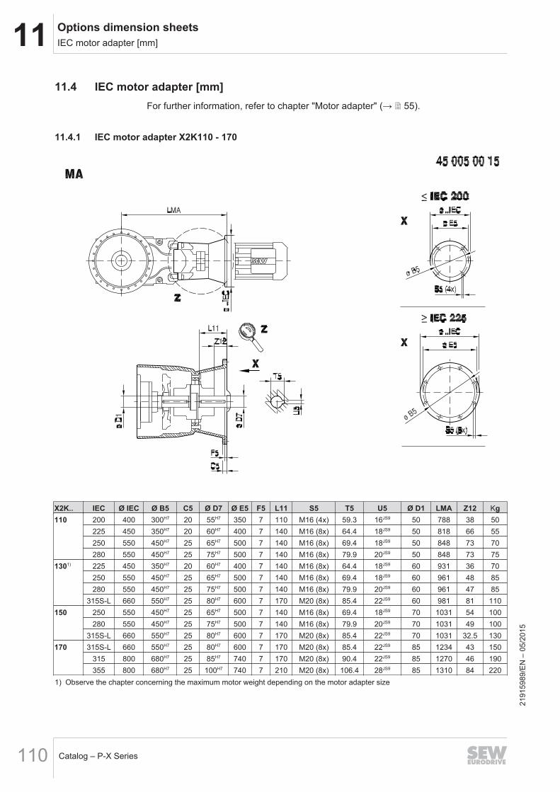
11 Options dimension sheetsIEC motor adapter [mm]
Catalog – P-X Series110
11.4 IEC motor adapter [mm]For further information, refer to chapter "Motor adapter" (→ 2 55).
11.4.1 IEC motor adapter X2K110 - 170
X2K.. IEC Ø IEC Ø B5 C5 Ø D7 Ø E5 F5 L11 S5 T5 U5 Ø D1 LMA Z12 Kg110 200 400 300H7 20 55H7 350 7 110 M16 (4x) 59.3 16JS9 50 788 38 50
225 450 350H7 20 60H7 400 7 140 M16 (8x) 64.4 18JS9 50 818 66 55250 550 450H7 25 65H7 500 7 140 M16 (8x) 69.4 18JS9 50 848 73 70280 550 450H7 25 75H7 500 7 140 M16 (8x) 79.9 20JS9 50 848 73 75
1301) 225 450 350H7 20 60H7 400 7 140 M16 (8x) 64.4 18JS9 60 931 36 70250 550 450H7 25 65H7 500 7 140 M16 (8x) 69.4 18JS9 60 961 48 85280 550 450H7 25 75H7 500 7 140 M16 (8x) 79.9 20JS9 60 961 47 85
315S-L 660 550H7 25 80H7 600 7 170 M20 (8x) 85.4 22JS9 60 981 81 110150 250 550 450H7 25 65H7 500 7 140 M16 (8x) 69.4 18JS9 70 1031 54 100
280 550 450H7 25 75H7 500 7 140 M16 (8x) 79.9 20JS9 70 1031 49 100315S-L 660 550H7 25 80H7 600 7 170 M20 (8x) 85.4 22JS9 70 1031 32.5 130
170 315S-L 660 550H7 25 80H7 600 7 170 M20 (8x) 85.4 22JS9 85 1234 43 150315 800 680H7 25 85H7 740 7 170 M20 (8x) 90.4 22JS9 85 1270 46 190355 800 680H7 25 100H7 740 7 210 M20 (8x) 106.4 28JS9 85 1310 84 220
1) Observe the chapter concerning the maximum motor weight depending on the motor adapter size
2191
5989
/EN
– 0
5/20
15
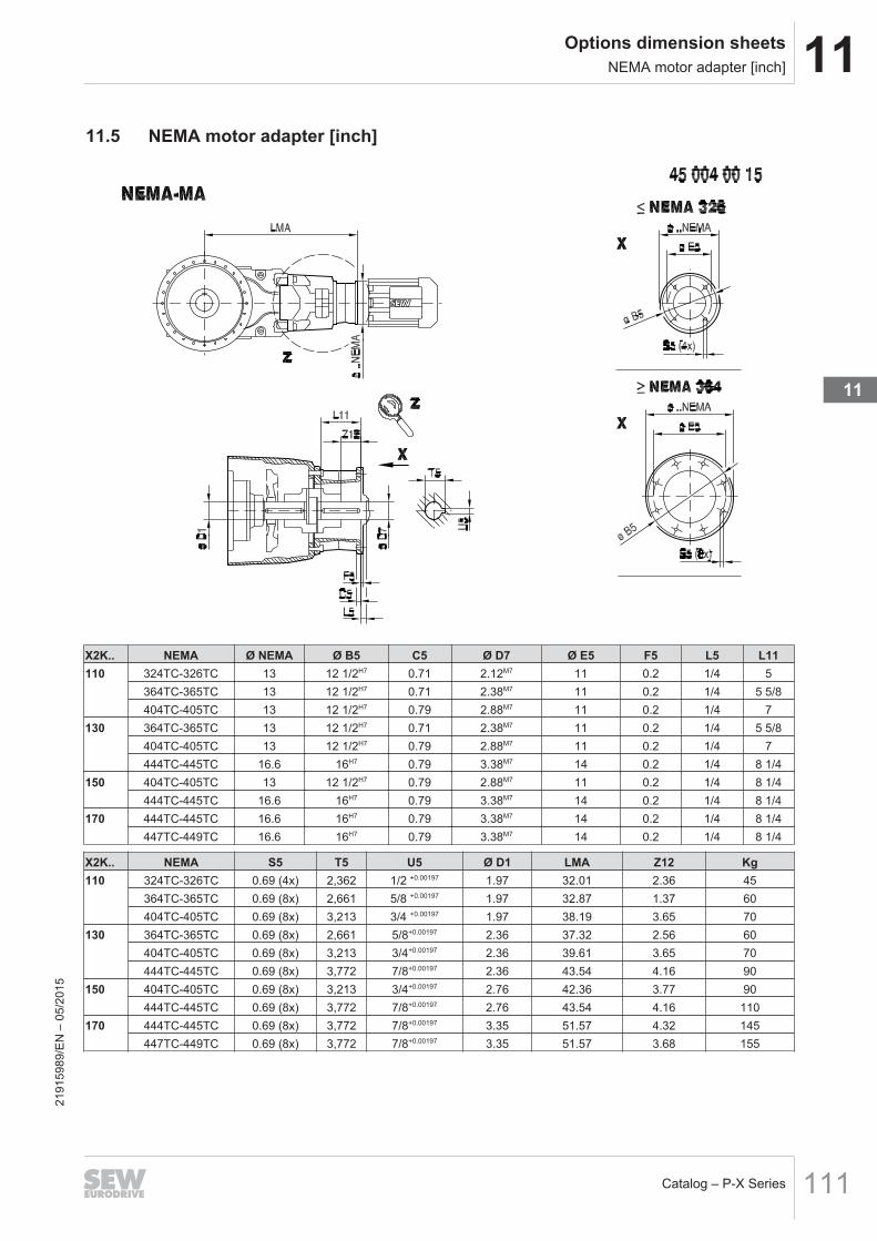
11Options dimension sheetsNEMA motor adapter [inch]
Catalog – P-X Series 111
11.5 NEMA motor adapter [inch]
X2K.. NEMA Ø NEMA Ø B5 C5 Ø D7 Ø E5 F5 L5 L11110 324TC-326TC 13 12 1/2H7 0.71 2.12M7 11 0.2 1/4 5
364TC-365TC 13 12 1/2H7 0.71 2.38M7 11 0.2 1/4 5 5/8404TC-405TC 13 12 1/2H7 0.79 2.88M7 11 0.2 1/4 7
130 364TC-365TC 13 12 1/2H7 0.71 2.38M7 11 0.2 1/4 5 5/8404TC-405TC 13 12 1/2H7 0.79 2.88M7 11 0.2 1/4 7444TC-445TC 16.6 16H7 0.79 3.38M7 14 0.2 1/4 8 1/4
150 404TC-405TC 13 12 1/2H7 0.79 2.88M7 11 0.2 1/4 8 1/4444TC-445TC 16.6 16H7 0.79 3.38M7 14 0.2 1/4 8 1/4
170 444TC-445TC 16.6 16H7 0.79 3.38M7 14 0.2 1/4 8 1/4447TC-449TC 16.6 16H7 0.79 3.38M7 14 0.2 1/4 8 1/4
X2K.. NEMA S5 T5 U5 Ø D1 LMA Z12 Kg110 324TC-326TC 0.69 (4x) 2,362 1/2 +0.00197 1.97 32.01 2.36 45
364TC-365TC 0.69 (8x) 2,661 5/8 +0.00197 1.97 32.87 1.37 60404TC-405TC 0.69 (8x) 3,213 3/4 +0.00197 1.97 38.19 3.65 70
130 364TC-365TC 0.69 (8x) 2,661 5/8+0.00197 2.36 37.32 2.56 60404TC-405TC 0.69 (8x) 3,213 3/4+0.00197 2.36 39.61 3.65 70444TC-445TC 0.69 (8x) 3,772 7/8+0.00197 2.36 43.54 4.16 90
150 404TC-405TC 0.69 (8x) 3,213 3/4+0.00197 2.76 42.36 3.77 90444TC-445TC 0.69 (8x) 3,772 7/8+0.00197 2.76 43.54 4.16 110
170 444TC-445TC 0.69 (8x) 3,772 7/8+0.00197 3.35 51.57 4.32 145447TC-449TC 0.69 (8x) 3,772 7/8+0.00197 3.35 51.57 3.68 155
2191
5989
/EN
– 0
5/20
15
11

Index
IndexA
Area of operation................................................. 11
B
BackstopDimension sheet........................................... 109Structure......................................................... 54
Bearing greases .................................................. 65Brakemotors ........................................................ 12
C
Churning losses................................................... 34Clockwise rotation ............................................... 54Connection screws, scope of delivery ................. 85Corrosion and surface protection ........................ 28Counterclockwise rotation ................................... 54
D
Design features ................................................... 11Designs ............................................................... 14Dimension sheets ................................................ 96Dimension sheets, note....................................... 88Dimensioning....................................................... 31Direction of rotation dependencies...................... 24DUO10A diagnostic unit ...................................... 83
E
Efficiency ............................................................. 34Exterior corrosion protection ............................... 26
F
Fan ...................................................................... 55Fixed pivoted mounting position
Definition ........................................................ 19Foot-mounted design .......................................... 55
G
Gear unit venting ................................................. 66General information............................................. 11
H
Hollow shaft with shrink disk ............................... 86
I
IEC....................................................................... 55
Internal conservation ........................................... 26
K
Keys .................................................................... 88
L
Limit temperature for gear unit startup .......... 69, 72Long-term protection ........................................... 26Lubricant fill quantities......................................... 64Lubricating greases ............................................. 65Lubrication type ................................................... 65
M
Motor adapterIEC dimension sheet .................................... 110NEMA dimension sheet................................ 111Structure......................................................... 55
Motor dimensions ................................................ 88Motor options....................................................... 88Motor, dimensions ............................................... 88Mounting position ................................................ 17Mounting position of the primary gear unit .......... 23
N
Nameplate ........................................................... 16NEMA .................................................................. 55Noise ................................................................... 12NTB ..................................................................... 80NTB temperature switch...................................... 80
Dimensions..................................................... 80Electrical connection ...................................... 80Technical data ................................................ 81
O
OH ....................................................................... 69Oil aging, diagnostics .......................................... 83Oil dipstick
Dimension sheet........................................... 108Oil drain ............................................................... 67Oil drain valve...................................................... 68
Dimension sheet........................................... 108Oil filling............................................................... 66Oil heater
Connected load .............................................. 71Dimension sheet........................................... 107
2191
5989
/EN
– 0
5/15
Catalog – P-X Series112

Index
Function.......................................................... 70Limit temperature for gear unit startup ..... 69, 72Structure......................................................... 69
Oil level glassDimension sheet........................................... 108
Oil quantities........................................................ 64Oil selection
Mineral oil ....................................................... 57Notes .............................................................. 57Synthetic oil .................................................... 57
Operating torque ................................................. 34OS ....................................................................... 29Overview of advantages...................................... 11
P
Packaging............................................................ 26Painting ............................................................... 12Peak load factor .................................................. 37Pivoted mounting position
Definition ........................................................ 18Product description, general information............. 11Product groups ...................................................... 6Product names ...................................................... 9Project planning for gear units
Permitted overhung load ................................ 42
S
Scope of delivery................................................. 85Sealing grease .................................................... 65Selection tables, structure ................................... 87Service factor, application-specific ...................... 34SEW-EURODRIVE
Group of companies ......................................... 5
SEW‑EURODRIVEProducts ........................................................... 6Systems............................................................ 6
Standard protection ............................................. 26Startup factor ....................................................... 37Storage and transport conditions ........................ 26Storage conditions............................................... 27
T
Technical data ..................................................... 14Temperature sensor PT100 ................................ 79Tolerances........................................................... 88Torque ................................................................. 14Torque arm.......................................................... 52Trademarks ........................................................... 9TSK...................................................................... 82TSK temperature switch ...................................... 82
Dimensions..................................................... 82Electrical connection ...................................... 82Technical data ................................................ 83
Type designation ................................................. 15
V
Variable pivoted mounting positionDefinition ........................................................ 20
W
Water cooling cartridgeRequirements on the water quality................. 75Sizes............................................................... 74Structure......................................................... 73Types of cooling water ................................... 78
2191
5989
/EN
– 0
5/15
Catalog – P-X Series 113

12 Address Directory
Catalog – P-X Series114
12 Address DirectoryGermanyHeadquartersProduction plantSales
Bruchsal SEW-EURODRIVE GmbH & Co KGErnst-Blickle-Strasse 4276646 Bruchsal, GermanyP.O. box addressPostfach 3023 • D-76642 Bruchsal, Germany
Tel. +49 7251 75-0Fax +49 7251 75-1970http://[email protected]
Production Plant / In-dustrial Gear Units
Bruchsal SEW-EURODRIVE GmbH & Co KGChristian-Pähr-Str.1076646 Bruchsal, Germany
Tel. +49 7251 75-0Fax +49 7251 75-2970
Production plant Graben SEW-EURODRIVE GmbH & Co KGErnst-Blickle-Strasse 176676 Graben-Neudorf, GermanyP.O. box addressPostfach 1220 • 76671 Graben-Neudorf, Ger-many
Tel. +49 7251 75-0Fax +49 7251 75-2970
Östringen SEW-EURODRIVE GmbH & Co KG, OestringenPlantFranz-Gurk-Strasse 276684 Oestringen, Germany
Tel. +49 7253 9254-0Fax +49 7253 9254-90oestringen@sew‑eurodrive.de
Service CompetenceCenters
Mechanical/MechatronicComponents
SEW-EURODRIVE GmbH & Co KGErnst-Blickle-Strasse 176676 Graben-Neudorf, Germany
Tel. +49 7251 75-1710Fax +49 7251 75-1711sc-mitte@sew‑eurodrive.de
Electronics SEW-EURODRIVE GmbH & Co KGErnst-Blickle-Strasse 4276646 Bruchsal, Germany
Tel. +49 7251 75-1780Fax +49 7251 [email protected]
Drive TechnologyCenter
North SEW-EURODRIVE GmbH & Co KGAlte Ricklinger Strasse 40-4230823 Garbsen (near Hanover)
Tel. +49 5137 8798-30Fax +49 5137 [email protected]
East SEW-EURODRIVE GmbH & Co KGDaenkritzer Weg 108393 Meerane (near Zwickau)
Tel. +49 3764 7606-0Fax +49 3764 7606-30sc-ost@sew‑eurodrive.de
South SEW-EURODRIVE GmbH & Co KGDomagkstrasse 585551 Kirchheim (near Munich)
Tel. +49 89 909552-10Fax +49 89 909552-50sc-sued@sew‑eurodrive.de
West SEW-EURODRIVE GmbH & Co KGSiemensstrasse 140764 Langenfeld (near Düsseldorf)
Tel. +49 2173 8507-30Fax +49 2173 8507-55sc-west@sew‑eurodrive.de
Drive Service Hotline/24-hour availability +49 800 SEWHELP+49 800 7394357
Technical offices Augsburg SEW-EURODRIVE GmbH & Co KGAugust-Wessels-Strasse 2786156 Augsburg, Germany
Tel. +49 821 22779-10Fax +49 821 22779-50tb-augsburg@sew‑eurodrive.de
Berlin SEW-EURODRIVE GmbH & Co KGLilienthalstrasse 3a12529 Schoenefeld, Germany
Tel. +49 306331131-30Fax +49 306331131-36tb-berlin@sew‑eurodrive.de
Lake Constance SEW-EURODRIVE GmbH & Co KGDornierstraße 488677 Markdorf, Germany
Tel. +49 7544 96590-90Fax +49 7544 96590-99tb-bodensee@sew‑eurodrive.de
Bremen SEW-EURODRIVE GmbH & Co KGBornstr.19 ... 2228195 Bremen, Germany
Tel. +49 421 33918-10Fax +49 421 33918-22tb-bremen@sew‑eurodrive.de
Dortmund SEW-EURODRIVE GmbH & Co KGHildastraße 844145 Dortmund, Germany
Tel. +49 231 229028-10Fax +49 231 229028-20tb-dortmund@sew‑eurodrive.de
Dresden SEW-EURODRIVE GmbH & Co KGHauptstrasse 3201445 Radebeul, Germany
Tel. +49 351 26338-0Fax +49 351 26338-38tb-dresden@sew‑eurodrive.de
Erfurt SEW-EURODRIVE GmbH & Co KGDubliner Strasse 1299091 Erfurt, Germany
Tel. +49 361 21709-70Fax +49 361 21709-79tb-erfurt@sew‑eurodrive.de
Guestrow SEW-EURODRIVE GmbH & Co KGGlasewitzer Chaussee 33 B18273 Guestrow, GermanyP.O. box addressPostfach 1216 • 18262 Güstrow, Germany
Tel. +49 3843 8557-80Fax +49 3843 8557-88tb-guestrow@sew‑eurodrive.de 21
9159
89/E
N –
05/
2015

12Address Directory
Catalog – P-X Series 115
GermanyHamburg SEW-EURODRIVE GmbH & Co KG
Bramfelder Strasse 11922305 Hamburg, Germany
Tel. +49 40 298109-60Fax +49 40 298109-70tb-hamburg@sew‑eurodrive.de
Hanover/Garbsen SEW-EURODRIVE GmbH & Co KGAlte Ricklinger Str.40-4230823 Garbsen, GermanyP.O. box addressPostfach 1104 53 • 30804 Garbsen, Germany
Tel. +49 5137 8798-10Fax +49 5137 8798-50tb-hannover@sew‑eurodrive.de
Heilbronn SEW-EURODRIVE GmbH & Co KGZeppelinstrasse 774357 Boennigheim, Germany
Tel. +49 7143 8738-0Fax +49 7143 8738-25tb-heilbronn@sew‑eurodrive.de
Herford SEW-EURODRIVE GmbH & Co KGGöbenstraße 3 – 732052 Herford
Tel. +49 5221 9141-0Fax +49 5221 9141-20tb-herford@sew‑eurodrive.de
Karlsruhe SEW-EURODRIVE GmbH & Co KGEttlinger Weg 276467 Bietigheim, GermanyP.O. box addressPostfach 43 • 76463 Bietigheim, Germany
Tel. +49 7245 9190-10Fax +49 7245 9190-20tb-karlsruhe@sew‑eurodrive.de
Kassel SEW-EURODRIVE GmbH & Co KGLange Strasse 1434253 Lohfelden, Germany
Tel. +49 561 95144-80Fax +49 561 95144-90tb-kassel@sew‑eurodrive.de
Koblenz SEW-EURODRIVE GmbH & Co KGBahnstrasse 17a56743 Mendig, Germany
Tel. +49 2652 9713-30Fax +49 2652 9713-40tb-koblenz@sew‑eurodrive.de
Lahr SEWEURODRIVE GmbH & Co KGEuropastrasse 3/177933 Lahr/Schwarzwald, Germany
Tel. +49 7821 90999-60Fax +49 7821 90999-79tb-lahr@sew‑eurodrive.de
Langenfeld SEW-EURODRIVE GmbH & Co KGSiemensstrasse 140764 Langenfeld, Germany
Tel. +49 2173 8507-10Fax +49 2173 8507-50tb-langenfeld@sew‑eurodrive.de
Magdeburg SEW-EURODRIVE GmbH & Co KGBreiteweg 5339179 Barleben, Germany
Tel. +49 39203 7577-1Fax +49 39203 7577-9tb-magdeburg@sew‑eurodrive.de
Mannheim SEW-EURODRIVE GmbH & Co KGBesselstrasse 2668219 Mannheim, Germany
Tel. +49 621 71683-10Fax +49 621 71683-22tb-mannheim@sew‑eurodrive.de
Munich SEW-EURODRIVE GmbH & Co KGDomagkstrasse 585551 Kirchheim, Germany
Tel. +49 89 90955-110Fax +49 89 90955-150tb-muenchen@sew‑eurodrive.de
Muenster SEW-EURODRIVE GmbH & Co KGHafenplatz 448155 Muenster, Germany
Tel. +49 251 41475-11Fax +49 251 41475-50tb-muenster@sew‑eurodrive.de
Nuremberg SEW-EURODRIVE GmbH & Co KGPlattenaeckerweg 690455 Nuremberg, Germany
Tel. +49 911 98884-50Fax +49 911 98884-60tb-nuernberg@sew‑eurodrive.de
Regensburg SEW-EURODRIVE GmbH & Co KGIm Gewerbepark A1593059 Regensburg, Germany
Tel. +49 941 46668-68Fax +49 941 46668-66tb-regensburg@sew‑eurodrive.de
Rhine-Main SEW-EURODRIVE GmbH & Co KGNiederstedter Weg 561348 Bad Homburg, Germany
Tel. +49 6172 9617-0Fax +49 6172 9617-50tb-rheinmain@sew‑eurodrive.de
Stuttgart SEW-EURODRIVE GmbH & Co KGFriedrich-List-Strasse 4670771 Leinfelden-Echterdingen, Germany
Tel. +49 711 16072-0Fax +49 711 16072-72tb-stuttgart@sew‑eurodrive.de
Ulm SEWEURODRIVE GmbH & Co KGDieselstrasse 1489160 Dornstadt, Germany
Tel. +49 7348 9885-0Fax +49 7348 9885-90tb-ulm@sew‑eurodrive.de
Drive CenterWuerzburg
SEW-EURODRIVE GmbH & Co KGNuernbergerstrasse 11897076 Wuerzburg-Lengfeld, Germany
Tel. +49 931 27886-60Fax +49 931 27886-66tb-wuerzburg@sew‑eurodrive.de
Zwickau / Meer-ane
SEW-EURODRIVE GmbH & Co KGDänkritzer Weg 108393 Meerane, Germany
Tel. +49 3764 7606-0Fax +49 3764 7606-20tb-zwickau@sew‑eurodrive.de
2191
5989
/EN
– 0
5/20
15
12

12 Address Directory
Catalog – P-X Series116
FranceProduction plantSalesService
Haguenau SEW-USOCOME48-54 route de SoufflenheimB. P. 2018567506 Haguenau Cedex, France
Tel. +33 3 88 73 67 00Fax +33 3 88 73 66 00http://[email protected]
Production plant Forbach SEW-USOCOMEZone industrielleTechnopôle Forbach SudB. P. 3026957604 Forbach Cedex, France
Tel. +33 3 87 29 38 00
Assembly plantSalesService
Bordeaux SEW-USOCOMEParc d'activités de Magellan62 avenue de Magellan - B. P. 18233607 Pessac Cedex, France
Tel. +33 5 57 26 39 00Fax +33 5 57 26 39 09
Lyon SEW-USOCOMEParc d'affaires RooseveltRue Jacques Tati69120 Vaulx en Velin, France
Tel. +33 4 72 15 37 00Fax +33 4 72 15 37 15
Nantes SEW-USOCOMEParc d’activités de la forêt4 rue des Fontenelles44140 Le Bignon, France
Tel. +33 2 40 78 42 00Fax +33 2 40 78 42 20
Paris SEW-USOCOMEZone industrielle2 rue Denis Papin77390 Verneuil I'Etang, France
Tel. +33 1 64 42 40 80Fax +33 1 64 42 40 88
Technical offices Alsace SEW-USOCOME1 rue Auguste Gasser68360 Soultz, France
Tel. +33 3 89 74 51 62Fax +33 3 89 76 58 71
Aquitaine/Char-ente
SEW-USOCOMEParc d'activités de Magellan62 avenue de Magellan - B.P.18233607 Pessac Cedex, France
Tel. +33 5 57 26 39 08Fax +33 5 57 26 39 09
Auvergne/Lim-ousin
SEW-USOCOMEFarges19600 Chasteaux, France
Tel. +33 5 55 20 12 10Fax +33 5 55 20 12 11
Lower Normandy SEW-USOCOME5 rue de la Limare14250 Brouay, France
Tel. +33 2 31 37 92 86Fax +33 2 31 74 68 15
Burgundy SEW-USOCOME10 rue de la poste71350 Saint Loup Géanges, France
Tel. +33 3 85 49 92 18Fax +33 3 85 49 92 19
Brittany SEW-USOCOMEParc d’activités de la forêt4 rue des Fontenelles44140 Le Bignon, France
Tel. +33 2 40 78 42 04Fax +33 2 40 78 42 20
Centre/Poitou SEW-USOCOMEParc d’activités de la forêt4 rue des Fontenelles44140 Le Bignon, France
Tel. +33 2 40 78 42 11Fax +33 2 40 78 42 20
Champagne-Ar-denne
SEW-USOCOME25 bis rue Victor HugoAppartement 710120 Saint André les Vergers, France
Tel. +33 3 25 79 63 24Fax +33 3 25 79 63 25
Franche-Comté SEW-USOCOME24 avenue Charles Boby70000 Quincey, France
Tel. +33 3 81 60 20 47Fax +33 3 81 87 75 93
Île-de-FranceEast/Aisne
SEW-USOCOME20 rue Félix Faure02100 Saint Quentin, France
Tel. +33 3 23 62 81 24Fax +33 3 23 62 81 44
Île-de-FranceNorth/Picardy
SEW-USOCOME25bis rue Kléber92300 Levallois Perret, France
Tel. +33 1 41 05 92 74Fax +33 1 41 05 92 75
Île-de-FranceSouth
SEW-USOCOME6 chemin des bergersLieu-dit Marchais91410 Roinville sous Dourdan, France
Tel. +33 1 60 81 10 56Fax +33 1 60 81 10 57
2191
5989
/EN
– 0
5/20
15

12Address Directory
Catalog – P-X Series 117
FranceLothringen/North-ern Alsace
SEW-USOCOME1 rue de la forêt54250 Champigneulles, France
Tel. +33 3 83 96 28 04Fax +33 3 83 96 28 07
Midi-Pyrénées/Roussillon
SEW-USOCOME179 route de Grazac31190 Caujac, France
Tel. +33 5 61 08 15 85Fax +33 5 61 08 16 44
Nord-Pas-de-Cal-ais
SEW-USOCOME209, route d’Hesdigneul62360 Hesdin l’Abbé, France
Tel. +33 3 21 10 86 86Fax +33 3 21 10 86 87
Paris/Île-de-France West
SEW-USOCOME42 avenue Jean Jaurès78580 Maule, France
Tel. +33 1 30 90 89 86Fax +33 1 30 90 93 15
Pays de la Loire SEW-USOCOMEParc d’activités de la forêt4 rue des Fontenelles44140 Le Bignon, France
Tel. +33 2 40 78 42 03Fax +33 2 40 78 42 20
Provence-Alpes-Côte d’Azur
SEW-USOCOMELe Clos Montolivet9 impasse Bounin – Bât. A13012 Marseille, France
Tel. +33 4 91 18 00 11Fax +33 4 91 18 00 12
Rhône-Alpes East SEW-USOCOMEMontée de la Garenne26750 Génissieux, France
Tel. +33 4 75 05 65 95Fax +33 4 75 05 65 96
Rhône-AlpesNorth
SEW-USOCOMEParc d'affaires RooseveltRue Jacques Tati69120 Vaulx en Velin, France
Tel. +33 4 72 15 37 03Fax +33 4 72 15 37 15
Rhône-AlpesWest
SEW-USOCOMEParc d'affaires RooseveltRue Jacques Tati69120 Vaulx en Velin, France
Tel. +33 4 72 15 37 04Fax +33 4 72 15 37 15
AlgeriaSales Algiers REDUCOM Sarl
16, rue des Frères ZaghnouneBellevue16200 El Harrach Alger
Tel. +213 21 8214-91Fax +213 21 [email protected]://www.reducom-dz.com
ArgentinaAssembly plantSales
Buenos Aires SEW EURODRIVE ARGENTINA S.A.Ruta Panamericana Km 37.5, Lote 35(B1619IEA) Centro Industrial GarínProv. de Buenos Aires
Tel. +54 3327 4572-84Fax +54 3327 4572-21sewar@sew‑eurodrive.com.arhttp://www.sew-eurodrive.com.ar
Córdoba SEW EURODRIVE ARGENTINA S.A.Ruta Nacional 19, Manzana 97, Lote 5(X5125) Malvinas ArgentinasProv. de Córdoba
Tel. +54 [email protected]://www.sew-eurodrive.com.ar
Santa Fe SEW EURODRIVE ARGENTINA S.A.Ruta Prov. 21 Km 7, Lote 41Parque Industrial Alvear(2126) Gral. AlvearProv. de Santa Fe
Tel. +54 [email protected]://www.sew-eurodrive.com.ar
Service Mendoza SEW EURODRIVE ARGENTINA S.A. Tel. +54 [email protected]://www.sew-eurodrive.com.ar
Technical offices Tucumán SEW EURODRIVE ARGENTINA S.A.Balcarce 609(T4000IAM) S.M. de TucumánProv. de Tucumán
Tel. +54 [email protected]://www.sew-eurodrive.com.ar
Bahía Blanca SEW EURODRIVE ARGENTINA S.A.O'Higgins 95, 1er Piso A(B8000IVA) Bahía BlancaProv. de Buenos Aires
Tel. +54 [email protected]://www.sew-eurodrive.com.ar
Comahue SEW EURODRIVE ARGENTINA S.A.Puerto Rico 1885(R8324IOE) CipollettiProv. de Río Negro
Tel. +54 [email protected]://www.sew-eurodrive.com.ar21
9159
89/E
N –
05/
2015
12

12 Address Directory
Catalog – P-X Series118
ArgentinaMining Mendoza SEW EURODRIVE ARGENTINA S.A. Tel. +54 261-430-0060
[email protected]://www.sew-eurodrive.com.ar
AustraliaAssembly plantsSalesService
Melbourne SEW‑EURODRIVE PTY. LTD.27 Beverage DriveTullamarine, Victoria 3043, Australia
Tel. +61 3 9933-1000Fax +61 3 9933-1003http://www.sew-eurodrive.com.auenquires@sew‑eurodrive.com.au
Sydney SEW‑EURODRIVE PTY. LTD.9, Sleigh Place, Wetherill ParkNew South Wales, 2164, Australia
Tel. +61 2 9725-9900Fax +61 2 9725-9905enquires@sew‑eurodrive.com.au
SalesService
Adelaide SEW‑EURODRIVE PTY. LTD.9C Park WayMawson Lakes, SA 5095, Australia
Tel. +61 8 8161 4000Fax +61 8 8161 4002enquires@sew‑eurodrive.com.au
Brisbane SEW‑EURODRIVE PTY.LTD.1 /34 Collinsvale StRocklea, Queensland, 4106, Australia
Tel. +61 7 3276 5100Fax +61 7 3276 5102enquires@sew‑eurodrive.com.au
Perth SEW‑EURODRIVE PTY. LTD.10 Colin Jamieson DriveWelshpool, WA 6106, Australia
Tel. +61 8 9251-4900Fax +61 8 9251-4903enquires@sew‑eurodrive.com.au
Sales Townsville SEW‑EURODRIVE PTY. LTD.12 Leyland StreetGarbutt, QLD 4814, Australia
Tel. +61 7 4779 4333Fax +61 7 4779 5333enquires@sew‑eurodrive.com.au
AustriaAssembly plantSalesService
Vienna SEW‑EURODRIVE Ges.m.b.H.Richard-Strauss-Strasse 241230 Wien, Austria
Tel. +43 1 617 55 00-0Fax +43 1 617 55 00-30http://www.sew-eurodrive.atsew@sew‑eurodrive.at
Technical offices Linz SEW‑EURODRIVE Ges.m.b.H.Reuchlinstr. 6/34020 Linz, Austria
Tel. +43 732 655 109-0Fax +43 732 655 109-20tb-linz@sew‑eurodrive.at
Graz SEW‑EURODRIVE Ges.m.b.H.Grabenstraße 2318045 Graz, Austria
Tel. +43 316 685 756-0Fax +43 316 685 755tb-graz@sew‑eurodrive.at
Dornbirn SEW‑EURODRIVE Ges.m.b.H.Lustenauerstraße 27/16850 Dornbirn, Austria
Tel. +43 5572 3725 99-0Fax +43 5572 3725 99-20tb-dornbirn@sew‑eurodrive.at
BangladeshSales Bangladesh SEW‑EURODRIVE INDIA PRIVATE LIMITED
345 DIT RoadEast RampuraDhaka-1219, Bangladesh
Mobile +88 01729 [email protected]
BelarusSales Minsk SEW‑EURODRIVE BY
RybalkoStr. 26220033 Minsk, Belarus
Tel. +375 17 298 47 56 / 298 47 58Fax +375 17 298 47 54http://[email protected]
BelgiumAssembly plantSalesService
Brussels SEW‑EURODRIVE n.v./s.a.Researchpark Haasrode 1060Evenementenlaan 7BE-3001 Leuven
Tel. +32 16 386-311Fax +32 16 386-336http://www.sew-eurodrive.beinfo@sew‑eurodrive.be
Service CompetenceCenters
Industrial gearunits
SEW‑EURODRIVE n.v./s.a.Rue de Parc Industriel, 316900 Marche-en-Famenne, Belgium
Tel. +32 84 219-878Fax +32 84 219-879http://www.sew-eurodrive.beservice-wallonie@sew‑eurodrive.be
BrazilProduction plantSalesService
São Paulo SEW‑EURODRIVE Brasil Ltda.Avenida Amâncio Gaiolli, 152 - Rodovia Presid-ente Dutra Km 208Guarulhos - 07251-250 - SP, BrazilSAT - SEW ATENDE - 0800 7700496
Tel. +55 11 2489-9133Fax +55 11 2480-3328http://[email protected] 21
9159
89/E
N –
05/
2015

12Address Directory
Catalog – P-X Series 119
BrazilAssembly plantsSalesService
Rio Claro SEW‑EURODRIVE Brasil Ltda.Rodovia Washington Luiz, Km 172Condomínio Industrial ConparkCaixa Postal: 32713501-600 – Rio Claro / SP
Tel. +55 19 3522-3100Fax +55 19 [email protected]
Joinville SEW‑EURODRIVE Brasil Ltda.Rua Dona Francisca, 12.346 – Pirabeiraba89239-270 – Joinville / SC
Tel. +55 47 3027-6886Fax +55 47 [email protected]
Indaiatuba SEW‑EURODRIVE Brasil Ltda.Estrada Municipal Jose Rubim, 205Rodovia Santos Dumont Km 4913347-510 – Indaiatuba / SP
Tel. +55 19 [email protected]
BulgariaSales Sofia BEVER-DRIVE GmbH
Bogdanovetz Str.11606 Sofia, Bulgaria
Tel. +359 2 9151160Fax +359 2 [email protected]
CameroonSales Douala,
CameroonElectro-ServicesRue Drouot AkwaB.P. 2024Douala, Cameroon
Tel. +237 33 431137Fax +237 33 [email protected]
CanadaAssembly plantsSalesService
Toronto SEW-EURODRIVE CO. OF CANADA LTD.210 Walker DriveBramalea, ON L6T 3W1
Tel. +1 905 791-1553Fax +1 905 791-2999http://www.sew-eurodrive.cal.watson@sew‑eurodrive.ca
Vancouver SEW-EURODRIVE CO. OF CANADA LTD.Tilbury Industrial Park7188 Honeyman StreetDelta, BC V4G 1G1
Tel. +1 604 946-5535Fax +1 604 946-2513b.wake@sew‑eurodrive.ca
Montreal SEW-EURODRIVE CO. OF CANADA LTD.2555 Rue LegerLasalle, PQ H8N 2V9
Tel. +1 514 367-1124Fax +1 514 367-3677a.peluso@sew‑eurodrive.ca
Please contact us for more addresses of service centers in Canada.
ChileAssembly plantSalesService
Santiago de Chile SEW‑EURODRIVE CHILE LTDA.Las Encinas 1295Parque Industrial Valle GrandeLAMPARCH-Santiago de ChileP.O. box addressCasilla 23 Correo Quilicura - Santiago - Chile
Tel. +56 2 75770-00Fax +56 2 75770-01http://www.sew-eurodrive.clventas@sew‑eurodrive.cl
ChinaProduction plantAssembly plantSalesService
Tianjin SEW‑EURODRIVE (Tianjin) Co., Ltd.No. 46, 7th Avenue, TEDATianjin 300457
Tel. +86 22 25322612Fax +86 22 25323273info@sew‑eurodrive.cnhttp://www.sew-eurodrive.cn
Assembly plantSalesService
Suzhou SEW‑EURODRIVE (Suzhou) Co., Ltd.333, Suhong Middle RoadSuzhou Industrial ParkJiangsu Province, 215021
Tel. +86 51262581781Fax +86 512 62581783suzhou@sew‑eurodrive.cn
Guangzhou SEW‑EURODRIVE (Guangzhou) Co., Ltd.No. 9, JunDa RoadEast Section of GETDDGuangzhou 510530, China
Tel. +86 20 82267890Fax +86 20 82267922guangzhou@sew‑eurodrive.cn
Shenyang SEW‑EURODRIVE (Shenyang) Co., Ltd.10A-2, 6th RoadShenyang Economic Technological Develop-ment AreaShenyang, 110141, China
Tel. +86 24 25382538Fax +86 24 25382580shenyang@sew‑eurodrive.cn
2191
5989
/EN
– 0
5/20
15
12

12 Address Directory
Catalog – P-X Series120
ChinaWuhan SEW‑EURODRIVE (Wuhan) Co., Ltd.
10A-2, 6th RoadNo. 59, the 4th Quanli Road, WEDA430056 Wuhan, China
Tel. +86 27 84478388Fax +86 27 84478389wuhan@sew‑eurodrive.cn
Xi'An SEW‑EURODRIVE (Xi'An) Co., Ltd.No. 12 Jinye 2nd RoadXi'An High-Technology Industrial DevelopmentZoneXi'An 710065
Tel. +86 29 68686262Fax +86 29 68686311xian@sew‑eurodrive.cn
ColombiaAssembly plantSalesService
Bogota SEW‑EURODRIVE COLOMBIA LTDA.Calle 22 No. 132-60Bodega 6, Manzana BSantafé de Bogotá, Colombia
Tel. +57 1 54750-50Fax +57 1 54750-44http://[email protected]
Côte d'IvoireSales Abidjan SICA
Société Industrielle & Commerciale pour l'Afrique165, Boulevard de Marseille26 BP 1173 Abidjan 26
Tel. +225 21 25 79 44Fax +225 21 25 88 [email protected]
CroatiaSalesService
Zagreb KOMPEKS d. o. o.Zeleni dol 1010 000 Zagreb, Croatia
Tel. +385 1 4613-158Fax +385 1 [email protected]
Czech RepublicSalesAssembly plantService
Hostivice SEW‑EURODRIVE CZ S.R.O.Floriánova 2459253 01 Hostivice
Tel. +420 255 709 601Fax +420 235 350 613http://www.sew-eurodrive.czsew@sew‑eurodrive.cz
Drive Service Hot-line/24-hour avail-ability
HOTLINE: +420 800 739 739 (800 SEW SEW) Service:Tel. +420 255 709 632Fax +420 235 358 218servis@sew‑eurodrive.cz
Assembly plantService
Plzeň SEW‑EURODRIVE CZ S.R.O.Areal KRPA a.s.Zahradni 173/2326 00 Plzeň
Tel. +420 378 775 320Fax +420 377 970 710sew@sew‑eurodrive.cz
Technical offices Brno SEW‑EURODRIVE CZ S.R.O.Křenová 5260200 Brno
Tel. +420 543 254 174Fax +420 543 256 [email protected]
Hradec Králové SEW‑EURODRIVE CZ S.R.O.Čechova 49850202 Hradec Králové
Tel. +420 495 510 141Fax +420 495 521 [email protected]
Ostrava SEW‑EURODRIVE CZ S.R.O.Studentská 6202/17708 00 Ostrava-Poruba
Tel. +420 597 329 [email protected]
Klatovy SEW‑EURODRIVE CZ S.R.O.Vídeňská 84133901 Klatovy
Tel. +420 376 331 634Fax +420 376 331 [email protected]
Service Horní Moštěnice SEW‑EURODRIVE CZ S.R.O.Nám.Dr.M.Tyrše 14/64751 17 Horní Moštěnice
Tel. +420 581 224 374Fax +420 581 224 374servis@sew‑eurodrive.cz
DenmarkAssembly plantSalesService
Copenhagen SEW‑EURODRIVE A/SGeminivej 28-302670 Greve, Denmark
Tel. +45 43 9585-00Fax +45 43 9585-09http://www.sew-eurodrive.dksew@sew‑eurodrive.dk
EgyptSalesService
Cairo Copam Egyptfor Engineering & Agencies33 EI Hegaz ST, Heliopolis, Cairo, Egypt
Tel. +20 2 22566-299 +1 23143088Fax +20 2 22594-757http://www.copam-egypt.com/[email protected] 21
9159
89/E
N –
05/
2015

12Address Directory
Catalog – P-X Series 121
EstoniaSales Tallinn ALAS-KUUL AS
Reti tee 4EE-75301 Peetri küla, Rae vald, Harjumaa, Esto-nia
Tel. +372 6593230Fax +372 [email protected]
FinlandAssembly plantSalesService
Hollola SEW‑EURODRIVE OYVesimäentie 415860 Hollola 2, Finland
Tel. +358 201 589-300Fax +358 3 780-6211http://[email protected]
Service Hollola SEW‑EURODRIVE OYKeskikankaantie 21FIN-15860 Hollola
Tel. +358 201 589-300Fax +358 3 780-6211http://[email protected]
Technical offices Helsinki SEW‑EURODRIVE OYLuutnantintie 500410 Helsinki, Finland
Tel. +358 201 [email protected]
Vaasa SEW‑EURODRIVE OYAsemakatu 765100 Vaasa, Finland
Tel. +358 201 [email protected]
Kuopio SEW‑EURODRIVE OYViestikatu 370600 Kuopio, Finland
Tel. +358 201 [email protected]
Production plantAssembly plant
Karkkila SEW Industrial Gears OyValurinkatu 6, PL 8FI-03600 Karkkila, 03601 Karkkila
Tel. +358 201 589-300Fax +358 201 [email protected]://www.sew-eurodrive.fi
GabonSales Libreville, Gabon ESG Electro Services Gabun
Feu Rouge Lalala1889 LibrevilleGabon
Tel. +241 741059Fax +241 [email protected]
GreeceSales Athens Christ. Boznos & Son S.A.
12, K. Mavromichali StreetP.O. Box 80136GR-18545 Piraeus
Tel. +30 2 1042 251-34Fax +30 2 1042 251-59http://[email protected]
Technical office Thessaloniki Christ. Boznos & Son S.A.Asklipiou 26562 24 Evosmos, Thessaloniki, Greece
Tel. +30 2 310 7054-00Fax +30 2 310 [email protected]
Great BritainAssembly plantSalesService
Normanton SEW‑EURODRIVE Ltd.DeVilliers WayTrident ParkNormantonWest YorkshireWF6 1GX
Tel. +44 1924 893-855Fax +44 1924 893-702http://www.sew-eurodrive.co.ukinfo@sew‑eurodrive.co.uk
Drive Service Hotline/24-hour availability Tel. +44 1924 896911Service CompetenceCenters
Southern England SEW‑EURODRIVE Ltd.Unit 41Easter ParkBenyon RoadSilchesterReadingBerkshireRG7 2PQ
Tel. +44 1189 701-699Fax +44 1189 701-021
Technical offices Midlands SEW‑EURODRIVE Ltd.5 Sugar Brook CourtAston RoadBromsgroveWorcs.B60 3EX
Tel. +44 1527 877-319Fax +44 1527 575-245
2191
5989
/EN
– 0
5/20
15
12

12 Address Directory
Catalog – P-X Series122
Great BritainScotland SEW‑EURODRIVE Ltd.
No 37 Enterprise HouseSpringkerse Business ParkStirlingFK7 7UF
Tel. +44 17 8647-8730Fax +44 17 8645-0223
Hong KongAssembly plantSalesService
Hong Kong SEW‑EURODRIVE LTD.Unit No. 801-806, 8th FloorHong Leong Industrial ComplexNo. 4, Wang Kwong RoadKowloon, Hong Kong
Tel. +852 36902200Fax +852 36902211contact@sew‑eurodrive.hk
HungarySalesService
Budapest SEW‑EURODRIVE Kft.1037 Budapest, HungaryKunigunda u. 18
Tel. +36 1 437 06-58Fax +36 1 437 06-50http://[email protected]
IndiaCompany officeAssembly plantSalesService
Vadodara SEW‑EURODRIVE India Private LimitedPlot No. 4, GIDCPOR Ramangamdi • Vadodara - 391 243, IndiaGujarat
Tel. +91 265 3045200, +91 265 2831086Fax +91 265 3045300, +91 265 2831087http://[email protected]
Assembly plantSalesService
Chennai SEW‑EURODRIVE India Private LimitedPlot No. K3/1, Sipcot Industrial Park Phase IIMambakkam VillageSriperumbudur - 602105Kancheepuram Dist, Tamil Nadu
Tel. +91 44 37188888Fax +91 44 [email protected]
Technical offices Ahmedabad SEW‑EURODRIVE India Private Limited306, Shaan office complex, Behind Sakar-IV,Ellisebridge, Ashram RoadAhmedabad – Gujarat, India
Tel. +91 79 40072067/68Fax +91 79 [email protected]
Aurangabad SEW‑EURODRIVE INDIA PRIVATE LIMITED Tel. +91 86000 [email protected]
Bangalore SEW‑EURODRIVE India Private LimitedSy.no:41-P3, Peenya1, Phase 1A, Peenya Vil-lage, Yeswanthapura Hobli, Bangalore NorthTaluk,Bangalore Dist, Karnataka
Tel. +91 80 22266565Fax +91 80 [email protected]
SEW‑EURODRIVE India Private Limited# C-104, 3rd Block, KSSIDC Complex, ElectronicCity.Bangalore – 560100, Karnataka
Tel. +91 80 28522662 / [email protected]
Bangladesh SEW‑EURODRIVE INDIA PRIVATE LIMITEDGenetic Udayanchal,House-96 (6th Floor), Road-23/A,Block-B, Banani, Dhaka-1213, Bangladesh
Mobile +88 01729 [email protected]
Bellary SEW‑EURODRIVE India Private LimitedDoor no-56/279 Ward No-16, Sindhigi com-pound, Near Raghavendra talkies,Bellary-583101Karnataka
Tel. +91 77609 [email protected]
Chandigarh SEW‑EURODRIVE India Private Limited# 72, Type- 4, Power Colony,Chandigarh - Rupnagar HighwayRupnagar- 140001, Punjab
Tel. +91 81462 [email protected]
Chennai SEW‑EURODRIVE India Private Limited2nd Floor, Josmans Complex,No. 5, McNichols Road,ChetpetChennai - 600031 - Tamil Nadu, India
Tel. +91 44 42849813Fax +91 44 [email protected]
Kochi SEW‑EURODRIVE India Private LimitedCF7-(2), Block No 1, Vasanth Nagar,Opposite Jawahar Lal Nehru Stadium,Palarivattom – Cochin 682025
Tel. +91 98951 [email protected]
2191
5989
/EN
– 0
5/20
15

12Address Directory
Catalog – P-X Series 123
IndiaCoimbatore SEW‑EURODRIVE INDIA PRIVATE LIMITED
687/2, SRI SAKTHIVEL TOWERS (NEARDEEPAM HOSPITAL)TRICHY ROAD, RAMANATHAPURAMCOIMBATORE - 641 045.Tamilnadu, India
Tel. +91 422 2322420Fax +91 422 [email protected]
Cuttack SEW‑EURODRIVE India Private LimitedPlot No. 1764,Nuasahi, NayapalliBhubaneswar-12Orissa
Tel. +91 [email protected]
Gandhidham SEW‑EURODRIVE India Private LimitedTCX-S-28, FF, Ward 12/A,Gandhidham - Kutch - 370201
Tel. +91 81282 [email protected]
Hyderabad SEW‑EURODRIVE India Private Limited408, 4th Floor, Meridian PlaceGreen Park RoadAmerpeetHyderabad - 500016 - Andhra Pradesh, India
Tel. +91 40 23414698Fax +91 40 [email protected]
Jamshedpur SEW‑EURODRIVE India Private LimitedFlat no.: S1 " Kashi Kunj",h. No. 60, New RaniKudar Road No - 3P.o. + P.s. - KadmaJamshedpur - Pin - 831005 Jharkhand
Tel. +91 [email protected]
Kolhapur SEW EURODRIVE India Private Limited Tel. +91 86000 [email protected]
Kolkata SEW EURODRIVE India Private Limited2nd floor, Room No. 35Chowringhee Court55, Chowringhee RoadKolkata - 700 071 - West Bengal, India
Tel. +91 33 22827457Fax +91 33 [email protected]
Lucknow SEW‑EURODRIVE India Private Limited69, Shiv Vihar ColonyVikas Nagar-5Lucknow 226022 - Uttar Pradesh
Tel. +91 [email protected]
Mumbai SEW‑EURODRIVE India Private Limited312 A, 3rd Floor, Acme Plaza, J.B. Nagar,Andheri Kurla Road, Andheri (E)Mumbai - 400059 - Maharashtra, India
Tel. +91 22 28348440Fax +91 22 [email protected]
Nagpur SEW‑EURODRIVE India Private LimitedPlot No 49, New Kailash Nager, Samta colony,Nagpur-440027
Tel. +91 95610 [email protected]
Nashik SEW‑EURODRIVE India Private Limited107, "YOG" Bunglow,Mahatama Nagar, Trimbak Road,Nashik, Maharashtra – 422 007
Tel. +91 [email protected]
New Delhi SEW‑EURODRIVE India Private Limited1008, 10th Floor, 12th Level"Westend Mall"Tower Plot, District CentreAdjacent Hotel HiltonJanak Puri, New Delhi – 110058
Tel. +91 11 25544111Fax +91 11 [email protected]
Pune SEW‑EURODRIVE India Private LimitedJai Tulajabhavani Complex.Office No: 15 First Floor,Opp. Century Enka Company,MIDC Bhosari, Pune 411 026
Tel. +91 20-65118890 / 91Fax +91 20 [email protected]
SEW‑EURODRIVE India Private LimitedLUNAWAT PRISM4th Floor, S.No. 148Opposite Wanaz Company, Besides Mega MartAt Neena Co-Operative Housing Society, PaudRoad,Pune 411038 - Maharashtra, India
Tel. +91 20 25380730/735Fax +91 20 [email protected]@seweurodriveindia.com
Raipur SEW‑EURODRIVE India Private LimitedA-42, Ashoka Millenium Complex,Ring Road-1,Raipur 492 001 - Chhattisgarh, India
Tel. +91 771 4090765Fax +91 771 [email protected]
9159
89/E
N –
05/
2015
12

12 Address Directory
Catalog – P-X Series124
IndiaRanchi SEW‑EURODRIVE India Private Limited
Flat No.: A - 101,Krishna Shree Apartment,Anantpur, P.O. Doranda – Ranchi 834002
Tel. +91 [email protected]
Tiruchirappalli SEW‑EURODRIVE India Private LimitedA-106,Trichy Towers,Chandrasekarapuram,Salai Road,Trichy – 620018.
Mobile +91 95009 [email protected]
Vadodara SEW‑EURODRIVE India Private LimitedUnit No. 301, Savorite Bldg,Plot No. 143, Vinayak Society,off old Padra Road,Vadodara - 390 007. Gujarat
Tel. +91 265 2325258Fax +91 265 [email protected]
Vijayawada SEW‑EURODRIVE India Private LimitedDoor No:40-5/3-10A, Syam Nagar, NGO'sColony,Tikkle Road, Vijayawada-520010
Tel. +91 99895 01748Fax +91 8662475157Mobile +91 [email protected]
IndonesiaSales Jakarta PT. Cahaya Sukses Abadi
Komplek Rukan Puri Mutiara Blok A no 99,SunterJakarta 14350, Indonesia
Tel. +62 21 65310599Fax +62 21 [email protected]
PT. Agrindo Putra LestariJl.Prof.DR.Latumenten no27/AJakarta 11330
Tel. +62 21 63855588Fax +62 21 [email protected]
Medan PT. Serumpun Indah LestariPulau Solor no. 8, Kawasan Industri Medan IIMedan 20252
Tel. +62 61 687 1221Fax +62 61 6871429 / +62 61 6871458 /+62 61 [email protected]@yahoo.com
Surabaya PT. TRIAGRI JAYA ABADIJl. Sukosemolo No. 63, Galaxi Bumi Permai G6No. 11Surabaya 60122
Tel. +62 31 5990128Fax +62 31 [email protected]
CV. Multi MasJl. Raden Saleh 43A Kav. 18Surabaya 60174
Tel. +62 31 5458589 / +62 31 5317224Fax +62 31 5317220 / +62 31 [email protected]
IrelandSalesService
Dublin Alperton Engineering Ltd.48 Moyle RoadDublin Industrial EstateGlasnevin, Dublin 11, Ireland
Tel. +353 1 830-6277Fax +353 1 [email protected]://www.alperton.ie
IcelandSales Reykjavik VARMA & VELAVERK EHF
Dalshrauni 5IS-220 Hafnarjördur
Tel. +354 585 1070Fax +354 585 [email protected]://www.varmaverk.is
IsraelSales Tel Aviv Liraz Handasa Ltd.
Ahofer Str 34B / 22858858 Holon, Israel
Tel. +972 3 5599511Fax +972 3 5599512http://[email protected]
ItalyAssembly plantSalesService
Solaro SEW‑EURODRIVE di R. Blickle & Co.s.a.s.Via Bernini,14I-20020 Solaro (Milano), Italy
Tel. +39 02 96 9801Fax +39 02 96 980 999http://www.sew-eurodrive.itsewit@sew‑eurodrive.it
Technical offices Bologna SEW‑EURODRIVE di R. Blickle & Co.s.a.s.Via della Grafica, 4740064 Ozzano dell'Emilia (Bo), Italy
Tel. +39 051 65-23-801Fax +39 02 96 980 499
2191
5989
/EN
– 0
5/20
15
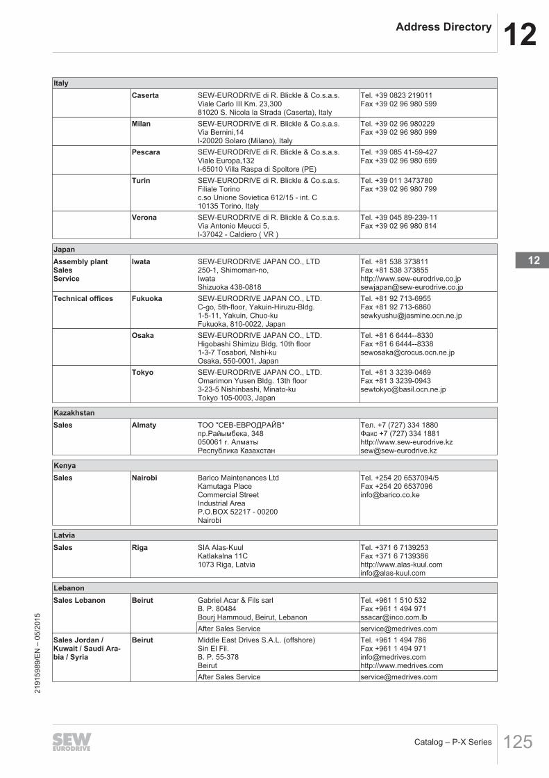
12Address Directory
Catalog – P-X Series 125
ItalyCaserta SEW‑EURODRIVE di R. Blickle & Co.s.a.s.
Viale Carlo III Km. 23,30081020 S. Nicola la Strada (Caserta), Italy
Tel. +39 0823 219011Fax +39 02 96 980 599
Milan SEW‑EURODRIVE di R. Blickle & Co.s.a.s.Via Bernini,14I-20020 Solaro (Milano), Italy
Tel. +39 02 96 980229Fax +39 02 96 980 999
Pescara SEW‑EURODRIVE di R. Blickle & Co.s.a.s.Viale Europa,132I-65010 Villa Raspa di Spoltore (PE)
Tel. +39 085 41-59-427Fax +39 02 96 980 699
Turin SEW‑EURODRIVE di R. Blickle & Co.s.a.s.Filiale Torinoc.so Unione Sovietica 612/15 - int. C10135 Torino, Italy
Tel. +39 011 3473780Fax +39 02 96 980 799
Verona SEW‑EURODRIVE di R. Blickle & Co.s.a.s.Via Antonio Meucci 5,I-37042 - Caldiero ( VR )
Tel. +39 045 89-239-11Fax +39 02 96 980 814
JapanAssembly plantSalesService
Iwata SEW‑EURODRIVE JAPAN CO., LTD250-1, Shimoman-no,IwataShizuoka 438-0818
Tel. +81 538 373811Fax +81 538 373855http://www.sew-eurodrive.co.jpsewjapan@sew‑eurodrive.co.jp
Technical offices Fukuoka SEW‑EURODRIVE JAPAN CO., LTD.C-go, 5th-floor, Yakuin-Hiruzu-Bldg.1-5-11, Yakuin, Chuo-kuFukuoka, 810-0022, Japan
Tel. +81 92 713-6955Fax +81 92 [email protected]
Osaka SEW‑EURODRIVE JAPAN CO., LTD.Higobashi Shimizu Bldg. 10th floor1-3-7 Tosabori, Nishi-kuOsaka, 550-0001, Japan
Tel. +81 6 6444--8330Fax +81 6 [email protected]
Tokyo SEW‑EURODRIVE JAPAN CO., LTD.Omarimon Yusen Bldg. 13th floor3-23-5 Nishinbashi, Minato-kuTokyo 105-0003, Japan
Tel. +81 3 3239-0469Fax +81 3 [email protected]
KazakhstanSales Almaty ТОО "СЕВ-ЕВРОДРАЙВ"
пр.Райымбека, 348050061 г. АлматыРеспублика Казахстан
Тел. +7 (727) 334 1880Факс +7 (727) 334 1881http://www.sew-eurodrive.kzsew@sew‑eurodrive.kz
KenyaSales Nairobi Barico Maintenances Ltd
Kamutaga PlaceCommercial StreetIndustrial AreaP.O.BOX 52217 - 00200Nairobi
Tel. +254 20 6537094/5Fax +254 20 [email protected]
LatviaSales Riga SIA Alas-Kuul
Katlakalna 11C1073 Riga, Latvia
Tel. +371 6 7139253Fax +371 6 7139386http://[email protected]
LebanonSales Lebanon Beirut Gabriel Acar & Fils sarl
B. P. 80484Bourj Hammoud, Beirut, Lebanon
Tel. +961 1 510 532Fax +961 1 494 [email protected]
After Sales Service [email protected] Jordan /Kuwait / Saudi Ara-bia / Syria
Beirut Middle East Drives S.A.L. (offshore)Sin El Fil.B. P. 55-378Beirut
Tel. +961 1 494 786Fax +961 1 494 [email protected]://www.medrives.com
After Sales Service [email protected]
2191
5989
/EN
– 0
5/20
15
12

12 Address Directory
Catalog – P-X Series126
LithuaniaSales Alytus UAB Irseva
Statybininku 106CLT-63431 Alytus
Tel. +370 315 79204Fax +370 315 [email protected]://www.sew-eurodrive.lt
LuxembourgAssembly plantSalesService
Brussels SEW‑EURODRIVE n.v./s.a.Researchpark Haasrode 1060Evenementenlaan 7BE-3001 Leuven
Tel. +32 16 386-311Fax +32 16 386-336http://www.sew-eurodrive.luinfo@sew‑eurodrive.be
MadagascarSales Antananarivo Ocean Trade
BP21bis. AndraharoAntananarivo.101 Madagascar
Tel. +261 20 2330303Fax +261 20 [email protected]
MalaysiaAssembly plantSalesService
Johor SEW‑EURODRIVE SDN BHDNo. 95, Jalan Seroja 39, Taman Johor Jaya81000 Johor Bahru, JohorWest Malaysia
Tel. +60 7 3549409Fax +60 7 3541404sales@sew‑eurodrive.com.my
Technical offices Kuala Lumpur SEW‑EURODRIVE Sdn. Bhd.No. 2, Jalan Anggerik Mokara 31/46Kota Kemuning Seksyen 3140460 Shah AlamSelangor Darul Ehsan
Tel. +60 3 51229633Fax +60 3 [email protected]
Kuching SEW‑EURODRIVE Sdn. Bhd.Lot 268, Section 9 KTLDLorong 9, Jalan Satok93400 Kuching, SarawakEast Malaysia
Tel. +60 82 232380Fax +60 82 242380
Penang SEW‑EURODRIVE Sdn. Bhd.No. 38, Jalan BawalKimsar Garden13700 Prai, Penang
Tel. +60 4 3999349Fax +60 4 [email protected]
MoroccoSalesService
Mohammedia SEW‑EURODRIVE SARL2 bis, Rue Al Jahid28810 Mohammedia
Tel. +212 523 32 27 80/81Fax +212 523 32 27 89sew@sew‑eurodrive.mahttp://www.sew-eurodrive.ma
MauritaniaSales Zouérat AFRICOM - SARL
En Face Marché DumezP.B. 88Zouérate
Tel. +222 45 44 50 19Fax +222 45 44 03 [email protected]
MacedoniaSales Skopje Boznos DOOEL
Dime Anicin 2A/7A1000 Skopje
Tel. +389 23256553Fax +389 23256554http://www.boznos.mk
MexicoAssembly plantSalesService
Quéretaro SEW‑EURODRIVE MEXICO SA DE CVSEM-981118-M93Tequisquiapan No. 102Parque Industrial QuéretaroC.P. 76220Quéretaro, Mexico
Tel. +52 442 1030-300Fax +52 442 1030-301http://[email protected]
MongoliaSales Ulan Bator SEW-EURODRIVE Representative Office Mon-
goliaOlympic street 8,2nd floor Juulchin corp bldg.,Sukhbaatar district,Ulaanbaatar 14253
Tel. +976-70009997Fax +976-70009997http://[email protected]
2191
5989
/EN
– 0
5/20
15

12Address Directory
Catalog – P-X Series 127
NamibiaSales Swakopmund DB Mining & Industrial Services
Einstein StreetStrauss Industrial ParkUnit1Swakopmund
Tel. +264 64 462 738Fax +264 64 462 [email protected]
New ZealandAssembly plantsSalesService
Auckland SEW‑EURODRIVE NEW ZEALAND LTD.P.O. Box 58-42882 Greenmount DriveEast Tamaki Auckland, New Zealand
Tel. +64 9 2745627Fax +64 9 2740165http://www.sew-eurodrive.co.nzsales@sew‑eurodrive.co.nz
Christchurch,New Zealand
SEW‑EURODRIVE NEW ZEALAND LTD.10 Settlers Crescent, FerrymeadChristchurch, New Zealand
Tel. +64 3 384-6251Fax +64 3 384-6455sales@sew‑eurodrive.co.nz
Technical offices Palmerston North SEW‑EURODRIVE NEW ZEALAND LTD.C/-Grant Shearman, RD 5, Aronui RoadPalmerston North
Tel. +64 6 355-2165Fax +64 6 355-2316sales@sew‑eurodrive.co.nz
NetherlandsAssembly plantSalesService
Rotterdam SEW‑EURODRIVE B.V.Industrieweg 1753044 AS Rotterdam, NetherlandsPostbus 100853004 AB Rotterdam, Netherlands
Tel. +31 10 4463-700Fax +31 10 4155-552Service: 0800-SEWHELPhttp://www.sew-eurodrive.nlinfo@sew‑eurodrive.nl
NigeriaSales Lagos EISNL Engineering Solutions and Drives Ltd
Plot 9, Block A, Ikeja Industrial Estate (OgbaScheme)Adeniyi Jones St. EndOff ACME Road, Ogba, Ikeja, LagosNigeria
Tel. +234 1 217 [email protected]://www.eisnl.com
NorwayAssembly plantSalesService
Moss SEW‑EURODRIVE A/SSolgaard skog 711599 Moss, Norway
Tel. +47 69 24 10 20Fax +47 69 24 10 40http://www.sew-eurodrive.nosew@sew‑eurodrive.no
PakistanSales Karatschi Industrial Power Drives
Al-Fatah Chamber A/3, 1st Floor Central Com-mercial Area,Sultan Ahmed Shah Road, Block 7/8,Karachi
Tel. +92 21 452 9369Fax +92-21-454 [email protected]
ParaguaySales Fernando de la
MoraSEW-EURODRIVE PARAGUAY S.R.LDe la Victoria 112, Esquina nueva AsunciónDepartamento CentralFernando de la Mora, Barrio Bernardino
Tel. +595 991 519695Fax +595 21 [email protected]
PeruAssembly plantSalesService
Lima SEW DEL PERU MOTORES REDUCTORESS.A.C.Los Calderos, 120-124Urbanizacion Industrial Vulcano, ATE, Lima,Peru
Tel. +51 1 3495280Fax +51 1 3493002http://www.sew-eurodrive.com.pesewperu@sew‑eurodrive.com.pe
PhilippinesSales Luzon Totaltech Corporation
5081-B C&L Mansion Filmore Ave. Cor. Fahren-heit St.1235 Makati City
Tel. +63 2 551-9265 / +63 2 551-9271 /+63 2 551-9378Fax +63 2 [email protected]
All Areas P.T. Cerna Corporation4137 Ponte St., Brgy. Santa Cruz, Makati City1205
Tel. +63 2 519 6214Fax +63 2 890 [email protected]
2191
5989
/EN
– 0
5/20
15
12

12 Address Directory
Catalog – P-X Series128
PolandAssembly plantSalesService
Łódź SEW‑EURODRIVE Polska Sp.z.o.o.ul. Techniczna 592-518 Łódź, Poland
Tel. +48 42 676 53 00Fax +48 42 676 53 49http://www.sew-eurodrive.plsew@sew‑eurodrive.pl
Service Tel. +48 42 6765332 / 42 6765343Fax +48 42 6765346
Linia serwisowa 24 hour hotlineTel. +48 602 739 739(+48 602 SEW SEW)serwis@sew‑eurodrive.pl
Technical office Tychy SEW‑EURODRIVE Polska Sp.z.o.o.ul. Strzelecka 66PL-43-109 Tychy
Tel. +48 32 32 32 610Fax +48 32 32 32 648
Bydgoszcz SEW‑EURODRIVE Polska Sp.z.o.o.ul. Fordońska 246PL-85-959 Bydgoszcz
Tel. +48 52 3606590Fax +48 52 3606591
Gdansk SEW‑EURODRIVE Polska Sp.z.o.o.ul. Galaktyczna 30APL-80-299 Gdańsk
Tel. +48 58 762 70 00Fax +48 58 762 70 09
Poznan SEW‑EURODRIVE Polska Sp.z.o.o.ul. Romana Maya 161-371 Poznań, Poland
Tel. +48 61 6465500Fax +48 61 6465519
Radom SEW‑EURODRIVE Polska Sp.z.o.o.ul. Słowackiego 8426-600 Radom, Poland
Tel. +48 48 365 40 50Fax +48 48 365 40 52
PortugalAssembly plantSalesService
Coimbra SEW‑EURODRIVE, LDA.Apartado 153050-901 Mealhada, Portugal
Tel. +351 231 20 9670Fax +351 231 20 3685http://www.sew-eurodrive.ptinfosew@sew‑eurodrive.pt
Service CompetenceCenters
Lisbon SEW‑EURODRIVE, LDA.Núcleo Empresarial I de São Julião do TojalRua de Entremuros, 54Fracção I2660-533 São Julião do Tojal, Portugal
Tel. +351 21 958-0198Fax +351 21 958-0245esc.lisboa@sew‑eurodrive.pt
Technical office Porto SEW‑EURODRIVE, LDA.Av. 25 de Abril, 684440-502 Valongo, Portugal
Tel. +351 229 350 383Fax +351 229 350 384Tel. +351 9 32559110esc.porto@sew‑eurodrive.pt
RomaniaSalesService
Bucharest Sialco Trading SRLstr. Brazilia nr. 36011783 Bucuresti, Romania
Tel. +40 21 230-1328Fax +40 21 [email protected]
RussiaAssembly plantSalesService
St. Petersburg ZAO SEW‑EURODRIVEP.O. Box 36RUS-195220 St. Petersburg
Tel. +7 812 3332522 +7 812 5357142Fax +7 812 3332523http://www.sew-eurodrive.rusew@sew‑eurodrive.ru
Technical office Ekaterinburg ZAO SEW‑EURODRIVEKominterna Str. 16Office 614620078 Ekaterinburg, Russia
Tel. +7 343 310 3977Fax +7 343 310 3978eso@sew‑eurodrive.ru
Irkutsk ZAO SEW‑EURODRIVE5-Armii Str., 31664011 Irkutsk, Russia
Tel. +7 3952 25 5880Fax +7 3952 25 5881iso@sew‑eurodrive.ru
Moscow ZAO SEW‑EURODRIVEMalaja Semjonowskaja Str.д. 9, корпус 2107023 Moscow
Tel. +7 495 9337090Fax +7 495 9337094mso@sew‑eurodrive.ru
Novosibirsk ZAO SEW‑EURODRIVEpr. K Marksa 30630087 Novosibirsk, Russia
Tel. +7 383 3350200Fax +7 383 3462544nso@sew‑eurodrive.ru
Perm ZAO SEW‑EURODRIVEStakhanovskaya str., 45 Office 512RUS-614066 Perm
Tel. +7 342 2219494Fax +7 342 [email protected] 21
9159
89/E
N –
05/
2015

12Address Directory
Catalog – P-X Series 129
RussiaTogliatti ZAO SEW‑EURODRIVE
Sportivnaya Str. 4B, office 2Samarskaya obl.445057 Togliatti, Russia
Tel. +7 8482 710529Fax +7 8482 810590
SenegalSales Dakar SENEMECA
Mécanique GénéraleKm 8, Route de RufisqueB.P. 3251, Dakar
Tel. +221 338 494 770Fax +221 338 494 [email protected]://www.senemeca.com
SerbiaSales Belgrade DIPAR d.o.o.
Ustanicka 128aPC Košum, IV spratSRB-11000 Beograd, Serbia
Tel. +381 11 347 3244 / +381 11 2880393Fax +381 11 347 [email protected]
SingaporeAssembly plantSalesService
Singapore SEW‑EURODRIVE PTE. LTD.No 9, Tuas Drive 2Jurong Industrial EstateSingapore 638644
Tel. +65 68621701Fax +65 68612827http://www.sew-eurodrive.com.sgsewsingapore@sew‑eurodrive.com
SlovakiaSales Bratislava SEW‑EURODRIVE SK s.r.o.
Rybničná 40831 06 Bratislava, Slovakia
Tel. +421 2 33595 202Fax +421 2 33595 200sew@sew‑eurodrive.skhttp://www.sew-eurodrive.sk
Žilina SEW‑EURODRIVE SK s.r.o.Industry Park - PChZulica M.R.Štefánika 71010 01 Žilina, Slovakia
Tel. +421 41 700 2513Fax +421 41 700 2514sew@sew‑eurodrive.sk
Banska Bystrica SEW‑EURODRIVE SK s.r.o.Rudlovská cesta 85974 11 Banská Bystrica, Slovakia
Tel. +421 48 414 6564Fax +421 48 414 6566sew@sew‑eurodrive.sk
Košice SEW‑EURODRIVE SK s.r.o.Slovenská ulica 26040 01 Košice, Slovakia
Tel. +421 55 671 2245Fax +421 55 671 2254sew@sew‑eurodrive.sk
SloveniaSalesService
Celje Pakman - Pogonska Tehnika d.o.o.UI. XIV. divizije 143000 Celje, Slovenia
Tel. +386 3 490 83-20Fax +386 3 490 [email protected]
SpainAssembly plantSalesService
Bilbao SEW‑EURODRIVE ESPAÑA, S.L.Parque Tecnológico, Edificio, 30248170 Zamudio (Vizcaya), Spain
Tel. +34 94 43184-70Fax +34 94 43184-71http://www.sew-eurodrive.essew.spain@sew‑eurodrive.es
Technical offices Barcelona Delegación BarcelonaAvda. Francesc Macià, 60 – Planta 16, porta 1Eix Macià – "Torre Milenium"08208 Sabadell (Barcelona), Spain
Tel. +34 93 7162200Fax +34 93 7233007
Madrid Delegación MadridGran Via. 48-2° A-D28220 Majadahonda (Madrid), Spain
Tel. +34 91 6342250Fax +34 91 6340899
Sevilla MEBPólogono Calonge, C/A Nave 2 - CE-41.077 Sevilla, Spain
Tel. +34 954 356 361Fax +34 954 356 [email protected]
Valencia MEBMúsico Andreu i Piqueres, 4E-46.900 Torrente (Valencia)
Tel. +34 961 565 493Fax +34 961 566 [email protected]
Sri LankaSales Colombo SM International (Pte) Ltd
254, Galle RaodColombo 4, Sri Lanka
Tel. +94 1 2584887Fax +94 1 2582981
2191
5989
/EN
– 0
5/20
15
12

12 Address Directory
Catalog – P-X Series130
South AfricaAssembly plantsSalesService
Johannesburg SEW‑EURODRIVE (PROPRIETARY) LIMITEDEurodrive HouseCnr. Adcock Ingram and Aerodrome RoadsAeroton Ext. 2Johannesburg 2013, South AfricaP.O.Box 90004Bertsham 2013, South Africa
Tel. +27 11 248-7000Fax +27 11 494-3104http://[email protected]
Cape Town SEW‑EURODRIVE (PROPRIETARY) LIMITEDRainbow ParkCnr. Racecourse & Omuramba RoadMontague GardensCape Town, South AfricaP.O. Box 36556Chempet 7442Cape Town, South Africa
Tel. +27 21 552-9820Fax +27 21 552-9830Telex 576 [email protected]
Durban, SouthAfrica
SEW‑EURODRIVE (PROPRIETARY) LIMITED48 Prospecton RoadIsipingoDurban, South AfricaP.O. Box 10433, Ashwood 3605, South Africa
Tel. +27 31 902 3815Fax +27 31 902 [email protected]
Nelspruit SEW‑EURODRIVE (PTY) LTD.7 Christie CrescentVintoniaP.O. Box 1942Nelspruit 1200
Tel. +27 13 752-8007Fax +27 13 [email protected]
Technical offices Port Elizabeth SEW‑EURODRIVE PTY LTD.8 Ruan Access ParkOld Cape RoadGreenbushes6000 Port Elizabeth
Tel. +27 41 3722246Fax +27 41 [email protected]
South KoreaAssembly plantSalesService
Ansan SEW‑EURODRIVE KOREA CO., LTD.B 601-4, Banweol Industrial Estate#1048-4, Shingil-Dong, Danwon-Gu,Ansan-City, Kyunggi-Do Zip 425-839
Tel. +82 31 492-8051Fax +82 31 492-8056http://www.sew-korea.co.krmaster.korea@sew‑eurodrive.com
Busan SEW‑EURODRIVE KOREA Co., Ltd.No. 1720 - 11, Songjeong - dongGangseo-kuBusan 618-270, Korea
Tel. +82 51 832-0204Fax +82 51 [email protected]
Technical offices Daegu SEW‑EURODRIVE KOREA Co., Ltd.No.1108 Sungan officetel87-36, Duryu 2-dong, Dalseo-kuDaegu 704-712
Tel. +82 53 650-7111Fax +82 53 650-7112
Daejeon SEW‑EURODRIVE KOREA Co., Ltd.No. 1502, Hongin officetel536-9, Bongmyung-dong, Yusung-kuDaejeon 305-301
Tel. +82 42 828-6461Fax +82 42 828-6463
Gwangju SEW‑EURODRIVE KOREA Co., Ltd.4fl., Dae-Myeong B/D96-16 Unam-dong, Buk-kuKwangju 500-170
Tel. +82 62 511-9172Fax +82 62 511-9174
Seoul SEW‑EURODRIVE KOREA Co., Ltd.No.504 Sunkyung officetel106-4 Kuro 6-dong, Kuro-kuSeoul 152-054, Korea
Tel. +82 2 862-8051Fax +82 2 862-8199
SwazilandSales Manzini C G Trading Co. (Pty) Ltd
PO Box 2960Manzini M200
Tel. +268 2 518 6343Fax +268 2 518 [email protected]
SwedenAssembly plantSalesService
Jönköping SEW-EURODRIVE ABGnejsvägen 6-855303 Jönköping, SwedenBox 3100 S-55003 Jönköping
Tel. +46 36 3442 00Fax +46 36 3442 80http://[email protected] 21
9159
89/E
N –
05/
2015

12Address Directory
Catalog – P-X Series 131
SwedenSales Göteborg SEW-EURODRIVE AB
Gustaf Werners gata 842132 Västra Frölunda, Sweden
Tel. +46 31 70968 80Fax +46 31 70968 [email protected]
Stockholm SEW-EURODRIVE ABBjörkholmsvägen 1014146 Huddinge, Sweden
Tel. +46 8 44986 80Fax +46 8 44986 [email protected]
Malmö SEW-EURODRIVE ABBorrgatan 521124 Malmö, Sweden
Tel. +46 40 68064 80Fax +46 40 68064 [email protected]
Skellefteå SEW-EURODRIVE ABTrädgårdsgatan 893131 Skellefteå, Sweden
Tel. +46 910 7153 80Fax +46 910 7153 [email protected]
SwitzerlandAssembly plantSalesService
Basel Alfred lmhof A.G.Jurastrasse 10CH-4142 Münchenstein bei Basel
Tel. +41 61 417 1717Fax +41 61 417 1700http://[email protected]
Technical offices Romandy André GerberEs Perreyres1436 Chamblon, Switzerland
Tel. +41 24 445 3850Fax +41 24 445 4887
Bern / Solothurn Rudolf BühlerMuntersweg 52540 Grenchen, Switzerland
Tel. +41 32 652 2339Fax +41 32 652 2331
Central Switzer-land, Aargau
Armin PfisterStierenweid4950 Huttwill, BE, Switzerland
Tel. +41 62 962 54 55Fax +41 62 962 54 56
Zurich, Tessin Gian-Michele MulettaFischerstrasse 618132 Egg bei Zürich, Switzerland
Tel. +41 44 994 81 15Fax +41 44 994 81 16
Lake Constanceand EasternSwitzerland
Markus KünzleEichweg 49403 Goldach, Switzerland
Tel. +41 71 845 2808Fax +41 71 845 2809
Taiwan (R.O.C.)Sales Nan Tou Ting Shou Trading Co., Ltd.
No. 55 Kung Yeh N. RoadIndustrial DistrictNan Tou 540
Tel. +886 49 255353Fax +886 49 257878
Taipei Ting Shou Trading Co., Ltd.6F-3, No. 267, Sec. 2Tung Hwa South Road, Taipei, Taiwan
Tel. +886 2 27383535Fax +886 2 27368268Telex 27 [email protected]
TanzaniaSales Dar es Salaam SEW-EURODRIVE PTY LIMITED TANZANIA
Plot 52, Regent EstatePO Box 106274Dar Es Salaam
Tel. +255 0 22 277 5780Fax +255 0 22 277 [email protected]
ThailandAssembly plantSalesService
Chonburi SEW‑EURODRIVE (Thailand) Ltd.700/456, Moo.7, DonhuarohMuangChonburi 20000, Thailand
Tel. +66 38 454281Fax +66 38 454288sewthailand@sew‑eurodrive.com
Technical offices Bangkok SEW‑EURODRIVE (Thailand) Ltd.6th floor, TPS Building1023, Phattanakarn RoadSuanluangBangkok,10250
Tel. +66 2 7178149Fax +66 2 7178152sewthailand@sew‑eurodrive.com
Hat Yai SEW‑EURODRIVE (Thailand) Ltd.Hadyai Country Home Condominium59/101 Soi.17/1Rachas-Utid Road.Hadyai, Songkhla 90110, Thailand
Tel. +66 74 359441Fax +66 74 359442sewthailand@sew‑eurodrive.com
2191
5989
/EN
– 0
5/20
15
12

12 Address Directory
Catalog – P-X Series132
ThailandKhon Kaen SEW‑EURODRIVE (Thailand) Ltd.
4th Floor, Kaow-U-HA MOTOR Bldg,359/2, Mitraphab Road.Muang DistrictKhonkaen 40000, Thailand
Tel. +66 43 225745Fax +66 43 324871sew-thailand@sew‑eurodrive.com
TunisiaSales Tunis T. M.S. Technic Marketing Service
Zone Industrielle Mghira 2Lot No. 392082 Fouchana
Tel. +216 79 40 88 77Fax +216 79 40 88 66http://[email protected]
TurkeyAssembly plantSalesService
Kocaeli-Gebze SEW-EURODRİVESistemleri San. Ve TIC. Ltd. StiGebze Organize Sanayi Böl. 400 Sok No. 40141480 Gebze Kocaeli
Tel. +90-262-9991000-04Fax +90-262-9991009http://www.sew-eurodrive.com.trsew@sew‑eurodrive.com.tr
Technical offices Adana SEW-EURODRİVECevat Yurdakul Cad.No:52Akdoğan İş Merkezi K:5 D.18Seyhan / Adana
Tel. +90 322 359 94 15Fax +90 322 359 94 16
Ankara SEW-EURODRİVE1368.Cadde Eminel İşmerkeziNo: 18/68İvogsan / Ankara
Tel. +90 312 385 33 90Fax +90 312 385 32 58
Bursa SEW-EURODRİVEÜçevler Mah. Bayraktepe Sok.Akay İş Merkezi Kat:3 No: 7/6Nilüfer / Bursa
Tel. +90 224 443 45 60Fax +90 224 443 45 58
Istanbul SEW-EURODRİVETekstilkent Ticaret MerkeziB-13 Blok No:70Esenler / İstanbul
Tel. +90-262-9991000-04Fax +90-262-9991009
Izmir SEW-EURODRİVE1203/11 Sok. No. 4/614Kara Hasan Atlı İş Merkezi Kat :6Yenişehir / İzmir
Tel. +90 232 469 62 64Fax +90 232 433 61 05
UkraineAssembly plantSalesService
Dnipropetrowsk ООО «СЕВ-Евродрайв»ул.Рабочая, 23-B, офис 40949008 Днепропетровск
Тел. +380 56 370 3211Факс. +380 56 372 2078http://www.sew-eurodrive.uasew@sew‑eurodrive.ua
Sales Kiev ООО «СЕВ-Евродрайв»ул.С.Олейника, 2102068 Киев
Тел. +380 44 503 95 77Факс. +380 44 503 95 78kso@sew‑eurodrive.ua
Donetsk ООО «СЕВ-Евродрайв»ул.25-летия РККА, 1-B, оф. 80583000 Донецк
Тел. +380 62 38 80 545Факс. +380 62 38 80 533dso@sew‑eurodrive.ua
Ivano-Frankivsk ООО «СЕВ-Евродрайв»ул.Независимости, 4, оф.30383000 Ивано-Франковск
Тел. +380 342 725 190Факс. +380 342 725 [email protected]
UruguayAssembly plantSales
Montevideo SEW‑EURODRIVE Uruguay, S. A.Jose Serrato 3569 Esqina CorumbeCP 12000 Montevideo
Tel. +598 2 21181-89Fax +598 2 21181-89sewuy@sew‑eurodrive.com.uy
USAProduction plantAssembly plantSalesService
Southeast Region SEW‑EURODRIVE INC.1295 Old Spartanburg HighwayP.O. Box 518Lyman, S.C. 29365
Tel. +1 864 439-7537Fax Sales +1 864 439-7830Fax Manufacturing +1 864 439-9948Fax Assembly +1 864 439-0566Fax Confidential/HR +1 864 949-5557http://[email protected]
2191
5989
/EN
– 0
5/20
15

12Address Directory
Catalog – P-X Series 133
USAAssembly plantsSalesService
Northeast Region SEW‑EURODRIVE INC.Pureland Ind. Complex2107 High Hill Road, P.O. Box 481Bridgeport, New Jersey 08014, USA
Tel. +1 856 467-2277Fax +1 856 [email protected]
Midwest Region SEW‑EURODRIVE INC.2001 West Main StreetTroy, Ohio 45373, USA
Tel. +1 937 335-0036Fax +1 937 [email protected]
SouthwestRegion
SEW‑EURODRIVE INC.3950 Platinum WayDallas, Texas 75237, USA
Tel. +1 214 330-4824Fax +1 214 [email protected]
Western Region SEW‑EURODRIVE INC.30599 San Antonio St.Hayward, CA 94544, USA
Tel. +1 510 487-3560Fax +1 510 [email protected]
Please contact us for other service center addresses in the USA.
VenezuelaAssembly plantSalesService
Valencia SEW‑EURODRIVE Venezuela S.A.Av. Norte Sur No. 3, Galpon 84-319Zona Industrial Municipal NorteValencia, Estado Carabobo, Venezuela
Tel. +58 241 832-9804Fax +58 241 838-6275http://www.sew-eurodrive.com.veventas@sew‑[email protected]
United Arab EmiratesSalesService
Sharjah Copam Middle East (FZC)Sharjah Airport International Free ZoneP.O. Box 120709Sharjah
Tel. +971 6 5578-488Fax +971 6 [email protected]
VietnamSales Ho-Chi-Minh-
StadtAll sectors except for ports and offshore:Nam Trung Co., Ltd250 Binh Duong Avenue, Thu Dau Mot Town,Binh Duong ProvinceHCM office: 91 Tran Minh Quyen StreetDistrict 10, Ho Chi Minh City
Tel. +84 8 8301026Fax +84 8 [email protected]@[email protected]
Ports and offshore:DUC VIET INT LTDIndustrial Trading and Engineering ServicesA75/6B/12 Bach Dang Street, Ward 02,Tan Binh District, 70000 Ho Chi Minh City
Tel. +84 8 62969 609Fax +84 8 62938 [email protected]
Hanoi Nam Trung Co., LtdR.205B Tung Duc Building22 Lang ha StreetDong Da District, Hanoi City
Tel. +84 4 37730342Fax +84 4 [email protected]
ZambiaSales Kitwe EC Mining Limited
Plots No. 5293 & 5294,Tangaanyika Road, OffMutentemuko Road,Heavy Industrial Park,P.O.BOX 2337Kitwe
Tel. +260 212 210 642Fax +260 212 210 [email protected]://www.ecmining.com
2191
5989
/EN
– 0
5/20
15
12


SEW-EURODRIVE—Driving the world
SEW-EURODRIVE GmbH & Co KGP.O. Box 302376642 BRUCHSALGERMANYPhone +49 7251 75-0Fax +49 7251 [email protected]