Interpretation of pipe-jacking and lubrication records for drives ...
Upload
khangminh22Category
view
1download
0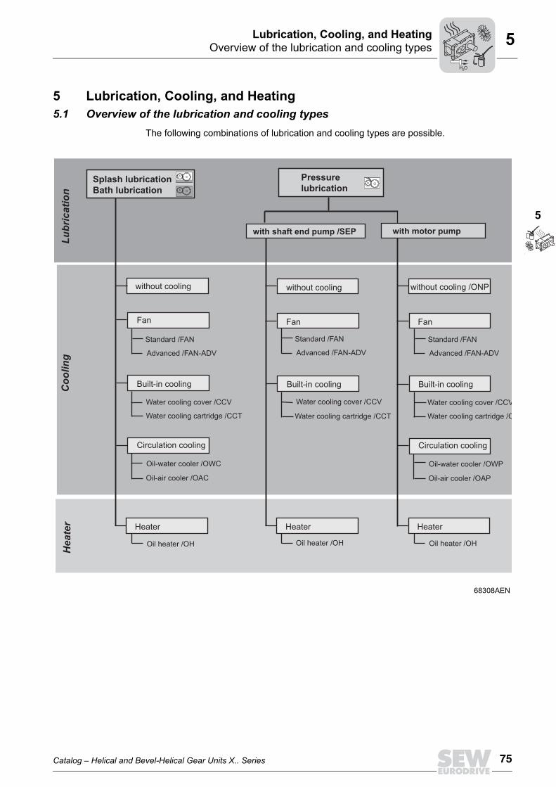
Catalog – Helical and Bevel-Helical Gear Units X.. Series 75
Overview of the lubrication and cooling typesLubrication, Cooling, and Heating
5
5
5 Lubrication, Cooling, and Heating5.1 Overview of the lubrication and cooling types
The following combinations of lubrication and cooling types are possible.
68308AEN
Splash lubricationBath lubrication
Pressurelubrication
with shaft end pump /SEP with motor pump
without cooling
Fan
Built-in cooling
Circulation cooling
Oil-water cooler /OWC
Oil-air cooler /OAC
Water cooling cartridge /CCT
Water cooling cover /CCV
without cooling
Fan
Built-in cooling
Water cooling cartridge /CCT
without cooling /ONP
Fan
Built-in cooling
Circulation cooling
Oil-water cooler /OWP
Oil-air cooler /OAP
Water cooling cartridge /C
Water cooling cover /CCV
Lubrication
Cooling
Standard /FAN
Advanced /FAN-ADV
Standard /FAN
Advanced /FAN-ADV
Standard /FAN
Advanced /FAN-ADV
Heater
Oil heater /OH
Heater Heater Heater
Oil heater /OH Oil heater /OH
Water cooling cover /CCV
H O2

76 Catalog – Helical and Bevel-Helical Gear Units X.. Series
Lubricant selection / lubricant tableLubrication, Cooling, and Heating5
5.2 Lubricant selection / lubricant table
5.2.1 General information on selecting the oilUnless a special arrangement is made, SEW-EURODRIVE delivers the drives withoutoil fill. This does not apply to auxiliary drives and primary gear units.
The following tables provide an overview of mineral and synthetic oils.
Mineral oilStandards Lubrication oils are divided into ISO VG viscosity classes according to ISO 3448 and
DIN 51519.
Synthetic oilStandards Lubrication oils are divided into ISO VG viscosity classes according to ISO 3448 and
DIN 51519.
INFORMATIONThe oil viscosity and type (mineral/synthetic) to be used are determined by SEW-EURODRIVE specifically for each order. This information is noted in the order confir-mation and on the gear unit's nameplate. Any deviation from these conditions requiresconsultation with SEW-EURODRIVE.
INFORMATIONThis means the gear unit must be filled with the correct oil grade and quantity beforestartup. You find the corresponding information on the nameplate of the gear unit.
ISOClass
ISO 6743-6Designation
DIN 51517-3Designation
AGMA 9005-D94Designation
150 ISO-L-CKC 150 DIN 51517-CLP 150 AGMA 4 EP
220 ISO-L-CKC 220 DIN 51517-CLP 220 AGMA 5 EP
320 ISO-L-CKC 320 DIN 51517-CLP 320 AGMA 6 EP
460 ISO-L-CKC 460 DIN 51517-CLP 460 AGMA 7 EP
680 ISO-L-CKC 680 DIN 51517-CLP 680 AGMA 8 EP
ISOClass
ISO 6743-6Designation
DIN 51519Designation
AGMA 9005-D94Designation
150 ISO-L-CKT 150 CLP HC 150 AGMA 4 EP
220 ISO-L-CKT 220 CLP HC 220 AGMA 5 EP
320 ISO-L-CKT 320 CLP HC 320 AGMA 6 EP
460 ISO-L-CKT 460 CLP HC 460 AGMA 7 EP
680 ISO-L-CKT 680 CLP HC 680 AGMA 8 EP
H O2

Catalog – Helical and Bevel-Helical Gear Units X.. Series 77
Lubricant selection / lubricant tableLubrication, Cooling, and Heating
5
5
In addition to the required viscosity, the oil must fulfill the following criteria:• CLP oils according to DIN 51517-3• Micro-pitting test according to FVA, FV no. 54/ I-IV, GFT class high, damage force
level >10
If synthetic oil is used, SEW-EURODRIVE recommends polyalphaolefin-based oil (CLPHC).
5.2.2 Permitted lubricants
Key to the lubricant tableThe lubricant table shows the permitted lubricants for SEW-EURODRIVE industrial gearunits. This information is provided to preselect the lubricant. The proper and final lubri-cant selection is made by SEW-EURODRIVE to match the specific project. Consider theused abbreviations, meaning of shading and notes.
INFORMATIONObserve the operating temperature of the gear unit when specifying the oil change in-tervals.If required, a cooling system must be used or the oil change interval must be shortened(see "Lubricant Change Intervals" in the "Helical and Bevel-Helical X.. Series GearUnits" operating instructions").
INFORMATION• The standard for viscosity and oil grade is the type of oil that is specified by SEW-
EURODRIVE in the order (see order confirmation and nameplate).• Consult SEW-EURODRIVE if you use bio and food grade lubricants or polyglycol
oils.• Check the compatibility of the greases and oils used.
CLP = Mineral oilCLP HC = Synthetic polyalphaolefinE = Ester oil (water hazard classification 1)
= Mineral lubricant = Synthetic lubricant
3) = Lubricants may only be used if service factor Fs = 1.3 4) = Take into account critical startup behavior at low ambient temperatures6) = Ambient temperature
= Lubricant for the food industry (food grade oil)
= Biodegradable oil (lubricant for agriculture, forestry, and water management)OilOil
H O2
78 Catalog – Helical and Bevel-Helical Gear Units X.. Series
Lubricant selection / lubricant tableLubrication, Cooling, and Heating5
5.2.3 Lubricant table
-10+60
-20
-20
-20
+20
+10
-10
+50
-25+40
-10
3)
Oil
Oil
Oil
VG 320
VG 150
VG 220
0+100
+50
6)
-10
-50D
IN (ISO
)
ISO,N
LGI
470490405
CLP C
C
CLP C
C
CLPC
C
VG 460
VG 680
CLP C
C
Alpha SP 320
Tribol 1100/320G
oya NT 320
Goya N
T 150
Goya N
T 220
Goya N
T 460
Goya N
T 680
Alpha SP 150
Tribol 1100/150
Alpha SP 220
Tribol 1100/220
Alpha SP 460
Tribol 1100/460
Alpha SP 680
Tribol 1100/680
Tribol 1100/1000
Renolin CLP 320 PlusRenolin High Gear 320
Renolin CLP 150 PlusRenolin High Gear 150
Renolin CLP 220 PlusRenolin High Gear 220
Renolin CLP 460 PlusRenolin High Gear 460
Renolin CLP 680 PlusRenolin High Gear 680
Carter EP
320
Carter EP
220
Carter EP
460
Carter EP
680
Optigear
BM 320
Optigear
BM 150
Optigear
BM 220
Optigear
BM 460
Optigear
BM 680
Meropa320
Meropa150
Meropa220
Meropa460
Meropa680
Shell Om
alaF 320
Shell Om
alaF 220
Shell Om
alaF 460
Klüberoil
GEM
1-320 N
Klüberoil
GEM
1-150 N
Klüberoil
GEM
1-220 N
Klüberoil
GEM
1-460 N
Klüberoil
GEM
1-680 N
BP Energol
GR
-XP-320
BP Energol
GR
-XP-150
BP Energol
GR
-XP-220
BP Energol
GR
-XP-460
BP Energol
GR
-XP-680
Mobilgear 600XP 320
Mobilgear 600XP 150
Mobilgear 600XP 220
Mobilgear 600XP 460
Mobilgear 600XP 680
°CT
O T A
LO
T A L
TribolO
ptimol
Sh
lle
AR
AL
AR
AL
FUCHS
TEX
AC
OTE
XA
CO
LUBRIC
ATION
-20-5
+500
CLP C
C
VG 1000
CLP C
C
+45
+5+60
-15+30
+40
+20
Q8
bp
Mobil ®
4)
3) 3)
VG 320
VG 68
VG 150
El Greco 320
El Greco 150
El Greco 220
El Greco 460
El Greco 680
AlphasynEP 320
AlphasynEP 150
AlphasynEP 220
AlphasynEP 460
Renolin Unisyn CLP 320Renolin High Gear
Synth 320
Renolin Unisyn CLP 220Renolin High Gear
Synth 220Renolin Unisyn CLP 460
Renolin High GearSynth 460
Carter SH
320
Carter SH
150
Carter SH
220
Carter SH
460
Carter SH
680
Optigear
SyntheticX 320
Optigear
SyntheticX 68
Reolin UnisynCLP 68
Reolin UnisynCLP 150
Reolin UnisynCLP 680
CassidaFluid G
L 460
CassidaFluid G
L 220
CassidaFluid G
L 68
Optigear
SyntheticX 150
Optigear
SyntheticX 220
Optigear
SyntheticX 460
Optigear
SyntheticX 680
PinnacleEP 320
PinnacleEP 150
PinnacleEP 220
PinnacleEP 460
PinnacleEP 680
Shell Om
alaS4 G
X 320
Shell Om
alaS4 G
X68
Shell Om
alaS4 G
X 150
Shell Om
alaS4 G
X 220
Shell Om
alaS4 G
X 460
Shell Om
alaS4 G
X 680
Shell Naturelle
Gear FluidEP 460
BP Enersyn
EP-XF-320
BP EnersynEP-XF-68
BP Enersyn
EP-XF-150
BP Enersyn
EP-XF-220
BP Enersyn
EP-XF-460
BP Enersyn
EP-XF-680
Klübersynth
GEM
4-320 N
Klübersynth
GEM
4-68 N
Klübersynth
GEM
4-150 N
Klübersynth
GEM
4-220 N
Klübersynth
GEM
4-460 N
Klübersynth
GEM
4-680 N
Klübersynth
GEM
4-1000 NMobil SHCGear 1000
Mobil SHC 639
Mobil SHCGear 680
Mobil SHC 636
Mobil SHCGear 460
Mobil SHC 634
Mobil SHCGear 220
Mobil SHC 630
Mobil SHCGear 150
Mobil SHC 629
Mobil SHCGear 320
Mobil SHC 632
Mobil SH
C 626
E
Optileb
HY 68
Optileb
GT 220
Optileb
GT 460
Klüberöl
4UH
1-460 N
Klüberöl
4UH
1-220 N
Klüberöl
4UH
1-68 N
Klüberbio
CA
2-460Oil
Oil
CLP H
CN
SF H1
CLP H
C
CLP H
C
3)4)3)4)3)
VG 32
Mobil SH
C 624
CLP H
C
CLP H
C
CLP H
C
CLP H
C
CLP H
C
VG 220
VG 460
VG 460
VG 680
CLP H
CVG
1000
VG 68
VG 220
VG 460
+40
-40
+30
0+70
+20
Plantogear460 S
-35-30+30
-40
-40-10
H O2
Catalog – Helical and Bevel-Helical Gear Units X.. Series 79
Lubricant selection / lubricant tableLubrication, Cooling, and Heating
5
5
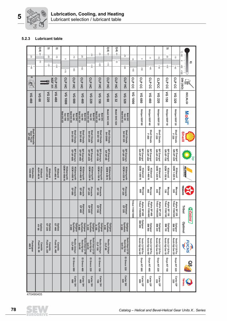
5.2.4 Oil quantity for horizontal gear units / M1 mounting positionThe specified oil quantity is a guide value. The precise value varies depending on thegear ratio and the number of stages. The mark on the oil sight glass, oil level glass and/or oil dipstick is the decisive indicatorfor the correct oil level.The following tables list the oil quantities for splash, bath and pressure lubrication.
X.F..
X.K..
X2F..
Oil quantity [l]
X3F..
Oil quantity [l]
X4F..
Oil quantity [l]
Splash lubri-cation
Pressure lubrication
Splash lubri-cation
Pressure lubrication
Splash lubri-cation
Pressure lubrication
X2F100 14 - X3F100 14 - X4F100 - -
X2F110 14 - X3F110 15 - X4F110 - -
X2F120 21 - X3F120 23 - X4F120 18 -
X2F130 23 - X3F130 23 - X4F130 18 -
X2F140 35 - X3F140 37 - X4F140 27 -
X2F150 38 - X3F150 38 - X4F150 29 -
X2F160 60 61 X3F160 63 63 X4F160 51 51
X2F170 60 61 X3F170 63 63 X4F170 51 51
X2F180 80 80 X3F180 80 80 X4F180 75 75
X2F190 80 80 X3F190 80 80 X4F190 75 75
X2F200 105 105 X3F200 105 105 X4F200 95 95
X2F210 105 105 X3F210 105 105 X4F210 95 95
X2F220 140 140 X3F220 145 145 X4F220 145 145
X2F230 140 140 X3F230 145 145 X4F230 145 145
X2F240 175 175 X3F240 170 170 X4F240 170 170
X2F250 175 175 X3F250 175 175 X4F250 170 170
X2F260 275 275 X3F260 270 270 X4F260 280 280
X2F270 275 275 X3F270 270 270 X4F270 280 280
X2F280 330 330 X3F280 335 335 X4F280 340 340
X2F290 405 405 X3F290 400 400 X4F290 415 415
X2F300 405 405 X3F300 400 400 X4F300 415 415
X2F310 550 550 X3F310 540 540 X4F310 540 540
X2F320 550 550 X3F320 540 540 X4F320 540 540
X2K..
Oil quantity [l]
X3K..
Oil quantity [l]
X4K..
Oil quantity [l]
Splash lubri-cation
Pressure lubrication
Splash lubri-cation
Pressure lubrication
Splash lubri-cation
Pressure lubrication
X2K100 11 - X3K100 13 - X4K100 - -
X2K110 12 - X3K110 14 - X4K110 - -
X2K120 17 - X3K120 20 - X4K120 24 -
X2K130 17 - X3K130 21 - X4K130 26 -
X2K140 26 - X3K140 33 - X4K140 38 -
X2K150 28 - X3K150 34 - X4K150 39 -
X2K160 48 48 X3K160 60 60 X4K160 63 64
X2K170 48 48 X3K170 60 60 X4K170 80 64
X2K180 60 60 X3K180 75 75 X4K180 80 80
X2K190 60 60 X3K190 75 75 X4K190 80 80
H O2

80 Catalog – Helical and Bevel-Helical Gear Units X.. Series
Lubricant selection / lubricant tableLubrication, Cooling, and Heating5
X.T..
X2K200 85 85 X3K200 100 100 X4K200 108 108
X2K210 85 85 X3K210 100 100 X4K210 115 115
X2K220 130 130 X3K220 130 130 X4K220 140 140
X2K230 130 130 X3K230 130 130 X4K230 140 140
X2K240 165 165 X3K240 170 170 X4K240 180 180
X2K250 165 165 X3K250 170 170 X4K250 176 176
X2K260 - - X3K260 255 255 X4K260 270 270
X2K270 - - X3K270 255 255 X4K270 270 270
X2K280 - - X3K280 325 325 X4K280 330 330
X2K290 - - X3K290 400 400 X4K290 410 410
X2K300 - - X3K300 400 400 X4K300 410 410
X2K310 - - X3K310 535 535 X4K310 540 540
X2K320 - - X3K320 535 535 X4K320 540 540
X2K..
Oil quantity [l]
X3K..
Oil quantity [l]
X4K..
Oil quantity [l]
Splash lubri-cation
Pressure lubrication
Splash lubri-cation
Pressure lubrication
Splash lubri-cation
Pressure lubrication
X3T..
Oil quantity [l]
X4T..
Oil quantity [l]
Splash lubri-cation
Pressure lubrication
Bath lubri-cation
Splash lubri-cation
Pressure lubrication
Bath lubri-cation
X3T100 13 - - X4T100 - - -
X3T110 14 - - X4T110 - - -
X3T120 20 - - X4T120 20 - -
X3T130 21 - - X4T130 21 - -
X3T140 33 - - X4T140 31 - -
X3T150 34 - - X4T150 32 - -
X3T160 60 51 - X4T160 54 54 -
X3T170 60 51 - X4T170 54 54 -
X3T180 75 65 - X4T180 75 75 -
X3T190 75 65 - X4T190 75 75 -
X3T200 100 85 - X4T200 95 95 -
X3T210 100 85 - X4T210 95 95 -
X3T220 - 135 315 X4T220 - 205 325
X3T230 - 135 315 X4T230 - 205 325
X3T240 - 165 395 X4T240 - 260 400
X3T250 - 165 395 X4T250 - 260 400
H O2

Catalog – Helical and Bevel-Helical Gear Units X.. Series 81
Lubricant selection / lubricant tableLubrication, Cooling, and Heating
5
5
5.2.5 Oil quantity for horizontal gear units / M3 mounting positionThe specified oil quantity is a guide value. The precise value varies depending on thegear ratio and the number of stages. The mark on the oil sight glass, oil level glass and/or oil dipstick is the decisive indicatorfor the correct oil level.The following tables list the oil quantities for splash and bath lubrication.
X.F..
X.K..
X2F..
Oil quantity [l]
X3F..
Oil quantity [l]
X4F..
Oil quantity [l]
Splash lubrica-tion
Splash lubrica-tion
Splash lubrica-tion
X2F100 14 X3F100 14 X4F100 -
X2F110 15 X3F110 15 X4F110 -
X2F120 21 X3F120 21 X4F120 25
X2F130 21 X3F130 21 X4F130 25
X2F140 35 X3F140 36 X4F140 40
X2F150 37 X3F150 38 X4F150 40
X2F160 61 X3F160 62 X4F160 76
X2F170 61 X3F170 62 X4F170 76
X2F180 75 X3F180 80 X4F180 100
X2F190 75 X3F190 80 X4F190 100
X2F200 100 X3F200 105 X4F200 135
X2F210 100 X3F210 105 X4F210 135
X2F220 130 X3F220 140 X4F220 180
X2F230 130 X3F230 140 X4F230 180
X2F240 170 X3F240 175 X4F240 235
X2F250 170 X3F250 175 X4F250 230
X2F260 275 X3F260 270 X4F260 280
X2F270 275 X3F270 270 X4F270 280
X2F280 330 X3F280 335 X4F280 340
X2F290 405 X3F290 400 X4F290 415
X2F300 405 X3F300 400 X4F300 415
X2F310 550 X3F310 540 X4F310 540
X2F320 550 X3F320 540 X4F320 540
X2K..
Oil quantity [l]
X3K..
Oil quantity [l]
X4K..
Oil quantity [l]
Splash lubri-cation
Splash lubri-cation
Bath lubri-cation
Splash lubri-cation
X2K100 11 X3K100 16 29 X4K100 -
X2K110 12 X3K110 16 29 X4K110 -
X2K120 16 X3K120 20 - X4K120 20
X2K130 17 X3K130 22 - X4K130 21
X2K140 25 X3K140 33 - X4K140 36
X2K150 28 X3K150 35 - X4K150 38
X2K160 47 X3K160 60 - X4K160 61
X2K170 47 X3K170 60 - X4K170 61
H O2

82 Catalog – Helical and Bevel-Helical Gear Units X.. Series
Lubricant selection / lubricant tableLubrication, Cooling, and Heating5
X.T..
X2K180 60 X3K180 75 - X4K180 75
X2K190 60 X3K190 75 - X4K190 75
X2K200 80 X3K200 95 - X4K200 115
X2K210 80 X3K210 95 - X4K210 115
X2K220 130 X3K220 125 - X4K220 140
X2K230 130 X3K230 125 - X4K230 140
X2K240 170 X3K240 165 - X4K240 175
X2K250 170 X3K250 165 - X4K250 175
X2K260 - X3K260 255 - X4K260 270
X2K270 - X3K270 255 - X4K270 270
X2K280 - X3K280 325 - X4K280 330
X2K290 - X3K290 400 - X4K290 410
X2K300 - X3K300 400 - X4K300 410
X2K310 - X3K310 535 - X4K310 540
X2K320 - X3K320 535 - X4K320 540
X2K..
Oil quantity [l]
X3K..
Oil quantity [l]
X4K..
Oil quantity [l]
Splash lubri-cation
Splash lubri-cation
Bath lubri-cation
Splash lubri-cation
X3T..
Oil quantity [l]
X4T..
Oil quantity [l]
Splash lubri-cation
Bath lubri-cation
Splash lubri-cation
Bath lubri-cation
X3T100 - 34 X4T100 - -
X3T110 - 34 X4T110 - -
X3T120 - 46 X4T120 - 50
X3T130 - 48 X4T130 - 52
X3T140 - 80 X4T140 - 80
X3T150 - 84 X4T150 - 84
X3T160 - 142 X4T160 - 146
X3T170 - 142 X4T170 - 146
X3T180 - 170 X4T180 - 175
X3T190 - 170 X4T190 - 175
X3T200 - 230 X4T200 - 235
X3T210 - 230 X4T210 - 235
X3T220 115 - X4T220 140 -
X3T230 115 - X4T230 140 -
X3T240 150 - X4T240 175 -
X3T250 150 - X4T250 175 -
H O2

Catalog – Helical and Bevel-Helical Gear Units X.. Series 83
Lubricant selection / lubricant tableLubrication, Cooling, and Heating
5
5
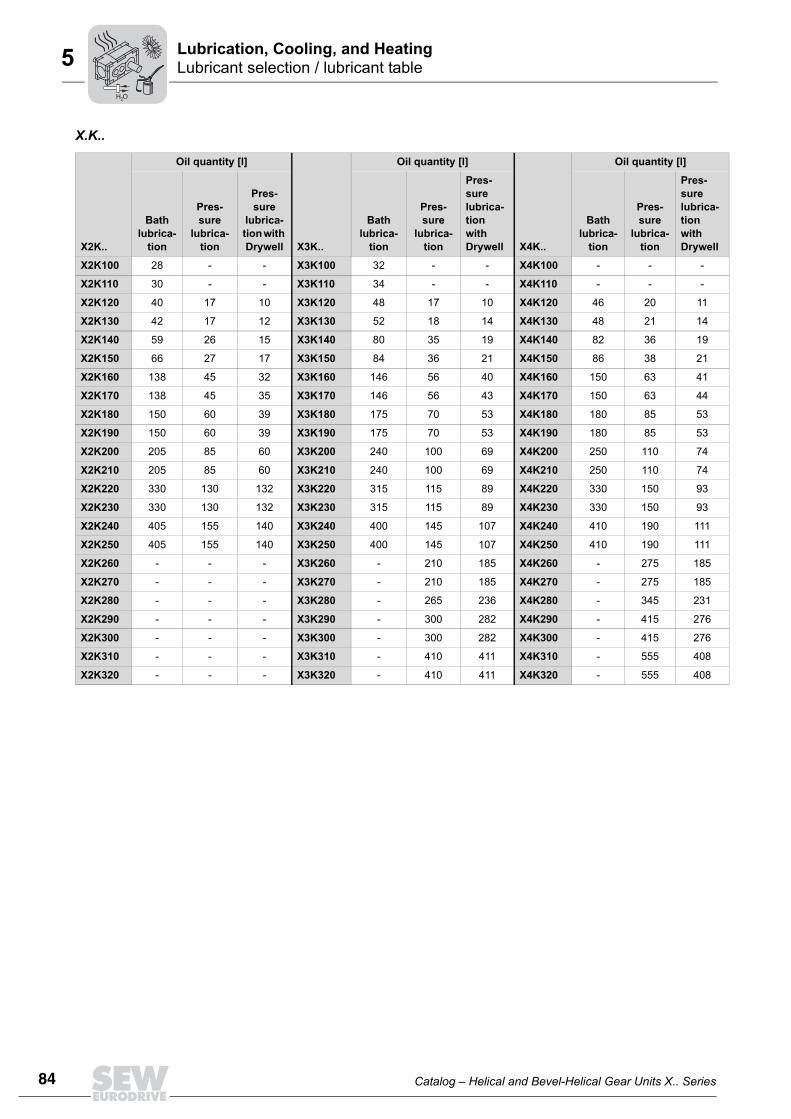
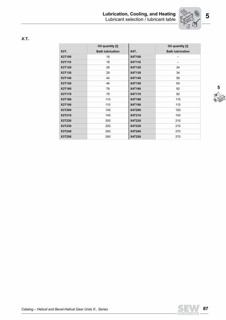
5.2.6 Oil quantities for vertical gear units / M5 and M6 mounting positionsThe specified oil quantity is a guide value. The precise value varies depending on thegear ratio and the number of stages. The mark on the oil sight glass, oil level glass and/or oil dipstick is the decisive indicatorfor the correct oil level.The following tables list the oil quantities for bath and pressure lubrication as well aspressure lubrication with Drywell.Note that for gear unit combinations in M5 or M6 mounting position with pressure lubri-cation and oil heater, the oil quantity must be increased by 20%. Observe the informa-tion on the nameplate.
X.F..
X2F..
Oil quantity [l]
X3F..
Oil quantity [l]
X4F..
Oil quantity [l]
Bath lubrica-
tion
Pres-sure
lubrica-tion
Pres-sure
lubrica-tion with Drywell
Bath lubrica-
tion
Pres-sure
lubrica-tion
Pres-sure lubrica-tion with Drywell
Bath lubrica-
tion
Pres-sure
lubrica-tion
Pres-sure lubrica-tion with Drywell
X2F100 34 - - X3F100 34 - - X4F100 - - -
X2F110 36 - - X3F110 36 - - X4F110 - - -
X2F120 50 18 11 X3F120 44 18 11 X4F120 44 18 12
X2F130 52 20 14 X3F130 46 20 14 X4F130 46 18 13
X2F140 86 38 20 X3F140 82 38 20 X4F140 78 24 21
X2F150 90 38 22 X3F150 88 36 22 X4F150 80 26 21
X2F160 152 62 38 X3F160 146 56 38 X4F160 146 45 37
X2F170 152 62 41 X3F170 146 56 41 X4F170 146 45 40
X2F180 185 75 54 X3F180 185 70 53 X4F180 175 65 50
X2F190 185 75 54 X3F190 185 70 53 X4F190 175 65 50
X2F200 250 105 75 X3F200 250 105 74 X4F200 240 100 68
X2F210 250 105 75 X3F210 250 105 74 X4F210 240 100 68
X2F220 335 125 95 X3F220 330 120 93 X4F220 330 150 93
X2F230 335 125 95 X3F230 330 120 93 X4F230 330 150 93
X2F240 410 155 113 X3F240 400 145 108 X4F240 410 185 110
X2F250 410 155 113 X3F250 400 145 108 X4F250 410 185 110
X2F260 - 220 192 X3F260 - 210 183 X4F260 - 250 186
X2F270 - 220 192 X3F270 - 210 183 X4F270 - 250 186
X2F280 - 265 234 X3F280 - 260 230 X4F280 - 305 230
X2F290 - 300 284 X3F290 - 295 275 X4F290 - 390 273
X2F300 - 300 284 X3F300 - 295 275 X4F300 - 390 273
X2F310 - 416 416 X3F310 - 400 399 X4F310 - 515 393
X2F320 - 416 416 X3F320 - 400 399 X4F320 - 515 393
H O2
84 Catalog – Helical and Bevel-Helical Gear Units X.. Series
Lubricant selection / lubricant tableLubrication, Cooling, and Heating5
X.K..
X2K..
Oil quantity [l]
X3K..
Oil quantity [l]
X4K..
Oil quantity [l]
Bath lubrica-
tion
Pres-sure
lubrica-tion
Pres-sure
lubrica-tion with Drywell
Bath lubrica-
tion
Pres-sure
lubrica-tion
Pres-sure lubrica-tion with Drywell
Bath lubrica-
tion
Pres-sure
lubrica-tion
Pres-sure lubrica-tion with Drywell
X2K100 28 - - X3K100 32 - - X4K100 - - -
X2K110 30 - - X3K110 34 - - X4K110 - - -
X2K120 40 17 10 X3K120 48 17 10 X4K120 46 20 11
X2K130 42 17 12 X3K130 52 18 14 X4K130 48 21 14
X2K140 59 26 15 X3K140 80 35 19 X4K140 82 36 19
X2K150 66 27 17 X3K150 84 36 21 X4K150 86 38 21
X2K160 138 45 32 X3K160 146 56 40 X4K160 150 63 41
X2K170 138 45 35 X3K170 146 56 43 X4K170 150 63 44
X2K180 150 60 39 X3K180 175 70 53 X4K180 180 85 53
X2K190 150 60 39 X3K190 175 70 53 X4K190 180 85 53
X2K200 205 85 60 X3K200 240 100 69 X4K200 250 110 74
X2K210 205 85 60 X3K210 240 100 69 X4K210 250 110 74
X2K220 330 130 132 X3K220 315 115 89 X4K220 330 150 93
X2K230 330 130 132 X3K230 315 115 89 X4K230 330 150 93
X2K240 405 155 140 X3K240 400 145 107 X4K240 410 190 111
X2K250 405 155 140 X3K250 400 145 107 X4K250 410 190 111
X2K260 - - - X3K260 - 210 185 X4K260 - 275 185
X2K270 - - - X3K270 - 210 185 X4K270 - 275 185
X2K280 - - - X3K280 - 265 236 X4K280 - 345 231
X2K290 - - - X3K290 - 300 282 X4K290 - 415 276
X2K300 - - - X3K300 - 300 282 X4K300 - 415 276
X2K310 - - - X3K310 - 410 411 X4K310 - 555 408
X2K320 - - - X3K320 - 410 411 X4K320 - 555 408
H O2

Catalog – Helical and Bevel-Helical Gear Units X.. Series 85
Lubricant selection / lubricant tableLubrication, Cooling, and Heating
5
5
X.T..
X3T..
Oil quantity [l]
X4T..
Oil quantity [l]
Bath lubri-cation
Pressure lubrication
Pressure lubrica-tion with Drywell
Bath lubri-cation
Pressure lubrica-
tion
Pressure lubrica-tion with Drywell
X3T100 34 - - X4T100 - - -
X3T110 34 - - X4T110 - - -
X3T120 46 17 12 X4T120 50 18 12
X3T130 48 18 13 X4T130 52 20 13
X3T140 80 32 21 X4T140 80 32 21
X3T150 84 33 21 X4T150 84 33 37
X3T160 142 54 37 X4T160 146 56 40
X3T170 142 54 40 X4T170 146 56 36
X3T180 170 70 50 X4T180 175 80 50
X3T190 170 70 50 X4T190 175 80 50
X3T200 230 95 68 X4T200 235 105 68
X3T210 230 95 68 X4T210 235 105 68
X3T220 315 115 89 X4T220 325 145 89
X3T230 315 115 89 X4T230 325 145 89
X3T240 395 145 107 X4T240 400 185 107
X3T250 395 145 107 X4T250 400 185 107
H O2

86 Catalog – Helical and Bevel-Helical Gear Units X.. Series
Lubricant selection / lubricant tableLubrication, Cooling, and Heating5
5.2.7 Oil quantities for upright gear units / M2 mounting positionThe specified oil quantity is a guide value. The precise value varies depending on thegear ratio and the number of stages. The mark on the oil sight glass, oil level glass and/or oil dipstick is the decisive indicatorfor the correct oil level.The following tables list the oil quantities for bath lubrication.
X.F..
X.K..
X2F..
Oil quantity [l]
X3F..
Oil quantity [l]
X4F..
Oil quantity [l]
Bath lubrication Bath lubrication Bath lubrication
X2F100 23 X3F100 21 X4F100 -
X2F110 23 X3F110 21 X4F110 -
X2F120 33 X3F120 33 X4F120 30
X2F130 35 X3F130 34 X4F130 31
X2F140 56 X3F140 54 X4F140 47
X2F150 59 X3F150 58 X4F150 50
X2F160 105 X3F160 91 X4F160 80
X2F170 105 X3F170 91 X4F170 80
X2F180 120 X3F180 120 X4F180 110
X2F190 120 X3F190 120 X4F190 110
X2F200 165 X3F200 165 X4F200 150
X2F210 165 X3F210 165 X4F210 150
X2F220 220 X3F220 215 X4F220 215
X2F230 220 X3F230 215 X4F230 215
X2F240 280 X3F240 265 X4F240 270
X2F250 280 X3F250 265 X4F250 270
X2K..
Oil quantity [l]
X3K..
Oil quantity [l]
X4K..
Oil quantity [l]
Bath lubrication Bath lubrication Bath lubrication
X2K100 17 X3K100 20 X4K100 -
X2K110 17 X3K110 20 X4K110 -
X2K120 25 X3K120 31 X4K120 32
X2K130 26 X3K130 31 X4K130 33
X2K140 38 X3K140 47 X4K140 54
X2K150 42 X3K150 50 X4K150 57
X2K160 66 X3K160 90 X4K160 91
X2K170 66 X3K170 90 X4K170 91
X2K180 90 X3K180 115 X4K180 120
X2K190 90 X3K190 115 X4K190 120
X2K200 125 X3K200 155 X4K200 160
X2K210 125 X3K210 155 X4K210 160
X2K220 195 X3K220 200 X4K220 215
X2K230 195 X3K230 200 X4K230 215
X2K240 250 X3K240 265 X4K240 275
X2K250 250 X3K250 265 X4K250 275
H O2
Catalog – Helical and Bevel-Helical Gear Units X.. Series 87
Lubricant selection / lubricant tableLubrication, Cooling, and Heating
5
5
X.T..
X3T..
Oil quantity [l]
X4T..
Oil quantity [l]
Bath lubrication Bath lubrication
X3T100 18 X4T100 -
X3T110 18 X4T110 -
X3T120 28 X4T120 34
X3T130 29 X4T130 34
X3T140 44 X4T140 56
X3T150 46 X4T150 60
X3T160 78 X4T160 92
X3T170 78 X4T170 92
X3T180 110 X4T180 115
X3T190 110 X4T190 115
X3T200 145 X4T200 150
X3T210 145 X4T210 150
X3T220 200 X4T220 210
X3T230 200 X4T230 210
X3T240 260 X4T240 270
X3T250 260 X4T250 270
H O2

88 Catalog – Helical and Bevel-Helical Gear Units X.. Series
Lubricant selection / lubricant tableLubrication, Cooling, and Heating5
5.2.8 Oil quantities for upright gear units / M4 mounting positionThe specified oil quantity is a guide value. The precise value varies depending on thegear ratio and the number of stages. The mark on the oil sight glass, oil level glass and/or oil dipstick is the decisive indicatorfor the correct oil level.The following tables list the oil quantities for bath and pressure lubrication.
X.F..
X.K..
X2F..
Oil quantity [l]
X3F..
Oil quantity [l]
X4F..
Oil quantity [l]
Bath lubri-cation
Pressure lubrication
Bath lubrica-tion
Pressure lubrication
Bath lubrica-tion
Pressure lubrication
X2F100 23 - X3F100 26 X4F100 - -
X2F110 23 - X3F110 27 X4F110 - -
X2F120 35 18 X3F120 35 18 X4F120 36 18
X2F130 36 18 X3F130 38 18 X4F130 38 18
X2F140 57 26 X3F140 66 26 X4F140 57 26
X2F150 62 27 X3F150 71 27 X4F150 60 27
X2F160 102 51 X3F160 108 51 X4F160 112 51
X2F170 102 51 X3F170 108 51 X4F170 104 51
X2F180 130 55 X3F180 150 55 X4F180 145 55
X2F190 130 55 X3F190 144 55 X4F190 145 55
X2F200 175 70 X3F200 200 70 X4F200 200 70
X2F210 175 70 X3F210 200 70 X4F210 200 70
X2F220 230 100 X3F220 265 100 X4F220 265 100
X2F230 230 100 X3F230 265 100 X4F230 265 100
X2F240 285 115 X3F240 330 115 X4F240 340 115
X2F250 285 115 X3F250 330 115 X4F250 340 115
X2F260 - 180 X3F260 - 180 X4F260 - 180
X2F270 - 180 X3F270 - 180 X4F270 - 180
X2F280 - 235 X3F280 - 235 X4F280 - 235
X2F290 - 255 X3F290 - 255 X4F290 - 255
X2F300 - 255 X3F300 - 255 X4F300 - 255
X2F310 - 360 X3F310 - 360 X4F310 - 360
X2F320 - 360 X3F320 - 360 X4F320 - 360
X2K..
Oil quantity [l]
X3K..
Oil quantity [l]
X4K..
Oil quantity [l]
Bath lubri-cation
Pressure lubrication
Bath lubrica-tion
Pressure lubrication
Bath lubrica-tion
Pressure lubrication
X2K100 28 X3K100 32 X4K100 - -
X2K110 30 X3K110 34 X4K110 - -
X2K120 40 18 X3K120 48 18 X4K120 46 18
X2K130 42 18 X3K130 52 18 X4K130 48 18
X2K140 66 26 X3K140 80 26 X4K140 82 26
X2K150 72 27 X3K150 84 27 X4K150 86 27
X2K160 138 51 X3K160 146 51 X4K160 150 51
X2K170 138 51 X3K170 146 51 X4K170 150 51
X2K180 150 55 X3K180 175 55 X4K180 180 55
H O2

Catalog – Helical and Bevel-Helical Gear Units X.. Series 89
Lubricant selection / lubricant tableLubrication, Cooling, and Heating
5
5
X.T..
X2K190 150 55 X3K190 175 55 X4K190 180 55
X2K200 205 70 X3K200 240 70 X4K200 250 70
X2K210 205 70 X3K210 240 70 X4K210 250 70
X2K220 330 100 X3K220 315 100 X4K220 330 100
X2K230 330 100 X3K230 315 100 X4K230 330 100
X2K240 405 115 X3K240 400 115 X4K240 410 115
X2K250 405 115 X3K250 400 115 X4K250 410 115
X2K260 - - X3K260 - 180 X4K260 - 180
X2K270 - - X3K270 - 180 X4K270 - 180
X2K280 - - X3K280 - 235 X4K280 - 235
X2K290 - - X3K290 - 255 X4K290 - 255
X2K300 - - X3K300 - 255 X4K300 - 255
X2K310 - - X3K310 - 360 X4K310 - 360
X2K320 - - X3K320 - 360 X4K320 - 360
X2K..
Oil quantity [l]
X3K..
Oil quantity [l]
X4K..
Oil quantity [l]
Bath lubri-cation
Pressure lubrication
Bath lubrica-tion
Pressure lubrication
Bath lubrica-tion
Pressure lubrication
X3T..
Oil quantity [l]
X4T..
Oil quantity [l]
Bath lubrication Pressure lubrica-tion Bath lubrication Pressure lubrication
X3T100 21 - X4T100 - -
X3T110 21 - X4T110 - -
X3T120 32 - X4T120 36 -
X3T130 33 - X4T130 38 -
X3T140 50 - X4T140 54 -
X3T150 53 27 X4T150 57 27
X3T160 90 51 X4T160 93 51
X3T170 90 51 X4T170 93 51
X3T180 120 55 X4T180 125 55
X3T190 120 55 X4T190 125 55
X3T200 160 70 X4T200 160 70
X3T210 160 70 X4T210 160 70
X3T220 215 100 X4T220 215 100
X3T230 215 100 X4T230 215 100
X3T240 270 115 X4T240 285 115
X3T250 270 115 X4T250 285 115
H O2
90 Catalog – Helical and Bevel-Helical Gear Units X.. Series
Lubricant selection / lubricant tableLubrication, Cooling, and Heating5
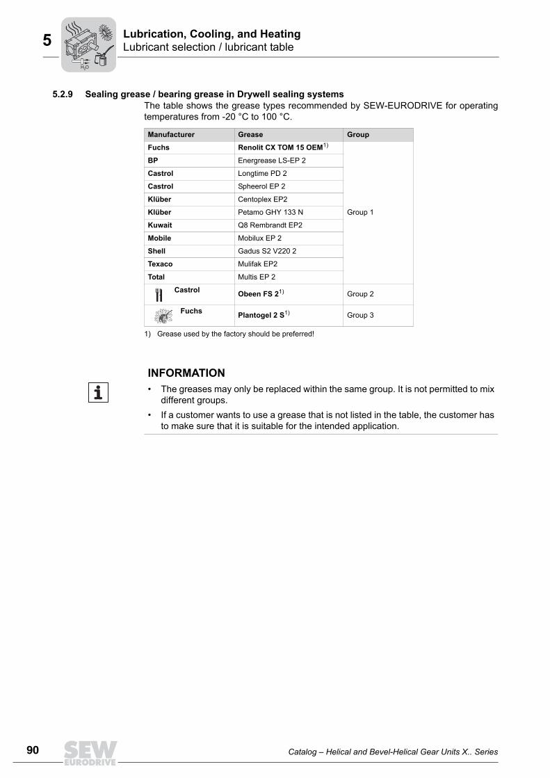
5.2.9 Sealing grease / bearing grease in Drywell sealing systemsThe table shows the grease types recommended by SEW-EURODRIVE for operatingtemperatures from -20 °C to 100 °C.
Manufacturer Grease Group
Fuchs Renolit CX TOM 15 OEM1)
1) Grease used by the factory should be preferred!
Group 1
BP Energrease LS-EP 2
Castrol Longtime PD 2
Castrol Spheerol EP 2
Klüber Centoplex EP2
Klüber Petamo GHY 133 N
Kuwait Q8 Rembrandt EP2
Mobile Mobilux EP 2
Shell Gadus S2 V220 2
Texaco Mulifak EP2
Total Multis EP 2
Castrol Obeen FS 21) Group 2
Fuchs Plantogel 2 S1) Group 3OilOil
INFORMATION• The greases may only be replaced within the same group. It is not permitted to mix
different groups.• If a customer wants to use a grease that is not listed in the table, the customer has
to make sure that it is suitable for the intended application.
H O2
Catalog – Helical and Bevel-Helical Gear Units X.. Series 91
AccessoriesLubrication, Cooling, and Heating
5
5
5.3 AccessoriesThe following section describes the accessories for the several types of lubrication.
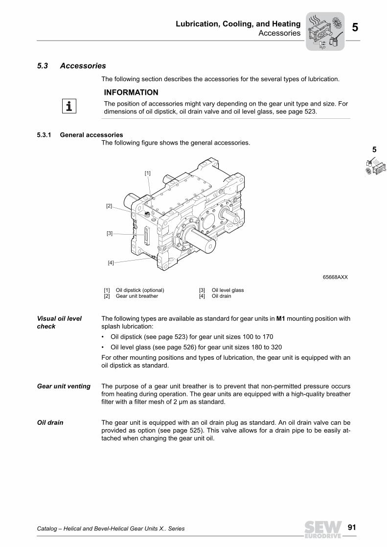
5.3.1 General accessories The following figure shows the general accessories.
Visual oil level check
The following types are available as standard for gear units in M1 mounting position withsplash lubrication: • Oil dipstick (see page 523) for gear unit sizes 100 to 170 • Oil level glass (see page 526) for gear unit sizes 180 to 320For other mounting positions and types of lubrication, the gear unit is equipped with anoil dipstick as standard.
Gear unit venting The purpose of a gear unit breather is to prevent that non-permitted pressure occursfrom heating during operation. The gear units are equipped with a high-quality breatherfilter with a filter mesh of 2 µm as standard.
Oil drain The gear unit is equipped with an oil drain plug as standard. An oil drain valve can beprovided as option (see page 525). This valve allows for a drain pipe to be easily at-tached when changing the gear unit oil.
INFORMATIONThe position of accessories might vary depending on the gear unit type and size. Fordimensions of oil dipstick, oil drain valve and oil level glass, see page 523.
65668AXX
[1][2]
Oil dipstick (optional)Gear unit breather
[3][4]
Oil level glassOil drain
[2]
[1]
[3]
[4]
H O2

92 Catalog – Helical and Bevel-Helical Gear Units X.. Series
AccessoriesLubrication, Cooling, and Heating5
5.3.2 Additional bath lubrication accessoriesOil expansion tank /ET
The purpose of the oil expansion tank is to compensate for oil volume variations in thesystem caused by temperature fluctuations. If the gear unit temperature increases, theexpansion tank absorbs some of the increasing oils volume and feeds it back to the gearunit as the temperature goes down, thus the gear unit is always completely filled with oil.Based on the oil level specified by SEW-EURODRIVE, the oil expansion tank is de-signed to compensate the oil volume change within the permitted operating temperaturerange. A temperature decrease below the permitted range causes the expansion tankto be completely emptied and air being sucked into the gear unit. This might result ininsufficient lubrication and a malfunction of the gear unit. An increase above the permit-ted range causes an overfilling of the expansion tank and oil might leak from the gearunit. During operation, any oil level below or above the level specified by SEW-EURODRIVE is permitted as long as there is oil in the expansion tank and the expansiontank does not overflow. The following figure shows the accessories for mounting positions M1, M4 and M5.
69236AEN
[2][1]
[2][1]
[3]
[3]
[4]
[2][1]
[4]
[4]
[3]
Mounting position M1
Mounting position M4
Mounting position M5
[1][2]
Gear unit breatherOil dipstick
[3][4]
Oil drain Oil expansion tank
INFORMATIONFor dimension sheets of oil expansion tanks, refer to page 426 ff.
H O2
Catalog – Helical and Bevel-Helical Gear Units X.. Series 93
AccessoriesLubrication, Cooling, and Heating
5
5
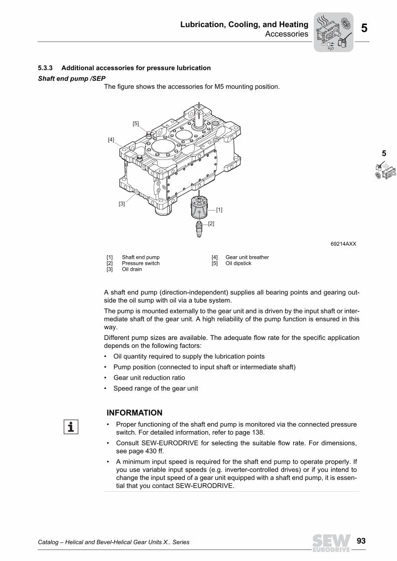
5.3.3 Additional accessories for pressure lubricationShaft end pump /SEP
The figure shows the accessories for M5 mounting position.
A shaft end pump (direction-independent) supplies all bearing points and gearing out-side the oil sump with oil via a tube system. The pump is mounted externally to the gear unit and is driven by the input shaft or inter-mediate shaft of the gear unit. A high reliability of the pump function is ensured in thisway.Different pump sizes are available. The adequate flow rate for the specific applicationdepends on the following factors:• Oil quantity required to supply the lubrication points• Pump position (connected to input shaft or intermediate shaft)• Gear unit reduction ratio• Speed range of the gear unit
69214AXX
[1][2][3]
Shaft end pumpPressure switchOil drain
[4][5]
Gear unit breatherOil dipstick
[5]
[4]
[3][1]
[2]
INFORMATION• Proper functioning of the shaft end pump is monitored via the connected pressure
switch. For detailed information, refer to page 138.• Consult SEW-EURODRIVE for selecting the suitable flow rate. For dimensions,
see page 430 ff.• A minimum input speed is required for the shaft end pump to operate properly. If
you use variable input speeds (e.g. inverter-controlled drives) or if you intend tochange the input speed of a gear unit equipped with a shaft end pump, it is essen-tial that you contact SEW-EURODRIVE.
H O2
94 Catalog – Helical and Bevel-Helical Gear Units X.. Series
AccessoriesLubrication, Cooling, and Heating5
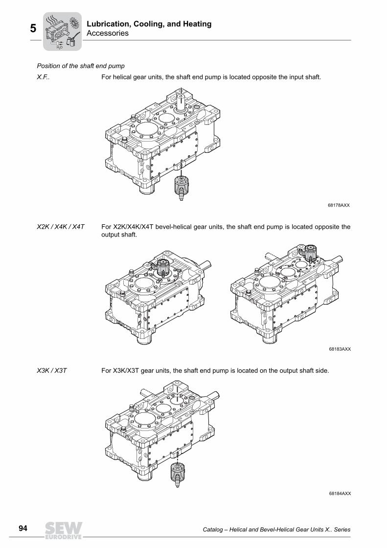
Position of the shaft end pump
X.F.. For helical gear units, the shaft end pump is located opposite the input shaft.
X2K / X4K / X4T For X2K/X4K/X4T bevel-helical gear units, the shaft end pump is located opposite theoutput shaft.
X3K / X3T For X3K/X3T gear units, the shaft end pump is located on the output shaft side.
68178AXX
68183AXX
68184AXX
H O2

Catalog – Helical and Bevel-Helical Gear Units X.. Series 95
AccessoriesLubrication, Cooling, and Heating
5
5
Motor pump /ONPWith pressure lubrication, a motor pump supplies all bearing points and gearing abovethe oil sump with oil via a tube system inside the gear unit. The motor pump is used, for example, when the required speed of the shaft end pump(≤ 400 rpm) is not reached. It is also used in inverter operation where a shaft end pumpcannot be used or can only be used under certain circumstances.The motor pump is mounted externally to the gear unit and depends on the speed of thegear unit.
Structure The figure shows an example of a motor pump.
The motor pump is delivered as a complete unit but without electrical connections.In its basic variant, the scope of the motor pump includes the following components:• Pump with directly connected asynchronous motor (pump always running)• Oil filter with filter element and electrical/optical contamination indicator• Pressure switch that monitors the pump pressure. Warning or switch-off signal when
the oil pressure reaches < 0.5 bar• Option: Temperature switch with trip point for monitoring the cooling group, i.e. warn-
ing or gear unit shutdown when the oil temperature exceeds 90 °C
The following motor pump types are available:• Directly mounted on the gear unit, incl. piping, or• On the mounting frame, for separate installation, but without piping to the gear unit
The customer has to carry out the following electrical wiring: • Pressure switch to the customer's evaluation unit• Electrical contamination indicator of the oil filter• Pump motor• Option: Between temperature switch and pump motor
68225AXX
M[2]
[3] [4]
[5]
[6]
[1]
[5] [3]
[7]
[4]
[6]
[2]
[8] [9]
[1] Motor [6] Pressure switch
[2] Pump [7] Contamination indicator
[3] Suction pipe [8] Temperature switch, optional (NTB)
[4] Pressure line [9] Check valve
[5] Oil filter
H O2
96 Catalog – Helical and Bevel-Helical Gear Units X.. Series
AccessoriesLubrication, Cooling, and Heating5
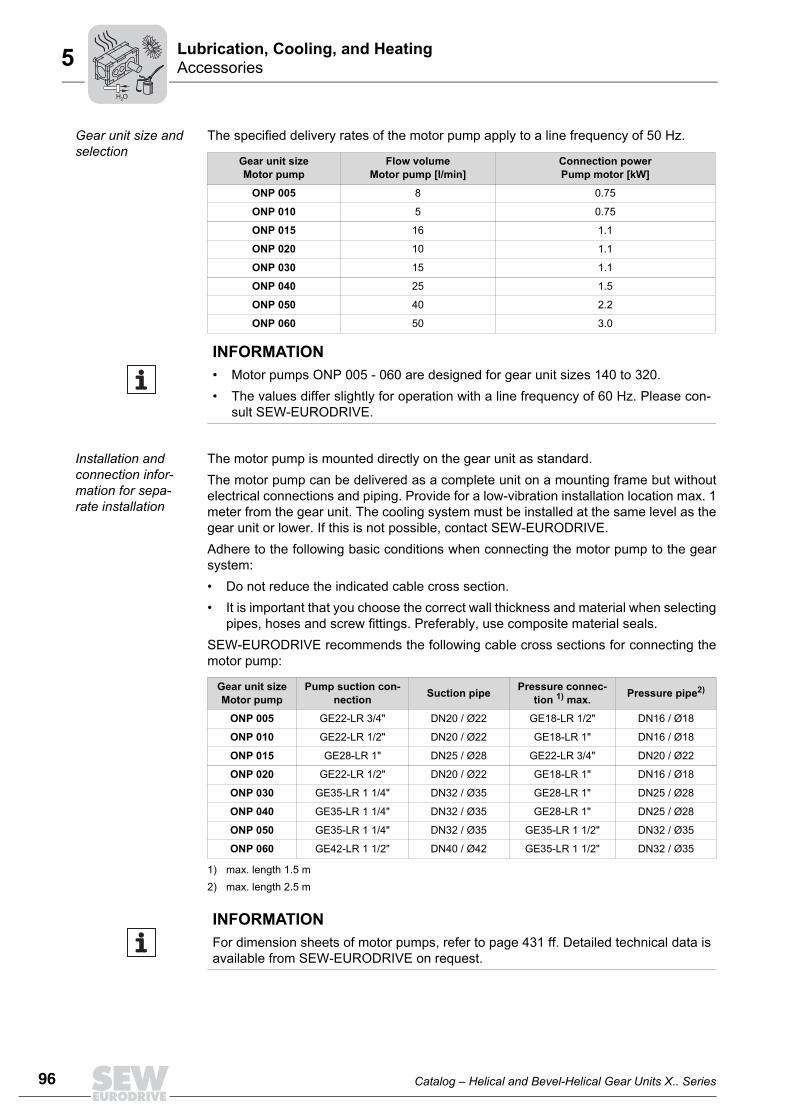
Gear unit size and selection
The specified delivery rates of the motor pump apply to a line frequency of 50 Hz.
Installation and connection infor-mation for sepa-rate installation
The motor pump is mounted directly on the gear unit as standard.The motor pump can be delivered as a complete unit on a mounting frame but withoutelectrical connections and piping. Provide for a low-vibration installation location max. 1meter from the gear unit. The cooling system must be installed at the same level as thegear unit or lower. If this is not possible, contact SEW-EURODRIVE.Adhere to the following basic conditions when connecting the motor pump to the gearsystem:• Do not reduce the indicated cable cross section.• It is important that you choose the correct wall thickness and material when selecting
pipes, hoses and screw fittings. Preferably, use composite material seals.SEW-EURODRIVE recommends the following cable cross sections for connecting themotor pump:
Gear unit sizeMotor pump
Flow volumeMotor pump [l/min]
Connection powerPump motor [kW]
ONP 005 8 0.75
ONP 010 5 0.75
ONP 015 16 1.1
ONP 020 10 1.1
ONP 030 15 1.1
ONP 040 25 1.5
ONP 050 40 2.2
ONP 060 50 3.0
INFORMATION• Motor pumps ONP 005 - 060 are designed for gear unit sizes 140 to 320. • The values differ slightly for operation with a line frequency of 60 Hz. Please con-
sult SEW-EURODRIVE.
Gear unit sizeMotor pump
Pump suction con-nection Suction pipe Pressure connec-
tion 1) max.
1) max. length 1.5 m
Pressure pipe2)
2) max. length 2.5 m
ONP 005 GE22-LR 3/4" DN20 / Ø22 GE18-LR 1/2" DN16 / Ø18
ONP 010 GE22-LR 1/2" DN20 / Ø22 GE18-LR 1" DN16 / Ø18
ONP 015 GE28-LR 1" DN25 / Ø28 GE22-LR 3/4" DN20 / Ø22
ONP 020 GE22-LR 1/2" DN20 / Ø22 GE18-LR 1" DN16 / Ø18
ONP 030 GE35-LR 1 1/4" DN32 / Ø35 GE28-LR 1" DN25 / Ø28
ONP 040 GE35-LR 1 1/4" DN32 / Ø35 GE28-LR 1" DN25 / Ø28
ONP 050 GE35-LR 1 1/4" DN32 / Ø35 GE35-LR 1 1/2" DN32 / Ø35
ONP 060 GE42-LR 1 1/2" DN40 / Ø42 GE35-LR 1 1/2" DN32 / Ø35
INFORMATIONFor dimension sheets of motor pumps, refer to page 431 ff. Detailed technical data isavailable from SEW-EURODRIVE on request.
H O2
Catalog – Helical and Bevel-Helical Gear Units X.. Series 97
CoolingLubrication, Cooling, and Heating
5
5
5.4 CoolingIf the permitted thermal rating of the gear unit is exceeded, additional cooling measuresmust be taken.The following cooling methods are available as standard:• Water cooling cover (for gear unit sizes 100 to 130 and 180 to 210)• Water cooling cartridge (for gear unit sizes 140 to 320)• Circulation cooling with oil-water cooler with a motor pump• Circulation cooling oil-air cooler with motor pump• Fan in combination with water cooling cover (for gear unit sizes 100 to 130 and 180
to 210) • Fan in combination with water cooling cartridge (for gear unit sizes 140 to 320)• Fan on HSS (only for 2- and 3-stage X gear units)
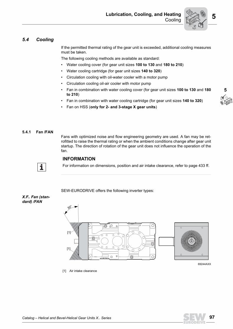
5.4.1 Fan /FANFans with optimized noise and flow engineering geometry are used. A fan may be ret-rofitted to raise the thermal rating or when the ambient conditions change after gear unitstartup. The direction of rotation of the gear unit does not influence the operation of thefan.
SEW-EURODRIVE offers the following inverter types:X.F.. Fan (stan-dard) /FAN
INFORMATIONFor information on dimensions, position and air intake clearance, refer to page 433 ff.
69244AXX
[1] Air intake clearance
[1]
[1]
30°
H O2
98 Catalog – Helical and Bevel-Helical Gear Units X.. Series
CoolingLubrication, Cooling, and Heating5
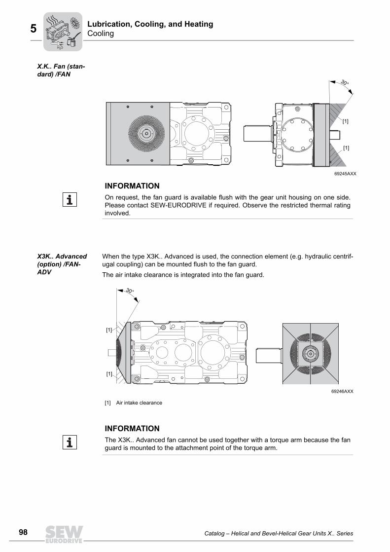
X.K.. Fan (stan-dard) /FAN
X3K.. Advanced (option) /FAN-ADV
When the type X3K.. Advanced is used, the connection element (e.g. hydraulic centrif-ugal coupling) can be mounted flush to the fan guard.The air intake clearance is integrated into the fan guard.
69245AXX
[1]
[1]
30°
INFORMATIONOn request, the fan guard is available flush with the gear unit housing on one side.Please contact SEW-EURODRIVE if required. Observe the restricted thermal ratinginvolved.
69246AXX
[1] Air intake clearance
[1]
[1]
30°
INFORMATIONThe X3K.. Advanced fan cannot be used together with a torque arm because the fanguard is mounted to the attachment point of the torque arm.
H O2
Catalog – Helical and Bevel-Helical Gear Units X.. Series 99
CoolingLubrication, Cooling, and Heating
5
5
5.4.2 Built-in cooling, water cooling cover /CCVThe water cooling cover is located on the gear unit's assembly opening and is providedwith cooling water through a water connection that is provided by the operator. It is avail-able for gear unit sizes 100 to 130 and 180 to 210. For connection dimensions, refer topage 439.The amount of heat that can be dissipated depends on the intake temperature and theflow rate of the cooling medium that flows through the unit. For the permitted thermalrating, refer to the selection tables from page 153.
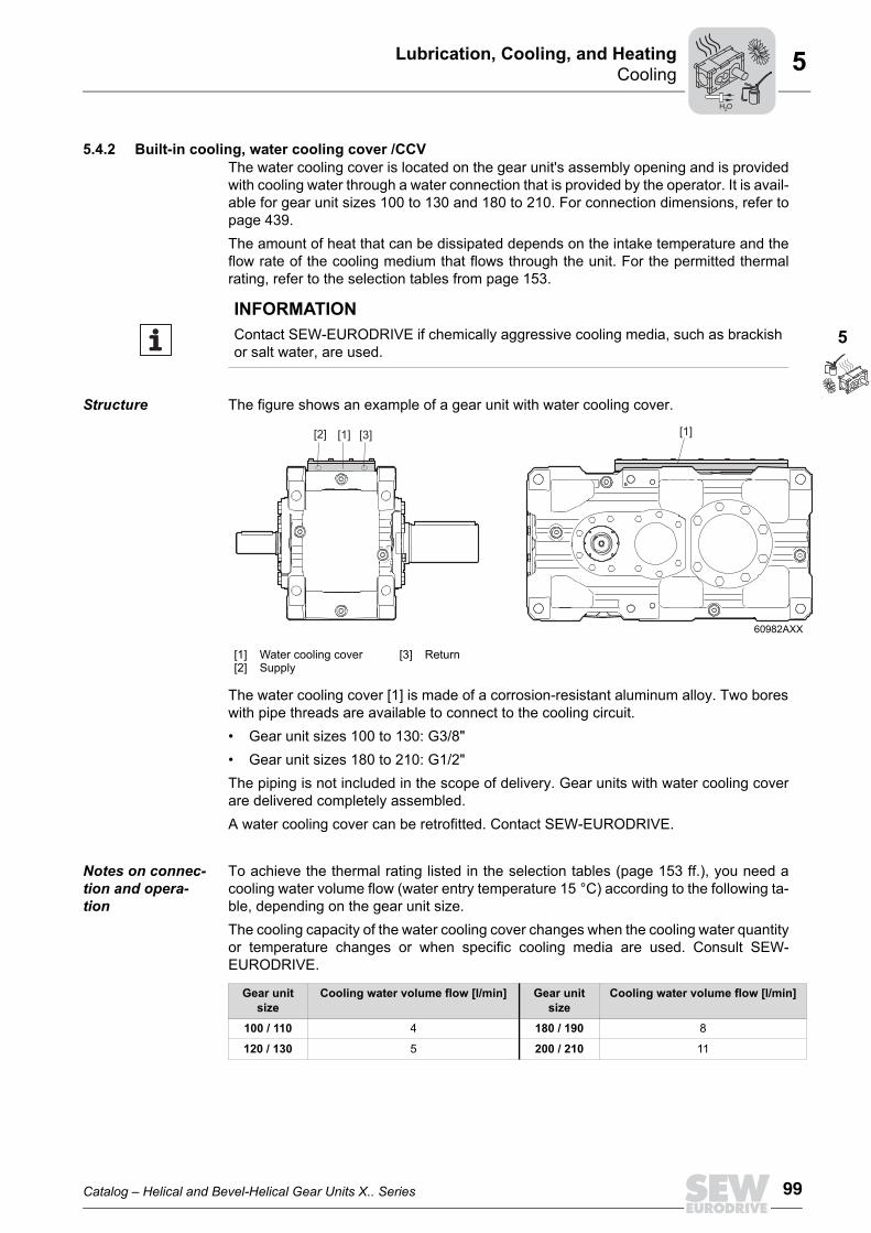
Structure The figure shows an example of a gear unit with water cooling cover.
The water cooling cover [1] is made of a corrosion-resistant aluminum alloy. Two boreswith pipe threads are available to connect to the cooling circuit. • Gear unit sizes 100 to 130: G3/8"• Gear unit sizes 180 to 210: G1/2"The piping is not included in the scope of delivery. Gear units with water cooling coverare delivered completely assembled.A water cooling cover can be retrofitted. Contact SEW-EURODRIVE.
Notes on connec-tion and opera-tion
To achieve the thermal rating listed in the selection tables (page 153 ff.), you need acooling water volume flow (water entry temperature 15 °C) according to the following ta-ble, depending on the gear unit size. The cooling capacity of the water cooling cover changes when the cooling water quantityor temperature changes or when specific cooling media are used. Consult SEW-EURODRIVE.
INFORMATIONContact SEW-EURODRIVE if chemically aggressive cooling media, such as brackishor salt water, are used.
60982AXX
[1][2]
Water cooling coverSupply
[3] Return
[1][1][2] [3]
Gear unit size
Cooling water volume flow [l/min] Gear unit size
Cooling water volume flow [l/min]
100 / 110 4 180 / 190 8
120 / 130 5 200 / 210 11
H O2
100 Catalog – Helical and Bevel-Helical Gear Units X.. Series
CoolingLubrication, Cooling, and Heating5
Cooling medium
Permitted cooling media
• The permitted cooling media is pure water. Cooling water additives, such as anti-freeze or corrosion inhibitor, might negatively influence the cooling performance andcompatibility of materials. Consult SEW-EURODRIVE.
• Cooling water temperature and flow rate of oil and cooling water according to the or-der documents.
Dirt The quantity of suspended solids (ball-shaped, particle size < 0.25 mm) should be lessthan 10 mg/l. Threadlike contaminants increase the risk of pressure loss.
Corrosion Limit values: free chlorine < 0.5 ppm, chlorine ions < 200 ppm, sulfate < 100 ppm, am-monia < 10 ppm, free CO < 10 ppm, pH 7-9.The following ions do not have a corrosive effect under normal conditions: phosphate,nitrate, nitrite, iron, manganese, sodium, potassium.
INFORMATION• Note that the service life, the efficiency, and the maintenance intervals of the heat
exchanger depend to a great degree on the quality and ingredients of the coolingmedium.
• Special measures have to be taken when using sea water or brackish water. Con-sult SEW-EURODRIVE.
H O2
Catalog – Helical and Bevel-Helical Gear Units X.. Series 101
CoolingLubrication, Cooling, and Heating
5
5
5.4.3 Built-in cooling, water cooling cartridge /CCTThe water cooling cartridge is mounted in the gear unit's oil sump and is supplied withcooling water through a water connection that is provided by the operator. It is availablefor sizes 140 to 320. For connection dimensions, refer to page 440.The amount of heat that can be dissipated depends on the intake temperature and theflow rate of the cooling medium that flows through the unit. For the permitted thermalrating, refer to the selection tables from page 153.
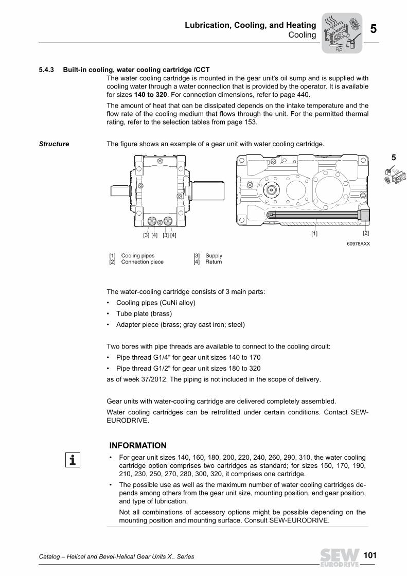
Structure The figure shows an example of a gear unit with water cooling cartridge.
The water-cooling cartridge consists of 3 main parts:• Cooling pipes (CuNi alloy)• Tube plate (brass)• Adapter piece (brass; gray cast iron; steel)
Two bores with pipe threads are available to connect to the cooling circuit: • Pipe thread G1/4" for gear unit sizes 140 to 170• Pipe thread G1/2" for gear unit sizes 180 to 320as of week 37/2012. The piping is not included in the scope of delivery.
Gear units with water-cooling cartridge are delivered completely assembled.Water cooling cartridges can be retrofitted under certain conditions. Contact SEW-EURODRIVE.
60978AXX
[1][2]
Cooling pipes Connection piece
[3][4]
SupplyReturn
[2][1][3] [4][4] [3]
INFORMATION• For gear unit sizes 140, 160, 180, 200, 220, 240, 260, 290, 310, the water cooling
cartridge option comprises two cartridges as standard; for sizes 150, 170, 190,210, 230, 250, 270, 280, 300, 320, it comprises one cartridge.
• The possible use as well as the maximum number of water cooling cartridges de-pends among others from the gear unit size, mounting position, end gear position,and type of lubrication.Not all combinations of accessory options might be possible depending on themounting position and mounting surface. Consult SEW-EURODRIVE.
H O2
102 Catalog – Helical and Bevel-Helical Gear Units X.. Series
CoolingLubrication, Cooling, and Heating5
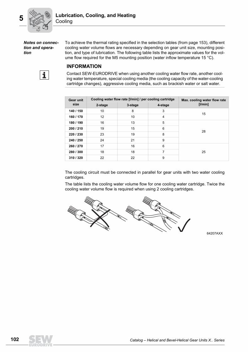
Notes on connec-tion and opera-tion
To achieve the thermal rating specified in the selection tables (from page 153), differentcooling water volume flows are necessary depending on gear unit size, mounting posi-tion, and type of lubrication. The following table lists the approximate values for the vol-ume flow required for the M5 mounting position (water inflow temperature 15 °C).
The cooling circuit must be connected in parallel for gear units with two water coolingcartridges.The table lists the cooling water volume flow for one cooling water cartridge. Twice thecooling water volume flow is required when using 2 cooling cartridges.
INFORMATIONContact SEW-EURODRIVE when using another cooling water flow rate, another cool-ing water temperature, special cooling media (the cooling capacity of the water-coolingcartridge changes), aggressive cooling media, such as brackish water or salt water.
Gear unit size
Cooling water flow rate [l/min] / per cooling cartridge Max. cooling water flow rate[l/min]2-stage 3-stage 4-stage
140 / 150 10 8 315
160 / 170 12 10 4
180 / 190 16 13 5
28200 / 210 19 15 6
220 / 230 23 19 8
240 / 250 24 21 9
260 / 270 17 16 6
25280 / 300 18 18 7
310 / 320 22 22 9
64207AXX
H O2

Catalog – Helical and Bevel-Helical Gear Units X.. Series 103
CoolingLubrication, Cooling, and Heating
5
5
Requirements on the water quality
The following requirements on the water quality are recommendations. In exceptionalcases, certain concentrations of substances of content might cause unforeseen reac-tions.The quality of the water as well as its substances are important factors for assessing thecooling water available for water cooling cartridges. The water quality is determined bythe water hardness and the pH value of the water.
Water hardness Water hardness is defined by the amount of hardeners (carbonates and bicarbonates)in the water. Hardeners accumulate on the surface of the water cooling cartridge in par-ticular at high temperatures and in this way impair the performance. Take these depositsinto account when selecting the water cooling cartridge for extremely hard water.The following table shows the classification of German degrees of hardness to waterquality °dH:
pH value • The water cooling cartridge partially consists of a copper and nickel alloy, to whichthe following applies:→ Corrosion problems when pH value < 6
• With alkaline water: → Corrosion problems when water hardness < 6 °dH.Smaller values can cause corrosion due to free carbonic acid.The following table describes the classification of the water quality based on the pHvalue:
INFORMATIONSpecial measures have to be taken when using sea water or brackish water. ConsultSEW-EURODRIVE.
Degree of hardness1)
1) 10 mg/l of hardener corresponds to 1 °dH
Water quality
0 - 5 °dH Very soft water
5 - 10 °dH Soft water
10 - 20 °dH Medium hard water
20 - 30 °dH Hard water
> 30 °dH Very hard water
pH value Water quality
4.5 Very acidic
4.5 - 6.0 Acidic
6.0 - 6.8 Slightly acidic
7.0 Neutral
7.2 - 7.7 Slightly alkaline
7.7 - 8.2 Alkaline
8.2 Very alkaline
H O2

104 Catalog – Helical and Bevel-Helical Gear Units X.. Series
CoolingLubrication, Cooling, and Heating5
Cooling water assessment based on water substances
The following table provides an overview of the resistance of copper pipes against sub-stances in non-potable water.
Assessment criterion Approximate concentration [mg/l] AssessmentCuNi
pH value
< 6 0
6 to 9 +
> 9 0
Chloride to 1000 +
> 1000 + (< 25000 mg/l)
Sulfate
up to 70 +
70 to 300 +
> 300 + (< 25000 mg/l)
Nitrate up to 100 +
> 100 0
Free (aggressive) carbonic acid
up to 20 +
20 to 50 0
> 50 -
Oxygen up to 2 +
> 2 +
Ammonium
up to 2 +
2 to 20 +
> 20 -
Iron (dissolved) up to 10 0
> 10 -
Manganese (dissolved) up to 1 0
> 1 -
Free chlorine up to 5 constantly < 0.5 mg/l
> 5 intermittently < 3.0 mg/l
Sulfide 0
Ammonia + (< 15 mg/l)
Key
0 = usually good resistivity
+ = corrosion problems can occur in particular if several factors are assessed with 0
- = we advise against use
H O2
Catalog – Helical and Bevel-Helical Gear Units X.. Series 105
CoolingLubrication, Cooling, and Heating
5
5
Cooling water types / character-isticsIndustrial water • Usually untreated water (no drinking water)
• Often very contaminated• A water analysis is necessary for assessment• Copper, brass and steel are very resistant against industrial water
Stream water and river water
• We recommend using copper brass pipes• Cast iron parts must be protected against corrosion by suitable coating• Usually untreated water (no drinking water)• Often very contaminated• A water analysis is necessary for assessment
H O2

106 Catalog – Helical and Bevel-Helical Gear Units X.. Series
CoolingLubrication, Cooling, and Heating5
5.4.4 Circulation cooling oil-water cooler for splash lubricationAn oil-water cooling system can be used if the thermal rating of the naturally cooled gearunit or cooling using a fan on the input shaft is not sufficient. The prerequisite for usingan oil-water cooler is that appropriate cooling water is available on site.
Structure SEW-EURODRIVE uses two different types of heat exchangers:• For gear unit sizes 140 to 170, a plate heat exchanger is used for oil supply systems
OWC 005/015/025.
INFORMATION• Contact SEW-EURODRIVE if chemically aggressive cooling media, such as brack-
ish or salt water, are used.• The following information applies to gear units with splash lubrication. The cooling
system with motor pump only cools the gear unit oil.• When installing a filter in the OWC cooling system, make sure there is sufficient
height for removing the filter element and the filter hood.
68912AXX
[1] Motor
[2] Pump
[3] Oil-water heat exchanger
[4] Suction pipe (not visible in this view)
[5] Pressure line
[6] Temperature switch with two switching points (TSK2)
[7] Water supply
[8] Water return
[6]
[5]
[2]
[1]
[3][4]
[7][8]
H O2

Catalog – Helical and Bevel-Helical Gear Units X.. Series 107
CoolingLubrication, Cooling, and Heating
5
5
• For gear unit sizes 180 to 320, a shell and tube heat exchanger is used for OWC10/20/30/40/50/60/70 oil supply systems.
The cooling system is delivered as a complete unit but without electrical connections.The standard delivery of the cooling system includes:• Pump with directly mounted asynchronous motor• Oil-water heat exchanger• Temperature switch with 2 switching points for
– Controlled startup of the pump motor with an oil temperature of > 40 °C– Monitoring of the cooling group, i.e. warning or gear unit shutdown when the
oil temperature exceeds 90 °C
The following cooling system types are available:• Directly mounted on the gear unit, including cooling circuit piping, or• On the mounting frame, for separate installation, but without piping to the gear unit
The customer has to perform the following electrical wiring: • Between temperature switch and pump motor• Pump motor
68913AXX
[1] Motor (provided by the customer) [5] Suction pipe
[2] Pump [6] Temperature switch with two switching points (TSK2)
[3] Oil-water heat exchanger [7] Water supply
[4] Pressure line [8] Water return
[3]
[5][6]
[4]
[2]
[1]
[7/8]
H O2

108 Catalog – Helical and Bevel-Helical Gear Units X.. Series
CoolingLubrication, Cooling, and Heating5
Further instrumentation available on request, such as:• Flow monitoring• Thermostatic valve in the oil and/or water circuit• Filter in the oil circuit• Manometer• Thermometer
Sizes, cooling capacity, and selection
The cooling capacities given in the table apply to a cooling water temperature of 30 °C,an oil temperature of 70 °C, equivalent volume flow of oil and cooling water, and 50 Hzline frequency.
For information about selecting a suitable cooling system, refer to chapter "Selecting thecooling system" on page 66.In addition, the selection of an appropriate cooling system depends on the following fac-tors:• Actual power loss to be cooled• Present cooling water temperature and volume flow• Ambient temperature• Ratio of oil quantity in the gear unit and oil volume flow of cooling system > 2
SizeCooling system
Cooling capacityCooling system
[kW]
Flow volumeCooling system
[l/min]
Connection powerPump motor
[kW]Weight [kg]1)
1) The cooling system is mounted on the gear unit
OWC 0052)
2) Cooling system with plate heat exchanger
4 8 0.75 23
OWC 010 5 10 0.75 36
OWC 0152) 8 16 1.1 28
OWC 020 10 21 1.1 57
OWC 0252) 11 28 1.5 31
OWC 030 14 28 1.5 57
OWC 040 24 53 2.2 85
OWC 050 30 77 3.0 88
OWC 060 49 91 4.0 132
OWC 070 77 144 5.5 139
INFORMATION• The cooling systems OWC 005 - 070 are designed for gear unit sizes 140 to 320.• The values differ slightly for operation with a line frequency of 60 Hz. Please con-
sult SEW-EURODRIVE.
INFORMATIONConsult SEW-EURODRIVE when selecting the appropriate cooling system based onthe ambient conditions present for your system.
H O2

Catalog – Helical and Bevel-Helical Gear Units X.. Series 109
CoolingLubrication, Cooling, and Heating
5
5
Installation and connection infor-mation for sepa-rate installation
The cooling system is mounted directly on the gear unit as standard.Optionally, the cooling system can be delivered as a complete unit on a mounting framebut without electrical connections and piping. Install it in a low-vibration installation loca-tion max. 1 meter from the gear unit. Install the cooling system at the same level as thegear unit or lower. If this is not possible, contact SEW-EURODRIVE.Adhere to the following basic conditions when connecting the cooling system:• Do not reduce the indicated cable cross section.• It is important that you choose the correct wall thickness and material when selecting
pipes, hoses and screw fittings. Preferably, use composite material seals.
SEW-EURODRIVE recommends the following cable cross sections for connecting thecooling system to the gear unit and the cooling circuit.
SizeCooling sys-
tem
Pump suction connection Suction pipe1) Pressure con-
nection Pressure pipe2)Cooling water connection of
cooler
Inner Ø of the cool-ing water line
OWC 005 GE22-LR 3/4" DN20 / Ø22 GE18-LR 1/2" DN16 / Ø18 G3/4" Ø25
OWC 010 GE22-LR 1/2" DN20 / Ø22 GE18-LR 1/2" DN16 / Ø18 G1/2" Ø13
OWC 015 GE28-LR 1" DN25 / Ø28 GE22-LR 3/4" DN20 / Ø22 G3/4" Ø25
OWC 020 GE35-LR 1 1/4" DN32 / Ø35 GE28-LR 1" DN25 / Ø28 G1/2" Ø19
OWC 025 GE35-LR 1 1/4" DN32 / Ø35 GE28-LR 1 1/4" DN25 / Ø28 G3/4" Ø25
OWC 030 GE35-LR 1 1/4" DN32 / Ø35 GE28-LR 1" DN25 / Ø28 G1" Ø25
OWC 040 GE42-LR 1 1/2" DN40 / Ø42 GE35-LR 1 1/2" DN32 / Ø35 G3/4" Ø25
OWC 050 GE42-LR 1 1/2" DN40 / Ø42 GE35-LR 1 1/2" DN32 / Ø35 G1 1/4" Ø32
OWC 060 SAE 2" SFL DN50 / Ø2" GE42-LR 1 1/2" DN40 / Ø42 G1 1/2" Ø38
OWC 070 SAE 2 1/2" SFL DN50 / Ø2" GE42-LR 1 1/2" DN40 / Ø42 G1" Ø38
1) max. length 1.5 m2) max. length 2.5 m
INFORMATION• For dimension sheets of oil-water coolers with motor pump, refer to page 444 ff.
More detailed technical data of the several cooling systems are available fromSEW-EURODRIVE on request.
• Dimensions for OWC 005/015/025 cooling systems for separate installation areavailable from SEW-EURODRIVE on request.
H O2

110 Catalog – Helical and Bevel-Helical Gear Units X.. Series
CoolingLubrication, Cooling, and Heating5
5.4.5 Circulation cooling oil-water cooler for pressure lubrication /OWPAn oil-water cooling system can be used if the thermal rating of the naturally cooled gearunit or cooling using a fan on the input shaft is not sufficient. The prerequisite for usingan oil-water cooling system is that appropriate cooling water is available on site.
Structure SEW-EURODRIVE uses two different types of heat exchangers:• For gear unit sizes 140 to 170, a plate heat exchanger is used for oil supply systems
OWP 005/015/025.
INFORMATION• Consult SEW-EURODRIVE if you use chemically aggressive cooling media, such
as brackish water or salt water.• The cooling system with motor pump cools the gear unit oil and the pressure lubri-
cation of the gear unit.• When installing a filter in the OWP cooling system, make sure there is sufficient
height for removing the filter element and the filter hood.
68914AXX
[1] Motor [7] Oil-water heat exchanger
[2] Pressure line [8] Pressure switch
[3] Contamination indicator [9] Temperature switch, optional (NTB)
[4] Oil filter [10] Cooling water supply
[5] Suction pipe (not visible in this view) [11] Cooling water return
[6] Pump [12] Check valve
[9]
[3]
[2]
[1]
[4]
[6]
[7] [5]
[8]
[10] [11]
[12]
H O2

Catalog – Helical and Bevel-Helical Gear Units X.. Series 111
CoolingLubrication, Cooling, and Heating
5
5
• For gear unit sizes 180 to 320, a shell and tube heat exchanger is used for OWP10/20/30/40/50/60/70 oil supply systems.
The cooling system is delivered as a complete unit but without electrical connections.The standard delivery of the cooling system includes:• Pump with directly connected asynchronous motor (pump always running)• Oil-water heat exchanger• Oil filter with filter element and electrical/optical contamination indicator• Pressure switch that monitors the pump pressure. Warning or switch-off signal when
the oil pressure reaches < 0.5 bar• Option: Temperature switch with trip point for monitoring the cooling group, i.e. warn-
ing or gear unit shutdown when the oil temperature exceeds 90 °C
The following cooling system types are available:• Directly mounted on the gear unit, including cooling circuit piping, or• On the mounting frame, for separate installation, but without piping to the gear unit
68915AXX
[1] Motor [7] Oil-water heat exchanger
[2] Pressure line [8] Pressure switch
[3] Contamination indicator [9] Temperature switch, optional (NTB)
[4] Oil filter [10] Cooling water supply
[5] Suction pipe [11] Cooling water return
[6] Pump [12] Check valve
[9]
[1]
[2]
[6]
[4]
[3]
[7] [5]
[8]
[10][11] [12]
H O2

112 Catalog – Helical and Bevel-Helical Gear Units X.. Series
CoolingLubrication, Cooling, and Heating5
The customer has to carry out the following electrical wiring: • Pressure switch to the customer's evaluation unit• Electrical contamination indicator of the oil filter• Pump motor• Option: Between temperature switch and pump motor
Further instrumentation available on request, such as:• Flow monitoring• Thermostatic valve in the oil and/or water circuit• Manometer• Thermometer
Sizes, cooling capacity, and selection
The performance data of the standardized cooling systems is summarized in the follow-ing tables.The cooling capacities given in the table apply to a cooling water temperature of 30 °C,an oil temperature of 70 °C, equivalent volume flow of oil and cooling water, and 50 Hzline frequency.
For information about selecting a suitable cooling system, refer to chapter "Selecting thecooling system" on page 66.In addition, the selection of an appropriate cooling system depends on the following fac-tors:• Actual power loss to be cooled• Present cooling water temperature and volume flow• Ambient temperature
SizeCooling system
Cooling capacityCooling system
[kW]
Flow volumeCooling system
[l/min]
Connection powerPump motor
[kW]Weight [kg]1)
1) The cooling system is mounted on the gear unit
OWP 0052)
2) Cooling system with plate heat exchanger
4 8 0.75 25
OWP 010 5 10 0.75 38
OWP 0152) 8 16 1.1 30
OWP 020 8.5 21 1.1 59
OWP 0252) 12 28 1.5 33
OWP 030 14 28 1.5 59
OWP 040 22 53 3.0 87
OWP 050 30 77 4.0 90
OWP 060 45 91 5.5 134
OWP 070 70 144 7.5 141
INFORMATION• The cooling systems OWP 005 - 070 are designed for gear unit sizes 140 to 320.• The values differ slightly for operation with a line frequency of 60 Hz. Please con-
sult SEW-EURODRIVE.
H O2

Catalog – Helical and Bevel-Helical Gear Units X.. Series 113
CoolingLubrication, Cooling, and Heating
5
5
• Ratio of oil quantity in the gear unit and oil volume flow of cooling system > 2
Notes on the installation and connection for separate installa-tion
The cooling system is mounted directly on the gear unit as standard.Optionally, the cooling system can be delivered as a complete unit on a mounting framebut without electrical connections and piping. Provide for a low-vibration installation lo-cation max. 1 meter from the gear unit. Install the cooling system at the same level asthe gear unit or lower. If this is not possible, contact SEW-EURODRIVE.Adhere to the following basic conditions when connecting the cooling system:• Do not reduce the indicated cable cross section.• It is important that you choose the correct wall thickness and material when selecting
pipes, hoses and screw fittings. Preferably, use composite material seals.
SEW-EURODRIVE recommends the following cable cross sections for connecting thecooling system to the gear unit and the cooling circuit.
INFORMATIONConsult SEW-EURODRIVE when selecting the appropriate cooling system based onthe ambient conditions present for your system.
SizeCooling sys-
tem
Pump suction connection Suction pipe1) Pressure con-
nection Pressure pipe2)Cooling water connection of
cooler
Inner Ø of the cooling water line
OWP 005 GE22-LR 3/4" DN20 / Ø22 GE18-LR 1/2" DN16 / Ø18 G3/4" Ø25
OWP 010 GE22-LR 1/2" DN20 / Ø22 GE18-LR 1/2" DN16 / Ø18 G1/2" Ø13
OWP 015 GE28-LR 1" DN25 / Ø28 GE22-LR 3/4" DN20 / Ø22 G3/4" Ø25
OWP 020 GE35-LR 1 1/4" DN32 / Ø35 GE28-LR 1" DN25 / Ø28 G1/2" Ø19
OWP 025 GE35-LR 1 1/4" DN32 / Ø35 GE28-LR 1" DN25 / Ø28 G3/4" Ø25
OWP 030 GE35-LR 1 1/4" DN32 / Ø35 GE28-LR 1" DN25 / Ø28 G1" Ø25
OWP 040 GE42-LR 1 1/2" DN40 / Ø42 GE35-LR 1 1/2" DN32 / Ø35 G3/4" Ø25
OWP 050 GE42-LR 1 1/2" DN40 / Ø42 GE35-LR 1 1/2" DN32 / Ø35 G1 1/4" Ø32
OWP 060 SAE 2" SFL DN50 / Ø2" GE42-LR 1 1/2" DN40 / Ø42 G1 1/2" Ø38
OWP 070 SAE 2 1/2" SFL DN50 / Ø2" GE42-LR 1 1/2" DN40 / Ø42 G1" Ø38
1) max. length 1.5 m2) max. length 2.5 m
INFORMATION• For dimension sheets of oil-water coolers with motor pump, refer to page 448 ff.
More detailed technical data of the several cooling systems are available fromSEW-EURODRIVE on request.
• Dimensions for OWP 005/015/025 cooling systems for separate installation areavailable from SEW-EURODRIVE on request.
H O2

114 Catalog – Helical and Bevel-Helical Gear Units X.. Series
CoolingLubrication, Cooling, and Heating5
5.4.6 Circulation cooling oil-air cooler for splash lubrication /OACAn oil-air cooling system can be used if the thermal rating of the naturally cooled gearunit or cooling using a fan on the input shaft is not sufficient.
Structure The figure shows an example of an oil-air cooler with motor pump for splash lubrication.
The cooling system is delivered as a complete unit on a mounting frame but withoutelectrical wiring and piping.The standard delivery of the cooling system includes:• Pump with directly mounted asynchronous motor• Oil-air heat exchanger• Temperature switch with two switching points for
• Controlled startup of the pump and fan motor at an oil temperature > 40 °C• Monitoring of the cooling group, i.e. warning or gear unit shutdown when the oil
temperature exceeds 90 °C.• Separate fan motor (for OAC 025/060)
The customer has to carry out the following electrical wiring: • Between temperature switch and pump and fan motor• Pump and fan motor• Separate fan motor (for OAC 025/060)
INFORMATIONThe following information applies to gear units with splash lubrication. The cooling sys-tem with a motor pump only cools the gear unit oil.
69242AXX
[4][4]
[5]
[3]
[5]
[2]
M[1] [2]
[3]
[5]
[1]
[4]
[1] Motor pump [4] Suction pipe connection
[2] Oil-air heat exchanger [5] Pressure pipe connection
[3] Temperature switch with two switching points
H O2
Catalog – Helical and Bevel-Helical Gear Units X.. Series 115
CoolingLubrication, Cooling, and Heating
5
5
Further instrumentation available on request, such as:• Flow monitoring• Filter in the oil circuit• Manometer• Thermometer
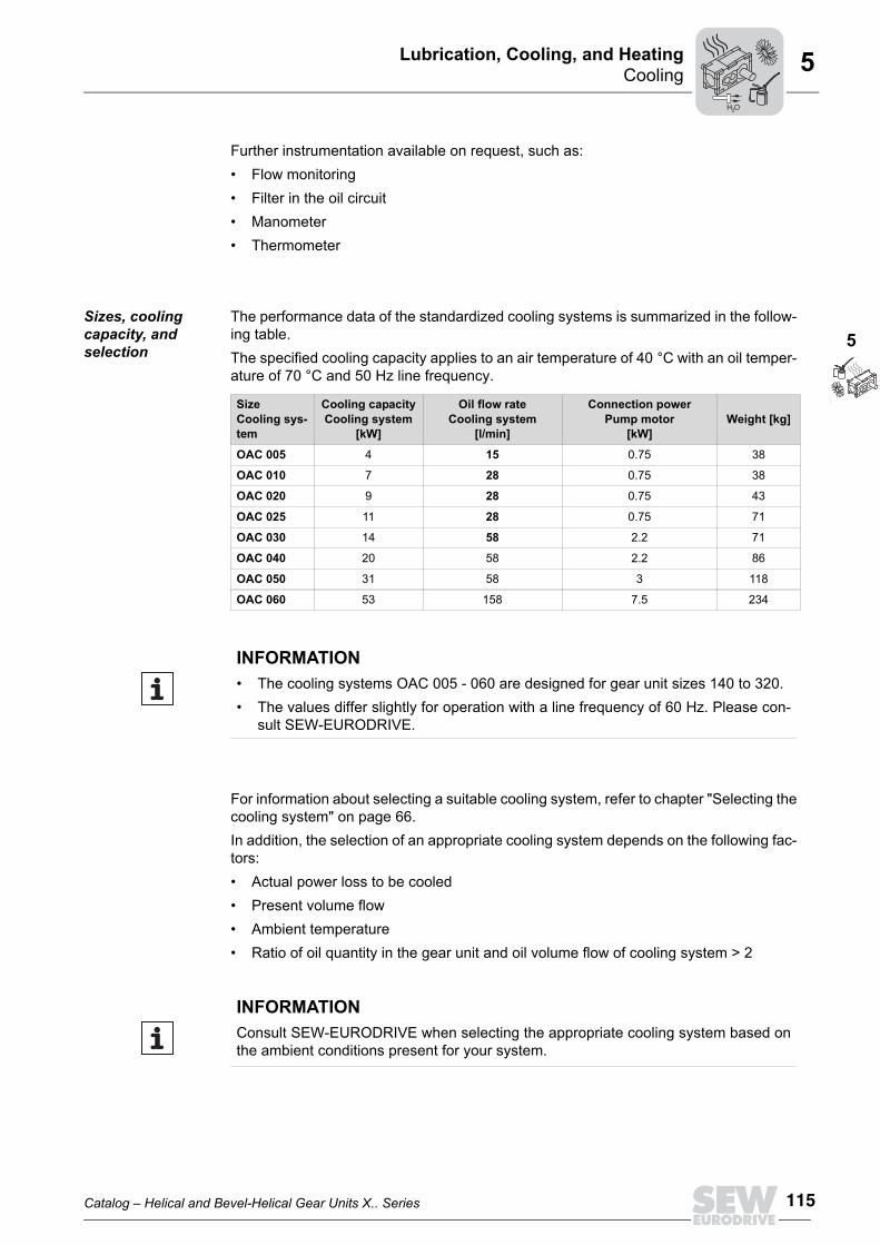
Sizes, cooling capacity, and selection
The performance data of the standardized cooling systems is summarized in the follow-ing table.The specified cooling capacity applies to an air temperature of 40 °C with an oil temper-ature of 70 °C and 50 Hz line frequency.
For information about selecting a suitable cooling system, refer to chapter "Selecting thecooling system" on page 66.In addition, the selection of an appropriate cooling system depends on the following fac-tors:• Actual power loss to be cooled• Present volume flow• Ambient temperature• Ratio of oil quantity in the gear unit and oil volume flow of cooling system > 2
SizeCooling sys-tem
Cooling capacityCooling system
[kW]
Oil flow rateCooling system
[l/min]
Connection powerPump motor
[kW]Weight [kg]
OAC 005 4 15 0.75 38
OAC 010 7 28 0.75 38
OAC 020 9 28 0.75 43
OAC 025 11 28 0.75 71
OAC 030 14 58 2.2 71
OAC 040 20 58 2.2 86
OAC 050 31 58 3 118
OAC 060 53 158 7.5 234
INFORMATION• The cooling systems OAC 005 - 060 are designed for gear unit sizes 140 to 320. • The values differ slightly for operation with a line frequency of 60 Hz. Please con-
sult SEW-EURODRIVE.
INFORMATIONConsult SEW-EURODRIVE when selecting the appropriate cooling system based onthe ambient conditions present for your system.
H O2

116 Catalog – Helical and Bevel-Helical Gear Units X.. Series
CoolingLubrication, Cooling, and Heating5
Notes on the installation and connection for separate installa-tion
Provide for a low-vibration installation location max. 1 meter from the gear unit. The cool-ing system must be installed at the same level as the gear unit or lower. If this is not pos-sible, contact SEW-EURODRIVE.The cooler must be installed in such a way that input and output air can flow unobstruct-edly. You have to provide for sufficient ventilation and protection against dirt. Adhere tothe following basic conditions when connecting the cooling system:• Avoid a short circuit in the cooling circuit. The suction and pressure lines must be in-
stalled on the gear unit as far apart as possible.• Do not reduce the indicated cable cross section.• It is important that you choose the correct wall thickness and material when selecting
pipes, hoses and screw fittings. Preferably, use composite material seals.
The oil-air cooling system is delivered in the design as illustrated as standard. The con-nections of the cooling system are located on the lefthand side of the system. In orderto keep the cable lengths to the gear unit short, the suction and pressure connectionshould be aligned towards the gear unit during installation. The connections can bemoved to the other side if required. To do so, loosen the pump head [1] and the register[2], rotate them by 180° and re-attach them.
63230AXX
180°
[2]
180°
[1]
H O2
Catalog – Helical and Bevel-Helical Gear Units X.. Series 117
CoolingLubrication, Cooling, and Heating
5
5
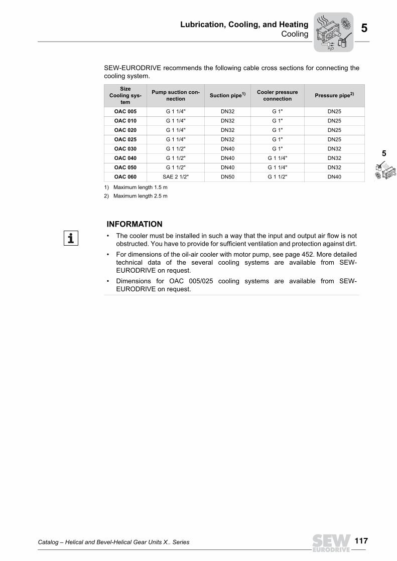
SEW-EURODRIVE recommends the following cable cross sections for connecting thecooling system.
SizeCooling sys-
tem
Pump suction con-nection Suction pipe1)
1) Maximum length 1.5 m
Cooler pressure connection Pressure pipe2)
2) Maximum length 2.5 m
OAC 005 G 1 1/4" DN32 G 1" DN25
OAC 010 G 1 1/4" DN32 G 1" DN25
OAC 020 G 1 1/4" DN32 G 1" DN25
OAC 025 G 1 1/4" DN32 G 1" DN25
OAC 030 G 1 1/2" DN40 G 1" DN32
OAC 040 G 1 1/2" DN40 G 1 1/4" DN32
OAC 050 G 1 1/2" DN40 G 1 1/4" DN32
OAC 060 SAE 2 1/2" DN50 G 1 1/2" DN40
INFORMATION• The cooler must be installed in such a way that the input and output air flow is not
obstructed. You have to provide for sufficient ventilation and protection against dirt.• For dimensions of the oil-air cooler with motor pump, see page 452. More detailed
technical data of the several cooling systems are available from SEW-EURODRIVE on request.
• Dimensions for OAC 005/025 cooling systems are available from SEW-EURODRIVE on request.
H O2
118 Catalog – Helical and Bevel-Helical Gear Units X.. Series
CoolingLubrication, Cooling, and Heating5
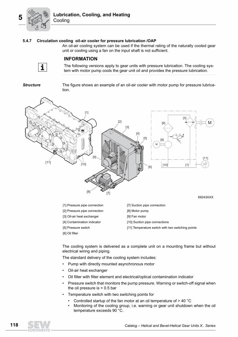
5.4.7 Circulation cooling oil-air cooler for pressure lubrication /OAPAn oil-air cooling system can be used if the thermal rating of the naturally cooled gearunit or cooling using a fan on the input shaft is not sufficient.
Structure The figure shows an example of an oil-air cooler with motor pump for pressure lubrica-tion.
The cooling system is delivered as a complete unit on a mounting frame but withoutelectrical wiring and piping.The standard delivery of the cooling system includes:• Pump with directly mounted asynchronous motor• Oil-air heat exchanger• Oil filter with filter element and electrical/optical contamination indicator• Pressure switch that monitors the pump pressure. Warning or switch-off signal when
the oil pressure is < 0.5 bar• Temperature switch with two switching points for
• Controlled startup of the fan motor at an oil temperature of > 40 °C• Monitoring of the cooling group, i.e. warning or gear unit shutdown when the oil
temperature exceeds 90 °C.
INFORMATIONThe following versions apply to gear units with pressure lubrication. The cooling sys-tem with motor pump cools the gear unit oil and provides the pressure lubrication.
69243AXX
[1] Pressure pipe connection [7] Suction pipe connection
[2] Pressure pipe connection [8] Motor pump
[3] Oil-air heat exchanger [9] Fan motor
[4] Contamination indicator [10] Suction pipe connections
[5] Pressure switch [11] Temperature switch with two switching points
[6] Oil filter
M
[8]
[3]
[11]
[10] [1]
M
[10]
[1]
[2]
[11]
[7][8]
[3]
[6]
[5][4]
[9]
[6]
H O2
Catalog – Helical and Bevel-Helical Gear Units X.. Series 119
CoolingLubrication, Cooling, and Heating
5
5
The customer has to carry out the following electrical wiring: • Between temperature switch and cooling system• Electrical contamination indicator of the oil filter• Pressure switch
Further instrumentation available on request, such as:• Flow monitoring• Manometer• Thermometer
Sizes, cooling capacity, and selection
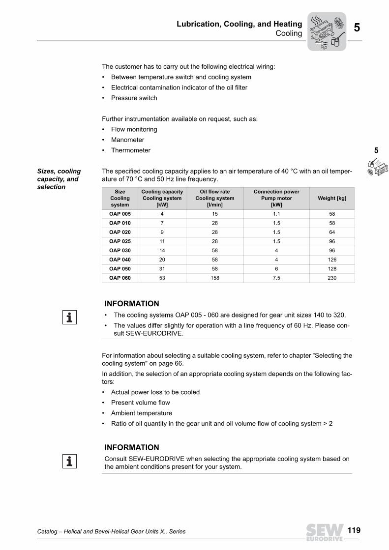
The specified cooling capacity applies to an air temperature of 40 °C with an oil temper-ature of 70 °C and 50 Hz line frequency.
For information about selecting a suitable cooling system, refer to chapter "Selecting thecooling system" on page 66.In addition, the selection of an appropriate cooling system depends on the following fac-tors:• Actual power loss to be cooled• Present volume flow• Ambient temperature• Ratio of oil quantity in the gear unit and oil volume flow of cooling system > 2
SizeCooling system
Cooling capacityCooling system
[kW]
Oil flow rateCooling system
[l/min]
Connection powerPump motor
[kW]Weight [kg]
OAP 005 4 15 1.1 58
OAP 010 7 28 1.5 58
OAP 020 9 28 1.5 64
OAP 025 11 28 1.5 96
OAP 030 14 58 4 96
OAP 040 20 58 4 126
OAP 050 31 58 6 128
OAP 060 53 158 7.5 230
INFORMATION• The cooling systems OAP 005 - 060 are designed for gear unit sizes 140 to 320.• The values differ slightly for operation with a line frequency of 60 Hz. Please con-
sult SEW-EURODRIVE.
INFORMATIONConsult SEW-EURODRIVE when selecting the appropriate cooling system based onthe ambient conditions present for your system.
H O2

120 Catalog – Helical and Bevel-Helical Gear Units X.. Series
CoolingLubrication, Cooling, and Heating5
Notes on the installation and connection for separate installa-tion
As standard, the cooling system must be set up separately from the gear unit. As an op-tion, the cooling system can be delivered mounted directly to the gear unit. The coolingsystem is delivered without wiring but with piping.Provide for a low-vibration installation location max. 1 meter from the gear unit. Installthe cooling system at the same level or lower than the gear unit. If this is not possible,contact SEW-EURODRIVE.The cooler must be installed in such a way that input and output air can flow unobstruct-edly. You have to provide for sufficient ventilation and protection against dirt.Adhere to the following basic conditions when connecting the cooling system:• Do not reduce the indicated cable cross section.• It is important that you choose the correct wall thickness and material when selecting
pipes, hoses and screw fittings. Preferably, use composite material seals.SEW-EURODRIVE recommends the following cable cross sections for connecting thecooling system to the gear unit and the cooling circuit:
SizeCooling sys-
tem
Pump suction con-nection Suction pipe1)
1) Maximum length 1.5 m
Pressure connection Pressure pipe2)
2) Maximum length 2.5 m
OAP 005 G 1 1/4" DN32 G 1" DN25
OAP 010 G 1 1/4" DN32 G 1" DN25
OAP 020 G 1 1/4" DN32 G 1" DN25
OAP 025 G 1 1/4" DN32 G 1" DN25
OAP 030 G 1 1/2" DN32 G 1" DN25
OAP 040 G 1 1/2" DN40 G 1 1/4" DN32
OAP 050 G 1 1/2" DN40 G 1 1/4" DN32
OAP 060 SAE 2 1/2" DN50 G 1 1/2" DN40
INFORMATION• The cooler must be installed in such a way that the input and output air flow is not
obstructed. You have to provide for sufficient ventilation and protection against dirt.• For dimensions of the oil-air cooler with motor pump, see page 453. More detailed
technical data of the several cooling systems are available from SEW-EURODRIVE on request.
• Dimensions for OAP 005/025 cooling systems are available from SEW-EURODRIVE on request.
H O2
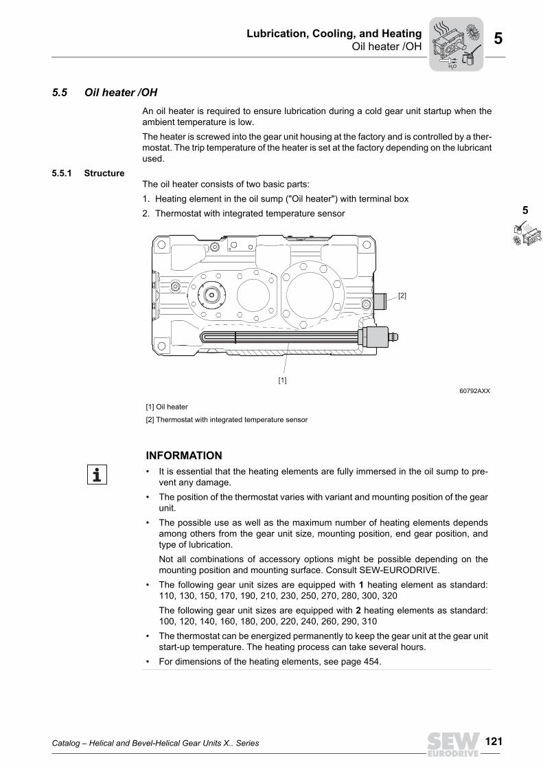
Catalog – Helical and Bevel-Helical Gear Units X.. Series 121
Oil heater /OHLubrication, Cooling, and Heating
5
5
5.5 Oil heater /OHAn oil heater is required to ensure lubrication during a cold gear unit startup when theambient temperature is low.The heater is screwed into the gear unit housing at the factory and is controlled by a ther-mostat. The trip temperature of the heater is set at the factory depending on the lubricantused.
5.5.1 StructureThe oil heater consists of two basic parts:1. Heating element in the oil sump ("Oil heater") with terminal box2. Thermostat with integrated temperature sensor
60792AXX
[1] Oil heater
[2] Thermostat with integrated temperature sensor
[2]
[1]
INFORMATION• It is essential that the heating elements are fully immersed in the oil sump to pre-
vent any damage.• The position of the thermostat varies with variant and mounting position of the gear
unit.• The possible use as well as the maximum number of heating elements depends
among others from the gear unit size, mounting position, end gear position, andtype of lubrication.Not all combinations of accessory options might be possible depending on themounting position and mounting surface. Consult SEW-EURODRIVE.
• The following gear unit sizes are equipped with 1 heating element as standard:110, 130, 150, 170, 190, 210, 230, 250, 270, 280, 300, 320The following gear unit sizes are equipped with 2 heating elements as standard:100, 120, 140, 160, 180, 200, 220, 240, 260, 290, 310
• The thermostat can be energized permanently to keep the gear unit at the gear unitstart-up temperature. The heating process can take several hours.
• For dimensions of the heating elements, see page 454.
H O2
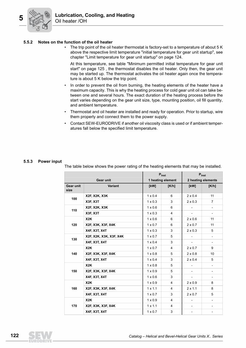
122 Catalog – Helical and Bevel-Helical Gear Units X.. Series
Oil heater /OHLubrication, Cooling, and Heating5
5.5.2 Notes on the function of the oil heater• The trip point of the oil heater thermostat is factory-set to a temperature of about 5 K
above the respective limit temperature "initial temperature for gear unit startup", seechapter "Limit temperature for gear unit startup" on page 124. At this temperature, see table "Minimum permitted initial temperature for gear unitstart" on page 125 , the thermostat disables the oil heater. Only then, the gear unitmay be started up. The thermostat activates the oil heater again once the tempera-ture is about 5 K below the trip point.
• In order to prevent the oil from burning, the heating elements of the heater have amaximum capacity. This is why the heating process for cold gear unit oil can take be-tween one and several hours. The exact duration of the heating process before thestart varies depending on the gear unit size, type, mounting position, oil fill quantity,and ambient temperature.
• Thermostat and oil heater are installed and ready for operation. Prior to startup, wirethem properly and connect them to the power supply.
• Contact SEW-EURODRIVE if another oil viscosity class is used or if ambient temper-atures fall below the specified limit temperature.
5.5.3 Power inputThe table below shows the power rating of the heating elements that may be installed.
Pinst Pinst
Gear unit 1 heating element 2 heating elements
Gear unit size
Variant [kW] [K/h] [kW] [K/h]
100X2F, X2K, X3K 1 x 0.4 6 2 x 0.4 11
X3F, X3T 1 x 0.3 3 2 x 0.3 7
110X2F, X2K, X3K 1 x 0.6 6 - -
X3F, X3T 1 x 0.3 4 - -
120
X2K 1 x 0.6 6 2 x 0.6 11
X2F, X3K, X3F, X4K 1 x 0.7 6 2 x 0.7 11
X4F, X3T, X4T 1 x 0.3 3 2 x 0.3 5
130X2F, X2K, X3K, X3F, X4K 1 x 0.7 5 - -
X4F, X3T, X4T 1 x 0.4 3 - -
140
X2K 1 x 0.7 4 2 x 0.7 9
X2F, X3K, X3F, X4K 1 x 0.8 5 2 x 0.8 10
X4F, X3T, X4T 1 x 0.4 3 2 x 0.4 5
150
X2K 1 x 0.8 5 - -
X2F, X3K, X3F, X4K 1 x 0.9 5 - -
X4F, X3T, X4T 1 x 0.6 3 - -
160
X2K 1 x 0.9 4 2 x 0.9 8
X2F, X3K, X3F, X4K 1 x 1.1 4 2 x 1.1 8
X4F, X3T, X4T 1 x 0.7 3 2 x 0.7 5
170
X2K 1 x 0.9 4 - -
X2F, X3K, X3F, X4K 1 x 1.1 4 - -
X4F, X3T, X4T 1 x 0.7 3 - -
H O2
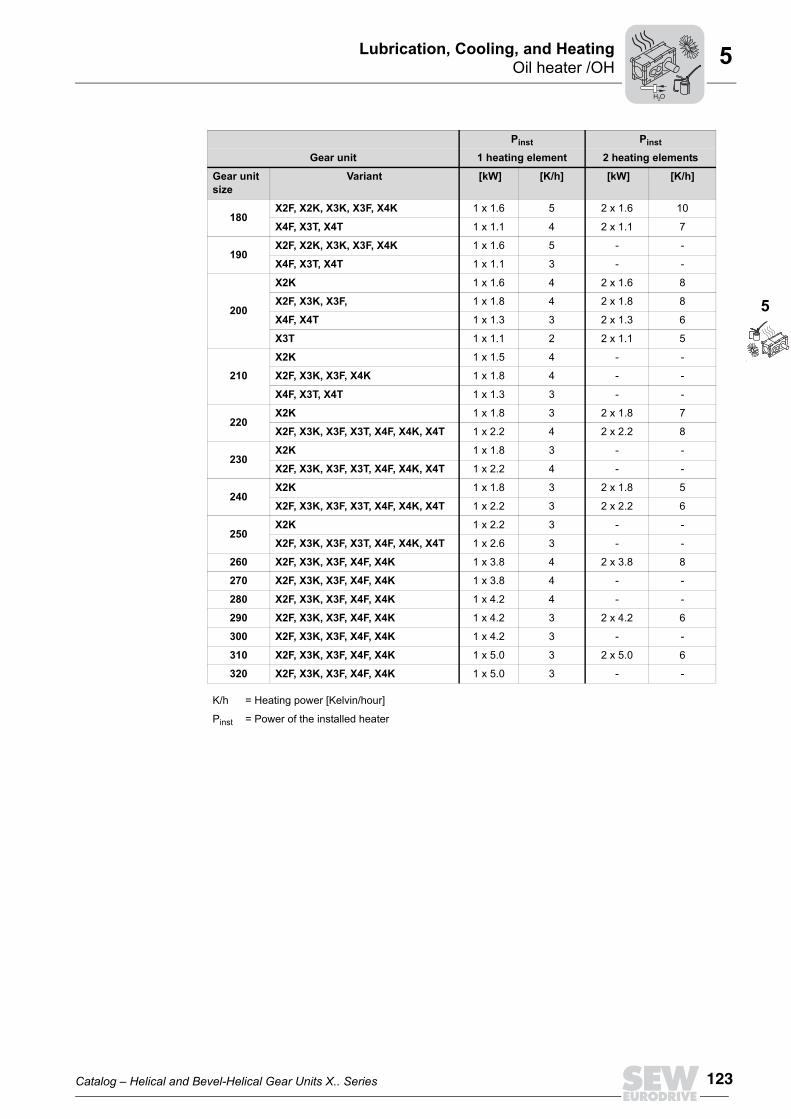
Catalog – Helical and Bevel-Helical Gear Units X.. Series 123
Oil heater /OHLubrication, Cooling, and Heating
5
5
180X2F, X2K, X3K, X3F, X4K 1 x 1.6 5 2 x 1.6 10
X4F, X3T, X4T 1 x 1.1 4 2 x 1.1 7
190X2F, X2K, X3K, X3F, X4K 1 x 1.6 5 - -
X4F, X3T, X4T 1 x 1.1 3 - -
200
X2K 1 x 1.6 4 2 x 1.6 8
X2F, X3K, X3F, 1 x 1.8 4 2 x 1.8 8
X4F, X4T 1 x 1.3 3 2 x 1.3 6
X3T 1 x 1.1 2 2 x 1.1 5
210
X2K 1 x 1.5 4 - -
X2F, X3K, X3F, X4K 1 x 1.8 4 - -
X4F, X3T, X4T 1 x 1.3 3 - -
220X2K 1 x 1.8 3 2 x 1.8 7
X2F, X3K, X3F, X3T, X4F, X4K, X4T 1 x 2.2 4 2 x 2.2 8
230X2K 1 x 1.8 3 - -
X2F, X3K, X3F, X3T, X4F, X4K, X4T 1 x 2.2 4 - -
240X2K 1 x 1.8 3 2 x 1.8 5
X2F, X3K, X3F, X3T, X4F, X4K, X4T 1 x 2.2 3 2 x 2.2 6
250X2K 1 x 2.2 3 - -
X2F, X3K, X3F, X3T, X4F, X4K, X4T 1 x 2.6 3 - -
260 X2F, X3K, X3F, X4F, X4K 1 x 3.8 4 2 x 3.8 8
270 X2F, X3K, X3F, X4F, X4K 1 x 3.8 4 - -
280 X2F, X3K, X3F, X4F, X4K 1 x 4.2 4 - -
290 X2F, X3K, X3F, X4F, X4K 1 x 4.2 3 2 x 4.2 6
300 X2F, X3K, X3F, X4F, X4K 1 x 4.2 3 - -
310 X2F, X3K, X3F, X4F, X4K 1 x 5.0 3 2 x 5.0 6
320 X2F, X3K, X3F, X4F, X4K 1 x 5.0 3 - -
K/h = Heating power [Kelvin/hour]
Pinst = Power of the installed heater
Pinst Pinst
Gear unit 1 heating element 2 heating elements
Gear unit size
Variant [kW] [K/h] [kW] [K/h]
H O2

124 Catalog – Helical and Bevel-Helical Gear Units X.. Series
Oil heater /OHLubrication, Cooling, and Heating5
5.5.4 Limit temperature for gear unit startupThe minimum permitted ambient temperature/oil temperature for gear unit startup de-pends on the viscosity of the oil used and of the lubrication type of the gear unit.
INFORMATIONBefore startup, the oil must be heated up to the temperature specified under "Starttemperature" (see following table).
INFORMATIONThe following tables show the limit temperatures (minimum ambient temperatures) forgear unit startup without and with oil heater.The tables apply to the following types of gear units/types of lubrication. • Horizontal gear unit
• Splash lubrication• Bath lubrication• Pressure lubrication with shaft end pump• Pressure lubrication with motor pump
• Vertical and upright gear units • Bath lubrication
For gear unit variants with mounting positions and types of lubrication not mentionedhere, please contact SEW-EURODRIVE.
H O2
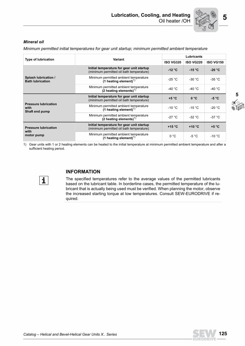
Catalog – Helical and Bevel-Helical Gear Units X.. Series 125
Oil heater /OHLubrication, Cooling, and Heating
5
5
Mineral oilMinimum permitted initial temperatures for gear unit startup; minimum permitted ambient temperature
Type of lubrication VariantLubricants
ISO VG320 ISO VG220 ISO VG150
Splash lubrication /Bath lubrication
Initial temperature for gear unit startup(minimum permitted oil bath temperature) -12 °C -15 °C -20 °C
Minimum permitted ambient temperature (1 heating element)1)
1) Gear units with 1 or 2 heating elements can be heated to the initial temperature at minimum permitted ambient temperature and after asufficient heating period.
-25 °C -30 °C -35 °C
Minimum permitted ambient temperature (2 heating elements)1) -40 °C -40 °C -40 °C
Pressure lubricationwith Shaft end pump
Initial temperature for gear unit startup(minimum permitted oil bath temperature) +5 °C 0 °C -5 °C
Minimum permitted ambient temperature (1 heating element)1) -10 °C -15 °C -20 °C
Minimum permitted ambient temperature (2 heating elements)1) -27 °C -32 °C -37 °C
Pressure lubricationwith motor pump
Initial temperature for gear unit startup(minimum permitted oil bath temperature) +15 °C +10 °C +5 °C
Minimum permitted ambient temperature (1 heating element)1) 0 °C -5 °C -10 °C
INFORMATIONThe specified temperatures refer to the average values of the permitted lubricantsbased on the lubricant table. In borderline cases, the permitted temperature of the lu-bricant that is actually being used must be verified. When planning the motor, observethe increased starting torque at low temperatures. Consult SEW-EURODRIVE if re-quired.
H O2

126 Catalog – Helical and Bevel-Helical Gear Units X.. Series
Oil heater /OHLubrication, Cooling, and Heating5
Synthetic oilMinimum permitted initial temperatures for gear unit startup; minimum permitted ambient temperature
Type of lubrication VariantLubricants
ISO VG320 ISO VG220 ISO VG150
Splash lubrication /Bath lubrication
Initial temperature for gear unit startup(minimum permitted oil bath temperature) -25 °C -30 °C -33 °C
Minimum permitted ambient temperaturewith heater (1 heating element)1)
1) Gear units with 1 or 2 heating elements can be heated to the initial temperature at minimum permitted ambient temperature and after asufficient heating period.
-40 °C -40 °C -40 °C
Minimum permitted ambient temperatureWith heater (2 heating elements)1) -40 °C -40 °C -40 °C
Pressure lubricationwith Shaft end pump
Initial temperature for gear unit startup(minimum permitted oil bath temperature) -5 °C -8 °C -15 °C
Minimum permitted ambient temperaturewith heater (1 heating element)1) -20 °C -25 °C -30 °C
Minimum permitted ambient temperatureWith heater (2 heating elements)1) -37 °C -40 °C -40 °C
Pressure lubricationwith motor pump
Initial temperature for gear unit startup(minimum permitted oil bath temperature) +8 °C +3 °C -3 °C
Minimum permitted ambient temperaturewith heater (1 heating element)1) -10 °C -15 °C -20 °C
INFORMATIONThe specified temperatures refer to the average values of the permitted lubricantsbased on the lubricant table. In borderline cases, the permitted temperature of the lu-bricant that is actually being used must be verified. When planning the motor, observethe increased starting torque at low temperatures. Consult SEW-EURODRIVE if re-quired.
H O2
Copyright © 2022 FDOKUMEN