Reliability Based Design
30
Reliability Based Design: Optimization of Suspension Bridges with Emphasis on Aerodynamic Stability Ibuki Kusano M. Cid, A. Baldomir, F. Nieto, J.A. Jurado, S. Hernandez
-
Upload
khangminh22 -
Category
Documents
-
view
0 -
download
0
Transcript of Reliability Based Design

Reliability Based Design:
Optimization of Suspension Bridges with
Emphasis on Aerodynamic Stability
Ibuki Kusano
M. Cid, A. Baldomir, F. Nieto, J.A. Jurado, S.
Hernandez

Outline
2
1. Motivation
2. Reliability Based Design Optimization
3. Reliability analysis of flutter
4. Application example
5. Summary
Structural Optimization
3
• Widely Used Technique (e.g., aerospace, automobile, defense)
• But Not So Common in Civil Engineering
• Many Uncertainties
• Reliability Based Design Optimization Considers
Uncertainty Parameters Explicitly

Benefits & Payoffs
4
Robust Optimum Design + Reduce Carbon Emission
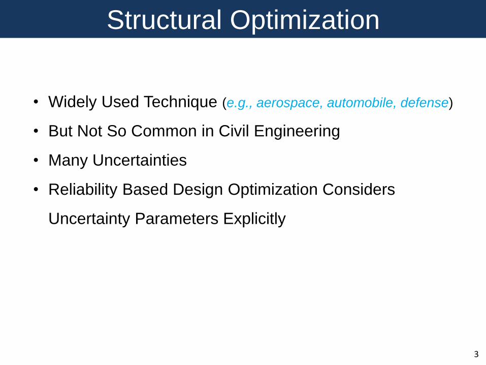
What Is Optimization?
5

6
YesFinal
Design
Optimum
Design?
ModifiedDesign
Optimization
Algorithm
Initial
Design
No
General Optimization Flow Chart
Analysis
Uncertainty in Analysis?
7
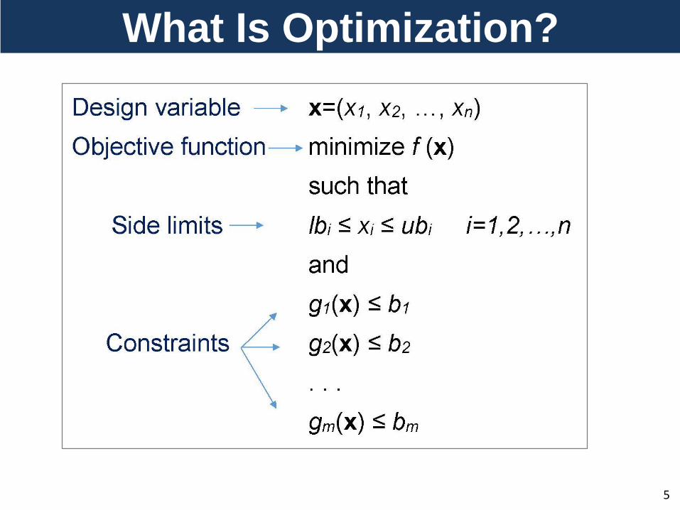
Uncertainty in Parameters

8
Sampling Methods
• Monte Carlo Sampling
• Latin Hypercube Sampling
• Importance Sampling
• 1st Order Reliability Method
• 2nd Order Reliability Method
Moment Methods
Two Methods

9
( ) ( ) ( )G R S x x x R: resistance S: Load
First Order Reliability Method (FORM)
Eurocode for bridges (EN1990)β=5.2 for 1 year period β=4.3 for 50 years β=3.8 for 100 years (Pf =7E-5)
Limit State Function:
Probability of Failure:
random variables
β
Safe region
G(u)=0
Failure region
U*
min T U U
x1 and x2i
i
i x
i
x
xu
μxi: mean values
σxi: standard deviation
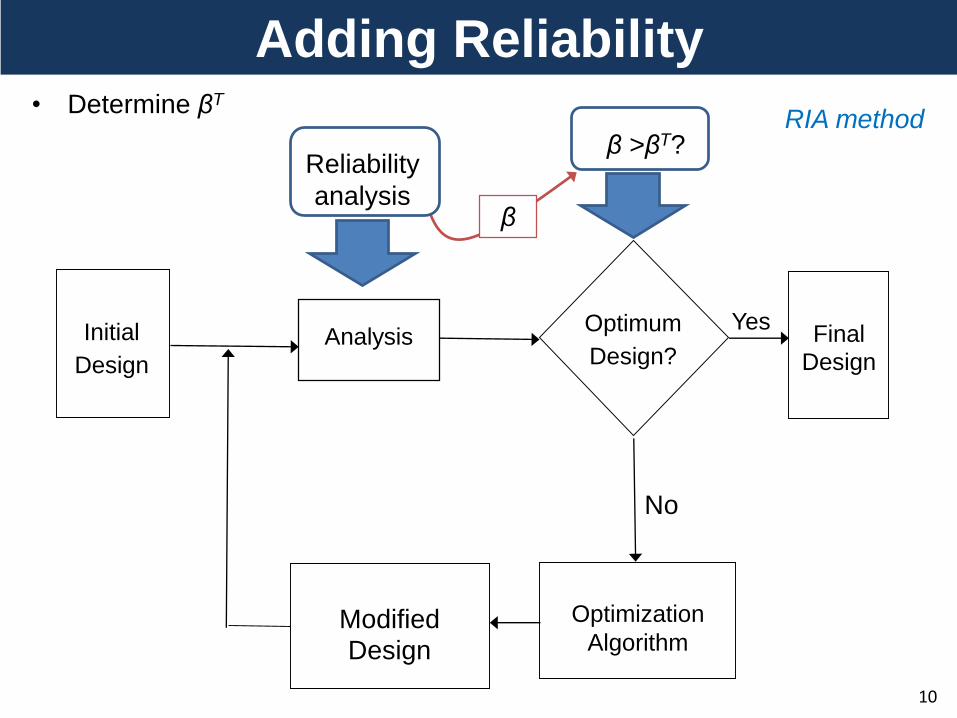
10
Adding Reliability
YesFinal
Design
Optimum
Design?
ModifiedDesign
Optimization
Algorithm
Initial
Design
No
Analysis
• Determine βT
β >βT?
β
Reliability
analysis
RIA method
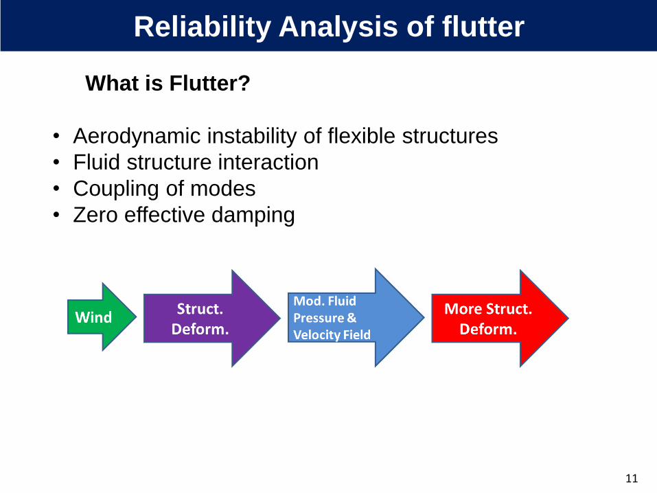
What is Flutter?
• Aerodynamic instability of flexible structures
• Fluid structure interaction
• Coupling of modes
• Zero effective damping
Reliability Analysis of flutter
11
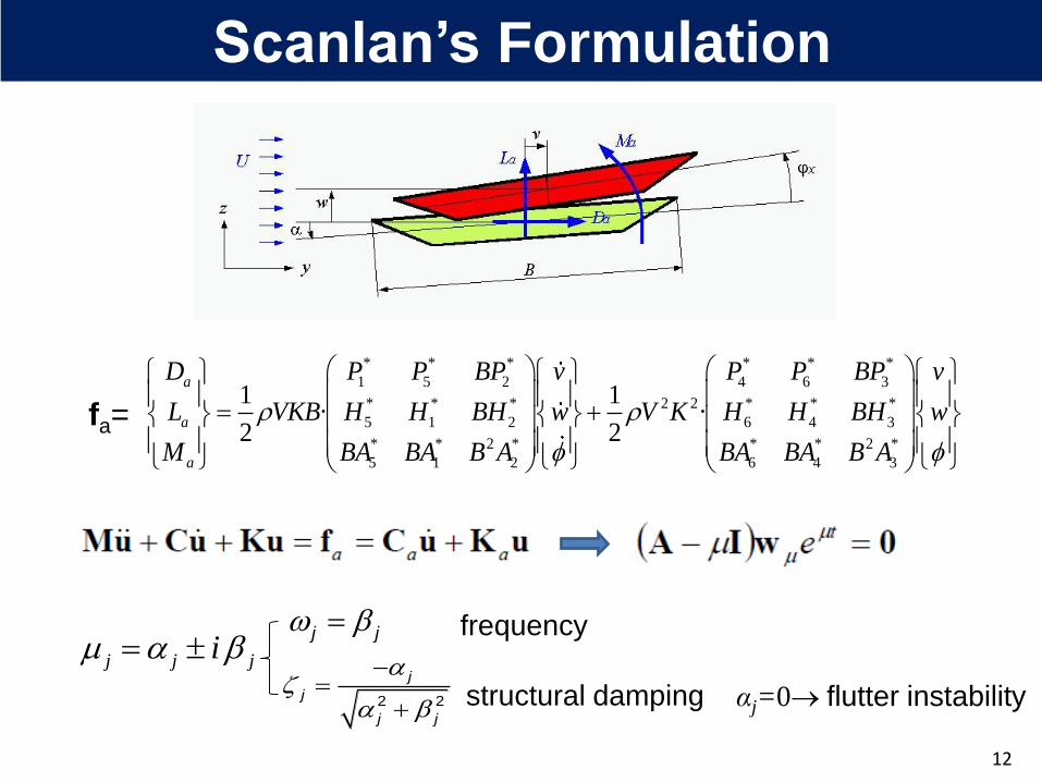
Scanlan’s Formulation
* * * * * *
1 5 2 4 6 3
* * * 2 2 * * *
5 1 2 6 4 3
* * 2 * * * 2 *
5 1 2 6 4 3
1 1· ·
2 2
a
a
a
D P P BP v P P BP v
L VKB H H BH w V K H H BH w
M BA BA B A BA BA B A
fa=
12
j j ji
j j
2 2
j
j
j j
αj=0 flutter instability
frequency
structural damping

Methods for Flutter Analysis
Full Bridge Model Test
13
+ Quasi Steady theory
Fully Computational Method
*Akashi bridge full model, PWRI
Hybrid Method
*Messina bridge sectional model, U. of Coruna
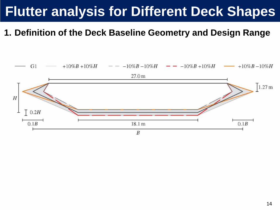
1. Definition of the Deck Baseline Geometry and Design Range
Flutter analysis for Different Deck Shapes
14

1. Definition of the Deck Baseline Geometry and Design Range
Flutter analysis for Different Deck Shapes
14ΔB (%)
ΔH
(%
)
G1
2. Sampling Plan of Computational
Fluid Dynamics (CFD) Models
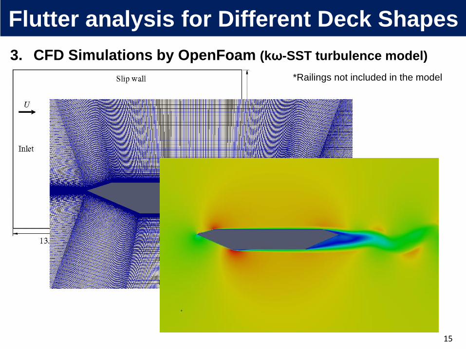
3. CFD Simulations by OpenFoam (kω-SST turbulence model)
15
Flutter analysis for Different Deck Shapes
*Railings not included in the model

16
4. Wind Tunnel Test Validations
Flutter analysis for Different Deck Shapes

5. Kriging surrogate model construction
CL CD CM CL’ CD’ CM’
17
,0*
1
' oMC
AK
,0*
2
' oM
A
CA
K
,0*
3 2
' oMC
AK
,0 ,0*
1
' o oL DC C
HK
,0 ,0*
2
' o oL D
H
C CH
K
,0*
3 2
' oLC
HK
6. Quasi-steady formulation to define flutter derivatives
Flutter analysis for Different Deck Shapes

Vf
Define
Deck
ShapeModified FEM
Multi-Modal
Analysis
18
Flowchart: Flutter Analysis
QS
Φ and ω

RBDO Formulation: Shape & Size
19
Design Optimization
6 design variables:
Obj. Func.
Min: bridge deck volume
Constraints:
g1: probabilistic flutter
g2: side limits
g3: deck max. vertical displacement
under overload case
g4: max main cable stress
Reliability Analysis
1( ) exp( ) exp exp( )
w
w wx w
X Xf X
7 random variables:
( ) ( )f i wG V x x x
xi: rand. variables of force coeff.
xw: rand. variable of extreme
wind

Flowchart: RBDO
i
G
u
f
i
V
x
20

Application Example: Great Belt East Bridge
Scanlan’s G1 Section
21

Mode Shapes and Frequencies
Mode Type Frequency (Hz)
2 VS 0.098
5 VS 0.131
11 LS 0.186
12 LS 0.195
13 LA 0.213
14 LS 0.213
15 VS 0.216
18 VS 0.249
19 LA 0.275
20 VS 0.282
21 TS/LS 0.285
22 VS 0.285
23 VA 0.286
24 TS/LS 0.290
d1
d2
d3
d4
ΔH=0; ΔB=0
d=[12, 10, 10, 10] (mm)
Flutter Analysis: Initial Design
22
Vf=78.2 m/s
K=0.47
V: vert. L: lat. T: tors. S: symm. A: asymm.

Limit State Function:
Probability of Failure:
Random variables:
– Case A: Extreme Wind Velocity
– Case B: Force Coefficients, Derivatives, Extreme Wind Velocity
Messina example –reliability analysis
( )f wG V x x
( ) 0fP P G d x,
Random variables of force
coefficients
Case random var. CV β Pf Vf (MPP) V*(MPP)
A xw 0.07 12.01 1.57E-33 78.20 13.22
B xw and xi 0.2 7.58 1.73E-14 62.13 12.33
Reliability Analysis of GB Bridge
23

6 Design Variables 7 Random Variables
Initial Design =7.58
Target Reliabilities T=6 and 8
1( ) exp( ) exp exp( )
w
w wx w
X Xf X
RBDO Formulation
24
DS410
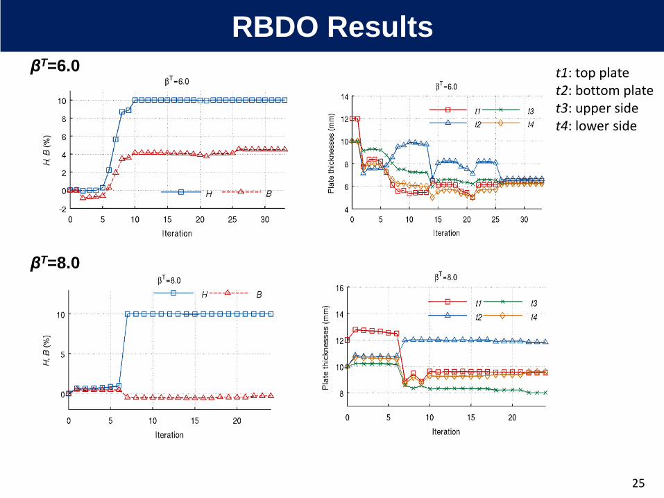
βT=6.0
βT=8.0
t1: top platet2: bottom platet3: upper sidet4: lower side
RBDO Results
25
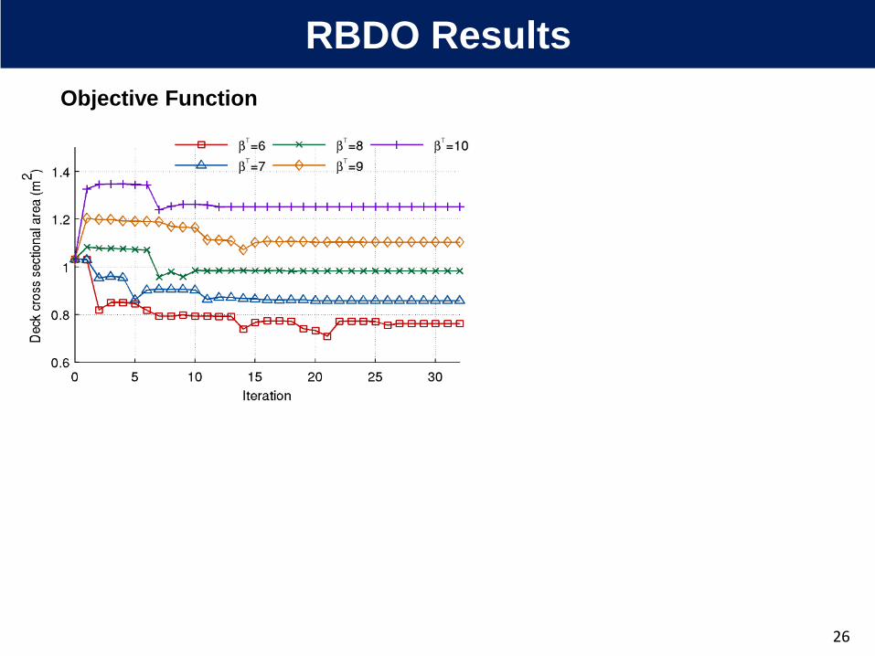
Objective Function
26
RBDO Results

Objective Function
βT Vf ΔH ΔB d1 d2 d3 d4
% variation
obj. func.
initial 78.2 0 0 12.0 10.0 10.0 10.0 -
6 69.45 10.00 4.51 6.48 6.63 6.24 6.24 -26.07
8 82.10 10.00 -0.32 9.51 11.82 8.02 9.58 -4.76
26
RBDO Results
RBDO Results Summary

1. RBDO Provides Accurate & Competitive Optimum Design for Considering
Uncertainty Explicitly.
2. Fully Numerical Approach of Flutter Velocity Computation Permits the Shape
Optimization of Bridge Decks.
3. More Probabilistic Constraints in the Future Study (aerodynamic instabilities,
turbulence effects, traffic loads, temperature loads…)
Summary
27

Thank you!
Thank you for your attention.
I hope you enjoyed the presentation