Inner and outer approximation of the polar diagram of a sailboat
Upload
khangminh22Category
view
0download
0
Redesign of a Classic Sailboat with FEA investigation of the plate curvature
Luis Gabriel Alessio dos Santos Master Thesis
presented in partial fulfillment
of the requirements for the double degree: “Advanced Master in Naval Architecture” conferred by University of Liege
"Master of Sciences in Applied Mechanics, specialization in Hydrodynamics, Energetics and Propulsion” conferred by Ecole Centrale de Nantes
developed at West Pomeranian University of Technology, Szczecin
in the framework of the
“EMSHIP” Erasmus Mundus Master Course
in “Integrated Advanced Ship Design”
Ref. 159652-1-2009-1-BE-ERA MUNDUS-EMMC
Supervisor:
Dr. Monika Bortnowska, West Pomeranian University of Technology, Szczecin
Co-Supervisor:
Prof. Jean-Baptiste R. G. Souppez, Southampton Solent University, UK
Reviewer: Prof. Dr. Dario Boote, University of Genoa
Szczecin, January 2017

Master Thesis developed at West Pomeranian University of Technology, Szczecin

REDESIGN OF A CLASSIC SAILBOAT WITH FEA INVESTIGATION iii OF THE PLATE CURVATURE
“EMSHIP” Erasmus Mundus Master Course, period of study September 2015 – February 2017
ABSTRACT
While there is still a strong passion and interest for traditional crafts, many of the designs now
need to be adapted to comply with the contemporary rules and regulations, and additional
modifications are required to meet modern expectations, in areas ranging from comfort to
safety, hence the need for modern replicas. In order to ascertain the constraints on modern
replicas, a redesign of a Dark Harbor 17.5 will be proposed. First, an initial design evaluation
will be performed to assess the characteristic of the original yacht, regarding hydrostatics,
hydrodynamics, structural arrangement and comfort. Modifications in accordance with
regulations and owner’s requirements will then be implemented to create a modern replica
suited to today’s market. Finally, the new design will be compared to the original one, allowing
to evaluate the challenges of design modernization and the impact of contemporary
requirements on a traditional design. The replica is being built at the boatbuilding school IBTC
Portsmouth, in the United Kingdom, by the time this thesis was written, and the owner intends
to develop commercial production of this boat. As the second part of this work, an analysis of
the stresses on the curved plate will be performed, targeting the evaluation of the stress
reduction coefficient associated to the curvature of the plate. The plate curvature coefficient
reduces the required thickness of the plates, reducing the weight and costs of the ship; this
reduction is due to the fact that the curved plates can handle higher pressure until the allowable
stress is achieved. With the values obtained in this work, the plates can be dimensioned
considering the double curvature of the hull, thus, a thinner plate than the ones calculated by
the ISO 12215 standard.

iv LUIS GABRIEL ALESSIO DOS SANTOS
Master Thesis developed at West Pomeranian University of Technology, Szczecin

REDESIGN OF A CLASSIC SAILBOAT WITH FEA INVESTIGATION v OF THE PLATE CURVATURE
“EMSHIP” Erasmus Mundus Master Course, period of study September 2015 – February 2017
Table of Contents
List of Figures ...................................................................................................................... ix
List of Tables ....................................................................................................................... xi
List of Symbols ................................................................................................................... xii
1. INTRODUCTION .......................................................................................................... 14
1.1. The Dark Harbor 17½ ................................................................................................ 14
1.2. Modern Replicas ........................................................................................................ 18
2. LITERATURE REVIEW............................................................................................... 18
2.1. Sailing Definitions ..................................................................................................... 18
2.2. Principles of Sailboat Design ...................................................................................... 21
2.2.1. Hull Design ......................................................................................................... 21
2.3. Hydrostatics and Stability of Sailboats ....................................................................... 23
2.3.1. The Simpson’s Rule ............................................................................................. 24
2.3.2. Water Plane Area ................................................................................................. 25
2.3.3. Wetted Surface .................................................................................................... 26
2.3.4. Hull Displacement and Boat Mass ....................................................................... 26
2.3.5. Weight Estimation and Centre of Gravity ............................................................. 26
2.3.6. Centre of Buoyancy ............................................................................................. 27
2.3.7. Centre of Flotation ............................................................................................... 27
2.3.8. Metacentric Height and the transverse stability .................................................... 27
2.3.9. Stability Index - STIX .......................................................................................... 31
2.3.10. The Dellenbaugh Angle ..................................................................................... 34
2.4. Keel design ................................................................................................................ 35
2.5. Rig design .................................................................................................................. 38
2.6. Boat Resistance .......................................................................................................... 38
2.6.1. The upright frictional resistance ........................................................................... 39

vi LUIS GABRIEL ALESSIO DOS SANTOS
Master Thesis developed at West Pomeranian University of Technology, Szczecin
2.6.2. The upright residuary resistance of the hull .......................................................... 40
2.6.3. The upright residuary resistance of the appendages .............................................. 42
2.7. Influence of the plate curvature on the admissible stress ............................................. 43
3. METHODOLOGY ......................................................................................................... 44
4. DESIGN ASSESSMENT ................................................................................................ 45
4.1. Hull modelling ........................................................................................................... 46
4.2. Original keel design ................................................................................................... 47
4.3. Hydrostatics study of the lines plan ............................................................................ 48
4.4. Weight Estimation ...................................................................................................... 48
4.5. Performance ............................................................................................................... 49
4.5.1. Hull Resistance .................................................................................................... 49
4.5.2. Appendage resistance .......................................................................................... 50
4.6. Stability analysis ........................................................................................................ 52
4.6.1. Righting moment curve ........................................................................................ 53
4.6.2. STIX calculations ................................................................................................ 54
4.6.3. Dellenbaugh angle ............................................................................................... 55
4.7. Hull structure analysis ................................................................................................ 55
4.7.1. HullScant ............................................................................................................. 58
5. DESIGN MODIFICATION ........................................................................................... 59
5.1. Frames Spacing and Hull Planking ............................................................................. 61
5.2. Rigging ...................................................................................................................... 63
5.3. General alterations ..................................................................................................... 64
5.4. New weight estimation ............................................................................................... 65
5.5. Keel Design ............................................................................................................... 66
5.5.1. Fin keel ................................................................................................................ 66
5.5.2. Bulb ballast .......................................................................................................... 67

REDESIGN OF A CLASSIC SAILBOAT WITH FEA INVESTIGATION vii OF THE PLATE CURVATURE
“EMSHIP” Erasmus Mundus Master Course, period of study September 2015 – February 2017
5.5.3. Keel structure ...................................................................................................... 69
5.6. Performance ............................................................................................................... 70
5.7. Propeller Selection ..................................................................................................... 70
5.8. Engine Selection ........................................................................................................ 72
5.9. Final Structure and General Arrangement ................................................................... 73
5.10. Stability .................................................................................................................... 74
5.11. Conclusions .............................................................................................................. 76
5.12. Note from the client.................................................................................................. 78
6. FINITE ELEMENT ANALYSIS OF THE PLATE CURVATURE ............................ 79
6.1. Flat panel aspect ratio and model validation ............................................................... 80
6.2. The double curvature coefficients ............................................................................... 83
6.3. Example of plate thickness calculation ....................................................................... 86
6.4. Conclusions ............................................................................................................... 88
7. GENERAL CONCLUSION ........................................................................................... 89
8. ACKNOWLEDGEMENTS ............................................................................................ 91
9. REFERENCES ............................................................................................................... 92
APPENDIX A – The dark harbor 17.5
APPENDIX B – Hullscant Reports of the original design
APPENDIX C – Hullscant Reports of the New design
APPENDIX D – Weight estimation of the new design
APPENDIX E – Rina Historic Ships 2016

viii LUIS GABRIEL ALESSIO DOS SANTOS
Master Thesis developed at West Pomeranian University of Technology, Szczecin
Declaration of Authorship
I declare that this thesis and the work presented in it are my own and have been generated by
me as the result of my own original research.
Where I have consulted the published work of others, this is always clearly attributed.
Where I have quoted from the work of others, the source is always given. With the exception of
such quotations, this thesis is entirely my own work.
I have acknowledged all main sources of help.
Where the thesis is based on work done by myself jointly with others, I have made clear exactly
what was done by others and what I have contributed myself.
This thesis contains no material that has been submitted previously, in whole or in part, for the
award of any other academic degree or diploma.
I cede copyright of the thesis in favour of the University of Liège.
Date: Signature

REDESIGN OF A CLASSIC SAILBOAT WITH FEA INVESTIGATION ix OF THE PLATE CURVATURE
“EMSHIP” Erasmus Mundus Master Course, period of study September 2015 – February 2017
LIST OF FIGURES
Figure 1.1 – The lines plan of the Dark Harbor 17½. ............................................................ 15
Figure 1.2 – Structure of the original boat. ............................................................................ 16
Figure 2.1 – The different parts of a sail. .............................................................................. 19
Figure 2.2 – Directions of sailing according to the wind direction. ........................................ 20
Figure 2.3 – Scheme of the tacking technique. ...................................................................... 21
Figure 2.4 – Table of offsets of the sailboat Dark Harbor 17½. ............................................. 23
Figure 2.5 – Scheme of the Simpson’s rule ........................................................................... 24
Figure 2.6 – Simpson’s Table for the calculation of the area under a curve. .......................... 25
Figure 2.7 – The transverse stability. .................................................................................... 28
Figure 2.8 – Curve of static stability. .................................................................................... 30
Figure 2.9 – Dellenbaugh Angle ........................................................................................... 35
Figure 2.10 – Typical keel geometry and definitions. ............................................................ 36
Figure 4.1 – Cloud of points based on the original table of offsets. ....................................... 46
Figure 4.2 – Hull, keel and rudder surfaces of the original design. ........................................ 46
Figure 4.3 – Geometry of the original keel design ................................................................. 47
Figure 4.4 – Resistance comparison between the various calculation methods. ..................... 50
Figure 4.5 – Resistance calculated by the DSYHS method and WinVPP software ................ 51
Figure 4.6 – Viscous resistance results .................................................................................. 51
Figure 4.7 – Total resistance of the boat ............................................................................... 52
Figure 4.8 – Righting moment curve ..................................................................................... 53
Figure 4.9 – Values of the factor for different positions on the waterline. ........................ 57
Figure 4.10 – HullScant model of the original Dark Harbor 17½ .......................................... 58
Figure 5.1 – Sails plan of the redesigned Dark Harbor 17.5 .................................................. 64
Figure 5.2 – Fin keel presented to the client with 8 inches of reduction on the draft. ............. 67
Figure 5.3 – Planform of the modified keel. .......................................................................... 68
Figure 5.4 – New design of the keel with the bulb ballast. .................................................... 69
Figure 5.5 – Ballast bolts distribution. View from the top of the ballast. ............................... 69
Figure 5.6 – Resistance curve of the original and new designs .............................................. 70
Figure 5.7 – Different positions of the FeatherStream propeller. ........................................... 71
Figure 5.8 - New design power curve. .................................................................................. 72
Figure 5.9 - Motoring range for different speeds, for the selected batteries. .......................... 73

x LUIS GABRIEL ALESSIO DOS SANTOS
Master Thesis developed at West Pomeranian University of Technology, Szczecin
Figure 5.10 – Structure of the new Dark Harbor 17.5 ............................................................ 74
Figure 5.11 –GZ curve and downflooding point .................................................................... 75
Figure 6.1 – Geometry of a stiffened curved panel. ............................................................... 80
Figure 6.2 – Plate under uniform pressure and fixed supports. .............................................. 80
Figure 6.3 – Convergence of the normal stress of the FEM analysis. ..................................... 81
Figure 6.4 – Pressure distribution on the fully fixed plate under uniform pressure. ................ 81
Figure 6.5 – Plate with double curvature and an aspect ratio equal to one. ............................ 84
Figure 6.6 – Normal stress on a curved plate under uniform pressure. ................................... 84
Figure 6.7 – Plate of the Dark Harbor hull ............................................................................ 86

REDESIGN OF A CLASSIC SAILBOAT WITH FEA INVESTIGATION xi OF THE PLATE CURVATURE
“EMSHIP” Erasmus Mundus Master Course, period of study September 2015 – February 2017
LIST OF TABLES
Table 1.1 - Original Dark Harbor 17.5 particulars. ................................................................ 17
Table 2.1 – Watercraft Design Categories. ............................................................................ 31
Table 2.2 – Requirements for STIX ...................................................................................... 31
Table 2.3 – Coefficients for Polynomial: Residuary Resistance of Bare Hull ........................ 41
Table 2.4 – Coefficients for the polynomial equation ............................................................ 42
Table 4.1 – Main dimensions of the original keel design of the Dark Harbor 17½ ................. 47
Table 4.2 –Results obtained by the Simpson’s Rule and by 3D Model .................................. 48
Table 4.3 – Wood densities ................................................................................................... 49
Table 4.4 – Mass and centre of gravity of the Dark Harbor 17½ before the modifications. .... 49
Table 4.5 – Stability analysis of the righting moment curve .................................................. 54
Table 4.6 – Stability index calculations................................................................................. 54
Table 4.7 – HullScant plate analysis of original design ......................................................... 59
Table 4.8 – HullScant Beams analysis of the original design ................................................ 59
Table 5.1 – Components and weight added to the boat .......................................................... 61
Table 5.2 – Different frames spacing according to the position on the boat length ................ 62
Table 5.3 - HullScant plate analysis of new design ............................................................... 62
Table 5.4 - HullScant Beams analysis of the new design ....................................................... 62
Table 5.5 – Final frames spacing according to the owner’s requirement ................................ 63
Table 5.6 – Centre of gravity and displacement before the alterations on the keel ................. 65
Table 5.7 – Weight and CG comparison between the original and new designs ..................... 65
Table 5.8 – Comparison between the original and the redesigned keel .................................. 68
Table 5.9 – Stability comparison .......................................................................................... 75
Table 5.10 – STIX comparison ............................................................................................. 76
Table 6.1 –Aspect ratio coefficient k2 for simply supported plates ........................................ 82
Table 6.2 - Aspect ratio coefficient k2 for fully fixed plates ................................................... 83
Table 6.3 – Curvature coefficients calculated for the different scenarios analysed ................. 85
Table 6.4 – Coefficients for the calculation of the plate thickness ......................................... 87

xii LUIS GABRIEL ALESSIO DOS SANTOS
Master Thesis developed at West Pomeranian University of Technology, Szczecin
LIST OF SYMBOLS
Symbol Description Units
GM Longitudinal metacentric height m A Positive area of the GZ curve, before the AVS m2 A Sail Area m2 B Maximum beam of the hull m
B Maximum beam of the waterline m GM Metacentric Height m GZ Restoring Lever M
GZ Righting lever at 90 degrees of heel m GZ Righting lever at the downflooding angle (DFA) m h Centre of sail effort over the waterline m k Plate aspect ratio factor k Pressure correcting factor for slamming k
LCB Longitudinal centre of buoyancy to fpp m LCF Longitudinal centre of flotation to fpp m
L Hull length m
m Boat weight when fully loaded kg P Bottom design pressure kN/m2 T Draft of canoe body m σ Ultimate flexural strength N/mm2 RM Restoring Moment
c Keel average chord m ∆ Hull displacement kg ∇ Volume displaced by the vessel m3 ∇c Volume displaced by the canoe body m3 ∇k Displaced volume of keel m3 AR Keel aspect ratio
AVS Angle of vanishing stability Degrees BM Metacentric Radius m
BOA Beam Overall M c Keel section chord m
Cb Transverse curvature coefficient Cl Longitudinal curvature coefficient
CLR Centre of Lateral Resistance DFA Downflooding angle Degrees
DSKS Delft Systematic Keel Series DSYHS Delft Systematic Yacht Hull Series
EEA European Economic Area FBD Beam-Displacement factor FDF Downfloodnig factor FDL Displacement Length Factor FIR Inversion Recovery Factor FKR Knockdown recovery factor fpp forward perpendicular -
FWM Wind moment factor FWM Wind moment factor
g Gravity acceleration m/s2 HA Heeling arm m ILFP Longitudinal moment of Inertia m4 k2b Panel aspect ratio factor
LCB Longitudinal Centre of Buoyancy m LCF Longitudinal Centre of Flotation m LCG Longitudinal Centre of Gravity m LOA Length Overall m LWL Waterline Length m

REDESIGN OF A CLASSIC SAILBOAT WITH FEA INVESTIGATION xiii OF THE PLATE CURVATURE
“EMSHIP” Erasmus Mundus Master Course, period of study September 2015 – February 2017
RCD Recreational Craft Directive Rhr Residuary resistance of the hull N Rrk residuary resistance of keel N
s Length of waterline division for Simpson’s Rule m Sc Wetted surface of canoe body at zero speed m2
STIX Stability Index t Keel section thickness m T Total draft of hull and keel m V Forward speed of the boat m/s
VCB Vertical Centre of Buoyancy m VCG Vertical Centre of Gravity m
W Mass of a relocated weight inboard kg WS Wind stiffness
Zcbk Vertical position of the centre of buoyancy of keel m Δ Weight displaced by the vessel Metric tonnes ρ Density of the water kg/m3 Cf Friction coefficient P Design pressure kN/m2 Rf Frictional resistance N Rn Reynolds number S Wetted surface m2
Tp Keel tapper ratio b Short dimension of the plate mm kc Panel curvature factor - tp Thickness of the plate mm σd Design stress N/mm2 υ Water kinematic viscosity m2/s

14 LUIS GABRIEL ALESSIO DOS SANTOS
Master Thesis developed at West Pomeranian University of Technology, Szczecin
1. INTRODUCTION
During the past decades, sailing ceased being just a sport for a minority and it turned to be a
foremost recreational activity, practised by a wide range of people. Sailing is both a relaxing
and interesting hobby used for just a few hours or entire days of sailing and pleasure at sea, and
the number of different models of sailboats available at the market is increasing according to
the demand of the customers.
It is noticed that the number of the people who are looking for this entertainment in the past
years has been increasing all over the world, and even though the recreational boating sections
in Europe has suffered from the economic crisis, the companies are optimistic about the future
of the market [1]. To supply this demand, the industries of the naval market are investing in
continuous research and development for new technologies to get the attention of the new yacht
owners, and a lot has been developed.
For the sailing boat owners, the excitement of going into the sea with a family and friends is a
priceless experience, very exciting and pleasurable, from a trip just crossing the bay or island-
hopping. Navigating long distances with all the safety and comfort requires a lot of experience
of navigation, sea survival, nutrition and other knowledge that only a sea expert can take and a
large degree of self-sufficiency.
The evolution of the sailing boats is very noticeable once the small to medium sized ships
evolved from simple vessels with rudimentary accommodation into a very luxurious and
sophisticated boat.
Besides the most modern sea crafts available, some sailors have a distinguished taste for the
classic designs. Historic vessels have some characteristic lines, which make them attractive and
beautiful with their elegant rigs; for these reasons, some sailors change from a modern boat for
the classic vessels.
1.1. The Dark Harbor 17½
Designed in 1908 by B. B. Crowninshield, the Dark Harbor 17.5 is a classic example of a
traditional day sailor. The particular lines of historic vessels that make them attractive and
elegant, and still lead some sailors to choose traditional boats. However, true replicas can prove
to be unsuitable from a commercial point of view. Indeed, traditional designs were not
conceived for contemporary rules and regulations. Moreover, what used to be inexistent or a

REDESIGN OF A CLASSIC SAILBOAT WITH FEA INVESTIGATION 15 OF THE PLATE CURVATURE
“EMSHIP” Erasmus Mundus Master Course, period of study September 2015 – February 2017
luxury feature, such as an engine on a small sailing vessel, has now become the norm. There is,
therefore, a call for modern replicas, complying with the relevant regulations and offering a
similar standard of comfort as modern boats.
To investigate the challenges resulting from those modern replicas, the redesign of a
contemporary Dark Harbor 17.5, currently being built at the IBTC Portsmouth, has been
undertaken. The initial design has been assessed, to later allow a comparison with the modern
version, with particular emphasis on the issues raised by regulatory compliance and the
incorporation of modern comfort elements.
A number of documents about the original Dark Harbor 17.5 are still in existence [2] and
include a lines plan, table of offsets and scantlings, as well as a sail and construction plan,
respectively presented in
Figure 1.1and Figure 1.2.
Figure 1.1 – The lines plan of the Dark Harbor 17½. The profile (top picture), the body plan (bottom picture) and the body plan (right picture). Reference [2].
16 LUIS GABRIEL ALESSIO DOS SANTOS
Master Thesis developed at West Pomeranian University of Technology, Szczecin
Figure 1.2 – Structure of the original boat. Reference [2].
Finally, the original design philosophy of the craft is captured in the following short historical
description of the design [3]:
“In 1908 B.B. Crowninshield was asked to draw up a one-design class of knockabouts to be
initially known as the Manchester 17½. The class was to become one of the most popular and
long-lived of the knockabouts; about 200 boats were built in Maine, for example, where the
name was altered to reflect yacht club affiliation. The most common name for the design is now
the Dark Harbor17½, named after the summer colony at Islesboro that once had the largest
number of these boats.
One still finds many a Dark Harbor 17½ “knocking about” New England waters. (a dozen or
so reside at the Buck’s Harbor Yacht Club in Brooksville, where they are still raced on
Eggemoggin Reach.) The boats were built well and have lasted well, with cedar planking over
oak frames, a lead ballast keel, copper and bronze fastenings, and simple deck construction –
canvas-over-cedar-or-pine – to discourage freshwater leaks. Most were built with the self-
bailing cockpit as shown in the drawings, although a few were given deep cockpits with seats
for more comfort.
While intended primarily for afternoon sailing and racing, these boats have often been used for
coastal cruising; the low cabin trunk has space for two transom berths.”
This document can be found entirely at the Appendix A. It is not dated, and it contains some of
the main parameters for the Dark Harbor 17.5, derived from the original plans and
documentation, and are listed in Table 1.1.

REDESIGN OF A CLASSIC SAILBOAT WITH FEA INVESTIGATION 17 OF THE PLATE CURVATURE
“EMSHIP” Erasmus Mundus Master Course, period of study September 2015 – February 2017
Table 1.1 - Original Dark Harbor 17.5 particulars. Reference [2].
LOA 25’ 10’’ 7.87 m LWL 17’ 6’’ 5.33 m BOA 6’ 3’’ 1.90 m Draft 4’ 3’’ 1.29 m
Displacement 3420 lbs 1551 kg Sail Area 311 ft2 28.89 m2
This boat combines the performance of a fast boat with the comfort offered by a large cockpit
and cosy cuddy cabin. Its wooden hull has beautiful slender lines, deep draft and a large rig,
making it fast, responsive and a handy boat.
The wide cockpit gives the comfort and safety to sail alone or with a companion and the cabin
offers the possibility to sleep two people comfortably. This modern replica calls for a number
of design alterations, concessions of traditional design to the modern world.
An initial design evaluation will be performed to assess the characteristic of the original yacht,
regarding hydrostatics, hydrodynamics, structural arrangement and comfort. Based on the
owner’s requirements, a number of modifications will be implemented. A shallower keel aims
at increasing the area of operation of the craft and making it trailerable while retaining
performance and stability. To improve the strength and durability of the craft, a modern strip-
planking sheathed with cold-moulded veneers has been chosen. The boat is also to be more
comfortable and practical to use. Indeed, modern standards dictate the presence of additional
comfort equipment as well as an electrical inboard engine.
The new design can finally be compared to the original one, allowing to evaluate the challenges
of design modernization, the impact of contemporary requirements on a traditional design and
the suitability of modern replicas in today’s market.
To achieve this goal, a deep study of the principles of sailboats shall be performed, analysing
the characteristics of the boat and studying how the modifications can impact on its
performance. The boat is currently being built by its owner in the boatbuilding school IBTC
Portsmouth, and it will have all the modifications implemented in partnership with the
Southampton Solent University in England and the West Pomeranian University, in Poland.
The boat is intended to be sailed from the Chichester Marina with a sailing programme focussed
on the Solent.

18 LUIS GABRIEL ALESSIO DOS SANTOS
Master Thesis developed at West Pomeranian University of Technology, Szczecin
1.2. Modern Replicas
There is great importance in being able to state whether a vessel can be considered a replica or
a reconstruction. Some definitions have been laid out by the National Historic Ships UK [4].
For instance, the process of replication is given as: “Replication means starting from scratch to
build a copy of a vessel and can be defined at various levels of detail and accuracy”.
A true replica would be characterised as an exact reproduction of the original vessel in every
detail, except some minor details such as the fender ropes.
Since the Dark Harbor will deviate from the original, the definition of an operational replica
seems better suited, as it allows for some modifications to meet the operational needs, such as
the safety equipment and some internal changes for specific functions.
However, the major changes to the keel design and radically different construction method
make the modern Dark Harbor a representation. Indeed, the representation is defined as a vessel,
which was based on a particular craft but had its appearance modified, considering the overall
impression but not the accuracy.
The vessel is to undergo some major changes, dictated by the owner to meet the contemporary
standard of comfort expected, but the vessel is to retain the spirit of the original Dark Harbor,
thus making it a representation project.
This work was developed at the same time the owner of the boat, referred as the client, started
to build the boat at the IBTC Portsmouth. Thus, several meetings with the client have occurred
to take the decisions on the design, and to assist with the manufacturing of the boat. More about
the relation with the client is described at the end of this thesis.
2. LITERATURE REVIEW
According to the bibliography indicated by the supervisor, a bibliography review allows a better
comprehension of the topic addressed in this work.
2.1. Sailing Definitions
It is important to define some definitions that are commercially used and is adopted at this work.
A lot of a sailboat have changed since the first designs; new studies have been performed aiming
the improvement of the performance, comfort, safety and reducing the costs.

REDESIGN OF A CLASSIC SAILBOAT WITH FEA INVESTIGATION 19 OF THE PLATE CURVATURE
“EMSHIP” Erasmus Mundus Master Course, period of study September 2015 – February 2017
For a sailor or a curious person about sailboats, it is fundamental the knowledge of some basic
terms to better understand the functionality of a boat. Some relevant geometric definitions
adopted in this work refer to the International Towing Tank Conference (ITTC) Dictionary of
Ship Hydrodynamics [5].
Figure 2.1 – The different parts of a sail.
Besides the definitions of the sailboat itself, other important characteristics should be nominated
to a better understanding of the sailing characteristics.
The fore part refers to anything towards the front of the boat and, on the other hand, aft part
refers to anything towards the back of the boat. When standing at the stern and looking towards
the bow of the boat, one has the port side located at his left, and the starboard is at his right side.
It is evident the importance of the wind direction about the sailboat. To sail in a determined
direction, the sails should be turned in the correct way, getting the best power of the winds. The
different sailing directions are exemplified in the figure below.
HULL
GAFF
BOW
MAST
STERN
JIB STAY
JIB
MAIN SAIL
KEEL RUDDER
FOOT BOOM

20 LUIS GABRIEL ALESSIO DOS SANTOS
Master Thesis developed at West Pomeranian University of Technology, Szczecin
Figure 2.2 – Directions of sailing according to the wind direction. From tillertowardstrouble.wordpress.com [Accessed 14 July 2016]
It is known that one cannot sail directly upwind, or into the winds, and, in order to navigate in
this direction, it is necessary having a zigzag movement; boats have different abilities regarding
how close to the wind they can sail. When turning from one side of the movement to the other,
the bow crosses through the wind, and this is called tack. This movement is illustrated below.
REDESIGN OF A CLASSIC SAILBOAT WITH FEA INVESTIGATION 21 OF THE PLATE CURVATURE
“EMSHIP” Erasmus Mundus Master Course, period of study September 2015 – February 2017
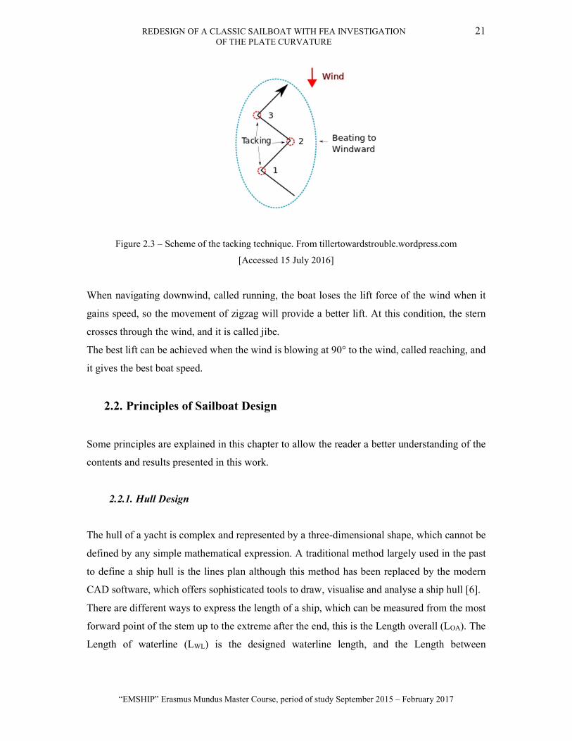
Figure 2.3 – Scheme of the tacking technique. From tillertowardstrouble.wordpress.com
[Accessed 15 July 2016]
When navigating downwind, called running, the boat loses the lift force of the wind when it
gains speed, so the movement of zigzag will provide a better lift. At this condition, the stern
crosses through the wind, and it is called jibe.
The best lift can be achieved when the wind is blowing at 90° to the wind, called reaching, and
it gives the best boat speed.
2.2. Principles of Sailboat Design
Some principles are explained in this chapter to allow the reader a better understanding of the
contents and results presented in this work.
2.2.1. Hull Design
The hull of a yacht is complex and represented by a three-dimensional shape, which cannot be
defined by any simple mathematical expression. A traditional method largely used in the past
to define a ship hull is the lines plan although this method has been replaced by the modern
CAD software, which offers sophisticated tools to draw, visualise and analyse a ship hull [6].
There are different ways to express the length of a ship, which can be measured from the most
forward point of the stem up to the extreme after the end, this is the Length overall (LOA). The
Length of waterline (LWL) is the designed waterline length, and the Length between

22 LUIS GABRIEL ALESSIO DOS SANTOS
Master Thesis developed at West Pomeranian University of Technology, Szczecin
perpendiculars (LPP) is from the forward end of the designed waterline to the rudder stock. In
the case of sailboats, the LPP is not commonly used.
An important way to represent a ship hull in a two-dimensional drawing is through the lines
plan. The hull is divided into several stations, perpendicular of the waterline, and usually
beginning from the stem of the ship until the stern. These lines contain relevant geometrical
data, which describes all the shape of the hull and it is divided into tree views drawing: the
profile plan, the body plan and the half breadth plan. A representation of the lines plan of the
sailboat Dark Harbor 17½ is shown in
Figure 1.1.
In principle, two groups of planes are created, the waterlines and the sections, and more lines
are added to give more precision to the geometry of the hull. The position of these lines is
inserted as notes on the drawing page, and through these notes, it is possible to construct the
hull by using the distances located at the table of offsets. This chart contains the position of
several points measured from specific locations at the drawings which describe the hull lines.
The Figure 2.4 shows the table of offsets of the Dark Harbor 17½ and this table describes the
lines plan of
Figure 1.1.
REDESIGN OF A CLASSIC SAILBOAT WITH FEA INVESTIGATION 23 OF THE PLATE CURVATURE
“EMSHIP” Erasmus Mundus Master Course, period of study September 2015 – February 2017
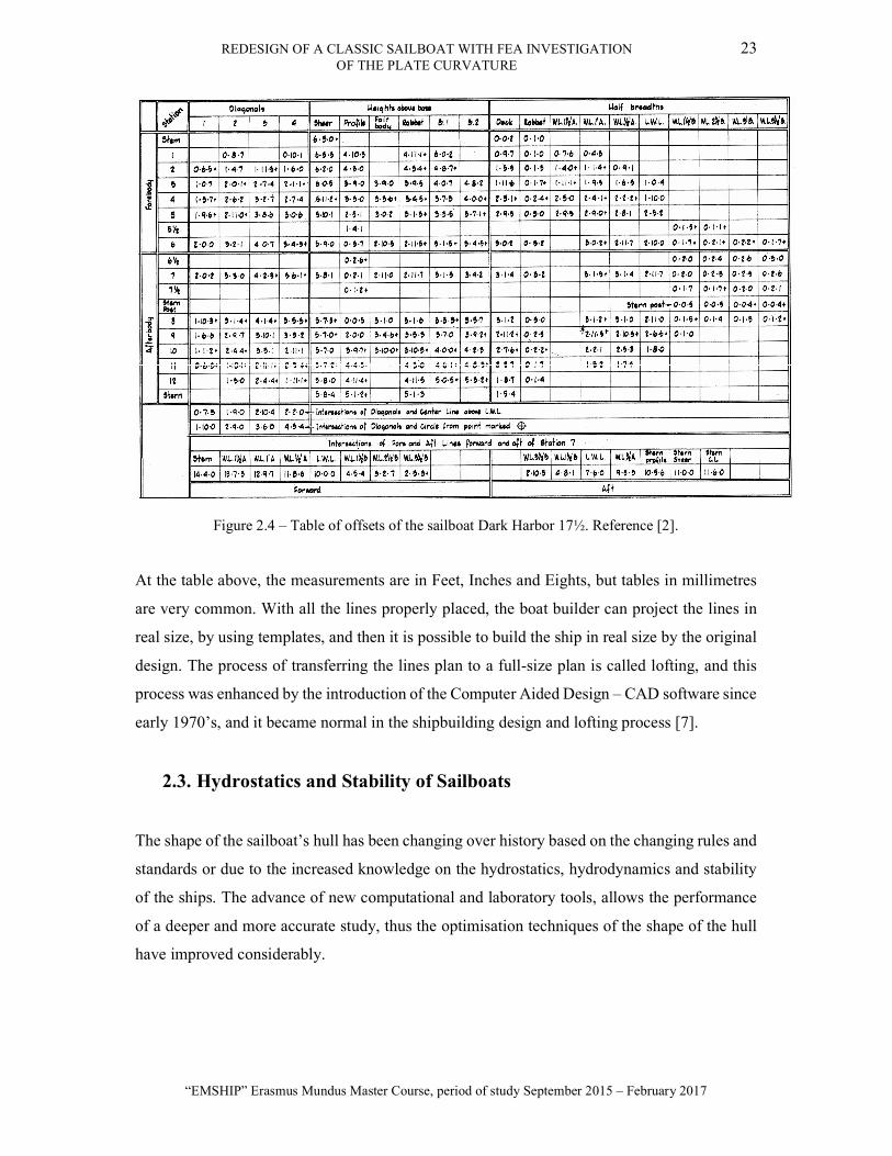
Figure 2.4 – Table of offsets of the sailboat Dark Harbor 17½. Reference [2].
At the table above, the measurements are in Feet, Inches and Eights, but tables in millimetres
are very common. With all the lines properly placed, the boat builder can project the lines in
real size, by using templates, and then it is possible to build the ship in real size by the original
design. The process of transferring the lines plan to a full-size plan is called lofting, and this
process was enhanced by the introduction of the Computer Aided Design – CAD software since
early 1970’s, and it became normal in the shipbuilding design and lofting process [7].
2.3. Hydrostatics and Stability of Sailboats
The shape of the sailboat’s hull has been changing over history based on the changing rules and
standards or due to the increased knowledge on the hydrostatics, hydrodynamics and stability
of the ships. The advance of new computational and laboratory tools, allows the performance
of a deeper and more accurate study, thus the optimisation techniques of the shape of the hull
have improved considerably.

24 LUIS GABRIEL ALESSIO DOS SANTOS
Master Thesis developed at West Pomeranian University of Technology, Szczecin
2.3.1. The Simpson’s Rule
The Simpson’s rule can be used to determine the area and volume of a curve, and it is a good
approximation when applied to ships, to determine the different areas and volumes of the hull.
Its accuracy depends on how near the curve follows a mathematical law and the spacing
between the ordinates [8].
The Simpson’s method divides the curve into n equally distributed intervals of length s, and n
should be even. The distances in function of Y for each X range are used to determine the area
under the curve, as shown in Figure 2.5.
Figure 2.5 – Scheme of the Simpson’s rule. [9]
The values are added to a table, and the Simpson’s multipliers are added.

REDESIGN OF A CLASSIC SAILBOAT WITH FEA INVESTIGATION 25 OF THE PLATE CURVATURE
“EMSHIP” Erasmus Mundus Master Course, period of study September 2015 – February 2017
Figure 2.6 – Simpson’s Table for the calculation of the area under a curve. [6]
The area can be calculated by multiplying the sum of the products of the table by the length of
each interval, and dividing it by three, as shown in the equation below.
=3
× ( ) (2.1)
Where s is the length of the division of the waterline in metres, and A is the area in square
metres.
To obtain the hydrostatic performance of a hull, it is necessary to calculate some geometrical
features, such as the water plane area, the wetted surface and the hull displacement. This values
are directly given by a CAD software, but a very popular method for calculating the areas in
the naval architecture, is the Simpson’s rule.
2.3.2. Water Plane Area
This is the area at the designed water plane line, and it is calculated straightforward by applying
the Simpson’s rule. It is important to calculate some aspects of the boat, such as the weight per
millimetre of immersion, this is how much the boat sink when a weight is added; the heel and
trim are calculated using the water plane moment of inertia, or also called the second moment
of area, and its centre of gravity is located where the hull is trimmed [6].
Longitudinal moment of inertia, ILFP, and the can be calculated by applying the Simpson’s
method at the water plane area, and it is used to calculate the longitudinal stability, while the

26 LUIS GABRIEL ALESSIO DOS SANTOS
Master Thesis developed at West Pomeranian University of Technology, Szczecin
transverse moment of inertia, IT, is also calculated by the same method as the longitudinal
moment of inertia and it is used for the transverse stability.
2.3.3. Wetted Surface
The surface area of the underwater body of the hull is called wetted area, or surface, and it is
important to determine the frictional drag, and it includes the appendages [5]. As the hull is a
three-dimensional geometry, the calculation of the wetted surface is more complex, and it is
performed by using the body plan and calculating the length of the arc between the waterline
and the keel at each station. Afterwards, the Simpson’s rule can be applied.
2.3.4. Hull Displacement and Boat Mass
The calculation of the hull displacement is made by calculating the cross-sectional area at each
of the stations, and then the Simpson’s rule can be applied. To calculate the area at each station,
the depth at that section is divided into five equal parts, and the lowest part is divided by a half.
In this way, the Simpson’s multipliers are changed and the area of that section is obtained. After
calculating the area in every section by this method, the Simpson’s rule is applied with the
values of the areas, and the final volume displaced by the hull is obtained.
The Archimedes’ principle states that the mass of the floating body is equal to the mass of the
displaced volume of water. Thus, the weight of the boat can be determined by multiplying the
submerged volume by the water density.
The mass displacement can be referred by the symbol – Δ, usually in kilogrammes or tonnes,
and the volume displacement by the symbol –∇, usually in m3.
2.3.5. Weight Estimation and Centre of Gravity
Each of the components of the boat has its mass and centre of gravity. It means that every object
inside the ship, i.e. structural components, furniture, crew, supplies, etc., add a moment to ship,
resulting in a combined moment acting in the centre of gravity of the ship. The position of the
centre of gravity of the ship is defined by calculating the moment generated by each of
component with its position and mass. With the mass of every component in the ship, the total
weight, and so the displacement, of the ship can be estimated, allowing the calculation of the
REDESIGN OF A CLASSIC SAILBOAT WITH FEA INVESTIGATION 27 OF THE PLATE CURVATURE
“EMSHIP” Erasmus Mundus Master Course, period of study September 2015 – February 2017
stability of the ship in different conditions. The stability will be treated in the following
chapters.
2.3.6. Centre of Buoyancy
The centre of gravity of the submerged volume of the hull is called centre of buoyancy. Its
position is determined by applying the Simpson’s rule to the volume of each of the stations. It
can be done by assuming an origin at the transverse axis at the fore part of the boat and the
waterline, and using the area as calculated in the Section 2.3.4. Each section area is then
multiplied by the distance between each section and the origin, plotting a new curve, and in the
end, the Simpson’s rule is applied to the curve of this area. This is the horizontal centre of
buoyancy, called LCB.
The vertical centre of buoyancy is determined by considering the vertical distribution of the
sectional moments. The waterline of each section should be known, as presented in the body
plan of the boat, and then it is possible to plot the vertical distribution of volume and apply the
Simpson’s rule to determine the VCB.
2.3.7. Centre of Flotation
The geometrical centre of area of the water plane is called the centre of flotation, and any change
in the water plane, i.e. change in draft, trim, heel, leads to a shift in the centre of flotation as
well [10]. The position of the longitudinal centre of flotation – LFC, is measured from the
amidships, aft or fore perpendiculars, and can be expressed as a ratio of the length of the
waterline [5].
2.3.8. Metacentric Height and the transverse stability
A vertical line can be traced from the buoyancy centre, and when the boat has a heel angle, the
submerged volume of the hull is altered, changing the buoyancy centre along. The intersection

28 LUIS GABRIEL ALESSIO DOS SANTOS
Master Thesis developed at West Pomeranian University of Technology, Szczecin
between the vertical line, which crosses the new buoyancy centre, and the previous line, is
called metacentre. It can be visualized at
Figure 2.7
Figure 2.7 – The transverse stability. [11]
The point marked as M is the metacentre, the distance between CG and M, GM, is called the
metacentric height, while the distance between B and M, BM, is called the metacentric radius.
The fundamental stability equation, as shown below, gives the distance BM, and trough
geometrical relations it is possible to obtain the righting momentum. [6].
= ∇
(2.2)
The transverse stability of yachts is proportional to the metacentric height, GM, and the two
ways that are usually employed to increase the stability, is lowering the centre of gravity G by
adding ballast or increasing the metacentre M, by increasing the water plane area.
When in the heeling condition, the buoyancy force acts in B’, coupled with the gravity force at
G, and this causes a moment with the lever GZ. This moment is given by multiplying the mass
by the gravity and the lever, GZ , and it is called the righting, or restoring, moment,
, but this method is only valid for small heeling angles, when the metacentre can be assumed
fix. This moment tends to return the ship to its original condition and it is given by the equation
below.
= ∆ . . (2.3)
B’ ∅
∅
CG Z’
M
WL
K
B
WL’
REDESIGN OF A CLASSIC SAILBOAT WITH FEA INVESTIGATION 29 OF THE PLATE CURVATURE
“EMSHIP” Erasmus Mundus Master Course, period of study September 2015 – February 2017
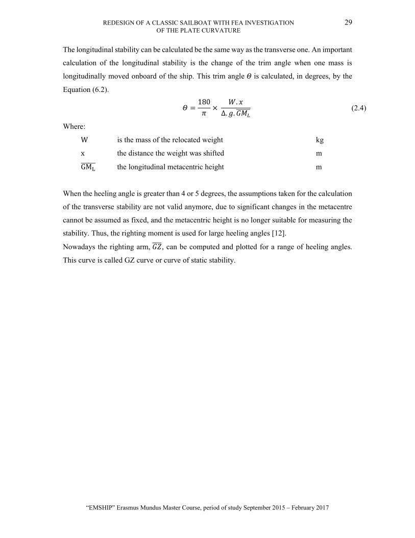
The longitudinal stability can be calculated be the same way as the transverse one. An important
calculation of the longitudinal stability is the change of the trim angle when one mass is
longitudinally moved onboard of the ship. This trim angle is calculated, in degrees, by the
Equation (6.2).
=180
× .
∆. . (2.4)
Where:
W is the mass of the relocated weight kg
x the distance the weight was shifted m
GM the longitudinal metacentric height m
When the heeling angle is greater than 4 or 5 degrees, the assumptions taken for the calculation
of the transverse stability are not valid anymore, due to significant changes in the metacentre
cannot be assumed as fixed, and the metacentric height is no longer suitable for measuring the
stability. Thus, the righting moment is used for large heeling angles [12].
Nowadays the righting arm, , can be computed and plotted for a range of heeling angles.
This curve is called GZ curve or curve of static stability.
30 LUIS GABRIEL ALESSIO DOS SANTOS
Master Thesis developed at West Pomeranian University of Technology, Szczecin
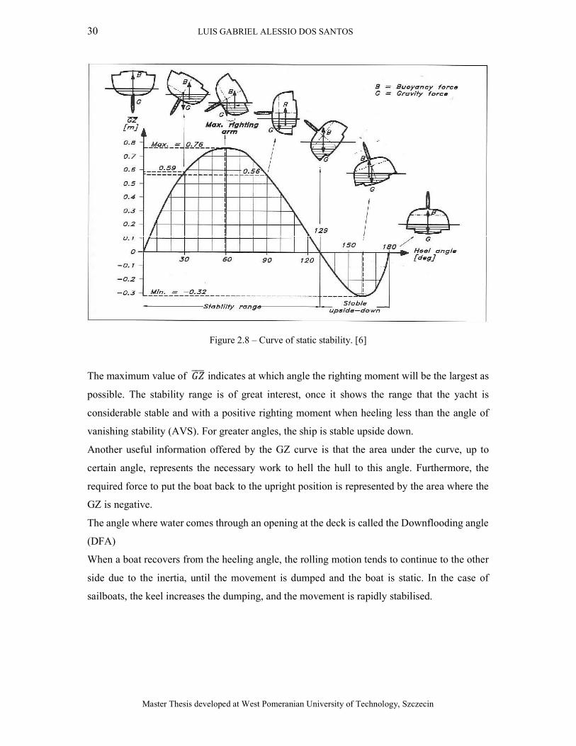
Figure 2.8 – Curve of static stability. [6]
The maximum value of indicates at which angle the righting moment will be the largest as
possible. The stability range is of great interest, once it shows the range that the yacht is
considerable stable and with a positive righting moment when heeling less than the angle of
vanishing stability (AVS). For greater angles, the ship is stable upside down.
Another useful information offered by the GZ curve is that the area under the curve, up to
certain angle, represents the necessary work to hell the hull to this angle. Furthermore, the
required force to put the boat back to the upright position is represented by the area where the
GZ is negative.
The angle where water comes through an opening at the deck is called the Downflooding angle
(DFA)
When a boat recovers from the heeling angle, the rolling motion tends to continue to the other
side due to the inertia, until the movement is dumped and the boat is static. In the case of
sailboats, the keel increases the dumping, and the movement is rapidly stabilised.
REDESIGN OF A CLASSIC SAILBOAT WITH FEA INVESTIGATION 31 OF THE PLATE CURVATURE
“EMSHIP” Erasmus Mundus Master Course, period of study September 2015 – February 2017
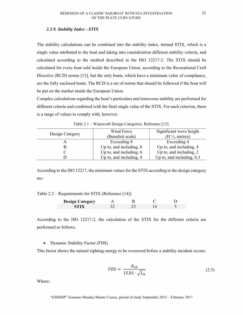
2.3.9. Stability Index - STIX
The stability calculations can be combined into the stability index, termed STIX, which is a
single value attributed to the boat and taking into consideration different stability criteria, and
calculated according to the method described in the ISO 12217-2. The STIX should be
calculated for every boat sold inside the European Union, according to the Recreational Craft
Directive (RCD) norms [13], but the only boats, which have a minimum value of compliance,
are the fully enclosed boats. The RCD is a set of norms that should be followed if the boat will
be put on the market inside the European Union.
Complex calculations regarding the boat’s particulars and transverse stability are performed for
different criteria and combined with the final single value of the STIX. For each criterion, there
is a range of values to comply with, however.
Table 2.1 – Watercraft Design Categories. Reference [13].
Design Category Wind Force
(Beaufort scale) Significant wave height
(H ⅓, metres) A Exceeding 8 Exceeding 4 B Up to, and including, 8 Up to, and including, 4 C Up to, and including, 6 Up to, and including, 2 D Up to, and including, 4 Up to, and including, 0.3
According to the ISO 12217, the minimum values for the STIX according to the design category
are:
Table 2.2 – Requirements for STIX (Reference [14])
Design Category A B C D STIX 32 23 14 5
According to the ISO 12217-2, the calculation of the STIX for the different criteria are
performed as follows.
Dynamic Stability Factor (FDS)
This factor shows the natural righting energy to be overawed before a stability incident occurs.
= 15.81 ∙
(2.5)
Where:

32 LUIS GABRIEL ALESSIO DOS SANTOS
Master Thesis developed at West Pomeranian University of Technology, Szczecin
A Positive area of the GZ curve, before the AVS m2
L Hull length m
FDS should be between 0.5 and 1.5.
Inversion Recovery Factor (FIR)
Represents the capacity to recover unassisted after capsizing.
=125 −
∆1600
∆ < 40000
=100
∆ ≥ 40000
(2.6)
FIR should be between 0.4 and 1.5.
Knockdown recovery factor (FKR)
The ability of the boat to spill water off the sails and recover after being knocked down.
= ∙ ∆/(2 ℎ ) (2.7)
Where:
h Centre of sail effort over the waterline m
GZ Righting lever at 90 degrees of heel m
= 0.875 + 0.0833 ∙ ≥ 1.5
= 0.5 + 0.333 ∙ < 1.5
= 0.5 = 90°
(2.8)
FKR shall be never taken less than 0.5 or greater than 1.5.

REDESIGN OF A CLASSIC SAILBOAT WITH FEA INVESTIGATION 33 OF THE PLATE CURVATURE
“EMSHIP” Erasmus Mundus Master Course, period of study September 2015 – February 2017
Displacement Length Factor (FDL)
This factor regards the favourable displacement to increase the resistance to capsize.
= 0.6 +15 ∙ ∆ ∙
(333 − 8 )
.
(2.9)
Where:
= (2 + )/3
= ( /11) .
Moreover, FDL should be taken between 0.75 and 1.25.
Beam-Displacement factor (FBD)
This factor accounts the predisposition to capsize in beam seas of boats with substantial topside
flare and increased beam about displacement.
=13.31 .
> 2.20
= 1.682
.
< 1.45
ℎ = 1.118.
(2.11)
Where:
B is the maximum beam of the hull m
B maximum beam of the waterline m
FBD should always be between 0.75 and 1.25.
Wind moment factor (FWM)
It represents the risk of downflooding due to a gust of wind heeling an unreefed boat.
= 1 ≥ 90°
(2.12)
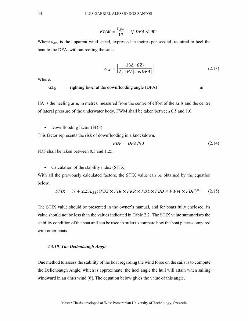
34 LUIS GABRIEL ALESSIO DOS SANTOS
Master Thesis developed at West Pomeranian University of Technology, Szczecin
=17
< 90°
Where is the apparent wind speed, expressed in metres per second, required to heel the
boat to the DFA, without reefing the sails.
=13∆ ∙
∙ |cos | (2.13)
Where:
GZ righting lever at the downflooding angle (DFA) m
HA is the heeling arm, in metres, measured from the centre of effort of the sails and the centre
of lateral pressure of the underwater body. FWM shall be taken between 0.5 and 1.0.
Downfloodnig factor (FDF)
This factor represents the risk of downflooding in a knockdown.
= /90 (2.14)
FDF shall be taken between 0.5 and 1.25.
Calculation of the stability index (STIX)
With all the previously calculated factors, the STIX value can be obtained by the equation
below.
= (7 + 2.25 )( × × × × × × ) . (2.15)
The STIX value should be presented in the owner’s manual, and for boats fully enclosed, its
value should not be less than the values indicated in Table 2.2. The STIX value summarises the
stability condition of the boat and can be used in order to compare how the boat places compared
with other boats.
2.3.10. The Dellenbaugh Angle
One method to assess the stability of the boat regarding the wind force on the sails is to compute
the Dellenbaugh Angle, which is approximate, the heel angle the hull will attain when sailing
windward in an 8m/s wind [6]. The equation below gives the value of this angle.
REDESIGN OF A CLASSIC SAILBOAT WITH FEA INVESTIGATION 35 OF THE PLATE CURVATURE
“EMSHIP” Erasmus Mundus Master Course, period of study September 2015 – February 2017
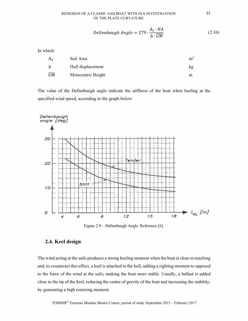
ℎ = 279 ∙∙
∆ ∙ (2.16)
In which:
A Sail Area m2
∆ Hull displacement kg
GM Metacentric Height m
The value of the Dellenbaugh angle indicate the stiffness of the boat when heeling at the
specified wind speed, according to the graph below:
Figure 2.9 – Dellenbaugh Angle. Reference [6].
2.4. Keel design
The wind acting at the sails produces a strong heeling moment when the boat is close to reaching
and, to counteract this effect, a keel is attached to the hull, adding a righting moment to opposed
to the force of the wind at the sails, making the boat more stable. Usually, a ballast is added
close to the tip of the keel, reducing the centre of gravity of the boat and increasing the stability,
by generating a high restoring moment.

36 LUIS GABRIEL ALESSIO DOS SANTOS
Master Thesis developed at West Pomeranian University of Technology, Szczecin
The keel works as a wing of an aircraft, where the wing theory is applied; some lift is generated
by the difference in pressure between the faces of the keel as well as a drag force. The side
force generated at the keel helps on the balance of the forces on acting on the sails.
The geometry of the keel has been changed over the years due to several studies aiming to
increase the performance of the keel to generate lift while reducing the drag and the weight of
the keel. Several sail races drive these studies across the world, where several boats of different
classes, compete to arrive first at the final destination. The race boats use the most technological
materials and techniques to increase their performance, which leads to new research into more
efficient keels and sails.
A keel can have different geometry, according to the type of vessel and the designer. A classical
keel geometry and some definitions are shown in the figure below.
Figure 2.10 – Typical keel geometry and definitions. Reference [6].
Some important aspects are:
The tapper ratio - :
= (2.17)
REDESIGN OF A CLASSIC SAILBOAT WITH FEA INVESTIGATION 37 OF THE PLATE CURVATURE
“EMSHIP” Erasmus Mundus Master Course, period of study September 2015 – February 2017
Average chord – :
=+2
(2.18)
The aspect ratio - :
= (2.19)
The sweep angle is defined between the vertical and the line crossing 25% of the root and tip
chords. Other important aspects regarding the keel design are the average thickness, the keel
displacement and draft, the wetted area and its VCB. All these data can be easily obtained from
a 3D model.
As the ballast is located at the tip of the keel, it has significant influence over the vertical
geometric centre (VCG) of the ship. Thus it affects the transverse stability. The tip of the keel
may have different geometries, depending on the requirements of stability, lift, resistance and
balance. One way to increase the stability of the boat is by using a bulb tip. This will keep the
VCG lower while reducing the whole draft, but it also increases the wetted area and the drag.
Whether or not the effect of the bulb keel is positive, depends on the stability requirement.
The relation lift and drag is a parameter, which impacts in the keel design, once a good design
generates high lift compared to the drag, and the aspect ratio is a crucial parameter on this
relation.
The centre of effort of the underwater canoe body and appendages is called by Centre of Lateral
Resistance (CLR), and there are several studies to obtain a good approximation of this position.
Some studies are based on experiments with different keels aim to find a more accurate location
of the CLR [15], which is a vital parameter when designing a sailboat, in order to keep the yacht
in the desired course while maintaining the performance, in addition to the manoeuvrability and
safety aspects.
A good approximation for finding the CLR is described at the Reference [6], where the position
where the lateral forces are acting is located in a line connecting the fore 25% of the two chords,
as indicated in the Figure 2.10, located at 45% of the draft. This method can be used for the
purpose of this work, which is to design a new keel but keeping the same CLR, and so,
maintaining the balance.

38 LUIS GABRIEL ALESSIO DOS SANTOS
Master Thesis developed at West Pomeranian University of Technology, Szczecin
2.5. Rig design
To design the rig of a sailboat it is necessary to estimate the maximum loads acting on the sails,
so the spar tube dimensions and the cords can be dimensioned to support the loads. The total
weight of the rigging is determined by the material and the size of the section of the components,
hence the importance of calculating the accurate load and selecting the appropriate section [16].
Nowadays, there are several different materials for the spars, from the classical wood masts to
the light and strong carbon fibre. Wood was the main material for masts in beginning of the 20th
century, but it has some drawbacks, such as the heavyweight and the chance to rot it not treated
correctly. The aluminium masts are commonly used in the modern days due to its good price,
strength, and resistance to corrosion, but the carbon fibre masts have gained space in the market,
especially in the racing boats, as they are very resistant and light. [17]
Different methods can be used to predict the loads on a sail, such as the Nordic Boat Standard
[18], which was used in this work to predict the loads and get the sections of the cords and
spars, as described in the Section 5.2.
2.6. Boat Resistance
There are different methods to evaluate the influence of the hydrodynamic forces acting on the
hull and appendages, i.e. carrying out towing tank tests with the model and performing
Computational Fluid Dynamics – CFD analysis, but both methods are time consumptive and
expensive. Therefore, designers use simpler and easier methods to evaluate the forces under the
waterline, and several studies have been carried out to find an accurate method to assist the
designers on this calculation.
A study based on the Delft Systematic Yacht Hull Series, which is an extensive yacht hull
database tested at Delft Shiphydromechanics Laboratory in the Delft University of Technology,
was performed by J A Keuning and U B Sonnenberg, Reference [19], to develop equations that
could be used to assess the main hydrodynamic forces acting on a sailing yacht.
Different hulls were tested with a single keel and rudder shape and the evaluation of the
influence of the appendages separately from the hull was made by different testing models of
keels configuration placed underneath one particular yacht hull.
REDESIGN OF A CLASSIC SAILBOAT WITH FEA INVESTIGATION 39 OF THE PLATE CURVATURE
“EMSHIP” Erasmus Mundus Master Course, period of study September 2015 – February 2017
This study resulted in a series of equations, which can be used to have an accurate
approximation for the hydrostatic resistance acting at the hull and appendages. The study
divides the resistance into two components, the frictional and the residuary resistances.
Some commercial software uses different methods to calculate the resistance of the hull and
appendages. Two of very popular ones are the WinVPP developed by the Wolfson Unit
(Reference [20]), which is also used to predict the velocity of the sailboat under different
conditions, and the Maxsurf Resistance (Reference [21]) which is a module of the Maxsurf
package to calculate the resistance of the bare hull.
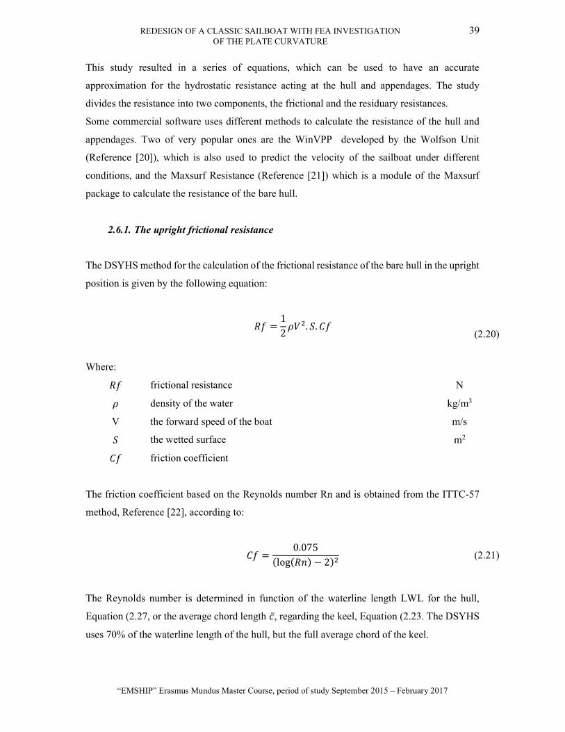
2.6.1. The upright frictional resistance
The DSYHS method for the calculation of the frictional resistance of the bare hull in the upright
position is given by the following equation:
=
12
. .
(2.20)
Where:
frictional resistance N
density of the water kg/m3
V the forward speed of the boat m/s
the wetted surface m2
friction coefficient
The friction coefficient based on the Reynolds number Rn and is obtained from the ITTC-57
method, Reference [22], according to:
=0.075
(log( ) − 2) (2.21)
The Reynolds number is determined in function of the waterline length LWL for the hull,
Equation (2.27, or the average chord length , regarding the keel, Equation (2.23. The DSYHS
uses 70% of the waterline length of the hull, but the full average chord of the keel.
40 LUIS GABRIEL ALESSIO DOS SANTOS
Master Thesis developed at West Pomeranian University of Technology, Szczecin
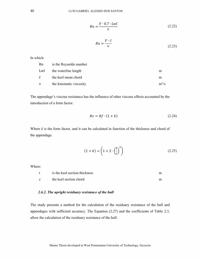
=∙ 0.7 ∙
(2.22)
=
∙
(2.23)
In which:
Rn is the Reynolds number
Lwl the waterline length m
c the keel mean chord m
υ the kinematic viscosity m2/s
The appendage’s viscous resistance has the influence of other viscous effects accounted by the
introduction of a form factor.
= ∙ (1 + ) (2.24)
Where k is the form factor, and it can be calculated in function of the thickness and chord of
the appendage.
(1 + ) = 1 + 2 ∙ (2.25)
Where:
t is the keel section thickness m
c the keel section chord m
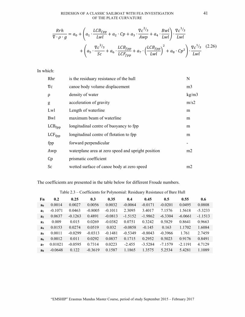
2.6.2. The upright residuary resistance of the hull
The study presents a method for the calculation of the residuary resistance of the hull and
appendages with sufficient accuracy. The Equation (2.27) and the coefficients of Table 2.3,
allow the calculation of the residuary resistance of the hull.
REDESIGN OF A CLASSIC SAILBOAT WITH FEA INVESTIGATION 41 OF THE PLATE CURVATURE
“EMSHIP” Erasmus Mundus Master Course, period of study September 2015 – February 2017
ℎ∇ ∙ ∙
= + ∙ + ∙ + ∙∇
+ ∙ ∙∇
+ ∙∇
+ ∙ + ∙ + ∙ ∙∇
(2.26)
In which:
Rhr is the residuary resistance of the hull N
∇c canoe body volume displacement m3
ρ density of water kg/m3
g acceleration of gravity m/s2
Lwl Length of waterline m
Bwl maximum beam of waterline m
LCB longitudinal centre of buoyancy to fpp m
LCF longitudinal centre of flotation to fpp m
fpp forward perpendicular -
Awp waterplane area at zero speed and upright position m2
Cp prismatic coefficient
Sc wetted surface of canoe body at zero speed m2
The coefficients are presented in the table below for different Froude numbers.
Table 2.3 – Coefficients for Polynomial: Residuary Resistance of Bare Hull
Fn 0.2 0.25 0.3 0.35 0.4 0.45 0.5 0.55 0.6 a0 0.0014 0.0027 0.0056 0.0032 -0.0064 -0.0171 -0.0201 0.0495 0.0808 a1 -0.1071 0.0463 -0.8005 -0.1011 2.3095 3.4017 7.1576 1.5618 -5.3233 a2 0.0637 -0.1263 0.4891 -0.0813 -1.5152 -1.9862 -6.3304 -6.0661 -1.1513 a3 0.009 0.015 0.0269 -0.0382 0.0751 0.3242 0.5829 0.8641 0.9663 a4 0.0153 0.0274 0.0519 0.032 -0.0858 -0.145 0.163 1.1702 1.6084 a5 0.0011 -0.0299 -0.0313 -0.1481 -0.5349 -0.8043 -0.3966 1.761 2.7459 a6 0.0012 0.011 0.0292 0.0837 0.1715 0.2952 0.5023 0.9176 0.8491 a7 0.01021 -0.0595 0.7314 0.0223 -2.455 -3.5284 -7.1579 -2.1191 4.7129 a8 -0.0648 0.122 -0.3619 0.1587 1.1865 1.3575 5.2534 5.4281 1.1089
42 LUIS GABRIEL ALESSIO DOS SANTOS
Master Thesis developed at West Pomeranian University of Technology, Szczecin
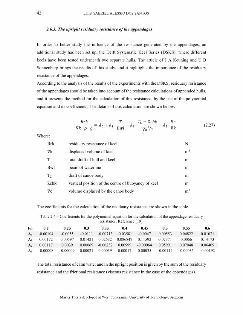
2.6.3. The upright residuary resistance of the appendages
In order to better study the influence of the resistance generated by the appendages, an
additional study has been set up, the Delft Systematic Keel Series (DSKS), where different
keels have been tested underneath two separate hulls. The article of J A Keuning and U B
Sonnenberg brings the results of this study, and it highlights the importance of the residuary
resistance of the appendages.
According to the analysis of the results of the experiments with the DSKS, residuary resistance
of the appendages should be taken into account of the resistance calculations of appended hulls,
and it presents the method for the calculation of this resistance, by the use of the polynomial
equation and its coefficients. The details of this calculation are shown below.
∇ ∙ ∙
= + ∙ + ∙+
∇+ ∙
∇∇
(2.27)
Where:
Rrk residuary resistance of keel N
∇k displaced volume of keel m3
T total draft of hull and keel m
Bwl beam of waterline m
T draft of canoe body m
Zcbk vertical position of the centre of buoyancy of keel m
∇c volume displaced by the canoe body m3
The coefficients for the calculation of the residuary resistance are shown in the table
Table 2.4 – Coefficients for the polynomial equation for the calculation of the appendage residuary resistance. Reference [19].
Fn 0.2 0.25 0.3 0.35 0.4 0.45 0.5 0.55 0.6 A0 -0.00104 -0.0055 -0.0111 -0.00713 -0.03581 -0.0047 0.00553 0.04822 0.01021 A1 0.00172 0.00597 0.01421 0.02632 0.086849 0.11592 0.07371 0.0066 0.14173 A2 0.00117 0.0039 0.00069 -0.00232 0.00999 -0.00064 0.05991 0.07048 0.06409 A3 -0.00008 -0.00009 0.00021 0.00039 0.00017 0.00035 -0.00114 -0.00035 -0.00192
The total resistance of calm water and in the upright position is given by the sum of the residuary
resistance and the frictional resistance (viscous resistance in the case of the appendages).

REDESIGN OF A CLASSIC SAILBOAT WITH FEA INVESTIGATION 43 OF THE PLATE CURVATURE
“EMSHIP” Erasmus Mundus Master Course, period of study September 2015 – February 2017
When the ship heels, there is an alteration in the frictional resistance of the hull and the residuary
resistance of the hull and appendages. The viscous resistance of the appendages is independent
of the heeling angle. In the present work the resistance will be calculated for the original and
the modified design, to evaluate the impact of the changes on the boat performance, thus, the
resistance due to the heel, trim and waves were not considered, and the only concern is the
upright resistance in the calm water.
2.7. Influence of the plate curvature on the admissible stress
The maximum stress supported by a plate under hydrostatic pressure depends on its thickness
related to its dimensions and curvature. In the book, Theory of Plates and Shells, by S.
Timoshenko and S. Woinowsky-Krieger [23], the influence of the geometry of the plates is
analysed analytically. The boundary conditions influence the way the loads are distributed
along the plates, thus the maximum value of the stress and its position, but finding how the
plate is truly supported at different applications is a very complex task, as it can be considered
simply supported, or entirely fixed, or something in the between.
Simply beam theory calculations can assess how the stresses are distributed on a plate,
considering different boundary conditions, and plate geometry, hence the stresses can be
calculated by using coefficients, which takes into consideration the contribution of the supports
to analysis the behaviour of the plate under pressure.
The maximum stress which the plate is submitted dictates the necessary thickness to support
the stress without suffering any plastic deformation, indeed, as thick the plate is, as heavy and
expensive the construction is, hence the necessity of using the thinnest plate possible, keeping
the safety margins.
Finite Element Analysis can compute the allowable stresses, but this method is costly and takes
time. Therefore, an analytical method can be used to make the design of the plate thickness
faster and cheaper, especially on the predesign stage.
In naval construction, some regulations and standards have different ways to calculate the
coefficients for the stress reduction due to the plate geometry. These coefficients can be used
for the various aspect ratios and curvature of the plates, reducing the maximum stress acting on
the plate and therefore, the required thickness.
The ISO12215 uses the curvature and aspect ratio coefficients to calculate the minimum
thickness of the plate, as seen in the following equation.

44 LUIS GABRIEL ALESSIO DOS SANTOS
Master Thesis developed at West Pomeranian University of Technology, Szczecin
= × ××
1000 × (2.28)
In which:
is the thickness of the plate mm
the short dimension of the plate mm
the panel curvature factor -
the design pressure kN/m2
the panel aspect ratio factor -
the design stress N/mm2
As seen by the equation above, the curvature coefficient reduces the required thickness of the
plate.
3. METHODOLOGY
This work began to be developed at the Southampton Solent University, in Southampton, UK
and was finalised at the West Pomeranian University, in Szczecin, Poland. Meanwhile, the
modern replica was being built at the IBTC Portsmouth shipyard, in England. The
communication with the client happened during all the development of this project to take the
decisions of the design and assisting with the construction of the boat.
Some milestones of this project are described below:
Study of the suggested literature
During all the development of this work, the biography review will add the relevant information
to the growth of the theoretical knowledge and the comprehension of the physics behind the
design of sailboats.
Modelling of the original design and validation
In order to study the stability, hydrostatics, and hydrodynamics, a 3D model was drawn
following the information available at the table of offsets and lines plan of the original design.
A hydrostatic study was performed on the designed model using the software Maxsurf, and for
the validation of the model, the results were compared to the ones calculated by the Simpson’s
Rule, a common method used by naval architects, as explained in the Chapter 2.3.1. The boat

REDESIGN OF A CLASSIC SAILBOAT WITH FEA INVESTIGATION 45 OF THE PLATE CURVATURE
“EMSHIP” Erasmus Mundus Master Course, period of study September 2015 – February 2017
centre of gravity and weight estimation were calculated following the construction plan of the
boat. In order to compare the original and the modified design, other aspects such as the VPP
and the compliance with the structure and stability standards, ISO 12215-5 (reference [24]) and
ISO 12217-2 (reference [14]) respectively, were performed.
Alteration of the keel
With the original model validated, the first modification of the original design was making the
keel shallower, to increase the area of operation of the ship and to make it trailable. By reducing
the draft, the centre of gravity was changed, in addition to the stability of the boat. Thus, the
new model aimed to maintain the centre of gravity as close to the original one as possible, by
changing the keel shape and ballast. Different designs of the keel were presented to the boat
owner, who chose the one that most satisfied him. The ISO 12215 part 9 [25] was followed to
the scantling calculations of the keel and ballast.
Electrical propulsion and batteries
With the results of the stability and resistance studies of the new keel, the calculations for the
electrical engine was performed to select the motor and the set of batteries necessary for
supplying the power to propel the boat for the desired distance.
Design of a new mast and rigging
The study of replacing the original mast by a new one made of carbon fibre, will perform in
order to assess the consequence of implementing this modification. The new rig sections were
calculated following the Nordic Boat Standard [18].
Structural changes and FEA analysis
Another part of this study aims to investigate the influence of the plate curvature on the
maximum stress supported by the plate. Thus an FEA analysis was achieved, checking the
curvature and comparing to the ISO 12215-5. The software HullScant was used to test the
compliance of the structural elements for different parts of the boat.
Finite Element Analysis of the plate curvature
The influence of the plate curvature was analysed by simulating the stresses acting on a plate
with different curvature and comparing the results with the actual ISO12215-5.
4. DESIGN ASSESSMENT
With the material supplied by the boat owner, the original design plan made by B. B.
Crowninshield, which include the lines plan, the table of offsets, the construction and rigging

46 LUIS GABRIEL ALESSIO DOS SANTOS
Master Thesis developed at West Pomeranian University of Technology, Szczecin
plan, a study was performed on the original design to compare the impact of the modifications
on the performance of the boat.
4.1. Hull modelling
The hull surface was modelled with a computer aided design (CAD) software, following the
instructions of the lines plan and the table of offsets, making the hull as close to the original
design as possible. The points of the table of offsets were drawn over the background figures,
as shown in Figure 4.1.
Figure 4.1 – Cloud of points based on the original table of offsets. Perspective and transverse views.
As the original design dates from 1908, there is some uncertainty regarding the accuracy of the
lines and the measurements. Originally, lofting the boat full size would have ensured fairness;
in this case, too, some corrections were necessary to make the hull lines smoother, leading to
the model presented in Figure 4.2.
Figure 4.2 – Hull, keel and rudder surfaces of the original design.
The model was validated by comparing the hydrostatics results obtained by the Simpson’s rule
and by a computational software; this is discussed in section 4.3.

REDESIGN OF A CLASSIC SAILBOAT WITH FEA INVESTIGATION 47 OF THE PLATE CURVATURE
“EMSHIP” Erasmus Mundus Master Course, period of study September 2015 – February 2017
4.2. Original keel design
Based on the original lines plan and table of offsets, the original keel was designed as shown in
Figure 4.2, extended to the waterline. The geometric aspects of the keel were calculated as
explained in Chapter 2.4, and the main dimensions of the keel are shown bellow.
Figure 4.3 – Geometry of the original keel design extended to the waterline and main parameters.
The position of the CLR is located at the 25% chord line and 45% of the draft, as explained in
Chapter 2.4. The characteristics of the original keel are summarised in Table 4.1.
Table 4.1 – Main dimensions of the original keel design of the Dark Harbor 17½
Parameter Dimension Unit C1: 3539 mm C2: 1252.2 mm
C mean 2395.6 mm Draft: 1270 mm Area: 3.04 m2 AR: 0.53 -
Taper Ratio: 0.35 - Sweep angle: 25 degrees
CLR (from amidships): 167 mm
The ballast of the original keel is placed with an inclination, as shown in the original lines plan,
in the
Figure 1.1, with a ballast of 700 kilogrammes. The centre of gravity of the ballast was calculated
at the 3D model by the software SolidWorks, and it is computed at the weight estimation (see
chapter 4.4).

48 LUIS GABRIEL ALESSIO DOS SANTOS
Master Thesis developed at West Pomeranian University of Technology, Szczecin
4.3. Hydrostatics study of the lines plan
To check the accuracy of the designed model, the hydrostatics were calculated based on the
lines plan using Simpson’s rule, explained at the Chapter 2.3.1, and then compared with the
hydrostatic analysis of the 3D model. This comparison is shown in Table 4.2.
Table 4.2 –Results obtained by the Simpson’s Rule and by 3D Model, with the relative error.
Particular 3D Model Simpson’s Rule Error LOA (m) 7.92 7.92 0% Lwl (m) 5.34 5.33 0.13%
BOA (m) 1.91 1.91 0% Bwl (m) 1.84 1.82 0.85% Tk (m) 1.28 1.28 0.05%
Displ. (kg) 1555 1542 0.86% WSA (m2) 12.64 12.06 4.62% WPA (m2) 6.61 6.78 -2.60%
Cp 0.47 0.50 -5.56% Cb 0.12 0.12 0.13%
LCB % from AP 45.41 45.18 0.49% LCF % from AP 44.28 45.97 -3.81%
To use Simpson’s rule, the waterline was divided into ten sections, and this may have affected
the accuracy of some calculations. To increase the accuracy, a greater number of sections may
be required. However, the relatively small errors demonstrate a faithful representation of the
original design.
4.4. Weight Estimation
Following the methodology explained in the Chapter 2.3.5, the weight and position of all the
components listed in the construction plan were listed and the boat displacement was estimated,
as well as the position of the centre of gravity. By designing the 3D model, the position and
mass of the components could be accurately obtained by the software. All the necessary
densities were taken from the Table E.1 – Mechanical properties of common wood species of
the ISO 12215-5 (Reference [24]), and the relevant wood densities used in this work are at
shown in the table below, together with the places where they are used according to the design
specifications.
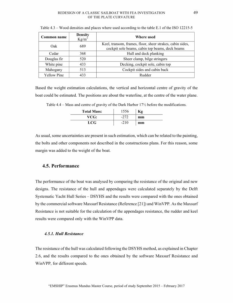
REDESIGN OF A CLASSIC SAILBOAT WITH FEA INVESTIGATION 49 OF THE PLATE CURVATURE
“EMSHIP” Erasmus Mundus Master Course, period of study September 2015 – February 2017
Table 4.3 – Wood densities and places where used according to the table E.1 of the ISO 12215-5
Common name Density Kg/m3
Where used
Oak 689 Keel, transom, frames, floor, sheer strakes, cabin sides,
cockpit sole beams, cabin top beams, deck beams Cedar 368 Hull and deck planking
Douglas fir 520 Sheer clamp, bilge stringers White pine 433 Decking, cockpit sole, cabin top Mahogany 513 Cockpit sides and cabin back
Yellow Pine 433 Rudder
Based the weight estimation calculations, the vertical and horizontal centre of gravity of the
boat could be estimated. The positions are about the waterline, at the centre of the water plane.
Table 4.4 – Mass and centre of gravity of the Dark Harbor 17½ before the modifications.
Total Mass: 1556 Kg
VCG: -272 mm
LCG -210 mm
As usual, some uncertainties are present in such estimation, which can be related to the painting,
the bolts and other components not described in the constructions plans. For this reason, some
margin was added to the weight of the boat.
4.5. Performance
The performance of the boat was analysed by comparing the resistance of the original and new
designs. The resistance of the hull and appendages were calculated separately by the Delft
Systematic Yacht Hull Series – DSYHS and the results were compared with the ones obtained
by the commercial software Maxsurf Resistance (Reference [21]) and WinVPP. As the Maxsurf
Resistance is not suitable for the calculation of the appendages resistance, the rudder and keel
results were compared only with the WinVPP data.
4.5.1. Hull Resistance
The resistance of the hull was calculated following the DSYHS method, as explained in Chapter
2.6, and the results compared to the ones obtained by the software Maxsurf Resistance and
WinVPP, for different speeds.

50 LUIS GABRIEL ALESSIO DOS SANTOS
Master Thesis developed at West Pomeranian University of Technology, Szczecin
Figure 4.4 – Resistance comparison between the various calculation methods.
The calculation done by the Maxsurf Resistance and the WinVPP are based on the 3D model
designed as explained in Chapter 4.1, so they presented close values.
4.5.2. Appendage resistance
As the rudder is attached to the keel, they were treated as one for the calculation of the resistance
of the appendage. Following the DSYHS method, the viscous and residuary resistance were
calculated and compared with the results from the WinVPP software, as shown in the figure
below.
0
0.5
1
1.5
2
2.5
2 3 4 5 6 7 8 9 10
Resi
stan
ce [k
N]
Speed [kn]
WinVPP DSYHS Maxsurf Resistance
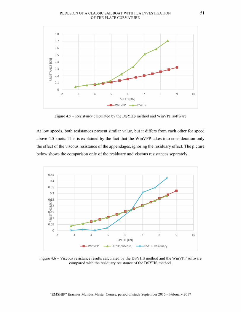
REDESIGN OF A CLASSIC SAILBOAT WITH FEA INVESTIGATION 51 OF THE PLATE CURVATURE
“EMSHIP” Erasmus Mundus Master Course, period of study September 2015 – February 2017
Figure 4.5 – Resistance calculated by the DSYHS method and WinVPP software
At low speeds, both resistances present similar value, but it differs from each other for speed
above 4.5 knots. This is explained by the fact that the WinVPP takes into consideration only
the effect of the viscous resistance of the appendages, ignoring the residuary effect. The picture
below shows the comparison only of the residuary and viscous resistances separately.
Figure 4.6 – Viscous resistance results calculated by the DSYHS method and the WinVPP software compared with the residuary resistance of the DSYHS method.
0
0.1
0.2
0.3
0.4
0.5
0.6
0.7
0.8
2 3 4 5 6 7 8 9 10
RESI
STAN
CE [K
N]
SPEED [KN]
WinVPP DSYHS
0
0.05
0.1
0.15
0.2
0.25
0.3
0.35
0.4
0.45
2 3 4 5 6 7 8 9 10
RESI
STAN
CE [K
N]
SPEED [KN]
WinVPP DSYHS Viscous DSYHS Residuary

52 LUIS GABRIEL ALESSIO DOS SANTOS
Master Thesis developed at West Pomeranian University of Technology, Szczecin
Apparently, the WinVPP underestimates the resistance of the appendages, which may result in
increased predicted boat speed by the software for speeds above 4.5 knots. The total resistance
of the appended hull is given by the sum of the bare hull resistance and the appendage
resistance. This calculation is shown in the chart below.
Figure 4.7 – Total resistance of the boat, including appendages, calculated by the DSYHS method and the WinVPP software
As discussed, the resistance calculated by the DSYHS is greater than the one given by the
WinVPP software because the WinVPP does not consider the residuary resistance of the
appendages.
4.6. Stability analysis
All the recreational crafts placed on the market within the European Economic Area (EEA) are
to comply with Recreational Craft Directive (RCD) [13]. Part of the requirements to make the
boat available on the market is to follow the guidelines of the ISO 12217 for stability to
demonstrate compliance of the craft with one of the four design categories. In this case, the
vessel being intended for coastal cruising, it will be designed for category C, inland, allowing
sailing in wind speeds up to Beaufort 6, and significant wave heights up to 2m.
0.00000
0.50000
1.00000
1.50000
2.00000
2.50000
3.00000
2 3 4 5 6 7 8 9 10
RESI
STAN
CE [K
N]
SPEED [KN]
WinVPP DSYHS
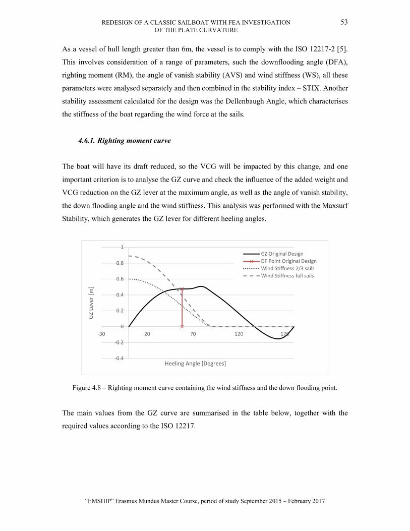
REDESIGN OF A CLASSIC SAILBOAT WITH FEA INVESTIGATION 53 OF THE PLATE CURVATURE
“EMSHIP” Erasmus Mundus Master Course, period of study September 2015 – February 2017
As a vessel of hull length greater than 6m, the vessel is to comply with the ISO 12217-2 [5].
This involves consideration of a range of parameters, such the downflooding angle (DFA),
righting moment (RM), the angle of vanish stability (AVS) and wind stiffness (WS), all these
parameters were analysed separately and then combined in the stability index – STIX. Another
stability assessment calculated for the design was the Dellenbaugh Angle, which characterises
the stiffness of the boat regarding the wind force at the sails.
4.6.1. Righting moment curve
The boat will have its draft reduced, so the VCG will be impacted by this change, and one
important criterion is to analyse the GZ curve and check the influence of the added weight and
VCG reduction on the GZ lever at the maximum angle, as well as the angle of vanish stability,
the down flooding angle and the wind stiffness. This analysis was performed with the Maxsurf
Stability, which generates the GZ lever for different heeling angles.
Figure 4.8 – Righting moment curve containing the wind stiffness and the down flooding point.
The main values from the GZ curve are summarised in the table below, together with the
required values according to the ISO 12217.
-0.4
-0.2
0
0.2
0.4
0.6
0.8
1
-30 20 70 120 170
GZ
Leve
r [m
]
Heeling Angle [Degrees]
GZ Original DesignDF Point Original DesignWind Stiffness 2/3 sailsWind Stiffness full sails

54 LUIS GABRIEL ALESSIO DOS SANTOS
Master Thesis developed at West Pomeranian University of Technology, Szczecin
Table 4.5 – Stability analysis of the righting moment curve
Calculated Required Downflooding angle – DFA [degrees] 55.1 >35
Lever of DFA [m] 0.445 - Angle of vanishing stability – AVS [degrees] 137.7 >90
Wind stiffness [Degrees] 42.0 <45 Maximum GZ Lever [m] 0.5 -
Angle at Maximum GZ [degrees] 78.0 - Lever at 90° [m] 0.419 -
The wind stiffness is the moment generated by the wind at the sails. It is an important factor as
it determines whether or not a wind gust can heel the boat over the specified limit. To calculate
this value, the total sail area and the heeling arm is taken into consideration, and the angle at
the intersection between the righting moment and wind stiffness curves should be less than 45
degrees. As seen from the GZ curve, for the full sails, the value of the wind stiffness is superior
to the admissible value, so according to the ISO 12217-2, the calculations should be performed
with 2/3 of the sails, and if approved in this criterion, it should be informed in the owner’s
manual that reefing the sails is necessary for increased wind speeds.
4.6.2. STIX calculations
Following the instructions of the ISO 12217-2, the stability factors were calculated for all the
criteria and then combined in the stability index, STIX. The method and all the equations were
presented in the Chapter 2.3.9, and the results are summarised in the table below.
Table 4.6 – Stability index calculations
Factor Value Admissible
LBS 6.24 - FDL 0.95 0.75 < FDL < 1.25 FBD 1.09 0.75 < FBD < 1.25 FKR 1.17 0.5 < FKR < 1.5 FIR 1.11 0.4 < FIR < 1.5 FDS 0.5 0.5 < FDS < 1.5
FWM 0.76 0.5 < FWM < 1 FDF 0.61 0.5 < FDF < 1.25
STIX 12 >14
As previously explained, there is no minimum STIX requirement for non-fully enclosed boats,
but the value should be included in the owner’s manual, though.
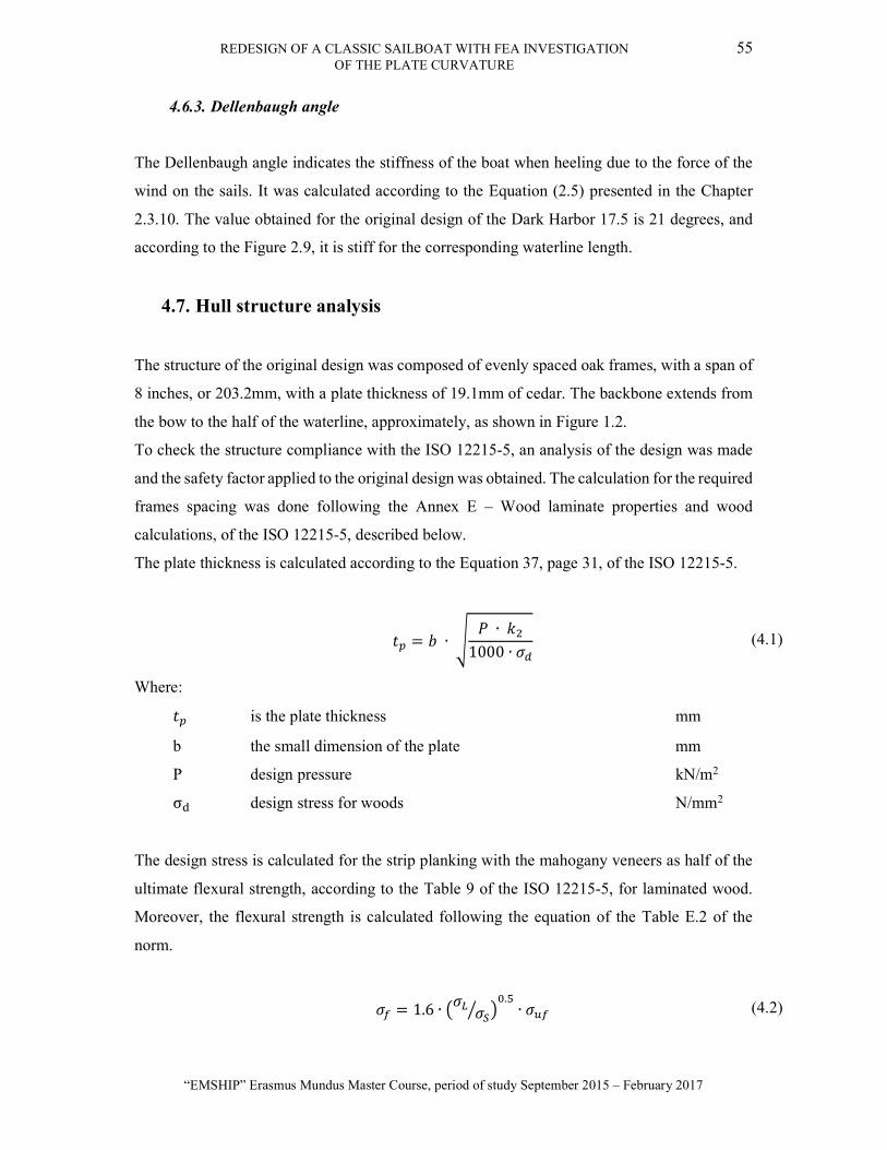
REDESIGN OF A CLASSIC SAILBOAT WITH FEA INVESTIGATION 55 OF THE PLATE CURVATURE
“EMSHIP” Erasmus Mundus Master Course, period of study September 2015 – February 2017
4.6.3. Dellenbaugh angle
The Dellenbaugh angle indicates the stiffness of the boat when heeling due to the force of the
wind on the sails. It was calculated according to the Equation (2.5) presented in the Chapter
2.3.10. The value obtained for the original design of the Dark Harbor 17.5 is 21 degrees, and
according to the Figure 2.9, it is stiff for the corresponding waterline length.
4.7. Hull structure analysis
The structure of the original design was composed of evenly spaced oak frames, with a span of
8 inches, or 203.2mm, with a plate thickness of 19.1mm of cedar. The backbone extends from
the bow to the half of the waterline, approximately, as shown in Figure 1.2.
To check the structure compliance with the ISO 12215-5, an analysis of the design was made
and the safety factor applied to the original design was obtained. The calculation for the required
frames spacing was done following the Annex E – Wood laminate properties and wood
calculations, of the ISO 12215-5, described below.
The plate thickness is calculated according to the Equation 37, page 31, of the ISO 12215-5.
= ∙ ∙
1000 ∙ (4.1)
Where:
is the plate thickness mm
b the small dimension of the plate mm
P design pressure kN/m2
σ design stress for woods N/mm2
The design stress is calculated for the strip planking with the mahogany veneers as half of the
ultimate flexural strength, according to the Table 9 of the ISO 12215-5, for laminated wood.
Moreover, the flexural strength is calculated following the equation of the Table E.2 of the
norm.
= 1.6 ∙.
∙ (4.2)

56 LUIS GABRIEL ALESSIO DOS SANTOS
Master Thesis developed at West Pomeranian University of Technology, Szczecin
Where:
σ is the flexural strength N/mm2
σσ the ratio strength of the panel and it is equal to 0.2 -
σ is the ultimate flexural strength (52 N/mm2 from Table E.1)
So, the design stress can be calculated as follows.
= 0.5 ∙ = 0.5 ∙ 1.6 ∙ 0.2 ∙ 52 = 18.6 /
The design pressure for the bottom pressure for sailing crafts can be calculated from the section
8.2 of the ISO 12215-5.
= ∙ ∙ ∙ (4.3)
In which:
P Bottom design pressure kN/m2
k aspect ratio factor -
k design category factor -
k longitudinal pressure distribution factor -
The P is the bottom base pressure calculated as follows.
= (2 . + 18) ∙ (4.4)
Where:
m is the boat weight when fully loaded kg
k is the pressure correcting factor for slamming (shall be taken equal to 1 for
design category C and D).
= (2 ∙ 1506 . + 18) ∙ 1 = 40.4 /

REDESIGN OF A CLASSIC SAILBOAT WITH FEA INVESTIGATION 57 OF THE PLATE CURVATURE
“EMSHIP” Erasmus Mundus Master Course, period of study September 2015 – February 2017
The designs pressure factors are calculated following the ISO standard for the selected design
category. The value of the is calculated taking into consideration the dimensions of the
plate, as follows:
= ∙ 0.1 ∙ .
. (4.5)
AD is the design area of the plate, in mm2, and is a structural component factor and can be
calculated for sailing craft according the equation below.
= 1.5 − 3 ∙ 10 ∙ (4.6)
Where b is the frame spacing in mm.
The value of for the design category C is equal to 0.6 and the can be calculated
according to the position in the waterline length, by making different frame spacing over the
waterline, and its value is given by the graph in the Figure 3, page 11, of the ISO 12215-5.
Figure 4.9 – Values of the factor for different positions on the waterline. Reference [24].
The value of of the original design was taken as 1, once all the frame span is the same over
the boat length. The frames spacing for the original boat was calculated following the procedure
described above, and the resulting frame spacing was of 1078mm. When compared with the 8

58 LUIS GABRIEL ALESSIO DOS SANTOS
Master Thesis developed at West Pomeranian University of Technology, Szczecin
inches, or 203,2mm used in the design, a safety factor greater than 5 was used, showing that the
original design had the frames spacing over dimensioned.
4.7.1. HullScant
HullScant (Reference [26]) is a commercial software developed by the Wolfson Unit to support
the maritime and aerospace industries to calculate the compliance with the ISO 12215. The
software is not certified but the Royal Yachting Association - RYA and the ISAF (World
Sailing), both well-renowned bodies, endorses it. After imputing the data of the design, such as
boat type and dimensions, materials, plate and stiffeners sizes, etc., the software makes the
calculations according to the ISO 12215 and checks the compliance.
Some plates and stiffeners of the Dark Harbor were selected to be evaluated by the software.
As the forward part is more affected by the water pressure, it is expected to have more
reinforced structure, while the panels to the aft part are less subjected to the pressure. The
components were added to the software in different positions of the boat, as shown in the figure
below.
Figure 4.10 – HullScant model of the original Dark Harbor 17½
The software analyses the structure and gives the results in the form of a report, as presented in
the Appendix B. A comparison of the required dimensions with the design dimensions is made,
and a safety factor is given. The plates from the stations 4, 7, 10, deck and cockpit were checked
and as shown in the Table 4.7.

REDESIGN OF A CLASSIC SAILBOAT WITH FEA INVESTIGATION 59 OF THE PLATE CURVATURE
“EMSHIP” Erasmus Mundus Master Course, period of study September 2015 – February 2017
Table 4.7 – HullScant plate analysis of original design
Label Requirements Offered Results t tmin
Label t
t Ratio tmin
Ratio Plating
mm mm Comply? Plate 7 3.23 5.09 Cedar, Western Red 19.10 5.92 3.76 yes Plate 4 3.41 5.09 Cedar, Western Red 19.10 5.61 3.76 yes
Plate 10 2.56 5.09 Cedar, Western Red 19.10 7.47 3.76 yes Deck 2.15 4.71 Pine, Yellow 19.05 8.87 4.05 yes
Cockpit 2.02 4.71 Pine, Yellow 19.05 9.43 4.05 yes
The software gave a safety factor greater than five, which was common with the constructions
techniques used in the past times, but with the modern technologies and materials, this safety
factor can be reduced, saving material and weight. The same analysis was done for the frames
and beams, and a high safety factor was found.
Table 4.8 – HullScant Beams analysis of the original design
Label
Dimensions Requirements Offered Results
Length Spacing SM AW tw SM AW tw SM Ratio
AW Ratio
tw Ratio
Comply? mm mm cm3 cm2 mm cm3 cm2 mm
Frame 7 683 203 0.91 1.12 1.10 10.90 4.8 22.0 11.95 4.32 20.77 yes
Deck beam 1300 229 5.22 1.69 1.70 19.26 8.5 22.2 3.69 5.01 13.06 yes
Frame 4 810 203 2.52 1.31 1.10 10.90 4.8 22.0 4.33 3.71 19.25 yes
Frame 10 691 203 1.83 1.11 1.10 10.90 4.8 22.0 5.95 4.35 20.85 yes
Cockpit beam
1200 229 4.45 1.56 1.60 19.26 8.5 22.2 4.33 5.43 13.59 yes
As the bottom pressure changes according to the longitudinal position on the hull, it is possible
to observe that the safety factors increase in afterwards because the structure is the same along
the length of the boat.
5. DESIGN MODIFICATION
The design was modified according to the client’s requirements with the objective of having a
classic sailboat, with some modernization to make the boat more comfortable, safe and trailable,
keeping the original classic appearance and navigability.
The first step to study the impact of the modifications was to add all the weight of the new
components to the boat’s weight estimation and check where some weight can be reduced as
well. As the draft should be reduced, a new keel was designed, and so some ballast could be
added to keep the stability. The added components are:

60 LUIS GABRIEL ALESSIO DOS SANTOS
Master Thesis developed at West Pomeranian University of Technology, Szczecin
Increase the operational area, by making the keel shallower, and therefore be able
to expand the sailing programme of the boat. This is also linked to the intention
of making the boat trailerable.
Modify the hull planking from carvel to strip planking with mahogany veneers.
This is aimed at achieving a stronger and more modern construction while
minimising the maintenance for the owner.
Add an electric inboard engine to make the boat safer and practical. Indeed, very
few owners would consider sailing into harbour nowadays.
Add a portable toilet to enhance the level of comfort for the owner and his guests;
this also extends the sailing programme and enables sspending a night on-board.
Add an anchor locker in a watertight compartment at the front of the boat.
Change the material of the mast, boom, gaff and fore boom from wood to carbon
fibre, making the boat lighter.
The design was modified according to the client’s requirements presented above, with the
objective of retaining a classic sailboat, with however some modernization to improve the level
of comfort and comply with the rules and regulations.
The addition of a propulsion system, toilet, modern electronic equipment, etc. will result in an
increase in weight. This is the motivation behind a modern construction and carbon rig: trying
to save weight to balance the addition of the equipment on board and keep the vessel on its
original waterline.
On the other hand, of the added weight, some reduction could be obtained by changing some
of the boat's components. There are other sources of saving weight than the change in the
material of the components, for example by the use of modern techniques, the change of the
rivets of the planking by resin, the use of new cordage, more resistant and lighter.
All the components mentioned above had their weight estimated to evaluate their impact on the
boat.

REDESIGN OF A CLASSIC SAILBOAT WITH FEA INVESTIGATION 61 OF THE PLATE CURVATURE
“EMSHIP” Erasmus Mundus Master Course, period of study September 2015 – February 2017
Table 5.1 – Components and weight added to the boat
Weight change Mass (Kg)
Gained 143
Saved
Structure 25
Rigging 23
Ballast 70
Total: 25
5.1. Frames Spacing and Hull Planking
A first glance at the boat structure allowed realising that the frames were very closely spaced.
As the boat was originally built in 1908, the techniques and materials were rudimentary, and
this required the boat to be over-dimensioned to ensure the safety of the crew. Nowadays with
new techniques and a higher control of the materials quality, it is possible to reduce the safety
factors according to the standards and reduce the boat weight and cost. By following the ISO
12215-5 standard about hull construction and scantling determination, a new frame spacing was
calculated based on the new hull planking chosen by the owner.
A modern wooden hull construction method has been selected, composed of 12mm thick
western red cedar strip planking, then covered by two layers of 2.4mm mahogany veneers,
placed at +/- 45 degrees; hence a total hull thickness of 16.8mm.
As the backbone of the boat was being built, the builder realised that the lines close to the bow,
between the stations 2 and 3, were not looking nice. Thus, he increased a few millimetres of the
hull depth at those stations. This modification was reported, and the dimensions of the stations
changed. This alteration affected the waterline length, making it 50 millimetres longer. The
impact of this change should not be significant on the performance of the boat, and it is expected
to have some differences between the original design and wooden boat, as it is being built by
students of boatbuilding.
The calculation of the new frames spans was done by dividing the boat length into two parts:
from the stern to the 25% of the waterline and from 25% of the waterline to the bow, with the
values of the factor equal to 0.7 and 1, respectively. The same method described in the
Chapter 4.7 was followed, and a safety factor of three was applied. The results are shown in the
Table 5.2.

62 LUIS GABRIEL ALESSIO DOS SANTOS
Master Thesis developed at West Pomeranian University of Technology, Szczecin
Table 5.2 – Different frames spacing according to the position on the boat length
Position Frame spacing [mm] Stern to 25% 450 40% to bow 350
By using these spans, the boat will be lighter, by reducing the number of frames, and it will
support all the loads according to the ISO 12215-5, this change also brings the LCG fore, as the
reduction of the number of frames were greater in the aft of the boat. These results were checked
with the software HullScant for the same structural components of the original design, allowing
the comparison of the structures.
Table 5.3 - HullScant plate analysis of new design
Label Requirements Offered Results t tmin
Label t
t Ratio tmin
Ratio Plating
mm mm Comply? Plate 7 4.8 5.09 Cedar, Western Red 16.8 3.501 3.3 yes Plate 4 5.33 5.09 Cedar, Western Red 16.8 3.155 3.3 yes
Plate 10 5.21 5.09 Cedar, Western Red 16.8 3.22 3.3 yes Deck 3.36 4.71 Pine, Yellow 19.05 5.67 4.05 yes
Cockpit 3.36 4.71 Pine, Yellow 19.05 5.67 4.05 yes
Table 5.4 - HullScant Beams analysis of the new design
Label
Dimensions Requirements Offered Results
Length Spacing SM AW tw SM AW tw SM Ratio
AW Ratio
tw Ratio
Comply? mm mm cm3 cm2 mm cm3 cm2 mm
Frame 7 683 350 1.49 1.83 1.40 12.91 4.84 22.00 8.66 2.64 16.25 yes
Deck beam 1300 308 7.04 2.28 2.00 20.49 8.47 22.20 2.91 3.27 11.25 yes
Frame 4 810 350 4.34 2.25 1.50 12.91 4.84 22.00 2.98 2.15 14.67 yes
Frame 10 691 450 4.16 2.50 1.60 12.91 4.84 22.00 3.10 1.94 13.92 yes
Cockpit beam
1200 380 7.40 2.59 2.10 20.59 8.47 22.20 2.78 3.27 10.54 yes
The full HullScant report is available at APPENDIX C – Hullscant Reports of the New design.
As a requirement of the client, the frames spacing was changed so that the new frames can be
on the position of the stations of the original design. As the boat is being lofted, the moulds are
placed at each station, so the planking can be fastened until the resin dries, and the frames
replace the moulds. By placing the frames on the position of the moulds, the roles at the
planking can be covered, improving the aesthetics of the interior of the boat. There is no
necessity of changing the after frames, as the holes are not inside the cabin. The resulting frames
spacing are:

REDESIGN OF A CLASSIC SAILBOAT WITH FEA INVESTIGATION 63 OF THE PLATE CURVATURE
“EMSHIP” Erasmus Mundus Master Course, period of study September 2015 – February 2017
Table 5.5 – Final frames spacing according to the owner’s requirement
Position Frame spacing [mm] Stern to 25% 450 40% to bow 308
The change required by the client adds two more frames to the arrangement, therefore
increasing the safety factor. The resulting structure is lighter than the original, and it was
checked against the ISO 12215-5 requirements for category C, thus ensuring compliance with
the regulation.
5.2. Rigging
The original rigging was composed of wooden spares, namely the mast, boom, gaff, and foresail
boom, as depicted earlier in Figure 1. Having raised the centre of gravity because of the
shallower keel and additional equipment installed, moving to carbon fibre spars appears
particularly attractive, as saving weight very high will significantly lower the overall VCG of
the boat.
Firstly, the foresail was modified, and the use of a furling system implies that no foresail boom
will be required. Then, the original keel-stepped mast (coming through the deck and resting on
the backbone) was replaced by a deck-stepped mast, supported by a mast pillar inside the hull.
From a structural point of view, this means that a stronger and therefore heavier mast section
will be required, due to the difference in end-fixity between a keel-stepped and a deck-stepped
mast. This decision is however dictated by the necessity for the owner to be able to take the
mast down; also, ensuring a better watertight integrity of the deck, critical on a wooden boat.
To evaluate the weight savings of a carbon mast, boom and gaff, a rig design based on the
Nordic Boat Standard (NBS) [18] was undertaken, and allowed to calculate the reduction in the
weight of the rig thanks to the use of carbon fibre. Furthermore, the sails will be replaced by a
high-quality polyester sailcloth, Dacron, which has greater resistance and durability compared
to the canvas. Other sources of weight savings include new shrouds and stays as well as deck
fittings and ropes.
The chosen material for the cords of the rigging is the Dyneema Fibre [27], which is a material
known to be stronger than steel and resistant to severe weather conditions, yet lighter than the
other cords materials. According to this material properties, the calculation was done by the

64 LUIS GABRIEL ALESSIO DOS SANTOS
Master Thesis developed at West Pomeranian University of Technology, Szczecin
NBS instructions, obtaining a diameter of 8mm for the cords, considering a safety factor of
three. The following picture shows the sail plan of the new Dark Harbor 17.5.
Figure 5.1 – Sails plan of the redesigned Dark Harbor 17.5
Overall, the new rigging will allow saving an estimated total of 23kg, now allowing performing
a weights and centres calculations for the new boat.
5.3. General alterations
To make the boat more visually attractive, the option of teak decking was adopted. Indeed, with
a low freeboard, a teak deck enhances the aesthetical appeal of the design. This represents an
increase in cost, but also weight; 20kg in this case.
An anchor locker was added at the bow of the boat in a watertight compartment. This fit with
the operation philosophy of the boat, and enables not compromising the appearance of the
vessel.
A portable chemical toilet was added, chosen for its minimum volume as the available space in
the boat is very restricted. This addition makes the sailing experience more comfortable,
especially when sailing with guests.
As per the engine location, the installation of the toilet highlighted a major challenge of modern
replicas: the extremely limited space available to implement all the required modifications to
REDESIGN OF A CLASSIC SAILBOAT WITH FEA INVESTIGATION 65 OF THE PLATE CURVATURE
“EMSHIP” Erasmus Mundus Master Course, period of study September 2015 – February 2017
meet the standard of comfort expected nowadays. Indeed, no spare volume was allocated to fit
an engine or a toilet in the original design, making the modernisation particularly complex.
5.4. New weight estimation
While the weight change is critical in the design process, so is the location of the centre of
gravity. Hence the need to update those parameters for the new vessel. To calculate how much
the VCG of the new design can change due to shallowing the keel, all the alterations on the
weight were computed in the weight estimation, so a new centre of gravity was obtained
including all the components. One remarkable change, which significantly affected the VCG of
the boat, was the new rigging, changed from wood to carbon fibre. This brought the VCG down
and allowed better options for the keel to be designed. The new values of the displacement and
centre of gravity, before the alterations on the keel, are shown below.
Table 5.6 – Centre of gravity and displacement before the alterations on the keel
Total Mass: 1648 Kg VCG: -314 mm LCG -176 mm
As discussed, the VCG was considerably dropped due to the change of the material of the
rigging, and this gives the possibility of reducing the ballast of the keel. The selected keel has
a ballast of 630kg, a reduction of 70kg from the original design. Thus, the final position of the
centre of gravity and the displacement of the vessel could be calculated, and it is compared to
the original design in the table below.
Table 5.7 – Weight and CG comparison between the original and new designs
Original Redesign Units Total Mass: 1556 1595 kg
VCG: -272 -272 mm LCG -210 -371 mm
Despite the addition of several new elements to the boat to fit with contemporary standards,
which includes engine, batteries and a toilet, savings in other locations brought the overall
weight to 1595kg, i.e. a 40kg increase, with no alteration to the location of the VCG. This
allows the vessel to float on its original waterline, and not to impact the original stability. The
changes in the structures and the added components are explained in the following chapters.
The design of the different keels presented to the client is explained at the next chapter.

66 LUIS GABRIEL ALESSIO DOS SANTOS
Master Thesis developed at West Pomeranian University of Technology, Szczecin
The detailed weight estimation can be found at Appendix D.
5.5. Keel Design
The new keel aims to keep the performance and stability of the original boat. As a result, some
parameters were kept the same, such as the centre of lateral resistance (CLR), the planform area
and the sweep angle. For rudder, the shape had to be changed as a consequence of the shallower
keel, but the area was conserved, thus keeping the original manoeuvrability of the boat.
The challenge on the keel design was to reduce the draft with the lesser impact on the VCG as
possible. Indeed, the weight added to the hull and a shallower keel, imply a higher VCG, and
therefore a reduction in stability, which should be avoided.
As a consequence of reducing the draft, the chord length will be increased to conserve a similar
planform area. The longitudinal position of the keel also must be modified for the CLR to be
kept in the same location. Finally, the longer root chord leads to a longer lead section at the
bottom, thus allowing to reduce its height for a given volume and lower the VCG for the given
span of the keel.
Different types of keel were designed, and the stability was checked for all to ensure compliance
with the ISO 12217-2. The final design was selected by the owner based on aesthetical
considerations, as well as the ability to save weight. Indeed, to retain a given righting moment,
either a larger mass must be provided acting on a smaller lever, or vice versa.
5.5.1. Fin keel
The fin keel has a section similar to the original keel, but the position of the ballast was changed.
As the original ballast was placed inclined to the horizontal line, as shown in the lines plan (
Figure 1.1), it has the centre of gravity closer to the waterline and fore of the middle ship. This
redesign has the line of the ballast parallel to the waterline, and to bring the VCG down, more
ballast was added. This option is represented below.
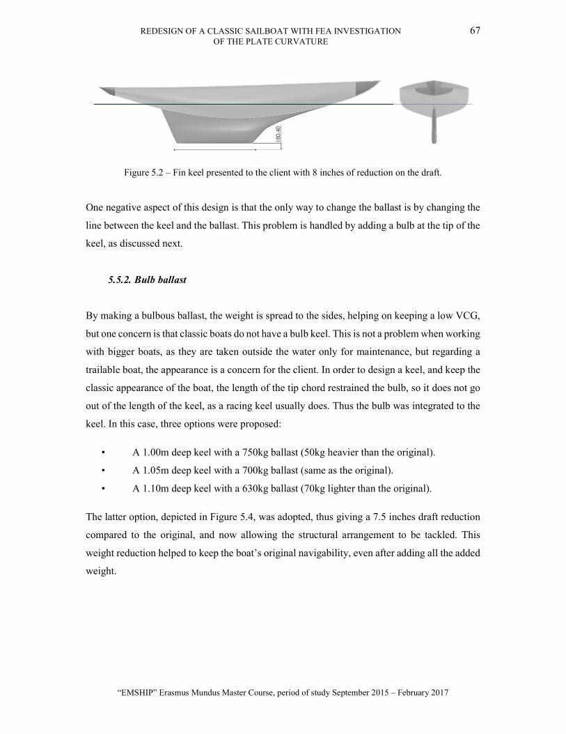
REDESIGN OF A CLASSIC SAILBOAT WITH FEA INVESTIGATION 67 OF THE PLATE CURVATURE
“EMSHIP” Erasmus Mundus Master Course, period of study September 2015 – February 2017
Figure 5.2 – Fin keel presented to the client with 8 inches of reduction on the draft.
One negative aspect of this design is that the only way to change the ballast is by changing the
line between the keel and the ballast. This problem is handled by adding a bulb at the tip of the
keel, as discussed next.
5.5.2. Bulb ballast
By making a bulbous ballast, the weight is spread to the sides, helping on keeping a low VCG,
but one concern is that classic boats do not have a bulb keel. This is not a problem when working
with bigger boats, as they are taken outside the water only for maintenance, but regarding a
trailable boat, the appearance is a concern for the client. In order to design a keel, and keep the
classic appearance of the boat, the length of the tip chord restrained the bulb, so it does not go
out of the length of the keel, as a racing keel usually does. Thus the bulb was integrated to the
keel. In this case, three options were proposed:
• A 1.00m deep keel with a 750kg ballast (50kg heavier than the original).
• A 1.05m deep keel with a 700kg ballast (same as the original).
• A 1.10m deep keel with a 630kg ballast (70kg lighter than the original).
The latter option, depicted in Figure 5.4, was adopted, thus giving a 7.5 inches draft reduction
compared to the original, and now allowing the structural arrangement to be tackled. This
weight reduction helped to keep the boat’s original navigability, even after adding all the added
weight.

68 LUIS GABRIEL ALESSIO DOS SANTOS
Master Thesis developed at West Pomeranian University of Technology, Szczecin
The planform of the keel is shown in Figure 5.3.
Figure 5.3 – Planform of the modified keel.
Some of the main characteristics of the planform were kept the same as the original boat. A
comparison between the original and the redesigned keel is available at the table
Table 5.8 – Comparison between the original and the redesigned keel
Parameter Original Redesign Unit C1: 3539 3650 mm C2: 1252.2 1900 mm
C mean 2395.6 2775 mm Draft: 1270 1100 mm Area: 3.04 3.05 m2 AR: 0.53 0.4 -
Taper Ratio: 0.35 0.52 - Sweep angle: 25 25 degrees
CLR (from amidships): 167 167 mm Append. displacement 0.208 0.227 m3 Append. wetted area 5.636 4.75 m2
As previously discussed, the CLR, the sweep angle and the planform area were kept the same.
These should make the navigability of the new keel as good the original one, but as the aspect
ratio was decreased due to the reduction on the draft, the efficiency may be decreased. The
geometry of the new keel with the ballast can be checked at the figure below.
REDESIGN OF A CLASSIC SAILBOAT WITH FEA INVESTIGATION 69 OF THE PLATE CURVATURE
“EMSHIP” Erasmus Mundus Master Course, period of study September 2015 – February 2017
Figure 5.4 – New design of the keel with the bulb ballast.
After finishing the design of the keel, the available space of the propeller and engine could be
checked and the items precisely positioned inside the boat. This will be discussed at the general
arrangement section.
5.5.3. Keel structure
The scantling of the keel was determined by following the instructions of the ISO 12215-9 [25],
which contents the guidelines for the scantling determination of the keel structure for crafts
under 24m. The chosen material for the keel bolts is the copper alloy Monel 500, due to its high
ultimate strength limit and the good interaction between the wood material. Six bolts, one more
bolt than the original version, compose the structure. The propeller shaft prevents adding bolts
at the aft part of the ballast, for this reason, the aft most bolt has 20mm diameter while the other
ones have 10mm, placed as shown in the picture below.
Figure 5.5 – Ballast bolts distribution. View from the top of the ballast.
As the new ballast is lighter and the bolts bigger than the original design, the over dimensioned
bolts will support the loads and keep the ballast in place. The details of the keel structure are
available in Section 5.9.

70 LUIS GABRIEL ALESSIO DOS SANTOS
Master Thesis developed at West Pomeranian University of Technology, Szczecin
5.6. Performance
The chosen method to calculate the resistance and compare with the original design was the
DSYHS method. The difference between the designs is the keel, which had its volume increased
and the shape of the rudder, so no change was made in the hull, and the canoe body draft was
kept the same, with the same waterline. Thus, the hull resistance was not changed, and the
resistance was calculated for the appended hull. The comparison between the original and the
new design is presented in the chart below.
Figure 5.6 – Resistance curve of the original and new designs by the DSYHS method.
With only a negligible increase in displacement and a constant wetted surface area despite the
shallower draft, as the keel area was kept constant, the maximum increase in the resistance is
2.7% at high speeds. Furthermore, as there is no significant change in the stability and the sail
plan will remain the same. Therefore, it can be concluded that the speed of the boat will not
suffer any significant alterations.
5.7. Propeller Selection
The propeller chosen by the client is a FeatherStream propeller [28], and in a meeting with the
Darglow Engineering representative, the company responsible for supplying this propeller, at
the Southampton Boat Show, a three-bladed propeller, with the smallest diameter of 12 inches
0.00
0.50
1.00
1.50
2.00
2.50
3.00
2.00 3.00 4.00 5.00 6.00 7.00 8.00 9.00
Resis
tanc
e [k
N]
Speed [knots]New Design Original Design

REDESIGN OF A CLASSIC SAILBOAT WITH FEA INVESTIGATION 71 OF THE PLATE CURVATURE
“EMSHIP” Erasmus Mundus Master Course, period of study September 2015 – February 2017
(304.8mm) manufactured by the company was chosen, as the available space for the installation
of the propeller is very small. The blades are feathered when sailing, reduced the drag generated
by the propeller. Therefore the sailing speed is increased. A scheme of the propeller system is
shown below.
Figure 5.7 – Different positions of the FeatherStream propeller. Reference [28].
According to the information provided by the company, this propeller has an efficiency of 95%
of a normal blade propeller. This difference in the efficiency is due to the fact that this propeller
has flat blades instead of curved ones. The main advantages of the selected propeller are:
The drive is automatically changed between forward or reverse when the engine runs
ahead or astern, and in the feathered position when sailing.
The forward drive operates close to the fixed propeller, while the manoeuvring is
improved when reversing.
By reducing the drag when sailing, the average speed can be increased by 15%. In this
case, the shaft remains stationary, with no need for a shaft break.
The pitch is easily adjustable after sea trials.
According to the customers’ reviews, the performance of the boat while sailing was
significantly increased. The propeller calculation was performed by the Darglow Engineering,
and the three-bladed propeller, with 304.8mm diameter, was selected.
The propeller efficiency was calculated following the Wageningen B-Series Propellers [29], for
the chosen propeller and the efficiency of 0.69 was calculated for the propeller with the shaft
system.

72 LUIS GABRIEL ALESSIO DOS SANTOS
Master Thesis developed at West Pomeranian University of Technology, Szczecin
5.8. Engine Selection
To be more manageable in marinas, add safety in emergencies and be able to operate against
the strong tidal currents found in the Solent, an engine must be fitted. As the vessel is aimed at
inshore operation, only a limited range is required; for this reason, associated with the will to
achieve a sustainable design and ensure quiet motoring, lead to the choice of a fully electric
propulsion. Based on the resistance of the new Dark Harbor 17.5, the power required to achieve
a given speed was ascertained, and is shown in Figure 5.8.
Figure 5.8 - New design power curve.
The considered Bellmarine electric engine [30] being available in 2.5kW or 4.2kW versions
would result in top speeds of 5.6 and 6.1 knots respectively (neglecting the air drag and added
resistance due to waves at this stage). Eventually, the 4.2kW engine was chosen for allowing a
sailing speed superior to the tide speed in the Chichester Harbour and the Solent.
This then allowed assessing the number of batteries needed and associated range. Initially, two
batteries were analysed, taking into consideration the cost, capacity and weight. With a capacity
of 1766Wh, each Valence U27-12XP battery [31] would provide a range of 8.2 nautical miles
at maximum speed for a weight of 19.5 kg each battery, requiring a total of 4 batteries to give
48 Volts, with a total weight of 78kg. The other model is a Torqueedo 26-104 [32], with a
capacity of 2685Wh, 24.3kg each; two batteries would give a range of 6.2 nautical miles at
maximum speed, for a total weight of 48.6kg. The comparison of the range of both batteries are
shown below:
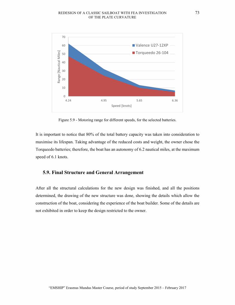
REDESIGN OF A CLASSIC SAILBOAT WITH FEA INVESTIGATION 73 OF THE PLATE CURVATURE
“EMSHIP” Erasmus Mundus Master Course, period of study September 2015 – February 2017
Figure 5.9 - Motoring range for different speeds, for the selected batteries.
It is important to notice that 80% of the total battery capacity was taken into consideration to
maximise its lifespan. Taking advantage of the reduced costs and weight, the owner chose the
Torqueedo batteries; therefore, the boat has an autonomy of 6.2 nautical miles, at the maximum
speed of 6.1 knots.
5.9. Final Structure and General Arrangement
After all the structural calculations for the new design was finished, and all the positions
determined, the drawing of the new structure was done, showing the details which allow the
construction of the boat, considering the experience of the boat builder. Some of the details are
not exhibited in order to keep the design restricted to the owner.
0
10
20
30
40
50
60
70
4.24 4.95 5.65 6.36
Rang
e [N
autic
al M
iles]
Speed [knots]
Valence U27-12XP
Torqueedo 26-104

74 LUIS GABRIEL ALESSIO DOS SANTOS
Master Thesis developed at West Pomeranian University of Technology, Szczecin
Figure 5.10 – Structure of the new Dark Harbor 17.5
The toilet is positioned beneath the cockpit and can be relocated to the cabin for using it. The
propeller shaft is connected to the engine by the gearbox, which should contain the bevel gears
well fixed to the shaft in the right angle and with the bearings positioned.
According to the ISO12215-9, some precautions should be followed:
Use of backing plate and friction washers made of the same material as the bolts;
The nuts should be blocked with a wing washer, glueing compound, counter nut, etc. to
increase the nut friction;
The connection between the hull and keel should be correctly coupled;
The nuts should be tightened occasionally.
For the boat owner and builder, it is recommended reading the ISO12215-9, which contains
instructions and specifications that should be followed to grantee the correct function and
maintenance of the keel structure.
5.10. Stability
After having the stability checked by the same methods as the original design, in Chapter 4.6,
the impact of the modification on the stability was verified by comparing the results of the new
and original designs.

REDESIGN OF A CLASSIC SAILBOAT WITH FEA INVESTIGATION 75 OF THE PLATE CURVATURE
“EMSHIP” Erasmus Mundus Master Course, period of study September 2015 – February 2017
The GZ curve of the hull was plotted with the new design, and compared with the original curve
at the picture below.
Figure 5.11 –GZ curve and downflooding point of the original and redesigned boat.
Despite the shallower draft and heavy modifications, the overall hydrostatics and stability of
the boat were retained, ensuring the original qualities of the vessel are conserved while meeting
the regulatory requirements. The results of the stability assessment are summarised in Table 5.9
and compared to the requirement for Category C under the ISO 12217-2.
Table 5.9 – Stability comparison
Parameter Original New Required DFA (°) 58.1 56.3 >35 AVS (°) 137.7 137.4 >90 WS (°) 38.0 38.5 <45
Max. Gz (m) 0.50 0.50 - Max. Gz (°) 79.0 78.0 -
The STIX value was calculated and compared to the original design at Table 5.10.
-0.2
-0.1
0
0.1
0.2
0.3
0.4
0.5
0.6
0 50 100 150
GZ
Leve
r [m
]
Heeling Angle [Degrees]
GZ Original DesignDF Point Original DesignGZ New DesignDF Point New Design

76 LUIS GABRIEL ALESSIO DOS SANTOS
Master Thesis developed at West Pomeranian University of Technology, Szczecin
Table 5.10 – STIX comparison
Factor Original Redesign Admissible
LBS 6.24 6.22 - FDL 0.95 0.96 0.75 < FDL < 1.25 FBD 1.09 1.09 0.75 < FBD < 1.25 FKR 1.17 1.20 0.5 < FKR < 1.5 FIR 1.11 1.11 0.4 < FIR < 1.5 FDS 0.50 0.50 0.5 < FDS < 1.5
FWM 0.76 0.82 0.5 < FWM < 1 FDF 0.61 0.63 0.5 < FDF < 1.25
STIX 11.79 12.47 >14
As seen from the results above, the stability index was increased in the new design; hence, the
new design is more stable than the original version. As there is no requirement for the STIX for
non-fully enclosed boats, the calculation of this index was done in order to compare the stability
of the original and the new designs. Is important to include this value in the owner’s manual.
5.11. Conclusions
The modifications implemented to the Dark Harbor 17.5 design made the vessel more in line
with today’s customer expectations. The addition of an engine, shallower keel and toilet offer
greater comfort, while the modern construction technique and carbon fibre rig provide an
attractive commercial argument, coupled with a minimum maintenance required. Furthermore,
compliance with the RCD category C was demonstrated. All of these did not affect the
behaviour and performance of the boat, and the aesthetical qualities of the original have been
conserved.
Thanks to the availability of historical designs, modern replicas can now be built with great
accuracy, with however contemporary requirements for a more comfortable and safer design,
complying with the appropriate rules and regulations.
The design of a modern Dark Harbor 17.5 replica, or rather representation, was undertaken to
significantly modify the engineering of the vessel while retaining the original aesthetical
attraction inherent to classical designs. A shallower keel allowed increasing the area of
operation and making the boat trailerable. The electric propulsion system allows for a more
practical use of the vessel while acknowledging the modern environmental concerns. The
addition of comfort such as a toilet also makes the vessel more commercially attractive.
Furthermore, the modern wooden construction, with strip planking covered with veneers makes

REDESIGN OF A CLASSIC SAILBOAT WITH FEA INVESTIGATION 77 OF THE PLATE CURVATURE
“EMSHIP” Erasmus Mundus Master Course, period of study September 2015 – February 2017
for a robust and durable hull, requiring minimum maintenance; while the carbon rigging allows
for weight savings and easier handling of the craft. Finally, the design was proven to comply
with the RCD and relevant ISO standards for category C.
The design assessment of the original craft allowed to ensure the modern representation would
perform and behave the same; this was achieved with a virtually identical stability and
resistance, an untouched sail plan, and a keel and rudder arrangement conserving the
characteristics of the original.
However, significant challenges were highlighted in the design process. The additional
components to be retrofitted to the original design are of significant volume of mass,
particularly on a vessel as small as the Dark Harbor 17.5. Physically positioning those such as
the engine, for instance, can be particularly challenging. Furthermore, it is very easy to make
the boat heavier, and new means of saving weight in other areas must be found, for instance
looking at a lighter structure, more efficient use of the ballast, or modern carbon fibre rig.
Finally, modern regulations, particularly for structure, are not suited to analyse traditional
construction methods such as carvel.
Nevertheless, those challenges can be overcome to provide modern replicas and
representations, commercially attractive and compliant with the present regulatory framework,
while capturing the essence of the original design and therefore supporting the conservation of
historic crafts and classic designs.
The redesign of the Dark Harbor 17.5 was presented on the conference Historic Ships 2016, on
December 8th, with the title “DESIGN EVALUATION AND ALTERATION OF THE DARK
HARBOR 17.5: CASE STUDY OF A MODERN REPLICA”. The conference took place in
the city of London, UK, where different papers were presented and discussed; this was
interesting for the opinions and personal experiences that the participants could share about this
project. The full paper is available at the Appendix E.

78 LUIS GABRIEL ALESSIO DOS SANTOS
Master Thesis developed at West Pomeranian University of Technology, Szczecin
5.12. Note from the client
The client had some personal comments to add, regarding the work developed about the author
of this work. The following quote is the words of the boat owner.
"Over the course of several months I worked closely with Luis in order to develop concepts and
plans from the original 1908 ‘Dark Harbour 17.5’ day sailor. Broadly, there were three key
factors for this process: performance and features, safety and rule compliance, and practical
construction considerations.
Regarding performance and features, it was critical that one criterion should not overwhelm
the other. For example, the addition of an auxiliary engine should not mean that the boat gained
so much in displacement as to make her a poor sailor.
Regarding safety and rule compliance with the RCD, the redesign process has been invaluable
in this regard also. For example, with a change from carvel to strip planking, it was necessary
to define what the appropriate planking thickness and framing requirements would be.
Regarding construction considerations, I found it very useful to be able to compare the
computer-generated lines for the boat, which Luis prepared to those of the original paper plans.
The original plans had very little detail, and Luis was able to provide valuable input on
dimensions and scantlings during the construction (which at the time of writing is still in the
early stages).
One aspect that crossed over all three of the above factors was the keel redesign. This had
implications for the often-opposing goals. For example, reducing the draft whilst maintaining
stability without adding weight and being able to actually build the revised design proved
particularly challenging. This was especially so in terms of incorporating the engine, shaft and
prop with a slender keel section and its necessary keel bolts. It was very useful to have Luis
present various options, each invariably with its own strengths and weaknesses. From there we
were able to make decisions based on these discussions.

REDESIGN OF A CLASSIC SAILBOAT WITH FEA INVESTIGATION 79 OF THE PLATE CURVATURE
“EMSHIP” Erasmus Mundus Master Course, period of study September 2015 – February 2017
The design process has been essential toward the goal of reviving this beautiful day sailor. She
will have lines from an unsurpassed era in yachting style but with the benefits of 21st-century
technology and knowledge. I would like to acknowledge and thank Luis for the considerable
body of work he has devoted to this goal.”
The opinion of the client is clearly important in the design of any boats, and the words above
enhances the quality achieved in this work.
6. FINITE ELEMENT ANALYSIS OF THE PLATE CURVATURE
The ISO 12215-5 gives the directions for the calculation of the plate thickness based on the
pressure and the small dimension of the plate; as the loads are distributed differently according
to the plate curvature and aspect ratio, coefficients are used to reduce the stress based on the
plate geometry. The aspect ratio and curvature coefficients may allow a lower plate thickness,
once the plate may be designed in a way that it can actually support a higher stress.
The actual ISO 12215-5 presents a method to calculate the plate thickness based on the
curvature of the small edge of the plate and it disregards the curvature of the long edge; it is a
single curvature based calculation. When the plate is curved on both edges, with a double
curvature, it can support a greater stress than when with single curvature.
There are simple and accurate methods for the determination of the aspect ratio coefficients,
the curvature coefficient is more complex, however. By using the FEA method, the stresses for
different cases can be compared to the literature, and the coefficients can be calculated.
The main dimensions of the plate are represented in the figure below, where l is the longer
dimension of the plate, while b is the short one.

80 LUIS GABRIEL ALESSIO DOS SANTOS
Master Thesis developed at West Pomeranian University of Technology, Szczecin
Figure 6.1 – Geometry of a stiffened curved panel. Reference [14].
The l is the direction longitudinal to the l edge, on the x-axis, while b is normal to the short
edge, on the y-axis. The Cb and Cl are the curvature coefficients for each direction.
6.1. Flat panel aspect ratio and model validation
The following figure represents one-quarter of the 3D model of the plate with the fully fixed
boundary supports and uniformly distributed pressure. The symmetry condition on the two
edges makes the simulations convergence quicker.
Figure 6.2 – Plate under uniform pressure and fixed supports.
The shell 181 element type was used for the simulation; the convergence criterion was added
to the normal stress, and the mesh is auto refined by the software to achieve convergence, as
shown in Figure 6.3.

REDESIGN OF A CLASSIC SAILBOAT WITH FEA INVESTIGATION 81 OF THE PLATE CURVATURE
“EMSHIP” Erasmus Mundus Master Course, period of study September 2015 – February 2017
Figure 6.3 – Convergence of the normal stress of the FEM analysis.
After the convergence is achieved, the resulting mesh is fine at the points where there is stress
concentration, and the results are the values of the normal stresses in the longitudinal and
transversal directions. Figure 6.4 shows a 1m x 1.6m, and 2.5mm thick, plate submitted to a
1Pa pressure.
Figure 6.4 – Pressure distribution on the fully fixed plate under uniform pressure.
To validate the FEA model, the results obtained by the computational method and the ISO12215
were compared for both fully fixed and simply supported cases, for a flat plate with different
aspect ratio. The stresses were computed by the FEA method and the coefficient calculated by
the Equation (6.2), as shown below:
. / = ×
×. /
(6.1)
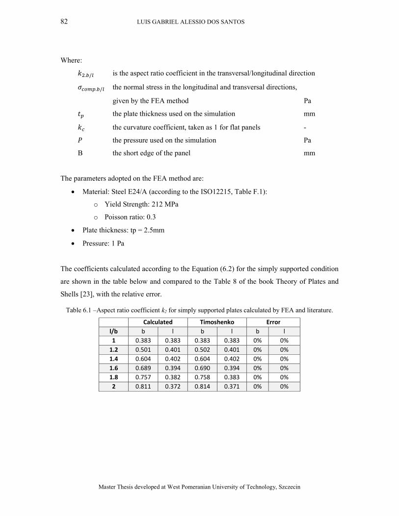
82 LUIS GABRIEL ALESSIO DOS SANTOS
Master Thesis developed at West Pomeranian University of Technology, Szczecin
Where:
. / is the aspect ratio coefficient in the transversal/longitudinal direction
. / the normal stress in the longitudinal and transversal directions,
given by the FEA method Pa
the plate thickness used on the simulation mm
the curvature coefficient, taken as 1 for flat panels -
the pressure used on the simulation Pa
B the short edge of the panel mm
The parameters adopted on the FEA method are:
Material: Steel E24/A (according to the ISO12215, Table F.1):
o Yield Strength: 212 MPa
o Poisson ratio: 0.3
Plate thickness: tp = 2.5mm
Pressure: 1 Pa
The coefficients calculated according to the Equation (6.2) for the simply supported condition
are shown in the table below and compared to the Table 8 of the book Theory of Plates and
Shells [23], with the relative error.
Table 6.1 –Aspect ratio coefficient k2 for simply supported plates calculated by FEA and literature.
Calculated Timoshenko Error l/b b l b l b l 1 0.383 0.383 0.383 0.383 0% 0%
1.2 0.501 0.401 0.502 0.401 0% 0% 1.4 0.604 0.402 0.604 0.402 0% 0% 1.6 0.689 0.394 0.690 0.394 0% 0% 1.8 0.757 0.382 0.758 0.383 0% 0% 2 0.811 0.372 0.814 0.371 0% 0%

REDESIGN OF A CLASSIC SAILBOAT WITH FEA INVESTIGATION 83 OF THE PLATE CURVATURE
“EMSHIP” Erasmus Mundus Master Course, period of study September 2015 – February 2017
The coefficients were also calculated for the fully supported condition.
Table 6.2 - Aspect ratio coefficient k2 for fully fixed plates calculated by FEA and literature.
Calculated Timoshenko Error l/b b l b l b l 1 0.304 0.304 0.308 0.308 -1% -1%
1.1 0.346 0.317 0.349 0.323 -1% -2% 1.2 0.379 0.328 0.383 0.332 -1% -1% 1.3 0.409 0.332 0.412 0.338 -1% -2% 1.4 0.431 0.332 0.436 0.341 -1% -3% 1.5 0.451 0.336 0.454 0.342 -1% -2% 1.6 0.459 0.338 0.468 0.343 -2% -1% 1.7 0.475 0.335 0.479 0.343 -1% -2% 1.8 0.479 0.338 0.487 0.343 -2% -1% 2 0.488 0.338 0.497 0.343 -2% -1%
As the results are very close to the ones of the literature, the method can be considered validated.
It is important to note that the stresses should be assessed in different directions, as they may
be used not only for isotropic but also for anisotropic materials.
6.2. The double curvature coefficients
When a panel is curved, it can handle a higher stress than a flat panel. To study the influence
of the curvature coefficients, the stresses given by the FEA method were compared with the
required plate thickness of the ISO12215 provided by the Equation (6.2), for different curvature
and aspect ratio.
The rearranged equation for the calculation of the curvature coefficients is given below.
= ×. /
× . / (6.2)
Where:
the curvature coefficient -
. / is the aspect ratio coefficient in the transversal/longitudinal direction
. / the normal stress in the longitudinal and transversal directions,
given by the FEA method Pa
the plate thickness used on the simulation mm

84 LUIS GABRIEL ALESSIO DOS SANTOS
Master Thesis developed at West Pomeranian University of Technology, Szczecin
the pressure used on the simulation Pa
B the short edge of the panel mm
The simulation was performed for the fully fixed condition for two different plate thickness and
two aspect ratios, changing the curvature of the plate; all the other parameters were kept the
same as the flat panel condition. The figure below shows the dimensions of the curved plate for
aspect ratio equal to one.
Figure 6.5 – Plate with double curvature and an aspect ratio equal to one. Units in metres.
The plate was submitted to a uniform pressure, and the normal stresses were given as results of
the FEA method, as seen below.
Figure 6.6 – Normal stress on a curved plate under uniform pressure.

REDESIGN OF A CLASSIC SAILBOAT WITH FEA INVESTIGATION 85 OF THE PLATE CURVATURE
“EMSHIP” Erasmus Mundus Master Course, period of study September 2015 – February 2017
The different scenarios were aspect ratio of 1.0 and 1.5, the thickness of 2.9mm and 5mm and
the curvature coefficients were changed from 0 to 0.25. With the normal stresses obtained with
the FEA, the kc coefficients were calculated according to the Equation (6.2), for both directions
and plates with fully fixed edges. The results are discussed below and compared with the single
curvature coefficients of the ISO 12215, as shown in the table below.
Table 6.3 – Curvature coefficients calculated for the different scenarios analysed
tp = 2.9 mm
Aspect ratio: 1.0 Aspect ratio: 1.5 ISO 15515 cl/l = 0.03 cl/l = 0.1 cl/l = 0.03 cl/l = 0.1
cb/b kcb kcl kcb kcl kcb kcl kcb kcl Single kc 0.03 0.22 0.23 0.15 0.13 0.20 0.24 0.14 0.14 1.00 0.10 0.13 0.15 0.12 0.12 0.11 0.15 0.11 0.12 0.77 0.25 0.08 0.11 0.07 0.11 0.08 0.11 0.09 0.07 0.50
tp = 5 mm
Aspect ratio: 1.0 Aspect ratio: 1.5 ISO 15515 cl/l = 0.03 cl/l = 0.1 cl/l = 0.03 cl/l = 0.1
cb/b kcb kcl kcb kcl kcb kcl kcb kcl Single kc 0.03 0.30 0.30 0.20 0.17 0.27 0.30 0.20 0.20 1.00 0.10 0.17 0.20 0.13 0.18 0.14 0.20 0.14 0.17 0.77 0.25 0.10 0.15 0.09 0.13 0.08 0.14 0.08 0.13 0.50
tp = 30 mm
Aspect ratio: 1.0 Aspect ratio: 1.5 ISO 15515 cl/l = 0.03 cl/l = 0.1 cl/l = 0.03 cl/l = 0.1
cb/b kcb kcl kcb kcl kcb kcl kcb kcl Single kc 0.03 0.78 0.78 0.52 0.45 0.72 0.78 0.49 0.52 1.00 0.10 0.45 0.52 0.39 0.39 0.37 0.50 0.34 0.42 0.77 0.25 0.25 0.35 0.23 0.32 0.21 0.34 0.20 0.31 0.50
As expected, plates with high curvature can handle a greater stress, thus as the curvature
increases, the coefficients decrease, allowing the use of thinner plates. The impact of the double
curvature on the coefficients is very clear, as when both edges are curved, the plate can support
a higher stress than when it is single curved.
Another interesting fact is that the curvature coefficients do not increase proportionally to the
plate thickness, as seen by the results, the greater the thickness is, the greater the coefficients,
but not in the same proportion, in other words, the impact of the curvature is more significant
on thinner plates. Thus, the curvature coefficients should be based on the thickness of the flat
plate.
The ISO 12215 underestimates the impact of the curvature on the plate thickness, especially
when the plate is double curved, so the ISO’s current method is over-dimensioning the plates.

86 LUIS GABRIEL ALESSIO DOS SANTOS
Master Thesis developed at West Pomeranian University of Technology, Szczecin
Therefore, thinner plates can be designed, obtaining a lighter structure than the one given by
the standard. The results of the curvature achieved in this work approach to the results of the
ISO when working with thicker plates.
It is evident that the capacity a plate has to support the stresses is not proportional to its
geometry, making the process of developing a single equation to the curvature coefficients a
complex task, hence the importance of performing Finite Element Analysis to the structure
design of boats.
6.3. Example of plate thickness calculation
For clarifying the methodology proposed in this work to calculate the minimum plate thickness
necessary at a pre-design stage, a case will be studied. According to instructions of the
ISO12215-5 the curvature is not considered for wooden plating, but for this example, the Dark
Harbor 17.5 is considered having a steel hull. Considering the plating between the sections 4.5
and 5.0, the curvature is now taken into consideration to check how much it could be reduced
if made of steel instead of wood. The following figure shows the plate and its dimensions.
Figure 6.7 – Plate of the Dark Harbor hull
In this case, we have the following dimensions:
b = 308mm cb = 45mm l = 648mm cl = 92mm

REDESIGN OF A CLASSIC SAILBOAT WITH FEA INVESTIGATION 87 OF THE PLATE CURVATURE
“EMSHIP” Erasmus Mundus Master Course, period of study September 2015 – February 2017
The calculated thickness tp is 16.8mm, and the other coefficients can be calculated according
to the equations previously described.
= ≅ 2
=45
308= 0.14
=92
648= 0.14
In order to use the values of Table 6.3 and to be conservative regarding the safety of the
structure, the plate will be considered as 30mm and the coefficients as follows.
Table 6.4 – Coefficients for the calculation of the plate thickness
AR 1.5
0.10
0.10
From the Table 6.4, we have the values of kcb and kcl equal to 0.34 and 0.42 respectively. As
it is considered an isotropic material, the highest value will be considered, so kc = 0.42, and for
the aspect ratio of 1.5, Table 6.2 gives a k2 equal to 0.44. At this location of the boat, the design
pressure is equal to 24.4 kN/m2 and the design stress for steel is equal to 212 N/mm2.
Disregarding the curvature and using the Equation (4.1) and the methodology described at
section 4.7, the required flat plate thickness can be obtained:
= ∙ ∙
1000 ∙= 308 ∙
24.4 ∙ 0.441000 ∙ 212
= 2.2
If steel were considered instead of wood, for the hull plating, the required thickness would be
2.2mm, ignoring any safety factors and curvature coefficients. Applying a safety factor of three,
the thickness of the flat panel would be 6.6mm, and after considering the kc of 0.42 as explained
in the previous paragraphs, the plate would be 3mm. According to the ISO12215, the kc value
for this case would be 0.77, resulting in a thickness of 5mm. This example emphasises the

88 LUIS GABRIEL ALESSIO DOS SANTOS
Master Thesis developed at West Pomeranian University of Technology, Szczecin
importance of considering the double curvature when calculating the plate thickness at the
structure design.
6.4. Conclusions
Curved plates can handle a higher pressure than flat plates because the curvature allows a higher
stress to be handled. It is crucial to know exactly how much stress the plate can support, so the
plate can be designed in a way to save weight and costs.
When designing the plating of a ship, the geometry changes according to the hull form, so in
different parts of the hull, the different thickness can be used, resulting in a more effective
design. There are theoretical methods to assess the stress distribution on a plate, but when
working with different plate geometries, the problem becomes complex to be solved only
analytical, requiring some more sophisticated techniques.
The stresses, which the plates are submitted, can be computed by Finite Element Analysis,
allowing the user to change the variables, such as the geometry of the plates, in a more precise
way than when working with analytical methods, and providing results that are more precise.
The ISO 12215 works with single curvature coefficients to reduce the thickness of the plates,
and these values were compared by the ones calculated by FEA. It was observed that the
predominant stresses of the plates are the normal stresses, and the coefficients of the ISO
standard are overestimated, so in fact, the plates are thicker than the required when calculating
according to the ISO method.
The FEA results show that the curvature coefficients are dependent on both the aspect ratio and
thickness, so on the plate geometry. The values of the curvature coefficients were calculated
for the longitudinal and transversal directions, allowing the design of the thickness of
anisotropic materials, such as plating made of composite materials. A deeper study of the
behaviour of composite plates with different curvature is recommended, though.
For isotropic materials, the higher coefficients, between the transversal and longitudinal, shall
be used, as they will grantee that the plate is safely dimensioned in both directions.
To join the transversal and longitudinal coefficients in a single one, the Von Mises stress may
be used, as this method combines the stresses in a single one, allowing to obtain a coefficient
which is valid for all directions, but for anisotropic materials, this method may not be
applicable, as the material can support different loads according to the direction.

REDESIGN OF A CLASSIC SAILBOAT WITH FEA INVESTIGATION 89 OF THE PLATE CURVATURE
“EMSHIP” Erasmus Mundus Master Course, period of study September 2015 – February 2017
With the results obtained in this work, the plates can be dimensioned according to the ISO
equations, for different plate geometries and aspect ratio. When compared to the actual
coefficients used by the ISO 12215, it shows that thinner plates can be used, reducing the weight
and costs of the plating. The calculation of the plate thickness by the equation can be very useful
for preliminary design stages, but as the geometry of the plate impacts significantly at the
stresses, it can support, the FEA is recommended at further stages of the design. As nowadays
the Finite Element software are more accessible and the computational power has been
increased, the structural analysis can be more accurate when performed by qualified
professionals.
7. GENERAL CONCLUSION
As the first part of this work, a modern replica of a classic design was recreated according to
the client’s requirements and modern standards. Nowadays, there is still keen interest in
traditional sailing with the classic aesthetics, such as the slender hull lines and rig, and the
customers want the comfort and safety of the modern world. This calls for a re-engineering of
the old and historic vessels to meet the clients’ expectations, making the boats commercially
attractive and feasible. The Recreational Craft Directive (RCD) dictates that any boat to be
available in the European Market should comply with the stability and structural requirements
of the ISO12217 and ISO12215, respectively.
In order to bring a replica of the classic yacht, Dark Harbor 17.5, to life, the original plans were
studied regarding the stability, hydrostatics, hydrodynamics, structural and comfort. The 3D
model of the boat was made by a Computer Aided Software, and the results of the hydrostatics
computationally obtained were compared to the results of the Simpson’s rule on the lines plan;
as the results were very close, the model was considered validated.
The stability analysis showed compliance with the modern standards, and the structure of the
original design was over dimensioned according to the ISO12215, with high safety factors. The
modern techniques and quality of the materials allow the reduction of the safety factors, making
the boat stronger and lighter. Taking advantage of this fact, a new structure was designed; the
cedar hull planking was changed from carvel to strip planking with mahogany veneers, and the
frames and beams spacing were increased; a carbon fibre rigging is light and strong; all the
Changes in the structure reduced the weight of the vessel, and making it stronger and allowing
more components to be added to the boat.

90 LUIS GABRIEL ALESSIO DOS SANTOS
Master Thesis developed at West Pomeranian University of Technology, Szczecin
The new shallower keel reduced the draft of the boat, increasing the operational area and
making it trailable while retaining the performance and stability. The electric engine and
batteries added to the boat allow a safe return to the marina when sailing against the tides, and
makes the manoeuvrability of the boat easier. The portable toilet makes a day sailing more
comfortable and private for the owner and his guests. The aesthetics with the boat was greatly
improved by the teak at the deck.
All the results caused no impact on the performance and stability of the boat. As a result, the
redesigned Dark Harbor 17.5 has all the features of a modern boat regarding comfort and safety,
keeping the spirit and appearance of the traditional sailboats which are part of the history of the
classic yachts. The new design complies with all the modern regulations, allowing it to be put
on the market inside the European Union.
Some suggestions for future work on this design is to develop some more detailed drawings
and the rendered 3D model, making it more attractive to possible customers. As a requirement
of the RCD, the owner’s manual must contain the relevant information about compliance,
proofing the requirements are followed, as well as other safety and information about the boat.
With the Finite Element Analysis, it was possible to study the influence of the plate curvature
on the maximum stress the plate can support. The double curvature coefficients were calculated
by using the FEA results applied to the equation of the ISO12215, the impact of the double
curvature is evident, as a plate can stand a higher pressure when it is double curved.
By comparing the double curvature coefficients obtained from this work and the ISO single
curvature ones, it is evident the high coefficients used by ISO leads to over dimensioned plates,
especially for thinner plates.
The importance of using the double curvature coefficients was demonstrated by an example of
calculating the minimum thickness for the Dark Harbor plate. According to the results of the
FEA, the plates could be thinner than the ones provided by ISO.
By studying the stresses in different directions, longitudinal and transverse coefficients were
calculated. For isotropic materials, only the highest one should be used, but for anisotropic
materials, the orientation of the stresses is important, and the suitable coefficient should be
used.
Using the Finite Element method is a very powerful tool for effective design, allowing
companies to elaborate the correct plate dimensions and save weight on the boat. Nowadays,
with the method becoming more available and the increased computational power, the results
can be brought closer to reality, making the design process more advanced and accurate.

REDESIGN OF A CLASSIC SAILBOAT WITH FEA INVESTIGATION 91 OF THE PLATE CURVATURE
“EMSHIP” Erasmus Mundus Master Course, period of study September 2015 – February 2017
As some recommendations for future work, a deeper analysis of the curvature can be performed,
testing different plate geometries and materials, leading to a formulation of a new equation and
precise coefficients.
8. ACKNOWLEDGEMENTS
The principal author would like express special thankfulness, warmth and appreciation to the
persons and organisations below for their support in the realisation of this project.
For all his family members for their unfailing support and continuous encouragement
throughout the years of study and through the process of researching and writing this thesis.
This accomplishment would not have been possible without them.
The professors of Southampton Solent University for all their patience in sharing their
knowledge and expertise, especially to Professor Jean-Baptiste Souppez, who proposed the
theme and advised on all the steps of this work.
The owner of the Dark Harbor replica and the IBTC Portsmouth, where the built is under way,
for the opportunity to be involved with the redesign and the fascinating discussions.
This thesis was developed in the frame of the European Master Course in “Integrated Advanced
Ship Design” named “EMSHIP” for “European Education in Advanced Ship Design”, Ref.:
159652-1-2009-1-BE-ERA MUNDUS-EMMC.
92 LUIS GABRIEL ALESSIO DOS SANTOS
Master Thesis developed at West Pomeranian University of Technology, Szczecin
9. REFERENCES
[1] ECSIP Consortium, “Study on the competitiveness of the recreational boating sector,”
Rotterdam, 2015.
[2] B. B. CROWNINSHIELD, “Dark Harbor 17½ - Dark Harbor Design Plan,” 1908.
[3] WOODEN BOATS, “‘25’10” Sloop, Dark Harbour 17½,” Wooden Boats,, undated.
[4] M. Heighton, “REPLICATING HISTORIC VESSELS,” National Historic Ships - United
Kingdom, December 2012.
[5] ITTC - International Towing Tank Conference, “Dictionary of Ship Hydrodynamics,”
2008. [Online].
[6] L. Larsson and E. R. Eliasson, Principles of Yacht Design, London: Adlard Coles
Nautical, 2007.
[7] Leith shipyards, “CAD-Computer Aided Design,” [Online]. Available:
http://www.leithshipyards.com/. [Accessed 13 July 2016].
[8] C. Barrass and C. D. Derrett , Ship Stability for Masters and Mates, Heinemann Newnes,
1990.
[9] M. Bourne, “6. Simpson’s Rule,” 1997. [Online]. Available: http://www.intmath.com/.
[Accessed 14 July 2016].
[10] S. Halpern, “A MATTER OF STABILITY AND TRIM,” 1998. [Online]. Available:
http://titanic-model.com/.
[11] K. Rawson and E. Tupper, Basic Ship Theory, Elsevier, 2001.
[12] E. Tupper, Introduction to Naval Architecture, Elsevier, 2004.
[13] EUROPEAN PARLIAMENT, “Directive 2013/53/EU,” Official Journal of the European
Union, 2013.
[14] B. S. E. I. 12217-2:2015, “Small Craft - Stability and buoyancy assesment and
categorization”. 2015.
[15] J. A. Keuning and . K. J. Vermeulen, “On the balance of large sailing yachts,” in 17th
International Symposium on "Yacht Design and Yacht Construction", Amsterdam, 2002.
[16] R. Janssen, “Best Mast: a new way to design a rig,” The International HISWA Symposium
on Yacht Design and Yacht Construction, 2004.

REDESIGN OF A CLASSIC SAILBOAT WITH FEA INVESTIGATION 93 OF THE PLATE CURVATURE
“EMSHIP” Erasmus Mundus Master Course, period of study September 2015 – February 2017
[17] “BoatDesign.net,” [Online]. Available: http://www.boatdesign.net/. [Accessed 16
December 2016].
[18] “Nordic Boat Standard - Commercial Boats less than 15 metres,” 1990.
[19] J. A. Keuning and U. B. Sonnenberg, “Approximation of the Hydrodynamic Forces on a
Sailing Yacht based on the 'Delft Systematic Yacht Hull Series',” The International
HISWA Sympostion on Yacht Design and Yacht Construction, 1998.
[20] Wolfston Unit, “WinDesign VPP,” Southampton.
[21] Bentley Systems, “Maxsurf”.
[22] ITTC, “Uncertainty Analysis, Example for Resistance Test,” in 23rd International
Towing Tank Conference, Venice, 202.
[23] S. Timoshenko and S. Woinowsky-Krieger, Thoery of Plantes and Shells, McGraw-Hill
Book Company, 1989.
[24] B. S. E. I. 1.-5. 2008, “Small Craft - Hull Construction and scantlings”. 2008.
[25] “Small Craft - Hull Construction and Scantling - Part 9: Sailing craft appendages. ISO
12215-9:2012”.
[26] Wolfston Unit, “HullScant,” Southampton.
[27] Malorw, “Marlow Ropes - Dyneema cords,” [Online]. [Accessed 15 January 2017].
[28] Darglow Engineering, “FeatherStream Propellers data sheet,” Wareham, United
Kingdom, 2015.
[29] M. M. Bernitsas, D. Ray and P. Kinley, “KT, KQ and Efficiency for the Wageningen B-
Series Propellers,” The University of Michigan, Michigan, 1981.
[30] IDTechnology BV (Bellmarine), “Propeller Shaft Propulsion,” 2013.
[31] VALENCE, “U-Charge® XP Modules,” 2016. [Online]. Available:
https://www.valence.com.
[32] Torqueedo, “Torqueedo,” 2016. [Online]. Available: http://www.torqeedo.com/en.
[Accessed 24 December 2016].
[33] “SAILING—THE BASICS SO YOU CAN UNDERSTAND,” 14 July 2013. [Online].
Available: tillertowardstrouble.wordpress.com. [Accessed 29 June 2016].
[34] C. Johnson, The Secret of Sailing, Stockholm, 2011.
[35] R. Boucher, “REPORT ON CURVATURE ANALYSIS,” Paris, 2011.

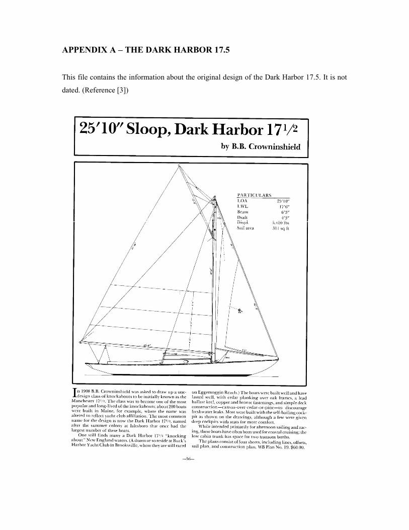
APPENDIX A – THE DARK HARBOR 17.5
This file contains the information about the original design of the Dark Harbor 17.5. It is not
dated. (Reference [3])

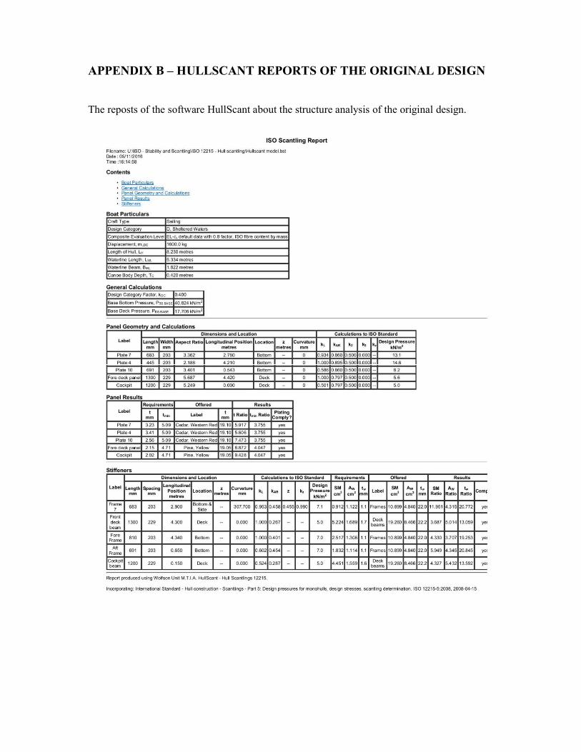
APPENDIX B – HULLSCANT REPORTS OF THE ORIGINAL DESIGN
The reposts of the software HullScant about the structure analysis of the original design.

APPENDIX C – HULLSCANT REPORTS OF THE NEW DESIGN
The reposts of the software HullScant about the structure analysis of the new design.

APPENDIX D – WEIGHT ESTIMATION OF THE NEW DESIGN
The weight estimation of the new design is presented in this annex, presented in sections for
better visualization.
1 - Oak Frames (square) N VCG LCG Cord Mass - m m*VCG m*LCG
1.1 1758 6200 480 0.327 574 2026 1.2 1655 5850 667 0.454 751 2655 1.3 1570 5500 810 0.551 865 3031 1.4 1534 5150 859 0.585 897 3012 1.5 1468 4800 979 0.667 978 3200 1.6 1409 4450 1120 0.762 1074 3392 1.7 1384 4100 1167 0.794 1099 3256 1.8 1339 3750 1260 0.858 1149 3216 1.9 1305 3400 1327 0.903 1178 3070
1.10 1282 3050 1355 0.922 1182 2813 1.11 1275 2700 1391 0.947 1207 2556 1.12 1205 2350 1462 0.995 1199 2339 1.13 1212 2000 1429 0.972 1179 1945 1.14 1238 1650 1366 0.930 1151 1534 1.15 1254 1300 1319 0.898 1126 1167 1.16 1293 850 1210 0.824 1066 700 1.17 1346 400 1085 0.739 994 295 1.18 1447 -50 855 0.582 842 -29 1.19 1527 -500 493 0.336 513 -168 1.37 1360 2581 2.8 3808 7228
TOTAL 1355 2804 16.8 22832 47238
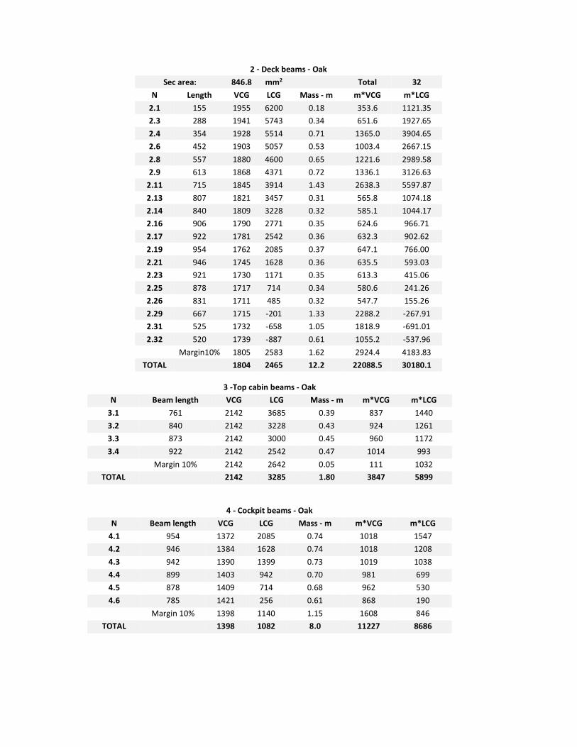
2 - Deck beams - Oak Sec area: 846.8 mm2 Total 32
N Length VCG LCG Mass - m m*VCG m*LCG 2.1 155 1955 6200 0.18 353.6 1121.35 2.3 288 1941 5743 0.34 651.6 1927.65 2.4 354 1928 5514 0.71 1365.0 3904.65 2.6 452 1903 5057 0.53 1003.4 2667.15 2.8 557 1880 4600 0.65 1221.6 2989.58 2.9 613 1868 4371 0.72 1336.1 3126.63
2.11 715 1845 3914 1.43 2638.3 5597.87 2.13 807 1821 3457 0.31 565.8 1074.18 2.14 840 1809 3228 0.32 585.1 1044.17 2.16 906 1790 2771 0.35 624.6 966.71 2.17 922 1781 2542 0.36 632.3 902.62 2.19 954 1762 2085 0.37 647.1 766.00 2.21 946 1745 1628 0.36 635.5 593.03 2.23 921 1730 1171 0.35 613.3 415.06 2.25 878 1717 714 0.34 580.6 241.26 2.26 831 1711 485 0.32 547.7 155.26 2.29 667 1715 -201 1.33 2288.2 -267.91 2.31 525 1732 -658 1.05 1818.9 -691.01 2.32 520 1739 -887 0.61 1055.2 -537.96
Margin10% 1805 2583 1.62 2924.4 4183.83 TOTAL 1804 2465 12.2 22088.5 30180.1
3 -Top cabin beams - Oak
N Beam length VCG LCG Mass - m m*VCG m*LCG 3.1 761 2142 3685 0.39 837 1440 3.2 840 2142 3228 0.43 924 1261 3.3 873 2142 3000 0.45 960 1172 3.4 922 2142 2542 0.47 1014 993
Margin 10% 2142 2642 0.05 111 1032 TOTAL
2142 3285 1.80 3847 5899
4 - Cockpit beams - Oak N Beam length VCG LCG Mass - m m*VCG m*LCG
4.1 954 1372 2085 0.74 1018 1547 4.2 946 1384 1628 0.74 1018 1208 4.3 942 1390 1399 0.73 1019 1038 4.4 899 1403 942 0.70 981 699 4.5 878 1409 714 0.68 962 530 4.6 785 1421 256 0.61 868 190
Margin 10% 1398 1140 1.15 1608 846 TOTAL
1398 1082 8.0 11227 8686

5 - Floors and planking
N Location Thickness QTD Material VCG LCG Mass m*VCG m*LCG 5.1 Cockpit floor 19.5 2 White pine 1398 1082 19.59 27389 21191 5.2 Cabin floor 19.5 2 White pine 1140 2910 33.24 37894 96728 5.3 Decking 19.1 1 White pine 1804 2465 44.98 81171 110906 5.4 Cabin top 12.7 2 White pine 2070 2950 11.20 23184 33040 5.6 Mahogany Hull 4.8 2 Mahogany 1572 2527 39.43 61975 99645 5.7 Cedar Hull 12.0 2 Cedar 1572 2527 70.71 111144 178700 5.8 Cabin door 2 Oak 1810 2040 2.80 5068 5712 5.9 Transom 22.2 2 Oak 1668 -1102 4.05 6758 -4465
5.10 Cabin Back 12.7 2 Mahogany 2040 1740 3.35 6826 5822 5.11 Cockpit sides 12.7 2 Mahogany 1593 1076 6.70 10677 7212 5.12 Coaming 19.5 2 Oak 1820 890 9.60 17472 8544 5.13 house side 19.5 2 Oak 1890 3020 10.10 19089 30502 5.14 Resin 1600 2340 25.00 40007 58492 5.15 Margin 10% 0.1 1628 2384 25.69 41817 61253
TOTAL 0.2 1601 2328 306.4 490471 713281
6 - General N Location Length/Thick QTD Material VCG LCG Mass m*VCG m*LCG
6.1 Rudder - 1 20 1 Oak 596 1018 2.93 1743.7 2978 6.2 Rudder - 2 15 1 Yellow Pine 496 863 1.38 683.972 1190 6.3 Backbone 1 Oak 1220 3700 15.00 18300 55500 6.4 Cabin Hatch White Pine 2160 2320 3.0 6480 6960 6.5 Stem 50.8 2 oak 1640 -1060 10.86 17810.4 -11512 6.6 Transom knee 1668 -1102 2 3336 -2204 6.7 Sheer clamps 8345 2 Douglas-fir 2100 4900 17.15 36009.9 84023 6.8 Sheer Strakes 8355 1 Oak 2100 4900 3.00 6300 14700 6.9 Tie rod 894.09 1 galv iron 1669 0.50 834.894 0
6.10 Bilge Stringers 1000 2910 6.00 6000 17460 6.11 Ruder tube and tiller 500 950 15.00 7500 14250 6.12 Deck teak 655 1804 2465 21.43 38673.2 52840 6.13 Crew 1 1900 1120 75 142500 84000 6.14 Electrical Engine 1 1250 1140 38 48000 43776 6.15 Batteries 4 1137 3709 78 88686 289302 6.16 Toilet 1 1230 1870 3 4059 6171 6.17 Propeller 1 1230 1870 2 2460 3740 6.18 Engine Shaft 1 1230 1870 2 2460 3740 6.19 Anchor 1 1758 6163 10 17580 61630 6.20 Achor chain 20m 1 1758 6163 20 35160 123260 6.21 0 0 6.22 Crew equipment 1 1646 2847 30.00 49391.7 85405 6.23 Margin 10% 0.1 1646 2847 5.65 9302.1 16085
TOTAL 1498 2629 362.6 543270.9 953295.2
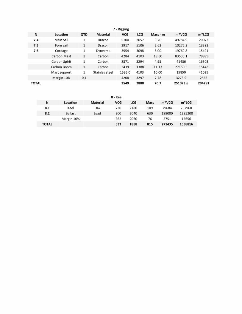
7 - Rigging N Location QTD Material VCG LCG Mass - m m*VCG m*LCG
7.4 Main Sail 1 Dracon 5100 2057 9.76 49784.9 20073 7.5 Fore sail 1 Dracon 3917 5106 2.62 10275.3 13392 7.6 Cordage 1 Dyneema 3954 3098 5.00 19769.8 15491
Carbon Mast 1 Carbon 4284 4103 19.50 83533.1 79999 Carbon Spirit 1 Carbon 8371 3294 4.95 41436 16303 Carbon Boom 1 Carbon 2439 1388 11.13 27150.5 15443 Mast support 1 Stainles steel 1585.0 4103 10.00 15850 41025 Margin 10% 0.1 4208 3297 7.78 3273.9 2565
TOTAL 3549 2888 70.7 251073.6 204291
8 - Keel N Location Material VCG LCG Mass m*VCG m*LCG
8.1 Keel Oak 730 2180 109 79684 237960 8.2 Ballast Lead 300 2040 630 189000 1285200
Margin 10% 362 2060 76 2751 15656 TOTAL 333 1888 815 271435 1538816
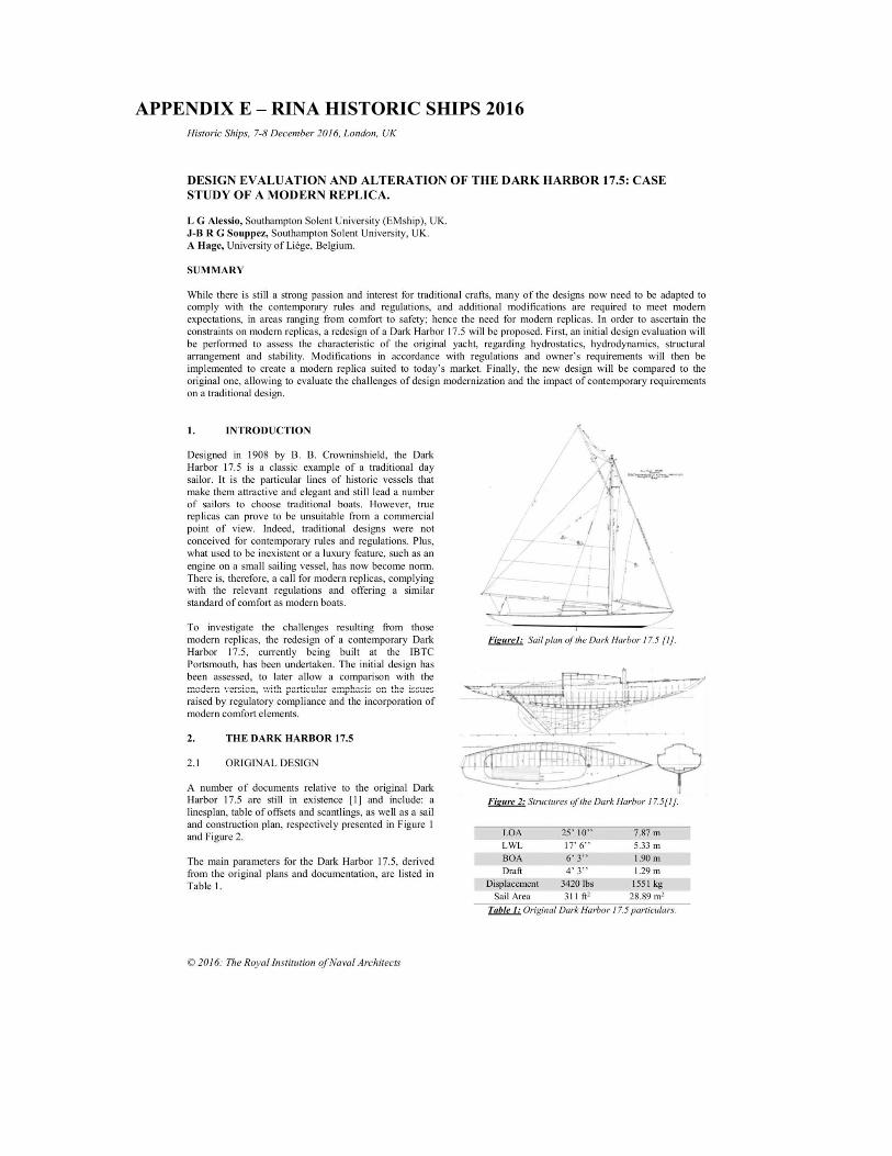
APPENDIX E – RINA HISTORIC SHIPS 2016


Copyright © 2022 FDOKUMEN