Application of FEA in Design and Verification of Bolted Joints ...
220
-
Upload
khangminh22 -
Category
Documents
-
view
0 -
download
0
Transcript of Application of FEA in Design and Verification of Bolted Joints ...


Application of FEA in Design and Verification of Bolted Joints According to VDI 2230
I
Preface
This master thesis was written the Fall of 2017 and early 2018, and concludes my degree in
Mechanical Engineering at the Norwegian University of Science and Technology. The master
project has been carried out while being a technical student in the engineering department at
CERN, the European Organisation for Nuclear Research.
The thesis is about how computer simulation tools can be combined with VDI 2230, a
calculation guideline for bolted joints, to achieve quality and productivity rewards in design
and verification of bolted joints. The scope was also to lower the threshold and making it easier
to perform such assessments.
It takes basis in a specific engineering case, which demonstrates the need for improved
knowledge and an analysis strategy. A complete framework with a simplified workflow and
support material is presented and demonstrated. In the end, specific recommendations for the
initial engineering case are given.
The reader is expected to have basic knowledge in mechanics, springs, bolted joints and finite
element analysis. ANSYS Workbench V17.2 has been used for FE-analysis, and Mathcad Prime
V4.0 for engineering calculations.
Genève, 2018
Jørgen Apeland

MSc Thesis 2018
II

Application of FEA in Design and Verification of Bolted Joints According to VDI 2230
III
Acknowledgements
I would like to thank my CERN supervisors Luca Dassa and Antonio Lafuente for their
guidance, discussions, and thorough feedback during my research. They have been essential for
the initiation and development of the project.
I would also like to thank my supervisor at NTNU, Torgeir Welo, for his contributions and
reviews, and for making this project possible.
The design and analysis office in EN-MME has provided a friendly and international working
environment, and they have provided useful input on user experiences and needs related to
analysis of bolted joints.
Finally, I would like to thank CERN and the Technical Student Programme for establishing a
framework where students can come and take part in cutting edge technology development, and
get practical and valuable experiences in a high competence environment.

MSc Thesis 2018
IV

Application of FEA in Design and Verification of Bolted Joints According to VDI 2230
V
Abstract
This thesis investigates how finite element analysis (FEA) can be used to simplify and improve
analysis of bolted joints according to the guideline VDI 2230. Some aspects of how FEA can
be applied to aid design and verification of bolted joints are given in the guideline, but not in a
streamlined way that makes it simple and efficient to apply.
The scope of this thesis is to clarify how FEA and VDI 2230 can be combined in analysis of
bolted joints, and to present a streamlined workflow. The goal is to lower the threshold for
carrying out such combined analysis. The resulting benefits are improved analysis validity and
quality, and improved analysis efficiency.
A case from the engineering department at CERN, where FEA has been used in analysis of
bolted joints is used as basis to identify challenges in combining FEA and VDI 2230. This
illustrates the need for a streamlined analysis strategy and well described workflow.
The case in question is the Helium vessel (pressure vessel) for the DQW Crab Cavities, which
is an important part of the High Luminosity upgrade of LHC (HL-LHC).
Investigations are performed into prying, a relevant source of non-linear bolt loads and
unpredictable load development, to understand the phenomenon and influence of preload. A
complete analysis framework is then presented, which consist of a streamlined basic workflow,
associated calculation template, details of more advanced verifications, a detailed guide with
best practices and references, examples where the analysis framework has been applied, and a
seminar to educate relevant personnel.
In the end, suggestions and recommendations are provided for a potential revision of the Helium
vessel analysis.
The hope is that this thesis can be used as a resource in analysis of bolted joints using VDI 2230
and FEA, and that it will benefit the engineering department at CERN and other relevant users.

MSc Thesis 2018
VI

Application of FEA in Design and Verification of Bolted Joints According to VDI 2230
VII
Sammendrag
Denne oppgaven tar for seg hvordan datasimuleringer (FEA) kan benyttes til å forenkle og
forbedre analyse av boltede forbindelser i henhold til retningslinjene i VDI 2230. Enkelte
aspekter av hvordan FEA kan benyttes for å assistere design og verifikasjon av boltede
forbindelser er omtalt i retningslinjene, men ikke på en strømlinjeformet måte som gjør det
enkelt og effektivt å benytte.
Målet med oppgaven er å redegjøre for hvordan FEA og VDI 2230 kan kombineres, og å
presentere en strømlinjeformet arbeidsflyt. Håpet er dermed å senke terskelen for å utføre slike
kombinerte analyser. Fordelene er forbedret validitet og kvalitet i analysen, samt forbedret
effektivitet i prosessen.
Det er tatt utgangspunkt i en analyse fra ingeniøravdelingen ved CERN, hvor FEA har blitt
benyttet i verifikasjon av boltede forbindelser. Denne er brukt som basis for å identifisere
utfordringer med å kombinere FEA og VDI 2230, og illustrerer behovet for en strømlinjeformet
analyse strategi og detaljert beskrivelse av arbeidsflyten.
Analysen det er tatt utgangspunkt i er en Helium beholder (trykkbeholder) for DQW Crab
Cavities, som er en viktig del av en kommende oppgradering av LHC kalt High Luminosity
LHC (HL-LHC).
En aktuell kilde for ikke-lineære bolt laster og uforutsigbar last utvikling kalt prying er
undersøkt for å forstå fenomenet bedre, samt innvirkningen av forspenning. Et komplett analyse
rammeverk er presentert, som består av en strømlinjeformet arbeidsflyt, tilhørende beregnings
mal, detaljer om mer avanserte beregninger og verifikasjoner, en detaljert guide med «beste
praksis» og relevante referanser, eksempler hvor den foreslåtte arbeidsflyten er benyttet, samt
et seminar for å undervise relevant personell.
Til slutt er spesifikke forslag og anbefalinger for en potensiell revisjon av Helium beholder
analysen gitt.
Håpet er at denne oppgaven kan bli benyttet som en ressurs innen design og verifikasjon av
boltede forbindelser ved bruk av VDI 2230 og FEA, og at den vil være til nytte for
ingeniøravdelingen ved CERN og andre relevante brukere.

MSc Thesis 2018
VIII

Application of FEA in Design and Verification of Bolted Joints According to VDI 2230
IX
Table of Contents
1 INTRODUCTION ............................................................................................................ 1
1.1 BACKGROUND ............................................................................................................. 1
1.2 PROBLEM DESCRIPTION............................................................................................... 1
1.3 PROJECT SCOPE ........................................................................................................... 1
1.4 STRUCTURE OF REPORT ............................................................................................... 2
1.5 LITERATURE ................................................................................................................ 2
2 THEORY ........................................................................................................................... 3
2.1 TERMS ......................................................................................................................... 3
2.2 BASICS OF BOLTED JOINTS .......................................................................................... 3
2.3 ANALYTIC VDI 2230 PROCEDURE ............................................................................ 11
2.4 FEA MODEL CLASSES ............................................................................................... 13
3 DQW CRAB CAVITIES HELIUM VESSEL ANALYSIS ........................................ 19
3.1 INTRODUCTION TO THE CRAB CAVITIES .................................................................... 19
3.2 HELIUM VESSEL FOR DQW CRAB CAVITIES ............................................................. 23
3.3 HELIUM VESSEL BOLT ANALYSIS ............................................................................. 25
3.4 RQ1: CHALLENGES IN ANALYSIS OF BOLTED JOINTS ................................................ 30
3.5 RQ2: HOW CAN THE CHALLENGES BE MET? .............................................................. 31
4 INVESTIGATIONS INTO PRYING ........................................................................... 33
4.1 WHAT IS PRYING? ..................................................................................................... 33
4.2 WHY AND WHEN IS IT RELEVANT? ............................................................................ 36
4.3 HOW SHOULD IT BE ENCOUNTERED?.......................................................................... 36
4.4 FEA-STUDY OF PRELOAD INFLUENCE ON PRYING .................................................... 37
4.5 DISCUSSION ............................................................................................................... 40
4.6 SUMMARY ................................................................................................................. 42
5 FEA AIDED ASSESSMENT OF BOLTED JOINTS ................................................. 43
5.1 ANALYSIS APPROACH ............................................................................................... 43
5.2 BASIC FEA WORKFLOW ........................................................................................... 45
5.3 NON-CRITICAL JOINTS ............................................................................................... 49
5.4 GUIDE FOR BASIC FEA WORKFLOW ......................................................................... 51
5.5 FURTHER ASSESSMENTS ............................................................................................ 64
5.6 CASE EXAMPLES ....................................................................................................... 66
5.7 SEMINAR ABOUT FEA & VDI 2230 ........................................................................... 67
6 REVISED CRAB CAVITY HE-VESSEL ANALYSIS .............................................. 69
6.1 SUGGESTIONS AND RECOMMENDATIONS ................................................................... 69
6.2 REVISED CALCULATIONS .......................................................................................... 72
7 DISCUSSION ................................................................................................................. 73
7.1 GOAL ACHIEVEMENT ................................................................................................ 73
7.2 RESEARCH ACTIVITIES .............................................................................................. 73
7.3 PRODUCTIVITY PARADOX AND SIMULATION DRIVEN DESIGN................................... 74
7.4 FUTURE RESEARCH ................................................................................................... 75
MSc Thesis 2018
X
8 SUMMARY ..................................................................................................................... 77
APPENDIX A: Basic FEA Workflow Calculation Template
APPENDIX B: Tightening Torque Template for Non-Critical Bolts
APPENDIX C: Blind Flange Analysis Example
C-1a Blind Flange Case Report
C-1b Calculations for Blind Flange Case
C-2a Blind Flange with Analytic VDI 2230 Procedure
C-2b Calculations for Blind Flange with Analytic VDI 2230 Procedure
APPENDIX D: Bolted Tuner Analysis Example
D-1 HG Cavity Bolted Tuner Analysis
D-2 Analytic Calculations for Tuner Analysis
APPENDIX E: VDI 2230 and FEA Seminar Presentation
APPENDIX F: Revised Calculations for HE-Vessel Joints

Application of FEA in Design and Verification of Bolted Joints According to VDI 2230
XI
List of Figures FIGURE 1: TTJ & TBJ .............................................................................................................................. 4
FIGURE 2: DIMENSIONS ASSOCIATED WITH A BOLT AND TAPPED THREADS............................................ 5
FIGURE 3: MECHANICAL SPRING MODEL OF A CLAMPED BJ .................................................................. 5
FIGURE 4: DISTORTION TRIANGLE ........................................................................................................... 6
FIGURE 5: DISTORTION TRIANGLE FOR N<1 ............................................................................................ 7
FIGURE 6: JOINT DIAGRAM WITH ASSOCIATED QUANTITIES .................................................................... 8
FIGURE 7: DEFORMATION CONES FOR A TBJ AND A TTJ ........................................................................ 9
FIGURE 8: DEFORMATION CONE AND SLEEVE (LEFT) AND LIMIT CRITERIA G (RIGHT) ......................... 10
FIGURE 9: CLAMPING SOLID INTERACTION IN MBJS ............................................................................. 10
FIGURE 10: JOINT DIAGRAM WITH ANALYTIC VDI 2230 QUANTITIES ................................................... 12
FIGURE 11: INTERSECTION FORCES CLASS I .......................................................................................... 14
FIGURE 12: EFFECT OF RIGID MPCS ON MESH STIFFNESS AND THE RESULTING PRESSURE DISTRIBUTION
WITH CLASS II MODEL ................................................................................................................... 15
FIGURE 13: THE CERN ACCELERATOR COMPLEX ................................................................................. 19
FIGURE 14: LOCATION OF DETECTORS AROUND LHC ........................................................................... 20
FIGURE 15: CRYOMODULE WITH TWO DQW CRAB CAVITIES .............................................................. 21
FIGURE 16: DQW CRAB CAVITY, BARE (LEFT) AND IN HE-VESSEL (RIGHT) ........................................ 21
FIGURE 17: VISUALISATION OF HOW CRAB CAVITIES ROTATE BUNCHES BEFORE AND AFTER
COLLISION POINT ........................................................................................................................... 22
FIGURE 18: TWO HELIUM VESSELS FOR DQW CRAB CAVITIES DURING ASSEMBLY IN 2017 ............... 22
FIGURE 19: HELIUM VESSEL AND BOLTED JOINTS ................................................................................. 23
FIGURE 20: THE THREE JOINT CONCEPTS ON THE HE-VESSEL, WITH FILLET WELDS FOR LEAK-
TIGHTNESS ..................................................................................................................................... 24
FIGURE 21: BCS OF HE-VESSEL FE-MODEL........................................................................................... 25
FIGURE 22: BOLT REPRESENTATION IN THE FE-MODEL ACCORDING TO VDI 2230 CLASS II ............... 26
FIGURE 23: AXIAL BOLT LOAD DISTRIBUTION IN ROW 1....................................................................... 27
FIGURE 24: RESULTING PRESSURE DISTRIBUTION IN BOLT ROW 1 (TOP) AND ROW 10 (LOWER) ......... 28
FIGURE 25: DEVELOPMENT IN TOTAL BOLT LOAD WITH INCREASING PRELOADS ............................... 30
FIGURE 26: PRYING ACTION IN A FLEXIBLE AND A RIGID JOINT ............................................................ 33
FIGURE 27: PRESSURE DISTRIBUTION IN THE CLAMPING INTERFACE .................................................... 34
FIGURE 28: ADDITIONAL BOLT LOAD DEVELOPMENT FOR AN OPENING JOINT ..................................... 34
FIGURE 29: BOLT LOAD BEFORE AND AFTER JOINT OPENING FOR FIVE LEVELS OF PRELOAD ............... 35
FIGURE 30: IMPORTANT PARAMETERS FOR JOINT STIFFNESS [16]......................................................... 36
FIGURE 31: GEOMETRY USED IN PRYING ANALYSIS ............................................................................. 37
FIGURE 32: MAXIMUM BOLT LOADS FOR VARIOUS PRELOAD LEVELS .................................................. 38
FIGURE 33: ADDITIONAL BOLT LOAD FOR VARIOUS PRELOAD LEVELS ................................................. 38
FIGURE 34: JOINT OPENING FOR VARIOUS PRELOAD LEVELS ................................................................ 39
FIGURE 35: STRATEGY TO ASSESS PRELOAD LEVEL AND PRESENCE OF PRYING ................................... 41
FIGURE 36: COMPARISON OF ANALYTIC AND SEMI ANALYTIC FEA WORKFLOWS .............................. 44
FIGURE 37: JOINT DIAGRAM WITH THE ANALYSIS CONCEPT OF THE BASIC WORKFLOW ANALYSIS. ..... 48
FIGURE 38: EXTRACT OF STEP S2 FROM THE BASIC WORKFLOW CALCULATION TEMPLATE IN
APPENDIX A .................................................................................................................................... 49
FIGURE 39: TWO EXAMPLES OF PROGRAMMING IN BOLT ASSESSMENT CALCULATIONS ...................... 49
FIGURE 40: TABLE WITH TIGHTENING TORQUES AND ASSOCIATED PRELOADS FOR M3-M12 BOLTS ... 50
FIGURE 41: TYPICAL STRESS-STRAIN CURVES FOR VARIOUS MATERIAL STRENGTHS ........................... 54
FIGURE 42: CLASS II AND CLASS III BOLT REPRESENTATION ............................................................... 57
FIGURE 43: CLASS III REPRESENTATION OF BOLT ................................................................................. 57
FIGURE 44: EXTRACTION OF SBJ FROM A MBJ ..................................................................................... 57
FIGURE 45: SIMULATION SETUP IN ANSYS WITH MAX AND MIN PRELOAD ........................................ 58

MSc Thesis 2018
XII
FIGURE 46: PRESSURE DISTRIBUTION IN THE INTERFACE, AND JOINT OPENING. ................................... 61
FIGURE 47: PLOT OF RELATIVE DEFORMATION FOR TWO EDGES ON THE CLAMPING INTERFACE ......... 61
FIGURE 48: ASSESSMENT OF JOINT OPENING WITH STATUS AND SURFACE PRESSURE PLOTS............ 61
FIGURE 49: ANSYS PLOTS FOR ASSESSMENT OF SLIPPING ................................................................... 62
FIGURE 50: BOLT LOAD DEVELOPMENT FOR A JOINT WITH PRYING ...................................................... 63
FIGURE 51: GUIDE FOR RECOMMENDED LENGTHS OF TAPPED THREAD ENGAGEMENT......................... 66
FIGURE 52: BLIND FLANGE ANALYSIS EXAMPLE ................................................................................. 66
FIGURE 53: BOLTED HG CAVITY TUNER SUBJECTED TO MBJ SLIPPING ANALYSIS .............................. 67
FIGURE 54: DETAIL DRAWINGS OF JOINT TYPE B AND C ....................................................................... 70
FIGURE 55: SBJ EXTRACTED FROM HE-VESSEL .................................................................................... 70
FIGURE 56: GROUP DRIVE ...................................................................................................................... 74

Application of FEA in Design and Verification of Bolted Joints According to VDI 2230
XIII
List of Tables TABLE 1: OUTLINE OF BJS ....................................................................................................................... 4
TABLE 2: OUTLINE OF THE ANALYTIC VDI 2230 PROCEDURE .............................................................. 11
TABLE 3: FACTORS CONSIDERED IN THE CALCULATION PROCEDURE ................................................... 13
TABLE 4: OVERVIEW OF THE MODEL CLASSES ...................................................................................... 13
TABLE 5: COMPARISON OF FE-MODEL CLASSES ................................................................................... 16
TABLE 6: BOUNDARY AND LOAD CONDITIONS ..................................................................................... 25
TABLE 7: BEAM PROPERTIES FOR M6 BOLT .......................................................................................... 26
TABLE 8: LOADS EXTRACTED FROM FEA AND CALCULATED BOLT STRESS, ADAPTED FROM [14] ....... 27
TABLE 9: TWO APPROACHES FOR COMBINING FEA AND VDI 2230 ...................................................... 43
TABLE 10: BASIC FEA WORKFLOW FOR ANALYSIS OF BOLDED JOINTS ACCORDING TO VDI 2230 ..... 45
TABLE 11: STRATEGIES FOR DETERMINATION OF BOLT WORKLOADS .................................................. 51
TABLE 12: TYPICAL TIGHTENING FACTOR RANGES FOR TYPICAL TIGHTENING METHODS .................... 55
TABLE 13: BOLT PROPERTIES ACCORDING FOR STEEL AND STAINLESS-STEEL BOLTS ......................... 56
TABLE 14: VALUES TO BE EXTRACTED FROM THE SIMULATIONS ......................................................... 59
TABLE 15 : SAFETY FACTOR STRATEGIES FOR FE-ANALYSIS OF BOLTED JOINTS ................................. 60

MSc Thesis 2018
XIV
Abbreviations
BJ Bolted joint, general
FE Finite element
FEA Finite element analysis
FEM Finite element method
TBJ Through-bolt joint
TTJ Tapped thread joint
SBJ Single-bolt joint
MBJ Multi-bolted joint
MPC Multiple point constraint
Pt. 1 VDI2230:2014 Part 1
Pt. 2 VDI2230:2014 Part 2
Cross Referencing
[#] Literature reference
(#) Equation / calculation
(RX/Y) Formula from VDI 2230 verification procedure
X = calculation step
Y = formula number
[X-Y] Reference to VDI 2230:2014
X= Pt. 1 or Pt. 2
Y= section / figure / table

Application of FEA in Design and Verification of Bolted Joints According to VDI 2230
XV
Nomenclature
Symbol Designation
SA Stress cross section of the bolt thread according to DIN 13-28
AD Substitutional outside diameter of the basic solid at the interface
d Bolt diameter. Outside diameter of the bolt thread. Nominal diameter.
hd Bolt clearance hole, hole diameter of the clamped parts [ISO 273]
Sd Diameter at stress cross section S
A
Wd Outside diameter of the bolt head bearing surface
0d Diameter of the relevant smallest cross section of the bolt
2d Pitch diameter of the bolt thread
3d Minor diameter of the bolt thread
E Young`s modulus
PE Young`s modulus of the clamped parts
SE Young`s modulus of the bolt material
e Distance of the bolt axis from the edge of the interface on the side at risk of opening
F Force, general
AF Axial load component in the bolt axis direction of the general working load B
F
AabF Axial load at the opening limit during eccentric loading
BF Working load in any direction
KF Clamp load
KabF Clamp load at the opening limit
KAF Minimum clamp load at the opening limit
KerfF Clamp load required for sealing functions, friction grip and prevention of one-
sided opening at the interface
MSc Thesis 2018
XVI
KPF Minimum clamp load ensuring a sealing function
KQF Minimum clamp load for transmitting a transverse load by friction grip
KRF Residual clamp load at the interface
MF Assembly preload
MF Difference between the assembly preload M
F and the minimum preload minMF
maxMF Maximum assembly preload
minMF
Minimum assembly preload which can occur at maxMF with preload losses and
lack of precision in the tightening method and maximum friction.
MzulF Permissible assembly preload
0,2MF Assembly preload at 0,2% proof stress of the bolt
PAF
Additional plate load, proportion of the axial load which changes the loading of the clamped parts
QF Transverse load, general; acting perpendicularly to the bolt axis
QzulF Limiting slip force
SF Bolt load
SAF Axial additional bolt load
VF Preload, general
VthF
Additional thermal load, change in the preload as a result of a temperature different from room temperature.
ZF Loss of preload as a result of embedding during operation
0,2F Bolt load at the minimum yield point of 0,2% proof stress (no torsional stress)
f Elastic linear deformation due to the force F
PAf Elastic linear deformation of the clamped parts due to PA
F
SAf Elongation of the bolt due to SA
F
Zf Plastic deformation as a result of embedding
G Limiting value for the dimensions at the interface area in bolted joints

Application of FEA in Design and Verification of Bolted Joints According to VDI 2230
XVII
'G Limiting value for the dimensions at the interface area in tapped thread joints
h Height, general
minh The smaller plate thickness of two clamped plates
I Areal moment of inertia, general
l Length, general
Gewl Length of the free loaded thread
Kl Clamping length
AM Tightening torque during assembly for preloading the bolt to M
F
BM Working moment (bending moment) acting on the bolting point
bM
Additional bending moment at the bolting point from the eccentrically applied
axial load AF or the moment B
M
GM Proportion of the tightening torque acting in the thread
SboM Maximum additional bending moment, acting on the bolt
YM Torque about the bolt axis
effm Effective length of thread engagement or nut height. Effective thread contact
length
gesm Total length of thread engagement or nut height.
n Load introduction factor
Sn Number of bolts
P Pitch of the thread
p Surface pressure
Kp Surface pressure under the bolt head
mR Tensile strength of the bolt according to DIN EN ISO 898-1
0,2pR 0,2% proof stress of the bolt according to DIN EN ISO 898-1
0,2p PR 0,2% proof stress of the plate
AS Safety margin against shearing off

MSc Thesis 2018
XVIII
DS Safety margin against fatigue failure
FS Safety margin against exceeding the yield point
GS Safety margin against slipping
PS Safety margin against surface pressure
syms Distance of the bolt axis from the axis of the imaginary laterally symmetrical
deformation body
T Temperature
T Temperature difference
U Location at which opening starts at the interface
PW Polar moment of resistance of a bolt cross section
SW Moment of resistance of the stress cross section of the bolt thread
w Joint coefficient for the type of bolted joint
A Tightening factor
P Coefficient of linear thermal expansion of the plate
S Coefficient of linear thermal expansion of the bolt
Elastic bending resilience, general
Skewness or angle of inclination of clamped parts as a result of eccentric loading; bending angle
S Bending angle of the bolt
Elastic resilience, general
P Elastic resilience of the clamped parts
S Elastic resilience of the bolt
G Coefficient of friction in the thread
K Coefficient of friction in the head bearing area
T Coefficient of friction in the interface
Utilisation factor of the bolt proof stress for allowed assembly preload .M zulF

Application of FEA in Design and Verification of Bolted Joints According to VDI 2230
XIX
a Continuous alternating stress acting on the bolt
b Bending stress
,red B Comparative stress in the working state
,red M Comparative stress in the assembled state
z Tensile stress in the bolt in the working state
Torsional stress in the thread as a result of GM
Load factor, relative resilience factor
*
en
Load factor with eccentric clamping and eccentric force application via the clamped parts
The nomenclature is based on VDI 2230. Since it is a German guideline, some subscripts are
German. Two of the most frequently used subscripts are:
zul - from ulassige last , meaning allowed loading
erf from erforderlich , meaning required

MSc Thesis 2018
XX
Application of FEA in Design and Verification of Bolted Joints According to VDI 2230
1
1 INTRODUCTION
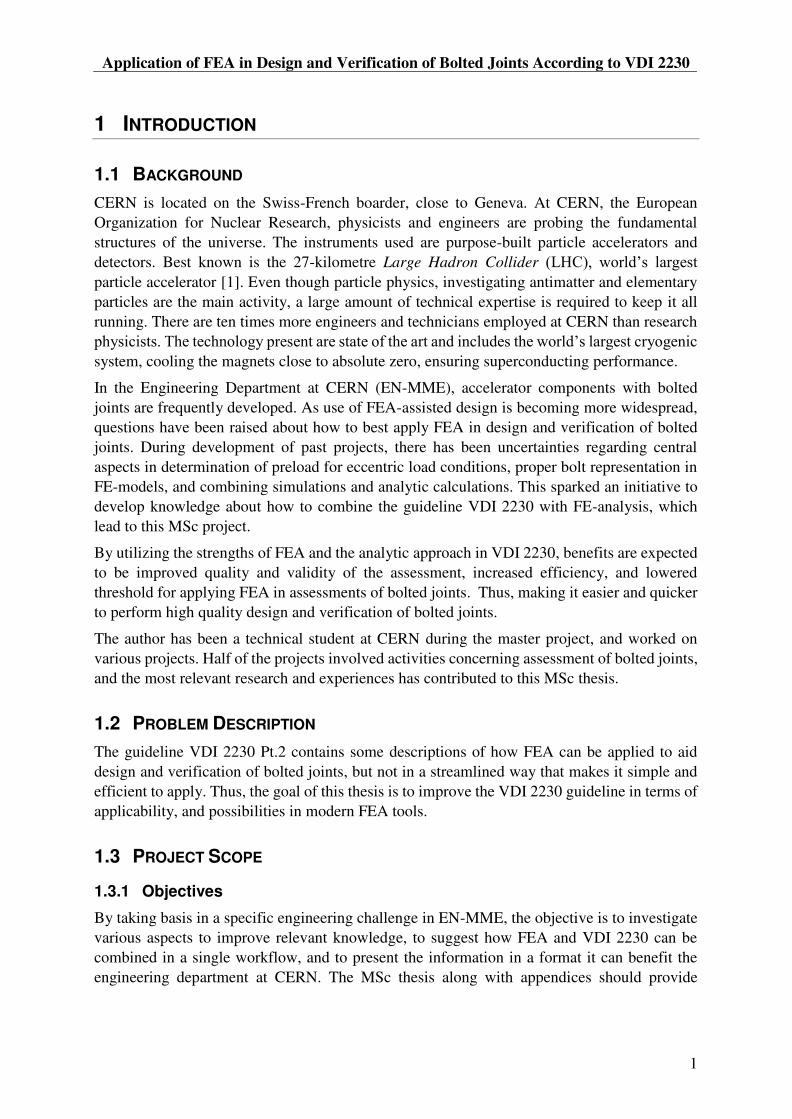
1.1 BACKGROUND
CERN is located on the Swiss-French boarder, close to Geneva. At CERN, the European
Organization for Nuclear Research, physicists and engineers are probing the fundamental
structures of the universe. The instruments used are purpose-built particle accelerators and
detectors. Best known is the 27-kilometre Large Hadron Collider
particle accelerator [1]. Even though particle physics, investigating antimatter and elementary
particles are the main activity, a large amount of technical expertise is required to keep it all
running. There are ten times more engineers and technicians employed at CERN than research
system, cooling the magnets close to absolute zero, ensuring superconducting performance.
In the Engineering Department at CERN (EN-MME), accelerator components with bolted
joints are frequently developed. As use of FEA-assisted design is becoming more widespread,
questions have been raised about how to best apply FEA in design and verification of bolted
joints. During development of past projects, there has been uncertainties regarding central
aspects in determination of preload for eccentric load conditions, proper bolt representation in
FE-models, and combining simulations and analytic calculations. This sparked an initiative to
develop knowledge about how to combine the guideline VDI 2230 with FE-analysis, which
lead to this MSc project.
By utilizing the strengths of FEA and the analytic approach in VDI 2230, benefits are expected
to be improved quality and validity of the assessment, increased efficiency, and lowered
threshold for applying FEA in assessments of bolted joints. Thus, making it easier and quicker
to perform high quality design and verification of bolted joints.
The author has been a technical student at CERN during the master project, and worked on
various projects. Half of the projects involved activities concerning assessment of bolted joints,
and the most relevant research and experiences has contributed to this MSc thesis.
1.2 PROBLEM DESCRIPTION
The guideline VDI 2230 Pt.2 contains some descriptions of how FEA can be applied to aid
design and verification of bolted joints, but not in a streamlined way that makes it simple and
efficient to apply. Thus, the goal of this thesis is to improve the VDI 2230 guideline in terms of
applicability, and possibilities in modern FEA tools.
1.3 PROJECT SCOPE
1.3.1 Objectives
By taking basis in a specific engineering challenge in EN-MME, the objective is to investigate
various aspects to improve relevant knowledge, to suggest how FEA and VDI 2230 can be
combined in a single workflow, and to present the information in a format it can benefit the
engineering department at CERN. The MSc thesis along with appendices should provide

MSc Thesis 2018
2
sufficient guidance to perform FEA assisted design and verification of bolted joints according
to VDI 2230.
1.3.2 Research Questions
The research questions are:
RQ 1: For a specific case, what were the challenges of combining VDI 2230 and FE-analysis?
RQ 2: How can the identified challenges be met, and avoided in the future?
1.4 STRUCTURE OF REPORT
First, some general and basic theory about bolted joints and use of FEA in analysis of bolted
joints are presented. Then, the specific case of a Helium vessel bolt assessment for the Crab
Cavities is described, illustrating challenges and uncertainties in combining FEA and VDI 2230.
Chapter 4 investigates prying by describing what it is, when it is relevant, and how it can be
encountered. Then a study is performed to investigate the influence of preload on prying, before
the chapter is concluded by a discussion and a summary.
Chapter 5 propose a basic workflow for combining VDI 2230 and FEA, and include a guide,
aspects of more advanced assessments, case examples, calculation support material, and a
seminar prepared to educate about assessment of bolted joints.
In Chapter 6, suggestions and recommendations for a potential revision of the Helium vessel
analysis is presented.
The discussion in Chapter 7 target the MSc project, some larger perspectives of the project, and
possible future research. The thesis is concluded by a summary in Chapter 8.
1.5 LITERATURE
The main literature for this thesis is the VDI 2230:2014 guideline in two parts [2, 3], for
Systematic calculation of highly stressed bolted joints. Part 1 present a 13-step analytic
calculation procedure for design and verification of single bolted joints (SBJ). Part 2 detail how
SBJs can be extracted from multi bolted joints through Rigid Body Mechanics and
Elastomechanic methods. Aspects of how FEA can be used to aid the analysis are also included.
The book Introduction to the Design and Behaviour of Bolted Joints by J. H. Bickford [4] has
served as a useful source of supplementary details to VDI 2230, as it presents and discuss many
relevant aspects of bolted joints. However, the nomenclature is different from VDI 2230, and
Imperial units is often used.
This thesis is based on investigations and studies presented in two reports [5, 6]. One report
was written as a pre-project, and the second report was written as the research activities
progressed and is in the format of a chronologic research log.
Throughout the thesis, other references are included where relevant.

Application of FEA in Design and Verification of Bolted Joints According to VDI 2230
3
2 THEORY
This chapter introduce basic concepts and fundamental theory about bolted joints and FEA
representation. First, some central terms are defined. The basics of bolted joints and joint
diagrams are then introduced, along with the analytic VDI 2230 calculation guideline. Last,
FEA model classes and aspects of bolt representation in MBJs are presented.
2.1 TERMS
SBJ (Single bolted joint) Bolted joint with one bolt.
MBJ (Multi bolted joint) Bolted joint with multiple bolts. More than one bolt are involved in transmitting a load or in fulfilling the joints function. The individual bolts may be subjected to markedly different loads.
Load Quantity of the effect of forces and moments on the structure
Global workload The global load on the structure/component in operation / working state. Can include pressure, forces, self-
Bolt workload The part of the global workload applied to a single bolt
Preload A certain tensional force created in the bolt from tightening and associated elongation of the bolt in assembled state
Clamped plate / plates Component / components clamped between the bolt head and nut / tapped threads
Clamping / deformation
solid
Volume in the clamped part / parts exposed to elastic strain from bolt preload. Can consist of deformation cone and a sleeve
Contact area Geometrically defined area through which loads are transmitted from one component to the other by means of the bolted joint / joints
Clamping interface The contact surface between the components that are bolted together and is involved in force transmission. Area of clamping solid in the contact area.
2.2 BASICS OF BOLTED JOINTS
Bolted Joints (BJs) have the function of clamping separate components together, often
transferring forces, moments or sealing against pressurized fluids. To transfer those loads and
for the joint to behave as a continuous part of the structure while doing it, BJs must have a
certain clamping pressure. To ensure this, bolts are tightened into tension, restricted by their
maximum load capacity. To be able to make a knowledge based design considering all
requirements, a calculation model can be made and used to aid the assessment.
This section provides a brief introduction to some of the most central elements of bolted joint
calculations. VDI 2230 contains comprehensive details on the calculation of BJs, and is

MSc Thesis 2018
4
introduced in next section. The theory below assumes a concentrically clamped bolt, with
concentric and axial loading in tension.
2.2.1 Classification and Characteristics of BJs
Bolted joints can have a variety of designs, resulting in different load characteristics in
distribution and type of loading. Table 1 list different types of SBJs and MBJs, with concentric,
eccentric, symmetric, and asymmetric geometries and loading. Simplified calculation-models
with relevant loads are included, as well as relevant calculation approaches. FEM applies to all
joint types. VDI 2230 apply to 1 and 2, and with limited treatment: 3, 4, 6, 7 and 8. The flange
with sealing gasket, 5, are covered by DIN EN 1591.
Table 1: Outline of BJs [Pt.1 - Table 1]
Two main types of bolted joints are shown in Figure 1. In the tapped thread joint (TTJ), the bolt
runs through a clearance hole in the first plate, and enters tapped threads in the second plate.
The through bolted joint (TBJ) has clearance hole in both plates, and is fastened by a nut. The
two types of joints are often referred to in the standard, and both entail special considerations.
Figure 1: TTJ & TBJ [Pt.2 - Figure 45 & 48]
Clamping interface


MSc Thesis 2018
6
When a bolt consists of multiple cross-sections, the combined stiffness is calculated according
to Eq. (3).
1 2
1 1 1 1
tot ik k k k
(3)
In VDI 2230 however, the term resilience is used, calculated according to Eq. (4). This quantity
is the inverse of stiffness and describes the compliance.
2
[mm] [mm/N]
[MPa] [mm ]
l
E A (4)
Using the resilience, summation of multiple cross-sections in series are simple, as Eq. (5) show.
1 2tot i (5)
With the quantity resilience, the general force expression of forces is given in Eq. (6).
f
F (6)
2.2.3 Joint Diagram
Figure 4: Distortion triangle [Pt.1 - Figure 2]
A joint diagram is a graphic representation of the forces and displacements of the bolt and the
clamped parts in a bolted joint. Figure 4 show a BJ in a) initial state, in b) assembled state, and
in c) working state. In assembled state, only internal forces apply. When the bolt is tightened,
the assembly preload is generated. This give the clamp force at the interface, as seen in
)a Initial state )b Assembled state )c Working state (n=1)


MSc Thesis 2018
8
Figure 6: Joint diagram with associated quantities [Pt.1 - Figure 22]
The additional loads are a result of the workload, and the total load in the bolt and in the
clamping interface depends on the preload. Taking the general preload ( into consideration,
the residual clamp load ( , and the bolt load can be calculated according to Eq. (11)
and Eq. (12). The associated quantities can be identified in Figure 6.
KR V PAF F F (11)
S V SAF F F (12)
The bolt stress can be calculated for both assembly and working states, and are calculated for
the bolt stress area ( . The assembly stress ( ) depend on the required tightening torque
( ) to achieve the permitted assembly preload ( ). The working stress ( are based
on the maximum bolt load ( ). These equations are presented later in the thesis.
2.2.5 Additional Factors to Consider
As section 2.2.4 show, the principles of calculating quantities in BJs are not that complicated,
and most of VDI 2230 are based on that simple theory. However, the above equations are only
valid for concentric joints, both in terms of clamping and loading. In practice, there are many
factors that complicate the calculations, which VDI 2230 presents techniques and strategies to
handle, making VDI 2230 a comprehensive standard.
Just identifying the bolt workload can be a complex task. There may be transverse loads,
moments, and a complex geometry. Both loading and clamping can be eccentric, leading to
bending effects and uneven distribution of pressure in the interface that may result in partial
joint opening. The preload itself may also change due to numerous reasons: tightening of other
bolts in the area, embedding of contact or thread surfaces, self-loosening by rotation, relaxation
of the materials, temperature change, or by overloading the BJ.
There is also uncertainty involved in tightening of the bolts, depending on the accuracy of the
tightening method. This results in a spread between the maximum and minimum probable

Application of FEA in Design and Verification of Bolted Joints According to VDI 2230
9
preload. The strategy is then to define a tightening torque to achieve the maximum preload,
making sure that the minimum preload is achieved. Verifications then has to be performed for
the preload extremes. The maximum bolt load occur with the maximum preload, and the
minimum clamp load occur with the minimum preload.
From the above, it is clear that a structured approach is required to perform a safe assessment
of bolted joints, taking all the relevant factors into consideration. This is what VDI 2230
provides with defined calculation steps, verification strategies, and assessment criteria. The
analytic procedure is described in further detail in section 2.3.
2.2.6 Deformation Cones and MBJ aspects
As described, when the bolt is elongated, the clamped parts are compressed. The volume in the
clamped parts that is compressed is assumed to form a prismatic solid, and is referred to as
clamping or deformation solid. The shape of the clamping solid depends on if it is a TBJ or
TTJ, as Figure 7 show. The pressure distribution in the clamping interface is different for the
two clamping solids, because the clamping interface cut the clamping solids at different
locations. If the clamping interface is smaller than the diameter of the clamping solid in the
interface cross section, the deformation solid will consist of a cone and a sleeve, as seen in
Figure 8. The clamping pressure is then distributed across the whole interface.
The resilience of the clamped parts depends on the volume of the clamping solid, and can be
estimated by analytic methods.
Figure 7: Deformation cones for a TBJ and a TTJ [7]
VDI 2230 defines a limiting diameter G in [Pt.1 5.1.2.2], which is calculated according to (13)
. This value defines the diameter where the compressive stresses in the clamping interface is
significant. For the analytic VDI 2230 approach to be valid, the clamping interface must be
smaller than the limiting diameter G. This is controlled in the step R0.

MSc Thesis 2018
10
(R0/1) & (R0/2) minTBJ:
TTJ: ' 1,5...2
W
W
G h d
G d (13)
When the limit criteria is fulfilled, there is sufficient pressure at the edges of the clamping
interface so that no opening occur, and the analytic equations are valid. If the interface width
exceeds the values in (14), joint opening can occur just by preloading the bolt.
min
if
TBJ: D (1,4...1,6)
TTJ: D 4,2
A
A W
A W
D G
h d
d
(14)
Figure 8: Deformation cone and sleeve (left) and limit criteria G (right)
For MBJs, the same principle of interface-width applies to bolt spacing. The clamping solids
must interact to provide a sufficient and continuous pressure in the clamping interface (Figure
9). Put simple, the clamping cone has to be cut on all sides to provide proper clamping pressure
in the interface. Conventional bolt spacing is: .
Figure 9: Clamping solid interaction in MBJs

Application of FEA in Design and Verification of Bolted Joints According to VDI 2230
11
2.3 ANALYTIC VDI 2230 PROCEDURE
The calculation procedure defined in VDI 2230 consist of 13 steps, and is outlined in Table 2.
First, input parameters are decided, and the validity is controlled. Then values of the joint
diagram are calculated and the clamping requirement is defined. The last steps include stress
calculations and strength verifications, before the tightening torque is determined. The factors
controlled and accounted for by the procedure are listed in Table 3.
The complete analytic verification procedure is presented in [Pt.1 Ch.4], also containing
relevant cross-references.
Table 2: Outline of the analytic VDI 2230 procedure [Pt.1 4.1]
Inputs
R0 Nominal diameter and limiting measurement ,d G
R1 Tightening factor A
R2 Minimum clamp load Kerf
F
Joint Diagram
R3 Dividing the workload / load factor , ,SA PA
F F
R4 Preload changes , 'Z Vth
F F
R5 Minimum assembly preload minM
F
R6 Maximum assembly preload maxM
F
Stress Cases and Strength Verifications
R7 Assembly stress . ,
red M MzulF
R8 Working stress . ,
red B FS
R9 Alternating stress , ,a ab D
S
R10 Surface pressure max ,
pp S
R11 Minimum length of engagement mineff
m
R12 Slipping, shearing max,
G QS
R13 Tightening torque A
M

MSc Thesis 2018
12
Figure 10 displays a joint diagram containing the most relevant quantities used in the analytic
VDI 2230 design and verification procedure. It can be seen from the steps in Table 2 that the
required clamp load ( is calculated early. Then, preload loss due to embedding ) and
additional thermal load ( are calculated. Together they give the minimum required
assembly preload ( . Taking the tightening uncertainty ( into account, the required
maximum assembly preload ( is calculated according to Eq. (15).
min
max min
1M Kerf A Z Vth
M A M
F F F F F
F F (15)
The permitted assembly preload ( is then calculated, and has to be larger than the
required maximum assembly preload ( . If not, the bolt diameter or strength class has to
be modified to achieve a higher allowed assembly preload. If it is larger, the permitted assembly
preload is used to define the tightening torque. The spread between required and allowed
assembly preload provides a safety factor against the clamping requirements.
maxS Mzul A VthF F F F (16)
Eq. (16) give the max bolt load in working state ( , and is used to calculate the work
stress.
Figure 10: Joint diagram with analytic VDI 2230 quantities [Pt.1 - Figure 5]
The validity of the analytic calculations relies on the following assumptions:
- Liner-elastic material behaviour
- Very small deformations, cross-sections remain flat
- Compliance with the limit distance G or G` (Step R0)

Application of FEA in Design and Verification of Bolted Joints According to VDI 2230
13
Table 3: Factors considered in the calculation procedure
Factors controlled Factors accounted for
Minimum clamping pressure, resisting:
o Transverse slip
o Internal pressure
o Opening of the joint interface
Assembly stress in bolt
Working stress during operation
Fatigue due to alternating stress
Surface pressure at bolt head bearing area
Thread engagement length
How applied work load divides between
increasing bolt load and relieving the
clamped parts
Uncertainty in preload from tightening
Embedding and thermal changes of
preload
Friction at interface and in the threads
Residual tightening torque in bolt
2.4 FEA MODEL CLASSES
VDI 2230 Part 2 divides FE-modelling of BJs into four basic model classes, as shown in Table
4. These classes have different level of details, required modelling efforts, and different
practical considerations related to applicability in FE-analysis. It is the scope of the analysis
that defines which model class most appropriate to use. There are advantages and disadvantages
with all classes.
All the classes and how they can be used to derive analytic calculation quantities, and important
aspects to achieve as realistic representation as possible are described in [Pt.2 Ch. 7].
Table 4: Overview of the model classes [Pt.2 Table 1]
Class I Class II Class III Class IV
Characteristic
Bolt and interface are not taken into consideration. Preload is not included in representation
Bolt is represented by a beam. Preload and interface contact can be included
Bolt is represented by a volume body. Preload and interface contact can be included
Bolt is fully modelled and include threads, preload, and contact on all surfaces

MSc Thesis 2018
14
Objective of
calculation
Internal forces in the clamping interface as determination of workload, or determination of analytic calculation quantities
Internal forces in the bolt
Internal forces in the bolt
Internal forces in the bolt, local stress in bolt threads and clamping area
2.4.1 Class I
The components are modelled as a continuous solid, without any bolt. This allows for extraction
of internal loads in the relevant cross-section, when exposed to working loads. The cross-
section forces and moment then serve as input parameters for the calculation procedure, giving
the bolt workload that the bolt has to withstand. The arm to the application point of eccentric
loading can be determined according to Figure 11 and Eq. (17).
If the components are modelled as two bodies, they can be connected using a contact
formulation. This approach simplifies extraction of the loads in the relevant cross-section. For
MBJs, the solids may be connected by spot welds where the bolts are located, for simple
extraction of the bolt workload.
The exact influence of the bolt resilience and preload is not considered, and it is not possible to
assess the clamping conditions. Therefore, this class has some limitations, and is primarily used
for determination of workload ( ).
K
K
Ma
F (17)
Figure 11: Intersection forces Class I [Pt.2 - Figure 60]

Application of FEA in Design and Verification of Bolted Joints According to VDI 2230
15
2.4.2 Class II
The bolt is represented by a line-element with the same properties as the bolt in question. The
line-element may be a tension-member, beam element or a spring. This element is connected to
the components via multiple point constraints (MPC), or kinematic joint definitions. The
connections should be applied in the actual bolt head bearing area and tapped tread length only,
to have a more realistic compliance. However, using MPC joints to attach the line-element,
artificial stiffness is often introduced. If the bolt properties are defined from the analytic axial
and bending resilience, this can be partially avoided. Also note the effect of MPC connection
for TTJs on the pressure distribution in the clamping interface, demonstrated in Figure 12. It
can be seen that artificial high pressures are present close to where the MPCs are connected.
Preload can be applied and clamping pressure in the interface and joint opening can be assessed.
Internal bolt forces is easily be extracted, and can serve as input parameter for analytical
calculations. Joint slip due to low clamping pressure is challenging to identify, as both ends of
the beam are fixed to the components. Some techniques to assess slipping include monitoring
of shear force and bending moment in the beam. Sudden changes, or high values, can indicate
that slipping would happen. Analytic verification calculations can be used to assess the safety
factor against slipping.
Figure 12: Effect of rigid MPCs on mesh stiffness and the resulting pressure distribution with
Class II model
2.4.3 Class III
In this class, the bolt is represented by a solid volume body. Through the bolt material
properties, the bolt compliance is represented in the FE-model by the relevant constitutive
equations. Contact in the bolt head bearing area is well represented, and no artificial stiffness
are introduced. Assessment of joint slip and tendency to self-loosening can be carried out.
The resilience of the bolt depends on the bolt diameter. A simple approximation is to use a
uniform diameter based on the thread minor diameter ( ). If there is a shank, it can be modelled
with the bolt nominal diameter. Further details on this topic are described in 2.4.6.
Preparing a Class III model requires some more effort than with Class II, especially for MBJs
with a large number of bolts. However, in some cases it still may be beneficial to use a Class
III model.

MSc Thesis 2018
16
2.4.4 Class IV
For this class, the bolt is modelled in detail down to the correct radius in the bottom of the
threads, and contact conditions are applied to all thread surfaces. The strength of this class is
assessment of micro behaviour and stress concentrations, and will not be practical to use with
VDI 2230 verifications or in a large scale load analysis. The required simulation and modelling
efforts are very high.
2.4.5 Comparison of Model Classes
Table 5 compares the different model classes, and how central model parameters are
represented.
Table 5: Comparison of FE-model classes [Pt.2 Table 2]
Model class: I II and III IV
Modelling of the BJ
Effort low medium high
Idealisation of the bolt not modelled simplified modelled in detail
Contact conditions in the interface
not modelled modelled modelled
Preload without with with
Required parameters from VDI 2230 Part 1 relevant section number is indicated
Compliance of the bolt
5.1.1 5.1.1 / included in
the model included in the
model
Compliance of the plates
5.1.2 included in the
model included in the
model
Load application factor
5.2.2 included in the
model included in the
model
Tightening factor 5.4.3 5.4.3 5.4.3
Amount of embedment
5.4.2.1 5.4.2.1 5.4.2.1

Application of FEA in Design and Verification of Bolted Joints According to VDI 2230
17
2.4.6 Bolt Diameter
There are three natural bolt diameters to use when modelling the bolt: nominal diameter ( ),
thread minor diameter ( ), and diameter based on the analytic bolt resilience ( ).
A diameter based on the thread minor diameter is the most simple option, and provides a fairly
realistic bolt resilience.
The diameter based on analytic bolt resilience can be calculated according to Eq.(18), and
require that the analytic resilience is known. Calculation of this is described in [Pt.1 5.1.1].
[Pt.2 - Eq.79] , 4
k
S S
lA d A
E (18)
k
S S
lI
E (19)
with separate definition of cross section area and areal moment of inertia. Those properties can
be calculated according to (18) and (19) from the analytic axial and bending resilience. With
this option, it is ensured that both axial and bending properties of the beam correspond to the
analytic resiliencies.
2.4.7 Validity in Resilience Representation
-
model. How the workload is distributed between relieving the clamped plates and increasing
the load in the bolt.
The mesh has to be refined in the clamping solid volume to have an accurate representation of
the clamping solid and the clamped parts resilience. The representation of clamping solid also
affect the clamping pressure distribution in the interface in the model.
Both the bending and axial resilience of the bolt in the FE-model can be inaccurate. With respect
to the bolt loads, the most conservative is that the FE-bolt is too stiff. The bolt will then absorb
higher axial load and bending moment than what might be realistic. Note that this also can
affect the load limit for joint opening. The uncertainty can be quantified by performing a
sensitivity study, or by comparing with analytic values.
For traditional joints with high preload, and where the bolt is much more resilient than the
clamped plates, the additional bolt loads are often small. In such cases, the effect of inaccurate
bolt resilience representation can be less critical.

MSc Thesis 2018
18

Application of FEA in Design and Verification of Bolted Joints According to VDI 2230
19
3 DQW CRAB CAVITIES HELIUM VESSEL ANALYSIS
The scope of this chapter is to investigate how VDI 2230 has been combined with FEA for a
practical case. It will introduce the Crab Cavities Helium vessel, and its role in the context of
LHC (Large Hadron Collider) and the High Luminosity upgrade. Then, the analysis of the
bolted joints will be presented and used as basis to identify challenges, and how those
challenges could be countered.
3.1 INTRODUCTION TO THE CRAB CAVITIES
3.1.1 LHC
At CERN, particles are accelerated to 99.9999991% the speed of light and to a kinetic energy
of 7 TeV1 [8]. The acceleration happens through 5 accelerator steps, as illustrated in Figure 13.
For acceleration of protons, a small bunch of Hydrogen atoms are ionized, and accelerated in
LINAC 2 to 30% the speed of light. Then the BOOSTER, PS, SPS, and LHC accelerate the
particle bunches to the maximum energy levels.
Figure 13: The CERN accelerator complex © CERN
The Large Hadron Collider (LHC) is one of the largest scientific instruments ever built. It has
a circumference of about 27 km, and is located 100m underground in average. Magnetic fields
from superconducting dipole magnets curve the particle trajectories, and electromagnetic
resonators (RF-cavities) accelerate the particles. There are two proton beams circulating in
opposite directions, and the design capacity is 2808 bunches per proton beam. Each bunch
contain protons, and circulate 11 245 rotations per second. One bunch is 30 cm long
(1 ns), and has a diameter of one millimetre when far from the collision point. Before collision,
they are squeezed to about 20 micro-meters in diameter. There are about 7.5m between the
bunches (25 ns), and the beam is kept within +/- 7mm traveling through LHC. The particles
1 1 eV = Joule. Thus 14 TeV = Joule. 1 TeV equals the energy of a flying mosquito.

MSc Thesis 2018
20
travel in UHV (Ultra-high Vacuum, 10e-10 mbar), and the beam pipe is cooled to 1.9K (-
271.3 ) by superfluid Helium.
3.1.2 Collisions and Luminosity
At four locations around LHC, the two particle beams are crossed to collide particles. These
collisions are probed by the detectors ATLAS, CMS, ALICE and LHCb, as seen in Figure 14.
Since the particle beams travel in opposite directions, the collision energy is 14 TeV.
Figure 14: Location of detectors around LHC © CERN
The detectors track secondary particles from the collisions, and study processes that vary with
collision energy and are often rare. Therefore, the goal is to have high collision energy, and a
large number of collisions.
There are about 100 billion particles in each bunch, but there is a very low probability of
collisions. The average number of collisions for each bunch crossing is 40, resulting in a total
of 1 billion collisions per second. The amount of collisions per time unit (rate) can be expressed
as luminosity. The integrated luminosity will then be the total number of collisions. To make
statistically significant discoveries, the integrated luminosity must be as high as possible. Some
parameters that influence the number of collisions are: number of particles in each bunch,
number of bunches, frequency of bunch rotations, and beam cross section.
Application of FEA in Design and Verification of Bolted Joints According to VDI 2230
21
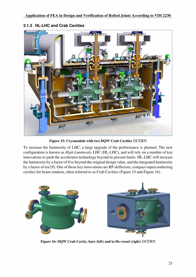
3.1.3 HL-LHC and Crab Cavities
Figure 15: Cryomodule with two DQW Crab Cavities ©CERN
To increase the luminosity of LHC, a large upgrade of the performance is planned. The new
configuration is known as High Luminosity LHC (HL-LHC), and will rely on a number of key
innovations to push the accelerator technology beyond its present limits. HL-LHC will increase
the luminosity by a factor of five beyond the original design value, and the integrated luminosity
by a factor of ten [9]. One of those key innovations are RF-deflectors, compact superconducting
cavities for beam rotation, often referred to as Crab Cavities (Figure 15 and Figure 16).
Figure 16: DQW Crab Cavity, bare (left) and in He-vessel (right) ©CERN

MSc Thesis 2018
22
At the collision point, bunches cross as shown in Figure 17, having a certain crossing angle. A
significant increase in the probability for collisions and gain in luminosity can be obtained from
achieving a more head-on crossing, like seen in centre of Figure 17. To achieve that, Crab
Cavities are to be placed on both sides of the collision points. A time-dependent transverse kick
from the Crab Cavities is used to rotate the bunches to impose head-on collisions at the impact
point. After the collision point, a second cavity reverses the rotation before the bunches continue
the path in LHC.
Figure 17: Visualisation of how Crab Cavities rotate bunches before and after collision point
©CERN
There are two crab cavity concepts: DQW (Double Quarter Wave, vertical) and RFD (RF
Dipole, horizontal). The most relevant cavity for this report is the DQW Crab Cavity. December
2017, one prototype cryomodule with two DQW cavities were assembled (Figure 18), and are
supposed to be tested in SPS in 2018. The long-term plan is that 8 cryomodules shall be installed
in LHC during LS3 (Long Shutdown 3) in 2024-2026.
Figure 18: Two Helium vessels for DQW Crab Cavities during assembly in 2017 ©CERN

Application of FEA in Design and Verification of Bolted Joints According to VDI 2230
23
3.2 HELIUM VESSEL FOR DQW CRAB CAVITIES
The DQW Crab Cavity is made of Niobium, which has superconducting properties when its
temperature is < 9.25K. To achieve such temperatures, it must be submerged into superfluid
Helium at 2K. To minimize the required volume of Helium and to maximize heat extraction
from the cavity, a Helium vessel was designed to enclose the cavity and contain the Helium.
The development of prototype cavities is detailed in several papers [10-12], and the design
evolution of the vessel is detailed in a report by N. Kuder [13]. The strength assessment for the
DQW Crab Cavity and Helium vessel is presented in another report [14].
The He-vessel has the outer dimensions 573x488x390, weighs 120kg or 180 kg with the cavity
included. It contains 30 of Helium and is designed for an internal operating pressure (PS) of
1.8 bar (abs). The test pressure2 is 2.6 bar (abs), which is 1.43xPS. This is the maximum
pressure the vessel must be able to withstand [10].
The Helium tank has a structural role and is rigidly connected to the Stainless-Steel cavity ports.
Thus, one goal of the design has been to minimize the loads acting on the cavity from the vessel.
To minimize the loads on the Niobium cavity during cool-down from room temperature (293K)
to cold (2K), it was decided that the He-Vessel plates should be made of Titanium Grade 2,
which is in the same thermal contraction range as Niobium. The integrated thermal contraction
is about 1.5 mm/m when cooled from 300K to 2K.
Figure 19: Helium vessel and bolted joints [14]
In the initial design, the six plates of the Helium vessel were joined together by welds. This
design was discarded due to high deformations resulting from the welding process, and the high
requirements for precision in the connections to the cavity. The final design concept was that
the vessel should be joined together by bolted joints (Figure 19), and that additional fillet welds
should ensure leak-tightness. This is an unconventional concept, and there was no experience
at CERN or other available sources with this concept. No known standards or guidelines
provide specific rules or recommendations for such pressure vessels. Therefore, the design and
verification of the He-vessel were innovative work, and efforts was made to perform a thorough
and conservative analysis. It was decided to use the calculation guideline VDI 2230 to aid the
analysis.
2 According to EN 13445 Unfired Pressure Vessels

MSc Thesis 2018
24
3.2.1 Joint Design
The three joint designs that are present on the He-vessel are displayed in Figure 20. The joint
rows are numbered, showing the location of the joints on the vessel. All the joints are tapped
thread joints (TTJ). Two of the joints has an overlap edge. Fillet welds are applied to ensure
leak tightness in the joints. As seen in Figure 22, the bolt heads are countersunk into a groove
in the plate. This grove is covered by a cover that is welded and serves as an additional barrier
to prevent leakage of Helium.
The bolt size is M6x20, and there are 276 bolts in total. The bolt material is Titanium Grade 5
because of its high proof stress, and to have a similar thermal contraction to the Titanium Grade
2 plates. This reduce preload losses from differential thermal contraction. The bolts have a
outgassing hole in the centre with diameter Ø1.75, to allow potential trapped Helium to
evacuate.
The clamping length is 13mm. For the prototype vessel, SCHNORR preload washers (10-6.4-
1) made of Bronze are applied under the bolt head.
Figure 20: The three joint concepts on the He-vessel, with fillet welds for leak-tightness [14]
(A) (B) (C)

Application of FEA in Design and Verification of Bolted Joints According to VDI 2230
25
3.3 HELIUM VESSEL BOLT ANALYSIS
In this section the bolt analysis of the He-vessel [14] is presented, and challenges in the
assessment and in combining VDI 2230 and FEA are identified and discussed (RQ1). This is
used as basis in answering how the challenges can be met and avoided in the future (RQ2).
3.3.1 Boundary and Load Conditions
The analysis is carried out for the boundary and load conditions shown in Figure 21, and listed
in Table 6. The loads on the model is: self-weight under normal gravity, internal Helium
pressure, and a load on the helium vessel plates from a 0.12mm pre-tuning deformation of the
cavity.
The He-vessel is attached to a support structure, which give realistic support response for the
vessel. The Niobium cavity stiffness is represented in the model. Room temperature has been
assumed for the analysis, since the material properties are weakest at this temperature.
The bolts are preloaded to 4.5 kN, which were selected to provide an acceptable level of work
stress during maximum loading. It is stated in the report [10] that it was not clear from relevant
codes how the preload should be defined.
Frictionless contact is applied in the clamping interfaces, as it was assumed that this would
provide a conservative approach, where the bolt would have to withstand axial, shear, and
bending loads.
Simulations has been performed with and without the fillet welds. The simulation results
relevant for the bolt analysis is when the welds are not present, as the bolted joints alone must
ensure the complete structural integrity of the vessel.
Table 6: Boundary and Load Conditions
Type Unit Value
Temperature K 300
Bolt preload N 4500
Figure 21: BCs of He-vessel FE-model [14]

MSc Thesis 2018
26
3.3.2 Bolt Representation in FE-analysis
Figure 22: Bolt representation in the FE-model according to VDI 2230 Class II [14]
The bolts are represented by beams, according to VDI 2230 Class II. They are connected with
Multi-Point Constraints (MPCs) in the bolt bearing face area and in the threaded hole, as
illustrated in Figure 22. The beam properties used are listed in Table 7, and has been calculated
according to Eq. (18) from the analytically calculated axial resilience and bending
resilience . The analytic resiliensies consideres the outgassing hole in the center of the bolt,
and the resilience contribution from the bolt head and thread engagement. The bolt material is
defined to be Titanium, with an elastic modulus of .
Table 7: Beam properties for M6 bolt
Length [mm] Area [mm2] Ix [mm4] Iy [mm4] J [mm4]
13 9.86 16.92 16.92 33.84
3.3.3 Analysis of Results and Verifications
Bolt loads
Table 8 list the extracted loads, calculated stress, and safety factors. In the original table, there
are two separate columns for simulations with and without fillet welds. As stated above, only
the results from the simulation without welds are relevant for the bolt analysis.
The maximum bolt load is 4.65 kN, and the additional bolt load resulting from the applied
workload is FSA = 150N. The equivalent stress is calculated to be 620 MPa, and is calculated
from the axial and shear load, bending moment, and residual tightening torque. Thus, a modified
version of the VDI 2230 working stress equation has been used. According to the standard VDI
2230 working stress calculation, shear and bending stress is not included. The resulting safety
factor against yield in the bolt has been calculated to be .

Application of FEA in Design and Verification of Bolted Joints According to VDI 2230
27
Table 8: Loads extracted from FEA and calculated bolt stress, adapted from [14]
Name Symbol Unit Value
Preload MF [N] 4500
Max axial bolt load maxSF [N] 4650
Max bending moment SboM [Nmm] 3430
Max shear force maxQF [N] 525
Equivalent stress .red B [MPa] 620
Proof stress Ti gr.5 0,2pR [MPa] 830
Safety factor FS - 1.34
Figure 23 show the axial bolt load distribution in Row 1 of the Helium vessel. It is clear that
there is an uneven workload distribution, and that the most highly loaded bolts are in the middle.
This illustrate that for this case, assuming uniform load distribution would be inaccurate.
However, the force difference is only about 30N and would not have any significant impact in
this case.
Figure 23: Axial bolt load distribution in Row 1
As there is no friction in the contact area, sliding is allowed and the shear force in the bolt is a
result of the relative displacement between the clamped plates. This gives rise to the bending
moment in the beam, which is analytically calculated in (20). Comparing this analytic bending
moment to the moment extracted in Table 8, it is clear that the shear load is the source of the
bending moment. This bending moment gives rise to the bolt bending stress, which is 270 MPa
and 39% of the equivalent stress.
13
525 3412.52 2K
Sb Q
l mmM F N Nmm (20)
The torsional stress from residual tightening torque is 155 MPa and 22.6% of the work stress.
It is according to VDI 2230 practice to include this in the calculation of working stress, but it
should be noted that there is significant uncertainty related to this value.
4470
4480
4490
4500
4510
4520
4530
1 2 3 4 5 6 7 8 9 101112131415161718192021222324252627
Axial Bolt Load - Row 1

MSc Thesis 2018
28
The report concludes: The stress for the bolts considering the worst loading condition is
acceptable. They will operate within the elastic limit
Clamping pressure
A verification of the clamping conditions has been performed by analysing the pressure
distribution for all the 12 clamping areas. Two of them are shown in Figure 24. Blue colour
indicates very low to zero pressure, and red indicate maximum pressures.
Figure 24: Resulting pressure distribution in bolt Row 1 (top) and Row 10 (lower)
Continuity of clamping pressure in the interfaces is required to prevent leakage, and normally
joint opening should not occur. In this case, care should be made that superfluid Helium, which
has zero viscosity and can penetrate the smallest glitches, does not reach the tapped threads.
There is continuity in pressure between the bolts. In Row 10, the pressure distribution is
relatively uniform, and there are only small signs of joint opening in the corners. In Row 1,
there is joint opening towards the middle bolts. This can be related to the bolt load distribution
in Figure 23.
The report concludes: the pressure contacts are evaluated and examined to find the
probable openings and overall behaviour of the plates. The helium vessel will secure the leak-
tightness.
3.3.4 Discussion of Bolt Assessment
In this section, the bolt analysis is discussed, and challenges related to combining VDI 2230
with FE-analysis are outlined.
Friction in the Clamping Interface
In principle, bolts should not experience shear or bending, and slipping in the joint is considered
a failure. The bolt should provide preload, so that the joint through clamping pressure and
friction achieve a friction grip and is able to transfer the workloads and behave as a continuous
solid. Thus, the joint should be designed to avoid slipping, and the main stress acting in the bolt
is normal stress (tension).
This scenario
includes having no friction in the clamping interfaces, which gives rise to slipping and
associated shear and bending loads. All the load components in the bolt are included in the
calculation of combined stress. This verifies that the bolt is able to withstand all the loads that
can act on the bolt and
One challenge with this approach is that it can encourage a low preload, to reduce the combined
stress and increase the bolt stress safety factor. However, having a low preload reduce the
friction grip of the joint and increase the chance of joint slipping to occur.

Application of FEA in Design and Verification of Bolted Joints According to VDI 2230
29
By following a standard VDI 2230 approach, emphasis is put on having a high preload and
verifying that no slipping occurs. In this case, only axial load and residual tightening torque is
included in the calculation of bolt stress. VDI 2230 also propose to calculate a shear safety
factor for a scenario where slipping is present.
In terms of bolt stress, t case it includes shear and
bending stress. However, since it favours low preload, taking a more standard VDI 2230
approach can in many cases be more beneficial. This will encourage a high preload and give a
higher friction grip capacity in the joint. Friction should then also be included in the FE-
analysis, and it should be verified that slipping is not occurring.
It can be noted that joint slip also is of importance when identifying the loads on the fillet welds,
as slipping can increase the loads significantly.
Joint Opening
According to the standard VDI 2230 approach, joint opening should be avoided and is a
prerequisite for the validity of the analytic calculations. However, FEA expands that validity
range with allowing for more detailed analysis of the bolt loads and clamping pressure
distribution.
In the He-vessel analysis the clamping pressure has been assessed and it is concluded that the
sealing function of the joint is fulfilled. Partial joint opening is present in some locations, and
it is pointed out that this is related to the uneven bolt load distribution. It is not known if, or to
which degree non-linear bolt load development (prying) is present. The validity of the pressure
distribution and bolt loads depends on the mesh size in the clamping solid and interface surface
mesh refinement, and is not known.
Uncertainty in preload
In the analysis, one preload level has been applied in the simulation that verifies both bolt stress
and clamping pressure. According to VDI 2230, there will be tightening uncertainty and preload
losses, which results in a minimum and maximum preload. The verification of bolt stresses
should then be carried out with the maximum preload, and verification of clamping
requirements with the minimum preload.
Operating Pressure
The analysis has been carried out for a nominal operating pressure (PS) of 1.8 bar (abs). The
bolted joints should be designed and verified for the maximum workload to ensure the structural
integrity in the extreme loading case. VDI 2230 does not treat how the maximum workload
should be defined, but according to one standard [15] the vessel should be designed for the test
pressure of 2.6 bar (abs). Which pressure to use depend on considerations about which safety
factor that is required from the design, and the probability of operating pressures above nominal
values.

MSc Thesis 2018
30
3.3.5 Selection of Preload
One of the challenges in design and verification of the bolted joints of the He-vessel was
selecting the bolt preload. The first guess of preload were based on the assumption that the bolt
would have to be preloaded with the same load as the bolt workload. However, when the preload
were selected to match the bolt workload, the bolt load became even higher in the next
simulation. This new bolt load were then applied as preload, and it resulted in a iterative process
where the preload were defined by the bolt load of the previous simulation.
This behaviour has been recreated in a simulation, and the loads are presented in Figure 25. It
can be seen that in the first simulation, the workload is 4.3 kN. In simulation 2, the preload is
set to be 4.3 kN, but the bolt load becomes 5.3 kN. For simulation 2, the additional bolt load is
893 N. In the next simulation, the preload is set to be 5.3kN. What can be seen is that as the
preload increase (>6 kN), the additional bolt load decrease and approaches 160-200 N. The
preload level where this happen is higher than the initial estimate of 4.3 kN which were based
on the workload.
Figure 25: Development in Total Bolt Load with Increasing Preloads
This behavior led to some confusion and uncertainty about how to best identify an appropriate
level of preload. It was expected that prying had a role in the described behavior, but not exactly
to which extent the preload influenced the presence of prying.
3.4 RQ1: CHALLENGES IN ANALYSIS OF BOLTED JOINTS
Based on the discussion of the analysis (3.3.4) and the description of preload selection (3.3.5),
this section summarises some central challenges in combining VDI 2230 and FE-analysis for
the case of the Crab Cavities Helium vessel.
Some challenges related to the scenario
clamping interface and including all load components in calculation of the combined stress are
discussed. It is pointed out that taking a more standard VDI 2230 approach with friction in the
interface and emphasis on avoiding joint slip will encourage a higher preload, and can in some
3000
3500
4000
4500
5000
5500
6000
6500
7000
7500
1 2 3 4 5 6 7 8 9 10
Bo
lt L
oa
d [
N]
Simulation number
Development in Total Bolt Load with Increasing Preloads
Preload Additional Bolt load

Application of FEA in Design and Verification of Bolted Joints According to VDI 2230
31
cases be more beneficial. Verifications must then be performed in the analysis that no slipping
will occur.
Partial joint opening is present in some locations, but the sealing function is fulfilled. To
improve the use of FEA in such assessments, methods to identify if prying is present could be
clarified, along with aspects of validity.
In the analysis, one preload level has been applied in the verification of clamping pressure and
bolt stress. According to VDI 2230 there is uncertainty in the preload, and verifications of bolt
stress and clamping pressure should be verified for the max and min preload level respectively.
There was some challenges in the selection of preload, as demonstrated by the preload
iterations. Prying were expected to have some role, but it was not known to which extent the
level of preload influenced the presence of prying.
Altogether, the above identify challenges in how FEA and VDI 2230 has been combined in the
Helium vessel bolt analysis and answers the first research question. It also serves as constructive
feedback on the analysis and outline relevant learning points. These findings are used as basis
for the suggestions and recommendations for a potential revision of the analysis given in Ch. 6,
and in answering RQ2.
3.5 RQ2: HOW CAN THE CHALLENGES BE MET?
With the challenges outlined above in mind, the next question is how they can be met and
avoided in the future?
The guideline VDI 2230 contains answers to many of the challenges, but not in a straight
forward and clear way. It is a detailed and thorough guideline, and it can be challenging to catch
the fundamental principles and verification concepts. The second part of the guideline cover
FEA aspects in general, but it does not provide a simple and easy to use workflow defining how
a combined analysis should be performed. For a user with little experience with VDI 2230 to
reach the required level of knowledge to perform such an assessment would be time consuming
and require high efforts.
To lower the threshold for combining VDI 2230 with FE-analysis, making it simple to apply
and to achieve high quality in the analysis, the following support material is suggested:
Analysis Approach - The typical difference in traditional analytic VDI 2230 approach and
FEA based analysis should be emphasized and made clear.
Simplified Workflow - This should provide a structured approach to bolt analysis, and include
all the basic elements like selection of preload, setup of FEA and BCs, how analytic calculations
and FEA results should be combined, and descriptions of verification strategies. To simplify
the calculations, a Mathcad template that matches the workflow steps should be prepared.
Guide - This should be related to the suggested workflow steps, and provide detail descriptions,
know how, best practices, discuss aspects of validity, and provide relevant references.
Examples of Application - For some cases, the simplified workflow and calculations should
be demonstrated so they can serve as examples of how FEA can be used in analysis of bolted
joints.

MSc Thesis 2018
32
Seminar - A seminar could be prepared to educate relevant personnel about use of FEA in
analysis of bolted joints. It should provide a thorough introduction to VDI 2230 and the
simplified workflow.
Studies of Prying - Studies should be performed to understand how it is related to additional
bolt loads and joint opening, and how it affected by the preload level. How it can be identified
and avoided should also be made clear.
The combination of the above suggested support material are believed to help the readers to
avoid the challenges in the He-vessel bolt analysis, and that the wish for having the material
presented in a format so can benefit the engineering department at CERN is achieved in a
good way.
The prying studies are presented in Ch. 4, and the workflow and associated support material
are presented in Ch. 5.
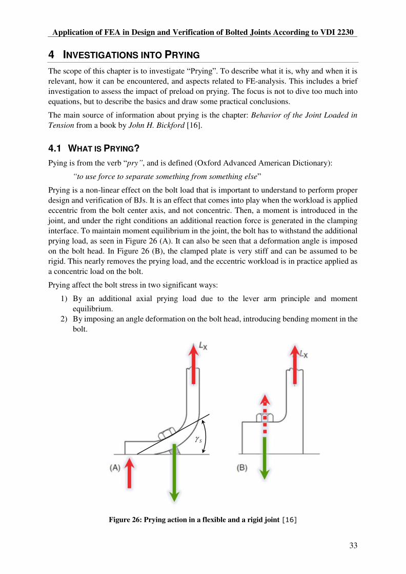
Application of FEA in Design and Verification of Bolted Joints According to VDI 2230
33
4 INVESTIGATIONS INTO PRYING
The scope of this chapter is to investigate . To describe what it is, why and when it is
relevant, how it can be encountered, and aspects related to FE-analysis. This includes a brief
investigation to assess the impact of preload on prying. The focus is not to dive too much into
equations, but to describe the basics and draw some practical conclusions.
The main source of information about prying is the chapter: Behavior of the Joint Loaded in
Tension from a book by John H. Bickford [16].
4.1 WHAT IS PRYING?
Pying is from the verb pry , and is defined (Oxford Advanced American Dictionary):
to use force to separate something from something else
Prying is a non-linear effect on the bolt load that is important to understand to perform proper
design and verification of BJs. It is an effect that comes into play when the workload is applied
eccentric from the bolt center axis, and not concentric. Then, a moment is introduced in the
joint, and under the right conditions an additional reaction force is generated in the clamping
interface. To maintain moment equilibrium in the joint, the bolt has to withstand the additional
prying load, as seen in Figure 26 (A). It can also be seen that a deformation angle is imposed
on the bolt head. In Figure 26 (B), the clamped plate is very stiff and can be assumed to be
rigid. This nearly removes the prying load, and the eccentric workload is in practice applied as
a concentric load on the bolt.
Prying affect the bolt stress in two significant ways:
1) By an additional axial prying load due to the lever arm principle and moment
equilibrium.
2) By imposing an angle deformation on the bolt head, introducing bending moment in the
bolt.
Figure 26: Prying action in a flexible and a rigid joint [16]
S


MSc Thesis 2018
38
Figure 32: Maximum bolt loads for various preload levels
Additional Bolt Load
To better compare the load developments, Figure 33 plot the additional bolt loads as the global
workload increase. The additional bolt load is obtained by subtracting the preload from the
maximum bolt load ( ).
Figure 33: Additional bolt load for various preload levels
0
20
40
60
80
100
120
140
160
180
0 10 20 30 40 50 60 70 80 90 100
Bo
lt L
oa
d [
kN
]
Pressure (Global Workload) [MPa]
Preload Influence on Prying: Bolt load
142.4 kN Analytic (for 142.4kN) 116 kN
89 kN 70 kN 50 kN
39.7 kN 0 kN
0
5
10
15
20
25
30
0 10 20 30 40 50 60 70 80 90 100
Ad
dit
ion
al
Bo
lt L
oa
d [
kN
]
Pressure (Global Workload) [MPa]
Preteload Influence on Prying: Additional Bolt Load
142.4 kN Analytic (for 142.4kN) 116 kN89 kN 70 kN 50 kN39.7 kN 0 kN

Application of FEA in Design and Verification of Bolted Joints According to VDI 2230
39
Comparing the additional bolt loads, they all coincide and increase in a linear manner up to a
global workload of about 20 MPa. Then, the lowest preloaded bolt experiences a rapid increase
in the bolt load. This increase is the effect of prying. As the global workload increase, prying
becomes present in all the bolts. The trend is clear: for low preloads, prying occurs at lower
workloads than for more highly preloaded bolts. The higher preload, the more workload can be
applied before prying occur.
For the joint preloaded to the required clamp load (39,7kN) to prevent opening at a global
workload of 22 MPa, opening appear to occur with about 20 MPa internal pressure. Thus, the
analytic estimate is quite close to the FEA results.
One interesting observation is that the radius of curvature on the graphs, before they straighten
out, increase as the preload increase. One explanation can be, based on the theory of Figure 28,
that the curved part of the graph is when the clamping solid is partially relieved. When the
preload is low, not much workload is required to relieve the clamping solid, and the radius of
curvature is small. When the preload is higher, it takes much more workload to fully relieve the
clamping solid, and the radius of curvature become large. Hence, the workload range for fully
relieving a clamping solid, and associated radius of curvature increase as the preload the joint
increase.
Joint Opening
In Figure 34, the relative displacement of the edges in the clamping interface are plotted
(described in 5.4.11), and show the joint opening as edge separation in millimeters. The joint
complies with the limit criteria G, so the clamping solid reaches the edge of the clamping
interface. Thus, edge separation is expected to be related to partial relief of the clamping solid
and the presence of prying loads.
Figure 34: Joint opening for various preload levels
0,000
0,010
0,020
0,030
0,040
0,050
0,060
0,070
0,080
0,090
0,100
0 10 20 30 40 50 60 70 80 90 100
Op
en
ing
[m
m]
Pressure (Global Workload) [MPa]
Preload Influence on Prying: Joint Opening
142.4 kN 116 kN 89 kN 70 kN 50 kN 39.7 kN 0 kN

MSc Thesis 2018
40
Comparing the joint opening and additional bolt load graphs, the resemblance is striking. The
joints with low preload open at lower global workloads than the more highly preloaded joints.
There is also a good correlation between the global workload where joint opening is occurring,
and where prying load becomes present. Before joint opening, the bolt loads are low and behave
in a linear manner. When the joint opens, prying loads significantly increase the bolt load.
For the lowest preload simulation (39,7kN), prying occurs at about 20 MPa global workload.
This corresponds well with when joint opening start to become significant. It also corresponds
well with the analytic calculations that predicted this level of preload as the required clamp load
to prevent joint opening at an internal pressure of 22 MPa.
One outcome of the correlation between joint opening and prying, is that joint opening can be
used to predict prying. If the limit criteria G is fulfilled and there is joint opening, there is
probably prying. On the other hand, if there is no opening, there is no prying. This knowledge
can be useful when performing verifications of joint performance, assessing if prying is present.
4.5 DISCUSSION
4.5.1 Validity of Simulations
The validity of the joint opening data depends on the mesh refinement in the bolt, clamping
interface, and clamping solid volume. The refinement is believed to be sufficient in this case,
but no sensitivity studies are performed. However, the refinement is the same for all
simulations, so the data should be qualitatively valid.
The interface edge separation displacements are an average of the total curve length, which can
introduce some inaccuracies. A more detailed assessment of the clamping pressure in the
interface could support the joint opening estimate and give a better understanding of the degree
of opening in the clamping interface.
The global workload (pressure) used in the preload simulations are higher than what is realistic.
The thread capacity and clamped parts stress level for the different materials would be limiting
factors. For tapped Aluminum threads, the thread-strip limit is 87.6kN. However, using this
large global workload, the trends and prying mechanisms are demonstrated in a good way.
The correlation between joint opening and prying are expected to be related to the limit criteria
G. If a joint does not comply with this limit criteria, joint opening does not have to imply that
prying is present. Further assessments would then have to be made to identify if prying is
present. However, it can be stated that if joint opening does not occur, prying is not present.
4.5.2 Preload Iterations
Looking back at the preload iterations in 3.3.5 and Figure 25 with the knowledge of prying from
this chapter in mind, it is clear that for the lowest levels of preload, prying was present and were
the reason for the high additional workloads. For the higher preloads, the additional workload
was relatively small and did not change much as the preload changed. For these preloads, it can
be assumed that no prying was present. Thus, prying is the source of the behavior described for
the preload iterations.
The preload iterations illustrate in a good way that the preload level can affect the presence of
prying.


MSc Thesis 2018
42
identification of preload level in the simulation. In-stead of identifying the exact clamp load at
the joint opening limit, it might be simpler and more time efficient to just test a smaller bolt
size and perform a verification simulation with it.
But it must be remembered that bolt assessment is no exact science, and there are many
uncertainties and sources of error that are challenging to fully account for. Thus, in some cases
it might be better to oversize slightly, than trying to be precise and have the risk of too small
margins.
4.6 SUMMARY
In this chapter, important knowledge about prying and the influence of preload are presented.
What prying is, why and when it is relevant, and how it can be encountered are answered, before
a brief study show how preload affect joint opening and prying loads.
Prying introduces higher loads on the bolt that what might be expected from analytic
calculations. This can have unfortunate consequences, and in general prying should be avoided.
The possibility to represent joint opening and prying loads has come forth as a large advantage
of using FEA over analytic methods.
The main findings of the study are:
When joint opening occurs (within limit G), the clamping solid is relived, and prying
loads become present in the bolt.
Joint opening and prying are highly dependent on the level of preload. If the preload is
high, the joint will accept a high workload before the joint open and prying loads arise.
If there is no joint opening, there is no prying. This can be used in FEA verification of
joint performance.
Based on the findings, verification that no prying is present for the minimum preload should be
included in the FEA workflow. A good first approach is to check if the joint remains closed, as
it can rule out any prying loads. If joint opening in present, it must be verified that no non-
linearities are present for the relevant workload range.
If prying is present, actions can be made to avoid it by increasing the preload or making the
joint geometry more stiff. Alternatively, the prying loads can be accounted for in the stress
calculations.

Application of FEA in Design and Verification of Bolted Joints According to VDI 2230
43
5 FEA AIDED ASSESSMENT OF BOLTED JOINTS
This chapter provides a complete analysis framework for bolted joints, and detail how FEA and
the analytic guideline VDI 2230 can be combined in a simple way to perform high quality
assessment of bolted joints. That is done through first comparing analytic and FEA based
approaches, and presenting a basic workflow in 13 steps which describe the interaction between
analytic calculations, CAD modelling, and FEA analysis. A calculation template to aid the
analysis is introduced, and how to handle non-critical joints are described. A Guide then provide
further details that are relevant for each of the steps. Some further verifications are presented,
before two case examples demonstrates the basic workflow. In the end, a seminar that is
prepared to educate about assessment of bolted joints and the simplified workflow are included.
5.1 ANALYSIS APPROACH
The analytic VDI 2230 approach are described in Ch. 2.3. Two approaches for combining FEA
and VDI 2230 are listed in Table 9. Strategies to identify parameters for the Analytic FEA
approach are described in VDI 2230 Pt. 2.
To best utilize the strengths of FEA and the possibilities in the FEA software, a Semi Analytic
FEA approach is most beneficial. It is by using this approach that the limitations of the analytic
approach can be omitted, and the efficiency and quality reward of using FEA can be fully
achieved.
Table 9: Two approaches for combining FEA and VDI 2230
Analytic FEA
(A-FEA)
The analytic procedure is used, and FEA assist identification of calculation parameters. E.g., Distance of load eccentricity,
Semi Analytic FEA
(SA-FEA)
The analysis structure is altered to optimize the workflow. Some simulation input parameters defined by analytic calculations. FEA is performed with representative geometry and bolts. Verifications are performed in FEA software or by analytic calculations using extracted loads.
Figure 36 compares the analytic and SA-FEA approaches. It can be seen that the major
differences are in step 4 to 6. In the analytic procedure, Step 4 includes many time-consuming
calculations. The outcome is a minimum required assembly preload, that ensure that the
clamping requirements are fulfilled. Then, in Step 5 the min/max required preloads are
calculated. The allowed assembly preload must be higher than the max required preload. In this
way, the clamping requirements are verified. In Step 6, further verifications are performed
before tightening torque is calculated and the joint is approved or not. If the calculations at any
time shows that the safety margins are too small, the bolt diameter or strength has to be
increased. This may affect some of the calculations in Step 4-6, which then will have to be re-
done. This can be quite time consuming.
In the SE-FEA approach, the max/min assembly preloads are calculated based on the estimated
bolt diameter and are used as input for the FE-analysis. Resilience, load introduction factor and
other analytic quantities are represented in the FE-model. For the max preload simulation, the

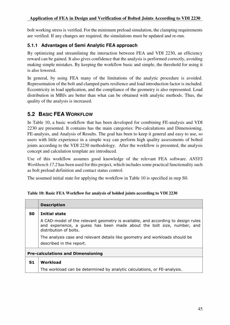
Application of FEA in Design and Verification of Bolted Joints According to VDI 2230
45
bolt working stress is verified. For the minimum preload simulation, the clamping requirements
are verified. If any changes are required, the simulations must be updated and re-run.
5.1.1 Advantages of Semi Analytic FEA approach
By optimizing and streamlining the interaction between FEA and VDI 2230, an efficiency
reward can be gained. It also gives confidence that the analysis is performed correctly, avoiding
making simple mistakes. By keeping the workflow basic and simple, the threshold for using it
is also lowered.
In general, by using FEA many of the limitations of the analytic procedure is avoided.
Representation of the bolt and clamped parts resilience and load introduction factor is included.
Eccentricity in load application, and the compliance of the geometry is also represented. Load
distribution in MBJs are better than what can be obtained with analytic methods. Thus, the
quality of the analysis is increased.
5.2 BASIC FEA WORKFLOW
In Table 10, a basic workflow that has been developed for combining FE-analysis and VDI
2230 are presented. It contains has the main categories: Pre-calculations and Dimensioning,
FE-analysis, and Analysis of Results. The goal has been to keep it general and easy to use, so
users with little experience in a simple way can perform high quality assessments of bolted
joints according to the VDI 2230 methodology. After the workflow is presented, the analysis
concept and calculation template are introduced.
Use of this workflow assumes good knowledge of the relevant FEA software. ANSYS
Workbench 17.2 has been used for this project, which includes some practical functionality such
as bolt preload definition and contact status control.
The assumed initial state for applying the workflow in Table 10 is specified in step S0.
Table 10: Basic FEA Workflow for analysis of bolded joints according to VDI 2230
Description
S0 Initial state
A CAD model of the relevant geometry is available, and according to design rules
and experience, a guess has been made about the bolt size, number, and
distribution of bolts.
The analysis case and relevant details like geometry and workloads should be
described in the report.
Pre calculations and Dimensioning
S1 Workload
The workload can be determined by analytic calculations, or FE analysis.

MSc Thesis 2018
46
S2 Estimation of Nominal Bolt Diameter
The nominal bolt diameter is based on the bolt workload, and can be estimated
from VDI 2230 Pt.1 Table A7. If other bolt materials than Steel is used, a bolt with
equivalent load capacity can be used:
0.2. _1 2
2 1
0.2. _ 2
( )p Bolt
p Bolt
Rd d
R
S3 Tightening Factor
The tightening factor is linked to the precision of the tightening method and tool
used for assembly, and can be estimated via VDI 2230 Pt. 1 Table A8.
S4 Maximum Assembly Preload
The allowed assembly preload can be calculated from the formula below using the
proof strength of the bolt and a utilization factor. For Steel bolts, assuming a
utilization factor 0.9 (90%), VDI 2230 Pt.1 Tables A1 A4 can be used to
quickly identify the allowed assembly preload.
Coefficients of friction can be obtained from [Pt.1 Table A5 A6] or [18, 19].
2
0 2
. 0.2 min
.max
23
min21 3 1.155
red Mzul p
red MzulM Mzul S
d PGd d
R
F F A
S5 Minimum Assembly Preload
The minimum preload is determined from the max preload and the tightening
factor. Estimated preload losses can be included to obtain a more realistic minimum
preload.
min (preload losses)Mzul
M
A
FF
FE Analysis
S6 Simplify and Prepare CAD Geometry
Simplify and prepare a CAD model that corresponds to Class II or III. The minor
thread diameter d3 can be used as bolt diameter. Other diameters can be used to
manipulate the bolt resilience. For Class III, the bolt and tapped threads must have
a corresponding diameter.
S7 Prepare and Run FE analysis
Create two static structural simulations for max/min assembly preloads, with
shared Engineering Data, Geometry, and FE Model.
Define correct material properties for the bolt and clamped parts.
Apply BCs, Loads, Contacts, and Create Mesh
o Apply maximum workload in both simulations to get max bolt load, and
min clamping pressure.
o Apply bonded contact (Class III), or MPC connection (Class II) in the
tapped thread area. Friction should be applied in the clamping interface.
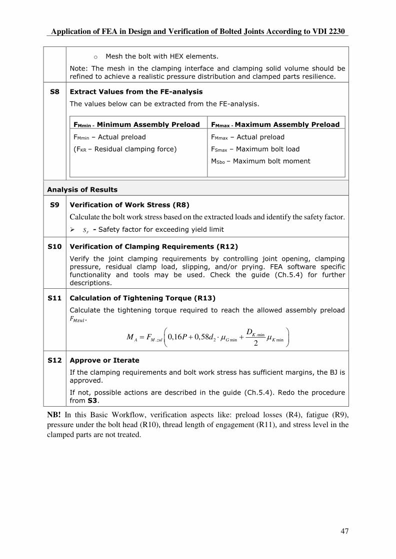
Application of FEA in Design and Verification of Bolted Joints According to VDI 2230
47
o Mesh the bolt with HEX elements.
Note: The mesh in the clamping interface and clamping solid volume should be
refined to achieve a realistic pressure distribution and clamped parts resilience.
S8 Extract Values from the FE analysis
The values below can be extracted from the FE analysis.
FMmin Minimum Assembly Preload FMmax Maximum Assembly Preload
FMmin Actual preload
(FKR Residual clamping force)
FMmax Actual preload
FSmax Maximum bolt load
MSbo Maximum bolt moment
Analysis of Results
S9 Verification of Work Stress (R8)
Calculate the bolt work stress based on the extracted loads and identify the safety factor.
F
S Safety factor for exceeding yield limit
S10 Verification of Clamping Requirements (R12)
Verify the joint clamping requirements by controlling joint opening, clamping
pressure, residual clamp load, slipping, and/or prying. FEA software specific
functionality and tools may be used. Check the guide (Ch.5.4) for further
descriptions.
S11 Calculation of Tightening Torque (R13)
Calculate the tightening torque required to reach the allowed assembly preload
.
.min. 2 min min0,16 0,58
2K
A M zul G K
DM F P d
S12 Approve or Iterate
If the clamping requirements and bolt work stress has sufficient margins, the BJ is
approved.
If not, possible actions are described in the guide (Ch.5.4). Redo the procedure
from S3.
NB! In this Basic Workflow, verification aspects like: preload losses (R4), fatigue (R9),
pressure under the bolt head (R10), thread length of engagement (R11), and stress level in the
clamped parts are not treated.


Application of FEA in Design and Verification of Bolted Joints According to VDI 2230
49
Figure 38: Extract of step S2 from the Basic Workflow calculation template in Appendix A
An advantage of using Mathcad templates is the possibility to have simple programming loops,
as displayed in Figure 39. The left is used to calculate a parameter that is determined differently
for different values of the input parameter. The right one is a verification loop that simplifies
criteria checking in the calculations.
Figure 39: Two examples of programming in bolt assessment calculations
5.3 NON-CRITICAL JOINTS
Joints under static conditions, with no working loads and no need for a specific preload may be
defined as non-critical joints. The only requirements might be that they should not come loose,
and not break during tightening. Such joints may be used to fix components, covers,
thermalisation points, sensors, or similar.
There is no need for detailed analysis of such joints. However, there are some factors that can
affect the tightening torque, like bolt strength and coefficients of friction. To aid the calculation
of tightening torque for specific non-critical bolts, a Mathcad calculation template has been
prepared in Appendix B.
The input parameters are the proof stress of the bolt, and the coefficient of friction in the threads
and under the bolt head. The output values are listed in a table, as seen in Figure 40, with
tightening torques and associated preloads for bolt range M3-M12. These values are provided
for 30%, 50%, 75%, 90% and 100% utilisation of the bolt proof stress.
Two standards provide data about the minimum breaking torque for Steel [20] and Stainless
Steel [21] bolts. These values can be used as reference values for the maximum tightening
torques.

MSc Thesis 2018
50
Figure 40: Table with tightening torques and associated preloads for M3-M12 bolts
In case of a TTJ joints, it is important to verify that the tapped threads length of engagement is
sufficient. Check 5.5.4 for further details.
Coefficients of Friction
Typical coefficients of friction can be found in [Pt.1-Table A5]. The CERN MME Mechanical
Lab has test facilities for identifying coefficients of friction for specific combinations of bolt,
clamped parts, and lubrications. For Steel bolts and a range of standard coefficients of friction,
tightening torques and associated preloads can be found in [Pt.1-Table A1-A4] for 90%
utilisation of the bolt capacity.
Note that there is a risk associated with using wrong coefficients of friction. Factors such as
oxidation and flattening of involved surfaces can influence the friction coefficient, so it deviates
from the expected value. If the coefficient of friction is large, small changes can have large
effects on the achieved preload. If the friction is higher than assumed, the resulting preload will
be lower than expected. If the friction is lower than assumed, the preload will be higher than
expected. If the last happens, the bolt might break due to the increased axial load.
Thus, if there is uncertainty associated with the friction, it is better to use the minimum
coefficients of friction in the threads and under the bolt head when calculating the tightening
torque.
One strategy can be to use lubrication to ensure low friction, which also give minimal
consequences if there is uncertainty in the friction. That is not a possible at CERN, since
lubrication is not acceptable in many cryogenic applications. One possibility however is to use
silver coating, and perform mechanical measurements of the resulting coefficient of friction.
Bolt Loosening
Preload losses can occur from surface flattening in the threads and under the bolt head. This
can lead to significant preload losses if the clamping length is small (stiff bolt). According to
VDI 2230, the clamping length is recommended to be according to (21) for the joint to provide
proper safety against bolt loosening. In the case of vibrations, retraining elements [Pt.1-Table
A14] can be used to reduce the risk of loosening.
/ (3...5)k
l d (21)

Application of FEA in Design and Verification of Bolted Joints According to VDI 2230
51
5.4 GUIDE FOR BASIC FEA WORKFLOW
This Guide contains supplementary details for the Basic FEA Workflow in Ch. 5.2, and is
intended to assist in performing FEA analysis of bolted joints. It provides descriptions of
calculations, verifications, and useful references. However, it is not an all-inclusive self-
standing guide and it is assumed that VDI 2230 is available to the user, and that the user has
good knowledge about the relevant FEA software.
It is important to be aware that even though analytic limitations are avoided by using FEA, there
are some aspects of validity with FE-analysis that is important to aware of. Therefore, aspects
of validity are discussed where relevant. In the end of the section, the importance of testing is
underlined.
[Pt.1 Table A9] provides useful information about properties for common materials, and useful
dimensions for Hexagon Head Bolts [22], Hexagon Socked Head Cap Screws [23], and
clearance holes [24] can be found in relevant references.
5.4.1 S0: Initial State
It is assumed that there is a CAD-model of the relevant geometry available, designed according
to basic rules and experience. A preliminary guess of the bolt size, number of bolts, and
distribution of bolts must be made. Two approaches are:
1) Unknown bolt size - To perform an initial guess about bolt size, spacing and number
of bolts, iterations of the steps S1 and S2 can be performed.
2) Bolt size is known - Step S1 and S2 can be skipped. However, it might still be
interesting to carry out the steps S1 and S2 to compare the estimated bolt diameter to
the actual bolt diameter. This can serve as a first indication of the suitability of the bolt
selected.
The analysis case and relevant details like geometry and workloads should be described in the
report.
5.4.2 S1: Workload
To estimate the nominal bolt diameter, the maximum workload on the bolt must be known. For
MBJs, there are different strategies for load determination. Table 11 list four strategies that can
be used to identify bolt workloads. The analytic methods of Rigid Body Mechanics and
Elastomechanics for determination of workload in MBJs are described in [Pt. 2-Ch.6].
Table 11: Strategies for determination of bolt workloads
Strategy Description +/
WL 1 Analytic
Assuming rigid bodies and
uniform distribution, or that the
transverse load is proportional
to the distance from the centre,
the workload can be identified
by simple analytic force and
moment equilibrium calculations
Can in some cases
underestimate the bolt
workload
May not be applicable for
complex geometries and loads

MSc Thesis 2018
52
WL 2 Class I
Using bonded contact in the
interface, the reaction forces in
the interface can be extracted
and by assuming uniform
distribution, divided on the
relevant bolts
The assumption of uniform
distribution may not be
completely valid, but with
complex loads and geometries
it can give a good first
estimate
WL 3 Spot welds
By applying spot welds in the
bolt locations, relative load
distribution is represented, and
the most highly loaded bolt can
be identified
The actual load distribution
may not be perfectly accurate,
but more accurate than
assuming uniform distribution.
Asymmetric geometric
conditions and prying can be
represented with this approach
WL 4 Class II, no
preload
By performing a Class II
simulation using beams without
preload and with frictionless
contact, similar to WL 3, the
most highly loaded bolt can be
identified
Rigid beams may be used
Same as for WL 3
Since slipping can occur, and
the beams have a certain
resilience, the load distribution
can be affected
Maximum Workload
A joint is designed to withstand axial ( ) and/or transverse ( ) loads. If both are present, VDI
2230 suggests to use the dominant load according to Eq. (22) when estimating the nominal
diameter. The maximum global workload, and most unfortunate combination of loads must be
applied to the structure to obtain the maximum bolt workload. A safety factor can be applied to
the global workload to account for uncertainties. This can be determined by codes and
standards, or company practice and experience.
max
max
min
max ,Q
A
T
FF (22)
FAmax is the maximum axial bolt workload, FQmax is the maximum transverse load, and µTmin is
the minimum friction in the interface.
As a result of designing the joint for the dominant load, it will also have a certain resistance for
the other load component. Thus, if designed for an axial load, the clamping will provide a
certain friction grip to resist transverse loads, and opposite. Verifications are made in step S10
to ensure that sufficient clamping pressure is present for the worst combination of loads.
Concentric or Eccentric Workload
If it is known that prying loads are included in the bolt workload, the joint can be said to be
concentric instead of eccentric in step B2 when estimating bolt diameter. In this way, the
eccentric or prying conditions will not be accounted for twice and result in overestimating the
bolt size.

Application of FEA in Design and Verification of Bolted Joints According to VDI 2230
53
Unit Load Approach
The standard way to identify the bolt workload is to apply the full global workload, and obtain
the working loads according to the strategies listed in Table 11. In some cases however, for
simple MBJs without prying effects, a unit load can be applied as global workload. Then the
percentage distribution of the unit load to the bolts becomes clear in a simple way, and can be
used to estimate bolt loads for other global workloads.
However, this assumes a linear relation between global load and bolt load development. As
seen with prying, that might not always be the case, and this approach does not capture non-
linear bolt load development.
Validity of Workload
When identifying the workload, no preload is present and friction grip in the clamping interface
is not represented. If the bolt representation is not rigid, the bolts have a certain resilience. These
two factors affect the global compliance of the assembly, and can affect the load distribution.
Because of this, it can be expected that the bolt workloads and global load distribution will be
different when preload, and friction in the clamping interface is present. This illustrates the
importance of the verification steps S9 and S10.
5.4.3 S2: Estimation of Nominal Bolt Diameter [Pt.1 R0]
[Pt.1-Table A7] provides a practical guide to perform a qualified guess to estimate the nominal
bolt diameter, based on the bolt workload. The workload is scaled in discrete steps based on
many different factors, such as loading mode, eccentric or concentric conditions for loading or
clamping, and tightening method. Then a nominal diameter is suggested for different strength
grades of Steel bolts.
Using this table, there is a higher chance of choosing the correct nominal diameter the first time.
However, there are large uncertainties in the estimate, so it is important to verify the bolt
performance.
Note that if the bolt workload already includes prying loads, concentric can be chosen instead
of eccentric in step B2.
Non-Steel bolts
For different reasons, bolts of other materials than Steel may be used. That might be to have
improved corrosion properties, match thermal contraction properties of the clamped plates, or
to improve the joint by having a more resilient (soft) bolt.
The most simple approach is to convert the nominal diameter for the Steel bolt resulting from
the above selection guide, to a bolt size of the new material having an equivalent proof load
capacity. The diameter of the non-steel bolt is calculated according to Eq. (26).
The bolt proof load is defined in (23). It can then be stated that the proof strength of the two
bolts should be the same, as (24) show.
2
0.2 0.2 0.24
p p S pF R A R d (23)
0.2. _1 0.2. _ 2p Bolt p BoltF F (24)

MSc Thesis 2018
54
Based on (23) and (24), the following relation can be made:
2 2
0.2. _1 1 0.2. _ 2 2( ) ( )4 4
p Bolt p BoltR d R d (25)
Thus, the diameter of an equivalent bolt diameter can be calculated:
0.2. _1 2
2 1
0.2. _ 2
( )p Bolt
p Bolt
Rd d
R (26)
Elongation Before Fracture
When selecting bolt strength, it is important to be aware of the ductility and elongation before
fracture properties of the bolt. The stronger and harder the bolt is, the less elongation is accepted
before the bolt fracture, as Figure 41 show.
For a high strength bolt where a lot of the strength is utilized, little yielding is allowed and
overloading can easily lead to fracture of the bolt and joint failure. Because of this, high grade
bolts should be used with care.
Figure 41: Typical stress-strain curves for various material strengths
5.4.4 S3: Tightening Factor [Pt.1 R1]
The tightening factor is based on the tightening uncertainty associated with different tightening
methods. Factors affecting the uncertainty is friction, accuracy in measurement and reading,
and the resilience of the joint.
A thorough guide to tightening methods and uncertainties are provided in [Pt.1 Table A8].
Some typical values are listed in Table 12.

Application of FEA in Design and Verification of Bolted Joints According to VDI 2230
55
Table 12: Typical tightening factor ranges for typical tightening methods
To reduce the tightening uncertainty and achieve a higher minimum assembly preload for a
given bolt, a more precise tightening method should be used. By using tightening angle, the
effect of friction is neglected, which is a large source of uncertainty. The uncertainty can also
be reduced by having a more resilient bolt by material selection, cross section, or larger
clamping length
Another source of tightening uncertainty to be aware of that is not treated in VDI 2230, is the
impact of tightening sequence for MBJs. If tightening is not performed according to
recommendations [25], single bolts can experience large preload losses that is challenging to
predict.
5.4.5 S4: Maximum Assembly Preload [Pt.1 R7]
The allowed assembly preload ( for a given bolt is calculated according to Eq. (27). The
maximum axial and torsional stress during assembly are used in the equation to identify the
allowed preload. The allowed bolt stress ) is based on the minimum bolt proof
strength ( , and a utilization factor ( ). It can be noted that the proof strength of the
bolt may be typically 85-95% of the yield strength.
(R7/2)
2
0 2
. 0.2 min
.max
23
min21 3 1.155
red Mzul p
red MzulM Mzul S
d PGd d
R
F F A (27)
For Steel bolts and a utilisation factor of 0.9 (90%), the tables [Pt.1 Table A1-A4] has listed
allowed assembly preloads for a range of bolts and standard coefficients of friction. Coefficients
of friction can be obtained from [Pt.1 Table A5-A6] or [18, 19].
Note the remarks about coefficient of friction provided on page 50.
Utilization Factor
For critical joints, a high utilisation factor is generally recommended. VDI 2230 suggest using
. That is because a high utilisation and high preload gives a higher acceptance of preload
losses, better resistance against bolt loosening, and reduces the risk of joint opening and
unpredictable prying loads.
Having a high utilisation factor may be counter intuitive, as it is based on having a high stress
level in the bolt, giving a lower bolt stress safety factor. However, due to the reasons above, the
overall safety is higher with high utilisation.

MSc Thesis 2018
56
Table 13: Bolt properties according for Steel and Stainless-Steel bolts [21, 26]
Steel Group Steel Stainless Steel (Austenitic)
Steel grade A1, A2 A3, A4 A5
Property class 8.8 10.9 12.9 50 70 80
Tensile strength mR [MPa] 800 1000 1200 500 700 800
Stress at 0,2% permanent strain 0,2p
R [MPa] 640 940 1080 210 450 600
Elongation at fracture 5A 12 % 9 % 8 % 0,6 d 0,4 d 0,3 d
Shear ratio B mR 0,65 0,62 0,60 0,80 0,72 0,68
5.4.6 S5: Minimum Assembly Preload
The minimum assembly preload is the lowest probable preload, and is determined from the
maximum assembly preload as Eq.(28) show. The two preload levels are illustrated in Figure
37. If preload losses are estimated (5.5.2), they can be included to obtain a more realistic and
conservative minimum preload.
max
min (preload losses)MM
A
FF (28)
5.4.7 S6: Simplify and Prepare CAD Geometry
The CAD geometry must be simplified and prepared for the FE-analysis. Which model class
(bolt representation) to use must be decided. The different classes are presented in Ch. 2.4.
Class I and IV are not suitable for simulations with preload, and for verification of joint
performance. Class II with beam representation and Class III with volume body representation
of the bolt (Figure 42) have different advantages and disadvantages.
Setting up a Class II model is more simple than a Class III model, but it can give a more stiff
bolt representation than Class III. That is because of the MPC joints connecting the beam to the
clamped parts. For TTJs, this can also affect the validity of the pressure distribution in the
clamping interface. Class III requires modelling of a volume body representing the bolt, and
can give a more accurate representation of the joint compliance. The bolt resilience for both
classes can be manipulated with the bolt diameter used in the the model.
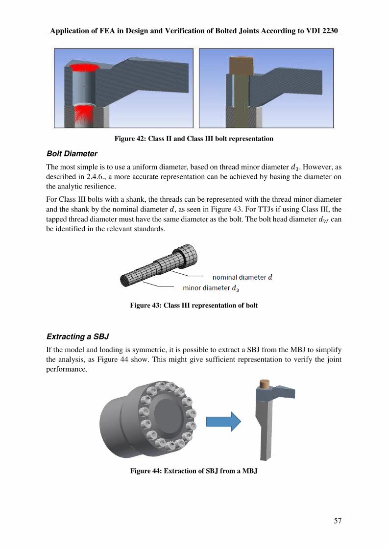
Application of FEA in Design and Verification of Bolted Joints According to VDI 2230
57
Figure 42: Class II and Class III bolt representation
Bolt Diameter
The most simple is to use a uniform diameter, based on thread minor diameter . However, as
described in 2.4.6., a more accurate representation can be achieved by basing the diameter on
the analytic resilience.
For Class III bolts with a shank, the threads can be represented with the thread minor diameter
and the shank by the nominal diameter , as seen in Figure 43. For TTJs if using Class III, the
tapped thread diameter must have the same diameter as the bolt. The bolt head diameter can
be identified in the relevant standards.
Figure 43: Class III representation of bolt
Extracting a SBJ
If the model and loading is symmetric, it is possible to extract a SBJ from the MBJ to simplify
the analysis, as Figure 44 show. This might give sufficient representation to verify the joint
performance.
Figure 44: Extraction of SBJ from a MBJ

MSc Thesis 2018
58
5.4.8 S7: Prepare and Run FE-analysis
Figure 45: Simulation setup in ANSYS with Max and Min preload
Two simulations must be performed, one for each preload state. Model geometry, material data
and mesh can be shared, as Figure 45 show.
Material data
Define correct material properties and apply correct materials to all parts of the assembly. Note
that some properties can be temperature dependent. [Pt.1 Table A9] provides a good overview
of common materials and their properties at room temperature.
Mesh
If the bolt has a Class III representation, the bolt must be meshed with HEX elements, e.g. using
poor mesh can give inaccurate results.
Normal mesh considerations should be used on the complete model to ensure correct
component or assembly compliance. The mesh in the clamping solid volume should be refined
to have the complete deformation cone represented. This is important to achieve the correct
resilience of the clamped parts in the model, and to get a realistic representation of the pressure
in the clamping interface.
Note that in [Pt.2-p.71], it is stated that the clamping pressure is represented with sufficient
realism only for large clamping lengths, and with TBJs. That is related to proper formation of
deformation cones, and stiffness introduced from the threads close to the clamping interface in
TTJs.
Boundary Conditions and Contact
The model should have realistic boundary conditions and supports. Realistic friction should be
applied in the clamping interface, so friction grip and its effect of the compliance is represented
and assessment if slipping occur can be performed.
Load
The maximum global workload, and most unfortunate combination of loads must be applied so
the bolted joint can be designed and verified for the maximum bolt workload.
As stated in Table 15 , and a higher workload than the design workload
can be applied. In this way, the joint performance can be demonstrated and verified with a
workload safety factor. Codes and standards can define required safety factors on the workload.
According to one code, EN 13445 Unfired Pressure Vessels [15], the test pressure for pressure
vessels is 1.43x the nominal operating pressure.

Application of FEA in Design and Verification of Bolted Joints According to VDI 2230
59
Sub-steps
Normally, the solver automatically detects the need for sub-steps that is required for the
simulation to converge. Sometimes however, a higher resolution of the data points might be
beneficial to track the load development, like when verifying prying behaviour. Then, sub-steps
can be defined to achieve the desired resolution.
5.4.9 S8: Extract Values from the FE-analysis
The forces and moments in Table 14 can be extracted from the simulations. The actual preloads
should be extracted to verify that the correct preload level is acheived. The residual clamping
force can be extracted and compared against joint or gasket requirements. The maximum bolt
load and moment is used in verification of the bolt work stress.
Note that when extracting forces and moments from surfaces, the nodal forces for that surface
are summarized. This is a potential source of error, and should be done with care.
Table 14: Values to be extracted from the simulations
FMmin - Minimum Assembly Preload FMmax - Maximum Assembly Preload
FMmin Achieved preload
(FKR Residual clamping force)
FMmax Achieved preload
FSmax Maximum bolt load
MSbo Maximum bolt moment
5.4.10 S9: Verification of Work Stress [Pt.1 R8]
Analytic calculation of the work stress is considered to be more accurate than analysing the
stress in the FEA model. From the maximum bolt loads extracted, the work stress can be
calculated according Eq. (29). This is a modified version of the working stress equation where
the bending stress is included. The criteria in (30) must be fulfilled, and the safety factor can be
calculated according to Eq. (31).
(R8/4)
2
2max. max3S Sbo
red B t
S S
F Mk
A W (29)
(R8/5-1) , 0.2minred B pR (30)
(R8/5-2) 0,2 min
,
1,0p
F
red B
RS (31)
The bolt proof load can be obtained from Table 13, experimental testing, or other sources. If
the bolt is exposed to different operating temperatures, the lowest proof load should be used.
The safety factor is in many cases expected to be in the range of 1.05 to 1.2.
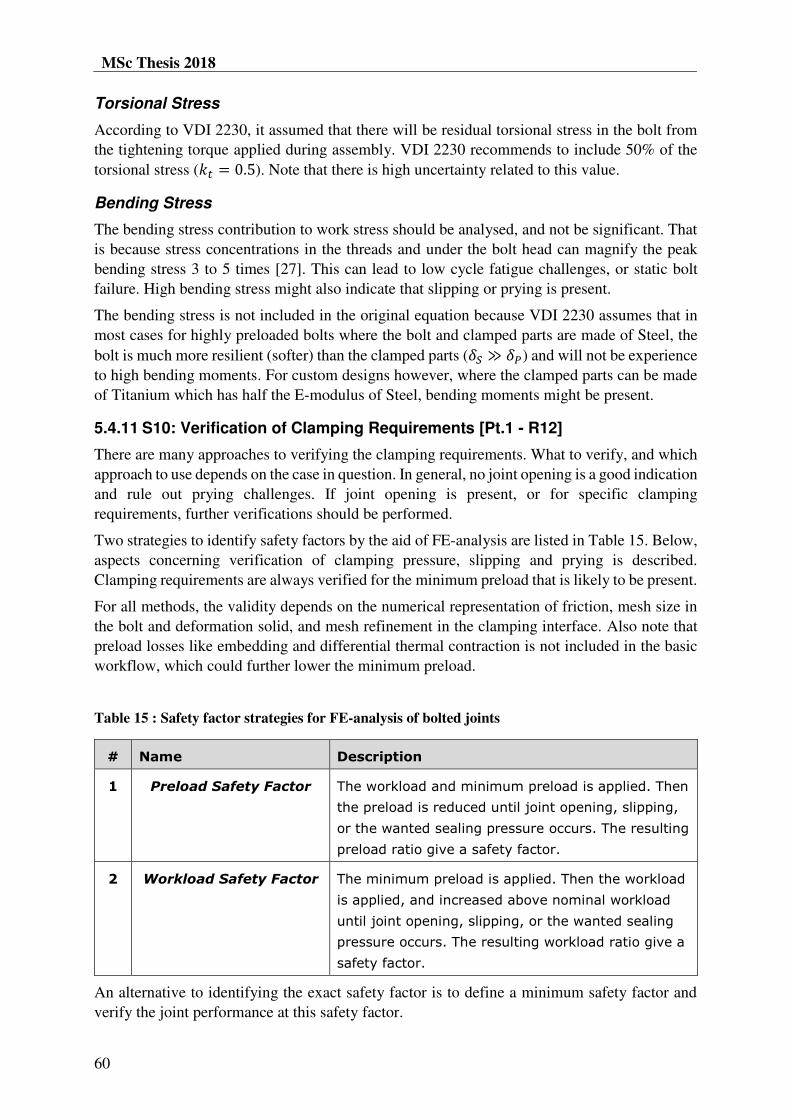
MSc Thesis 2018
60
Torsional Stress
According to VDI 2230, it assumed that there will be residual torsional stress in the bolt from
the tightening torque applied during assembly. VDI 2230 recommends to include 50% of the
torsional stress ( ). Note that there is high uncertainty related to this value.
Bending Stress
The bending stress contribution to work stress should be analysed, and not be significant. That
is because stress concentrations in the threads and under the bolt head can magnify the peak
bending stress 3 to 5 times [27]. This can lead to low cycle fatigue challenges, or static bolt
failure. High bending stress might also indicate that slipping or prying is present.
The bending stress is not included in the original equation because VDI 2230 assumes that in
most cases for highly preloaded bolts where the bolt and clamped parts are made of Steel, the
bolt is much more resilient (softer) than the clamped parts ( ) and will not be experience
to high bending moments. For custom designs however, where the clamped parts can be made
of Titanium which has half the E-modulus of Steel, bending moments might be present.
5.4.11 S10: Verification of Clamping Requirements [Pt.1 - R12]
There are many approaches to verifying the clamping requirements. What to verify, and which
approach to use depends on the case in question. In general, no joint opening is a good indication
and rule out prying challenges. If joint opening is present, or for specific clamping
requirements, further verifications should be performed.
Two strategies to identify safety factors by the aid of FE-analysis are listed in Table 15. Below,
aspects concerning verification of clamping pressure, slipping and prying is described.
Clamping requirements are always verified for the minimum preload that is likely to be present.
For all methods, the validity depends on the numerical representation of friction, mesh size in
the bolt and deformation solid, and mesh refinement in the clamping interface. Also note that
preload losses like embedding and differential thermal contraction is not included in the basic
workflow, which could further lower the minimum preload.
Table 15 : Safety factor strategies for FE-analysis of bolted joints
# Name Description
1 Preload Safety Factor The workload and minimum preload is applied. Then
the preload is reduced until joint opening, slipping,
or the wanted sealing pressure occurs. The resulting
preload ratio give a safety factor.
2 Workload Safety Factor The minimum preload is applied. Then the workload
is applied, and increased above nominal workload
until joint opening, slipping, or the wanted sealing
pressure occurs. The resulting workload ratio give a
safety factor.
An alternative to identifying the exact safety factor is to define a minimum safety factor and
verify the joint performance at this safety factor.


MSc Thesis 2018
62
Slipping
There are multiple techniques to analyse if slipping occur in a joint. One is to have friction in
the clamping area, and use the integrated ANSYS functionality and check
clamping interface Figure 49. Another approach is to probe
and plot the shear loads of the bolts. If there are any sudden load developments, it might indicate
that slipping is initiated.
Figure 49: ANSYS plots for assessment of slipping
Analytic approaches can be made according to [Pt.1 R12] and [Pt.2 R12 p.99] to identify a
safety factor against slipping ( . The transverse loads can be identified from having a bonded
interface and probing the reaction loads, or from performing a Class II or III simulation with
frictionless conditions and probe the bolt loads. The shear loads on the most highly loaded bolt
can be extracted, and used in the analytic verification calculations. Note that the validity aspects
Validity of Workload
Prying
What prying is, how it can be encountered, and the influence of preload is treated in Ch.4. In
most cases, the goal is to verify that prying is not present in the joint. A typical development in
additional bolt load for a certain preload level, as the workload is applied, is demonstrated in
Figure 50. This characteristic development applies to both axial loads and bending moments if
prying is present in the joint.
In the example case demonstrated in Figure 50, the joint is verified for a workload of 40 MPa,
with a workload safety factor of 1.25. In the green area, the load development is linear and
predictable. In the red area, partial joint opening is occurring, and the load is non-linear and
challenging to predict.
When verifying that no prying is present, the workload must be in the green area. For this
preload level, the bolt will experience linear and predictable loads up to the global workload of
50 MPa. Note that this curve will change for other preload levels.
To ensure the validity of the verification, the data points defined through sub-steps should have
a sufficient resolution.


MSc Thesis 2018
64
If prying is present, the minimum preload should be increased. The design can also be modified
to stiffen the geometry, as detailed in section 4.3. Further details of improving joint design is
given in [Pt.1-Figure 37] and detailed in [Pt.1-Ch.6]. A list of measures to increase the service
reliability of BJs is provided in [Pt.1-A13], including how the bolt loading and stress can be
reduced and how the stressability of the bolt can be increased. The actions are described terms
of geometry, material and assembly.
5.4.14 Testing and Verification
There are many questions that can be asked about the accuracy in a FE-analysis: Are the
coefficients of friction correct? Are all non-linear phenomena captured? Are all boundary
conditions represented correctly? Are the contacts correctly represented? Are the numerical
representation of contacts and friction in the FE-analysis correct?
No certainty about the joint performance can reached before physical testing has been carried
out under realistic conditions. After the test, critical bolts should be inspected for plastic
deformations like reduced cross section, or increased length. Significantly reduced loosening
torque is a clear indication of unexpected preload losses.
5.5 FURTHER ASSESSMENTS
Some calculation quantities and verification aspects are left out of the Basic FEA Workflow to
simplify it. This section briefly describes the most relevant aspects that are left out, and how
they can be included in the analysis. Some of the further assessments are demonstrated in
Appendix C-2 and Part 2 of Appendix F.
5.5.1 Analytic Calculation Quantities
For some of the following calculations, it is required that the resilience of the joint is known.
This can be determined with FEA according to the methods described in [Pt.1 7.3.1], or
calculated by the analytic methods described in [Pt.1-R3].
5.5.2 Preload Losses [Pt.1 R4]
Two sources of preload losses accounted for by the analytic VDI 2230 procedure is embedding
and differential thermal expansion. Identification of these quantities require some efforts, but
increase the accuracy of the bolted joint analysis. When the preload losses is estimated, they
can be included in Eq.(28) to provide a more realistic minimum assembly preload.
Embedding
Embedding or relaxation is local deformations that occur during assembly or loading. The
amount of embedding depends on the number of surfaces that interacts and the surface
roughness. Guide values are provided in [Pt.1-Table 5], and the preload loss is calculated
according to Eq. (33).
(R4/1) ZZ
S P
fF (33)
According to a NASA report, the preload loss due to embedding can be expected to be 5% of
the maximum assembly preload [28]. This can serve as a quick estimate.

Application of FEA in Design and Verification of Bolted Joints According to VDI 2230
65
Differential thermal expansion
If the joint is exposed to thermal changes and the thermal expansion properties of the bolt and
clamped parts are different, it can result in increased or reduced bolt loads. If the plate contracts
more than the bolt, the preload will be reduced. If the bolt contracts more than the plate, the
bolt load is increased. The change in preload can be calculated according to Eq. (34).
The change in bolt load from differential thermal expansion should be included in the maximum
bolt load in Eq.(29) if the preload increase, and as a preload loss in Eq.(28) if the bolt load
decrease.
' K S S P P
VthSRT PRT
S P
ST PT
l T TF
E E
E E
(34)
Changes in bolt load due to thermal changes can also be identified from a separate thermal FE-
analysis, where the thermal material properties are defined.
To reduce the effect of differential thermal expansion, the material of the bolt and the clamped
parts can be selected to have the same coefficient of thermal expansion.
5.5.3 Fatigue [Pt.1 R9]
If the workload is dynamic, the alternating stresses can be calculated with Eq. (35) using the
extracted axial load and bending moment for maximum and minimum workload. This gives a
stress amplitude that can be compared against fatigue the relevant fatigue limits. VDI 2230
contains relevant reference values for Steel bolts.
[Pt.1 Eq.93] SA SA
SAb
S S
F M
A W (35)
5.5.4 Tapped Thread Length [Pt.1 R11]
For TTJ joints, it can be important to verify that the tapped threads length of engagement is
sufficient. A common rule is that the tapped thread length of engagement should be 1.5 times
the nominal bolt diameter ( ). With longer thread length of engagements, there is
a risk that the thread can become jammed. A quick guide for Steel bolts and different tapped
thread materials are provided in Figure 51.
Detailed calculation of the minimum thread length of engagement can be performed according
to [Pt.1-R11] and [Pt.1-5.5.5].

MSc Thesis 2018
66
Figure 51: Guide for recommended lengths of tapped thread engagement [29]
5.6 CASE EXAMPLES
Two example cases with bolted joints has been solved using the Basic FEA Workflow. The
cases are different from each other, and demonstrate different techniques and analysis aspects.
The scope is that they can serve as practical examples of the workflow applied, and provide
guidance in how such analysis can be performed.
5.6.1 Blind Flange Analysis Example
Figure 52: Blind Flange Analysis Example
A SBJ is extracted from the Blind Flange MBJ, as seen in Figure 52, and a Class III
representation of the bolt is used. The bolt is eccentrically loaded from internal pressure in the
cylinder. Verifications of the bolt working stress and clamping pressure is performed.
The analysis rapport is attached in Appendix C-1a, and the Mathcad calculations in Appendix
C-1b.
This same case has also been solved by the analytic VDI 2230 procedure. It can be used as a
reference to compare the approaches, and it demonstrates calculation of analytic quantities. The
report is attached in Appendix C-2a, and the Mathcad calculations in Appendix C-2b.

Application of FEA in Design and Verification of Bolted Joints According to VDI 2230
67
5.6.2 Bolted Tuner Analysis Example
Figure 53: Bolted HG Cavity Tuner subjected to MBJ slipping analysis
This is an analysis that were performed for the practical case of a bolted tuner (Figure 53) for
the High Gradient (HG) Cavities. The main scope of the analysis was to assess if slipping would
occur in the joint, while subjected to the maximum tuning load.
Different approaches and techniques are used to assess MBJ slipping. The report is attached in
Appendix D-1, and the associated Mathcad calculations are attached in Appendix D-2.
5.7 SEMINAR ABOUT FEA & VDI 2230
To transfer knowledge about how to use FEA in analysis of bolted joints according to VDI 2230
to relevant personnel, a seminar has been prepared and attached in Appendix E. The seminar
format allows interaction and discussion about relevant topics, and is a practical way to
introduce the topic. The presentation has 43 slides, and includes the following main topics:
1. Basic Concepts of Bolted Joints and VDI 2230
2. Combining FEA and VDI 2230
3. Further Calculations and Verifications
4. Improvements of Bolted Joint Design
5. Support Material and References
6. Summary
Aspects like how to estimate the bolt diameter from workload, calculate preload, and how to
verify bolt stress and clamping conditions are included in the presentation. The scope is also to
emphasize the importance of joint design, and how different factors can influence the joint
performance. After the seminar, the participants should feel confident with the use of VDI 2230
and FEA in design and verification of BJs. Thus:
Know central terms and principles in VDI 2230
Know how FEA and VDI 2230 can be combined
Get introduced to further VDI 2230 calculations and verifications
Know how to improve the joint design and performance
Know where to look for more information
The seminar was held for a group of engineers in the engineering department at CERN in
December 2017. The time allocated were 1.5hr, with 1hr for presentation and 30 minutes for
discussion. This was a bit too short time, and for the future it is recommended to have the
presentation in 3x45 minutes, and to include brief discussions after each of the chapters.
The seminar can also be adapted to focus on some of the topics, or to serve as a shorter
introduction by removing some of the topics.

MSc Thesis 2018
68

Application of FEA in Design and Verification of Bolted Joints According to VDI 2230
69
6 REVISED CRAB CAVITY HE-VESSEL ANALYSIS
After the prototypes are tested and before the series production is initiated, there is a possibility
to review the design and structural analysis of the He-vessel and bolted joints. This chapter
takes basis in the initial He-vessel analysis and provide suggestions and recommendations for
this potential review.
6.1 SUGGESTIONS AND RECOMMENDATIONS
Inspection of Prototype Vessel Bolts
According to the recommendations in 5.4.14, the bolts from the prototype He-vessel should be
inspected. Plastic deformations of the bolts and low loosening torques can indicate unexpected
preload losses. An external inspection of the vessel can identify gaps or cracked sealing welds,
which can indicate joint slipping. If any deviations are identified, this can serve as useful input
for the revised analysis.
Workflow in New Analysis
If a revised analysis is performed, it should follow the Basic FEA Workflow and
recommendations provided in the Guide (Ch.5.4). In addition, preload losses should be
considered and included in the calculations. By doing this, many of the challenges outlined in
section 3.4 would be cared for. It will ensure:
Two levels of preload from tightening uncertainty and preload losses
Friction in the clamping interface, giving realistic bolt loads and allowing
verification of slipping
Analysis of prying loads
Good validity of the FEA results
Possible Improvements
Some possible improvements of bolted joints in general are referred to in 5.4.13. Relevant
modifications might be to increase the clamping length to increase the bolt resilience and lower
the load factor. That will give lower additional bolt loads, reduce preload losses, and improve
the resistance against loosening. The plate thickness is 23mm, but because of the groove and
sealing cap the clamping length is 13mm. If the design is changed, the plate thickness could in
principle allow for a larger clamping length.
If prying loads and joint opening is problematic, actions can be made to improve the stiffness
of the clamped plate and increase the preload. To increase the minimum assembly preload in
the current design, a more precise tightening method can be used, or the maximum preload can
be increased.
The joint designs could also be studied in detail to understand how they perform, and to identify
potential improvements. The joint concepts are shown in Figure 20, and two joint drawings are
displayed in Figure 54. It could be interesting to investigate the influence of the 7mm large
chamfer in joint B on prying loads and pressure in the interface, and how the 5mm lip interacts
with the plates. In joint C, the bolt is eccentrically positioned in the clamping interface, and
there is only a small edge (1.75mm) between the bolt and the edge of the interface. How this
influences the clamping pressure distribution and bolt loads could be of interest.

MSc Thesis 2018
70
If joint slipping turns out to be a challenge, one solution could be to add shear pins in strategic
positions. That could be a simple way to rule out slipping.
Figure 54: Detail drawings of joint type B and C
Simplified Simulations
There are some techniques that can be used to simplify the simulations. For the He-vessel
structural analysis, it can be assumed that the bolded joints will manage to provide the complete
structural integrity, and that no slipping will occur. In the simulation, all clamping interfaces
can then be bonded.
For the analysis of the bolted joints, the most critical clamping area in terms of slipping, joint
opening, and bolt workload can be identified. The other clamping areas, which are not
determined to be critical for the assessment can be bonded. This can reduce the computing time,
and still provide an accurate analysis. However, attention must be paid to how this affect the
global compliance, load distribution, and slipping characteristics. E.g., the boundary conditions
must not prevent the critical joint from slipping.
Another technique that can be used to learn about the qualitative performance of the joints is to
create a SBJ model of the actual joint geometry, as in Figure 55. With this simple model, FE-
simulations require small computational efforts. They will provide information about the joint
characteristics and allow for quick iterations. The initial design can serve as a reference, and
the effect of small design changes and different preload levels on bolt loads, slipping, and joint
opening can be investigated. Such a model might not be representative enough to provide a
final verification of the multi body joint, but it can provide useful qualitative information.
Figure 55: SBJ extracted from He-vessel
B C

Application of FEA in Design and Verification of Bolted Joints According to VDI 2230
71
Overall Design Concept
If the bolted He-vessel is qualified from the prototype testing, a brief review of the analysis and
calculations might be sufficient to provide confidence enough to initiate the series production.
However, if any challenges with leak tightness, fractured fillet welds, or loose bolts emerges, a
more comprehensive review might be needed. One option could then be to modify the design
of the bolted joints. Another option in that case, in the authors opinion, would be to revisit the
initial design concept with a welded vessel. That is because there are some fundamental
challenges with the bolted joint concept:
Bolted joints are not optimal for permanent installations. Over time, unexpected relief
in preload can occur from load cycles and relaxation in the surfaces and material. This
is not easily recreated in short term testing. If the preload degrades, this can lead to
increasing loads on the fillet welds, which they might not be designed to handle, and
can result in leaks.
Installed bolts should be available for inspection, so their performance can be verified
over time. This is not so easy for the He-vessel bolts, which are covered by welded
covers, packed with MLI3, and assembled in a cryo-vessel. Therefore, potential bolt
failure might not be identified in an initial phase, and the failure can evolve and lead to
larger consequences.
With a very large number of bolts (276), there is a high statistical chance that some
unexpected conditions during tightening, in friction or tightening method, can cause the
installation preload to deviate more than expected. This can have influence on the bolt
load, and be a source of failure.
It should also be noted that for the He-vessel, the consequence of failure is significant. The
vessel is out of reach, and a failure or leakage could in the worst case jeopardize the LHC
performance. Therefore, the uncertainty regarding the structural integrity of the He-vessel and
bolted joints should be minimized as much as possible.
A welded vessel would be more permanent, and not have the same risk of degradation in
performance over time. In principle, it can be a more permanent and safe concept. There were
some challenges with the welded vessel concept, and reasons why it was discarded in the first
place. But in the case a comprehensive review of the bolted joints is needed, these reasons could
be revisited, and perhaps overcoming these challenges might be easier than improving the
design of the bolted joints.
A compromise could be to have some of the joints completely welded, and some joints bolted.
It could also be investigated if some of the joints could be made self-sealing, where the internal
pressure assists the sealing function.
3 Multilayer Insulation used as thermal insulation in cryogenic systems to block for heat radiation

MSc Thesis 2018
72
6.2 REVISED CALCULATIONS
The calculations associated with the He-vessel analysis has been reviewed and adapted to the
Basic FEA Workflow calculation template in Appendix F. There was no room within the
framework of this project to redo the complete He-vessel simulations, so the same bolt loads
used in the initial analysis has been re-used in the calculations. If new bolt loads are obtained
from future simulations, the calculations can easily be modified in the attached Mathcad file.
5.5 to identify
preload losses and assessing the strength of the tapped threads. All input parameters must be
checked before the results are used.

Application of FEA in Design and Verification of Bolted Joints According to VDI 2230
73
7 DISCUSSION
7.1 GOAL ACHIEVEMENT
The first research question was answered by presenting the He-vessel analysis and the
assessment of the bolted joints. This illustrated the significance of the bolt assessment and
placed it in the larger context of LHC and CERN. Taking basis in this analysis also
demonstrated in a good way which challenges that can arise and proved the need for improved
descriptions of how FEA can aid analysis of bolted joints.
The second research question asked how the challenges could be met and avoided in the future.
It was suggested to study prying, since it is a topic that is important to understand to perform
safe design and verification of bolted joints. It was also suggested to develop support material
that could be used in future analysis of bolted joints, so similar challenges could be avoided.
Next, the study of prying is carried out, and the relevant support material that has been
developed is presented. Aspects of validity are mentioned where relevant throughout the
support material, so it is easy to achieve a high analysis quality. A priority has been that the
findings and material are presented in a format where it easily can be applied and benefit the
engineering department at CERN.
The author considers the thesis in total to answer the research questions and goals of the thesis
in a good way, and think it will serve as a useful resource for applying FEA in design and
verification of bolted joints according to VDI 2230 in the future.
7.2 RESEARCH ACTIVITIES
It has been challenging to pinpoint the most relevant investigations, and to define the aspects
of most interest to present in this thesis. The intension was never to make a self-standing
guideline, since VDI 2230 is very thorough and describe many aspects and concepts about
analysis of bolted joints in a good way. The scope has more been to provide a description of
how the interaction between FEA and VDI 2230 can be streamlined and performed as efficient
as possible. By doing that, the scope was that it should be simple to obtain a certain standard
on the analysis, making it easy to have control of the validity and to achieve a good quality.
Therefore, the idea was that the material should provide a practical introduction, outlining the
major steps, and provide relevant information about them. This has been the central elements
when choosing what to investigate, and what to present in the thesis.
Another challenge has been to balance being generic and being specific. Being generic is
challenging because there is many possible variations and configurations of bolted joints, so it
would be confusing and impossible to try and cover all. Being too specific could reduce the
value of the material, making it impossible to transfer to other cases. It is believed that a suitable
balance has been found, and that the methodology and concepts are described with adequate
detail, also providing examples of application and relevant references for the user to customize
it to own needs.
During the MSc project work and preparations for the thesis, many questions about combining
FEA and assessment of bolted joints has been identified and investigated [5, 6]. The first report
goes into detail about the analytic calculations of VDI 2230, and basic principles of FEA
representation and analysis. This report identified topics of interest for further investigations

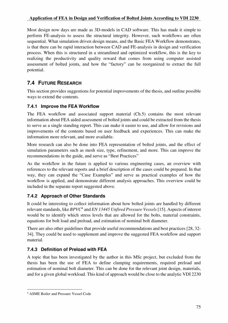
Application of FEA in Design and Verification of Bolted Joints According to VDI 2230
75
Most design now days are made as 3D-models in CAD software. This has made it simple to
perform FE-analysis to assess the structural integrity. However, such workflows are often
sequential. What simulation driven design means, and the Basic FEA Workflow demonstrates,
is that there can be rapid interaction between CAD and FE-analysis in design and verification
process. When this is structured in a streamlined and optimized workflow, this is the key to
realizing the productivity and quality reward that comes from using computer assisted
potential.
7.4 FUTURE RESEARCH
This section provides suggestions for potential improvements of the thesis, and outline possible
ways to extend the contents.
7.4.1 Improve the FEA Workflow
The FEA workflow and associated support material (Ch.5) contains the most relevant
information about FEA aided assessment of bolted joints and could be extracted from the thesis
to serve as a single standing report. This can make it easier to use, and allow for revisions and
improvements of the contents based on user feedback and experiences. This can make the
information more relevant, and more available.
More research can also be done into FEA representation of bolted joints, and the effect of
simulation parameters such as mesh size, type, refinement, and more. This can improve the
recommendations Practices
As the workflow in the future is applied to various engineering cases, an overview with
references to the relevant reports and a brief description of the cases could be prepared. In that
of how the
workflow is applied, and demonstrate different analysis approaches. This overview could be
included in the separate report suggested above.
7.4.2 Approach of Other Standards
It could be interesting to collect information about how bolted joints are handled by different
relevant standards, like BPVC4 and EN 13445 Unfired Pressure Vessels [15]. Aspects of interest
would be to identify which stress levels that are allowed for the bolts, material constraints,
equations for bolt load and preload, and estimation of nominal bolt diameter.
There are also other guidelines that provide useful recommendations and best practices [28, 32-
34]. They could be used to supplement and improve the suggested FEA workflow and support
material.
7.4.3 Definition of Preload with FEA
A topic that has been investigated by the author in this MSc project, but excluded from the
thesis has been the use of FEA to define clamping requirements, required preload and
estimation of nominal bolt diameter. This can be done for the relevant joint design, materials,
and for a given global workload. This kind of approach would be close to the analytic VDI 2230
4 ASME Boiler and Pressure Vessel Code

MSc Thesis 2018
76
procedure, using FEA to define calculation parameters as described in Table 9 (Analytic FEA
approach).
In the research, the scope was to check if this type of approach could be more simple and time
saving than the Semi Analytic FEA approach. According to the preliminary results, significant
time savings or reduction in simulation efforts were not identified. For unexperienced users, it
could also be easy to get lost in the details. Therefore, this research was excluded from this
thesis, and it was decided it was better to fully focus on the Basic FEA Workflow. But even
though it was excluded from this thesis, it could still be interesting to continue the research and
investigate and clarify alternative workflows and analysis approaches. It is possible that they
could give some advantages for some cases.
Application of FEA in Design and Verification of Bolted Joints According to VDI 2230
77
8 SUMMARY
In the engineering department at CERN (EN-MME), accelerator components with bolted joints
are frequently developed. As use of FEA (Finite Element Analysis) aided design is becoming
more widespread, questions have been raised about how to best apply FEA in design and
verification of bolted joints.
First, the specific case of a bolt analysis for the Crab Cavities Helium vessel, a part of the HL-
LHC upgrade, is investigated. Challenges in combining FEA and VDI 2230 are identified and
provides the basis for the following investigations.
Next, investigations into prying are performed, a relevant source of non-linear bolt loads and
unpredictable load development, to understand the phenomenon and the influence of preload.
A complete analysis framework is then proposed, which consist of a streamlined Basic FEA
Workflow, associated calculation templates, details about more advanced verifications, a
detailed guide with best practices and references, examples where the analysis framework has
been applied, and seminar slides that can be used to educate relevant personnel.
The basic workflow suggested takes basis in the analytic VDI 2230 workflow, but is adapted to
optimize the interaction between CAD modelling, FE-analysis, and analytic calculations. The
Mathcad calculation template matches the steps in the workflow, and simplifies the
calculations.
In the end, specific suggestions and recommendations for a potential revision of Helium vessel
bolt analysis are provided.
Altogether, the goal has been to leverage the threshold for using FEA in analysis of bolted joints
according to VDI 2230, and achieving quality and productivity rewards. The thesis and
associated support material could serve as a resource on the topic, and should benefit the
engineering department at CERN and other potential users.
In the discussion, the project is put in a broader perspective stating that the full benefits are not
achieved by just replacing analytic steps with computer aided steps. Only by structuring and
optimizing the interaction between CAD, FEA and analytic calculations, the full rewards can
be achieved.
The thesis provides a good basis for further research. In the discussion, possible improvements
and ways forward are described:
Extract Ch. 5 to a self-standing report that can be revised based on user experiences and
feedback. Future assessment using the suggested workflow can be referenced to as
examples of application.
Investigate how relevant standards handle bolted joints, to identify allowed stress levels,
relevant equations, estimation of preload, and more.
Investigate alternative approaches in other calculation guidelines and best practices to
improve the suggested workflow and associated material.
Investigate how FEA can be used to define the required preload, clamping requirements and
more, as parts of alternative analysis approaches.

MSc Thesis 2018
78

Application of FEA in Design and Verification of Bolted Joints According to VDI 2230
79
References
[1] CERN. (2016). About CERN. Available: www.home.cern/about
[2] Systematic calculation of highly stressed bolted joints; Joints with one cylindrical bolt, VDI 2230 Part 1, 2014.
[3] Systematic calculation of highly stressed bolted joints; Multi bolted joints, VDI 2230 Part 2, 2014.
[4] J. H. Bickford, Introduction to the Design and Behavior of Bolted Joints, Fourth
Edition (Dekker Mechanical Engineering). CRC Press, 2007.
[5] J. Apeland, "Assessment of Bolted Joints According to VDI 2230 Using Finite Element Analysis," Project Thesis, Engineering Design and Materials, NTNU, Trondheim, 2016.
[6] J. Apeland, "Studies into Application of FEA in Assessment of Bolted Joints," EDMS 1770646, 2017, Available: https://edms.cern.ch/document/1770646.
[7] Y.-L. Lee and H.-C. Ho, "Chapter 12 - Design and Analysis of Metric Bolted Joints: VDI Guideline and Finite Element Analysis," in Metal Fatigue Analysis Handbook
Boston: Butterworth-Heinemann, 2012, pp. 461-513.
[8] "LHC - The Guide ", CERN 2017, Available: https://cds.cern.ch/record/2255762.
[9] G. Apollinari, I. Béjar Alonso, O. Brüning, M. Lamont, and L. Rossi, High-Luminosity
Large Hadron Collider (HL-LHC): Preliminary Design Report (no. CERN Yellow Reports: Monographs). Geneva: CERN, 2015.
[10] K. Artoos et al., "Compact Crab Cavity Cryomodule: Deliverable: D4.4," CERN-ACC-2015-0130, Oct 2015, Available: https://cds.cern.ch/record/2059225.
[11] F. Carra et al., "Crab Cavity and Cryomodule Development For HL-LHC," presented at the 17th International Conference on RF Superconductivity (SRF2015), Whistler, BC, Canada, 2015.
[12] C. Zanoni et al., "Design of Dressed Crab Cavities for the HL-LHC Upgrade," in 17th
International Conference on RF Superconductivity (SRF2015), Whistler, BC, Canada, 2015, pp. 1284-1288.
[13] N. Kuder, "History of Development of DQW Dressed Cavity Design," EDMS 1708890, 2016, Available: https://edms.cern.ch/document/1708890.
[14] N. Kuder, "DQW Dressed Cavity Strength Assessment," EDMS 1549819, 2016, Available: https://edms.cern.ch/document/1549819.
[15] Unfired Pressure Vessels - Part 3: Design, EN 13445-3, 2014.
[16] J. H. Bickford, "Behavior of the Joint Loaded in Tension " in Introduction to the
Design and Behavior of Bolted Joints, Fourth Edition (Dekker Mechanical Engineering: CRC Press, 2007).
[17] -Bolted Connections Using the Innovative Beam Model," Structural Interity and Life, vol. 11, no. 3, pp. 147-156, 2011.
[18] M. Guinchard, "Tightening Tests: Evaluation of the Friction Coefficient for Several Configurations of Inox," EDMS 1184393, 2012, Available: https://edms.cern.ch/document/1184393.

MSc Thesis 2018
80
[19] R. Beardmore. (2013). Various Coefficients of Friction. Available: http://www.roymech.co.uk/Useful_Tables/Tribology/co_of_frict.htm
[20] Mechanical Properties of Fasteners, Part 7: Torsional test and minimum torques for
bolts and screws with nominal diameters 1mm to 10mm, ISO 898-7, 1992.
[21] Mechanical Properties of Corrosion Resistant Stainless-Steel Fasteners, Part 1: Bolts,
screws and studs, ISO 3506-1, 1997.
[22] Hexagon Head Bolts - Product Grades A and B, ISO 4014, 1999.
[23] Hexagon Socket Head Cap Screws, ISO 4762, 2004.
[24] Fasteners - Clearance Holes for Bolts and Screws, ISO 273, 1979.
[25] "Bolt Tightening ", vol. 8, Tohnici Torque Handbook [Online]. Available: https://www.tohnichi.com/torque-technical-data.htm.
[26] Mechanical Properties of Fasteners made of Carbon Steel and Alloy Steel, ISO 898-1, 2013.
[27] T. F. Lehnhoff and B. A. Bunyard, "Bolt Thread and Head Fillet Stress Concentration Factors," Journal of Pressure Vessel Technology, vol. 122, no. 2, pp. 180-185, 2000.
[28] NASA, "Criteria for Preloaded Bolts," NSTS 08307, 1998.
[29] Böllhoff, "The Manual of Fastening Technology ", vol. 5 Available: https://eshop.boellhoff.de/out/media/pdf/normteile/The-Manual-of-Fastening-EN-8100.pdf.
[30] P. A. David, "The dynamo and the computer : an historical perspective on the modern productivity paradox," The American economic review, vol. 80, no. 2, pp. 355-361, 1990.
[31] E. Brynjolfsson and L. M. Hitt, "Beyond the Productivity Paradox: Computers are the catalyst for bigger changes," Communications of the ACM, vol. 41, no. 8, p. 49, 1998.
[32] K. H. Brown, C. W. Morrow, S. Durbin, and A. Baca, "Guideline for Bolted Joint Design and Analysis: Version 1.0," Sandia National Laboratories SAND2008-0371, 2008, Available: www.osti.gov/scitech/servlets/purl/929124.
[33] R. T. Barrett, "Fastener Design Manual," NASA Reference Publication 1228, 1990.
[34] J. A. Chambers, "Preloaded Joint Analysis Methodology for Space Flight Systems," NASA Technical Memorandium 106943, 1995.

Application of FEA in Design and Verification of Bolted Joints According to VDI 2230
81
APPENDIX A: Basic FEA Workflow Calculation Template
APPENDIX B: Tightening Torque Template for Non-Critical Bolts
APPENDIX C: Blind Flange Analysis Example
C-1a Blind Flange Case Report
C-1b Calculations for Blind Flange Case
C-2a Blind Flange with Analytic VDI 2230 Procedure
C-2b Calculations for Blind Flange with Analytic VDI 2230 Procedure
APPENDIX D: Bolted Tuner Analysis Example
D-1 HG Cavity Bolted Tuner Analysis
D-2 Analytic Calculations for Tuner Analysis
APPENDIX E: VDI 2230 and FEA Seminar Presentation
APPENDIX F: Revised Calculations for HE-Vessel Joints

MSc Thesis 2018
82

APPENDIX A
BASIC FEA WORKFLOW CALCULATION TEMPLATE


Appendix A Basic FEA Workflow Calculation Template v3.mcdx
Calculation Template for Basic FEA Workflow
Analysis performed by: Name Date of Analysis: Month, 201#
Analysis revision: v# EDMS Reference: -
Color codes: Input parameters Calculation quantities Results Functions Criteria check
S1 - Workload
Run FE-analysis of perform analytic calculations to identify the maximum workload.
Maximum Workload: ≔FA.max N
====================================================
S2 - Nominal Bolt Diameter
Bolt data parameters
Nominal diameter: ≔d mm Friction coefficient in the threads: ≔μGmin Note!Minimum coefficients of friction must be applied. Pitch: ≔P mm Friction in head bearing area: ≔μKmin
Effective bolt head diameter: ≔dW mm Proof strength of the bolt: ≔Rp0.2min MPa
Clearence hole diameter: ≔dh mm
Calculated parameters
Pitch diameter: ≔d2 =-d ――3 ‾‾3
8P ? mm =H ⋅――
‾‾3
2P
Minor diameter of the bolt: ≔d3 =-d P⎛⎜⎜⎝―――17 ‾‾3
24
⎞⎟⎟⎠
? mm
S3 - Tightening Factor
Torque wrench: ≔αA
S4 - Max Assembly Pretension
Calculation quanteties
Stress diameter: ≔dS =0.5 ⎛⎝ +d2 d3⎞⎠ ? mm
Stress area: ≔AS =―ππππ
4⎛⎝dS
⎞⎠2
? mm2
Parameters
Bolt capacity utililization factor: ≔ν 0.9 VDI 2230 suggest: 0.9
CalculationsAllowed assembly stress: ≔σMzul =ν Rp0.2min ? MPa
Maximum permitted assembly preload:
≔FMzul AS ――――――――――――ν Rp0.2min
‾‾‾‾‾‾‾‾‾‾‾‾‾‾‾‾‾‾‾‾‾‾‾‾‾‾‾
+1 3⎛⎜⎝―3
2―d2
dS
⎛⎜⎝
+――P
ππππ d2
1.155 μGmin
⎞⎟⎠
⎞⎟⎠
2ans.==============
=FMzul ? kN
Page 1 of 4

Appendix A Basic FEA Workflow Calculation Template v3.mcdx
S5 - Min Assembly Pretension
Minimum assembly preload: ≔FMmin ――FMzul
αA
ans.===============
=FMmin ? kN
S6 - Simplify and Prepare CAD-geometry
S7 - Prepare and Run FE-analysis
Parameters
Coefficient of friction in the head bearing area: =μKmin ?
Calculation of theoretical beam parameters:
Minor diameter area: ≔Ad3.g =―ππππ
4⎛⎝d3
2 ⎞⎠ ? mm2
Minor second area areal moment of inertia: ≔Id3.g =―ππππ
64⎛⎝d3
4 ⎞⎠ ? mm4
Torsional stiffness: ≔J =―ππππ
32⎛⎝d3
4 ⎞⎠ ? mm4
S8 - Results and Analysis
Max assembly preload Min assembly preload||
||
||
|
Acheived preload: ≔FVmax kN Acheived preload: ≔FVmin kN
Max bolt load: ≔FSmax kN Clamping force in the interface: ≔FKR kN
Max bolt bending moment: ≔MSbo N mm
S9 - Work Stress
Note: In this calculated work-stress, bending stress is included. That is not the case for the standard VDI 2230 equation.
ParametersResidual torque factor: ≔kt 0.5 VDI 2230 suggest: 0.5
Calculation quanteties
Bending modulus: ≔WS =―ππππ
32⎛⎝dS
3 ⎞⎠ ? mm3
Thread moment: ≔MG =⋅⋅FMzul ―d2
2
⎛⎜⎝
+――P
ππππ d2
1.155 μGmin
⎞⎟⎠
? N m
Polar moment of inertia: ≔Wp =⋅―ππππ
16⎛⎝dS
3 ⎞⎠ ? mm3
CalculationsBending stress
Normal stress: ≔σzb.max =+――FSmax
AS
――MSbo
WS
? MPa ≔σSbo =――MSbo
WS
? MPa
Torsional stress: ≔τmax =――MG
Wp
? MPaBending stress contribution to work stress
Working stress: ≔σred.B =‾‾‾‾‾‾‾‾‾‾‾‾‾‾‾‾‾‾
+σzb.max2 3 ⎛⎝ ⋅kt τmax
⎞⎠2
? MPa ≔∆σSbo.p =――σSbo
σred.B
?
Page 2 of 4

Appendix A Basic FEA Workflow Calculation Template v3.mcdx
Assessment
Criteria: <=σred.B ? MPa =Rp0.2min ? MPa ≔Work_Stress ‖‖‖‖‖
if <σred.B Rp0.2min
‖‖ return “Ok”
“Not OK”=Work_Stress ?
Safety factor: ≔SF =―――Rp0.2min
σred.B
?
=============================================================
S10 - Clamping Requirements
S11 - Tightening Torque
Average head friction diameter: ≔DKm =―――+dW dh
2? mm
Tightening Torque: ≔MA =⋅FMzul
⎛⎜⎝
++0.16 P 0.58 d2 μGmin ――DKm
2μKmin
⎞⎟⎠
? N m
===============================================================
S12 - Approve or Iterate
===========APPROVED
===========
===========NOT APPROVED
===========
Page 3 of 4

Appendix A Basic FEA Workflow Calculation Template v3.mcdx
Summary of Key Results
___________________________________________________________________________________________________________________________________________
Calculation step Results
S1 - Workload Maximum axial load: =FA.max ?
___________________________________________________________________________________________________________________________________________
S2 - Nominal Bolt Diameter =d ? mm =P ? mm
___________________________________________________________________________________________________________________________________________
S3 - Tightening Factor =αA ?
___________________________________________________________________________________________________________________________________________
=μGmin ?S4 - Max Assembly Pretension
=ν 0.9
=FMzul ? kN =σMzul ? MPa
___________________________________________________________________________________________________________________________________________
S5 - Min Assembly Pretension =FMmin ? kN
___________________________________________________________________________________________________________________________________________
S6 - Simplify and Prepare CAD-geometry
___________________________________________________________________________________________________________________________________________
S7 - Prepare and Run FE-analysis =μKmin ?
___________________________________________________________________________________________________________________________________________
=FVmax ? kN =FSmax ? kN =MSbo ? N mS8 - Extracted Results
=FVmin ? kN =FKR ? kN
___________________________________________________________________________________________________________________________________________
S9 - Work Stress =σred.B ? MPa < =Rp0.2min ? MPa =SF ? =Work_Stress ?=====================================================
___________________________________________________________________________________________________________________________________________
S10 - Clamping requirements
___________________________________________________________________________________________________________________________________________
S11 - Tightening Torque =MA ? N m
___________________________________________________________________________________________________________________________________________
===========APPROVED
===========
===========NOT APPROVED
===========
S12 - Approve or Iterate
___________________________________________________________________________________________________________________________________________
Page 4 of 4

APPENDIX B
TIGHTENING TORQUE TEMPLATE FOR NON-CRITICAL BOLTS


Appendix B - Tightening Torque Template for M3-M12 V2.mcdx
Tightening Torques for M3 - M12
Calculations prepared by: Name Date of Analysis: Month 201#
EDMS Reference: EDMS 1840088
Head dia. from: ISO 4014 - Hexagon head boltsClearence hole: ISO 273-mInput parameters
d = Nominal diameterP = Thread pitch
= Min. bolt head diadW
= Clearance holedh
= Venting hole diameterdv
Yield strength of the bolt: ≔Rp0.2min 640 MPa
Friction coefficient in the threads: ≔μGmin 0.2
d
((mm))
3
4
5
6
8
10
12
P
((mm))
0.5
0.7
0.8
1
1.25
1.5
1.75
dW
((mm))
5.07
5.74
6.74
8.74
11.47
14.47
16.47
dh
((mm))
3.4
4.5
5.5
6.6
9
11
13.5
dg
((mm))
0
1
1.2
1.6
2
3
3
Friction coefficient in the
head bearing area:
≔μKmin 0.2
Bolt capacity utililization factors: ≔ν
10.900.750.500.30
⎡⎢⎢⎢⎢⎢⎣
⎤⎥⎥⎥⎥⎥⎦
Allowed assembly stress≔σMzul =ν Rp0.2min
640576480320192
⎡⎢⎢⎢⎢⎢⎣
⎤⎥⎥⎥⎥⎥⎦
MPa
Calculation quanteties
Pitch diameter: Bolt minor thread dia.: Stress diameter: Stress area: Modified stress area: Average head friction diameter
≔d2 -d ――3 ‾‾3
8P ≔d3 -d P
⎛⎜⎜⎝―――17 ‾‾3
24
⎞⎟⎟⎠
≔dS 0.5 ⎛⎝ +d2 d3⎞⎠ ≔AS ―ππππ
4⎛⎝dS⎞⎠
2 ≔AS.g ―ππππ
4⎛⎝ -dS
2 dg2 ⎞⎠ ≔DKm ―――
+dW dh
2
=d2
2.683.554.485.357.199.03
10.86
⎡⎢⎢⎢⎢⎢⎢⎢⎣
⎤⎥⎥⎥⎥⎥⎥⎥⎦
mm =d3
2.393.144.024.776.478.169.85
⎡⎢⎢⎢⎢⎢⎢⎢⎣
⎤⎥⎥⎥⎥⎥⎥⎥⎦
mm =dS
2.533.344.255.066.838.59
10.36
⎡⎢⎢⎢⎢⎢⎢⎢⎣
⎤⎥⎥⎥⎥⎥⎥⎥⎦
mm =AS
5.038.78
14.1820.1236.6157.9984.27
⎡⎢⎢⎢⎢⎢⎢⎢⎣
⎤⎥⎥⎥⎥⎥⎥⎥⎦
mm2 =AS.g
5.037.99
13.0518.1133.4750.9277.20
⎡⎢⎢⎢⎢⎢⎢⎢⎣
⎤⎥⎥⎥⎥⎥⎥⎥⎦
mm2 =DKm
4.245.126.127.67
10.2412.7414.99
⎡⎢⎢⎢⎢⎢⎢⎢⎣
⎤⎥⎥⎥⎥⎥⎥⎥⎦
mm
Functions
Maximum permitted assembly preload: ≔FMzul(( ,ν A))
→――――――――――――
A ――――――――――――ν Rp0.2min
‾‾‾‾‾‾‾‾‾‾‾‾‾‾‾‾‾‾‾‾‾‾‾‾‾‾‾
+1 3⎛⎜⎝―3
2―d2
dS
⎛⎜⎝
+――P
ππππ d21.155 μGmin
⎞⎟⎠
⎞⎟⎠
2
Tightening Torque: ≔MA((F))
→――――――――――――
⋅F⎛⎜⎝
++0.16 P 0.58 d2 μGmin ――DKm
2μKmin
⎞⎟⎠
Calculations for standard bolts (Collapsible area)
Calculations for vented bolts (Collapsible area)
Note:
If the friction is lower than what is assumed, the resulting assembly preload will be higher than what is listed above, when tightened
to the specified torque.
If the bolt head diameter is larger than what is assumed, a slightly lower assmebly preload will be acheived.
The strength of tapped threads are not considered in this analysis. For short length of engagement or soft materials, additional verifications should be performed.
If spring washers are applied, the maximum spring force should be compared to the acheived preloads above. If the preload is
higher, the washer is flattened.
Page 1 of 2

Appendix B - Tightening Torque Template for M3-M12 V2.mcdx
Suggested Lengths of Tapped Threads
Page 2 of 2

APPENDIX C
BLIND FLANGE ANALYSIS EXAMPLE
C-1a Blind Flange Case Report
C-1b Calculations for Blind Flange Case
C-2a Blind Flange with Analytic VDI 2230 Procedure
C-2b Calculations for Blind Flange with Analytic VDI 2230 Procedure

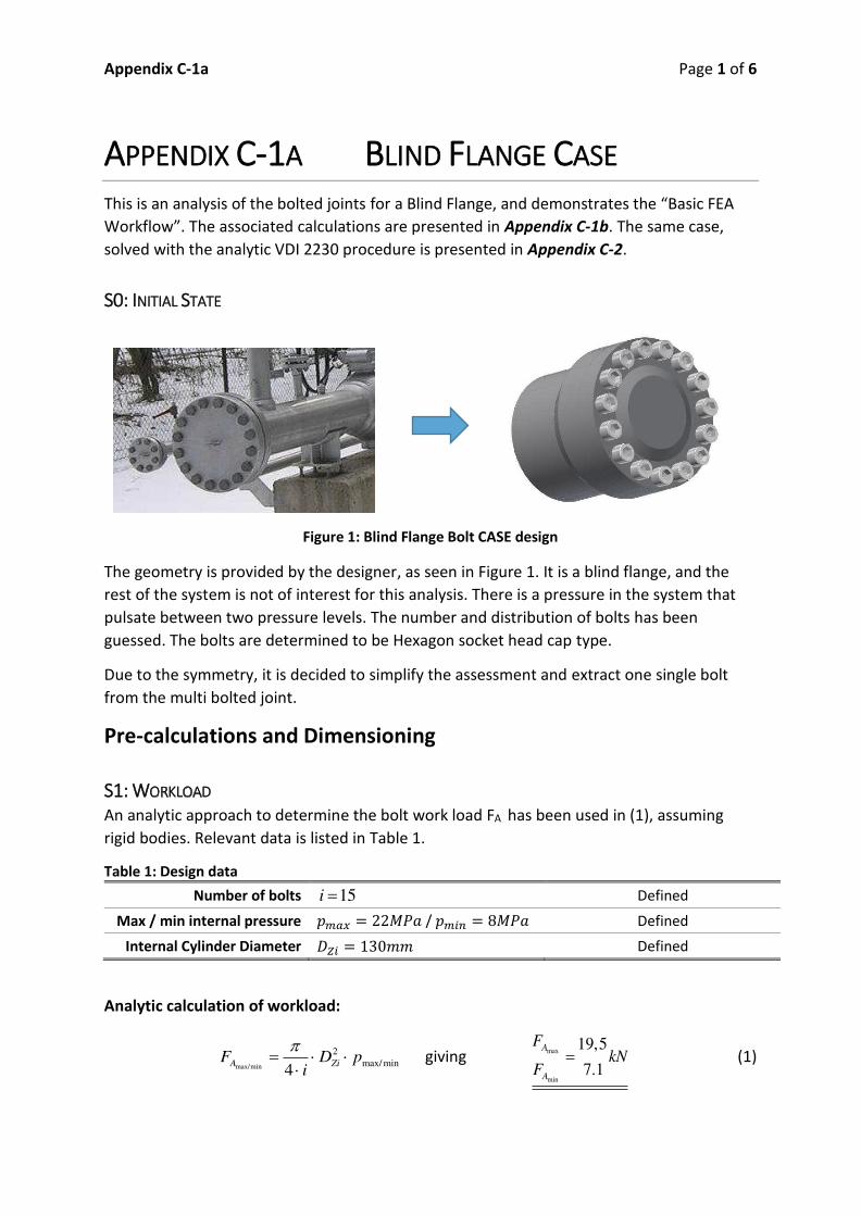
Appendix C 1a Page 1 of 6
APPENDIX C 1A BLIND FLANGE CASE
This is an analysis of the bolted joints for
Appendix C 1b. The same case,
solved with the analytic VDI 2230 procedure is presented in Appendix C 2.
S0: INITIAL STATE
Figure 1: Blind Flange Bolt CASE design
The geometry is provided by the designer, as seen in Figure 1. It is a blind flange, and the
rest of the system is not of interest for this analysis. There is a pressure in the system that
pulsate between two pressure levels. The number and distribution of bolts has been
guessed. The bolts are determined to be Hexagon socket head cap type.
Due to the symmetry, it is decided to simplify the assessment and extract one single bolt
from the multi bolted joint.
Pre calculations and Dimensioning
S1: WORKLOAD
An analytic approach to determine the bolt work load FA has been used in (1), assuming
rigid bodies. Relevant data is listed in Table 1.
Table 1: Design data
Number of bolts 15i Defined
Max / min internal pressure / Defined
Internal Cylinder Diameter Defined
Analytic calculation of workload:
max/min
2
max/ min4
A ZiF D p
i giving
max
min
19,5
7.1
A
A
FkN
F (1)

Appendix C 1a Page 2 of 6
S2: NOMINAL BOLT DIAMETER
According to the bolt size estimation guide in [Pt.1 Table A7], the bolt chosen is: M16x60
12.9. The estimation steps are shown in Table 2. Relevant bolt data are listed in Table 3.
Table 2: Preliminary dimensioning procedure
Step Evaluation Result
A 25 kN
B + two steps for dynamic and eccentrically applied load 63 kN
C + one step for using a torque wrench 100 kN
D Strength grade 12.9 give nominal diameter: 16 mm
Table 3: Data for M16x60 12.9 bolt
Parameter Sym. Value Unit Source
Bolt material Steel
E modulus E 205 GPa
0.2% Proof strength of the bolt Rp0.2 1100 MPa Class 12.9
Nominal diameter 16
Thread Pitch 2 [Pt.1 Table A12]
Pitch Diameter 14.701 [Pt.1 Table A11] / Calc.
Minor Diameter 13.546 [Pt.1 Table A12] / Calc.
Effective head diameter 22 ISO 4762
Bolt head height 16 ISO 4762
Bolt length 60 Defined
Clearance hole diameter 17.5 ISO 273 medium
Thread Coefficient of Friction 0.1 [Pt.1 Table A5 A6]
Friction in Head Bearing Area 0.1 [Pt.1 Table A5 A6]
S3: TIGHTENING FACTOR
Using [Pt.1 Table A8] for friction coefficient class B, knowing a precision torque wrench will
be used and choosing a high value in the allowed range give the tightening factor 1.6A
.
(R1/1) max
min
1,6MA
M
F
F (2)

Appendix C 1a Page 3 of 6
S4: MAXIMUM ASSEMBLY PRELOAD
By defining how much of the bolt capacity that should be utilized during assembly through
the utilization factor , a maximum permitted assembly preload is obtained. The associated
data is found in Table 4.
Table 4: Data associated with calculation of the maximum assembly pretension
Utilization factor 0.9 Defined
Stress Area SA 156,7 [Pt.1 Table A11] / Calc.
Maximum Permitted
Assembly Preload 142.5 Calculated
S5: MINIMUM ASSEMBLY PRELOAD
Taking the tightening uncertainty into account, the lowest preload after assembly should be
the minimum assembly preload listed in Table 5.
Table 5: Data and Results Min Assembly Pretension
Minimum Assembly Preload 89 Calculated
FE Analysis
S6: SIMPLIFY AND PREPARE CAD GEOMETRY
A simplified CAD model is prepared. The data required for modelling is listed in Table 3. The
bolt is represented by a Class III model, with diameter based on the thread minor
diameter . The tapped thread hole dimeter is modified to have a corresponding
diameter.
Figure 2: SBJ extracted from a MBJ

Appendix C 1a Page 4 of 6
S7: PREPARE AND RUN FE ANALYSIS
The material properties are defined and applied to all parts. The meshed model can be seen
in Figure 3. The bolt is meshed with HEX elements. The mesh is refined in the clamping
interface.
In Figure 4, the boundary conditions are shown. On the cut sides of the model, frictionless
boundary conditions are applied to represent the symmetric conditions. In the tapped
threads are, the bolt is bonded. In the clamping interface and the head bearing area,
friction contact is applied with the coefficient of friction Table 6) has been applied.
Pressure is applied to internal surfaces, and the bolt is preloaded.
Table 6: Data needed for FE simulation
Contact Coefficient of Friction [Pt.1 Table A5 A6]
Figure 3: Meshed model
Figure 4: Boundary conditions of the model and applied loads

Appendix C 1a Page 5 of 6
S8: EXTRACT VALUES FROM THE FE ANALYSIS
The results from the simulation is listed in Table 7. They are used for later calculations and
verifications.
Table 7: Extracted values from FE analysis
Actual max preload 142.5
Max bolt load 143.7
Bolt moment 7.5
Workload 19.46
Actual min preload 89
Residual clamping force 70.8
Analysis of Results
S9: WORK STRESS
The work stress is calculated, and found to provide a safety factor against yield of 1.1.
Table 8: Calculated values from FE analysis
Work Stress 979.6 MPa Calculated
Amount bending stress 2.8 %
Bolt Yield Safety Factor FS 1.12 Calculated
S10: CLAMPING REQUIREMENTS
Figure 5: Pressure in the clamping interface with max load and minimum pretension
In Figure 5, the residual clamping pressure resulting from the minimum assembly preload
simulation is shown. The pressure distribution looks good, and the amount of opening is
minimal. From this, it is concluded that there is a small chance of prying, and that the
clamping requirements are fulfilled.

Appendix C 1a Page 6 of 6
Joint Function OK Visual inspection
S11: TIGHTENING TORQUE
The tightening torque is calculated and presented in Table 9.
Table 9: Data and Results Max Assembly Pretension
Average Head Friction Area 19.75 Calculated
Tightening Torque 307.9 Calculated
S12: APPROVE OR ITERATE
Based on this analysis, the bolted joint is approved.
Approved
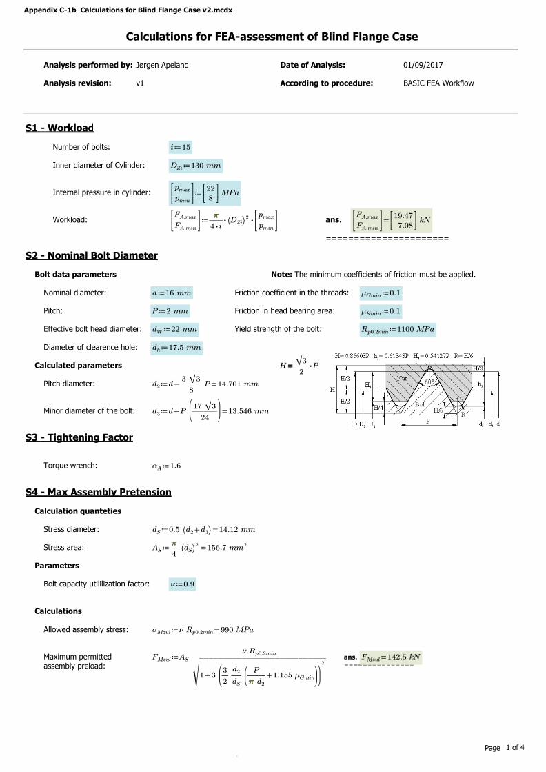
Appendix C-1b Calculations for Blind Flange Case v2.mcdx
Calculations for FEA-assessment of Blind Flange Case
Analysis performed by: Jørgen Apeland Date of Analysis: 01/09/2017
Analysis revision: v1 According to procedure: BASIC FEA Workflow
S1 - Workload
Number of bolts: ≔i 15
Inner diameter of Cylinder: ≔DZi 130 mm
Internal pressure in cylinder: ≔pmax
pmin
⎡⎢⎣
⎤⎥⎦
228⎡⎢⎣
⎤⎥⎦MPa
Workload: ≔FA.max
FA.min
⎡⎢⎣
⎤⎥⎦
⋅⋅――ππππ
⋅4 i⎛⎝DZi
⎞⎠2 pmax
pmin
⎡⎢⎣
⎤⎥⎦
ans.
======================
=FA.max
FA.min
⎡⎢⎣
⎤⎥⎦
19.477.08
⎡⎢⎣
⎤⎥⎦kN
S2 - Nominal Bolt Diameter
Bolt data parameters Note: The minimum coefficients of friction must be applied.
Nominal diameter: ≔d 16 mm Friction coefficient in the threads: ≔μGmin 0.1
Pitch: ≔P 2 mm Friction in head bearing area: ≔μKmin 0.1
Effective bolt head diameter: ≔dW 22 mm Yield strength of the bolt: ≔Rp0.2min 1100 MPa
Diameter of clearence hole: ≔dh 17.5 mm
Calculated parameters =H ⋅――‾‾3
2P
Pitch diameter: ≔d2 =-d ――3 ‾‾3
8P 14.701 mm
Minor diameter of the bolt: ≔d3 =-d P⎛⎜⎜⎝―――17 ‾‾3
24
⎞⎟⎟⎠13.546 mm
S3 - Tightening Factor
Torque wrench: ≔αA 1.6
S4 - Max Assembly Pretension
Calculation quanteties
Stress diameter: ≔dS =0.5 ⎛⎝ +d2 d3⎞⎠ 14.12 mm
Stress area: ≔AS =―ππππ
4⎛⎝dS⎞⎠2 156.7 mm2
Parameters
Bolt capacity utililization factor: ≔ν 0.9
Calculations
Allowed assembly stress: ≔σMzul =ν Rp0.2min 990 MPa
Maximum permitted assembly preload:
≔FMzul AS ――――――――――――ν Rp0.2min
‾‾‾‾‾‾‾‾‾‾‾‾‾‾‾‾‾‾‾‾‾‾‾‾‾‾‾
+1 3⎛⎜⎝―3
2―d2
dS
⎛⎜⎝
+――P
ππππ d2
1.155 μGmin
⎞⎟⎠
⎞⎟⎠
2ans.===============
=FMzul 142.5 kN
Page 1 of 4
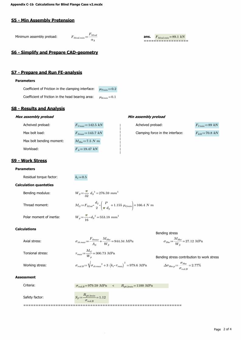
Appendix C-1b Calculations for Blind Flange Case v2.mcdx
S5 - Min Assembly Pretension
Minimum assembly preload: ≔FMzul.min ――FMzul
αA
ans.==================
=FMzul.min 89.1 kN
S6 - Simplify and Prepare CAD-geometry
S7 - Prepare and Run FE-analysis
Parameters
Coefficient of Friction in the clamping interface: ≔μTmin 0.2
Coefficient of friction in the head bearing area: =μKmin 0.1
S8 - Results and Analysis
Max assembly preload Min assembly preload
Acheived preload: ≔FVmax 142.5 kN ||
|||
||
||
Acheived preload: ≔FVmin 89 kN
Max bolt load: ≔FSmax 143.7 kN Clamping force in the interface: ≔FKR 70.8 kN
Max bolt bending moment: ≔MSbo 7.5 N m
Workload: ≔FA 19.47 kN
S9 - Work Stress
Parameters
Residual torque factor: ≔kt 0.5
Calculation quanteties
Bending modulus: ≔WS =―ππππ
32dS
3 276.59 mm3
Thread moment: ≔MG =⋅⋅FMzul ―d2
2
⎛⎜⎝
+――P
ππππ d2
1.155 μGmin
⎞⎟⎠166.4 N m
Polar moment of inertia: ≔Wp =⋅―ππππ
16dS
3 553.18 mm3
CalculationsBending stress
Axial stress: ≔σzb.max =+――FSmax
AS
――MSbo
WS
944.34 MPa ≔σSbo =――MSbo
WS
27.12 MPa
Torsional stress: ≔τmax =――MG
Wp
300.73 MPaBending stress contribution to work stress
Working stress: ≔σred.B =‾‾‾‾‾‾‾‾‾‾‾‾‾‾‾‾‾‾
+σzb.max2 3 ⎛⎝ ⋅kt τmax
⎞⎠2979.6 MPa ≔∆σSbo.p =――
σSbo
σred.B
%2.77
Assessment
Criteria: <=σred.B 979.59 MPa =Rp0.2min 1100 MPa
Safety factor: ≔SF =―――Rp0.2min
σred.B
1.12
================================================================
Page 2 of 4

Appendix C-1b Calculations for Blind Flange Case v2.mcdx
S10 - Clamping Requirements
S11 - Tightening Torque
Average head friction diameter: ≔DKm =―――+dW dh
219.75 mm
Tightening Torque: ≔MA =⋅FMzul
⎛⎜⎝
++0.16 P 0.58 d2 μGmin ――DKm
2μKmin
⎞⎟⎠307.9 N m
===============================================================
S12 - Approve or Iterate
=========
APPROVED=========
Additional Calculations
Additional bolt load: ≔FSA =-FSmax FVmax 1.2 kN
Load factor: ≔ΦFE =――FSA
FA
0.062
Page 3 of 4

Appendix C-1b Calculations for Blind Flange Case v2.mcdx
Summary of Key Results
___________________________________________________________________________________________________________________________________________Calculation step Results
S1 - Workload =pmax
pmin
⎡⎢⎣
⎤⎥⎦
228
⎡⎢⎣
⎤⎥⎦MPa =
FA.max
FA.min
⎡⎢⎣
⎤⎥⎦
19.57.1
⎡⎢⎣
⎤⎥⎦kN
___________________________________________________________________________________________________________________________________________
S2 - Nominal Bolt Diameter =d 16 mm =P 2 mm___________________________________________________________________________________________________________________________________________
S3 - Tightening Factor =αA 1.6___________________________________________________________________________________________________________________________________________
≔μGmin 0.1
S4 - Max Assembly Preload ≔ν 0.9
=FMzul 142.5 kN =σMzul 990 MPa___________________________________________________________________________________________________________________________________________
S5 - Min Assembly Preload =FMzul.min 89.1 kN___________________________________________________________________________________________________________________________________________
S6 - Simplify and Prepare CAD geometry =d3 13.55 mm___________________________________________________________________________________________________________________________________________
S7 - Prepare and Run FE-analysis =μTmin 0.2 =μKmin 0.1___________________________________________________________________________________________________________________________________________
=FVmax 142.5 kN =FSmax 143.7 kN =MSbo 7.5 N mS8 - Extracted Results
=FVmin 89 kN =FKR 70.8 kN =FA 19.47 kN___________________________________________________________________________________________________________________________________________
S9 - Work Stress =σred.B 979.6 MPa < =Rp0.2min 1100 MPa =SF 1.12==========================================
___________________________________________________________________________________________________________________________________________
S10 - Clamping requirements
___________________________________________________________________________________________________________________________________________
S11 - Tightening Torque =MA 308 N m
___________________________________________________________________________________________________________________________________________
=========APPROVED
=========
S12 - Approve or Iterate
______________________________________________________________________________________________________________________________________________________________________________________________________________________________________________________________________________________
Additional Calculations =FSA 1200 N =ΦFE 0.06______________________________________________________________________________________________________________________________________________________________________________________________________________________________________________________________________________________
Page 4 of 4

Appendix C 2a Page 1 of 14
Blind Flange with Analytic VDI 2230 Procedure
Case Description
This case is based on example B5 in VDI 2230 Part 1, but geometry details and parameters
has been changed. The case to be analysed is a blind flange (Figure 1), with the function as
an inspection hatch for a pressurized system. In operation, there is a pulsating internal
pressure. 15 tapped thread joints (TTJ) holds the cap attached to the cylinder, and the scope
is to design and verify that the bolts can withstands the operating pressure, without opening
in the interface. The bolts are to be tightened with a precession torque wrench.
Figure 1: CASE model
CASE Parameters
The case data are stated in Table 1. The 15 bolts are placed around the edge, equally
spaced. Since it is symmetric, it allows for simplification of the case geometry into 15 equally
sized parts. The geometry, with all relevant dimensions are shown in Figure 2. Some central
geometry parameters are listed in Table 2, together with symbols and a description of the
parameter. The material data of S355 JO is listed in Table 3.
Table 1: CASE data
Cap / Cylinder material S355 JO Plain structural steel
Tightening Precision torque wrench
Number of bolts 15i Hexagon socket head cap screws
Strength grade 12.9
Interface roughness 16ZR m Surfaces of head bearing area
Max / min internal pressure min max8 , 22p MPa p MPa

Appendix C 2a Page 2 of 14
Figure 2: CASE section
Table 2: Geometry data
Description Sym. Value Unit
Outside diameter of cap and cylinder aD 190 mm
Cylinder inside diameter ZiD 130 mm
Pitch circle diameter STD 160 mm
Clamp length Kl 30 mm
Length, side at risk of opening e 14 mm
Width of the interface Tc 29 mm
Table 3: Material data according to table A9 [Pt.1 Annex A]
Material 355 S JO
Tensile strength .minmR 490 MPa
0,2% proof stress 0,2.minpR 325 MPa
Shear strength .minB 390 MPa
Lim. Surface pressure Gp 760 MPa
E modulus E 205000 MPa
Density 7,85 3/kg dm
ANALYTIC CALCULATIONS
The analytic calculations have been solved according to the procedure described in VDI 2230
Part 1. The calculation steps together with a brief description, the most relevant formulas,
and the results are presented. The (Rx/y) formulas refer to the formulas defined in the
verification procedure. The complete calculations are found in the attached MathCAD
calculations in Appendix C 2b.
e

Appendix C 2a Page 3 of 14
R0: NOMINAL DIAMETER
Working load
Based on the internal pressure, the max and minimum working loads max/ minAF are calculated
according to (1).
2
4A Zi
F D pi
giving max
min
19,5
7.1
A
A
FkN
F (1)
Assuming the cap is flexible, the load is introduced on one side of the bolt, thus being
subjected to eccentric loading.
Preliminary dimensioning
According to the preliminary dimensioning procedure [Pt.1 Table A7], the nominal diameter
is found to be 16mm (Table 4). This procedure is a quick way to make a qualified estimate
based on some critical conditions: Dynamic or static loading, tightening method, and if
concentric or eccentric loading are present.
Table 4: Preliminary dimensioning procedure
Step Evaluation Result
A max
25AF kN 25kN
B + two steps for dynamic and eccentrically applied load 63kN
C + one step for using a torque wrench 100kN
D Strength grade 12.9 give nominal diameter: 16mm
Evaluation criteria: Validity range
Then, a check for compliance with the validity range is performed (2), making sure that the
width of the interface area Tc is smaller than the limiting size of the interface area 'G . A
check at the side at risk of opening give that the distance on the interface e , from the bolt
axis to the edge at risk of opening is below half the minimum limiting size (3). The interface
design complies with the validity range.
(R0/1) 29T
c mm < 1.5
'2
WG d (2)
(R0/2) 14e mm < min'
17,42
Gmm (3)

Appendix C 2a Page 4 of 14
Bolt data
A Hexagon socket head cap screw ISO 4762 M16x60 12.9 bolt is selected, and according to
[Pt.1 Table A11] and [7 10], the dimensions shown in Figure 3 and listed in Table 5 apply.
Figure 3: Bolt dimensions [8]
Table 5: Bolt dimensions
ISO 4762 M16x60 12.9 [8]
Head diameter Kd 24 mm
Effective head diameter Wd 23,17 mm
Bolt shank diameter Sd 16 mm
Nominal bolt length l 60 mm
Thread length b 44 mm
Length to effective thread noml b gl 16 mm
Bolt shank length 5gl P Sl 6 mm
Data from [Pt. 1 Table A11]
Load at minimum yield point [10] 0,2minF 173 kN
0,2% minimum yield limit for the bolt . 0.2.minS pR 1100 MPa
Pitch P 2 mm
Pitch diameter 2d 14,701 mm
Cross section at 3d 3dA 144,1 2
mm
Minor diameter 3d 13,55 mm
Stress cross section SA 157 2mm
Clearance hole diameter [7] hd 17,5 mm

Appendix C 2a Page 5 of 14
R1: TIGHTENING FACTOR Using [Pt.1 Table A8] for friction coefficient class B, knowing a precision torque wrench will
be used and choosing a high value in the allowed range give the tightening factor (4).
(R1/1) max
min
1,6MA
M
F
F (4)
R2: REQUIRED MINIMUM CLAMP LOAD The required minimum clamp load KerfF has to satisfy (5). Since there is no transverse load
or any acting moments, 0KQF . There is no extra sealing requirement, so 0KPF . However,
prevention of opening has to be considered, and the minimum clamp force at the opening
limit KAF has to be calculated (6). The results are presented in Table 6.
(R2/4) max ;Kerf KQ KP KA
F F F F (5)
(R2/3) max
D sym
Kerf KA A
BT sym D
A a u s uF F F
I s u A (6)
Calculation approach
Figure 4: Calculation model with calculation parameters [Pt.1 Figure 4 & Figure 25]
To find KAF , the parameters of (6) had to be calculated. The approach is to create a centred
imaginary laterally symmetrical clamp solid consisting of a cone and sleeve, shifted with the
distance syms from the eccentric. Knowing syms give u . Then the distance from the centre of
the new cone to where the axial load is applied, a , is found based on a Class I simulation
giving the cross section forces and moments. Then the areal moment of inertia BTI , and the
surface of the interface area DA is calculated. All values are now known, and the clamping
requirement KerfF is calculated.

Appendix C 2a Page 6 of 14
Parameters and results
Table 6: R2 analytic values
Sym. Value Unit Description
KerfF 39,7 kN Clamp load required for sealing functions and prevention of one sided
opening at the interface
KAF 39,7 kN Minimum clamp load at the opening limit
maxAF 19,5 kN Axial load directed in the bolt axis direction
DA 737,3 2mm Sealing area of interface
a 13,5 mm Distance of the substitutional line of action of the axial load AF from
the axis of the imaginary laterally symmetrical deformation body
u 12,2 mm Distance of the edge bearing point V from the axis of the imaginary
laterally symmetrical deformation body
syms 1,8 mm Distance of the bolt axis from the axis of the imaginary laterally
symmetrical deformation body
BTI 67791,4 4mm Areal moment of inertia of the interface area
R3: LOAD FACTOR AND RESILIENCIES Finding the load factor , which is the relation between the work load
AF and the
additional bolt load SAF (7), requires information about the resilience of the clamped parts
P and the bolt
S. The proportion of the work load that relieves the clamped parts is
calculated from (8). For the case of eccentric clamping and loading, the load introduction
factor n is also included and the load factor en is found (9). All the results are presented in
Table 7.
(R3/1) SA
A
F
F (7)
(R3/2) 1PA A
F F (8)
(R3/4) Pen
S P
n (9)
Figure 5: Bolt resilience dimensions [Pt.1 Figure 6]

Appendix C 2a Page 7 of 14
Calculation approach
First, the resilience of all the parts of the bolt (Figure 5) is calculated, and combined to the
bolt resilience S. Then the bending resilience of the bolt
S is calculated, since it later is
needed to calculate the alternating stresses. To calculate the resilience of the clamped
parts, the form and size of the substitutional deformation body is calculated (Figure 6). Then
the resilience of the deformation sleeve H
P , and of the deformation cone V
P is calculated
and combined, giving the resilience of the clamped parts P
. Due to the eccentric clamping
and loading, the compensated values P and P are calculated. In the end, the load
introduction factor n is found, based on [Pt.1 Figure 22 & Table 2]. The SV2 is the best fit,
and n is obtained.
Figure 6: Parameters related to the substitutional deformation body [Pt.1 Figure 8]
Parameters and results
Table 7: R3 analytic values
Sym. Value Unit Description
en 0,051 ul Load factor for eccentric clamping and eccentric load
introduction via the clamped parts
S 31,4 10 mmkN
Elastic resilience of the bolt
S 0,107 1kNm
Elastic bending resilience of the bolt
P 42,0 10 mmkN
Elastic resilience of the clamped parts or eccentric clamping and
eccentric loading
n 0,27 ul Load introduction factor for describing the effect of the
introduction point of AF on the displacement of the bolt head
.maxPAF 18,5 kN Proportion of the axial load which changes the loading of the
clamped parts, additional plate load
.maxSAF 1,002 kN Axial additional bolt load


Appendix C 2a Page 9 of 14
Parameters and results
Table 10: R6 analytic values
Sym. Value Unit Description
.maxMF 100,8 kN
Maximum assembly preload for which a bolt must be designed, so that,
despite lack of precision in the tightening technique and the expected
embedding during operation, the required clamp load in the joint is
produced and maintained.
R7: ASSEMBLY STRESS & LOAD The assembly stress ,red M resulting from the preloading .maxMF must be checked against the
allowed assembly stress ,red Mzul (13). That is done by checking that the assembly preloading
.maxMF is below the maximum allowed assembly force MzulF (14). This value can also be
obtained from [Pt.1 Table A1 A4]. The result is given in Table 11, and evaluation against the
criteria is done in (16). The different preload values are identified and compared to the bolt
strength in Figure 7.
(R7/1) , 0,2minred Mzul pR (13)
(R7/2) 0,2 min
0
2min
0 2
31 3 1,155
2
p
Mzul
G
RF A
d P
d d
(14)
(R7/3) maxM MzulF F (15)
Figure 7: Permissable assembly preload [Pt.1 Figure 33]


Appendix C 2a Page 11 of 14
Parameters and results
Table 12: R8 analytic values
Sym. Value Unit Description
.red B 949,5 MPa Comparative stress in the working state
FS 1,2 ul Safety margin against exceeding the yield point
.maxSF 143,4 kN Max bolt load
.maxz 913,4 MPa Max tensile stress in the bolt based on .maxSF
max 299,5 MPa Torsional stress in the thread as a result of tightening torque on the
thread
R9: ALTERNATING STRESS Since the load is pulsating, the bolt will be exposed to alternating stresses. For the case of
eccentricity, the stress amplitude ab has to be compared to the fatigue limit for bolts rolled
before heat treatment ASV . The results are presented in Table 13.
(R9/2) 0
2SAb SAbu
ab (21)
31
18
sym K S S en ASAb
Bersen ers P S
s l E a d F
a l E AI (22)
.max
.min
A SAbo
A
A SAbu
FF
F (23)
(R9/3) ab ASV (24)
(R9/4) 1,0ASVD
ab
S (25)
Calculation Approach
The max ( SAbo ) and minimum ( SAbu ) stress states (23), are calculated using (22). That
equation use some of the geometry, stiffness and loading parameters. The substitutional
bending length of the bolt ersl is calculated based on the bending resilience of the bolt, S .
The stress amplitude is calculated according to (21), and compared to the fatigue limit ASV
(24) or by the safety factor DS (25).

Appendix C 2a Page 12 of 14
Relevant parameters and results
Table 13: R9 analytic values
Sym. Value Unit Description
ab 10,9 MPa Continuous alternating stress acting on the bolt during eccentric
clamping and loading
DS 4, 2 ul Safety margin against fatigue failure
ASV 46,2 MPa Stress amplitude of the endurance limit of the bolts rolled before heat
treatment
ersl 36,2 mm Substitutional bending length for a bolt
BersI 45,6 10 4mm
Substitutional areal moment of inertia for the deformation body,
subtracted the areal moment of inertia of the bolt hole
R10: SURFACE PRESSURE The surface pressure in the bearing area, between the bolt head and the cap, is checked
against the maximum material surface pressure (26), or by finding a safety factor PS (27). If
exceeded, creep may pose a threat. The results are listed in Table 14. Only the assembled
state is considered, since that is where the forces are largest.
(R10/1) max
min
MzulM G
p
Fp p
A (26)
(R10/4) max
GP
M
pS
p (27)
Parameters and results
Table 14: R10 analytic values
Sym. Value Unit Description
Gp 760 MPa Maximum permissible pressure under the bolt head
PS 0,97 ul Safety margin against surface pressure
.maxMp 786,3 MPa Surface pressure in the assembled state
.minpA 181,1 2mm Minimum bolt head bearing area
R11: LENGTH OF ENGAGEMENT To make sure the thread length of engagement is sufficient, a calculation of the thread
capacity is compared the effective thread length. The results are listed in Table 15.
Calculation Approach
First, the thread is identified as critical (28). Then, a diagram [Pt.1 Figure 36] gives the
specific length of thread engagement required, effm . Then it is checked that the effective
thread length of engagement is larger than the required length (29).


Appendix C 2a Page 14 of 14
CONCLUSION AND SUMMARY OF KEY RESULTS The analytical calculations of the case defined in section 0, has resulted in the
recommended use of bolt: ISO 4762 M16x60 12.9, rolled before heat treatment. The BJ
design has been verified, and the most relevant results are summarized in Table 17.
Table 17: Summary of analytic values
Calculation step Sym. Value Unit
R0: Nominal Diameter
maxAF 19,5 kN
minAF 7.1 kN
d 16 mm
R1: Tightening Factor A 1,6 ul
R2: Required Minimum Clamp Load KerfF 39,7 kN
R3: Load factor and resiliencies
en 0,051 ul
S 31,4 10 mmkN
P 42,0 10 mmkN
.maxSAF 1,002 kN
.maxPAF 18,5 kN
R4: Preload changes ZF 4,8 kN
R5: Minimum assembly load .minMF 63 kN
VF 58,2 kN
R6: Maximum assembly load .maxMF 100,8 kN
R7: Assembly stress & load .M zulF 142,4 kN
R8: Working stress
.red B 949,5 MPa
FS 1,2 ul
.maxSF 143,3 kN
R9: Alternating stress ab 10,9 MPa
DS 4, 2 ul
R10: Surface pressure PS 0,97 ul
.maxMp 786,3 MPa
R11: Length of engagement effvorhm 26 mm
R12: Safety margin against slipping
R13: Tightening torque AM 309 Nm

Appendix C-2b Calculations for Blind Flange with Analytic VDI 2230 Procedure.mcdx
Blind Flange Calculations with Anaytic VDI 2230 Procedure
This analytic calculation are based on the calculation procdure defined in VDI 2230, and are associated with Appendix C-2a.
A summary of key results are found on page 8.
Parameters
Internal pressure in cylinder: ≔pmax
pmin
⎡⎢⎣
⎤⎥⎦
228
⎡⎢⎣
⎤⎥⎦MPa ≔p
pmax
pmin
⎡⎢⎣
⎤⎥⎦
Geometry data Data for M16x60-12.9 bolt Material data: S355 JO
≔DST 160 mm ≔i 15 ≔Rm.min 490 MPa
≔DZi 130 mm ≔d 16 mm ≔RM.p0.2.min 325 MPa
≔Da 190 mm ≔F0.2min 173 kN ≔τB.min 390 MPa
≔cT 29 mm ≔P 2 mm ≔pG 760 MPa
≔e 14 mm ≔d2 14.701 mm ≔E 205 GPa
≔chamf 1 mm ≔Ad3 144.1 mm2 ≔ρ 7.85 ――kg
dm3
≔dh 17.5 mm ≔AS 157 mm2
≔lK 30 mm ≔dK 24 mm ≔ES
EP
⎡⎢⎣
⎤⎥⎦
E
E
⎡⎢⎣
⎤⎥⎦
≔l 60 mm ≔dW 23.17 mm≔RmM Rm.min
≔b 44 mm ≔dS 16 mm
≔lg =-l b 16 mm ≔d3 =‾‾‾‾‾――4 Ad3
ππππ13.55 mm
≔ls =-lg 5 P 6 mm≔dS =
‾‾‾‾‾――4 AS
ππππ14.14 mm
R0 - Nominal diameter ≔RS.p0.2.min =―――F0.2min
AS
1102 MPa
≔FA.max
FA.min
⎡⎢⎣
⎤⎥⎦
=⋅⋅――ππππ
⋅4 i⎛⎝DZi
⎞⎠2 p
19.57.1
⎡⎢⎣
⎤⎥⎦kN ≔FA
FA.max
FA.min
⎡⎢⎣
⎤⎥⎦
≔G' =dW1.52
⎡⎢⎣
⎤⎥⎦
34.846.3
⎡⎢⎣
⎤⎥⎦mm > =cT 29 mm
=e 14 mm < =―G'
217.423.2
⎡⎢⎣
⎤⎥⎦mm
R1: Tightening factor
≔αA 1.6
R2: Required Minimum Clamp Load
Substitutional outside diameter of the basic solid
Limiting outside diameter Lower bearing area diameter (inside)
Average bearing area diameter
≔D'A.I =DST 160 mm ≔DA.R =2 ⎛⎝ -cT e⎞⎠ 30 mm ≔dWu =2 e 28 mm ≔dWm =―――+dW dWu
225.6 mm
≔βL =――lK
dWm
1.2 ≔y =――D'A.I
dWm
6.3 ≔φD =atan⎛⎜⎝
++0.362 0.032 ln⎛⎜⎝―βL
2
⎞⎟⎠
0.153 ln((y))⎞⎟⎠
0.6
Limiting diameter on the inside
≔DAGr.I =+dWu lK tan⎛⎝φD⎞⎠ 46.8 mm
Page 1 of 8

Appendix C-2b Calculations for Blind Flange with Analytic VDI 2230 Procedure.mcdx
Average diameter of inside and cap edge side Small cone component
≔Dm.A.I =――――+DAGr.I dWu
237.4 mm ≔Dm.A.R =DA.R 30 mm
Average diameter of the complete substitutional sleve
≔DAm =―――――+DA.R Dm.A.I
233.7 mm ≔v =――
DAm
216.8 mm
Check sign rules in table 4, VDI2230 pt. 1.CASE III - for the displacement of the deformation body into a symmetrical position.
≔ssym =--cT e v -1.8 mm ≔u =+e ssym 12.2 mm
To determine the eccentrity of the load introduction, a FE-simulation a
according to Class I was performed:
Force reaction: ≔FKI 19462 N
≔Fsim.Q 6842.5 N
Moment reaction:≔MKI 2.6309 105 N mm
=FKI 19462 N
Note - Very similar to: =FA.max 19467 N
≔a =――MKI
FKI
13.5 mm
Outer radius Effective internal radius Radius to bolt axis Spacing
≔ra ―Da
2≔ri +――
DZi
2chamf ≔rs ――
DST
2≔t =―――
ππππ DST
i33.5 mm
The interface area is: ≔AD =-―ππππ
i⎛⎝ -ra
2ri
2 ⎞⎠⎛⎜⎝―ππππ
4dh
2 ⎞⎟⎠
737.34 mm2
Areal moment of inertia for the interface segment: ≔IBT =――――――――t cT
3 ⎛⎝ ++ra2 ⋅4 ra ri ri
2 ⎞⎠⋅36 rs ⎛⎝ +ra ri⎞⎠
67791.4 mm4
The requesite clamp load is thus:
≥FKerf ≔FKA =⋅FA.max ――――――⋅AD⎛⎝ +a u ssym u⎞⎠+IBT ssym u AD
39.7 kN
≔FKerf FKA
========================================
R3: Load factor and resiliences
Axial resilience of the bolt are calculated:
≔lG ⋅0.5 d ≔lM 0.33 d ≔lSK =d 0.4 6.4 mm
≔lGew =-lK lg 14 mm ≔Id3 =―ππππ
64d3
4 ⎛⎝ ⋅1.7 103 ⎞⎠ mm4
≔δG =―――lG
⋅ES Ad3
⎛⎝ ⋅2.7 10-7⎞⎠ ――mm
N≔AN ―
ππππ
4d
2
≔IN ―ππππ
64d
4≔δM =―――lM
⋅EP AN
⎛⎝ ⋅1.3 10-7⎞⎠ ――mm
N
≔δGM =+δG δM⎛⎝ ⋅4 10-7⎞⎠ ――
mm
N
Page 2 of 8

Appendix C-2b Calculations for Blind Flange with Analytic VDI 2230 Procedure.mcdx
Unengaged loaded part of the thread
≔δGew =―――lGew
⋅ES Ad3
⎛⎝ ⋅4.7 10-7⎞⎠ ――mm
N
≔δ1 =―――lg
⋅ES AN
⎛⎝ ⋅3.9 10-7⎞⎠ ――mm
N
≔δSK =―――lSK
⋅ES AN
⎛⎝ ⋅1.6 10-7⎞⎠ ――mm
N
≔δS =+++δSK δ1 δGew δGM⎛⎝ ⋅1.4 10-6⎞⎠ ――
mm
N
Bending resiliences:
≔βGew =―――lGew
⋅ES Id3
⎛⎝ ⋅4.1 10-8⎞⎠ ―――1
N mm
≔βSK =―――lSK
⋅ES IN
⎛⎝ ⋅9.7 10-9⎞⎠ ―――1
N mm
≔βG =―――lG
⋅ES Id3
⎛⎝ ⋅2.4 10-8⎞⎠ ―――1
N mm≔βM =―――
lM
⋅EP IN
⎛⎝ ⋅8 10-9⎞⎠ ―――1
N mm
≔βGM =+βG βM⎛⎝ ⋅3.2 10-8⎞⎠ ―――
1N mm
≔β1 =―――lg
⋅ES IN
⎛⎝ ⋅2.4 10-8⎞⎠ ―――1
N mm
≔βS =+++βSK β1 βGM βGew⎛⎝ ⋅1.1 10-7⎞⎠ ―――
1N mm
Substitutional length for a cylindrical bolt: ≔lers =⋅⋅βS ES Id3 36.2 mm
For the clamped parts, form and size of the substitutional deformation
body of the present TTJ is determined.
=D'A.I 160 mm
Substititional outside diameter of the basic solid
≔D'A =―――――――――++D'A.I 2 ⎛⎝ -cT e⎞⎠ ⎛⎝ -2 t dh⎞⎠
379.8 mm
≔βL =――lK
dW74.2 deg ≔y =――
D'A
dW3.4
Substitutional cone angle ≔φE =atan⎛⎝ ++0.348 0.013 ln⎛⎝βL⎞⎠ 0.193 ln((y))⎞⎠ 30.5 deg
ref. p. 45 - eq. 39 for TTJ≔w 2
Limiting diameter≔DA.Gr =+dW ⋅⋅w lK tan⎛⎝φE
⎞⎠ 58.6 mm
Page 3 of 8

Appendix C-2b Calculations for Blind Flange with Analytic VDI 2230 Procedure.mcdx
Substitutional outside diameter at the interface: ≔DA =―――――――――++⎛⎝ -2 t dh⎞⎠ 2 e 2 ⎛⎝ -cT e⎞⎠
335.8 mm
See that > =DA.Gr 58.6 mm =DA 35.8 mm
The substitutional deformation body consist of cone and sleve.
The following applises for the resilience of the substitutional cone, with the cone height:
≔lV =――――-DA dW
2 tan⎛⎝φE⎞⎠
10.7 mm
≔δV.P =―――――――――――――
ln⎛⎜⎝―――――――――――
⋅⎛⎝ +dW dh⎞⎠ ⎛⎝ -+dW 2 lV tan⎛⎝φE⎞⎠ dh⎞⎠
⋅⎛⎝ -dW dh⎞⎠ ⎛⎝ ++dW 2 lV tan⎛⎝φE⎞⎠ dh⎞⎠
⎞⎟⎠
⋅⋅⋅EP dh ππππ tan⎛⎝φE⎞⎠
⎛⎝ ⋅1.4 10-7⎞⎠ ――mm
N
The remaining substitutional sleve has the height:
≔lH =-lK ――2 lV
w19.3 mm
≔δH.P =――――――4 lH
⋅⋅EP ππππ ⎛⎝ -DA2 dh
2 ⎞⎠
⎛⎝ ⋅1.2 10-7⎞⎠ ――mm
N
≔δP =+δV.P δH.P⎛⎝ ⋅2.6 10-7⎞⎠ ――
mm
N
Resilience for eccentric loading & clamping
≔IV.Bers ⋅0.147 ―――――――⋅⋅⎛⎝ -DA dW⎞⎠ dW
3 DA3
-DA3 dW
3
Substitutional cone: ≔IVE.Bers +IV.Bers ⋅ssym2 ―
ππππ
4DA
2
Substitutional sleeve: ≔IH.Bers ―――――⋅⎛⎝ -2 t dh⎞⎠ cT
3
12
Substitational areal moment of inertia: ≔IBers =―――――――lK
+――――2 lV
⋅w IVE.Bers―――lH
IH.Bers
⎛⎝ ⋅6 104 ⎞⎠ mm4
≔δ'P =+δP ―――⋅ssym
2 lK
⋅EP IBers
⎛⎝ ⋅2.7 10-7⎞⎠ ――mm
N
≔δ''P =+δP ――――⋅⋅a ssym lK
⋅EP IBers
⎛⎝ ⋅2 10-7⎞⎠ ――mm
N
Determining KEF n by Table 2: (most unfavorable variant)
≔ak =--a ssym ――dW
23.8 mm
≔r =―ak
lK0.1 =―
lA
lK0
The connecting solid start at the line of action of . In table 2, use SV2FA
Linear interpolation ≔n =+0.3 0.04 ――――-0.13 0.3
-0.5 0.30.266 = load introduction factorn
Load factor Additional bolt load Additional plate load
≔Φ'en =⋅n ―――+δ''P δM
+δ'P δS0.0515 ≔FSA.max =⋅FA.max Φ'en
⎛⎝ ⋅1 103 ⎞⎠ N ≔FPA.max =⋅FA.max⎛⎝ -1 Φ'en⎞⎠ 18.5 kN
Page 4 of 8

Appendix C-2b Calculations for Blind Flange with Analytic VDI 2230 Procedure.mcdx
R4 - Preload changes
From Table 5, embedding from is for an inner interface, for for head bearing area≔Rz 16 μm 2 μm 3 μm
and for the thread contact, thus:3 μm
≔fZ 8 μm
With eg. (R4/1)
≔FZ =―――fZ
+δS δP4.8 kN
R5 - Minimum assembly preloadeq. (R5/1)
=FKerf 39.7 kN =FA.max 19.5 kN =FZ 4.8 kN
≔FM.min ++FKerf⎛⎝ -1 Φ'en⎞⎠ FA.max FZ ≔FV +FKerf
⎛⎝ -1 Φ'en⎞⎠ FA.max
=FM.min 63 kN =FV 58.2 kN
R6 - Maximum assembly preloadeq. (R6/1)
≔FM.max =⋅αA FM.min 100.8 kN
R7 - Assembly stress
according to Table A1, with ≔μG.min 0.1
=FM.zul FM.Tab =FM.max 100.8 kN < ≔FM.zul 142.4 kN
R8 - Working stresseq. (R8/1)
≔FS.max =+FM.zul ⋅Φ'en FA.max 143.4 kN
≔σz.max =―――FS.max
AS
913.4 MPa
≔MG =FM.zul ―d2
2
⎛⎜⎝
+――P
⋅ππππ d2⋅1.155 μG.min
⎞⎟⎠
166.2 N m
≔WP =⋅―ππππ
16⎛⎝dS⎞⎠
3 554.9 mm3
≔τmax =――MG
WP
299.5 MPa
eq. (R8/4) ≔kt 0.5
≔σred.B =‾‾‾‾‾‾‾‾‾‾‾‾‾‾‾‾‾
+σz.max2 3 ⎛⎝kt τmax
⎞⎠2
949.5 MPa
Checking that maximum working stress is below the minimum yield stress of the bolt. =σred.B 949.5 MPa < =RS.p0.2.min 1101.9 MPa
Safetyfactor against yielding are:
≔SF =――――RS.p0.2.min
σred.B
1.2
Page 5 of 8

Appendix C-2b Calculations for Blind Flange with Analytic VDI 2230 Procedure.mcdx
R9 - Alternating stress
Amplitude of alternating stress ref. eq. (9/2):
Surface areal moment of inertia: Bending resilience of the clamped parts: Bending moment absorbed by the bolt:
≔I'Bers =-IBers ―ππππ
64dh
4 ⎛⎝ ⋅5.6 104 ⎞⎠ mm4 ≔βP =―――
lK
EP I'Bers
⎛⎝ ⋅2.6 10-6⎞⎠ ――1
N m≔MSb =―
βP
βS
⎛⎜⎝
-1 ――ssym
aΦ'en
⎞⎟⎠FA a
6.52.4
⎡⎢⎣
⎤⎥⎦N m
≔σSAb =⎛⎜⎜⎝
+1 ⋅⋅⎛⎜⎝
-――1
Φ'en――ssym
a
⎞⎟⎠――lK
lers――ES
EP
―――⋅⋅ππππ a dS
3
⋅8 I'Bers
⎞⎟⎟⎠―――
⋅Φ'en FA
AS
34.212.4
⎡⎢⎣
⎤⎥⎦MPa ≔
σSAbo
σSAbu
⎡⎢⎣
⎤⎥⎦
σSAb
≔σab =―――――-σSAbo σSAbu
210.9 MPa
Permissable continous alternating stress for bolts rolled before heat treatment
≔σASV =0.85⎛⎜⎝
+――150
d'45
⎞⎟⎠MPa 46.2 MPa ≔lers =⋅⋅βS ES Id3 36.2 mm
The amplitude are smaller then tha allowed stress amplitude
=σab 10.9 MPa< =σASV 46.2 MPa
The safetyfactor against fatigue are
≔SD =――σASV
σab
4.2
R10 - Surface pressure
≔Ap.min =―ππππ
4⎛⎝ -dW
2 dh2 ⎞⎠ 181.1 mm2
Assembled state: ≔pM.max =――FM.zul
Ap.min
786.3 MPa
The surface pressure are not below the allowed surface pressure. A washer should be used to reduce the surface pressure.
=pM.max 786.3 MPa > =pG 760 MPa
≔SP =―――pG
pM.max
0.97
Working state omitted, since: =∆FVth 0 and >FZ FSA.max
R11 - Length of engagementacc. to eq. (199)
≔D2 d2 ≔D1 14.2 mm ≔RmS =RS.p0.2.min⎛⎝ ⋅1.1 103 ⎞⎠ MPa =RmM 490 MPa
≔RS =⋅――――――――――
⋅d⎛⎜⎝
+―P
2⋅⎛⎝ -d D2
⎞⎠ tan((30 deg))⎞⎟⎠
⋅d⎛⎜⎝
+―P
2⋅⎛⎝ -d2 D1
⎞⎠ tan((30 deg))⎞⎟⎠
――RmM
RmS
0.604 < 1 => The thread is critical
p. 101=τB.min 390 MPa
≔meff =⋅1.05 d 16.8 mm ≔mgesvorh =-l lK 30 mm
≔meffvorh =-mgesvorh 2 P 26 mm
=meffvorh 26 mm > =meff 16.8 mm
R12 - Safety margin against slipping
Omitted
Page 6 of 8

Appendix C-2b Calculations for Blind Flange with Analytic VDI 2230 Procedure.mcdx
R13 - Tightening torque
≔μK.min μG.min ≔DKm =+―――⎛⎝ -dW dh⎞⎠
2dh 20.3 mm
≔MA =⋅FM.zul
⎛⎜⎝
++0.16 P ⋅0.58 d2 μG.min ⋅――DKm
2μK.min
⎞⎟⎠
311.8 N m
Table A1: ≔MA 309 N m==================
Page 7 of 8

Appendix C-2b Calculations for Blind Flange with Analytic VDI 2230 Procedure.mcdx
Summary of Key Results
___________________________________________________________________________________________________________________________________________Calculation step Main output Sub parameters
=FA.max
FA.min
⎡⎢⎣
⎤⎥⎦
19.57.1
⎡⎢⎣
⎤⎥⎦kN
R0 - Nominal diameter =G'34.846.3
⎡⎢⎣
⎤⎥⎦mm > =cT 29 mm
=IBT 67791.4 mm4
=e 14 mm < =―G'
217.423.2
⎡⎢⎣
⎤⎥⎦mm
___________________________________________________________________________________________________________________________________________
R1: Tightening factor =αA 1.6___________________________________________________________________________________________________________________________________________
≥FKerf FKA =ssym -1.8 mm =a 13.5 mmR2: Required Minimum Clamp Load
=FKerf 39.7 kN =u 12.2 mm =FKA 39.7 kN___________________________________________________________________________________________________________________________________________
=δS⎛⎝ ⋅1.4 10-3⎞⎠ ――
mm
kN=δP
⎛⎝ ⋅2.6 10-4⎞⎠ ――mm
kN=n 0.27
R3: Load factor and resiliences =FPA.max 18.5 kN=βS 0.107 ―――
1
kN m=δ'P
⎛⎝ ⋅2.7 10-4⎞⎠ ――mm
kN=FSA.max 1.002 kN
=Φ'en 0.051 =δ''P⎛⎝ ⋅2 10-4⎞⎠ ――
mm
kN___________________________________________________________________________________________________________________________________________
R4 - Preload changes =FZ 4.8 kN =fZ 8 μm___________________________________________________________________________________________________________________________________________
=FKerf 39.7 kNR5 - Minimum assembly preload =FM.min 63 kN =FA.max 19.5 kN
=FV 58.2 kN =FZ 4.8 kN___________________________________________________________________________________________________________________________________________
R6 - Maximum assembly preload =FM.max 100.8 kN
___________________________________________________________________________________________________________________________________________
R7 - Assembly stress =FM.max 100.8 kN< =FM.zul 142.4 kN
___________________________________________________________________________________________________________________________________________
R8 - Working stress =σred.B 949.5 MPa< =RS.p0.2.min 1101.9 MPa =FS.max 143.4 kN=σz.max 913.4 MPa
=SF 1.2 =τmax 299.5 MPa___________________________________________________________________________________________________________________________________________
R9 - Alternating stress =σab 10.9 MPa < =σASV 46.2 MPa =σab 10.9 MPa=I'Bers
⎛⎝ ⋅5.6 104 ⎞⎠ mm4
=SD 4.2 =lers 36.2 mm______________________________________________________________________________________________________________________________________________________________________________________________________________________________________________________________________________________
R10 - Surface pressure =pM.max 786.3 MPa < =pG 760 MPa
=SP 0.97______________________________________________________________________________________________________________________________________________________________________________________________________________________________________________________________________________________
R11 - Length of engagement =RS 0.6 < 1 => Thread is critical
=meffvorh 26 mm > =meff 16.8 mm___________________________________________________________________________________________________________________________________________
R12 - Safety margin against slipping Omitted
___________________________________________________________________________________________________________________________________________
R13 - Tightening torque =MA 309 N m___________________________________________________________________________________________________________________________________________
Additional calculations:
≔FKR.min =--――FM.zul
αA
FZ FPA.max 65.8 kN =FKerf 39.7 kN =FKA 39.7 kN ≔SC =―――FKR.min
FKA
1.65
Page 8 of 8

APPENDIX D
BOLTED TUNER ANALYSIS EXAMPLE
D-1 HG Cavity Bolted Tuner Analysis (EDMS 1716574)
D-2 Analytic Calculations for Tuner Analysis


Appendix D 1 Page 1 of 22
HG Cavity Tuner Bolted Joint Analysis Analysis performed by: Jørgen Apeland Date of Analysis: September 2017
Analysis revision: V2 EDMS Reference: 1716574
According to procedure: BASIC FEA Workflow
Mathcad calculation: Appendix D 2 Analytic Calculations for Tuner Analysis
BASIC FE ASSISTED ANALYSIS
This is an analysis of the bolted joint on the HG Cavity Tuner. The scope of this analysis is to
assess if slipping occur under operational loads, and define tightening specifications. The
assessment is performed according to a simplified procedure based on VDI 2230.
S0: INITIAL STATE
Figure 1: Tuner geometry without bolted joint
The initial tuner geometry is presented in Figure 1. In Figure 2, the tuner geometry with
bolted joint is shown. There are 4 separate bolted joints, with 9 bolts in each. The total
number of bolts are 36. The bolts are determined by the designer to be: ISO 4762 M8x20
A4, Austenitic Stainless Steel of property class 70. The tuner is made of AISI 316 Stainless
Steel.
For this analysis, the eight alignment/shear pins are neglected.

Appendix D 1 Page 2 of 22
Figure 2: Tuner geometry with bolted joint
Based on an analysis of the HG Cavity and tank [1], the stiffness of the tank is found to be
130 kN/mm, and the cavity to be 4 kN/mm. The cavity deformation range is +/ 1mm, thus
2mm in total. Assuming the tank is stiff, due to the much higher stiffness, a 2mm
deformation of the cavity will introduce 8 kN of load on the tuner. Including a small safety
factor (1.25), assuming 2.5 mm deformation, the load on the tuner is 10 kN. The friction in
the clamping interface has been assumed to be 0.2.
The most important data is summarised in Table 1.
Table 1: Design and workload data
Bolt type ISO 4762 M8x20 A4 Class 70
Number of bolts .9 4 36S S tot S
n n n
Tuner material AISI 316 Stainless Steel
Friction in the clamping interface min 0.2T
Max Tuner Workload

Appendix D 1 Page 3 of 22
Pre calculations and Dimensioning
S1: WORKLOAD
Figure 3: Naming of bolts and bolt positions
In Figure 3, the bolts for one of the four BJs are named and positioned. In the associated
Mathcad document (Appendix D 2), the center of the bolt pattern and the radius to each
bolt is identifie B9
center.
Through a Class I simulation, having the clamping interface bonded, a reaction moment
about the bolt pattern center were extracted, and found to be . From analytic
equations, the following quantities are calculated:
Assuming:
Coefficient of friction in the interface: min 0.2T
Minimum required safety factor: . 1.2G reqS
Transverse force on critical bolt: max 902.6QF N
Minimum req. clamp load: max
min
5.4G qM
KQ
T
S FF kN
The analytic approach assumes rigid bodies, and that the reactive forces of the bolting
points are divided proportionally to their distance from the centroid. The outermost bolt(s)
are defined as critical, and are the subject of verification.
Based on this calculation, the minimum preload to satisfy the required transverse load
carrying capacity is 5.4kN, when not considering preload losses.
From a simulation with frictionless conditions in the interface and bonded contacts in the
head bearing area, the maximum transverse load is found to be 1.85kN. This is twice as high

Appendix D 1 Page 4 of 22
as the load obtained from analytic calculations. This load is however expected to be too
high, due to unrealistic load distribution in the joint when friction is not present.
S2: NOMINAL BOLT DIAMETER
For Standard Steel Bolts
According to the bolt size estimation guide in [Pt.1 Table A7], knowing the maximum
transverse load on the bolt FqMmax, the bolt has to be: M8 8.8. The estimation steps are
shown in Table 2.
For the transverse load resulting from a FE analysis with frictionless contact in the interface,
the estimated nominal diameter would be 12mm.
Table 2: Preliminary dimensioning procedure for analytic load
Step Evaluation Result
A 1 kN
B + four steps for static or dynamic transverse load 6.3 kN
C + one step for using a torque wrench 10 kN
D Strength grade 8.8 give nominal diameter: 8 mm
For Bolts of Other Materials
The bolt will be of Stainless Steel, so two approaches can be taken:
1. Verify that the yield stress of a similar SS bolt will be the same
Rp0.2 of A4 70 is 450 MPa < 640 MPa of Steel class 8.8
Thus, the Stainless Steel bolt is weaker than the bolt suggested by [Pt.1 Table A7]. The
nominal diameter should therefore be larger than what the procedure suggest.
2. Identify a new SS bolt size based on the same capacity as the steel bolt.
0.2. 0.2.
2 2
2
SS
640 (8 ) 450 ( )4 4
640 (8 )
450
9.5
Steel SS
p Steel Steel p SS SS
SS
SS
F F
R A R A
MPa mm MPa d
MPa mmd
MPa
d mm
According to this calculation, to achieve the same capacity in the Stainless Steel bolt
as the one suggested by VDI 2230 Table A7, The bolt should have the size M10.
Based on the above estimates, the bolt should have been larger. However, since M8 is
specified, this bolt will be kept for the following analysis.

Appendix D 1 Page 5 of 22
Bolt and Clamped Parts Data
Figure 4: Cross section of bolted connection
A cross section of the bolted connection is shown in Figure 4. The bolt data is presented in
Table 3, and the clamped parts data in Table 4.
Table 3: Bolt data
Parameter Sym. Value Unit Source
Bolt material Stainless Steel A4 70 [Pt.1 Table A9]
E modulus E 200 GPa EDMS 1530740
Tensile strength of bolt Rm 700 MPa BOSSARD
0.2% Proof strength of the bolt Rp0.2 450 MPa BOSSARD
Nominal diameter 8 Defined
Thread Pitch 1.25 [Pt.1 Table A12]
Pitch Diameter 7.188 [Pt.1 Table A11] / Calc.
Minor Diameter 6.466 [Pt.1 Table A12] / Calc.
Effective head diameter 12.33 ISO 4762
Bolt head height 8 ISO 4762
Bolt shank length 20 Defined
Clearance hole diameter 9 ISO 273 medium
Thread Coefficient of Friction 0.2 [Pt.1 Table A5 A6]
Friction in Head Bearing Area 0.2 [Pt.1 Table A5 A6]
Table 4: Clamped parts data
Parameter Sym. Value Unit Source
Clamped parts material AISI 316 Stainless Steel / 1.4401
E modulus E 200 GPa [Pt.1 Table A9]
Tensile strength 530 MPa [Pt.1 Table A9]
0.2% Proof strength Rp0.2 220 MPa [Pt.1 Table A9]
Friction in the interface 0.2

Appendix D 1 Page 6 of 22
S3: TIGHTENING FACTOR
Using [Pt.1 Table A8] for friction coefficient class B, knowing a precision torque wrench will
be used, and choosing a high value in the allowed range give the tightening factor 1.6A.
(R1/1) max
min
1,6M
A
M
F
F (1)
S4: MAXIMUM ASSEMBLY PRETENSION
By defining how much of the bolt capacity that should be utilized during assembly through
the utilization factor , a maximum permitted assembly preload is obtained. The associated
data is found in Table 5. Knowing the bolt might be too small, a high utilization is chosen.
Table 5: Data associated with calculation of the maximum assembly pretension
Utilization factor 0.9 Defined
Stress Area 36.6 [Pt.1 Table A11] / Calc.
Maximum Permitted
Assembly Preload 11.7 Calculated
S5: MINIMUM ASSEMBLY PRETENSION
Taking the tightening uncertainty into account, the lowest preload after assembly should be
the minimum assembly preload listed in Table 6.
Table 6: Data and Results Min Assembly Pretension
Minimum Assembly
Preload 7.3 Calculated
FE analysis
S6: SIMPLIFY AND PREPARE CAD GEOMETRY
In this step, a simplified FE model is prepared and small holes are removed. All relevant data
is listed in Table 3 and Figure 4.
The bolt is represented by a Class III model, with diameter based on the minor
diameter . The tapped thread hole dimeter correspond to the bolt diameter.


Appendix D 1 Page 8 of 22
S8: EXTRACT VALUES FROM THE FE ANALYSIS
Figure 8: Using the bolt tool, the workload can be visualised.
From Figure 8 it is clear that the bolt loading is quite symmetric, and that the B9 bolts that
are most highly loaded. The results with 10kN applied workload is listed in Table 7.
The residual clamping force in the interface is divided by number of bolts.
Table 7: Extracted values from FE analysis
Maximum Assembly preload Max preload for M8x20 A4 70: 1B 2
Max achieved preload 11.70
Extracted FEA Max bolt load 11.75
Max bolt moment 1.8
Minimum Assembly Preload Min preload for M8x20 A4 70: 1B 2
Actual preload 7.29
Extracted FEA Max work moment on BJ 131
Residual clamping force 7.31
Analysis of Results
S9: WORK STRESS
Since no axial loads are applied, stress verification in assembly state is sufficient, and
calculation of the working stress can be omitted. To have a reference value, it is calculated
in this situation.
Table 8: Calculated values from FE analysis
Work Stress 413 MPa Calculated
Amount bending stress 14 %
Bolt Yield Safety Factor 1.09 Calculated

Appendix D 1 Page 9 of 22
S10: CLAMPING REQUIREMENTS
In this step, the clamping requirement that no slipping should occur assessed. First, an
analytic approach is done. Then, an assessment is performed using the functionality in
ANSYS, before results using CADFEM is presented. In the end, the different results are
compared, before a conclusion is made.
Analytic calculations
Using the extracted moment of the clamping interface, , the following safety factor
against slipping can be identified:
min min
.
1.52 >1.2V TG G
qM nax
FS S
F
According to this calculation, the slipping resistance is higher than the occurring transverse
force at the most highly loaded bolt. With maximum preload, the safety factor is 2.43 for
this bolt.
If slipping should occur, the following safety factor for shearing of the bolt can be
calculated:
.max
19.2 1.1B SA A
qM
AS S
F
Preload losses
Preload losses are not considered in this analysis. Since both bolt and clamped parts are of
similar material, the thermal coefficient of expansion is similar, so no preload loss are
expected from cooling the components to 2K.
Embedding might occur however. The values in VDI 2230 are based on ordinary Steel, and
would for this joint be
The resulting preload loss depend on the resilience of the joint. Two estimates are
performed, suggesting preload losses of 4.4kN and 3kN. That would result in safety against
slipping of 0.6 and 0.9 respectively.
Embedding could have a critical impact on the joint function. However, there is uncertainty
about actual embedding for Stainless Steel, and it will depend on surface finish.
Two alternatives to reduce the effect of embedding are to use Heavy Duty spring washers,
or to introduce a counter bore (Figure 9). That will increase the resilience of the joint, and
reduce the resulting preload loss from embedding.

Appendix D 1 Page 10 of 22
Figure 9: Effect of introducing counter bore
Increased thread friction
Another uncertainty is the friction in the threads, interface, and in the head bearing area. If
the friction in the threads and head bearing area increase to 0.3, applying the
recommended tightening torque will result in preloads of max/min = 8kN / 5kN. The safety
factor against slipping would in this case be SG=1.04.
ANSYS Assessment
Table 9: Legends for result plots
Surface pressure Status Sliding distance
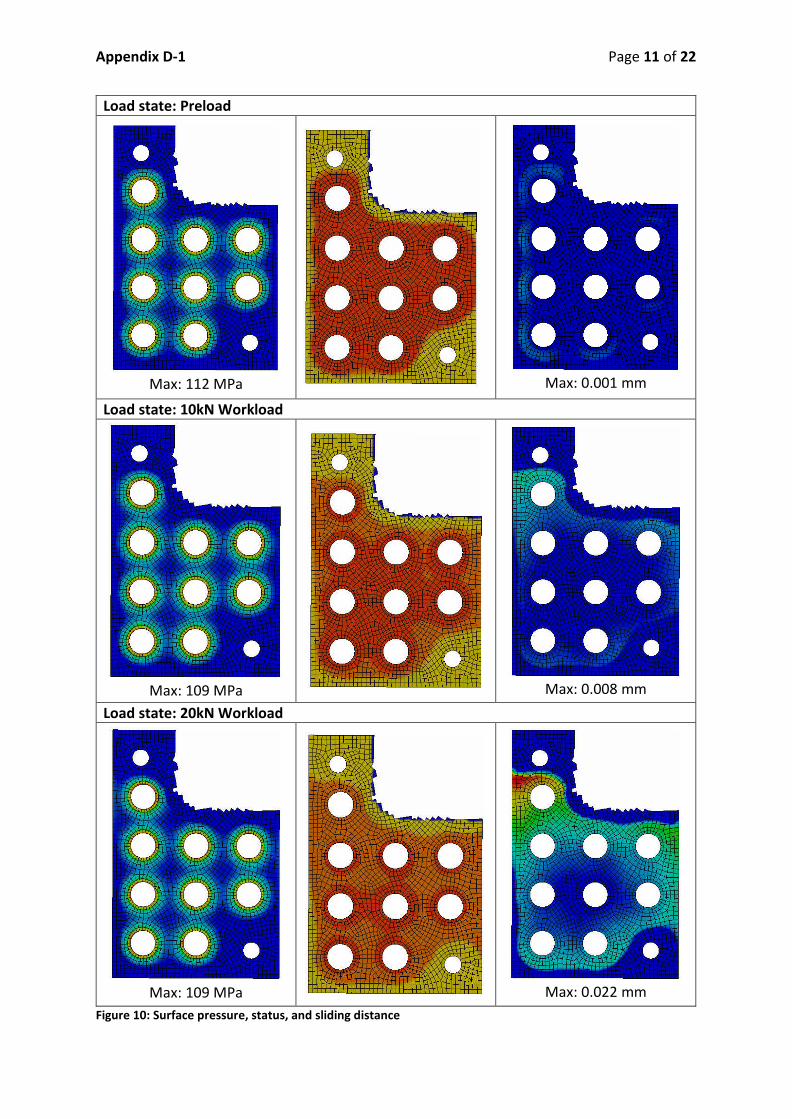
Appendix D 1 Page 11 of 22
Load state: Preload
Max: 112 MPa
Max: 0.001 mm
Load state: 10kN Workload
Max: 109 MPa
Max: 0.008 mm
Load state: 20kN Workload
Max: 109 MPa
Max: 0.022 mm
Figure 10: Surface pressure, status, and sliding distance

Appendix D 1 Page 12 of 22
In Figure 10, investigations of the clamping interface using ANSYS functionality has been
performed. The following observations can be made:
The pressure resulting from the deformation cones slightly interact, and appear to
be well positioned.
There is no significant change in the pressure distribution with applied workload.
No slipping occur when only preload are applied, and only negligible sliding distance
are present.
For 10kN workload, the status plot indicate that in general, no slipping occur in the
deformation cone areas. Some slipping is present in the outermost areas, and the
upper left bolt (B9) is most highly affected by slipping. The slipping distance plot
confirm this, but the slipping distance is still negligible.
For 20kN workload, slipping is occurring in the joint. The middle bolt is not affected,
but slipping is occurring on the outer bolts. The maximum slipping distance are in the
range of 0.02 mm. This is not much, but with the high level of slipping, such slipping
can accumulate with multiple load cycles.
Based on the ANSYS analysis, only acceptable levels of slipping occur for the 10kN workload
scenario, and it is concluded that the joint should withstand such a workload.
CADFEM Assessment
Figure 11 show the slipping safety factors for the different bolts, and the results are
summarised in Table 10. It is clear that bolt B9 is the most exposed bolt, and the factor is
lower than the 1.2 recommended by VDI 2230. The other bolts have factors from 1.6 and
up, and are fine. Note that torsion about the bolt axis are excluded.
The exact reason for the difference to the analytic safety factor is unknown, but
contributing factors might be:
Better representation of elastic effects and load distribution between the bolts in
FEA.
The analytic approach rely on some assumptions and simplifications.
Mesh size effects in the FE analysis and numerical inaccuracies.
Table 10: Safety factors with 10kN Workload
Safety factor SG Bolts
1.08 B9
1.6 1.9 B6, B8
2.2 2.8 B1, B2, B5, B7
4.3 B3
18.8 B4

Appendix D 1 Page 13 of 22
Figure 11: CADFEM plot of slipping safety factors with 10 kN workload and minimum preload (7.3kN)
Pressure Under the Bolt Head
Based on the limiting surface pressure, and the highest bolt load, a verification of the
pressure under the bolt head has been carried out (Table 11).
Table 11: Surface Pressure under the Bolt Head
Limiting surface pressure 630 MPa Calculated
Safety factor 3 Calculated
S11: TIGHTENING TORQUE
The tightening torque is calculated, and listed in Table 12.The minimum breaking torque for
this bolt is 32 Nm (ISO 3506).
Table 12: Data and Results Max Assembly Pretension
Average Head Friction Area 10.67 Calculated
Tightening Torque 24.5 Calculated

Appendix D 1 Page 14 of 22
S12: APPROVE OR ITERATE
Several approaches has been made to assess if slipping will occur in the joint. In the analysis,
a tightening uncertainty of 1.6 are applied, resulting in max/min preload of 11.7kN / 7.3kN
respectively. The actual workload from 2mm cavity deformation is 8kN. In this analysis, a
small workload safety factor is applied in assuming 2.5mm cavity deformation resulting in
10kN workload. In S1, an estimate is made that the minimum preload should stay above at
least 5.4kN to achieve a satisfying safety factor. All the analysis are carried out for the
minimum preload case and with a workload of 10kN. The results are summarized in Table
13.
Table 13: Summary of Slipping Assessments
Analytic Slipping Safety Factor 1.5 Calculated
Analytic Shearing Safety Factor 19.2 Calculated
ANSYS assessment Ok ANSYS inspection of Status and slipping
distance
CADFEM assessment 1.08 Semi analytic (FEA and calc.)
All assessment indicate that the B9 bolt and surrounding area is critical. Due to the fact that
there will be a guide pin located close to bolt B9, a safety factor against slipping slightly
lower than recommended 1.2, but still above 1 is considered to be sufficient. If slipping
occur, the safety against bolt shear is 19.2.
Further preload losses are mentioned and assessed. Since the bolt is quite short and have a
small elongation when assembled, embedding might pose a risk of reliving a large amount
of the preload. There is however some uncertainty about embedding behaviour for Stainless
Steel. A suggested action is to apply heavy duty force washers for the bolts.
Preload loss due to thermal contraction are assumed not to have any influence on the
preload.
An argument can be made that the considered preload loss due to tightening uncertainty (
38% / 4.4kN) is quite high, and that the preload most likely will be higher than what is
applied in this analysis. Thus, this margin could also include some risk for additional preload
losses
With the mentioned aspects in mind, making a total assessment of the joint functionality, it
is concluded that for the defined tightening conditions the joint will not slip, and does fulfil
the requirements of the joint.
Approved

Appendix D 1 Page 15 of 22
ADDITIONAL RESULTS
REQUIRED LENGTH OF THREAD ENGAGEMENT
It is found that the internal thread is the critical thread. With the present thread
engagement (16mm), the thread stripping force is 100kN, while the breaking load of the
free loaded bolt thread is 25.6kN. Thus, the bolt will beak before the tapped thread. The
minimum thread length of engagement is 6.6mm. The full calculations can be found in
Appendix D 2.
GEOMETRY
Solid Tuner Tuner with Bolted Joints (BJs)
GLOBAL DEFORMATION FOR 10KN

Appendix D 1 Page 16 of 22
Comments: The deformations for this load level is very similar. The top circular plate is not
included, since the actual connection to the cavity might introduce some additional stiffness
to it. It is of highest relevance to assess how the rest of the body deforms.
GLOBAL STRESS

Appendix D 1 Page 17 of 22
Comments: The stress level in the tuner body is generally low, with peaks of about 50 MPa.
The proof stress of the material are 220MPa. Some higher stresses arise in the BJs, but
verifications of the bolt stress level are performed analytically.
Figure 12: Stress distribution in the bolts
AXIAL DEFORMATION AND RELATIVE STIFFNESS
By obtaining the axial deformations of the highlighted area for both the solid and bolted
Tuner, information about relative axial stiffness are extracted. The minimum deformation
values are extracted, to have the most realistic and comparable results.
The stiffness are found to be 0.0042 mm/kN, up to a workload of 10kN.

Appendix D 1 Page 18 of 22
Comments: The deformation characteristics of the two tuners are very similar until 10kN
workload. Above that, the solid tuner continues linearly. The bolted tuner then has larger
deformation pr. Unit load, resulting in a non linear curve. It is assumed that it is slipping in
the joint that leads to this behaviour.
SPECIFIC PROBES
One other point on the Tuner that might be critical, is the connection highlighted above. For
the solid and bolted tuner, the moment to be carried through the contact are 97 Nm and
102 Nm respectively.
If this connection only rely on a preloaded bolt connection and no slipping should occur, an
additional verification should be carried out. This applies to both the solid and the bolted
Tuner. In the model, it appears as the plan has been to use two M8 bolts.
0,00
0,01
0,02
0,03
0,04
0,05
0,06
0,07
0,08
0,09
0,10
0 2 4 6 8 10 12 14 16 18 20
Axi
al
dis
pla
cem
en
t [m
m]
Axial load [kN]
HG Cavity Tuner Axial Displacement
Solid Tuner Bolted Tuner (7.3kN)
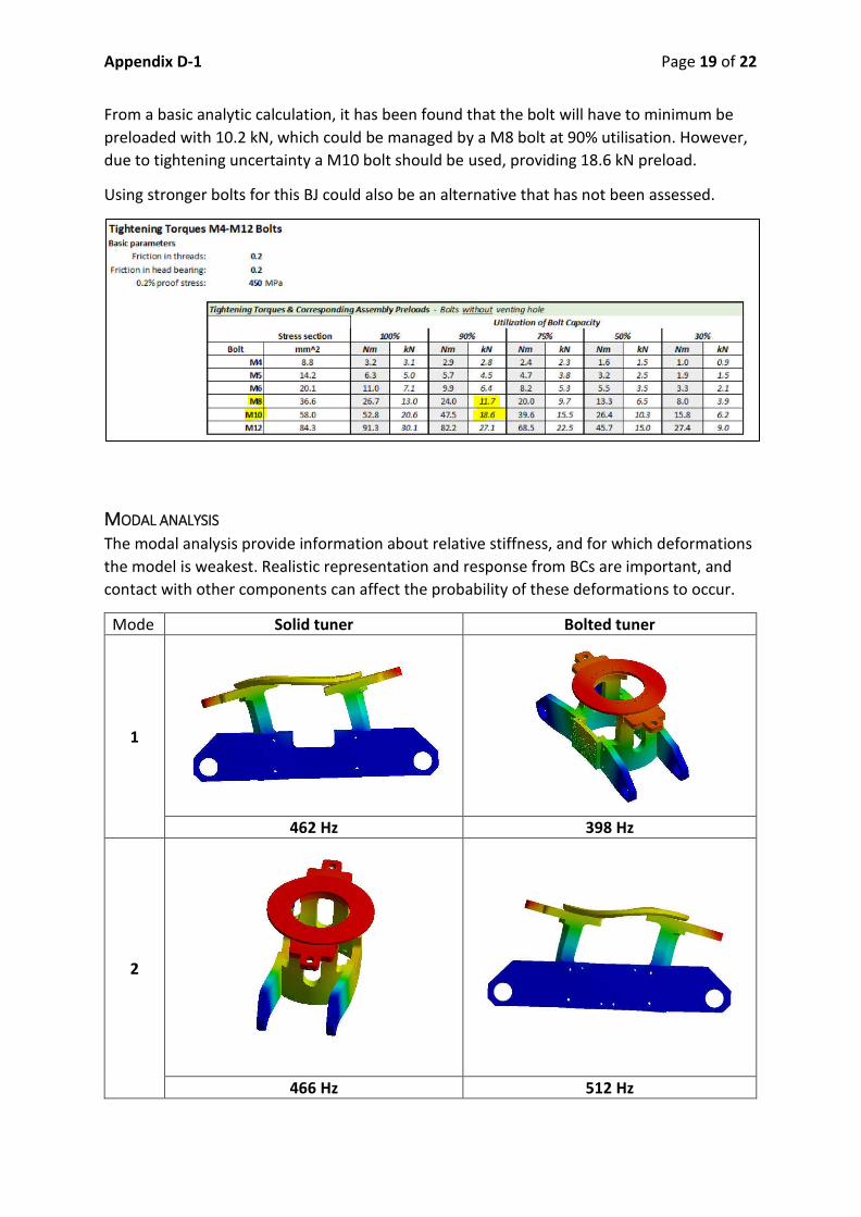
Appendix D 1 Page 19 of 22
From a basic analytic calculation, it has been found that the bolt will have to minimum be
preloaded with 10.2 kN, which could be managed by a M8 bolt at 90% utilisation. However,
due to tightening uncertainty a M10 bolt should be used, providing 18.6 kN preload.
Using stronger bolts for this BJ could also be an alternative that has not been assessed.
MODAL ANALYSIS
The modal analysis provide information about relative stiffness, and for which deformations
the model is weakest. Realistic representation and response from BCs are important, and
contact with other components can affect the probability of these deformations to occur.
Mode Solid tuner Bolted tuner
1
462 Hz 398 Hz
2
466 Hz 512 Hz
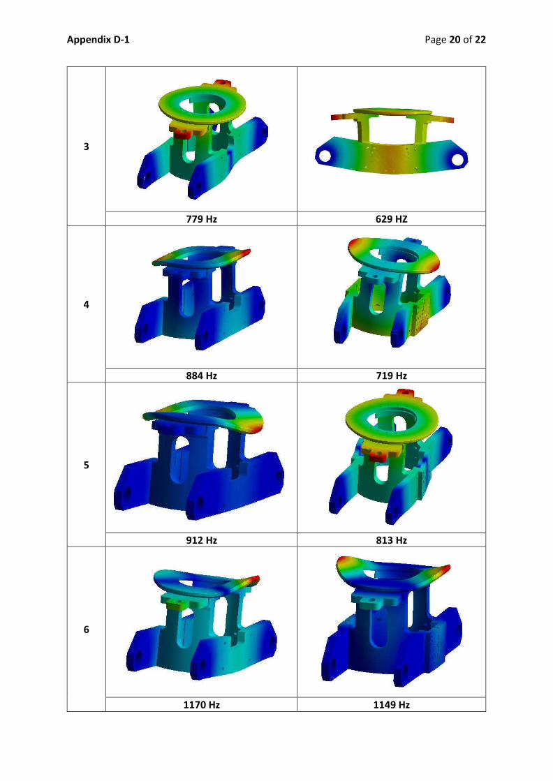
Appendix D 1 Page 20 of 22
3
779 Hz 629 HZ
4
884 Hz 719 Hz
5
912 Hz 813 Hz
6
1170 Hz 1149 Hz
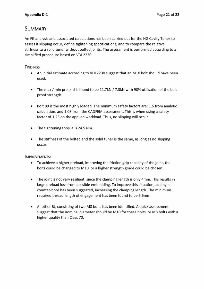
Appendix D 1 Page 21 of 22
SUMMARY
An FE analysis and associated calculations has been carried out for the HG Cavity Tuner to
assess if slipping occur, define tightening specifications, and to compare the relative
stiffness to a solid tuner without bolted joints. The assessment is performed according to a
simplified procedure based on VDI 2230.
FINDINGS
An initial estimate according to VDI 2230 suggest that an M10 bolt should have been
used.
The max / min preload is found to be 11.7kN / 7.3kN with 90% utilisation of the bolt
proof strength.
Bolt B9 is the most highly loaded. The minimum safety factors are: 1.5 from analytic
calculation, and 1.08 from the CADFEM assessment. This is when using a safety
factor of 1.25 on the applied workload. Thus, no slipping will occur.
The tightening torque is 24.5 Nm.
The stiffness of the bolted and the solid tuner is the same, as long as no slipping
occur.
IMPROVEMENTS:
To achieve a higher preload, improving the friction grip capacity of the joint, the
bolts could be changed to M10, or a higher strength grade could be chosen.
The joint is not very resilient, since the clamping length is only 4mm. This results in
large preload loss from possible embedding. To improve this situation, adding a
counter bore has been suggested, increasing the clamping length. The minimum
required thread length of engagement has been found to be 6.6mm.
Another BJ, consisting of two M8 bolts has been identified. A quick assessment
suggest that the nominal diameter should be M10 for these bolts, or M8 bolts with a
higher quality than Class 70.

Appendix D 1 Page 22 of 22
REFERENCES
[1] M. Esposito, "Mechanical & Thermal calculations for the SPL cavity and tank," EDMS
1219955, 2012.
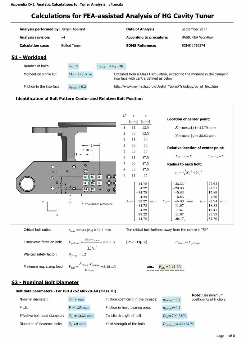
Appendix D-2 Analytic Calculations for Tuner Analysis v4.mcdx
Calculations for FEA-assisted Analysis of HG Cavity Tuner
Analysis performed by: Jørgen Apeland Date of Analysis: September 2017
Analysis revision: v4 According to procedure: BASIC FEA Workflow
Calculation case: Bolted Tuner EDMS Reference: EDMS 1716574
S1 - Workload
Number of bolts: ≔nS 9 ≔nS.tot =4 nS 36
Moment on single BJ: ≔MZ 123 N m Obtained from a Class I simulation, extracting the moment in the clamping
interface with centre defined as below.
Friction in the interface: ≔μTmin 0.2 http://www.roymech.co.uk/Useful_Tables/Tribology/co_of_frict.htm
Identification of Bolt Pattern Center and Relative Bolt Position
Location of center point:B
1
2
3
4
5
6
7
8
9
x
((mm))
11
30
11
30
49
11
30
49
11
y
((mm))
12.5
12.5
30
30
30
47.5
47.5
47.5
65
≔X =mean ((x)) 25.78 mm
≔Y =mean ((y)) 35.83 mm
Relative location of center point:
≔XC -x X ≔YC -y Y
Radius to each bolt:
≔rC‾‾‾‾‾‾‾‾+XC
2 YC2
=XC
-14.784.22
-14.784.22
23.22-14.78
4.2223.22
-14.78
⎡⎢⎢⎢⎢⎢⎢⎢⎢⎢⎢⎣
⎤⎥⎥⎥⎥⎥⎥⎥⎥⎥⎥⎦
mm =YC
-23.33-23.33
-5.83-5.83-5.8311.6711.6711.6729.17
⎡⎢⎢⎢⎢⎢⎢⎢⎢⎢⎢⎣
⎤⎥⎥⎥⎥⎥⎥⎥⎥⎥⎥⎦
mm =rC
27.6223.7115.89
7.2023.9418.8312.4125.9932.70
⎡⎢⎢⎢⎢⎢⎢⎢⎢⎢⎢⎣
⎤⎥⎥⎥⎥⎥⎥⎥⎥⎥⎥⎦
mm
Critical bolt radius: ≔rmax =max ⎛⎝rC⎞⎠ 32.7 mm The critical bolt furthest away from the centre is "B9"
Transverse force on bolt: ≔FqM.max =―――⋅MZ rmax
∑rC2
902.6 N [Pt.2 - Eq.12] ≔FQmax FqM.max
Wanted safety factor: ≔SG.req 1.2
Minimum req. clamp load: ≔FKQ =―――――⋅SG.req FQmax
μTmin
5.42 kN ans.===============
=FKQ 5.42 kN
S2 - Nominal Bolt Diameter
Bolt data parameters - For ISO 4762 M8x20-A4 (class 70)Note: Use minimum coefficients of friction.Nominal diameter: ≔d 8 mm Friction coefficient in the threads: ≔μGmin 0.2
Pitch: ≔P 1.25 mm Friction in head bearing area: ≔μKmin 0.2
Effective bolt head diameter: ≔dW 12.33 mm Tensile strength of bolt: ≔Rm 700 MPa
Diameter of clearence hole: ≔dh 9 mm Yield strength of the bolt: ≔Rp0.2min 450 MPa
Page 1 of 8
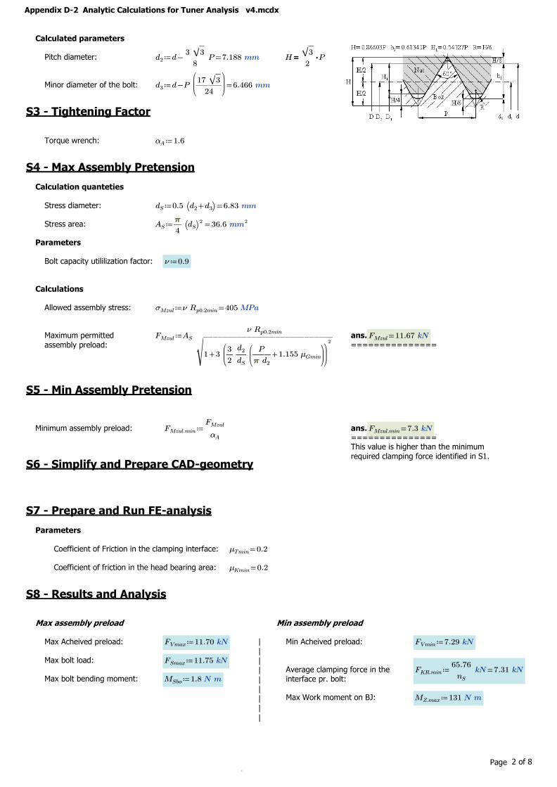
Appendix D-2 Analytic Calculations for Tuner Analysis v4.mcdx
Calculated parameters
Pitch diameter: ≔d2 =-d ――3 ‾‾3
8P 7.188 mm =H ⋅――
‾‾3
2P
Minor diameter of the bolt: ≔d3 =-d P⎛⎜⎜⎝―――17 ‾‾3
24
⎞⎟⎟⎠
6.466 mm
S3 - Tightening Factor
Torque wrench: ≔αA 1.6
S4 - Max Assembly Pretension
Calculation quanteties
Stress diameter: ≔dS =0.5 ⎛⎝ +d2 d3⎞⎠ 6.83 mm
Stress area: ≔AS =―ππππ
4⎛⎝dS⎞⎠
2 36.6 mm2
Parameters
Bolt capacity utililization factor: ≔ν 0.9
Calculations
Allowed assembly stress: ≔σMzul =ν Rp0.2min 405 MPa
Maximum permitted
assembly preload:
≔FMzul AS ――――――――――――ν Rp0.2min
‾‾‾‾‾‾‾‾‾‾‾‾‾‾‾‾‾‾‾‾‾‾‾‾‾‾‾
+1 3⎛⎜⎝―3
2―d2
dS
⎛⎜⎝
+――P
ππππ d21.155 μGmin
⎞⎟⎠
⎞⎟⎠
2ans.
===============
=FMzul 11.67 kN
S5 - Min Assembly Pretension
Minimum assembly preload: ≔FMzul.min ――FMzul
αAans.===============
=FMzul.min 7.3 kN
This value is higher than the minimum
required clamping force identified in S1.S6 - Simplify and Prepare CAD-geometry
S7 - Prepare and Run FE-analysis
Parameters
Coefficient of Friction in the clamping interface: =μTmin 0.2
Coefficient of friction in the head bearing area: =μKmin 0.2
S8 - Results and Analysis
Max assembly preload Min assembly preload
Max Acheived preload: ≔FVmax 11.70 kN ||
||
||
||
|
Min Acheived preload: ≔FVmin 7.29 kN
Max bolt load: ≔FSmax 11.75 kNAverage clamping force in the interface pr. bolt:
≔FKR.min =――65.76
nSkN 7.31 kN
Max bolt bending moment: ≔MSbo 1.8 N m
Max Work moment on BJ: ≔MZ.max 131 N m
Page 2 of 8

Appendix D-2 Analytic Calculations for Tuner Analysis v4.mcdx
S9 - Work Stress Note! bending stress is included
ParametersResidual torque factor: ≔kt 0.5
Calculation quantetiesBending modulus: ≔WS =―
ππππ
32dS
3 31.24 mm3
Thread moment: ≔MG =⋅⋅FMzul ―d2
2
⎛⎜⎝
+――P
ππππ d21.155 μGmin
⎞⎟⎠
12 N m
Polar moment of inertia: ≔Wp =⋅―ππππ
16dS
3 62.48 mm3
Bending stressCalculations
Axial stress: ≔σzb.max =+――FSmax
AS
――MSbo
WS
378.58 MPa ≔σSbo =――MSbo
WS
57.61 MPa
Torsional stress: ≔τmax =――MG
Wp
192.25 MPaBending stress contribution to work stress
Working stress: ≔σred.B =‾‾‾‾‾‾‾‾‾‾‾‾‾‾‾‾‾‾
+σzb.max2 3 ⎛⎝ ⋅kt τmax
⎞⎠2
413.6 MPa ≔∆σSbo.p =――σSbo
σred.B
%13.93
AssessmentCriteria: <=σred.B 413.57 MPa =Rp0.2min 450 MPa
Safety factor: ≔SF =―――Rp0.2min
σred.B
1.09
================================================================
S10 - Clamping Requirements
Analytic slipping safetyfactorMax actual transverse shear-load on bolt: ≔FqM.max =――――
⋅MZ.max rmax
∑rC2
961.3 N
Required clamp load to transmit transverse loads: ≔FKQerf =―――FqM.max
μTmin
4.81 kN
Slipping safety-factor for minimum preload: ≔SG.gl =――――⋅FVmin μTmin
FqM.max
1.52 ≔SG =―――FKR.min
FKQerf
1.52 ≥SG 1.2
Slipping safety-factor for maximum preload: ≔SG.gl =――――⋅FVmax μTmin
FqM.max
2.43
Analytic shear safetyfactorShear capacity of bolt: ≔τB =⋅0.72 Rm 504 MPa [VDI 2230 Pt. 1 - Table 7]
Safety factor for shearing of bolt: ≔SA =―――⋅τB AS
FqM.max
19.2 ≥SA 1.1
S11 - Tightening Torque
Average head friction diameter: ≔DKm =―――+dW dh
210.67 mm
Tightening Torque: ≔MA =⋅FMzul
⎛⎜⎝
++0.16 P 0.58 d2 μGmin ――DKm
2μKmin
⎞⎟⎠
24.5 N m Minimum breaking torque for
M8-70 is 32 Nm (ISO 3506)===========================================================
S12 - Approve or Iterate
========APPROVED
========
Page 3 of 8

Appendix D-2 Analytic Calculations for Tuner Analysis v4.mcdx
Additional Calculations
Additional bolt load: ≔FSA =-FSmax FVmax 0.05 kN
Embedding
Embedding for surface roughness < 10 :μm ≔fZ =(( ++3 3 2)) μm 8 μm =FZ ―――fZ
+δS δP
For comparison, during preloading, the bolt were adjusted: ≔∆lM ⋅3.1 10-2 mm ≔∆FM 11.7 kN ≔δJ =――∆lM
∆FM
⎛⎝ ⋅2.65 10-3⎞⎠ ――mm
kN
Analytic calculation of resiliensies:
Parameters: ≔ES 200 GPa ≔EP ES ≔lGew 4 mm ≔lK lGew
Calculation quanteties: ≔AN ―ππππ
4d2 ≔Ad3 ―
ππππ
4d3
2 ≔IN ―ππππ
64d4 ≔Id3 ―
ππππ
64d3
4
Axial resilience of the bolt are calculated:
≔lG ⋅0.5 d ≔lM 0.33 d ≔lSK =d 0.4 3.2 mm
≔δG =―――lG
⋅ES Ad3
⎛⎝ ⋅6.1 10-7⎞⎠ ――mm
N≔δM =―――
lM
⋅EP AN
⎛⎝ ⋅2.6 10-7⎞⎠ ――mm
N
≔δGM =+δG δM⎛⎝ ⋅8.7 10-7⎞⎠ ――
mm
N
Unengaged loaded part of the thread
≔δGew =―――lGew
⋅ES Ad3
⎛⎝ ⋅6.09 10-4⎞⎠ ――mm
kN
≔δSK =―――lSK
⋅ES AN
⎛⎝ ⋅3.18 10-7⎞⎠ ――mm
N
≔δS =++δSK δGew δGM⎛⎝ ⋅1.8 10-3⎞⎠ ――
mm
kN
A worst case will be using the resilience of only the bolt: ≔FZ.1 =―fZ
δS4.45 kN
Using the resilience of the joint derived from FEA: ≔FZ.2 =―fZ
δJ3.02 kN
Thus, the minimum residual clamp force would be: ≔FKR.min.Z =-FVmin
FZ.1
FZ.2
⎡⎢⎣
⎤⎥⎦
2.844.27
⎡⎢⎣
⎤⎥⎦kN
Resulting in unsatisfactoring safety-factor against slipping: ≔SG.Z =―――FKR.min.Z
FKQerf
0.590.89
⎡⎢⎣
⎤⎥⎦
Scenario with higher thread friction
Control of resulting preload if thread friction are higher: =μGmin 0.2 => ≔μGmin.1 0.30
=μKmin 0.2 => ≔μKmin.1 0.30
The resulting assembly preload: ≔FM.max =―――――――――――――MA
⎛⎜⎝
++0.16 P 0.58 d2 μGmin.1 ――DKm
2μKmin.1
⎞⎟⎠
8.04 kN
≔FM.min =―――FM.max
αA5.02 kN
ans. ≔SG.gl =―――――⋅FM.min μTmin
FqM.max
1.04 Thus, according to this analytic calculation, the resulting
preload if the friction is 0.3 would still be okay. ===============================================================
Page 4 of 8

Appendix D-2 Analytic Calculations for Tuner Analysis v4.mcdx
Calculation for additional BJMoment in the Joint: ≔MZ.2 100 N m
Critical bolt radius: ≔r2 30 mm
Transverse force on bolt: ≔FqM2.max =――――――⋅MZ.2 r2
⎛⎝ +302 302 ⎞⎠ mm21.67 kN [Pt.2 - Eq.12]
≔FQ2max FqM2.max
Alternative simple calculation: ≔FqM2.max =――MZ.2
⋅2 r21.67 kN
Required Slip Resistance: ≔FKQ2erf =―――FQ2max
μTmin
8.33 kN
Wanted safety factor: ≔SG.req 1.2
Minimum req. clamp load: ≔FKQ2 =⋅SG.req FKQ2erf 10 kN ans.
===============
=FKQ2 10 kN
Thread Strength and Required Length of Engagement
Note that there is two factors that will lead to better load distribution on the threads than in a normal case:
1) Titanium is more resilient than Steel2) The outgassing hole in the bolt
Parameters Bolt Clamped parts
Tensile strength: ≔RmS 700 MPa ≔RmM 530 MPa
Shear strength: ≔τBS.min =⋅0.72 RmS 504 MPa ≔τBM.min 410 MPa
Dimensions with tolerance: ≔dmin 7.760 mm[ISO 965-2 - 6H/6g]
≔D2.max 7.348 mm ≔d1 =-d ――5 ‾‾3
8P 6.647 mm
≔D1 d1 ≔D2 d2Effective thread length: ≔leff =-20 mm lK 16 mm
Determination of Critical Thread
Thread strength ratio: =RS ――――⋅ASGM τBM
⋅ASGS τBS
RS > 1 bolt thread is critical ASG is the thread shear area of for the bolt / tapped threadsCriteria: τB is the shear strength
RS < 1 internal thread is critical
≔Thread_Critical⎛⎝RS⎞⎠
‖‖‖‖‖‖‖
if >RS 1‖‖ return “bolt thread”
if <RS 1‖‖ return “Internal thread”
≔RS =⋅――――――――――
⋅d⎛⎜⎝
+―P
2⋅⎛⎝ -d D2
⎞⎠ tan ((30 deg))⎞⎟⎠
⋅d⎛⎜⎝
+―P
2⋅⎛⎝ -d2 D1
⎞⎠ tan ((30 deg))⎞⎟⎠
―――τBM.min
τBS.min
0.95
Ans.
=Thread_Critical⎛⎝RS⎞⎠ “Internal thread”
==============================
Page 5 of 8

Appendix D-2 Analytic Calculations for Tuner Analysis v4.mcdx
Stripping Force of Internal ThreadsThe calculation of strength in the threads is solely based on the shear stress on the nut materials caused by the tensile force in the
bolt thread and that the influence of superimposed bending stresses in the thread turns can be ignored.
The correction factors C1 and C3 take into account among other things the reduction in the shear area resulting from flexure.
Parameter C1: Parameter C3:
"s" is the equivalent diameter of the material surrounding the internal thread.
≔s 20 mm =―s
d2.5 =RS 0.949
||
||
||
||
||
||
||
≔C1
‖‖‖‖‖‖‖‖‖‖‖‖‖‖‖‖
if <≤1.4 ―s
d1.9
‖‖‖‖
←C1 --⋅3.8 ―s
d
⎛⎜⎝―s
d
⎞⎟⎠
2
2.61
if >―s
d1.9
‖‖ ←C1 1
if <―s
d1.4
‖‖ return “not valid”
≔C3‖‖‖‖‖‖‖‖‖‖‖
if ≤RS 0.43‖‖ ←C3 1
if <<0.43 RS 1‖‖‖ ←C3 +-+0.728 1.769 RS 2.896 RS
2 1.296 RS3
if ≥RS 1‖‖ ←C3 0.897
=C1 1 =C3 0.906======= =======
Shear area for nut/internal thread: ≔ASGM =
→―――――――――――――――
⋅⋅⋅ππππ dmin
⎛⎜⎝――leff
P
⎞⎟⎠
⎛⎜⎝
+―P
2⋅⎛⎝ -dmin D2.max
⎞⎠ tan ((30 deg))⎞⎟⎠
269.3 mm2
Stripping force of internal thread: ≔FmGM =⋅C1 C3 τBM.min ASGM 100.05 kN
Reference stripping force, with no correction: ≔FmGM.ref =⋅τBM.min ASGM 110.4 kN
Breaking stress of free loaded bolt thread: ≔FmS =⋅RmS AS 25.6 kN
Criteria (R11/1): =FmS 25.6 kN < =FmGM 100 kN ≔Status_R11.1 ‖‖‖‖‖
if <FmS FmGM
‖‖ return “Ok”
“Not Ok”=Status_R11.1 “Ok”
=================
Load case specific data:
Utilisation of thread capacity: ≔νmGM =――FSmax
FmGM
%11.7
Thread stripping force safety factor: ≔SmGM =――FmGM
FSmax
8.51
Required effective length oftapped threads:
≔mges.min =+―――――――――――――――――――⋅⋅RmS AS P
⋅⋅⋅⋅⋅C1 C3 τBM.min
⎛⎜⎝
+―P
2⋅⎛⎝ -dmin D2.max
⎞⎠ tan ((30 deg))⎞⎟⎠ππππ dmin
2 P 6.6 mm
Note: The "2P" is a margine for non-effective thread length, like chamfer.
Criteria: ans. =mges.min 6.6 mm < =leff 16 mm ≔Status_thread_length ‖‖‖‖‖
if <mges.min leff‖‖ return “Ok”
“Not Ok”=Status_thread_length “Ok”
===============================
Page 6 of 8

Appendix D-2 Analytic Calculations for Tuner Analysis v4.mcdx
Summary of Key Results
Calculation step Results___________________________________________________________________________________________________________________________________________
=FQmax 902.6 NS1 - Workload
=FKQ 5.4 kN___________________________________________________________________________________________________________________________________________
S2 - Nominal Bolt Diameter =d 8 mm =P 1.25 mm =Rp0.2min 450 MPa___________________________________________________________________________________________________________________________________________
S3 - Tightening Factor =αA 1.6___________________________________________________________________________________________________________________________________________
S4 - Max Assembly Pretension ≔ν 0.9 =μGmin 0.2 =μKmin 0.2
=FMzul 11.7 kN =σMzul 405 MPa___________________________________________________________________________________________________________________________________________
S5 - Min Assembly Pretension =FMzul.min 7.3 kN___________________________________________________________________________________________________________________________________________
S6 - Simplify and Prepare CAD-geometry =d3 6.47 mm___________________________________________________________________________________________________________________________________________
S7 - Prepare and Run FE-analysis =μTmin 0.2 =μKmin 0.2___________________________________________________________________________________________________________________________________________
=FVmax 11.7 kN =FSmax 11.75 kN =MSbo 1.8 N mS8 - Extracted Results
=FVmin 7.29 kN =FKR.min 7.31 kN =MZ.max 131 N m___________________________________________________________________________________________________________________________________________
S9 - Work Stress =σred.B 413.6 MPa < =Rp0.2min 450 MPa =SF 1.09
___________________________________________________________________________________________________________________________________________
S10 - Clamping requirements =SG 1.5 =SA 19.2
___________________________________________________________________________________________________________________________________________
S11 - Tightening Torque =MA 24.5 N m
___________________________________________________________________________________________________________________________________________
========APPROVED
========
S12 - Approve or Iterate
______________________________________________________________________________________________________________________________________________________________________________________________________________________________________________________________________________________
Additional bolt load: ≔FSA =-FSmax FVmax 0.05 kNAdditional Calculations
Minimum clamp load with embedding: =FKR.min.Z2.844.27
⎡⎢⎣
⎤⎥⎦kN =SG.Z
0.590.89
⎡⎢⎣
⎤⎥⎦
Result of +50% friction: =SG.gl 1.04
Minimum length of thread engagement: =mges.min 6.6 mm
Utilisation of thread capacity: =νmGM %11.74
______________________________________________________________________________________________________________________________________________________________________________________________________________________________________________________________________________________
Page 7 of 8

Appendix D-2 Analytic Calculations for Tuner Analysis v4.mcdx
Page 8 of 8

APPENDIX E
VDI 2230 AND FEA SEMINAR PRESENTATION


•
•
•
•
•
•

•
•
•
•
•
•
•
•
•
•
•
•

•
•
•
•
•
•
•

•
•
•
•
•
.

•
•
•
•
•
•

·
.
•
•
•
•
• 0.05
mm/N·
N/mm·
⋅
⋅
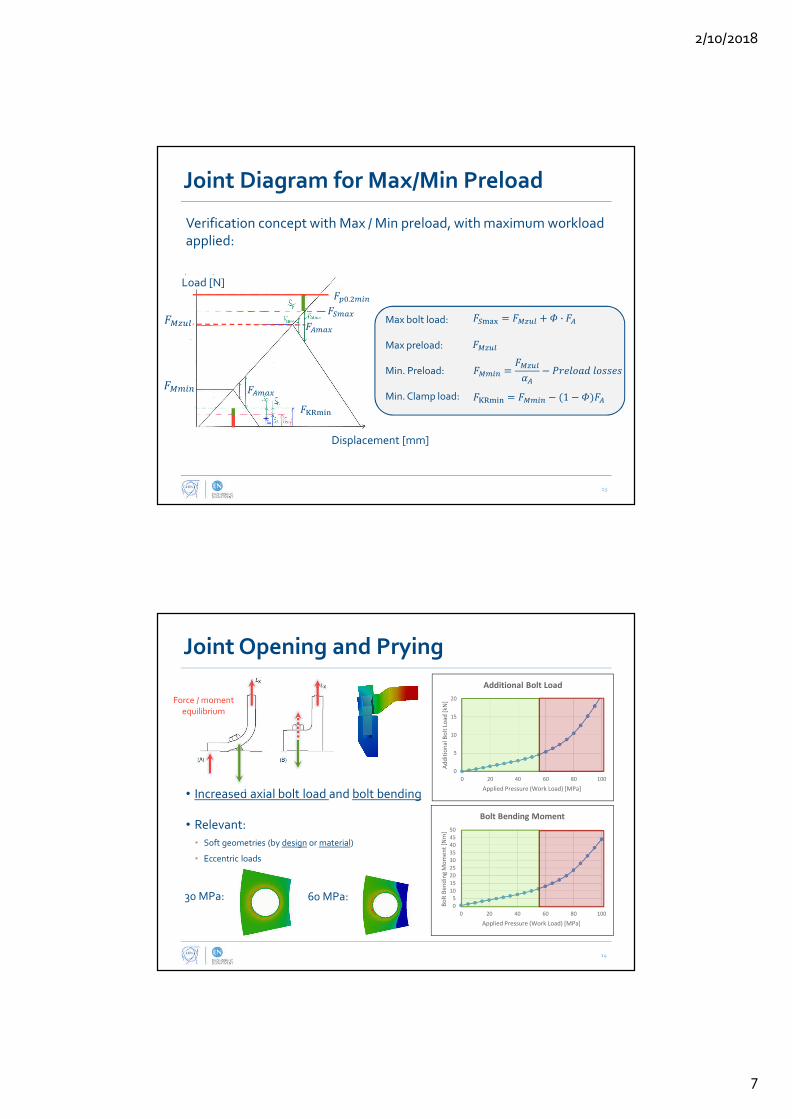
·
1
.
•
•
•
•

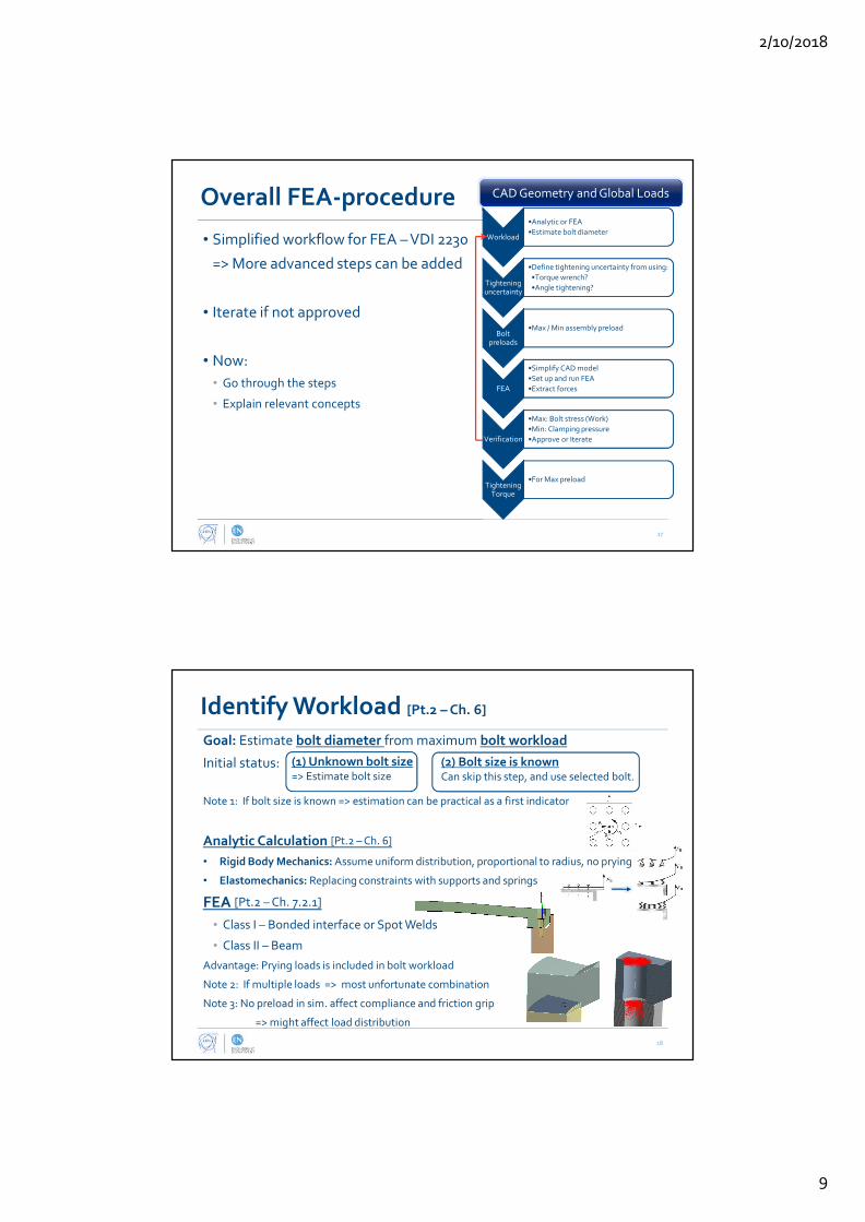
•
•
•
•
•
•
•
•
•

•
•
•
. . _ . . _
. . _
. . _
⋅
. . ⋅

. ⋅ .
⋅ .
1 332 ⋅
1,155
.

•
• 0.5
•
•
•
•
•
(R8/4)
. .
. 3 ⋅

•
•
•
•
•
•
•
•
•
•
•
•
.min. 2 .min .min
threadbolt head bearing
0.16 0.582
K
A M zul G K
DM F P d µ µ= + ⋅ ⋅ + (R13/1)

•
•
•
•
•
•
•
•
•
•
•
•
•
•
•
•
•

•
•
•
•

•
•
•
•
•
(R4/1)
•
•
•
•
•
60 .
9.4%

•
•
•
•
•
•
•
•
max
1.1B
A
Q
AS
F
ττ ⋅
= ≥min
max
min
1.21.8
KR
G
Q
T
FS
F
µ
= >

•
•
•
•
•
·
•
•
•
•
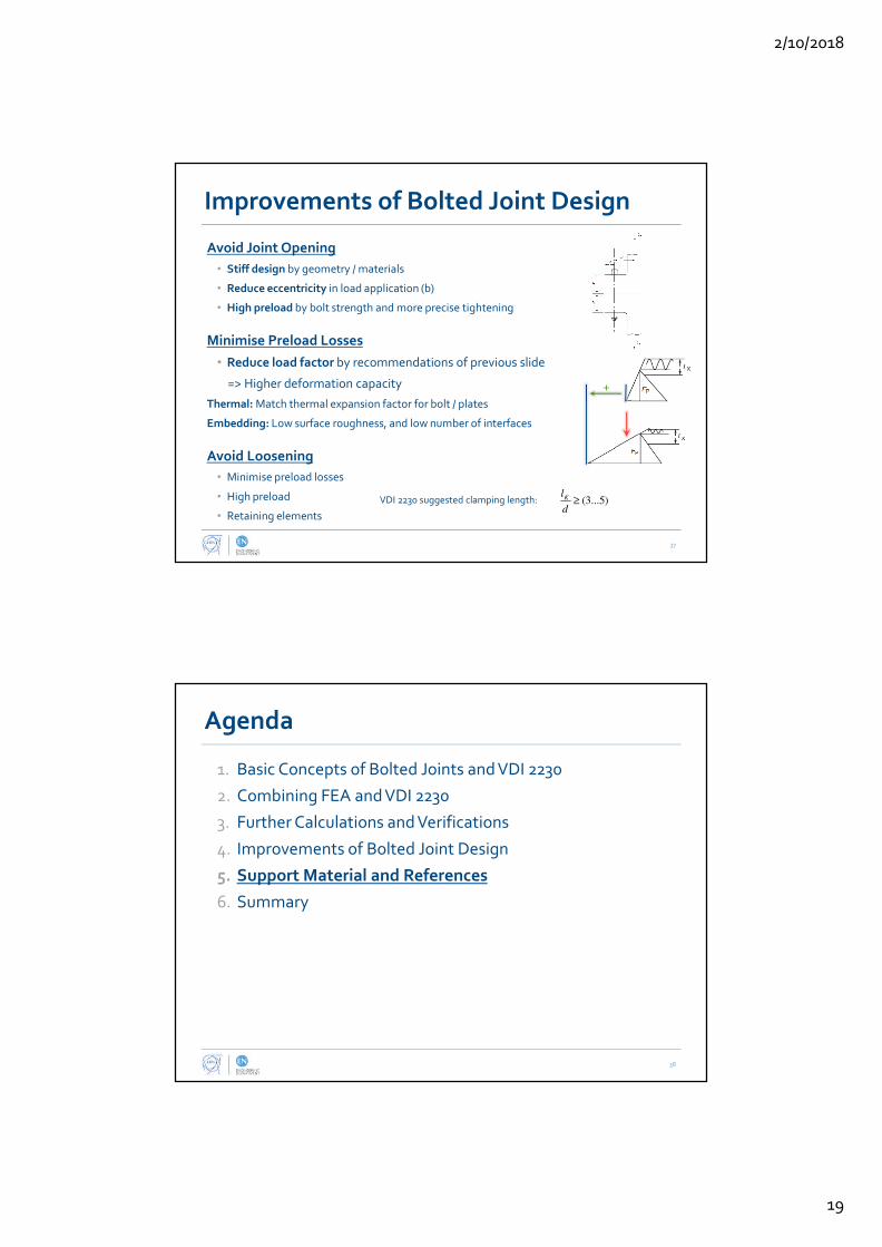
•
•
•
•
•
•
•
(3...5)Kl
d≥

•
•
•
•
•
•
•
•
•
•
•
•

•
•
•
•
•
•
•


APPENDIX F
REVISED CALCULATIONS FOR HE-VESSEL JOINTS


Appendix F Revised Calculations for HE-vessel Joints v5.mcdx
Calculations for FE-analysis of He-vessel Joints
Analysis performed by: Jørgen Apeland Date of Analysis: Oktober 2017
Calculation case: DQW Crab Cavity He-vessel Bolted Joints According to procedure: VDI 2230 - Basic FEA Workflow
Color codes: Input parameters Calculation quantities Results Functions Criteria check
S1 - Workload
Coefficient of friction in the clamping interface: ≔μTmin 0.3
Below, an analytic approach is made to identify the workloads as a first estimate to identify the required preload.
1 - Slipping for "Upper Cover"
Number of bolts: ≔i1 =+⋅2 27 ⋅2 24 102
Assumed axial workload from pressure: ≔FA.1 350 N The axial workload from pressure will
give a relief in the residual clamping load in the interface. Assumed load-factor: ≔Φ1 0.1
Resulting relief in clamping force: ≔FPA.1 =⎛⎝ -1 Φ1⎞⎠ FA.1 315 N
Transverse load from pressure: ≔FQ.p 37.6 kN
Transverse load from weight: ≔FQ.m =gggg (( -200 kg 25.2 kg)) 1.71 kN
Total transverse load on bolts: ≔FQ.tot =+FQ.p FQ.m 39.31 kN
Transverse load on one bolt: ≔Fq.max =――FQ.tot
i1385.4 N Assuming uniform distribution of loads,
and no axial workloads on the bolts. Required safety factor against slipping: ≔SG.req 1.2
Minimum clamp-load to avoid slipping: ≔FKQ =―――――⋅SG.req Fq.max
μTmin1.54 kN
Required clamping load: ≔FKerf =+FKQ FPA.1 1.86 kN
2 - Axial workload on "Beam side" plate
Number of bolts: ≔i2 =+⋅2 27 ⋅2 18 90
Axial load from pressure: ≔Fp.2 31.3 kN
Axial workload pr. bolt: ≔FA.2 =――Fp.2
i2347.8 N Assuming uniform distribution of loads.
3 - Axial and slipping for "Downstream / upstream" plates
Number of bolts: ≔i3 =+⋅2 24 ⋅2 18 84
Axial load from pressure: ≔Fp.3 22.7 kN
Axial workload pr. bolt: ≔FA.3 =――Fp.3
i3270.2 N Assuming uniform distribution of loads.
Since this bolt load is lower than the two previous cases, this bolt loading is not critical.
Maximum analytic workload on the bolt
Maximum transverse load: ≔FQ.max =Fq.max 385.4 N
Minimum clamp-load to avoid slipping: =FKQ 1.54 kN
Maximum axial load: ≔FA.max =FA.2 347.8 N===============================================
Page 1 of 14

Appendix F Revised Calculations for HE-vessel Joints v5.mcdx
S2 - Nominal Bolt Diameter
Bolt data parametersNote!
Apply minimum coefficients of friction.
Nominal diameter: ≔d 6 mm Friction coefficient in the threads: ≔μGmin 0.3
Pitch: ≔P 1 mm Friction in head bearing area: ≔μKmin 0.3
Effective bolt head diameter: ≔dW 8.74 mm Yield strength of the bolt: ≔Rp0.2min 820 MPa
Diameter of clearence hole: ≔dh.max 6.9 mm Thread length: ≔l 20 mm
Diameter of outgassing hole: ≔dg 1.75 mm
Calculated parameters
Pitch diameter: ≔d2 =-d ――3 ‾‾3
8P 5.35 mm =H ⋅――
‾‾3
2P
Minor diameter of the bolt: ≔d3 =-d P⎛⎜⎜⎝―――17 ‾‾3
24
⎞⎟⎟⎠
4.773 mm
S3 - Tightening Factor
Torque wrench: ≔αA 1.6
S4 - Max Assembly Pretension
Calculation quanteties
Stress diameter: ≔dS =0.5 ⎛⎝ +d2 d3⎞⎠ 5.06 mm
Stress area: ≔AS =―ππππ
4⎛⎝dS⎞⎠
2 20.1 mm2
Reduced stress area: ≔AS.g =―ππππ
4⎛⎝ -dS
2 dg2 ⎞⎠ 17.7 mm2
Parameters
Bolt capacity utililization factor: ≔ν 0.9
CalculationsAllowed assembly stress: ≔σMzul =ν Rp0.2min 738 MPa
Maximum permitted
assembly preload:
≔FMzul AS.g ――――――――――――ν Rp0.2min
‾‾‾‾‾‾‾‾‾‾‾‾‾‾‾‾‾‾‾‾‾‾‾‾‾‾‾
+1 3⎛⎜⎝―3
2―d2
dS
⎛⎜⎝
+――P
ππππ d21.155 μGmin
⎞⎟⎠
⎞⎟⎠
2ans.
=============
=FMzul 8.73 kN
S5 - Min Assembly Pretension
Minimum assembly preload: ≔FMmin ――FMzul
αAans.
================FMmin 5.46 kN
S6 - Simplify and Prepare CAD-geometry
Page 2 of 14

Appendix F Revised Calculations for HE-vessel Joints v5.mcdx
S7 - Prepare and Run FE-analysis
Parameters
Coefficient of Friction in the clamping interface: =μTmin 0.3
Coefficient of friction in the head bearing area: =μKmin 0.3
Calculation of theoretical beam parameters:
Minor diameter area: ≔Ad3.g =―ππππ
4⎛⎝ -d3
2 dg2 ⎞⎠ 15.49 mm2
Minor second area areal moment of inertia: ≔Id3.g =―ππππ
64⎛⎝ -d3
4 dg4 ⎞⎠ 25.02 mm4
Torsional stiffness: ≔J =―ππππ
32⎛⎝ -d3
4 dg4 ⎞⎠ 50.04 mm4
S8 - Results and Analysis Must be updated with values from the revised simulations
Max assembly preload |
||
||
||
||
Min assembly preload
Max bolt bending moment: ≔MSbo 3430 N mm Acheived preload: ≔FVmin 4.5 kN
Acheived preload: ≔FVmax 4.5 kN
Workload: ≔FA 500 N
Max bolt load: ≔FSmax 4650 N
S9 - Work Stress
Note: In this calculated work-stress, bending stress is included. That is not the case for the standard VDI 2230 equation.
ParametersResidual torque factor: ≔kt 0.5
Calculation quanteties
Bending modulus: ≔WS.g =―ππππ
32
⎛⎜⎜⎝―――
-dS4 dg
4
dS
⎞⎟⎟⎠
12.55 mm3 Notice that the outgassing hole has been included,
so it is a hollow cylinder that is considered.
Thread moment: ≔MG =⋅⋅FMzul ―d2
2
⎛⎜⎝
+――P
ππππ d21.155 μGmin
⎞⎟⎠
9.5 N m
Polar moment of inertia: ≔Wp.g =⋅―ππππ
16
⎛⎜⎜⎝―――
-dS4 dg
4
dS
⎞⎟⎟⎠
25.1 mm3
CalculationsBending stress
Normal stress: ≔σzb.max =+――FSmax
AS.g――MSbo
WS.g
535.7 MPa ≔σSbo =――MSbo
WS.g
273.3 MPa
Torsional stress: ≔τmax =――MG
Wp.g
377.77 MPaBending stress contribution to work stress:
Working stress: ≔σred.B =‾‾‾‾‾‾‾‾‾‾‾‾‾‾‾‾‾‾
+σzb.max2 3 ⎛⎝ ⋅kt τmax⎞⎠
2627.7 MPa ≔∆σSbo.p =――
σSbo
σred.B%43.5
Assessment
Criteria: <=σred.B 627.73 MPa =Rp0.2min 820 MPa ≔Work_Stress ‖‖‖‖‖
if <σred.B Rp0.2min‖‖ return “Ok”
“Not OK”=Work_Stress “Ok”
Safety factor: ≔SF =―――Rp0.2min
σred.B1.31
==============================================================
Page 3 of 14

Appendix F Revised Calculations for HE-vessel Joints v5.mcdx
S10 - Clamping Requirements
S11 - Tightening Torque
Average head friction diameter: ≔DKm =――――+dW dh.max
27.82 mm
Tightening Torque: ≔MA =⋅FMzul⎛⎜⎝
++0.16 P 0.58 d2 μGmin ――DKm
2μKmin
⎞⎟⎠
19.8 N m
===============================================================
S12 - Approve or Iterate
===========APPROVED
===========
Page 4 of 14

Appendix F Revised Calculations for HE-vessel Joints v5.mcdx
Additional Calculations According to VDI 2230
R0 - Checking limiting size G
Parameters
Width of the interface: ≔cT.ACcT.B
⎡⎢⎣
⎤⎥⎦
2518
⎡⎢⎣
⎤⎥⎦mm
Eccentric distance e: ≔eACeB
⎡⎢⎣
⎤⎥⎦
135
⎡⎢⎣
⎤⎥⎦mm
Criteria
This criteria is defined for TTJs in Steel. Exceeding the limiting dimensions entails a relatively large calculation error.
For eccentrically clamped joints, approxemately constant
interface pressure can be expected on the bending tension side of the basic solid if the outer contour in the region of the
interface is not separated from the bolt azis S-S by a greater distance than G/2:
≤e ―G
2
Compliance with this requirement takes priority over the basic requirement .<cT G
For TTJs:
≔G'minG'
⎡⎢⎣
⎤⎥⎦
=dW1.52
⎡⎢⎣
⎤⎥⎦
13.117.5
⎡⎢⎣
⎤⎥⎦mm
Assuming an approximate constant pressure, although at a lower level than above, the following criteria can be used:
≔G'max =3 dW 26.2 mmControl
=eB 5 mm < =0.5 G'min 6.6 mm
=eAC 13 mm < =0.5 G'max 13.1 mm
ConclusionJoint A and C only comply with the requirement based on .G'max
Joint B comply with all the requirements.
It should however be noted that Joint B has an edge in the interface. The components are also made of Titanium, and it is
unclear how the deformation cone is affected by a more resilient material.
R3 - Analytic Resilience and Load Factors
Parameters
Elastic modulus of bolt (S) and clamped parts (P): ≔ES 110 GPa ≔EP ES Titanium Gr. 5 and Gr. 2
Clamping length: ≔lK 11 mm
Calculation quantities
Bolt quantities: ≔l1 3 P ≔lGew =-lK l1 8 mm ≔lSK d 0.4 ≔lG d 0.5 ≔lM d 0.33
Bolt areas, considering outgassing hole:
≔Ad3.g =―ππππ
4⎛⎝ -d3
2dg
2 ⎞⎠ 15.49 mm2 ≔AN.g =―ππππ
4⎛⎝ -d
2dg
2 ⎞⎠ 25.87 mm2
Areal moment of Intertia: ≔IN.g ―ππππ
64⎛⎝ -d4 dg
4 ⎞⎠
Page 5 of 14
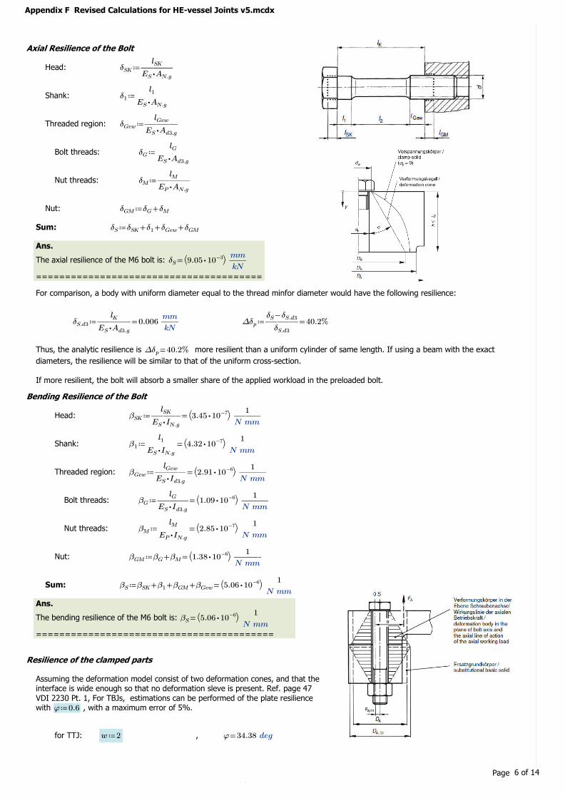
Appendix F Revised Calculations for HE-vessel Joints v5.mcdx
Axial Resilience of the Bolt
Head: ≔δSK ―――lSK
⋅ES AN.g
Shank: ≔δ1 ―――l1
⋅ES AN.g
Threaded region: ≔δGew ―――lGew
⋅ES Ad3.g
Bolt threads: ≔δG ―――lG
⋅ES Ad3.g
Nut threads: ≔δM ―――lM
⋅EP AN.g
Nut: ≔δGM +δG δM
Sum: ≔δS +++δSK δ1 δGew δGM
Ans.
The axial resilience of the M6 bolt is: =δS⎛⎝ ⋅9.05 10-3⎞⎠ ――
mm
kN
=======================================
For comparison, a body with uniform diameter equal to the thread minfor diameter would have the following resilience:
≔δS.d3 =―――lK
⋅ES Ad3.g0.006 ――
mm
kN≔∆δp =―――
-δS δS.d3
δS.d3%40.2
Thus, the analytic resilience is more resilient than a uniform cylinder of same length. If using a beam with the exact =∆δp %40.2
diameters, the resilience will be similar to that of the uniform cross-section.
If more resilient, the bolt will absorb a smaller share of the applied workload in the preloaded bolt.
Bending Resilience of the Bolt
Head: ≔βSK =―――lSK
⋅ES IN.g
⎛⎝ ⋅3.45 10-7⎞⎠ ―――1
N mm
Shank: ≔β1 =―――l1
⋅ES IN.g
⎛⎝ ⋅4.32 10-7⎞⎠ ―――1
N mm
Threaded region: ≔βGew =―――lGew
⋅ES Id3.g
⎛⎝ ⋅2.91 10-6⎞⎠ ―――1
N mm
Bolt threads: ≔βG =―――lG
⋅ES Id3.g
⎛⎝ ⋅1.09 10-6⎞⎠ ―――1
N mm
Nut threads: ≔βM =―――lM
⋅EP IN.g
⎛⎝ ⋅2.85 10-7⎞⎠ ―――1
N mm
Nut: ≔βGM =+βG βM⎛⎝ ⋅1.38 10-6⎞⎠ ―――
1
N mm
Sum: ≔βS =+++βSK β1 βGM βGew⎛⎝ ⋅5.06 10-6⎞⎠ ―――
1
N mm
Ans.
The bending resilience of the M6 bolt is: =βS⎛⎝ ⋅5.06 10-6⎞⎠ ―――
1
N mm
=========================================
Resilience of the clamped parts
Assuming the deformation model consist of two deformation cones, and that the interface is wide enough so that no deformation sleve is present. Ref. page 47
VDI 2230 Pt. 1, For TBJs, estimations can be performed of the plate resilience with , with a maximum error of 5%. ≔φ 0.6
for TTJ: ≔w 2 , =φ 34.38 deg
Page 6 of 14
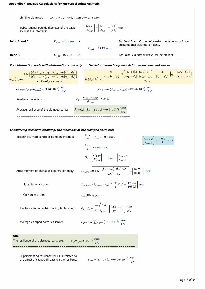
Appendix F Revised Calculations for HE-vessel Joints v5.mcdx
Limiting diameter: ≔DA.Gr =+dW ⋅⋅w lK tan ((φ)) 23.8 mm
Substitutional outside diameter of the basic
solid at the interface:
≔DA.ACDA.B
⎡⎢⎣
⎤⎥⎦
=cT.ACcT.B
⎡⎢⎣
⎤⎥⎦
2518
⎡⎢⎣
⎤⎥⎦mm
Joint A and C: =DA.AC 25 mm > For Joint A and C, the deformatoin cone consist of one substitutional deformation cone.
=DA.Gr 23.79 mm
Joint B: =DA.B 18 mm < For Joint B, a partial sleeve will be present. =====================================================================================
For deformation body with deformation cone only For deformation body with deformation cone and sleeve
≔δP.Z⎛⎝dh⎞⎠ ―――――――――――――
2 ln⎛⎜⎝―――――――――――
⋅⎛⎝ +dW dh⎞⎠ ⎛⎝ -+dW w lK tan ((φ)) dh⎞⎠⋅⎛⎝ -dW dh⎞⎠ ⎛⎝ ++dW w lK tan ((φ)) dh⎞⎠
⎞⎟⎠
⋅⋅⋅⋅w EP dh ππππ tan ((φ))≔δP⎛⎝ ,dh DA⎞⎠ ―――――――――――――――――――――
+――――2
w dh tan ((φ))ln
⎛⎜⎝―――――――
⋅⎛⎝ +dW dh⎞⎠ ⎛⎝ -DA dh⎞⎠⋅⎛⎝ -dW dh⎞⎠ ⎛⎝ +DA dh⎞⎠
⎞⎟⎠
――――4
-DA2 dh
2
⎛⎜⎝
-lK ――――⎛⎝ -DA dW⎞⎠w tan ((φ))
⎞⎟⎠
EP ππππ
≔δP.AC =δP.Z ⎛⎝dh.max⎞⎠ ⎛⎝ ⋅9.46 10-4⎞⎠ ――mm
kN≔δP.B =δP⎛⎝ ,dh.max DA.B⎞⎠ ⎛⎝ ⋅9.94 10-4⎞⎠ ――
mm
kN
Relative comparison: ≔∆δP =――――-δP.B δP.AC
δP.AC%5.08
Average resilience of the clamped parts: ≔δP =0.5 ⎛⎝ +δP.AC δP.B⎞⎠ ⎛⎝ ⋅9.7 10-4⎞⎠ ――mm
kN
======================================================
Considering eccentric clamping, the resiliense of the clamped parts are:
Eccentricity from centre of clamping interface: =-――cT.AC
2eAC -0.5 mm
≔ssym.ACssym.B
⎡⎢⎣
⎤⎥⎦
-0.54
⎡⎢⎣
⎤⎥⎦mm
=-――cT.B
2eB 4 mm
≔DADA.ACDA.B
⎡⎢⎣
⎤⎥⎦
≔ssymssym.ACssym.B
⎡⎢⎣
⎤⎥⎦
Areal moment of inertia of deformation body: ≔IV.Bers =
→――――――――
⋅0.147 ―――――――⋅⋅⎛⎝ -DA dW⎞⎠ dW
3 DA3
-DA3 dW
3
1667.01026.3
⎡⎢⎣
⎤⎥⎦mm4
Substitutional cone: ≔IVE.Bers =→―――――――
+IV.Bers ⋅ssym1
2 ―ππππ
4DA
2 1789.71089.9
⎡⎢⎣
⎤⎥⎦mm4
Only cone present: ≔IBers IVE.Bers
Resilience for eccentric loading & clamping ≔δ'P =+δP ―――
⋅ssym1
2 lK
⋅EP IBers
⋅9.84 10-4
⋅9.93 10-4
⎡⎢⎣
⎤⎥⎦
――mm
kN
Average clamped parts resilience: ≔δ'P =0.5 ∑δ'P⎛⎝ ⋅9.88 10-4⎞⎠ ――
mm
kN
Ans.
The resilience of the clamped parts are: =δ'P⎛⎝ ⋅9.88 10-4⎞⎠ ――
mm
kN
==========================================================
Supplementing resilience for TTJs, related to the effect of tapped threads on the resilience: ≔δPZu =(( -w 1)) δM ⎛⎝ ⋅6.96 10-4⎞⎠ ――
mm
kN
Page 7 of 14

Appendix F Revised Calculations for HE-vessel Joints v5.mcdx
Load factor
Concentric load factor: ≔ΦK =―――+δP δPZu
+δS δP0.166
Load factor for eccentric
clamping:
≔Φ'K =―――+δ'P δPZu
+δS δ'P0.168 Note that for these load factors, the load introduction factor
is assumed to be 1. Thus, that the load is introduced under the bolt-head.=========================================
Calculation of Beam Properties for FEA
Based on the analytic properties of the bolt, equivalent values to use when defining the beam properties can be calculated from (Eq. 79), VDI
2230 Pt.2.
Beam input values: For comparison:
Beam length: ≔lK.FE 10 mm =lK 11 mm
Equivalent area: ≔Aers =――lK.FE
⋅ES δS10.05 mm2 =Ad3.g 15.49 mm2 =――
Aers
Ad3.g%64.9
Equivalent aream moment of intertia: ≔Iers =―――lK.FE
⋅ES βS17.97 mm4 =Id3.g 25.02 mm4 =――
Iers
Id3.g%71.8
≔Jers =2 Iers 35.94 mm4
R4 - Preload Changes
Embedding Note: Does in principle only apply to Steel.
Assuming surface roughness height Rz < 10 .μm
According to "Table 5": ≔fZ =(( ++3 2.5 1.5)) μm 7 μm
NASA Estimate:Resulting preload loss from embedding: ≔FZ =―――
fZ
+δS δ'P697 N =⋅%5 FMzul 436.53 N
=======================================
Thermal Contraction Effects
The thermal integrals from 293K to 4K is used to determine the thermal deformations:
Titanium Gr.2 Titanium Gr.5Therma integrals:
≔ΑT_Ti2 0.00151 ≔ΑT_Ti5 0.00173 Source: EDMS 1530740
Change in length of bolt and clamped parts: ≔∆lS =⋅lK -ΑT_Ti5 -0.019 mm ≔∆lP =⋅lK -ΑT_Ti2 -0.017 mm
The thermal deformation is: ≔∆fVth =-∆lS ∆lP -0.002 mm
Preload loss due to thermal contraction: ≔∆F'Vth =―――∆fVth
+δS δP-242 N ≔Status_∆F'Vth
‖‖‖‖‖
if ≤∆F'Vth 0‖‖ return “Preload Increase”
“Preload loss”=Status_∆F'Vth “Preload Increase”
Note that as the bolt will contract more than the plate. This will give an increase in preload. This could be considered in the
calculation of Work Stress. In terms of minimum preload, the most conservative is to ignore this effect.
Page 8 of 14

Appendix F Revised Calculations for HE-vessel Joints v5.mcdx
Sum of losses
The sum of the preload losses are: ≔Floss =+∆F'Vth FZ 456 N
Resulting minimum preload: ≔FMmin.Z =-FMmin FZ 4.76 kN
R9 - Alternating Stress - Fatigue
Additional bolt load: ≔FSA -FSmax FVmax
The additional stress in the bolt that will vary with the workload is: ≔σzb.max =+――FSA
AS.g――MSbo
WS.g
281.8 MPa ≔σSAboσSAbu
⎡⎢⎣
⎤⎥⎦
σzb.max0 MPa
⎡⎢⎣
⎤⎥⎦
The resulting stress amplitude is: ≔σab =―――――-σSAbo σSAbu
2140.9 MPa
Permissable continous alternating stress for bolts
rolled before heat treatment:
≔σASV =0.85⎛⎜⎝
+―――150
d mm-145
⎞⎟⎠MPa 59.5 MPa ≔rASV =―――
σASV
Rp0.2min%7.3
The fatigue limit makes up of the bolt proof stress.=rASV %7.3
Criteria: =σab 140.88 MPa < =σASV 59.5 MPa ≔Status_R9 ‖‖‖‖‖
if <σab σASV‖‖ return “Ok”
“Not Ok”=Status_R9 “Not Ok”
The safetyfactor against fatigue is: ≔SD =――σASV
σab0.42 ≔SD.req 1.2
R10 - Surface Pressure Under the Bolt Head
Limiting surface pressure: ≔pG 1340 MPa
Head bearing area: ≔Ap.min =―ππππ
4⎛⎝ -dW
2 dh.max2 ⎞⎠ 22.6 mm2
Pressure in assembly state: ≔pMmax =――FMzul
Ap.min386.3 MPa
Pressure in working state: ≔pBmax =――FSmax
Ap.min205.7 MPa ≔pMmax =max ⎛⎝ ,pBmax pMmax⎞⎠ 386.3 MPa
Safety factor: ≔Sp =―――pG
pMmax3.47
R11- Thread Strength and Required Length of Engagement
Note that there is two factors that will lead to better load distribution on the threads than in a normal case:
1) Titanium is more resilient than Steel2) The outgassing hole in the bolt
Parameters Bolt Clamped parts
Tensile strength: ≔RmS =Rp0.2min 820 MPa ≔Rp0.2_Ti2 275 MPa ≔RmM Rp0.2_Ti2
Shear strength: ≔τBS.min 600 MPa ≔τBM.min =⋅0.6 345 MPa 207 MPa
Dimensions with tolerance: ≔dmin 5.794 mm ≔d1 =-d ――5 ‾‾3
8P 4.917 mm
[ISO 965-2 - 6H/6g]≔D2.max 5.50 mm ≔D1 d1 ≔D2 d2
Effective thread length: ≔leff =⎛⎝ -l lK⎞⎠ 9 mm
Page 9 of 14

Appendix F Revised Calculations for HE-vessel Joints v5.mcdx
Determination of Critical Thread
Thread strength ratio: =RS ――――⋅ASGM τBM
⋅ASGS τBSASG is the thread shear area of for the bolt / tapped threadsτB is the shear strength
RS > 1 bolt thread is criticalCriteria: ≔Thread_Critical ⎛⎝RS⎞⎠
‖‖‖‖‖‖‖
if >RS 1‖‖ return “bolt thread”
if <RS 1‖‖ return “Internal thread”
RS < 1 internal thread is critical
≔RS =⋅――――――――――
⋅d⎛⎜⎝
+―P
2⋅⎛⎝ -d D2⎞⎠ tan ((30 deg))
⎞⎟⎠
⋅d⎛⎜⎝
+―P
2⋅⎛⎝ -d2 D1⎞⎠ tan ((30 deg))
⎞⎟⎠
―――τBM.min
τBS.min0.403
Ans.=Thread_Critical ⎛⎝RS⎞⎠ “Internal thread”
===============================
Stripping Force of Internal ThreadsThe calculation of strength in the threads is solely based on the shear stress on the nut materials caused by the tensile force in the
bolt thread and that the influence of superimposed bending stresses in the thread turns can be ignored.
The correction factors C1 and C3 take into account among other things the reduction in the shear area resulting from flexure.
Parameter C1: Parameter C3:
"s" is the equivalent diameter of the material surrounding the internal thread.
≔s 10 mm =―s
d1.67 =RS 0.403
||
||
||
||
||
||
||
≔C1
‖‖‖‖‖‖‖‖‖‖‖‖‖‖‖‖
if <≤1.4 ―s
d1.9
‖‖‖‖
←C1 --⋅3.8 ―s
d
⎛⎜⎝―s
d
⎞⎟⎠
2
2.61
if >―s
d1.9
‖‖ ←C1 1
if <―s
d1.4
‖‖ return “not valid”
≔C3‖‖‖‖‖‖‖‖‖‖‖
if ≤RS 0.43‖‖ ←C3 1
if <<0.43 RS 1‖‖‖ ←C3 +-+0.728 1.769 RS 2.896 RS
2 1.296 RS3
if ≥RS 1‖‖ ←C3 0.897
=C1 0.95 =C3 1======= =====
Shear area for nut/internal thread: ≔ASGM =
→―――――――――――――――
⋅⋅⋅ππππ dmin⎛⎜⎝――leff
P
⎞⎟⎠
⎛⎜⎝
+―P
2⋅⎛⎝ -dmin D2.max⎞⎠ tan ((30 deg))
⎞⎟⎠
109.7 mm2
Stripping force of internal thread: ≔FmGM =⋅C1 C3 τBM.min ASGM 21.48 kN
Reference stripping force, with no correction: ≔FmGM.ref =⋅τBM.min ASGM 22.71 kN
Breaking stress of free loaded bolt thread: ≔FmS =⋅RmS AS.g 14.5 kN
Criteria (R11/1): =FmS 14.5 kN < =FmGM 21.5 kN ≔Status_R11.1 ‖‖‖‖‖
if <FmS FmGM‖‖ return “Ok”
“Not Ok”=Status_R11.1 “Ok”
=================
Load case specific data:
Utilisation of thread capacity: ≔νmGM =――FSmax
FmGM%21.7
Thread stripping force safety factor: ≔SmGM =――FmGM
FSmax4.62
Required effective length oftapped threads:
≔mges.min =+―――――――――――――――――――⋅⋅RmS AS.g P
⋅⋅⋅⋅⋅C1 C3 τBM.min⎛⎜⎝
+―P
2⋅⎛⎝ -dmin D2.max⎞⎠ tan ((30 deg))
⎞⎟⎠ππππ dmin
2 P 8.09 mm
Note: The "2P" is a margine for non-effective thread length, like chamfer.
Page 10 of 14

Appendix F Revised Calculations for HE-vessel Joints v5.mcdx
Criteria: ans. =mges.min 8.1 mm < =leff 9 mm ≔Status_thread_length ‖‖‖‖‖
if <mges.min leff‖‖ return “Ok”
“Not Ok”=Status_thread_length “Ok”
===============================
Considering non-uniform load distribution in the thread, the following assessment can be performed:
Numer of internal threads: ≔n =――leff
P9
Stripping force pr. thread: ≔FmGM_n =――FmGM
n2.4 kN
Say the first threads should be able to hold of the load:≔nt 2 ≔λP %50≔Non_uniform_status ‖
‖‖‖‖
if >nt FmGM_n FMzul λP‖‖ return “Ok”
“Not Ok”
=nt FmGM_n 4.77 kN > =FSmax λP 2.33 kN
=Non_uniform_status “Ok”
==============================
The first thread(s) can hold of the load.=nt 2 =――――nt FmGM_n
FSmax%102.6
R12 - Safety Margin Against Slipping
Negative preload loss, thus increase in preload from thermal contraction should not be included: ≔∆F'Vth.f =if <∆F'Vth 0‖‖ 0 kN
0 kN
Analytic minimum residual clamping force: ≔FKR.min =---――FMzul
αA⎛⎝ -1 Φ'K⎞⎠ FA.max FZ ∆F'Vth.f 4.47 kN (R12/1)
Required clamp load to transfer the maximum transverse load:
≔FKQerf =―――FQ.max
μTmin1.3 kN (R12/2)
Criteria: >FKQerf FKR.min (R12/3)
Safety factor: ≔SG =―――FKR.min
FKQerf3.5 > ≔SG.req 1.2 ≔Status_R12_4 if >SG SG.req
‖‖ “Ok”
(R12/4)
=Status_R12_4 “Ok”=================
Safety against sharing of the bolt: ≔SA =―――――⋅τBS.min Ad3.g
FQ.max24.1 > ≔SA.req 1.1 ≔Status_R12_7 if >SA SA.req
‖‖ “Ok”
(R12/7)
=Status_R12_7 “Ok”=================
Page 11 of 14

Appendix F Revised Calculations for HE-vessel Joints v5.mcdx
Summary of Key Results
___________________________________________________________________________________________________________________________________________
Calculation step Results
Maximum transverse load: =FQ.max 385.4 N
S1 - Workload Minimum clamp-load to avoid slipping: =FKQ 1.54 kN
Maximum axial load: =FA.max 347.8 N___________________________________________________________________________________________________________________________________________
S2 - Nominal Bolt Diameter =d 6 mm =P 1 mm
___________________________________________________________________________________________________________________________________________
S3 - Tightening Factor =αA 1.6
___________________________________________________________________________________________________________________________________________
=μGmin 0.3
S4 - Max Assembly Pretension =ν 0.9
=FMzul 8.7 kN =σMzul 738 MPa
___________________________________________________________________________________________________________________________________________
S5 - Min Assembly Pretension =FMmin 5.5 kN
___________________________________________________________________________________________________________________________________________
S6 - Simplify and Prepare CAD-geometry
___________________________________________________________________________________________________________________________________________
S7 - Prepare and Run FE-analysis =μTmin 0.3 =μKmin 0.3
___________________________________________________________________________________________________________________________________________
=FVmax 4.5 kN =FSmax 4.65 kN =MSbo 3.43 N mS8 - Extracted Results
=FVmin 4.5 kN =FA 0.5 kN
___________________________________________________________________________________________________________________________________________
S9 - Work Stress =σred.B 627.7 MPa < =Rp0.2min 820 MPa =SF 1.31 =Work_Stress “Ok”======================================================
___________________________________________________________________________________________________________________________________________
S10 - Clamping requirements
___________________________________________________________________________________________________________________________________________
S11 - Tightening Torque =MA 20 N m
___________________________________________________________________________________________________________________________________________
===========APPROVED
===========
S12 - Approve or Iterate
___________________________________________________________________________________________________________________________________________
Page 12 of 14

Appendix F Revised Calculations for HE-vessel Joints v5.mcdx
___________________________________________________________________________________________________________________________________________
Additional CalculationsAdditional bolt load: =FSA 150 N
FE-based quanteties
Load factor: ≔ΦFE =――FSA
FA0.3
______________________________________________________________________________________________________
=eB 5 mm < =0.5 G'min 6.6 mmR0 - Checking limiting size G
=eAC 13 mm < =0.5 G'max 13.1 mm
_______________________________________________________________________________________________________
Axial resilience: =δS⎛⎝ ⋅9.05 10-3⎞⎠ ――
mm
kN
Bending resilience: =βS⎛⎝ ⋅5.06 10-6⎞⎠ ―――
1
N mmR3 -Analytic Resilience and Load Factors
Resilience of clamped parts: =δ'P⎛⎝ ⋅9.88 10-4⎞⎠ ――
mm
kN
Load factor: =Φ'K 0.168_______________________________________________________________________________________________________
Beam length: =lK.FE 10 mmCalculation of Beam Properties for FEA
Equivalent area: =Aers 10.05 mm2
Equivalent areal moment of intertia: =Iers 17.97 mm4
_______________________________________________________________________________________________________
Loss from embedding: =FZ 697.3 NR4 - Preload Changes
Loss from thermal contraction: =∆F'Vth -241.5 N
_______________________________________________________________________________________________________
R10 - Surface Pressure Under the Bolt Head
Safety factor: =Sp 3.47
_______________________________________________________________________________________________________
=Thread_Critical ⎛⎝RS⎞⎠ “Internal thread”
=Status_R11.1 “Ok”
Utilisation of thread capacity: =νmGM %21.7R11 - Thread Strength and
Required Length of Engagement Thread stripping safety factor: =SmGM 4.6
Required thread length Effective thread length=mges.min 8.09 mm < =leff 9 mm
=Status_thread_length “Ok”
=Non_uniform_status “Ok”
_______________________________________________________________________________________________________
=SG 3.5 =Status_R12_4 “Ok”R12 - Safety Against Slipping
=SA 24.1 =Status_R12_7 “Ok”
___________________________________________________________________________________________________________________________________________
Page 13 of 14

Appendix F Revised Calculations for HE-vessel Joints v5.mcdx
Page 14 of 14