Special Joints - Leigh Dovetail Jigs
8
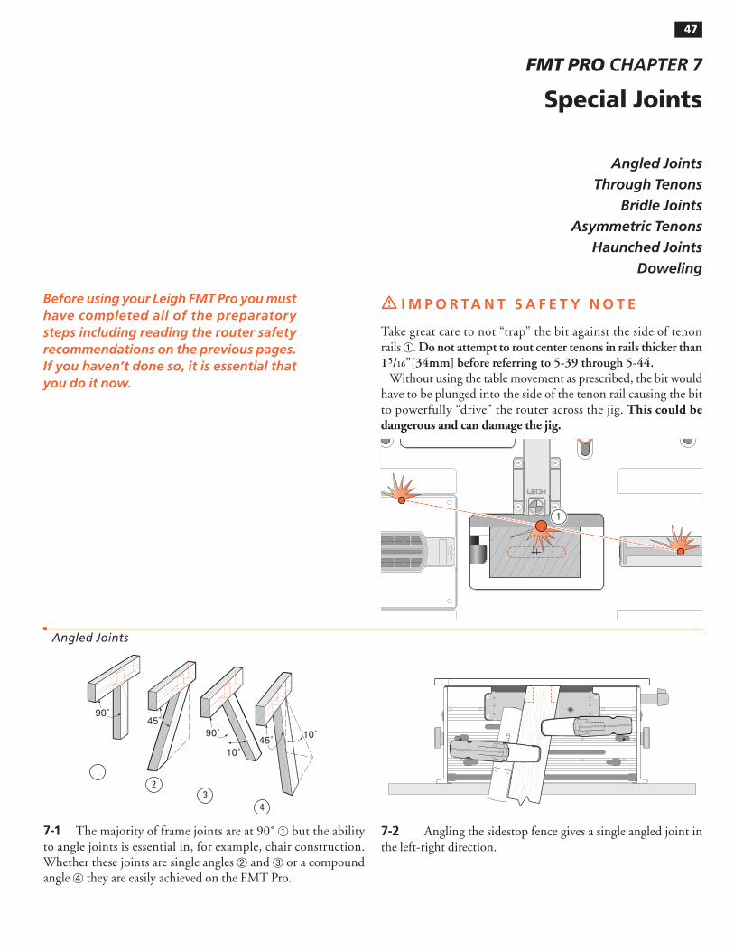
Angled Joints Through Tenons Bridle Joints Asymmetric Tenons Haunched Joints Doweling m IMPORTANT SAFETY NOTE Take great care to not “trap” the bit against the side of tenon rails ➀ . Do not attempt to rout center tenons in rails thicker than 1 5 / 16"[34mm] before referring to 5-39 through 5-44. Without using the table movement as prescribed, the bit would have to be plunged into the side of the tenon rail causing the bit to powerfully “drive” the router across the jig. This could be dangerous and can damage the jig. Before using your Leigh FMT Pro you must have completed all of the preparatory steps including reading the router safety recommendations on the previous pages. If you haven’t done so, it is essential that you do it now. Special Joints FMT PRO CHAPTER 7 47 7-1 The majority of frame joints are at 90˚ ➀ but the ability to angle joints is essential in, for example, chair construction. Whether these joints are single angles ➁ and ➂ or a compound angle ➃ they are easily achieved on the FMT Pro. 90˚ 45˚ 90˚ 45˚ 10˚ 1 2 3 4 10˚ 7-2 Angling the sidestop fence gives a single angled joint in the left-right direction. Angled Joints 1
-
Upload
khangminh22 -
Category
Documents
-
view
0 -
download
0
Transcript of Special Joints - Leigh Dovetail Jigs
Angled Joints
Through Tenons
Bridle Joints
Asymmetric Tenons
Haunched Joints
Doweling
m I M P O R TA N T S A F E T Y N O T E
Take great care to not “trap” the bit against the side of tenon rails ➀. Do not attempt to rout center tenons in rails thicker than 15/16"[34mm] before referring to 5-39 through 5-44.
Without using the table movement as prescribed, the bit would have to be plunged into the side of the tenon rail causing the bit to powerfully “drive” the router across the jig. This could be dangerous and can damage the jig.
Before using your Leigh FMT Pro you must have completed all of the preparatory steps including reading the router safety recommendations on the previous pages. If you haven’t done so, it is essential that you do it now.
Special Joints
FMT PRO CHAPTER 7
MORTISE & TENON ROUTING PROCEDURES47
7-1 The majority of frame joints are at 90˚ ➀ but the ability to angle joints is essential in, for example, chair construction. Whether these joints are single angles ➁ and ➂ or a compound angle ➃ they are easily achieved on the FMT Pro.
90˚45˚
90˚45˚
10˚
12
34
10˚
7-2 Angling the sidestop fence gives a single angled joint in the left-right direction.
Angled Joints
1

Frame Mortise & Tenon Jig User Guide48 Chapter 7 SPECIAL JOINTS
7-3 Angling the clamp plate with vertical sidestops also gives a single angled joint in the front-back direction.
7-4 Angling both fence and clamp plate give a double, or compound angled joint.
7-5 The FMT Pro clamp plate can be angled up to 30˚ but it is doubtful you will ever need to approach even 10˚ on a mortise and tenon joint. The strength of a tenon across its grain lessens consider-ably as the angle increases ➀. In addition, the length and position of the tenon is limited in slope by the angled workpiece relative to the vertical bit ➁ (angle demonstrated in this illustration is excessive.)
1
2
7-6 However, you may for example, want to machine spline mortises or dowel holes in a stave type construction in, say, octa-gons at 221⁄2˚, or hexagons at 30˚, so the 30˚ capacity may prove to be useful. You can then machine precisely fitting splines on the FMT Pro and trim them to length. ■
7-7 Through Tenons Occasionally, a design feature will call for through, exposed tenons, possibly “wedged” for decorative effect. The limited depth of cut of router bits can make this difficult, but the two-sized bit technique described previously, combined with the precision of the FMT Pro, makes this procedure perfectly feasible in many instances.
7-8 The problem with through mortises is their great depth relative to the cutting depth and diameter of the bit. However, if the left-right part of the joint center mark ➀ is carefully squared around the mortise workpiece, it is possible to accurately plunge from both sides.
1
Through Tenons

Frame Mortise & Tenon Jig User Guide 49Chapter 7SPECIAL JOINTS
7-9 Here’s an example.1⁄4"[6mm] joint through 11⁄2"[35mm] deep mortise.Select 1⁄4"[6mm] bit for mortises ➀.Select 1⁄2"[10mm] bit to rout the 11⁄2"[35mm] long tenon ➁.Select 3⁄8"[8mm] guide ➂ for length from the guide/bit selection chart in Appendix I.
1
2
3
7-10 Carefully sight the mortise taking particular care to center the “vertical” line ➀ in the sight. Plunge and rout down deeper than half the mortise board depth.
1
7-11 Turn the mortise piece end for end and, keeping the same reference side of the mortise board to the clamp face, carefully sight the “vertical” mortise center mark ➁ and lock the table . Plunge and rout to clear the through mortise.
2
7-12 Rout the tenons with the larger (longer) bit slightly deeper than the mortise depth.
7-13 It may even be possible to make tenons long enough to be raised if this decorative effect is desired. “Wedging” the tenons is a simple hand procedure and a nice decorative touch.
7-14 If the tenon stock is smaller than the table opening it may be possible (after sighting) to slide the tenon workpiece up to almost touch the router base and thereby gain an extra 1⁄2"[10mm] of tenon length. Assuming of course that the bit has sufficient cutting depth. ■

Frame Mortise & Tenon Jig User Guide50 Chapter 7 SPECIAL JOINTS
7-19 Floating Tenons A “floating” tenon in a mitered corner allows for a greater joint glue area at the inside of the corner. On this mitred corner, the workpieces are mounted in the jig at 45˚ and the mortises routed. The floating tenon ➀ is routed on the end of a vertically mounted scrap piece using the same guide and then sawn off. ■
1
7-15 Routing bridle joints on the FMT Pro is simple. All the work-pieces (with the exception of the mitered tenon) ➀ are mounted vertically on the jig.
1
7-16 Select a guide that is greater in length than the workpiece width ➀ by at least two bit diameters. Rout right through the “vertical mortise” ➁ and across the tenon sides ➂. The bit will clear the edge of the workpiece before the guide pin reaches the rounded part of the guide.
MORTISE
TENON
2
3
1
7-17 The mitered “tenon” is mounted at 45˚ on the clamp plate ➀. The “mortise” end miter ➁ is cut on the table saw after routing the mortise.
1
2
7-18 Twin bridle joints use the technique described above com-bined with the table movement ➀ (see 5-12, Twin Joints).
1
Bridle Joints
Frame Mortise & Tenon Jig User Guide 51Chapter 7SPECIAL JOINTS
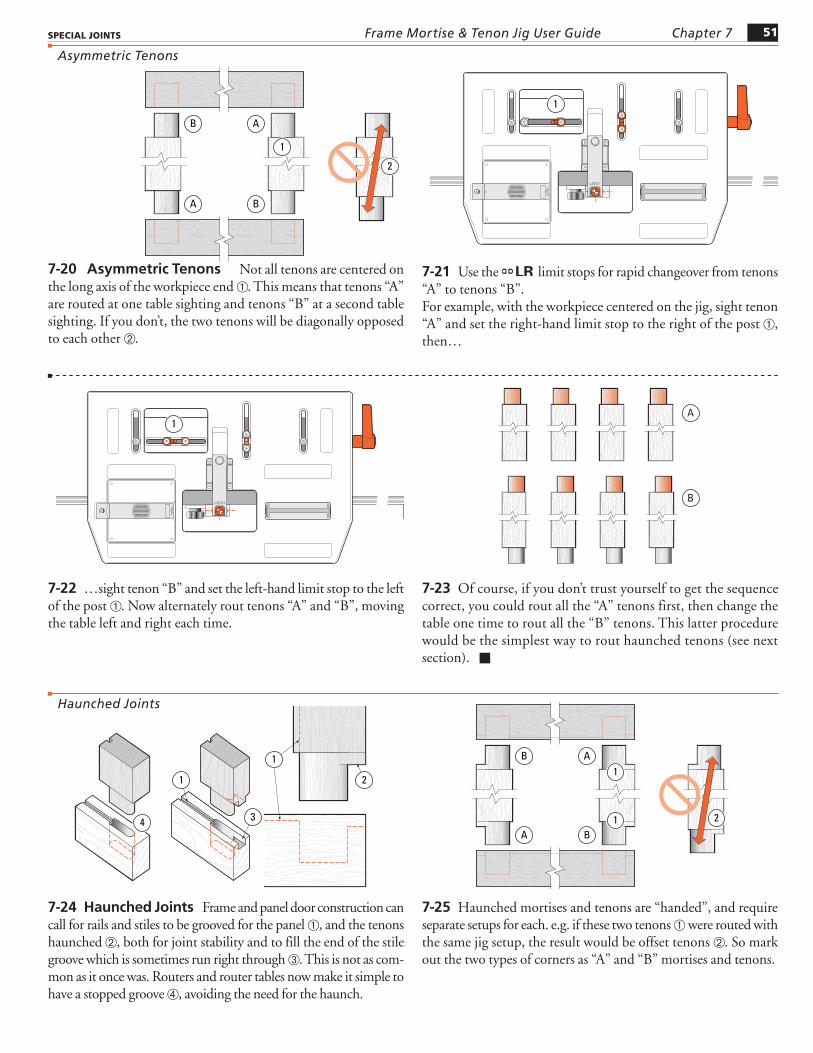
7-20 Asymmetric Tenons Not all tenons are centered on the long axis of the workpiece end ➀. This means that tenons “A” are routed at one table sighting and tenons “B” at a second table sighting. If you don’t, the two tenons will be diagonally opposed to each other ➁.
B
A
A
2
1
B
7-21 Use the LR limit stops for rapid changeover from tenons “A” to tenons “B”.For example, with the workpiece centered on the jig, sight tenon “A” and set the right-hand limit stop to the right of the post ➀, then…
1
7-22 …sight tenon “B” and set the left-hand limit stop to the left of the post ➀. Now alternately rout tenons “A” and “B”, moving the table left and right each time.
1
7-23 Of course, if you don’t trust yourself to get the sequence correct, you could rout all the “A” tenons first, then change the table one time to rout all the “B” tenons. This latter procedure would be the simplest way to rout haunched tenons (see next section). ■
B
A
7-24 Haunched Joints Frame and panel door construction can call for rails and stiles to be grooved for the panel ➀, and the tenons haunched ➁, both for joint stability and to fill the end of the stile groove which is sometimes run right through ➂. This is not as com-mon as it once was. Routers and router tables now make it simple to have a stopped groove ➃, avoiding the need for the haunch.
1
4 3
1
2
7-25 Haunched mortises and tenons are “handed”, and require separate setups for each. e.g. if these two tenons ➀ were routed with the same jig setup, the result would be offset tenons ➁. So mark out the two types of corners as “A” and “B” mortises and tenons.
B
A
A1
1 2
B
Asymmetric Tenons
Haunched Joints
Frame Mortise & Tenon Jig User Guide52 Chapter 7 SPECIAL JOINTS
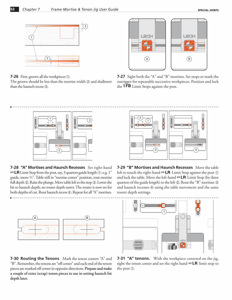
7-30 Routing the Tenons Mark the tenon centers “A” and “B”. Remember, the tenons are “off center” and each end of the tenon pieces are marked off center in opposite directions. Prepare and make a couple of extra (scrap) tenon pieces to use in setting haunch bit depth later.
BA
7-31 “A” tenons. With the workpiece centered on the jig, sight the tenon center and set the right hand LR limit stop to the post ➀.
1
7-26 First, groove all the workpieces ➀.The groove should be less than the mortise width ➁ and shallower than the haunch recess ➂.
1
2
3
7-27 Sight both the “A” and “B” mortises. Set stops or mark the outrigger for repeatable successive workpieces. Position and lock the FB Limit Stops against the post.
BA
7-28 “A” Mortises and Haunch Recesses Set right-hand LRLimit Stop from the post, say, 3 quarters guide length ➀: e.g. 1"
guide, move 3⁄4". Table still in “mortise center” position, rout mortise full depth ➁. Raise the plunge. Move table left to the stop ➂. Lower the bit to haunch depth; set router depth turret. The router is now set for both depths of cut. Rout haunch recess ➃. Repeat for all “A” mortises.
1
2 4
3
7-29 “B” Mortises and Haunch Recesses Move the table left to touch the right-hand LR Limit Stop against the post ➀ and lock the table. Move the left-hand LR Limit Stop (by three quarters of the guide length) to the left ➁. Rout the “B” mortises ➂ and haunch recesses ➃ using the table movement and the same router depth settings.
21
3 4
Frame Mortise & Tenon Jig User Guide 53Chapter 7SPECIAL JOINTS
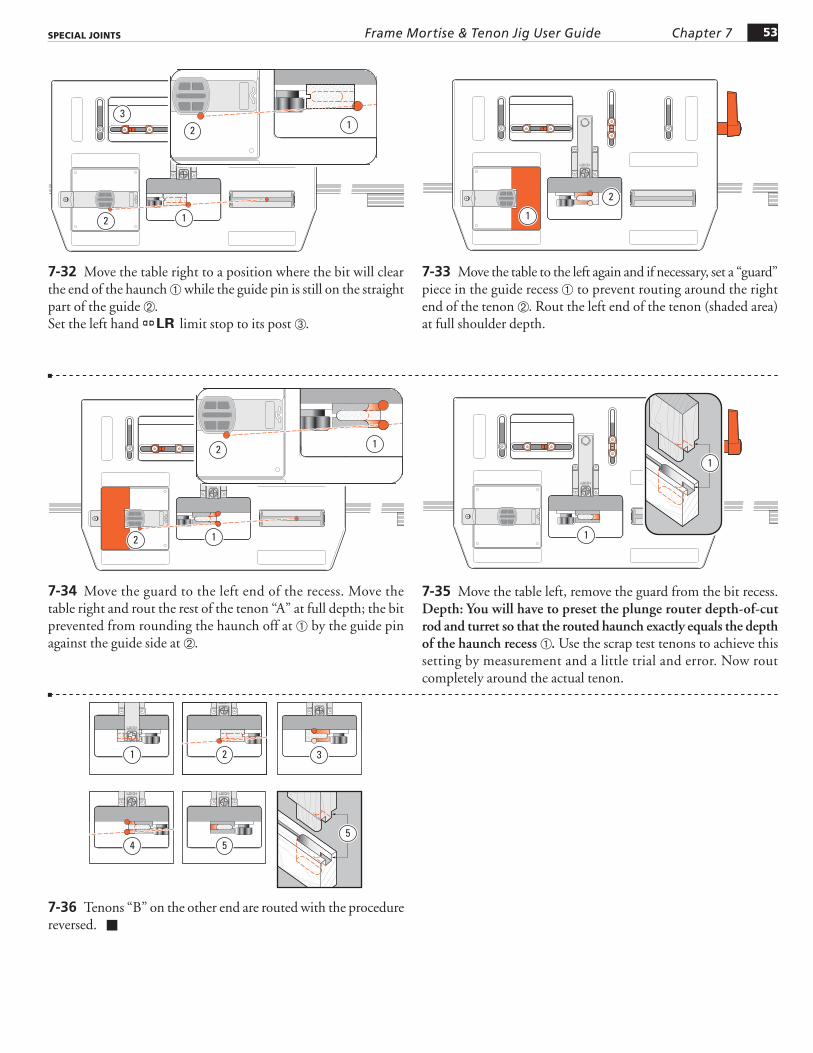
7-32 Move the table right to a position where the bit will clear the end of the haunch ➀ while the guide pin is still on the straight part of the guide ➁.Set the left hand LR limit stop to its post ➂.
3
12
12
7-33 Move the table to the left again and if necessary, set a “guard” piece in the guide recess ➀ to prevent routing around the right end of the tenon ➁. Rout the left end of the tenon (shaded area) at full shoulder depth.
1
2
7-34 Move the guard to the left end of the recess. Move the table right and rout the rest of the tenon “A” at full depth; the bit prevented from rounding the haunch off at ➀ by the guide pin against the guide side at ➁.
12
12
7-35 Move the table left, remove the guard from the bit recess. Depth: You will have to preset the plunge router depth-of-cut rod and turret so that the routed haunch exactly equals the depth of the haunch recess ➀. Use the scrap test tenons to achieve this setting by measurement and a little trial and error. Now rout completely around the actual tenon.
1
1
7-36 Tenons “B” on the other end are routed with the procedure reversed. ■
5
1 2 3
4 5
Frame Mortise & Tenon Jig User Guide54 Chapter 7 SPECIAL JOINTS
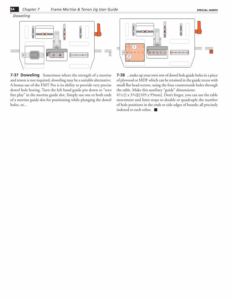
7-37 Doweling Sometimes where the strength of a mortise and tenon is not required, doweling may be a suitable alternative. A bonus use of the FMT Pro is its ability to provide very precise dowel hole boring. Turn the left hand guide pin down to “zero free play” in the mortise guide slot. Simply use one or both ends of a mortise guide slot for positioning while plunging the dowel holes, or...
7-38 ...make up your own row of dowel hole guide holes in a piece of plywood or MDF which can be retained in the guide recess with small flat head screws, using the four countersunk holes through the table. Make this auxiliary “guide” dimensions:45⁄32➀ x 33⁄4➁[105 x 95mm]. Don’t forget, you can use the table movement and limit stops to double or quadruple the number of hole positions in the ends or side edges of boards; all precisely indexed to each other. ■
2
1
Doweling