Computer-Aided Design of Traditional Jigs and Fixtures - MDPI
37
applied sciences Article Computer-Aided Design of Traditional Jigs and Fixtures Abdullah D. Ibrahim 1 , Hussein M. A. Hussein 2,3 , Ibrahim Ahmed 4 , Emad Abouel Nasr 5 , Ali Kamrani 6 and Sabreen A. Abdelwahab 7, * Citation: Ibrahim, A.D.; Hussein, H.M.A.; Ahmed, I.; Nasr, E.A.; Kamrani, A.; Abdelwahab, S.A. Computer-Aided Design of Traditional Jigs and Fixtures. Appl. Sci. 2022, 12, 3. https://doi.org/ 10.3390/app12010003 Academic Editors: Paolo Renna and Arkadiusz Gola Received: 8 October 2021 Accepted: 25 November 2021 Published: 21 December 2021 Publisher’s Note: MDPI stays neutral with regard to jurisdictional claims in published maps and institutional affil- iations. Copyright: © 2021 by the authors. Licensee MDPI, Basel, Switzerland. This article is an open access article distributed under the terms and conditions of the Creative Commons Attribution (CC BY) license (https:// creativecommons.org/licenses/by/ 4.0/). 1 Senior Lab Engineer, Process and Product Development Unit, American University in Cairo, Cairo 11835, Egypt; [email protected] 2 Mechanical Engineering Department, Faculty of Engineering, Helwan University, Cairo 11732, Egypt; [email protected] 3 Mechanical Engineering Department, Faculty of Engineering, Ahram Canadian University, Giza 12451, Egypt 4 Automotive Technology Department, Faculty of Technology and Education, Helwan University, Cairo 11732, Egypt; [email protected] 5 Industrial Engineering Department, College of Engineering, King Saud University, Riyadh 11421, Saudi Arabia; [email protected] 6 Industrial Engineering Department, College of Engineering, University of Houston, Houston, TX 77204, USA; [email protected] 7 Production Technology Department, Faculty of Technology and Education, Helwan University, Cairo 11732, Egypt * Correspondence: [email protected] Abstract: Conventional design of jigs and fixtures has become unsuitable given the requirements of modern technology and complexity and diversity in the production with the rapid update of products. Computer-aided design (CAD) of jigs and fixtures is an effective solution in this direction. The current paper focuses on a computer-aided design of the traditional jigs and fixtures and developed a system containing tailor-made software, created using the Visual Basic programming language and installed on it the viewer screen to show the part. The developed system has been built by connecting Visual Basic programming language to the SolidWorks software on which the part is drawn and saved as STEP AP-203 file format, and the system reads and extracts the data from the STEP AP-203 file. Heuristic rules of feature recognition are pre-prepared for checking the extracted geometric data and deciding which data shape will represent the machining feature; then, the system provides the optimum design of the traditional jigs and fixtures for a group of hollow cylindrical parts that contain a group of cross-holes on the cylinder body, whether perpendicular or offset from the cylinder’s axis, (inclined or inclined offset, or blind or through, by applying pre-prepared heuristic rules for the design of traditional jigs and fixtures. Keywords: traditional fixtures; jig and fixture design; cross-hole; data extraction; feature recognition; STEP AP-203 file 1. Introduction Jigs and fixtures are devices which are widely used in manufacture; they provide guidance for the tool and supporting, locating, and holding for the workpiece during manufacturing process. Moreover, they are used for assembling a big number of parts [1]. Jigs and fixtures help in eliminating the individual marking, adjusting the position, and repeating the checking and getting a better quality of manufacturing process. This increases productivity and reduces the time of the operation. The efficient and reliable design and manufacture of jigs and fixtures became more required with the application of computer- aided manufacture (CAM) technology. The manual designing of the jigs and fixtures is considered time-consuming in manufacturing process, and the designer’s experience and skill play an important role in the designing of jigs and fixtures [2]. Jigs and fixtures are helping devices which deal with cutting machines such as milling machines, turning machines, drilling machines, grinding machines, and broaching ma- Appl. Sci. 2022, 12, 3. https://doi.org/10.3390/app12010003 https://www.mdpi.com/journal/applsci
-
Upload
khangminh22 -
Category
Documents
-
view
0 -
download
0
Transcript of Computer-Aided Design of Traditional Jigs and Fixtures - MDPI

applied sciences
Article
Computer-Aided Design of Traditional Jigs and Fixtures
Abdullah D. Ibrahim 1 , Hussein M. A. Hussein 2,3, Ibrahim Ahmed 4, Emad Abouel Nasr 5 , Ali Kamrani 6
and Sabreen A. Abdelwahab 7,*
�����������������
Citation: Ibrahim, A.D.; Hussein,
H.M.A.; Ahmed, I.; Nasr, E.A.;
Kamrani, A.; Abdelwahab, S.A.
Computer-Aided Design of
Traditional Jigs and Fixtures. Appl.
Sci. 2022, 12, 3. https://doi.org/
10.3390/app12010003
Academic Editors: Paolo Renna and
Arkadiusz Gola
Received: 8 October 2021
Accepted: 25 November 2021
Published: 21 December 2021
Publisher’s Note: MDPI stays neutral
with regard to jurisdictional claims in
published maps and institutional affil-
iations.
Copyright: © 2021 by the authors.
Licensee MDPI, Basel, Switzerland.
This article is an open access article
distributed under the terms and
conditions of the Creative Commons
Attribution (CC BY) license (https://
creativecommons.org/licenses/by/
4.0/).
1 Senior Lab Engineer, Process and Product Development Unit, American University in Cairo,Cairo 11835, Egypt; [email protected]
2 Mechanical Engineering Department, Faculty of Engineering, Helwan University, Cairo 11732, Egypt;[email protected]
3 Mechanical Engineering Department, Faculty of Engineering, Ahram Canadian University, Giza 12451, Egypt4 Automotive Technology Department, Faculty of Technology and Education, Helwan University,
Cairo 11732, Egypt; [email protected] Industrial Engineering Department, College of Engineering, King Saud University,
Riyadh 11421, Saudi Arabia; [email protected] Industrial Engineering Department, College of Engineering, University of Houston, Houston, TX 77204, USA;
[email protected] Production Technology Department, Faculty of Technology and Education, Helwan University,
Cairo 11732, Egypt* Correspondence: [email protected]
Abstract: Conventional design of jigs and fixtures has become unsuitable given the requirements ofmodern technology and complexity and diversity in the production with the rapid update of products.Computer-aided design (CAD) of jigs and fixtures is an effective solution in this direction. The currentpaper focuses on a computer-aided design of the traditional jigs and fixtures and developed a systemcontaining tailor-made software, created using the Visual Basic programming language and installedon it the viewer screen to show the part. The developed system has been built by connecting VisualBasic programming language to the SolidWorks software on which the part is drawn and savedas STEP AP-203 file format, and the system reads and extracts the data from the STEP AP-203 file.Heuristic rules of feature recognition are pre-prepared for checking the extracted geometric dataand deciding which data shape will represent the machining feature; then, the system provides theoptimum design of the traditional jigs and fixtures for a group of hollow cylindrical parts that containa group of cross-holes on the cylinder body, whether perpendicular or offset from the cylinder’saxis, (inclined or inclined offset, or blind or through, by applying pre-prepared heuristic rules for thedesign of traditional jigs and fixtures.
Keywords: traditional fixtures; jig and fixture design; cross-hole; data extraction; feature recognition;STEP AP-203 file
1. Introduction
Jigs and fixtures are devices which are widely used in manufacture; they provideguidance for the tool and supporting, locating, and holding for the workpiece duringmanufacturing process. Moreover, they are used for assembling a big number of parts [1].Jigs and fixtures help in eliminating the individual marking, adjusting the position, andrepeating the checking and getting a better quality of manufacturing process. This increasesproductivity and reduces the time of the operation. The efficient and reliable design andmanufacture of jigs and fixtures became more required with the application of computer-aided manufacture (CAM) technology. The manual designing of the jigs and fixtures isconsidered time-consuming in manufacturing process, and the designer’s experience andskill play an important role in the designing of jigs and fixtures [2].
Jigs and fixtures are helping devices which deal with cutting machines such as millingmachines, turning machines, drilling machines, grinding machines, and broaching ma-
Appl. Sci. 2022, 12, 3. https://doi.org/10.3390/app12010003 https://www.mdpi.com/journal/applsci
Appl. Sci. 2022, 12, 3 2 of 37
chines. Welding, assembly, and inspection fixtures are other branches of fixtures whichhave no deals with the cutting machine. Jigs are machining aid devices which includemeans of tool guiding in drilling operations, such as drilling and reaming processes. Fix-tures are holding devices which are used for holding the workpiece firmly in easy way,and they might contain the means of the cutting tool setting; fixtures are used for milling,turning, grinding, and other manufacturing operations [3].
Jigs and fixtures design is a complex process that requires a good experience andproduct understanding of the designer and might take many days or longer [4].
The costs related to traditional jigs and fixtures may account for (10–20%) of thetotal cost of the manufacturing process. These costs include their manufacture, assembly,operation, and design [5].
Automatic feature recognition (AFR) techniques are still limited to asymmetrical andorthogonal features and cannot deal with non-symmetrical and nonorthogonal featuresand errors made because of combining of AFR techniques. Researchers in the AFR field arestill trying to find a fully automated feature recognition algorithm for such features [6].
Jigs and fixtures are still important devices for both traditional manufacturing andmodern flexible manufacturing systems (FMS) because they affect the quality and theproductivity of the manufacturing process as well as the product cost. Soo Waihong,in 2003, proved that using the time in improving current products and presenting newproducts is better than wasting it in the manual design and manufacture of jigs andfixtures [7].
Increasing global competition made all manufacturers in the industrial market makethe best effort for improving their competitiveness by developing the quality of theirproducts and reducing the production cost and time; therefore, there is a strong need toupgrade the jigs and fixtures design methods for obtaining more efficient design witha lower cost. Developing a computer-aided fixture design (CAFD) technology as anintegration of computer-aided design (CAD) and computer-aided manufacture (CAM) canhelp in achieving this goal which is able to support and simplify the design process [8].
The difference between the traditional fixtures and modular fixtures is that the mod-ular fixtures are primarily used with C.N.C. machines and they do not need to calculatethe clamping force during the machining operation. Furthermore, the positioning of thelocators and clamps is still a problem within the modular fixtures’ assembly. Traditionalfixtures design needs several calculation modules for covering several items, such as featurerecognition, the required clamping force, the cam design, the locator position, the guideposition, selecting the standard components of the fixture, modeling the whole jigs andfixture, and process planning [3,9,10].
Different approaches have been used in jigs and fixtures design, such as case-basedreasoning (CBR), rule-based expert system, genetic algorithm (GA), multi-agent approach,and geometric analysis [11,12].
There are few pieces of research found in the literature that cover the traditional jigsand fixture design technique [13,14].
2. Literature Review
The literature review section introduces the work that is more closely related to theapproach used in the current work as shown in Table 1:
Table 1. Summary of major research work on computer-aided design of jigs and fixtures.
Ref. No. Authors System Details Remarks
[15] A.S. Kumar, A.Y.C. Nee, andS. Prombanpong (1992)
Used an integrated expert systemshell with computer-aided
design (CAD).
Developed a complete system for automatedfixture design; this system recognizes
manufacturing features in the CAD model,determines set-ups, and generates the fixture
configuration based on the 3-2-1locating principle.

Appl. Sci. 2022, 12, 3 3 of 37
Table 1. Cont.
Ref. No. Authors System Details Remarks
[9] A.Y.C. Nee, K. Whybrew, andA.S. Kumar (1995)
Used heuristic rule-based methodto generate a fixturing
recommendations list whichincludes the locating and base
elements for the fixture.
Presented an expert system for performingthe fixture design task and generated a list of
fixturing recommendations including thelocating and base elements for the fixture.
[16]R.H. Alarco’n, J.R. Chueco,
J.M.P. Garcia, andA.V. Idoipe (2010)
Used a knowledge model for thefixture design.
Presented an automatic fixture design systemdeveloped by knowledge-based
engineering application.
[17]S. Selvakumar, K.P. Arulshri,
K.P. Padmanaban, andK.S.K. Sasikumar (2013)
Used an artificial neural networks(ANN)-based algorithm with the
design of experiments (DOE).
Proposed a hybrid system for designing theoptimum fixture layout to decrease the
maximum the workpiece’s elasticdeformation caused by the clamping and
machining forces during themachining operation.
[18] H. Hashemi, A.M. Shaharoun,and I. Sudin (2014)
Used a case-based reasoningmethod for improving the fixture
design process efficiency.
Proposed a system of fixture design in whichan appropriate workpiece was found in the
first level of the database by applying designrequirements. This allowed the proper
conceptual fixture design to be achieved byretrieving a related fixture case from the
second level.
[19] W. Fu, I. Matthew, andCampbell (2014)
Used a developed hierarchicalsearch system to identify which
operations were suitable in termsof manufacturing cost, time, and
fixture quality.
Demonstrated a rule-based algorithm thatdefines fixture design for a set of operations.
[3]H.M.A Hussein, A. Mahrous,
A.F. Barakat, andO.M. Dawood (2016)
Used a package includingAutoCAD software and VisualBasic programming language.
Developed a systematic framework for acomputer-aided design of traditional jigs andfixtures; this system is limited to cylindrical
parts having axisymmetrical features.
[20]V. Ivanov, I. Pavlenko, O.
Liaposhchenko, O. Gusak,and V. Pavlenko (2018)
Used a technique integrated into acomputer-aided fixture design
system based on aprocess-oriented approach.
Proposed a methodology for computer-aidedpositioning of functional fixture elements
regarding the technological part parameters;this system reduced the fixture design time
of the drilling, milling, and boring operationsand improved the fixtures‘
components quality.
After reviewing the previous studies and research, it becomes clear that there is aneed for a developed system to recognize the combined and interacted features such as thecross-hole feature and design the appropriate traditional jigs and fixtures.
3. Computer-Aided Design of Traditional Jigs and Fixtures
Figure 1 shows a typical example of jig and fixture [21], which includes the locatingunits on which the workpiece rests for locating it accurately and constrained it in 3:5degrees of freedom, the clamping units that hold the workpiece during machining forsecuring the location of the workpiece and the jig guiding elements which guide the cuttingtool for obtaining an accurate machining operation [21,22].
There is a relationship between the traditional method of jigs and fixture design andthe machine elements design. These devices are primarily dependent on the standard parts,i.e., dowel pins, bolts, cams, etc. [3].

Appl. Sci. 2022, 12, 3 4 of 37
Appl. Sci. 2021, 11, x FOR PEER REVIEW 4 of 42
3. Computer-Aided Design of Traditional Jigs and Fixtures Figure 1 shows a typical example of jig and fixture [21], which includes the locating
units on which the workpiece rests for locating it accurately and constrained it in 3:5 de-grees of freedom, the clamping units that hold the workpiece during machining for se-curing the location of the workpiece and the jig guiding elements which guide the cut-ting tool for obtaining an accurate machining operation [21,22].
(a) (b)
Figure 1. Typical example of (a) a drilling jig, (b) a machining fixture [21].
There is a relationship between the traditional method of jigs and fixture design and the machine elements design. These devices are primarily dependent on the stand-ard parts, i.e., dowel pins, bolts, cams, etc. [3].
The jigs and fixtures design process have four phases, which are typically setup planning, jig and fixture planning, unit design, and verification. In the setup planning phase, analyzing the workpiece and machining information is done for determining the suitable position of the locating units and all the setups needed to perform the required machining operations. In the jig and fixture planning phase, six fixturing requirements (physical, tolerance, constraining, affordability, collision prevention, usability) are gen-erated for the setup of a specific manufacturing operation as well as the fixture’s layout plan which details the workpiece surface with the positioning of the locating and clamping units. In the unit phase design, the appropriate design generation of units is conducted, such as the design of locating and clamping units for obtaining an accurate location and to overcome the deformation of the fixture components. In the verification phase, the jig and fixture test is carried out. This phase can also be performed before the unit design phase for evaluating the validity of the current fixture system layout [23,24].
CAD part model description in basic geometrical and topological form cannot be used for process planning directly because it requires information extracted from the CAD part model in the form of features, and then, this information is used in process planning [25]. Thus, the problem of the planning process is how to extract, recognize, and manufacture these features.
The extraction and recognition of the manufacturing features in a design database have received significant attention since the mid-1970s; therefore, many standards for data exchange have been developed for solving the design complexity problem and for integrating different CAD systems, such as Initial Graphics Exchange Specification (IGES), Data Exchange Format (DXF), Standard Exchange Transfer (SET) and Standard for Exchange of Product (STEP) format [26,27].
STEP is a standard that gives the obvious and complete representation of the par data during the life cycle, independent of any system [28]. In a STEP file, the specifica-tion of product information is standardized by ISO10303, and there are many applica-tion protocols (APs) available in it which are used for different applications, such as
Figure 1. Typical example of (a) a drilling jig, (b) a machining fixture [21].
The jigs and fixtures design process have four phases, which are typically setup plan-ning, jig and fixture planning, unit design, and verification. In the setup planning phase,analyzing the workpiece and machining information is done for determining the suitableposition of the locating units and all the setups needed to perform the required machiningoperations. In the jig and fixture planning phase, six fixturing requirements (physical,tolerance, constraining, affordability, collision prevention, usability) are generated for thesetup of a specific manufacturing operation as well as the fixture’s layout plan whichdetails the workpiece surface with the positioning of the locating and clamping units. Inthe unit phase design, the appropriate design generation of units is conducted, such as thedesign of locating and clamping units for obtaining an accurate location and to overcomethe deformation of the fixture components. In the verification phase, the jig and fixture testis carried out. This phase can also be performed before the unit design phase for evaluatingthe validity of the current fixture system layout [23,24].
CAD part model description in basic geometrical and topological form cannot be usedfor process planning directly because it requires information extracted from the CAD partmodel in the form of features, and then, this information is used in process planning [25].Thus, the problem of the planning process is how to extract, recognize, and manufacturethese features.
The extraction and recognition of the manufacturing features in a design databasehave received significant attention since the mid-1970s; therefore, many standards for dataexchange have been developed for solving the design complexity problem and for integrat-ing different CAD systems, such as Initial Graphics Exchange Specification (IGES), DataExchange Format (DXF), Standard Exchange Transfer (SET) and Standard for Exchange ofProduct (STEP) format [26,27].
STEP is a standard that gives the obvious and complete representation of the par dataduring the life cycle, independent of any system [28]. In a STEP file, the specification ofproduct information is standardized by ISO10303, and there are many application protocols(APs) available in it which are used for different applications, such as AP203, AP214,AP224, AP238, etc., as illustrated in Figure 2. The process begins with exporting the modelfrom the STEP AP-203 file. The file is translated for producing an AP-224 data file whichis read by MASTERCAM (CNC Software Inc. founded in Massachusetts, USA, 1983).Then, MASTERCAM generates an AP-238 file which contains the geometrical information,features, and tool path for the controller of the machine.
The current work introduces a developed system for designing the traditional jigs andfixtures, in which the workpiece is drawn using SolidWorks software and saved as a STEPAP-203 file format because of its compatibility with most CAD programs. Tailor-madesoftware is used for extracting and recognizing the machining feature of the part and thenproviding the appropriate jig design of the part.

Appl. Sci. 2022, 12, 3 5 of 37
Appl. Sci. 2021, 11, x FOR PEER REVIEW 5 of 42
AP203, AP214, AP224, AP238, etc., as illustrated in Figure 2. The process begins with exporting the model from the STEP AP-203 file. The file is translated for producing an AP-224 data file which is read by MASTERCAM (CNC Software Inc. founded in Massachu-setts, USA, 1983). Then, MASTERCAM generates an AP-238 file which contains the geo-metrical information, features, and tool path for the controller of the machine.
Figure 2. Data exchange process, recreated from [27].
The current work introduces a developed system for designing the traditional jigs and fixtures, in which the workpiece is drawn using SolidWorks software and saved as a STEP AP-203 file format because of its compatibility with most CAD programs. Tai-lor-made software is used for extracting and recognizing the machining feature of the part and then providing the appropriate jig design of the part.
4. Architecture of the Proposed System The system proposed in the current work solves three problems: the first one is ex-
tracting data from the STEP AP-203 file, the second one is the cross-hole feature recogni-tion in hollow cylinders in different cases, and the third one is providing the suitable jig design of the cylindrical part. The system has been built by connecting the Visual Basic programming language to the SolidWorks software (Dassault Systèmes SOLIDWORKS Corp. Waltham, MA, USA, December 1993). The drawing is sent to Visual Basic after saving it as a STEP AP-203 file. Tailor-made software is installed on Visual Basic which is used for showing the drawing on a special screen. Then, the system extracts the geometrical data and recognizes the cross-hole features of the hollow cylinder [29,30]. Finally, it pro-vides the final design of jigs according to rule-based reasoning. Figure 3 shows the data extraction and feature recognition process [27].
Figure 2. Data exchange process, recreated from [27].
4. Architecture of the Proposed System
The system proposed in the current work solves three problems: the first one is extract-ing data from the STEP AP-203 file, the second one is the cross-hole feature recognition inhollow cylinders in different cases, and the third one is providing the suitable jig design ofthe cylindrical part. The system has been built by connecting the Visual Basic programminglanguage to the SolidWorks software (Dassault Systèmes SOLIDWORKS Corp. Waltham,MA, USA, December 1993). The drawing is sent to Visual Basic after saving it as a STEPAP-203 file. Tailor-made software is installed on Visual Basic which is used for showing thedrawing on a special screen. Then, the system extracts the geometrical data and recognizesthe cross-hole features of the hollow cylinder [29,30]. Finally, it provides the final designof jigs according to rule-based reasoning. Figure 3 shows the data extraction and featurerecognition process [27].
The data extraction and feature recognition processes start with the part that is drawnand saved as STEP AP-203 file format, and the system then reads and extracts the datafrom the STEP AP-203 file. Heuristic rules of feature recognition are pre-prepared forchecking the extracted geometric data and deciding which data shape will represent themachining feature.

Appl. Sci. 2022, 12, 3 6 of 37Appl. Sci. 2021, 11, x FOR PEER REVIEW 6 of 42
Figure 3. Data extraction and feature recognition process [27].
The data extraction and feature recognition processes start with the part that is drawn and saved as STEP AP-203 file format, and the system then reads and extracts the data from the STEP AP-203 file. Heuristic rules of feature recognition are pre-prepared for checking the extracted geometric data and deciding which data shape will represent the machining feature.
4.1. Data Extraction and Feature Recognition The method used for extracting data from the STEP AP-203 file is the ob-
ject-oriented approach, in which the system starts to read the STEP AP-203 file and search for (B_Spline_Curve_With_Knots) string which indicates the existence of the cross-hole feature. Then, it traced the data related to that string to identify the orienta-tion of the cross-hole feature. The technique used for representing the part geometrical structure is boundary representation (B-Reb). The approach will specify the type and orientation of all faces using the (B-Rep) database which includes the topological and geometrical information.
Figure 3. Data extraction and feature recognition process [27].
4.1. Data Extraction and Feature Recognition
The method used for extracting data from the STEP AP-203 file is the object-orientedapproach, in which the system starts to read the STEP AP-203 file and search for(B_Spline_Curve_With_Knots) string which indicates the existence of the cross-hole feature.Then, it traced the data related to that string to identify the orientation of the cross-holefeature. The technique used for representing the part geometrical structure is boundaryrepresentation (B-Reb). The approach will specify the type and orientation of all faces usingthe (B-Rep) database which includes the topological and geometrical information.
Figure 4 shows a flowchart of the feature recognition process, which is based ongeometric properties and an object-oriented approach for recognizing cross-hole features.
The flowchart shows that the number of B_Spline_Curve_With_Knots (BSp) indicatesthat the cross-hole feature is blind or through. For recognizing the offset cross-hole, thesystem reads the values of vertex (1 and 2) of (BSp), and if both values are ( 6=0), thisindicates that the cross-hole is offset from the axis of the cylinder. For recognizing theinclined cross-hole, the system reads the directions (Dx, Dy, and Dz) of (BSp); if the valuesof two directions of these three are (>0), this indicates that the cross-hole is inclined.

Appl. Sci. 2022, 12, 3 7 of 37
Appl. Sci. 2021, 11, x FOR PEER REVIEW 7 of 42
Figure 4 shows a flowchart of the feature recognition process, which is based on geometric properties and an object-oriented approach for recognizing cross-hole fea-tures.
Figure 4. Flowchart of automatic feature recognition of cross-holes in hollow cylinders.
The flowchart shows that the number of B_Spline_Curve_With_Knots (BSp) indi-cates that the cross-hole feature is blind or through. For recognizing the offset cross-hole, the system reads the values of vertex (1 and 2) of (BSp), and if both values are (≠0), this indicates that the cross-hole is offset from the axis of the cylinder. For recognizing the inclined cross-hole, the system reads the directions (Dx, Dy, and Dz) of (BSp); if the val-ues of two directions of these three are (>0), this indicates that the cross-hole is inclined.
4.2. Design of Jigs and Fixtures The jig design process depends on the feature recognition of the part. The proposed
system recognizes the cross-hole feature of the cylindrical part which is needed for the design process automatically after checking it, and then the software starts to draw the appropriate jig of the part on the system graphical area according to the geometrical and topological information of the cross-hole feature. Figure 5 shows a flowchart of the tra-ditional jig design.
Figure 4. Flowchart of automatic feature recognition of cross-holes in hollow cylinders.
4.2. Design of Jigs and Fixtures
The jig design process depends on the feature recognition of the part. The proposedsystem recognizes the cross-hole feature of the cylindrical part which is needed for thedesign process automatically after checking it, and then the software starts to draw theappropriate jig of the part on the system graphical area according to the geometricaland topological information of the cross-hole feature. Figure 5 shows a flowchart of thetraditional jig design.
The flowchart shows that the jig design process depends on the cross-hole feature.Initially, the system read the feature recognition to identify the cross-hole type. If thecross-hole is perpendicular or offset, the system will design a vertical jig according tothe design rules. If the cross-hole is inclined or inclined offset, the system will design aninclined jig according to the design rules.

Appl. Sci. 2022, 12, 3 8 of 37Appl. Sci. 2021, 11, x FOR PEER REVIEW 8 of 42
Figure 5. Flowchart of computer-aided traditional jigs and fixtures design.
The flowchart shows that the jig design process depends on the cross-hole feature. Initially, the system read the feature recognition to identify the cross-hole type. If the cross-hole is perpendicular or offset, the system will design a vertical jig according to the design rules. If the cross-hole is inclined or inclined offset, the system will design an in-clined jig according to the design rules.
5. Validation of the Proposed System For validating the proposed methodology, it has been tested in both feature recog-
nition and jig design of hollow cylinders with a cross-hole in various orientations. SolidWorks software is used for preparing the part drawing and saving it as a STEP AP-203 file, and then, the file is sent to Visual Basic for showing the part on a special screen. The developed system extracts data from the STEP AP-203 file, recognizes the cross-hole feature, and provides the final design of the jig for the part.
Figure 5. Flowchart of computer-aided traditional jigs and fixtures design.
5. Validation of the Proposed System
For validating the proposed methodology, it has been tested in both feature recognitionand jig design of hollow cylinders with a cross-hole in various orientations. SolidWorkssoftware is used for preparing the part drawing and saving it as a STEP AP-203 file, andthen, the file is sent to Visual Basic for showing the part on a special screen. The developedsystem extracts data from the STEP AP-203 file, recognizes the cross-hole feature, andprovides the final design of the jig for the part.
5.1. The System Interface
Figure 6 shows the main window of the developed system, including the code filesfor data extraction, feature recognition, and jigs and fixtures design.
Clicking the (Start) button opens the system interface which contains a group ofbuttons for importing the STEP AP-203; file, extracting the geometrical data from the STEPAP-203 file, feature recognition, and designing the traditional jigs and fixtures.

Appl. Sci. 2022, 12, 3 9 of 37
Appl. Sci. 2021, 11, x FOR PEER REVIEW 9 of 42
5.1. The System Interface Figure 6 shows the main window of the developed system, including the code files
for data extraction, feature recognition, and jigs and fixtures design.
Figure 6. The main window of the developed system.
Clicking the (Start) button opens the system interface which contains a group of buttons for importing the STEP AP-203 ;file, extracting the geometrical data from the STEP AP-203 file, feature recognition, and designing the traditional jigs and fixtures.
5.2. The First Screen Figure 7 illustrates that the system activates (Import File) and (Exit) buttons and is
ready for importing STEP AP-203 files.
Figure 7. The first screen of the system interface.
Figure 6. The main window of the developed system.
5.2. The First Screen
Figure 7 illustrates that the system activates (Import File) and (Exit) buttons and isready for importing STEP AP-203 files.
Appl. Sci. 2021, 11, x FOR PEER REVIEW 9 of 42
5.1. The System Interface Figure 6 shows the main window of the developed system, including the code files
for data extraction, feature recognition, and jigs and fixtures design.
Figure 6. The main window of the developed system.
Clicking the (Start) button opens the system interface which contains a group of buttons for importing the STEP AP-203 ;file, extracting the geometrical data from the STEP AP-203 file, feature recognition, and designing the traditional jigs and fixtures.
5.2. The First Screen Figure 7 illustrates that the system activates (Import File) and (Exit) buttons and is
ready for importing STEP AP-203 files.
Figure 7. The first screen of the system interface. Figure 7. The first screen of the system interface.
After clicking (Import File), the system browses the STEP AP-203 file saved on thePC or an external memory for importing it by selecting the file and clicking on the (Open)button as shown in Figure 8.
Once the file is selected and imported, the system activates the other interface buttonsand shows the part on its interface screen as illustrated in Figure 9. The system allowszooming in and out, dragging and dropping, and rotating the part.

Appl. Sci. 2022, 12, 3 10 of 37
Appl. Sci. 2021, 11, x FOR PEER REVIEW 10 of 42
After clicking (Import File), the system browses the STEP AP-203 file saved on the PC or an external memory for importing it by selecting the file and clicking on the (Open) button as shown in Figure 8.
Figure 8. Importing STEP AP-203 file.
Once the file is selected and imported, the system activates the other interface but-tons and shows the part on its interface screen as illustrated in Figure 9. The system al-lows zooming in and out, dragging and dropping, and rotating the part.
5.3. The Second Screen
Figure 9. The second screen of the system interface.
After clicking the (View of STEP file) button, the system divides the interface screen into two parts to show both the part and STEP AP-203 file as shown in Figure 10.
Figure 8. Importing STEP AP-203 file.
Appl. Sci. 2021, 11, x FOR PEER REVIEW 10 of 42
After clicking (Import File), the system browses the STEP AP-203 file saved on the PC or an external memory for importing it by selecting the file and clicking on the (Open) button as shown in Figure 8.
Figure 8. Importing STEP AP-203 file.
Once the file is selected and imported, the system activates the other interface but-tons and shows the part on its interface screen as illustrated in Figure 9. The system al-lows zooming in and out, dragging and dropping, and rotating the part.
5.3. The Second Screen
Figure 9. The second screen of the system interface.
After clicking the (View of STEP file) button, the system divides the interface screen into two parts to show both the part and STEP AP-203 file as shown in Figure 10.
Figure 9. The second screen of the system interface.
5.3. The Second Screen
After clicking the (View of STEP file) button, the system divides the interface screeninto two parts to show both the part and STEP AP-203 file as shown in Figure 10.
5.4. The Third Screen
Figure 11 shows the third screen of the system, in which we click the (Data Extraction)button for extracting the geometrical data of the cylindrical part that is needed for featurerecognition and traditional jigs and fixtures design.
After clicking on the (Data Extraction) button, the system creates a report of thegeometrical data of all the part features according to the rules of data extraction. Figure 12shows the extracted data report, and this report helps in feature recognition and design oftraditional jigs and fixtures for the cylindrical part.

Appl. Sci. 2022, 12, 3 11 of 37
5.5. The Fourth Screen
Figure 13 clarifies the fourth screen of the system interface, in which we click the(Feature Recognition) button; then, the system applies the rules to recognize the cross-holefeature and shows a message box of the feature recognitions process.
5.6. The Fifth Screen
For designing the appropriate traditional jigs and fixtures for the cylindrical part, weclick the (Jig or Fixture) button as shown in Figure 14 in which the system applies thedesign rules based on the feature recognition process and provides the final design of thetraditional jigs and fixtures. The (Jig Projections) button is used to draw the jigs views onthe interface screen to show the design details of traditional jigs and fixtures as illustratedin Figure 15.
Appl. Sci. 2021, 11, x FOR PEER REVIEW 11 of 42
Figure 10. The system shows the part and the STEP AP-203 file.
5.4. The Third Screen Figure 11 shows the third screen of the system, in which we click the (Data Extrac-
tion) button for extracting the geometrical data of the cylindrical part that is needed for feature recognition and traditional jigs and fixtures design.
Figure 11. The third screen of the system interface.
After clicking on the (Data Extraction) button, the system creates a report of the geometrical data of all the part features according to the rules of data extraction. Figure 12 shows the extracted data report, and this report helps in feature recognition and de-sign of traditional jigs and fixtures for the cylindrical part.
Figure 10. The system shows the part and the STEP AP-203 file.
Appl. Sci. 2021, 11, x FOR PEER REVIEW 11 of 42
Figure 10. The system shows the part and the STEP AP-203 file.
5.4. The Third Screen Figure 11 shows the third screen of the system, in which we click the (Data Extrac-
tion) button for extracting the geometrical data of the cylindrical part that is needed for feature recognition and traditional jigs and fixtures design.
Figure 11. The third screen of the system interface.
After clicking on the (Data Extraction) button, the system creates a report of the geometrical data of all the part features according to the rules of data extraction. Figure 12 shows the extracted data report, and this report helps in feature recognition and de-sign of traditional jigs and fixtures for the cylindrical part.
Figure 11. The third screen of the system interface.

Appl. Sci. 2022, 12, 3 12 of 37Appl. Sci. 2021, 11, x FOR PEER REVIEW 12 of 42
Figure 12. A report of the extracted data.
5.5. The Fourth Screen Figure 13 clarifies the fourth screen of the system interface, in which we click the
(Feature Recognition) button; then, the system applies the rules to recognize the cross-hole feature and shows a message box of the feature recognitions process.
Figure 13. The fourth screen of the system interface.
5.6. The Fifth Screen For designing the appropriate traditional jigs and fixtures for the cylindrical part,
we click the (Jig or Fixture) button as shown in Figure 14 in which the system applies the design rules based on the feature recognition process and provides the final design of the traditional jigs and fixtures. The (Jig Projections) button is used to draw the jigs views on the interface screen to show the design details of traditional jigs and fixtures as illustrated in Figure 15.
Figure 12. A report of the extracted data.
Appl. Sci. 2021, 11, x FOR PEER REVIEW 12 of 42
Figure 12. A report of the extracted data.
5.5. The Fourth Screen Figure 13 clarifies the fourth screen of the system interface, in which we click the
(Feature Recognition) button; then, the system applies the rules to recognize the cross-hole feature and shows a message box of the feature recognitions process.
Figure 13. The fourth screen of the system interface.
5.6. The Fifth Screen For designing the appropriate traditional jigs and fixtures for the cylindrical part,
we click the (Jig or Fixture) button as shown in Figure 14 in which the system applies the design rules based on the feature recognition process and provides the final design of the traditional jigs and fixtures. The (Jig Projections) button is used to draw the jigs views on the interface screen to show the design details of traditional jigs and fixtures as illustrated in Figure 15.
Figure 13. The fourth screen of the system interface.
Appl. Sci. 2021, 11, x FOR PEER REVIEW 13 of 42
Figure 14. The fifth screen of the system interface.
Figure 15. The sixth screen of the system interface.
5.7. The Sixth Screen A Jig Design for a Cylindrical Part with a Perpendicular Cross Blind Hole Figure 16 shows the drawing of the cylindrical part with a perpendicular cross
blind hole. Figure 17 shows the main components of the required jig design which will be done
through the following steps: The drawing and isometric of a cylindrical part were prepared using SolidWorks
software as shown in Figure 16. The file is saved in STEP-AP203 file format.
Figure 14. The fifth screen of the system interface.

Appl. Sci. 2022, 12, 3 13 of 37
Appl. Sci. 2021, 11, x FOR PEER REVIEW 13 of 42
Figure 14. The fifth screen of the system interface.
Figure 15. The sixth screen of the system interface.
5.7. The Sixth Screen A Jig Design for a Cylindrical Part with a Perpendicular Cross Blind Hole Figure 16 shows the drawing of the cylindrical part with a perpendicular cross
blind hole. Figure 17 shows the main components of the required jig design which will be done
through the following steps: The drawing and isometric of a cylindrical part were prepared using SolidWorks
software as shown in Figure 16. The file is saved in STEP-AP203 file format.
Figure 15. The sixth screen of the system interface.
5.7. The Sixth Screen
A Jig Design for a Cylindrical Part with a Perpendicular Cross Blind HoleFigure 16 shows the drawing of the cylindrical part with a perpendicular cross
blind hole.Figure 17 shows the main components of the required jig design which will be done
through the following steps:The drawing and isometric of a cylindrical part were prepared using SolidWorks
software as shown in Figure 16. The file is saved in STEP-AP203 file format.
Appl. Sci. 2021, 11, x FOR PEER REVIEW 14 of 42
Figure 16. The drawing and isometric of the part.
Figure 16. The drawing and isometric of the part.

Appl. Sci. 2022, 12, 3 14 of 37Appl. Sci. 2021, 11, x FOR PEER REVIEW 15 of 42
Figure 17. A drawing for the required jig design of the part.
The tailor-made software that is installed on the Visual Basic platform is used to ex-tract the part data from the STEP AP-203 file and compare the data with the rules of feature recognition by searching for B-Spline-Curve-with Knots string; then, it counts the number of the BSp strings to identify the end condition of the cross-hole (eight strings), which indicates the cross-hole is blind. Then, the system reads the values of the vertex (1 and 2) of BSp which indicates that the cross-hole is not offset from the cylinder axis, then the system read the directions (Dx, Dy, and Dz) of BSp which identifies that the cross-hole is not inclined, and this means that the cross-hole is a perpendicular cross blind hole.
In the system interface, once the file is selected and imported, the system activates all the interface buttons and shows the part on its interface screen. Moreover, the system allows zooming in and out, dragging and dropping, and rotating the part.
In Figure 18, the system divides the interface screen into two parts to show the part with STEP AP-203 file, the highlighted string in the STEP AP-203 file is (B_Spline_Curve_With_Knots) which indicates is the existence of a cross-hole on the part body.
Figure 17. A drawing for the required jig design of the part.
The tailor-made software that is installed on the Visual Basic platform is used to extractthe part data from the STEP AP-203 file and compare the data with the rules of featurerecognition by searching for B-Spline-Curve-with Knots string; then, it counts the numberof the BSp strings to identify the end condition of the cross-hole (eight strings), whichindicates the cross-hole is blind. Then, the system reads the values of the vertex (1 and 2)of BSp which indicates that the cross-hole is not offset from the cylinder axis, then thesystem read the directions (Dx, Dy, and Dz) of BSp which identifies that the cross-hole isnot inclined, and this means that the cross-hole is a perpendicular cross blind hole.
In the system interface, once the file is selected and imported, the system activatesall the interface buttons and shows the part on its interface screen. Moreover, the systemallows zooming in and out, dragging and dropping, and rotating the part.
In Figure 18, the system divides the interface screen into two parts to show the part withSTEP AP-203 file, the highlighted string in the STEP AP-203 file is (B_Spline_Curve_With_Knots)which indicates is the existence of a cross-hole on the part body.
Figure 19 illustrates a report of the extracted data of the part. The system creates ageometrical data report of all the part features according to the data extraction rules, andthis report helps in feature recognition and design of traditional jigs and fixtures for thecylindrical part.
The faces in the extracted report are shown on the 3D part model in Figure 20.The software is also recognizing the perpendicular cross blind hole feature, as shown
in Figure 21, by applying the rules to recognize the cross-hole feature and showing amessage box of the feature recognitions process.

Appl. Sci. 2022, 12, 3 15 of 37Appl. Sci. 2021, 11, x FOR PEER REVIEW 16 of 42
Figure 18. STEP-AP203 file of the part.
Figure 19 illustrates a report of the extracted data of the part. The system creates a geometrical data report of all the part features according to the data extraction rules, and this report helps in feature recognition and design of traditional jigs and fixtures for the cylindrical part.
Figure 19. Report of the extracted data.
The faces in the extracted report are shown on the 3D part model in Figure 20.
Figure 18. STEP-AP203 file of the part.
Appl. Sci. 2021, 11, x FOR PEER REVIEW 16 of 42
Figure 18. STEP-AP203 file of the part.
Figure 19 illustrates a report of the extracted data of the part. The system creates a geometrical data report of all the part features according to the data extraction rules, and this report helps in feature recognition and design of traditional jigs and fixtures for the cylindrical part.
Figure 19. Report of the extracted data.
The faces in the extracted report are shown on the 3D part model in Figure 20.
Figure 19. Report of the extracted data.Appl. Sci. 2021, 11, x FOR PEER REVIEW 17 of 42
Figure 20. The faces of the part.
The software is also recognizing the perpendicular cross blind hole feature, as shown in Figure 21, by applying the rules to recognize the cross-hole feature and show-ing a message box of the feature recognitions process.
Figure 21. Automatic feature recognition of a perpendicular cross blind hole.
For drilling the perpendicular cross blind hole of (4 mm) diameter, the program checks the inner boring of (16 mm) diameter for identifying the appropriate locator di-ameter.
The program checks the perpendicular cross blind hole of (4 mm) diameter for identifying the suitable guide bush.
Figure 20. The faces of the part.

Appl. Sci. 2022, 12, 3 16 of 37
Appl. Sci. 2021, 11, x FOR PEER REVIEW 17 of 42
Figure 20. The faces of the part.
The software is also recognizing the perpendicular cross blind hole feature, as shown in Figure 21, by applying the rules to recognize the cross-hole feature and show-ing a message box of the feature recognitions process.
Figure 21. Automatic feature recognition of a perpendicular cross blind hole.
For drilling the perpendicular cross blind hole of (4 mm) diameter, the program checks the inner boring of (16 mm) diameter for identifying the appropriate locator di-ameter.
The program checks the perpendicular cross blind hole of (4 mm) diameter for identifying the suitable guide bush.
Figure 21. Automatic feature recognition of a perpendicular cross blind hole.
For drilling the perpendicular cross blind hole of (4 mm) diameter, the program checksthe inner boring of (16 mm) diameter for identifying the appropriate locator diameter.
The program checks the perpendicular cross blind hole of (4 mm) diameter for identi-fying the suitable guide bush.
The program identifies the jig height according to the part maximum diameter asfollows [31]:
H = 2Dmax
where (Dmax) is the maximum part diameter.The program determines the center of the guide bush to be collinear with the cross-hole
center as follows:The cross-hole center = (x, y1, z)The guide bush center = (x, y2, z)The program identifies suitable clamp devices.The jig design for this part is done parametrically on the software screen as shown in
Figure 22.
Appl. Sci. 2021, 11, x FOR PEER REVIEW 18 of 42
The program identifies the jig height according to the part maximum diameter as follows [31]:
H = 2Dmax
where (Dmax) is the maximum part diameter. The program determines the center of the guide bush to be collinear with the
cross-hole center as follows: The cross-hole center = (x, y1, z) The guide bush center = (x, y2, z) The program identifies suitable clamp devices. The jig design for this part is done parametrically on the software screen as shown
in Figure 22.
Figure 22. Computer-aided design of a jig for the cylindrical part.
The software shows the jig views in Figure 23. The button (Jig Projections) is used to draw the jigs views on the interface screen to show the details of the design of tradi-tional jigs and fixtures.
Figure 22. Computer-aided design of a jig for the cylindrical part.

Appl. Sci. 2022, 12, 3 17 of 37
The software shows the jig views in Figure 23. The button (Jig Projections) is used todraw the jigs views on the interface screen to show the details of the design of traditionaljigs and fixtures.
Appl. Sci. 2021, 11, x FOR PEER REVIEW 19 of 42
Figure 23. The jig views.
The first case was explained in detail, but the following seven cases will be ex-plained briefly:
A Jig Design for a Cylindrical Part with an Offset Cross Blind Hole Figure 24 shows the drawing of the cylindrical part with an offset cross blind hole,
and Figure 25 shows the main components of the required jig design which will be done through the following steps:
The drawing and isometric of a cylindrical part prepared using SolidWorks soft-ware as shown in Figure 24. The file is saved in STEP-AP203 file format.
Figure 23. The jig views.
The first case was explained in detail, but the following seven cases will be explainedbriefly:
A Jig Design for a Cylindrical Part with an Offset Cross Blind HoleFigure 24 shows the drawing of the cylindrical part with an offset cross blind hole,
and Figure 25 shows the main components of the required jig design which will be donethrough the following steps:
The drawing and isometric of a cylindrical part prepared using SolidWorks softwareas shown in Figure 24. The file is saved in STEP-AP203 file format.
Appl. Sci. 2021, 11, x FOR PEER REVIEW 19 of 42
Figure 23. The jig views.
The first case was explained in detail, but the following seven cases will be ex-plained briefly:
A Jig Design for a Cylindrical Part with an Offset Cross Blind Hole Figure 24 shows the drawing of the cylindrical part with an offset cross blind hole,
and Figure 25 shows the main components of the required jig design which will be done through the following steps:
The drawing and isometric of a cylindrical part prepared using SolidWorks soft-ware as shown in Figure 24. The file is saved in STEP-AP203 file format.
Figure 24. The drawing and isometric of the part.

Appl. Sci. 2022, 12, 3 18 of 37
Appl. Sci. 2021, 11, x FOR PEER REVIEW 20 of 42
Figure 24. The drawing and isometric of the part.
Figure 25. A drawing for the required jig design of the part.
The tailor-made software which is installed on the Visual Basic platform is used to extract the part data from the STEP AP-203 file and compare these data with the rules of feature recognition by searching for B-Spline-Curve-with Knots string; then, it counts the number of the BSp strings to identify the end condition of the cross-hole (eight strings), which identifies that the cross-hole is blind. Then, the system reads the values of the vertex (1 and 2) of BSp and both values are (≠0 mm) which indicates that the cross-hole is offset from the axis of the cylinder, and then the system reads the directions (Dx, Dy, and Dz) of BSp which identifies that the cross-hole is not inclined, which means that the cross-hole is an offset cross blind hole.
The software is also recognizing the offset cross blind hole feature as shown in Fig-ure 26 by applying the rules to recognize the cross-hole feature and showing a message box of the feature recognitions process.
Figure 25. A drawing for the required jig design of the part.
The tailor-made software which is installed on the Visual Basic platform is used toextract the part data from the STEP AP-203 file and compare these data with the rules offeature recognition by searching for B-Spline-Curve-with Knots string; then, it counts thenumber of the BSp strings to identify the end condition of the cross-hole (eight strings),which identifies that the cross-hole is blind. Then, the system reads the values of the vertex(1 and 2) of BSp and both values are ( 6=0 mm) which indicates that the cross-hole is offsetfrom the axis of the cylinder, and then the system reads the directions (Dx, Dy, and Dz) ofBSp which identifies that the cross-hole is not inclined, which means that the cross-hole isan offset cross blind hole.
The software is also recognizing the offset cross blind hole feature as shown inFigure 26 by applying the rules to recognize the cross-hole feature and showing a messagebox of the feature recognitions process.
Appl. Sci. 2021, 11, x FOR PEER REVIEW 21 of 42
Figure 26. Automatic feature recognition of an offset cross blind hole.
The program checks the offset cross blind hole of (4 mm) diameter for identifying the suitable guide bush.
The design of the jig for this part is done parametrically on the software screen as shown in Figure 27.
Figure 27. Computer-aided design of a jig for the cylindrical part.
The software shows the jig views in Figure 28. The button (Jig Projections) is used to draw the jigs views on the interface screen to show the details of the design of tradi-tional jigs and fixtures.
Figure 26. Automatic feature recognition of an offset cross blind hole.

Appl. Sci. 2022, 12, 3 19 of 37
The program checks the offset cross blind hole of (4 mm) diameter for identifying thesuitable guide bush.
The design of the jig for this part is done parametrically on the software screen asshown in Figure 27.
Appl. Sci. 2021, 11, x FOR PEER REVIEW 21 of 42
Figure 26. Automatic feature recognition of an offset cross blind hole.
The program checks the offset cross blind hole of (4 mm) diameter for identifying the suitable guide bush.
The design of the jig for this part is done parametrically on the software screen as shown in Figure 27.
Figure 27. Computer-aided design of a jig for the cylindrical part.
The software shows the jig views in Figure 28. The button (Jig Projections) is used to draw the jigs views on the interface screen to show the details of the design of tradi-tional jigs and fixtures.
Figure 27. Computer-aided design of a jig for the cylindrical part.
The software shows the jig views in Figure 28. The button (Jig Projections) is used todraw the jigs views on the interface screen to show the details of the design of traditionaljigs and fixtures.
Appl. Sci. 2021, 11, x FOR PEER REVIEW 22 of 42
Figure 28. The jig views.
A Jig Design for a Cylindrical Part with an Inclined Cross Blind Hole. Figure 29 shows the drawing of the cylindrical part with an inclined cross blind
hole. Figure 30 shows the main components of the required jig design which will be done through the following steps:
The drawing and isometric of a cylindrical part were prepared using SolidWorks software as shown in Figure 29. The file is saved in STEP-AP203 file format.
Figure 29. The drawing and isometric of the part.
Figure 28. The jig views.
A Jig Design for a Cylindrical Part with an Inclined Cross Blind Hole.Figure 29 shows the drawing of the cylindrical part with an inclined cross blind
hole. Figure 30 shows the main components of the required jig design which will be donethrough the following steps:

Appl. Sci. 2022, 12, 3 20 of 37
The drawing and isometric of a cylindrical part were prepared using SolidWorkssoftware as shown in Figure 29. The file is saved in STEP-AP203 file format.
Appl. Sci. 2021, 11, x FOR PEER REVIEW 22 of 42
Figure 28. The jig views.
A Jig Design for a Cylindrical Part with an Inclined Cross Blind Hole. Figure 29 shows the drawing of the cylindrical part with an inclined cross blind
hole. Figure 30 shows the main components of the required jig design which will be done through the following steps:
The drawing and isometric of a cylindrical part were prepared using SolidWorks software as shown in Figure 29. The file is saved in STEP-AP203 file format.
Figure 29. The drawing and isometric of the part. Figure 29. The drawing and isometric of the part.
Appl. Sci. 2021, 11, x FOR PEER REVIEW 23 of 42
Figure 30. A drawing for the required jig design of the part.
The tailor-made software which is installed on the Visual Basic platform is used to extract the part data from the STEP AP-203 file and compare these data with the rules of feature recognition by searching for B-Spline-Curve-with Knots string; then, it counts the number of the BSp strings to identify the end condition of the cross-hole (eight strings), which illustrates the cross-hole is blind. Then, the system reads the values of the vertex (1 and 2) of BSp which indicates that the cross-hole is not offset from the axis of the cyl-inder. Then, the system reads the directions (Dx, Dy, and Dz) of BSp and the values of two directions of these three are (>0 mm), which identifies that the cross-hole is inclined, and this means that the cross-hole is an inclined cross blind hole.
The software is also recognizing the inclined cross blind hole feature as shown in Figure 31 by applying the rules to recognize the cross-hole feature and showing a mes-sage box of the feature recognitions process.
Figure 30. A drawing for the required jig design of the part.
The tailor-made software which is installed on the Visual Basic platform is used toextract the part data from the STEP AP-203 file and compare these data with the rules offeature recognition by searching for B-Spline-Curve-with Knots string; then, it counts the

Appl. Sci. 2022, 12, 3 21 of 37
number of the BSp strings to identify the end condition of the cross-hole (eight strings),which illustrates the cross-hole is blind. Then, the system reads the values of the vertex (1and 2) of BSp which indicates that the cross-hole is not offset from the axis of the cylinder.Then, the system reads the directions (Dx, Dy, and Dz) of BSp and the values of twodirections of these three are (>0 mm), which identifies that the cross-hole is inclined, andthis means that the cross-hole is an inclined cross blind hole.
The software is also recognizing the inclined cross blind hole feature as shown inFigure 31 by applying the rules to recognize the cross-hole feature and showing a messagebox of the feature recognitions process.
Appl. Sci. 2021, 11, x FOR PEER REVIEW 24 of 42
Figure 31. Automatic feature recognition of an inclined cross blind hole.
The program checks the inclined cross blind hole of (4 mm) diameter for identifying the suitable guide bush.
The program identifies the jig height according to the part maximum diameter of the part and the inclination angle of the cross-hole as follows:
H = 2Dmax/cos (θ rad)
θ rad = θ°π/180 where (Dmax) is the maximum diameter of the part and (θ°) is the inclination angle of the cross-hole.
The design of the jig for this part is done parametrically on the software screen as shown in Figure 32.
Figure 32. Computer-aided design of a jig for the cylindrical part.
Figure 31. Automatic feature recognition of an inclined cross blind hole.
The program checks the inclined cross blind hole of (4 mm) diameter for identifyingthe suitable guide bush.
The program identifies the jig height according to the part maximum diameter of thepart and the inclination angle of the cross-hole as follows:
H = 2Dmax/cos (θ rad)
θ rad = θ◦π/180
where (Dmax) is the maximum diameter of the part and (θ◦) is the inclination angle of thecross-hole.
The design of the jig for this part is done parametrically on the software screen asshown in Figure 32.
The software shows the jig views in Figure 33. The button (Jig Projections) is used todraw the jigs views on the interface screen to show the details of the design of traditionaljigs and fixtures.
A Jig Design for a Cylindrical Part with an Inclined Offset Cross Blind HoleFigure 34 shows the drawing of the cylindrical part with an inclined offset blind hole,
and Figure 35 shows the main components of the required jig design which will be donethrough the following steps:
The drawing and isometric of a cylindrical part were prepared using SolidWorkssoftware as shown in Figure 34. The file is saved in STEP-AP203 file format.

Appl. Sci. 2022, 12, 3 22 of 37
Appl. Sci. 2021, 11, x FOR PEER REVIEW 24 of 42
Figure 31. Automatic feature recognition of an inclined cross blind hole.
The program checks the inclined cross blind hole of (4 mm) diameter for identifying the suitable guide bush.
The program identifies the jig height according to the part maximum diameter of the part and the inclination angle of the cross-hole as follows:
H = 2Dmax/cos (θ rad)
θ rad = θ°π/180 where (Dmax) is the maximum diameter of the part and (θ°) is the inclination angle of the cross-hole.
The design of the jig for this part is done parametrically on the software screen as shown in Figure 32.
Figure 32. Computer-aided design of a jig for the cylindrical part. Figure 32. Computer-aided design of a jig for the cylindrical part.
Appl. Sci. 2021, 11, x FOR PEER REVIEW 25 of 42
The software shows the jig views in Figure 33. The button (Jig Projections) is used to draw the jigs views on the interface screen to show the details of the design of traditional jigs and fixtures.
Figure 33. The jig views.
A Jig Design for a Cylindrical Part with an Inclined Offset Cross Blind Hole Figure 34 shows the drawing of the cylindrical part with an inclined offset blind
hole, and Figure 35 shows the main components of the required jig design which will be done through the following steps:
The drawing and isometric of a cylindrical part were prepared using SolidWorks software as shown in Figure 34. The file is saved in STEP-AP203 file format.
Figure 33. The jig views.

Appl. Sci. 2022, 12, 3 23 of 37Appl. Sci. 2021, 11, x FOR PEER REVIEW 26 of 42
Figure 34. The drawing and isometric of the part.
Figure 35. A drawing for the required jig design of the part.
The tailor-made software which is installed on the Visual Basic platform is used to extract the part data from the STEP AP-203 file and compare these data with the feature recognition rules by searching for B-Spline-Curve-with Knots string; then, it counts the number of the BSp strings to identify the end condition of the cross-hole (eight strings), which indicates the cross-hole is blind. Then, the system reads the values of the vertex (1 and 2) of BSp and both values are (≠0 mm) which indicates that the cross-hole is offset from the axis of the cylinder. The system reads the directions (Dx, Dy, and Dz) of BSp,
Figure 34. The drawing and isometric of the part.
Appl. Sci. 2021, 11, x FOR PEER REVIEW 26 of 42
Figure 34. The drawing and isometric of the part.
Figure 35. A drawing for the required jig design of the part.
The tailor-made software which is installed on the Visual Basic platform is used to extract the part data from the STEP AP-203 file and compare these data with the feature recognition rules by searching for B-Spline-Curve-with Knots string; then, it counts the number of the BSp strings to identify the end condition of the cross-hole (eight strings), which indicates the cross-hole is blind. Then, the system reads the values of the vertex (1 and 2) of BSp and both values are (≠0 mm) which indicates that the cross-hole is offset from the axis of the cylinder. The system reads the directions (Dx, Dy, and Dz) of BSp,
Figure 35. A drawing for the required jig design of the part.
The tailor-made software which is installed on the Visual Basic platform is used toextract the part data from the STEP AP-203 file and compare these data with the featurerecognition rules by searching for B-Spline-Curve-with Knots string; then, it counts thenumber of the BSp strings to identify the end condition of the cross-hole (eight strings),which indicates the cross-hole is blind. Then, the system reads the values of the vertex(1 and 2) of BSp and both values are ( 6=0 mm) which indicates that the cross-hole is offsetfrom the axis of the cylinder. The system reads the directions (Dx, Dy, and Dz) of BSp, and

Appl. Sci. 2022, 12, 3 24 of 37
the values of two directions of these three are (>0 mm), which identifies that the cross-holeis inclined, and this means that the cross-hole is an inclined offset cross blind hole.
The software is also recognizing the inclined offset cross blind hole feature as shown inFigure 36 by applying the rules to recognize the cross-hole feature and showing a messagebox of the feature recognitions process.
Appl. Sci. 2021, 11, x FOR PEER REVIEW 27 of 42
and the values of two directions of these three are (>0 mm), which identifies that the cross-hole is inclined, and this means that the cross-hole is an inclined offset cross blind hole.
The software is also recognizing the inclined offset cross blind hole feature as shown in Figure 36 by applying the rules to recognize the cross-hole feature and show-ing a message box of the feature recognitions process.
Figure 36. Automatic feature recognition of an inclined offset cross blind hole.
The program checks the inclined offset cross blind hole of (4 mm) diameter for identifying the suitable guide bush.
The program identifies suitable clamp devices. The design of the jig for this part is done parametrically on the software screen as
shown in Figure 37.
Figure 37. Computer-aided design of a jig for the cylindrical part.
Figure 36. Automatic feature recognition of an inclined offset cross blind hole.
The program checks the inclined offset cross blind hole of (4 mm) diameter for identi-fying the suitable guide bush.
The program identifies suitable clamp devices.The design of the jig for this part is done parametrically on the software screen as
shown in Figure 37.
Appl. Sci. 2021, 11, x FOR PEER REVIEW 27 of 42
and the values of two directions of these three are (>0 mm), which identifies that the cross-hole is inclined, and this means that the cross-hole is an inclined offset cross blind hole.
The software is also recognizing the inclined offset cross blind hole feature as shown in Figure 36 by applying the rules to recognize the cross-hole feature and show-ing a message box of the feature recognitions process.
Figure 36. Automatic feature recognition of an inclined offset cross blind hole.
The program checks the inclined offset cross blind hole of (4 mm) diameter for identifying the suitable guide bush.
The program identifies suitable clamp devices. The design of the jig for this part is done parametrically on the software screen as
shown in Figure 37.
Figure 37. Computer-aided design of a jig for the cylindrical part. Figure 37. Computer-aided design of a jig for the cylindrical part.
The software shows the jig views in Figure 38. The button (Jig Projections) is used todraw the jigs views on the interface screen to show the details of the design of traditionaljigs and fixtures.

Appl. Sci. 2022, 12, 3 25 of 37
Appl. Sci. 2021, 11, x FOR PEER REVIEW 28 of 42
The software shows the jig views in Figure 38. The button (Jig Projections) is used to draw the jigs views on the interface screen to show the details of the design of tradi-tional jigs and fixtures.
Figure 38. The jig views.
A Jig Design for a Cylindrical Part with a Perpendicular Cross Through-Hole Figure 39 shows the drawing of the cylindrical part with a perpendicular
cross-through-hole, and Figure 40 shows the main components of the required jig design which will be done through the following steps:
The drawing and isometric of a cylindrical part were prepared using SolidWorks software as shown in Figure 39. The file is saved in STEP-AP203 file format.
Figure 38. The jig views.
A Jig Design for a Cylindrical Part with a Perpendicular Cross Through-HoleFigure 39 shows the drawing of the cylindrical part with a perpendicular cross-
through-hole, and Figure 40 shows the main components of the required jig design whichwill be done through the following steps:
The drawing and isometric of a cylindrical part were prepared using SolidWorkssoftware as shown in Figure 39. The file is saved in STEP-AP203 file format.
Appl. Sci. 2021, 11, x FOR PEER REVIEW 29 of 42
Figure 39. The drawing and isometric of the part.
Figure 40. A drawing for the required jig design of the part.
The tailor-made software which is installed on the Visual Basic platform is used to extract the part data from the STEP AP-203 file and compare these data with the rules of feature recognition by searching for B-Spline-Curve-with Knots string; then, it counts the
Figure 39. The drawing and isometric of the part.

Appl. Sci. 2022, 12, 3 26 of 37
Appl. Sci. 2021, 11, x FOR PEER REVIEW 29 of 42
Figure 39. The drawing and isometric of the part.
Figure 40. A drawing for the required jig design of the part.
The tailor-made software which is installed on the Visual Basic platform is used to extract the part data from the STEP AP-203 file and compare these data with the rules of feature recognition by searching for B-Spline-Curve-with Knots string; then, it counts the
Figure 40. A drawing for the required jig design of the part.
The tailor-made software which is installed on the Visual Basic platform is used toextract the part data from the STEP AP-203 file and compare these data with the rules offeature recognition by searching for B-Spline-Curve-with Knots string; then, it counts thenumber of the BSp strings to identify the end condition of the cross-hole (16 strings) whichidentifies the cross-hole is through. Then, the system reads the values of the vertex (1 and 2)of BSp which indicates that the cross-hole is not offset from the axis of the cylinder; thesystem also reads the directions (Dx, Dy, and Dz) of BSp which identifies that the cross-holeis not inclined, and this means that the cross-hole is a perpendicular cross through-hole.
The software is also recognizing the perpendicular cross through-hole feature asshown in Figure 41 by applying the rules to recognize the cross-hole feature and showing amessage box of the feature recognitions process.
Appl. Sci. 2021, 11, x FOR PEER REVIEW 30 of 42
number of the BSp strings to identify the end condition of the cross-hole (16 strings) which identifies the cross-hole is through. Then, the system reads the values of the ver-tex (1 and 2) of BSp which indicates that the cross-hole is not offset from the axis of the cylinder; the system also reads the directions (Dx, Dy, and Dz) of BSp which identifies that the cross-hole is not inclined, and this means that the cross-hole is a perpendicular cross through-hole.
The software is also recognizing the perpendicular cross through-hole feature as shown in Figure 41 by applying the rules to recognize the cross-hole feature and show-ing a message box of the feature recognitions process.
Figure 41. Automatic feature recognition of a perpendicular cross through-hole.
The program checks the perpendicular cross through-hole of (4 mm) diameter for identifying the suitable guide bush.
The design of the jig for this part is done parametrically on the software screen as shown in Figure 42.
Figure 41. Automatic feature recognition of a perpendicular cross through-hole.
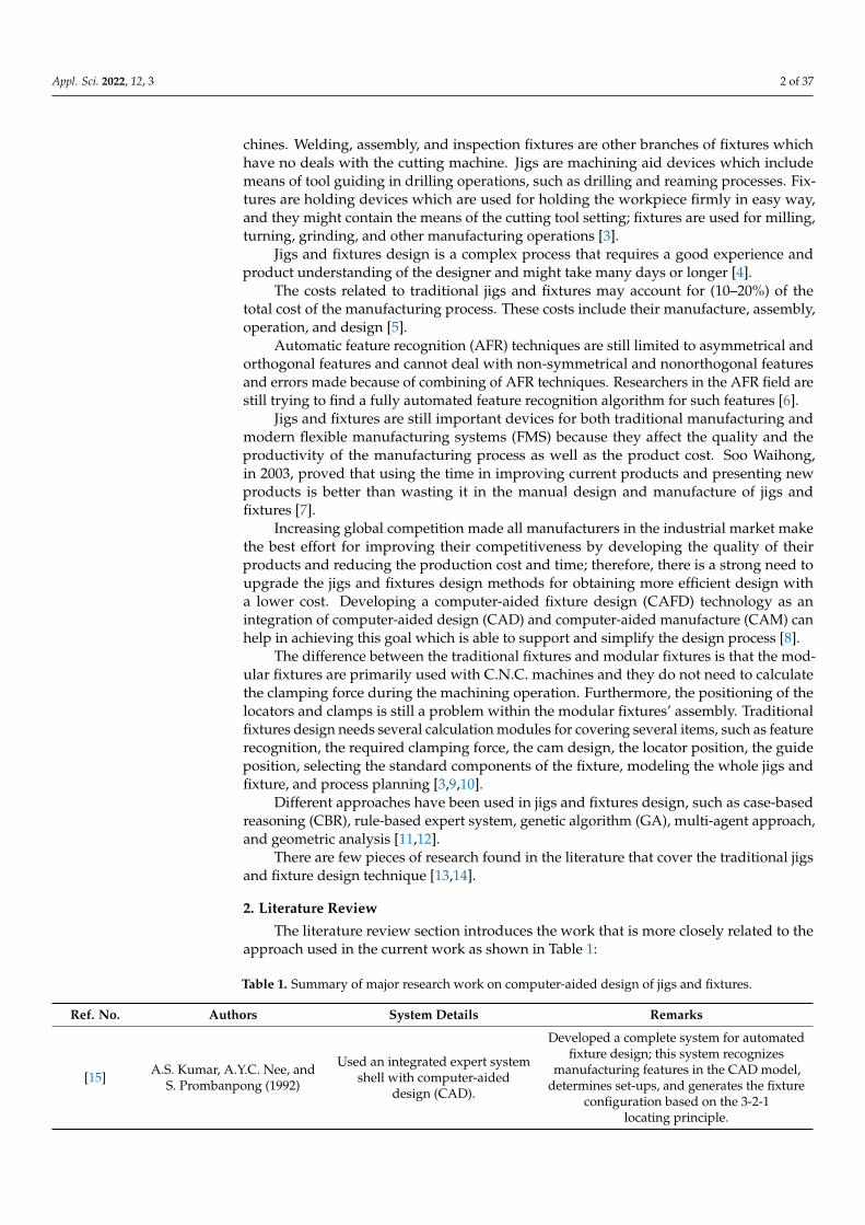
Appl. Sci. 2022, 12, 3 27 of 37
The program checks the perpendicular cross through-hole of (4 mm) diameter foridentifying the suitable guide bush.
The design of the jig for this part is done parametrically on the software screen asshown in Figure 42.
Appl. Sci. 2021, 11, x FOR PEER REVIEW 30 of 42
number of the BSp strings to identify the end condition of the cross-hole (16 strings) which identifies the cross-hole is through. Then, the system reads the values of the ver-tex (1 and 2) of BSp which indicates that the cross-hole is not offset from the axis of the cylinder; the system also reads the directions (Dx, Dy, and Dz) of BSp which identifies that the cross-hole is not inclined, and this means that the cross-hole is a perpendicular cross through-hole.
The software is also recognizing the perpendicular cross through-hole feature as shown in Figure 41 by applying the rules to recognize the cross-hole feature and show-ing a message box of the feature recognitions process.
Figure 41. Automatic feature recognition of a perpendicular cross through-hole.
The program checks the perpendicular cross through-hole of (4 mm) diameter for identifying the suitable guide bush.
The design of the jig for this part is done parametrically on the software screen as shown in Figure 42.
Figure 42. Computer-aided design of a jig for the cylindrical part.
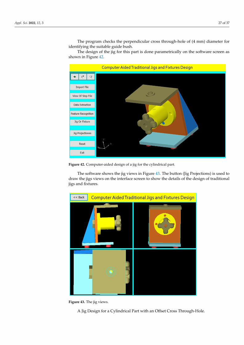
The software shows the jig views in Figure 43. The button (Jig Projections) is used todraw the jigs views on the interface screen to show the details of the design of traditionaljigs and fixtures.
Appl. Sci. 2021, 11, x FOR PEER REVIEW 31 of 42
Figure 42. Computer-aided design of a jig for the cylindrical part.
The software shows the jig views in Figure 43. The button (Jig Projections) is used to draw the jigs views on the interface screen to show the details of the design of tradi-tional jigs and fixtures.
Figure 43. The jig views.
A Jig Design for a Cylindrical Part with an Offset Cross Through-Hole Figure 44 Shows the drawing of the cylindrical part with an offset cross
through-hole, while Figure 45 shows the main components of the required jig design, which will be done through the following steps:
The drawing and isometric of a cylindrical part were prepared using SolidWorks software as shown in Figure 44. The file is saved in STEP-AP203 file format.
Figure 43. The jig views.
A Jig Design for a Cylindrical Part with an Offset Cross Through-Hole.

Appl. Sci. 2022, 12, 3 28 of 37
Figure 44 Shows the drawing of the cylindrical part with an offset cross through-hole,while Figure 45 shows the main components of the required jig design, which will be donethrough the following steps:
The drawing and isometric of a cylindrical part were prepared using SolidWorkssoftware as shown in Figure 44. The file is saved in STEP-AP203 file format.
Appl. Sci. 2021, 11, x FOR PEER REVIEW 32 of 42
Figure 44. The drawing and isometric of the part.
Figure 45. A drawing for the required jig design of the part.
Figure 44. The drawing and isometric of the part.
Appl. Sci. 2021, 11, x FOR PEER REVIEW 32 of 42
Figure 44. The drawing and isometric of the part.
Figure 45. A drawing for the required jig design of the part. Figure 45. A drawing for the required jig design of the part.

Appl. Sci. 2022, 12, 3 29 of 37
The tailor-made software which is installed on the Visual Basic platform is used toextract the part data from the STEP AP-203 file and compare these data with the rulesof feature recognition by searching for B-Spline-Curve-with Knots string; then, it countsthe number of the BSp strings to identify the end condition of the cross-hole (16 strings)which illustrates the cross-hole is through. Then, the system reads the values of the vertex(1 and 2) of BSp, and both values are ( 6=0 mm), which indicates that the cross-hole is offsetfrom the axis of the cylinder. Then, the system reads the directions (Dx, Dy, and Dz) of BSpwhich identifies that the cross-hole is not inclined, and this means that the cross-hole is anoffset cross through-hole.
The software is also recognizing the offset cross through-hole feature as shown inFigure 46 by applying the rules to recognize the cross-hole feature and showing a messagebox of the feature recognitions process.
Appl. Sci. 2021, 11, x FOR PEER REVIEW 33 of 42
The tailor-made software which is installed on the Visual Basic platform is used to extract the part data from the STEP AP-203 file and compare these data with the rules of feature recognition by searching for B-Spline-Curve-with Knots string; then, it counts the number of the BSp strings to identify the end condition of the cross-hole (16 strings) which illustrates the cross-hole is through. Then, the system reads the values of the ver-tex (1 and 2) of BSp, and both values are (≠0 mm), which indicates that the cross-hole is offset from the axis of the cylinder. Then, the system reads the directions (Dx, Dy, and Dz) of BSp which identifies that the cross-hole is not inclined, and this means that the cross-hole is an offset cross through-hole.
The software is also recognizing the offset cross through-hole feature as shown in Figure 46 by applying the rules to recognize the cross-hole feature and showing a mes-sage box of the feature recognitions process.
Figure 46. Automatic feature recognition of an offset cross through-hole.
The program checks the offset cross through-hole of (4 mm) diameter for identify-ing the suitable guide bush.
Design of the jig for this part is done parametrically on the software screen as shown in Figure 47.
Figure 46. Automatic feature recognition of an offset cross through-hole.
The program checks the offset cross through-hole of (4 mm) diameter for identifyingthe suitable guide bush.
Design of the jig for this part is done parametrically on the software screen as shownin Figure 47.
Appl. Sci. 2021, 11, x FOR PEER REVIEW 34 of 42
Figure 47. Computer-aided design of a jig for the cylindrical part.
The software shows the jig views in Figure 48. The button (Jig Projections) is used to draw the jigs views on the interface screen to show the details of the design of tradi-tional jigs and fixtures.
Figure 48. The jig views.
A Jig Design for a Cylindrical Part with an Inclined Cross Through-Hole Figure 49 shows the drawing of the cylindrical part with an inclined cross
through-hole, and Figure 50 shows the main components of the required jig design which will be done through the following steps:
The drawing and isometric of a cylindrical part prepared using SolidWorks soft-ware as shown in Figure 49. The file is saved in STEP-AP203 file format.
Figure 47. Computer-aided design of a jig for the cylindrical part.

Appl. Sci. 2022, 12, 3 30 of 37
The software shows the jig views in Figure 48. The button (Jig Projections) is used todraw the jigs views on the interface screen to show the details of the design of traditionaljigs and fixtures.
Appl. Sci. 2021, 11, x FOR PEER REVIEW 34 of 42
Figure 47. Computer-aided design of a jig for the cylindrical part.
The software shows the jig views in Figure 48. The button (Jig Projections) is used to draw the jigs views on the interface screen to show the details of the design of tradi-tional jigs and fixtures.
Figure 48. The jig views.
A Jig Design for a Cylindrical Part with an Inclined Cross Through-Hole Figure 49 shows the drawing of the cylindrical part with an inclined cross
through-hole, and Figure 50 shows the main components of the required jig design which will be done through the following steps:
The drawing and isometric of a cylindrical part prepared using SolidWorks soft-ware as shown in Figure 49. The file is saved in STEP-AP203 file format.
Figure 48. The jig views.
A Jig Design for a Cylindrical Part with an Inclined Cross Through-Hole.Figure 49 shows the drawing of the cylindrical part with an inclined cross through-
hole, and Figure 50 shows the main components of the required jig design which will bedone through the following steps:
The drawing and isometric of a cylindrical part prepared using SolidWorks softwareas shown in Figure 49. The file is saved in STEP-AP203 file format.
Appl. Sci. 2021, 11, x FOR PEER REVIEW 35 of 42
Figure 49. The drawing and isometric of the part.
Figure 50. A drawing for the required jig design of the part.
The tailor-made software which is installed on the Visual Basic platform is used to extract the part data from the STEP AP-203 file and compare these data with the rules of feature recognition by searching for B-Spline-Curve-with Knots string; then, it counts the number of the BSp strings to identify the end condition of the cross-hole (16 strings) which indicates the cross-hole is through. Then, the system reads the values of the vertex (1 and 2) of BSp which indicates that the cross-hole is not offset from the axis of the cyl-
Figure 49. The drawing and isometric of the part.

Appl. Sci. 2022, 12, 3 31 of 37
Appl. Sci. 2021, 11, x FOR PEER REVIEW 35 of 42
Figure 49. The drawing and isometric of the part.
Figure 50. A drawing for the required jig design of the part.
The tailor-made software which is installed on the Visual Basic platform is used to extract the part data from the STEP AP-203 file and compare these data with the rules of feature recognition by searching for B-Spline-Curve-with Knots string; then, it counts the number of the BSp strings to identify the end condition of the cross-hole (16 strings) which indicates the cross-hole is through. Then, the system reads the values of the vertex (1 and 2) of BSp which indicates that the cross-hole is not offset from the axis of the cyl-
Figure 50. A drawing for the required jig design of the part.
The tailor-made software which is installed on the Visual Basic platform is used toextract the part data from the STEP AP-203 file and compare these data with the rules offeature recognition by searching for B-Spline-Curve-with Knots string; then, it counts thenumber of the BSp strings to identify the end condition of the cross-hole (16 strings) whichindicates the cross-hole is through. Then, the system reads the values of the vertex (1 and 2)of BSp which indicates that the cross-hole is not offset from the axis of the cylinder, thesystem read the directions (Dx, Dy, and Dz) of BSp, and the values of two directions ofthese three are (>0 mm), which identifies that the cross-hole is inclined; this means that thecross-hole is an inclined cross through-hole.
The software is also recognizing the inclined cross through-hole feature as shown inFigure 51 by applying the rules to recognize the cross-hole feature and showing a messagebox of the feature recognitions process.
Appl. Sci. 2021, 11, x FOR PEER REVIEW 36 of 42
inder, the system read the directions (Dx, Dy, and Dz) of BSp, and the values of two di-rections of these three are (>0 mm), which identifies that the cross-hole is inclined; this means that the cross-hole is an inclined cross through-hole.
The software is also recognizing the inclined cross through-hole feature as shown in Figure 51 by applying the rules to recognize the cross-hole feature and showing a mes-sage box of the feature recognitions process.
Figure 51. Automatic feature recognition of an inclined cross through-hole.
The program checks the inclined cross through-hole of (4 mm) diameter for identi-fying the suitable guide bush.
Design of the jig for this part is done parametrically on the software screen as shown in Figure 52.
Figure 52. Computer-aided design of a jig for the cylindrical part.
Figure 51. Automatic feature recognition of an inclined cross through-hole.

Appl. Sci. 2022, 12, 3 32 of 37
The program checks the inclined cross through-hole of (4 mm) diameter for identifyingthe suitable guide bush.
Design of the jig for this part is done parametrically on the software screen as shownin Figure 52.
Appl. Sci. 2021, 11, x FOR PEER REVIEW 36 of 42
inder, the system read the directions (Dx, Dy, and Dz) of BSp, and the values of two di-rections of these three are (>0 mm), which identifies that the cross-hole is inclined; this means that the cross-hole is an inclined cross through-hole.
The software is also recognizing the inclined cross through-hole feature as shown in Figure 51 by applying the rules to recognize the cross-hole feature and showing a mes-sage box of the feature recognitions process.
Figure 51. Automatic feature recognition of an inclined cross through-hole.
The program checks the inclined cross through-hole of (4 mm) diameter for identi-fying the suitable guide bush.
Design of the jig for this part is done parametrically on the software screen as shown in Figure 52.
Figure 52. Computer-aided design of a jig for the cylindrical part. Figure 52. Computer-aided design of a jig for the cylindrical part.
The software shows the jig views in Figure 53. The button (Jig Projections) is used todraw the jigs views on the interface screen to show the details of the design of traditionaljigs and fixtures.
Appl. Sci. 2021, 11, x FOR PEER REVIEW 37 of 42
The software shows the jig views in Figure 53. The button (Jig Projections) is used to draw the jigs views on the interface screen to show the details of the design of tradi-tional jigs and fixtures.
Figure 53. The jig views.
A Jig Design for a Cylindrical Part with an Inclined Offset Cross Through-Hole Figure 54 shows the drawing of the cylindrical part with an inclined offset
through-hole. Figure 55 shows the main components of the required jig design which will be done through the following steps:
The drawing and isometric of a cylindrical part were prepared using SolidWorks software as shown in Figure 54. The file is saved in STEP-AP203 file format.
Figure 53. The jig views.
A Jig Design for a Cylindrical Part with an Inclined Offset Cross Through-Hole.Figure 54 shows the drawing of the cylindrical part with an inclined offset through-
hole. Figure 55 shows the main components of the required jig design which will be donethrough the following steps:

Appl. Sci. 2022, 12, 3 33 of 37
The drawing and isometric of a cylindrical part were prepared using SolidWorkssoftware as shown in Figure 54. The file is saved in STEP-AP203 file format.
Appl. Sci. 2021, 11, x FOR PEER REVIEW 38 of 42
Figure 54. The drawing and isometric of the part.
Figure 55. A drawing for the required jig design of the part.
The tailor-made software which is installed on the Visual Basic platform is used to extract the part data from the STEP AP-203 file and compare these data with the rules of
Figure 54. The drawing and isometric of the part.
Appl. Sci. 2021, 11, x FOR PEER REVIEW 38 of 42
Figure 54. The drawing and isometric of the part.
Figure 55. A drawing for the required jig design of the part.
The tailor-made software which is installed on the Visual Basic platform is used to extract the part data from the STEP AP-203 file and compare these data with the rules of
Figure 55. A drawing for the required jig design of the part.

Appl. Sci. 2022, 12, 3 34 of 37
The tailor-made software which is installed on the Visual Basic platform is used toextract the part data from the STEP AP-203 file and compare these data with the rulesof feature recognition by searching for B-Spline-Curve-with Knots string; then, it countsthe number of the BSp strings to identify the end condition of the cross-hole (16 strings)which identifies the cross-hole is through. Then, the system reads the values of the vertex(1 and 2) of BSp and both values are ( 6=0 mm), which indicates that the cross-hole is offsetfrom the axis of the cylinder. Furthermore, the system reads the directions (Dx, Dy, andDz) of BSp, and the values of two directions of these three are (>0 mm), which identifiesthat the cross-hole is inclined, and this means that the cross-hole is an inclined offset crossthrough-hole.
The software is also recognizing the inclined offset cross through-hole feature asshown in Figure 56 by applying the rules to recognize the cross-hole feature and showing amessage box of the feature recognitions process.
Appl. Sci. 2021, 11, x FOR PEER REVIEW 39 of 42
feature recognition by searching for B-Spline-Curve-with Knots string; then, it counts the number of the BSp strings to identify the end condition of the cross-hole (16 strings) which identifies the cross-hole is through. Then, the system reads the values of the ver-tex (1 and 2) of BSp and both values are (≠0 mm), which indicates that the cross-hole is offset from the axis of the cylinder. Furthermore, the system reads the directions (Dx, Dy, and Dz) of BSp, and the values of two directions of these three are (>0 mm), which identifies that the cross-hole is inclined, and this means that the cross-hole is an inclined offset cross through-hole.
The software is also recognizing the inclined offset cross through-hole feature as shown in Figure 56 by applying the rules to recognize the cross-hole feature and show-ing a message box of the feature recognitions process.
Figure 56. Automatic feature recognition of an inclined offset cross through-hole.
The program checks the inclined offset cross through-hole of (4 mm) diameter for identifying the suitable guide bush.
Design of the jig for this part is done parametrically on the software screen as shown in Figure 57.
Figure 56. Automatic feature recognition of an inclined offset cross through-hole.
The program checks the inclined offset cross through-hole of (4 mm) diameter foridentifying the suitable guide bush.
Design of the jig for this part is done parametrically on the software screen as shownin Figure 57.
Appl. Sci. 2021, 11, x FOR PEER REVIEW 40 of 42
Figure 57. Computer-aided design of a jig for the cylindrical part.
The software shows the jig views in Figure 58. The button (Jig Projections) is used to draw the jigs views on the interface screen to show the details of the design of tradi-tional jigs and fixtures.
Figure 58. The jig views.
6. Design Verification For verifying the jig design, the jig dimensions are compared to the design rules for
the part which identify the following: The jig height (H) = 2 Dmax (for the vertical jig).
Figure 57. Computer-aided design of a jig for the cylindrical part.

Appl. Sci. 2022, 12, 3 35 of 37
The software shows the jig views in Figure 58. The button (Jig Projections) is used todraw the jigs views on the interface screen to show the details of the design of traditionaljigs and fixtures.
Appl. Sci. 2021, 11, x FOR PEER REVIEW 40 of 42
Figure 57. Computer-aided design of a jig for the cylindrical part.
The software shows the jig views in Figure 58. The button (Jig Projections) is used to draw the jigs views on the interface screen to show the details of the design of tradi-tional jigs and fixtures.
Figure 58. The jig views.
6. Design Verification For verifying the jig design, the jig dimensions are compared to the design rules for
the part which identify the following: The jig height (H) = 2 Dmax (for the vertical jig).
Figure 58. The jig views.
6. Design Verification
For verifying the jig design, the jig dimensions are compared to the design rules forthe part which identify the following:
The jig height (H) = 2 Dmax (for the vertical jig).The jig height (H) = 2Dmax/cos (θ rad) (for the inclined jig).The jig width (W) = 1.5 Dmax.The distance between the part and drill plate = 1.5 Dc.The guide bush center is collinear with the cross-hole center.
7. Conclusions
Jigs and fixture design is a significant issue in the manufacturing process. Computer-aided traditional jigs and fixture design is a critical activity process for bridging CADand CAM systems. This research presented the developed system for computer-aidedtraditional jigs and fixture design. This system extracts data from a STEP AP-203 filewith full details of the part geometry, recognizes the different cases of the cross-holes inhollow cylinders, and provides an appropriate design of the traditional jigs and fixtures.The software has been built by connecting the Visual Basic programming language to theSolidWorks software, and this system has improved the design efficiency and reliability ofthe traditional jigs and fixtures and made the results of the design process more reasonable.
The developed system solves the problems of the manual design process by reducingthe cost, time, and effort of the design process.
This system is of great importance for medium- and small-sized factories, and it is agood start for making an integrated system for all mechanical parts.

Appl. Sci. 2022, 12, 3 36 of 37
We recommend developing this system to design the traditional jigs and fixtures ofthe cylinders having intersected cross-holes.
Author Contributions: Conceptualization, H.M.H. and A.D.I.; methodology, A.D.I.; software, A.D.I.;validation, E.A.N., A.K. and S.A.A.; formal analysis, A.D.I.; investigation, H.M.H.; resources, H.M.H.and S.A.A.; writing—original draft preparation, A.D.I.; writing—review and editing, I.A.; visual-ization, E.A.N. and A.K.; supervision, and S.A.A.; project administration, E.A.N. and A.K.; fund-ing acquisition, E.A.N. and A.K. All authors have read and agreed to the published version ofthe manuscript.
Funding: This research work is supported through the Researchers Supporting Project (RSP-2021/164),King Saud University, Riyadh, Saudi Arabia.
Data Availability Statement: Not applicable.
Acknowledgments: The authors extend their appreciation to King Saud University for funding thiswork through Researchers Supporting Project number (RSP-2021/164), King Saud University, Riyadh,Saudi Arabia.
Conflicts of Interest: The authors declare no conflict of interest.
References1. Kb, S.; Babu, K.R. An Advanced Treatise on Jigs and Fixture Design. Int. J. Eng. Res. Technol. 2013, 2, 1076–1080.2. Mervyn, F.; Kumar, A.S.; Bok, S.H.; Nee, A.Y.C. Development of an Internet-enabled interactive fixture design system. Comput.
Aided Des. 2003, 35, 945–957. [CrossRef]3. Hussein, H.M.A.; Mahrous, A.; Barakat, A.F.; Dawood, O.M. Computer-Aided Traditional Jigs and Fixtures Design. In Proceedings
of the 17th International Conference on Applied Mechanics and Mechanical Engineering, Cairo, Egypt, 19–21 April 2016; pp. 8–18.[CrossRef]
4. Sánchez, H.T.; Estrems, M.; Faura, F. Determination of Key Workpiece Product Characteristics in a Machining Fixture UsingUncertainty Analysis and Loss Cost Function Implementation. Int. J. Adv. Manuf. Technol. 2009, 42, 452. [CrossRef]
5. Bi, Z.M.; Zhang, W.J. Flexible fixture design and automation: Review, issues and future directions. Int. J. Prod. Res. 2001, 39,2867–2894. [CrossRef]
6. Ibrahim, A.D.; Abdelwahab, S.A.; Hussein, H.M.A.; Ahmed, I. Review of Automatic Feature Recognition of Cylindrical Parts. Int.Res. J. Eng. Technol. 2019, 6, 1219–1233.
7. Hong, S.W. Development of Modular Jigs and Fixture for CATIA. Bachelor’s Thesis, Universti Tecknikal Malaysia, Melaka,Malaysia, 2007.
8. Wang, H.; Rong, Y.; Li, H.; Shaun, P. Computer-aided fixture design: Recent research and trends. Computer-aided fixture design:Recent research and trends. Comput. Aided Des. 2010, 42, 1085–1094. [CrossRef]
9. Nee, A.Y.C.; Whybrew, K.; Kumar, A.S. Advanced Fixture Design for FMS; Springer: London, UK, 1995. [CrossRef]10. Rong, Y.; Huang, S.H.; Hou, Z. Advanced Computer-Aided Fixture Design; Springer: London, UK, 2005. [CrossRef]11. Wang, H.; Rong, Y.K. Case based reasoning method for computer-aided welding fixture design. Comput. Aided Des. 2008, 40,
1121–1132. [CrossRef]12. Hashemi, H.; Shaharoun, A.M.; Izman, S.; Kurniawan, D. Recent Developments on Computer-aided Fixture Design: Case Based
Reasoning Approaches. Adv. Mech. Eng. 2014, 6, 484928. [CrossRef]13. Joshi, P.H. Jigs and Fixtures—Design Manual, 2nd ed.; McGraw Hill: New York, NY, USA, 2003; ISBN 0-07-140556-9.14. Nee, A.Y.C.; Tao, Z.J.; Kumar, S. An Advanced Treatise on Fixture Design and Planning; Series on Manufacturing Systems and
Technology; World Scientific: Singapore, 2004; ISBN 981-256-059-9.15. Kumar, A.S.; Nee, A.Y.C.; Prombanpong. Expert fixture-design system for an automated manufacturing environment. Comput.
Des. 1992, 24, 316–326. [CrossRef]16. Alarco’n, R.H.; Chueco, J.R.; Garcia, J.M.P.; Idoipe, V.A. Fixture knowledge model development and implementation based on a
functional design approach. Robot. Comput. Integr. Manuf. 2010, 26, 56–66. [CrossRef]17. Selvakumar, S.; Arulshri, K.P.; Padmanaban, K.P.; Sasikumar, K.S.K. Design and optimization of machining fixture layout using
ANN and DOE. Int. J. Adv. Manuf. Technol. 2013, 65, 1573–1586. [CrossRef]18. Hashemi, H.; Shaharoun, A.M.; Sudin, I. A case-based reasoning approach for design of machining fixture. Int. J. Adv. Manuf.
Technol. 2014, 74, 113–124. [CrossRef]19. Fu, W.; Campbell, M.I. Concurrent fixture design for automated manufacturing process planning. Int. J. Adv. Manuf. Technol.
2014, 76, 375–389. [CrossRef]20. Ivanov, V.; Pavlenko, I.; Liaposhchenko, O.; Gusak, O.; Pavlenko, V. Computer-Aided Positioning of Elements of the System
‘Fixture—Workpiece’. In Proceedings of the 3rd EAI International Conference on Management of Manufacturing Systems (MMS 2018),Dubrovnik, Croatia, 6–8 November 2018; European Alliance for Innovation: Gent, Belgium, 2018. [CrossRef]
21. Okpala, C.C.; Okechukwu, E. The Design and Need for Jigs and Fixtures in Manufacturing. Sci. Res. 2015, 3, 213–219. [CrossRef]

Appl. Sci. 2022, 12, 3 37 of 37
22. Boyle, I.; Rong, Y.; Brown, D.C. A review and analysis of current computer-aided fixture design approaches. Robot. Comput. Integr.Manuf. 2011, 27, 1–12. [CrossRef]
23. Kang, Y.; Rong, Y.; Yang, J.C. Computer-aided Fixture Design Verification. Part 1. The Framework and Modelling. Int. J. Adv.Manuf. Technol. 2003, 21, 827–835. [CrossRef]
24. Hashemi, H.; Shaharoun, A.M.; Izman, S. Fixture Designers Guidance: A Review of Recent Advanced Approaches. Jordan J. Mech.Ind. Eng. 2014, 8, 377–384.
25. Kumar, J.; Roy, N. Feature Recognition of Rotational Parts Using Biquadratic Bezirer Patches. In Proceedings of the InternationalConference on Mechanical Engineering, Dhaka, Bangladesh, 29–31 December 2007; Bangladesh University of Engineering andTechnology: Dhaka, Bangladesh, 2007; pp. 1–8.
26. Malleswari, V.N. Automatic Feature Recognition for Rotational Components from STEP Files. Ph.D. Thesis, Andhra University,College of Engineering, Andhra, India, 2013.
27. Ibrahim, A.D.; Abdelwahab, S.A.; Hussein, H.M.A. Automatic Feature Recognition of Cross Holes in Hollow Cylinders. J. Inst.Eng. Ser. C 2021, 102, 257–274. [CrossRef]
28. Sreeramulu, D.; Rao, C. A new methodology for recognizing features in rotational parts using STEP data exchange standard. Int.J. Eng. Sci. Technol. 2012, 3, 6. [CrossRef]
29. Nasr, E.A.; Khan, A.A.; Al-Ahmari, A.; Hussein, H.M.A. A Feature Recognition System Using Geometric Reasoning. InProceedings of the International Conference on Manufacture of Lightweight Components (ManuLight2014), Dortmund, Germany,3–4 April 2014; Volume 18, pp. 238–243. [CrossRef]
30. Hussein, H.M.A.; Nasr, E.A.; Khan, A.A. Automated Feature Extraction from Cylindrical Parts Based on STEP. In Proceedings ofthe 17th International Conference on Applied Mechanics and Mechanical Engineering, Cairo, Egypt, 19–21 April 2016.
31. Venkataraman, K. Design of Jigs, Fixtures, Press Tools; John Wiley & Sons Ltd.: Hoboken, NJ, USA, 2015.