design of special purpose jigs and fixtures using pro-E
127
1 DESIGN OF SPECIAL PURPOSE JIGS AND FIXTURES USING PRO-E A Project Report submitted in partial fulfillment of the requirement for the award of Degree of BACHELOR OF TECHNOLOGY IN MECHANICAL ENGINEERING By SUNIL KUMAR 11H51A03B1 RAHUL PATYARA 12H55A0314 VENNAM RAMYA SRI 11H51A03B9 C. NITHIN KUMAR 11H51A0372 Under the esteemed guidance of Mr. M.RAVIKANTH S.T.O (CAD/CAM)
-
Upload
independent -
Category
Documents
-
view
1 -
download
0
Transcript of design of special purpose jigs and fixtures using pro-E

1
DESIGN OF SPECIAL PURPOSE JIGS AND FIXTURES
USING PRO-EA Project Report submitted in partial fulfillment of the requirement for the award of
Degree of
BACHELOR OF TECHNOLOGY
IN
MECHANICAL ENGINEERING
By
SUNIL KUMAR 11H51A03B1
RAHUL PATYARA 12H55A0314
VENNAM RAMYA SRI 11H51A03B9
C. NITHIN KUMAR11H51A0372
Under the esteemed guidance of
Mr. M.RAVIKANTH
S.T.O(CAD/CAM)

2
Project guide
And
V.KIRAN KUMAR
Chief Manager
Department of Mechanical Engineering
CMR College of Engineering and Technology
ACKNOWLEDGEMENT
It gives us immense pleasure to acknowledge withgratitude, the help and support extended during thecourse of the project entitled ‘DESIGN OF SPECIALPURPOSE JIGS AND FIXTURES USING PRO-E’ from allthe people who helped in the successful completion ofthis project.
We convey our sincere and earnest thanks to ourproject guide Mr. M.RAVIKANTH, S.T.O (CAD/CAM) and

3
Mr.V.KIRAN KUMAR, Chief Manager (Project), for theircontinuous guidance and encouragement for the project.
We would take this opportunity to express our deepsense of gratitude to Prof. S.SHYAM KUMAR, Head ofMechanical Engineering, CMRCET, for encouraging us todo project in CENTRAL INSTITUTE OF PLASTICS ENGINEERINGAND TECHNOLOGY.
Our sincere thanks to Dr. M. RAMALINGA REDDY,Principal, CMRCET for giving us the permission to do aproject at CENTRAL INSTITUTE OF PLASTICS ENGINEERINGAND TECHNOLOGY.

4
INDEXAbstract 03
1. Introduction 04-06
1.1Introduction for Jigs and Fixtures
1.2Tool Design
2. Jigs 06-07
3. Fixtures 07-08
4. Elements of Jigs and Fixtures08-09
5. Advantages of Jigs and Fixtures09-10
6. Types of 10-376.1 Jigs 6.2 Fixtures 6.3 Clamping Devices
5
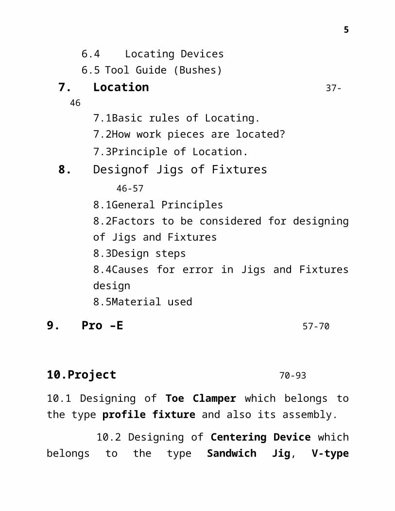
6.4 Locating Devices 6.5 Tool Guide (Bushes)
7. Location 37-46
7.1Basic rules of Locating.7.2How work pieces are located? 7.3Principle of Location.
8. Designof Jigs of Fixtures46-57
8.1General Principles8.2Factors to be considered for designingof Jigs and Fixtures8.3Design steps8.4Causes for error in Jigs and Fixturesdesign8.5Material used
9. Pro –E 57-70
10.Project 70-93
10.1 Designing of Toe Clamper which belongs tothe type profile fixture and also its assembly.
10.2 Designing of Centering Device whichbelongs to the type Sandwich Jig, V-type

6
Locator, Cam operated clamper and Plate fixturealong with its assembly.
10 Conclusion 9411 References 95

7
ABSTRACT
This project is about the design of Specialpurpose jigs and fixture (Toe Clamper &Centering Device). The objectives of thisproject are to develop structural modeling.
Jigs and Fixtures are the production toolsused to accurately manufacture, duplicate andinterchangeable parts. These are speciallydesigned so that a large no. of components canbe machined or assembled identically, and toensure interchangeability of the components.They eliminate the necessity of the special setup for each individual part. The amount ofplanning in a tool design greatly affects thesuccess/failure. All of the information andspecifications pertaining to the proposedproduct should be evaluated to arrive at themost efficient and cost effective tool design.
The structure of special purpose jigs andfixtures will be modeled utilizing pro-Esoftware.

8
Keywords:Special purpose jigs and fixtures, ToeClamper, Centering Device modeling, Pro-E.

9
1. INTRODUCTION INTRODUCTION FOR JIGS AND FIXTURES:The successful running of any mass production
depends upon the interchangeability tofacilitate easy assembly and reduction of unitcost. Mass production methods demand a fast andeasy method of positioning work for accurateoperations on it.If a component is to beproduced in small numbers, then proceduresadopted is marking out, setting on machine,clamping on the machine table. But it would notbe suitable for producing same component inlarge quantities because of economic reasons. Afaster and more profitable method calls for adevice (i.e., Jigs and Fixtures) on which thecomponents can be quickly positioned in thecorrect relationship to the cutting tool andquickly clamped before machining. Correctrelationship and the alignment between the tooland work must be maintained. Jigs and Fixturesare designed to hold, support, and locate everypart to ensure that part is machined within thespecified limits.
10
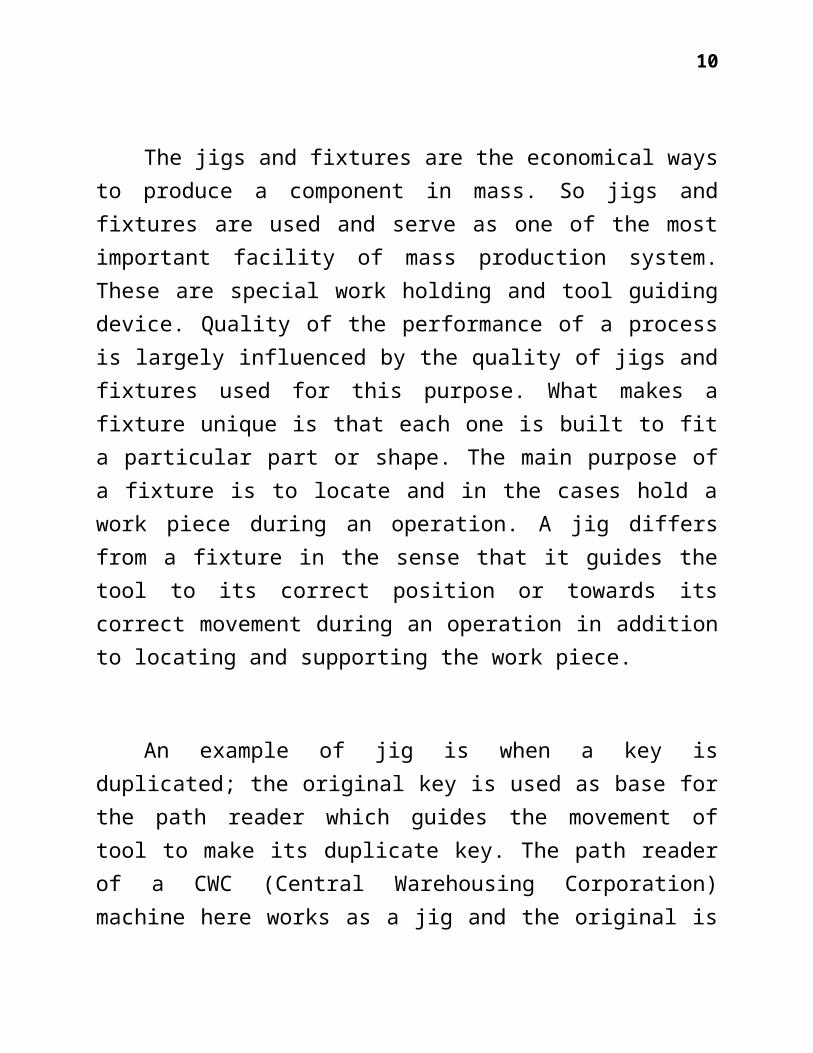
The jigs and fixtures are the economical waysto produce a component in mass. So jigs andfixtures are used and serve as one of the mostimportant facility of mass production system.These are special work holding and tool guidingdevice. Quality of the performance of a processis largely influenced by the quality of jigs andfixtures used for this purpose. What makes afixture unique is that each one is built to fita particular part or shape. The main purpose ofa fixture is to locate and in the cases hold awork piece during an operation. A jig differsfrom a fixture in the sense that it guides thetool to its correct position or towards itscorrect movement during an operation in additionto locating and supporting the work piece.
An example of jig is when a key isduplicated; the original key is used as base forthe path reader which guides the movement oftool to make its duplicate key. The path readerof a CWC (Central Warehousing Corporation)machine here works as a jig and the original is

11
called template. Sometimes the template and jigboth are the name of same part of amanufacturing system.
Jigs and Fixtures are the production toolsused to accurately manufacture, duplicate andinterchangeable parts. These are speciallydesigned so that a large no. of components canbe machined or assembled identically, and toensure interchangeability of the components.They eliminate the necessity of the special setup for each individual part.
TOOL DESIGN:Tool design is concerned with design and
development of machines and special toolingmethods and techniques required by today’s highspeed mass manufacture at high efficiency andproductivity. Its main objective is to producecomponent at a competitive price, maintainingits quality and increase production. All thiscalls for the selection of best tool materialsfor adequate tool life, providing simple andeasy to operate tools for high efficiency ,design of tools to be fool proof with no

12
possibility of wrong operation, qualityconsciousness at all levels.
For success of any component the productdesigner and process planning engineer have towork in close coordination. The amount ofplanning in a tool design greatly affects thesuccess/failure. All of the information andspecifications pertaining to the proposedproduct should be evaluated to arrive at themost efficient and cost effective tool design.The tool designer must analyze the part drawingcarefully considering the important aspects likeoverall size, shape of part, material used, typeof machining operations to be performed, degreeof accuracy required , number of pieces to bemade, locating and clamping surfaces on part.
To select best tool design, severalalternatives are determined and the mostefficient, dependable and cost effective designis chosen. The use of jigs and fixtures reducesthe need for highly skilled production workersin many operations and the chances of error aredecreased.
2. JIG:

13
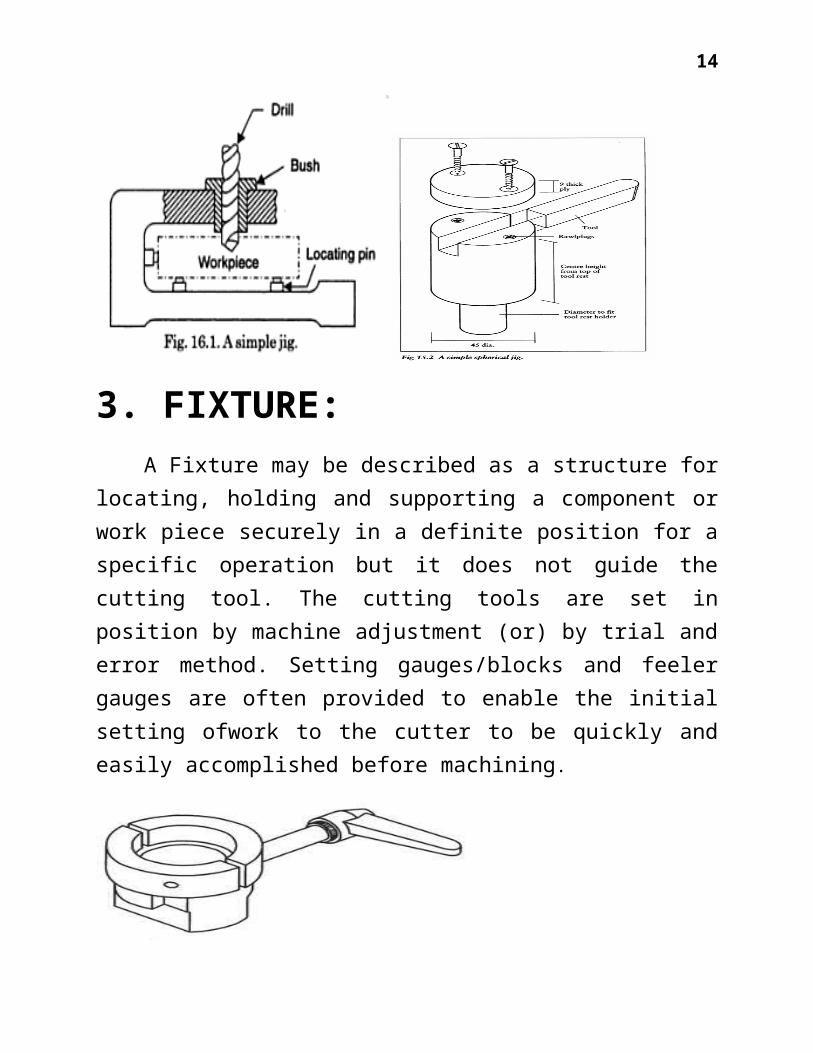
A jig may be described as a plate (or) metalbox, structures (or) devices usually made ofmetal on to or into which components can beclamped or fastened or located and held inpositive manner in identical position one afterthe other for specific operation, in such a waythat it will guide one or more cutting tools tothe same position on any number of similarcomponents which may be used upon it. Jigs areusually fitted with hardened steel bushings forguiding drills or other cutting tools. Holes arebored in the structure, so that when the toolsare fed through them and into the components,holes are made in the components in the correctpositions as required by the component drawing,the holes in the jig positively locating andguiding the cutting tools. It is usuallynecessary for the work to be held in the jig byclamping. Jig is usually not fixed to themachine table by clamping
14
3. FIXTURE:A Fixture may be described as a structure for
locating, holding and supporting a component orwork piece securely in a definite position for aspecific operation but it does not guide thecutting tool. The cutting tools are set inposition by machine adjustment (or) by trial anderror method. Setting gauges/blocks and feelergauges are often provided to enable the initialsetting ofwork to the cutter to be quickly andeasily accomplished before machining.

15
4. ELEMENTS OF JIGS ANDFIXTURE:
The employment of jigs and fixtures is animportant aspect of workshop engineering for theproduction of articles in large quantities witha high degree of accuracy and interchangeabilityat a competitive cost. The purpose of jigs andfixtures is to maintain low manufacturing costsand to increase industrial efficiency. Thus thejigs and fixtures are mainly used to reducecosts and ensure interchangeability which allowsfor the rapid assembly. Its purpose is also tospeed up the machining times by eliminating timeof handling and setting up of the component

16
parts. Further jigs and fixtures are taking theplace of the skilled man in the productionfactory and making it possible to employunskilled or semi-skilled operators. Their usealso ensures the uniformity of finished productwhich could not be expected otherwise, becauseof variation of skill between individuals. Theprimary object of the use of jig and fixtures tofacilitate the holding and supporting ofcomponents by using fixtures, to position itproperly and guide the cutters so that everycomponent will be uniform. It is particularlyvery suitable where correct positioning ofvarious holes at various exact places isimportant and which otherwise would consume lotof time in marking etc. The distinction betweenjig and fixture is not important but it isgenerally understood that jig is that part whichincorporates bushes, guides the tools orcutters, whereas the fixture holds and locatesthe work without necessarily providing definite
Basically the jigs and fixtures toolingsystem consists of the following parts
Body A Jig for guiding the tool.
17
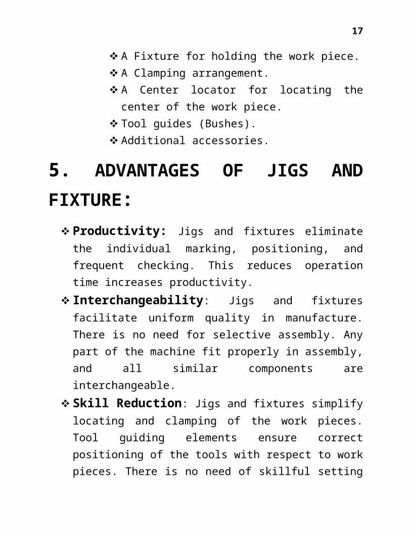
A Fixture for holding the work piece. A Clamping arrangement. A Center locator for locating thecenter of the work piece.
Tool guides (Bushes). Additional accessories.
5. ADVANTAGES OF JIGS ANDFIXTURE:
Productivity: Jigs and fixtures eliminatethe individual marking, positioning, andfrequent checking. This reduces operationtime increases productivity.
Interchangeability: Jigs and fixturesfacilitate uniform quality in manufacture.There is no need for selective assembly. Anypart of the machine fit properly in assembly,and all similar components areinterchangeable.
Skill Reduction: Jigs and fixtures simplifylocating and clamping of the work pieces.Tool guiding elements ensure correctpositioning of the tools with respect to workpieces. There is no need of skillful setting

18
of the work piece of tool. Any average can betrained to use jigs and fixtures thereplacement of the skilled work man withunskilled labor can effect substantialsaving in labor cost
Cost Reduction: Higher production,reduction of scrap, easy assembly and savingsin labor costs results in substantialreduction in the cost of the work piecesproduced with jigs and fixtures.
6. TYPES: JIGS:Jigs are normally used for boring or drilling
holes. For simple operations, where work is doneon only one side of the part, open jig is used.Closed or box jig are used for parts which mustbe machined on more than one side.
Various types of jigs used are describedbelow:
Template Jigsare the simplest type usedmore for accuracy that speed. This typeof jig fits over on (or) into the work

19
and is not usually clamped. If bushingsare not used, then the whole jig plate isnormally hardened.
Plate Jigsare similar to the templatesexcepting that these have built in clampsto hold the work.
Table Jigis similar to the plate jigexcept that legs are provided to raise

20
the jig off the table for large workpiece.
Sandwich Jigis used for drilling thinor soft parts to avoid bending, wrappingetc. For this purpose a support plate isprovided at the bottom and top jig islocated by use of locating pins.
Angle Plate Jigsare used to hold theparts which are to be drilled at rightangles or some other angles to theirmounting locators.

21
Box Jigs are usually surrounds the partcompletely. Since the part is completelylocated and held within the box, it ispossible to drill holes from all thesides.
Channel Jigs are the simplest form ofbox jig. The jig is placed is placed overthe work and is located by one side ofwork and clamped from other side.

22
Leaf Jigs are small box type jigs with ahinged leaf to permit easy loading andunloading of part. Normally, these do notcompletely surround the part.
Indexing Jigs are used to accuratelyspace holes or other machined areasaround a pant. Indexing is achieved byusing a reference plate and a plunger.

23
Trunion Jigs are used for drillingholes on very large or odd shaped partsfrom different sides. The part is firstput into a box type carrier and thenloaded on the trunion.
Multistation Jig is used for severaloperations simultaneously. While one partis drilled, another can be reamed and athird counter bored. The final stationmay be used for unloading the finishedparts and loading fresh parts. This Jigis commonly used on multiple-spindlemachines.
Drill Jig is a work holding devicegenerally used in a drill press in

24
conjunction with drill bushings forguiding the tools so that the drills willproduce holes where the bushings arelocated in the drill jig. The body of thejig is made use that the job isdefinitely located in the same positionevery time. Therefore, a simple drill jigmay consist of a body, locating theelements, clamping element, jig bush. Thedesign of jig is very much influenced bythe tolerances required on the parts,number of sides of the part to be drilledand number of parts to be drilled. Onlarge parts, the jig may also employindexing devices, power devices foroperating clamping elements, jig feet foreasy movement, fastening parts for jigetc. The jig body (box or frame) may beeither built up type, welded orfabricated type, or cast iron type.Welded type is becoming quite popular butafter fabrication it should be properlyheat treated to relieve the stresses setup.

25
In the design of drill jig, thefollowing points should be borne in mind.Work should be located accurately andquickly with the possibility of itsinsertion only from the desireddirection, provision of proper clampingmeans, and provision of ample chipclearance and the possibility of clearingthe jig readily and easily, rigidity ofjig and at the same time lightconstruction, simplicity in design and noloose parts.
Universal Jigs are those jigs which areeither adjustable, or adaptable to morethan one drilling job. Usually the mainbody and operating mechanism remain sameand only top plate and adaptor are changed.In the universal jigs the top plate issecured to two vertical posts which can beraised and lowered through a lever arm. Thepiece is to be drilled is secured on anadopter under the top pressure. Generally alocking device connected with the lever armis also provided. The use of universal jigshas the advantages of speed of operation,

26
interchangeability, and saving in toolcost, design cost and time-study cost.
Plastic Jigs: Plastic materials are nowbeing used to expedite the production ofdrill jigs, particularly in aircraftindustry. Heavy plastic dies are used forsheet metal stretching operation and theyreplace zinc-alloy dies. As these are lightin weight, these can be handled moreconveniently. If a plastic jig breaksaccidently, it can be replaced with littleloss of ground as tools become obsolete andused over and over again. The desirablecharacteristics of plastic materialsrequired to be used for the dieconstruction are: it should be easilyreclaimable, it should be possible tomachine the plastic jigs with wood workingtools, should have sufficient impactstrength to withstand ordinary shophandling, should not become brittle at lowtemperatures or after aging, should beresistant to oil metal chips. The mostcommonly used plastics for jigs arethermoplastic phenol formaldehyde.

27
Fixture: Fixtures are normally builtstronger and heavier than a jig because ofthe increased tool forces on fixtures.Various types of fixtures are:
Plate Fixture: It is the simplestform of popular fixture due to itsadaptability. The basic fixture ismade from a flat plate which has avariety of clamps and locators to holdand locate the part. It is useful formost machining operations.

28
Angle Fixture: This is used when thepart is to be machined at right angleto its locator. Angle plate fixturesare normally made at 90 degrees, butother angles are also possible.
Vise-jaw Fixtures: It is used formachining small parts. The standardvise jaws are replaced with jawsconforming to the shape of the part tobe fitted. Their use in limited onlyby the sizes of varies available.
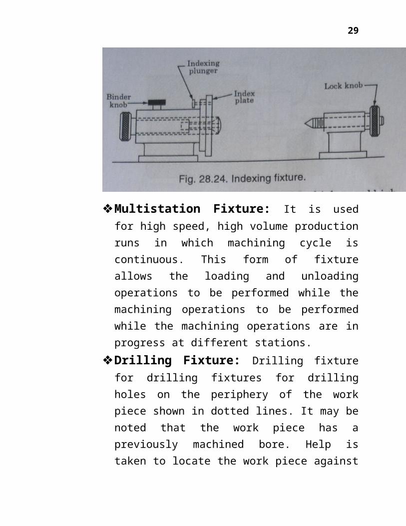
Indexing Fixture: It is used formachining parts having evenly spacedmachined surfaces
29
Multistation Fixture: It is usedfor high speed, high volume productionruns in which machining cycle iscontinuous. This form of fixtureallows the loading and unloadingoperations to be performed while themachining operations to be performedwhile the machining operations are inprogress at different stations.
Drilling Fixture: Drilling fixturefor drilling fixtures for drillingholes on the periphery of the workpiece shown in dotted lines. It may benoted that the work piece has apreviously machined bore. Help istaken to locate the work piece against

30
this by providing a hardened andground male spigot in the fixture. Thespider clamp plate is swung up theclamp plate, lowered and the workpiece is inserted. It is thus clampedagainst the spigot shoulder with thespider clamp plate by actuating thecam operated plunger by operating thehandle. It may be noted that thismethod of clamping does not cause anydistortion of the work piece. Thetwist drill is positioned relative tothe work by means of hardened andground drill bushes which act asguides for the drill. Adequate gap isprovided between the bush and the workpiece so as to avoid it being swarftrap. In order that swarf could easilyfail clear through the jig body andslider clamp, adequate clearance isprovided. Jig is made of lightconstruction with high rigidity sothat it can be handled easily. It hasno sharp corners to hurt the operator.The base of the jig is so designed its

31
feet can’t fall into the drillingmachine table tee slots. In order thatwork piece may be placed in thedesired position only, fool proof pinscan be provided.
Milling Fixture: As far as possible,the milling fixtures should bedesigned such that the work in thefixture is located as close aspossible to the milling machine table.This avoids the possibilities ofchatter or of springing the work. Thebase of the fixture is to be rigidenough to deflect during the upsetmilling and made of cast iron toabsorb the forces tending to set up

32
vibrational effects of chatter.Milling fixtures are usually providedwith keys for locating the fixtureproperly in the T-slots of the millingmachine table. Base is provided withlugs on each side for fixing the baseto the machine table. Lug surfaces areslightly raised up and slot faced. Insome instances an extension of thebase of the fixture can be providedfor the application of the clamps sothat the fixture can be properlysecured to the milling machine table.
Clamping Devices:Its purpose is to hold work in thecorrect relative position in the fixtureand to ensure that the job is notdisplaced under the cutting forces. It isalso necessary for clamping the jig tothe work. The most efficient scheme ofthe clamping means that the clampingshould be adequate and at the same time,the clamping devices design should besuch that the operating time of the jigsand fixtures is least possible. Thus for
33
high rates of production, quick-actingclamps are essential whereas the simpleclamps may be adequate for small batchesof work. In the design of efficientclamping devices, the following should beconsidered.
The rotary or reciprocatingmovement of clamp should be avoided asfar as possible. If however, the movementof the clamp is necessary, then onlypositively guided movement should beemployed. Arrangements should be made tolift the clamp away from the work, orotherwise clear it, when the clampingload is released. This can be achieved byemploying compression springs.
Basic Rules of Clamping: Clampingprevents the part from shifting or beingpulled from the jig/fixture during themachining.
Clamps should always contact the workat its most rigid point to avoidbending or damage of part by the

34
clamping force. It is the clampingforce at any point could bend thepart; it must be supported suitablyat that point.
Clamps should be positioned such thatthey do not interfere with theoperation of the machine or tool andenable operator to work easily andsafely.
Tool forces generated by cuttingaction should help in holding thework piece instead of lifting ortilting it. The tool forces should bedirected at solid part of the toolbody.
The type and amount of clamping forceneeded to hold a part is usuallydetermined by the tool forces workingon the part and the way and the partis positioned in the tool. Clampingpressure should only be enough tohold the part against the locators.The locators should resist the bulkof the thrust. Clamps must never beexpected t hold all of the thrust.

35
Screw Clamps: These are widely usedfor jigs and fixtures. These havelower costs. However, their operatingspeed is quite slow. The basic screwclamp uses the torque developed by ascrew thread to hold a part in place.This is done by direct pressure or byacting on another clamp.
Cam-action Clamps: Cam-actionclamps, when properly used, provide afast, efficient, and simple way tohold work. Due to their constructionand basic operating principles, theuse of cam-action clamps is limited insome types of tools.

36
Hinged Clamps: These utilize hingedlids for loading and unloading thecomponents. Generally the clamp ismade integral with the hinged lid. Thefigure shows that an arrangement usingcombination of hinged clamp is oftenrequired when it is necessary to moveboth the clamp and the bolt completelyout of the way for the loading ofcomponent. The jig casing is designedsuch that the lugs are provided forlocating the hinge pins. In order tosave the operator’s time, a coil

37
spring is used to hold the washerunder the nut.
Two ways Clamp: It consists of rapidclamping in two directions from onescrew. Clamping force is applied tothe top and one side of the workpiece. The clamp has a quick releaseaction. In this arrangement, thelength of the levers should beapproximately such that equal pressureis applied by each clamp at itsclamping position. The top clamp isslotted at the end so that the wholeof its clamping mechanism could beswung clear of the work.

38
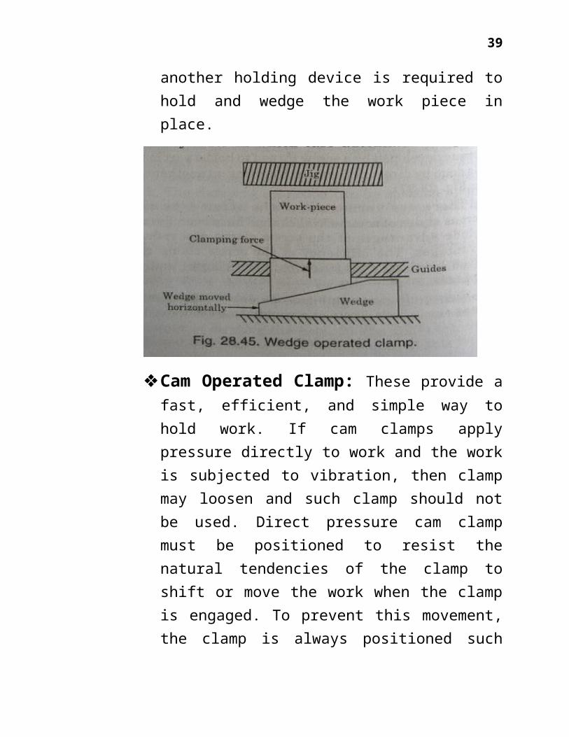
Wedge Operated Clamp: The operationof the wedge operated clamps in whichthe horizontal movement of the wedgecauses upward vertical clamping forceon the work piece. The wedge could beoperated either manually by a screw orcam or by pneumatic or hydrauliccylinder in which case automaticclamping of the work piece as part ofa fully automatic machine cycle ispossible. Wedges having the angles10--40 are self-holding type andnormally hold the work without anyadditional attachments. Large angleswedges are used where large movementsare required. In these wedge clamps,
39
another holding device is required tohold and wedge the work piece inplace.
Cam Operated Clamp: These provide afast, efficient, and simple way tohold work. If cam clamps applypressure directly to work and the workis subjected to vibration, then clampmay loosen and such clamp should notbe used. Direct pressure cam clampmust be positioned to resist thenatural tendencies of the clamp toshift or move the work when the clampis engaged. To prevent this movement,the clamp is always positioned such

40
that work is pushed into the locatorswhen pressure is applied. Theadvantages of cam can be obtainedinindirect clamping method by usingcam action rather than screw thread tobind strap clamps. In this method, thepossibility of loosening or shiftingthe work during clamping is decreased.
Toggle action Clamps: These arefast acting clamps. These have thenatural ability to move completelyfree of the work, allowing for fasterinsertion or taking out of parts. Theholding force to toggle clampscompared to the application force isvery high. Fig .28.51 shows the fourbasic clamping actions, viz. hold down,

41
pull, squeeze and straight lineaction.
Power clamping: power-activatedclamps may operate under hydraulicpower, pneumatic power or with an air-to-hydraulic booster.The power clamps have better controlof clamping pressures. Wear on movingparts of the clamp is less, operatingcycles become faster. Productionspeeds and efficiency are higher butinitial cost is high. Fig. 28.53 showsa typical application of power clamp.

42
Chucks and vises: commerciallyavailable chucks and vises with slightmodifications of jaws to suit the jobcan be used for a variety ofapplications. Blank vises jaws andblank chuck jaws can be easilymodified to suit practically everyclamping need.A great deal of time and money can besaved and the efficiency of the jobincreased by using standard chucks andvises for special tools.
Non-mechanical clamping: Non-mechanical clamping like magnetic andvacuum chucks are used to hold partswhich are difficult to be held byother devices because of their size,shape or fragile nature. Magneticchucks may either use permanentmagnets or electro-magnets. Magnetic

43
chucks are obviously suitable forferrous parts. For other materials,mechanical devices have to be usedalong with magnetic chucks. Magneticchucks and accessories are availablein numerous styles and shapes. Fornon-magnetic parts, vacuum chucks aresuited. Vacuum chucks equalize theclamping pressure over the entireclamping surface. Vacuum chucks aresuitable for almost every machiningoperation, particularly where uniformclamping is required. To clamp smallerparts, the exposed chucks ports can becovered with a mask or closed bytightening the special part screws.
Locating devices These are usually made of casehardened steeland separate from the jig or fixtureaccurately ground and accurately positionedin the jig or fixture body. The typical locating devices used forjigs and fixtures are:
Locating buttons Adjustable locators

44
Locating pins Conical locators Diamond and pin locators Profile locators
Locating buttons:The locatingbuttons can be either press fit typeor screwed type. These are generallyused for the location of the flatsurfacessome clearance is alwaysprovided so that chip at the corner ofthe job would not affect the location.The screwed types of locating buttonsare used where wear and tear oflocating buttons is more and it is tobe replaced at quick intervals.However cylindrical fits are best forexact locations and not the threats asthese cannot align the job properly.Jacks or pins are also employed forlocating jobs and are raised in jigbody to support the work beneath theclamps. Thus the support pins andjacks enable the component to besupported at convenient points.

45
Adjustable locators:Adjustablelocators are normally used with one ormore solid locators to allow anyadjustment needed to level the work.

46
Locating pins:Pin type locators areused for smaller holes and foraligning members of the tool when pinsare used for alignment specialbushings should also be used sothat,they can be replaced when theywear. Alignment pins usually have alarger bearing contact area pins usedfor part location are made with eithertapered or rounded ends;allowing theparts to be installed and removed

47
easily. Locating pins usually have acontact area of 1/8 to 1/2 of thepart thickness,otherwise placement andremoval of part becomes difficult.
Conical locators:The conical pin isthe most commonly used type oflocating pin having shouldered end.The shoulder is provided to preventthe pin from being pushed into thefixture by the work. The conical pinis used where tolerance of the hole iswider. By its use,the operator canapply the work to correct positionmore readily.
Diamond and pin locators:The pin isnot exactly conical but rounded at thetop for small diameter holes andreduced to segmental type for largerdiameters. This pin is normally usedalong with the round type to reducethe time taken to load/unload the tooland the round pin locates the part andthe diamond pin prevents the movementaround the pin.When component partsare of heavy nature and it is only

48
possible to slide them into the jig orfixture,it is of advantage to usedisappearing pins in which the pin becovered or raised by rotating a clamp.
Profile locators:Profile locators areused to locate work from an externalprofile or outside edge which is themost common method of locatingwork,particularly in the early stagesof machining profile locators positionthe work in relation to an outsideedge bar detail(like hub or boss).Nesting is the most accurate form oflocating device for profile locaton.Ejectors are required to be used toremove work from close fitting

49
locators (as in the case of fullnests).
Tool guide (Bushes):Drill bushes are generally used only withjigs. These are used to locate and guidecutting tools such as twist drills,reamers, tap and counter boring cutters.These are fitted into that portion of jigknown as the bush plate. Drill bushingsare ground to exact sizes to ensure theneeded repeatability in the jig. Jigbushes are made of mild steel but arecase hardened because these are subjectedto wear during use. Wear is caused mainlydue to the action of the chips.Therefore, consideration should always be

50
given to the necessity of replacing thebushings in the design of the jig. Drillbushes are classified as follows:
1) Fixed Bushes. Plain type Head type
2) Linear Bushes. Plain type Head or flange type
3) Renewable Bushes.4) Slip-in Bushes.5) Screw or clamp Bushes.6) Special Bushes.
Some common features about all typeof bushes. An adequate chamfer or radiusshould be provided at the top of the borein order to provide an easy entrance forthe tool. The bushes should be chamferedat the bottom of their external diametersto facilitate entry into the bush plateand sharp edge should be avoided.
Screw or clamp Bushes: In this typeof bush, threaded portion is used forholding purposes and as threads can’tprovide good location, the plain

51
portion of the bush is utilized forthat purpose.
Special Bush: suppose it may berequired to drill two holes very nearto each other and there may not besufficient space to fit the bushes. Inthat case we provide a bush with morethan one hole.
Liner Bushes: These act as hardenedguide for both slip and renewal typebushes and sometimes used as a guideto tools. In this way the jig plate ofsoft metal could be used and after

52
wear and tear only liner is to bereplaced and not the whole of jigpate. The liner bush is either pressfit in the jig plate or secured bymeans of screws.
Renewable Bushes: These are usedwhen bushings are changed many timesduring the life of the jig. In thesebushes, press fit type is notgenerally used but only light pressfit type is used. In order that thebush may not come out with the tool,when it is withdrawn some sort of setscrew for retaining the bush with jigplate is used. When the bush is to bereplaced due to wear, retainer screwis removed and worn bush is taken out.As the operation of taking out thebush generally damages the bore of thebush plate, it is usual practice touse liner bush which has otheradvantages also. Slip renewal bushesare used for performing more than oneoperation in same location, likedrilling and reaming.

53
Slip-in Type Bushes: Sometimes werequire more drills to pass at oneplace. When any hole require two ormore tools to be used then it isnecessary to use a slip bush for eachtool except when the tool is guided bythe liner bush. The bore of each bushis made to suit a particular size oftool.
7. Location: In the design of jigs and fixtures, the
location of the component is very important

54
aspect as the correct location influences theaccuracy of the finished product andparticularly in reference to the positionalrelationship with other surfaces on thecomponent. Further the location arrangements areclosely related to the other aspects of jigcauses the component to lift away from thelocating surface though the perfectlysatisfactory method of location might have beenemployed
Basic rules for locating: Part locatorsfor restricting the movement of a part andits proper positioning, require skill andplanning. They must be planed into the tooldesign and never be installed as anafterthought.
The basic rules for locating are:
A tool designer must always ensure thelocators are positioned to contact the workthe work on a machined surface. This isessential for accurate placement of thepart in the tool and to ensure therepeatability of jig or fixture.

55
The locator should be spaced as far apartas possible, thus using fewer locators andinsuring complete contact over the locatingsurface.
Locators should be placed to avoidinterference with chips or dust. Where itis not possible, the locator should berelieved. Fixed shop locators may be eithermachined into the tool body or beinstalled. Installed locators are normallymore economical to use because of timetaken to make the machined locators. Sincethe installed locators can be replaced whenworn, the entire body need not be madeagain.

56
The tool tolerance should be between 20 to50% of the part tolerance in order tomaintain the required precision.
Fool – proofing must be incorporated i.e.to insure that the part will fit into thetool only in its correct position. For thispurpose fool- proofing pins should beincorporated at suitable location so thatwrong insertion would not be permitted bythis pin.
57
Use of duplicate locators, which not onlyis costly but causes inaccuracy, should beavoided. Once the reference surface forlocation is decided, there should not beother locator to cause interference inlocation with reference to the referencesurface. For instance, locating a part bothfrom its outside edge and the hole cancreate problem.
How work pieces are located? Locating elements help in placing the
work piece essentially the same positionevery time again and again. These provide areference point from which all sizing orspacing can be accomplished. Theseestablished desired relationship between workpiece and jig or fixture. The purpose of thelocators is to restrict the three degrees offreedom of translation and the three degreesof freedom of rotation in order to providepoints of reference. The surface condition ofthe work piece to be located exerts a greatinfluence on the form of the locator, e.g.;finished surfaces can be located on a plane

58
but a rough surface located on a few pointsof contact as deemed necessary for stabilityof the part. However a plane is generally notused even though a highly finished and truesurface is available as a reference surfacebecause of the danger of misalignment due tominute chip particle or dust. Usually partsare located on three points which form aplane the introduction of more points thoughoffers greater stability but may introducethe risk of unevenness with the plane formedby three points
The type of locator selected for aparticular application is largely a functionof the shape of the work piece and moreparticularly the shape of the referencesurface. The various types of locators aredescribed below.
EDGE LOCATORS: These must be so designedthat provision for clearance of burrs andchips is taken care of. Sometimes workpieces may be spoiled because ofmisalignment due to non-provision ofclearance for chip and burrs which may be

59
present in jig or fixture as a result ofprevious cutting operations.
PIN LOCATORS: These frequently used inapplications where holes are used asreference points. It is important that thework piece be placed over the locating pin.
V-LOCATORS: It provides the most desirablemeans of locating for applications wherereference surface is the outside diameterof a cylindrical part. The 90 degree anglebetween faces on the V gives the bestcylindrical surface location. In the useif V locator, it must be ensured that thedirection of the force introduced by thetool bisects the included angle of the Vlocator, which ensures positive seating.Two examples of good and bad design oflocation.

60
Principle of location A body in space has twelve degrees of
freedom. i. e it is capable of moving intospace in the twelve precise ways and forsuccessful location the necessary degreesof freedom as consistent with the jobrequirement should be constrained orrestricted. The twelve degrees of freedom are: 6 movements of translation, i.e. Axial
movements in either direction alongwith axes XX, YY, or ZZ.

61
6 rotational movements, i.e. Rotationof the body about axes XX, YY and ZZ ineither clockwise or anticlockwisedirection.
Thus for designing locationfacilities, it is to be ensured thatarrangements are provided forpositive restraints as well as ensurethe surface relationshipsnecessitated by the job i.e. naturallocation relationships betweensurfaces, points and lines.

62
Bar in Vee Black: In this case,all the motions are restrained exceptfree movement parallel to axis of barand the rotational movement about itsown axis. If however, these fourmovements are also to berestrainedthen additional location would benecessary.
Location of a lever on two plugs:If the lever be located by a singleplug and it be good fit on it andlocated by a shoulder then allmovements except rotation about oneaxis are restrained. However, thiscan also be restrained by providing aplug cut away on two sides for theopposite boss. The plug is cut away

63
on two sides in order to accommodatefor slight variations in centerdistance of the two holes in thelever.
Location in two Vees: Whenever theshape of a component permits,location in two Vees can be used withone Vee fixed and other sliding. Itis thus suitable for both clampingand locating
Location upon a plug or in aspigot recess: In many applicationsa component is required to be locatedinternally upon a plug or externallyin a recess. As a threaded hole doesnot allow the plug to be positionedin the fixture accurately, plug

64
should not be screwed into thefixture body but be only push fit.For spigot recesses, the shape of therecess corresponds to that of thecomponent.
Location of rectangular Job: Forthis purpose, three pins A, B and Care provided in the base of the fixedbody of the jig at the horizontallevel. This constrains one downwardmovement along axis YY, tworotational movements about axis XX

65
and two rotational movements aboutaxis ZZ.
Further two pins D and E checkone movement along axis XX, tworotational movements along axis ZZand finally one more pin F at theback restricts the linear movementalong axis ZZ. Thus it is seen that3-2-1 pin method or six pointlocation method checks nine degreesof freedom which are essential to bechecked and rest may not be botheredalso as the facilitating of job inthe jig and its location is takencare of by checking nine degrees offreedom only and checking ofadditional movements will beunnecessary. Thus it will be observedthat for good location scheme theintroduction of redundant checkingshould be avoided. A redundantlocation is said to exist when twolocators are attempting to constrainone freedom from two location points.Other important points to be observed

66
are that locating points should bechosen as far apart as possible; asfar as possible as possible, thelocation points should be chosen inmutually perpendicular planes andavoided in inclined planes; smalllocating surfaces such as on restbuttons, supporting pins orcylindrical locators should be used,and their replacement due to wearshould be easy.
8. Design of Jigs andFixtures:
General Principles: Keep the design simple in order tominimize cost and to avoid breakdowncaused by over-complication
Utilize standard and ‘bought out’parts as much as possible
Ensure that the w.p. can be loadedinto and removed from the equipment.

67
Factors to be considered fordesign of
Jigs and Fixtures:Jig and fixture design is based upon
a number of fundamental principles butthere are no hard and fast rules. The jigtool designer is likely to meet a newproblem on almost every component ithandles, but the underlying principleswill be found to be similar. There can beseveral ways of achieving the sameresults but the designer has to see therelative merits of various possible waysin respect of their cost, ease of making,facility of using, possibilities foraccuracy etc. Each job is design on itsmerits to suit individual componentsfulfilling all its requirements. However,with any design followed, the aim shouldbe simplicity and economy.
For precision in machining operation,the work be properly positioned withrespect to tool (referencing). Foraccuracy the designer has to ensure that

68
the part is precisely located and rigidlysupported. It should be ensured that thetool is easily loaded and unloaded and befool-proof. The work holder or clamp mustbe strong enough to resist the cuttingforces and accurately hold the positionof the part against the cutting forces.Clamps must also allow for rapid loading/unloading.
While designing the jigs and fixturesthe following principles should be bornein mind:
The method of location and clamping should besuch as to reduce idle time to a minimum.For this purpose the aim of the designershould be to arrange in such a way that theloading can take place on one batch ofcomponents while other is being machined.Location and clamping influence the accuracyand quality of a component.
Locating surfaces should be as smallas possible and the location must bedone from the machined surfaces. Forfirst operation upon roughunmachined surface, three point

69
locations should be used wherepossible, and adjusting or expandinglocators being used to allow forlarge variations in size.
Sharp corners in the locatingsurfaces must be avoided. A goodradius or chamfer on the end oflocating pin permits the componentto be placed on easily and quickly.
As many degree of freedom ofmovements as necessary to maintainthe required accuracy should becurtailed. Redundant locationfeatures need not be provided.
At least one datum surface should beestablished at the firstopportunity. Location should beestablished machined surfaces for asmany operations as possible toreduce the possibility of error.
Adjustable locators should beprovided for rough surface.
Locating pins should be tapered andbe easily accessible and visible tothe operator.

70
Quick acting clamps should be usedwherever possible.
The necessity of lifting the clampby hand should be avoided by fittinga spring suitably to lift it.
Location should be designed to befool proof so that a component canbe loaded into only one correctposition and it can’t enter into anyother position.
Enough clearance for clearingmachining burrs should be provided.Locating features should not be ableto collect swarf.
Operator’s safety and themanipulative difficulties in loadingthe component into the fixtureshould be given due consideration.Sometimes it may be desirable to useretractable location pins.
The basic principle for good clamping design are: Clamping should always be arrangeddirectly above the points supporting thework; otherwise the work will be sprungand machined in a distorted position

71
thus resulting in inaccuracies. Thesupporting points should be strongenough to resist bending. In otherwords, clamps should be applied to thecomponent where it is rigid and wellsupported.
Fiber pads should be riveted to clampfaces where metallic contact with thework would cause damage.
The position of the clamps should besuch that it provides best resistancesto the cutting forces.
Clamps should not cause deformation ofthe work piece, i.e. clamping forcesshould be controlled such that they donot distort the locators, work fixtures,or the clamp themselves.
Pressure of cutting force should actagainst the solid part of the jig andnot against the clamps.
All the clamps and the adjustmentsshould be on that side of the fixturefrom where the loading or unloading ofthe component will take place.

72
Clamping arrangement should be designedin such a way that it can be easily andclearly removed clear of the work byavoiding the necessity of lengthunscrewing of nuts.
Clamps should be quick acting and assimple as possible.
Clamps should be well clear of cuttingtools, and adequate clearance should beavailable with the clamps released toload and unload the work in safety.
For ease of unloading use of ejectorsmay be considered.
The process of loading and unloadingthecomponent should be as easy as possible.Ample space should be left for handmovement. It should also take into accountany possible size variation and some meansshould be provided for releasing thecomponent if for some reason it sticks.
Work supports: The number of fixed supports on anysurface should not be more than threeand they should three points withoutrocking. If, however, more than three

73
supports are necessary then springloaded adjustable supports should beused for additional supports so thatthree fixed supports will locate thesurface and spring loaded type willautomatically rise to touch thecomponent through the medium of thesprings.
The area of supporting surface shouldbe least possible so that it can bekept clean. Its surface should not takedust or swarf.
The support should be visible andaccessible to the operator. Loading andsupporting surfaces should be renewablewherever possible. Generally suchsurfaces should be of hardenedmaterial. This is very important forthe proper maintenance of the jigs andfixtures. They should be fitted intothrough holes and not blind holes.
Stability and Rigidity: Jigs and Fixtures shouldbe rigid enough as this fault is generallynot realized in normal working. For thispurpose at least four legs should be provided

74
on the jigs and suitable means should beprovided for clamping the fixture on themachine bed. If possible, arrangements todamp out and absorb the vibrations shouldalso be provided.
Clearance of chips: For cleanliness andaccuracy, the importance of providing goodswarf and chip clearance cannot be overemphasized. Adequate space in the form ofchannel ways should be provided to enable themetal chips to be blown clear by usingcompressed air. The awkward little cornersthat cannot help but collect chips, should beavoided.
Coolant to the cutting edges: Adequatearrangements must be made for the supplycoolant to the cutting edges, so that at sametime as the cutters are cooled the swarf iskept clear.
Fool-proof: Jig and fixtures should be fool-proof. The design of the jig and fixtureshould be such that it is impossible for anoperator to insert either the work piece orthe cutting tools in any position other thanthe correct one. This can be arranged by

75
placing a pin or abutment in a position toclear the component when it is in its correctrelative position, but fouling the componentwhen the reverse is the case. Also the pilotbushes could be used of different sizes inorder that the tools may not be appliedthrough the wrong bushes in a jig.
Careful consideration should be given to theinitial method of location with particularreference to the operations that follow.
Safety of the operation: All the necessaryprecautions in this respect should beobserved.
Design should be as simple as possible. Asfar as possible standard components of partsshould be used and similar operations shouldbe grouped.
Drilling jigs should be as light as possibleconsistent with strength to facilitatehandling.
The job is normally not bolted to the machinetable and should be provided with four feetso that it will rock if it is not standingsquare on the machine table and worn theoperator.

76
Fixtures should be robust especially forintermittent cuts in order to preventdistortion and avoid vibrational effects.
Tennon strips should be provided for accurateand quick location of the fixture on themachine bed.
Milling fixtures should be provided with asetting piece so that a feeler gauge may beused for setting the fixture relative to thecutters.
Design stepsThe following steps should be followed fordesigning jigs and fixtures:
Draw the outline of the work piece inposition of machine.
Inspect the drawing carefully and noteall limited dimensions and features whichare strictly related.
Consider the sequence of operations. Draw the location system for locating thecomponent in fixture.
Draw the clamping system for clamping thecomponent in the fixture.

77
Draw the tool guide or tool setting dies,i.e., method of positioning the toolrelative to the component.
Method of positioning the fixturerelative to the machine. In the case ofjig which is not clamped on machine, someform of stop must be provided againstwhich the jig may be held to give a quickinitial positioning.
Decide the most suitable jig and body forfixture.
Combine all the components as rigidly aspossible.
Safety aspects to protect the user whileusing the fixture should be considered.
Causes of Error in Jigs and FixtureDesign:
In operations with jigs and fixtures,variations in sizes may result fromerrors resulting from following causes:
Variations in rough work piece: Theircorrect location is generally aproblem and proper locating deviceshave to be selected when rough workpieces have to be handled. As the

78
stock to be removed varies, itresults in fluctuations in theforcesexperienced by cutting tools,the allowance for which should besuitably made.
Variations in materials:These result invariations in forces and powerrequirement and also result invariation of thermal expansion, wearand deflection. To the extentpossible, allowance for these must bemade.
Deflections in Tools and Machines: Alltool dimensions have tolerances andthese will affect size of work piece.Depending on accuracy desiredsuitable compromise is necessary toget desired work at the lowestpossible cost. For criticaldimensions, it is customary to allow10% tolerances of work pieces onjigs, fixtures and gauges. Details offixtures, jigs dies that requireaccurate location should be held bythat screws should not be used to

79
perform double function of locatingand holding. Where several piece areto be placed in a fixture or jig,they should be located independentlyand not one against the other.
Wear:It further adds to variations.As far as possible, wear resistancematerials should be used for partssubject to wear on fixtures, jigsetc. in the design, wearing surfacesshould be kept as small as possiblewithout sacrificing too muchdurability. Wear considerationdemands bigger locating surfaces butlocating surfaces should have smallarea which results in advantage ofless time for cleaning, reducedchance of lodgment of chips or dirt,providing more realistic approach tothe mean plane of a rough surface,saving in material and labor. Slidingover the locators during clampingshould be avoided. As far aspossible, provisions must be made toovercome variations due to wear. The

80
wear allowance is made on gaugesalso.
Deflection:Variation in materials,speeds and feeds bring about changesin deflection which results invariation in work pieces. Deflectioncannot be eliminated but it can bereduced to minor proportions topobtain work piece dimension withintolerance. Forces causing deflectionmay come from handling, clamping orcutting action. Positive measuresmust be taken to protect againstdeflection. For this purpose, clampsshould never be applied onoverhanging section of the work pieceand should bear directly over fixedlocating rests or stops. Otherwisethe clamping force should be opposedby adjustable supports. The devicesemployed as reinforcements againstdeflection themselves should notintroduce additional deflection. Itis necessary to provide adequateprovisions to limit operator from
81
applying excessive force in applyingthe support. Supports should bedesigned to directly oppose theforces. Adequate holding devicesshould be arranged so thatdeflections including forces aretransmitted to rigid basic members.All clamping strain should be takencare of within a fixture and nottransmitted to the table of themachine.
Thermal expansion: It can affectvariations and occurs due to heatgenerated during cutting operation.Its effect is more pronounced whentwo dissimilar metals are involved.The temperature differential shouldbe minimized by adopting sharp toolsof proper shape, including provisionsfor heat dissipation from tools andmachine and employing controlled roomtemperatures.
Dirt, chips and burrs:These directlyinterfere with work piece location,positioning and gauging. For this,

82
sharp corners should be avoidedbetween locating surfaces as theycatch dust and are hard to clean.Locating surfaces should be elevatedsurrounding surfaces. Access tolocators should be free for cleaningpurposes.
Human deficiencies: many devices havebeen developed to mitigate theeffects of human deficiencies. Jigsand fixtures should be designed toprovide means of achieving desiredaccuracy with least skill and efforton part of operator.
Material Used:Jigs and Fixtures are made of variety
of materials, some of which can behardened to resist wear.
High speed Steel: Cutting tools likedrills, reamers and milling cutters.
Die steels: Used for press tools,contain 1% carbon, 0.5 to 1%tungstenand fewer quantities of silicon andmanganese.
Carbon steels: Used for standardcutting tools.

83
Collet steels: Spring steels containing1% carbon, 0.5%manganese and less ofsilicon.
Non shrinking tool steels:High carbon orhigh chromium, Very little distortionduring heat treatment,Used widely for fine, intricate presstools.
Nickel chrome steels: Used for gears. High tensile steels: Used for fastenerslike high tensile screws.
Mild steel: Used in most part of Jigsand Fixtures,Contains less than 0.3%carbon.
Nylon and Fiber: Used for soft liningfor clamps to damage to work piecedue to clamping pressure.
Phosphor bronze:used for nuts as havehigh tensile strength
Before knowing about the design of thecomponents, we have to know about Pro E.
9. Pro E:Pro-E is a family or suite of design
software supporting product

84
design for discrete manufacturers and isdeveloped by PTC. The suite consists of apps,each delivering a distinct set ofcapabilities for a user role within productdevelopment.
C reo runs on Microsoft windows and providesapps for 2D design, 3D CAD parametric featuredsolid modeling, 3D direct modeling, FiniteElement Analysis and simulation, schematic

85
design, technical illustrations, viewing andvisualization.
The C reo suite of apps replace andsupersede PTC’s products formerly knownas Pro/ENGINEER, Co-Create, and Product view.PTC began developing C reo in 2009, andannounced it using the code name ProjectLightning at Planet PTC Live, in Las Vegas, inJune 2010. In October 2010, PTC unveiled theproduct name for Project Lightning to be C reo.PTC released C reo 1.0 in June 2011.
Developer(s) PTC
Initial
release
2011
Stable
release
Creo 2.0
Operating
system
Windows
Available in English, Chinese (Traditional),
Chinese (Simplified), French, German,
86
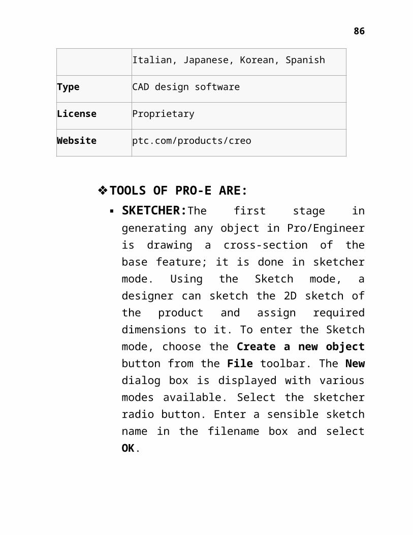
Italian, Japanese, Korean, Spanish
Type CAD design software
License Proprietary
Website ptc.com/products/creo
TOOLS OF PRO-E ARE: SKETCHER:The first stage ingenerating any object in Pro/Engineeris drawing a cross-section of thebase feature; it is done in sketchermode. Using the Sketch mode, adesigner can sketch the 2D sketch ofthe product and assign requireddimensions to it. To enter the Sketchmode, choose the Create a new objectbutton from the File toolbar. The Newdialog box is displayed with variousmodes available. Select the sketcherradio button. Enter a sensible sketchname in the filename box and selectOK.

87
THE SKETCHER ENVIRONMENT: When youenter the Sketch mode, the initialscreen appearance will be similar tothe one shown in the figure 1 ofintroduction section.
Sketch and datum tool bar:Thisfigure shows the Sketcher Toolstoolbar that is on the right of thegraphics screen. The buttonsavailable in this toolbar are used todraw a sketch. The various drawingoptions are also available in theSketch menu in the menu bar. When you

88
enter the sketcher environment, theIntent Manager is on by default.
The following steps outline theprocedure to use the Sketch mode:
Sketch the required sectiongeometry.
Add the constraints and dimensionthe sketched section.
Add relations to the sketch. Regenerate the sketch.
Deleting the Sketcher Entities:To delete a sketched entity,
select it by defining a window bydragging the cursor around theentity. The color of the selectedentity changes to red. Right-click onthe graphics screen and hold down theright mouse button until a shortcutmenu appears. Now, choose the Delete

89
option from this menu. The selecteditem will be deleted.
Scaling and Rotating Entities:The sketches can be scaled or rotatedby using the Scale and rotateselected entities button from theSketcher Tools toolbar. To invokethis button, select the sketch andthen choose the arrow on the right ofthe Mirror selected entities button.This button is available on the flyout that is displayed. After choosingthis tool button, the sketch that iscomposed of various entities now actsas a single entity. The sketchappears orange in color and isenclosed in a boundary.
Modifying the Dimensions of aSketch:

90
There are four ways to modify thedimensions of a sketch. These methodsare listed next.
Using the Modify Dimensionsdialog box.
Using the Edit menu. Modifying a dimension by double-clicking.
Modify dimensions dynamically. The Modeling Process: Thefollowing graphic illustrates themodeling process and the role designintent plays.
91
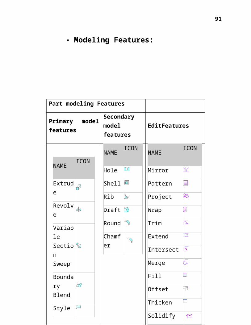
Modeling Features:
Part modeling Features
Primary modelfeatures
Secondarymodelfeatures
EditFeatures
NAME ICON
Extrude
Revolve
VariableSectionSweep
BoundaryBlend
Style
NAME ICON
Hole
Shell
Rib
Draft
Round
Chamfer
NAME ICON
Mirror
Pattern
Project
Wrap
Trim
Extend
Intersect
Merge
Fill
Offset
Thicken
Solidify

92
Extrusion: Extrusion is a method ofdefining three-dimensional geometry byprojecting a two-dimensional section at aspecified distance normal to the sketchingplane. You can create the following extrusiontypes with the Extrude tool:
Protrusion—Solid, Thickened Cut—Solid, Thickened Extruded surface Surface trim—Regular, Thickened
Hole Feature: The Hole tool enables you toadd simple, custom, and industry-standardholes to your models. You add holes bydefining a placement reference, settingsecondary (offset) references, and definingthe specific characteristics of the hole. Asyou work, Pro/ENGINEER displays previewgeometry of the hole. Notice that a hole

93
always begins at the placement reference andextends to the specified depth. You candirectly manipulate and define the hole inthe graphics window and in the dashboard.
You can create the following hole types: Straight: Consists of a revolved cut with arectangular section. You can create thefollowing Straight holes types:
Simple: Uses (straight) geometrypredefined by Pro/ENGINEER. By default,Pro/ENGINEER creates 1-sided Simpleholes. However, you can create 2-sidedSimple Straight holes by using the Shapeslide-up panel. 2-sided Simple holes aretypically used in assemblies and enableyou to simultaneously format both holesides.
Sketched: Uses a sketch profile that youcreate in Sketcher.
Standard: Consists of an extruded cut basedon industry-standard fastener tables.Pro/ENGINEER provides industry-standard holecharts and tapped or clearance diameters forthe selected fastener. You can also createyour own hole charts. Note that thread notes

94
are automatically created for Standardholes.
Blends: A blended feature consists of aseries of at least two planar sections thatPro/ENGINEER joins together at their edgeswith transitional surfaces to form acontinuous feature.
Blend Types: Parallel: All blend sections lie onparallel planes in one sectionsketch.
Rotational: Blend sections arerotated about the Y-axis, up to amaximum of 120 degrees. Each sectionis sketched individually and alignedusing the coordinate system of thesection.
General: Sections of a general blendcan be rotated about and translatedalong the X-, Y-, and Z-axes. Eachsection is sketched individually, andaligned using the coordinate systemof the section

95
Rib feature: Rib feature is a thin fin orweb protrusion that attaches to solidsurfaces in your design. Typically, ribs aredesigned to strengthen parts in your designand are often used to prevent unwantedbending. The Rib tool enables you to quicklydevelop both simple and complex rib features.
Variable Section Sweep: A VariableSection Sweep is unique in its ability tochange as it is swept along the sweeptrajectory.
The three basic components of theVariable Section Sweep are:

96
Trajectories : Origin Trajectory Defines the path of the sweep Establishes the origin of sketchChains
Establish the sketch Planeorientation (X-Trajectory)
Provide sketcher reference and guidecurve capabilities
The origin trajectory typicallydefines the path of the sweep featurein addition to setting up the originof the sweeping coordinate system.Additional chains may also beselected by the user. The primaryreason to define additional chains isto specify additional geometry usedfor section referencing and sketchplane orientation.
Once a chain has been specified, theuser has the option of designatingthe entity as the X-Trajectory. Thepurpose of the X-Trajectory is toestablish the sketch planeorientation. X-Trajectory–X-axis ofthe section plane passes through theintersection point of the specified

97
X-Trajectory and the section planealong the sweep.
Section Plane Control: clocking orrotation of the sketch plane by specifying adirectional reference.
Section Plane Control determines how the sectionor sketching plane is oriented with respect tothe XY Plane.
The three methods of Section Plane Control are:
Normal to Trajectory (default) Normal to Projection Constant Normal to Trajectory (default) Section Plane is normal to the selectedtrajectory
Normal to Projection
Section plane is normal to the projection ofthe origin trajectory along specifieddirection reference
Constant Normal Direction
Section plane normal vector is normal to thedirectional reference

98
The Normal to Trajectory option is used toorient the sketch plane normal to the trajectoryalong the entire length of sweep. The Normal to Projection option is used tocontrol the section plane orientation normal tothe projection of the origin along a specifieddirection reference. This is particularly usefulwhen defining geometry that requires the user tomaintain a constant section or draft anglerelative to the directional reference. The last option is the Constant NormalDirection. This is very similar to Normal toProjection, but gives additional control tospecify the
Horizontal / Vertical ControlOptions:Horizontal / Vertical Controldetermine how the section plane is orientedalong the sweep trajectory in terms of itsrotation about the Z axis.

99
Normal to Surface This option controls rotation bymaintaining the Y axis of the sweepcoordinate system normal to thesurface on which the trajectory lies
Automatic Section plane is automaticallyoriented in the XY direction (Uses X-vector to calculate minimal twist)
X-Trajectory X-axis of the section plane passesthrough the intersection point of thespecified X-Trajectory
Probably the most frequently usedoption is the X-Trajectory
Pattern Tables: Pattern tables allows you to createcomplicated or irregular patterns offeatures or groups by letting youspecify unique dimensions for eachinstance in the pattern through aneditable table.
Multiple tables can be establishedfor a pattern, so you can change thepattern by switching the table thatdrives it. You can use pattern

100
tables in Assembly mode to patternassembly features and components.
Pattern tables are notfamily tables.Pattern tables can only drivepattern dimensions, and unless theyare un-patterned, pattern instancescannot be made independent.
You can also include pattern tablesin family tables, so a particularfamily instance can use a specifiedpattern table
10. Project: The existing project is performedis to Design of special purpose jigsand fixturesusingPro Esoftware.
Designing of Toe Clamper of a robotwhichbelongs to the type profile fixture andalso its assembly.
Designing of Centering Device whichbelongs to the type sandwich jig, V- type

101
locator, Cam operated clamper and platefixture along with its assembly.
The following are the step by step procedurefor the components:
For Part Modeling: Part module selection. Unit selection. Plane selection. Drawing the profile on the plane. Extruding. Drawing the sketch of the slotprofile.
Cutting the material usingextrude cut.
Adding the material in the stemin order to eliminate bulging.
Smoothening the surface usinground option.
Assemble the designed parts. For Toe Clamper:
Part modelling section:

102
Unit Section:

103
Plane section:

104
It consists of 6 components
For 1st component
Profile sketch:
Extrude section
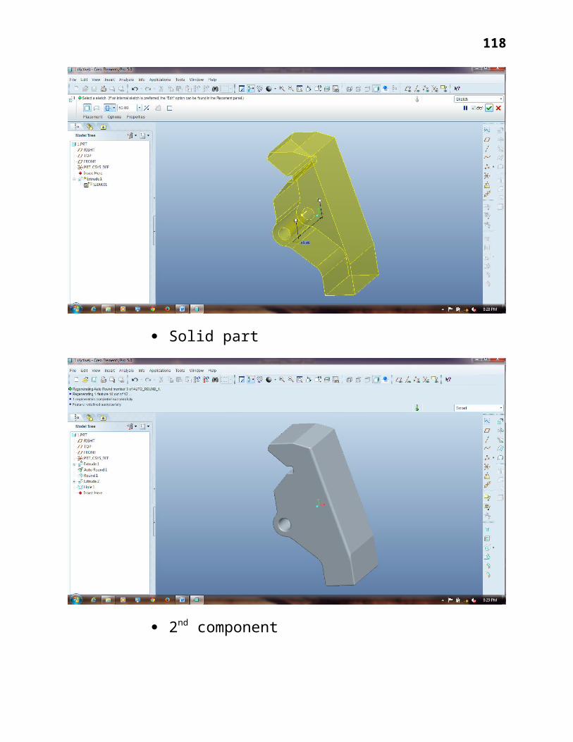
Solid Part:
105
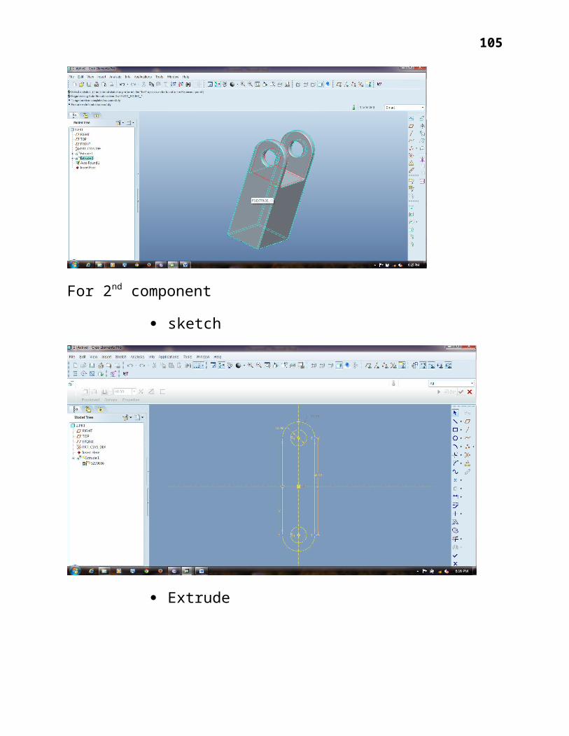
For 2nd component
sketch
Extrude

106
Solid Part with 3rd component sketch
Solid Part for 3rd component

107
Sketch for 4th component
Solid Part for 4th component

108
Sketch for 5th component
Solid for 5th component

109
Sketch for 6th component
6th component top flange sketch
110
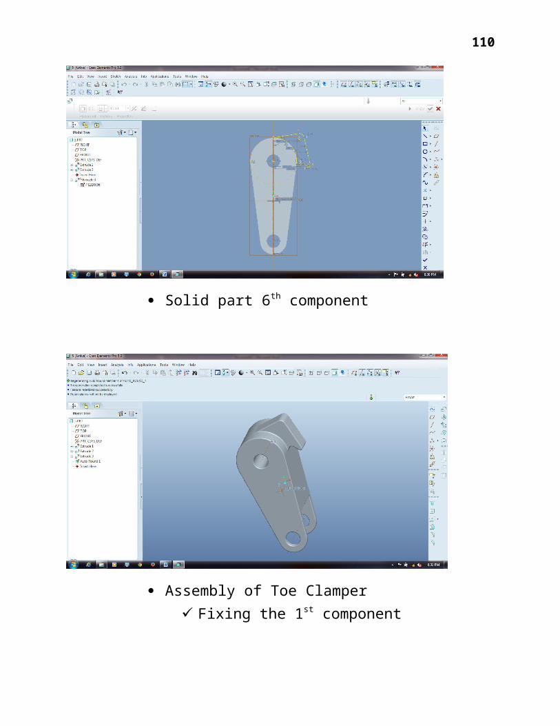
Solid part 6th component
Assembly of Toe Clamper Fixing the 1st component

111

112
Aligning the components:

113

114

115
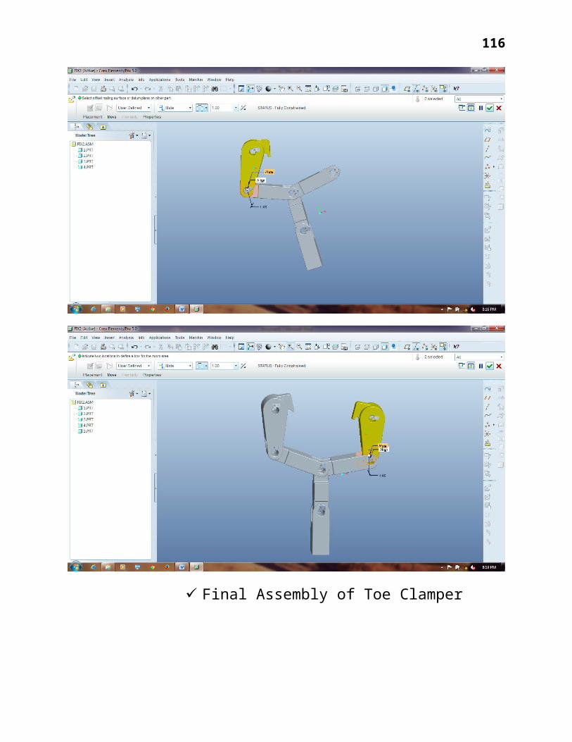
116
Final Assembly of Toe Clamper

117
For Centering equipment: Sketch of 1st component
Extrude section
118
Solid part
2nd component

119
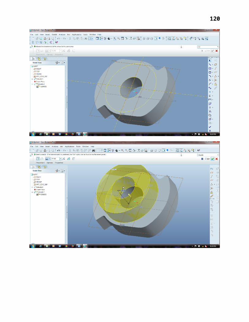
120

121
3rd components

122
4th components
Assembly of centering device:

123
Final Assembly

124

125
10.Conclusion :Designing of special purpose jigs and
fixtures has done by utilizing PRO-Esoftwarewhich is a single database, Pro-Engineer is built on a unified database ongrass-roots, unlike some of the traditionalCAD / CAM system based on multipledatabases. The so-called single databasethat works in all the information from adatabase, so that each user uses a separateform for a product to work, no matter whatsector. In other words, throughout thedesign process the occurrence of changescan be reflected in the design processbefore and after the relevant manipulation.
This advancement in the designingtechniques is greatly employed all over theworld. It is very easy to operate andunderstand the design of even complexcomponents without involving frequentguidance.

126
11.References :
“Production Technology” by R.K.Jain,Khanna Publications
“Production Technology” by HMTPublications

127
“Manufacturing technologies” by YeinCheing
“Design of Machine Elements” byV.B.Bhandari, TMH Publications.
“Wikipedia”