Stiffness of joints in bolted connected cold-formed steel trusses
10
Journal of Constructional Steel Research 62 (2006) 240–249 www.elsevier.com/locate/jcsr Stiffness of joints in bolted connected cold-formed steel trusses Raul Zaharia, Dan Dubina ∗ Department of Steel Structures and Structural Mechanics, Faculty of Civil Engineering and Architecture, “Politehnica” University of Timisoara, I. Curea no.1, 1900 Timisoara, Romania Received 10 January 2005; accepted 1 July 2005 Abstract Web members in cold-formed steel trusses are usually assumed to have pinned connections at the ends, but the latest AISI Cold-Formed Steel Truss Design Standard allows for the joint stiffness to be considered in design. The paper summarizes experimental research performed for several years at the University of Timisoara, Romania, aimed at evaluating the real behaviour of bolted joints in cold-formed steel trusses. By means of tests on single lap joints and on truss sub-assemblies, a theoretical model for joint stiffness was proposed. The formula for the joint stiffness, from which the buckling length of web members was further determined, was also validated through a test on a full-scale truss. © 2005 Elsevier Ltd. All rights reserved. Keywords: Cold-formed steel trusses; Bolted connections; Joint stiffness; Buckling length; Experimental tests; Numerical analysis 1. Introduction Cold-formed steel framing demonstrates extensive development, even if is a relatively new system, due to some great advantages, such as high strength-to-weight ratio, reduced labor costs and fast erection due to the light weight of cold-formed members. The cold-formed steel trusses rep- resent an economical option to the classical wood trusses used mainly in residential buildings, and to the hot-rolled trusses used for industrial applications. Several proprietary products have been developed, considering C, Z, hat, or more particular sections for chords and webs. The con- nections may be realized by welding, by using adhesives, with mechanical connectors as bolts or screws, or by some innovative mechanical connecting techniques such as press joining or rosette joining. The mechanical connections are among the most suitable, taking into account the production costs and rapidity of execution. Initiated by the more widespread use of the cold-formed steel in the residential construction market, systematic research to investigate the behaviour of cold-formed steel trusses was carried out at the University of Missouri-Rolla. ∗ Corresponding author. Tel.: +40 56 192970; fax: +40 56 192970. E-mail address: [email protected] (D. Dubina). 0143-974X/$ - see front matter © 2005 Elsevier Ltd. All rights reserved. doi:10.1016/j.jcsr.2005.07.002 On the basis of full-scale tests on fink C-section truss assemblies, Harper [10] studied the buckling lengths for the top chord members, realized by a single C-section. Riemann [22] developed a computer analysis model and conducted full-scale truss tests in order to determine the capacity of compression web members, and suggested an interaction equation for the design of compression webs as beam–columns. Ibrahim et al. [11] made another series of tests on full-scale truss assemblies, considering the same system, i.e. single C-sections for chords and webs, connected by self-drilling screws. The authors proposed an interaction equation for checking unreinforced top chords subjected to axial compression, bending and web crippling. LaBoube and Yu [13] synthesized the above-presented research conducted at the University of Missouri-Rolla, which strongly influenced the design recommendations contained in the Standard for Cold-Formed Steel Truss Design issued recently by AISI [1]. This standard is intended to be a response to the problems that these particular systems raise for the designer, and applies to the design, quality assurance, installation and testing of cold-formed steel trusses used for load carrying purposes in buildings. As shown in the Standard Commentary [2], even if the structural analysis requirements are based on available information concerning the behaviour of cold-formed steel
Transcript of Stiffness of joints in bolted connected cold-formed steel trusses
Journal of Constructional Steel Research 62 (2006) 240–249
www.elsevier.com/locate/jcsr
d-Formedrmeds.ula for theale truss.
Stiffness of joints in bolted connected cold-formed steel trusses
Raul Zaharia, Dan Dubina∗
Department of Steel Structures and Structural Mechanics, Faculty of Civil Engineering and Architecture, “Politehnica” University of Timisoara,I. Curea no.1, 1900 Timisoara, Romania
Received 10 January 2005; accepted 1 July 2005
Abstract
Web members incold-formed steel trusses are usually assumed to have pinned connections at the ends, but the latest AISI ColSteel Truss Design Standard allows for the joint stiffness to be considered in design. The paper summarizes experimental research perfofor several years at the University of Timisoara, Romania, aimed at evaluating the real behaviour of bolted joints in cold-formed steel trusseBy means of tests on single lap joints and on truss sub-assemblies, a theoretical model for joint stiffness was proposed. The formjoint stif fness, from which the buckling length of web members was further determined, was also validated through a test on a full-sc© 2005 Elsevier Ltd. All rights reserved.
Keywords: Cold-formed steel trusses; Bolted connections; Joint stiffness; Buckling length; Experimental tests; Numerical analysis
iveme
atioigh-sedtary, oon-esme
ssaretion
edaticteella.
.
ussron.ndthed anebs
thes,nsng.
edlla,nsuss
ular
edngs.
blel
1. Introduction
Cold-formed steel framing demonstrates extensdevelopment, even if is a relatively new system, due to sogreat advantages, such as high strength-to-weight rreduced labor costs and fast erection due to the light weof cold-formed members. The cold-formed steel trusses represent an economical option to the classical wood trusused mainly in residential buildings, and to the hot-rolletrusses used for industrial applications. Several proprieproducts have been developed, considering C, Z, hatmore particular sections for chords and webs. The cnections may be realized by welding, by using adhesivwith mechanical connectors as bolts or screws, or by soinnovative mechanical connecting techniques such as prejoining or rosette joining. The mechanical connectionsamong the most suitable, taking into account the produccosts and rapidity of execution.
Initiated by the more widespread use of the cold-formsteel in the residential construction market, systemresearch to investigate the behaviour of cold-formed strusses was carried out at the University of Missouri-Ro
∗ Corresponding author. Tel.: +40 56 192970; fax: +40 56 192970.E-mail address: [email protected] (D. Dubina).
0143-974X/$ - see front matter © 2005 Elsevier Ltd. All rights reserveddoi:10.1016/j.jcsr.2005.07.002
,t
s
r
,
l
On the basis of full-scale tests on fink C-section trassemblies, Harper [10] studied the buckling lengths fothe top chord members, realized by a single C-sectiRiemann [22] developed a computer analysis model aconducted full-scale truss tests in order to determinecapacity of compression web members, and suggesteinteraction equation for the design of compression was beam–columns. Ibrahim et al. [11] made another seriesof tests on full-scale truss assemblies, consideringsame system, i.e. single C-sections for chords and webconnected by self-drilling screws. The authors proposed ainteraction equation for checking unreinforced top chordsubjected to axial compression, bending and web crippli
LaBoube and Yu [13] synthesized the above-presentresearch conducted at the University of Missouri-Rowhich strongly influenced the design recommendatiocontained in the Standard for Cold-Formed Steel TrDesign issued recently by AISI [1]. This standard isintendedto be a response to the problems that these particsystems raise for the designer, and applies to thedesign,quality assurance, installation and testing of cold-formsteel trusses used for load carrying purposes in buildiAs shown in the Standard Commentary [2], even if thestructural analysis requirements are based on availainformation concerning the behaviour of cold-formed stee

R. Zaharia, D. Dubina / Journal of Constructional Steel Research 62 (2006) 240–249 241
ssignd/o
es,eresofold-
esnts
onntthein
n bple
ns,tiusnaln ofe oonsad-ssd
tedrdssiblblectedges
ny
est,
stheinds
in
upd by
eduiltion,ent
forsedses,
the
ngess,ed, thectuse
theith
f theebding
g
t
single C-section truss assemblies [13], these requirementdo not preclude the use of more rigorous analysis or deassumptions, as determined by rational analysis antesting.
As regards innovative mechanical connection techniqutwo interesting research areas are worth mentioning hPedreschi et al. [17] demonstrated the efficiency of presjoining, by making tests on single lap joints or groupspress joins and on full-scale pitched trusses made from cformed Z-sections. Mäkeläinen and Kesti [15] studied thebehaviour of the rosette joining system and its possibilitiin roof-truss structures, by making tests on simple joiin shear or in cross-tension, and also by making testssub-assemblies. The authors concluded that the rosette joihas very good capacity to resist tensile forces and thatshear capacity seems to be sufficient for applicationslightweight steel trusses.
The research on cold-formedsteel trusses is generallyfocused on systems for residential roofs, having relativelyreduced spans. For larger spans, efficient solutions caachieved with higher resistance members, made for examwith optimized cross-sections, like “pentagon” sectiostudied by Blumel and Fontana [3]. The authors showed thathe use of this particular cross-section with a large radof gyration for both axes offers statical and constructioadvantages for the chords. However, the low-cost desigthe truss joints using a gusset plate welded onto the ridgthe cross-section can lead to important section deformatiThe authors developed a calculation model for the local lobearing behaviour of this particular type of cold-formed trujoint, and validated this model by means of numerical anexperimental analysis on truss segments.
The trusses built of cold-formed steel sections with bolconnections, made from built-up C-sections for choand single C-sections for webs, represent another posconstructive system for residential buildings, also reliafor larger spans. In this system, the webs are conneto the chords by means of bolts placed on both flanof the C-section of the web member.Fig. 1 shows twoapplications using such trusses.Fig. 1(a) shows the structureof a supplementary storey built for the Alcatel Compabuilding in Timisoara, Romania, whileFig. 1(b) shows thetrusses used to build the roof of a church in BucharRomania.
As regards thedesign of this type of cold-formed trussystem, two problems arise: the stability behaviour ofcompressed chord, taking into account that for these kof built-up members no design recommendations existsthenorms, and the real behaviour of the joints.
Studies concerning the stability behaviour of the built-C-profiles connected by bolted C-stitches were performeNiazi [16]: based on the results obtained by Johnston [12],for hot-rolled columns in which the battens are attachto the chords by hinged connections, the compressed bup C-section is supposed to work on an elastic foundatprovided by the roof purlins. The authors of the pres
r
.
e
f.
e
-
Fig. 1. Cold formed steel trusses.
paper calibrated a finite element model suitablepredicting the ultimate load for such built-up elements, ufor the compressed chords of cold-formed steel trusbut also as columns in cold-formed steel framing [7]. Thenumerical model showed good results compared withabove procedure and experimental results.
As regards the analysis of the web members, it must beemphasized that the use of two or more bolts for each flaof the C-section, in relation with the element slenderneis supposed to modify the classical assumption of pinnconnections, used in case of truss structures. Moreovereccentricity of joints could not be avoided, and this fashould also be considered into a global analysis, becait may require additional efforts. For these reasons,analysis of trusses built of cold-formed steel sections wbolted connections should consider the real behaviour ojoints. This may lead to reduced buckling lengths of the wmembers, but at the same time, to supplementary benmoments in these elements.
In chapter D3 “Analysis” of the latest AISI Cold-FormedSteel Truss Design Standard [1] it is shown that: “in lieu ofa rigorous analysis to define joint flexibility, the followinanalysis model assumptions should be assumed:. . . (b)web members are assumed to have pinned connections a
242 R. Zaharia, D. Dubina / Journal of Constructional Steel Research 62 (2006) 240–249
allcesnt
ssno
.ofoldourhenthee
onsingandlylley
onsteeintude
ingctivherionsnd
del
neests
thofiourlts,ss.
tepsase
ltedfordingalsome
r.
adyd
T-intsto
nsointhe of
el.s
nly
oltay
ate
dyaseheinga
e
enle,nse-was
laphicaland
rent, andical
each end. Use of a specific joint stiffness other than thecomplete rotational freedom of a pin for a connection shbe permitted if the connection is designed for the forresulting from a structural analysis with this specific joistiffness”.
This means that the Standard allows for joint stiffneto be considered in the design of a truss, even ifspecific equations for calculating this parameter are givenThis should be in fact difficult, considering the numberdifferent cold-formed steel truss systems. In the case of cformed trusses with bolted connections, a rigid behaviof the joints is also not realistic, taking into account tdeformability of the joint due to the bearing deformatioproduced by the bolt in the thin plate, associated withhole elongation, bolt tilting and slippage due to the holclearance.
Generally, the research in the field of bolted connectiin cold-formed steel framing is focused on determintheir bearing resistance. For the first time, ZadanfarrokhBryan [25] analysedboth experimentally and theoreticalthe flexibility of bolted connections in cold-formed steesections, and gave a formula for the flexibility of a singlap bolted joint, but this approach was not included in andesign recommendation. More recently, [24] investigatedexperimentally some particular column base connectiand beam–column sub-frames, made from cold-formed ssections, in different bolted connection configurations,order to assess their strength and stiffness. The sidentified different failuremodes and concluded that thbolted moment connections were effective in transmittmoment between the connected sections, enabling effemoment framing in cold-formed steel structures. Anotrecent study concerning the stiffness of bolted connectin a steel portal framing system was made by Lim aNethercot [14]. The authors described a finite element mothat can be used to determine thestiffness of the individualbolt joint. Using this stiffness, a beam idealization of a cold-formed steel bolted moment connection was determined, iorder to predict the initial stiffness of the apex joints. Thnumerical and theoretical study was validated through ton full-scale joints.
The research presented in this paper summarizeswork performed for several years at the UniversityTimisoara, Romania, aimed at evaluating the real behavof joints in cold-formed steel trusses connected by boand at proposing a theoretical model for the joint stiffneThe experimental programme was developed in three sFirst, the rotational rigidity of some truss connections wevaluated, by means of tests on typical T-joints. In thsecond step, a formula for the stiffness of a single lap bojoint was determined, together with a theoretical modelthe rotational stiffness of cold-formed steel truss boltejoints. Based on this model, an equation for determinthe reduced buckling length of the web members wasproposed. The third step of the experimental program
-
l
y
e
e
.
included a full-scale test of a cold-formed steel truss, in ordeto validate the theoretical formulations at structural level
2. Experimental programme step 1: Tests on T-jointspecimens
This first step of the experimental programme has alrebeen described in detail [5,6], and the results were includein the Database for Research onCold-formed Steel Structurefrom University of Missouri-Rolla, USA [4]. From theexperimental moment–rotation characteristic of the tenjoint specimens tested, it was concluded that all tested jowere of semi-rigid type with partial resistance, accordingEurocode 3 [21] criteria of joint classification.An importantinitial rotational slippage was observed for all specimetested, but it was not considered in the evaluation of the jrigidity, because the triangulated shape of the truss, whicis geometrically and kinetically stable, and the presencthe axial forces in connectedmembers prevent, or limit, atleast, this phenomenon at structural level. The test of thcold-formed steel truss, in the third step of the experimentaprogramme, was aimed also at validating this assumptionFrom this first partof the experimental programme it waalso concluded that the rotational deformability is maidue to the bearing work of the boltsin the thin plates, i.e. theelastic and plastic deformation of the bolt holes and btilting. Consequently, the rotational rigidity of the joints mbe determined by analysing the single lap bolted joint.
3. Experimental programme step 2: Tests on single lapjoints
Experimental studies carried out in order to calibra formula for the flexibility of single lap bolted joint forthin-walled cold-formed elements were already performeby Zadanfarrokh and Bryan [25]. The formula proposed bthese authors gives the flexibility of a single lap joint,a function of the thickness of the plates and the presencof the threaded portion of the bolt in the connection. Tformula does not include the effect of bolt diameter, bedetermined for lap joints using M16 bolts, but makesdistinction between perfectfit and 2 mm clearance of thbolt hole.
For thecase of T-joints tested at Timisoara, for all tspecimens, M12 bolts with 1 mm clearance of the bolt hoas specified in the Romanian code, were considered. Coquently, the second step of the experimental programmeaimed at calibrating a formula for the stiffness of singlejoints, considering the plate thickness as in the Zadanfarrokand Bryan study, but also the bolt diameter, for the practcase of a threaded portion of the bolt in the connection1 mmhole clearance.
The experimental programme considered three diffethicknesses for the plates, between 1.85 and 3.75 mmfive bolt diameters, between 8 and 16 mm. The mechancharacteristics of the steel plates are given inTable 1.

R. Zaharia, D. Dubina / Journal of Constructional Steel Research 62 (2006) 240–249 243
ansion
in.anslateachests
t,nte
intfrd,omions
edionillent.
beon.is,Df ae
dal
le
,
istermm
etyr
ers,
f aof
Table 1Mechanical characteristics (N, mm)
t f y fu
1.85 279.8 402.13.15 276.8 3923.75 258.5 375.5
Fig. 2. Test set-up.
The test set-up is shown inFig. 2. The specimens weretested in a ZWICK universal testing machine, usingangular displacement transducer to record the extenreadings. The loading rate of 1 kN/min and the platedimensions were in accordance with the ones usedthe Zadanfarrokh and Bryanexperimental programmeThis value of loading rate is also given in the EuropeRecommendations [8]. Table 2gives the experimental valueof the specimens’ stiffnesses. For each thickness of pthree different bolt diameters were used, and for ecombination of plate thickness and bolt diameter, three twere performed(a–c). Thus, a total of 27 experimentalresults are available. Typical load–extension characteristicsfor determining the initial stiffness of the lap joinconsidering an identical set of parameters, are presein Fig. 3.
The formula for the stiffness of a single lap bolted jowas calibrated using Annex D of Eurocode 0: Basis oStructural Design [18]. This appendix describes a standaprocedure for the determination of the characteristic valuesdesign values and partial factor values for strength frtests that is in compliance with the basic safety assumptoutlined in Eurocode 1: Actions on Structures [19].
As shown by Tomà [23], in a pioneering studyconcerning the rigidity of screw connections in cold-formelements, underestimating the rigidity of the connectin the elastic range will relieve the connection, but wput a supplementary bending moment into the elem
,
d
Fig. 3. Typical load–extension characteristics.
Overestimating the rigidity, on another hand, leads to asupplementary moment into the joint, but this canresolved by an appropriate design of the connectiIt is safe, for the stability and displacement analysto underestimate the rigidity. Therefore, the Annexprocedure for calibration of the formula for the stiffness osingle lap bolted joint, will follow the same steps as for thdetermination of the characteristic values, design values anpartial factor values for a strength-type formula. The fincharacteristic value, obtained after the application of thestandard procedure of Annex D, for the stiffness of a singlap bolted joint, is given by the following formula [27]:
K = 6.8
√D(
5t1
+ 5t2
− 1) (kN/mm) (1)
with a partial safety factorγR = 1.25. In the above equationD is the nominal diameter of the bolt whilet1, t2 representthe thicknesses of joined plates. The range of validity of thformula is for bolts between 8 and 16 mm nominal diameand thickness of plates between 2 and 4 mm, using 1hole clearance and considering the threaded portion of thebolt in the connection. It can be noted that the partial saffactor for this formula is identical to the partial safety factoused in Eurocode 3 Part 1.3 [20] for the resistance of boltedconnections.
On the basis of Eq. (1), the stiffness of truss joints maybe determined. For the displacement analysis, and for thcomputation of the buckling lengths of the web membethe design value must be applied, while for the connectiondesign the characteristic one is suitable.
4. Computation models for rotational stiffness of trussjoints
The computation scheme for the rotational stiffness otruss joint with two bolts on each flange of the C-sectionthe web member (four bolts in total) is presented inFig. 4.
The rotational stiffness of the joint,Knode,t , can beexpressed in terms of total bending moment,Mtot, and

244 R. Zaharia, D. Dubina / Journal of Constructional Steel Research 62 (2006) 240–249
Fig. 4. Computation model for a four bolt joint.
995
Table 2Experimental values for single lap joint stiffness (kN/mm)
Bolt Plate thicknesst (mm)1.85 3.15 3.75a b c a b c a b c
M8 4.237 4.695 4.348 – – – – – –M10 5.102 6.211 5.025 10.000 10.417 10.204 – – –M12 7.353 5.263 5.236 10.869 10.753 10.526 9.259 13.333 13.6M14 – – – 11.111 11.628 11.765 14.286 14.493 14.92M16 – – – – – – 16.667 16.393 15.385
Table 3Comparison between experimental and theoretical values of joint stiffness
Node t1 (mm) t2 (mm) Knode,exp (kN mm/rad) Knode,t (kN mm/rad) Knode,t /Knode,exp K dnode,t /Knode,exp
1 3 2.05 10 130 9 830 0.971 0.7773 10270 0.958 0.766
2 3 3 12480 13 083 1.047 0.8384 11110 1.177 0.942
5 4.05 2.05 10560 11 418 1.080 0.8648 10968 1.041 0.833
6 4.05 3 15320 16 057 1.048 0.8389 15490 1.037 0.830
7 4.05 4.05 21189 20 779 0.981 0.78510 20 361 1.021 0.817
tal
sed
tionisticdeient
corresponding rotation,θ , as [27]
Knode,t = Mtot
θ= 2(Fa)
tanθ= 2K da( d
0.5a
) = K a2
= 6.8a2√
D(5t1
+ 5t2
− 1) (kN mm/rad) (2)
with the same partial safety factor as in Eq. (1), γR = 1.25.The terma represents the distance between bolts.
Table 3shows the comparison between the experimenvalues ofthe rotational stiffness for the T-joints obtainedin the first step of the experimental programme(Knode,exp)
and the theoretical values obtained with the proporelation (Knode,t ).
It may be observed that there is a good correlabetween the experimental results and the charactervalues ofthe joint rotational stiffness. The average reporteratio between the theoretical characteristic values and thexperimental ones is 1.036 and the correlation coeffic
R. Zaharia, D. Dubina / Journal of Constructional Steel Research 62 (2006) 240–249 245
ofr,e
eat
inebetion
ral.ed
eds
berod.
lof
tale at
ve,s
stics
loadin
is ρ = 0.982. Considering the design theoretical valuethe formula(K d
node,t ), affected by the partial safety factoit may be observed that all the theoretical values are in thsaferange.
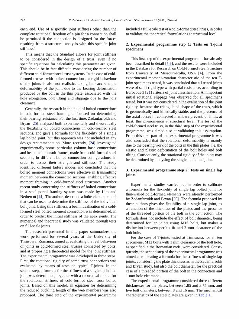
A similar model may be used for determining throtational stiffness for a six bolt truss joint. Considering ththe centre of rotation of thebolt group is in the axis of themiddle bolt, as shown inFig. 5, the following equation maybe determined [26]:
Knode,t = Mtot
θ= 2(F × 2a)
tanθ= 4K da( d
a
) = 4K a2
= 27.2a2√
D(5t1
+ 5t2
− 1) (kN mm/rad). (3)
5. Buckling length of truss web members
The rotational stiffness of joints may be used to determthe buckling lengths of the web members. Trusses mayclassified as fixed-node-type structures. The computamodel for the buckling length of truss web membersLb,webis then as for an element with fixed nodes for latedisplacement and elastic rotational springs on both endsFor this model, the buckling length should be determinconsidering the following equation:
Lb,web = µLweb (4)
where Lweb is the length of the web member measuredbetween centrelines of connections andµ is computed withEq. (5):
µ = 0.5 + 0.14(η1 + η2) + 0.055(η1 + η2)2. (5)
For the case of cold-formed steel trusses with boltjoints, the coefficientsη1 and η2 may be computed afollows:
η1 = Kweb
Kweb + Knode,1η2 = Kweb
Kweb + Knode,2
with Kweb = E Iweb
Lweb(6)
whereIweb is the second moment of area of the web memand Knode,1, Knode,2 are the rotational rigidities of the twjoints connecting the web member on the chords, computewith Eq. (2) or (3), a function of the number of boltsNote that for the computation of the buckling length, thedesign values of the rotational rigiditiesKnode,i should beconsidered.
6. Experimental programme step 3: Test on the trussstructure
In order to demonstrate that the initial rotationaslippage from the moment–rotation characteristicsT-joints determined in the first step of the experimenprogramme is not present in the truss, and to validat
Fig. 5. Computation model for a six bolt joint.
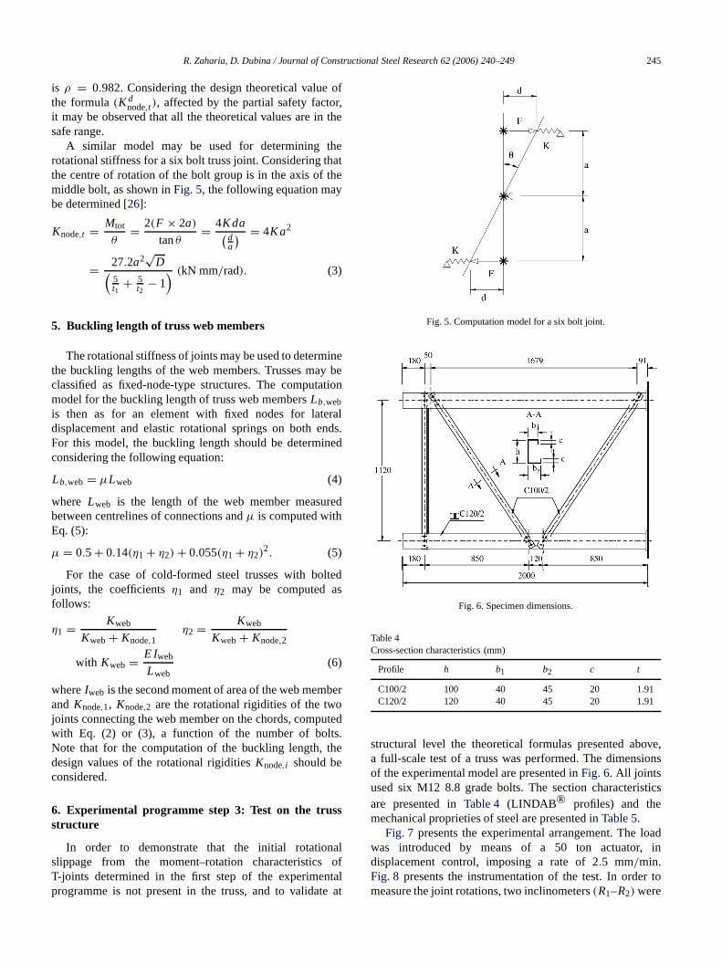
Fig. 6. Specimen dimensions.
Table 4Cross-section characteristics (mm)
Profile h b1 b2 c t
C100/2 100 40 45 20 1.91C120/2 120 40 45 20 1.91
structural level the theoretical formulas presented aboa full-scale test of a truss wasperformed. The dimensionof the experimental model are presented inFig. 6. All jointsused six M12 8.8 grade bolts. The section characteriare presented inTable 4 (LINDAB ® profiles) and themechanical proprieties of steel are presented inTable 5.
Fig. 7 presents the experimental arrangement. Thewas introduced by means of a 50 ton actuator,displacement control, imposing a rate of 2.5 mm/min.Fig. 8 presents the instrumentation of the test. In order tomeasure the joint rotations, two inclinometers(R1–R2) were

246 R. Zaharia, D. Dubina / Journal of Constructional Steel Research 62 (2006) 240–249
ber
the
.
re,ebwn
nts,d.int.theholeof
of
s
erveonrcethencethe
e inrence
russgegere,
ringthe
calby
teel
3al
eForthentisss inthelysistheothe
icalnal
nsrs
Table 5Materialcharacteristics (N, mm)
Profile f y fu εu (%)
C100/2 367.2 542 19C120/2 354 493.4 14
Fig. 7. Experimental arrangement.
Fig. 8. Instrumentation.
placed on the web of the C-section of each web memin the axis of the lower chord joints. For determining theslippage on the connections, along the axial forces inweb members, four LVDT displacement transducers(I1–I4)
were placed along the axis of webmembers, near the jointsFour potentiometric displacement transducers(P1–P4) werealso used for global structural displacement control.
The load increased until the failure of the structuproduced by the flexural instability of the compressed wmember, occurred in the plane of the truss, as sho
,
in Fig. 9(a). A local buckling of the lower chord C-sectionwebs, due to the shear of the panel between the joiwasobserved (Fig. 9(b)), before reaching the ultimate loaThis phenomenon increases the deformability of the joFig. 9(c) presents the bolt hole plastic deformations, forcompressed web member. It may be observed that theof the middle bolt suffers only elongations along the axisthe member, which confirms the computation model fromFig. 5, in which the middle bolt was considered the centrerotation for the sixbolt connection.
Fig. 10 presents the evolution of the displacementreported by the LVDT transducersI3 and I4, along theaxis of the compressed web member. One may obsthe typical behaviour of a thin-walled bolted connectisubjected to shear. After reaching the slippage fo(corresponding, at bolt level, to approximately 200 daN)initial slippage extension is extended until the hole clearais reached; the size of this extension is a function ofinitial position of the elements in the structure.
Fig. 11 shows the evolution of the rotations in webmember connections. Corresponding to the load rangwhich the axial slippage occurs, only small rotations aobserved. Until the structure ‘shakes down’, the preseof the axial forces and the triangulated shape of the tprevent the development of significant rotational slippain connections. Consequently, the initial rotational slippaobserved for the T-joints is not present in the structuand the rotational stiffness evaluated without considethe initial slippage represents the real initial stiffness ofconnection in the truss.
For quantitative validation of the proposed theoretiformulas, the tested truss was numerically analysedmeans of PEP-micro programme [9]. PEP-micro is aspecialized programme for the non-linear analysis of sstructures with semi-rigid joints.
The static scheme of the structure is presented inFig. 12.For the stability verification of a structure, Eurocodeallows for a second order analysis with initial sinusoidimperfection of the elements. The amplitude of thoseinitial imperfections is a function of the buckling curvfor the corresponding cross-section of the element.lipped channels, according to Eurocode 3 Part 1.3,corresponding buckling curve is B, with an initial equivaleimperfectione0 = l/380. The ultimate load of the elementthen the load corresponding to the reach of the yield strethe extreme fibre of the cross-section, taking into accountsecond order effects. A step-by-step second order anawas performed, with a load step corresponding to 1% ofultimate load. The connectioneccentricities were taken intaccount by introducing supplementary rigid elements onedges of the diagonals, of lengthLexc in Fig. 12.
The structure was analysed considering the classpinned assumption for joint behaviour and also the rotatiostiffness, computed by means of Eq. (3), for a six boltjoint. The effect of the axial stiffness of the connectioon the direction of the axial force in web membe

R. Zaharia, D. Dubina / Journal of Constructional Steel Research 62 (2006) 240–249 247
Fig. 9. Structure after test.
otan
thectioingnttre
n,
en-the-
naling
ce-ethenot
Fig. 10. Axial displacements of the web member.
Fig. 11. Web member joint rotations.
was also considered. The PEP-micro programme is nable to model this axial stiffness, and consequentlyequivalent finite element to simulate this behaviour ofconnections was considered. The equivalent cross-searea of this finite element may be determined by equalizthe expression for the axial stiffness of the bar elemehaving a lengthLechequal to the distance between the cenof rotation of the bolts group and the lastbolt, with the axialstiffness of the connection,Kaxial, determined using Eq. (1)
n
Fig. 12. Static scheme of the experimental model.
for the corresponding number of bolts in the connectioi.e. multiplied by six:
Kaxial = 6 × 6.8
√D(
10t − 1
) = E Aech
Lech(7)
Fig. 13 presents the comparison between the experimtal load–displacement characteristic and the results ofnumerical analysis. InFig. 13(a) are represented the numerical load–displacement characteristics, considering therotational stiffness (Knode), together or not with theaxial stiffness of the joint(Kaxial). Fig. 13(b) shows also theresponse of the numerical model for the complete rotatiofreedom of web member connections (pinned), considerthe axial stiffness of the joints.
One may observe, in the experimental load–displament curve, an initial structural slippage, at the level of thforce corresponding to the connection slippage alongaxis of the web members. Neglecting this phenomenon,considered in the numerical analysis, the structural rigidity

248 R. Zaharia, D. Dubina / Journal of Constructional Steel Research 62 (2006) 240–249
Table 6Results of the numerical and experimental analysis
Knodewithout Kaxial (1) Knodewith Kaxial (2) Pinned withKaxial (3) Experiment (4) (1)/(4) (2)/(4) (3)/(4)
Ultimate load (daN)6650 7665 5790 7820 0.85 0.98 0.74
Displacement (mm)3.3 9.9 7.5 15.8 0.21 0.63 0.47
Structural rigidity(daN/mm)
2015 774 772 734 2.74 1.05 0.99
.
l
othesndegeingthethe
ternlyints
On
ave
theay
ltheds
y inableC-ithns,of
drsn
ularrrentnnededbe
dard
intethe
ussicalityndayint.tedd,s
Fig. 13. Comparison between experimental and numerical analysis
obtained numerically, taking into account both axial(Kaxial)
and rotational(Knode) stiffness of the connections, is veryclose to the experimental one.Table 6presents the results ofthe numerical analysis, in comparison with the experimentavalues.
It may be observed that the analysis considering baxial and rotational stiffness of the connections givdifferences around only 2% for the ultimate load a37% for the corresponding displacement. The differencat displacement level is due to the initial axial slippain the joints and to the bolt plastic bearing appearat high force levels, phenomena not considered innumerical analysis. However, the comparison betweeninitial numerical and experimental structural rigidities, afthe consumption of the slippage, gives differences of o5%. It may be observed that the axial stiffness of the joplays an importantrole in the structural rigidity, and itaffects also, but to a lower extent, the ultimate load.
the other hand, the rotational stiffnesses of the joints ha very slight influence on the structural rigidity comparedwith the classical assumption of pinned joints, due totriangulated shape of the truss, but affect in a significant wthe resistance of the structure.
Considering the results of thenumerical and experimentaanalysis at structural level, it may be concluded thattheoretical formulas proposedmay be successfully applieto represent the joint stiffness in cold-formed steel trussewith bolted joints.
7. Conclusions
Cold-formed steel trusses are much used, especiallresidential construction, but such systems are also relifor larger span applications. Trusses made from built-upsections for chords and single C-sections for webs, wbolted joints, represent a suitable solution for both situatiotaking into account the production costs and the rapidityexecution.
Despite the extensive use of cold-formed steel trusssystems and of cold-formed steel framing in general, andespite the fact that new standards appeared in recent yeato cover this domain, there is still a lack of informatioconsidering different behavioural aspects of this partictype of structural system. In the case of steel trusses, cudesign practice assumes that web members have piconnections, but the latest revision of the AISI Cold-FormSteel Truss Design Standard allows for joint stiffness toconsidered in the design of a truss. However, the standid not offer formulas for calculating this parameter.
In order to determine a theoretical model for the jostiffness of bolt connected cold-formedsteel trusses, thauthors developed an experimental programme. Infirst step, the stiffness of some cold-formed steel trbolted joints was evaluated, by means of tests on typT-joints. It was emphasized that the joint deformabilis mainly due to the bearing work of the bolts, aconsequently the rotational rigidity of the connection mbe determined by analysing the single lap bolted joIn order to determine the stiffness of a single lap boljoint, a second experimental programme was performeand a formula for the characteristic and design stiffneswas calibrated. Using this formula, a computational model

R. Zaharia, D. Dubina / Journal of Constructional Steel Research 62 (2006) 240–249 249
d.testalaer
nitianon
ts.
dt,ntahosignseinig
dthts,
gnel
[1s
ingon
oll
tureelrsit
nallle
.
nsna
hetions,
rdree
isinlla,
el1998;
971;
old-
t-l Res
eel
seesenteences
e4.sels
m):
1.3ugee for
1.8,for
old-ofe
BI-
entonstr
saltyuri-
h.D.[in
ltedeel
for the rotational stiffness of truss joints was establisheThe theoretical model for a four bolt joint demonstraa good correlation in comparison with the experimenresults on T-joints. Considering this model, a formufor the buckling length of truss diagonals was furthdetermined.
In the last part of the experimental programme, otest on a full-scale truss demonstrated that the inrotational slippages observed in the T-joint tests arepresent at structural level, so these slippages areinfluencing the initial rotational stiffness of the truss joinThe numerical analysis of the truss tested, consideringthe axial and rotational stiffness of the joints, computewith the corresponding formulas for a six bolt joindemonstrates a good correlation with the experimeresults. Consequently, the formulas proposed by the autmay be successfully applied to represent the joint stiffnesin cold-formed steel trusses with bolted joints. For despurposes, when computing the displacements of the trusthe buckling lengths of the web members, the design valuof the joint stiffness computed with the formulas proposedthis paper have to be applied, while for the connection desthe characteristic values are suitable. The study revealethat the response of the truss is influenced not only byrotational stiffness, but also by the axial stiffness of joinin the direction of the axial forces of web members.
References
[1] AISI/COFS. Standard for cold-formed steel framing — Truss desiRevision of AISI/COFS/TRUSS 2000. American Iron and SteInstitute, Committee on Framing Standards (COFS); 2001printing June 2002].
[2] AISI. Commentary on the standard for cold-formed steel fram— Truss design. American Iron and Steel Institute. CommitteeFraming Standards (COFS); 2001 [1st printing June 2002].
[3] Blumel S, Fontana M. Load-bearing and deformation behaviourtruss joints using thin-walled pentagon cross-sections. Thin WaStruct 2004;42(2):295–307.
[4] Database. Database for research on cold-formed steel strucproject title: Behaviour of bolted connections in cold-formed stplane trusses — Center for Cold-formed Steel Structures. Univeof Missouri-Rolla M 065401-0249 USA; 1996.
[5] Dubina D, Zaharia R. Experimentalevidence of semi-rigid behaviourof some cold-formed steel truss bolted joints. In: Internatioconference on experimental model research and testing of thin-wasteel structures. 1997.
[6] Dubina D, Zaharia R. Cold-formedsteel trusses with semi-rigid jointsThin Wall Struct 1998;29(1–4):237–87.
[7] Dubina D, Zaharia R, Ungureanu V. Behaviour of built-up colummade of C sections connected with bolted stitches. In: Internatiocolloquium on stability and ductility of steel structures. 2002.
l
eltot
lrs
ors
n
e
,
t
f
es
y
d
l
[8] ECCS. TC7 Europeanrecommendations for steel construction: Tdesign and testing of connections in steel sheeting and secPublication No. 21; 1983.
[9] Galea Y, Bureau A. PEP–micro: Analyse plastique au second ode structures plannes a barres. Paris (France): Centre TechniquIndustriel de la Construction Metallique; 1992.
[10] Harper MM. Cold-formed steel inresidential roof trusses. Thespresented to the Faculty of the University of Missouri-Rollapartial fulfillment for the degree master of Science. Missouri-RoUSA; 1995.
[11] Ibrahim TM, LaBoube RA, Yu WW. Behaviour of cold-formed steroof trusses under concentrated loads. J Constr Steel Res46(1–3):176–7.
[12] Johnston BG. Spaced steel columns. J Struct Div, ASCE 197(ST5):1465–79.
[13] LaBoube RA, Yu WW. Recent research and developments in cformed steel framing. Thin Wall Struct 1998;32(1–3):19–39.
[14] Lim JPB, Nethercot DA. Stiffness prediction for bolted momenconnections between cold-formed steel members. J Constr Stee2004;60(1):85–107.
[15] Mäkeläinen P, Kesti J. Advanced method for light-weight stjoining. J Constr Steel Res 1999;49(2):107–16.
[16] Niazi A. Contribution a l’etude de la stabilite des structures compode profils a parois minces et section ouverte de type C. These presen vue de l’obtention du grade scientifique de Docteur en ScieAppliquees. Universite de Liege; 1993.
[17] Pedreschi RF, Sinha BP, Davies R. Advanced connection techniqufor cold-formed steel structures. J Struct Eng 1997;123(2):138–4
[18] prEN1990. Eurocode 0, Basis of structural design. Brus(Belgium): European Committee for Standardisation; 2001.
[19] prEN1991. Eurocode 1: Actions on structures. Brussels (BelgiuEuropean Committee for Standardisation; 2001.
[20] prEN1993-1-3. Eurocode 3, Design of steel structures, PartGeneral rules, Supplementary rules for cold formed thin gamembers and sheeting. Brussels (Belgium): European CommitteStandardisation; 2003.
[21] prEN1993-1-8. Eurocode 3, Design of steel structures, Part‘Design of steel joints’. Brussels (Belgium): European CommitteeStandardisation; 2003.
[22] Riemann JA. The behaviour of compression web members in cformed steel truss assemblies. Thesis presented to the Facultythe University of Missouri-Rolla in partial fulfillment for the degremaster of Science. Missouri-Rolla, USA; 1996.
[23] Tomà AW. Connections in cold-rolled sections. Research report76-78, TNO Delft; 1976.
[24] Wong MF, Chung KF. Structural behaviour of bolted momconnections in cold-formed steel beam–column sub-frames. J CSteel Res 2002;58(2):253–74.
[25] Zadanfarrokh F, Bryan ER. Testing and design of bolted connectionin cold-formed steel sections. In: Eleventh international speciconference on cold-formed steel structures, University of MissoRolla, St. Louis, Missouri, U.S.A, 1992.
[26] Zaharia R. Cold-formed steel trusses with bolted connections. Pthesis. Romania: The ‘Politehnica’ University of Timisoara; 2000Romanian].
[27] Zaharia R, Dubina D. Behaviour of cold-formed steel truss bojoints. In: The IV’th international workshop on connections in ststructures. 2000.