5.Analysis of Structures Trusses .15
13
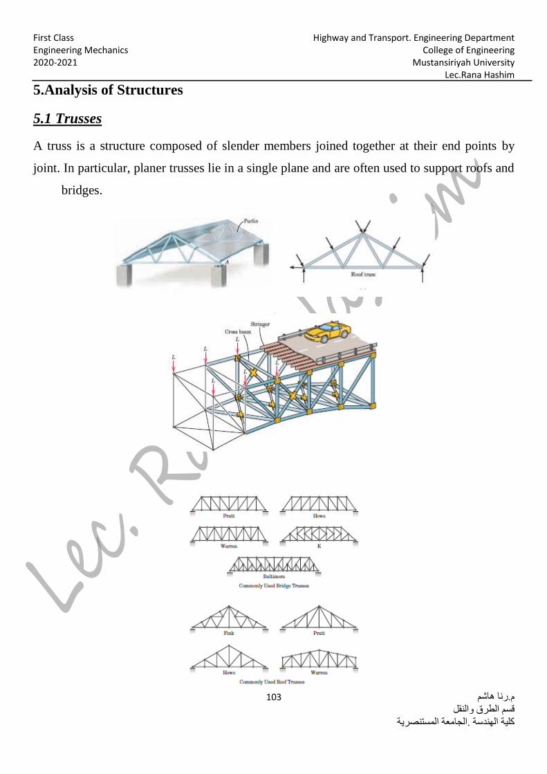
Highway and Transport. Engineering Department First Class College of Engineering Engineering Mechanics Mustansiriyah University 2020-2021 Lec.Rana Hashim 103 .رنا هاشم منقلسم الطرق وال قعة المستنصريةلجامية الهندسة .ا كل5.Analysis of Structures Trusses .1 5 A truss is a structure composed of slender members joined together at their end points by joint. In particular, planer trusses lie in a single plane and are often used to support roofs and bridges.
-
Upload
khangminh22 -
Category
Documents
-
view
2 -
download
0
Transcript of 5.Analysis of Structures Trusses .15
Highway and Transport. Engineering Department First Class College of Engineering Engineering Mechanics
Mustansiriyah University 2020-2021 Lec.Rana Hashim
م.رنا هاشم 103
قسم الطرق والنقل
كلية الهندسة .الجامعة المستنصرية
5.Analysis of Structures
Trusses .15
A truss is a structure composed of slender members joined together at their end points by
joint. In particular, planer trusses lie in a single plane and are often used to support roofs and
bridges.
Highway and Transport. Engineering Department First Class College of Engineering Engineering Mechanics
Mustansiriyah University 2020-2021 Lec.Rana Hashim
م.رنا هاشم 104
قسم الطرق والنقل
كلية الهندسة .الجامعة المستنصرية
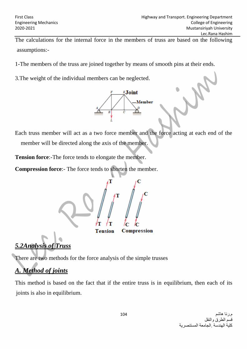
The calculations for the internal force in the members of truss are based on the following
assumptions:-
1-The members of the truss are joined together by means of smooth pins at their ends.
3.The weight of the individual members can be neglected.
Each truss member will act as a two force member and the force acting at each end of the
member will be directed along the axis of the member.
Tension force:-The force tends to elongate the member.
Compression force:- The force tends to shorten the member.
.2Analysis of Truss5
There are two methods for the force analysis of the simple trusses
A. Method of joints
This method is based on the fact that if the entire truss is in equilibrium, then each of its
joints is also in equilibrium.
Highway and Transport. Engineering Department First Class College of Engineering Engineering Mechanics
Mustansiriyah University 2020-2021 Lec.Rana Hashim
م.رنا هاشم 105
قسم الطرق والنقل
كلية الهندسة .الجامعة المستنصرية
∑ 𝐹𝑥 = 0
∑ 𝐹𝑦 = 0
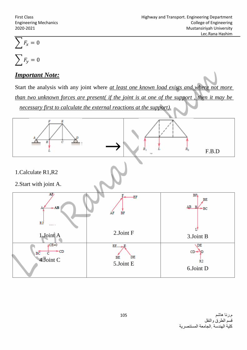
:NoteImportant
at least one known load exists and where not more Start the analysis with any joint where
( if the joint is at one of the support , then it may be than two unknown forces are present
).necessary first to calculate the external reactions at the support
F.B.D →
1.Calculate R1,R2
2.Start with joint A.
3.Joint B
2.Joint F
1.Joint A
6.Joint D
5.Joint E
4.Joint C
Highway and Transport. Engineering Department First Class College of Engineering Engineering Mechanics
Mustansiriyah University 2020-2021 Lec.Rana Hashim
م.رنا هاشم 106
قسم الطرق والنقل
كلية الهندسة .الجامعة المستنصرية
Examples
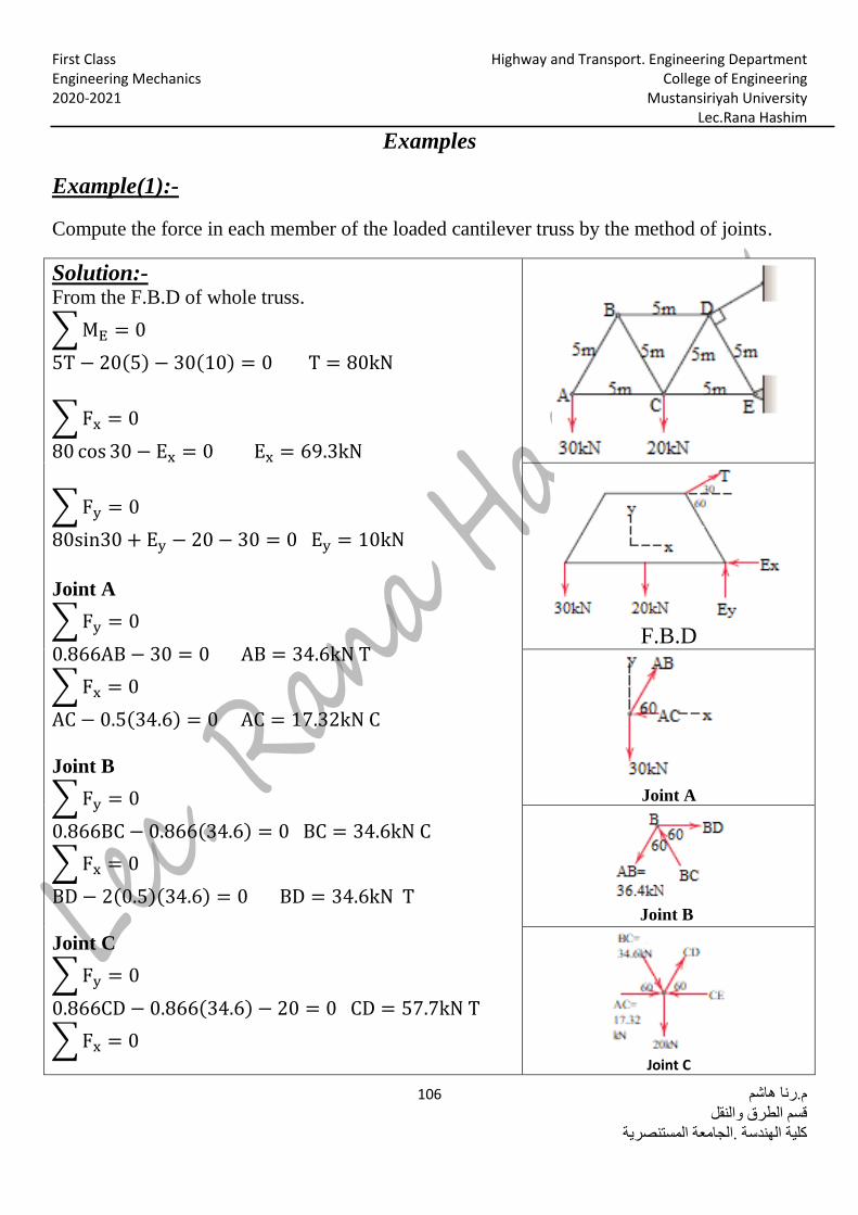
-:Example(1)
Compute the force in each member of the loaded cantilever truss by the method of joints.
-:Solution From the F.B.D of whole truss.
∑ ME = 0
5T − 20(5) − 30(10) = 0 T = 80kN
∑ Fx = 0
80 cos 30 − Ex = 0 Ex = 69.3kN
∑ Fy = 0
80sin30 + Ey − 20 − 30 = 0 Ey = 10kN
Joint A
∑ Fy = 0
0.866AB − 30 = 0 AB = 34.6kN T
∑ Fx = 0
AC − 0.5(34.6) = 0 AC = 17.32kN C Joint B
∑ Fy = 0
0.866BC − 0.866(34.6) = 0 BC = 34.6kN C
∑ Fx = 0
BD − 2(0.5)(34.6) = 0 BD = 34.6kN T
Joint C
∑ Fy = 0
0.866CD − 0.866(34.6) − 20 = 0 CD = 57.7kN T
∑ Fx = 0
F.B.D
Joint A
Joint B
Joint C
Highway and Transport. Engineering Department First Class College of Engineering Engineering Mechanics
Mustansiriyah University 2020-2021 Lec.Rana Hashim
م.رنا هاشم 107
قسم الطرق والنقل
كلية الهندسة .الجامعة المستنصرية
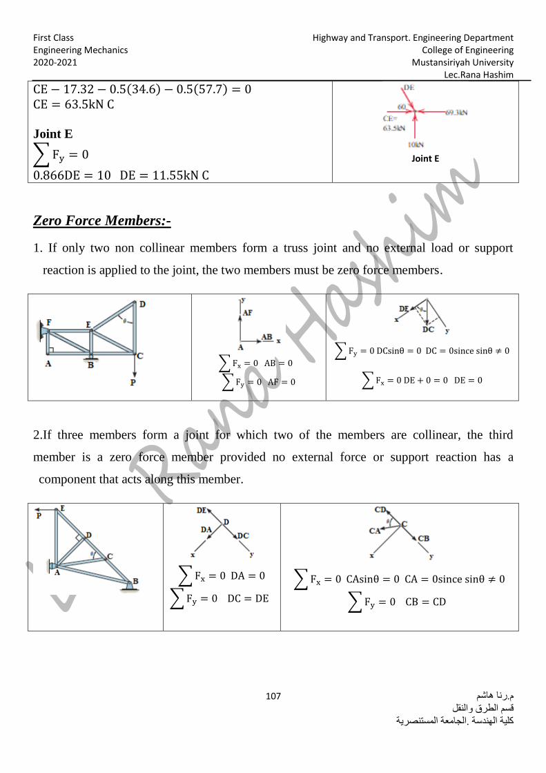
Joint E
CE − 17.32 − 0.5(34.6) − 0.5(57.7) = 0 CE = 63.5kN C
Joint E
∑ Fy = 0
0.866DE = 10 DE = 11.55kN C
-:Zero Force Members
1. If only two non collinear members form a truss joint and no external load or support
reaction is applied to the joint, the two members must be zero force members.
∑ Fy = 0 DCsinθ = 0 DC = 0since sinθ ≠ 0
∑ Fx = 0 DE + 0 = 0 DE = 0
∑ Fx = 0 AB = 0
∑ Fy = 0 AF = 0
2.If three members form a joint for which two of the members are collinear, the third
member is a zero force member provided no external force or support reaction has a
component that acts along this member.
∑ Fx = 0 CAsinθ = 0 CA = 0since sinθ ≠ 0
∑ Fy = 0 CB = CD
∑ Fx = 0 DA = 0
∑ Fy = 0 DC = DE
Highway and Transport. Engineering Department First Class College of Engineering Engineering Mechanics
Mustansiriyah University 2020-2021 Lec.Rana Hashim
م.رنا هاشم 108
قسم الطرق والنقل
كلية الهندسة .الجامعة المستنصرية
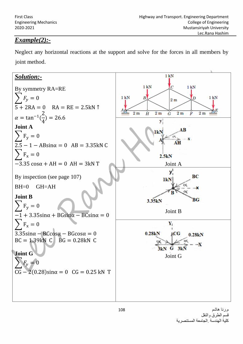
-:Example(2)
Neglect any horizontal reactions at the support and solve for the forces in all members by
joint method.
-:Solution
By symmetry RA=RE
∑ 𝐹𝑦 = 0
5 + 2RA = 0 RA = RE = 2.5kN ↑
𝛼 = tan−1(2
4) = 26.6
Joint A
∑ Fy = 0
2.5 − 1 − ABsinα = 0 AB = 3.35kN C
∑ Fx = 0
−3.35 cosα + AH = 0 AH = 3kN T
By inspection (see page 107)
BH=0 GH=AH
Joint B
∑ Fy = 0
−1 + 3.35sinα + BGsinα − BCsinα = 0
∑ Fx = 0
3.35sinα − BCcosα − BGcosα = 0
BC = 1.39kN C BG = 0.28kN C
Joint G
∑ 𝐹𝑦 = 0
CG − 2(0.28)sinα = 0 CG = 0.25 kN T
Joint A
Joint B
Joint G

Highway and Transport. Engineering Department First Class College of Engineering Engineering Mechanics
Mustansiriyah University 2020-2021 Lec.Rana Hashim
م.رنا هاشم 109
قسم الطرق والنقل
كلية الهندسة .الجامعة المستنصرية
By symmetry
DE = AB = 3.35kN C
CD = BC = 1.39kN C
EF = AH = 3kN T
DF = BH = 0 FG = GH = 3kN T DG = BG = 0.28kN C
Highway and Transport. Engineering Department First Class College of Engineering Engineering Mechanics
Mustansiriyah University 2020-2021 Lec.Rana Hashim
م.رنا هاشم 110
قسم الطرق والنقل
كلية الهندسة .الجامعة المستنصرية
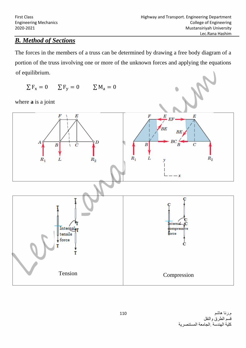
sSection. Method of B
The forces in the members of a truss can be determined by drawing a free body diagram of a
portion of the truss involving one or more of the unknown forces and applying the equations
of equilibrium.
∑ Fx = 0 ∑ Fy = 0 ∑ Ma = 0
where a is a joint
Compression
Tension

Highway and Transport. Engineering Department First Class College of Engineering Engineering Mechanics
Mustansiriyah University 2020-2021 Lec.Rana Hashim
م.رنا هاشم 111
قسم الطرق والنقل
كلية الهندسة .الجامعة المستنصرية
Examples
-:Example(1)
Determine the force in members GE,GC and BC of the truss shown below.
-:Solution Section aa has been chosen
From F.B.D
∑ Fx = 0
400 − Ax = 0 Ax = 400N ←
∑ MA = 0
−1200(8) − 400(3) + Dy(12) = 0
∑ Fy = 0
Ay − 1200 + 900 = 0 Ay = 300N ↑
From the F.B.D of left portion
∑ MG = 0
−300(4) − 400(3) + BC(3) = 0
BC = 800N T
∑ MC = 0
−300(8) + GE(3) = 0
GE = 800N C
∑ Fy = 0
300 −3
5GC = 0
GC = 500N T
F.B.D
F.B.D of left portion
x45
Pencil

Highway and Transport. Engineering Department First Class College of Engineering Engineering Mechanics
Mustansiriyah University 2020-2021 Lec.Rana Hashim
م.رنا هاشم 112
قسم الطرق والنقل
كلية الهندسة .الجامعة المستنصرية
-:Example(2)
Determine the load(P) which can be supported by the truss shown below and product a force
of 10000N compression in member CE.
-:Solution
Joint C
∑ Fy = 0
Cy − 10000 (2.4
3) = 0 Cy = 8000N ↑
For all structure
∑ MA = 0
P(5.4) − Cy(3.6) = 0
p =8000(3.6)
5.4= 5333.33N ↓
x45
Pencil
Highway and Transport. Engineering Department First Class College of Engineering Engineering Mechanics
Mustansiriyah University 2020-2021 Lec.Rana Hashim
م.رنا هاشم 113
قسم الطرق والنقل
كلية الهندسة .الجامعة المستنصرية
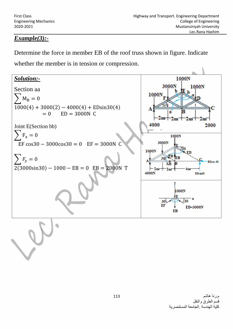
-:(3)eExampl
Determine the force in member EB of the roof truss shown in figure. Indicate
whether the member is in tension or compression.
-:Solution
Section aa
∑ MB = 0
1000(4) + 3000(2) − 4000(4) + EDsin30(4)= 0 ED = 3000N C
Joint E(Section bb)
∑ Fx = 0
EF cos30 − 3000cos30 = 0 EF = 3000N C
∑ 𝐹𝑦 = 0
2(3000sin30) − 1000 − EB = 0 EB = 2000N T
x45
Pencil
Highway and Transport. Engineering Department First Class College of Engineering Engineering Mechanics
Mustansiriyah University 2020-2021 Lec.Rana Hashim
م.رنا هاشم 114
قسم الطرق والنقل
كلية الهندسة .الجامعة المستنصرية
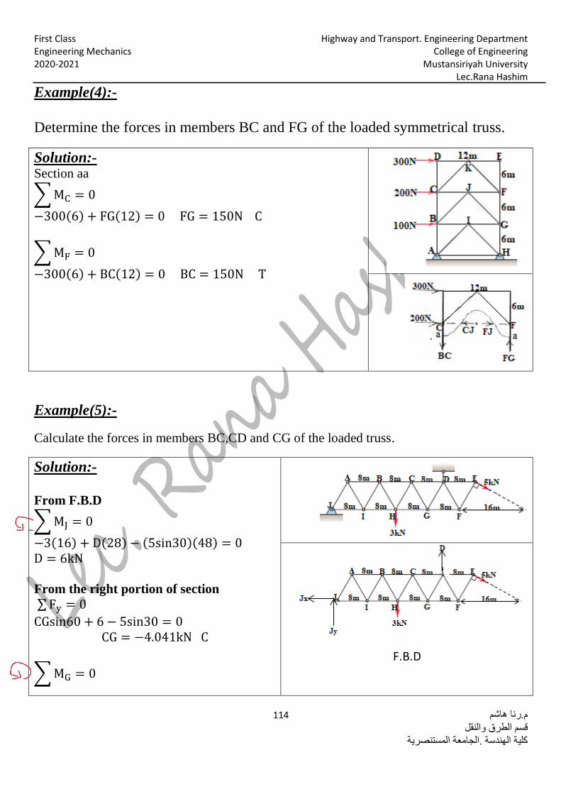
-:Example(4)
Determine the forces in members BC and FG of the loaded symmetrical truss.
-:Solution Section aa
∑ MC = 0
−300(6) + FG(12) = 0 FG = 150N C
∑ MF = 0
−300(6) + BC(12) = 0 BC = 150N T
-:Example(5)
Calculate the forces in members BC,CD and CG of the loaded truss.
-:Solution
From F.B.D
∑ MJ = 0
−3(16) + D(28) − (5sin30)(48) = 0 D = 6kN
From the right portion of section
∑ Fy = 0
CGsin60 + 6 − 5sin30 = 0 CG = −4.041kN C
∑ MG = 0
F.B.D
x45
Pencil
Highway and Transport. Engineering Department First Class College of Engineering Engineering Mechanics
Mustansiriyah University 2020-2021 Lec.Rana Hashim
م.رنا هاشم 115
قسم الطرق والنقل
كلية الهندسة .الجامعة المستنصرية
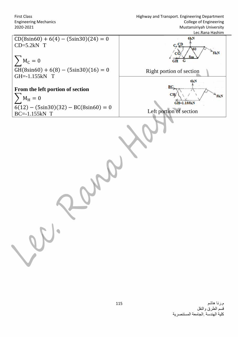
Right portion of section
CD(8sin60) + 6(4) − (5sin30)(24) = 0
T CD=5.2kN
∑ MC = 0
GH(8sin60) + 6(8) − (5sin30)(16) = 0 T GH=-1.155kN
From the left portion of section
∑ MH = 0
6(12) − (5sin30)(32) − BC(8sin60) = 0
T BC=-1.155kN
Left portion of section
x45
Pencil


![Ch 6 Trusses[1]](https://static.fdokumen.com/doc/165x107/631285ddb033aaa8b20fad21/ch-6-trusses1.jpg)