Using the Principles of SoTL to Redesign an Advanced ... - ERIC
Upload
khangminh22Category
view
0download
0
UNIVERSITAT POLITECNICA DE CATALUNYADepartament de Llenguatges i Sistemes Informatics
Redesign Support Framework forComplex Technical Processes
Ivan Lopez Arevalo
Thesis submitted to obtain the degree ofPh.D. in Artificial Intelligence
Supervisors :Dr. Arantza Aldea CorralesDr. Rene Banares-Alcantara
Barcelona, Spain, November 2005.

Redesign Support Framework for Complex Technical Processes
Copyright c© 2005 by Ivan Lopez Arevalo.

Dedicated to
my family, for always being there.
a mi familia, por estar siempre ahi.


Acknowledgements
I would like to thank all those people who have made this thesis possible. I would like tothank my supervisors Drs. Arantza Aldea Corrales and Rene Banares-Alcantara for theirconfidence, guiding, support, time and effort that they spent during this thesis. Also, Iwould like to thank Drs. Matıas Alvarado and Leonid Sheremetov for their support andinspired my decision to work in the field of Artificial Intelligence. I am also indebted tothe reviewers who were available to read and comment an earlier version of this thesisthat made the final version so much better.
I thank the invaluable contribution of Dr. Laureano Jimenez and Antonio Rodrıguezin the area of Chemical Engineering Process Design. Their penetrating and constructivecriticisms and discussions have contributed greatly to the completion of this work.
This work has been mainly supported by the Department of Computer Engineeringand Mathematics of the University Rovira i Virgili. I am indebted to all the membersand staff for providing financial support and resources, particularly the members of theBanzai Group.
My sincerest thanks and acknowledgement to my family for their support and en-couragement. Thanks my parents for their unconditional support during these years.Especially I wish to thank my wife, Joria, for all her kind support and for all her timeand activities sacrificed.
Without the support in one way or another of all these people I would probably havenever finished this work. To all of them, thanks.
Barcelona, Spain, November 2005.
Ivan Lopez Arevalo
v


Abstract
Industrial processes require periodic evaluations to verify their correct operation, both intechnical and economical terms. These evaluations are necessary due to changes in themarkets, and in safety and environmental legislation. In order to satisfy these demandsit is necessary to investigate process alternatives that allow the optimal use of existingresources with the minimum possible investment. This task is known as ”redesign”, whichis a procedure to determine possible changes to an existing process in order to improve itwith respect to some metric, such as economical, environmental, safety, etc.
A redesign support framework for technical processes is proposed in this thesis. Thisframework employs a multiple-model hierarchical representation of the process to be re-designed together with a case-based reasoning engine that helps to decide which elementsof the process should be modified. The framework consists of four main stages: acqui-sition of the design description, candidate identification, generation of alternatives, andadaptation and evaluation.
The original process is modelled hierarchically exploiting means-end and part-wholeconcepts, and thus knowledge about the behaviour, structure, function and intention ofeach part of the process is automatically generated and stored. Given the new specifica-tions or requirements that the process must fulfil, the system finds the parts of the processwhich must be redesigned and a case library is used to obtain alternative process sectionswhich can be adapted to substitute parts of the original process. Therefore, the pro-posed framework allows to model the process, to identify process components suitable forredesign, to obtain alternative components, and finally, to adapt these components intothe original process. This procedure can be seen as a reverse engineering activity whereabstract models at different levels are generated from a detailed description of an existingprocess to reduce its complexity. The framework has been implemented and tested on theChemical Engineering domain.
vii


CONTENTS
Acknowledgements v
Abstract vii
1 Introduction 1
1.1 Research context . . . . . . . . . . . . . . . . . . . . . . . . . . . . . . . . 1
1.2 Motivation . . . . . . . . . . . . . . . . . . . . . . . . . . . . . . . . . . . . 3
1.3 Research goals . . . . . . . . . . . . . . . . . . . . . . . . . . . . . . . . . . 4
1.4 Research proposal . . . . . . . . . . . . . . . . . . . . . . . . . . . . . . . . 5
1.5 Contributions . . . . . . . . . . . . . . . . . . . . . . . . . . . . . . . . . . 5
1.6 Scope of work . . . . . . . . . . . . . . . . . . . . . . . . . . . . . . . . . . 6
1.7 Thesis layout . . . . . . . . . . . . . . . . . . . . . . . . . . . . . . . . . . 7
2 The process of redesign 9
2.1 Introduction . . . . . . . . . . . . . . . . . . . . . . . . . . . . . . . . . . . 9
2.2 Redesign in general . . . . . . . . . . . . . . . . . . . . . . . . . . . . . . . 10
2.2.1 The Design-Redesign relationship . . . . . . . . . . . . . . . . . . . 10
2.2.2 Types of redesign . . . . . . . . . . . . . . . . . . . . . . . . . . . . 13
2.3 The general (re)design approach . . . . . . . . . . . . . . . . . . . . . . . 15
2.3.1 Conceptual models in (re)design . . . . . . . . . . . . . . . . . . . . 16
2.3.2 The role of function in the design process . . . . . . . . . . . . . . . 18
2.3.3 The design process . . . . . . . . . . . . . . . . . . . . . . . . . . . 19
2.3.4 The design object . . . . . . . . . . . . . . . . . . . . . . . . . . . 22
2.4 Redesign approaches . . . . . . . . . . . . . . . . . . . . . . . . . . . . . . 27
2.4.1 Generic approaches in Engineering . . . . . . . . . . . . . . . . . . 28
2.4.2 Mechanical Engineering . . . . . . . . . . . . . . . . . . . . . . . . 28
2.4.3 Electrical and Electronic Engineering . . . . . . . . . . . . . . . . . 29
2.4.4 Chemical Engineering . . . . . . . . . . . . . . . . . . . . . . . . . 30
2.5 Chapter conclusions . . . . . . . . . . . . . . . . . . . . . . . . . . . . . . . 32
ix
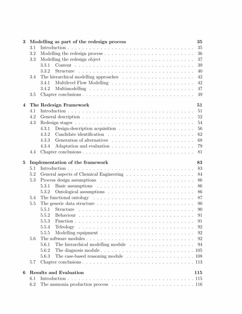
3 Modelling as part of the redesign process 353.1 Introduction . . . . . . . . . . . . . . . . . . . . . . . . . . . . . . . . . . . 353.2 Modelling the redesign process . . . . . . . . . . . . . . . . . . . . . . . . . 363.3 Modelling the redesign object . . . . . . . . . . . . . . . . . . . . . . . . . 37
3.3.1 Content . . . . . . . . . . . . . . . . . . . . . . . . . . . . . . . . . 393.3.2 Structure . . . . . . . . . . . . . . . . . . . . . . . . . . . . . . . . 40
3.4 The hierarchical modelling approaches . . . . . . . . . . . . . . . . . . . . 423.4.1 Multilevel Flow Modelling . . . . . . . . . . . . . . . . . . . . . . . 423.4.2 Multimodelling . . . . . . . . . . . . . . . . . . . . . . . . . . . . . 47
3.5 Chapter conclusions . . . . . . . . . . . . . . . . . . . . . . . . . . . . . . . 49
4 The Redesign Framework 514.1 Introduction . . . . . . . . . . . . . . . . . . . . . . . . . . . . . . . . . . . 514.2 General description . . . . . . . . . . . . . . . . . . . . . . . . . . . . . . . 524.3 Redesign stages . . . . . . . . . . . . . . . . . . . . . . . . . . . . . . . . . 54
4.3.1 Design-description acquisition . . . . . . . . . . . . . . . . . . . . . 564.3.2 Candidate identification . . . . . . . . . . . . . . . . . . . . . . . . 624.3.3 Generation of alternatives . . . . . . . . . . . . . . . . . . . . . . . 684.3.4 Adaptation and evaluation . . . . . . . . . . . . . . . . . . . . . . . 79
4.4 Chapter conclusions . . . . . . . . . . . . . . . . . . . . . . . . . . . . . . . 81
5 Implementation of the framework 835.1 Introduction . . . . . . . . . . . . . . . . . . . . . . . . . . . . . . . . . . . 835.2 General aspects of Chemical Engineering . . . . . . . . . . . . . . . . . . . 845.3 Process design assumptions . . . . . . . . . . . . . . . . . . . . . . . . . . 86
5.3.1 Basic assumptions . . . . . . . . . . . . . . . . . . . . . . . . . . . 865.3.2 Ontological assumptions . . . . . . . . . . . . . . . . . . . . . . . . 86
5.4 The functional ontology . . . . . . . . . . . . . . . . . . . . . . . . . . . . 875.5 The generic data structure . . . . . . . . . . . . . . . . . . . . . . . . . . . 90
5.5.1 Structure . . . . . . . . . . . . . . . . . . . . . . . . . . . . . . . . 905.5.2 Behaviour . . . . . . . . . . . . . . . . . . . . . . . . . . . . . . . . 915.5.3 Function . . . . . . . . . . . . . . . . . . . . . . . . . . . . . . . . . 915.5.4 Teleology . . . . . . . . . . . . . . . . . . . . . . . . . . . . . . . . 925.5.5 Modelling equipment . . . . . . . . . . . . . . . . . . . . . . . . . . 92
5.6 The software modules . . . . . . . . . . . . . . . . . . . . . . . . . . . . . . 925.6.1 The hierarchical modelling module . . . . . . . . . . . . . . . . . . 945.6.2 The diagnosis module . . . . . . . . . . . . . . . . . . . . . . . . . . 1055.6.3 The case-based reasoning module . . . . . . . . . . . . . . . . . . . 108
5.7 Chapter conclusions . . . . . . . . . . . . . . . . . . . . . . . . . . . . . . . 113
6 Results and Evaluation 1156.1 Introduction . . . . . . . . . . . . . . . . . . . . . . . . . . . . . . . . . . . 1156.2 The ammonia production process . . . . . . . . . . . . . . . . . . . . . . . 116

6.3 Hierarchical modelling of the ammonia process . . . . . . . . . . . . . . . . 1176.4 Identification of candidates . . . . . . . . . . . . . . . . . . . . . . . . . . . 1236.5 Generation of alternatives . . . . . . . . . . . . . . . . . . . . . . . . . . . 1276.6 Other results . . . . . . . . . . . . . . . . . . . . . . . . . . . . . . . . . . 134
6.6.1 Concentration variable . . . . . . . . . . . . . . . . . . . . . . . . . 1346.6.2 Temperature variable . . . . . . . . . . . . . . . . . . . . . . . . . . 136
6.7 Discussion of results . . . . . . . . . . . . . . . . . . . . . . . . . . . . . . 1416.8 Chapter conclusions . . . . . . . . . . . . . . . . . . . . . . . . . . . . . . . 144
7 Conclusions 1477.1 Summary of thesis . . . . . . . . . . . . . . . . . . . . . . . . . . . . . . . 1477.2 Limitations . . . . . . . . . . . . . . . . . . . . . . . . . . . . . . . . . . . 1487.3 Further work . . . . . . . . . . . . . . . . . . . . . . . . . . . . . . . . . . 148
A Data file of ammonia production process 151
B Failure conditions for flow functions 157
C Modelling of the ammonia process 161
D Chemical processes modelled 163
E Publications 179
Bibliography 183


LIST OF FIGURES
1.1 Product design path. . . . . . . . . . . . . . . . . . . . . . . . . . . . . . . 2
3.1 The basic systems engineering process. . . . . . . . . . . . . . . . . . . . . 373.2 Means-ends and part-whole dimensions in MFM. . . . . . . . . . . . . . . . 43
4.1 Proposed redesign framework. . . . . . . . . . . . . . . . . . . . . . . . . . 544.2 Functional relations. . . . . . . . . . . . . . . . . . . . . . . . . . . . . . . 594.3 Grouping of units/meta-units. . . . . . . . . . . . . . . . . . . . . . . . . . 614.4 Intralevel meta-models. . . . . . . . . . . . . . . . . . . . . . . . . . . . . . 614.5 Interlevel meta-models. . . . . . . . . . . . . . . . . . . . . . . . . . . . . . 614.6 Abstraction of a process. . . . . . . . . . . . . . . . . . . . . . . . . . . . . 624.7 Content of redesign specification. . . . . . . . . . . . . . . . . . . . . . . . 634.8 Cause and consequence units/meta-units for variable X. . . . . . . . . . . . 654.9 Stages of the CBR cycle [Aamodt 94]. . . . . . . . . . . . . . . . . . . . . . 704.10 The CBR system in the framework. . . . . . . . . . . . . . . . . . . . . . . 714.11 Abstract and ground cases. . . . . . . . . . . . . . . . . . . . . . . . . . . . 724.12 Case representation. . . . . . . . . . . . . . . . . . . . . . . . . . . . . . . 734.13 Case organisation. . . . . . . . . . . . . . . . . . . . . . . . . . . . . . . . . 744.14 The teleological similarity measurements. . . . . . . . . . . . . . . . . . . . 774.15 The functional similarity measurements. . . . . . . . . . . . . . . . . . . . 784.16 The hierarchical similarity measurements. . . . . . . . . . . . . . . . . . . 79
5.1 Instantiating concepts in the ontology. . . . . . . . . . . . . . . . . . . . . 885.2 Partial structural scheme of the ontology. . . . . . . . . . . . . . . . . . . . 895.3 The generic data model of equipment. . . . . . . . . . . . . . . . . . . . . . 935.4 Mapping from stages to software modules. . . . . . . . . . . . . . . . . . . 935.5 The software modules in the framework. . . . . . . . . . . . . . . . . . . . 935.6 Flow diagram of the modelling module. . . . . . . . . . . . . . . . . . . . . 945.7 The hierarchy of functions. . . . . . . . . . . . . . . . . . . . . . . . . . . . 975.8 MFM and Multimodelling functions in the functional hierarchy. . . . . . . 985.9 One of the rules to group flow change units to more important functions. . 995.10 Assignation of functional concepts to a pump. . . . . . . . . . . . . . . . . 100
xiii
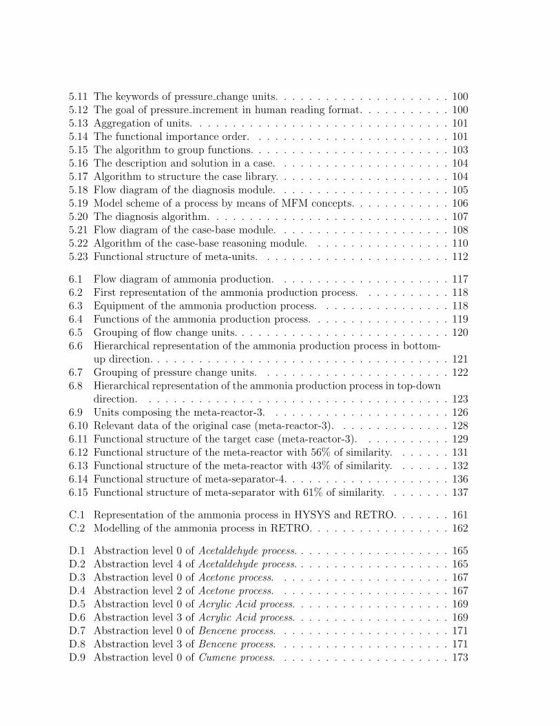
5.11 The keywords of pressure change units. . . . . . . . . . . . . . . . . . . . . 1005.12 The goal of pressure increment in human reading format. . . . . . . . . . . 1005.13 Aggregation of units. . . . . . . . . . . . . . . . . . . . . . . . . . . . . . . 1015.14 The functional importance order. . . . . . . . . . . . . . . . . . . . . . . . 1015.15 The algorithm to group functions. . . . . . . . . . . . . . . . . . . . . . . . 1035.16 The description and solution in a case. . . . . . . . . . . . . . . . . . . . . 1045.17 Algorithm to structure the case library. . . . . . . . . . . . . . . . . . . . . 1045.18 Flow diagram of the diagnosis module. . . . . . . . . . . . . . . . . . . . . 1055.19 Model scheme of a process by means of MFM concepts. . . . . . . . . . . . 1065.20 The diagnosis algorithm. . . . . . . . . . . . . . . . . . . . . . . . . . . . . 1075.21 Flow diagram of the case-base module. . . . . . . . . . . . . . . . . . . . . 1085.22 Algorithm of the case-base reasoning module. . . . . . . . . . . . . . . . . 1105.23 Functional structure of meta-units. . . . . . . . . . . . . . . . . . . . . . . 112
6.1 Flow diagram of ammonia production. . . . . . . . . . . . . . . . . . . . . 1176.2 First representation of the ammonia production process. . . . . . . . . . . 1186.3 Equipment of the ammonia production process. . . . . . . . . . . . . . . . 1186.4 Functions of the ammonia production process. . . . . . . . . . . . . . . . . 1196.5 Grouping of flow change units. . . . . . . . . . . . . . . . . . . . . . . . . . 1206.6 Hierarchical representation of the ammonia production process in bottom-
up direction. . . . . . . . . . . . . . . . . . . . . . . . . . . . . . . . . . . . 1216.7 Grouping of pressure change units. . . . . . . . . . . . . . . . . . . . . . . 1226.8 Hierarchical representation of the ammonia production process in top-down
direction. . . . . . . . . . . . . . . . . . . . . . . . . . . . . . . . . . . . . 1236.9 Units composing the meta-reactor-3. . . . . . . . . . . . . . . . . . . . . . 1266.10 Relevant data of the original case (meta-reactor-3). . . . . . . . . . . . . . 1286.11 Functional structure of the target case (meta-reactor-3). . . . . . . . . . . 1296.12 Functional structure of the meta-reactor with 56% of similarity. . . . . . . 1316.13 Functional structure of the meta-reactor with 43% of similarity. . . . . . . 1326.14 Functional structure of meta-separator-4. . . . . . . . . . . . . . . . . . . . 1366.15 Functional structure of meta-separator with 61% of similarity. . . . . . . . 137
C.1 Representation of the ammonia process in HYSYS and RETRO. . . . . . . 161C.2 Modelling of the ammonia process in RETRO. . . . . . . . . . . . . . . . . 162
D.1 Abstraction level 0 of Acetaldehyde process. . . . . . . . . . . . . . . . . . . 165D.2 Abstraction level 4 of Acetaldehyde process. . . . . . . . . . . . . . . . . . . 165D.3 Abstraction level 0 of Acetone process. . . . . . . . . . . . . . . . . . . . . 167D.4 Abstraction level 2 of Acetone process. . . . . . . . . . . . . . . . . . . . . 167D.5 Abstraction level 0 of Acrylic Acid process. . . . . . . . . . . . . . . . . . . 169D.6 Abstraction level 3 of Acrylic Acid process. . . . . . . . . . . . . . . . . . . 169D.7 Abstraction level 0 of Bencene process. . . . . . . . . . . . . . . . . . . . . 171D.8 Abstraction level 3 of Bencene process. . . . . . . . . . . . . . . . . . . . . 171D.9 Abstraction level 0 of Cumene process. . . . . . . . . . . . . . . . . . . . . 173

D.10 Abstraction level 2 of Cumene process. . . . . . . . . . . . . . . . . . . . . 173D.11 Abstraction level 0 of Di-Metyl Ether process. . . . . . . . . . . . . . . . . 175D.12 Abstraction level 1 of Di-Metyl Ether process. . . . . . . . . . . . . . . . . 175D.13 Abstraction level 0 of Ethanol process. . . . . . . . . . . . . . . . . . . . . 177D.14 Abstraction level 3 of Ethanol process. . . . . . . . . . . . . . . . . . . . . 177


LIST OF TABLES
4.1 Balance equations and state constraints for flow functions. . . . . . . . . . 67
6.1 Equipments and functions of the ammonia production process. . . . . . . . 1196.2 Identified candidates. . . . . . . . . . . . . . . . . . . . . . . . . . . . . . . 1256.3 Cause and consequence units. . . . . . . . . . . . . . . . . . . . . . . . . . 1276.4 Used values in the similarity computations. . . . . . . . . . . . . . . . . . . 1286.5 Result of the global similarity computation for meta-reactor-3. . . . . . . . 1306.6 Values of meta-reactor with 56% of similarity. . . . . . . . . . . . . . . . . 1316.7 Values of meta-reactor with 43% of similarity. . . . . . . . . . . . . . . . . 1326.8 Values of meta-reactor with 37% of similarity. . . . . . . . . . . . . . . . . 1336.9 Identified candidates related to increase purity. . . . . . . . . . . . . . . . . 1346.10 Cause and consequence units of candidates related to increase purity. . . . 1356.11 Values of meta-separator-4. . . . . . . . . . . . . . . . . . . . . . . . . . . 1376.12 Result of the global similarity computation for meta-separator-4. . . . . . . 1386.13 Values of meta-separator with 61% of similarity. . . . . . . . . . . . . . . . 1396.14 Identified candidates related to increase conversion. . . . . . . . . . . . . . 1396.15 Cause and consequence units of candidates related to increase conversion. . 1406.16 Values of heat exchanger-2 (E-102). . . . . . . . . . . . . . . . . . . . . . . 1416.17 Result of the global similarity computation for heat exchanger-2 (E-102). . 1426.18 Values of heat exchanger with 69% of similarity. . . . . . . . . . . . . . . . 143
D.2 Result of the global similarity computation for T-101 (vapour absorption column)in the Acetaldehyde process. Inlet function: inlet/reaction, Outlet function:outlet/reaction . . . . . . . . . . . . . . . . . . . . . . . . . . . . . . . . . 166
D.3 Result of the global similarity computation for MU2-2-temperature (heater)in the Acetone process. Inlet function: tank, Outlet function: tubular reactor 168
D.4 Result of the global similarity computation for MU11-3-separation (liq liq extractor)in the Acrylic Acid process. Inlet function: vapour absorption/trayed, Out-let function: trayed/trayed . . . . . . . . . . . . . . . . . . . . . . . . . . . 170
D.5 Result of the global similarity computation for MU14-3-reaction (tubu-lar reactor) in the Bencene process. Inlet function: tmp change, Outletfunction: separation . . . . . . . . . . . . . . . . . . . . . . . . . . . . . . . 172
xvii

D.6 Result of the global similarity computation for MU3-2-temperature (heat exchanger)in the Cumene process. Inlet function: inlet/tubular reactor, Outlet func-tion: outlet/flash . . . . . . . . . . . . . . . . . . . . . . . . . . . . . . . . 174
D.7 Result of the global similarity computation for T-101 (trayed) in the Di-Methyl Ether process. Inlet function: valve, Outlet function: outlet/pump . 176
D.8 Result of the global similarity computation for MU7-3-separation (trayed)in the Ethanol process. Inlet function: tank, Outlet function: outlet/outlet . 178

CHAPTER
ONE
Introduction
In this chapter a brief introduction to the research presented in this thesis and
its context is given. The research context is described to place the problem.
The motivation behind the research is defined, which focuses on the redesign
of technical complex processes. The research objectives and scope of the work
are presented in general terms to define the specific area of application. Finally
the chapter ends with a description of the layout of the thesis.
1.1 Research context
Nowadays the design and development of new products or modification of existent ones
(redesign) is a key and fundamental element to enhance innovation and competivity of
industrial companies. Design has an increasing importance to differentiate one product
from another.
In general, design is the process of specifying a description of a product that satisfies a
set of requirements [Umeda 90]. Redesign is the process of changing the description of an
existent product (original design) to satisfy a new set of requirements [Brown 98]. Design
engineering includes both design and redesign. In the literature we can find diverse terms
to refer design and redesign, such as preliminary, conceptual, functional, creative, routine,
non-routine, personified, parametric, innovative, etc., but the characteristic activities of
the global design engineering can be divided as follows [Subba-Rao 99], see Figure 1:
1

2 INTRODUCTION 1.2
• Conceptual (re)design, the phase where the global goals, requirements and operation
of the product are established based on abstract concepts. The research presented
in this thesis deals with this aspect.
• Detailed (re)design, the phase where the results of the conceptual design are used
to physically implement a product.
ideas, objectives,desired functions,
functional requirements,etc.
productdesign-description
final product
Conceptualdesign
Detaileddesign
Figure 1.1: Product design path.
Design engineering involves a wide range of activities. Some of them require human
intelligence to process the information. Design engineering can appear in a broad variety
of domains, from the assembly of brakes to complex industrial plants and from simple
chips to the most advanced super computers.
Both design and redesign consist of two main elements: the (re)design process and the
(re)design object. The (re)design process involves all the (re)design activities performed
over the (re)design object, which is the subject entity to be (re)designed. In engineering
domains is common to refer to the (re)design object as the artefact. An artefact is a type
of product to denote physical and technical devices.
The (re)design process is characterised by the map between functional requirements to
structural requirements. Thus, design and redesign involves different types of reasoning
and different sources of knowledge. In other words, both can be considered as a dialectic
process between goals (what it is desired) and possibilities (real constraints), directed to
the satisfaction of functional specifications and performance [Stephanopoulos 90b]. At
the moment only few general theories for the systematic and rigorous development of the
procedure of product design exist, as Quality Function Deployment [Sullivan 86] or the
General Design Theory [Tomiyama 87].

1.2 MOTIVATION 3
1.2 Motivation
The industry deals with complex technical processes where its behaviour is mainly pre-
dicted by means of complex numerical simulators; the redesign of such processes is a
common task. Nowadays for a very mature technology redesign represents the 75% of in-
dustrial projects [Grossmann 00]. The redesign of a process is sometimes necessary when
certain time has passed from its implantation or when they must adapt to economical,
technological, or environmental requirements. The redesign is not part of the maintenance
stage but must be considered into the process’s life cycle.
Although a systematic methodology of redesign does not exist, most of the existing
methodologies have been centred in solving some aspects of the redesign process such
as:
• Increment production capacity,
• Increment production efficiency,
• Enhance quality of products
• Reduce energy consumption,
• Reduce pollution,
• Implement new technologies, or
• Implement control and safety considerations.
From a general point of view, the redesign is done typically in three steps: design-
description acquisition (modelling), problem analysis (diagnosis) and proposal of mod-
ifications (generation of alternatives). In real redesign situations, human designers in-
tuitively create mental abstract models by removing superfluous information about the
process. Such models are based on functions of the equipment1 of the process and its
context.
From the early 60’s, Artificial Intelligence techniques have been used for design, such as
constraint-based systems, case-based reasoning, model-based reasoning, planning, neural
networks, and genetic algorithms. Although in these approaches the modelling and sim-
ulation of the processes has been solved in acceptable way, another problem has been
1In the rest of the document the term equipment or device is used to refer the physical items within theprocess (also named plant or artefact) being modelled. Examples of equipment are compressors, mixers,reactors, etc. Examples of process are hydraulic system of cars, electrical circuits, industrial plants, etc.

4 INTRODUCTION 1.3
generated, the used knowledge representations require so detailed information that some-
times it is difficult to understand.
Although several redesign frameworks exist [Akin 82, Mitchell 83, Howe 86, Fischer 87,
Mostow 89, Goel 91, Bras 92, Stroulia 92a, Chandrasekaran 93, French 93, Brazier 96,
Eldonk 96, Pos 97, Price 97, Umeda 97, Gero 98, Culley 99, Culley 99, Kitamura 99,
Kraslawski 00, Grossmann 00, Arana 01, Maher 01], we are interested in one that consid-
ers:
• Cognitive aspects to reduce the complexity of complex processes and facilitate its
understanding.
• Functional and teleological concepts to enhance the redesign activities (modelling,
diagnosis, and generation of alternatives).
• Of “general” (not exclusive) application, i.e., it may be applied to support several
redesign objectives in a same domain, and not only one.
1.3 Research goals
Taking into account the previous mentioned situation, the main objective of this re-
search is to obtain a support framework to assist the human designer in the redesign
of complex technical processes. The structure of this framework must be based on the
common redesign activities performed by human designers on real redesign situations.
Therefore, the framework must able to reduce the complexity of the processes to be
redesigned, and therefore facilitate the redesign activities.
In order to obtain the framework, more specific objectives of this research have been
identified, which purposes are described as follows:
1. Modelling of the redesign process. The redesign steps must be identified according
to how human designer made them. This must be based on a hybrid approach from
redesign, modelling, human computer-interaction, and reasoning issues. These steps
must be directed toward manipulate and modify the object of redesign.
2. Use of models to reason about the object of redesign. Since the redesign object
(complex technical process) is the core of the redesign approach, then it must be
modelled taking into account cognitive aspects to reduce its complexity. The aim is
to facilitate its manipulation and consequently to enhance the redesign activities in
the overall redesign process.

1.5 RESEARCH PROPOSAL 5
3. Suggestion of equipment to be modified and adapted. By using the approach con-
sidered in the two previous points, appropriate reasoning tasks must be integrated
into the framework to identify the equipment to be modified and to obtain similar
ones from other processes.
4. The framework must be tested in real situations. The framework must be applied to
a real redesign domain to demonstrate its suitability and evaluate its performance.
1.4 Research proposal
The framework may be obtained integrating model-based reasoning and case-based rea-
soning techniques. Using model-based reasoning the original process can be modelled
hierarchically. Using case-based reasoning alternative process parts can be obtained from
other processes, which have to be adapted into the original process. In a detailed view,
the framework would allow the process to be modelled, the process sections suitable for
modification can be identifed, and the alternative parts must be obtained, adapted and
evaluated.
The redesign activities will be guided by an approach means-end and part-whole following
the inverse sense of the activities made during the original design of the process. The idea
is to reason at abstract levels on the function of the equipment in similar way to the
reasoning made in the beginning of the original design (without worrying temporarily
about the implementation of equipment). This can be seen as a reverse engineering
activity, which employs a hierarchical representation of the process at different levels of
abstraction to reduce the complexity of the process.
The framework is implemented in Chemical Engineering domain due to the complexity
of the processes involved and the interaction with experts in the area. This thesis is mul-
tidisciplinary, several chemical engineers experts in design have contributed with ideas,
discussions, and suggestions to carry out this research. At same time, a Chemical Engi-
neering PhD thesis [Rodrıguez-Martınez 05] has been obtained with contributions of this
work.
1.5 Contributions
The main goal of this thesis is to obtain a redesign support framework for complex pro-
cesses. To do this, we proposed the use of hierarchical multiple models to facilitate the

6 INTRODUCTION 1.6
redesign activities. Thus, the framework focused on conceptual redesign issues where
abstract models are employed. The processes are modelled hierarchically based on their
functions and goals.
Thus, the primary contributions of this thesis can be summarised as follows:
• A novel redesign framework that combines model-based reasoning and case-base
reasoning techniques has been designed, implemented and tested (see Chapters 4, 5,
and 6). This framework enables the designer to work directly with the conceptual
design of an existing process (i.e. a process already in operation) to automatically
generate abstract multiple-models which can be modified to develop alternative
process designs. The procedure can be seen as the reverse engineering approach
“replay and modify”. This model-based approach provides an appropriate way of
combinining hierarchical and functional modelling to represent and reason about
complex processes. The hierarchical case-based approach provides a systematic way
of reusing the sections of previous processes.
• The use of Multimodelling and Multilevel Flow Modelling approaches to integrate
mental abstract models about the behaviour of processes in the redesign activities
(see Chapter 3, 4, and 5). These models provide a more intuitive vision of reasoning
on each task to be performed, and thus the redesign activities are enhanced (see
Chapter 6). These modelling approaches have been applied successfully in diagnosis
and control domains in other investigations; we have applied them to redesign com-
plex processes with acceptable and interesting results (see Chapter 6 and Appendix
D).
These contributions have been reported on several publications (see Appendix E).
1.6 Scope of work
The proposed redesign framework has to be able to deal with complex technical processes.
In this sense, the type of processes we are referring to, need to be clarified. Thus, the
following assumptions about processes were considered in this research:
1. The complexity of the process must be high. Complex in the sense that the process is
composed by several interrelated equipment which behaviour may consist on several
hundreds of non-linear equation systems.

1.7 THESIS LAYOUT 7
2. Complex numerical simulators can be used to model the behaviour of the process.
3. The process is already implemented, which means there is a design solution that
satisfies the original requirements of such process and the process is in operation.
4. Human designers can understand the process intuitively identifying its functional
sections. That means that internal equipment of the process can be grouped based
on functions and goals using an ontological commitment.
5. The process can be represented by functional abstract concepts. In other words, the
domain has a well-defined structure about the functions of the processes. Any do-
main, which can be symbolically modelled, is representable by using the knowledge
representation scheme used.
1.7 Thesis layout
This thesis consists of seven chapters and five appendixes. The remainder is structured
as follows:
In Chapter 2 the relevant literature on (re)design is presented. This is to give a context
of the relationship between design and redesign and how both share common features, as
the structure of the process (the required steps) and the manipulation of the object of
interest. Artificial Intelligence contributions to (re)design are also presented, both in the
(re)design process as in the (re)design object. Finally some of the most relevant redesign
approaches in some engineering domains are presented.
In Chapter 3 the theoretical background to structure the (re)design process and to manip-
ulate the (re)design object is described. The structure of the (re)design process extends
the general engineering process. To enhance the manipulation of the (re)design object a
hierarchical modelling approach is presented exploiting cognitive and functional concepts.
The theoretical issues regarding the manipulation of (re)design object only involve mod-
elling. The manipulation approaches are described in the next chapter because they are
not directly related either to the (re)design process or the (re)design object.
In Chapter 4 the proposed redesign framework is presented. The modelling approaches
presented in Chapter 3 are used to structure the redesign process and to show how the
manipulation of the redesign object is performed. Thus, how the redesign process guides
the redesign object manipulation is illustrated. All these issues are presented from a
general point of view.

8 INTRODUCTION 1.7
In Chapter 5 the implementation of the framework is described. Here the Chemical
Engineering process domain (redesign of chemical plants) is presented as it is the domain
used. Although the framework may face other types of processes, this domain was chosen
because the complexity of the processes and the interaction with expert designers.
In Chapter 6 experimental results and evaluation of the implementation are presented.
Practical examples of redesign are tackled by using as case study the ammonia production
process. A discussion of the results of the research is described to provide a way to describe
the functionality of each stage.
In Chapter 7 the conclusions and remarks of the research are presented. Here the main
limitations of the research are included. Furthermore, ideas for future work are presented.
In Appendix A the acquired data file of the ammonia production process is presented.
In Appendix B the possible fault conditions of the flow functions in the Multilevel Flow
Modelling are described.
In Appendix C the modelling secuence of the ammonia production process is given.
In Appendix D the list of processes modelled in the framework is presented. Also the
modelling screenshots of some process modelled in the framework with its corresponding
results are shown.
In Appendix E the publications carried out in the investigation are listed.

CHAPTER
TWO
The process of redesign
In this chapter a review of research work related to the process of redesign
is presented. The different research approaches are presented from a general
point of view to more specific one. (Re)design research work on engineering
was investigated as research in other areas although is interesting, is out of the
scope of this thesis.
2.1 Introduction
In the literature there is a tremendous amount of research work about design. Research
work on design can be grouped in different perspectives, a revision of representative
approaches related to methods and techniques employed in engineering applications is
presented in this chapter. The involved subjects are: general issues of design-redesign,
the general (re)design approach, and the approaches of (re)design. The review presented
in this section is from an engineering perspective, as the work described in this thesis has
been performed on the (re)design of physical artefacts.
Firstly within the general issues of (re)design, the design-redesign relationship is pre-
sented (§2.2.1) to clarify the point of view adopted in this thesis and to explain that the
term (re)design is used sometimes to refer to both design and redesign. Based on those
descriptions, the classification of redesign types is presented (§2.2.2).
9
10 THE PROCESS OF REDESIGN 2.2
Next, the general (re)design approach is presented. This involves a brief description of
employed models (§2.3.1) and the role of function in (re)design (§2.3.2). This is relevant
to explain the elements of the overall design approach: design process and design object;
which are described in more detail in subsections §2.3.3 and §2.3.4 respectively.
Therefore, some relevant approaches on redesign are briefly presented, they are presented
only from redesign perspective. In the last subsection (§2.4) the contributions related to
a specific area, such as mechanical, electrical and chemical points of view are considered.
Finally in the last subsection (§2.5) the most important aspects of the presented work
are remarked in the conclusions. This will stand out the main issues related to this thesis
and explain the (re)design approach adopted.
2.2 Redesign in general
In this subsection general issues about design are described, such as the design-redesign
relationship and the classification of redesign types.
2.2.1 The Design-Redesign relationship
In the literature there are diverse definitions about design and redesign; both concepts
share common characteristics and can be included into a single “umbrella” of problem-
solving methods. Through strongly related both concepts use different approximations.
To clarify the relation between design and redesign is necessary to define both concepts.
Some of the most interesting definitions of design that we have found in the literature are
summarised bellow:
• Design can be described as the process of transforming a set of functional specifica-
tions and requirements into a complete description of a physical product or system,
which meets those specifications, and requirements [Anderson 89].
• Design is formally a search problem in a large space of objects that satisfy multiple
constraints [Chandrasekaran 90].
• Design is the task of devising courses of action to change or create better
ones [Simon 96].

2.2 REDESIGN IN GENERAL 11
• Design starts with an intended activity or use [Maher 97b] and uses available
knowledge to arrive at a description of an artefact which will produce those re-
sults [Gero 90b].
Defining design is difficult because the term refers both to a product (the object to
be designed) and a process (the process of design). The reasoning process involved in
design allows to move from a functional concept as a starting point to a product solution.
Therefore, the design activity can be seen as an activity of synthesis, which is strongly
influenced by the skills and mental models of the designer.
However, in Artificial Intelligence, design has been studied analytically using scientific
methods. Design process and Design object strongly depend on the design knowledge em-
ployed, which also depends on the domain knowledge and the expertise of the designer.
During the transformation of the specifications to the final description process, the de-
signer makes decisions about function, shape, properties of material, manufacturing tech-
nologies etc., based on information provided by handbooks, standards, numeric analyses,
company practices, rules of thumb and personal intuition and experience [Salomons 95].
Regarding the process of redesign we have identified the following definitions in the liter-
ature:
• Redesign is considered as design in which there is a priori knowledge on the general
and specialised functions to be performed and on the working principles1 to be
selected [Salomons 95].
• Redesign is an inherent part of most design processes; in which new requirements
or new domain knowledge influence the original design process [Brazier 96]; but can
also be seen as a family of design methods in itself [Pos 97].
• Redesign is part of design, which proposes suitable modifications free from the
inconvenience of existent artefacts [Kitamura 99].
As can be seen, most researchers consider redesign as a subset of design. Similar to
design, in redesign there is a priori knowledge on the general and specialised functions
to be performed by means of working principles of such functions. Usually the functions
and working principles are taken from previous designs, which are adapted (redesigned)
to new requirements. With respect to the commonly considered main phases of the design
process: problem definition, conceptual design, and detail design, it is clear that redesign
1A working principle is the conception or realisation of a specific function; working principles offunctions are explained later in this chapter.

12 THE PROCESS OF REDESIGN 2.2
can primarily be considered to take place in the last two phases [Salomons 95]. Usually
only working principle dependent functions are subject to change in redesign.
In design a high percentage of all the design tasks can be considered as redesign tasks;
in industry most of the works of redesign have been developed in the context of design
problems [Bernaras 94, Wielinga 97, Pos 97], as they are interlaced and/or overlapped.
Redesign is often time-consuming and error prone. From a computing point of view,
redesign have been an attractive field which demand effective support tools in order to
reduce the throughput time for redesign and to improve the quality of both the product
and the manufacturing process.
According to Pos [Pos 97] and based on the previously mentioned definitions of de-
sign/redesign, it is possible distinguish two general points of view about the relationship
between design and redesign, these are:
1. Viewing the design as a total set which contains redesign as a subset. In order
to satisfy this relationship all the elements of the design reasoning process should
be satisfied for redesign. However redesign as a specialised subset would not be
applicable in the same contexts as the more general notion of design. Here, design
is viewed as an iterative process that uses intermediate results to get a final design
description that fulfills the requirements. The task of redesign on the basis of a
design created earlier produces a new temporary design description that is closer to
the specification than the former design description.
2. Viewing both design and redesign as independent sets joined by a small common sub-
set. For this relationship to be satisfied there is an expectation that some crossover
or overlap will occur, thus only some of the elements of design reasoning will be
applicable in the redesign context and vice versa. Here, redesign starts with a
previously constructed design description, and a new set of requirements. The pre-
viously constructed design description must now be modified to fulfill the new set
of requirements.
Adopting any of the above points of view, basically we can distinguish minimal differences.
In both cases the important issue is to bridge the gap between a set of requirements and
an existing design description. We can see that design starts from scratch, however,
redesign starts with an existing design description, which is modified it until it fulfills
the current requirements. Both points of view can be captured by a single spectrum of
problem-solving methods for redesign.

2.2 REDESIGN IN GENERAL 13
2.2.2 Types of redesign
In general and independently of the point of view of redesign, three types of redesign can
be identified [Dixon 89]:
• Parametric redesign. This type implies the adaptation of the form-related variables
in an equipment. The general functionality remains invariable except that a differ-
ent instantiation is searched for modify some variable. Parametric changes in the
specification leads to a new design. These changes should be significant with respect
to the original values. Constraint-based approaches are suitable to deal with this
type of redesign.
• Component redesign. This type occurs when one component in the equipment is
replaced by another component with a different behaviour. This type of redesign is
more complex that parametric redesign because several variables can be involved.
Machine learning and model-based approaches are suitable to deal with this type of
redesign.
• Structural redesign. This type deals with the altering of the structure: the addition,
deletion or movement of components within the original design. This type of re-
design is considered the most difficult. To deal with it, above explained approaches
are applicable here, in an isolated or interrelated manner.
In order to perform any of the above redesign types, it is essential that some form
of knowledge is available that allows the adaptation of existing designs. Several au-
thors [Akin 82, Chandrasekaran 93, Eldonk 96, Brazier 96, Bridge 97, Pos 97] state that
this knowledge is based on the following two principles:
• Minimise changes in the current design, and
• Maximise existing properties and benefits of the current design.
An underlying assumption of the task of redesign is that the existing design description
is “close enough” to fulfill the new requirements by only some limited adaptations.
Many systems that solve redesign problems have been described in litera-
ture [Akin 82, Mitchell 83, Howe 86, Fischer 87, Mostow 89, Goel 91, Bras 92,
Stroulia 92a, Chandrasekaran 93, French 93, Brazier 96, Eldonk 96, Pos 97, Price 97,
Umeda 97, Gero 98, Culley 99, Culley 99, Kitamura 99, Kraslawski 00, Grossmann 00,
Arana 01, Maher 01]. However when one takes a closer look at the different variants of

14 THE PROCESS OF REDESIGN 2.2
the redesign task, subtle differences exist that have an impact on how the task can be
performed and what kinds of knowledge are involved. Focusing on the differences of the
types of redesign [Pos 97], there are three relevant differences that are described bellow:
1. The design description. Two aspects can be distinguished:
• The fixedness of the structure of the design description. On one hand, the
structure of the design description can be completely fixed during redesign, and
only the values assigned to parameters can be altered (this leads to parametric
redesign), on the other hand, there are situations where changes to the structure
of the design description are not limited. For example by changing software
components.
• The nature of the information in the design description. On one hand, the de-
sign description can purely describe the current status of the design, whereas
on the other hand the design description includes a complete plan of design
steps resulting in the current design. The latter results in a form of redesign
called derivational analogy [Mostow 89, Carbonell 86], while the former is the
subject of redesign approaches that directly modify the current design descrip-
tion [Goel 91, Pos 97].
2. The requirements of the design description. These can be classified by following two
aspects:
• Operationality of requirements. Requirements are operational if their truth
can be automatically derived from the design description by some inference
method. Depending on the application domain, it must be necessary to express
needs and requirements only with operational requirements or through non-
operational requirements.
• The local or global nature of requirements. Sometimes, modifications to a single
component or parameter are required, which are named local requirements.
In contrast, global requirements are applicable to properties of the complete
design.
3. The nature of the adaptation knowledge. The adaptation knowledge employed in
the redesign process allows that some adaptations are possible or suitable. Again,
there are two aspects which the adaptation knowledge can be characterised:
• The knowledge intensity of the adaptation knowledge. On one hand there
are purely search-based approaches, like constraint satisfaction or evolutive
algorithms. On the other hand there are purely knowledge-based approaches
like case-based design.

2.3 THE GENERAL (RE)DESIGN APPROACH 15
• The generality of the adaptation knowledge. This means the applicability of
the adaptation knowledge, the application-specific strategies, and very general
strategies like “divide-and-conquer”.
Most of the issues mentioned above have been formulated in the context of design prob-
lems rather than redesign [Wielinga 97, Bernaras 94]. There are a variety of research
works referring to design or redesign; from (re)design of abstract (for example, com-
ponents in software engineering) to physical entities (for example, a reactor in chemical
engineering) for a general review see [Brown 97], for some details see [Akin 82, Mitchell 83,
Howe 86, Fischer 87, Mostow 89, Goel 91, Bras 92, Stroulia 92a, Chandrasekaran 93,
French 93, Brazier 96, Eldonk 96, Pos 97, Price 97, Umeda 97, Gero 98, Culley 99,
Culley 99, Kitamura 99, Kraslawski 00, Grossmann 00, Arana 01, Maher 01].
In this thesis, the issue of physical entities, which is commonly named Engineering Design
is tackled. In the literature the term Engineering Design is applied to design or redesign
of physical systems (processes, devices, equipment, etc.). Also, in this thesis the point
of view considering the redesign as a phase of the reuse process of design is adopted,
where similar methods and strategies can be applied to both design and redesign using
the appropriate specialisations. Some researchers use the term (re)design indistinctly in
order to refer to design or redesign instead of using such concepts in an isolated manner.
Also in this thesis this term is adopted.
2.3 The general (re)design approach
As mentioned before, the design problems in different domains share a common core of
skills and knowledge. In this sense, in (re)design can be identified two relevant aspects,
one is the (re)design process and the other is the (re)design object. The former is related
to cognitive issues and the latter is closely related to physical modelling and manipulation
issues.
Commonly, design is considered an activity involving human expertise. Within design
several methods and techniques are used in (re)design process. From a general perspective,
the process of design is generic, occurs in many areas with some little variations. The
objective is to find a configuration of certain elements (design objects) that, combined in
one artefact, performs required functions [Alberts 93b, Blessing 99].
This subsection is divided into five subsections, in the first (§2.3.1), general issues about
models commonly used are described. The next section (§2.3.2), the role of function in
16 THE PROCESS OF REDESIGN 2.3
the (re)design process is examined in more detail. In section §2.3.3, relevant works on
(re)design process are presented describing how influence the work of the last review.
Finally in section §2.3.4, research contributions on the (re)design object are described
remarking therelated areas to this thesis, model-based reasoning and case-based reasoning.
2.3.1 Conceptual models in (re)design
Models in design and redesign are particularly important to guarantee that they represent
the intentions for which they were created. In general, the models are abstractions of
the reality that guarantees communication of ideas by joining concepts, aggregations
and relations [Bridge 97]. Akin [Akin 82] outlines that the representational aspects to
determine the utility of a model in design are:
• The represented information must be in a level of abstraction suitable for its inten-
tion.
• The contents must be on such way that they are compatible with the expected
results according to the mental representations of the designer.
• The model must be consistent with the reality that it tries to reflect.
A substantial amount of research has focused on defining models of design [French 85,
Tomiyama 87, Treur 89, Brown 89, Chandrasekaran 90, Gero 90a, Takeda 90a, Alberts 92,
Vescovi 93, Ohsuga 97, Brown 97]. Most of this research highlight that the modelling of
the functionality (or properties) of the design object description is an important aspect
of the overall design process.
Particularly in Engineering Design it is possible to represent explicit knowledge in
(re)design by means of modelling functions of artefacts. This facilitates the systema-
tisation of the reasoning and some tasks of (re)design. The reasoning based on func-
tions allows abstracting information of the design on the same way as it is made in
the reasoning of the initial stages of the design. The process of design of an arte-
fact starts with the conceptual or functional design followed by the basic design and
the detailed design [Stephanopoulos 90a]. Within these, the functional design plays
the central role since it guarantees the quality of the design and the innovation of
the product [Umeda 97, Culley 99]. The idea of function is fundamental in design
since the work of the designer is to design artefacts that must achieve explicit func-
tions [Chandrasekaran 00].

2.3 THE GENERAL (RE)DESIGN APPROACH 17
Functional modelling is useful to model the object of (re)design, this modelling of ob-
jects enhance the formulation of (re)design strategies and the overall (re)design process.
Functional modelling “hide” sections of the artefact structure at a lower abstraction level
facilitating the manipulation of the artefact description. In the (re)design object subsec-
tion (see §2.3.4) a discussion of functional modelling is presented.
Most research work on (re)design considers redesign as a knowledge-intensive field;
wherein the processes (e.g., tasks) performed, descriptions of sequencing of processes,
descriptions of the information within the system, and knowledge employed to perform a
task are explicitly modelled most of the time by means of knowledge-based systems. These
modelling frameworks try to model the (re)design so the (re)design object as well as the
(re)design process are understandable by humans. To do this, the (re)design needs and
how humans use the object specifications to propose a reasonable (re)design approach need
to be understood [Leveson 00]. Reasoning strategies employed in (re)design are deriva-
tives or extensions of the commonly named problem-solving methods (some authors refer
it as problem-solving strategies) -see [Rist 95]-. Examples of strategies are hypothesis
and test [Hempel 66, White 05], pattern recognition [Doyle 62, Kirsch 64, Mitchell 97],
skeletal plan refinement [Friedland 85, Tu 89], heuristic classification [Clancey 85], pro-
pose and revise [Goel 89], propose critique modify [Chandrasekaran 90], decision tree
search [Raiffa 68, Qi 92], means-ends analysis [Newell 63, Rasmussen 86], and reasoning
by analogy [Gick 80, Gentner 83].
Thus, the knowledge engineer needs to formulate an explicit model, either implicit/
explicit or formal/informal, of expertise that can be thought of as an integration of
two types of models: a domain model and problem solving method model. The do-
main model corresponds to the (re)design object and the problem solving method model
corresponds to the (re)design process. Work on domain modelling, has only recently
attracted the attention of knowledge based system researchers [Stephanopoulos 90a,
Schoen 91, Gruber 93, Skuce 93, Sowa 95, Kitamura 98, Fensel 01b, Gomez-Perez 04].
The problem solving method determines how those entities in the model will be used
in the actual problem solving process. That is, a problem solving method model con-
tains knowledge that is procedural in nature whereas a domain model contains declar-
ative knowledge about the target domain. Domain specific concepts, relationships,
and knowledge pertaining to them are captured in the domain model through ontolo-
gies [Chittaro 93, Kitamura 99, Fensel 01b, Kuraoka 03]. In several domains, particularly
physical domains, the modelling paradigm named compositional modelling, which was
originally proposed by Falkenhainer and Forbus [Falkenhainer 91] has predominated.
Independently of models and strategies employed in the (re)design, it is important that
such data and knowledge can be recorded in a consistent manner for the future under-

18 THE PROCESS OF REDESIGN 2.3
standing of the (re)design. This constitutes the named (re)design rationale, which is next
described.
2.3.2 The role of function in the design process
Functions in design play the central role since it guarantees the quality of the design
and the innovation of the product [Umeda 97, Culley 99]. Function is regarded as what
a design object is supposed to do; it is a manageable representation of the overall be-
haviour of the object [Price 98]. Some authors define function as an abstraction of
its intended behaviour strongly related to its context [Gero 90a, Goel 92, Stroulia 92a,
Chittaro 93, Brown 97, Chandrasekaran 00]. One of the most relevant strategies of de-
sign has been proposed by Chandrasekaran by means of functional concepts, this strategy
is named Propose-Critique-Modify [Chandrasekaran 90]. Also, Chandrasekaran describes
the importance of functions in design activities by means of his Functional Representation
framework [Chandrasekaran 93].
Initially the designers think in functions before they are concerned with specific properties.
Functions can exist at different levels of abstraction, depending on the design phase that
one is in and the current focus of design interest. In preliminary design phases, functions
usually are independent of working principle, whereas in later design phases, when the
functions have been detailed, they become more and more dependent on the working
principles that has been selected. In the following, a distinction between three levels or
categories of functions is made:
• General functions. [Keuneke 91, Lind 94, Kitamura 98, Bo 99] proposed a restricted
list of general functions dealing with the transformation of matter, energy and/or
information, which are independent of the working principle.
• Specialised functions or sub-functions. Act on flows, forces, moments etc., indepen-
dent of the working principle.
• Working principle dependent function. Salomons [Salomons 95] define it as the
realisation of a specialised function (by means of physical phenomena). Several
alternative solutions for fulfilling working principle dependent functions can exist
without changing the working principle itself.
A lot of research has been carried out to investigate the role of function in the design
process, particularly to assist the designer in the more conceptual levels of the design
process, i.e. focusing on the first two categories of functions. These two categories are

2.3 THE GENERAL (RE)DESIGN APPROACH 19
often referred to as the “systems model of functions” because they are closely related to
systematic design approaches.
2.3.3 The design process
Several researchers have studied the design process, overviews are provided in [Libardi 88,
Finger 89, Ullman 92, Brown 98]. The design process is a complex and not yet well
understood cognitive process conducted by humans [Salomons 95]. The design process
is related to the process of actions and decisions that are taken during design in order
to arrive at completed product design. Models of design processes provide a structured
description of a process of design. The models differ in their underlying formalisations
and have been represented in structures such as:
• blackboard architectures [Ball 92],
• algorithms [Alberts 93b],
• SOAR [Steier 91],
• task models or problem solving methods [Brown 89, Brazier 94, Wielinga 97], or
• agent architectures [Dunskus 95, Berker 96, Lander 97].
The following models of the design process can be distinguished [Finger 89, Salomons 95]:
Prescriptive models
The prescriptive models are sometimes referred to as underlying models for methodical
or systematic design approaches [Salomons 95]. In these models the design process con-
sists of several main phases: the problem definition phase, the conceptual design phase,
the embodiment or structure design phase and the detail design phase. In the problem
definition phase, the design problem is described and its requirements and specifications
are generated, validated and reformulated. In the conceptual design phase the functions
that have to be fulfilled are discerned through mapping the requirements of the definition
phase to a more realisable description. During embodiment design, working principles
are translated from the conceptual realisable description to the definition of real equip-
ment. After embodiment design has finished, detail design of each individual equipment
can start. During this design phase, each equipment is fully detailed by means of its
real-world properties such as dimensions, compositions, positioning and restrictions.
Another perspective is described by Alberts [Alberts 93a], he describes it as a synthesis
process. Original requirements and basic generic elements are input of the design process,

20 THE PROCESS OF REDESIGN 2.3
and final requirements and product descriptions are output of the design process. This
perspective on engineering design includes the manipulation of requirements (and the
manipulation of a product description) but does not explicitly include objectives on the
design process itself.
Descriptive models
Descriptive studies of the design process revealed that in practice design is not con-
ducted in such a strict top-down manner as suggested by the previously described pre-
scriptive approaches. Sometimes designers switch from more conceptual design actions
to more detailed design actions and vice versa, merging top-down and bottom-up strate-
gies [Stephanopoulos 90b] in similar way like protocolary flows by means of transition
states.
Ohsuga [Ohsuga 97] proposes a model of design which features both the manipulation
of a design object description as well as strategic knowledge on the management of this
process. Two kinds of knowledge are identified in this model: knowledge applied directly
to the model being designed, and knowledge to guide and control the exploration or search
process. An extension of this model investigates the manipulation of sets of requirements
in interaction with users [Sumi 97]. An experience-based approach is taken, allowing
users to explore the space of requirements. Smithers [Smithers 92] proposes another
model in which both the manipulation of requirements and the manipulation of design
object descriptions are discerned. From his viewpoint of design as exploration, both the
exploration of possible sets of requirements as well the exploration of possible design
object descriptions are explicitly modelled.
Opportunistic design
Opportunistic design is a different view where designers survey a problem by suggesting
critical areas in the design and making some tentative decisions about how the func-
tions concerned may best be achieved [French 93]. This is very similar to the descriptive
models of the design process. Opportunistic design contrasts to methodical, systematic
design [French 93]. Here the design depends on the mental models and skills of the de-
signer.
Decision support problem
Bras [Bras 92] has looked upon the design process as a decision support problem. Bras
derives two fundamental equations which are used to model decision based design. De-
sign processes are modelled using a set of fundamental entities. The quality of the design
support problem (design support process) is modelled and improved by using axioms of
Suh [Suh 90]. The design process has also been viewed upon as a constraint satisfac-
tion process [Serrano 87, Thornton 93]. During design, constraints are continually being

2.3 THE GENERAL (RE)DESIGN APPROACH 21
added, deleted and modified. Ullman made the following classification of constraints:
introduced, given and derived [Ullman 91]. The introduced constraints are introduced by
the designer during the design process through domain knowledge. The given constraints
are constraints external to the design process, as introduced by e.g. product specifica-
tions. The derived constraints are introduced through a design decision. In same manner,
Arana et al. [Forster 97a, Arana 00, Arana 01] proposes other application of constraints
in the DEKLARE project (which is explained in the next subsection).
Theorem problem solving process
From a mathematical foundation perspective, Takeda et al. [Takeda 90a, Takeda 90b,
Takeda 94a] has been viewed design as a theorem solving process in their extended General
Design Theory [Tomiyama 87]. The General Design Theory is based on axiomatic set
theory, proposes a logical framework for design processes to construct a general structure
of intelligent CAD systems. Design is viewed as a mapping from functional space to
attribute space. Takeda et al. define design and design processes in terms of logic and
explain how a design process is formed under given knowledge. This clarifies what kind
of inferences should be prepared and when they are used in design processes.
Human learning process
Within the FBS (Function-Behaviour-Structure) framework [Gero 04] Gero and Kan-
nengiesser have seen the design process as a human learning process. This time, Gero
and his colleagues define design as purposeful, constrained, decision making, exploration,
and learning activity. Here the designer operates within a context, which partially de-
pends on the designer perception of purposes, constraints, and related contexts. These
perceptions change as the designer explores the emerging relationships between assumed
designs and the context as the designer learns more about possible designs. The difference
between the described on descriptive models and this work is that latter is related to the
learning aspect of design, focusing on that form of learning which relates to exploration,
that is modifying the problem spaces defined in the former approach. In that manner the
designer can changed his/her decisions.
Multiagent design
Taking advantage of multiagent systems several authors have worked on the collabo-
rative aspect of the (re)design process. Several authors have addressed this aspect by
means of Multiagent Systems, this class of systems are named Multiagent Design System
(MADS) [Marco 94, Lander 97, Maguire 98, Shakeri 98, Batres 99, Zhao 01, Wood 01,
DeLoach 04]. These design approaches generally combine automated software compo-
nents with human decision-makers, making necessary to provide support for both human
and computational participants in the design process. Personal-assistant agents provide
support to humans within the overall process design, combining diverse sources and types

22 THE PROCESS OF REDESIGN 2.3
of information and reasoning. Most of work in building MADS applications has focused
on sharing information and data among agents. However, it is equally important that
agents coordinate their activities during the design process to produce quality designs
and effective use of resources [Lander 97]. Multiagent Systems provide theories of control
and coordination between agents to tackle parallel activities imposed in concurrent de-
sign, the objective is obtain a globally cooperative behaviour. In this later sense, MADS
applications include conflict-management techniques.
Modelling language for design
Within a more specific field, in the named “process engineering”, Stephanopoulos et
al. [Stephanopoulos 90b, Stephanopoulos 90a, Christopher 95] have proposed a modelling
language called MODEL.LA for conceptualisation of processing systems. The author
claims that MODEL.LA allows a) to enhance the procedure for defining process mod-
els and the documentation of contextual data and knowledge, such as assumptions and
simplifications, and b) have a procedure to build process models without dictating the
modelling work too early with some algorithm solving the problem. MODEL.LA provides
a framework for declarative knowledge (“what is”) but it does not model design process
(“how to”).
2.3.4 The design object
The design object is the central “actor” object that receives the attention during the
overall design process. This can be a model of an equipment, artefact, process or system.
Traditionally, the design object was created by technical drafts; but with the advent of
computers, the design object has become a computer model that can be shown, modified
and deleted easily. Thus, several models (models of artefacts) have been used in design.
A human designer can model a single object from different points of view. That is, they
can get some different models from it and use them, but the important point is that they
still regard these models as representation of the same object [Takeda 94b]. The objective
is transfer information between different models.
Some authors [Rasmussen 86, Douglas 88, Hoover 91, Lind 94, Turton 98, Leveson 00]
have observed that abstractions of the design object are important during the design
process to manipulate design objects. In this sense, Hoover [Hoover 91] has observed
that:
• the design object evolves through abstractions and refinements.
• abstractions and refinements are selected opportunistically and are characterised by

2.3 THE GENERAL (RE)DESIGN APPROACH 23
the designer focusing on a few aspects of the design object at a time.
• refinements are made within the framework of abstractions. During the design
process, the level of detail both decreases and increases.
• conceptual, layout and detailed stages are not distinct steps in the design process.
These observations are in accordance with the descriptive and opportunistic views of
the design process. Note that both top-down and bottom-up strategies are employed to
obtain these observations. The use of abstractions in design is addressed later in Chapter
3. Several research work have been developed about (re)design object manipulation.
According to these works, the most relevant approaches in this issue are model-based
design and case-based design, which are following briefly presented.
2.3.4.1 Model-based design
One of the most used approaches in the manipulation of the (re)design object is model-
based design which really is a branch of model-based reasoning (MBR) applied to (re)design.
Model-based reasoning constitutes a set of techniques applied in several domains and used
to create models and reasoning about them. Mainly the most used issue of MBR has been
to model functions on equipment, devices, processes, systems. Within this aspect, the
compositional modelling technique has been strongly used.
The compositional modelling approach was described by Falkenhainer and For-
bus [Falkenhainer 91, Falkenhainer 92]; is an approach to construct a model of an artefact
on the basis of a description of the artefact and a query about the composition of the arte-
fact. Queries are not further manipulated, but strategies are employed for reconstruction
of models. Extensions have been proposed by Nayak and Joskowicz [Nayak 96] within
the manipulation of design parts of models. Although it is not considered to be a design
or redesign task, compositional modelling can be viewed from that perspective. In other
words, compositional modelling is a technique to model equipment by means of simpler
components (sometimes named blocks).
Thus, in compositional modelling, components are used to describe the structure of more
abstract artefacts. In this approach the task that a process performs (i.e., its ‘functional-
ity’) is composed of smaller components. The components correspond to processes that
modify the flows. Relationships of events on components give an explicit order about the
behaviour of the system. From a cognitive point of view, can be considered as an intuitive
technique to construct complex systems.

24 THE PROCESS OF REDESIGN 2.3
This functional modelling was named Functional Representation by Sembugamoorthy
and Chandrasekaran [Sembugamoorthy 86, Chittaro 98, Chandrasekaran 00]. Functional
Representation is a top-down approach to describe functions on devices, its structure and
its causal processes (the notion of causal process derives from cause-and-effect relations)
of the device that culminate with the achievement of the function [Chandrasekaran 93].
In other words, models of structure, behaviour and function (also named SBF models) are
employed to describe an artefact. In Functional Representation the function of a device
is described first and the behaviour of each component of the artefact is described in
terms of how it contributes to the achievement of this function. Therefore, the function
is defined in terms of low level primitives of the artefact.
Originally Functional Representation was conceived as complement to techniques from
Model-based Reasoning (MBR) to model devices in diagnosis problems, but have been
recognised, explored, and used by many researchers in other domains such as simula-
tion and design since it reduces drastically the amount of information if simulation is
required [Price 98]. The approaches of Functional Representation can be classified in two
groups:
• State-based representations, and
• Flow-based representations.
The former has been developed from the research work done by Sembugamoorthy and
Chandrasekaran at the Ohio State University [Sembugamoorthy 86]. This representation
use units of function representation, which are abstractions of behaviour states. Behaviour
states and hence function may be associated even with static objects which do not cause
any state change. In general, state-based approaches do not provide predefined function
primitives, but a language for building user-defined, on-demand functional units. The
structure is represented in terms of attributes, components and relations between compo-
nents. The behaviour is represented like graphs of transition-states and causal sequences.
The function is represented like assemblies of inputs and outputs with possible annotations
of functional primitives or physical principles.
Flow-based representations are based on the concept of flow and effort. In these rep-
resentations, function is separated from the purpose and treated as a relation between
input and output of energy, matter, or information [Chittaro 98]. In this approach exists
a predefined set of functions, and functions of all existent components are expressed in
terms of these primitives. Several flow model representations define similar sets of primi-
tives even though they were developed independently [Chittaro 93, Lind 94, Kumar 95].
In general, this approach is based on the system theory (proposed in the 1940’s by

2.3 THE GENERAL (RE)DESIGN APPROACH 25
the biologist Von Bertalanffy [Bertalanffy 50] and its derivatives (Abstraction Hierar-
chy [Rasmussen 86], Qualitative Process Theory [Forbus 84], and Multilevel Flow Mod-
elling [Lind 90, Lind 94]). This theory is often used to describe the structure of com-
plex physical systems based on flows. Within this approach, hierarchical components
are distinguished, as well as interfaces with which components can be connected. On-
tologies employed to describe physical systems use this approach extensively, see, for
example, [Grant 90, Alberts 93b, Borst 97, Rushby 01].
Although originally both state-based and flow-based representations were conceived from
different ideas, nowadays is recognised that both focus on different aspects of a component,
and solve different problems [Chandrasekaran 00].
2.3.4.2 Case-based design
Case-based reasoning (CBR) has been applied to component-based systems [Rist 95,
Takahashi 95, Maher 97a] which is, however, mostly concerned with the manipulation of
design object descriptions. Case-based reasoning is a general paradigm to solve problems
based on the recovery, reuse, revision and retention of specific experiences [Aamodt 94].
This paradigm is particularly attractive in domains where explicit models do not exist or
its understanding is difficult [Kolodner 93]. In CBR similarities between formal methods
implemented in computer programs and informal observations from designers (from their
previous experiences) are taken into account [Maher 97a]. CBR formalises an approach
for solution of problems by means of the storage and recovery of cases. According to
Watson [Watson 97], the applications of CBR can be classified in:
• Classification tasks and
• Synthesis tasks
(Re)design problems are within the synthesis tasks. The direct or analogical use of previ-
ous designs or plans of design can reduce and improve the quality of design because they
take advantage of previous experience [Maher 95]. Also, the use of CBR in design allows
the designer to recover previous experiences that can help him/her in new situations. The
reuse of verified and optimised designs is an important aspect to reduce the spent time
and to increase the quality of the design [Borner 96].
CBR is viewed as a redesign process for the adaptation of a case. Thus, CBR is an integral
part of the process of (re)design [Daube 89] where previous design object descriptions are
inspected and a promising design object description is modified to achieve requirements.

26 THE PROCESS OF REDESIGN 2.3
Therefore, CBR offers strategies for searching through histories of past cases [Dearden 93,
Gebhardt 97], such as:
• Similarity assessment and classification algorithms [Simoudis 90, Goel 94a,
Bhatta 92, Gero 04], and
• Strategies for the adaptation of cases [Mostow 89, Carbonell 86, Voss 96, Pos 97,
de Silva Garza 96, Maher 01].
In CBR, a new artefact (named goal) is designed to achieve certain function, its physical
structure can be inferred in analogical way from some physical, chemical or biological ob-
ject (named source) whose function is similar to the required function. In CBR design the
transferred elements from a previous situation to a new one can be components, relations
between components or configurations of components and relations [Goel 97b].
CBR applications in design
CBR has been applied to solve problems of real world. For an overview of theories, formali-
sations, techniques and applications, see [Kolodner 93, Hunt 94, Watson 94, Altmeyer 96,
Gebhardt 97]. For an deeper survey of design applications that employ case-based rea-
soning, see [Watson 94, Maher 97a, Watson 97, Lenz 98] and for an overview of reuse in
CBR see [Voss 96]. Following a brief overview of some CBR applications in design are
presented.
Qian and Gero [Qian 92] present an interactive system of creative design called DSSUA
(Design Support System Using Analogy). DSSUA is oriented to problems of mechanical
design in the context of architectonic design. The knowledge of familiar designs is stored
in the form of prototypes of design (cases), wherein a prototype is an abstraction of specific
instances of design. Each prototype is represented in form of a model FBS (Function-
Behaviour-Structure).
Sycara [Sycara 92] implements a design system based on cases called CADET. CADET
is a support tool in mechanical design. It recovers previous designs eliminating previous.
CADET transforms abstract descriptions of the wished behaviour of a device into a de-
scription that can be used to recover good designs and to generate design alternatives
equivalent that fulfill a set of new specifications.
Bhatta and Goel [Bhatta 94] develop a computational theory of creative design using mod-
els SBF (Structure-Behaviour-Function). This theory initially was implemented in Kri-

2.4 REDESIGN APPROACHES 27
tik [Goel 89] and later in IDEAL (Integrated Design by Analogy and Learning) [Bhatta 94].
Kritik has a case base wherein each case is represented by a model SBF. When a designer
specifies a desired function, Kritik recovers a case functionally similar to the specified
function and makes a modification of the plan of the case. IDEAL integrates analogical
design and case-based design and contains diverse classes of knowledge: analogous designs
(cases), design patterns, design concepts, generic components of design and elements of
generic domains.
Borner et. al. [Borner 96] based on design concepts describes a module called SYN into the
system FABEL to support creative architectonic design. FABEL is an ambient CAD based
on cases to support architects to design distributions of spaces in buildings. The FABEL
objective is to support tasks of design by means of methods of case-based reasoning and
model-based reasoning.
Gomez de Silva Garza and Maher [de Silva Garza 96, Maher 01] present the system GEN-
CAD for creative design in design of structures. GENCAD combines aspects of CBR with
genetic algorithms. It uses an approach of genetic algorithms for adaptation of design
cases. This approach provides a method to combine and to modify design cases that
require little knowledge about the domain.
Price et. al. [Price 97] describe a case-based assistant for troubleshooting process problems
in an aluminum foundry. They try to improve the manufacturing process by reducing the
incidence of problems in the future. The cases are problem descriptions that come from a
quality control system and are represented as flat records in a database. For case matching
they use a nearest neighbour algorithm with weights. They use a component hierarchy
to order the cases as close as possible depending on the type of problem. An additional
module generates FMEA (Failure Mode and Effects Analysis) processes to trace and to
eradicate process problems during the design stage of a new component.
2.4 Redesign approaches
Although in past subsections the division between research on design and redesign has no
been remarked, in this subsection only research from the redesign perspective is presented.
Redsign is not totally separated from the design perspective, it is involved in design
too, but this perspective is not considered. Firstly generic approaches in engineering are
presented; according to their authors, these approaches can be extended in any engineering
domain with the appropriate adaptations. Next, specific approaches are described into
the mechanical, electrical, and chemical engineering areas.

28 THE PROCESS OF REDESIGN 2.4
2.4.1 Generic approaches in Engineering
Goel et. al. [Stroulia 92a, Stroulia 92b, Goel 94b, Goel 97a] present a control architecture
for model-based redesign in the context of case-based redesign. They state that the
redesign task is characterised by small differences in the functions desired of and delivered
by an existent known design. The redesign is divided in three subtasks: a) generation
of modifications to the structure of the old design, b) realisation of the modifications
on the structure, and c) evaluation of the new design. This approach use SBF models
(Structure-Behaviour-Function) [Goel 89]. This approach was implemented in the Kritik
system [Goel 89], which was explained in the case-based reasoning subsection.
Eldonk et. al. [Alberts 93a, Bakker 94, Eldonk 96] present a redesign approach based
on techniques developed in model-based diagnosis. Eldonk et. al. state that redesign
activities are diagnosis and re-specification. The objective of this approach is to find the
part of the system, which causes the discrepancy between a formal specification of the
system to be redesigned and the description of the existing technical system. Then new
specifications are generated to describe the behaviour for the faulty part. These new
specification guide the design of this part.
Kitamura and Mizoguchi [Sasajima 95, Kitamura 99] propose an approach of redesign
based on ontologies of functional concepts. They focus on capturing the rationales of
design of an artefact and in organising general strategies of redesign. For the first point
they use an ontology of functional concepts that allows them to identify functional struc-
tures and to represent automatically part of the design rationale. For the second point
they use an ontology of redesign strategies. This approach consists of the following stages:
functional understanding, analysis of requirements, proposal of alternative and evaluation.
2.4.2 Mechanical Engineering
Arana et. al. [Fothergill 95, Forster 96, Forster 97b, Arana 00] propose a redesign environ-
ment called DEKLARE, which supports acquisition, representation and reuse of redesign
knowledge. It allows the designer to use design techniques to suggest alternative designs
that fulfill specific requirements. They refer redesign as a design problem of mapping
some specification on a known design space to generate a client specific variant. Such de-
sign does not involves the creation of new solutions and strongly encourages reuse of past
designs. DEKLARE does not use hierarchical ontologies, instead, use domain elements
defined semantically.

2.4 REDESIGN APPROACHES 29
Gupta et. al. [Das 94] propose a methodology that automatically provides suggestions
of redesign for reducing setup costs for mechanical parts. This approach is based on the
interpretation of the design as a collection of mechanical features. The objective is to gen-
erate alternative mechanical features by means of geometric changes of original parts and
adding them to the feature set of the original part. The basic steps of this approach are
pre-processing, analysis of current design, generation of possible modifications and gener-
ation and presentation of design alternatives. Functional requirements are not described
in detailed manner, instead the components are represented as assemblies describing how
the part interacts with other portions in a larger assembly.
Kim [Kim 93], proposes an approach for redesign of assemblies in DFA (Design-for-
Assembly) by means of planning techniques. Kim deals with the absence of required
design information using the replay and modify principle. He employ a reverse engineer-
ing model to infer information about the process realised in creating a given design, and
using the inferred information for design recreation or redesign. The proposed model con-
sists of the three stages: knowledge acquisition, construction of the default design plan,
and redesign based on cases. After an analysis to detect undesirable aspects of the design,
a heuristic algorithm and the acquired knowledge are used to reconstruct a default design
plan2. The reconstructed design plan serves as basis for case-base modification.
2.4.3 Electrical and Electronic Engineering
Steinberg and Mitchell develop the system REDESIGN to redesign VLSI cir-
cuits [Steinberg 85]. This redesign approach is based on planning techniques and causal
and teleological reasoning [de Kleer 79]. The subtasks of this approach are: a) focus on
an appropriate section of the circuit, b) generate redesign options to the level of proposed
specifications for individual modules, c) rank the generated redesign options, d) imple-
ment the selected redesign option, and e) detect and repair of side effects resulting from
the redesign. This approach employs two modes of reasoning about circuits: one, based
on a causal model of the circuit, to analyse circuit operation; and one to reason about
the purposes of circuit sub-modules (i.e., their roles in the global circuit specifications).
These two modes of reasoning are combined to provide assistance at different redesign
stages. A design plan contains enough information to allow “replay” the original design.
This design plan must be provided as input to the system as part of the characterisation
of the circuit to be redesigned.
2a default design plan is a sequence of probable design actions that might have happened during theactual design

30 THE PROCESS OF REDESIGN 2.4
Maulik et. al. [Maulik 92] propose the use of optimisation techniques to redesign CMOS
analog circuits. The optimisation approach is guided by three principles. First equations
that describe device characteristics are encapsulated and separated from equations that
describe the performance of the circuit topologies. Secondly, constrained optimisation
techniques are employed to synthesise the redesigned-scaled CMOS circuit. Finally, con-
strained optimisation allows the solution of some final constraints over specific variables.
The requirements for the design of an analog block are usually formulated in terms of
bounds of specified performance parameters (gain, bandwidth, voltage, etc.). Analytical
expressions are employed to represent the functional performance in terms of small-signal
model parameters, and in terms of design variables. The analytical equations replace the
circuit simulations.
Umeda et. al. [Umeda 92, Umeda 94] consider the potential functions of the components
of an artefact to redesign it. The architecture consists of sensors, which monitor the
machine, and a model-based reasoner diagnoses faults and plans repairs. The system
generates a FBS (Function-Behaviour-State) model based on the design object, and then
searches the model for candidate redundant function. The FBS model consists of a func-
tion hierarchy that represents the designer’s intentions, and a behaviour network that
describes how the function hierarchy is realised. The system first tries a control type
strategy that adjusts various machine parameters. If the strategy fails the system applies
a strategy based on functional redundancy, it uses the potential functions of existing parts
in a slightly different way from the original design.
Heo et. al. [Heo 98] present a redesign approach of digital electronic systems by means
of evolutive programming. They use directed acyclic graphs known as task flow graph
(TFG) to represent the redesign object. Each node of the graph represents computational
tasks; an edge represents a transfer of data. The design process consists of five tiers: a)
system-level design, b) architectural design, c) logic design, d) circuit design, and e)
physical design. During the design process, the information flows in both direction of
the hierarchy (top-down and bottom-up). The architecture of this approach receives as
input a task flow graph and an existing design for the TFG, as output gives a new design
specification. The existing design may be specified as a partial design where some design
decisions are hard or soft depending on the necessity of it appearing in the final design.
2.4.4 Chemical Engineering
The (re)design of chemical processes is made with the purpose of adapting existing pro-
cesses to changes in economic, technological or environmental requirements. In the eight-

2.5 REDESIGN APPROACHES 31
ies mainly were significant advances on saving energy by means of two constraint-based
approaches: a) pinch methodology (analysis to determine the minimum consumption of
energy in a process. [Tjoe 86, Smith 87, Linnhoff 88]) and b) mathematical programming
on synthesis and design of processes [Papoulias 83, Pistikopoulos 87, Vaselenak 87]. In
the nineties Gundersen [Gundersen 90] made a revision of systematic methods of redesign
of processes, which are the broadly tackled. In such revision he emphasised two important
observations:
• Most of the projects in the industry of processes were redesign projects.
• The systematic methods of redesign of processes are based on methods of design of
processes.
Doherty et. al. [Fischer 87] develop a systematic procedure of redesign by means of
opportunistic searches; the procedure considers modifications in the structure of the flow-
sheet (in other words is a flowsheet) and in the dimension of equipment. Kirkwood et.
al. [Kirkwood 88] implement a methodology of redesign by means of an expert system by
using heuristic rules to construct hierarchical structures. Nelson and Douglas [Nelson 90]
develop a systematic procedure considering alternative reaction routes; the procedure is hi-
erarchical and provides guides to identify viable processes. Rapoport et. al. [Rapoport 94]
propose an algorithm to design units of process by means of the redesign of already exist-
ing ones. The algorithm consists of hierarchical levels and heuristic rules; this approach
is similar to synthesis of processes. Han et. al. [Han 95] develop an approach based on
agents to synthesis of processes; they model the process of design like a set of tasks that
can be executed by agents.
Also have been developed systems to satisfy economic, environmental and safety con-
straints. Kraslawski et. al. [Kraslawski 00] develop a methodology centred on the iden-
tification and elimination of bottlenecks in reaction and separation sections. Sylvester
et. al. [Sylvester 00] optimise processes within the concept of Greener Process3. Hertwig
et. al. [Hertwig 01] apply techniques of MINLP (Mixed-Integer Non-Linear Program-
ming) to optimise configuration of processes. Pasanen [Pasanen 01] developed a tool in
which a methodology for conceptual design of processes is implemented. This is called
Phenomenon Driven Process Design (PDPD). This methodology focuses on the system-
atisation of conceptual design of chemical processes; in other words, in the manipulation
and documentation of conceptual models. Uerdingen et. al. [Uerdingen 01] present a
“screening” method based on an analysis of the flow path pattern. They use performance
indicators to rate the economic impact of each equipment in the flow path.
3Methodology of design in environmental contexts by means of the development of models to estimatecosts of waste products and selection of solvents

32 THE PROCESS OF REDESIGN 2.5
2.5 Chapter conclusions
In the literature there is a lot of work about (re)design and reviews about specific issues of
(re)design. This gives the idea that (re)design can be tackled from different perspectives.
The review presented in this chapter was conceived from two ideas:
• present the methods and techniques usually employed in (re)design, and
• present some research work of mechanical, electrical and chemical engineering areas.
The former point is with the aim of giving a general outlook of (re)design in some theo-
retical manner. This distinguish the most relevant issues in (re)design: a) the (re)design
process and b) the (re)design object. These aspects have been explained deeper to em-
phasise the general guidelines employed in some research. This have been reviewed to
understand what is necessary to propose a redesign support framework. Complementary
to the former point, the latter point gives a shallow perspective of some research in me-
chanical, electrical and chemical engineering. This last review is presented to describe
practical applications in engineering.
Design is considered an activity involving human expertise. Within (re)design several
methods and techniques have been used in its stages. The general (re)design approach
can be seen as global process composed of two general issues:
• (Re)design process. Here, the reasoning strategies used have been: generate-and-
test, means-end analysis, problem decomposition, search methods and constraint
satisfaction and conflict resolution.
• (Re)design object. Here different techniques have been used to model the object:
object-oriented, frames, semantic networks, bond-graphs, AND/OR trees, first-
order logic, and equation systems.
In general terms, the overall (re)design approach can be more or less complex depending on
the modelling approach employed in the modelling of the (re)design object. The (re)design
object is the central “actor” and receives the attention during the overall design process.
As mentioned earlier, most of the redesign work has been developed in the context of the
design problems. In this thesis the approach adopted is considering redesign as phase of
the reuse process of design. The important point is to reduce the differences between the
original design description and the new set of requirements. In few words, the redesign
approaches generally follow common steps. Normally in a general (re)design process,

2.5 CHAPTER CONCLUSIONS 33
the first step is to obtain the design description. The design description contains all
the data necessary to model the redesign object. From this description the part to be
modified or replaced must be identified. Then new design descriptions can be generated
by means of insertion and/or adaptation of new or existent equipment to the original
design description. Some approaches include the systematisation of the evaluation step to
verify the suitability of the generated design descriptions. This depend on the availability
of integrating a simulator of the artefact to know its behaviour. Other approaches do
not systematise this step and the designer must simulate the artefact by hand in external
simulators.
With respect to the (re)design object two important aspects can be distinguished: a) the
modelling and b) the manipulation. These aspects can be tackled by two promising and
extensively employed approaches, Functional Representation and Case-Based Reasoning
respectively. As has be remarked, functions play an important role in redesign because
facilitate the modelling of the redesign object. The modelling of the redesign object affects
the overall redesign process. Independently of the redesign strategy, the activities in the
stages of any approach of redesign are facilitated if they are made by means of functions-
based reasoning. Initially the designer conceives the design of an artefact based on the
function or functions that must be carried out according to certain requirements. In
redesign the designer can modify these functions to obtain an alternative design. In other
words, the conception of the original functions can be identified tracing the decisions
made in the original design of the artefact with the aim of modifying them to obtain
an alternative design. The previous issue can be achieved by means of application of
functional representation. The Functional Representation can, by means of abstractions,
manipulate design descriptions; this would help the systematisation of redesign activities.
An aspect to emphasise of the Functional Representation is its capacity to manipulate
qualitative (abstract) representations that allow to abstract granular information. Thus,
Functional Representation allows to generalise information about the components of an
object to redesign by means of hierarchical representations. Therefore, abstract functional
representations of an artefact in previous design can offer to designer ideas of how modify
the current design description.
One of the most employed techniques in the modification of the (re)design object is case-
based reasoning (CBR). Case-based reasoning uses abstractions of acquired experiences
in the solution of previous problems to solve new ones. The manipulation of qualitative
representations and the possibility of reuse previous experiences have extended the use
of case-based reasoning as a viable approach in (re)design. One important characteristic
of case-based reasoning not employed in (re)design (at least not found in the literature
revised) is the use of hierarchical representations. Then, since that Functional Represen-

34 THE PROCESS OF REDESIGN 2.5
tation allows represent design descriptions hierarchically, these representations would be
properly managed by hierarchical Case-Based Reasoning to obtain promising alternative
design descriptions from other artefacts.
In the following chapter the theoretical background to support the above issues (both
(re)design process and (re)design object) is presented. This background has been selected
according to deal with issues of complex technical processes.

CHAPTER
THREE
Modelling as part of the redesign process
The modelling approaches used to build our redesign framework are explained
in this chapter. That involves the modelling approach employed to describe the
redesign process and the redesign object. As human designer plays an impor-
tant role in redesign, hierarchical modelling approaches that reflect designer
cognitive issues are described. We claim that these modelling approaches fa-
cilitate the manipulation of the redesign object and consequently the redesign
activities performed in the redesign process stages.
3.1 Introduction
The previous chapter presented a review of the literature of redesign and related fields.
This chapter describes the most promising approaches that have been selected by taking
into account cognitive aspects (how human designer works to redesign a complex system).
Although talking about redesign is similar to talk about design, in this chapter only the
term redesign will be used. We must also bear in mind that talking about redesign process
is similar to talk about the general reasoning strategy used in the redesign. In a similar
way, referring to redesign object is similar to referring to the modelling and manipulation
approaches of the redesign object. Since manipulation strongly depends on the modelling
approach used, first, we will talk about modelling issues, in the following chapters the
manipulation will be discussed.
35

36 MODELLING AS PART OF THE REDESIGN PROCESS 3.3
In the previous chapter the main aspects of redesign were described: the redesign process
and the redesign object. Next section (§3.2) presents the approach employed to model
the redesign process. Section §3.3 deals with issues of modelling of the redesign object
by considering utility and complexity of the information available. Finally in section §3.4
the hierarchical modelling approaches used in this thesis are described.
3.2 Modelling the redesign process
In general, the redesign process is based on human skills, particularly on modelling and
reasoning capabilities, i.e., on the reasoning strategy (also known as problem-solving
method) employed [Pos 97]. Thus, following the basic system engineering principles, a de-
signer models and manipulates the object to be redesigned to obtain suitable alternatives,
which satisfy the new requirements.
The overall redesign process depends on the problem-solving strategy used. The redesign
approach of this thesis is based on the basic concepts of systems engineering process, shown
in Figure 3.1. The logical structure of this process provides a good and simple base for
problem solving in redesign. Its structure allows us, by means of iterations, to increase
gradually the complexity of the redesign alternatives by generating solutions at different
levels of detail. The redesign process can be viewed as a subset of the larger system
engineering process. In this perspective, each artefact can be viewed as an integrated
whole even though it is composed of diverse specialised components.
In order to start the redesign process, the problem must be specified in terms of objectives
that the original artefact must satisfy and the criteria that can be used to rank the
alternative designs. Then a synthesis process takes place and the results are a set of
alternative designs. Each of these alternatives is analysed and evaluated in terms of
the predefined objectives and design criteria. Finally one alternative is selected to be
implemented. The process is highly iterative; the results from later stages are fed back to
early stages to modify objectives, criteria, design alternatives.
Design alternatives are generated through a process of analysis of system composition.
The designer breaks down the system (artefact) into a set of subsystems (components),
together with the functions and constraints imposed upon the individual subsystem de-
signs. These aspects are analysed with respect to desired system performance features
and constraints. The process is iterative until an acceptable design alternative is achieved.
At the end of this process all components must be described in such detail that an imple-
mentation of the whole object can be performed.

3.3 MODELLING THE REDESIGN OBJECT 37
Identify objectives and criteria
Generate alternative designs,Identify subsystem functions
and constraints
Evaluate alternatives againstobjectives and criteria
Select one alternativefor implementation
Figure 3.1: The basic systems engineering process.
3.3 Modelling the redesign object
As was mentioned in the previous chapter, the redesign object1 is the central point of all
redesign activities. Thus, the adequate understanding of the redesign object is essential;
this understanding depends strongly on the mental models of the human designer. Usually
designers communicate their ideas more easily in terms of abstract, high-level descriptions
to describe complex concepts [Price 03]. Therefore, certain amount of specific knowledge
that “explains” those abstract concepts and translates them into more basic requirements
is needed. The description of the redesign object can be done in many different ways,
depending on the context and purpose for which the description is to be used. For
example, in the early phases of redesign, highly abstract descriptions (e.g. qualitative
or causal) might be helpful, whereas in later phases, more detailed and quantitative
descriptions provide more suitable information. Thus, the use of adequate representations
of the conceived ideas and models is essential. In this sense, the use of computer tools is
fundamental to support the designer.
From an Artificial Intelligence perspective, the redesign object can be modelled following
the ideas stated in Qualitative Physics. The purpose of Qualitative Physics is to model
qualitatively the behaviour of physical systems [Hayes 79, Forbus 88] taking into account
the notion of causality2. Within Qualitative Physics there are two basic approaches, the
1The term redesign object means a physical system/process.2The notion of causality plays an important role in the understanding of phenomena and consequently
processes. It concerns with aspects of causes and consequences.

38 MODELLING AS PART OF THE REDESIGN PROCESS 3.3
Theory of Confluences of de Kleer and Brown [de Kleer 84] and the Qualitative Process
Theory of Forbus [Forbus 84].
In the Theory of Confluences [de Kleer 84] a system (or device or artefact) is viewed as
a collection of physically interconnected components. The behaviour of a component is
specified by internal laws which are often decomposed into distinct states or operating
regions. Each device has a number of ports through which interaction between other
components occur. The theory is based on a bottom-up approach centred on components.
In the Qualitative Process Theory (QPT) [Forbus 84] the behaviour of physical systems
is modelled by a collection of processes which describe continuous changes. This theory
is based on a process centred approach. Processes are the equivalent to the differential
equations that describe system dynamics. The main advantage of Qualitative Process
Theory over the Theory of Confluences is that it provides a simpler notion of causality.
In the Qualitative Process Theory, processes are the source of all changes, while in the
Theory of Confluences, the changes arise from the interaction of the involved equations,
a change is propagated by these constraints.
Mainly both theories are based on structural and behavioural knowledge. Consider-
ing the notion of function, some researchers [Sembugamoorthy 86, Goel 89, Franke 92,
Keuneke 91, Chittaro 93, Iwasaki 93] have extended such theories. They attempt or-
ganise the knowledge in a domain by means of functional concepts. The main claim
of these approaches is that functions and intentions can provide important additional
information for understanding and reasoning about the structure and behaviour of phys-
ical systems. In addition other researchers have directed they extentions to hierarchical
modelling by means of different aggregation levels [Liu 91, Rajamoney 91] or different
aproximations [Weld 86, Kuipers 87, Struss 91, Falkenhainer 91] to organise the knowl-
edge.
Independently of the tools and representations employed, several authors [Fischoff 78,
Checkland 81, Jaffe 91, Vicente 92] suggest that two important aspects must be addressed
if computer tools are used to tackle activities of complex systems:
• Content, the semantic information that should be contained in the representation
given the goals and tasks of the users, and
• Structure, how to design the representation to facilitate that the user can extract
the required information.
The content gives the basic issues to understand the information about the redesign
object. Independently of the amount and complexity of the information, the designer can

3.3 MODELLING THE REDESIGN OBJECT 39
conceive, in general terms, the objectives of the redesign object. The structure concerns to
the organisation of information. Commonly, the amount of redesign object information is
enormous, and contains data that sometimes is not relevant to the redesign activities.
Thus, the necessary and more useful information about the redesign object must be
selected. These two aspects are described in more detail in the next two sub-sections.
3.3.1 Content
The designer should decide what information should be in the design specification ac-
cording to the task that he/she must perform. In this sense, to obtain a suitable design
specification the basic system theory [Bertalanffy 50] must be taken into account. The
system theory defines a system (in the context of this thesis, an artefact, device or equip-
ment) as a set of components that act together as a whole to achieve some common goal,
objective, or purpose. The components are all interrelated and are, either directly or
indirectly, connected to each other. The system state at any moment is the set of rele-
vant properties describing the system at that time. The system environment is a set of
components (and their properties) that are not part of the system, but which behaviour
can affect the system state.
It is important to notice that a system is always a model, an abstraction conceived by
the human designer and that it can have several interpretations. For the same system,
a designer may see a different purpose than the original designer and may also focus on
different relevant properties. Thus, there are a set of multiple “right” system models or
specifications. In this way, to ensure consistency and enhance communication, a system
model should define [Jaffe 91, Leveson 00]:
• System boundaries,
• Inputs and outputs,
• Components,
• Structure,
• Relations between components, and
• Purpose (or goals) of the system.
all these properties should be included in the whole system model along with a description
of the aspects of the environment that can affect the system state. Most of the aspects
listed are already included in several modelling approaches. However, the last topic of the

40 MODELLING AS PART OF THE REDESIGN PROCESS 3.3
list is often not. Therefore, our approach considers all the mentioned properties as they
are essential to define processes.
3.3.2 Structure
The structure of information is the basis for organising information in the specification
of the redesign object. In general, the amount of information needed to solve redesign
problems is enormous. Thus, the designer must organise such information in accordance
to its relevance in the context of the redesign task.
Rasmussen [Rasmussen 85] observed that the complexity of a system depends on the level
of resolution in which the system is considered. Therefore, complexity can only be defined
with respect to a particular representation (i.e., the point of view) of a system. Then, the
complexity can only be measured comparing with other systems observed at the same level
of abstraction. Thus, a way to cope with complex systems is to structure the situation in
a way that the observer can transfer the problem to a level of abstraction with a lower
resolution. The complexity faced by the builders or users of a system is determined by
their mental models (representations) of the internal state of the system. The designer
builds such mental models and updates them based on what he/she observes about the
system (commonly using the computer tool to operate the system). Thus, complexity
itself is not a problem if humans have meaningful information in a coherent, structured
context. As Rasmussen observed, the complexity of a system is not an objective feature
of the system.
The complexity can be manageable with more or less detail in the representations, hi-
erarchical modelling can be seen as a way to handle complex systems. This modelling
approach allows modeling and manipulating of complex systems as system theory states.
Next, a brief description of the hierarchical modelling approach is presented. In the fol-
lowing subsection the hierarchical modelling approaches used in this thesis are described.
3.3.2.1 Hierarchical modelling
Designers cope with complexity in two ways: (1) using top-down reasoning; and, (2)
using stratified hierarchies. Building artefacts in bottom-up way is relatively easy for
non-complex artefacts. But if the number of cases and objects of the artefact increase,
this approach becomes infeasible. Top-down reasoning is a way of managing that com-
plexity. At the same time, pure top-down reasoning is not adequate alone. Therefore

3.3 MODELLING THE REDESIGN OBJECT 41
designers have to combine top-down with bottom-up reasoning. Thus, the structure of
the information must allow reasoning in both directions. Furthermore, designers cope
with complexity by building stratified hierarchies. Models of complex artefacts can be
expressed in terms of a hierarchy of levels of organisation, each one more complex than
the previous. This modelling approach is named Hierarchy Theory [Rasmussen 81].
Hierarchy Theory deals with the fundamental differences between one level of complexity
and the following. Its aim is to explain the relationships between different levels: what
generates the levels, what separates them, and which are the links between them. Ras-
mussen [Rasmussen 86] studied the protocols developed by people working on complex
systems and found that human users structure the system along two dimensions:
• a part-whole abstraction, and
• a means-ends abstraction.
In part-whole abstractions the system is seen as a group of components linked at sev-
eral levels of physical aggregation. Each level of a hierarchy represents a more abstract
model of the aggregated components from the lower level. Each level contains the same
conceptual information but detailed information about the concepts is hidden.
In a means-end abstraction, each level represents a different model of the same system, at
any point in the hierarchy, the information at one level acts as the goals (the ends) with
respect to the model at the next lower level (the means). In a means-ends abstraction,
the current level specifies “what”, while the level below the “how”, and the level above
the “why” [Rasmussen 86]. Models at the lower levels are related to a specific physical
implementation that can serve several purposes, while those at higher levels are related to a
specific purpose that can be performed by several physical implementations. Thus, reasons
for proper function are derived top-down. In contrast, causes of improper function depend
upon changes in the physical world (i.e., the implementation) and thus they are explained
bottom up [Vicente 92]. Rasmussen [Rasmussen 85] also shown that the consideration of
purpose or reason (top-down analysis in a means-ends hierarchy) plays a major role in
understanding the operation of complex systems. Glaser and Chi [Glaser 88] suggest that
experts tend to focus first on analysing the functional structure of the problem at a high
level of abstraction. Then, they narrow the search for a solution by focusing on specific
details.
Viewing a system from a high level of abstraction is not limited to a means-ends hierarchy.
Most hierarchies allow to observe systems at a lower detailed level. The difference is
that the means-ends hierarchy is explicitly goal oriented and thus assists goal-oriented

42 MODELLING AS PART OF THE REDESIGN PROCESS 3.4
problem solving. With other hierarchies, such as the part-whole hierarchies, the links
between levels are not necessarily related to goals. So, although it is possible to use
higher-levels of abstraction to select a subsystem and to constrain the search, the subtree
of the hierarchy connected to a particular subsystem does not necessarily contains all the
components of the system relevant to the goals that the designer is considering.
3.4 The hierarchical modelling approaches
Complexity can be tackled by means of appropriate problem decomposition and the
cooperation of a variety of knowledge sources organised at different levels of abstrac-
tion [Rasmussen 86, Struss 91, Falkenhainer 91]. Some authors [Umeda 90, Franke 92,
Lind 94] propose representation approaches for physical systems which maintain a clear
separation between knowledge of structure and behaviour on one side and knowledge of
function or purposes on the other side. In essence, the aim of these approaches is to
deal with functional aspects. In this sense, functional modelling has been employed in
physical domains based on hierarchical modelling. This feature makes them useful in re-
design of technical complex systems. Thus, in the following subsections these hierarchical
functional modelling approaches are presented.
3.4.1 Multilevel Flow Modelling
Multilevel Flow Models (MFM) is a functional modelling approach developed by
Lind [Lind 90, Lind 94, Lind 96, Lind 99]. MFM provides a graphical and systematic
basis for using means-end and whole-part hierarchical decompositions in the modelling of
complex systems such as industrial plants. By the distinction between means and ends, a
system is described in terms of goals, functions and the physical components that involves.
At the same time, each of these descriptions can be given on different levels of whole-part
decompositions. The main types of decomposition are illustrated in Figure 3.2. These
are functional models with a very high level of abstraction, combined with a teleological
representation of goals, or purposes, of the modelled system. Lind has suggested a syntax
for a formal language and given the general ideas on how to use the MFM representation.
An MFM model is a prescriptive description of a system, a representation of what it has
been designed to do, how it should do it, and with which information it should do it.
Thus, the three basic concept types of MFM are:

3.4 THE HIERARCHICAL MODELLING APPROACHES 43
whole part
ends
means
goals
objectives
functions
components
Figure 3.2: Means-ends and part-whole dimensions in MFM.
• goals, which are the objectives or purposes of the system, i.e., the ends that the
designers and operators want that the system reaches.
• functions, which are the means by which the goals are obtained, i.e., the powers or
capabilities of the system.
• physical components, which are the different elements of the system, the equipment
of which it consists.
The goals, functions, and components depend on each other in specific ways. Thus, in
MFM there are different types of relations to connect these concepts:
• achievement relations, connects a set of functions to a goal, and it means that these
functions are used to obtain this particular goal.
• condition relations, connects a goal to a function, so the goal must be fulfilled in
order that the function is available.
• implementation relations, connects a physical component to a function, so that the
component is used to implement the function.
It is important to observe that all the relations can be many-to-many. There are many
alternative realisations of the same function and alternative ways of achieving the same
goal. One function may satisfy several goals, one goal can be a condition to several
functions, one function may be conditioned by several goals, one function can be im-
plemented with many different components, and one component can implement several
different functions, as is shown in Figure 3.2. MFM requires that goals, functions, and
physical components are considered as separate, but cooperative entities in similar way
as Multimodelling approach (which is explained in the next section). The assumption

44 MODELLING AS PART OF THE REDESIGN PROCESS 3.4
that functions are separate from components is similar to the no function in structure
assumption of Qualitative Physics [de Kleer 82]. In addition to this, MFM assumes that
the goals are not given by separate functions, instead the designer must state them during
model construction.
3.4.1.1 Goals
The concept of goal is central to MFM, as it is the “descriptor object” for teleological
information. It is important to be able to recognise and describe goals, as they play
an important role in every activity using means-end information. Without knowing the
goals, it is virtually impossible to know the available functions. Next, a general definition
of goal is given:
definition:
“A goal is the outcome towards which certain activities of a system are di-
rected” [Larsson 96].
This definition is very general, and it is useful to narrow it to a more specific description.
Thus, three different types of goals can be recognised:
• production goals, which are used to express how to enable production. For example,
a specific process variable should be kept within a given interval.
• safety goals, which are used to express conditions for safe operation. For instance,
a particular process variable should be kept above or below some value, or inside or
outside an interval.
• economy goals, which are used to express considerations of overall process optimi-
sation.
3.4.1.2 Functions
This is the second important concept on MFM. A function is always associated with a
goal, and correspondingly, goals are always associated with functions. In general, the
function of a system could be defined as:

3.4 THE HIERARCHICAL MODELLING APPROACHES 45
definition:
“A function is a role that a system has in the achievement of a goal” [Larsson 96].
MFM describes the functional structure of a system as a set of interrelated flow structures
on different abstraction levels. The levels are connected via achievement and condition
relations; the flow structures consist of connected flow functions. Thus, the following
types of flow structures can be:
• mass flows,
• energy flows,
• information flows.
These flows are of completely different types, they have many properties in common.
Most flow functions can appear in each type of flow structure, thus, there are three flow
types of flow functions. In MFM plant functions are represented by a set of mass, energy,
activity and information flow structures on several levels of abstraction. The levels are
interdependent and form means-end structures. Mass and energy flow structures are used
to model the functions of the plant and activity and information flow structures are used
to model the functions of the operator and the control systems.
Thus, there are also several function types. First, there are the following mass and energy
flow functions:
• source, the capability of a physical system to act as an infinite reservoir of mass,
energy, or information.
• transport, the capability of a system to transfer mass, energy, or information from
one part of the system to another (from one medium to another).
• barrier, the capability of a system to prevent the transfer of mass, energy or infor-
mation from one part of the system to another (from one medium to another).
• storage, the capability of a system to accumulate mass, energy, or information.
• balance, the capability of a system to provide a balance between the total rates of
incoming and outgoing flows.
• sink, represents the capability of a system to act as an infinite drain of mass, energy
or information.

46 MODELLING AS PART OF THE REDESIGN PROCESS 3.4
These functions can be used to describe information flows. There are also some specific
information flow functions:
• observer, the capability of a system to translate physical observations to information.
• decision maker, represents the decision-making capabilities of a system.
• actor, represents the capability of a system to turn information into physical con-
sequences.
In addition to the flow functions, some organisational functions are used. They are con-
cerned with expressing support and control:
• network, which is used to group a flow structure and connect it to a goal.
• manager, which describes control and supervisory systems, including human oper-
ators.
3.4.1.3 Flow structures
Flow functions may be connected each other into flow paths or flow structures. These
structures are used to model how mass, energy, or information flows from function to
function. In fact, flow functions always belong to a flow path and never can be used in
isolate manner. A flow structure is a graph of connected flow functions. The functions
can be connected via three different types of relations:
• mass flow connections,
• energy flow connections,
• information flow connections.
The given description of MFM is based on [Lind 90]. It should be noted that the
later versions of MFM differ in the descriptions of control systems and information
flow [Lind 94, Lind 99]. Comprehensive discussions of the MFM concepts are given in
the works of Lind [Lind 90, Lind 96]. The relations between MFM models and other
model categories are discussed in other references of the author [Lind 90, Lind 94].

3.4 THE HIERARCHICAL MODELLING APPROACHES 47
3.4.2 Multimodelling
Multimodelling is mainly derived from the DEVS (Discrete Event System Specifications)
multiformalism of Zeigler [Zeigler 79]. Ziegler presents a mathematical ground helping to
handle the aggregation problem. The idea of multimodelling has its roots within the work
in combined simulation modelling. Combined modelling has traditionally referred to a
integration of discrete-event and continuous modeling within the same system description.
First Pritsker [Pritsker 74] implemented combined modelling in the GASP modeling lan-
guage. Cellier [Cellier 79] developed an approach to combined continuous/discrete-event
models implemented in a GASP language extension. Praehofer [Praehofer 91] extended
the DEVS (Discrete Event System Specification) [Zeigler 79] to provide a formalism and
a simulation environment for specifying combined continuous/discrete-event models.
In order to meet multimodelling requirements, Fishwick proposed the integration of mod-
elling approaches of Artificial Intelligence and Simulation [Fishwick 92a]. He considered
the object-oriented approach of multimodelling [Fishwick 91, Fishwick 92b] as natural
approach of combine knowledge at different levels. He was based on Artificial Intel-
ligence qualitative concepts as envisionment [de Kleer 84] and landmark [Kuipers 87].
Thus, Fishwick introduced a new methodology called Object-Oriented Physical Mod-
elling (OOPM) [Fishwick 97] to extend the classical object-oriented analysis and design
methods in use in the simulation community. His approach has similar goals to the work
of Falkenheiner and Forbus [Falkenhainer 91]
So, a multimodel is considered as a composition of different homogeneous or heterogeneous
submodels at several abstraction levels. This approach helps the building of hierarchical
models of real-world systems which cannot be simulated easily by using one monolithic
model [Fishwick 93, Fishwick 95].
The Multimodelling approach [Brajnik 90, Chittaro 92, Chittaro 93] is characterised by
the representation of many diverse, explicit models of a system, which are used in a
cooperative way in specific problem solving tasks. The fundamental assumptions about
knowledge modelling and reasoning mechanisms in the Multimodelling approach do not
identify a unique way of representing a physical system and reasoning about it. On
the contrary, the Multimodelling approach is an abstract and general framework that
allows for a variety of specific implementations. In this sense, similar approaches have
been proposed for several researchers [Weld 92, Struss 92, Iwasaki 92, Loia 97, Leitch 99,
Struss 99, Coghill 01, Snooke 02], but we are based on the work of Chittaro et al.
The fundamental concepts in Multimodelling are:

48 MODELLING AS PART OF THE REDESIGN PROCESS 3.4
1. Ontologies. The descriptions of entities in the real system. Two types of ontologies
can be distinguished:
• Object-centred ontology. The real world is made up of individual objects whose
properties can be stated in an objective, context independent and general way.
• System-centred ontology. The real world is made up of systems, intended as
organised units, whose elements cannot be defined in isolation.
2. Representational assumptions. This issue concerns about what to represent of the
real system in the model. This involves two basic aspects:
• The scope of the model, i.e., the aspects of the real system which are considered
relevant to the purpose of the model.
• The precision of the model, i.e., the degree of accuracy of the representation
3. Epistemological types. The type of knowledge represented in the model. These
types can be:
• Structural. The knowledge about system topology, i.e., the equipment that
constitute the system and how they are linked.
• Behavioural. The knowledge that describes how equipment work and interact
in terms of the physical quantities (variables and parameters).
• Functional. The knowledge about the role of equipment plays in the physical
processes in which they take part. This knowledge relates the behaviour of the
system to its goals, and deals with functional roles, processes, and phenomena.
• Teleological. The knowledge about the goals assigned to the system by its
designer and about the operational conditions that allow their achievement
through correct operation.
• Empirical. The knowledge concerning the explicit representation of the system
properties through empirical associations (such as observation, experimenta-
tion, and experience). This knowledge may include subjective competence that
usually human experts acquire through direct interaction with the system.
4. Aggregation levels. The degree of granularity of the represented knowledge. For a
physical system several models featuring different aggregation levels may be identi-
fied.
Taking into account the concepts described, ontological, representational, epistemological,
and aggregation links may be established between the models of a same system. Each
link relates one model to the others by connecting explicitly corresponding knowledge

3.5 CHAPTER CONCLUSIONS 49
elements in different models. Therefore, there are two restrictions in the organisation of
models, which are the following:
• Models must be separated. Any individual model may encompass only one specific
choice about ontology, representational assumptions, epistemological types, and ag-
gregation levels.
• Models must be interconnected. Any individual model must be explicitly and prop-
erly interconnected to others with appropriate ontological, representational, episte-
mological or aggregation links.
According to the specific problem-solving task considered, different types of knowledge
may be useful at different times and with different roles. Therefore, their representation
must be separate as much as possible.
3.5 Chapter conclusions
In this chapter the description of the modelling approaches used and extended in this
thesis were shown. First, the approach employed to model the redesign process has been
presented in subsection §3.2. Later, the theoretical basis of the approaches employed on
the redesign object is explained in subsection §3.3.
The existing redesign approaches, based on formal or informal theories, have as objec-
tive to obtain design alternatives. Depending on the context, these approaches contain
certain number of stages. Basically these approaches follow the basic system engineer-
ing principles. These principles give a good base to obtain a suitable logical structure
of reasoning. The specialisation of these principles depends on the application domain.
Thus, we decided to take these principles as the basis to propose a redesign framework.
Our objective is to obtain a framework that operates with functional abstract concepts
to support conceptual redesign activities.
A redesign approach can be very detailed, or not, depending on the modelling approach
used in the redesign object. The easiness of manipulation of redesign object affects the
redesign activities, which affect the overall redesign approach. Thus, it is important that
the modelling approach applied on the redesign object represents the information in a
coherent and helpful form.
Hierarchical modelling is a good modelling approach especially to model complex systems.
In redesign, the amount of information is enormous, and may become unmanageable if it

50 MODELLING AS PART OF THE REDESIGN PROCESS 3.5
is not represented properly. Therefore, the designer should organise the information on
several levels of detail. In physical domains this kind of modelling can be performed by
means of the modelling of functions. In essence, functions are abstractions of fundamental
knowledge (structure and behaviour knowledge). In this manner, functional modelling
satisfies the hierarchical modelling issues.
Taking into account the cognitive point of view (i.e., how a designer works), the functional
modelling approaches selected are Multilevel Flow Modelling (MFM) and Multimodelling.
The aim of MFM is to provide a systematic basis for using means-end and whole-part
decompositions in the modelling of complex systems. Thus, a system is described in
terms of goals, functions and the physical components. At the same time, each of these
descriptions can be given on different levels of whole-part decompositions. Thus, this
approach reflects the natural way (high level of abstraction) how a human designer creates
models about the system.
In the same sense, the Multimodelling approach states that the addition of a cognitive
point of view enhances the representation of information and the reasoning strategies used.
Similar to the MFM approach, Multimodelling allow to represent information on several
abstraction levels based on four basic concepts: ontologies, representational assumptions,
epistemological types and aggregation levels. The difference between these approaches
is that, while MFM is focused on high-level abstractions, Multimodelling is focused on
intermediate levels of abstractions, dealing and explaining physical phenomena.
We propose to integrate these two modelling approaches as is described in next chapter
where the redesign framework is presented. The framework is guided by the system
engineering process principles. The described hierarchical modelling approaches are used
as the modelling approach employed in the framework. The aim is to obtain a redesign
framework for complex technical systems. In this sense, high and intermediate levels of
abstractions will be employed in the manipulation of the redesign object.

CHAPTER
FOUR
The Redesign Framework
In this chapter the proposed redesign framework is described in detail. The
theories described in the previous chapter are extended to clarify the cognitive
view of the framework. Thus, extending the general engineering process the
proposed redesign framework is structured. The main stages of the framework
are explained taking into account the modelling approach, which is the core of
the overall framework. Diagnosis and case-base approaches are included in the
framework to facilitate the redesign activities.
4.1 Introduction
As was explained in the previous chapter, cognitive issues about how humans model com-
plex systems must be considered. Section §4.2 of this chapter gives a general description
of the overall process; the methodologies described in Chapter 3 are related. Then, in
section §4.3 the redesign framework is presented, each one of the main stages is described
in detail. Implementation issues are not provided in this chapter, only the theoretical
base of the framework. The particular implementation of the framework will be specific
to the domain of application.
51

52 THE REDESIGN FRAMEWORK 4.2
4.2 General description
In the redesign of complex systems the modelling approach employed is crucial to facilitate
the redesign activities in the overall redesign stages. The appropriate modelling of the
redesign object gives a better understanding of what and how to perform the redesign.
The inclusion of the cognitive point of view has been considered an important aspect
to identify the most important functions and sections within a process. This gives an
approximation to the intentions of the human designer when he/she performs redesign.
Human designers model complex processes by using mental models about it. Intuitively
the designer organises such mental models hierarchically for a better understanding of
the process. The Multilevel Flow Modelling (MFM) [Lind 90, Lind 94, Lind 99] and the
Multimodelling [Brajnik 90, Chittaro 92, Chittaro 93] approaches are able to represent
how the human designers behave during the redesign process. Thus, as part of this thesis,
the Multilevel Flow Modelling (MFM) and Multimodelling approaches were applied to
redesign of complex processes. MFM can be used for high-levels of abstractions and Mul-
timodelling is more suitable for the intermediate and lower levels. Thus, the structure and
behaviour of the equipment are abstracted using the Multimodelling approach and then
this abstraction is mapped to the MFM approach. The bridge between both approaches
are the functions for the equipment in the domain. This functional modelling is the basis
to manipulate the process during all the redesign process.
System engineering principles are considered as basis to structure the redesign frame-
work. The framework extends the basic structure adapting it to the redesign of technical
processes. Each stage of the redesign process is formed by simpler tasks. These tasks
correspond to conceptual redesign, i.e., the tasks do not consider directly all details of
real equipment in performance.
As mentioned earlier, the general objective of this framework is obtain an alternative
process design at the conceptual level. This is based on the following ideas about how
human designers behave:
1. The sections of the process can be identified in similar way as the designer does it
in the original design.
2. Abstracts concepts of the equipment should be taken into account when the process
is modelled.
3. Similar sections of the current process can be extracted from other processes to
guide the modifications/substitutions in the current process.

4.2 GENERAL DESCRIPTION 53
4. The human designer may evaluate the suggested sections until the redesign objec-
tives are satisfied.
The main idea is to model hierarchically the process and reason by using functional
abstract concepts. In this way the designer can “navigate” in top-down and bottom-up
directions in the representation in similar way as when the designer creates its mental
models about the process.
The first step is to obtain the design description1. The best way is to extract this data
is from a simulator. In this way, human errors in the data acquisition are avoided. An
interface between the simulator and the redesign framework is required. Then, with these
data is possible to model the process. Each equipment is modelled by means of structural,
behavioural, functional and teleological models (as states the Multimodelling approach).
Depending on the function of each equipment the most important functional sections of
the process are identified. Equipment with lower functional importance are grouped with
the most important ones. Thus, a hierarchy of the functional sections of the process
is generated. This represents a tree-structure graph where the root denotes the most
important functional section of the process, the rest of functions help it to achieve the
goal of the overall process.
When the hierarchical representation of the existing system has been generated, the de-
signer must identify the most promising equipment/sections to be modified or substituted
according to the new specifications imposed to the system. This is supported by a diag-
nostic algorithm using the functional abstract models identified in the modelling process.
When the appropriate equipment or section has been chosen, similar equipment or sections
can be extracted from a case library based on such equipment or section. This is done using
a case-based reasoning approach. The human designer may evaluate the most promising
retrieved equipment or sections until a suitable alternative process design that fulfills the
new specifications is obtained. Note that this is an abstract conceptual alternative design
that has not been physically implemented yet.
We have decided combine the model-based and case-based techniques for a better manage-
ment of abstract data. The model-based approach is useful for deal with the generation
of the process representation because provide a good base to generate abstract models.
But for suggest alternative models it would require a complex rule-based system with a
high-consistent rule base for a complete validation of entire models. It requires rules of
general aplication in the domain for a good performance, which is not always possible.
1The design description is an abstract representation about the process to be redesigned.

54 THE REDESIGN FRAMEWORK 4.3
Instead the case-based approach, from a technical point of view, is a psychologically rea-
sonable technique for model human reasoning by using past experiences. It do not require
”standardised” codified principles (globally accepted in the domain) for give results, it
can provide approximated results by using ”light” models of the domain. In summary, in
the reasoning for suggest alternative models the model-based approach requires complete
knowledge and the case-based approach not. However, if the models of a domain can be
formalised the case-based approach can be omitted and the model-based approach can be
applied completely in the overall redesign framework
4.3 Redesign stages
As mentioned above, the structure of the proposed redesign framework is based on the
structure of the general engineering process. The stages of the general engineering process
have been divided according to redesign tasks. The redesign framework proposed is shown
in the Figure 4.1.
Structure/Behaviour
Simulator
dataacquisition
the mostsimilar
unit/meta-unit
HumanDesigner
candidateidentification to
modification/substitution
functionalontology
functionalunits/meta-units
library
redesignheuristics
of processes
retrievingunits/meta-units
newrequeriments
computingadaptation
costs
Structure/Behaviour/
Function/Teleology
Design-descriptionacquisition
CandidateIdentification
Generation of alternatives
Adaptationand evaluationof alternative
processs designs
Generation of cases
Functional identification
functionalunits
identification
functionalmeta-units
identification
equationsystems
satisfaction
Reasoner
Figure 4.1: Proposed redesign framework.
From an abstract point of view, there are three actors that play an independent role in
this framework:
1. The simulator. The commercial software used to obtain the design description of the

4.3 REDESIGN STAGES 55
process and to implement and evaluate the generated alternative process designs.
In this part only structural and behavioural information is manipulated.
2. The reasoner. The software modules required to model the process, identify the suit-
able equipment/section to be modified and obtain similar equipment/sections based
on the selected equipment/section. In this part structural, behavioural, functional,
and teleological information is manipulated.
3. The human designer. The human designer provides the input to the system and
interprets the results.
According to the general engineering process, four general redesign stages are identified:
1. Design-description acquisition. This stage is composed of two substages:
• Data acquisition. The data of the process is obtained from a specialised simu-
lator to avoid human errors in the introduction of data and to save time.
• Functional analysis. With the extracted data, the process is modelled. Func-
tional equipment identification and functional section identification are per-
formed.
2. Candidate identification. Given the modelled process, the redesign criteria, and the
human designer expertise, the most suitable candidates for modification or substi-
tution are identified.
3. Generation of alternatives. Based on the identified candidates at the previous stage,
similar ones are extracted from a library of equipment/sections of other processes.
4. Adaptation and evaluation. The most similar extracted equipment/sections are
adapted into the process to evaluate its performance in the overall process. This
is an iterative cycle that finishes until an appropriate alternative process design is
obtained according to the new established objectives.
Mapping the stages of the redesign framework to stages of the basic systems engineering
process, the corresponding stages can be described as follows:
1. Identification of objectives and criteria. This stage covers the design-description
acquisition and the identification of candidates stages of the framework.
2. Generation of design alternatives. This stage is similar to the obtaining alternatives
and adaptation stages in the framework.

56 THE REDESIGN FRAMEWORK 4.3
3. Evaluation of alternatives. This stage has the same name in the framework. It is
carried out manually by the human designer.
4. Implementation of alternatives. Also this stage is carried out manually by the hu-
man designer. In the framework this stage is not considered as an additional stage
because conceptual redesign is only considered. In this sense, this stage is involved
in the evaluation stage because the alternative process design first must be “imple-
mented” in the specialised simulator to evaluate its performance.
This redesign framework deals with complex technical processes (the redesign object) and
the modelling approach was chosen to mimic the behaviour of human designers in real
redesign situation of such processes. The final intention is to support human designers,
not to carry out the redesign automatically without human intervention. Thus, the stages
of the framework are described in more detail in the rest of this subsection.
4.3.1 Design-description acquisition
The first stage of the framework is to obtain the design description of the process to be
redesigned. The design description is the representation of the process containing all the
information necessary to manipulate the process in the redesign activities. This descrip-
tion must be enough to carry out the redesign activities, and just few adaptations are
necessary to fulfill the redesign objective. The design description in human terms means
representations required to communicate and reflect a reality expressed through some
common conventions about the process. In computational terms it means abstracting
knowledge about the process features that can be selected, retrieved, and transformed.
Most research work does not consider this stage; they start from the idea that the human
designer must recognise the need for customer requirement. This need is analysed and
translated into a statement, which defines the function that the process should provide
(referred to as a functional requirement) and the physical requirements that the process
must satisfy. In our approach this stage is carried out in two substages: data acquisition
and functional analysis.
4.3.1.1 Data acquisition
Data acquisition deals with data extracted from the specialised simulator used to imple-
ment the process to be redesigned. It was conceived as an appropriate step to reduce
human intervention on the introduction of data to the reasoner module. Thus, human

4.3 REDESIGN STAGES 57
errors are avoided, the data is more consistent with the simulated performance of the
process, and a routine task is eliminated. The aim of the data acquisition stage is to
obtain only the most useful data to generate the appropriate knowledge useful for the
redesign of the process; thus irrelevant data is ignored. Based on this data, the following
types of knowledge are generated:
• Structural. Knowledge related to the topology of the process, i.e., the equipment
conforming the process and the connection between them.
• Behavioural. Knowledge related to the values of variables and parameters that
characterise the behaviour of each equipment.
Considering the overall performance of the process, this knowledge is incomplete. But
consistent2 because the simulator ensures the correct performance of the process by using
all the process variables involved.
4.3.1.2 Functional identification
The data obtained from the simulator is used to model hierarchically the process. To
do this, the functions of each equipment in the process must be identified. Based on the
identified functions, the functional sections of the process can incrementally be identified.
In the rest of the thesis any equipment will be named “unit” and a functional section will
be named “meta-unit”. Thus, in the first representation the process only is composed by
units.
This stage is divided into functional units identification and functional meta-units iden-
tification. Here it is necessary to specify an ontology (not necessarily with a formal
specification) about the functional issues of the existent equipment in the process. By
using this ontology, it is also required to specify a priority order of functions and the
process variables related to each one. The grouping of functions depends strongly on such
priority order.
Functional unit identification
The function of each unit is inferred by analysing their inputs (preconditions) and their
outputs (postconditions), the variables involved, and the neighbour units. This process
2Consistent in a sense that no contradictory knowledge can be in the model.

58 THE REDESIGN FRAMEWORK 4.3
involves the analysis of the behaviour of the unit and its consequences in the surrounding
units (the units connected to it).
As stated earlier, an artefact (i.e., an equipment) can be modelled according to the flow
variables that affect its behaviour. The flow variables involved are relative to mass and
energy. Most physical processes can be modelled in this way because they always involve
mass and energy. It is useful to determine its functions.
The inference process relates the flow variables with the physical processes (properly
speaking, the subprocess) that the real equipment that carries it out. This is done by
comparing the values of its input and output and identifying additional flow variables
affected into the unit. Thus the role that the unit plays in the process is identified. This
role is named “functional role”. Then a function of a unit is defined as follows.
definition:
A function is the role that a unit plays in the process in which it takes part
denoting a bridge between the behaviour of the unit and its goals.
This is a general definition involving several types of functions that can be in a process.
Consequently, a function can be achieved by one or more units and a unit can achieve
more than one function. Only one the functions is of interest in the process. Thus, the
next classification of functions was obtained following the theory described in section §3.4:
• Broad function. Denotes a process-independent function that can be achieved con-
sidering only flows of mass, energy, or information. These functions are the ones
defined by the Multilevel Flow Modelling: source, transport, barrier, storage, bal-
ance, and sink.
• General function. Denotes a function that can be achieved by several equipment in
a domain. These functions deal with the transformation of mass and energy and are
independent of the physical phenomena. For example functions denoting general
changes of certain property as temperature, pressure, etc.
• Specific function. Denotes the abstract function as is known in the domain of the
process. These functions relate flow variables with a specific physical process. Ac-
cording to the domain, these are functions to denote functional sections into the
process. For example, divide, add, separate, etc.
• Working function. Denotes a function that can be achieved by a specific single unit.
These functions relate specific flow variables with a specific physical phenomenon.

4.3 REDESIGN STAGES 59
They are derived from specific functions to represent the real role of the unit into
the process. Examples are divide voltage, increment pressure, displace fluid X, etc.
The above classification denotes the assumption about physical phenomena and physical
processes into a system. Although temporal relationships are not considered, we are based
on the main idea of Qualitative Process Theory (process-centred approach) [Forbus 84] .
Basically the behaviour (working function) of a unit is achieved by a set of physical phe-
nomena. The behaviour of several units achieves a physical process (specific function). A
set of physical processes achieve a more general physical process (general function). Dif-
ferent general physical processes can be grouped in independent-domain functions (broad
functions).These relations are illustrated in Figure 4.2.
relations betweenprocess variables andequipment parameters
physicalphenomena
working functionin the equipment
achieve
working functionspecific
physical process(specific function)
achieve
achievegeneral
physical process(general function)
achieve
1..n 1..n1 1
1..n 1..n 11
Figure 4.2: Functional relations.
With the identification of the functional roles it is possible to determine the goals of a
unit. In this sense, a goal is defined as:
definition:
A goal is the objective, intention or purpose of a unit.
As mentioned before, a unit can have several functions but only one goal. Several units
can have a common goal.
Therefore, based on the data extracted from the simulator it is possible to infer the
knowledge mentioned before:

60 THE REDESIGN FRAMEWORK 4.3
• Functional. Knowledge about the roles of each unit. The functional knowledge
connects the behaviour (physical phenomena and processes) of the unit to its goal.
• Teleological. Knowledge related to the goals of each unit by considering the required
input operational conditions and the output operational conditions that meant to
be produced.
The functional knowledge is independent of the process (the same functional knowledge
can be found in others processes), while the teleological knowledge is not (are the goals
assigned to the units by the designer).
As result of this stage, each unit is represented by structural, behavioural, functional,
and teleological models. The aim of this stage is to model the process in a higher level
of abstraction (respect to the simulator). This level is named the “abstraction level 0”.
This is the first modelling step from which the hierarchical modelling starts.
Functional meta-unit identification
Based on the functions inferred in the functional unit identification stage it is possible
to identify the functional sections of the process (named meta-units). The incremental
identification of these functional sections denotes the most important sections of the pro-
cess. This incremental identification is carried out by generating different representations
of the process at different levels of abstraction. The function of a unit is a working func-
tion because the unit (representing real equipment) was designed to perform only such
function. The functional sections of the process denote specific and general functions by
means of meta-units. Meta-units representing general functions are composed by meta-
units with specific functions, not necessarily of the same type. A meta-unit represents a
functional section at an abstract level. Thus a meta-unit at a higher abstract level can
contain several units and other meta-units. Two or more meta-units can generate a more
abstract meta-unit.
Units/meta-units with lower priority functions are “absorbed” by units/meta-units with
higher priority functions, as shows Figure 4.3. In this sense, the priority order must be
defined by human expert designers to ensure the appropriate grouping of functions. Note
that the functional priority order also must be defined considering the goals that functions
could achieve.
Thus, in the identification of functional sections, the functional and teleological models
of every unit and meta-unit involved are considered. Every functional section forms a
hierarchy of meta-units and units. Basically this is a hierarchy of meta-models where

4.3 REDESIGN STAGES 61
meta-unit
unit
Abst
ract
ion l
evel
s
Number of equipments in the process
Figure 4.3: Grouping of units/meta-units.
the meta-models are connected in a same level (intralevel), as shows Figure 4.4, and
at different levels (interlevel), as shown in Figure 4.5. Then, a functional section is a
collection of meta-models with two different views (Figure 4.4 and Figure 4.5).
Figure 4.4: Intralevel meta-models. Figure 4.5: Interlevel meta-models.
Then, the overall process is represented by several functional sections denoting flow struc-
tures (following the MFM approach). Incrementally the identification of such functional
sections denotes the most important sections of the process. Following this grouping pro-
cess, units and meta-units with lower functional priorities disappear and meta-units with
the highest functional priorities “survive”. This process continues until the most impor-
tant functional sections are identified. This corresponds to the “blackbox” from which
the original design could begin (Figure 4.6).

62 THE REDESIGN FRAMEWORK 4.3
FunctionTeleology
Structure
FunctionTeleology
Structure
FunctionTeleology
StructureBehaviour
detail
-
+
Behaviour
Behaviour
Figure 4.6: Abstraction of a process.
Thus, a process is represented as a tree. At the same time, this tree is composed of
subtrees. A subtree represents a meta-unit (functional section). The union of all subtrees
denotes the overall process. Every sub-tree also represents a flow structure with a coherent
objective, the goal of the functional section.
The aim of this abstraction process is not the generation of abstract models for the
qualitative simulation of the process. In the redesign framework, the simulation is an
activity that only can be performed with specialised and external simulators. This is a
topic out of the scope of this thesis. The main objective of the modelling stage is to obtain
a qualitative and complete knowledge representation at different levels of detail3.
4.3.2 Candidate identification
The aim of this stage is to get the suitable unit or meta-unit to be modified to fulfill
the redesign objectives. To perform this task, the design description of the process and
the specification of the requirements that the process must satisfy are required. Some
redesign approaches consider this stage as the first stage in the redesign process.
In a first instance, the redesign must be focused on a process variable. Once the variable
is identified, a diagnostic algorithm is used to identify the units/meta-units affecting
such process variable. This reasoning process is based on the functions identified at the
functional analysis stage. For that reason the ontology used must specify the process
variable involved in every function of the process. In the redesign framework, this stage
3Complete in the sense that involves all the desired characteristics of the knowledge representation inredesign activities.

4.3 REDESIGN STAGES 63
is composed of two substages: specification of redesign requirements and identification of
the suitable unit or meta-unit for modification or substitution.
4.3.2.1 Specification of redesign requirements
In this stage the human designer must specify the new requirements that the process
must satisfy. The content of a redesign specification is illustrated in Figure 4.7. Two
categories of redesign requirement can be identified: functional requirements and physical
requirements. A design specification always contains a single functional requirement; it
may also contain a set of physical requirements.
Functional requirement
Function to be provided
Redesign requirements
Physical requirement
Preferences valueson process variables
Figure 4.7: Content of redesign specification.
A functional requirement represents an abstraction of the intended behaviour of the prod-
uct. It can be a general, specific, or working function. There is no direct association be-
tween the function that has to be provided and the physical mechanism that provides it.
A design specification should never be specific about the intended behaviour of a product.
Physical requirements represent an abstraction of the physical process variables, which
satisfy the functional requirement specified in the design specification. It denotes prefer-
ences about the designer intentions regarding some aspect of the process. For example, a
physical requirement may be related to the value of a process variable. A preference for
a value may mean to set thresholds according to the desired effect in the overall process.
The redesign specification can be represented by the functional and physical requirements
or only by physical requirements. For example “Increase pressure of water in 120 kPa”
or “Increase concentration of the main product”.

64 THE REDESIGN FRAMEWORK 4.3
A redesign specification is a means (goal) which is defined in terms of functions that must
be embodied in a process in order to provide some higher level functionality. The functions
that define a redesign specification, generally, have a number of context relations defined
between them. These context relations describe how the parts in the process that provide
these functions, should be configured to achieve the redesign specification. Thus, the
units/meta-units which function or process variables may be involved in the achievement
of the redesign specification must be identified, they are named candidates.
4.3.2.2 Identification of candidates
The design description and the new specifications are used to identify the possible can-
didates for modification or substitution. To perform this task, the framework employs a
diagnostic algorithm based on the functional concepts identified in the functional analysis.
Diagnosis helps us to detect “faulty” components in the process. In other words, those
components that do not satisfy the global performance of the process. We consider that
units or meta-units affected by the redesign specification are “faulty” because its current
performance will contradict the new redesign specification.
Thus, the aim of this stage is to identify the units or meta-units that affect the process
variables represented in the redesign specification. The diagnostic algorithm returns an
ordered list of units or meta-units. Because the diagnostic algorithm operates over ab-
stract functional concepts, no simulation is required. The diagnostic algorithm does not
return the exact unit or meta-unit responsible for the “faulty” behaviour, it returns a list
of units/meta-units that do not fulfill the global performance of the process represented
by the redesign specification.
The human designer is responsible for choosing, from the resulting list, the appropri-
ate unit/meta-unit that has to be modified or substituted into the process. Since this
unit/meta-unit is connected to others by a flow path (Figure 4.8), the “cause” and “con-
sequence” units/meta-units also must be identified. These units/meta-units are defined
as follows.
definition:
Cause unit/meta-unit is(are) the unit(s)/meta-unit(s) situated before the cur-
rent unit/meta-unit in the flow path. They are responsible to provide the appro-
priate operational conditions to the involved process variables in the function
of the unit/meta-unit of interest.

4.3 REDESIGN STAGES 65
unit affectingvariable X
unit affectingvariable Y
unit of interestaffecting variable X
unit affectingvariable X
cause unit
consequence unitNot cause unit
Figure 4.8: Cause and consequence units/meta-units for variable X.
definition:
Consequence unit/meta-unit is(are) the unit(s)/meta-unit(s) situated after the
current unit/meta-unit in the flow path. They are the unit(s)/meta-unit(s)
affected by the operational conditions given by the unit/meta-unit of interest.
Both, the cause and the consequence units/meta-units, are not necessarily the closest
neighbours. The diagnostic algorithm employs the causal relationship of the process
variable involved in the functions to find these units/meta-units. A unit/meta-unit can
receive several process variables, but its behaviour may affect only one, see Figure 4.8.
Given the selected unit/meta-unit, similar units/meta-units are retrieved from other pro-
cesses. Any of the retrieved units/meta-units may substitute the selected unit/meta-unit
or can be used to modify it. The modification or substitution depends on the operational
conditions provided by the identified cause and consequence units/meta-units. The diag-
nostic algorithm employed is described next.
The diagnostic algorithm
The diagnostic algorithm employs functional models with a very high level of abstrac-
tion, combined with a teleological representation of goals (or purposes) of the process.
This algorithm is an extention of the work of Larsson [Larsson 96]. The inputs come from
structural, behavioural, functional models, and the redesign specification introduced by
the human designer.
As was mentioned before, the redesign specification concerns to functional and behavioural

66 THE REDESIGN FRAMEWORK 4.3
information, structural and teleological information is not given explicitly. Our framework
uses values from simulated behavioural models. Flow values are assigned to the attributes
of the appropriate flow functions according to the functional ontology. Diagnosis operates
over these flow values.
The knowledge representation used must relate every function to the notion of flow (mass
and energy), i.e., the process variables involved in the achievement of the function. Thus,
the relationships between flow structures and functions of a process are described by
teleological relations, which connect the flow structures into a graph, built at the modelling
stage. This allows the diagnostic reasoning to be implemented as search in the graph
structure.
The model of the process (the redesign object) consists of several connected flow functions,
which aims to fullfil a set of objectives (and goals). A flow function within this structure
is primarily responsible for the achievement of a specific objective, while others serve
to assist that function. It is possible to make explicit such differences between flow
functions of the same flow structure by referring to main functions and assisting functions,
respectively. The integrity of main functions is often accomplished by the behaviour of
other components or subsystems performing assisting functions. This is relevant in the
causal analysis performed by the diagnostic algorithm.
The purpose of a process (i.e. the intention of its function) is a result of the interaction
of its components in a specific way to achieve overall goals, by means of causal interac-
tions. Flow functions can be evaluated using two types of constraints defined in relation
to their port variables and state variables [Lind 90]. The first type of constraints are the
socalled balance equations prescribing the basic normal behaviour in terms of mass and
energy conservation laws formulated in relations to the input and output port variables of
flow functions. The second type of constraints, the so called state constraints, prescribe
the intended operational performance of flow function in relation to their respective state
variables. The balance equations and the state constraints describe different levels of
process constraints. The former refers to the correct workings of the individual compo-
nents (no leaks etc.) while the latter refers to intended behaviour of the mass and energy
transformation processes that have to be maintained by means of proper management of
the flow structures. The two types of constraints are formulated as shown Table 1.
Here, the means-end dependencies are explicitly represented. Therefore, when a certain
process variable does not have the appropriate operational conditions, the function fails
and the goal is not achieved (i.e., a fault occurs). The model provides information on
which functions may be faulty, and, thus, in which component a reason for failure can be
found.

4.3 REDESIGN STAGES 67
Flow Function Balance Equation State Constraint
Transport Fin = Fout Flow <= F <= Fhigh
Storage∑
Fout =∑
Fin + dV / dt Vlow <= V <= Vhigh
Balance∑
Fin =∑
Fout
Barrier Fin = Fout = F F = 0
Source Fout = Funknow + dV / dt Vlow <= V <= Vhigh
Sink Fin = Funknow + dV / dt Vlow <= V <= Vhigh
Table 4.1: Balance equations and state constraints for flow functions.
The operational conditions for flow functions might be in a normal or working state, or
have a fault. Thus, based on the operational conditions it is possible to define discrete
qualitative states of flow functions in relation to the constraints defined in Table 4.1. The
possible abnormal states for each flow function are defined in Appendix B.
By using the defined ontology, several qualitative states can be identified over such con-
cepts (process variables) in a process. These states represent the performing state of a
flow function. Then, these states denote failures on flow functions that do not satisfy the
redesign specification. Some of them are directly connected to primary sources of error,
but others may be secondary. In a failure state it is vital to separate the primary from
the secondary failures.
The fault diagnostic algorithm must have a way of finding out the failure states of the
components corresponding to the different flow functions. Thus, each flow function may
have a question to be asked, or a test to be performed, in order to investigate the failure
state of the function.
Search strategy
The general model of the process (the redesign object) consists of information about
the goals of the process, how these goals are achieved by networks of functions, how the
functions depend on subgoals, and how they are performed by equipment. The fault
diagnosis can be implemented as a search in the model graph.
The fault diagnostic algorithm traverses the MFM graph (the hierarchical model of the
process), and when it arrive to single flow functions it uses diagnostic questions4 (con-
4A diagnostic question is associated with each flow function to relate it with a possible fault. Examplesof diagnostic questions are: Is important the value of variable X in this function ?, Must be considered

68 THE REDESIGN FRAMEWORK 4.3
sidering values of process variables) to find the failure state of those flow functions. De-
pending on the answers (or values of variables), parts of the flow model may not have
to be crossed. The algorithm is combined with an analysis of operating conditions and
consequence propagation, which is performed incrementally as information comes in, and
alternates with the diagnostic algorithm. The simple rule for successful matching of di-
agnosis and consequence propagation (i.e., guessing of consequences), is that every flow
function should have either a diagnostic question/values of variables or be subject to
guessing. The specific topics of the diagnostic search are as follows:
1. The user selects a goal for diagnosis (specified by the functional and physical re-
quirements). If this is in top-level, the whole model (and thus the whole process)
will be investigated. However, the goal chosen can also be a subgoal, in which case
only a section of the process will be diagnosed.
2. The search propagates downwards from the goal, via achieve relations, into the
connected network of flow functions, each of which is now investigated.
3. Each flow function may have a diagnostic question, which is asked in order to find out
whether the corresponding physical component is currently performing the function,
i.e., whether the function is available or not. Alternatively, there can be a rule or
relation to an equipment, where information about the working order of the function
can be found.
4. The appropriate state of the flow function is set, and the state analysis and conse-
quence propagation algorithms are activated.
5. If a flow function conditioned by a subgoal is found to be at fault, or has no way to
be checked, the connected subgoal is recursively investigated. However, if a function
is working, this part of the sub-tree is skipped.
This simple fault diagnostic method is very efficient and fast because the propagation is in
the direction of static connections. Additionally the model graphs used are small making
the traverse path very short. Thus neither global search, pattern matching, nor conflict
resolution are needed, and the algorithm is very efficient with fast execution.
4.3.3 Generation of alternatives
The aim of this stage is to obtain similar units (equipment) or meta-units (sections) to
adapt them into the current process based on the suitable unit/meta-unit identified by
minimal magnitude in variable Y ?

4.3 REDESIGN STAGES 69
the human designer at the last stage. The best way to obtain similar units/meta-units
is from similar processes. With the adaptation of any retrieved unit/meta-unit into the
process of interest, then the alternative process design is obtained, which is the final goal
of the redesign framework.
An appropriate approach to perform this stage is case-based reasoning (CBR) because its
philosophy is the reuse of past experiences on new situations [Aamodt 94]. In addition,
the complete cycle of CBR corresponds exactly to the remaining stages of the redesign
framework. Thus, in this stage, only a part of the CBR cycle will be explained, the rest
will be explained in the section §4.3.4.
4.3.3.1 The case-based reasoning approach
Case-based reasoning is a computational paradigm based on the idea that adapting solu-
tions that were used to solve old problems can help to solve similar problems [Aamodt 94].
Therefore, a CBR system requires:
• a cases library where each case describes a problem and a solution to a particular
problem, and
• a similarity engine to compute the similarities between cases.
A CBR system consists of four essential stages [Aamodt 94], as shown in Figure 4.9:
1. Retrieve, where the most similar cases (source cases) to the new problem specifica-
tions (target case) are retrieved from the case library.
2. Reuse, where the retrieved cases are modified with the aim of solving the target
case.
3. Revise, where the adapted source cases are verified to determine their capability to
the target case.
4. Retain, where the best adapted case is saved into the case library if it solves the
new problem.
4.3.3.2 Case-based reasoning in the redesign framework
Starting with the selected unit/meta-unit at the candidate identification stage, similar
units/meta-units can be retrieved from other processes. The retrieved unit/meta-unit

70 THE REDESIGN FRAMEWORK 4.3
Figure 4.9: Stages of the CBR cycle [Aamodt 94].

4.3 REDESIGN STAGES 71
which functional and teleological models are the most approximate to the functional and
teleological models of the unit/meta-unit of interest is adapted. This process requires that
the performance and operational conditions of the cause and consequence units/meta-
units associated with the retrieved unit must be similar to the original case.
The structure of the CBR system is shown in Figure 4.10. The reasoning process to
obtain alternatives in the framework corresponds to the retrieve stage of CBR and the
adaptation and evaluation stages in the redesign framework correspond to the reuse,
revision and retention stages of the CBR cycle.
Structure/Behaviour
mostsimilar
unit/meta-unit
functionalontology
functionalunits/meta-units
library
retrievingunits/meta-units
computingadaptation
costs
Generation of alternatives
Adaptationand evaluationof alternative
processs designs
equationsystems
satisfaction redesignheuristics
of processes
Simulator
Structure/Behaviour/
Function/Teleology
(Retrieve stage)
(Adaptation andevaluation stages)
Retention stageGeneration of cases
Functional identification
functionalunits
identification
functionalmeta-units
identificationHuman
Designer
Figure 4.10: The CBR system in the framework.
As was described previously, the overall process was modelled as a graph denoting a hi-
erarchy of functions. Therefore hierarchical case-based reasoning [Branting 95, Smyth 01]
is requried. Hierarchical CBR is an approach in which abstract solutions produced dur-
ing hierarchical problem solving are used to assist case-based retrieval, matching, and
adaptation [Branting 95].
4.3.3.3 Definition of cases
Based on the levels of abstraction, two kinds of cases are distinguished (see Figure 4.11):
• ground cases. Cases located at the lowest level of abstraction, units (real equipment),

72 THE REDESIGN FRAMEWORK 4.3
• abstract cases. Cases represented at higher levels of abstraction, meta-units (non-
existent “meta-equipment”).
meta-unit
unitAbstract cases
Ground cases
Figure 4.11: Abstract and ground cases.
There are several ways to use the information provided in abstract cases to solve a new
problem [Bergmann 96]:
• No use of abstract solutions, so abstract cases are only used to guide the search of
ground cases.
• Abstract solutions. The CBR system retrieves and reuses abstract cases. The ab-
stract solutions contained in the abstract cases are not refined to more specific levels
but are directly returned as output. The interpretation of abstract solutions is up
to the user.
• Refinement of abstract cases. The CBR system retrieves and reuses abstract cases
and refines abstract solutions to the lower level.
The advantages of use this hierarchical cases are:
• Abstract cases can be used as indices to a set of less abstract cases. Such indices
can improve the efficiency of retrieval.
• Matching cases at higher level of abstraction is easier than at lower level of abstrac-
tion.
• Retrieval and refinement at the abstract space can be used as an efficient method
of adaptation, i.e., an abstract solution in a matched case can be efficiently refined
to a solution of a new problem.

4.3 REDESIGN STAGES 73
4.3.3.4 Representation of cases
In our framework, the ground cases are the units created during the first representation
of the process at the abstraction level 0. The abstract cases are the meta-units created
during the identification of functional sections. The idea behind hierarchical case-based
reasoning, is to preserve crucial information in abstract cases (see Figure 4.12):
Case representation
Process identification
Functions
Abstraction level
Parent function
Children functions
Inlet flows
Outlet flows
Goal
Figure 4.12: Case representation.
4.3.3.5 Case library organisation
The organisation of cases into the library is performed according to the type of functions
of the unit/meta-unit. In this way, several groups can be distinguished according to the
general function type: source, transport, barrier, storage, balance, and sink (see section
§3.4 in Chapter 3). Within each functional group, units and meta-units are grouped based
on their specific functions. Again, within specific functions groups, the units/meta-units
are grouped based on the working function achieved. There are no distinctions between
units and meta-units with the same specific function. This organisation scheme allows one
to store cases from several processes considering only the function of the unit/meta-unit.
Therefore at modelling time, the cases are stored into the case base. Abstract cases are
stored together with ground cases. The case library is organised by an abstract hierar-
chy based on function groups. This structure denotes the organisation of the functional
ontology used in the framework, as shown in Figure 4.13.

74 THE REDESIGN FRAMEWORK 4.3
Generalfunction X
Specificfunction 1
Specificfunction 2
Specificfunction n
Workingfunction n.1
Workingfunction n.2
Workingfunction n.m
Unit n.2.1
Unit n.2.2
Unit n.2.q
Workingfunction 1.1
Workingfunction 1.2
Workingfunction 1.k
Unit 1.2.1
Unit 1.2.2
Unit 1.2.p
Abstract cases- meta-units -
(functional sections) Ground cases- units -
(equipments)
Figure 4.13: Case organisation.

4.3 REDESIGN STAGES 75
4.3.3.6 Case retrieval
To retrieve cases from the case library, a similarity engine is used. Only units/meta-
units of the same specific functional group are considered. The similarity engine uses
functional and teleological targets to search into the library of cases. Functional and
teleological models denote strongly the relationship between the units/meta-units and its
neighbours. Two types of similarity are computed, local and global, which are defined as
follows:
• Local similarity. Similarity between two cases is based on the local similarity be-
tween each feature of such cases. The computation depends on the type of the
feature and the value may take.
• Global similarity. Once a set of local similarities has been computed for each known
feature-value pair, the CBR system computes the global similarity of the candidate
cases based on such set.
The similarity engine uses an Euclidean algorithm5 to compute the global similarity. This
is defined as follows, let a and b be two different cases. First the global distance between
a and b is computed as shows Equation 4.1.
distance(a, b) =
[1
p
p∑
i=1
[simi(ai, bi) ∗ wi]2
]1/2
(4.1)
where,
sim i is the local similarity calculated for attribute i,
p is the number of attributes,
a i and bi are the attributes of a and b respectively, and
w i is the weight for the attribute.
Then the global similarity between the case a and case b is defined as the complementary
distance between them, taking into account a maxim distance, as shows Equation 4.2.
sim(a, b) = 1−[
distance(a, b)
distancemax(valuesmax, valuesmin)
](4.2)
5The Euclidean distance is one of the most widely used approaches to similarity detection. It isapplicable to cases represented by N-dimensional vectors of attributes.

76 THE REDESIGN FRAMEWORK 4.3
where,
distance is the distance calculated for a and b, and
distancemax is the distance calculated for maxim and minim values of at-
tributes.
Local similarities are computed on each feature of the cases. Depending on the type of
data, the following local similarity measures can be employed:
1. Numerical. Let a and b be numbers, the similarity between a and b is given by
Equation 4.3.
sim(a, b) =|a− b|range
(4.3)
where,
range is the absolute value of differences between the upper and lower
boundary of the range where a and b fall.
2. Symbolic. Let a and b be labels with a defined semantic in the ontology, the simi-
larity between a and b is given by Equation6.
sim(a, b) =card(a ∪ b)− card(a ∩ b)
card(a ∪ b)(4.4)
where,
card is the cardinality of the set,
∪ is the union of sets, and
∩ is the intersection of sets.
3. Hierarchical (i.e., level of abstraction, functional parent node, functional leaf nodes,
and function of the node). Let a and b be functional trees, the similarity between
a and b is given by Equation 4.5. This is a simplified version the Ganesan et al.
equation [Ganesan 03] used and described in more detail in Chapter 5.
6Each unit/meta-unit has vectors of strings as attributes. For example the vector of strings to de-note its functionality and the absorbed functions. Examples of this attribute are: [pressure change,pressure increment, pump, rotary pump], [temperature change, temperature increment, heater, pres-sure increment, pump, rotary pump]. These examples are sets of labels with common labels. The symbolicmeasure determines the similarity between these types variables ignoring the order.

4.3 REDESIGN STAGES 77
sim(a, b) =h(commonnode(a, b))
min(h(a), h(b))(4.5)
where,
h is the height (number of levels) of the tree,
commonnode is common node (if exists) between a and b, and
min is the minimum value of the height of tree a and tree b.
The numerical measure is used to compare values of process variables, number of input or
output ports, etc. The symbolic measure is used to compare labels of functions, labels of
functions in a group, labels of chemical compounds in a port or tube, etc. The hierarchical
measure is applied to compare subtrees (meta-units). The later measure takes into account
the levels of abstraction, the number of units/meta-units contained and the functions of
them.
The computing of similarity between cases is performed in three cycles. In the first
one, the similarity of teleological models is obtained (i.e., comparisons of goals) from the
description of the target case (the unit/meta-unit to modify/substitute) and source cases
(the units/meta-units extracted from the case library). The considered features are shown
in Figure 4.14.
Teleological features
Process variables
Variables of neighbour
units/meta-units
Causal relations
General function
Flow components involved
Preconditions
Postconditions
Figure 4.14: The teleological similarity measurements.
For every extracted unit or meta-unit, the local similarity is computed, and represented
as a normalised numerical value in the corresponding unit or meta-unit. Thus, every
extracted unit or meta-unit has a numerical value denoting its similarity respect to the
target case.
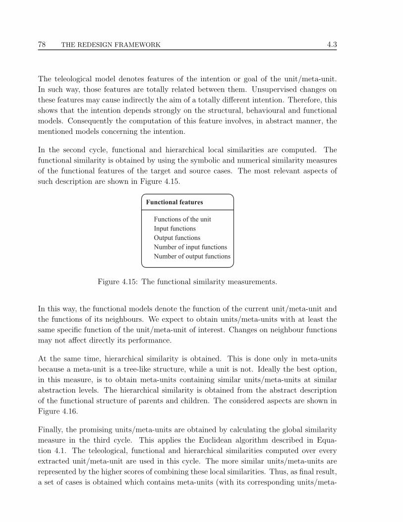
78 THE REDESIGN FRAMEWORK 4.3
The teleological model denotes features of the intention or goal of the unit/meta-unit.
In such way, those features are totally related between them. Unsupervised changes on
these features may cause indirectly the aim of a totally different intention. Therefore, this
shows that the intention depends strongly on the structural, behavioural and functional
models. Consequently the computation of this feature involves, in abstract manner, the
mentioned models concerning the intention.
In the second cycle, functional and hierarchical local similarities are computed. The
functional similarity is obtained by using the symbolic and numerical similarity measures
of the functional features of the target and source cases. The most relevant aspects of
such description are shown in Figure 4.15.
Functional features
Functions of the unit
Input functions
Output functions
Number of input functions
Number of output functions
Figure 4.15: The functional similarity measurements.
In this way, the functional models denote the function of the current unit/meta-unit and
the functions of its neighbours. We expect to obtain units/meta-units with at least the
same specific function of the unit/meta-unit of interest. Changes on neighbour functions
may not affect directly its performance.
At the same time, hierarchical similarity is obtained. This is done only in meta-units
because a meta-unit is a tree-like structure, while a unit is not. Ideally the best option,
in this measure, is to obtain meta-units containing similar units/meta-units at similar
abstraction levels. The hierarchical similarity is obtained from the abstract description
of the functional structure of parents and children. The considered aspects are shown in
Figure 4.16.
Finally, the promising units/meta-units are obtained by calculating the global similarity
measure in the third cycle. This applies the Euclidean algorithm described in Equa-
tion 4.1. The teleological, functional and hierarchical similarities computed over every
extracted unit/meta-unit are used in this cycle. The more similar units/meta-units are
represented by the higher scores of combining these local similarities. Thus, as final result,
a set of cases is obtained which contains meta-units (with its corresponding units/meta-

4.3 REDESIGN STAGES 79
Hierarchical features
Number of levels
Number of functions
Involved functions
Parent functions
Children Functions
Figure 4.16: The hierarchical similarity measurements.
units) or units. The set is ranked according to the global similarity between the target case
(the unit/meta-unit of interest) and the source cases (the retrieved units/meta-units).
4.3.4 Adaptation and evaluation
The reuse, revision, and retention stages of the CBR cycle correspond to the adaptation
and evaluation stages at the redesign framework (Figure 4.10). Although the retention is
not an explicit stage of the framework, is carried out in this stage.
The aim of the reuse stage is the adaptation of the most similar cases into the process.
The aim of the revision stage is the evaluation of the performance of the adapted case into
the process. Both stages are not systematised in the redesign framework, the human de-
signer must carry them out manually using the specialised simulator employed in the data
acquisition. The adaptation is highly domain-dependent and requires online simulation
of the process to verify its correct performance.
Since information of abstract cases can not be used directly, the adaptation and revision
stages must use information of ground cases (real equipment on the simulator). Conse-
quently to carry out both stages it is necessary to simulate the overall process. These
stages are carried out almost at the same time on the simulator. The human designer
simultaneously must fit the ground cases with the process variables involved. To facilitate
the adaptation, for each retrieved case, adaptation costs are computed to suggest to the
human designer the adaptability of the chosen unit/meta-unit into the current process.

80 THE REDESIGN FRAMEWORK 4.3
The adaptation cost
The adaptation cost is based on the differences of the selected unit (source case) and the
cause and consequence units/meta-units identified in the Candidate Identification stage
(see section §4.3.2). In this way, all the units/meta-units at the inlet and outlet path (of
the unit/meta-unit of interest) in the process are taken into account. Thus, the adaptation
cost is a normalised numerical value denoting the difference on the values of the process
variables involved in the performance of the unit/meta-unit of interest and the values
of the process variables involved in the performance of the neighbour units/meta-units.
For example, it will be easier to adapt a unit/meta-unit with small differences on its inlet
temperature that one with large differences on the same temperature. Equation 4.6 shows
the calculation of the adaptation cost:
adaptation cost = 1−[1
p
p∑
i=1
[ |source valuei − α valuei|range
]](4.6)
where,
i is the process variable,
α is a cause or consequence unit,
range is the absolute value of differences between the upper and lower bound-
ary of the range where source value i and α value i fall, and
p is the number of process variables.
The adaptation cost has a value between 0 and 1. Values close to zero mean the adaptation
is difficult. With the computed adaptation cost the human designer can operate over the
process on the simulator. The designer experience is determinant because modifications
on equipment may affect the overall performance of the process. The modification of the
original process, based on the adaptation of a retrieved case, generates an alternative of
the process for every unit/meta-unit adapted. This alternative is known as alternative
process design.
The final activity is to store the adapted cases in the case library for future alternative
process design generation. When an abstract case is adapted into the process, it represents
a new case that must be stored in the case library. The storing process is similar when
new units and meta-units are generated in the modelling stage of the framework. In this
task the alternative process design is not retained entirely, only the cases (units or meta-
units) obtained/derived from the case library. It is important to maintain the consistency

4.4 CHAPTER CONCLUSIONS 81
of the adapted case and its relations to the overall process, such as neighbour functions,
information of connections, information of the goal, etc.
4.4 Chapter conclusions
This chapter has described our approach to conceptual redesign. Basically the redesign
process is as follows. The input to the redesign process is the models of the process that
has to be redesigned. Based on these models and the new requirements that the process
must fulfill, the equipment (or section of the process) which can not achieve the overall
performance of the process are identified. Those equipment or sections must be modified
or substituted. To do this, similar equipment from other processes must be obtained
to adapt them into the process. Thus, the human designer can test several alternative
equipment (or connections of equipment) until the desired performance of the overall
process is found.
Therefore this chapter presents a novel perspective of the redesign process. The framework
is based on the well-known general engineering process. The novelty is the approach used
in the knowledge representation. Since our aim is the redesign of complex technical
processes, we propose the use of a modelling approach taking into account cognitive
aspects. The modelling approach is based in an extension of the Multilevel Flow Modelling
[Lind 90, Lind 94, Lind 99] and Multimodelling [Brajnik 90, Chittaro 92, Chittaro 93]
approaches. The cognitive basis is necessary for a better understanding of the process
and consequently a better managing of complexity in all the redesign activities.
We propose the use of structural, behavioural, functional and teleological models to rep-
resent the equipment of a process exploiting means-end relationships. Based on these
models the process (the redesign object) can be represented hierarchically. The hierarchi-
cal representation simplifies the process using approximations at several levels of detail.
Such representation facilitates the identification of the suitable parts of the process to be
modified or substituted.
In order to assist to human designers during conceptual redesign the computer tool em-
ployed needs be to capable of reasoning about the fundamental (structure and behavioural
information) and interpretative (functional and teleological information) aspects of the
process. Thus, the proposed framework is composed of the following stages: design-
description acquisition, candidate identification, generation of alternatives, and adapta-
tion and evaluation. The framework can be applied to well-structured functional domains.
Although the framework deals with complex technical process, not embedded simulations

82 THE REDESIGN FRAMEWORK 4.4
are performed in the framework. The core of the modelling approach of the framework
exploit functional and teleological models emphasising the no function in structure prin-
ciple.
The redesign framework proposed in this chapter no tackles a specific domain. In the next
chapter the implementation of the framework in the domain of Chemical Engineering is
presented.

CHAPTER
FIVE
Implementation of the framework
The implementation issues of the redesign framework are given in this chapter.
The processes considered are from the Chemical Engineering domain. The
software modules of the main stages of the redesign framework are described.
The implementation includes the major complete algorithms.
5.1 Introduction
In this chapter the implementation of the redesign framework is given. The framework has
been applied to the Chemical Engineering domain by two reasons; the first was because the
research was developed in a multidisciplinary group of Computer Science and Chemical
Engineering people. Therefore, common ideas about the framework were applied to this
thesis and in the thesis obtained in Chemical Engineering [Rodrıguez-Martınez 05]. The
second was because the assumptions given in section §1.4 (scope of the work) were fulfilled
for the issues involved in a chemical plant. These contributed in generating and improving
others assumptions in the Chemical Engineering thesis [Rodrıguez-Martınez 05].
The stages of the redesign framework were described in Chapter 4. These stages are now
implemented over chemical processes (a chemical plant can be constituted of one or more
chemical processes). Thus, firstly in section §5.2 a brief introduction to some aspects of
chemical processes is given to the reader to get a better understanding of why the domain
was chosen and how the framework developed can be applied.
83

84 IMPLEMENTATION OF THE FRAMEWORK 5.2
Some assumptions and limitations are highlighted in section §5.3 concerning the design
process and the type of chemical processes to understand the ontological concepts em-
ployed. Chemical processes are the object to be redesigned, and the idea of complex
system is completely fulfilled by this kind of technical processes as this processes has
several equipment (each one with a specific task) connected by streams. Therefore, the
used concepts of the domain contitute the ontology decribed in section §5.4. Based on the
ontological assumptions, the elements of the generic data structure used in the software
modules are presented in section §5.5.
The software modules of the redesign framework for chemical process domain are pre-
sented in section §5.6. These have been implemented in Java [Sun 05], additional li-
braries have been used such as JESS 1 [JESS 04], Ozone2 [Ozone 03], and The Selection
Engine3 [Wetzel 00]. The interaction with the user is done through a graphical interface
to facilitate the interpretation of results.
The main framework described in the previous chapter could be applied to other processes
but not this implementation as it is specific to chemical process redesign.
5.2 General aspects of Chemical Engineering
Chemical Engineering is the branch of engineering that is concerned with the design,
construction and operation of the plants and machinery used in industrial chemical pro-
cesses [Britannica 05]. It is one of the broadest fields of engineering, this breadth stems
from the fact that the discipline is founded on mathematics and on all the basic sciences,
namely, chemistry, physics, as well as biology, making it a truly interdisciplinary field of
study [WPI 05]. Thus, by applying science, mathematics, and economics Chemical En-
gineering converts starting materials or chemicals into more useful forms. That is done
through operations called chemical processes, which often consist of many separated and
independent steps. Such chemical processing results in thousands of products that are
part of virtually every aspect of our lives [Biggs 03], such as:
• Oil industry,
1JESS (Java Expert System Shell) is the Java version of CLIPS (C Language Integrated ProductionSystem).
2Ozone is an Object Oriented Data Base Manager implemented entirely in Java. It allows all the database operations by using Java objects.
3The Selection Engine is an open source case-based reasoning engine written in Java. It provides basicmatching for numbers, strings and booleans.

5.3 GENERAL ASPECTS OF CHEMICAL ENGINEERING 85
• Foods and drinks,
• Chemical and allied products,
• Household products (washing powder,...),
• Process plant manufacture and construction,
• Personal care (cosmetics, moisturisers,...),
• Pharmaceutical (aspirin, hormones, drug delivery,...),
• Materials (silicon chips, porous media, catalysts,...).
Thus, Chemical Engineering deals with the development and application of manufactur-
ing processes in which chemical and physical transformation of raw materials is carried
out to obtain valuable products. This involves all aspects of design, testing, scale-up,
operation, control, and optimisation, and requires a detailed understanding of the several
“unit operations” (equipment of the process), such as distillation, mixing, and biological
processes, which make these conversions possible. Conservation of mass, momentum, and
energy transfer along with thermodynamics and chemical kinetics are applied to anal-
yse and design all “unit operations”. These processes cover from the nano-scale (design
of catalysts, or molecular design of drugs) to the meso-scale (petroleum refinery) to the
global-scale (air pollution modelling and control). Constantly, new methods are devel-
oped or adapted to manage energy resources as well as commercial consumer products.
This involves the (re)design of reliable, cost effective manufacturing plants and implement
pollution control systems. Then, new technologies are researched, developed, or applied
to improve the design of systems and products.
Within Chemical Engineering, there are several working areas such as heat transfer, fluid
dynamics, chemical reaction kinetics, thermodynamics, separation operations, materials
science, process control, and plant design. A recent area is Process Systems Engineering,
which is concerned with the understanding and development of systematic procedures for
the design and operation of chemical processes, ranging from microsystems to industrial
scale continuous and batch processes [Grossmann 00]. Our research has been focused in
this area.
As mentioned in Chapter 2, redesign of chemical process have been carried out in two
directions: optimisation of energy consumption, and synthesis and design of processes.
The implementation of our redesign framework will be explained considering the latter
direction. The novelty of our approach is that Model-Based Reasoning has been combined
with Case-Based Reasoning to redesign chemical process.

86 IMPLEMENTATION OF THE FRAMEWORK 5.3
5.3 Process design assumptions
With the aim to situate the reader in the field of implementation, some assumptions must
be described, basic assumptions about the process of redesign and ontological assumptions
are described in this subsection.
5.3.1 Basic assumptions
The design process can not be seen as a kind of general routine activity suitable to
be fully computerised [Banares-Alcantara 95]. Fortunately, recent work has placed the
human designer in a central role in process design and, as a consequence, a more realistic
view concerning process design and AI has arisen [Ballinger 94, Han 95]. Thus human
beings are crucial in the development of the redesign framework. The chemical process
has been viewed as an artefact, which is the result of human interference with the nature
by taking spontaneous phenomena under control or forcing non-spontaneous processes.
Thus, the design process has been characterised as follows:
• Redesign is a creative activity. This issue limits on how process design is system-
atised and how “detailed” a level is attainable. It does not follow that the design
activity for building methodologies did not contain a good amount of generic fea-
tures.
• Redesign requires decision-making. The properties of a chemical process are directly
related to the human decision making which makes it an artefact. Every artefact
may have a purpose given to it by its designer or user and, consequently, a per-
formance. While the behaviour is ultimately dictated by the fundamental laws of
natural phenomena, the other features of the process are a direct result of human
decision making.
• Redesign is a human, goal-oriented activity. How the target is described dictates
most of the activities carried out with the model. Thus the methodology of process
design will crucially depend on the generic model of the chemical process adopted.
5.3.2 Ontological assumptions
When a redesign task is expressed in a tractable mathematical form suitable to be pro-
cessed by a computer, abstractions are required. These abstractions are based on assump-
tions and simplifications. Thus, the resulting solution has only limited significance. These

5.4 THE FUNCTIONAL ONTOLOGY 87
abstractions are crucial in the process of redesign because we are designing something that
does not exist. Deep knowledge and experience helps the human designer to approximate
the credibility of the mathematical tools relative to the specific problem at hand as well
as to select other appropriate tools required and knowledge needed for reliable decision
making. Thus, the implementation of the concepts of the proposed redesign framework
is based on the following ontological commitments.
• The chemical processes typically operate at steady-state. That means that values of
variables do not change with respect to time.
• A chemical process is constituted of real and abstract units. The abstract units are
the sections of the process that appear as atomic elements in conceptual models.
All real equipment can be viewed as descendants of the generic real equipment.
• A generic real equipment can be modelled as an object having four attributes: struc-
ture, behaviour, function and teleology. These attributes are necessaries and suffi-
cient to describe all the properties of any real equipment.
5.4 The functional ontology
Since the framework requires functional concepts, a crucial point is to define the type of
functions we are using. These concepts give us the idea about how redesign is viewed in
the Chemical Engineering domain. We have identified several concepts about redesign of
chemical process. These are mainly concerning to the functions achieved by the equipment
of the chemical process (named unit operations in Chemical Engineering) and its related
issues. This decision was adopted based on two aspects:
• Historically it has been recognised that it is possible to define a chemical process as
a collection of unit operations connected with more elementary ones.
• The systematic study of the individual unit operations leads to the development of
mathematical models and methods to compute their behaviour in simulators.
The functional ontology obtained is formed by high-level and low-level concepts in a sim-
ilar way to the SUMO (Suggested Upper Merged Ontology) ontology structure [Niles 01].
SUMO structures the concepts using meta-concepts, where terminology of general pur-
pose is situated at higher levels, while terminology to specific domains is situated at lower
levels. The ontology developed has extended generic concepts of SUMO such as process,

88 IMPLEMENTATION OF THE FRAMEWORK 5.4
objects and mereological4 and topological concepts. These specific concepts have been
defined:
• physico-chemical processes,
• thermodynamic processes,
• substances (mass and energy),
• substance roles (of chemical compounds),
• functional roles,
• devices (equipment and connections),
• measure units,
• tasks,
• operations, and
• relations.
Most of the concepts in the ontology correspond to physical entities. All added or extended
concepts have justification on Chemical Engineering and functional reasoning. Figure
5.1 depicts an example to illustrate the instantiation of concepts in the creation of the
ontology.
Entity
Physical Abstract
ProcessObject
SelfConnectedObject
CorpuscularObject
Artifact
Device
EngineeringComponent
Mixer
DualObjectProcess
Combining
Mixing
hasFunction
Relation
Figure 5.1: Instantiating concepts in the ontology.
4Mereology is the theory of parthood relations: of the relations of part to whole and the relations ofpart to part within a whole, p.ex. has-part, part-of, composed-by, etc.

5.4 THE FUNCTIONAL ONTOLOGY 89
In general terms, the high-level concepts denote very abstract concepts, which can be
found in several domains. The middle-level includes the functional concepts proposed in
the Multilevel Flow Modelling and Multimodelling approaches, which are: source, trans-
port, barrier, storage, balance, and sink. These concepts are also called broad functions
because are inherent to other functions. The low-level functional concepts come from the
well-known chemical process design methodologies developed by Douglas [Douglas 88] and
Turton [Turton 98] (details are given in [Rodrıguez-Martınez 05]). The low-level func-
tional concepts can be grouped as: reaction, separation, temperature change, pressure
change, and flow change. These concepts are called general functions.
Each specific function is divided into more specific ones named specific functions, which
denote the function of the equipment in the process. Also each specific function is divided
in more specific ones, called working functions. A working function can be associated
with one or more units and a unit can be related to more than one function. But from the
several working functions, only one is the main function in the process (see the Functional
unit identification subsection in Chapter 4 ). The scheme of the functional ontology is
shown in Figure 5.2. An illustrative explanation is given later in the Classification strategy
section of this chapter.
Generalfunction X
Specificfunction 1
Specificfunction 2
Specificfunction n
Workingfunction 1
Workingfunction 2
Workingfunction n
Realequipment 1
Realequipment 2
Realequipment n
Figure 5.2: Partial structural scheme of the ontology.
Over the identified functions we have defined an importance functional order and the
variables involved in such functions (carried out by the equipment of the process). This
order was defined with the aim to form groups of functions where more important functions
“absorb” functions with minor importance. Later in the modelling module section (§5.6.1)
this functional order is explained.
Thus, we have defined an ontology to constrain the application domain. Although this
ontology is employed in the overall redesign framework, it has not been defined with a
formal specification (using an ontology definition language). The ontology definition is
implicit in the framework. The objectives in the creation of this ontology are:

90 IMPLEMENTATION OF THE FRAMEWORK 5.5
• to create a common vocabulary for the framework,
• to develop the software prototypes of the framework,
• to facilitate the interchange of information between the prototypes and users,
• to support the integration of the simulator and the software prototypes,
5.5 The generic data structure
As we state in the ontological assumptions, every equipment of the process can be modelled
by an entity instantiated from a generic one. Thus, considering the attributes of real
equipment and the MFM and Multimodelling approaches, such generic entity can be
modelled as an object having four generic models: structure, behaviour, function and
teleology.
5.5.1 Structure
This attribute covers all the generic structural characteristics of a piece of equipment.
These denote its external connections to other equipment and its own internal structural
characteristics. The set of structural connections denotes the overall topology of the
process. These attributes are:
• process identificator,
• name of equipment,
• number of substances,
• name of substances,
• number of input streams,
• name of input streams,
• number of output streams,
• name of output streams,
• input function,
• number of input functions,
• output function, and
• number of input functions.

5.5 THE GENERIC DATA STRUCTURE 91
5.5.2 Behaviour
Although every equipment has this attribute, it is specific to each equipment. Thus, this
attribute defines generic variables related to flow of mass and energy at arbitrary time.
Depending on the type of equipment, this attribute may cover some additional variables.
Each variable is related to an external connection of the equipment. The set of variables
of the overall process denotes a causal net where each node on the net corresponds to
particular equipment. Note that the real behaviour of equipment can only be predicted
by complex numerical simulators. The generic variables are:
• vapour fraction,
• temperature,
• pressure,
• mass flow,
• molar flow,
• molar enthalpy,
• molar entropy,
• heat flow,
• mass fraction,
• molar fraction,
• mass balance definition, and
• energy balance definition.
5.5.3 Function
This attribute represents the role of the equipment in the process. Thus, this attribute
denotes the useful behaviour of the equipment in the process. This behaviour concerns
the action performed by the equipment over the flows of mass or energy of chemical
substances. Thus, based on the ontology, the action of each equipment is represented by
means of labels denoting:
• general function,
• specific function, and
• working function,

92 IMPLEMENTATION OF THE FRAMEWORK 5.6
5.5.4 Teleology
This attribute denotes the goal of the equipment into the processes. It represents the
intention of the designer when this equipment was placed in the plant. It is formulated
in terms of operational constraints to make explicit values on specific variables. The
values of such variables are achieved by the effect of the actions denoted by the functions
of the equipment. Consequently such actions affect the variables of the behaviour of
the equipment. The goal of an equipment may be part of a top-level goal related to
a specific section of the process. Thus, the goal of an equipment is represented using
verbal sentences involving keywords to denote the constraints. For example, the goal
“maintain the output temperature below 320◦C so the separation equipment at the output
is not damaged” is presented to users in the same manner, but for reasoning purposes, the
goal is translated as the constraint represented by the keyword “maxOutputTemperature
= 320” and “outputFunction = separation”. Then the components of this attribute
are:
• intended behaviour,
• pre-conditions, and
• post-conditions.
5.5.5 Modelling equipment
Using the object oriented formalism, every generic equipment is defined as depicts Figure
5.3. Thus, every equipment of the process extends from this generic equipment adding
the corresponding attributes of the specific equipment. In the rest of the chapter the term
unit is used without distinction between specific or generic equipment.
5.6 The software modules
As stated early in Chapter 4, the framework consists of four main stages, design-description
acquisition, candidate identification, generation of alternatives, and adaptation and eval-
uation. The first three stages have been implemented, the last stage is performed by
the user, as Figure 5.4 shows. Then, the framework architecture has been reorganised
according to the software modules implemented, as Figure 5.5 depicts.

5.6 THE SOFTWARE MODULES 93
Generic Equipment
AttributesStructureBehaviourFunctionTeleology
MethodsgetName()getParent() ....getAbstractionLevel() ....
Own and neighboursstructural attributes
Values of processvariables and matter or
energy balances
Actions overprocess variables to
achieve goals
How and why theequipment is there
Figure 5.3: The generic data model of equipment.
Design-description acquisition
Candidate identification
Generation of alternatives
Adaptation and evaluation
Modelling module
Diagnosis module
Case-based reasoning module
Human intervention
Figure 5.4: Mapping from stages to software modules.
Simulator
dataacquisition
mostsimilar
unit/meta-unit
HumanDesigner
candidateidentification to
modification/substitution
functionalontology
functionalunits/meta-units
library
redesignheuristics
of processes
retrievingunits/meta-units
newrequeriments
computingadaptation
costs
MODELLINGMODULE
DIAGNOSIS MODULE
CASE-BASED REASONING MODULE
HUMANINTERVENTION
Generation of cases
Functional identification
functionalunits
identification
functionalmeta-units
identification
CASERETENTION
Adaptationand evaluationof alternative
processs designs
Figure 5.5: The software modules in the framework.

94 IMPLEMENTATION OF THE FRAMEWORK 5.6
In real redesign situations the first task is to simulate the process of interest in the
simulator. The next task is to obtain the description of the process, which is the first
task performed by the modelling module. After that, the following modules can operate
based on such descriptions.
5.6.1 The hierarchical modelling module
Its aim is to obtain the hierarchical representation of the process. The obtained represen-
tation is crucial for the following modules. Two tasks are carried out in this module: data
acquisition and functional identification. In Figure 5.6 the flow diagram of the modelling
module is shown in general terms denoting the most important submodules.
Assign functionalconcepts based on the
functional hiearchy
Assign teleologicaldescriptions
Functional IdentificationIdentify functional
concepts
Aggregate the unit/meta-unitto input or output
depending of functions
Abstraction Process
Generate a newabstraction level
Identify inputs andoutputs of process
Assignstreams
Eliminateconnection loops
Connect Units
Identify typesof equipments
Create unitsand assign data
File Parser
Stablish connectionwith case library Identify functions
Store Cases
Close connectionStore cases incorresponding group
Data file fromsimulator
Display componentsin graphical interface
Store/retrieve incommon data base
Figure 5.6: Flow diagram of the modelling module.
5.6.1.1 The data acquisition module
The data can be acquired directly from the process simulator. In our case, we have
employed the Hysys simulator [Hysys 04]. This simulator is broadly employed in the
simulation of chemical processes as much in industry as in universities. Hysys allows

5.6 THE SOFTWARE MODULES 95
extracting information by means of its Application Program Interface (API). In general
terms, since all the information generated by the simulator is not required, a filter to
identify the useful data was implemented [Lopez-Arevalo 02, Lopez-Arevalo 03a].
Thus, the data acquisition is focused mainly on the process units and its streams, which
are the composing elements of the flowsheet5. The process units are the equipment that
carry out the conversion of the input (mass/energy)into the desired output product. The
streams are the connections between equipment or between equipment and its external
environment. The extracted information concerns the structure and behaviour of the
process. An example of extracted information from the simulator is shown in Appendix
A, more detail in [Lopez-Arevalo 03c, Lopez-Arevalo 03b, Lopez-Arevalo 04]. From the
simulation point of view this information is incomplete, but from redesign point of view it
is consistent because it comes from a reliable source. Irrelevant information for redesign
is not considered. Finally, a data file is obtained containing all the information extracted
from de simulator (see Appendix A). Note that the equipment do not contain information
about the process variables. They mainly contain information about the type of equipment
and which are its input and output streams. The streams contain the values of such
variables. Thus, this data file represents structural and behavioural data. The software
module that gets this data is called HEAD (Hysys ExtrAction Data) [Lopez-Arevalo 02,
Lopez-Arevalo 03a].
5.6.1.2 Functional identification module
This module receives as input the data file generated in the previous module to identify the
functions of each equipment. Based on such functions the functional sections of the process
are identified. As mentioned earlier (Functional identification subsection in Chapter 4),
initially the original equipment are represented by the named units, the functional sections
are represented by the named meta-units. As output this module returns a hierarchical
representation of the process with a tree-like structure. The grouping strategy is based
on the functional importance of units and meta-units. The tree represents a tree of meta-
models because it contains units, which encapsulate structural, behavioural, functional
and teleological models. This task is carry out by the AHA! (Automatic Hierarchical
Abstraction tool) prototype [Lopez-Arevalo 03a, Lopez-Arevalo 03c, Lopez-Arevalo 03b,
Lopez-Arevalo 04]. AHA! has been implemented in Java and JESS [JESS 04]. The main
elements of AHA! are:
• The knowledge base contains heuristic rules obtained from the Chemical Engineering
5The flow diagram of the process.

96 IMPLEMENTATION OF THE FRAMEWORK 5.6
literature of design of processes and from human designer experiences. Specifically
applying the Douglas [Douglas 88] and Turton [Turton 98] methodologies.
• The data base contains facts concerning information of the units and meta-units of
the process of interest. These are introduced to the data base when the units/meta-
units are created.
Since the aim is to obtain a hierarchical representation of the process, the original knowl-
edge of the process must be abstracted preserving the most important functions and goals.
In such manner, a consistent classification strategy must be employed to highlight such
functions and goals. The classification strategy employed is described in more detail in
the rest of this subsection.
Classification strategy
In the data acquisition stage all the types of equipment have been identified. This identi-
fication corresponds to real class of equipment in the process. Each equipment has been
designed to carry out certain function. Of course within each equipment certain physico-
chemical phenomena and processes occur to achieve such function, but we are interested
only in the function performed by the equipment. Then we have classified the functions
as is shown in Figure 5.7 following the concepts of functions described in the Functional
unit identification subsection in Chapter 4.
Each specific function denotes the type of physical effect occurred into the real equip-
ment. One or more broad function6 can be related to any function in the hierarchy as it
can take part in several physical phenomena, but only one function is important in the
performance of the process (see Figure 5.8, where the functions in bold font denote the
designer intention).
Since the functional classification shown in Figure 5.7, a process can be interpreted as
follows:
1. By equipment. This corresponds to the classes of equipment (Level3 - Working
Functions) such as, pumps, heaters, coolers, etc. Specific details of the type of
equipment are not considered. This interpretation may be obtained directly from
flowsheet in the simulator and corresponds to the first representation of the process.
2. By processes. This corresponds to the subprocess achieved by groups of equipment.
It can be considered that “more important” functions are achieved. At the same
6A broad function denotes a MFM/Multimodelling function, see section §4.3.1 in Chapter 4.

5.6 THE SOFTWARE MODULES 97
Continuos Stirred Tank Reactor
Plug Flow Reactor
Tubular Reactor
Tank
Liquid Liquid Extractor
Flash
3-Phase Separator
Trayed
Packed
Vapour Absorption Column
Liquid Absorption Column
Gas Adsorption Column
Liquid Adsorption Column
Cristalliser
Leacher
Dryer
Membrane
Heater
Heat Exchanger
Cooler
Compressor
Pump
Valve
Expander
Mixer
Splitter
Reaction
Decantation
Extraction
Distillation
Absortion
Absortion
Stripping
Cristallisation
Leaching
Drying
Filtration
Heating
Cooling
Pressure increment
Pressure decrement
Flow increment
Flow decrement
Reaction
Separation
Temperaturechange
Pressurechange
Flowchange
Evaporator
Condenser
ProcessUnit
Rotary Type
Piston Type
Total Condenser
Partial Condenser
Total Evaporator
Partial Evaporator
1-n plates
GeneralFunction
SpecificFunction
WorkingFunction
Type ofequipment
Figure 5.7: The hierarchy of functions.

98 IMPLEMENTATION OF THE FRAMEWORK 5.6
Reaction
Decantation
Extraction
Distillation
Absortion
Absortion
Stripping
Cristallisation
Leaching
Drying
Filtration
Heating
Cooling
Pressure increment
Pressure decrement
Mixing
Splitting
Reaction
Separation
Temperaturechange
Pressurechange
Flowchange
ProcessUnit
GeneralFunction
SpecificFunction
barrierbalance
sink
source
barriertransport
sink
sourcebarrierbalance
balancesink
transportbarrier
source
balance
balance
balance
transport
barrier
barrier
source
storage
storage
storage
storage
storage
storage
storage
storage
storage
storage
storage
Exchanging balance
Figure 5.8: MFM and Multimodelling functions in the functional hierarchy.
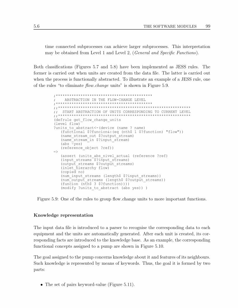
5.6 THE SOFTWARE MODULES 99
time connected subprocesses can achieve larger subprocesses. This interpretation
may be obtained from Level 1 and Level 2, (General and Specific Functions).
Both classifications (Figures 5.7 and 5.8) have been implemented as JESS rules. The
former is carried out when units are created from the data file. The latter is carried out
when the process is functionally abstracted. To illustrate an example of a JESS rule, one
of the rules “to eliminate flow change units” is shown in Figure 5.9.
;*******************************************; ABSTRACTION IN THE FLOW-CHANGE LEVEL;*******************************************;;***********************************************************;; START ABSTRACTION OF UNITS CORRESPONDING TO CURRENT LEVEL;;***********************************************************(defrule get_flow_change_units(level flow)?units_to_abstract<-(device (name ? name) (functional $?funcion&:(eq (nth$ 1 $?function) "flow")) (name_stream_out $?output_stream) (name_stream_in $?input_stream) (abs ~yes) (reference_object ?ref))=> (assert (units_abs_nivel_actual (reference ?ref) (input_streams $?input_streams) (output_streams $?output_streams) (inlet_hierarchy flow) (copied no) (num_input_streams (length$ $?input_streams)) (num_output_streams (length$ $?output_streams)) (funcion (nth$ 3 $?function)))) (modify ?units_to_abstract (abs yes)) )
Figure 5.9: One of the rules to group flow change units to more important functions.
Knowledge representation
The input data file is introduced to a parser to recognise the corresponding data to each
equipment and the units are automatically generated. After each unit is created, its cor-
responding facts are introduced to the knowledge base. As an example, the corresponding
functional concepts assigned to a pump are shown in Figure 5.10.
The goal assigned to the pump concerns knowledge about it and features of its neighbours.
Such knowledge is represented by means of keywords. Thus, the goal it is formed by two
parts:
• The set of pairs keyword-value (Figure 5.11).

100 IMPLEMENTATION OF THE FRAMEWORK 5.6
(defrule assign_functional_concepts_pump?eq_pump <-( device (pump ?type_equipment)
(working_function $?wfunction) =>
(modify ?eq_pump (general_function "pressure_change") (specific_function "pressure_increment") (working_function "pump") (mfm_function "transport"))
Figure 5.10: Assignation of functional concepts to a pump.
[TYPE_PHASE] = value[ROLE_INLET_STREAM] = value[NAME_EQUIPMENT_INPUT] = value[NAME_EQUIPMENT_OUTPUT] = value[NAME_INLET_STREAM] = value[WHO_X_CONNECTED_TO_OUTPUT] = value[DELTA_PRESSURE] = value
Figure 5.11: The keywords of pressure change units.
• The structured values of keywords in human understanding format (Figure 5.12).
"Increases the pressure in [DELTA_PRESSURE]kPa of [ROLE_INLET_STREAM] stream (name/phase:[NAME_INLET_STREAM]/[TYPE_ PHASE]) to providethe conditions required [WHO_X_CONNECTED_TO_OUTPUT]([NAME_EQUIPMENT_OUT-PUT])."
Figure 5.12: The goal of pressure increment in human reading format.
Note that the keywords correspond to the complete specific function, which involves pump,
compressor, expander, or valve. The keywords must be present on all units of this specific
function although its value can be null. For that reason some keywords may not appear
in the goal description. The representation of the modelled process is given to the user by
means of a graphical interface for better understanding (p.ex. see Figure 6.2 in Chapter
6). The graphical interface has been implemented by means of the Swing package of Java.

5.6 THE SOFTWARE MODULES 101
Knowledge abstraction
After the first representation of the units has been obtained, these units must be ab-
stracted to reduce the complexity of the overall process. This is carried out by means
of an aggregation process. The construction of the models in the previous step started
with detailed models of the units. Now these units are aggregated to generate “super”
units (called meta-units), which will simplify the process. Aggregation is defined as the
action of combining several components into one bigger component without eliminating
any of the variables or equations that define the models of the abstracted components.
An example of aggregation is shown in Figure 5.13.
Mixer Reactor
Str-25
Str-31
Str-37 Str-45Mixer Reactor
Str-25
Str-31
Str-37 Str-45
Meta-Reactor
a) Units b) Meta-unit
Figure 5.13: Aggregation of units.
The aggregation process has been implemented by using heuristic rules taken from the lit-
erature and the expert designers in the chemical process design. This aggregation heuristic
establishes a functional order over the functions of the units. The heuristic considers the
main sections of a chemical process [Turton 98]. These sections are represented by the
general functions of the hierarchy of functions. The functional order denotes the impor-
tance of the functions in the achievement of the overall goal of the process. Changes on
that order generate different redesign results. This functional order is shown in Figure
5.14.
Reaction SeparationTemperature
changePressurechange
Flowchange
Functional importance+ -
Figure 5.14: The functional importance order.
Considering only one level of representation, units with high functional importance “over-
lap” units with lower functional importance. Then the latter are considered auxiliary func-
tions of the former. In other words, the formers are primary functions and the latter are
secondary functions. Then, the heuristic rules denote a grouping mechanism where units
with high functional importance “absorb” units with lower functional importance. Thus
102 IMPLEMENTATION OF THE FRAMEWORK 5.6
in a next representation (a new level in the hierarchical representations of the process),
only the “survivors” units and meta-units are represented. Thus, the grouping mecha-
nism was implemented following the algorithm shown in Figure 5.15. The algorithm is an
encapsulation of the functional order (Figure 5.14).
The case library is filled at the same time the units and meta-units are generated.
Case library
As mentioned in Chapter 4, the ground cases are the units created during the first repre-
sentation of the process, at the abstraction level 0. The abstract cases are the meta-units
created during the functional section identification. Mainly the function and goal of the
unit/meta-unit represents the description of the case and the overall unit/meta-unit rep-
resents itself the solution of the case (Figure 5.16).
Since the case library may contain several complete chemical processes, the amount of
ground and abstract cases may be large. In this sense, a simple representation of the
case library is not enough. In this case, the flattening of the information contained in
a unit/meta-unit is not a good option. In addition, quick access to relevant cases is
necessary. Then the use of an Object Oriented Data Base Manager (OODBM) is an
appropriate option to enhance the storing and retrieving process. Thus, the interaction
with the case library is carried out using the OODBM named Ozone [Ozone 03].
Indexing
The organisation of cases into the library of cases is performed according to the type of
function of the unit/meta-unit. The aim is to structure the case library in a similar way
as the hierarchy of functions (see Figure 5.7). In this way, five general groups can be dis-
tinguished: reaction, separation, temperature change, pressure change, and flow change.
Within each group, units and meta-units are grouped based on its specific function. There
are not distinctions between units and meta-units with the same specific function. This
organisation scheme allows to store cases from several processes considering only the func-
tion of the unit/meta-unit. Both storing and retrieving processes are carried out quickly.
The algorithm to start the organisation of the case library is shown in Figure 5.17.
Although complete chemical process may be stored, it is not our intention to retrieve such
processes entirely. We are interested only in retrieving specific parts (units or meta-units)
as suggestion to the designer.

5.6 THE SOFTWARE MODULES 103
aggregation_processinput: = the first representation of the process ; only unitsoutput: = the process represented at several abstraction levelsbegin global_set_of_functional_sets: = all the units arranged into groups while ( there is more than one element in global_set_of_functional_sets ) functional_group := set of units with minor functional importance in global_set_of_functional_sets while (exists units in functional_group) component_to_aggregate := choose one unit from functional_group ; depending of type of component_to_aggregate, the ; component_to_aggregate may be grouped with the input ; or output units/meta-units aggregation_direction := input or output set_elements_to_meta-unit := elements at aggregation_direction while ( number of elements at set_elements_to_meta-unit > 0 ) element_to_meta-unit := next element of set_elements_to_meta-unit aggregate_units (component_to_aggregate, element_to_meta-unit, aggregation_direction) end-while remove component_to_aggregate from functional_group end-while generate a new abstraction level representing the remanent units/meta-units end-whileend
;;;;;;;;;;;;;;;;;;;;;;;;;;;;;;;;;;;;;;;;;;;;;;;;;;;;;;;;
aggregate_units; component_to_aggregate is the unit to be absorbed,; element_to_meta-unit is the unit that absorbs; aggregation_direction is to whom the component_to_aggregate; will be aggregated
input := component_to_aggregate, element_to_meta-unit, aggregation_directionoutput := a new meta-unit createdbegin meta-unit := copy information from element_to_meta-unit aggregate structural, behavioural, functional and teleological information of component_to_aggregate to meta-unit depending on aggregation_direction assign meta-unit to component_to_aggregate as parent unit assign component_to_aggregate to meta-unit to as child unit functional_group = the functional_group of element_to_meta-unit remove element_to_meta-unit from functional_group add meta-unit to functional_groupend
Figure 5.15: The algorithm to group functions.

104 IMPLEMENTATION OF THE FRAMEWORK 5.6
Unit
Structure
Behaviour
Function
Teleology
Case description
Case solution
Figure 5.16: The description and solution in a case.
create_functional_groups_in_data_baseinput := the empty database file, list of general functionsoutput := the partitioned database filebegin open the database while ( there are elements in the list of general functions )
general_function := get next general function create a database_object from general_function end-while close the databaseend
Figure 5.17: Algorithm to structure the case library.

5.6 THE SOFTWARE MODULES 105
At this point the complete hierarchical representation of the process has been obtained.
From here the rest of software modules can operate with this representation. The designer
can navigate in the representation, get information from units/meta-units or from streams,
know about the chemical substances involved. The representation is given to the designer
in a graphical interface allowing the a complete interaction with the overall information
of the modelled process.
5.6.2 The diagnosis module
The aim of this module is to identify the most suitable candidates to be redesigned.
A candidate may be a unit or a meta-unit. In general terms, the flow diagram of the
diagnosis module is depicted in Figure 5.18.
Functional treerepresentation
Determine order ofcomponents in flow path
Diagnose Components
Determine if componentaffects the variable
Determine magnitudeof effect
Propagate andanalyse statesin actual level
Determine causeand consequence
components
Determine childrencomponents
Organise list ofcandidates for each level
Organise list ofcauses and consequences
for each candidates
Display resultsin graphical interface
Organise Output
Figure 5.18: Flow diagram of the diagnosis module.
The diagnosis module receives as input the hierarchical representation obtained in the
modelling module and the variable in which the redesign is focused. As output it returns a
list of the most promising candidates to be redesigned in the different levels as is described
in subsection §4.3.2 in Chapter 4. The process variable of interest is obtained from the

106 IMPLEMENTATION OF THE FRAMEWORK 5.6
new design objective. The expert designer must interpret the new design objective to
get such variable. We assume that the new design objective concerns with one or more
process variables.
This module has been implemented in Java and it is part of the RETRO proto-
type [Lopez-Arevalo 05a, Lopez-Arevalo 05b]. It is based on the fault diagnosis algorithm
described by Larsson [Larsson 96]. Thus, concepts of the Multilevel Flow Modelling have
been employed (see section §3.4.1 in Chapter 3). Basically the algorithm performs recur-
sively a depth-first search on the tree representation of the process. The search propagates
along static connections, thus neither global search, pattern matching nor conflict resolu-
tion is needed. To get a better understanding of the process, Figure 5.19 depicts how the
representation of the process is considered in the algorithm. The algorithm is shown in
Figure 5.20.
G2
Achieve Goal 1 (G1)
Achieve Goal 2 (G2)
Achieve Goal 3 (G3)
F4 F5 F6
C1 C2 C3
G3
F7 F8 F9
C4 C5 C6
G1
F2 F3
C7 C8
G - GoalF - FunctionC - Component (unit/meta-unit)
Figure 5.19: Model scheme of a process by means of MFM concepts.
The algorithm is applied over all the components at all the levels initiating from the
root level. Finally, a list of candidates at each level is obtained. Each candidate has its
corresponding cause and consequence components, which are useful at the adaptation and
evaluation of alternatives. This constitutes a global diagnosis, where all the components
(equipment and sections) of the overall process are explored. This module does not
identify exactly a unique candidate. This would be very difficult because deeper domain
knowledge would be necessary, including complex simulations. Furthermore the result
would not ensure a good redesign alternative [Bakker 94, Clarkson 04]. At this point, the
designer may decide what candidate to focus considering the desired level of abstraction.
Thus based on every candidate, different alternative solutions may be generated. The
designer intervention is fundamental here, specifically his/her expertise.

5.6 THE SOFTWARE MODULES 107
identify_candidatesinput := the hierarchical representation of the process, the variable of interestoutput := a list of possible candidatesbegin
level := the highest levelwhile ( level has components )
component := component at the beginning of the flow path in levellist_candidates := diagnose_component (representation of the
process, level, component, variable of interest)end-whilereturn list_candidates
end
;;;;;;;;;;;;;;;;;;;;;;;;;;;;;;;;;;;;;;;;;
diagnose_componentinput := the representation of the process, level to analyse, the component to diagnose, the variable of interestoutput := a list of "faulty" componentsbegin list_candidates := empty if ( component affects the variable ) then
effect_magnitude := determine the magnitude of the effectif ( effect_magnitude = LARGE ) then
set the appropriate state to the component fault := perform state analysis and propagation to
determine primary and secondary faults component.list_consequence_components := components with secondary faults component.list_cause_components := components before component with primary faults
if ( fault is primary ) then list_candidates += component while ( component not at ground level )
while ( component has children ) down_component := next child_component of component component.list_candidates := diagnose_component
(representation of the process, level, down_component, variable of interest) end-while
end-while end-if end-if end-if return list_componentsend
Figure 5.20: The diagnosis algorithm.

108 IMPLEMENTATION OF THE FRAMEWORK 5.6
5.6.3 The case-based reasoning module
The aim of this module is to obtain similar units/meta-units (source cases) from the
selected candidate to be redesigned (original case). In general terms, the most important
steps of the case-based reasoning module are illustrated by means of the flow diagram
shown in Figure 5.21.
Originalcase
Extract source casesfrom case library
Obtain AlternativeUnits/Meta-units
Obtain original andsource goals
Iterate over eachsource case
Obtain similaritycriteria and weights
Compute Similarities
Normalise data oforiginal case
Determinemax distance
Obtain target case
Normalise data oforiginal case
Computelocal similarities
Computeglobal similarities
Rank and sortelements
Display resultsin graphical interface
Figure 5.21: Flow diagram of the case-base module.
The module receives as input the candidate and gives as output a list of the most similar
ones. The candidate may be a unit or meta-unit depending on the designer needs. Then
the output also may contain units or meta-units.

5.6 THE SOFTWARE MODULES 109
When the results are obtained, human intervention is necessary to test any of the alter-
natives proposed (the retrieved units or meta-units). The designer iteratively must adapt
and evaluate the alternatives in the simulator employed in the data-acquisition until the
new design objectives are fulfilled. The alternatives are not introduced directly in the
process of interest, they just guide the modifications that must be carried out. When
an alternative design-description is finally accepted as good option, the process must be
modelled again to identify the new units and meta-units, which are retained in the case
library, as is illustrated in the algorithm to store cases.
This module has been implemented entirely in Java by using the OODBM
Ozone [Ozone 03] to store and retrieve cases. The core of this module was implemented
extending libraries of the project named The Selection Engine [Wetzel 00]. Additional
submodules were developed to adapt it in the framework. As mentioned early, a complete
case-based reasoning system has not been implemented, only the retrieve and retention
stages. Adaptability costs are computed to guide the adaptation. This module also is
part of the RETRO prototype [Lopez-Arevalo 05a, Lopez-Arevalo 05b]
The main elements of this module are the case library and the similarity engine:
• The case library. It contains units and meta-units (cases) from diverse chemical
process, which may be used to guide the modifications of another process (this li-
brary was filled by chemical engineers). In our approach a case consists of two parts,
the description of the situation/problem (the functional concepts of the unit/meta-
unit) and the solution of such situation/problem (the entire unit/meta-unit). The
structure of the case library is hierarchical denoting the same hierarchy of functions
employed in the framework (see Figure 5.7). As mentioned early, the case library is
filled simultaneously at the modelling process.
• The similarity engine. Is the responsible to extract the best matching cases from
the case library. Its output depends on the similarity between cases. Thus, to
compute similarity between two cases, two types of similarities are calculated, local
(over specific properties) and global (over local similarities). Then, numeric, sym-
bolic, and hierarchical measures have been implemented to compute local similarity
and the Euclidean measure to compute the global similarity (see the Case retrieval
subsection in Chapter 4).
Explicitly, the overall module behaves as a case-based retrieving system. Its overall per-
formance is described by means of the algorithm shown in Figure 5.22.

110 IMPLEMENTATION OF THE FRAMEWORK 5.6
obtain_alternativesinput := the original case from the process, the case libaryoutput := an ordered list of possible alternativesbegin original_function := specific function of original case source_cases := extract from the case library cases with original_function original_goal := goal of original case source_goals := goals of source_cases list_teleological_similarities := compute_similarity(original_goal, source_goals) for each element in source_cases assign corresponding value from list_teleological_similarities end-for list_alternatives := compute_similarity(target_case, source_cases)end
;;;;;;;;;;;;;;;;;;;;;;;;;;;;;;;;;;;;;;;;;;;;
compute_similarityinput := the original case, the set of source casesoutput := an ordered list of similarity valuesbegin similarity_criteria := specify values and preferences on attributes of the original case similarity_weights := specify weights on attributes of the original case gather max and min values on original case and source cases normalise values and weights to obtain target case based on similarity_criteria and similarity_weights determine max distance based on similarity_criteria and similarity_weights for each element in source cases score the element for each similarity criterion by:
for each similarity criterion normalise values and weights
end-for compute distances by: for each score distance := compute distance of element respect to target case end-for percent_similarity = ( 1 - (distance/max distance) ) * 100 end-for returned_list := rank elements by sorting on percent_similarityend
Figure 5.22: Algorithm of the case-base reasoning module.

5.6 THE SOFTWARE MODULES 111
The returned list will contain cases ranked according to the percent of similarity. With the
returned set of cases, adaptation costs are computed to suggest such cases to the designer.
The implemented similarity measures are not described in depth in the algorithm. Of
these, the most complex is described in the next subsection.
5.6.3.1 Similarity measures
The similarity measures compute the similarity degree between two cases. They constitute
the kernel of the similarity engine. Typically most CBR applications use these measures
to compute distance between cases. In general, these measures use nearest neighbour
search to compute distances. The similarity between two cases Ci and Cj can be defined
as complementary to their distance, as shows Equation 5.1.
similarity(Ci, Cj) = 1− distance(Ci, Cj) (5.1)
where,
distance is the global distance (with a normalised value -[0,1]- ) calculated
for all the attributes of Ci and Cj. For example Equation 4.1 in the Case
retrieval subsection of Chapter 4 (subsection §4.3.3.6) shows the computation
of the distance by means of an Euclidean algorithm.
In this way, two cases which are equal have the maximum similarity degree, i.e. 1, while
two absolutely different cases have a minimum similarity degree, i.e. about 0.
The similarity engine implement local and global similarity measures, which have been
described in the section Generation of alternatives (§4.3.3 in Chapter 4). From these, the
most simple is the numeric measure, the symbolic is into the named Inclusion Measure
(using the bag/set data model), but the most complex is the hierarchical measure. In
Chapter 4 (also in section §4.3.3), a short version of the hierarchical measure was pre-
sented, next, to get a better understanding, it is described in more detail.
Hierarchical similarity measure
This measure exploits the “semantic knowledge” in the hierarchy of functions to iden-
tify meta-units sharing common characteristics (see Figure 5.7). Note that this measure
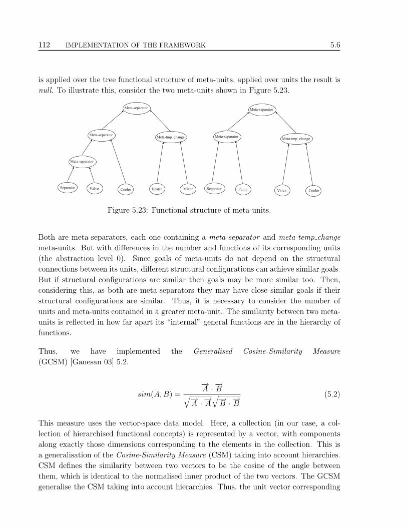
112 IMPLEMENTATION OF THE FRAMEWORK 5.6
is applied over the tree functional structure of meta-units, applied over units the result is
null. To illustrate this, consider the two meta-units shown in Figure 5.23.
Meta-separator
Meta-separatorMeta-tmp_change
Meta-separator
ValveSeparatorCooler Heater Mixer
Meta-separator
Meta-separatorMeta-tmp_change
Valve CoolerSeparator Pump
Figure 5.23: Functional structure of meta-units.
Both are meta-separators, each one containing a meta-separator and meta-temp change
meta-units. But with differences in the number and functions of its corresponding units
(the abstraction level 0). Since goals of meta-units do not depend on the structural
connections between its units, different structural configurations can achieve similar goals.
But if structural configurations are similar then goals may be more similar too. Then,
considering this, as both are meta-separators they may have close similar goals if their
structural configurations are similar. Thus, it is necessary to consider the number of
units and meta-units contained in a greater meta-unit. The similarity between two meta-
units is reflected in how far apart its “internal” general functions are in the hierarchy of
functions.
Thus, we have implemented the Generalised Cosine-Similarity Measure
(GCSM) [Ganesan 03] 5.2.
sim(A,B) =
−→A · −→B√−→
A · −→A√−→
B · −→B(5.2)
This measure uses the vector-space data model. Here, a collection (in our case, a col-
lection of hierarchised functional concepts) is represented by a vector, with components
along exactly those dimensions corresponding to the elements in the collection. This is
a generalisation of the Cosine-Similarity Measure (CSM) taking into account hierarchies.
CSM defines the similarity between two vectors to be the cosine of the angle between
them, which is identical to the normalised inner product of the two vectors. The GCSM
generalise the CSM taking into account hierarchies. Thus, the unit vector corresponding

5.7 CHAPTER CONCLUSIONS 113
to a leaf l is represented by−→l . Now according to CSM, all leaf unit vectors are perpendic-
ular to each other, which means that the dot product of any two of them is zero. The dot
product of a unit vector with itself is equal to 1. For a formal discussion see [Ganesan 03].
5.7 Chapter conclusions
The redesign framework was applied to the Chemical Engineering domain due to the
close collaboration between us and chemical engineers. Within this domain the processes
fulfill the assumptions considered about the type of processes where the framework can
be applied. Additionally, the domain allows a well structure of functions.
Thus, the framework has been implemented according to the definition given in the pre-
vious chapter. The redesign knowledge was acquired from the literature and the expertise
of the chemical engineers involved in this research. Suggestions about the interaction of
human designer were considered in the implementation to get a useful tool. As result,
a computer redesign aid tool has been obtained which interact with the designer and a
simulator. The tool does not redesign processes either automatically or autonomously.
The aim is to support human designers to understand a process and facilitate the redesign
activities. Thus the entirely framework (shown section §4.3 of Chapter 4) is formed by
the simulator, the tool implemented and the human designer.
The implementation was carried out using the object-oriented approach. Thus, the
Java language was employed. To get better implementation results and to save time,
JESS [JESS 04], Ozone [Ozone 03], and The Selection Engine [Wetzel 00] have been in-
tegrated in the tool. These Java libraries were useful in the codification because its
interoperability is transparent. To facilitate the reading of the chapter, only minimal
source code was presented. Thus, the algorithms used were given to illustrate. In addi-
tion, the flow diagrams of each software module were presented to explain the logic of the
implementation.
Although the implementation already includes domain concepts, application examples are
not given here. The performance and evaluation of this implementation is explained in
the next chapter.

114 IMPLEMENTATION OF THE FRAMEWORK 5.7

CHAPTER
SIX
Results and Evaluation
In this chapter the results are analysed and the evaluation of redesign frame-
work is provided. The theoretical and practical bases described in the two pre-
vious chapters were applied to the Chemical Process domain. The ammonia
production process is taken as case study.
6.1 Introduction
In order to analyse the performance of the redesign framework, practical results are dis-
cussed and evaluated in this chapter. The framework was tested on over 50 chemical
processes [Lopez-Arevalo 05a, Lopez-Arevalo 05b]. Technical changes on equipment were
taken into account and some other issues such as economical costs, changes in pipes, envi-
ronment impact, etc. were not considered. Although the framework was tested on several
process, in this chapter, only the ammonia production process is used as case study.
The chapter is organised as follows. Section §6.2 presents the ammonia production pro-
cess to give a general idea of the case study. In section §6.3, the modelling process is
illustrated to show the way in which functional sections are identified. Once the process
representation was generated, the identification of candidates is done by selecting the
unit/meta-unit to guide the generation of alternatives, as shown sections §6.4 and §6.5.
Other results are presented in section §6.6. A discussion of results is given in section §6.7
and finally the chapter conclusions are given in section §6.8.
115

116 RESULTS AND EVALUATION 6.3
6.2 The ammonia production process
We have selected as case study this process because is one of the most relevant chemical
processes in the industry. Ammonia is one of the most important chemicals commodities
because of its role in the production of fertiliser and hence of food. It is produced in
over 80 countries worldwide with a volume of 130 million tonnes annually [GIA 04].
Approximately 85% of all ammonia produced is used in fertiliser production. Another
usages include textile fibre processing, water purification, food production, etc. Ammonia
is produced from water, nitrogen and energy. Energy usually comes from hydrocarbons,
which also provide hydrogen. Nowadays natural gas is likely to be the main feedstock.
As such, ammonia production can be viewed as a petrochemical process. The production
of ammonia is a relatively clean process, where main emissions are carbon dioxide and
oxides of nitrogen, both of which can be recovered or reduced to very low levels in modern
plants. In this sense, no pollution problems may be considered.
As ammonia is used in several ways, its production varies according to the needs of the
industrial consumers. Thus, sometimes may it be necessary to scale up the production, to
increase the purity, etc. In another ocasions is necessary to decrease energy costs since the
major cost of ammonia production depends on the source of energy used. This represents
situations where the plant must be adapted to the new requirements, i.e. the plant must
be redesigned.
Process model
The primary feedstocks for production of ammonia are nitrogen and hydrogen gas. They
react with an iron catalyst at high pressure and temperature (500◦C) to produce the
ammonia. The process model used as case study was extracted from the examples library
of Hysys simulator. The detailed model is shown in Figure 6.1 and it is described in more
detail in [Hysys 04, Lopez-Arevalo 05a].
In this process, a hydrogen/nitrogen stream is fed to three catalytic reactors in serie
(PFR-100, PFR-101, and PFR-102). The ammonia produced is fed to the separation
section (V-100, V-101) to obtain a 99% pure product stream. Two heat exchangers (E-
102 and E-104) are used for energy recovery and two coolers (E-101 and E-103) are used
to obtain appropriate separation conditions. The equilibrium mixture obtained in the
reactor will contain more ammonia when the temperature is low and the pressure is high.
Low temperatures affect the equilibrium favourably, but the reaction is too slow. Very
high pressures, though favouring product creation, increase the costs of plant construction,
and present a greater risk.

6.3 HIERARCHICAL MODELLING OF THE AMMONIA PROCESS 117
Figure 6.1: Flow diagram of ammonia production.
6.3 Hierarchical modelling of the ammonia process
As was described in Chatpter 5, HEAD extracts the data from the Hysys simulator
(Appendix A shows these data), then AHA! reads the data file provided by HEAD and
asks user for the “roles” of chemical substances. These roles are used to generate the
teleological descriptions. AHA! represents the first level of the process (abstraction level
0) as shown Figure 6.2. This GUI allows the user to interact in two ways, through
menus and panels. The diagram panel (upper-right panel) allows the user to manipulate
the process layout; the user can organise the components (equipment/sections) of the
process according to its needs. The navigation panel (upper-left panel) is used to navigate
into the levels of the process; abstraction levels and its corresponding components. The
information panel (bottom panel) displays information about operations carried out in
the prototypes.
In general terms, the equipment of the process are interconnected (Figure 6.3). From a
functional point of view, the general functions of the equipment are depicted in Figure 6.4.
The generation of the abstract models is based on these functions. Table 6.1 summarises
the type of equipment and its corresponding functions.
The generation of meta-units starts by grouping the equipment with minor functional
importance with equipment with higher functional importance. Thus, first the flow change

118 RESULTS AND EVALUATION 6.3
Figure 6.2: First representation of the ammonia production process.
Mixer HtExch
Splitter
HtExch
Separator
Cooler
Cooler
Reactor Mixer
Mixer
Valve
Valve
Compressor Splitter Valve
Separator
Reactor
Reactor
Figure 6.3: Equipment of the ammonia production process.

6.3 HIERARCHICAL MODELLING OF THE AMMONIA PROCESS 119
Separation
Temp_change
Reaction
Press_change
Temp_change
Temp_change
Temp_change
Press_change
Separation
Press_change
Press_change
Flow_change
Flow_change
Flow_change
Reaction
ReactionFlow_change
Flow_change
Figure 6.4: Functions of the ammonia production process.
General Function Specific Function Working Function Label
Flow changeFlow increment Mixer
MIX-100
MIX-101
MIX-102
Flow decrement SplitterTEE-100
TEE-101
Pressure change
Pressure increment Compressor K-100
Pressure decrement Valve
VLV-100
VLV-101
VLV-10
Temperature change
Temperatureincrement
CoolerE-101
E-103
Temperatureexchange
Heat ExchangerE-102
E-104
Separation Distillation Flash SeparatorV-100
V-101
Reaction Reaction Tubular ReactorPFR-100
PFR-101
PFR-102
Table 6.1: Equipments and functions of the ammonia production process.

120 RESULTS AND EVALUATION 6.3
equipment (mixers and splitters) are grouped to other ones in the abstraction level 1, as
is shown in Figure 6.5. An scheme of the meta-units generated are depicted in Figure 6.6
(see the label abstraction level 1 ), where the complete abstraction scheme is given.
Figure 6.5: Grouping of flow change units.
In this level, 5 meta-units (functional groups) are created, MU1-1-reaction, MU2-1-
reaction, MU3-1-tmp change, MU4-1-separation, and MU5-1-tmp change. For instance,
MU1-1-reaction was generated from the tubular reactor PFR-101 and the mixer MIX-
100. The meta-unit preserves the function reaction because reaction is more important
than mixing. The other meta-units were created in similar way. The chemical engineer-
ing experts are agreed with this performance since a human designer had done the same
grouping.
The identificator of a meta-unit is MUX-Y-function, where MU is the abbreviation of
meta-unit, X is the number of meta-unit in the abstraction process, and Y is the abstrac-
tion level where the meta-unit is created. A meta-unit is called “meta” + “general-class-
equipment”.
In Figure 6.7 the abstraction level 2 is shown. In this level units and meta-units with

6.3 HIERARCHICAL MODELLING OF THE AMMONIA PROCESS 121
metaseparator-6
metareactor-6
metareactor-7
metareactor-8
abstraction level 0
abstraction level 1
abstraction level 2
abstraction level 3
abstraction level 3-C
abstraction level 3-B
abstraction level 3-A
abstraction level 4
abstraction level 5
abstraction level 6
abstraction level 5-B
abstraction level 5-A
metaseparator-3
metaseparator-4
metareactor-5
metaseparator-5
metareactor-3
metareactor-4
metatmp_change-3
metaseparator-2
reactor-1 mixer-1heat ex-changer-1
valve-1reactor-2 mixer-2 valve-2mixer-3 separator-1 cooler-1 compressor-1heat ex-
changer-2 splitter-1 separator-2 splitter-2 valve-3
metareactor-1
metatmp_change-1
metareactor-2
metatmp_change-2
metaseparator-1
reactor-3 cooler-2
Figure 6.6: Hierarchical representation of the ammonia production process in bottom-updirection.
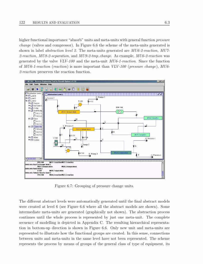
122 RESULTS AND EVALUATION 6.3
higher functional importance “absorb” units and meta-units with general function pressure
change (valves and compressor). In Figure 6.6 the scheme of the meta-units generated is
shown in label abstraction level 2. The meta-units generated are MU6-2-reaction, MU7-
2-reaction, MU8-2-separation, and MU9-2-tmp change. As example, MU6-2-reaction was
generated by the valve VLV-100 and the meta-unit MU6-1-reaction. Since the function
of MU6-1-reaction (reaction) is more important than VLV-100 (pressure change), MU6-
2-reaction preserves the reaction function.
Figure 6.7: Grouping of pressure change units.
The different abstract levels were automatically generated until the final abstract models
were created at level 6 (see Figure 6.6 where all the abstract models are shown). Some
intermediate meta-units are generated (graphically not shown). The abstraction process
continues until the whole process is represented by just one meta-unit. The complete
secuence of modelling is depicted in Appendix C. The resulting hierarchical representa-
tion in bottom-up direction is shown in Figure 6.6. Only new unit and meta-units are
represented to illustrate how the functional groups are created. In this sense, connections
between units and meta-units in the same level have not been represented. The scheme
represents the process by means of groups of the general class of type of equipment, its

6.4 IDENTIFICATION OF CANDIDATES 123
general function can be easily deduced from them. This figure represents all the unit and
meta-units in each level, in similar way that they are presented to the designer.
In Figure 6.6 each meta-unit has links to its creator units/meta-unit. So there is top-down
relations between models, as shown in Figure 6.8. Thus, both representations (Figure 6.6
and Figure 6.8) are used in the diagnosis and case-based reasoning modules. The tree of
abstract models can be traversed bottom-up or top-down.
metaseparator-6
metareactor-6
metareactor-7
metareactor-8
abstraction level 1
abstraction level 2
abstraction level 3
abstraction level 4
abstraction level 5
abstraction level 6
metaseparator-3
metaseparator-4
metareactor-5
metaseparator-5
metareactor-3
metareactor-4
metatmp_change-3
metaseparator-2
reactor-1
mixer-1heat ex-changer-1
valve-1
reactor-2 mixer-2
valve-2
mixer-3 separator-1 cooler-1 compressor-1
heat ex-changer-2 splitter-1 separator-2 splitter-2
valve-3meta
reactor-1meta
tmp_change-1
metareactor-2
metatmp_change-2
metaseparator-1
reactor-3
cooler-2
Figure 6.8: Hierarchical representation of the ammonia production process in top-downdirection.
6.4 Identification of candidates
With the process representation obtained, the human designer can modify the process by
focusing on the composing functions. According to the new design objective(s) that the
process must fulfill. In this section, modifications on reactors are employed to illustrate
the results of the framework. Thus, in this section only one type of problem is considered.
Later, in section §6.6, other aspects are considered.
Problem
The redesign problem that was investigated in this case was to increase the production of
ammonia by 15% in the plant represented by the scheme of Figure 6.2.

124 RESULTS AND EVALUATION 6.4
Intervention approach of designer
The human designer first needs to identify the variables that may affect directly the
production of ammonia. Then the designer identifies that the increase of production can
be achieved by modifying any of the following conditions:
• Pressure,
• Temperature, and
• Concentration.
This gives an idea on the types of equipment the diagnosis must focus on. In this case,
assuming that the concentration variable is selected, which is affected by reactors and
separators. Initially, reactors affect the concentration of product because they produce
the main product, and separators affect it in secondary manner by incrementing the purity
of the product. Therefore, the focus will be on reactors, where the ammonia is originated.
Since all the roles of the chemical substances are known, the diagnostic module focuses on
the concentration of ammonia (which has the main product role). Thus all values related
to this substance are analysed.
Diagnostic performance
We are interested in finding where the main product is produced. The search starts at
the highest level in the hierarchy -abstraction level 6- (see Figure 6.8) following the flow
direction, from left to right.
The unique component in that level is meta-reactor-8 with the MFM (Multilevel Flow
Modelling) function source, which acts as “producer” of the main product. Since this
component affects the concentration, it is added to the list of possible candidates. Then,
the lower level (level 5) is explored. Only meta-reactor-7 has the MFM function source,
so it is added to the list of candidates. The search continues in the subsequent lower
level exploring only the branch of meta-reactor-7. In the level 4 the linked components
of meta-reactor-7 are meta-reactor-6 and meta-reactor-4. Since both have the MFM
function source, both are added to the list of candidates. In the level 3 the children units
of meta-reactor-6 are meta-reactor-5 and meta-reactor-3; for meta-reactor-4 are meta-
reactor-2 and valve-2. All meta-reactors have the MFM function source, but valve-2
has MFM function barrier, which does not affect the concentration variable. Then, only
meta-reactor-5, meta-reactor-3, and meta-reactor-2 are added to the list of candidates.
In the level 2 the meta-units reactor-1, meta-tmp change-1, meta-reactor-1, valve-1,
reactor-3, and mixer-3 are explored. From these components only reactor-1, meta-reactor-

6.4 IDENTIFICATION OF CANDIDATES 125
1, and reactor-3 have the MFM function source, which are added to the list of candidates.
In this case only meta-reactor-1 is not in the ground level, so the search continues in the
lower level, exploring only this branch.
In the level 1 the units connected to meta-reactor-1 are reactor-2 and mixer-2. reactor-1
has the MFM function source and mixer-2 has the MFM function balance, then only
reactor-1 is added to the list of candidates. Since reactor-1 is in the ground level the
search finishes.
As result of the search, all the units and meta-units affecting the concentration variable
have been identified, as shown Table 6.2.
Abstraction level Identified components
6 meta-reactor-8
5 meta-reactor-7
4 meta-reactor-6, meta-reactor-4
3 meta-reactor-5, meta-reactor-3, meta-reactor-2
2 reactor-1, meta-reactor-1, reactor-3
1 reactor-2
Table 6.2: Identified candidates.
Since modifications to the process can be performed only at ground level, the cause
and consequence units are searched in this level. This search is based on the primary
candidates found in the above search. For this, all the units connected to the explored
candidate are taken into account. Thus, connections between units in the ground level
are explored by using state analysis.
To illustrate the cause and consequence identification, assume that we focus on the meta-
reactor-3, which at ground level includes the units PFR-101, MIX-100, and VLV-100
(Figure 6.9). In the state analysis the state conditions are propagated to the units con-
nected to the meta-reactor-3 in the flow path. The analysis in back/forward stream
directions finishes when a closer primary function is reached. The state of the meta-
reactor-3 is set to low capacity (locap) because the production of the main product is not
enough. Since this meta-unit is not an initial unit in the path, its state may be originated
by the effect of the performance of other units. Then back units are analysed.
Considering the stream-4, the function to analyse is a source (PFR-100 ), which directly
affects the concentration variable. Perhaps other back units in the same direction may
affect the variable, but this is the closer primary function affecting the concentration

126 RESULTS AND EVALUATION 6.4
Figure 6.9: Units composing the meta-reactor-3.
variable. It may have low volume (lovol) state, which originates the low capacity of meta-
reactor-3. Therefore, the unit associated to this function is identified as cause unit and
the analysis in this direction finishes.
Considering the stream-7, the function to analyse is a balance (TEE-100 ), which does
not affects the variable. Then, the next function is analysed, which is a balance of
temperature (E-102 ), which again does not affect directly the variable. The next function
is storage (V-101 ), which affects the variable. This is another primary function affecting
the concentration variable, it may have low volume (lovol) state. Then its associated unit
is a cause unit and the analysis finishes.
Now, forward analysis is carried out following the output stream of the functional group.
The low capacity (locap) state of meta-reactor-3 originates a low flow (loflow) state and a
low volume (lovol) state, and consequently affects the following source functions producing
a low capacity (locap) state in such function.
Thus, considering the stream-2, the function to analyse is a balance (MIX-101 ), which
does not affect the concentration variable. The next function is source (PFR-102 ), which
affects the variable, it may have low capacity (locap) state originated for the low capacity
(locap) state of the meta-reactor-3. Then, the unit associated with this function is a
consequence unit. Since is the closer primary function affected in the forward stream

6.5 GENERATION OF ALTERNATIVES 127
direction, the analysis finishes.
Therefore, the identified cause and consequence units for meta-reactor-3 are shown in
Table 6.3, which also represents the cause and consequence units for all the meta-units.
Using this information the human designer can select any of the candidates to obtain
similar alternatives in the case-based reasoning module, as is described in next section.
Candidate Cause units Consequence unitsreactor-1 (PFR-100) separator-2 (V-101) reactor-2 (PFR-101)
reactor-2 (PFR-101) reactor-1 (PFR-100) reactor-3 (PFR-102)
reactor-3 (PFR-102) reactor-2 (PFR-101) separator-1 (V-101)
meta-reactor-1 reactor-1 (PFR-100) reactor-3 (PFR-102)
separator-2 (V-101)
meta-reactor-2 reactor-2 (PFR-101) separator-1 (V-101)
meta-reactor-3 reactor-1 (PFR-100) reactor-3 (PFR-102)
separator-2 (V-101)
meta-reactor-4 reactor-2 (PFR-101) separator-1 (V-101)
meta-reactor-5 separator-2 (V-101) reactor-2 (PFR-101)
meta-reactor-6 separator-2 (V-101) reactor-3 (PFR-102)
meta-reactor-7 separator-2 (V-101) separator-1 (V-101)
Table 6.3: Cause and consequence units.
6.5 Generation of alternatives
With the results of the diagnosis module, the CBR module is used to obtain alternatives
units/meta-units that may be adapted into the ammonia process. Again, the process
representation shown in Figure 6.6 is used to denote the composition of meta-units; and
the process representation shown in Figure 6.8 to denote the presence of units/meta-units
in each abstraction level.
Following the example of the meta-reactor-3 case and assuming that the designer has
selected it to obtain alternatives to this meta-unit. Thus, meta-reactor-3 constitutes
the original case with information shown in Figure 6.10. From the description of meta-
reactor-3, the values used in the similarity computations are shown in Table 6.41).
The human designer may assign weights (low, medium, and high) to these values to denote
the importance of some attribute in the description and the designer preference in ob-
1Values are expressed in the International System of Units.

128 RESULTS AND EVALUATION 6.5
Process identificator: ammoniaGeneral function: reactionSpecific function: reactionWorking function: tubular_reactorAbstraction level: 2Number inlet: 2Number outlet: 1Inlet function: reaction, flow_changeOutlet function: reactionGoal:
�Increases production of ammonia (family: Nitrogen_Compound)
in this second reactor in serie with the similar temperature and
pressure than the previous reactor. With outlet temperature: 393.19º C
and outlet pressure: 14970.05 kPa is achieved a conversion of: 99 %
mass of Methane, Hydrogen and Nitrogen (family: Alkane,
Inorganic_Compound, Inorganic_Compound) respectively in gas phase.�
Figure 6.10: Relevant data of the original case (meta-reactor-3).
General values of Keyword values of goalmeta-reactor-3 of meta-reactor-3
Process identificator: ammonia Type connection: serie
General function: reaction Inlet temperature: 393.03
Specific function: reaction Inlet pressure: 14985.05
Working function: tubular reactor Inlet phase: gas
Abstraction level: 2 Outlet temperature: 393.19
Number inlet: 2 Outlet pressure: 14970.05
Number outlet: 1 Outlet phase: gas
Inlet function: reaction, Conversion: 99
flow change Main product: ammonia
Outlet function: flow change Reactant: methane, hydrogen,
nitrogen
Main product family: nitrogen
compound
Reactant family: alkane,
inorganic compound,
inorganic compound
Table 6.4: Used values in the similarity computations.

6.5 GENERATION OF ALTERNATIVES 129
taining similar ones. With this preference the target case is obtained. By default medium
weights are assigned to all attributes. Then, to simplify the example, no modifications on
weights are performed and thus the target case is the original case. Although the total
number of inlets and outlets is considered as numeric values, only the most important
function at the inlet and the outlet are considered. In the above description, the inlet
function has the value reaction and flow change. Only reaction is considered as it is more
important to retrieve a source case with reaction as inlet function than flow change (see
hierarchy of functions in Figure 5.7 in Chapter 5). The functional structure is shown
in Figure 6.11. Thus, with the values of Table 6.4, units and meta-units with the same
metareactor
valve
reactor mixer
metareactor
Figure 6.11: Functional structure of the target case (meta-reactor-3).
specific function are extracted from the case library. The ground and abstract cases from
the ammonia process are not considered in this search. The search returns 93 ground and
abstract cases. The similarity computations are carried out over those extracted cases.
Teleological similarity
The teleological similarity is computed using the keyword values (see Table 6.4). That is,
only similarities in the goals of the extracted source cases against the goal of the target
case. Numeric and symbolic measures are employed (see the case retrieval section in
Chapter 4). Thus, corresponding teleological similarities are assigned to each source case,
it constitutes an additional value in the source case to employ in the global similarity
computation.

130 RESULTS AND EVALUATION 6.5
Global similarity
With the teleological value in each source case, the global similarity can be computed.
Here functional and hierarchical similarities are calculated, the former by means of sym-
bolic measure and the latter by means of the hierarchical measure.
Assume that a threshold of 142 was established to show the most similar source cases.
Thus, the computed global similarities are summarised in Table 6.5.
Rank Similarity Function Inlet Function Outlet Function1 56 % reaction reaction separation
tmp change
2 43 % reaction reaction pres change
3 37 % tubular reactor heater packed
4 31 % plug flow reactor valve separation/
cooler
5 30 % meta-reactor separation pres change
6 29 % tubular reactor reaction splitter
7 29 % reaction tmp change tmp change
8 27 % reaction tubular reactor tmp change
9 25 % reaction tubular reactor mixer
10 23 % tubular reactor tmp change separation
11 20 % plug flow reactor flow change cooler/
pres change
12 20 % reaction tmp change reaction
13 16 % reaction reaction tmp change
14 15 % reaction separation reaction
Table 6.5: Result of the global similarity computation for meta-reactor-3.
In Table 6.5 the percentage of similarity, the specific function, the inlet and outlet func-
tions of the source case are shown. Given these results, the designer can take any of
retrieved cases to adapt it and evaluate its performance in the simulator. Normally the
designer chooses the most similar ones, which are presented next.
1. meta-reactor with 56% of similarity
The values are given in Table 6.6. The functional structure is shown in Figure 6.12.
2This number may vary according to the human designer needs. In this case, for illustration andexemplification purposes, the number was stablished in 14 to show the 14 most similar cases.

6.5 GENERATION OF ALTERNATIVES 131
General values of Keyword values of goalmeta-reactor of meta-reactor
Process identificator: methanol Type connection: isolate
General function: reaction Inlet temperature: 321.15
Specific function: reaction Inlet pressure: 4985.05
Working function: tubular reactor Inlet phase: gas
Abstraction level: 2 Outlet temperature: 373.47
Number inlet: 2 Outlet pressure: 4870.52
Number outlet: 1 Outlet phase: gas
Inlet function: reaction, Conversion: 97
tmp change Main product: methanol
Outlet function: separation Reactant: carbon dioxide, nitrogen
Main product family: alcohol
Reactant family: inorganic compound,
inorganic compound
Table 6.6: Values of meta-reactor with 56% of similarity.
metareactor
separator
reactor mixer
metareactor
Figure 6.12: Functional structure of the meta-reactor with 56% of similarity.
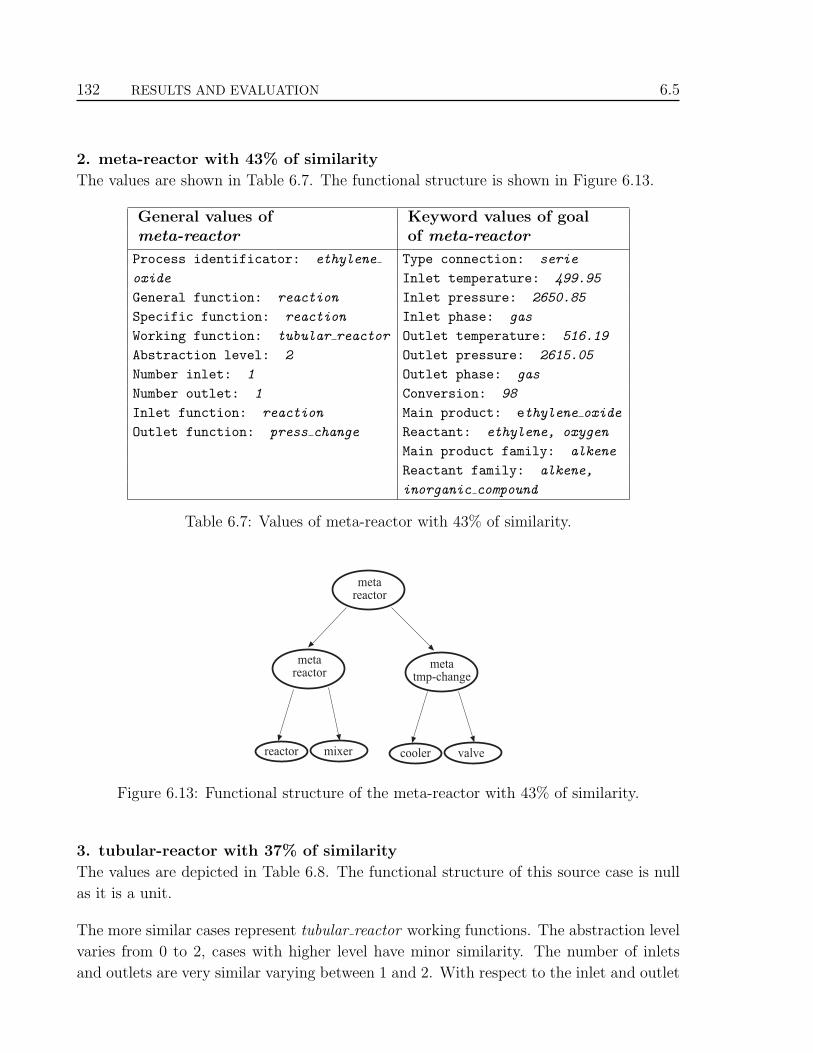
132 RESULTS AND EVALUATION 6.5
2. meta-reactor with 43% of similarity
The values are shown in Table 6.7. The functional structure is shown in Figure 6.13.
General values of Keyword values of goalmeta-reactor of meta-reactor
Process identificator: ethylene Type connection: serie
oxide Inlet temperature: 499.95
General function: reaction Inlet pressure: 2650.85
Specific function: reaction Inlet phase: gas
Working function: tubular reactor Outlet temperature: 516.19
Abstraction level: 2 Outlet pressure: 2615.05
Number inlet: 1 Outlet phase: gas
Number outlet: 1 Conversion: 98
Inlet function: reaction Main product: ethylene oxide
Outlet function: press change Reactant: ethylene, oxygen
Main product family: alkene
Reactant family: alkene,
inorganic compound
Table 6.7: Values of meta-reactor with 43% of similarity.
metareactor
metatmp-change
reactor mixer
metareactor
cooler valve
Figure 6.13: Functional structure of the meta-reactor with 43% of similarity.
3. tubular-reactor with 37% of similarity
The values are depicted in Table 6.8. The functional structure of this source case is null
as it is a unit.
The more similar cases represent tubular reactor working functions. The abstraction level
varies from 0 to 2, cases with higher level have minor similarity. The number of inlets
and outlets are very similar varying between 1 and 2. With respect to the inlet and outlet

6.5 GENERATION OF ALTERNATIVES 133
General values of Keyword values of goaltubular-reactor of tubular-reactor
Process identificator: cumene Type connection: isolate
General function: reaction Inlet temperature: 350.17
Specific function: reaction Inlet pressure: 3090.54
Working function: tubular reactor Inlet phase: gas
Abstraction level: 0 Outlet temperature: 350.01
Number inlet: 1 Outlet pressure: 3075.26
Number outlet: 1 Outlet phase: gas
Inlet function: heater Conversion: 96
Outlet function: packed Main product: cumene
Reactant: benzene, propene
Main product family: alkene
Reactant family: alkene, alkene
Table 6.8: Values of meta-reactor with 37% of similarity.
functions, the variation is pronounced in the second and third cases because both have 1
inlet and 1 outlet function. The first case has 2 inlet and 1 outlet functions as the target
case.
With respect to the goals of each case, there are several variations. The type of connection
is the same, only in the second case with value serie. The variations on temperatures is
clear in the first and second case because the outlet temperature is greater than the inlet.
Temperature values are more similar in the first and third cases. Variations on pressures
are more evident because the target case has values close to 15000 whereas the most
similar value is of the first case with value close to 5000. The phase of the three cases is
equal to target case, gas phase. The conversion values in the three cases are very similar
to the target (99% ), 97%, 98%, and 96% respectively. Obviously since the units are from
different process, the chemical substances in the main product and reactant are different.
In temperature and pressure, the range of values is also taken into account in addition
to quantitative values. In the Chemical Engineering domain is not recommendable to
compare these differences qualitatively. For example, the difference between 14985 and
14970 is small; also the difference between 2650 and 2615 is small. In both cases the
quantitative difference is small, but the values have different order of magnitude, which
is the most important characteristic in these differences.
Finally, it is decision of the human designer to perform the appropriate adjustments in the
above cases to adapt them into the ammonia process. To do this, he/she must take into

134 RESULTS AND EVALUATION 6.6
account the cause and consequence units identified in the candidates section (section §6.4).
The alternatives are descriptions of already existing equipment; these are not description
of prototypes that can be modified. Then, the three most similar retrieved cases were
adapted into the ammonia process. Although each case required specific adjustments,
the human experts considered as acceptable the alternatives proposed by the framework.
Depending on the adapted case, its retention must be carried out by modelling again the
entire process. The performance is similar to described in the modelling section (section
§6.3).
6.6 Other results
The framework was tested with other examples. Here, detailed steps are omitted illus-
trating only the most important ones.
6.6.1 Concentration variable
Following the ammonia process, now that we are interesting in incrementing the purity
of the main product (increment the concentration variable -the mass flow -). That means
some waste must be removed from the produced substance (main product). The MFM
function related to increment the amount of mass (purity of products) is storage linked
to separators. Therefore, the diagnosis module returns from the search process in the
hierarchical representation (see Figure 6.8) the results shown in Table 6.9 and Table 6.10.
Abstraction level Identified components
5 meta-separator-6
4 meta-separator-5, meta-separator-4
3 meta-separator-3, meta-separator-2
2 separator-1, meta-separator-1
1 separator-2
Table 6.9: Identified candidates related to increase purity.
From Table 6.10 the expert can see that outlet process-1, outlet process-4, and out-
let process-5 are considered as consequence units. The search algorithm considers the
inlets and outlets as units will null functions but with source and sink MFM functions

6.6 OTHER RESULTS 135
Candidate Cause units Consequence unitsseparator-1 (V-101) separator-2 (V-100) reactor-1 (PFR-100)
reactor-2 (PFR-101)
reactor-3 (PFR-102)
outlet process-5
separator-2 (V-100) reactor-3 (PFR-102) separator-1 (V-101)
outlet process-1
outlet process-4
meta-separator-1 reactor-3 (PFR-102) separator-1 (V-101)
outlet process-1
outlet process-4
meta-separator-2 reactor-3 (PFR-102) separator-1 (V-101)
outlet process-1
outlet process-4
meta-separator-3 separator-2 (V-100) reactor-1 (PFR-100)
reactor-2 (PFR-101)
reactor-3 (PFR-102)
outlet process-5
meta-separator-4 reactor-3 (PFR-102) separator-1 (V-101)
outlet process-1
outlet process-4
meta-separator-5 separator-2 (V-100) reactor-1 (PFR-100)
reactor-2 (PFR-101)
reactor-3 (PFR-102)
outlet process-5
meta-separator-6 reactor-3 (PFR-102) reactor-1 (PFR-100)
reactor-2 (PFR-101)
reactor-3 (PFR-102)
outlet process-1
outlet process-4
outlet process-5
Table 6.10: Cause and consequence units of candidates related to increase purity.

136 RESULTS AND EVALUATION 6.6
respectively. These units are not real equipment, but connection ports to external pro-
cesses. We are not interested in the nature of such processes, only in the input and output.
In inlet ports raw material are introduced and in outlet ports the produced products are
delivered.
Let’s assume that meta-separator-4 is selected. The functional structure of this meta-unit
covers four types of general functions, separation (flash separator, V-100), flow change
(splitter, TEE-101), pressure change (valve, VLV-102), and temperature change (cooler,
E-101) as depicted in Figure 6.14. The values of the meta-unit are shown in Table 6.11.
metaseparator
metaseparator
separator splitter
valvemeta
separator
cooler
Figure 6.14: Functional structure of meta-separator-4.
From the data of Table 6.11, alternative units/meta-units are obtained in the same manner
as the previous example. The result of this is presented in Table 6.12. Again the human
designer may test the resulting cases into the ammonia process to evaluate its performance
and the overall result. The values (Table 6.13) and functional structure (Figure 6.15) of
most similar case is given as follows.
6.6.2 Temperature variable
Following with the same redesign problem, now we desire to focus on the temperature due
to the high effect on conversion. Therefore, units that modify directly the temperature
must be identified. That means the closest source, barrier, and balance MFM functions to
the main product producers must be identified. They must be the closest because they are

6.6 OTHER RESULTS 137
General values of Keyword values of goalmeta-separator-4 of meta-separator-4
Process identificator: ammonia Type separation: distillation
General function: separation Concentration: 0.13
Specific function: distillation Main product: ammonia
Working function: flash Sub-product: water, carbon
Abstraction level: 3 monoxide, carbon dioxide
Number inlet: 1 Main product family: nitrogen compound
Number outlet: 3 Sub-product family: inorganic compound,
Inlet function: tmp change inorganic compound,
Outlet function: pres change, inorganic compound
null outlet, null outlet
Table 6.11: Values of meta-separator-4.
metaseparator
separator valve
coolermeta
separator
Figure 6.15: Functional structure of meta-separator with 61% of similarity.

138 RESULTS AND EVALUATION 6.6
Rank Similarity Function Inlet Function Outlet Function1 61 % separation tmp change outlet/
pres change
2 57 % separation separation tmp change/
valve
3 55 % separation pres change reaction/
separation
4 48 % separation tmp change outlet/
tmp change
5 42 % packed mixer cooler/
pres change
6 37 % flash separation outlet/
plug flow reactor
7 31 % trayed pump outlet/
tmp change
8 28 % separation pres change reaction/
tubular reactor
9 24 % flash separation separation/
pres change
10 21 % separation reaction reaction/
pres change
11 17 % separation separation reaction/
separation
12 17 % packed tmp change separation/
tmp change
13 15 % trayed pres change outlet/
pres change
14 11 % separation tmp change outlet/
pres change
Table 6.12: Result of the global similarity computation for meta-separator-4.

6.6 OTHER RESULTS 139
General values of Keyword values of goalmeta-separator of meta-separator
Process identificator: formaldehyde Type separation: distillation
General function: separation Concentration: 0.15
Specific function: distillation Main product: formaldehyde
Working function: flash Sub-product: water,
Abstraction level: 2 carbon monoxide
Number inlet: 2 Main product family: aldehyde
Number outlet: 2 Sub-product family:
Inlet function: tmp change inorganic compound,Outlet function:outlet, pres change inorganic compound
Table 6.13: Values of meta-separator with 61% of similarity.
the units that affect directly the inlet temperature to produce the main product. The units
linked to source, barrier, and balance functions are heaters, coolers and heat exchangers
respectively. Thus, after the search process in the diagnosis module, the most promising
candidates are shown in Table 6.14 and Table 6.15. From Table 6.15 the user can see that
meta-tmp change-2 and meta-tmp change-3 are generated from heat exchanger-2 (E-102).
Furthermore, they have the same cause and consequence units. This is a clear example
that shows how the grouping process conserves the main goals.
Abstraction level Identified components
3 meta-tmp change-3, cooler-2
2 meta-tmp change-1, cooler-1, meta-tmp change-2
1 heat exchanger-1, heat exchanger-2
Table 6.14: Identified candidates related to increase conversion.
Now assume that heat exchanger-2 (E-102) is selected to guide the retrieving of alterna-
tives. In this case, as is a unit, has not a functional tree structure. The unit has the
values depicted in Table 6.16. With the data from Table 6.16, similar units/meta-units
are extracted, but in this case assigning weights and preferences on the inlet and outlet
functions. In this analysis we are not interested on what type of connections the source
case must satisfy, we focus only the effect on temperature. The result of this retrieving is
presented in Table 6.17.
Since in this case the retrieving process is not restrictive, the similarities are higher than
in previous examples. Again, the human designer must adapt the alternative cases consid-
ering the cause and consequence units. Next, the values (Table 6.18) of the most similar

140 RESULTS AND EVALUATION 6.6
Candidate Cause units Consequence unitscooler-1 (E-101) heat exchanger-1 (E-104) separator-2 (V-100)
cooler-2 (E-103) heat exchanger-2 (E-102) separator-1 (V-101)
heat exchanger-1 (E-104) reactor-3 (PFR-102) reactor-1 (PFR-100)
inlet process-1 cooler-1 (E-101)
heat exchanger-2 (E-102)
heat exchanger-2 (E-102) separator-1 (V-101) heat exchanger-1 (E-104)
separator-2 (V-100) reactor-2 (PFR-101)
reactor-3 (PFR-102)
cooler-2 (E-103)
meta-tmp change-1 reactor-3 (PFR-102) reactor-1 (PFR-100)
inlet process-1 cooler-1 (E-101)
heat exchanger-2 (E-102)
meta-tmp change-2 separator-1 (V-101) heat exchanger-1 (E-104)
separator-2 (V-100) reactor-2 (PFR-101)
reactor-3 (PFR-102)
cooler-2 (E-103)
meta-tmp change-3 separator-1 (V-101) heat exchanger-1 (E-104)
separator-2 (V-100) reactor-2 (PFR-101)
reactor-3 (PFR-102)
cooler-2 (E-103)
Table 6.15: Cause and consequence units of candidates related to increase conversion.
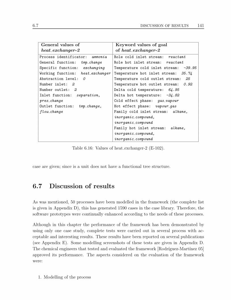
6.7 DISCUSSION OF RESULTS 141
General values of Keyword values of goalheat exchanger-2 of heat exchanger-2
Process identificator: ammonia Role cold inlet stream: reactant
General function: tmp change Role hot inlet stream: reactant
Specific function: exchanging Temperature cold inlet stream: -39.95
Working function: heat exchanger Temperature hot inlet stream: 35.74
Abstraction level: 0 Temperature cold outlet stream: 25
Number inlet: 2 Temperature hot outlet stream: 0.92
Number outlet: 2 Delta cold temperature: 64.95
Inlet function: separation, Delta hot temperature: -34.82
pres change Cold effect phase: gas vapour
Outlet function: tmp change, Hot effect phase: vapour gas
flow change Family cold inlet stream: alkane,
inorganic compound,
inorganic compound
Family hot inlet stream: alkane,
inorganic compound,
inorganic compound
Table 6.16: Values of heat exchanger-2 (E-102).
case are given; since is a unit does not have a functional tree structure.
6.7 Discussion of results
As was mentioned, 50 processes have been modelled in the framework (the complete list
is given in Appendix D), this has generated 1590 cases in the case library. Therefore, the
software prototypes were continually enhanced according to the needs of these processes.
Although in this chapter the performance of the framework has been demonstrated by
using only one case study, complete tests were carried out in several process with ac-
ceptable and interesting results. These results have been reported on several publications
(see Appendix E). Some modelling screenshots of these tests are given in Appendix D.
The chemical engineers that tested and evaluated the framework [Rodrıguez-Martınez 05]
approved its performance. The aspects considered on the evaluation of the framework
were:
1. Modelling of the process

142 RESULTS AND EVALUATION 6.7
Rank Similarity Function Inlet Function Outlet Function1 69 % tmp change inlet/ tubular reactor/
mixer tmp change
2 68 % heat exchanger inlet/ outlet/
separation separation
3 65 % heat exchanger pump/ packed/
splitter heater
4 61 % tmp change tubular reactor/ tubular reactor/
mixer cooler
5 58 % heat exchanger inlet/ outlet/
mixer heater
6 57 % tmp change tmp change/ outlet/
pres change reaction
7 49 % tmp change reaction/ separaton/
pres change tmp change
8 48 % tmp change reaction/ separation/
separation pres change
9 44 % tmp change inlet/ outlet/
separation separation
10 40 % heat exchanger inlet/ reaction/
pres change tmp change
11 38 % tmp change reaction/ outlet/
tmp change pres change
12 37 % heat exchanger pump/ reaction/
splitter cooler
13 34 % tmp change reaction/ outlet/
separation reaction
14 31 % tmp change inlet/ reaction/
separation tmp change
Table 6.17: Result of the global similarity computation for heat exchanger-2 (E-102).

6.7 DISCUSSION OF RESULTS 143
General values of Keyword values of goalheat exchanger of heat exchanger
Process identificator: acetic acid Role cold inlet stream: reactant
General function: tmp change Role hot inlet stream: reactant
Specific function: exchanging Temp. cold inlet stream: 28.42
Working function: heat exchanger Temp. hot inlet stream: 37.74
Abstraction level: 0 Temp. cold outlet stream: 85.39
Number inlet: 2 Temp. hot outlet stream: 52.66
Number outlet: 2 Delta cold temperature: 66.16
Inlet function: inlet, Delta hot temperature: 32.73
mixer Cold effect phase: vapour gas
Outlet function: tubular reactor, Hot effect phase: gas gas
tmp change Family cold inlet stream:
carboxilic acid
Family hot inlet stream:
carboxilic acid
Table 6.18: Values of heat exchanger with 69% of similarity.
• use of simplified models
• suitable grouping of equipment/sections
• intuitive goal-driven approach
• comprehensive and clear representations of equipment/sections
• easy and intuitive graphical interface
• transparent integration with the numerical simulator
2. Identification of candidates
• clear and easy search over simple but consistent concepts
• module easy to use
• intuitive interpretation of results
3. Suggestion of equipment/sections
• suggestions according to purpose-driven strategy
• appropriate guidelines for modification/substitution
• reuse of past design solutions
• easy access to abstract and detailed data of proposed solutions
• rapid response making agile the creation of alternative prototypes

144 RESULTS AND EVALUATION 6.8
As result, we can claim that the framework fulfills with the objectives; obviously it can
be enhanced in several aspects.
From the development point of view, the modelling module can be better by enhancing
the interaction with other commercial packages, the inference engine can be improved
by adding more heuristic rules, and the interfaces must be more sophisticated. Respect
to the diagnostic module, the advantage of using the MFM approach is that models
consist of static graphs. Thus the algorithm is local and incremental, it works in real
time and propagates information along static links only. Therefore, the diagnostic is
implemented as searches in MFM graphs by using depth-first search in sub-trees, which its
size is known. Respect to the case-base reasoning module, unlike other hierarchical CBR
systems [Branting 95, Smyth 01], recursive retrieving guided by the nodes of the graph
are not done. To compute distances a brute force nearest neighbour search is carried
out, but employing pre-calculate distances and putting those in memory. This approach
trades flexibility for performance. The pre-calculation routine uses a pre-defined subset
of attributes and defines intermediate weights for each attribute. Those decisions are not
altered at time the similarity relationships are pre-calculated. Although the process is
performed dynamically the attributes and weights can not be changed on the fly.
From the application point of view, the modelling module (data acquisition and functional
identification) fulfilled all the needs to represent the processes and its performance was
satisfactory, after several tests which continuously improved it. The diagnostic module
(although with some pending issues) was sufficiently good providing the most promising
candidates to be redesigned, this was a fundamental aspect to enhance the framework. The
case-base reasoning module was better and more acceptable by introducing weights. The
hierarchical CBR approach was determinant because it contributes to identify properly
abstract parts of processes. Some users proposed integrate to this module a decision-
making support system to facilitate the evaluation of the resulting cases in the simulator.
In general, the user interaction was easy and intuitive, several user comments and discus-
sions were taken into account to improve the framework. The alternatives provided by
the framework were good and acceptable taken into account the number of processes in
the case library. With more processes the alternatives could be better.
6.8 Chapter conclusions
In this chapter, results of the performance of the implementation of the redesign framework
have been described. At the same time, the evaluation of the framework is carried out.
To maintain the uniformity on the examples described, only one process has been used

6.8 CHAPTER CONCLUSIONS 145
as basis, the ammonia production process.
First the process is defined to clarify some basic aspect. After that, the basic modelling
process is explained describing how the meta-units are generated. As the process is iter-
ative, not all abstraction levels are presented. The hierarchical representation produced
is reorganised for the next modules can operate.
Thus, the redesign problem is presented to guide the identification of candidates and the
generation of alternatives. As result of the former, a list of possible candidates is obtained.
Then, the human designer must decide what unit/meta-unit is the most appropriate to
guide the next stage. Based on the chosen unit/meta-unit, the most similar ones are
obtained from the case base.
With these results, the human designer may adapt any of the most similar units/meta-
units in the external simulator to evaluate its performance and the overall process. This
is performed taking into account the units that may be affected by the modifications. The
retention of the adapted unit/meta-unit is not described because the process is very similar
to that described in the modelling process, but in this case, the “new” units/meta-units
are identified as not original in the process.
The human experts that have evaluated the framework have been in agreement with its
performance. Obviously, during the development of the framework, they gave several
comments to enhance it, which were taken into account in latter versions. We can claim
that the framework can give better results with a bigger case library since the alternative
equipment come from already implemented processes.

146 RESULTS AND EVALUATION 6.8

CHAPTER
SEVEN
Conclusions
This chapter consists of a brief summary of the thesis, the limitations of the
work and suggestions for further work.
7.1 Summary of thesis
This thesis describes the research carried out to obtain a redesign support framework of
processes based on hierarchical modelling. This hierarchical modelling is based on means-
end and whole-parts aspects. The hierarchical representation enhances the reasoning
mechanism to identify the elements to be modified and the possible alternatives.
Chapter 2 presented research work on redesign. We saw the use of model-based and
case-based techniques for design but we could not find any redesign work that use hierar-
chical modelling in combination with model-based and case-based reasoning techniques.
The modelling approaches applied in this research were described in Chapter 3, these
approaches were applied satisfactorily in the control and diagnosis but never in redesign.
Our redesign framework was described in Chapter 4. We proposed four stages for perform-
ing redesign: design-description acquisition, identification of candidates to be redesigned,
generation of alternatives, and adaptation and evaluation. The implementation of these
stages was described in Chapter 5, where the development of a prototype in the Chemical
Engineering domain was presented. Finally, some results were discussed in Chapter 6.
147

148 CONCLUSIONS 7.3
7.2 Limitations
The research has many limitations, some of the major ones are:
• The framework was implemented only in one domain. The ideas can be applied to
another domain, but a new implementation will be necessary.
• The framework was tested with simulated plants. We did not have access to real
plant information1, but the results obtained were validated by a team of chemical
engineers specialised in design of processes.
• Nowadays, inexpert users can not use the framework. The implementation is not
manageable by novice users because important human decisions must be taken.
7.3 Further work
The research presented in this thesis initiates a number of new research questions and
provides a basis for the following related research activities:
1. Improvement of the current framework. The following issues must be considered:
• Integration of an explanation module. Although the actual implementation
produces explanations, these are abstract and they are not sufficiently intuitive
to users. Also the formalised ontology may be used to enhance the explana-
tions; in this way, the basis of abstract models can be obtained. For example,
design histories may be available.
• Improvement of the redesign-requirements acquisition. The new requirements
that the process must satisfy must be valid and consistent. This may be
achieved using of a consistency-based system.
• Improvement of teleological descriptions. The actual descriptions have been
employed satisfactorily, but it can be extended to cover other issues of process
equipment, such as costs, dimensions, etc.
• Integration of quantitave models to tackle other redesign aspects as economical
or environmental. In this case, Constraint Reasoning or Fuzzy Logic may be
used.
1It is very difficult that a company gives its actual designs because they are part of the know-how and,in many cases, they are protected by patents.
7.3 FURTHER WORK 149
• Testing and validation. The testing and validation of the resulting alternative
designs could be enhanced incorporating a decision-making support module to
facilitate the evaluation of the resulting cases in the simulator.
2. Improvement of the current implementation. Although the current performance of
the implementation is acceptable, this may be enhanced taking into account the
following points:
• Formalise the existing ontology. The current framework can be reinforced with
logical aspects. In addition, more standard concepts (for example concepts of
CAPE-Open2) may be added. Protege [Protege 05] can be used to define the
ontology in the DAML-OIL [DAML-OIL 05] language and JTP [JTP 05] to
reason with it.
• Scaling up the case library of processes. With this, the performance of the
implementation can be enhanced by improving the abstraction rules. This may
be done by acquiring and modelling more processes from the literature or, if
possible, from a company. This will contribute to a more realistic performance.
• Carry out more validations. The framework must be tested and validated with
more processes. Thus, the current implementation can be enhanced to adapt
it to the “new” situations.
3. Applications to other domains. Particularly the issues to be considered may be:
• Functions taxonomy. Must be a hierarchy of functions to define the general,
specific, and working functions. The broad functions (from the MFM approach)
can be applied to any domain. This is necessary to define the functional prece-
dence.
• The simulator. The simulator to use must allow the extraction of specific
data from its internal representations. Some data may not be in the “normal”
information given to the user.
• The abstraction rules. The aggregation of equipment must be defined properly
by a consistent abstraction rule set. This may be obtained by considering the
existent designs approaches in the domain.
2CAPE-Open [CAPE-Open 05] (Computer-Aided Process Engineering) is a standard for develop com-putational tools in Process Engineering.

150 CONCLUSIONS

APPENDIX
A
Data file of ammonia production process
This is the data file extracted from the simulator Hysys.
components 9 Methane H2O CO CO2 Hydrogen Nitrogen Oxygen
Ammonia Argon @
pid controller LIC-100 14 @
pid controller LIC-101 21 @
pid controller PIC-100 VLV-102 @
recycle RCY-1 22 23 @
material stream 5 9 1 199.9999538 15000.0464 126481.6618 14098.59635
3596.108837 84.16952424 50700086.91 0.037346967 0 0 0 0.163417102
0.75691192 0 0 0.042324011 0.020884503 0 0 0 0.727208015
0.242402672 0 0 0.00950481 @
material stream 1 9 1 269.9997284 15000.0464 620019.2784 49994.28695
-10149.33493 112.5493418 -507408763 0.298107834 0 0 0 0.083685692
0.413965054 0 0.019309228 0.184932192 0.230449264 0 0 0 0.51480824
0.183268939 0 0.01406161 0.057411946 @
material stream 4 9 1 393.1674856 14985.0464 620018.1217 45927.31035
-11048.04107 129.893639 -507406811.2 0.29810839 0 0 0 0.063849817
0.322089579 0 0.131019676 0.184932537 0.250856115 0 0 0 0.427565339
0.155220978 0 0.103861652 0.062495916 @
151

152 APPENDIX A
material stream 7 9 1 25 15000.0464 258.5861741 18.80733907
-24998.44378 99.98988045 -470154.2085 0.364934489 0 0 0 0.063252474
0.326076131 0 0.024257712 0.221479193 0.312759116 0 0 0 0.431384892
0.160043237 0 0.019584529 0.076228227 @
material stream 8 9 1 393.0272007 14985.0464 620276.7078
45946.11769 -11053.75146 129.8852575 -507876965.4 0.298136249 0 0 0
0.063849568 0.322091241 0 0.130975168 0.184947773 0.250881454 0 0 0
0.427566903 0.155222952 0 0.103827155 0.062501537 @
material stream 10 9 1 25 15000.0464 369.9323747 26.90570611
-24998.44378 99.98988045 -672600.7815 0.364934489 0 0 0 0.063252474
0.326076131
0 0.024257712 0.221479193 0.312759116 0 0 0 0.431384892 0.160043237
0 0.019584529 0.076228227 @
material stream 11 9 1 392.9875226 14970.0464 620646.6417 45967.77772
-11063.10347 129.9044675 -508546281.4 0.298176063 0 0 0 0.063823652
0.321975229 0 0.131055508 0.184969547 0.250946301 0 0 0 0.427446748
0.155186427 0 0.10390382 0.062516704 @
material stream 12 9 1 393.0780582 14955.0464 620646.6391 45964.85638
-11063.72342 129.9257322 -508542458.2 0.298176065 0 0 0 0.063809419
0.321909314 0 0.131135655 0.184969548 0.25096225 0 0 0 0.427378586
0.155164517 0 0.103973969 0.062520677 @
material stream 13 9 1 34.97613389 14940.51629 620646.6391 45964.85638
-24122.43924 101.9311223 -1108784455 0.298176065 0 0 0 0.063809419
0.321909314 0 0.131135655 0.184969548 0.25096225 0 0 0 0.427378586
0.155164517 0 0.103973969 0.062520677 @
material stream 14 9 0 34.97613323 14940.51629 0 0 -26268.22548
104.6234779 0 0.30478513 0 0 0 0.057374896 0.300490544 0
0.153187161 0.184162269 0.264635122 0 0 0 0.396431323 0.149419669 0
0.125298044 0.064215842 @
material stream 15 9 1 34.97613323 14940.51629 620646.6391 45964.85638
-24122.43924 101.9311223 -1108784455 0.298176065 0 0 0 0.063809419
0.321909314 0 0.131135655 0.184969548 0.25096225 0 0 0 0.427378586
0.155164517 0 0.103973969 0.062520677 @
material stream 17 9 1 34.97613323 14940.51629 4857.338609 359.7326683
-24122.43924 101.9311223 -8677629.432 0.298176065 0 0 0 0.063809419
0.321909314 0 0.131135655 0.184969548 0.25096225 0 0 0 0.427378586
0.155164517 0 0.103973969 0.062520677 @
material stream 18 9 1 35.73862298 15045.4772 615789.3005 45605.12371
-24099.28375 101.9498779 -1099050817 0.298176065 0 0 0 0.063809419
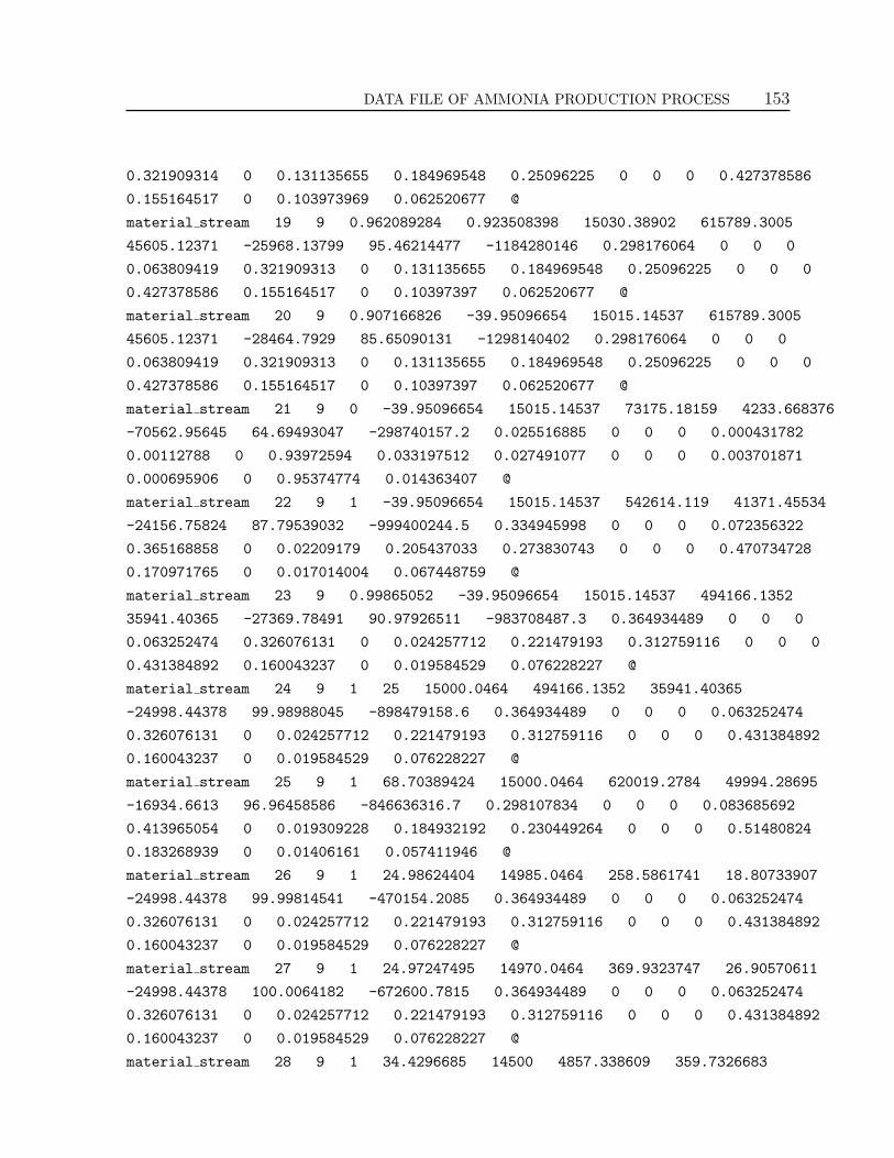
DATA FILE OF AMMONIA PRODUCTION PROCESS 153
0.321909314 0 0.131135655 0.184969548 0.25096225 0 0 0 0.427378586
0.155164517 0 0.103973969 0.062520677 @
material stream 19 9 0.962089284 0.923508398 15030.38902 615789.3005
45605.12371 -25968.13799 95.46214477 -1184280146 0.298176064 0 0 0
0.063809419 0.321909313 0 0.131135655 0.184969548 0.25096225 0 0 0
0.427378586 0.155164517 0 0.10397397 0.062520677 @
material stream 20 9 0.907166826 -39.95096654 15015.14537 615789.3005
45605.12371 -28464.7929 85.65090131 -1298140402 0.298176064 0 0 0
0.063809419 0.321909313 0 0.131135655 0.184969548 0.25096225 0 0 0
0.427378586 0.155164517 0 0.10397397 0.062520677 @
material stream 21 9 0 -39.95096654 15015.14537 73175.18159 4233.668376
-70562.95645 64.69493047 -298740157.2 0.025516885 0 0 0 0.000431782
0.00112788 0 0.93972594 0.033197512 0.027491077 0 0 0 0.003701871
0.000695906 0 0.95374774 0.014363407 @
material stream 22 9 1 -39.95096654 15015.14537 542614.119 41371.45534
-24156.75824 87.79539032 -999400244.5 0.334945998 0 0 0 0.072356322
0.365168858 0 0.02209179 0.205437033 0.273830743 0 0 0 0.470734728
0.170971765 0 0.017014004 0.067448759 @
material stream 23 9 0.99865052 -39.95096654 15015.14537 494166.1352
35941.40365 -27369.78491 90.97926511 -983708487.3 0.364934489 0 0 0
0.063252474 0.326076131 0 0.024257712 0.221479193 0.312759116 0 0 0
0.431384892 0.160043237 0 0.019584529 0.076228227 @
material stream 24 9 1 25 15000.0464 494166.1352 35941.40365
-24998.44378 99.98988045 -898479158.6 0.364934489 0 0 0 0.063252474
0.326076131 0 0.024257712 0.221479193 0.312759116 0 0 0 0.431384892
0.160043237 0 0.019584529 0.076228227 @
material stream 25 9 1 68.70389424 15000.0464 620019.2784 49994.28695
-16934.6613 96.96458586 -846636316.7 0.298107834 0 0 0 0.083685692
0.413965054 0 0.019309228 0.184932192 0.230449264 0 0 0 0.51480824
0.183268939 0 0.01406161 0.057411946 @
material stream 26 9 1 24.98624404 14985.0464 258.5861741 18.80733907
-24998.44378 99.99814541 -470154.2085 0.364934489 0 0 0 0.063252474
0.326076131 0 0.024257712 0.221479193 0.312759116 0 0 0 0.431384892
0.160043237 0 0.019584529 0.076228227 @
material stream 27 9 1 24.97247495 14970.0464 369.9323747 26.90570611
-24998.44378 100.0064182 -672600.7815 0.364934489 0 0 0 0.063252474
0.326076131 0 0.024257712 0.221479193 0.312759116 0 0 0 0.431384892
0.160043237 0 0.019584529 0.076228227 @
material stream 28 9 1 34.4296685 14500 4857.338609 359.7326683

154 APPENDIX A
-24122.43924 102.1717725 -8677629.432 0.298176065 0 0 0 0.063809419
0.321909314 0 0.131135655 0.184969548 0.25096225 0 0 0 0.427378586
0.155164517 0 0.103973969 0.062520677 @
material stream 16 9 1 34.97613323 14940.51629 615789.3005 45605.12371
-24122.43924 101.9311223 -1100106826 0.298176065 0 0 0 0.063809419
0.321909314 0 0.131135655 0.184969548 0.25096225 0 0 0 0.427378586
0.155164517 0 0.103973969 0.062520677 @
material stream 29 9 1 25 15000.0464 493537.6166 35895.69061
-24998.44378 99.98988045 -897336403.6 0.364934489 0 0 0 0.063252474
0.326076131 0 0.024257712 0.221479193 0.312759116 0 0 0 0.431384892
0.160043237 0 0.019584529 0.076228227 @
material stream 2 9 1 393.1881181 14970.0464 620276.7093 45940.87201
-11054.94211 129.916481 -507873680.7 0.298136249 0 0 0 0.063823993
0.321972783 0 0.131119203 0.184947773 0.2509101 0 0 0 0.427444441
0.155183582 0 0.103953203 0.062508674 @
material stream 30 9 1 194.0818107 14955.0464 620646.6391 45964.85638
-18443.87383 116.7938376 -847770011.9 0.298176065 0 0 0 0.063809419
0.321909314 0 0.131135655 0.184969548 0.25096225 0 0 0 0.427378586
0.155164517 0 0.103973969 0.062520677 @
energy stream Q-100 1056008.719 @
energy stream Q-101 261014443.1 @
energy stream Q-102 113860256.2 @
mixer MIX-100 2 4 26 8 @
mixer MIX-101 2 27 2 11 @
mixer MIX-102 2 5 29 25 @
splitter TEE-101 15 2 16 17 @
splitter TEE-100 24 3 10 7 29 @
valve VLV-100 7 26 15 @
valve VLV-101 10 27 30 @
valve VLV-102 17 28 440.5162942 @
compressor K-100 16 18 Q-100 104.9609102 @
cooler E-101 30 13 Q-101 14.53010101 -159.1056768 @
cooler E-103 19 20 Q-102 15.24364877 -40.87447494 @

DATA FILE OF AMMONIA PRODUCTION PROCESS 155
heat exchanger E-104 12 30 25 1 60.31857895 6 160 0
-339227553.7 339227553.7 12 25 @
heat exchanger E-102 18 19 23 24 60.31857895 6 160 0
-85229328.72 85229328.72 18 23 @
flash V-100 1 13 2 14 15 15 14 @
flash V-101 1 20 2 21 22 22 21 @
tubular reactor PFR-102 1 11 1 12 1 3 0.005 0.001 2500
Synthesis 15 @
tubular reactor PFR-101 1 8 1 2 1 3 0.005 0.001 2500
Synthesis 15 @
tubular reactor PFR-100 1 1 1 4 1 3 0.005 0.001 2500
Synthesis 15 @

156 APPENDIX A

APPENDIX
B
Failure conditions for flow functions
Every flow function in the Multilevel Flow Modelling [Lind 90, Lind 94, Lind 96, Larsson 96,
Lind 99] approach depends of some or more process variables (related to mass and energy).
The values of such process variables denote whether the function is currently available or
not. However, the state conditions are limited according to the following rules:
• A source is working if the current outflow F is less than the source’s maximum
capacity Fcap:
F <= Fcap
If this condition is not fulfilled, the state locap is true.
• A transport is working if the current flow F lies within an interval, specified in the
design:
Flo <= F <= Fhi
If the flow F is below Flo the state loflow is true; if it is above Fhi hiflow is true.
• A barrier is working if the current flow F is low enough, (approximately zero):
|F | <= a1
If this condition is not fulfilled, the state leak is true.
157

158 APPENDIX B
• A storage is working if the current volume V lies within a specified interval:
Vlo <= V <= Vhi
and the following inequality is fulfilled:
|dV/dt - Fi + Fo| <= a1
If the volume V is lower than Vlo the state lovol is true, if it is higher than Vhi,
hivol is true. If the expression within bars is less than -a1 the state leak is true; if
it is larger than a1 the state fill is true.
• A balance is working if the following inequality is fulfilled:
| F1 + F2 + F3 + ... + Fn | <= a1
If the expression within bars is less than a1 the state leak is true; if it is larger than
a1 the state fill is true.
• A sink is working if the current inflow F is less than the sink’s maximum capacity
Fcap:
F < Fcap
If the condition is not fulfilled, the state locap is true.
These qualitative states can only propagate from flow function to flow function in cer-
tain ways. This is a consequence of the failure conditions described above. Thus, some
primary states in some types of flow functions may cause secondary states in the con-
nected functions, while failures in others will not. A state in one flow function may or will
cause consequential states in the connected functions. A complete set of rules producing
secondaries states is defined as follows:
• A source locap will force the connected transport to have a loflow.
• A transport loflow may cause a storage connected at the inlet of the transport to
have a hivol, and a storage connected at the outlet to have a lovol. It may cause
another transport connected in the same direction via a balance to have a loflow. If
the balance has no other connections the same state will be forced.

FAILURE CONDITIONS FOR FLOW FUNCTIONS 159
• A transport hiflow may cause a connected source or sink to have a locap. It may
cause a storage connected at the inlet of the transport to have a lovol, and a storage
connected at the outlet to have a hivol. It may cause a transport connected in
the same direction via a balance to have a hiflow. If the balance has no other
connections, the same state will be forced. It may cause another transport connected
in the opposite direction via a balance to have a loflow.
• A barrier leak may cause a transport connected via a balance to have a loflow, or a
hiflow.
• A storage lovol may cause an outgoing connected transport to have a loflow.
• A storage hivol may cause an incoming connected transport to have a loflow, and
it may cause an outgoing connected transport to have a hiflow.
• A storage leak may cause the same storage to have a lovol.
• A storage fill may cause the same storage to have a hivol.
• A balance leak may cause a connected outgoing transport to have a loflow, and a
connected incoming transport to have a hiflow.
• A balance fill may cause a connected incoming transport to have a loflow, and a
connected outgoing transport to have a hiflow.
• A sink locap will force the connected transport to have a loflow.
• An state in a network will force a function depending on this network to fail.
Note that the final rule makes use of means-end relations. Thus, even if most of the
algorithm is concerned with comparing states of functions in a single flow structure,
information may propagate upwards in the model graph, and a single state may ultimately
affects the failure states of all goals and networks above it all the way up to the top level
goals of the entire model.

160 APPENDIX B

APPENDIX
C
Modelling of the ammonia process
The complete modelling of the ammonia production process is given in the two following
pages.
Figure C.1: Representation of the ammonia process in HYSYS and RETRO.
161

162 APPENDIX C
Figure C.2: Modelling of the ammonia process in RETRO.

APPENDIX
D
Chemical processes modelled
This is the list of processes modelled in the framework.
Process Number of Chemicalequipment substances
1. Acetaldehide from ethanol 15 72. Acetaldehide from ethylene and oxygen 27 73. Ethyl acetate 39 54. Vinyl acetate 25 35. Acetone 13 46. Acetic acid 35 47. Acrylic acid 17 88. Cyanhydric acid 16 69. Nitric acid 18 710. Acrolein 10 711. Ammonia from natural gas and pure N2 35 812. Ammonia from pure N2 and H2 19 1013. Phthalic anhydride from naphtalene 19 914. Phthalic anhydride from o-Xylene 9 715. Maleic anhydride 7 1016. Bencene and methane 17 417. Bencene and o-Xylene 5 318. Bencene, Toluene and Styrene 33 1019. Separation of Chlorine-Bencene and Bencene 12 3
163

164 APPENDIX D
20. Ethyl-Bencene 19 621. Cumene 12 622. 1,3-Butadiene 6 423. Cyclohexane 18 424. Allyl Chloride 17 625. Separation of Ciclohexane 17 326. Chloroform 10 827. Ethanol 24 528. Purification of Ethanol 8 229. Dimethyl ether 9 330. Ethyl tert-butylic ether (ETBE) 11 531. Methyl tert-butylic ether (MTBE) 12 432. Tert-amyl Methyl ether (TAME) 19 533. Styrene 23 834. Separation of ethane, n-heptane y n-octane 4 335. Ethylene 27 536. Ethylene oxide 25 737. Formaldehyde 14 738. Formaline 10 539. Methyl formate 21 440. HP gas 11 1041. Heptane 14 1042. Hydrogen 5 743. Separation of metane 5 1044. Separation of metane and ethane 3 1045. Methanol from natural gas 10 646. Methanol from carbon monoxyde 27 647. Oxygen and nitrogen 19 548. Purification of parafins 4 549. Propyleneglycol and dipropylene glycol 10 450. Vinyl chloride 10 6
Next, the modelling screenshots of some processes modelled in the framework are shown
with they corresponding results. The unit/meta-unit chosen to modification/substitution
is indicated in each process.

CHEMICAL PROCESSES MODELLED 165
Acetaldehyde process
Figure D.1: Abstraction level 0 of Acetaldehyde process.
Figure D.2: Abstraction level 4 of Acetaldehyde process.
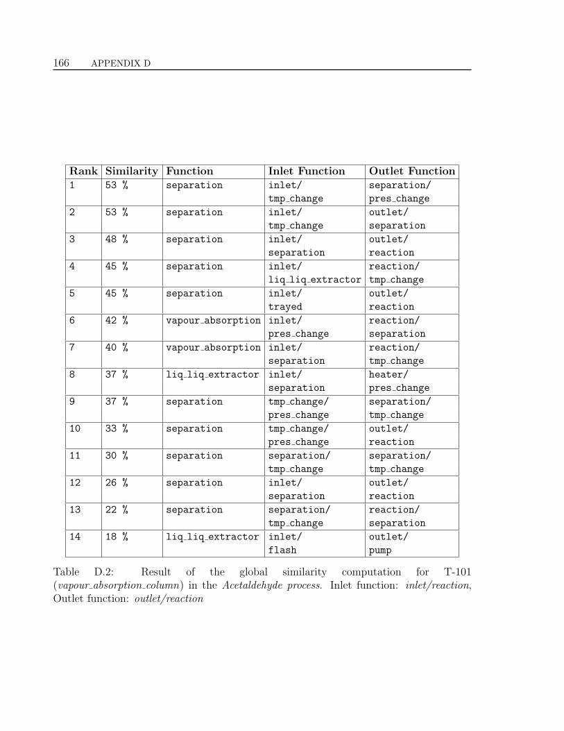
166 APPENDIX D
Rank Similarity Function Inlet Function Outlet Function1 53 % separation inlet/ separation/
tmp change pres change
2 53 % separation inlet/ outlet/
tmp change separation
3 48 % separation inlet/ outlet/
separation reaction
4 45 % separation inlet/ reaction/
liq liq extractor tmp change
5 45 % separation inlet/ outlet/
trayed reaction
6 42 % vapour absorption inlet/ reaction/
pres change separation
7 40 % vapour absorption inlet/ reaction/
separation tmp change
8 37 % liq liq extractor inlet/ heater/
separation pres change
9 37 % separation tmp change/ separation/
pres change tmp change
10 33 % separation tmp change/ outlet/
pres change reaction
11 30 % separation separation/ separation/
tmp change tmp change
12 26 % separation inlet/ outlet/
separation reaction
13 22 % separation separation/ reaction/
tmp change separation
14 18 % liq liq extractor inlet/ outlet/
flash pump
Table D.2: Result of the global similarity computation for T-101(vapour absorption column) in the Acetaldehyde process. Inlet function: inlet/reaction,Outlet function: outlet/reaction

CHEMICAL PROCESSES MODELLED 167
Acetone process
Figure D.3: Abstraction level 0 of Acetone process.
Figure D.4: Abstraction level 2 of Acetone process.

168 APPENDIX D
Rank Similarity Function Inlet Function Outlet Function1 53 % heater pump flash
2 53 % tmp change separation reaction
3 48 % tmp change reaction reaction
4 45 % tmp change mixer heat exchanger
5 45 % heater tmp change tank
6 42 % tmp change trayed tubular reactor
7 40 % tmp change flash CSTR
8 37 % heater packed heat exchanger
9 37 % tmp change splitter pump
10 33 % heater mixer flash
11 30 % heater inlet reaction
12 26 % tmp change flash valve
13 22 % tmp change separation reaction
14 18 % tmp change reaction reaction
Table D.3: Result of the global similarity computation for MU2-2-temperature (heater)in the Acetone process. Inlet function: tank, Outlet function: tubular reactor

CHEMICAL PROCESSES MODELLED 169
Acrylic Acid process
Figure D.5: Abstraction level 0 of Acrylic Acid process.
Figure D.6: Abstraction level 3 of Acrylic Acid process.

170 APPENDIX D
Rank Similarity Function Inlet Function Outlet Function1 56 % separation inlet/ tubular reactor/
separation heater
2 53 % separation inlet/ outlet/
tmp change separation
3 51 % liq liq extractor heat exchanger/ tubular reactor/
pump flash
4 48 % liq liq extractor inlet/ tubular reactor/
tmp change packed
5 46 % separation separation/ separation/
tmp change tmp change
6 44 % separation inlet/ packed/
liq liq extractor pres change
7 38 % separation trayed/ outlet/
heater tubular reactor
8 36 % vapour absorption inlet/ reaction/
packed tmp change
9 33 % separation inlet/ tubular reactor/
heat exchanger cooler
10 24 % vapour absorption inlet/ tubular reactor/
mixer flash
11 19 % separation packed/ outlet/
tmp change valve
12 17 % liq liq extractor inlet/ outlet/
separation reaction
13 14 % separation tmp change/ outlet/
heater reaction
14 9 % liq liq extractor inlet/ separation/
tank heat exchanger
Table D.4: Result of the global similarity computation for MU11-3-separation(liq liq extractor) in the Acrylic Acid process. Inlet function: vapour absorption/trayed,Outlet function: trayed/trayed

CHEMICAL PROCESSES MODELLED 171
Bencene process
Figure D.7: Abstraction level 0 of Bencene process.
Figure D.8: Abstraction level 3 of Bencene process.

172 APPENDIX D
Rank Similarity Function Inlet Function Outlet Function1 61 % reaction reaction outlet
2 57 % reaction reaction reaction
3 54 % reaction separation reaction
4 51 % tubular reactor trayed mixer
5 49 % tubular reactor separation outlet
6 46 % reaction tmp change separation
7 42 % reaction tmp change reaction
8 39 % CSTR packed heat exchanger/
cooler
9 37 % reaction separation separation
10 34 % plug flow separation reaction/
splitter
11 34 % plug flow packed cooler/
mixer
12 34 % reaction tubular reactor tmp change
13 27 % reaction tubular reactor mixer
14 20 % tubular reactor heater heat exchanger
Table D.5: Result of the global similarity computation for MU14-3-reaction (tubu-lar reactor) in the Bencene process. Inlet function: tmp change, Outlet function: sep-aration

CHEMICAL PROCESSES MODELLED 173
Cumene process
Figure D.9: Abstraction level 0 of Cumene process.
Figure D.10: Abstraction level 2 of Cumene process.

174 APPENDIX D
Rank Similarity Function Inlet Function Outlet Function1 47 % tmp change inlet/ tubular reactor/
mixer cooler
2 42 % tmp change tubular reactor/ separation/
separation valve
3 37 % heat exchanger inlet/ outlet/
mixer heater
4 30 % tmp change inlet/ CSTR/
packed pres change
5 23 % heat exchanger tubular reactor/ tubular reactor/
mixer cooler
6 16 % tmp change reaction/ tubular reactor/
tmp change separation
7 8 % heat exchanger pump/ packed/
splitter heater
8 5 % tmp change tubular reactor/ outlet/
tmp change separation
9 2 % tmp change inlet/ outlet/
inlet reaction
10 1 % tmp change inlet/ outlet/
separation separation
11 0 % tmp change inlet/ reaction/
separation separation
12 0 % heat exchanger inlet/ outlet/
separation separation
13 0 % tmp change inlet/ outlet/
inlet separation
14 0 % tmp change inlet/ reaction/
mixer separation
Table D.6: Result of the global similarity computation for MU3-2-temperature(heat exchanger) in the Cumene process. Inlet function: inlet/tubular reactor, Outletfunction: outlet/flash

CHEMICAL PROCESSES MODELLED 175
Di-Metyl Ether process
Figure D.11: Abstraction level 0 of Di-Metyl Ether process.
Figure D.12: Abstraction level 1 of Di-Metyl Ether process.

176 APPENDIX D
Rank Similarity Function Inlet Function Outlet Function1 56 % trayed valve packed/
cooler
2 56 % separation trayed reaction/
pres change
3 54 % trayed heater compressor/
mixer
4 50 % separation heater separation/
splitter
5 48 % separation pres change outlet/
outlet
6 48 % flash heat exchanger tubular reactor/
flash
7 45 % separation separation outlet/
reaction
8 43 % packed tmp change reaction/
separation
9 39 % packed valve heater/
splitter
10 37 % separation tmp change outlet/
reaction
11 34 % flash reaction outlet/
reaction
12 31 % trayed mixer trayed/
cooler
13 24 % separation pres change CSTR/
tmp change
14 21 % separation tmp change outlet/
reaction
Table D.7: Result of the global similarity computation for T-101 (trayed) in the Di-MethylEther process. Inlet function: valve, Outlet function: outlet/pump

CHEMICAL PROCESSES MODELLED 177
Ethanol process
Figure D.13: Abstraction level 0 of Ethanol process.
Figure D.14: Abstraction level 3 of Ethanol process.

178 APPENDIX D
Rank Similarity Function Inlet Function Outlet Function1 57 % separation separation reaction/
packed
2 55 % separation separation reaction/
trayed
3 51 % trayed separation outlet/
separation
4 47 % separation separation outlet/
packed
5 45 % packed heat exchanger outlet/
pump
6 42 % separation tmp change cooler/
valve
7 38 % trayed pres change pump/
splitter
8 36 % trayed heat exchanger reaction/
separation
9 33 % separation tmp change outlet/
reaction
10 30 % flash pump cooler/
splitter
11 27 % packed tank outlet/
separation
12 24 % separation inlet outlet/
reaction
13 19 % flash pres change reaction/
tubular reactor
14 12 % trayed reaction separation/
trayed
Table D.8: Result of the global similarity computation for MU7-3-separation (trayed) inthe Ethanol process. Inlet function: tank, Outlet function: outlet/outlet

APPENDIX
E
Publications
Some publications have been carried out based on the investigation presented in this
thesis. These are the followings:
Journals
1. An aggregational approach for suggesting process sections
I. Lopez-Arevalo, A. Rodrıguez-Martınez, R. Banares-Alcantara, L. Jimenez, and
A. Aldea. Special Issue of Computer and Chemical Engineering Journal. Elsevier.
Invited paper in preparation.
2. A hierarchical approach for the redesign of chemical processes
I. Lopez-Arevalo, A. Rodrıguez-Martınez, R. Banares-Alcantara, and A. Aldea.
Journal of Knowledge and Information Systems. Springer. In press.
3. The application of ontologies in the retrofit of chemical processes.
I. Lopez-Arevalo, A. Rodrıguez-Martınez, R. Banares-Alcantara and A. Aldea. Re-
vista Mexicana De Ingenierıa Quımica. Academia Mexicana de Investigacion y
Docencia en Ingenierıa Quımica. ISSN 1665-2738. Vol 3 (2004) pags. 39-53.
4. Multi-model knowledge representation in the retrofit of processes
A. Rodrıguez-Martınez, I. Lopez-Arevalo, R. Banares-Alcantara and A. Aldea. Spe-
cial Issue of Computer and Chemical Engineering Journal. Elsevier. Vol. 28 (2004)
pags. 781-788.
179

180 APPENDIX E
Congresses, Simposiums and Workshops
1. Redesign by using hierarchical models
I. Lopez-Arevalo, A. Rodrıguez-Martınez, R. Banares-Alcantara, L. Jimenez, and
A. Aldea. 2nd. MONET Workshop on Model-Based Systems. 19th International
Joint Conference on Artificial Intelligence. Edinburgh, Scotland, July-August 2005.
2. Redesign support framework based on hierarchical multiple models
I. Lopez-Arevalo, A. Rodrıguez-Martınez, R. Banares-Alcantara, L. Jimenez, and
A. Aldea. 19th International Joint Conference on Artificial Intelligence. Edinburgh,
Scotland, July-August 2005. Poster.
3. Generation of process alternatives using case-based reasoning
I. Lopez-Arevalo, A. Rodrıguez-Martınez, R. Banares-Alcantara, L. Jimenez, and
A. Aldea. 7th World Congress of Chemical Engineering. Glasgow, Scotland, July
2005.
4. Ontologıas: desarrollo y aplicacion en ingenierıa quımica
I. Lopez-Arevalo, A. Rodrıguez-Martınez, R. Banares-Alcantara and A. Aldea. XXV
Encuentro de la Academia Mexicana de Investigacion y Docencia en Ingenierıa
Quımica. Ref. PRO-30. Puerto Vallarta, Mexico, May 2004.
5. Intelligent identification of process sections during the redesign of processes
R. Banares-Alcantara, I. Lopez-Arevalo, A. Rodrıguez-Martınez, and A. Aldea. In-
vited talk in the Mexican International Conference on Artificial Intelligence (MI-
CAI’04). Mexico City. 26-27 April 2004.
6. Towards the automatic identification of process sections during the redesign of petroleum
and chemical processes
I. Lopez-Arevalo, A. Rodrıguez-Martınez, R. Banares-Alcantara and A. Aldea. 2nd
Workshop on Intelligent Computing in the Petroleum Industry (ICPI’03), 18th In-
ternational Joint Conference on Artificial Intelligence (IJCAI’03), ISBN 968-489-
020-6 (Printed version). Acapulco, Mexico, August 2003.
7. Automatic hierarchical abstraction tool for the retrofit of processes
A. Rodrıguez-Martınez, I. Lopez-Arevalo, R. Banares-Alcantara and A. Aldea. 4th
European Congress in Chemical Engineering (ECCE-4), Topic 9.2 Computer Aided
Modelling, Simulation & Optimisation. Ref. O-9.2-005. ISBN 84-88233-31-0.
Granada, Spain, September 2003.

PUBLICATIONS 181
8. Retrofit approach for developing sustainable chemical processes
A. Rodrıguez-Martınez, I. Lopez-Arevalo, R. Banares-Alcantara and A. Aldea. 13th
Annual Meeting of the Society of Environmental Toxicology and Chemistry in Eu-
rope (SETAC’03), Hamburg, Germany, April 2003.
9. A multi-modelling approach for the retrofit of processes
A. Rodrıguez-Martınez, I. Lopez-Arevalo, R. Banares-Alcantara and A. Aldea. 13th
European Symposium on Computer Aided Process Engineering (ESCAPE-13). El-
sevier Ed. pag. 269-274. ISBN 0-444-51368-X, Lappeenranta, Finland, June 2003.
10. Integrated framework for the retrofit of processes
A. Rodrıguez-Martınez, I. Lopez-Arevalo, R. Banares-Alcantara and A. Aldea. 9o.
Congreso Mediterraneo de Ingenierıa Quımica (COMIEQ’02), Posters Communica-
tion Report, pp. 81, Barcelona, Spain, December 2002.
11. Modelado multiple en el rediseno de procesos quımicos
Ivan Lopez-Arevalo, Arantza Aldea y Rene Banares-Alcantara. 8a. Conferencia
Iberoamericana de Inteligencia Artificial (IBERAMIA 2002), Open Discussion Track
Proceedings, pp. 21-30, Sevilla, Spain, November 2002.
12. Uso de HYSYS en la abstraccion y retrofit de procesos
Antonio Rodrıguez Martınez, Rene Banares-Alcantara, Ivan Lopez-Arevalo y Arantza
Aldea. 1r. Encuentro Universitario sobre Simulacion de Procesos y Aplicaciones
Hysys, Valencia, Spain, July 2001.
Technical Reports
1. Sistemas basados en modelos en diseno. Ivan Lopez-Arevalo y Arantza Aldea. Re-
port de recerca DEIM-RR-03-001, February 2003. Universitat Rovira i Virgili.
2. Razonamiento Funcional. Ivan Lopez-Arevalo y Arantza Aldea. Report de recerca
DEIM-RR-03-002, February 2003. Universitat Rovira i Virgili.
3. Razonamiento Analogico. Ivan Lopez-Arevalo y Arantza Aldea. Report de recerca
DEIM-RR-03-003, February 2003. Universitat Rovira i Virgili.

182 APPENDIX E

BIBLIOGRAPHY
[Aamodt 94] A. Aamodt & E. Plaza. Case-based reasoning: Foundational issues, method-
ological variations and system approaches. AI Communications, vol. 7, pages 39–59,
1994.
[Akin 82] O. Akin. Representation and architecture. Silver Spring, O. Akin and E.F.
Weinel eds., Maryland, Information Dynamics Inc., 1982.
[Alberts 92] L.K. Alberts P.M. Wognum & N.J. Mars. Structuring design knowledge on
the basis of generic components. Artificial Intelligence in Design (AID’92), vol. In:
Gero, J.S. (Ed.), pages 639–656, 1992. Kluwer, Dordrecht.
[Alberts 93a] L.K. Alberts. YMIR: An ontology for engineering design. PhD thesis,
University of Twente, 1993. Netherlands.
[Alberts 93b] L.K. Alberts R.R. Bakker D. Beekman & P.M. Wognum. Model-based re-
design of technical systems. Proceedings of the 4th international workshop on principles
of diagnosis, 1993.
[Altmeyer 96] J. Altmeyer & B. Schurmann. On design formalisation and retrieval of
reuse candidates. Artificial Intelligence in Design, (AID’96), vol. Gero, J.S. and Sud-
weeks, F. (Eds.), pages 231–250, 1996. Kluwer Academic Publishers.
[Anderson 89] D.C. Anderson & R.H. Crawford. Knowledge management for preliminary
computer aided mechanical design. Organization of engineering knowledge for product
modelling in computer integrated manufacturing, vol. Sata T. (Ed.), pages 15–34, 1989.
Elsevier.
[Arana 00] I. Arana H. Ahriz & P. Fothergill. Improving re-design support. In Pro-
ceedings of the Fifth World Conference on Integrated Design and Process Technology
(IDPT2000), 2000.
183

184 BIBLIOGRAPHY
[Arana 01] I. Arana H. Ahriz & P. Fothergill. Redesign Knowledge Analysis, Represen-
tation and Reuse. Industrial Knowledge Management A Micro-level Approach, 2001.
Springer-Verlag.
[Bakker 94] R.R. Bakker S.J. van Eldonk P.M. Wognum & N.I. Mars. The use of model-
based diagnosis in redesign. In Proc. Reasoning about physical systems. 11th European
Conference on Artificial Intelligence, pages 647–651, A. Cohn Ed., 1994.
[Ballinger 94] G.H. Ballinger R. Banares-Alcantara D. Costello E.S. Fraga J. King J.
Krabbe D.M. Laing R.C. McKinnel J.W. Ponton N. Skilling & M. Spenceley. Develop-
ing an Environment for Creative Process Design. Chemical Engineering Research and
Design, vol. 72, no. A3, pages 316–324, 1994.
[Ball 92] N.R. Ball & F. Bauert. The Integrated Design Framework: supporting the design
process using a blackboard system. Artificial Intelligence in Design (AID’92), vol. Gero,
J.S. (Ed.), pages 327–348, 1992. Kluwer academic publishers.
[Banares-Alcantara 95] R. Banares-Alcantara. Design Support Systems for Process Engi-
neering. I. Requirements and Proposed Solutions for a Design Process Representation.
Computers and Chemical Engineering, vol. 19, no. 3, page 267-277, 1995.
[Batres 99] R. Batres S.P. Asprey T. Fuchino & Y. Naka. A KQML Multi-Agent Envi-
ronment for Concurrent Process Engineering. Computers and Chemical Engineering,
vol. 23 - SupplementVol, pages 653–656, 1999.
[Bergmann 96] R. Bergmann & W. Wilke. On the Role of Abstraction in Case-Based
Reasoning. Advances in Case-Based Reasoning: Third European Workshop, no. LNAI
1168, pages 28–43, 1996. I. Smith and B. Faltings (Eds), Springer.
[Berker 96] I. Berker & D.C. Brown. Conflicts and Negotiation in Single Function Agent
Based Design Systems. Concurrent Engineering: Research and Applications, Journal,
Special Issue: Multi Agent Systems in Concurrent Engineering, vol. 4, no. 1, pages
17–33, 1996. Brown, D.C., Landes, S.E. and Petrie, C.J. (Eds.), Technomic Publishing
Inc.
[Bernaras 94] A. Bernaras. Problem-oriented and task-oriented models of design in the
Commonkads framework. Artificial Intelligence in Design ’94, vol. Gero, J. S. and
Sudweeks, F., (Edts.), 1994. Dordrecht, The Netherlands, Kluwer Academic Publishers.
[Bertalanffy 50] L.von Bertalanffy. An Outline of General Systems Theory. British Jour-
nal for the Philosophy of Science, vol. 1, no. 2, 1950.

BIBLIOGRAPHY 185
[Bhatta 92] S. Bhatta & A. Goel. Use of mental models for constraining index learning
in experience-based design. Proceedings of AAAI Workshop on Constraining Learning
with Prior Knowledge, pages 1–10, 1992. San Jose, USA.
[Bhatta 94] S. Bhatta A. Goel & S. Prabhakar. Innovation in Analogical Design: A
Model-Based Approach. Proceedings of Artificial Intelligence in Design, pages 57–74,
1994. Kluwer Academic Publishers, Dordrecht, The Netherlands.
[Biggs 03] M.J. Biggs. Introduction to Chemical Engineering. Seminar. Chemical Engi-
neering Department, School of Engineering and Electronics, University of Edinburgh,
2003.
[Blessing 99] L. Blessing K. Wallace G. Pahl W. Beitz K. Wallace & F. Bauert. Engi-
neering design: A systematic approach. Springer-Verlag London, 1999.
[Bo 99] Y. Bo & F. Salustri. Function Modeling Based on Interactions of Mass, Energy
and Information. Florida Artificial Intelligence Research Society, 1999.
[Borner 96] K. Borner E. Pipping E. Tammer & C. Coulon. Structural Similarity and
Adaptation. Proceedings of the Third European Workshop on Case-Based Reasoning,
pages 58–75, 1996. Springer-Verlag.
[Borst 97] W.N. Borst J.M. Akkermans & J.L. Top. Engineering ontologies. International
Journal of Human-Computer Studies, special issue on using explicit ontologies in KBS
development, vol. 46, pages 365–406, 1997.
[Brajnik 90] G. Brajnik L. Chittaro C. Tasso & E. Toppano. Epistemolology, organisation
and use of functional knowledge for reasoning about physical systems. In Proceedings
of the 10th Int. Workshop on Expert Systems and Their Application, pages 53–66,
Avignon, France, 1990.
[Branting 95] L.K. Branting & D.W. Aha. Stratified Case-Based Reasoning: Reusing
Hierarchical Problem Solving Episodes. In Proceedings of the Fourteenth International
Joint Conference on Artificial Intelligence (IJCAI-95), pages 20–25, Montreal, Canada,
1995.
[Bras 92] B.A. Bras. Foundation for designing decision-based design processes. PhD
thesis, University of Houston, 1992.
[Brazier 94] F.M. Brazier P.H. Van Langen Zs. Ruttkay & J. Treur. On formal specifi-
cation of design tasks. Artificial Intelligence in Design (AID’94), vol. Gero, J.S. and
Sudweeks, F. (Eds.), pages 535–552, 1994. Kluwer Academic Publishers, Dordrecht.

186 BIBLIOGRAPHY
[Brazier 96] F.M. Brazier P.H. Van Langen J. Treur & N.J. Wijngaards. Redesign and
reuse in compositional knowledge-based systems. Knowledge Based Systems, Special
Issue on Models and Techniques for Reuse of Designs, vol. 9, no. 2, pages 105–119,
1996.
[Bridge 97] C. Bridge. From design to redesign: Revisiting design models to highlight
similarities and differences. Seminar Presentation, 1997. Department of Architectural
and Design Science, University of Sydney, Australia.
[Britannica 05] Encyclopedia Britannica. http://www.britannica.com/, 2005.
[Brown 89] D.C. Brown & B. Chandrasekaran. Design problem solving: knowledge struc-
tures and control strategies. Morgan Kaufmann, 1989.
[Brown 97] D.C. Brown & W.P. Birmingham. Understanding the Nature of Design. IEEE
Expert, vol. 12, no. 2, pages 14–16, 1997.
[Brown 98] D.C. Brown. Intelligent Computer-Aided Design. AI in Design Group, Com-
puter Science Department, WPI, September 1998. Worcester, MA, USA.
[Buckingham 91] S. Buckingham Shum. Cognitive Dimensions of Design Rationale. In
People and Computers VI: Proceedings of HCI’91, pages 331–344, Cambridge Univer-
sity Press. Cambridge, 1991.
[Buckingham 96] S. Buckingham Shum. Design Argumentation as Design Rationale. The
Encyclopedia of Computer Science and Technology, vol. 35, no. 20, pages 95–128, 1996.
A. Kent and J. G. Williams, (Eds.), New York: Marcel Dekker, Inc.
[CAPE-Open 05] CAPE-Open. Computer-Aided Process Engineering Open.
http://www.global-cape-open.org/CAPE-OPEN standard.html, 2005.
[Carbonell 86] J.G. Carbonell. Derivational analogy: A theory of reconstructive prob-
lem solving and expertise acquisition. Machine Learning: An Artificial Intelligence
Approach, pages 371–392, 1986. Morgan and Kaufmann Publishers.
[Cellier 79] F.E. Cellier. Combined continuous system simulation by use of digital com-
puters: Techniques and tools. PhD thesis, Swiss Federal Institute of Technology, Zurich,
Switzerland, 1979.
[Chandrasekaran 90] B. Chandrasekaran. Design problem solving: a task analysis. AI
Magazine, vol. 11, no. 4, pages 59–71, 1990.

BIBLIOGRAPHY 187
[Chandrasekaran 93] B. Chandrasekaran A. Goel & Y. Iwasaki. Functional Representa-
tion as Design Rationale. IEEE Computer, no. Special Issue on Concurrent Engineering,
pages 48–56, 1993.
[Chandrasekaran 00] B. Chandrasekaran & J.R. Josephson. Function in Device Repre-
sentation. Engineering with Computers, Special Issue on Computer Aided Engineering,
vol. 16, pages 162–177, 2000.
[Checkland 81] P. Checkland. Systems thinking, systems practice. John Wiley and Sons,
1981.
[Chittaro 92] L. Chittaro G. Guida C. Tasso & E. Toppano. Developing diagnostic ap-
plications using multiple models: The role of interpretative knowledge. Industrial Ap-
plications of Knowledge-Based Diagnosis, 1992. G. Guida and A. Stefanini (Eds.),
Elsevier.
[Chittaro 93] L. Chittaro G. Guida C. Tasso & E. Toppano. Functional and Teleological
Knowledge in the Multimodeling Approach for Reasoning about Phisical Systems: A
case study in diagnosis. IEEE Transactions on Systems Man. and Cybernetics., vol. 23,
no. 6, pages 1718–1751, 1993.
[Chittaro 98] L. Chittaro & A.N. Kumar. Reasoning about function and its applications
to engineering. Artificial Intelligence in Engineering, vol. 12, pages 331–336, 1998.
[Christopher 95] J. Christopher H. Chonghum & G. Stephanopoulos. Modeling language:
Declarative and imperative descriptions of chemical reactions and processing systems.
Intelligent Systems in Process Engineering. Part I: Paradigms from Product and Process
Design, vol. 21, pages 73–91, 1995. Academic Press, San Diego, USA.
[Clancey 85] W.J. Clancey. Heuristic classification. Artificial Intelligence, vol. 27, pages
289–350, 1985.
[Clarkson 04] P.J. Clarkson C.S. Simons & C.M. Eckert. Predicting change propagation
in complex design. ASME Journal of Mechanical Design, vol. 126, no. 5, pages 765–797,
2004.
[Coghill 01] G.M. Coghill Q. Shen. Towards the specification of models for diagnosis of
dynamic systems. AI Communications, vol. 14(2), pages 93–104, 2001.
[Culley 99] S.J. Culley. Final Report - Future Issues For Design Research Workshop.
Rapport technique, Faculty of Engineering and Design, University of Bath, 1999.
[DAML-OIL 05] DAML-OIL. The DAML-OIL Language. http://www.w3.org/TR/
daml+oilreference, 2005.

188 BIBLIOGRAPHY
[Das 94] D. Das S. Gupta & D.Nau. Reducing setup cost by automated generation of
redesign suggestions. Proc. ASME Computers in Engineering Conference, pages 159–
170, 1994.
[Daube 89] F. Daube & B. Hayes-Roth. A Case-Based Mechanical Redesign System. In
Proceedings of the 11th International Joint Conference on Artificial Intelligence (IJCAI-
89) Vol. 2, pages 1402–1407, Morgan Kaufmann Publishers, 1989.
[de Kleer 79] J. de Kleer. Causal and Teleological Reasoning in Circuit Recongnition.
PhD thesis, Massachusetts Institute of Technology, 1979.
[de Kleer 82] J. de Kleer & J.S. Brown. Mental Models of Physical Mechanisms and
their Acquisition. In Cognitive skills and their acquisition, J.R. Anderson (ed), pages
285–309, Erlbaum, 1982.
[de Kleer 84] J. de Kleer & B.C. Brown. A qualitative physics based on confluences.
Artificial Intelligence, vol. 24, pages 7–83, 1984.
[de Silva Garza 96] A. Gomez de Silva Garza & M.L. Maher. Design by interactive explo-
ration using memory based techniques. Knowledge based systems, vol. 9, no. 1, pages
151–161, 1996.
[Dearden 93] A.M. Dearden & M.D. Harrison. Using previous experience in similarity
assessment for CBR: A formal treatment. In Proceedings of the IJCAI’93, 1993.
[DeLoach 04] S.A. DeLoach. The MaSE Methodology. Methodologies and Software Engi-
neering for Agent Systems. The Agent-Oriented Software Engineering Handbook Series
: Multiagent Systems, Artificial Societies and Simulated Organizations, vol. 11, 2004.
Bergenti, F., Gleizes, M.P., Zambonelli, F. (Eds.) Kluwer Academic Publishing.
[Dixon 89] J.R. Dixon M.J. Guenette R.K. Irani E.H. Nielsen M.F. Orelup & R.V. Welch.
Computer-based models of design processes: the evaluation of design for redesign. NSF
Engineering Design Research Conference, pages 491–506, 1989. University of Mas-
sachusetts, USA.
[Douglas 88] J.M. Douglas. Conceptual design of chemical processes. Mc Graw Hill, New
York, 1988.
[Doyle 62] L. Doyle. Indexing and Abstracting by Association. American Documentation,
vol. 18(4), pages 378–390, 1962.
[Duffy 97] A.H. Duffy. The What and How of Learning in Design. IEEE Expert, vol. 12,
no. 3, pages 71–76, 1997.

BIBLIOGRAPHY 189
[Dunskus 95] B.V. Dunskus D.L. Grecu D.C. Brown & I. Berker. Using Single Function
Agents to Investigate Conflict. Artificial Intelligence in Engineering Design and Man-
ufacturing (AIEDAM), Special Issue: Conflict Management in Design, vol. 9, no. 4,
pages 299–312, 1995.
[Eldonk 96] S.J. van Eldonk L.K. Alberts R.R. Bakker F. Diker & P.M. Wognum. Re-
design of technical systems. Knowledge-based Systems, Special Issue on Models and
Techniques for Reuse of Designs, vol. 9, pages 93–104, 1996.
[Falkenhainer 91] B. Falkenhainer & K.D. Forbus. Compositional Modeling: Finding the
Right Model for the Job. Artificial Intelligence, vol. 51, pages 95–143, 1991.
[Falkenhainer 92] B. Falkenhainer & K.D. Forbus. Composing task-specific models. Au-
tomated Modelling, ASME, vol. 41, pages 1–9, 1992.
[Fensel 01a] D. Fensel & E. Motta. Structured development of problem solving methods.
IEEE Transactions on Knowledge and Data Engineering, vol. 13, no. 6, pages 913–932,
2001.
[Fensel 01b] D. Fensel. Ontologies: A silver bullet for knowledge management and elec-
tronic commerce. Heidelberg, Germany, 2001.
[Finger 89] S. Finger & J.R. Dixon. A review of research in engineering design, Part I:
Descriptive, prescriptive and computer based models of design processes. Research in
Engineering Design, vol. 1, pages 51–67, 1989.
[Fischer 87] G. Fischer A.C. Lemke & C. Rathke. From design to redesign. In Proceedings
of the 9th International Conference on Software Engineering, pages 369–376, IEEE
Computer Society Press, 1987.
[Fischer 95] G. Fischer K. Nakakoji & J. Ostwald. Supporting the evolution of design arti-
facts with representations of context and intent. In Symposium on Designing Interactive
Systems. Proceedings of the conference on Designing interactive systems: processes,
practices, methods, and techniques, pages 7–15, Ann Arbor, USA, 1995.
[Fischoff 78] B. Fischoff P. Slovic & S. Lichtenstein. Fault trees: Sensitivity of estimated
failure probabilities to problem representation. Journal of Experimental Psychology:
Human Perception and Performance, vol. 4, 1978.
[Fishwick 91] P.A. Fishwick. Heterogeneous decomposition and coupling for combined
modelling. In 1991 Winter Simulation Conference, pages 1199–1208, Phoenix, USA,
1991.

190 BIBLIOGRAPHY
[Fishwick 92a] P.A. Fishwick & B.P. Zeigler. A Multimodel Methodology for Qualitative
Model Engineering. ACM Transactions on Modeling and Computer Simulation, vol. 2,
no. 1, pages 52–81, 1992.
[Fishwick 92b] P.A. Fishwick. An integrated approach to system modeling using a synthe-
sis of Artificial Intelligence, software engineering and simulation methodologies. ACM
Transactions on Modeling and Computer Simulation, vol. 2, no. 4, pages 307–330, 1992.
[Fishwick 93] P.A. Fishwick. A Simulation Environment for Multimodelling. Discrete
Event Dynamic Systems: Theory and applications, vol. 3, no. 1, pages 151–171, 1993.
[Fishwick 95] P.A. Fishwick. Simulation model design and execution: Building digital
worlds. Prentice Hall, Upper Saddle River, USA, 1995.
[Fishwick 97] P.A. Fishwick. A visual object-oriented multimodeling design approach
for physical modeling. Technical Report 9, University of Florida, CISE Department,
Gainesville, USA, 1997.
[Forbus 84] K.D. Forbus. Qualitative Process Theory. Artificial Intelligence, vol. 24, pages
85–168, 1984.
[Forbus 88] K.D. Forbus. Commonsense physics. A review. Annual Review of Computer
Science, vol. 3, pages 197–232, 1988.
[Forster 96] J. Forster I. Arana & P. Fothergill. Re-design knowledge representation with
DEKLARE. In Proceedings of KEML’96: 6th Workshop on Knowledge Engineering:
Methods and Languages, Paris, France, 1996.
[Forster 97a] J. Forster P. Fothergill & I. Arana. Enabling intelligent variant design using
constraints. IEE Intelligent Design Systems Colloquium, vol. Digest No: 97/016, 1997.
London.
[Forster 97b] J. Forster P. Fothergill & I. Arana. Enabling intelligent variant design using
constraints. IEE Intelligent Design Systems Colloquium, vol. Digest No: 97/016, 1997.
London.
[Fothergill 95] P. Fothergill J. Forster J. A. Lacunza F. Plaza & I. Arana. DEKLARE:
A methodological approach to re-design. Proceedings of Conference on Integration in
Manufacturing, pages 109–122, 1995. K. R. von Barisani, P. A. MacConaill and K.
Tierney (Eds.), Vienna. IOS Press.
[Franke 92] D.W. Franke. A theory of teleology. PhD thesis, University of Texas at Austin,
1992.

BIBLIOGRAPHY 191
[French 85] R. French & J. Mostow. Toward Better Models of the Design Process. AI
Magazine, vol. 6, no. 1, pages 44–57, 1985.
[French 93] M.J. French R.V. Chaplin & P.M. Langdon. A creativity aid for designers.
International Conference on Engineering Design, ICED’93, pages 53–59, 1993. The
Hague, Netherlands.
[Friedland 85] P. Friedland & Y. Iwasaki. The Concepts and Implementation of Skeletal
Plans. Journal of Automated Reasoning, vol. 1, pages 161–208, 1985.
[Galsey 96] A. Galsey M. Schwabacher & D. Smith. Using Modelling Knowledge to Guide
Design Space Search. In Artificial Intelligence in Design (AID’96), pages 367–385,
Kluwer Academic Publishers, 1996.
[Ganesan 03] P. Ganesan H. Garcia-Molina & J. Widom. Exploiting hierarchical domain
structure to compute similarity. ACM Transactions on Information Systems, vol. 21,
no. 1, pages 64–93, 2003. ACM Press. New York, USA.
[Gebhardt 97] F. Gebhardt. Survey on structure-based case retrieval. The Knowledge
Engineering Review, vol. 12, no. 1, pages 41–58, 1997.
[Gentner 83] D. Gentner. Structure mapping: A theoretical framework for analogy. Cog-
nitive Science, vol. 7, no. 2, pages 155–170, 1983.
[Gero 90a] J.S. Gero. Design prototypes: a knowledge representation schema for design.
AI Magazine, vol. 11, no. 4, pages 26–36, 1990.
[Gero 90b] J.S. Gero & A. Rosenman. A conceptual framework for knowledge-based de-
sign research at Sydney University’s design computing unit. Artificial Intelligence in
Engineering, vol. 5, no. 2, pages 65–77, 1990.
[Gero 98] J.S. Gero. Conceptual designing as a sequence of situated acts. Artificial In-
telligence in Structural Engineering, pages 165–177, 1998. I. Smith (Ed.), Springer,
Berlin.
[Gero 04] J.S. Gero & U. Kannengiesser. The situated Function-Behaviour-Structure
framework. Design Studies, vol. 25, no. 4, pages 373–391, 2004.
[GIA 04] GIA. Greener Industry Association: Ammonia Process.
http://www.uyseg.org/greener industry/index.htm, 2004.
[Gick 80] M.L. Gick & K.J. Holyoak. Analogical problem solving. Cognitive Psychology,
vol. 12, pages 306–355, 1980.
192 BIBLIOGRAPHY
[Glaser 88] R. Glaser & M.T.H. Chi. The nature of expertise. Erlbaum, Hillsdale, New
Jersey, 1988.
[Goel 89] A. Goel & B. Chandrasekaran. Functional representation of designs and re-
design problem solving. Proc. Eleventh International Joint Conference on Artificial
Intelligence, pages 1388–1394, 1989. Los Altos, California: Morgan Kaufmann Publish-
ers.
[Goel 91] A. Goel. A model-based approach to case adaptation. In In Proceedings of the
13th Annual Conference of the Cognitive Science Society (CogSci’91), pages 143–148,
Chicago, Illinois, 1991.
[Goel 92] A. Goel & B. Chandrasekaran. Case-Based Design: A Task Analysis. Artificial
Intelligence Approaches to Engineering Design, Innovative Design, vol. II, no. 6, pages
165–184, 1992. Academic Press, Tong y D. Sriram (editors).
[Goel 94a] A. Goel A. Gomez de Silva Garza J. Pittages M. Shankar & E. Stroulia. Model-
based redesign: Indexing causal mechanisms and qualitative equations. Proceedings of
the SPIE’s Optical Engineering/Aerospace Sensing Conference, pages 164–171, 1994.
Orlando, Florida.
[Goel 94b] A. Goel & S. Prabhakar. A control architecture for redesign and design verifi-
cation. Proc. Second Australian and New Zealand Conference on Intelligent Information
Systems Conference, pages 377–381, 1994. Brisbane, Qld., Australia.
[Goel 97a] A. Goel A. Gomez de Silva Garza N. Grue J.W. Murdock & M.M. Recker.
Functional Explanations in Design. IJCAI-97 Workshop on Modeling and Reasoning,
1997.
[Goel 97b] A. Goel. Design, Analogy and Creativity. IEEE Expert Special Issue on
Artificial Intelligence in Design, 1997.
[Gomez-Perez 04] A. Gomez-Perez R. Gonzalez-Cabero & M. Lama. Development of
Semantic Web Services at the Knowledge Level. In The European Conference on Web
Service (ECOWS’04), pages 72–86, 2004.
[Grant 90] A.S. Grant. Modelling Cognitive Aspects of Complex Control Tasks. PhD
thesis, Department of Computer Science, University of Strathclyde. Glasgow, UK, 1990.
[Grossmann 00] I.E. Grossmann & A.W. Westerberg. Research Challenges in Process
Systems Engineering. AICHE Journal, vol. 46, no. 9, pages 1700–1703, 2000.
[Gruber 93] T.R. Gruber. A translation approach to portable ontology specifications.
Knowledge Acquisition, vol. 5, no. 2, pages 199–220, 1993.

BIBLIOGRAPHY 193
[Gundersen 90] T. Gundersen. Retrofit Process Design - Research and Applications of
Systematic Methods. Foundations of Computer-Aided Process Design, pages 213–240,
1990. J.J. Siirola, I. E. Grossmann and G. Stephanopoulos (Eds.).
[Han 95] Ch. Han J.M. Douglas G. Stephanopoulos. Agent-Based Approach to a Design
Support System For the Synthesis of Continuous Chemical Processes. Computers in
Chemical Engineering, vol. 19 (Supplement), pages S63–S69, 1995.
[Hayes 79] P.J. Hayes. The naive physics manifesto. In Expert Systems in the Microelec-
tronic Age, D. Michie (ed.), Edinburgh University Press, Edinburgh, 1979.
[Hempel 66] C. Hempel. Philosophy of natural science. Prentice-Hall, Englewood Cliffs,
1966.
[Heo 98] D.H. Heo A.C. Parker & C.P. Ravikumar. An Evolutionary Approach to System
Redesign. Proc. Eleventh International Conference on VLSI Design, pages 359–362,
1998. Chennai, India.
[Hertwig 01] T.A. Hertwig A. Xu A.B. Nagy R.W. Pike J.R. Hopper & C.L. Yaws. A pro-
totype system for economic, environmental and sustainable optimization of a chemical
complex. Proc. 11th European Symposium on Computer Aided Process Engineering,
pages 1017–1022, 2001. R. Gani and S.B. Jorgensen eds, Elsevier.
[Hinrichs 89] T. Hinrichs. Strategies for adaptation and recovery in a design problem
solver. Proc. of the 2nd DARPA Case-Based Reasoning Workshop, pages 115–118,
1989. Morgan and Kaufmann Publishers.
[Hoover 91] S.P. Hoover J.R. Rinderle S. Finger. Models and abstractions in design. In
Proceedings of the International Conf. on Engineering Design, ICED’91, pages 46–57,
Zurich, 1991.
[Howe 86] A. Howe P. Cohen J. Dixon & M.D. Simmons. A domain-independent program
for mechanical engineering design. In Proceedings of the 1st International Conference on
Applications of AI in Engineering Problems, pages 289–299, Southampton University,
U.K., 1986.
[Hunt 94] J. Hunt & R. Miles. Hybrid case-based reasoning. The Knowledge Engineering
Review, vol. 9, no. 4, 1994.
[Hysys 04] Hysys. Introduction to hysys.plant ver. 3.1. AEA Technology Engineering
Software, Hyprotech, Calgary, Canada, 2004.

194 BIBLIOGRAPHY
[Iwasaki 92] Y. Iwasaki. Reasoning with Multiple Abstraction Models. In B. Faltings &
P. Struss, editors, Recent Advances in Qualitative Physics, pages 67–82. MIT Press,
Cambridge, MA, 1992.
[Iwasaki 93] Y. Iwasaki R. Fikes M. Vescovi & B. Chandrasekaran. How Things are
Intended to Work: Capturing Functional Knowledge in Device Design. Proceedings of
the International Joint Conference on Artificial Intelligence, pages 1516–1522, 1993.
AAAI Press.
[Jaffe 91] M.S. Jaffe N.G. Leveson M.P. Heimdahl & B.Melhart. Software requirements
analysis for real-time process-control systems. IEEE Trans. on Software Engineering,
vol. 17, no. 3, 1991.
[JESS 04] JESS. Jess 7.0 manual. http://herzberg.ca.sandia.gov/jess/docs/index.shtml,
2004.
[JTP 05] JTP. JTP: An Object Oriented Modular Reasoning System.
http://www.ksl.stanford.edu/software/jtp/, 2005.
[Kavakli 02] M. Kavakli & J.S. Gero. The structure of concurrent cognitive actions: A
case study of novice and expert designers. Design Studies, vol. 23, no. 1, pages 25–40,
2002.
[Keuneke 91] A.M. Keuneke. Device Representation: The Significance of Functional
Knowledge. IEEE Expert, vol. 6, no. 2, pages 22–25, 1991.
[Kim 93] G.Y. Kim & G. Bekey. Construting Design Plans for DFA Redesign. Proc.
IEEE International Conference on Robotics and Automation, pages 312–318, 1993.
[Kirkwood 88] R.L. Kirkwood M.H. Locke & J.M. Douglas. A prototype expert system
for synthesizing chemical process flowsheets. Comp. Chem. Eng., vol. 12, no. 4, pages
329–343, 1988.
[Kirsch 64] R. Kirsch. Computer interpretation of English text and pattern recognition.
IEEE Transactions on Electronic Computers, vol. 13, pages 363–376, 1964.
[Kitamura 98] Y. Kitamura & R. Mizoguchi. Functional Ontology for Functional Under-
standing. Proceedings of The Twelfth International Workshop on Qualitative Reason-
ing, AAAI Press, pages 77–87, 1998. Cape Cod, USA.
[Kitamura 99] Y. Kitamura & R. Mizoguchi. Towards Redesign based on Ontologies of
Functional Concepts and Redesign Strategies. In Second International Workshop On
Strategic Knowledge And Concept Formation, page JSPS8, Iwate, Japan, 1999.
BIBLIOGRAPHY 195
[Kolodner 93] J. Kolodner. Case-based reasoning. Morgan Kaufman Publishers, Inc.,
1993.
[Kraslawski 00] R. Ben-Guang H. Fan-Yu A. Kraslawski & L. Nystrom. Review: study on
the methodology for retrofitting chemical processes. Chemical Engineering Technology,
vol. 23, no. 6, pages 479–484, 2000.
[Kuipers 87] B. Kuipers. Abstraction by time-scale in qualitative simulation. In Proc. 6th
National Conference on Artificial Intelligence, pages 621–625, Seattle, USA, 1987.
[Kumar 95] A.N. Kumar & S.J. Upadhyaya. Function based discrimination during model-
based diagnosis. Applied Artificial Intelligence, vol. 9, pages 65–80, 1995.
[Kuraoka 03] K. Kuraoka & R. Batres. An Ontological Approach to Represent HAZOP
Information. Rapport technique, Technical Report TR-2003-01, Process Systems En-
gineering Laboratory, Tokyo Institute of Technology, 2003.
[Lander 97] S.E. Lander. Issues in Multi-agent Design Systems. IEEE Expert, vol. 12,
no. 2, pages 18–26, 1997.
[Larsson 96] J.E. Larsson. Diagnosis based on explicit meas-end models. Artificial Intel-
ligence, vol. 80, pages 29–93, 1996.
[Lee 97] J. Lee. Design Rationale Systems: Understanding the Issues. IEEE Expert,
vol. 12, no. 3, pages 78–85, 1997.
[Lee 01] K. Lee & K. Lee. Framework of an Evolutionary Design System Incorporating
Design Information and History. Computers in Industry, vol. 44, pages 205–227, 2001.
[Leitch 99] R.R. Leitch Q. Shen G.M. Coghill & M.J. Chantler. Choosing the Right Model.
IEE Proceedings - Control Theory and Applications, vol. 146(5), pages 435–449, 1999.
[Lenz 98] M. Lenz B. Bartsch-Sporl H. Burkhard & S. Wess. Case-based reasoning tech-
nology -from foundations to applications-. Springer-Verlag, Berlin, 1998.
[Leveson 00] N.G. Leveson. Intent specifications: an approach to building human-centered
specifications. IEEE Transactions on Software Engineering, vol. 26, no. 1, pages 15–35,
2000.
[Libardi 88] E.C. Libardi J.R. Dixon & M.K. Simmons. Computer environments for the
Design of Mechanical Assemblies: A Research Review. Engineering with Computers,
vol. 3, pages 121–136, 1988.

196 BIBLIOGRAPHY
[Lind 90] M. Lind. Representing Goals and Functions of Complex Systems. Rapport
technique 90-D-38, Institute of Automatic Control Systems, Technical University of
Denmark, 1990.
[Lind 94] M. Lind. Modelling goals and functions of complex industrial plants. Applied
Artificial Intelligence, vol. 8, pages 259–284, 1994.
[Lind 96] M. Lind. Status and chanllenges of intelligent plant control. Annual Reviews
in Control, vol. 20, pages 23–41, 1996.
[Lind 99] M. Lind. Plant Modeling for Human Supervisory Control. Transactions of the
Institute of Measurement and Control, vol. 21, no. 4/5, pages 171–180, 1999.
[Linnhoff 88] B. Linnhoff G.T. Polley & V. Sahdev. General Process Improvements
Through Pinch Technology. Chem. Eng. Progr., vol. 84, pages 51–58, 1988.
[Liu 91] Z. Liu & M.A. Farley. Structural aggregation in commonsense reasoning. In Proc.
National Conference on Artificial Intelligence, pages 868–873, Anaheim, USA, 1991.
[Loia 97] V. Loia A. Gisolfi. A distributed approach for multiple model diagnosis of phys-
ical systems. Information Sciences, vol. 99, pages 247–288, 1997.
[Lopez-Arevalo 02] A. Rodrıguez-Martınez I. Lopez-Arevalo R. Banares-Alcantara &
A. Aldea. Integrated Framework for the Retrofit of Processes. In 9o. Congreso
Mediterraneo de Ingenierıa Quımica (COMIEQ’02), page 81, 2002.
[Lopez-Arevalo 03a] A. Rodrıguez-Martınez I. Lopez-Arevalo R. Banares-Alcantara &
A. Aldea. Automatic Hierarchical Abstraction Tool for the Retrofit of Processes. In
4th European Congress in Chemical Engineering (ECCE-4), Topic on Computer Aided
Modelling, Simulation & Optimisation, pages O–9.2–005, 2003.
[Lopez-Arevalo 03b] A. Rodrıguez-Martınez I. Lopez-Arevalo R. Banares-Alcantara &
A. Aldea. A Multi-Modelling Approach for the Retrofit of Processes. In 13th European
Symposium on Computer Aided Process Engineering (ESCAPE-13), pages 269–274,
2003.
[Lopez-Arevalo 03c] A. Rodrıguez-Martınez I. Lopez-Arevalo R. Banares-Alcantara &
A. Aldea. Towards the Automatic Identification of Process Sections during the Re-
design of Petroleum and Chemical Processes. 2nd Workshop on Intelligent Computing
in the Petroleum Industry (ICPI’03), 18th International Joint Conference on Artificial
Intelligence (IJCAI’03), 2003.

BIBLIOGRAPHY 197
[Lopez-Arevalo 04] A. Rodrıguez-Martınez I. Lopez-Arevalo R. Banares-Alcantara &
A. Aldea. Multi-model knowledge representation in the retrofit of processes. Journal of
Computer Applications in Chemical Engineering, vol. 28, pages 781–788, 2004.
[Lopez-Arevalo 05a] I. Lopez-Arevalo A. Rodrıguez-Martınez R. Banares-Alcantara L.
Jimenez & A. Aldea. Generation of process alternatives using case-based reasoning. 7th
World Congress of Chemical Engineering. Managing Complexity in Process Synthesis
and Design. Glasgow, UK. June, 2005.
[Lopez-Arevalo 05b] I. Lopez-Arevalo A. Rodrıguez-Martınez R. Banares-Alcantara L.
Jimenez & A. Aldea. Redesign framework by using hierarchical models. 2nd MONET
Workshop on Model-Based Systems - IJCAI-19. Edinburgh, Scotland. July 2005.
[Maguire 98] P.Z. Maguire & A. Struthers. The Use of Agents both to Represent and to
Implement Process Engineering Models. Computers in Chemical Engineering, vol. 22,
pages 571–578, 1998.
[Maher 90] M.L. Maher & J.S. Gero. Editorial. AI Magazine, Special issue on AI based
design systems, vol. 11, no. 4, 1990.
[Maher 95] M.L. Maher B. Balachandran & D.M. Zhang. Case-based reasoning in design.
Lawrence Erlbaum Associates, Sydney, 1995.
[Maher 97a] M.L. Maher & A. Gomez de Silva Garza. Case-Based Reasoning in Design.
IEEE Expert, vol. 12, no. 2, pages 34–41, 1997.
[Maher 97b] M.L. Maher S. Simnoff & J. Mitchell. Formalising building requirements
using an activity/space model. Automation in construction, vol. 6, pages 77–95, 1997.
[Maher 01] M.L. Maher & A. Gomez de Silva Garza. GENCAD: A Hybrid Analogi-
cal/Evolutionary Model of Creative Design. Proc. of the 4th International Conference
on Computational Models of Creative Design, 2001. J.S. Gero and M.L. Maher (eds).
[Marco 94] D.P. Marco C.F. Eubanks & K. Ishii. Compatibility Analysis of Product Design
for Recyclability and Reuse. In Proceedings of the ASME International Computers in
Engineering Conference and Exhibition, pages 105–112, 1994.
[Maulik 92] P.C. Maulik M.J. Flynn D.J. Allstot & L.R. Carley. Rapid Redesign of Ana-
log Standar Cells Using Constrained Optimization Techniques. Proc. IEEE Custom
Integrated Circuits Conference, pages 8.1.1–81.3, 1992.
[Minton 90] S. Minton. Quantitative Results Concerning the Utility of Explanation-Based
Learning. Artificial Intelligence, vol. 42, pages 363–392, 1990.

198 BIBLIOGRAPHY
[Mitchell 83] T.M. Mitchell L.I. Steinberg S. Kedar-Cabelli V.E. Kelly J. Shul-Man &
T. Weinrich. An intelligent aid for circuit redesign. In Proceedings of the 3th National
Conference on Artificial Intelligence (AAAI-83), Washington, USA, 1983.
[Mitchell 97] T.M. Mitchell. Machine learning. McGraw-Hill, Boston, 1997.
[Moran 96] T.P. Moran & J.M. Carroll. Overview of design rationale. Design rationale:
concepts, techniques and use, pages 1–19, 1996. Moran, T.P. and Carroll, J.M. (Eds.),
Lawrence Erlbaum Associates, Mahwah.
[Mostow 89] J. Mostow. Design by derivational analogy: Issues in the automated replay
of design plans. Artificial Intelligence, vol. 40, no. 1-3, pages 119–184, 1989.
[Nayak 96] P.P. Nayak & L. Joskowicz. Efficient Compositional Modelling for Generating
Causal Explanations. Artificial Intelligence, vol. 83, no. 2, pages 193–227, 1996.
[Nelson 90] D.A. Nelson & J.M. Douglas. A systematic procedure for retrofitting chemical
plants to operate utilising different reaction paths. Ind. Eng. Chem. Res., vol. 29, pages
819–829, 1990.
[Newell 63] A. Newell & H. Simon. GPS: A program that simulates human thought. In
Computers and Thought, Feigenbaum and Feldman eds., McGraw-Hill, New York,
USA, 1963.
[Niles 01] I. Niles & A. Pease. Towards a Standard Upper Ontology. In 2nd International
Conference on Formal Ontology in Information Systems (FOIS-2001), pages 2–9, 2001.
[Ohsuga 97] S. Ohsuga. Strategic Knowledge Makes Knowledge Based Systems Truly In-
telligent. In Proceedings of the First International Workshop on Strategic Knowledge
and Concept Formation, pages 1–24, Lutchi Research Centre, 1997.
[Ozone 03] Ozone. Ozone Developers’ Guide. http://www.ozone-
db.org/frames/documentation/overview.html, 2003.
[Papoulias 83] S.A. Papoulias & I.E. Grossman. A Structural Optimization Approach in
Process Synthesis II: Heat Recovery Networks. Computers and Chemical Engineering,
vol. 7, pages 707–721, 1983.
[Parunak 97] H.V. Parunak A. Ward M. Fleischer & J. Sauter. A Marketplace of Design
Agents for Distributed Concurrent Set Based Design. In Fourth Ispe International
Conference On Concurrent Engineering: Research And Applications, Michigan, USA,
1997.

BIBLIOGRAPHY 199
[Pasanen 01] A. Pasanen. Phenomenon-Driven Process Design Methodology. PhD the-
sis, Department of Process and Environmental Engineering of the University of Oulu,
Finland, 2001.
[Petrie 95] C.J. Petrie T.A. Webster & M.R. Cutkosky. Using Pareto Optimality to Co-
ordinate Distributed Agents. AIEDAM special issue on conflict management, vol. 9,
pages 269–281, 1995.
[Pistikopoulos 87] E.N. Pistikopoulos & I.E. Grossman. Optimal Retrofit Design for Im-
proving Process Flexibility in Linear Systems. Rapport technique Report EDRC-06-24-
87, Engineering Design Research Center. Carnegie Mellon University, 1987.
[Pos 97] A. Pos. Problem Solving for Redesign. 10th European Knowledge Workshop on
Knowledge Acquisition. Modeling and Management, pages 205–220, 1997. Sant Feliu
de Guıxols, Catalonia.
[Praehofer 91] H. Praehofer. System theoretic foundations for combined discrete-
continuous system simulation. PhD thesis, Johannes Kepler University, Linz, Austria,
1991.
[Price 97] C.J. Price I.S. Pegler M.B. Ratcliffe & A. McManus. From troubleshooting to
process design: closing the manufacturing loop. In 2nd International Conference on
Case-based Reasoning Research and Development, pages 114–121, London, UK, 1997.
LNCS Vol. 1266, Springer-Verlag.
[Price 98] C.J. Price. Function-directed electrical design analysis. Artificial Intelligence
in Engineering, vol. 12, pages 445–456, 1998. Elsevier.
[Price 03] C.J. Price N.A. Snooke & S.D. Lewis. Adaptable Modeling of Electrical Sys-
tems. In 17th International Workshop on Qualitative Reasoning, pages 147–153, 2003.
Brasilia, Brazil.
[Pritsker 74] A.A. Pritsker. The gasp iv simulation language. Wiley, New York, 1974.
[Protege 05] Protege. Ontology Editor Protege. http://protege.stanford.edu/, 2005.
[Qi 92] R. Qi & D. Poole. Two algorithms for decision tree search. In Proceedings of the
Second Pacific Rim International Conference on Artificial Intelligence, pages 121–127,
Seoul, Korea, 1992.
[Qian 92] L. Qian & J.S. Gero. A design support system using analogy. Proceedings of
the Second International Conference on AI in Design, pages 795–813, 1992. Kluwer
Academic Publishers.

200 BIBLIOGRAPHY
[Raiffa 68] H. Raiffa. Decision analysis. Addison-Wesley, 1968.
[Rajamoney 91] S. Rajamoney & S. Koo. Behavioral aggregation within complex situa-
tions: A case study involving dynamic equilibria. In Proc. 9th National Conference on
Artificial Intelligence, pages 862–867, Anaheim, USA, 1991.
[Rapoport 94] H. Rapoport R. Lavie & E. Kehat. Retrofit design of new units into an
existing plant: Case study: Adding new units to an aromatics plant. Computers and
Chemical Engineering, vol. 18, no. 8, pages 743–753, 1994.
[Rasmussen 81] J. Rasmussen. Coping With Complexity. Rapport technique RISØ-M-
2293, Riso National Laboratory, Denmark, 1981.
[Rasmussen 85] J. Rasmussen. The Role of hierarchical knowledge representation in de-
cision making and system management. IEEE Transactions on Systems, Man and
Cybernetics, vol. SMC-15, no. 2, 1985.
[Rasmussen 86] J. Rasmussen. Information processing and human-machine interaction:
An approach to cognitive engineering. North Holland, 1986.
[Reich 91] Y. Reich. Design Knowledge Acquisition: Task Analysis and a Partial Imple-
mentation. Knowledge Acquisition: An International Journal of Knowledge Acquisition
for Knowledge-Based Systems, 1991.
[Reich 93] Y. Reich. The development of Bridger: a methodological study of research on
the use of machine learning in design. Artificial Intelligence in Engineering, vol. 8,
no. 3, pages 217–231, 1993.
[Reich 95] Y. Reich. A critical review of General Design Theory. Research in Engineering
Design, vol. 7, no. 1, pages 1–18, 1995.
[Rist 95] R.S. Rist. Program structure and design. Cognitive Science, vol. 19, pages
507–562, 1995.
[Rodrıguez-Martınez 05] A. Rodrıguez-Martınez. Metodologıa para el retrofit de procesos
quımicos basada en una representacion jerarquica. PhD thesis. Chemical Engineering
Department. University Rovira i Virgili, 2005.
[Rushby 01] J. Rushby. Modeling the Human in Human Factors. In 20th International
Conference of Computer Safety, Reliability and Security, pages 86–91, Budapest, Hun-
gary, 2001.
[Salomons 95] O.W. Salomons. Computer Support In The Design Of Mechanical Products.
PhD thesis, University of Twente, 1995.

BIBLIOGRAPHY 201
[Sasajima 95] M. Sasajima Y. Kitamura M. Ikeda & R. Mizoguchi. FBRL: A Function
and Behavior Representation Language. Proceedings of IJCAI, pages 1830–1836, 1995.
[Schoen 91] E. Schoen. Intelligent Assistance for the Design of Knowledge based Systems.
PhD thesis, Stanford University, 1991.
[Sembugamoorthy 86] V. Sembugamoorthy & B. Chandrasekaran. Functional Represen-
tation of Devices and Compilation of Diagnostic Problem-Solving Systems. Experience,
Memory and Reasoning, J.L. Kolodner and C.K. Riesbeck, eds, Lawrence Erlbaum,
Hillsdale, N.J., pages 47–73, 1986.
[Serrano 87] D. Serrano. Constraints in conceptual design. PhD thesis, Massachusetts
Institute of Tecnology, 1987.
[Shakeri 98] C. Shakeri. Discovery of Design Methodologies for the Integration of Multi-
disciplinary Design Problems. PhD thesis, Faculty of Mechanical Engineering, Worces-
ter Polytechnic Institute, 1998.
[Simon 96] H.A. Simon. The sciences of the artificial. MIT Press, Cambridge, Mas-
sachusetts, 1996.
[Simoudis 90] E. Simoudis. Learning Redesign Knowledge. IEEE Transactions on
Computer-Aided Design, vol. 9, no. 10, pages 1047–1062, 1990.
[Skuce 93] D. Skuce. A multi functional knowledge management system. Knowledge
Acquisition, vol. 5, pages 305–346, 1993.
[Smith 87] R. Smith & B. Linnhoff. Process integration using pinch technology. Proceed-
ings of ATEE Symp. Energy Management in Industry, 1987. Paris.
[Smithers 92] T. Smithers. Design as Exploration: Puzzle-Making and Puzzle-Solving. In
Proceedings of the workshop on exploration-based models of design and search-based
models of design. Second International Conference on AI in Design, 1992.
[Smyth 96] B. Smyth & M.T. Keane. Using adaptation knowledge to retrieve and adapt
design cases. Knowledge-based Systems, Special Issue on Models and Techniques for
Reuse of Designs, vol. 9, no. 2, pages 127–136, 1996.
[Smyth 01] B. Smyth M.T. Keane & P. Cunningham. Hierarchical Case-Based Reason-
ing Integrating Case-Based and Decompositional Problem-Solving Techniques for Plant-
Control Software Design. IEEE Trans. on Knowledge and data engineering, vol. 13,
no. 5, pages 793–812, 2001.

202 BIBLIOGRAPHY
[Snooke 02] N.A. Snooke & J. Bell. Abstracting Automotive System Models from
Component-based Simulation with Multi Level behaviour. In Sixteenth International
Workshop on Qualitative Reasoning, pages 151–160, 2002.
[Sowa 95] J. Sowa. Distinctions, Combinations and Constraints. In Proceedings of IJCAI
95 Workshop on Basic Ontological Issues in Knowledge Sharing, Montreal, Canada,
1995.
[Steier 88] D. Steier & A. Newell. Integrating Multiple Sources of Knowledge into
Designer-Soar, an Automatic Algorithm Designer. In Proceedins of 7th National Con-
ference on Artificial Intelligence Vol I, pages 9–13, St. Paul, USA, 1988.
[Steier 91] D. Steier. Automating Algorithm Design within a General Architecture for
Intelligence. Automating Software Design, pages 577–602, 1991. Lowry, M.R. and
Mccartney, R.D. (Eds.).
[Steinberg 85] L. Steinberg & T. Mitchell. The Redesign System: A Knowledge-base
approach to VLSI CAD. IEEE Design and Test of Computers, vol. 2, no. 45-54, 1985.
[Stephanopoulos 90a] G. Henning G. Stephanopoulos & H. Leone. MODEL.LA A mod-
elling framework language for process engineering II. Multifaced modelling of processing
systems. Computers and Chemical Engineering, vol. 14, no. 8, pages 847–869, 1990.
[Stephanopoulos 90b] G. Stephanopoulos G. Henning & H. Leone. MODEL.LA A mod-
elling framework language for process engineering I. The formal framework. Computers
and Chemical Engineering, vol. 14, no. 8, pages 813–846, 1990.
[Straatman 97] R. Straatman. Kids for Kads. In Proceedings of the 10th European
Workshop on Knowledge Acquisition, Modelling and Management (EKAW’97), pages
371–376, Sant Feliu de Guixols, Spain, 1997.
[Stroulia 92a] E. Stroulia M. Shankar A. Goel & L. Penberthy. A Model-Based Approach
to Blame Assignment in Design. Proceedings of the Second International Conference
on AI in Design, pages 519–537, 1992. J.S. Gero (editor).
[Stroulia 92b] E. Stroulia & A. Goel. Generic Teleological Mechanisms and their use in
Case Adaptation. Proceedings of the Fourteenth Anual Conference of the Cognitive
Science Society, pages 319–324, 1992. Indiana, USA.
[Stroulia 94] E. Stroulia & A. Goel. Learning Problem-Solving Concepts by Reflecting on
Problem Solving. In Proceedings of ECML-94, pages 287–306, 1994.

BIBLIOGRAPHY 203
[Struss 91] P. Struss. A theory of model simplification and abstraction for diagnosis. In
Proceedings of the Fifth International Workshop on Qualitative Reasoning, pages 25–
57, 1991.
[Struss 92] P. Struss. What’s in SD? Towards a Theory of Modeling for Diagnosis. Read-
ings in Model-based Diagnosis, pages 419–450, 1992. Morgan Kaufmann Publishers.
Hamscher et al. Eds.
[Struss 99] P. Struss. There Are no Hybrid Systems - A Multiple-Modeling Approach to
Hybrid Modeling. Hybrid Systems and AI: Modeling, Analysis and Control of Discrete
and Continuous Systems, pages 180–185, 1999. AAAI Technical Report SS-99-05.
[Subba-Rao 99] S. Subba-Rao A. Nahm Z. Shi X. Deng & A. Syamil. Artificial intelli-
gence and expert systems applications in new product development-a survey. Journal
of Intelligent Manufacturing, vol. 10, no. 3-4, pages 231–244, 199. Kluwer Academic
Publishers.
[Suh 90] N.P. Suh. The principles of design. Oxford University Press, New York, 1990.
[Sullivan 86] L.P. Sullivan. Quality Function Deployment. Quality Progress, vol. June,
pages 39–50, 1986.
[Sumi 97] Y. Sumi. Supporting the Acquisition and Modelling of Requirements in Software
Design. In Proceedings of the First International Workshop on Strategic Knowledge
and Concept Formation, pages 205–216, Lutchi Research Centre, 1997.
[Sun 05] Sun Microsystems. Java Language Specification.
http://java.sun.com/docs/index.html, 2005.
[Sycara 92] K. Sycara. CADET: A case-based synthesis tool for engineering design. In-
ternational Journal for Expert Systems, no. 2, pages 157–188, 1992.
[Sylvester 00] R.W. Sylvester W.D. Smith & J. Carberry. Information and modelling for
greener process design. AIChE Symp. Series, vol. 96, no. 323, pages 26–30, 2000.
[Takahashi 95] M. Takahashi J. Oono K. Saitoh & S. Matsumoto. Reusing makes it
easier: Manufacturing Process Design by CBR with KnowledgeWare. IEEE Expert,
pages 74–80, 1995.
[Takeda 90a] H. Takeda P. Verkaamp T. Tomiyama & H. Yoshikawa. Modelling Design
Processes. AI Magazine, vol. 11, no. 4, pages 37–48, 1990.

204 BIBLIOGRAPHY
[Takeda 90b] H. Takeda T. Tomiyama & H. Yoshikawa. A logical formalization of design
processes for intelligent CAD systems. Intelligent CAD II, pages 325–336, 1990. H.
Yoshikawa and T. Holden (Eds.).
[Takeda 94a] H. Takeda. Abduction for design. In Proceddings of Formal Design Methods
for CAD, pages 221–243, Tallinn, Estonia, 1994.
[Takeda 94b] H. Takeda. Towards Multi-aspect Design Support Systems. Rapport tech-
nique Technical Report NAIST-IS-TR94006, Nara Institute of Science and Technology,
Nara, Japan, 1994.
[Thornton 93] A.C. Thornton & A. Johnson. Constraint specification and satisfaction
in embodiment design. In Procedings of the International Conference on Engineering
Design, ICED 93, pages 1319–1326, The Hague, 1993.
[Tjoe 86] T.N. Tjoe & B. Linnhoff. Using pinch technology for processes retrofit. Chem.
Eng., vol. 93, pages 47–60, 1986.
[Tomiyama 87] T. Tomiyama & H. Yoshikawa. Extended General Design Theory. In
Proceedings of the IFIP WG 5.2 Working Conference on Design Theory for CAD,
pages 95–125, 1987.
[Tong 90] C. Tong. Knowledge-Based Design as an Engineering Science: the Rutgers
AI/Design Project. In Proc. 5th Int. Conf. on Appl. of AI in Eng. Applications of AI
in Engineering V, Vol. 1: Design, pages 297–319, Boston. USA, 1990.
[Treur 89] J. Treur. A logical analysis of design tasks for expert systems. International
Journal of Expert Systems, vol. 2, pages 233–253, 1989.
[Tu 89] S. W. Tu M. G. Kahn M. A. Musen J. C. Ferguson E. H. Shortliffe & L. M.
Fagan. Episodic Skeletal-Plan Refinement Based on Temporal Data. Communications
of the ACM, vol. 32(12), pages 1439–1455, 1989.
[Turton 98] R. Turton R.C. Bailie W.B. Whiting & J.A. Shaeiwitz. Analysis, synthesis
and design of chemical processes. Prentice-Hall, New Jersey, 1998.
[Uerdingen 01] E. Uerdingen U. Fischer & K. Hunderbuhler. A screening method for iden-
tifying economic improvement potentials in retrofit design. In ESCAPE-11 (European
Symposium on Computer Aided Process Engineering), pages 573–578, 2001.
[Ullman 91] D.G. Ullman. Design histories: archiving the evolution of products. In Pro-
ceedings of the DARPA Workshop on Manufacturing, Salt Lake City, USA, 1991.
[Ullman 92] D.G. Ullman. The mechanical design process. McGraw Hill, 1992.

BIBLIOGRAPHY 205
[Umeda 90] Y. Umeda T. Tomiyama & H. Yoshikawa. Function, Behaviour and Structure.
Applications of Artificial Intelligence in Engineering V, pages 177–193, 1990. J.S. Gero
(Ed).
[Umeda 92] Y. Umeda T. Tomiyama & H. Yoshikawa. A design methodology for a self-
maintenance machine based on funtional redundancy. Design Theory and Methodology
- DTM’92, pages 317–324, 1992.
[Umeda 94] Y. Umeda T. Tomiyama H. Yoshikawa & Y. Shomimura. Using Functional
maintenance to improve fault tolereance. IEEE Expert, vol. 9, no. 3, pages 25–31, 1994.
[Umeda 97] Y. Umeda & T. Tomiyama. Functional Reasoning in Design. IEEE Expert,
vol. 12, no. 2, pages 42–48, 1997.
[Vaselenak 87] J.A. Vaselenak I.E. Grossman & A.W. Westerberg. Optimal Retrofit De-
sign of Multiproduct Batch Plant. Industrial and Engineering Chemistry Research,
vol. 26, no. 4, pages 718–726, 1987.
[Vescovi 93] M. Vescovi & Y. Iwasaki. Device design as functional and structural refine-
ment. In Working Notes of the IJCAI’93 Workshop on AI in Design, pages 55–60,
1993.
[Vicente 92] K.J. Vicente & J. Rasmussen. Ecological interface design: Theoretical foun-
dations. IEEE Trans. on Systems, Man and Cybernetics, vol. 22, no. 4, 1992.
[Voss 96] A. Voss & R. Oxman. A study of case adaptation systems. In Artificial Intelli-
gence in Design (AID’96), pages 173–189, 1996.
[Watson 94] I. Watson & F. Marir. Case-based reasoning: A review. The Knowledge
Engineering Review, vol. 9, no. 4, pages 327–354, 1994.
[Watson 97] I. Watson. Applying case-based reasoning. Morgan Kaufmann Publishers,
San Francisco, CA, 1997.
[Wehe 87] R. Wehe K. Lien & A.W. Westerberg. Control Architecture Considerations for
Separation Design Expert System. In NSF-AAAI Workshop on AI in Process Engineer-
ing, Columbia University, 1987.
[Weld 86] D. Weld. The use of aggregation in causal simulation. Artificial Intelligence,
vol. 30, no. 1, pages 1–34, 1986.
[Weld 92] D.S. Weld. Reasoning about model accuracy. Artificial Intelligence, vol. 56,
pages 255–300, 1992.

206 BIBLIOGRAPHY
[Westerberg 97] A.W. Westerberg E. Subrahmanian Y. Reich S. Konda & the n-dim
group. Designing the process design process. Computers and Chemical Engineering,
vol. 21, no. S, pages S1–S9, 1997.
[Wetzel 00] B. Wetzel. The Selection Engine. http://selectionengine.sourceforge.net/,
2000.
[White 05] B. White. Reasoning maps: a generally applicable method for characterizing
hypothesis-testing behaviour. International Journal of Science Education, vol. 26(14),
pages 1715–1731, 2005.
[Wielinga 97] B.J. Wielinga & A.Th. Schreiber. Configuration-design problem solving.
IEEE Expert, vol. 12, no. 2, pages 49–56, 1997.
[Wood 01] M. Wood & S.A. DeLoach. An Overview of the Multiagent Systems Engi-
neering Methodology. Agent-Oriented Software Engineering, LNAI, vol. 1957, 2001. P.
Ciancarini, M. Wooldridge, (Eds.).
[WPI 05] WPI. Worcester Polytechnic Institute. http://www.wpi.edu/Academics/Depts/
CHE/About/definition.html, 2005.
[Xin 01] W. Xin & X. Guangleng. Supporting design reuse based on integrated design
rationale. IEEE International Conference on Systems, Man and Cybernetics, vol. 3,
pages 1909–1912, 2001.
[Yoshikawa 91] H. Yoshikawa F. Arbab & T. Tomiyama. Intelligent CAD III: Selected and
Reviewed Papers and Reports. In Third International Workshop on Computer Aided
Design, 1991.
[Zeigler 79] B.P. Zeigler. Multi-level Multiformalism Modelling: An Ecosystem Example.
In Theoretical Systems Ecology 1979, E. Halfton (Ed.), Academic Press, 1979.
[Zhao 01] G. Zhao J. Deng & W. Shen. CLOVER: an Agent-based Approach to Systems
Interoperability in Cooperative Design Systems. Computers in Industry, vol. 45, pages
261–276, 2001.
Copyright © 2022 FDOKUMEN