Computational redesign of protein-protein interaction specificity.
Upload
khangminh22Category
view
1download
0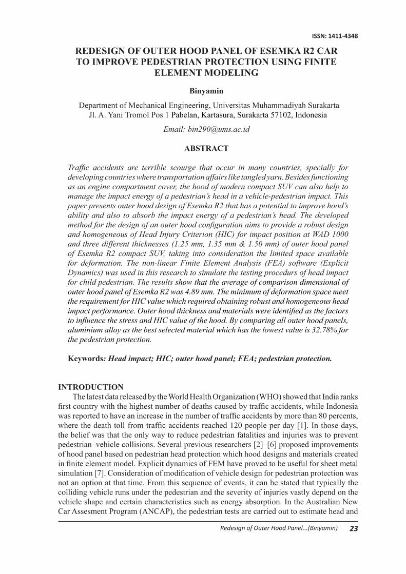
23Redesign of Outer Hood Panel...(Binyamin)
ISSN: 1411-4348
REDESIGN OF OUTER HOOD PANEL OF ESEMKA R2 CAR TO IMPROVE PEDESTRIAN PROTECTION USING FINITE
ELEMENT MODELING
Binyamin
Department of Mechanical Engineering, Universitas Muhammadiyah SurakartaJl. A. Yani Tromol Pos 1 Pabelan, Kartasura, Surakarta 57102, Indonesia
Email: [email protected]
ABSTRACT
Traffic accidents are terrible scourge that occur in many countries, specially for developing countries where transportation affairs like tangled yarn. Besides functioning as an engine compartment cover, the hood of modern compact SUV can also help to manage the impact energy of a pedestrian’s head in a vehicle-pedestrian impact. This paper presents outer hood design of Esemka R2 that has a potential to improve hood’s ability and also to absorb the impact energy of a pedestrian’s head. The developed method for the design of an outer hood configuration aims to provide a robust design and homogeneous of Head Injury Criterion (HIC) for impact position at WAD 1000 and three different thicknesses (1.25 mm, 1.35 mm & 1.50 mm) of outer hood panel of Esemka R2 compact SUV, taking into consideration the limited space available for deformation. The non-linear Finite Element Analysis (FEA) software (Explicit Dynamics) was used in this research to simulate the testing procedurs of head impact for child pedestrian. The results show that the average of comparison dimensional of outer hood panel of Esemka R2 was 4.89 mm. The minimum of deformation space meet the requirement for HIC value which required obtaining robust and homogeneous head impact performance. Outer hood thickness and materials were identified as the factors to influence the stress and HIC value of the hood. By comparing all outer hood panels, aluminium alloy as the best selected material which has the lowest value is 32.78% for the pedestrian protection.
Keywords: Head impact; HIC; outer hood panel; FEA; pedestrian protection.
INTRODUCTION The latest data released by the World Health Organization (WHO) showed that India ranks
first country with the highest number of deaths caused by traffic accidents, while Indonesia was reported to have an increase in the number of traffic accidents by more than 80 percents, where the death toll from traffic accidents reached 120 people per day [1]. In those days, the belief was that the only way to reduce pedestrian fatalities and injuries was to prevent pedestrian–vehicle collisions. Several previous researchers [2]–[6] proposed improvements of hood panel based on pedestrian head protection which hood designs and materials created in finite element model. Explicit dynamics of FEM have proved to be useful for sheet metal simulation [7]. Consideration of modification of vehicle design for pedestrian protection was not an option at that time. From this sequence of events, it can be stated that typically the colliding vehicle runs under the pedestrian and the severity of injuries vastly depend on the vehicle shape and certain characteristics such as energy absorption. In the Australian New Car Assesment Program (ANCAP), the pedestrian tests are carried out to estimate head and
24 Media Mesin: Jurnal Ilmiah Teknik Mesin Vol. 17 No. 2 Juli 2016: 23-37
ISSN: 1411-4348
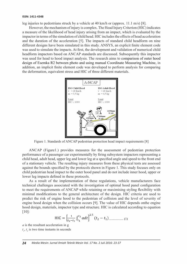
leg injuries to pedestrians struck by a vehicle at 40 km/h or (approx. 11.1 m/s) [8]. However, the mechanism of injury is complex. The Head Injury Criterion (HIC) indicates
a measure of the likelihood of head injury arising from an impact, which is evaluated by the impactor in terms of the simulation of child head. HIC includes the effects of head acceleration and the duration of the acceleration [5]. The impacts of standard child headform on nine different designs have been simulated in this study. ANSYS, an explicit finite element code was used to simulate the impacts. At first, the development and validation of numerical child headform impactors based on ANCAP standards are discussed. Subsequently this impactor was used for head to hood impact analysis. The research aims to comparison of outer hood design of Esemka R2 between photo and using manual Coordinate Measuring Machine, in addition, an implicit finite element code was developed to perform analysis for comparing the deformation, equivalent stress and HIC of three different materials.
Figure 1. Standards of ANCAP pedestrian protection head impact requirements [8]
ANCAP (Figure1.) provides measures for the assessment of pedestrian protection performance of a passenger car experimentally by firing subsystem impactors representing a child head, adult head, upper leg and lower leg at a specified angle and speed to the front end of a stationary vehicle. The resulting injury measures from these physical tests are assessed against the bounds specified by the protocols shown in Figure 1. This study focuses only on child pedestrian head impact to the outer hood panel and do not include inner hood, upper or lower leg impacts defined in these protocols.
As a result of the implementation of these regulations, vehicle manufacturers face technical challenges associated with the investigation of optimal hood panel configuration to meet the requirements of ANCAP while retaining or maximising styling flexibility with minimal modifications to the general architecture of the design. HIC criteria are used to predict the risk of engine hood to the pedestrian of collision and the level of severity of engine hood design when the collision occurs [9]. The value of HIC depends onthe engine hood design, materials, impactor type and structure. HIC is calculated according to equation [10]:
.................. (1)
a is the resultant acceleration in g t1, t2 is two time instants in seconds
25Redesign of Outer Hood Panel...(Binyamin)
ISSN: 1411-4348
which define the start and end of the recording when HIC is at maximum. Values of HIC in the time interval t1–t2 is greater than 15 ms are ignored for the purpose of calculating the maximum value.In this study, HIC value is calculated using DIAdem for the pedestrian head impact on automotive hoods.
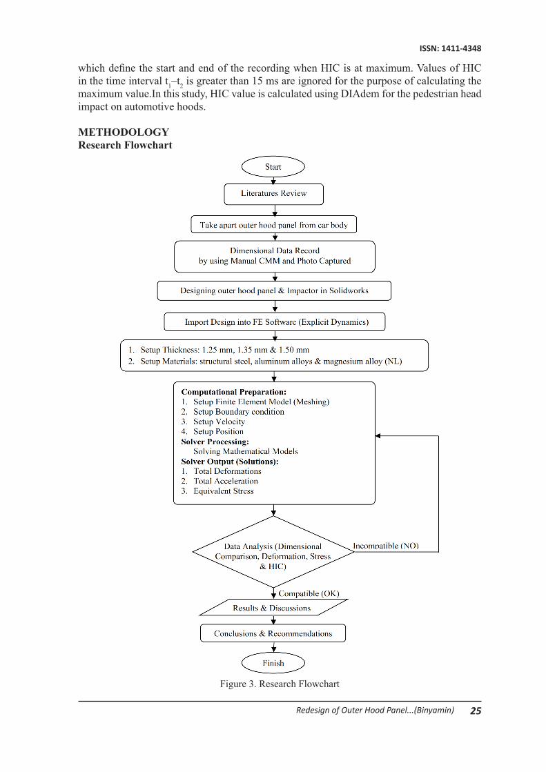
METHODOLOGYResearch Flowchart
Figure 3. Research Flowchart
26 Media Mesin: Jurnal Ilmiah Teknik Mesin Vol. 17 No. 2 Juli 2016: 23-37
ISSN: 1411-4348
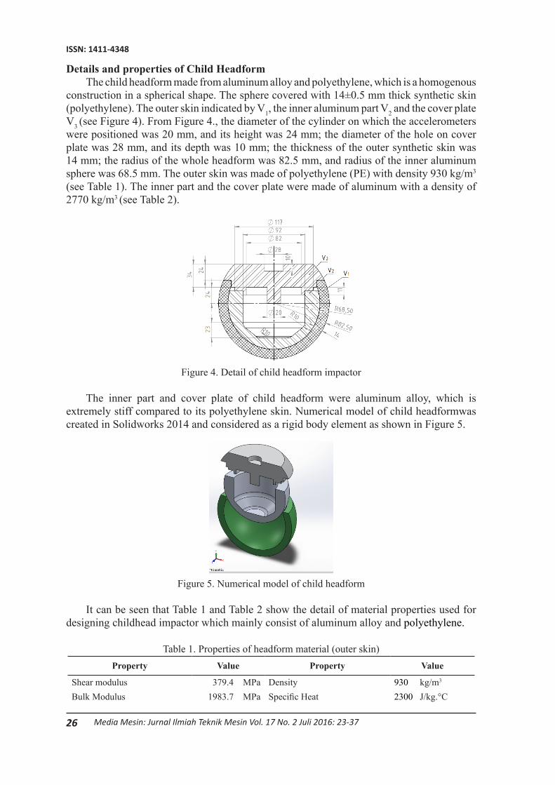
Details and properties of Child HeadformThe child headform made from aluminum alloy and polyethylene, which is a homogenous
construction in a spherical shape. The sphere covered with 14±0.5 mm thick synthetic skin (polyethylene). The outer skin indicated by V1, the inner aluminum part V2 and the cover plate V3 (see Figure 4). From Figure 4., the diameter of the cylinder on which the accelerometers were positioned was 20 mm, and its height was 24 mm; the diameter of the hole on cover plate was 28 mm, and its depth was 10 mm; the thickness of the outer synthetic skin was 14 mm; the radius of the whole headform was 82.5 mm, and radius of the inner aluminum sphere was 68.5 mm. The outer skin was made of polyethylene (PE) with density 930 kg/m3
(see Table 1). The inner part and the cover plate were made of aluminum with a density of 2770 kg/m3 (see Table 2).
Figure 4. Detail of child headform impactor
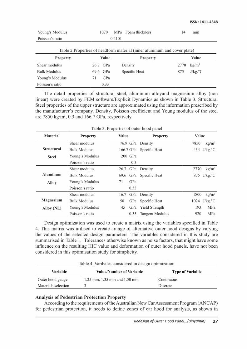
The inner part and cover plate of child headform were aluminum alloy, which is extremely stiff compared to its polyethylene skin. Numerical model of child headformwas created in Solidworks 2014 and considered as a rigid body element as shown in Figure 5.
Figure 5. Numerical model of child headform
It can be seen that Table 1 and Table 2 show the detail of material properties used for designing childhead impactor which mainly consist of aluminum alloy and polyethylene.
Table 1. Properties of headform material (outer skin)Property Value Property Value
Shear modulus 379.4 MPa Density 930 kg/m3
Bulk Modulus 1983.7 MPa Specific Heat 2300 J/kg.°C
27Redesign of Outer Hood Panel...(Binyamin)
ISSN: 1411-4348
Young’s Modulus 1070 MPa Foam thickness 14 mmPoisson’s ratio 0.4101
Table 2.Properties of headform material (inner aluminum and cover plate)Property Value Property Value
Shear modulus 26.7 GPa Density 2770 kg/m3
Bulk Modulus 69.6 GPa Specific Heat 875 J/kg.°CYoung’s Modulus 71 GPaPoisson’s ratio 0.33
The detail properties of structural steel, aluminum alloyand magnesium alloy (non linear) were created by FEM software/Explicit Dynamics as shown in Table 3. Structural Steel properties of the upper structure are approximated using the information prescribed by the manufacturer’s company. Density, Poisson coefficient and Young modulus of the steel are 7850 kg/m3, 0.3 and 166.7 GPa, respectively.
Table 3. Properties of outer hood panelMaterial Property Value Property Value
Structural
Steel
Shear modulus 76.9 GPa Density 7850 kg/m3
Bulk Modulus 166.7 GPa Specific Heat 434 J/kg.°CYoung’s Modulus 200 GPaPoisson’s ratio 0.3
Aluminum
Alloy
Shear modulus 26.7 GPa Density 2770 kg/m3
Bulk Modulus 69.6 GPa Specific Heat 875 J/kg.°CYoung’s Modulus 71 GPaPoisson’s ratio 0.33
Magnesium
Alloy (NL)
Shear modulus 16.7 GPa Density 1800 kg/m3
Bulk Modulus 50 GPa Specific Heat 1024 J/kg.°CYoung’s Modulus 45 GPa Yield Strength 193 MPaPoisson’s ratio 0.35 Tangent Modulus 920 MPa
Design optimization was used to create a matrix using the variables specified in Table 4. This matrix was utilised to create arange of alternative outer hood designs by varying the values of the selected design parameters. The variables considered in this study are summarised in Table 1. Tolerances otherwise known as noise factors, that might have some influence on the resulting HIC value and deformation of outer hood panels, have not been considered in this optimisation study for simplicity.
Table 4. Varibales considered in design optimization
Variable Value/Number of Variable Type of Variable
Outer hood gauge 1.25 mm, 1.35 mm and 1.50 mm ContinuousMaterials selection 3 Discrete
Analysis of Pedestrian Protection Property According to the requirements of the Australian New Car Assessment Program (ANCAP)
for pedestrian protection, it needs to define zones of car hood for analysis, as shown in

28 Media Mesin: Jurnal Ilmiah Teknik Mesin Vol. 17 No. 2 Juli 2016: 23-37
ISSN: 1411-4348
Figure 6. It can be noted that when the collision projection point locates between (Wrap Around Distance) WAD 1000 and WAD 1500, the head type will use the children head type. The adult head type will be used while the collision projection point locates between WAD 1700 and WAD 2100. In the current study, the collision projection point located at WAD 1000 when the children head type will be used.
Figure 6. Zoning of pedestrian head impact protection for ANCAP
Finite Element ModelingThe identification of relevant optimisation parameters, the methodology used to
create three dimensional geometric models and FE models, as well as the development of optimisation methodology are presented in this paper such as child headform impactor model, equivalent stress models, deformation models and headform acceleration models. The finite element model of head impactor (see Figure 7) should be validated before utilizing.
Figure 7. Finite element models of outer hood panel with child headform
All of the layers were discretized using the S4R elements (4-node general-purpose shell, reduced integration with hourglass control, finite membrane strains). The numbers ofnodes and elements used in different outer hood thickness for details are shown in Table 5. The headform part is described as a solid shape in ANSYS/Dynamics Explicit, where the number of the elements was 16623. Due to the poor of aspect ratio of these elements, a reasonably
29Redesign of Outer Hood Panel...(Binyamin)
ISSN: 1411-4348
finest mesh was required to ensure convergence. Finite element models of the outer engine hood (see Table 5) was created by ANSYS/Dynamics Explicit were simulated with S4R shell element. The number of elements for outer hood panel (1.25 mm, 1.35 mm and 1.50 mm) were 5370, 5347 and 6373 respectively.
Table 5. The number of nodes and elements used in the modeling of child headform and outer hood parts
Parts Number of nodes Number of elements
Inner headform 2411 10825Cover plate 1144 4971Skin (PE) 293 827Outer hood panel (1.25 mm) 5506 5370Outer hood panel (1.35 mm) 5501 5347Outer hood panel (1.50 mm) 6519 6373
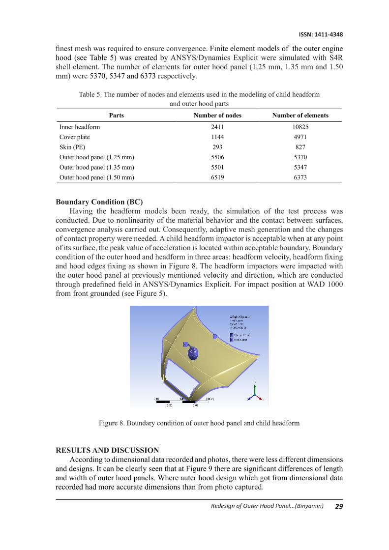
Boundary Condition (BC)Having the headform models been ready, the simulation of the test process was
conducted. Due to nonlinearity of the material behavior and the contact between surfaces, convergence analysis carried out. Consequently, adaptive mesh generation and the changes of contact property were needed. A child headform impactor is acceptable when at any point of its surface, the peak value of acceleration is located within acceptable boundary. Boundary condition of the outer hood and headform in three areas: headform velocity, headform fixing and hood edges fixing as shown in Figure 8. The headform impactors were impacted with the outer hood panel at previously mentioned velocity and direction, which are conducted through predefined field in ANSYS/Dynamics Explicit. For impact position at WAD 1000 from front grounded (see Figure 5).
Figure 8. Boundary condition of outer hood panel and child headform
RESULTS AND DISCUSSIONAccording to dimensional data recorded and photos, there were less different dimensions
and designs. It can be clearly seen that at Figure 9 there are significant differences of length and width of outer hood panels. Where auter hood design which got from dimensional data recorded had more accurate dimensions than from photo captured.
30 Media Mesin: Jurnal Ilmiah Teknik Mesin Vol. 17 No. 2 Juli 2016: 23-37
ISSN: 1411-4348
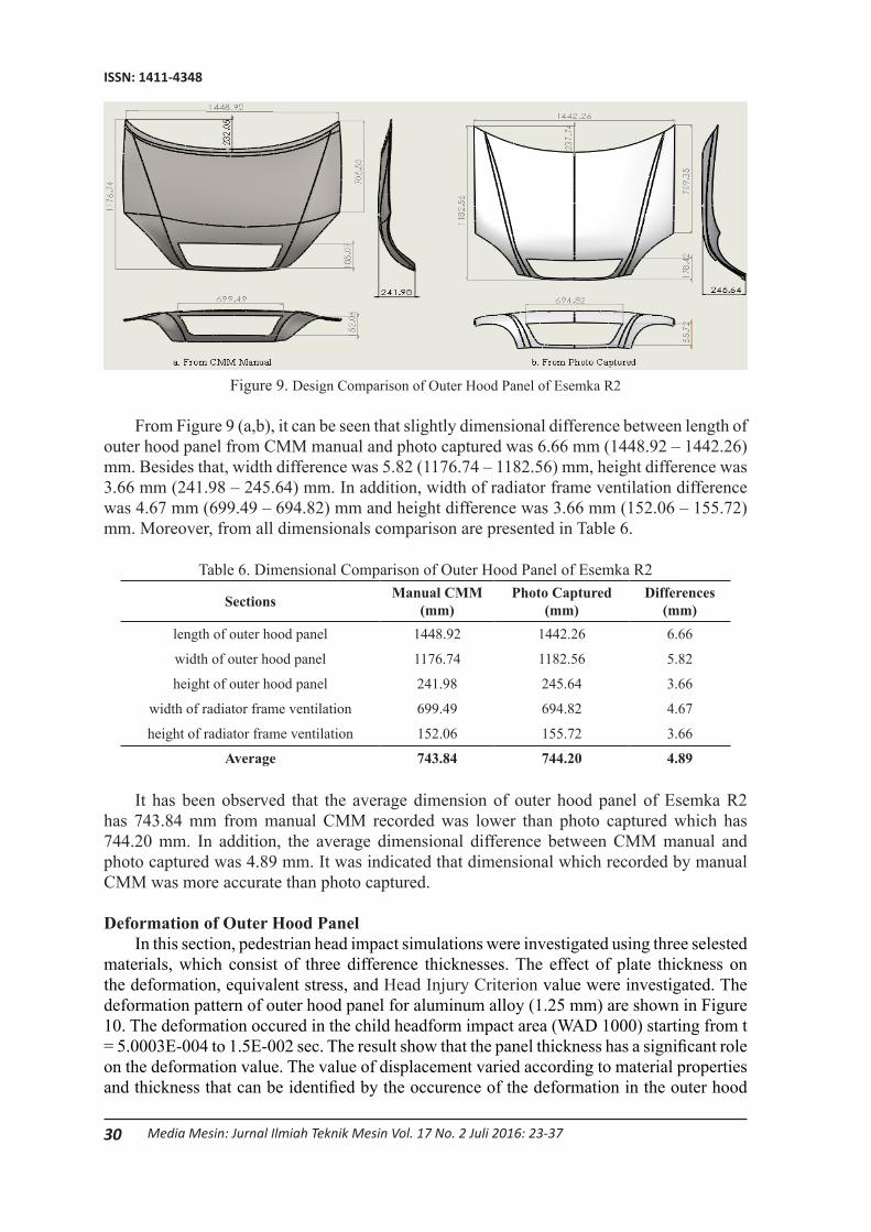
Figure 9. Design Comparison of Outer Hood Panel of Esemka R2
From Figure 9 (a,b), it can be seen that slightly dimensional difference between length of outer hood panel from CMM manual and photo captured was 6.66 mm (1448.92 – 1442.26) mm. Besides that, width difference was 5.82 (1176.74 – 1182.56) mm, height difference was 3.66 mm (241.98 – 245.64) mm. In addition, width of radiator frame ventilation difference was 4.67 mm (699.49 – 694.82) mm and height difference was 3.66 mm (152.06 – 155.72) mm. Moreover, from all dimensionals comparison are presented in Table 6.
Table 6. Dimensional Comparison of Outer Hood Panel of Esemka R2
Sections Manual CMM (mm)
Photo Captured (mm)
Differences (mm)
length of outer hood panel 1448.92 1442.26 6.66
width of outer hood panel 1176.74 1182.56 5.82
height of outer hood panel 241.98 245.64 3.66
width of radiator frame ventilation 699.49 694.82 4.67
height of radiator frame ventilation 152.06 155.72 3.66
Average 743.84 744.20 4.89
It has been observed that the average dimension of outer hood panel of Esemka R2 has 743.84 mm from manual CMM recorded was lower than photo captured which has 744.20 mm. In addition, the average dimensional difference between CMM manual and photo captured was 4.89 mm. It was indicated that dimensional which recorded by manual CMM was more accurate than photo captured.
Deformation of Outer Hood PanelIn this section, pedestrian head impact simulations were investigated using three selested
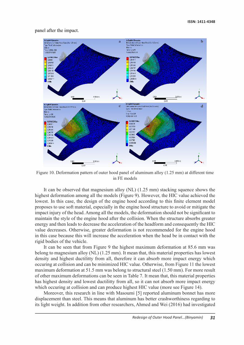
materials, which consist of three difference thicknesses. The effect of plate thickness on the deformation, equivalent stress, and Head Injury Criterion value were investigated. The deformation pattern of outer hood panel for aluminum alloy (1.25 mm) are shown in Figure 10. The deformation occured in the child headform impact area (WAD 1000) starting from t = 5.0003E-004 to 1.5E-002 sec. The result show that the panel thickness has a significant role on the deformation value. The value of displacement varied according to material properties and thickness that can be identified by the occurence of the deformation in the outer hood
31Redesign of Outer Hood Panel...(Binyamin)
ISSN: 1411-4348
panel after the impact.
Figure 10. Deformation pattern of outer hood panel of aluminum alloy (1.25 mm) at different time in FE models
It can be observed that magnesium alloy (NL) (1.25 mm) stacking squence shows the highest deformation among all the models (Figure 9). However, the HIC value achieved the lowest. In this case, the design of the engine hood according to this finite element model proposes to use soft material, especially in the engine hood structure to avoid or mitigate the impact injury of the head. Among all the models, the deformation should not be significant to maintain the style of the engine hood after the collision. When the structure absorbs greater energy and then leads to decrease the acceleration of the headform and consequently the HIC value decreases. Otherwise, greater deformation is not recommended for the engine hood in this case because this will increase the acceleration when the head be in contact with the rigid bodies of the vehicle.
It can be seen that from Figure 9 the highest maximum deformation at 85.6 mm was belong to magnesium alloy (NL) (1.25 mm). It mean that, this material properties has lowest density and highest ductilitty from all, therefore it can absorb more impact energy which occuring at collision and can be minimized HIC value. Otherwise, from Figure 11 the lowest maximum deformation at 51.5 mm was belong to structural steel (1.50 mm). For more result of other maximum deformations can be seen in Table 7. It mean that, this material properties has highest density and lowest ductilitty from all, so it can not absorb more impact energy which occuring at collision and can produce highest HIC value (more see Figure 14).
Moreover, this research in line with Masoumi [5] reported aluminum bonnet has more displacement than steel. This means that aluminum has better crashworthiness regarding to its light weight. In addition from other researchers, Ahmed and Wei (2016) had investigated
dc
ba
32 Media Mesin: Jurnal Ilmiah Teknik Mesin Vol. 17 No. 2 Juli 2016: 23-37
ISSN: 1411-4348
composite laminate and sanwich stucture materials for engine hood found that composite laminate [0/90, ±45]2 had higher deformation but lower HIC than sandwich structure [[0/90, ±45]2 0/90, Core, [0/90]4] were 219.3 mm, 354, 84.7 mm and 820 respectively.
Although the intense of collision is crucial, but the displacement of head is also important which may lead to extreme acceleration in the second impact, or rebound. It means that this structure not only must be strengthened in front of static and dynamic forces such as aerodynamic, slam and dent, it also should be able to reduce the intense of impact and avoid extra deformation of hood.
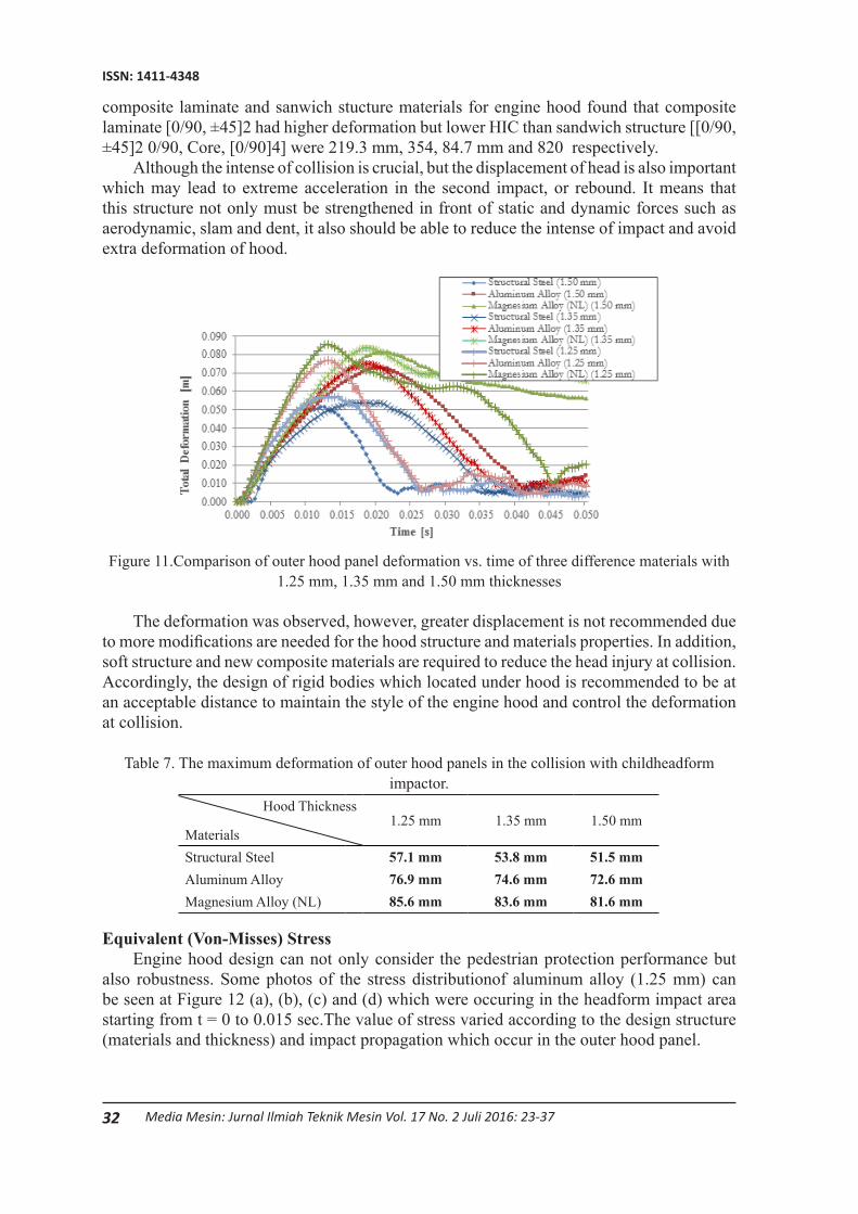
Figure 11.Comparison of outer hood panel deformation vs. time of three difference materials with 1.25 mm, 1.35 mm and 1.50 mm thicknesses
The deformation was observed, however, greater displacement is not recommended due to more modifications are needed for the hood structure and materials properties. In addition, soft structure and new composite materials are required to reduce the head injury at collision. Accordingly, the design of rigid bodies which located under hood is recommended to be at an acceptable distance to maintain the style of the engine hood and control the deformation at collision.
Table 7. The maximum deformation of outer hood panels in the collision with childheadform impactor.
Hood Thickness
Materials1.25 mm 1.35 mm 1.50 mm
Structural Steel 57.1 mm 53.8 mm 51.5 mmAluminum Alloy 76.9 mm 74.6 mm 72.6 mmMagnesium Alloy (NL) 85.6 mm 83.6 mm 81.6 mm
Equivalent (Von-Misses) StressEngine hood design can not only consider the pedestrian protection performance but
also robustness. Some photos of the stress distributionof aluminum alloy (1.25 mm) can be seen at Figure 12 (a), (b), (c) and (d) which were occuring in the headform impact area starting from t = 0 to 0.015 sec.The value of stress varied according to the design structure (materials and thickness) and impact propagation which occur in the outer hood panel.
33Redesign of Outer Hood Panel...(Binyamin)
ISSN: 1411-4348
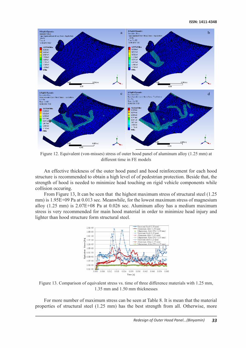
Figure 12. Equivalent (von-misses) stress of outer hood panel of aluminum alloy (1.25 mm) at different time in FE models
An effective thickness of the outer hood panel and hood reinforcement for each hood structure is recommended to obtain a high level of of pedestrian protection. Beside that, the strength of hood is needed to minimize head touching on rigid vehicle components while collision occuring.
From Figure 13, It can be seen that the highest maximum stress of structural steel (1.25 mm) is 1.95E+09 Pa at 0.013 sec. Meanwhile, for the lowest maximum stress of magnesium alloy (1.25 mm) is 2.07E+08 Pa at 0.026 sec. Aluminum alloy has a medium maximum stress is very recommended for main hood material in order to minimize head injury and lighter than hood structure form structural steel.
Figure 13. Comparison of equivalent stress vs. time of three difference materials with 1.25 mm, 1.35 mm and 1.50 mm thicknesses
For more number of maximum stress can be seen at Table 8. It is mean that the material properties of structural steel (1.25 mm) has the best strength from all. Otherwise, more
abd
dc
ba
34 Media Mesin: Jurnal Ilmiah Teknik Mesin Vol. 17 No. 2 Juli 2016: 23-37
ISSN: 1411-4348
harder material of outer hood panel can increase the number of HIC values. Masoumi et al. [5] had investigated comparison between engine hood made of composite material, steel and aluminiumin terms of material cost, manufacturing cost, maximum displacement, HIC valuesand weight. They found that the composite materials have higher material and manufacturing costs thansteel and aluminum and maximum displacement, lower HIC, and weighter than aluminum and steel.
Table 8. The maximum stress of outer hood panelsin the collision with child headform impactor.Hood Thickness
Materials1.25 mm 1.35 mm 1.50 mm
Structural Steel 1.95E+09 Pa 1.88E+09 Pa 1.70E+09 PaAluminum Alloy 1.04E+09 Pa 1.03E+09 Pa 8.23E+08 PaMagnesium Alloy (NL) 2.07E+08 Pa 2.09E+08 Pa 2.09E+08 Pa
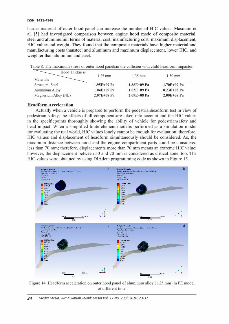
Headform AccelerationActually when a vehicle is prepared to perform the pedestrianheadform test in view of
pedestrian safety, the effects of all componentsare taken into account and the HIC values in the specificpoints thoroughly showing the ability of vehicle for pedestriansafety and head impact. When a simplified finite element modelis performed as a simulation model for evaluating the real world, HIC values lonely cannot be enough for evaluation; therefore, HIC values and displacement of headform simultaneously should be considered. As, the maximum distance between hood and the engine compartment parts could be considered less than 70 mm; therefore, displacements more than 70 mm means an extreme HIC value; however, the displacement between 50 and 70 mm is considered as critical zone, too. The HIC values were obtained by using DIAdem programming code as shown in Figure 15.
Figure 14. Headform acceleration on outer hood panel of aluminum alloy (1.25 mm) in FE model at different time
dc
ba

35Redesign of Outer Hood Panel...(Binyamin)
ISSN: 1411-4348
The value of headform acceleration varied according to impact duration which can be seen in Figure 14. The headform acceleration distribution on outer hood panel for aluminum alloy (1.25 mm) which was occuring when the headform touched the hood from t = 0 to 0.015 sec are presented in Figure 14 (a), (b), (c) and (d). The comparison among the outer hood panel thickness and materials were caaried out in terms of deformation, equivalent stress and HIC value.
Figure 15. HIC values of the finite element modeling
From Figure 15, there are comparison of HIC value from all models. As it can be seen that outer hood panel of magnesium alloy (NL) with 1.25 mm thickness has lowest HIC value was 440. Meanwhile, it has highest deformation was 85.6 mm. Otherwise, structural steel (1.50 mm) has the highest HIC value was 687 and in contrast has minimum deformation was 51.5 mm. It is clear that the magnesium alloy is the lightest from all models. This means that magnesium alloy has the best crashworthiness regarding to its light weight. This result was in line with previous researchers, Torkestani et al. [11] had found that increasing the thickness increases the HIC value for all the materials and it had the most effect on steel, carbon-epoxy, glass-epoxy and aluminum materials, respectively. However, it can be reported that the models achieves the basic requirements of the pedestrian safety where the HIC value should be less than 1000. In addition, all of hood models have under limit of HIC requirement, in this paper was not consider about inner structure of hood which can be important variable factor to affect HIC value.
Table 9. HIC and Deformation
Outer Hood Mod-els HIC HIC
AverageDeformation
(mm)Deformation
Average (mm)HIC (%)
Defor-mation
(%)
Ave-rage (%)
SS (1.25 mm) 586648.33
57.154.13
SS (1.35 mm) 672 53.8 40.86 25.48 33.17SS (1.50 mm) 687 51.5 AA (1.25 mm) 461
482.3376.9
74.70
AA (1.35 mm) 474 74.6 30.40 35.16 32.78AA (1.50 mm) 512 72.6 MA (1.25 mm) 440
456.0085.6
83.60
MA (1.35 mm) 451 83.6 28.74 39.35 34.05MA (1.50 mm) 477 81.6
Note: SS (Structural Steel), AA (Aluminum Alloy), MA (Magnesium Alloy) NL
36 Media Mesin: Jurnal Ilmiah Teknik Mesin Vol. 17 No. 2 Juli 2016: 23-37
ISSN: 1411-4348
Along with the increase of deformation, in contrast HIC is reduced, as shown in Table 9. Generally, with the value increasing the hood deformation and energy absorption capability is increased, resulting in the reducing of HIC. It can be seen that there are slighly difference results of all models, where percentage average values for structural steel, aluminum alloy and magnesium alloy (NL) are 33.17%, 32.78% and 34.05% respectively. It mean that outer hood panel which made from aluminum alloy is the best selected from all. Therefore, it could be stated that aluminum alloy is required to meet pedestrian head injury requirement and acceptable distance when collision is occuring.
CONCLUSIONSThe results show that the average of comparison dimensional of outer hood panel of
Esemka R2 was 4.89 mm. Beside that the minimum deformation space is 51.5 mm and maximum HIC of 687. That values are required to obtain robust and homogeneous head impact performance. Moreover, hood thickness and materials are the factors which can influence stress and HIC value. It is shown that the pedestrian safety is greatly improved up to 32.78% for aluminium alloy model. As the requirements of the friendliest car, the structure of the engine hood should be soft to easy to form and to absorb more energy and also provide lower deformation, lower HIC and less displacement of the headform impactors. Thus, possible improvements in lower HIC and deformation could be studied, as well as materials, selection of engine hood structures should be considered in the future studies.
REFERENCES
[1] J. Marbun, “Indonesia Urutan Pertama Peningkatan Kecelakaan Lalu Lintas,” 2014. [Online]. Available: http://www.republika.co.id. [Accessed: 03-Feb-2016].
[2] A. Ahmed and L. Wei, “Thin-Walled Structures Introducing CFRP as an alternative material for engine hood to achieve better pedestrian safety using fi nite element modeling,” Thin Walled Struct., vol. 99, pp. 97–108, 2016.
[3] J. Huang, Z. Liu, and Y. Long, “A Numerical Investigation of a Novel Hood Design for Pedestrian Protection,” pp. 872–878, 2014.
[4] S. Min, H. Kim, S.-W. Chae, and J. Hong, “Design method of a hood structure adopting modal analysis for preventing pedestrian’s head injury,” Int. J. Precis. Eng. Manuf., vol. 17, no. 1, pp. 19–26, 2016.
[5] A. Masoumi, M. Hassan, and A. Najibi, “Comparison of steel , aluminum and composite bonnet in terms of pedestrian head impact,” Saf. Sci., vol. 49, no. 10, pp. 1371–1380, 2011.
[6] H. M. Samaka and F. Tarlochan, “Building And Performance Validating Of Adult Pedestrian Finite Element Head Model To Evaluate The Car Hood Design,” vol. 2, no. 7, pp. 44–49, 2013.
[7] A. D. Anggono, T. W. B. Riyadi, and W. A. Siswanto, “Dynamic Explicit Finite Element Code for U-Bending Simulation and Springback Prediction,” Appl. Mech. Mater., vol. 660, no. August, pp. 337–341, 2014.
[8] R. Krishnamoorthy, M. Takla, A. Subic, and D. Scott, “Design Optimisation of Passenger Car Hood Panels for Improved Pedestrian Protection,” vol. 633, pp. 62–76, 2013.
37Redesign of Outer Hood Panel...(Binyamin)
ISSN: 1411-4348
[9] C. Cruz, PM; Vinyals, J., “Validation of FE-models of pedestrian protection impactor,” 2004.
[10] M. H. Shojaeefard, A. Najibi, and M. R. Ahmadabadi, “Thin-Walled Structures Pedestrian safety investigation of the new inner structure of the hood to mitigate the impact injury of the head,” Thin Walled Struct., vol. 77, pp. 77–85, 2014.
[11] A. Torkestani, M. Sadighi, and R. Hedayati, “Thin-Walled Structures Effect of material type , stacking sequence and impact location on the pedestrian head injury in collisions,” Thin Walled Struct., vol. 97, pp. 130–139, 2015.
Copyright © 2022 FDOKUMEN