An Investigation of the Effect of Ventilation Inlet and Outlet ...
Upload
khangminh22Category
view
0download
0
Outlet Nozzle (N2): FEA ResultsResults were generated with the finite element program FE/Pipe®. Stress results are post-processed in accordance with the rulesspecified in ASME Section III and ASME Section VIII, Division 2.
Analysis Time Stamp: Mon Oct 12 09:31:13 2020.
Model NotesLoad Case ReportSolution DataASME Code Stress Output PlotsStress Results - NotesASME Overstressed AreasHighest Primary Stress RatiosHighest Secondary Stress RatiosHighest Fatigue Stress RatiosStress Intensification FactorsAllowable LoadsFlexibilitiesGraphical Results


Model Notes Model Notes Input Echo: Model Type : Cylindrical Shell Parent Geometry Parent Outside Diam. : 20.000 in. Thickness : 0.203 in. Fillet Along Shell : 0.375 in. Parent Properties: Cold Allowable : 17100.0 psi Hot Allowable : 17100.0 psi Material ID #2 : Low Alloy Steel Ultimate Tensile (Amb) : 60000.0 psi Yield Strength (Amb) : 35000.0 psi Yield Strength (Hot) : 25900.0 psi Elastic Modulus (Amb) : 29400000.0 psi Poissons Ratio : 0.300 Weight Density : 0.2830E+00 lb./cu.in. Nozzle Geometry Nozzle Outside Diam. : 8.625 in. Thickness : 0.375 in. Length : 10.750 in. Nozzle Weld Length : 0.375 in. RePad Width : 3.000 in. RePad Thickness : 0.375 in. RePad Weld Leg : 0.375 in. Nozzle Tilt Angle : 0.000 deg. Distance from Top : 12.640 in. Distance from Bottom : 42.312 in. Nozzle Properties Cold Allowable : 17100.0 psi Hot Allowable : 17100.0 psi Material ID #2 : Low Alloy Steel Ultimate Tensile (Amb) : 60000.0 psi Yield Strength (Amb) : 35000.0 psi Yield Strength (Hot) : 25900.0 psi Elastic Modulus (Amb) : 29400000.0 psi Poissons Ratio : 0.300 Weight Density : 0.2830E+00 lb./cu.in. Design Operating Cycles : 0. Ambient Temperature (Deg.) : 70.00 Uniform thermal expansion produces no stress in this geometry. Any thermal loads will come through operating forces and moments applied through the nozzle. Nozzle Inside Temperature : 650.00 deg. Nozzle Outside Temperature : 650.00 deg. Vessel Inside Temperature : 650.00 deg. Vessel Outside Temperature : 650.00 deg. Nozzle Pressure : 121.2 psi Vessel Pressure : 121.2 psi FEA Model Loads: Loads are given at the End of Nozzle Loads are defined in Global Coordinates Forces( lb.) Moments (ft-lb) Load Case FX FY FZ MX MY MZ --------------------------------------------------------------------------- OPER: 1000.0 1000.0 1000.0 3750.0 -1281.2 2031.2 The "top" or "positive" end of this model is "free" in the axial and translational directions. Stresses will be calculated in the weld elements surrounding the junction of the nozzle with the parent shell. This is typically done to get accurate values for the pressure stresses on the inside surface of the nozzle in the longitudinal plane. The effect of any external loads will overemphasized (too conservative) in this run. Stresses are NOT averaged.

Vessel Centerline Vector : 0.000 1.000 0.000 Nozzle Orientation Vector : 1.000 0.000 0.000
Table of Contents
Load Case Report FEPipe Version 14.0 Jobname: OUTLETN $P Released Mar 2019 9:30am OCT 12,2020 Load Case Report $X Inner and outer element temperatures are the same throughout the model. No thermal ratcheting calculations will be performed. THE 7 LOAD CASES ANALYZED ARE: 1 SUSTAINED (Pr Only) Sustained case run to satisfy local primary membrane and bending stress limits. /-------- Loads in Case 1 Pressure Case 1 2 OPERATING (Fatigue Calc Performed) Case run to compute the operating stresses used in secondary, peak and range calculations as needed. /-------- Loads in Case 2 Pressure Case 1 Loads from (Operating) 3 Program Generated -- Force Only Case run to compute sif's and flexibilities. /-------- Loads in Case 3 Loads from (Axial) 4 Program Generated -- Force Only Case run to compute sif's and flexibilities. /-------- Loads in Case 4 Loads from (Inplane) 5 Program Generated -- Force Only Case run to compute sif's and flexibilities. /-------- Loads in Case 5 Loads from (Outplane) 6 Program Generated -- Force Only Case run to compute sif's and flexibilities. /-------- Loads in Case 6 Loads from (Torsion) 7 Program Generated -- Force Only Case run to compute sif's and flexibilities. /-------- Loads in Case 7 Pressure Case 1
Table of Contents

Solution Data FEPipe Version 14.0 Jobname: OUTLETN $P Released Mar 2019 9:30am OCT 12,2020 Solution Data Maximum Solution Row Size = 714 Number of Nodes = 2184 Number of Elements = 720 Number of Solution Cases = 7 Summation of Loads per Case
Case # FX FY FZ
1 -576. 37319. 0. 2 424. 38077. 1000. 3 194386. 0. 0. 4 0. 0. 0. 5 0. 0. 0. 6 0. 0. 0. 7 -576. 37319. 0.
Table of Contents
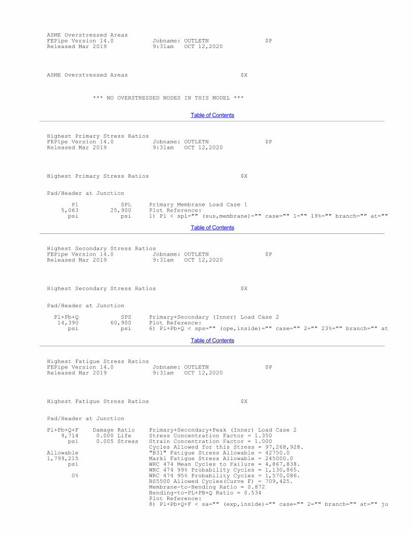
ASME Code Stress Output Plots FEPipe Version 14.0 Jobname: OUTLETN $P Released Mar 2019 9:31am OCT 12,2020 ASME Code Stress Output Plots $X 1) Pl < spl="" (sus,membrane)="" case="" 1="" 2)="" qb="">< sps="" (sus,bending)="" case="" 1="" 3)="" pl+pb+q="">< sps="" (sus,inside)="" case="" 1="" 4)="" pl+pb+q="">< sps="" (sus,outside)="" case="" 1="" 5)="" s1+s2+s3="">< 4s="" (sus,s1+s2+s3)="" case="" 1="" 6)="" pl+pb+q="">< sps="" (ope,inside)="" case="" 2="" 7)="" pl+pb+q="">< sps="" (ope,outside)="" case="" 2="" 8)="" pl+pb+q+f="">< sa="" (exp,inside)="" case="" 2="" 9)="" pl+pb+q+f="">< sa="" (exp,outside)="" case="" 2="" 10)="" membrane="">< user="" (ope,membrane)="" case="" 2="" 11)="" bending="">< user="" (ope,bending)="" case="" 2="" 12)="" pl+pb+q+f="">< sa="" (sif,outside)="" case="" 3="" 13)="" pl+pb+q+f="">< sa="" (sif,outside)="" case="" 4="" 14)="" pl+pb+q+f="">< sa="" (sif,outside)="" case="" 5="" 15)="" pl+pb+q+f="">< sa="" (sif,outside)="" case="" 6="" 16)="" pl+pb+q+f="">< sa="" (sif,outside)="" case="" 7="">
Table of Contents
Stress Results - Notes FEPipe Version 14.0 Jobname: OUTLETN $P Released Mar 2019 9:31am OCT 12,2020 Stress Results - Notes - Results in this analysis were generated using the finite element solution method. - Using 2013-2017 ASME Section VIII Division 2 - Use Polished Bar fatigue curve. - Assume free end displacements of attached pipe (e.g. thermal loads) are secondary loads. - Primary bending stresses at discontinuities are treated like secondary stresses. - Use Equivalent Stress (Von Mises). - TRIAXIAL Stress Guidelines: S1+S2+S3 evaluation omitted from operating stress. Include S1+S2+S3 evaluation in primary case evaluation. Bending stress NOT included for all S1+S2+S3 calculations. - Use local tensor values for averaged and not averaged stresses.
Table of Contents
ASME Overstressed Areas FEPipe Version 14.0 Jobname: OUTLETN $P Released Mar 2019 9:31am OCT 12,2020 ASME Overstressed Areas $X *** NO OVERSTRESSED NODES IN THIS MODEL ***
Table of Contents
Highest Primary Stress Ratios FEPipe Version 14.0 Jobname: OUTLETN $P Released Mar 2019 9:31am OCT 12,2020 Highest Primary Stress Ratios $X Pad/Header at Junction Pl SPL Primary Membrane Load Case 1 5,063 25,900 Plot Reference: psi psi 1) Pl < spl="" (sus,membrane)="" case="" 1="" 19%="" branch="" at="" junction="" pl="" spl="" primary="" membrane="" load="" case="" 1="" 5,292="" 25,900="" plot="" reference:="" psi="" psi="" 1)="" pl="">< spl="" (sus,membrane)="" case="" 1="" 20%="" branch="" transition="" pl="" spl="" primary="" membrane="" load="" case="" 1="" 1,706="" 25,900="" plot="" reference:="" psi="" psi="" 1)="" pl="">< spl="" (sus,membrane)="" case="" 1="" 6%="" pad="" outer="" edge="" weld="" pl="" spl="" primary="" membrane="" load="" case="" 1="" 5,746="" 25,900="" plot="" reference:="" psi="" psi="" 1)="" pl="">< spl="" (sus,membrane)="" case="" 1="" 22%="" header="" outside="" pad="" area="" pl="" spl="" primary="" membrane="" load="" case="" 1="" 6,468="" 25,900="" plot="" reference:="" psi="" psi="" 1)="" pl="">< spl="" (sus,membrane)="" case="" 1="" 24%="" branch="" removed="" from="" junction="" pl="" spl="" primary="" membrane="" load="" case="" 1="" 1,787="" 25,900="" plot="" reference:="" psi="" psi="" 1)="" pl="">< spl="" (sus,membrane)="" case="" 1="" 6%="">
Table of Contents
Highest Secondary Stress Ratios FEPipe Version 14.0 Jobname: OUTLETN $P Released Mar 2019 9:31am OCT 12,2020 Highest Secondary Stress Ratios $X Pad/Header at Junction Pl+Pb+Q SPS Primary+Secondary (Inner) Load Case 2 14,390 60,900 Plot Reference: psi psi 6) Pl+Pb+Q < sps="" (ope,inside)="" case="" 2="" 23%="" branch="" at="" junction="" pl+pb+q="" sps="" primary+secondary="" (outer)="" load="" case="" 2="" 18,024="" 60,900="" plot="" reference:="" psi="" psi="" 7)="" pl+pb+q="">< sps="" (ope,outside)="" case="" 2="" 29%="" branch="" transition="" pl+pb+q="" sps="" primary+secondary="" (outer)="" load="" case="" 2="" 4,461="" 60,900="" plot="" reference:="" psi="" psi="" 7)="" pl+pb+q="">< sps="" (ope,outside)="" case="" 2="" 7%="" pad="" outer="" edge="" weld="" pl+pb+q="" sps="" primary+secondary="" (outer)="" load="" case="" 2="" 26,736="" 60,900="" plot="" reference:="" psi="" psi="" 7)="" pl+pb+q="">< sps="" (ope,outside)="" case="" 2="" 43%="" header="" outside="" pad="" area="" pl+pb+q="" sps="" primary+secondary="" (inner)="" load="" case="" 2="" 11,175="" 60,900="" plot="" reference:="" psi="" psi="" 6)="" pl+pb+q="">< sps="" (ope,inside)="" case="" 2="" 18%="" branch="" removed="" from="" junction="" pl+pb+q="" sps="" primary+secondary="" (inner)="" load="" case="" 2="" 4,894="" 60,900="" plot="" reference:="" psi="" psi="" 6)="" pl+pb+q="">< sps="" (ope,inside)="" case="" 2="" 8%="">
Table of Contents
Highest Fatigue Stress Ratios FEPipe Version 14.0 Jobname: OUTLETN $P Released Mar 2019 9:31am OCT 12,2020 Highest Fatigue Stress Ratios $X Pad/Header at Junction Pl+Pb+Q+F Damage Ratio Primary+Secondary+Peak (Inner) Load Case 2 9,714 0.000 Life Stress Concentration Factor = 1.350 psi 0.005 Stress Strain Concentration Factor = 1.000 Cycles Allowed for this Stress = 97,268,928. Allowable "B31" Fatigue Stress Allowable = 42750.0 1,799,215 Markl Fatigue Stress Allowable = 245000.0 psi WRC 474 Mean Cycles to Failure = 4,867,838. WRC 474 99% Probability Cycles = 1,130,865. 0% WRC 474 95% Probability Cycles = 1,570,086. BS5500 Allowed Cycles(Curve F) = 709,425. Membrane-to-Bending Ratio = 0.872 Bending-to-PL+PB+Q Ratio = 0.534 Plot Reference: 8) Pl+Pb+Q+F < sa="" (exp,inside)="" case="" 2="" branch="" at="" junction="" pl+pb+q+f="" damage="" ratio="" primary+secondary+peak="" (outer)="" load="" case="" 2="" 12,166="" 0.000="" life="" stress="" concentration="" factor="1.350" psi="" 0.007="" stress="" strain="" concentration="" factor="1.000" cycles="" allowed="" for="" this="" stress="1,157,260." allowable="" "b31"="" fatigue="" stress="" allowable="42750.0" 1,799,215="" markl="" fatigue="" stress="" allowable="245000.0" psi="" wrc="" 474="" mean="" cycles="" to="" failure="3,568,961." wrc="" 474="" 99%="" probability="" cycles="829,118." 0%="" wrc="" 474="" 95%="" probability="" cycles="1,151,142." bs5500="" allowed="" cycles(curve="" f)="361,048." membrane-to-bending="" ratio="0.404" bending-to-pl+pb+q="" ratio="0.712" plot="" reference:="" 9)="" pl+pb+q+f="">< sa="" (exp,outside)="" case="" 2="" branch="" transition="" pl+pb+q+f="" damage="" ratio="" primary+secondary+peak="" (outer)="" load="" case="" 2="" 2,230="" 0.000="" life="" stress="" concentration="" factor="1.000" psi="" 0.001="" stress="" strain="" concentration="" factor="1.000" cycles="" allowed="" for="" this="" stress="1.0000E11" allowable="" "b31"="" fatigue="" stress="" allowable="42750.0" 1,799,215="" markl="" fatigue="" stress="" allowable="245000.0" psi="" wrc="" 474="" mean="" cycles="" to="" failure="2.4042E8" wrc="" 474="" 99%="" probability="" cycles="55,853,484." 0%="" wrc="" 474="" 95%="" probability="" cycles="77,546,640." bs5500="" allowed="" cycles(curve="" f)="43,091,160." membrane-to-bending="" ratio="12.516" bending-to-pl+pb+q="" ratio="0.074" plot="" reference:="" 9)="" pl+pb+q+f="">< sa="" (exp,outside)="" case="" 2="" pad="" outer="" edge="" weld="" pl+pb+q+f="" damage="" ratio="" primary+secondary+peak="" (outer)="" load="" case="" 2="" 18,047="" 0.000="" life="" stress="" concentration="" factor="1.350" psi="" 0.010="" stress="" strain="" concentration="" factor="1.000" cycles="" allowed="" for="" this="" stress="134,648." allowable="" "b31"="" fatigue="" stress="" allowable="42750.0" 1,799,215="" markl="" fatigue="" stress="" allowable="245000.0" psi="" wrc="" 474="" mean="" cycles="" to="" failure="1,552,742." wrc="" 474="" 99%="" probability="" cycles="360,723." 1%="" wrc="" 474="" 95%="" probability="" cycles="500,825." bs5500="" allowed="" cycles(curve="" f)="110,624." membrane-to-bending="" ratio="0.350" bending-to-pl+pb+q="" ratio="0.741" plot="" reference:="" 9)="" pl+pb+q+f="">< sa="" (exp,outside)="" case="" 2="" header="" outside="" pad="" area="" pl+pb+q+f="" damage="" ratio="" primary+secondary+peak="" (inner)="" load="" case="" 2="" 5,588="" 0.000="" life="" stress="" concentration="" factor="1.000" psi="" 0.003="" stress="" strain="" concentration="" factor="1.000" cycles="" allowed="" for="" this="" stress="1.0000E11" allowable="" "b31"="" fatigue="" stress="" allowable="42750.0" 1,799,215="" markl="" fatigue="" stress="" allowable="245000.0" psi="" wrc="" 474="" mean="" cycles="" to="" failure="21,430,298." wrc="" 474="" 99%="" probability="" cycles="4,978,542." 0%="" wrc="" 474="" 95%="" probability="" cycles="6,912,178." bs5500="" allowed="" cycles(curve="" f)="1,514,811." membrane-to-bending="" ratio="1.744" bending-to-pl+pb+q="" ratio="0.364" plot="" reference:="" 8)="" pl+pb+q+f="">< sa="" (exp,inside)="" case="" 2="" branch="" removed="" from="" junction="" pl+pb+q+f="" damage="" ratio="" primary+secondary+peak="" (inner)="" load="" case="" 2="" 2,447="" 0.000="" life="" stress="" concentration="" factor="1.000" psi="" 0.001="" stress="" strain="" concentration="" factor="1.000" cycles="" allowed="" for="" this="" stress="1.0000E11" allowable="" "b31"="" fatigue="" stress="" allowable="42750.0" 1,799,215="" markl="" fatigue="" stress="" allowable="245000.0" psi="" wrc="" 474="" mean="" cycles="" to="" failure="1.8067E8" wrc="" 474="" 99%="" probability="" cycles="41,971,372." 0%="" wrc="" 474="" 95%="" probability="" cycles="58,272,800." bs5500="" allowed="" cycles(curve="" f)="27,122,224." membrane-to-bending="" ratio="6.611" bending-to-pl+pb+q="" ratio="0.131" plot="" reference:="" 8)="" pl+pb+q+f="">< sa="" (exp,inside)="" case="" 2="">

Table of Contents
Stress Intensification Factors FEPipe Version 14.0 Jobname: OUTLETN $P Released Mar 2019 9:31am OCT 12,2020 Stress Intensification Factors $X
Branch/Nozzle Sif Summary
Peak Primary Secondary SSI Axial : 8.878 6.576 13.153 3.051 Inplane : 2.820 2.089 4.178 2.608 Outplane: 6.046 4.478 8.956 2.793 Torsion : 1.007 1.011 1.492 1.853 Pressure: 1.437 1.084 2.129 2.007
The above stress intensification factors are to be used in a beam-type analysis of the piping system. Inplane, Outplane and Torsional sif's should be used with the matching branch pipe whose diameter and thickness is given below. The axial sif should be used to intensify the axial stress in the branch pipe calculated by F/A. The pressure sif should be used to intensify the nominal pressure stress in the PARENT or HEADER, calculated from PDo/2T. B31 calculations use mean diameters and Section VIII calculations use outside diameters. SSIs are based on peak stress factors and correlated test results.
Pipe OD : 8.625 in. Pipe Thk: 0.375 in. Z approx: 20.046 cu.in. Z exact : 19.214 cu.in.
(SSI = SIF^x) Axial Inpl Outpl Tors Pres SIF/SSI Exponents: 0.863 0.711 0.833 1.488 0.222
SIF/SSI exponent based on relationship between primary and peak stress factors from the finite element analysis.
B31.3 Branch Pressure i-factor = 12.866 Header Pressure i-factor = 2.904
The B31.3 pressure i-factors should be used with with F/A, where F is the axial force due to pressure, and A is the area of the pipe wall. This is equivalent to finding the pressure stress from (ip)(PD/4T).
B31.3 (Branch) Peak Stress Sif .... 0.000 Axial 7.006 Inplane 8.726 Outplane 1.000 Torsional B31.1 (Branch) Peak Stress Sif .... 0.000 Axial 8.726 Inplane 8.726 Outplane 8.726 Torsional WRC 330 (Branch) Peak Stress Sif .... 0.000 Axial 4.726 Inplane 8.726 Outplane 4.726 Torsional
Table of Contents

Allowable Loads FEPipe Version 14.0 Jobname: OUTLETN $P Released Mar 2019 9:31am OCT 12,2020 Allowable Loads $X SECONDARY Maximum Conservative Realistic Load Type (Range): Individual Simultaneous Simultaneous Occuring Occuring Occuring Axial Force (lb. ) 45002. 13817. 20725. Inplane Moment (in. lb.) 280048. 60799. 128973. Outplane Moment (in. lb.) 130647. 25491. 54074. Torsional Moment (in. lb.) 784069. 206827. 310240. Pressure (psi ) 580.90 121.20 121.20
PRIMARY Maximum Conservative Realistic Load Type: Individual Simultaneous Simultaneous Occuring Occuring Occuring Axial Force (lb. ) 38278. 10152. 15228. Inplane Moment (in. lb.) 238201. 44673. 94765. Outplane Moment (in. lb.) 111125. 20677. 43864. Torsional Moment (in. lb.) 492242. 132004. 198007. Pressure (psi ) 485.35 121.20 121.20
NOTES:
1) Maximum Individual Occuring Loads are the maximum allowed values of the respective loads if all other load components are zero, i.e. the listed axial force may be applied if the inplane, outplane and torsional moments, and the pressure are zero.
2) The Conservative Allowable Simultaneous loads are the maximum loads that can be applied simultaneously. A conservative stress combination equation is used that typically produces stresses within 50-70% of the allowable stress.
3) The Realistic Allowable Simultaneous loads are the maximum loads that can be applied simultaneously. A more realistic stress combination equation is used based on experience at Paulin Research. Stresses are typically produced within 80-105% of the allowable.
4) Secondary allowable loads are limits for expansion and operating piping loads.
5) Primary allowable loads are limits for weight, primary and sustained type piping loads.
Table of Contents
Flexibilities FEPipe Version 14.0 Jobname: OUTLETN $P Released Mar 2019 9:31am OCT 12,2020 Flexibilities $X
The following stiffnesses should be used in a piping, "beam-type" analysis of the intersection. The stiff- nesses should be inserted at the surface of the branch/header or nozzle/vessel junction. The general characteristics used for the branch pipe should be:
Outside Diameter = 8.625 in. Wall Thickness = 0.375 in.
Axial Translational Stiffness = 1490046. lb./in. Inplane Rotational Stiffness = 948080. in.lb./deg Outplane Rotational Stiffness = 306610. in.lb./deg Torsional Rotational Stiffness = 5997212. in.lb./deg

Intersection Flexibility Factors for Branch/Nozzle :
Find axial stiffness: K = 3EI/(kd)^3 lb./in. Find bending and torsional stiffnesses: K = EI/(kd) in.lb.per radian. The EI product is 0.24361E+10 lb.in.^2 The value of (d) to use is: 8.250 in.. The resulting bending stiffness is in units of force x length per radian.
Axial Flexibility Factor (k) = 2.059 Inplane Flexibility Factor (k) = 5.436 Outplane Flexibility Factor (k) = 16.809 Torsional Flexibility Factor (k) = 0.859
Table of ContentsFinite Element Model
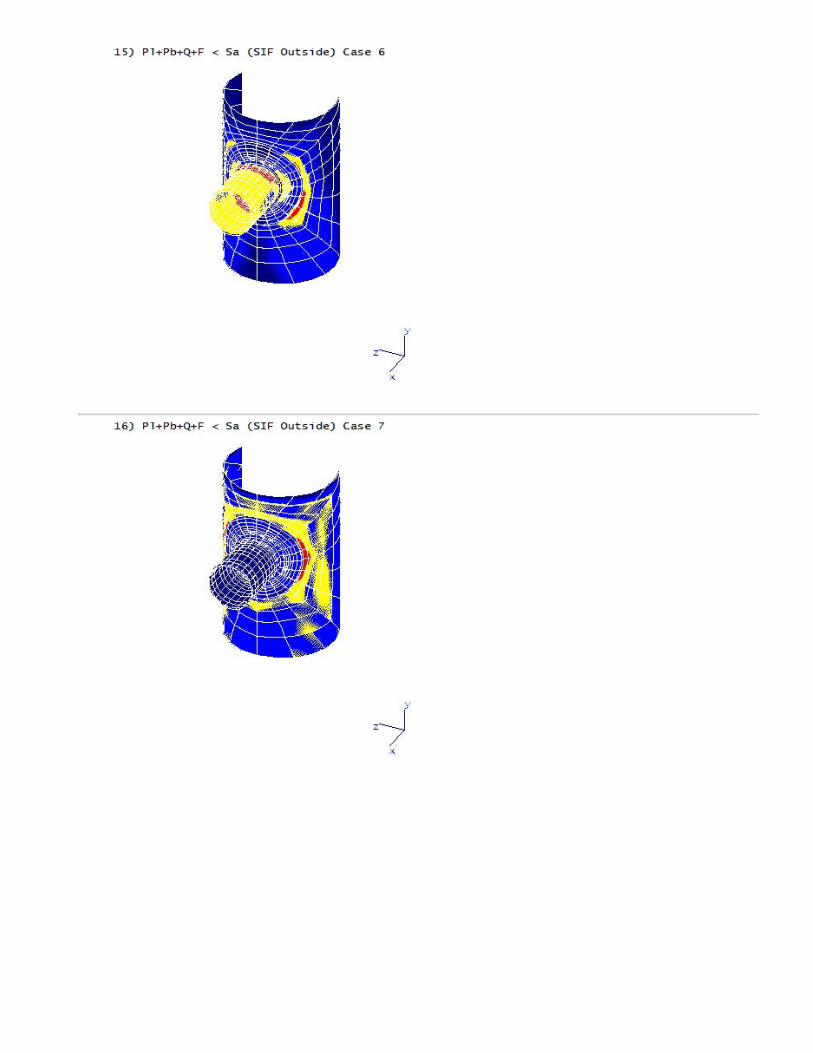
Finite Element Model1) Pl < spl="" (sus="" membrane)="" case="" 1="">2) Qb < sps="" (sus="" bending)="" case="" 1="">3) Pl+Pb+Q < sps="" (sus="" inside)="" case="" 1="">4) Pl+Pb+Q < sps="" (sus="" outside)="" case="" 1="">5) S1+S2+S3 < 4s="" (sus="" s1+s2+s3)="" case="" 1="">6) Pl+Pb+Q < sps="" (ope="" inside)="" case="" 2="">7) Pl+Pb+Q < sps="" (ope="" outside)="" case="" 2="">8) Pl+Pb+Q+F < sa="" (exp="" inside)="" case="" 2="">9) Pl+Pb+Q+F < sa="" (exp="" outside)="" case="" 2="">10) Membrane < user="" (ope="" membrane)="" case="" 2="">11) Bending < user="" (ope="" bending)="" case="" 2="">12) Pl+Pb+Q+F < sa="" (sif="" outside)="" case="" 3="">13) Pl+Pb+Q+F < sa="" (sif="" outside)="" case="" 4="">14) Pl+Pb+Q+F < sa="" (sif="" outside)="" case="" 5="">15) Pl+Pb+Q+F < sa="" (sif="" outside)="" case="" 6="">16) Pl+Pb+Q+F < sa="" (sif="" outside)="" case="" 7="">
Tabular Results


Copyright © 2022 FDOKUMEN