Radio Frequency Detection & Ranging - SUST Repository
75
Sudan University of Science and Technology Collage of Engineering School Of Electronics Engineering Radio Frequency Detection & Ranging ت الراديوكتشاف وتحديد موجا اA Research Submitted in Partial fulfillment for the Requirements of the Degree of B.Sc. (Honors) in Electronics Engineering Prepared by: 1- Abdallah Faisal DafaallahDawelnour 2- Mohammed Hashim Abdel Al-rahmanHussien 3- Mohanad Mustafa HimedaBakri 4- Moudther Mohammed Abdel Al-hadiHamadto Supervisor: DR. Ashraf Gasim Abdullah September 2015
-
Upload
khangminh22 -
Category
Documents
-
view
3 -
download
0
Transcript of Radio Frequency Detection & Ranging - SUST Repository

Sudan University of Science and Technology
Collage of Engineering
School Of Electronics Engineering
Radio Frequency Detection & Ranging
اكتشاف وتحديد موجات الراديو
A Research Submitted in Partial fulfillment for the Requirements of the
Degree of B.Sc. (Honors) in Electronics Engineering
Prepared by:
1- Abdallah Faisal DafaallahDawelnour
2- Mohammed Hashim Abdel Al-rahmanHussien
3- Mohanad Mustafa HimedaBakri
4- Moudther Mohammed Abdel Al-hadiHamadto
Supervisor: DR. Ashraf Gasim Abdullah
September 2015

قال ذعانى:
ء قدر } ده الملك وهو على كل ش { الذي خلق 1)تبارك الذي ب
كم أحسن عملا وهو العزز الغفور } بلوكم أ اة ل { 2الموت والح
ا ترى حمن من تفاوت الذي خلق سبع سماوات طباقاا م ف خلق الر
{(3فارجع البصر هل ترى من فطور}
صدق هللا العظم
(3-1سورة الملك اآلة )

اإلهذاء
إىهي اليطيب اىييو إال بشنزك واليطيب اىىهار إال بطاعتل .. والتطيباىيحظاث إال
.. وال تطيب اىجىت إالبزؤيتناهلل بذمزك .. وال تطيب اآلخزة إال بعفىك
إى مه بيغ اىزساىت وأدىاألماوت .. ووصح األمت .. إى وبي اىزحمت ووىر اىعاىميه
إى مه مييه هللا باىهيبتواىىقار .. إى مه عيمىي اىعطاء بذون اوتظار .. إى مه أحمو أسمه
أرجى مه هللا أن يمذ في عمزك ىتزي ثمارا قذ حان قطافها بعذ طىه اوتظار .. بنو افتخار
وستبقىنيماتل

Acknowledgement
We would like to extend our great thanks and appreciation to those people
who have contributed to the completion of this project and thesis. We
would like to thank our supervisor, Dr. Ashraf GasimElsid Abdulla for
assisting us every step of the way and for being there whenever we needed
him. We will always be thankful to himfor his valuable comments and
insightful guidance. We want toexpress our special appreciation to the
committee members for their expertise and
constructive criticism. We would like to thank our families, specially our
mothers and fathers, for theircontinued love, understanding and support in
the past year.

Abstract
In this project, we examine the RSSI measurement modelTo detected the
direction of illegal broadcasting. We also showhow to use Directional
antenna efficiently to detect the position of the Received signal strength
indication (RSSI) module by sampling multiple readings from the module
by Arduino. The results of the simulation of our method in Proteus indicate
that the location of the module can be detected in a small amount of time
and that the quality of the solution is competitive with previous approaches.

انسرخهص
ذاوند هر اندزاسح كيفيح ذرثع اإلشازج وذحديد إذجاهها , وذى ذنك في خسح أتىاب , وذى عم
يقديح ع انشسوع وانشاكم انري يجة ا ذرى يعانجرها وذنك في انثاب األول , وفي انثاب
انىضىع , وذى شسح اندائسج انصاي ذى ذاول األتحاز واألوزاق انعهيح انري ذحدشح ع هرا
انعهيح وطسيقح انعم تشكم أكصس ذفصال تاإلضافح انى يكىاخ اندائسج في انثاب انصانس , وذى
يحاكاج اندائسج انعهيح تإسرخداو أحد تسايج انحاكاج وعسض انرائج وذنك في انثاب انساتع , وذى
.فرح نهشسوع في انسرقثمكراتح خالصح انىضىع تإلضافح انى يايك وذحديصح وإضا

TABLE OF CONTENTS
Dedication………………………………….……I
Acknowledgement………………………………….....7I
Abstract……………………………………………….7I
Abstract in Arabic………………………...............…7
1. ChapterOne......................................................................1
1.1 Introduction…………………………………………….…2
1.1.1 Early Radio Technologies……………………………....2
1.1.2 Radio Frequency detector……………………………....3
1.2 Problem statement…………………………………….…..4
1.3 Objective………………………………………………..…4
1.4 Project approach……………………………………….…5
1.5 Thesis Outlines…………………………………………...5
2. ChapterTwo......................................................................6
2.1 Radio Frequency Identification (RFID)……………….....7
2.2 RFID HISTORY…………………………………………11
2.3 RFID Antenna……………………………………….…...14
2.4 Received signal strength indication (RSSI)………..……17

2.5 Mobile Phone Signal Detector………………………….…19
2.5.1DESIGN PROCEDURE/ METHODOLOGY…………..21
2.6 Source of Radio Waves…………………………………....22
3. ChapterThree .....................................................................23
3.1 Methodology……………………………………………….25
3.2 Block Diagram……………………………………………..25
3.3Flow chart……………………………………………….….27
3.4 Arduino mega 2650………………………………………..28
3.5 Stepper motor…………………………………..…………31
3.6Driver ULN 2003…………………………………..……...35
3.7 UlN2003 Stepper motor driver circuit……………..….…36
3.8 Stepper Motor with an Arduino…………………..…......37
4. Chapter four......................................................................38
4.1 Simulations & Result……………………………………....41
4.1.1Software outputs………………………………………….41
4.1.2 Hardware steps……………………………….…………..44
5. Chapter five.........................................................................49

5.1 Conclusion…………………………………………...….50
5.2 Recommendations…………………………………....…50

List of Tables
Table No Page
3.1Arduino Mega 2560 Technical specs………………...29
3.2 28BYJ-48 – 5V Stepper Motor…………….….........32
3.3 Stepper motor half step……………………….…….34

List of Figures
Figure No Page
3.1 Block Diagram of RFDR………………………….….…..26
3.2 Flow chart of particular circuit……………………...……27
3.3 Arduino Mega 2560…………………………………...….29
3.4 Arduino Mega 2560 PIN diagram………………….….…30
3.5 28BYJ-48 – 5V Stepper Motor data sheet……………....33
3.6 Half mode Sequence……………………………….…......34
3.7 Driver ULN2003 (16 pin)………………………….….....35
3.8 The motor control circuit………………………….……..36
3.9 Stepper Motor with an Arduino……………………........38
4.1 the circuit simulation by proteus…………………...……41
4.2 run code in aruino...........................................................42
4.3 simulation window……………………..……….……..…43
4.4 simulation result ……………………………………...…44
4.5 stepper motor with driver uln2003………………….......45

References............................................................................52
Appendix...............................................................................54

Chapter One
Introduction

Chapter One
Introduction
Many people call telecommunication the world’s most lucrative
industry. Added cellular and PCS users,1 there are about 1800 million
subscribers to telecommunication services worldwide (1999). Annual
expenditures on telecommunications reach 900,000 million dollars in the
year 2000.
1.1 Early Radio Technologies
"Electromagnetic wave–based communications have been utilized for
many decades. In fact, radio and television both depend on these
electromagnetic waves. Additionally, these electromagnetic waves—or
radio waves—have been used for purposes such as wireless voice
conversations (today, we call these cell phones) and data communications.
The military has used wireless communications for many decades, and
expensive proprietary equipment has also been available. You could say
that wireless communications over great distance all started with the letter
S. It was this letter that Guglielmo Marconi transmitted, received, and
printed with the Morse inker across the Atlantic in the first decade of the
twentieth century. Though Marconi was not the first to communicate over a
distance without wires, this event started a greater stirring through the
government and business communities that resulted in the many uses of
wireless technology we see today. Radio Frequency and Antenna
Fundamentals By the 1920s, radio waves were being used for
telecommunications. In fact, the first transatlantic telephone service became
available in 1927from New York to London. Twenty-one years earlier, in
1906, Reginald Fessenden successfully communicated from land to sea over

a distance of 11 miles using radio waves to carry voice communications.
Bell Laboratories had created a mobile two-way voice-carrying radio wave
device by 1924, but mobile voice technology was not really perfected and
used widely until the 1940s."[1]
1.1.1 Radio Frequency detector
"An RF detector monitors or samples the output of an RF circuit and
develops a dc output voltage proportional to the power at that point .RF
detectors are used primarily to measure and control RF power in wireless
systems .RF power, rather than voltage, is the primary measure of a
wireless signal. In a receiver, signal strength is a key factor in maintaining
reliable communications. In the transmitter, the amount of power
transmitted is critical because of regulatory guidelines. It’s also important
for maintaining the range and reliability of the radio link. Transmitter
output power measurement is the primary application. It is essential to
know the RF output power because the application specifies it in most
cases, and certain maximum values must not be exceeded according to
Federal CommunicationsCommission regulations. In many cases, the
transmitter power is controlled automatically. As a result, the output power
is measured and compared to a set point level in a feedback control circuit
so power can be adjusted as required. In receivers, power measurement is
usually referred to as the received signal strength indicator (RSSI). The
RSSI signal typically is used to control the gain of the RF/IF signal chain
with an automatic gain control (AGC) or automatic level control (ALC)
circuit to maintain a constant signal level suitable for analog-to-digital
conversion and demodulation."[2]

1.2 Problem statement
Broadcasting is the distribution of audio or video content to a dispersed
audience via any electronic mass communications medium .Illegal
broadcasting otherwise known as a pirate radio is the operation of a licensed
and unregulated radio station. Illegal broadcasters use radio transmitters
which can cause interference to legitimate users, they also have the
potential of critical services such as the emergency services and traffic
control .so that the main problem is Illegal broadcasting.
1.3 Project approach
In this project we are going to design RF detector device ,the block diagram
consist of directional antenna, arduino ,two stepper motors two drivers,
LCD and serial board. The antenna receive the frequency to stop the
stepper motors after the arduino compare between the receive frequency
and the standard frequency (27MHZ) in order to detect the direction of
broadcasting . The detailed methodology included in chapter three.

1.4 Objective
- Detect the direction of illegal broadcasting.
- Design a circuit that control directional antenna connected to stepper
motor
- Write a program that stops the stepper motors based on a certain signal
- Design a circuit that receive a certain frequency
1.5 Thesis Outlines
This project consist of five chapter, chapter one includes an introduction
and overview about radio frequency detection and ranging. Chapter two
includes background and literature review about all rf detector projects .
Chapter three includes the block diagram, components, code and the
method of the design rf detector techniques. Chapter four includes the
simulation and results. Finally chapter five includes conclusion and
recommendation

Chapter Two
Background
&
Literature Review

Chapter Two
Literature Review
2.1 Radio Frequency Identification (RFID)
"During the last decades bar codes have probably been the most
successful identification technology, as other procedures didn't yet exist or
were too expensive to be deployed recently, although technologies like
RFID have many advantages. RFID technology is cheap, fast, does not
require line of sight and supports simultaneous reading of several tags at
once over distances ranging from few centimeters to hundreds of meters.
Due to technological progress the technology behind RFID has improved,
lowering the costs to reasonable levels allowing it to enter the mass market.
Every RFID system consists of a reader, a transponder, and an application
software. The transponder is a data-carrier which is commonly called tag.
They come in various shapes and sizes, mostly in form of a so called
smart cards or smart labels, which are sticky and can easily be attached to
objects. Widespread applications can be found in the else anti-theft, access
control, logistics, supply chain management, animal identification and
tracking, and electronic payment systems, to name few examples for the
countless uses of RFID. In the next section the history of RFID technology
is presented, followed by an introduction to the principles and components
of RFID systems along with important standards, which specify the basics
of RFID. Afterwards modern applications are analyzed before introducing
possible risks and attack vectors which can result out of the use of RFID
technology.

The invention of radar in the mid-1930s made it possible to detect
aircraft from vast distances, but during World WarII the issue of
distinguishing friendly from enemy planes became problem. For this
purpose the Germans would upside-down on command before entering
friendly airspace, altering the rejected radio signal to identify the aircraft as
friendly. One can call this the rst passive RFID system, which was
simplistic to spoof by Allied forces. This called for a more sophisticated
methods of identification and as a result IFF (Identify Friend or Foe)
systems were developed, for example the German FuG 25a "Erstling"
manufactured by GEMA in 1941 which sent back a pre-dened signal to
ground radar stations when asked for identification. This method of
automatic identification via radio-frequency signals is one of the rest active
RFID systems. In 1948 Harry Stockman described in his publication
"Communication by Means of Reacted Power" basic theoretical principles
for passive RFID systems and suggested more active foundational research
in this area. [3]
Radio-frequency identification was invented. More experimental work
followed in the upcoming decades, such as Donald B. Harris' "Radio
Transmission Systems with Modula table Passive Responder" in 1960.
Harris patented wireless communication system similar to the military
's"Walkie Talkie" systems with the main divergence that only one station
needs an external power source whereas the portable station draws the
required energy to reply out of the received radio signals. Another RFID-
related development was Robert M. Richardson's invention "Remotely
Actuated Radio Frequency Powered Devices" primarily focusing on evident
usage of radio frequency energy "approaching the theoretical maximum".
As RFID technology was mostly used by the military, in the1960s

_rstcompanies recognized the advantages it brings for civilian commercial
usage. One of the most widespread and well known inventions of this time
were RFID based electronic article surveillance (EAS), to prevent theft and
loss of merchandise, which was developed by Arthur Minas later the
founder of the company "Knogo" (1966). Also "Sensormatic Electronics
Corporation" (1960) and "Checkpoint Systems, Inc." (1969) competed in
this area of E-Systems, which mostly uses 1-bit passive tags and several
readers called gates which form a detection zone. If a functional tag is
detected in this area an alarm is triggered to signalize an unauthorized
passing, whereas no radio signal can be received when the tag is either
destroyed, deactivated or removed. In 1975 three scientists from the Los
Alamos Sciatic Laboratory published their work on "Short-Range Radio-
Telemetry for Electronic Identification, Using Modulated RF Backscatter
"and presented an innovative method of communication for passive RFID
tags.
They were developing a passive "electronic identification system for
livestock", which reported the animals identification number as well as its
body temperature over a distance of several meters between tag and reader
During the 1970s further novel developments of RFID systems included
also the ends of vehicle identification and access control systems. So far
RFID technology was mostly a subject of research and development,
whereas widespread commercial applications were yet to come in the
following decades. Since the late 1980s several countries began to deploy
electronic toll collection systems, rst of all Norway in October 1987, soon
followed by the United States, Italy, and France. As there was only little
competition in this market section prices for RFID systems were very high,
hindering it from becoming mainstream technology, although

improvements were made considering the size, weight and range of tags.
This enabled applications such as animal tracking with implanted tags under
the skin, and container tracking which was a development of the
Association of American Railroads and the Container Handling Cooperative
Program. The 1990s and 2000s are characterized by RFID technology
becoming part of everyday life of consumers and the _rest establishment of
industrial standards along with governmental regulations concerning the
power and used frequencies of RFID systems. New applications developed
in the 1990sincluded systems for electronic toll payment, ski passes, vehicle
access and article tracking. The Auto-ID Center at the Massachusetts
Institute of Technology was founded in 1999supported by the EAN
International (today known as GS1) and Uniform Code Council Inc. (UCC,
today known as GS1US) along with Procter & Gamble and Gillette in order
to develop the Electronic Product Code (EPC) and standards for low-cost
UHF RFID tags used in supply chain applications. As the Auto-ID Center
gained supporters and became a worldwide operating research facility, the
need for global RFID standards was recognized and resulted among other
developments in two air interface protocols (Class 0, Class 1) and the EPC
global Network, a multi corporate network for real-time tag tracking via the
Internet.
Until the late 1990s most aspects of modern RFID technology were
standardized. These standards applied to animal identification (ISO/IEC
11784, 11785 and 14223), contactless smartcards (based on ISO/IEC 7810:
ISO/IEC 10536, 14443 and156693), container identification (ISO 10374),
anti-theft systems for goods (VDI 4470) and item management
(ISO/IEC18000, EPCglobal Network). All standards are subjectto
continuous revisions as technology progresses. In 2003 the UCC and EAN

International formed the nonprime _t organization EPCglobal Inc. to
commercialize theEPC global Network internationally. It kept developing
new protocols parallel to the combined e_orts of the International Standards
Organization (ISO) and International Electro technical Commission (IEC).
Although EPCglobal tried to create the ISO compatible Gen2 standard it
took until 2006before it was merged wth the ISO/IEC 18000 standards. In
the meantime large organizations like Wal-Mart and the US Department of
Defense set up mandates, which required many of their suppliers to apply
RFID tags on their shipments. In 2004 the US Food and Drug
Administration (FDA) eased the way for human RFID implants containing
a unique ID number."
Short for Radio Frequency Identification. The term RFID is used to
describe various technologies that use radio waves to automatically identify
people or objects. RFID technology is similar to the bar code identification
systems we see in retail stores every day; however one big difference
between RFID and bar code technology is that RFID does not rely on the
line-of-sight reading that bar code scanning requires to work. Basically
RFID is a wireless communication system which use RF signal to establish
the communication between two ends. RFID system does this
communication by using modulated RF signal which is sent between the
two main components in the system; the reader and the tag. [4]
2.2 RFID HISTORY
Radio Frequency Identification (RFID) is not a recent technology in
fact it has been used years ago in many application. It is believed that RFID
can be traced back to World War II where the Germans, Japanese and

British were using radar which has been discovered by the Scottish
Physicist Robert Watson Watt. Back then those radars used radio
frequency systems in order to warn of approaching planes; the problem
was that those radars could only sense the approaching plane but could
not identify it. It was of particular importance to be able to identify the
approaching object that’s why Watson Watt developed a system known
as IFF Identification Friend or Foe which can differentiate between objects.
The system basic concept is placing a transponder on a certain object, when
this transponder is interrogated by a radio station it will respond with a code
which identifies the object. Through years researches has been done to
study the communication between the reader and the tag placed on the
object and how can the reader communicate with a certain object. Although
that the IFF system successfully demonstrated the principles of remote
detection then object interrogation but the cost of the system
implementation is significantly high that is why studies were done to enable
this system to be used for low cost commercial application.
In the 70’s, at Los Alamos National Laboratories researches have been
done to implement a RFID system which can track the transportation of
nuclear materials[2]. Since it was a very sensitive issue they developer a
system which can keep tracking the vehicles used to transport these
materials at various points along its route. By the same time further
activities were done by Charles Walton a researcher who quitted IBM to
start producing proximity devices. Walton’s patent was using radio waves
to control door locks, where radio transceiver sends a small electrical
current to a tag to identify it then unlocking the door. Schlage the lock
making firm bought his prototype to produce an electronic lock which can
be operated using a keycard. Years later the cost of RFID component

reduced, one of the first applications for RFID technology is the electronic
surveillance tags used in hypermarkets, where RFID technology is used as a
replacement for the European Article Number (EAN) or the Universal
Product Code (UPC) which are commonly known as barcode. Barcode has
been used for years to identify a certain object by placing a barcode tag
closely to the barcode scanner. The barcode tag represents the product’s
data in Terms of variation of the width and spacing of printed parallel lines.
The Data imprinted on a barcode tag is a fixed data and cannot be changed,
While there is a certain type of RFID tags which are rewritable. Also unlike
RFID, optical scanners which are known as barcode readers must be placed
closely to the tag in order to identify it properly. The 80s was the decade for
full implementation of RFID technology. That’s when RFID system was
used for access control in different fields of life. A significant achievement
in 1987 Norway was the implementation of the first successful toll
collection system, this was a breakthrough product for RFID technology.
That is why after few years toll systems and government toll collection
agencies had spread across the United States.
In the 21st century RFID technology spread nearly everywhere and it
is used in different life fields. The reason behind that is that the used tags
can vary in shapes and sizes which make it easily to use RFID in different
applications. Since RFID technology continues to spread all over the world
therefore a quantity of applications implemented using RFID in different
aspects of life and each application is implemented to fulfill a unique task.
This proves how flexible RFID technology is and how interesting it is to
work with it.
The reason why RFID technology is flexible is the variability in its
components especially the RFID tag. Tags can be easily implemented in
different shapes in order to fulfill different tasks. For access control
systems, RFID tags are designed in the shape of cards. That is not the only
form of tags; tags can also be designed as small chips so that they can be
implanted in animals to keep track of their location and even their medical
conditions and in some cases tags can be implanted into humans too. This is
because there are certain types of RFID tags which could be rewritable.
This is not the only variation in RFID technology, RFID can be operated at
different frequencies depending on the application and the appropriate
frequency band in each country. There are many more advantages of RFID
technology that is why it is believed that within a short period of time,
RFID technology will take over barcode technology. Like any technology
there are certain problems could confront RFID like inaccuracy due to
reading collision. There are two types of collision, reader collision and tag
collision. After many researches and many introduced anti-collision
protocols RFID technology has proven its efficiency and its accuracy
identifying each different tag. Another problem which can confront RFID
technology is the inaccuracy occurs due to RF signals interference and in
order to solve this problem the human operator should be aware of the
RFID operating frequency. This is not the only problem occurred due to RF
signals, another problem is the RF signal reflection due to the presence of
objects. This problem is encountered only in certain RFID applications. [5]
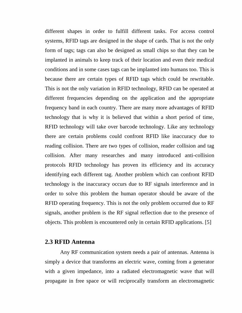
2.3 RFID Antenna
Any RF communication system needs a pair of antennas. Antenna is
simply a device that transforms an electric wave, coming from a generator
with a given impedance, into a radiated electromagnetic wave that will
propagate in free space or will reciprocally transform an electromagnetic

wave into an electric wave to a receiver. Because it is difficult to transmit
power over the air, an antenna designer wants reasonable power efficiency
in the transmission. To do this, you need to take care of two things: the
electric and the electromagnetic sides of the transmission: On the electric
side, you need good impedance matching between the transmitter or
receiver and the antenna or, more exactly, between the transmitter and the
combination of the antenna and free space. On the electromagnetic side,
because the antenna transforms the electric energy into a radiated field, you
need it to radiate its power in the direction that you want. That’s the
radiation pattern of the antenna.
An antenna (or aerial) is an electrical device which converts electric
currents into radio waves, and vice versa. It is usually used with a radio
transmitter or radio receiver. In transmission, a radio transmitter applies an
oscillating radio frequency electric current to the antenna's terminals, and
the antenna radiates the energy from the current as electromagnetic waves
(radio waves). In reception, an antenna intercepts some of the power of an
electromagnetic wave in order to produce a tiny voltage at its terminals that
is applied to a receiver to be amplified. An antenna can be used for both
transmitting and receiving. Antennas are essential components of all
equipment that uses radio. They are used in systems such as radio
broadcasting, broadcast television, two-way radio, communications
receivers, radar, cell phones, and satellite communications, as well as other
devices such as garage door openers, wireless microphones, Bluetooth
enabled devices, wireless computer networks, baby monitors, and RFID
tags on merchandise.
The helical antenna is an antenna consisting of a conducting wire
wound in the form of a helix. In most cases, helical antennas are mounted

over a ground plane. The feed line is connected between the bottom of the
helix and the ground plane. Helical antennas can operate in one of two
principal modes: normal mode or axial mode. In the normal mode or
broadside helix, the dimensions of the helix (the diameter and the pitch) are
small compared with the wavelength. The antenna acts similarly to an
electrically short dipole or monopole, and the radiation pattern, similar to
these antennas is omnidirectional, with maximum radiation at right angles
to the helix axis. The radiation is In the axial mode or end-fire helix, the
dimensions of the helix are comparable to a wavelength. The antenna
functions as a directional antenna radiating a beam off the ends of the helix,
along the antenna's axis. It radiates circularly polarized radio waves. IN
order to make the beam that is radiated by the antenna to by directional we
made a helical antenna to make the radiated beam as narrow as possible to
be more accurate to locate the place of the Active tags. The wire used for
making the antenna is 1.5mm wire diameter which is twisted to a number of
turns to make a helical antenna. [6]

Figure 2.1 an example of a helical antenna
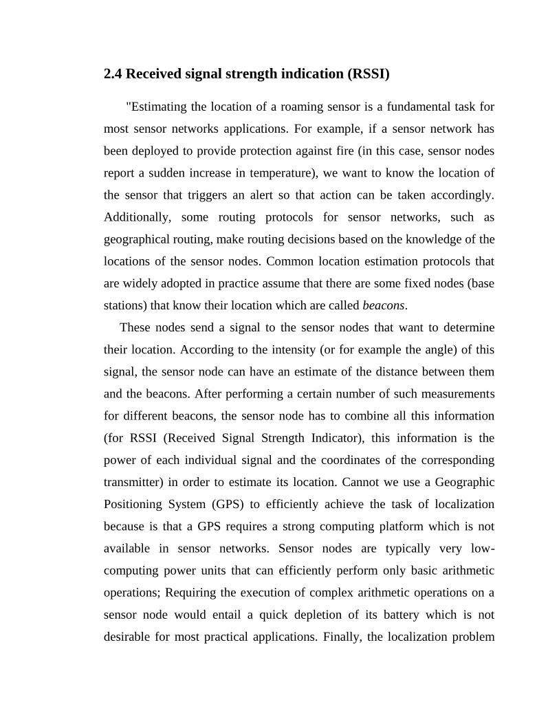
2.4 Received signal strength indication (RSSI)
"Estimating the location of a roaming sensor is a fundamental task for
most sensor networks applications. For example, if a sensor network has
been deployed to provide protection against fire (in this case, sensor nodes
report a sudden increase in temperature), we want to know the location of
the sensor that triggers an alert so that action can be taken accordingly.
Additionally, some routing protocols for sensor networks, such as
geographical routing, make routing decisions based on the knowledge of the
locations of the sensor nodes. Common location estimation protocols that
are widely adopted in practice assume that there are some fixed nodes (base
stations) that know their location which are called beacons.
These nodes send a signal to the sensor nodes that want to determine
their location. According to the intensity (or for example the angle) of this
signal, the sensor node can have an estimate of the distance between them
and the beacons. After performing a certain number of such measurements
for different beacons, the sensor node has to combine all this information
(for RSSI (Received Signal Strength Indicator), this information is the
power of each individual signal and the coordinates of the corresponding
transmitter) in order to estimate its location. Cannot we use a Geographic
Positioning System (GPS) to efficiently achieve the task of localization
because is that a GPS requires a strong computing platform which is not
available in sensor networks. Sensor nodes are typically very low-
computing power units that can efficiently perform only basic arithmetic
operations; Requiring the execution of complex arithmetic operations on a
sensor node would entail a quick depletion of its battery which is not
desirable for most practical applications. Finally, the localization problem

gets even more difficult because the available power on the sensor node is
limited: therefore no accurate measurements of the signal can be made
(since an accurate measurement requires more computing power) which
means that the measurements are prone to errors. This is something that
should also be taken into consideration and treated accordingly. Therefore,
any location estimation algorithm should have the following requirements:
1. The sensor node should avoid complex and time consuming
computations, which would deplete its energy supply (typically a low-cost
battery) rapidly.
2. The computations should take into consideration the error in the
measurements, which can be large.
The Received Signal Strength Indicator (RSSI) value is part of the data
packet transmitted by all VerisAerospond sensor units. It is intended as
means to obtain a relative indication of the quality of connection that exists
between the sensor unit and the access point it is connected to on the
wireless network. In order for this to be a useful tool in determining the
quality of the connection, there are a few principals that need to be
understood about what the RSSI value means. Signal strength is based on a
number of factors, including the output power of the transmitter (the
original strength of the signal), the sensitivity of the receiver (how well the
receiving device can hear weak signals), the gain of the antennae at both
ends of the path, and the path loss, or attenuation of the signal as it travels
through the air from the transmitter to the receiver. Signal strength is
expressed in units of decibels (dB). Due to the low power levels and the
attenuation of free space, an RSSI value is expressed as a negative number.
The more negative the number, the weaker the signal strength; conversely
the closer the number is to zero, the stronger the signal.

The RSSI value is an indication of how well the sensor hears the
signal being transmitted by the access point. It does not indicate how well
the access point is hearing the Aerospond unit, as that information must be
attained directly from the access point itself and is not typically available.
Since Aerospond units typically transmit with lower power than most
access points, it is reasonable to assume that the Aerospond unit sees a
slightly stronger signal from the access point than the access point sees
from the Aerospond unit. This normally does not pose any problems unless
the sensor is on the very fringe of the access point’s range. It should also be
noted that RSSI values are a relative indication of signal strength, not an
absolute measurement. It is normal to see RSSI values fluctuate several dB
between readings. If a sensor is in range of multiple access points, it is also
normal to see the unit occasionally switch between them, even though one
access point may have a much higher RSSI value than the other. [7]
2.5 Mobile Phone Signal Detector
The existing technology currently available in the open market utilizes
mostly discrete components, and a design approach using a down converter
in conjunction with a band pass filter. These technologies are not adequate
because they are inaccurate and expensive. The first signal detection
technique, an RF detector using tuned Inductor-Capacitor (LC)utilizes
discrete components which is difficult to implement.
They are very affordable to construct, but requires precision tuning. This
design when analyzed was found to be inaccurate. The design incorporated
tuned LC circuit which is used to detect low frequency radiation in the
Amplitude Modulation (AM) and Frequency Modulation (FM) bands. It
detects signals in the GHz frequency band used in mobile phones as the

transmission frequency of mobile phone ranges from 0.9 to 3 GHz. A
capacitor is used to form a part of the LC circuit as C while the lead (coiled
wire) of the same forms the L to receive RF signals from the mobile phone.
When the mobile phone is activated the RF transmission signal is detected
by the detector and starts sounding a beep alarm and the LED blinks.
The second technique seems to be accurate but has its own short comings,
in addition to being very expensive. The two most popular mobile phone
detectors available under this technology are produced by Berkeley
Varitronics Systems and mobile Security products. These companies
produce the wolfhound cell phone detector and cell buster, respectively.
The Berkeley Varitronics systems Wolfhound cell phone detects Personal
Computers (PCs), Code Division Multiple Access (CDMA), Global System
for Mobiles (GSM) and cellular bands using the RF signals. It is also
capable to directionally find and locate cellular phones that are nearby.
The Wolfhound seems to be a great way to detect cellular phones but may
just randomly detect mobile phone communications in the area and not
necessarily the Phone or device that set it off. The Cell Buster from mobile
security product which provides continuous monitoring for mobile phone
and has voice alert that tells the user to shut their phone off if detected. The
Cell Buster only receives and does not transmit, making it great for areas
that are sensitive to cellular phone usage. It also detects phones that are in
standby mode. The Cell Buster also seems like it would work wonderfully
for keeping people from bringing their phones into restricted areas,
however, like the Berkeley Vantronics systems it has its shortcomings as it
takes up to 20 minutes to detect if it is in standby and that the phone needs
to be on and its detection could be random transmission in that area.

2.5.1DESIGN PROCEDURE/ METHODOLOGY
An ordinary RF detector using tuned LC circuits is not suitable for detecting
signals in the GHz frequency band used in mobile phones due to the high
frequency at which it transmit and huge energy that it gives out.
Figure 2.2 Block Diagram of Mobile Signal Detector

The construction of this pocket size mobile phone signal detector is so
simple and not expensive. For the construction to be understood and
appreciated a more detailed description of the design is required using the
block diagram.
The design consists of four stages as shown in the block diagram.
1. The sensor stage
2. The power stage
3. Operational Amplifier (Op-Amp) stage
4. Response stage
From the above block diagram, once the RF antenna receives wireless
signal after the circuit has been powered by a 9 Volts dc battery, the
operational Amplifier LM358AN amplifies the received signal which is
turn triggers the buzzer and makes the LED to flicker when signal is
detected. [8]
2.6 Source of Radio Waves
Consider electric current as a flow of electrons along a conductor
between points of differing potential. A direct current flows continuously in
the same direction. This would occur if the polarity of the electromotive
force causing the electron flows were constant, such as is the case with a
battery. If, however, the current is induced by the relative motion between
a conductor and a magnetic field, such as is the case in a rotating machine
called a generator, then the resulting current changes direction in the
conductor as the polarity of the electromotive force changes with the
rotation of the generator’s rotor. This is known as alternating current. The
energy of the current flowing through the conductor is either dissipated as
heat (an energy loss proportional to both the current flowing through the

conductor and the conductor’s resistance) or stored in an electromagnetic
field oriented symmetrically about the conductor. The orientation of this
field is a function of the polarity of the source producing the current. When
the current is removed from the wire, this electromagnetic field will, after a
finite time, collapse back into the wire. When occur should the polarity of
the current source supplying the wire be reversed at a rate which exceeds
the finite amount of time required for the electromagnetic field to collapse
back upon the wire In this case, another magnetic field, proportional in
strength but exactly opposite in magnetic orientation to the initial field, will
be formed upon the wire. The initial magnetic field, its current source gone,
cannot collapse back upon the wire because of the existence of this second
electromagnetic field. Instead, it propagates out into space. This is the basic
principle of a radio antenna, which transmits a wave at a frequency
proportional to the rate of pole reversal and at a speed equal to the speed of
light. [8]

Chapter Three

Chapter Three
Block Diagram and Design
3.1 Methodology
In this project the methodology can be described as following:
-Study the previous work about RF detector
-Study the types of signals that can be track
-Draw the block diagram of the project
-Design the circuit simulation
- Choose the rssi module and suitable antenna
-Upload the code in arduino
-Connecting the directional antenna to stepper motor in serial board
-Connecting the stepper motor to arduino to control the steps based on
the received signal
-Making metal cavities to antenna to concentrate radiation in one way
-Complete the component of the circuit
-Test the system

3.2 Block Diagram
This RF detector suitable for detecting the direction of signals in the
MHz frequency band The design consists of ten stages as shown in the
block diagram. From the below block diagram, the band pass filter to pass
frequencies within a certain range and rejects the frequencies outside the
range, once the RF antenna receive signal after the circuit has been powered
by a 5 Volts dc battery, the operational Amplifier amplifies the received
signal which is turn the stepper motor to move the antenna the arduino
control the moving of stepper motors by comparing between the receive
frequency and the standard frequency. The LCD show the frequency when
signal direction is detected.

Figure 3.1 Block Diagram of RFDR
3.3 Flow chart
In this project the flow chart can be described in figure 3.2

Figure3.2 Flow chart of particular circuit

3.4 Arduino mega 2650
The Arduino/Genuino Mega 2560 is a microcontroller board based on
the ATmega2560. It has 54 digital input/output pins (of which 15 can be
used as PWM outputs), 16 analog inputs, 4 UARTs (hardware serial ports),
a 16 MHz crystal oscillator, a USB connection, a power jack, an ICSP
header, and a reset button. It contains everything needed to support the
microcontroller; simply connect it to a computer with a USB cable or power
it with a AC-to-DC adapter or battery to get started. The Mega 2560 board
is compatible with most shields designed for Arduino/Genuino Uno and the
former boards Duemilanove or Diecimila.
The Arduino/Genuino Mega 2560 board has a number of facilities for
communicating with a computer, another board, or other microcontrollers.
The ATmega2560 provides four hardware UARTs for TTL (5V) serial
communication. An ATmega16U2 (ATmega 8U2 on the revision 1 and
revision 2 boards) on the board channels one of these over USB and
provides a virtual com port to software on the computer (Windows
machines will need a .inf file, but OSX and Linux machines will recognize
the board as a COM port automatically. The Arduino Software (IDE)
includes a serial monitor which allows simple textual data to be sent to and
from the board. The RX and TX LEDs on the board will flash when data is
being transmitted via the ATmega8U2/ATmega16U2 chip and USB
connection to the computer (but not for serial communication on pins 0 and
1).

Table 3.1Arduino Mega 2560 Technical specs
Microcontroller ATmega2560
Operating Voltage 5V
Input Voltage (recommended) 7-12V
Input Voltage (limit) 6-20V
Digital I/O Pins 54 (of which 15 provide PWM
output)
Analog Input Pins 16
DC Current per I/O Pin 20 mA
DC Current for 3.3V Pin 50 mA
Flash Memory 256 KB of which 8 KB used by
bootloader
SRAM 8 KB
EEPROM 4 KB
Clock Speed 16 MHz
Length 101.52 mm
Width 53.3 mm
Weight 37 g

Figure 3.3 Arduino Mega 2560


Figure 3.4 Arduino Mega 2560 PIN diagram
3.5 Stepper motor
A stepper motor is an electromechanical device which converts
electrical pulses into discrete mechanical movements. The shaft or spindle
of a stepper motor rotates in discrete step increments when electrical
command pulses are applied to it in the proper sequence. The motors
rotation has several direct relationships to these applied input pulses. The
sequence of the applied pulses is directly related to the direction of motor
shafts rotation. The speed of the motor shafts rotation is directly related to
the frequency of the input pulses and the length of rotation is directly
related to the number of input pulses applied.
stepper motor is a ―digital‖ version of the electric motor. The rotor moves
in discrete steps as commanded, rather than rotating continuously like a
conventional motor. When stopped but energized, a stepper (short for
stepper motor) holds its load steady with a holding torque. Wide spread
acceptance of the stepper motor within the last two decades was driven by
the ascendancy of digital electronics. Modern solid state driver electronics
was a key to its success. And, microprocessors readily interface to stepper
motor driver circuits.
Application wise, the predecessor of the stepper motor was the servo
motor. Today this is a higher cost solution to high performance motion
control applications. The expense and complexity of a servomotor is due
to the additional system components: position sensor and error amplifier.
It is still the way to position heavy loads beyond the grasp of lower power
steppers. High acceleration or unusually high accuracy still requires a

servo motor. Otherwise, the default is the stepper due to low cost, simple
drive electronics, good accuracy, good torque, moderate speed, and low
cost.
Table 3.2 28BYJ-48 – 5V Stepper Motor
Rated voltage 5VDC
Number of Phase 4
Speed Variation Ratio 1/64
Stride Angle 5.625° /64
Frequency 100Hz
DC resistance 50Ω±7%(25℃)
Idle In-traction Frequency > 600Hz
Idle Out-traction Frequency > 1000Hz
In-traction Torque >34.3mN.m(120Hz)
Self-positioning Torque >34.3mN.m
Friction torque 600-1200 gf.cm
Pull in torque 300 gf.cm

Figure 3.5 28BYJ-48 – 5V Stepper Motor data sheet
In Half mode step sequence, motor step angle reduces to half the angle in
full mode. So the angular resolution is also increased i.e. it becomes double
the angular resolution in full mode. Also in half mode sequence the number

of steps gets doubled as that of full mode. Half mode is usually preferred
over full mode. Table below shows the pattern of energizing the coils
Table 3.3 Stepper motor half step
step A B A' B'
0 1 1 0 0
1 0 1 0 0
2 0 1 1 0
3 0 0 1 0
4 0 0 1 1
5 0 0 0 1
6 1 0 0 1
7 1 0 0 0
Figure3.6 Half mode Sequence

3.6 Driver ULN 2003
The ULN2003 is a monolithic IC consists of seven NPN darling ton
transistor pairs with high voltage and current capability. It is commonly
used for applications such as relay drivers, motor, display drivers, led lamp
drivers, logic buffers, line drivers, hammer drivers and other high voltage
current applications. It consists of common cathode clamp diodes for each
NPN darlington pair which makes this driver IC useful for switching
inductive loads.that the driver provides open collector output, so it can only
sink current, cannot source. Thus when a 5V is given to 1B terminal, 1C
terminal will be connected to ground via darlington pair and the maximum
current that it can handle is 500A. From the above logic diagram we can see
that cathode of protection diodes are shorted to 9th pin called COM. So for
driving inductive loads, it must connected to the supply voltage.
ULN2003 is widely used in relay driving and stepper motor driving
applications.

Figure3.7 Driver ULN2003 (16 pin)
3.7 UlN2003 Stepper motor driver circuit
This is an easy to build stepper motor driver that will allow you to
precisely control a unipolar stepper motor through your computer's parallel
port. With a stepper motor you can build a lot of interesting gadgets such as
robots, elevator, PCB drilling mill, camera panning system, automatic fish
feeder, etc. Stepper motors are very different from a regular DC motors.
Instead of spinning like DC motors do, stepper motor steps at a specific
resolution for each pulse. The motor that we are using needs 48 steps /
pulses just to complete a single revolution! That should be enough to tell
about its precision. Another advantage of stepper motors is the fact that
their speed of rotation can be achieved almost instantly even if you change
the spinning direction Stepper motor consists of a rotor - the permanent
magnet that rotates inside, and stator - four coils (north, east, south, west)
that are part of the case, and which don't move. Rotor can be moved by

sequentially applying a pulsed DC voltage to one or two coils at a time. In
able to move the rotor you will need a driver. Driver is a circuit that applies
a voltage to any of the four stator coils. Driver can be built with IC such as
ULN2003 (pictured on the circuit diagram), four Darlington transistors or
four power transistors such as 2N3055.
Figure3.8 The motor control circuit
3.8 Stepper Motor with an Arduino
Working with the Arduino coding platform, there is a wide range of
example libraries to get you started. Connecting a stepper motor to
an Arduino is a different than connecting a DC motor to the board. Because
stepper motors have to pulse in a specific way for the rotor to spin, there is
a special Stepper library and function built into the Arduino code platform.
Opening the Arduino software, browseto
"File>Examples>Stepper>stepper_oneRevolution"
This program drives a unipolar or bipolar stepper motor, by attaching the
motor to digital pins 8 - 11 of the Arduino. After the sketch is loaded on to

the Arduino board, the motor should revolve one revolution clockwise,
then one revolution moving counter-clockwise.
The example code is an excellent point to start from; you can certainly
make edits to the sketch to suit your needs. The delay is listed in
microseconds, so if you want there to be no break between its revolutions,
you can set delay to delay(10). Or if you want it to spin for a long time you
can change steps Per Revolution to equal = (1000000)
How you modify the sketch will depend on what you are trying to
accomplish with the motor. Playing with some of the other sketches in the
example sketch library will help you develop a greater understanding of
how stepper motors are able to communicate with Arduino Boards.

Figure3.9 Stepper Motor with an Arduino

Chapter Four
Simulation
&
Result

Chapter Four
Results and Dissection
4.1 Simulations & Result
This section discusses the achieved from the project, the software
outputs are discussed first.
4.1.1 Software Outputs
The simulation has been performed to get the initial results using the
pouteus 7 professional software and added arduino mega2560, two stepper
motors, two driver’s uln2003, signal generation,oscilloscope and terminal.

Figure 4.1 the circuit simulation by proteus.
The next section will display the system response in each case, the first
figure shows the uploading of the code to the aruino.
Figure 4.2 run code in aruino.

The next figure shows the response of the system for the low frequencies,
you can notice the motors rotation, from the LCD the value of the
frequency.

Figure 4.3 simulation window
Stepper motors stop when antenna senesce the reference value of frequency

Figure 4.4 simulation result

4.1.2 Hardware steps
The first step place the components on the board by interfacing the
arduino to the stepper motors using the motors driver (ULN2003).
The two motors are used move the antenna in the two axis either vertically
and horizontally
The coming figure shows the connection between the motors and the motor
driver:
Figure 4.5 stepper motor with driver uln2003

The next step in the following figure is to interface the previous circuit to
the arduino circuit, you can notice the ground pins are connected together
and the motors control signal is taken from the (pin 49).
Figure 4.6 particular circuits (arduino)

Chapter Five
Conclusion
&
Recommendation

Chapter Five
Conclusion and Recommendations
5.1 Conclusion
After a year of well-organized work, we reached the objective of this
project, which can be summarized as following:
- Manage to control the stepper motors to detect the direction of broad
casting
- The directional antenna mange to sense the frequency
The RF detector can be used as an indicator of objects and can be used in
tracking, but not in a fully exact way, and needs development of up to date
technology in order to reach full accurate results.
After working on detection the direction of broad casting using the RF
detector technology, with all the possible materials available for us as
students, for sure the results won't be very accurate, as well as the operation
itself. The results were fair, but the rate of error had well known reasons:
1- The antenna of the reader should have special properties, as it should be
directional with very small beam width, and getting such an antenna for a
reader working at such low operating frequency (27MHZ) with high
directionality will make it have large size, which is inconvenient for the
motor. So it was replaced by the cavity.
2- The stepper motor itself has a large step

5.2 Recommendations
The clearest application that can be used in detection the direction is the
robot. For an automatically controlled robot, a robot can be used to carry or
lift boxes and move them somewhere else. Our exact demo version of the
project can be used for the robot, after treating the problems in our demo
project. The motor will be placed on the robot, with the antenna connected
to it. With this target detection method, the robot can detect the target
automatically without any human interference.
From the previous problems, the results from our demo project for the idea
weren't giving satisfying results for the industrial field. If the previous
problems had a good industrial solution, the RF detector technology can be
used very well in detection direction. So in order to solve the previous
problems, the following steps should be carried out:
-A directional antenna with small beam width, with small size and non-
effective side lobes, with high gain should be used.
-A stepper motor with a step angle equals to the beam width of the antenna
should be used.
-In case of finding the required antenna, there will be no need for the cavity.

References
[1]Roger L. Freeman, John Wiley & Sons,‖Radio Frequency and Antenna
Fundamentals‖, 1999.
[2] Louis E Frenzel,‖Design radio frequency detectors for wireless
devices‖, 2004.
[3]Lukas Grillmayer,‖Radio-Frequency Identification‖,2012.
[4]Roberti, M,‖The History of RFID Technology‖,1990.
[5]Garfinkel, S. and Holtzman, H,‖Understanding RFIDTechnology‖,2005.
[6]Robert Lacoste’s,‖The Darker Side: Practical Applications for
Electronic‖, 2010.
[7]Kaemarungsi, K., and Krishnamurthy,‖Properties of indoor received
signal strength for WLAN location fingerprinting‖, 2004.
[8]O. Shoewu, and P.O. Nwamina,‖Design and Development of a Mobile
Phone Signal Detector‖, 2014.

Appendix
Ardiuno code:
/* FreqMeasure - Example with serial output
* http://www.pjrc.com/teensy/td_libs_FreqMeasure.html
*
* This example code is in the public domain.
*/
#include <FreqMeasure.h>
#include <LiquidCrystal.h>
LiquidCrystallcd(22, 23, 24, 25, 26, 27);
//constintanalogInPin = A0; // Analog input pin that the potentiometer is
attached to
//constintanalogOutPin = 9; // Analog output pin that the LED is attached to
float Rssi1 = 5500;
float Rssi2;
int i;
int d;
constint led1=8;
constint led2=9;
constint led3=10;
constint led4=11;
constint led5=4;

constint led6=5;
constint led7=6;
constint led8=7;
intsensorValue = 0; // value read from the pot
intoutputValue = 0; // value output to the PWM (analog out)
void motor1_F(){
digitalWrite(led1, HIGH);
digitalWrite(led2, LOW);
digitalWrite(led3, LOW);
digitalWrite(led4, LOW);
delay(0.2);
digitalWrite(led1, LOW);
digitalWrite(led2, HIGH);
digitalWrite(led3, LOW);
digitalWrite(led4, LOW);
delay(0.2);
digitalWrite(led1, LOW);
digitalWrite(led2, LOW);
digitalWrite(led3, HIGH);
digitalWrite(led4, LOW);
delay(0.2);
digitalWrite(led1, LOW);
digitalWrite(led2, LOW);

digitalWrite(led3, LOW);
digitalWrite(led4, HIGH);
delay(0.2);
}
void motor1_R(){
digitalWrite(led1, LOW);
digitalWrite(led2, LOW);
digitalWrite(led3, LOW);
digitalWrite(led4, HIGH );
delay(0.2);
digitalWrite(led1, LOW);
digitalWrite(led2, LOW);
digitalWrite(led3, HIGH);
digitalWrite(led4, LOW);
delay(0.2);
digitalWrite(led1, LOW);
digitalWrite(led2, HIGH);
digitalWrite(led3, LOW);
digitalWrite(led4, LOW);
delay(0.2);
digitalWrite(led1, HIGH);
digitalWrite(led2, LOW);
digitalWrite(led3, LOW);
digitalWrite(led4, LOW);
delay(0.2);
}
void motor2_F(){
digitalWrite(led5, HIGH);
digitalWrite(led6, LOW);
digitalWrite(led7, LOW);
digitalWrite(led8, LOW);
delay(0.2);
digitalWrite(led5, LOW);
digitalWrite(led6, HIGH);
digitalWrite(led7, LOW);
digitalWrite(led8, LOW);
delay(0.2);
digitalWrite(led5, LOW);
digitalWrite(led6, LOW);
digitalWrite(led7, HIGH);
digitalWrite(led8, LOW);
delay(0.2);
digitalWrite(led5, LOW);
digitalWrite(led6, LOW);
digitalWrite(led7, LOW);
digitalWrite(led8, HIGH);

delay(0.2);
}
void motor2_R(){
digitalWrite(led5, LOW);
digitalWrite(led6, LOW);
digitalWrite(led7, LOW);
digitalWrite(led8, HIGH );
delay(0.6);
digitalWrite(led5, LOW);
digitalWrite(led6, LOW);
digitalWrite(led7, HIGH);
digitalWrite(led8, LOW);
delay(0.6);
digitalWrite(led5, LOW);
digitalWrite(led6, HIGH);
digitalWrite(led7, LOW);
digitalWrite(led8, LOW);
delay(0.6);
digitalWrite(led5, HIGH);
digitalWrite(led6, LOW);
digitalWrite(led7, LOW);
digitalWrite(led8, LOW);
delay(0.6);

}
void motor2_S(){
digitalWrite(led5, LOW);
digitalWrite(led6, LOW);
digitalWrite(led7, LOW);
digitalWrite(led8, LOW );}
void motor1_S(){
digitalWrite(led5, LOW);
digitalWrite(led6, LOW);
digitalWrite(led7, LOW);
digitalWrite(led8, LOW );}
void setup() {
Serial.begin(57600);
FreqMeasure.begin();
pinMode(led1,OUTPUT);
pinMode(led2,OUTPUT);
pinMode(led3,OUTPUT);
pinMode(led4,OUTPUT);
lcd.begin(20, 4);
lcd.print("frequ:");
//lcd.setCursor(0, 6);
lcd.print(Rssi1);
}

double sum = 0;
int count = 0;
void loop() {
if (FreqMeasure.available()) {
// average several reading together
sum = sum + FreqMeasure.read();
count = count + 1;
//myStepper1.step(1);
if (count > 30) {
float frequency = FreqMeasure.countToFrequency(sum / count);
Serial.println(frequency);
lcd.setCursor(0, 2);
lcd.print(frequency);
sum = 0;
count = 0;
Rssi2 = frequency;
}
}

if((Rssi1>Rssi2)||(Rssi1<Rssi2)){
i++;
if((i<30)&&(i>1)){
motor1_R();
d++;
if(d<5){
motor2_R();}
if((d>5)&&(d>8)){
motor2_F();d=0;i=0;}
}
if((i<31)&&(i>40)){
motor1_F(); }
d++;
if(d<5){
motor2_R();}
if((d>5)&&(d>8)){
motor2_F();d=0;i=0;}
if(i==40){
motor2_R();
motor2_S();
}
}
if(Rssi1==Rssi2){

motor2_S();
motor1_S();
}
//delay(50);
}