Network Backbone Devices Management - SUST Repository
99
SUDAN UNIVERSITY OF SCIENCE AND TECHNOLOGY COLLEGE OF COMPUTER SCIENCE & INFORMATION TECHNOLOGY COMPUTER SYSTEMS AND NETWORK DEPARTMENT Network Backbone Devices Management A PROJECT SUBMITTED AS ONE OF THE REQUIREMENTS FOR OBTAINING A BACHELOR OF HONOR IN COMPUTER SYSTEMS AND NETWORKS OCTOBER 2016
-
Upload
khangminh22 -
Category
Documents
-
view
2 -
download
0
Transcript of Network Backbone Devices Management - SUST Repository
SUDAN UNIVERSITY OF SCIENCE AND
TECHNOLOGY
COLLEGE OF COMPUTER SCIENCE&
INFORMATION TECHNOLOGY
COMPUTER SYSTEMS AND NETWORK
DEPARTMENT
Network Backbone Devices Management
A PROJECT SUBMITTED AS ONE OF THE REQUIREMENTS FOR OBTAINING A BACHELOR OF HONOR IN COMPUTER SYSTEMS AND NETWORKS
OCTOBER 2016
الرحيم الرحمن الله بسم
SUDAN UNIVERSITY OF SCIENCE ANDTECHNOLOGY
COLLEGE OF COMPUTER SCIENCE &INFORMATION TECHNOLOGY
COMPUTER SYSTEMS AND NETWORKDEPARTMENT
Network Backbone Devices Management
OCTOBER 2016
PROPOSED BY:
ESRAA ABDULLA MOHAMED
MOHAMED OMER MOHAMED
OMER HAYDER AHMED
SIGNATURE OF SUPERVISOR Signature
Dr.Abuaglaa Babikar...…………………

اليــــــــــــــةتعالى :قال
{ ًا م ْل ِع ِني ْد ِز ِّب َر ْل ُق َو }
العظيم الله صدق
طـه 114 ]سورة ]
الحـمدلله3

عنا وفرجت وأنقذتنا وعلمتنا وهديتنا ورزقتنا خلقتنا بما الحمد لك ربنا اللهم لله الحمد
والمعافاة والمال بالأهل الحمد ولك بالقرآن الحمد ولك بالإسلم الحمد ولك بالإيمان الحمد لك
معافاتنا وأحسنت فرقتنا وجمعت أمننا وأظهرت رزقنا وبسطت عدونا كبت
أعطيتنا ربنا سألناك ما كل ومن
كثيرا حمدا ذلك على الحمد فلك
عامة أو خاصة أو علنية أو سر أو حديث أو قديم في علينا بها أنعمت نعمة بكل الحمد لك
غائب أو شاهد أو ميت أو ًا حي أو
الرضى بعد الحمد ولك رضيت إذا الحمد ولك ترضى حتى الحمد لك
كثيرا تسليما وسلم محمد سيدنا على وسلم اللهم وصلى
والعرفان الشكر
قضيناها أعوام إلى نعود وقفة من الجامعية الحياة في الأخيرة خطواتنا نخطو ونحن لنا لبدبناء في كبيرة جهودا بذلك باذلين الكثير لنا قدمو الذين الكرام اساتذتنا مع الجامعة رحاب في
لتبعث الغد جيل4

جديد من .. الأمهأقدس حملو الذين الى والمحبة والتقدير والمتنان الشكر آيات آسمى تقدم نمضي أن وقبل
في رساله.. الحياة
والمعرفة العلم طريق لنا مهدو الذين .. إلىالأفاضل أساتذتنا جميع .. إلى
" .. .. .. تستطع لمن فإن العلماء فأحب تستطع لم فإن متعلما فكن تستطع لم فإن عالما كن"فلتبغضهم
الغالية مشرفتنا والتقدير بالشكر ..ونخصلطفي/ رهام أ
لها نقول أن الإ ليسعنا والتي" , الخير , الناس معلم على ليصلون السماء في والطير البحر في الحوت "إن
طريقنا في أحيانا تقف كنت التي الظلمه يضيء ونورا هذا بحثنا في لنا عونا كانو من كل الىفلهم , والمعلومات والفكار والتسهيلت المساعدات لنا وقدمو دربنا في التفاؤل زرعو من إلى
مناونخص , الشكر .. كل
( الكريمة (عائلتناو
جمال - - - - - مقداد عبود ربا أسامة محاسن عبدالحميد رزان يوسف تقى المنان عطا نهىالدين
/ الدين/ عز نعمة د هاشم وليد موعرقل , جانبنا الى يقف لم من كل الى ايضا بالشكر فنتوجه الخاص النوع من الذي الشكر أماولولهم , , الإيجابية المنافسة حلوة ول البحث بمتعة أحسسنا لما وجودهم فلول بحثنا مسيرة
الشكر كل منا فلهم إليه ماوصلنا إلى وصلنا لما
لإهداء ا.. تنطوي الليالي سهر صفحات لله والحمد اليوم وها تنتهي والشقاء العناء أيام تلك ها
.. .. .. تنقضي .. وساعاتها وأيامها بشهورها سنين أيامها.. النقي العلم خلصة المتواضع البحث هذا دفتي في لكم لنضع
5
..إلى والوقار بالهيبة الله كللهم منافتخار بكل اسمهم نحمل من ..إلى
النجاح، لطريق دفعنا أجل من بشيء يبخلو لم من الىسعادة لحظة لنا ليقدمو أناملهم ّلت ك من إلى
.. درجة درجة الفلح درجات صعود علمونا من إلى( الأعزاء( والدينا
.. الحياة في ملكنا الى.. نعتمد وعليها نكبر بها من إلى
.. حياتنا ظلمة تنير متقدة شمعة إلى.. لها حدود ل ومحبة قوة نكتسب بوجودها من إلى
.. شهادتنا نحمل يوم ترانا لكي معنا الليالي سهرت من إلىالحبايب أغلى إلى جراحنا بلسم وحنانها نجاحنا سر دعائها كان من إلى
( الحنونات ( أمهاتنا
الصادقة والنوايا الطيب القلب أصحاب إلىخطوة خطوة الدرب سرنا ومعهم صغيرة حقائب حملنا أن منذ رافقونا من إلى
واصرارنا عزتنا نستمد وبهم الم حضن شاركونا من الى( وأخواتنا( أخواننا
همومنا وشاركونا دراستنا في انسونا من إلىإلى والعطاء بالوفاء وتميزو باليخاء تحلو من إلى أمهاتنا تلدهن لم الذين والأخوات الأخوان إلى
سرنا والحزينة الحلوة الحياة دروب في وبرفقتهم سعدنا معهم من إلى الصافي الصدق ينابيعوالخير النجاح طريق على معنا كانو من إلى
نضيعهم ل ان وعلمونا نجدهم كيف عرفنا من إلى( أصدقاؤونا(
الجبار الفتي العلمي الصرح هذه إلى ( والتكنلوجيا للعلوم السودان (جامعة
( المعلومات وتقانة الحاسوب علوم (كلية
ABSTRACT
Computer networks became a necessary and important aspect of any
organization to provide connectivity among its devices and to reach the internet.
Building such network needs certain devices and configurations which require effort
from network administrators to configure, control and manage those devices to keep
the network working properly according to the organization policies.
6
That is why we found it more suitable to build an application that helps the
administrator perform those tasks through a clear graphical user interface with
additional features help in configuring and managing the network (e.g. tasks
scheduling, backup and restore configuration, mobile notifications and remote
management.(
This application gives administrators flexibility, time and effort efficiency to
manage organization network devices.
المستخلص
مع ا المؤسسة أجزاء ربط ليتم مؤسسة لأي وأساسي ضروري أمر شبكة وجود إلي الحوجة صبحت
, ذات اجهزة توفر ذلك يتطلب الشبكة هذه ولبناء الإنترنت بشبكة داخلها المخدمات وربط بعضها
الشبكة لربط الرئيسة الأجهزة منها خاصة .مواصفات
وإدارتها فيها والتحكم ضبطها عملية في الشبكة مسؤولي من مجهود تتطلب الجهزة هذه
, المؤسسة سياسات وحسب وجه أكمل على عملها إستمرار سبيل في وذلك من ومراقبتها وجدنا لذلك
مع الشبكة أجهزة لضبط واضحة رسومية واجهات خلل من المهام بهذه يقوم برنامج إنشاء المناسب
, : إلى إضافة الضبط واسترجاع الحتياطي النسخ المهام جدولة منها الدارية المزايا من العديد توفير
بعد عن الجهزة في والتحكم الجوال الهاتف من الإشعار .نظام
7
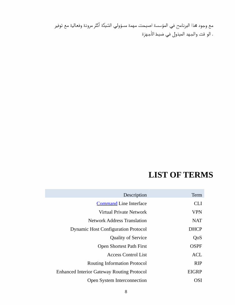
توفير مع وفعالية مرونة أكثر الشبكة مسؤولي مهمة اصبحت المؤسسة في البرنامج هذا وجود مع
الأجهزة ضبط في المبذول والجهد . الوقت
LIST OF TERMS
TermDescription
CLICommand Line Interface
VPNVirtual Private Network
NATNetwork Address Translation
DHCPDynamic Host Configuration Protocol
QoSQuality of Service
OSPFOpen Shortest Path First
ACLAccess Control List
RIPRouting Information Protocol
EIGRPEnhanced Interior Gateway Routing Protocol
OSIOpen System Interconnection
8
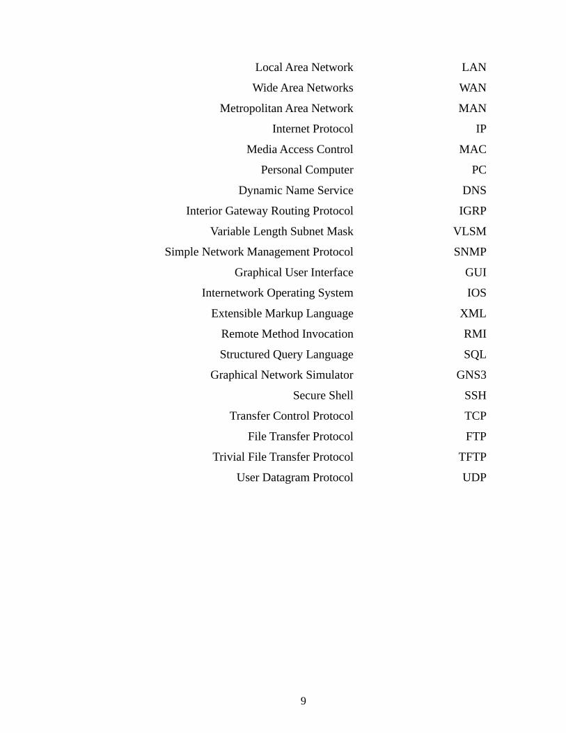
LANLocal Area Network
WANWide Area Networks
MANMetropolitan Area Network
IPInternet Protocol
MACMedia Access Control
PCPersonal Computer
DNSDynamic Name Service
IGRPInterior Gateway Routing Protocol
VLSMVariable Length Subnet Mask
SNMPSimple Network Management Protocol
GUIGraphical User Interface
IOSInternetwork Operating System
XMLExtensible Markup Language
RMIRemote Method Invocation
SQLStructured Query Language
GNS3Graphical Network Simulator
SSHSecure Shell
TCPTransfer Control Protocol
FTPFile Transfer Protocol
TFTPTrivial File Transfer Protocol
UDPUser Datagram Protocol
9
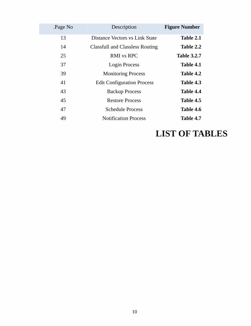
Figure NumberDescriptionPage No.
Table 2.1Distance Vectors vs Link State13
Table 2.2Classfull and Classless Routing14
Table 3.2.7RMI vs RPC25
Table 4.1Login Process37
Table 4.2Monitoring Process39
Table 4.3Edit Configuration Process 41
Table 4.4Backup Process43
Table 4.5Restore Process45
Table 4.6Schedule Process47
Table 4.7Notification Process49
LIST OF TABLES
10
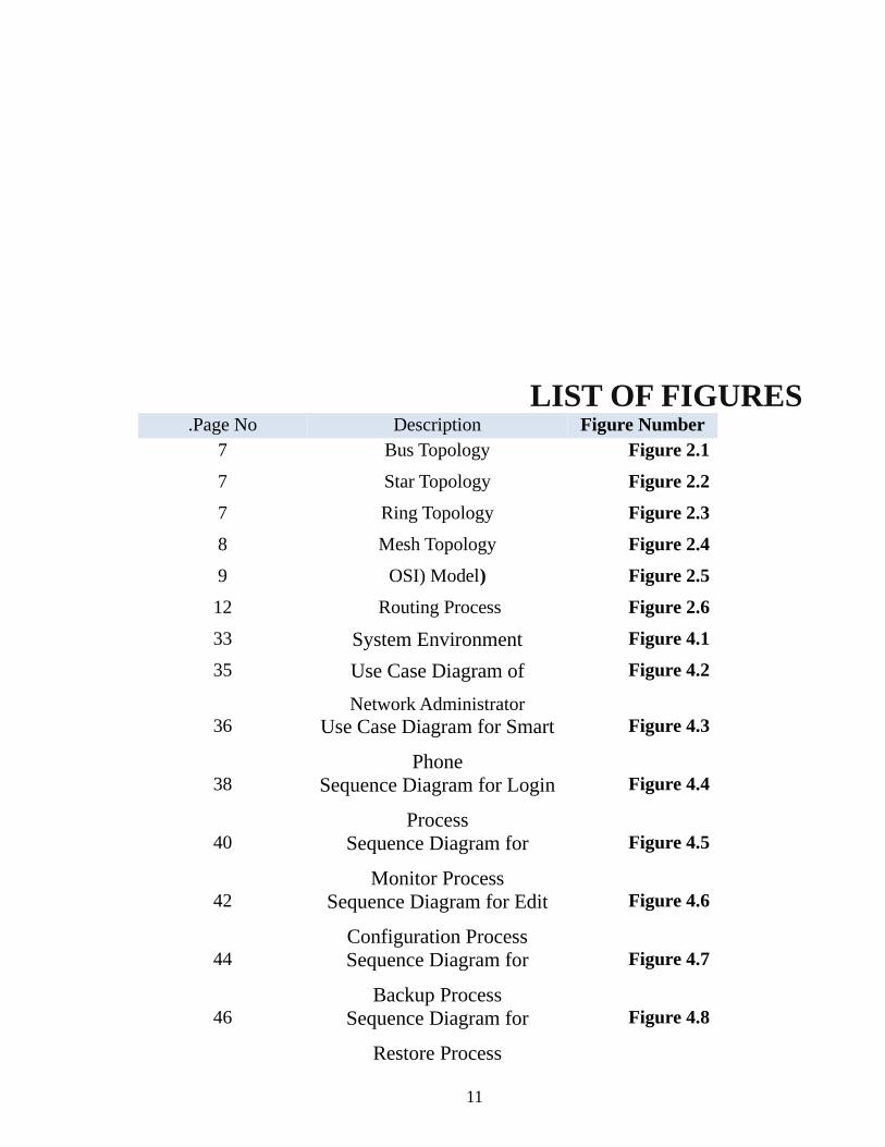
LIST OF FIGURESFigure NumberDescriptionPage No.
Figure 2.1Bus Topology7
Figure 2.2Star Topology7
Figure 2.3Ring Topology7
Figure 2.4Mesh Topology8
Figure 2.5)OSI) Model9
Figure 2.6Routing Process 12
Figure 4.1System Environment33
Figure 4.2Use Case Diagram of
Network Administrator
35
Figure 4.3Use Case Diagram for Smart
Phone
36
Figure 4.4Sequence Diagram for Login
Process
38
Figure 4.5Sequence Diagram for
Monitor Process
40
Figure 4.6Sequence Diagram for Edit
Configuration Process
42
Figure 4.7Sequence Diagram for
Backup Process
44
Figure 4.8Sequence Diagram for
Restore Process
46
11

Figure 4.9Sequence Diagram for
Schedule Process
48
Figure 4.10Sequence Diagram for
Notifications Process
50
Figure 4.11Deployment Diagram51
Figure 5.1First screen 54
Figure 5.2Login screen55
Figure 5.3Main screen56
Figure 5.4Add router screen57
Figure 5.5Configure router screen58
Figure 5.6Router interface screen59
Figure 5.7Access list screen60
Figure 5.8Access list setting 61
Figure 5.9System logo62
Figure 5.10Login screen63
Figure 5.11Home interface64
Figure 5.12List of routers in network65
Figure 5.13Router interface66
Figure 5.14Notification67
12
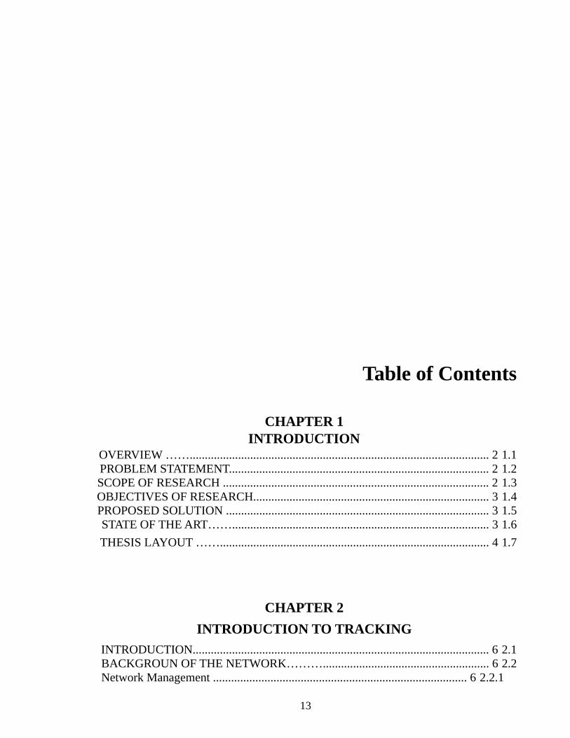
Table of Contents
CHAPTER 1INTRODUCTION
1.1 OVERVIEW ……................................................................................................... 21.2 PROBLEM STATEMENT...................................................................................... 21.3 SCOPE OF RESEARCH ........................................................................................ 21.4 OBJECTIVES OF RESEARCH.............................................................................. 31.5 PROPOSED SOLUTION ....................................................................................... 31.6 STATE OF THE ART……..................................................................................... 3
1.7 THESIS LAYOUT ……......................................................................................... 4
CHAPTER 2
INTRODUCTION TO TRACKING
2.1 INTRODUCTION.................................................................................................. 62.2 BACKGROUN OF THE NETWORK………....................................................... 6
2.2.1 Network Management .................................................................................... 6
13
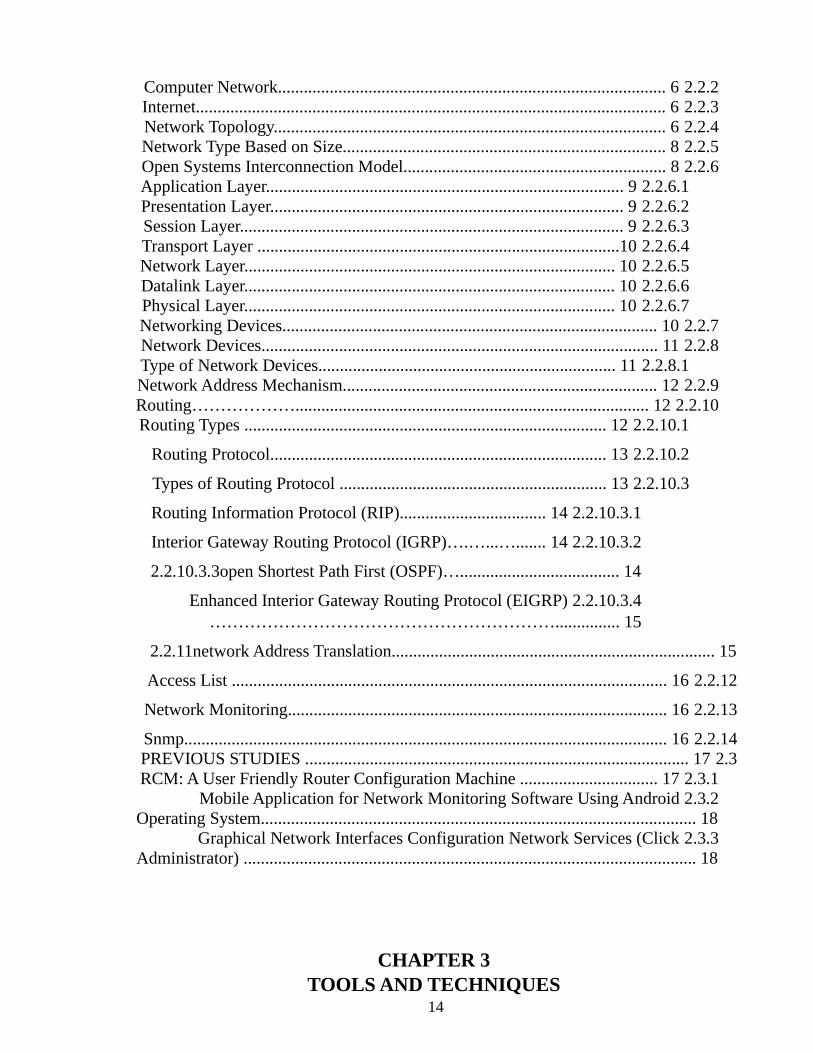
2.2.2 Computer Network.......................................................................................... 62.2.3 Internet............................................................................................................. 62.2.4 Network Topology........................................................................................... 62.2.5 Network Type Based on Size........................................................................... 82.2.6 Open Systems Interconnection Model............................................................. 8
2.2.6.1 Application Layer................................................................................... 92.2.6.2 Presentation Layer.................................................................................. 92.2.6.3 Session Layer......................................................................................... 92.2.6.4 Transport Layer ....................................................................................102.2.6.5 Network Layer...................................................................................... 102.2.6.6 Datalink Layer...................................................................................... 102.2.6.7 Physical Layer...................................................................................... 10
2.2.7 Networking Devices....................................................................................... 102.2.8 Network Devices............................................................................................ 11
2.2.8.1 Type of Network Devices..................................................................... 112.2.9 Network Address Mechanism......................................................................... 12
2.2.10 Routing……………….................................................................................. 122.2.10.1 Routing Types .................................................................................... 12
2.2.10.2 Routing Protocol.............................................................................. 13
2.2.10.3 Types of Routing Protocol .............................................................. 13
2.2.10.3.1 Routing Information Protocol (RIP).................................. 14
2.2.10.3.2 Interior Gateway Routing Protocol (IGRP)….…...…....... 14
2.2.10.3.3open Shortest Path First (OSPF)…..................................... 14
2.2.10.3.4 Enhanced Interior Gateway Routing Protocol (EIGRP)……………………………………………………............... 15
2.2.11network Address Translation........................................................................... 15
2.2.12 Access List ..................................................................................................... 16
2.2.13 Network Monitoring........................................................................................ 16
2.2.14 Snmp................................................................................................................ 162.3 PREVIOUS STUDIES ......................................................................................... 17
2.3.1 RCM: A User Friendly Router Configuration Machine ................................ 172.3.2 Mobile Application for Network Monitoring Software Using Android
Operating System..................................................................................................... 182.3.3 Graphical Network Interfaces Configuration Network Services (Click
Administrator) ......................................................................................................... 18
CHAPTER 3TOOLS AND TECHNIQUES
14
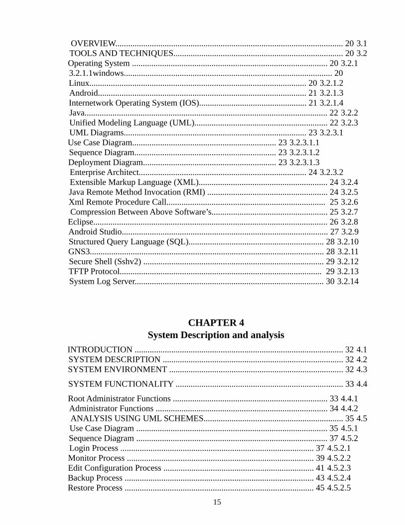
3.1 OVERVIEW.......................................................................................................... 203.2 TOOLS AND TECHNIQUES............................................................................... 20
3.2.1 Operating System ........................................................................................... 203.2.1.1windows................................................................................................. 20
3.2.1.2 Linux..................................................................................................... 203.2.1.3 Android................................................................................................. 213.2.1.4 Internetwork Operating System (IOS).................................................. 21
3.2.2 Java................................................................................................................. 223.2.3 Unified Modeling Language (UML).............................................................. 22
3.2.3.1 UML Diagrams..................................................................................... 233.2.3.1.1 Use Case Diagram................................................................... 233.2.3.1.2 Sequence Diagram.................................................................. 233.2.3.1.3 Deployment Diagram.............................................................. 23
3.2.3.2 Enterprise Architect.............................................................................. 243.2.4 Extensible Markup Language (XML)............................................................ 243.2.5 Java Remote Method Invocation (RMI) ........................................................ 243.2.6 Xml Remote Procedure Call.......................................................................... 253.2.7 Compression Between Above Software’s...................................................... 253.2.8 Eclipse............................................................................................................. 26
3.2.9 Android Studio................................................................................................ 27 3.2.10 Structured Query Language (SQL)............................................................... 28 3.2.11 GNS3............................................................................................................. 28 3.2.12 Secure Shell (Sshv2) .................................................................................... 29 3.2.13 TFTP Protocol.............................................................................................. 29 3.2.14 System Log Server........................................................................................ 30
CHAPTER 4System Description and analysis
4.1 INTRODUCTION ................................................................................................. 324.2 SYSTEM DESCRIPTION .................................................................................... 324.3 SYSTEM ENVIRONMENT ................................................................................. 32
4.4 SYSTEM FUNCTIONALITY .............................................................................. 33
4.4.1 Root Administrator Functions ........................................................................ 334.4.2 Administrator Functions ................................................................................ 34
4.5 ANALYSIS USING UML SCHEMES................................................................. 354.5.1 Use Case Diagram ......................................................................................... 354.5.2 Sequence Diagram ......................................................................................... 37
4.5.2.1 Login Process .......................................................................................... 374.5.2.2 Monitor Process ....................................................................................... 394.5.2.3 Edit Configuration Process ...................................................................... 414.5.2.4 Backup Process ........................................................................................ 434.5.2.5 Restore Process ........................................................................................ 45
15
4.5.2.6 Schedule Process ..................................................................................... 474.5.2.7 Notifications Process ............................................................................... 49
4.5.3 Deployment Diagram...................................................................................... 514.6 CONCLUSION...................................................................................................... 51
CHAPTER 5IMPLEMENTATION
5.1 INTRODUCTION................................................................................................. 535.2 NETWORK ENVIRONMENT............................................................................. 535.3 SERVER SIDE…….............................................................................................. 53
5.3.1 Loading Devices …................................................................................. 535.3.2 TFTP Server Verification........................................................................ 545.3.3 Starting Syslog Server............................................................................. 54
5.4 DESKTOP APPLICATION.................................................................................. 555.4.1 Login Screen............................................................................................ 555.4.2 Main Screen............................................................................................. 565.4.3 Add Device.............................................................................................. 575.4.4 Interface Configuration and Status.......................................................... 595.4.5 Access List Screen .................................................................................. 60
5.5 ANDROID APPLICATION ................................................................................. 625.5.1 Main Screen............................................................................................. 625.5.2 Login …………………........................................................................... 635.5.3 Home Interface ........................................................................................ 645.5.4 Display Network...................................................................................... 655.5.5 Router Interface........................................................................................ 665.5.6 Notification…. ........................................................................................ 67
CHAPTER 6RESULTS AND RECOMMENDATIONS
6.1 INTRODUCTION.................................................................................................. 696.2 CONCLUSION...................................................................................................... 696.3 RESULTS ………………...………………………………………………........... 696.3 RECOMMENDATIONS....................................................................................... 70
REFERENCES……………………………………………………………….....…… 71
APPENDIXS................................................................................................................... 7
16

17

CHAPTER ONE
INTRODUCTION
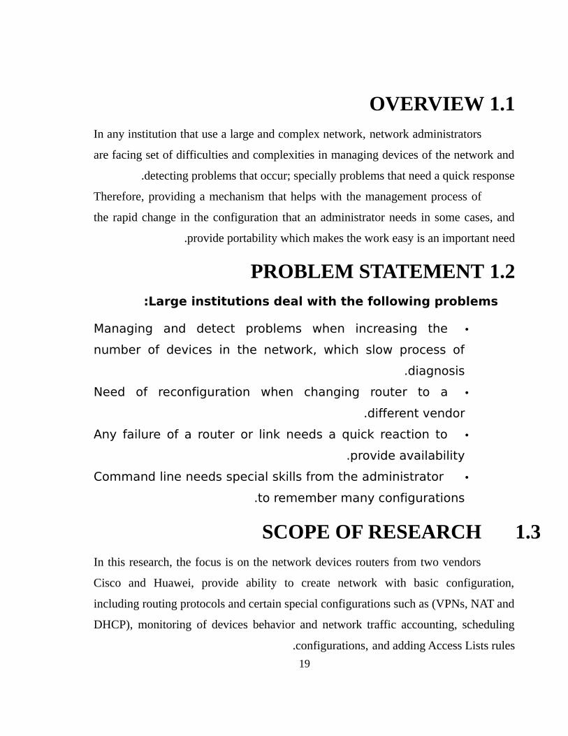
1.1 OVERVIEWIn any institution that use a large and complex network, network administrators
are facing set of difficulties and complexities in managing devices of the network and
detecting problems that occur; specially problems that need a quick response .
Therefore, providing a mechanism that helps with the management process of
the rapid change in the configuration that an administrator needs in some cases, and
provide portability which makes the work easy is an important need.
1.2 PROBLEM STATEMENTLarge institutions deal with the following problems:
•Managing and detect problems when increasing the
number of devices in the network, which slow process of
diagnosis.
•Need of reconfiguration when changing router to a
different vendor .
•Any failure of a router or link needs a quick reaction to
provide availability .
• Command line needs special skills from the administrator
to remember many configurations.
1.3SCOPE OF RESEARCHIn this research, the focus is on the network devices routers from two vendors
Cisco and Huawei, provide ability to create network with basic configuration,
including routing protocols and certain special configurations such as (VPNs, NAT and
DHCP), monitoring of devices behavior and network traffic accounting, scheduling
configurations, and adding Access Lists rules.
19
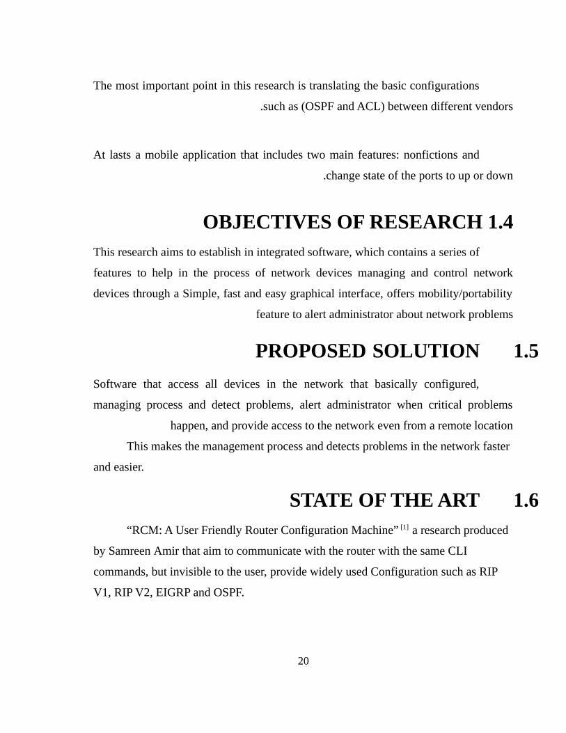
The most important point in this research is translating the basic configurations
such as (OSPF and ACL) between different vendors .
At lasts a mobile application that includes two main features: nonfictions and
change state of the ports to up or down.
1.4 OBJECTIVES OF RESEARCHThis research aims to establish in integrated software, which contains a series of
features to help in the process of network devices managing and control network
devices through a Simple, fast and easy graphical interface, offers mobility/portability
feature to alert administrator about network problems
1.5PROPOSED SOLUTION
Software that access all devices in the network that basically configured,
managing process and detect problems, alert administrator when critical problems
happen, and provide access to the network even from a remote location
This makes the management process and detects problems in the network faster
and easier.
1.6STATE OF THE ART“RCM: A User Friendly Router Configuration Machine” [1] a research produced
by Samreen Amir that aim to communicate with the router with the same CLI
commands, but invisible to the user, provide widely used Configuration such as RIP
V1, RIP V2, EIGRP and OSPF.
20
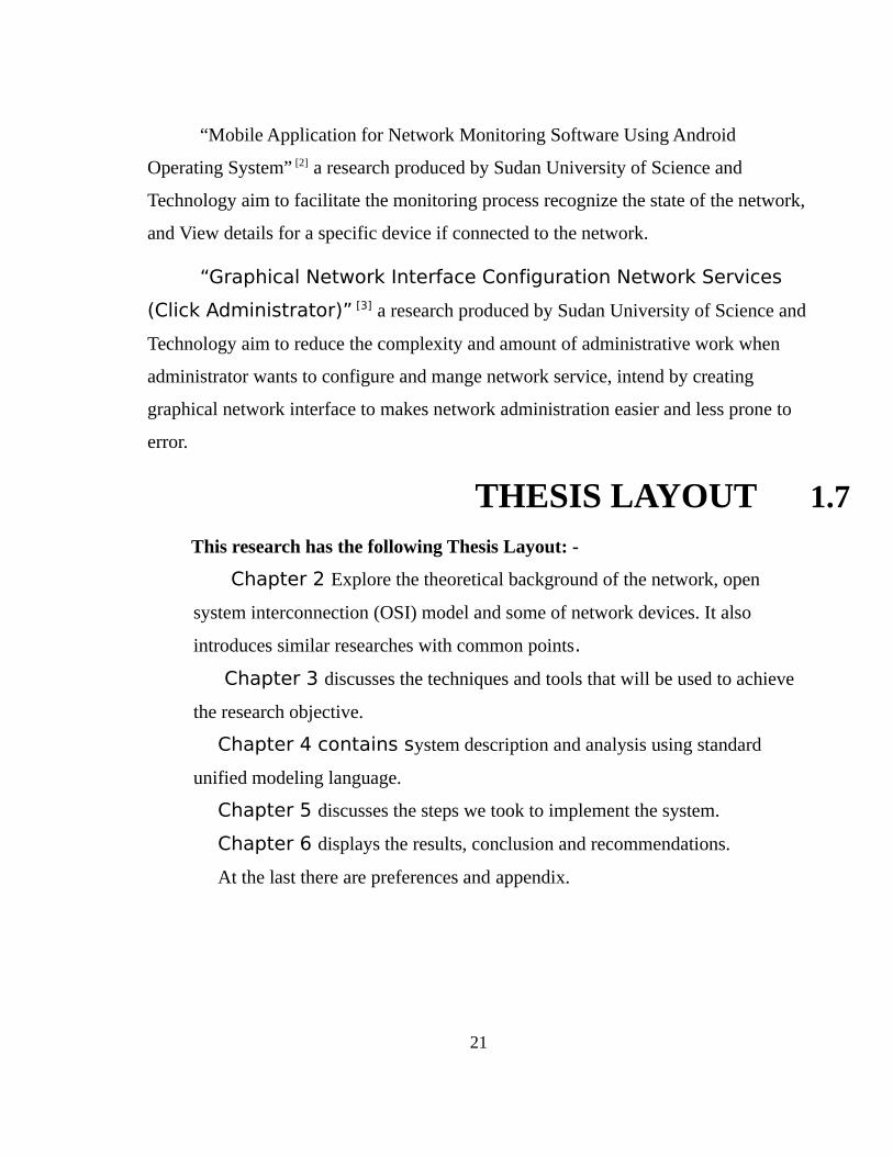
“Mobile Application for Network Monitoring Software Using Android
Operating System” [2] a research produced by Sudan University of Science and
Technology aim to facilitate the monitoring process recognize the state of the network,
and View details for a specific device if connected to the network.
“Graphical Network Interface Configuration Network Services
(Click Administrator)” [3] a research produced by Sudan University of Science and
Technology aim to reduce the complexity and amount of administrative work when
administrator wants to configure and mange network service, intend by creating
graphical network interface to makes network administration easier and less prone to
error.
1.7THESIS LAYOUTThis research has the following Thesis Layout: -
Chapter 2 Explore the theoretical background of the network, open
system interconnection (OSI) model and some of network devices. It also
introduces similar researches with common points.
Chapter 3 discusses the techniques and tools that will be used to achieve
the research objective.
Chapter 4 contains system description and analysis using standard
unified modeling language.
Chapter 5 discusses the steps we took to implement the system.
Chapter 6 displays the results, conclusion and recommendations.
At the last there are preferences and appendix.
21
CHAPTER TWO
BACKGROUND OF THE NETWORK
AND PREVIOUS STUDIES
1.INTRODUCTION
This chapter will touch two major parts; the general description of network
devices and monitoring process to introduce the area of the research and the related
studies to this research to be aware of the state of the art so far.
2.BACKGROUND OF THE NETWORK
2.2.1 Network management
The process of controlling a complex data network to maximize its efficiency
and productivity.
2.2.2 Computer Network
A set of computers connected together to communicate and share resources via
network device by using Ethernet cable, wireless or through radio waves.
2.2.3 Internet
Are a million of connected computing devices (hosts, end-system.(
2.2.4 Network Topology
It is the schematic description of a network arrangement, connecting various
nodes through lines of connection.
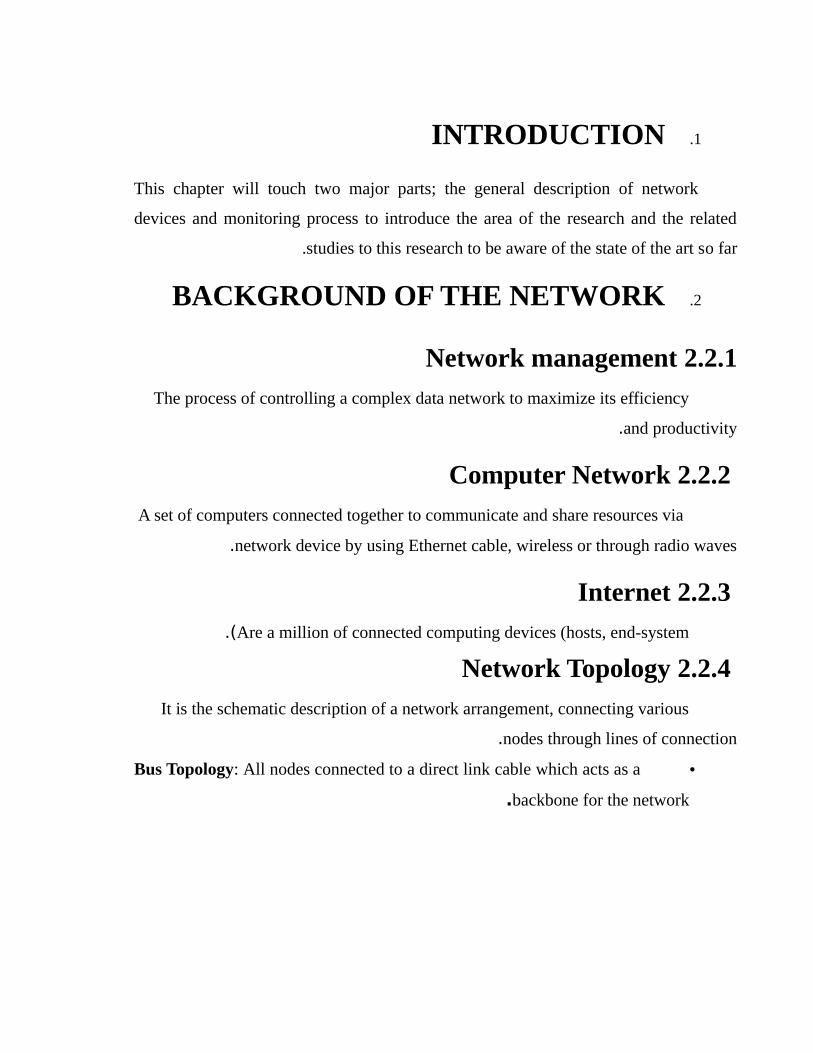
•Bus Topology: All nodes connected to a direct link cable which acts as a
backbone for the network.
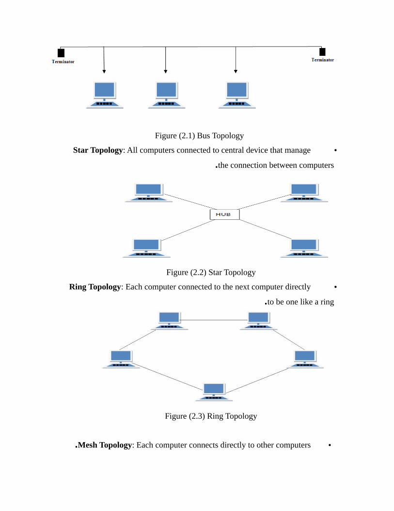
Figure (2.1) Bus Topology
•Star Topology: All computers connected to central device that manage
the connection between computers.
Figure (2.2) Star Topology
•Ring Topology: Each computer connected to the next computer directly
to be one like a ring.
Figure (2.3) Ring Topology
•Mesh Topology: Each computer connects directly to other computers.
Figure (2.4) Mesh Topology
2.2.5 Network Type Based on Size
•LAN (Local Area Network): is a network with simple, short distance
and limited by number of computers such as in room, a floor and building.
•WAN (Wide Area Networks): connects multiple LANs to one another
over great geographic distances such as towns, states, and countries.
•MAN (Metropolitan Area Network): connect multiple geographically
nearby LANs to one another such as a city.[4[
2.2.6 Open Systems Interconnection Model
The OSI reference model architecture divides the network communication into
seven layers. Each layer covers different network activities, equipment, and protocols.
The model defines how each layer communicates and works with the layers directly
above and below it.
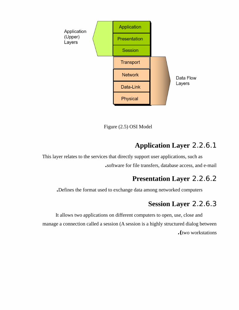
Figure (2.5) OSI Model
2.2.6.1 Application Layer
This layer relates to the services that directly support user applications, such as
software for file transfers, database access, and e-mail.
2.2.6.2 Presentation Layer
Defines the format used to exchange data among networked computers.
2.2.6.3 Session Layer
It allows two applications on different computers to open, use, close and
manage a connection called a session (A session is a highly structured dialog between
two workstations.(
2.2.6.4 Transport Layer
This layer provides an additional connection level beneath the session layer.
The transport layer ensures that packets are delivered error free, in sequence, fragment
and reassembling packets without any losses or duplications .
2.2.6.5 Network Layer
It is responsible for addressing messages and data link. This layer also
determines the route from the source to the destination computer. It determines which
path the data should take based on network conditions, priority of service, and other
factors. It also manages traffic problems on the network, such as switching and routing
of packets and controlling the congestion of data.
2.2.6.6 Data-Link Layer
This layer sends data frames from the network layer to the physical layer. It
controls the electrical impulses that enter and leave the network cable. On the
receiving end, the data-link layer packages raw bits from the physical layer into data
frames.
2.2.6.7 Physical Layer
This layer transmits the unstructured, raw bit stream over a physical medium
(such as the network cable .(
The physical layer is totally hardware-oriented and deals with all aspects of
establishing and maintaining a physical link between communicating computers.
2.2.7 Networking Devices
Equipment that connects directly to a network segment is referred to as a
device.
These devices are broken up into two classifications
•End-User Devices: include computers, printer, scanners, and
other devices that provide services directly to the user.
•Network Devices: include all the devices that connect end-user
devices together to allow them communicate .
2.2.8 Network Devices
A special device used in computer networking and it is responsible of
communication between computers.
2.2.8.1 Type of Network Devices
Hub: A central point device connects group of hosts receives incoming packets,
possibly amplifies the electrical signal, and broadcasts these packets out to all devices
on the network.
Switch: A switch is a multi-port bridge and it operates at OSI data link layer 2.
It stores MAC addresses in an internal lookup table so temporary switched paths are
created between the frame’s source and destination. Some Switches have limited layer
3 IP routing capabilities.
Router: Is an OSI network layer 3 devices that forwards data packets between
computer networks, this device examines incoming packets to determine the
destination address of the data, then examines its internal routing table to choose the
best path for the packet through the network, and switches them to the proper outgoing
port .
Firewall: is a device designed to control the flow of traffic into and out of a
network by examining them against its inner rules. In general, firewalls are installed to
prevent attacks.
2.2.9 Network Address Mechanism
•Internet Protocol address (IP): Is the logical hierarchical address that
is used mainly in computer networks addressing, and it is used by layer 3
devices to determine the exit interface.
• Media Access Control Address (MAC): Is the physical flat address
that is used mainly by switches to determine the exit interface.
•Name: Is the address that mainly used by human to easily remember the
websites; however the PCs use the Domain Name Service (DNS) server to
translate the name into IP address.
2.2.10 Routing
The process of transferring packet of data from source to destination, by
selecting the minimum cost, distance, and/or time path from several alternatives.
Figure (2.6) Routing process
2.2.10.1 Routing Types
•Static routing: Network administrator configures information about
remote networks manually.
•Dynamic routing: Information is learned from other routers, and routing
protocols adjust routes automatically.
•Default routing: Accessing to a network that doesn’t know you and not
exist in your network address when you want to connect to the Internet [5[.
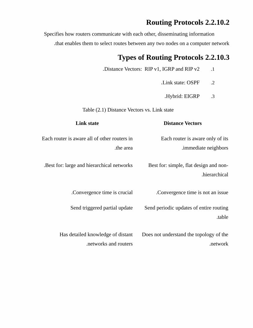
2.2.10.2 Routing Protocols
Specifies how routers communicate with each other, disseminating information
that enables them to select routes between any two nodes on a computer network.
2.2.10.3 Types of Routing Protocols
1.Distance Vectors: RIP v1, IGRP and RIP v2.
2.Link state: OSPF.
3.Hybrid: EIGRP.
Table (2.1) Distance Vectors vs. Link state
Distance VectorsLink state
Each router is aware only of its
immediate neighbors.
Each router is aware all of other routers in
the area.
Best for: simple, flat design and non-
hierarchical .
Best for: large and hierarchical networks.
Convergence time is not an issue.Convergence time is crucial.
Send periodic updates of entire routing
table.
Send triggered partial update
Does not understand the topology of the
network.
Has detailed knowledge of distant
networks and routers.
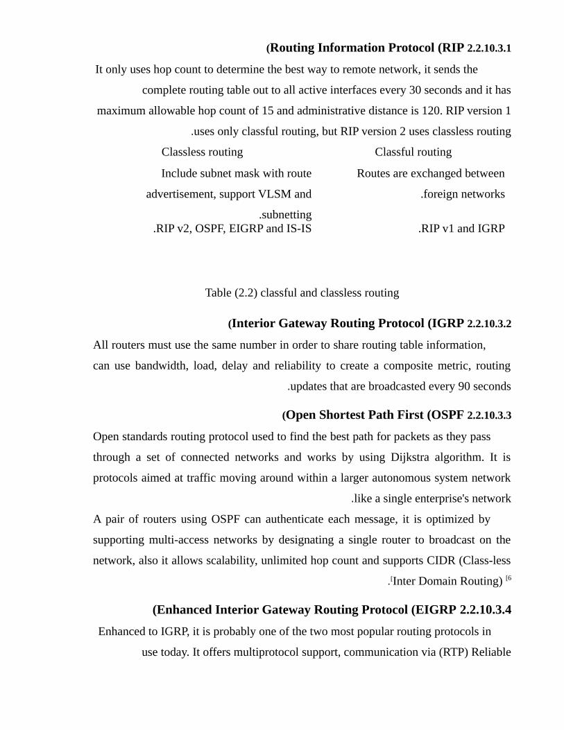
2.2.10.3.1 Routing Information Protocol (RIP(
It only uses hop count to determine the best way to remote network, it sends the
complete routing table out to all active interfaces every 30 seconds and it has
maximum allowable hop count of 15 and administrative distance is 120. RIP version 1
uses only classful routing, but RIP version 2 uses classless routing.
Classful routingClassless routing
Routes are exchanged between
foreign networks.
Include subnet mask with route
advertisement, support VLSM and
subnetting.RIP v1 and IGRP.RIP v2, OSPF, EIGRP and IS-IS.
Table (2.2) classful and classless routing
2.2.10.3.2 Interior Gateway Routing Protocol (IGRP(
All routers must use the same number in order to share routing table information,
can use bandwidth, load, delay and reliability to create a composite metric, routing
updates that are broadcasted every 90 seconds.
2.2.10.3.3 Open Shortest Path First (OSPF(
Open standards routing protocol used to find the best path for packets as they pass
through a set of connected networks and works by using Dijkstra algorithm. It is
protocols aimed at traffic moving around within a larger autonomous system network
like a single enterprise's network .
A pair of routers using OSPF can authenticate each message, it is optimized by
supporting multi-access networks by designating a single router to broadcast on the
network, also it allows scalability, unlimited hop count and supports CIDR (Class-less
Inter Domain Routing) [6[.
2.2.10.3.4 Enhanced Interior Gateway Routing Protocol (EIGRP(
Enhanced to IGRP, it is probably one of the two most popular routing protocols in
use today. It offers multiprotocol support, communication via (RTP) Reliable
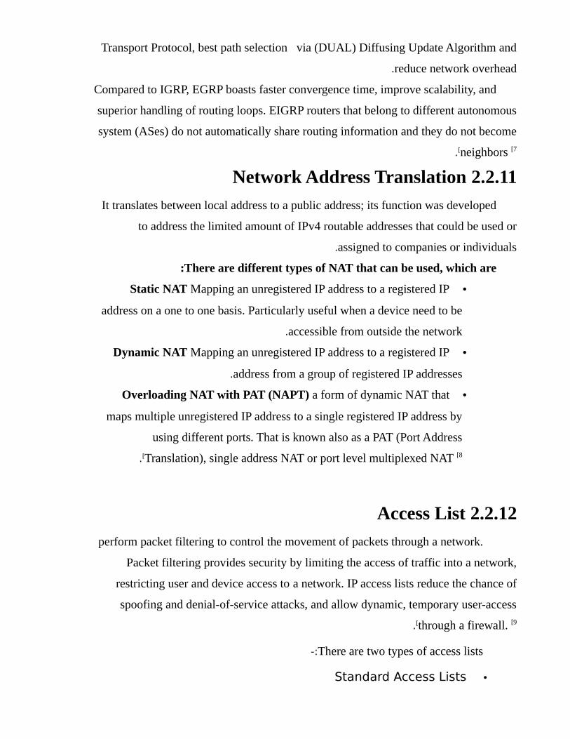
Transport Protocol, best path selection via (DUAL) Diffusing Update Algorithm and
reduce network overhead .
Compared to IGRP, EGRP boasts faster convergence time, improve scalability, and
superior handling of routing loops. EIGRP routers that belong to different autonomous
system (ASes) do not automatically share routing information and they do not become
neighbors [7[ .
2.2.11 Network Address Translation
It translates between local address to a public address; its function was developed
to address the limited amount of IPv4 routable addresses that could be used or
assigned to companies or individuals.
There are different types of NAT that can be used, which are:
•Static NAT Mapping an unregistered IP address to a registered IP
address on a one to one basis. Particularly useful when a device need to be
accessible from outside the network .
•Dynamic NAT Mapping an unregistered IP address to a registered IP
address from a group of registered IP addresses.
•Overloading NAT with PAT (NAPT) a form of dynamic NAT that
maps multiple unregistered IP address to a single registered IP address by
using different ports. That is known also as a PAT (Port Address
Translation), single address NAT or port level multiplexed NAT [8[.
2.2.12 Access List
perform packet filtering to control the movement of packets through a network.
Packet filtering provides security by limiting the access of traffic into a network,
restricting user and device access to a network. IP access lists reduce the chance of
spoofing and denial-of-service attacks, and allow dynamic, temporary user-access
through a firewall. [9[.
There are two types of access lists-:
•Standard Access Lists
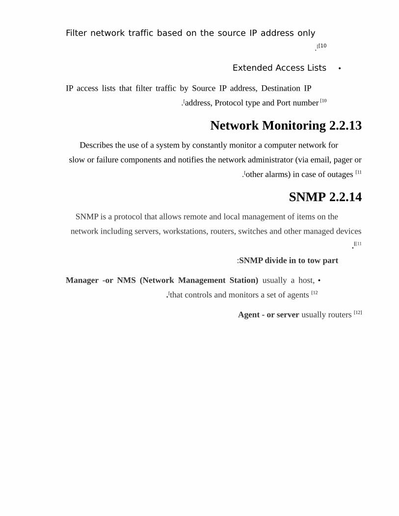
Filter network traffic based on the source IP address only [10[.
•Extended Access Lists
IP access lists that filter traffic by Source IP address, Destination IP
address, Protocol type and Port number [10[.
2.2.13 Network Monitoring
Describes the use of a system by constantly monitor a computer network for
slow or failure components and notifies the network administrator (via email, pager or
other alarms) in case of outages [11[.
2.2.14 SNMP
SNMP is a protocol that allows remote and local management of items on the
network including servers, workstations, routers, switches and other managed devices [11[.
SNMP divide in to tow part:
•Manager -or NMS (Network Management Station) usually a host,
that controls and monitors a set of agents [12[.
Agent - or server usually routers [12]
2.3 PREVIOUS STUDIES
2.3.1 RCM: A user friendly Router Configuration
Machine
This paper presents a graphical user interface configuration for Cisco routers by
Using Visual C # .NET as a language of programming to create the applications that
communicates with the Cisco Internetwork Operating System to configure the router .
The Communication between Application and Cisco Router is performed using
router console port and then the application sends the CLI commands to the IOS using
graphical interfaces part; the interface is created for all various types of protocols and
features that are supported.
This study has provision flexible, easy to use, easy to implement and secure
solution to the conventional Command Line Interface (CLI) method and as well as to
the complex GUI architecture of Cisco Configuration Professional. It further makes it
important that RCM communicates with the router done with the same CLI commands
but invisible to the user .
RCM configures the most widely used configuration commands and the interior
routing protocols such as RIP V1, RIP V2, EIGRP and OSPF. It also provides protocol
authentication for interior routing protocols .
34
2.3.2 Mobile Application for Network Monitoring
Software Using Android Operating System:
This study aims to facilitate the monitoring process; there is too much delay
between the moment of the fall of the device or server and the moment the message
arrival to the Administrator or by email.
So this research designs a Monitoring Application that works in an effective and
strong way on the mobile smart phone, This application allows mobility property; So
that the network administrator know what is happening in the network from anywhere
by opening the application only, It is also expected to solve the problem of delays by
sending a notification in real time of failure in a particular device.
This study has recognized the state of the network, by knowing the network
connected-devices and devices that are not connect also View details of a specific
device if connected to the network, also showing services associated with each device,
and view details on the status of each service in the devices.
2.3.3 Graphical Network Interface
Configuration Network Services (Click
Administrator:(This research aims to reduce the complexity and amount of
administrative work when administrator wants to configure and
mange network service, intend by creating graphical network
interface to makes network administration easier and less prone to
error.
Running services (DHCP, DNS, Proxy, NSF AND FTP) using
Ubuntu server11.04, programing language C++, testing software in
35
a LAN consist of 20 devices, there portioning system is Windows and
Ubuntu.
36
CAPTER THREE
TOOLS AND TECHNIQUE
3.1OVERVIEW
This chapter describes the tools and techniques that will be used; to achieve the
objectives of the project .
3.2 TOOLS AND TECHNIQUE
3.2.1 Operating System
An OS is a program that controls the execution of application programs and
acts as an interface between applications and the computer hardware.
3.2.1.1 Windows
An operating system and Graphical User Interface (GUI) created by Microsoft,
allows easy “point and click” operations to provide a user friendly environment .
Windows begins with Microsoft developed the first IBM personal computer
and referred to as MS-DOS. The initial version, MS-DOS 1.0, was released in August
1981; by 1990 Microsoft create a successful Graphical User Interface (GUI) operating
system called windows 3.0 which implemented as a layer on top of MS-DOS .
Over the years Windows is developed to reach multiple versions with the same
fundamentals [13[.
3.2.1.2Linux
An open source operating system began in 1991 with the commencement of a
personal project by Finnish student Linus Torvalds to create a new free operating
system kernel. Since then, the resulting kernel has been marked by constant growth
throughout its history; it has grown from a small number of C files under a license
38
prohibiting commercial distribution to more than 18 million lines of source code under
the GNU General Public License v2 [14[ .
3.2.1.3Android
Android is an open source mobile operating system based on Linux kernel and
currently developed by Google. With a user interface designed primarily for
touchscreen mobile devices such as smartphones and tablet computers [15[.
Advantages to developing for the Android platform
•Zero startup costs to begin development: The
development tools for the platform are free to download
•Freedom to innovate in Android OS due to its open-source
platform
•Open distribution model: developers are free to distribute
their applications through other distribution channels as
well .
•Multi-platform support: There are a wide variety of
hardware devices powered by the Android OS, including
many different phones and tablet computers.
Development for the platform can occur on Windows, Mac
OS or Linux.
3.2.1.4Internetwork operating system (IOS(
Cisco IOS (Internetwork Operating System) is a proprietary operating system
that runs on most Cisco Systems routers and switches .
The core function of Cisco IOS is to enable data communications between
network nodes. In addition to routing and switching, Cisco IOS offers dozens of
additional services that an administrator can use to improve the performance and
security of network traffic. Such services include encryption, authentication, 39
firewall capabilities, policy enforcement, deep packet inspection, Quality of Service,
intelligent routing and proxy capability [16[.
3.2.2 JAVA
A very popular programming language developed by Sun
Microsystems; it is the global standard for developing mobile
applications, games, Web-based content, and enterprise software,
Java is a C-language derivative; so its syntax rules look much like C's [17[ .
Some of the Java’s important features:
•Easy to learn and understand [18[ .
•Designed to be platform-independent and secure, using
virtual machines [18[ .
•Object-oriented (It is close to the reality perceived in
dealing with things) [18[.
3.2.3 Unified Modeling Language (UML(
UML first appeared in the 1990's as an effort to select the best elements of
many modeling systems proposed at the time, and to combine them into a single
coherent notation. It has since become the industry standard for software modeling and
design, as well as the modeling of other processes in the scientific and business
worlds. The UML is a tool for specifying software systems. Standardized diagram
types to help you describe and visually map a software system's design and structure.
Using UML it is possible to model just about any kind of application, both specifically
and independently of a target platform. The use of UML as a tool for defining the
structure of a system is a very useful way to manage large, complex systems. Having a
clearly visible structure makes it easy to introduce new people to an existing project .
40
Some UML features:
•UML breaks the complex system into discrete pieces that
can be understood easily .
•Hand over the system to new team becomes easier .
•Complex system can be understood by the disparate
developers who are working on different platforms.
•UML model is not a system or platform specific. It unifies
all disparate developers under one roof .
3.2.3.1 UML Diagrams
3.2.3.1.1 Use Case Diagram
Use case diagram at its simplest is a representation of a user's interaction with
the system that shows the relationship between the user and the different use cases in
which the user is involved. A use case diagram can identify the different types of users
of a system and the different use cases .
3.2.3.1.2Sequence diagram
Sequence diagram is an interaction diagram that shows how processes operate
with one another and in what order. A sequence diagram shows object interactions
arranged in time sequence. It depicts the objects and classes involved in the scenario
and the sequence of messages exchanged between the objects needed to carry out the
functionality of the scenario. Sequence diagrams are typically associated with use case
realizations in the Logical View of the system under development. Sequence diagrams
are sometimes called event diagrams or event scenarios.
3.2.3.1.3Deployment diagram
41
Deployment diagram depicts a static view of the run-time configuration of
processing nodes and the components that run on those nodes. In other words,
deployment diagrams show the hardware for your system, the software that is installed
on that hardware, and the middleware used to connect the disparate machines to one
another.
3.2.3.2 Enterprise Architect
Is a program that is used to design and manage the schemes UML, this program
is fast and easy to use, and it features reduce the costs spent on the follow-up course of
the project under development [20[.
3.2.4 Extensible Markup Language (XML(
An extensible Markup Language, which is a language that can be used to
describe data in a meaningful way. Virtually anywhere there is a need to store data,
especially where it may need to be consumed by more than one application
It defines a set of rules for encoding documents in a format, which is both
human readable and machine-readable; one of the aims of XML is to implement a
clear separation between data and presentation. It is defined by the W3C's XML 1.0
Specification and by several other related specifications, all of which are free open
standards [21[ .
3.2.5 Java Remote Method Invocation (RMI(
An API that provides a mechanism to create distributed application in java that
allows an object to invoke methods on an object running in another JVM. The RMI
provides remote communication between the applications using two objects stub and
skeleton [22[.
42
3.2.6 XML Remote Procedure Call The XML-RPC protocol was created in 1998 by Dave Winer of User Land
Software and Microsoft which uses XML to encode its calls and HTTP as a transport
mechanism [23[.
3.2.7 Compression between above software’s:
Next Table shows the comparison between java RMI and XML RPC that can
used to create connection between server and client.
Technology Advantages Disadvantages
43
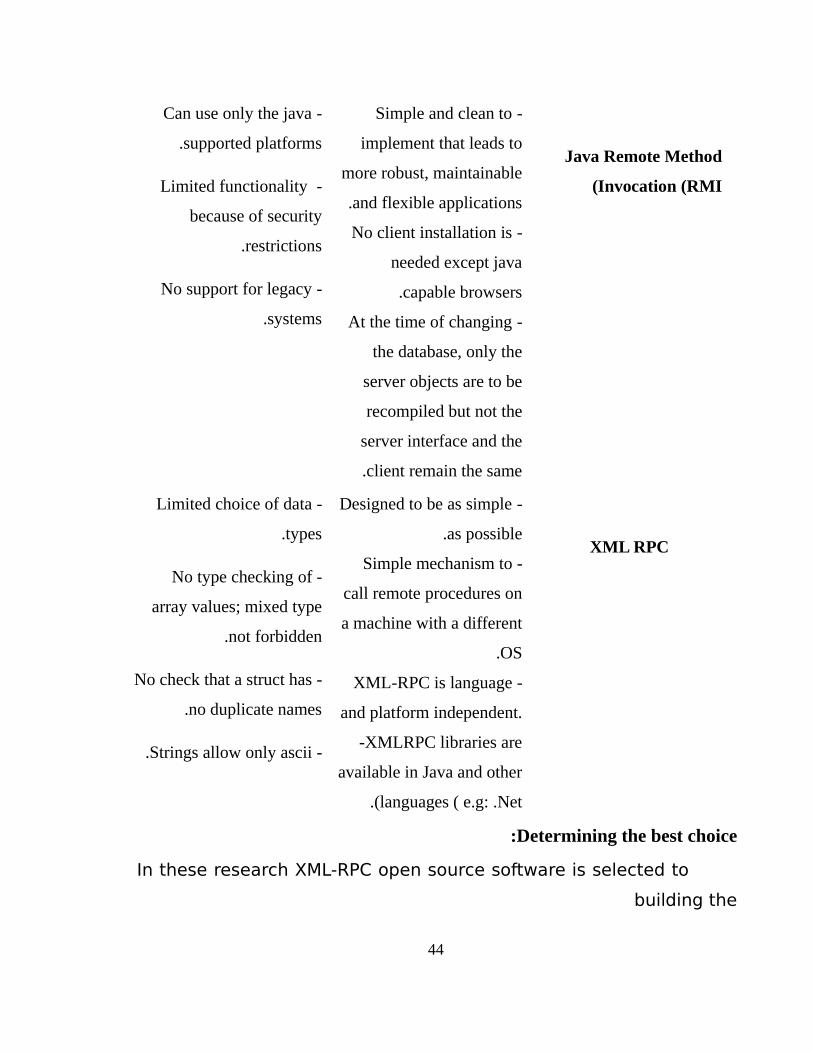
Java Remote Method
Invocation (RMI(
-Simple and clean to
implement that leads to
more robust, maintainable
and flexible applications.
-No client installation is
needed except java
capable browsers.
-At the time of changing
the database, only the
server objects are to be
recompiled but not the
server interface and the
client remain the same.
-Can use only the java
supported platforms.
-Limited functionality
because of security
restrictions.
-No support for legacy
systems.
XML RPC
-Designed to be as simple
as possible.
- Simple mechanism to
call remote procedures on
a machine with a different
OS.
- XML-RPC is language
and platform independent.
-XMLRPC libraries are
available in Java and other
languages ( e.g: .Net.(
- Limited choice of data
types.
- No type checking of
array values; mixed type
not forbidden.
- No check that a struct has
no duplicate names.
- Strings allow only ascii.
Determining the best choice:
In these research XML-RPC open source software is selected to
building the
44
Connection between the server and client:
•the architecture is simple compared with java RMI
•Support for many programming language
•Simple user interface
3.2.8 Eclipse
A general purpose open platform that facilitates and encourages the
development of third party plug-ins. It is known as IDE, provides tools for coding,
building, running and debugging applications. Originally designed for Java, now
supports many other languages [24[.
Advantages [24[
•Faster code/compile/run cycles (real time .(
•Open source (free .(
•Extensible (plug-in .(
Disadvantages [24[
•Pretty heavyweight .
•Requires JRE .
•Difficult to Learn
45
3.2.9 Android Studio
Official IDE for Android platform development, was announced on May 16,
2013 at the Google I/O conference, it is available for download on Windows and
Linux [25[.
Android Studio features
•Gradle -based build support.
•Android-specific refactoring and quick fixes.
•ProGuard integration and app-signing capabilities.
•Template-based wizards to create common Android
designs and components.
•A rich layout editor that allows users to drag-and-drop UI
components, option to preview layouts on multiple screen
configurations.[12[
•Built-in support for Google Cloud Platform, enabling
integration with Google Cloud Messaging and App Engine.
3.2.10 Structured Query Language (SQL(
A standard language used to access and manipulate databases in: MySQL, SQL
Server, Access, Oracle and other database systems .
SQL consists of a data definition language, data manipulation language, and a
data control language. The scope of SQL includes data insert, select, update and delete,
schema creation and modification, and data access control .
Some of the SQL important features :
•Portable: Databases using SQL can be moved from device
to another without any problems .
46
•Easy to learn and understand
•Integrates with Java: by using an API known as JDBC (Java
Database Connectivity .(
3.2.11 GNS3
A Graphical Network Simulator program developed primarily by Jeremy
Grossman. It allows emulation of complex networks and running operating systems
such as Windows XP Professional or Ubuntu Linux in a virtual environment on the
computer, also it allows the same type of emulation using Cisco Internetwork
Operating Systems [26[.
Advantages
•GNS3 is an open source, free program offers an easy way to
design and build networks of any size, pre-deployment testing
without the need for network hardware.
•Test more than 20 different network vendors in risk-free virtual
environment.
•Create dynamic network maps for troubleshooting and proof of
concept (POC) testing.
•Connect virtual network to any real network.
Disadvantages
•Slower throughput than real equipment
•The switching functionality is very limited.
•Only a few older Cisco router platforms supported.
•High CPU utilization
•It can’t take the place of a real router.
47
3.2.12 Secure Shell (SSHv2(
An application protocol and software suite that allows secure network services
over an insecure network such as the public Internet. It replaces other, insecure
protocols and services, including Telnet and FTP. It can be used for remote terminal
connections, remote file copying, and forwarding X11 sessions (on UNIX) as well as
arbitrary TCP ports through a secure tunnel. It is based on strong encryption and
authentication [27[.
3.2.13 TFTP Protocol
TFTP is an acronym for Trivial File Transfer Protocol and is a forerunner
protocol of FTP. The TFTP protocol is basically used for information transfer from a
server to a client or vice versa. TFTP is intended to be used when bootstrapping disk
less systems are used. This is also used by memory less devices like routers, switches
to get their bootstrap information from their servers.
TFTP protocol uses UDP for transferring files between server and the client on
port "69", by default. When TFTP is used, the file that is getting transferred is split up
into packets each containing 512 bytes of data. The completion of the transfer is
informed to the receiver by sending a packet that has 0-511 bytes [28[ .
3.2.14 System log server
Syslog is a way for network devices to send event messages to a logging server
usually known as a Syslog server. The Syslog protocol is supported by a wide range of
devices and can be used to log different types of events. For example, a router might
send messages about users logging on to console sessions, while a web-server might
log access-denied events.48
Most network equipment, like routers and switches, can send Syslog messages,
as do most firewalls [29[.
By using this tools and techniques the research achieved its
objectives.
49
CHAPTER FOUR
SYSTEM DESCRIPTION AND ANALYSIS
4.1 INTRODUCTION This chapter addresses the system functions and its general description, clarifies
the system components, and also deals with the detailed analysis of the operations of
the system using the UML schemes.
4.2 SYSTEM DESCRIPTION The system provides to the administrator the ability to manage and control the
network devices followed by the basic stage of doing preparation configurations for
routers and firewall. The first function of the system is to help creating simplified
network design and put the basic configurations, through using an effective graphical
user interface GUI .
The second stage is connecting devices with the server software using the
console port, and applied all configurations to the device by desktop software after that
placed devices on the operating environment. That was the second most important
function for this system which is connecting the software server with network which
gives important features for management .
The last function is to access the network through a mobile application when
the administrator is away from the work place.
4.3 SYSTEM ENVIRONMENT The system consists of a desktop application, smart phone client and server. The
server connects to all routers through SSH.
51
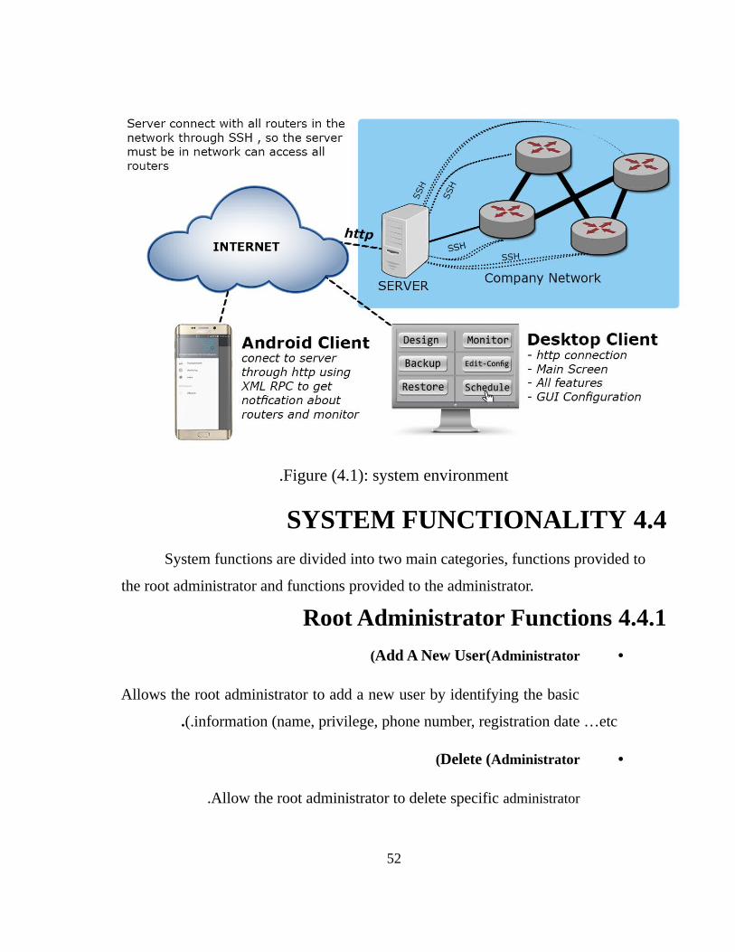
Figure (4.1): system environment.
4.4 SYSTEM FUNCTIONALITYSystem functions are divided into two main categories, functions provided to
the root administrator and functions provided to the administrator.
4.4.1 Root Administrator Functions
•Add A New User(Administrator(
Allows the root administrator to add a new user by identifying the basic
information (name, privilege, phone number, registration date …etc(..
•Delete (Administrator(
Allow the root administrator to delete specific administrator.
52
•Preparation Configurations
It allows the administrator to prepare basics configuration including
routing protocols and certain special configurations such as (VPNs), (NAT),
(DHCP) and (QoS.(
•Monitoring
Allows to monitor devices behavior and network traffic accounting,
gives statistical performance of devices and overview of the flow in the
network.
•Edit Configurations
This feature allows editing many Configuration such as (VPNs), (NAT),
(DHCP) and (QoS.(
•Backup
Allows saving all configurations of specified routers in database.
•Restore
It allows the administrator to restore all Configurations in old (Cisco)
routers to the new one even the routers that are from different vendors such as
(Huawei) the system translates and reconfigure the new device.
•Scheduling
Allows defining a set of configurations that are automatically executing
in a given time.
•Notifications
53
Alert the administrator when there are critical problems.
4.4.2 Administrator Functions
The administrator has the same functions as the root administrator except that it
cannot add or delete an administrator because this operation is limited only to the root
administrator.
4.5 ANALYSIS USING UML SCHEMES To analyze this system using UML diagrams three schemes were adopted:
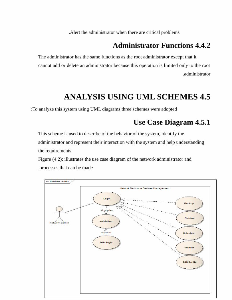
4.5.1 Use Case Diagram
This scheme is used to describe of the behavior of the system, identify the
administrator and represent their interaction with the system and help understanding
the requirements
Figure (4.2): illustrates the use case diagram of the network administrator and
processes that can be made.
54
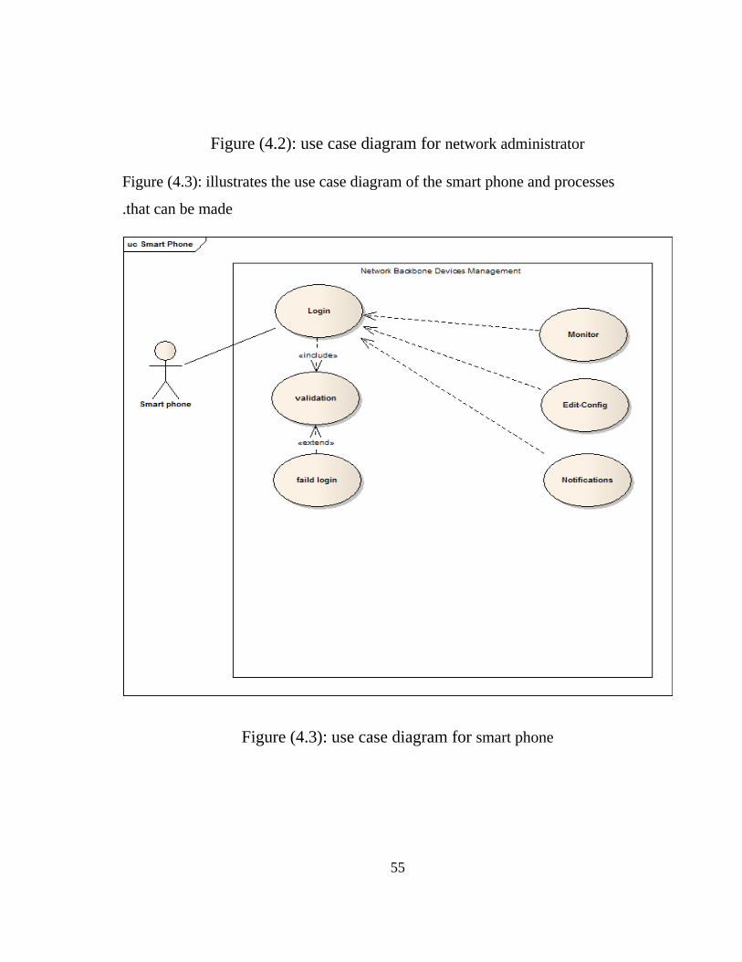
Figure (4.2): use case diagram for network administrator
Figure (4.3): illustrates the use case diagram of the smart phone and processes
that can be made.
Figure (4.3): use case diagram for smart phone
55
4.5.2 Sequence Diagram
This scheme is used to show how processes operate with one another and in
which order they operate, used to show the flow of data and messages between the
various system components and it’s an essential component used in processes related
to analysis, design and documentation.
The research contains seven sequence diagrams for the system each of them
illustrates a function provided by the system whether to the administrator or
smartphone.
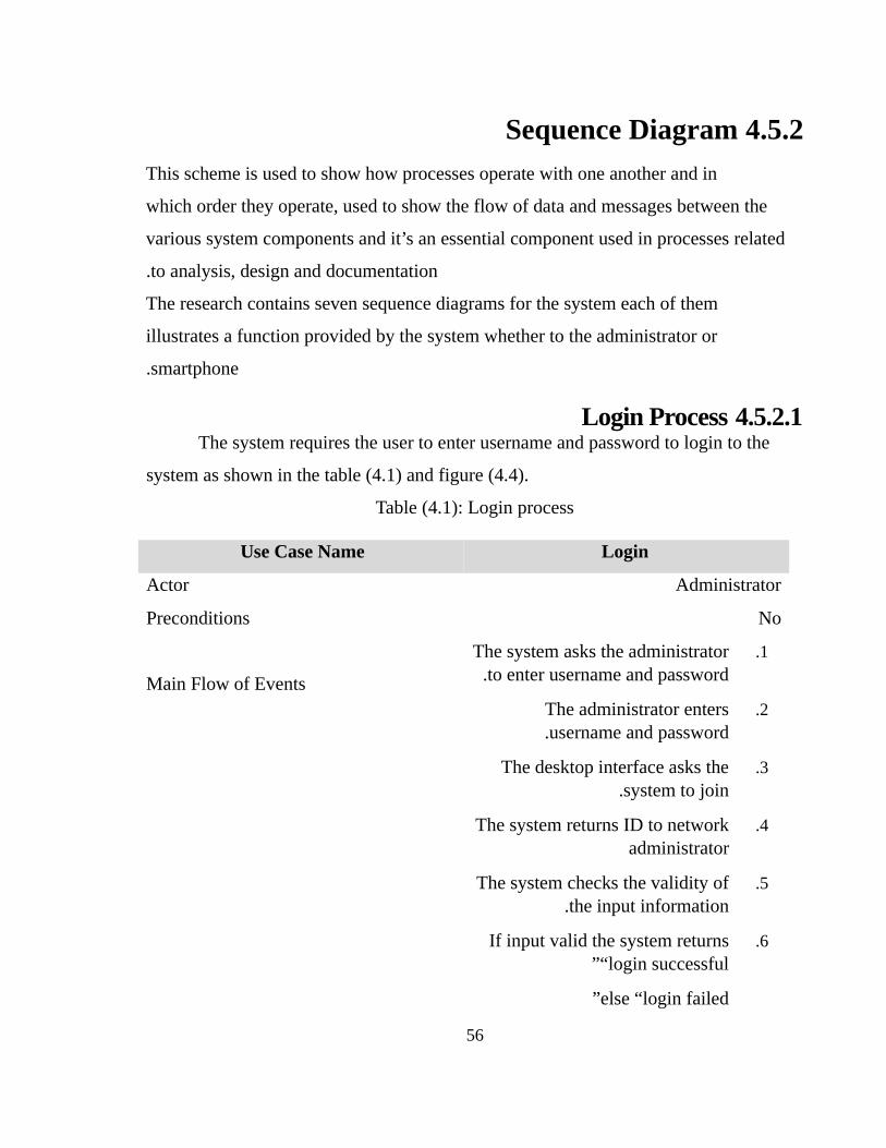
4.5.2.1 Login ProcessThe system requires the user to enter username and password to login to the
system as shown in the table (4.1) and figure (4.4).
Table (4.1): Login process
Use Case Name Login
Actor Administrator
Preconditions No
Main Flow of Events
1.The system asks the administrator to enter username and password.
2.The administrator enters username and password.
3.The desktop interface asks the system to join.
4.The system returns ID to network administrator
5.The system checks the validity of the input information.
6.If input valid the system returns “login successful”
else “login failed”
56
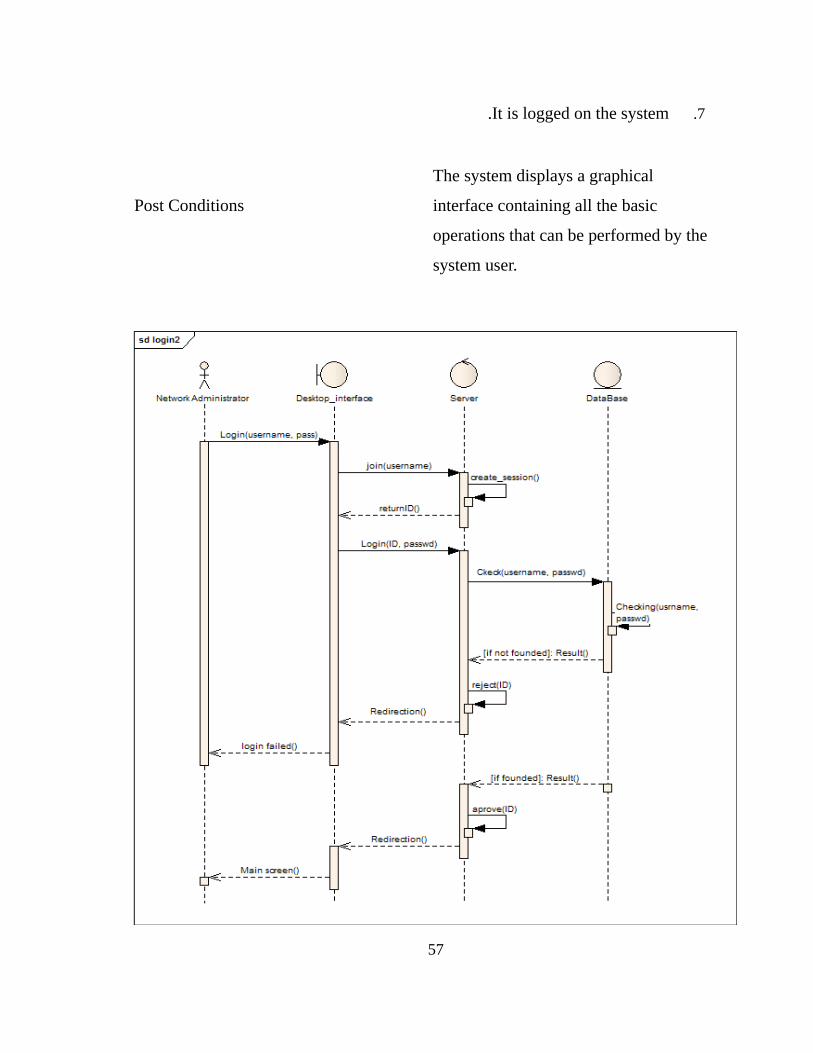
7.It is logged on the system.
Post Conditions
The system displays a graphical
interface containing all the basic
operations that can be performed by the
system user.
57
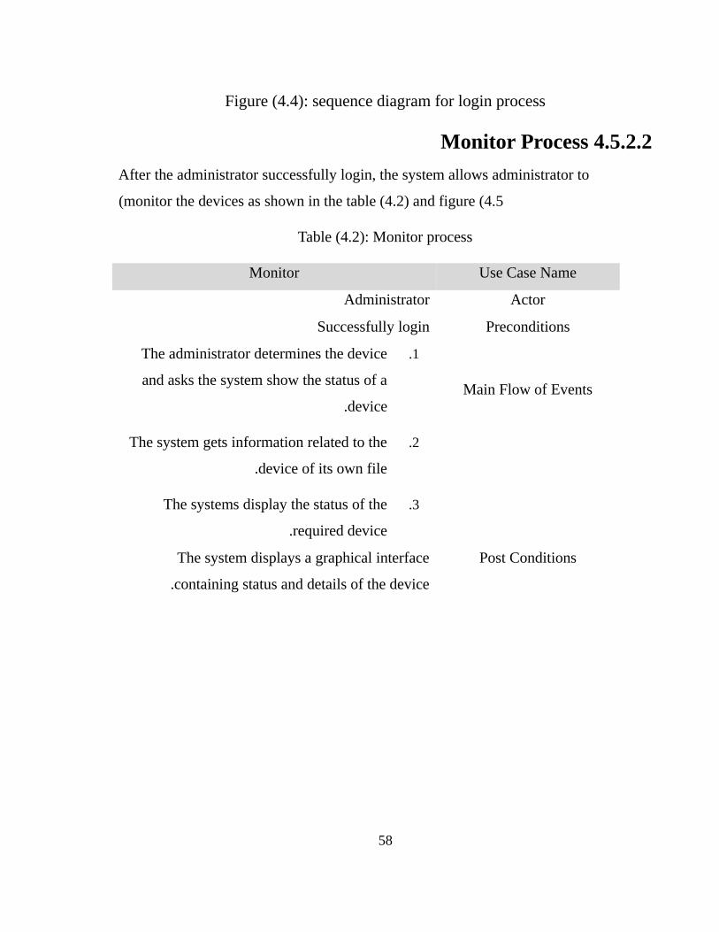
Figure (4.4): sequence diagram for login process
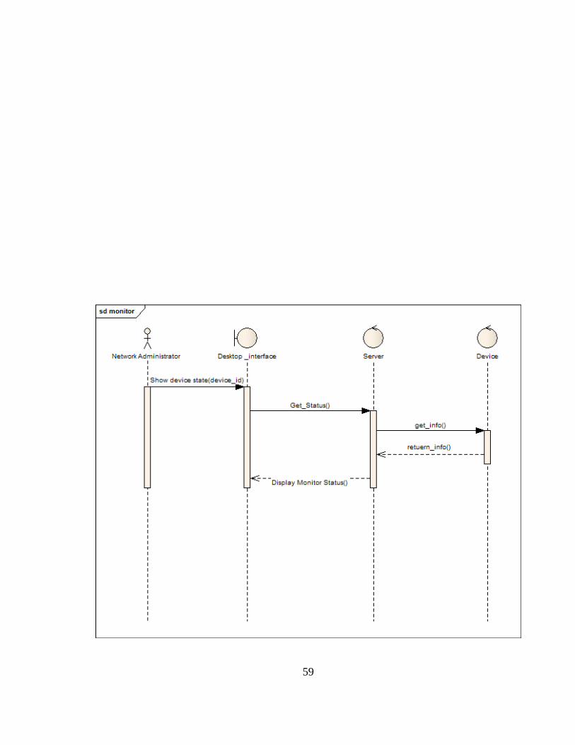
4.5.2.2 Monitor Process
After the administrator successfully login, the system allows administrator to
monitor the devices as shown in the table (4.2) and figure (4.5(
Table (4.2): Monitor process
Use Case NameMonitor
ActorAdministrator
PreconditionsSuccessfully login
Main Flow of Events
1.The administrator determines the device
and asks the system show the status of a
device .
2.The system gets information related to the
device of its own file.
3.The systems display the status of the
required device.
Post ConditionsThe system displays a graphical interface
containing status and details of the device.
58
59
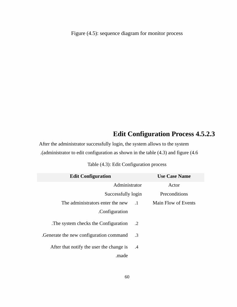
Figure (4.5): sequence diagram for monitor process
4.5.2.3 Edit Configuration Process After the administrator successfully login, the system allows to the system
administrator to edit configuration as shown in the table (4.3) and figure (4.6 .(
Table (4.3): Edit Configuration process
Use Case NameEdit Configuration
ActorAdministrator
PreconditionsSuccessfully login
Main Flow of Events1.The administrators enter the new
Configuration.
2.The system checks the Configuration.
3.Generate the new configuration command.
4.After that notify the user the change is
made.
60

Post ConditionsThe system displays message illustrate that the
edit completed successfully .
61
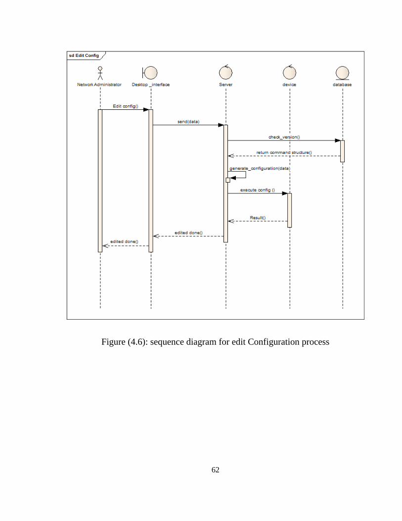
Figure (4.6): sequence diagram for edit Configuration process
62
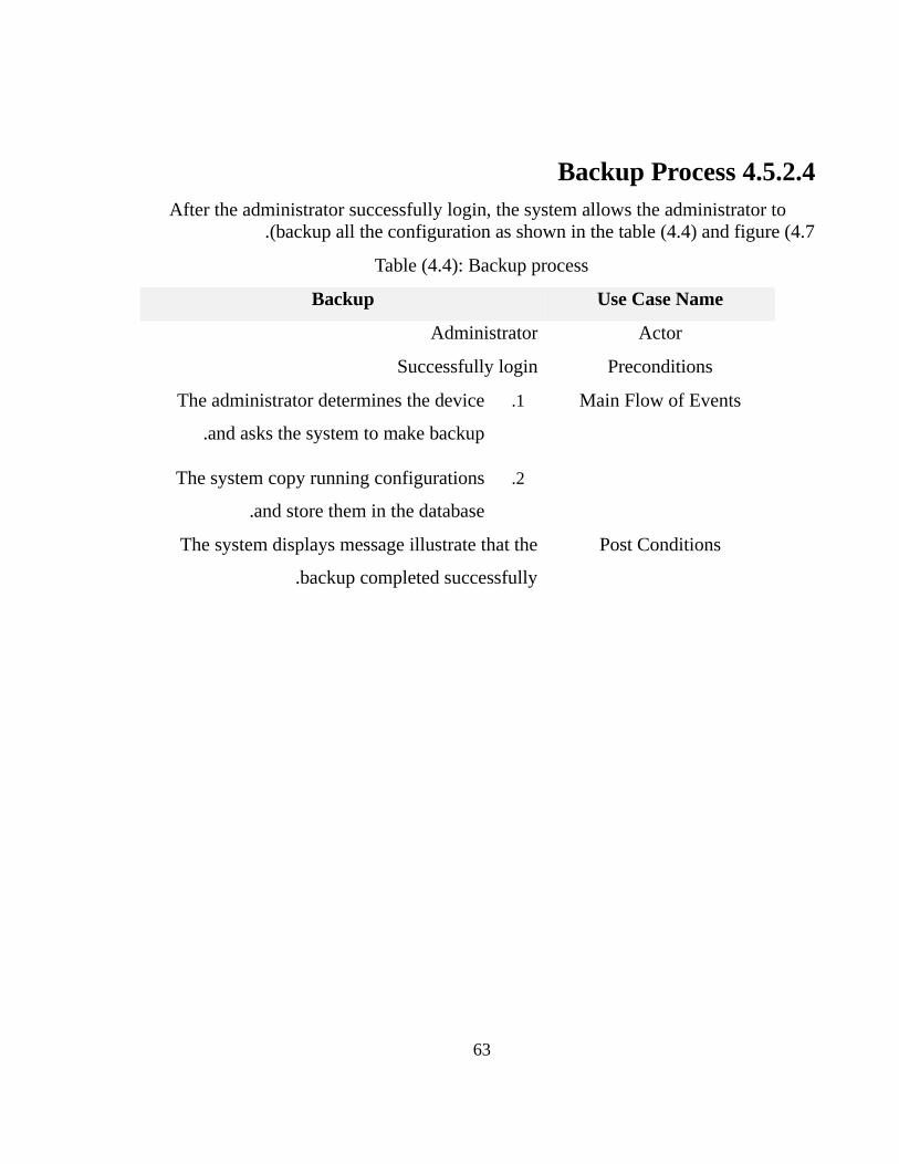
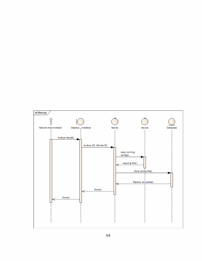
4.5.2.4 Backup Process After the administrator successfully login, the system allows the administrator to
backup all the configuration as shown in the table (4.4) and figure (4.7.(
Table (4.4): Backup process
Use Case NameBackup
ActorAdministrator
PreconditionsSuccessfully login
Main Flow of Events1.The administrator determines the device
and asks the system to make backup.
2.The system copy running configurations
and store them in the database .
Post ConditionsThe system displays message illustrate that the
backup completed successfully .
63
64
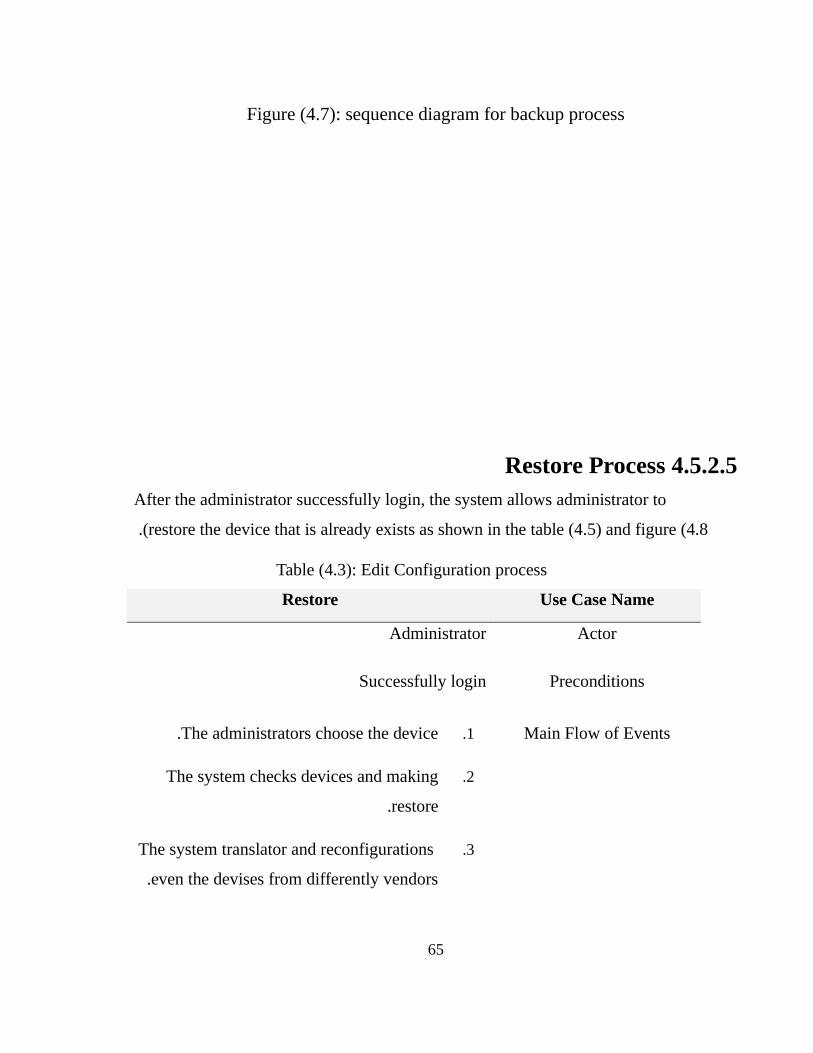
Figure (4.7): sequence diagram for backup process
4.5.2.5 Restore Process After the administrator successfully login, the system allows administrator to
restore the device that is already exists as shown in the table (4.5) and figure (4.8 .(
Table (4.3): Edit Configuration process
Use Case NameRestore
ActorAdministrator
PreconditionsSuccessfully login
Main Flow of Events1.The administrators choose the device.
2.The system checks devices and making
restore.
3. The system translator and reconfigurations
even the devises from differently vendors.
65
4.It restores the devices .
Post ConditionsThe system displays message illustrate that the
operation completed successfully .
66
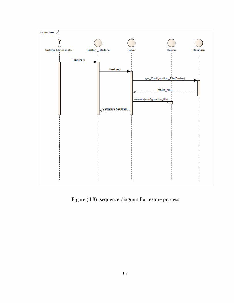
Figure (4.8): sequence diagram for restore process
67
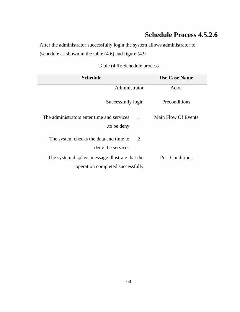
4.5.2.6 Schedule Process After the administrator successfully login the system allows administrator to
schedule as shown in the table (4.6) and figure (4.9(
Table (4.6): Schedule process
Use Case NameSchedule
ActorAdministrator
PreconditionsSuccessfully login
Main Flow Of Events1.The administrators enter time and services
to be deny.
2.The system checks the data and time to
deny the services.
Post ConditionsThe system displays message illustrate that the
operation completed successfully .
68
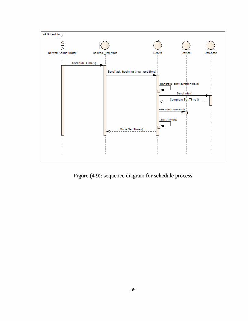
Figure (4.9): sequence diagram for schedule process
69
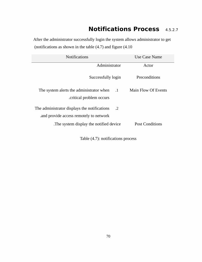
4.5.2.7Notifications Process
After the administrator successfully login the system allows administrator to get
notifications as shown in the table (4.7) and figure (4.10 (
Use Case NameNotifications
ActorAdministrator
PreconditionsSuccessfully login
Main Flow Of Events1.The system alerts the administrator when
critical problem occurs.
2.The administrator displays the notifications
and provide access remotely to network .
Post ConditionsThe system display the notified device.
Table (4.7): notifications process
70
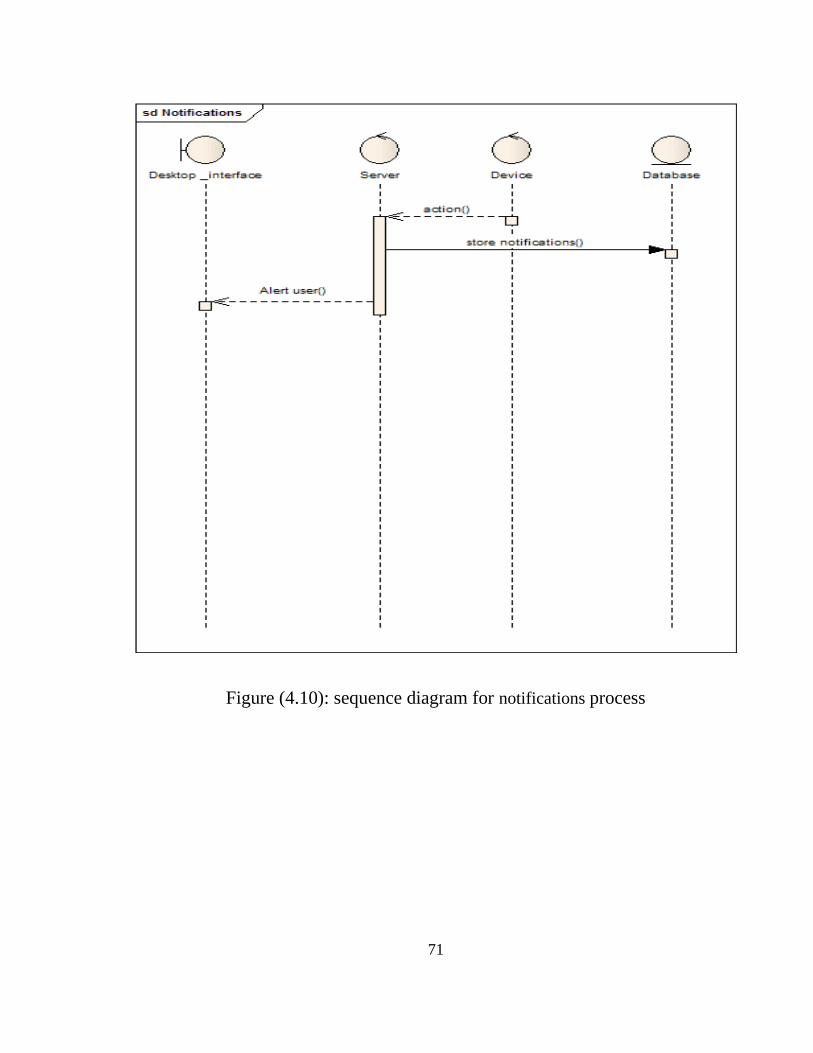
Figure (4.10): sequence diagram for notifications process
71
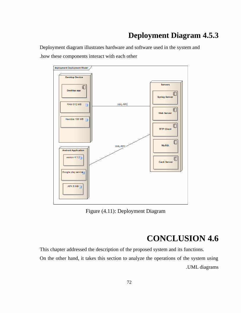
4.5.3 Deployment Diagram
Deployment diagram illustrates hardware and software used in the system and
how these components interact with each other.
Figure (4.11): Deployment Diagram
4.6 CONCLUSIONThis chapter addressed the description of the proposed system and its functions.
On the other hand, it takes this section to analyze the operations of the system using
UML diagrams.
72

73
CAPTER FIVE
IMPLEMENTATION
5.1INTRODUCTION This chapter deals with the graphical interfaces for (desktop application,
Android Application); explain the components and how it works.
This chapter discusses the implementation of the system and how the server and
clients will communicate with devices, as we shown in (figure 4.1) the server works as
an intermediate between clients and the devices that constitute organization network .
5.2 NETWORKING ENVIRONMENTA network scenario has been created using GNS-due to cost
limitations of using real routers.
This scenario contains of many routers connected to each other
based on the topology defined by network administrator. Any device
in this network configured to be reachable from any connected node,
so static route configured or routing protocol has been enabled in
each device
Finally, confirmed the SSHv2 activated in all routers in addition
to a local username and password created in all Routers.
5.3 SERVER SIDE When server starts a connection to database establish and set
of operations and verification processes will execute.
5.3.1 Loading Devices The server fetches all information about devices from
database, and based on it server establish SSHv2 connection with
each device and save them as objects to make server execute
configurations on specific router during the runtime.
75
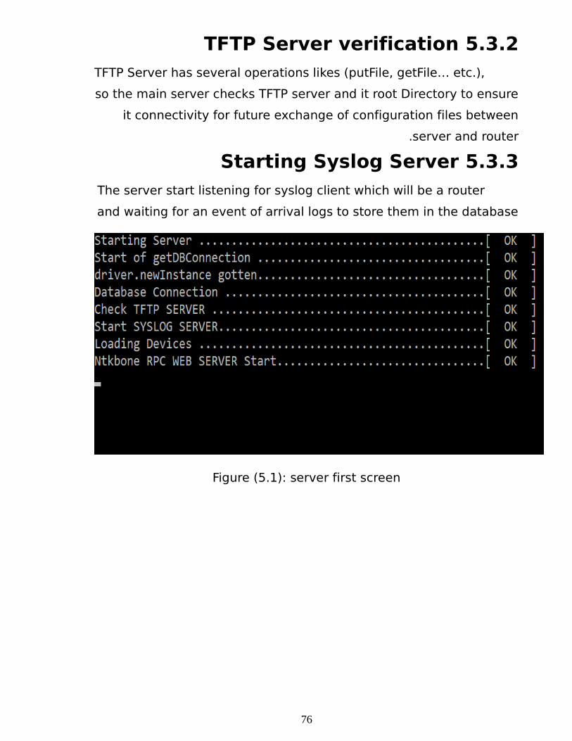
5.3.2 TFTP Server verificationTFTP Server has several operations likes (putFile, getFile… etc.),
so the main server checks TFTP server and it root Directory to ensure
it connectivity for future exchange of configuration files between
server and router.
5.3.3 Starting Syslog ServerThe server start listening for syslog client which will be a router
and waiting for an event of arrival logs to store them in the database
Figure (5.1): server first screen
76
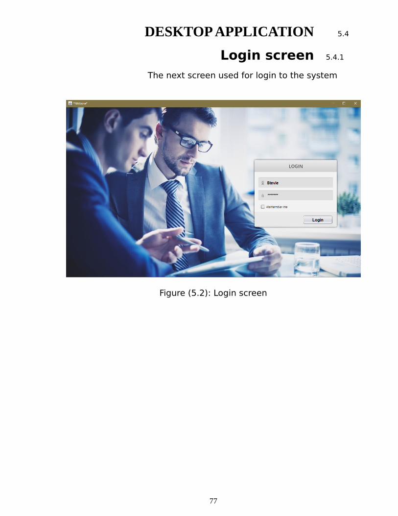
5.4DESKTOP APPLICATION
5.4.1Login screenThe next screen used for login to the system
Figure (5.2): Login screen
77
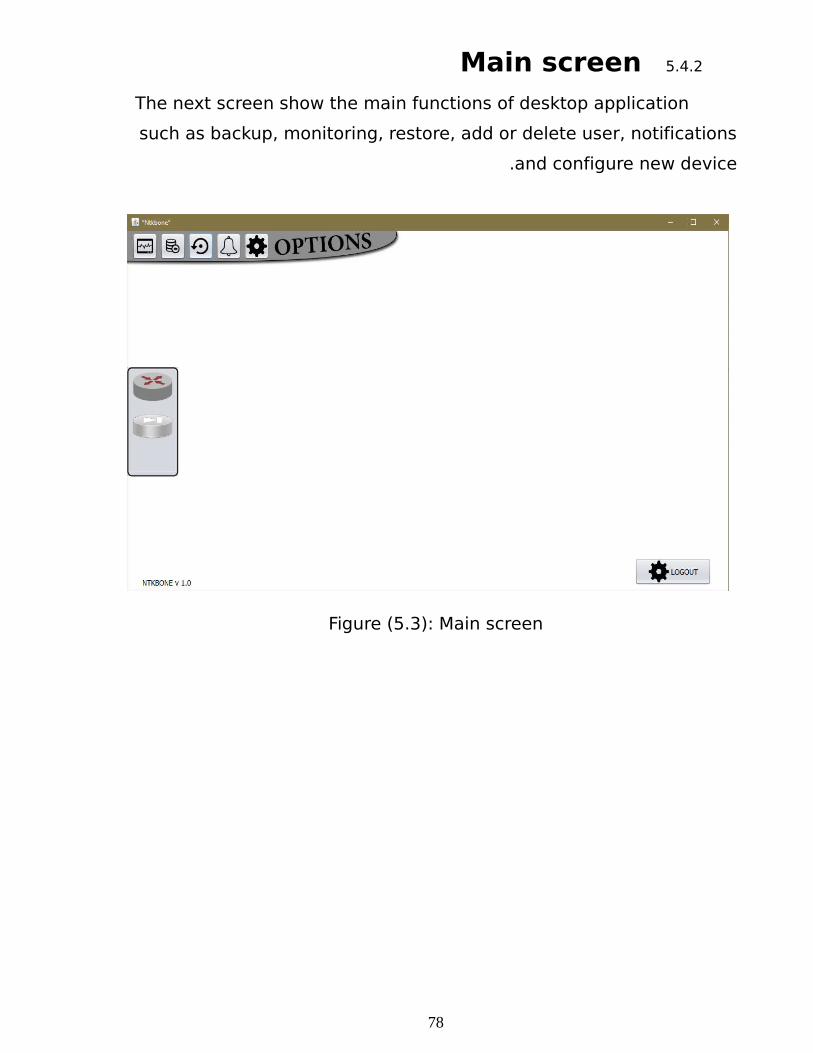
5.4.2Main screenThe next screen show the main functions of desktop application
such as backup, monitoring, restore, add or delete user, notifications
and configure new device.
Figure (5.3): Main screen
78
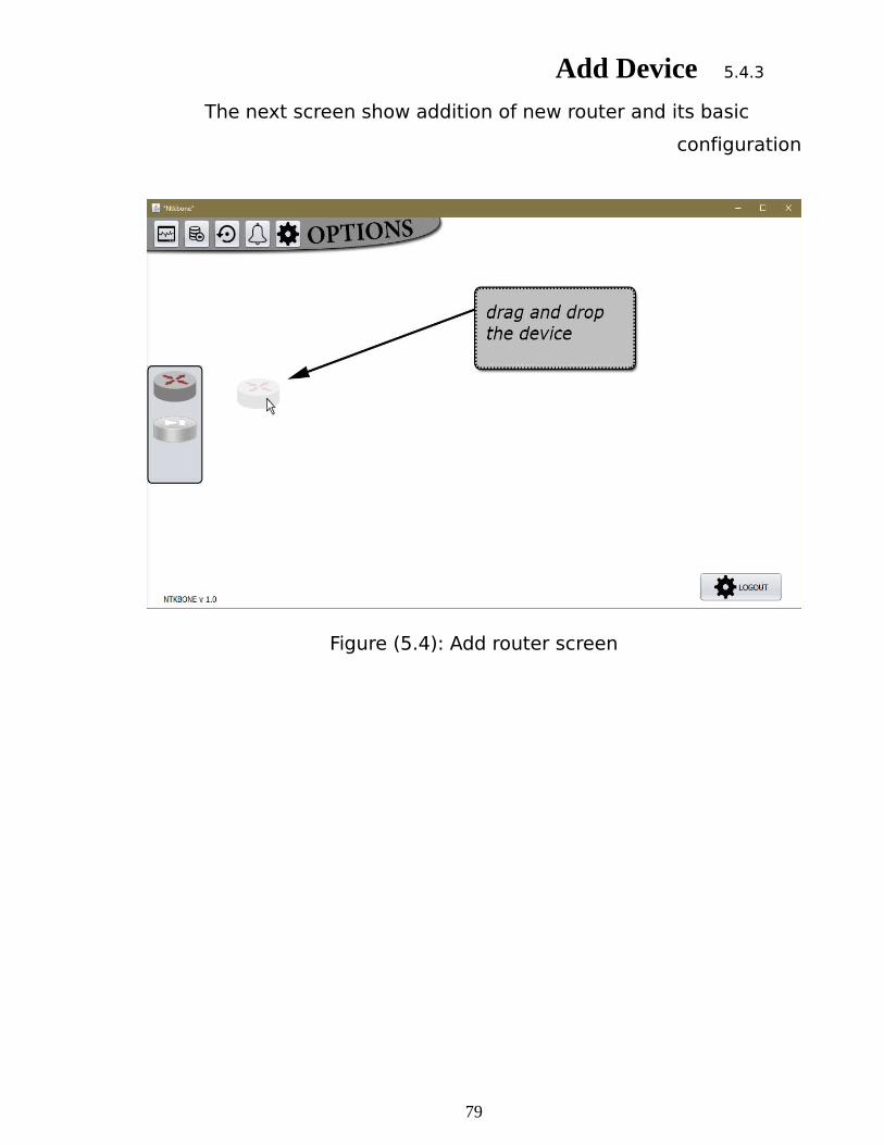
5.4.3Add Device
The next screen show addition of new router and its basic
configuration
Figure (5.4): Add router screen
79
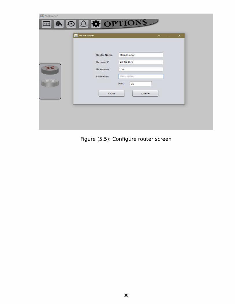
Figure (5.5): Configure router screen
80

5.4.4Interfaces configuration and status
The next screen show how router interfaces accessed to apply
new ACL group, shut down the interface, configure DHCP and show
interface state.
Figure (5.6): router interface screen
81
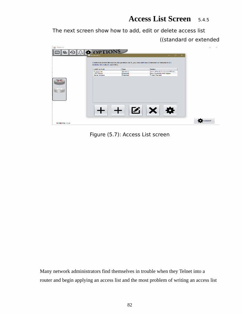
5.4.5Access List Screen
The next screen show how to add, edit or delete access list
(standard or extended (
Figure (5.7): Access List screen
Many network administrators find themselves in trouble when they Telnet into a
router and begin applying an access list and the most problem of writing an access list
82
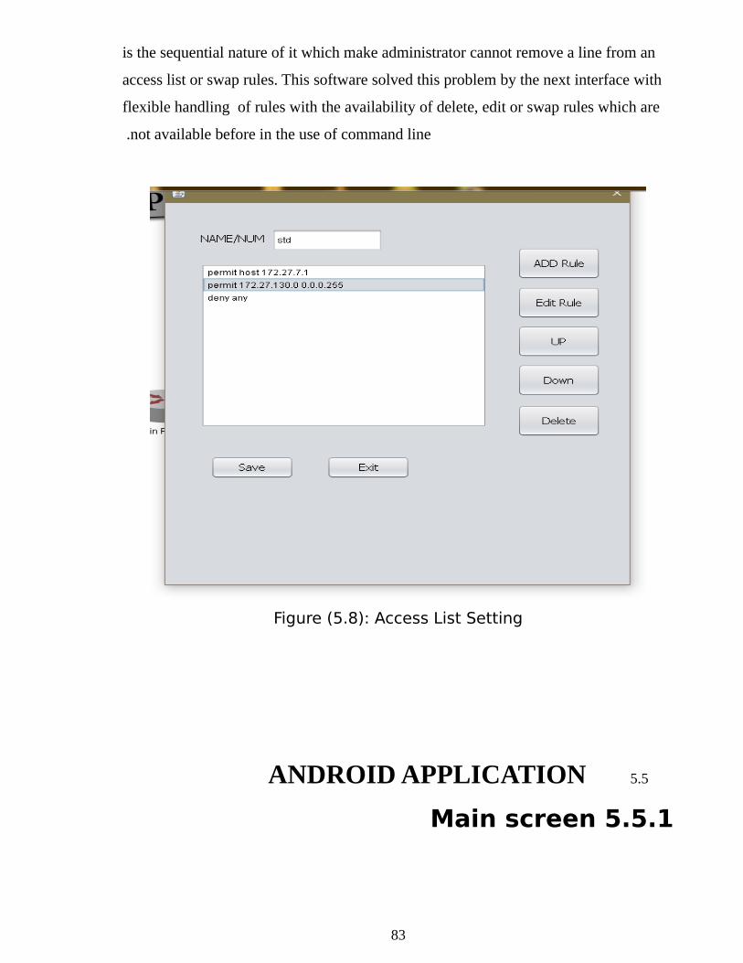
is the sequential nature of it which make administrator cannot remove a line from an
access list or swap rules. This software solved this problem by the next interface with
flexible handling of rules with the availability of delete, edit or swap rules which are
not available before in the use of command line .
Figure (5.8): Access List Setting
5.5ANDROID APPLICATION
5.5.1 Main screen
83
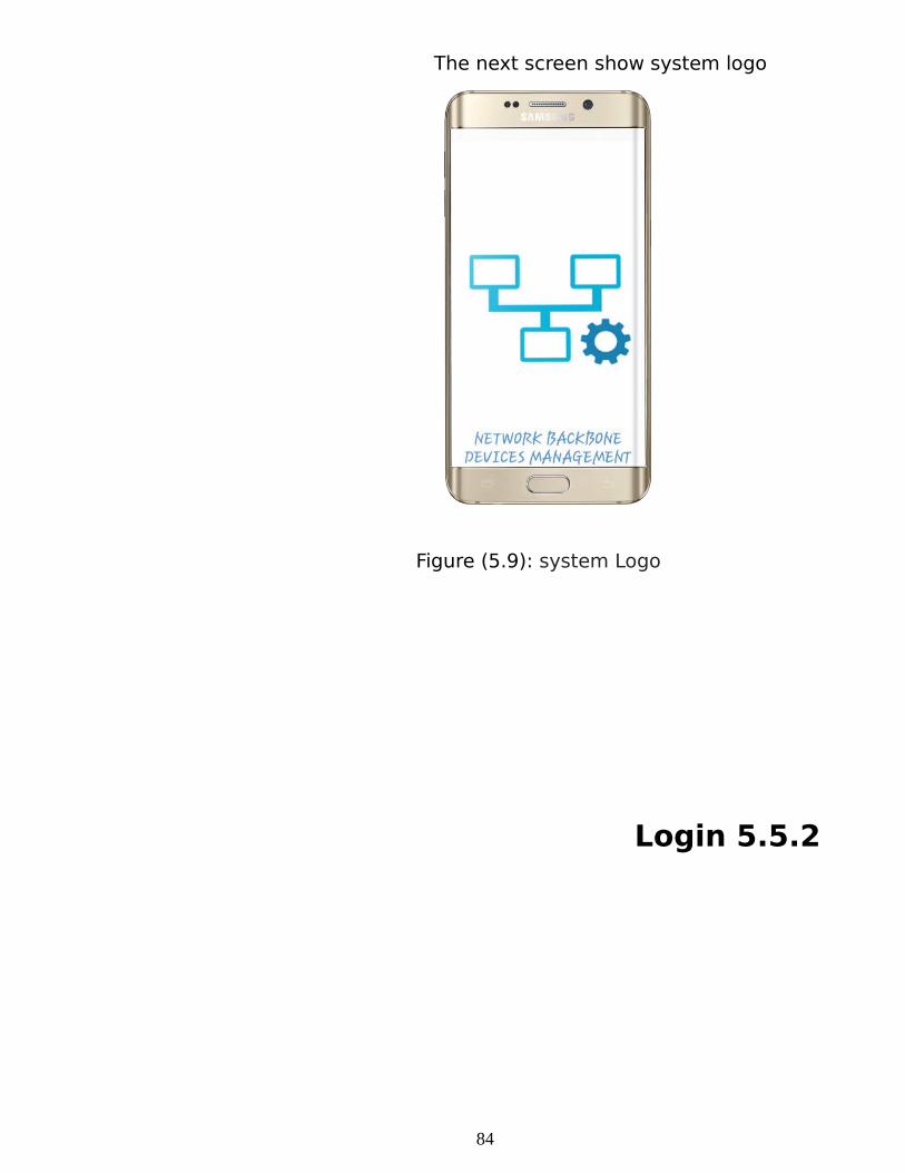
The next screen show system logo
Figure (5.9): system Logo
5.5.2 Login
84
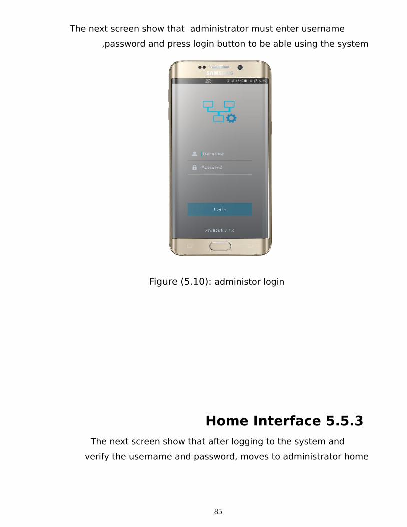
The next screen show that administrator must enter username
,password and press login button to be able using the system
Figure (5.10): administor login
5.5.3 Home Interface The next screen show that after logging to the system and
verify the username and password, moves to administrator home
85
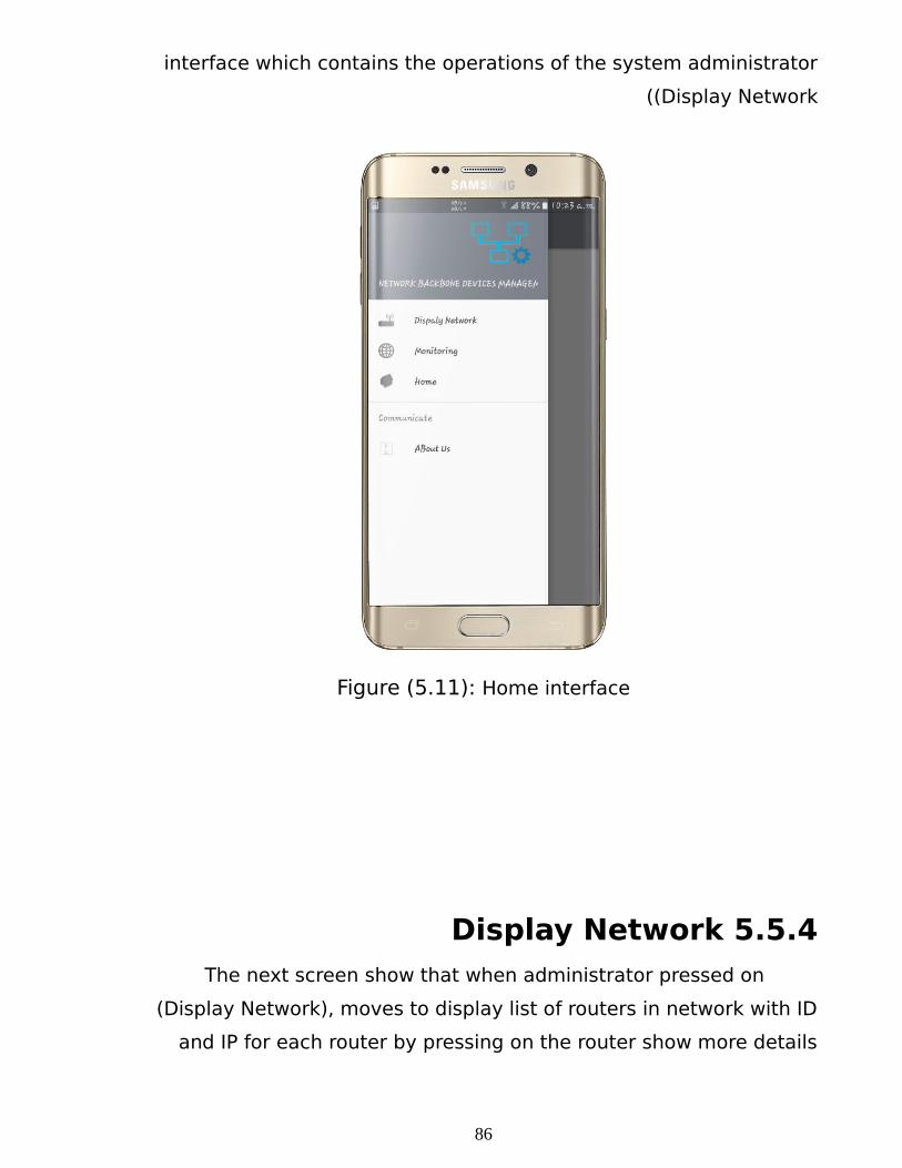
interface which contains the operations of the system administrator
(Display Network (
Figure (5.11): Home interface
5.5.4 Display NetworkThe next screen show that when administrator pressed on
(Display Network), moves to display list of routers in network with ID
and IP for each router by pressing on the router show more details
86
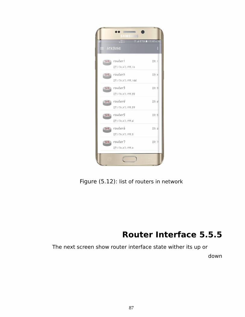
Figure (5.12): list of routers in network
5.5.5 Router InterfaceThe next screen show router interface state wither its up or
down
87
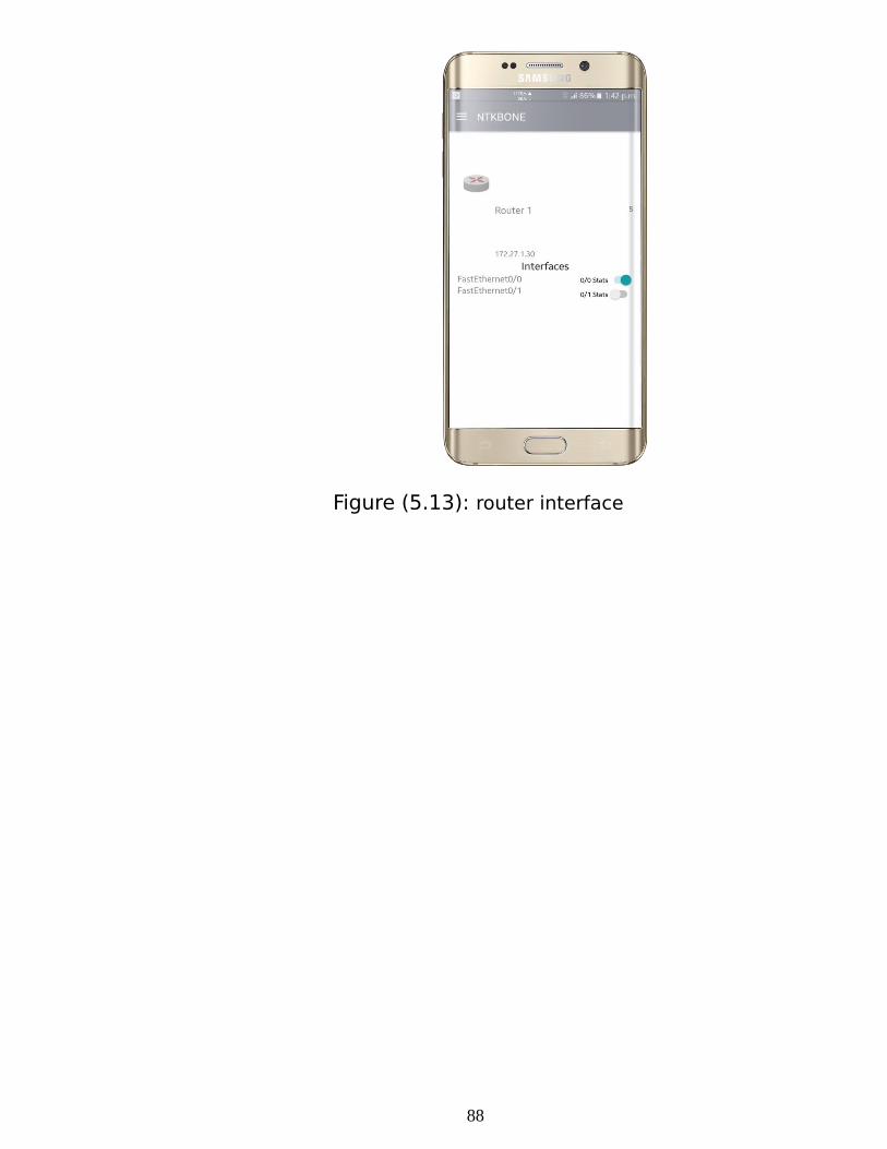
Figure (5.13): router interface
88
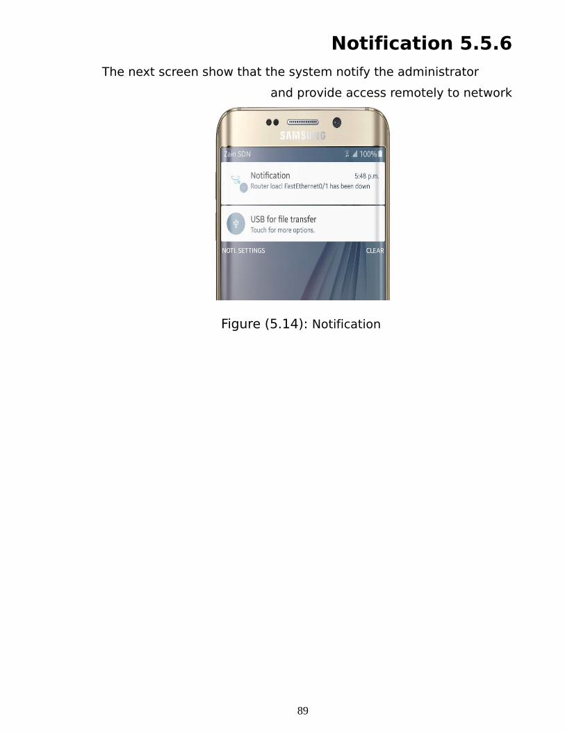
5.5.6 NotificationThe next screen show that the system notify the administrator
and provide access remotely to network
Figure (5.14): Notification
89
CHAPTER SIX
RESULTS, CONCLUSION AND RECOMMENDATION
6.1 INTRODUCTION This chapter display research results that have been accessible after
implementing the system and recommendations for future research and studies .
6.2 CONCLUSIONSystem software has been established and implemented to provide help to
network administrators in managing the backbone devices in the network of institution
by using graphical interfaces for only one vendor (Cisco) and no special configurations
are made except the NAT .
As the software aims to be addition to the administrator it provides simple tool to
control and maintain the work of network devices, add access list rules on the routers
and notify administrator about network problems.
6.3 RESULTSThe application was tested in android smart phone and desktop application and
achieved the goals of the research successfully by :
•Create Graphical Interfaces to configure devices.
Provide simple way for administrator to access backbone devices of institution
network from any location.
•Sends alerts to network administration when critical problems happen and
provide access to the network, even from a remote location.
•Backup and restore network devices configuration
•Apply scheduler of specific configurations that performs for a fixed period of
time
91
6.4 RECOMMENDATIONSAfter the completion of this project and applied it, we recommend
the following to improve the system :
•More development of the system to make it work on other operating system for smart
phones (e.g. IOS, Windows Phone) to keep up with technological evolution .
•Applying IPV6.
•Include switching
•Apply BGP commands.
•Include all Huawei and Juniper commands.
•Do some special GUI for firewall.
•Does some security link such as (finger point, and encryptions.(
REFERENCES
92
]1 [Amir, S., Chowdhry, B. S., Gichki, I., & Shakeel, O. (2013). RCM: A User
Friendly Router Configuration Machine. Wireless personal
communications,69(3), 1033-1046.
]2 [Mohammed Waraq, Mohammed Kamal, Mohammed Sadiq,Awad Mamamon - Mobile
Application for Network Monitoring Software Using Android Operating System - Sudan
University of Since and Technology - computer system and network –
August.
]3 [Ruaa Abdalhleam, Mohammed Alkatem Hassan, Mohammed Alkatem, Mohammed
Hasab-Click Administrator- Sudan University of Since and Technology -
computer system and network - 2012.
]4 [CCM, type of network, http://ccm.net/contents/266-types-of-networks/
access at 30/3/2016 05:13pm.
]5[BUSINESSDICTIONARY,routing,http://www.businessdictionary.com/definit
ion/routing.html/ access at 1/4/2016 01:30pm.
]6 [Comer, D. E. (2008). Computer networks and internets. Prentice Hall
Press.
]7 [CISCOPRESS, EIGRP , http://www.ciscopress.com/articles/article.asp?p=102174&seqNum=6/ access
at 2/4/2016 02:00 pm.
]8[http://www.cisco.com/c/en/us/support/docs/ip/network-address-
translation-nat/26704-nat-faq-00.html access at 10/5/2016 04:00 pm.
]9[http://www.cisco.com/c/en/us/td/doca/ios-
xml/sec_data_acl/configuration/xe-3s/sec-data-acl-xe-3s-book/sec-access-
list-ov.html/ access at 13/5/2016 08:45 pm.
]10 [http://study-ccna.com/types-of-acls/ access at 13/5/2016 11:15 pm.
]11 [Johnson, M., Healy, M., van de Ven, P., Hayes, M. J., Nelson, J., Newe,
T., & Lewis, E. (2009, October). A comparative review of wireless sensor
network mote technologies. In Sensors, 2009 IEEE (pp. 1439-1442. (
93
]12 [Mauro, D., & Schmidt, K. (2005). Essential snmp. " O'Reilly Media, Inc .
]13 [Stallings, W., & Paul, G. K. (1998). Operating systems: internals and
design principles (Vol. 3). Upper Saddle River, NJ: prentice hall.
]14 [Torvalds, L. History of Linux.
]15 [https://www.ijeas.org/download_data/IJEAS0202022.pdf access at 10/6/2016 12:00 pm.
]16 [TechTarget website access at 12/6/2016 09:00 am.
]17 [http://www.singularissoftwares.com/training_java.php access at 23/6/2016 04:00 pm.
]18 [https://www.tutorialspoint.com/ java / java _overview.htm access at 24/6/2016 08:00 am.
]19 [https://en.wikipedia.org/wiki/Unified_Modeling_Language access at 29/6/2016 01:00 pm.
]20 [http://www.gartner.com/it-glossary/enterprise-architecture-ea/ access at 15/7/2016 10:00 am.
]21 [Fawcett, J., Ayers, D., & Quin, L. R. (2012). Beginning XML. John Wiley & Sons.
]22 [Docs.oracle.com access at 30/7/2016 06:00 pm.
]23 [Simon St. Laurent, Joe Johnston, Edd Dumbill. (June 2001)Programming Web Services with XML-RPC. O'Reilly. First Edition.
]24[
https://www.csee.umbc.edu/courses/undergraduate/CMSC341/Lectures/Ecli
pse/intro-to-eclipse.pdf access at 17/8/2016 02:00 pm.
]25 [http://stacktips.com/tutorials/android/android-studio-features access
at 22/8/2016 07:00 am.
]26 [https://gns3.com/software/ access at 10/9/2016 10:00 am.
]27 [https://www.vandyke.com/solutions/ssh_overview/ssh_overview.pdf
access at 15/9/2016 12:00 pm.
]28[
https://www.webnms.com/telecom/help/developer_guide/tftp_service/confi
g_tftpintroduction.html access at 22/9/2016 04:00 pm.
]29 [Network management website access at 25/9/2016 09:00 am.
94

95
APPENDIXS
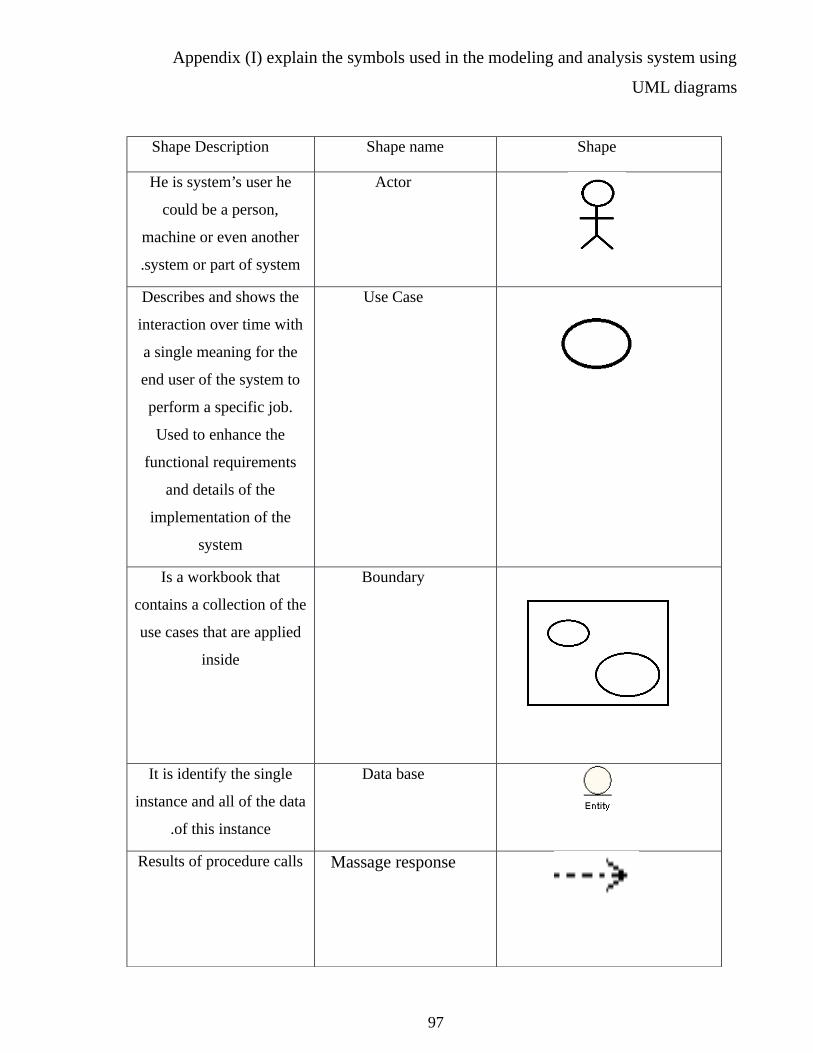
Appendix (I) explain the symbols used in the modeling and analysis system using
UML diagrams
ShapeShape nameShape Description
ActorHe is system’s user he
could be a person,
machine or even another
system or part of system.
Use CaseDescribes and shows the
interaction over time with
a single meaning for the
end user of the system to
perform a specific job.
Used to enhance the
functional requirements
and details of the
implementation of the
system
BoundaryIs a workbook that
contains a collection of the
use cases that are applied
inside
Data baseIt is identify the single
instance and all of the data
of this instance.
Massage responseResults of procedure calls
97
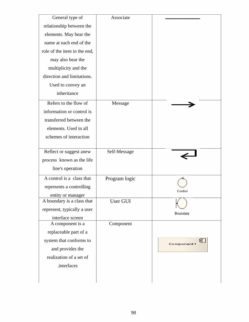
AssociateGeneral type ofـــــــــــــــــــــــــــــــــــــــــ
relationship between the
elements. May bear the
name at each end of the
role of the item in the end,
may also bear the
multiplicity and the
direction and limitations.
Used to convey an
inheritance
MessageRefers to the flow of
information or control is
transferred between the
elements. Used in all
schemes of interaction
Self-MessageReflect or suggest anew
process known as the life
line's operation
Program logicA control is a class that
represents a controlling
entity or managerUser GUIA boundary is a class that
represent, typically a user
interface screenComponentA component is a
replaceable part of a
system that conforms to
and provides the
realization of a set of
interfaces.
98
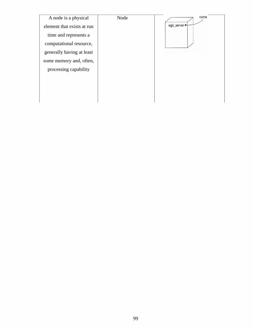
NodeA node is a physical
element that exists at run
time and represents a
computational resource,
generally having at least
some memory and, often,
processing capability
99