SYSTEM MODEL - SUST Repository
16
Chapter three SYSTEM MODEL 40 SYSTEM MODEL 3-1 Design Flow Overview This chapter provides a design of simulation model for OFDM system by using labview package tools to simulate a system as shown in figure (3-1) firstly design OFDM system in two approaches (OFDM-FFT based and OFDM- DWT based) then evaluate OFDM system in two approaches then build a MIMO- OFDM system for two scenarios, after that compare between two scenarios
-
Upload
khangminh22 -
Category
Documents
-
view
1 -
download
0
Transcript of SYSTEM MODEL - SUST Repository

Chapter three SYSTEM MODEL
40
SYSTEM MODEL
3-1 Design Flow Overview
This chapter provides a design of simulation model for OFDM system by
using labview package tools to simulate a system as shown in figure (3-1) firstly
design OFDM system in two approaches (OFDM-FFT based and OFDM- DWT
based) then evaluate OFDM system in two approaches then build a MIMO- OFDM
system for two scenarios, after that compare between two scenarios

Chapter three SYSTEM MODEL
41
Figure (3-1) system model flow chart
Select test bench
OFDM demod
Done
OFDM demod
Digital to analog
AWGN AWGN
Parallel to serial
Parallel to serial
Symbol de-mapping
Symbol de-mapping
Output bit stream
Output bit stream
Measure BER & capacity
Measure PAPR
Measure BER & capacity Compare
OFDM-DWT mod
OFDM-FFT mod
Measure PAPR
Generate bit stream
Symbol mapping
Serial to Parallel
Select OFDM
Digital to analog

Chapter three SYSTEM MODEL
42
3-2 MIMO-OFDM SYSTEM MODEL
A multicarrier system can be efficiently implemented in discrete time using
an inverse FFT (IFFT) or inverse DWT (IDWT) to act as a modulator and an FFT/
DWT to act as a demodulator the transmitted data are the “frequency” domain
coefficients and the samples at the output of the IFFT stage are “time” domain
samples of the transmitted waveform. Figure (3-2) shows a typical MIMO-OFDM
system transceiver implementation model [15-16].
Random stream of data is generated as the input symbols, with length equal
to the number of bits per frame. This is processed according to the modulation
techniques BPSK or 16-QAM to get the desired constellation mapping. Next, these
modulated data are converted from a serial vector to parallel data streams
according to the numbers of subcarriers and the numbers of bits per frame. Finally
the pilot subcarriers are inserted at predefined locations in the parallel data streams,
and are then used to estimate and equalize the channel performance. The length of
the parallel streams will then become equal to the size of the FFT (which is equal
to the number of subcarriers and pilot subcarriers)
3-3 OFDM system:
OFDM system structured from a three main section OFDM-Transmitter,
OFDM-channel and OFDM-Receiver the following topic take it in details figure
(3-1) provide a OFDM system transceiver firstly generate input Bit stream and
then mapped to symbols modulation (BPSK, QPSK, 16QAM and 64QAM) after
that converted from serial to parallel after that using (FFT/or DWT) to convert signal

Chapter three SYSTEM MODEL
43
from time Domain to Frequency Domain then use a digital to analog converter to send
signal over AWGN channel in the seam processes inversely in receiver side[17-
19]
Figure (3-2) OFDM transceiver
Chapter three SYSTEM MODEL
44
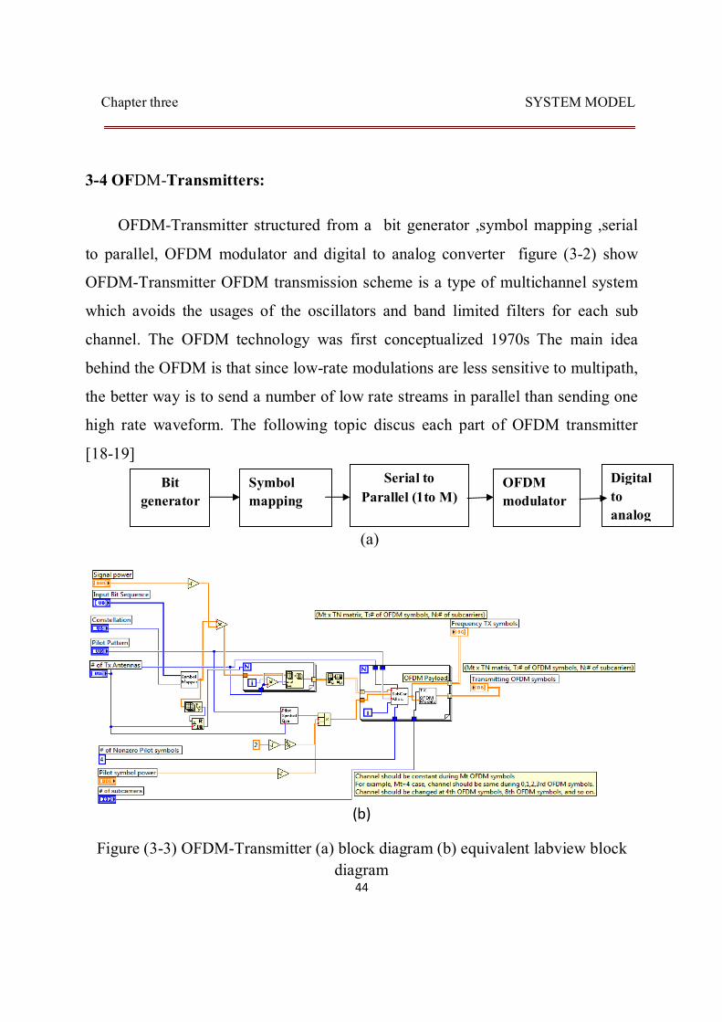
3-4 OFDM-Transmitters:
OFDM-Transmitter structured from a bit generator ,symbol mapping ,serial
to parallel, OFDM modulator and digital to analog converter figure (3-2) show
OFDM-Transmitter OFDM transmission scheme is a type of multichannel system
which avoids the usages of the oscillators and band limited filters for each sub
channel. The OFDM technology was first conceptualized 1970s The main idea
behind the OFDM is that since low-rate modulations are less sensitive to multipath,
the better way is to send a number of low rate streams in parallel than sending one
high rate waveform. The following topic discus each part of OFDM transmitter
[18-19]
(a)
(b)
Figure (3-3) OFDM-Transmitter (a) block diagram (b) equivalent labview block diagram
Bit generator
Symbol mapping
Serial to Parallel (1to M)
OFDM modulator
Digital to analog

Chapter three SYSTEM MODEL
45
3-4-1 Bit generator:
Figure (3-3) show MIMO- OFDM bit generator by using random function can be generate a random sequence of bits is generated. The number of bits is determined according to the number of sub-carriers required, number of bits per symbol and number of OFDM symbols used in the simulation [20]
Figure (3-4) Bit generator equivalent labview block diagram
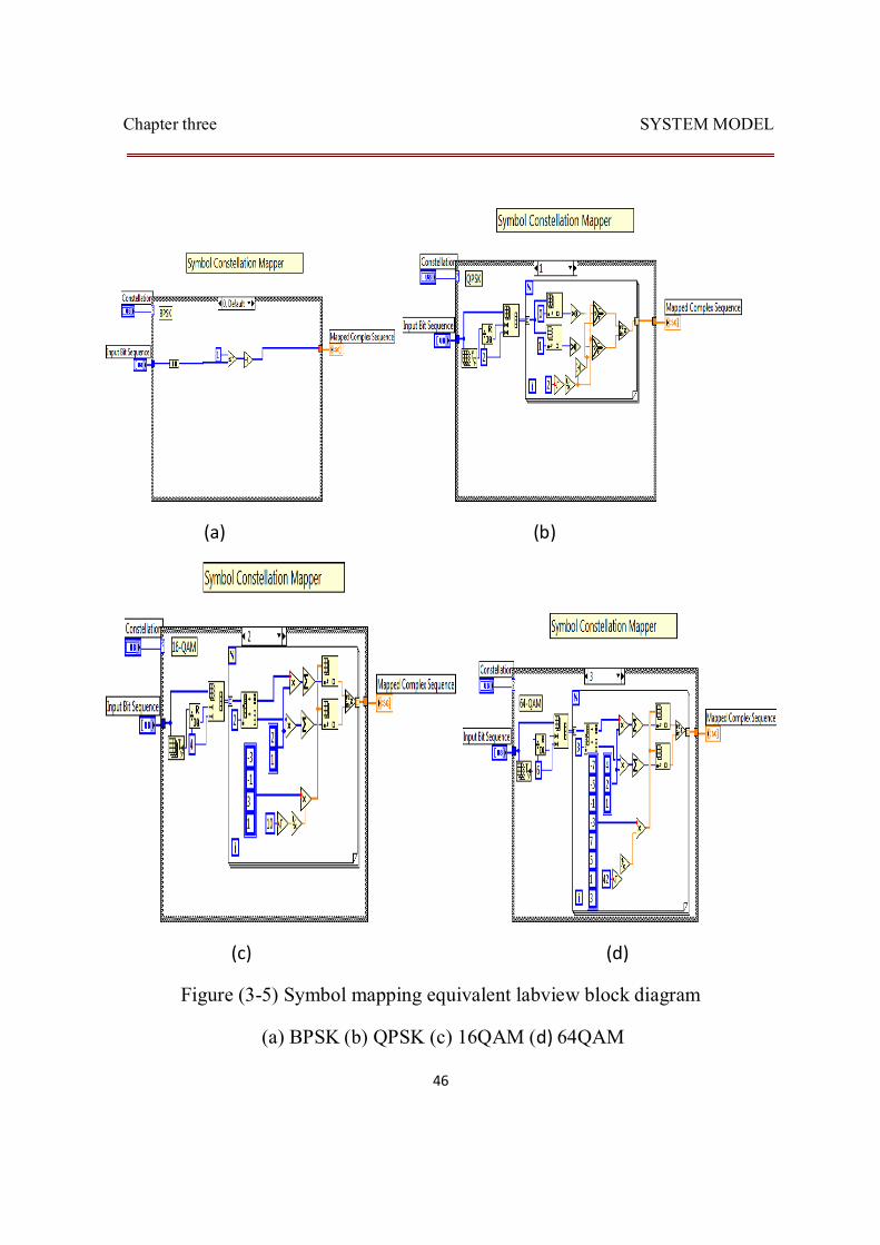
3-4-2 Symbol mapping:
At the transmitter, system has an input bit stream of B bits. Suppose if system have N FFT sub-carriers. Then we must transmit 푛푢푚푏푒푟표푓푠푦푚푏표푙 =
where each symbol has N FFT bits. Here assuming each signal value in our
modulation represents one bit, e.g. (BPSK,QPSK,16QAM and 64QAM) each symbol will have (2,2,4,8) N FFT bits respectively .The bits in each is then fed into a serial-to-parallel converter and modulated (BPSK,QPSK,16QAM and 64QAM). it is possible for different sub-carriers to use different modulation schemes. An inverse fast Fourier transforms (IFFT) or inverse discrete wavelet transform (IDWT) is performed ,Basic single-carrier modulation techniques modify only one of the three parameters–amplitude, frequency and phase–of the sinusoidal wave according to the binary information to be transmitted.[20]
Figure (3-4) represent of modulation techniques used in this system model in simulation
Chapter three SYSTEM MODEL
46
(a) (b)
(c) (d)
Figure (3-5) Symbol mapping equivalent labview block diagram
(a) BPSK (b) QPSK (c) 16QAM (d) 64QAM

Chapter three SYSTEM MODEL
47
3-4-3 OFDM modulator:
OFDM modulator is a block modulation scheme where a block of N information symbols is transmitted in parallel on N subcarriers. The time duration of an OFDM symbol is N times larger than that of single-carrier system. An OFDM modulator can be implemented as either of inverse Fourier transforms (IFFT) or inverse discrete wavelet transforms (IDWT) on a block of N information symbol followed by digital to analog converter (ADC).in this thesis use two type of OFDM modulator.
3-4-3-1 OFDM modulator-FFT based
In OFDM modulator-FFT based to mitigate the effect of Intersymbol interference (ISI) caused by channel time spread, each block of N IFFT coefficient is typically preceded by a cyclic prefix (CP), such that the length of (CP) is at least equal to the channel length The Cyclic Prefix or Guard Interval is a periodic extension of the last part of an OFDM symbol that is added to the front of the symbol in the transmitter, and is removed at the receiver side before demodulation. According to the figures (3-5) the addition of Cyclic Prefix (CP) takes place after the parallel to serial conversion and being removed at the receiver side before the FFT operation. The OFDM symbol with considering the Cyclic Prefix is shown in figures (3-5)

Chapter three SYSTEM MODEL
48
(a)
(b)
Figure (3-6) OFDM FFT based modulator (a) block diagram
(b) Equivalent labview block diagram
IFFT
N point and
Add cyclic prefix
Digital to analog Serial to parallel (1 to N)

Chapter three SYSTEM MODEL
49
3-4-3-2 OFDM modulator-DWT based:
In OFDM modulator-DWT based there is no need two add cyclic prefix, that can provide bandwidth utilization and improve system performances The IDWT Daubechies-4 (DAUB-4) takes as the input QAM or PSK symbols and outputs them in parallel time frequencies “subcarriers.” IDWT works in a similar fashion to an IFFT the figure (3-6) show OFDM modulator-DWT based and equivalent labview block diagram [16].
(a)
(b)
Figure (3-7) OFDM DWT based modulator (a) block diagram
(b) Equivalent labview block diagram
IDWT
N point
Digital to analog
Serial to parallel (1 to N)

Chapter three SYSTEM MODEL
50
3-5 AWGN channel:
In wireless communication the channel is always unpredictable. The signal traveling from the transmitter to the receiver suffers from very harsh conditions, such as fading, noise and Doppler spread.
In this system model the channel impairment is the noise in the channel which causes the signal to attenuate. Noise in the channel is modeled as an additive white Gaussian noise (AWGN). AWGN is a result of several independent noise sources and is added to the signal figure (3-7) show AWGN channel [16].
Figure (3-8) AWGN equivalent labview block diagram

Chapter three SYSTEM MODEL
51
3-6 OFDM-Receivers:
The receiving process is inversely process to transmitting process OFDM-Receiver structured from a Analog to Digital, OFDM de-modulator, , parallel to serial , symbol de mapping OFDM modulator and output bit stream figure (3-8) show OFDM Receiver
(a)
(b)
Figure (3-9) OFDM-receiver
(a) Block diagram (b) equivalent labview block diagram
Analog to Digital
OFDM de-modulator
Parallel to serial (M to1)
Symbol de-mapping
Out Bit stream
ou

Chapter three SYSTEM MODEL
52
3-6-1 Analog-to digital converter:
In a digital communication receiver, there is an important mixed-signal block: the analog-to digital converter (ADC). The ADC acts as an interface between the analog and digital subsystems, and converts the continuous-time received signal 푥(푡) to the discrete-time received samples 푥[푛]for the baseband receiver. To assure that the baseband algorithms work properly, the receiver may control the dynamic range of푥(푡) through a gain–control feedback loop
3-6-2 OFDM de-modulator:
OFDM de-modulator is inversely process of OFDM modulator An OFDM de modulator can be implemented as either of Fourier transforms (FFT) or discrete wavelet transforms (DWT) as shown in next figure (3-9) and figure (3-10) show OFDM de-modulator [21]

Chapter three SYSTEM MODEL
53
(a)
(b)
Figure (3-10) OFDM FFT based de modulator
(a) block diagram (b) equivalent labview block diagram
FFT
N point and
Remove cyclic prefix
Parallel to Serial
(N to 1)
Analog to Digital

Chapter three SYSTEM MODEL
54
(a)
(b)
Figure (3-11) OFDM DWT based de modulator
(a) Block diagram (b) equivalent labview block diagram
IDWT
N point
Parallel to Serial
(N to 1)
Analog to Digital

Chapter three SYSTEM MODEL
55
3-6-3 Symbol demapper:
Symbol demapper is inverse process to a symbol mapping in which convert a digital signal to output bit stream figure (3-11) show equivalent simulation block diagram [19].
Figure (3-12) symbol demapper equivalent labview block diagram