
Literature review - SUST Repository
21
5 Literature review 2-1 Basic Gas Turbine Operation A schematic diagram of a simple cycle, single shaft gas turbine is shown in Figure 2-1.Air enters the axial flow compressor through point 1 which is at ambient conditions. Then it is compressed up to a higher pressure level. During this process there is no heat addition to the air, however the compression of air raises the temperature. So that the compressed air at the compressor discharge is at high pressure and temperature. The compressed air then enters the combustion chamber at point 2, where fuel is injected and combustion takes place. Either gaseous fuel (e.g. methane, natural gas, etc.) or liquid fuels (e.g. diesel, heavy fuel) can be used here. The combustion process occurs at constant pressure. The combustion chamber is design to provide mixing, burning and dilution effects to have proper combustion .The combustion product which is the flue gas leaves the combustion chamber at very high temperature. Figure 2-1 Schematic layout of a single-shaft gas turbine [1].
-
Upload
khangminh22 -
Category
Documents
-
view
1 -
download
0
Transcript of Literature review - SUST Repository

5
Literature review
2-1 Basic Gas Turbine Operation A schematic diagram of a simple cycle, single shaft gas turbine is shown in
Figure 2-1.Air enters the axial flow compressor through point 1 which is at
ambient conditions. Then it is compressed up to a higher pressure level. During
this process there is no heat addition to the air, however the compression of air
raises the temperature. So that the compressed air at the compressor discharge is at
high pressure and temperature. The compressed air then enters the combustion
chamber at point 2, where fuel is injected and combustion takes place. Either
gaseous fuel (e.g. methane, natural gas, etc.) or liquid fuels (e.g. diesel, heavy fuel)
can be used here. The combustion process occurs at constant pressure. The
combustion chamber is design to provide mixing, burning and dilution effects to
have proper combustion .The combustion product which is the flue gas leaves the
combustion chamber at very high temperature.
Figure 2-1 Schematic layout of a single-shaft gas turbine [1].

6
at point 3 the flue gas enters the turbine. In the turbine section, energy of the hot
gas is converted into work. This conversion happens in two steps. In the first step,
hot gases are expanding through the nozzle by converting the thermal energy to
the kinetic energy. Then the turbine blades are converting this kinetic energy to
mechanical work. The work delivered by the turbine blades is used to run the
compressor and the remaining power is available for useful work at the output
shaft of the turbine. As shown in the Figure 2-1 the output shaft can be coupled to
an electrical generator to produce electricity. After the expansion through the
turbine, exhaust gas leaves the system to the atmosphere at point 4. Still the
exhaust gas is at a very high temperature and therefore has considerable amount of
energy content in it. An energy recovery unit can be used to recover this energy for
useful work. Heat recovery steam generator (HRSG) is a component which can be
used to capture the energy of exhaust gas from the gas turbine. Recovered energy
can be used to run a steam turbine and generate electricity.[1]YunusA.Cengel et al.
2-2 Brayton cycle: The Ideal Cycle for Gas-Turbine Engines
The Brayton cycle (or Joule cycle) was first proposed by George Brayton for use in
the reciprocating oil-burning engine that he developed around 1870. Today, it is
used for gas turbines only where both the compression and expansion processes
take place in rotating machinery. Gas turbines usually operate on an open cycle, as
shown in Figure 2-2. Fresh air at ambient conditions is drawn into the compressor,
where its temperature and pressure are raised. The high pressure air proceeds into
the combustion chamber, where the fuel is burned at constant pressure. The
resulting high-temperature gases then enter the turbine, where they expand to the
atmospheric pressure while producing power. The exhaust gases leaving the
turbine are thrown out (not recirculated), causing the cycle to be classified as an
open cycle. The open gas-turbine cycle described above can be modeled as a
closed cycle, as shown in Figure 2-3, by utilizing the air-standard assumptions.
Here the compression and expansion processes remain the same, but the
combustion process is replaced by a constant-pressure heat-addition process from
7
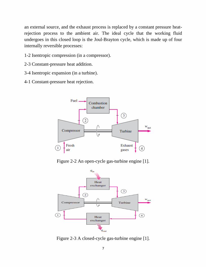
an external source, and the exhaust process is replaced by a constant pressure heat-
rejection process to the ambient air. The ideal cycle that the working fluid
undergoes in this closed loop is the Joul-Brayton cycle, which is made up of four
internally reversible processes:
1-2 Isentropic compression (in a compressor).
2-3 Constant-pressure heat addition.
3-4 Isentropic expansion (in a turbine).
4-1 Constant-pressure heat rejection.
Figure 2-2 An open-cycle gas-turbine engine [1].
Figure 2-3 A closed-cycle gas-turbine engine [1].

8
The T-s and P-v diagrams of an ideal Joule-Brayton cycle are shown in Figure 2-4a
Figure 2-4b
Figure 2-4a T-s diagram of an ideal Joule-Brayton cycle [1].
Figure 2-4b P-v diagram of an ideal Joule-Brayton cycle [1].

9
Figure 2-5 Thermal efficiency of the ideal Joule-Brayton cycle as a function of the
pressure ratio,rp [1].
In gas-turbine power plants, the ratio of the compressor work to the turbine work,
called the back work ratio, is very high,Figure 2-6.Usually more than one-half of
the turbine work output is used to drive the compressor. The situation is even
worse when the isentropic efficiencies of the compressor and the turbine are low.
This is quite in contrast to steam power plants, where the back work ratio is only a
few percent. This is not surprising, however, since a liquid is compressed in steam
power plants instead of a gas, and the steady-flow work is proportional to the
specific volume of the working fluid. A power plant with a high back work ratio
requires a larger turbine to provide the additional power requirements of the
compressor. Therefore, the turbines used in gas-turbine power plants are larger
than those used in steam power plants of the same net power output.
Figure 2-6 the fraction of the turbine work used to drive the compressor [1].
10
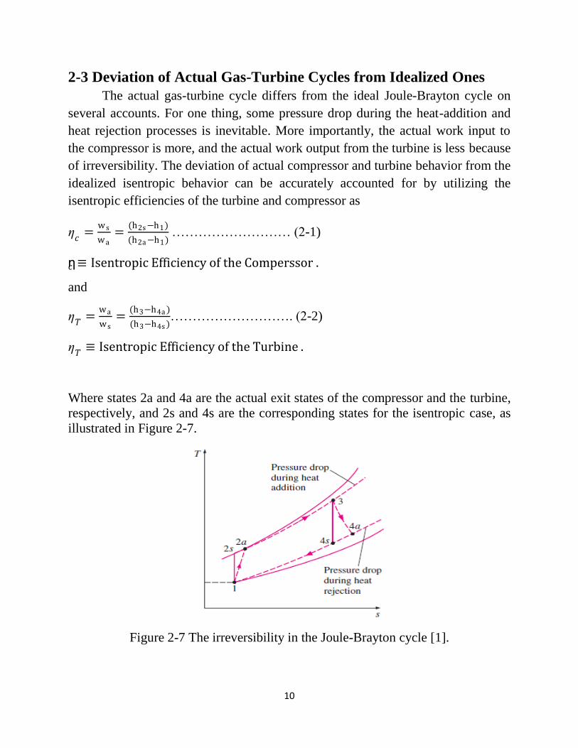
2-3 Deviation of Actual Gas-Turbine Cycles from Idealized Ones
The actual gas-turbine cycle differs from the ideal Joule-Brayton cycle on
several accounts. For one thing, some pressure drop during the heat-addition and
heat rejection processes is inevitable. More importantly, the actual work input to
the compressor is more, and the actual work output from the turbine is less because
of irreversibility. The deviation of actual compressor and turbine behavior from the
idealized isentropic behavior can be accurately accounted for by utilizing the
isentropic efficiencies of the turbine and compressor as
ƞ𝑐
=ws
wa=
(h2s−h1)
(h2a−h1) ……………………… (2-1)
ƞc ≡ Isentropic Efficiency of the Comperssor .
and
ƞ𝑇
=wa
ws=
(h3−h4a )
(h3−h4s )………………………. (2-2)
ƞ𝑇≡ Isentropic Efficiency of the Turbine .
Where states 2a and 4a are the actual exit states of the compressor and the turbine,
respectively, and 2s and 4s are the corresponding states for the isentropic case, as
illustrated in Figure 2-7.
Figure 2-7 The irreversibility in the Joule-Brayton cycle [1].

11
2-4 The Joule-Brayton Cycle With Regeneration
In gas-turbine engines, the temperature of the exhaust gas leaving the turbine
is often considerably higher than the temperature of the air leaving the compressor.
Therefore, the high-pressure air leaving the compressor can be heated by
transferring heat to it from the hot exhaust gases in a counter-flow heat exchanger,
which is also known as a regenerator or a recuperator. A sketch of the gas-turbine
engine utilizing a regenerator and the T-s diagram of the new cycle are shown in
Figure 2-8 and Figure 2-9, respectively.
Figure 2-8 a gas-turbine engine with regeneration [1].
Figure 2-9 T-s diagram of Ideal Joule-Brayton cycle with regeneration [1].
12
2-5 The JBC With Intercooling,Reheating,andRegeneration
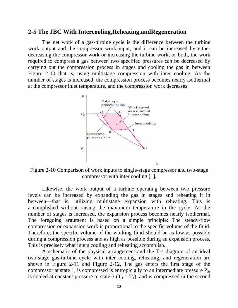
The net work of a gas-turbine cycle is the difference between the turbine
work output and the compressor work input, and it can be increased by either
decreasing the compressor work or increasing the turbine work, or both, the work
required to compress a gas between two specified pressures can be decreased by
carrying out the compression process in stages and cooling the gas in between
Figure 2-10 that is, using multistage compression with inter cooling. As the
number of stages is increased, the compression process becomes nearly isothermal
at the compressor inlet temperature, and the compression work decreases.
Figure 2-10 Comparison of work inputs to single-stage compressor and two-stage
compressor with inter cooling [1].
Likewise, the work output of a turbine operating between two pressure
levels can be increased by expanding the gas in stages and reheating it in
between—that is, utilizing multistage expansion with reheating. This is
accomplished without raising the maximum temperature in the cycle. As the
number of stages is increased, the expansion process becomes nearly isothermal.
The foregoing argument is based on a simple principle: The steady-flow
compression or expansion work is proportional to the specific volume of the fluid.
Therefore, the specific volume of the working fluid should be as low as possible
during a compression process and as high as possible during an expansion process.
This is precisely what inters cooling and reheating accomplish.
A schematic of the physical arrangement and the T-s diagram of an ideal
two-stage gas-turbine cycle with inter cooling, reheating, and regeneration are
shown in Figure 2-11 and Figure 2-12, The gas enters the first stage of the
compressor at state 1, is compressed is entropic ally to an intermediate pressure P2,
is cooled at constant pressure to state 3 (T3 = T1), and is compressed in the second

13
stage isentropic ally to the final pressure P4. At state 4 the gas enters the
regenerator, where it is heated to T5 at constant pressure. In an ideal regenerator,
the gas leaves the regenerator at the temperature of the turbine exhaust, that is, T5
=T9. The primary heat addition (or combustion) process takes
Figure 2-11 a gas-turbine engine with two-stage compression with inter cooling,
two-stage expansion with reheating, and regeneration [1].
Place between states 5 and 6. The gas enters the first stage of the turbine at
state 6 and expands isentropic ally to state 7, where it enters the re heater. It is
reheated at constant pressure to state 8 (T8 = T6), where it enters the second stage
of the turbine. The gas exits the turbine at state 9 and enters the regenerator, where
it is cooled to state 10 at constant pressure. The cycle is completed by cooling the
gas to the initial state (or purging the exhaust gases).

14
Figure 2-12 T-s diagram of an ideal gas-turbine cycle with inter cooling, reheating,
and regeneration [1].
2-6 Preview Studies Gas turbines are used for power electric generation, operating airplanes and
for several industrial applications, The gas turbine engine consist of a compressor
to raise combustion air pressure, a combustion chamber where the fuel/air mixing
is burned, and a turbine that through expansion extracts energy from the
combustion gases, These cycles operates according to the open Brayton
thermodynamic cycle and present low thermal efficiency and are referred as
combustion turbines. Usually, the rated capacities of combustion turbines are based
on standard ambient air, and zero inlet and exhaust pressure drops, as specified by
the International Standardization Organization (ISO) Therefore, the air inlet
conditions are: air temperature 15 °C, relative humidity 60%, absolute pressure
101.325 k Pa at sea level. Combustion turbines are constant-volume engines and
their power output is directly proportional and limited by the air mass flow rate
entering the engine. Combustion turbines are constant-volume engines and their
power output is directly proportional and limited by the air mass flow rate entering
the engine. As the compressor has a fixed capacity for a given rotational speed and
a volumetric flow rate of air, their volumetric capacity remains constant and the
mass flow rate of air it enter into the gas turbine varies with ambient air
temperature and relative humidity ,The performance of a gas turbine power plant is
commonly presented in function of power output and specific fuel consumption ,
and it is sensible to the ambient conditions Thermodynamic analyses from
literature show that thermal efficiency and specific output decrease with the
increase of humidity and ambient temperature, but the temperature ambient is the

15
variable that has the greatest effect on gas turbine performance, the temperature
ambient rise results in decrease in air density, and consequently, in the reduction of
the mass flow rate. Thereby, less air passes through the turbine and the power
output is reduced, at a given turbine entry temperature. Moreover, the compression
work increase due the augmentation of the volume occupied by the air. According
to, the net power output produced by gas turbine is directly proportional to the air
mass flow, it that decreases when ambient temperature increases. The work of
Ibrahim, shown that an increment of 1 °C in the compressor air inlet temperature
decreases the gas turbine power output by 1 % [2] Ibrahim T. K. et al.
Discussed Power augmentation methods, which could be applied to existing
gas turbines, can be divided into two main categories. The first category includes
inlet air cooling techniques and the second involves techniques based on the
injection of compressed air, steam, or water [3] Boyce.
Gas turbines have been used for power generation in several places in the
world, and each region has different climatic conditions. Furthermore, the periods
of the peak electricity demand occur during the summer, when the ambient
temperature is high. For example, in Arabian Gulf region the average ambient
temperature presents a variation by more than 30 °C from summer to winter and
this factor generate a large drop in power output during the summer Due to these
severe ambient conditions, the turbine inlet air cooling is one of many available
technologies to improve the performance of the gas turbine power plants by
cooling the air at the compressor entry. Thus, the interest in the intake air cooling
techniques for gas turbines has augmented in the last years, due the increasing
requirement for power to a low specific investment cost [4] Nasser A. E. M. et al.
Two different methods are frequently employed to obtain turbine inlet air
cooling: the evaporative cooling and inlet chilling systems. Several works has been
studied these cooling technologies as below detailed. Presented a comparison
between two usual inlet air cooling methods, evaporative cooler and mechanical
chiller, and one new technique that uses turbo-expanders to improve performance
of a gas turbine located at the Khangiran refinery in Iran. Their results showed that
turbo-expander method has the better cost benefit, because it offers the greatest
increase inlet power and a lower payback period, performed a review of inlet air
cooling methods that can be used for enhancing the power production of the Saudi
Electric Company’s gas turbine during summer peak hours. They concluded that
the evaporative cooling system and the high-pressure fogging require a large

16
amount of water this factor limits its use in the desert climate, the absorption
chillers an expensive system and its cost of investment isn’t justifiable if it used
only to improve the power output in the hour’s peak. Mechanical refrigeration
requires large electric power demand during the peak times, and thermal energy
storage methods necessitate low electric power, but these Systems need a very
large storage volume. The favored alternative choose for these authors is
refrigeration cooling with chilled water or ice thermal storage, the last option can
produce lower inlet air temperature and requires a smaller Storage volume.
presented a thermodynamic assessment of some inlet air cooling system for gas
turbine power plants in two different regions of Oman, and the considered
techniques are evaporative cooling, fogging cooling, absorption cooling using both
LiBr–H2O and aqua-ammonia, and vapor-compression Cooling systems. These
different cooling techniques were compared with relation their electrical energy
production augmentation, as well as their impact on increasing the on peak
capacity of the considered gas turbine. Modeled and evaluated an evaporative
cooling system installed in gas turbines of the combined cycle power plant in Fars
(Iran). Their results showed that the power, output of a gas turbine, at ambient
temperature of 38 °C and relative humidity of 8%, it presents an increment by 11
MW for temperature drop of the intake air of about 19 °C. At this context, the
present work focuses on the comparison of two inlet air cooling technologies.
Evaporative cooling and absorption chiller are tested at different ambient
temperature and humidity conditions, and the gas turbine power output and thermal
efficiency are compared, [5] Ana Paula P. dos Santos et al.
Gas turbine plants are used for electricity production in many countries
around the world because of their low capital cost, short synchronization time of
30 minutes (time required for gas turbine to reach the base load from zero speed),
stability with regard to the electricity grid and availability in many countries,
including in this case Egypt. Total electricity generated by gas turbine plants in
Egypt is about 7001 MW, from deferent gas turbine models and capacities varying
from 25 MW to 260 MW. On hot days in summer, the ambient temperature
reaches 40°C and the gas turbine power output decreases by18% from rated
capacity, leading to total power lost from gas turbine plants of about 1440 MW
while the electric load increases to maximum due to air conditioning and
ventilation. It is therefore necessary to enhance the achievable gas turbine power
output by cooling the inlet air. There are two main inlet cooling types: evaporative

17
or fogging cooling, and chiller cooling— electrical or absorption. Evaporative
systems cool the inlet air by evaporating water into the air stream. The water
evaporation causes the air temperature to drop. Low humidity climates are suitable
for use of this cooling technology. Two considerations must be taken into account.
Firstly, the maximum relative humidity that it is possible to reach with an
evaporative system is just over 90%. Secondly, the deference between wet and dry
bulb temperatures in the outer section of the evaporative system is recommended
not to be under 1°C. Two working fluids are used in the chiller system; the first
one is the refrigerant in the refrigeration machine which consists of a compressor,
evaporator, condenser and expansion device. The refrigerant is used in this cycle to
cool secondary fluid, usually chilled water, which is pumped through an air-water
heat exchanger located at the gas turbine inlet to cool air coming into the
compressor. The chiller system has the advantage of being able to reduce the air
temperature to 5°C, but it involves very high capital cost. The first application of
combustion turbine inlet air cooling (CTIAC) was a direct air conditioning system
for a plant in Battle Creek, Michigan (USA)in 1987–88, the second was an o-peak
ice harvester system in Lincoln Nebraska (USA) in 1992, documented the
performance of a 36MWCT plant in which a chilled water-based storage
refrigeration system was tasked with cooling inlet air. The cooling system was able
to reduce the air temperature from an ambient 35°C to 7°C, thus enhancing plant
performance by 10%.Examinedthe potential use of employing CTIAC refrigeration
systems in the United Arab Emirates, they used wet-bulb and dry bulb weather
data to determine characteristic design conditions of three Emirates: Al-Ain, inland
arid, very hot and relatively dry; Abu Dhabi, coastal Arabian Gulf, very hot and
humid; and Fujairah, coastal Oman Gulf, hot and very humid. For given inlet air
temperatures, they determined annual gross energy Increase, average heat-rate
reduction, cooling load requirement and net power increase. For viability, they
recommended an inlet air temperature of 15°C – 25°C. They recommended that
evaporative cooling be used where a peak-power increase between 8% and 15% is
required at high temperatures, and refrigeration cooling where a sustainable
increase of 10– 25% is required Depending on the weather. [6] Ali Marzouk et al.
An exergy economic and environment analysis for a 4900 kW absorption chiller
integrated with a 159 MW gas turbine unit located at Bushr-Iran. The analysis
shows that the gas turbine’s power increases from 137 MW to 153 MW during the
18
hottest month (August) when the inlet air was cooled from 37°C to 15°C.
Moreover, efficiency rose from 33.4% to 43.2% [7] M. A. Ehyaei et al.
Discussed the following four cooling methods: prevalent evaporative
cooling systems: In this method, in the entrance of filter chamber, a hive-shaped
humid field is installed that cools the inlet air by circulating water and vaporizing it
in the field of action. Generally such system is effective to go down the compressor
inlet air temperature to the ideal conditions of the environment (85% to 90%), Fog
pumping systems: The organic water is sprayed directly into inlet air current and
water drop vaporization in the inlet air causes cooling it. This sort of system
regulates compressor's air temperature to the degree, which is higher partially than
wet temperature of the environment. Mechanical chilling: To cool the inlet air by
series of fan-tubes in the entrance filter, a chilling system used. Generally such
system guaranties for certain dry inlet temperature and based on the maximum
conditions of environmental design. These kinds of systems may have a secondary
circulating cycle of Glycol-water in the fan-tubes and also the filter chamber,
Thermal storage: For thermal storage, the chilling system is applied. However, a
great amount of glycol-water the inlet air circulates into the fan-tubes or pipes in
order to decrease the internal power consumption of chilling system during climate
load periods [8] Seyed Ali Sakhaei et al.
Generally, for co generative applications, the gas turbine is designed to
operate in standard conditions, established by the International Standards
Organization and defined as ISO conditions: 15°C, 1.013 bars and 60 % humidity.
During summer season air temperature rises and its density decreases, leading to a
decrease in the intake air mass flow; consequently decreases power output because
it is proportional to the intake air mass flow rate. Without taking supplementary
measures, both gas turbine output power and efficiency drop, with the operation
during summer season, the increase of ambient temperature leads to a decrease in
gas turbine plants power output with25-35%, also leading to an average increase of
the consumption of fuel 6%. The effect of intake air temperature over the
performances differs from one gas turbine to another, but, generally, aero
derivative gas turbines are more sensitive to this phenomenon than the industrial
gas turbines [9] Abam F. et al.
During summer season, when the days are long and hot, the power
requirements increase for the residential spaces ventilation, offices, store rooms,
etc. Additional energy consumption can be ensured by starting other backup

19
groups, or compensating the loss of power through various other methods. The
usual compensation methods of power loss are compressor inlet air cooling (pre-
cooling) , for industrial gas turbine manufacturers searching on for new materials
that meet the requirements imposed by the higher strains of the gas turbines and
also the development of new technologies, including technological transfer from
aviation domain to power generation domain. Thus, in aviation, after burning is
used in order to increase traction of supersonic engines. The introduction of after
burning into co generative applications leads to an increase in flexibility and global
efficiency of the cogeneration group, Cogeneration group's research focused
specifically on increase in burning temperature; increase in compression ratio;
improving the methods of design, cooling and burning technologies, and also
advanced materials; technological transfer from the aviation domain in the
industrial gas turbine domain and conversion of aviation gas turbine, Ambient
parameters humidity, pressure, temperature can vary significantly depending on
geographic location and season, affecting air density and implicitly the gas turbine
co generative group performances. In the past, the effect of air humidity was
neglected but the increase in gas turbine co generative group's power and the
introduction of water/steam in the combustion chamber made this effect to be
reconsidered. Thus, some authors consider that air relative humidity even at
temperatures higher than 10 °C has a neglect able influence over the gas turbine
output power as the other performance parameters. This leads to the fact that in
some calculus (especially when the results are presented in correlation to ISO
conditions) the variations in atmospheric humidity and pressure to be neglected.
Others consider that due to the fact that water content modifies thermodynamic
properties of inlet air (density, specific heat), at certain gas turbines (depending on
specific processes) the performances may increase when humidity rises and in the
case of some gas turbines the performances may decrease in the same conditions
[10] Kurz R.
However, the increase in relative humidity leads to a significant reduction of
NOx emissions, ambient pressure is defined by the conditions from plant location,
altitude modification leading to air density modification and implicitly to power
output variation. Thus, 3-4% losses occur for each 304.8 m (1000 ft) rise in
altitude. [11] Roointon Pavri et al.
20
There is research study the effect of using evaporative cooler at combined
cycle (Garri)the power produced from gas turbine increased by 4 MW and steam
turbine increased by 1 MW [12] O.H.M. El-Hassan et al.
2-7 Gas Turbine Inlet Air Cooling Available Technologies There are many cooling air technologies used at cooling inlet air for the gas
turbine. Briefly explanation of main technologies with the advantages and
disadvantages for these technologies, the main types are:
1. Evaporative cooler.
2. Fogging system.
3. Mechanical refrigeration system.
4. Lithium Bromide Absorption chiller.
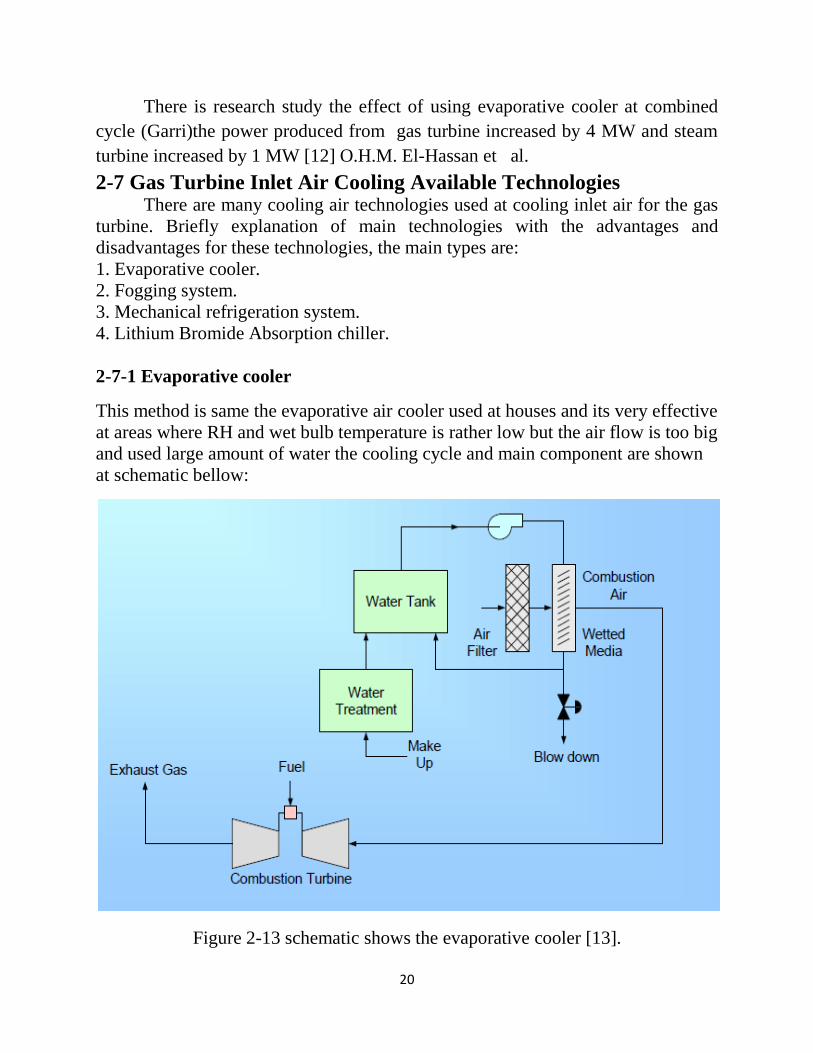
2-7-1 Evaporative cooler
This method is same the evaporative air cooler used at houses and its very effective
at areas where RH and wet bulb temperature is rather low but the air flow is too big
and used large amount of water the cooling cycle and main component are shown
at schematic bellow:
Figure 2-13 schematic shows the evaporative cooler [13].

21
Advantages of the evaporative air cooling system are:
Lowest capital cost.
Lowest Operation &Maintenance cost.
Can operate on raw water.
Quick delivery and installation time.
Operates as an air washer and cleans the inlet air.
Disadvantage of the evaporative air cooling system are:
Limitation on capacity improvement at Garri power plant after used this
technology the output power increase only by 10% and still there is 10% of
rate power.
Highly influenced by the site wet bulb temperature.
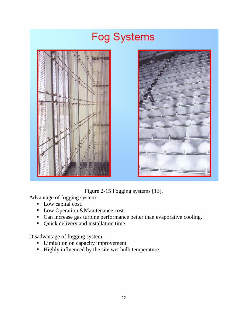
2-7-2 Fogging system
In this system spray treated water at the compressor bill moth and this system
although suitable for the high ambient temperature and low relative humidity areas,
and main component are shown at Figure 2-14
Figure 2-14schematic shows the Fogging system [13].
22
Figure 2-15 Fogging systems [13].
Advantage of fogging system:
Low capital cost.
Low Operation &Maintenance cost.
Can increase gas turbine performance better than evaporative cooling.
Quick delivery and installation time.
Disadvantage of fogging system:
Limitation on capacity improvement
Highly influenced by the site wet bulb temperature.

23
2-7-3 Mechanical refrigeration system
This technology used mechanical devises to produced chilled water to cool inlet air
at heat exchanger installed in side inlet air duct, this technology suitable for the
high ambient temperature and high relative humidity areas, and main component
are shown at Figure 2-16
Figure 2-16 Schematic Systems Using a Mechanical Chiller [13].
Advantage of Mechanical Refrigeration System:
Can increase gas turbine performance better than evaporative cooling, and
fog system.
Not very sensitive to ambient air wet bulb temperature.

24
Disadvantage of Mechanical Refrigeration System:
High initial capital cost.
High Operation &Maintenance cost.
Long delivery and installation time.
Requires chilled water cooling circuit.
Higher parasitic load than direct type.
Higher energy input compared to evaporative cooler.
2-7- 4 Lithium Bromide Absorption chiller
An absorption refrigerator is a refrigerator that uses a heat source solar energy, a
fossil-fueled flame, waste heat from factories, and district heating systems which
provides the required energy to drive the cooling process. Cooling inlet air at gas
turbine by using the heat from gas turbine exhaust this use is very efficient. Since
the gas turbine then produces electricity, the main components to produced chilled
water are shown at schematic bellow:
Figure 2-17 absorption chiller inlet air cooling system schematic [13].

25
Figure2-18 Absorption Chiller Flow Diagram from York international [13].
Single Stage Lithium Bromide Absorption Chiller used at areas where relative
humidity is rather high, and the plant is going to operate in a combined cycle or
cogeneration mode and has access to low pressure steam.
Advantage of Lithium Bromide Absorption Chiller:
Can increase gas turbine performance better than evaporative cooling, and
fog system.
Not very sensitive to ambient air wet bulb temperature.
Disadvantage of Lithium Bromide Absorption Chiller:
High initial capital cost.
High Operation &Maintenance cost.
Longer delivery and installation time.
High expertise is needed to operate and maintain the plant, [13] Bob
Omidvar.
In case of a steam operated chiller, cannot be applied in an open cycle gas turbine
plant.