CHAPTER 3 System design - SUST Repository
19
33 CHAPTER 3 System design 3.1The Line Follower Robot This Line Follower Robot basically use a Cadmium Sulphide (CdS) photocell sensor or known as Light Dependent Resistor (LDR) and the high intensity blue Light Emitting Diode (LED) to illuminate the area under the photocell sensor to sense the black track line and the DC motor speed control technique to navigate the black line track as shown the: figure 3.1. Figure 3.1 Line-follower Robot 3.2.1 Basic Design and Requirements The robot is built with ATmega8, L293D, IR sensors, and platform consisting of a toy car chassis (or robotic kits). The robot is designed using two DC motors controlling wheels (4 wheel drive car). It has a combination of IR LED’s and Photo Transistor for detect black tracking tape .It captures the line position with the help of these optical sensors called opto-couplers mounted at front end of the robot. (Each opto-coupler consists of an IR LED and an IR Sensor) when the sensors detect black surface, output of sensors enter as inputting to ATmega32 in ADC (analogue to digital conversion) , ADC is low logic and for white surface the
-
Upload
khangminh22 -
Category
Documents
-
view
1 -
download
0
Transcript of CHAPTER 3 System design - SUST Repository

33
CHAPTER 3
System design
3.1The Line Follower Robot
This Line Follower Robot basically use a Cadmium Sulphide (CdS) photocell
sensor or known as Light Dependent Resistor (LDR) and the high intensity blue
Light Emitting Diode (LED) to illuminate the area under the photocell sensor to
sense the black track line and the DC motor speed control technique to navigate
the black line track as shown the: figure 3.1.
Figure 3.1 Line-follower Robot
3.2.1 Basic Design and Requirements
The robot is built with ATmega8, L293D, IR sensors, and platform consisting
of a toy car chassis (or robotic kits). The robot is designed using two DC motors
controlling wheels (4 wheel drive car). It has a combination of IR LED’s and
Photo Transistor for detect black tracking tape .It captures the line position with
the help of these optical sensors called opto-couplers mounted at front end of the
robot. (Each opto-coupler consists of an IR LED and an IR Sensor) when the
sensors detect black surface, output of sensors enter as inputting to ATmega32 in
ADC (analogue to digital conversion) , ADC is low logic and for white surface the

34
output is high. It reports to the microcontroller for accurate control and steering of
motors. Microcontroller ATmega8 and Motor driver L293D were used to drive the
motors. show figure 3.2
figure 3.2 Stages of the system of line follower robot
3.2.2 The program for Line following robot
The Line following robot Program needs help from three libraries :
LED lib (to turn on/off five indicator LEDs)
Motor lib (to control the speed and direction of rotation of motor)
ADC lib (to configure and use the analog to digital converter of ATmega8).

35
3.2.3 Introduction to ATmelStdio6
Atmel Studio 6 or AS6 in short, is the latest IDE (Integrated Development
Environment) by Atmel for their 8 bit and 32bit MCUs lines. AVR Studio 6
comes integrated with latest version of avr-gcc compiler. So the completed
development environment can be installed with a single easy to use installer.
The IDE Consist of a high end editor with flawless auto-complete. The editor is
powered by proven Microsoft Visual Studio. The editor makes it easy to type and
edit C source file with its auto complete feature, the user don’t have to “refer” to
the reference manual often as the editor itself shows the parameter requirements of
a function, return type and the help.
The line following robot(LFR) Code Walk through:-
1.Design PD controller using MATLAB commands:
Syntax:
Sys=tf(num,den);
[kp,ki,kd]=tf(G(s));
Kp =200;
Ki =0.2;
Kd =120;
Numc =[Kd Kp Ki];
Denc = [1 0];
[numCL, denCL]=cloop(conv(num,numc),conv(den,denc));
step(numCL, denCL)
Figure 3.3 response PD controller using MATLAB
1. The main program begins by Initializing three subsystems namely Motor,
LED and ADC (for sensor input).

36
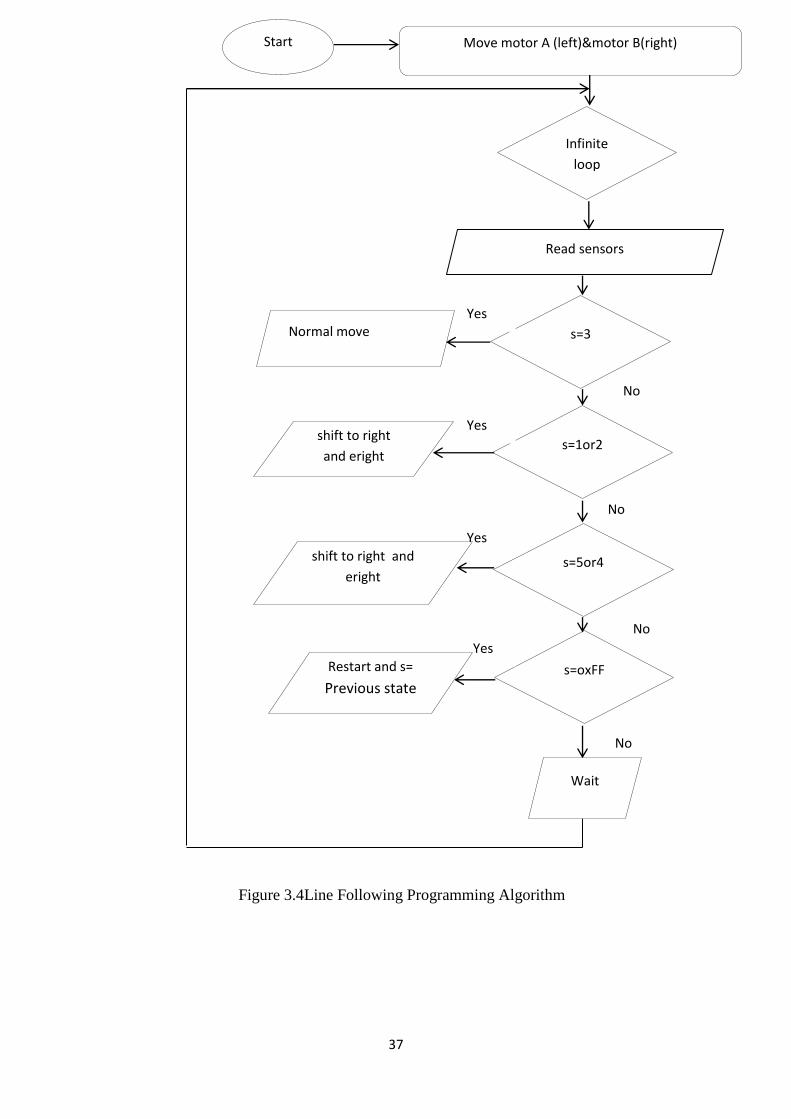
2. Then program enters into a infinite loop ( while(1) { //Main LFR Loop }end
the loop off power ), this infinite loop keeps the robot follow line as long as it has
power.
In the loop first thing we do is to read the sensor using the ReadSensors() we get a
value between 1 to 5 as follows.
the line is towards right of center then value tends to 5
When the line is towards left of center then value tends to 1
When line is in the exact center the value is 3
Returns 0xFF if no line is detected.
Return value may be fractional also, like it is 2.5 when line is beneath sensor 2 and
sensor 3
In case a line is NOT found we below any sensor we used value we got last time.
This is done by storing the current line position in a variable sprev just before the
end of main loop.
Now a PID algorithm is used to find out the control variable from the current
position and required position.
Current Position it is the position of line as read by the sensors.
Required Position is 3 (to keep the line on the middle sensor whose number is 3)
37
Figure 3.4Line Following Programming Algorithm
Start
Infinite
loop
s=1or2
s=5or4
s=oxFF
s=3
Move motor A (left)&motor B(right)
No
Yes
Yes
Yes
Yes
No
No
No
Read sensors
Normal move
shift to right
and eright
shift to right and
eright
Restart and s= Previous state
Wait

38
Then we make the control variable come within a range of -510 to +510
When the control variable is more than 0 that means line is towards the left, so we
need to take right turn to correct the error and bring the robot back to track. To do
a right turn we need to make the right motor go slow by the amount of control (if
control is less than 255).
if control is more than 255 then we need to make the right motor go in opposite
direction by the amount of control.
This will create a much faster right turning.
Similarly if control variable is less than 0 that means line is towards the right, so
we need to take left turn to correct the error and bring the robot back to track. The
whole code looks like this.
Figure3.5 Flow chart of the code

39
If Right black line sensor (sensor5=1) than LED5 (ON) .
If Right black line sensor (sensor4=1) than LED4 (ON) .
If Middle black line sensor (sensor3=1) than LED3 (ON).
If Left black line sensor (sensor2=1) than LED2 (ON).
If Left black line sensor (sensor1=1) than LED1 (ON).
Figure 3.6 LED &SENSORS programming

40
3.2.3 Voltage Regulator 78xx
Voltage regulators convert fixed DC output voltage from variable DC. The
most commonly used ones are 7805 and 7812. 7805 gives fixed 5V DC voltage if
input voltage is between 7.5V to 20V. They help to maintain a steady voltage
level despite varying current demands and input voltage variations. If input
voltage is <7.5 V then regulation whon't i.e. if input is 6V then output may be 5V
or 4.8V, but there are some parameters for the voltage regulators like maximum
output current capability, line regulation etc.. , that won't be proper. To identify
the leads of the 7805, you have to keep the lead downward and the writing to your
side, (see the figure 3.7). You can see the heat sink above the voltage regulator.(1-
input,2-gnd,3-output) [2]
.
Figure 3.7circuit of regulator and sample of integrated circuit
Figure above shows how to use 7805 voltage regulator. Here you can see that
coupling capacitors are used for good regulation. But there is no need for it in
normal case. But if 7805 is used in analog circuit we should use capacitor,
otherwise the noise in the output voltage will be high. The mainly available 78xx
IC's are 7805, 7809,7812,7815 [2]
.
3.2.4 Processing System
Processing system acts as the Brain of robot, which generates desired output
for corresponding inputs. For that we use microcontrollers. In present days, there
are several companies that manufacture microcontrollers, see the figure 3.8. For
example ATMEL, Microchip, Intel, Motorola etc. We will be using ATmega8L
microcontroller in our robot. It is an ATMEL product. It is also called AVR.
41
It's used ATmega8L because Line follower robot requires simple
microcontroller as it uses simple algorithms. We can use any microcontroller for
that.It is an ISP (In System Programmable) device. It means programming
(Burning) of ATmega8 IC can be done without removing it from the system.
Note: Programming (Burning) of a microcontroller means transferring the code
from computer to microcontroller. More details show the appendix B.
It has on chip PWM (Pulse Width Modulation) circuit at three pins (Pin 15, 16
and 17). We have explained PWM in another tutorial.
It consumes low power than other microcontrollers.
It has an inbuilt RC oscillator. (Oscillator is a clock generator circuit).
3.3.1Hardware Details
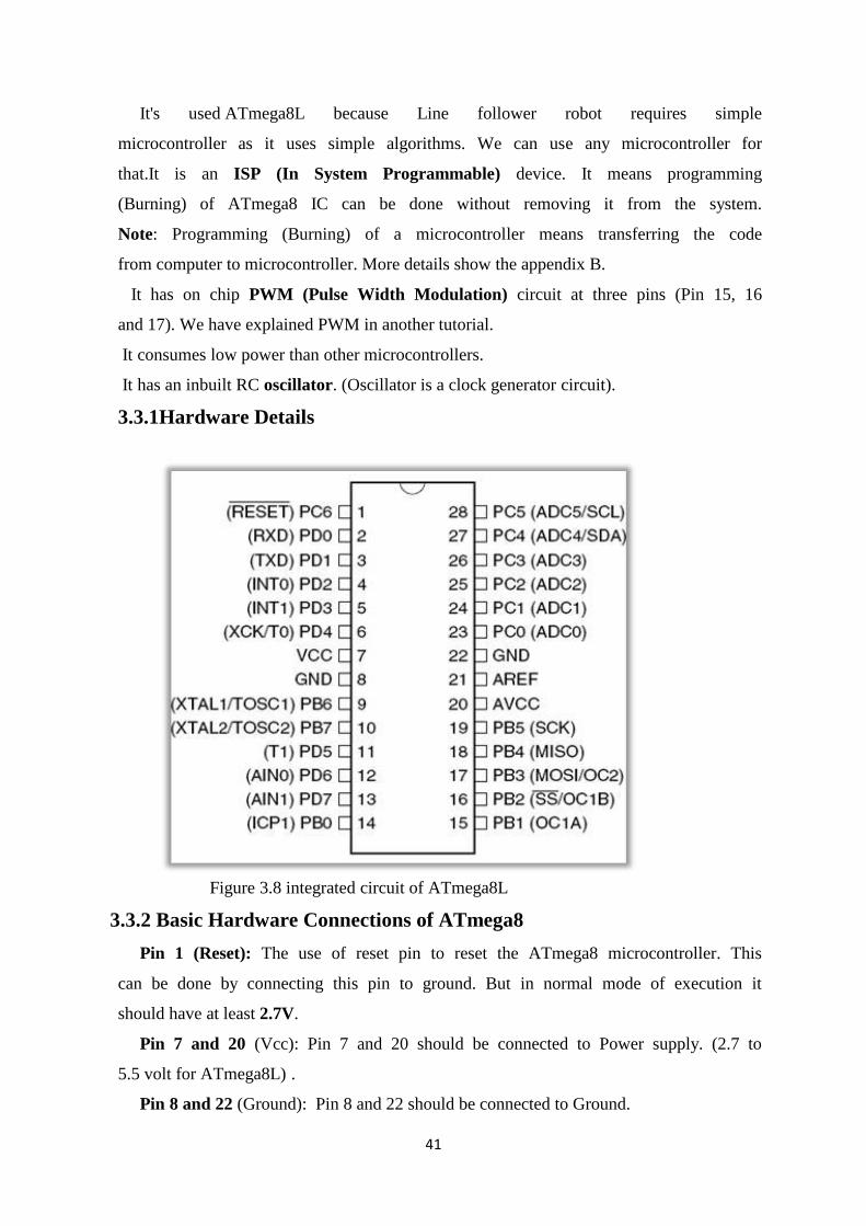
Figure 3.8 integrated circuit of ATmega8L
3.3.2 Basic Hardware Connections of ATmega8
Pin 1 (Reset): The use of reset pin to reset the ATmega8 microcontroller. This
can be done by connecting this pin to ground. But in normal mode of execution it
should have at least 2.7V.
Pin 7 and 20 (Vcc): Pin 7 and 20 should be connected to Power supply. (2.7 to
5.5 volt for ATmega8L) .
Pin 8 and 22 (Ground): Pin 8 and 22 should be connected to Ground.

42
Input and Output Ports
In ATmega8 we have three I/O (input/output) ports viz. Port B, Port C, Port D .
One can configure any pin of all these ports as input or output pin by software.
We are using Port B pins (PB0 to PB3) as output pins because at pinPB1 and
PB2 we have on-chip PWM output that can control the speed of motors. Pin
PORT Connection PWM 14 PB0 Negative of right NO 15 PB1 Positive of right
YES 16 PB2 Positive of Left YES 17 PB3 Negative of Left NO [2]
more details
sees the appendix C.
Table 3.1 function of pins at ATmega8L microcontroller
Thus we can use Port C or Port D or remaining Pins of Port B as input. But
forthe sake of simple hardware connection we choose Port D pins as input pins
3.3.3Burner (or Programmer)
Burner (or programmer) is the circuit used to transfer the code from computer
to microcontroller IC. For programming AVR there are different types of burners
available Eg stk200, stk500, jtag2 etc. We are using stk200 programmer.
3.3.3.1
i. Requirements
Parallel Port DB 25 connector (connects to the computer )
5 Pin RMC connector goes to AVR PCB.
5 wired Bus They are shown in following figure 3.8.
Pin Port Connection
14 PB0 Negative of right
15 PB1 Positive of right
16 PB2 Positive of left
17 PB3 Negative of left
18 PB4 medium
43
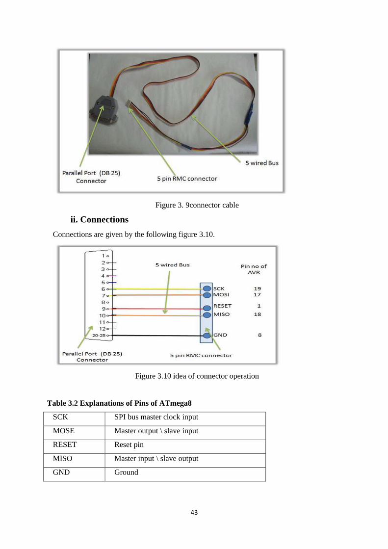
Figure 3. 9connector cable
ii. Connections
Connections are given by the following figure 3.10.
Figure 3.10 idea of connector operation
Table 3.2 Explanations of Pins of ATmega8
SCK SPI bus master clock input
MOSE Master output \ slave input
RESET Reset pin
MISO Master input \ slave output
GND Ground
44
3.3.4Program Details
i. Programming and Simulation
Programs for the AVR series of microcontrollers can be written in assembly
(AVR ASM), C and BASIC. AVR Studio, WinAVR etc. are some free
development software's for programming the AVR Microcontrollers. We are using
winAVR for programming and AVR Studio for simulating (Simulation means
debugging the code on software, one can virtually give the input and check the
output for that code). In winAVR programmers Notepad we write our C code,
after compilation it generates ‘.hex’ file that is a hardware level code.
i.Motor Output System
For moving a robot we have to dc motor attached to wheels gears.
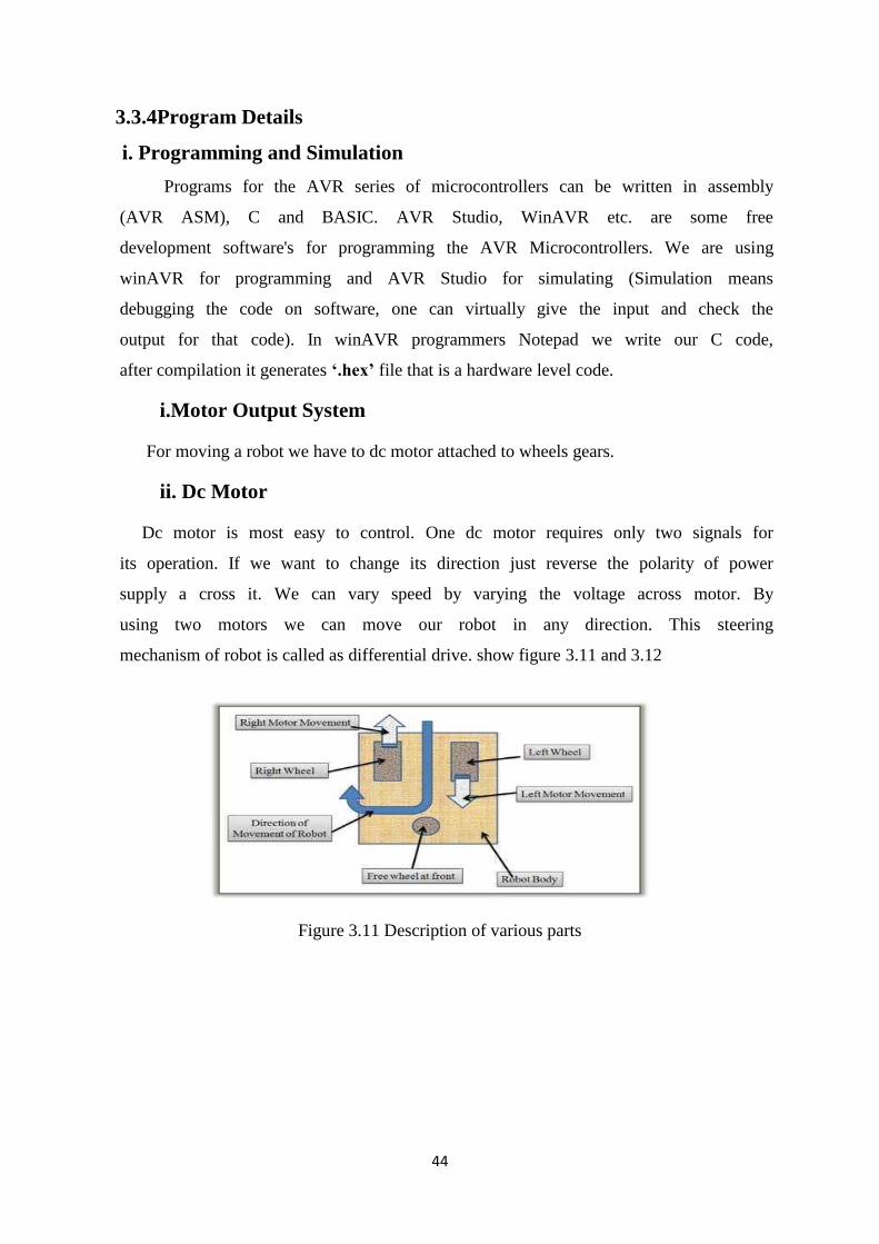
ii. Dc Motor
Dc motor is most easy to control. One dc motor requires only two signals for
its operation. If we want to change its direction just reverse the polarity of power
supply a cross it. We can vary speed by varying the voltage across motor. By
using two motors we can move our robot in any direction. This steering
mechanism of robot is called as differential drive. show figure 3.11 and 3.12
Figure 3.11 Description of various parts

45
Figure 3.12 Different Types of Movement of Robot
iii. Motor Driver L293D(H-bridge)
From microcontroller we cannot connect a motor directly because
microcontroller cannot give sufficient current to drive the DC motors. Motor
driver is a current enhancing device; it can also be act as Switching Device. Thus
we insert motor driver in between motor and microcontroller.
Motor driver take the input signals from microcontroller and generate
corresponding output for motor.
Figure 3.13 Pin details of L293
This is a motor driver IC that can drive two motor simultaneously. Let's see how
we use this IC (see in the figure 3.13)

46
3.3.6.1 operation H- bridge
The H-bridge arrangement is generally used to reverse the polarity of the motor,
but can also be used to 'brake' the motor, where the motor comes to a sudden stop,
as the motor's terminals are shorted, or to let the motor 'free run' to a stop, as the
motor is effectively disconnected from the circuit. The following table summarises
operation, with S1-S4 corresponding to the diagram above.
Figure 3.14 Structure of an H bridge (highlighted in red)
Figure 3.15 The two basic states of an H bridge
Table 3.3 Output of tow motors
S
1
S
2
S
3
S
4
Result
1 0 0 1 Motor moves
right
0 1 1 0 Motor moves
left
0 0 0 0 Motor free runs
0 1 0 1 Motor brakes
1 0 1 0 Motor brakes
1 1 0 0 Shoot-through
0 0 1 1 Shoot-through
1 1 1 1 Shoot-through

47
Figure 3. 16 Block diagram H bridge
3.4.1 Sensing of the Black Line
The sensors used for the project are Reflective Object Sensors, 0PB710F that
are already ready in the Electronic Lab. The single sensor consists of an infrared
emitting diode and a NPN Darlington phototransistor. When a light emitted from
the diode is reflected off an object and back into the phototransistor, output current
is produced, depending on the amount of infrared light, which triggers the base
current of the phototransistor.
In my case, the amount of light reflected off a black line is much less than that of
a white background, so we can detect the black line somehow by measuring the
current. (This current is converted to voltage.)
Figure 3.17 Sensor in an opto-coupler

48
Figure 3.18 Sensor circuit redrawn with the comparator
3.4.2 Control of DC Motor
The easy method to navigate the black track line is to turn ON and OFF the
left or the right DC motor according to the sensor reading (black turn OFF and
white turn ON), but using this method will make the LFR to move in zigzag way.
By proportionally control both left and right DC motor speed according to the
light intensity level received by the photocell sensor (reflected back by the black
track line) we could make the LFR easily navigate this track. The common
technique to control the motor speed efficiently is to use a pulse signal known as
the pulse width modulation or PWM for short.
PWM basically is an ON and OFF pulse signal with a constant period or
frequency. The proportion of pulse ON time to the pulse period is called a “duty
cycle” and it expressed in percentage. For example if the proportion of pulse ON
time is 50% to the total pulse period than we say that the PWM duty cycle is 50%.
The PWM duty cycle percentage is corresponding to the average power produced
by the pulse signal; the lower percentage produces less power than the higher
percentage.
Therefore by changing the PWM duty cycles we could change the average voltage
across the DC motor terminals, this mean we could vary the DC motor speed just
by changing the PWM duty cycle. Therefore to make the LFR smoothly navigate
the black track line, we have to adjust the PWM duty cycle according to the
photocell sensor reading. The brighter light intensity level received by sensor
(sensor is on the white surface) will result in higher PWM duty cycle percentage
and the darker light intensity level (sensor is on the black line) received by
photocell sensor will result in lower PWM duty cycle percentage.

49
Figure 3.19 PWM timing diagram
3.5Principles How a Robot Can Follow a Guideline
A robot seeks a guideline by riding on a spiral trajectory until it crosses. Even
then the robot starts to follow a given guideline. There are three fundamental
situations that could happen:
3.5.1 Being on a Line
The simplest case is when both sensors are above a guideline and a robot
follows it going straight on, show figure 3.20.
Figure 3.20 Being on line
3.5.2 Loosing a Line
Approaching a curve, a right sensor looses contact with a line. The robot
unclothes its left engine; thereby it begins to turn left to return to the line. Show
figure 3.21

50
Figure 3.21 Losing a line
3.5.3 Outside of a Line
If a curve is too sharp (it means a robot’s turning radius is greater than a
curve radius of the line), a robot can lose the guideline and it is outside of it. It
changes the direction of the engine, which causes the robot to turn towards to the
line. The sensors that are placed off axis get the same situation could also occur at
the end of the line. In such case the robot reverses at 180 degrees and turns back,
Show figure 3.22
Figure 3.22 Outside

51
3.6 Line follower board using ATmaga8 circuit
Figure 3.23 Line Following Robot Simulation Circuit