Transmission Line Protection Using Numerical Relay - SUST ...
74
Sudan University of Sciences and Technology College of Engineering Electrical Engineering Transmission Line Protection Using Numerical Relay A Project Submitted In Partial Fulfillment for the Requirements of the Degree of B.Sc. (Honor) In Electrical Engineering Prepared By : 1. Ahmed Abbas Elhaj Faroug 2. Altahir Abass Ahmed Mohamed 3. Mohmmed Ahmed Haroun Ibrahim 4. Muhammad Yassir Nsr Eldeen Alatta Supervised By: Dr. Elfadil Zakaria Yahia October 2018
-
Upload
khangminh22 -
Category
Documents
-
view
0 -
download
0
Transcript of Transmission Line Protection Using Numerical Relay - SUST ...

Sudan University of Sciences and
Technology
College of Engineering
Electrical Engineering
Transmission Line Protection Using
Numerical Relay
A Project Submitted In Partial Fulfillment for the Requirements
of the Degree of B.Sc. (Honor) In Electrical Engineering
Prepared By :
1. Ahmed Abbas Elhaj Faroug
2. Altahir Abass Ahmed Mohamed
3. Mohmmed Ahmed Haroun Ibrahim
4. Muhammad Yassir Nsr Eldeen Alatta
Supervised By:
Dr. Elfadil Zakaria Yahia
October 2018

I
اآلية
قال تعالى:
أحا انعهى ) انذي آيا يكى ( درجاث يزفع هللا انذي
(11انجادنت االيت)

II
Dedication
To our great parents, who never stop giving us themselves in countless
ways.
To our dearest friends, who leads us through the valley of darkness with
light of hope and give us encourage and support.
To our beloved brothers and sisters who stands by us when things look
bleak.
To all our family, the symbol of love and giving.
To all the people in our life who touch our heart, we dedicate this research.

III
Acknowledgments
First and foremost, we must acknowledge our limitless thanks to Allah,
the Ever-Magnificent; the Ever-Thankful, for His help and bless.
We owe a deep debt of gratitude to our university for giving us an
opportunity to complete this work.
We grateful to some people, who worked hard with us from the
beginning till the completion of the present research particularly our
supervisor, Dr: Alfadel Zakaria Yahia who has been always generous
during all phases of the research and we totally sure that this work would
have never become truth, without His guidance.
And we highly appreciate the efforts expended by Eng. Mohamed
Youssef the manager of protection system department in (Sudanese
Electricity Transmission Grid) who never stingy us by his knowledge and
always help us and we thank all Engineers in protection system department
for help us to do our thesis.
We would like to take this opportunity to say warm thanks to all my
beloved friends, who have been so supportive along the way of doing our
thesis.
IV
Abstract The objective of this research to study and understand the technology
and function of the latest developed relays with the main focus on the
preparation of the relay setting and uploading them in the relays and check
correct operation of the relay’s zones.
The thesis first describes the protection system of the transmission lines
with the recently constructed high voltage transmission line linking shagara
110KV substation with Local market high voltage 110KV substation.
This line is protected using numerical relays type MicoM P442.
The thesis then describes the theory of distance protection together with
the evolution of protective relay. The function of numerical relays type P442
is described. Data is collected from the transmission line and calculated the
setting to fed to the relay by using software (MicoM Studio). According to the
data which inserted to the numerical relay has been excepted the relay
operated in corrective zone’s without made any overlap with other zones.
Lastly conclusion and recommendation are made.

V
المستخلصانذف ي ذا انبحذ دراست فى اخز انخمياث اناو نخطر انزحالث بانخزكيز عهي
حجيز انضبظ ادخال انعهياث انضبظ اني ذ انزحالث انخحمك ي صحت عم انزحالث في
مم نهجذ انعاني خاصت خظ انع ظاو انحايت في خطط انمم ذا انبحذ يخحذد .انطمت انحذدة
انسق انحهي انفزعيخي. شجزة انذي حزبظ بي يحطخي
MicoM P442 . ذا انخظ حج حايخ باجزة حايت
انبحذ يشزح ظزيت انحايت انسافيت يع حطر يزحالث انحايت انسافيت .
ي خظ انمم حى ادخانا في ذ ياو عم ذ انزحالث حى شزحا .انعهياث حى جعا
انزحالث . ا حساباث انضبظ لذ اجزث ي رى ادخهج نهزحم باسطت بزايج
MicoM Studio). ) فما نهبيااث انذخهت نهزحم انعذدي خلع عها في انطمت انحذدة نا د
انخصياث.اخيزا يخحذد انبحذ ع انخاحت حذد اي حذاخم يع اناطك االخزي.

VI
TABLE OF CONTENT
Page Title Section
I االستهالل
II Dedication
III Acknowledgement
IV Abstract
V سخخهصان
VI-VIII Table of Contents
IX-XI List of Figures
XI List of Abbreviations
CHAPTER ONE:
INTRODUCTION
1 Overview 1.1
2 Sudan National Electricity Network
Topology 1.2
2 Problem Statement 1.3
3 Objective 1.4
3 Thesis Layout 1.5
CHAPTER TWO:
LITERATURE REVIEW
4 Electric Power System 2.1

VII
5 Nature and Causes of Faults 2.2
6 Power System Protection 2.3
12 Protective Relay 2.4
CHAPTER THREE:
DISTANCE PROTECTION
18 Introduction 3.1
20 Principle of Distance Relays 3.2
20 Relay Performance 3.3
23 Zones of Protection 3.4
26 Distance Relay Characteristics 3.5
38 Auto-Reclosing 3.6
39 Auto-Reclosing on HV Transmission lines 3.7
CHAPTER FOUR:
NUMERICAL RELAY p442 AND OMICRON
DEVICE TEST
40 Introduction 4.1
41 MiCOM Distance Relay 4.2
42 CMC 356 –OMICRON
4.3
44 Relay Setting of Distance Protection (p442) 4.4
47 Test Result on Omicron Studio 4.5

VIII
CHAPTER FIVE:
CONCLUSIONS AND RECOMMENDATIONS
56 Conclusions 5.1
57 Recommendations 5.2
58 References
59 Appendix

IX
LIST OF FIGURES
Page Title Fig
5 Generation, transmission and
distribution of electrical power
2.1
7 power system protection 2.2
8 Protection zones marked 2.3
9 Unit protection 2.4
9 Non-unit protection 2.5
11 Station battery 2.6
14 Attracted armature relay 2.7
15 types of static relays 2.8
17 types of digital relays 2.9
17 types of numerical relays 2.10
19 Advantages of distance over
overcurrent protection
3.1
22 Typical of impedance reach accuracy
characteristics for zone 1
3.2
22 Typical operation time characteristics
for Zone 1 phase-phase faults
3.3
23 Typical operation-time contours 3.4
25 Typical time/distance characteristics for
three zone distance protection
3.5
28 Plain impedance relay characteristic 3.6
29 Basic operation of impedance relay 3.7
29 Combined directional and impedance
relays
3.8
31 Directional Characteristics 3.9
32 Modified directional impedance relay
characteristics
3.10
33 Operating characteristics of reactance
relay
3.11

X
35 Mho relay characteristic 3.12
37 Quadrilateral characteristic 3.13
41 MICOM p442 relay 4.1
42 MICOM p442 relay inputs and outputs 4.2
43 CMC 356 –OMICRON (front) 4.3
44 CMC 356 –OMICRON (back) 4.4
47 90% of zone one impedance 4.5
48 110% of zone one impedance 4.6
49 90% of zone two impedance 4.7
50 110% of zone two impedance 4.8
51 90% of zone three impedance 4.9
52 110% of zone three impedance 4.10
53 90% of zone four impedance 4.11
54 110% of zone four impedance 4.12
55 zones (Z1,Z2,Z3andZ 4). 4.13
55 zones (Z1,Z2,Z3andZ 4). 4.14

XI
LIST OF ABBREVIATIONS
Direct Current DC
Alterative current AC
Low voltage LV
Line to ground fault LG
Double line to ground fault LLG
Line to line fault LL
Current transformer CT
Voltage Transformers VT
High voltage HV
Analogue to Digital Convertors A/D
Discrete Fourier Transform DFT
digital signal processor DSP
system impedance ratios S.I.R
Switch-on-to fault SOTF
Digital signal processors DSPS
Data acquisition system DAS
Series of distance relay P441,
P442,…..
Personal computer PC

1
CHAPTER ONE
INTRODUCTION
1.1 Overview
Electrical energy is known to be the most popular form of energy,
because it can be transported easily at high efficiency and reasonable cost.
The first electrical power stations supplied the direct current (DC) power for
the consumers and distributed it by underground cables, but because of
excessive power loess RI2 (where R represent the cable resistance and I is the
current) at low voltage, the companies could deliver electrical energy only a
short distance from their stations.
With the invention of the transformers to raise the level of the
alternative voltage or alterative current (AC) for transmission and distribution
and the invention of induction motors to replace DC motors, the advantage of
AC system became apparent, and made AC system prevalent. Another
advantage of the AC system is that to lack of commutators in the AC
generators, more power can be produced conveniently at high voltages.
In recent years, the vast enterprise of supplying electrical energy
presents many engineering problems which provided the engineers with a
variety of challenges. The entire design must be predicated on automatic
control and not on the slow response of human operations which has made it
possible to design and construct economic and reliable power systems capable
of satisfying the continuity growth in demand for electrical energy. In this,
power system protection and control play a significant part, and progress in
design and development in these fields has necessarily had to keep pace with
advances in the design of primary plant, such as transformers, switchgears,
and overhead lines.
The problem of combining fast fault clearance with selective tripping
of plant is a key aim for the protection of power systems. To meet these

2
requirements, high-speed protection systems for transmission and primary
distribution circuits that are suitable for use with the automatic enclosure of
circuit breakers are under continuous development and are very widely
applied.
Distance protection, in its basic form, is a non-unit system of protection
offering considerable economic and technical advantages. Unlike phase and
neutral overcurrent protection, the key advantage of distance protection is that
its fault coverage of the protected circuit is virtually independent of source
impedance variations [1].
The kilovolt standards for high voltage transmission lines used in
Sudan electrical network are 500KV,220KVand 110KV.The generation
consists of hydro generation which is far away from the load center and
thermal generation which is concentrated in the load center which is
surrounded by 220KVand 110KV transmission lines known as Khartoum
rings. The Blue Nile transmission line connect Roseries hydro power station
with the load center throw 220KV transmission line. The 500KV transmission
line connect Merowe hydro power station with the load center.
1.2 Problem Statement
There is unacceptable operation in zone two when the fault occurs at
distribution sides (LV).
1.3 Objectives
i. obtain Correct operation of the numerical relay in all zones.
ii. maintain continuity supply to grid.
iii. improve the power system reliability.
iv. Increase the sensitivity of protection system.
v. Obtain full information about the faults.

3
1.4 Methodology
Several stages were taken in order to ensure that the desired objectives
of the project were achieved. The first stage of this project; necessary data of
transmission line between Shagara and Local-market substations was
obtained. The second stage; CT and VT ratio were selected, and then the
setting was calculated according to IEEE and IEC standards. The third stage;
numeric relays from Omicron which offers them last version of numerical
relays in the field of protection were used in order to obtain full and advanced
protection of the transmission line.
1.5 Project Layout
In chapter one introduction. In chapter two represent the literature
review of protection system, types of faults, and relays technology. In chapter
three the present distance protection, and distance relays and their
characteristics. The numerical relay, its application at distance protection, and
the results are present in chapter four. at chapter five present the conclusions
and recommendations.

4
CHAPTER TWO
LITERATURE REVIEW
2.1 Electric Power System
An electric Power system refers to a network that constitutes electrical
components/machines used in the generation, transmission and consumption
of electric power [2]. The diagram below illustrates a complete electric power
system. It involves generation, transmission and distribution of electric power
to various categories of consumers. The generation plant is normally located
far from the load center. There are different levels of electric power
consumption depending on the purpose for which a consumer uses electricity.
Electrical power consumers may be industrial, commercial or domestic. These
consumers require different levels of electric power supply. In order to meet
their specific needs, certain devices that adjust the voltage levels accordingly
have to be used. Some of those components include: step up and step down
transformers, capacitor banks, protective devices etc [3]. The purpose of the
electric transmission system is the interconnection of the electric-energy-
producing power plants or generating stations with the loads. A three-phase
AC system is used for most transmission lines[4]. It is shown in Figure (2.1).

5
Fig.2.1: Generation, transmission and distribution of electrical power.
2.2 Nature and Causes of Faults
Faults are caused by insulation failures or by conducting path failures.
Most of faults in transmission line caused by overvoltage due to lightning,
switching surge or external faults (trees, birds, snow, windy…etc.).
2.2.1 Types of Faults
They are three types of fault such as:
i. Symmetrical faults; (Is a three-phase short-circuited with ground or
without ground).
ii. Unsymmetrical faults;(LG, LLG, LL, and open circuit).
iii. Simultaneous faults;(The same or different types of faults occurring
at the same or different point of the line).

6
2.2.2 Effect of Faults
The most dangerous type of fault is short-circuiting. It has effects to
power system if it remains uncleared:
i. Heavy current causes damage.
ii. Arcs cause fire hazards.
iii. Reduce in the supply voltage.
iv. Unbalance supply voltage and current effected to load
(machine).
v. Loess of system stability.
vi. It causes an interruption of supply to consumers, thereby
causing a loss of revenue.
50% of total faults occur on overhead lines hence it is overload lines
that required more attention while planning and design protective schemes for
power system. The cost of protective equipment generally works out to be
about 5% of the total cost of the system[4].
2.3 Power System Protection
A branch of electrical power engineering that deals with protection of
Power system from faults is known as power system protection. It does this
by isolating the faulted parts of the system from the rest of healthy electrical
network [5]. The diagram below shows a model of a power protection system.
It is shown in Figure (2.2).
7
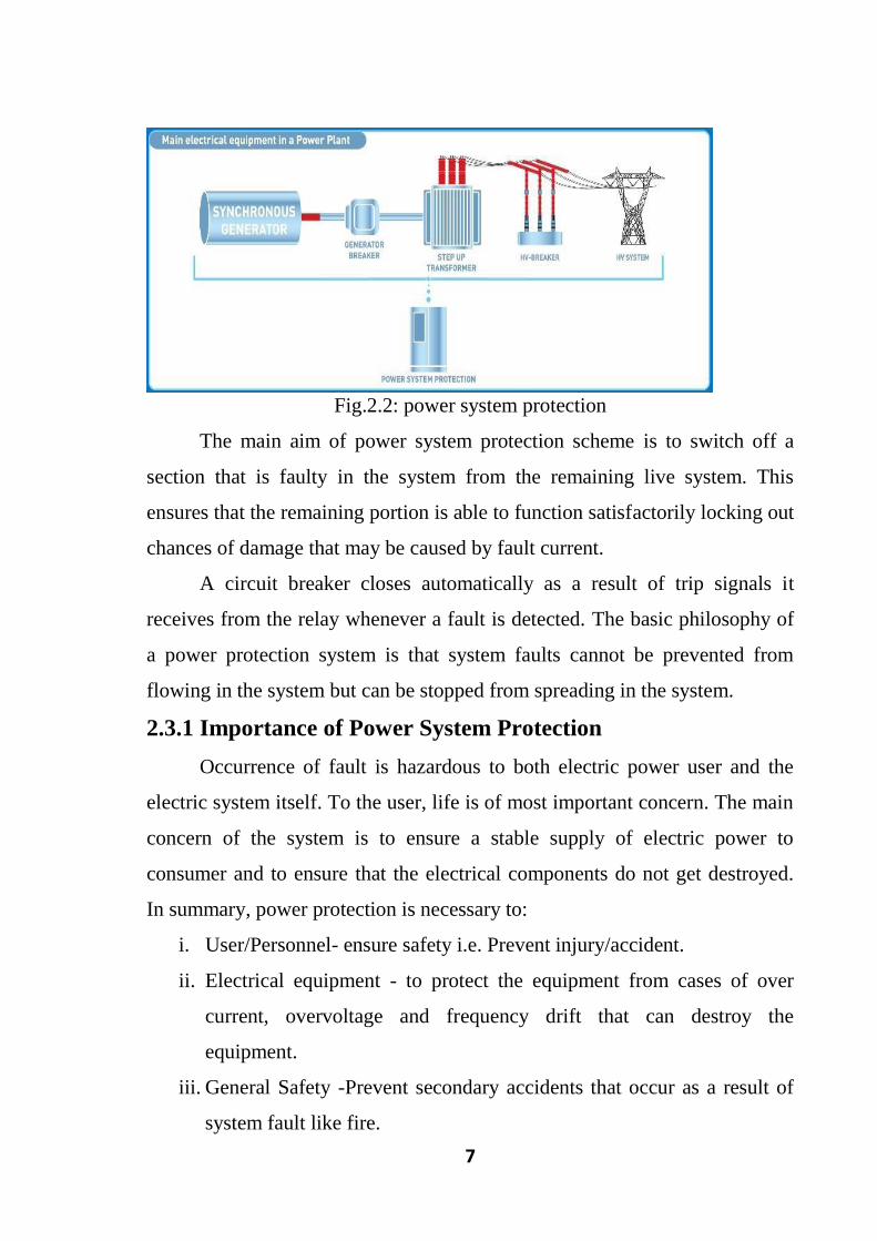
Fig.2.2: power system protection
The main aim of power system protection scheme is to switch off a
section that is faulty in the system from the remaining live system. This
ensures that the remaining portion is able to function satisfactorily locking out
chances of damage that may be caused by fault current.
A circuit breaker closes automatically as a result of trip signals it
receives from the relay whenever a fault is detected. The basic philosophy of
a power protection system is that system faults cannot be prevented from
flowing in the system but can be stopped from spreading in the system.
2.3.1 Importance of Power System Protection
Occurrence of fault is hazardous to both electric power user and the
electric system itself. To the user, life is of most important concern. The main
concern of the system is to ensure a stable supply of electric power to
consumer and to ensure that the electrical components do not get destroyed.
In summary, power protection is necessary to:
i. User/Personnel- ensure safety i.e. Prevent injury/accident.
ii. Electrical equipment - to protect the equipment from cases of over
current, overvoltage and frequency drift that can destroy the
equipment.
iii. General Safety -Prevent secondary accidents that occur as a result of
system fault like fire.

8
iv. Power Supply Stability- Ensures a continuous and stable supply of
electrical power.
v. Operation Cost -Ensure optimal operating efficiency so as to reduce
equipment maintenance/replacement cost.
2.3.2 Protective Zones
A protective zone is the separate zone which around each system
element. The significance of such a protective zone is that any fault occurring
within a given zone will cause the tripping of relays which cause opening of
all circuit breakers located within that zone. As shown in Figure (2.3).
The boundaries of protective zones are decided by the location of the
current and voltage transformers. In practice, various protective zones are
overlapped. The overlapping of protective zones is done to ensure complete
safety of each and every element of the system, otherwise there could be
some portion which is left out and remains unprotected [6].
Fig.2.3: Protection zones marked.

9
2.3.3 Types of Protection Systems
Implementation of power system protection can be done in two ways.
These are: the unit protection and non-unit protection, OR main and backup
protection[2].
i. Unit Protection:
The unit protection scheme protects a definite\discrete zone bounded
by the protection system. Differential relay protection is normally employed
in this scheme. It is shown in Figure (2.4).
Fig.2.4: Unit protection.
ii. Non-Unit Protection:
The Non-Unit protection protects a system\zone and can overlap with
another protection zone in the system. This scheme ensures an isolation of the
entire circuit (a larger area) in case a fault occurs as illustrated in figure
below, It is shown in Figure (2.5).
Fig.2.5: Non-unit protection
iii. Primary Protection or Main Protection:
The primary protection is the first line of defense and is responsible to
protect all the power system elements from all types of faults[6].

10
iv. Back-up Protection:
As already mentioned there are times when the primary protection may
fail. This could due to failure of the CT/VT or relay, or failure of the circuit
breaker. One of the possible causes of the circuit breaker failure is the failure
of the trip battery due to inadequate maintenance. We must have a second line
of defense in such a situation. Therefore, it is a normal practice to provide
another zone of protection which should operate and isolate the faulty element
in case the primary protection fails. A little thought will convince the reader
that the back-up protection should not have anything in common with the
primary protection. It should also preferably be located at a place different
from where the primary protection is located. Further, the back-up protection
must wait for the primary protection to operate, before issuing the trip
command to its associated circuit breakers. In other words, the operating time
of the back-up protection must be delayed by an appropriate amount over that
of the primary protection. Thus, the operating time of the back-up protection
should be equal to the operating time of primary protection plus the operating
time of the primary circuit breaker[5].
2.3.4 Power Protection Elements
There are four types of these elements, namely instrument
transformers, switchgears, protective gears and station batteries.
i. Instrument Transformers: these include current transformers and
voltage transformers. Instrument transformers step down current
and voltage from the power line to level that can be measured
safely.
ii. Switchgears: switchgears basically include circuit breakers.
Circuit breakers are the main part of a protection system. They
break contacts of the system in case of a fault. They include
minimum oil, bulk oil, SF6, vacuum and air blast circuit

11
breakers. Mechanisms of operation of circuit breakers include:
hydraulic, solenoid, spring and pneumatic[2].
iii. Protective Gear: consists of protective relays like voltage,
current, impedance, frequency and power relays, based on
operating parameter, definite time, inverse time, and stepped
relays, classified according to operating characteristic,
differential and over fluxing relays classified according to logic.
When a fault occurs, relay sends signal to relay to the circuit
breaker completing its circuit thus making it to trip.[2]
iv. Station Batteries: all circuit breakers in a power system operate
using direct current. The current is provided by battery banks
that are installed together with the circuit breaker. It is thus an
essential element in a power protection system. It is shown in
Figure (2.6).
Fig.2.6: Station battery.
2.3.5 Functional Requirement of Protection Relay
In order for a protection relay to operate effectively, it must have the
following qualities:
i. Reliability: power protection relays should remain inoperative always
as long as a fault does not occur. But when a fault occurs, they should
respond as quickly as possible.

12
ii. Selectivity: it must only operate on the section that has experienced a
fault to avoid unnecessary power outs due to wrong detections. It
should also respond only when a fault occurs.
iii. Sensitivity: The relaying equipment should be highly sensitive so that
it can be relied on to provide the required detection.
iv. Speed: the relaying equipment must operate at the required speed. It
should not delay so as to give time for system equipment to get
destroyed. It should also not be too fast to cause undesired operation.
v. Stability: Stable to the external fault condition or the fault occur
outside the zone protected.
vi. Adequateness: The protective system must provide adequate protection
for any element of the system. the adequateness of the system can be
assessed by considering following factors:
a. Rating of various equipment.
b. Cost of the equipment.
c. Location of the equipment.
d. Probability of abnormal condition due to
internal and external causes.
e. Discontinuity of supply due to the failure of
the equipment.
vii. Simplicity and economy: The protective system should be as
simple as possible so that it can be easily maintained. The protection
cost should not be more than 5% of the total cost. But if the
equipments to be protected are very important, the economic
constraints can be relaxed[7].
2.4 Protective Relay
Relaying is the branch of electric power engineering concerned with
the principles of design and operation of equipment (called ‘relays’ or
‘protective relays’) that detects abnormal power system conditions and

13
initiates corrective action as quickly as possible in order to return the power
system to its normal state. The quickness of response is an essential element
of protective relaying systems – response times of the order of a few
milliseconds are often required. Consequently, human intervention in the
protection system operation is not possible. The response must be automatic,
quick and should cause a minimum amount of disruption to the power
system[8].
The last thirty years have seen enormous changes in relay technology.
The electromechanical relay in all of its different forms has been replaced
successively by static, digital and numerical relays, each change bringing with
it reductions and size and improvements in functionality. At the same time,
reliability levels have been maintained or even improved and availability
significantly increased due to techniques not available with older relay types.
This represents a tremendous achievement for all those involved in relay
design and manufacture[9].
2.4.1 Electromechanical Relays
These relays were the earliest forms of relay used for the protection of
power systems, and they date back around 100 years. They work on the
principle of a mechanical force operating a relay contact in response to a
stimulus. The mechanical force is generated through current flow in one or
more windings on a magnetic core or cores, hence the term electromechanical
relay. The main advantage of such relays is that they provide galvanic
isolation between the inputs and outputs in a simple, cheap and reliable form.
Therefore, these relays are still used for simple on/off switching functions
where the output contacts carry substantial currents. It is shown in
Figure(2.7).

14
Fig.2.7: Attracted armature relay.
Electromechanical relays can be classified into several different types as
follows:
i. attracted armature.
ii. moving coil.
iii. induction.
iv. thermal.
v. motor operated.
vi. mechanical.
However, only attracted armature types have significant application at this
time, all other types having been superseded by more modern equivalents. It
has limited because the moving parts required repeating maintenance[1].
2.4.2 Static Relays
The expansion and growing complexity of modern power systems have
brought a need for protective relays with a higher level of performance and
more sophisticated characteristics. This has been made possible by the
development of semiconductors and other associated components which can

15
be utilized in relay designs, generally referred to as solid-state or static relays.
In a protection relay, the term ‘static’ refers to the absence of moving parts to
create the relay characteristic[1, 8].
Early versions used discrete devices such as transistors and diodes in
conjunction with resistors, capacitors, inductors, etc., they can be viewed in
simple terms as an analogue electronic replacement for electromechanical
relays, with some additional flexibility in settings and some saving in space
requirements. A number of design problems had to be solved in static relays.
In particular, the relays generally require a reliable source of D.C power and
measures to prevent damage to vulnerable electric circuits had to be devised.
this type used have limited it is more sensitive to temperature and voltage
transients[9]. It is shown in Figure(2.8).
Fig .2.8: types of static relays.
2.4.3 Digital Relays
Digital protection relays introduced a step change in technology.
Microprocessors and microcontrollers replaced analogue circuits used in
static relays to implement relay functions. Early examples began to be
introduced into service around 1980, and, with improvements in processing

16
capacity, can still be regarded as current technology for many relay
applications. However, such technology will be completely superseded within
the next five years by numerical relays.
Compared to static relays, digital relays introduce A/D conversion of
all measured analogue quantities and use a microprocessor to implement the
protection algorithm. The microprocessor may use some kind of counting
technique or use the Discrete Fourier Transform (DFT) to implement the
algorithm. However, the typical microprocessors used have limited
processing capacity and memory compared to that provided in numerical
relays. The functionality tends therefore to be limited and restricted largely to
the protection function itself. Additional functionality compared to that
provided by an electromechanical or static relay is usually available, typically
taking the form of a wider range of settings, and greater accuracy. A
communications link to a remote computer may also be provided.
The limited power of the microprocessors used in digital relays restrict
the number of samples of the waveform that can be measured per cycle. This,
in turn, limits the speed of operation of the relay in certain applications.
Therefore, a digital relay for a particular protection function may have a
longer operation time than the static relay equivalent[1]. It is shown in
Figure(2.9).

17
Fig.2.9: types of digital relays.
2.4.4 Numerical Relays
The distinction between digital and numerical relay rests on points of
fine technical detail, and is rarely found in areas other than Protection. They
can be viewed as natural developments of digital relays as a result of
advances in technology. It is shown in Figure(2.10) Typically, they use a
specialized digital signal processor (DSP) as the computational hardware,
together with the associated software tools.
Fig.2.10: types of numerical relays.

18
CHAPTER THREE
DISTANCE PROTECTION
3.1 Introduction
Overcurrent relays, which were quite adequate protective devices for
radial circuits, are not generally capable of being properly coordinated for
meshed transmission systems. Because of this inadequacy of overcurrent
relays, other types of relays have been devised that are more selective and that
have performance features that make them more applicable to the needs of
high voltage transmission circuits. Distance relays are often a first choice for
replacing overcurrent relays when the overcurrent relays are found to be
inadequate for an application[10].
Distance protection provides short-circuit protection for universal
application. It provides the basis for network protection in transmission
systems and meshed distribution systems. While classic distance protection,
based on electro mechanical or static technology, are still in wide use, the
state of the art today are multi-functional micro-processor devices. They
communicate with centralized control systems and may be operated with
personal computers locally or from remote. The basic operating principles of
distance protection also apply to the new technology. Numerical signal
processing, and intelligent evaluation algorithms facilitate measuring
techniques with increased accuracy and protection functions with improved
selectivity[11].
The problem of combining fast fault clearance with selective tripping
of plant is a key aim for the protection of power systems. To meet these
requirements, high speed protection systems for transmission and primary
distribution circuits that are suitable for use with the automatic reclosure of
circuit breakers are under continuous development and are very widely
applied. Distance protection, in its basic form, is a non-unit system of

19
protection offering considerable economic and technical advantages. Unlike
phase and neutral overcurrent protection, the key advantage of distance
protection is that its fault coverage of the protected circuit is virtually
independent of source impedance variations.
√ ( )
Relay R1 setting >7380A (a)
√ (b)
Therefore, for relay operation for line fault,
Relay current setting <6640A and >7380A
This is impractical, overcurrent relay not suitable. Must use Distance or Unit
protection
Fig.3.1: Advantages of distance over overcurrent protection.
This is illustrated in Figure 3.1, where it can be seen that overcurrent
protection cannot be applied satisfactorily. Distance protection is
comparatively simple to apply and it can be fast in operation for faults located
along most of a protected circuit. It can also provide both primary and remote
back-up functions in a single scheme. It can easily be adapted to create a unit
protection scheme when applied with a signaling channel. In this form it is

20
eminently suitable for application with high-speed auto reclosing, for the
protection of critical transmission lines[1].
3.2 Principle of Distance Relays
Since the impedance of a transmission line is proportional to its length,
for distance measurement it is appropriate to use a relay capable of measuring
the impedance of a line up to a predetermined point (the reach point). Such a
relay is described as a distance relay and is designed to operate only for faults
occurring between the relay location and the selected reach point, thus giving
discrimination for faults that may occur in different line sections. The basic
principle of distance protection involves the division of the voltage at the
relaying point by the measured current. The apparent impedance so calculated
is compared with the reach point impedance. If the measured impedance is
less than the reach point impedance, it is assumed that a fault exists on the
line between the relay and the reach point. The reach point of a relay is the
point along the line impedance locus that is intersected by the boundary
characteristic of the relay. Since this is dependent on the ratio of voltage and
current and the phase angle between them, it may be plotted on an R/X
diagram. The loci of power system impedances as seen by the relay during
faults, power swings and load variations may be plotted on the same diagram
and in this manner the performance of the relay in the presence of system
faults and disturbances may be studied[1].
3.3 Relay Performance
Distance relay performance is defined in terms of reach accuracy and
operating time. Reach accuracy is a comparison of the actual ohmic reach of
the relay under practical conditions with the relay setting value in ohms.
Reach accuracy particularly depends on the level of voltage presented to the
relay under fault conditions. The impedance measuring techniques employed
in particular relay designs also have an impact. Operating times can vary with
fault current, with fault position relative to the relay setting, and with the

21
point on the voltage wave at which the fault occurs. Depending on the
measuring techniques employed in a particular relay design, measuring signal
transient errors, such as those produced by Capacitor Voltage Transformers or
saturating CT’s, can also adversely delay relay operation for faults close to
the reach point. It is usual for electromechanical and static distance relays to
claim both maximum and minimum operating times. However, for modern
digital or numerical distance relays, the variation between these is small over
a wide range of system operating conditions and fault positions[1].
3.3.1 Electromechanical/Static Distance Relays
With electromechanical and earlier static relay designs, the magnitude
of input quantities particularly influenced both reach accuracy and operating
time. It was customary to present information on relay performance by
voltage/reach curves, as shown in Figure 3.2, and operating time/fault
position curves for various values of system impedance ratios (S.I.R.’s) as
shown in Figure 3.3, where:
(3.1)
and
ZS = system source impedance behind the relay location.
ZL = li ne impedance equivalent to relay reach setting.

22
Fig.3.2: Typical of impedance reach accuracy characteristics for zone 1.
Fig.3.3: Typical operation time characteristics for Zone 1 phase-phase faults.
Alternatively, the above information was combined in a family of
contour curves, where the fault position expressed as a percentage of the relay
setting is plotted against the source to line impedance ratio, as illustrated in
Figure 3.4.

23
Fig.3.4: Typical operation-time contours
3.3.2 Digital/Numerical Distance Relays
Digital/Numerical distance relays tend to have more consistent
operating times. They are usually slightly slower than some of the older relay
designs when operating under the best conditions, but their maximum
operating times are also less under adverse waveform conditions or for
boundary fault conditions[1].
3.4 Zones of Protection
Careful selection of the reach settings and tripping times for the various
zones of measurement enables correct coordination between distance relays
on a power system.
Basic distance protection will comprise instantaneous directional Zone
1 protection and one or more-time delayed zones. Typical reach and time
settings for a 3- zone distance protection are shown in Figure 3.5. Digital
and numerical distance relays may have up to five zones, some set to measure

24
in the reverse direction. Typical settings for three forward-looking zones of
basic distance protection are given in the following sub-sections. To
determine the settings for a particular relay design or for a particular distance
teleprotection scheme, involving end-to-end signalling, the relay
manufacturer’s instructions should be referred to[1].
3.4.1 Zone 1 Setting
Electromechanical/static relays usually have a reach setting of up to
80% of the protected line impedance for instantaneous zone 1 protection. For
digital/numerical distance relays, settings of up to 85% may be safe. The
resulting 15-20% safety margin ensures that there is no risk of the Zone 1
protection over-reaching the protected line due to errors in the current and
voltage transformers, in accuracies in line impedance data provided for setting
purposes and errors of relay setting and measurement. Otherwise, there would
be a loss of discrimination with fast operating protection on the following line
section. Zone 2 of the distance protection must cover the remaining 15-20%
of the line[1].
3.4.2 Zone 2 Setting
Ensure full cover of the line with allowance for the sources of error
already listed in the previous section, the reach setting of the Zone 2
protection should be at least 120% of the protected line impedance. In many
applications it is common practice to set the Zone 2 reach to be equal to the
protected line section +50% of the shortest adjacent line. Where possible, this
ensures that the resulting maximum effective Zone 2 reach does not extend
beyond the minimum effective Zone 1 reach of the adjacent line protection.
This avoids the need to grade the Zone 2 time settings between upstream and
downstream relays. In electromechanical and static relays, Zone 2 protection
is provided either by separate elements or by extending the reach of the Zone
1 elements after a time delay that is initiated by a fault detector. In most
digital and numerical relays, the Zone 2 elements are implemented in

25
software. Zone 2 tripping must be time-delayed to ensure grading with the
primary relaying applied to adjacent circuits that fall within the Zone 2 reach.
Thus complete coverage of a line section is obtained, with fast clearance of
faults in the first 80-85% of the line and somewhat slower clearance of faults
in the remaining section of the line[1]. All zones shown in Figure (3.5)
Figure 3.5: Typical time/distance characteristics for three zone distance
protection.
Zone 1 = 80-85% of protected line impedance
Zone 2 (minimum) = 120% of protected line
Zone 2 (maximum) <protected line + 50% of shortest second line
Zone 3F =1.2 (protected line +longest second line)
Zone 3R = 20% of protected line
X = Circuit Breaker tripping time
Y = Discriminating time
3.4.3 Zone 3 Setting
Remote back-up protection for all faults on adjacent lines can be
provided by a third zone of protection that is time delayed to discriminate
with Zone 2 protection plus circuit breaker trip time for the adjacent line.
Zone 3 reach should be set to at least 1.2 times the impedance presented to the
relay for a fault at the remote end of the second line section. On
interconnected power systems, the effect of fault current infeed at the remote
busbars will cause the impedance presented to the relay to be much greater

26
than the actual impedance to the fault and this needs to be taken into account
when setting Zone 3. In some systems, variations in the remote busbar infeed
can prevent the application of remote back-up Zone 3 protection but on radial
distribution systems with single end infeed, no difficulties should arise[1].
3.4.4 Settings for Reverse Reach and Other Zones
Modern digital or numerical relays may have additional impedance
zones that can be utilized to provide additional protection functions. For
example, where the first three zones are set as above, Zone 4 might be used to
provide back-up protection for the local busbar, by applying a reverse reach
setting of the order of 25% of the Zone 1 reach. Alternatively, one of the
forward-looking zones (typically Zone 3) could be set with a small reverse
offset reach from the origin of the R/X diagram, in addition to its forward
reach setting. An offset impedance measurement characteristic is non-
directional. One advantage of a non-directional zone of impedance
measurement is that it is able to operate for a close-up, zero-impedance fault,
in situations where there may be no healthy phase voltage signal or memory
voltage signal available to allow operation of a directional impedance zone.
With the offset-zone time delay bypassed, there can be provision of ‘Switch-
on-to Fault’ (SOTF) protection. This is required where there are line voltage
transformers, to provide fast tripping in the event of accidental line
energization with maintenance earthing clamps left in position. Additional
impedance zones may be deployed as part of a distance protection
scheme used in conjunction with a teleprotection signaling channel[1].
3.5 Distance Relay Characteristics
Some numerical relays measure the absolute fault impedance and then
determine whether operation is required according to impedance boundaries
defined on the R/X diagram. Traditional distance relays and numerical relays
that emulate the impedance elements of traditional relays do not measure
absolute impedance.

27
They compare the measured fault voltage with a replica voltage derived
from the fault current and the zone impedance setting to determine whether
the fault is within zone or out-of-zone. Distance relay impedance comparators
or algorithms which emulate traditional comparators are classified according
to their polar characteristics, the number of signal inputs they have, and the
method by which signal comparisons are made. The common types compare
either the relative amplitude or phase of two input quantities to obtain
operating characteristics that are either straight lines or circles when plotted
on an R/X diagram. At each stage of distance relay design evolution, the
development of impedance operating characteristic shapes and sophistication
has been governed by the technology available and the acceptable cost. Since
many traditional relays are still in service and since some numerical relays
emulate the techniques of the traditional relays, a brief review of impedance
comparators is justified[1].
3.5.1 Amplitude and Phase Comparison
Relay measuring elements whose functionality is based on the
comparison of two independent quantities are essentially either amplitude or
phase comparators. For the impedance elements of a distance relay, the
quantities being compared are the voltage and current measured by the relay.
There are numerous techniques available for performing the comparison,
depending on the technology used. Any type of impedance characteristic
obtainable with one comparator is also obtainable with the other. As shown in
Figure (3.6) The addition and subtraction of the signals for one type of
comparator produces the required signals to obtain a similar characteristic
using the other type. For example, comparing V and I in an amplitude
comparator results in a circular impedance characteristic centered at the origin
of the R/X diagram. If the sum and difference of V and I are applied to the
phase comparator the result is a similar characteristic[1].

28
Fig.3.6: Plain impedance relay characteristic.
3.5.2 Plain Impedance Relay Characteristic
As shown in Figure(3.8),this characteristic takes no account of the
phase angle between the current and the voltage applied to it; for this reason,
its impedance characteristic when plotted on an R/X diagram is a circle with
its center at the origin of the co-ordinates and of radius equal to its setting in
ohms. Operation occurs for all impedance values less than the setting, that is,
for all points within the circle. The relay characteristic, shown in Figure 3.6,
is therefore non-directional, and in this form would operate for all faults along
the vector AL and also for all faults behind the busbars up to an impedance
AM.
The impedance relay work corresponding to the ratio of voltage V and
current I of the circuit to be protected. There are two elements in this relay,
the one produce a torque proportional to current (operating torque –positive
torque) while the other produce a torque proportional to voltage (restraining
torque-negative torque) [3].
When the fault occurs at point F in the protected zone then the voltage
drops while current increases. Thus, the ratio V/I i.e. the impedance reduces

29
drastically than it's predetermined value ZL it trips and makes the circuit
breaker open. As shown in Figure below:
Figure3.7:Basic operation of impedance relay.
(a) Characteristic of combined directional/impedance relay
(b) Illustration of use of directional/impedance circuit diagram
(c) Logic for directional and impedance elements at A
Fig.3.8: Combined directional and impedance relays.

30
A relay using this characteristic has three important disadvantages:
i. it is non-directional; it will see faults both in front of and behind the
relaying point, and therefore requires a directional element to give it
correct discrimination.
ii. it has non-uniform fault resistance coverage.
iii. it is susceptible to power swings and heavy loading of a long line,
because of the large area covered by the impedance circle Directional
control is an essential discrimination quality for a distance relay, to
make the relay non-responsive to faults outside the protected line. This
can be obtained by the addition of a separate directional control
element.
3.5.3 Directional Impedance Relay
The directional impedance relay can be obtained by adding a
directional element in the basic impedance relay. The element can sense the
direction of power or current flow and relay can operate only if the direction
of power flow is in one particular direction with respect to the point where
relay is installed. The impedance characteristic of a directional control
element is a straight line on the R/X diagram, so the combined characteristic
of the directional and impedance relays is the semi-circle APLQ shown in
Figure3.8.
By applying additional voltage to the voltage coils of an impedance
relay, the torque equation of the relay can be modified, the additional voltage
supplied is proportional to the line current and is called current bias. The
modified torque equation is[6]
T=K1 I2 –K2 (V+K3 I)
2 (3.2)
where (v+k3 I) = voltage supplied to the voltage coil
T= Torque (N.M).
V=Voltage(V).
I= current(A)

31
K1, K2= constant
Fig.3.9: Directional Characteristics.

32
Fig.3.10: Modified directional impedance relay characteristics.
3.5.4 Reactance Relay
In this relay the operating torque is obtained by current while the
restraining torque due to a current-voltage directional relay. The overcurrent
element develops the positive torque and directional unit produce negative
torque. Thus, the reactance relay is an overcurrent relay with the directional
restraint. The directional element is so designed that maximum torque angle is
90o.This relay is a non-directional relay also the relay will operate even under
normal load conditions if the system is operating at or near unity power factor
condition as shown in Figure(3.11). The reactance relay with directional
feature is called mho relay or admittance relay[6].

33
Fig.3.11: Operating characteristics of reactance relay.
3.5.5 Mho Relay
In the impedance relay a separate unit required to make it directional
while the same unit can not be used to make a reactance relay with directional
feature. The mho relay is made inherently directional by adding a voltage
winding called polarizing winding. The relay works on the measurement of
admittance Y. This relay is also called angle impedance relay[6].
The mho impedance element is generally known as such because it
characteristic is a straight line on an admittance diagram. It cleverly combines
the discriminating qualities of both reach control and directional control,
thereby eliminating the ‘contact race’ problems that may be encountered with
separate reach and directional control elements. This is achieved by the
addition of a polarizing signal. Mho impedance elements were particularly
attractive for economic reasons where electromechanical relay elements were
employed. As a result, they have been widely deployed worldwide for many
years and their advantages and limitations are now well understood. For this
reason, they are still emulated in the algorithms of some modern numerical
relays. The characteristic of a mho impedance element, when plotted on an
R/X diagram, is a circle whose circumference passes through the origin, as

34
illustrated in Figure 3.8(b). This demonstrates that the impedance element is
inherently directional and such that it will operate only for faults in the
forward direction along line AB. As shown in fig(3.12).
(a)Phase compartor inputs
(b)Mho impedance characteristic

35
(c)Increased arc resistance coverage
Fig.3.12: Mho relay characteristic.
The impedance characteristic is adjusted by setting Zn, the impedance
reach, along the diameter and ϕ, the angle of displacement of the diameter
from the R axis. Angle ϕ is known as the Relay Characteristic Angle
(RCA). The relay operates for values of fault impedance ZF within its
characteristic.
It will be noted that the impedance reach varies with fault angle. As the
line to be protected is made up of resistance and inductance, its fault angle
will be dependent upon the relative values of R and X at the system operating
frequency. Under an arcing fault condition, or an earth fault involving
additional resistance, such as tower footing resistance or fault through
vegetation, the value of the resistive component of fault impedance will
increase to change the impedance angle. Thus, a relay having a characteristic
angle equivalent to the line angle will under-reach under resistive fault

36
conditions. It is usual, therefore, to set the RCA less than the line angle, so
that it is possible to accept a small amount of fault resistance without causing
under-reach. However, when setting the relay, the difference between the line
angle and the relay characteristic angle ϕ must be known. The resulting
characteristic is shown in Figure 3.12(c) where AB corresponds to the length
of the line to be protected. With ϕ set less than , the actual amount of line
protected, AB, would be equal to the relay setting value AQ multiplied by
cosine ( -ϕ). Therefore, the required relay setting AQ is given by:
( ) (3.3)
Due to the physical nature of an arc, there is a non-linear relationship
between arc voltage and arc current, which results in a non-linear resistance.
Using the empirical formula derived by A.R. van C. Warrington, [3.1] the
approximate value of arc resistance can be assessed as:
(3.4)
where:
Ra = arc resistance (ohms)
L = length of arc (meters)
I = arc current (A)
On long overhead lines carried on steel towers with overhead earth
wires the effect of arc resistance can usually be neglected. The effect is most
significant on short overhead lines and with fault currents below 2000A (i.e.
minimum plant condition), or if the protected line is of wood-pole
construction without earth wires. In the latter case, the earth fault resistance
reduces the effective earth-fault reach of a mho Zone 1 element to such an
extent that the majority of faults are detected in Zone 2 time. This problem
can usually be overcome by using a relay with a cross-polarized mho or a
polygonal characteristic.

37
Where a power system is resistance-earthed, it should be appreciated
that this does not need to be considered with regard to the relay settings other
than the effect that reduced fault current may have on the value of arc
resistance seen. The earthing resistance is in the source behind the relay and
only modifies the source angle and source to line impedance ratio for earth
faults. It would therefore be taken into account only when assessing relay
performance in terms of system impedance ratio[1].
3.5.6 Quadrilateral Characteristic
This form of polygonal impedance characteristic is shown in Figure
3.13. The characteristic is provided with forward reach and resistive reach
settings that are independently adjustable. It therefore provides better resistive
coverage than any mho-type characteristic for short lines. This is especially
true for earth fault impedance measurement, where the arc resistances and
fault resistance to earth contribute to the highest values of fault resistance. To
avoid excessive errors in the zone, reach accuracy, it is common to impose a
maximum resistive reach in terms of the zone impedance reach.
Recommendations in this respect can usually be found in the
appropriate relay manuals.
Fig.3.13: Quadrilateral characteristic.

38
Quadrilateral elements with plain reactance reach lines can introduce
reach error problems for resistive earth faults where the angle of total fault
current differs from the angle of the current measured by the relay. This will
be the case where the local and remote source voltage vectors are phase
shifted with respect to each other due to pre-fault power flow. This can be
overcome by selecting an alternative to use of a phase current for polarization
of the reactance reach line. Polygonal impedance characteristics are highly
flexible in terms of fault impedance coverage for both phase and earth faults.
For this reason, most digital and numerical distance relays now offer this form
of characteristic. A further factor is that the additional cost implications of
implementing this characteristic using discrete component electromechanical
or early static relay technology do not arise[1].
3.6 Auto-Reclosing
Faults on overhead lines fall into one of three categories:
i. transient
ii. semi-permanent
iii. permanent
80-90% of faults on any overhead line network are transient in nature.
The remaining 10%-20% of faults are either semi-permanent or permanent.
Transient faults are commonly caused by lightning or temporary contact with
foreign objects, and immediate tripping of one or more circuit breakers clears
the fault. Subsequent re-energization of the line is usually successful.
Use of an auto-reclose scheme to re-energize the line after a fault trip permits
successful re-energizations of the line. Sufficient time must be allowed after
tripping for the fault arc to de-energize before reclosing otherwise the arc will
re-strike. Such schemes have been the cause of a substantial improvement in
continuity of supply. A further benefit, particularly to HV systems, is the
maintenance of system stability and synchronism.

39
Instantaneous tripping reduces the duration of the power arc resulting
from an overhead line fault to a minimum. The chance of permanent damage
occurring to the line is reduced.
The application of instantaneous protection may result in nonselective
tripping of a number of circuit breakers and an ensuing loss of supply to a
number of healthy sections. Auto reclosing allows these circuit breakers to be
reclosed within a few seconds. With transient faults, the overall effect would
be loss of supply for a very short time but affecting a larger number of
consumers.
When instantaneous protection is used with auto-reclosing, the scheme
is normally arranged to inhibit the instantaneous protection after the first trip.
For a permanent fault, the time graded protection will give discriminative
tripping after reclosure, resulting in the isolation of the faulted section. Some
schemes allow a number of reclosures and time-graded trips after the first
instantaneous trip, which may result in the burning out and clearance of semi-
permanent faults. A further benefit of instantaneous tripping is a reduction in
circuit breaker maintenance by reducing pre-arc heating when clearing
transient faults.[1]
3.7 Auto-Reclosing on HV Transmission Lines
The most important consideration in the application of auto-reclosing
to HV transmission lines is the maintenance of system stability and
synchronism. The problems involved are dependent on whether the
transmission system is weak or strong. With a weak system, loss of a
transmission link may lead quickly to an excessive phase angle across the
circuit breaker (CB) used for reclosure, thus preventing a successful re-
closure. In a relatively strong system, the rate of change of phase angle will
be slow, so that delayed auto-reclose can be successfully applied[1].

40
CHAPTER FOUR
DISTANCE RELAY p442 AND OMICRON
DEVICE TEST
4.1 Introduction
The numerical relay is the latest development in the area of power
system protection and differs from conventional ones both in design and
methods of operation and which derives its characteristics by means of a
pre-program series of instructions and calculations (algorithms), based on the
selected settings and the measured current or voltage signals. It is based on
numerical (digital) devices e.g. microprocessor microcontrollers, digital
signal processors (DSPS) etc. This relay acquires sequential samples of the ac
quantities in numeric (digital) data form through the data acquisition system
(DAS), and processes the data numerically using relaying algorithm to
calculate the fault discriminants and make trip decisions. In a numerical relay,
the analog current and voltage signals monitored through primary transducers
(CTs and VTs) are conditioned, sampled at specified instants of time and
converted to digital form for numerical manipulation, analysis, display and
record in. This processor provides a flexible and very reliable relaying
function there by enabling the same basic hardware units to be used for
almost any kind of relaying scheme. Thus, a numerical relay has an additional
entity, the software, which runs in the background and makes the relay
functional Hardware is more or less the in most all the numerical relay. The
software used in a numerical relay depends upon the processor used and the
type of the relay[4].
41
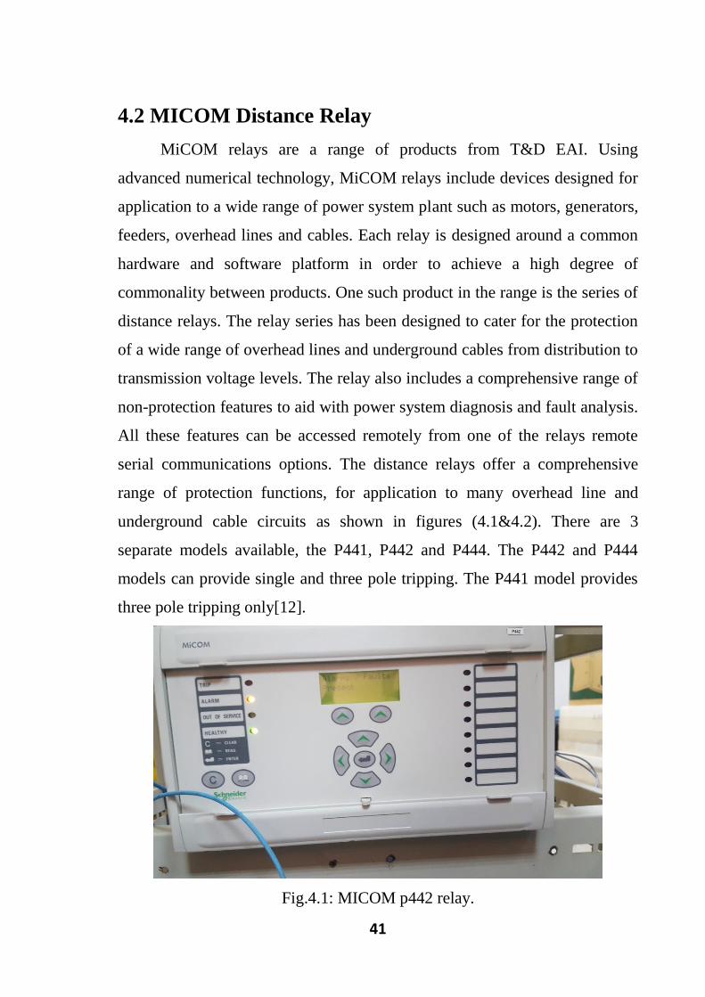
4.2 MICOM Distance Relay
MiCOM relays are a range of products from T&D EAI. Using
advanced numerical technology, MiCOM relays include devices designed for
application to a wide range of power system plant such as motors, generators,
feeders, overhead lines and cables. Each relay is designed around a common
hardware and software platform in order to achieve a high degree of
commonality between products. One such product in the range is the series of
distance relays. The relay series has been designed to cater for the protection
of a wide range of overhead lines and underground cables from distribution to
transmission voltage levels. The relay also includes a comprehensive range of
non-protection features to aid with power system diagnosis and fault analysis.
All these features can be accessed remotely from one of the relays remote
serial communications options. The distance relays offer a comprehensive
range of protection functions, for application to many overhead line and
underground cable circuits as shown in figures (4.1&4.2). There are 3
separate models available, the P441, P442 and P444. The P442 and P444
models can provide single and three pole tripping. The P441 model provides
three pole tripping only[12].
Fig.4.1: MICOM p442 relay.
42
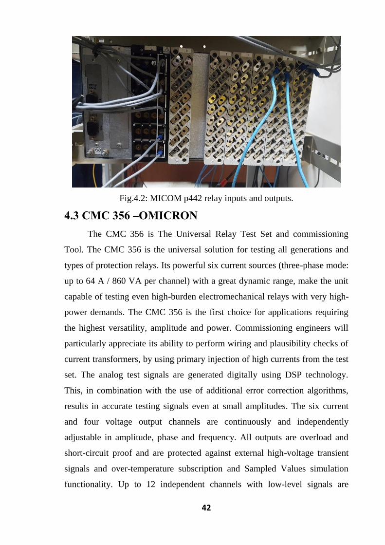
Fig.4.2: MICOM p442 relay inputs and outputs.
4.3 CMC 356 –OMICRON
The CMC 356 is The Universal Relay Test Set and commissioning
Tool. The CMC 356 is the universal solution for testing all generations and
types of protection relays. Its powerful six current sources (three-phase mode:
up to 64 A / 860 VA per channel) with a great dynamic range, make the unit
capable of testing even high-burden electromechanical relays with very high-
power demands. The CMC 356 is the first choice for applications requiring
the highest versatility, amplitude and power. Commissioning engineers will
particularly appreciate its ability to perform wiring and plausibility checks of
current transformers, by using primary injection of high currents from the test
set. The analog test signals are generated digitally using DSP technology.
This, in combination with the use of additional error correction algorithms,
results in accurate testing signals even at small amplitudes. The six current
and four voltage output channels are continuously and independently
adjustable in amplitude, phase and frequency. All outputs are overload and
short-circuit proof and are protected against external high-voltage transient
signals and over-temperature subscription and Sampled Values simulation
functionality. Up to 12 independent channels with low-level signals are

43
available at the back of the test set, which can be used to test relays which
have a low-level input facility or to control external amplifier units. By
utilizing the EnerLyzer software option, the ten binary inputs of a CMC 356
equipped with the ELT-1 hardware option alternatively work as analog
measurement inputs. The unit then can also be used as a multifunctional
multimeter and transient recorder. Besides its operation with the powerful
Test Universe software running on a PC, the CMC 356 can also manually be
controlled with the highly flexible CMC control unit and the CMC control
Applied running on an Android Tablet or a Windows PC[13] ,as shown in
figures (4.3&4.4).The CMC 356 –OMICRON used in:
Fig. 4. 3: CMC 356 –OMICRON (front).

44
Fig.4. 4: CMC 356 –OMICRON (back).
i. Protection Relay Test Set
a. High-burden electromechanical relays
b. Static relays
c. Numerical relays.
ii. Test Universe(distance)
Distance provides the functionality to define and perform tests of
distance relays by impedance element evaluations using single-shot
definitions in the Z-plane with graphical characteristic display[13].
4.4 Relay Setting of Distance Protection (p442)
4.4.1 System Data (Shagara Local Market Substation)
Line length(L)=7.8Km(kilo-meters).
Nominal voltage=110kv.
Line impedances:
(Positive sequence) z1= 0.067 + j0.269 = 0.277 / 76.014° Ω/km.
(Negative sequence) z0 = 0.262 + j1.044 = 1.076 / 75.912° Ω/km.
z0 /z1 = 3.884 / -0.102° (4.1)

45
(Compaction factor) KZ = (1/3) *(z0/z1-1) =0.96/ -0.137° (4.2)
CT ratio: 1600 / 1
VT ratio: 1000 / 1
Line Impedance:
Line impedance to secondary(z1)
z1=ratio CT/VT*Z1*L (4.3)
z1= (1600/1000) (0.277/ 76.014°) (7.8)
=3.456/ 76.014° Ω
4.4.2 Zone 1 Phase Reach Settings
Required Zone 1 impedance(Z1) = [ 80% of the line impedance]
Z1=80%z1 (4.4)
Z1=0.8*3.456=2.7648 Ω
Time T1=0 sec.
Ground fault resistance (RG) and phase fault resistance (Rph).
RG=40 Ω, Rph=30 Ω.
4.4.3 Zone 2 Phase Reach Settings
Required Zone 2 impedance (Z2) =
min [line impedance + 50% transformer impedance OR
Line impedance + 50% shortest line impedance]. (4.5)
Z2=min [3.456+0.5*1.388 OR 3.456+0.5*4.848]
Z2=min [4.15 OR 5.88]
Z2=4.15 Ω.
Time T2=400msec.
Ground fault resistance (RG) and phase fault resistance (Rph).
RG=40 Ω, Rph=30 Ω.
4.4.4 Zone 3 Phase Reach Settings
Required Zone 3 impedance(Z3) =120% [z of longest line+z1]. (4.6)
Z3 =1.2*(17.3+3.456) =24.9 Ω.
Time T3=800msec.

46
Ground fault resistance (RG) and phase fault resistance (Rph).
RG=40 Ω, Rph=30 Ω.
4.4.5 Zone 4 Reverse Settings
Required Zone 4 reverse reach impedance(Z4) =
[Typically, 25%line impedance]. (4.7)
Z4=0.25*3.456=0.86 Ω.
Time T4=1sec.
Ground fault resistance (RG) and phase fault resistance (Rph).
RG=40 Ω, Rph=30 Ω.
47
4.5 Test Result on Omicron Studio
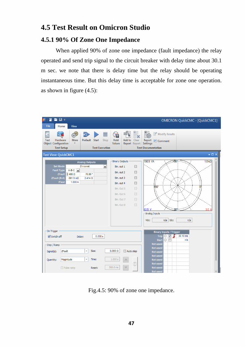
4.5.1 90% Of Zone One Impedance
When applied 90% of zone one impedance (fault impedance) the relay
operated and send trip signal to the circuit breaker with delay time about 30.1
m sec. we note that there is delay time but the relay should be operating
instantaneous time. But this delay time is acceptable for zone one operation.
as shown in figure (4.5):
Fig.4.5: 90% of zone one impedance.

48
4.5.2 110% of Zone One Impedance
When took 110% of zone one impedance (fault impedance) the relay
operated at zone two and relay operation occupy time (408.1 msec) to send
trip signal to the circuit breaker to clear the fault. The relay operated time
(408.1msec) accepted for zone two because its sitting time equal to(400msec).
as shown in figure (4.6):
Fig.4.6: 110% of zone one impedance.

49
4.5.3 90% of Zone Two Impedance
When took 90% of zone two impedance (fault impedance) the relay
operated at zone two it is taken about (415.5 m sec) to send trip signal to the
circuit breaker. we note that there is delay time because the relay should be
operated in 400 msec. But this delay time is acceptable for zone two operating
time. Also the fault current remains at maximum value (1A) because the
three-phase fault has very high and dangerous current and operation time
depend on it. as shown in figure (4.7):
Fig.4.7: 90% of zone two impedance.

50
4.5.4 110% of Zone Two Impedance
When took 110% of zone two impedance (fault impedance) the relay
operated at zone three and send trip signal to the circuit breaker to clear fault
at time (814.9msec). The operating time of relay is near to zone three tripping
time (800msec) because the fault trip time depend on the impedance of fault
(or location of fault). As shown in figure (4.8):
Fig.4.8: 110% of zone two impedance.

51
4.5.5 90% of Zone Three Impedance
When took 90% of zone three impedance (fault impedance) the
relay operated at zone three it is taken about (816.5 msec) to send trip signal
to the circuit breaker. we note that there is delay time although the relay
should be operated in 800 msec. But this delay time is acceptable for zone
three operation. as shown in figure (4.9):
fig.4.9: 90% of zone three impedance.

52
4.5.6 110% of Zone Three Impedance
When applied 110% of zone three impedance (fault impedance) The
relay would not operate because this value is out of relay’s zones. as shown in
figure (4.10):
Fig.4.10: 110% of zone three impedance.

53
4.5.7 90% of Zone Four Impedance
When were took 90% of zone four impedance the relay operated at
zone four and relay operation occupy time (1.022 sec) to send trip signal to
the circuit breaker to clear the fault. The largest delay time to provide chance
to other’s zones to operate and get decision if not the reverse zone will
operate. as shown in figure (4.11):
Fig.4.11: 90% of zone four impedance.

54
4.5.8 110% of Zone Four Impedance
When took 110% of zone four impedance the relay would not
operate because out of it’s zone, as shown in figure (4.12):
Fig.4.12: 110% of zone four impedance.

55
4.5.9 The Zones of Protection Relay and All points Took to Test
the Accuracy Operation of Distance Relay:
The figures (4.13&4.14) represented All points Took to Test the
Accuracy Operation of Distance Relay zones.
Fig.4.13: zones (Z1,Z2,Z3andZ 4).
Fig.4.14: zones (Z1,Z2,Z3andZ 4).

56
CHAPTER FIVE
CONCLUSIONS AND RECOMMENDATIONS
5.1 Conclusions
The project objectives have been achieved where the 110kV
Transmission line has been protected by using numerical relays. They are the
latest development in the area of protection, which are based on
microprocessors. The multi-function numerical relays provide better
protection, high reliability, troubleshooting and recording the fault
information. This line is protected using numerical relays type MICOM P442.
The distance numeral relay has been operated at it’s corrective zones, when
applied the transformer impedance in the setting of zone two. The reliability
of the transmission line and grid increased. The grading time in distance relay
depend on the fault impedance or the fault location. The numerical relay in
distance protection has self-activate the types of fault.
5.2 Recommendations:
According to this project and the facts that we had known during the
operation in project, we recommend the following points:
CMC 356 –OMICRON must be brought in the protection laboratory in
the university instead of large power supply to provide excellent
source of supply and minimum space and then the students will
understand and gives full information about the last technique in
protection field.
Numerical relays must be brought in the protection laboratory in the
university instead of or with the electromechanical relays. By using
software program loaded the information to the relays.
As the transmission line which connected between Local market and
shgara substations it is very short line and very important line in the
national grid, the reliability must be utilized to it, and the future

57
studies must execute the following recommendations to utilize
differential protection by using numerical relay.

58
Referance
[1] Alstom, Grid, " Network protection & automation guid", France, May
2011.
[2] Galvan, I.," Virtual reality system for training of operators of power live
lines", in Proceedings of the world congress on engineering and computer
science, 2010.
[3] El-Hawary, M.E, " Electrical power systems: design and analysis Vol. 2"
John Wiley & Sons, 1995.
[4] Ram, B.," Power system protection and switchgear", Tata McGraw-Hill
Education, 2011.
[5] Paithankar, Y.G. and S. Bhide," Fundamentals of power system
protection", PHI Learning Pvt. Ltd, 2011.
[6] Bakshi, U. and M. Bakshi," Protection And Switchgear", Technical
Publications, 2009.
[7] Gonen, T., "Modern power system analysis", CRC Press, 2013.
[8] Horowitz, S.H. and A.G. Phadke," Power system relaying. Vol. 22", John
Wiley & Sons,2008.
[9] Areva, "Protective Relays Application Guide, 3rd edition.
Protection and Control", 1987.
[10] Anderson, P.M. and P. Anderson," Power system protection", 1999.
[11] Ziegler, G., "Numerical distance protection: principles and applications"
John Wiley & Sons,2011.
[12] Othman, M., et al., "MiCOM P441/P442/P444 numerical distance
protection technical manual, Version B1.2", Journal of Applied
Sciences, 1996.
[13] Birgersson, P. and M. Svensson, "Utvärdering av möjligheter för
semiautomatisk reläskyddsprovning med Omicron CMC 356", 2017.

59
Appendix A
Shagara Substation:

60
Local Market Substation

61
Appendix B
Transmission Lines Data

62
Transformer Data