Programmable AC/DC Electronic Load - ITECH
105
Programmable AC/DC Electronic Load User Manual for IT8600 Series Model: IT8615/IT8615L/IT8616/IT8617/ IT8624/IT8625/IT8626/IT8627/IT8628 Version: V2.7
-
Upload
khangminh22 -
Category
Documents
-
view
2 -
download
0
Transcript of Programmable AC/DC Electronic Load - ITECH

Programmable AC/DC Electronic Load
User Manual for IT8600 Series
Model: IT8615/IT8615L/IT8616/IT8617/ IT8624/IT8625/IT8626/IT8627/IT8628
Version: V2.7
Notices © Itech Electronic, Co., Ltd. 2019 No part of this manual may be
reproduced in any form or by any means
(including electronic storage and
retrieval or translation into a foreign
language) without prior permission and
written consent from Itech Electronic,
Co., Ltd. as governed by international
copyright laws.
Manual Part Number
IT8600-402247
Revision
2nd Edition: Mar. 7, 2019
Itech Electronic, Co., Ltd.
Trademarks
Pentium is U.S. registered trademarks
of Intel Corporation.
Microsoft, Visual Studio, Windows and
MS Windows are registered trademarks
of Microsoft Corporation in the United
States and/or other countries and
regions.
Warranty
The materials contained in this document are provided “as is”, and is subject to change, without prior notice, in future editions. Further, to the maximum extent permitted by applicable laws, ITECH disclaims all warrants, either express or implied, with regard to this manual and any information contained herein, including but not limited to the implied warranties of merchantability and fitness for a particular purpose. ITECH shall not be held liable for errors or for incidental or indirect damages in connection with the furnishing, use or application of this document or of any information contained herein. Should ITECH and the user enter into a separate written agreement with warranty terms covering the materials in this document that conflict with these terms, the warranty terms in the separate agreement shall prevail.
Technology Licenses
The hardware and/or software described
herein are furnished under a license and
may be used or copied only in
accordance with the terms of such
license.
Restricted Rights Legend
Restricted permissions of the U.S.
government. Permissions for software
and technical data which are authorized
to the U.S. Government only include
those for custom provision to end users ITECH provides this customary commercial license in software and technical data pursuant to FAR 12.211 (Technical Data) and 12.212 (Computer Software) and, for the Department of Defense, DFARS 252.227-7015 (Technical Data – Commercial Items) and DFARS 227.7202-3 (Rights in Commercial Computer Software or Computer Software Documentation).
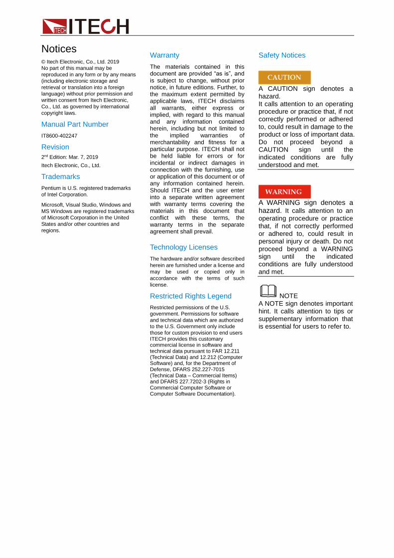
Safety Notices
A CAUTION sign denotes a hazard. It calls attention to an operating procedure or practice that, if not correctly performed or adhered to, could result in damage to the product or loss of important data. Do not proceed beyond a CAUTION sign until the indicated conditions are fully understood and met.
A WARNING sign denotes a hazard. It calls attention to an operating procedure or practice that, if not correctly performed or adhered to, could result in personal injury or death. Do not proceed beyond a WARNING sign until the indicated conditions are fully understood and met.
NOTE A NOTE sign denotes important hint. It calls attention to tips or supplementary information that is essential for users to refer to.

IT8600 User Manual
Copyright © ITECH Electronic Co., Ltd. i
Quality Certification and Assurance We certify that IT8600 electronic load meets all the published specifications.
Warranty ITECH warrants that the product will be free from defects in material and workmanship under normal use for a period of one (1) year from the date of delivery (except those described in the Limitation of Warranty below). For warranty service or repair, the product must be returned to a service center designated by ITECH.
⚫ The product returned to ITECH for warranty service must be shipped PREPAID. And ITECH will pay for return of the product to customer.
⚫ If the product is returned to ITECH for warranty service from overseas, all the freights, duties and other taxes shall be on the account of customer.
Limitation of Warranty This Warranty will be rendered invalid if the product is:
⚫ Damage caused by circuit installed by customer or using customer own products or accessories;
⚫ Modified or repaired by customer without authorization;
⚫ Damage caused by circuit installed by customer or not operating our products under designated environment;
⚫ The product model or serial number is modified, deleted, removed or illegible;
⚫ Damaged as a result of accidents, including but not limited to lightning, moisture, fire, improper use or negligence.
Safety Symbols
Direct current
ON (power on)
Alternating current OFF (power off)
Both direct and alternating current
Power-on state
Protective conductor terminal
Power-off state
Earth (ground) terminal
Reference terminal
Caution, risk of electric shock
Positive terminal
Warning, risk of danger (refer to this manual for specific Warning or Caution information)
Negative terminal

IT8600 User Manual
Copyright © ITECH Electronic Co., Ltd. ii
Frame or chassis terminal - -
Safety Precautions The following safety precautions must be observed during all phases of operation of this instrument. Failure to comply with these precautions or specific warnings elsewhere in this manual will constitute a default under safety standards of design, manufacture and intended use of the instrument. ITECH assumes no liability for the customer’s failure to comply with these precautions.
⚫ Do not use the instrument if it is damaged. Before operation, check the casing to see whether it cracks. Do not operate the instrument in the presence of inflammable gasses, vapors or dusts.
⚫ The instrument is provided with a power cord during delivery and should be connected to a socket with a protective earth terminal, a junction box or a three-phase distribution box. Before operation, be sure that the instrument is well grounded.
⚫ Make sure to use the power cord supplied by ITECH.
⚫ Check all marks on the instrument before connecting the instrument to power supply.
⚫ Use electric wires of appropriate load. All loading wires should be capable of bearing maximum short-circuit of electronic load without overheating. If there are multiple loads, each pair of the load power cord must be carry out the full rated short-circuit output current of the power securely.
⚫ Ensure the voltage fluctuation of mains supply is less than 10% of the working voltage range in order to reduce risks of fire and electric shock.
⚫ Do not install alternative parts on the instrument or perform any unauthorized modification.
⚫ Do not use the instrument if the detachable cover is removed or loose.
⚫ To prevent the possibility of accidental injuries, be sure to use the power adapter supplied by the manufacturer only.
⚫ We do not accept responsibility for any direct or indirect financial damage or loss of profit that might occur when using the instrument.
⚫ This instrument is used for industrial purposes, Do not apply this product to IT power supply system.
⚫ Never use the instrument with a life-support system or any other equipment subject to safety requirements.
⚫ SHOCK HAZARD Ground the Instrument. This product is provided with a protective earth terminal. To minimize shock hazard, the instrument must be connected to the AC mains through a grounded power cable, with the ground wire firmly connected to an electrical ground (safety ground) at the power outlet or distribution box. Any interruption of the protective (grounding) conductor or disconnection of the protective earth terminal will cause a potential shock hazard that could result in injury or death.

IT8600 User Manual
Copyright © ITECH Electronic Co., Ltd. iii
⚫ Before applying power, verify that all safety precautions are taken. All connections must be made with the instrument turned off, and must be performed by qualified personnel who are aware of the hazards involved. Improper actions can cause fatal injury as well as equipment damage.
⚫ SHOCK HAZARD, LETHAL VOLTAGES This product can input the dangerous voltage that can cause personal injury, and the operator must always be protected from electric shock. Ensure that the input electrodes are either insulated or covered using the safety covers provided, so that no accidental contact with lethal voltages can occur.
⚫ Never touch cables or connections immediately after turning off the instrument. Verify that there is no dangerous voltage on the electrodes or sense terminals before touching them.
⚫ Failure to use the instrument as directed by the manufacturer may render its protective features void.
⚫ Always clean the casing with a dry cloth. Do not clean the internals.
⚫ Make sure the vent hole is always unblocked.
Environmental Conditions The instrument is designed for indoor use and an area with low condensation. The table below shows the general environmental requirements for the instrument. The speed of fan will change intelligently by the temperature of radiator. When the temperature is up to 40°C, the fan will be on and adjust intelligently when temperature changes.
Environmental Conditions Requirements
Operating temperature 0°C to 40°C Operating humidity 20%-80% (non-condensation) Storage temperature -20°C to 70 °C Altitude ≤2,000m Pollution degree Pollution degree 2 Installation category Ⅱ
NOTE
To make accurate measurements, allow the instrument to warm up for 30 min before operation.
Regulatory Markings
The CE mark is a registered trademark of the European Community. This CE mark shows that the product complies with all the relevant European Legal Directives.
The instrument complies with the WEEE Directive (2002/96/EC) marking requirement. This affixed product label indicates that you must not discard the electrical/electronic product in domestic household waste.

IT8600 User Manual
Copyright © ITECH Electronic Co., Ltd. iv
This symbol indicates the time period during which no hazardous or toxic substances are expected to leak or deteriorate during normal use. The expected service life of the product is 10 years. The product can be used safely during the 10-year Environment Friendly Use Period (EFUP). Upon expiration of the EFUP, the product must be immediately recycled.
Waste Electrical and Electronic Equipment (WEEE) Directive
2002/96/EC Waste Electrical and Electronic Equipment (WEEE) Directive This product complies with the WEEE Directive (2002/96/EC) marking requirement. This affix product label indicates that you must not discard the electrical/electronic product in domestic household waste. Product Category With reference to the equipment classifications described in the Annex I of the WEEE Directive, this instrument is classified as a “Monitoring and Control Instrument” product. To return this unwanted instrument, contact your nearest ITECH office.

IT8600 User Manual
Copyright © ITECH Electronic Co., Ltd. v
Compliance Information Complies with the essential requirements of the following applicable European Directives, and carries the CE marking accordingly:
⚫ Electromagnetic Compatibility (EMC) Directive 2014/30/EU ⚫ Low-Voltage Directive (Safety) 2014/35/EU
Conforms with the following product standards:
EMC Standard
IEC 61326-1:2012/ EN 61326-1:2013 ¹²³ Reference Standards CISPR 11:2009+A1:2010/ EN 55011:2009+A1:2010 (Group 1, Class A) IEC 61000-4-2:2008/ EN 61000-4-2:2009 IEC 61000-4-3:2006+A1:2007+A2:2010/ EN 61000-4-3:2006+A1:2008+A2:2010 IEC 61000-4-4:2004+A1:2010/ EN 61000-4-4:2004+A1:2010 IEC 61000-4-5:2005/ EN 61000-4-5:2006 IEC 61000-4-6:2008/ EN 61000-4-6:2009 IEC 61000-4-11:2004/ EN 61000-4-11:2004
1. The product is intended for use in non-residential/non-domestic environments. Use of the
product in residential/domestic environments may cause electromagnetic interference. 2. Connection of the instrument to a test object may produce radiations beyond the specified
limit. 3. Use high-performance shielded interface cable to ensure conformity with the EMC standards
listed above.
Safety Standard
IEC 61010-1:2010/ EN 61010-1:2010

IT8600 User Manual
Copyright © ITECH Electronic Co., Ltd. vi
Contents Quality Certification and Assurance ............................................................................................................. i Warranty....................................................................................................................................................... i Limitation of Warranty .................................................................................................................................. i Safety Symbols ............................................................................................................................................ i Safety Precautions ...................................................................................................................................... ii Environmental Conditions .......................................................................................................................... iii Regulatory Markings .................................................................................................................................. iii Waste Electrical and Electronic Equipment (WEEE) Directive .................................................................. iv Compliance Information .............................................................................................................................. v
Chapter1 Inspection and Installation ............................................................................................... 1
1.1 Verifying the Shipment ......................................................................................................................... 1 1.2 Instrument Size Introduction ................................................................................................................ 1 1.3 Connecting the Power Cord................................................................................................................. 9 1.4 Connecting Test Lines ........................................................................................................................ 11
Chapter2 Quick Start ....................................................................................................................... 13
2.1 Brief Introduction ................................................................................................................................ 13 2.2 Front Panel Introduction .................................................................................................................... 14 2.3 Key Introduction ................................................................................................................................. 14 2.4 Introduction to Information on the Interface ....................................................................................... 16 2.5 Introduction to Interface Symbols ...................................................................................................... 16 2.6 Rear Panel Introduction ..................................................................................................................... 17 2.7 Power-on Self-test ............................................................................................................................. 20
Chapter3 Basic Operations ............................................................................................................ 24
3.1 Input On/Off Control ........................................................................................................................... 24 3.2 Key Lock Function ............................................................................................................................. 24 3.3 Menu Configuration Function............................................................................................................. 24 3.4 Configuration Save/Recall ................................................................................................................. 26 3.5 Screen Capture Function ................................................................................................................... 27 3.6 Local/Remote Switching Function ..................................................................................................... 27 3.7 Load Switching .................................................................................................................................. 27 3.8 Operating Mode ................................................................................................................................. 27 3.9 Data Recording Function ................................................................................................................... 28 3.10 Online Load Setting ......................................................................................................................... 28 3.11 Timing Mode ..................................................................................................................................... 28 3.12 Protection Function .......................................................................................................................... 29 3.13 Remote Measurement Function ...................................................................................................... 32 3.14 External On/Off Control ................................................................................................................... 33 3.15 External Analog Quantity Control (Only for IT8615 /IT8615L) ......................................................... 33 3.16 Voltage/Current Monitoring (I/V Monitor) ......................................................................................... 33 3.17 Parallel Function .............................................................................................................................. 33 3.18 Three-phase Function ...................................................................................................................... 38 3.19 Three-phase Parallel Function......................................................................................................... 43 3.20 Three-phase setup ........................................................................................................................... 45
Chapter4 Load Functions ............................................................................................................... 47
4.1 Load Function Introduction ................................................................................................................ 47 4.2 AC Load Function .............................................................................................................................. 47
4.2.1 CF and PF Setting ....................................................................................................................... 47 4.2.2 Constant Current Mode (CC) ...................................................................................................... 48 4.2.3 Constant Resistance Mode (CR) ................................................................................................ 52 4.2.4 Constant Power Mode (CP) ........................................................................................................ 53
4.3 DC Load Function .............................................................................................................................. 56 4.3.1 Constant Current Mode (CC) ...................................................................................................... 56 4.3.2 Constant Resistance Mode (CR) ................................................................................................ 57 4.3.3 Constant Voltage Mode (CV) (Only for IT8615/IT8615L) ........................................................... 57 4.3.4 Constant Power Mode (CP) ........................................................................................................ 57 4.3.5 Short Circuit Simulation Function ............................................................................................... 57
Chapter5 Measurement Functions ................................................................................................. 59

IT8600 User Manual
Copyright © ITECH Electronic Co., Ltd. vii
5.1 Interface Introduction ......................................................................................................................... 59 5.2 Parameter Measurement ................................................................................................................... 59
5.2.1 AC Mode ..................................................................................................................................... 60 5.2.2 DC Mode ..................................................................................................................................... 62
Chapter6 Waveform Display Function ........................................................................................... 65
6.1 Interface Introduction ......................................................................................................................... 65 6.2 Adjustment of Measurement Parameters .......................................................................................... 68 6.3 Setting of Trigger Configuration ......................................................................................................... 68
Chapter7 Harmonic Measurement Function ................................................................................. 70
7.1 Overview ............................................................................................................................................ 70 7.2 Setting of Harmonic Measurement Configuration ............................................................................. 72
Chapter8 Routine Maintenance ...................................................................................................... 74
8.1 Error Information Reference .............................................................................................................. 74 8.2 Routine Maintenance ......................................................................................................................... 75 8.3 Contact ITECH Engineer ................................................................................................................... 76 8.4 Return for Repair ............................................................................................................................... 77
Chapter9 Communication Interfaces ............................................................................................. 79
9.1 USB Interface .................................................................................................................................... 79 9.2 GPIB Interface ................................................................................................................................... 79 9.3 LAN Interface ..................................................................................................................................... 79
Chapter10 Technical Specifications ................................................................................................ 80
10.1 Main Technical Specifications .......................................................................................................... 80 10.2 Supplemental characteristics ........................................................................................................... 94
Appendix .................................................................................................................................................... 95
Specifications of Red and Black Test Lines ............................................................................................. 95

Copyright © ITECH Electronic Co., Ltd. 1
Chapter1 Inspection and Installation
1.1 Verifying the Shipment Unpack the box and check the contents before operating the instrument. If wrong items have been delivered, if items are missing, or if there is a defect with the appearance of the items, contact the dealer from which you purchased the instrument immediately. The package contents include:
Checklist of Package Contents
Item Qty. Model Remarks
Programmable AC/DC load
x1 IT8600 series
IT8600 series including: IT8615/IT8615L/IT8616/IT8617 /IT8624/IT8625/IT8626/IT8627 /IT8628
Power cord x1 IT-E171/IT-E172/IT-E173/IT-E174
User may select an appropriate power cord that matches the specifications of power socket used in the area. See the Section 1.3 Connecting the Power Cord.
Test leads - - The test leads are not the standard accessories for IT8615 and IT8615L.
USB cable x1 - -
CD x1 - It contains IT8600 electronic load User’s Manual, Programming Guide and other user documentations.
Ex-factory Test Report
x1 - It is the test report of the instrument before delivery.
NOTE
Upon verification of the shipment, keep the package and relevant contents thereof in a safe place. When returning the instrument for warranty service or repair, the specified packing requirements shall be met.
1.2 Instrument Size Introduction The instrument should be installed at well-ventilated and rational-sized space. Please select appropriate space for installation based on the electronic load size.
IT8616 and IT8617 have two sizes, including side plate structure and 15U cabinet. Besides, the 15U cabinet of IT8617 also has two types: one consists of one master and two slaves and the other consists of three masters. You can choose according to your requirement.

Copyright © ITECH Electronic Co., Ltd. 2
IT8615/IT8615L
Dimension: Width: 482.50mm Height: 151.35mm Depth: 600.60mm
Detailed Dimension Drawing
IT8616 (side plate structure)
Dimension: Width: 483.00mm Height: 348.99mm Depth: 641.08mm

Copyright © ITECH Electronic Co., Ltd. 3
Detailed Dimension Drawing
IT8616 (15U cabinet)
Dimension: Width: 550.00mm Height: 801.40mm Depth: 839.10mm

Copyright © ITECH Electronic Co., Ltd. 4
Detailed Dimension Drawing
IT8617 (side plate structure)
Dimension: Width:483.00mm Height:482.34mm Depth:641.08mm
Detailed Dimension Drawing

Copyright © ITECH Electronic Co., Ltd. 5
IT8617 (15U cabinet: one master and two slaves)
Dimension: Width: 550.00mm Height: 801.40mm Depth: 839.10mm
Detailed Dimension Drawing

Copyright © ITECH Electronic Co., Ltd. 6
IT8617 (15U cabinet: three masters)
Dimension: Width: 550.00mm Height: 801.40mm Depth: 839.10mm
Detailed Dimension Drawing

Copyright © ITECH Electronic Co., Ltd. 7
IT8624/IT8625/IT8626
Dimension: Width: 600.00mm Height: 1441.51mm Depth: 841.10mm
Detailed Dimension Drawing

Copyright © ITECH Electronic Co., Ltd. 8
IT8627/IT8628
Dimension: Width: 600.00mm Height: 1886.06mm Depth: 841.10mm
Detailed Dimension Drawing

Copyright © ITECH Electronic Co., Ltd. 9
1.3 Connecting the Power Cord
Before Connecting the Power Cord
Connect power cord of standard accessories and ensure that the electronic load is under normal power supply.
⚫ The power cords supplied with this product is certified for safety. In case the supplied lines assembly needs to be replaced, or an extension lines must be added, be sure that it can meet the required power ratings of this product. Any misuse voids the warranty of this product.
⚫ Before connecting power cord, be sure to switch off the instrument. Power switch is in Off position.
⚫ To avoid fire or electric shock, Make sure to use the power cord supplied by ITECH.
⚫ Be sure to connect the main power socket to the power outlet with protective grounding. Do not use terminal board without protective grounding.
⚫ Do not use an extended power cord without protective grounding, otherwise the protection function will fail.
Categories of Power Cords
⚫ We provide standard power cords for IT8615/IT8615L and IT8616/IT8617 side plate structure. Please select appropriate power cords appropriate to local voltage based on the specifications of power cords below. If purchased model fails to meet local voltage requirements, please contact distributor or factory for change.
China
IT-E171
America, Canada, Japan
IT-E172
Europe
IT-E173
Britain
IT-E174
⚫ The power cord of IT8616(15U cabinet)/IT8617(15U cabinet)/IT8624 /IT8625/IT8626/IT8627/IT8628 electronic load is shown in the next figure.

Copyright © ITECH Electronic Co., Ltd. 10
Connecting the Power Cord
⚫ Model IT8615/IT8615L/IT8616(side plate structure)/IT8617(side plate structure) electronic load
Connect standard power cord to the AC input terminals directly. (Take the example of model IT8615)
⚫ Model IT8616(15U cabinet)/IT8617(15U cabinet)/IT8624/IT8625/IT8626 /IT8627/IT8628 electronic load (take the example of model IT8617)
Bofore connecting, you need to take apart the rear panel which covers the AC input terminals.
Connecting Method: 1. See the above illustration, connect one end of the AC power cord to the AC input terminal in the rear board of the electronic load. Connect the fire wire, zero line and ground to the corresponding terminal of the device. Connect the brown terminal to line (L), blue to neutral (N), and yellow-green to ground. 2. Connect the plug on the other end of the power cord to your AC power source.
AC input terminal
AC input terminal

Copyright © ITECH Electronic Co., Ltd. 11
1.4 Connecting Test Lines
Precautions When Wiring the Circuit
⚫ To prevent electric shock, turn the circuit under measurement off before
connection.
⚫ Always put the mains plug into the grounded socket. Never use an ungrounded wiring board. Before connecting the circuit, make sure the electronic load is grounded properly.
⚫ Strip the insulation covers of the measurement cables so that when they are wired to the input terminals, the conductive parts (bare wires) do not protrude from the terminals. Also, make sure to fasten the input terminal screws securely so that cables do not come loose.
⚫ When connecting measurement cables to the input terminals, only connect measurement cables that have safety rubber terminals that cover their conductive parts. Also, make sure to fasten the input terminal screws securely so that cables do not come loose.
⚫ Use measurement cables satisfying the rated conditions and with dielectric
strengths and current capacities that are appropriate for the voltage and current being measured.
⚫ Example: when making measurements on a current of 20A, use copper wires that have a conductive cross-sectional area of 4mm2 or greater.
Connecting the Measurement Circuit
IT8600 electronic load can measure electrical parameters of the test object. The specific circuit connection diagram is shown below.
⚫ The wiring for basic measurements of Model IT8615/IT8615L/IT8616 (side plate structure)/IT8617 (side plate structure and 15U cabinet: three masters) is as follows.
1. Respectively connect drive wires to six terminals Vs+/ V+/ V+ and Vs-/ V-/V- of the rear panel.
2. Respectively connect the other ends of wires to the anode and cathode of the test object (as shown below).
Power supply
Load

Copyright © ITECH Electronic Co., Ltd. 12
NOTE
The anode and cathode of the AC power supply has no influence on measurement data. The anode and cathode of the output end of the DC power supply must be connected properly; otherwise, measurement data will be negative.
3. Install the protection cover of the current input terminal after connecting the measurement circuit, to prevent contact with the input terminal in measurement and protect the personal safety.
⚫ The wiring for basic measurements of Model IT8616(15U cabinet)/IT8617 (15U cabinet: one master and two slaves)/IT8624/IT8625/IT8626/IT8627 /IT8628 is as follows.
DUT

Quick Start
Copyright © ITECH Electronic Co., Ltd. 13
Chapter2 Quick Start
This chapter describes the power-on inspection steps of IT8600 electronic load to ensure the normal startup and use in the initial state, and the front panel, rear panel, key functions and LCD (Liquid Crystal Display) functions of IT8600 series loads to help the user know the appearance, structure and key functions before operation and better operate these loads.
2.1 Brief Introduction The IT8600 programmable AC/DC load, using a 3U small structure to realize the input of 420V/20A/1800W, has a powerful function of data measurement. In addition to measurement of such conventional parameters as Vrms, Vpk, Vdc, Irms, Ipk, Idc, W, VA, VAR, CF, PF and Freq, the load has the unique function of voltage harmonic analysis to test harmonic interference of the test object (UPS, generator, etc.) to the power grid. At most 50 voltage harmonics can be analyzed.
The highlight of IT8600 programmable AC/DC load is the oscilloscope display, which can display the input voltage and current waveform of the test object. In the harmonic measurement mode, analysis results of the percentage of each kind of harmonics can be displayed in the bar form. Multiple display modes bring new user experience.
IT8600 programmable AC/DC load can be used in parallel connection of multiple units and three-phase parallel connection to test three-phase AC power supplies or power supplies of high power. In three-phase parallel applications, the user can select the Y-type and Δ-type connection according to the actual requirements. Flexible connection can meet various test requirements.
IT8600 programmable AC/DC load includes the standard GPIB, LAN and USB communication interface for fast and stable communication.
⚫ Frequency range: 45-450HZ
⚫ 7-inch LCD screen
⚫ Parallel/three-phase control
⚫ Oscilloscope function for display of the voltage and current waveform
⚫ Measure Vrms, Vpk, Vdc, Irms, Ipk, Idc, W, VA, VAR, CF, PF and FREQ
⚫ Measure the THD (V) parameters of 50 harmonics at most
⚫ AC electronic load: CC/CR/CP mode
⚫ DC electronic load: CC/CR/CP/CV mode①
⚫ External 0-10V analog control② and voltage/current analog monitoring
⚫ OTP, OCP, OVP, UVP and OPP protection
⚫ GPIB, LAN and USB communication interface and external USB interface
Note
①②: CV mode and external 0-10V analog control function are only for IT8615 and
IT8615L.
Model Voltage Current Power
IT8615 420V 20A 1.8KW
IT8615L 260V 20A 1.8KW
IT8616 420V 40A 3.6KW
IT8617 420V 60A 5.4KW

Quick Start
Copyright © ITECH Electronic Co., Ltd. 14
IT8624 420V 80A 7.2KW
IT8625 420V 100A 9.0KW
IT8626 420V 120A 10.8KW
IT8627 420V 140A 12.6KW
IT8628 420V 160A 14.4KW
2.2 Front Panel Introduction The schematic diagram of the front panel and key functions of IT8600 AC/DC electronic load is shown below.
1 Operation buttons 8 Function key
2 USB interface 9 Power switch
3 LCD display 10 Menu key
4 Menu key 11 Home key
5 Rotary knob 12 Arrow keys and Enter key
6 Number key 13 Esc key and Enter key
7 Memory key
2.3 Key Introduction The key functions of the front panel and the keys in the key zones of IT8600 are shown in the following figure.

Quick Start
Copyright © ITECH Electronic Co., Ltd. 15
Key Details
Key Symbol
Name & Function
Print Used for saving screen images
Local Used for switching the remote control mode to the local mode
Trig Used for manual trigger.
Log Used for recording data. The recording interval can be set in second
Home Used for going back to home page
F1-F6 R1-R5
Soft keys for corresponding screen menu operations
Key Details
Key Symbol
Name & Function
Rotary knob: used for setting the value indicated by the cursor, selecting the voltage and current range, adjusting the waveform, etc.
Up/Down key and Left/Right key. List edit: the programming items can be rolled by operating the Up/Down key. Corresponding information is shown on the right side and options can be selected through the soft key. Digit Edit: the programming items can be rolled by operating the Up/Down key. The digit to be edited is selected by operating the Left/Right key or through the knob. Carrying can be completed automatically.
0-9 Number key. Enter the number directly.
M1-M4 Memory key. Short press it to recall the saved parameter settings of the corresponding storage areas. Long-press it to save current settings into the corresponding storage areas.
Enter Enter key, used for confirming the message.
Esc Cancel/Esc key.
Used to delete the input digits in the digit editing mode.
ON Used for enabling the load function and input.
OFF Used for disabling the load function and input.
Set Setting key used for setting loading parameters.
Meter Basic metering key used for basic metering.

Quick Start
Copyright © ITECH Electronic Co., Ltd. 16
Key Symbol
Name & Function
Scope Oscilloscope key used for enabling the oscilloscope function.
Harmonic Harmonic key used for enabling the harmonic function and starting harmonic measurement.
Save Save the current load values.
Recall Recall the saved load parameters.
Menu Enter the System Menu and set the configuration parameters of various functions.
Lock The key to lock the keyboard, press the key again to unlock.
2.4 Introduction to Information on the Interface
IT8600 electronic load can simulate both the AC load and DC load. Below is the basic interface information, with the basic metering interface in the AC load mode as an example.
Basic metering interface
Press “Meter”, and the following initial interface of basic metering will appear.
2.5 Introduction to Interface Symbols The interface of IT8600 electronic load will display the following symbols. All the symbols and description are listed in the table below.
Symbol Description Symbol Description
SHORT Enable the short-circuit function.
LOG Record log.
RMT Remote function. CF-PRIO CF Priority.
Status bar Display area of measuring data Soft key
Setting value

Quick Start
Copyright © ITECH Electronic Co., Ltd. 17
Symbol Description Symbol Description
LOCK LOCK key. When the key is pressed, all keys in the keyboard are disabled. Press the key again to unlock.
PF-PRIO PF Priority.
LOL LOCAL key, to shift local and remote operation.
CF-ONLY Only set CF value.
FE Frequency failure. PF-ONLY Only set PF value. UV Under Voltage Protection.
AC mode.
OVP Over Voltage Protection.
CC mode.
OCPP Over Current Protection of the Peak value.
CP mode.
OCP Over Current Protection.
CR mode.
OPP Over Power Protection.
CV mode.
OTP Over Temperature Protection.
DC mode.
LDF Load Failure.
Turn on the timer.
EXT External Enabled.
CAN communication
2.6 Rear Panel Introduction ⚫ The rear panel of IT8615/IT8615L electronic load is shown in the next
figure.
1: Input terminals and remote measurement terminals
6: TTL I/O: for system input/output control signal. Each pin has a serial number and the definitions are as follows: 1: Fail 6: status 4: external on/off 9: external trigger terminals 5: earth connection.
2: Analog input terminal 7: GPIB communication interface 3: Current monitor terminal 8: USB communication interface 4: Voltage monitor terminal 9: LAN communication interface 5: System bus: for master/slave control system data communication
10: AC power input socket (support 100V-240V input voltage, including fuse)

Quick Start
Copyright © ITECH Electronic Co., Ltd. 18
⚫ The rear panel of IT8616/IT8617 side plate structure is shown in the next figure.IT8616 electronic load consists of two IT8615 and IT8617 electronic load consists of three IT8615. Take the example of IT8616, the rear panel of the instrument above is the same as that of IT8615. Except the system bus terminals and AC power input sockets, the instruments below have no communication interfaces. The rear panel of IT8616 is shown as below:
⚫ The rear panel of IT8616(15U cabinet)/IT8617 (15U cabinet: one master and two slaves) is shown in the next figure.
Take the example of IT8617, before connecting the communication terminals, you need to take apart the rear panel which covers the communication terminals by using a screwdriver. The communication terminals of 15U cabinet are the same as those of the side plate structure. Before connecting the load input terminals and AC power input terminals, you also need to take apart the rear panel which covers them by using a screwdriver. The figure below shows the rear panel.
1. Communication interface threading hole
2. Load input terminals
3. Remote measurement terminals
4. Power master switch
5. AC power input terminals
2
3
4
1
5

Quick Start
Copyright © ITECH Electronic Co., Ltd. 19
⚫ The rear panel of IT8617 15U cabinet (three masters) is shown in the next figure.
Before connecting the communication terminals, load input terminals and remote measurement terminals, you need to take apart the rear panel which covers the communication terminals by using a screwdriver. These terminals are the same as those of IT8615.
1. Communication interface and test line threading hole
2. Power master switch
3. AC power cord threading hole
2
3
1

Quick Start
Copyright © ITECH Electronic Co., Ltd. 20
⚫ The rear panel of IT8624/IT8625/IT8626/IT8627/IT8628 is shown in the next figure. (Take the example of IT8625).
Before connecting the communication terminals, you need to take apart the rear panel which covers the communication terminals by using a screwdriver. IT8620 series electronic loads have two groups of system bus interfaces. One of them is used to connect the internal instruments which make up the cabinet, which is connected well when delivered; the other is used to connect between the cabinets to realize the parallel or three-phase function. Other communication terminals are the same as those of IT8615.
1. Communication interface threading hole
2. Load input terminal threading hole
3. Remote measurement terminal threading hole
4. Power master switch
5. AC power cord threading hole
2.7 Power-on Self-test A successful self-test indicates that the purchased product meets delivery standards and is available for normal usage. Before operation, please confirm that you have fully understood the safety instructions.
Introduction of Switch
You can turn on the instrument by switch. Descriptions of the switch are as follows:
On Off Off On
1
2
3
4
5

Quick Start
Copyright © ITECH Electronic Co., Ltd. 21
If the instrument is the cabinet type, the rear panel of the cabinet provides a master power switch. The relationships between the device status and switch status are listed in the following table.
Master switch status Desperate switch status Device status
ON ON ON
ON OFF OFF
OFF ON OFF
OFF OFF OFF
Power-On
The normal power-on process of the electronic load is as follows:
1. Properly connect the power cord and press [Power] to power on the
instrument.
The LCD screen displays the electronic load version and time information.
2. After initialization, the LCD screen displays the following information.
NOTE
In case of any error, self-test will stop. Contact ITECH sales agent or technical service engineer.
3. Press [Menu], and the LCD screen of the electronic load displays the system
information.

Quick Start
Copyright © ITECH Electronic Co., Ltd. 22
System Self-Test
The self-test function of the electronic load can be enabled to test the Lcd, Led, Dsp and Backup Ram. Specific steps are as follows:
1. Press [Menu] to enter.
2. Press [>>] in this interface, and the system menu is scrolling. 3. Select [SELF TEST] in this interface, and the system enters the self-test
interface.
4. Press [START] and the system starts self-test, including Lcd, Led, Dsp and
Backup Ram. 5. If OK appears behind the self-test item, the item has passed self-test. If NG
appears, the user should check self-test results, such as the clarity of LED display, etc.
Input Inspection
The minimum AC input voltage of IT8600 AC/DC electronic load is 50Vrms. The minimum DC input voltage of IT8600 AC/DC electronic load is 10Vrms.

Quick Start
Copyright © ITECH Electronic Co., Ltd. 23
When any load is applied on the AC/DC electronic load and the input voltage setting is more than the minimum value, the current and CF value should be adjusted according to the present load operation; otherwise, under voltage protection of the AC/DC electronic load will be enabled and no load can be applied.
1. Connect the basic measurement circuit according to the connection method specified in 1.4 Connecting Test Lines.
2. Set the output voltage and current at the power supply end.
3. Press [Set] to set the on-load current, resistance or power at present at the load end.
NOTE
For details of the current, resistance or power settings in various operating modes, refer to
chapter 4 Load Functions.
4. Press [Enter] to confirm.
5. Press [On] to enable the load input. The current is absorbed at the beginning of on-load operation.
Replace the Fuse
During normal use of the instrument, you need to replace a blown fuse where necessary by following the procedures below. The fuse of IT8615/IT8615L and IT8616/IT8617 side plate structure can be replaced by yourself, but the fuse of other models needs to be replaced by professional.
1. First pull out the power cord, and then take out the fuse block from the power cord jack with a small screwdriver, as shown below:
2. Have a visual inspection of the fuse to see whether it is burnt out; if yes, replace it with another fuse of the same specification. Refer to the corresponding technical specifications for fuse rating.
3. After replacement, mount the fuse block to the original position, as illustrated below:

Basic Operations
Copyright © ITECH Electronic Co., Ltd. 24
Chapter3 Basic Operations
This chapter describes operations of the keys on the front panel of the electronic load. The electronic load must be in the local mode when controlled by the front panel. The default mode is the local mode after the electronic load is turned on. In the local mode, the user can enable all functions of the load through the front panel.
3.1 Input On/Off Control [On]/[Off] button on the front panel are used to control input switch. [On] button lighted indicates the load input is on and the [Off] button lighted indicates the load input is off. The initial state of electronic load is OFF.
3.2 Key Lock Function Press [Lock] key to lock the front panel keys, LOCK label will display in LCD screen. In this condition, the other keys are invalid except Lock key. Press [Lock] key again to unlock.
3.3 Menu Configuration Function System configuration such as the load mode and general settings are set in the load menu. Press “MENU” on the front panel to set the system menu. You can set the following menu items.
Menu Menu Setting
SYSTEM
SYSTEM INFO Instrument system information
Model Instrument model
Serial Instrument SN
Cpu Version The version of Cpu
Dsp Version The version of Dsp
Fpga Version The version of Fpga
MAC address Network hardware address
Socket Port Port number
SYSTEM SETUP System setup
Mode select AC/DC mode selection
CF/PF setting CF/PF setting: CF/PF/BOTH
CF/PF Priority CF/PF setting priority: CF/PF
Timing Mode Timing mode enabling/disabling: Off/ On
Short Function Short-circuit function enabling/disabling (Disable/ Enable), only for the load with DC mode
Harmonic Formula Harmonic formula: THDF/ THDR
Peak Hold Mode Peak holding mode: Off/ On
Power On Setting Power-on status: SAV0/RST ⚫ If Rst is selected, factory settings are
recovered after each start-up

Basic Operations
Copyright © ITECH Electronic Co., Ltd. 25
⚫ If Sav0 is selected, the voltage and current are the values in the file FILE0
Ext prog External port: Off/ On Only IT8615 and IT8615L are with the function
Protect Auto Clear Clear UV and FE protection state under AC load automatically: Off/ On
Average Count(2^n) Average times of sampling rate in measurement function. The setting range is 1 to 16
SYSTEM CONFIG System configuration
Date(YY/MM/DD) System date: Year/Month/Day
Time(hh:mm:ss) System time: Hour/Minute/Second
Brightness Set the screen brightness within the range of 1 to 9
Beep Set the keyboard sound: OFF/ ON
COMM CONFIG Communication configuration
SCPI protocol SCPI protocol: Default/ Extended ⚫ Default: default command
⚫ Extended: Extension command
Mode
USB Select the USB communication interface
GPIB GPIB Address Select the GPIB communication interface within the range of 0 to 30
LAN
IP Mode IP Mode: MANU/ DHCP ⚫ MANU: manual settings ⚫ DHCP: automatic allocation
Socket Socket port within the range of 2000 to 65535
IP Address Set the IP address
Subnet Mask Set the subnet mask
Gateway Set the gateway
PARALLEL SETUP Parallel setup (IT8615/IT8615L)
Operating Mode Operating Mode: Single/ Parallel ⚫ Single: single mode ⚫ Parallel: parallel mode
Master/Slave
Set up the Slave/ Master ⚫ Master ⚫ Slave Only valid when the operating mode is set to Parallel
Single/Three Phase
Set the phase: Single/ A+B+C ⚫ Single: single phase ⚫ A+B+C: three phase Only valid when the operating mode is set to Parallel
Total Slave Unit Total Slave Unit Only valid when the operating mode is set to Parallel
PARALLEL SETUP Parallel setup (IT8620 Series)
Operating Mode Operating Mode: Single/ Parallel ⚫ Single: single mode ⚫ Parallel: parallel mode

Basic Operations
Copyright © ITECH Electronic Co., Ltd. 26
Phase Class
Set the phase class: Single/ A+B+C ⚫ Single: single phase ⚫ A+B+C: three phase Only valid when the operating mode is set to Parallel
Phase/Position
Set the phase: ⚫ Master-A(1) ⚫ Slave-B(2) ⚫ Slave-C(3) Only valid when the operating mode is set to Parallel
Total Unit Total unit number Only valid when the operating mode is set to Parallel
SYSTEM INITIAL System initialization
Meter Initialize the measurement function
Scope Initialize the waveform display function
Harmonic Initialize the harmonic measurement function
Setup Initialize the setup parameter
System Initialize the system parameter
SELF TEST System self-test
System Self_Test self-test items: LCD/ LED/ DSP/ Backup Ram
PRODUCT INFO
Display the parallel unit product information
Only IT8615/IT8615L/IT8616/ IT8617 are with this menu item
RESTART DEVICE Restart the device Only IT8620 series are with this menu item
3.4 Configuration Save/Recall IT8600 electronic load can save all the present parameter settings into ten nonvolatile memories so that the operator can easily and rapidly recall such
parameter settings. The storage files are FILE0 to FILE9. The user can long-press M1 to M4 on the front panel to save the present parameters and short-press M1 to M4 to recall the saved parameters. The access to M1 to M4 is equivalent to that to FILE1 to FILE4.
Operating steps
To save the present parameter for direct recalling in the future, refer to the following steps.
Example: The constant current (CC) of the electronic load is 1A, CF is 2.0 and PF is 1.000. Save the present parameters into Register 3 and recall them.
⚫ Save
1. Set the parameters and press [Enter] to confirm them.
2. Press [Save] to save the data. Set “Save file to:”. Set the FILE number to be saved at present as 3. Press [Enter] to confirm the file number.
3. Press [Enter] to save.

Basic Operations
Copyright © ITECH Electronic Co., Ltd. 27
The user can long-press M3. When the system prompt “Save3 is performed” appears, the present parameter settings are saved in Register 3.
⚫ Recall
1. Press [Recall]. When the system prompts “Recall file from:” appears, select the file number saved previously, such as 3. Press [Enter] to confirm the file number.
2. Press [Enter], and the system displays the recalled data.
The user can short-press M3 and the system prompt “Recall3 is performed” appears. Then the system will display the recalled data.
3.5 Screen Capture Function The electronic load has the function of screen capture. When [Print] on the front panel is pressed, the electronic load will capture the present screen and save it into the external storage device.
3.6 Local/Remote Switching Function The electronic load has two operating modes, i.e. local and remote mode, which can be switch according to the communication command. The default mode is the local mode.
Local mode: you can use keys on the electronic load to perform related operations.
Remote mode: the electronic load is connected to PC and related operations are performed through PC. In the remote mode, all the keys on the panel cannot be enabled except the “Local” key. You can press the “Local” key to enable the local mode.
3.7 Load Switching IT8600 electronic load can simulate both AC load and DC load. The user can set the load mode currently simulated in the system menu. Detailed operations are as follows:
1. Press [Menu] to enter the system menu setting interface.
2. Press [SYSTEM SETUP] to enter the system setting interface.
3. Press the Up and Down key to move the cursor and select “Mode select”.
4. The corresponding options of the parameter are displayed on the right side. Press the corresponding soft key to select AC or DC.
AC: indicating that the load is the AC load when the present function is enabled.
DC: indicating that the load is the DC load when the present function is enabled.
5. Press [Enter] to confirm.
3.8 Operating Mode When the AC load is simulated, you can press [Set] on the front panel, and then select the AC load operating mode by pressing the soft keys corresponding to CC, CR and CP in the setting interface. When the DC load is simulated, you can press [Set] on the front panel, and then select the DC load operating mode by

Basic Operations
Copyright © ITECH Electronic Co., Ltd. 28
pressing the soft keys corresponding to CC, CR, CP and CV in the setting interface. After selecting the operating mode, you can easily set the voltage, current, resistance, power and other information.
All data are adjusted according to the current, power, CF and PF value in any mode. In the local mode, all data can be set in the front panel.
When the parameter is edited, the text or area edited or selected in the interface will flash to remind you of the value edited or set at present.
NOTE
The CV operating mode is only for IT8615 and IT8615L.
3.9 Data Recording Function IT8600 electronic load can record all measurement data. The user can press [Log] and set the recording interval (in second). You can press Start to start data recording. The electronic load can record present measurement data at intervals and save such data into the peripheral memory disc. All data are saved in files ending in CSV. The file name is IT8615Meter.csv, and the file contents are shown below.
3.10 Online Load Setting The load has two modes for modification of online settings, so that the user can directly modify the current setting when the input is ON. Settings can be modified in two ways:
⚫ Rotate the knob: rotate the knob towards the Decrease direction to decrease the current, resistance and power and the Increase direction to increase the current, resistance and power.
⚫ Use the cursor and number keys: press the Up and Down key to select the parameter to be set, and directly press the numeric keypad to input the setting.
3.11 Timing Mode The loading time of IT8600 electronic load can be set within the range from 1 s to 60000 s. When the timing mode is enabled and the time is set, the electronic load will calculate the time during loading. When the loading time reaches the set time, the input will be turned off automatically.
The user can enable the timing mode in the system setting menu, as shown below.
1. Press [Menu] to enter the system setting interface.

Basic Operations
Copyright © ITECH Electronic Co., Ltd. 29
2. Select the soft key corresponding to [SYSTEM SETUP] to enter the system parameter setting interface.
3. Press the Up and Down key and select the setting of “Timing Mode”. Press the soft key corresponding to [On] on the right side to enable the timing mode.
4. Go back to the main interface. The interface will display the timing parameters. Rotate the knob or press the numeric keys to set the loading time.
3.12 Protection Function The load includes the following protection functions: overvoltage protection (OVP), overcurrent protection (OCP), overpower protection (OPP), over-temperature protection (OTP), out-of-range frequency protection, undervoltage protection and loading failure protection. Any protection or warning will be alarmed or displayed. In case of OVP, OCP, OPP, OTP and warning, the input will be turned off and the buzzer will send the alarm. You can unlock the protection status and press [Enter] to reset the protection function. In case of loading failure, press the power switch key to restart the electronic load. If loading failure still occurs after restart, contact the technical service engineer of ITECH.
To protect the electronic load from damage, the input voltage must not exceed the maximum input voltage of the electronic load.
Setting of protection function
The OCP (Current Rms Protect), OCPP (Current Peak Protect) and OPP (Power Protect) functions of IT8600 AC/DC load can be set.
1. Press [Set].
Basic Operations
Copyright © ITECH Electronic Co., Ltd. 30
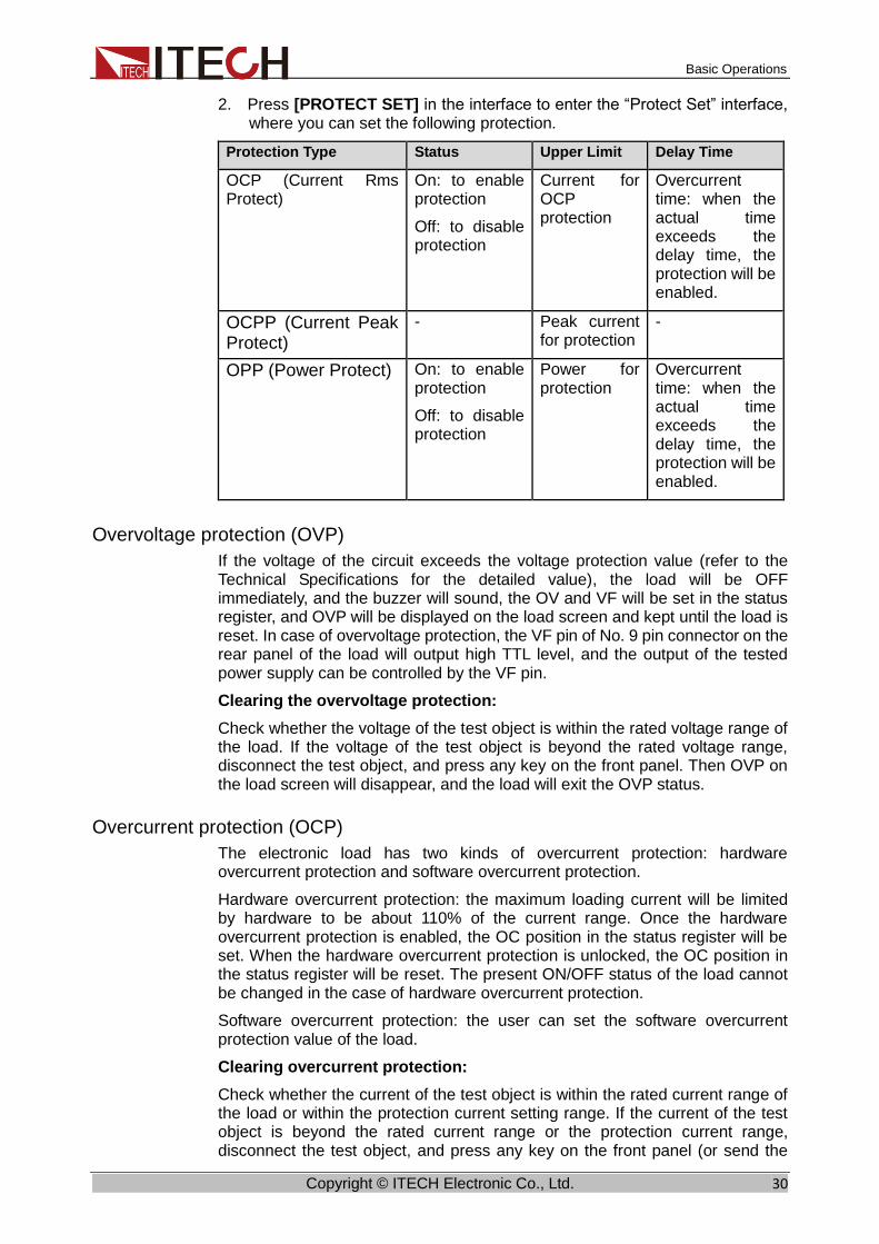
2. Press [PROTECT SET] in the interface to enter the “Protect Set” interface, where you can set the following protection.
Protection Type Status Upper Limit Delay Time
OCP (Current Rms Protect)
On: to enable protection
Off: to disable protection
Current for OCP protection
Overcurrent time: when the actual time exceeds the delay time, the protection will be enabled.
OCPP (Current Peak Protect)
- Peak current for protection
-
OPP (Power Protect) On: to enable protection
Off: to disable protection
Power for protection
Overcurrent time: when the actual time exceeds the delay time, the protection will be enabled.
Overvoltage protection (OVP)
If the voltage of the circuit exceeds the voltage protection value (refer to the Technical Specifications for the detailed value), the load will be OFF immediately, and the buzzer will sound, the OV and VF will be set in the status register, and OVP will be displayed on the load screen and kept until the load is reset. In case of overvoltage protection, the VF pin of No. 9 pin connector on the rear panel of the load will output high TTL level, and the output of the tested power supply can be controlled by the VF pin.
Clearing the overvoltage protection:
Check whether the voltage of the test object is within the rated voltage range of the load. If the voltage of the test object is beyond the rated voltage range, disconnect the test object, and press any key on the front panel. Then OVP on the load screen will disappear, and the load will exit the OVP status.
Overcurrent protection (OCP)
The electronic load has two kinds of overcurrent protection: hardware overcurrent protection and software overcurrent protection.
Hardware overcurrent protection: the maximum loading current will be limited by hardware to be about 110% of the current range. Once the hardware overcurrent protection is enabled, the OC position in the status register will be set. When the hardware overcurrent protection is unlocked, the OC position in the status register will be reset. The present ON/OFF status of the load cannot be changed in the case of hardware overcurrent protection.
Software overcurrent protection: the user can set the software overcurrent protection value of the load.
Clearing overcurrent protection:
Check whether the current of the test object is within the rated current range of the load or within the protection current setting range. If the current of the test object is beyond the rated current range or the protection current range, disconnect the test object, and press any key on the front panel (or send the

Basic Operations
Copyright © ITECH Electronic Co., Ltd. 31
command “PROTection:CLEar”). Then OCP on the load screen will disappear, and the load will exit the OCP status.
Overpower protection (OPP)
The electronic load has two kinds of overpower protection: hardware overpower protection and software overpower protection.
Hardware overpower protection: the user can set the hardware overpower protection value, and the load power will be limited at the present power by the hardware. The present ON/OFF status of the load cannot be changed in hardware overpower protection. Software overpower protection: the user can set the software overpower protection value of the load. Clearing overpower protection:
Check whether the power of the test object is within the rated power range of the load or within the protection power setting range. If the power of the test object is beyond the rated power range or protection power setting range, disconnect the test object, and press any key on the front panel (or send the command “PROTection:CLEar”). Then OPP on the load screen will disappear, and the load will exit the OPP status.
Over-temperature protection (OTP)
When the temperature of the power component in the load exceeds 85℃, the
temperature protection will be enabled. In this case, the load will be automatically OFF, and the LCD will display OTP. At the same time, the OT and PS position in the status register will be set and kept until the load is reset.
Clearing over-temperature protection:
When the load temperature decreases to the protection temperature, press any key on the front panel (or send the command “PROTection:CLEar”). Then OTP on the load screen will disappear, and the load will exit the OTP status.
Out-of-range frequency protection
When the measured frequency is beyond the frequency range (45HZ to 450HZ), “FREQ ERR” will be displayed.
Undervoltage protection
When the load is applied and current is sinking, the voltage will decrease instantly as a result of impedance of the test unit. When the voltage is lower than the required input voltage, loading will be stopped to protect the load and test unit, and the UV prompt will appear on the interface. The user should decrease the loading current or CF value to ensure normal operation.
Loading failure
Loading failure occurs in the following cases:
⚫ The input voltage is 0 during loading;
⚫ The voltage is reduced to 0 during loading;
⚫ The load hardware is abnormal;
⚫ The voltage and loading current fluctuates continuously.
Basic Operations
Copyright © ITECH Electronic Co., Ltd. 32
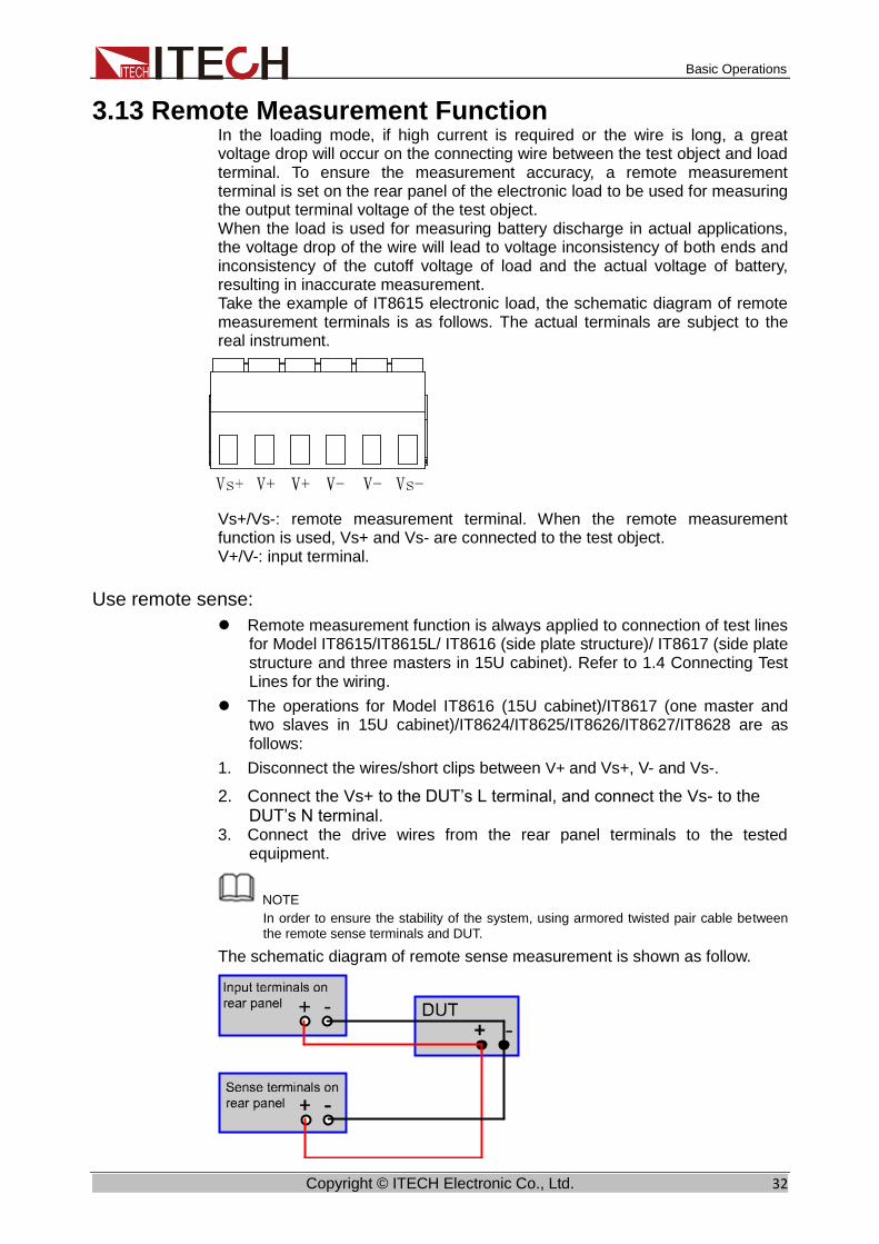
3.13 Remote Measurement Function In the loading mode, if high current is required or the wire is long, a great voltage drop will occur on the connecting wire between the test object and load terminal. To ensure the measurement accuracy, a remote measurement terminal is set on the rear panel of the electronic load to be used for measuring the output terminal voltage of the test object. When the load is used for measuring battery discharge in actual applications, the voltage drop of the wire will lead to voltage inconsistency of both ends and inconsistency of the cutoff voltage of load and the actual voltage of battery, resulting in inaccurate measurement. Take the example of IT8615 electronic load, the schematic diagram of remote measurement terminals is as follows. The actual terminals are subject to the real instrument.
Vs+/Vs-: remote measurement terminal. When the remote measurement function is used, Vs+ and Vs- are connected to the test object. V+/V-: input terminal.
Use remote sense:
⚫ Remote measurement function is always applied to connection of test lines for Model IT8615/IT8615L/ IT8616 (side plate structure)/ IT8617 (side plate structure and three masters in 15U cabinet). Refer to 1.4 Connecting Test Lines for the wiring.
⚫ The operations for Model IT8616 (15U cabinet)/IT8617 (one master and two slaves in 15U cabinet)/IT8624/IT8625/IT8626/IT8627/IT8628 are as follows:
1. Disconnect the wires/short clips between V+ and Vs+, V- and Vs-.
2. Connect the Vs+ to the DUT’s L terminal, and connect the Vs- to the DUT’s N terminal.
3. Connect the drive wires from the rear panel terminals to the tested equipment.
NOTE In order to ensure the stability of the system, using armored twisted pair cable between the remote sense terminals and DUT.
The schematic diagram of remote sense measurement is shown as follow.

Basic Operations
Copyright © ITECH Electronic Co., Ltd. 33
3.14 External On/Off Control The input switch of IT8600 electronic load can be controlled by the external TTL level. When the external level is low, the load switch will be in the On position; otherwise, the load switch will be in the Off position. The input switch of the load can only be controlled by the external TTL level.
For IT8620 series, including IT8624, IT8625, IT8626, IT8627 and IT8628, the user must set the “Ext Prog” item into the “On” state in the menu before using this function.
1. Press [Menu] to enter the menu setting interface.
2. Press the soft key corresponding to [SYSTEM SETUP] to enter the system setting interface.
3. Press the Down key and select “Ext Prog”. Set the “Ext Prog” item into the “On” state.
4. Press [Esc] to go back.
3.15 External Analog Quantity Control (Only for IT8615 /IT8615L)
IT8600 electronic load has an analog input terminal. Loading voltage or current of the electronic load can be controlled by analog quantity terminal on rear panel. Connect 0-10V adjustable voltage at the Ext-prog terminal to analog input from 0- full range so as to adjust input voltage and current of load (10V corresponds to voltage or current of load at full range).
The user must set the “Ext Prog” item into the “On” state in the menu before using this function.
5. Press [Menu] to enter the menu setting interface.
6. Press the soft key corresponding to [SYSTEM SETUP] to enter the system setting interface.
7. Press the Down key and select “Ext Prog”. Set the “Ext Prog” item into the “On” state.
8. Press [Esc] to go back.
3.16 Voltage/Current Monitoring (I/V Monitor) IT8600 electronic load has an output terminal for voltage and current monitoring. The user can connect this terminal to the oscilloscope of the BNC terminal to observe the current and UUT output voltage of the load. This function is effective when the voltage and current changes are monitored according to the waveform.
For the voltage/current monitoring output terminal, the 0-10V analog output signals represent the input voltage/current from 0 to the rating in the corresponding channel where the terminal is located.
3.17 Parallel Function IT8600 programmable AC/DC load can be used in parallel connection of multiple units of the same models to test power supplies of high power. In parallel application, AC and DC operations can be carried out in the CC/CR/CP mode.

Basic Operations
Copyright © ITECH Electronic Co., Ltd. 34
NOTE
Only IT8615, IT8615L and IT8620 series are with the function.
⚫ IT8615/IT8615L electronic load: Up to nine units of the same voltage and current rating can be connected in parallel.
⚫ IT8620 series (IT8624/IT8625/IT8626/IT8627/IT8628): Up to three units of the same voltage and current rating can be connected in parallel.
Take the example of IT8615 electronic load, the schematic diagram of parallel connection is as follows. When you connect system bus, the Terminating Resistor is a must for the first load unit and the last load unit.
Configure the internal relationship of instruments after connecting the system bus. In the parallel mode, the master and slaves are determined by the instrument setting. If the instrument is set to Master, the present AC load is the master unit, and if the instruments are set to Slave, the AC loads are slaves. The user should set the total number of slave or unit in master to determine the electronic load power in the present mode.
When the AC load is set in the parallel operation mode, slaves should be set with priority to correctly set the total number of parallel units during master unit setting.
The configuration interface of IT8620 series and IT8615/IT8615L are not the same. The specific setting steps are as follows.
⚫ Take the parallel connection of two IT8615 electronic loads as an example.
Select one electronic load as the slave.
1. Press [Menu] to enter the system menu setting interface.
2. Select [PARALLEL SETUP] to enter the parallel setting interface.
3. Press the Up and Down key to select the “Operating Mode” > “Parallel”.
4. Set “Master/Slave” as Slave, as shown below:
Basic Operations
Copyright © ITECH Electronic Co., Ltd. 35
5. Press [Enter] to save the setting.
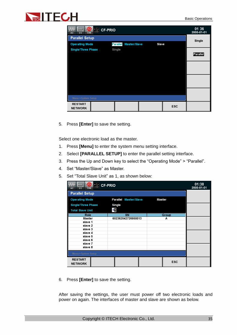
Select one electronic load as the master.
1. Press [Menu] to enter the system menu setting interface.
2. Select [PARALLEL SETUP] to enter the parallel setting interface.
3. Press the Up and Down key to select the “Operating Mode” > “Parallel”.
4. Set “Master/Slave” as Master.
5. Set “Total Slave Unit” as 1, as shown below:
6. Press [Enter] to save the setting.
After saving the settings, the user must power off two electronic loads and power on again. The interfaces of master and slave are shown as below.

Basic Operations
Copyright © ITECH Electronic Co., Ltd. 36
⚫ Take the parallel connection of three IT8628 electronic loads as an example.
Select two electronic loads as the slave.
1. Press [Menu] to enter the system menu setting interface.
2. Select [PARALLEL SETUP] to enter the parallel setting interface.
3. Press the Up and Down key to select the “Operating Mode” > “Parallel”.
4. Set “Phase Class” as “Single”.
5. Set “Phase/Position” of each unit as “Slave-B(2)” and “Slave-C(3)”.

Basic Operations
Copyright © ITECH Electronic Co., Ltd. 37
6. Press [Enter] to save the setting.
Select one electronic load as the master.
1. Press [Menu] to enter the system menu setting interface.
2. Select [PARALLEL SETUP] to enter the parallel setting interface.
3. Press the Up and Down key to select the “Operating Mode” > “Parallel”.
4. Set “Phase Class” as “Single”.
5. Set “Phase/Position” as “Master-A(1)”.
6. Set “Total Unit” as 3.
7. Press [Enter] to save the setting.
After saving the settings, the user must power off three electronic loads and power on again. The interfaces of master and slave are shown as below.

Basic Operations
Copyright © ITECH Electronic Co., Ltd. 38
3.18 Three-phase Function IT8600 can be used to test three-phase AC power supplies. The AC load can be operated in the CC/CR/CP mode. In three-phase applications, the user can select Y-type and Δ-type connection according to actual requirements. The flexible connection meets various test requirements.
NOTE
Only IT8615, IT8615L and IT8620 series are with the function.
Take the example of IT8615 electronic load, the schematic diagram of three-phase connection is as follows. When you connect system bus, the Terminating Resistor is a must for the first load unit and the last load unit.

Basic Operations
Copyright © ITECH Electronic Co., Ltd. 39
⚫ Y-type connection
⚫ Δ-type connection
Configure the internal relationship of instruments after connecting the system bus.
The configuration interface of IT8620 series and IT8615/IT8615L are not the same. The specific setting steps are as follows.
⚫ Take the example of IT8615 electronic load
During the three-phase setting, firstly, the user must set three electronic loads to be one master and two slaves. Then the user can configure the phase of three electronic loads in master.
Select two electronic loads as the slaves.
1. Press [Menu] to enter the system menu setting interface.
2. Select [PARALLEL SETUP] to enter the parallel setting interface.
3. Press the Up and Down key to select the “Operating Mode” > “Parallel”.

Basic Operations
Copyright © ITECH Electronic Co., Ltd. 40
4. Set “Master/Slave” as Slave, as shown below:
5. Press [Enter] to save the setting.
Select one electronic load as the master.
1. Press [Menu] to enter the system menu setting interface.
2. Select [PARALLEL SETUP] to enter the parallel setting interface.
3. Press the Up and Down key to select the “Operating Mode” > “Parallel”.
4. Press the Up and Down key to select the “Single/Three Phase” > “Single”.
5. Set “Master/Slave” as Master.
6. Set “Total Slave Unit” as 2, as shown below:
7. Press [Enter] to save the setting.
After saving the settings, the user must power off the three electronic loads and power on again.

Basic Operations
Copyright © ITECH Electronic Co., Ltd. 41
Then the user can configure the Phase A/B/C of three electronic loads on master.
1. Press [Menu] to enter the system menu setting interface.
2. Select [PARALLEL SETUP] to enter the parallel setting interface.
3. Press the Up and Down key to select the “Single/Three Phase” > “A+B+C”.
4. Press [EDIT PHASE], configure the Phase A/B/C of three electronic loads, as shown below.
5. Press [Enter] to save the setting.
After saving the settings, the user must power off the master and power on again. The interface of master is shown as below.
⚫ Take the example of IT8628 electronic load
Select two electronic loads as the slaves.
1. Press [Menu] to enter the system menu setting interface.

Basic Operations
Copyright © ITECH Electronic Co., Ltd. 42
2. Select [PARALLEL SETUP] to enter the parallel setting interface.
3. Press the Up and Down key to select the “Operating Mode” > “Parallel”.
4. Set “Phase Class” as “A+B+C”.
5. Set “Phase/Position” of each unit as “Slave-B(2)” and “Slave-C(3)”.
6. Press [Enter] to save the setting.
Select one electronic load as the master.
1. Press [Menu] to enter the system menu setting interface.
2. Select [PARALLEL SETUP] to enter the parallel setting interface.
3. Press the Up and Down key to select the “Operating Mode” > “Parallel”.
4. Set “Phase Class” as “A+B+C”.
5. Set “Phase/Position” as “Master-A(1)”.
6. Set “Total Unit” as 3.
Basic Operations
Copyright © ITECH Electronic Co., Ltd. 43
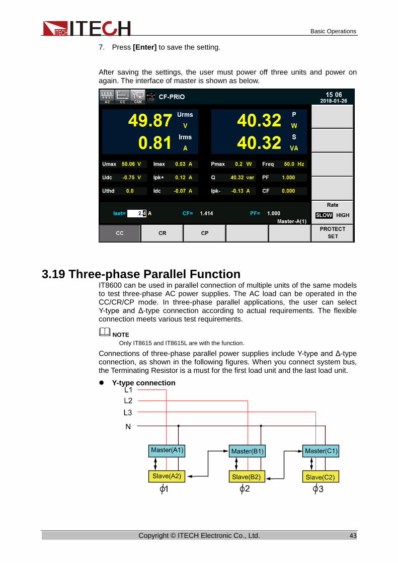
7. Press [Enter] to save the setting.
After saving the settings, the user must power off three units and power on again. The interface of master is shown as below.
3.19 Three-phase Parallel Function IT8600 can be used in parallel connection of multiple units of the same models to test three-phase AC power supplies. The AC load can be operated in the CC/CR/CP mode. In three-phase parallel applications, the user can select Y-type and Δ-type connection according to actual requirements. The flexible connection meets various test requirements.
NOTE
Only IT8615 and IT8615L are with the function.
Connections of three-phase parallel power supplies include Y-type and Δ-type connection, as shown in the following figures. When you connect system bus, the Terminating Resistor is a must for the first load unit and the last load unit.
⚫ Y-type connection

Basic Operations
Copyright © ITECH Electronic Co., Ltd. 44
⚫ Δ-type connection
The system bus interface can be connected to multiple units via cross-over cables, as shown in the above connection of diagram of three-phase parallel power supplies.
During the three-phase parallel setting, the user can make six or nine electronic loads to be connected. Take the example of six, firstly, the user must set six electronic loads to be one master and five slaves. Then the user can configure the phase of six electronic loads in master. Specific setting steps are as follows.
Select five electronic loads as the slaves.
1. Press [Menu] to enter the system menu setting interface.
2. Select [PARALLEL SETUP] to enter the parallel setting interface.
3. Press the Up and Down key to select the “Operating Mode” > “Parallel”.
4. Set “Master/Slave” as Slave, as shown below:
5. Press [Enter] to save the setting.
Select one electronic load as the master.
1. Press [Menu] to enter the system menu setting interface.
2. Select [PARALLEL SETUP] to enter the parallel setting interface.
3. Press the Up and Down key to select the “Operating Mode” > “Parallel”.
4. Press the Up and Down key to select the “Single/Three Phase” > “Single”.
5. Set “Master/Slave” as Master.

Basic Operations
Copyright © ITECH Electronic Co., Ltd. 45
6. Set “Total Slave Unit” as 5, as shown below:
7. After saving the settings, the user must power off the six electronic loads and power on again.
Configure the Phase A/A/B/B/C/C of the six electronic loads on master.
1. Press [Menu] to enter the system menu setting interface.
2. Select [PARALLEL SETUP] to enter the parallel setting interface.
3. Press the Up and Down key to select the “Single/Three Phase” > “A+B+C”.
4. Press [EDIT PHASE], configure the Phase A/A/B/B/C/C of the six electronic loads.
5. Press [Enter] to save the setting.
6. After saving the settings, the user must power off the master and power on again.
3.20 Three-phase setup You can set different power or current in three-phase mode. Press [Enter] to save the parameter of three-phase, then press [Set] to enter into the configure interface, as shown as below.

Basic Operations
Copyright © ITECH Electronic Co., Ltd. 46
Description of parameter setting:
Parameter Description
Balance ⚫ NO: Unbalance mode. You can set different values of each phase.
⚫ YES: Balance mode. You can set value of each phase consistently.
Set Sel Select A/B/C/ABC phase. You can set ABC phase only in balance mode.
View Sel Select the phase A/B/C to display.

Load Functions
Copyright © ITECH Electronic Co., Ltd. 47
Chapter4 Load Functions
This chapter describes the AC load simulation function and DC load simulation function in details. IT8600 electronic load supports the AC load function and DC load function. The user can set system parameters to select the AC load function or DC load function.
IT8600 electronic load has two working modes, i.e. AC and DC, and multiple operating modes, i.e. CC, CR, CP, CV (DC).
The CF and PF of current can be set in the CC and CP mode under the AC mode to truly simulate the actual current.
4.1 Load Function Introduction IT8600 AC/DC electronic load supports the function of AC load and DC load. The user can set system parameters and select the AC load function or DC load function. Load functions are shown in the following figure.
4.2 AC Load Function The AC load function can be simulated by IT8600 electronic load according to the settings. The user can select the present load function in the system menu. When “Mode Select” is set as AC, the electronic load is in the AC load mode. The default mode of IT8600 electronic load is the AC load mode.
In the AC load mode, the load can work in the following steady-state operating modes:
⚫ Constant current mode (CC);
⚫ Constant resistance mode (CR);
⚫ Constant power mode (CP).
4.2.1 CF and PF Setting The operating modes of the AC load mode include the constant current mode,

Load Functions
Copyright © ITECH Electronic Co., Ltd. 48
constant resistance mode and constant power mode. In the constant current and constant power operating mode, the user can program the power factor (PF) or crest factor (CF). In the constant resistance operating mode, the PF is constantly 1.
The user can set the CF, PF and their priority by pressing “Menu” > “SYSTEM SETUP”.
⚫ When the “CF/PF setting” item is set as CF, only CF can be programmed in the AC load mode.
⚫ When the “CF/PF setting” item is set as PF, only PF can be programmed in the AC load mode.
⚫ When the “CF/PF setting” item is set as “BOTH”, set the CF and PF priority and select the prevailing parameter.
Crest factor (CF): the crest factor is the ratio of the waveform crest value to the effective value. When CF is set as 1.414, a sinusoidal current waveform will be created under DSP.
Power factor (PF): the power factor is the ratio of the active power to apparent power.
When the CF/PF setting is “BOTH”, set the CF and PF priority. The setting range of CF and PF is affected by the priority. When priority is given to CF, the setting range of PF is affected by the present CF value. When priority is given to PF, the setting range of CF is affected by the PF setting.
4.2.2 Constant Current Mode (CC) In CC mode, the load will sink a constant current according to the programmed value if the input voltage is higher than the minimum operating voltage. Press [Set] on the front panel and soft key CC to enter the CC mode setting interface.
The current waveform is synchronized with the sinusoidal waveform of the voltage on the right side of the coordinate axis. The PF value can be set within ±1. According to the definition of IT8600 electronic load, when the PF setting is positive, the current is ahead of voltage; otherwise, the current lags behind voltage.
In the CC mode, press the Up and Down key and select the parameter to be set, including the Iset, CF and PF value. The CF mode, PF mode and “Both” mode can be set for CF/PF.
In the case of loading, the current setting and voltage input should meet the input requirements; otherwise, the undervoltage protection of the electronic load will be enabled, and loading will fail. For details of undervoltage protection, refer to 3.12 Protection Function.
The voltage-current relation is shown below:
Fig. 3-1 Voltage-current Relation in CC Mode
load current
Load input voltage
I
V
Set current
CC mode
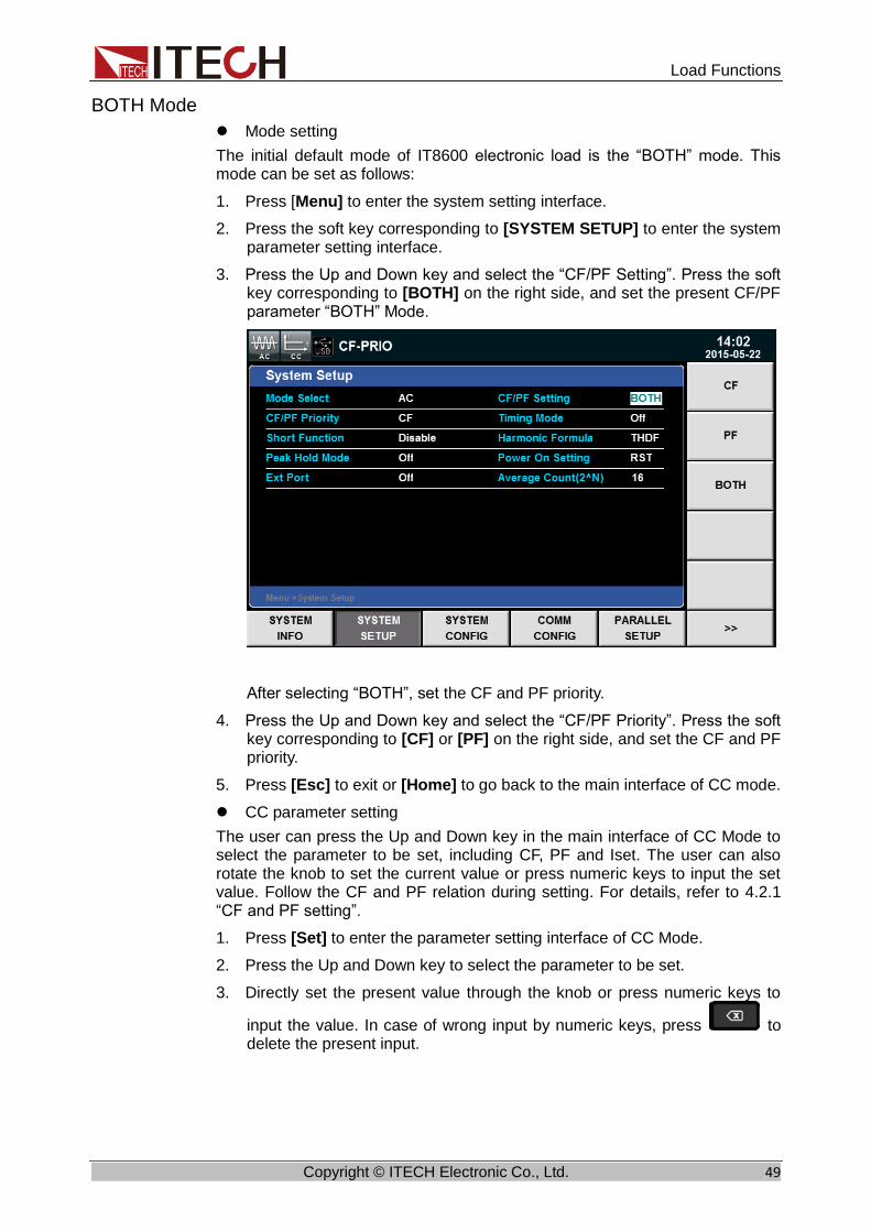
Load Functions
Copyright © ITECH Electronic Co., Ltd. 49
BOTH Mode
⚫ Mode setting
The initial default mode of IT8600 electronic load is the “BOTH” mode. This mode can be set as follows:
1. Press [Menu] to enter the system setting interface.
2. Press the soft key corresponding to [SYSTEM SETUP] to enter the system parameter setting interface.
3. Press the Up and Down key and select the “CF/PF Setting”. Press the soft key corresponding to [BOTH] on the right side, and set the present CF/PF parameter “BOTH” Mode.
After selecting “BOTH”, set the CF and PF priority.
4. Press the Up and Down key and select the “CF/PF Priority”. Press the soft key corresponding to [CF] or [PF] on the right side, and set the CF and PF priority.
5. Press [Esc] to exit or [Home] to go back to the main interface of CC mode.
⚫ CC parameter setting
The user can press the Up and Down key in the main interface of CC Mode to select the parameter to be set, including CF, PF and Iset. The user can also rotate the knob to set the current value or press numeric keys to input the set value. Follow the CF and PF relation during setting. For details, refer to 4.2.1 “CF and PF setting”.
1. Press [Set] to enter the parameter setting interface of CC Mode.
2. Press the Up and Down key to select the parameter to be set.
3. Directly set the present value through the knob or press numeric keys to
input the value. In case of wrong input by numeric keys, press to delete the present input.
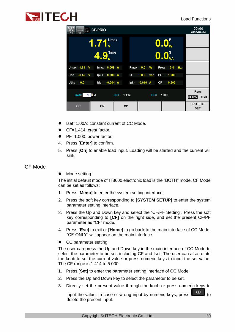
Load Functions
Copyright © ITECH Electronic Co., Ltd. 50
⚫ Iset=1.00A: constant current of CC Mode.
⚫ CF=1.414: crest factor.
⚫ PF=1.000: power factor.
4. Press [Enter] to confirm.
5. Press [On] to enable load input. Loading will be started and the current will sink.
CF Mode
⚫ Mode setting
The initial default mode of IT8600 electronic load is the “BOTH” mode. CF Mode can be set as follows:
1. Press [Menu] to enter the system setting interface.
2. Press the soft key corresponding to [SYSTEM SETUP] to enter the system parameter setting interface.
3. Press the Up and Down key and select the “CF/PF Setting”. Press the soft key corresponding to [CF] on the right side, and set the present CF/PF parameter as “CF” mode.
4. Press [Esc] to exit or [Home] to go back to the main interface of CC Mode. “CF-ONLY” will appear on the main interface.
⚫ CC parameter setting
The user can press the Up and Down key in the main interface of CC Mode to select the parameter to be set, including CF and Iset. The user can also rotate the knob to set the current value or press numeric keys to input the set value. The CF range is 1.414 to 5.000.
1. Press [Set] to enter the parameter setting interface of CC Mode.
2. Press the Up and Down key to select the parameter to be set.
3. Directly set the present value through the knob or press numeric keys to
input the value. In case of wrong input by numeric keys, press to delete the present input.

Load Functions
Copyright © ITECH Electronic Co., Ltd. 51
⚫ Iset=1.00A: constant current of CC Mode.
⚫ CF=1.414: crest factor, 1.414 to 5.000.
⚫ PF=1.000: power factor. It cannot be edited.
4. Press [Enter] to confirm.
5. Press [On] to enable load input. Loading will be started and the current will sink.
PF Mode
⚫ Mode setting
The initial default mode of IT8600 electronic load is the “BOTH” mode. PF Mode can be set as follows:
1. Press [Menu] to enter the system setting interface.
2. Press the soft key corresponding to [SYSTEM SETUP] to enter the system parameter setting interface.
3. Press the Up and Down key and select the “CF/PF Setting”. Press the soft key corresponding to [PF] on the right side, and set the present CF/PF parameter as “PF” mode. The figure shows the “BOTH” setting interface.
4. Press [Esc] to exit or [Home] to go back to the main interface of CC Mode. “PF-ONLY” will appear on the main interface.
⚫ CC parameter setting
The user can press the Up and Down key in the main interface of CC Mode to select the parameter to be set, including PF and Iset. The user can also rotate the knob to set the current value or press numeric keys to input the set value. The PF range is -1.000 to 1.000.
1. Press [Set] to enter the parameter setting interface of CC Mode.
2. Press the Up and Down key to select the parameter to be set.
3. Directly set the present value through the knob or press numeric keys to
input the value. In case of wrong input by numeric keys, press to delete the present input.

Load Functions
Copyright © ITECH Electronic Co., Ltd. 52
⚫ Iset=1.00A: constant current of CC Mode.
⚫ CF=1.414: crest factor. It cannot be edited.
⚫ PF=1.000: power factor, -1.000 to 1.000.
4. Press [Enter] to confirm.
5. Press [On] to enable load input. Loading will be started and the current will sink.
4.2.3 Constant Resistance Mode (CR) In the constant resistance mode, the AC electronic load is equivalent to the constant resistance and will suck the current of linear ratio to the input voltage, the current waveform is the same as the input voltage waveform, and PF is constantly 1, as shown below.
Fig. 3-2 Voltage-current Relation in CR Mode
In CR Mode, the resistance can be modified in two methods: ⚫ Rotate the knob to set the constant resistance. ⚫ Use numeric keys to input the resistance value and press [Enter] to confirm
the set resistance.
Operating steps
1. Press [Set] and [CR] to enter the parameter setting interface of CR Mode.
Rset=2500Ω
The resistance, input voltage and load’s sink current should meet the requirements of R=U/I.
Input Voltage
Load Current
V
I
The Slope is R setting
CR mode

Load Functions
Copyright © ITECH Electronic Co., Ltd. 53
2. Set the working resistance value and press [Enter] to confirm it.
4.2.4 Constant Power Mode (CP) In the constant power mode, the constant power is required for the electronic load, and the current sinks according to the set power, as shown below. If the input voltage increases, the input current will decrease to keep the power P (=V * I) at the set value.
Fig. 3-3 Voltage-current Relation of CP Mode
The set current waveform is synchronized with the sinusoidal waveform of the voltage on the right side of the coordinate axis. PF can be set within ±1.
Similar to CC Mode, the user can set the PF and CF value in CP Mode. The user can also select the CF Mode, PF Mode and BOTH Mode. The loading parameter CF, PF and Pset can be set in the main interface of CP Mode.
BOTH Mode
⚫ Mode setting
The initial default mode of IT8600 electronic load is the “BOTH” mode. This mode can be set in the same method as in CC Mode. Refer to 4.2.2 “Constant Current Mode (CC)”.
⚫ CP parameter setting
The user can press the Up and Down key in the main interface of CP Mode to select the parameter to be set, including CF, PF and Pset. The user can also rotate the knob to set the current value or press numeric keys to input the set value. Follow the CF and PF relation during setting. For details, refer to 4.2.1 “CF and PF setting”.
1. Press [Set] to enter the parameter setting interface of CC Mode.
2. Press the soft key corresponding to CP to enter the CP mode setting interface.
3. Press the Up and Down key to select the parameter to be set.
4. Directly set the present value through the knob or press numeric keys to
input the value. In case of wrong input by numeric keys, press to delete the present input.
Load Current
V
I
Set power value V2
V3
I2 I3
Input Voltage
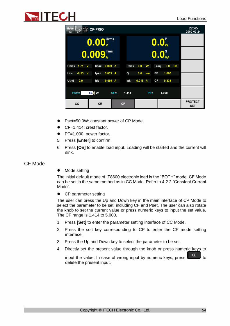
Load Functions
Copyright © ITECH Electronic Co., Ltd. 54
⚫ Pset=50.0W: constant power of CP Mode.
⚫ CF=1.414: crest factor.
⚫ PF=1.000: power factor.
5. Press [Enter] to confirm.
6. Press [On] to enable load input. Loading will be started and the current will sink.
CF Mode
⚫ Mode setting
The initial default mode of IT8600 electronic load is the “BOTH” mode. CF Mode can be set in the same method as in CC Mode. Refer to 4.2.2 “Constant Current Mode”.
⚫ CP parameter setting
The user can press the Up and Down key in the main interface of CP Mode to select the parameter to be set, including CF and Pset. The user can also rotate the knob to set the current value or press numeric keys to input the set value. The CF range is 1.414 to 5.000.
1. Press [Set] to enter the parameter setting interface of CC Mode.
2. Press the soft key corresponding to CP to enter the CP mode setting interface.
3. Press the Up and Down key to select the parameter to be set.
4. Directly set the present value through the knob or press numeric keys to
input the value. In case of wrong input by numeric keys, press to delete the present input.

Load Functions
Copyright © ITECH Electronic Co., Ltd. 55
⚫ Pset=50.0W: constant power of CP Mode.
⚫ CF=1.414: crest factor, 1.414 to 5.000.
⚫ PF=1.000: power factor. It cannot be edited.
5. Press [Enter] to confirm.
6. Press [On] to enable load input. Loading will be started and the current will sink.
PF Mode
⚫ Mode setting
The initial default mode of IT8600 electronic load is the “BOTH” mode. PF Mode can be set in the same method as in CC Mode. Refer to 4.2.2 “Constant Current Mode”.
⚫ CP parameter setting
The user can press the Up and Down key in the main interface of CP Mode to select the parameter to be set, including PF and Pset. The user can also rotate the knob to set the current value or press numeric keys to input the set value. The PF range is -1.000 to 1.000.
1. Press [Set] to enter the parameter setting interface of CC Mode.
2. Press the soft key corresponding to CP to enter the CP mode setting interface.
3. Press the Up and Down key to select the parameter to be set.
4. Directly set the present value through the knob or press numeric keys to
input the value. In case of wrong input by numeric keys, press to delete the present input.

Load Functions
Copyright © ITECH Electronic Co., Ltd. 56
⚫ Pset=50.0W: constant power of CP Mode.
⚫ CF=1.414: crest factor. It cannot be edited.
⚫ PF=1.000: power factor, -1.000 to 1.000.
5. Press [Enter] to confirm.
6. Press [On] to enable load input. Loading will be started and the current will sink.
4.3 DC Load Function IT8600 electronic load can simulate the DC electronic load function according to the setting. The user can select the present load function in the system menu. When “Mode Select” is set as “DC”, the present load function of the electronic load is in the DC mode.
IT8600 electronic load can be operated in the following four modes:
⚫ Constant current mode (CC)
⚫ Constant voltage mode (CV) (Only for IT8615/IT8615L)
⚫ Constant register mode (CR)
⚫ Constant power mode (CP)
4.3.1 Constant Current Mode (CC) In this mode, the electronic load will sink a constant current in accordance with the programmed value regardless of the input voltage. See figure 3-4.
Figure 3-4 CC mode
Load Current
Load input voltage
I
V
Set current
CC mode

Load Functions
Copyright © ITECH Electronic Co., Ltd. 57
4.3.2 Constant Resistance Mode (CR) In this mode, the electronic load was equivalent to a constant resistance, as shown below, the electronic load will linearly change the current according to the input voltage. See figure 3-5.
Figure 3-5 CR mode
4.3.3 Constant Voltage Mode (CV) (Only for IT8615/IT8615L) In this mode, the electronic load will attempt to sink enough current to control the source voltage to the programmed value. See figure 3-6.
Figure 3-6 CV mode
4.3.4 Constant Power Mode (CP) In CP mode, the load will consume a constant power. See Figure 3-7. If the input voltage rises, the input current will decline. The P (=V * I) will remain on the set power.
Figure 3-7 CP mode
4.3.5 Short Circuit Simulation Function The electronic load can simulate a short circuit at the input end in the DC load mode. You can press [Short] to switch over the short circuit status. Short circuit operations have no influence on the present setting. When the OFF status is
Input Voltage
Load Current
V
I
Set power value V2
V3
I2 I3
Input voltage
Load Current
V
I
The Slope is R setting
CR mode
Load Current
Input voltage
I
V
Set current
CV mode

Load Functions
Copyright © ITECH Electronic Co., Ltd. 58
enabled, the load will return to the original setting.
The actual current of the load in the short circuit status depends on the current working mode and current range. In CC, CP and CR Mode, the maximum short circuit current is 120% of the current range. In CV Mode, the short circuit means that the constant voltage of the load is 0V.
Enabling the short circuit function:
1. In the main interface of the DC load function, press [SHORT] to enter the short circuit simulation mode.
2. Press the soft key [SHORT FUN] on the right side. Press the set value once to switch DIS and ENA. DIS means the short circuit function is disabled, and ENA means the short circuit function is enabled. You can also perform setting in the system menu.
a) Press [Menu] to enter the system setting interface.
b) Press the soft key corresponding to [SYSTEM SETUP] to enter the system parameter setting interface.
c) Press the Up and Down key and select “Short Function”. Press the soft key corresponding to [On] on the right side to enable the short circuit simulation function.
3. Press [START] and [STOP] to start and stop short circuit simulation.

Measurement Functions
Copyright © ITECH Electronic Co., Ltd. 59
Chapter5 Measurement Functions
This chapter describes the characteristics and operations of the basic metering function of IT8600 electronic load.
IT8600 electronic load has rich functions of basic metering of electric energy and can accurately measure the parameters such as Vrms, Vpk, Vdc, Irms, Ipk, Idc, W, VA, VAR, CF, PF and Freq.
5.1 Interface Introduction
Soft Key of Menu
Description
Peak Hold Peak Holding Mode On: to enable the peak holding mode. Measurement data are updated if peak data are sampled. Off: to disable the peak holding mode.
CONFIG Configuration of basic metering.
5.2 Parameter Measurement The measured value displayed in large letters on the upper part of the interface can be modified according to the user requirements. Press [CONFIG] to enter the metering parameter configuration interface. Press the soft key corresponding to the metering parameter.
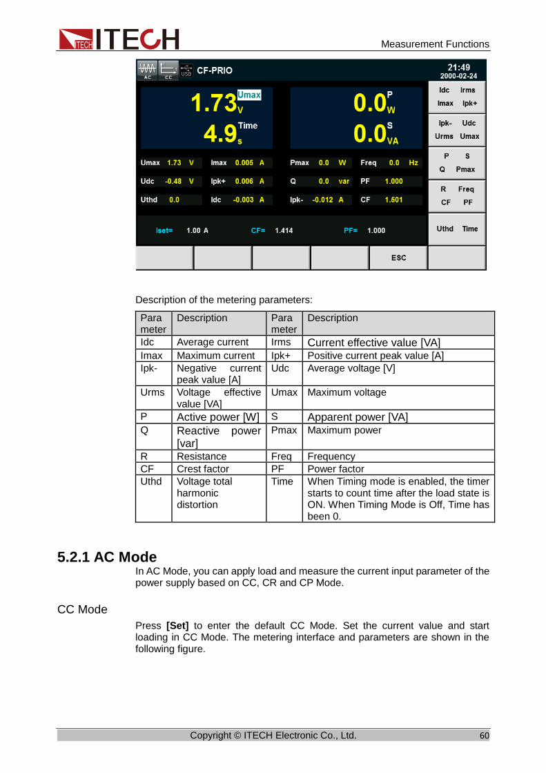
Measurement Functions
Copyright © ITECH Electronic Co., Ltd. 60
Description of the metering parameters:
Parameter
Description Parameter
Description
Idc Average current Irms Current effective value [VA] Imax Maximum current Ipk+ Positive current peak value [A]
Ipk- Negative current peak value [A]
Udc Average voltage [V]
Urms Voltage effective value [VA]
Umax Maximum voltage
P Active power [W] S Apparent power [VA] Q Reactive power
[var]
Pmax Maximum power
R Resistance Freq Frequency
CF Crest factor PF Power factor
Uthd Voltage total harmonic distortion
Time When Timing mode is enabled, the timer starts to count time after the load state is ON. When Timing Mode is Off, Time has been 0.
5.2.1 AC Mode In AC Mode, you can apply load and measure the current input parameter of the power supply based on CC, CR and CP Mode.
CC Mode
Press [Set] to enter the default CC Mode. Set the current value and start loading in CC Mode. The metering interface and parameters are shown in the following figure.

Measurement Functions
Copyright © ITECH Electronic Co., Ltd. 61
CR Mode
Press [Set] and [CR] to enter CR Mode. Set the resistance value and start loading in CR Mode. The metering interface and parameters are shown in the following figure.
CP Mode
Press [Set] and [CP] to enter CP Mode. Set the resistance value and start loading in CP Mode. The metering interface and parameters are shown in the following figure.
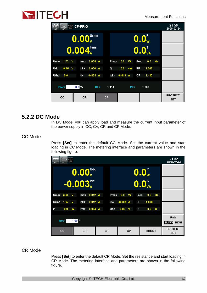
Measurement Functions
Copyright © ITECH Electronic Co., Ltd. 62
5.2.2 DC Mode In DC Mode, you can apply load and measure the current input parameter of the power supply in CC, CV, CR and CP Mode.
CC Mode
Press [Set] to enter the default CC Mode. Set the current value and start loading in CC Mode. The metering interface and parameters are shown in the following figure.
CR Mode
Press [Set] to enter the default CR Mode. Set the resistance and start loading in CR Mode. The metering interface and parameters are shown in the following figure.

Measurement Functions
Copyright © ITECH Electronic Co., Ltd. 63
CP Mode
Press [Set] to enter the default CP Mode. Set the resistance and start loading in CP Mode. The metering interface and parameters are shown in the following figure.
CV Mode (Only for IT8615/IT8615L)
Press [Set] to enter the default CV Mode. Set the resistance and start loading in CV Mode. The metering interface and parameters are shown in the following figure.

Measurement Functions
Copyright © ITECH Electronic Co., Ltd. 64

Waveform Display Function
Copyright © ITECH Electronic Co., Ltd. 65
Chapter6 Waveform Display Function
IT8600 electronic load has the oscilloscope function. This chapter describes the oscilloscope function and operations of the electronic load.
6.1 Interface Introduction
IT8600 electronic load has the function of displaying the waveform based on sampling data. The user can select to display or hide the voltage and current waveform of the input unit. Only the necessary waveform is displayed, which can facilitate observation. The waveform display interface includes the vertical axis and horizontal axis.
Introduction to soft keys of interface
Press [Scope] and the following waveform display interface will appear.
Description of keys on the waveform display interface:
Parameter Name Description
Knob Func
Knob selection: the following variables can be adjusted by rotating the knob: ⚫ Volt Range ⚫ CURR Range ⚫ Volt Base ⚫ Curr Base ⚫ Trig Level ⚫ Trig Delay
⚫ Time/div
RUN/STOP Run/stop: press the corresponding soft key to run or stop the waveform status.

Waveform Display Function
Copyright © ITECH Electronic Co., Ltd. 66
Parameter Name Description
SINGLE Single measurement key: when single measurement is enabled in the Stop status, the stop status is enabled again after one measurement based on the current data updating rate. When single measurement is enabled in the Run status, the instrument immediately restarts one measurement and then enters the Stop status.
WAVE(U/A/UA) Used for selecting the waveform to be displayed on the screen: voltage, current and voltage/current.
AUTO Automatic adjustment key: when the corresponding soft key is pressed, the input signal of the power meter will be calibrated automatically to display the best effects of input signals.
TRIG SETUP Trigger setting.
MEASURE SETUP Measurement setting
Introduction to waveform display interface
Description of the trigger state:
Trigger State
Description
Auto The selected trigger mode is “Auto”. After triggering, the trigger state “Auto” appears.
Auto? The selected trigger mode is “Auto”. The trigger state is “Auto?” if triggering is not performed.
Trigger level
V/I grid Trigger delay
Delay time Time grid
Trigger state
The voltage/current difference between ground level and point of center vertical
wave Measuring parameters
Trigger level

Waveform Display Function
Copyright © ITECH Electronic Co., Ltd. 67
Trigger State
Description
Trig The selected trigger mode is “Normal”. After triggering, the trigger state “Trig” appears.
Trig? The selected trigger mode is “Normal”. The trigger state is “Trig?” if triggering is not performed.
Stop Press the soft key [Stop] in the waveform display interface. The trigger state “Stop” appears.
Vertical calibration
The voltage range and current range are subject to vertical calibration (voltage/scale and current/scale). Press the soft key [Knob Func] and select Volt Range or CURR Range. Rotate the knob to set the voltage or current range of each interval.
Horizontal calibration
If the soft key [Knob Func] is pressed and “Time/div” is selected, you can rotate the knob to adjust the horizontal scale (scanning speed). When the horizontal (time/scale) setting is changed by rotating the knob, you can observe the change of time/scale on the screen. During data collection, the sampling speed can be changed by adjusting the horizontal calibration knob. After collection is stopped, the collected data can be amplified by adjusting the horizontal calibration knob.
Trigger delay
If the soft key [Knob Func] is pressed and “Trig Delay” is selected, you can rotate the knob to adjust the trigger delay. In this case, if the knob is rotated, the trigger point will move horizontally and the delay time will be displayed on the
screen. To change the delay time, move the trigger point ( ) horizontally and set the distance between the trigger point and the horizontal center. The trigger point moves along the top end of the display grid.
Trigger waveform
When the specified trigger conditions are satisfied, the trigger waveform will be displayed. The triggering time is the trigger point, generally on the right of the screen. When the trigger point is reached, the screen will display the waveform from left to right over time. The user should set the following parameters before using the trigger function.
⚫ Trigger mode
The trigger mode refers to the condition to update the contents on the screen. It is divided into the Auto mode and Normal mode. In the Auto mode, the displayed waveform will be updated when triggering occurs in the suspension time; otherwise, the displayed waveform will be updated automatically.
In the Normal mode, the displayed waveform will be updated in the case of triggering and not updated in the case of no triggering.
⚫ Trigger source
The trigger source is used for generating trigger conditions. The user can select the trigger source in the input signal of the input unit.

Waveform Display Function
Copyright © ITECH Electronic Co., Ltd. 68
⚫ Trigger slope
The slope refers to the change of the signal from low level to high level (rising edge) or from high level to low level (falling edge). The slope used as a trigger condition is referred to as the trigger slope.
⚫ Trigger level
The trigger level refers to the level which the trigger slope passes through. If the signal of the trigger source passes through the set trigger level according to the specified trigger slope, triggering occurs. When the soft key [Knob Func] is pressed and “Trig Level” is selected, you can rotate the knob to adjust the trigger level. In this case, the trigger level can be changed by rotating the knob and you can observe trigger level changes on the screen.
6.2 Adjustment of Measurement Parameters
You can rotate the knob to adjust the vertical calibration, horizontal calibration, trigger delay and trigger level on the waveform display interface. Detailed steps are as follows.
Operating steps
1. Press [Scope] to enter the waveform display interface.
2. In the waveform display interface, press the soft key [Knob Func] to select
the parameter to be adjusted.
3. Rotate the knob to adjust the parameter. Corresponding value changes will
be displayed in the interface.
6.3 Setting of Trigger Configuration
To enable the trigger function, you should select the trigger source, trigger mode, trigger slope, etc. Detailed steps are as follows.

Waveform Display Function
Copyright © ITECH Electronic Co., Ltd. 69
Operating steps
1. Press [Scope] to enter the waveform display interface.
2. In the waveform display interface, press the soft key corresponding to
[TIRG SETUP] to enter the trigger setting interface, as shown below.
3. Press the soft key corresponding to the parameter on the right side and
select the required trigger configuration. Refer to the Trigger Waveform for
details.
Source (trigger source): select the voltage or current as the trigger source.
Mode (trigger mode): select the Auto or Normal mode. Slope (trigger slope): select the rising edge, falling edge or
rising/falling.
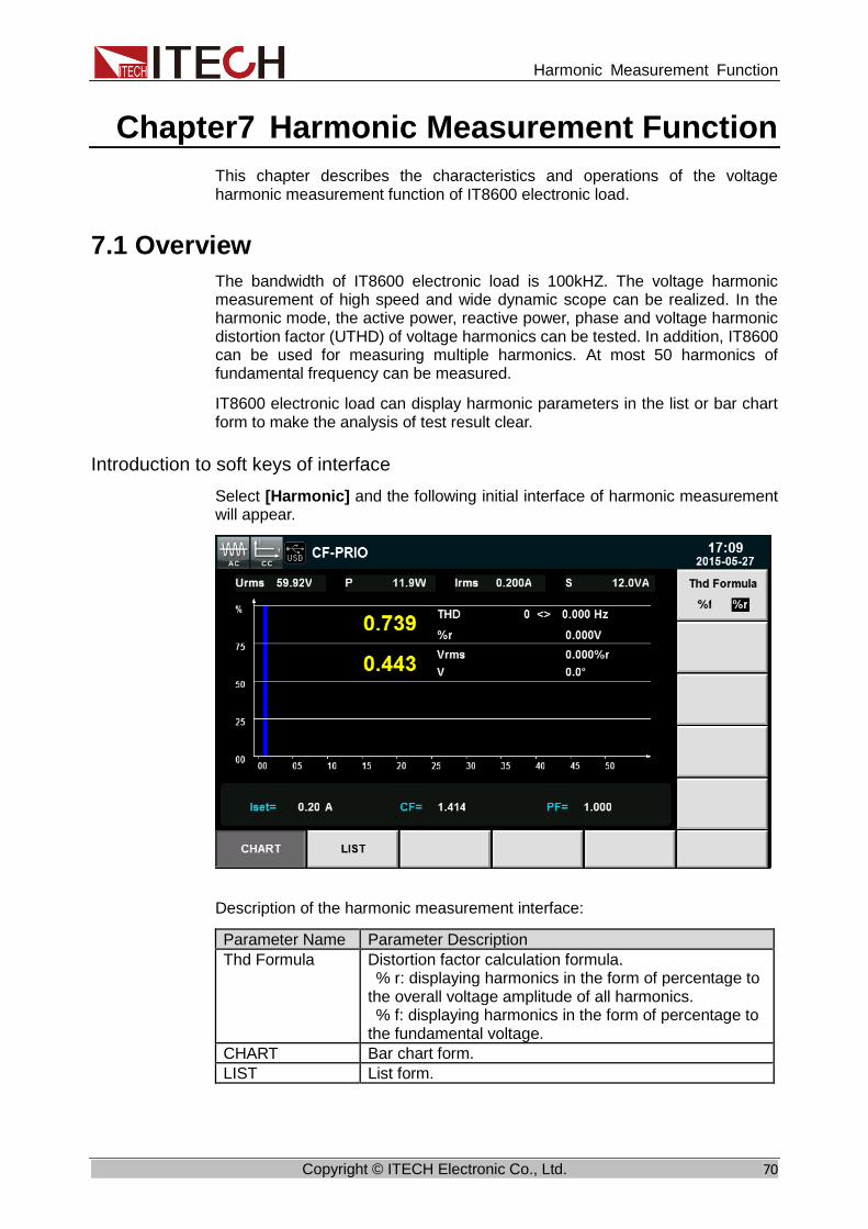
Harmonic Measurement Function
Copyright © ITECH Electronic Co., Ltd. 70
Chapter7 Harmonic Measurement Function
This chapter describes the characteristics and operations of the voltage harmonic measurement function of IT8600 electronic load.
7.1 Overview
The bandwidth of IT8600 electronic load is 100kHZ. The voltage harmonic measurement of high speed and wide dynamic scope can be realized. In the harmonic mode, the active power, reactive power, phase and voltage harmonic distortion factor (UTHD) of voltage harmonics can be tested. In addition, IT8600 can be used for measuring multiple harmonics. At most 50 harmonics of fundamental frequency can be measured.
IT8600 electronic load can display harmonic parameters in the list or bar chart form to make the analysis of test result clear.
Introduction to soft keys of interface
Select [Harmonic] and the following initial interface of harmonic measurement will appear.
Description of the harmonic measurement interface:
Parameter Name Parameter Description
Thd Formula Distortion factor calculation formula. % r: displaying harmonics in the form of percentage to the overall voltage amplitude of all harmonics. % f: displaying harmonics in the form of percentage to the fundamental voltage.
CHART Bar chart form.
LIST List form.

Harmonic Measurement Function
Copyright © ITECH Electronic Co., Ltd. 71
Introduction to harmonic information
⚫ Harmonic bar chart screen
When “CHART” is selected in the harmonic measurement screen, the bar chart of harmonic measurement results will be displayed. The bar chart is used to show the percentage of each harmonic measurement. Harmonics can be displayed in full sequence, odd sequence and even sequence by options. The bar chart shown below is harmonics in full sequence.
Technical terms of explanation:
THD value: the total harmonic parameters include the total harmonic distortion factor (THD) and total harmonic content.
Parameters of single harmonic measurement include the frequency, harmonic content, harmonic distortion factor and phase of each harmonic. The user can rotate the knob to select each harmonic to be displayed. The selected harmonic will be displayed in red in the bar chart.
⚫ Harmonic list
When “LIST” is selected in the harmonic measurement mode, the list of harmonic measurement results will be displayed, including the voltage, phase and voltage harmonic distortion factor (UTHD) of each harmonic.
Percentage of harmonic
Parameter of harmonic
Histogram THD value
Parameter of each harmonic
X-axis: harmonic numbers

Harmonic Measurement Function
Copyright © ITECH Electronic Co., Ltd. 72
Harmonic content: this list includes all harmonic parameters of each harmonic, including voltage, harmonic distortion factor of voltage and phase. Measurement parameters are defined as follows:
Abbreviation
Description Abbreviation Description
U (V) Voltage φUI (°) Phase difference of kth order harmonic voltage and harmonic current
U (%f) Harmonic distortion factor of voltage
UThd -
Phase (°) Phase - -
Harmonic number list: the signal data of 0-50 harmonic(s) will be shown in the LIST. You can press the Up and Down key to display the hidden rows, i.e. hidden data of each harmonic. In this case, when the row scrolling bar is operated, the current page is displayed in the high-brightness green bar.
7.2 Setting of Harmonic Measurement Configuration
Distortion factor calculation formula:
The following two formulas can be selected for calculation of the distortion factor.
⚫ %r: using all harmonic measurement data from the minimum harmonic order (0th) to the maximum harmonic order (within the upper limit of analysis orders) as the denominator.
⚫ %f: using the data of fundamental wave (1-order) components as the denominator.
The distortion factor calculation formulas and methods of different measurement functions are as follows:

Harmonic Measurement Function
Copyright © ITECH Electronic Co., Ltd. 73
Measurement
function
Calculation formula and method %r %f
Harmonic distortion factor of voltage
( )( )TotalU
kU ( )( )1U
kU
Harmonic distortion factor of active power
( )( )TotalP
kP ( )( )1P
kP
Total harmonic distortion rate of voltage
( )
( )TotalU
kUk
=
max
2
2
( )
( )1
max
2
2
U
kUk
=
Total harmonic distortion rate of active power
( )
( )TotalP
kPk
=
max
2 ( )
( )1
max
2
P
kPk
=
NOTE
Total harmonics are calculated as follows: ( ) ( )=
=max
0
2
k
kUTotalU,
( ) ( )=
=max
0
2
k
kITotalI,
( ) ( )=
=max
0k
kPTotalP . k indicates the harmonic order, and max indicates the upper limit of
analysis orders. max is determined by the frequency of PLL source automatically, 50 orders
at most.

Routine Maintenance
Copyright © ITECH Electronic Co., Ltd. 74
Chapter8 Routine Maintenance
This chapter describes the general maintenance items and methods for IT8600 AC/DC load.
8.1 Error Information Reference
IT8600 AC/DC load can provide detailed error and prompt information to help the user easily locate problems and implement measurement during measurement and operation.
This section introduces all error information, causes and troubleshooting of IT8600 AC/DC load, and lists all prompt information.
Prompt information list
Prompt Information
Voltage range has reach the lowest limit
Current range has reach the lowest limit
Voltage base has reached the highest limit
Current base has reached the highest limit
Voltage trig level has reached the highest limit
Current trig level has reached the highest limit
Trig delay has reached the lowest limit
Time base has reach the lowest limit
Voltage range has reached the highest limit
Current range has reached the highest limit
Voltage base has reach the lowest limit
Current base has reached the lowest limit
Voltage trig level has reached the lowest limit
Current trig level has reached the lowest limit
Trig delay has reached the highest limit
Time base has reached the highest limit
Time set ok
Local has been locked
Remote state
Key has been locked
Protect clear
not used in current state!
Save4 is performed
Save3 is performed
Save2 is performed
Save1 is performed
Recall4 is performed
Recall3 is performed
Recall2 is performed
Recall1 is performed
Save screen ok
Log stop
Log start

Routine Maintenance
Copyright © ITECH Electronic Co., Ltd. 75
Error information list
Error Information Error Interpretation Cause
Time set fail! The time setting fails.
Invalid time setting.
Dsp is abnormal DSP is abnormal. Low power voltage or other causes.
Save screen fail Screen copying fails. The USB file system is not applicable to the instrument.
usb is not detected No USB is detected. USB is not readable or the USB interface is damaged.
Save error Saving fails. The setting is invalid or EEPROM is damaged.
Recall error Recalling fails. No information can be recalled.
8.2 Routine Maintenance
This section introduces the basic maintenance involved in routine operation of the instrument, such as cleaning, self-repair, etc.
Cleaning
Wipe the machine with dry or slightly wet cloth. Do not wipe the inside of the machine without permission. Cut off the power supply before cleaning.
Initialization
Factory settings of the system will be restored by implementing this operation:
1. Select [Menu] to enter the system menu interface.
2. Press [>>] to display the system menu in the scrolling form.
3. Press the soft key corresponding to [SYSTEM INITIAL] to enter the system initialization interface, as shown below.
4. Press the Up and Down key and select the menu item (blue background) to

Routine Maintenance
Copyright © ITECH Electronic Co., Ltd. 76
be initialized. “✓” behind the menu item indicates that this item will be
initialized, while “” indicates that this item will not be initialized.
5. Press the soft key corresponding to the symbol on the right side of the
interface and select whether to initialize this menu item, or press the soft
key [All/✓] (all menu items will be initialized) or [All/] (all menu items will
not be initialized) at the bottom.
6. Press the soft key [START] and the system will be initialized. Press [ESC]
to exit.
8.3 Contact ITECH Engineer
This section introduces the procedures for troubleshooting.
Preparations before contact
In case of instrument failure, make the following preparations before returning the instrument to ITECH for repair or contacting the engineer.
1. Complete all inspections specified in “Self-check of Instrument Fault” and check whether the fault still occurs.
2. If the fault still occurs, carefully read the warranty service and restriction requirements in the foreword of the manual and confirm that your instrument meets the warranty service requirements.
3. To send the instrument back to the manufacturer for repair, see the requirements in “Return for Repair”.
Self-check of Instrument Fault
In case of instrument failure, please perform the following self-checks. If the instrument can be recovered by simple check, the cost and time can be saved. Before contacting the engineer of ITECH, please check the following items.
⚫ Check whether the instrument is powered on. ⚫ Check whether the instrument is started up normally. ⚫ Check whether the fuse is in good condition. ⚫ Check whether other connectors are in good condition, including cables,
plugs, etc. ⚫ Check whether the system configuration is correct in operation. ⚫ Check whether the self-test is successfully and whether all specifications
and performance meet the specified requirements. ⚫ Check whether the instrument displays error information. ⚫ Use other instruments instead of this instrument for confirmation.
SN collection
ITECH will improve the product performance, availability and reliability from time to time. The service personnel of ITECH will record the changes of each instrument, and all the relevant information will be identified according to the SN. The SN will be used as the tracking ID of the instrument returned for repair.
To contact the engineer, the valid SN will be an effective guarantee for effective service and complete information. You can obtain the instrument SN in the following methods:

Routine Maintenance
Copyright © ITECH Electronic Co., Ltd. 77
1. Press [Menu] to enter the system setting interface of the electronic load.
2. The system will enter into “SYSTEM INFO” by default.. If the system is
displayed in other menus, press [SYSTEM INFO] to enter the “SYSTEM
INFO” interface and view the product model, SN, software version, etc.
In this interface above, “Serial” is the instrument SN.
3. Record the SN.
Calibration interval
The calibration frequency recommended by ITECH for IT8600 AC/DC load is once a year.
8.4 Return for Repair Before returning the instrument for repair, please read the following
requirements.
Packaging
Refer to the following steps to package the instrument to be returned for repair.
Pack the instrument to be repaired into the package used in delivery, including relevant accessories.
Provide the detailed problem description, such as copy of error information and any related problem information.
⚫ The instrument may be damaged if the unspecified package is used for
delivery. Use the special package for delivery, and pack the instrument according to the packaging standards of delivery.
⚫ Do not use the styrene particle material of any shape as the package material, as the instrument cannot be well fixed in the package or prevented from shaking. In addition, the instrument may be damaged by static electricity

Routine Maintenance
Copyright © ITECH Electronic Co., Ltd. 78
generated by styrene particles or penetration of styrene particles into holes of the rear panel.
Read the requirements of transportation costs of warranty services in the foreword before delivery.

Communication Interfaces
Copyright © ITECH Electronic Co., Ltd. 79
Chapter9 Communication Interfaces
Three standard interfaces are equipped for IT8600: GPIB, USB and LAN. Users can choose any of the USB, GPIB and LAN to achieve the communication with PC.
9.1 USB Interface Use cables with both USB ends to connect with IT8600 and PC. All electronic load functions are programmable over the USB.
The USB488 interface capabilities are described below:
⚫ The interface is 488.2 USB488 interface. ⚫ The interface accepts REN_CONTROL, GO_TO_LOCAL, and
LOCAL_LOCKOUT requests. ⚫ The interface accepts MsgID = TRIGGER USBTMC command message
and forwards TRIGGER requests to the function layer. The USB488 device functions are described below:
⚫ The device understands all mandatory SCPI commands. ⚫ The device is SR1 capable. ⚫ The device is RL1 capable. ⚫ The device is DT1 capable.
9.2 GPIB Interface First connect GPIB interface to GPIB card of PC with IEEE488 BUS. They must be sufficient contact and tighten the screws. Press [Menu] key to enter system menu, press [COMM CONFIG] to find Communication interface. Select GPIB, and then set the GPIB address. The address can be set from 0 to 30. Press [Enter] to confirm. The electronic load operates from a GPIB address set from the front panel. The GPIB address is stored in non-volatile memory.
9.3 LAN Interface Press [Menu] on the front panel to access the menu. Select [COMM CONFIG] to enter communication configuration page. Select LAN by pressing up/down keys and then configure Gateway, IP, Mask and Socket Port in the LAN options. Use a cross network cable through LAN interface to connect PC.

Technical Specifications
Copyright © ITECH Electronic Co., Ltd. 80
Chapter10 Technical Specifications
10.1 Main Technical Specifications Parameter IT8615 V1.4
AC Section
Input parameter
Input voltage 50-420Vrms , 600V peak
Current 0-20Arms ,60Apeak
Power 0-1800VA
Frequency 45-450Hz
CC mode *1
Range 0.1-20Arms
Resolution 2mA
Accuracy ±(0.1%+0.2%FS)
CR mode *2
Range 3Ω~2.5KΩ
Resolution 16bit
Accuracy 0.2% +0.01S
CP mode
Range 1800W
Resolution 0.4W
Accuracy 0.5%+0.5%FS
Crest Factor(CF) (in CP and CC
mode)
Range 1.414-5.0
Resolution 0.005
Accuracy (0.5% / Irms) + 1% FS
Power Factor (PF)
Range 0-1 lead or lag
Resolution 0.001
DC Section
Input parameter
Input voltage 10V-600V
Input current 0.1A-20A
Input power 0-1800VA
Operating Mode CC, CV, CR and CP
Short Circuit Simulation
The maximum power or current in CC mode
Meter
Current Range 0-60A

Technical Specifications
Copyright © ITECH Electronic Co., Ltd. 81
Parameter IT8615 V1.4
*1 Resolution 1mA
Accuracy 0.1%+0.2%FS+0.1%*CF^2*KHZ
Voltage *1
Range 0-600V
Resolution 10mV
Accuracy 0.1%+0.1%FS
Meter (continue)
Other Parameters S(VA), Q(VAR), P(W), Ip+, Ip-, Freq, THDv, CF, PF, R, FFT
Other
Vmonitor ±600V/±10V(Isolation)
Imonitor ±60A/±10V(Isolation)
Protection OCP: 21Arms,OVP: 430Vrms,OPP: 1900W,OTP: 85℃
Interface GPIB, USB, LAN
Dimension(WxHxD) 482.5 mm x 133mm x 600.6mm
Weight 25Kg
Power Supply Input
Voltage 100-240V AC
Frequency 47-63 Hz
Fuse 3.15A
Power 150VA
*1. Typical parameter values in case of the 45-100HZ. *2. The scope of read-back resistance is( 1/(1/R+(1/R)*0.2%+0.01),1/(1/R-(1/R)*0.2%-0.01) Test condition: The voltage/current input is no less than 10% FS
*3. Operating temperature: 0-40℃ , temperature coefficient: 100ppm/℃
Parameter IT8615L V1.1
AC Section
Input parameter
Input voltage 15~260Vrms , 360V peak
Current 0~20Arms ,60Apeak
Power 0~1800VA
Frequency 45~450Hz
CC mode *1
Range 0.1~20Arms
Resolution 2mA
Accuracy ±(0.1%+0.2%FS)
CR mode Range 3Ω~2.5KΩ

Technical Specifications
Copyright © ITECH Electronic Co., Ltd. 82
Parameter IT8615L V1.1
*2 Resolution 16bit
Accuracy 0.2% +0.01S
CP mode
Range 1800W
Resolution 0.4W
Accuracy 0.5%+0.5%FS
Crest Factor(CF) (in CP and CC
mode)
Range 1.414~5.0
Resolution 0.005
Accuracy (0.5% / Irms) + 1% FS
Power Factor (PF)
Range 0-1 lead or lag
Resolution 0.001
DC Section
Input parameter
Input voltage 10~ 360
Input current 0.1~20A
Input power 0~1800 VA
Operating Mode CC, CV, CR and CP
Short Circuit Simulation
The maximum power or current in CC mode
Meter
Current *1
Range 0~60A
Resolution 1mA
Accuracy 0.1%+0.2%FS+0.1%*CF^2*KHZ
Voltage *1
Range 0~360V
Resolution 10mV
Accuracy 0.1%+0.1%FS
Meter (continue)
Other Parameters S(VA),Q(VAR),P(W),Ip+,Ip-,Freq,THDv,CF,PF,R,FFT
Other
V monitor ±360v/±10V(Isolation)
I monitor ±60A/±10V(Isolation)
Protection OCP:21Arms,OVP:286Vrms,OPP:1900W,OTP:85℃
Interface GPIB, USB, LAN

Technical Specifications
Copyright © ITECH Electronic Co., Ltd. 83
Parameter IT8615L V1.1
Dimension(WxHxD) 482.5 mm x 133mm x 600.6mm
Weight 25Kg
Power Supply Input
Voltage 100~240V AC
Frequency 47~63 Hz
Fuse 3.15A
Power 150VA
*1. Typical parameter values in case of the 45-100HZ. *2. The scope of read-back resistance is (1/ (1/R+(1/R)*0.2%+0.01),1/(1/R-(1/R)*0.2%-0.01)).
Test condition: The voltage/current input is no less than 10% FS
The above specifications may be subject to change without prior notice.
Parameter IT8616 V1.3
AC Section
Input parameter
Input voltage
50~420Vrms , 600V peak
Current 0~40Arms ,120Apeak
Power 0-3600W
Frequency 45~450Hz
CC mode *1
Range 0.2~40Arms
Resolution 2mA
Accuracy ±(0.1%+0.2%FS)
CR mode *2
Range 1.5Ω~1.25KΩ
Resolution 16bit
Accuracy 0.2% +0.02S
CP mode
Range 3600W
Resolution 0.4W
Accuracy 0.5%+0.5%FS
Crest Factor(CF) (in CP and CC
mode)
Range 1.414~5.0
Resolution 0.005
Accuracy (1% / Irms) + 1% FS
Power Factor (PF)
Range 0~1 lead or lag
Resolution 0.001
DC Section

Technical Specifications
Copyright © ITECH Electronic Co., Ltd. 84
Parameter IT8616 V1.3
Input parameter
Input voltage
10- 600V
Input current
0.2~40A
Input power 0-3600W
Operating Mode CC, CR, CP
Short Circuit Simulation
The maximum power or current in CC mode
Meter
Current
Range 0-120A
Resolution 1mA
Accuracy 0.2%+0.2%FS+0.2%*CF^2*KHZ
voltage
Range 0-600V
Resolution 10mV
Accuracy 0.1%+0.1%FS
Meter (continue)
Other Parameters S(VA),Q(VAR),P(W),Ip+,Ip-,Freq,THDv,CF,PF,R,FFT
Other
V monitor ±600v/±10V(Isolation)
I monitor ±120A/±10V(Isolation)
Protection OCP:42Arms,OVP:430Vrms,OPP:3700W,OTP:85℃
Interface GPIB, USB, LAN
Dimension side plate structure: 483.00mm(W) *348.99mm (H)*641.08mm (D) cabinet: 50.0000 (W)*801.40 (H)*839.10mm (D)
Weight side plate structure: 68KG cabinet: 120KG
Power Supply Input
Voltage 100-240V AC
Frequency 47-63 Hz
Power 300VA
*1. Typical parameter values in case of the 45-100HZ. *2. The scope of read-back resistance is( 1/(1/R+(1/R)*0.2%+0.01),1/(1/R-(1/R)*0.2%-0.01) Test condition: The voltage/current input is no less than 10% FS
*3. Operating temperature: 0-40℃ , temperature coefficient: 100ppm/℃
Parameter IT8617 (AC/DC Load) V1.3
AC Section
Parameter Input voltage 50~420Vrms, 600V peak
Input current 0~60Arms, 180A peak

Technical Specifications
Copyright © ITECH Electronic Co., Ltd. 85
Input power 0-5400W
Frequency 45~450Hz
CC mode *1
Range 0.3~60Arms
Resolution 2mA
Accuracy ±(0.1%+0.2%FS)
CR mode *2
Range 1Ω~833Ω
Resolution 16bit
Accuracy 0.2% +0.02S
CP mode
Range 5400W
Resolution 0.4W
Accuracy 0.5%+0.5%FS
Crest Factor(CF) (CP,CC mode)
Range 1.414~5.0
Resolution 0.005
Accuracy (1.5% / Irms) + 1% FS
Power Factor (PF)
Range 0~1 lead or lag
Resolution 0.001
DC Section
Rating value
Input voltage 10~600V
Input current 0.3~60A
Input power 0-5400W
Working mode CC,CP,CR
Short circuit simulation
The max. power point or max. current in CC mode
Meter
Current
Range 0-180A
Resolution 1mA
Accuracy 0.2%+0.2%FS+0.2%*CF^2*KHZ
Voltage
Range 0-600V
Resolution 10mV
Accuracy 0.1%+0.1%FS
Meter(Continue)
Other parameter S(VA),Q(VAR),P(W),Ip+,Ip-,Freq,THDv,CF,PF,R,FFT
Other
Voltage Monitor ±600v/±10V(Isolated)
Current Monitor ±180A/±10V(Isolated)
Protection OCP:63Arms,OVP:430Vrms,OPP:5500 W,OTP:85℃
Interface GPIB, USB, LAN
Dimension side plate structure: 483.00mm (W)*482.34mm(H)*641.08mm(D) cabinet: 550.0000mm (W)*801.40(H)*807.5mm(D)
Weight side plate structure: 98KG cabinet: 145KG
AC Input
Voltage 100-240V AC
Frequency 47-63Hz
Power 450VA
Parameter of each phase
IT8617 (AC/DC Load) V1.2
Three-Phase Mode
Delta or Star connection type are supported of IT8617.The connection depends on user’s testing requirement.
AC Section
Parameter
Input voltage 50~420Vrms, 600V peak
Input current 0~20Arms, 60A peak
Input power 0-1800VA
Frequency 45~450Hz

Technical Specifications
Copyright © ITECH Electronic Co., Ltd. 86
CC mode
Range 0.1~20Arms
Resolution 2mA
Accuracy ±(0.1%+0.2%FS)
CR mode *2
Range 3Ω~2.5KΩ
Resolution 16bit
Accuracy 0.2% +0.01S
CP mode
Range 1800W
Resolution 0.4W
Accuracy 0.5%+0.5%FS
Crest Factor(CF) (CP,CC mode)
Range 1.414~5.0
Resolution 0.005
Accuracy (0.5%* / Irms) + 1% FS
Power Factor (PF)
Range 0~1 lead or lag
Resolution 0.001
*1, Typical condition: 45-100Hz *2, Resistance accuracy range: (1/(1/R+(1/R)*0.2%+0.01),1/(1/R-(1/R)*0.2%-0.01)
Test condition: voltage>10%FS, current>10%FS
*3 Operating Temperature:0-40℃.Temperature coefficient:100ppm/℃
Parameter IT8624 V1.3
AC Section
Parameter
Input voltage 50~420Vrms , 600V peak
Input current 0~80Arms ,240Apeak
Input power 0-7.2kW
Frequency 45~450Hz
CC mode *1
Range 0.4~80Arms
Resolution 20mA
Accuracy ±(0.2%+0.2%FS)
CR mode *2
Range 0.75Ω~625Ω
Resolution 16bit
Accuracy 0.2% +0.02S
CP mode
Range 7.2kW
Resolution 1W
Accuracy 0.5%+0.5%FS
Crest Factor(CF) (CP,CC mode)
Range 1.414~5.0
Resolution 0.005
Accuracy (2% / Irms) + 1% FS
Power Factor (PF)
Range 0~1 lead or lag
Resolution 0.001

Technical Specifications
Copyright © ITECH Electronic Co., Ltd. 87
DC Section
Rating value
Input voltage 10-600V
Input current 0.4~80A
Input power 0-7.2kW
Operating Mode
CC, CR, CP
Short Circuit Simulation
The max. power point or max. current in CC mode
Meter
Current
Range 0-240A
Resolution 5mA
Accuracy 0.1%+0.2%FS+0.1%*CF^2*KHZ
Voltage
Range 0-600V
Resolution 10mV
Accuracy 0.1%+0.1%FS
Meter (continue)
Other Parameters
S(VA),Q(VAR),P(W),Ip+,Ip-,Freq,THDv,CF,PF,R,FFT
Other
Voltage Monitor ±600v/±10V(Isolation)
Current Monitor ±240A/±10V(Isolation)
Protection OCP:≈84Arms,OVP:≈430Vrms,OPP:≈7.5kW,OTP:85℃
Interface GPIB, USB, LAN
Dimension 600.00mm(W) * 1475.01mm(H) *841.1mm(D)
Weight 145KG
AC Input
Voltage 100-240V AC
Frequency 47-63 Hz
Working current
<7A(110V), <3.5A(220V)
*1, Typical parameter values in case of the 45-100HZ *2, The scope of read-back resistance is( 1/(1/R+(1/R)*0.2%+0.01),1/(1/R-(1/R)*0.2%-0.01) Test condition: The voltage/current input is no less than 10% FS.
Parameter IT8625 V1.3
AC Section

Technical Specifications
Copyright © ITECH Electronic Co., Ltd. 88
Parameter
Input voltage 50~420Vrms , 600V peak
Input current 0~100Arms ,300Apeak
Input power 0-9kW
Frequency 45~450Hz
CC mode *1
Range 0.5~100Arms
Resolution 20mA
Accuracy ±(0.5%+0.5%FS)
CR mode *2
Range 0.6Ω~500Ω
Resolution 16bit
Accuracy 0.2% +0.02S
CP mode
Range 9kW
Resolution 3W
Accuracy 0.5%+0.5%FS
Crest Factor(CF) (CP,CC mode)
Range 1.414~5.0
Resolution 0.005
Accuracy (2.5% / Irms) + 1% FS
Power Factor (PF)
Range 0~1 lead or lag
Resolution 0.001
DC Section
Rating value
Input voltage 10-600V
Input current 0.5~100A
Input power 0-9kW
Operating Mode
CC, CR, CP
Short Circuit Simulation
The max. power point or max. current in CC mode
Meter
Current
Range 0-300A
Resolution 0.1A
Accuracy 0.1%+0.2%FS+0.1%*CF^2*KHZ
Voltage
Range 0-600V
Resolution 10mV
Accuracy 0.1%+0.1%FS

Technical Specifications
Copyright © ITECH Electronic Co., Ltd. 89
Meter (continue)
Other Parameters
S(VA),Q(VAR),P(W),Ip+,Ip-,Freq,THDv,CF,PF,R,FFT
Other
Voltage Monitor ±600v/±10V(Isolation)
Current Monitor ±300A/±10V(Isolation)
Protection OCP:≈110Arms,OVP:≈430Vrms,OPP:≈9.5kW,OTP:85℃
Interface GPIB, USB, LAN
Dimension 600.00mm(W) * 1475.01mm(H) *841.1mm(D)
Weight 160KG
AC Input
Voltage 100-240V AC
Frequency 47-63 Hz
Working current
<7.6A(110V), <3.8A(220V)
*1, Typical parameter values in case of the 45-100HZ *2, The scope of read-back resistance is( 1/(1/R+(1/R)*0.2%+0.01),1/(1/R-(1/R)*0.2%-0.01) Test condition: The voltage/current input is no less than 10% FS.
Parameter IT8626 V1.3
AC Section
Parameter
Input voltage 50~420Vrms , 600V peak
Input current 0~120Arms ,360Apeak
Input power 0-10.8kW
Frequency 45~450Hz
CC mode *1
Range 0.1~120Arms
Resolution 20mA
Accuracy ±(0.5%+0.5%FS)
CR mode *2
Range 0.5Ω~416.6Ω
Resolution 16bit
Accuracy 0.2% +0.02S
CP mode
Range 10.8kW
Resolution 3W
Accuracy 0.5%+0.5%FS
Crest Factor(CF) Range 1.414~5.0

Technical Specifications
Copyright © ITECH Electronic Co., Ltd. 90
(CP,CC mode) Resolution 0.005
Accuracy (3% / Irms) + 1% FS
Power Factor (PF)
Range 0~1 lead or lag
Resolution 0.001
DC Section
Rating value
Input voltage 10-600V
Input current 0.1~120A
Input power 0-10.8kW
Operating Mode
CC, CR, CP
Short Circuit Simulation
The max. power point or max. current in CC mode
Meter
Current
Range 0-360A
Resolution 0.1A
Accuracy 0.1%+0.2%FS+0.1%*CF^2*KHZ
Voltage
Range 0-600V
Resolution 10mV
Accuracy 0.1%+0.1%FS
Meter (continue)
Other Parameters
S(VA),Q(VAR),P(W),Ip+,Ip-,Freq,THDv,CF,PF,R,FFT
Other
Voltage Monitor ±600v/±10V(Isolation)
Current Monitor ±360A/±10V(Isolation)
Protection OCP:≈125Arms,OVP:≈430Vrms,OPP:≈11kW,OTP:85℃
Interface GPIB, USB, LAN
Dimension 600.00mm(W) * 1475.01mm(H) *841.1mm(D)
Weight 185KG
AC Input
Voltage 100-240V AC
Frequency 47-63 Hz
Working current
<9A(110V), <4.5A(220V)
*1, Typical parameter values in case of the 45-100HZ *2, The scope of read-back resistance is( 1/(1/R+(1/R)*0.2%+0.01),1/(1/R-(1/R)*0.2%-0.01)

Technical Specifications
Copyright © ITECH Electronic Co., Ltd. 91
Test condition: The voltage/current input is no less than 10% FS.
Parameter IT8627 V1.2
AC Section
Parameter
Input voltage 50~420Vrms , 600V peak
Input current 0~140Arms ,420Apeak
Input power 0-12.6kW
Frequency 45~450Hz
CC mode *1
Range 0.7~140Arms
Resolution 20mA
Accuracy ±(0.5%+0.5%FS)
CR mode *2
Range 0.5Ω~350Ω
Resolution 16bit
Accuracy 0.2% +0.02S
CP mode
Range 12.6kW
Resolution 3W
Accuracy 0.5%+0.5%FS
Crest Factor(CF) (CP,CC mode)
Range 1.414~5.0
Resolution 0.005
Accuracy (3.5% / Irms) + 1% FS
Power Factor (PF)
Range 0~1 lead or lag
Resolution 0.001
DC Section
Rating value
Input voltage 10-600V
Input current 0.7~140A
Input power 0-12.6kW
Operating Mode
CC, CR, CP
Short Circuit Simulation
The max. power point or max. current in CC mode
Meter
Current
Range 0-420A
Resolution 0.1A
Accuracy 0.1%+0.2%FS+0.1%*CF^2*KHZ
Voltage Range 0-600V
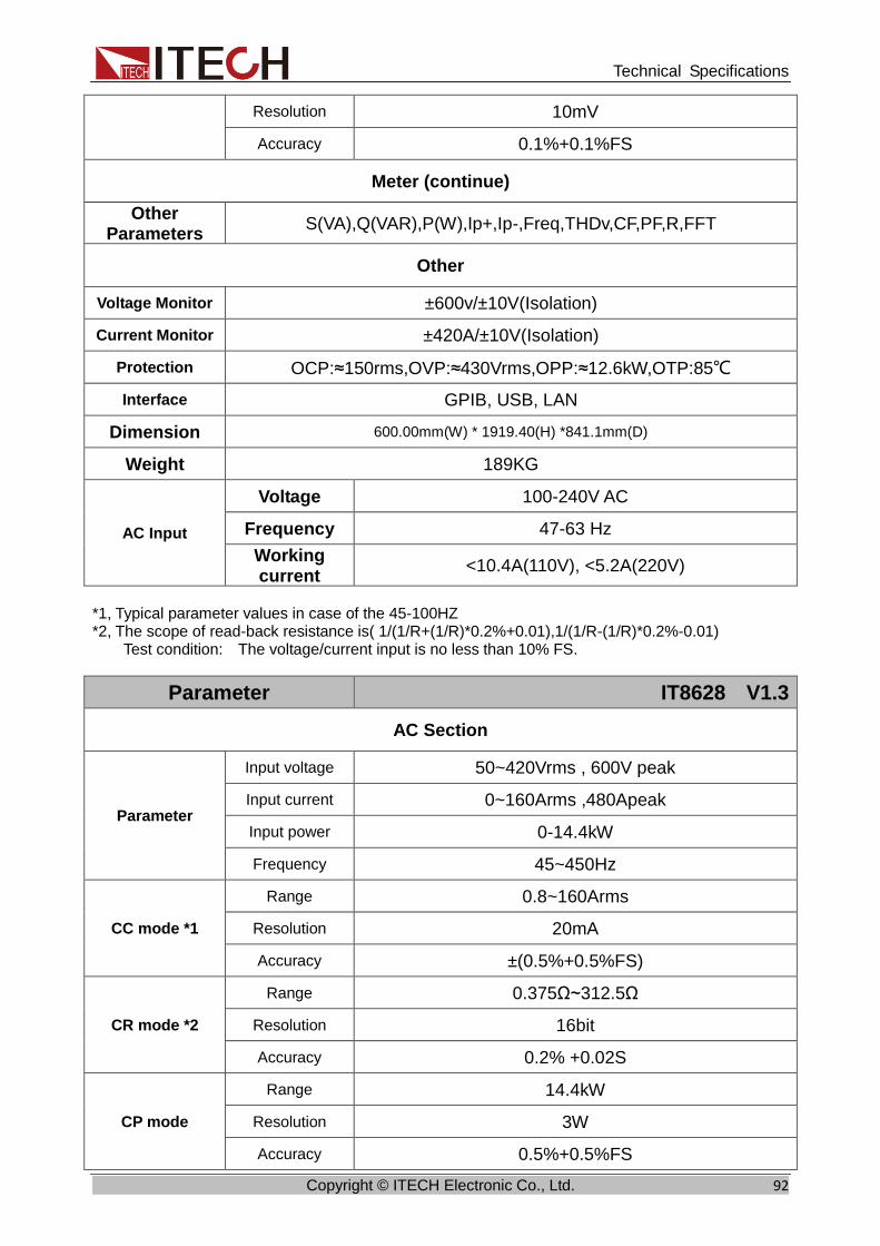
Technical Specifications
Copyright © ITECH Electronic Co., Ltd. 92
Resolution 10mV
Accuracy 0.1%+0.1%FS
Meter (continue)
Other Parameters
S(VA),Q(VAR),P(W),Ip+,Ip-,Freq,THDv,CF,PF,R,FFT
Other
Voltage Monitor ±600v/±10V(Isolation)
Current Monitor ±420A/±10V(Isolation)
Protection OCP:≈150rms,OVP:≈430Vrms,OPP:≈12.6kW,OTP:85℃
Interface GPIB, USB, LAN
Dimension 600.00mm(W) * 1919.40(H) *841.1mm(D)
Weight 189KG
AC Input
Voltage 100-240V AC
Frequency 47-63 Hz
Working current
<10.4A(110V), <5.2A(220V)
*1, Typical parameter values in case of the 45-100HZ *2, The scope of read-back resistance is( 1/(1/R+(1/R)*0.2%+0.01),1/(1/R-(1/R)*0.2%-0.01) Test condition: The voltage/current input is no less than 10% FS.
Parameter IT8628 V1.3
AC Section
Parameter
Input voltage 50~420Vrms , 600V peak
Input current 0~160Arms ,480Apeak
Input power 0-14.4kW
Frequency 45~450Hz
CC mode *1
Range 0.8~160Arms
Resolution 20mA
Accuracy ±(0.5%+0.5%FS)
CR mode *2
Range 0.375Ω~312.5Ω
Resolution 16bit
Accuracy 0.2% +0.02S
CP mode
Range 14.4kW
Resolution 3W
Accuracy 0.5%+0.5%FS
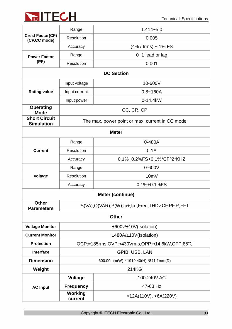
Technical Specifications
Copyright © ITECH Electronic Co., Ltd. 93
Crest Factor(CF) (CP,CC mode)
Range 1.414~5.0
Resolution 0.005
Accuracy (4% / Irms) + 1% FS
Power Factor (PF)
Range 0~1 lead or lag
Resolution 0.001
DC Section
Rating value
Input voltage 10-600V
Input current 0.8~160A
Input power 0-14.4kW
Operating Mode
CC, CR, CP
Short Circuit Simulation
The max. power point or max. current in CC mode
Meter
Current
Range 0-480A
Resolution 0.1A
Accuracy 0.1%+0.2%FS+0.1%*CF^2*KHZ
Voltage
Range 0-600V
Resolution 10mV
Accuracy 0.1%+0.1%FS
Meter (continue)
Other Parameters
S(VA),Q(VAR),P(W),Ip+,Ip-,Freq,THDv,CF,PF,R,FFT
Other
Voltage Monitor ±600v/±10V(Isolation)
Current Monitor ±480A/±10V(Isolation)
Protection OCP:≈185rms,OVP:≈430Vrms,OPP:≈14.6kW,OTP:85℃
Interface GPIB, USB, LAN
Dimension 600.00mm(W) * 1919.40(H) *841.1mm(D)
Weight 214KG
AC Input
Voltage 100-240V AC
Frequency 47-63 Hz
Working current
<12A(110V), <6A(220V)

Technical Specifications
Copyright © ITECH Electronic Co., Ltd. 94
*1, Typical parameter values in case of the 45-100HZ *2, The scope of read-back resistance is( 1/(1/R+(1/R)*0.2%+0.01),1/(1/R-(1/R)*0.2%-0.01) Test condition: The voltage/current input is no less than 10% FS.
10.2 Supplemental characteristics ⚫ Recommended calibration frequency
Once a year
⚫ Cooling style
Fans

Appendix
Copyright © ITECH Electronic Co., Ltd. 95
Appendix
Specifications of Red and Black Test Lines ITECH provides you with optional red and black test lines, which individual sales and you can select for test. For specifications of ITECH test lines and maximum current values, refer to the table below.
Model Specification Length Description
IT-E30110-AB 10A 1m A pair of red and black test cables
with an alligator clip at one end and a
banana plug at the other end
IT-E30110-BB 10A 1m A pair of red and black test cables
with banana plugs at both ends
IT-E30110-BY 10A 1m A pair of red and black test cables with
a banana plug at one end and a
Y-terminal at the other end
IT-E30312-YY 30A 1.2m A pair of red and black test cables
with Y-terminals at both ends
IT-E30320-YY 30A 2m A pair of red and black test cables
with Y-terminals at both ends
IT-E30615-OO 60A 1.5m A pair of red and black test cables with
round terminals at both ends
IT-E31220-OO 120A 2m A pair of red and black test cables with
round terminals at both ends
IT-E32410-OO 240A 1m A pair of red and black test cables with
round terminals at both ends
IT-E32420-OO 240A 2m A pair of red and black test cables with
round terminals at both ends
IT-E33620-OO 360A 2m A pair of red and black test cables with
round terminals at both ends
For maximum current of AWG copper wire, refer to table below.
AWG 10 12 14 16 18 20 22 24 26 28
The Maximum current value( A)
40 25 20 13 10 7 5 3.5 2.5 1.7
Note: AWG (American Wire Gage), it means X wire (marked on the wire). The table above lists current capacity of single wire at working temperature of 30°C. For reference only.

Contact US Thank you for purchasing ITECH products. If you have any doubt about this product, please contact us as follows. 1. Please refer to the CD-ROM of related user’s manual in package. 2. Visit ITECH website www.itechate.com. 3. Select the most convenient contact for further consultation.