Programmable Hardware Manual (PHM) - Tibbo
698
Copyright Tibbo Technology Tibbo Programmable Hardware Manual
-
Upload
khangminh22 -
Category
Documents
-
view
0 -
download
0
Transcript of Programmable Hardware Manual (PHM) - Tibbo

Copyright Tibbo Technology
Tibbo Programmable Hardware Manual

Programmable Hardware Manual (PHM)I
© Tibbo Technology Inc.
Table of ContentsIntroduction 1
Legal Information 1
Common vs. ProprietaryKnowledge 4
Embedded Modules 5
................................................................................................................................... 5WM2000 Programmable Wireless IIoT Module
............................................................................................................................................................... 10Detailed Device Info
............................................................................................................................................................ 11General-purpose I/O Lines
............................................................................................................................................................ 13Wi-Fi and BLE Communications
............................................................................................................................................................ 14Analog-to-digital Converter (ADC)
............................................................................................................................................................ 14Serial Ports
.......................................................................................................................................................... 16Wiegand and Clock/Data Circuit Examples
............................................................................................................................................................ 17I²C/SPI Support (SSI Channels)
............................................................................................................................................................ 17Pulse-width Modulation (PWM)
............................................................................................................................................................ 17Flash and EEPROM Memory
............................................................................................................................................................ 18Real-time Clock (RTC) and Low-power Mode
............................................................................................................................................................ 20Status LEDs and LED Control Lines
............................................................................................................................................................ 21External Keypad Support
............................................................................................................................................................ 23Power, Reset, and Control Lines
............................................................................................................................................................... 24Mechanical Dimensions
............................................................................................................................................................... 26Ordering Info and Specifications
................................................................................................................................... 28EM2000 BASIC/C-programmable IoT Module
............................................................................................................................................................... 31Detailed Device Info
............................................................................................................................................................ 35General-purpose I/O Lines
............................................................................................................................................................ 36Wireless Add-on Port, Wi-Fi Communications
............................................................................................................................................................ 37Ethernet Port Lines
............................................................................................................................................................ 38Serial Ports
.......................................................................................................................................................... 40Wiegand and Clock/Data Circuit Examples
............................................................................................................................................................ 41Analog-to-digital Converter (ADC)
............................................................................................................................................................ 41I2C/SPI Support (SSI Channels)
............................................................................................................................................................ 41Square Wave Generator
............................................................................................................................................................ 42Real-time Clock (RTC)
............................................................................................................................................................ 42Flash and EEPROM Memory
............................................................................................................................................................ 43LED Lines
............................................................................................................................................................ 43External LCD Support
............................................................................................................................................................ 44External Keypad support
............................................................................................................................................................ 46Power, Reset, PLL Control, and Mode Selection
............................................................................................................................................................... 47Mechanical Dimensions
............................................................................................................................................................... 49Ordering Info and Specifications
................................................................................................................................... 51EM1000 BASIC/C-programmable Ethernet Module
............................................................................................................................................................... 53EM1000-00 and -01
............................................................................................................................................................... 54Detailed Device Info
............................................................................................................................................................ 58General-purpose I/O Lines
............................................................................................................................................................ 59Wireless Add-on Port
............................................................................................................................................................ 60Ethernet Port Lines
............................................................................................................................................................ 62Serial Ports
............................................................................................................................................................ 63Square Wave Generator
............................................................................................................................................................ 63Flash and EEPROM Memory
............................................................................................................................................................ 63Real-time Counter

IIContents
© Tibbo Technology Inc.
............................................................................................................................................................ 65LED Lines
............................................................................................................................................................ 65Power, Reset, PLL Control, and Mode Selection Lines
............................................................................................................................................................... 67Mechanical Dimensions
............................................................................................................................................................... 68Ordering Info and Specifications
................................................................................................................................... 71EM1206 BASIC/C-programmable Ethernet Module
............................................................................................................................................................... 73Detailed Device Info
............................................................................................................................................................ 76General-purpose I/O Lines
............................................................................................................................................................ 77Ethernet Port Lines
............................................................................................................................................................ 77Serial Ports
............................................................................................................................................................ 78Square Wave Generator
............................................................................................................................................................ 78Flash and EEPROM Memory
............................................................................................................................................................ 78Real-time Counter
............................................................................................................................................................ 79LED Lines
............................................................................................................................................................ 80Power, Reset, and Mode Selection Lines
............................................................................................................................................................... 81Onboard LEDs
............................................................................................................................................................... 82Thermal Considerations
............................................................................................................................................................... 83Mechanical Dimensions
............................................................................................................................................................... 85Ordering Info and Specifications
................................................................................................................................... 87EM510 "MiniMo" BASIC/C-programmable IoT Module
............................................................................................................................................................... 90Detailed Device Info
............................................................................................................................................................ 91Serial Port and General-purpose I/O Lines
............................................................................................................................................................ 93Ethernet Port Lines
............................................................................................................................................................ 94Flash and EEPROM Memory
............................................................................................................................................................ 95LED Lines
............................................................................................................................................................ 96Power, Reset, and Mode Selection Lines
............................................................................................................................................................... 97Mechanical Dimensions
............................................................................................................................................................... 98Ordering Info and Specifications
................................................................................................................................... 99EM500 "MiniMo" BASIC/C-programmable Ethernet Module
............................................................................................................................................................... 102Detailed Device Info
............................................................................................................................................................ 103Serial Port and General-purpose I/O Lines
............................................................................................................................................................ 104Ethernet Port Lines
............................................................................................................................................................ 105Flash and EEPROM Memory
............................................................................................................................................................ 106LED Lines
............................................................................................................................................................ 107Power, Reset, and Mode Selection Lines
............................................................................................................................................................... 109Mechanical Dimensions
............................................................................................................................................................... 110Ordering Info and Specifications
................................................................................................................................... 112EM1202 BASIC/C-programmable Ethernet Module
............................................................................................................................................................... 114Detailed Device Info
............................................................................................................................................................ 116General-purpose I/O Lines
............................................................................................................................................................ 117Ethernet Port Lines
............................................................................................................................................................ 118Serial Ports
............................................................................................................................................................ 118Square Wave Generator
............................................................................................................................................................ 118Flash and EEPROM Memory
............................................................................................................................................................ 119LED Lines
............................................................................................................................................................ 120Power, Reset, and Mode Selection Lines
............................................................................................................................................................... 122Mechanical Dimensions
............................................................................................................................................................... 123Ordering Info and Specifications
................................................................................................................................... 124EM200
............................................................................................................................................................... 126Detailed Device Info
............................................................................................................................................................ 128Ethernet Port Lines
............................................................................................................................................................ 129Serial Port and General-purpose I/O Lines
............................................................................................................................................................ 130Flash and EEPROM Memory
............................................................................................................................................................ 130LED Lines
............................................................................................................................................................ 131Power, Reset, and Mode Selection Lines
............................................................................................................................................................... 132Mechanical Dimensions
............................................................................................................................................................... 133Ordering Info and Specifications

Programmable Hardware Manual (PHM)III
© Tibbo Technology Inc.
Boards 134
................................................................................................................................... 134EM2001 BASIC/C-programmable IoT Board
............................................................................................................................................................... 138Detailed Device Info
............................................................................................................................................................ 142General-purpose I/O Lines
............................................................................................................................................................ 143Wireless Add-on Port, Wi-Fi Communications
............................................................................................................................................................ 143Ethernet Port
............................................................................................................................................................ 144Serial Ports
.......................................................................................................................................................... 145Wiegand and Clock/Data Circuit Examples
............................................................................................................................................................ 146Analog-to-digital Converter (ADC)
............................................................................................................................................................ 146I2C/SPI Support (SSI Channels)
............................................................................................................................................................ 146Square Wave Generator
............................................................................................................................................................ 147Flash and EEPROM Memory
............................................................................................................................................................ 147Real-time Clock (RTC) and Backup Battery
............................................................................................................................................................ 147LEDs and LED Lines
............................................................................................................................................................ 148External LCD Support
............................................................................................................................................................ 148External Keypad support
............................................................................................................................................................ 151Power, Reset, PLL Control, and Mode Selection
............................................................................................................................................................... 152Mechanical Dimensions
............................................................................................................................................................... 153Ordering Info and Specifications
................................................................................................................................... 154EM1001 BASIC/C-programmable IoT Board
............................................................................................................................................................... 157Detailed Device Info
............................................................................................................................................................ 161General-purpose I/O Lines
............................................................................................................................................................ 161Wireless Add-on Port
............................................................................................................................................................ 162Ethernet Port
............................................................................................................................................................ 162Serial Ports
............................................................................................................................................................ 162Square Wave Generator
............................................................................................................................................................ 163Flash and EEPROM Memory
............................................................................................................................................................ 163Real-time Counter and Backup Supercap
............................................................................................................................................................ 164LEDs and LED Lines
............................................................................................................................................................ 164Power, Reset, PLL Control, MD Button, and Mode Lines
............................................................................................................................................................... 166Mechanical Dimensions
............................................................................................................................................................... 167Ordering Info and Specifications
................................................................................................................................... 168NB10x0 and IB100x Boards
............................................................................................................................................................... 170NB10x0 Network Boards
............................................................................................................................................................ 170NB1000 Board
.......................................................................................................................................................... 171NB1000 Connectors and Controls
....................................................................................................................................................... 171Power Jack, Terminals and Power Regulator
....................................................................................................................................................... 172Ethernet Jack
....................................................................................................................................................... 172Jumpers, Buttons and LEDs
....................................................................................................................................................... 173External LED Control
....................................................................................................................................................... 174Buzzer
.......................................................................................................................................................... 174Ordering Info and Specifications
............................................................................................................................................................ 176NB1010 Board
.......................................................................................................................................................... 177NB1010 Connectors and Controls
....................................................................................................................................................... 177Power Jack, Terminals and Power Regulator
....................................................................................................................................................... 178Ethernet Jack
....................................................................................................................................................... 178Jumpers, Buttons and LEDs
....................................................................................................................................................... 179External LED Control
....................................................................................................................................................... 180Buzzer
....................................................................................................................................................... 180Optional Wi-Fi Interface
....................................................................................................................................................... 181Optional GPRS Interface
............................................................................................................................................................ 182Ordering Info and Specifications
............................................................................................................................................................... 183IB100x Interface Boards
............................................................................................................................................................ 184IB1000, IB1002, and IB1003 (4 Serial Ports)
.......................................................................................................................................................... 184Connectors and Headers
.......................................................................................................................................................... 186Serial Ports

IVContents
© Tibbo Technology Inc.
.......................................................................................................................................................... 189LED Control
.......................................................................................................................................................... 189Ordering Info and Specifications
............................................................................................................................................................ 190IB1004 and SB1004 (Analog I/O)
.......................................................................................................................................................... 191Terminal Blocks
.......................................................................................................................................................... 193Control Lines
.......................................................................................................................................................... 196Detailed Information
....................................................................................................................................................... 196A/D Converter
....................................................................................................................................................... 202D/A Converter
....................................................................................................................................................... 204Relays
....................................................................................................................................................... 205RS232/485 Port
....................................................................................................................................................... 206LED Control
.......................................................................................................................................................... 207Ordering Info and Specifications
............................................................................................................................................................ 208IB1005 and SB1005 (Digital I/O)
.......................................................................................................................................................... 209Terminal Blocks
.......................................................................................................................................................... 211Control Lines
.......................................................................................................................................................... 213Detailed Information
....................................................................................................................................................... 214Opto-isolated Inputs
....................................................................................................................................................... 216Relays
....................................................................................................................................................... 217RS232/485 Port
....................................................................................................................................................... 219LED Control
.......................................................................................................................................................... 219Ordering Info and Specifications
............................................................................................................................................................... 220LB100x LED Boards
............................................................................................................................................................ 220LB1000
............................................................................................................................................................ 221LB1001
............................................................................................................................................................... 222Cable Data
............................................................................................................................................................ 222IC1000 Interboard Cable
............................................................................................................................................................ 223LC1000 LED Board Cable
............................................................................................................................................................... 224Mechanical Data
............................................................................................................................................................ 224NB10x0 and IB100x Board Dimensions
............................................................................................................................................................ 226SB100x Board Dimensions
............................................................................................................................................................ 228LB100x Board Dimensions
................................................................................................................................... 230DS1206N
............................................................................................................................................................... 233DS1206N Hardware
............................................................................................................................................................ 233Power Arrangement
............................................................................................................................................................ 234Ethernet Port
............................................................................................................................................................ 235Multi-channel Serial Port
............................................................................................................................................................ 237Flash and EEPROM Memory
............................................................................................................................................................... 238Mechanical Dimensions
............................................................................................................................................................... 239Ordering Info and Specifications
................................................................................................................................... 241EM1202EV
............................................................................................................................................................... 243EM1202EV Hardware
............................................................................................................................................................ 244Power Arrangement
............................................................................................................................................................ 244Ethernet Port
............................................................................................................................................................ 245Multi-channel Serial Port
.......................................................................................................................................................... 247Additional Information on Serial Port Lines
............................................................................................................................................................ 248Flash and EEPROM Memory
............................................................................................................................................................... 249Mechanical Dimensions
............................................................................................................................................................... 250Ordering Info and Specifications
................................................................................................................................... 252EM1206EV
............................................................................................................................................................... 253Wireless Add-on Connector
............................................................................................................................................................... 254Main and Backup Power
............................................................................................................................................................... 255Multi-channel RS232 Port and Expansion Connector
................................................................................................................................... 258EM120/EM200EV
............................................................................................................................................................... 258Power Jack
............................................................................................................................................................... 259Ethernet Port Pin Assignment
............................................................................................................................................................... 259RS232 Port Pin Assignment
............................................................................................................................................................... 260Expansion Connector Pin Assignment

Programmable Hardware Manual (PHM)V
© Tibbo Technology Inc.
Development Systems 261
................................................................................................................................... 261WM2000EV
............................................................................................................................................................... 264Getting Started
............................................................................................................................................................ 265WM2000EV Demo #1 — Keen
............................................................................................................................................................ 270WM2000EV Demo #2 — WebPWM
............................................................................................................................................................ 273WM2000EV Demo #3 — Azure
................................................................................................................................... 287EM2000EV
................................................................................................................................... 289EM1000EV
................................................................................................................................... 290EM1000TEV
............................................................................................................................................................... 291TEV-MB0
............................................................................................................................................................... 291TEV-KB0
............................................................................................................................................................... 293TEV-LBx Boards
............................................................................................................................................................ 295TEV-LB0
............................................................................................................................................................ 297TEV-LB1
............................................................................................................................................................ 299TEV-LB2
............................................................................................................................................................... 300TEV-IBx Boards
............................................................................................................................................................ 302TEV-IB0
............................................................................................................................................................ 303TEV-IB1
............................................................................................................................................................... 305Ordering Info
................................................................................................................................... 306EM500EV/EM510EV
............................................................................................................................................................... 307EM500EV-MB0
............................................................................................................................................................... 308EM500EV-IB0
............................................................................................................................................................... 310EM500EV-IB1
............................................................................................................................................................... 311EM500EV-IB2
............................................................................................................................................................... 312Ordering Info
Tibbo Project System (TPS) 314
................................................................................................................................... 316TPS: the General View
................................................................................................................................... 316Tibbits
............................................................................................................................................................... 317Tibbit Form Factors & Colors
............................................................................................................................................................ 318M1 "Narrow" Tibbits
............................................................................................................................................................ 320M2 "Wide" Tibbits
............................................................................................................................................................ 322C1 "Narrow" Tibbits
............................................................................................................................................................ 323C2 "Wide" Tibbits
............................................................................................................................................................ 325H1 "Hybrid" Tibbits
............................................................................................................................................................ 326H2 "Hybrid" Tibbits
............................................................................................................................................................... 327Tibbit Power Lines
............................................................................................................................................................... 328Tibbit Sockets and Tiles
............................................................................................................................................................... 329Electrical Connections on a Tile
............................................................................................................................................................... 330Tibbits with "Special Needs"
............................................................................................................................................................ 330[SER] Tibbits That Require UART Functionality
............................................................................................................................................................ 331[INT] Tibbits That Require an Interrupt Line
............................................................................................................................................................ 332[POE] Tibbits That Require PoE Power Lines
............................................................................................................................................................ 332[CAN] Tibbits That Require CAN functionality
............................................................................................................................................................ 333[AUD] Tibbits That Require Audio Functionality
............................................................................................................................................................ 333[MMC] Tibbits That Require MMC (SD) Functionality
............................................................................................................................................................ 333[USB] Tibbits That Require USB Functionality
............................................................................................................................................................... 333Combining "C" and "M" Tibbits
............................................................................................................................................................ 334C1 + M1
............................................................................................................................................................ 335C2 + M2
............................................................................................................................................................ 336C2 + Two M1s
............................................................................................................................................................ 337Two C1s + M2
............................................................................................................................................................... 337Tibbit LEDs and Their Colors
............................................................................................................................................................... 339Labeling

VIContents
© Tibbo Technology Inc.
............................................................................................................................................................... 339Available Tibbits
............................................................................................................................................................ 341#00-1, M1S: Four Direct I/O Lines
............................................................................................................................................................ 343#00-2, M1S: Three Direct I/O Lines and Ground
............................................................................................................................................................ 344#00-3, M1S: Two Direct I/O Lines, +5V Power, Ground
............................................................................................................................................................ 345#01, M1S: Four-line RS232 Port
............................................................................................................................................................ 347#02, M2S: RS232/422/485 Port
............................................................................................................................................................ 350#03-1, M1S: Two Low-power Relays (Configuration 1)
............................................................................................................................................................ 351#03-2, M1S: Two Low-power Relays (Configuration 2)
............................................................................................................................................................ 352#04-1, M1S: Two Isolated Inputs
............................................................................................................................................................ 353#04-2, M1S: Three Isolated Inputs, Common (-)
............................................................................................................................................................ 354#04-3, M1S: Three Isolated Inputs, Common (+)
............................................................................................................................................................ 355#04-4, M1S: Four Opto-inputs, Common Ground
............................................................................................................................................................ 356#04-5, M1S: Two 24V Isolated Inputs
............................................................................................................................................................ 357#04-6, M1S: Three 24V Isolated Inputs, Common (-)
............................................................................................................................................................ 358#04-7, M1S: Three 24V Isolated Inputs, Common (+)
............................................................................................................................................................ 359#04-8, M1S: Four 24V Isolated Inputs, Common Ground
............................................................................................................................................................ 360#05, M1S: RS485 Port
............................................................................................................................................................ 361#06, M2T: Two High-power Relays
............................................................................................................................................................ 363#07, M1S: Two Solid State Relays
............................................................................................................................................................ 364#08, M1S: Wiegand and Clock/Data Reader Port
............................................................................................................................................................ 365#09, M1S: Low-power 5V Supply, 12V Input
............................................................................................................................................................ 366#10, M1T: Medium-power 5V Supply, 12V Input
............................................................................................................................................................ 367#11, M1S: Four Open Collector Outputs
............................................................................................................................................................ 369#12, M1S: Low-power +15/-15V Power Supply, 5V Input
............................................................................................................................................................ 370#13, M1S: Four-channel ADC
............................................................................................................................................................ 371#14, M1S: Four-channel DAC
............................................................................................................................................................ 372#15, H1: High-voltage AC Solid State Relay
............................................................................................................................................................ 374#16, M1S: Three PWMs With OC Outputs
............................................................................................................................................................ 375#17, M1S: Three PWMs With Power Outputs
............................................................................................................................................................ 377#18, C1: Power Input
............................................................................................................................................................ 378#19, C2: DB9M Connector
............................................................................................................................................................ 378#20, C2: Nine Terminal Blocks
............................................................................................................................................................ 379#21, C1: Four Terminal Blocks
............................................................................................................................................................ 380#22, M1S: RTD Temperature Meter
............................................................................................................................................................ 382#23, M2T: Isolated PoE Power Supply, 5V Output
............................................................................................................................................................ 384#25: M2T: High-power 5V Supply, 12/24/48V Input
............................................................................................................................................................ 386#26, M1S: IR Command Processor
.......................................................................................................................................................... 388Theory of Operation
.......................................................................................................................................................... 389Resetting and Initializing the Onboard FPGA
.......................................................................................................................................................... 390SPI Read and Write Transactions
.......................................................................................................................................................... 391Registers
....................................................................................................................................................... 392Command Register
....................................................................................................................................................... 392Status Register
....................................................................................................................................................... 392TX Length Registers
....................................................................................................................................................... 393RX Length Registers
....................................................................................................................................................... 393Carrier Divider Registers
....................................................................................................................................................... 393TX and RX Data Buffers
.......................................................................................................................................................... 394Examples of Wiring to IR Receivers & Emitters
............................................................................................................................................................ 395#27, C1: IR Receiver/Transmitter
............................................................................................................................................................ 396#28, C1: Ambient Light Sensor
............................................................................................................................................................ 397#29, C1: Ambient Temperature Meter
............................................................................................................................................................ 398#30, C1: Ambient Humidity/Temperature Meter
............................................................................................................................................................ 399#31, C1: PIC Coprocessor
............................................................................................................................................................ 400#33, M1T: Wide Input Range Power Supply
.......................................................................................................................................................... 403Specifications
.......................................................................................................................................................... 404Efficiency Data
.......................................................................................................................................................... 405Handling Current and Power Spikes
............................................................................................................................................................ 405#35, C1: Barometric Pressure Sensor
............................................................................................................................................................ 406#36, C1: 3-axis Accelerometer

Programmable Hardware Manual (PHM)VII
© Tibbo Technology Inc.
............................................................................................................................................................ 407#37, C1: RF Connector
............................................................................................................................................................ 408#38: C1: Pushbutton
............................................................................................................................................................ 409#39-1~4, C1: Large LED (Four Colors Available)
............................................................................................................................................................ 410#40-1~4, M1S: Digital Potentiometer (Four Nominals)
............................................................................................................................................................ 411#41, C1: 8-bit Port
............................................................................................................................................................ 412#42, M1S: RTC and NVRAM With Backup
............................................................................................................................................................ 414#43-1, M1S: Four-Channel Streaming ADC ±10V
.......................................................................................................................................................... 417Settings
.......................................................................................................................................................... 418Interface Protocol
.......................................................................................................................................................... 429Data Output Formats
.......................................................................................................................................................... 432Working With Tibbit #43-1
.......................................................................................................................................................... 433Specifications
............................................................................................................................................................ 436#43-2, M1S: Four-Channel Streaming ADC ±100V
.......................................................................................................................................................... 440Settings
.......................................................................................................................................................... 441Interface Protocol
.......................................................................................................................................................... 452Data Output Formats
.......................................................................................................................................................... 455Working With Tibbit #43-2
.......................................................................................................................................................... 457Specifications
............................................................................................................................................................ 460#44-1, H2: Isolated RS232/422/485 Port (DB9M Connector)
............................................................................................................................................................ 463#44-2, H2: Isolated RS232/422/485 Port (Terminal Block)
............................................................................................................................................................ 466#45-1~3, H2: 4G (LTE) Modem
............................................................................................................................................................ 471#46, H2: Cat-M1/NB-IoT Modem
............................................................................................................................................................ 475#47, H2: GPRS Modem [DEPRECATED]
............................................................................................................................................................ 478#48, H2: Audio In/Out [DEPRECATED]
............................................................................................................................................................ 480#49, C2: Micro SD Card Slot [DEPRECATED]
............................................................................................................................................................ 481#50, C1: Mini Type B USB Port [DEPRECATED]
............................................................................................................................................................ 482#51, M1S: CAN Bus [DEPRECATED]
............................................................................................................................................................ 483#52, M2S: Four-channel Isolated +/-10V ADC
............................................................................................................................................................ 485#53, M2S: Isolated 4-20mA ADC
............................................................................................................................................................ 487#54, M1S: Four Dry Contact Inputs
............................................................................................................................................................ 488#56, C1: Type A USB Port [DEPRECATED]
............................................................................................................................................................ 489#57, M1S: FPGA Tibbit
.......................................................................................................................................................... 490Resetting and Initializing the Onboard FPGA
.......................................................................................................................................................... 491Implemented Configurations
....................................................................................................................................................... 491Smart LED Controller Configuration
............................................................................................................................................................ 493#58, M1S: Two 24V NPN Isolated Open Collector Outputs
............................................................................................................................................................ 495#59, M1S: Two 24V PNP Isolated Open Collector Outputs
............................................................................................................................................................ 496#63-1/2, H1: AC Voltage Detector
................................................................................................................................... 498Tibbo Project PCBs (TPPs)
............................................................................................................................................................... 499Available TPP Models
............................................................................................................................................................ 499Size 2 Tibbo Project PCB (TPP2), Gen 2
.......................................................................................................................................................... 502Tiles, Sockets, Connectors, Controls
............................................................................................................................................................ 503Size 3 Tibbo Project PCB (TPP3), Gen 2
.......................................................................................................................................................... 506Tiles, Sockets, Connectors, Controls
............................................................................................................................................................ 508Size 2 Tibbo Project PCB (TPP2)
.......................................................................................................................................................... 511Tiles, Sockets, Connectors, Controls
............................................................................................................................................................ 512Size 3 Tibbo Project PCB (TPP3)
.......................................................................................................................................................... 514Tiles, Sockets, Connectors, Controls
............................................................................................................................................................ 516Size 3 Linux Tibbo Project PCB (LTPP3)
.......................................................................................................................................................... 518Tiles, Sockets, Connectors, Controls
............................................................................................................................................................ 519Size 3 Linux Tibbo Project PCB (LTPP3), Gen 2
.......................................................................................................................................................... 522Tiles, Sockets, Connectors, Controls
.......................................................................................................................................................... 522Plus1 (SP7021) CPU
............................................................................................................................................................ 524Common Information
.......................................................................................................................................................... 525Power Arrangement
.......................................................................................................................................................... 525Ethernet Port
.......................................................................................................................................................... 525MD and RST Buttons
.......................................................................................................................................................... 526LEDs

VIIIContents
© Tibbo Technology Inc.
.......................................................................................................................................................... 527Buzzer
.......................................................................................................................................................... 527LCD Connector (TPP2 Only)
.......................................................................................................................................................... 528Keypad Connector (TPP2 Only)
.......................................................................................................................................................... 528Optional Wi-Fi Interface
................................................................................................................................... 529Tibbo Project Box (TPB) Kits
............................................................................................................................................................... 530TPB Structure
............................................................................................................................................................... 531Available Tibbo Project Box Kits
............................................................................................................................................................ 531Size 2 Tibbo Project Box (TPB2)
.......................................................................................................................................................... 532TPB2 Parts and Accessories
.......................................................................................................................................................... 534Size 2 Vibration Protection Kit (VPK)
.......................................................................................................................................................... 535Mechanical Dimensions
............................................................................................................................................................ 535Size 2 Project Box With LCD/Keys (TPB2L)
.......................................................................................................................................................... 536TPB2L Parts and Accessories
.......................................................................................................................................................... 538Size 2 Vibration Protection Kit (VPK)
.......................................................................................................................................................... 539Mechanical Dimensions
............................................................................................................................................................ 539Size 3 Tibbo Project Box (TPB3)
.......................................................................................................................................................... 540TPB3 Parts and Accessories
.......................................................................................................................................................... 541Size 3 Vibration Protection Kit (VPK)
.......................................................................................................................................................... 542Mechanical Dimensions
............................................................................................................................................................ 543Size 3 Linux Tibbo Project Box (LTPB3)
.......................................................................................................................................................... 544LTPB3 Parts and Accessories
.......................................................................................................................................................... 546Size 3 Vibration Protection Kit (VPK) for LTPB3
.......................................................................................................................................................... 547Mechanical Dimensions
................................................................................................................................... 548Retail Packaging
............................................................................................................................................................... 549TPB2/TPS2 Retail Packaging Kit
............................................................................................................................................................... 550TPB2L/TPS2L Retail Packaging Kit
............................................................................................................................................................... 551TPB3/TPS3 Retail Packaging Kit
............................................................................................................................................................... 552Assembled Retail Package
External Controllers 552
................................................................................................................................... 553DS/WS110x
............................................................................................................................................................... 556DS/WS110x Connectors and Controls
............................................................................................................................................................ 556Power Arrangement
.......................................................................................................................................................... 557DS1100
.......................................................................................................................................................... 557DS1101
.......................................................................................................................................................... 558DS1102
............................................................................................................................................................ 559Ethernet Port (DS1100/1/2)
............................................................................................................................................................ 559Serial Port
.......................................................................................................................................................... 559DS1100
.......................................................................................................................................................... 560DS1101
.......................................................................................................................................................... 562DS1102
....................................................................................................................................................... 564Mapping Options for the RS232 Mode
....................................................................................................................................................... 564Mapping Options for the RS422 Mode
....................................................................................................................................................... 564Mapping Options for the RS485 Mode
.......................................................................................................................................................... 565WS1102
.......................................................................................................................................................... 567Definition of RS422 and RS485 Modes
............................................................................................................................................................ 567Flash and EEPROM Memory
............................................................................................................................................................ 568Buzzer (DS1101, DS1102, and WS1102)
............................................................................................................................................................ 569Optional Wi-Fi (DS1101 and DS1102)
............................................................................................................................................................ 569Built-in Wi-Fi and BLE (WS1102)
............................................................................................................................................................ 570Optional OLED Display (DS1101 and DS1102)
............................................................................................................................................................ 571LED Bar (DS1101, DS1102, and WS1102)
............................................................................................................................................................ 573DIN Rail and Wall Mounting Plates
............................................................................................................................................................... 574Ordering Info and Specifications
................................................................................................................................... 578DS1206
............................................................................................................................................................... 580DS1206 Connectors and Controls
............................................................................................................................................................ 581Power Arrangement

Programmable Hardware Manual (PHM)IX
© Tibbo Technology Inc.
............................................................................................................................................................ 582Ethernet Port
............................................................................................................................................................ 582Multi-channel RS232 Port
............................................................................................................................................................ 584Flash and EEPROM Memory
............................................................................................................................................................... 585Ordering Info and Specifications
................................................................................................................................... 586DS1202
............................................................................................................................................................... 588DS1202 Connectors and Controls
............................................................................................................................................................ 588Power Arrangement
............................................................................................................................................................ 589Ethernet Port
............................................................................................................................................................ 589Multi-Channel RS232 Port
............................................................................................................................................................ 591Flash and EEPROM Memory
............................................................................................................................................................... 591Ordering Info and Specifications
................................................................................................................................... 593DS10xx
............................................................................................................................................................... 594Common Features of the DS10xx Family
............................................................................................................................................................ 594Secondary Cover
............................................................................................................................................................ 596DIN Rail Mounting
............................................................................................................................................................... 596DS10x0, DS10x2, DS10x3 (4 Serial Ports)
............................................................................................................................................................ 597Ordering Info and Specifications
............................................................................................................................................................... 599DS10x4 (Analog I/O)
............................................................................................................................................................ 600Ordering Info and Specifications
............................................................................................................................................................... 601DS10x5 (Digital I/O)
............................................................................................................................................................ 602Ordering Info and Specifications
Sensors (Probes) 603
................................................................................................................................... 603RS485 Modbus Sensors ("Bus Probes")
............................................................................................................................................................... 604Connectors and Controls
............................................................................................................................................................... 605Modbus Registers of Bus Probes
............................................................................................................................................................... 609Setting Up and Testing Bus Probes
............................................................................................................................................................... 609Setting Modbus IDs
............................................................................................................................................................... 610Updating Probe Firmware
............................................................................................................................................................... 612Status LEDs
............................................................................................................................................................... 614Outline Dimensions
............................................................................................................................................................... 614Ordering Info and Specifications
................................................................................................................................... 616Cable Probes
............................................................................................................................................................... 617Wire Connections
............................................................................................................................................................... 618Testing Cable Probes
............................................................................................................................................................... 619Outline Dimensions
............................................................................................................................................................... 619Ordering and Specifications
Companion Products 621
................................................................................................................................... 621WA2000
............................................................................................................................................................... 623Connector Pin Assignment
............................................................................................................................................................... 624Connecting WA2000 to Tibbo Devices
............................................................................................................................................................... 625Status LED
............................................................................................................................................................... 625Firmware Upgrades
............................................................................................................................................................... 626Mechanical Dimensions
............................................................................................................................................................... 627Ordering Info and Specifications
................................................................................................................................... 628GA1000
............................................................................................................................................................... 629Connector pin assignment
............................................................................................................................................................... 630Connecting GA1000 to Tibbo Devices
............................................................................................................................................................... 632Status LED
............................................................................................................................................................... 633Mechanical Dimensions
............................................................................................................................................................... 634Ordering Info and Specifications
................................................................................................................................... 635RJ203 Jack/Magnetics Module
............................................................................................................................................................... 635Interface Pads
............................................................................................................................................................... 636Interfacing the RJ203 to the DM9000B

XContents
© Tibbo Technology Inc.
............................................................................................................................................................... 637Using the RJ203 With the EM203 and Other Modules
............................................................................................................................................................... 638Mechanical Dimensions: RJ203
............................................................................................................................................................... 639Mechanical Dimensions: RJ203+EM203
............................................................................................................................................................... 640Mechanical Dimensions: RJ203+EM1206
............................................................................................................................................................... 641Ordering Info and Specifications
Accessories 642
................................................................................................................................... 642WAS-P0004(B) DS-to-Device Serial Cable
................................................................................................................................... 642WAS-P0005(B) DS-to-PC Serial Cable
................................................................................................................................... 643WAS-1499 'Straight' Ethernet Cable
................................................................................................................................... 643WAS-1498 'Crossover' Ethernet Cable
................................................................................................................................... 64312VDC Power Adapters
................................................................................................................................... 644TB100 Terminal Block Adapter
................................................................................................................................... 645TB1000 Terminal Block Adapter
................................................................................................................................... 647TB1004 Test Board
................................................................................................................................... 649TB1005 Test Board
Setup (MD) Button (Line) 650
Status LEDs (LED Control Lines) 651
Monitor/Loader (M/L) 651
................................................................................................................................... 652M/L Flowchart (All Devices Except WM2000 and WS1102)
................................................................................................................................... 655M/L V4 Flowchart (WM2000 and WS1102)
................................................................................................................................... 657Update Phases
............................................................................................................................................................... 658XModem Serial Updates
............................................................................................................................................................ 660TPS Devices
............................................................................................................................................................ 661Programmable Serial Controllers
............................................................................................................................................................ 661Programmable Boards and Modules
............................................................................................................................................................... 662Network Updates
............................................................................................................................................................... 665Bluetooth Low Energy (BLE) Updates
............................................................................................................................................................ 666Using the Tibbo Updater Smartphone App
............................................................................................................................................................ 668Using the BLE Firmware Updater Web App
................................................................................................................................... 670Device Configuration Block (WM2000 and WS1102 Only)
............................................................................................................................................................... 672BLE Console
............................................................................................................................................................... 674Companion App
............................................................................................................................................................... 676Configuration Reset
............................................................................................................................................................... 677Wi-Fi Regulatory Domains
Prolonging and EstimatingEEPROM Life 679
Update History 680

1 Programmable Hardware Manual (PHM)
© Tibbo Technology Inc.
Introduction
Last update: 19OCT2021
Legal Information | Common vs. Proprietary Knowledge | Manual Update History
This Manual has the following sections:
· Embedded Modules
· Boards
· Development Systems
· Tibbo Project System (TPS)
· External Controllers
· Sensors
· Companion Products
· Kits and Accessories
Important notes:
· This manual should be used in conjunction with the TIDE, TiOS, Tibbo BASIC, andTibbo C Manual — a separate resource that documents Tibbo BASIC/C, TIDEsoftware, hardware "platforms," and everything else required for successfuldevelopment of Tibbo BASIC/C applications.
· This manual does not include any information on fixed-function, non-programmable Tibbo devices, such as the original EM100 module or the DS100serial device server. The data on these devices can be found in the "Serial-over-IP Solutions Manual" — a separate document.
· Some Tibbo devices are dual-use in nature. Depending on the loaded firmware,any dual-use product can be a fixed-function, serial-over-IP device, or a BASIC-programmable controller. Dual-use devices are documented in this manual aswell as the "Serial-over-IP Solutions Manual". This manual describes each suchdevice as a BASIC-programmable one, while the "Serial-over-IP SolutionsManual" describes the same device as a serial device server.
Legal InformationTibbo Technology ("TIBBO") is a Taiwan corporation that designs and/or manufactures
a number of hardware products, software products, and applications ("PRODUCTS").
In many cases, Tibbo PRODUCTS are combined with each other and/or third-party
products thus creating a PRODUCT COMBINATION.
Whereas you (your Company) wish to purchase any PRODUCT from TIBBO, and/or whereas you
(your Company) wish to make use of any documentation or technical information published by
TIBBO, and/or make use of any source code published by TIBBO, and/or consult TIBBO and
receive technical support from TIBBO or any of its employees acting in an official or unofficial
capacity,
You must acknowledge and accept the following disclaimers:
2Legal Information
© Tibbo Technology Inc.
1. Tibbo does not have any branch office, affiliated company, or any other form of
presence in any other jurisdiction. TIBBO customers, partners and distributors in
Taiwan and other countries are independent commercial entities and TIBBO does
not indemnify such customers, partners or distributors in any legal proceedings
related to, nor accepts any liability for damages resulting from the creation,
manufacture, importation, advertisement, resale, or use of any of its PRODUCT or
PRODUCT COMBINATION.
2. BASIC/C-programmable devices ("PROGRAMMABLE DEVICES") manufactured by
TIBBO can run a variety of applications written in Tibbo BASIC, Tibbo C, or a
combination of the two ("BASIC APPLICATIONS"). Combining a particular
PROGRAMMABLE DEVICE with a specific BASIC and/or C APPLICATION, either
written by TIBBO or any third party, may potentially create a combinatorial end
product ("END PRODUCT") that violates local rules, regulations, and/or infringes
an existing patent granted in a country where such combination has occurred or
where the resulting END PRODUCT is manufactured, exported, advertised, or sold.
TIBBO is not capable of monitoring any activities by its customers, partners or
distributors aimed at creating any END PRODUCT, does not provide advice on
potential legal issues arising from creating such END PRODUCT, nor explicitly
recommends the use of any of its PROGRAMMABLE DEVICES in combination with
any BASIC APPLICATION, either written by TIBBO or any third party.
3. TIBBO publishes a number of BASIC and/or C APPLICATIONS and segments
thereof ("CODE SNIPPETS"). Such APPLICATIONS and CODE SNIPPETS are
provided "as is" without warranty of any kind, either expressed or implied,
including, but not limited to, the implied warranties of merchantability and fitness
for a particular purpose. The entire risk as to the quality and performance of said
APPLICATIONS and CODE SNIPPETS resides with you. The APPLICATIONS and
CODE SNIPPETS may be used only as a part of a commercial device based on
TIBBO hardware. Modified code does not have to be released into the public
domain, and does not have to carry a credit to TIBBO. APPLICATIONS and CODE
SNIPPETS are provided solely as coding aids and should not be construed as any
indication of the predominant, representative, legal, or best mode of use for any
PROGRAMMABLE DEVICE.
4. BASIC/C-programmable modules ("PROGRAMMABLE MODULES"), such as the
EM1000 device, are shipped from TIBBO in either a blank state (without any
APPLICATION loaded), or with a simple test APPLICATION aimed at verifying
correct operation of a PROGRAMMABLE MODULE's hardware. All other BASIC/C-
programmable products including boards, external controllers, and developments
systems ("NON-MODULE PRODUCTS"), such as the DS1000 and NB1000, are
normally shipped with an APPLICATION preloaded. This is done solely for the
convenience of testing by the customer and the nature and function of the
preloaded APPLICATION shall not be construed as any indication of the
predominant, representative, or best mode of use for any such NON-MODULE
PRODUCT.
5. All specifications, technical information, and any other data published by TIBBO
are subject to change without prior notice. TIBBO assumes no responsibility for
any errors or omissions in the information TIBBO publishes, and does not make

3 Programmable Hardware Manual (PHM)
© Tibbo Technology Inc.
any commitment to update any published information. TIBBO further assumes no
responsibility for any failures to inform its customers about potential limitations or
pitfalls of using TIBBO PRODUCTS. As a condition of using TIBBO PRODUCTS you
agree to accept full responsibility for the decisions you make regarding the use
and the mode of use of TIBBO PRODUCTS. You further agree that it is not the
responsibility of TIBBO to relate to you or teach you the knowledge that is
considered to belong to the accepted body of knowledge for the electronic
engineering and information technology professions.
6. Any technical advice provided by TIBBO or its personnel is offered on a purely
technical basis, does not take into account any potential legal issues arising from
the use of such advice, and should not be construed as a suggestion or indication
of the possible, predominant, representative, or best mode of use for any Tibbo
PRODUCT.
7. Any advance product or business information posted as news or updates of any
kind (including Tibbo Blog posts, Tibbo Newsflashes, site news, forum posts and
any other timely information posted by Tibbo personnel) shall not be construed as
obligatory to TIBBO in any way, shape or form. TIBBO may change or delay any of
its plans and product roadmaps without prior notice, and shall not be held liable
for such changes.
8. Neither TIBBO nor its employees shall be held responsible for any damages
resulting from the creation, manufacture, or use of any third-party product or
system, even if this product or system was inspired, fully or in part, by the advice
provided by Tibbo staff (in an official capacity or otherwise) or content published
by TIBBO or any other third party.
9. TIBBO may make non-English documentation or other information available at its
discretion. Such texts may be the result of work done by third parties, and may
not always be reviewed by TIBBO personnel. As such, these are not to be
considered official statements by TIBBO. Any apparent inaccuracies, conflicts or
differences in meaning between English-language and non-English texts shall
always be resolved in favor of the English-language version.
10. TIBBO reserves the right to halt the production or availability of any of its
PRODUCTS at any time and without prior notice. The availability of a particular
PRODUCT in the past is not an indication of the future availability of this
PRODUCT. The sale of the PRODUCT to you is solely at TIBBO's discretion and any
such sale can be declined without explanation.
11. TIBBO makes no warranty for the use of its PRODUCTS, other than that expressly
contained in the Standard Warranty located on the Company's website. Your use
of TIBBO PRODUCTS is at your sole risk. TIBBO PRODUCTS are provided on an "as
is" and "as available" basis. TIBBO expressly disclaims the warranties of
merchantability, future availability, fitness for a particular purpose and non-
infringement. No advice or information, whether oral or written, obtained by you
from TIBBO shall create any warranty not expressly stated in the Standard
Warranty.

4Legal Information
© Tibbo Technology Inc.
12. LIMITATION OF LIABILITY. BY USING TIBBO PRODUCTS YOU EXPRESSLY AGREE
THAT TIBBO SHALL NOT BE LIABLE TO YOU FOR ANY DIRECT, INDIRECT,
INCIDENTAL, SPECIAL, CONSEQUENTIAL OR EXEMPLARY DAMAGES, INCLUDING,
BUT NOT LIMITED TO, DAMAGES FOR LOSS OF PROFITS, GOODWILL, OR OTHER
INTANGIBLE LOSSES (EVEN IF TIBBO HAS BEEN ADVISED OF THE POSSIBILITY
OF SUCH DAMAGES) RESULTING FROM THE USE OR THE INABILITY TO USE OF
TIBBO PRODUCTS.
13. "Tibbo" is a registered trademark of Tibbo Technology, Inc.
14. Terms and product names mentioned on TIBBO website or in TIBBO
documentation may be trademarks of others.
Common vs. Proprietary KnowledgeAll Tibbo documentation is created with briefness in mind. No one has time forbloated manuals.
In deciding what should and should not be in this Manual, I generally apply the"common engineering knowledge vs. proprietary knowledge" judgment.
"Common engineering knowledge" comprises facts that are widely known in theengineering community.
Such facts are typically disseminated through the Internet, taught in technicalschools (colleges, universities) and are generally considered to fall into theaccepted body of knowledge for the electronic engineering and informationtechnology professions.
In simple terms, if you can easily Google something, and you get plenty of searchresults from multiple sources, and these results largely agree on the subject, thenthis "something" falls into the "common engineering knowledge" domain.
"Proprietary knowledge," on the other hand, comprises facts that originate from aparticular vendor, such as Tibbo.
Proprietary knowledge is something that, unless Tibbo tells the world about it, youwon't know and won't be able to find the information on from any other source.
To keep the size of this Manual to the minimum, I strive to exclude, wherepossible, all "common engineering knowledge."
You don't need to learn the common stuff from me. If you don't know something —Google it.
Example:
Let's suppose Tibbo makes an embedded module that has a number of I/O lines,and these lines are of the CMOS type.
Proprietary knowledge here is that I/O lines on the module are of the CMOS type. Ineed to tell you this, because if I don't tell you then you don't have any other wayto find out (except through guessing or reverse-engineering my product).
Public engineering knowledge is everything else that there is to know about "CMOSI/O lines." I believe that the body of engineering knowledge includes the generalunderstanding of what "CMOS" means. It also includes the whole culture of working

5 Programmable Hardware Manual (PHM)
© Tibbo Technology Inc.
with CMOS lines, of preventing them from failing, of designing the products thatutilize CMOS lines in the right way, etc. etc. It is not my job to explain any of thisto you.
Bottom line: This manual is not an encyclopedia, nor it is a school textbook. It is abrief source of Tibbo's proprietary knowledge.
Think something is missing from this manual? Let me know! My email [email protected].
Embedded Modules The following embedded modules are currently being offered by Tibbo:
· WM2000
· EM2000
· EM1000
· EM1206
· EM510
· EM500
· EM1202
· EM200*
* The EM200 module is a dual-use device. For best results, use the EM1000 andEM1202 modules based on the new T1000 ASIC developed by Tibbo.
WM2000 Programmable Wireless IIoT
Module
Introduction

6Embedded Modules
© Tibbo Technology Inc.
The WM2000 is the first programmable wireless IIoT module offered by Tibbo. Thedevice incorporates Wi-Fi and Bluetooth Low Energy (BLE) interfaces that introduceseveral new features, such as Wi-Fi auto-connects (automatic association), wirelessdebugging, over-the-air (OTA) updates, and Transport Layer Security (TLS).
The WM2000's hardware incorporates two high-speed serial ports. It also featuressoftware I²C/SPI ports, onboard flash and EEPROM, a real-time clock, and ten GPIOlines, two of which work as external interrupts. Nine lines can be configured toprovide Pulse-width Modulation (PWM) output.
The WM2000 is fully supported by Tibbo IDE software and a dedicated WM2000platform that covers all of the module's hardware facilities (see the TIDE, TiOS,Tibbo BASIC, and Tibbo C Manual).
Dual Tibbo BASIC/C apps
The WM2000 is the first Tibbo device that can store up to two compiled TibboBASIC/C binaries — "APP0" and "APP1" (only one can run at any given time).
All our earlier products store a single app that can take up all of the flash space notoccupied by the Monitor/Loader (M/L) and TiOS. The WM2000 — which has at leastfour times the flash storage of any predecessor — allows you to store the secondapp — APP1 — in the space left over from the M/L, TiOS, and APP0.
A Device Configuration Block (DCB) stored in the flash memory allows you to definewhich of the two apps runs when the WM2000 is powered up or reboots (there isalso an override through the MD line that forces execution of APP0). We haveprovided a convenient web app called BLE Terminal to interface with a new BLEconsole, allowing you to access the DCB.
Tibbo BASIC/C applications can work with the DCB through a provided API (newproperties and methods of several objects). Specifically, your APP0 and APP1 canread and write DCB data, as well as switch between each other.
Tibbo envisions APP0 playing the role of a "secondary Monitor/Loader" and APP1implementing the main functionality of WM2000-based products. For example, this"secondary M/L" could provide avenues for configuring the product's settings,updating its code from the cloud, or performing other management functions. Tothis end, we have developed a "companion" application that ships with theWM2000 as APP0. This companion app allows users to view and alter the device'sconfiguration through the L.U.I.S. smartphone app (available on iOS and Android).As this companion app was written in Tibbo BASIC, our customers can alter its codeto suit their needs.
Simplified Wi-Fi connectivity
The WM2000's platform features a significantly improved wln. object (see theTIDE, TiOS, Tibbo BASIC, and Tibbo C Manual) supporting automatic associationwith a designated wireless network. This makes the WM2000's Wi-Fi interface aseasy to use as the Ethernet port on "wired-first" Tibbo devices. Set the target Wi-FInetwork's SSID and password, enable "autoconnect," and the WM2000 willautomatically associate with the network and keep associated when in range! Thisalso enables the wireless debugging of your Tibbo BASIC/C apps.
All parameters related to automatic Wi-Fi association are stored in the DCB and canbe configured via the BLE console or through Tibbo BASIC/C code. The companionapp that ships with the module also allows for configuration of the Wi-Fi interface.

7 Programmable Hardware Manual (PHM)
© Tibbo Technology Inc.
Hardware features
· 32-bit architecture
· Powered by Tibbo OS (TiOS)
· Stores up to two compiled Tibbo BASIC/C binaries (apps)1
o A Device Configuration Block (DCB)2 defines which of the two apps normally
runs on power-up
o Forced launch of APP0 through the MD line
· Built-in Wi-Fi (802.11a/b/g/n) interface
o TLS1.2 with RSA-2048 cryptosystem3
o Optional "autoconnect" — automatic association with a designated Wi-Fi
network as defined by the DCB2
o Optional debugging of Tibbo BASIC/C applications via Wi-Fi interface4
· Built-in Bluetooth Low Energy (BLE 4.2) interface
o Can access the DCB via the new BLE console2
· Two high-speed serial ports (CMOS-level)
o Baud rates of up to 921,600bps
o None/even/odd/mark/space parity modes
o 7/8 bits/character
o Full-duplex mode with RTS/CTS and XON/XOFF flow control
o Half-duplex mode with direction control
o Encoding and decoding of Wiegand and clock/data streams
o One of the ports can function as a serial debugging port5
· Ten general-purpose I/O lines
o Two lines can work as interrupts
o Nine lines can provide pulse-width modulation (PWM) output
o Three lines can function as ADC inputs
· Support for externally connected matrix and binary output keypads
· RTC with a dedicated backup power input6
o Only 30µA power draw on the backup power input7
· 58KB SRAM for Tibbo BASIC/C variables and data
· 4MB flash for code storage
o Monitor/Loader, TiOS, and the DCB2 occupy the combined 2,408KB
o 1,688KB available for storing up to two app binaries — APP0 and APP11

8Embedded Modules
© Tibbo Technology Inc.
· Additional 4MB flash for the hardened fault-tolerant file system
· 2048-byte EEPROM for data storage
· Three onboard status LEDs and control lines for external status LEDs
o Green and red main status LEDs/lines
o Yellow Wi-Fi/BLE link LED/line
· Reliable power-on reset (no brown-out detection)
· Active power: 150mA @ 3.3V (Wi-Fi on and scanning)
· Provisions for a deep power-down "sleep" mode
· Dimensions (L x W x H): 45.1 x 28.15 x 3.5mm
· Prototyping-friendly 2.54mm (100mil) pin pitch
· Operating temperature range: -40°C to +85°C
· Firmware and compiled Tibbo BASIC/C apps can be uploaded via:
o Serial port
o Wi-Fi interface
o Bluetooth Low Energy (BLE) interface
· Tibbo BASIC/C applications can be debugged via the Wi-Fi interface4 or a serial
port5
· Supplied with a companion app preloaded as APP0
o The app allows editing of the DCB2 from the L.U.I.S. smartphone app
(available on iOS and Android)
o Users are free to modify the app as needed
Notes:1. Although two independent Tibbo BASIC/C compiled binaries (apps) can be
stored in the WM2000's flash memory, only one can run at a time.
2. Several of the WM2000's configuration parameters are stored in the DCB,which is accessible via the BLE console. Our BLE Terminal web app leveragesthe Web Bluetooth API (compatible with the Chrome, Chromium, Edge, andOpera web browsers) to connect to the WM2000's BLE console. Configurationparameters can also be read and set through Tibbo BASIC/C code.
3. TLS is supported on a single outgoing TCP connection.
4. To enable Wi-Fi debugging, you must turn on autoconnect — automaticassociation with a designated Wi-Fi network. This can be accomplished via theBLE console, the companion app, or in code.
5. Only one serial port is available to Tibbo BASIC/C apps when in serial debugmode. If you need to use both serial ports, use Wi-Fi debugging instead. Thedebug mode can be selected via the M/L console or the companion app.
6. For normal module operation, RTC power must be connected at all times. Ifthere's no backup battery, connect the backup power input to VCC. Thebackup power input draws power even when the module is active.
7. The power draw on the backup power input can vary up to ±15 percentdepending on the configuration of the attached hardware.

9 Programmable Hardware Manual (PHM)
© Tibbo Technology Inc.
Programming features
· Platform objects:
o adc — provides access to three ADC channels
o beep — generates buzzer patterns1
o bt — in charge of the BLE (Bluetooth Low Energy) interface1
o button — monitors the MD (setup) line
o fd — manages the flash memory file system and direct sector access1
o io — handles I/O lines, ports, and interrupts
o kp — works with matrix and binary keypads
o pat — "plays" patterns on up to five LED pairs
o ppp — accesses the Internet over a serial modem (GPRS, etc.)
o pwm — handles pulse-width modulation channels1
o romfile — facilitates access to resource files (fixed data)
o rtc — keeps track of date and time
o ser — controls the serial ports (UART, Wiegand, clock/data modes)1
o sock — socket comms (up to 32 UDP, TCP, and HTTP sessions) and support
for TLS2
o ssi — controls serial synchronous interface channels (SPI, I²C)
o stor — provides access to the EEPROM
o sys — in charge of general device functionality1
o wln — handles the Wi-Fi interface1
Notes:
1. These platform objects are either new or have new features (as compared tothe EM2000).
2. TLS1.2 with RSA-2048 cryptosystem, supported on a single outgoing TCPconnection.
· Function groups: String functions, trigonometric functions, date/time conversionfunctions, encryption/hash calculation functions, and more
· Variable Types: Byte, char, integer (word), short, dword, long, real, and string,as well as user-defined arrays and structures

10Embedded Modules
© Tibbo Technology Inc.
Detailed Device Info
I/O pin assignment
Pin#
Function Description
1 GPIO0/P0.0/RX0/PWM0
GPIO line 0 (P0.0). RX, W1 input, and DATA inputof serial port 0.
2 GPIO1/P0.1/TX0/PWM1
GPIO line 1 (P0.1). TX, W1 output, and DATAoutput of serial port 0. REDUCED LOADINGABILITY.
3 GPIO2/P0.2/INT0/PWM2
GPIO line 2 (P0.2). Interrupt line 0.
4 GPIO3/P0.3/INT1/PWM3
GPIO line 3 (P0.3). Interrupt line 1. REDUCEDLOADING ABILITY.
5 GPIO4/P0.4/ADC0/PWM4
GPIO line 4 (P0.4). ADC channel 0.
6 GPIO5/P0.5/ADC1/PWM5
GPIO line 5 (P0.5). ADC channel 1.
7 GPIO6/P0.6/ADC2/PWM6
GPIO line 6 (P0.6). ADC channel 2.
8 GPIO7/P0.7/RX1/PWM7
GPIO line 7 (P0.7). RX, W1 input, and DATA inputof serial port 1 or RX line of the serial debug port.
9 GPIO8/P1.0/TX1/PWM8
GPIO line 8 (P1.0). TX, W1 output, and DATAoutput of serial port 1 or TX line of the serial debugport. Also a square-wave output controlled by thebeep. object.

11 Programmable Hardware Manual (PHM)
© Tibbo Technology Inc.
10 <Reserved> Flash memory SPI bus. Reserved for futuredevelopment. Leave this pin unconnected.
11 <Reserved> Flash memory SPI bus. Reserved for futuredevelopment. Leave this pin unconnected.
12 GND System ground.
13 <Reserved> Flash memory SPI bus. Reserved for futuredevelopment. Leave this pin unconnected.
14 <Reserved> Flash memory SPI bus. Reserved for futuredevelopment. Leave this pin unconnected.
15 GPIO9/P1.1 GPIO line 9 (P1.1).
16 HM Hardware monitor activation line.
17 MD Mode selection pin.
18 SY Yellow status LED control line.
19 SG Green status LED control line.
20 SR Red status LED control line.
21 RST Reset line, active LOW.
22 LP Low-power mode output. When LOW, indicatesthat the WM2000 is in the low-power (shutdown)mode.
23 VCCB RTC power line. For normal module operation, RTCpower must be connected at all times. If there's nobackup battery, tie VCCB to VCC. The backuppower input draws power even when the module isactive.
24 VCC Main power input, 3.3V nominal, ±5%, max.average current consumption of 150mA.Occasional current bursts up to 500mA.
For additional information on the various hardware features of the WM2000, pleasesee below:
· General-purpose I/O Lines
· Wi-Fi and BLE Communications
· Analog-to-digital Converter (ADC)
· Serial Ports
· I²C/SPI Support (SSI Channels)
· Pulse-width modulation (PWM)
· Flash and EEPROM Memory
· Real-time Clock (RTC) and Low-Power Mode
· Status LEDs and LED Control Lines
· External Keypad Support
· Power, Reset, and Control Lines
4.1.1.1General-purpose I/O LinesThe WM2000 has ten general-purpose I/O lines (GPIO0 through GPIO9). All linesare 3.3V CMOS. The maximum load for each I/O line is 12mA, with the exception oflines 2 and 4 (see the Special case section below).

12Embedded Modules
© Tibbo Technology Inc.
The simplified structure of one I/O line of the WM2000 is shown in the circuitdiagram below. Each line has an independent output buffer control. When theWM2000 powers up, all its I/O lines are configured as inputs. You need to explicitlyenable the output buffer of a specific I/O line if you want it to become an output.
Many of the WM2000's control lines also serve as inputs or outputs of special-function modules, such as serial ports. The majority of these lines need to becorrectly configured as inputs or outputs — this won't happen automatically.Several lines — such as the TX and RX lines of the serial ports when in UART mode— are automatically configured as outputs and inputs when the serial port isenabled. For details, see platform-specific information for the WM2000 in theplatforms section of the TIDE, TiOS, Tibbo BASIC, and Tibbo C Manual.
When the serial debugging is enabled, the RX and TX lines of UART1 become theRX and TX lines of the debug serial port and cannot be used as GPIO lines orUART1's RX and TX lines.
Each I/O line has a weak pull-up resistor that prevents the line from floating whenthe output buffer is tri-stated.
GPIO2 and GPIO3 can work as interrupts.
Special case — GPIO lines 1 and 3
GPIO1 and GPIO3 are much weaker than all other GPIOs — the maximum load foreach of the two lines is only 500µA. Both lines retain all other functionality. Belowis a diagram illustrating the simplified structure of GPIO1 and GPIO3.
In most applications, these two lines will function like any other GPIO. For example,when used for communications (e.g., serial, I²C, SPI), there is absolutely nonegative effect stemming from their design difference.
Wiring to other hardware will require additional buffering.

13 Programmable Hardware Manual (PHM)
© Tibbo Technology Inc.
The circuitry of GPIO1 and GPIO3 differs from the rest of the lines because theyalso act as bootstrap pins of the module's microcontroller. At boot, these lines haveto be disconnected from any external circuitry your host board may have to ensurethat the WM2000 does not enter the bootloader.
8-bit ports
Eight I/O lines are grouped into one primary 8-bit port P0, while the second port —P1 — only has two GPIO lines. P0 and P1 are "pseudo ports," meaning that theirGPIO lines actually belong to several different physical ports of the module'smicrocontroller. As a result, port operations such as io.portset, io.portget, orio.portstate do not access all port pins in perfect unison. In port operations, thewriting or reading of some of the port's lines will happen sooner than the writing orreading of other lines. This "dissonance" is very small and will not matter to mostapplications, but keep in mind that it exists.
I/O line control is described in detail in the documentation for the io. object in theTIDE, TiOS, Tibbo BASIC, and Tibbo C Manual.
4.1.1.2Wi-Fi and BLE CommunicationsThe WM2000 is a wireless device featuring integrated Wi-Fi (802.11a/b/g/n) andBluetooth Low Energy (BLE 4.2) interfaces.
The Wi-Fi interface is controlled via the wln. object, while the BLE interface isunder the management of the bt. object (see the TIDE, TiOS, Tibbo BASIC, andTibbo C Manual).
The three important improvements to the Wi-Fi functionality of the WM2000compared to its predecessors are:
· Support for Transport Layer Security (TLS) V1.2 using RSA keys with a maximumlength of 2048 bytes. Due to memory limitations, TLS is available on a singleoutgoing TCP connection.
· Wi-Fi autoconnect — optional automatic association with (connection to) specifiedaccess points (networks). When the autoconnect feature is enabled, the WM2000will attempt to stay connected whenever possible.

14Embedded Modules
© Tibbo Technology Inc.
· Tibbo BASIC/C code debugging via Wi-Fi (this requires autoconnect to beenabled).
The autoconnect feature, as well as Wi-Fi debugging, can be enabled and disabledthrough:
· The BLE console by accessing the Device Configuration Block (DCB)
· The Companion App
· Tibbo BASIC/C code
The following table lists the related DCB parameters and properties of the sys. andwln. objects:
DCB parameter wln. or sys. property
autoconnect wln.autoconnect
ssid wln.autoconnectssid
password wln.autoconnectpassword
debugmode sys.debugmode
4.1.1.3Analog-to-digital Converter (ADC)The WM2000 features a three-channel analog-to-digital converter (ADC). The ADC'shardware resolution is 12 bits, while its effective resolution is about 7 bits due tothe device's internal noise.
The ADC input voltage range is 0 ~ Vref — which is 2.5V nominal. The ADC will
measure 0 when an input is at 0V and 4,095 when an input is at VCC.
Your Tibbo BASIC/C applications can access the ADC through the adc. object,which is documented in the TIDE, TiOS, Tibbo BASIC, and Tibbo C Manual.
4.1.1.4Serial PortsThe WM2000 has two serial ports. In addition to their "standard use" as serial portsunder the control of Tibbo BASIC/C code:
· Both UART0 and UART1 can be used for XModem serial updates performed in theMonitor/Loader (M/L)
· UART1 can be configured to serve as a serial debug port
Serial debugging
Serial debugging is effected through lines RX1 and TX1 of serial port 1.
Serial debugging can be enabled and disabled through:
· The BLE console — see the debugmode parameter of the Device ConfigurationBlock (DCB)
· The Companion App
· Tibbo BASIC/C code — see the sys.debugmode property in the TIDE, TiOS,Tibbo BASIC, and Tibbo C Manual

15 Programmable Hardware Manual (PHM)
© Tibbo Technology Inc.
When serial debugging is enabled, Tibbo BASIC/C apps have no access to serialport 1 because TiOS will not allow setting ser.num to 1.
The three modes of the serial ports
Each UART can work in one of three modes: UART, Wiegand, or clock/data.
UART mode
UART mode supports full and half-duplex communications.
The full-duplex interface is typically used for RS232, RS422, full-duplex RS485, or"serial TTL" (CMOS) communications.
In UART full-duplex mode, each port has TX and RX lines, as well as RTS and CTSlines, which are optionally used for the flow control. When flow control is enabled,the WM2000 will control the RTS and CTS lines automatically.
The half-duplex interface is typically associated with half-duplex RS485communications. In this mode, a serial port uses TX, RX, and RTS lines, the latterserving as the direction control line. Direction control is automatic and does notrequire any intervention from your Tibbo BASIC/C program.
TX and RX lines cannot be relocated. RTS and CTS lines can be reconfigured. ForRTS, any unused GPIO line can be assigned to work as the RTS line of a serial port.For CTS, only interrupt lines 0 and 1 (GPIO lines 2 and 3) can be selected. Flexibleremapping of RTS and CTS lines is facilitated by the I/O mapping properties offeredby the ser. object.
DTR and DSR lines often found on RS232 ports are not controlled by the ser.object. It is the responsibility of your Tibbo BASIC/C application to take care ofthese lines. Therefore, you can choose which GPIO lines of the WM2000 will beused as DTR and DSR lines in your system.
The WM2000 supports all common UART modes — none/even/odd/mark/spaceparity and 7/8 bits per character — at the following baudrates: 110 / 300 / 600 /1,200 / 2,400 / 4,800 / 9,600 / 19,200 / 38,400 / 57,600 / 115,200 / 230,400 /460,800 / 921,600.
Wiegand mode
The Wiegand interface is often used in security products. A large number ofmagnetic card and RFID readers support this interface. The ser. object allows youto both send and receive data streams in the Wiegand format.
Wiegand requires only two interface lines — W0 and W1. Here is how these linesmap to the "traditional" lines of a serial port:
TX W1 output
RX W1 input
RTS W0 output
CTS W0 & W1 input
As shown in the table, the CTS line is supposed to receive a "logical AND" ofincoming W0 and W1 signals. This requires external circuitry — see Wiegand andClock/Data Circuit Examples for details. No additional circuitry is required to outputWiegand data.

16Embedded Modules
© Tibbo Technology Inc.
W1 output (on TX) and W1 input (on RX) cannot be remapped, while W0 output(on RTS) can be reassigned to any suitable GPIO line. W0&W1 input (on CTS) canbe remapped, but possible choices are limited to interrupt lines 0 and 1 (GPIO 2and 3).
Clock/data mode
The clock/data interface is also a very popular reader interface. The ser. objectallows you to receive and send data streams in the clock/data format.
As the name implies, this interface requires two data lines — CLOCK and DATA.Here is how these lines map to the "traditional" lines of the serial port:
TX DATA output
RX DATA input
RTS CLOCK output
CTS CLOCK input
As in UART mode, DATA output (on TX) and DATA input (on RX) cannot beremapped, while CLOCK output (on RTS) can be reassigned to any suitable GPIOline. CLOCK input (on CTS) can be remapped, but possible choices are limited tointerrupt lines 0 and 1 (GPIO 2 and 3).
No additional circuitry is required to handle clock/data streams.
For more information, see the documentation for the ser. object in the TIDE, TiOS,Tibbo BASIC, and Tibbo C Manual.
Wiegand and Clock/Data Circuit Examples

17 Programmable Hardware Manual (PHM)
© Tibbo Technology Inc.
In Wiegand mode, the serial port's W0&1in input must receive a logical AND of W0and W1 output from the attached Wiegand device. A simple AND gate will do thejob (figure A). More popular than AND gates are NOR-AND gates, which can also beused (figure B).
If you are building a product that will also accept clock/data input, you may needto control whether the W0&1in input should receive a logical AND from both lines orjust one of the lines. Schematic diagram C uses an additional I/O line of the deviceto control this. When the control line is HIGH, the W0&1in input receives a logicalAND from both the W0 and W1 lines. When the control line is LOW, the W0&1ininput receives just the signal from the W0 line. Four gates are required for this, soyou can get away with using a single 74HC00 IC.
4.1.1.5I²C/SPI Support (SSI Channels)Tibbo OS (TiOS) running on the WM2000 offers up to four "soft" synchronous serialports that can be used for I²C and SPI communications, with the WM2000 acting asthe master. All four SPI modes are supported.
As the WM2000 only has ten GPIO lines, it is not actually possible to arrange fourseparate SPI channels, as these would need sixteen GPIOs. Having four I²Cchannels will only require eight lines and would fit on the WM2000.
As the SSI channels are implemented entirely in software, any combination of GPIOlines can be selected to serve as interface lines for an SSI channel. This isfacilitated by several I/O mapping properties offered by the ssi. object.
For more information, see the documentation on the ssi. object in the TIDE, TiOS,Tibbo BASIC, and Tibbo C Manual.
4.1.1.6Pulse-width Modulation (PWM)Nine of the WM2000’s general-purpose I/O lines — GPIO0 through GPIO8 — canwork as pulse-width modulation (PWM) outputs.
All nine channels share the same clock, which is set to 2MHz and is not user-configurable.
For each PWM channel, you can independently set:
· Channel frequency in the 30Hz ~ 20KHz range, with 16-bit resolution
· The duty cycle from 0 to 100 percent, with 16-bit resolution
As explained in General-purpose I/O Lines, GPIO1 and GPIO3 can only source orsink up to 1mA of current. Due to this limitation, if you plan on using these GPIOsfor PWM, you will need to add external buffers.
PWM channels are controlled via the pwm. object, which is documented in theTIDE, TiOS, Tibbo BASIC, and Tibbo C Manual.
4.1.1.7Flash and EEPROM MemoryThe WM2000 has three kinds of non-volatile memory onboard:
· 4MB program flash. TiOS and system files occupy 2,408KB, while the remaining1,688KB can be used to store up to two Tibbo BASIC/C application binaries.

18Embedded Modules
© Tibbo Technology Inc.
o The program flash also stores the Device Configuration Block (DCB).
· 4MB flash disk that houses hardened, fault-tolerant file system. The entire diskcan be used by your application to store the necessary data. The disk is under thecontrol of the flash disk (fd.) object.
· 2KB EEPROM. The EEPROM is almost fully available to your application, save fora small 28-byte area called the "special configuration area." The EEPROM isaccessed through the storage (stor.) object. Details on the special configurationarea are provided in the WM2000 platform documentation in the TIDE, TiOS,Tibbo BASIC, and Tibbo C Manual.
For more information on fd. and stor. objects see the TIDE, TiOS, Tibbo BASIC,and Tibbo C Manual.
On the advice of one of our customers, we would like to remind you that,like all other EEPROMs on the market, the EEPROM ICs used in Tibbodevices allow for a limited number of write cycles. As the Wikipedia article
on the subject states, the EEPROM "... has a limited life for erasing andreprogramming, now reaching a million operations in modern EEPROMs. In anEEPROM that is frequently reprogrammed while the computer is in use, the life ofthe EEPROM is an important design consideration."
If you plan to use the stor. object, please carefully consider if the intended modeof EEPROM use will allow the EEPROM to work reliably throughout the entireprojected life of your product. For more information, see Prolonging and EstimatingEEPROM Life.
Like all other flash memory devices on the market, flash ICs used in Tibbo productsonly allow for a limited number of write cycles. As the Wikipedia article on thesubject explains, modern flash ICs still suffer from comparatively low writeendurance. In Tibbo devices, this endurance is about 100,000 write cycles persector. When you are using the flash memory storage, the fd. object employssector wear leveling to maximize the life of the flash IC — but the life remainslimited. If your application employs direct sector access, you need to plan theapplication around the flash memory's life limitations. For data that changes often,consider using the EEPROM memory instead. EEPROMs have much betterendurance.
4.1.1.8Real-time Clock (RTC) and Low-power ModeThe WM2000 features a real-time clock (RTC) and a dedicated RTC power input pincalled "VCCB." The acceptable voltage range on this pin is 1.8V ~ VCC (which is3.3V nominal). VCCB draws about 3µA (±15 percent depending on theconfiguration of the attached hardware).
For normal module operation, RTC power must be connected at all times. If there'sno backup battery (supercapacitor), connect the VCCB pin to VCC. The VCCB pindraws power even when the WM2000 is active. Therefore, it is not an "RTC backuppower input," but simply an "RTC power input." To prevent the backup battery(supercapacitor) from getting drained even when the main power is applied, use asimple "power selector" circuit as shown below.

19 Programmable Hardware Manual (PHM)
© Tibbo Technology Inc.
Your Tibbo BASIC/C applications can access the RTC through the rtc. object, whichis documented in the TIDE, TiOS, Tibbo BASIC, and Tibbo C Manual.
Low-power mode
By adding an external power switch controlled by the WM2000's LP line — as shownin the below diagram — you can allow the module to go into the low-power mode.
The LP line belongs to the RTC domain and remains operational for as long as thereis backup power on the VCCB pin. During normal module operation, LP is HIGH,thus keeping the power switch turned on and the VCC line powered. Callingsys.sleep (see the TIDE, TiOS, Tibbo BASIC, and Tibbo C Manual) halts the moduleand causes LP to go LOW. The power switch then opens, and the power supply tothe VCC pin is interrupted. The RTC continues to run, consuming only about 30µAfrom the backup power source.
The sys.sleep method defines the date and time for the module to wake up. Whenthat moment is reached, the LP line goes high, and the WM2000 powers up.
Note that "waking up" from the low-power state does not "resume" execution fromthe previous point but is instead a full reboot of the module.

20Embedded Modules
© Tibbo Technology Inc.
4.1.1.9Status LEDs and LED Control LinesThe WM2000 has three onboard LEDs — "Status Green" (SG), "Status Red" (SR),and "Status Yellow" (SY). Each LED, when turned on, draws about 4mA of current.
The three control lines driving the status LEDs are exposed on the WM2000's pins,thus allowing you to connect external LEDs in parallel with the ones embedded inthe module. The total current drawn on each control line should not exceed 16mA.Therefore, your externally connected LEDs cannot consume more than 12mA ofcurrent. If you plan to use more powerful external LEDs, add external buffer gatesor transistors as needed.

21 Programmable Hardware Manual (PHM)
© Tibbo Technology Inc.
Further information on status LEDs can be found in Status LEDs.
Your Tibbo BASIC/C application can control the red and green status LEDs, as wellas up to four LED pairs connected to GPIO lines through the pat. object, which isdocumented in the TIDE, TiOS, Tibbo BASIC, and Tibbo C Manual.
4.1.1.10External Keypad SupportThe WM2000 supports both matrix and binary keypads. A typical matrix keypad isshown in the schematic diagram below:
Due to flexible scan and return line mapping provided by the kp. object, you canassign any combination of GPIO lines to connect to your keypad. Up to eight scanand eight return lines can be assigned. Note that since the WM2000 only has tenGPIO lines, it isn't actually possible to connect an 8 x 8 keypad. The maximummatrix size is 5 x 4 (or 4 x 5).
On the WM2000, all scan lines must be configured as outputs and all return lines asinputs.
To build a keypad, you will need to have at least one return line. A sensible countof scan lines, however, starts from two! Having a single scan line is like having noscan lines — you might just as well ground this single scan line (i.e., always keep itactive):

22Embedded Modules
© Tibbo Technology Inc.
Scan lines can optionally perform the secondary function of driving LEDs. One suchLED can be connected to each scan line, preferably through a buffer, as shown inthe diagram below. These LEDs can be used for any purpose you desire — whichcan be completely unrelated to the keypad itself.
If the LEDs are connected as shown in the diagram, you turn them on by settingtheir corresponding control lines LOW.
Binary keypads (i.e., keypads that output binary key codes) do not requirescanning — they contain a (typically microcontroller-based) circuit that performsthe scanning and outputs encoded binary code of pressed keys. Such keypads aresometimes called "encoded keypads."

23 Programmable Hardware Manual (PHM)
© Tibbo Technology Inc.
The WM2000 can work with binary keypads incorporating up to eight data lines.
For more information, see the documentation for the io. and kp. objects in theTIDE, TiOS, Tibbo BASIC, and Tibbo C Manual.
4.1.1.11Power, Reset, and Control Lines
Power
The WM2000 should be powered from a stabilized DC power supply with a nominaloutput voltage of 3.3V (±5% tolerance). This power should be applied to the VCCpin (#24).
The current consumption of the WM2000 is approximately 150mA with Wi-Fienabled and scanning. The burst current might (infrequently) reach 500mA.Therefore, providing an adequate power supply is very important — a poorly builtcircuit could affect the WM2000's operation.
For correct device operation, the VCCB line should always be connected.
Reset
The WM2000 has a reliable power-on reset circuit but no brownout detectioncircuit. Therefore, an external reset circuit is not required but is recommended,especially in applications where proper brownout behavior is desired.
Pulling this line LOW will trigger a reset of the device.
To take advantage of the internal power-on reset, leave the RST pin unconnected.You can also wire in an external reset button.

24Embedded Modules
© Tibbo Technology Inc.
MD line
The function of the MD line is described in Setup Button (MD line).
On the WM2000, the line can be used to:
· Enter the Monitor/Loader (M/L)
· Force-boot into APP0 even if the module is configured to select APP1
· Access the BLE console
· Restore Device Configuration Block (DCB) parameters to their factory defaults
HM line
The use of the HM (hardware monitor) line is reserved as the last-resort method torecover a "bricked" module. This line is needed for re-flashing the device'sbootloader.
This line is active HIGH and is pulled LOW internally, so no additional componentsare required for normal operation. We recommend that you leave this lineunconnected.
To re-flash the bootloader, pull this line HIGH (by connecting it to VCC) before themodule is turned on or released from reset.
For more information on rescuing your WM2000, contact Tibbo support.
Mechanical Dimensions
Notes:

25 Programmable Hardware Manual (PHM)
© Tibbo Technology Inc.
The WM2000 incorporates a jumper resistor that can be installed vertically
(lengthwise) or horizontally. If it is installed vertically, the module will use the
onboard chip antenna — this is the default "WM2000C" configuration. If the
resistor is installed horizontally, then the module will use the U.FL antenna
connector ("WM2000U" configuration).
If the WM2000 is surface-mounted on the host board, special care is required to
ensure the optimal operation of the onboard antenna. The two possible choices
are:
· Have the entire "narrowed" portion of the module hang off the edge of the host
PCB. In other words, ideally, only the length of the module labeled L1 should
rest on top of the host board.
· Alternatively, keep the host board area located directly under the module's chip
antenna free of any components or PCB traces. A "keep-out" area of
approximately 15mm x 10mm is recommended.
L M
a
x
.
4
5
.
1
Module length (mm)
L
1
M
a
x
.
3
1
.
7
5
Module length (mm) not including the "narrowed" chip antenna/LED area
W M
a
x
.
2
8
.
1
5
Module width (mm)
W
1
M
a
x
.
2
1
.
5
Width of the "narrowed" chip antenna/LED area (mm)
H M
a
x
.
3
.
5
Module height (mm)
p A
v
2
.
Pin pitch (mm)

26Embedded Modules
© Tibbo Technology Inc.
g
.
5
4
d M
a
x
.
1
.
8
5
Offset (mm) from the center of the bottom-most pin to the bottom edge
of the module
K
1
M
a
x
.
1
5
Keep-out area height (mm)
K
2
M
a
x
.
1
0
Keep-out area width (mm)
Dimensions are for reference only. Tibbo assumes no responsibility for any errors inthis manual, and does not make any commitment to update the informationcontained herein.
Ordering Info and SpecificationsWM2000 devices are supplied with an onboard chip antenna and a U.FL connectorfor attaching an external antenna.
The module carries a jumper resistor defining which of the two antennas will beused. Use the following ordering codes for specifying the jumper resistor's position:
· WM2000C — resistor installed vertically: the onboard chip antenna is selected(default configuration)
· WM2000U — resistor installed horizontally: the U.FL connector is selected
Hardware specifications
Wireless interfaces 802.11a/b/g/n + BLE4.2
Serial ports Two ports, CMOS-level
UART capabilities Baudrates of up to 921,600bps;
none/even/odd/mark/space parity and 7/8 bits/character
Number of I/O lines 10 general-purpose I/O lines, two of which can serve as
interrupts.
GPIO lines 0-7 are combined into port P0, lines 8-9 — into
port P1.
Max. load current for each
I/O line
12mA for all lines except GPIO1 and GPIO3

27 Programmable Hardware Manual (PHM)
© Tibbo Technology Inc.
1mA for GPIO1 and GPIO3
Pulse-width modulation PWM output of between 30Hz and 20KHz availableon up to nine GPIO lines.
Frequency and duty cycle programming with a 16-bitresolution.
A core clock of 2MHz is used for all lines and is notuser-configurable.
Clock frequency 192MHz
Program flash memory 4MB program flash for TiOS and up to two compiledapplication binaries.
System files use 960KB, TiOS occupies 1,448KB.
The remaining 1,688KB are available for storing userapplications.
Flash disk 4MB for hardened, fault-tolerant file system. Theentire disk can be used to store application data.
Typical write endurance is 100,000 write cycles per512-byte sector. For more information, see Flashand EEPROM Memory.
EEPROM memory 2,048 bytes, 2,020 bytes are available for storingapplication data.
Typical write endurance is about 1,000,000 writecycles per 16-byte EEPROM sector. See Prolongingand Estimating EEPROM life.
Nominal power supply
voltage (VCC pin)
DC 3.3V, ±5%
Reset circuit trip voltage
(VCC pin)
~2.97V on power-up (i.e., when the voltage on VCC is
rising)
Operating current (VCC
pin)
Fully functional, scanning: ~150mA
Fully functional, associated: ~120mA
Occasional bursts of up to ~500mA
Backup power voltage
range (VCCB pin)
1.8V - 3.3V
Backup current (VCCB pin) 30µA ±15% when the WM2000 is not powered (0V on
VCC)
Operating temperature -40°C to +85°C
Operating relative
humidity
10-90%

28Embedded Modules
© Tibbo Technology Inc.
Mechanical dimensions (L
x W x H)
45.1 x 28.15 x 3.5mm
All specifications are subject to change without notice and are for reference only.Tibbo assumes no responsibility for any errors in this manual and does not makeany commitment to update the information contained herein.
Think the above table should contain additional data? Do not just assume that youknow the answer — talk to Tibbo! Remember that the ultimate responsibility for alldecisions you make regarding the use and the mode of use of Tibbo products lieswith you, our customer.
EM2000 BASIC/C-programmable IoT Module
Introduction
The EM2000 is Tibbo's fastest, as well as the most powerful and versatile BASIC/C-programmable IoT module. The module is a high-performance upgrade to ourpopular EM1000 device.
The module's hardware features include 100/10BaseT Ethernet port, four serialports supporting UART, Wiegand, and clock/data modes, four I2C/SPI ports,onboard flash, EEPROM, RTC, and up to 56 I/O lines.
The EM2000 is also excellent for prototyping your projects — it has the standardpin pitch of 2.54mm (0.1").
The EM2000 is fully supported by Tibbo IDE software and a dedicated EM2000platform that covers all hardware facilities of the module (see TIDE, TiOS, TibboBASIC, and Tibbo C Manual). For convenient testing and evaluation Tibbo offersEM1000TEV and EM1000EV development systems (they are compatible with theEM2000 module). The EM2000 can also support Wi-Fi and GPRS communications.
EM2000 advantages over the EM1000 module

29 Programmable Hardware Manual (PHM)
© Tibbo Technology Inc.
The EM2000 is a high-performance upgrade to our EM1000 device. Here is smalllist of important improvements:
· 32-bit architecture (vs. 16-bit architecture of the EM1000).
· 5 to 80 times better performance, depending on the calculations and variabletypes.
· 7 times faster GPIO manipulation.
· 3 times larger available user SRAM (66KB vs. 22KB).
· 1.5-3.0 times faster graphics.
· 2.2 times lower power consumption (100mA vs. 220mA).
· 2 times larger flash memory (1MB for TiOS/code + 1MB for the file system vs.1MB total for TiOS, code, and file system).
· 56 I/O lines (vs. 54 lines on the EM1000).
· 4-channel ADC.
· The ability to update TiOS firmware and compiled Tibbo BASIC/C app over-the-air(this requires the WA2000 and an iOS or Android device).
Hardware features
· 32-bit architecture.
· Powered by Tibbo OS (TiOS).
· 10/100BaseT auto-MDIX Ethernet port (automatic detection of "straight" and"cross" cables). Standard Ethernet magnetics are NOT integrated into themodule.
· Optional Wi-Fi interface (requires the WA2000 add-on module to be connected).
· Optional BLE interface (requires the WA2000 add-on module).
· Can control a GPRS modem* (such as the SIM900).
· Four high-speed serial ports (CMOS-level):
o Baudrates of up to 460,800bps;
o None**/even/odd/mark/space parity modes;
o 7**/8 bits/character;
o Full-duplex mode with RTS/CTS and XON/XOFF flow control;
o Half-duplex mode with direction control;
o Encoding and decoding of Wiegand and clock/data streams.
· 56 general-purpose I/O lines; 8 lines can work as interrupts.
· Square wave output (can be used for buzzer* control).
· 4-channel ADC.
· 4 synchronous serial ports with SPI and I2C modes.
· Supports a 320x240 TFT LCD*.
· Supports matrix and binary output keypads*.
· RTC with dedicated backup power input.
· 66KB SRAM for Tibbo BASIC/C variables and data.
· 1MB flash for TiOS and application code.
· Additional 1MB flash for the hardened fault-tolerant file system.

30Embedded Modules
© Tibbo Technology Inc.
· 2048-byte EEPROM for data storage.
· Three status LEDs onboard:
o Green and red main status LEDs;
o Yellow Ethernet link LED.
· Four control lines for external status LEDs:
o Two control lines for green and red main status LEDs;
o Two control lines for Ethernet "link" and "100Mb" LEDs.
· Software-controlled PLL allows selecting full, medium, or low speed.
· Reliable power-on/ brown-out reset circuit.
· Power: 100mA @ 3.3V (100BaseT mode, full speed).
· Dimensions (LxWxH): 38.4 x 28.4 x 5.5mm.
· Prototyping-friendly 2.54mm (100mil) pin pitch.
· Operating temperature range: -40 ~ +80 C.
· Firmware and compiled Tibbo BASIC/C app can be updated through:
o The serial port;
o Ethernet LAN; oR
o Over-the-air (this requires the WA2000 and an iOS or Android device).
· Tibbo BASIC/C application can be debugged through the Ethernet LAN (noadditional debugging hardware is required).
· CE- and FCC-certified.
* Must be connected externally.
** The EM2000 does not support the combination of 7 bits/character mode and the"none" parity mode.
Programming features
· Platform objects:
o adc — provides access to four ADC channels.
o beep — generates buzzer patterns.
o bt — in charge of the BLE (Bluetooth Low-Energy) interface.
o button — monitors the MD (setup) line.
o fd — manages the flash memory file system and direct sector access.
o io — handles I/O lines, ports, and interrupts.
o kp — works with matrix and binary keypads.
o lcd — controls the LCD.
o net — controls the Ethernet port.
o pat — "plays" patterns on up to five LED pairs.
o ppp — accesses the Internet over a serial modem (GPRS, etc.).
o pppoe — accesses the Internet over an ADSL modem.
o romfile — facilitates access to resource files (fixed data).

31 Programmable Hardware Manual (PHM)
© Tibbo Technology Inc.
o rtc — keeps track of date and time.
o ser — controls serial ports (UART, Wiegand, clock/data modes).
o sock — socket comms (up to 32 UDP, TCP, and HTTP sessions).
o ssi — controls serial synchronous interface channels (SPI, I2C...).
o stor — provides access to the EEPROM.
o sys — in charge of general device functionality.
o wln — handles the Wi-Fi interface.
· Variable Types: Byte, char, integer (word), short, dword, long, real, string, plususer-defined arrays and structures.
· Function groups: String functions, trigonometric functions, date/time conversionfunctions, encryption/hash calculation functions, and more.
Detailed Device Info
Note: "SPI connector" is now referred to as "wireless add-on port"
See these topics for more information on various hardware facilities of the EM2000:
· General-purpose I/O Lines
· Wireless Add-on port, Wi-Fi Communications
· Ethernet Port Lines
· Serial Ports

32Embedded Modules
© Tibbo Technology Inc.
· Analog-to-digital Converter (ADC)
· I2C/SPI Support (Serial Synchronous Interface Channels)
· Square Wave Generator
· Flash and EEPROM Memory
· Real-time Clock (RTC)
· LED Lines
· External LCD Support
· External Keypad Support
· Power, Reset, PLL Control, and Mode Selection Lines
I/O pin assignment
Notes (refer to superscript numbers placed after pin #):
1. This line is 5V-tolerant and can be interfaced to 5V CMOS devices directly.
2. This line can be mapped to serve as an RTS, W0 output, or CLOCK output line ofa serial port. The line can also be assigned to an I2C/SPI channel, or act as aninterface line of the Wi-Fi add-on module, keypad, or an LED control channel.
3. This line can serve as a CTS, W0&1 input, or CLOCK input line of a serial port.
4. This pin is on the wireless add-on port. EM2000-...-A devices have a connectorheader facing down (towards the host PCB). "-T" devices have a femaleconnector facing up. Add-on modules, such as the WA2000 can be plugged intothis female connector. Standard EM2000 devices only have the landing pads onthe PCB, no connector is installed at the factory. You can solder the WA2000 inby yourself or order the EM2000Nx device combination, in which case you willreceive the EM2000 with the WA2000 installed (soldered in) on top of themodule.
Pin#
Function Description
1 (1,2) GPIO0/P0.0/RTS0
General-purpose I/O line 0 (P0.0).
2 (1,2) GPIO1/P0.1/RTS1
General-purpose I/O line 1 (P0.1).
3 (1,2) GPIO2/P0.2/RTS2
General-purpose I/O line 2 (P0.2).
4 (1,2) GPIO3/P0.3/RTS3
General-purpose I/O line 3 (P0.3).
5 (1,2) GPIO4/P0.4/DTR0
General-purpose I/O line 4 (P0.4).
6 (1,2) GPIO5/P0.5/DTR1
General-purpose I/O line 5 (P0.5).
7 (1,2) GPIO6/P0.6/DTR2
General-purpose I/O line 6 (P0.6).
8 (1,2) GPIO7/P0.7/DTR3
General-purpose I/O line 7 (P0.7).
9 (1,2) GPIO8/P1.0/RX0
General-purpose I/O line 8 (P1.0);
RX, W1 input, and DATA input of the serial port 0.

33 Programmable Hardware Manual (PHM)
© Tibbo Technology Inc.
10(1,2)
GPIO9/P1.1/TX0
General-purpose I/O line 9 (P1.1);
TX, W1 output, and DATA output of the serial port0.
11(1,2)
GPIO10/P1.2/RX1
General-purpose I/O line 10 (P1.2);
RX, W1 input, and DATA input of the serial port 1.
12(1,2)
GPIO11/P1.3/TX1
General-purpose I/O line 11 (P1.3);
TX, W1 output, and DATA output of the serial port1.
13(1,2)
GPIO12/P1.4/RX2
General-purpose I/O line 12 (P1.4);
RX, W1 input, and DATA input of the serial port 2.
14(1,2)
GPIO13/P1.5/TX2
General-purpose I/O line 13 (P1.5);
TX, W1 output, and DATA output of the serial port2.
15(1,2)
GPIO14/P1.6/RX3
General-purpose I/O line 14 (P1.6);
RX, W1 input, and DATA input of the serial port 3.
16(1,2)
GPIO15/P1.7/TX3
General-purpose I/O line 15 (P1.7);
TX, W1 output, and DATA output of the serial port3.
17(1,2,3)
GPIO16/P2.0/INT0/CTS0
General-purpose I/O line 16 (P2.0);
interrupt line 0.
18(1,2,3)
GPIO17/P2.1/INT1/CTS1
General-purpose I/O line 17 (P2.1);
interrupt line 1.
19(1,2,3)
GPIO18/P2.2/INT2/CTS2
General-purpose I/O line 18 (P2.2);
interrupt line 2.
20(1,2,3)
GPIO19/P2.3/INT3/CTS3
General-purpose I/O line 19 (P2.3);
interrupt line 3.
21(1,2,3)
GPIO20/P2.4/INT4/DSR0
General-purpose I/O line 20 (P2.4);
interrupt line 4.
22(1,2,3)
GPIO21/P2.5/INT5/DSR1
General-purpose I/O line 21 (P2.5);
interrupt line 5.
23(1,2,3)
GPIO22/P2.6/INT6/DSR2
General-purpose I/O line 22 (P2.6);
interrupt line 6.
24(1,2,3)
GPIO23/P2.7/INT7/DSR3
General-purpose I/O line 23 (P2.7);
interrupt line 7.
25(1,2)
GPIO40/ADC0 General-purpose I/O line 40 (does not belong toany 8-bit port); ADC input 0.
26(1,2)
GPIO41/ADC1 General-purpose I/O line 41 (does not belong toany 8-bit port); ADC input 1.
27(1,2)
GPIO42/ADC2 General-purpose I/O line 42 (does not belong toany 8-bit port); ADC input 2.
28(1,2)
GPIO43/ADC3 General-purpose I/O line 43 (does not belong toany 8-bit port); ADC input 3.
29 GND System ground.
30(1,2)
GPIO44 General-purpose I/O line 44 (does not belong toany 8-bit port).
31(1,2)
GPIO25/P3.1 General-purpose I/O line 25 (P3.1).

34Embedded Modules
© Tibbo Technology Inc.
32(1,2)
GPIO24/P3.0 General-purpose I/O line 24 (P3.0).
33(1,2)
GPIO27/P3.3 General-purpose I/O line 27 (P3.3).
34(1,2)
GPIO26/P3.2 General-purpose I/O line 26 (P3.2).
35(1,2)
GPIO29/P3.5 General-purpose I/O line 29 (P3.5).
36(1,2)
GPIO28/P3.4 General-purpose I/O line 28 (P3.4).
37(1,2)
GPIO31/P3.7 General-purpose I/O line 31 (P3.7).
38(1,2)
GPIO30/P3.6 General-purpose I/O line 30 (P3.6).
39(1,2)
GPIO33/P4.1 General-purpose I/O line 33 (P4.1).
40(1,2)
GPIO32/P4.0 General-purpose I/O line 32 (P4.0).
41(1,2)
GPIO35/P4.3 General-purpose I/O line 35 (P4.3).
42(1,2)
GPIO34/P4.2 General-purpose I/O line 34 (P4.2).
43(1,2)
GPIO37/P4.5 General-purpose I/O line 37 (P4.5).
44(1,2)
GPIO36/P4.4 General-purpose I/O line 36 (P4.4).
45(1,2)
GPIO39/P4.7 General-purpose I/O line 39 (P4.7).
46(1,2)
GPIO38/P4.6 General-purpose I/O line 38 (P4.6).
47 MD Mode selection pin.
48(1,2)
GPIO55 General-purpose I/O line 55 (does not belong toany 8-bit port).
49 RST Reset line, active low.
50(1,2)
GPIO54 General-purpose I/O line 54 (does not belong toany 8-bit port).
51 SR Red status LED control line.
52 SG Green status LED control line.
53(1,2)
GPIO46 General-purpose I/O line 46.
54(1,2)
GPIO45/CO General-purpose I/O line 45 (does not belong toany 8-bit port);
square wave output line.
55(1,2)
GPIO48 General-purpose I/O line 48 (does not belong toany 8-bit port).
56(1,2)
GPIO47 General-purpose I/O line 47 (does not belong toany 8-bit port).
57 DBGRX RX line of debug serial port.
58 VCCB Backup power for the real-time counter; connectdirectly to the backup power source (1.8-3.3Vrange).
59 DBGTX TX line of debug serial port.
60 VCC Positive power input, 3.3V nominal, +/- 5%, max. current
consumption 100mA (100BaseT, full speed).

35 Programmable Hardware Manual (PHM)
© Tibbo Technology Inc.
61 TX- Ethernet port, negative line of the differential output
signal pair.
62 <N.C.> Not connected.
63 TX+ Ethernet port, positive line of the differential output
signal pair.
64 EY Yellow ("link") Ethernet status LED control line.
65 <N.C.> Not connected.
66 EG Green ("100mb") Ethernet status LED control line.
67 RX- Ethernet port, negative line of the differential input
signal pair.
68 GND System ground.
69 RX+ Ethernet port, positive line of the differential input
signal pair.
70 GND System ground.
71 (4) GND Wireless add-on port, ground line.
72 (4) VCC Wireless add-on port,3.3V power line of theavailable on this pin. Do not connect to the powersource. To avoid current loops, only use pin #60 topower the device.
73(1,2,4)
GPIO49 Wireless add-on port, general-purpose I/O line 49(does not belong to any 8-bit port).
74 (4) <N.C.> Leave this pin unconnected.
75(1,2,4)
GPIO50 Wireless add-on port, general-purpose I/O line 50(does not belong to any 8-bit port).
76 (4) <N.C.> Leave this pin unconnected.
77(1,2,4)
GPIO51 Wireless add-on port, general-purpose I/O line 51(does not belong to any 8-bit port).
78 (4) <N.C.> Leave this pin unconnected.
79(1,2,4)
GPIO52 Wireless add-on port, general-purpose I/O line 52(does not belong to any 8-bit port).
80(1,2,4)
GPIO53 Wireless add-on port, general-purpose I/O line 53(does not belong to any 8-bit port).
4.2.1.1General-purpose I/O LinesThe EM2000 has 56 general-purpose I/O lines (GPIO0 - GPIO55). All lines are 3.3V,CMOS, 5V-tolerant lines. Maximum load current for each I/O line is 20mA. Fifty oneof these lines are always available. Remaining five lines are located on the wirelessadd-on connector. This connector is facing the host PCB only on EM2000-...-Adevices.
The simplified structure of one I/O line of the EM2000 is shown on the circuitdiagram below. Each line has an independent output buffer control. When theEM2000 powers up, all its I/O lines have their output buffers tri-stated (in otherwords, all I/O lines are configured as inputs). You need to explicitly enable theoutput buffer of a certain I/O line if you want this line to become an output.
Many I/O lines of the EM2000 also serve as inputs or outputs of special functionmodules, such as serial ports. Majority of those lines need to be correctlyconfigured as inputs or outputs — this won't happen automatically. Several lines —such as TX and RX lines of the serial port when in the UART mode — are configured

36Embedded Modules
© Tibbo Technology Inc.
as outputs and inputs automatically when the serial port (or some other hardwareblock) is enabled. For details see "Platform-dependent Programming Informationinside the EM2000 platform documentation (TIDE, TiOS, Tibbo BASIC, and Tibbo CManual).
Each I/O line has a weak pull-up resistor that prevents the line from floating whenthe output buffer is tri-stated.
8-bit ports
Forty I/O lines are grouped into five 8-bit ports. To preserve compatibility with theEM1000 module, the grouping of I/O lines into ports is exactly the same as on theEM2000. Unfortunately, this preservation of compatibility has turned the ports ofthe EM2000 into "pseudo ports", meaning that GPIO lines of these ports actuallybelong to several different physical ports of the onboard microcontroller. As aresult, port operations such as io.portset, io.portget, or io.portstate do not accessport pins in perfect unison. In port operations, writing or reading of some lines willhappen sooner than writing or reading of other lines. This "dissonance" is verysmall and will not matter for most applications, but do keep in mind that it doesexist.
Port mapping arrangement is different for different ports, so their performancevaries slightly as well. Ports P0 and P1 are about 10% slower than P2, P3, and P4.In most cases this difference is negligible, especially considering that GPIO line andport manipulation on the EM2000 is about 7 times faster compared to theEM1000.
I/O line control is described in detail in the documentation for the I/O (io.) objectfound inside the TIDE, TiOS, Tibbo BASIC, and Tibbo C Manual.
4.2.1.2Wireless Add-on Port, Wi-Fi CommunicationsThe wireless add-on port of the EM2000 is a separate 10-pin connector (or pads onthe PCB). It is primarily intended for connecting our WA2000 add-on modules. Theport carries 5 general-purpose I/O lines. In the absence of the wireless modulethese 5 lines may be used for other purposes.

37 Programmable Hardware Manual (PHM)
© Tibbo Technology Inc.
EM2000 versions and the wireless add-on port
Standard EM2000 devices do not have the wireless add-on port connector and thelanding PCB area for the connector is left empty.
Wireless add-on modules, such as the WA2000, may be directly soldered into thewireless add-on port pads on the EM2000. Ordering the EM2000G or EM2000Nxdevice combination will get you the EM2000 module with the WA2000 add-onalready soldered in.
EM2000-...-A devices feature a 10-pin wireless add-on pin header. The pins on thisheader are identical to all other pins on the EM2000 and face the host PCB. Thisway the wireless port of the EM2000 can be connected to some other circuitry onthe host PCB.
EM2000-...-T devices have a female wireless add-on port connector, which theWA2000 can be plugged into. EM2000 modules of "-T" variety are intended forconvenient testing of the WA2000 and are not recommended for use in productiondevices.
For further information on available EM2000 versions see Mechanical Dimensionsand Ordering Info and Specifications topics.
Flexible mapping of Wi-Fi interface lines
It should be noted that the WA2000 can be controlled through any five GPIO linesof the EM2000. Obviously, the lines on the wireless add-on port are the mostconvenient for the task: The pin assignment of the connector matches that of theWA2000, so the Wi-Fi add-on can be inserted into the connector directly. Also, thisway the WA2000 takes no extra space on the host PCB. Nonetheless, it is alwayspossible to connect the WA2000 using wires (or traces on the PCB), in which caseany combination of I/O lines can be used for communicating with it. This isfacilitated by several I/O mapping properties offered by the Wi-Fi (wln.) object.
For more details on Wi-Fi communications see wln. object's documentation in theTIDE, TiOS, Tibbo BASIC, and Tibbo C Manual.
4.2.1.3Ethernet Port LinesThe Ethernet port of the EM2000 is of the 100/10BaseT type. Onboard electronicsof the EM2000 do not include Ethernet magnetics, so the magnetics circuitry mustbe connected externally (to pins TX+, TX-, RX+, and RX-).
You can use either a standalone magnetics part (such as YCL-PH163112) or anRJ45 connector with integrated magnetics (i.e. YCL-PTC1111-01G). Here is thecircuit diagram based on the YCL-PTC1111-01G:

38Embedded Modules
© Tibbo Technology Inc.
It is important to make the PCB traces interconnecting the Ethernet port pins of theEM2000 and external magnetics circuitry as short as possible. Making the tracestoo long may cause the noise level generated by your PCB to surpass the maximumradiated emission limits stipulated by FCC/CE regulations. Additionally, longerEthernet lines on the PCB will decrease the performance of your Ethernet port.
Note that the EM2000 has an onboard Ethernet link LED (yellow), as well as twoEthernet status LED control lines.
Using the EM2000 with the host board designed for theEM1000
The EM2000 will work with boards designed for our EM1000 module. The circuitdiagram for attaching Ethernet magnetics to the EM1000 is slightly different.Specifically, the EM1000 has AVCC lines, and the EM2000 does not. Pins 62 and 65,that used to be AVCC pins on the EM1000 are left unconnected on the EM2000product (so it is OK if your board has these lines).
4.2.1.4Serial PortsThe EM2000 has four serial ports that can work in one of the three modes: UART,Wiegand, or clock/data.

39 Programmable Hardware Manual (PHM)
© Tibbo Technology Inc.
UART mode
UART mode supports full- and half-duplex communications.
Full-duplex interface is typically used for RS232, RS422, full-duplex RS485, or"serial TTL" (CMOS) communications.
In the UART full-duplex mode, each port has TX and RX lines, as well as RTS andCTS lines, which are optionally used for the hardware flow control. When the flowcontrol is enabled, the EM2000 will control the RTS and CTS lines automatically.
Half-duplex interface is typically associated with half-duplex RS485communications. In this mode, the serial port uses TX, RX, and RTS lines, the latterserving as the direction control line. Direction control is automatic and does notrequire any intervention from your Tibbo BASIC/C program.
TX and RX lines cannot be relocated. RTS and CTS lines can be moved around. ForRTS, any unused GPIO line can be assigned to work as the RTS line of a serial port.For CTS, only interrupt lines I0-7 (GPIO lines 16-23) can be selected. Flexibleremapping of RTS and CTS line is facilitated by I/O mapping properties offered bythe serial (ser.) object.
DTR and DSR lines often found on RS232 ports are not controlled by the ser.object. It is the responsibility of your Tibbo BASIC/C application to take care ofthese lines. Therefore, you can choose what GPIO lines of the EM2000 will be usedas DTR and DSR lines in your system.
Flexible mapping notwithstanding, Tibbo has defined the default mapping for RTS,CTS, DTR, and DSR lines. This was done in an effort to standardize schematicdiagrams across our entire product range. The EM2000 diagram shows such defaultassignments in BLUE color.
UARTs of the EM2000 module have one significant limitation: it is not possible tosimultaneously use the 7 bits/character mode and "no parity" mode. All othermodes are supported.
Wiegand mode
The Wiegand interface is often used in security products. A large number ofmagnetic card and RFID readers support this interface. The ser. object allows youto both receive and send data streams in the Wiegand format.
"Wiegand" requires only two interface lines — W0 and W1. Here is how these linesmap to the "traditional" lines of the serial port:
TX W1 output
RX W1 input
RTS W0 output
CTS W0 & W1 input
As shown in the table, the CTS line is supposed to receive a "logical AND" ofincoming W0 and W1 signals. This requires external circuitry — see Wiegand andClock/Data Circuit Examples for details. No additional circuitry is required to outputWiegand data.

40Embedded Modules
© Tibbo Technology Inc.
"W1 output" (on TX) and "W1 input" (on RX) cannot be remapped, while "W0output" (on RTS) can be reassigned to any suitable GPIO line. "W0 & W1 input" (onCTS) can be remapped, but possible choices are limited to interrupt lines I0-7(GPIO16-23).
Clock/data mode
The clock/data interface is also a very popular reader interface. The ser. objectallows you to receive and send data streams in the clock/data format.
As the name implies, this interface requires two data lines - CLOCK and DATA. Hereis how these lines map to the "traditional" lines of the serial port:
TX DATA output
RX DATA input
RTS CLOCK output
CTS CLOCK input
As in the UART mode, "DATA output" (on TX) and "DATA input" (on RX) cannot beremapped, while "CLOCK output" (on RTS) can be reassigned to any suitable GPIOline. "CLOCK input" (on CTS) can be remapped, but possible choices are limited tointerrupt lines I0-7 (GPIO16-23).
No additional circuitry is required to handle clock/data streams.
For more information see the documentation for the serial (ser.) object found insidethe TIDE, TiOS, Tibbo BASIC, and Tibbo C Manual.
Wiegand and Clock/Data Circuit ExamplesIn the Wiegand mode, the W0&1in input of the serial port must receive a logicalAND of W0 and W1 output of attached Wiegand device. A simple AND gate will dothe job (figure A below). NOR-AND gates are more popular than AND gates, andthese can be used too (figure B). In case you are building a product that will alsoaccept clock/data input, you may need to control whether the W0&1in input shouldreceive a logical AND of the two lines, or just one of the lines. Schematic diagram Cuses an additional I/O line of the device to control this. When the control line isHIGH the W0&1in input receives a logical AND of both W0 and W1 lines, when thecontrol line is LOW, the W0&1in input receives just the signal from the W0 line.Four gates are required for this, so you will get away with using a single 74HC00IC.

41 Programmable Hardware Manual (PHM)
© Tibbo Technology Inc.
4.2.1.5Analog-to-digital Converter (ADC)The EM2000 features a four-channel analog-to-digital converter (ADC). The ADC'shardware resolution is 12 bits, while its effective resolution is about 7 bits. Thisreduction in resolution is caused by the internal noise of the EM2000. Even withthis low resolution, the ADC module is useful for a wide variety of measurements.
The input voltage range of ADC inputs is from 0 to VCC (3.3V nominal). The ADCwill measure 0 when an ADC's input is at 0V, and 4095 when an input is at VCC.
Your Tibbo BASIC/C application can access the ADC module through the ADC (adc.)object, which is documented in the TIDE, TiOS, Tibbo BASIC, and Tibbo C Manual.
4.2.1.6I2C/SPI Support (SSI Channels)Tibbo OS (TiOS) running on the EM2000 offers four "soft" synchronous serial portsthat can be used for I2C and SPI communications, with the EM2000 acting as themaster. All four SPI modes are supported.
Because the SSI channels are implemented entirely in software, any combination ofGPIO lines can be selected to serve as interface lines of an SSI channel. This isfacilitated by several I/O mapping properties offered by the ssi. object.
For more information see the documentation for the ssi. object found inside theTIDE, TiOS, Tibbo BASIC, and Tibbo C Manual.
4.2.1.7Square Wave GeneratorThe square wave generator can produce a square wave output on pin GPIO45/COof the EM2000. This output is primarily intended for generating audio signals usingbuzzer and is covered in the beep (beep.) object — see the TIDE, TiOS, TibboBASIC, and Tibbo C Manual.

42Embedded Modules
© Tibbo Technology Inc.
4.2.1.8Real-time Clock (RTC)The EM2000 features an onboard real-time clock (RTC). This RTC has a dedicatedbackup power input through pin VCCB of the module. Acceptable input voltagerange for the VCCB pin is 1.8~3.3V.
You can connect the VCCB pin directly to the backup battery, just make sure thatthe voltage on VCCB line does not exceed 3.3V. You can also forget this line to themain 3.3V power.
Your Tibbo BASIC/C application can access the RTC through the RTC (rtc.) object,which is documented in the TIDE, TiOS, Tibbo BASIC, and Tibbo C Manual.
4.2.1.9Flash and EEPROM MemoryThe EM2000 has three kinds of non-volatile memory onboard:
· 1MB program flash. TiOS occupies 256KB in the program flash memory. Theremaining 768KB can be used to store your compiled application binary andpermanent (unchangeable) data.
· 1MB flash disk that houses hardened, fault-tolerant file system. The entire diskcan be used by your application to store necessary data. The disk is under thecontrol of the flash disk (fd.) object.
· 2KB EEPROM. The EEPROM is almost fully available to your application, save fora small 28-byte area called the "special configuration area". The EEPROM isaccessed through the storage (stor.) object.
For more information on fd. and stor. objects see TIDE, TiOS, Tibbo BASIC, andTibbo C Manual. Details on the special configuration area are provided in thePlatform-dependent Programming Information section inside the EM2000 platformdocumentation (same manual).
On the advice of one of our customers we are giving you the followingreminder: Like all other EEPROMs on the market, EEPROM ICs used in Tibbodevices allow for a limited number of write cycles. As the Wikipedia article
on EEPROMs (https://en.wikipedia.org/wiki/EEPROM) states, the EEPROM "...has alimited life for erasing and reprogramming, now reaching a million operations inmodern EEPROMs. In an EEPROM that is frequently reprogrammed while thecomputer is in use, the life of the EEPROM is an important design consideration."When planning to use the stor. object, please carefully consider if the plannedmode of EEPROM use will allow the EEPROM to work reliably through the entireprojected life of your product. For more information see Prolonging and EstimatingEEPROM Life.
Like all other flash memory devices on the market, flash ICs used in Tibbo productsonly allow for a limited number of write cycles. As the Wikipedia article on flashmemory (https://en.wikipedia.org/wiki/Flash_memory) explains, modern flash ICsstill suffer from comparatively low write endurance. In Tibbo devices, thisendurance is around 100'000 write cycles per sector. When you are using the flashmemory for file storage, the fd. object employs sector wear leveling to maximizethe life of the flash IC (but the life still remains limited). If your applicationemploys direct sector access, then it is your job to plan the application around thelife limitations of the flash memory. For data that changes often, consider using theEEPROM memory instead. EEPROMs have much better endurance.

43 Programmable Hardware Manual (PHM)
© Tibbo Technology Inc.
4.2.1.10LED LinesThe EM2000 has four LED control lines — SG, SR, EG, and EY. All lines have thesame internal structure and the LEDs should be connected to these lines as shownon the schematic diagram below. Maximum load for each line is 20mA.
Further information on status LEDs can be found in Status LEDs.
Your Tibbo BASIC/C application can control red and green status LEDs, as well asup to four externally connected LED pairs through the pattern (pat.) object, whichis documented in the TIDE, TiOS, Tibbo BASIC, and Tibbo C Manual.
Note that the EM2000 also features three onboard LEDs: green and red statusLEDs, plus one yellow Ethernet link LED.
4.2.1.11External LCD SupportUnlike the EM1000 module, the EM2000 device does not offer flexible mapping forLCD control lines, nor does it support several different LCD controller models. Theonly controller supported is SSD1963. Moreover, only one specific configuration issupported:
· Data bus width is 8 bits
· Color depth is 24 bits
Here is how you must connect the SSD1963-based LCD controller to the EM2000:
· Connect the data bus lines DB7-0 to GPIO lines 32-39 (port 4).
· Connect the RST line to GPIO44.
· Connect the RS (command/data) line to GPIO43.
· Connect the WR line to GPIO42.
· Optionally connect the RD line to GPIO41 (this line is not used on the currentdriver version but may be used in the future).
· Connect the CS line to GPIO40.
· Note that most LCD panels have a dedicated pin for controlling the backlight. Ifyour LCD panel has such a line, connect it to any suitable line of the EM2000 andcontrol it from your Tibbo BASIC/C code.

44Embedded Modules
© Tibbo Technology Inc.
"Programmable Hardware Manual" provides an initialization example for the LCD.See THE REFERENCE -> Platforms -> EM2000W -> Working with the LCD.
4.2.1.12External Keypad supportThe EM2000 module supports both matrix and binary keypads. A typical matrixkeypad is shown on the schematic diagram below:
Due to flexible scan and return line mapping provided by the keypad (kp.) object,you can assign any combination of GPIO lines to connect to your keypad. Up to 8scan and 8 return lines can be assigned. On the EM2000 module, all scan line mustbe configured as outputs, and all return lines — as inputs.
To build a keypad you will need to have at least one return line. A sensible count ofscan lines, however, starts from two! Having a single scan line is like having noscan lines whatsoever — you might just as well ground this single scan line, i.e.always keep it active:

45 Programmable Hardware Manual (PHM)
© Tibbo Technology Inc.
Scan lines can optionally perform the second function of driving LEDs. One suchLED can be connected to each scan line, preferably through a buffer, as shown onthe diagram below. These LEDs can be used for any purpose you desire — and thispurpose can be completely unrelated to the keypad itself.
If the LEDs are connected as shown on the diagram, you will turn them ON bysettings their corresponding control lines LOW.
Binary keypads (i.e. "keypads that output binary key codes") do not requirescanning — they contain a (typically microcontroller-based) circuit that performsthe scanning and outputs encoded binary codes of pressed keys. Such keypads aresometimes called "encoded keypads":

46Embedded Modules
© Tibbo Technology Inc.
The EM2000 can work with binary keypads incorporating up to 8 data lines.
For more information see I/O (io.) and keypad (kp.) objects. They are documentedin the "Programmable Hardware Manual".
4.2.1.13Power, Reset, PLL Control, and Mode Selection
Power
The EM2000 should be powered from a stabilized DC power supply with thenominal output voltage of 3.3V (+/- 5% tolerance). This power should be appliedto the pin #60. "-A" modification of the EM2000 has the second VCC pin — #72. Toprevent "current loops", use either pin (but not both pins) to supply the power tothe device.
The current consumption of the EM2000 is approximately 100mA (PLL on,100BaseT mode). This does not include the power consumption of the wireless add-on module, such as the WA2000. This Wi-Fi add-on significantly contributes to thepower consumed by the EM2000. Therefore, providing an adequate power supply isvery important — a poorly built circuit may affect EM2000 operation. Werecommend that you use a switching power supply.
For correct device operation, the VCCB line should not be left unconnected. Youmay connect this line to the backup battery, or main 3.3V power (see Real-timeCounter).

47 Programmable Hardware Manual (PHM)
© Tibbo Technology Inc.
Reset
Proper external reset is not required. The EM2000 has a reliable power-on resetcircuit with brown-out detection. Optionally, you can connect a reset button orsome other reset-generating circuit to the RST pin of the EM2000. This will allowyou to generate external resets. The RST line has active LOW polarity. If you arenot using the RST pin you can leave it unconnected.
PLL control
The EM2000 can run at three clock frequencies (speeds):
· Full speed: 120MHz (default post-reset speed)
· Medium speed: 43Mhz
· Low speed: 16MHz
The clock speed can be changed programmatically, via the system (sys.) object.For more information see TIDE, TiOS, Tibbo BASIC, and Tibbo C Manual.
Mode selection
The function of the MD line is described in Setup Button (MD line).
Mechanical Dimensions

48Embedded Modules
© Tibbo Technology Inc.
Notes:
Standard EM2000 devices do not have a wireless add-on connector (a.k.a. "SPIport") and the "landing" PCB area for the connector is left empty (cross-section A).Compatible wireless add-on modules (such as the WA2000 Wi-Fi module) canoptionally be soldered into the connector pads (cross-section B).
Option "-A" EM2000 devices feature a 10-pin wireless add-on header (cross-sectionC). The pins on this header are identical to all other pins of the EM2000 and facethe host PCB. This way the wireless add-on port of the EM2000 can be connected tosome other circuitry on the host PCB. For example, instead of mounting onto theEM2000, the WA2000 add-on can be mounted directly onto the host PCB. Option "-A" EM2000 module is then required to facilitate the connection between theEM2000 and the wireless add-on.
Finally, option "-T" devices have a female wireless add-on port connector, whichthe WA2000 can be plugged into. EM2000 modules of "-T" variety (cross-section D)are intended for convenient testing of wireless modules and are not recommendedfor use in production devices.
L M
a
x
.
3
8
.
4
Module length
W M
a
x
.
2
8
.
4
Module width
H M
a
x
.
5
.
5
Module height
H
'
M
a
x
.
1
1
.
0
Module height with the WA2000 module soldered into the EM2000
module
h M
a
x
.
4 Additional height added by the supercapacitor ("-S" option devices only)
I M
i
n
.
6
.
0
Lead length
p A
v
e
r.
2
.
5
4
Pin pitch
Dimensions are for reference only. Tibbo assumes no responsibility for any errors inthis Manual, and does not make any commitment to update the informationcontained herein.

49 Programmable Hardware Manual (PHM)
© Tibbo Technology Inc.
Ordering Info and SpecificationsDevice numbering scheme is as follows:
"A" and "T" versions are not standard and cannot be ordered from our online store.Contact Tibbo if you wish to order EM2000 devices with "A" or "T" options.
If the flash memory size is omitted, 1024K option is implied.
To order the EM2000 in combination with the WA2000 Wi-Fi/BLE add-on module,use the "EM2000NC" ordering code for the WA2000C (chip antenna onboard), and"EM2000NU" ordering code for the WA2000U (coaxial connector for an externalantenna). These codes mean that the EM2000 module will be supplied with theWA2000 add-on soldered into it (the resulting mechanical structure is presented as"option B" on the Mechanical Dimensions drawing).
Hardware specifications
Ethernet interface 10/100BaseT Ethernet, Auto-MDIX, magnetics not built-in
Serial ports 4 ports, CMOS-level
UART capabilities Baudrates up to 460'800bps;
none/even/odd/mark/space parity and 7/8bits/character (7 bits/character and "none" paritycannot be used together)
Number of I/O lines 56 lines.
All lines are 5V-tolerant,
40 lines are combined into five 8-bit ports,
8 lines can be used as interrupt lines.
Max. load current for each
I/O line
20mA
Square wave generator 458Hz - 15MHz (with the full-speed clock), primarilyintended for driving external buzzer
Clock frequency
(controlled
programmatically)
120MHz at full speed34MHz at medium speed
16MHz at low speed

50Embedded Modules
© Tibbo Technology Inc.
Program flash memory 1MB program flash for TiOS and compiled applicationbinary. TiOS occupies 256KB. The remaining 768KBcan be used to store the compiled application binaryand permanent (unchangeable) data.
Flash disk 1MB for hardened, fault-tolerant file system. Theentire disk can be used by the application to store itsdata .
Typical write endurance is 100'000 write cycles per256-byte sector. See the warning in Flash andEEPROM Memory.
EEPROM memory 2048 bytes, 2020 bytes available for storingapplication's data.
Typical write endurance is around 1'000'000 writecycles per 16-byte EEPROM sector. See Prolongingand Estimating EEPROM life.
Nominal power supply
voltage (VCC pin)
DC 3.3V, +/- 5%
Reset circuit trip voltage
(VCC pin)
~2.95V on power-up (i.e. when the voltage on VCC is
rising)
~2.85V on brown-out (i.e. when the voltage on VCC is
dropping)
Operating current (VCC
pin), not including
hardware consumed by an
add-on modules plugged
into the EM2000
100mA at full speed, 100BaseT Ethernet mode
Backup power voltage
range (VCCB pin)
1.8V - 3.3V
Backup current (VCCB pin) 13uA when the EM2000 is not powered (0V on VCC)
Operating temperature -40 to +80 degrees C
Operating relative
humidity
10-90%
Mechanical dimensions
(excl. leads)
EM2000: 38.4x28.4x5.5 mm
EM2000W: 38.4x28.4x11.0 mm
Pin diameter 0.64mm
Packaging Plain EM2000 devices: tube, 10 modules/tube
All other variants: tray, 30 modules/tray
All specifications are subject to change without notice and are for reference only.Tibbo assumes no responsibility for any errors in this Manual, and does not makeany commitment to update the information contained herein.
Think the above table should contain additional data? Do not just assume that youknow the answer — talk to Tibbo! Remember that the ultimate responsibility for alldecisions you make regarding the use and the mode of use of Tibbo products lieswith you, our Customer.

51 Programmable Hardware Manual (PHM)
© Tibbo Technology Inc.
EM1000 BASIC/C-programmable Ethernet
Module
Please be sure to read the following topic: EM1000-00 and -01.
Introduction
The EM1000 is Tibbo's most powerful and versatile BASIC-programmableembedded module.
The module's hardware is a potent combination that includes 100/10BaseTEthernet port, four serial ports, onboard flash, EEPROM, RTC with onboard backuppower, and abundant I/O lines (up to 54!) to interface with external LCD, keypad,buzzer, and card readers. Thus, the EM1000 is perfect for designing data collectionand automation such as access control panels, time and attendance terminals,inventory control systems, factory floor automation terminals, and the like.
The EM1000 is also excellent for prototyping your projects — its pin pitch isstandard 2.54mm (0.1).
The EM1000 is fully supported by TIDE software and a dedicated EM1000 platformthat covers all hardware facilities of the module (see TIDE, TiOS, Tibbo BASIC, andTibbo C Manual). For convenient testing and evaluation Tibbo offers EM1000TEVand EM1000EV development systems. The EM1000 can also support Wi-Ficommunications (this requires WA2000 add-on).
Hardware features
· Powered by Tibbo OS (TiOS).
· 10/100BaseT auto-MDIX Ethernet port (automatic detection of "straight" and"cross" cables). Standard Ethernet magnetics are NOT integrated into themodule.
· Optional Wi-Fi interface (requires the WA2000 add-on module to be connected).
· Can control a GPRS modem* (such as the SIM900).
· Four high-speed serial ports (CMOS-level):
o Baudrates of up to 921,600bps;
o None/even/odd/mark/space parity modes;
o 7/8 bits/character;

52Embedded Modules
© Tibbo Technology Inc.
o Full-duplex mode with RTS/CTS and XON/XOFF flow control;
o Half-duplex mode with direction control;
o Encoding and decoding of Wiegand and clock/data streams.
· 54 general-purpose I/O lines; 8 lines can work as interrupts.
· Square wave output (can be used for buzzer* control).
· 4 synchronous serial ports with SPI and I2C modes.
· Supports LCD and OLED panels*.
· Supports matrix and binary output keypads*.
· RTC with dedicated backup power input; optional onboard supercapacitor.
· 22KB SRAM for Tibbo BASIC/C variables and data.
· 1MB flash memory for TiOS, application code, and file system.
· 2048-byte EEPROM for data storage.
· Four control lines for external status LEDs:
o Two control lines for green and red main status LEDs;
o Two control lines for Ethernet "link" and "100Mb" LEDs.
· Software- and hardware-controlled PLL for selecting high or low speed.
· Reliable power-on/ brown-out reset circuit.
· Power: 230mA @ 3.3V (100Base-T mode, full speed).
· Dimensions (LxWxH): 38.4 x 28.4 x 5.5mm.
· Prototyping-friendly 2.54mm (100mil) pin pitch.
· Operating temperature range: -40 ~ +70 C.
· Firmware and compiled Tibbo BASIC/C app can be updated through the serialport or Ethernet LAN.
· Tibbo BASIC/C application can be debugged through the Ethernet LAN (noadditional debugging hardware is required).
· CE- and FCC-certified.
* Must be connected externally.
Programming features
· Platform objects:
o beep — generates buzzer patterns.
o button — monitors the MD (setup) line.
o fd — manages the flash memory file system and direct sector access.
o io — handles I/O lines, ports, and interrupts.
o kp — works with matrix and binary keypads.
o lcd — controls graphical display panels.
o net — controls the Ethernet port.
o pat — "plays" patterns on up to five LED pairs.
o ppp — accesses the Internet over a serial modem (GPRS, etc.).
o pppoe — accesses the Internet over an ADSL modem.

53 Programmable Hardware Manual (PHM)
© Tibbo Technology Inc.
o romfile — facilitates access to resource files (fixed data).
o rtc — keeps track of date and time.
o ser — controls serial ports (UART, Wiegand, clock/data modes).
o sock — socket comms (up to 16 UDP, TCP, and HTTP sessions).
o ssi — controls serial synchronous interface channels (SPI, I2C...).
o stor — provides access to the EEPROM.
o sys — in charge of general device functionality.
o wln — handles the Wi-Fi interface.
· Variable Types: Byte, char, integer (word), short, dword, long, real, string, plususer-defined arrays and structures.
· Function Groups: 27 string functions, 8 date/time conversion functions,encryption/hash calculation functions (RC4, MD5, SHA-1), and more.
EM1000-00 and -01Small hardware changes were made to the EM1000 since its first release. CurrentlyTibbo supplies version "-01" of the module. The first version ever produced was "-00". The main difference is in the Ethernet IC: the EM1000-...-00 used Davicom'sDM9000 while the EM1000-...- 01 features newer DM9000A. This change reducedmodule's current consumption and operating temperature. Unfortunately, thistransition requires certain alterations to the way Ethernet magnetics and RJ45 arewired to the module. Tibbo apologizes for any inconvenience caused!
Throughout this document, differences between hardware versions of the moduleare highlighted in pink. Please, note that from the programming standpoint thereare no functional differences between the EM1000-...- 00 and EM1000-...- 00.
Pictures below show the original EM1000-...- 00 and the EM1000-...- 01.
This is how the original EM1000-...- 00 looks like:
And this is how the EM1000-...- 01 looks like:

54Embedded Modules
© Tibbo Technology Inc.
Detailed Device Info
Note: "SPI connector" is now referred to as "wireless add-on port"
See these topics for more information on various hardware facilities of the EM1000:
· General-purpose I/O Lines
· Wireless Add-on port
· Ethernet Port Lines

55 Programmable Hardware Manual (PHM)
© Tibbo Technology Inc.
· Serial Ports
· Square Wave Generator
· Flash and EEPROM Memory
· Real-time Counter
· LED Lines
· Power, Reset, PLL Control, and Mode Selection Lines
I/O pin assignment
Pin#
Function Description
1 (1,2) GPIO0/P0.0 General-purpose I/O line 0 (P0.0).
2 (1,2) GPIO1/P0.1 General-purpose I/O line 1 (P0.1).
3 (1,2) GPIO2/P0.2 General-purpose I/O line 2 (P0.2).
4 (1,2) GPIO3/P0.3 General-purpose I/O line 3 (P0.3).
5 (1,2) GPIO4/P0.4 General-purpose I/O line 4 (P0.4).
6 (1,2) GPIO5/P0.5 General-purpose I/O line 5 (P0.5).
7 (1,2) GPIO6/P0.6 General-purpose I/O line 6 (P0.6).
8 (1,2) GPIO7/P0.7 General-purpose I/O line 7 (P0.7).
9 (1,2) GPIO8/P1.0/RX0
General-purpose I/O line 8 (P1.0);
RX, W1, and din input of the serial port 0.
10(1,2)
GPIO9/P1.1/TX0
General-purpose I/O line 9 (P1.1);
TX, W1, and dout output of the serial port 0.
11(1,2)
GPIO10/P1.2/RX1
General-purpose I/O line 10 (P1.2);
RX, W1, and din input of the serial port 1.
12(1,2)
GPIO11/P1.3/TX1
General-purpose I/O line 11 (P1.3);
TX, W1, and dout output of the serial port 1.
13(1,2)
GPIO12/P1.4/RX2
General-purpose I/O line 12 (P1.4);
RX, W1, and din input of the serial port 2.
14(1,2)
GPIO13/P1.5/TX2
General-purpose I/O line 13 (P1.5);
TX, W1, and dout output of the serial port 2.
15(1,2)
GPIO14/P1.6/RX3
General-purpose I/O line 14 (P1.6);
RX, W1, and din input of the serial port 3.
16(1,2)
GPIO15/P1.7/TX3
General-purpose I/O line 15 (P1.7);
TX, W1, and dout output of the serial port 3.
17(1,2,3)
GPIO16/P2.0/INT0
General-purpose I/O line 16 (P2.0);
interrupt line 0.
18(1,2,3)
GPIO17/P2.1/INT1
General-purpose I/O line 17 (P2.1);
interrupt line 1.
19(1,2,3)
GPIO18/P2.2/INT2
General-purpose I/O line 18 (P2.2);
interrupt line 2.
20(1,2,3)
GPIO19/P2.3/INT3
General-purpose I/O line 19 (P2.3);
interrupt line 3.

56Embedded Modules
© Tibbo Technology Inc.
21(1,2,3)
GPIO20/P2.4/INT4
General-purpose I/O line 20 (P2.4);
interrupt line 4.
22(1,2,3)
GPIO21/P2.5/INT5
General-purpose I/O line 21 (P2.5);
interrupt line 5.
23(1,2,3)
GPIO22/P2.6/INT6
General-purpose I/O line 22 (P2.6);
interrupt line 6.
24(1,2,3)
GPIO23/P2.7/INT7
General-purpose I/O line 23 (P2.7);
interrupt line 7.
25(1,2)
GPIO40 General-purpose I/O line 40 (does not belong toany 8-bit port).
26(1,2)
GPIO41 General-purpose I/O line 41 (does not belong toany 8-bit port).
27(1,2)
GPIO42 General-purpose I/O line 42 (does not belong toany 8-bit port).
28(1,2)
GPIO43 General-purpose I/O line 43 (does not belong toany 8-bit port).
29 GND System ground.
30(1,2)
GPIO44 General-purpose I/O line 44.
31(1,2)
GPIO25/P3.1 General-purpose I/O line 25 (P3.1).
32(1,2)
GPIO24/P3.0 General-purpose I/O line 24 (P3.0).
33(1,2)
GPIO27/P3.3 General-purpose I/O line 27 (P3.3).
34(1,2)
GPIO26/P3.2 General-purpose I/O line 26 (P3.2).
35(1,2)
GPIO29/P3.5 General-purpose I/O line 29 (P3.5).
36(1,2)
GPIO28/P3.4 General-purpose I/O line 28 (P3.4).
37(1,2)
GPIO31/P3.7 General-purpose I/O line 31 (P3.7).
38(1,2)
GPIO30/P3.6 General-purpose I/O line 30 (P3.6).
39(1,2)
GPIO33/P4.1 General-purpose I/O line 33 (P4.1).
40(1,2)
GPIO32/P4.0 General-purpose I/O line 32 (P4.0).
41(1,2)
GPIO35/P4.3 General-purpose I/O line 35 (P4.3).
42(1,2)
GPIO34/P4.2 General-purpose I/O line 34 (P4.2).
43(1,2)
GPIO37/P4.5 General-purpose I/O line 37 (P4.5).
44(1,2)
GPIO36/P4.4 General-purpose I/O line 36 (P4.4).
45(1,2)
GPIO39/P4.7 General-purpose I/O line 39 (P4.7).
46(1,2)
GPIO38/P4.6 General-purpose I/O line 38 (P4.6).
47 MD Mode selection pin.
48 <TEST PIN> Leave this pin unconnected.
49 RST Reset line, active high.

57 Programmable Hardware Manual (PHM)
© Tibbo Technology Inc.
50 PM PLL control line (HIGH- PLL ON, LOW- PLL OFF).
51 SR Red status LED control line.
52 SG Green status LED control line.
53(1,2)
GPIO46 General-purpose I/O line 46.
54(1,2)
GPIO45/CO General-purpose I/O line 45 (does not belong toany 8-bit port);
square wave output line.
55(1,2)
GPIO48 General-purpose I/O line 48 (does not belong toany 8-bit port).
56(1,2)
GPIO47 General-purpose I/O line 47 (does not belong toany 8-bit port).
57 DBGRX RX line of debug serial port (details to bepublished).
58 VCCB Backup power for the real-time counter; connect to3.3V through a 50 Ohm resistor.
59 DBGTX TX line of debug serial port (details to bepublished).
60 VCC Positive power input, 3.3V nominal, +/- 5%, max. current
consumption 230mA (100BaseT, PLL on).
61 TX- Ethernet port, negative line of the differential output
signal pair.
62 AVCC "Clean" power output for magnetics circuitry:
EM1000-...- 00: 3.3V (not in production)
EM1000-...- 01: 2.5V (currently in production).
63 TX+ Ethernet port, positive line of the differential output
signal pair.
64 EY Yellow Ethernet status LED control line.
65 EM1000-...- 00:---
EM1000-...- 01:SCAP
EM1000-...- 00: ---
EM1000-...- 01: external supercapacitor input.
66 EG Green Ethernet status LED control line.
67 RX- Ethernet port, negative line of the differential input
signal pair.
68 EM1000-...- 00:---
EM1000-...- 01:AGND
EM1000-...- 00: ---
EM1000-...- 01: analog ground.
69 RX+ Ethernet port, positive line of the differential input
signal pair.
70 EM1000-...- 00:---
EM1000-...- 01:AGND
EM1000-...- 00: ---
EM1000-...- 01: analog ground.
71 (4) GND System ground.

58Embedded Modules
© Tibbo Technology Inc.
72 (4) VCC 3.3V power available on this pin. Do not connect tothe power source. To avoid current loops, only usepin #60 to power the device.
73(1,2,4)
GPIO49 General-purpose I/O line 49 (does not belong toany 8-bit port).
74(4,5)
SPIDI SPI, data in [no longer in use].
75(1,2,4)
GPIO50 General-purpose I/O line 50 (does not belong toany 8-bit port).
76(4,5)
SPIDO SPI, data out [no longer in use].
77(1,2,4)
GPIO51 General-purpose I/O line 51 (does not belong toany 8-bit port).
78(1,2,4,5)
SPICLK SPI, clock line [no longer in use].
79(1,2,4)
GPIO52 General-purpose I/O line 52 (does not belong toany 8-bit port).
80(1,2,4)
GPIO53 General-purpose I/O line 53 (does not belong toany 8-bit port).
Notes:
1. This line is 5V-tolerant and can be interfaced to 5V CMOS devices directly.
2. This line can be mapped to serve as an RTS/Wout/cout line of a serial port(provided that this does not interfere with any other function).
3. This line can serve as a CTS/W0&1in/cin line of a serial port (provided that thisdoes not interfere with any other function).
4. This pin is on the wireless add-on port (formerly known as "SPI port"). "-A"option device modification has the connector header soldered in and "available"to the host PCB. "T" option devices have a female connector. Other EM1000versions do not have any connector installed.
5. The SPI lines are no longer used. Our current wireless add-on modules, such asthe WA2000, rely on GPIO49~53 for communicating with add-on devices. SPIDI,SPIDO, and SPOCLK lines should never be connector to.
4.3.2.1General-purpose I/O LinesThe EM1000 has 54 general-purpose I/O lines (GPIO0 - GPIO53). All lines are 3.3V,CMOS, 5V-tolerant lines. Maximum load current for each I/O line is 10mA. 49 ofthese lines are always available. Remaining 5 lines are located on the wireless add-on connector. This connector is "available" to the host PCB only on option "-A"EM1000 devices.
40 of the I/O lines are combined into five 8-bit ports.
The simplified structure of one I/O line of the EM1000 is shown on the circuitdiagram below. Each line has an independent output buffer control. When theEM1000 powers up all its I/O lines have their output buffers tri-stated (in otherwords, all I/O lines are configured as inputs). You need to explicitly enable theoutput buffer of a certain I/O line if you want this line to become an output.
Many I/O lines of the EM1000 also serve as inputs or outputs of special functionmodules, such as serial ports. Majority of those lines need to be correctlyconfigured as inputs or outputs — this won't happen automatically. Several lines —such as TX and RX lines of the serial port when in the UART mode — are configured

59 Programmable Hardware Manual (PHM)
© Tibbo Technology Inc.
as outputs and inputs automatically when the serial port (or some other hardwareblock) is enabled. For details see "Platform-dependent Programming Informationinside the EM1000 platform documentation (TIDE, TiOS, Tibbo BASIC, and Tibbo CManual).
Each I/O line has a weak pull-up resistor that prevents the line from floating whenthe output buffer is tri-stated.
I/O line control is described in detail in the documentation for the I/O (io.) objectfound inside the TIDE, TiOS, Tibbo BASIC, and Tibbo C Manual.
4.3.2.2Wireless Add-on PortThe wireless add-on port (a.k.a. "SPI port") of the EM1000 is a separate 10-pinconnector.
This port carries 5 general-purpose I/O lines. When a wireless add-on module, suchas the WA2000 add-on, is plugged into the EM1000, these lines are used for SPIcommunications with the add-on. In the absence of a wireless module these 5 linesmay be used as general-purpose input/output lines.
It should be noted that wireless add-ons can be controlled through any five I/Olines of the EM1000. Obviously, the lines on the wireless add-on port are the mostconvenient for the task as the connector pinout matches that of the WA2000.Nonetheless, it is always possible to connect the WA2000 by wires, in which caseany combination of I/O lines can be used for communicating with it.
The wireless add-on port also carries three legacy lines SPIDI, SPIDO, and SPOCLK.These lines are not used by wireless add-on devices and should never be connectedto.
For more details on Wi-Fi communications see TIDE, TiOS, Tibbo BASIC, and TibboC Manual (wln. object).
EM1000 versions and the wireless add-on port
Standard EM1000 devices do not have the wireless add-on port connector and the"landing" PCB area for the connector is left empty.
Wireless add-on modules, such as the WA2000, may be soldered into the wirelessadd-on port pads on the EM1000. Tibbo will solder the WA2000 in if you order the"EM1000Nx" device.
Option "-A" EM1000 devices feature a 10-pin wireless add-on pin header. The pinson this header are identical to all other pins on the EM1000 and face the host PCB.This way the wireless port of the EM1000 can be connected to some other circuitry

60Embedded Modules
© Tibbo Technology Inc.
on the host PCB. For example, instead of mounting onto the EM1000, the WA2000can be mounted directly onto the host PCB. Option "-A" EM1000 module is thenrequired to facilitate the connection between the EM1000 and the WA2000.
Finally, option "-T" devices have a female wireless add-on port connector, which awireless add-on like WA2000 can be plugged into. EM1000 modules of "-T" varietyare intended for convenient testing and are not recommended for use in productiondevices.
For further information on available EM1000 versions see Mechanical Dimensionsand Specifications and Ordering Info topics.
4.3.2.3Ethernet Port LinesATTENTION! There are two different Ethernet magnetics arrangements: one fororiginal EM1000-...- 00, another one — for the EM1000-...- 01.
Ethernet port of the EM1000 is of 100BaseT type. Onboard electronics of theEM1000 do not include Ethernet magnetics, so magnetics circuitry must beconnected externally to pins TX+, TX-, RX+, RX-, and AVCC. The AVCC pin outputsclean power for the magnetics circuitry, which is very sensitive to noise. Thevoltage on the AVCC depends on the EM1000 version: 3.3V for EM1000-...- 00,2.5V for the EM1000-...- 01. Separate AGND analog ground pins have been addedon the EM1000-...- 01. For the EM1000-...- 00 there is no separate analog ground.Please, note the following:
· The AVCC is an output!
· Do not combine AVCC with the VCC (main power) pin. On the EM1000-...- 00 thisis counter-productive, and on the EM1000-...- 01 this will apply wrong voltage tothe AVCC pin. Doing so appears to be causing no immediate permanent damageto the EM1000-...- 01, but the circuit will not work and the effects of prolongedover-voltage on the AVCC line are not known.
You can use either a standalone magnetics part (such as YCL-PH163112) or RJ45connector with integrated magnetics (i.e. YCL-PTC1111-01G). Here are twoconnection diagrams based on the YCL-PTC1111-01G — one for the EM1000-...-00, another one - for the EM1000-...- 01.

61 Programmable Hardware Manual (PHM)
© Tibbo Technology Inc.
Once again, the EM1000-...- 00 is a legacy part that has been replaced with theEM1000-...- 01. In case you have already made the PCB based on the EM1000-...-00 specifications and are not willing to change it, you can easily modify it toaccommodate the EM1000-...- 01 (see diagram below):
· Do not install four 50 Ohm resistors (they are crossed out on the diagram).
· Connect a wire between pins 4 and 7 of the RJ45 connector (pin numbers are forYCL-PTC1111-01G).

62Embedded Modules
© Tibbo Technology Inc.
· If possible, find a way to install a 220uF capacitor. The circuit will still work evenif you don't have this capacitor but you may have FCC/CE certification issues.
· Notice that one of the 0.1 capacitors becomes redundant but that's OK.
· All of the above is based on the assumption that your host PCB was designedcorrectly and the AVCC output of the EM1000 is not joined together with the mainVCC line. If you erroneously had AVCC and VCC combined together then you willneed to separate them as well: pin AVCC outputs 2.5V on the EM1000-...- 01 and this is different from the main power on the VCC pin, which is 3.3V. Applying3.3V to pin AVCC of the EM1000-...- 01 appears to be causing no immediatepermanent damage to the device, but the circuit will not work and the effects ofprolonged over-voltage on the AVCC line are not known.
It is important to make the PCB wire connections between the Ethernet port pins ofthe EM1000 and external magnetics circuitry as short as possible. Making the wirestoo long may cause the noise level generated by your PCB to surpass the maximumradiated emission limits stipulated by FCC/CE regulations. Additionally, longerEthernet lines on the PCB will make your board more susceptible to the damagefrom the ESD (electrostatic discharge).
The EM1000 also has two Ethernet status LED control lines- see here for details.
4.3.2.4Serial PortsThe EM1000 has four serial ports that can work in one of the three modes: UART,Wiegand, or clock/data. All three modes are described in detail in thedocumentation for the serial (ser.) object found inside the TIDE, TiOS, TibboBASIC, and Tibbo C Manual. Additionally, see the Platform-dependent ProgrammingInformation section inside the EM1000 platform documentation (same manual).

63 Programmable Hardware Manual (PHM)
© Tibbo Technology Inc.
4.3.2.5Square Wave GeneratorThe square wave generator can produce a square wave output on pin GPIO45/COof the EM1000. This output is primarily intended for generating audio signals usingbuzzer and is covered in the beep (beep.) object — see the TIDE, TiOS, TibboBASIC, and Tibbo C Manual.
4.3.2.6Flash and EEPROM MemoryThe EM1000 has 512KBytes or 1024KBytes of flash memory and 2KBytes ofEEPROM memory (see Specifications and Ordering Info).
The first 64KBytes of flash memory are used to store the TiOS firmware. When youare performing a firmware upgrade it is this memory you are saving the firmwarebinary into.
The rest of this flash memory is available to your Tibbo BASIC/C application and itsdata. Whatever memory space is left after the compiled application is loaded canbe used as a flash disk (see fd. object documentation in the TIDE, TiOS, TibboBASIC, and Tibbo C Manual).
The EEPROM is almost fully available to your application, save for a small 28-bytearea called "special configuration area". The EEPROM is accessed through the stor.object (see TIDE, TiOS, Tibbo BASIC, and Tibbo C Manual). Details on the specialconfiguration area are provided in the Platform-dependent ProgrammingInformation section inside the EM1000 platform documentation (same manual).
On the advice of one of our customers we are giving you the followingreminder: Like all other EEPROMs on the market, EEPROM ICs used in Tibbodevices allow for a limited number of write cycles. As the Wikipedia article
on EEPROMs (https://en.wikipedia.org/wiki/EEPROM) states, the EEPROM "...has alimited life for erasing and reprogramming, now reaching a million operations inmodern EEPROMs. In an EEPROM that is frequently reprogrammed while thecomputer is in use, the life of the EEPROM is an important design consideration."When planning to use the stor. object, please carefully consider if the plannedmode of EEPROM use will allow the EEPROM to work reliably through the entireprojected life of your product. For more information see Prolonging and EstimatingEEPROM Life.
Like all other flash memory devices on the market, flash ICs used in Tibbo productsonly allow for a limited number of write cycles. As the Wikipedia article on flashmemory (https://en.wikipedia.org/wiki/Flash_memory) explains, modern flash ICsstill suffer from comparatively low write endurance. In Tibbo devices, thisendurance is around 100'000 write cycles per sector. When you are using the flashmemory for file storage, the fd. object employs sector wear leveling to maximizethe life of the flash IC (but the life still remains limited). If your applicationemploys direct sector access, then it is your job to plan the application around thelife limitations of the flash memory. For data that changes often, consider using theEEPROM memory instead. EEPROMs have much better endurance.
4.3.2.7Real-time CounterThe real-time counter (RTC) of the EM1000 is a free-running 40-bit register thatincrements at a rate of 128Hz.
As a source of backup power, the EM1000 can rely on a supercapacitor. Option "-S"of the EM1000 (see Specifications and Ordering Info) has this onboardsupercapacitor. To enable charging, connect 3.3V power to the VCCB pin of the

64Embedded Modules
© Tibbo Technology Inc.
EM1000, preferably through a current-limiting resistor (50 Ohm is a good value). Afully discharged supercapacitor creates a nearly short-circuit current inrush when itstarts charging and this can damage the power supply of the host board.
The EM1000-...-S carries the supercapacitor on the bottom side of its PCB (seeMechanical Dimensions). With this supercapacitor present, it is impossible to solderthe module into the host PCB directly and the module can only be installed on asocket. If this is not acceptable you can use a "plain" EM1000 (non- "-S") andconnect an external supercapacitor to the SCAP pin of the EM1000. This option isonly available on the newer EM1000-...- 01 device (EM1000-...- 00 does nothave the SCAP input).
The supercapacitor has many advantages — it charges almost instantly and hasvirtually unlimited lifespan. The disadvantage is that the supercapacitor is only ableto sustain the RTC of the EM1000 for several days at most (about 6 days for the 4Fsupercapacitor of the EM1000-...-S), which may appear to be insufficient.Remember, however, that the EM1000 is usually connected to the network and canalways synchronize its clock* with an Internet time server or a master clock on themain server of your system. Therefore, the role of the supercapacitor is to providethe backup power during relatively short periods of power interruption, i.e. whenthe device is unplugged and moved to another location, or when the device ispowered off over the weekend.
It is also possible to use a 3V lithium battery to power the RTC (in this case, do notuse the EM1000 with "-S"). Connect the battery to the VCCB pin through a smallSchottky diode. This diode is necessary to slightly reduce the voltage on the VCCBpin. You can calculate the time the battery will be able to sustain the EM1000 fromthe average backup current, which is ~13uA. Note that the VCCB pin cosumes amuch larger current (~1mA) when the Vcc is applied and the EM1000 is running.Therefore, your battery-based backup circuit should be designed in a way that doesnot drain the battery while the Vcc is applied.
The RTC will continue to function with backup power on the VCCB pin as low as2.2V. Make sure that the voltage on this pin does not exceed 3.3V. Failure toobserve this limit may cause permanent damage to the EM1000.
Your Tibbo BASIC/C application can access the RTC through the RTC (rtc.) object,which is documented in the TIDE, TiOS, Tibbo BASIC, and Tibbo C Manual.

65 Programmable Hardware Manual (PHM)
© Tibbo Technology Inc.
*With the right application, that is.
4.3.2.8LED LinesThe EM1000 has four LED control lines — SG, SR, EG, and EY. All lines have thesame internal structure and the LEDs should be connected to these lines as shownon the schematic diagram below. Maximum load for each line is 10mA.
Further information on status LEDs can be found in Status LEDs.
Your Tibbo BASIC/C application can control red and green status LEDs, as well asup to four externally connected LED pairs through the pattern (pat.) object, whichis documented in the TIDE, TiOS, Tibbo BASIC, and Tibbo C Manual.
4.3.2.9Power, Reset, PLL Control, and Mode Selection LinesThe EM1000 should be powered from a stabilized DC power supply with nominaloutput voltage of 3.3V (+/- 5% tolerance). This power should be applied to the pin#60. "-A" modification of the EM1000 has the second VCC pin — #72. To prevent"current loops", only use either pin #60, or pin #72 to supply the power to thedevice.
Current consumption of the EM1000 is approximately 230mA (PLL on, 100BaseTmode). This does not include the power consumption of the wireless add-onmodule, such as the WA2000. The slave module, depending on its type, can addsignificantly to the power consumed by the EM1000. Therefore, providing anadequate power supply is very important — poorly built circuit may affect EM1000operation. We recommend that you use a switching power supply. One (but not theonly) example of such circuit is shown below.
Please, do not forget that the VCCB pin should not be left unconnected (see Real-time Counter).
Proper external reset is not required. The EM1000 has a reliable power-on resetcircuit with brown-out detection. Optionally, you can connect a reset button orsome other reset-generating circuit to the RST pin of the EM1000. This will allowyou to generate "external" resets. The RST line has active HIGH polarity. If you arenot using the RST pin you can leave it unconnected.
The main clock frequency of the EM1000 is generated by the 11.0592MHz crystalconnected to the onboard PLL circuit. When the PLL is off, the EM1000 is clocked at

66Embedded Modules
© Tibbo Technology Inc.
11.0592MHz. When the PLL is on, the main clock is eight times higher-88.4736MHz. Naturally, with PLL turned on the EM1000 works 8 times faster andconsumers more current (230mA with PLL on against 110mA with PLL off). Mainclock frequency also affects the baudrates of serial ports when in the UART mode,as well as the frequency produced by the square wave generator.
The PLL cannot be switched off and on while the EM1000 is running. This isbecause when the PLL mode changes its output needs some time to stabilize. Forthis reason, the PLL mode of the EM1000 can only be changed on reset. A specialinternal delay circuit will hold the EM1000 in reset while PLL frequency stabilizes.
The state of the PM pin at power-on or external reset (i.e. reset pulse on the RSTline) defines whether the EM1000 will run with PLL on or off. To have the PLL on,leave the PM pin unconnected. To disable PLL and run at lower clock frequency,ground the PM pin.
Your Tibbo BASIC/C application can also change the PLL mode programmatically.The Tibbo BASIC/C application can check the current PLL mode through the system(sys.) object (see TIDE, TiOS, Tibbo BASIC, and Tibbo C Manual). If the PLL modeneeds to be changed, the application can set new mode and then perform aninternal reset (again, through the system object). The internal reset is identical tothe power-on or external reset with one difference: the PLL mode is set basing noton the PM pin but on the PLL mode requested by the application prior to the reset.
The function of the MD line is described in Setup Button (MD line).
Power supply circuit
Many power supply circuits will work well. The one below is being used by Tibbo.The circuit can handle input voltages in the 9-24V range.
Notes:
· U1 (AP1501-33) is a popular power IC manufactured by Anachip (now DiodesIncorporated, www.diodes.com)
· C1 and C2 capacitors: Do not use SMD capacitors — use regular through-holealuminum capacitors. This really helps reduce noise produced by the powersupply.
· This is an analog circuit, so layout matters. Apply reasonable "good layout"effort.
Ideally, one should use an oscilloscope to see what sort of "square wave"the power supply generates, both at low and high input voltages, as well as

67 Programmable Hardware Manual (PHM)
© Tibbo Technology Inc.
light and heavy loads. There are no recipes here — just try and see whatworks for your circuit.
Mechanical Dimensions
Notes:
Standard EM1000 devices do not have a wireless add-on connector (a.k.a. "SPIport") and the "landing" PCB area for the connector is left empty (cross-section A).Compatible wireless add-on modules (such as the WA2000 Wi-Fi module) canoptionally be soldered into the connector pads (cross-section B).
Option "-A" EM1000 devices feature a 10-pin wireless add-on header (cross-sectionC). The pins on this header are identical to all other pins of the EM1000 and facethe host PCB. This way the wireless add-on port of the EM1000 can be connected tosome other circuitry on the host PCB. For example, instead of mounting onto theEM1000, the WA2000 can be mounted directly onto the host PCB. Option "-A"EM1000 module is then required to facilitate the connection between the EM1000and the WA2000.
Finally, option "-T" devices have a female wireless add-on port connector, whichthe WA2000 can be plugged into. EM1000 modules of "-T" variety (cross-section D)are intended for convenient testing of the WA2000 and are not recommended foruse in production devices.
L M
a
x
.
3
8
.
4
Module length
W M
a
2
8
Module width

68Embedded Modules
© Tibbo Technology Inc.
x
.
.
4
H M
a
x
.
5
.
5
Module height
H
'
M
a
x
.
1
1
.
0
Module height with the WA2000 module soldered into the EM1000
module
h M
a
x
.
4 Additional height added by the supercapacitor ("-S" option devices only)
I M
i
n
.
6
.
0
Lead length
p A
v
e
r.
2
.
5
4
Pin pitch
Dimensions are for reference only. Tibbo assumes no responsibility for any errors inthis Manual, and does not make any commitment to update the informationcontained herein.
Ordering Info and SpecificationsDevice numbering scheme is as follows:
"A" and "T" versions are not standard and cannot be ordered from our online store.Contact Tibbo if you wish to order EM1000 devices with "A" or "T" options.
512K devices are no longer available.

69 Programmable Hardware Manual (PHM)
© Tibbo Technology Inc.
If the flash memory size is omitted, 1024K option is implied.
To order the EM1000 in combination with the WA2000 Wi-Fi/BLE add-on module,use the "EM1000NC" ordering code for the WA2000C (chip antenna onboard), and"EM1000NU" ordering code for the WA2000U (coaxial connector for an externalantenna). These codes mean that the EM1000 module will be supplied with theWA2000 add-on soldered into it (the resulting mechanical structure is presented as"option B" on the Mechanical Dimensions drawing).
Hardware specifications
Ethernet interface 10/100BaseT Ethernet, Auto-MDIX, magnetics not built-in
Serial ports 4 ports, CMOS-level
UART capabilities Baudrates up to 921'600bps;
none/even/odd/mark/space parity and 7/8bits/character
Number of I/O lines "Regular" EM1000: 49 lines; option "-A" device: 54 lines;
all lines are 5V-tolerant;
40 of I/O lines are combined into five 8-bit ports;
8 lines can be used as interrupt lines.
Max. load current for each
I/O line
10mA
Square wave generator 6Hz - 22'1184MHz, primarily intended for drivingexternal buzzer
Real-time counter (RTC) 40 bit, increments at 128Hz, has its own backuppower input
RTC backup power source Supercapacitor, supports RTC for app. 6 days ("-S"version only); alternatively, external supercapacitoror backup battery can be connected.
Clock frequency 11.0592MHz with PLL off88.4736MHz with PLL on
Flash memory 512KBytes or 1024KBytes, the entire memory minus64KB is available for storing Tibbo BASIC/Capplication and data.
Typical write endurance is 100'000 write cycles per256-byte sector. See the warning in Flash andEEPROM Memory.
EEPROM memory 2048 bytes, 2020 bytes available for storingapplication data.
Typical write endurance is around 1'000'000 writecycles per 16-byte EEPROM sector. See Prolongingand Estimating EEPROM life.
Nominal power supply
voltage (VCC pin)
DC 3.3V, +/- 5%
Reset circuit trip voltage
(VCC pin)
3.0V on power-up (i.e. when the voltage on VCC is rising)
2.9V on brown-out (i.e. when the voltage on VCC is
dropping)

70Embedded Modules
© Tibbo Technology Inc.
Operating current (VCC
pin), not including
hardware consumed by an
add-on modules plugged
into the EM1000
40mA with PLL off, Ethernet cable unplugged
50mA with PLL off, 10BaseT mode
110mA with PLL off, 100BaseT mode
160mA with PLL on, Ethernet cable unplugged
170mA with PLL on, 10BaseT mode
230mA with PLL on, 100BaseT mode
Backup power voltage
range (VCCB pin)(1)
2.2V - 3.3V (option without "-S" only)
Backup current (VCCB pin) 1mA when the EM1000 is running (3.3V on VCC)
13uA when the EM1000 is not powered (0V on VCC)
Operating temperature -20 to +70 degrees C
Operating relative
humidity
10-90%
Mechanical dimensions
(excl. leads)
"Plain" EM1000: 38.4x28.4x5.5 mm
EM1000-...-S(2): 38.4x28.4x9.5 mm
EM1000G: 38.4x28.4x11.0 mm
EM1000G-...-S(2): 38.4x28.4x15.0 mm
Pin diameter 0.64mm
Packaging Plain EM1000 devices: tube, 10 modules/tube
All other variants: tray, 30 modules/tray
Notes:
1. The RTC will not lose its data and will keep running as long as the backupvoltage stays within this range.
2. The EM1000-xxxK-S device cannot be installed on the PCB directly. This isbecause it has a supercapacitor mounted on the bottom side of the module. Thisdevice must be be mounted on a socket.
All specifications are subject to change without notice and are for reference only.Tibbo assumes no responsibility for any errors in this Manual, and does not makeany commitment to update the information contained herein.
Think the above table should contain additional data? Do not just assume that youknow the answer — talk to Tibbo! Remember that the ultimate responsibility for alldecisions you make regarding the use and the mode of use of Tibbo products lieswith you, our Customer.

71 Programmable Hardware Manual (PHM)
© Tibbo Technology Inc.
EM1206 BASIC/C-programmable Ethernet
Module
EM1206 module
EM1206 in combination with the RJ203
Introduction
The EM1206 is a miniature BASIC-programmable embedded module. This device isa member of the x20x family of embedded modules and takes full advantage ofunique mechanical concept of x20x devices. The module can be used with anysuitable jack and magnetics, or with our patent-pending RJ203 jack/magneticsmodule. The combined PCB footprint of the EM1206 and RJ203 is only 34.5x19mm.
The module's hardware mix, which includes 100Base/T Ethernet, four serial ports,flash disk, EEPROM, and RTC, has been carefully tailored to address the typicalneeds of network-enabled control applications. This makes the EM1206 especiallysuitable for "connected" edge products such as sensors, network-enabled cardreaders, actuators, and other lightweight devices.
The EM1206 is fully supported by TIDE software and a dedicated EM1206 platformthat covers all hardware facilities of the module (see TIDE, TiOS, Tibbo BASIC, andTibbo C Manual). For convenient testing and evaluation Tibbo offers the EM1206EVevaluation board. The EM1206 can also support Wi-Fi communications (thisrequires WA2000 add-on module), as well as external LCD, keypad, and buzzer.
Hardware features
· Powered by Tibbo OS (TiOS).
· 10/100BaseT auto-MDIX Ethernet port (automatic detection of "straight" and"cross" cables). Standard Ethernet magnetics are NOT integrated into themodule:
o Connect any suitable external jack and magnetics; or

72Embedded Modules
© Tibbo Technology Inc.
o Combine the EM1206 with the RJ203 jack/magnetics front end to achieve
minimal PCB footprint.
· Optional Wi-Fi interface (requires the WA2000 add-on module to be connected).
· Can control a GPRS modem* (such as the SIM900).
· Four high-speed serial ports (CMOS-level):
o Baudrates of up to 921,600bps;
o None/even/odd/mark/space parity modes;
o 7/8 bits/character;
o Full-duplex mode with RTS/CTS and XON/XOFF flow control;
o Half-duplex mode with direction control;
o Encoding and decoding of Wiegand and clock/data streams.
· 17 general-purpose I/O lines; 8 lines can work as interrupts.
· Square wave output (can be used for buzzer* control).
· 4 synchronous serial ports with SPI and I2C modes.
· Supports LCD and OLED panels*.
· Supports matrix and binary output keypads*.
· RTC with dedicated backup power input.
· 22KB SRAM for Tibbo BASIC/C variables and data.
· 1MB flash memory for TiOS, application code, and file system.
· 2048-byte EEPROM for data storage.
· Four status LEDs onboard:
o Green and red main status LEDs;
o Yellow Ethernet link LED;
o Green 100Mb LED.
· Two control lines for attaching external green and red main status LEDs.
· Software- and hardware-controlled PLL for selecting high or low speed.
· Reliable power-on/ brown-out reset circuit.
· Power: 230mA @ 3.3V (100Base-T mode, full speed).
· Dimensions: 33.4x18.1x4.2mm.
· Dimensions with RJ203 (LxWxH): 34.4 x 20.0 x 15.5mm.
· Operating temperature range: -40 ~ +70 C.
· Firmware and compiled Tibbo BASIC/C app can be updated through the serialport or Ethernet LAN.
· Tibbo BASIC/C application can be debugged through the Ethernet LAN (noadditional debugging hardware is required).
· CE- and FCC-certified.
* Must be connected externally.
Programming features
· Platform objects:
o beep — generates buzzer patterns.

73 Programmable Hardware Manual (PHM)
© Tibbo Technology Inc.
o button — monitors the MD (setup) line.
o fd — manages the flash memory file system and direct sector access.
o io — handles I/O lines, ports, and interrupts.
o kp — works with matrix and binary keypads.
o lcd — controls graphical display panels.
o net — controls the Ethernet port.
o pat — "plays" patterns on up to five LED pairs.
o ppp — accesses the Internet over a serial modem (GPRS, etc.).
o pppoe — accesses the Internet over an ADSL modem.
o romfile — facilitates access to resource files (fixed data).
o rtc — keeps track of date and time.
o ser — controls serial ports (UART, Wiegand, clock/data modes).
o sock — socket comms (up to 16 UDP, TCP, and HTTP sessions).
o ssi — controls serial synchronous interface channels (SPI, I2C...).
o stor — provides access to the EEPROM.
o sys — in charge of general device functionality.
o wln — handles the Wi-Fi interface.
· Variable Types: Byte, char, integer (word), short, dword, long, real, string, plususer-defined arrays and structures.
· Function Groups: 27 string functions, 8 date/time conversion functions,encryption/hash calculation functions (RC4, MD5, SHA-1), and more.
Detailed Device InfoThe EM1206 has three connectors: main connector, additional connector, andmagnetics connector. Depending on the EM1206 version, magnetics connector canbe soldered facing up or down, as described in the Mechanical Dimensions topic.
See these topics for more information on various hardware facilities of the EM1206:

74Embedded Modules
© Tibbo Technology Inc.
· General-purpose I/O Lines
· Ethernet Port Lines
· Serial Ports
· Square Wave Generator
· Flash and EEPROM Memory
· Real-time Counter
· LED Lines
· Power, Reset, and Mode Selection Lines
Main connector
Pin#
Function Description
1 VCCB Backup power for the real-time counter.
Do not connect to 3.3V directly!
2 MD Mode selection pin.
3 RST Reset line, active high.
4(1,2,3)
GPIO5/P0.5/TX2/INT5
General-purpose I/O line 5 (P0.5);
TX, W1, dout output of the serial port 2;
Interrupt line 5.
5(1,2,3)
GPIO4/P0.4/RX2/INT4
General-purpose I/O line 4 (P0.4);
RX, W1, din input of the serial port 2;
Interrupt line 4.
6(1,2,3)
GPIO6/P0.6/RX3/INT6
General-purpose I/O line 6 (P0.6);
RX, W1, din input of the serial port 3;
Interrupt line 6.
7(1,2,3)
GPIO7/P0.7/TX3/INT7
General-purpose I/O line 7 (P0.7);
TX, W1, dout output of the serial port 3;
Interrupt line 7.
8 VCC Positive power input, 3.3V nominal, +/- 5%, max. current
consumption 230mA (100BaseT, PLL on).
9 GND System ground.
10(1,2,3)
GPIO0/P0.0/RX0/INT0
General-purpose I/O line 0 (P0.0);
RX, W1, din input of the serial port 0;
Interrupt line 0.
11(1,2,3)
GPIO1/P0.1/TX0/INT1
General-purpose I/O line 1 (P0.1);
TX, W1, dout output of the serial port 0;
Interrupt line 1.
12(1,2,3)
GPIO2/P0.2/RX1/INT2
General-purpose I/O line 2 (P0.2);
RX, W1, din input of the serial port 1;
Interrupt line 2.
13(1,2,3)
GPIO3/P0.3/TX1/INT3
General-purpose I/O line 3 (P0.3);
TX, W1, dout output of the serial port 1;
Interrupt line 3.
Notes:

75 Programmable Hardware Manual (PHM)
© Tibbo Technology Inc.
1. This line is 5V-tolerant and can be interfaced to 5V CMOS devices directly.
2. This line can serve as an RTS/Wout/cout line of a serial port (provided that thisdoes not interfere with any other function).
3. This line can serve as a CTS/W0&1in/cin line of a serial port (provided that thisdoes not interfere with any other function).
Additional connector
Pin
#
Function Description
1 SG Green status LED control line.
2 SR Red status LED control line.
3 (1,2) GPIO16/CO General-purpose I/O line 16 (does not belong to
any port);
square wave output line.
4 (1,2) GPIO8/P1.0 General-purpose I/O line 8 (P1.0).
5 (1,2) GPIO9/P1.1 General-purpose I/O line 9 (P1.1).
6 (1,2) GPIO10/P1.2 General-purpose I/O line 10 (P1.2).
7 (1,2) GPIO11/P1.3 General-purpose I/O line 11 (P1.3).
8 (1,2) GPIO12/P1.4 General-purpose I/O line 12 (P1.4).
9 (1,2) GPIO13/P1.5 General-purpose I/O line 13 (P1.5).
10(1,2)
GPIO14/P1.6 General-purpose I/O line 14 (P1.6).
11(1,2)
GPIO15/P1.7 General-purpose I/O line 15 (P1.7).
Notes:
1. This line is 5V-tolerant and can be interfaced to 5V CMOS devices directly.
2. This line can be assigned to serve as an RTS/Wout/cout line of a serial port.
Magnetics connector
Pin # Function Description
#1 RX+ Ethernet port, positive line of the differential input
signal pair.
#2 RX- Ethernet port, negative line of the differential input
signal pair.
#3 AVCC "Clean" 1.8V power output for magnetics circuitry.
#4 --- ---
#5 --- ---
#6 AGND Analog ground.
#7 TX+ Ethernet port, positive line of the differential output
signal pair.

76Embedded Modules
© Tibbo Technology Inc.
#8 TX- Ethernet port, negative line of the differential output
signal pair.
4.4.1.1General-purpose I/O Lines The EM1206 has 17 general-purpose I/O lines (GPIO0 - GPIO16). All lines are3.3V, CMOS, 5V-tolerant. Maximum load current for each line is 10mA. Out ofseventeen available lines, sixteen are combined into two 8-bit ports.
The simplified structure of one I/O line of the EM1206 is shown on the circuitdiagram below. Each line has an independent output buffer control. When theEM1206 powers up all I/O lines have their output buffers tri-stated (in other words,all I/O lines are configured as inputs). You need to explicitly enable the outputbuffer of a certain I/O line if you want this line to become an output.
Each I/O line has a weak pull-up resistor that prevents the line from floating whenthe output buffer is tri-stated. I/O line control is described in the io. objectdocumentation (TIDE, TiOS, Tibbo BASIC, and Tibbo C Manual).
Many I/O lines of the EM1206 have alternative functions and serve as inputs oroutputs of special function modules: On the EM1206, the special function modulesare four serial ports and the square wave generator. When any special functionmodule is enabled, its I/O lines seize to work as inputs/outputs and are controlledby this special function module directly. Depending on the nature of an alternativefunction a given I/O line is to perform, your application may still have to manuallyconfigure this line for input or output. The table below details which specialfunction module lines require manual configuration:
RX lines of serial ports Automatically configured as inputs when acorresponding serial port is enabled, revert toprevious state when this port is disabled.
TX lines of serial ports Automatically configured as outputs when acorresponding serial port is enabled, revert toprevious state when this port is disabled.
CTS lines of serial ports Must be configured as inputs by your application.Note that CTS lines can be "remapped".
RTS lines of serial ports Must be configured as outputs by your application.Note that RTS lines can be "remapped".

77 Programmable Hardware Manual (PHM)
© Tibbo Technology Inc.
CO (square wave output) Automatically configured as output when the squarewave is being generated, reverts to previous statewhen the square wave output stops.
4.4.1.2Ethernet Port LinesEthernet port of the EM1206 is of 100BaseT type. Onboard electronics of theEM1206 do not include Ethernet magnetics, so magnetic circuitry must beconnected externally to pins TX+, TX-, RX+, RX-, and AVCC. The AVCC pin outputsclean 1.8V power for the magnetics circuitry, which is very sensitive to noise.Separate AGND analog ground is also provided. Please, note the following:
· The AVCC is an output!
· Do not combine AVCC with the VCC (main power) pin. This will apply wrongvoltage to the AVCC pin. Doing so appears to cause no immediate permanentdamage to the EM1206, but the circuit will not work and the effects of prolongedover-voltage on the AVCC line are not known.
You can use either a standalone magnetics part (such as YCL-PH163112) or anRJ45 connector with integrated magnetics (i.e. YCL-PTC1111-01G). Here is aconnection diagram for the YCL-PTC1111-01G jack with integrated magnetics.
Alternatively, you can use the EM1206 in combination with the RJ203jack/magnetics module. Unique patent-pending design of the RJ203 "tucks" theEM1206 under the RJ203 thus minimizing required host PCB space. For moreinformation see RJ203 documentation (mechanical drawing of the EM1206+RJ203module combination can be found here).
4.4.1.3Serial PortsThe EM1206 has four serial ports that can work in one of the three modes: UART,Wiegand, or clock/data. All three modes are described in detail in the ser. objectdocumentation (TIDE, TiOS, Tibbo BASIC, and Tibbo C Manual). Additionally, seethe Platform-dependent Programming Information section inside the EM1206platform documentation (same manual).

78Embedded Modules
© Tibbo Technology Inc.
4.4.1.4Square Wave GeneratorThe square wave generator can produce a square wave output on pin GPIO16/COof the EM1206. This output is primarily intended for generating audio signals usingbuzzer and is covered in the beep. object documentation (TIDE, TiOS, Tibbo BASIC,and Tibbo C Manual).
4.4.1.5Flash and EEPROM MemoryThe EM1206 has 512KBytes or 1024KBytes of flash memory and 2KBytes ofEEPROM memory.
The first 64KBytes of flash memory are used to store the TiOS firmware. When youare performing a firmware upgrade it is this memory you are saving the firmwarebinary into.
The rest of this flash memory is available to your Tibbo BASIC/C application and itsdata. Whatever memory space is left after the compiled application is loaded canbe used as a flash disk (see fd. object documentation in the TIDE, TiOS, TibboBASIC, and Tibbo C Manual).
The EEPROM is almost fully available to your application, save for a small 28-bytearea called "special configuration area". The EEPROM is accessed through the stor.object (see TIDE, TiOS, Tibbo BASIC, and Tibbo C Manual). Details on the specialconfiguration area are provided in the Platform-dependent ProgrammingInformation section inside the EM1206 platform documentation (same manual).
On the advice of one of our customers we are giving you the followingreminder: Like all other EEPROMs on the market, EEPROM ICs used in Tibbodevices allow for a limited number of write cycles. As the Wikipedia article
on EEPROMs (https://en.wikipedia.org/wiki/EEPROM) states, the EEPROM "...has alimited life for erasing and reprogramming, now reaching a million operations inmodern EEPROMs. In an EEPROM that is frequently reprogrammed while thecomputer is in use, the life of the EEPROM is an important design consideration."When planning to use the stor. object, please carefully consider if the plannedmode of EEPROM use will allow the EEPROM to work reliably through the entireprojected life of your product. For more information see Prolonging and EstimatingEEPROM Life.
Like all other flash memory devices on the market, flash ICs used in Tibbo productsonly allow for a limited number of write cycles. As the Wikipedia article on flashmemory (https://en.wikipedia.org/wiki/Flash_memory) explains, modern flash ICsstill suffer from comparatively low write endurance. In Tibbo devices, thisendurance is around 100'000 write cycles per sector. When you are using the flashmemory for file storage, the fd. object employs sector wear leveling to maximizethe life of the flash IC (but the life still remains limited). If your applicationemploys direct sector access, then it is your job to plan the application around thelife limitations of the flash memory. For data that changes often, consider using theEEPROM memory instead. EEPROMs have much better endurance.
4.4.1.6Real-time CounterThe real-time counter (RTC) of the EM1206 is a free-running 40-bit register thatincrements at a rate of 128Hz.
As a source of backup power, the EM1206 can rely on a supercapacitor. Suggestedschematic diagram is shown below. The resistor is used for current limiting: a fully

79 Programmable Hardware Manual (PHM)
© Tibbo Technology Inc.
discharged supercapacitor creates a nearly short-circuit current inrush when itstarts charging and this can damage the power supply of your host board.
The supercapacitor has many advantages- it charges almost instantly and hasvirtually unlimited lifespan. The disadvantage is that the supercapacitor is only ableto sustain the RTC of the EM1206 for about 5-6 days, which may appear to beinsufficient. Remember, however, that the EM1206 is a "connected" product. Assuch, it can always synchronize its clock with an Internet time server or a masterclock on the main server of your system. Therefore, the role of the supercapacitoris to provide backup power during relatively short periods of power interruption, forexample when the device is unplugged and moved to another location, or when thedevice is powered off over the weekend.
It is also possible to use a 3V lithium battery for backup power. Remember,however, that the voltage on the VCCB pin should not exceeed 2.5V. Therefore, youneed to use several diodes in series between the battery and the VCCB input. Youcan calculate the time the battery will be able to sustain the EM1206 from theaverage backup current, which is ~13uA. Note that the VCCB pin cosumes a muchlarger current (~1mA) when the Vcc is applied and the EM1206 is running.Therefore, your battery-based backup circuit should be designed in a way that doesnot drain the battery while the Vcc is applied.
Your Tibbo BASIC/C application can access the RTC through the rtc. object (seeTIDE, TiOS, Tibbo BASIC, and Tibbo C Manual).
4.4.1.7LED Lines
The EM1206 has two LED control lines — Status Green (SG), and Status Red (SR).Both lines have the same internal structure and the LEDs should be connected tothese lines as shown on the schematic diagram below. The use of an external gateis recommended because the EM1206 has its own onboard status LEDs, and thoseare driven by SG and SR lines as well. The combined load of the internal andexternal LED on the same line is too "heavy".

80Embedded Modules
© Tibbo Technology Inc.
Further information on status LEDs can be found in Status LEDs.
4.4.1.8Power, Reset, and Mode Selection Lines
The EM1206 should be powered from a stabilized DC power supply with nominaloutput voltage of 3.3V (+/- 5% tolerance). Current consumption of the EM1206 isapproximately 230mA (PLL on, 100BaseT mode). Providing an adequate powersupply is very important — poorly built circuit may affect EM1206 operation. Werecommend that you use a switching power supply. One (but not the only) exampleof such circuit is shown below.
Proper external reset is not required. The EM1206 has a reliable power-on resetcircuit with brown-out detection. Optionally, you can connect a reset button orsome other reset-generating circuit to the RST pin of the EM1206. This will allowyou to generate "external" resets. The RST line has active HIGH polarity. If you arenot using the RST pin you can leave it unconnected.
The main clock frequency of the EM1206 is generated by an 11.0592MHz crystalconnected to the onboard PLL circuit. When the PLL is off, the EM1206 is clocked at11.0592MHz. When the PLL is on, the main clock is eight times higher-88.4736MHz. Naturally, with PLL on the EM1206 works 8 times faster andconsumers more current (230mA with PLL on against 110mA with PLL off). Mainclock frequency also affects the baudrates of serial ports when in the UART mode,as well as the frequency produced by the square wave generator.
The PLL cannot be switched off and on while the EM1206 is running. This isbecause when PLL mode changes its output needs some time to stabilize. For thisreason, the PLL mode of the EM1206 can only be changed on reset. A specialinternal delay circuit will hold the EM1206 in reset while PLL frequency stabilizes.
Unlike the EM1000, the EM12062 does not have a hardware pin to control the stateof the PLL. On power up, the PLL is always enabled. Your Tibbo BASIC/C applicationcan change the PLL mode programmatically. The application can check the currentPLL mode through the sys. object (see TIDE, TiOS, Tibbo BASIC, and Tibbo CManual). If the PLL mode needs to be changed, the application can set new modeand then perform an internal reset (again, through the sys. object). The internalreset is identical to the power-on or external reset with one difference: the PLLmode will not default to "PLL on" but instead will be set as requested by theapplication prior to the reset.
The function of the MD line is described in Setup Button (MD line).

81 Programmable Hardware Manual (PHM)
© Tibbo Technology Inc.
Power supply circuit
Many power supply circuits will work well. The one below is being used by Tibbo.The circuit can handle input voltages in the 9-24V range.
Notes:
· U1 (AP1501-33) is a popular power IC manufactured by Anachip (now DiodesIncorporated, www.diodes.com)
· C1 and C2 capacitors: Do not use SMD capacitors — use regular through-holealuminum capacitors. This really helps reduce noise produced by the powersupply.
· This is an analog circuit, so layout matters. Apply reasonable "good layout"effort.
Ideally, one should use an oscilloscope to see what sort of "square wave"the power supply generates, both at low and high input voltages, as well aslight and heavy loads. There are no recipes here — just try and see whatworks for your circuit.
Onboard LEDs
The EM1206 features four onboard status LEDs. The LEDs are strategicallypositioned on the edge of the module's board. Your product can have a smallwindow or opening on its cover to make the LEDs of the EM1206 visible from theoutside. When the EM1206 is used in combination with the RJ203 module, thestatus LEDs are visible through a transparent portion of the RJ203's housing.

82Embedded Modules
© Tibbo Technology Inc.
Further information on status LEDs can be found in Status LEDs.
Thermal ConsiderationsThe DM9000B Ethernet controller of the EM1206 can become very hot duringnormal module operation. To aid the module in dissipating excess heat, a specialheat-conductive sticker is applied to the top of the DM9000B. The protective paperof the sticker MUST BE REMOVED prior to installing the module on the host PCB.
To further lower the operating temperature of the EM1206 we advise you toarrange a copper area on the host PCB and in contact with the heat-conductivesticker. Best results are achieved when the copper area is larger, and also whentwo copper areas are provided on both sides of the host PCB and interconnected bya number of large vias.

83 Programmable Hardware Manual (PHM)
© Tibbo Technology Inc.
Mechanical Dimensions
L M
a
x
.
3
3
.
4
Length
W M
a
1
8
Width

84Embedded Modules
© Tibbo Technology Inc.
x
.
.
1
H M
a
x
.
4
.
2
Height
l1
A
v
e
r.
1
4
.
4
Length of the narrower part of the board
w M
a
x
.
1
6
.
7
Width at the narrower part of the board
p A
v
e
r.
1
.
2
7
Pin pitch
s
1
A
v
e
r.
3
2
.
1
5
Distance from the edge of the board to the pins of the main connector
s
2
A
v
e
r.
2
7
.
2
Distance from the edge of the board to the pins of the magnetics
connector
s
3
A
v
e
r.
3
.
8
Distance from the edge of the board to the pins of the additional
connector
l M
i
n
.
4
.
0
Connector pin length

85 Programmable Hardware Manual (PHM)
© Tibbo Technology Inc.
All dimensions are in millimeters. Dimensions are for reference only. Tibbo assumesno responsibility for any errors in this Manual, and does not make any commitmentto update the information contained herein.
Ordering Info and Specifications
Device numbering scheme is as follows:
512K devices are no longer available.
If the flash memory size is omitted, 1024K option is implied.
To order the EM1206 in combination with the RJ203 module, use the"RJ203+EM1206" ordering code. This code means that the RJ203 and the EM1206will come pre-assembled together.
Examples of valid model numbers
Model number Description
EM1206-1024K EM1206 with 1024KBytes of flash memory, configured for
mating with the RJ203
RJ203+EM1206 EM1206 with 1024KBytes of flash, in combination with the
RJ203
EM1206-D EM1206 with 1024KBytes of flash memory, configured for
mating with the host PCB
Hardware specifications
Ethernet interface 10/100BaseT Ethernet, Auto-MDIX, magnetics not built-in
Serial ports 4 ports, CMOS-level.
UART capabilities Baudrates up to 921'600bps;
none/even/odd/mark/space parity and 7/8bits/character.
Number of I/O lines 17 lines, all lines are 5V-tolerant;

86Embedded Modules
© Tibbo Technology Inc.
16 lines are combined into five 8-bit ports;
8 lines can be used as interrupt lines.
Max. load current for each
I/O line
10mA
Square wave generator 6Hz - 22'1184MHz, primarily intended for drivingexternal buzzer
Real-time counter (RTC) 40 bit, increments at 128Hz, has its own backuppower input
Clock frequency 11.0592MHz with PLL off
88.4736MHz with PLL on
Flash memory 1024KBytes, entire memory minus 64KB is availableto store Tibbo BASIC/C application and data.
Typical write endurance is 100'000 write cycles per256-byte sector. See the warning in Flash andEEPROM Memory.
EEPROM memory 2048 bytes, 2020 bytes available to store applicationdata.
Typical write endurance is around 1'000'000 writecycles per 16-byte EEPROM sector. See Prolongingand Estimating EEPROM life.
Nominal power supply
voltage (VCC pin)
DC 3.3V, +/- 5%
Reset circuit trip voltage
(VCC pin)
3.0V on power-up (i.e. when the voltage on VCC is rising)
2.9V on brown-out (i.e. when the voltage on VCC is
dropping)
Operating current (VCC
pin), excluding hardware
consumed by an add-on
modules plugged into the
EM1000
40mA with PLL off, Ethernet cable unplugged
50mA with PLL off, 10BaseT mode
110mA with PLL off, 100BaseT mode
160mA with PLL on, Ethernet cable unplugged
170mA with PLL on, 10BaseT mode
230mA with PLL on, 100BaseT mode
Nominal backup voltage
(VCCB pin)
2.5V
Backup current (VCCB pin) 1mA when the EM1000 is running (3.3V on VCC)
13uA when the EM1000 is not powered (0V on VCC)
Operating temperature -40 to +70 degrees C
Operating relative
humidity
10-90%
Mechanical dimensions
(excl. leads)
33.4x18.1x4.2mm
Pin diameter 0.4mm
Packaging Tray, 30 modules/tray

87 Programmable Hardware Manual (PHM)
© Tibbo Technology Inc.
* Implemented in (supported through) firmware.
All specifications are subject to change without notice and are for reference only.Tibbo assumes no responsibility for any errors in this Manual, and does not makeany commitment to update the information contained herein.
Think the above table should contain additional data? Do not just assume that youknow the answer — talk to Tibbo! Remember that the ultimate responsibility for alldecisions you make regarding the use and the mode of use of Tibbo products lieswith you, our Customer.
EM510 "MiniMo" BASIC/C-programmable IoT
Module
Introduction
The EM510 "MiniMo" (R) device is a miniature stand-alone BASIC-programmableembedded module, designed to be used in combination with a standardLED/magnetics RJ45 jack. The combined footprint of the EM510 and a standardRJ45 jack is only 28.5x18.5mm.
The module's hardware mix, which includes 10/100BaseT Ethernet port, a serialport, and 8 GPIO lines, has been carefully tailored to address the basic needs oflightweight IoT devices. If your application has a need to store data in files, anexternal flash IC can be connected to the EM510. By connecting the WA2000 add-on module to the EM510 you can also enable Wi-Fi and BLE (Bluetooth Low Energy)communications.
Compact dimensions, innovative space-saving "vertical slice" mechanical design,low power consumption, and patented dual-function LED control lines make themodule an excellent fit for miniature, cost-sensitive IoT designs.
The EM510 is fully supported by TIDE software and a dedicated EM510 platformthat covers all hardware facilities of the device (see TIDE, TiOS, Tibbo BASIC, andTibbo C Manual). For convenient testing and evaluation Tibbo offers the EM510EVdevelopment system.

88Embedded Modules
© Tibbo Technology Inc.
The EM510 can be ordered standalone or in combination with an industry-standardRJ45 jack and other discrete components required to complete a working circuit.
EM510 advantages over the EM500 module
The EM510 is a higher-performance upgrade to our EM500 device. Here is a smalllist of important improvements:
· 32-bit architecture (vs. 8-bit architecture of the EM500).
· 17 to 33 times better performance, depending on the calculations and variabletypes.
· 8 times faster GPIO manipulation.
· 2.3 times lower power consumption (110mA vs. 260mA).
· Added support for BLE (Bluetooth Low Energy) communications (this requires theWA2000 add-on).
· Added suppport for WPA and WPA2 Wi-Fi security modes (Wi-Fi communicationsrely on the WA2000 add-on).
· SSI (SPI and I2C communications) object included.
· The ability to update TiOS firmware and compiled Tibbo BASIC/C app over-the-air(this requires the WA2000 and an iOS or Android device).
· 20oC lower internal running temperature (52oC vs. 73oC).
· Industrial operating temperature range (-40 ~ +85C).
Hardware features
· 32-bit architecture.
· Powered by Tibbo OS (TiOS).
· 10/100BaseT auto-MDIX Ethernet port (automatic detection of "straight" and"cross" cables). Standard Ethernet magnetics are NOT integrated into themodule.
· Optional Wi-Fi interface (requires the WA2000 add-on module to be connected).
· Optional BLE (Bluetooth Low Energy) interface (requires the WA2000 add-onmodule to be connected).
· One serial port (CMOS-level):
o Baudrates of up to 460,800bps;
o None*/even/odd/mark/space parity modes;
o 7*/8 bits/character;
o Full-duplex mode with RTS/CTS and XON/XOFF flow control;
o Half-duplex mode with direction control;
o Encoding and decoding of Wiegand and clock/data streams.
· 10 general-purpose I/O lines; 2 lines can work as interrupts.
· 16.1KB SRAM for Tibbo BASIC/C variables and data.
· 512KB flash memory for TiOS and application code (224KB for application code).
· Optional 1MB flash disk (requires an external SPI flash IC).

89 Programmable Hardware Manual (PHM)
© Tibbo Technology Inc.
· 2048-byte EEPROM (2016 bytes are available for the application's data storage).
· Three control lines for status LEDs:
o Control lines for two external dual-function status LEDs.
o A separate control line for the Ethernet link LED.
· Reliable power-on/brown-out reset circuit (external reset IC not required).
· Power: 110mA @ 3.3V (100BaseT mode).
· "Vertical slice" form factor.
· Dimensions (HxWxT): 16 x 18.5 x 6.5mm.
· Operating temperature range: -40 ~ +85C.
· Firmware and compiled Tibbo BASIC/C app can be updated through:
o The serial port;
o Ethernet LAN; or
o Over-the-air (this requires the WA2000 and an iOS or Android device).
· Tibbo BASIC/C application can be debugged through the Ethernet LAN (noadditional debugging hardware is required).
· CE- and FCC-certified.
* The EM510 does not support the combination of 7 bits/character mode and the"none" parity mode.
Programming features
· Platform objects:
o bt — in charge of the BLE (Bluetooth Low-Energy) interface.
o button — monitors the MD (setup) line.
o fd — manages the flash memory file system and direct sector access.
o io — handles I/O lines, ports, and interrupts.
o net — controls the Ethernet port.
o pat — "plays" patterns on up to five LED pairs.
o ppp — accesses the Internet over a serial modem (GPRS, etc.).
o pppoe — accesses the Internet over an ADSL modem.
o romfile — facilitates access to resource files (fixed data).
o ser — controls the serial port (UART, Wiegand, clock/data modes).
o sock — socket comms (up to 16 UDP, TCP, and HTTP sessions).
o ssi — controls serial synchronous interface channels (SPI, I2C).
o stor — provides access to the EEPROM.
o sys — in charge of general device functionality.
o wln — handles the Wi-Fi interface.
· Variable Types: Byte, char, integer (word), short, dword, long, real, string, plususer-defined arrays and structures.
· Function groups: String functions, date/time conversion functions,encryption/hash calculation functions, and more.

90Embedded Modules
© Tibbo Technology Inc.
Detailed Device Info
See these topics for more information on various hardware facilities of the EM510:
· Serial Port and General-purpose I/O Lines
· Ethernet Port Lines
· Flash and EEPROM Memory
· LED Lines
· Power, Reset, and Mode Selection Lines
I/O pin assignment
Pin#
Function Description
1 (1,2) GPIO0/P0.0/INT0
General-purpose I/O line 0 (P0.0);
interrupt line 0.
2 (1,2) GPIO1/P0.1/INT1
General-purpose I/O line 1 (P0.1);
interrupt line 1;
This pin is also used for interfacing to the externalflash.
3 (1) GPIO2/P0.2 General-purpose I/O line 2 (P0.2).
4 (1) GPIO3/P0.3 General-purpose I/O line 3 (P0.3);
This pin is also used for interfacing to the externalflash.

91 Programmable Hardware Manual (PHM)
© Tibbo Technology Inc.
5 (1) GPIO4/P0.4 General-purpose I/O line 4 (P0.4);
This pin is also used for interfacing to the externalflash.
6 (1) GPIO5/P0.5 General-purpose I/O line 5 (P0.5);
This pin is also used for interfacing to the WA2000add-on.
7 (1) GPIO6/P0.6 General-purpose I/O line 6 (P0.6);
This pin is also used for interfacing to the WA2000add-on.
8 (1) GPIO7/P0.7 General-purpose I/O line 7 (P0.7);
This pin is also used for interfacing to the WA2000add-on.
9 GPIO8/P1.0/RX General-purpose I/O line 8 (P1.0);
RX, W1, and din input of the serial port.
10 GPIO9/P1.1/TX General-purpose I/O line 9 (P1.1);
TX, W1, and dout output of the serial port.
11 GND System ground.
12 MD Mode selection pin.
13 RST Reset input, active low. External reset is optional.
14 SE Link status LED control line.
15 SR Dual-function red status LED control line.
16 SG Dual-function green status LED control line.
17 RX- Ethernet port, negative line of the differential input
signal pair.
18 RX+ Ethernet port, positive line of the differential input
signal pair.
19 TX- Ethernet port, negative line of the differential output
signal pair.
20 TX+ Ethernet port, positive line of the differential output
signal pair.
21 AVCC "Clean" power output for magnetics circuitry.
22 VCC Positive power input, 3.3V nominal, +/- 5%, max. current
consumption 110mA.
Notes:
1. This line can serve as an RTS/Wout/cout line of a serial port.
2. This line can serve as a CTS/W0&1in/cin line of a serial port.
4.5.1.1Serial Port and General-purpose I/O LinesThe EM510 has ten I/O lines: eight general-purpose I/O lines GPIO0-7, plus TX andRX lines of the serial port.
I/O lines of the EM510 are NOT 5V-tolerant. The maximum load current foreach line is 10mA.

92Embedded Modules
© Tibbo Technology Inc.
GPIO0 and GPIO1 lines double as interrupt inputs INT0 and INT1. GPIO1, GPIO3,and GPIO4 can optionally be used to connect an external flash IC. This IC isrequired if you want to use the flash disk (fd.) object. GPIO5, GPIO6, and GPIO7can optionally be used to connect to the WA2000 Wi-Fi/BLE add-on. The add-on isrequired if you want to use the Wi-Fi (wln.) and BLE (bt.) objects.
The serial port has four I/O lines: RX, TX, CTS, and RTS. TX and RX lines belongexclusively to the serial port and are separate from the GPIO lines. CTS and RTSlines do not exist independently. Rather, either GPIO0/INT0 or GPIO1/INT1 can beselected to serve as the CTS line, while any of the GPIO0-7 lines can be selected toserve as the RTS line. This is done through ser.rtsmap and ser.ctsmap properties ofthe serial (ser.) object.
The serial port of the EM510 can work in one of the three modes: UART, Wiegand,or clock/data (TX, RX, CTS, and CTS lines have different names and functions inthe Wiegand and clock/data modes).
A simplified structure of one I/O line of the EM510 is shown on the circuit diagrambelow. Each line has an independent output buffer control. When the EM510 powersup, all its I/O lines have their output buffers tri-stated (in other words, all I/O linesare configured as inputs). With the exception of several cases listed below, youneed to programmatically enable the output buffer of a GPIO line if you want thisline to become an output.
Cases when IO lines are controlled automatically
Direction configuration of TX and RX lines happens automatically when the serialport is in the UART mode: Setting ser.mode= 0- PL_SER_MODE_UART andser.enabled= 1- YES for the first time automatically configures the TX line as anoutput, while the RX line remains an input. The same is not true for Wiegand andclock/data modes. Once the serial port is enabled, you lose the ability to control theTX line (set it HIGH or LOW) programmatically. Disabling the serial port(ser.enabled= 0- NO) does not alter the direction configuration of the TX line.
Another group of pins that will be configured and controlled automatically are thepins responsible for communicating with the external flash IC. When the flash disk(fd.) object is enabled, GPIO1, GPIO3, and GPIO4 are automatically handled byTiOS and your application should not attempt to manipulate these lines at the sametime. The fd. object is enabled in the Project Settings dialog of Tibbo IDE software.To enable, click on the Customize button (of the Project Settings dialog) and set"Flash disk (fd.) object" to "Enabled."

93 Programmable Hardware Manual (PHM)
© Tibbo Technology Inc.
Note that the interface lines of the WA2000 must be enabled in your code, as thiswill not happen automatically. For more information see Connecting WA2000 toTibbo Devices.
For more information on fd., bt., ser., io., and other objects, see the TIDE, TiOS,Tibbo BASIC, and Tibbo C Manual. Additionally, see the Platform-dependentProgramming Information section inside the EM510 platform documentation (samemanual).
4.5.1.2Ethernet Port LinesThe EM510 has a 10/100BaseT Ethernet port. The onboard electronics of the EM510do not include Ethernet magnetics, so the magnetics circuitry must be connectedexternally to pins TX+, TX-, RX+, RX-, and AVCC. The AVCC pin outputs cleanpower for the magnetics circuitry, which is very sensitive to noise.
Please, note the following:
· The AVCC is an output!
· Do not combine the AVCC with the VCC (main power) pin.
You can use either a standalone magnetics part, or an RJ45 jack with integratedmagnetics (recommended). Here is a circuit diagram based on the UDE RT7-114A1A1A part:
It is important to make the PCB wire connections between the pins of the EM510and RJ45 jack (magnetics circuitry) as short as possible. Making the wires too longmay cause the noise level generated by your PCB surpass the maximum radiatedemission limits set by FCC/CE regulations. Additionally, longer Ethernet lines on thePCB will make Ethernet operation less stable.
Note that the circuit above shows an RJ45 jack with two LEDs. Further informationon the use of these LEDs can be found in the LED Lines topic.

94Embedded Modules
© Tibbo Technology Inc.
4.5.1.3Flash and EEPROM MemoryThe EM510 has 512KBytes of internal flash memory and 2048 bytes of EEPROMmemory (see Specifications and Ordering Info).
A portion of the internal flash memory is used to store the TiOS firmware. Whenyou are performing a firmware upgrade it is this memory you are saving thefirmware binary into.
The rest of this flash memory is available to your Tibbo BASIC/C application. Theinternal flash memory cannot be used as a flash disk. On the E510, the fd. object(see TIDE, TiOS, Tibbo BASIC, and Tibbo C Manual) requires an external flash IC.
As shown on the schematic diagram below, this flash IC is ATMEL AT45DB041.When connected, this flash IC is used exclusively by the flash disk (fd.) object andprovides 1MB of storage. When the flash disk (fd.) object is enabled, GPIO1,GPIO3, and GPIO4 are automatically handled by TiOS and your application shouldnot attempt to manipulate these lines at the same time. The fd. object is enabled inthe Project Settings dialog of Tibbo IDE software. To enable, click on the Customizebutton (of the Project Settings dialog) and set "Flash disk (fd.) object" to"Enabled."
The EEPROM is almost fully available to your application, save for a small 32-bytearea called "special configuration area". The EEPROM is accessed through the stor.object (see TIDE, TiOS, Tibbo BASIC, and Tibbo C Manual). Details on the specialconfiguration area are provided in the Platform-dependent ProgrammingInformation section inside the EM510 platform documentation (same manual).
On the advice of one of our customers we are giving you the followingreminder: Like all other EEPROMs on the market, EEPROM ICs used in Tibbodevices allow for a limited number of write cycles. As the Wikipedia article
on EEPROMs (https://en.wikipedia.org/wiki/EEPROM) states, the EEPROM "...has alimited life for erasing and reprogramming, now reaching a million operations inmodern EEPROMs. In an EEPROM that is frequently reprogrammed while thecomputer is in use, the life of the EEPROM is an important design consideration."When planning to use the stor. object, please carefully consider if the plannedmode of EEPROM use will allow the EEPROM to work reliably through the entireprojected life of your product. For more information see Prolonging and EstimatingEEPROM Life.
Like all other flash memory devices on the market, flash ICs used in Tibbo productsonly allow for a limited number of write cycles. As the Wikipedia article on flash

95 Programmable Hardware Manual (PHM)
© Tibbo Technology Inc.
memory (https://en.wikipedia.org/wiki/Flash_memory) explains, modern flash ICsstill suffer from comparatively low write endurance. In Tibbo devices, thisendurance is around 100'000 write cycles per sector. When you are using the flashmemory for file storage, the fd. object employs sector wear leveling to maximizethe life of the flash IC (but the life still remains limited). If your applicationemploys direct sector access, then it is your job to plan the application around thelife limitations of the flash memory. For data that changes often, consider using theEEPROM memory instead. EEPROMs have much better endurance.
4.5.1.4LED LinesThe EM510 has three LED control lines — SG, SR, SE. All lines have the sameinternal structure and the LEDs should be connected as shown on the schematicdiagram below. The maximum load for each line is 10mA. For a small LED, a 330Ohm series resistor will provide sufficient brightness.
The SG and SR lines are used to control two status LEDs found on Tibbo products.These LEDs can show various flashing patterns indicating the current device state(see Status LEDs). On the EM510, there is an added twist: the same pair of statusLEDs also indicates the current Ethernet link status through LED brightness. Werefer to the EM510's status LEDs as "dual-function LEDs." This is a patentedfeatured available exclusively on our MiniMo (R) devices. Here is how this works:
When a "live" Ethernet cable is not plugged into the RJ45 jack, flashing patternsdisplayed by the status LEDs are "dimmed". That is, LEDs turn on at around 20% oftheir nominal brightness. When a "live" Ethernet cable is plugged into the RJ45jack, flashing patterns are displayed at full brightness.
This dual functionality was designed into the EM510 for an important reason: Manypopular RJ45 jacks have two internal LEDs. With the EM510, it is possible to usethese LEDs both for the module state indication, and for Ethernet link indication.This eliminates the need for any additional LEDs.
The third LED control line — SE — is a separate line for Ethernet link indication.The SE LED will be on when the Ethernet interface is in the linked state.
There is no indication of the Ethernet link speed on the EM510.

96Embedded Modules
© Tibbo Technology Inc.
4.5.1.5Power, Reset, and Mode Selection LinesThe EM510 should be powered from a stabilized DC power supply with a nominaloutput voltage of 3.3V (+/- 5% tolerance). The module's current consumption isapproximately 110mA. Providing an adequate power supply is very important — apoorly built circuit may affect the EM510's operation. We recommend that you usea switching power regulator. One example of such a circuit is shown below.
External reset is optional — the EM510 generates a reliable power-on/brown-outreset on its own. If the EM510 is to serve as a communications co-processor in alarger system that has its own CPU (microcontroller) it is also OK to control the RSTline through a general-purpose I/O pin of this CPU. Reset pulses for the EM510 canthen be generated programmatically, by setting the I/O pin of the CPU to LOW andthen to HIGH.
The function of the MD line is described in Setup Button (MD line).
Power supply circuit
Many power supply circuits will work well. The one below is being used by Tibbo.This circuit can handle input voltages in the 9-24V range.
Notes:
· U1 (AP1501-33) is a popular power IC manufactured by Anachip (now DiodesIncorporated, www.diodes.com)
· C1 and C2 capacitors: Do not use SMD capacitors — use regular through-holealuminum capacitors. This really helps reduce the noise produced by the powersupply.
· This is an analog circuit, so layout matters. Apply reasonable "good layout"effort.

97 Programmable Hardware Manual (PHM)
© Tibbo Technology Inc.
Mechanical Dimensions
H M
a
x
.
1
6
.
0
Module height
W M
a
x
.
1
8
.
5
Module width
T M
a
x
.
6
.
5
Module thickness
I M
i
n
.
5
.
5
Lead length
p A
v
e
r.
1
.
2
7
Pin pitch
s1
M
a
3
.
7
Module footprint dimension

98Embedded Modules
© Tibbo Technology Inc.
x
.
s2
M
a
x
.
2
.
8
Module footprint dimension
s3
A
v
e
r.
1
.
0
Module footprint dimension
Dimensions are for reference only. Tibbo assumes no responsibility for any errors inthis Manual, and does not make any commitment to update the informationcontained herein.
Ordering Info and SpecificationsThe EM510 "MiniMo" (R) device is only available in a single configuration and canbe ordered as "EM510".
Hardware specifications
Ethernet interface 10/100BaseT Ethernet, Auto-MDIX, magnetics not built-in
Serial ports 1 port, CMOS-level.
UART capabilities Baudrates up to 460'800bps;
none/even/odd/mark/space parity and 7/8bits/character (7 bits/character and "none" paritycannot be used together).
Number of I/O lines 10 I/O lines: 8 GPIO lines plus TX and RX lines of the serial
port;
GPIO lines are combined into an 8-bit port;
2 GPIO lines can be used as interrupt lines;
I/O lines are NOT 5V-tolerant.
Max. load current for each
I/O line
10mA
Flash memory 512 KBytes, 224KBytes are available to store acompiled Tibbo BASIC/C application;
this memory cannot be used as a flash disk.
EEPROM memory 2048 bytes, 2016 bytes are available to storeapplication data.
The typical write endurance is around 1'000'000write cycles per 8-byte EEPROM sector. SeeProlonging and Estimating EEPROM life.
Nominal power supply
voltage (VCC pin)
DC 3.3V, +/- 5%

99 Programmable Hardware Manual (PHM)
© Tibbo Technology Inc.
Operating current (VCC
pin)
110mA
Operating temperature -40 to +85 degrees C
Operating relative
humidity
10-90%
Mechanical dimensions
(excl. leads)
18.5x16.0x6.5mm
Pin diameter 0.4mm
Packaging Tray, 30 modules/tray
All specifications are subject to change without notice and are for reference only.Tibbo assumes no responsibility for any errors in this Manual, and does not makeany commitment to update the information contained herein.
Think the above table should contain additional data? Do not just assume that youknow the answer — talk to Tibbo! Remember that the ultimate responsibility for alldecisions you make regarding the use and the mode of use of Tibbo products lieswith you, our Customer.
EM500 "MiniMo" BASIC/C-programmable
Ethernet ModuleNOT RECOMMENDED FOR NEW DESIGNS

100Embedded Modules
© Tibbo Technology Inc.
Introduction
The EM500 "MiniMo"* device is a miniature stand-alone BASIC-programmableembedded module, designed to be used in combination with a standardLED/magnetics RJ45 jack. The combined footprint of the EM500 and a standardjack is only 28.5x18.5mm.
The module's hardware mix, which includes 10/100BaseT Ethernet port, a serialport, and 8 I/O lines, has been carefully tailored to address the basic needs oflightweight network-enabled control devices. If your application has a need to storedata in files, an external flash IC can be connected to the EM500. The EM500 alsosupports Wi-Fi communications (using the GA1000 add-on board).
Compact dimensions, innovative "vertical slice" mechanical design, low powerconsumption, and patented dual-function LED control lines make the module anexcellent fit for miniature, cost-sensitive designs.
The EM500 is fully supported by TIDE software and a dedicated EM500 platformthat covers all hardware facilities of the module (see TIDE, TiOS, Tibbo BASIC, andTibbo C Manual). For convenient testing and evaluation Tibbo offers the EM500EVdevelopment system.
The EM500 can be ordered standalone or in combination with an industry-standardRJ45 jack and/or other discrete components required to complete a working circuit.
Hardware features
· Powered by Tibbo OS (TiOS).
· 10/100BaseT auto-MDIX Ethernet port (no magnetics).
· Optional Wi-Fi interface (requires GA1000 add-on module to be connected).
· One serial port (CMOS-level):
o Baudrates of up to 460'800bps;
o None/even/odd/mark/space parity modes;
o 7/8 bits/character modes;
o Full-duplex mode with optional flow control;
o Half-duplex mode with direction control;
o Encoding and decoding of Wiegand and clock/data streams.
· 8 general-purpose I/O lines; 2 lines can work as interrupts.
· 17.5KB SRAM for Tibbo BASIC/C variables and data.
· 512KB flash memory for TiOS and application code.
· Optional 1MB flash disk (requires an external SPI flash IC).
· 208-byte EEPROM for data storage.
· Three control lines for status LEDs:
o Control lines for two external dual-function status LEDs.
o A separate control line for the Ethernet link LED.
· Reliable power-on/ brown-out reset circuit*.
· "Vertical slice" form factor.
· Dimensions (HxWxT): 16 x 18.5 x 6.5mm.
· Operating temperature range: -40 ~ +70C.

101 Programmable Hardware Manual (PHM)
© Tibbo Technology Inc.
· Firmware and compiled Tibbo BASIC/C app can be updated through the serialport or Ethernet LAN.
· Tibbo BASIC/C application can be debugged through the Ethernet LAN (noadditional debugging hardware is required).
· CE- and FCC-certified.
* Added in revision -01 of the module.
Programming features
· Variable Types: Byte, char, integer (word), short, dword, long, real, string, plususer-defined arrays and structures.
· Function Groups: string functions (27 in total!), date/time conversion functions(8), encryption/hash calculation functions (RC4, MD5, SHA-1), and more.
· Platform objects:
o sock — socket communications (up to 16 UDP, TCP, and HTTP sessions);
o net — controls the Ethernet port;
o wln — handles the Wi-Fi interface (requires GA1000 add-on module);
o ser — in charge of serial ports (UART, Wiegand, and clock/data modes);
o io — handles I/O lines, ports, and interrupts;
o fd** — manages flash memory file system and direct sector access;
o stor — provides access to the EEPROM;
o romfile — facilitates access to resource files (fixed data);
o pppoe — provides access to the Internet over an ADSL modem;
o ppp — provides access to the Internet over a serial modem (GPRS, POTS, etc.);
o pat — "plays" patterns on up to five LED pairs;
o button — monitors MD line (setup button);
o sys — in charge of general device functionality;
* MiniMo is a registered trademark of Tibbo Technology.
** Fully supported with the exception of fd.copyfirmware; requires an externallyconnected flash IC.

102Embedded Modules
© Tibbo Technology Inc.
Detailed Device Info
See these topics for more information on various hardware facilities of the EM500:
· Serial Port and General-purpose I/O Lines
· Ethernet Port Lines
· Flash and EEPROM Memory
· LED Lines
· Power, Reset, and Mode Selection Lines
I/O pin assignment
Pin#
Function Description
1(1,2,3)
GPIO0/P0.0/INT0
General-purpose I/O line 0 (P0.0);
interrupt line 0.
2(1,2,3)
GPIO1/P0.1/INT1
General-purpose I/O line 1 (P0.1);
interrupt line 1;
for flash disk operation, connect to SI and SO ofexternal flash.
3 (1,2) GPIO2/P0.2 General-purpose I/O line 2 (P0.2).
4 (1,2) GPIO3/P0.3 General-purpose I/O line 3 (P0.3);
for flash disk operation, connect to CLK of externalflash, also connect to 5.1K pull-up resistor to VCC(3.3V).

103 Programmable Hardware Manual (PHM)
© Tibbo Technology Inc.
5 (1,2) GPIO4/P0.4 General-purpose I/O line 4 (P0.4);
for flash disk operation, connect to CS of externalflash.
6 (1,2) GPIO5/P0.5 General-purpose I/O line 5 (P0.5);
for Wi-Fi operation, connect to DI and DO ofGA1000.
7 (1,2) GPIO6/P0.6 General-purpose I/O line 6 (P0.6);
for Wi-Fi operation, connect to CLK of GA1000,also to reset-generating logic (NAND gates).
8 (1,2) GPIO7/P0.7 General-purpose I/O line 7 (P0.7);
for Wi-Fi operation, connect to CS of GA1000, alsoto reset-generating logic (NAND gates).
9 (1) RX RX, W1, and din input of the serial port.
10 (1) TX TX, W1, and dout output of the serial port.
11 GND System ground.
12 MD Mode selection pin.
13 RST Reset input, active low. Proper external reset is amust.
14 SE Link status LED control line.
15 SR Dual-function red status LED control line.
16 SG Dual-function green status LED control line.
17 RX- Ethernet port, negative line of the differential input
signal pair.
18 RX+ Ethernet port, positive line of the differential input
signal pair.
19 TX- Ethernet port, negative line of the differential output
signal pair.
20 TX+ Ethernet port, positive line of the differential output
signal pair.
21 AVCC "Clean" power output for magnetics circuitry.
22 VCC Positive power input, 3.3V nominal, +/- 5%, max. current
consumption 260mA.
Notes:
1. This line is 5V-tolerant and can be interfaced to 5V CMOS devices directly.
2. This line can serve as an RTS/Wout/cout line of a serial port (provided that thisdoes not interfere with any other function).
3. This line can serve as a CTS/W0&1in/cin line of a serial port (provided that thisdoes not interfere with any other function).
4.6.1.1Serial Port and General-purpose I/O LinesThe EM500 has eight general-purpose I/O lines GPIO0-7 grouped into a single 8-bitGPIO port P0, plus one serial port.
GPIO0 and GPIO1 lines double as interrupt inputs INT0 and INT1.

104Embedded Modules
© Tibbo Technology Inc.
The serial port has four I/O lines: RX, TX, CTS, and RTS. TX and RX lines belongexclusively to the serial port and are separate from the GPIO lines. CTS and RTSlines do not exist independently. Rather, either GPIO0/INT0 or GPIO1/INT1 can beselected to serve as the CTS line, while any of the GPIO0-7 lines can be selected toserve as the RTS line.
The serial port of the EM500 can work in one of the three modes: UART, Wiegand,or clock/data. TX, RX, CTS, and CTS lines have different names and functions in theWiegand and clock/data modes. Serial port operation is described in detail in thedocumentation for the serial (ser.) object found inside the TIDE, TiOS, TibboBASIC, and Tibbo C Manual. Additionally, see the Platform-dependent ProgrammingInformation section inside the EM500 platform documentation (same manual).
In total, the EM500 has ten I/O lines (GPIO0-7, TX, RX). The simplified structure ofone such I/O line is shown on the circuit diagram below. All lines are "quasi-bidirectional" and can be viewed as open collector outputs with weak pull-upresistors. There is no explicit direction control. To "measure" an external signalapplied to a GPIO line, set this line to HIGH first, then read the state of the pin. Itis OK to drive the pin LOW externally when the pin outputs HIGH internally.
Each I/O line has a weak pull-up resistor that prevents the line from floating whenthe output transistor is closed. All I/O lines are 3.3V, CMOS, 5V-tolerant. Themaximum load current for each line is 10mA.
I/O line control is described in detail in the documentation for the I/O (io.) objectfound inside the TIDE, TiOS, Tibbo BASIC, and Tibbo C Manual.
4.6.1.2Ethernet Port LinesThe EM500 has a 10/100BaseT Ethernet port. The onboard electronics of the EM500do not include Ethernet magnetics, so magnetics circuitry must be connectedexternally to pins TX+, TX-, RX+, RX-, and AVCC. The AVCC pin outputs cleanpower for the magnetics circuitry, which is very sensitive to noise.
Please, note the following:
· The AVCC is an output!
· Do not combine the AVCC with the VCC (main power) pin.

105 Programmable Hardware Manual (PHM)
© Tibbo Technology Inc.
You can use either a standalone magnetics part, or an RJ45 jack with integratedmagnetics (recommended). Here is a circuit diagram based on the UDE RT7-114A1A1A part:
It is important to make the PCB wire connections between the pins of the EM500and RJ45 jack (magnetics circuitry) as short as possible. Making the wires too longmay cause the noise level generated by your PCB surpass the maximum radiatedemission limits stipulated by FCC/CE regulations. Additionally, longer Ethernet lineson the PCB will make Ethernet operation less stable.
Note that the circuit above shows an RJ45 jack with two LEDs. Further informationon the use of these LEDs can be found in the LED Lines topic.
4.6.1.3Flash and EEPROM MemoryThe EM500 has 512KBytes of internal flash memory and 208 bytes of EEPROMmemory (see Specifications and Ordering Info).
A portion of the internal flash memory is used to store the TiOS firmware. Whenyou are performing a firmware upgrade it is this memory you are saving thefirmware binary into.
The rest of this flash memory is available to your Tibbo BASIC/C application. Theinternal flash memory cannot be used as a flash disk. The fd. object (see TIDE,TiOS, Tibbo BASIC, and Tibbo C Manual) requires an external flash IC.
As shown on the schematic diagram below, this flash IC is ATMEL AT45DB041.When connected, this flash IC is used exclusively by the fd. object and provides1MB of storage.
The 5.1K pull-up resistor is needed to "sharpen" SPI clock signal. EM500'sbidirectional GPIOs allow interconnecting SI and SO lines (this saves one GPIOline!).

106Embedded Modules
© Tibbo Technology Inc.
The EEPROM is almost fully available to your application, save for a small 28-bytearea called "special configuration area". The EEPROM is accessed through the stor.object (see TIDE, TiOS, Tibbo BASIC, and Tibbo C Manual). Details on the specialconfiguration area are provided in the Platform-dependent ProgrammingInformation section inside the EM500 platform documentation (same manual).
On the advice of one of our customers we are giving you the followingreminder: Like all other EEPROMs on the market, EEPROM ICs used in Tibbodevices allow for a limited number of write cycles. As the Wikipedia article
on EEPROMs (https://en.wikipedia.org/wiki/EEPROM) states, the EEPROM "...has alimited life for erasing and reprogramming, now reaching a million operations inmodern EEPROMs. In an EEPROM that is frequently reprogrammed while thecomputer is in use, the life of the EEPROM is an important design consideration."When planning to use the stor. object, please carefully consider if the plannedmode of EEPROM use will allow the EEPROM to work reliably through the entireprojected life of your product. For more information see Prolonging and EstimatingEEPROM Life.
Like all other flash memory devices on the market, flash ICs used in Tibbo productsonly allow for a limited number of write cycles. As the Wikipedia article on flashmemory (https://en.wikipedia.org/wiki/Flash_memory) explains, modern flash ICsstill suffer from comparatively low write endurance. In Tibbo devices, thisendurance is around 100'000 write cycles per sector. When you are using the flashmemory for file storage, the fd. object employs sector wear leveling to maximizethe life of the flash IC (but the life still remains limited). If your applicationemploys direct sector access, then it is your job to plan the application around thelife limitations of the flash memory. For data that changes often, consider using theEEPROM memory instead. EEPROMs have much better endurance.
4.6.1.4LED LinesThe EM500 has three LED control lines — SG, SR, SE. All lines have the sameinternal structure and the LEDs should be connected as shown on the schematicdiagram below. The maximum load for each line is 10mA. For a small LED, a 330Ohm series resistor will provide sufficient brightness.

107 Programmable Hardware Manual (PHM)
© Tibbo Technology Inc.
The SG and SR lines are used to control two status LEDs found on Tibbo products.These LEDs can show various flashing patterns indicating the current device state(see Status LEDs). On the EM500, there is an added twist: the same pair of statusLEDs also indicates the current Ethernet link status through LED brightness. Werefer to the EM500's status LEDs as "dual-function LEDs." This is a patentedfeatured available exclusively on our MiniMo (R) devices. Here is how this works:
When a "live" Ethernet cable is not plugged into the RJ45 jack, flashing patternsdisplayed by the status LEDs are "dimmed". That is, LEDs turn on at around 20% oftheir nominal brightness. When a "live" Ethernet cable is plugged into the RJ45jack, flashing patterns are displayed at full brightness.
This dual functionality was designed into the EM500 for an important reason: Manypopular RJ45 jacks have two internal LEDs. With the EM500, it is possible to usethese LEDs both for the module state indication, and for Ethernet link indication.This eliminates the need for any additional LEDs.
The third LED control line — SE — is a separate line for Ethernet link indication.The SE LED will be on when the Ethernet interface is in the linked state.
There is no indication of the Ethernet link speed on the EM500. That is, there is noLED control line to indicate whether the link is established in the 10BaseT or100BaseT mode. Many networked devices have such an LED, but its existence hasbecome meaningless: it is actually very difficult to find any old-style 10Mb Ethernetequipment in active use these days.
4.6.1.5Power, Reset, and Mode Selection LinesThe EM500 should be powered from a stabilized DC power supply with a nominaloutput voltage of 3.3V (+/- 5% tolerance). The module's current consumption isapproximately 260mA. Providing an adequate power supply is very important — apoorly built circuit may affect the EM500's operation. We recommend that you usea switching power supply. One example of such a circuit is shown below.
For revision -00 devices, proper external reset is a must! Reset pulse should beactive LOW. We strongly advise against using low-cost RC circuits and otherunreliable methods of generating reset pulses. Reset should be applied for as longas the power supply voltage is below 2.9V. We recommend using a dedicated resetIC, such as the MCP130-300 device from Microchip. This part has a trip point at~2.95V — perfect for the EM500.
Revision -01 modules have the reset IC onboard and do not rely on the externalreset. A master reset input is still provided.

108Embedded Modules
© Tibbo Technology Inc.
If the EM500 is to serve as a communications co-processor in a larger system thathas its own CPU (microcontroller) it is also OK to control the RST line through ageneral-purpose I/O pin of this CPU. Reset pulses for the EM500 can then begenerated programmatically, by setting the I/O pin of the CPU to LOW and then toHIGH.
The function of the MD line is described in Setup Button (MD line).
Power supply circuit
Many power supply circuits will work well. The one below is being used by Tibbo.This circuit can handle input voltages in the 9-24V range.
Notes:
· U1 (AP1501-33) is a popular power IC manufactured by Anachip (now DiodesIncorporated, www.diodes.com)
· C1 and C2 capacitors: Do not use SMD capacitors — use regular through-holealuminum capacitors. This really helps reduce the noise produced by the powersupply.
· This is an analog circuit, so layout matters. Apply reasonable "good layout"effort.
Ideally, one should use an oscilloscope to see what sort of "square wave"the power supply generates, both at low and high input voltages, as well aslight and heavy loads. There are no recipes here — just try and see whatworks for your circuit.

109 Programmable Hardware Manual (PHM)
© Tibbo Technology Inc.
Mechanical Dimensions
H M
a
x
.
1
6
.
0
Module height
W M
a
x
.
1
8
.
5
Module width
T M
a
x
.
6
.
5
Module thickness
I M
i
n
.
5
.
5
Lead length

110Embedded Modules
© Tibbo Technology Inc.
p A
v
e
r.
1
.
2
7
Pin pitch
s
1
M
a
x
.
3
.
7
Module footprint dimension
s
2
M
a
x
.
2
.
8
Module footprint dimension
s
3
A
v
e
r.
1
.
0
Module footprint dimension
Dimensions are for reference only. Tibbo assumes no responsibility for any errors inthis Manual, and does not make any commitment to update the informationcontained herein.
Ordering Info and SpecificationsThe EM500 "MiniMo"* device is only available in a single configuration and can beordered as "EM500-00".
Hardware specifications
Ethernet interface 10/100BaseT Ethernet, Auto-MDIX, magnetics not built-in
Serial ports 1 port, CMOS-level.
UART capabilities Baudrates up to 460'800bps;
none/even/odd/mark/space parity and 7/8bits/character.
Number of I/O lines 8 lines (this does not include the TX and RX lines of the
serial port);
all 8 lines are combined into an 8-bit port;
2 lines can be used as interrupt lines.
Max. load current for each
I/O line
10mA
Flash memory 512 KBytes, 320KBytes are available to store acompiled Tibbo BASIC/C application;

111 Programmable Hardware Manual (PHM)
© Tibbo Technology Inc.
this memory cannot be used as a flash disk.
EEPROM memory 208 bytes, 180 bytes are available to storeapplication data.
Typical write endurance is around 1'000'000 writecycles per 8-byte EEPROM sector. See Prolongingand Estimating EEPROM life.
Nominal power supply
voltage (VCC pin)
DC 3.3V, +/- 5%
Required external reset
circuit trip voltage
2.9-3.0V
Operating current (VCC
pin)
260mA
Operating temperature -40 to +70 degrees C
Operating relative
humidity
10-90%
Mechanical dimensions
(excl. leads)
18.5x16.0x6.5mm
Pin diameter 0.4mm
Packaging Tray, 30 modules/tray
*Minimo is a registered trademark of Tibbo Technology Inc.
All specifications are subject to change without notice and are for reference only.Tibbo assumes no responsibility for any errors in this Manual, and does not makeany commitment to update the information contained herein.
Think the above table should contain additional data? Do not just assume that youknow the answer — talk to Tibbo! Remember that the ultimate responsibility for alldecisions you make regarding the use and the mode of use of Tibbo products lieswith you, our Customer.

112Embedded Modules
© Tibbo Technology Inc.
EM1202 BASIC/C-programmable Ethernet
ModuleNOT RECOMMENDED FOR NEW DESIGNS
Introduction
While occupying miniscule 19x17mm on your PCB, the EM1202 BASIC-programmable embedded module retains most features of the much larger EM1000device. These include 100Base/T Ethernet, four serial ports, onboard flash,EEPROM, and 24 I/O lines that can be used to interface with external LCD, keypad,buzzer, and card readers.
Thanks to its miniature dimensions, the EM1202 can be conveniently used as anetwork front-end in automation, security, and data collection systems.
The EM1202 is fully supported by TIDE software and a dedicated EM1202 platformthat covers all hardware facilities of the module (see TIDE, TiOS, Tibbo BASIC, andTibbo C Manual). For convenient testing and evaluation Tibbo offers EM1202EVevaluation board. The EM1202 can also support Wi-Fi communications (thisrequires GA1000 add-on board).
Hardware features
· Powered by Tibbo OS (TiOS).
· 10/100BaseT auto-MDIX Ethernet port (automatic detection of "straight" and"cross" cables). Standard Ethernet magnetics are NOT integrated into themodule.
· Optional Wi-Fi interface (requires GA1000 add-on module to be connected).
· Four high-speed serial ports (CMOS-level):
o Baudrates of up to 921,600bps;
o None/even/odd/mark/space parity modes;
o 7/8 bits/character modes;
o Full-duplex mode with optional flow control;
o Half-duplex mode with direction control;
o Encoding and decoding of Wiegand and clock/data streams.
· 512K or 1024KB flash memory for firmware, application, and data storage.

113 Programmable Hardware Manual (PHM)
© Tibbo Technology Inc.
· 2KB EEPROM for data storage.
· Up to 32 general-purpose I/O lines. Among them:
o 8 interrupt lines;
o Serial port lines;
o 24 lines that are combined into three 8-bit ports;
o Square wave output (6Hz - 22'1184MHz), which can be used to control an
external buzzer.
· Supports external LCD and keypad.
· Four control lines for status LEDs:
o 2 lines for green and red status LED control;
o 2 lines for Ethernet status LED control.
· Software- controlled onboard PLL to select the clock frequency of the device:11.0592MHz with PLL off, 88.4736MHz with PLL on.
· Reliable power-on/ brown-out reset circuit; no additional external reset circuitryrequired. Master reset input also provided.
· Power: 230mA @ 3.3V (100BaseT mode, PLL on).
· Dimensions: 17.1x19.1x14.6mm.
· Firmware and compiled Tibbo BASIC/C app can be updated through the serialport or Ethernet LAN.
· Tibbo BASIC/C application can be debugged through the network and noadditional debugging hardware, such as in-circuit emulator, is required.
Programming features
· Variable Types: Byte, char, integer (word), short, dword, long, real, string, plususer-defined arrays and structures.
· Function Groups: string functions (27 in total!), date/time conversion functions(8), encryption/hash calculation functions (AES128, RC4, MD5, SHA-1), andmore.
· Platform objects:
o sock — socket communications (up to 16 UDP, TCP, and HTTP sessions);
o net — controls the Ethernet port;
o wln — handles the Wi-Fi interface (requires GA1000 add-on module);
o ssi — implements up to four serial synchronous interface (SSI) channels,
supports SPI, I2C, clock/data, etc.;
o ser — in charge of serial ports (UART, Wiegand, and clock/data modes);
o io — handles I/O lines, ports, and interrupts;
o lcd — controls graphical display panels (several types supported, LCD must be
connected externally);
o kp — scans keypads of matrix and "binary" types (keypad must be connected
externally);
o fd — manages flash memory file system and direct sector access;
o stor — provides access to the EEPROM;
o romfile — facilitates access to resource files (fixed data);
o pppoe — provides access to the Internet over an ADSL modem;

114Embedded Modules
© Tibbo Technology Inc.
o ppp — provides access to the Internet over a serial modem (GPRS, POTS, etc.);
o pat — "plays" patterns on up to five LED pairs (LEDs must be connected
externally);
o beep — generates buzzer patterns (buzzer must be connected externally);
o button — monitors MD line;
o sys — in charge of general device functionality.
Detailed Device Info
See these topics for more information on various hardware facilities of the EM1202:
· General-purpose I/O Lines
· Ethernet Port Lines
· Serial Ports
· Square Wave Generator
· Flash and EEPROM Memory
· LED Lines
· Power, Reset, and Mode Selection Lines
I/O pin assignment
Pin#
Function Description
1 (1,2) GPIO28 General-purpose I/O line 28 (does not belong toany 8-bit port).
2 (1,2) GPIO27 General-purpose I/O line 27 (does not belong toany 8-bit port).

115 Programmable Hardware Manual (PHM)
© Tibbo Technology Inc.
3 (1,2) GPIO26 General-purpose I/O line 26 (does not belong toany 8-bit port).
4 (1,2) GPIO25 General-purpose I/O line 25 (does not belong toany 8-bit port).
5 (1,2) GPIO24 General-purpose I/O line 24 (does not belong toany 8-bit port).
6 (1,2) GPIO7/P0.7 General-purpose I/O line 7 (P0.7).
7 (1,2) GPIO6/P0.6 General-purpose I/O line 6 (P0.6).
8 (1,2) GPIO5/P0.5 General-purpose I/O line 5 (P0.5).
9 (1,2) GPIO4/P0.4 General-purpose I/O line 4 (P0.4).
10(1,2)
GPIO3/P0.3 General-purpose I/O line 3 (P0.3).
11(1,2)
GPIO2/P0.2 General-purpose I/O line 2 (P0.2).
12(1,2)
GPIO1/P0.1 General-purpose I/O line 1 (P0.1).
13(1,2)
GPIO0/P0.0 General-purpose I/O line 0 (P0.0).
14 <Noconnection>
This pin must be left unconnected.
15 GND System ground.
16(1,2)
GPIO30 General-purpose I/O line 30 (does not belong toany 8-bit port).
17 VCC Positive power input, 3.3V nominal, +/- 5%, max. current
consumption 300mA (100BaseT, PLL on).
18(1,2)
GPIO29/CO General-purpose I/O line 29 (does not belong toany 8-bit port);
square wave output line.
19(1,2)
GPIO31 General-purpose I/O line 31 (does not belong toany 8-bit port).
20 SG Green status LED control line.
21 RST Reset line, active high.
22 SR Red status LED control line.
23 MD Mode selection pin.
24(1,2)
GPIO8/P1.0/RX0
General-purpose I/O line 8 (P1.0);
RX, W1, and din input of the serial port 0.
25(1,2,3)
GPIO16/P2.0/INT0
General-purpose I/O line 16 (P2.0);
interrupt line 0.
26(1,2)
GPIO9/P1.1/TX0
General-purpose I/O line 9 (P1.1);
TX, W1, and dout output of the serial port 0.
27(1,2,3)
GPIO17/P2.1/INT1
General-purpose I/O line 17 (P2.1);
interrupt line 1.
28(1,2)
GPIO10/P1.2/RX1
General-purpose I/O line 10 (P1.2);
RX, W1, and din input of the serial port 1.
29(1,2,3)
GPIO18/P2.2/INT2
General-purpose I/O line 18 (P2.2);
interrupt line 2.
30 (1) GPIO11/P1.3/TX1
General-purpose I/O line 11 (P1.3);
TX, W1, and dout output of the serial port 1.

116Embedded Modules
© Tibbo Technology Inc.
31(1,2,3)
GPIO19/P2.3/INT3
General-purpose I/O line 19 (P2.3);
interrupt line 3.
32(1,2)
GPIO12/P1.4/RX2
General-purpose I/O line 12 (P1.4);
RX, W1, and din input of the serial port 2.
33(1,2,3)
GPIO20/P2.4/INT4
General-purpose I/O line 20 (P2.4);
interrupt line 4.
34(1,2)
GPIO13/P1.5/TX2
General-purpose I/O line 13 (P1.5);
TX, W1, and dout output of the serial port 2.
35(1,2,3)
GPIO21/P2.5/INT5
General-purpose I/O line 21 (P2.5);
interrupt line 5.
36(1,2)
GPIO14/P1.6/RX3
General-purpose I/O line 14 (P1.6);
RX, W1, and din input of the serial port 3.
37(1,2,3)
GPIO22/P2.6/INT6
General-purpose I/O line 22 (P2.6);
interrupt line 6.
38(1,2)
GPIO15/P1.7/TX3
General-purpose I/O line 15 (P1.7);
TX, W1, and dout output of the serial port 3.
39(1,2,3)
GPIO23/P2.7/INT7
General-purpose I/O line 23 (P2.7);
interrupt line 7.
40 AVCC "Clean" 2.5V power output for magnetics circuitry.
41 TX- Ethernet port, negative line of the differential output
signal pair.
42 EG Green Ethernet status LED control line.
43 TX+ Ethernet port, positive line of the differential output
signal pair.
44 EY Yellow Ethernet status LED control line.
45 RX- Ethernet port, negative line of the differential input
signal pair.
46 AGND Analog ground.
47 RX+ Ethernet port, positive line of the differential input
signal pair.
Notes:
1. This line is 5V-tolerant and can be interfaced to 5V CMOS devices directly.
2. This line can serve as an RTS/Wout/cout line of a serial port (provided that thisdoes not interfere with any other function).
3. This line can serve as a CTS/W0&1in/cin line of a serial port (provided that thisdoes not interfere with any other function).
4.7.1.1General-purpose I/O LinesThe EM1202 has 32 general-purpose I/O lines (GPIO0 - GPIO31). 24 of these linesare combined into three 8-bit ports. All lines are 3.3V, CMOS, 5V-tolerant.Maximum load current for each I/O line is 10mA.
Simplified structure of one I/O line of the EM1202 is shown on the circuit diagrambelow. Each line has an independent output buffer control. When the EM1202powers up all I/O lines have their output buffers tri-stated (in other words, all I/O

117 Programmable Hardware Manual (PHM)
© Tibbo Technology Inc.
lines are configured as inputs). You need to explicitly enable the output buffer of acertain I/O line if you want this line to become an output.
Many I/O lines of the EM1202 also serve as inputs or outputs of special functionmodules, such as serial ports. Majority of those lines need to be correctlyconfigured as inputs or outputs — this won't happen automatically. Several lines —such as TX and RX lines of the serial port when in the UART mode — are configuredas outputs and inputs automatically when the serial port (or some other hardwareblock) is enabled. For details see Platform-dependent Programming Informationinside the EM1202 platform documentation (TIDE, TiOS, Tibbo BASIC, and Tibbo CManual).
Each I/O line has a weak pull-up resistor that prevents the line from floating whenthe output buffer is tri-stated.
\
I/O line control is described in detail in the documentation for the I/O (io.) objectfound inside the TIDE, TiOS, Tibbo BASIC, and Tibbo C Manual.
4.7.1.2Ethernet Port LinesEthernet port of the EM1202 is of 100BaseT type. Onboard electronics of theEM1202 do not include Ethernet magnetics, so magnetic circuitry must beconnected externally to pins TX+, TX-, RX+, RX-, and AVCC. The AVCC pin outputsclean 2.5V power for the magnetics circuitry, which is very sensitive to noise.Separate AGND analog ground is also provided. Please, note the following:
· The AVCC is an output!
· Do not combine AVCC with the VCC (main power) pin. This will apply wrongvoltage to the AVCC pin. Doing so appears to be causing no immediatepermanent damage to the EM1202, but the circuit will not work and the effects ofprolonged over-voltage on the AVCC line are not known.
You can use either a standalone magnetics part (such as YCL-PH163112) or RJ45connector with integrated magnetics (i.e. YCL-PTC1111-01G). Here is a connectiondiagram for the YCL-PTC1111-01G jack with integrated magnetics.

118Embedded Modules
© Tibbo Technology Inc.
It is important to make the PCB wire connections between the Ethernet port pins ofthe EM1202 and external magnetics circuitry as short as possible. Making the wirestoo long may cause the noise level generated by your PCB to surpass the maximumradiated emission limits stipulated by FCC/CE regulations. Additionally, longerEthernet lines on the PCB will make your board more susceptible to the damagefrom the ESD (electrostatic discharge). Follow these three recommendations:
· Route TX+, TX-, RX+, RX- in such a way that they do not cross each other. Try toavoid using vias (keep on the same board side).
· Keep more or less uniform distance between "+" and "-" traces of each pair.
The EM1202 also has two Ethernet status LED control lines- see here for details.
4.7.1.3Serial PortsThe EM1202 has four serial ports that can work in one of the three modes: UART,Wiegand, or clock/data. All three modes are described in detail in thedocumentation for the serial (ser.) object found inside the TIDE, TiOS, TibboBASIC, and Tibbo C Manual. Additionally, see the Platform-dependent ProgrammingInformation section inside the EM1202 platform documentation (same manual).
4.7.1.4Square Wave GeneratorThe square wave generator can produce a square wave output on pin GPIO29/COof the EM1202. This output is primarily intended for generating audio signals usingbuzzer and is covered in the beep (beep.) object — see the TIDE, TiOS, TibboBASIC, and Tibbo C Manual.
4.7.1.5Flash and EEPROM MemoryThe EM1202 has 512KBytes or 1024KBytes of flash memory and 2KBytes ofEEPROM memory.
The first 64KBytes of flash memory are used to store the TiOS firmware. When youare performing a firmware upgrade it is this memory you are saving the firmwarebinary into.

119 Programmable Hardware Manual (PHM)
© Tibbo Technology Inc.
The rest of this flash memory is available to your Tibbo BASIC/C application and itsdata. Whatever memory space is left after the compiled application is loaded canbe used as a flash disk (see fd. object documentation in the TIDE, TiOS, TibboBASIC, and Tibbo C Manual).
The EEPROM is almost fully available to your application, save for a small 28-bytearea called "special configuration area". The EEPROM is accessed through the stor.object (see TIDE, TiOS, Tibbo BASIC, and Tibbo C Manual). Details on the specialconfiguration area are provided in the Platform-dependent ProgrammingInformation section inside the EM1202 platform documentation (same manual).
On the advice of one of our customers we are giving you the followingreminder: Like all other EEPROMs on the market, EEPROM ICs used in Tibbodevices allow for a limited number of write cycles. As the Wikipedia article
on EEPROMs (https://en.wikipedia.org/wiki/EEPROM) states, the EEPROM "...has alimited life for erasing and reprogramming, now reaching a million operations inmodern EEPROMs. In an EEPROM that is frequently reprogrammed while thecomputer is in use, the life of the EEPROM is an important design consideration."When planning to use the stor. object, please carefully consider if the plannedmode of EEPROM use will allow the EEPROM to work reliably through the entireprojected life of your product. For more information see Prolonging and EstimatingEEPROM Life.
Like all other flash memory devices on the market, flash ICs used in Tibbo productsonly allow for a limited number of write cycles. As the Wikipedia article on flashmemory (https://en.wikipedia.org/wiki/Flash_memory) explains, modern flash ICsstill suffer from comparatively low write endurance. In Tibbo devices, thisendurance is around 100'000 write cycles per sector. When you are using the flashmemory for file storage, the fd. object employs sector wear leveling to maximizethe life of the flash IC (but the life still remains limited). If your applicationemploys direct sector access, then it is your job to plan the application around thelife limitations of the flash memory. For data that changes often, consider using theEEPROM memory instead. EEPROMs have much better endurance.
4.7.1.6LED LinesThe EM1202 has four LED control lines — SG, SR, EG, and EY. All lines have thesame internal structure and the LEDs should be connected to these lines as shownon the schematic diagram below. Maximum load for each line is 10mA.

120Embedded Modules
© Tibbo Technology Inc.
Further information on status LEDs can be found in Status LEDs.
4.7.1.7Power, Reset, and Mode Selection LinesThe EM1202 should be powered from a stabilized DC power supply with nominaloutput voltage of 3.3V (+/- 5% tolerance). Current consumption of the EM1202 isapproximately 230mA (PLL on, 100BaseT mode). Providing an adequate powersupply is very important — poorly built circuit may affect EM1000 operation. Werecommend that you use a switching power supply. One (but not the only) exampleof such circuit is shown below.
Proper external reset is not required. The EM1202 has a reliable power-on resetcircuit with brown-out detection. Optionally, you can connect a reset button orsome other reset-generating circuit to the RST pin of the EM1202. This will allowyou to generate "external" resets. The RST line has active HIGH polarity. If you arenot using the RST pin you can leave it unconnected.
The main clock frequency of the EM1202 is generated by an 11.0592MHz crystalconnected to the onboard PLL circuit. When the PLL is off, the EM1202 is clocked at11.0592MHz. When the PLL is on, the main clock is eight times higher-88.4736MHz. Naturally, with PLL on the EM1202 works 8 times faster andconsumers more current (230mA with PLL on against 110mA with PLL off). Mainclock frequency also affects the baudrates of serial ports when in the UART mode,as well as the frequency produced by the square wave generator.
The PLL cannot be switched off and on while the EM1202 is running. This isbecause when PLL mode changes its output needs some time to stabilize. For thisreason, the PLL mode of the EM1202 can only be changed on reset. A specialinternal delay circuit will hold the EM1202 in reset while PLL frequency stabilizes.
Unlike the EM1000, the EM1202 does not have a hardware pin to control the stateof the PLL. On power up, the PLL is always enabled. Your Tibbo BASIC/C applicationcan change the PLL mode programmatically. The application can check the currentPLL mode through the system (sys.) object (see TIDE, TiOS, Tibbo BASIC, andTibbo C Manual). If the PLL mode needs to be changed, the application can set newmode and then perform an internal reset (again, through the system object). Theinternal reset is identical to the power-on or external reset with one difference: thePLL mode will not default to "PLL on" but instead will be set as requested by theapplication prior to the reset.
The function of the MD line is described in Setup Button (MD line).
Power supply circuit
Many power supply circuits will work well. The one below is being used by Tibbo.The circuit can handle input voltages in the 9-24V range.

121 Programmable Hardware Manual (PHM)
© Tibbo Technology Inc.
Notes:
· U1 (AP1501-33) is a popular power IC manufactured by Anachip (now DiodesIncorporated, www.diodes.com)
· C1 and C2 capacitors: Do not use SMD capacitors — use regular through-holealuminum capacitors. This really helps reduce noise produced by the powersupply.
· This is an analog circuit, so layout matters. Apply reasonable "good layout"effort.
Ideally, one should use an oscilloscope to see what sort of "square wave"the power supply generates, both at low and high input voltages, as well aslight and heavy loads. There are no recipes here — just try and see whatworks for your circuit.

122Embedded Modules
© Tibbo Technology Inc.
Mechanical Dimensions
L Ma
x.
17.
1
Module length
W Ma
x.
19.
1
Module width
H Ma
x.
14.
6
Module height (option without supercapacitor)
I Mi
n.
2.5 Lead length
p Av
er.
1.2
7
Pin pitch
Dimensions are for reference only. Tibbo assumes no responsibility for any errors inthis Manual, and does not make any commitment to update the informationcontained herein.

123 Programmable Hardware Manual (PHM)
© Tibbo Technology Inc.
Ordering Info and SpecificationsDevice numbering scheme is as follows:
512K devices are no longer available.
If the flash memory size is omitted, 1024K option is implied.
Examples of valid model numbers
Model number Description
EM1202-512K This is an obsolete device with only 512KBytes of flash
memory
EM1202-1024K EM1202 module with 1024KBytes of flash memory
EM1202 EM1202 module with 1024KBytes of flash memory
Hardware specifications
Ethernet interface 10/100BaseT Ethernet, Auto-MDIX, magnetics not built-in
Serial ports 4 ports, CMOS-level.
UART capabilities Baudrates up to 921'600bps;
none/even/odd/mark/space parity and 7/8bits/character.
Number of I/O lines 32 lines, all lines are 5V-tolerant;
24 of I/O lines are combined into five 8-bit ports;
8 lines can be used as interrupt lines.
Max. load current for each
I/O line
10mA
Square wave generator 6Hz - 22'1184MHz, primarily intended for drivingexternal buzzer
Clock frequency 11.0592MHz with PLL off88.4736MHz with PLL on
Flash memory 512KBytes or 1024KBytes, entire memory minus64KB is available to store Tibbo BASIC/C applicationand data.
Typical write endurance is 100'000 write cycles per256-byte sector. See the warning in Flash andEEPROM Memory.
EEPROM memory 2048 bytes, 2020 bytes available to store applicationdata.

124Embedded Modules
© Tibbo Technology Inc.
Typical write endurance is around 1'000'000 writecycles per 16-byte EEPROM sector. See Prolongingand Estimating EEPROM life.
Nominal power supply
voltage (VCC pin)
DC 3.3V, +/- 5%
Reset circuit trip voltage
(VCC pin)
3.0V on power-up (i.e. when the voltage on VCC is rising)
2.9V on brown-out (i.e. when the voltage on VCC is
dropping)
Operating current (VCC
pin), not including
hardware consumed by an
add-on modules plugged
into the EM1000
40mA with PLL off, Ethernet cable unplugged
50mA with PLL off, 10BaseT mode
110mA with PLL off, 100BaseT mode
160mA with PLL on, Ethernet cable unplugged
170mA with PLL on, 10BaseT mode
230mA with PLL on, 100BaseT mode
Operating temperature -20 to +70 degrees C
Operating relative
humidity
10-90%
Mechanical dimensions
(excl. leads)
17.1x19.1x14.6mm
Pin diameter 0.4mm
Packaging Tray, 30 modules/tray
All specifications are subject to change without notice and are for reference only.Tibbo assumes no responsibility for any errors in this Manual, and does not makeany commitment to update the information contained herein.
Think the above table should contain additional data? Do not just assume that youknow the answer — talk to Tibbo! Remember that the ultimate responsibility for alldecisions you make regarding the use and the mode of use of Tibbo products lieswith you, our Customer.
EM200
Important notices:
1. This device is also supplied with a non-programmable, fixed-function, ready-to-use serial device server firmware. Refer tothe "Serial-over-IP Solutions Manual" for more information.
Introduction
The EM200 is a BASIC-programmable embedded module that can serve as anetworking coprocessor of your "connected" device. The firmware of the EM200,called TiOS, features a virtual machine that executes your application written inTibbo BASIC/C. The EM200 has no pre-defined functionality whatsoever —programmability in Tibbo BASIC/C means that you can create your own uniqueEM200 applications!
Each hardware faculty of the EM200 is supported by a sophisticated programming"object" which you interact with from the Tibbo BASIC/C application. Together,

125 Programmable Hardware Manual (PHM)
© Tibbo Technology Inc.
objects form a "platform" that defines EM200 capabilities from the programmingpoint of view.
The EM200 platform, along with the Tibbo BASIC/C language and TIDE software isdescribed in the TIDE, TiOS, Tibbo BASIC, and Tibbo C Manual.
Hardware features
· Very compact dimensions (32.1 x 18.5 x 7.3 mm).
· One 100/10BaseT Ethernet port. Standard Ethernet magnetics are NOTintegrated into the module.
· One serial ports (CMOS-level):
o The port can work in the UART, Wiegand, or clock/data mode. Support of
Wiegand and clock/data interfaces is a unique feature of Tibbo devices.
o UART supports:
§ baudrates of up to 115'200bps;
§ none/even/odd/mark/space parity modes;
§ 7/8 bits/character modes;
§ full-duplex mode with optional flow control, half-duplex mode with automaticdirection control.
· 128KBytes of flash memory. First 64KB are used to store device firmware (TiOS).The rest is available to your Tibbo BASIC/C application.
· 2KBytes of EEPROM memory.
· 9 general-purpose I/O lines.
· The following lines are additionally available:
o 2 lines for green and red status LED control;
o 2 lines for Ethernet status LED control;
o 1 line to connect the "system" button.
o External reset input.
· Device firmware can be upgraded through the serial port or Ethernet.
· Tibbo BASIC/C application can be uploaded and debugged through the Ethernet.
Programming features
· The following data types and related functions are supported:
o Byte and char (occupy 1 byte);
o Integer (word) and short (occupy 2 bytes);
o String, can be up to 255 characters long;
· The following function groups are supported:
o Conversion to and from strings: asc, chr, val, str, left, mid, right, len, instr, etc.
(16 function in total);
· The following objects form the EM200 platform:
o Sockets (sock.) object — supports up to 16 simultaneous UDP or TCP
connections, or HTTP sessions;
o Ethernet (net.) object — controls Ethernet interface;
o Serial (ser.) object — supports UART, Wiegand, and clock/data modes;

126Embedded Modules
© Tibbo Technology Inc.
o Input/output (io.) object — handles I/O lines;
o EEPROM (stor.) object — facilitates access to the EEPROM memory;
o ROM data (romfile.) object — provides access to the fixed ("ROM") data of your
Tibbo BASIC/C application;
o LED pattern (pat.) object — "plays" patterns on Green and Red Status LEDs;
o System button (btn.) object — handles special system (MD) button;
o System (sys.) object — controls general device functionality.
Detailed Device Info
The information on various hardware faculties of the EM200 can be found in thefollowing topics:
· Ethernet Port Lines
· Serial Port and General-purpose I/O Lines
· Flash and EEPROM Memory
· LED Lines
· Power, Reset, and Mode Selection Lines
I/O pin assignment
Pin
#
Function Description
1 EG Green Ethernet status LED control line.
2 EY Yellow Ethernet status LED control line.

127 Programmable Hardware Manual (PHM)
© Tibbo Technology Inc.
3 RX+ Ethernet port, positive line of the differential input
signal pair.
4 RX- Ethernet port, negative line of the differential input
signal pair.
5 Vout "Clean" power for the magnetics circuitry:
EM200C-02 devices: 3.3V
EM200C-04 devices: 1.8V
6 TX+ Ethernet port, positive line of the differential output
signal pair.
7 TX- Ethernet port, negative line of the differential output
signal pair.
8 GPIO8 General-purpose I/O line 8.
9 GPIO7 General-purpose I/O line 7.
10 GPIO6 General-purpose I/O line 6.
11 GPIO1 General-purpose I/O line 1.
12 GPIO0 General-purpose I/O line 0.
13 VCC Positive power input, 5V nominal, +/- 5%, max. current
consumption 50mA
14 GND System ground.
15 GPIO3/DTR(1) General-purpose I/O line 3; conventionally also
DTR output line of the serial port.
16 GPIO2/DSR(2) General-purpose I/O line 2; conventionally also
DSR output line of the serial port.
17 TX/W1out/dout(1)
TX, W1, and dout output of the serial port.
18 RX/W1in/din(1) RX, W1, and din input of the serial port.
19 GPIO4/CTS/W0
&1in/cin(1)
General-purpose I/O line 4; also CTS, W0&1, and
cin input of the serial port.
20 GPIO5/RTS/W0
out/cout(1)
General-purpose I/O line 5; also RTS, W0, and
cout output of the serial port.
21 SG Green status LED control line.
22 SR Red status LED control line.
23 RST Reset line, active high.
24 MD Mode selection pin.

128Embedded Modules
© Tibbo Technology Inc.
4.8.1.1Ethernet Port Lines
Ethernet port of the EM200 is of 100/10BaseT type. Onboard electronics of theEM200 do not include Ethernet magnetics, so magnetic circuitry must be connectedexternally. You can use either a standalone magnetics part (such as YCL-PH163112) or RJ45 connector with integrated magnetics (for example, YCL-PTC1111-01G). Drawings below show circuit diagrams for both parts.
Please, note the following: The Vout is an output that provides clean power for themagnetics circuitry, which is very sensitive to noise. On EM200C-02 devices, thispin outputs 3.3V; on EM200C-04 devices—1.8V.

129 Programmable Hardware Manual (PHM)
© Tibbo Technology Inc.
It is important to make the PCB traces connecting the Ethernet port pins of theEM200 to the magnetics circuitry as short as possible. Making the wires too longmay cause the noise level generated by your PCB to surpass the maximum radiatedemission limits stipulated by the FCC and CE regulations. Additionally, longerEthernet lines on the PCB will make your board more susceptible to the ESD(electrostatic discharge) damage.
4.8.1.2Serial Port and General-purpose I/O Lines
The EM200 features a serial port (RX, TX lines), plus nine general-purpose I/O lines(GPIO0-8). All of the above lines are of CMOS type. Maximum load current for eachI/O line is 10mA.
The serial port of the EM200 can work in one of the three modes: UART, Wiegand,or clock/data. All three modes are described in detail in the documentation for theserial (ser.) object found inside the TIDE, TiOS, Tibbo BASIC, and Tibbo C Manual.Additionally, see the Platform-dependent Programming Information" section insidethe EM200 platform documentation (same manual).
Simplified structure of EM200's I/O lines is shown on the circuit diagram below. Alllines are "quasi-bidirectional" and can be viewed as open collector outputs withweak pull-up resistor. There is no explicit direction control. To "measure" anexternal signal applied to a pin the OUT line must first be set to HIGH. It is OK todrive the pin LOW externally when the pin outputs HIGH internally.
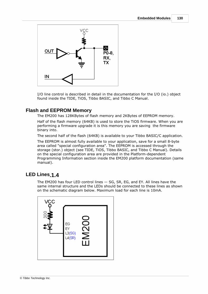
130Embedded Modules
© Tibbo Technology Inc.
I/O line control is described in detail in the documentation for the I/O (io.) objectfound inside the TIDE, TiOS, Tibbo BASIC, and Tibbo C Manual.
4.8.1.3Flash and EEPROM MemoryThe EM200 has 128KBytes of flash memory and 2KBytes of EEPROM memory.
Half of the flash memory (64KB) is used to store the TiOS firmware. When you areperforming a firmware upgrade it is this memory you are saving the firmwarebinary into.
The second half of the flash (64KB) is available to your Tibbo BASIC/C application.
The EEPROM is almost fully available to your application, save for a small 8-bytearea called "special configuration area". The EEPROM is accessed through thestorage (stor.) object (see TIDE, TiOS, Tibbo BASIC, and Tibbo C Manual). Detailson the special configuration area are provided in the Platform-dependentProgramming Information section inside the EM200 platform documentation (samemanual).
4.8.1.4LED Lines
The EM200 has four LED control lines — SG, SR, EG, and EY. All lines have thesame internal structure and the LEDs should be connected to these lines as shownon the schematic diagram below. Maximum load for each line is 10mA.

131 Programmable Hardware Manual (PHM)
© Tibbo Technology Inc.
Further information on status LEDs can be found in Status LEDs.
4.8.1.5Power, Reset, and Mode Selection LinesThe EM200 should be powered from a stabilized DC power supply with nominaloutput voltage of 5V (+/- 5% tolerance). Current consumption of the EM200 isapproximately 220mA (in 100BaseT mode). Providing an adequate power supply isvery important — poorly built circuit may affect EM200 operation. We recommendthat you use a switching power supply circuit. One (but not the only) example ofsuch circuit is shown below.
Proper external reset is a must! Reset pulse should be an active HIGH. We stronglyadvise against using low-cost RC-networks and other unreliable methods ofgenerating reset pulse. Reset should be applied for as long as the power supplyvoltage is below 4.6V. We recommend using a dedicated reset IC with brownoutdetection, such as MAX810. Reset pulse length should be no less than 50ms,counting from the moment the power supply voltage exceeds 4.6V.
If the EM200 is used to serve as a communications co-processor in a larger systemthat has its own CPU it is also OK to control the RST line of the EM200 through ageneral-purpose I/O pin of the "host" microcontroller. I/O pins of manymicrocontrollers default to HIGH after the powerup and this means that properreset will be applied to the EM200 when the host device is switched on. All the hostmicrocontroller has to do is release the EM200 from reset at an appropriate time byswitching the state of the I/O line to LOW.
The function of the MD line is described in Setup Button (MD line).
Power supply circuit
Many power supply circuits will work well. The one below is being used by Tibbo.The circuit can handle input voltages in the 9-30V range.
Notes:
· U1 (MC35063) is a very popular power IC manufactured by ON Semiconductor.
· R1 is very important. It is just 1 (one!) Ohm, but we really do not recommendthe user to omit it.
· R2 and R3 are "1% tolerance" (high-precision) because they define the outputvoltage of the power supply.
· C1 and C3 capacitors: Do not use SMD capacitors — use regular through-holealuminum capacitors. This really helps reduce noise produced by the powersupply.

132Embedded Modules
© Tibbo Technology Inc.
· This is an analog circuit, so layout matters. Apply reasonable "good layout"effort.
Ideally, one should use an oscilloscope to see what sort of "square wave"the power supply generates, both at low and high input voltages, as well aslight and heavy loads. R1 can be adjusted to achieve a better (cleaner)square wave signal on a particular PCB layout. There are no recipes here —just try and see what works for your circuit.
Mechanical Dimensions
L Ma
x.
32.
1
Module length
W Ma
x.
18.
5
Module width
H Ma
x.
7.3 Module height
I Mi
n.
2.2 Lead length
m Ma
x.
0.5 Lead "flash"
d Av
er.
28.
0
Distance between lead rows
p Av
er.
1.2
7
Pin pitch
Dimensions are for reference only. Tibbo assumes no responsibility for any errors inthis Manual, and does not make any commitment to update the informationcontained herein.

133 Programmable Hardware Manual (PHM)
© Tibbo Technology Inc.
Ordering Info and Specifications
The EM200 has two sub-models in circulation- the EM200-00 and EM200-01. TheEM200-01 is a RoHS-compliant version of the EM200-00. There are no otherdifferences between these two versions. Currently, only the EM200-01 is beingmanufactured.
Specifications
Ethernet interface 100/10BaseT Ethernet, magnetics not built-in
Serial ports 1 port; UART, Wiegand(1), and clock/data(1) modes
UART capabilities Baudrates up to 115'200bps;
none/even/odd/mark/space parity and 7/8 bits/char.; full-duplex UART mode with optional flow control(1)
and half-duplex UART mode with automatic directioncontrol(1); RX, TX, RTS(1), CTS(1), DTR(1), and DSR(1) linesprovided.
Number of I/O lines 9 (TX and RX lines of the serial port are not included into
this count)
Max. load current for each
I/O line
10mA
Flash memory 128KBytes, 64KB available for your Tibbo BASIC/Capplication
EEPROM memory 2048 bytes, 2040 bytes available to store applicationdata
Supported network
protocols(1)
UDP(1), TCP(1), ICMP (ping)(1), and HTTP(1). Otherprotocols (such as DHCP) are implemented as TibboBASIC/C functions.
Number of simultaneous
UDP or TCP (HTTP)
connections(1)
16(1)
Nominal power supply
voltage (VCC pin)
DC 5V, +/- 5%
Max. operating current 220mA
Device temperature during
operation(2)
55 degrees C
Operating temperature -10 to +70 degrees C
Operating relative humidity 10-90%
Mechanical dimensions
(excl. leads)
32.1x18.5x7.3mm
Pin diameter 0.4mm
Packaging EM200-01: tube, 10 modules/tube
EM200-B-01: tray, 30 modules/tray
Notes:
1. Actually a feature of TiOS firmware.
2. Measured at 22 degrees C ambient temperature, in the non-enclosedenvironment.

134Embedded Modules
© Tibbo Technology Inc.
All specifications are subject to change without notice and are for reference only.Tibbo assumes no responsibility for any errors in this Manual, and does not makeany commitment to update the information contained herein.
Think the above table should contain additional data? Do not just assume that youknow the answer — talk to Tibbo! Remember that the ultimate responsibility for alldecisions you make regarding the use and the mode of use of Tibbo products lieswith you, our Customer.
BoardsThe following boards and board families are currently being offered by Tibbo:
· EM2001
· EM1001
· NB10x0 and IB100x Boards
· DS1206N
· EM1202EV
· EM1206EV
· EM120/EM200-EV
EM2001 BASIC/C-programmable IoT Board
Introduction
The EM2001 is Tibbo's most powerful and versatile BASIC-programmable Ethernetboard. The EM2001 is a close relative of the EM2000 Ethernet module. Two deviceshave the same feature set, including the 10/100BaseT Ethernet port, four serialports, onboard flash disk, EEPROM, and the RTC with optional backupsupercapacitor. Like the EM2000, the EM2001 board can control a WA2000 Wi-Fi/BLE add-on, as well as an external LCD, keypad, buzzer, and many otherperipheral components.
Unlike the EM2000, the EM2001 is a self-sufficient board: it has a 12V-to-3.3Vswitching power regulator, RJ45 connector with magnetics, three LEDs, and the MDbutton. Thus, the EM2001 does not require a host board to plug into. The EM2001is the host board. As such, the EM2001 is equally suited to low-volume productiondevices and hobbyist projects alike.

135 Programmable Hardware Manual (PHM)
© Tibbo Technology Inc.
The EM2001 is fully supported by TIDE software. The board shares the sameprogramming platform with the EM2000 module (see TIDE, TiOS, Tibbo BASIC, andTibbo C Manual).
EM2001 advantages over the EM1001 board
The EM2001 is a high-performance upgrade to our EM1001 board. Here is small listof important improvements:
· 32-bit architecture (vs. 16-bit architecture of the EM1001).
· 5 to 80 times better performance, depending on the calculations and variabletypes.
· 7 times faster GPIO manipulation.
· 3 times larger available user SRAM (66KB vs. 22KB).
· 1.5-3.0 times faster graphics.
· 2.2 times lower power consumption (100mA vs. 220mA).
· 2 times larger flash memory (1MB for TiOS/code + 1MB for the file system vs.1MB total for TiOS, code, and file system).
· 56 I/O lines (vs. 54 lines on the EM1001).
· 4-channel ADC.
· The ability to update TiOS firmware and compiled Tibbo BASIC/C app over-the-air(this requires the WA2000 and an iOS or Android device).
Hardware features
· 32-bit architecture.
· Powered by Tibbo OS (TiOS).
· 10/100BaseT auto-MDIX Ethernet port with RJ45/magnetics (MDIX feature meansautomatic detection of "straight" and "cross" cables).
· Optional Wi-Fi interface (requires the WA2000 add-on module to be connected).
· Optional BLE interface (requires the WA2000 add-on module).
· Can control a GPRS modem* (such as the SIM900).
· Four high-speed serial ports (CMOS-level):
o Baudrates of up to 460,800bps;
o None**/even/odd/mark/space parity modes;
o 7**/8 bits/character;
o Full-duplex mode with RTS/CTS and XON/XOFF flow control;
o Half-duplex mode with direction control;
o Encoding and decoding of Wiegand and clock/data streams.
· 56 general-purpose I/O lines; 8 lines can work as interrupts.
· Square wave output (can be used for buzzer* control).
· 4-channel ADC.
· 4 synchronous serial ports with SPI and I2C modes.
· Supports a 320x240 TFT LCD*.

136Boards
© Tibbo Technology Inc.
· Supports matrix and binary output keypads*.
· RTC with backup battery.
· 66KB SRAM for Tibbo BASIC/C variables and data.
· 1MB flash for TiOS and application code.
· Additional 1MB flash for the hardened fault-tolerant file system.
· 2048-byte EEPROM for data storage.
· Three status LEDs onboard:
o Green and red main status LEDs;
o Yellow Ethernet link LED.
· Two control lines for external green and red main status LEDs;
· Software-controlled PLL allows selecting full, medium, or low speed.
· Reliable power-on/ brown-out reset circuit.
· Powering options:
o Through the switching regulator, 12VDC nominal (8 ~ 20V);
o Using regulated 3.3V power (the regulator is bypassed).
· The regulator can provide up to 1.3A @ 3.3V to external devices.
· Power: 100mA @ 3.3V (100BaseT mode, full speed).
· Dimensions (LxWxH): 75 x 36 x 17.5mm***.
· Operating temperature range: -40 ~ +80 C.
· Firmware is upgradeable through:
o The serial port;
o Ethernet LAN; or
o Over-the-air (requires the WA2000 and an iOS or Android device).
· Tibbo BASIC/C application can be uploaded and debugged through the EthernetLAN (no additional debugging hardware is required).
· CE- and FCC-certified.
* Must be connected externally.
** The EM2001 does not support the combination of 7 bits/character mode and the"none" parity mode.
***Not including RJ45, power jack, WA2000.
Programming features
· Platform objects:
o adc — provides access to four ADC channels.
o beep — generates buzzer patterns.
o bt — in charge of the BLE (Bluetooth Low-Energy) interface.
o button — monitors the MD (setup) line.
o fd — manages the flash memory file system and direct sector access.
o io — handles I/O lines, ports, and interrupts.
o kp — works with matrix and binary keypads.

137 Programmable Hardware Manual (PHM)
© Tibbo Technology Inc.
o lcd — controls the LCD.
o net — controls the Ethernet port.
o pat — "plays" patterns on up to five LED pairs.
o ppp — accesses the Internet over a serial modem (GPRS, etc.).
o pppoe — accesses the Internet over an ADSL modem.
o romfile — facilitates access to resource files (fixed data).
o rtc — keeps track of date and time.
o ser — controls serial ports (UART, Wiegand, clock/data modes).
o sock — socket comms (up to 32 UDP, TCP, and HTTP sessions).
o ssi — controls serial synchronous interface channels (SPI, I2C...).
o stor — provides access to the EEPROM.
o sys — in charge of general device functionality.
o wln — handles the Wi-Fi interface.
· Variable Types: Byte, char, integer (word), short, dword, long, real, string, plususer-defined arrays and structures.
· Function groups: String functions, trigonometric functions, date/time conversionfunctions, encryption/hash calculation functions (AES, RC4, MD5, SHA-1), andmore.

138Boards
© Tibbo Technology Inc.
Detailed Device Info
Note: "SPI connector" is now referred to as "wireless add-on port"
See these topics for more information on various hardware facilities of the EM2001:
· General-purpose I/O Lines
· Wireless Add-on port, Wi-Fi Communications
· Ethernet Port
· Serial Ports
· Analog-to-digital Converter (ADC)
· I2C/SPI Support
· Square Wave Generator
· Flash and EEPROM Memory
· Real-time Clock (RTC) and Backup Battery
· LEDs and LED Lines
· External LCD Support
· External Keypad Support

139 Programmable Hardware Manual (PHM)
© Tibbo Technology Inc.
· Power, Reset, PLL Control, and Mode Selection Lines
I/O pin assignment
Notes (refer to superscript numbers placed after pin #):
1. This line is 5V-tolerant and can be interfaced to 5V CMOS devices directly.
2. This line can be mapped to serve as an RTS, W0 output, or CLOCK output line ofa serial port. The line can also be assigned to an I2C/SPI channel, or act as aninterface line of the Wi-Fi add-on module, keypad, or an LED control channel.
3. This line can serve as a CTS, W0&1 input, or CLOCK input line of a serial port.
Pin#
Function Description
1 (1,2) GPIO0/P0.0/RTS0
General-purpose I/O line 0 (P0.0).
2 (1,2) GPIO1/P0.1/RTS1
General-purpose I/O line 1 (P0.1).
3 (1,2) GPIO2/P0.2/RTS2
General-purpose I/O line 2 (P0.2).
4 (1,2) GPIO3/P0.3/RTS3
General-purpose I/O line 3 (P0.3).
5 (1,2) GPIO4/P0.4/DTR0
General-purpose I/O line 4 (P0.4).
6 (1,2) GPIO5/P0.5/DTR1
General-purpose I/O line 5 (P0.5).
7 (1,2) GPIO6/P0.6/DTR2
General-purpose I/O line 6 (P0.6).
8 (1,2) GPIO7/P0.7/DTR3
General-purpose I/O line 7 (P0.7).
9 (1,2) GPIO8/P1.0/RX0
General-purpose I/O line 8 (P1.0);
RX, W1 input, and DATA input of the serial port 0.
10(1,2)
GPIO9/P1.1/TX0
General-purpose I/O line 9 (P1.1);
TX, W1 output, and DATA output of the serial port0.
11(1,2)
GPIO10/P1.2/RX1
General-purpose I/O line 10 (P1.2);
RX, W1 input, and DATA input of the serial port 1.
12(1,2)
GPIO11/P1.3/TX1
General-purpose I/O line 11 (P1.3);
TX, W1 output, and DATA output of the serial port1.
13(1,2)
GPIO12/P1.4/RX2
General-purpose I/O line 12 (P1.4);
RX, W1 input, and DATA input of the serial port 2.
14(1,2)
GPIO13/P1.5/TX2
General-purpose I/O line 13 (P1.5);
TX, W1 output, and DATA output of the serial port2.
15(1,2)
GPIO14/P1.6/RX3
General-purpose I/O line 14 (P1.6);
RX, W1 input, and DATA input of the serial port 3.
16(1,2)
GPIO15/P1.7/TX3
General-purpose I/O line 15 (P1.7);

140Boards
© Tibbo Technology Inc.
TX, W1 output, and DATA output of the serial port3.
17(1,2,3)
GPIO16/P2.0/INT0/CTS0
General-purpose I/O line 16 (P2.0);
interrupt line 0.
18(1,2,3)
GPIO17/P2.1/INT1/CTS1
General-purpose I/O line 17 (P2.1);
interrupt line 1.
19(1,2,3)
GPIO18/P2.2/INT2/CTS2
General-purpose I/O line 18 (P2.2);
interrupt line 2.
20(1,2,3)
GPIO19/P2.3/INT3/CTS3
General-purpose I/O line 19 (P2.3);
interrupt line 3.
21(1,2,3)
GPIO20/P2.4/INT4/DSR0
General-purpose I/O line 20 (P2.4);
interrupt line 4.
22(1,2,3)
GPIO21/P2.5/INT5/DSR1
General-purpose I/O line 21 (P2.5);
interrupt line 5.
23(1,2,3)
GPIO22/P2.6/INT6/DSR2
General-purpose I/O line 22 (P2.6);
interrupt line 6.
24(1,2,3)
GPIO23/P2.7/INT7/DSR3
General-purpose I/O line 23 (P2.7);
interrupt line 7.
25(1,2)
GPIO40/ADC0 General-purpose I/O line 40 (does not belong toany 8-bit port); ADC input 0.
26(1,2)
GPIO41/ADC1 General-purpose I/O line 41 (does not belong toany 8-bit port); ADC input 1.
27(1,2)
GPIO42/ADC2 General-purpose I/O line 42 (does not belong toany 8-bit port); ADC input 2.
28(1,2)
GPIO43/ADC3 General-purpose I/O line 43 (does not belong toany 8-bit port); ADC input 3.
29 GND System ground.
30(1,2)
GPIO44 General-purpose I/O line 44 (does not belong toany 8-bit port).
31(1,2)
GPIO25/P3.1 General-purpose I/O line 25 (P3.1).
32(1,2)
GPIO24/P3.0 General-purpose I/O line 24 (P3.0).
33(1,2)
GPIO27/P3.3 General-purpose I/O line 27 (P3.3).
34(1,2)
GPIO26/P3.2 General-purpose I/O line 26 (P3.2).
35(1,2)
GPIO29/P3.5 General-purpose I/O line 29 (P3.5).
36(1,2)
GPIO28/P3.4 General-purpose I/O line 28 (P3.4).
37(1,2)
GPIO31/P3.7 General-purpose I/O line 31 (P3.7).
38(1,2)
GPIO30/P3.6 General-purpose I/O line 30 (P3.6).
39(1,2)
GPIO33/P4.1 General-purpose I/O line 33 (P4.1).
40(1,2)
GPIO32/P4.0 General-purpose I/O line 32 (P4.0).
41(1,2)
GPIO35/P4.3 General-purpose I/O line 35 (P4.3).

141 Programmable Hardware Manual (PHM)
© Tibbo Technology Inc.
42(1,2)
GPIO34/P4.2 General-purpose I/O line 34 (P4.2).
43(1,2)
GPIO37/P4.5 General-purpose I/O line 37 (P4.5).
44(1,2)
GPIO36/P4.4 General-purpose I/O line 36 (P4.4).
45(1,2)
GPIO39/P4.7 General-purpose I/O line 39 (P4.7).
46(1,2)
GPIO38/P4.6 General-purpose I/O line 38 (P4.6).
47 MD Mode selection pin.
48(1,2)
GPIO55 General-purpose I/O line 55 (does not belong toany 8-bit port).
49 RST Reset line, active high.
50(1,2)
GPIO54 General-purpose I/O line 54 (does not belong toany 8-bit port).
51 SR Red status LED control line.
52 SG Green status LED control line.
53(1,2)
GPIO46 General-purpose I/O line 46.
54(1,2)
GPIO45/CO General-purpose I/O line 45 (does not belong toany 8-bit port);
square wave output line.
55(1,2)
GPIO48 General-purpose I/O line 48 (does not belong toany 8-bit port).
56(1,2)
GPIO47 General-purpose I/O line 47 (does not belong toany 8-bit port).
57 DBGRX RX line of debug serial port.
58 3.3V Direct 3.3V power input or 3.3V power output ifyou are supplying 12V power via a power jack orVIN pin.
59 DBGTX TX line of debug serial port.
60 VIN (12V NOM.) 12V (nominal) power input to the onboard power
regulator. Acceptable input voltage range is 8-20V.
61 GND Wireless add-on port, ground line.
62 VCC Wireless add-on port, 3.3V power output for thewireless add-on module.
63(1,2)
GPIO49 Wireless add-on port, general-purpose I/O line 49(does not belong to any 8-bit port).
64 <N.C.> Leave this pin unconnected.
65(1,2)
GPIO50 Wireless add-on port, general-purpose I/O line 50(does not belong to any 8-bit port).
66 <N.C.> Leave this pin unconnected.
67(1,2)
GPIO51 Wireless add-on port, general-purpose I/O line 51(does not belong to any 8-bit port).
68 <N.C.> Leave this pin unconnected.
69(1,2)
GPIO52 Wireless add-on port, general-purpose I/O line 52(does not belong to any 8-bit port).
70(1,2)
GPIO53 Wireless add-on port, general-purpose I/O line 53(does not belong to any 8-bit port).

142Boards
© Tibbo Technology Inc.
5.1.1.1General-purpose I/O LinesThe EM2001 has 56 general-purpose I/O lines (GPIO0 - GPIO55). All lines are 3.3V,CMOS, 5V-tolerant lines. The maximum load current for each I/O line is 10mA. Fiftyone of these lines are always available. Remaining five lines are located on thewireless add-on connector and can be used if no wireless add-on module isinstalled.
The simplified structure of one I/O line of the EM2001 is shown on the circuitdiagram below. Each line has an independent output buffer control. When theEM2001 powers up, all its I/O lines have their output buffers tri-stated (in otherwords, all I/O lines are configured as inputs). You need to explicitly enable theoutput buffer of a certain I/O line if you want this line to become an output.
Many I/O lines of the EM2001 also serve as inputs or outputs of special functionmodules, such as serial ports. Majority of those lines need to be correctlyconfigured as inputs or outputs — this won't happen automatically. Several lines —such as TX and RX lines of the serial port when in the UART mode — are configuredas outputs and inputs automatically when the serial port (or some other hardwareblock) is enabled. For details see "Platform-dependent Programming Informationinside the EM2000 platform documentation (TIDE, TiOS, Tibbo BASIC, and Tibbo CManual).
Each I/O line has a weak pull-up resistor that prevents the line from floating whenthe output buffer is tri-stated.
8-bit ports
Forty I/O lines are grouped into five 8-bit ports. To preserve compatibility with theEM1001 board, the grouping of I/O lines into ports is exactly the same as on theEM1001. Unfortunately, this preservation of compatibility has turned the ports ofthe EM2001 into "pseudo ports", meaning that GPIO lines of these ports actuallybelong to several different physical ports of the onboard microcontroller. As aresult, port operations such as io.portset, io.portget, or io.portstate do not accessport pins in perfect unison. In port operations, writing or reading of some lines willhappen sooner than writing or reading of other lines. This "dissonance" is verysmall and will not matter for most applications, but do keep in mind that it doesexist.
Port mapping arrangement is different for different ports, so their performancevaries slightly as well. Ports P0 and P1 are about 10% slower than P2, P3, and P4.In most cases this difference is negligible, especially considering that GPIO line and

143 Programmable Hardware Manual (PHM)
© Tibbo Technology Inc.
port manipulation on the EM2001 is about 7 times faster compared to theEM1001.
I/O line control is described in detail in the documentation for the I/O (io.) objectfound inside the TIDE, TiOS, Tibbo BASIC, and Tibbo C Manual.
5.1.1.2Wireless Add-on Port, Wi-Fi CommunicationsThe wireless add-on port of the EM2001 is a separate 10-pin connector.
This port carries 5 general-purpose I/O lines. When a wireless add-on module, suchas the WA2000 Wi-Fi/BLE add-on, is plugged into the EM2001, these lines are usedfor interfacing to this add-on. In the absence of a wireless module these 5 linesmay be used as general-purpose input/output lines.
It should be noted that the WA2000 can be controlled through any five I/O lines ofthe EM2001. Obviously, the lines on the wireless add-on port are the mostconvenient for the task as the connector pinout matches that of the WA2000.Nonetheless, it is always possible to connect the WA2000 by wires, in which caseany combination of I/O lines can be used for communicating with it.
For more details on Wi-Fi communications see TIDE, TiOS, Tibbo BASIC, and TibboC Manual (wln. object).
5.1.1.3Ethernet Port
The Ethernet port of the EM2001 is of 10/100BaseT type.
The connector is of the RJ45 type, pin assignment is as follows:
#1 TX+
#2 TX-
#3 RX+
#4 PoE+
#5 PoE+
#6 RX-
#7 PoE-
#8 PoE-

144Boards
© Tibbo Technology Inc.
5.1.1.4Serial PortsThe EM2001 has four serial ports that can work in one of the three modes: UART,Wiegand, or clock/data.
UART mode
UART mode supports full- and half-duplex communications.
Full-duplex interface is typically used for RS232, RS422, full-duplex RS485, or"serial TTL" (CMOS) communications.
In the UART full-duplex mode, each port has TX and RX lines, as well as RTS andCTS lines, which are optionally used for the hardware flow control. When the flowcontrol is enabled, the EM2001 will control the RTS and CTS lines automatically.
Half-duplex interface is typically associated with half-duplex RS485communications. In this mode, the serial port uses TX, RX, and RTS lines, the latterserving as the direction control line. Direction control is automatic and does notrequire any intervention from your Tibbo BASIC/C program.
TX and RX lines cannot be relocated. RTS and CTS lines can be moved around. ForRTS, any unused GPIO line can be assigned to work as the RTS line of a serial port.For CTS, only interrupt lines I0-7 (GPIO lines 16-23) can be selected. Flexibleremapping of RTS and CTS line is facilitated by I/O mapping properties offered bythe serial (ser.) object.
DTR and DSR lines often found on RS232 ports are not controlled by the ser.object. It is the responsibility of your Tibbo BASIC/C application to take care ofthese lines. Therefore, you can choose what GPIO lines of the EM2000 will be usedas DTR and DSR lines in your system.
Flexible mapping notwithstanding, Tibbo has defined the default mapping for RTS,CTS, DTR, and DSR lines. This was done in an effort to standardize schematicdiagrams across our entire product range. The EM2001 diagram shows such defaultassignments in BLUE color.
UARTs of the EM2001 module have one significant limitation: it is not possible tosimultaneously use the 7 bits/character mode and "no parity" mode. All othermodes are supported.
Wiegand mode
The Wiegand interface is often used in security products. A large number ofmagnetic card and RFID readers support this interface. The ser. object allows youto both receive and send data streams in the Wiegand format.
"Wiegand" requires only two interface lines — W0 and W1. Here is how these linesmap to the "traditional" lines of the serial port:
TX W1 output
RX W1 input
RTS W0 output
CTS W0 & W1 input

145 Programmable Hardware Manual (PHM)
© Tibbo Technology Inc.
As shown in the table, the CTS line is supposed to receive a "logical AND" ofincoming W0 and W1 signals. This requires external circuitry — see Wiegand andClock/Data Circuit Examples for details. No additional circuitry is required to outputWiegand data.
"W1 output" (on TX) and "W1 input" (on RX) cannot be remapped, while "W0output" (on RTS) can be reassigned to any suitable GPIO line. "W0 & W1 input" (onCTS) can be remapped, but possible choices are limited to interrupt lines I0-7(GPIO16-23).
Clock/data mode
The clock/data interface is also a very popular reader interface. The ser. objectallows you to receive and send data streams in the clock/data format.
As the name implies, this interface requires two data lines - CLOCK and DATA. Hereis how these lines map to the "traditional" lines of the serial port:
TX DATA output
RX DATA input
RTS CLOCK output
CTS CLOCK input
As in the UART mode, "DATA output" (on TX) and "DATA input" (on RX) cannot beremapped, while "CLOCK output" (on RTS) can be reassigned to any suitable GPIOline. "CLOCK input" (on CTS) can be remapped, but possible choices are limited tointerrupt lines I0-7 (GPIO16-23).
No additional circuitry is required to handle clock/data streams.
For more information see the documentation for the serial (ser.) object found insidethe TIDE, TiOS, Tibbo BASIC, and Tibbo C Manual.
Wiegand and Clock/Data Circuit ExamplesIn the Wiegand mode, the W0&1in input of the serial port must receive a logicalAND of W0 and W1 output of attached Wiegand device. A simple AND gate will dothe job (figure A below). NOR-AND gates are more popular that AND gates, andthese can be used too (figure B). In case you are building a product that will alsoaccept clock/data input, you may need to control whether the W0&1in input shouldreceive a logical AND of the two lines, or just one of the lines. Schematic diagram Cuses an additional I/O line of the device to control this. When the control line isHIGH the W0&1in input receives a logical AND of both W0 and W1 lines, when thecontrol line is LOW, the W0&1in input receives just the signal from the W0 line.Four gates are required for this, so you will get away with using a single 74HC00IC.

146Boards
© Tibbo Technology Inc.
5.1.1.5Analog-to-digital Converter (ADC)The EM2001 features a four-channel analog-to-digital converter (ADC). The ADC'shardware resolution is 12 bits, while its effective resolution is about 7 bits. Thisreduction in resolution is caused by the internal noise of the EM2001. Even withthis low resolution, the ADC module is useful for a wide variety of measurements.
The input voltage range of ADC inputs is from 0 to VCC (3.3V nominal). The ADCwill measure 0 when an ADC's input is at 0V, and 4095 when an input is at VCC.
Your Tibbo BASIC/C application can access the ADC module through the ADC (adc.)object, which is documented in the TIDE, TiOS, Tibbo BASIC, and Tibbo C Manual.
5.1.1.6I2C/SPI Support (SSI Channels)Tibbo OS (TiOS) running on the EM2001 offers four "soft" synchronous serial portsthat can be used for I2C and SPI communications, with the EM2001 acting as themaster. All four SPI modes are supported.
Because the SSI channels are implemented entirely in software, any combination ofGPIO lines can be selected to serve as interface lines of an SSI channel. This isfacilitated by several I/O mapping properties offered by the ssi. object.
For more information see the documentation for the ssi. object found inside theTIDE, TiOS, Tibbo BASIC, and Tibbo C Manual.
5.1.1.7Square Wave GeneratorThe square wave generator can produce a square wave output on pin GPIO45/COof the EM2001. This output is primarily intended for generating audio signals usingbuzzer and is covered in the beep (beep.) object — see the TIDE, TiOS, TibboBASIC, and Tibbo C Manual.

147 Programmable Hardware Manual (PHM)
© Tibbo Technology Inc.
5.1.1.8Flash and EEPROM MemoryThe EM2001 has three kinds of non-volatile memory onboard:
· 1MB program flash. TiOS occupies 256KB in the program flash memory. Theremaining 768KB can be used to store your compiled application binary andpermanent (unchangeable) data.
· 1MB flash disk that houses hardened, fault-tolerant file system. The entire diskcan be used by your application to store necessary data. The disk is under thecontrol of the flash disk (fd.) object.
· 2KB EEPROM. The EEPROM is almost fully available to your application, save fora small 28-byte area called the "special configuration area". The EEPROM isaccessed through the storage (stor.) object.
For more information on fd. and stor. objects see TIDE, TiOS, Tibbo BASIC, andTibbo C Manual. Details on the special configuration area are provided in thePlatform-dependent Programming Information section inside the EM2000 platformdocumentation (same manual).
On the advice of one of our customers we are giving you the followingreminder: Like all other EEPROMs on the market, EEPROM ICs used in Tibbodevices allow for a limited number of write cycles. As the Wikipedia article
on EEPROMs (https://en.wikipedia.org/wiki/EEPROM) states, the EEPROM "...has alimited life for erasing and reprogramming, now reaching a million operations inmodern EEPROMs. In an EEPROM that is frequently reprogrammed while thecomputer is in use, the life of the EEPROM is an important design consideration."When planning to use the stor. object, please carefully consider if the plannedmode of EEPROM use will allow the EEPROM to work reliably through the entireprojected life of your product. For more information see Prolonging and EstimatingEEPROM Life.
Like all other flash memory devices on the market, flash ICs used in Tibbo productsonly allow for a limited number of write cycles. As the Wikipedia article on flashmemory (https://en.wikipedia.org/wiki/Flash_memory) explains, modern flash ICsstill suffer from comparatively low write endurance. In Tibbo devices, thisendurance is around 100'000 write cycles per sector. When you are using the flashmemory for file storage, the fd. object employs sector wear leveling to maximizethe life of the flash IC (but the life still remains limited). If your applicationemploys direct sector access, then it is your job to plan the application around thelife limitations of the flash memory. For data that changes often, consider using theEEPROM memory instead. EEPROMs have much better endurance.
5.1.1.9Real-time Clock (RTC) and Backup BatteryThe EM2001 features an onboard real-time clock (RTC). As a source of backuppower, the EM2001 relies on an onboard coin battery. Your Tibbo BASIC/Capplication can access the RTC through the RTC (rtc.) object, which is documentedin the TIDE, TiOS, Tibbo BASIC, and Tibbo C Manual.
5.1.1.10LEDs and LED LinesThe EM2001 has three LEDs onboard:
· The red and green status LEDs.
· The yellow Ethernet status LED.

148Boards
© Tibbo Technology Inc.
Further information on status LEDs can be found in Status LEDs.
The EM2001 also has two control lines — SG and SR — for connecting to externalgreen and red status LEDs. These external LEDs work in parallel with the onboardLEDs. Since the maximum sink current of an I/O line is 10mA and the onboardLEDs already consume around 7mA, externally connected LEDs must not consumeover 3mA of current. Connect external SR and SG LEDS through buffers (logicgates) if higher current is desired. SG and SR lines are active low, i.e. an LEDsmust turn on when its control line is at LOW. Take this into consideration whendesigning the LED circuit.
Your Tibbo BASIC/C application can control red and green status LEDs, as well asup to four externally connected LED pairs through the pattern (pat.) object, whichis documented in the TIDE, TiOS, Tibbo BASIC, and Tibbo C Manual.
5.1.1.11External LCD SupportUnlike the EM1001 device, the EM2001 device does not offer flexible mapping forLCD control lines, nor does it support several different LCD controller models. Theonly controller supported is SSD1964. Moreover, only one specific configuration issupported:
· Data bus width is 8 bits
· Color depth is 24 bits
Here is how you must connect the SSD1964-based LCD controller to the EM2001:
· Connect the data bus lines DB7-0 to GPIO lines 32-39 (port 4).
· Connect the RST line to GPIO44.
· Connect the RS (command/data) line to GPIO43.
· Connect the WR line to GPIO42.
· Optionally connect the RD line to GPIO41 (this line is not used on the currentdriver version but may be used in the future).
· Connect the CS line to GPIO40.
· Note that most LCD panels have a dedicated pin for controlling the backlight. Ifyour LCD panel has such a line, connect it to any suitable line of the EM2001 andcontrol it from your Tibbo BASIC/C code.
"Programmable Hardware Manual" provides an initialization example for the LCD.See THE REFERENCE -> Platforms -> EM2000W -> Working with the LCD.
5.1.1.12External Keypad supportThe EM2001 supports both matrix and binary keypads. A typical matrix keypad isshown on the schematic diagram below:

149 Programmable Hardware Manual (PHM)
© Tibbo Technology Inc.
Due to flexible scan and return line mapping provided by the keypad (kp.) object,you can assign any combination of GPIO lines to connect to your keypad. Up to 8scan and 8 return lines can be assigned. On the EM2001 board, all scan line mustbe configured as outputs, and all return lines — as inputs.
To build a keypad you will need to have at least one return line. A sensible count ofscan lines, however, starts from two! Having a single scan line is like having noscan lines whatsoever — you might just as well ground this single scan line, i.e.always keep it active:

150Boards
© Tibbo Technology Inc.
Scan lines can optionally perform the second function of driving LEDs. One suchLED can be connected to each scan line, preferably through a buffer, as shown onthe diagram below. These LEDs can be used for any purpose you desire — and thispurpose can be completely unrelated to the keypad itself.
If the LEDs are connected as shown on the diagram, you will turn them ON bysettings their corresponding control lines LOW.
Binary keypads (i.e. "keypads that output binary key codes") do not requirescanning — they contain a (typically microcontroller-based) circuit that performsthe scanning and outputs encoded binary codes of pressed keys. Such keypads aresometimes called "encoded keypads":

151 Programmable Hardware Manual (PHM)
© Tibbo Technology Inc.
The EM2001 can work with binary keypads incorporating up to 8 data lines.
For more information see I/O (io.) and keypad (kp.) objects. They are documentedin the "Programmable Hardware Manual".
5.1.1.13Power, Reset, PLL Control, and Mode SelectionThe EM2001 consumes around 100mA @ 3.3V of current (full speed, 100BaseTmode, all onboard LEDs on).
There are two ways to power the EM2001.
Powering through the regulator
The onboard switching regulator has the 8-20V input range and delivers enoughcurrent to power the EM2001 itself, the WA2000 Wi-Fi/BLE add on, PLUS externalloads with up to 1A of combined current.
To use the regulator, connect the power source to the power jack or GND and VINpins. The power jack and GND/VIN are wired in parallel, with no diodes or anyother circuitry between them.
The regulator has a single diode in front of it. The diode will protect the regulator ifthe power is accidentally connected in reverse.
External loads can be powered through the 3.3V pin. When the board is poweredthrough the regulator, this pin serves as a power output. Up to 1A of current isavailable with the WA2000 installed, 1.3A available if the WA2000 is not installed.
Using direct 3.3V power
It is also possible to power the EM1001 through the GND and 3.3V lines. In thiscase the 3.3V pin serves as a power input and the regulator is bypassed. The 3.3Vpower source should be regulated to at least +/-10%.
Reset
Proper external reset is not required. The EM2001 has a reliable power-on resetcircuit with brown-out detection. Optionally, you can connect a reset button orsome other reset-generating circuit to the RST line of the EM2001. This will allowyou to generate external resets. The RST line has active LOW polarity. If you arenot using the RST line you can leave it unconnected.
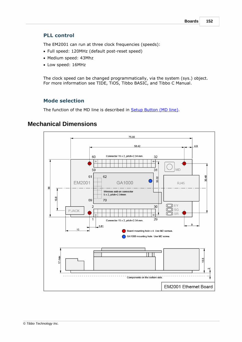
152Boards
© Tibbo Technology Inc.
PLL control
The EM2001 can run at three clock frequencies (speeds):
· Full speed: 120MHz (default post-reset speed)
· Medium speed: 43Mhz
· Low speed: 16MHz
The clock speed can be changed programmatically, via the system (sys.) object.For more information see TIDE, TiOS, Tibbo BASIC, and Tibbo C Manual.
Mode selection
The function of the MD line is described in Setup Button (MD line).
Mechanical Dimensions

153 Programmable Hardware Manual (PHM)
© Tibbo Technology Inc.
Dimensions are for reference only. Tibbo assumes no responsibility for any errors inthis Manual, and does not make any commitment to update the informationcontained herein.
Ordering Info and SpecificationsTo order, use the "EM2001" ordering code.
Hardware specifications
Ethernet interface 10/100BaseT Ethernet, Auto-MDIX, with RJ45/magnetics
Serial ports 4 ports, CMOS-level
UART capabilities Baudrates up to 460'800bps;
none/even/odd/mark/space parity and 7/8bits/character (7 bits/character and "none" paritycannot be used together)
Number of I/O lines 56 lines (including 5 on the wireless add-on connector);
all lines are 5V-tolerant;
40 of I/O lines are combined into five 8-bit ports;
8 lines can be used as interrupt lines.
Max. load current for each
I/O line
10mA
Square wave generator 458Hz - 15MHz (with the full-speed clock), primarilyintended for driving an external buzzer
Real-time counter (RTC) YES
RTC backup power source Onboard coin cell
Clock frequency 120MHz at full speed
34MHz at medium speed
16MHz at low speed
Program flash memory 1MB program flash for TiOS and compiled applicationbinary. TiOS occupies 256KB. The remaining 768KBcan be used to store the compiled application binaryand permanent (unchangeable) data.
Flash disk 1MB for hardened, fault-tolerant file system. Theentire disk can be used by the application to store itsdata .
Typical write endurance is 100'000 write cycles per256-byte sector. See the warning in Flash andEEPROM Memory.
EEPROM memory 2048 bytes, 2020 bytes available for storingapplication's data.
Typical write endurance is around 1'000'000 writecycles per 16-byte EEPROM sector. See Prolongingand Estimating EEPROM life.
Switching regulator supply
voltage (supplied via the
power jack or VIN pin)
unregulated, 8-20V input range, 12V nominal

154Boards
© Tibbo Technology Inc.
Direct system power
(supplied via the 3.3V pin
bypassing the switching
regulator)
regulated, 3.3V +/- 10%
Available current on the
3.3V pin (when powering
through the voltage
regulator)
1.0A if the WA2000 is used
1.3A if the WA2000 is not used
Reset circuit trip voltage
(3.3V system power line)
~2.95V on power-up (i.e. when the voltage on VCC is
rising)
~2.85V on brown-out (i.e. when the voltage on VCC is
dropping)
Operating current when
the 3.3V is supplied
directly through the 3.3V
pin
100mA at full speed, 100BaseT Ethernet mode
Operating temperature -40 to +80 degrees C
Operating relative
humidity
10-90%
Mechanical dimensions
(excluding RJ45 and power
jack)
EM2001: 75x36x17.5mm
EM2001G: 75x36x19mm
All specifications are subject to change without notice and are for reference only.Tibbo assumes no responsibility for any errors in this Manual, and does not makeany commitment to update the information contained herein.
Think the above table should contain additional data? Do not just assume that youknow the answer — talk to Tibbo! Remember that the ultimate responsibility for alldecisions you make regarding the use and the mode of use of Tibbo products lieswith you, our Customer.
EM1001 BASIC/C-programmable IoT Board

155 Programmable Hardware Manual (PHM)
© Tibbo Technology Inc.
Introduction
The EM1001 is a BASIC-programmable Ethernet board. The EM1001 is a closerelative of the EM1000 Ethernet module. Two devices have the same feature set,including the 10/100BaseT Ethernet port, four serial ports, onboard flash disk,EEPROM, and the RTC with optional backup supercapacitor. Like the EM1000, theEM1001 board can control a WA2000 Wi-Fi add-on, as well as an external LCD,keypad, buzzer, and many other peripheral components.
Unlike the EM1000, the EM1001 us a self-sufficient board: it has a 12V-to-3.3Vswitching power regulator, RJ45 connector with magnetics, three LEDs, and the MDbutton. Thus, the EM1001 does not require a host board to plug into. The EM1001is the host board. As such, the EM1001 is equally suited to low-volume productiondevices and hobbyist projects alike.
The EM1001 is fully supported by TIDE software. The board shares the sameplatform with the EM1000 module (see TIDE, TiOS, Tibbo BASIC, and Tibbo CManual).
Hardware features
· Powered by Tibbo OS (TiOS).
· 10/100BaseT auto-MDIX Ethernet port with RJ45/magnetics (MDIX feature meansautomatic detection of "straight" and "cross" cables).
· Optional Wi-Fi interface (requires the WA2000 add-on module to be connected).
· Can control a GPRS modem* (such as the SIM900).
· Four high-speed serial ports (CMOS-level):
o Baudrates of up to 460,800bps;
o None/even/odd/mark/space parity modes;
o 7/8 bits/character;
o Full-duplex mode with RTS/CTS and XON/XOFF flow control;
o Half-duplex mode with direction control;
o Encoding and decoding of Wiegand and clock/data streams.
· 54 general-purpose I/O lines; 8 lines can work as interrupts.
· Square wave output (can be used for buzzer* control).
· 4 synchronous serial ports with SPI and I2C modes.
· Supports LCD and OLED panels*.
· Supports matrix and binary output keypads*.
· RTC with backup power input (optional onboard supercapacitor).
· 22KB SRAM for Tibbo BASIC/C variables and data.
· 1MB flash memory for TiOS, application code, and file system.
· 2048-byte EEPROM for data storage.
· Three status LEDs onboard:
o Green and red main status LEDs;
o Yellow Ethernet link LED.
· Two control lines for external green and red main status LEDs;
· Software- and hardware-controlled PLL for selecting high or low speed.

156Boards
© Tibbo Technology Inc.
· Reliable power-on/ brown-out reset circuit.
· Powering options:
o Through the switching regulator, 12VDC nominal (8 ~ 20V);
o Using regulated 3.3V power (the regulator is bypassed).
· The regulator can provide up to 1.3A @ 3.3V to external devices.
· Power: 100mA @ 3.3V (100BaseT mode, full speed).
· Dimensions (LxWxH): 75 x 36 x 17.5mm**.
· Operating temperature range: -40 ~ +70 C.
· Firmware is upgradeable through the serial port or network.
· Tibbo BASIC/C application can be uploaded and debugged through the EthernetLAN (no additional debugging hardware is required).
· CE- and FCC-certified.
* Must be connected externally.
**Not including RJ45, power jack, WA2000.
Programming features
· Platform objects:
o beep — generates buzzer patterns.
o button — monitors the MD (setup) line.
o fd — manages the flash memory file system and direct sector access.
o io — handles I/O lines, ports, and interrupts.
o kp — works with matrix and binary keypads.
o lcd — controls graphical display panels.
o net — controls the Ethernet port.
o pat — "plays" patterns on up to five LED pairs.
o ppp — accesses the Internet over a serial modem (GPRS, etc.).
o pppoe — accesses the Internet over an ADSL modem.
o romfile — facilitates access to resource files (fixed data).
o rtc — keeps track of date and time.
o ser — controls serial ports (UART, Wiegand, clock/data modes).
o sock — socket comms (up to 16 UDP, TCP, and HTTP sessions).
o ssi — controls serial synchronous interface channels (SPI, I2C...).
o stor — provides access to the EEPROM.
o sys — in charge of general device functionality.
o wln — handles the Wi-Fi interface.
· Variable Types: Byte, char, integer (word), short, dword, long, real, string, plususer-defined arrays and structures.
· Function Groups: 27 string functions, 8 date/time conversion functions,encryption/hash calculation functions (RC4, MD5, SHA-1), and more.

157 Programmable Hardware Manual (PHM)
© Tibbo Technology Inc.
Detailed Device Info
See these topics for more information on various hardware facilities of the EM1001:
· General-purpose I/O Lines
· Wireless add-on port
· Ethernet Port
· Serial Ports
· Square Wave Generator
· Flash and EEPROM Memory
· Real-time Counter
· LED Lines
· Power, Reset, PLL Control, and Mode Selection Lines
I/O pin assignment

158Boards
© Tibbo Technology Inc.
Pin#
Function Description
1 (1,2) GPIO0/P0.0 General-purpose I/O line 0 (P0.0).
2 (1,2) GPIO1/P0.1 General-purpose I/O line 1 (P0.1).
3 (1,2) GPIO2/P0.2 General-purpose I/O line 2 (P0.2).
4 (1,2) GPIO3/P0.3 General-purpose I/O line 3 (P0.3).
5 (1,2) GPIO4/P0.4 General-purpose I/O line 4 (P0.4).
6 (1,2) GPIO5/P0.5 General-purpose I/O line 5 (P0.5).
7 (1,2) GPIO6/P0.6 General-purpose I/O line 6 (P0.6).
8 (1,2) GPIO7/P0.7 General-purpose I/O line 7 (P0.7).
9 (1,2) GPIO8/P1.0/RX0
General-purpose I/O line 8 (P1.0);
RX, W1, and din input of the serial port 0.
10(1,2)
GPIO9/P1.1/TX0
General-purpose I/O line 9 (P1.1);
TX, W1, and dout output of the serial port 0.
11(1,2)
GPIO10/P1.2/RX1
General-purpose I/O line 10 (P1.2);
RX, W1, and din input of the serial port 1.
12(1,2)
GPIO11/P1.3/TX1
General-purpose I/O line 11 (P1.3);
TX, W1, and dout output of the serial port 1.
13(1,2)
GPIO12/P1.4/RX2
General-purpose I/O line 12 (P1.4);
RX, W1, and din input of the serial port 2.
14(1,2)
GPIO13/P1.5/TX2
General-purpose I/O line 13 (P1.5);
TX, W1, and dout output of the serial port 2.
15(1,2)
GPIO14/P1.6/RX3
General-purpose I/O line 14 (P1.6);
RX, W1, and din input of the serial port 3.
16(1,2)
GPIO15/P1.7/TX3
General-purpose I/O line 15 (P1.7);
TX, W1, and dout output of the serial port 3.
17(1,2,3)
GPIO16/P2.0/INT0
General-purpose I/O line 16 (P2.0);
interrupt line 0.
18(1,2,3)
GPIO17/P2.1/INT1
General-purpose I/O line 17 (P2.1);
interrupt line 1.
19(1,2,3)
GPIO18/P2.2/INT2
General-purpose I/O line 18 (P2.2);
interrupt line 2.
20(1,2,3)
GPIO19/P2.3/INT3
General-purpose I/O line 19 (P2.3);
interrupt line 3.
21(1,2,3)
GPIO20/P2.4/INT4
General-purpose I/O line 20 (P2.4);
interrupt line 4.
22(1,2,3)
GPIO21/P2.5/INT5
General-purpose I/O line 21 (P2.5);
interrupt line 5.
23(1,2,3)
GPIO22/P2.6/INT6
General-purpose I/O line 22 (P2.6);
interrupt line 6.
24(1,2,3)
GPIO23/P2.7/INT7
General-purpose I/O line 23 (P2.7);
interrupt line 7.
25(1,2)
GPIO40 General-purpose I/O line 40 (does not belong toany 8-bit port).

159 Programmable Hardware Manual (PHM)
© Tibbo Technology Inc.
26(1,2)
GPIO41 General-purpose I/O line 41 (does not belong toany 8-bit port).
27(1,2)
GPIO42 General-purpose I/O line 42 (does not belong toany 8-bit port).
28(1,2)
GPIO43 General-purpose I/O line 43 (does not belong toany 8-bit port).
29 GND System ground.
30(1,2)
GPIO44 General-purpose I/O line 44.
31(1,2)
GPIO25/P3.1 General-purpose I/O line 25 (P3.1).
32(1,2)
GPIO24/P3.0 General-purpose I/O line 24 (P3.0).
33(1,2)
GPIO27/P3.3 General-purpose I/O line 27 (P3.3).
34(1,2)
GPIO26/P3.2 General-purpose I/O line 26 (P3.2).
35(1,2)
GPIO29/P3.5 General-purpose I/O line 29 (P3.5).
36(1,2)
GPIO28/P3.4 General-purpose I/O line 28 (P3.4).
37(1,2)
GPIO31/P3.7 General-purpose I/O line 31 (P3.7).
38(1,2)
GPIO30/P3.6 General-purpose I/O line 30 (P3.6).
39(1,2)
GPIO33/P4.1 General-purpose I/O line 33 (P4.1).
40(1,2)
GPIO32/P4.0 General-purpose I/O line 32 (P4.0).
41(1,2)
GPIO35/P4.3 General-purpose I/O line 35 (P4.3).
42(1,2)
GPIO34/P4.2 General-purpose I/O line 34 (P4.2).
43(1,2)
GPIO37/P4.5 General-purpose I/O line 37 (P4.5).
44(1,2)
GPIO36/P4.4 General-purpose I/O line 36 (P4.4).
45(1,2)
GPIO39/P4.7 General-purpose I/O line 39 (P4.7).
46(1,2)
GPIO38/P4.6 General-purpose I/O line 38 (P4.6).
47 MD Mode selection pin. Connected in parallel with theonboard MD button. Use an open collectorcircuit to control this line as pressing the MDbutton short-circuits the line onto the GND.
48 <TEST PIN> Leave this pin unconnected.
49 RST Reset line, active high.
50 PM PLL control line (HIGH- PLL ON, LOW- PLL OFF).
51 SR Red status LED control line. Also connected to theonboard LED. Maximum load on this line is3mA. Use a buffer (logic gate) if highercurrent is desired.
52 SG Green status LED control line. Also connected tothe onboard LED. Maximum load on this line is

160Boards
© Tibbo Technology Inc.
3mA. Use a buffer (logic gate) if highercurrent is desired.
53(1,2)
GPIO46 General-purpose I/O line 46.
54(1,2)
GPIO45/CO General-purpose I/O line 45 (does not belong toany 8-bit port);
square wave output line.
55(1,2)
GPIO48 General-purpose I/O line 48 (does not belong toany 8-bit port).
56(1,2)
GPIO47 General-purpose I/O line 47 (does not belong toany 8-bit port).
57 DBGRX RX line of debug serial port (details to bepublished).
58 3.3V Output of the onboard 3.3V regulator. Can supplyup to 1A of current to external devices (1.3Awithout the WA2000).
This line can also be used to power the EM1001.Use regulated 3.3V power source only!
59 DBGTX TX line of debug serial port (details to bepublished).
60 VIN Switching regulator supply voltage in the 8-20V range.
The regulator generates 3.3V power for the onboard
circuitry, WA2000, and external devices connected to
the 3.3V line.
There is no need to use this input if the EM1001 is
powered directly through the 3.3V line.
This line is also connected to the positive terminal on
the power jack.
61 (4) GND System ground.
62 (4) 3.3V 3.3V power available on this pin. Do not connect tothe power source.
63(1,2,4)
GPIO49 General-purpose I/O line 49 (does not belong toany 8-bit port).
64 --- No connection.
65(1,2,4)
GPIO50 General-purpose I/O line 50 (does not belong toany 8-bit port).
66 --- No connection.
67(1,2,4)
GPIO51 General-purpose I/O line 51 (does not belong toany 8-bit port).
68 --- No connection.
69(1,2,4)
GPIO52 General-purpose I/O line 52 (does not belong toany 8-bit port).
70(1,2,4)
GPIO53 General-purpose I/O line 53 (does not belong toany 8-bit port).
Notes:
1. This line is 5V-tolerant and can be interfaced to 5V CMOS devices directly.

161 Programmable Hardware Manual (PHM)
© Tibbo Technology Inc.
2. This line can be mapped to serve as an RTS/Wout/cout line of a serial port(provided that this does not interfere with any other function).
3. This line can serve as a CTS/W0&1in/cin line of a serial port (provided that thisdoes not interfere with any other function).
4. This pin is on the wireless add-on connector.
5.2.1.1General-purpose I/O LinesThe EM1001 has 54 general-purpose I/O lines (GPIO0 - GPIO53). All lines are 3.3V,CMOS, 5V-tolerant lines. The maximum load current for each I/O line is 10mA. 49of these lines are always available. Remaining 5 lines are located on the wirelessadd-on connector and can be used if no wireless add-on module is installed.
40 of the I/O lines are combined into five 8-bit ports.
The simplified structure for one I/O line is shown on the circuit diagram below.Each line has an independent output buffer control. When the EM1001 powers up,all I/O lines have their output buffers tri-stated (in other words, all I/O lines areconfigured as inputs). You need to explicitly enable the output buffer of a certainI/O line if you want this line to work as an output.
Many I/O lines of the EM1001 also serve as inputs or outputs of special functionmodules, such as serial ports. The majority of those lines need to be correctlyconfigured as inputs or outputs — this won't happen automatically. Several lines —such as TX and RX lines of the serial port when in the UART mode — are configuredas outputs and inputs automatically when the serial port (or some other hardwareblock) is enabled. For details see "Platform-dependent Programming Informationinside the EM1000 platform documentation (TIDE, TiOS, Tibbo BASIC, and Tibbo CManual).
Each I/O line has a weak pull-up resistor that prevents the line from floating whenthe output buffer is tri-stated.
I/O line control is described in detail in the documentation for the I/O (io.) objectfound inside the TIDE, TiOS, Tibbo BASIC, and Tibbo C Manual.
5.2.1.2Wireless Add-on PortThe wireless add-on port of the EM1001 is a separate 10-pin connector.
This port carries 5 general-purpose I/O lines. When a wireless add-on module, suchas the WA1000 Wi-Fi add-on, is plugged into the EM1001 these lines are used forinterfacing to this add-on. In the absence of a wireless module these 5 lines maybe used as general-purpose input/output lines.

162Boards
© Tibbo Technology Inc.
It should be noted that the WA2000 can be controlled through any five I/O lines ofthe EM1001. Obviously, the lines on the wireless add-on port are the mostconvenient for the task as the connector pinout matches that of the WA2000.Nonetheless, it is always possible to connect the WA2000 by wires, in which caseany combination of I/O lines can be used for communicating with it.
For more details on Wi-Fi communications see TIDE, TiOS, Tibbo BASIC, and TibboC Manual (wln. object).
5.2.1.3Ethernet Port
The Ethernet port of the EM1001 is of 10/100BaseT type.
The connector is of the RJ45 type, pin assignment is as follows:
#1 TX+
#2 TX-
#3 RX+
#4 PoE+
#5 PoE+
#6 RX-
#7 PoE-
#8 PoE-
5.2.1.4Serial PortsThe EM1001 has four serial ports that can work in one of the three modes: UART,Wiegand, or clock/data. All three modes are described in detail in thedocumentation for the serial (ser.) object found inside the TIDE, TiOS, TibboBASIC, and Tibbo C Manual. Additionally, see the Platform-dependent ProgrammingInformation section inside the EM1000 platform documentation (same manual).
5.2.1.5Square Wave GeneratorThe square wave generator can produce a square wave output on pin GPIO45/COof the EM1001. This output is primarily intended for generating audio signals usingbuzzer and is covered in the beep (beep.) object — see the TIDE, TiOS, TibboBASIC, and Tibbo C Manual.

163 Programmable Hardware Manual (PHM)
© Tibbo Technology Inc.
5.2.1.6Flash and EEPROM MemoryThe EM1001 has 1024KBytes of flash memory and 2KBytes of EEPROM memory.
The first 64KBytes of flash memory are used to store the TiOS firmware. When youare performing a firmware upgrade it is this memory you are saving the firmwarebinary into.
The rest of this flash memory is available to your Tibbo BASIC/C application and itsdata. Whatever memory space is left after the compiled application is loaded canbe used as a flash disk (see fd. object documentation in the TIDE, TiOS, TibboBASIC, and Tibbo C Manual).
The EEPROM is almost fully available to your application, save for a small 28-bytearea called "special configuration area". The EEPROM is accessed through the stor.object (see TIDE, TiOS, Tibbo BASIC, and Tibbo C Manual). Details on the specialconfiguration area are provided in the Platform-dependent ProgrammingInformation section inside the EM1000 platform documentation (same manual).
On the advice of one of our customers we are giving you the followingreminder: Like all other EEPROMs on the market, EEPROM ICs used in Tibbodevices allow for a limited number of write cycles. As the Wikipedia article
on EEPROMs (https://en.wikipedia.org/wiki/EEPROM) states, the EEPROM "...has alimited life for erasing and reprogramming, now reaching a million operations inmodern EEPROMs. In an EEPROM that is frequently reprogrammed while thecomputer is in use, the life of the EEPROM is an important design consideration."When planning to use the stor. object, please carefully consider if the plannedmode of EEPROM use will allow the EEPROM to work reliably through the entireprojected life of your product. For more information see Prolonging and EstimatingEEPROM Life.
Like all other flash memory devices on the market, flash ICs used in Tibbo productsonly allow for a limited number of write cycles. As the Wikipedia article on flashmemory (https://en.wikipedia.org/wiki/Flash_memory) explains, modern flash ICsstill suffer from comparatively low write endurance. In Tibbo devices, thisendurance is around 100'000 write cycles per sector. When you are using the flashmemory for file storage, the fd. object employs sector wear leveling to maximizethe life of the flash IC (but the life still remains limited). If your applicationemploys direct sector access, then it is your job to plan the application around thelife limitations of the flash memory. For data that changes often, consider using theEEPROM memory instead. EEPROMs have much better endurance.
5.2.1.7Real-time Counter and Backup SupercapThe real-time counter (RTC) of the EM1001 is a free-running 40-bit register thatincrements at a rate of 128Hz.
As a source of backup power, the EM1001 relies on a supercapacitor. Only EM1001-S devices carry this supercapacitor (see Specifications and Ordering Info).
The supercapacitor has many advantages — it charges instantly and has a virtuallyunlimited lifespan. The disadvantage is that the supercapacitor is only able tosustain the RTC for several days (about 6 days for the 4F supercapacitor of theEM1001-S), which may appear insufficient. Remember, however, that the EM1001is usually connected to the network and can always synchronize its clock* with anInternet time server or a master clock on the main server of your system.Therefore, the role of the supercapacitor is to provide the backup power duringrelatively short periods of power interruption, i.e. when the device is unplugged

164Boards
© Tibbo Technology Inc.
and moved to another location, or when the device is powered off over theweekend.
Your Tibbo BASIC/C application can access the RTC through the RTC (rtc.) object,which is documented in the TIDE, TiOS, Tibbo BASIC, and Tibbo C Manual.
*With the right application, that is.
5.2.1.8LEDs and LED LinesThe EM1001 has three LEDs onboard:
· The red and green status LEDs.
· The yellow Ethernet status LED.
Further information on status LEDs can be found in Status LEDs.
The EM1001 also has two control lines — SG and SR — for connecting to externalgreen and red status LEDs. These external LEDs work in parallel with the onboardLEDs. Since the maximum sink current of an I/O line is 10mA and the onboardLEDs already consume around 7mA, externally connected LEDs must not consumeover 3mA of current. Connect external SR and SG LEDS through buffers (logicgates) if higher current is desired. SG and SR lines are active low, i.e. an LEDsmust turn on when its control line is at LOW. Take this into consideration whendesigning the LED circuit.
Your Tibbo BASIC/C application can control red and green status LEDs, as well asup to four externally connected LED pairs through the pattern (pat.) object, whichis documented in the TIDE, TiOS, Tibbo BASIC, and Tibbo C Manual.
5.2.1.9Power, Reset, PLL Control, MD Button, and Mode LinesThe EM1001 consumes around 250mA @ 3.3V of current (PLL on, 100BaseT mode,all onboard LEDs on).
There are two ways to power the EM1001.
Powering through the regulator
The onboard switching regulator has the 8-20V input range and delivers enoughcurrent to power the EM1001 itself, the WA2000 Wi-Fi add on, PLUS external loadswith up to 1A of combined current.

165 Programmable Hardware Manual (PHM)
© Tibbo Technology Inc.
To use the regulator, connect the power source to the power jack or GND and VINpins. The power jack and GND/VIN are wired in parallel, with no diodes or anyother circuitry between them.
The regulator has a single diode in front of it. The diode will protect the regulator ifthe power is accidentally connected in reverse.
External loads can be powered through the 3.3V pin. When the board is poweredthrough the regulator, this pin serves as a power output. Up to 1A of current isavailable with the WA2000 installed, 1.3A available if the WA2000 is not installed.
Using direct 3.3V power
It is also possible to power the EM1001 through the GND and 3.3V lines. In thiscase the 3.3V pin serves as a power input and the regulator is bypassed. The 3.3Vpower source should be regulated to at least +/-10%.
Board reset
Proper external reset is not required. The EM1001 has a reliable power-on resetcircuit with brown-out detection. You can optionally connect a reset button or someother reset-generating circuit to the RST pin. This will allow you to generate"external" resets. The RST line has active HIGH polarity. If you are not using theRST line you can leave it unconnected.
PLL
The main clock frequency of the EM1001 is generated by the 11.0592MHz crystalconnected to the onboard PLL circuit. When the PLL is off, the EM1001 is clocked at11.0592MHz. When the PLL is on, the main clock is eight times higher-88.4736MHz. Naturally, with PLL turned on the EM1001 works 8 times faster andconsumers more current (250mA @ 3.3V with PLL on vs. 130mA with PLL off). Mainclock frequency also affects the baudrates of serial ports when in the UART mode,as well as the frequency produced by the square wave generator.
The PLL cannot be switched off and on while the EM1001 is running. This isbecause when the PLL mode changes its output needs some time to stabilize. Forthis reason, the PLL mode of the EM1001 can only be changed on reset. A specialinternal delay circuit will hold the EM1001 in reset while the PLL frequencystabilizes.
The state of the PM pin at power-up or after the external reset (i.e. reset pulse onthe RST line) defines whether the EM1001 will run with PLL on or off. To have thePLL on, leave the PM pin unconnected. To disable PLL and run at lower clockfrequency ground the PM pin prior to turning on the power or resetting the board.
Your Tibbo BASIC/C application can also change the PLL mode programmatically.The Tibbo BASIC/C application can check the current PLL mode through the system(sys.) object (see TIDE, TiOS, Tibbo BASIC, and Tibbo C Manual). If the PLL modeneeds to be changed the application must set the desired new mode and thenperform an internal reset (again, through the system object). The internal reset isidentical to the power-on or external reset with one crucial difference: the PLLmode is set basing on the mode requested by the application, while the PM linestate is disregarded.
MD button and line
The function of the MD button/line is described in Setup Button (MD line). TheEM1001 board has both the button and the MD line. The button is wired in parallel

166Boards
© Tibbo Technology Inc.
with the MD line. Use an open collector circuit to control the MD line aspressing the MD button short-circuits the line onto the GND.
Mechanical Dimensions
Dimensions are for reference only. Tibbo assumes no responsibility for any errors inthis Manual, and does not make any commitment to update the informationcontained herein.

167 Programmable Hardware Manual (PHM)
© Tibbo Technology Inc.
Ordering Info and SpecificationsDevice numbering scheme is as follows:
Hardware specifications
Ethernet interface 10/100BaseT Ethernet, Auto-MDIX, with RJ45/magnetics
Serial ports 4 ports, CMOS-level
UART capabilities Baudrates up to 921'600bps;
none/even/odd/mark/space parity and 7/8bits/character
Number of I/O lines 54 lines (including 5 on the wireless add-on connector);
all lines are 5V-tolerant;
40 of I/O lines are combined into five 8-bit ports;
8 lines can be used as interrupt lines.
Max. load current for each
I/O line
10mA
Square wave generator 6Hz - 22'1184MHz, primarily intended for drivingexternal buzzer
Real-time counter (RTC) 40 bit, increments at 128Hz
RTC backup power source
("-S" version only)
Supercapacitor, supports RTC for approximately 6days
Clock frequency 11.0592MHz with PLL off88.4736MHz with PLL on
Flash memory 1024KBytes, the entire memory minus 64KB isavailable for storing Tibbo BASIC/C application anddata.
Typical write endurance is 100'000 write cycles per256-byte sector. See the warning in Flash andEEPROM Memory.
EEPROM memory 2048 bytes, 2020 bytes available for storingapplication data.
Typical write endurance is around 1'000'000 writecycles per 16-byte EEPROM sector. See Prolongingand Estimating EEPROM life.
Switching regulator supply
voltage (supplied via the
power jack or VIN pin)
unregulated, 8-20V input range, 12V nominal

168Boards
© Tibbo Technology Inc.
Direct system power
(supplied via the 3.3V pin
bypassing the switching
regulator)
regulated, 3.3V +/- 10%
Available current on the
3.3V pin (when powering
through the voltage
regulator)
1.0A if the WA2000 is used
1.3A if the WA2000 is not used
Reset circuit trip voltage
(3.3V system power line)
3.0V on power-up (i.e. when the voltage is rising)
2.9V on brown-out (i.e. when the voltage is dropping)
Operating current when
the 3.3V is supplied
directly through the 3.3V
pin
55mA with PLL off, Ethernet cable unplugged
70mA with PLL off, 10BaseT mode
130mA with PLL off, 100BaseT mode
175mA with PLL on, Ethernet cable unplugged
190mA with PLL on, 10BaseT mode
250mA with PLL on, 100BaseT mode
Operating temperature -20 to +80 degrees C
Operating relative
humidity
10-90%
Mechanical dimensions
(excluding RJ45 and power
jack)
EM1001: 75x36x17.5mm
EM1001G: 75x36x19mm
All specifications are subject to change without notice and are for reference only.Tibbo assumes no responsibility for any errors in this Manual, and does not makeany commitment to update the information contained herein.
Think the above table should contain additional data? Do not just assume that youknow the answer — talk to Tibbo! Remember that the ultimate responsibility for alldecisions you make regarding the use and the mode of use of Tibbo products lieswith you, our Customer.
NB10x0 and IB100x BoardsThe NB10x0 and IB100x boards offered by Tibbo allow you to quickly create aBASIC-programmable communication, control, or data acquisition system from aset of standard components. A pair of boards — one network board ("NB"), and oneinterface board ("IB") — form a complete system, as shown on the drawing below.Both boards have the same outline dimensions.

169 Programmable Hardware Manual (PHM)
© Tibbo Technology Inc.
The network board acts as a "connected brain" of your system. It also carries a3.3V switching power regulator. This 3.3V power is provided to the interface boardas well.
The Interface board implements all necessary I/O functionality. You can choose astandard board manufactured by Tibbo or create your own interface boardcontaining just the right mix of I/O circuitry required for your project.
The network board and the interface board are joined together by an IC1000interboard cable. The wiring of this cable is standard and allows you to connect any"NB" board to any "IB" board. One IC1000 cable is provided with each "NB" board(but not with "IB" boards).
Where the required I/O components cannot fit on the interface board alone, asupplementary board ("SB") is used. The supplementary board sits on top of theinterface board and can be almost as large as the latter (see here for mechanicalspec). Connections (connectors) between the interface board and thesupplementary board are not standardized and are implemented as needed for aparticular "IB" + "SB" combination. There is no direct connection between thesupplementary board and the network board.
To indicate various system states, there are LB100x LED boards. Each LB100xboard accommodates up to 11 LEDs. A typical system uses two standard LEDboards — the LB1000 on the "NB" side, and the LB1001 on the "IB" side. LEDboards connect to "NB" and "LB" boards by a flat LC1000 cable. Network andinterface boards have mounting holes for optionally attaching LB100x boards tothem. A custom-made "brass offset" part BP1000 is used for the purpose. LEDboards can also be mounted independently. Ordering any "NB" or "IB" board alsogets you an LED board and LC1000 cable, which will come attached to said "NB" or"LB" board.

170Boards
© Tibbo Technology Inc.
Tibbo NB10x0 and IB100x boards can be used "as is" or with a stylish, industrial-grade housing — the DS10xx series industrial controllers are based on these boardsas well. The NB1000 and IB1000 bords are also used in the EM1000-EV evaluationkit.
NB10x0 Network BoardsAt the moment, two models of the network board are being offered:
· NB1000 — Ethernet interface only
· NB1010 — Ethernet interface plus optional Wi-Fi and GPRS interfaces
5.3.1.1NB1000 Board
The NB1000 board is based on the EM1000 embedded module. The board featuresEthernet network interface. If you require Wi-Fi or GPRS interfaces, use theNB1010 board instead.
The NB1000 product includes the LB1000 LED board as well. The NB1000 and theLB1000 come assembled together and interconnected by the LC1000 cable.Additionally, the NB1000 comes with the IC1000 interboard cable. Therefore, youdon't need to order the LB1000, LC1000, or IC1000 separately when purchasingthe NB1000 board.

171 Programmable Hardware Manual (PHM)
© Tibbo Technology Inc.
NB1000 Connectors and Controls
Refer to the following topics to learn more about the NB1000:
· Power Jack, Terminals, and Power Regulator
· Ethernet Jack
· Jumpers, Buttons, and LEDs
· External LED Control
· Buzzer
Power Jack, Terminals and Power RegulatorPower jack of the NB1000 accepts "small" power connectors with 3.5mm diameter.Use 12VDC/1A APR-P0008 (APR-P0009, or APR-P0010) power adapter supplied byTibbo or similar adapter. On the power jack, the ground is "on the outside", asshown on the figure below.
Another way to connect power is through the power terminals located next to thepower jack. Ground and "+" terminal positions are shown on the NB1000 drawing.Acceptable supply power range is 10-18VDC (12VDC nominal).
The NB1000 carries an onboard 3.3V switching power regulator that providesstabilized power to the NB1000 itself and to an IB100x interface board, connectedto the NB1000 via the IC1000 interboard cable.

172Boards
© Tibbo Technology Inc.
Note, that the IC1000 interboard cable also has lines that carry "raw" input power(Vin lines). The IB100x board you are using may have its own power supply.
Ethernet Jack
RJ45 Ethernet jack has the standard pin assignment:
#1 TX+
#2 TX-
#3 RX+
#4 <No connection>
#5 <No connection>
#6 RX-
#7 <No connection>
#8 <No connection>
Jumpers, Buttons and LEDs
PLL jumper
Leave this jumper open if you want the EM1000 onboard the NB1000 to run at fullspeed (88.4736MHz). Close the jumper if you want the EM1000 to run at 1/8th thefull speed (11.0592MHz). Notice, that the jumper state is only recognized after thepower-up or external reset (caused by pressing the reset button). The PLL modecan also be changed programmatically. For more information see Power, Reset, PLLControl, and Mode Selection Lines topic of the EM1000 documentation.
MD jumper and mode button
The function of the mode button is described in Setup Button (MD line). On theNB1000 board, MD jumper is connected in parallel with the button.
US jumper
This jumper selects the serial port of the EM1000 that will be used for firmwareupgrades. When the jumper is opened, serial port 1 is used (TX0 (#17) and RX0(#19) lines on the IC1000 interboard cable). Interface boards typically implementserial port 1, thus making serial firmware upgrades possible.
When the US jumper is closed, debug serial port is used.
Reset button
This button is connected to the RST pin of the EM1000. Pressing this button causesan "external" reset.

173 Programmable Hardware Manual (PHM)
© Tibbo Technology Inc.
Ethernet Status LEDs
These are yellow and green LEDs connected to the EY and EG pins of the EM1000.Further information on status LEDs can be found in Status LEDs.
External LED ControlThe NB1000 is intended to be used with the LB1000 board. This board provides:
· Green and red LED pair.
· Green and yellow LED pair.
· LED bar comprising five yellow LEDs.
Green and red LED pair — system status indication
These LEDs are controlled by the SG and SR pins of the EM1000. Furtherinformation on status LEDs can be found in Status LEDs.
Green and yellow LED pair — Ethernet status indication
These LEDs are connected to the same EG and EY lines of the EM1000 that controlgreen and yellow LEDs on the NB1000 board itself.
LED bar — wireless signal strength indication
These LEDs are controlled through three GPIO lines of the EM1000- GPIO46,GPIO47, and GPIO48.
GPIO46 is the reset line of the LED bar. Clearing this line sets all five outputs toLOW and this turns all LEDs ON. GPIO47 is a clock line- a positive (LOW-to-HIGH)transition on this line "shifts in" the data on the GPIO48 line. The circuit thatcontrols the LEDs is shown below. LED numbers correspond to numbers shown onthe LB100x drawing.

174Boards
© Tibbo Technology Inc.
If you want to switch an LED ON then set the data line LOW. The data bit for theLED#1 (indicating the highest signal strength) is clocked in first. That's the shortexplanation. In further detail, we can say:
· GPIO 48 is the Data line; set it to the state that you wish the LED to be in, LOW= ON, HIGH = OFF.
· When you then pull GPIO 47 (Clock line) from its normal state (HIGH) to LOWand then back to HIGH, the state of the Data line is read in and used for LED1.
· If you want to turn on LED2 (for example) you have to set GPIO 48 to LOW,toggle the clock once (HIGH-LOW-HIGH) which would set LED1 ON, set GPIO48to HIGH (because you want LED1 off) and then just toggle the clock again (HIGH-LOW-HIGH). At this point, the state of LED1 would shift to LED2 (so LED2 wouldlight up).
So assuming that all LEDs are OFF and each row means that we have toggledthrough one clock cycle:
Clockcycle
Data LED1 LED2 LED3 LED4 LED5
1 LOW ON OFF OFF OFF OFF
2 LOW ON ON OFF OFF OFF
3 HIGH OFF ON ON OFF OFF
4 LOW ON OFF ON ON OFF
5 HIGH OFF ON OFF ON ON
As you can see, each clock cycle sets a new state for LED1 which directlycorresponds to the state of the Data line, and shifts all previous LED states.
BuzzerThe buzzer of the NB1000 is connected to the GPIO45/CO line of the onboardEM1000.
Your application can control the buzzer through the "beeper" (beep.) object (seeTIDE, TiOS, Tibbo BASIC, and Tibbo C Manual). Recommended value for thebeep.divider property is 21600.
Ordering Info and Specifications
Model number Description
NB1000 The NB1000 board with the EM1000-1024K-S module,
IB1000 interboard connector, and LB1000 LED board
mounted on the NB1000 and connected to the latter with
the LC1000 cable.
If you wish to have Wi-Fi or GPRS ports on the NB board, please order the NB1010product.
Hardware specifications

175 Programmable Hardware Manual (PHM)
© Tibbo Technology Inc.
Ethernet interface 10/100BaseT Ethernet, Auto-MDIX
Supply voltage range 10-18VDC
Operating temperature -30 to +80 degrees C
Operating relativehumidity
10-90%
Board dimensions 76x85mm
Other details See EM1000-1024K-S specification
All specifications are subject to change without notice and are for reference only.Tibbo assumes no responsibility for any errors in this Manual, and does not makeany commitment to update the information contained herein.

176Boards
© Tibbo Technology Inc.
5.3.1.2NB1010 Board
Front (left) and back of the NB1010 board
The NB1010 board is functionally equivalent to the EM1000 embedded module. Theboard features Ethernet, as well as optional Wi-Fi and GPRS network interfaces. Ifyou only need the Ethernet interface, then you may use the NB1000 board.
The NB1010 product includes the LB1000 LED board as well. The NB1010 and theLB1000 come assembled together and interconnected by the LC1000 cable.Additionally, the NB1010 comes with the IC1000 interboard cable. Therefore, youdon't need to order the LB1000, LC1000, or IC1000 separately when purchasingthe NB1010 board.

177 Programmable Hardware Manual (PHM)
© Tibbo Technology Inc.
Read carefully the explanation about external antennas that should beused when the NB1010 is ordered with Wi-Fi and/or GPRS options.
NB1010 Connectors and Controls
Refer to the following topics to learn more about the NB1000:
· Power Jack, Terminals, and Power Regulator
· Ethernet Jack
· Jumpers, Buttons, and LEDs
· External LED Control
· Buzzer
· Optional Wi-Fi Interface
· Optional GPRS Interface
Power Jack, Terminals and Power RegulatorPower jack of the NB1010 accepts "small" power connectors with 3.5mm diameter.Use 12VDC/1A APR-P0008 (APR-P0009, or APR-P0010) power adapter supplied byTibbo or similar adapter. On the power jack, the ground is "on the outside", asshown on the figure below.
Another way to connect power is through the power terminals located next to thepower jack. Ground and "+" terminal positions are shown on the NB1010 drawing.Acceptable supply power range is 10-18VDC (12VDC nominal).
The NB1010 carries an onboard regulator that provides stabilized 3.3V power to theNB1010 itself and to an IB100x interface board, connected to the NB1010 via theIC1000 interboard cable.

178Boards
© Tibbo Technology Inc.
Note, that the IC1000 interboard cable also has lines that carry "raw" input power(Vin lines). The IB100x board you are using may have its own power supply.
Ethernet Jack
RJ45 Ethernet jack has the standard pin assignment:
#1 TX+
#2 TX-
#3 RX+
#4 <No connection>
#5 <No connection>
#6 RX-
#7 <No connection>
#8 <No connection>
Jumpers, Buttons and LEDs
PLL jumper
Leave this jumper open if you want the NB1010 to run at full speed (88.4736MHz).Close the jumper if you want the NB1010 to run at 1/8th the full speed(11.0592MHz). Notice, that the jumper state is only recognized after the power-upor external reset (caused by pressing the reset button). The PLL mode can also bechanged programmatically.
MD jumper and mode button
The function of the mode button is described in Setup Button (MD line). On theNB1010 board, MD jumper is connected in parallel with the button.
US jumper
This jumper selects the serial port of the NB1010 that will be used for serialfirmware upgrades. When the jumper is opened, serial port 1 is used (TX0 (#17)and RX0 (#19) lines on the IC1000 interboard cable). Interface boards typicallyimplement serial port 1, thus making serial firmware upgrades possible.
When the US jumper is closed, debug serial port is used.
Reset button
Pressing this button causes an "external" reset.
Ethernet Status LEDs

179 Programmable Hardware Manual (PHM)
© Tibbo Technology Inc.
Further information on Ethernet status LEDs can be found in Status LEDs.
External LED ControlThe NB1010 is intended to be used with the LB1000 board. This board provides:
· Green and red LED pair.
· Green and yellow LED pair.
· LED bar comprising five yellow LEDs.
Green and red LED pair — system status indication
Further information on status LEDs can be found in Status LEDs.
Green and yellow LED pair — Ethernet status indication
Further information on Ethernet status LEDs can be found in Status LEDs.
LED bar — wireless signal strength indication
Five yellow LEDs of the LED bar are intended primarily for the indication of the RFsignal strength (i.e. when the Wi-Fi and/or GPRS options are installed). These LEDsare controlled through three GPIO lines 46, 47, and 48.
GPIO46 is the reset line of the LED bar. Clearing this line sets all five outputs toLOW and this turns all LEDs ON. GPIO47 is a clock line- a positive (LOW-to-HIGH)transition on this line "shifts in" the data on the GPIO48 line. The circuit thatcontrols the LEDs is shown below. LED numbers correspond to numbers shown onthe LB100x drawing.
If you want to switch an LED ON then set the data line LOW. The data bit for theLED#1 (indicating the highest signal strength) is clocked in first. That's the shortexplanation. In further detail, we can say:
· GPIO 48 is the Data line; set it to the state that you wish the LED to be in, LOW= ON, HIGH = OFF.

180Boards
© Tibbo Technology Inc.
· When you then pull GPIO 47 (Clock line) from its normal state (HIGH) to LOWand then back to HIGH, the state of the Data line is read in and used for LED1.
· If you want to turn on LED2 (for example) you have to set GPIO 48 to LOW,toggle the clock once (HIGH-LOW-HIGH) which would set LED1 ON, set GPIO48to HIGH (because you want LED1 off) and then just toggle the clock again (HIGH-LOW-HIGH). At this point, the state of LED1 would shift to LED2 (so LED2 wouldlight up).
So assuming that all LEDs are OFF and each row means that we have toggledthrough one clock cycle:
Clockcycle
Data LED1 LED2 LED3 LED4 LED5
1 LOW ON OFF OFF OFF OFF
2 LOW ON ON OFF OFF OFF
3 HIGH OFF ON ON OFF OFF
4 LOW ON OFF ON ON OFF
5 HIGH OFF ON OFF ON ON
As you can see, each clock cycle sets a new state for LED1 which directlycorresponds to the state of the Data line, and shifts all previous LED states.
BuzzerThe buzzer of the NB1010 is connected to the GPIO45/CO line.
Your application can control the buzzer through the "beeper" (beep.) object (seeTIDE, TiOS, Tibbo BASIC, and Tibbo C Manual). Recommended value for thebeep.divider property is 21600.
Optional Wi-Fi InterfaceThe NB1010 can optionally accommodate the GA1000 Wi-Fi add-on module.
The following GPIO lines are used to control the GA1000:
GPIO line Functio
n
GA1000
pin
49 CS 3
50 DO(1) 5
51 RST 7
52 DI(2) 9
53 CLK 10

181 Programmable Hardware Manual (PHM)
© Tibbo Technology Inc.
Notes:
1. "Data out" line of the NB1010, connects to the "data in" on the GA1000.
2. "Data in" line of the NB1010, connects to the "data out" on the GA1000.
Wi-Fi data communications is the responsibility of the sock. object (see see TIDE,TiOS, Tibbo BASIC, and Tibbo C Manual). Before such data communications cantake place, the Wi-Fi interface must be properly configured. This is jointly achievedby the wln. object and WLN library (again, see TIDE, TiOS, Tibbo BASIC, and TibboC Manual).
Optional GPRS InterfaceThe NB1010 can optionally accommodate the GC864 GPRS module manufacturedby TELIT (www.telit.com).
The GPRS module is controlled through the serial port 4 of the NB1010. A dedicatedGPIO line 54 is used for multiplexing this serial port:
· When the output buffer of the GPIO line 54 is disabled (default post-reset state),or the line is at HIGH, the serial port 4 is switched to the interboard cableconnector (lines TX3 (#31), RX3 (#29), RTS3 (#7), and CTS3 (#39)).
· When the output buffer of the GPIO line 54 is enabled and the line is LOW, theserial port is switched to the GPRS module. In this state, your application cancommunicate with the GPRS module through the serial port 4 (and use flowcontrol, too).
GPIO line 55 of the NB1010 is connected to the reset pin on the GPRS module. Toput the module in reset, enable this line and set it HIGH. For reliable reset, keepthe reset applied for at least 2 seconds. To release the module from reset, set theline 55 LOW. Note that the GC864 module module may take up to 1 minute toboot, recognize the SIM card, and become operational.
GPIO line manipulation is performed using the io. object (see TIDE, TiOS, TibboBASIC, and Tibbo C Manual). Another object — ser. — is responsible for serial portcommunications. Actual data exchange via the GPRS module is the domain of thesock. object. Before such data exchange can take place, the GPRS interface mustbe properly configured. This is jointly achieved by the ppp. object and GPRS library(again, see TIDE, TiOS, Tibbo BASIC, and Tibbo C Manual).

182Boards
© Tibbo Technology Inc.
5.3.1.3Ordering Info and SpecificationsDevice numbering scheme is as follows:
All NB1010 boards are equipped with 1024KBytes of flash memory.
NB1010 devices without "G", "C", or "GC" options are not being offered by Tibbo. Ifyou want to purchase Ethernet-only board (without any wireless options), thenorder NB1000 instead.
Examples of valid model numbers
Model number Description
NB1010GC The board with Wi-Fi and GPRS interfaces
NB1010C The board with GPRS interface
External Antenna
The Wi-Fi interface works better when equipped with an antenna. In the absence ofWi-Fi antenna, the Wi-Fi interface still works (relying on a small "chip" antenna onthe GA1000), but the operating range is reduced. The GPRS interface can't workwithout the antenna at all. Therefore, consider purchasing necessary externalantennas as required by your application.
Hardware specifications
Ethernet interface 10/100BaseT Ethernet, Auto-MDIX
Wi-Fi interface Optional, uses GA1000 add-on module
GPRS interface Optional, uses TELIT GC864 GPRS module
(www.telit.com)
Serial ports 4 ports, CMOS-level.
UART capabilities Baudrates up to 921'600bps;
none/even/odd/mark/space parity and 7/8bits/character.
Max. load current for each
I/O line
10mA

183 Programmable Hardware Manual (PHM)
© Tibbo Technology Inc.
Square wave generator 6Hz - 22'1184MHz, connected to buzzer
Real-time counter (RTC) 40 bit, increments at 128Hz
RTC backup power source Supercapacitor, supports RTC for app. 6 days
Clock frequency 11.0592MHz with PLL off88.4736MHz with PLL on
Flash memory 1024KBytes, entire memory minus 64KB isavailable to store Tibbo BASIC/C application anddata.
Typical write endurance is 100'000 write cycles per256-byte sector. See the warning in Flash andEEPROM Memory.
EEPROM memory 2048 bytes, 2020 bytes available to storeapplication data.
Typical write endurance is around 1'000'000 writecycles per 16-byte EEPROM sector. See Prolongingand Estimating EEPROM life.
Power supply voltage 10-18VDC
Operating temperature -30 to +80 degrees C
Operating relative humidity 10-90%
Board dimensions 76x85mm
Pin diameter 0.64mm
All specifications are subject to change without notice and are for reference only.Tibbo assumes no responsibility for any errors in this Manual, and does not makeany commitment to update the information contained herein.
Think the above table should contain additional data? Do not just assume that youknow the answer — talk to Tibbo! Remember that the ultimate responsibility for alldecisions you make regarding the use and the mode of use of Tibbo products lieswith you, our Customer.
IB100x Interface BoardsThe following IB100x series interface boards are currently available:
· IB1000 (4 RS232 ports)
· IB1002 (4 RS232/422/485 ports)
· IB1003 (4 isolated RS232/422/485 ports)
· IB1004 + SB1004 (8 A/D inputs, 4 D/A outputs, 2 low-power relays, 1RS232/485 port)
· IB1005 + SB1005 (8 opto-isolated digital inputs, 6 high-power relays, 1RS232/485 port)

184Boards
© Tibbo Technology Inc.
5.3.2.1IB1000, IB1002, and IB1003 (4 Serial Ports)The IB1000, IB1002, and IB1003 interface boards provide 4 RS232 ports:
· The IB1000 has 4 non-isolated RS232 ports.
· The IB1002 has 4 non-isolated universal ports that can work in RS232, RS422,and RS485 modes.
· The IB1003 (shown below) has 4 electrically isolated universal ports that canwork in RS232, RS422, and RS485 modes.
These boards can optionally be used with the TB1000 terminal block adapter.
Connectors and HeadersIB1000/2/3 boards carry two DB9-M connectors onboard. Two additionalconnectors attach (via cables) to two 2x5 pin headers located on the boards.

185 Programmable Hardware Manual (PHM)
© Tibbo Technology Inc.
DB-9M connectors
Pin#
RS232 mode RS422 mode
(IB1002/3 only)
RS485 mode
(IB1002/3 only)
1 --- RTS- (output) ---
2 RX (input) RX- (input) RX- (input)
3 TX (output) TX+ (output) TX+ (output)
4 DTR (output) TX- (output) TX- (output)
5 SYSTEM GROUND SYSTEM GROUND SYSTEM GROUND
6 DSR (input) RX+ (input) RX+ (input)
7 RTS (output) RTS+ (output) ---
8 CTS (input) CTS+ (input) ---

186Boards
© Tibbo Technology Inc.
9 --- CTS- (input) ---
Pin headers
Pin#
RS232 mode RS422 mode
(IB1002/3 only)
RS485 mode
(IB1002/3 only)
1 --- RTS- (output) ---
2 RX (input) RX- (input) RX- (input)
3 TX (output) TX+ (output) TX+ (output)
4 DTR (output) TX- (output) TX- (output)
5 SYSTEM GROUND SYSTEM GROUND SYSTEM GROUND
6 DSR (input) RX+ (input) RX+ (input)
7 RTS (output) RTS+ (output) ---
8 CTS (input) CTS+ (input) ---
9 --- CTS- (input) ---
10 --- --- ---
Serial PortsThe serial ports of the IB1000/2/3 are controlled by the EM1000 module (locatedon the NB10x0 network board).
Tibbo BASIC/C application running on the EM1000 works with serial ports through a"serial" (ser.) object (see TIDE, TiOS, Tibbo BASIC, and Tibbo C Manual). Theobject takes care of the data transmission through the TX line as well as datareception through the RX line. When the flow control of a serial port is enabled(ser.flowcontrol= 1- ENABLED), the serial object also handles RTS and CTS lines ofthis port automatically.
With flow control disabled, the CTS and RTS lines can be controlled by theapplication as general-purpose I/O lines (GPIO). The DTR and DSR lines of portsare always treated as GPIO, the serial object does not "touch" them. Actually, evenTX and RX lines of each port can be controlled as GPIO lines, but this is onlypossible when the corresponding serial port is "closed" (ser.enabled= 0- NO). I/Oline control is effected through another object called the "I/O" (io.) object.
The IB1002 and IB1003 boards have universal RS232/422/485 ports. Two interfaceselection lines — HD/FD and RS_MODE — are provided for each port and connectedto GPIO lines of the EM1000:
· The HD/FD line selects half-duplex (LOW) or full-duplex (HIGH) mode for theserial port.
· The RS_MODE line selects "physical" signal mode: RS232 (LOW) or RS422/485(HIGH).
To select RS232, RS422, or RS485 mode for a serial port, setup the HD/FC andRS_MODE lines as shown in the table below. Ser.interface property of the serialobject must also be set correctly:

187 Programmable Hardware Manual (PHM)
© Tibbo Technology Inc.
Mode HD/FD RS_MODE
ser.interface
RS232 HIGH LOW 0-PL_SER_SI_FULLDUPLEX
RS422 HIGH HIGH 0-PL_SER_SI_FULLDUPLEX
RS485 LOW HIGH 1-PL_SER_SI_HALFDUPLEX
The RS485 mode is half-duplex, which means that only the transmission orreception can occur at any given time. In this mode, the RTS line is used fordirection control, which is handled by the EM1000 automatically. The RTS lineshould be LOW for data input, and HIGH for data output. This is achieved by settingthe ser.dircontrol= 0- PL_SER_DCP_LOWFORINPUT.
Do not forget that all lines of the EM1000 are configured as inputs by default. Anyline that should work as an output must be configured as such. This is donethrough the io.enabled property of the i/o object. The only exceptions are the TXand RX lines. The TX line automatically becomes an output, and the RX lineautomatically becomes an output once the serial port is enabled (ser.enabled= 1-YES).
The HD/FD and RS_MODE lines have pull-up and pull-down resistors respectively.On startup the HD/FD line defaults to HIGH (full-duplex mode), and the RS_MODEline defaults to LOW (RS232 mode).
Serial port 1
Line Corresponding EM1000 I/O IC1000 cable line
RX (input) GPIO8/RX0 17
TX (output) GPIO9/TX0 19
CTS (input) GPIO16/CTS0 33
RTS(output)
GPIO0/RTS0 1
DSR (input) GPIO20/DSR0 41
DTR(output)
GPIO4/DTR0 9
HD/FD* GPIO32 30
RS_MODE* GPIO33 28
*IB1002 and IB1003 boards only
Serial port 2
Line Corresponding EM1000 I/O IC1000 cable line

188Boards
© Tibbo Technology Inc.
RX (input) GPIO10/RX1 21
TX (output) GPIO11/TX1 23
CTS (input) GPIO17/CTS1 35
RTS(output)
GPIO1/RTS1 3
DSR (input) GPIO21/DSR1 43
DTR(output)
GPIO5/DTR1 11
HD/FD* GPIO34 26
RS_MODE* GPIO35 24
*IB1002 and IB1003 boards only
Serial port 3
Line Corresponding EM1000 I/O IC1000 cable line
RX (input) GPIO12/RX2 25
TX (output) GPIO13/TX2 27
CTS (input) GPIO18/CTS2 37
RTS(output)
GPIO2/RTS2 5
DSR (input) GPIO22/DSR2 45
DTR(output)
GPIO6/DTR2 13
HD/FD* GPIO36 22
RS_MODE* GPIO37 20
*IB1002 and IB1003 boards only
Serial port 4
Line Corresponding EM1000 I/O IC1000 cable line
RX (input) GPIO14/RX3 29
TX (output) GPIO15/TX3 31
CTS (input) GPIO19/CTS3 39
RTS(output)
GPIO3/RTS3 7
DSR (input) GPIO23/DSR3 47
DTR(output)
GPIO7/DTR3 15

189 Programmable Hardware Manual (PHM)
© Tibbo Technology Inc.
HD/FD* GPIO38 18
RS_MODE* GPIO39 16
*IB1002 and IB1003 boards only
LED ControlThe IB1000 works with the standard LB1001 LED board and controls the LEDsthrough 8 general-purpose I/O (GPIO) lines of the EM1000 module (installed on the NB10x0 network board). To turn the LED on, set the corresponding line LOW. Donot forget to configure LED control lines as outputs. This is done through theio.enabled property of the .io object (see TIDE, TiOS, Tibbo BASIC, and Tibbo CManual).
LED #, color (LB1001) CorrespondingEM1000 I/O
IC1000 cable line
#8, red GPIO24 46
#7, green GPIO25 44
#6, red GPIO26 42
#5, green GPIO27 40
#4, red GPIO28 38
#3, green GPIO29 36
#2, red GPIO30 34
#1, green GPIO31 32
Ordering Info and Specifications
Model number Description
IB1000 The IB1000 board and LB1001 LED board mounted on the
IB1000 and connected to the latter with the LC1000 cable.
The TB1000 terminal block adapter is not included with this
product.
IB1002 The IB1002 board and LB1001 LED board mounted on the
IB1002 and connected to the latter with the LC1000 cable.
Also included is the TB1000 terminal block adapter.
IB1003 The IB1002 board and LB1001 LED board mounted on the
IB1002 and connected to the latter with the LC1000 cable.
Also included is the TB1000 terminal block adapter.
Hardware specifications
Serial port lines RS232 mode: RX, TX, CTS, RTS, DSR, DTR

190Boards
© Tibbo Technology Inc.
RS422 mode (IB1002/3): RX+/-, TX+/-, CTS+/-,RTS+/-
RS485 mode (IB1002/3): RX+/-, TX+/-
Baudrate Up to 460800bps
Operating temperature -30 to +80 degrees C
Operating relativehumidity
10-90%
Board dimensions 76x85mm
All specifications are subject to change without notice and are for reference only.Tibbo assumes no responsibility for any errors in this Manual, and does not makeany commitment to update the information contained herein.
Think the above table should contain additional data? Do not just assume that youknow the answer — talk to Tibbo! Remember that the ultimate responsibility for alldecisions you make regarding the use and the mode of use of Tibbo products lieswith you, our Customer.
5.3.2.2IB1004 and SB1004 (Analog I/O)Featuring 8 analog inputs and 4 analog outputs, the IB1004 + SB1004 boardcombination is ideally suited for industrial (building) control and data acquisitionapplications. Additional relays and the RS232/485 serial port further expandproduct capabilities. To improve reliability and conversion precision, the A/D andD/A portions each have their own power/ground domains that are fully isolatedfrom the rest of the circuitry.
The IB1004 is the main board in the pair, and is connected to an NB10x0 networkboard by the IB1000 interboard cable. The SB1004 is a supplementary board, it

191 Programmable Hardware Manual (PHM)
© Tibbo Technology Inc.
exists because a single IB1004 would not be able to accommodate all requiredcircuitry and terminal blocks. In the board pair, the IB1004 carries the A/Dconverter, while the SB1004 contains the D/A converter, RS232/485 port, and 2low-power relays.
The IB1004 and SB1004 are not meant to be used separately and should always beordered together.
The IB1004 product includes the LB1001 LED board. The IB1004 and the LB1001come assembled together and interconnected by the LC1000 cable. Therefore, youdon't need to order the LB1001 and LC1000 separately when purchasing theIB1004 board.
All I/O lines of the IB1004 + SB1004 are grouped into four terminal blocks (two perboard), with 9 terminals in each block. The boards are controlled by the EM1000module located on the NB10x0 board. More information on specific IB1004 +SB1004 functionality is found in the Detailed Information section.
To simplify testing and evaluation of the product use the TB1004 test board.
Terminal BlocksThe IB1004 and the SB1004 have four terminal blocks in total, two on each board.There are nine terminals in each terminal block.
· All A/D inputs are grouped into terminal blocks 1 and 2.
· All D/A outputs are on terminal block 3.
· Relay outputs and the serial port are on terminal block 4.

192Boards
© Tibbo Technology Inc.
Terminal block 1
Terminal # Function
9 A/D channel 4, negative input (-)
8 A/D channel 4, positive input (+)
7 A/D channel 3, negative input (-)
6 A/D channel 3, positive input (+)
5 A/D channel 2, negative input (-)
4 A/D channel 2, positive input (+)
3 A/D channel 1, negative input (-)
2 A/D channel 1, positive input (+)
1 A/D GROUND (isolated from the rest of the device)
Terminal block 2
Terminal # Function
9 A/D channel 8, negative input (-)
8 A/D channel 8, positive input (+)
7 A/D channel 7, negative input (-)
6 A/D channel 7, positive input (+)
5 A/D channel 6, negative input (-)
4 A/D channel 6, positive input (+)
3 A/D channel 5, negative input (-)
2 A/D channel 5, positive input (+)
1 A/D GROUND (isolated from the rest of the device)
Terminal block 3
Terminal # Function
9 D/A channel 4, current output
8 D/A channel 4, voltage output
7 D/A channel 3, current output
6 D/A channel 3, voltage output
5 D/A channel 2, current output
4 D/A channel 2, voltage output
3 D/A channel 1, current output

193 Programmable Hardware Manual (PHM)
© Tibbo Technology Inc.
2 D/A channel 1, voltage output
1 D/A GROUND (isolated from the rest of the device)
Terminal block 4
Terminal # Function
9 Relay 2, normally opened line
8 Relay 2, normally closed line
7 Relay 2, common line
6 Relay 1, normally opened line
5 Relay 1, normally closed line
4 Relay 1, common line
3 Serial port: TX (RS232); TX/RX+ (RS485)
2 Serial port: RX (RS232); TX/RX- (RS485)
1 SYSTEM (COMMON) GROUND
Control LinesThe following lines of the EM1000 module (located on the NB10x0 network board)are used to control the IB1004 + SB1004.
In the tables below, "output" means an output of the EM1000, and "input" meansan input of the EM1000.
A/D converter control
For more information see A/D Converter.
Line Function Corresponding EM1000I/O
IC1000cable line
DI (input) Serial data in GPIO12 25
DO (output) Serial data out GPIO13 27
CLOCK(output)
Serial clock
(LOW idle state)
GPIO2 5
C/D(output)
Register selection:
HIGH - data register
LOW - control register
GPIO40 6
RFS(output)
Receive frame sync
(Active LOW)
GPIO32 30

194Boards
© Tibbo Technology Inc.
TFS(output)
Transmit frame sync
(active LOW)
GPIO33 28
CHS0(output)
Channel selection, bit 0 GPIO41 8
CHS1(output)
Channel selection, bit 1 GPIO42 10
CHS2(output)
Channel selection, bit 2 GPIO43 12
D/A converter control
For more information see D/A Converter.
Line Function Corresponding EM1000I/O
IC1000cable line
DATA(output)
Serial data out GPIO11 23
CLOCK(output)
Serial clock
(LOW idle state)
GPIO1 3
WR (output) Data latch strobe
(active LOW)
GPIO34 26
EN (output) Output enable:
HIGH (or input*) - disabled
LOW - enabled
GPIO35 24
*GPIO line configured as input (default state)
Relay control
For more information see Relays.
Line Function Corresponding EM1000I/O
IC1000cable line
RELAY1(output)
Relay 1 control:
HIGH (or input*) - relay off
LOW - relay on
GPIO36 22
RELAY2(output)
Relay 2 control:
HIGH (or input*) - relay off
LOW - relay on
GPIO37 20
*GPIO line configured as input (default state)

195 Programmable Hardware Manual (PHM)
© Tibbo Technology Inc.
RS232/485 port control
For more information see RS232/485 Port.
Line Function Corresponding EM1000I/O
IC1000cable line
RX (input) Receive line of the serial port GPIO8/RX0 17
TX (output) Transmit line of the serial port GPIO9/TX0 19
MODE(output)
Mode selection:
HIGH - RS485
LOW (or input*) - RS232
GPIO44 14
DIR(output)
Direction control in RS485mode:
HIGH - output
LOW - input
GPIO0/RTS0 1
*GPIO line configured as input (default state)
LED control
For all LED control lines:
HIGH (or input*) - LED off
LOW - LED on
For more information see LED Control.
LED #, color (LB1001) CorrespondingEM1000 I/O
IC1000 cable line
#8, red GPIO24 46
#7, green GPIO25 44
#6, red GPIO26 42
#5, green GPIO27 40
#4, red GPIO28 38
#3, green GPIO29 36
#2, red GPIO30 34
#1, green GPIO31 32
*GPIO line configured as input (default state)

196Boards
© Tibbo Technology Inc.
Detailed InformationThe IB1004 + SB1004 include the following blocks:
· A/D converter (8 channels, 24 bits, based on the 24-bit AD7712 converter).
· D/A converter (4 channels, 14 bits, with separate voltage and current outputs,based on the 14-bit AD7836 converter).
· Two low-current mechanical relays (both normally-opened and normally-closedterminals are provided).
· RS232/485 port (RX/TX signals for the RS232, TX/RX+ and TX/RX- for theRS485).
· Control lines for 8 LEDs on the LB1001 board.
A/D ConverterThe A/D converter is based on the Analog Devices' 24-bit AD7712 chip and has 8independent channels.
Each channel has two differential input lines. Maximum input range is +/-10V. Therange can be adjusted to 1/2, 1/4, ... 1/128 of that by programming the internalgain of the A/D circuit to 2, 4, ...128. With the gain of 1 and with bipolar modeselected , applying +10V to the A/D input produces the conversion result of "all1's". Applying -10V produces "all 0's". Applying 0V produces "1" followed by 0's(this is a "middle" value). Of course, this explanation is idealized as it doesn't takeinto account inevitable conversion errors.
The A/D converter is designed for relatively slow, but highly accuratemeasurements. With recommended configuration (see below), the converter willproduce 250 measurements/second for any selected channel. Only one channel canbe selected at any given time.
The A/D converter has full galvanic isolation from the rest of the IB1004 + SB1004circuitry: the power for the A/D section is generated by an isolated switching powersupply, all control lines use opto-couplers.
A/D inputs
The A/D converter inputs are available on terminal blocks 1 and 2.
Terminal block 1:
Terminal # Function
9 A/D channel 4, negative input (-)
8 A/D channel 4, positive input (+)
7 A/D channel 3, negative input (-)
6 A/D channel 3, positive input (+)
5 A/D channel 2, negative input (-)
4 A/D channel 2, positive input (+)
3 A/D channel 1, negative input (-)
2 A/D channel 1, positive input (+)
1 A/D GROUND (isolated from the rest of the device)

197 Programmable Hardware Manual (PHM)
© Tibbo Technology Inc.
Terminal block 2:
Terminal # Function
9 A/D channel 8, negative input (-)
8 A/D channel 8, positive input (+)
7 A/D channel 7, negative input (-)
6 A/D channel 7, positive input (+)
5 A/D channel 6, negative input (-)
4 A/D channel 6, positive input (+)
3 A/D channel 5, negative input (-)
2 A/D channel 5, positive input (+)
1 A/D GROUND (isolated from the rest of the device)
A/D control lines
Nine lines of the EM1000 (located on the NB10x0 network board) control the A/Dconverter. In the table below, "output" means an output of the EM1000, and"input" means an input of the EM1000:
Line Function Corresponding EM1000I/O
IC1000cable line
DO (output) Serial data out GPIO13 27
DI (input) Serial data in GPIO12 25
CLOCK(output)
Serial clock
(LOW idle state)
GPIO2 5
C/D(output)
Register selection:
HIGH - data register
LOW - control register
GPIO40 6
RFS(output)
Receive frame sync
(Active LOW)
GPIO32 30
TFS(output)
Transmit frame sync
(active LOW)
GPIO33 28
CHS0(output)
Channel selection, bit 0 GPIO41 8
CHS1(output)
Channel selection, bit 1 GPIO42 10

198Boards
© Tibbo Technology Inc.
CHS2(output)
Channel selection, bit 2 GPIO43 12
The A/D converter has a 24-bit configuration register, and a 24-bit data registerthat contains the A/D conversion result. These registers are accessed through theserial interface consisting of 5 I/O lines:
· Two lines — RFS and TFS — are used for selecting the transaction type. Inactivestate for these signals is HIGH. The RFS line must be set LOW prior to the readtransaction and remain LOW for the entire transaction duration. The TFS linemust be set LOW prior to the write transaction and remain LOW for the entiretransaction duration.
· The CLOCK line is used both for writing to and reading from the converter. Theinactive state for this line is LOW. Each read and write "transaction" consists of24 clock pulses, after which the clock returns to the LOW state. Alternatively, theIC can be programmed for 16-bit resolution, in which case each transaction willconsist of 16 pulses.
· The DO line is for sending the data to the converter (writing to the configurationregister). Each data bit must be placed on the DO line while the CLOCK is LOW.This means that the first, most significant bit, of data must be placed on the DOline before the first clock pulse of the transaction. Switching the CLOCK fromLOW to HIGH will latch the bit into the converter.
· The DI line serves double purpose. Before the RFS line is brought LOW, the DIinput indicates whether new measurement data is ready. The DI line is HIGHwhile the converter is not ready, and goes LOW when the new data becomesavailable. After the RFS line is brought LOW, the DI is used to receive the datafrom the converter (read the data register). The most significant bit of thereadout is present on the DI line right after the RFS becomes LOW. The converterwill output next data bit on every HIGH to LOW transition on the CLOCK line. Werecommend that your application records the data while the CLOCK line is HIGH.
· The C/D line defines whether the data is exchanged with the configurationregister (C/D is LOW), or data register that contains the conversion result (C/D isHIGH). The C/D line must remain stable (HIGH or LOW) for the entire duration ofthe transaction.
Read and write "transactions" are illustrated on the diagram below.

199 Programmable Hardware Manual (PHM)
© Tibbo Technology Inc.
The A/D converter has 8 inputs and three control lines — CHS2, CHS1, and CHS0 —are used to select the channel. Only one channel can be selected at any given time.
Preparing to communicate with the A/D converter
Before you start exchanging data with the A/D converter you need to configurecertain GPIO lines of the EM1000 as outputs. These lines are CLOCK, DO, C/D, TFS,RFS, CHS0, CHS1, and CHS2. In other words, all lines except DI must beconfigured as outputs.
Writing to the configuration register
Follow these steps to write to the configuration register:
· Set the C/D line LOW to indicate that the configuration register access will takeplace.
· Set the TFS line LOW to indicate that this will be a write operation (RFS mustremain HIGH).
· Place the value of the most significant bit of the configuration word on the DOline.
· Set the CLOCK line HIGH.
· Set the CLOCK line LOW. This will conclude the first clock pulse.
· Generate 23 additional clock pulses, every time setting the next bit on the DOline while the CLOCK is at LOW.
· Set the TFS line HIGH. The write is complete.
A/D converter initialization

200Boards
© Tibbo Technology Inc.
If you refer to the data sheet for the AD7712 you will find that there are manyconfiguration options. Without resorting to reprinting the data sheet, we providethe following brief info:
bit23
bit22
bit21
bit20
bit19
bit18
bit17
bit16
bit15
bit14
bit13
bit12
MD2
MD1
MD0
G2 G1 G0 CH PD WL X BO BU
bit11
bit10
bit9 bit8 bit7 bit6 bit5 bit4 bit3 bit2 bit1 bit0
FS11
FS10
FS9 FS8 FS7 FS6 FS5 FS4 FS3 FS2 FS1 FS0
· The MD2-0 field is set to 000 for normal operation or 001 for self-calibration.There are also other configuration modes available, but they are not supported bythe IB1004.
· The G2-0 field defines the gain of the A/D. The signal measured by the A/D ispre-amplified according to this gain. Writing 000 will select the gain of 1, 001-the gain of 2,... 111- the gain if 128.
· The CH field selects the channel and has to be set to 1 for the IB1004 to workproperly. This channel selection should not be confused with the IB1004 inputchannel selector described above.
· The PD power down bit should be at 0.
· The WL word length bit should be at 0 for 16-bit resolution (sufficient for mostapplications), or at 1 for 24-bit resolution.
· The BO burnout current bit should be at 0.
· The B/U bit should be at 0 to select bipolar operation.
· The FS11-0 filter selection bits that should be set according to the requirementsof your application. We often use the value of 4E Hex. Read page 10 of the IC'sdatasheet and you will find out that this corresponds with the data rate of 250Hz(times/second) and the effective resolution of 15 bits. We choose this as a goodcompromise between the speed and resolution. We choose the resolution of 15bits because the D/A portion of the product has the resolution of 14 bits.
To initialize the A/D converter, write the desired configuration word on startup. Forthe 15-bit effective resolution described above write the hex value of 22004E. Thiswill set up the converter and kick-off a self-calibration process (see below).
Optional self-calibration
The A/D converter will operate at a better precision if you calibrate it first. Set bitsMD2-0 of the configuration register to 001 to start self-calibration. Self-calibration,as the name implies, is an automatic process that does not require any externalintervention. The calibration takes time. To determine when the calibration is over,poll the DI line after writing to the configuration register:
· Once the TFS line goes HIGH marking the end of the write transaction, the DI linestarts indicating the status of the converter.
· The DI line will be HIGH while the converter is still busy.
· The DI line will become LOW when the calibration is finished.

201 Programmable Hardware Manual (PHM)
© Tibbo Technology Inc.
There is no need to set MD2-0= 000 after the calibration — this happensautomatically. So, in effect, your entire A/D converter setup may consist of writing22004E Hex (or other suitable configuration word) and waiting for the DI tobecome LOW.
Changing channels
Follow these steps to change the channel:
· If the desired channel is not selected yet, select it by manipulating control linesCHS2-0. Code 000 selects the channel 1, 001- channel 2, ... 111- channel 8.
· After the channel change, discard the results of the first conversion. This isbecause the channel change may result in the wrong measurement. The secondmeasurement will contain correct data. Alternatively, your program can wait thetime equal to two A/D measurement periods. Conversion period is related to thefilter setting. For the filter set at 250Hz, the conversion period is 1/250Hz=4ms.So, the application needs to wait for 8ms before correct data for the newlyselected channel becomes available.
Receiving A/D conversion result
The data register of the A/D converter is updated at the conversion rate (for ourrecommended setting, 1/250Hz=4ms). So, the new measurement result isavailable every 4ms. You are always reading the most recent conversion result.
The readout can only start when the A/D converter is ready. Starting the readtransaction when the converter is not ready will produce invalid data (you will read"all zeroes" or "all ones"). Follow this algorithm to perform the read:
· While the RFS line is at HIGH, read the state of the DI line. If the line is HIGH,then the A/D converter is not ready and you need to wait.
· Keep polling the DI line until it becomes LOW. This will indicate that the readtransaction can be started.
· Set C/D line HIGH to indicate that the data register access will take place.
· Set the RFS line LOW to indicate that this will be a read operation (TFS mustremain HIGH).
· Set the CLOCK line HIGH and record the state of the DI line — this is the value ofthe most significant bit.
· Set the CLOCK LOW — this concludes the first clock cycle.
· Perform 23 or 15 more clock cycles (depending on the value you set in the WLbit of the configuration register), every time recording the state of the DI linewhen the CLOCK is it HIGH.
· Set the RFS line HIGH. The read is complete.
Remember that the "effective resolution" discussed above has nothing to dowith the number of bits you are supposed to read from the converter. Thisnumber is either 24 or 16, depending on the WL bit of the configurationregister.
Clock speed limitations
The A/D converter is optically isolated from the rest of the device, so there areopto-couplers on all interface lines. Opto-couplers are relatively slow devices. Thisimposes a limit on how fast the clock line can be toggled. The minimum clock

202Boards
© Tibbo Technology Inc.
period is 200us. Both half-periods must be at least 100uS long. This means, thatthe conversion result can be obtained in 200uS*24=4.8ms or 200uS*16=3.2ms.
D/A ConverterThe D/A converter is based on the Analog Devices' 14-bit AD7836 chip and has 4independent output channels with 14-bit resulution. Each of the four channels haveindependent voltage and current output lines (both can be used at the same time ifneeded).
Each channel has two outputs: one voltage and one current output. The voltageoutputs have +/-10V range (20mA max load). Writing all 1's (14 of them) into theD/A channel produces the maximum positive level on the voltage output (+10Vnominal), writing all 0's produces the maximum negative level on the voltageoutput (-10V nominal). Writing a "middle" binary value of"10000000000000" (that's 1 followed by 13 zeroes) produces a 0V output. Ofcourse, this explanation is idealized as it doesn't take into account inevitableconversion errors.
The output current range on the current output is 0-20mA. An external 4-15Vpower source is required for current outputs to work. Writing all 1's into the D/Achannel results the maximum output current. Writing a middle value(10000000000000B) results in zero current. Writing any value below that stillproduces zero current. Hence, the actual resolution of the current output is not 14,but 13 bits.
The D/A converter has full galvanic isolation from the rest of the IB1004 + SB1004circuitry: the power for the D/A section is generated by an isolated switching powersupply, all control lines use opto-couplers.
D/A outputs
All D/A-related lines are available on a 9-pin terminal block #3:
Terminal # Function
9 D/A channel 4, current output
8 D/A channel 4, voltage output
7 D/A channel 3, current output
6 D/A channel 3, voltage output
5 D/A channel 2, current output
4 D/A channel 2, voltage output
3 D/A channel 1, current output

203 Programmable Hardware Manual (PHM)
© Tibbo Technology Inc.
2 D/A channel 1, voltage output
1 D/A GROUND (isolated from the rest of the device)
D/A control
Four lines of the EM1000 (located on the NB10x0 network board) control the D/Aconverter. In the table below, "output" means an output of the EM1000, and"input" means an input of the EM1000:
Line Function Corresponding EM1000I/O
IC1000cable line
DATA(output)
Serial data GPIO11 23
CLOCK(output)
Serial clock
(LOW idle state)
GPIO1 3
WR (output) Data latch strobe
(active LOW)
GPIO34 26
EN (output) Output enable:
HIGH (or input*) - disabled
LOW - enabled
GPIO35 24
*GPIO line configured as input (default state)
The D/A converter control cycle consists of the following steps. First, a 16-bit dataword is serially clocked into the D/A circuit. Bits 15 and 14 of the data word selectthe output channel, remaining 14 bits carry desired output value. The word is sentmost significant bit first.
Two lines — CLOCK and DATA — are used for sending the data word to the D/Aconverter. Inactive state for the CLOCK line is LOW. Each write transaction consistsof 16 clock pulses. With each LOW-to-HIGH transition on the CLOCK line, the stateof the DATA line is latched into the D/A converter. The process is illustrated below.
Once all 16 bits have been clocked in, the negative pulse on the WR line sets newdata and the new analog value appears on the outputs of the corresponding D/Achannel (provided that the EN lines is at low).

204Boards
© Tibbo Technology Inc.
The EN line is used for enabling the analog outputs of the D/A converter. Thesystem powers up with EN line pulled HIGH internally. This disables the D/Aconverter and produces 0V (0mA) on its outputs. Taking the EN line LOW willenable the D/A. Before that, your application should write the desired value intoeach D/A channel. Failure to do so will result in the unknown voltage (current)output levels once the EN line is set LOW.
Remember that you need to configured all four control lines of the EM1000 asoutputs.
Clock speed limitations
The D/A converter is electrically isolated from the rest of the device, so there areopto-couplers on all interface lines. Opto-couplers are relatively slow devices. Thisimposes a limit on how fast the clock line can be toggled. The minimum clockperiod is 200us. Both half-periods must be at least 100uS long. The minimum pulsewidth on the WR line is also 100uS. This means that the new value can be outputto the converter in 200uS*16+100=3.3ms.
RelaysThe IB1004 + SB1004 has two low-power mechanical relays.
These relays can only handle relatively light loads — they are rated for 24V/1A. Ifyour load is inductive in nature, then the power the relays can handle may actuallybe several times lower.
Relay outputs
Relay outputs are on terminal block #4. Both normally closed and normally openedlines are provided for each relay.
Terminal # Function
9 Relay 2, normally opened line
8 Relay 2, normally closed line

205 Programmable Hardware Manual (PHM)
© Tibbo Technology Inc.
7 Relay 2, common line
6 Relay 1, normally opened line
5 Relay 1, normally closed line
4 Relay 1, common line
3 Serial port: RX (RS232); TX/RX+ (RS485)
2 Serial port: TX (RS232); TX/RX- (RS485)
1 SYSTEM (COMMON) GROUND
Relay control
Two lines of the EM1000 (located on the NB10x0 network board) control the relays.On power up, all EM1000 lines are configured as inputs and pulled up internally,keeping relays off. To turn the relay on, set the corresponding control line LOW.Naturally, you need to configure these GPIO lines as outputs in order to be able tocontrol the relays.
Line Function Corresponding EM1000I/O
IC1000cable line
RELAY1(output)
Relay 1 control:
HIGH (or input*) - relay off
LOW - relay on
GPIO36 22
RELAY2(output)
Relay 2 control:
HIGH (or input*) - relay off
LOW - relay on
GPIO37 20
*GPIO line configured as input (default state)
RS232/485 PortThere is a simple serial port that supports both RS232 and RS485 modes. The portoperates through two signal terminals. In the RS232 mode, these are RX and TX, inthe RS485 mode — RX/TX+ and RX/TX-. There is no provision for flow control (RTSand CTS lines are not present), or RS422 interface.
The serial port can be used, for instance, to connect to another IB100x board. Inthe RS232 mode, the serial port can also be used to update the firmware of theEM1000 module located on the NB10x0 board.
Port lines
Serial port lines are on terminal block #4:
Terminal # Function
9 Relay 2, normally opened line
8 Relay 2, normally closed line

206Boards
© Tibbo Technology Inc.
7 Relay 2, common line
6 Relay 1, normally opened line
5 Relay 1, normally closed line
4 Relay 1, common line
3 Serial port: TX (RS232); TX/RX+ (RS485)
2 Serial port: RX (RS232); TX/RX- (RS485)
1 SYSTEM (COMMON) GROUND
Serial port control
Four lines of the EM1000 module (located on the NB10x0 board) control the serialport:
Line Function Corresponding EM1000I/O
IC1000cable line
RX (input) Receive line of the serial port GPIO8/RX0 17
TX (output) Transmit line of the serial port GPIO9/TX0 19
MODE(output)
Mode selection:
HIGH - RS485
LOW (or input*) - RS232
GPIO44 14
DIR(output)
Direction control in RS485mode:
HIGH - output
LOW - input
GPIO0/RTS0 1
*GPIO line configured as input (default state)
Do not forget to configure the TX, MODE, and DIR lines as outputs. A pull-downresistor on the MODE line ensures that the system boots up with the RS232 portselected.
LED ControlThe IB1004 works with a standard LB1001 board and controls the LEDs through 8general-purpose I/O (GPIO) lines of the EM1000 module (installed on the NB10x0network board). To turn the LED on, set the corresponding line LOW. Remember toconfigure all LED control lines as outputs.
For all LED control lines:
HIGH (or input*) - LED off
LOW - LED on

207 Programmable Hardware Manual (PHM)
© Tibbo Technology Inc.
LED #, color (LB1001) CorrespondingEM1000 I/O
IC1000 cable line
#8, red GPIO24 46
#7, green GPIO25 44
#6, red GPIO26 42
#5, green GPIO27 40
#4, red GPIO28 38
#3, green GPIO29 36
#2, red GPIO30 34
#1, green GPIO31 32
*GPIO line configured as input (default state)
Ordering Info and SpecificationsUse the following model numbers to order the IB1004 and SB1004 boards.Normally, you will want to order both boards "in parallel":
IB1004 The IB1004 board and LB1001 LED board mounted on
the IB1004 and connected to the latter with the LC1000
cable. Also included is the TB1004 test board.
SB1004 The SB1004 supplementary board. Order thisboard "in parallel" with the IB1004.
Note: the IB1004 and SB1004 plug into each other. No soldering is required tointerconnect them.
Hardware specifications
A/D channels 8 channels, 24-bit resolution
D/A channels 4 channels, voltage and current output, 14-bitresolution
Relays 2 relays, 24V/1A
Serial port lines RS232 mode: RX, TX
RS485 mode: RX+/-, TX+/-
Baudrate Up to 460800bps
Operating temperature -30 to +80 degrees C
Operating relativehumidity
10-90%
Dimensions 76x85mm
All specifications are subject to change without notice and are for reference only.Tibbo assumes no responsibility for any errors in this Manual, and does not makeany commitment to update the information contained herein.

208Boards
© Tibbo Technology Inc.
Think the above table should contain additional data? Do not just assume that youknow the answer — talk to Tibbo! Remember that the ultimate responsibility for alldecisions you make regarding the use and the mode of use of Tibbo products lieswith you, our Customer.
5.3.2.3IB1005 and SB1005 (Digital I/O)Featuring 8 opto-isolated inputs and 6 relay outputs, the IB1005 + SB1005 boardcombination is perfect for automation, security, access control, and monitoringapplications. An additional RS232/485 port further expands product capabilities.
The IB1005 is the main board in the pair, and is connected to an NB10x0 networkboard by the IB1000 interboard cable. The SB1005 is a supplementary board, itexists because a single IB1005 would not be able to accommodate all requiredcircuitry and terminal blocks. In the board pair, the IB1005 carries isolated digitalinputs and the RS232/485, while the SB1005 contains all relays.
The IB1005 and SB1005 are not meant to be used separately and should always beordered together.
The IB1005 product includes the LB1001 LED board. The IB1005 and the LB1001come assembled together and interconnected by the LC1000 cable. Therefore, youdon't need to order the LB1001 and LC1000 separately when purchasing theIB1005 board.
All I/O lines of the IB1005 + SB1005 are grouped into four terminal blocks (two perboard), with 9 terminals in each block. The boards are controlled by the EM1000module located on the NB10x0 board. More information on specific IB1005 +SB1005 functionality is found in the Detailed Information section.
To simplify testing and evaluation of the product use the TB1005 test board.

209 Programmable Hardware Manual (PHM)
© Tibbo Technology Inc.
Terminal BlocksThe IB1005 and the SB1005 have four terminal blocks between them. There arenine terminals in each block.
· The serial port and sensor input lines are grouped into terminal blocks 1 and 2.
· All relay outputs are on terminal blocks 3 and 4.
Terminal block 1
Terminal # Function
9 Sensors 3 and 4, positive line (+)
8 Sensor 4, negative line (-)
7 Sensor 3, negative line (-)
6 Sensors 1 and 2, positive line (+)
5 Sensor 2, negative line (-)

210Boards
© Tibbo Technology Inc.
4 Sensor 1, negative line (-)
3 Serial port: RX (RS232); TX/RX- (RS485)
2 Serial port: TX (RS232); TX/RX+ (RS485)
1 SYSTEM (COMMON) GROUND
Terminal block 2
Terminal # Function
9 Sensor 8, positive line (+)
8 Sensor 8, negative line (-)
7 Sensor 7, positive line (+)
6 Sensor 7, negative line (-)
5 Sensor 6, positive line (+)
4 Sensor 6, negative line (-)
3 Sensor 5, positive line (+)
2 Sensor 5, negative line (-)
1 Vin (connected to the power input of the NB10x0)
Terminal block 3
Terminal # Function
9 Relay 3, normally closed line
8 Relay 3, normally opened line
7 Relay 3, common line
6 Relay 2, normally closed line
5 Relay 2, normally opened line
4 Relay 2, common line
3 Relay 1, normally closed line
2 Relay 1, normally opened line
1 Relay 1, common line
Terminal block 4
Terminal # Function
9 Relay 6, normally closed line
8 Relay 6, normally opened line

211 Programmable Hardware Manual (PHM)
© Tibbo Technology Inc.
7 Relay 6, common line
6 Relay 5, normally closed line
5 Relay 5, normally opened line
4 Relay 5, common line
3 Relay 4, normally closed line
2 Relay 4, normally opened line
1 Relay 4, common line
Control LinesThe following lines of the EM1000 module (located on the NB10x0 network board)are used to communicate with the IB1005 + SB1005.
In the tables below, "output" means an output of the EM1000, and "input" meansan input of the EM1000.
Opto-isolated inputs
For more information see Opto-isolated Inputs.
Line Function Corresponding EM1000I/O
IC1000cable line
I1 (input) Data line for input 1
W0&1 input for Wiegandreader 1
Clock input for clock/datareader 1
GPIO17/
W0&1in1/
cin1
35
I2 (input) Data line for input 2
W1 input for Wiegand reader1
Data input for clock/datareader 1
GPIO10/
W1in1/
din1
21
I3 (input) Data line for input 3
W0&1 input for Wiegandreader 2
Clock input for clock/datareader 2
GPIO18/
W0&1in2/
cin2
37
I4 (input) Data line for input 4
W1 input for Wiegand reader2
Data input for clock/datareader 2.
GPIO12/
W1in2/
din2
25
I5 (input) Data line for input 5 GPIO40 6

212Boards
© Tibbo Technology Inc.
I6 (input) Data line for input 6 GPIO41 8
I7 (input) Data line for input 7 GPIO42 10
I8 (input) Data line for input 8 GPIO43 12
C1 (output) Channels 1 and 2 mode:
LOW - separate use orclock/data i/f
HIGH - Wiegand i/f
GPIO1 3
C2 (output) Channels 3 and 4 mode:
LOW - separate use orclock/data i/f
HIGH - Wiegand i/f
GPIO2 5
Relay control
For all relay control lines:
HIGH (or input*) - relay off
LOW - relay on
For more information see Relays.
Line Function Corresponding EM1000I/O
IC1000cable line
RELAY1(output)
Relay 1 control GPIO32 30
RELAY2(output)
Relay 2 control GPIO33 28
RELAY3(output)
Relay 3 control GPIO34 26
RELAY4(output)
Relay 4 control GPIO35 24
RELAY5(output)
Relay 5 control GPIO36 22
RELAY6(output)
Relay 6 control GPIO37 20
*GPIO line configured as input (default state)
RS232/485 port control
For more information see RS232/485 port.
Line Function Corresponding
EM1000 I/O
IC1000cable line

213 Programmable Hardware Manual (PHM)
© Tibbo Technology Inc.
RX (input) Receive line of the serial port GPIO8/RX0 17
TX (output) Transmit line of the serial port GPIO9/TX0 19
MODE(output)
Mode selection:
HIGH - RS485
LOW (or input*) - RS232
GPIO44 14
DIR(output)
Direction control in RS485mode:
HIGH - output
LOW - input
GPIO0/RTS0 1
*GPIO line configured as input (default state)
LED control
For all LED control lines:
HIGH (or input*) - LED off
LOW - LED on
For more information see LED Control.
LED #, color (LB1001) CorrespondingEM1000 I/O
IC1000 cable line
#8, red GPIO24 46
#7, green GPIO25 44
#6, red GPIO26 42
#5, green GPIO27 40
#4, red GPIO28 38
#3, green GPIO29 36
#2, red GPIO30 34
#1, green GPIO31 32
*GPIO line configured as input (default state)
Detailed InformationThe IB1005 includes the following blocks:
· Opto-isolated inputs (8 in total, 4 can be used to connect two Wiegand orclock/data readers).
· Six high-current mechanical relays (both normally-opened and normally-closedterminals are provided).
· RS232/485 port (RX/TX signals for the RS232, TX/RX+ and TX/RX- for theRS485).
· Control lines for 8 LEDs on the LB1001 board (the board must be orderedseparately).

214Boards
© Tibbo Technology Inc.
Opto-isolated InputsThe IB1005 features 8 opto-isolated input channels. Channels 1-4 are combinedinto two pairs. Channels of each pair have separate negative inputs and commonpositive inputs. These channels can be activated with voltages as low as 2V andaccept voltages of up to 15V. Each channel pair can work as two independentsensor inputs or accept the data from an external Wiegand or clock/data cardreader.
Channels 4-8 are independent and have separate negative and positive lines. Thesechannels can be activated with voltage levels as low as 5V and accept voltages ashigh as 50V.
Sensor Inputs
All inputs are on terminal blocks 1 and 2.
For terminal block 1:
Terminal # Function
9 Sensors 3 and 4, positive line (+)
8 Sensor 4, negative line (-)
7 Sensor 3, negative line (-)
6 Sensors 1 and 2, positive line (+)
5 Sensor 2, negative line (-)
4 Sensor 1, negative line (-)
3 Serial port: RX (RS232); TX/RX- (RS485)
2 Serial port: TX (RS232); TX/RX+ (RS485)
1 SYSTEM (COMMON) GROUND
For terminal block 2:
Terminal # Function
9 Sensor 8, positive line (+)
8 Sensor 8, negative line (-)
7 Sensor 7, positive line (+)
6 Sensor 7, negative line (-)
5 Sensor 6, positive line (+)
4 Sensor 6, negative line (-)
3 Sensor 5, positive line (+)
2 Sensor 5, negative line (-)
1 Vin (connected to the power input of the NB10x0)
Working with inputs

215 Programmable Hardware Manual (PHM)
© Tibbo Technology Inc.
The state of inputs is available on 8 general-purpose I/O (GPIO) lines of theEM1000 module (located on the NB10x0 network board). The EM1000 can checkGPIO line state through the I/O (io.) object — see TIDE, TiOS, Tibbo BASIC, andTibbo C Manual for details.
Line Function Corresponding EM1000I/O
IC1000cable line
I1 (input) Data line for input 1
W0&1 input for Wiegandreader 1
Clock input for clock/datareader 1
GPIO17/
W0&1in1/
cin1
35
I2 (input) Data line for input 2
W1 input for Wiegand reader1
Data input for clock/datareader 1
GPIO10/
W1in1/
din1
21
I3 (input) Data line for input 3
W0&1 input for Wiegandreader 2
Clock input for clock/datareader 2
GPIO18/
W0&1in2/
cin2
37
I4 (input) Data line for input 4
W1 input for Wiegand reader2
Data input for clock/datareader 2.
GPIO12/
W1in2/
din2
25
I5 (input) Data line for input 5 GPIO40 6
I6 (input) Data line for input 6 GPIO41 8
I7 (input) Data line for input 7 GPIO42 10
I8 (input) Data line for input 8 GPIO43 12
C1 (output) Channels 1 and 2 mode:
LOW - separate use orclock/data i/f
HIGH - Wiegand i/f
GPIO1 3
C2 (output) Channels 3 and 4 mode:
LOW - separate use orclock/data i/f
HIGH - Wiegand i/f
GPIO2 5

216Boards
© Tibbo Technology Inc.
When sufficient voltage is applied to the sensor input, the corresponding GPIO lineof the EM1000 is turned LOW, otherwise the line is HIGH.
As was explained above, channels 1, 2, 3, and 4 form two input pairs that canoptionally accept data from Wiegand or clock/data readers. These channels arewired into the serial ports 1 and 2 of the EM1000. The serial ports of the modulehave a unique ability to decode the Wiegand and clock/data streams so processingthe reader data is very simple. More info can be found in the documentation for the"serial" (ser.) object (TIDE, TiOS, Tibbo BASIC, and Tibbo C Manual).
As the serial object documentation explains, accepting Wiegand data requiresadditional logic circuit to be connected to the EM1000. This circuit is located on theIB1005 board. Two control lines — C1 and C2 (one for each input pair) — enableWiegand-compatible operation of the channels. For Wiegand readers, set thecontrol line HIGH. For clock/data readers or independent operation of channels ofthe signal pair, set the line to LOW.
Note that C1 and C2 lines have to be configured as outputs.
RelaysThe IB1005 + SB1005 have 6 mechanical relays. These relays are rated for30VDC/16A or 250VAC/15A. If your load is inductive in nature, then the actualpower the relays can handle may be several times lower.
Relay outputs
Relay outputs are on terminal blocks 3 and 4. Both normally closed and normallyopened lines are provided for each relay.
For terminal block 3:
Terminal # Function
9 Relay 3, normally closed line
8 Relay 3, normally opened line
7 Relay 3, common line
6 Relay 2, normally closed line
5 Relay 2, normally opened line
4 Relay 2, common line
3 Relay 1, normally closed line
2 Relay 1, normally opened line
1 Relay 1, common line
For terminal block 4:
Terminal # Function
9 Relay 6, normally closed line
8 Relay 6, normally opened line

217 Programmable Hardware Manual (PHM)
© Tibbo Technology Inc.
7 Relay 6, common line
6 Relay 5, normally closed line
5 Relay 5, normally opened line
4 Relay 5, common line
3 Relay 4, normally closed line
2 Relay 4, normally opened line
1 Relay 4, common line
Relay control
Six lines of the EM1000 (located on the NB10x0 network board) control the relays.On power up, all EM1000 lines are configured as inputs and pulled up internally,keeping relays off. To turn the relay on, set the corresponding control line LOW.Naturally, each relay line must be configured as output.
For all relay control lines:
HIGH (our input*) - relay off
LOW - relay on
Line Function Corresponding EM1000I/O
IC1000cable line
RELAY1(output)
Relay 1 control GPIO32 30
RELAY2(output)
Relay 2 control GPIO33 28
RELAY3(output)
Relay 3 control GPIO34 26
RELAY4(output)
Relay 4 control GPIO35 24
RELAY5(output)
Relay 5 control GPIO36 22
RELAY6(output)
Relay 6 control GPIO37 20
*GPIO line configured as input (default state)
RS232/485 PortThere is a simple serial port that supports both RS232 and RS485 modes. The portoperates through two signal terminals. In the RS232 mode, these are RX and TX, inthe RS485 mode — RX/TX+ and RX/TX-. There is no provision for flow control (RTSand CTS lines are not present), or RS422 interface.
The serial port can be used, for instance, to connect to another IB100x board. Inthe RS232 mode, the serial port can also be used to update the firmware of theEM1000 module located on the NB10x0 board.

218Boards
© Tibbo Technology Inc.
Serial port lines
Serial port lines are on terminal block 1:
Terminal # Function
9 Sensors 3 and 4, positive line (+)
8 Sensor 4, negative line (-)
7 Sensor 3, negative line (-)
6 Sensors 1 and 2, positive line (+)
5 Sensor 2, negative line (-)
4 Sensor 1, negative line (-)
3 Serial port: RX (RS232); TX/RX- (RS485)
2 Serial port: TX (RS232); TX/RX+ (RS485)
1 SYSTEM (COMMON) GROUND
Serial port control
Four lines of the EM1000 module (located on the NB10x0 board) control the serialport.
Line Function Corresponding EM1000I/O
IC1000cable line
RX (input) Receive line of the serial port GPIO8/RX0 17
TX (output) Transmit line of the serial port GPIO9/TX0 19
MODE(output)
Mode selection:
HIGH - RS485
LOW (or input*) - RS232
GPIO44 14
DIR(output)
Direction control in RS485mode:
HIGH - output
LOW - input
GPIO0/RTS0 1
*GPIO line configured as input (default state)
Do not forget to configure the TX, MODE, and DIR lines as outputs. A pull-downresistor on the MODE line ensures that the system boots up with the RS232 portselected.

219 Programmable Hardware Manual (PHM)
© Tibbo Technology Inc.
LED ControlThe IB1005 works with a standard LB1001 board and controls the LEDs through 8general-purpose I/O (GPIO) lines of the EM1000 module (installed on the NB10x0network board). To turn the LED on, set the corresponding line LOW. All LEDcontrol lines have to be configured as outputs.
For all LED control lines:
HIGH (or input*) - LED off
LOW - LED on
LED #, color (LB1001) Corresponding EM1000I/O
IC1000 cable line
#8, red GPIO24 46
#7, green GPIO25 44
#6, red GPIO26 42
#5, green GPIO27 40
#4, red GPIO28 38
#3, green GPIO29 36
#2, red GPIO30 34
#1, green GPIO31 32
*GPIO line configured as input (default state)
Ordering Info and SpecificationsUse the following model numbers to order the IB1005 and SB1005 boards.Normally, you will want to order both boards "in parallel":
IB1005 The IB1005 board and LB1001 LED board mounted on
the IB1005 and connected to the latter with the LC1000
cable. Also included is the TB1005 test board.
SB1005 The SB1005 supplementary board. Order thisboard "in parallel" with the IB1005.
Note: the IB1005 and SB1005 plug into each other. No soldering is required tointerconnect them.
Hardware specifications
Opto-isolated inputs 8 channels:
- channels 1-4: 2V-15V input range, can be usedto connect card readers
- channels 5-8: 5-50V input range
Relays 6 relays, 30VDC/16A or 250VAC/15A
Serial port lines RS232 mode: RX, TX
RS485 mode: RX+/-, TX+/-

220Boards
© Tibbo Technology Inc.
Baudrate Up to 460800bps
Operating temperature -30 to +80 degrees C
Operating relativehumidity
10-90%
Dimensions 76x85mm
All specifications are subject to change without notice and are for reference only.Tibbo assumes no responsibility for any errors in this Manual, and does not makeany commitment to update the information contained herein.
Think the above table should contain additional data? Do not just assume that youknow the answer — talk to Tibbo! Remember that the ultimate responsibility for alldecisions you make regarding the use and the mode of use of Tibbo products lieswith you, our Customer.
LB100x LED BoardsThe following LED boards are currently supplied as standard.
· LB1000 (for NB10x0 network boards).
· LB1001 (for IB100x interface boards).
5.3.3.1LB1000The LB1000 is a standard LED board supplied with NB10x0 network boards. Tablebelow shows LED arrangement for this board. LED numbers correspond to thenumbers shown on the mechanical drawing for the LB1000. LED control isdescribed in the External LED Control topic of the NB1000 documentation.
LED#
Color
SeriesResistor
value (Ohm)
Function
#8 Green
0(1) Status LED, connected to the SG line of theEM1000(3)
#7 Red 0(1) Status LED, connected to the SR line of theEM1000(3)
#11 --- --- <not installed>
#6 Green
220 Ethernet status LED, connected to the EG lineof the EM1000
#5 Yellow
220 Ethernet status LED, connected to the EY lineof the EM1000
#10 --- --- <not installed>
#4(2) Yellow
220 Signal strength bar, #1 (the lowest level).
#3(2) Yellow
220 Signal strength bar, #2.

221 Programmable Hardware Manual (PHM)
© Tibbo Technology Inc.
#9(2) Yellow
220 Signal strength bar, #3.
#2(2) Yellow
220 Signal strength bar, #4.
#1(2) Yellow
220 Signal strength bar, #5 (the highest strength).
Note 1. This resistor's value is 0 because there is another resistor connected inseries with the EM1000's I/O line and located on the NB10x0 board.
Note 2. This LED is controlled through an additional "LED bar" circuit, described inthe External LED Control topic.
Note 3. Further information on status LEDs can be found in Status LEDs.
5.3.3.2LB1001The LB1001 is a standard LED board supplied with IB100x interface boards. TheLEDs on the board are arranged into 4 groups, each group consisting of one greenand one red LED. Although the LB1001 connects to IB100x boards, the actualcontrol of the LEDs is effected from the EM1000 module installed on the NB10x0board. To turn a certain LED on, set the corresponding general-purpose I/O (GPIO)line LOW. The line has to be configured as output. I/O line control is described indetail in the documentation for the "I/O" (io.) object found inside the TIDE, TiOS,Tibbo BASIC, and Tibbo C Manual. These LED's can also be used to play patternsgenerated by the ("pattern") .pat object. Correct "mapping" is required for this towork — see object documentation for details.
Table below shows LED arrangement for this board. LED numbers correspond to thenumbers shown on the mechanical drawing for the LB1001.
LED#
Color
Resistorvalue (Ohm)
Function
#8 Red 0(1) Controlled by the GPIO24 of the EM1000 (pin46 on the interboard connector header).
#7 Green
0(1) Controlled by the GPIO25 of the EM1000 (pin44 on the interboard connector header).
#11 --- --- <not installed>
#6 Red 0(1) Controlled by the GPIO26 of the EM1000 (pin42 on the interboard connector header).
#5 Green
0(1) Controlled by the GPIO27 of the EM1000 (pin40 on the interboard connector header).
#10 --- --- <not installed>
#4 Red 0(1) Controlled by the GPIO28 of the EM1000 (pin38 on the interboard connector header).
#3 Green
0(1) Controlled by the GPIO29 of the EM1000 (pin36 on the interboard connector header).
#9 --- --- <not installed>

222Boards
© Tibbo Technology Inc.
#2 Red 0(1) Controlled by the GPIO30 of the EM1000 (pin34 on the interboard connector header).
#1 Green
0(1) Controlled by the GPIO31 of the EM1000 (pin32 on the interboard connector header).
Note 1. This resistor's value is 0 because there is another resistor connected inseries with the EM1000's GPIO line and located on the NB10x0 board.
Cable DataThe following standard cables are supplied:
· IC1000 interboard cable
· LC1000 LED board cable
5.3.4.1IC1000 Interboard CableNB10x0 and IB100x boards are interconnected by a 50-wire cable called the"interboard cable". This cable can be ordered as IC1000. There is a 50-pin header oneach board to receive the cable end. The header type is 2x25, pitch=2.54mm.Connector pin assignment is shown below. The IC1000 length is approximately40mm (as measured between the connectors). This cable is supplied with eachNB10x0 board (but not with IB100x boards).

223 Programmable Hardware Manual (PHM)
© Tibbo Technology Inc.
Note 1: indicated pin functions correspond to the pin functions of the EM1000module (installed on the NB10x0 board). To save space, "GPIO" and "P" wereomitted. For example, "17/2.1" actually means "GPIO17/P2.1". "I1" means "INT1".
Note2: not all pin functions are shown. For example, pin #2 also has "W0out/cout0"functionality which is not shown on the diagram above. Refer to EM1000documentation for complete pin function description.
5.3.4.2LC1000 LED Board CableThe LB100x LED boards connect to the network board ("NB") or interface board("IB") via the LC1000 cable. There is a connector on the LB100x, as well as "NB"and "IB" boards. Connector pin assignment is shown below. LED numberscorrespond to the numbers shown on the mechanical drawing of the LB100x. Pin#1 position of the connector is also shown on the drawing.
Pin#
Function Description

224Boards
© Tibbo Technology Inc.
1 VCC 3.3V power from the "NB" ("IB").
2 VCC 3.3V power from the "NB" ("IB").
3 LED8 Cathode (-) of LED #8.
4 LED7 Cathode (-) of LED #7.
5 LED11 Cathode (-) of LED #11.
6 LED6 Cathode (-) of LED #6.
7 LED5 Cathode (-) of LED #5.
8 LED10 Cathode (-) of LED #10.
9 LED4 Cathode (-) of LED #4.
10 LED3 Cathode (-) of LED #3.
11 LED9 Cathode (-) of LED #9.
12 LED2 Cathode (-) of LED #2.
13 LED1 Cathode (-) of LED #1.
14 GND System ground.
Important note: For correct operation, a current-limiting resistor must beconnected in series with each LED. Most I/O lines of the EM1000 (installed on theNB1000 network board) already have a current-limiting resistor, so the resistoronboard the IB100x is not always necessary. In this case, the 0 Ohm resistor isused. Documentation for specific LB100x boards provides necessary info.
Mechanical DataThe following drawings are provided in this section:
· NB10x0 and IB100x board dimensions
· SB100x board dimensions
· LB100x board dimensions
5.3.5.1NB10x0 and IB100x Board DimensionsThe NB10x0 and IB100x have the same outline dimensions. Both types of boardsalso feature identical 50-pin headers for the IC1000 interboard cable, as well asmounting holes for the LB1000 LED board. The only difference is that on the "IB"boards the 50-pin header is on the right, while the LB1000 mounting holes are onthe left. On the "NB" boards, the pin header is on the left, while the mounting holesare located on the right.

225 Programmable Hardware Manual (PHM)
© Tibbo Technology Inc.
W Max. 76.0 Board width
H Aver. 85.0 Board height
T Aver. 1.6 Board thickness
g Min. 5.0 No-component zone width
d Aver. 3.0 Mounting hole diameter
m1 Aver. 3.0 Distance to the board mounting hole
m2 Aver. 2.5 Distance to the board mounting hole
m3 Aver. 22.0 Distance to the LB100x mounting hole
m4 Aver. 8.5 Distance to the LB100x mounting hole

226Boards
© Tibbo Technology Inc.
m5 Aver. 50.3 Distance to the LB100x mounting hole
m6 Aver. 3.2 LB100x mounting hole dimension
m7 Aver. 6.0 LB100x mounting hole, copper area diameter
Dimensions are for reference only. Tibbo assumes no responsibility for any errors inthis Manual, and does not make any commitment to update the informationcontained herein.
5.3.5.2SB100x Board DimensionsThe supplementary board ("SB") has the same height as the interface board ("IB").The "SB" is narrower — its maximum width is limited to 67mm. The limit is due tothe interboard connector protruding from the side of the "IB". The "SB" does nothave to have the maximum width — it can be as short as permitted by the design.

227 Programmable Hardware Manual (PHM)
© Tibbo Technology Inc.
W Max. 67.0 Board width
H Aver. 85.0 Board height
T Aver. 1.6 Board thickness
g Min. 5.0 No-component zone height
d Aver. 3.0 Mounting hole diameter
m1 Aver. 3.0 Distance to the board mounting hole
m2 Aver. 2.5 Distance to the board mounting hole
c Max. 19.0 Header & interboard cable connector height
G Aver. 18.5 Gap between the IB100x and SB100x boards*

228Boards
© Tibbo Technology Inc.
* This is the standard gap; it will "happen" automatically when the boards are usedinside the DS10xx housing.
Dimensions are for reference only. Tibbo assumes no responsibility for any errors inthis Manual, and does not make any commitment to update the informationcontained herein.
5.3.5.3LB100x Board DimensionsThe LB100x LED board accommodates up to 11 LEDs. What LEDs are actuallyinstalled depends on the board version. See LB100x LED Boards for description ofstandard boards offered by Tibbo. The LB100x connects either to an NB10x0 boardor IB100x board. The LC1000 flat cable is used for this.
The LB100x can be mounted independently or attached to the "NB" ("IB") board. Acustom-made "brass offset" part BP1000 is used for the purpose in the latter case.The BP1000 ensures precise 3.5mm gap between the LB100x and the "NB" ("IB")board.

229 Programmable Hardware Manual (PHM)
© Tibbo Technology Inc.
W Aver. 25.0 Board width
H Aver. 75.0 Board height
T Aver. 1.6 Board thickness
m1 Aver. 3.7 Distance to the board mounting hole
m2 Aver. 50.3 Distance between board mounting holes
m3 Aver. 3.0 Distance to the board mounting hole
m4 Aver. 24.6 Distance from the board mounting hole to the LED edge
m5 Max. 12.5 Distance from the LED edge to the center of the first LED
m6 Aver. 5.0 Distance between LEDs
m7 Aver. 2.6 Distance from the board surface to the LED center
m8 Max. 6.5 LED height with respect to the board surface
G Aver. 3.5 Gap between the LB100x and the bottom side of the NB10x0
(IB100x)

230Boards
© Tibbo Technology Inc.
d Max. 3.0 LED diameter
Dimensions are for reference only. Tibbo assumes no responsibility for any errors inthis Manual, and does not make any commitment to update the informationcontained herein.
DS1206N
Introduction
The DS1206N is a BASIC-programmable board designed primarily for serial-over-IPand serial control applications. Being small enough to fit inside your product, theboard offers a rapid development alternative to using modules, which requiremaking new host PCB.
The DS1206N features a multi-channel serial port. The board has a single serialport connector and is priced as a single-port product, yet it packs four independentserial channels. Have no use for those DSR and DTR lines? Turn them into RX andTX of an additional serial channel. Don't want CTS and RTS either? That's one morechannel! In total, there are 15 different configurations to choose from.
The board is supplied in three versions offering various serial port and poweroptions (see below).
The DS1206N is fully supported by TIDE software and a dedicated DS1206 platformthat covers all hardware facilities of the board (see TIDE, TiOS, Tibbo BASIC, andTibbo C Manual). This product ships preloaded with a fully functional serial-over-IPapplication. Written in Tibbo BASIC/C, the application is compatible with TibboDevice Server Toolkit software, comes with full source codes, and can be modifiedby the user.
Available models
The board is supplied in three modifications.
The DS1206N-RS is, essentially, a DS1206 device without a housing. The board hasa proper RS232 port (RS232 transceiver IC and DB9M connector), as well as thepower regulator ("12V"-to-3.3V). There is also a power switch that controls "12V"power output on pin 9 of the DB9M connector.
The DS1206N-TM is different from the "-RS" version in that it has a TTL serial portand no power switch. The port is accessible through a 12-pin connector on the PCB.

231 Programmable Hardware Manual (PHM)
© Tibbo Technology Inc.
The power regulator of the board can be used to supply 3.3V power to the attachedserial device as well.
Finally, the DS1206N-TS is like the "-TM" version but has no "12V"-to-3.3V powerregulator. Instead, an attached serial device is supposed to provide stabilized 3.3Vpower to the board.
Available models and their features DS1206N-RS
(RS232)
DS1206N-TM
(TTLmaster)
DS1206N-TS
(TTL slave)
Setup button YES
Status LEDs YES
RS232 transceiver & DB9Mconnector
YES NO
TTL interface connector NO YES
Power switch YES NO
Power jack and "12V"-to-3.3Vregulator
YES NO
Hardware features
· Superior upgrade to the EM1202EV board.
· Based on a high-performance purpose-built 88MHz T1000 ASIC.
· Powered by Tibbo OS (TiOS).
· 10/100Base-T auto-MDIX Ethernet port (automatic detection of "straight" and"cross" cables).
· Up to 3.5 serial channels:
o DS1206N-RS: RS232 port (DB9M connector with optional software-controllable
"12V" power output);
o DS1206N-TM and "-TS": TTL serial port (pin header) with optional "12V" power
input (instead of supplying power through the power jack);
o Baudrates of up to 921,600bps;
o None/even/odd/mark/space parity modes;
o 7/8 bits/character modes;
o Full-duplex mode with optional flow control;
o DS-1206N-TM and "-TS": half-duplex mode with direction control;
o Flexible mapping with 15 different options, such as RX, TX, CTS, RTS, DSR, and
DTR lines on a single channel, and RX, TX, RX2, TX2, RX3, TX3, and RX4 lineson 3.5 channels.
· 512KB or 1024KB flash memory for firmware, application, and data storage.
· 2KB EEPROM for data storage.
· Four LEDs:
o Green and red status LEDs on top of the device;
o Link and speed Ethernet status LEDs on the RJ45 jack.

232Boards
© Tibbo Technology Inc.
· Software-controlled onboard PLL to select the clock frequency of the device:11.0592MHz with PLL off, 88.4736MHz with PLL on.
· Power:
o DS1206N-RS and "-TM": onboard regulator, 10-24V input range (12V nominal);
o DS1206N-TS: direct 3.3V input (must be regulated to +/- 5%).
· Board dimensions: 52.6x38.0mm.
· Firmware and Tibbo BASIC/C application are upgradeable through the serial portor network.
· Tibbo BASIC/C application can be debugged through the network and noadditional debugging hardware, such as in-circuit emulator, is required.
· Also available as a DS1206 (DS1206N board with housing).
Programming features
· Variable Types: Byte, char, integer (word), short, dword, long, real, string, plususer-defined arrays and structures.
· Function Groups: string functions (27 in total!), date/time conversion functions(8), encryption/hash calculation functions (AES128, RC4, MD5, SHA-1), andmore.
· Platform objects:
o sock — socket communications (up to 16 UDP, TCP, and HTTP sessions);
o net — controls the Ethernet port;
o ser — in charge of serial channels;
o io — handles I/O lines, ports, and interrupts;
o fd — manages flash memory file system and direct sector access;
o stor — provides access to the EEPROM;
o romfile — facilitates access to resource files (fixed data);
o pat — "plays" patterns on green and red status LEDs;
o button — monitors the setup button;
o sys — in charge of general device functionality.

233 Programmable Hardware Manual (PHM)
© Tibbo Technology Inc.
DS1206N Hardware
Click on one of the links provided below to learn more about the DS1206N:
· Power arrangement
· Ethernet port
· Multi-channel Serial Port
· Flash and EEPROM Memory
· Status LEDs
· Setup button
5.4.1.1Power ArrangementThe DS1206N-RS and "-TM" devices have "12V"-to-3.3V switching regulatoronboard. Conventionally, the power is supplied through the power jack. The PowerJack of the DS1206N accepts "small" power connectors with 3.5mm diameter. UseAPR-P0011, APR-P0012, or APR-P0013 power adapter supplied by Tibbo or similaradapter with 12V nominal output voltage. Adapter current rating should be at least500mA. On the power jack, the ground is "on the outside", as shown on the figurebelow.
Alternatively, the DS1206N-RS can be powered through pin 9 of the DB9M (RS232)connector, while the DS1206N-TM can be powered through pin 2 of the TTLinterface connector. Two internal diodes combine power jack and pin 9 (pin 2)inputs into a single line, which goes to the internal regulator of the DS1206N.
On the DS1206N-RS, pin 9 of the DB9M connector can also be used to provide"12V" power to an attached serial device. "12V" actually means "input power on thepower jack", which is not necessarily stabilized. The power line of the jack passesthrough a software-controlled switch and is then connected to pin 9 through a

234Boards
© Tibbo Technology Inc.
Schottky diode (shown on the diagram below). Therefore, the voltage on pin 9 isclose to the input voltage on the power jack.
Tibbo serial-over-IP application supplied with the DS1206N has a dedicated"PS" ("Power on pin 9") setting to control the power switch. To turn the powerswitch on from within your Tibbo BASIC/C application, enable (configure as output)line PL_IO_NUM8_PWROUT and then set this line to HIGH. Additional programminginformation can be found in TIDE, TiOS, Tibbo BASIC, and Tibbo C Manual (see i.oobject and DS1206 platform documentation).
If you want to use pin 9 to power an attached serial device, then you must powerthe DS1206N-RS itself through the power jack. We know you understand this, butwe still had to mention it.
The DS1206N-TS board does not have "12V"-to-3.3V regulator at all. 3.3V powerrequired for board operation must be supplied by the external device through pin 1of the TTL interface connector.
The DS1206N-TM and "-TS" boards do not have the power switch.
5.4.1.2Ethernet Port
Ethernet port of the DS1206N is of 10/100BaseT type.
Connector is of RJ45 type, pin assignment is as follows:

235 Programmable Hardware Manual (PHM)
© Tibbo Technology Inc.
#1 TX+
#2 TX-
#3 RX+
#4 <No connection>
#5 <No connection>
#6 RX-
#7 <No connection>
#8 <No connection>
The Ethernet port of the DS1206N incorporates two Ethernet status LEDs.
5.4.1.3Multi-channel Serial PortThe DS1206N has four serial ports internally. The DS1206N-RS has an RS232 portwith DB9M connector, while "-TM" and "-TS" devices have TTL serial port availablethrough a TTL interface connector, which is a standard pin header with 2mmpitch.
The DS1206N-RS implements three outputs and four inputs. Each of the threeoutputs can be used as a TX line of a serial port, or as a control output such as RTSor DTR. Each of the four input lines can be used as an RX line of a serial port, or asa control input such as CTS or DSR.
With three outputs and four inputs, the DS1206N can be said to offer 3.5 serial"channels". We say "3.5 channels" and not "four channels" because one channelwill only have RX line and no TX line (remember, there are four inputs but onlythree outputs).
TTL interface connector pin assignment is as follows:
Pin Name DS1206N-TM DS1206N-TS
#1 3.3V Output to external device Input from external device
#2 Power Power input/output Not used
#3 GND Ground
#4 RST Reset input, active low, use open collector driving circuit
#5 MD Setup line input, active low, use open collector driving circuit
#6-12 Lines of TTL serial port, see mapping table below

236Boards
© Tibbo Technology Inc.
For more information on serial ports and I/O lines of the DS1206N see ser. and io.object manuals (TIDE, TiOS, Tibbo BASIC, and Tibbo C Manual).
Serial-over-IP application offered by Tibbo defines 15 "mapping options", or waysin which available I/O lines are utilized. These are presented in the table below:
Mappingoption
Available signals Pins on the DB9M connector of theDS1206N-RS
Missing
line#2
#3 #8 #7 #6 #4 #1
Option 0
RX/TX/CTS/RTS/DSR/DTR
RX
TX CTS
RTS
DSR
DTR
--- ---
Option 1
RX/TX/CTS/RTS/DSR/DTR + RX/tx
RX
TX CTS
RTS
DSR
DTR
RX4
tx4
Option 2
RX/TX/CTS/RTS +RX/TX + RX/tx
RX
TX CTS
RTS
RX3
TX3
RX4
tx4
Option 3
RX/TX/CTS/RTS +RX/TX/CTS/rts
RX
TX CTS
RTS
RX3
TX3
CTS3
rts3
Option 4
RX/TX/CTS/RTS +RX/TX/DSR/dtr
RX
TX CTS
RTS
RX3
TX3
DSR3
dtr3
Option 5
RX/TX/DSR/DTR +RX/TX + RX/tx
RX
TX RX2
TX2
DSR
DTR
RX4
tx4
Option 6
RX/TX/DSR/DTR +RX/TX/CTS/rts
RX
TX RX2
TX2
DSR
DTR
CTS2
rts2
Option 7
RX/TX/DSR/DTR +RX/TX/DSR/dtr
RX
TX RX2
TX2
DSR
DTR
DSR2
dtr2
Option 8
RX/TX + RX/TX +RX/TX + RX/tx
RX
TX RX2
TX2
RX3
TX3
RX4
tx4
Option 9
RX/TX/CTS/rts +RX/TX + RX/TX
RX
TX RX2
TX2
RX3
TX3
CTS
rts
Option 10
RX/TX/DSR/dtr +RX/TX + RX/TX
RX
TX RX2
TX2
RX3
TX3
DSR
dtr
Option 11
RX/TX/CTS/RTS +RX/tx/CTS/RTS
RX
TX CTS
RTS
CTS4
RTS4
RX4
tx4
Option 12
RX/TX/CTS/RTS +RX/tx/DSR/DTR
RX
TX CTS
RTS
DSR4
DTR4
RX4
tx4
Option 13
RX/TX/DSR/DTR +RX/tx/CTS/RTS
RX
TX CTS4
RTS4
DSR
DTR
RX4
tx4
Option 14
RX/TX/DSR/DTR +RX/tx/DSR/DTR
RX
TX DSR4
DTR4
DSR
DTR
RX4
tx4
Mappingoption
Available signals #12
#11
#10
#9 #8 #7 #6 Missing
line
Pins on the TTL connector of theDS1206N-TM and "-TS"
"Available signals" column shows a particular combination of I/O lines for eachoption. For example, option 0 defines the standard serial port arrangement withRX, TX, CTS, RTS, DSR, and DTR lines. Option 2 gives you one channel with RX,TX, CTS, and RTS lines, one more channel with just RX and TX lines, and yet

237 Programmable Hardware Manual (PHM)
© Tibbo Technology Inc.
another channel with a single RX line. The TX line is "missing" because, once again,there are only three outputs available. This is why this line is shown in greylowercase (tx).
Notice that on the DS1206N, pin 9 of the RS232 port can be used to power theDS1206 or provide power to an attached serial device. See Power Arrangement fordetails.
5.4.1.4Flash and EEPROM MemoryThe DS1206N has 512K or 1024KBytes of flash memory and 2KBytes of EEPROMmemory.
The first 64KBytes of flash memory are used to store the TiOS firmware. When youare performing a firmware upgrade it is this memory you are saving the firmwarebinary into.
The rest of this flash memory is available to your Tibbo BASIC/C application and itsdata. Whatever memory space is left after the compiled application is loaded canbe used as a flash disk (see fd. object documentation in the TIDE, TiOS, TibboBASIC, and Tibbo C Manual).
The EEPROM is almost fully available to your application, save for a small 28-bytearea called "special configuration area". The EEPROM is accessed through the stor.object (see TIDE, TiOS, Tibbo BASIC, and Tibbo C Manual). Details on the specialconfiguration area are provided in the Platform-dependent ProgrammingInformation section inside the DS1206 platform documentation (same manual).
On the advice of one of our customers we are giving you the followingreminder: Like all other EEPROMs on the market, EEPROM ICs used in Tibbodevices allow for a limited number of write cycles. As the Wikipedia article
on EEPROMs (https://en.wikipedia.org/wiki/EEPROM) states, the EEPROM "...has alimited life for erasing and reprogramming, now reaching a million operations inmodern EEPROMs. In an EEPROM that is frequently reprogrammed while thecomputer is in use, the life of the EEPROM is an important design consideration."When planning to use the stor. object, please carefully consider if the plannedmode of EEPROM use will allow the EEPROM to work reliably through the entireprojected life of your product. For more information see Prolonging and EstimatingEEPROM Life.
Like all other flash memory devices on the market, flash ICs used in Tibbo productsonly allow for a limited number of write cycles. As the Wikipedia article on flashmemory (https://en.wikipedia.org/wiki/Flash_memory) explains, modern flash ICsstill suffer from comparatively low write endurance. In Tibbo devices, thisendurance is around 100'000 write cycles per sector. When you are using the flashmemory for file storage, the fd. object employs sector wear leveling to maximizethe life of the flash IC (but the life still remains limited). If your applicationemploys direct sector access, then it is your job to plan the application around thelife limitations of the flash memory. For data that changes often, consider using theEEPROM memory instead. EEPROMs have much better endurance.
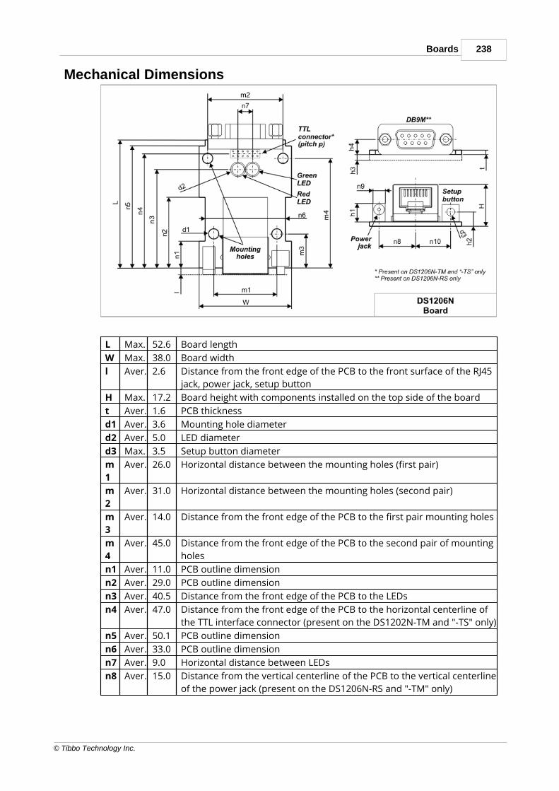
238Boards
© Tibbo Technology Inc.
Mechanical Dimensions
L Max. 52.6 Board length
W Max. 38.0 Board width
l Aver. 2.6 Distance from the front edge of the PCB to the front surface of the RJ45
jack, power jack, setup button
H Max. 17.2 Board height with components installed on the top side of the board
t Aver. 1.6 PCB thickness
d1 Aver. 3.6 Mounting hole diameter
d2 Aver. 5.0 LED diameter
d3 Max. 3.5 Setup button diameter
m
1
Aver. 26.0 Horizontal distance between the mounting holes (first pair)
m
2
Aver. 31.0 Horizontal distance between the mounting holes (second pair)
m
3
Aver. 14.0 Distance from the front edge of the PCB to the first pair mounting holes
m
4
Aver. 45.0 Distance from the front edge of the PCB to the second pair of mounting
holes
n1 Aver. 11.0 PCB outline dimension
n2 Aver. 29.0 PCB outline dimension
n3 Aver. 40.5 Distance from the front edge of the PCB to the LEDs
n4 Aver. 47.0 Distance from the front edge of the PCB to the horizontal centerline of
the TTL interface connector (present on the DS1202N-TM and "-TS" only)
n5 Aver. 50.1 PCB outline dimension
n6 Aver. 33.0 PCB outline dimension
n7 Aver. 9.0 Horizontal distance between LEDs
n8 Aver. 15.0 Distance from the vertical centerline of the PCB to the vertical centerline
of the power jack (present on the DS1206N-RS and "-TM" only)

239 Programmable Hardware Manual (PHM)
© Tibbo Technology Inc.
n9 Max. 5.1 Power jack width (the power jack is present on the EM1206N-RS and "-
TM" only)
n1
0
Aver. 14.5 Distance from the vertical centerline of the PCB to the vertical centerline
of the setup button
h1 Max. 7.5 Power jack height (the power jack is present on the DS1206N-RS and "-
TM" only)
h2 Aver. 5.5 Distance from the bottom surface of the PCB to the center of the setup
button
h3 Max. 2.5 Height of the tallest component on the bottom side of the PCB
h4 Aver. 6.2 Distance from the bottom surface of the PCB to the centerline of the
DB9M connector (present on the DS1206N-RS only)
p Aver. 2.0 TTL pin header pin pitch (present on the DS1206N-TM and "-TS" only)
Dimensions are for reference only. Tibbo assumes no responsibility for any errors inthis Manual, and does not make any commitment to update the informationcontained herein.
Ordering Info and SpecificationsDevice numbering scheme is as follows:
All DS1206B boards are equipped with 1024KBytes of flash memory.
· "RS" version: "true" RS232 port on the DB9M connector, power jack and "12V"-to-3.3V power regulator, optional "12V" power on pin 9 of the DB9M (software-controllable).
· "TM" version: TTL serial port on the pin header connector, power jack and "12V"-to-3.3V power regulator.
· "TS" version: TTL serial port on the pin header connector, direct 3.3V powerinput.
"TM" and "TS" versions are not standard and cannot be ordered from our onlinestore. Contact Tibbo if you wish to order DS1206B devices in "TM" or "TS"configurations.
Examples of valid model numbers
Model number Description
DS1206N-RS DS1206N device with 1024KBytes of flash memory, "-RS"
version

240Boards
© Tibbo Technology Inc.
DS1206N-TM DS1206N device with 1024KBytes of flash memory, "-TM"
version
Hardware specifications
Ethernet interface 10/100BaseT Ethernet, Auto-MDIX
Serial ports One serial port with 3.5 serial channels (fourinputs and three outputs), optional "12V" poweroutput on pin 9
DS1206N-...-RS: RS232 port on the DB9Mconnector
DS1206N-...-TM, DS1206N-...-TS: TTL serial porton the pin header connector
UART capabilities Baudrates up to 921'600bps;none/even/odd/mark/space parity and 7/8bits/character.
Clock frequency 11.0592MHz with PLL off
88.4736MHz with PLL on
Flash memory 512KBytes or 1024KBytes, entire memory minus64KB is available to store Tibbo BASIC/Capplication and data.
Typical write endurance is 100'000 write cycles per256-byte sector. See the warning in Flash andEEPROM Memory.
EEPROM memory 2048 bytes, 2020 bytes available to storeapplication data.
Typical write endurance is around 1'000'000 writecycles per 16-byte EEPROM sector. See Prolongingand Estimating EEPROM life.
Supply voltage range DS1206N-...-RS, DS1206N-...-TM: DC 10-24V(12V nominal)
DS1206N-...-TS: DC 3.3V (+/- 5%)
Operating temperature -5 to +70 degrees C
Operating relativehumidity
10-90%
Board dimensions 52.6x38.0mm
All specifications are subject to change without notice and are for reference only.Tibbo assumes no responsibility for any errors in this Manual, and does not makeany commitment to update the information contained herein.
Think the above table should contain additional data? Do not just assume that youknow the answer — talk to Tibbo! Remember that the ultimate responsibility for alldecisions you make regarding the use and the mode of use of Tibbo products lieswith you, our Customer.

241 Programmable Hardware Manual (PHM)
© Tibbo Technology Inc.
EM1202EV
Introduction
The EM1202EV is a BASIC-programmable board designed primarily for serial-over-IP and serial control applications. Being small enough to fit inside your product, theboard offers a rapid development alternative to using modules, which requiremaking new host PCB. The EM1202EV can also be used to evaluate and test theEM1202 module it is based on.
The EM1202EV features a multi-channel serial port. The board has a single serialport connector and is priced as a single-port product, yet it packs four independentserial channels. Have no use for those DSR and DTR lines? Turn them into RX andTX of an additional serial channel. Don't want CTS and RTS either? That's one morechannel! In total, there are 15 different configurations to choose from.
The board is supplied in three versions offering various serial port and poweroptions (see below).
The EM1202EV is fully supported by TIDE software and a dedicated DS1202platform that covers all hardware facilities of the board (see TIDE, TiOS, TibboBASIC, and Tibbo C Manual). The EM1202 platform can be used with the board aswell. This product ships preloaded with a fully functional serial-over-IP application.Written in Tibbo BASIC/C, the application is compatible with Tibbo Device ServerToolkit software, comes with full source codes, and can be modified by the user.
Available models
The board is supplied in three modifications.
The EM1202EV-RS is, essentially, a DS1202 device without its housing. The boardhas a proper RS232 port (RS232 transceiver IC and DB9M connector), a power jackand a power regulator ("12V"-to-3.3V), a pair of status LEDs on top of the board,and a setup button.
The EM1202EV-TM is different from the "-RS" version in that it has a TTL serial portand no status LEDs on top of the board. The port is accessible through a 12-pinconnector on the PCB. The power regulator of the board can be used to supply 3.3Vpower to the attached serial device as well.
Finally, the DS1206N-TS is like the "-TM" version but has no power jack and no"12V"-to-3.3V power regulator. Instead, an attached serial device is supposed toprovide stabilized 3.3V power to the board.

242Boards
© Tibbo Technology Inc.
Available models and their features EM1202EV-RS
(RS232)
EM1202EV-TM
(TTLmaster)
EM1202EV-TS
(TTL slave)
Setup button YES
Status LEDs (on top of the board) YES NO
RS232 transceiver & DB9Mconnector
YES NO
TTL interface connector NO YES
Power jack and "12V"-to-3.3Vregulator
YES NO
Hardware features
· Based on the EM1202 BASIC-programmable embedded module.
· Powered by Tibbo OS (TiOS).
· 10/100BaseT auto-MDIX Ethernet port (automatic detection of "straight" and"cross" cables).
· Up to 3.5 serial channels:
o EM1202EV-RS: RS232 port (DB9M connector);
o EM1202EV-TM and "-TS": TTL serial port (pin header);
o Baudrates of up to 921,600bps;
o None/even/odd/mark/space parity modes;
o 7/8 bits/character modes;
o Full-duplex mode with optional flow control;
o EM1202EV-TM and "-TS": half-duplex mode with direction control;
o Flexible mapping with 15 different options, such as:
§ A single channel: RX, TX, CTS, RTS, DSR, and DTR lines;
§ 3.5 channels: RX, TX, RX2, TX2, RX3, TX3, and RX4 lines.
· 1024KB flash memory for firmware, application, and data storage.
· 2KB EEPROM for data storage.
· Up to six LEDs:
o EM12-2EV-RS: Green and red status LEDs on top of the device;
o Green and red status LEDs on the RJ45 jack;
o Link and speed Ethernet status LEDs on the RJ45 jack.
· Software-controlled onboard PLL to select the clock frequency of the device:11.0592MHz with PLL off, 88.4736MHz with PLL on.
· Power:
o EM1202EV-RS and "-TM": onboard regulator, 10-24V input range;
o EM1202EV-TS: direct 3.3V input (must be regulated to +/- 5%).
· Board dimensions: 52.6x38.0mm.

243 Programmable Hardware Manual (PHM)
© Tibbo Technology Inc.
· Firmware and Tibbo BASIC/C application are upgradeable through the serial portor network.
· Tibbo BASIC/C application can be debugged through the network and noadditional debugging hardware, such as in-circuit emulator, is required.
· Also available as a DS1202 (EM1202EV-RS board with housing).
Programming features
· Variable Types: Byte, char, integer (word), short, dword, long, real, string, plusser-defined arrays and structures.
· Function Groups: string functions (27 in total!), date/time conversion functions(8), encryption/hash calculation functions (AES128, RC4, MD5, SHA-1), andmore.
· Platform objects:
o sock — socket communications (up to 16 UDP, TCP, and HTTP sessions);
o net — controls the Ethernet port;
o ser — in charge of serial channels;
o io — handles I/O lines, ports, and interrupts;
o fd — manages flash memory file system and direct sector access;
o stor — provides access to the EEPROM;
o romfile — facilitates access to resource files (fixed data);
o pat — "plays" patterns on green and red status LEDs;
o button — monitors the setup button;
o sys — in charge of general device functionality.
EM1202EV Hardware
Click on one of the links provided below to learn more about the EM1202EV:
· Power arrangement
· Ethernet port
· Multi-channel Serial Port

244Boards
© Tibbo Technology Inc.
· Flash and EEPROM Memory
· Status LEDs
· Setup button
5.5.1.1Power ArrangementThe EM1202EV-RS and "-TM" devices have "12V"-to-3.3V switching regulatoronboard. The power is supplied through the power jack. The power jack of theEM1202EV accepts "small" power connectors with 3.5mm diameter. Use APR-P0011, APR-P0012, or APR-P0013 power adapter supplied by Tibbo or similaradapter with 12V nominal output voltage. Adapter current rating should be at least500mA. On the power jack, the ground is "on the outside", as shown on the figurebelow.
Stabilized 3.3V power used by the EM1202EV-RS and "-TM" is also available on pin12 of the TTL interface connector. This can be used to provide power to an attachedserial device.
The EM1202EV-TS board does not have "12V"-to-3.3V regulator at all. 3.3V powerrequired for board operation must be supplied by the external device through pin12 of the TTL interface connector.
5.5.1.2Ethernet Port
Ethernet port of the EM1202EV is of 10/100BaseT type.
Connector is of RJ45 type, pin assignment is as follows:
#1 TX+
#2 TX-
#3 RX+
#4 <No connection>
#5 <No connection>
#6 RX-

245 Programmable Hardware Manual (PHM)
© Tibbo Technology Inc.
#7 <No connection>
#8 <No connection>
The Ethernet port of the EM1202EV incorporates four LEDs (two status LEDs andtwo Ethernet status LEDs). The EM1202EV-RS has another pair of status LEDslocated on top of the board. Two status LED pairs work in parallel.
5.5.1.3Multi-channel Serial PortThe EM1202EV has four serial ports internally. The EM1202EV-RS has an RS232port with DB9M connector, while "-TM" and "-TS" devices have TTL serial portavailable through a TTL interface connector, which is a standard pin header with2mm pitch.
The EM1202EV implements three outputs, four inputs, and one "spare" input (CD).Each of the three outputs can be used as a TX line of a serial channel, or as acontrol output such as RTS or DTR. Input lines can be used as an RX line of a serialchannel, or as a control input such as CTS or DSR. The spare input cannot work asan RX line. This input is not used by the serial-over-IP application supplied byTibbo and will be largely omitted from further discussion. Your Tibbo BASIC/Capplication can always use this extra input if you require it.
With three outputs and four inputs, the EM1202EV can be said to offer 3.5 serial"channels". We say "3.5 channels" and not "four channels" because one channelwill only have RX line and no TX line (remember, there are four inputs but onlythree outputs).
DB9M connector pin assignment:
Pin Name EM1202EV-RS
#1 CD Spare input*
#2-4, 6-9 Lines of the RS232 port, see mapping table below
#5 GND Ground
*Not used in Tibbo serial-over-IP application. Your Tibbo BASIC/C program can usethis line if needed.
TTL interface connector pin assignment:

246Boards
© Tibbo Technology Inc.
Pin Name EM1202EV-TM EM1202EV-TS
#1 CD Spare input*
#2-8 Lines of TTL serial port, see mapping table below
#9 MD Setup line input, active low, use open collector driving circuit
#10 RST Reset input, active low, use open collector driving circuit
#11 GND Ground
#12 3.3V Output to external device Input from external device
*Not used in Tibbo serial-over-IP application. Your Tibbo BASIC/C program can usethis line if needed.
Serial-over-IP application offered by Tibbo defines 15 "mapping options", or waysin which available I/O lines are utilized ("spare" input is not used or shown). Theseare presented in the table below:
Mappingoption
Available signals Pins on the DB9M connector of theEM1202EV-RS
Missing
line#2
#3 #8 #7 #6 #4 #9
Option 0
RX/TX/CTS/RTS/DSR/DTR
RX
TX CTS
RTS
DSR
DTR
--- ---
Option 1
RX/TX/CTS/RTS/DSR/DTR + RX/tx
RX
TX CTS
RTS
DSR
DTR
RX4
tx4
Option 2
RX/TX/CTS/RTS +RX/TX + RX/tx
RX
TX CTS
RTS
RX3
TX3
RX4
tx4
Option 3
RX/TX/CTS/RTS +RX/TX/CTS/rts
RX
TX CTS
RTS
RX3
TX3
CTS3
rts3
Option 4
RX/TX/CTS/RTS +RX/TX/DSR/dtr
RX
TX CTS
RTS
RX3
TX3
DSR3
dtr3
Option 5
RX/TX/DSR/DTR +RX/TX + RX/tx
RX
TX RX2
TX2
DSR
DTR
RX4
tx4
Option 6
RX/TX/DSR/DTR +RX/TX/CTS/rts
RX
TX RX2
TX2
DSR
DTR
CTS2
rts2
Option 7
RX/TX/DSR/DTR +RX/TX/DSR/dtr
RX
TX RX2
TX2
DSR
DTR
DSR2
dtr2
Option 8
RX/TX + RX/TX +RX/TX + RX/tx
RX
TX RX2
TX2
RX3
TX3
RX4
tx4
Option 9
RX/TX/CTS/rts +RX/TX + RX/TX
RX
TX RX2
TX2
RX3
TX3
CTS
rts
Option 10
RX/TX/DSR/dtr +RX/TX + RX/TX
RX
TX RX2
TX2
RX3
TX3
DSR
dtr
Option 11
RX/TX/CTS/RTS +RX/tx/CTS/RTS
RX
TX CTS
RTS
CTS4
RTS4
RX4
tx4
Option 12
RX/TX/CTS/RTS +RX/tx/DSR/DTR
RX
TX CTS
RTS
DSR4
DTR4
RX4
tx4
Option 13
RX/TX/DSR/DTR +RX/tx/CTS/RTS
RX
TX CTS4
RTS4
DSR
DTR
RX4
tx4

247 Programmable Hardware Manual (PHM)
© Tibbo Technology Inc.
Option 14
RX/TX/DSR/DTR +RX/tx/DSR/DTR
RX
TX DSR4
DTR4
DSR
DTR
RX4
tx4
Mappingoption
Available signals #6
#5 #4 #3 #7 #8 #1 Missing
linePins on the TTL connector of theEM1202EV-TM and "-TS"
"Available signals" column shows a particular combination of I/O lines for eachoption. For example, option 0 defines the standard serial port arrangement withRX, TX, CTS, RTS, DSR, and DTR lines. Option 2 gives you one channel with RX,TX, CTS, and RTS lines, one more channel with just RX and TX lines, and yetanother channel with a single RX line. The TX line is "missing" because, once again,there are only three outputs available. This is why this line is shown in greylowercase (tx).
Additional Information on Serial Port LinesThis topic contains information related to programming of the EM1202EV. Itassumes that you are familiar with Tibbo BASIC/C and the concept of "platforms".Everything you need to know regarding this can be found in TIDE, TiOS, TibboBASIC, and Tibbo C Manual.
You can create Tibbo BASIC/C applications for the EM1202EV using two differentplatforms — the "DS1202" platform and "EM1202" platform. The DS1202 platformcan be used because the EM1202EV is, essentially, a DS1202 device without theplastic housing. The EM1202 platform can be used because the board is based onthe EM1202 module.
Generally speaking, the EM1202 platform offers "more". It addresses everyhardware faculty of the EM1202. The DS1202 platform is much more limited andonly includes features that can be used when the EM1202 module is mounted onthe EM1202EV board (inside the DS1202 device).
The biggest difference between the two platforms is in how the I/O lines are wired.The EM1202 platform defines 32 I/O lines. Half of these are not used on theEM1202EV, and the remaining lines are interconnected. Each line of the serial port(save for the "spare" line discussed previously) is connected to two GPIO lines ofthe EM1202. This was done to ensure more flexible mapping (see Multi-ChannelSerial Port). Care should be taken to avoid enabling both outputs of the same serialport line simultaneously! This can permanently damage the EM1202. We suggestthat you use GPIO8/P1.0/RX0 - GPIO14/P1.6/RX3 for actual input/output and useGPIO16/P2.0/INT0 - GPIO19/P2.3/INT3 as interrupt inputs only.
The DS1202 platform "looks" at the same hardware differently and defines fewerI/O lines. Each of the physical line pair is represented by a single GPIO line. GPIOlines of the EM1202 that are unused are not defined at all.
GPIO lines of the EM1202platform — two lines areconnected to each serial portline, except in the case of the"spare" input
GPIO lines of theDS1202 platform
DB9M pinand itsconventionalfunction ("-RS")
TTLconnectorpin ("-TS","-TM")
GPIO8/P1.0/RX0
GPIO16/P2.0/INT0
PL_IO_NUM_0_RX0_INT0
#2 (RXinput)
#6

248Boards
© Tibbo Technology Inc.
GPIO9/P1.1/TX0
GPIO20/P2.4/INT4
PL_IO_NUM_1_TX0_INT4
#3 (TXoutput)
#5
GPIO10/P1.2/RX1
GPIO17/P2.1/INT1
PL_IO_NUM_2_RX1_INT1
#8 (CTSinput)
#4
GPIO11/P1.3/TX1
GPIO21/P2.5/INT5
PL_IO_NUM_3_TX1_INT5
#7 (RTSoutput)
#3
GPIO12/P1.4/RX2
GPIO18/P2.2/INT2
PL_IO_NUM_4_RX2_INT2
#6 (DSRinput)
#7
GPIO13/P1.5/TX2
GPIO22/P2.6/INT6
PL_IO_NUM_5_TX2_INT6
#4 (DTRoutput)
#8
GPIO14/P1.6/RX3
GPIO19/P2.3/INT3
PL_IO_NUM_6_RX3_INT3
#9 (RIinput)
#2
--- GPIO23/P2.7/INT7*
PL_IO_NUM_7_INT7
#1 (CDinput)*
#1*
* Spare input (see above).
5.5.1.4Flash and EEPROM MemoryThe EM1202EV has 1024KBytes of flash memory and 2KBytes of EEPROM memory.
The first 64KBytes of flash memory are used to store the TiOS firmware. When youare performing a firmware upgrade it is this memory you are saving the firmwarebinary into.
The rest of this flash memory is available to your Tibbo BASIC/C application and itsdata. Whatever memory space is left after the compiled application is loaded canbe used as a flash disk (see fd. object documentation in the TIDE, TiOS, TibboBASIC, and Tibbo C Manual).
The EEPROM is almost fully available to your application, save for a small2 8-bytearea called "special configuration area". The EEPROM is accessed through the stor.object (see TIDE, TiOS, Tibbo BASIC, and Tibbo C Manual). Details on the specialconfiguration area are provided in the Platform-dependent ProgrammingInformation section inside the EM1202 and DS1202 platform documentation (samemanual).
On the advice of one of our customers we are giving you the followingreminder: Like all other EEPROMs on the market, EEPROM ICs used in Tibbodevices allow for a limited number of write cycles. As the Wikipedia article
on EEPROMs (https://en.wikipedia.org/wiki/EEPROM) states, the EEPROM "...has alimited life for erasing and reprogramming, now reaching a million operations inmodern EEPROMs. In an EEPROM that is frequently reprogrammed while thecomputer is in use, the life of the EEPROM is an important design consideration."When planning to use the stor. object, please carefully consider if the plannedmode of EEPROM use will allow the EEPROM to work reliably through the entireprojected life of your product. For more information see Prolonging and EstimatingEEPROM Life.
Like all other flash memory devices on the market, flash ICs used in Tibbo productsonly allow for a limited number of write cycles. As the Wikipedia article on flashmemory (https://en.wikipedia.org/wiki/Flash_memory) explains, modern flash ICsstill suffer from comparatively low write endurance. In Tibbo devices, thisendurance is around 100'000 write cycles per sector. When you are using the flashmemory for file storage, the fd. object employs sector wear leveling to maximizethe life of the flash IC (but the life still remains limited). If your application

249 Programmable Hardware Manual (PHM)
© Tibbo Technology Inc.
employs direct sector access, then it is your job to plan the application around thelife limitations of the flash memory. For data that changes often, consider using theEEPROM memory instead. EEPROMs have much better endurance.
Mechanical Dimensions
L Ma
x.
52.
6
Board length
W Ma
x.
38.
0
Board width
l Av
er.
2.6 Distance from the front edge of the PCB to the front surface of the RJ45
jack, power jack, setup button
H Ma
x.
17.
2
Board height with components installed on the top side of the board
t Av
er.
1.6 PCB thickness
d1 Av
er.
3.6 Mounting hole diameter
d2 Av
er.
5.0 LED diameter (these LEDs are present on the EM1202EV-RS only)
d3 Ma
x.
3.5 Setup button diameter
m1 Av
er.
26.
0
Horizontal distance between the mounting holes (first pair)
m2 Av
er.
31.
0
Horizontal distance between the mounting holes (second pair)
m3 Av
er.
14.
0
Distance from the front edge of the PCB to the first pair mounting holes

250Boards
© Tibbo Technology Inc.
m4 Av
er.
45.
0
Distance from the front edge of the PCB to the second pair of mounting
holes
n1 Av
er.
11.
0
PCB outline dimension
n2 Av
er.
29.
0
PCB outline dimension
n3 Av
er.
40.
5
Distance from the front edge of the PCB to the LEDs (present on the
EM1202EV-RS only)
n4 Av
er.
47.
0
Distance from the front edge of the PCB to the horizontal centerline of the
TTL interface connector (present on the EM1202EV-TM and "-TS" only)
n5 Av
er.
50.
1
PCB outline dimension
n6 Av
er.
33.
0
PCB outline dimension
n7 Av
er.
9.0 Horizontal distance between LEDs (present on the EM1202EV-RS only)
n8 Av
er.
15.
0
Distance from the vertical centerline of the PCB to the vertical centerline of
the power jack (present on the EM1202EV-RS and "-TM" only)
n9 Ma
x.
5.1 Power jack width (the power jack is present on the EM1202EV-RS and "-TM"
only)
n1
0
Av
er.
14.
5
Distance from the vertical centerline of the PCB to the vertical centerline of
the setup button
h1 Ma
x.
7.5 Power jack height (the power jack is present on the EM1202EV-RS and "-TM"
only)
h2 Av
er.
5.5 Distance from the bottom surface of the PCB to the center of the setup
button
h3 Ma
x.
2.5 Height of the tallest component on the bottom side of the PCB
h4 Av
er.
6.2 Distance from the bottom surface of the PCB to the centerline of the DB9M
connector (present on the EM1202EV-RS only)
p Av
er.
2.0 TTL connector pin pitch (connector present on the EM1202EV-TM and "-TS"
only)
Dimensions are for reference only. Tibbo assumes no responsibility for any errors inthis Manual, and does not make any commitment to update the informationcontained herein.
Ordering Info and SpecificationsDevice numbering scheme is as follows:
· All EM1202EV boards are equipped with 1024KBytes of flash memory.

251 Programmable Hardware Manual (PHM)
© Tibbo Technology Inc.
· "RS" version: "true" RS232 port on the DB9M connector, power jack and "12V"-to-3.3V power regulator.
· "TM" version: TTL serial port on the pin header connector, power jack and "12V"-to-3.3V power regulator.
· "TS" version: TTL serial port on the pin header connector, direct 3.3V powerinput.
"TM" and "TS" versions are not standard and cannot be ordered from our onlinestore. Contact Tibbo if you wish to order DS1206B devices in "TM" or "TS"configurations.
Examples of valid model numbers
Model number Description
EM1202EV-RS EM1202EV device with 1024KBytes of flash memory, "-RS"
version
EM1202EV-TM EM1202EV device with 1024KBytes of flash memory, "-
TM" version
Hardware specifications
Ethernet interface 10/100BaseT Ethernet, Auto-MDIX, magnetics notbuilt-in
Serial ports One serial port with 3.5 serial channels (four inputsand three outputs)
DS1206N-...-RS: RS232 port on the DB9M connector
DS1206N-...-TM, DS1206N-...-TS: TTL serial port onthe pin header connector
UART capabilities Baudrates up to 921'600bps;
none/even/odd/mark/space parity and 7/8bits/character.
Clock frequency 11.0592MHz with PLL off
88.4736MHz with PLL on
Flash memory 1024KBytes, entire memory minus 64KB is availableto store Tibbo BASIC/C application and data.
Typical write endurance is 100'000 write cycles per256-byte sector. See the warning in Flash andEEPROM Memory.
EEPROM memory 2048 bytes, 2020 bytes available to store applicationdata.
Typical write endurance is around 1'000'000 writecycles per 16-byte EEPROM sector. See Prolongingand Estimating EEPROM life.
Supply voltage range DS1206N-...-RS, DS1206N-...-TM: DC 10-24V (12Vnominal)
DS1206N-...-TS: DC 3.3V (+/- 5%)

252Boards
© Tibbo Technology Inc.
Operating temperature -5 to +70 degrees C
Operating relativehumidity
10-90%
Board dimensions 52.6x38.0mm
All specifications are subject to change without notice and are for reference only.Tibbo assumes no responsibility for any errors in this Manual, and does not makeany commitment to update the information contained herein.
Think the above table should contain additional data? Do not just assume that youknow the answer — talk to Tibbo! Remember that the ultimate responsibility for alldecisions you make regarding the use and the mode of use of Tibbo products lieswith you, our Customer.
EM1206EV
The EM1206EV Evaluation Board offers a convenient way to test the EM1206BASIC/C-programmable Ethernet module.
The board features the following components:
· The EM1206 and RJ203 modules (assembled together and soldered into theEM1206EV board).
· Connector for a wireless add-on module, such as the WA2000 Wi-Fi device(purchased separately).
· Power jack and a switching power regulator.
· Multi-channel RS232 port with three RS232 outputs and four RS232 inputs.
· Expansion connector with GND, 3.3V (Vcc), 12V (Vin), and 8 TTL I/O lines.
· Eight yellow LEDs to indicate the status of I/O lines (see RS232 port andExpansion Connector topic).

253 Programmable Hardware Manual (PHM)
© Tibbo Technology Inc.
· Four jumpers to select between RS232 port and expansion connector (see RS232port and Expansion Connector topic).
· Two buttons: setup (connected to the MD line of the EM1206), and reset(connected to the RST line).
· Green and red status LEDs (connected to SG and SR lines of the EM1206).Further information on status LEDs can be found in Status LEDs.
· Buzzer (connected to the CO line of the EM1206).
· Supercapacitor (backup power source) for the RTC of the EM1206.
Board structure is further illustrated by this block diagram:
Wireless Add-on ConnectorThis connector is used to plug in an optional wireless add-on, such as the WA2000Wi-Fi add-on, as well as other add-on modules that may be released by Tibbo inthe future.
The connector has 10 pins, as shown on the drawing below. Apart from the groundand Vcc (3.3V) lines, there are eight I/O lines that are connected directly to port 1(GPIO lines 8-15) of the EM1206.

254Boards
© Tibbo Technology Inc.
Pin EM1206 line WA2000 line
#1 GND GND
#2 Vcc (3.3V) Vcc (3.3V)
#3 GPIO15/P1.7 CS
#4 GPIO10/P1.2 ---
#5 GPIO13/P1.5 DO
#6 GPIO9/P1.1 ---
#7 GPIO11/P1.3 RST
#8 GPIO8/P1.0 ---
#9 GPIO12/P1.4 DI
#10 GPIO14/P1.6 CLK
It should be noted that GPIO lines 8-15 can be used for any desired I/O purpose,not just to control a wireless add-on board. You can use this connector for yourown control purposes.
Main and Backup PowerThe power jack of the EM1206EV accepts "small" power connectors, 3.5mm indiameter. Use APR-P0011, APR-P0012, or APR-P0013 power adapter supplied byTibbo or a similar adapter with 12V nominal output voltage. Adapter current ratingshould be at least 500mA. On the power jack, the ground is "on the outside", asshown on the figure below.
Alternatively, you can power the board through the Vin line on the expansionconnector. Two onboard diodes combine power jack and Vin inputs into a singleline, which goes to the switching regulator. Clean 3.3V output produced by theregulator is used to power the EM1206EV board itself, the EM1206 module, andoptionally an add-on board plugged into the wireless add-on connector. This 3.3Vpower is available on the expansion connector as well.
The following drawing illustrates this power arrangement:

255 Programmable Hardware Manual (PHM)
© Tibbo Technology Inc.
The EM1206 module features an RTC and a dedicated VCCB input for providingbackup power when the EM1206EV is off. On the EM1206EV, the backup powercomes from a supercapacitor located on the bottom side of the board. Thesupercapacitor charges almost instantly and, in the absence of main power,supports the RTC for about a week.
Notice that the supercapacitor is not connected to the Vcc line directly. TheVCCB pin "expects" the backup power to have a nominal voltage of 2.5V.See the Real-time Counter topic of the EM1206 manual for details.
Multi-channel RS232 Port and Expansion ConnectorThe EM1206 module has four serial ports (four pairs of RX and TX lines). Each ofthose lines can also be used as general-purpose I/O. Hence, each line can serve asa CTS, RTS, DSR, or DTR line; or play another role which is unrelated to thefunction of the serial port.
The I/O lines of the EM1206 module are bi-directional: each line can beprogrammed to work as an output or input line. On the RS232 port of theEM1206EV, however, each line has a fixed direction defined by the RS232transceiver IC. The IC used on the EM1206EV board implements three outputs andfour inputs. Therefore, only seven I/O lines of the EM1206 are connected to theRS232 port of the EM1206EV board.

256Boards
© Tibbo Technology Inc.
Out of these seven lines, each of the three outputs can be used as a TX line of aserial port, or as a control output such as RTS, DTR, etc. Each of the four inputlines can be used as an RX line of a serial port, or as a control input such as CTS,DSR, CD, etc. It can be said that the RS232 port of the EM1206EV offers 3.5 serial"channels". We say "3.5 channels" and not "four channels" because one channelwill only have RX line and no TX line (remember, there are four inputs but onlythree outputs).
Note that all four inputs of the serial port are connected to the EM1206 modulethrough jumpers. Jumpers are necessary to select between the RS232 port inputsand expansion connector terminals. Putting a jumper "up" selects an input from theRS232 transceiver, putting a jumper "down" selects an expansion connector line.
All eight lines are available on the expansion connector as TTL signals. When theexpansion connector is used, any of these eight lines can be used as an input oroutput.
You can conveniently see the state of I/O lines on a bank of yellow LEDs. An LED isON when a corresponding TTL line is HIGH. Notice that the RS232 transceiver ICinverts the signal on each line. For example, if the GPIO1/P0.1/TX/INT1 pin of theEM1206 is HIGH then the TX pin on the DB9M collector is LOW.
For more information on serial ports and I/O lines of the EM1206 see ser. and io.object manuals (TIDE, TiOS, Tibbo BASIC, and Tibbo C Manual).
Serial-over-IP application offered by Tibbo defines 15 "mapping options", or waysto utilize the available I/O lines. These are presented in the table below:
Mappingoption
Available signals Pins on the DB9M connector Missing
line#2
#3 #8 #7 #6 #4 #1
Option 0
RX/TX/CTS/RTS/DSR/DTR
RX
TX CTS
RTS
DSR
DTR
--- ---
Option 1
RX/TX/CTS/RTS/DSR/DTR + RX/tx
RX
TX CTS
RTS
DSR
DTR
RX4
tx4

257 Programmable Hardware Manual (PHM)
© Tibbo Technology Inc.
Option 2
RX/TX/CTS/RTS +RX/TX + RX/tx
RX
TX CTS
RTS
RX3
TX3
RX4
tx4
Option 3
RX/TX/CTS/RTS +RX/TX/CTS/rts
RX
TX CTS
RTS
RX3
TX3
CTS3
rts3
Option 4
RX/TX/CTS/RTS +RX/TX/DSR/dtr
RX
TX CTS
RTS
RX3
TX3
DSR3
dtr3
Option 5
RX/TX/DSR/DTR +RX/TX + RX/tx
RX
TX RX2
TX2
DSR
DTR
RX4
tx4
Option 6
RX/TX/DSR/DTR +RX/TX/CTS/rts
RX
TX RX2
TX2
DSR
DTR
CTS2
rts2
Option 7
RX/TX/DSR/DTR +RX/TX/DSR/dtr
RX
TX RX2
TX2
DSR
DTR
DSR2
dtr2
Option 8
RX/TX + RX/TX +RX/TX + RX/tx
RX
TX RX2
TX2
RX3
TX3
RX4
tx4
Option 9
RX/TX/CTS/rts +RX/TX + RX/TX
RX
TX RX2
TX2
RX3
TX3
CTS
rts
Option 10
RX/TX/DSR/dtr +RX/TX + RX/TX
RX
TX RX2
TX2
RX3
TX3
DSR
dtr
Option 11
RX/TX/CTS/RTS +RX/tx/CTS/RTS
RX
TX CTS
RTS
CTS4
RTS4
RX4
tx4
Option 12
RX/TX/CTS/RTS +RX/tx/DSR/DTR
RX
TX CTS
RTS
DSR4
DTR4
RX4
tx4
Option 13
RX/TX/DSR/DTR +RX/tx/CTS/RTS
RX
TX CTS4
RTS4
DSR
DTR
RX4
tx4
Option 14
RX/TX/DSR/DTR +RX/tx/DSR/DTR
RX
TX DSR4
DTR4
DSR
DTR
RX4
tx4
Mappingoption
Available signals RX
TX RX2/
CTS
TX2/
RTS
RX3/
DSR
TX3/
DTR
RX4
TX4
Terminal blocks of the expansion connector(as marked on the EM1206EV)
"Available signals" column shows a particular combination of I/O lines for eachoption. For example, option 0 defines the standard serial port arrangement withRX, TX, CTS, RTS, DSR, and DTR lines. Option 2 gives you one channel with RX,TX, CTS, and RTS lines, one more channel with just RX and TX lines, and yetanother channel with a single RX line. The TX line is "missing" because, once again,there are only three outputs available on the RS232 port. This is why this line isshown in grey lowercase (tx). This line, of course, is present and available on theexpansion connector.

258Boards
© Tibbo Technology Inc.
EM120/EM200EV
The EM120/200-EV Evaluation Board offers a convenient way of testing the EM120(which is no longer supported as a programmable device) and EM200 embeddedmodules. The board features the following components:
· A socket for EM120 or EM200 installation
· Power jack and a switching power regulator (12VDC-->5VDC, adapter currentrating must be no less than 500mA)
· RJ45 connector and 10/100BaseT Ethernet Magnetics (EM120 and EM200 do nothave built-in magnetics)
· DB9M RS232 connector and RS232 transceiver (supported signals are RX, TX,RTS, CTS, DTR, DSR)
· Setup button (connected to the MD line of EM120/EM200)
· Two Ethernet LEDs and two status LEDs (connected to LED lines of EM120/200).Further information on status LEDs can be found in Status LEDs.
· Five additional LEDs connected to lines P0, P1, P6-8 of the EM120/EM200
· 15-pin expansion connector provides access to EM120/EM200's serial andgeneral-purpose I/O pins (therefore, all I/O lines on this connector are of TTLtype)
Power Jack
Power Jack of the EM120/EM200-EV accepts "large" power connectors with 5.5mmdiameter. Use APR-1014, APR-1015A, or APR-1018A power adapter supplied byTibbo or similar adapter with 12V nominal output voltage. Adapter current ratingshould be at least 500mA. On the power jack, the ground is "on the outside", asshown on the figure below.

259 Programmable Hardware Manual (PHM)
© Tibbo Technology Inc.
Ethernet Port Pin Assignment
RJ45 Ethernet connector has the following pin assignment:
#1 TX+
#2 TX-
#3 RX+
#4 <No connection>
#5 <No connection>
#6 RX-
#7 <No connection>
#8 <No connection>
RS232 Port Pin Assignment
DB9M RS232 connector has the following pin assignment:
#1 <No connection>
#2 RX (input)
#3 TX (output)
#4 DTR (output)
#5 Ground
#6 DSR (input)
#7 RTS (output)
#8 CTS (input)
#9 <No connection>

260Boards
© Tibbo Technology Inc.
Expansion Connector Pin Assignment
15-pin expansion connector has the following pin assignment:
P0 Connected to pin P0 of EM120/EM200
P1 Connected to pin P1 of EM120/EM200
P6 Connected to pin P6 of EM120/EM200
P7 Connected to pin P7 of EM120/EM200
P8 Connected to pin P8 of EM120/EM200
GND Ground
VCC +5V from the EM120/EM200-EV board. Available "spare" current about 50mA
RST Reset (active high) from the EM120/EM200-EV board. The signal is generated by
an onboard reset IC. The same signal is applied to pin RST of EM120/EM200
MD Connected to the download/setup button on the EM120/EM200-EV board. The
signal is connected to pin MD of EM120/EM200
DTR Connected to pin P3(DTR) of EM120/EM200
RTS Connected to pin P5(RTS) of EM120/EM200
TX Connected to pin TX of EM120/EM200
RX Connected to pin RX of EM120/EM200
CTS Connected to pin P4(CTS) of EM120/EM200
DSR Connected to pin P2(DSR) of EM120/EM200
Output signals that are present both on the DB9M and expansion connectors (DTR,RTS, TX) need not be switched. So, for example, the TX (output) line from theEM120/EM200 is connected to the RS232 transceiver IC and to the expansionconnector. For input signals (RX, CTS, DSR) there must be a way to disconnect theRS232 transceiver IC from the EM120/EM200. Three jumpers (combined with pinsRX, CTS, DSR of the expansion connector) serve this purpose.
For example, when the RX jumper is closed the RX pin of the EM120/EM200receives a signal from the RS232 transceiver. When the jumper is opened you canuse the RX pin on the expansion connector to supply a TTL RX signal from your ownexternal board. Figure below illustrates this.
Maximum load for all CMOS-type lines (P0, P1, ... RX, TX...) is 10mA.

261 Programmable Hardware Manual (PHM)
© Tibbo Technology Inc.
Development SystemsThe following development systems are currently being offered by Tibbo:
· WM2000EV
· EM2000EV
· EM1000EV
· EM1000TEV
· EM500EV/EM510EV
WM2000EV
The WM2000EV is an evaluation kit designed for evaluating the capabilities of theWM2000 Programmable Wireless IIoT Module. One module is included in the kitand is preloaded with a demonstration app — the first chapter of our guidedjourney of exploration for the WM2000. Also included in the kit are a USB Type-C-to-A cable, a CR2032 button cell battery, and four jumpers installed in their defaultpositions.
The WM2000EV was designed to be completely self-contained and enable theexploration of the module's features without the need to wire in any externalcircuitry. It is equipped with all essential buttons and status LEDs, integrated lightand temperature sensors, an RGB LED controlled by three I/O lines with pulse-width modulation (PWM) output, a backup battery, and the circuitry necessary forenabling the WM2000's low-power "sleep" mode.
The module is connected and secured to the WM2000EV through a unique lock-and-release mechanism consisting of two rows of horizontal spring-loaded pins.This mechanism allows for the effortless removal and insertion of the module and

262Development Systems
© Tibbo Technology Inc.
ensures reliable connections to its pins. Two 12x2 male pin headers are integratedinto the board to facilitate the connection of external components.
The kit is powered either through a two-pin terminal block for 3V-5.5V input or viathe USB Type-C connector, which also allows for the serial debugging of theWM2000.
The jumpers toggle the power source for the module's real-time clock and enable ordisable the low-power mode, as well as allow for measuring current consumption ofthe board and/or module.
In addition to hosting all the primary hardware, the WM2000EV's front platefeatures quick-response (QR) codes linking to CODY, Tibbo's project code wizard,and the L.U.I.S. (Loadable User Interface System) web app. The backplate has"unboxing" instructions and a QR code linking to the Getting Started guide.
Diagrams
This diagram shows the overall layout of the WM2000EV, including the keepoutarea needed to prevent interference with the module's wireless connectivity.

263 Programmable Hardware Manual (PHM)
© Tibbo Technology Inc.
This block diagram illustrates the basic configuration of the evaluation board inrelation to the module.
(Click here to open the image in a new window/tab)
This diagram provides a more detailed look at how the evaluation board'scomponents are wired to a seated WM2000. Lines have been grouped according totheir use and color-coded for easier viewing. The line colors correspond with thoseof the block diagram.
Hardware features
The WM2000EV board incorporates the following components:
· Two horizontal rows of spring-loaded pins hold the WM2000 in place
o The module can be easily popped out and popped back in
· I²C temperature sensor

264Development Systems
© Tibbo Technology Inc.
· I²C light sensor
· A large RGB LED driven by three pulse-width modulation (PMW)-capable lines
· Two buttons:
o MD — Connected to the MD line
o Reset — Connected to the RST (reset) line
· Four status LEDs:
o Green (SG), red (SR), and yellow (SY) main status LEDs
o A blue LED (LPW) indicating if the power is applied to the board
· Jumpers and test points:
o For measuring the current of the WM2000 and the entire board
o For enabling the low-power mode
o For selecting the RTC power source (3.3V or backup battery)
· Two 12x2 male pin headers for connecting to external circuitry
· Kit dimensions (L x W x H): 100 x 120 x 27.5mm
· Tibbo BASIC/C applications can be debugged via Wi-Fi or USB
· A USB Type-C connector for powering the board and serial debugging
· A two-pin terminal block for connecting external 3V–5.5V power*
· A CR2032 backup battery (in a holder)
· External circuitry required to enable the WM2000's low-power mode
· A USB Type-C-to-A cable is included with the kit
* Only needed if power is not applied via the USB port
Getting StartedCongratulations on acquiring the WM2000EV Evaluation Kit!
We have prepared a tutorial consisting of several projects that take you on acurated journey to explore the WM2000's capabilities. All of these projects arecontained in a dedicated Github repository. Each highlights the core features of themodule that make it ideal for Internet of Things (IoT) and industrial automationapplications.
The first of these projects comes preloaded on the module included in yourWM2000EV kit.

265 Programmable Hardware Manual (PHM)
© Tibbo Technology Inc.
Chapter 1 — Keen
Click here for step-by-step instructions
In this project, we will use the L.U.I.S. (Loadable User Interface System) app —available as a web app or on iOS and Android — to connect the module to your Wi-Fi network. Then we will configure it for secure communications to a nonaffiliated,third-party cloud services provider, Keen. In as little as 10 minutes, your modulewill be polling the board's integrated light and temperature sensors andtransmitting the data to Keen.
This project leverages a number of our API components (see the TIDE, TiOS, TibboBASIC, and Tibbo C Manual) to provide a straightforward configuration and userexperience. In particular, our implementation of Transport Layer Security (TLS) —combined with Tibbo's HTTP library — significantly simplifies the securetransmission of data to the cloud.
Chapter 2 — WebPWM
Click here for step-by-step instructions
In the second demonstration, we'll use the L.U.I.S. app to interface with theWM2000's Companion App to configure the device. Then, we'll upload the WebPWMproject into the WM2000 via the Wi-Fi interface.
The WebPWM project is a blueprint for creating cloud-connected lighting controlapplications with the WM2000 module. It uses three PWM channels to control thecolor and brightness of the board's RGB LED. The project demonstrates how easy itis to control the WM2000's PWM channels. It also shows the techniques for creatingmodern web interfaces — the LED can be controlled in real time and without pagereloads. Finally, the project offers a hands-on demonstration of the Companion Appand the dual-application capability of the WM2000 module.
Chapter 3 — Azure
Click here for step-by-step instructions
In the third demonstration, we'll apply the lessons learned in the first two chaptersto connect the WM2000 to Microsoft Azure. One of the leading cloud servicesplatforms, Azure not only aggregates and analyzes data from edge devices, but italso enables you to control IoT solutions from the cloud. In this project, you'll useAzure to trigger the WM2000EV's onboard RGB LED.
As this project possibly requires a firmware update for your device, we provide aTibbo Composite Uncompressed (TCU) file. We'll walk you through upgrading TiOSon the WM2000 through the over-the-air (OTA) Bluetooth Low Energy (BLE) updateprocess. Using TCU files for updates is preferable on the WM2000, as they allowyou to upload not just the firmware, but also up to two compiled Tibbo BASIC/Capplication binaries at the same time.
6.1.1.1WM2000EV Demo #1 — KeenThis chapter will demonstrate how quickly and easily the WM2000 can beconfigured to gather data and send it to the cloud for analysis.

266Development Systems
© Tibbo Technology Inc.
In this chapter, you'll need to copy long strings of text from a website into the
L.U.I.S. (Loadable User Interface System) app. To simplify this process, Tibbo
strongly recommends that you use a single device for the entire tutorial.
This may be either a smartphone (tablet), or a computer equipped with a
Bluetooth 4.0 interface (adapter).
L.U.I.S. is available as a smartphone app for iOS and Android, or as a web app.
Due to the limitations of the Web Bluetooth API, the web app only works in
recent versions of the Chrome, Chromium, Edge or Opera web browsers running
on a Mac or Windows 10 (version 1703 and later) computer equipped with a
Bluetooth 4.0 adapter.
If you haven't already, remove your WM2000EV kit from the packaging, andconnect the included USB Type-C-to-A cable into the device's USB Type-Cconnector and into a powered USB Type-A port.
1. Open your web browser and
navigate to keen.io (this link
opens in a new tab/window). If
you already have an account, log
in. Otherwise, click on Get
Started for Free to create an
account.
2. After logging in or creating an
account, you will be at the Keen
management console. Next to
Projects in the left-hand menu,
click Add New.
If you're on a mobile device, you
may have to first click on
Projects in the menu under the
Organizations drop-down menu to
see the Add New button.

267 Programmable Hardware Manual (PHM)
© Tibbo Technology Inc.
3. Give your project a name (for
example, "WM2000") and click
Add Project.
4. After creating your project, you
will be on the Dashboards page.
In the left-hand menu, click on
Access.
On a mobile device, this button
will be in the menu under the
Projects drop-down box.
5. Open the L.U.I.S. app (click here
to open the web version in a new
tab/window). Pair with your
WM2000EV. A page with several
configurable parameters
(settings) will open.

268Development Systems
© Tibbo Technology Inc.
6. Configure the settings for your
Wi-Fi network.
Keen L.U.I.S.
7. In the Project Details section of
the Access page, locate and
copy the Project ID.
8. Paste the Project ID into the
corresponding field in the
L.U.I.S. app.
9. Next, locate and copy the Read
Key.
10. Paste the Read Key into the
corresponding field in the
L.U.I.S. app.
11. Then, locate and copy the Write
Key.
12. Paste the Write Key into the
corresponding field in the
L.U.I.S. app.
13. Click Save to save the changes,
then click Reboot.
The device will reboot and
attempt to associate with your
wireless network. When a link is
established, the Status Yellow
(SY) LED will turn on.1
After associating with your
wireless network, the device will
begin periodically sending the

269 Programmable Hardware Manual (PHM)
© Tibbo Technology Inc.
sensor data to your Keen
account.2 The Status Green (SG)
LED will turn on when the device
is transmitting.3
14. Let the device gather and
transmit the data to the platform
for a few minutes. Then, in
Keen's left-hand menu, click on
Data Explorer; this will take
you to the New Query page.
On a mobile device, the Data
Explorer button will be in the
menu under the Projects drop-
down box.
15. Under Analysis, select Median.
16. Under Event Stream, select
sensors.
17. Under Target property, select
either light or temperature.
18. Under Timeframe, change days
to minutes.
19. Under Interval, select Minutely.
20. Click on Run Query.
You will be presented with a line graph of the data sent by your WM2000EV to
Keen.4

270Development Systems
© Tibbo Technology Inc.
1. If the SY LED doesn't turn on after about a minute, reconnect to the device via
the L.U.I.S. app and check your Wi-Fi settings.
2. The evaluation app preloaded on the WM2000 instructs the device to poll the EV
kit's sensors every 10 seconds, regardless of whether a wireless link has been
established. The polling data is stored locally and sent to the server at the next
available transmission interval (set to one minute by default). If the amount of
data exceeds what can be sent in one transmission, the module will continue
sending in five-second intervals until all stored data is uploaded to the platform
and then resume one-minute transmissions.
3. The Status Red (SR) LED will blink steadily if the app is unable to connect to the
Keen platform. In this case, verify that the device has Internet connectivity and
that you correctly entered the Project ID, Read Key, and Write Key.
4. The data will be timestamped from 2000-01-01 00:00:00 until the device
associates with a network and synchronizes its internal clock.
Congratulations on completing this tutorial. From here, you can experiment withdifferent parameters and settings in Keen. You can also try changing the lightconditions and temperature of the EV board's built-in sensors and see how the datachanges on the platform. Hint: For quick results, just put your fingers over thesensors.
Your WM2000 will continue attempting to send data to Keen for as long as it ispowered on and connected to your Wi-Fi network.
The source code for this app is available on Github. Feel free to explore it, and evenuse it as the foundation for your own IIoT projects!
6.1.1.2WM2000EV Demo #2 — WebPWMIn the previous chapter, we connected a WM2000 to a wireless network andsecurely transmitted data polled from the WM2000EV's integrated light andtemperature sensors to the cloud.
In this chapter, we will:
· Configure the WM2000 for wireless connectivity and debugging using L.U.I.S.(Loadable User Interface System) and the Companion App.
· Load an application into the WM2000 via TIDE.
· Use a web interface to directly manipulate the module's pulse-width modulation(PWM)-capable lines.

271 Programmable Hardware Manual (PHM)
© Tibbo Technology Inc.
Configuring the WM2000 for wireless connectivity anddebugging
The WM2000 is Tibbo's first programmable module capable of storing two compiledTibbo BASIC/C application binaries referred to as "APP0" and "APP1" (only one canrun at any given time). Every WM2000 ships preloaded with the Companion App asAPP0. This app provides direct access to the Device Configuration Block (DCB)parameters through the L.U.I.S. app, which is available as a web app or asmartphone app for iOS and Android.
While the previous chapter's demonstration app featured built-in settings fordirectly configuring wireless connectivity, in this example we'll use the CompanionApp to connect the module to your wireless network. Note that because suchsettings are saved in the DCB, if you completed the first tutorial you won't need toreconfigure your Wi-Fi, but you will still need to use the Companion App to enablewireless debugging.
The WM2000 can be forced to boot into APP0 — that is, the Companion App if thisis what resides in your module's APP0 space — through the use of the MD button.The M/L V4 Flowchart shows how to do this. Alternatively, follow this infographicdetailing the shortest path to launching APP0:
Once the Companion App is running, you can interact with it through the L.U.I.Sapp. Launch your preferred version of the L.U.I.S. app and select WM2000Companion to connect to your WM2000.
After connecting , you will be able to modify the DCB settings. Here is what youneed to touch:
· Set Autoconnect to Yes
· Enter your Wi-Fi SSID and Wi-Fi Password (if you didn't do this in the previouschapter)
· Set Debug Mode to Wi-Fi
· Set DHCP to Yes
When you're done, click Save and then Reboot.
Uploading and using WebPWM app
Now that you've configured the wireless interface on your WM2000, you can useTIDE to upload and debug applications, just like on Tibbo's "wired-first"programmable devices. In this chapter, we'll be uploading the WebPWM demo appfrom the WM2000EV Project Repository.

272Development Systems
© Tibbo Technology Inc.
1. Clone the repository to your
computer.
2. Open WebPwm.tpr in TIDE.
3. Make sure that the Transport
option is WinPCap (non-broadcast)
UDP Transport.
4. Click Select next to the Target
address field; this will launch the
Device Explorer.
If your computer is on the same
network as the WM2000, you'll see
your module in the list. Write down
the IP address; you'll need it to
access the web interface.
Note the "1" before the name of the
application — this indicates that the
device is running APP1.
In the Device Explorer:
5. Double-click on the WM2000 to
select it as a debug target. This will
return you into the Project
Settings window. Click OK.
6. Before running the project, make
sure that the compilation mode is
set to Release.
7. Click Run (or press F5). The demo
application will be uploaded into the
WM2000, then the module will
reboot and start executing the
application.

273 Programmable Hardware Manual (PHM)
© Tibbo Technology Inc.
In your browser:
8. Open a new browser window and
type your WM2000's IP address
(you recorded it earlier, remember?)
into the address bar.
9. When the page loads, use the color
picker to select the color of the
WM2000EV's integrated RGB LED.
You can also use the red, green,
and blue sliders to adjust each color
channel's level separately.
Note #1: The RGB LED is not calibrated for color accuracy, so there might be some
discrepancy between what you see on the screen in the color picker and the output
of the device. Placing a sheet of regular white paper over the LED will diffuse its
output, which will improve color rendition.
Note #2: In this demo, the WM2000's PWM channels are only driving a single RGB
LED, but you can use the same control method to drive a large number of LEDs; for
example, an RGB LED strip. The PWM control method will remain the same.
However, because the current consumed by an LED strip is much higher than the
current of a single LED, controlling the strip will require a few power FETs between
the WM2000's PWM outputs and the strip.
Debugging the app
With the Autoconnect option set to Yes, and the Debug Mode set to Wi-Fi, youcan now debug Tibbo BASIC/C applications over Wi-Fi. The process is identical tothat for traditional wired Tibbo devices: Simply change the compilation mode toDebug and run your application.
Note that if your application sends a significant number of debug messages(sys.debugprint method, see the TIDE, TiOS, Tibbo BASIC, and Tibbo C Manual),you may experience some performance degradation. This is because debugcommunications use UDP, and many Wi-Fi access points limit the number of UDPpackets they allow to pass through each second.
6.1.1.3WM2000EV Demo #3 — AzureIn the first chapter, we connected a WM2000 to a wireless network and securelytransmitted data polled from the WM2000EV's integrated light and temperaturesensors to the cloud. In the second chapter, we configured the WM2000 toassociate with a Wi-Fi network automatically, enabled wireless debugging, loadedan application, and directly controlled the WM2000EV's onboard RGB LED via a webinterface.
In this chapter, we'll update TiOS on your WM2000 and then connect it to theMicrosoft Azure cloud services platform and securely transmit sensor data. As Azuresupports controlling edge devices from the cloud, we'll also configure your module

274Development Systems
© Tibbo Technology Inc.
to receive and execute commands — such as activating the WM2000's onboard RGBLED.
In this chapter, you'll need to copy long strings of text from a website into the
L.U.I.S. (Loadable User Interface System) app. To simplify this process, Tibbo
strongly recommends that you use a single device for the entire tutorial.
This may be either a smartphone (tablet), or a computer equipped with a
Bluetooth 4.0 interface (adapter). Due to the complexity of the Azure platform,
we suggest that you use a computer.
L.U.I.S. is available as a smartphone app for iOS and Android, or as a web app.
Due to the limitations of the Web Bluetooth API, the web app only works in
recent versions of the Chrome, Chromium, Edge or Opera web browsers running
on a Mac or Windows 10 (version 1703 and later) computer equipped with a
Bluetooth 4.0 adapter.
Updating TiOS on your WM2000
The project for this demonstration (located in the IotCentral folder of theWM2000EV Project Repository) requires a TiOS version of at least 4.01.02 Tosimplify uploading the application, we supply a Tibbo Composite Uncompressed(TCU) file — azureiot_demo-wm2000.tcu — containing the correct firmware, theCompanion App, and this project. The following instructions use our BLE FirmwareUpdater web app, but this upgrade can also be accomplished with the TibboUpdater smartphone app (available for iOS and Android).
1. Place your WM2000 in the update mode's BLE phase. The Monitor/Loader V4Flowchart shows how to do this. Alternatively, follow this infographic thatsummarizes the steps:

275 Programmable Hardware Manual (PHM)
© Tibbo Technology Inc.
2. Open the BLE Firmware Updater(click here to open the web app in anew tab/window).
3. Click on the button labeled 4 at thebottom. Then click on Connect adevice.
4. Select your WM2000 from the pop-up dialog and click Pair.
5. Click on Update Firmware FromLocal File.
6. In the dialog, find and select theazureiot_demo-wm2000.tcu filein the repo. Then click on Open.
7. The firmware update, CompanionApp, and demo project will beuploaded to the device.
Do not power off the device.

276Development Systems
© Tibbo Technology Inc.
8. When the update is complete, thedevice will reboot automatically.
Connecting your WM2000 to Azure
As this demonstration uses Azure IoT Central, it goes without saying that you'llneed an Azure account. If you do not already have an account, Microsoft currentlyoffers a free trial of Azure services. Note that a credit card is required for identityverification. The following instructions assume that you will be setting up a newaccount. If you already have one, skip to step number 6.
These instructions also assume that you have already configured your WM2000 toassociate with a Wi-Fi network automatically and enabled wireless debugging. Ifyou need help doing so, see the previous chapter for guidance.
1. Open a new browser window/taband navigate toazure.microsoft.com.
2. Click on Try Azure for free.
3. Click on Start free.
4. Sign in or create a Microsoftaccount, or use one of the alternatesign-in options.

277 Programmable Hardware Manual (PHM)
© Tibbo Technology Inc.
5. Fill out the form to create yourAzure account, then click Next.Microsoft will then verify youridentity via text message or phonecall. You might also be asked toinput your tax information,depending on your local laws andregulations. Finally, you will have toprovide a credit card for the finalverification of your identity. Whenyou're done, click Sign up.
Note: Tibbo is not affiliated withMicrosoft. We chose Azure for thisdemonstration because it is one ofthe world's largest cloud servicesplatforms and is commonly used forInternet of Things (IoT)applications.
As the Microsoft Azure websitestates, your credit card won't becharged unless you upgrade. If youhave any unintended chargesassociated with Azure, pleasecontact Microsoft directly forassistance.
6. After your account is created, youwill be at a screen that reads:"You're ready to start with Azure."Next, click on Build in the portal.
If you already had an Azureaccount, log in and then click onPortal from the Azure homepage.
7. Search for "IoT CentralApplications."

278Development Systems
© Tibbo Technology Inc.
8. Click on Create.
9. You'll need to give your applicationa name, which must be unique as itwill be used for an URL.
For the Resource group field, youwill need to create an entry if youdon't already have one.
Under Template, choose customapplication.
For Location, you'll likely want topick whichever choice is closestgeographically to your deploymentlocation. When you're done, click onCreate.
10. At the "Your deployment iscomplete" screen, click on Go toresource.

279 Programmable Hardware Manual (PHM)
© Tibbo Technology Inc.
11. Click on IoT Central ApplicationURL.
12. You will be at the dashboard foryour application. Click on Devicetemplates.
13. For the device type, select IoTDevice and then click on Next:Customize.

280Development Systems
© Tibbo Technology Inc.
14. Give the template a name. Do notcheck "This is a gateway device"and click Next: Review.
15. At the review screen, click onCreate.

281 Programmable Hardware Manual (PHM)
© Tibbo Technology Inc.
16. At the create a model screen, clickon Import a model. In the dialog,find and select thewm2000evm.json file included inthe WM2000EV Project Repositoryand then click Open.
17. Leave the default settings includedin the imported model. Click onViews.
18. Click on Generate default views.

282Development Systems
© Tibbo Technology Inc.
19. Leave the defaults unchanged (allshould be On). Click on Generatedefault dashboard view(s).
20. You will be returned to the devicetemplate you're configuring. Clickon Publish.
21. You will be presented with asummary of what will bepublished. Click on Publish.
22. In the left-hand menu, click onDevices. Then click on Create adevice.

283 Programmable Hardware Manual (PHM)
© Tibbo Technology Inc.
23. Leave the default values for Devicename and Device ID. Make surethat the Device template fieldmatches the name of yourtemplate. Then click on Create.
24. You'll be taken to the devicespage. Click on the name of yourdevice.
25. On the details page for yourdevice, click on Connect.
This demo project requires a TiOS version of 4.01.02 or newer. If yourdevice is running an older version, attempting to connect it with Azure willresult in continuous reboots.
If you haven't already, Tibbo strongly recommends that you follow theBLE update process detailed in the previous section before you continue.
26. Power on your device and open the L.U.I.S. app (click here to open the webversion in a new tab/window). Pair the app with your WM2000.
Microsoft Azure L.U.I.S.

284Development Systems
© Tibbo Technology Inc.
27. Click the blue button next to theID scope field to copy its value.
28. Paste the string you copied intothe Scope ID field.
29. Click the blue button next to theDevice ID field to copy its value.
30. Paste the string you copied intothe Device ID field.
31. Click the blue button next to thePrimary key field to copy its value.
32. Paste the string you copied intothe Primary key field.
33. Click on Save.
34. Click on Reboot.
35. Back in your Azure portal, click onDevices and then select yourdevice.

285 Programmable Hardware Manual (PHM)
© Tibbo Technology Inc.
36. Click on the Overview tab. You'll be presented with a graph of the datatransmitted from your device. This graph is updated in real time — it willrefresh whenever new data is collected.
Note: Azure requires multiple data points to provide a graph and averages.You may need to wait a few minutes for the device to transmit sufficientdata for the platform to visualize it.
Controlling your WM2000 from Azure
As we mentioned at the start of this tutorial, your WM2000 can receive andexecutive commands sent via Azure. The device template included with thisdemonstration is preconfigured to send a command to your module, which will turnon the WM2000EV's RGB LED in a pattern you determine. The following instructionswill enable this functionality on your device and demonstrate how to use thecommand function.
1. Open TIDE on your computer.
2. Open the demo project in TIDE (thefile is IotCentral.tpr).
3. In the Files pane, look foriothub.xtxt under Resource Filesand double-click it.

286Development Systems
© Tibbo Technology Inc.
4. On line 3 of the file, input thefollowing exactly:
· >>LedTest
· Tab five times
· C
· Tab two times
· Pattern,
· Enter
5. Find "#defineIOTHUB_COMMAND_NUM 0" on line10. Change the 0 to 1. This switchenables your device to processcommands received via Azure.
6. Save your changes.
7. Upload the updated app to yourWM2000.
8. In the left-hand menu of your Azureportal, click on Devices and selectyour device.
9. Click on the Command tab. Here,you can input a pattern that will betransmitted to your module, whichwill trigger the RGB LED. Thispattern has the same syntax as thepat.play method (see the TIDE,TiOS, Tibbo BASIC, and Tibbo CManual), except that the "B"represents the color blue.

287 Programmable Hardware Manual (PHM)
© Tibbo Technology Inc.
10. Enter "R-G-B-" and click on Run.Your WM2000EV's RGB LED willflash red, green, and blue beforeturning off. Feel free toexperiment with other patterns.
Note that if you don't end with"-" (dash), the LED will remain onat the last color in the pattern.
EM2000EV
The EM2000EV is a low-cost board for evaluating the EM2000 BASIC/C-programmable IoT Module (the module is not included with the board and must bepurchased separately).

288Development Systems
© Tibbo Technology Inc.
The EM2000EV board incorporates the following:
· Two 15x2 and one 6x2 female sockets (shown in gray) for plugging in theEM2000 IoT module (not included with the EM2000EV).
· Two additional 15x2 female sockets (shown in black) located on the sides of theEM2000. Each pin on these sockets is connected to a corresponding pin on theEM2000's socket.
· Power jack and a 3.3V switching power supply. The nominal input voltage is 12V.
· Ethernet port — RJ45 jack with magnetics.
· MD button.
· Three LEDs:
o SR (status red) and SG (status green) LEDs connected to SR and SG lines of
the EM2000;
o EY (Ethernet yellow) LED connected to the EY line of the EM2000.

289 Programmable Hardware Manual (PHM)
© Tibbo Technology Inc.
EM1000EV
The EM1000-EV Evaluation System offers a convenient way of testing the EM1000BASIC/C-programmable embedded module. The board features the followingcomponents:
· Metal base.
· The NB1000 network board with the EM1000 module (EM1000-512K-ST)installed on a socket.
· The IB1000 interface board with four RS232 ports.
· The IC1000 interboard cable interconnecting the NB1000 and the IB1000.
· The LB1000 LED board, which is connected to the NB1000 by the LC1000 LEDboard cable.
· The LB1001 LED board, which is connected to the IB1000 by the LC1000 cable.
The EM1000-EV requires 12VDC/0.5A power adapter.

290Development Systems
© Tibbo Technology Inc.
EM1000TEV
The EM1000-TEV development system has been designed to aid you in developingdata terminals, data collection devices, and control equipment based on theEM1000 embedded module. Hence, the abbreviation: "TEV" stands for "terminalevaluation".
The EM1000-TEV includes the following boards:
· TEV-MB0 motherboard with EM1000-512K-ST module. The EM1000 canoptionally have a WA2000 Wi-Fi slave module installed on top of it.
· TEV-KB0 keypad board with 16 keys and 4 LEDs.
· TEV-LBx display board. Three different display boards are currently supplied:
o TEV-LB0 (shown): carries 128x64, black/white WINSTAR WG12864A LCD panel
(SAMSUNG S6B0108 controller);
o TEV-LB1: carries 128x96, 4-bit RITDISPLAY RGS13128096 OLED panel
(SOLOMON SSD1329 controller);
o TEV-LB2: carries 176x220 AMPIRE AM176220 TFT panel (HIMAX HX8309
controller).
· TEV-IBx interface boards. Four boards can be installed at the same time, andtwo board kinds are currently supplied:

291 Programmable Hardware Manual (PHM)
© Tibbo Technology Inc.
o TEV-IB0: RS232/422/485 serial port board (each EM1000-TEV system has two
of them);
o TEV-IB1: 3 x opto-input/ 3 x relay output board (each EM1000-TEV system has
two of them). Opto-inputs can optionally be used to connected a Wiegand orclock/data reader.
You can choose what display board will be installed on your EM1000-TEV. SeeOrdering Info for details.
The EM1000-TEV is supplied with a sophisticated Tibbo BASIC/C "terminal" demoapplication that demonstrates the use of all hardware facilities of this developmentsystem. The application implements a hypothetical data collection terminalcomplete with onscreen setup menus, browser interface, event log, etc. The latestversion of the application can be obtained from Tibbo website.
TEV-MB0The TEV-MB0 is a motherboard that has the EM1000 module (EM1000-512K-ST)installed on it. The EM1000 is installed on a socket. Schematic diagram of the TEV-MB0 board can be found on Tibbo website.
The TEV-MB0 motherboard also features the following:
· A switching regulator with 5V output. 5V power is provided on all connectors toother boards of the EM1000-TEV system.
· A switching regulator with 3.3V output. 3.3V power is provided on all connectorsto other boards of the EM1000-TEV system and also powers the EM1000.
· MD button and jumper. Connected to the MD input of the EM1000. See SetupButton (MD line) for details.
· RESET button. This is a master reset for the EM1000 module.
· Status LEDs — for details see Status LEDs.
· U/S jumper. Leave it opened.
· PLL jumper. Powering up with this jumper closed causes the EM1000 to run withthe PLL off. For normal operation leave this jumper opened.
TEV-KB0The TEV-KB0 board carries 16 keys and 4 green LEDs. The keys are arranged as a4x4 matrix, with 4 scan lines and 4 return lines. Each scan line additionally controlsone green LED. Schematic diagram of the TEV-KP0 board can be found on Tibbowebsite.
TEV-LBx Board Connector
The TEV-KB0 board is connected to the TEV-MB0 motherboard through a 2x12-pinconnector. Each two pins of the connector are combined together for betterelectrical contact. Therefore, the connector effectively has 12 lines.

292Development Systems
© Tibbo Technology Inc.
Pin # Function Keypad
1 VIN (12V)
2 5V
3 3.3V
4 GND
5 GPIO24* Scan1, LED1
6 GPIO25* Scan2, LED2
7 GPIO26* Scan3, LED3
8 GPIO27* Scan4, LED4
9 GPIO28* Return1
10 GPIO29* Return2
11 GPIO30* Return3
12 GPIO31* Return4
* I/O pins of the EM1000 module
Required initialization code in Tibbo BASIC/C application

293 Programmable Hardware Manual (PHM)
© Tibbo Technology Inc.
This section assumes that you are familiar with Tibbo BASIC/C and TIDE software.These are documented in the TIDE, TiOS, Tibbo BASIC, and Tibbo C Manual.
For correct board operation, click Project-> Settings, and select "EM1000" or"EM1000G" platform. Additionally, click Customize to open a Customize Platformdialog. In the dialog, double-click the Keypad (kp.) Object line and choose"Enabled".
The following initialization code should also be added to your project:
kp.scanlinesmapping="24,25,26,27"kp.returnlinesmapping="28,29,30,31"
io.num=PL_IO_NUM_24io.enabled=YES
io.num=PL_IO_NUM_25io.enabled=YES
io.num=PL_IO_NUM_26io.enabled=YES
io.num=PL_IO_NUM_27io.enabled=YES kp.enabled=YES
All key-related events are served in the event handler for the on_kp() event. Thekey_code argument carries the code of the key. Keycodes of each key are indicatedin parentheses on the drawing above. For example, key <5> has the code of12Hex.
Each scan line of the keypad also controls one LED. To turn the LED on, set thecorresponding scan line LOW. This will not affect the operation of the keypad.
TEV-LBx BoardsThe TEV-LBx boards carry display panels. Three boards are currently supplied byTibbo:
· TEV-LB0: carries 128x64, black/white WINSTAR WG12864A LCD panel(SAMSUNG S6B0108 controller).
· TEV-LB1: carries 128x96, 4-bit RITDISPLAY RGS13128096 OLED panel(SOLOMON SSD1329 controller).
· TEV-LB2: carries 176x220 AMPIRE AM176220 TFT panel (HIMAX HX8309controller).
You can choose what display board will be installed on your EM1000-TEV. SeeOrdering Info for details.
TEV-LBx Board Connector
The TEV-LBx boards are connected to the TEV-MB0 motherboard through a 2x20-pin connector. Each two pins of the connector are combined together for betterelectrical contact. Therefore, the connector effectively has 20 lines.

294Development Systems
© Tibbo Technology Inc.
Pin # Function
1 VIN (12V)
2 5V
3 3.3V
4 GND
5 GPIO48*
6 GPIO47*
7 GPIO46*
8 GPIO39/P4.7*
9 GPIO38/P4.6*
10 GPIO37/P4.5*
11 GPIO36/P4.4*
12 GPIO35/P4.3*
13 GPIO34/P4.2*
14 GPIO33/P4.1*

295 Programmable Hardware Manual (PHM)
© Tibbo Technology Inc.
15 GPIO32/P4.0*
16 GPIO44*
17 GPIO43*
18 GPIO42*
19 GPIO41*
20 GPIO40*
* I/O pins of the EM1000 module
6.4.3.1TEV-LB0The TEV-LB0 board carries a 128x64, black/white WINSTAR WG12864A LCD panel.This panel is based on a SAMSUNG S6B0108 controller (there are two controllerson one panel). The WG12864A does not have the contrast control, so the contrastcontrol circuit is added externally. Additionally, there is a control line for the LCDpanel's backlight. The image displayed on the panel is not visible unless thebacklight is turned on.
Related datasheets, as well as the schematic diagram for the TEV-LB0 board can befound on Tibbo website.
Interconnection between the EM1000 and the panel/ contrastcontrol/ backlight control
Pin
#(1)
EM1000 I/O line Panel
5 GPIO48 CTRST_SET(2)
6 GPIO47 BL(3)
7 GPIO46 EN
8 GPIO39/P4.7 D7
9 GPIO38/P4.6 D6
10 GPIO37/P4.5 D5
11 GPIO36/P4.4 D4
12 GPIO35/P4.3 D3, CTRST3(2)
13 GPIO34/P4.2 D2, CTRST2(2)
14 GPIO33/P4.1 D1, CTRST1(2)
15 GPIO32/P4.0 D0, CTRST0(2)

296Development Systems
© Tibbo Technology Inc.
16 GPIO44 RST
17 GPIO43 D/I
18 GPIO42 R/W
19 GPIO41 CS2
20 GPIO40 CS1
(1) Pin number on the TEV-LB0 connector.
(2) The line of the contrast control circuit, not the LCD panel itself.
(3) Backlight control line.
Required initialization code in Tibbo BASIC/C application
This section assumes that you are familiar with Tibbo BASIC/C and TIDE software.These are documented in the TIDE, TiOS, Tibbo BASIC, and Tibbo C Manual.
For correct panel operation, click Project-> Settings, and select "EM1000" or"EM1000G" platform. Additionally, click Customize to open a Customize Platformdialog. In the dialog, double-click the Display Panel Type line and choose "SamsungS6B0108 (Winstar WG12864A)".
The following initialization code should also be added to your project:
lcd.iomapping="44,46,40,41,43,42,4" 'RST,EN,CS1,CS2,DI,RW,data_bus io.num=PL_IO_NUM_46io.enabled=YES
io.num=PL_IO_NUM_44io.enabled=YES
io.num=PL_IO_NUM_40io.enabled=YES
io.num=PL_IO_NUM_41io.enabled=YES
io.num=PL_IO_NUM_42io.enabled=YES
io.num=PL_IO_NUM_43io.enabled=YES
lcd.width=128lcd.height=64lcd.rotated=NOlcd.inverted=NOlcd.enabled=YESset_lcd_contrast(11)
The set_lcd_contrast() procedure should be called after the panel initialization. Theprocedure sets the contrast level in 16 steps — the contrast control hardware onlyhas 4 data lines. Therefore, the contrast level of 16 is equal to the contrast level of0.
Here is the suggested code for this function:

297 Programmable Hardware Manual (PHM)
© Tibbo Technology Inc.
Sub Set_lcd_contrast(level As Byte)'Contrast control shares the data bus with the LCD. Initialize LCD first,'then set the contrast (before LCD initialization the bus may be driven'by the LCD)
'enable port, output data io.portnum=PL_IO_PORT_NUM_4 io.portenabled=255 io.portstate=level 'generate strobe for the data register (on the LCD PCB) io.num=PL_IO_NUM_48 io.enabled=YES io.state=HIGH io.state=LOW 'disable port io.portenabled=0End Sub
Use the following code to turn on the backlight:
io.num=PL_IO_NUM_47 'backlightio.enabled=YESio.state=LOW
6.4.3.2TEV-LB1The TEV-LB1 board carries a 128x96, 4-bit RITDISPLAY RGS13128096 OLED panel.This panel is based on a SOLOMON SSD1329 controller.
Related datasheets, as well as the schematic diagram for the TEV-LB1 board can befound on Tibbo website.
Interconnection between the EM1000 and the panel
Pin
#(1)
EM1000 I/O line Panel
5 GPIO48 ---
6 GPIO47 ---
7 GPIO46 ---

298Development Systems
© Tibbo Technology Inc.
8 GPIO39/P4.7 D7
9 GPIO38/P4.6 D6
10 GPIO37/P4.5 D5
11 GPIO36/P4.4 D4
12 GPIO35/P4.3 D3
13 GPIO34/P4.2 D2
14 GPIO33/P4.1 D1
15 GPIO32/P4.0 D0
16 GPIO44 RST
17 GPIO43 D/C
18 GPIO42 R/W
19 GPIO41 E
20 GPIO40 CS
(1) Pin number on the TEV-LB1 connector.
Required initialization code in Tibbo BASIC/C application
This section assumes that you are familiar with Tibbo BASIC/C and TIDE software.These are documented in the TIDE, TiOS, Tibbo BASIC, and Tibbo C Manual.
For correct panel operation, click Project-> Settings, and select "EM1000" or"EM1000G" platform. Additionally, click Customize to open a Customize Platformdialog. In the dialog, double-click the Display Panel Type line and choose "SolomonSSD1329 (Ritdisplay RGS13128096)".
The following initialization code should also be added to your project:
lcd.iomapping="44,43,42,41,40,4" 'RST,DC,WR,RD,CS,data_bus'(W is marked "R/W" on the schematic diagram, RD is marked "E") io.num=PL_IO_NUM_40io.enabled=YES io.num=PL_IO_NUM_41io.enabled=YES
io.num=PL_IO_NUM_42io.enabled=YES
io.num=PL_IO_NUM_43io.enabled=YES
io.num=PL_IO_NUM_44io.enabled=YES

299 Programmable Hardware Manual (PHM)
© Tibbo Technology Inc.
lcd.width=128lcd.height=96lcd.rotated=NOlcd.inverted=NOlcd.enabled=YES
6.4.3.3TEV-LB2The TEV-LB2 board carries a 176x220 AMPIRE AM176220 TFT panel. This panel isbased on a HIMAX HX8309 controller. There is also a control line for panel'sbacklight. The image displayed on the panel is not visible unless the backlight isturned on.
Related datasheets, as well as the schematic diagram for the TEV-LB2 board can befound on Tibbo website.
Interconnection between the EM1000 and the panel/backlight control
Pin
#(1)
EM1000 I/O line Panel
5 GPIO48 ---
6 GPIO47 BL(2)
7 GPIO46 ---
8 GPIO39/P4.7 D7
9 GPIO38/P4.6 D6
10 GPIO37/P4.5 D5
11 GPIO36/P4.4 D4
12 GPIO35/P4.3 D3
13 GPIO34/P4.2 D2
14 GPIO33/P4.1 D1
15 GPIO32/P4.0 D0
16 GPIO44 RST
17 GPIO43 DC

300Development Systems
© Tibbo Technology Inc.
18 GPIO42 WR
19 GPIO41 RD
20 GPIO40 CS
(1) Pin number on the TEV-LB2 connector.
(2) Backlight control line.
Required initialization code in Tibbo BASIC/C application
This section assumes that you are familiar with Tibbo BASIC/C and TIDE software.These are documented in the TIDE, TiOS, Tibbo BASIC, and Tibbo C Manual.
For correct panel operation, click Project-> Settings, and select "EM1000" or"EM1000G" platform. Additionally, click Customize to open a Customize Platformdialog. In the dialog, double-click the Display Panel Type line and choose "HimaxHX8309 (Ampire AM176220)".
The following initialization code should also be added to your project:
lcd.iomapping="44,43,42,41,40,4" 'RST,DC,WR,RD,CS,data_bus io.num=PL_IO_NUM_44io.enabled=YES io.num=PL_IO_NUM_43io.enabled=YES
io.num=PL_IO_NUM_42io.enabled=YES
io.num=PL_IO_NUM_41io.enabled=YES
io.num=PL_IO_NUM_40io.enabled=YES
lcd.width=176lcd.height=220lcd.rotated=NOlcd.inverted=NOlcd.enabled=YES
Use the following code to turn on the backlight:
io.num=PL_IO_NUM_47io.enabled=YESio.state=LOW
TEV-IBx BoardsThe TEV-IBx are interface boards. Two boards are currently supplied by Tibbo:
· TEV-IB0: RS232/422/485 serial port board (each EM1000-TEV system has twoof them);

301 Programmable Hardware Manual (PHM)
© Tibbo Technology Inc.
· TEV-IB1: 3 x opto-input/ 3 x relay output board (each EM1000-TEV system hastwo of them). Opto-inputs can optionally be used to connected a Wiegand orclock/data reader.
TEV-IBx Board Connector
The TEV-IBx boards are connected to the TEV-MB0 motherboard through a 2x10-pin connector. Each two pins of the connector are combined together for betterelectrical contact. Therefore, the connector effectively has 10 lines.
Each EM1000-TEV system has four interface boards and each board is controlledthrough one of the four serial ports of the EM1000 module.
Pin
#
Port 1 Port 2 Port 3 Port 4
1 VIN (12V)
2 5V
3 3.3V
4 GND
5 GPIO8/RX0* GPIO10/RX1* GPIO12/RX2* GPIO14/RX3*
6 GPIO9/TX0* GPIO11/TX1* GPIO13/TX2* GPIO15/TX3*
7 GPIO16/INT0/C
TS0*
GPIO17/INT1/C
TS1*
GPIO18/INT2/C
TS2*
GPIO19/INT3/C
TS3*
8 GPIO0/RTS0* GPIO1/RTS1* GPIO2/RTS2* GPIO3/RTS3*
9 GPIO20/INT4/D
SR0*
GPIO21/INT5/D
SR1*
GPIO22/INT6/D
SR2*
GPIO23/INT7/D
SR3*

302Development Systems
© Tibbo Technology Inc.
10 GPIO4/DTR0* GPIO5/DTR1* GPIO6/DTR2* GPIO7/DTR3*
* I/O pins of the EM1000 module. Not all pin functions are shown. See EM1000documentation for full description.
6.4.4.1TEV-IB0The TEV-IB0 implements one RS232/422/485 serial port. The port is built aroundSIPEX SP334 multi-protocol transceiver IC. A small PIC10F200 microcontroller fromMICROCHIP is also used. This microcontroller replaces discreet logic that would beneeded to control the SP334 in different operating modes. Related datasheets,assembly program for the microcontroller, as well as the schematic diagram for theTEV-IB0 board can be found on Tibbo website.
Two switches are provided on the board for protocol selection. Switch 1 selectsbetween RS232 and RS422/485 signal levels. Switch 2 selects half-duplex or full-duplex mode of operation. Note that these switches only control the operation ofthe SP334. Serial ports of the EM1000 must be correctly preset for desiredcommunication mode as well.
For your convenience, each TEV-IB0 board is supplied with a TB100 terminal blockadapter.
DB-9M connector pin assignment
Pin # RS232 mode RS422 mode RS485 mode
1 --- RTS- (output) ---
2 RX (input) RX- (input) RX- (input)
3 TX (output) TX+ (output) TX+ (output)
4 DTR (output) TX- (output) TX- (output)
5 SYSTEM GROUND SYSTEM GROUND SYSTEM GROUND
6 DSR (input) RX+ (input) RX+ (input)
7 RTS (output) RTS+ (output) ---
8 CTS (input) CTS+ (input) ---
9 --- CTS- (input) ---

303 Programmable Hardware Manual (PHM)
© Tibbo Technology Inc.
Required initialization code in Tibbo BASIC/C application
This section assumes that you are familiar with Tibbo BASIC/C and TIDE software.These are documented in the TIDE, TiOS, Tibbo BASIC, and Tibbo C Manual.
Correct preset of serial ports falls outside the scope of this manual. This section willonly remind you that you need to set a correct serial port mode matching the modeselected by the switches of the TEV-IB0. For RS232 or RS422 mode, setser.interface=PL_SER_SI_FULLDUPLEX. For the RS485 mode setser.interface=PL_SER_SI_HALFDUPLEX.
Do not forget that all lines of the EM1000 are configured as inputs by default. Anyline that should work as an output should be configured as such. This is donethrough the "I/O" (io.) object. The only exception is the TX line that becomes anoutput automatically once the serial port is enabled.
6.4.4.2TEV-IB1The TEV-IB1 board contains three relays and three optically isolated inputs.Common, normally closed, and normally opened lines of each relay are available onthe terminal block. Six status LEDs located on the board indicate the state of relaysand opto-inputs.
The relays can switch loads of up to 24V/1A. This rating is for non-inductive loadsonly! For inductive loads, the maximum allowed current falls to about 200mA.Status LEDs 4-6 indicate the state of relays. An LED will be ON when acorresponding relay is activated.
Each optically isolated input has a pair of (+) and (-) contacts with a 330 Ohmseries resistor and a LED of the photo-couple between them. The input is activatedat a differential voltage of around 4V, and can accept input voltages as high as24V. Both (+) and (-) inputs are isolated from the rest of the system. Status LEDs1-3 indicate the state of inputs. An LED will be ON when the current is flowingthrough a corresponding input and the input is "triggered".
You can use inputs 1-3 to connect to external sensors. Alternatively, inputs 1 and 2can be used to attach a Wiegand or clock/data card reader. See below for details.
Related EM1000 I/O lines
Pin
#(1)
EM1000 I/O line(2) Function
1 TX Relay1(3)
2 RTS Relay2(3)
3 DTR Relay3(3)
4 RX Input1(4)
5 CTS Input2(4)
6 DSR Input3(4)
(1) Pin number on the TEV-IB1 connector.

304Development Systems
© Tibbo Technology Inc.
(2) There are four ports, so lines are independent for each port. For example, "TX"means "TX0" for port 1, "TX1" for port 2, etc.
(3) Set GPIO line of the EM1000 LOW to activate the relay (do not forget toconfigure this line as an output).
(4) The GPIO line of the EM1000 will be LOW when the current is flowing through theinput.
Terminal block
Terminal #(1) Function
1 Relay1, common
2 Relay1, normally closed
3 Relay1, normally opened
4 Relay2, common
5 Relay2, normally closed
6 Relay2, normally opened
7 Relay3, common
8 Relay3, normally closed
9 Relay3, normally opened
10 Input1, positive line (+)

305 Programmable Hardware Manual (PHM)
© Tibbo Technology Inc.
11 Input1, negative line (-)
12 Input2, positive line (+)
13 Input2, negative line (-)
14 Input3, positive line (+)
15 Input3, negative line (-)
Connecting a card reader
Ability to handle a Wiegand or clock/data reader output is a unique feature of theserial ports of the EM1000. For more information, see TIDE, TiOS, Tibbo BASIC,and Tibbo C Manual ("Serial" (ser.) object documentation).
When connecting a clock/data reader, attach the reader's DATA output to thepositive line of the input 1 of the TEV-IB1 board. Attach the CLOCK output to thepositive line of the input 2. Combine negative lines of inputs 1 and 2 together andconnect them to the ground line of the reader. Leave JP4 jumper opened.
When connecting a Wiegand reader, attach the reader's W0 output to the positiveline of the input 1 of the TEV-IB1 board. Attach the W1 output to the positive lineof the input 2. Combine negative lines of inputs 1 and 2 together and connect themto the ground line of the reader. Close the jumper JP4.
Most Wiegand readers have open-collector outputs, which means you may need toinstall pull-up resistors on their W0 and W1 outputs.
The function of the JP4 is to combine the signals W0 and W1 — this is required forthe EM1000's serial port operation in Wiegand mode.
Jumpers JP1-3 should be left open.
Ordering InfoThe EM1000-TEV has several versions available. The numbering scheme is asfollows:
The following is included into each EM1000-TEV:
· The TEV-MB0 board with the EM1000-512K-ST or EM1000-1024K-ST module (seeEM1000 Ordering Info for details).
· Additionally, the WA2000 Wi-Fi module and antenna are installed if option "N" isspecified.
· The TEV-KB0 keypad board.

306Development Systems
© Tibbo Technology Inc.
· The TEV-LBx display board of your choice.
· Two TEV-IB0 boards, installed on ports 1 and 2.
· Two TEV-IB1 boards, installed on ports 3 and 4.
· Two TB100 terminal block adapters.
· One 12V/1A power adapter.
· One WAS-1499 "straight" Ethernet cable. Good for crossover connections as well,since the EM1000 supports Auto-MDIX.
· One WAS-P0005(B) serial cable. Can be used for firmware upgrades through theserial port.
Additionally, any board or accessory from the EM1000-TEV system can bepurchased separately.
EM500EV/EM510EV
The EM500EV (with IB0 interface board)

307 Programmable Hardware Manual (PHM)
© Tibbo Technology Inc.
The EM500EV and EM510EV Evaluation Systems offers a convenient way of testingthe EM500 and EM510 BASIC/C-programmable Embedded modules. The systemsconsist of two boards:
· EM500EV-MB0 motherboard with EM500 or EM510 module.
· Either the "IB0" or "IB1" interface board:
o The EM500EV-IB0 board implements the RS232 interface with RX, TX, CTS,
RTS, DSR, and DTR lines.
o The EM500EV-IB1 board provides a connector for the GA1000 Wi-Fi add-on
module, 1024KBytes of flash memory, and a limited RS232 interface (RX, TX,CTS, RTS).
Tibbo offers a fully functional serial-over-IP application that can be tested on theEM500EV. Written in Tibbo BASIC, the application is compatible with Tibbo DeviceServer Toolkit software, comes with complete source code, and can be modified bythe user.
EM500EV-MB0
The EM500EV-MB0 board incorporates a socket for inserting the EM500 or EM510IoT module.
It is physically possible to plug the EM500 (EM510) module into theEM500EV-MB0 incorrectly. Doing so may irreparably damage the modules.
Only plug the EM500 (EM510) as shown on the photo above.
The EM500EV-MB0 board also features the following:

308Development Systems
© Tibbo Technology Inc.
· A power jack and a switching regulator with 3.3V output. This 3.3V power issupplied to the EM500 (EM510) and is also provided on the interface boardconnector (see below).
· An MD button, which is connected to the MD input of the EM500 (EM510).
· Green and red status LEDs.
· A two-row interface board connector.
Interface board (IB) connector
Pin # Function
1 Vcc output (3.3V)
2 GND
3 RX (1)
4 TX (1)
5 GPIO0/P0.0/INT0 (1)
6 GPIO1/P0.1/INT1 (1)
7 GPIO2/P0.2 (1)
8 GPIO3/P0.3 (1)
9 GPIO4/P0.4 (1)
10 GPIO5/P0.5 (1)
11 GPIO6/P0.6 (1)
12 GPIO7/P0.7 (1)
13 MD (1)
14 RST (1)
15 GND
16 VIN (12V)
(1) Directly connected to the corresponding pin of the EM500 (EM510).
EM500EV-IB0The EM500EV-IB0 RS232 interface board implements one RS232 serial port. Theboard incorporates the SIPEX SP3243 RS232 transceiver IC. RS232 interface linesare available on a standard DB-9M connector:

309 Programmable Hardware Manual (PHM)
© Tibbo Technology Inc.
Pin # (DB-
9M)
R232 line (DB-
9M)
EM500 control line
1 CD (input) GPIO4/P0.4
2 RX (input) RX
3 TX (output) TX
4 DTR (output) GPIO3/P0.3
5 SYSTEM GROUND
6 DSR (input) GPIO1/P0.1/INT1
7 RTS (output) GPIO2/P0.2
8 CTS (input) GPIO0/P0.0/INT0
9 ---

310Development Systems
© Tibbo Technology Inc.
EM500EV-IB1
The EM500EV-G development system (featuring the IB1 interface board).
Notice the orientation of the GA1000 module.
The EM500EV-IB1 features a connector for the GA1000 Wi-Fi add-on module,1024KBytes of flash memory, and a serial port with limited functionality (RX, TX,CTS, and RTS lines only).
Connection to the GA1000 is implemented according to the schematic diagram Cpresented in the Connecting GA1000 to Tibbo Devices topic. Note that the GA1000is only supported by the EM500 module.
Connection to the flash memory is implemented according to the schematicdiagram presented in the Flash and EEPROM Memory topic (of the EM500documentation).
RS232 interface lines are available on a standard DB-9M connector:

311 Programmable Hardware Manual (PHM)
© Tibbo Technology Inc.
Pin # (DB-
9M)
R232 line (DB-
9M)
EM500 control line
1 --- ---
2 RX (input) RX
3 TX (output) TX
4 --- ---
5 SYSTEM GROUND
6 --- ---
7 RTS (output) GPIO2/P0.2
8 CTS (input) GPIO0/P0.0/INT0
9 ---
EM500EV-IB2

312Development Systems
© Tibbo Technology Inc.
The EM510EV-W development system (featuring the IB2 interface board).
Notice the orientation of the WA2000 module.
The EM500EV-IB2 features a connector for the WA2000 Wi-Fi add-on module,1024KBytes of flash memory, and a serial port with limited functionality (RX, TX,CTS, and RTS lines only).
Connection to the WA2000 is implemented according to the schematic diagram inthe Connecting WA2000 to Tibbo Devices topic. Note that the WA2000 is onlysupported by the EM510 module.
Connection to the flash memory is implemented according to the schematicdiagram presented in the Flash and EEPROM Memory topic (of the EM510documentation).
RS232 interface lines are available on a standard DB-9M connector:
Pin # (DB-
9M)
R232 line (DB-
9M)
EM500 control line
1 --- ---
2 RX (input) RX
3 TX (output) TX
4 --- ---
5 SYSTEM GROUND
6 --- ---
7 RTS (output) GPIO2/P0.2
8 CTS (input) GPIO0/P0.0/INT0
9 ---
Ordering Info
Ordering codes for complete Development Systems
Model number Description
EM510EV-R EM500 development system, includes:
· The EM500EV-MB0 motherboard with the EM510module on a socket.

313 Programmable Hardware Manual (PHM)
© Tibbo Technology Inc.
· The EM500EV-IB0 interface board.
· No power adapter.
EM510EV-R-E Same as EM510EV-R, but with an EU type 12V poweradapter included.
EM510EV-R-U Same as EM510EV-R, but with a US type 12V poweradapter included.
EM510EV-W EM510 development system, includes:
· The EM500EV-MB0 motherboard with the EM510module on a socket.
· The EM500EV-IB2 interface board.
· WA2000 Wi-Fi/BLE add-on.
· 2.4GHz/5GHz antenna with cable.
· No power adapter.
EM510EV-W-E Same as EM510EV-W, but with an EU type 12Vpower adapter included.
EM510EV-W-U Same as EM510EV-W, but with a US type 12V poweradapter included.
EM500EV-i0 (Obsolete) EM500 development system, includes:
· The EM500EV-MB0 motherboard with the EM500module on a socket.
· The EM500EV-IB0 interface board.
· 12V power adapter.
EM500EV-G (Obsolete)
EM500 development system, includes:
· The EM500EV-MB0 motherboard with the EM500module on a socket.
· The EM500EV-IB1 interface board with GA1000Wi-Fi add-on.
· 2.4GHz antenna with cable.
· 12V power adapter.
Ordering codes for individual boards
Model number Description
EM500EV-IB0 The EM500EV-IB0 interface board (full RS232 port).
Does not include EM500 or EM510.
EM500EV-IB2 The EM500EV-IB2 interface board (WA2000 socket*,flash disk, simplified RS232 port).
This board is only compatible with the EM510device**.
EM500EV-IB1(Obsolete)
The EM500EV-IB1 interface board (GA1000, flashdisk, simplified RS232 port).
This board is only compatible with the EM500device***.
* The WA2000 is not included.

314Development Systems
© Tibbo Technology Inc.
** Because only the EM510 module works with the W2000 add-on.
*** Because only the EM500 module works with the GA1000 add-on.
If you wish to receive both the IB0 and IB1 boards, order the completedevelopment system with one of the IB boards, and separately the secondIB board separately.
Tibbo Project System (TPS)
Tibbo Project System (TPS) is a highly configurable and affordable modularizedautomation platform.
The TPS comprises three major components:
Tibbits
Tibbits (as in "Tibbo Bits") are blocks of prepackaged I/O functionality housed inbrightly colored rectangular shells.
Want an ADC? There's a Tibbit for that. A 5V power supply? Got that! AnRS232/422/485 port? We have this, and many other Tibbits, too.
Tibbo Project PCB (TPP)
Tibbo Project PCBs are motherboards that accommodate Tibbits. Each TPP carries aCPU, an Ethernet port, memory, status LEDs, buzzer, and a number of installationsockets for Tibbit blocks. Depending on the size, each TPP can fit up to 12 or 28Tibbits.
TPPs come in two flavors: TPP2 and TPP3 boards that run Tibbo OS (TiOS) andexecute applications written in Tibbo BASIC or Tibbo C (or both). The LTPP3 andLTPP3(G2) run Linux.
Tibbo Project Box (TPB)
Most projects require an enclosure. Designing one is a tough job. Making itbeautiful is even more difficult and could also be prohibitively expensive. Not toworry! Your TPS can be ordered with a Tibbo Project Box (TPB) kit.
There is a TPB for every TPP size. You can also choose a TPB with an LCD displayand sensor keys.

315 Programmable Hardware Manual (PHM)
© Tibbo Technology Inc.
TPBs can be ordered unassembled (as part kits) or fully assembled. We also offeran optional retail packaging for TPBs, as well as vibration protection and DIN railmounting kits.
TPP + Tibbits [+ TPB] = Tibbo Project System (TPS)
Combine a Tibbo Project PCB (TPP) with at least one Tibbit, and you get a TibboProject System (TPS). A TPS may or may not be housed in a Tibbo Project Box(TPB).
Configure your TPS online
For your convenience we've created the TPS Online Configurator, which allows youto choose the TPP, "plug in" Tibbits, and save your custom configuration under aunique name. The configurator will make sure your design is valid (i.e., Tibbitcombinations are correct, the total power consumption is within the available powerbudget, etc.)
The configurator will also let you select options: whether the system should beshipped unassembled or assembled and in commercial packaging or not. You willbe able to specify if your need the vibration protection kit, DIN rail mounting kit(s),and/or Wi-Fi.
You can immediately view and order validated configurations at our online store:http://tibbo.com/buy/tps/tpc.

316Tibbo Project System (TPS)
© Tibbo Technology Inc.
TPS: the General View
Shown above is a typical Tibbo Project System in a housing (Tibbo Project Box).
To be exact, the above image depicts a size 3 system. We also offer size 2 systemsthat are approximately half as wide.
The internal structure of the Tibbo Project System can be found in the TPBStructure topic.
Tibbits

317 Programmable Hardware Manual (PHM)
© Tibbo Technology Inc.
Tibbits (as in "Tibbo Bits") are blocks of prepackaged I/O functionality, designed tosimplify your testing, prototyping, product development, and integration.
Tibbits implement a wide variety of I/O functions. Want an ADC? There is a Tibbitfor this. 5V power supply? Got that! RS232/422/485 port? We have this, and manyother Tibbits, too.
Tibbits are housed in color-coded rectangular shells. Their pins have a classic 2.54(0.1") pitch, so they can be installed on prototyping boards. You can use Tibbitswith virtually all popular microcontrollers (PIC, Atmel, ARM,...).
Tibbits are divided into Tibbit modules ("M" devices) and Tibbit connectors ("C"devices). There are also hybrid ("H") Tibbits that combine the two. Tibbitconnectors have convenient hooks that additionally secure them on the board'sedge.
Tibbits are an integral part of the Tibbo Project System. They plug into TibboProject PCBs and fit in our Tibbo Project Box enclosures. Connector Tibbits actuallyform two walls of a Tibbo Project Box, as you can clearly see on the general viewimage.
Tibbit Form Factors & ColorsTibbits are divided into Tibbit modules ("M" devices) and Tibbit connectors ("C"devices). There are also hybrid ("H") Tibbits that combine the two.
"M" and "C" devices can have single ("1") or double ("2") width. They can also beshort ("S") or tall ("T").
Tibbit connectors have convenient hooks that additionally secure them on theboard's edge.
M1 "Narrow" Tibbits
M2 "Wide" Tibbits
C1 "Narrow" Tibbits
C2 "Wide" Tibbits
H1 "Hybrid" Tibbits
H2 "Hybrid" Tibbits

318Tibbo Project System (TPS)
© Tibbo Technology Inc.
7.2.1.1M1 "Narrow" Tibbits
M1 Tibbits are single-width modules occupying one "M" socket on the standard tile.Their footprint is roughly 7 x 14 "squares" (one "square" is 2.54 x 2.54 mm).
M1 devices have four I/O lines for interfacing with the outside world. We found fourto be the magic number. it is just right for a wide variety of I/O functions.
M1s can be short (M1S) or tall (M1T). Most M1 devices fit into "short" 12.5mmshells, selected few are 17.5mm "tall".
Each M1 module's color will tell you if it is an...
Input
module
Output
module
Input/
Output
Power
supply
Blank
module
M1 Tibbits can incorporate up to four status LEDs.
I/O pins
M1 modules have 2 rows of 6 pins:

319 Programmable Hardware Manual (PHM)
© Tibbo Technology Inc.
Pins 8-11 are control lines A-D. They are for interfacing to our embedded modulesor other microcontrollers. On Tibbo Project PCBs these pins are connected to themain CPU.
Pins 2-5 are I/O lines facing the outside world. On Tibbo Project PCBs they go toTibbit connector sockets (i.e. connect to C1 and C2 devices).
Pins 6 and 12 are the GROUND and +5V power pins. Most Tibbit Modules consume(take) 5V power. There are also power supply Tibbits that generate 5V power froma variety of sources. Those output 5V through pin 12. As an example of powerTibbits see Tibbits #10 and #23.
Pins 1 and 7 are for the additional +15V and -15V voltages. These are optionaland only needed by few Tibbits. A special power supply Tibbit #12 generates +/-15V from the main 5V power.

320Tibbo Project System (TPS)
© Tibbo Technology Inc.
7.2.1.2M2 "Wide" Tibbits
M2 Tibbits are double-width modules occupying two "M" sockets on the standardtile. They are roughly 14 x 14 "squares" (one "square" is 2.54 x 2.54 mm).
With double the size comes the doubled internal space and I/O capacity. M2s haveeight I/O lines. They are used for "grander things" that just wouldn't fit into the M1form factor.
Like M1s, M2 devices can be short (M2S) or tall (M2T).
The color coding scheme is identical to that of M1 Tibbits:
Input
module
Output
module
Input/
Output
Power
supply
Blank
module
M2 Tibbits can incorporate up to eight status LEDs.
I/O pins
M2 modules have 4 groups of 6 pins arranged into 2 rows:

321 Programmable Hardware Manual (PHM)
© Tibbo Technology Inc.
Pins 14-17 and 20-23 are control lines A-H. They are for interfacing to ourembedded modules or other microcontrollers. On Tibbo Project PCBs these pins areconnected to the main CPU.
Pins 2-5 and 8-11 are I/O lines facing the outside world. On Tibbo Project PCBsthey go to Tibbit connector sockets (i.e. connect to C1 and C2 devices).
Pins 12 and 24 are the GROUND and +5V power pins. Most Tibbit Modulesconsume (take) 5V power. There are also power supply Tibbits that generate 5Vpower from a variety of sources. Those output 5V through pin 12. As an example ofpower Tibbits see Tibbits #10 and #23.
Pins 1 and 13 are for the additional +15V and -15V voltages. These are optionaland only needed by few Tibbits. A special power supply Tibbit #12 generates +/-15V from the main 5V power.
Pins 6, 7, 18 and 19 are unused and should be left unconnected.
Notice that each pin row has a "missing pin" in this middle. This separates a rowinto two groups of 6 pins.

322Tibbo Project System (TPS)
© Tibbo Technology Inc.
7.2.1.3C1 "Narrow" Tibbits
C1 devices are single-width "connectors". They occupy one "C" socket on thestandard tile and install alongside "M" Tibbits. C1s have the equal width and heightwith M1T devices. Tibbit "connectors" have hooks that hold on to the host board'sedge thus adding mechanical stability.
Some C1s are really just connectors of the power jack, terminal block, etc. variety.Others "sense" the outside world: temperature, humidity, vibration, and so on.
C1 Tibbits are always orange. C1s never have status LEDs.
I/O pins
C1 Tibbits have a single row of 4 pins:
All four pins are I/O lines that connect directly to four I/O lines of the adjacent "M"socket.
There are no dedicated ground or power pins. Many C1s don't need ground andpower anyway — they house connectors and nothing else.

323 Programmable Hardware Manual (PHM)
© Tibbo Technology Inc.
If an attached external device needs ground and/or power then these must comefrom the adjacent "M" Tibbit. Ground and power are also necessary for "sensor"C1s.
For example, Tibbit #28 is the ambient light sensor. it houses active circuitry whichrequires 5V power. Two of this device's pins are I2C clock and data, the third pin is+5V power, and the remaining pin is ground. This C1 device must be used inconjunction with Tibbit #00-3, which passes through 2 lines of the I2C interface,and also provides power and ground.
7.2.1.4C2 "Wide" Tibbits
With double the width of C1s, C2 Tibbits are wide enough to house DB9 connectorsand 9-row terminal block banks. They occupy two "C" sockets on the standard tile.C2s have the equal width and height with M2T devices. Tibbit "connectors" havehooks that hold on to the host board's edge thus adding mechanical stability.
C2 Tibbits are always orange. C2s never have status LEDs.
I/O pins
C2 Tibbits have a single row of 11 pins:

324Tibbo Project System (TPS)
© Tibbo Technology Inc.
Pins 1-4 and 8-11 are I/O lines that connect directly to the I/O lines of twoadjacent "M" sockets. A single C2 may connect to one M2 Tibbit or two M1 Tibbits.
Pin 5 is the +5V power pin. Most C2 devices only house connectors and do notrequire any power. Still, we are sure there will be uses for this power pin in thefuture.
Pin 6 is the ground pin.
Pin 7 is the +15V power pin. Again, this is reserved for the future use.
Since C2 devices have dedicated ground and power lines they are not dependent on"M" Tibbits for power and ground, as C1s are. There is no provision for connecting -15V power though. If any C2 device needs -15V then this must be supplied by theadjacent "M" device.

325 Programmable Hardware Manual (PHM)
© Tibbo Technology Inc.
7.2.1.5H1 "Hybrid" Tibbits
H1 Tibbits are merged M1T and C1 devices. They occupy the combined space ofone M1 and one C1 Tibbit.
The H1 form factor is used when it is unsafe or undesirable to interconnect M1 andC1 Tibbits via a Tibbo Project PCB (or any other host board).
Examples of such cases are high-voltage and high-frequency (radio) circuits.
H1 devices can have up to four status LEDs on the M1 side.
I/O pins
H1 devices have no pins on their C1 "section":
Pins on the M1 section have the standard positioning, except not all of the pins 1-5may or may not be present. This is because the M1 and C1 sections of hybriddevices are interconnected directly.

326Tibbo Project System (TPS)
© Tibbo Technology Inc.
7.2.1.6H2 "Hybrid" Tibbits
H2 Tibbits are merged M2T and C2 devices. They occupy the combined space ofone M2 and one C2 Tibbit.
The H2 form factor is used when it is unsafe or undesirable to interconnect M2 andC2 Tibbits via a Tibbo Project PCB (or any other host board).
Examples of such cases are high-voltage and high-frequency (radio) circuits.
H3 devices can have up to eight status LEDs on the M2 side.
I/O pins
H2 devices have no pins on their C2 "section":

327 Programmable Hardware Manual (PHM)
© Tibbo Technology Inc.
Pins on the M2 section have the standard positioning, except that not all pins 1-11might be present, because the M2 and C2 sections of hybrid devices areinterconnected directly.
Tibbit Power LinesBy now you know that the main supply voltage for Tibbits is +5V, and that someTibbits also need +15V and -15V power. You also know that C1 Tibbits have nostandard ground and +5V pins, while C2s do not have a provision for -15V power.Finally, you know that some Tibbits do not require any power. This sectioncontinues with the explanation of Tibbit power lines.
The diagram above shows five Tibbits. Two of them are #10 (+5V power supply),one is #01 (four-line RS232 port), another one is #12 (+15/-15V power supply),and the last one is #13 (the ADC converter).
Notice how all five Tibbits have diodes in their power lines. On power consumingTibbits (#01, #13) these diodes prevent damage to Tibbits if power is accidentallyapplied in reverse. On power generating Tibbits (#10, #12) the diodes allow you tobank power sources. By having two power supply Tibbits (#10) you can eithercombine their current output or increase reliability (by having several redundantpower sources).
Power, of course, can also be applied to the power rails externally (i.e. from a labpower supply). Our own TPP2 and TPP3 boards have power terminals for direct 5Vpower input. The boards do not have direct inputs for +15V and -15V. So, althoughTPP2 and TPP3 have +15V and -15V power rails, the only way to have power onthem is to insert the Tibbit #12. You only have to do it if there are any Tibbits inyour system that require these optional voltages. On the above diagram, Tibbit#13 does require +/-15V.
One additional point. Power supply Tibbits that provide +5V power generate it fromexternal power sources. For example, Tibbit #10 takes DC input in the 9-18Vrange, while Tibbit #23 implements PoE (power-over-Ethernet) power supply. Bothtake external power and convert it into +5V. Tibbit #12, however, generates +15/-15V voltages form the 5V power rail.

328Tibbo Project System (TPS)
© Tibbo Technology Inc.
Tibbit Sockets and TilesAs long as you follow electrical specifications for Tibbits you can use andinterconnect them in any way you like. This manual teaches a structured approachbased on Tibbit sockets and tiles. This is the approach used by the Tibbo ProjectSystem.
We will use the term Tibbit socket (or simply socket) to denote a landing space fora Tibbit. "Socket" here does not mean a physical socket into which a Tibbit can beplugged. Rather, it describes a space on the board that can accommodate a Tibbitdevice. This is not to say that actual physical sockets aren't there. In fact, Tibbitsare installed on physical sockets most of the time. Our TPP2 and TPP3 boards offera pair of physical sockets for each Tibbit socket.
More strictly, we will use the term Tibbit socket to describe landing spaces forsingle-width C1 or M1 devices. Of course, Tibbits sockets for M1 and C1 aredifferent.
The following diagram depicts a fragment of the TPP3 board. The diagram shows asingle tile with Tibbit sockets (S5), (S6), (S7), and (S8).
Tibbit socket for "M" Tibbits occupies 7 x 14 board "squares" (one "square" is 2.54x 2.54 mm) and has two 6-pin physical sockets. M2 devices require two Tibbitsockets next to each other. On the picture above (S5) and (S7) are "M" sockets.Note how there is an arrow with the M2 mark. This arrow indicates that an M2device will occupy both S5 and S7 spaces.
Tibbit socket for "C" Tibbits occupies 7 x 4.5 board "squares". C2 devices take twoTibbit sockets. On the picture above (S6) and (S8) are "C" sockets. Notice how thissocket pair shares a single 11-pin physical socket. This is because C2 devices have11 pins.
A pair of "M" sockets and a pair of "C" sockets together form a tile, as shown on thepicture above. The diagram above on the right illustrates how the pins of M1, M2,C1, and C2 modules plug into the tile sockets.

329 Programmable Hardware Manual (PHM)
© Tibbo Technology Inc.
A single tile can accommodate Tibbits of difference sizes and in variouscombinations:
· Up to two C1 + up to two M1 devices
· Up to two C1 and one M2 device
· One C2 device and up to two M1 devices
· Up to two H1 hybrid Tibbits
Electrical Connections on a TileThe diagram below shows electrical connections on a tile. Again, if you are makingyour own board or using a prototype board you can connect Tibbits in any way youlike (as long as it doesn't cause them to smoke and burn). The diagram illustratesour own structured approach to building things with Tibbits.
GND, +5V, +15V, and -15V rails were already explained in Tibbit Power Lines.
Eight control lines of the tile — four per "M" socket — go to the TPP's CPU.

330Tibbo Project System (TPS)
© Tibbo Technology Inc.
"C" sockets and "M" sockets are interconnected directly (see eight short blacklines).
A word on the naming of control lines. "M" sockets (these are (S5) and (S7) on thediagram above) have control lines A, B, C, and D. M1 Tibbits have a matching setof control lines A-D. M2 Tibbits have eight control lines A-H. When you plug an M2device into the tile, its control lines correspond to the control lines of the tile asfollows:
M2Tibbit
Corresponding control line on a tile
A First "M" socket*, A
B First "M" socket*, B
C First "M" socket*, C
D First "M" socket*, D
E Second "M" socket**, A
F Second "M" socket**, B
G Second "M" socket**, C
H Second "M" socket**, D
* (S5) on the diagram
** (S7) on the diagram
Tibbits with "Special Needs"Most Tibbits happily work with simple control (GPIO) lines of the CPU. Some,however, require dedicated I/O functionality from the CPU lines:
[SER] Tibbits that require TX and RX UART lines
[INT] Tibbits that require an interrupt line
[POE] Tibbits that require PoE power lines
[CAN] Tibbits that require CAN functionality
[AUD] Tibbits that require audio functionalily
[MMC] Tibbits that require MMC (SD) functionality
[USB] Tibbits that require USB functionality
7.2.5.1[SER] Tibbits That Require UART FunctionalitySome Tibbits, such as #01 (four-line RS232 port) and #02 (universalRS232/422/485 port) are designed to work with UART lines of the CPU. Of course,nothing "bad" will happen if you just connect them to regular GPIO lines. After all,UART communications at low baud rates can even be emulated with regular CPUpins. The intended use of these Tibbits, however, is with TX and RX UART lines ofthe CPU.

331 Programmable Hardware Manual (PHM)
© Tibbo Technology Inc.
TX and RX control lines, when present on a Tibbit, are always mapped onto thecontrol lines A and B, respectively:
TPP2 and TPP3 boards offer four "M" sockets with UART lines.
7.2.5.2[INT] Tibbits That Require an Interrupt LineSome Tibbits require an interrupt line. For example, on Tibbits #01 (simple RS232port), #02 (universal RS232/422/485 port) the interrupt is used to detect statechanges on the CTS line. This is necessary for the RTS/CTS flow control. Obviously,an RS232 port doesn't always need the flow control, so the interrupt line may notbe necessary. Other Tibbits, such as #08 (Wiegand and clock/data reader port)must be wired to the interrupt line, or they won't be able to do their job.
The INT line, when present on a Tibbit, is always mapped into the control line D:

332Tibbo Project System (TPS)
© Tibbo Technology Inc.
The TPP2 features six "M" sockets with interrupt lines, while the TPP3 has eightsuch sockets.
7.2.5.3[POE] Tibbits That Require PoE Power LinesTibbit #23 implement PoE (power-over-Ethernet) power supplies. By definition, PoEpower comes from the Ethernet cable. Therefore, PoE Tibbits must be wired in sucha way as to receive PoE power input from the RJ45 jack.
TPP2 and TPP3 both have a single socket which can receive PoE power.
7.2.5.4[CAN] Tibbits That Require CAN functionalityTibbits that require CAN functionality can only work in "CAN" sockets. At themoment, only our Linux TPP boards support CAN Tibbits.

333 Programmable Hardware Manual (PHM)
© Tibbo Technology Inc.
7.2.5.5[AUD] Tibbits That Require Audio FunctionalityTibbits that require AUDIO functionality can only work in "AUDIO" sockets. At themoment, only our Linux TPP boards support AUDIO Tibbits.
7.2.5.6[MMC] Tibbits That Require MMC (SD) FunctionalityTibbits that require MMC functionality can only work in "MMC" sockets. At themoment, only our Linux TPP boards support MMC Tibbits.
7.2.5.7[USB] Tibbits That Require USB FunctionalityTibbits that require USB functionality can only work in "USB" sockets. At themoment, only our Linux TPP boards support USB Tibbits.
Combining "C" and "M" Tibbits"M" and "C" Tibbits were designed to work together and complement each other. Asingle tile can accommodate Tibbits of all possible form factors.
Narrow "M" Tibbits can be mixed with wide "C" devices and vice versa, but thereare rules for this. All such combinations can only take place within the space of asingle tile. Under no circumstances should Tibbits be arranged in ways that sharethem between tiles. In other words, Tibbits can't cross tile borders.
The four possible combinations are:
C1 + M1
C2 + M2
C2 + Two M1s
Two C1s + M2
There is also a generous degree of interchangeability. For example, Tibbit #02(universal RS232/422/485 port) can be wired to Tibbit #19 (DB9 connector). The#02 can also be used with #20 ("nine terminal blocks" device). Who knows —maybe this, and not the DB9, is what's need in your project! This is the mainreason why Tibbits were split into "modules" and "connectors".

334Tibbo Project System (TPS)
© Tibbo Technology Inc.
7.2.6.1C1 + M1C1 and M1 devices are interconnected by four interface lines:
As was explained, C1 devices do not have dedicated ground and power lines.
Sometimes, such lines are just not necessary. For example, Tibbit #27 (IRreceiver/transmitter) works fine without the ground and power:
Some C1 devices, such as #18 (power input) do need to be connected to thesystem ground. Tibbit #18 was designed to be used with power supply Tibbits #09and #10. These "M" devices provide ground on their pin 5, and this solves theproblem. Incoming supply voltage (Vin) is routed through pin 1:

335 Programmable Hardware Manual (PHM)
© Tibbo Technology Inc.
Several C1 Tibbits implement various sensors: temperature, humidity, pressure,etc. These need both the ground and +5V power lines, which are provided by the"M" Tibbit #00-3. This Tibbit propagates ground through pin 5 and outputs +5Vpower through pin 4:
7.2.6.2C2 + M2C2 and M2 devices are interconnected by eight interface lines.
C2 Tibbits have dedicated ground, +5V, and +15V pins. Here is the illustration ofhow the ground line gets used. Tibbit #19 incorporates the DB9 connector, whichrequires the ground line. Since C2 devices have ground pins, there is no need towaste one of the available eight interface lines, so all lines can be put to good useand this comes handy for Tibbit #02 (RS232/422/485 port) that utilizes all eightlines.

336Tibbo Project System (TPS)
© Tibbo Technology Inc.
7.2.6.3C2 + Two M1sSome C2 devices can be connected to two M1 Tibbits simultaneously. The mostobvious example is "C" Tibbit #20 (nine terminal blocks). This is a very genericTibbit that mixes well with various "M" devices. For example, "M" Tibbits #03-1(two relays) can surely be connected to the outside world through the terminalblock connector:

337 Programmable Hardware Manual (PHM)
© Tibbo Technology Inc.
7.2.6.4Two C1s + M2This possibility exists but there is little practical use for it...
Tibbit LEDs and Their Colors"M" Tibbits have LED indicators. M1 devices have up to four LEDs. M2s can have asmany as eight "lights".
LEDs on most Tibbits indicate the state of their control lines. This is why thenumber of LEDs matches the number of control lines on narrow and wide Tibbits.This is not a rule — LEDs exist to provide sensible and useful indication of Tibbitstates, so they do not "belong" to control lines per se. For example, there are"power good" LEDs on power supply Tibbits (#09, #10, #23, etc.). They indicatethe presence of the required voltage on the power line.
We use different LED colors to indicate the direction of the corresponding signal:
· Red LEDs are used for output lines (and power "flowing" out).
· Green LEDs are used for input lines (and power "flowing" in).
· Yellow LEDs are used for lines that work both as inputs and outputs.
Terms output and input should be interpreted with respect to the main CPU of thehost board. Therefore, "in" means "from the outside world and into the board"."Out" means "from the board towards the outside world".

338Tibbo Project System (TPS)
© Tibbo Technology Inc.
As an example, consider Tibbit #14 (DAC, shown above). This Tibbit is based onthe MCP4728 IC from Microchip. It communicates with the main CPU via the I2Cinterface lines SCL and SDA. There are also two additional interface lines LDAC andBUSY. LED colors are:
· SCL: this is the clock line of the I2C interface. Red LED is used because this lineis an output.
· SDA: this is the data line of the I2C interface. Yellow LED is used because thedata line is bi-directional.
· LOAD: this is the control line manipulated by the CPU. Hence, the LED color isred.
· BUSY: this is the status line from the DAC IC. Hence, the LED color is green.
The same logic applies to "power good" LEDs. If the LED is on the power line thatprovides power to the main CPU/board (power flowing in) then the color of this LEDwill be green. If this is the power line that takes power from the main CPU/board(power flowing out) then the color of this LED will be red.
Example: Tibbit #12 (+/-15V power supply). This Tibbit takes power from the +5Vsupply rail and generates voltages for +15V and -15V power rails. Four LEDindicators on the module are:
· 5V power good — the LED is red because this power is provided by (is flowing outof) the system.
· SDWN — the LED is red because this is a shutdown line that is controlled by themain CPU.
· +15V and -15V — these LEDs are green because the Tibbit provides thecorresponding voltages to the board (+15V and -15V power is flowing into theboard).

339 Programmable Hardware Manual (PHM)
© Tibbo Technology Inc.
LEDs connected to the control lines are usually wired to light up when the controlline state is LOW. On the contrary, "power good" LEDs indicate the presence ofvoltage on power lines (a "HIGH" state of sorts).
LEDs of Tibbit devices are usually buffered. That is, they do not impose anysignificant load on the lines they are connected to.
There are no LEDs on "C" Tibbits.
LabelingEach Tibbit device has a label which states this Tibbit's number and function.
A small 2D barcode (micro QR type) encodes the Tibbit number as well. Thisnumber is a 4-digit code. First three digits in the code represent Tibbit number, andthe fourth digit indicates the device version (some Tibbits have more than oneversion available).
For example, if the code is 0032 then this is Tibbit #03, version 2:
Available Tibbits#00-1, M1S: Four Direct I/O lines
#00-2, M1S: Three direct I/O lines and ground
#00-3, M1S: Two direct I/O lines, +5V power, ground
#01, M1S: Four-line RS232 port [SER, INT]
#02, M2S: RS232/422/485 port [SER, INT]
#03-1, M1S: Two low-power relays (configuration 1)
#03-2, M1S: Two low-power relays (configuration 2)
#04-1, M1S: Two isolated inputs
#04-2, M1S: Three isolated inputs, common (-)
#04-3, M1S: Three isolated inputs, common (+)
#04-4, M1S: Four opto-inputs, common ground
#04-5, M1S: Two 24V isolated inputs
#04-6, M1S: Three 24V isolated inputs, common (-)
#04-7, M1S: Three 24V isolated inputs, common (+)

340Tibbo Project System (TPS)
© Tibbo Technology Inc.
#04-8, M1S: Four 24V opto-inputs, common ground
#05, M1S: RS485 port
#06, M2T: Two high-power relays
#07, M1S: Two solid state relays
#08, M1S: Wiegand and clock/data reader port [INT]
#09, M1S: Low-power 5V supply, 12V input
#10, M1T: Medium-power 5V supply, 12V input
#11, M1S: Four open collector outputs
#12, M1S: Low-power +15/-15V power supply
#13, M1S: Four-channel ADC
#14, M1S: Four-channel DAC
#15, H1S: High-voltage AC solid state relay
#16, M1S: Three PWMs with OC outputs
#17, M1S: Three PWMs with power outputs
#18, C1: Power input
#19, C2: DB9 connector
#20, C2: Nine terminal blocks
#21, C1: Four terminal blocks
#22, M1S: RTD temperature meter
#23, M2T: Isolated PoE [POE] (can be used as generic isolated power supply with48V input)
#25, M2T: High-power 5V supply, 24V/48V input
#26, M1S: IR command processor
#27, C1: IR receiver/transmitter
#28, C1: Ambient light sensor
#29, C1: Ambient temperature meter
#30, C1: Ambient humidity/temperature meter
#31, M1S: PIC coprocessor
#33, M1T: Wide Input Range Power Supply
#35, C1:Barometric pressure sensor
#36, C1: 3-axis accelerometer
#37, C1: RF connector
#38, C1: Pushbutton
#39-1~4, C1: Large LED (four colors)
#40-1~4, M1S: Digital potentiometer (four nominals)
#41, C1: 8-bit port
#42, M1S: RTC and NVRAM with backup
#43-1, M1S: Four-Channel Streaming ADC ±10V
#43-2, M1S: Four-Channel Streaming ADC ±100V
#44-1, H2: Isolated RS232/422/485 port (DB9M connector)
#44-2, H2: Isolated RS232/422/485 port (terminal blocks)
#45-1~3, H2: LTE (4G) Modem

341 Programmable Hardware Manual (PHM)
© Tibbo Technology Inc.
#46, H2: Cat-M1/NB-IoT Modem
#47, H2: GPRS modem
#48, H2: Audio in/out [AUD] [DEPRECATED]
#49, C2: Micro SD card slot [MMC] [DEPRECATED]
#50, C1: Mini Type B USB port [USB] [DEPRECATED]
#51, M1S: CAN bus [CAN] [DEPRECATED]
#52, M2T: Four-channel isolated +/-10V ADC
#53, M2T: Isolated 4-20mA ADC
#54, M1S: Four dry contact inputs
#56, C1: Type A USB port [USB] [DEPRECATED]
#57, M1S: FPGA Tibbit
#58, M1S: Two 24V NPN isolated open collector outputs
#59, M1S: Two 24V PNP isolated open collector outputs
#63, H1: 110V and 220V AC voltage detectors
7.2.9.1#00-1, M1S: Four Direct I/O Lines
Function: Four directly exposed I/O lines of the microcontroller
Form factor: M1S
Category: Blank module
Special needs: ---
Power requirements: 5V/20mA
Mates with: #19, #20, #21 (limited use)
See also: #00-2, #00-3

342Tibbo Project System (TPS)
© Tibbo Technology Inc.
Details
Sometimes you just want to work with CPU I/O lines directly — no logic or circuitryin between. This Tibbit is (basically) four wires that connect its control lines to I/Olines. Complement it with terminal block Tibbit #20 (nine terminal blocks) or #21(four terminal blocks) and you have four CPU lines "exposed" and ready to be used.
Note that a CPU I/O line has the voltage swing from 0-3.3V when the line isenabled (io.enabled= 1- YES). The voltage may be close to 5V when the line isdisabled (io.enabled= 0- NO). This is because the CPU has weak pull-up resistorsconnected to 5V.
Combining this Tibbit with #21 is potentially limited in use because #00-1 doesn'thave dedicated ground or power lines, and Tibbit #21 doesn't have them, either.Need ground (and power)? Consider replacing #21 with #20 (it has ground andpower), or turn to using Tibbit #00-2 (it provides ground) or #00-3 (it providesground and power).
LEDs
Four yellow LEDs are connected to four control lines of the CPU (through bufferinggates). LEDs light up for the LOW state of control lines.

343 Programmable Hardware Manual (PHM)
© Tibbo Technology Inc.
7.2.9.2#00-2, M1S: Three Direct I/O Lines and Ground
Function: Three directly exposed I/O lines of the microcontroller plus the groundline
Form factor: M1S
Category: Blank module
Special needs: ---
Power requirements: 5V/20mA
Mates with: #19, #20, #21
See also: #00-1, #00-3
Details
As with Tibbit #00-1, this device allows you to work with CPU lines directly. Theonly difference is that one of the lines is replaced by the ground (GND) line.
The GND line may be necessary when using this Tibbit with "C" device #21 (fourterminal blocks). #21 doesn't have its own dedicated ground, so if the ground isnecessary (and it usually is) then it must come from the neighboring "M" device,such as this Tibbit.
Note that a CPU I/O line has the voltage swing from 0-3.3V when the line isenabled (io.enabled= 1- YES). The voltage may be close to 5V when the line isdisabled (io.enabled= 0- NO). This is because the CPU has weak pull-up resistorsconnected to 5V.
LEDs

344Tibbo Project System (TPS)
© Tibbo Technology Inc.
Three yellow LEDs are connected to three control lines of the CPU (throughbuffering gates). LEDs light up for the LOW state of control lines.
7.2.9.3#00-3, M1S: Two Direct I/O Lines, +5V Power, Ground
Function: Two directly exposed I/O lines of the microcontroller plus the +5Voutput and ground lines
Form factor: M1S
Category: Blank module
Special needs: ---
Power requirements: 5V/20mA
Mates with: #19, #20, #21, #28, #29, #30, #35, #36, #38, #39, #41
See also: #00-1, #00-2
Details
As with Tibbits #00-1 and #00-2, this one "gets the CPU lines out". The onlydifference is that one of the lines is replaced by +5V power, and another line isground. This leaves you with only two CPU lines, but very often this is sufficient.
The GND and +5V lines may be necessary when using this Tibbit with "C" Tibbit#21 (four terminal blocks). #21s doesn't have its own ground or power, so thosemust come from the neighboring "M" device, such as this Tibbit.

345 Programmable Hardware Manual (PHM)
© Tibbo Technology Inc.
Another use for this Tibbit is with "C" devices that implement various sensors:
· #28: Ambient light sensor
· #29: Ambient temperature meter
· #30: Ambient humidity meter
· #35: Barometric pressure sensor
· #36: 3-axis accelerometer
All of the above sensors use I2C interface to talk to the main CPU. I2C onlyrequires two CPU lines. The remaining two lines are ground and +5V power.
Note that a CPU I/O line has the voltage swing from 0-3.3V when the line isenabled (io.enabled= 1- YES). The voltage may be close to 5V when the line isdisabled (io.enabled= 0- NO). This is because the CPU has weak pull-up resistorsconnected to 5V.
LEDs
Two yellow LEDs are connected to two control lines of the CPU (through bufferinggates). LEDs light up for the LOW state of control lines.
7.2.9.4#01, M1S: Four-line RS232 Port
Function: Simple RS232 port with only TX, RX, RTS, and CTS lines
Form factor: M1S
Category: Input/output module
Special needs: [SER], [INT]
Power requirements: 5V/20mA
Mates with: #19, #20, #21 (limited use)
See also: #02, #05

346Tibbo Project System (TPS)
© Tibbo Technology Inc.
Details
This is a standard "simple" RS232 port. This Tibbit is based on a generic RS232transceiver (we use Zywyn ZT232F).
For "normal" RS232 applications, this Tibbit has to be connected to the TX and RXlines of the CPU's UART (see [SER]). Planning to use RTS/CTS flow control as well?An interrupt line must be available, too (see [INT]).
Combining this Tibbit with the "C" device #19 (DB9M connector) will create a serialport with standard pin assignment on the DB9M:
#1 <No connection>
#2 RX (input)
#3 TX (output)
#4 <No connection>
#5 Ground
#6 <No connection>
#7 RTS (output)
#8 CTS (input)
#9 <No connection>
You can also combine the RS232 Tibbit with #20 (9 terminal blocks). Using #21(four terminal blocks) is also possible if you can steal the ground elsewhere (#21doesn't have its own ground line).
LEDs

347 Programmable Hardware Manual (PHM)
© Tibbo Technology Inc.
There are four LEDs: two red and two green. Red LEDs are connected to TX andRTS lines. Green ones are for RX and CTS. All LEDs are buffered (with logic gates)and light up for the LOW state of control lines.
7.2.9.5#02, M2S: RS232/422/485 Port
Function: Universal RS232/422/485 port
Form factor: M2S
Category: Input/output module
Special needs: [SER], [INT].
Power requirements: 5V/40mA
Mates with: #19, #20
See also: #01, #05

348Tibbo Project System (TPS)
© Tibbo Technology Inc.
Details
This is a "full" serial port that can be electronically programmed to work in RS232,RS422, or RS485 mode. The Tibbit is based on the Sipex SP337 universaltransceiver.
Mode selection is through FD/HD and 232/422-485 control lines:
Mode FD/-HD -232/422-485
RS232 HIGH LOW
RS422 HIGH HIGH
RS485 LOW HIGH

349 Programmable Hardware Manual (PHM)
© Tibbo Technology Inc.
When unconnected, FD/-HD defaults to HIGH, while -232/422-485 defaults to LOW.This means that the RS232 mode will be selected.
In the RS232 mode the port has RX, TX, RTS, CTS, DTR, and DSR signals. This isthe full-duplex mode.
In the RS422 mode the port has +/-RX, +/-TX, +/-RTS, and +/-CTS signal pairs.This is the full-duplex mode.
In the RS485 mode the port has only +/-RX and +/-TX signal pairs. This is thehalf-duplex mode, so you can connect +RX to +TX, and -RX to -TX. This will allowyour system to communicate over a single twisted pair. Direction control is throughthe RTS line — the line shall be LOW for data input and HIGH for output.
For "normal" RS232/422/485 applications, this Tibbit has to be connected to the TXand RX lines of the CPU's UART (see [SER]). Planning to use RTS/CTS flow controlas well? An interrupt line must be available, too (see [INT]).
Combining this Tibbit with the "C" device #19 (DB9M connector) will create a serialport with the following pin assignment on the DB9M:
RS232 RS422 RS485
#1 <No connection> RTS- (output) <No connection>
#2 RX (input) RX- (input) RX- (input)
#3 TX (output) TX+ (output) TX+ (output)
#4 DTR (output) TX- (output) TX- (output)
#5 Ground Ground Ground
#6 DSR (input) RX+ (input) RX+ (input)
#7 RTS (output) RTS+ (output) <No connection>
#8 CTS (input) CTS+ (input) <No connection>
#9 <No connection> CTS- (input) <No connection>
The above pin assignment is the same we use on all our devices with the universalport (for example, see the serial port of the DS1102).
You can also combine the RS232 Tibbit with #20 (9 terminal blocks).
LEDs
There are eight LEDs: five red and three green. Red LEDs are connected to TX,RTS, DTR, FD/-HD, and -232/422-485 lines. Green ones are for RX, CTS, and DSR.All LEDs are buffered (with logic gates) and light up for the LOW state of controllines.

350Tibbo Project System (TPS)
© Tibbo Technology Inc.
7.2.9.6#03-1, M1S: Two Low-power Relays (Configuration 1)
Function: Two mechanical low-power relays with independent normally openedterminals
Form factor: M1S
Category: Output module
Special needs: ---
Power requirements: 5V/60mA (with both relays activated)
Mates with: #19, #20, #21
See also: #03-2, #06, #07, #15, #58, #59
Details
These relays are rated for 1A/30V.
To activate a relay, set the corresponding control line LOW. When left unconnected,control lines default to HIGH (and, hence, relays are off).
Combine this Tibbit with terminal block devices — #20 (nine terminal blocks) or#21 (four terminal blocks).
LEDs
There are two red LEDs which are connected to two relay control lines. LEDs lightup for the LOW state of control lines (i.e. when relays are activated).

351 Programmable Hardware Manual (PHM)
© Tibbo Technology Inc.
7.2.9.7#03-2, M1S: Two Low-power Relays (Configuration 2)
Function: Two mechanical low-power relays with joined middle (common)terminals. Relay 1 has normally closed and normally opened terminals. Relay 2only has the normally opened terminal exposed.
Form factor: M1S
Category: Output module
Special needs: ---
Power requirements: 5V/60mA (with both relays activated)
Mates with: #19, #20, #21
See also: #03-1, #06, #07, #15, #58, #59
Details
These relays are rated for 1A/30V.
To activate a relay, set the corresponding control line LOW. When left unconnected,control lines default to HIGH (and, hence, relays are off).
Combine this Tibbit with terminal block devices — #20 (nine terminal blocks) or#21 (four terminal blocks).
LEDs
There are two red LEDs which are connected to two relay control lines. LEDs lightup for the LOW state of control lines (i.e. when relays are activated).

352Tibbo Project System (TPS)
© Tibbo Technology Inc.
7.2.9.8#04-1, M1S: Two Isolated Inputs
Function: Two optically isolated inputs with independent terminals. Inputs arefully isolated from system ground.
Form factor: M1S
Category: Input module
Special needs: ---
Power requirements: 5V/30mA
Mates with: #19, #20, #21
See also: #04-2, #04-3, #04-4, #04-05, #04-06, #04-07, #04-08, #54
Details
If no external resistor is added these inputs activate at about 2V. Forward currentshould not exceed 10mA, and this caps the maximum input voltage at around 5V.Add external resistors if you need to apply higher input voltage.
Combine this Tibbit with terminal block devices — #20 (nine terminal blocks) or#21 (four terminal blocks).
LEDs
There are two green LEDs which are connected to two control lines. LEDs light upfor the LOW state of control lines (i.e. when current passes through the diodes ofthe opto-couples).

353 Programmable Hardware Manual (PHM)
© Tibbo Technology Inc.
7.2.9.9#04-2, M1S: Three Isolated Inputs, Common (-)
Function: Three optically isolated inputs with common (-). Inputs are fully isolatedfrom system ground.
Form factor: M1S
Category: Input module
Special needs: ---
Power requirements: 5V/35mA
Mates with: #19, #20, #21
See also: #04-1, #04-3, #04-4, #04-05, #04-06, #04-07, #04-08, #54
Details
If no external resistor is added these inputs activate at about 2V. Forward currentshould not exceed 10mA, and this caps the maximum input voltage at around 5V.Add external resistors if you need to apply higher input voltage.
Combine this Tibbit with terminal block devices — #20 (nine terminal blocks) or#21 (four terminal blocks).
LEDs
There are three green LEDs which are connected to three control lines. LEDs lightup for the LOW state of control lines (i.e. when current passes through the diodesof the opto-couples).

354Tibbo Project System (TPS)
© Tibbo Technology Inc.
7.2.9.10#04-3, M1S: Three Isolated Inputs, Common (+)
Function: Three optically isolated inputs with common (+). Inputs are fullyisolated from system ground.
Form factor: M1S
Category: Input module
Special needs: ---
Power requirements: 5V/35mA
Mates with: #19, #20, #21
See also: #04-1, #04-2, #04-4, #04-05, #04-06, #04-07, #04-08, #54
Details
If no external resistor is added these inputs activate at about 2V. Forward currentshould not exceed 10mA, and this caps the maximum input voltage at around 5V.Add external resistors if you need to apply higher input voltage.
Combine this Tibbit with terminal block devices — #20 (nine terminal blocks) or#21 (four terminal blocks).
LEDs
There are three green LEDs which are connected to three control lines. LEDs lightup for the LOW state of control lines (i.e. when current passes through the diodesof the opto-couples).

355 Programmable Hardware Manual (PHM)
© Tibbo Technology Inc.
7.2.9.11#04-4, M1S: Four Opto-inputs, Common Ground
Function: Four opto-couple inputs with the '-' terminal connected to the systemground, independent '+' terminals
Form factor: M1S
Category: Input module
Special needs: ---
Power requirements: 5V/40mA
Mates with: #19, #20, #21 (limited use)
See also: #04-1, #04-2, #04-3, #04-05, #04-06, #04-07, #04-08, #54
Details
If no external resistor is added these inputs activate at about 2V. Forward currentshould not exceed 10mA, and this caps the maximum input voltage at around 5V.Add external resistors if you need to apply higher input voltage.
Note that these are not "isolated inputs" — they share the ground line with the restof your system. Still, the optical stage isolates your system from noise, ESD,spikes, and other external influences.
Combine this Tibbit with terminal block devices — #20 (nine terminal blocks) or#21 (four terminal blocks).
LEDs
There are four green LEDs which are connected to four control lines. LEDs light upfor the LOW state of control lines (i.e. when current passes through the diodes ofthe opto-couples).

356Tibbo Project System (TPS)
© Tibbo Technology Inc.
7.2.9.12#04-5, M1S: Two 24V Isolated Inputs
Function: Two optically isolated inputs with independent terminals. Inputs arefully isolated from system ground.
Form factor: M1S
Category: Input module
Special needs: ---
Power requirements: 5V/30mA
Mates with: #19, #20, #21
See also: #04-1, #04-2, #04-3, #04-4, #04-06, #04-07, #04-08, #54
Details
This Tibbit is optimized for the nominal input voltage of 24V. If no external resistoris added these inputs activate at about 13V. Forward current should not exceed10mA, and this caps the maximum input voltage at around 30V. Add externalresistors if you need to apply higher input voltage.
Combine this Tibbit with terminal block devices — #20 (nine terminal blocks) or#21 (four terminal blocks).
LEDs
There are two green LEDs which are connected to two control lines. LEDs light upfor the LOW state of control lines (i.e. when current passes through the diodes ofthe opto-couples).

357 Programmable Hardware Manual (PHM)
© Tibbo Technology Inc.
7.2.9.13#04-6, M1S: Three 24V Isolated Inputs, Common (-)
Function: Three optically isolated inputs with common (-). Inputs are fully isolatedfrom system ground.
Form factor: M1S
Category: Input module
Special needs: ---
Power requirements: 5V/35mA
Mates with: #19, #20, #21
See also: #04-1, #04-2, #04-3, #04-4, #04-05, #04-07, #04-08, #54
Details
This Tibbit is optimized for the nominal input voltage of 24V. If no external resistoris added these inputs activate at about 13V. Forward current should not exceed10mA, and this caps the maximum input voltage at around 30V. Add externalresistors if you need to apply higher input voltage.
Combine this Tibbit with terminal block devices — #20 (nine terminal blocks) or#21 (four terminal blocks).
LEDs

358Tibbo Project System (TPS)
© Tibbo Technology Inc.
There are three green LEDs which are connected to three control lines. LEDs lightup for the LOW state of control lines (i.e. when current passes through the diodesof the opto-couples).
7.2.9.14#04-7, M1S: Three 24V Isolated Inputs, Common (+)
Function: Three optically isolated inputs with common (+). Inputs are fullyisolated from system ground.
Form factor: M1S
Category: Input module
Special needs: ---
Power requirements: 5V/35mA
Mates with: #19, #20, #21
See also: #04-1, #04-2, #04-3, #04-4, #04-05, #04-06, #04-08, #54
Details
This Tibbit is optimized for the nominal input voltage of 24V. If no external resistoris added these inputs activate at about 13V. Forward current should not exceed10mA, and this caps the maximum input voltage at around 30V. Add externalresistors if you need to apply higher input voltage.
Combine this Tibbit with terminal block devices — #20 (nine terminal blocks) or#21 (four terminal blocks).
LEDs

359 Programmable Hardware Manual (PHM)
© Tibbo Technology Inc.
There are three green LEDs which are connected to three control lines. LEDs lightup for the LOW state of control lines (i.e. when current passes through the diodesof the opto-couples).
7.2.9.15#04-8, M1S: Four 24V Isolated Inputs, Common Ground
Function: Four opto-couple inputs with the '-' terminal connected to the systemground, independent '+' terminals
Form factor: M1S
Category: Input module
Special needs: ---
Power requirements: 5V/40mA
Mates with: #19, #20, #21 (limited use)
See also: #04-1, #04-2, #04-3, #04-4, #04-05, #04-06, #04-07, #54
Details
This Tibbit is optimized for the nominal input voltage of 24V. If no external resistoris added these inputs activate at about 13V. Forward current should not exceed10mA, and this caps the maximum input voltage at around 30V. Add externalresistors if you need to apply higher input voltage.
Note that these are not "isolated inputs" — they share the ground line with the restof your system. Still, the optical stage isolates your system from noise, ESD,spikes, and other external influences.
Combine this Tibbit with terminal block devices — #20 (nine terminal blocks) or#21 (four terminal blocks).

360Tibbo Project System (TPS)
© Tibbo Technology Inc.
LEDs
There are four green LEDs which are connected to four control lines. LEDs light upfor the LOW state of control lines (i.e. when current passes through the diodes ofthe opto-couples).
7.2.9.16#05, M1S: RS485 Port
Function: RS485 port with half-duplex operation
Form factor: M1S
Category: Input/output module
Special needs: [SER]
Power requirements: 5V/15mA
Mates with: #19, #20, #21
See also: #01, #02
Details
This serial port offers a single pair of +/-485 lines. Hence, it can only communicatein a half-duplex mode.
Direction control is through the RTS line — the line must be LOW for data input(data flowing into the host Tibbo Project PCB) and HIGH for output.
For proper operation, the RTS line must be mapped and configured to be an output.This can be accomplished through the ser.rtsmap and io.enabled properties (seethe TIDE, TiOS, Tibbo BASIC, and Tibbo C Manual).

361 Programmable Hardware Manual (PHM)
© Tibbo Technology Inc.
Combine this Tibbit with terminal block devices — #20 (nine terminal blocks) or#21 (four terminal blocks).
Tibbit versions
The original version of this Tibbit made no use of IO3 and IO4.
Revision B of this Tibbit provides 5V power on IO3 and GND on IO4. There is alsoan onboard 120Ω termination resistor (0402 package) between the +/-RS485 lines.This resistor was added for the convenience of users.
Revision B devices are marked by a small round sticker with the letter "B" on theside of the Tibbit.
LEDs
There are three LEDs: two red and one green. The red LEDs are connected to theTX and OUT/-IN outputs. The green LED is for the RX input. All LEDs are buffered(with logic gates) and light up for the LOW state of their respective lines.
7.2.9.17#06, M2T: Two High-power Relays
Function: Two mechanical high-power relays with normally opened and normallyclosed terminals
Form factor: M2T
Category: Output module
Special needs: ---
Power requirements: 5V/140mA (with both relays activated)
Mates with: #19, #20, #21
See also: #03-1, #03-2, #07, #15, #58, #59

362Tibbo Project System (TPS)
© Tibbo Technology Inc.
Details
These relays have the contact capacity rated at 16A/48V (resistive load).
To activate a relay, set the corresponding control line LOW. When left unconnected,control lines default to HIGH (and, hence, relays are off).
Combine this Tibbit with Tibbit #20 (nine terminal blocks).
LEDs
There are two red LEDs which are connected to two relay control lines. LEDs lightup for the LOW state of control lines (i.e. when relays are activated).

363 Programmable Hardware Manual (PHM)
© Tibbo Technology Inc.
7.2.9.18#07, M1S: Two Solid State Relays
Function: Two solid state normally opened relays
Form factor: M1S
Category: Output module
Special needs: ---
Power requirements: 5V/25mA (with both relays activated)
Mates with: #19, #20, #21
See also: #03-1, #03-2, #06, #15, #58, #59
Details
These relays are rated for the maximum load of 1A per relay.
To activate a relay, set the corresponding control line LOW. When left unconnected,control lines default to HIGH (and, hence, relays are off).
Combine this Tibbit with terminal block devices — #20 (nine terminal blocks) or#21 (four terminal blocks).
LEDs
There are two red LEDs which are connected to two SSR control lines. LEDs light upfor the LOW state of control lines (i.e. when relays are activated).

364Tibbo Project System (TPS)
© Tibbo Technology Inc.
7.2.9.19#08, M1S: Wiegand and Clock/Data Reader Port
Function: Wiegand and clock/data reader port plus one open collector output
Form factor: M1S
Category: Input/output module
Special needs: [SER]
Power requirements: 5V/20mA
Mates with: #19, #20, #21 (limited use)
See also: #11
Details
Our programmable devices (such as TPP2 and TPP3) have the unique ability toprocess input from card readers with clock/data or Wiegand interface. This isachieved through the ser. object running in the clock/data or Wiegand mode. Tibbit#08 implements necessary hardware.
In order to be able to process card reader output, this Tibbit has to be connected tothe RX and CTS lines of the CPU's UART (see [SER]).
When connecting a clock/data reader, wire the clock line to IO1, and the data lineto IO2. Set the CONTROL line to LOW — this selects the clock/data mode for theTibbit's hardware.
When connecting a Wiegand reader, wire the W0 line to IO1, W1 line — to IO2. Setthe CONTROL line to HIGH to select the Wiegand mode.
Most card readers with clock/data and Wiegand interfaces have open collectoroutputs. Such outputs require pull-up resistors on the receiving end. On this Tibbit,the role of pull-up resistors is played by opto-LEDs and resistors connected in

365 Programmable Hardware Manual (PHM)
© Tibbo Technology Inc.
series. The original version of this Tibbit required 5V power to be connected to theIO line 3. On the new Tibbit #08 of the revision B, line IO3 is connected to theinternal 5V power (the diagram above shows this modification in red color). Thismodification spares you from the necessity to provide external power for pull-ups.You can even use IO3 line to power your reader (if the reader can run on 5V andyour TPS system has enough spare power). Revision B devices are marked by asmall round sticker with letter "B". The sticker is on the side of the Tibbit.
Tibbit #08 has a standalone open collector output controlled through LINE D. SetLINE D LOW to open the transistor. When left unconnected, the line defaults toHIGH (hence, the transistor is closed).
Combine this Tibbit with terminal block devices — #20 (nine terminal blocks) or#21 (four terminal blocks). Note that #21 doesn't provide the ground line, andusing this Tibbit requires the ground line between the reader and your system.Hence, if you use Tibbit #21 you will need to "steal" the ground somewhere else.
Check out the Tibbit #11 (four open collector outputs) if you are looking to emulateclock/data or Wiegand reader output (that is, of you want to turn your device into areader that outputs data).
LEDs
There are four LEDs: two red and two green. Red LEDs are connected to theCONTROL and OC line. Green LEDs are connected to W0&1 and W1 lines. All LEDsare buffered (with logic gates) and light up for the LOW state of control lines.
7.2.9.20#09, M1S: Low-power 5V Supply, 12V Input
Function: Low-power non-isolated power supply with 5V output, 9-18V inputrange, shutdown control
Form factor: M1S
Category: Power supply module
Special needs: ---
Power requirements: external 9-18V power
Mates with: #18, #19, #20, #21
See also: #10, #12, #23, #25, #33

366Tibbo Project System (TPS)
© Tibbo Technology Inc.
Details
This Tibbit is capable of generating up to 700mA of 5V power from the externalinput in the 9-18V range. Multiple power supply Tibbits can be used to increaseavailable current or for power redundancy.
The module has a dedicated shutdown (-SDWN) line. Pull the line LOW to disablethis Tibbit.
Combine this Tibbit with #18 (it has a power jack and two terminal blocks), #20(nine terminal blocks), or #21 (four terminal blocks).
LEDs
There is one green and one red LED. The green LED is connected to the +5V outputand lights up when the voltage is present on this line. Red LED is connected to the-SHUTDOWN line and lights up when the line is LOW (i.e. when the power supply isin shutdown). The red LED is buffered (with a logic gate).
7.2.9.21#10, M1T: Medium-power 5V Supply, 12V Input
Function: Medium-power non-isolated power supply with 5V output, 9-18V inputrange, and shutdown control
Form factor: M1T
Category: Power supply module
Special needs: ---
Power requirements: external 9-18V power
Mates with: #18, #19, #20, #21
See also: #09, #12, #23, #25, #33

367 Programmable Hardware Manual (PHM)
© Tibbo Technology Inc.
Details
This Tibbit is capable of generating up to 1100mA of 5V power from the externalinput in the 9-18V range. Multiple power supply Tibbits can be used to increaseavailable current or for power redundancy.
The module has a dedicated shutdown (-SDWN) line. Pull the line LOW to disablethis Tibbit.
Combine this Tibbit with #18 (it has a power jack and two terminal blocks), #20(nine terminal blocks), or #21 (four terminal blocks).
LEDs
There is one green and one red LED. The green LED is connected to the +5V outputand lights up when the voltage is present on this line. Red LED is connected to the-SHUTDOWN line and lights up when the line is LOW (i.e. when the power supply isin shutdown). The red LED is buffered (with a logic gate).
7.2.9.22#11, M1S: Four Open Collector Outputs
Function: Four open collector outputs
Form factor: M1S
Category: Output module
Special needs: [SER] (if reader emulation is desired)
Power requirements: 5V/50mA
Mates with: #19, #20, #21 (limited use)

368Tibbo Project System (TPS)
© Tibbo Technology Inc.
See also: #16
Details
Transistors are rated for the maximum voltage of 24V and the maximum per-channel current of 0.5A. Note that the maximum current should not be exceededeven at lower voltages. Do not apply negative voltage!
To open a transistor, set the corresponding control line LOW. When leftunconnected, control lines default to HIGH (and, hence, transistors will be closed).
Combine this Tibbit with terminal block devices — #20 (nine terminal blocks) or#21 (four terminal blocks). Note that #21 doesn't provide the ground line, andusing this Tibbit requires the ground line between the outside world and yoursystem. Hence, if you use Tibbit #21 you will need to "steal" the groundsomewhere else.
One additional possible use of this Tibbit is for the emulation of clock/data orWiegand card readers. Our programmable devices (such as TPP2 and TPP3) havethe unique ability to output data in the clock/data or Wiegand format. This isachieved through the ser. object running in the clock/data or Wiegand mode. Cardreaders usually have open collector outputs so this Tibbit is ideally suited as thehardware front-end for the job. For this to work, the Tibbit has to be connected tothe TX and RTS lines of the CPU's UART (see [SER]).
As with many "real" readers, the equipment on the receiving end will need pull-upresistors.
LEDs
There are four red LEDs which are connected to four control lines. All LEDs arebuffered (using logic gates) and light up for the LOW state of control lines (i.e.when transistors are in the opened state).

369 Programmable Hardware Manual (PHM)
© Tibbo Technology Inc.
7.2.9.23#12, M1S: Low-power +15/-15V Power Supply, 5V Input
Function: Low-power non-isolated power supply with +15/-15V output, 5V input,shutdown control
Form factor: M1S
Category: Power supply module
Special needs: ---
Power requirements: 5V/230mA + curr * 4.5 ("curr" is the combined currentconsumed on 15V and -15V outputs)
Mates with*: #19, #20, #37
See also: #09, #10, #13, #14, #23, #25, #33
Details
This Tibbit is capable of generating up to 15mA of +15V power and 15mA of -15Vpower from the main 5V supply rail. This Tibbit, therefore, does not rely on theoutside power but instead generates +/-15V from the internal main power of theTPS. The diagram in Tibbit Power Lines actually shows Tibbit #12 and its "powerrelationship" with other Tibbits. Multiple Tibbits #12 can be used to increaseavailable +/-15V current budget.
The module is required for the correct operation of Tibbits #13 (ADC) and #14(DAC).
This Tibbit has a base (idle) power consumption of 230mA. Each additional mA ofcurrent consumed on the +15V and -15V outputs results in 4.5mA of extra powerdrain on the 5V input. This 4.5 ratio is explained by the threefold difference in theinput (5V) and output (15V) voltages, as well as associated power conversionlosses.

370Tibbo Project System (TPS)
© Tibbo Technology Inc.
The module has a dedicated shutdown (-SDWN) line. Pull the line LOW to disablethis Tibbit.
LEDs
There are two red and two green LEDs. The first red LED is connected to the +5Vinput. The second red LED is connected to the -SHUTDOWN line and lights up whenthe line is LOW (i.e. when the module is in shutdown). Green LEDs are +15V and -15V power indicators.
* "Mates" in this case means "doesn't mind them close" as this device requires noconnector Tibbits for its own operation.
7.2.9.24#13, M1S: Four-channel ADC
Function: Four-channel ADC
Form factor: M1S
Category: Input module
Special needs: +15V and -15V power (use Tibbit #12 to generate these voltages)
Power requirements: 5V/10mA, 15V/9mA, -15V/3.5mA (the aggregatedconsumption through Tibbit #12 is 66mA)
Mates with: #19, #20, #21 (limited use)
See also: #12, #14, #31, #43-1, #52, #53
Details

371 Programmable Hardware Manual (PHM)
© Tibbo Technology Inc.
This ADC Tibbit is based on the LTC2309 12-bit ADC with I2C interface. The Tibbituses only four channels of this ADC. The analog front end of the module allows youto measure signals in the -10V to +10V range. All measurements are relative to thesystem ground.
Keep in mind that every time you read data out of the LTC2309 IC you are actuallygetting the previous conversion result. This may not be an issue when running aconversion loop for a single ADC channel. You will have to ignore the first result inthese cases:
· Discard the first ADC result after the channel change. Only the secondmeasurement will bring you the conversion data for the newly selected channel.
· Do the conversion twice and discard the first result when performing sporadicmeasurements. This way you will obtain the "current" data.
The LTC2309 ADC IC has 12-bit resolution. Tibbit #13 has an effective resolution ofabout 9 to 10 bits. This reduction is caused by system noise and other factors thataffect measurement quality.
Combine this Tibbit with #20 (nine terminal blocks) or #19 (DB9M connector). It'snot common but possible to use the latter for wiring into the ADC inputs.
Tibbit #21 (four terminal blocks) can also be used, but you will have to steal theground elsewhere, as #21 doesn't have its own ground line and the ADC measuresinput voltages relative to the system ground.
LEDs
There is one red and one yellow LED. The red LED is connected to the SCL line ofthe I2C interface, the yellow LED — to the SDA line.
Sample project
The use of this Tibbit is illustrated by a Tibbo BASIC test project. You can find ithere: https://github.com/tibbotech/CA-Test-Tibbits-13-14.
7.2.9.25#14, M1S: Four-channel DAC
Function: Four-channel DAC
Form factor: M1S
Category: Output module
Special needs: ---
Power requirements: 5V/20mA, 15V/4mA, -15V/4mA (the aggregatedconsumption through Tibbit #12 is 56mA, measurements were made with no loadson the DAC outputs)
Mates with: #19, #20, #21 (limited use)
See also: #13

372Tibbo Project System (TPS)
© Tibbo Technology Inc.
Details
This DAC Tibbit is based on the MCP4728 12-bit DAC with I2C interface. All fourchannels of this DAC are used by the Tibbit. The analog front end of the moduleallows you to output signals in the -10V to +10V range (respective to the systemground).
The MCP4728 DAC IC has a 12-bit resolution. The Tibbit #14 has the effectiveresolution of around 9~10 bits. This reduction is caused by the system noise andother factors that affect the measurement quality.
Combine this Tibbit with #20 (nine terminal blocks) or #19 (DB9M connector). It'snot common but possible to use the latter for wiring into the DAC outputs. TheTibbit #21 (four terminal blocks) can also be used but you will have to steal theground elsewhere, as #21 doesn't have its own ground line and the DAC outputsvoltages with respect to the system ground.
LEDs
There are two red, one yellow, and one green LED. The red LEDs are connected tothe SCL and LDAC lines, the yellow LED — to the SDA line, and the green LED — tothe -BUSY line.
Sample project
The use of this Tibbit is illustrated by a Tibbo BASIC test project. Yo can find ithere: https://github.com/tibbotech/CA-Test-Tibbits-13-14.
7.2.9.26#15, H1: High-voltage AC Solid State Relay
Function: High-voltage AC solid state normally opened relay

373 Programmable Hardware Manual (PHM)
© Tibbo Technology Inc.
Form factor: H1
Category: Output module
Special needs: ---
Power requirements: 5V/20mA
Mates with: ---
See also: #03-1, #03-2, #06, #07, #58, #59
Details
This Tibbit is based on the CPC1965 AC solid state relay and is implemented as theH1 hybrid device. The CPC1965 is capable of handling AC voltages of up to 260Vand load currents of up to 1A.
To activate the relay set the control line LOW. When left unconnected, the linedefaults to HIGH (and, hence, the relay is off).
LEDs
There is a single red LED, which lights up when the control line is LOW (i.e. whenthe relay is activated).
NO LIABILITY
Tibbo does not advertise the use of this Tibbit for the commutation of highvoltages and assumes no responsibility for any injuries and/or damagecaused by the use of this Tibbit. By purchasing this Tibbit you agree to useit at your own risk and accept full responsibility for such use.

374Tibbo Project System (TPS)
© Tibbo Technology Inc.
7.2.9.27#16, M1S: Three PWMs With OC Outputs
Function: Three PWMs with open collector outputs
Form factor: M1S
Category: Output module
Special needs: ---
Power requirements: 5V/20mA
Mates with: #19, #20, #21 (limited use)
See also: #17, #31
Details
This Tibbit is based on the PIC16F1824 microcontroller and takes advantage of thePWM channels available on this PIC device. The PIC micro has four PWM channelsbut one of the channels cannot be used because it shares I/O lines with the I2Cinterface. The I2C interface is utilized for communications with the main CPU of theTPP board and also for PIC firmware upgrades.
The frequency and the pulse width (duty cycle) are set independently for each PWMchannel. The frequency is controlled through a divider and a period value. Thedivider allows you to select the base frequency applied to the divider. Availablechoices are 32MHz, 8MHz, 2MHz, and 500KHz. The output signal of the PWM canthen be programmed to have the period equal to 4~1024 base frequency periods in4-period steps (i.e. 4, 8, 12,...1020, 1024). This gives you the output range from8MHz down to 488Hz. The PWM pulse width can be programmed to have the periodequal to 1~1024 base frequency periods in 1-period steps (1, 2, 3,... 1023, 1024).
Each PWM channel uses one Zetex FFMT491 NPN transistor which is rated for 1Acontinuous collector current.

375 Programmable Hardware Manual (PHM)
© Tibbo Technology Inc.
Combine this Tibbit with #20 (nine terminal blocks) or #19 (DB9M connector). It'snot common but possible to use the latter for wiring into the PWM outputs. TheTibbit #21 (four terminal blocks) can also be used but you will have to steal theground elsewhere, as #21 doesn't have its own ground line and the PWM Tibbitoutputs voltages with respect to the system ground.
LEDs
There are two red, one yellow, and one green LED. The first red LED is connected tothe SCL line of the I2C interface, the second one — to the -RST line of the PICmicro. The yellow LED is connected to the SDA line of the I2C interface. The greenLED is on the -INT line.
PIC micro and GRA firmware
Tibbit #16 ships with the GRA (general register access) firmware, which allows youto access internal PIC registers and memory through the I2C interface. Thefirmware implements a very simple communications protocol which essentiallyconsists of two important commands — address read and address write. These twocommands are used to write to and read from PIC's internal RAM and registers.This facilitates a simple and versatile access to all microcontroller resources. Theavailable Tibbo BASIC library sits on top of the GRA firmware and uses thecommunications protocol to access and set the PWM channels.
Since the GRA firmware does not do anything intelligent and all the setup work isessentially scripted in Tibbo BASIC, it is possible to modify PWM setup (and PICbehavior) without making any changes to the PIC firmware.
The GRA firmware can be updated or replaced using the pic_firmware_upgradeTibbo BASIC project (see below). You can, therefore, create and run PICapplications that go far beyond providing simple register and memory access.
Sample project
The use of this Tibbit is illustrated by a Tibbo BASIC test project. Yo can find ithere: https://github.com/tibbotech/CA-Test-Tibbits-16-17-31.
7.2.9.28#17, M1S: Three PWMs With Power Outputs
Function: Three PWMs with power outputs (the power must be supplied externally)
Form factor: M1S
Category: Output module
Special needs: ---
Power requirements: 5V/20mA
Mates with: #19, #20, #21 (limited use)
See also: #16, #31

376Tibbo Project System (TPS)
© Tibbo Technology Inc.
Details
This Tibbit is based on the PIC16F1824 microcontroller and takes advantage of thePWM channels available on this PIC device. The PIC micro has four PWM channelsbut one of the channels cannot be used because it shares I/O lines with the I2Cinterface. The I2C interface is utilized for communications with the main CPU of theTPP board and also for PIC firmware upgrades.
The frequency and the pulse width (duty cycle) are set independently for each PWMchannel. The frequency is controlled through a divider and a period value. Thedivider allows you to select the base frequency applied to the divider. Availablechoices are 32MHz, 8MHz, 2MHz, and 500KHz. The output signal of the PWM canthen be programmed to have the period equal to 4~1024 base frequency periods in4-period steps (i.e. 4, 8, 12,...1020, 1024). This gives you the output range from8MHz down to 488Hz. The PWM pulse width can be programmed to have the periodequal to 1~1024 base frequency periods in 1-period steps (1, 2, 3,... 1023, 1024).
Each PWM channel uses one Singreat Electronics GT430PSB P-channel FETtransistor which is rated for 4A continuous current at room temperature.
Combine this Tibbit with #20 (nine terminal blocks) or #19 (DB9M connector). It'snot common but possible to use the latter for wiring into the PWM outputs. TheTibbit #21 (four terminal blocks) can also be used but you will have to steal theground elsewhere, as #21 doesn't have its own ground line and the PWM Tibbitoutputs voltages with respect to the system ground.
LEDs
There are two red, one yellow, and one green LED. The first red LED is connected tothe SCL line of the I2C interface, the second one — to the -RST line of the PICmicro. The yellow LED is connected to the SDA line of the I2C interface. The greenLED is on the -INT line.
PIC micro and GRA firmware

377 Programmable Hardware Manual (PHM)
© Tibbo Technology Inc.
Tibbit #16 ships with the GRA (general register access) firmware, which allows youto access internal PIC registers and memory through the I2C interface. Thefirmware implements a very simple communications protocol which essentiallyconsists of two important commands — address read and address write. These twocommands are used to write to and read from PIC's internal RAM and registers.This facilitates a simple and versatile access to all microcontroller resources. Theavailable Tibbo BASIC library sits on top of the GRA firmware and uses thecommunications protocol to access and set the PWM channels.
Since the GRA firmware does not do anything intelligent and all the setup work isessentially scripted in Tibbo BASIC, it is possible to modify PWM setup (and PICbehavior) without making any changes to the PIC firmware.
The GRA firmware can be updated or replaced using the pic_firmware_upgradeTibbo BASIC project (see below). You can, therefore, create and run PICapplications that go far beyond providing simple register and memory access.
Sample project
The use of this Tibbit is illustrated by a Tibbo BASIC test project. Yo can find ithere: https://github.com/tibbotech/CA-Test-Tibbits-16-17-31.
7.2.9.29#18, C1: Power Input
Function: Power jack and two terminal blocks
Form factor: C1
Special needs: ---
Power requirements: ---
See also: #19, #20, #21
Details
---
LEDs
---

378Tibbo Project System (TPS)
© Tibbo Technology Inc.
7.2.9.30#19, C2: DB9M Connector
Function: DB9M connector
Form factor: C2
Special needs: ---
Power requirements: ---
See also: #18, #20, #21
Details
---
7.2.9.31#20, C2: Nine Terminal Blocks
Function: Nine terminal blocks
Form factor: C2
Special needs: ---

379 Programmable Hardware Manual (PHM)
© Tibbo Technology Inc.
Power requirements: ---
See also: #18, #19, #21
Details
---
7.2.9.32#21, C1: Four Terminal Blocks
Function: Four terminal blocks
Form factor: C1
Special needs: ---
Power requirements: ---
See also: #18, #19, #20

380Tibbo Project System (TPS)
© Tibbo Technology Inc.
Details
---
7.2.9.33#22, M1S: RTD Temperature Meter
Function: RTD temperature meter
Form factor: M1S
Category: Input module
Special needs: ---
Power requirements: 5V/10mA
Mates with: #19, #20, #21
See also: #29

381 Programmable Hardware Manual (PHM)
© Tibbo Technology Inc.
Details
Tibbit #22 is based on the MAX31865 15-bit RTD-to-digital converter IC. ThisTibbit can work with platinum RTD sensors (PT-RTDs) in the 100 Ohm to 1000 Ohmrange. Our Tibbo BASIC demo application (see below) supports PT100, PT200,PT500, and PT1000 sensors (this is selectable in code, see the main.tbs file).
In addition to the MAX31865 IC, this Tibbit also carries a PIC16F1824microcontroller. The microcontroller interfaces the converter IC to the main CPU ofthe TPP board. With the right firmware, it can also be used for data preprocessing(for example, for averaging of measurements with the purpose of increasingmeasurement precision).
Combine this Tibbit with #21 (four terminal blocks), #20 (nine terminal blocks) or#19 (DB9M connector). It's not common but possible to use the latter for wiringinto the meter's inputs.
Tibbit #22 is very accurate. Here are the results of measurement comparisonsbetween the Tibbit #22 and a Fluke 726 process calibrator:
· PT100 sensor: Measurements performed by the Tibbit deviated from those ofthe calibrator by no more than 0.5 degrees C in the temperature range from -100C to +400C. The error did not exceeded 2.5 degrees C outside of thistemperature range.
· PT1000 sensor: Measurements performed by the Tibbit deviated from those ofthe calibrator by no more than 0.5 degrees C in the temperature range from -125C to +550C. The error did not exceeded 2.5 degrees C outside of thistemperature range.
Connecting the RTD sensor
You can use 2-wire or 4-wire sensor connection. The 2-wire connection does notallow the system to compensate for errors caused by cable resistance. Therefore,this type of connection is suitable for cases where the sensor cable is short:
The 4-wire connection eliminates errors caused by cable resistance. It isrecommended for cases where the sensor is located at some distance from theTibbit.

382Tibbo Project System (TPS)
© Tibbo Technology Inc.
LEDs
There are two red, one yellow, and one green LED. The first red LED is connected tothe SCL line of the I2C interface, the second one — to the -RST line of the PICmicro. The yellow LED is connected to the SDA line of the I2C interface. The greenLED is on the -INT line.
Sample project
The use of this Tibbit is illustrated by a Tibbo BASIC test project. Yo can find ithere: https://github.com/tibbotech/CA-Test-Tibbit-22.
7.2.9.34#23, M2T: Isolated PoE Power Supply, 5V Output
Function: Isolated PoE power supply with 5V output, shutdown control. Also canbe used as generic isolated power supply with 35-60V input range.
Form factor: M2T
Category: Power supply module
Special needs: [POE] (unless used as a generic power supply)
Power requirements: PoE-compliant power source (unless used as a genericpower supply, in which case external 35-60V power source is required)
Mates with: #19, #20, #21 (aligns with the lower portion of this Tibbit), #37
See also: #09, #10, #12, #25, #33

383 Programmable Hardware Manual (PHM)
© Tibbo Technology Inc.
Details
This Tibbit is capable of generating up to 1.3A of 5V power from the external PoEpower source.
The following table details the maximum ambient temperature at given outputcurrent:
Outputcurrent
Ambient T
up to 1.3A up to 50C

384Tibbo Project System (TPS)
© Tibbo Technology Inc.
up to 1.0A up to 60C
up to 0.5A up to 80C
As the PoE device, this Tibbit must be installed in the POE socket. On the TPP2board Tibbit #23 will occupy sockets S9 and S11. On the TPP3 board this Tibbit willoccupy sockets S25 and S27. To connect the Tibbit to the Ethernet lines, fourjumpers located next to the RJ45 jack will have to be in the "PoE (1-2)" position.
Tibbit #23 can also be used as a generic isolated power supply. The 35-60V inputrange makes it ideal for applications relying on 48V power. In case of non-PoE usethe external power is applied (in any polarity) via line pairs IO5/IO6 or IO7/IO8.
The module has a dedicated shutdown (-SDWN) line. Pull the line LOW to disablethis Tibbit.
LEDs
There is one green and one red LED. The green LED is connected to the +5V outputand lights up when the voltage is present on this line. This LED's brightness variesdepending on the load current. Red LED is connected to the -SHUTDOWN line andlights up when the line is LOW (i.e. when the power supply is in shutdown).
7.2.9.35#25: M2T: High-power 5V Supply, 12/24/48V Input
Function: High-power non-isolated power supply with 5V output, 8-60V inputrange, and shutdown control
Form factor: M2T
Category: Power supply module
Special needs: ---
Power requirements: external 8-60V power
Mates with: #18, #19, #20, #21
See also: #09, #10, #12, #23, #33

385 Programmable Hardware Manual (PHM)
© Tibbo Technology Inc.
Details
This Tibbit is capable of generating up to 1.5A of 5V power from the external inputin the 8-60V range. Although this Tibbit is primarily intended for 24V and 48Vapplications, it is equally suited for 12V systems (albeit the current it is capable ofproviding with 12V input is lower).
The following table details the maximum ambient temperature at given outputcurrent and input voltage:

386Tibbo Project System (TPS)
© Tibbo Technology Inc.
Outputcurrent
@ Input V Ambient T
up to 1A @ 12V up to 70C
up to 1.5A @ 24V up to 60C
up to 1.0A @ 24V up to 80C
up to 1.0A @ 48V up to 60C
up to 1.0A @ 60V up to 50C
up to 0.5A @ 48V up to 80C
up to 0.5A @ 60V up to 70C
Multiple power supply Tibbits can be used to increase available current or for powerredundancy.
The module has a dedicated shutdown (-SDWN) line. Pull the line LOW to disablethis Tibbit.
Combine this Tibbit with #18 (it has a power jack and two terminal blocks), #20(nine terminal blocks), or #21 (four terminal blocks).
LEDs
There is one green and one red LED. The green LED is connected to the +5V outputand lights up when the voltage is present on this line. Red LED is connected to the-SHUTDOWN line and lights up when the line is LOW (i.e. when the power supply isin shutdown).
7.2.9.36#26, M1S: IR Command Processor
Function: Records and plays back infrared commands (codes) of conventional IRremote controls
Form factor: M1S
Category: Input/output module
Special needs: ---
Power requirements: 5V/100mA
Mates with: #19, #20, #21
See also: ---

387 Programmable Hardware Manual (PHM)
© Tibbo Technology Inc.
Details
IR command processor Tibbit records and plays back infrared commands ofconventional IR remote controls. This Tibbit utilizes an FPGA-based circuit forcapturing and reproducing IR signals, thus ensuring high timing precision and lowsignal jitter. Tibbit #26 is based on the iCE5LP1K-SWG36 FPGA from LatticeSemiconductor.
The Tibbit is controlled through a standard SPI interface lines -CS, SCLK, MOSI,and MISO. There are two non-standard features built on top of the SPI interface:
· -CS and SCLK lines are used to produce a reset pulse for the FPGA IC.
· MISO line also doubles as a status (DONE) line.
Both non-standard features are described in Resetting and Initializing the OnboardFPGA.
A suitable IR receiver and emitter must be connected to this Tibbit. Typically, youwould pair this Tibbit with #20 or #21, then attach the IR receiver and emitterusing wires. Tibbit #26 can work with a wide variety of IR receivers andtransmitters. We have provided some examples of suitable IR front-ends, but thespectrum of receivers and transmitters that will work with this Tibbit is much widerthan what's documented here.
Note that there is no need to have a current-limiting resistor on the IR OUTPUT.This is a current-regulated output that internally limits the output current to500mA.
LEDs
There are three red LEDs and one green LED. These four LEDs are connected tofour interface lines of the Tibbit. LEDs light up for the LOW state of the interfacelines.

388Tibbo Project System (TPS)
© Tibbo Technology Inc.
Red LEDs are connected to the -CS, SCLK, and MOSI lines. The green LED isconnected to the DONE/MISO line.
Sample project
The use of this Tibbit is illustrated by a Tibbo BASIC test project. Yo can find ithere: https://github.com/tibbotech/CA-Test-Tibbit-26.
Further info
Theory of operation
Resetting and initializing the onboard FPGA
SPI read and write transactions
Registers
Examples of wiring to IR receivers & emitters
Theory of OperationBefore the IR Tibbit can begin normal operation it must be properly reset andinitialized.
Once initialized, the Tibbit is controlled through a number of registers. Registersare accessed through the SPI interface using SPI read and write transactions.
This Tibbit supports two commands, which are issued through the commandregister: receive (record) IR data, and transmit (reproduce) IR data.
The Tibbit looks at IR data as a sequence of "IR light ON" and "IR light OFF" times.No intelligent data analysis is performed. When recording an incoming IR signal,Tibbit #26 simply measures ON and OFF times and outputs the data as an array ofmeasured ON and OFF lengths. Measured lengths represent demodulated IR signal,i.e. the signal without the carrier frequency. ON and OFF time lengths areexpressed as the number of clock periods of the modulation frequency.
Modulated and unmodulated incoming IR streams
The IR Tibbit can work with IR receivers that output IR data intact, including themodulation frequency. The Tibbit also works with receivers that filter the carrierout. Option bit 4 in the command register determines what kind of incoming IRstream is expected.
If the Tibbit is set to record a modulated incoming IR stream, then it willdemodulate the incoming signal. The modulation frequency will be filtered out,measured (with averaging), and the corresponding divider value will be stored intothe carrier divider registers. The relationship between the divider value and themodulation frequency is as follows:
Modulation_frq = 12Mhz / divider_value
If the Tibbit is set to record a demodulated incoming RX stream then it will beexpecting to work with data that doesn't contain the carrier frequency. In this case,your program must preset the carrier divider registers with the value correspondingto the expected modulation frequency before starting the recording.

389 Programmable Hardware Manual (PHM)
© Tibbo Technology Inc.
In both cases, ON and OFF period lengths in the information-bearing(demodulated) signal are measured in periods of the carrier frequency and theresulting data is stored into the RX data buffer. The length of the recorded data (inbytes) can be obtained from the RX length registers.
After the Tibbit receives the command to record the data, it starts waiting for thefirst "IR light ON" state. The end of data is detected using a timeout method. Afterthe recording ends, bit 0 of the status register is set to 1. Therefore, your programcan poll this bit to determine when the data is ready (and if anything was receivedat all).
IR receivers vary in how they output "IR light ON" (detected) and "IR lightOFF" (not detected) states. Many receivers output HIGH when the IR light is OFF,and LOW when it is ON. We refer to such output lines as "normal". Some receiversare doing this in reverse, meaning that LOW corresponds to the absence of the IRlight, and HIGH corresponds to the presence of the IR light. We refer to such outputlines as "inverted". Option bit 2 of the command register allows you to set the typeof the attached IR receiver.
When storing the recorded IR signal, remember to preserve not only the data fromthe RX buffer (in the length determined by the RX length registers), but also thedivider value from the carrier divider registers.
Outgoing IR streams
Your program shall prepare the data for the output IR stream in the TX data buffer.The format of data is the same wit the RX data buffer. Note that RX and TX buffersare physically separate so if you want to immediately play back the signal you'vejust recorded you still need to copy the data from the RX buffer into the TX buffer.
Prior to sending the "start transmitting data" command your program must presetthe carrier divider registers. As explained above, the information about themodulation frequency should be stored along with the IR data itself.
IR emitters vary in the polarity of their control signal. Many emitters turn their IRLED on when the control line is LOW. We refer to such control lines as "normal".Some emitters turn their IR LED on when the control line is HIGH. We call this aninverted control line. Option bit 3 of the command register allows you to set thetype of the attached IR emitter.
Resetting and Initializing the Onboard FPGAFor correct operation, the FPGA IC must be properly reset and uploaded with therun-time binary code. Since M1 Tibbits only have four CPU lines, implementing adedicated reset line wasn't possible. As a result, FPGA reset is generated bymanipulating -CS and SCLK lines.
Here is the FPGA reset procedure (for reference, see tbt26_init() @ tbt26.tbs of thetest_tibbit_26 project):
· Set the -CS line HIGH.
· Set the SCLK line LOW.
· Set the SCLK line HIGH. Now the FPGA is in reset.
· Generate a small delay (optional).

390Tibbo Project System (TPS)
© Tibbo Technology Inc.
· Set the -CS line LOW.
· Set the SCLK line LOW.
· Set the SCLK line HIGH. Now the FPGA is out of reset.
If the above sounds cryptic, here is the schematic diagram of the reset circuit:
The circuit is based on a D trigger that is clocked by the SCLK line. The data inputD of the trigger is connected to the -CS line. The FPGA's reset line (active LOW) istaken from the inverted output -Q of the trigger. Setting the -CS line HIGH andproducing a rising edge on the SCLK line latches the trigger, and its -Q (inverted)output becomes LOW. The FPGA IC enters the reset state. To release the FPGAfrom reset, you need to set the -CS line LOW and produce another rising edge onthe SCLK line.
Once the FPGA is out of reset, avoid toggling the SCLK line while the -CS is HIGH(inactive). This shouldn't be problematic as there is no point in generating SPIclocks while the chip select is not asserted.
Following reset, the FPGA must be uploaded with the run-time binary file (forreference, see tbt26_init() @ tbt26.tbs of the test_tibbit_26 project).
Key points:
· SPI mode 2 is used; bytes are transmitted MSBit first.
· Bytes of the run-time binary (IR_Remote_bitmap.bin) are sent to the FPGA oneafter one.
· After the last byte has been sent, the program generates 50 additional clockcycles. We don't know why this is necessary. We just followed Latticespecification.
· After that, the success or failure of the upload procedure are verified through theDONE/MISO line.
As the name implies, the DONE/MISO line serves two functions. When the -CS isasserted (LOW), this line works as the standard MISO line of the SPI interface.When the -CS line is HIGH, this line channels the state of the FPGA's CDONEoutput. This output becomes HIGH if the upload of the binary file was successful.
SPI Read and Write TransactionsAs with all SPI communications, transactions start when the -CS line goes LOW andend when the -CS line goes HIGH.
SPI write transaction

391 Programmable Hardware Manual (PHM)
© Tibbo Technology Inc.
Byte number MOSI MISO
1 &h02 (write opcode) ---
2 Register address, highbyte
---
3 Register address, lowbyte
---
4 Data byte 1 ---
5 Data byte 2 ---
... ---
SPI read transaction
Byte number MOSI MISO
1 &h03 (read opcode) ---
2 Register address, highbyte
---
3 Register address, lowbyte
---
4 --- Data byte 1
5 --- Data byte 2
--- ...
Address auto-increments
Register address sent in bytes 2 and 3 of every SPI transaction will auto-incrementwith each data byte send to or received from the FPGA.
This allows you to write or read multiple registers within the span of a singletransaction.
RegistersRegisters described here are implemented within the IR_Remote_bitmap.bin FPGAproject, which needs to be uploaded into the FPGA during the initialization process.
Registers are accessed using SPI read and write transactions.
Available registers:
· Command register
· Status register
· TX length registers
· RX length registers
· Carrier divider registers
· TX and RX data buffers

392Tibbo Project System (TPS)
© Tibbo Technology Inc.
Command Register
Address = &h000; read/write access
This register is used to direct the Tibbit to start receiving IR data or starttransmitting IR data. This register also contains three option bits.
· Bit 4, carrier mode: 0- incoming signal contains the carrier frequency, 1-incoming signal does not contain the carrier frequency.
· Bit 3, data output mode: 0- LOW to turn the emitter LED on (normal mode), 1-HIGH to turn the emitter LED on (inverted mode).
· Bit 2, data input mode: 0- LOW means that the IR light is detected (normalmode), 1- HIGH means that the IR light is detected (inverted mode).
· Bit 1: "Rising edge" on this bit directs the Tibbit to start receiving data.
· Bit 0: "Rising edge" on this bit directs the Tibbit to start transmitting data.
"Rising edge" for bits 1 and 0 refers to the change of the bit state. For example, toinitiate data reception in the no-carrier mode, do the following:
· Write &h10 into the command register. This will set bit 4 (carrier mode) to thedesired state and clear bit 1.
· Write &h12 into the command register. This will still keep bit 4 in the desiredstate and set bit 1 to HIGH. Since this bit was previously set LOW, this secondstep will achieve the "rising edge" on bit 1.
Note that two writes above are two separate write transactions that sequentiallystore &h10 and &h12 into the command register.
Status Register
Address = &h001; read-only access
This register reports the status of the data recording and transmission (playback).
· Bit 1: 0- IR data transmission is in progress, 1- IR data transmission has beencompleted.
· Bit 0: 0- IR data recording is in progress, 1- IR data recording has beencompleted. If the data recording fails (i.e. because no IR signal has been receivedat all) then this bit will remain at 0.
TX Length Registers
Address = &h002 (low byte) and &h003 (high byte);read/write access
Low and high bytes of the length of data prepared for transmission in the TX databuffer. Your program must set the actual length of data prepared for transmission.
Note that the data length is expressed in bytes (even though the logical unit ofdata in the TX buffer is a 16-bit word).

393 Programmable Hardware Manual (PHM)
© Tibbo Technology Inc.
RX Length Registers
Address = &h004 (low byte) and &h005 (high byte); read-only access
Low and high bytes of the length of received data awaiting readout from the RXdata buffer. The Tibbit sets these registers automatically, upon the completion ofthe IR data recording.
Note that the data length is expressed in bytes (even though the logical unit ofdata in the RX buffer is a 16-bit word).
Carrier Divider Registers
Address = &h006 (low byte) and &h007 (high byte);read/write access
Low and high bytes of the carrier divider — a value that corresponds to themodulation frequency in the following manner:
Modulation_frq = 12Mhz / divider_value
How to use these registers:
· When the IR data recording is conducted in the carrier mode (command register,bit 4 = 0) then after the successful reception of an IR code the carrier dividerregisters will contain the divider value for the measured carrier frequency. Yourprogram will need to save the measured divider value together with the recordeddata.
· When the IR data recording is conducted in the no-carrier mode (commandregister, bit 4 = 1) then your program must preset the carrier divider registerswith the correct value for the expected carrier frequency.
· Before transmitting the IR data, your program must preset the carrier dividerregisters with the correct value for the desired carrier frequency.
TX and RX Data Buffers
Address range = &h800 ~ &hFFF
There are two data buffers — TX buffer and RX buffer. Each buffer's capacity is2048 bytes or 1024 16-bit words.
Both buffers are mapped into the same address space. The TX buffer is accessedwith write transactions, while the RX buffer is accessed with read transactions. It isnot possible to read from the TX buffer or write into the RX buffer.
The TX buffer stores the data prepared for transmission. Before the datatransmission, your program must store the data to be transmitted into the TXbuffer, beginning from address &h800. Your program must also set TX lengthregisters to the length of prepared TX data (in bytes).
The RX buffer accumulates incoming IR data received in the cause of datarecording. After the IR data recording completes, this buffer will contain thereceived data, aligned at address &h800. RX length registers contain the length ofreceived data (in bytes).

394Tibbo Project System (TPS)
© Tibbo Technology Inc.
The IR Tibbit treats IR data (demodulated, information-bearing signal) as asequence of "IR light ON" and "IR light OFF" periods of measured lengths. That is,the IR Tibbit does not attempt to process the data "intelligently" (i.e. classify the IRprotocol, etc.). The length of each ON and OFF period is measured and recorded inperiods of the modulation frequency. Here is how the data is stored in the buffer:
Address Byte Word
&h800 Low byte ON time
&h801 High byte
&h802 Low byte OFF time
&h803 High byte
... ... ...
Examples of Wiring to IR Receivers & Emitters
Kingbright APECVA3010P3BT phototransistor
These are popular SMT phototransistors. The carrier frequency is filtered out, sorun the IR data recording in the no-carrier mode (command register, bit 4 = 1).The output produced by this circuit is "normal" (non-inverted), so set bit 2 of thecommand register to 0.
Vishay TSMP6000
This is a photo detector and preamplifier in one package, with good noise filtering.This part is fast enough to preserve the modulation frequency in the output signal.Therefore, set bit 4 of the command register to 0. The output produced by this IC is"normal" (non-inverted), so set bit 2 of the command register to 0.

395 Programmable Hardware Manual (PHM)
© Tibbo Technology Inc.
Vishay TSAL6100
This is a high-power infrared emitting diode, very popular for IR applications.Notice that a current limiting resistor is not necessary. The diode connects directlyto VCC and IR OUTPUT lines of Tibbit #16.
Xantech 282D "designer" emitter and 283D emitter
To connect this emitter, cut the audio connector off the emitter's cable, thenconnect black-and-white wire to VCC and black write to IR OUTPUT.
7.2.9.37#27, C1: IR Receiver/Transmitter
Function: Infrared receiver circuitry and transmitter diode
Form factor: C1
Special needs: ---
Power requirements: 5V/10mA (the peak current may reach 200mA)
Mates with: #26
See also: ---
Details
This Tibbit is a front end for Tibbit #26 (IR command processor).
The Tibbit contains Vishay TSMP6000 infrared photo detector and TSAL6100infrared emitter. Some useful information on these parts and the required setup onthe Tibbit #26 side can be found in the Examples of Wiring to IR Receivers andEmitters topic.

396Tibbo Project System (TPS)
© Tibbo Technology Inc.
7.2.9.38#28, C1: Ambient Light Sensor
Function: Visible spectrum ambient light sensor
Form factor: C1
Special needs: Tibbit #00-3
Power requirements: 5V/2mA
See also: #29, #30, #35, #36
Details
This Tibbit is based on the BH1721FVC ambient light sensor with I2C interface. Thesensor is implemented as the C1 device with a clear (transparent) window. Themodule measures the light intensity of the surrounding environment and itsspectral response is close to that of a human eye.
The module outputs ambient light measurements as 16-bit values that do notcorrespond to any standard measurement units.
This C1 device requires the Tibbit #00-3 to be installed in the neighboring "M"Tibbit socket. #00-3 provides two direct lines for I2C comms, as well as the groundand +5V power for the BH1721FVC IC.
Sample project
The use of this Tibbit is illustrated by a Tibbo BASIC test project. Yo can find ithere: https://github.com/tibbotech/CA-Test-Tibbit-28.

397 Programmable Hardware Manual (PHM)
© Tibbo Technology Inc.
7.2.9.39#29, C1: Ambient Temperature Meter
Function: Ambient temperature meter
Form factor: C1
Special needs: Tibbit #00-3
Power requirements: 5V/2mA
See also: #28, #30, #35, #36
Details
This Tibbit is based on the MCP9808 ambient temperature sensor IC with I2Cinterface. The sensor is implemented as the C1 device with perforated front faceand a rubber wall separating the temperature sensor from the internal space of theTPS system. This is done to minimize the influence of the heat produced by the TPSmotherboard and adjacent Tibbits.
The MCP9808 has programmable resolution and can measure the ambienttemperature in steps as small as 1/16 degree Celsius. The conversion process israther slow at this resolution and takes ~250ms. Our sample project (see below)operates with 1/4 degree precision, which also requires a relatively shortconversion time of ~65ms.
This device operates with a typical accuracy of +/-0.25 deg.C.
This C1 device requires the Tibbit #00-3 to be installed in the neighboring "M"Tibbit socket. #00-3 provides two direct lines for I2C comms, as well as the groundand +5V power for the MCP9808.
Sample project
The use of this Tibbit is illustrated by a Tibbo BASIC test project. Yo can find ithere: https://github.com/tibbotech/CA-Test-Tibbit-29.

398Tibbo Project System (TPS)
© Tibbo Technology Inc.
7.2.9.40#30, C1: Ambient Humidity/Temperature Meter
Function: Ambient humidity and temperature meter
Form factor: C1
Special needs: Tibbit #00-3
Power requirements: 5V/2mA
See also: #28, #29, #35, #36
Details
This Tibbit is based on the HIH6130 ambient humidity and temperature sensor ICwith I2C interface. The sensor is implemented as the C1 device with perforatedfront face and a rubber wall separating the sensor from the internal space of theTPS system. This is done to minimize the influence of the heat produced by the TPSmotherboard and adjacent Tibbits.
The module measures the ambient relative humidity with 0.04% resolution and +/-4%RH accuracy. The temperature is measured with 0.025 deg.C resolution and +/-1 deg.C accuracy.
This C1 device requires the Tibbit #00-3 to be installed in the neighboring "M"Tibbit socket. #00-3 provides two direct lines for I2C comms, as well as the groundand +5V power for the HIH6130 IC.
Sample project
The use of this Tibbit is illustrated by a Tibbo BASIC test project. Yo can find ithere: https://github.com/tibbotech/CA-Test-Tibbit-30.

399 Programmable Hardware Manual (PHM)
© Tibbo Technology Inc.
7.2.9.41#31, C1: PIC Coprocessor
Function: PIC coprocessor (PWM, ADC, UART, IO)
Form factor: M1S
Category: Input/output module
Special needs: ---
Power requirements: 5V/20mA
Mates with: #19, #20, #21 (limited use)
See also: #13, #16, #17, #43-1, #52, #53
Details
Tibbit #31 is based on the PIC16F1824 microcontroller and takes advantage of therich peripheral set available on this PIC device. The I2C interface is used forcommunications with the main CPU of the TPP board and also for PIC firmwareupgrades. Four of the micro's I/O lines act as IO1 ~ 4 lines of the Tibbit module:
· Three lines have PWM capability;
· All four lines can work as ADC inputs;
· Two lines can act as TX and RX of the PIC's UART;
· Each line can also function as a a regular input/output.
Three PWM channels are exposed through lines IO1 ~ IO3. Each channel allows youto independently set its frequency and the pulse width (duty cycle). The frequencyis controlled through a divider and a period value. The divider selects the basefrequency for the PWM channel. Available choices are 32MHz, 8MHz, 2MHz, and

400Tibbo Project System (TPS)
© Tibbo Technology Inc.
500KHz. The output signal of the PWM can then be programmed to have the periodequal to 4 ~ 1024 base frequency periods in 4-period steps (i.e. 4, 8, 12 ... 1020,1024). This gives you the output range from 8MHz down to 488Hz. The PWM pulsewidth can be programmed to have the period equal to 1 ~ 1024 base frequencyperiods in 1-period steps (1, 2, 3 ... 1023, 1024).
The analog-to-digital converter has the resolution of 10 bits and the input range of0 ~ 5V.
The UART has standard capabilities that include programmable baudrate, parity bit,and the choice of the 8-bit or 9-bit operation.
Combine this Tibbit with #20 (nine terminal blocks) or #19 (DB9M connector). It'snot common but possible to use the latter for wiring into this Tibbit. The Tibbit #21(four terminal blocks) can also be used but you will have to steal the groundelsewhere, as #21 doesn't have its own ground line and the PWM Tibbit outputsvoltages with respect to the system ground.
LEDs
There are two red, one yellow, and one green LED. The first red LED is connected tothe SCL line of the I2C interface, the second one — to the -RST line of the PICmicro. The yellow LED is connected to the SDA line of the I2C interface. The greenLED is on the -INT line.
PIC micro and GRA firmware
Tibbit #31 ships with the GRA (general register access) firmware, which allows youto access internal PIC registers and memory through the I2C interface. Thefirmware implements a very simple communications protocol which essentiallyconsists of two important commands — address read and address write. These twocommands are used to write to and read from the PIC's internal RAM and registers.This facilitates a simple and versatile access to all microcontroller resources. Theavailable Tibbo BASIC library sits on top of the GRA firmware and uses thecommunications protocol to control the micro.
Since the GRA firmware does not do anything intelligent and all the setup work isessentially scripted in Tibbo BASIC, it is possible to modify the PIC behaviorwithout making any changes to its firmware.
The GRA firmware can be updated or replaced using the update_pic_firmware TibboBASIC project (see below). You can, therefore, create and run PIC applications thatgo far beyond providing simple register and memory access.
Sample project
The use of this Tibbit is illustrated by a Tibbo BASIC test project. Yo can find ithere: https://github.com/tibbotech/CA-Test-Tibbits-16-17-31.
7.2.9.42#33, M1T: Wide Input Range Power Supply
Function: Wide input range power supply with 5V output, shutdown control, andpower failure detection
Form factor: M1T
Category: Power supply module

401 Programmable Hardware Manual (PHM)
© Tibbo Technology Inc.
Special needs: [INT] (optional)
Input voltage: 8–60V (accepts voltage dips down to 6V and spikes up to 100V)
Output voltage: 5V
Output current: Continuous 1.5A and peaks up to 2A
Temperature range: –40°C to +85°C
Mates with: #18, #19, #20, #21
See also: #09, #10, #12, #23, #25
Details
Tibbit #33 is ideal for powering Tibbo Project System (TPS) devices from the
popular 12V, 24V, and 48V DC input voltages. The Tibbit is capable of supplying up
to 1.5A1 of current from 8–60V input voltage and in the entire industrial
temperature range from –40°C to +85°C. The module can handle voltage dips
down to 6V and spikes up to 100V, which makes it suitable for battery-powered
and automotive applications. Tibbit #33 also features transient input voltage,
reverse input voltage, reverse output current, output current (short circuit), and
temperature (overheating) protection.
Multiple Tibbits #33 can be used to increase the available current, for power
redundancy, or for load sharing2.
Combine this Tibbit with #18 (it has a power jack and two terminal blocks), #19
(DB9M), #20 (nine terminal blocks), or #21 (four terminal blocks).
1. To ensure your system's reliability and longevity, derate this value for input
voltages above 48V, especially in high ambient temperature conditions. While
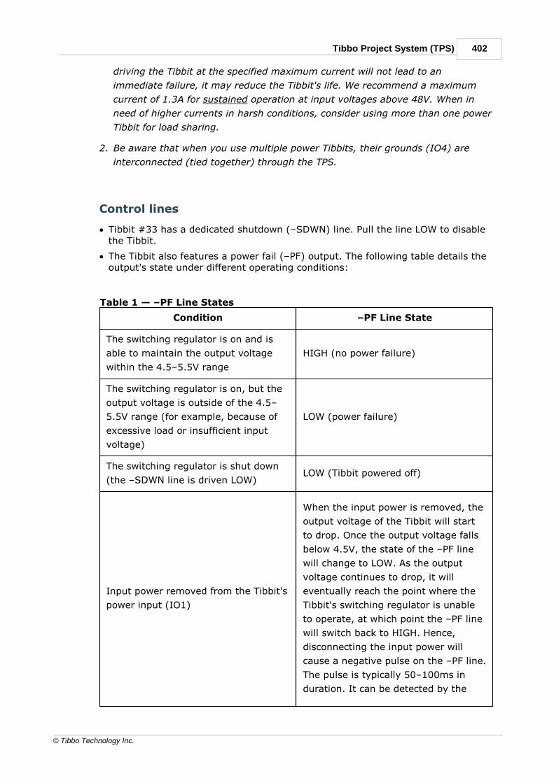
402Tibbo Project System (TPS)
© Tibbo Technology Inc.
driving the Tibbit at the specified maximum current will not lead to an
immediate failure, it may reduce the Tibbit's life. We recommend a maximum
current of 1.3A for sustained operation at input voltages above 48V. When in
need of higher currents in harsh conditions, consider using more than one power
Tibbit for load sharing.
2. Be aware that when you use multiple power Tibbits, their grounds (IO4) are
interconnected (tied together) through the TPS.
Control lines
· Tibbit #33 has a dedicated shutdown (–SDWN) line. Pull the line LOW to disablethe Tibbit.
· The Tibbit also features a power fail (–PF) output. The following table details theoutput's state under different operating conditions:
Table 1 — –PF Line States
Condition –PF Line State
The switching regulator is on and is
able to maintain the output voltage
within the 4.5–5.5V range
HIGH (no power failure)
The switching regulator is on, but the
output voltage is outside of the 4.5–
5.5V range (for example, because of
excessive load or insufficient input
voltage)
LOW (power failure)
The switching regulator is shut down
(the –SDWN line is driven LOW)LOW (Tibbit powered off)
Input power removed from the Tibbit's
power input (IO1)
When the input power is removed, the
output voltage of the Tibbit will start
to drop. Once the output voltage falls
below 4.5V, the state of the –PF line
will change to LOW. As the output
voltage continues to drop, it will
eventually reach the point where the
Tibbit's switching regulator is unable
to operate, at which point the –PF line
will switch back to HIGH. Hence,
disconnecting the input power will
cause a negative pulse on the –PF line.
The pulse is typically 50–100ms in
duration. It can be detected by the

403 Programmable Hardware Manual (PHM)
© Tibbo Technology Inc.
TPS' GPIO line running in the interrupt
mode.
Note: Tibbo recommends monitoring the –PF line with an interrupt routine insteadof polling the status of the line. Using interrupts will help catch transient failures orinstabilities that cannot be detected through polling.
LEDs
Tibbit #33 features two green LEDs and one red LED:
· The green "5V" LED is connected to the 5V output of the Tibbit's switchingregulator. It is on when the regulator is outputting power. The LED will be offwhen the regulator is not outputting power, even if the host TPS system isreceiving power from some other source (for example, a second Tibbit #33).
· The red –SDWN LED turns on when the host processor pulls the –SDWN lineLOW, thus disabling the Tibbit's switching regulator.
· The green –PF LED is on when the corresponding –PF line is LOW. –PF linebehavior is detailed in the table above.
Library support
The Tibbit works as soon as the power source is connected, and no code is requiredto make the Tibbit function in your system. If you want to monitor the –PF line, youcan use the Tibbo-supplied companion software library. The library can be easilyincluded in your project through CODY, our project code generator. Thecombination of CODY-generated code and the library will enable the –PF linemonitoring through an interrupt. It will also help you implement the shutdown,reset, and restart mechanisms for your application.
Additional info
Specifications
Efficiency Data
Handling Current and Power Spikes
SpecificationsUsing Tibbit #33 outside of the boundaries specified below may cause irreversibledamage to the Tibbit.
Table 2 — Absolute Maximum Ratings
Parameter Value
Input Voltage — IO1
(Permanent)
–60V to +60V

404Tibbo Project System (TPS)
© Tibbo Technology Inc.
Input Voltage — IO1
(Transient)
–100V to +100V
–SWDN Relative to GND –0.3V to 5.2V
–PF Relative to GND –0.3V to 5.5V
Output Voltage (Pin 12) 5.2V
Operating Temperature –40°C to +85°C
Table 3 — Nominal Electrical Characteristics
Parameter Minimum Average Maximum
Input Voltage — IO1 @ Iout =
1,500mA
8VDC --- 60VDC
Output Voltage (Pin 12) 4.9VDC 5.15VDC 5.2VDC
Output Current --- 1.5A 2A
Efficiency --- ~85 percent ~92 percent
Efficiency DataTibbit #33's efficiency vs. the input voltage, output current, and ambienttemperature is shown in the diagram below.
(a) (b) (c)
Fig. 1 — Efficiency vs. the Input Voltage, Output Current, and the
Ambient Temperature

405 Programmable Hardware Manual (PHM)
© Tibbo Technology Inc.
Handling Current and Power SpikesMany Tibbo Project System (TPS) configurations exhibit a "pulsating" currentconsumption pattern.
The pulse handling ability of Tibbit #33 depends on the input voltage, averageoutput power, and ambient temperature. The following information can be used asa reference point: Tibbit #33 can output a sustained 1.5A of current while handlingcurrent pulses of up to 2A, but such current pulses should not be longer than100ms. As a rule of thumb, the average output current over a long period of timeshould not exceed 1.5A by more than 5 percent.
In common usage scenarios like wireless and cellular applications, currentconsumption periodically peaks for 10–100ms (usually for less than 1 percent ofthe duty cycle), as shown in Fig. 2a and 2b.
Fig. 2a — Maximum Current Test @
+85°C
Fig. 2b — Maximum Current Test @
+85°C
Tibbit #33 can handle voltage spikes of up to 100V while operating at full loadthroughout the entire industrial temperature range. For reliable module operation,each spike's length should not exceed 100ms at a duty cycle of 10 percent. Fig. 3illustrates the test that Tibbit #33 successfully passed.
Fig. 3 — Voltage Spikes @ +85°C
7.2.9.43#35, C1: Barometric Pressure Sensor
Function: Barometric pressure sensor

406Tibbo Project System (TPS)
© Tibbo Technology Inc.
Form factor: C1
Special needs: Tibbit #00-3
Power requirements: 5V/2mA
See also: #28, #29, #30, #36
Details
This Tibbit is based on the MPL115A2 barometric pressure measurement IC withI2C interface. The sensor is implemented as the C1 device with perforated frontface.
The module measures the atmospheric pressure with 0.15 kPa resolution and +/-1kPa accuracy.
This C1 device requires the Tibbit #00-3 to be installed in the neighboring "M"Tibbit socket. #00-3 provides two direct lines for I2C comms, as well as the groundand +5V power for the MPL115A2 IC.
Sample project
The use of this Tibbit is illustrated by a Tibbo BASIC test project. Yo can find ithere: https://github.com/tibbotech/CA-Test-Tibbit-35.
7.2.9.44#36, C1: 3-axis Accelerometer
Function: 3-axis accelerometer (shock sensor)
Form factor: C1
Special needs: Tibbit #00-3
Power requirements: 5V/2mA
See also: #28, #29, #30, #35

407 Programmable Hardware Manual (PHM)
© Tibbo Technology Inc.
Details
This Tibbit is based on the ADXL312 accelerometer IC with I2C interface. Thesensor is implemented as the C1 device.
The module measures acceleration in the +/-12G range, simultaneously in threeaxes, and with 2.9mG resolution.
This C1 device requires the Tibbit #00-3 to be installed in the neighboring "M"Tibbit socket. #00-3 provides two direct lines for I2C comms, as well as the groundand +5V power for the ADXL312 IC.
Sample project
The use of this Tibbit is illustrated by a Tibbo BASIC test project. Yo can find ithere: https://github.com/tibbotech/CA-Test-Tibbit-36.
7.2.9.45#37, C1: RF Connector
Function: RF connector
Form factor: C1
Special needs: ---
Power requirements: ---
See also: ---

408Tibbo Project System (TPS)
© Tibbo Technology Inc.
Details
---
7.2.9.46#38: C1: Pushbutton
Function: One pushbutton
Form factor: C1
Special needs: Tibbit #00-3
Power requirements: 5V/1mA
See also: #39

409 Programmable Hardware Manual (PHM)
© Tibbo Technology Inc.
Details
This C1 device requires the Tibbit #00-3 to be installed in the neighboring "M"Tibbit socket.
The output signal will be available on line A of Tibbit #00-3. The output will beLOW when the button is pressed.
7.2.9.47#39-1~4, C1: Large LED (Four Colors Available)
Function: Large LED (red, blue, green, and yellow colors available)
Form factor: C1
Special needs: Tibbit #00-3
Power requirements: 5V/30mA
See also: #38

410Tibbo Project System (TPS)
© Tibbo Technology Inc.
Details
This C1 device requires the Tibbit #00-3 to be installed in the neighboring "M"Tibbit socket.
The LED is to be controlled through line A of Tibbit #00-3. Set the line LOW to turnthe LED ON.
IMPORTANT NOTE! Red and blue LEDs used in this Tibbit are high-brightnessLEDs that are fairly visible in regular office lighting conditions. Green and yellowLEDs are less bright and are only recommended for use in dimly lit environments(equipment closets, etc.).
7.2.9.48#40-1~4, M1S: Digital Potentiometer (Four Nominals)
Function: Digital potentiometer (5KOhm, 10KOhm, 50KOhm, and 100KOhmversions available)
Form factor: M1S
Category: Input/output module
Special needs: ---
Power requirements: 5V/10mA
Mates with: #19, #20, #21 (limited use)
See also: ---

411 Programmable Hardware Manual (PHM)
© Tibbo Technology Inc.
Details
The Tibbit is based on the MCP4561 digital POT IC from Microchip. This IC has an8-bit resolution. Refer to Microchip datasheet for operation details.
LEDs
There is one red and one yellow LED. The red LED is connected to the SCL line ofthe I2C interface, the yellow LED — to the SDA line.
Sample project
The use of this Tibbit is illustrated by a Tibbo BASIC test project. Yo can find ithere: https://github.com/tibbotech/CA-Test-Tibbit-40.
7.2.9.49#41, C1: 8-bit Port
Function: 8-bit port (supplied with 200mm cable)
Form factor: C1
Special needs: Tibbit #00-3
Power requirements: 5V/40mA
See also: ---

412Tibbo Project System (TPS)
© Tibbo Technology Inc.
Details
This Tibbit is based on the MCP23008 8-bit port expander IC from Microchip. Referto Microchip datasheet for operation details.
This C1 device requires the Tibbit #00-3 to be installed in the neighboring "M"Tibbit socket.
To simplify wiring, Tibbit #41 is supplied with a 200mm WAS-P044 cable.
Sample project
The use of this Tibbit is illustrated by a Tibbo BASIC test project. Yo can find ithere: https://github.com/tibbotech/CA-Test-Tibbit-41.
7.2.9.50#42, M1S: RTC and NVRAM With Backup
Function: Real-time clock and non-volatile memory with backup battery andinterrupt output
Form factor: M1S
Category: Input/output module
Special needs: ---
Power requirements: 5V/10mA
Mates with: #19, #20, #21 (limited use), #37
See also: ---

413 Programmable Hardware Manual (PHM)
© Tibbo Technology Inc.
Details
This Tibbit is based on the DS3234 IC from Maxim Integrated. This is atemperature-compensated high accuracy RTC with non-volatile memory. Refer toMaxim Integrated datasheet for operation details.
The DS3234 RTC has the -INT/SQW pin, which can be set to trigger at a predefineddate/time or output a square wave signal. The -INT/SQW is available to the outsideworld through the line IO1. -INT/SQW is also accessible from the CPU. The line ismultiplexed with the DOUT signal of the DS3234. The multiplexor is controlled bythe CS state. When CS is LOW, thus indicating that an SPI transaction is inprogress, the multiplexor selects the DOUT line. When CS is HIGH, the multiplexorselects the -INT/SQW signal. Therefore, it is only possible to gauge the -INT/SQWstate when the SPI bus is idle.
The Tibbit carries a backup battery which powers the RTC when the main +5Vsupply is off.
LEDs
There are three red LEDs and one green LED. Red LEDs are connector to CS, SCLK,and MOSI lines. Green LED is connected to the -INT/MISO line.
Sample project
The use of this Tibbit is illustrated by a Tibbo BASIC test project. Yo can find ithere: https://github.com/tibbotech/CA-Test-Tibbit-42.
The non-volatile memory of the DS3234 can be used from within the STG (settings)library. Projects often have parameters (settings) that change too often to bestored in the EEPROM, yet must be preserved even when the power is off. The non-volatile memory of this Tibbit offers a perfect storage for such parameters.

414Tibbo Project System (TPS)
© Tibbo Technology Inc.
7.2.9.51#43-1, M1S: Four-Channel Streaming ADC ±10V
Function: Four-channel streaming ADC, ±10V range
Form factor: M1S
Category: Input module
Special needs: [SER]
Power requirements: 5V/20mA average
Temperature range: –40°C to +85°C
Mates with: #19, #20, #21
See also: #13, #31, #43-2, #52, #53
Details
This Tibbit is based on the AD7323 12-bit+sign successive-approximation (SAR)analog-to-digital converter (ADC) IC. It offers four single-ended or two differentialchannels.
In the single-ended mode, this Tibbit has an input range of ±10V, while in thedifferential mode it accepts signals in the ±20V range. Both are common outputranges of industrial pressure, temperature, and other types of transducers. If yourapplication requires a wider input voltage range, consider using Tibbit #43-2instead.
Tibbit #43-1 requires only the main 5V power source. To accept inputs greater than5V, the Tibbit is equipped with a low-noise, inductorless DC-DC convertergenerating –14V and +14V from the module's +5V power supply. Since alladditional voltages are generated onboard, there is no need for an external dual-rail power Tibbit #12.

415 Programmable Hardware Manual (PHM)
© Tibbo Technology Inc.
An onboard PIC16F1825 microcontroller resides between the ADC and the host CPUof the Tibbo Project PCB (TPP). The microcontroller's firmware implements a simplecommand interface, accessible via TX and RX UART lines (there is also an RTS flowcontrol line). Dedicated to serving the needs of the ADC and unburdened by anyother tasks, the PIC microcontroller enables low-jitter sampling of analog data inthe data streaming mode and enhances the linearity and precision of analog-to-digital conversions.
Tibbit #43-1 operates in either command (default) or data streaming mode. Thecommand mode is used to configure the Tibbit's settings (operating parameters)and also to perform single ("spot") analog-to-digital conversions. In the datastreaming mode, the Tibbit sends a continuous stream of low-jitter measurementsperformed at a preset sampling rate. The device is capable of performing up to1,000 measurements/second when a single channel is enabled. Up to 200measurements per second per channel are possible when all four channels areused.
The PIC microcontroller's firmware can be upgraded in the system and without anyadditional external hardware. The firmware update process utilizes the low-voltageprogramming (LVP) mode of the PIC microcontroller, with the TX line acting asICSPCLK, the RX line acting as ICSPDAT, and the –MCLR line used to put themicrocontroller into the LVP mode. CODY can include a firmware update file in yourproject and generate code for its execution. The firmware source code andpublished update hex files are available in a dedicated repository.
For information on the operating parameters of Tibbit #43-1, please refer toSpecifications.
For information on operating Tibbit #43-1, please see Working with Tibbit #43-1.
Single-ended and differential modes
Whether the Tibbit operates in the single-ended or differential mode is determinedby the SM command.
In the single-ended mode, the Tibbit provides four input channels. The voltage oneach channel is with reference to the system ground; however, the Tibbit does notexpose the ground line. This means that when running Tibbit #43-1 in the single-ended mode, you will need to get the ground line elsewhere. One of the commonways is to use Tibbit #43-1 in conjunction with Tibbit #20, which offers the systemground terminal.
Table 1 — Single-ended Mode Line Assignments
IO1 Single-ended analog input channel 1
IO2 Single-ended analog input channel 2
IO3 Single-ended analog input channel 3
IO4 Single-ended analog input channel 4
GNDNot provided by this Tibbit, must be obtained elsewhere (for
example, by using Tibbit #20)
Table 2 — Differential Mode Line Assignments

416Tibbo Project System (TPS)
© Tibbo Technology Inc.
IO1 Positive input of the differential analog input channel 1
IO2 Negative input of the differential analog input channel 1
IO3 Positive input of the differential analog input channel 2
IO4 Negative input of the differential analog input channel 2
The system ground is not needed in the differential mode. However, to reduce thenoise, you may wish to connect the signal cable's shield to the TPS ground. Thiswill, again, require obtaining the ground line elsewhere.
Control lines
This Tibbit has four control lines:
· TX: Connects to the TX output of the host CPU. The line is used to sendcommands from the host CPU to the Tibbit. The line is HIGH when idle.
· RX: Connects to the RX input of the host CPU. The line is used to receive repliesand stream sampling data from the Tibbit to the host CPU. The line is HIGH whenidle.
· RTS: Connects to the RTS output of the host CPU. The line is used by the hostCPU to indicate whether it is ready to receive the UART data from the Tibbit.When this line is HIGH, it means that the host CPU is not ready to receive theUART data. When it is LOW, that indicates that the host CPU is ready to receivethe data.
· –MCLR: Connects directly to the PIC's reset pin. The –MCLR pin should always beHIGH for normal operation of the Tibbit. To reset the PIC microcontroller, set theline LOW, then set it back to HIGH. This pin is also used for low-voltageprogramming of the PIC microcontroller, enabling in-system upgrades of theTibbit's firmware.
Flow control
Although Tibbit #43-1 features an RTS line, it does not have a CTS line. Thereasons for the absence of the CTS line are that (1) there is no spare pin toaccommodate this line, the fourth I/O interface line of the Tibbit being taken by the–MCLR pin; and (2) flow control in the host CPU-to-Tibbit direction is unnecessary.Large volumes of data potentially requiring flow control can only flow from Tibbit#43-1 to the host CPU. Only commands are ever sent in the opposite direction. Allcommands are short, and Tibbit #43-1 will always receive them reliably.
When enabling flow control in your application, remember to map the CTS line tothe NULL line (ser.ctsmap = PL_INT_NULL — see the TIDE, TiOS, Tibbo BASIC,and Tibbo C Manual).
If flow control is not used, remember to set the RTS line to LOW (see io.state inthe TIDE, TiOS, Tibbo BASIC, and Tibbo C Manual). Failing to set the RTS line LOWwill prevent Tibbit #43-1 from ever sending any data.
LEDs
Control lines A through D are each equipped with an LED. The RX line is equippedwith a green LED, and all other lines have red LEDs. An LED will turn on when thestate of its corresponding line is LOW.

417 Programmable Hardware Manual (PHM)
© Tibbo Technology Inc.
Library support
Tibbo supplies a companion software library for Tibbit #43-1 that takes care ofcalculations and conversions for you. The library can be easily included in yourproject through CODY, our project code generator. CODY examines your TPSconfiguration to create the starter code — adopting Tibbo's best coding practices —that you can use as your project's foundation.
SettingsTibbit #43-1 operates according to a set of configurable parameters referred to assettings. The Tibbit keeps several sets of settings values, as explained below.
RAM settings
User settings stored in the PIC microcontroller's RAM serve as the immediate("current") operating parameters of the Tibbit. Any change made to these settingshas an instant effect on the Tibbit's operation.
The Tibbit's interface protocol provides several S ("set") commands for altering thevalue of individual RAM settings. For example, the SM command allows forselecting the sampling mode (single-ended or differential).
EEPROM (post-reset) settings
The settings stored in the PIC microcontroller's EEPROM define the post-resetoperating parameters of the Tibbit. Every time the Tibbit emerges from reset(reboot), it copies the values of all settings from the EEPROM into the RAM.Therefore, the EEPROM settings can be thought of as "post-reset" settings, becausethey are applied after every reset of the Tibbit.
The Tibbit's interface protocol provides several commands for copying settingsbetween the RAM and the EEPROM, as well as for initializing the settings to theirfactory defaults. All such commands operate on all settings as a group.
The group of EEPROM settings is protected by a single checksum covering thevalues of all settings in the group. The checksum is verified before copying theEEPROM settings into the RAM.
If the checksum verification fails, not a single setting value is copied. In addition:
· If the copying was being performed after the Tibbit was reset (reboot), then theTibbit's factory defaults are copied into the RAM settings instead.
· If the copying was being performed during the FE ("fetch EEPROM settings")command execution, then the Tibbit will return the F ("fail") reply code.
In either case, the values of the EEPROM settings are not repaired and will requirea manual reinitialization with the SF ("set factory values") command.
Factory defaults
Most default values are hard-coded into the PIC microcontroller's firmware. Thedefault ADC calibration parameters, on the contrary, are individually programmedinto each Tibbit during their production. These calibration parameters are stored inthe EEPROM, but are kept separate from the EEPROM settings described above.

418Tibbo Project System (TPS)
© Tibbo Technology Inc.
As with anything stored in the EEPROM, default calibration values may getcorrupted. These default calibration values are not checksum-protected, theircorruption is undetectable, and there is no remedy if such corruption occurs.
Factory defaults can be copied simultaneously into the RAM and EEPROM settingsusing the SF ("set factory values") command. Factory defaults are also loaded intothe RAM after the Tibbit is reset (rebooted) if the checksum verification of theEEPROM settings fails.
Interface ProtocolThe UART interface of Tibbit #43-1 operates in one of two communications modes:
· Command mode (default), which allows the host system to configure the Tibbit,and also perform single ("spot") analog-to-digital conversions.
· Data streaming mode, in which the Tibbit continuously outputs ADCmeasurements for the enabled channels at the specified sampling rate and in theselected format.
In the command mode, the host system communicates with the Tibbit using acommand-and-reply protocol. All commands and replies have the followingformat:
STX Command or Reply CR
The STX (ASCII code 0x02) and CR (ASCII code 0x0D) characters provide thecommand or reply packet encapsulation. Everything before STX and after CR isignored. Incomplete (an STX without CR) commands and replies are ignored.
The Tibbit will send a reply for each correctly encapsulated command issued by thehost, except the D command.
The material that follows does not show the encapsulating <STX> and <CR>characters, but their presence is always implied.
Available commands
Table 3 — Available Commands
Comman
dDescription
Commands for switching the communications mode
C Switches the Tibbit into the command mode.
DSwitches the Tibbit into the data streaming mode. No reply is
provided for this command.
User-level commands for configuring the analog-to-digital conversion
and streaming. These commands apply to the RAM (current) settings.

419 Programmable Hardware Manual (PHM)
© Tibbo Technology Inc.
SM
Sets the sampling mode (single-ended or differential). Applies to
single reads using the RA and RH commands, as well as the data
streaming mode.
SDSpecifies the data output format. Applies only to the data streaming
mode.
SRSpecifies the sampling rate. Applies only to the data streaming
mode.
SCEnables the specified channels for sampling. Applies only to the
data streaming mode.
Calibration commands (the calibration is performed at the factory — do
not manipulate these parameters unless you know what you are doing).
These commands apply to the RAM (current) settings.
SASets the values of the A parameters. Applies to single reads using
the RA and RH commands, as well as the data streaming mode.
SBPSets the values of the BP parameters. Applies to single reads using
the RA and RH commands, as well as the data streaming mode.
SBNSets the values of the BN parameters. Applies to single reads using
the RA and RH commands, as well as the data streaming mode.
RAM read-back and EEPROM-related commands
GC Returns the current values of the RAM (current) settings.
GE
Returns the values of the EEPROM (post-reset) settings. Executing
this command does not alter the values of the RAM (current)
settings.
SE Copies the RAM (current) settings into the EEPROM (post-reset)
settings.
FECopies the EEPROM (post-reset) settings into the RAM (current)
settings.
SF
Restores all settings to their factory defaults (including the factory-
programmed calibration values). This command overwrites the RAM
(current) settings and the EEPROM (post-reset) settings.
Miscellaneous commands
RAObtains a single read on the specified channel(s) while staying in
the command mode. The data is returned in the ASCII format.
RH
Obtains a single read on the specified channel(s) while staying in
the command mode. The data is returned in the hexadecimal
format.

420Tibbo Project System (TPS)
© Tibbo Technology Inc.
V Returns the version of the PIC microcontroller's firmware.
Table 4 — Standard Replies
Reply Description
ACommand accepted. If the reply carries any data, this data
will follow the A reply code.
C Syntax error. No additional data ever follows this reply code.
OParameter out of range. No additional data ever follows this
reply code.
FExecution failed. This can only be related to the EEPROM
operations. No additional data ever follows this reply code.
Commands for switching the communications mode
Comman
dC
Descript
ion
Instructs the Tibbit to exit the data streaming mode and enter the
command mode. If the device was in the data streaming mode, it
will stop sending the data stream and start accepting commands
from the host. This is the only command that is recognized while
the Tibbit is in the data streaming mode; all other commands are
ignored.
Note: After the power-up (reset), the Tibbit is in the command
mode.
SyntaxCommand: C
Reply: A
Comman
dD
Descript
ion
Instructs the Tibbit to exit the command mode and enter the data
streaming mode. This is the only command to which the Tibbit does
not offer any reply. Instead, the data streaming commences
immediately upon the receipt of this command.

421 Programmable Hardware Manual (PHM)
© Tibbo Technology Inc.
Note: After the power-up (reset), the Tibbit is in the command
mode.
SyntaxCommand: D
Reply: (the Tibbit will start streaming the data directly)
User-level commands for configuring the ADC conversion andstreaming
Comman
dSM
Descript
ion
Sets the sampling mode. Applies to single reads using the RA and
RH commands, as well as the data streaming mode. This setting is
stored in the RAM and applies immediately.
Syntax
Command: SMp, where p is the sampling mode: 0 — single-ended
(four channels available), 1 — differential (two channels available)
Reply: A
Default
value0
Example SM1 (selects the differential mode)
Comman
dSD
Descript
ion
Specifies the data output format. Applies only to the data streaming
mode. This setting is stored in the RAM and applies immediately.
Syntax
Command: SDp, where p is the data output format: 0 — ASCII, 1
— binary, 2 — hexadecimal
Reply: A
Default
value0
Example SD2 (selects the hexadecimal data mode)

422Tibbo Project System (TPS)
© Tibbo Technology Inc.
Comman
dSR
Descript
ion
Specifies the sampling rate. Applies only to the data streaming
mode. This setting is stored in the RAM and applies immediately.
Syntax
Command: SRp, where p is the sampling rate expressed as the
number of sampling groups per second, in the 1 to 1000 range
Reply: A
Note: Since a sampling group includes the analog-to-digital
conversion results for each enabled channel, each such group may
include up to four values. 1000 samples/second is a permissible
rate when the binary output format is enabled (see the SD
command) and only one ADC channel is active. Refer to
Specifications for the maximum recommended sampling rates
depending on the data output format and the number of channels
used.
Default
value1
ExampleSR200 (200 sampling groups per second — a comfortable sampling
rate for any data output format and any number of active channels)
Comman
dSC
Descript
ion
Enables the specified channels for sampling. Applies only to the
data streaming mode. This setting is stored in the RAM and applies
immediately.
Syntax
Command: SCp, where p is a comma-delimited list of active
channels, from 1 to 4
Reply: A
Note 1: Only CH1 and CH2 are available in the differential mode
(see the SM command). If CH3 and CH4 are specified while in the
differential mode, the command will be rejected with the O status
code.
Note 2: The channels are sampled in the order in which they are
listed in this command. This affects not only the timing of the ADC
sampling, but also the order in which the channel data will be sent
in the data streaming mode.

423 Programmable Hardware Manual (PHM)
© Tibbo Technology Inc.
Default
value1,2,3,4
ExampleSC4,2 (enable CH2 and CH2; the channels will be sampled in the 4-
2 order)
Calibration commands
All calibration parameters are set at the factory — do not change unless
you know what you are doing!
These commands allow you to calibrate the ADC's linearity and offset. While these
commands are normally only used during the production of the Tibbit, they remain
available, and you can use them to recalibrate the device.
The A, BP, and BN parameters are used to calibrate individual channels. In the
table below:
· Vo is the compensated output of an ADC channel
· Vi is the averaged raw output of an ADC channel
Table 5 — Calibration Formulas
Single-ended mode, positive input
voltages
Vo = 0.0078125 × A × Vi +
0.00244140625 × BP
Single-ended mode, negative input
voltages
Vo = 0.0078125 × A × Vi +
0.00244140625 × BN
Differential mode, positive input
voltages
Vo = 0.0078125 × A × Vi + 2 ×
0.00244140625 × BP
Differential mode, negative input
voltages
Vo = 0.0078125 × A × Vi + 2 ×
0.00244140625 × BN
Comman
dSA
Descript
ion
Sets the values of the A parameters. Applies to single reads using
the RA and RH commands, as well as the data streaming mode.
This setting is stored in the RAM and applies immediately.

424Tibbo Project System (TPS)
© Tibbo Technology Inc.
Syntax
Command: SAp, where p is a comma-delimited list of six values —
four for single-ended channels 1~4 and two for differential channels
1 and 2
Reply: A
Default
valuesPreset at the factory during the calibration process
Example
Command: SA128,128,128,128,128,128 (Sets the A parameter
as follows:
Single-ended channel 1: A=128
Single-ended channel 2: A=128
Single-ended channel 3: A=128
Single-ended channel 3: A=128
Differential channel 1: A=128
Differential channel 2: A=128)
Comman
dSBP
Descript
ion
Sets the values of the BP parameters. Applies to single reads using
the RA and RH commands, as well as the data streaming mode.
This setting is stored in the RAM and applies immediately.
Syntax
Command: SBPp, where p is a comma-delimited list of six values
— four for single-ended channels 1~4 and two for differential
channels 1 and 2
Reply: A
Default
valuesPreset at the factory during the calibration process
Example
SBP8,8,8,8,8,4,3 (Sets the BP parameter as follows:
Single-ended channel 1: BP=8
Single-ended channel 2: BP=8
Single-ended channel 3: BP=8
Single-ended channel 3: BP=8
Differential channel 1: BP=4
Differential channel 2: BP=3)

425 Programmable Hardware Manual (PHM)
© Tibbo Technology Inc.
Comman
dSBN
Descript
ion
Sets the values of the BN parameters. Applies to single reads using
the RA and RH commands, as well as the data streaming mode.
This setting is stored in the RAM and applies immediately.
Syntax
Command: SBNp, where p is a comma-delimited list of six values
— four for single-ended channels 1~4 and two for differential
channels 1 and 2
Reply: A
Default
valuesPreset at the factory during the calibration process
Example
SBN5,5,5,5,2,2 (Sets the BN parameter as follows:
Single-ended channel 1: BN=5
Single-ended channel 2: BN=5
Single-ended channel 3: BN=5
Single-ended channel 3: BN=5
Differential channel 1: BN=2
Differential channel 2: BN=2)
RAM read-back and EEPROM-related commands
Comman
dGC
Descript
ionReturns the current values of all RAM (current) settings.
Syntax
Command: GC
Reply: Asetting_str, where the setting_str contains the list of
semicolon-separated RAM (current) setting values in the
name=value(s) format; if a setting has several values, these values
are separated by commas. Each name corresponds to the command
used for changing the setting's value. For example, "SR=1000"
would mean that the sampling rate (see the SR command) is set to
1000.
Example
Command: GC
Reply:
ASR=1000;SM=1;SC=1,2;SD=0;SA=128,128,128,128,128,12
8;SBP=8,8,8,8,4,3;SBN=5,5,5,5,2,2;

426Tibbo Project System (TPS)
© Tibbo Technology Inc.
Comman
dGE
Descript
ion
Returns the values of the EEPROM (post-reset) settings. Executing
this command does not alter the values of the RAM (current)
settings.
Syntax
Command: GE
Reply: Asetting_str, see the GC command for the setting_str
description and example
Comman
dSE
Descript
ion
Copies the RAM (current) settings into the EEPROM (post-reset)
settings. The next time the Tibbit boots up, these values will be
copied into the RAM and used as operating parameters.
Syntax
Command: SE
Reply: A
Note: This command writes into the Tibbit's EEPROM. Tibbo
recommends that you be extra careful with this command to avoid
excessive EEPROM writing. While modern EEPROMs have a
significant number of allowed write cycles, there is still a limit. For
more information, see Prolonging and Estimating EEPROM Life. If
the write to the EEPROM fails, this command will return the F status
code.
Comman
dFE
Descript
ion
Copies the EEPROM (post-reset) settings into the RAM (current)
settings. After this, the Tibbit will be running as if it just booted up.

427 Programmable Hardware Manual (PHM)
© Tibbo Technology Inc.
This is because the settings stored in the EEPROM are also fetched
at boot.
Syntax
Command: FE
Reply: A
Note: The integrity of the EEPROM (post-reset) settings is protected
by a checksum. If the checksum verification fails during the
execution of this command, no EEPROM setting values will be
copied into the RAM and the command will return the F status code.
Comman
dSF
Descript
ion
Restores all settings to their factory defaults (including the factory-
programmed calibration values). This command overwrites the RAM
(current) and EEPROM (post-reset) settings.
Syntax
Command: FE
Reply: A
Note 1: The integrity of the EEPROM (post-reset) settings is
protected by a checksum. If the checksum verification fails during
the execution of this command, no EEPROM setting values will be
copied into the RAM, and the command will return the F status
code.
Note 2: This command writes into the Tibbit's EEPROM. Tibbo
recommends that you be extra careful with this command to avoid
excessive EEPROM writing. While modern EEPROMs have a
significant number of allowed write cycles, there is still a limit. For
more information, see Prolonging and Estimating EEPROM Life. If
the write to the EEPROM fails, this command will return the F status
code.
Miscellaneous commands
Comman
dRA
Descript
ion
Obtains a single read on the specified channel(s) while staying in
the command mode. The data is returned in the ASCII format.

428Tibbo Project System (TPS)
© Tibbo Technology Inc.
Syntax
Command: RAp, where p is a comma-delimited list of active
channels, from 1 to 4
Reply: Aadc_value(s), where the adc_values string is formatted
as explained in the Data Output Formats topic, under ASCII format.
Note 1: Only CH1 and CH2 are available in the differential mode
(see the SM command). If CH3 and CH4 are specified while in the
differential mode, the command will be rejected with the O status
code.
Note 2: The channels are sampled in the order in which they are
listed in this command.
Example
Command: RA4,1 (assuming the single-ended mode)
Reply: A7.2800,-4.2713; (channel 4: 7.2800V, channel 1: –
4.2713V)
Comman
dRH
Descript
ion
Obtains a single read on the specified channel(s) while staying in
the command mode. The data is returned in the hexadecimal
format.
Syntax
Command: RAp, where p is a comma-delimited list of active
channels, from 1 to 4
Reply: Aadc_value(s), where the adc_values string is formatted
as explained in the Data Output Formats topic, under Hexadecimal
format.
Note 1: Only CH1 and CH2 are available in the differential mode
(see the SM command). If CH3 and CH4 are specified while in the
differential mode, the command will be rejected with the O status
code.
Note 2: The channels are sampled in the order in which they are
listed in this command.
ExampleCommand: RA4,1 (assuming the single-ended mode)
Reply: A099B,666A; (channel 4: 099B, channel 1: 666A)

429 Programmable Hardware Manual (PHM)
© Tibbo Technology Inc.
Comman
dV
Descript
ionReturns the version of the PIC microcontroller's firmware.
SyntaxCommand: V
Reply: Aver_string
ExampleCommand: V
Reply: ATibbo Inc. Tibbit#43-1 FW1.1b
Data Output Formats
Tibbit #43-1 supports three data output formats: ASCII, binary, and hexadecimal.Which format to use at low sampling rates is solely up to your preferences andneeds. However, if you plan to stream the data continuously and at a highsampling rate, Tibbo recommends that you use the binary format — especially ifyour desired sampling rate is near the maximum limit for the ASCII andhexadecimal modes (see the Specifications).
ASCII format
When using the ASCII format, the Tibbit's onboard PIC microcontroller calculatesthe actual voltages corresponding to the binary measurement data received fromthe ADC and outputs these voltages in a human-readable decimal format. Eachnumber is rounded to four decimal places*.
In the output, channel voltages are separated by a comma (",") and each samplinggroup ends with a semicolon (";"). The term "sampling group" refers to the groupof the currently enabled channels. In the single-ended mode and with all channelsenabled, the group will comprise four measurements, performed one after another.If some channels are disabled, each group will have fewer than four measurements.
The following shows a sample output containing three groups with twomeasurements in each group:
3.2800,-4.2713;3.3120,-4.2600;3.1421,-4.1701;
Note that it is your application's job to remember which channels are enabled, aschannel numbers are not printed in this mode. For example, the two members ofeach group in the output above could be from CH1 and CH2, or CH1 and CH3, orCH1 and CH4 — there is no way to tell this from the output itself.
* This, of course, is not an indicator of the ADC's measurement precision. The valueof "1.2345" does not mean that the ADC was able to sample the applied voltagewith a 0.0001V accuracy. Since the effective resolution of this Tibbit is 11 bits (10bits plus sign), the actual measurement "step" of the ADC is 20V / 2048 = 0.0098V(for the single-ended mode).

430Tibbo Project System (TPS)
© Tibbo Technology Inc.
Binary format
The binary data output format is the most compact, which is why it isrecommended for high sampling rates. The sampling value obtained from an ADCchannel, as well as the channel number, are encoded into just 16 bits of data. Bits15 and 14 encode the channel number, while bits 13-0 contain the result of theADC conversion. Each 16-bit word is sent as two bytes; the high byte is sent first.
The channel number encoding is as follows:
Table 6 — Channel Number Encoding
Channel B15 B14
CH1 0 0
CH2 0 1
CH3 1 0
CH4 1 1
The ADC data encoding depends on whether the Tibbit is running in the single-ended or differential mode, as detailed below:
Single-ended mode
Table 7 — Binary Format Single-ended Mode Data Structure
B
1
5
B
1
4
B
1
3
B
1
2
B
1
1
B
1
0
B
9
B
8
B
7
B
6
B
5
B
4
B
3
B
2
B
1
B
0
ADC
channe
l
SI
G
N
Al
w
ay
s
0
ADC conversion data without the sign ([D11:0])
The sign bit will be 0 for positive numbers (measurements above 0V) and 1 fornegative numbers (measurements below 0V). B12 is always zero.
Use the following formulas to convert the data into corresponding voltage values:
Table 8 — Binary-to-Voltage Conversion Formulas for the Single-EndedMode
Positive number (SIGN
= 0)
Vi = (D[11:0] / 4095) × 10V
Negative number (SIGN
= 1)
Vi = -((4095 - D[11:0]) / 4095) × 10V
Differential mode

431 Programmable Hardware Manual (PHM)
© Tibbo Technology Inc.
Table 9 — Binary Format Differential Mode Data Structure
B
1
5
B
1
4
B
1
3
B
1
2
B
1
1
B
1
0
B
9
B
8
B
7
B
6
B
5
B
4
B
3
B
2
B
1
B
0
ADC
channe
l
SI
G
N
ADC conversion data without the sign ([D12:0])
The sign bit will be 0 for positive numbers (measurements above 0V) and 1 fornegative numbers (measurements below 0V).
Use the following formulas to convert the data into corresponding voltage values:
Table 10 — Binary-to-Voltage Conversion Formulas for the DifferentialMode
Positive number (SIGN
= 0)
Vi = (D[12:0] / 8191) × 20V
Negative number (SIGN
= 1)
Vi = -((8191 - D[12:0]) / 8191) × 20V
The following shows a sample "hex dump" output containing three groups with twomeasurements in each group:
09 9D 66 66 09 9A 66 65 09 9B 66 68
Here is how to interpret this data:
· First, combine the byte pairs into 16-bit words. The result is: 0x099D, 0x7666,0x099A, 0x7665, 0x099B, 0x7668.
· Next, extract the channel field (bits 15 and 14) and the sign (bit 13). Assumingthe single-ended mode, the result is: CH1: + 0x99D, CH2: – 0x1666, CH1: +0x99A, CH2: – 0x1665, CH1: + 0x99B, CH2: – 0x1668.
· The final step is to convert these values into the corresponding voltages (usingthe formulas in Table 10): CH1: + 6.0098V, CH2: – 6.0000V, CH1: + 6.0024V,CH2: – 6.0024V, CH1: + 6.0049V, CH2: – 5.9951V.
The binary data output format is extremely compact, but care should be taken toavoid losing any data bytes. Although the channel number is encoded in theoutput, missing a single data byte will result in a permanent "data interpretationshift."
Hexadecimal (HEX) format
This format is a hybrid of the ASCII and binary formats:
· As with the ASCII format, individual values are separated by commas (",") andsampling groups are separated by semicolons (";").

432Tibbo Project System (TPS)
© Tibbo Technology Inc.
· As with the binary format, each value is transmitted in 16 bits (2 bytes) of datathat encode the channel number, the sign, and the measured voltage. Thedifference with the binary format is that these 16-bit words are sent as "HEXstrings." In other words, they are "printed" in a HEX format, using ASCIIcharacters.
The following shows a sample "hex dump" output containing three groups with twomeasurements in each group:
30 39 39 42 2C 36 36 36 41 3B 30 39 39 43 2C
36
36 37 32 3B 30 39 39 42 2C 36 36 36 39 3B
099B,666A;099C,6
672;099B,6669;
The HEX format is a good compromise between the ASCII and binary formats. Likethe ASCII format, it allows you to regain synchronization if some characters aremissed. Unlike the binary format, it employs printable ASCII characters, which maybe desirable. At the same time, the HEX output is a bit more compact than theASCII one, thus achieving a slightly higher sampling rate than the latter.
Working With Tibbit #43-1Before you can start the signal acquisition with Tibbit #43-1, you must configure it.
If your application will only need to perform analog-to-digital conversions fromtime to time, it can keep the Tibbit in the command mode and use the RA or RHcommands to measure the voltages on Tibbit's inputs whenever needed. In thiscase, Tibbit #43-1 only requires you to select between the single-ended ordifferential mode using the SM command:
<Power up — settings values loaded from the EEPROM>
Command: SM0 'Single-ended mode
Reply: A
Command: RA1,2 'Get ADC measurements
...
If your application requires a steady stream of signal measurements, configure theTibbit for the data streaming mode. This entails programming four settings:
· SM to select the sampling mode
· SD to choose the data output format
· SR to set the sampling rate
· SC to enable the desired channels
After that, your application should switch into the data streaming mode and startreceiving the ADC sampling data:
<Power up — setting values loaded from the EEPROM>
Command: SM1 'Single-ended mode
Reply: A
Command: SD0 'ASCII format
Reply: A

433 Programmable Hardware Manual (PHM)
© Tibbo Technology Inc.
Command: SR400 '400 sample groups per second
Reply: A
Command: SC1,2 'Enable CH1 and CH2
Reply: A
Command: D
<Data streaming starts>
...
The above configuration steps must be performed after every power-up or reset, asthe settings configured through these commands are only stored in the PICmicrocontroller's RAM.
Another approach would be to configure the Tibbit once and save the configurationinto the EEPROM:
<Power up — setting values loaded from the EEPROM>
Command: SM1 'Single-ended mode
Reply: A
Command: SD0 'ASCII format
Reply: A
Command: SR400 '400 sample groups per second
Reply: A
Command: SC1,2 'Enable CH1 and CH2
Reply: A
Command: SE 'Save the configuration into the EEPROM
Reply A
...
Note: Tibbo recommends that you be extra careful with the SE command to avoid
excessive EEPROM writing. While modern EEPROMs have a significant number of
allowed write cycles, there is still a limit. For more information, see Prolonging and
Estimating EEPROM Life. If the write to the EEPROM fails, this command will return
the F status code.
Once the desired configuration has been saved into the EEPROM, your applicationdoes not have to program the same settings on each power-up and can proceeddirectly into the data streaming mode:
<Power up — setting values loaded from the EEPROM>
Command: D
<Data streaming starts>
...
SpecificationsNote that operating Tibbit #43-1 in extreme conditions (i.e., close to the absoluteboundaries) for extended periods can lead to component aging, performancedegradation, and premature failure.

434Tibbo Project System (TPS)
© Tibbo Technology Inc.
Table 11 — Absolute Maximum Ratings
Supply voltage –10V to +5.5V
CH1 to CH4 relative to GND –12V to +12V
Differential voltage: CH1-to-CH2 and CH3-to-
CH4–24V to +24V
TX, RX, RTS, –MCLR lines –0.3V to +5.5V
Operating temperature –40°C to +85°C
ESD protection on analog I/O lines* 2.5kV
* While the analog lines have electrostatic discharge (ESD) protection capability(embedded in the ADC IC), Tibbo recommends that ESD precautions still be takento avoid any performance degradation or permanent damage to the device. Thisspecification has not been tested by Tibbo. The value is reproduced from theAD7323 ADC datasheet.
Table 12 — Nominal Electrical Characteristics
Input supply voltage 4.5VDC to 5.5VDC
Current consumption 20mA to 25mA
CH1 to CH4 relative to GND –10V to +10V
Differential voltage: CH1-to-CH2 and CH3-to-
CH4 (without GND connection)–20V to +20V
Input resistance: CH1 through CH4 relative to
GND>10MΩ
Input resistance: CH1-to-CH2 or CH3-to-CH4
(differential)
TX, RX, RTS, –MCLR lines, LOW state 0V to 0.8V
TX, RX, RTS, –MCLR lines, HIGH state 2V to 5V
Table 13 — Functional Characteristics (Verified @ 25°C)
Sampling mode
4 x single-ended
channels OR 2 x
differential channels
Single-ended input voltage range –10V to +10V
Differential input voltage range –20V to +20V
Common-mode input voltage (differential
mode)1
–2VDC to +2VDC

435 Programmable Hardware Manual (PHM)
© Tibbo Technology Inc.
Nominal output resolution 12-bit + 1-bit sign
Effective output resolution2 10-bit + 1-bit sign
Non-linearity @ full-scale and effective output
resolution
< ±0.1%
Offset @ full-scale and effective output
resolution
< ±10mV
Maximum sampling rate, one single-ended or
differential channel enabled, ASCII or
hexadecimal data output format3
500 samples per second
Maximum sampling rate, one single-ended
channel enabled, binary data output format3
1,000 samples per
second
Maximum sampling rate, two single-ended or
differential channels enabled, ASCII or
hexadecimal data output format3
200 sampling
groups/second
Maximum sampling rate, two single-ended or
differential channels enabled, binary data
output format3
400 sampling
groups/second
Maximum sampling rate, four single-ended
channels enabled, ASCII or hexadecimal data
output format3
100 sampling
groups/second
Maximum sampling rate, four single-ended
channels enabled, binary data output format3
200 sampling
groups/second
Maximum delay between the sampling of two
sequential channels in a group, binary data
output format
~30 microseconds
Input resistance: CH1 to CH4 relative to GND >10MΩ
Input resistance: CH1 to CH2 (differential) >10MΩ
Input resistance: CH3 to CH4 (differential) >10MΩ
1. If the common-mode DC voltage in differential mode exceeds the specifiedvalues, the input voltage range (swing) cannot be as high as the differentialinput voltage range. Based on the application, exceeding the specified common-mode input voltage range will likely affect the input swing. In general, themaximum input swing will be narrowed by the amount of voltage in excess ofthe common-mode input voltage range to maintain the nominal input voltagethresholds.For example, if a sensor with a common-mode input voltage of 5VDC —exceeding the specified range by 3VDC — is connected to Tibbit #43-1 indifferential mode, the input swing will be reduced to –20V to +17V. For more

436Tibbo Project System (TPS)
© Tibbo Technology Inc.
information, refer to the "True-differential mode" section of the datasheet for theAD7323.
2. During the quality control stage of production, Tibbit #43-1 is calibrated forlinearity and resolution.
3. Tibbo recommends that the binary output data format be used for high samplingrates. See Data Output Formats for more information.
Table 14 — Temperature Effect (Compared with Characteristics @ 25°C)
Maximum added error @ -40°C ±5mV @ Vin = full range
Maximum added error @ +85°C ±5mV @ Vin = 9.9V
Table 15 — Serial Interface Characteristics
Interface type UART
Flow control* Standard RTS (no CTS)
Mode Full duplex
Baudrate 230,400 (fixed)
Data bits 8 bits
Stop bits 1 bit
Parity No
* All Tibbo Project PCBs support flow control for UART communications with only anRTS line. If you use Tibbit #43-1 on another platform whose CPU does not supportflow control, the Tibbit's RTS line must be set to LOW to allow data flow out of theTibbit permanently. Note that in such a case, the host CPU's buffer must be bigenough to accommodate the desired sampling rate to avoid data loss or a bufferoverflow.
7.2.9.52#43-2, M1S: Four-Channel Streaming ADC ±100V
Function: Four-channel streaming ADC, ±100V range
Form factor: M1S
Category: Input module
Special needs: [SER]
Power requirements: 5V/20mA average
Temperature range: –40°C to +85°C
Mates with: #19, #20, #21
See also: #13, #31, #43-1, #52, #53

437 Programmable Hardware Manual (PHM)
© Tibbo Technology Inc.
Details
This Tibbit is based on the AD7323 12-bit+sign successive-approximation (SAR)analog-to-digital converter (ADC) IC. It offers four single-ended or two differentialchannels.
In the single-ended mode, this Tibbit has an input range of ±100V, while in thedifferential mode it accepts signals in the ±200V range. Tibbit #43-2 can be usedas a multichannel wide input range voltmeter. Its wide input range enablesapplications with high-voltage sampling requirements, including battery bankmanagement, industrial instrumentation systems, and solar panel voltagemonitoring and logging. It also provides compatibility with multiple sensorsoperating at different input ranges.
In the differential mode, the data streams of two AC signals can be sampled fordigital signal processing operations, such as phase detection and power qualityfactor calculations. However, special care must be taken when handling highvoltages, as this is not an isolated Tibbit.
If your application does not require such a wide input voltage range — but wouldbenefit from a higher precision — consider using Tibbit #43-1 instead.
Tibbit #43-2 requires only the main 5V power source. To accept inputs greater than5V, the Tibbit is equipped with a low-noise, inductorless DC-DC convertergenerating –14V and +14V from the module's +5V power supply. Since alladditional voltages are generated onboard, there is no need for an external dual-rail power Tibbit #12.
An onboard PIC16F1825 microcontroller resides between the ADC and the host CPUof the Tibbo Project PCB (TPP). The microcontroller's firmware implements a simplecommand interface, accessible via TX and RX UART lines (there is also an RTS flowcontrol line). Dedicated to serving the needs of the ADC and unburdened by anyother tasks, the PIC microcontroller enables low-jitter sampling of analog data inthe data streaming mode and enhances the linearity and precision of analog-to-digital conversions.

438Tibbo Project System (TPS)
© Tibbo Technology Inc.
Tibbit #43-2 operates in either command (default) or data streaming mode. Thecommand mode is used to configure the Tibbit's settings (operating parameters)and also to perform single ("spot") analog-to-digital conversions. In the datastreaming mode, the Tibbit sends a continuous stream of low-jitter measurementsperformed at a preset sampling rate. The device is capable of performing up to1,000 measurements/second when a single channel is enabled. Up to 200measurements per second per channel are possible when all four channels areused.
The PIC microcontroller's firmware can be upgraded in the system and without anyadditional external hardware. The firmware update process utilizes the low-voltageprogramming (LVP) mode of the PIC microcontroller, with the TX line acting asICSPCLK, the RX line acting as ICSPDAT, and the –MCLR line used to put themicrocontroller into the LVP mode. CODY can include a firmware update file in yourproject and generate code for its execution. The firmware source code andpublished update hex files are available in a dedicated repository.
For information on the operating parameters of Tibbit #43-2, please refer toSpecifications.
For information on operating Tibbit #43-2, please see Working with Tibbit #43-2.
Single-ended and differential modes
Whether the Tibbit operates in the single-ended or differential mode is determinedby the SM command.
In the single-ended mode, the Tibbit provides four input channels. The voltage oneach channel is with reference to the system ground; however, the Tibbit does notexpose the ground line. This means that when running Tibbit #43-2 in the single-ended mode, you will need to get the ground line elsewhere. One of the commonways is to use Tibbit #43-2 in conjunction with Tibbit #20, which offers the systemground terminal.
When using this Tibbit, be aware that the I/O inputs have an equivalent resistanceof ~98kΩ. This is important when connected sensors have a large output resistanceor when using the Tibbit in the differential mode, which could result in anunintended path to the ground from the input pairs. The input diagram for each IOline is as follows:
Fig. 1 — Input Diagram
Table 1 — Single-ended Mode Line Assignments
IO1 Single-ended analog input channel 1
IO2 Single-ended analog input channel 2
IO3 Single-ended analog input channel 3
IO4 Single-ended analog input channel 4

439 Programmable Hardware Manual (PHM)
© Tibbo Technology Inc.
GNDNot provided by this Tibbit, must be obtained elsewhere (for
example, by using Tibbit #20)
Table 2 — Differential Mode Line Assignments
IO1 Positive input of the differential analog input channel 1
IO2 Negative input of the differential analog input channel 1
IO3 Positive input of the differential analog input channel 2
IO4 Negative input of the differential analog input channel 2
The system ground is not needed in the differential mode. However, to reduce thenoise, you may wish to connect the signal cable's shield to the TPS ground. Thiswill, again, require obtaining the ground line elsewhere.
Control lines
This Tibbit has four control lines:
· TX: Connects to the TX output of the host CPU. The line is used to sendcommands from the host CPU to the Tibbit. The line is HIGH when idle.
· RX: Connects to the RX input of the host CPU. The line is used to receive repliesand stream sampling data from the Tibbit to the host CPU. The line is HIGH whenidle.
· RTS: Connects to the RTS output of the host CPU. The line is used by the hostCPU to indicate whether it is ready to receive the UART data from the Tibbit.When this line is HIGH, it means that the host CPU is not ready to receive theUART data. When it is LOW, that indicates that the host CPU is ready to receivethe data.
· –MCLR: Connects directly to the PIC's reset pin. The –MCLR pin should always beHIGH for normal operation of the Tibbit. To reset the PIC microcontroller, set theline LOW, then set it back to HIGH. This pin is also used for low-voltageprogramming of the PIC microcontroller, enabling in-system upgrades of theTibbit's firmware.
Flow control
Although Tibbit #43-2 features an RTS line, it does not have a CTS line. Thereasons for the absence of the CTS line are that (1) there is no spare pin toaccommodate this line, the fourth I/O interface line of the Tibbit being taken by the–MCLR pin; and (2) flow control in the host CPU-to-Tibbit direction is unnecessary.Large volumes of data potentially requiring flow control can only flow from Tibbit#43-2 to the host CPU. Only commands are ever sent in the opposite direction. Allcommands are short, and Tibbit #43-2 will always receive them reliably.
When enabling flow control in your application, remember to map the CTS line tothe NULL line (ser.ctsmap = PL_INT_NULL — see the TIDE, TiOS, Tibbo BASIC,and Tibbo C Manual).
If flow control is not used, remember to set the RTS line to LOW (see io.state inthe TIDE, TiOS, Tibbo BASIC, and Tibbo C Manual). Failing to set the RTS line LOWwill prevent Tibbit #43-2 from ever sending any data.

440Tibbo Project System (TPS)
© Tibbo Technology Inc.
LEDs
Control lines A through D are each equipped with an LED. The RX line is equippedwith a green LED, and all other lines have red LEDs. An LED will turn on when thestate of its corresponding line is LOW.
Library support
Tibbo supplies a companion software library for Tibbit #43-2 that takes care ofcalculations and conversions for you. The library can be easily included in yourproject through CODY, our project code generator. CODY examines your TPSconfiguration to create the starter code — adopting Tibbo's best coding practices —that you can use as your project's foundation.
SettingsTibbit #43-2 operates according to a set of configurable parameters referred to assettings. The Tibbit keeps several sets of settings values, as explained below.
RAM settings
User settings stored in the PIC microcontroller's RAM serve as the immediate("current") operating parameters of the Tibbit. Any change made to these settingshas an instant effect on the Tibbit's operation.
The Tibbit's interface protocol provides several S ("set") commands for altering thevalue of individual RAM settings. For example, the SM command allows forselecting the sampling mode (single-ended or differential).
EEPROM (post-reset) settings
The settings stored in the PIC microcontroller's EEPROM define the post-resetoperating parameters of the Tibbit. Every time the Tibbit emerges from reset(reboot), it copies the values of all settings from the EEPROM into the RAM.Therefore, the EEPROM settings can be thought of as "post-reset" settings, becausethey are applied after every reset of the Tibbit.
The Tibbit's interface protocol provides several commands for copying settingsbetween the RAM and the EEPROM, as well as for initializing the settings to theirfactory defaults. All such commands operate on all settings as a group.
The group of EEPROM settings is protected by a single checksum covering thevalues of all settings in the group. The checksum is verified before copying theEEPROM settings into the RAM.
If the checksum verification fails, not a single setting value is copied. In addition:
· If the copying was being performed after the Tibbit was reset (reboot), then theTibbit's factory defaults are copied into the RAM settings instead.
· If the copying was being performed during the FE ("fetch EEPROM settings")command execution, then the Tibbit will return the F ("fail") reply code.
In either case, the values of the EEPROM settings are not repaired and will requirea manual reinitialization with the SF ("set factory values") command.

441 Programmable Hardware Manual (PHM)
© Tibbo Technology Inc.
Factory defaults
Most default values are hard-coded into the PIC microcontroller's firmware. Thedefault ADC calibration parameters, on the contrary, are individually programmedinto each Tibbit during their production. These calibration parameters are stored inthe EEPROM, but are kept separate from the EEPROM settings described above.
As with anything stored in the EEPROM, default calibration values may getcorrupted. These default calibration values are not checksum-protected, theircorruption is undetectable, and there is no remedy if such corruption occurs.
Factory defaults can be copied simultaneously into the RAM and EEPROM settingsusing the SF ("set factory values") command. Factory defaults are also loaded intothe RAM after the Tibbit is reset (rebooted) if the checksum verification of theEEPROM settings fails.
Interface ProtocolThe UART interface of Tibbit #43-2 operates in one of two communications modes:
· Command mode (default), which allows the host system to configure the Tibbit,and also perform single ("spot") analog-to-digital conversions.
· Data streaming mode, in which the Tibbit continuously outputs ADCmeasurements for the enabled channels at the specified sampling rate and in theselected format.
In the command mode, the host system communicates with the Tibbit using acommand-and-reply protocol. All commands and replies have the followingformat:
STX Command or Reply CR
The STX (ASCII code 0x02) and CR (ASCII code 0x0D) characters provide thecommand or reply packet encapsulation. Everything before STX and after CR isignored. Incomplete (an STX without CR) commands and replies are ignored.
The Tibbit will send a reply for each correctly encapsulated command issued by thehost, except the D command.
The material that follows does not show the encapsulating <STX> and <CR>characters, but their presence is always implied.
Available commands
Table 3 — Available Commands
Comman
dDescription
Commands for switching the communications mode
C Switches the Tibbit into the command mode.

442Tibbo Project System (TPS)
© Tibbo Technology Inc.
DSwitches the Tibbit into the data streaming mode. No reply is
provided for this command.
User-level commands for configuring the analog-to-digital conversion
and streaming. These commands apply to the RAM (current) settings.
SM
Sets the sampling mode (single-ended or differential). Applies to
single reads using the RA and RH commands, as well as the data
streaming mode.
SDSpecifies the data output format. Applies only to the data streaming
mode.
SRSpecifies the sampling rate. Applies only to the data streaming
mode.
SCEnables the specified channels for sampling. Applies only to the
data streaming mode.
Calibration commands (the calibration is performed at the factory — do
not manipulate these parameters unless you know what you are doing).
These commands apply to the RAM (current) settings.
SASets the values of the A parameters. Applies to single reads using
the RA and RH commands, as well as the data streaming mode.
SBPSets the values of the BP parameters. Applies to single reads using
the RA and RH commands, as well as the data streaming mode.
SBNSets the values of the BN parameters. Applies to single reads using
the RA and RH commands, as well as the data streaming mode.
RAM read-back and EEPROM-related commands
GC Returns the current values of the RAM (current) settings.
GE
Returns the values of the EEPROM (post-reset) settings. Executing
this command does not alter the values of the RAM (current)
settings.
SE Copies the RAM (current) settings into the EEPROM (post-reset)
settings.
FECopies the EEPROM (post-reset) settings into the RAM (current)
settings.
SF
Restores all settings to their factory defaults (including the factory-
programmed calibration values). This command overwrites the RAM
(current) settings and the EEPROM (post-reset) settings.
Miscellaneous commands

443 Programmable Hardware Manual (PHM)
© Tibbo Technology Inc.
RAObtains a single read on the specified channel(s) while staying in
the command mode. The data is returned in the ASCII format.
RH
Obtains a single read on the specified channel(s) while staying in
the command mode. The data is returned in the hexadecimal
format.
V Returns the version of the PIC microcontroller's firmware.
Table 4 — Standard Replies
Reply Description
ACommand accepted. If the reply carries any data, this data
will follow the A reply code.
C Syntax error. No additional data ever follows this reply code.
OParameter out of range. No additional data ever follows this
reply code.
FExecution failed. This can only be related to the EEPROM
operations. No additional data ever follows this reply code.
Commands for switching the communications mode
Comman
dC
Descript
ion
Instructs the Tibbit to exit the data streaming mode and enter the
command mode. If the device was in the data streaming mode, it
will stop sending the data stream and start accepting commands
from the host. This is the only command that is recognized while
the Tibbit is in the data streaming mode; all other commands are
ignored.
Note: After the power-up (reset), the Tibbit is in the command
mode.
SyntaxCommand: C
Reply: A

444Tibbo Project System (TPS)
© Tibbo Technology Inc.
Comman
dD
Descript
ion
Instructs the Tibbit to exit the command mode and enter the data
streaming mode. This is the only command to which the Tibbit does
not offer any reply. Instead, the data streaming commences
immediately upon the receipt of this command.
Note: After the power-up (reset), the Tibbit is in the command
mode.
SyntaxCommand: D
Reply: (the Tibbit will start streaming the data directly)
User-level commands for configuring the ADC conversion andstreaming
Comman
dSM
Descript
ion
Sets the sampling mode. Applies to single reads using the RA and
RH commands, as well as the data streaming mode. This setting is
stored in the RAM and applies immediately.
Syntax
Command: SMp, where p is the sampling mode: 0 — single-ended
(four channels available), 1 — differential (two channels available)
Reply: A
Default
value0
Example SM1 (selects the differential mode)
Comman
dSD
Descript
ion
Specifies the data output format. Applies only to the data streaming
mode. This setting is stored in the RAM and applies immediately.
Syntax
Command: SDp, where p is the data output format: 0 — ASCII, 1
— binary, 2 — hexadecimal
Reply: A

445 Programmable Hardware Manual (PHM)
© Tibbo Technology Inc.
Default
value0
Example SD2 (selects the hexadecimal data mode)
Comman
dSR
Descript
ion
Specifies the sampling rate. Applies only to the data streaming
mode. This setting is stored in the RAM and applies immediately.
Syntax
Command: SRp, where p is the sampling rate expressed as the
number of sampling groups per second, in the 1 to 1000 range
Reply: A
Note: Since a sampling group includes the analog-to-digital
conversion results for each enabled channel, each such group may
include up to four values. 1000 samples/second is a permissible
rate when the binary output format is enabled (see the SD
command) and only one ADC channel is active. Refer to
Specifications for the maximum recommended sampling rates
depending on the data output format and the number of channels
used.
Default
value1
ExampleSR200 (200 sampling groups per second — a comfortable sampling
rate for any data output format and any number of active channels)
Comman
dSC
Descript
ion
Enables the specified channels for sampling. Applies only to the
data streaming mode. This setting is stored in the RAM and applies
immediately.
Syntax
Command: SCp, where p is a comma-delimited list of active
channels, from 1 to 4
Reply: A

446Tibbo Project System (TPS)
© Tibbo Technology Inc.
Note 1: Only CH1 and CH2 are available in the differential mode
(see the SM command). If CH3 and CH4 are specified while in the
differential mode, the command will be rejected with the O status
code.
Note 2: The channels are sampled in the order in which they are
listed in this command. This affects not only the timing of the ADC
sampling, but also the order in which the channel data will be sent
in the data streaming mode.
Default
value1,2,3,4
ExampleSC4,2 (enable CH2 and CH2; the channels will be sampled in the 4-
2 order)
Calibration commands
All calibration parameters are set at the factory — do not change unless
you know what you are doing!
These commands allow you to calibrate the ADC's linearity and offset. While these
commands are normally only used during the production of the Tibbit, they remain
available, and you can use them to recalibrate the device.
The A, BP, and BN parameters are used to calibrate individual channels. In the
table below:
· Vo is the compensated output of an ADC channel
· Vi is the averaged raw output of an ADC channel
Table 5 — Calibration Formulas
Single-ended mode, positive input
voltages
Vo = 0.0078125 × A × Vi + 0.024554
× BP
Single-ended mode, negative input
voltages
Vo = 0.0078125 × A × Vi + 0.024554
× BN
Differential mode, positive input
voltages
Vo = 0.0078125 × A × Vi + 2 ×
0.024554 × BP
Differential mode, negative input
voltages
Vo = 0.0078125 × A × Vi + 2 ×
0.024554 × BN

447 Programmable Hardware Manual (PHM)
© Tibbo Technology Inc.
Comman
dSA
Descript
ion
Sets the values of the A parameters. Applies to single reads using
the RA and RH commands, as well as the data streaming mode.
This setting is stored in the RAM and applies immediately.
Syntax
Command: SAp, where p is a comma-delimited list of six values —
four for single-ended channels 1~4 and two for differential channels
1 and 2
Reply: A
Default
valuesPreset at the factory during the calibration process
Example
Command: SA128,128,128,128,128,128 (Sets the A parameter
as follows:
Single-ended channel 1: A=128
Single-ended channel 2: A=128
Single-ended channel 3: A=128
Single-ended channel 3: A=128
Differential channel 1: A=128
Differential channel 2: A=128)
Comman
dSBP
Descript
ion
Sets the values of the BP parameters. Applies to single reads using
the RA and RH commands, as well as the data streaming mode.
This setting is stored in the RAM and applies immediately.
Syntax
Command: SBPp, where p is a comma-delimited list of six values
— four for single-ended channels 1~4 and two for differential
channels 1 and 2
Reply: A
Default
valuesPreset at the factory during the calibration process
Example SBP8,8,8,8,8,4,3 (Sets the BP parameter as follows:

448Tibbo Project System (TPS)
© Tibbo Technology Inc.
Single-ended channel 1: BP=4
Single-ended channel 2: BP=4
Single-ended channel 3: BP=3
Single-ended channel 3: BP=4
Differential channel 1: BP=2
Differential channel 2: BP=1)
Comman
dSBN
Descript
ion
Sets the values of the BN parameters. Applies to single reads using
the RA and RH commands, as well as the data streaming mode.
This setting is stored in the RAM and applies immediately.
Syntax
Command: SBNp, where p is a comma-delimited list of six values
— four for single-ended channels 1~4 and two for differential
channels 1 and 2
Reply: A
Default
valuesPreset at the factory during the calibration process
Example
SBN5,5,5,5,2,2 (Sets the BN parameter as follows:
Single-ended channel 1: BN=11
Single-ended channel 2: BN=11
Single-ended channel 3: BN=12
Single-ended channel 3: BN=11
Differential channel 1: BN=5
Differential channel 2: BN=5)
RAM read-back and EEPROM-related commands
Comman
dGC
Descript
ionReturns the current values of all RAM (current) settings.
Syntax
Command: GC
Reply: Asetting_str, where the setting_str contains the list of
semicolon-separated RAM (current) setting values in the

449 Programmable Hardware Manual (PHM)
© Tibbo Technology Inc.
name=value(s) format; if a setting has several values, these values
are separated by commas. Each name corresponds to the command
used for changing the setting's value. For example, "SR=1000"
would mean that the sampling rate (see the SR command) is set to
1000.
Example
Command: GC
Reply:
ASR=1;SM=1;SC=1,2;SD=0;SA=128,128,128,128,128,128;S
BP=4,4,3,4,2,1;SBN=11,11,12,11,5,5;
Comman
dGE
Descript
ion
Returns the values of the EEPROM (post-reset) settings. Executing
this command does not alter the values of the RAM (current)
settings.
Syntax
Command: GE
Reply: Asetting_str, see the GC command for the setting_str
description and example
Comman
dSE
Descript
ion
Copies the RAM (current) settings into the EEPROM (post-reset)
settings. The next time the Tibbit boots up, these values will be
copied into the RAM and used as operating parameters.
Syntax
Command: SE
Reply: A
Note: This command writes into the Tibbit's EEPROM. Tibbo
recommends that you be extra careful with this command to avoid
excessive EEPROM writing. While modern EEPROMs have a
significant number of allowed write cycles, there is still a limit. For
more information, see Prolonging and Estimating EEPROM Life. If
the write to the EEPROM fails, this command will return the F status
code.
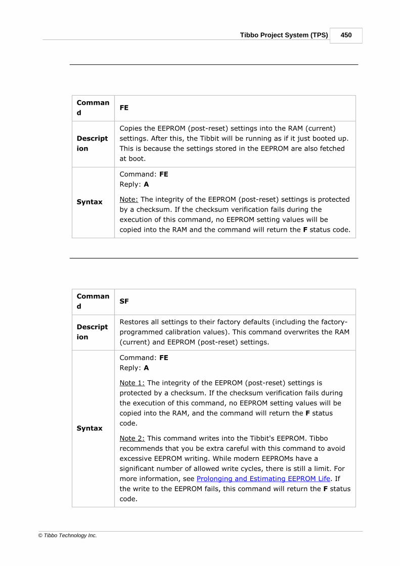
450Tibbo Project System (TPS)
© Tibbo Technology Inc.
Comman
dFE
Descript
ion
Copies the EEPROM (post-reset) settings into the RAM (current)
settings. After this, the Tibbit will be running as if it just booted up.
This is because the settings stored in the EEPROM are also fetched
at boot.
Syntax
Command: FE
Reply: A
Note: The integrity of the EEPROM (post-reset) settings is protected
by a checksum. If the checksum verification fails during the
execution of this command, no EEPROM setting values will be
copied into the RAM and the command will return the F status code.
Comman
dSF
Descript
ion
Restores all settings to their factory defaults (including the factory-
programmed calibration values). This command overwrites the RAM
(current) and EEPROM (post-reset) settings.
Syntax
Command: FE
Reply: A
Note 1: The integrity of the EEPROM (post-reset) settings is
protected by a checksum. If the checksum verification fails during
the execution of this command, no EEPROM setting values will be
copied into the RAM, and the command will return the F status
code.
Note 2: This command writes into the Tibbit's EEPROM. Tibbo
recommends that you be extra careful with this command to avoid
excessive EEPROM writing. While modern EEPROMs have a
significant number of allowed write cycles, there is still a limit. For
more information, see Prolonging and Estimating EEPROM Life. If
the write to the EEPROM fails, this command will return the F status
code.

451 Programmable Hardware Manual (PHM)
© Tibbo Technology Inc.
Miscellaneous commands
Comman
dRA
Descript
ion
Obtains a single read on the specified channel(s) while staying in
the command mode. The data is returned in the ASCII format.
Syntax
Command: RAp, where p is a comma-delimited list of active
channels, from 1 to 4
Reply: Aadc_value(s), where the adc_values string is formatted
as explained in the Data Output Formats topic, under ASCII format.
Note 1: Only CH1 and CH2 are available in the differential mode
(see the SM command). If CH3 and CH4 are specified while in the
differential mode, the command will be rejected with the O status
code.
Note 2: The channels are sampled in the order in which they are
listed in this command.
Example
Command: RA4,1 (assuming the single-ended mode)
Reply: A–7.931,96.129; (channel 4: –7.931V, channel 1:
96.129V)
Comman
dRH
Descript
ion
Obtains a single read on the specified channel(s) while staying in
the command mode. The data is returned in the hexadecimal
format.
Syntax
Command: RAp, where p is a comma-delimited list of active
channels, from 1 to 4
Reply: Aadc_value(s), where the adc_values string is formatted
as explained in the Data Output Formats topic, under Hexadecimal
format.
Note 1: Only CH1 and CH2 are available in the differential mode
(see the SM command). If CH3 and CH4 are specified while in the
differential mode, the command will be rejected with the O status
code.

452Tibbo Project System (TPS)
© Tibbo Technology Inc.
Note 2: The channels are sampled in the order in which they are
listed in this command.
ExampleCommand: RA4,1 (assuming the single-ended mode)
Reply: AEEBD,0F4A; (channel 4: EEBD, channel 1: 0F4A)
Comman
dV
Descript
ionReturns the version of the PIC microcontroller's firmware.
SyntaxCommand: V
Reply: Aver_string
ExampleCommand: V
Reply: ATibbo Inc. Tibbit#43-2 FW1.1b
Data Output Formats
Tibbit #43-2 supports three data output formats: ASCII, binary, and hexadecimal.Which format to use at low sampling rates is solely up to your preferences andneeds. However, if you plan to stream the data continuously and at a highsampling rate, Tibbo recommends that you use the binary format — especially ifyour desired sampling rate is near the maximum limit for the ASCII andhexadecimal modes (see the Specifications).
ASCII format
When using the ASCII format, the Tibbit's onboard PIC microcontroller calculatesthe actual voltages corresponding to the binary measurement data received fromthe ADC and outputs these voltages in a human-readable decimal format. Eachnumber is rounded to three decimal places*.
In the output, channel voltages are separated by a comma (",") and each samplinggroup ends with a semicolon (";"). The term "sampling group" refers to the groupof the currently enabled channels. In the single-ended mode and with all channelsenabled, the group will comprise four measurements, performed one after another.If some channels are disabled, each group will have fewer than four measurements.
The following shows a sample output containing three groups with twomeasurements in each group:
–7.931,96.105;–7.906,96.129;–7.906,96.105;
Note that it is your application's job to remember which channels are enabled, aschannel numbers are not printed in this mode. For example, the two members of

453 Programmable Hardware Manual (PHM)
© Tibbo Technology Inc.
each group in the output above could be from CH1 and CH2, or CH1 and CH3, orCH1 and CH4 — there is no way to tell this from the output itself.
* This, of course, is not an indicator of the ADC's measurement precision. The valueof "1.2345" does not mean that the ADC was able to sample the applied voltagewith a 0.0001V accuracy. The nominal resolution of this Tibbit is 13 bits (12 bitsplus sign), meaning that the nominal measurement "step" of the ADC is 201.14V /8192 = 0.02455V (for the single-ended mode). However, as its effective resolutionis 11 bits (10 bits plus sign), its accuracy is about 201.14V / 2048 = 0.09821.
Binary format
The binary data output format is the most compact, which is why it isrecommended for high sampling rates. The sampling value obtained from an ADCchannel, as well as the channel number, are encoded into just 16 bits of data. Bits15 and 14 encode the channel number, while bits 13-0 contain the result of theADC conversion. Each 16-bit word is sent as two bytes; the high byte is sent first.
The channel number encoding is as follows:
Table 6 — Channel Number Encoding
Channel B15 B14
CH1 0 0
CH2 0 1
CH3 1 0
CH4 1 1
The ADC data encoding depends on whether the Tibbit is running in the single-ended or differential mode, as detailed below:
Single-ended mode
Table 7 — Binary Format Single-ended Mode Data Structure
B
1
5
B
1
4
B
1
3
B
1
2
B
1
1
B
1
0
B
9
B
8
B
7
B
6
B
5
B
4
B
3
B
2
B
1
B
0
ADC
channe
l
SI
G
N
Al
w
ay
s
0
ADC conversion data without the sign ([D11:0])
The sign bit will be 0 for positive numbers (measurements above 0V) and 1 fornegative numbers (measurements below 0V). B12 is always zero.
Use the following formulas to convert the data into corresponding voltage values:

454Tibbo Project System (TPS)
© Tibbo Technology Inc.
Table 8 — Binary-to-Voltage Conversion Formulas for the Single-EndedMode
Positive number (SIGN
= 0)
Vi = (D[11:0] / 4095) × 100.57V
Negative number (SIGN
= 1)
Vi = -((4095 - D[11:0]) / 4095) × 100.57V
Differential mode
Table 9 — Binary Format Differential Mode Data Structure
B
1
5
B
1
4
B
1
3
B
1
2
B
1
1
B
1
0
B
9
B
8
B
7
B
6
B
5
B
4
B
3
B
2
B
1
B
0
ADC
channe
l
SI
G
N
ADC conversion data without the sign ([D12:0])
The sign bit will be 0 for positive numbers (measurements above 0V) and 1 fornegative numbers (measurements below 0V).
Use the following formulas to convert the data into corresponding voltage values:
Table 10 — Binary-to-Voltage Conversion Formulas for the DifferentialMode
Positive number (SIGN
= 0)
Vi = (D[12:0] / 8191) × 201.14V
Negative number (SIGN
= 1)
Vi = -((8191 - D[12:0]) / 8191) × 201.14V
The following shows a sample "hex dump" output containing three groups with twomeasurements in each group:
05 18 BF 38 05 16 BF 36 05 16 BF 37
Here is how to interpret this data:
· First, combine the byte pairs into 16-bit words. The result is: 0x0518, 0xBF38,0x0516, 0xBF36, 0x0516, 0xBF37.
· Next, extract the channel field (bits 15 and 14) and the sign (bit 13). Assumingthe differential mode, the result is: CH1: + 0x0518, CH2: – 0xBF38, CH1: +0x0516, CH2: – 0xBF36, CH1: + 0x0516, CH2: – 0xBF37.
· The final step is to convert these values into the corresponding voltages (usingthe formulas in Table 10): CH1: + 32.021V, CH2: – 4.887V, CH1: + 31.972V,CH2: – 4.936V, CH1: + 31.972V, CH2: – 4.911V.

455 Programmable Hardware Manual (PHM)
© Tibbo Technology Inc.
The binary data output format is extremely compact, but care should be taken toavoid losing any data bytes. Although the channel number is encoded in theoutput, missing a single data byte will result in a permanent "data interpretationshift."
Hexadecimal (HEX) format
This format is a hybrid of the ASCII and binary formats:
· As with the ASCII format, individual values are separated by commas (",") andsampling groups are separated by semicolons (";").
· As with the binary format, each value is transmitted in 16 bits (2 bytes) of datathat encode the channel number, the sign, and the measured voltage. Thedifference with the binary format is that these 16-bit words are sent as "HEXstrings." In other words, they are "printed" in a HEX format, using ASCIIcharacters.
The following shows a sample "hex dump" output containing three groups with twomeasurements in each group (from the same inputs as the previous example):
30 35 31 38 2C 42 46 33 38 3B 30 35 31 36 2C
42
46 33 38 3B 30 35 31 36 2C 42 46 33 38 3B
0518,BF38;0516,B
F38;0516,BF38;
The HEX format is a good compromise between the ASCII and binary formats. Likethe ASCII format, it allows you to regain synchronization if some characters aremissed. Unlike the binary format, it employs printable ASCII characters, which maybe desirable. At the same time, the HEX output is a bit more compact than theASCII one, thus achieving a slightly higher sampling rate than the latter.
Working With Tibbit #43-2Before you can start the signal acquisition with Tibbit #43-2, you must configure it.
If your application will only need to perform analog-to-digital conversions fromtime to time, it can keep the Tibbit in the command mode and use the RA or RHcommands to measure the voltages on Tibbit's inputs whenever needed. In thiscase, Tibbit #43-2 only requires you to select between the single-ended ordifferential mode using the SM command:
<Power up — settings values loaded from the EEPROM>
Command: SM0 'Single-ended mode
Reply: A
Command: RA1,2 'Get ADC measurements
...
If your application requires a steady stream of signal measurements, configure theTibbit for the data streaming mode. This entails programming four settings:
· SM to select the sampling mode
· SD to choose the data output format

456Tibbo Project System (TPS)
© Tibbo Technology Inc.
· SR to set the sampling rate
· SC to enable the desired channels
After that, your application should switch into the data streaming mode and startreceiving the ADC sampling data:
<Power up — setting values loaded from the EEPROM>
Command: SM1 'Single-ended mode
Reply: A
Command: SD0 'ASCII format
Reply: A
Command: SR400 '400 sample groups per second
Reply: A
Command: SC1,2 'Enable CH1 and CH2
Reply: A
Command: D
<Data streaming starts>
...
The above configuration steps must be performed after every power-up or reset, asthe settings configured through these commands are only stored in the PICmicrocontroller's RAM.
Another approach would be to configure the Tibbit once and save the configurationinto the EEPROM:
<Power up — setting values loaded from the EEPROM>
Command: SM1 'Single-ended mode
Reply: A
Command: SD0 'ASCII format
Reply: A
Command: SR400 '400 sample groups per second
Reply: A
Command: SC1,2 'Enable CH1 and CH2
Reply: A
Command: SE 'Save the configuration into the EEPROM
Reply A
...
Note: Tibbo recommends that you be extra careful with the SE command to avoid
excessive EEPROM writing. While modern EEPROMs have a significant number of
allowed write cycles, there is still a limit. For more information, see Prolonging and
Estimating EEPROM Life. If the write to the EEPROM fails, this command will return
the F status code.
Once the desired configuration has been saved into the EEPROM, your applicationdoes not have to program the same settings on each power-up and can proceeddirectly into the data streaming mode:

457 Programmable Hardware Manual (PHM)
© Tibbo Technology Inc.
<Power up — setting values loaded from the EEPROM>
Command: D
<Data streaming starts>
...
SpecificationsNote that operating Tibbit #43-2 in extreme conditions (i.e., close to the absoluteboundaries) for extended periods can lead to component aging, performancedegradation, and premature failure.
Table 11 — Absolute Maximum Ratings
Supply voltage –10V to +5.5V
CH1 to CH4 relative to GND –120V to +120V
Differential voltage: CH1-to-CH2 and CH3-to-
CH4–210V to +210V
TX, RX, RTS, –MCLR lines –0.3V to +5.5V
Operating temperature –40°C to +85°C
ESD protection on analog I/O lines* 2.5kV
* While the analog lines have electrostatic discharge (ESD) protection capability(embedded in the ADC IC), Tibbo recommends that ESD precautions still be takento avoid any performance degradation or permanent damage to the device. Thisspecification has not been tested by Tibbo. The value is reproduced from theAD7323 ADC datasheet.
Table 12 — Nominal Electrical Characteristics
Input supply voltage 4.5VDC to 5.5VDC
Current consumption 20mA to 25mA
CH1 to CH4 relative to GND –100V to +100V
Differential voltage: CH1-to-CH2 and CH3-to-
CH4 (without GND connection)–200V to +200V
Input resistance: CH1 through CH4 relative to
GND~98kΩ
Input resistance: CH1-to-CH2 or CH3-to-CH4
(differential)~196kΩ
TX, RX, RTS, –MCLR lines, LOW state 0V to 0.8V
TX, RX, RTS, –MCLR lines, HIGH state 2V to 5V

458Tibbo Project System (TPS)
© Tibbo Technology Inc.
Table 13 — Functional Characteristics (Verified @ 25°C)
Sampling mode
4 x single-ended
channels OR 2 x
differential channels
Single-ended input voltage range –100V to +100V
Differential input voltage range –200V to +200V
Common-mode input voltage (differential
mode)1
–20VDC to +20VDC
Nominal output resolution 12-bit + 1-bit sign
Effective output resolution2 10-bit + 1-bit sign
Non-linearity @ full-scale and effective output
resolution
< ±0.5%
Offset @ full-scale and effective output
resolution (single-ended)
< 100mV
Offset @ full-scale and effective output
resolution (differential)
< 200mV
Maximum sampling rate, one single-ended or
differential channel enabled, ASCII or
hexadecimal data output format3
500 samples per second
Maximum sampling rate, one single-ended
channel enabled, binary data output format3
1,000 samples per
second
Maximum sampling rate, two single-ended or
differential channels enabled, ASCII or
hexadecimal data output format3
200 sampling
groups/second
Maximum sampling rate, two single-ended or
differential channels enabled, binary data
output format3
400 sampling
groups/second
Maximum sampling rate, four single-ended
channels enabled, ASCII or hexadecimal data
output format3
100 sampling
groups/second
Maximum sampling rate, four single-ended
channels enabled, binary data output format3
200 sampling
groups/second
Maximum delay between the sampling of two
sequential channels in a group, binary data
output format
~30 microseconds
Input resistance: CH1 to CH4 relative to GND ~98kΩ

459 Programmable Hardware Manual (PHM)
© Tibbo Technology Inc.
Input resistance: CH1 to CH2 (differential) ~196kΩ
Input resistance: CH3 to CH4 (differential) ~196kΩ
1. If the common-mode DC voltage in differential mode exceeds the specifiedvalues, the input voltage range (swing) cannot be as high as the differentialinput voltage range. Based on the application, exceeding the specified common-mode input voltage range will likely affect the input swing. In general, themaximum input swing will be narrowed by the amount of voltage in excess ofthe common-mode input voltage range to maintain the nominal input voltagethresholds.For example, if a sensor with a common-mode input voltage of 50VDC —exceeding the specified range by 30VDC — is connected to Tibbit #43-2 in thedifferential mode, the input swing will be reduced to –200V to +170V. For moreinformation, refer to the "True-differential mode" section of the datasheet for theAD7323.
2. During the quality control stage of production, Tibbit #43-2 is calibrated forlinearity and resolution.
3. Tibbo recommends that the binary output data format be used for high samplingrates. See Data Output Formats for more information.
Table 14 — Temperature Effect (Compared with Characteristics @ 25°C)
Maximum added error @ -40°C ±200mV @ Vin = 100V
Maximum added error @ +85°C ±200mV @ Vin = 100V
Table 15 — Serial Interface Characteristics
Interface type UART
Flow control* Standard RTS (no CTS)
Mode Full duplex
Baudrate 230,400 (fixed)
Data bits 8 bits
Stop bits 1 bit
Parity No
* All Tibbo Project PCBs support flow control for UART communications with only anRTS line. If you use Tibbit #43-2 on another platform whose CPU does not supportflow control, the Tibbit's RTS line must be set to LOW to allow data flow out of theTibbit permanently. Note that in such a case, the host CPU's buffer must be bigenough to accommodate the desired sampling rate to avoid data loss or a bufferoverflow.

460Tibbo Project System (TPS)
© Tibbo Technology Inc.
7.2.9.53#44-1, H2: Isolated RS232/422/485 Port (DB9M Connector)
Function: Universal galvanically isolated RS232/422/485 port with a DB9Mconnector
Form factor: H2
Category: Input/output module
Special needs: [SER], [INT].
Power requirements: maximum 5V/80mA
Mates with: ---
See also: #44-2, #01, #02, #05

461 Programmable Hardware Manual (PHM)
© Tibbo Technology Inc.
Details
This is a "full" serial port that can be electronically configured to work in RS232,RS422, or RS485 mode. The Tibbit is based on the Sipex SP337 universaltransceiver.
Galvanic isolation is achieved by using ISO7141 and ISOW7842 digital isolatorsmanufactured by Texas Instruments (ISOW7842 also generates isolated power).These isolators create a separate power domain containing the SP337 transceiver,surrounding circuitry (not shown on the diagram), and the DB9 connector.
Due to the isolation, the ground pin (pin 5) of the DB9M is not connected to thesystem (CPU) ground and exposes the ground of the isolated domain instead. AllI/O lines on the DB9M connector are also from this isolated domain. The need to

462Tibbo Project System (TPS)
© Tibbo Technology Inc.
route an isolated ground to the outside world is why this Tibbit is implemented as ahybrid (H2) and not just a module (M2), as is the case with the non-isolatedRS232/422/485 Tibbit #02.
The theoretical isolation between the system power domain and the isolated powerdomain of this Tibbit is large enough to withstand typical ESD events. The isolationalso protects against small ground potential differences that may eventually causeequipment failures.
Communications modes
RS232, RS422, or RS485 mode selection is through FD/HD and 232/422-485control lines:
Mode FD/-HD -232/422-485
RS232 HIGH LOW
RS422 HIGH HIGH
RS485 LOW HIGH
When left unconnected, FD/-HD defaults to HIGH, while -232/422-485 defaults toLOW. This means that the RS232 mode will be selected by default.
In the RS232 mode, the port has RX, TX, RTS, CTS, DTR, and DSR signals. This is afull-duplex mode.
In the RS422 mode, the port has +/-RX, +/-TX, +/-RTS, and +/-CTS signal pairs.This is a full-duplex mode.
In the RS485 mode, the port has only +/-RX and +/-TX signal pairs. This is a half-duplex mode, so you can connect +RX to +TX, and -RX to -TX. This will allow yoursystem to communicate over a single (twisted) wire pair. Direction control isthrough the RTS line — the line will be LOW for data input and HIGH for output.
For "normal" RS232/422/485 applications, this Tibbit has to be connected to the TXand RX lines of the CPU's UART (see [SER]). Planning to use RTS/CTS flow controlas well? An interrupt line must be available, too (see [INT]).
DB9 connector
Tibbit #44-1 is a hybrid device integrating a DB9M connector. Connector pinassignment is as follows:
RS232 RS422 RS485
#1 <No connection> Isolated RTS- (output) <No connection>
#2 Isolated RX (input) Isolated RX- (input) Isolated RX- (input)
#3 Isolated TX (output) Isolated TX+ (output) Isolated TX+ (output)
#4 Isolated DTR (output) Isolated TX- (output) Isolated TX- (output)
#5 Isolated ground Isolated ground Isolated ground
#6 Isolated DSR (input) Isolated RX+ (input) Isolated RX+ (input)

463 Programmable Hardware Manual (PHM)
© Tibbo Technology Inc.
#7 Isolated RTS (output) Isolated RTS+ (output) <No connection>
#8 Isolated CTS (input) Isolated CTS+ (input) <No connection>
#9 <No connection> Isolated CTS- (input) <No connection>
The above pin assignment is standard for all Tibbo devices with the universal port(for example, see the serial port of the DS1102).
LEDs
There are eight LEDs: five red and three green. Red LEDs are connected to TX,RTS, DTR, FD/-HD, and -232/422-485 lines. Green LEDs are for RX, CTS, and DSR.
All LEDs are buffered (with logic gates) and light up for the LOW state ofcorresponding control lines.
7.2.9.54#44-2, H2: Isolated RS232/422/485 Port (Terminal Block)
Function: Universal galvanically isolated RS232/422/485 port with a terminalblock connector
Form factor: H2
Category: Input/output module
Special needs: [SER], [INT].
Power requirements: maximum 5V/80mA
Mates with: ---
See also: #44-1, #01, #02, #05

464Tibbo Project System (TPS)
© Tibbo Technology Inc.
Details
This is a "full" serial port that can be electronically configured to work in RS232,RS422, or RS485 mode. The Tibbit is based on the Sipex SP337 universaltransceiver.
Galvanic isolation is achieved by using ISO7141 and ISOW7842 digital isolatorsmanufactured by Texas Instruments (ISOW7842 also generates isolated power).These isolators create a separate power domain containing the SP337 transceiver,surrounding circuitry (not shown on the diagram), and the terminal blockconnector.
Due to the isolation, the ground pin (pin 5) of the terminal block is not connectedto the system (CPU) ground and exposes the ground of the isolated domain

465 Programmable Hardware Manual (PHM)
© Tibbo Technology Inc.
instead. All I/O lines on the terminal block connector are also from this isolateddomain. The need to route an isolated ground to the outside world is why thisTibbit is implemented as a hybrid (H2) and not just a module (M2), as is the casewith the non-isolated RS232/422/485 Tibbit #02.
The theoretical isolation between the system power domain and the isolated powerdomain of this Tibbit is large enough to withstand typical ESD events. The isolationalso protects against small ground potential differences that may eventually causeequipment failures.
Communications modes
RS232, RS422, or RS485 mode selection is through FD/HD and 232/422-485control lines:
Mode FD/-HD -232/422-485
RS232 HIGH LOW
RS422 HIGH HIGH
RS485 LOW HIGH
When left unconnected, FD/-HD defaults to HIGH, while -232/422-485 defaults toLOW. This means that the RS232 mode will be selected by default.
In the RS232 mode, the port has RX, TX, RTS, CTS, DTR, and DSR signals. This is afull-duplex mode.
In the RS422 mode, the port has +/-RX, +/-TX, +/-RTS, and +/-CTS signal pairs.This is a full-duplex mode.
In the RS485 mode, the port has only +/-RX and +/-TX signal pairs. This is a half-duplex mode, so you can connect +RX to +TX, and -RX to -TX. This will allow yoursystem to communicate over a single (twisted) wire pair. Direction control isthrough the RTS line — the line will be LOW for data input and HIGH for output.
For "normal" RS232/422/485 applications, this Tibbit has to be connected to the TXand RX lines of the CPU's UART (see [SER]). Planning to use RTS/CTS flow controlas well? An interrupt line must be available, too (see [INT]).
Terminal block connector
Tibbit #44-2 is a hybrid device integrating a terminal block connector. Connectorpin assignment is as follows:
RS232 RS422 RS485
#1 Isolated TX (output) Isolated TX+ (output) Isolated TX+ (output)
#2 Isolated RX (input) Isolated RX- (input) Isolated RX- (input)
#3 Isolated RTS (output) Isolated RTS+ (output) <No connection>
#4 Isolated CTS (input) Isolated CTS+ (input) <No connection>
#5 Isolated ground Isolated ground Isolated ground

466Tibbo Project System (TPS)
© Tibbo Technology Inc.
#6 Isolated DTR (output) Isolated TX- (output) Isolated TX- (output)
#7 Isolated DSR (input) Isolated RX+ (input) Isolated RX+ (input)
#8 <No connection> Isolated RTS- (output) <No connection>
#9 <No connection> Isolated CTS- (input) <No connection>
LEDs
There are eight LEDs: five red and three green. Red LEDs are connected to TX,RTS, DTR, FD/-HD, and -232/422-485 lines. Green LEDs are for RX, CTS, and DSR.
All LEDs are buffered (with logic gates) and light up for the LOW state ofcorresponding control lines.
7.2.9.55#45-1~3, H2: 4G (LTE) Modem
Function: 4G (LTE) modem
Form factor: H2
Category: Input/output module
Special needs: [SER]
Power requirements: 5V/500mA average, peak current consumption reaches 2A
Temperature range: –40°C to +85°C
Mates with: ---
See also:#46, #47

467 Programmable Hardware Manual (PHM)
© Tibbo Technology Inc.
Details
This Tibbit comes in the H2 hybrid form factor and is based on the SIM7500 LTECAT-1 family of modems manufactured by SIMCom. It features an SMA connectoron the front for use with an external antenna, which is not included with the Tibbitbut is required for it to operate.
The modem has standard TX, RX, RTS, and CTS signals, as well as severaladditional control lines.

468Tibbo Project System (TPS)
© Tibbo Technology Inc.
Control lines
This Tibbit has four control lines:
· –SDWN (shutdown): When LOW, turns off the Tibbit's power regulators. Whenthe line is switched to HIGH, the power regulators are enabled, but the modemremains off.
· PWRKEY (power key): A LOW-to-HIGH transition on this line toggles the power onand off; it turns the modem on if it was off or off if it was on. Toggling themodule on requires keeping a HIGH state of signal (after a transition from LOW)for about 500ms (see Fig. 1). Turning the module off requires keeping a HIGHstate for about 2.5 seconds (see Fig. 2).
Fig. 1 — Powering On the Modem
Fig. 2 — Powering Off the Modem
· STATUS: This line is LOW when the modem is off and HIGH when it is on. Thisline can be used to check the current power state of the modem. It takes at least22 seconds for the STATUS line to reach HIGH after the modem is powered on,after which the module can begin operating. There are two methods ofdetermining whether the modem is on or off: by sending an AT command andchecking for a response or querying the STATUS line's state. Note that the line'sstate is undetermined when the modem is shut down (i.e., the –SDWN line isLOW).
· RESET: Bringing this line HIGH for about one second resets the modem. There isno need to reset the modem after turning on its power.

469 Programmable Hardware Manual (PHM)
© Tibbo Technology Inc.
Before establishing a connection, the modem should be initialized. First, pull the –SDWN line HIGH to enable the power regulators. Next, toggle the PWRKEY lineHIGH for about 500ms to turn on the modem. After the STATUS line goes HIGH,the modem is ready to communicate using AT commands via a standard UARTinterface with RTS/CTS flow control. At this point, you can decide whether to allowthe system to establish a PPP connection automatically or to remain in ATcommand mode (see the Library section below).
SIM card slot
The card holder of Tibbit #45 accepts a 4G LTE micro-SIM card and features a“close-and-slide” locking mechanism. The card holder is located on the bottom ofthe Tibbit, meaning that insertion or removal of the SIM card requires opening theTibbo Project Box enclosure and removing the Tibbit from the Tibbo Project PCB(TPP). We chose this relatively inaccessible location for the SIM card to reduce thechances of theft — accessing the card holder requires quite a bit of time and work,making it impossible to remove the card surreptitiously.
LEDs
There is one red and one green LED. The red LED is connected to the TX line, whilethe green LED is linked to the RX line. The remaining lines are not equipped withLEDs due to the internal board’s space constraints.
Power considerations
At full LTE bandwidth, Tibbit #45 consumes an average current of 500mA, withpeak current consumption of about 2A. While these current “spikes” are so narrowthat they can’t be seen on a regular multimeter, they occur regularly when themodem is operating. We advise using an adequate power source to preventunexpected reboots or unstable operation.
The modem consumes approximately 22mA when idle and sips about 1.6mA whenin sleep mode. Note that the idle and sleep modes are not available when the Tibbitis in the automatic PPP connection mode.
Table 1 — Tibbit #45 Current Consumption
State Consumption
Average 500mA
Peak 2A
Idle About 22mA
Sleep About 1.6mA
The Tibbo Project System (TPS) platform offers several power supply Tibbitscapable of providing sufficient current.
The TPS Online Configurator can help you decide which parts to use in conjunctionwith Tibbit #45. The Online Configurator lists the Tibbit as consuming 500mA ofcurrent, which we found to be a good approximation of the current burden it places

470Tibbo Project System (TPS)
© Tibbo Technology Inc.
on a power source, but does not take into account the current spikes or that theTibbit often operates with lower power consumption.
Operating temperature
In testing, this Tibbit operated normally in the –40°C to 85°C range. However,SIMCom recommends the –30°C to +80°C operating temperature range for itsmodem IC and warns of reduced performance when operating outside of this range.
In addition to the temperature constraints on the module, there are also limitationsfor off-the-shelf SIM cards. While regular consumer SIM cards are certified tooperate in a temperature range of –25°C to +85°C, industrial/automotive SIMcards can operate from –40°C to +85°C, with some reaching even up to 105°C. Ininternal testing, some consumer SIM cards deformed at high and low temperatures.Therefore, we highly recommend that you asses your application's projectedenvironmental conditions and choose and appropriate SIM card.
Library Support
The CELL software library (see the TIDE, TiOS, Tibbo BASIC, and Tibbo C Manual)unlocks the full capabilities of this Tibbit and can be easily included in your projectthrough CODY, our project setup wizard.
The library allows you to automate the process of initializing the modem andautomatically establish and maintain a PPP connection. It also offers an ATcommand mode for manual control of the SIMcom modem.
Tibbit variations
This Tibbit is supplied in three regional variants as detailed in Table 2.
Table 2 — Tibbit #45 Variants
Tibbit #45-1 Tibbit #45-2 Tibbit #45-3
Internal Modem
Model1SIM7500SA SIM7500E SIM7500A
GSM Support NO YES:900/1800MHz
NO
WCDMASupport
YES: B1/B5 YES: B1/B8 YES: B2/B5
LTE Support YES:B1/B3/B5/B7/B8/
B28
YES:B1/B3/B7/B8/B20
YES: B2/B4/B12
1. While SIMCom identifies a few specific countries or regions for each variant ofthe SIM7500 family of modems, we have omitted them because they are notfully inclusive lists. What is important is that you select the version mostcompatible with the bands in use in your region (and compliant with your localregulations).

471 Programmable Hardware Manual (PHM)
© Tibbo Technology Inc.
7.2.9.56#46, H2: Cat-M1/NB-IoT Modem
Function: Cat-M1/NB-IoT modem
Form factor: H2
Category: Input/output module
Special needs: [SER]
Power requirements: 5V/300mA average
Temperature range: –40°C to +85°C
Mates with: ---
See also: #45-1~3, #47

472Tibbo Project System (TPS)
© Tibbo Technology Inc.
Details
This Tibbit comes in the H2 hybrid form factor and is based on the SIM7000G NB-IoT (Cat-M1/Cat-NB/LTE/GSM) modem manufactured by SIMCom. It features anSMA connector on the front for use with an external antenna, which is not includedwith the Tibbit but is required for it to operate. This Tibbit is compatible with LTECat-M1 and NB-IoT services.
The modem has standard TX, RX, RTS, and CTS signals, as well as severaladditional control lines.

473 Programmable Hardware Manual (PHM)
© Tibbo Technology Inc.
Control lines
This Tibbit has four control lines:
· –SDWN (shutdown): When LOW, turns off the Tibbit's power regulators. Whenthe line is switched to HIGH, the power regulators are enabled, but the modemremains off.
· PWRKEY (power key): A LOW-to-HIGH transition on this line toggles the power onand off; it turns the modem on if it was off or off if it was on. Toggling themodule on requires keeping a HIGH state of signal (after a transition from LOW)for about one second (see Fig. 1). Turning the module off requires keeping aHIGH state for about 1,200ms (see Fig. 2).
Fig. 1 — Power On the Modem
Fig. 2 — Power Off the Modem
· STATUS: This line is LOW when the modem is off and HIGH when it is on. Thisline can be used to check the current power state of the modem. It takes aboutfive seconds for the STATUS line to reach HIGH after the modem is powered on,after which the module can begin operating. Note that the line's state isundetermined when the modem is shut down (i.e., the –SDWN line is LOW).
· RESET: Bringing this line HIGH for about one second resets the modem. There isno need to reset the modem after turning on its power.
Before establishing a connection, the modem should be initialized. First, pull the –SDWN line HIGH to enable the power regulators. Next, toggle the PWRKEY line

474Tibbo Project System (TPS)
© Tibbo Technology Inc.
HIGH for about one second to turn on the modem. After the STATUS line goesHIGH, the modem is ready to communicate using AT commands via a standardUART interface with RTS/CTS flow control. At this point, you can decide whether toallow the system to establish a PPP connection automatically or to remain in ATcommand mode (see the Library section below).
SIM card slot
The SIM card holder in Tibbit #46 accepts a micro-SIM card and features a "close-and-slide" locking mechanism. The card holder is located on the bottom of theTibbit, meaning that insertion or removal of the SIM card requires opening theTibbo Project Box (TPB) enclosure and removing the Tibbit from the Tibbo ProjectPCB (TPP). We chose this relatively inaccessible location for the SIM card to reducethe chances of theft — accessing the card holder requires quite a bit of time andwork, making it impossible to remove the card surreptitiously.
LEDs
There is one red and one green LED. The red LED is connected to the TX line, whilethe green LED is linked to the RX line. The remaining lines are not equipped withLEDs due to the internal board's space constraints.
Power considerations
At full bandwidth, Tibbit #46 consumes an average current of 300mA, with peakcurrent consumption of about 2A. While these current "spikes" are so narrow thatthey can't be seen on a regular multimeter, they occur regularly when the modemis operating. We advise using an adequate power source to prevent unexpectedreboots or unstable operation. Consumption can fall to as little as 100mA in low-bandwidth usage scenarios.
The Tibbo Project System (TPS) platform offers several power supply Tibbitscapable of providing the necessary current.
The TPS Online Configurator can help you decide which parts to use in conjunctionwith Tibbit #46. The configurator lists the Tibbit as consuming 300mA of current,which we found to be a good approximation of the current burden it places on apower source, but does not take into account the spikes or that it often operateswith lower power utilization.
While Tibbit #46 supports power-saving mode (PSM), Tibbo does not currentlysupply a Tibbo BASIC library for its management. PSM places the Tibbit into a statesimilar to the power-off mode, but the connection does not need to bereestablished after the module is powered back on. In other words, the link is"remembered" even while the Tibbit is powered off. This provides massive powersavings for low-power applications. If you need to use the PSM, please refer to theSIM7000G manual for instructions on its implementation. Tibbo supplies the CELLlibrary (see the TIDE, TiOS, Tibbo BASIC, and Tibbo C Manual), which hasprovisions for the AT command mode that can be used to implement the PSMmanually.
Operating temperature

475 Programmable Hardware Manual (PHM)
© Tibbo Technology Inc.
In testing, this Tibbit operated normally in the –40°C to +85°C range. However,SIMCom recommends the –30°C to +80°C operating temperature range for itsmodem IC and warns of reduced performance when operating outside of this range.
In addition to the temperature constraints on the module, there are also limitationsfor off-the-shelf SIM cards. While regular consumer SIM cards are certified tooperate in a temperature range of –25°C to +85°C, industrial/automotive SIMcards can operate from –40°C to +85°C, with some reaching even up to +105°C.In internal testing, some consumer SIM cards deformed at high and lowtemperatures. Therefore, we highly recommend that you assess your application'sprojected environmental conditions and choose an appropriate SIM card.
Library Support
The CELL software library (see the TIDE, TiOS, Tibbo BASIC, and Tibbo C Manual)unlocks the capabilities of this Tibbit and can be easily included in your projectthrough CODY, our project setup wizard.
The library allows you to automate the process of initializing the modem andautomatically establish and maintain a PPP connection. It also offers an ATcommand mode for manual control of the SIMCom modem. When using the library,make sure to select which service — Cat-M1 or NB-IoT — is provided by yournetwork operator.
Additional considerations
As Cat-M1 and NB-IoT services provided by telecoms are typically cheaper than LTE(4G), their appeal for mass deployment is obvious. However, before subscribing toany telecommunications service, you must properly assess your project's needs.
The most important criterion is whether your application will be mobile orstationary. While Cat-M1 is suitable for either, NB-IoT is specifically intended forstationary applications only. For example, if your application is being deployed in avehicle, Cat-M1 should be chosen because it supports tower handovers. Bycontrast, NB-IoT does not support such handovers, but is ideal for stationaryapplications with low data requirements, such as vending machines, street lighting,as well as heating, ventilation, and air-conditioning (HVAC) systems.
You must also factor in your project's expected bandwidth usage. If you need totransfer large amounts of data relatively quickly, Cat-M1 will be more suitable. Ifyour system will only be transmitting small amounts of data that are not time-critical, NB-IoT will be sufficient for your needs and likely more cost-effective. Ifyou require significant bandwidth for longer periods, Tibbo recommends that youconsider using LTE(4G) and our Tibbit #45-1~3.
Finally, consider the cellular signal strength at your target deployment locations.NB-IoT has better signal penetration than LTE(4G) and Cat-M1. This means that ifNB-IoT service is available at all, it may have a better signal reception. At the sametime, NB-IoT usually has a much less stable "spot" bandwidth, meaning that theactual data throughput fluctuates wildly from one moment to the next.
7.2.9.57#47, H2: GPRS Modem [DEPRECATED]
THIS TIBBIT HAS BEEN DEPRECATED, USE TIBBITS #45 AND #46 INSTEAD

476Tibbo Project System (TPS)
© Tibbo Technology Inc.
Function: GPRS modem
Form factor: H2
Category: Input/output module
Special needs: [SER]
Power requirements: 5V/300mA average, spot current consumption reaches1500mA
Mates with: ---
See also: #45-1~3, #46

477 Programmable Hardware Manual (PHM)
© Tibbo Technology Inc.
As of the time of this writing, GPRS support has been disabled on mostcellular networks (although there are still a few places in the world thatallow GPRS).
We recommend Tibbit #45-1~3 and Tibbits #46 for all new projectsrequiring cellular communications.
Details
This Tibbit is based on the SIM900 GPRS modem manufactured by SIMCOM. TheTibbit is implemented as the H2 hybrid device. An external antenna (not includedwith the Tibbit) connects to the SMA type connector located on the front of thishybrid Tibbit. The use of external antenna is a must — the Tibbit will not be able tooperate without it.
There is also a standard stereo phone jack, which can accommodate regular mobilephone headsets. With the right application controlling the modem through ATcommands this Tibbit will be able to make voice calls as well!
The modem has standard TX, RX, RTS, and CTS signals, plus several additionallines.
The -SDWN (shutdown) line, when LOW, turns off the power regulator of the Tibbit.When the line is switched HIGH the power regulator is re-enabled but the modemremains in the off state. Toggle the PWRKEY line (see below) to turn on themodem.
The PWRKEY (power key) line toggles the power on and off. A HIGH-to-LOWtransition on this line flips the power: turns the Tibbit on if it was off, and off if theTibbit was on. This control method is highly inconvenient but is somehow used onall GPRS modems. There are two methods of finding out whether the modem iscurrently on or off: by sending an AT command and checking for a response, or byquerying the state of the STATUS line (see below).
The RESET line is active high. Bringing the line HIGH for about one second resetsthe modem. There is no need to reset the Tibbit after turning on its power.
The STATUS line is LOW when the modem is off and HIGH when the modem is on.The line can be used to check the current power state of the modem.
SIM card slot
The SIM card holder is located on the bottom of the Tibbit. This means that in orderto insert or remove the SIM you must first open up the TPS and then remove theTibbit from the Tibbo Project PCB. We chose this relatively inaccessible SIM cardlocation to lower the chances of the SIM getting stolen. While it is still possible toget to the SIM card, doing so requires quite a bit of time and work, thus making itimpossible to remove the card "in a flash".
LEDs
There is one red and one green LED. The red LED is connected to the TX line, thegreen LED — to the RX line. Remaining lines are not equipped with LEDs because ofthe board space constraints.
Power considerations
Tibbit #47 consumes a modest average current of 300mA but has the peak currentconsumption of 1.5A. The current "spikes" are so narrow that they can't be seen ona regular multimeter. Nevertheless, they are present and occur regularly when the

478Tibbo Project System (TPS)
© Tibbo Technology Inc.
GPRS link is established. To prevent reboots and unstable operation make sure thatyou use an adequate power source.
At this time, the TPS platform only offers two power supply Tibbits capable ofproviding the required surge current — Tibbit #23 (PoE) and #25 (12/24/48V).Tibbit #25 will only be able to sustain the GPRS modem when powered from the24V or higher voltage.
The Online Configurator (http://tibbo.com/buy/tps/tpc.html) lists Tibbit #47 asconsuming 850mA of current. This is because the Configurator does not account forsurge currents and only specifies the average current consumption for each Tibbit.We found 800mA to be a good approximation of the current burden that the GPRSTibbit puts on the power source.
GPRS library and the sample project
The easiest way to incorporate the Tibbit #47 into your project is by using ourofficial GPRS library (http://docs.tibbo.com/taiko/lib_gprs.htm). We've published asmall project that illustrates the use of this library. You can find it here:http://tibbo.com/basic/resources/examples/test_gprs_lib.html.
7.2.9.58#48, H2: Audio In/Out [DEPRECATED]
THIS TIBBIT HAS BEEN DEPRECATED
Function: Audio In/Out Tibbit
Form factor: H2
Category: Input/output module
Special needs: [AUD]
Power requirements: 5V/50mA
Mates with: ---
See also: ---

479 Programmable Hardware Manual (PHM)
© Tibbo Technology Inc.
This Tibbit was designed for use with the LTPP3 board, which has nowbeen superseded by the LTPP3(G2) board.
The Tibbit is not compatible with the LTPP3(G2).
Details
Tibbit #48 has two 3.5mm stereo jacks on the front of its C2 section. The left jackis for connecting to a stereo microphone, and the right jack is for connecting tostereo headphones or an external amplifier. The Tibbit is based on theTLV320AIC3105 audio codec IC.
This Tibbit is only supported on Linux-based boards, such as the LTPP3 board.

480Tibbo Project System (TPS)
© Tibbo Technology Inc.
Interface signals
The clock frequency is supplied via the MCLK (master clock) line. BCLK and WCLKclocks are generated by the audio IC and are fed back into the sound port on theLTPP board's processor. The audio data is transmitted via DIN and DOUT lines.There is also an additional I2C port (SCL and SDA lines) that is used for configuringthe codec.
LEDs
There are three green, four red, and one yellow LED. Green LEDs are connected toBCLK, WCLK, and DOUT lines. Red LEDs are connected to MCLK, RESET, I2C_SCL,and DIN lines. The yellow LED is connected to the I2C_SDA line.
7.2.9.59#49, C2: Micro SD Card Slot [DEPRECATED]
THIS TIBBIT HAS BEEN DEPRECATED
Function: Micro SD Card Slot
Form factor: C2
Special needs: [MMC]
Power requirements: 5V/10mA
See also: ---
Mates with: #00-1 (two #00-1s are required)

481 Programmable Hardware Manual (PHM)
© Tibbo Technology Inc.
This Tibbit was designed for use with the LTPP3 board, which has nowbeen superseded by the LTPP3(G2) board.
Since the SD card slot is present on the LTPP3(G2) board itself, this Tibbitis not required on, nor compatible with the LTPP3(G2).
Details
Use this Tibbit in conjunction with two Tibbits #00-1.
This Tibbit is only supported on Linux-based boards, such as the LTPP3 board.
7.2.9.60#50, C1: Mini Type B USB Port [DEPRECATED]
THIS TIBBIT HAS BEEN DEPRECATED
Function: Mini-B USB port with OTG
Form factor: C1
Special needs: [USB]
Power requirements: 5V/10mA (keep in mind that an attached USB device mayadditionally consume up to 500mA)
See also: #56

482Tibbo Project System (TPS)
© Tibbo Technology Inc.
This Tibbit was designed for use with the LTPP3 board, which has nowbeen superseded by the LTPP3(G2) board.
Since USB ports are present on the LTPP3(G2) board itself, this Tibbit isnot required on, nor compatible with the LTPP3(G2).
Details
This Tibbit is only supported on Linux-based boards, such as the LTPP3 board.
7.2.9.61#51, M1S: CAN Bus [DEPRECATED]
THIS TIBBIT HAS BEEN DEPRECATED
Function: CAN bus transceiver with isolated power
Form factor: M1S
Category: Input/output module
Special needs: [CAN]
Power requirements: 5V/60mA (keep in mind that externally attached CANdevices may additionally consume up to 200mA)
Mates with: #19, #20, #21
See also: ---

483 Programmable Hardware Manual (PHM)
© Tibbo Technology Inc.
This Tibbit was designed for use with the LTPP3 board, which has nowbeen superseded by the LTPP3(G2) board.
The Tibbit is not compatible with the LTPP3(G2).
Details
This Tibbit features an isolated power supply that can provide up to 200mA ofpower to attached CAN devices.
This Tibbit is only supported on Linux-based boards, such as the LTPP3 board.
LEDs
There are two LEDs: one red and one green connected to the TX and RX linescorrespondingly.
7.2.9.62#52, M2S: Four-channel Isolated +/-10V ADC
Function: Four-channel isolated +/-10V ADC
Form factor: M2T
Category: Input module
Special needs: --- (isolated power is generated internally)
Power requirements: 5V/100mA
Mates with: #19, #20
See also: #13, #31, #43-1, #53

484Tibbo Project System (TPS)
© Tibbo Technology Inc.
Details
This ADC Tibbit uses four ADC1100 16-bit analog-to-digital converter ICs. All fourconverters are used in the differential mode, i.e. the "+" and "-" lines of each ADCare exposed to the outside world.
ADCs are connected to a PIC16F1824 microcontroller. PIC micro interfaces ADCs tothe main CPU of the TPP board and also stores the calibration data in its EEPROM.This calibration data is written into the EEPROM during manufacturing, when eachADC channel is individually tested and calibrated. The calibration data reduces thefull-scale error caused by the imperfection of ADC input divider stages (not shownon the diagram).

485 Programmable Hardware Manual (PHM)
© Tibbo Technology Inc.
To lower noise and improve resolution, this Tibbit has its own isolated powerdomain.
ADC characteristics:
· Each channel measures signals from -10V to +10V.
· With our official Tibbo BASIC library (performing the data correction using thecalibration data) you can measure the voltage level on one channel in about140ms.
· Effective flicker-free resolution is better than 13 bits.
· Zero offset error is within 0.005% of the input signal's scale (20V, from -10V to+10V).
· Full-scale nonlinearity error is around 1% (after the range correction).
Combine this Tibbit with #20 (nine terminal blocks) or #19 (DB9M connector). It'snot common but possible to use the latter for wiring into the ADC's inputs.
LEDs
There are two red, one yellow, and one green LED. The first red LED is connected tothe SCL line of the I2C interface, the second one — to the -RST line of the PICmicro. The yellow LED is connected to the SDA line of the I2C interface. The greenLED is on the -INT line.
Sample project
The use of this Tibbit is illustrated by a Tibbo BASIC test project. You can find ithere: https://github.com/tibbotech/CA-Test-Tibbit-52.
7.2.9.63#53, M2S: Isolated 4-20mA ADC
Function: Isolated 4-20mA ADC
Form factor: M2T
Category: Input module
Special needs: --- (isolated +/-15V power is generated internally)
Power requirements: 5V/100mA
Mates with: #19, #20, #21
See also: #13, #31, #43-1, #52

486Tibbo Project System (TPS)
© Tibbo Technology Inc.
Details
This ADC Tibbit uses an RCV420 current loop receiver front-end and an ADC110016-bit analog-to-digital converter IC. To lower noise and improve resolution, thisTibbit has its own isolated power domain.
The full-scale conversion error for this Tibbit does not exceed 2%, and the effectiveflicker-free resolution is 15 bits.
Combine this Tibbit with #21 (four terminal blocks), #20 (nine terminal blocks) or#19 (DB9M connector). It's not common but possible to use the latter for wiringinto the meter's inputs.

487 Programmable Hardware Manual (PHM)
© Tibbo Technology Inc.
LEDs
There is one red and one yellow LED. The red LED is connected to the SCL line ofthe I2C interface; the yellow LED — to the SDA line.
Sample project
The use of this Tibbit is illustrated by a Tibbo BASIC test project. You can find ithere: https://github.com/tibbotech/CA-Test-Tibbit-53.
7.2.9.64#54, M1S: Four Dry Contact Inputs
Function: Four dry contact inputs; external switches should be installed betweenthe input terminals and the system ground.
Form factor: M1S
Category: Input module
Special needs: ---
Power requirements: 5V/40mA
Mates with: #19, #20, #21 (limited use)
See also: #04-1, #04-2, #04-3, #04-4, #04-05, #04-06, #04-07, #04-08
Details
Unlike Tibbit #04, this device requires no external power to control its inputs:Shorting an input to the system ground will activate this input and set thecorresponding control line LOW.

488Tibbo Project System (TPS)
© Tibbo Technology Inc.
Note that these are not "isolated inputs", even though they feature opto-couplers intheir circuitry. Still, the optical stage isolates your system from the noise, ESDs,spikes, and other external disturbances.
Combine this Tibbit with terminal block devices — #20 (nine terminal blocks) or#21 (four terminal blocks). Note that this Tibbit does not provide a ground line soyou will need to "steal" the ground elsewhere. The ground is immediately availableon terminal 5 of Tibbit #20.
LEDs
There are four green LEDs, which are connected to four control lines. An LED lightsup for the LOW state of a control line, i.e. when the corresponding input is shortedto the system ground.
7.2.9.65#56, C1: Type A USB Port [DEPRECATED]
THIS TIBBIT HAS BEEN DEPRECATED
Function:Type A USB port
Form factor: C1
Special needs: [USB]
Power requirements: 5V/10mA (keep in mind that an attached USB device mayadditionally consume up to 500mA)
See also: #50
This Tibbit was designed for use with the LTPP3 board, which has nowbeen superseded by the LTPP3(G2) board.
Since USB ports are present on the LTPP3(G2) board itself, this Tibbit isnot required on, nor compatible with the LTPP3(G2).
Details
This Tibbit is only supported on Linux-based boards, such as the LTPP3 board.

489 Programmable Hardware Manual (PHM)
© Tibbo Technology Inc.
7.2.9.66#57, M1S: FPGA Tibbit
Function: Contains an ICE5LP1K-SWG36ITR50 FPGA from Lattice Semiconductor
Form factor: M1S
Category: Input/output module
Special needs: ---
Power requirements: 5V/25mA
Mates with: #19, #20, #21
See also: ---
Details
The FPGA Tibbit carries a ICE5LP1K-SWG36ITR50 FPGA from LatticeSemiconductor. The Tibbit is suitable for implementing a wide variety ofconfigurations (functions). The list of currently available configurations is found inImplemented Configurations. Four IO lines of the FPGA are exposed to the outsideworld. Since the FPGA only works with 3.3V logical signals, there are automatic bi-directional level shifters between the FPGA and pins 2-5 of the Tibbit. "Automatic"means that these level shifters do not require direction control and choose thedirection for each IO line automatically, depending on which side (FPGA or anexternal circuit) is driving this line.
The Tibbit is controlled through a standard SPI interface lines -CS, SCLK, MOSI,and MISO. There are two non-standard features built on top of the SPI interface:
· -CS and SCLK lines are used to produce a reset pulse for the FPGA IC.
· MISO line also doubles as a status (DONE) line.

490Tibbo Project System (TPS)
© Tibbo Technology Inc.
Both non-standard features are described in Resetting and Initializing the OnboardFPGA.
LEDs
There are three red LEDs and one green LED. These four LEDs are connected tofour interface lines of the Tibbit. LEDs light up for the LOW state of the interfacelines.
Red LEDs are connected to the -CS, SCLK, and MOSI lines. The green LED isconnected to the DONE/MISO line.
Sample project
The use of this Tibbit is illustrated by a Tibbo BASIC test project. Yo can find ithere: https://github.com/tibbotech/CA-Test-Tibbit-57.
Further info
Resetting and initializing the onboard FPGA
Implemented Configurations
Resetting and Initializing the Onboard FPGAFor correct operation, the FPGA IC must be properly reset and uploaded with therun-time binary code. Since M1 Tibbits only have four CPU lines, implementing adedicated reset line wasn't possible. As a result, FPGA reset is generated bymanipulating -CS and SCLK lines.
Here is the FPGA reset procedure (for reference, see tbt57_init() @tbt57_common.tbs of the test_tibbit_57_sled project):
· Set the -CS line HIGH.
· Set the SCLK line LOW.
· Set the SCLK line HIGH. Now the FPGA is in reset.
· Generate a small delay (optional).
· Set the -CS line LOW.
· Set the SCLK line LOW.
· Set the SCLK line HIGH. Now the FPGA is out of reset.
If the above sounds cryptic, here is the schematic diagram of the reset circuit:
The circuit is based on a D trigger that is clocked by the SCLK line. The data inputD of the trigger is connected to the -CS line. The FPGA's reset line (active LOW) istaken from the inverted output -Q of the trigger. Setting the -CS line HIGH and

491 Programmable Hardware Manual (PHM)
© Tibbo Technology Inc.
producing a rising edge on the SCLK line latches the trigger, and its -Q (inverted)output becomes LOW. The FPGA IC enters the reset state. To release the FPGAfrom reset, you need to set the -CS line LOW and produce another rising edge onthe SCLK line.
Once the FPGA is out of reset, avoid toggling the SCLK line while the -CS is HIGH(inactive). This shouldn't be problematic as there is no point in generating SPIclocks while the chip select is not asserted.
Following reset, the FPGA must be uploaded with the run-time binary file (forreference, see tbt57_init() @ tbt57_common.tbs of the test_tibbit_57_sledproject). What binary file is to be uploaded depends on the desired FPGA function.The full list of available configurations is found in Implemented Configurations.
Key points:
· SPI mode 2 is used; bytes are transmitted MSBit first.
· Bytes of the run-time binary (IR_Remote_bitmap.bin) are sent to the FPGA oneafter one.
· After the last byte has been sent, the program generates 50 additional clockcycles. We don't know why this is necessary. We just followed Latticespecification.
· After that, the success or failure of the upload procedure are verified through theDONE/MISO line.
As the name implies, the DONE/MISO line serves two functions. When the -CS isasserted (LOW), this line works as the standard MISO line of the SPI interface.When the -CS line is HIGH, this line channels the state of the FPGA's CDONEoutput. This output becomes HIGH if the upload of the binary file was successful.
Implemented ConfigurationsAt the moment there is only one use for the FPGA Tibbit:
· Smart LED Controller Configuration
Smart LED Controller ConfigurationIn the smart LED configuration, Tibbit #57 can control a string of daisy-chainedSK6812RGBW LEDs. SK6812RGBW devices carry a small IC driving four onboardlight emitters with red, green, blue, and white colors. Each of the color sources canbe set to one of the 256 levels of brightness, meaning that four bytes of data areneeded per LED.
Smart LEDs are controlled via a special 1-wire protocol. Each LED has a DIN (datain) and DOUT (data out) pins. The DIN pin of the first LED in the chain is connectedto the IO1 line of the FPGA Tibbit. The DOUT of the first LED is connected to theDIN of the second LED, the DOUT of the second LED — to the DIN of the third LED,and so on.

492Tibbo Project System (TPS)
© Tibbo Technology Inc.
In the smart LED configuration, the FPGA receives the data from the CPU throughthe SPI interface and stores this data in the 8192-byte data buffer.
As with all SPI communications, transactions start when the -CS line goes LOW andend when the -CS line goes HIGH. Bringing the -CS line LOW clears the memorybuffer of the FPGA and resets the buffer pointer to 0 (first buffer location). Eachsubsequent byte of data sent in the course of an SPI transaction is stored into thebuffer location pointed at by the buffer, and then the pointer is incremented byone. Once the -CS line goes HIGH, the FPGA starts sending the data stored in itsbuffer memory to the LED chain.
The DONE signal (which is multiplexed with the MISO line) is asserted LOW for theduration of the LED update cycle, meaning that DONE goes LOW as soon as -CSgoes HIGH. The DONE signal goes HIGH once the LED update cycle is completed.To query the state of the DONE signal, read the DONE/MISO line while the -CS isHIGH.
New SPI transaction should not start while the DONE signal is LOW.
Data format for SPI write transactions
Byte number MOSI MISO
1 Green level, LED N* ---
2 Red level, LED N ---
3 Blue level, LED N ---
4 White level, LED N ---
5 Green level, LED N-1 ---
6 Red level, LED N-1 ---
7 Blue level, LED N-1 ---
8 White level, LED N-1 ---
--- --- ---
Green level, LED 2 ---
Red level, LED 2 ---
Blue level, LED 2 ---
White level, LED 2 ---
Green level, LED 1 ---

493 Programmable Hardware Manual (PHM)
© Tibbo Technology Inc.
Red level, LED 1 ---
Blue level, LED 1 ---
White level, LED 1 ---
* LED numbers (N, 2, 1) correspond to numbers on the diagram above.
Data format for SPI read transactions
No read transactions are supported in this configuration.
Sample project
The use of this and other "I2C/SPI" Tibbits is illustrated by a group of Tibbo BASICtest projects. You can find them athttp://tibbo.com/basic/resources/i2c_tibbits.html. The smart LED project is titledtest_tibbit_57_sled.
7.2.9.67#58, M1S: Two 24V NPN Isolated Open Collector Outputs
Function: Two 24V NPN isolated open collector outputs
Form factor: M1S
Category: Output module
Special needs: ---
Power requirements: 5V/20mA (with both transistors activated)
Mates with: #19, #20, #21
See also: #03-1, #03-2, #06, #07, #15, #59

494Tibbo Project System (TPS)
© Tibbo Technology Inc.
Details
Output transistors are rated for 24V/0.5A.
To activate a transistor, set the corresponding control line LOW. When leftunconnected, control lines default to HIGH (and, hence, transistors will be closed).
Combine this Tibbit with terminal block devices — #20 (nine terminal blocks) or#21 (four terminal blocks).
LEDs
There are two red LEDs, which are connected to two transistor control lines. LEDslight up for the LOW state of control lines (i.e. when transistors are opened).
Typical connection diagram
The diagram below shows an external 24V power supply and two loads connectedto the outputs of Tibbit #58.

495 Programmable Hardware Manual (PHM)
© Tibbo Technology Inc.
7.2.9.68#59, M1S: Two 24V PNP Isolated Open Collector Outputs
Function: Two 24V PNP isolated open collector outputs
Form factor: M1S
Category: Output module
Special needs: ---
Power requirements: 5V/20mA (with both transistors activated)
Mates with: #19, #20, #21
See also: #03-1, #03-2, #06, #07, #15, #58
Details
Output transistors are rated for 24V/0.5A.
To activate a transistor, set the corresponding control line LOW. When leftunconnected, control lines default to HIGH (and, hence, transistors will be closed).
Combine this Tibbit with terminal block devices — #20 (nine terminal blocks) or#21 (four terminal blocks).
LEDs
There are two red LEDs, which are connected to two transistor control lines. LEDslight up for the LOW state of control lines (i.e. when transistors are opened).
Typical connection diagram
The diagram below shows an external 24V power supply and two loads connectedto the outputs of Tibbit #59.

496Tibbo Project System (TPS)
© Tibbo Technology Inc.
7.2.9.69#63-1/2, H1: AC Voltage Detector
Function: 110V AC (#63-1) or 220V AC (#63-2) voltage detector
Form factor: H1
Category: Input module
Special needs: [INT] (optional)
Power requirements: 5V/12mA
Temperature range: –40°C to +85°C
Mates with: ---
See also: #15

497 Programmable Hardware Manual (PHM)
© Tibbo Technology Inc.
Details
This Tibbit is based on the MID400 AC line-to-logic optocoupler. AC voltagedetection is particularly useful when integrating old contactor-based controlsystems into digital management systems, such as detecting and reacting toblackouts or monitoring AC feedback lines to ensure power delivery in mission-critical applications.
Tibbit #63 comes in two versions: #63-1 and #63-2.
Tibbit #63-1 is designed for use with 110V AC lines. Due to its low detectionthreshold, it can also monitor 24V and 48V AC voltages, which are not uncommonin contactor-based control systems.
Tibbit #63-2 is primarily designed for use with 220V AC lines, but will also reliablydetect the presence of 110V AC power. Due to its higher detection threshold, thisTibbit is not suitable for monitoring 24V AC lines. We recommend choosing #63-1for all low AC voltage needs.
The MID400's output is exposed on the Tibbit's –DETECT pin (Line D). The line goesLOW when the AC voltage exceeds the "on threshold" (see the table below). Theline is set to HIGH when the AC voltage falls below the "off threshold."
When connected to a Tibbo Project PCB socket with interrupt capabilities, changesto the –DETECT pin can generate interrupts. The use of an interrupt line is optional— you can also poll the –DETECT line.
Tibbit #63-1/2 Specifications
Tibbit #63-1 Tibbit #63-2
Maximum AC input current 5.5mArms @ 110V 6mArms @ 220V
AC voltage detection — on
threshold
~19Vrms ±5% ~40Vrms ±5%
AC voltage detection — off
threshold
~18Vrms ±5% ~36Vrms ±5%
5V current consumption, LED off ~1mA
5V current consumption, LED on ~12mA
Operating temperature range* –40°C to +85°C
* Tested according to procedures I, II, and III of MIL-STD-810H Method 501.7 andMIL-STD-810H Method 502.7.
LED
There is a single green LED, which lights up when Line D is LOW (AC voltagedetected).
LIABILITY DISCLAIMER
Tibbits #63-1 and 63-2 are designed to detect high AC voltages. Improperhandling of high AC voltages may lead to property damage, injuries, and

498Tibbo Project System (TPS)
© Tibbo Technology Inc.
even death. By using Tibbits #63-1 and 63-2, you explicitly agree not tohold Tibbo liable for any damages, injuries, or death arising from the use ofthese Tibbits.
Tibbo Project PCBs (TPPs)
Tibbo Project PCBs are motherboards that accommodate Tibbits. Each board carriesa CPU, an Ethernet port, memory, status LEDs, and a buzzer.
Each TPP offers a number of standard tiles with installation sockets for Tibbits. Plugin desired Tibbits, put the assembly into an optional Tibbo Project Box, and you'vegot yourself a cost-effective, highly customized automation device that carries nounwanted excess.
To achieve economical basic unit price, TPPs keep the onboard circuitry to thenecessary minimum. For example, there is no built-in power supply — the boardsdirectly accept only regulated +5V power. Real-world power processing (from 12V,PoE, etc.) is achieved by adding power supply Tibbits. This "no excess" approach isthe cornerstone of the Tibbo Project System.
TPPs come in two flovors: TPP2 and TPP3 boards run Tibbo OS (TiOS) and executeapplications written in Tibbo BASIC or Tibbo C (or both). The LTPP3 board runsLinux.
TiOS-based TPPs are available in gen. 1 (original) and gen. 2 (fast) versions. Gen.2 boards are 6-70 times faster than their original counterparts.

499 Programmable Hardware Manual (PHM)
© Tibbo Technology Inc.
Available TPP ModelsAvailable TPP models:
Size 2 Tibbo Project PCB (TPP2), Gen. 2 — three tiles
Size 3 Tibbo Project PCB (TPP3), Gen. 2 — seven tiles
Size 2 Tibbo Project PCB (TPP2) — three tiles
Size 3 Tibbo Project PCB (TPP3) — seven tiles
Size 3 Linux Tibbo Project PCB (LTPP3) — seven tiles
Size 3 Linux Tibbo Project PCB (LTPP3), Gen. 2 — four tiles
7.3.1.1Size 2 Tibbo Project PCB (TPP2), Gen 2
Gen. 2 performance highlights
The TPP2(G2) is a high-performance upgrade to the original TPP2 board. Here is alist of important improvements:
· 32-bit architecture (vs. 16-bit architecture of the TPP2)
· Five to 80 times better performance, depending on the calculations and variabletypes
· Seven times faster GPIO manipulation
· Three times larger available user SRAM (66KB vs. 22KB)
· 1.5-3.0 times faster graphics
· Two times larger flash memory (1MB for TiOS/code + 1MB for the file system vs.1MB total for TiOS, code, and file system)
· 2.2 times lower power consumption (100mA vs. 220mA)

500Tibbo Project System (TPS)
© Tibbo Technology Inc.
· The ability to update TiOS firmware and compiled Tibbo BASIC/C app over-the-air(this requires the WA2000 and an iOS or Android device)
Introduction
Size 2 Tibbo Project PCB (TPP2), Gen. 2 runs Tibbo OS and is programmable inTibbo BASIC and Tibbo C.
TPP2(G2) is perfect for systems with a medium number of I/O lines. The board canoptionally control a TFT display and a keypad, so it is suitable for applicationsrequiring a human-machine interface (HMI).
This product can be used as a bare board or assembled into a size 2 Tibbo ProjectBox. For HMI applications, the board can also be assembled into the TPB2L box,which features a 320x240 TFT LCD and a 4-button sensor keypad.
Featuring 3 tiles for a total of 6 "M" and 6 "C" sockets, the TPP2(G2) can implementconfigurations with up to four simple serial ports, up to 12 relays, or up to 24 opto-inputs, PWM, or open-collector outputs.
The TPP2(G2) is perfect for data collection and AutoID projects, as well as factory,shop, data center, hotel, and home automation applications. The board containsenough "C" sockets to simultaneously accommodate temperature, humidity,pressure, ambient light, and shock sensors. With the use of appropriate Tibbits theboard can even control legacy IR devices by emulating traditional IR remotecontrols.
Hardware features
· 32-bit architecture
· Powered by Tibbo OS (TiOS)
· 10/100BaseT auto-MDIX Ethernet port (automatic detection of "straight" and"cross" cables)
· Optional Wi-Fi interface (requires the WA2000 add-on module)
· Optional BLE interface (requires the WA2000 add-on module)
· Optional GPRS interface (requires Tibbit #47)
· Four tiles with 24 general-purpose I/O lines
o Six sockets for Tibbit modules
o Six sockets for Tibbit connectors
o One extra socket for Tibbit #37
o Four Tibbit module sockets have UART capability
§ Baudrates of up to 460,800bps
§ None*/even/odd/mark/space parity modes
§ 7*/8 bits/character
§ Full-duplex mode with RTS/CTS and XON/XOFF flow control
§ Half-duplex mode with direction control
§ Encoding and decoding of Wiegand and clock/data streams
o Each module socket has an interrupt capability
o One module socket has PoE capability
o Four remappable synchronous serial ports with SPI and I2C modes

501 Programmable Hardware Manual (PHM)
© Tibbo Technology Inc.
· Onboard buzzer
· Connectors for the TFT LCD and sensor keypad of the TPB2L
· RTC with a backup supercapacitor
· 66KB SRAM for Tibbo BASIC/C variables and data
· 1MB flash for TiOS and application code
· Additional 1MB flash for the hardened fault-tolerant file system
· 2048-byte EEPROM for data storage
· Eight onboard LEDs
o Green and Red main status LEDs
o Yellow Ethernet link LED
o Five blue LEDs (for Wi-Fi signal strength indication, etc.)
· Software-controlled PLL allows selecting full, medium, or low speed
· Reliable power-on/ brown-out reset circuit
· Power: 100mA @ 3.3V (100Base-T mode, full speed)
· Dimensions (LxW): 94 x 94mm
· Operating temperature range: -40°C to 70°C
· Firmware is upgradeable through
o The serial port
o Ethernet LAN
o Over-the-air (requires the WA2000 and an iOS or Android device)
· Tibbo BASIC/C application can be debugged through the Ethernet LAN
· CE and FCC-certified
* The TPP2(G2) does not support the combination of 7 bits/character mode and the"none" parity mode.
Programming features
· Platform objects
o beep — generates buzzer patterns
o bt — in charge of the BLE (Bluetooth Low-Energy) interface
o button — monitors the MD button
o fd — manages the flash memory file system and direct sector access
o io — handles I/O lines, ports, and interrupts
o kp — works with matrix and binary keypads
o lcd — controls the LCD
o net — controls the Ethernet port
o pat — "plays" patterns on up to five LED pairs
o ppp — accesses the Internet over a serial modem (GPRS, etc.)
o pppoe — accesses the Internet over an ADSL modem
o romfile — facilitates access to resource files (fixed data)
o rtc — keeps track of date and time

502Tibbo Project System (TPS)
© Tibbo Technology Inc.
o ser — controls serial ports (UART, Wiegand, clock/data modes)
o sock — socket comms (up to 32 UDP, TCP, and HTTP sessions)
o ssi — controls serial synchronous interface channels (SPI, I2C...)
o stor — provides access to the EEPROM
o sys — in charge of general device functionality
o wln — handles the Wi-Fi interface.
· 27 string functions, 8 date/time conversion functions, encryption/hash calculationfunctions (RC4, MD5, SHA-1), and more
· Function groups: String functions, trigonometric functions, date/time conversionfunctions, encryption/hash calculation functions (AES, RC4, MD5, SHA-1), andmore
Tiles, Sockets, Connectors, Controls
The TPP2(G2) board features 6 x "M" and (6+1) x "C" sockets.
Sockets (S1) ~ (S12) form 3 standard tiles.

503 Programmable Hardware Manual (PHM)
© Tibbo Technology Inc.
There are 24 control lines connecting "M" sockets to the CPU — four per eachsocket.
Additionally:
· "M" sockets (S1), (S3), (S5), and (S7) have the UART capability.
· "M" sockets (S1), (S3), (S5), (S7), (S9), and (S10) have the interrupt capability.
· "M" socket (S11) has the PoE capability, provided that four TPP2(G2) jumpers areset to 1-2 position (see below).
· "C" socket (S13) exists exclusively for the installation of the RF connector Tibbit#37. This socket has no other functions.
The jumpers
Four jumpers next to the RJ45 jack define the connection between the "M" socket(S11), "C" socket (S12), and the RJ45 jack:
· When the jumpers are in the 1-2 position, four power lines from the RJ45 jackare connected to four I/O lines of (S11). Under this arrangement you can installan M1 PoE device into the (S11), or M2 PoE device into the (S9)-(S11).
· When the jumpers are in the 2-3 position, the RJ45 jack is disconnected from thesocket (S11). The socket (S11) is instead connected to (S12) in a "standard tileway".
7.3.1.2Size 3 Tibbo Project PCB (TPP3), Gen 2
Gen. 2 performance highlights
The TPP2(G2) is a high-performance upgrade to the original TPP2 board. Here is alist of important improvements:

504Tibbo Project System (TPS)
© Tibbo Technology Inc.
· 32-bit architecture (vs. 16-bit architecture of the TPP2)
· Five to 80 times better performance, depending on the calculations and variabletypes
· Seven times faster GPIO manipulation
· Three times larger available user SRAM (66KB vs. 22KB)
· Two times larger flash memory (1MB for TiOS/code + 1MB for the file system vs.1MB total for TiOS, code, and file system)
· 2.2 times lower power consumption (100mA vs. 220mA)
· Four-channel ADC
· The ability to update TiOS firmware and compiled Tibbo BASIC/C app over-the-air(this requires the WA2000 and an iOS or Android device)
Introduction
Size 3 Tibbo Project PCB (TPP3), Gen. 2 runs Tibbo OS and is programmable inTibbo BASIC and Tibbo C.
TPP3(G2) is ideal for applications that require no human-machine interface (HMI)while calling for a significant number of I/O lines and/or functions.
The board can be used to replace dumb PLC controllers or work as a safety,security, or access control device. The TPB3 is also ideal for factory, lab, shop,building, hotel, and home automation projects.
Offering 7 tiles for a total of 14 "M" and 14 "C" sockets, the TPP3(G2) can be usedto construct devices with up to four full serial ports, up to 25 relays, or up to 47opto-inputs, PWM, or open-collector outputs.
Further, the generous number of available Tibbit sockets means you can increaseyour system's versatility by offering multiple power supply options, such as +5V,+12V, PoE, etc. You can also install multiple power supply Tibbits to increase totalavailable power or provide power redundancy.
This product can be used as a bare board, or assembled into a size 3 Tibbo ProjectBox.
Hardware features
· 32-bit architecture
· Powered by Tibbo OS (TiOS)
· 10/100BaseT auto-MDIX Ethernet port (automatic detection of "straight" and"cross" cables)
· Optional Wi-Fi interface (requires the WA2000 add-on module)
· Optional BLE interface (requires the WA2000 add-on module)
· Optional GPRS interface (requires Tibbit #47)
· Seven tiles with 47 general-purpose I/O lines
o Fourteen sockets for Tibbit modules
o Fourteen sockets for Tibbit connectors
o One extra socket for Tibbit #37
o Four Tibbit module sockets have UART capability
§ Baudrates of up to 460,800bps

505 Programmable Hardware Manual (PHM)
© Tibbo Technology Inc.
§ None*/even/odd/mark/space parity modes
§ 7*/8 bits/character
§ Full-duplex mode with RTS/CTS and XON/XOFF flow control
§ Half-duplex mode with direction control
§ Encoding and decoding of Wiegand and clock/data streams
o Eight module sockets have interrupt capability
o One module socket has four ADC lines
o One module socket has PoE capability
o Four remappable synchronous serial ports with SPI and I2C modes
· Onboard buzzer
· RTC with a backup supercapacitor
· 66KB SRAM for Tibbo BASIC/C variables and data
· 1MB flash for TiOS and application code
· Additional 1MB flash for the hardened fault-tolerant file system
· 2048-byte EEPROM for data storage
· Eight onboard LEDs
o Green and Red main status LEDs
o Yellow Ethernet link LED
o Five blue LEDs (for Wi-Fi signal strength indication, etc.)
· Software-controlled PLL allows selecting full, medium, or low speed
· Reliable power-on/ brown-out reset circuit
· Power: 100mA @ 3.3V (100Base-T mode, full speed)
· Dimensions (LxW): 165 x 94mm
· Operating temperature range: -40°C to 70°C
· Firmware is upgradeable through
o The serial port
o Ethernet LAN
o Over-the-air (requires the WA2000 and an iOS or Android device)
· Tibbo BASIC/C application can be debugged through the Ethernet LAN
· CE and FCC-certified
* The TPP3(G2) does not support the combination of 7 bits/character mode and the"none" parity mode.
Programming features
· Platform objects:
o adc — provides access to four ADC channels
o beep — generates buzzer patterns
o button — monitors the MD button
o fd — manages the flash memory file system and direct sector access
o io — handles I/O lines, ports, and interrupts

506Tibbo Project System (TPS)
© Tibbo Technology Inc.
o kp — works with matrix and binary keypads
o lcd — controls the LCD
o net — controls the Ethernet port
o pat — "plays" patterns on up to five LED pairs
o ppp — accesses the Internet over a serial modem (GPRS, etc.)
o pppoe — accesses the Internet over an ADSL modem
o romfile — facilitates access to resource files (fixed data)
o rtc — keeps track of date and time
o ser — controls serial ports (UART, Wiegand, clock/data modes)
o sock — socket comms (up to 32 UDP, TCP, and HTTP sessions)
o ssi — controls serial synchronous interface channels (SPI, I2C...)
o stor — provides access to the EEPROM
o sys — in charge of general device functionality
o wln — handles the Wi-Fi interface
· 27 string functions, 8 date/time conversion functions, encryption/hash calculationfunctions (RC4, MD5, SHA-1), and more
· Function groups: String functions, trigonometric functions, date/time conversionfunctions, encryption/hash calculation functions (AES, RC4, MD5, SHA-1), andmore
Tiles, Sockets, Connectors, Controls
The TPP3(G2) board features 14 x "M" and (14+1) x "C" sockets.
Sockets (S1) ~ (S28) form 7 standard tiles.
There are 47 control lines connecting "M" sockets to the CPU. The number ofcontrol lines is smaller than the number of "M" sockets multiplied by four. This is

507 Programmable Hardware Manual (PHM)
© Tibbo Technology Inc.
because some sockets have a reduced number of control lines, or have no linesconnected at all:
· Socket (S23) only has control lines A and B. Control lines C and D are notimplemented.
· Socket (S25) only has the control line A. Control lines B, C, and D are notimplemented.
· Socket (S27) has no control lines connected to it.
· Remaining "M" sockets have all four control lines implemented.
Additionally:
· "M" sockets (S1), (S5), (S9), and (S13) have the UART capability.
· "M" sockets (S1), (S3), (S5), (S7), (S9), (S11), (S13), and (S15) have theinterrupt capability.
· "M" socket (S21) has the ADC capability.
· "M" socket (S27) has the PoE capability, provided that four TPP2(G2) jumpers areset to 2-3 position (see below).
· "C" socket (S29) exists exclusively for the installation of the RF connector Tibbit#37. This socket has no other functions.
The jumpers
Four jumpers next to the RJ45 jack define the connection between the "M" socket(S27), "C" socket (S28), and the RJ45 jack:
· When the jumpers are in the 1-2 position, four power lines from the RJ45 jackare connected to four I/O lines of (S27). Under this arrangement you can installan M1 PoE device into the (S27), or M2 PoE device into the (S25)-(S27).
· When the jumpers are in the 2-3 position, the RJ45 jack is disconnected from thesocket (S27). The socket (S27) is instead connected to (S28) in a "standard tileway".

508Tibbo Project System (TPS)
© Tibbo Technology Inc.
7.3.1.3Size 2 Tibbo Project PCB (TPP2)
Introduction
Size 2 Tibbo Project PCB (TPP2) runs Tibbo OS and is programmable in TibboBASIC and Tibbo C.
TPP2 is perfect for systems with a medium number of I/O lines. The board canoptionally control a TFT display and a keypad, so it is suitable for applicationsrequiring a human-machine interface (HMI).
This product can be used as a bare board or assembled into a size 2 Tibbo ProjectBox. For HMI applications, the board can also be assembled into the TPB2L box,which features a 320x240 TFT LCD and a 4-button sensor keypad.
Featuring 3 tiles for a total of 6 "M" and 6 "C" sockets, the TPP2 can implementconfigurations with up to four simple serial ports, up to 12 relays, or up to 24 opto-inputs, PWM, or open-collector outputs.
The TPP2 is perfect for data collection and AutoID projects, as well as factory, shop,data center, hotel, and home automation applications. The board contains enough"C" sockets to simultaneously accommodate temperature, humidity, pressure,ambient light, and shock sensors. With the use of appropriate Tibbits the board caneven control legacy IR devices by emulating traditional IR remote controls.
Hardware features
· Powered by Tibbo OS (TiOS)
· 10/100BaseT auto-MDIX Ethernet port (automatic detection of "straight" and"cross" cables)
· Optional Wi-Fi interface (requires the WA2000 add-on module)
· Optional GPRS interface (requires Tibbit #47)
· Three tiles with 24 general-purpose I/O lines

509 Programmable Hardware Manual (PHM)
© Tibbo Technology Inc.
o Six sockets for Tibbit modules
o Six sockets for Tibbit connectors
o One extra socket for Tibbit #37
o Four Tibbit module sockets have UART capability
§ Baudrates of up to 921,600bps
§ None/even/odd/mark/space parity modes
§ 7/8 bits/character
§ Full-duplex mode with RTS/CTS and XON/XOFF flow control
§ Half-duplex mode with direction control
§ Encoding and decoding of Wiegand and clock/data streams
o Each module socket has an interrupt capability
o One module socket has PoE capability
o Four remappable synchronous serial ports with SPI and I2C modes
· Onboard buzzer
· Connectors for the TFT LCD and sensor keypad of the TPB2L
· RTC with a backup supercapacitor
· 22KB SRAM for Tibbo BASIC/C variables and data
· 1MB flash memory for TiOS, application code, and file system
· 2048-byte EEPROM for data storage
· Eight onboard LEDs
o Green and Red main status LEDs
o Yellow Ethernet link LED
o Five blue LEDs (for Wi-Fi signal strength indication, etc.)
· Software-controlled PLL for selecting high or low speed
· Reliable power-on/ brown-out reset circuit
· Power: 220mA @ 3.3V (100Base-T mode, full speed)
· Dimensions (LxW): 94 x 94mm
· Operating temperature range: -40°C to 70°C
· Firmware is upgradeable through the serial port or network
· Tibbo BASIC/C application can be debugged through the Ethernet LAN
· CE and FCC-certified
Programming features
· Platform objects:
o beep — generates buzzer patterns
o button — monitors the MD button
o fd — manages the flash memory file system and direct sector access
o io — handles I/O lines, ports, and interrupts
o kp — works with matrix and binary keypads
o lcd — controls the LCD

510Tibbo Project System (TPS)
© Tibbo Technology Inc.
o net — controls the Ethernet port
o pat — "plays" patterns on up to five LED pairs
o ppp — accesses the Internet over a serial modem (GPRS, etc.)
o pppoe — accesses the Internet over an ADSL modem
o romfile — facilitates access to resource files (fixed data)
o rtc — keeps track of date and time
o ser — controls serial ports (UART, Wiegand, clock/data modes)
o sock — socket comms (up to 16 UDP, TCP, and HTTP sessions)
o ssi — controls serial synchronous interface channels (SPI, I2C...)
o stor — provides access to the EEPROM
o sys — in charge of general device functionality
o wln — handles the Wi-Fi interface.
· 27 string functions, 8 date/time conversion functions, encryption/hash calculationfunctions (RC4, MD5, SHA-1), and more
· Function Groups: 27 string functions, 8 date/time conversion functions,encryption/hash calculation functions (RC4, MD5, SHA-1), and more

511 Programmable Hardware Manual (PHM)
© Tibbo Technology Inc.
Tiles, Sockets, Connectors, Controls
The TPP2 board features 6 x "M" and (6+1) x "C" sockets.
Sockets (S1) ~ (S12) form 3 standard tiles.
There are 24 control lines connecting "M" sockets to the CPU — four per eachsocket.
Additionally:
· "M" sockets (S1), (S3), (S5), and (S7) have the UART capability.
· "M" sockets (S1), (S3), (S5), (S7), (S9), and (S10) have the interrupt capability.
· "M" socket (S11) has the PoE capability, provided that four TPP2 jumpers are setto 1-2 position (see below).
· "C" socket (S13) exists exclusively for the installation of the RF connector Tibbit#37. This socket has no other functions.
The jumpers

512Tibbo Project System (TPS)
© Tibbo Technology Inc.
Four jumpers next to the RJ45 jack define the connection between the "M" socket(S11), "C" socket (S12), and the RJ45 jack:
· When the jumpers are in the 1-2 position, four power lines from the RJ45 jackare connected to four I/O lines of (S11). Under this arrangement you can installan M1 PoE device into the (S11), or M2 PoE device into the (S9)-(S11).
· When the jumpers are in the 2-3 position, the RJ45 jack is disconnected from thesocket (S11). The socket (S11) is instead connected to (S12) in a "standard tileway".
7.3.1.4Size 3 Tibbo Project PCB (TPP3)
Introduction
Size 3 Tibbo Project PCB (TPP3) runs Tibbo OS and is programmable in TibboBASIC and Tibbo C.
TPP3 is ideal for applications that require no human-machine interface (HMI) whilecalling for a significant number of I/O lines and/or functions.
The board can be used to replace dumb PLC controllers or work as a safety,security, or access control device. The TPB3 is also ideal for factory, lab, shop,building, hotel, and home automation projects.
Offering 7 tiles for a total of 14 "M" and 14 "C" sockets, the TPP3 can be used toconstruct devices with up to four full serial ports, up to 25 relays, or up to 47 opto-inputs, PWM, or open-collector outputs.
Further, the generous number of available Tibbit sockets means you can increaseyour system's versatility by offering multiple power supply options, such as +5V,+12V, PoE, etc. You can also install multiple power supply Tibbits to increase totalavailable power or provide power redundancy.
This product can be used as a bare board, or assembled into a size 3 Tibbo ProjectBox.

513 Programmable Hardware Manual (PHM)
© Tibbo Technology Inc.
Hardware features
· Powered by Tibbo OS (TiOS)
· 10/100BaseT auto-MDIX Ethernet port (automatic detection of "straight" and"cross" cables)
· Optional Wi-Fi interface (requires the WA2000 add-on module)
· Optional GPRS interface (requires Tibbit #47)
· Seven tiles with 47 general-purpose I/O lines
o Fourteen sockets for Tibbit modules
o Fourteen sockets for Tibbit connectors
o One extra socket for Tibbit #37
o Four Tibbit module sockets have UART capability
§ Baudrates of up to 921,600bps
§ None/even/odd/mark/space parity modes
§ 7/8 bits/character
§ Full-duplex mode with RTS/CTS and XON/XOFF flow control
§ Half-duplex mode with direction control
§ Encoding and decoding of Wiegand and clock/data streams
o Eight module sockets have an interrupt capability
o One module socket has PoE capability
o Four remappable synchronous serial ports with SPI and I2C modes
· Onboard buzzer
· RTC with a backup supercapacitor
· 22KB SRAM for Tibbo BASIC/C variables and data
· 1MB flash memory for TiOS, application code, and file system
· 2048-byte EEPROM for data storage
· Eight onboard LEDs
o Green and Red main status LEDs
o Yellow Ethernet link LED
o Five blue LEDs (for Wi-Fi signal strength indication, etc.)
· Software-controlled PLL for selecting high or low speed
· Reliable power-on/ brown-out reset circuit
· Power: 220mA @ 3.3V (100Base-T mode, full speed)
· Dimensions (LxW): 165 x 94mm
· Operating temperature range: -40°C to 70°C
· Firmware is upgradeable through the serial port or network
· Tibbo BASIC/C application can be debugged through the Ethernet LAN
· CE and FCC-certified
Programming features
· Platform objects:

514Tibbo Project System (TPS)
© Tibbo Technology Inc.
o beep — generates buzzer patters
o button — monitors the MD button
o fd — manages the flash memory file system and direct sector access
o io — handles I/O lines, ports, and interrupts
o kp — works with matrix and binary keypads
o lcd — controls graphical display panels
o net — controls the Ethernet port
o pat — "plays" patterns on up to five LED pairs
o ppp — accesses the Internet over a serial modem (GPRS, etc.)
o pppoe — accesses the Internet over an ADSL modem
o romfile — facilitates access to resource files (fixed data)
o rtc — keeps track of date and time
o ser — controls serial ports (UART, Wiegand, clock/data modes)
o sock — socket comms (up to 16 UDP, TCP, and HTTP sessions)
o ssi — controls serial synchronous interface channels (SPI, I2C...)
o stor — provides access to the EEPROM
o sys — in charge of general device functionality
o wln — handles the Wi-Fi interface
· 27 string functions, 8 date/time conversion functions, encryption/hash calculationfunctions (RC4, MD5, SHA-1), and more
· Function Groups: 27 string functions, 8 date/time conversion functions,encryption/hash calculation functions (RC4, MD5, SHA-1), and more
Tiles, Sockets, Connectors, Controls
The TPP3 board features 14 x "M" and (14+1) x "C" sockets.

515 Programmable Hardware Manual (PHM)
© Tibbo Technology Inc.
Sockets (S1) ~ (S28) form 7 standard tiles.
There are 47 control lines connecting "M" sockets to the CPU. The number ofcontrol lines is smaller than the number of "M" sockets multiplied by four. This isbecause some sockets have a reduced number of control lines, or have no linesconnected at all:
· Socket (S23) only has control lines A and B. Control lines C and D are notimplemented.
· Socket (S25) only has the control line A. Control lines B, C, and D are notimplemented.
· Socket (S27) has no control lines connected to it.
· Remaining "M" sockets have all four control lines implemented.
Additionally:
· "M" sockets (S1), (S5), (S9), and (S13) have the UART capability.
· "M" sockets (S1), (S3), (S5), (S7), (S9), (S11), (S13), and (S15) have theinterrupt capability.
· "M" socket (S27) has the PoE capability, provided that four TPP2 jumpers are setto 2-3 position (see below).
· "C" socket (S29) exists exclusively for the installation of the RF connector Tibbit#37. This socket has no other functions.
The jumpers
Four jumpers next to the RJ45 jack define the connection between the "M" socket(S27), "C" socket (S28), and the RJ45 jack:
· When the jumpers are in the 1-2 position, four power lines from the RJ45 jackare connected to four I/O lines of (S27). Under this arrangement you can installan M1 PoE device into the (S27), or M2 PoE device into the (S25)-(S27).
· When the jumpers are in the 2-3 position, the RJ45 jack is disconnected from thesocket (S27). The socket (S27) is instead connected to (S28) in a "standard tileway".

516Tibbo Project System (TPS)
© Tibbo Technology Inc.
7.3.1.5Size 3 Linux Tibbo Project PCB (LTPP3)
Introduction
Size 3 Linux Tibbo Project PCB (LTPP3) comes preloaded with our own, highlypolished distribution of Linux that is derived from the Red Hat line.
The TPP3 is ideal for applications that require no human-machine interface whilecalling for a significant number of I/O lines and/or functions.
Offering seven tiles for a total of fourteen "M" and fourteen "C" sockets, the LTPP3can be used to construct devices with up to five full serial ports, up to 25 relays, orup to 51 control lines, such as opto-inputs, PWMs, or open-collector outputs.
The generous number of available Tibbit sockets means you can increase yoursystem's versatility by offering multiple power supply options, such as +5V, +12V,PoE, etc. You can also install multiple power supply Tibbits to increase totalavailable power or provide redundancy.
This product can be used as a bare board, or assembled into a Size 3 Tibbo ProjectBox.
Features
· 1GHz Cortex-A8 Sitara CPU from Texas Instruments
· Runs a fine-tuned Linux distribution (kernel 4.10)
· Comes with Tibbo OS for Linux (LTiOS) and Node.js preinstalled
· 10/100BaseT auto-MDIX Ethernet port (automatic detection of "straight" and"cross" cables)
· Optional Wi-Fi interface (requires the GA1000 add-on module in the "L"modification)
· Optional GPRS interface (requires Tibbit #47)
· Seven tiles with 51 general-purpose I/O lines
o Fourteen sockets for Tibbit modules
o Fourteen sockets for Tibbit connectors

517 Programmable Hardware Manual (PHM)
© Tibbo Technology Inc.
o One extra socket for Tibbit #37
o Five Tibbit module sockets have UART capability
§ Baudrates of up to 921,600bps
§ None/even/odd/mark/space parity modes
§ 7/8 bits/character
§ Full-duplex mode with RTS/CTS and XON/XOFF flow control
§ Half-duplex mode with direction control
§ Encoding and decoding of Wiegand and clock/data streams
§ One of the UARTs works as a Linux console
o Two module sockets have CAN capability (this requires Tibbit #51)
o Eight module sockets have interrupt capability
o One module socket has audio capability (this requires Tibbit #48)
o One module socket can accommodate an SD card Tibbit (#49)
o One module socket has PoE capability
· Up to 12 SPI or 13 I2C interfaces
· Onboard buzzer
· RTC with a backup supercapacitor
· 512MB DDR3 SDRAM
· 512MB NAND flash
· 2048-byte EEPROM for data storage
· Eight onboard LEDs
o Green and red main status LEDs
o Yellow Ethernet link LED
o Five blue LEDs (for Wi-Fi signal strength indication, etc.)
· Automatic on-demand CPU speed throttling
· Reliable power-on/ brown-out reset circuit
· Power: 500mA @ 5V (100Base-T mode, full speed)
· Dimensions (LxW): 165 x 94mm
· Operating temperature range: -40°C to 70°C
· Linux software and applications are upgradeable using the DNF system
· Tibbo BASIC/C application can be debugged through the Ethernet LAN

518Tibbo Project System (TPS)
© Tibbo Technology Inc.
Tiles, Sockets, Connectors, Controls
The LTPP3 board features 14 x "M" and (14+1) x "C" sockets.
Sockets (S1) ~ (S28) form 7 standard tiles.
There are 51 control lines connecting "M" sockets to the CPU. The number ofcontrol lines is smaller than the number of "M" sockets multiplied by four. This isbecause some sockets have a reduced number of control lines, or have no linesconnected at all:
· Socket (S25) only has control lines A thru C. Control line D is not implemented.
· Socket (S27) has no control lines connected to it.
· Remaining "M" sockets have all four control lines implemented.
Additionally:
· "M" sockets (S1), (S5), (S9), and (S13) have the UART capability.
· "M" socket (S17) has limited UART capability (only TX and RX lines are provided).This UART is intended to be used as a debug serial port (debug console port), andthis is why (S17) is marked with the word "DEBUG".
· "M" sockets (S1), (S3), (S5), (S7), (S9), (S11), (S13), and (S15) have theinterrupt capability.
· Tile 3 has the audio capability.
· "M" sockets (S17) and (S19) have the CAN capability.
· Tile 6 has the MMC (SD) capability.
· "M" socket (S27) has the PoE capability, provided that four TPP2 jumpers are setto 2-3 position (see below).
· "C" socket (S29) exists exclusively for the installation of the RF connector Tibbit#37. This socket has no other functions.
The jumpers

519 Programmable Hardware Manual (PHM)
© Tibbo Technology Inc.
Four jumpers next to the RJ45 jack define the connection between the "M" socket(S27), "C" socket (S28), and the RJ45 jack:
· When the jumpers are in the 1-2 position, four power lines from the RJ45 jackare connected to four I/O lines of (S27). Under this arrangement you can installan M1 PoE device into the (S27), or M2 PoE device into the (S25)-(S27).
· When the jumpers are in the 2-3 position, the RJ45 jack is disconnected from thesocket (S27). The socket (S27) is instead connected to (S28) in a "standard tileway".
7.3.1.6Size 3 Linux Tibbo Project PCB (LTPP3), Gen 2
Gen. 2 performance highlights
The Size 3 Linux Tibbo Project PCB (LTPP3) Gen. 2 is a comprehensive reimaginingof the original LTPP3 concept. Commonly used features and interfaces are nowdirectly integrated onto the board, creating a more complete, efficient, and refinedsolution. Highlights:
· Based on the specially designed Plus1 (SP7021) quad-core 1GHz Cortex-A7 CPU
· 4GB of eMMC storage
· Two 10/100 Base-T Ethernet ports support daisy-chaining
· Optional 802.11a/b/g/n/ac and Bluetooth/BLE 5.0
· An integrated wide-input-range power supply
Introduction
In response to users' feedback, the LTTP3(G2) introduces several improvementsover its predecessor, starting with the board's processor — Plus1 (SP7021) CPUjointly developed by Sunplus and Tibbo. The Plus1 chip was specifically designed todirectly address the unmet needs of the IoT and industrial control markets.

520Tibbo Project System (TPS)
© Tibbo Technology Inc.
While sporting the same 512MB DDR3 SDRAM as its predecessor, the LTPP3(G2)boasts 4GB of eMMC storage — a significant increase from 512MB of NAND flashstorage of the original LTPP3 board. It now also includes a built-in microSD slot.
The LTTP3(G2) features two 10/100 Base-T Ethernet ports with RJ45/magnetics.These ports have an internal transparent switch for daisy-chaining with otherEthernet devices or they can be configured to work as two independent ports. Inaddition, wireless connectivity (through an optional add-on module) has beenexpanded to 802.11a/b/g/n/ac and Bluetooth/BLE 5.0. The system also supports4G LTE Cat-1 or NB-IoT through the use of dedicated Tibbits.
Also new are integrated HDMI and serial-over-USB console ports, as well as twoUSB 2.0 Host ports with Type-A connectors. An onboard wide-input-range powersupply provides 2.5A of current and eliminates the need for power Tibbits — useeither of the 8V to 60V DC-in connectors. Note that while there are two DC-inconnectors, only one should be used at a time.
The LTTP3(G2) comes preloaded with our own highly polished Linux distributionthat was derived from Red Hat.
The LTTP3(G2) is ideal for applications that require no human-machine interfacebut need a substantial quantity of I/O lines and/or functions. The board is equippedwith four tiles offering a total of eight Tibbit module and eight Tibbit connectorsockets. These can be used to create TPS configurations with up to four full serialports, up to 16 relays, or up to 32 control lines, such as opto-inputs, PWMs, oropen-collector outputs. While this may seem like a step down from the I/Ocapabilities of the LTPP3, consider that the LTPP3(G2) directly incorporates mostinterfaces and even the power supply, thus reducing the number of Tibbits typicallyneeded in a user's application.
The LTTP3(G2) can be used as a bare board or assembled into a Size 3 Linux TibboProject Box (LTPB3).
Hardware features
· Quad-core 1GHz Cortex-A7 Plus1 (SP7021) chip
· Runs a fine-tuned Yocto-based Linux distribution (kernel 4.19)
· Two 10/100BaseT auto-MDIX Ethernet ports with RJ45/magnetics
o Internal transparent switch for daisy-chaining with Ethernet devices
o Can alternatively be configured as two independent Ethernet ports
· Optional 802.11a/b/g/n/ac and Bluetooth/BLE 5.0 through WM6256 add-onmodule
· Optional LTE Cat-1 or NB-IoT connectivity through dedicated Tibbits
· Four tiles with 32 general-purpose I/O lines
o Eight sockets for Tibbit modules
o Eight sockets for Tibbit connectors
o Four Tibbit module sockets have UART capability
§ Baudrates of up to 921,600bps
§ None/even/odd/mark/space parity modes
§ 7 or 8 bits/character
§ Full-duplex mode with RTS/CTS, XON/XOFF flow control
§ Half-duplex mode with direction control
o Eight module sockets have interrupt capability

521 Programmable Hardware Manual (PHM)
© Tibbo Technology Inc.
o Four Tibbit module sockets have SPI/I2C capability
· Onboard buzzer
· RTC with a backup supercapacitor
· 512MB DDR3 SDRAM
· 4GB eMMC
· microSD socket
· 2048-byte EEPROM for data storage
· Twelve onboard LEDs
o Green and red main status LEDs
o Yellow Ethernet link/activity LED (serving both ports)
o Five blue LEDs (for Wi-Fi signal strength indication, etc.)
o Two yellow Ethernet link LEDs, one for each Ethernet port*
o Two green Ethernet activity LEDs, one for each Ethernet port*
· Serial-over-USB console port
· Reliable power-on/brown-out reset circuit
· Power
o Onboard power supply with 8~60V input range provides 2.5A of current and
eliminates the need for power Tibbits
o Current consumption: 400mA@12V (with both Ethernet ports enabled)
· Dimensions (LxW): 165 x 94mm
· Operating temperature range: -40°C to 85°C
· Linux software and applications are upgradeable using the DNF system
* These LEDs are not visible when the board is placed inside the LTPB3.

522Tibbo Project System (TPS)
© Tibbo Technology Inc.
Tiles, Sockets, Connectors, Controls
The LTPP3 (G2) board features eight "M" and eight "C" sockets.
Sockets (S1) through (S15) form four standard tiles.
There are 32 control lines connecting the "M" sockets to the CPU, four for eachsocket.
"M" sockets (S1), (S5), (S9), and (S13) have the UART capability.
All "M" sockets have the interrupt capability.
Four "M" sockets have SPI/I2C capability.
Plus1 (SP7021) CPU

523 Programmable Hardware Manual (PHM)
© Tibbo Technology Inc.
Introduction
Although there are many embedded Linux CPUs on the market, few were designedto directly address the needs of the IoT and industrial control markets. Most CPUsfound on popular boards such as the Raspberry Pi were initially meant forsomething else (for example, a set-top box) and were merely repurposed for theneeds of the IoT and industrial control communities.
Such CPUs usually have adequate processing power but lack I/O features, which isnot surprising: Set-top boxes have very different I/O needs than IoT or industrialcontrol devices. These CPUs are also rather complex, need multiple additionalcomponents to work, are available only in difficult-to-handle BGA packaging, andrequire six or eight-layer boards. All this poses severe obstacles to low andmedium-volume device vendors.
Take the BGA packaging as an example. Everything about BGA is an order ofmagnitude more complex compared to other packaging choices, such as LQFP. BGArepresents the cut-off line, where it becomes impossible to handle the chipsmanually. Everything from soldering to desoldering and verifying the assemblyquality requires specialized and expensive equipment. Smartphone manufacturersaccept BGA challenges as the inevitable side effect of the desired boardminiaturization that the technology enables, but vendors of IoT or industrial controldevices view this differently. IoT and industrial control products rarely have anysize pressure, and having to deal with ever-smaller IC packages only bringscomplications without any apparent benefits.
As another example, consider the logic levels of GPIO lines. As processor designstake advantage of ever-more advanced fabrication processes, chip supply voltageshave also decreased. Subsequently, standard semiconductor I/O libraries havedropped support for 5V and even 3.3V logic levels. This did not bother thedesigners of set-top boxes and other "closed" products but was bad news for thearchitects of control hardware.
To summarize, there was an apparent gap between existing processor offerings andthe requirements of IoT and industrial control applications. Recognizing the unmetneeds of IoT and industrial control vendors, Sunplus Technology Co., Ltd. and TibboTechnology, Inc. in late 2017 set out to develop a Linux-grade chip that woulddirectly address these markets. The idea was to create a powerful SoC with I/Ofeatures and packaging specifically targeting IoT and industrial control applications,as well as the needs of low-to-medium-volume hardware manufacturers. Thus, thePlus1 concept was born.
Key features
· Easy-to-use LQFP package
· Quad-core 1GHz Cortex-A7 CPU, plus A926 and 8051 cores
· Single 3.3V power
· Integrated 128MB or 512MB DDR3 DRAM
· Eight 8-bit 5V-tolerant I/O ports, plus one high-current port
· Flexible Peripheral Multiplexing (PinMux)
· Dual PinMuxable Ethernet MACs
- In the switch configuration, the OS is presented a single Ethernet adapter
- In the dual-port configuration, the OS detects two independent Ethernetadapters

524Tibbo Project System (TPS)
© Tibbo Technology Inc.
· Four PinMuxable Enhanced UARTs, plus one console UART
· Industrial operating temperature range: -40°C to 85°C
· Low EMI simplifies certification
· Modern, Yocto-based Linux distribution
· Flash interface supporting eMMC, SPI NAND, and SPI NOR memories
· PinMuxable SD2.0 interface
· PinMuxable SDIO (SD2.0) interface (intended for connecting a Wi-Fi/BT module)
· Two OTG USB2.0 ports with Linux boot and USB video class support
· Four PinMuxable buffered SPI modules
· Four PinMuxable buffered I2C modules
· Two PinMuxable 4-channel PWM modules
· Four PinMuxable timers/counters
· Four PinMuxable capture modules
· MIPI-CSI camera interface for up to two cameras supporting resolutions up to1328x864 @ 60 fps
· MIPI video interface supporting resolutions up to 1366x768 and 1312x816
· HDMI 1.4 video interface for connecting monitors with up to 720p resolution
· TFT LCD controller with parallel bus interface (resolution up to 320x240x24)
· I2S/SPDIF/PWM audio output for up to five channels
· PDM interface for an 8-channel MEMS microphone array
· 32-bit FPGA bus I/O (FBIO) interface
· Temperature sensor for estimating the internal temperature of the IC
· Real-time clock (RTC) with an alarm (system power on) function, dedicatedbackup power input, and backup battery (supercapacitor) charging circuit
· 128-byte one-time programmable (OTP) memory carrying vendor/device IDs, tworegistered MAC addresses, as well as providing 64-byte space for user data
· SWD and JTAG debug interfaces
· Watchdog timer
· Secure boot: boot image verified by ED25519 algorithm
· PKA engine (RSA), hash engine (SHA3, MD5), and encryption/decryption engine(AES)
7.3.1.7Common Information· Power arrangement
· Ethernet port
· MD and RST Buttons
· LEDs
· Buzzer
· LCD Display Connector (TPP2 only)
· Keypad Connector (TPP2 only)
· Optional Wi-Fi

525 Programmable Hardware Manual (PHM)
© Tibbo Technology Inc.
Power ArrangementThe TPP2 can be powered directly through two terminal blocks located next to theRJ45 jack. The board expects regulated +5V power. We recommend the powersupply with at least 1-1.5A output current capability. 300mA of this power budgetwill be used for the TPP2 alone. The WA2000 Wi-Fi add-on, if present, will consumean additional 300mA of current. Installed Tibbits will also add to the overall powerconsumption.
Alternatively, the TPP2 can be powered using power supply Tibbits (such as #9,#10, #23, etc.), in which case there will be no need to connect +5V power to theboard.
Some Tibbits (such as #13 or #14) require additional +15V and -15V power tofunction. These voltages are not generated by the TPP2 and can't be appliedexternally. The only way to produce them is to install a special power Tibbit #12.
The Tibbit Power Lines topic contains additional information on the subject.
Ethernet Port
The Ethernet port of the TPP2 is of 10/100BaseT type.
The connector is of RJ45 type, pin assignment is as follows:
#1 TX+
#2 TX-
#3 RX+
#4 PoE+
#5 PoE+
#6 RX-
#7 PoE-
#8 PoE-
MD and RST ButtonsThe function of the MD button is described in Setup (MD) Button (line).
Pressing the reset button causes a hardware reset.
Both buttons face right on Tibbo Project PCBs. For assembly inside a Tibbo ProjectBox (TPB), a TPP must be outfitted with a so-called MD/RST button PCB. This is asmall PCB with two buttons facing upward. When plugged into the TPP board, thesebuttons work in parallel with the buttons of the TPP board.
The MD/RTS PCB is necessary only when you assemble the TPP board into theTibbo Project Box. Hence, the MD/RST PCB is supplied as a part of the TPB kit, notthe Tibbo Project PCB.

526Tibbo Project System (TPS)
© Tibbo Technology Inc.
LEDsEach TPP board carries 8 LEDs.
Two status LEDs
These are our standard green and red status LEDs. See Status LEDs. on how thisLED works.
One Ethernet status LED
The TPP2 has a single Ethernet status LEDs — the yellow "link" LED. See StatusLEDs. on how this LED works.
Five signal strength LEDs
Five blue LEDs form an LED bar. They are intended primarily for the indication ofthe RF signal strength (i.e. of the Wi-Fi signal). These LEDs are controlled throughthree GPIO lines 46, 47, and 48.
GPIO46 is the reset line of the LED bar. Clearing this line sets all five outputs LOWand this turns all LEDs ON. GPIO47 is a clock line- a positive (LOW-to-HIGH)transition on this line "shifts in" the data on the data line. The LED control circuit isshown below.

527 Programmable Hardware Manual (PHM)
© Tibbo Technology Inc.
If you want to switch an LED ON then set the corresponding data line LOW. In thefollowing example we set the LEDs like this:
LED #5 LED #4 LED #3 LED #2 LED #1
OFF ON OFF ON ON
Assuming all the LEDs were off previously (shown in bold), these are our steps.Each step represents one cycle of the clock line (HIGH-LOW-HIGH):
Clock Data LED #5 LED #4 LED #3 LED #2 LED #1
1 LOW ON OFF OFF OFF OFF
2 LOW ON ON OFF OFF OFF
3 HIGH OFF ON ON OFF OFF
4 LOW ON OFF ON ON OFF
5 HIGH OFF ON OFF ON ON
The reset line is not really necessary. You can be certain what pattern is displayedby the LEDs for as long as you generate five clock cycles every time you send newdata into this circuit.
BuzzerThe buzzer of the TPP2 is connected to the GPIO45/CO line.
Your application can control the buzzer through the "beeper" (beep.) object (seeTIDE, TiOS, Tibbo BASIC, and Tibbo C Manual). Recommended value for thebeep.divider property is 21600.
LCD Connector (TPP2 Only)The Size 2 Tibbo Project PCB (TPP2) and TPP2 (G2) can control the LCD of theTPB2L kit. The TPB2L has a 320x240 TFT LCD with an onboard controller. Thefollowing GPIO lines are used to control the LCD:
GPIOline/port
Function
Port 0 8-bit bi-directional databus
GPIO40 CS
GPIO41 RD
GPIO42 WR
GPIO43 DC

528Tibbo Project System (TPS)
© Tibbo Technology Inc.
GPIO55 RST
GPIO54 Backlight (ON whenLOW)
LCD control is the responsibility of the lcd. object. See TIDE, TiOS, Tibbo BASIC,and Tibbo C Manual for details.
Keypad Connector (TPP2 Only)The Size 2 Tibbo Project PCB (TPP2) and TPP2 (G2) can control the four-key sensorkeypad of the TPB2L kit. The following GPIO lines are used to work with thekeypad:
GPIOline/port
Function
GPIO44 Reset (active LOW)
GPIO36 Return line 1 (leftbutton)
GPIO37 Return line 2
GPIO38 Return line 3
GPIO39 Return line 4 (rightbutton)
Keypad handling is the responsibility of the kp. object. See TIDE, TiOS, TibboBASIC, and Tibbo C Manual for details.
Optional Wi-Fi InterfaceThe Size 2 Tibbo Project PCB (TPP2), Size 3 Tibbo Project PCB (TPP3), TPP2 (G2),and TPP3 (G2) can optionally accommodate the WA2000 Wi-Fi add-on module.
The following GPIO lines are used to control the WA2000:
GPIO line Functio
n
WA2000 pin
49 CS 3
50 DO(1) 5

529 Programmable Hardware Manual (PHM)
© Tibbo Technology Inc.
51 RST 7
52 DI(2) 9
53 CLK 10
Notes:
1. "Data out" line of the TPP2, connects to the "data in" on the WA2000.
2. "Data in" line of the TPP2, connects to the "data out" on the WA2000.
Wi-Fi data communications is the responsibility of the sock. object (see TIDE, TiOS,Tibbo BASIC, and Tibbo C Manual). Before such data communications can takeplace, the Wi-Fi interface must be properly configured. This is jointly achieved bythe wln. object and WLN library (again, see TIDE, TiOS, Tibbo BASIC, and Tibbo CManual).
Tibbo Project Box (TPB) Kits
Most projects require an enclosure. Designing one is a tough job. Making itbeautiful is even tougher, and may also be prohibitively expensive. Not to worry —your Tibbo Project System can optionally be ordered with a Tibbo Project Box (TPB)kit.

530Tibbo Project System (TPS)
© Tibbo Technology Inc.
There is a Box for every Tibbo Project PCB size. You can also choose a TPB with anLCD display and sensor keys.
Tibbo Project Boxes can be ordered unassembled (as part kits) or fully assembled.We also offer an optional retail packaging, as well as vibration protection and DINrail mounting kits.
When housed in a TPB equipped with the available vibration protection kit, TPSdevices meet the shock and vibration resistance requirements of the IEC 60068-2-27 standard.
TPB Structure
This exploded view illustrates the internal construction of a Tibbo Project System(TPS) assembled in the Tibbo Project Box (TPB). Specifically, this is the size 2system (TPS2) in the size two Box (TPB2).
A Tibbo Project Box comprises the bottom cover, left and right side walls, the topcover, and the LED light guide. Unless this is the TB2L system with LCD and keys,the top cover has two recesses for paper inserts and protective cover overlays.Paper inserts are for marking wires and connectors in the same way you markdirect dial buttons on your office phone.
The Box assembly is extremely easy and fast. Snap the LED light guide into the topcover, then attach the left and right walls onto the top cover as well. All three parts

531 Programmable Hardware Manual (PHM)
© Tibbo Technology Inc.
snap into place with a "click". To avoid confusion, the inner surface of the bottomcover has arrows indicating left, right, top, and bottom. The left wall has the "L"mark on it, while the right wall is marked "R". Notice that the left wall has a cutoutfor the terminal blocks and the RJ45 jack of the Tibbo Project PCB (TPP).
There are 2 sets of screws supplied with each Box. Smaller screws secure the TPP,large screws are for the Box itself. Pay attention to the TPP placement. In thenormal bottom cover orientation (judging by arrows printed on the inner surface ofthe cover), the RJ45 jack should face away from you. You will notice that thebottom cover has a small protrusion on which the RJ45 rests if the TPP is correctlyinstalled.
Each Tibbo Project Box kit additionally includes the MD/RST button PCB. This PCBplugs into the TPP. The PCB is necessary if the TPP is to be assembled into theTibbo Project Box.
The vibration protection plate shown above is optional and must be purchased(specified) separately as a part of the vibration protection kit (VPK).
Available Tibbo Project Box KitsSize 2 Tibbo Project Box (TPB2) — fits TPP2 and TPP2(G2)
Size 2 Tibbo Project Box with LCD/Keys (TPB2L) — fits TPP2 and TPP2(G2)
Size 3 Tibbo Project Box (TPB3) — fits TPP3, TPP3(G2), and LTPP3
Size 3 Linux Tibbo Project Box (LTPB3) — fits LTPP3(G2)
7.4.2.1Size 2 Tibbo Project Box (TPB2)
This Tibbo Project Box accommodates one Size 2 Tibbo Project PCB (TPP2) or TPP2Gen. 2.

532Tibbo Project System (TPS)
© Tibbo Technology Inc.
TPB2 Parts and Accessories
List of parts included with the TPB2 kit
No.
Part Description Qty.
1.
PM01P1054 Top cover (TPB2) 1
2.
PM01P1055 Bottom cover (TPB2, TPB2L) 1
3.
PM01P1049 Right side wall (all TPB models) 1
4.
PM01P1050 Left side wall (all TPB models) 1
5.
PM06P1004 LED light guide (all TPB models) 1

533 Programmable Hardware Manual (PHM)
© Tibbo Technology Inc.
6.
PM03P1017 Back label (TPB2, TPB2L) 1
7.
PM921009 Paper insert, bottom row (TPB2) 1
8.
PM921010 Paper insert, top row (TPB2) 1
9.
PM03P1020 Paper Insert Cover (TPB2) 2
10.
PCB-P2164 MD/RST button PCB (all TPB models) 1
11.
PM12P1001-03 Blank Tibbit shell, C1 form factor, orange 7
12.
SM3R5+32SPBC Main Screw (all TPB models) 4
13.
SM2R6+05SPNC PCB screw (all TPB models) 4
The TPB2 can be purchased with an optional DIN rail mounting kit and an availablevibration protection kit (VPK), with which TPS devices meet the shock and vibrationresistance requirements of the IEC 60068-2-27 standard.

534Tibbo Project System (TPS)
© Tibbo Technology Inc.
Size 2 Vibration Protection Kit (VPK)
The vibration protection kit (VPK) consists of the vibration protection plate, fourspecial screws, and two small rubber parts that cushion the WA2000 Wi-Fi add-on,when installed (they come attached to the plate and are not visible on the abovepicture).
The plate is installed as shown on the exploded view of the TPS:
· Four M2.5 screws securing the TPP are removed and four special screws (shownabove) are instead used to attach the TPP onto the bottom cover;
· The vibration protection plate goes over Tibbits (installed on the TPP) and restson these special screws;
· Four M2.5 screws that originally held the TPP in place are used to secure thevibration protection plate onto the special screws.

535 Programmable Hardware Manual (PHM)
© Tibbo Technology Inc.
Mechanical Dimensions
Dimensions are for reference only. Tibbo assumes no responsibility for any errors inthis Manual, and does not make any commitment to update the informationcontained herein.
7.4.2.2Size 2 Project Box With LCD/Keys (TPB2L)

536Tibbo Project System (TPS)
© Tibbo Technology Inc.
This Tibbo Project Box accommodates one Size 2 Tibbo Project PCB (TPP2) or TPP2Gen. 2.
TPB2L Parts and Accessories
List of parts included with the TPB2L kit
No.
Part Description Qty.
1.
PM01P1053 Top cover (TPB2L) 1
2.
PM03P1018 Faceplate (TPB2L) 1

537 Programmable Hardware Manual (PHM)
© Tibbo Technology Inc.
3.
PM01P1055 Bottom cover (TPB2, TPB2L) 1
4.
PM01P1049 Right side wall (all TPB models) 1
5.
PM01P1050 Left side wall (all TPB models) 1
6.
PM06P1004 LED light guide (all TPB models) 1
7.
PM03P1017 Back label (TPB2, TPB2L) 1
8.
LCD-P0005 3.5" 320x240 TFT LCD panel with controller 1
9.
WAS-P0036 LCD-to-TPP2 cable 1
10.
PA-PCB-P2165-00 Keypad PCB for TPB2L, with cable 1
11.
PCB-P2164 MD/RST button PCB (all TPB models) 1
12.
PM12P1001-03 Blank Tibbit shell, C1 form factor, orange 7
13.
SM3R5+32SPBC Main Screw (all TPB models) 4
14.
SM2R6+05SPNC PCB screw (all TPB models) 4
The TPB2L can be purchased with an optional DIN rail mounting kit and anavailable vibration protection kit (VPK), with which TPS devices meet the shock andvibration resistance requirements of the IEC 60068-2-27 standard.

538Tibbo Project System (TPS)
© Tibbo Technology Inc.
Size 2 Vibration Protection Kit (VPK)
The vibration protection kit (VPK) consists of the vibration protection plate, fourspecial screws, and two small rubber parts that cushion the WA2000 Wi-Fi add-on,when installed (they come attached to the plate and are not visible on the abovepicture).
The plate is installed as shown on the exploded view of the TPS:
· Four M2.5 screws securing the TPP are removed and four special screws (shownabove) are instead used to attach the TPP onto the bottom cover;
· The vibration protection plate goes over Tibbits (installed on the TPP) and restson these special screws;
· Four M2.5 screws that originally held the TPP in place are used to secure thevibration protection plate onto the special screws.
The TPB2L uses the same Size 2 VPK as the TPB2.

539 Programmable Hardware Manual (PHM)
© Tibbo Technology Inc.
Mechanical Dimensions
Dimensions are for reference only. Tibbo assumes no responsibility for any errors inthis Manual, and does not make any commitment to update the informationcontained herein.
7.4.2.3Size 3 Tibbo Project Box (TPB3)

540Tibbo Project System (TPS)
© Tibbo Technology Inc.
This Tibbo Project Box accommodates one Size 3 Tibbo Project PCB (TPP3),TPP3(G2) or the original Linux Tibbo Project PCB (LTPP3).
TPB3 Parts and Accessories
List of parts included with the TPB3 kit
No.
Part Description Qty.
1.
PM01P1047 Top cover (TPB3) 1
2.
PM01P1048 Bottom Cover (TPB3) 1
3.
PM01P1049 Right side wall (all TPB models) 1
4.
PM01P1050 Left side wall (all TPB models) 1

541 Programmable Hardware Manual (PHM)
© Tibbo Technology Inc.
5.
PM06P1004 LED light guide (all TPB models) 1
6.
PM03P1016 Back label (TPB3) 1
7.
PM921007 Paper insert, bottom row (TPB3) 1
8.
PM921008 Paper insert, top row (TPB3) 1
9.
PM03P1019 Paper Insert Cover (TPB3) 2
10.
PCB-P2164 MD/RST button PCB (all TPB models) 1
11.
PM12P1001-03 Blank Tibbit shell, C1 form factor, orange 15
12.
SM3R5+32SPBC Main Screw (all TPB models) 4
13.
SM2R6+05SPNC PCB screw (all TPB models) 4
The TPB3 can be purchased with an optional DIN rail mounting kit and an availablevibration protection kit (VPK), with which TPS devices meet the shock and vibrationresistance requirements of the IEC 60068-2-27 standard.
Size 3 Vibration Protection Kit (VPK)

542Tibbo Project System (TPS)
© Tibbo Technology Inc.
The vibration protection kit (VPK) consists of the vibration protection plate, fourspecial screws, and two small rubber parts that cushion the WA2000 Wi-Fi add-on,when installed (they come attached to the plate and are not visible on the abovepicture).
The plate is installed as shown on the exploded view of the TPS:
· Four M2.5 screws securing the TPP are removed and four special screws (shownabove) are instead used to attach the TPP onto the bottom cover;
· The vibration protection plate goes over Tibbits (installed on the TPP) and restson these special screws;
· Four M2.5 screws that originally held the TPP in place are used to secure thevibration protection plate onto the special screws.
Mechanical Dimensions
Dimensions are for reference only. Tibbo assumes no responsibility for any errors inthis Manual, and does not make any commitment to update the informationcontained herein.
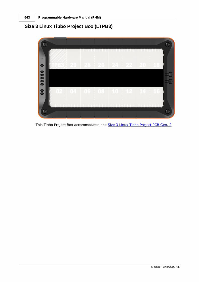
543 Programmable Hardware Manual (PHM)
© Tibbo Technology Inc.
7.4.2.4Size 3 Linux Tibbo Project Box (LTPB3)
This Tibbo Project Box accommodates one Size 3 Linux Tibbo Project PCB Gen. 2.

544Tibbo Project System (TPS)
© Tibbo Technology Inc.
LTPB3 Parts and Accessories
List of parts included with the LTPB3 kit
No.
Part Description Qty.
1.
PM01P1047 Top cover (TPB3) 1
2.
PM01P1048 Bottom Cover (TPB3) 1
3.
PM01P1049 Right side wall (all TPB models) 1
4.
PM01P1050 Left side wall (all TPB models) 1
5.
PM06P1004 LED light guide (all TPB models) 1

545 Programmable Hardware Manual (PHM)
© Tibbo Technology Inc.
6.
PM03P1016 Back label (TPB3) 1
7.
PM921007 Paper insert, bottom row (TPB3) 1
8.
PM921008 Paper insert, top row (TPB3) 1
9.
PM03P1019 Paper Insert Cover (TPB3) 2
10.
PCB-P2164 MD/RST button PCB (all TPB models) 1
11.
PM12P1001-03 Blank Tibbit shell, C1 form factor, orange 8
12.
SM3R5+32SPBC Main Screw (all TPB models) 4
13.
SM2R6+05SPNC PCB screw (all TPB models) 4
14.
PM01P1091-01 Connector plate (LTPB3) 1
The LTPB3 can be purchased with an optional DIN rail mounting kit and anavailable vibration protection kit (VPK), with which TPS devices meet the shock andvibration resistance requirements of the IEC 60068-2-27 standard.

546Tibbo Project System (TPS)
© Tibbo Technology Inc.
Size 3 Vibration Protection Kit (VPK) for LTPB3
The vibration protection kit (VPK) for the Size 3 Linux Tibbo Project Box consists ofa vibration protection plate and four special screws.
The plate is installed as shown on the exploded view of the TPS:
1. Four M2.5 screws securing the TPP are removed and the four special screws(shown above) are instead used to attach the TPP onto the bottom cover.
2. The vibration protection plate goes over Tibbits (installed on the TPP) and restson the special screws.
3. Four M2.5 screws that originally held the TPP in place are used to secure thevibration protection plate onto the special screws.

547 Programmable Hardware Manual (PHM)
© Tibbo Technology Inc.
Mechanical Dimensions
Dimensions are for reference only. Tibbo assumes no responsibility for any errors inthis Manual and does not make any commitment to update the informationcontained herein.

548Tibbo Project System (TPS)
© Tibbo Technology Inc.
Retail Packaging
In the automation world, presentation may not be everything but it is certainly stillvery important. Any product benefits from an attractive retail box, and our TibboProject Box (TPB) kits and Tibbo Project Systems (TPS) are no exception.
TPB/TPS retail packaging kits were designed with the ease of assembly andeconomical cost in mind. You have the choice of ordering unassembled (flattened)cartons and stacked plastic inserts to save space and transportation costs, or youcan order your TPB/TPS fully assembled, in which case it will arrive in the retailpackage fully assembled as well.
Important note: if you order fully assembled TPB/TPS, the retail packaging for eachBox (System) will be automatically included as well. This is because assembledBoxes (Systems) require proper packaging for transportation. Orderingunassembled goods allows you to choose whether to include the retail packagingkits or not.
Another note: the Tibbit remover tool (shown above) is not included with the retailpackaging kit. It is provided for free for every Tibbo Project System ordered. Theremover can also be purchased separately (part #PM05P1014-01).

549 Programmable Hardware Manual (PHM)
© Tibbo Technology Inc.
TPB2/TPS2 Retail Packaging Kit
List of parts included with the TPS2/TPB2 retail packaging kit
Part Description Qty
1
.
PM911018 Retail box (all TPS/TPB models) 1
2
.
PM07P1012 Package tray for TPS2/TPB2, TPS2L/TPB2LTPB2L 1
3
.
PM07P1010 Transparent tray cover (all TPS/TPB models) 1
4
.
PM911019 Accessories box (all TPS/TPB models) 1
5
.
PM921012 Retail package label (TPS2/TPB2) 1

550Tibbo Project System (TPS)
© Tibbo Technology Inc.
TPB2L/TPS2L Retail Packaging Kit
List of parts included with the TPS2L/TPB2L retail packagingkit
Part Description Qty
1
.
PM911018 Retail box (all TPS/TPB models) 1
2
.
PM07P1012 Package tray for TPS2/TPB2,
TPS2L/TPB2LTPB2L
1
3
.
PM07P1010 Transparent tray cover (all TPS/TPB models) 1
4
.
PM911019 Accessories box (all TPS/TPB models) 1
5
.
PM921011 Retail package label (TPS2L/TPB2L) 1

551 Programmable Hardware Manual (PHM)
© Tibbo Technology Inc.
TPB3/TPS3 Retail Packaging Kit
List of parts included with the TPS3/TPB3 retail packaging kit
Part Description Qty
1
.
PM911018 Retail box (all TPS/TPB models) 1
2
.
PM07P1011 Package tray (TPS3/TPB3) 1
3
.
PM07P1010 Transparent tray cover (all TPS/TPB models) 1
4
.
PM911019 Accessories box (all TPS/TPB models) 1
5
.
PM921014 Retail package label (TPS3/TPB3) 1

552Tibbo Project System (TPS)
© Tibbo Technology Inc.
Assembled Retail Package
This is how the assembled retail package looks. The accessories box (2) goes intothe retail package box (1). The accessories box is meant for transporting Wi-Fiantennas, wires, cables, etc.
External Controllers The following external controllers and controller families are currently beingoffered by Tibbo:
· DS/WS110x Family
· DS1206
· DS1202
· DS10xx Family

553 Programmable Hardware Manual (PHM)
© Tibbo Technology Inc.
DS/WS110xIntroduction
The DS/WS110x is a family of compact BASIC-programmable controllers designedfor serial-over-IP and serial control applications.
The DS/WS110x family currently includes:
· WS1102 — BASIC-programmable wireless serial controller featuring Wi-Fi andBLE interfaces on the network side, and an RS232/422/485 port on the serialside.
· DS1100/1/2 — wired serial controllers equipped with an Ethernet port:
o The DS1100 is an entry-level, economically priced serial controller with a
standard RS232 port.
o The DS1101 is a powerful serial controller with a 3.5-channel RS232 port.
o The DS1102 has the same features as the DS1101, but is equipped with a 3-
channel RS232/422/485 port.
DS/WS110x devices are supported by the TIDE software and ship preloaded with afully functional Serial-over-IP application. Written in Tibbo BASIC, the application iscompatible with Tibbo Device Server Toolkit software, comes with full source codes,and can be modified by the user.
Differentiating features
DS1100 DS1101 DS1102 WS1102
Devicecolor
Ethernetport
10/100BaseT Ethernet, Auto-MDIX,debugging over Ethernet
No
Wi-Fi No
optional 802.11a/b/g/n
interface (WA2000)(1)
optional 802.11b/g interface(GA1000) — OBSOLETE
Built-in802.11a/b/g/ninterface withoptional auto-
connect, wireless
debugging,TLS1.2
encryption
BLE No BLE4.2
Serialport
RS232 port ona DB9M
connector
RS232 port ona DB9M
connector
RS232/422/485 port on a
DB9Mconnector
RS232/422/485 port on a
DB9Mconnector
No. ofserial port
1 channel 3.5 channels3 channels(RS232),
1 channel

554External Controllers
© Tibbo Technology Inc.
channels1 ch.
(RS422/485)
Serial portlines
TX, RX, RTS,CTS, DTR,
DSR
TX, RX, RTS,CTS, DTR,DSR, DCD
RS232: TX,RX, RTS, CTS,
DTR, DSR
RS422: TX,RX, RTS, CTS
RS485 (half-duplex): TX,
RX
RS232: TX,RX, RTS, CTS,
DTR(2),
DSR(2)
RS422: TX,RX, RTS, CTS
RS485 (half-duplex): TX,
RX
Maximumbaudrate
Up to115,200bps
Up to 460,800bpsUp to
921,600bps
Flow anddirectioncontrol
Optional RTS/CTS flow control
RS232/422: Optional RTS/CTSflow control
RS485: Direction control
Paritymodes
None/even/odd/mark/space parity
Bits/character
7/8 bits/character
Powerinput/output onDB9
"12V" powerinput on pin 9
of DB9
"12V" powerinput and
output on pin9 of DB9
(software-controllable)
No
Flashmemory
512KB forfirmware andapplicationstorage. Noflash disk
functionality.
1,024KB for firmware,application and data (flash disk)
- 4MB flash forcode storage.- Additional4MB flash forthe hardenedfault-tolerantfile system.
EEPROM 200 bytes 2,048 bytes
LEDs
- Red andgreen status
LEDs
- YellowEthernet link
LED
- Red and green status LEDs
- Yellow Ethernet link LED
- Five blue LEDs (for Wi-Fisignal strength indication, etc.)
- Red andgreen status
LEDs
- Yellow Wi-Filink (access
pointassociation)
LED
- Five blueLEDs (for Wi-
Fi signalstrength

555 Programmable Hardware Manual (PHM)
© Tibbo Technology Inc.
indication,etc.)
Display NoOptional 96x32 monochrome
OLEDNo
PoE Optional(1) No
Buzzer No Yes
Processor
T2000 T1000Tibbo Wi-Fi/BLE SoC
Superiorupgradeto...
DS203 DS1206DS1206,DS100B
---
TiOS andcompiledTibboBASIC/Cappupgrades
Through theserial port or
network(including cold
upgradesthrough thenetwork).
Through the serial port ornetwork (no cold upgrades
through the network).
Through theserial port,
Wi-Fi, or BLE(cold
upgradessupported for
all threeinterfaces).
TibboBASIC/Cappdebugging
Through the EthernetThrough Wi-
Fi(3)
Dual app
support(4)
No Yes(4)
1. The Wi-Fi and PoE options are mutually exclusive.
2. The DTR and DSR lines are not available if serial debugging is enabled.
3. Requires Wi-Fi auto-connects (automatic association with a wireless network) tobe enabled.
4. The WS1102 inherits this and all other advanced features from the WM2000Programmable Wireless IIoT Module, with which it shares the Wi-Fi/BLE SoC.

556External Controllers
© Tibbo Technology Inc.
DS/WS110x Connectors and Controls
· Power arrangement
· Ethernet port
· Serial port
· Flash and EEPROM Memory
· Buzzer (DS1101, DS1102 only, and WS1102)
· Optional Wi-Fi (DS1101 and DS1102 only)
· Built-in Wi-Fi and BLE (WS1102)
· Optional OLED display (DS1101 and DS1102 only)
· LED bar (DS1101, DS1102 only, and WS1102)
· DIN rail and wall mounting plates
· Status LEDs
· Setup (MD) button
8.1.1.1Power Arrangement
All DS/WS110x devices can be powered through the power jack.
The power jack accepts "small" power connectors with a 3.5mm diameter. Use theAPR-P0011, APR-P0012, or APR-P0013 power adapters supplied by Tibbo or asimilar adapter with a 12VDC nominal output voltage. The adapter's current ratingshould be at least 500mA. On the power jack, the ground is "on the outside," asshown in the figure below.

557 Programmable Hardware Manual (PHM)
© Tibbo Technology Inc.
There are also "alternative" ways of powering the devices listed below. Click thelinks below to explore:
DS1100
DS1101
DS1102
DS1100The DS1100 can be powered through its power jack, pin 9 of the DB9 (RS232)connector, or the optional Power over Ethernet (PoE) module (letter "P" in themodel numbering scheme).
Pin 9 input has the same input voltage requirements as the power jack.
The optional PoE module should be powered by 48V (nominal), which is standardfor PoE equipment. Your PoE-enabled hub will take care of this. The PoE moduleoutputs 12VDC.
Internally, all three power sources are connected to the DS1100's power regulatorthrough three diodes, as shown in the diagram below.
DS1101The DS1101 can be powered through its power jack, pin 9 of the DB9 (RS232)connector, or the optional Power over Ethernet (PoE) module (letter "P" in themodel numbering scheme).
Pin 9 input has the same input voltage requirements as the power jack.
The optional PoE module should be powered by 48V (nominal), which is standardfor PoE equipment. Your PoE-enabled hub will take care of this. The PoE moduleoutputs 12VDC.
Internally, all three power sources are connected to the DS1101's power regulatorthrough three diodes, as shown in the diagram below.

558External Controllers
© Tibbo Technology Inc.
Pin 9 of the DB9M connector can also provide "12VDC" power to an attached serialdevice. Many small serial devices, such as barcode scanners, accept power on pin 9of their DB9 connectors.
We intentionally printed "12VDC" in quotation marks. This is because there is noguarantee that the output voltage will be exactly 12V. It will actually be the "inputvoltage minus the voltage drop across the diode." In plain English, it will be slightlyless than the input voltage. If you connect 12V to the power jack, you will getabout 11.7V out of pin 9.
To turn the power switch on from within your Tibbo BASIC/C application, enable(configure as output) the PL_IO_NUM8_PWROUT GPIO line and then set this line toLOW. Additional programming information can be found in TIDE, TiOS, TibboBASIC, and Tibbo C Manual (see the io. object and the DS1101 platformdocumentation).
Note that DS110x devices cannot accommodate the PoE and Wi-Fi options at thesame time.
DS1102The DS1102 can be powered through its power jack or the optional Power overEthernet (PoE) module (letter "P" in the model numbering scheme).
The PoE module should be powered by 48V (nominal), which is standard for PoEequipment. Your PoE-enabled hub will take care of this. The PoE module outputs12VDC.
Internally, both power sources are connected to the DS1102's power regulatorthrough two diodes, as shown in the diagram below.

559 Programmable Hardware Manual (PHM)
© Tibbo Technology Inc.
Note that DS110x devices cannot accommodate the PoE and Wi-Fi options at thesame time.
8.1.1.2Ethernet Port (DS1100/1/2)
The Ethernet port of the DS1100, DS1101, and DS1102 devices is of the10/100BaseT type.
The connector is of the RJ45 type; pin assignment is as follows:
#1 TX+
#2 TX–
#3 RX+
#4 PoE+
#5 PoE+
#6 RX–
#7 PoE–
#8 PoE–
The WS1102 is a wireless-only controller. It has no Ethernet port.
8.1.1.3Serial PortSerial port capabilities are different for each device in the DS/WS110x family:
DS1100
DS1101
DS1102
WS1102
DS1100The DS1100 carries a single-channel RS232 DB9M port.

560External Controllers
© Tibbo Technology Inc.
#1 <No connection>
#2 RX (input)
#3 TX (output)
#4 DTR (output)
#5 Ground
#6 DSR (input)
#7 RTS (output)
#8 CTS (input)
#9 Power input ("12VDC")
DS1101The DS1101 features a multichannel RS232 port. Physically, the port isimplemented as a single DB9M connector with three output lines, four input lines,power input/output, and the ground.
Internally, the DS1101 has four independent serial ports. These are controlledthrough the ser. object (see the TIDE, TiOS, Tibbo BASIC, and Tibbo C Manual).
Each of the four ports has its own TX and RX lines. These lines are implemented inhardware and can't be "remapped." The following table shows how the RX and TXlines are connected to the DB9M:
#1 RX4 (input, commonly DCD)
#2 RX (input)
#3 TX (output)
#4 TX3 (output, commonly DTR)
#5 Ground
#6 RX3 (input, commonly DSR)
#7 TX2 (output, commonly RTS)
#8 RX2 (input, commonly CTS)
#9 Power input/output ("12VDC")

561 Programmable Hardware Manual (PHM)
© Tibbo Technology Inc.
Each logical serial port of the ser. object also supports RTS/CTS flow control, whichis implemented in firmware (TiOS). The ser.rtsmap and ser.ctsmap properties allowyou to assign any GPIO line of the DS1101 to serve as the RTS or CTS line of anylogical serial port. So, the TX2 and RX2 lines (pins 7 and 8) can be assigned towork as RTS and CTS lines, as is traditionally the case for RS232 ports. At thesame time, these lines can be set to function as an independent serial channel.
The same goes for the DTR and DSR lines, except they don't even "exist" from theser. object's perspective. These lines are implemented on the application level. Forexample, our Serial-over-IP application supports these lines. Again, instead ofusing TX3 and RX3 (pins 4 and 6) as the lines of an independent serial channel, itis possible to use them as DTR and DSR lines, as is common.
To simplify the discussion, let's look at the RS232 port from the Serial-over-IPapplication's point of view. This application defines 15 mapping options:
Mappingoption
Available signals Pins on the DB9M connector Missing
line#2
#3 #8 #7 #6 #4 #1
Option 0
RX/TX/CTS/RTS/DSR/DTR
RX
TX CTS
RTS
DSR
DTR
--- ---
Option 1
RX/TX/CTS/RTS/DSR/DTR + RX/tx
RX
TX CTS
RTS
DSR
DTR
RX4
tx4
Option 2
RX/TX/CTS/RTS +RX/TX + RX/tx
RX
TX CTS
RTS
RX3
TX3
RX4
tx4
Option 3
RX/TX/CTS/RTS +RX/TX/CTS/rts
RX
TX CTS
RTS
RX3
TX3
CTS3
rts3
Option 4
RX/TX/CTS/RTS +RX/TX/DSR/dtr
RX
TX CTS
RTS
RX3
TX3
DSR3
dtr3
Option 5
RX/TX/DSR/DTR +RX/TX + RX/tx
RX
TX RX2
TX2
DSR
DTR
RX4
tx4
Option 6
RX/TX/DSR/DTR +RX/TX/CTS/rts
RX
TX RX2
TX2
DSR
DTR
CTS2
rts2
Option 7
RX/TX/DSR/DTR +RX/TX/DSR/dtr
RX
TX RX2
TX2
DSR
DTR
DSR2
dtr2
Option 8
RX/TX + RX/TX +RX/TX + RX/tx
RX
TX RX2
TX2
RX3
TX3
RX4
tx4
Option 9
RX/TX/CTS/rts +RX/TX + RX/TX
RX
TX RX2
TX2
RX3
TX3
CTS
rts
Option 10
RX/TX/DSR/dtr +RX/TX + RX/TX
RX
TX RX2
TX2
RX3
TX3
DSR
dtr
Option 11
RX/TX/CTS/RTS +RX/tx/CTS/RTS
RX
TX CTS
RTS
CTS4
RTS4
RX4
tx4
Option 12
RX/TX/CTS/RTS +RX/tx/DSR/DTR
RX
TX CTS
RTS
DSR4
DTR4
RX4
tx4
Option 13
RX/TX/DSR/DTR +RX/tx/CTS/RTS
RX
TX CTS4
RTS4
DSR
DTR
RX4
tx4
Option 14
RX/TX/DSR/DTR +RX/tx/DSR/DTR
RX
TX DSR4
DTR4
DSR
DTR
RX4
tx4

562External Controllers
© Tibbo Technology Inc.
The Available signals" column shows a particular combination of I/O lines for eachoption. For example, option 0 defines the standard serial port arrangement withRX, TX, CTS, RTS, DSR, and DTR lines. Option 2 gives you one channel with RX,TX, CTS, and RTS lines, one more channel with just RX and TX lines, and yetanother channel with a single RX line. The TX line is "missing" because, once again,there are only three outputs available. This is why this line is shown in gray (tx).
DS1102The DS1102 features a multimode, multichannel RS232/422/485 port. Physically,the port is implemented as a single DB9M connector.
Note: See Definition of RS422 and RS485 Modes for information on how thesemodes are implemented on the DS1102.
Port pin assignment
In the RS232 mode, the serial port of the DS1102 has three output and three inputlines. In the RS422 mode, you get two output and two input line pairs. The RS485mode offers one output line pair and one input line pair. These are not independent— they operate in the half-duplex mode.
Internally, the DS1102 has three independent serial ports. These are controlledthrough the ser. object (see the TIDE, TiOS, Tibbo BASIC, and Tibbo C Manual).
Each of those ports has its own TX and RX lines. These lines are implemented inhardware and can't be "remapped." The following table shows how these RX and TXlines are connected to the DB9M:
RS232 RS422 RS485
#1 <No connection> TX2– (output,
commonly RTS-)
<No connection>
#2 RX (input) RX– (input) RX– (input)
#3 TX (output) TX+ (output) TX+ (output)
#4 TX3 (output, commonly
DTR)
TX– (output) TX– (output)
#5 Ground Ground Ground
#6 RX3 (input, commonly
DSR)
RX+ (input) RX+ (input)
#7 TX2 (output, commonly
RTS)
TX2+ (output,
commonly RTS+)
<No connection>
#8 RX2 (input, commonly
CTS)
RX2+ (input, commonly
CTS+)
<No connection>

563 Programmable Hardware Manual (PHM)
© Tibbo Technology Inc.
#9 <No connection> RX2– (input, commonly
CTS-)
<No connection>
Each logical serial port of the ser. object also supports RTS/CTS flow control, whichis implemented in firmware (TiOS). The ser.rtsmap and ser.ctsmap properties allowyou to assign any GPIO line of the DS1102 to serve as the RTS or CTS line of anylogical serial port. So, the TX2 and RX2 lines (pins 7 and 8) can be assigned towork as RTS and CTS lines, as is traditionally the case for RS232 ports. At thesame time, these lines can be turned to function as an independent serial channel.
The same goes for the DTR and DSR lines, except they don't even "exist" from theser. object's perspective. These lines are implemented on the application level. Forexample, our Serial-over-IP application supports these lines. Again, instead ofusing TX3 and RX3 (pins 4 and 6) as the lines of an independent serial channel, itis possible to use them as DTR and DSR lines, as is common.
To simplify the discussion, let's look at the serial port from the Serial-over-IPapplication's point of view. This application defines 15 mapping options. Even in theRS232 mode, some options are redundant on the DS1102 (but not on theDS1101). Many more options are redundant in the RS422 mode. See the linksbelow to explore further:
Mapping options for the RS232 mode
Mapping options for the RS422 mode
And where are the mapping options for the RS485 mode? There are none — butyou knew this already.
Selecting the serial port mode
On the DS1102, the serial port mode is controlled via two GPIO lines of the CPU —PL_IO_NUM_17 and PL_IO_NUM_18. Both lines should be configured as outputs(see the io. object in the TIDE, TiOS, Tibbo BASIC, and Tibbo C Manual).
To select the desired serial port mode, set the state of these lines as shown in thetable below.
Serial portmode
PL_IO_NUM_17
PL_IO_NUM_18
RS232 LOW HIGH
RS422 HIGH HIGH
RS485 HIGH LOW
Direction control in the RS485 mode
In the RS485 mode, which is half-duplex, the PL_IO_NUM_3_TX1_INT3 GPIO lineacts as the direction control line. The line must be configured as an output.
Direction PL_IO_NUM_3_TX1_INT3
Output HIGH
Input LOW

564External Controllers
© Tibbo Technology Inc.
Mapping Options for the RS232 ModeUnlike on the DS1101, the DS1102 does not have an input on line 1. Hence, someof the 15 mapping options become indistinguishable from other options. Only"unique" options are shown in the table below.
Mappingoption
Available signals Pins on the DB9M connector Missing
lines#2
#3 #8 #7 #6 #4
Option 0
RX/TX/CTS/RTS/DSR/DTR
RX TX CTS RTS DSR
DTR ---
Option 2
RX/TX/CTS/RTS +RX/TX
RX TX CTS RTS RX3 TX3 rx4,tx4
Option 5
RX/TX/DSR/DTR +RX/TX
RX TX RX2 TX2 DSR
DTR rx4,tx4
Option 8
RX/TX + RX/TX +RX/TX
RX TX RX2 TX2 RX3 TX3 rx4,tx4
Option 11
RX/TX/CTS/RTS +CTS/RTS
RX TX CTS RTS CTS4
RTS4
rx4,tx4
Option 12
RX/TX/CTS/RTS +DSR/DTR
RX TX CTS RTS DSR4
DTR4
rx4,tx4
Option 13
RX/TX/DSR/DTR +CTS/RTS
RX TX CTS4
RTS4
DSR
DTR rx4,tx4
Option 14
RX/TX/DSR/DTR +DSR/DTR
RX TX DSR4
DTR4
DSR
DTR rx4,tx4
Mapping Options for the RS422 ModeThere are even fewer options in the RS422 mode:
Mappingoption
Available signals Pin pairs on the DB9Mconnector
Missing
lines
#6,2
#3,4
#8,9
#7,1
Option0
RX/TX/CTS/RTS/DSR/DTR
RX TX CTS RTS dsr, dtr
Option5
RX/TX/DSR/DTR +RX/TX + RX/tx
RX TX RX2 TX2 dsr, dtr, rx4,tx4
Option14
RX/TX/DSR/DTR +RX/tx/DSR/DTR
RX TX DSR4
DTR4
dsr, dtr, rx4,tx4
Mapping Options for the RS485 ModeThere are no mapping options in the RS485 mode. You have one TX line pair andone RX line pair — that's all.

565 Programmable Hardware Manual (PHM)
© Tibbo Technology Inc.
WS1102The WS1102 features a multimode RS232/422/485 port. Physically, the port isimplemented as a single DB9M connector.
Note: See Definition of RS422 and RS485 Modes for information on how thesemodes are implemented on the WS1102.
Port pin assignment
In the RS232 mode, the serial port of the WS1102 has three output and three inputlines. In the RS422 mode, you get two output and two input line pairs. The RS485mode offers one output line pair and one input line pair. These are not independent— they operate in the half-duplex mode.
The serial port of the WS1102 is controlled via the ser. object (see the TIDE, TiOS,Tibbo BASIC, and Tibbo C Manual).
RS232 RS422*** RS485***
#1 <No connection> RTS– (output) <No connection>
#2 RX (input) RX– (input) RX– (input)
#3 TX (output) TX+ (output) TX+ (output)
#4 DTR (output)* TX– (output) TX– (output)
#5 Ground Ground Ground
#6 DSR (input)** RX+ (input) RX+ (input)
#7 RTS (output) RTS+ (output) <No connection>
#8 CTS (input) CTS+ (input) <No connection>
#9 <No connection> CTS– (input) <No connection>
* When serial debugging is enabled, this line ceases to work as the DTR line of theserial port and becomes the TX line of the debug serial port.
** When serial debugging is enabled, this line ceases to work as the DSR line of theserial port and becomes the RX line of the debug serial port.
*** Serial debugging is not possible in these modes.
Selecting the serial port mode
On the WS1102, the serial port mode is controlled via Microchip's MCP23008 I/Oexpander IC. The I²C interface of this IC is connected to GPIO5 and GPIO6 of theWS1102's CPU, as shown in the diagram below.

566External Controllers
© Tibbo Technology Inc.
Use the ssi. object (see the TIDE, TiOS, Tibbo BASIC, and Tibbo C Manual) tocommunicate with the MCP23008. To select the desired serial port mode, set thestate of the I/O expander's lines GP5 and GP6 as shown in the table below (theselines are not to be confused with GPIO5 and GPIO6, which are the CPU lines drivingthe I²C interface of the I/O expander). Both GP5 and GP6 should be configured asoutputs.
Serial portmode
GP5 GP6
RS232 HIGH LOW
RS422 HIGH HIGH
RS485 LOW HIGH
Direction control in the RS485 mode
In the RS485 mode, which is half-duplex, the PL_IO_NUM_3_INT1 GPIO line actsas the direction control line. The line must be configured as an output.

567 Programmable Hardware Manual (PHM)
© Tibbo Technology Inc.
Direction PL_IO_NUM_3_INT1
Output HIGH
Input LOW
Definition of RS422 and RS485 ModesTo avoid any misunderstanding of what the RS422 and RS485 modes are, let'sclarify that the term "RS422 mode" refers to a full-duplex differential signalinginterface with at least RX and TX signals, and possibly with CTS and RTS signals.Each signal is carried by a pair of "+" and "–" lines.
The term "RS485 mode" refers to a half-duplex differential signaling interface withRX and TX lines, where each signal is also carried by a pair of "+" and "–" lines.The RTS line of the serial port is used (within the serial controller) to control thedirection, so TX and RX lines can be combined (externally) to form a two-wire busthat carries data in both directions. On a physical signal level (voltages, etc.), thereis no difference between the RS422 and RS485 modes — they are implemented inthe same way.
The RS422 and RS485 modes typically require termination circuits. No such circuitsare provided within the DS1102 and WS1102. A simple 120Ω resistor (addedexternally) is sufficient to terminate one "+/–" pair properly.
8.1.1.4Flash and EEPROM MemoryThese are the three types of flash memory that you will encounter on DS/WS110xdevices:
· Unified flash memory – stores the TiOS firmware, compiled Tibbo BASIC/C app,and, optionally, the flash disk. All flash space not occupied by TiOS is available tothe compiled Tibbo BASIC/C app. All flash space left over from TiOS and the appcan be formatted as a fault-tolerant flash disk. The flash disk is accessiblethrough the fd. object (see the TIDE, TiOS, Tibbo BASIC, and Tibbo C Manual).
· Program flash memory — stores the TiOS firmware and compiled Tibbo BASICapp(s). All flash space not occupied by TiOS is available to the compiled TibboBASIC/C app.
· Data flash memory — the entire memory space can be formatted as a fault-tolerant flash disk. The flash disk is accessible through the fd. object.
In addition, all DS/WS110x devices are equipped with EEPROM memory. A smallarea at the bottom of the EEPROM is occupied by the Special Configuration Section(SCS) that stores the device's MAC(s) and password. The rest of the EEPROM isavailable to Tibbo BASIC/C applications. The EEPROM is accessible through thestor. object (see the TIDE, TiOS, Tibbo BASIC, and Tibbo C Manual).
Device Unified flashmemory
(availableapp/diskspace)
Programflash
memory
(availableapp space)
Data flashmemory
EEPROM
(spaceoccupied by
the SCS)
DS1100 --- 512KB --- 208 bytes

568External Controllers
© Tibbo Technology Inc.
DS1101 1,024KB(64KB)
--- 2KB (8 bytes)
DS1102 1,024KB(64KB)
--- --- 2KB (8 bytes)
WS1102 --- 4MB(4,048KB)
4MB(4,048KB)
2KB (28bytes)
On the advice of one of our customers, we are giving you the followingreminder: Like all other EEPROMs on the market, EEPROM ICs used in Tibbodevices allow for a limited number of write cycles. As the Wikipedia article
on EEPROM states, the EEPROM "... has a limited life for erasing andreprogramming, now reaching a million operations in modern EEPROMs. In anEEPROM that is frequently reprogrammed while the computer is in use, the life ofthe EEPROM is an important design consideration." When planning to use the stor.object, please carefully consider if the planned mode of EEPROM use will allow theEEPROM to work reliably through the entire projected life of your product. For moreinformation, see Prolonging and Estimating EEPROM Life.
Like all other flash memory devices on the market, flash ICs used in Tibbo productsonly allow for a limited number of write cycles. As the Wikipedia article on flashmemory explains, modern flash ICs still suffer from comparatively low writeendurance. In Tibbo devices, this endurance is about 100,000 write cycles persector. When you are using the flash memory for file storage, the fd. objectemploys sector wear leveling to maximize the life of the flash IC (but the life stillremains limited). If your application employs direct sector access, then it is yourjob to plan the application around the life limitations of the flash memory. For datathat changes often, consider using the EEPROM instead — EEPROMs have muchbetter endurance.
8.1.1.5Buzzer (DS1101, DS1102, and WS1102)The buzzer is available on the DS1101, DS1102, and WS1102 devices. The buzzer'scenter frequency is 2,750Hz.
Your application can control the buzzer through the "beeper" (beep.) object (seethe TIDE, TiOS, Tibbo BASIC, and Tibbo C Manual).
On the DS1101 and DS1102, the buzzer is connected to the PL_IO_NUM_37_COGPIO line. The recommended value for the beep.divider property is 16203.
On the WS1102, the buzzer is connected to the PL_IO_NUM_9 GPIO line. Therecommended value for the beep.frequency property is 2750.

569 Programmable Hardware Manual (PHM)
© Tibbo Technology Inc.
8.1.1.6Optional Wi-Fi (DS1101 and DS1102)The DS1101 and DS1102 can optionally accommodate the WA2000 Wi-Fi/BLE add-on module (letter "W" in the model numbering scheme). Only the Wi-Fifunctionality of the WA2000 is supported by the DS1101 and DS1102. The WA2000superseded the GA1000 Wi-Fi add-on module, which is now obsolete.
The following GPIO lines are used to control the WA2000 (GA1000):
GPIO line Functio
n
WA2000 (GA1000)
pin
PL_IO_NUM_1
5
CS 3
PL_IO_NUM_1
3
DO(1) 5
PL_IO_NUM_1
1
RST 7
PL_IO_NUM_1
2
DI(2) 9
PL_IO_NUM_1
4
CLK 10
Notes:
1. The "data out" line of the DS1101/2; connects to the "data in" on the WA2000(GA1000).
2. The "data in" line of the DS1101/2; connects to the "data out" on the WA2000(GA1000).
Wi-Fi data communications are the responsibility of the sock. object (see the TIDE,TiOS, Tibbo BASIC, and Tibbo C Manual). Before such data communications cantake place, the Wi-Fi interface must be properly configured. This is jointly achievedby the wln. object and WLN library.
Note that DS110x devices cannot accommodate the Wi-Fi and PoE options at thesame time.
8.1.1.7Built-in Wi-Fi and BLE (WS1102)The WS1102 features built-in Wi-Fi and BLE interfaces. These interfaces areaccessible via wln. and bt. objects.
The expanded wln. object supports automatic association with a designatednetwork, wireless debugging, and Transport Layer Security (TLS) 1.2 encryption.

570External Controllers
© Tibbo Technology Inc.
8.1.1.8Optional OLED Display (DS1101 and DS1102)The DS1101 and DS1102 can be optionally outfitted with a 96x32 pixelmonochrome OLED display (letter "D" in the model numbering scheme).
As all displays of this type, the DS1101/2's OLED display has a limited lifespan. There will be a decrease in the display brightness after ~10,000hours of operation. To prolong display life, use the lcd.lock method of thelcd. object to turn the display off whenever possible. The display image ispreserved when the display is "locked."
The following GPIO lines are used to control the display:
GPIO line Function
PL_IO_NUM_36_OLED_RST RST
PL_IO_NUM_35_OLED_DC DC
PL_IO_NUM_34_OLED_WR WR
PL_IO_NUM_33_OLED_RD RD
PL_IO_NUM_32_OLED_CS CS
PL_IO_PORT_NUM_0 data bus
The display is controlled by the lcd. object. Proper I/O line mapping is required forthe display to work, and it takes a single line of code to set this right:
lcd.iomapping="36,35,34,33,32,0"
Additionally, the following lines must be enabled (io.enabled = 1 — YES):
· PL_IO_NUM_36_OLED_RST
· PL_IO_NUM_35_OLED_DC
· PL_IO_NUM_34_OLED_WR
· PL_IO_NUM_33_OLED_RD
· PL_IO_NUM_32_OLED_CS
The PL_IO_PORT_NUM_0 port doesn't need to be enabled. It is bidirectional andthe lcd. object will control it internally.

571 Programmable Hardware Manual (PHM)
© Tibbo Technology Inc.
8.1.1.9LED Bar (DS1101, DS1102, and WS1102)The DS1101, DS1102, and WS1102 feature an LED bar comprised of five blueLEDs. The bar can be used for signal strength indication and other purposes.
Note: The green, red, and yellow status LEDs, which are present on all DS/WS110xdevices, are described in the Status LEDs topic.
DS1101 and DS1102

572External Controllers
© Tibbo Technology Inc.
On these devices, each of the five LEDs is connected to a dedicated GPIO line of theCPU:
GPIO line LED
PL_IO_NUM_23_SB5
LED5 (top, the strongest signal)
PL_IO_NUM_22_SB4
LED4
PL_IO_NUM_21_SB3
LED3
PL_IO_NUM_20_SB2
LED2
PL_IO_NUM_19_SB1
LED1 (bottom, "the lowest signal"
To turn an LED on, enable the corresponding I/O line (io.enabled = 1 — YES) andset this line LOW (io.state = 0 — LOW). Hint: these are properties of the io. object(see the TIDE, TiOS, Tibbo BASIC, and Tibbo C Manual).
WS1102
On this wireless controller, the LEDs are controlled via Microchip's MCP23008 I/Oexpander IC. The I²C interface of this IC is connected to GPIO lines 5 and 6 of theWS1102's CPU, as shown in the diagram below.

573 Programmable Hardware Manual (PHM)
© Tibbo Technology Inc.
Use the ssi. object (see the TIDE, TiOS, Tibbo BASIC, and Tibbo C Manual) tocommunicate with the MCP23008.
To turn an LED on, configure the corresponding line of the IC as an output and setit LOW. Refer to the MCP23008 datasheet for information on how to achieve this.
The WS1102 is fully supported by CODY, Tibbo's project code wizard. CODY cangenerate the scaffolding for your WS1102 projects, including the code to controlthe LED bar.
8.1.1.10DIN Rail and Wall Mounting PlatesEvery DS/WS110x device ships with two mounting plates — one for installation ona DIN rail and one for mounting on a wall.
Both plates are secured onto the device using two screws (included with eachdevice).
The wall mounting plate can be used to mount the DS/WS110x on a wall in a semi-permanent or permanent manner. The diagram below shows the installationfootprint.

574External Controllers
© Tibbo Technology Inc.
Ordering Info and SpecificationsDevice numbering scheme is as follows:

575 Programmable Hardware Manual (PHM)
© Tibbo Technology Inc.
Visit our online store for an up-to-date list of accessories offered with DS/WS110xdevices.
Examples of valid model numbers
Model
numberDescription
WS1102Wireless controller with 802.11a/b/g/n Wi-Fi and BLE4.2 interfaces,
universal RS232/422/485 serial port
DS1101WDWired controller with Ethernet port, universal 3.5-channel RS232 port,
802.11a/b/g/n Wi-Fi add-on, OLED display
DS1102PWired controller with Ethernet port, universal 3-channel
RS232/422/485 serial port, Power over Ethernet (PoE) module
Hardware specifications
DS1100 DS1101 DS1102 WS1102
Ethernet 10/100BaseT Ethernet, Auto-MDIX No
Wi-Fi No
optional 802.11a/b/g/n interface
(WA2000)(1)
optional 802.11b/g interface(GA1000) — OBSOLETE
Built-in802.11a/b/g/ninterface withoptional auto-connect and
wirelessdebugging
Wi-FiSecurity
---WEP, WPA-PSK, and
WPA2-PSK
Wi-FiRange
---At least 100min open spaces
BLE No BLE4.2
Serialport
RS232 port ona DB9M
RS232 port ona DB9M
RS232/422/485 port on a
RS232/422/485 port on a

576External Controllers
© Tibbo Technology Inc.
connector connectorDB9M
connectorDB9M
connector
No. ofserialportchannels
1 channel 3.5 channels
3 channels(RS232),
1 ch.(RS422/485)
1 channel
Serialport lines
TX, RX, RTS,CTS, DTR,
DSR
TX, RX, RTS,CTS, DTR,DSR, DCD
RS232: TX,RX, RTS, CTS,
DTR, DSR
RS422: TX,RX, RTS, CTS
RS485 (half-duplex): TX,
RX
RS232: TX,RX, RTS, CTS,
DTR(2), DSR(2)
RS422: TX,RX, RTS, CTS
RS485 (half-duplex): TX,
RX
Maximumbaudrate
Up to115,200bps
Up to 460,800bpsUp to
921,600bps
Flow anddirectioncontrol
Optional RTS/CTS flow control
RS232/422: Optional RTS/CTSflow control
RS485: Direction control
Paritymodes
None/even/odd/mark/space parity
Bits/character
7/8 bits/character
Powerinput/output onDB9
"12V" powerinput on pin 9
of DB9
"12V" powerinput and
output on pin9 of DB9
(software-controllable)
No
Flashmemory
512KB forfirmware andapplicationstorage. Noflash disk
functionality.
1,024KB for firmware,application and data (flash
disk).
Typical write endurance is100,000 write cycles per 256-byte sector. See the warning in
Flash and EEPROM Memory.
- 4MB flash forcode storage.- Additional4MB flash forthe hardenedfault-tolerantfile system
EEPROM
208 bytes,180 bytes areavailable to
storeapplication
data.(3)
2,048 bytes, 2,020 bytes areavailable to store application
data.(3)
2,048 bytes,28 bytes areavailable to
storeapplication
data.(3)
LEDs- Red and
green statusLEDs
- Red and green status LEDs
- Yellow Ethernet link LED
- Red andgreen status
LEDs

577 Programmable Hardware Manual (PHM)
© Tibbo Technology Inc.
- YellowEthernet link
LED
- Five blue LEDs (for Wi-Fisignal strength indication, etc.)
- Yellow Wi-Filink (access
pointassociation)
LED
- Five blueLEDs (for Wi-
Fi signalstrength
indication,etc.)
PoE(1) Optional(1) No
Buzzer No Yes
Processor
T2000 T1000Tibbo Wi-Fi/BLE SoC
Operatingfrequency andPLL
80MHz, no PLL 88MHz, software-controlled PLL 192MHz
Firmwareupgrades
Through theserial port or
network(including cold
upgradefirmwareuploads
through thenetwork).
Through the serial port ornetwork (no cold upgrades
through the network).
Through theserial port, Wi-
Fi, or BLE(cold upgradessupported for
all threeinterfaces).
Supplyvoltage
12VDC nominal (min. 9V, max. 18V)
CurrentConsumption
~100mA@12VDC withspikes of up to
120mA
- Power outputdisabled:~90mA
@12VDC withspikes of up to
100mA
- Power outputenabled:~125mA
@12VDC withspikes of up to
135mA
~90mA@12VDC withspikes of up to
100mA
- Idle: 55mA~ 65mA@12VDC
- In operation(transferring
data): ~80mA@12VDC withspikes of up to
130mA
Operatingtemperaturerange
–5°C ~ 70 °C–40°C ~ 85°
C(4)

578External Controllers
© Tibbo Technology Inc.
Operatingrelativehumidity
10 ~ 90%
Mechanicaldimensions
90x48x25mm
Cartondimensions
137x99x70mm
1. The Wi-Fi and PoE options are mutually exclusive.
2. The DTR and DSR lines are not available if serial debugging is enabled.
3. Typical write endurance is about 1,000,000 write cycles per EEPROM sector.See Prolonging and Estimating EEPROM Life.
4. Tested according to procedures I, II, and III of MIL-STD-810H Method 501.7and MIL-STD-810H Method 502.7.
All specifications are subject to change without notice and are for reference only.Tibbo assumes no responsibility for any errors in this Manual, and does not makeany commitment to update the information contained herein.
Think the above table should contain additional data? Do not just assume that youknow the answer — talk to Tibbo! Remember that the ultimate responsibility for alldecisions you make regarding the use and the mode of use of Tibbo products lieswith you, our Customer.
DS1206
Introduction
The DS1206 is a miniature BASIC-programmable controller designed primarily forserial-over-IP and serial control applications.
The DS1206 features a multi-channel serial port. The device has a single DB9Mconnector and is priced as a single-port product, yet it packs four independentserial channels. Have no use for those DSR and DTR lines? Turn them into RX and

579 Programmable Hardware Manual (PHM)
© Tibbo Technology Inc.
TX of an additional serial channel. Don't want CTS and RTS either? That's one morechannel! In total, there are 15 different configurations to choose from.
Another feature of the DS1206 is software-controlled power output on pin 9 of theRS232 port, so you can power an attached serial device directly through theDS1206. Alternatively, the DS1206 itself can be powered through this pin.
The DS1206 is fully supported by TIDE software and a dedicated DS1206 platformthat covers all hardware facilities of the device (see TIDE, TiOS, Tibbo BASIC, andTibbo C Manual). This product ships preloaded with a fully functional serial-over-IPapplication. Written in Tibbo BASIC, the application is compatible with Tibbo DeviceServer Toolkit software, comes with full source codes, and can be modified by theuser.
Hardware features
· 10/100Base-T, auto-MDIX Ethernet port.
· 3.5-channel RS232 port on a DB9M connector:
o TX, RX, RTS, CTS, DTR, DSR, DCD lines;
o Baudrates of up to 921,600bps;
o None/even/odd/mark/space parity modes;
o 7 or 8 bits/character;
o RTS/CTS and XON/XOFF flow control;
o Flexible mapping with 15 different options, such as:
§ A single channel: RX, TX, CTS, RTS, DSR, and DTR lines;
§ 3.5 channels: RX, TX, RX2, TX2, RX3, TX3, and RX4 lines;
§ 13 additional arrangements.
· 22KB SRAM for Tibbo BASIC/C variables and data.
· 1MB flash memory for TiOS, application code, and file system.
· 2048-byte EEPROM for data storage.
· Four LEDs:
o Green and red main status LEDs on top of the device;
o Link and speed Ethernet status LEDs on the RJ45 jack.
· Software-controlled PLL for selecting high or low speed.
· Power: 12VDC (10 ~ 24V).
· Programmable "12V" power output on pin 9 of the DB9;
· Pin 9 can also be used for "12V" power input.
· Dimensions (LxWxH): 60 x 47 x 30mm.
· Operating temperature range: -5 ~ +70C.
· Firmware is upgradeable through the serial port or network.
· Tibbo BASIC/C application can be debugged through the Ethernet LAN.
· CE- and FCC-certified.
· Also available as DS1206N (board without housing).
Programming features
· Platform objects:

580External Controllers
© Tibbo Technology Inc.
o button — monitors the MD (setup) button.
o fd — manages the flash memory file system and direct sector access.
o io — handles I/O lines, ports, and interrupts.
o net — controls the Ethernet port.
o pat — "plays" patterns on a pair of status LEDs.
o ppp — accesses the Internet over a serial modem (GPRS, etc.).
o pppoe — accesses the Internet over an ADSL modem.
o romfile — facilitates access to resource files (fixed data).
o ser — controls the serial channels.
o sock — socket comms (up to 16 UDP, TCP, and HTTP sessions).
o stor — provides access to the EEPROM.
o sys — in charge of general device functionality.
· Variable Types: Byte, char, integer (word), short, dword, long, real, string, plususer-defined arrays and structures.
· Function Groups: 27 string functions, 8 date/time conversion functions,encryption/hash calculation functions (RC4, MD5, SHA-1), and more.
DS1206 Connectors and Controls
Click on one of the links provided below to learn more about the DS1206:
· Power arrangement
· Ethernet port
· Multi-channel RS232 port
· Flash and EEPROM Memory
· Status LEDs
· Setup button

581 Programmable Hardware Manual (PHM)
© Tibbo Technology Inc.
8.2.1.1Power Arrangement
Normally, the DS1206 is powered through its power jack.
The power jack of the DS1206 accepts "small" power connectors with 3.5mmdiameter. Use APR-P0011, APR-P0012, or APR-P0013 power adapter supplied byTibbo or similar adapter with 12V nominal output voltage. Adapter current ratingshould be at least 500mA. On the power jack, the ground is "on the outside", asshown on the figure below.
Alternatively, the DS1206 can be powered through a pin 9 of the DB9M (RS232)connector. Two internal diodes combine power jack and pin 9 inputs into a singleline, which goes to the internal regulator of the DS1206.
The pin 9 of the RS232 port can also be used to provide "12V" power to anattached serial device. Many small serial devices, such as barcode scanners, acceptpower on pin 9 of their DB9 connectors.
"12V" actually means "input power on the power jack", which is not necessarilystabilized. The power line of the jack passes through a software-controlled switchand is then connected to pin 9 of the RS232 port through a Schottky diode (shownon the diagram below). Therefore, the voltage on pin 9 is close to the input voltageon the power jack. Also, the maximum current an attached serial device can sourcedepends on the maximum output power of the power adapter (power supply)plugged into the power jack (minus the power consumed by the DS1206 itself).
Tibbo serial-over-IP application supplied with the DS1206 has a dedicated"PS" ("Power on pin 9") setting to control the power switch. To turn the powerswitch on from within your Tibbo BASIC/C application, enable (configure as output)line PL_IO_NUM8_PWROUT and then set this line to HIGH. Additional programming

582External Controllers
© Tibbo Technology Inc.
information can be found in TIDE, TiOS, Tibbo BASIC, and Tibbo C Manual (see i.oobject and DS1206 platform documentation).
If you want to use pin 9 of the DB9M connector to power an attached serial device,then you must power the DS1206 itself through the power jack. We know youunderstand this, but we still had to mention it.
8.2.1.2Ethernet Port
Ethernet port of the DS1206 is of 10/100BaseT type.
The connector is of RJ45 type, pin assignment is as follows:
#1 TX+
#2 TX-
#3 RX+
#4 <No connection>
#5 <No connection>
#6 RX-
#7 <No connection>
#8 <No connection>
The Ethernet port of the DS1206 incorporates two Ethernet status LEDs.
8.2.1.3Multi-channel RS232 PortThe DS1206 features a multi-channel RS232 port. Internally, the DS1206 has fourindependent serial ports, and each of those ports can potentially have its own RX,TX, CTS, RTS, DSR, and DTR lines. Physically, the RS232 port of the DS1206 hasthree output lines and four input lines. Flexible mapping allows you to choose howthese inputs and outputs will be used.
The serial-over-IP application supplied with the DS1206 defines 15 mappingoptions. These are presented in the table below:

583 Programmable Hardware Manual (PHM)
© Tibbo Technology Inc.
Mappingoption
Available signals Pins on the DB9M connector Missing
line#2
#3 #8 #7 #6 #4 #1
Option 0
RX/TX/CTS/RTS/DSR/DTR
RX
TX CTS
RTS
DSR
DTR
--- ---
Option 1
RX/TX/CTS/RTS/DSR/DTR + RX/tx
RX
TX CTS
RTS
DSR
DTR
RX4
tx4
Option 2
RX/TX/CTS/RTS +RX/TX + RX/tx
RX
TX CTS
RTS
RX3
TX3
RX4
tx4
Option 3
RX/TX/CTS/RTS +RX/TX/CTS/rts
RX
TX CTS
RTS
RX3
TX3
CTS3
rts3
Option 4
RX/TX/CTS/RTS +RX/TX/DSR/dtr
RX
TX CTS
RTS
RX3
TX3
DSR3
dtr3
Option 5
RX/TX/DSR/DTR +RX/TX + RX/tx
RX
TX RX2
TX2
DSR
DTR
RX4
tx4
Option 6
RX/TX/DSR/DTR +RX/TX/CTS/rts
RX
TX RX2
TX2
DSR
DTR
CTS2
rts2
Option 7
RX/TX/DSR/DTR +RX/TX/DSR/dtr
RX
TX RX2
TX2
DSR
DTR
DSR2
dtr2
Option 8
RX/TX + RX/TX +RX/TX + RX/tx
RX
TX RX2
TX2
RX3
TX3
RX4
tx4
Option 9
RX/TX/CTS/rts +RX/TX + RX/TX
RX
TX RX2
TX2
RX3
TX3
CTS
rts
Option 10
RX/TX/DSR/dtr +RX/TX + RX/TX
RX
TX RX2
TX2
RX3
TX3
DSR
dtr
Option 11
RX/TX/CTS/RTS +RX/tx/CTS/RTS
RX
TX CTS
RTS
CTS4
RTS4
RX4
tx4
Option 12
RX/TX/CTS/RTS +RX/tx/DSR/DTR
RX
TX CTS
RTS
DSR4
DTR4
RX4
tx4
Option 13
RX/TX/DSR/DTR +RX/tx/CTS/RTS
RX
TX CTS4
RTS4
DSR
DTR
RX4
tx4
Option 14
RX/TX/DSR/DTR +RX/tx/DSR/DTR
RX
TX DSR4
DTR4
DSR
DTR
RX4
tx4
"Available signals" column shows a particular combination of I/O lines for eachoption. For example, option 0 defines the standard serial port arrangement withRX, TX, CTS, RTS, DSR, and DTR lines. Option 2 gives you one channel with RX,TX, CTS, and RTS lines, one more channel with just RX and TX lines, and yet

584External Controllers
© Tibbo Technology Inc.
another channel with a single RX line. The TX line is "missing" because, once again,there are only three outputs available. This is why this line is shown in greylowercase (tx).
Notice that on the DS1206, pin 9 of the RS232 port can be used to power theDS1206 or provide power to an attached serial device. See Power Arrangement fordetails.
Additional programming information regarding serial ports can be found in TIDE,TiOS, Tibbo BASIC, and Tibbo C Manual.
8.2.1.4Flash and EEPROM MemoryThe DS1206 has 512KBytes or 1024KBytes of flash memory and 2KBytes ofEEPROM memory.
The first 64KBytes of flash memory are used to store the TiOS firmware. When youare performing a firmware upgrade it is this memory you are saving the firmwarebinary into.
The rest of this flash memory is available to your Tibbo BASIC/C application and itsdata. Whatever memory space is left after the compiled application is loaded canbe used as a flash disk (see fd. object documentation in the TIDE, TiOS, TibboBASIC, and Tibbo C Manual).
The EEPROM is almost fully available to your application, save for a small 28-bytearea called "special configuration area". The EEPROM is accessed through the stor.object (see TIDE, TiOS, Tibbo BASIC, and Tibbo C Manual).
On the advice of one of our customers we are giving you the followingreminder: Like all other EEPROMs on the market, EEPROM ICs used in Tibbodevices allow for a limited number of write cycles. As the Wikipedia article
on EEPROMs (https://en.wikipedia.org/wiki/EEPROM) states, the EEPROM "...has alimited life for erasing and reprogramming, now reaching a million operations inmodern EEPROMs. In an EEPROM that is frequently reprogrammed while thecomputer is in use, the life of the EEPROM is an important design consideration."When planning to use the stor. object, please carefully consider if the plannedmode of EEPROM use will allow the EEPROM to work reliably through the entireprojected life of your product. For more information see Prolonging and EstimatingEEPROM Life.
Like all other flash memory devices on the market, flash ICs used in Tibbo productsonly allow for a limited number of write cycles. As the Wikipedia article on flashmemory (https://en.wikipedia.org/wiki/Flash_memory) explains, modern flash ICsstill suffer from comparatively low write endurance. In Tibbo devices, thisendurance is around 100'000 write cycles per sector. When you are using the flashmemory for file storage, the fd. object employs sector wear leveling to maximizethe life of the flash IC (but the life still remains limited). If your applicationemploys direct sector access, then it is your job to plan the application around thelife limitations of the flash memory. For data that changes often, consider using theEEPROM memory instead. EEPROMs have much better endurance.

585 Programmable Hardware Manual (PHM)
© Tibbo Technology Inc.
Ordering Info and Specifications
Device numbering scheme is as follows:
Visit our online store for the up-to-date list of accessories offered with the DS1206.
Examples of valid model numbers
Model number Description
DS1206-512K-00 DS1206 device with 512KBytes of flash memory
DS1206-1024K-00 DS1206 device with 1MB of flash memory
Hardware specifications
Ethernet interface 10/100BaseT Ethernet, Auto-MDIX
Serial ports One RS232 port (DB9M) with 3.5 serial channels(four inputs and three outputs)
UART capabilities Baudrates up to 921'600bps;none/even/odd/mark/space parity and 7/8bits/character.
Clock frequency 11.0592MHz with PLL off
88.4736MHz with PLL on
Flash memory 512KBytes or 1024KBytes, entire memory minus64KB is available to store Tibbo BASIC/Capplication and data.
Typical write endurance is 100'000 write cycles per256-byte sector. See the warning in Flash andEEPROM Memory.
EEPROM memory 2048 bytes, 2020 bytes available to storeapplication data.
Typical write endurance is around 1'000'000 writecycles per 16-byte EEPROM sector. See Prolongingand Estimating EEPROM life.
Supply voltage range DC 10-24V (12V nominal)
Operating temperature -5 to +70 degrees C
Operating relativehumidity
10-90%
Mechanical dimensions 60x47x30mm
Carton dimensions 125x95x52mm

586External Controllers
© Tibbo Technology Inc.
Gross weight 110g
All specifications are subject to change without notice and are for reference only.Tibbo assumes no responsibility for any errors in this Manual, and does not makeany commitment to update the information contained herein.
Think the above table should contain additional data? Do not just assume that youknow the answer — talk to Tibbo! Remember that the ultimate responsibility for alldecisions you make regarding the use and the mode of use of Tibbo products lieswith you, our Customer.
DS1202
Introduction
The DS1202 is a miniature BASIC-programmable controller designed primarily forserial-over-IP and serial control applications.
The DS1202 features a multi-channel serial port. The device has a single DB9Mconnector and is priced as a single-port product, yet it packs four independentserial channels. Have no use for those DSR and DTR lines? Turn them into RX andTX of an additional serial channel. Don't want CTS and RTS either? That's one morechannel! In total, there are 15 different configurations to choose from.
The DS1202 is fully supported by TIDE software and a dedicated DS1202 platformthat covers all hardware facilities of the device (see TIDE, TiOS, Tibbo BASIC, andTibbo C Manual). This product ships preloaded with a fully functional serial-over-IPapplication. Written in Tibbo BASIC, the application is compatible with Tibbo DeviceServer Toolkit software, comes with full source codes, and can be modified by theuser.
Hardware features
· Superior upgrade to the DS203 devices.
· Based on the EM1202 BASIC-programmable embedded module.
· 100BaseT auto-MDIX Ethernet port (automatic detection of "straight" and "cross"cables).
· Up to 3.5 serial channels on a single RS232 connector:
o Baudrates of up to 921,600bps;

587 Programmable Hardware Manual (PHM)
© Tibbo Technology Inc.
o None/even/odd/mark/space parity modes;
o 7/8 bits/character modes;
o Optional flow control;
o Flexible mapping with 15 different options, such as:
§ A single channel: RX, TX, CTS, RTS, DSR, and DTR lines;
§ 3.5 channels: RX, TX, RX2, TX2, RX3, TX3, and RX4 lines.
· 1024KB flash memory for firmware, application, and data storage.
· 2KB EEPROM for data storage.
· Six LEDs:
o Green and red status LEDs on top of the device;
o Green and red status LEDs on the RJ45 jack;
o Link and speed Ethernet status LEDs on the RJ45 jack.
· Software-controlled onboard PLL to select the clock frequency of the device:11.0592MHz with PLL off, 88.4736MHz with PLL on.
· Supply voltage range: 10-24V (12V nominal).
· Dimensions: 60x47x30mm.
· Firmware and Tibbo BASIC/C application are upgradeable through the serial portor network.
· Tibbo BASIC/C application can be debugged through the network and noadditional debugging hardware, such as in-circuit emulator, is required.
· Also available as a EM1202EV (board without housing).
Programming features
· Variable Types: Byte, char, integer (word), short, dword, long, real, string, plususer-defined arrays and structures.
· Function Groups: string functions (27 in total!), date/time conversion functions(8), encryption/hash calculation functions (AES128, RC4, MD5, SHA-1), andmore.
· Platform objects:
o sock — socket communications (up to 16 UDP, TCP, and HTTP sessions);
o net — controls the Ethernet port;
o ser — in charge of serial channels;
o ssi — implements up to four serial synchronous interface (SSI) channels,
supports SPI, I2C, clock/data, etc.;
o io — handles I/O lines, ports, and interrupts;
o fd — manages flash memory file system and direct sector access;
o stor — provides access to the EEPROM;
o romfile — facilitates access to resource files (fixed data);
o pppoe — provides access to the Internet over an ADSL modem;
o ppp — provides access to the Internet over a serial modem (GPRS, POTS, etc.);
o pat — "plays" patterns on green and red status LEDs;
o button — monitors the setup button;

588External Controllers
© Tibbo Technology Inc.
o sys — in charge of general device functionality.
DS1202 Connectors and Controls
Click on one of the links provided below to learn more about the DS1202:
· Power arrangement
· Ethernet port
· Multi-channel RS232 port
· Flash and EEPROM memory
· Status LEDs
· Setup button
8.3.1.1Power ArrangementThe DS1202 is powered through its power jack. The power jack of the DS1202accepts "small" power connectors with 3.5mm diameter. Use APR-P0011, APR-P0012, or APR-P0013 power adapter supplied by Tibbo or similar adapter with 12Vnominal output voltage. Adapter current rating should be at least 500mA. On thepower jack, the ground is "on the outside", as shown on the figure below.

589 Programmable Hardware Manual (PHM)
© Tibbo Technology Inc.
8.3.1.2Ethernet Port
Ethernet port of the DS1202 is of 10/100BaseT type.
Connector is of RJ45 type, pin assignment is as follows:
#1 TX+
#2 TX-
#3 RX+
#4 <No connection>
#5 <No connection>
#6 RX-
#7 <No connection>
#8 <No connection>
The Ethernet port of the DS1202 incorporates four LEDs (two status LEDs and twoEthernet status LEDs). The DS1202 has another pair of status LEDs located on topof the board. Two status LED pairs work in parallel.
8.3.1.3Multi-Channel RS232 PortThe DS1202 has four serial ports internally. The RS232 port of the DS1202implements three outputs, four inputs, and one "spare" input (CD). Each of thethree outputs can be used as a TX line of a serial channel, or as a control outputsuch as RTS or DTR. Input lines can be used as an RX line of a serial channel, or asa control input such as CTS or DSR. The spare input cannot work as an RX line.This input is not used by the serial-over-IP application supplied by Tibbo and will belargely omitted from further discussion. Your Tibbo BASIC/C application can alwaysuse this extra input if you require it.
With three outputs and four inputs, the DS1202 can be said to offer 3.5 serial"channels". We say "3.5 channels" and not "four channels" because one channelwill only have RX line and no TX line (remember, there are four inputs but onlythree outputs).

590External Controllers
© Tibbo Technology Inc.
Mappingoption
Available signals Pins on the DB9M connector of theDS1202-RS
Missing
line#2
#3 #8 #7 #6 #4 #9
Option 0
RX/TX/CTS/RTS/DSR/DTR
RX
TX CTS
RTS
DSR
DTR
--- ---
Option 1
RX/TX/CTS/RTS/DSR/DTR + RX/tx
RX
TX CTS
RTS
DSR
DTR
RX4
tx4
Option 2
RX/TX/CTS/RTS +RX/TX + RX/tx
RX
TX CTS
RTS
RX3
TX3
RX4
tx4
Option 3
RX/TX/CTS/RTS +RX/TX/CTS/rts
RX
TX CTS
RTS
RX3
TX3
CTS3
rts3
Option 4
RX/TX/CTS/RTS +RX/TX/DSR/dtr
RX
TX CTS
RTS
RX3
TX3
DSR3
dtr3
Option 5
RX/TX/DSR/DTR +RX/TX + RX/tx
RX
TX RX2
TX2
DSR
DTR
RX4
tx4
Option 6
RX/TX/DSR/DTR +RX/TX/CTS/rts
RX
TX RX2
TX2
DSR
DTR
CTS2
rts2
Option 7
RX/TX/DSR/DTR +RX/TX/DSR/dtr
RX
TX RX2
TX2
DSR
DTR
DSR2
dtr2
Option 8
RX/TX + RX/TX +RX/TX + RX/tx
RX
TX RX2
TX2
RX3
TX3
RX4
tx4
Option 9
RX/TX/CTS/rts +RX/TX + RX/TX
RX
TX RX2
TX2
RX3
TX3
CTS
rts
Option 10
RX/TX/DSR/dtr +RX/TX + RX/TX
RX
TX RX2
TX2
RX3
TX3
DSR
dtr
Option 11
RX/TX/CTS/RTS +RX/tx/CTS/RTS
RX
TX CTS
RTS
CTS4
RTS4
RX4
tx4
Option 12
RX/TX/CTS/RTS +RX/tx/DSR/DTR
RX
TX CTS
RTS
DSR4
DTR4
RX4
tx4
Option 13
RX/TX/DSR/DTR +RX/tx/CTS/RTS
RX
TX CTS4
RTS4
DSR
DTR
RX4
tx4
Option 14
RX/TX/DSR/DTR +RX/tx/DSR/DTR
RX
TX DSR4
DTR4
DSR
DTR
RX4
tx4
"Available signals" column shows a particular combination of I/O lines for eachoption. For example, option 0 defines the standard serial port arrangement withRX, TX, CTS, RTS, DSR, and DTR lines. Option 2 gives you one channel with RX,
591 Programmable Hardware Manual (PHM)
© Tibbo Technology Inc.
TX, CTS, and RTS lines, one more channel with just RX and TX lines, and yetanother channel with a single RX line. The TX line is "missing" because, once again,there are only three outputs available. This is why this line is shown in greylowercase (tx).
8.3.1.4Flash and EEPROM MemoryThe DS1202 has 1024KBytes of flash memory and 2KBytes of EEPROM memory.
The first 64KBytes of flash memory are used to store the TiOS firmware. When youare performing a firmware upgrade it is this memory you are saving the firmwarebinary into.
The rest of this flash memory is available to your Tibbo BASIC/C application and itsdata. Whatever memory space is left after the compiled application is loaded canbe used as a flash disk (see fd. object documentation in the TIDE, TiOS, TibboBASIC, and Tibbo C Manual).
The EEPROM is almost fully available to your application, save for a small 28-bytearea called "special configuration area". The EEPROM is accessed through the stor.object (see TIDE, TiOS, Tibbo BASIC, and Tibbo C Manual). Details on the specialconfiguration area are provided in the Platform-dependent ProgrammingInformation section inside the DS1202 and EM1202 platform documentation (samemanual).
On the advice of one of our customers we are giving you the followingreminder: Like all other EEPROMs on the market, EEPROM ICs used in Tibbodevices allow for a limited number of write cycles. As the Wikipedia article
on EEPROMs (https://en.wikipedia.org/wiki/EEPROM) states, the EEPROM "...has alimited life for erasing and reprogramming, now reaching a million operations inmodern EEPROMs. In an EEPROM that is frequently reprogrammed while thecomputer is in use, the life of the EEPROM is an important design consideration."When planning to use the stor. object, please carefully consider if the plannedmode of EEPROM use will allow the EEPROM to work reliably through the entireprojected life of your product. For more information see Prolonging and EstimatingEEPROM Life.
Like all other flash memory devices on the market, flash ICs used in Tibbo productsonly allow for a limited number of write cycles. As the Wikipedia article on flashmemory (https://en.wikipedia.org/wiki/Flash_memory) explains, modern flash ICsstill suffer from comparatively low write endurance. In Tibbo devices, thisendurance is around 100'000 write cycles per sector. When you are using the flashmemory for file storage, the fd. object employs sector wear leveling to maximizethe life of the flash IC (but the life still remains limited). If your applicationemploys direct sector access, then it is your job to plan the application around thelife limitations of the flash memory. For data that changes often, consider using theEEPROM memory instead. EEPROMs have much better endurance.
Ordering Info and SpecificationsThe DS1202 device is only available in a single configuration and can be order as"DS1202".
Hardware specifications

592External Controllers
© Tibbo Technology Inc.
Ethernet interface 10/100BaseT Ethernet, Auto-MDIX
Serial ports One RS232 port (DB9M) with 3.5 serial channels(four inputs and three outputs)
UART capabilities Baudrates up to 921'600bps;none/even/odd/mark/space parity and 7/8bits/character.
Clock frequency 11.0592MHz with PLL off
88.4736MHz with PLL on
Flash memory 1024KBytes, entire memory minus 64KB isavailable to store Tibbo BASIC/C application anddata.
Typical write endurance is 100'000 write cycles per256-byte sector. See the warning in Flash andEEPROM Memory.
EEPROM memory 2048 bytes, 2020 bytes available to storeapplication data.
Typical write endurance is around 1'000'000 writecycles per 16-byte EEPROM sector. See Prolongingand Estimating EEPROM life.
Supply voltage range DC 10-24V (12V nominal)
Operating temperature -5 to +70 degrees C
Operating relativehumidity
10-90%
Mechanical dimensions 60x47x30mm
Carton dimensions 125x95x52mm
Gross weight 110g
All specifications are subject to change without notice and are for reference only.Tibbo assumes no responsibility for any errors in this Manual, and does not makeany commitment to update the information contained herein.
Think the above table should contain additional data? Do not just assume that youknow the answer — talk to Tibbo! Remember that the ultimate responsibility for alldecisions you make regarding the use and the mode of use of Tibbo products lieswith you, our Customer.

593 Programmable Hardware Manual (PHM)
© Tibbo Technology Inc.
DS10xx
The DS10xx is a family of BASIC-programmable industrial controllers.
The DS10xx is a universal platform that is well suited for a variety of controlapplications. The functionality of the device depends on a Tibbo BASIC/C applicationcreated (loaded) by the user.
All devices of the DS10xx family share a number of common features.
Internally, each device contains two main boards: an NB10x0 network board ("NB"),and an IB100x interface boards ("IB") that implements the I/O functionality ofdevices. These boards are interconnected by an IC1000 cable. Some interface boardsalso carry a second "supplementary" board ("SB"). Additionally, there are two LEDboards — LB1000 and LB1001. The LB1000 is attached to the NB10x0, the LB1001— to the IB100x.
At the moment, the DS10xx family includes the following devices:
· DS10x0 (4 RS232 ports);
· DS10x2 (4 RS232/422/485 ports);
· DS10x3 (4 isolated RS232/422/485 ports);
· DS10x4 (8 analog inputs, 4 analog outputs, RS232/485 port, 2 relays);
· DS10x5 (8 opto-isolated inputs, 6 relays, RS232/485 port);
If none of standard DS10xx devices suit your needs, you are welcome to create yourvery own controller with exactly the set of I/Os required for your project. You canalso subcontract the design and manufacturing of your custom "IB" board to Tibbo.
When used with the included waterproof cover, all devices of the DS10xx family aredust and water-proof to IP68.
Programming features
· Variable Types: Byte, char, integer (word), short, dword, long, real, string, plususer-defined arrays and structures.

594External Controllers
© Tibbo Technology Inc.
· Function Groups: string functions (27 in total!), date/time conversion functions(8), encryption/hash calculation functions (AES128, RC4, MD5, SHA-1), andmore.
· Platform objects:
o sock — socket communications (up to 16 UDP, TCP, and HTTP sessions);
o net — controls the Ethernet port;
o wln — handles the Wi-Fi interface (requires GA1000 add-on module);
o ser — in charge of serial channels;
o ssi — implements up to four serial synchronous interface (SSI) channels,
supports SPI, I2C, clock/data, etc.;
o io — handles I/O lines, ports, and interrupts;
o rtc — keeps track of date and time;
o fd — manages flash memory file system and direct sector access;
o stor — provides access to the EEPROM;
o romfile — facilitates access to resource files (fixed data);
o pppoe — provides access to the Internet over an ADSL modem;
o ppp — provides access to the Internet over a serial modem (GPRS, POTS, etc.);
o pat — "plays" patterns on green and red status LEDs;
o beep — generates buzzer patterns;
o button — monitors the setup button;
o sys — in charge of general device functionality.
Common Features of the DS10xx FamilyThis section describes all common features of the DS10xx family:
· Secondary cover
· DIN rail mounting
8.4.1.1Secondary CoverAll DS10xx devices are dust- and water-proof to IP68 when used with the properlyinstalled secondary cover. Diagram below shows the procedure of waterproofingany DS10xx device. Shown on the diagram are devices with terminal blocks(DS1004, DS1005). Other devices in the DS10xx series have DB9 connectors (seeDS1000, DS1002, DS1003). Tibbo offers a TB1000 terminal block adapter that"converts" DB9 connector into terminal blocks. The TB1000 is compatible with thesecondary cover.

595 Programmable Hardware Manual (PHM)
© Tibbo Technology Inc.

596External Controllers
© Tibbo Technology Inc.
8.4.1.2DIN Rail Mounting
All DS10xx devices are supplied with the DMK1000 DIN rail mounting kit. Mountingholes on the back of the device allow you to attach the DIN rail mounting brackethorizontally or vertically.
DS10x0, DS10x2, DS10x3 (4 Serial Ports)

597 Programmable Hardware Manual (PHM)
© Tibbo Technology Inc.
The DS10x0, DS10x2, and DS10x3 BASIC-programmable controllers offer fourserial ports. DS1000, DS1002, and DS1003 are based on the NB1000 networkboard (Ethernet interface only). DS1010, DS1012, and DS1013 are based on theNB1010 network board (Ethernet + optional Wi-Fi + optional GPRS).
Read carefully the explanation about the type of antenna installed whenthe DS1010, DS1012, and DS1013 are ordered with Wi-Fi, GPRS, or Wi-Fiand GPRS options.
· The DS1000 and DS1010 have 4 "simple" RS232 serial ports (the IB1000interface board is used);
· The DS1002 and DS1012 have 4 non-isolated universal RS232/422/485 serialports (the IB1002 interface board is used);
· The DS1003 and DS1013 have 4 electrically isolated RS232/422/485 serial ports(the IB1003 interface board is used);
Follow these quick links to often needed information:
· Right (network) side of the device:
o Power jack, terminals, and power regulator;
o Ethernet jack;
o Ethernet LEDs, M (mode) and R (reset) buttons;
o "Right side" LEDs;
o Buzzer control;
o Optional Wi-Fi interface (DS101x devices only);
o Optional GPRS interface (DS101x devices only).
· Left (interface) side of the device:
o Pin assignment and control of serial ports;
o "Left side" LEDs.
8.4.2.1Ordering Info and SpecificationsDevice numbering scheme is as follows:

598External Controllers
© Tibbo Technology Inc.
DS101x devices without "G", "C", or "GC" options are not being offered by Tibbo. Ifyou want to purchase Ethernet-only device (without any wireless options), thenorder DS100x instead.
External Antenna
DS1010, DS1012, and DS1013 devices can be ordered with Wi-Fi, GPRS, or Wi-Fiand GPRS options. The Wi-Fi interface works better when equipped with anantenna. In the absence of Wi-Fi antenna, the Wi-Fi interface still works (relying ona small "chip" antenna on the GA1000), but the operating range is reduced. TheGPRS interface can't work without the antenna at all. Therefore:
· DS1010G, DS1012G, and DS1013G devices (with Wi-Fi option) will be shippedwith Wi-Fi antenna.
· DS1010C, DS1012C, and DS1013C devices (with GPRS option) will be shippedwith GPRS antenna.
· DS1010GC, DS1012GC, and DS1013GC devices (with Wi-Fi and GPRS options)will be shipped with GPRS antenna. The Wi-Fi interface will rely on the internal"chip" antenna and, therefore, will have reduced range compared to DS1010G,DS1013G, and DS1013G devices.
Hardware specifications
Network side DS1000, DS1002, and DS1003: NB1000 + LB1000
DS1010, DS1012, and DS1013: NB1000 + LB1000
Interface side DS1000 and DS1010: IB1000 + LB1001
DS1002 and DS1012: IB1002 + LB1001
DS1003 and DS1013: IB1003 + LB1001
Supply voltage range DC 10-18VDC (12VDC nominal)
Operating temperature -30 to +80 degrees C
Operating relativehumidity
10-90%
Mechanical dimensions 91x104x99mm
Carton dimensions 203x160x110mm
All specifications are subject to change without notice and are for reference only.Tibbo assumes no responsibility for any errors in this Manual, and does not makeany commitment to update the information contained herein.
Think the above table should contain additional data? Do not just assume that youknow the answer — talk to Tibbo! Remember that the ultimate responsibility for alldecisions you make regarding the use and the mode of use of Tibbo products lieswith you, our Customer.

599 Programmable Hardware Manual (PHM)
© Tibbo Technology Inc.
DS10x4 (Analog I/O)
The DS10x4 BASIC-programmable controllers feature eight A/D inputs, four D/Aoutputs with both voltage and current outputs, two low-power relays, and oneRS232/485 port. The DS1004 is based on the NB1000 network board (Ethernetinterface only), and the DS1014 is based on the NB1010 network board (Ethernet+ optional Wi-Fi + optional GPRS).
Read carefully the explanation about the type of antenna installed whenthe DS1014 is ordered with Wi-Fi, GPRS, or Wi-Fi and GPRS options.
Follow these quick links to often needed information:
· Right (network) side of the device:
o Power jack, terminals, and power regulator;
o Ethernet jack;
o Ethernet LEDs, M (mode) and R (reset) buttons;
o "Right side" LEDs;
o Buzzer control;
o Optional Wi-Fi interface (DS1014 devices only);
o Optional GPRS interface (DS1014 devices only).
· Left (interface) side of the device:

600External Controllers
© Tibbo Technology Inc.
o Terminal blocks and control lines;
o A/D converter;
o D/A converter;
o Relays;
o RS232/485 port;
o "Left side" LEDs.
8.4.3.1Ordering Info and SpecificationsDevice numbering scheme is as follows:
DS1014 devices without "G", "C", or "GC" options are not being offered by Tibbo. Ifyou want to purchase Ethernet-only device (without any wireless options), thenorder DS1004 instead.
External Antenna
The DS1014 can be ordered with Wi-Fi, GPRS, or Wi-Fi and GPRS options. The Wi-Fi interface works better when equipped with an antenna. In the absence of Wi-Fiantenna, the Wi-Fi interface still works (relying on a small "chip" antenna on theGA1000), but the operating range is reduced. The GPRS interface can't workwithout the antenna at all. Therefore:
· The DS1014G device (with Wi-Fi option) will be shipped with Wi-Fi antenna.
· The DS1014C device (with GPRS option) will be shipped with GPRS antenna.
· The DS1014GC device (with Wi-Fi and GPRS options) will be shipped with GPRSantenna. The Wi-Fi interface will rely on the internal "chip" antenna and,therefore, will have reduced range compared to the DS1014G.
Hardware specifications
Network side DS1004: NB1000 + LB1000
DS1014: NB1000 + LB1000
Interface side IB1004 + SB1004 + LB1001
Supply voltage range DC 10-18VDC (12VDC nominal)
Operating temperature -30 to +80 degrees C
Operating relativehumidity
10-90%
Mechanical dimensions 91x104x99mm

601 Programmable Hardware Manual (PHM)
© Tibbo Technology Inc.
Carton dimensions 203x160x110mm
All specifications are subject to change without notice and are for reference only.Tibbo assumes no responsibility for any errors in this Manual, and does not makeany commitment to update the information contained herein.
Think the above table should contain additional data? Do not just assume that youknow the answer — talk to Tibbo! Remember that the ultimate responsibility for alldecisions you make regarding the use and the mode of use of Tibbo products lieswith you, our Customer.
DS10x5 (Digital I/O)
The DS10x5 BASIC-programmable controllers feature eight opto-isolated digitalinputs, six high-power relays, and one RS232/485 port. The DS1005 is based onthe NB1000 network board (Ethernet interface only), and the DS1015 is based onthe NB1010 network board (Ethernet + optional Wi-Fi + optional GPRS).
Read carefully the explanation about the type of antenna installed whenthe DS1015 is ordered with Wi-Fi, GPRS, or Wi-Fi and GPRS options.
Follow these quick links to often needed information:
· Right (network) side of the device:

602External Controllers
© Tibbo Technology Inc.
o Power jack, terminals, and power regulator;
o Ethernet jack;
o Ethernet LEDs, M (mode) and R (reset) buttons;
o "Right side" LEDs;
o Buzzer control;
o Optional Wi-Fi interface (DS1015 devices only);
o Optional GPRS interface (DS1015 devices only).
· Left (interface) side of the device:
o Terminal blocks and control lines;
o Opto-isolated inputs;
o Relays;
o RS232/485 port;
o "Left side" LEDs.
8.4.4.1Ordering Info and SpecificationsDevice numbering scheme is as follows:
DS1015 devices without "G", "C", or "GC" options are not being offered by Tibbo. Ifyou want to purchase Ethernet-only device (without any wireless options), thenorder DS1005 instead.
External Antenna
The DS1015 can be ordered with Wi-Fi, GPRS, or Wi-Fi and GPRS options. The Wi-Fi interface works better when equipped with an antenna. In the absence of Wi-Fiantenna, the Wi-Fi interface still works (relying on a small "chip" antenna on theGA1000), but the operating range is reduced. The GPRS interface can't workwithout the antenna at all. Therefore:
· The DS1015G device (with Wi-Fi option) will be shipped with Wi-Fi antenna.
· The DS1015C device (with GPRS option) will be shipped with GPRS antenna.
· The DS1015GC device (with Wi-Fi and GPRS options) will be shipped with GPRSantenna. The Wi-Fi interface will rely on the internal "chip" antenna and,therefore, will have reduced range compared to the DS1015G.
Hardware specifications

603 Programmable Hardware Manual (PHM)
© Tibbo Technology Inc.
Network side DS1005: NB1000 + LB1000
DS1015: NB1000 + LB1000
Interface side IB1005 + SB1005 + LB1001
Supply voltage range DC 10-18VDC (12VDC nominal)
Operating temperature -30 to +80 degrees C
Operating relativehumidity
10-90%
Mechanical dimensions 91x104x99mm
Carton dimensions 203x160x110mm
All specifications are subject to change without notice and are for reference only.Tibbo assumes no responsibility for any errors in this Manual, and does not makeany commitment to update the information contained herein.
Think the above table should contain additional data? Do not just assume that youknow the answer — talk to Tibbo! Remember that the ultimate responsibility for alldecisions you make regarding the use and the mode of use of Tibbo products lieswith you, our Customer.
Sensors (Probes)The following sensor families are currently being offered by Tibbo:
· RS485 Modbus Sensors ("Bus Probes")
· Cable Probes
RS485 Modbus Sensors ("Bus Probes")
BP#01 sensor shown
Bus Probes are a family of environment sensors with an RS485 interface. TheProbes communicate using standard Modbus RTU protocol.
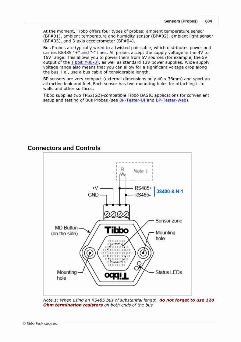
604Sensors (Probes)
© Tibbo Technology Inc.
At the moment, Tibbo offers four types of probes: ambient temperature sensor(BP#01), ambient temperature and humidity sensor (BP#02), ambient light sensor(BP#03), and 3-axis accelerometer (BP#04).
Bus Probes are typically wired to a twisted pair cable, which distributes power andcarries RS485 "+" and "-" lines. All probes accept the supply voltage in the 4V to15V range. This allows you to power them from 5V sources (for example, the 5Voutput of the Tibbit #00-3), as well as standard 12V power supplies. Wide supplyvoltage range also means that you can allow for a significant voltage drop alongthe bus, i.e., use a bus cable of considerable length.
BP sensors are very compact (external dimensions only 40 x 36mm) and sport anattractive look and feel. Each sensor has two mounting holes for attaching it towalls and other surfaces.
Tibbo supplies two TPS2(G2)-compatible Tibbo BASIC applications for convenientsetup and testing of Bus Probes (see BP-Tester-UI and BP-Tester-Web).
Connectors and Controls
Note 1: When using an RS485 bus of substantial length, do not forget to use 120Ohm termination resistors on both ends of the bus.

605 Programmable Hardware Manual (PHM)
© Tibbo Technology Inc.
· Each Bus Probe has a detachable terminal block with four terminals: ground(GND), power (+V), as well as RS485+ and RS485- lines of the RS485 signalpair.
· Communications parameters of the RS485 port are 38400-8-N-1.
· When using an RS485 bus of substantial length, do not forget to add 120 Ohmtermination resistors on both ends of the bus.
· The MD button* has two uses:
o For enabling writes into protected Modbus registers of Bus Probes;
o For entering the firmware update mode of the Monitor/Loader.
· Status LEDs display a number of device states and errors.
· Mounting holes can be used to attach Probes to flat surfaces.
* Each Bus Probe comes with a metal pin that makes pushing and holding down theMD button easier.
Modbus Registers of Bus ProbesThis topic lists Modbus registers found on Tibbo Bus Probes.
Common registers
These registers are present on all Bus Probes.
Addr.
Name R/W
Type Description
200
ID(non-volatile)
R/Wp
Unsigned16-bit
Device ID (Modbus address). This ID must bebetween 1 to 247. Attempts to set an ID outside ofthis range will be ignored.
Default ID of a Probe depends on the Probe's type:
0x40 for BP#01 (ambient temperature sensor);0x41 for BP#02 (relative humidity andtemperature sensor);0x42 for BP#03 (ambient light sensor);0x43 for BP#04 (3-axis accelerometer).
201
TYPE R Unsigned16-bit
Probe type:
1 — BP#01 (ambient temperature sensor);2 — BP#02 (ambient temperature and humiditysensor);

606Sensors (Probes)
© Tibbo Technology Inc.
3 — BP#03 (ambient light sensor);4 — BP#04 (3-axis acceleration sensor).
203
SIGNATURE
R Unsigned16-bit
Always returns 0xAA55. This is a commonsignature for all Bus Probes.
207
USERWORD 1(non-volatile)
R/W
Unsigned16-bit
Users are free to save any application-specific datain this register.
208
USERWORD 2(non-volatile)
R/W
Unsigned16-bit
Users are free to save any application-specific datain this register.
209
USERWORD 3(non-volatile)
R/W
Unsigned16-bit
Users are free to save any application-specific datain this register.
210
USERWORD 4(non-volatile)
R/W
Unsigned16-bit
Users are free to save any application-specific datain this register.
211
MONITORVERSION
R Unsigned16-bit
Firmware version of the Monitor/Loader.
212
FIRMWAREVERSION
R Unsigned16-bit
Firmware version of the application firmware.
R = read, W = write, Wp = protected write (possible only while the MD button* isbeing pressed).
* Each Bus Probe comes with a metal pin that makes pushing and holding down theMD button easier.
Additional registers of BP#01 (ambient temperature sensor)
Addr.
Name R/W
Type Description
300
TEMP_PROC
R Signed16-bit
Processed fixed-point temperature data expressedin steps of 0.01 degrees C.Measurement resolution is 0.25 degrees C.
30
TEMP_RAW
R Unsigned
Raw temperature data from the measurement IC(MCP9808).

607 Programmable Hardware Manual (PHM)
© Tibbo Technology Inc.
1 16-bit
See vendor datasheet for details.
R = read (only)
Additional registers of BP#02 (ambient temperature andrelative humidity sensor)
Addr.
Name R/W
Type Description
400
TEMP_PROC
R Signed16-bit
Processed fixed-point temperature data expressedin steps of 0.1 degrees C.Measurement resolution is 0.5 degrees C.
401
TEMP_RAW
R Unsigned16-bit
Raw temperature data from the measurement IC(HIH6130).See vendor datasheet for details.
404
HUM_PROC
R Unsigned16-bit
Processed fixed-point relative humidity dataexpressed in steps of 0.1%.Measurement resolution is 0.1%.
405
HUM_RAW
R Unsigned16-bit
Raw humidity data from the measurement IC(HIH6130).See vendor datasheet for details.
R = read (only)
Additional registers of BP#03 (ambient light sensor)
Addr.
Name R/W
Type Description
500
LUM_PROC
R Unsigned16-bit
Processed fixed-point luminance data expressed insteps of 1 Lux.Measurement resolution is 1 Lux.
501
LUM_RAW
R Unsigned16-bit
Raw luminance data from the measurement IC(BH1721FVC).See vendor datasheet for details.
R = read (only)

608Sensors (Probes)
© Tibbo Technology Inc.
Additional registers of BP#04 (3-axis accelerometer)
Addr.
Name R/W
Type Description
600
AXIS_X_PROC
R Signed 16-bit
Processed fixed-point X-axis acceleration dataexpressed in steps of ~0.003G.Measurement resolution is ~0.003 G.
601
AXIS_X_RAW
R Signed 16-bit
Raw X-axis acceleration data from themeasurement IC (ADXL312).See vendor datasheet for details.
602
AXIS_Y_PROC
R Signed 16-bit
Processed fixed-point Y-axis acceleration dataexpressed in steps of ~0.003G.Measurement resolution is ~0.003 G.
603
AXIS_Y_RAW
R Signed 16-bit
Raw Y-axis acceleration data from themeasurement IC (ADXL312).See vendor datasheet for details.
604
AXIS_Z_PROC
R Signed 16-bit
Processed fixed-point Z-axis acceleration dataexpressed in steps of ~0.003G.Measurement resolution is ~0.003 G.
605
AXIS_Z_RAW
R Signed 16-bit
Raw Z-axis acceleration data from themeasurement IC (ADXL312).See vendor datasheet for details.
R = read (only)

609 Programmable Hardware Manual (PHM)
© Tibbo Technology Inc.
Setting Up and Testing Bus ProbesPerhaps the most convenient way of managing and testing the Bus Probes is byusing a TPS2(G2) system running one of our Bus Probe testing apps:
· BP-Tester-UI — allows you to test and manage the Probes. Offers an LCD- andkeypad-based user interface. You can find this app and its description here:http://tibbo.com/programmable/applications/sensors/bp-tester-ui.html.
· BP-Tester-Web — offers the same functionality, but relies on a web interface forinteracting with a user. You can find this app and its description here:http://tibbo.com/programmable/applications/sensors/bp-tester-web.html.
Both apps allow you to:
· Scan for Probes connected to a RS485 port of the TPS2 system;
· Set Modbus IDs of Bus Probes;
· Poll the Probes for data and display it on the LCD screen (or web page);
· Update internal firmware of bus probes.
Setting Modbus IDsLike all Modbus devices, Bus Probes connected to the same RS485 bus must beassigned unique Modbus IDs.
Modbus ID of each probe is stored in its register 0x200. IDs must be in the rangebetween 1 and 247. Attempts to set a value outside of this range will be ignored.
Perhaps the most convenient way of setting the IDs of Bus Probes is by using aTPS2(G2) system running one of the two Bus Probe testing apps provided by Tibbo.
Alternatively, you can use any suitable Modbus software to write a new value intothe ID register. Since personal computers do not come equipped with RS485 ports,you will need to procure a USB-to-RS485 cable. We successfully tested DigiFusion"FTDI-based" USB-to-RS485 cable. You will also need a DC power source to powerthe Probes (5~12V voltage range recommended).
It is only possible to alter the ID register when the MD button is pressed*.Therefore, you must press and hold the MD button when sending the writecommand to your Bus Probe.
* Note: each Bus Probe comes with a metal pin that makes pushing and holdingdown the MD button easier.
Default Modbus IDs
Default Modbus ID of a Probe depends on the Probe's type:
· 0x40 for BP#01 (ambient temperature sensor);
· 0x41 for BP#02 (relative humidity and temperature sensor);
· 0x42 for BP#03 (ambient light sensor);
· 0x43 for BP#04 (3-axis accelerometer).

610Sensors (Probes)
© Tibbo Technology Inc.
Updating Probe Firmware
The Monitor/Loader
The application firmware of Bus Probes is updated with the aid of a residentfirmware called the Monitor/Loader (M/L).
The M/L is launched every time a Bus Probe is powered up or reboots. Whenhappens next depends on whether the MD button is pressed at the moment the M/Lstarts running:
· If the MD button is not pressed, the M/L verifies the sanity of and launchesthe application firmware.
· If the MD button is pressed, the M/L enters the firmware update mode. Thismode is for updating the application firmware of Bus Probes. The firmware isupdated via the RS485 port of Bus Probes, using the XModem communicationsprotocol.
Prerequisites
To update a Bus Probe's firmware, you must have the firmware file you will besending into that Bus Probe. BP firmware is published here:http://tibbo.com/support/downloads/bus-probe-firmware.html. A single firmwarefile covers all BP models.
Perhaps the most convenient way of updating the application firmware of BusProbes is by using a TPS2(G2) system running one of the two Bus Probe testingapps provided by Tibbo.
If you don't have a TPS(G2) device you can perform a firmware upgrade from yourPC.
To perform an XModem serial upgrade from a PC:
· You must have a USB-to-RS485 cable. We successfully tested DigiFusion "FTDI-based" USB-to-RS485 cable.
· You must have a DC power source providing clean power in the 5~12V range.
· You will need a "terminal" software supporting XModem file transfers. Any"terminal" software capable of sending files using XModem protocol will do. Forexample, you can employ Tibbo's own IO Ninja software. You can download ithere: http://ioninja.com/downloads.html.
Update procedure
· Connect the USB-to-RS485 cable to your PC.
· Interconnect the RS485+ and RS485- terminals of your Bus Probe withcorresponding terminals on the USB-to-RS485 cable.
· Connect the power source to +V and GND terminals of the Bus Probe. Keep thesupply voltage in the 5~12V range.
· Turn off the power.
· Run IO Ninja software.

611 Programmable Hardware Manual (PHM)
© Tibbo Technology Inc.
IO Ninja toolbar
· Click New Session, then choose Serial.
· Click New Layer and add the XModem layer.
· Click Settings and make sure that:
o Correct Port is selected;
o The Baud rate is 38400;
o The number of Data Bits is set to 8;
o The number of Stop Bits is set to 1; and
o Parity is set to None.
o The flow control is set to None.
· Click Open.
· Click Transmit File With XModem, select the firmware file to send, and clickOpen.
· Press and hold the MD button on the Bus Probe. Each Bus Probe comes with ametal pin that makes pushing and holding down the MD button easier.
· Apply power to the Bus Probe. The upload should start. You may release the MDbutton at this point.
· During the upload, the status LEDs will be showing the following patterns:
o — the Probe is receiving and storing the file;
o — XModem transmission completed;
o A number of error patterns may also be displayed. Please refer to the status
LEDs topic for more info.
· After the upload completes, power-cycle the Probe. The newly loaded applicationfirmware will start executing.

612Sensors (Probes)
© Tibbo Technology Inc.
Updating the Monitor/Loader
It is also possible to update the M/L itself. M/L updates are distributed asapplication firmware files. The sole function of a M/L updater firmware is to updatethe M/L (with the M/L code contained within the firmware).
To update the M/L:
· Upload this updater firmware in the same manner used to upload the applicationfirmware (explained above).
· Reboot your Bus Probe and let the updater firmware execute.
· The updater firmware will go through displaying three distinctive status LEDpatterns:
o — the Probe is preparing to update the M/L. Do not turn off the
power.
o — the Probe is updating the M/L. Do not turn off the power.
o — the M/L has been updated. You can now safely turn off the
power or reboot the Probe.
· Upload the application firmware to make the Probe operational.
Status LEDsBus Probes feature two status LEDs — greed and red. LED patterns of Bus Probesconform to Tibbo's standard LED patterns used on our programmable devices.
Here is the list of LED patterns supported by BP sensors:
· During the device boot, after the Monitor/Loader (M/L) verifies the integrity of theapplication firmware:
Pattern Description Meaning
Green and red LEDs blinking in
turns at high speed
Application firmware is not loadedor corrupted
· When the M/L is in the firmware update mode:
Pattern
Description Meaning
Green LED is permanently on The M/L is ready to receive a file
Green LED is flickering unevenly The M/L is receiving a file
Green LED blinking at slow speed XModem file upload completed
successfully
"One long + one short" red LED
pattern
Communications error during the
XModem file upload
"One long + two short" red LED
pattern
The file is too large

613 Programmable Hardware Manual (PHM)
© Tibbo Technology Inc.
"One long + three short" red LED
pattern
FLASH memory failure
"One long + four short" red LED
pattern
The file is invalid (that is, contains
invalid data)
· When the application firmware is executing:
Pattern
Description Meaning
Green LED blinks once Bus Probe sensor has received a
Modbus request with correct
checksum
Red LED blinks once Bus Probe sensor has received a
Modbus request with incorrect
checksum
· When the M/L updater firmware is executing:
Pattern
Description Meaning
Red LED is permanently on The Probe is preparing to update the
M/L. Do not turn off the power.
Green LED is flickering unevenly,
red LED permanently on
The Probe is updating the M/L. Do not
turn off the power.
"Two short" green LED pattern The M/L has been updated. You can
now safely turn off or power-cycle the
Probe.

614Sensors (Probes)
© Tibbo Technology Inc.
Outline Dimensions
Dimensions are for reference only. Tibbo assumes no responsibility for any errors inthis Manual, and does not make any commitment to update the informationcontained herein.
Ordering Info and SpecificationsBus Probes are available in four versions:
· BP#01 — Ambient temperature sensor
· BP#02 — Ambient temperature and humidity sensor
· BP#03 — Ambient light sensor
· BP#04 — Three-axis accelerometer
Specifications
Interface Half-duplex (two-wire) RS485 interface
Communications
parameters:
38400-8-N-1
Protocol Modbus RTU
Power supply
range
4~15VDC

615 Programmable Hardware Manual (PHM)
© Tibbo Technology Inc.
BP#01
(ambient
temperature
sensor)
· Measurement range: –40°C to 125°C1
· Measurement resolution: 0.25°C
· Measurement accuracy: ±1°C2
BP#02
(ambient
temperature and
humidity sensor)
· Temperature measurement:
o Measurement range: –25 to 50°C
o Measurement resolution: 0.5°C
o Measurement accuracy: not specified3
· Humidity measurement:
o Measurement range: 10% to 90% RH
o Measurement resolution: 0.1% RH
o Measurement accuracy: ±5% RH4
o Temperature range for valid humidity measurements: 5°C to
50°C
BP#03
(ambient light
sensor)
· Measurement range: 1 to 8,191 lux
· Measurement resolution: 1 lux
· Measurement accuracy: 1 lux
BP#04
(Three-axis
accelerometer)
· Independent X, Y, and Z axes
· Measurement range for each axis: ±6G
· Measurement resolution for each axis: 0.003G
· Measurement accuracy for each axis: 0.1G
Operating
temperature
range
–40°C to +85°C
Operating relative
humidity
10-90%
Mechanical
dimensions
(excluding
terminal blocks)
40.0 x 36.0 x 19.0 mm
1. The actual measurement range is limited by the operating temperature range ofthe Bus Probe itself, which is –40°C to +85°C.
2. Independent lab tests commissioned by our Romanian distributor found BP#01'smeasurement accuracy for ambient temperature to be ±0.45°C or better.
3. Independent lab tests commissioned by our Romanian distributor found BP#02'smeasurement accuracy for ambient temperature to be ±0.5°C or better.
4. Independent lab tests commissioned by our Romanian distributor found BP#02'smeasurement accuracy for relative humidity to be ±3.8% or better.
Disclaimer

616Sensors (Probes)
© Tibbo Technology Inc.
All specifications are subject to change without notice and are for reference only.Tibbo assumes no responsibility for any errors in this documentation, and does notmake any commitment to update the information contained herein.
Think the above table should contain additional data? Do not just assume that youknow the answer — talk to Tibbo! Remember that the ultimate responsibility for alldecisions you make regarding the use and the mode of use of Tibbo products lieswith you, our Customer.
Cable Probes
Cable Probes are a family of miniature environment sensors measuring ambienttemperature, humidity, and light. The family also includes an IRreceiver/transmitter. Cable Probes are primarily intended for use with our TibboProject System (TPS) devices. Each Probe has a Tibbit counterpart and you canthink of CP devices as "Tibbits on a cable." Of course, you can wire the Probes toother hardware as well.
At the moment, Tibbo offers four Probe types:
· Ambient temperature sensor (CP#01). This Probe is functionally compatiblewith Tibbit #29. The accuracy of this Tibbit is affected by the internal heatgenerated by the host TPS device. A Cable Probe is immune to such negativeinfluence by virtue of being outside of the TPS.
· Ambient temperature and humidity sensor (CP#02). This Probe isfunctionally compatible with Tibbit #30. Again, the accuracy of this Tibbit isaffected by the internal heat generated by the host TPS device. A Cable Probe isimmune to such negative influence by virtue of being outside of the TPS.
· Ambient light sensor (CP#03). This Probe is functionally compatible withTibbit #28. This Probe has an advantage over the Tibbit in that, unlike its Tibbitcounterpart, it can be easily pointed in the desired direction.

617 Programmable Hardware Manual (PHM)
© Tibbo Technology Inc.
· IR receiver/transmitter (BP#04). This Probe is functionally compatible withTibbit #27. Again, the advantage of this Probe over the Tibbit implementation isthat the Probe can be easily pointed in the desired direction.
Cable Probes are inconspicuous and can be mounted on walls and ceilings withoutattracting unwanted attention. The Probes come with a 100cm cable and areavailable with and without mounting ears. To simplify the installation on smoothflat surfaces, a double-sided sticker is included with each Probe.
Wire Connections
Wiring the Probes to TPS devices
Color Cable Probes ##1~3 Cable Probe #4
White (light gray) I2C-SCL IR-TX
Green I2C-SDA IR-RX
Red +5VDC
Black Ground

618Sensors (Probes)
© Tibbo Technology Inc.
This wiring scheme ensures compatibility with Tibbits of similar functions. Forexample, let's suppose that there is a Tibbo BASIC/C app that works with Tibbit#29 (ambient temperature meter) plugged into the slot S2 of the TPS2 device.Then, replacing this Tibbit with Tibbit #21 (four terminal blocks) and wiring a CableProbe #01 to this terminal block as shown above will allow the app to rununchanged. The same applies to other Probes and their Tibbit counterparts.
The only adjustment that the app may need is the speed of the I2Ccommunications for Probes 1~3. Since the cable of these Probes moves the sensingICs away from the CPU, the I2C clock frequency needs to be lowered. Werecommend the ssi.baudrate of 100.
Wiring the Probes to other hardware
Although the Cable Probes are primarily intended for use with TPS devices, theycan also be wired to other hardware. When connecting to third-party hardwaredevices, remember to add a pull-up resistor (of about 2KOhm) to the SCL line ofProbes ##1~3 (this is not necessary for wiring to TPS devices).
Testing Cable ProbesPerhaps the most convenient way of testing the Cable Probes ##01~0-3 is byusing a TPS2(G2) system running one of these testing apps:
· Sensor-Tester-UI — Automatically identifies the connected Probe and displaysits readings on the LCD of a TPS2L(G2) device. You can find this app and itsdescription here: https://github.com/tibbotech/Sensor-Tester-UI.
· Sensor-Tester-Web — offers the same functionality, but shows the readings ona web page. You can find this app and its description here:https://github.com/tibbotech/Sensor-Tester-Web.
We recommend testing the Cable Probe #04 using this application:http://tibbo.com/programmable/applications/office_aircon_control.html.

619 Programmable Hardware Manual (PHM)
© Tibbo Technology Inc.
Outline Dimensions
Dimensions are for reference only. Tibbo assumes no responsibility for any errors inthis Manual, and does not make any commitment to update the informationcontained herein.
Ordering and SpecificationsCable Probes are supplied in two versions:
· CP#01, CP#02, CP#03, and CP#04 devices have no mounting ears;
· CP#01E, CP#02E, CP#03E, and CP#04E devices have mounting ears for M2screws.
Mounting ears are detailed in Outline Dimensions.
Specifications
Power supply range 5VDC±10%
CP#01 and CP#01E(ambient temperaturesensor)
· Based on the MCP9808 IC;
· Functionally compatible with Tibbit #29;
· Measurement range: -40 to +125°C*;
· Measurement resolution: 0.25°C;

620Sensors (Probes)
© Tibbo Technology Inc.
· Measurement accuracy: ±1°C.
CP#02 and CP#02E(ambient temperatureand humidity sensor)
· Based on the HIH6130 IC;
· Functionally compatible with Tibbit #30;
· Temperature measurement:
o Measurement range: -25 to +50°C;
o Measurement resolution: 0.5°C;
o Measurement accuracy: not specified.
· Humidity measurement:
o Measurement range: 10 to 90%RH;
o Measurement resolution: 0.1%RH;
o Measurement accuracy: ±5%RH;
o Temperature range for valid humidity
measurements: +5 to +50°C.
CP#03 and CP#03E(ambient light sensor)
· Based on the BH1721FVC IC;
· Functionally compatible with Tibbit #28;
· Measurement range: 1 to 65528 lux;
· Measurement resolution: 1 lux;
· Measurement accuracy: 1 lux.
CP#04 and CP#04E(IR receiver/transmitter)
· Based on TSMP6000 infrared photo detector and
TSAL6100 infrared emitter;
· Functionally compatible with Tibbit #27.
Operating temperaturerange
-40 to +85 degrees C
Operating relativehumidity
10-90%
Mechanical dimensions · Without mounting ears: 22.0 x 29.0 x 12 mm
· With mounting ears: 33.0 x 29.0 x 12 mm
* The actual measurement range is limited by the operating temperature range ofthe Cable Probe itself, which is -40 to +125°C.
All specifications are subject to change without notice and are for reference only.Tibbo assumes no responsibility for any errors in this Manual, and does not makeany commitment to update the information contained herein.
Think the above table should contain additional data? Do not just assume that youknow the answer — talk to Tibbo! Remember that the ultimate responsibility for alldecisions you make regarding the use and the mode of use of Tibbo products lieswith you, our Customer.

621 Programmable Hardware Manual (PHM)
© Tibbo Technology Inc.
Companion ProductsThe following companion products are currently being offered by Tibbo:
· WA2000 (802.11a/b/g/n Wi-Fi + BLE 4.2 add-on module)
· GA1000 (802.11b/g Wi-Fi add-on module)
· RJ203 (jack/magnetics module)
WA2000
Introduction
The WA2000 is an upgrade to Tibbo's GA1000 Wi-Fi add-on module. Notableimprovements include:
· Support for the 5GHz Wi-Fi band (802.11a and 801.11n standards).
· Support for BLE4.2 communications.
· WPA key calculation completely on the module, complex calculations in TibboBASIC/C are no longer necessary.
· Firmware stored in the module's flash memory, thus eliminating the need to sendthe firmware file into the module on every boot.
· The firmware can be upgraded from a Tibbo BASIC/C app or over-the-air (OTA),from Tibbo Updater iOS and Android apps.
· Wide operating temperature range: -40 ~ +85C.
The WA2000 is fully supported on Tibbo's ARM-based programmable devices:EM2000, EM2001, TPP2(G2), TPP3(G2).
The WA2000 is also partially supported on T1000-based programmable Tibboproducts. Such devices can only access the Wi-Fi interface of the WA2000, as theBLE interface is not supported by related platforms. The devices are: DS1101,DS1102, EM1000, EM1001, EM1206, TPP2, TPP3.
Like the GA1000, the WA2000 utilizes an SPI interface and only requires five GPIOsto control. The module is supplied in two versions: the WA2000U with an U.FLconnector for attaching an external antenna, and WA2000C device with a chipantenna onboard.
Please note that the WA2000 is a slave device and cannot be used on its own. Thisadd-on will only work with one of Tibbo devices listed above.

622Companion Products
© Tibbo Technology Inc.
Hardware features
· Supports the following wireless communications standards:
o 2.4/5.0GHz Wi-Fi (802.11abgn);
o Bluetooth Low-Energy (BLE4.2)1.
· Nearly 100% backward-compatible with the original GA1000 device.
· Performs WPA key calculation completely internally.
· Requires only five GPIO lines to control.
· Internal firmware of the WA2000:
o Stored in the WA2000's onboard flash memory.
o Upgradeable from a Tibbo BASIC/C app or over-the-air (OTA)2;
o OTA updates may cover TiOS+Tibbo BASIC/C app of the host2;
o Tibbo supplies iOS/Android apps for performing OTA updates.
· L.U.I.S. app for iOS and Android facilitates convenient HTML5-based
configuration of host devices through the BLE interface3.
· Two antenna configurations:
o WA2000U — has a U.FL connector for an external antenna;
o WA2000C — carries a chip antenna onboard.
· Red status LED for connection indication4.
· Power: 200mA @ 3.3V (active state with data transmission).
· Dimensions (LxWxH): 42.0 x 20.0 x 5.8mm.
· Prototyping-friendly 2.54mm (100mil) pin pitch.
· Operating temperature range: -40 ~ +85C.
· CE and FCC-certified (FCC ID: XOJ-WA2000).
1. BLE is only supported on ARM-based Tibbo devices.
2. Over-the-air (OTA) updates rely on the BLE interface and are only possible onARM-based Tibbo devices.
3. Requires a programmable Tibbo device running a Tibbo BASIC/C app supportingL.U.I.S. (through the use of the L.U.I.S. library).
4. "Connection" means a BLE link or a Wi-Fi association with an access point.

623 Programmable Hardware Manual (PHM)
© Tibbo Technology Inc.
Connector Pin Assignment
I/O pin assignment
Pin # Function
Description
1 GND System ground.
2 VCC Positive power input, 3.3V nominal, +/- 5%.
3 CS Chip select, active LOW (input*).
4 RX UART, receive line (input*).
5 DI SPI port, data in (input*, must be connected to DO of Tibbomodule).
6 TX UART, transmit line (output*).
7 RST Reset, active LOW (input*).
8 N.C. No connection.
9 DO SPI port, data out (output*, must be connected to DI ofTibbo module).
10 CLK SPI port, clock (input*).
* Of the WA2000.

624Companion Products
© Tibbo Technology Inc.
The UART of the WA2000 is currently unused but may be enabled in the future.
Connecting WA2000 to Tibbo DevicesThe WA2000 communicates with Tibbo devices through an SPI interface. Fiveinterface lines are involved:
· CS — chip select;
· CLK — clock;
· DI — data in (must be connected to the DO line of the host);
· DO — data out (must be connected to DI line of the host);
· RST — reset.
Most Tibbo devices that can work with the WA2000 allow remapping of CS, CLK,DI, and DO lines. This is done through wln.csmap, wln.clkmap, wln.dimap, andwln.domap properties of the Wi-Fi (wln.) object. The only exception is the EM510device, which has a fixed set of GPIO lines for interfacing to the WA2000.
The wln. object does not automatically configure these interface lines as inputs oroutputs, this is the responsibility of your Tibbo BASIC/C application. To allow theproper communications with the WA2000, configure the following lines as outputs:CS, CLK, DO, and RST.
The wln. object works with these four interface lines: CS, CLK, DI, and DO. TheRST line is not directly controlled by the wln. object, so providing a properhardware reset is your application's responsibility. Any suitable GPIO line can beconnected to the RST line. To reset the WA2000, set the RST line LOW, wait for 1ms, then set the line HIGH.
Special case — the EM510
The diagram below shows how to connect the WA2000 to the EM510 module. GPIOlines are a precious commodity on the EM510 — there are only eight of themavailable. You get away with using only three lines to control the WA2000 (againstthe standard five lines).
The EM510 does not allow remapping of WA2000 lines, so the line assignmentshown below cannot be changed.

625 Programmable Hardware Manual (PHM)
© Tibbo Technology Inc.
To allow the proper communications with the WA2000, configure the following linesas outputs: GPIO7 (CS), GPIO6 (CLK), and GPIO5 (DI/DO).
The wln. object works with these three interface lines: CS, CLK, and DI/DO. TheRST line is not directly controlled by the wln. object, so providing a properhardware reset is your application's responsibility. Here is how to reset the WA2000from the EM510:
· Set GPIO7 (CS) LOW
· Set GPIO5 (DI/DO) HIGH
· Wait 1 ms
· Set GPIO7 (CS) HIGH
Status LEDThe WA2000 has a single red status LED:
· When the WA2000 is idle (no BLE or Wi-Fi connection), the status LED is blinkingonce every second.
· The LED is on when:
o There is a BLE connection;
o The Wi-Fi interface is in the station mode and is associated with an access
point; or
o The Wi-Fi interface is in the access point ("own network") mode and there is a
station associated with it.
Firmware UpgradesUnlike the GA1000 add-on, the WA2000 stores its firmware in an onboard flashmemory and does not require the firmware to be sent into the WA2000 on everyboot. The WA2000 carries two distinct firmware files: the application firmware andthe internal Monitor/Loader (M/L) of the WA2000. Both firmware files can beupdated using the following methods:
· Over-the-air (OTA), from an iOS or Android device, using a Bluetooth Low-Energy(BLE) link. This is covered by the BLE (Bluetooth Low-Energy) Updates topic. Asthe topic states, "BLE updates can be used to upload new TiOS firmware, TibboBASIC/C application, and even the internal firmware and the internalMonitor/Loader of the WA2000!" What's more, all of this is accomplished using asingle update file.*

626Companion Products
© Tibbo Technology Inc.
· From the host Tibbo device, using a Tibbo self-updater app. This applicationrelies on the extended wln. object supporting writes into the WA2000's flashmemory.
* OTA updates are only possible when the WA2000 is connected to one of thefollowing products: EM2000, EM2001, TPP2(G2), or TPP3(G2).
Mechanical Dimensions
L Max. 42.0 mm Module length
W Max. 20.0 mm Module width
H Max. 5.8 mm Module height
I Min. 6.5 mm Pin length
p Aver. 2.54 mm Pin pitch

627 Programmable Hardware Manual (PHM)
© Tibbo Technology Inc.
d
1
Aver. 1.4 mm Distance from the first pin row to the top side of the module
d
2
Aver. 10.8 mm Distance from the centerline to the left side of the module
d
3
Aver. 9.2 mm Distance from the centerline to the right side of the module
d
4
Aver. 33.6 mm Distance from the first pin row to the center of the antenna
connector, the center of the mounting hole, and the center of
the status LED
d
5
Aver. 0.3 mm Distance from the centerline to the center of the antenna
connector
d
6
Aver. 4.5 mm Distance from the centerline to the center of the mounting
hole
d
7
Aver. 8.1 mm Distance from the centerline to the center of the status LED
d
8
Aver. 2.1 mm Mounting hole diameter
Dimensions are for reference only. Tibbo assumes no responsibility for any errors inthis Manual, and does not make any commitment to update the informationcontained herein.
Ordering Info and SpecificationsThe WA2000 device is available in two configurations:
· WA2000U — U.FL connector for an external antenna.
· WA2000C — chip antenna onboard.
Specifications
Compatibility EM510, EM2000, EM2001, TPP2(G2), TPP3(G2) —support for both Wi-Fi and BLE;EM1000, EM1001, EM1206, EM1202, DS1101/2 —support for Wi-Fi only
Wireless interfaces 802.11a/b/g/n + BLE4.2
Host interface type SPI
Nominal power supply
voltage (VCC pin)
DC 3.3V, +/- 5%
Operating current (VCC pin) Post-reset, before boot: ~70mA;
Fully functional, no data transmission: ~120mA;
During the data transmission: ~200mA;
Short current consumption bursts up to 500mA.

628Companion Products
© Tibbo Technology Inc.
Operating temperature
range
-40 to +85 degrees C
Operating relative humidity 10-90%
Mechanical dimensions
(excl. leads)
42.0 x 20.0 x 6.0 mm
Packaging Tray, 30 modules/tray.
All specifications are subject to change without notice and are for reference only.Tibbo assumes no responsibility for any errors in this Manual, and does not makeany commitment to update the information contained herein.
Think the above table should contain additional data? Do not just assume that youknow the answer — talk to Tibbo! Remember that the ultimate responsibility for alldecisions you make regarding the use and the mode of use of Tibbo products lieswith you, our Customer.
GA1000
Introduction
The GA1000 Wi-Fi add-on module further expands the scope of potentialapplications for Tibbo BASIC/C-programmable modules by adding 802.11b/gcommunications capability to the already powerful hardware mix. The GA1000 canbe used with these Tibbo devices: DS1101, DS1102, EM500, EM1000, EM1001,EM1206, EM2000, EM2001, TPP2, TPP2(G2), TPP3, TPP3(G2), LTPP3.
The module utilizes an SPI interface and only requires five GPIOs to control. Thiscan be reduced to four if two NAND gates are used to generate reset signal. On theEM500, the number is even down to three lines! For more information, seeConnecting GA1000 to Tibbo Devices.
The GA1000 is fully supported by TIDE software (see TIDE, TiOS, Tibbo BASIC, andTibbo C Manual, wln. object). For convenient testing and evaluation Tibbo offersEM1206EV, EM1000TEV and EM1000EV development systems.
Please note that the GA1000 is a slave device and cannot be used on its own. Thisadd-on will only work with one of Tibbo devices listed above.
Hardware features
· Implements 802.11b/g Wi-Fi standard.
· Requires only 3-5 GPIO lines to control.
· Chip antenna onboard, coaxial connector for external antenna.

629 Programmable Hardware Manual (PHM)
© Tibbo Technology Inc.
· Red status LED for scan/link indication.
· Power: 280mA @ 3.3V (active state).
· Dimensions (LxWxH): 42.0 x 19.0 x 6.7mm.
· Prototyping-friendly 2.54mm (100mil) pin pitch.
· Operating temperature range: -20 ~ +70C.
· CE- and FCC-certified.
· FCC ID: XOJGA1000.
Connector pin assignment
I/O pin assignment
Pin # Function
Description
1 GND System ground.
2 VCC Positive power input, 3.3V nominal, +/- 5%.
3 CS Chip select, active LOW (input*).

630Companion Products
© Tibbo Technology Inc.
4 N.C. No connection.
5 DI SPI port, data in (input*, must be connected to DO of Tibbomodule).
6 N.C. No connection.
7 RST Reset, active LOW (input*).
8 N.C. No connection.
9 DO SPI port, data out (output*, must be connected to DI ofTibbo module).
10 CLK SPI port, clock (input*).
* Of the GA1000.
Connecting GA1000 to Tibbo Devices
GA1000 interface
The GA1000 communicates with Tibbo devices through an SPI interface. Yourdevice will control the GA1000 through five GPIO lines:
· CS — SPI bus, chip select (active low);
· CLK — SPI bus, clock;
· DI — SPI bus, data in (must be connected to the DO line of the host);
· DO — SPI bus, data out (must be connected to the DI line of the host);
· RST — reset (active low). This line can be eliminated — see below for details.
On all devices except the EM500, do not forget to configure CS, CLK, DO,and RST as outputs. DI must be configured as input. The wln. object won'tdo this automatically. GPIO configuration is not necessary on the EM500,whose lines are bidirectional.
Providing hardware reset
The wln. object directly controls CS, CLK, DI, and DO lines. Your application,however, must take care of the proper hardware reset for the GA1000. There aretwo methods for doing this:
· Use a dedicated GPIO line to act as the RST line of the GA1000 interface (shownon diagram A below).
· Use 2 NAND gates to combine CS and CLK signals and produce the reset signalfor the GA1000 (shown on diagram B). This approach takes advantage of the factthat during SPI communications, CLK line will never be LOW while the CS line isHIGH. Schematic diagram on figure B generates reset when CS=HIGH andCLK=LOW. This way you save one GPIO line of your programmable module.

631 Programmable Hardware Manual (PHM)
© Tibbo Technology Inc.
Tibbo devices differ in whether the CS, CLK, DI, and DO lines are remappable. Onthe EM1000, EM1202, and EM1206, you can choose any set of GPIOs to control theGA1000. On the EM500 where remapping isn't provided, you just have to use"prescribed" GPIO lines.
Special case — the EM500
Diagram C shows the recommended way of connecting the GA1000 to the EM500module. GPIO lines are a precious commodity on the EM500 — there are only eightof them available. You get away with using only three lines to control the GA1000(against the standard five lines). One line is saved by producing the reset out of CSand CLK lines. The second line is saved because EM500's bidirectional GPIOs allowinterconnecting DI and DO. The EM500 does not allow remapping of GA1000 lines,so the line assignment shown below cannot be changed.

632Companion Products
© Tibbo Technology Inc.
Here is how to reset the GA1000 from the EM500:
· Set GPIO7 (CS) HIGH
· Set GPIO6 (CLK) LOW
· Set GPIO5 (CLK) HIGH
Status LEDThe GA1000 has a single red status LED:
· During scanning (see wln.scan*), the LED blinks.
· When the GA1000 is associated with an access point (see wln.associate*), theLED is ON.
· When the GA1000 is in ad-hoc mode and has another peer connected to it, theLED is ON as well.
· In all other cases, the LED is off.
*See TIDE, TiOS, Tibbo BASIC, and Tibbo C Manual, .wln object documentation.

633 Programmable Hardware Manual (PHM)
© Tibbo Technology Inc.
Mechanical Dimensions
L Max. 42.1 Module length.
W Max. 19.1 Module width.
H Max. 6.7 Module height.
I Min. 4.0 Pin length.
w Min 11.7 Horizontal cutout dimension.
h Min. 4.5 Vertical cutout dimension.
d
1
Aver. 4.5 Horizontal distance from the centerline of the module to the
center of the mounting hole.
d
2
Aver. 35.0 Vertical distance from the edge of the board to the center of the
mounting hole.
d
3
Min. 2.1 Mounting hole diameter
d
4
Aver. 1.4 Vertical distance from the edge of the board to the center of the
first row of pins of the connector

634Companion Products
© Tibbo Technology Inc.
p Aver. 2.54 Pin pitch
Dimensions are for reference only. Tibbo assumes no responsibility for any errors inthis Manual, and does not make any commitment to update the informationcontained herein.
Ordering Info and SpecificationsThe GA1000 device is available in two configurations: GA1000 and GA1000L. Usethe GA1000 device with all compatible products except the LTPP3 board. For thisboard, order the GA1000L.
A set consisting of the EM1000 and GA1000 modules can be ordered using the"EM1000G" ordering code (see Specifications and Ordering Info for the EM1000).Likewise, a set consisting of the EM2000 and GA1000 modules can be ordered as"EM2000G".
Specifications
Compatibility GA1000: DS1101, DS1102, EM500, EM1000,EM1001, EM1206, EM2000, EM2001, TPP2,TPP2(G2), TPP3, TPP3(G2)
GA1000L: LTPP3
Wireless interface 802.11b/g
Host interface type SPI
Nominal power supply
voltage (VCC pin)
DC 3.3V, +/- 5%
Operating current (VCC pin) Post-reset, before boot: ~65mA;
Fully functional, no data transmission: ~200mA;
During data transmission: ~280mA.
Operating temperature
range
-20 to +70 degrees C
Operating relative humidity 10-90%
Mechanical dimensions
(excl. leads)
42x19x6.7mm
Packaging Tray, 30 modules/tray.
All specifications are subject to change without notice and are for reference only.Tibbo assumes no responsibility for any errors in this Manual, and does not makeany commitment to update the information contained herein.
Think the above table should contain additional data? Do not just assume that youknow the answer — talk to Tibbo! Remember that the ultimate responsibility for alldecisions you make regarding the use and the mode of use of Tibbo products lieswith you, our Customer.

635 Programmable Hardware Manual (PHM)
© Tibbo Technology Inc.
RJ203 Jack/Magnetics Module
The RJ203 is an "Ethernet front-end" module that contains 10/100BaseT Ethernetmagnetics and a standard RJ45 jack. Module's magnetics are designed to work withDavicom's DM9000B Ethernet controller.
Unique patent-pending design of the module minimizes module's footprint andallows you to put other components required on your host board under the RJ203, thus saving valuable host board space. Moreover, translucent housing of theRJ203's face enables you to place status LEDs directly on the host board and havethese LEDs visible through the front face of the RJ203.
There are two ways in which you can utilize the RJ203 in your design:
· You can interface the RJ203 to the DM9000B IC located, together with the CPUand other necessary components, directly on your host PCB.
· Alternatively, you can use the RJ203 in combination with the EM203 Ethernet-to-serial module (documented in the "Serial-over-IP Solutions Manual") or EM1206BASIC/C-programmable Ethernet module. These modules fit right "under" theRJ203, thus taking (virtually) no additional space on the host PCB.
Interface PadsThe RJ203 has a single row or interface pins.
#1 RX+ Output Ethernet port, positive line of the differential input
signal pair
#2 RX- Output Ethernet port, negative line of the differential input
signal pair
#3 AVCC Input "Clean" 1.8V power output for magnetics circuitry
#4 --- --- ---
#5 --- --- ---
#6 GND Ground

636Companion Products
© Tibbo Technology Inc.
#7 TX+ Input Ethernet port, positive line of the differential output
signal pair
#8 TX- Input Ethernet port, negative line of the differential output
signal pair
Interfacing the RJ203 to the DM9000BThe RJ203 module interfaces directly to the DAVICOM's DM9000B Ethernetcontroller. The following table details the interconnection between the DM9000Aand the interface pads of the RJ203:
DM9000B RJ203
RX+ (#3) RX+ (#1)
RX- (#4) RX- (#2)
TX+ (#7) TX+ (#7)
TX- (#8) TX- (#8)
RXVDD (#2), TXVDD (#9) AVCC (#3)
Don't forget to connect grounds too!
Additional passive components, such as resistors and capacitors must also beplaced near the DM9000B and connected to RX and TX lines. For detailedinformation see the DM9000B datasheet.
To take full advantage of the unique space-saving design of the RJ203, place theDM9000B (and/or any other components as you see fit) under the module. Thehousing of the module has a substantial recess area under the RJ45 jack. This areacan be utilized to accommodate various board components. Moreover, the housingof the RJ203 is made of a translucent material, so you can also place necessarystatus LEDs within the recess area and in the proximity to the front wall of theRJ203. This way, your status LEDs will be visible through the translucent front faceof the RJ203. Four to six LEDs can easily fit along that front wall.

637 Programmable Hardware Manual (PHM)
© Tibbo Technology Inc.
Using the RJ203 With the EM203 and Other Modules
The RJ203 can also be used in combination with the EM203 Ethernet-to-serialmodule (documented in the "Serial-over-IP Solutions Manual") or EM1206BASIC/C-programmable Ethernet module.
Connector pins of the EM203 and EM1206 are designed to mate with interface padsof the RJ203. The EM203 (EM1206) fits "under" the RJ203 and partially within therecess area provided by the RJ203. This recess area is formed by a translucenthousing of the RJ203. When the EM203 (EM1206) is combined with the RJ203, thestatus LEDs of the EM203 (EM1206) become positioned close to the translucentfront wall of the RJ203 and remain visible through the front face of the RJ203.
Detailed mechanical information can be found in the Mechanical Dimensions:RJ203+EM203 and Mechanical Dimensions: RJ230+EM1206 topic.

638Companion Products
© Tibbo Technology Inc.
Mechanical Dimensions: RJ203
L Max. 31.0 Length
W Max. 20.0 Width
H Max. 15.5 Height
l Aver
.
5.5 Clearance between the installation surface and the bottom of the RJ203's
board
w1 Max. 19.0 Width at the face excluding mounting stands
w2 Max. 18.1 Board width
M Min. 1.9 Mounting stand and tail height
t1 Aver
.
2.5 Mounting stand diameter
t2 Aver
.
1.5 Solder tail width
t3 Aver
.
0.25 Solder tail thickness
p Aver
.
1.27 Connector pad pitch
s1 Aver
.
28.1 Distance from device face to the pad row
s2 Aver
.
17.4 Distance from the second pad row to the vertical centerline of solder
tails
s3 Aver
.
21.4 Distance from the second pad row to the vertical centerline of mounting
stands
h1 Aver
.
17.5 Distance between the horizontal centerlines of mounting stands

639 Programmable Hardware Manual (PHM)
© Tibbo Technology Inc.
h2 Aver
.
18.5 Distance between the horizontal centerlines of solder tails
C Min. 4.4 Clearance from the installation surface to the top wall of the recess area
of the housing
Dimensions are for reference only. Tibbo assumes no responsibility for any errors inthis Manual, and does not make any commitment to update the informationcontained herein.
Mechanical Dimensions: RJ203+EM203
L Max. 31.0 Length
W Max. 20.0 Width
H Max. 15.5 Height
l Min. 4.0 Connector pin length
w1 Max. 19.0 Width at the face excluding mounting stands
w2 Max. 18.1 Board width
M Min. 1.9 Mounting stand and tail height
t1 Aver. 2.5 Mounting stand diameter
t2 Aver. 1.5 Solder tail width
t3 Aver. 0.25 Solder tail thickness
p Aver. 1.27 Connector pin pitch
s1 Aver. 29.7 Distance from the face to the connector pins
s2 Aver. 19.0 Distance from connector pins to the vertical centerline of solder tails

640Companion Products
© Tibbo Technology Inc.
s3 Aver. 23.0 Distance from connector pins to the vertical centerline of mounting
stands
h1 Aver. 17.5 Distance between the horizontal centerlines of mounting stands
h2 Aver. 18.5 Distance between the horizontal centerlines of solder tails
Dimensions are for reference only. Tibbo assumes no responsibility for any errors inthis Manual, and does not make any commitment to update the informationcontained herein.
Mechanical Dimensions: RJ203+EM1206
L Max. 34.4 Length
W Max. 20.0 Width
H Max. 15.5 Height
l Min. 4.0 Connector pin length
w
1
Max. 19.0 Width at the face excluding mounting stands
w
2
Max. 18.1 Board width
M Min. 1.9 Mounting stand and tail height
t1 Aver
.
2.5 Mounting stand diameter
t2 Aver
.
1.5 Solder tail width
t3 Aver
.
0.25 Solder tail thickness

641 Programmable Hardware Manual (PHM)
© Tibbo Technology Inc.
p Aver
.
1.27 Connector pin pitch
s1 Aver
.
33.1 Distance from the face to the connector pins of the main connector
s2 Aver
.
22.2 Distance from the connector pins of the main connector to the vertical
centerline of solder tails
s3 Aver
.
26.2
5
Distance from the connector pins of the main connector to the vertical
centerline of mounting stands
s4 Aver
.
28.3
5
Distance from the connector pins of the main connector to the connector
pins of the additional connector
h1 Aver
.
17.5 Distance between the horizontal centerlines of mounting stands
h2 Aver
.
18.5 Distance between the horizontal centerlines of solder tails
Dimensions are for reference only. Tibbo assumes no responsibility for any errors inthis Manual, and does not make any commitment to update the informationcontained herein.
Ordering Info and SpecificationsThe RJ203 device is only available in a single configuration and can be order as"RJ203".
The RJ203 can also be ordered in combination with the EM203 (documented in the"Serial-over-IP Solutions Manual") or EM1206 module. To receive the RJ203 andEM203 pre-assembled together, please specify "RJ203+EM203" on your order. Toreceive the RJ203 and EM1206 pre-assembled together, please specify"RJ203+EM1206" on your order.
Specifications
Jack type Standard RJ45 Ethernet jack
Magnetics type 10/100BaseT, designed to work with DAVICOM DM9000B
Ethernet controller
Operating temperature -20 to +70 degrees C
Operating relative humidity 10-90%
Mechanical dimensions
(excl. leads)
31.0x20.0x15.5 mm
Packaging RJ203 devices and RJ203+EM1206 module combination:
tray, 30 modules/tray
RJ203+EM203 module combination: tube, 10
modules/tube
All specifications are subject to change without notice and are for reference only.Tibbo assumes no responsibility for any errors in this Manual, and does not makeany commitment to update the information contained herein.

642Companion Products
© Tibbo Technology Inc.
Think the above table should contain additional data? Do not just assume that youknow the answer — talk to Tibbo! Remember that the ultimate responsibility for alldecisions you make regarding the use and the mode of use of Tibbo products lieswith you, our Customer.
Accessories
The following accessories are currently being offered by Tibbo:
· WAS-P0004(B) DS-to-device serial cable
· WAS-P0005(B) DS-to-PC serial cable
· WAS-1499 "straight" Ethernet cable (DS-to-hub cable)
· WAS-1498 "crossover" Ethernet cable (DS-to-device cable)
· 12VDC Power Adapters
· TB100 Terminal Block Adapter
· TB1000 Terminal Block Adapter
· TB1004 Test Board
· TB1005 Test Board
WAS-P0004(B) DS-to-Device Serial Cable
WAS-P0004(B) is a female-male serial cable that can be used to connect TibboDevice Server or Board to the serial port of your device.
DB9M (Male) DB9F (Female)
#2 #2
#3 #3
#4 #4
#5 #5
#6 #6
#7 #7
#8 #8
The cable is of blue color, approximately 1.5m long.
WAS-P0005(B) DS-to-PC Serial Cable
WAS-P0005(B) is a female-female serial cable that can be used to connect TibboDevice Server or Evaluation Board to the COM port of your PC.
DB9F (Female) DB9F (Female)
#2 #3
#3 #2
#4 #6
#5 #5
#6 #4
#7 #8
#8 #7

643 Programmable Hardware Manual (PHM)
© Tibbo Technology Inc.
The cable is of green color, approximately 1.5m long.
WAS-1499 'Straight' Ethernet Cable
WAS-1499 can be used to connect Tibbo Device Server or Evaluation Board to anEthernet hub.
Side A Side B
#1 (pair 1) #1
#2 (pair 1) #2
#3 (pair 2) #3
#6 (pair 2) #6
The cable is of blue color, approximately 1.5m long.
WAS-1498 'Crossover' Ethernet Cable
WAS-1498 can be used to connect Tibbo Device Server or Evaluation Board directlyto some other Ethernet device (i.e. Ethernet port of the PC). This is a so called"crossover" cable that can interconnect two Ethernet devices without a hub.
Side A Side B
#1 (pair 1) #3
#2 (pair 1) #6
#3 (pair 2) #1
#6 (pair 2) #2
The cable is of green color, approximately 1.5m long.
12VDC Power Adapters
The following adapter models are now offered:
Products Specifications US Europe UK
EM120/200-EV 12VDC/0.5A,non-switching,"large" connector(5.5mm)
APR-1014
APR-1015A
APR-1018A
EM1000-EV
EM1000-TEV
DS1000 family
12VDC/1A,switching,"small" connector(3.5mm)
APR-P0008
APR-P0009
APR-P0010
DS1202,DS1206,DS1026N,EM1202EV
12VDC/0.5A,switching,"small" connector(3.5mm)
APR-P0011
APR-P0012
APR-P0013

644Accessories
© Tibbo Technology Inc.
TB100 Terminal Block AdapterThe TB100 Terminal Block Adapter attaches to the DB9M connector. The TB100provides a convenient way of wiring RS422 and RS485 lines to the serial port of aTibbo device. The wires are inserted into the terminal contacts and the terminalsare then tightened using a screwdriver.
The following table details terminal block contact functions in RS232, RS422, andRS485 modes of operation. The table assumes that the TB100 is connected to aTibbo device with universal serial port that has DB9M connector.
RS232 RS422 RS485
#2 <No connection> RTS- (output) <No connection>
#7 RX (input) RX- (input) RX- (input)
#8 TX (output) TX+ (output) TX+ (output)
#9 DTR (output) TX- (output) TX- (output)
#10 Ground Ground Ground
#6 DSR (input) RX+ (input) RX+ (input)
#1 RTS (output) RTS+ (output) <No connection>
#3 CTS (input) CTS+ (input) <No connection>
#4 <No connection> CTS- (input) <No connection>
Although Tibbo devices support half-duplex RS485 communications, TX and RXlines remain independent on these devices even in the RS485 mode. In order toarrange a two-wire half-duplex RS485 bus you need to externally connect RX+ toTX+ and RX- to TX-. On the TB100 this is conveniently done by closing (putting toON position) two switches- SW1 and SW2. These are located on the back of theTB100.
Additionally, the TB100 provides termination circuits typically needed at the end oflong RS422 or RS485 lines. There are four identical terminators that can beswitched on and off individually using four switches located on the back of theTB100. The following table details which line pairs the terminators can beconnected to:
SW3 CTS+/CTS-
SW4 RTS+/RTS-
SW5 RX+/RX-
SW6 TX+/TX-
Schematic diagram for one of the terminators is shown on figure below.

645 Programmable Hardware Manual (PHM)
© Tibbo Technology Inc.
If you are using RS485 mode (SW1 and SW2 are closed) and you want to terminatethe RS485 bus, then you only need to close either SW5 or SW6. Having bothswitches closed will effectively add two termination circuits to the same bus!
TB1000 Terminal Block Adapter
The TB1000 Terminal Block Adapter is designed to be used with DS1000, DS1002,and DS1003 devices (or IB1000, IB1002, and IB1003 boards). This adapter"converts" DB9 connectors of the DS1000, DS1002, and DS1003 into 9-terminalblocks of "spring clamp" type. These are convenient for attaching wires, which isvery useful for industrial installations.
Each terminal of the terminal block connects directly to a pin on the DB9 connector.Pin numbers on DB9 connectors and terminal blocks match exactly. Therefore,terminal assignment on each terminal block is as follows:
Terminal # RS232 mode RS422 mode RS485 mode
1 --- RTS- (output) ---
2 RX (input) RX- (input) RX- (input)
3 TX (output) TX+ (output) TX+ (output)
4 DTR (output) TX- (output) TX- (output)
5 SYSTEM GROUND SYSTEM GROUND SYSTEM GROUND
6 DSR (input) RX+ (input) RX+ (input)
7 RTS (output) RTS+ (output) ---

646Accessories
© Tibbo Technology Inc.
8 CTS (input) CTS+ (input) ---
9 --- CTS- (input) ---
DS1002 and DS1003 devices have universal serial ports that can additionally workin RS422 and RS485 modes. Proper signal termination may be required whenlonger cables are used in these modes. The TB1000 have four switch blocks, onefor each port. Each switch block includes four switches. When closed, each switchconnects a termination circuit between the "+" and "-" signals in a signal pair:
Switch # withinthe block
Signal pair
1 CTS+/CTS-
2 RTS+/RTS-
3 RX+/RX-
4 TX+/TX-
The TB1000 can be additionally secured on the DS10xx device using four screws(included). This terminal block adapter is also compatible with the "secondarycover", also known as "waterproof cover".

647 Programmable Hardware Manual (PHM)
© Tibbo Technology Inc.
TB1004 Test Board
The TB1004 test board is provided for the convenience of evaluating the DS1004controller (IB1004 + SB1004 boards). The board is basically a loopback, feedingD/A outputs into A/D inputs of the DS1004. Schematic diagram of the test board'sconnections is shown below:

648Accessories
© Tibbo Technology Inc.
Voltage outputs of D/A channels 1-4 are connected directly to A/D inputs 1-4, andalso to four red LEDs 1-4. The brightness of these LEDs is proportional to thevoltage on D/A outputs. Obviously, LEDs will only work for positive output voltagesand will stay off for negative voltages. Thus, LEDs provide indication only for 1/2 ofthe D/As' output range.
Current outputs of D/A channels are not used at all and can't be tested with theTB1004 board.
A/D inputs 4-8 are wired into the circuit through four adjustable resistors R1-4.Voltage for these resistors comes from the D/A output 4. Therefore, the voltages oncentral taps of R1-4 are a fraction of the current output of D/A 4.

649 Programmable Hardware Manual (PHM)
© Tibbo Technology Inc.
TB1005 Test Board
The TB1005 test board is provided for the convenience of evaluating the DS1005controller (IB1005 + SB1005 boards). The board is basically a loopback, feedingrelay outputs into sensor inputs of the DS1004. Schematic diagram of the testboard's connections is shown below:

650Accessories
© Tibbo Technology Inc.
Relays 1-6 are wired into sensor inputs 1-6. They commutate "Vin", which is thevoltage from the power source for the DS1005. When a relay is activated, thisvoltage is applied to a corresponding sensor input.
There are eight sensor inputs but only six relays. Remaining sensor inputs 7 and 8are controlled by two buttons which play the same role as the relays. Push a buttonand a corresponding sensor input is triggered.
Setup (MD) Button (Line)Tibbo boards and external controllers (such as the EM2001 and DS1101) have abutton called "setup" or "MD" button ("MD" stands for "mode"). Tibbo modules(such as the EM2000) have an MD pin (line).
The setup button (line) has three functions:
· When a Tibbo BASIC/C application is running, it can use the button for its ownpurposes (see the button. object in the TIDE, TiOS, Tibbo BASIC, and Tibbo CManual).
· When the device is password-protected, keeping the button pressed (line pulledLOW) while accessing the device from TIDE allows the password to be bypassed.This is the way to reset the password on the device.

651 Programmable Hardware Manual (PHM)
© Tibbo Technology Inc.
· When the device is powered up (exits from a hardware reset) with the buttonpressed (line pulled LOW), it boots into the Monitor/Loader (M/L).
Status LEDs (LED Control Lines)Every Tibbo device has two status LEDs — green and yellow — that indicate variousdevice modes and states. We refer to these LEDs as "Status Green" (SG) and"Status Red" (SR). These LEDs are used:
· By the Monitor/Loader (M/L)
· By Tibbo OS (TiOS):
o When a Tibbo BASIC/C app is not running, these LEDs show the current state of
the device
o When a Tibbo BASIC/C app is running, the status LEDs are under the app's
control through the pat. object (see the TIDE, TiOS, Tibbo BASIC, and Tibbo CManual)
Many Tibbo programmable devices also have a "Status Yellow" (SY) LED. This LEDis commonly used to indicate that a network link has been established, but itserves other functions in certain situations.
Three devices — the EM500, EM510, and DS1100 — are a special case: they do nothave an SY LED. Instead, the network link status is indicated through thebrightness of the SG and SR LEDs. When a live Ethernet cable is not plugged intothe device, SG and SR "play" patterns at reduced brightness. When a live Ethernetcable is plugged in, these LEDs "play" patterns at full brightness. This is a patentedfeature that we refer to as "dual-function LEDs."
Monitor/Loader (M/L)The Monitor/Loader (M/L) is resident firmware that is present on all Tibbo devices.
The M/L is launched every time a Tibbo device powers up, reboots, or is releasedfrom reset. What happens next depends on whether the MD button is pressed (MDline held LOW) when the M/L starts running. On M/L V4 or later, how long thebutton is pressed for also matters.
All programmable Tibbo devices except the WM2000 andWS1102
If the MD button is not pressed, the M/L verifies the sanity of and launchesTibbo OS (TiOS), the main firmware powering our Tibbo BASIC/C programmabledevices. TiOS then verifies your compiled Tibbo BASIC/C application. If the app isvalid and compiled for release, TiOS starts the app's execution. If the app iscompiled for debugging, it must be started manually from Tibbo IDE (TIDE).
If the MD button is pressed, the M/L enters the firmware update mode. Eitherjust the TiOS firmware or TiOS firmware combined with your compiled TibboBASIC/C application binary can be uploaded in this mode. The following uploadmethods are supported:
· Uploads through the device's serial port.
· Uploads through the Ethernet port.

652Monitor/Loader (M/L)
© Tibbo Technology Inc.
· For Tibbo products compatible with the WA2000 Wi-Fi/BLE add-on and have thisadd-on present, uploads can also be performed through the Bluetooth LowEnergy (BLE) interface.
Updates performed via the M/L should not be confused with updates performedfrom within TiOS itself. The difference is that to perform an update from withinTiOS, your device must already be running a healthy version of TiOS. If your deviceis "bricked" (for example, because an incorrect TiOS firmware file was uploadedinto it), then the only way to "unbrick" it is by using the update function of the M/L.
For details on M/L behavior, see this flowchart.
WM2000 and WS1102
The WM2000 introduced M/L V4, which took on additional responsibilities related tothe expanded functionality of the WM2000.
First, M/L V4 now allows you to access (read or write) and initialize the DeviceConfiguration Block (DCB) — an area of the WM2000's flash storing the device'sconfiguration parameters. Parameters can be accessed via a new BLE console andinitialized (reset) using the MD button.
Second, as the WM2000 and WS1102 can store two compiled Tibbo BASIC/Capplication binaries referred to as APP0 and APP1, the M/L is now responsible fordetermining which of the apps is launched at boot. Normally, this is defined by aparameter stored in the DCB, but the MD button can also be used to override thisparameter and force-select APP0.
M/L V4 supports the following upload methods:
· Uploads through the device's serial port.
· Uploads via Wi-Fi.
· Uploads through the Bluetooth Low Energy (BLE) interface. For the WM2000, thismode is supported natively.
For details on M/L V4 behavior, see this flowchart.
Status LEDs
The M/L makes extensive use of the status LEDs found on all Tibbo devices.Observe the patterns displayed by these LEDs to see what your Tibbo device isdoing.
M/L Flowchart (All Devices Except WM2000
and WS1102)The following diagram illustrates the behavior of the Monitor/Loader (M/L) and,partially, Tibbo OS (TiOS) for all programmable Tibbo devices except the WM2000and WS1102.
The green, red, and yellow "ribbons" depict the patterns displayed by the green,red, and yellow status LEDs.

653 Programmable Hardware Manual (PHM)
© Tibbo Technology Inc.

654Monitor/Loader (M/L)
© Tibbo Technology Inc.

655 Programmable Hardware Manual (PHM)
© Tibbo Technology Inc.
M/L V4 Flowchart (WM2000 and WS1102)The following diagram illustrates the behavior of the Monitor/Loader (M/L) and,partially, Tibbo OS (TiOS) for the WM2000 and WS1102.
The green, red, and yellow ribbons depict the patterns displayed by the green, red,and yellow status LEDs.

656Monitor/Loader (M/L)
© Tibbo Technology Inc.

657 Programmable Hardware Manual (PHM)
© Tibbo Technology Inc.
Update PhasesAs was explained in the Monitor/Loader (M/L) topic, the M/L supports severalupload modes. In switching between these modes, the M/L goes through "updatephases." In each phase, one of the possible upload modes is enabled.
The general flow from phase to phase is as follows:
· XModem serial update phase — Such updates are performed through the device'sserial port (UART) using the XModem file transfer protocol. All Tibbo devices canbe updated (or resuscitated) via their serial ports. While any terminal softwarecapable of sending files using the XModem protocol is suitable to conduct theupdate, Tibbo recommends the Device Explorer utility available as a stand-aloneapplication or as part of Tibbo IDE (TIDE).
· Network update phase — Network updates are performed either through anEthernet or Wi-Fi network. Only some of our devices support network updatesthrough the M/L. To perform network updates, you'll need to install DeviceExplorer.
· Bluetooth Low Energy (BLE) update phase — BLE updates are only supported bysome of our devices. BLE updates are performed using the BLE Firmware Updaterweb app or the Tibbo Updater smartphone app (available for iOS and Android).
File types
XModem and Network updates use .BIN files, which can contain just TiOS or TiOSwith a compiled Tibbo BASIC/C app attached.
BLE updates rely on .TCU (Tibbo Composite Uncompressed) files, which consist ofvarious sections. For example, a .TCU file may include TiOS, a compiled TibboBASIC/C app, and the internal firmware for the WA2000 add-on module.
Tibbo provides convenient online utilities for generating .BIN and .TCU files:
· For .BIN files: https://apps.tibbo.com/bin_merger/
· For .TCU files: https://apps.tibbo.com/tc_generator/
There is also a legacy BinMerger utility for Windows that generates .BIN files:https://tibbo.com/support/downloads/tide.html.
Update mode support by device
Device XModem Ethernet Wi-Fi BLE
Use .BIN files Use .TCUfiles
EM500 + +
EM510 + + +*
EM1000 +
EM1001 +
EM1202 +
EM1206 +

658Monitor/Loader (M/L)
© Tibbo Technology Inc.
DS1100 + +
DS1101 + +
DS1102 + +
WS1102 + + +
DS1202 +
DS1206 +
TPP2 +
TPP3 +
EM2000 + + +*
EM2001 + + +*
TPP2(G2) + + +*
TPP3(G2) + + +*
WM2000 + + +
* Only available with M/L V3 and later, and only when the WA2000 Wi-Fi/BLE add-on module is installed.
XModem Serial UpdatesAll Tibbo devices support XModem serial updates. Such updates can be used toupload just the TiOS firmware or TiOS firmware combined with a compiled TibboBASIC/C application binary.
Prerequisites
To perform an XModem serial update:
· You must have the firmware file you will be sending into your device.
o You may upload just a TiOS firmware file (.BIN). All TiOS firmware is published
here: https://tibbo.com/support/downloads/tios.html.
o You may upload a TiOS firmware file combined with a compiled application
binary. You can produce such combined files using our BinMerger web app orthe legacy BinMerger utility.
· Your PC must have a COM (serial) port. Built-in COM ports are now a rarity —fortunately, there are inexpensive USB-to-serial adapters.
· You will need a "terminal" software supporting XModem file transfers. Werecommend our Device Explorer utility, which is available as a stand-aloneapplication or as part of Tibbo IDE (TIDE).
· You will need access to your Tibbo device's serial port (UART).
o If your device has a single serial port (UART), this is the port you will be using.
o If your device has several serial ports, then you will need to use the first port.
· You will need to be able to push the MD button on your Tibbo device (or pull itsMD line LOW).
· Optional: you will benefit from observing the patterns "played" by the statusLEDs of your Tibbo device.
o Some Tibbo modules require the status LEDs to be connected externally.

659 Programmable Hardware Manual (PHM)
© Tibbo Technology Inc.
For detailed information on preparing a Tibbo device for an XModem firmwareupdate, see the following:
· TPS Devices — TPP2, TPP3, TPP2(G2), TPP3(G2)
· Programmable Serial Controllers — DS1100, DS1101, DS1102, WS1102,DS1202, DS1206
· Programmable Boards and Modules — EM500, EM510, EM1000, EM1001,EM1202, EM1206, EM2000, EM2001, WM2000
Update procedure
After you have connected the device to
your PC, do the following:
· Run the Device Explorer utility.
· There is no need to select any device
in the list. Click Upload... and
choose Load Firmware Through
the Serial Port (X-Modem).
· When prompted, select the firmware
file.
· When asked, choose the COM port
you will use to perform the upgrade
and click OK.
· The M/L flowchart shows how to place your device in the XModem Phase to
conduct an update. Alternatively, follow this step-by-step infographic:
Additional details
· XModem serial updates rely on the XModem protocol. In the protocol, it is thereceiving side (in this case, a programmable Tibbo device) that sends the firstcharacter in the exchange. This character is the ASCII start of heading (SOH)control code, which means that the receiving end is ready to receive the file. Inresponse to the SOH character sent by the receiving side, the transmitting side(your PC) commences the file transfer. To ensure successful file transmission,

660Monitor/Loader (M/L)
© Tibbo Technology Inc.
always start the file transfer on the PC's end first, then power up your Tibbodevice with the MD button pressed (and release the button).
· XModem file transfers time out quickly, in less than a second. If your Tibbodevice does not start receiving the file from the PC pretty much immediately aftersending the first SOH character, it will abandon the XModem mode. Whathappens next depends on the availability of the next update mode:
o If your device supports Network Updates, the Monitor/Loader (M/L) will
advance to that phase
o If network updates are not supported, the M/L will halt with a "timeout error"
pattern (i.e., the red status LED blinking slowly)
For more information on the various update modes and how the M/L selects andhandles them, see these two flowcharts:
· The flowchart for all programmable Tibbo devices except the WM2000 andWS1102
· The flowchart for the WM2000 and WS1102
14.3.1.1TPS Devices

661 Programmable Hardware Manual (PHM)
© Tibbo Technology Inc.
This information pertains to these Tibbo Project System (TPS) devices: TPP2, TPP3,TPP2(G2), TPP3(G2).
TPS devices have the TX and RX lines of their first serial port routed to socket S1.Plug Tibbit #01 (RS232) or #02 (RS232/422/485) into S1 (Tibbit #02 will alsooccupy S3). Plug Tibbit #19 (DB9M) into S2/S4. Alternatively, you can use just oneTibbit #44-1 in S1-S4.
Provide power, for example, by using a 12V power adapter and Tibbits #09 or #18.Use Tibbo's WAS-P0005(B) green serial cable to connect the device's DB9Mconnector with the COM port of your PC (or your USB-to-serial adapter).
14.3.1.2Programmable Serial Controllers
This information pertains to these devices: DS1100, DS1101, DS1102, WS1102,DS1202, DS1206.
All our programmable serial controllers have a standard DB9M serial port. UseTibbo's WAS-P0005(B) green serial cable to connect the device's DB9M connectorwith the COM port of your PC (or your USB-to-serial adapter).
The above image shows our DS110x programmable serial controllers.
14.3.1.3Programmable Boards and ModulesThis information pertains to Tibbo's programmable IoT boards (EM1001 andEM2001) and embedded modules (EM500, EM510, EM1000, EM1202, EM1206,EM2000, and WM2000).
Updating these devices via a serial port can be tricky, as they don't have properRS232 ports, but only "TTL/CMOS-level" UART(s). There is an easy solution forTibbo modules that have not been embedded in a host device: Such modules canbe upgraded using their evaluation (EV) boards. We offer EV boards for everymodel of our programmable modules. Unfortunately, there are no EV boards for ourprogrammable boards.
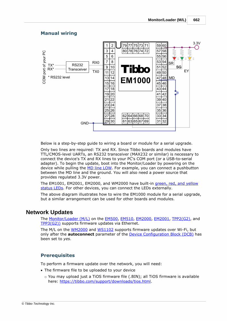
662Monitor/Loader (M/L)
© Tibbo Technology Inc.
Manual wiring
Below is a step-by-step guide to wiring a board or module for a serial upgrade.
Only two lines are required: TX and RX. Since Tibbo boards and modules haveTTL/CMOS-level UARTs, an RS232 transceiver (MAX232 or similar) is necessary toconnect the device's TX and RX lines to your PC's COM port (or a USB-to-serialadapter). To begin the update, boot into the Monitor/Loader by powering on thedevice while pulling the MD line LOW. For example, you can connect a pushbuttonbetween the MD line and the ground. You will also need a power source thatprovides regulated 3.3V power.
The EM1001, EM2001, EM2000, and WM2000 have built-in green, red, and yellowstatus LEDs. For other devices, you can connect the LEDs externally.
The above diagram illustrates how to wire the EM1000 module for a serial upgrade,but a similar arrangement can be used for other boards and modules.
Network UpdatesThe Monitor/Loader (M/L) on the EM500, EM510, EM2000, EM2001, TPP2(G2), andTPP3(G2)) supports firmware updates via Ethernet.
The M/L on the WM2000 and WS1102 supports firmware updates over Wi-Fi, butonly after the autoconnect parameter of the Device Configuration Block (DCB) hasbeen set to yes.
Prerequisites
To perform a firmware update over the network, you will need:
· The firmware file to be uploaded to your device
o You may upload just a TiOS firmware file (.BIN); all TiOS firmware is available
here: https://tibbo.com/support/downloads/tios.html.

663 Programmable Hardware Manual (PHM)
© Tibbo Technology Inc.
o You may upload TiOS combined with a compiled application binary; to create
combined files, use our BinMerger web app or the legacy BinMerger utility.
· The target device must be connected to the same network segment as your PC
o The EM2001, TPP2(G2), and TPP3(G2) have an integrated RJ45 Ethernet jack.
o The EM500, EM510, and EM2000 require an Ethernet front-end (magnetics and
RJ45) to be connected externally. If your module is "on its own" (not integratedinto a host device), then the easiest way to connect it to your Ethernet networkis by plugging it into an evaluation (EV) board. We offer EV boards for all threedevices.
o For a WM2000 or WS1102, you will need to enable its association with a Wi-Fi
access point that is a part of your local network. To achieve this, you will needto configure three DCB parameters: autoconnect, ssid, and password. Thiscan be done via the BLE console or the Companion App that ships preloaded onWM2000 modules.
· Tibbo's Device Explorer utility, which is available as a stand-alone application oras part of Tibbo IDE (TIDE).
· You will need to be able to push the MD button on your Tibbo device (or pull itsMD line LOW).
· Optional: you will benefit from observing the patterns "played" by the statusLEDs of your Tibbo device.
Update procedure
After connecting your Tibbo device to your local network — either through
Ethernet or Wi-Fi — carry out the following steps to update its firmware:
· The M/L flowchart shows how to place your device in the update mode's
Network Phase. Alternatively, follow this step-by-step infographic:

664Monitor/Loader (M/L)
© Tibbo Technology Inc.
· On your computer, run the Device
Explorer utility.
· The target device should appear in
the list and its version should read:
"TiOS-32 Loader (Vx.xx)" — "Vx.xx"
is the firmware version of the M/L.
· If your device does not appear on
the list, click Refresh to rescan the
network for Tibbo devices.
· Select the target device in the list,
click Upload, and choose Load
Firmware Through the Network.
· A dialog will open prompting to
select a file. After doing so, click
Open to begin the upload (the green
status LED will flicker while the
yellow status LED will remain solid).
· Your device will reboot automatically
after the update is completed.
Additional details
· If your device supports BLE (Bluetooth Low Energy) Updates, the M/L willadvance to that phase if a network connection has not been established within 15seconds.
o On the WM2000 and WS1102, you can press the MD button to skip the network
connection and advance to the BLE Phase.
o On the WM2000 and WS1102, if the autoconnect DCB parameter is set to no,
the M/L will wait for 15 seconds without making any actual attempts toassociate with an access point.
· If your device doesn't support BLE updates, the M/L will wait indefinitely toestablish a network connection.
For more information on the various update modes and how the M/L selects andhandles them, see these two flowcharts:
· The flowchart for all programmable Tibbo devices except the WM2000 andWS1102
· The flowchart for the WM2000 and WS1102

665 Programmable Hardware Manual (PHM)
© Tibbo Technology Inc.
Bluetooth Low Energy (BLE) UpdatesBluetooth Low Energy (BLE) updates are a form of over-the-air (OTA) updates.
The EM510, EM2000, EM2001, TPP2(G2), and TPP3(G2), when equipped with aWA2000 wireless add-on module and loaded with Monitor/Loader (M/L) V3 or later,support BLE updates. If the M/L of your device is too old to support BLE updates,you can update it by running the Monitor/Loader Upgrader app.
The WM2000 and WS1102 natively support BLE updates.
Prerequisites
To perform a BLE update:
· You must have the file you will be sending into your device. BLE upgrades useTibbo Composite Uncompressed (.TCU) firmware files.
o All TiOS firmware and related files are published here:
https://tibbo.com/support/downloads/tios.html.
o You can also produce .TCU files using our online tool found at
https://apps.tibbo.com/tc_generator/.
· You will have to:
o Install the Tibbo Updater app (available for iOS and Android) on your
compatible device.
o Alternatively, you can use the BLE Firmware Updater web app on a Windows PC
that has a Bluetooth interface and a compatible web browser (Chrome,Chromium, Opera, or Edge).
· You will need to be able to push the MD button on your Tibbo device (or pull itsMD line LOW).
· Optional: you will benefit from observing the patterns "played" by the statusLEDs of your Tibbo device.
For step-by-step instructions, see:
· Updating using the Tibbo Updater smartphone app
· Updating using the BLE Firmware Updater web app

666Monitor/Loader (M/L)
© Tibbo Technology Inc.
14.3.3.1Using the Tibbo Updater Smartphone AppThere are three ways of accessing
.TCU files from the Tibbo Updater
app (available on iOS and Android):
· You can select one of Tibbo's
officially released .TCU files (it is not
possible to access your own .TCU
files in this manner).
· You can open a .TCU file that you
previously saved on your device or in
iCloud or Dropbox.
· You can "copy" (export, share) a
.TCU file to the Tibbo Updater app
from some other app that has this
file. For example, you can email a
.TCU file as an attachment and open
this email in the email client app on
your iOS/Android device. You can
then "copy" the attached file to the
Tibbo Updater app.
· Make sure your Tibbo device is not connected to the network — this will allow
it to enter the Bluetooth Low Energy (BLE) update mode.
o For Tibbo devices with an Ethernet port, this is as easy as making sure that
the Ethernet cable is not plugged in.
o For the WM2000 and WS1102, you need to prevent the device's association
with an access point. To achieve this:
§ Power down your access point(s) or move the device out of your Wi-Fi
network's range.
§ Alternatively, you can set the autoconnect parameter of the Device
Configuration Block (DCB) to no. This can be done either via the BLE
console or the Companion App that ships preloaded on WM2000 modules.
Note that the WM2000 ships with autoconnect set to no.
· The M/L flowchart shows how to place your device in the update mode's BLEPhase. Alternatively, follow this step-by-step infographic:

667 Programmable Hardware Manual (PHM)
© Tibbo Technology Inc.
Note:On the WM2000 and WS1102, you can skip the wait by pressing and releasingthe MD button before the device associates with an access point.
· The following illustrates the update
procedure using an iOS device when
you are "copying" the file from
another app.
o In that other app (such as an email
client), tap on the .TCU file and tap
Copy) — you will be presented
with exporting choices.
· Select the Tibbo Updater app (note
that the app's icon could be "beyond
the screen edge" and you may need
to scroll through the list to get to it).
· Once you tap on the Tibbo Updater
app's icon, you will be "teleported"
into the Tibbo Updater app. The
app will display a list of discovered
Tibbo devices. Only the devices that
are in the BLE update mode will
appear on the list. If you followed
the steps above, your Tibbo device
should appear on the list.
· Tap the target device to start the
upload.

668Monitor/Loader (M/L)
© Tibbo Technology Inc.
· The app will start sending the file to
the selected device. During the
upload, keep your iOS device as
close to the target Tibbo device as
possible.
· When the file upload completes, your
Tibbo device will perform the internal
copying of the received data. The
green and red status LEDs will be
solid on during the copying. This is
the "critical section" of the entire
procedure.
Do not disconnect the power or
reset your Tibbo device while the
file is uploading or in the "critical
section" of the update procedure.
Doing so may brick the
hardware!
· Once the update completes, your
Tibbo device will reboot
automatically.
14.3.3.2Using the BLE Firmware Updater Web App
· Make sure your Tibbo device is not connected to the network — this will allow
it to enter the Bluetooth Low Energy (BLE) update mode.
o For Tibbo devices with an Ethernet port, this is as easy as making sure that
the Ethernet cable is not plugged in.
o For the WM2000 and the WS1102, you need to prevent the device's
association with an access point. To achieve this:
§ Power down your access point(s) or more the device out of your Wi-Fi
network's range
§ Alternatively, set the autoconnect parameter of the Device Configuration
Block (DCB) to no. This can be done either via the BLE console or the
Companion App that ships preloaded on WM2000 modules. Note that the
WM2000 ships with autoconnect set to no.
· The M/L flowchart shows how to place your device in the update mode's BLE
Phase. Alternatively, follow this step-by-step infographic:

669 Programmable Hardware Manual (PHM)
© Tibbo Technology Inc.
Note:On the WM2000 and WS1102, you can skip the wait by pressing and releasingthe MD button before the device associates with an access point.
· On your PC, open the BLE
Firmware Updater web app
(https://apps.tibbo.com/BLEFirmwar
eUpdater/).
· Click on the number "4" to skip to
the final slide.
· Click Connect a Device; a dialog
will pop up.
· In this dialog, select your device,
then click Pair.
· Now select your update source:
o Click Update Firmware From
Server to update the device using
one of Tibbo's official .TCU files.

670Monitor/Loader (M/L)
© Tibbo Technology Inc.
o For WA2000-compatible devices,
you can also select Update
Firmware From Server (include
Wi-Fi firmware) — this will
update the internal firmware of the
WA2000 as well.
o To upload a .TCU file saved on
your PC, click Update Firmware
From Local File.
· The green status LED will flicker
while the .TCU file is being
transmitted.
· When the file upload completes, your
Tibbo device will perform the internal
copying of the received data. The
green and red status LEDs will be
solid on during the copying. This is
the "critical section" of the
procedure.
Do not disconnect the power or
reset your Tibbo device while the
file is uploading or in the "critical
section" of the update procedure.
Doing so may brick the
hardware!
· The device will reboot automatically
when the update is complete.
Device Configuration Block (WM2000 and
WS1102 Only)The Device Configuration Block (DCB) of the WM2000 and the WS1102 has thefollowing parameters:
Parameter
Possiblevalues
Defaultvalue
Description

671 Programmable Hardware Manual (PHM)
© Tibbo Technology Inc.
autoconnect
no | yes no Determines whether the device willattempt to associate with (connect to) awireless access point (Wi-Fi network) andmaintain this association wheneverpossible. Must be set to yes for Wi-FiUpdates and wireless debugging(debugmode = net) to work.
domain 0 (US) |1 (EU) |2 (Japan)...The fulllist ofcodes
0 (US) The wireless regulatory domain. Affectsthe list of channels the device's Wi-Fiinterface will use to communicate whenautoconnect = yes
ssid 0-32characters
<emptystring>
The SSID (name) of the access point (Wi-Fi network) to connect to whenautoconnect = yes
password
0-64characters
<emptystring>
The password for the access point (Wi-Finetwork) to connect to when autoconnect= yes
dhcp no | yes no Determines the default value of thewln.dhcp property (see the TIDE, TiOS,Tibbo BASIC, and Tibbo C Manual). Whenset to yes, starts the DHCP process beforeyour app launches, thus getting yourdevice a valid IP address even faster —more on this below.
debugmode
serial |net
serial Determines whether the serial port or Wi-Fi network will be used for debugging
defaultapp
0 | 1 1 Determines which compiled Tibbo BASIC/Cbinary will be loaded at boot — APP0 orAPP1. Note that there is an MD buttonoverride that force-launches APP0regardless of the defaultapp value.
More on the dhcp parameter
Prior to the WM2000, Tibbo devices implemented the DHCP client through a DHCPlibrary (see TIDE, TiOS, Tibbo BASIC, and Tibbo C Manual). The WM2000 and theWS1102 allow you to delegate DHCP to the internal process of TiOS. This reallyspeeds up the IP procurement! The new wln.dhcp property of the wln. object isprovided for enabling this "internal DHCP."
The default value of wln.dhcp is determined by the dhcp parameter of the DCB. Ifthe dhcp parameter is set to no, then wln.dhcp will be 0 (disabled) by default andyour code will need to set it to 1 (enabled) to take advantage of the internal DHCPservice offered by TiOS. If the dhcp parameter is set to yes, your app will startrunning with wln.dhcp at 1 (enabled).
We have provided the dhcp parameter not to (potentially) save you a line of code.The real reason is that enabling DHCP before your app starts shaves additionalmilliseconds off that wait for the IP address to be configured. This means that yourapp will be ready to perform its network-related tasks even sooner!

672Monitor/Loader (M/L)
© Tibbo Technology Inc.
Accessing and initializing the DCB
There are three ways of reading and writing DCB parameters:
· Through the BLE console. This console is a feature of the Monitor/Loader (M/L)used by the WM2000 and WS1102.
· Using the Companion App. The WM2000 module ships with this app preloaded asAPP0.
· In Tibbo BASIC/C code, using the provided API (see the TIDE, TiOS, Tibbo BASIC,and Tibbo C Manual).
It is also possible to reset the DCB parameters to their default values.
BLE ConsoleThe BLE console allows you to access the Device Configuration Block (DCB)
parameters through the BLE interface of the WM2000 and WS1102.
The M/L V4 Flowchart shows how to access the BLE console (see the very bottom
of the flowchart). Alternatively, follow this infographic detailing the shortest path
into the console:
Note:
Once the green status LED turns on, you are in the Wi-Fi Phase. If the
autoconnect parameter is set to yes, the device will attempt to associate with
an access point. To skip this, you need to press the MD button (pull the MD line
LOW) as soon as the green status LED is on and before the association occurs. If

673 Programmable Hardware Manual (PHM)
© Tibbo Technology Inc.
the association is happening too fast, turn the access point off or move out of its
range.
After the BLE console starts, access it
from a Bluetooth-enabled PC:
· In a Chromium-based web browser
(Chrome, Chromium, Opera, or
Edge), open
https://apps.tibbo.com/BLETerminal/
.
· Click on Connect a Device.
· In the pop-up dialog, select your
device.
· Click on Pair.
· Once the BLE State readsConnected, the console is ready foruse.
Available commands
Command Description
help Prints the help info shown on the screenshot below
get <parameter> Returns the current value of the specified DCB parameter
set <parameter><value>
Sets the new value of the specified DCB parameter
reset all Restores (initializes) all DCB parameters to their factorydefaults. You can initialize the DCB parameters using theMD button.
exit Exits the BLE console and reboots the device
Note that all commands, parameters, and values are case-sensitive.

674Monitor/Loader (M/L)
© Tibbo Technology Inc.
Companion AppThe WM2000 ships with a Companion App preloaded as APP0. This app is also
supported by the WS1102, but is not preloaded at the factory.
The app is meant to serve two purposes:
· To provide another way of accessing the Device Configuration Block (DCB)
parameters (the primary way is through the BLE console).
· To serve as the starting point and inspiration for app developers. The source
code for the app is published here, and you are free to modify it in any way
you please.
As the Companion App comes preloaded as APP0, it is always possible to force-
boot into this app using the MD button, thus overriding the defaultapp
parameter of the DCB.

675 Programmable Hardware Manual (PHM)
© Tibbo Technology Inc.
The M/L V4 Flowchart shows how to do this. Alternatively, follow this infographic
detailing the shortest path to launching APP0:
Once the Companion App is running,
you can interact with it through the
L.U.I.S. app (available on iOS and
Android):
· Follow the infographic above to
launch into the Companion App.
· Start the L.U.I.S. app on your iOS or
Android device.
· Select WM2000 Companion.

676Monitor/Loader (M/L)
© Tibbo Technology Inc.
· Edit the DCB parameters in the
configuration screen that will appear.
Configuration Reset
The MD button (line) can be used to restore (initialize) all Device Configuration
Block (DCB) parameters of the WM2000 and WS1102 to their factory defaults.
The M/L V4 flowchart shows how to do this (the DCB reset is at the very bottom
of the flowchart). Alternatively, follow this infographic detailing the shortest path
to the DCB reset:

677 Programmable Hardware Manual (PHM)
© Tibbo Technology Inc.
Note:Once the green status LED turns on, you are in the Wi-Fi Phase. If the
autoconnect parameter is set to yes, the device will attempt to associate with
an access point. To skip this, you need to press the MD button (pull the MD line
LOW) as soon as the green status LED turns on and before the association
occurs. If the association is happening too fast, turn the access point off or move
out of its range.
Wi-Fi Regulatory Domains
0 — United States (Federal Communications Commission)
1 — European Union
2 — Japan
3 — Antigua and Barbuda
4 — Argentina
5 — Aruba
6 — Australia
7 — Austria
8 — Bahamas
9 — Barbados
10 — Bermuda
11 — Brazil
12 — Belgium
13 — Bulgaria
14 — Canada
15 — Cayman Islands
16 — Chile

678Monitor/Loader (M/L)
© Tibbo Technology Inc.
17 — China
18 — Colombia
19 — Costa Rica
20 — Cyprus
21 — Czech Republic
22 — Denmark
23 — Dominican Republic
24 — Ecuador
25 — El Salvador
26 — Finland
27 — France
28 — Germany
29 — Greece
30 — Guam
31 — Guatemala
32 — Haiti
33 — Honduras
34 — Hong Kong
35 — Hungary
36 — Iceland
37 — India
38 — Indonesia
39 — Ireland
40 — Israel
41 — Italy
42 — Japan
43 — Jordan
44 — Latvia
45 — Liechtenstein
46 — Lithuania
47 — Luxembourg
48 — Malaysia
49 — Malta
50 — Morocco
51 — Mexico
52 — Netherlands
53 — New Zealand
54 — Norway
55 — Peru
56 — Portugal
57 — Poland
58 — Romania
59 — Russia
60 — Saudi Arabia
61 — Serbia and Montenegro
62 — Singapore

679 Programmable Hardware Manual (PHM)
© Tibbo Technology Inc.
63 — Slovakia
64 — Slovenia
65 — South Africa
66 — South Korea
67 — Spain
68 — Sweden
69 — Switzerland
70 — Taiwan
71 — Turkey
72 — United Kingdom
73 — Ukraine
74 — United Arab Emirates
75 — United States
76 — Venezuela
Prolonging and Estimating EEPROM LifeHere are some ideas on prolonging the life of your EEPROM (this text assumes yourfamiliarity with the stor. object*):
· Limit the number of updates you make to the EEPROM's data. For example, if youare counting events, then do not write to the EEPROM every time you incrementthe count. Instead, keep a counter variable in RAM and implement the EEPROMupdate policy. For example, you may choose to update the EEPROM once forevery 100 increments of the RAM counter, or after x hours of inactivity.
· Before writing data into an EEPROM location, read this location to see if it alreadycontains the data to be written. In EEPROMs, writing the same data into the samelocation still counts as a write cycle!
· Use a wear leveling scheme, in which you rotate your storage area through arange of EEPROM addresses. For example, if you have a 32-bit counter, create anarray of 32-bit locations and rotate between these locations when incrementingthe counter. This one should be taken in conjunction with the next point...
· When placing a frequently updated data into the EEPROM, try to keep this datawithin sector boundaries. Like flash storage, EEPROMs do have sectors. Tibbodevices with 2KB EEPROMs have 16-byte sectors. Devices with 256-byteEEPROMs have 8-byte sectors. When you update the data in a portion of a sector,you are actually wearing off the entire sector! When counting sector boundaries,take into the account the stor.base property — it gives all your writes a fixedoffset! For example, on the EM1000 (2KB EEPROM), to write into the third sectorof the EEPROM, use stor.setdata(s,4), because stor.base=29 and 29+4=33, i.e.the first location of the third 16-byte sector (stor. locations are counted from 1).
· Use redundancy — keep two or more copies of your EEPROM data and protect thedata with checksums. Should one copy fail, there will be another copy to use.This also helps against abrupt power failures. If the power is turned off while theEEPROM write is in progress you may lose your data. Having a backup copy helpsin such situations.
· Consider using our STG library* — it will save you a lot of headache in dealingwith EEPROM data.
When estimating the life of the EEPROM in your system, consider the following:

680Prolonging and Estimating EEPROM Life
© Tibbo Technology Inc.
· Always take into the account the underlying sector nature of EEPROM ICs. Writingeven a single byte into a sector reduces the lifespan of the entire sector.
· Writing a string of several characters constitutes the number of write cycles equalto the number of characters in that string. Executing stor.setdata("ABC",4)counts as three write cycles, not one.
· High ambient temperature reduces the life of EEPROMs.
· All vendor estimates for the projected EEPROM life are probabilistic in nature. Youwill encounter "stronger" and "weaker" specimen with vastly different endurancelevels. All in all, it is quite safe to assume that your EEPROM will last for at least1 million write cycles per sector... and yet, there is no guarantee of that.
* The stor. object and STG library are documented in the TIDE, TiOS, Tibbo BASIC,and Tibbo C manual.
Update History19OCT2021
· Documented Tibbit #63-1/2 AC Voltage Detector
29JUN2021
· Documented WM2000EV Demo #3 — Azure
28MAY2021
· Documented Tibbit #43-2 Four-Channel Streaming ADC ±100V
· Documented the WS1102 wireless device server as part of the revampedDS/WS110x family
27APR2021
· Documented WM2000EV Demo #2 — WebPWM
15MAR2021
· Documented the WM2000EV evaluation kit
· Documented WM2000EV Demo #1 — Keen as part of the WM2000 journey ofexploration
10MAR2021
· Documented Tibbit #33 Wide Input Range Power Supply
· Documented Tibbit #43-1 Four-channel Streaming ADC ±10V
05FEB2021
· Documented Tibbit #46 Cat-M1/NB-IoT Modem.
05NOV2020
· Documented WM2000 Programmable Wireless IIoT Module.
· Revamped the Monitor/Loader (M/L) section.

681 Programmable Hardware Manual (PHM)
© Tibbo Technology Inc.
17AUG2020
· Documented Tibbit #45-1~3 4G (LTE) Modem.
21JUL2020
· Updated Tibbo Project System to include LTPP3(G2).
24JUN2020
· Updated TPB2, TPB2L, and TPB3 with links to all compatible devices.
· Documented LTPP3(G2).
· Documented Tiles, Sockets, Connectors, Controls for LTPP3(G2).
· Documented Plus1 (SP7021) CPU for LTPP3(G2).
· Documented LTPB3.
· Documented LTPB3 Parts and Accessories.
· Documented Size 3 Vibration Protection Kit (VPK) for LTPB3.
· Documented Mechanical Dimensions for LTPB3.
19JUN2020
· Documented Tibbits #44-1 and 44-2 (isolated RS232/422/485 interface).
· Marked Tibbits #47, #48, #49, #50, #51, and #56 as deprecated.
16DEC2019
· Documented the change between EM200C-02 and -04 devices (3.3V on Vout for -02, but 1.8V for -04 devices).
23OCT2019
· PHM has a new HTML look!
21MAY2019
· Documented the EM510 IoT module.
· Documented WA2000 connection to the EM510 module.
· Reworked the EM500EV section into the EM500EV/EM510EV.
18MAR2019
· Updated DS1101 and DS1102 devices with information about the"W" (802.11abgn) option.
27DEC2018
· Documented Cable Probes.
03DEC2018
· Documented RS485 Modbus Sensors ("Bus Probes").

682Update History
© Tibbo Technology Inc.
· Documented the WA2000 Wi-Fi/BLE add-on module.
· Amended Mechanical Dimensions and Ordering Info and Specifications topics ofthe EM2000 module (added the info about the WA2000 device and EM2000 +WA2000 combinations).
· Updated the following topics (sections): Setup (MD) Button (Line), Status LEDs(LED Control Lines), Monitor/Loader (M/L).
31MAY2018
· Corrected the block diagram for Tibbit #53.
17MAY2018
· Updated Detailed Device Info for the EM2001
03OCT2017
· Documented ADC functionality of EM2000, EM2001, and TPP3(G2) devices.
31JUL2017
· Documented Tibbit #53 (isolated 4-20mA ADC)
24JUL2017
· Documented Tibbit #22 (RTD temperature meter)
07JUL2017
· Corrected the operating temperature range for the EM2001 (it is -40 to +80 C)
06JUL2017
· Documented Tibbit #52 (4-channel isolated +/-10V ADC)
27JUN2017
· Documented the EM2001 board
23MAY2017
· Documented the EM2000EV board
25APR2017
· Documented the EM2000 module (photo not yet available).
13FEB2017
· Documented Tibbits #04-5, #04-6, #04-7, #04-8, #27, #48, #49, #50, #51,#54, #56, #58, #59.
· Documented changed introduced in the revision B of Tibbit #08.
· Documented changed introduced in the revision B of Tibbit #05.

683 Programmable Hardware Manual (PHM)
© Tibbo Technology Inc.
10OCT2016
· Corrected pin assignment in RS232 and RS422 modes for Tibbit #02.
23SEP2016
· On the advice of one of our customers, we added EEPROM and flash writeendurance warning messages and information throughout the manual (example:EM2000/Flash and EEPROM memory), update device specifications with EEPROMand flash endurance info (example: EM1000/Ordering Info and Specifications).
· Added new Common vs. Proprietary Knowledge topic.
· Added new Prolonging and Estimating EEPROM life topic.
07SEP2016
· Updated test project links for Tibbits ##13, 14, 16, 17, 26, 28, 29, 30, 31, 35,36, 40, 41, 42, 57.
· Added info on the SIM card holder location for GPRS Tibbit (#47).
31AUG2016
· DocumentedTibbit #57 (FPGA Tibbit).
04JUL2016
· Documented new TPP2(G2) and TPP3(G2) boards.
27APR2015
· Documented Tibbit #26 (IR command processor).
05APR2015
· Documented the LTPP3 board.
10FEB2015
· Documented the H2 Tibbit form factor.
16JAN2015
· Documented the EM1001 board.
18NOV2014
· Documented Tibbits #25, #38, #39, #40, #41, #42.
08MAY2014
· Documented Tibbits #16, #17, and #31.
12MAR2014
· Updated documentation for the following Tibbits: #12, #13, #14, #28, #29,#30, #35, #36.

684Update History
© Tibbo Technology Inc.
· Revealed these upcoming Tibbits: #25, #31, #38, #39, #40, #41, #42.
08NOV2013
· Corrections made to the Tibbo Project System (TPS) documentation (notably,there are several new diagrams).
01NOV2013
· Documented Tibbo Project System (TPS).
01SEP2012 release
· Documented DS110x devices.
06FEB2012 release
· Documented the NB1010 board.
· Expanded DS10xx documentation to include devices based on the NB1010.
· Documented TB1000, TB1004, and TB1005 adapters.
· Updated EM500EV documentation in connection with the release of the new IB1(Wi-Fi/flash) board.
· Corrected Ethernet Port Lines topic in EM1206 documentation to note correctvoltage (1.8V instead of 2.5V).
· Updated the ordering info for most products.
30MAY2011 release
· Expanded and corrected GA1000 documentation:
- Many small corrections throughout;
- Correction in I/O Pin Assignment and Pin Functions (of the GA1000): DI and DOpins were shown incorrectly (swapped);
- One new Connecting GA1000 to Tibbo Devices topic.
· Expanded and corrected EM500 documentation:
- Many small corrections throughout;
- Flash and EEPROM Memory topic now provides information on connectingexternal flash IC for fd. object.
- I/O Pin Assignment and Pin Functions contains information about attachingexternal flash IC and GA1000.
25MAY2011 release
· Corrected a part number in EM1206 Ordering Info and Specifications.
16MAY2011 release
· Edited EM500 manual: provided details on how an external flash IC can beconnected to the EM500.
21MAR2011 release

685 Programmable Hardware Manual (PHM)
© Tibbo Technology Inc.
· Removed all references to WA1000. This legacy module is no longer supported.
8MAR2011 release
· Replaced references to obsolete WA1000 with GA1000, updated part numbersand links.
16FEB2011 release
· Updated list of power adapters.
14FEB2011 release
· Corrected typographical error in PSU part numbers (APR instead of ARP)
04JAN2011 release
· Updated image on EM1000TEV topic to reflect use of GA1000 component.
03DEC2010 release
· Added pin diameter for EM500, EM1206, EM1202, EM200, EM1000
20JUL2010 release
· Documented EM500EV.
· Reworked Status LEDs topic.
· Reworked Setup Button (MD line) topic, also renamed it to "Setup (MD) Button(Line)".
------
22JUN2010 release
· Corrected various documentation errors, including incorrect model numbers inDS1000, DS1002, DS1003 (4 Serial Ports) topic.
------
17JUN2010 release
· Clarified and expanded External LED Control topic for NB1000.
------
15JUN2010 release
· Fixed incorrect reference to Winstar LCD model number (replaced WG12864Fwith WG12864A)
· Fixed GA1000 max. power consumption.
· Fixed lines 6 and 7 in EM1206 I/O Pin Assignment and Pin Functions
------
01JUN2010 release

686Update History
© Tibbo Technology Inc.
· Updated Module Comparison Table.
· Documented EM500.
------
01FEB2010 release
· Updated NB10x0 and IB100x Boards section (new IB1004 + SB1004, IB1005 +SB1005 devices). Almost every pre-existing topic has also been edited.
· Updated DS10xx Family section -- again, almost every topic has been edited.
· Documented TB1000, TB1004, and TB1005 accessories.
------
29JUL2009 release
· Documented the following products: EM1206, EM1206EV, GA1000, DS1206,DS1206N, DS1202, and EM1202EV.
· Edited cover pages for EM1000 and EM1202 products.
· Edited Ordering Info and Specifications for EM1000 and EM1202 devices.
· Created Status LEDs and Setup Button (MD line) topics, added links to these newtopics from each product's manual.
· Edited I/O Pin Assignment and Pin Functions topics of EM1000 and EM1202modules.
------
Initial release
· Revamped DS1000 description. It now includes DS1001 and DS1002 devices.Content is totally new -- the manual simply refers to the NB1000 and IB1000-2docs.
· Documented IB1004 and DS1004 devices.
· Documented IB1005 and DS1005 devices.
The Programmable Hardware Manual is a spin-off of the Tibbo Document SystemManual. Original split was performed on 09JUN2008.

Programmable Hardware Manual (PHM)687
© Tibbo Technology Inc.
Index
- E -EM120/200-EV 258
EM200 124
- M -Monitor/Loader 674
- R -rj203 635