Preparation and characterization of nickel-based mixed-oxides and their performance for catalytic...
7
Preparation and characterization of nickel-based mixed-oxides and their performance for catalytic methane decomposition M.E. Rivas a , J.L.G. Fierro a, * , R. Guil-Lo ´pez a , M.A. Pen ˜a a , V. La Parola a , M.R. Goldwasser b, * a Instituto de Cata ´lisis y Petroleoquı ´mica, CSIC, Cantoblanco, 28049 Madrid, Spain b Centro de Cata ´lisis Petro ´leo y Petroquı ´mica, Escuela de Quı ´mica, Facultad de Ciencias, Universidad Central de Venezuela, Apartado 40600, Los Chaguaramos, Caracas 1020-A, Venezuela Available online 31 January 2008 Abstract The preparation of three different types of mixed nickel oxides is described. These systems include: (i) the perovskite LaNiO 3 oxide, (ii) a mixed-oxide derived from a hydrotalcite Ni–Al (64:38) precursor, and (iii) the spinel-type NiAl 2 O 4 oxide. These systems were prepared with the aim of studying the activation procedure that develops small nickel nanoparticles deposited on a La 2 O 3 or Al 2 O 3 substrate active in H 2 production through catalytic decomposition of CH 4 . Different preparation procedures have been applied to each precursors (i)–(iii). Perovskite-type oxide LaNiO 3 was prepared by the sol–gel methodology (citrates method). Mixed oxide derived from hydrotalcite was obtained by co-precipitation using urea as a basic agent. NiAl 2 O 4 spinel synthesis was performed by the ceramic method. The three oxide-type materials were characterized by XRD, BET specific area, TPR and XPS. Characterization results showed that the preparation methods used allow formation of highly crystalline and homogeneous oxide precursors. After activation, the oxide precursors showed a high activity in the decomposition reaction of CH 4 . The catalysts derived from hydrotalcite mixed oxide showed the highest activity with CH 4 conversions reaching 50% at 500 8C. # 2007 Elsevier B.V. All rights reserved. Keywords: Nickel catalysts; NiAl hydrotalcite precursors; Methane decomposition; TPR; XRD and XPS characterization 1. Introduction Methane, as the principal component of natural gas, is an ideal source for hydrogen production due to its enormous proven reserves and also to the high H/C atomic ratio in CH 4 molecule (H/C ratio in methane is 4). Among the routes outlined to obtain hydrogen from CH 4 , the catalytic decom- position of methane remains prominent [1]. The CO-free hydrogen produced by CH 4 decomposition appears particularly suited for fuel cell applications since there is no need of further purification steps. The decomposition reaction is moderately endothermic and produces carbon as a by-product: CH 4 ! C þ 2H 2 DH ¼ 45:0 kJ=mol: (1) Indeed, this reaction is much less endothermic than the methane steam reforming, (MSR), which is the conventional technology employed in the industry for the massive production of hydrogen: CH 4 þ H 2 O ! CO þ 3H 2 DH ¼ 225:9 kJ=mol: (2) In the MSR reaction, methane conversions close to that pre- dicted by the thermodynamic equilibrium can be obtained over Ni catalysts or supported catalysts (1), although important differences in CO and H 2 selectivity’s are usually found for a few metal catalysts. Reactions involved in the catalytic conversion of methane show two major drawbacks: (i) the temperature required to conduct reactions (1) and (2) at a reasonable rate is rather high, usually above 800 8C, which results detrimental for catalyst performance since sintering of metal particles occurs simulta- neously with subsequent activity lose; (ii) carbon deposits are developed along the reaction on the surface of metal particles which block the metal sites responsible for the reaction. For this reason, the development of active and thermally and chemically stable catalyst systems is of prime importance. www.elsevier.com/locate/cattod Available online at www.sciencedirect.com Catalysis Today 133–135 (2008) 367–373 * Corresponding authors. E-mail addresses: jlgfi[email protected] (J.L.G. Fierro), [email protected] (M.R. Goldwasser). 0920-5861/$ – see front matter # 2007 Elsevier B.V. All rights reserved. doi:10.1016/j.cattod.2007.12.045
-
Upload
independent -
Category
Documents
-
view
1 -
download
0
Transcript of Preparation and characterization of nickel-based mixed-oxides and their performance for catalytic...

www.elsevier.com/locate/cattod
Available online at www.sciencedirect.com
5 (2008) 367–373
Catalysis Today 133–13Preparation and characterization of nickel-based mixed-oxides
and their performance for catalytic methane decomposition
M.E. Rivas a, J.L.G. Fierro a,*, R. Guil-Lopez a, M.A. Pena a,V. La Parola a, M.R. Goldwasser b,*
a Instituto de Catalisis y Petroleoquımica, CSIC, Cantoblanco, 28049 Madrid, Spainb Centro de Catalisis Petroleo y Petroquımica, Escuela de Quımica, Facultad de Ciencias, Universidad Central de Venezuela,
Apartado 40600, Los Chaguaramos, Caracas 1020-A, Venezuela
Available online 31 January 2008
Abstract
The preparation of three different types of mixed nickel oxides is described. These systems include: (i) the perovskite LaNiO3 oxide, (ii) a
mixed-oxide derived from a hydrotalcite Ni–Al (64:38) precursor, and (iii) the spinel-type NiAl2O4 oxide. These systems were prepared with the
aim of studying the activation procedure that develops small nickel nanoparticles deposited on a La2O3 or Al2O3 substrate active in H2 production
through catalytic decomposition of CH4. Different preparation procedures have been applied to each precursors (i)–(iii). Perovskite-type oxide
LaNiO3 was prepared by the sol–gel methodology (citrates method). Mixed oxide derived from hydrotalcite was obtained by co-precipitation using
urea as a basic agent. NiAl2O4 spinel synthesis was performed by the ceramic method. The three oxide-type materials were characterized by XRD,
BET specific area, TPR and XPS. Characterization results showed that the preparation methods used allow formation of highly crystalline and
homogeneous oxide precursors. After activation, the oxide precursors showed a high activity in the decomposition reaction of CH4. The catalysts
derived from hydrotalcite mixed oxide showed the highest activity with CH4 conversions reaching 50% at 500 8C.
# 2007 Elsevier B.V. All rights reserved.
Keywords: Nickel catalysts; NiAl hydrotalcite precursors; Methane decomposition; TPR; XRD and XPS characterization
1. Introduction
Methane, as the principal component of natural gas, is an
ideal source for hydrogen production due to its enormous
proven reserves and also to the high H/C atomic ratio in CH4
molecule (H/C ratio in methane is 4). Among the routes
outlined to obtain hydrogen from CH4, the catalytic decom-
position of methane remains prominent [1]. The CO-free
hydrogen produced by CH4 decomposition appears particularly
suited for fuel cell applications since there is no need of further
purification steps. The decomposition reaction is moderately
endothermic and produces carbon as a by-product:
CH4 ! C þ 2H2 DH¼ 45:0 kJ=mol: (1)
* Corresponding authors.
E-mail addresses: [email protected] (J.L.G. Fierro),
[email protected] (M.R. Goldwasser).
0920-5861/$ – see front matter # 2007 Elsevier B.V. All rights reserved.
doi:10.1016/j.cattod.2007.12.045
Indeed, this reaction is much less endothermic than the methane
steam reforming, (MSR), which is the conventional technology
employed in the industry for the massive production of hydrogen:
CH4þH2O ! CO þ 3H2 DH¼ 225:9 kJ=mol: (2)
In the MSR reaction, methane conversions close to that pre-
dicted by the thermodynamic equilibrium can be obtained over
Ni catalysts or supported catalysts (1), although important
differences in CO and H2 selectivity’s are usually found for
a few metal catalysts.
Reactions involved in the catalytic conversion of methane
show two major drawbacks: (i) the temperature required to
conduct reactions (1) and (2) at a reasonable rate is rather high,
usually above 800 8C, which results detrimental for catalyst
performance since sintering of metal particles occurs simulta-
neously with subsequent activity lose; (ii) carbon deposits are
developed along the reaction on the surface of metal particles
which block the metal sites responsible for the reaction. For this
reason, the development of active and thermally and chemically
stable catalyst systems is of prime importance.

M.E. Rivas et al. / Catalysis Today 133–135 (2008) 367–373368
Many studies have been carried out to prepare mixed-oxides
with perovskite structure [2–5] and mixed-oxides derived from
hydrotalcite precursors [6] suited for methane conversion
reactions such as steam reforming, partial oxidation and dry
reforming. These mixed-oxides are highly stable under the
severe conditions imposed by these reactions, i.e. high pressure,
high temperature and presence of steam in the reaction
medium. In addition, the efficient use of these catalyst
precursors implies necessarily a high dispersion of metal
phases which can be achieved by controlled segregation of the
active phase. This objective can be reached by starting with a
crystalline precursor, such as a mixed oxide perovskite type
structure, or by decomposing an ordered lamellar structure such
as the mixed-oxides derived from hydrotalcite.
Within this framework, the present work was undertaken to
compare the catalytic performance of two different nickel-
based metal oxides for the methane decomposition into CO-free
hydrogen. One of this is the LaNiO3 perovskite-type oxide and
the other is a mixed oxide derived from an aluminium and
nickel-containing hydrotalcite precursor.
2. Experimental
2.1. Preparation of catalyst precursors
The LaNiO3 perovskite-type oxide was prepared according
to the modified citrate method [7]. Stoichiometric amounts of
La(NO3)3�xH2O (Merck, reagent grade) and of Ni(NO3)3�6H2O
(Merck, reagent grade) were dissolved in distilled water and
then added to a second solution containing equimolecular
amounts of citric (99.5, Riedel-de Haen) and ethylene glycol
(99.5%, Riedel-de Haen) as a polydentate ligand. The excess of
water was slowly removed in a rotary-evaporator until a viscous
liquid was obtained. Subsequently, this viscous material was
slowly heated in air atmosphere at a rate of 1 8C/min from room
temperature to 800 8C and maintained at this temperature for
5 h. These conditions are essential to obtain a crystalline
material.
The nickel and aluminium mixed oxide was prepared from
an Al–Ni-containing hydrotalcite (Ni–Al-HT), with 1.8 Ni/Al
atomic ratios. The hydrotalcite precursor was prepared by co-
precipitation [8], using urea (Merck, reagent grade) as
precipitating agent. Urea-salts concentration was: urea/
[Al3+ + Ni2+] = 3/1 and salt precursors used were NiCl2�6H2O
6H2O and AlCl3�6H2O (Panreac, 95%). The methodology
included adding urea solution over another solution containing
Al3+ and Ni2+ salts. The precipitate was maintained at 95 8Cunder vigorous stirring. The solid was separated by filtration
and washed repeatedly with distilled water, dried at 100 8C and
finally calcined at 800 8C for 4 h in air. Under these conditions,
an Al–Ni-mixed oxide was obtained, hereafter referred as MO-
HT-800.
A reference NiAl2O4 spinel material was synthesized by
ceramic methodology. For this purpose, NiCl2�6H2O (Panreac
98%) and AlCl3�6H2O (Panreac 95%) were mixed in an agate
mortar and calcined at 1000 8C for 10 h. After calcining, the solid
was grounded and calcined again at the same temperature for 2 h.
2.2. Characterization of catalyst precursors
Oxide catalysts precursors were characterized by different
techniques, including X-ray diffraction (DRX), specific surface
area (BET), temperature-programmed reduction and photo-
electron spectroscopy (XPS).
X-ray powder diffraction (XRD) patterns of all calcined
samples were obtained with nickel-filtered Cu Ka radiation
(l = 1.538 A) using a Seifert 3000P instrument. XRD
diffractograms were collected in the 2u range 5–808, in steps
of 28/min. Phase identification was carried out by comparison
with the JCPDF database cards. Particle size of nickel
crystallites were determined by means of the Scherrer equation
using the Ni (1 1 1) reflection at 2u = 44.58 for line broadening
measurements. Specific surface areas were calculated using the
BET method from the nitrogen adsorption isotherms, recorded
at the temperature of liquid nitrogen on a Micromeritics ASAP
2100 apparatus, taking a value of 0.162 m2 for the cross-
sectional area of the N2 molecule adsorbed. Prior to the
adsorption measurements, samples were outgassed at 150 8C.
Temperature-programmed reduction (TPR) experiments
were performed on a semiautomatic Micromeritics TPD/TPR
2900 apparatus interfaced with a microcomputer. Samples of
about 30 mg were placed in a U-shape quartz tube first purged
in a synthetic air stream at 200 8C for 1 h and then cooled to
room temperature. Reduction profiles were recorded passing a
10% H2/Ar flow at a rate of 50 mL/min while heating at a rate of
10 8C/min from room to 950 8C. A cold-trap was placed just
before the TCD of the instrument to remove the water from the
exit stream.
Surface analysis were carried out on a VG ESCAALAB
200R electron spectrometer provided with Al Ka
(hn = 1486.6 eV, 1 eV = 1.6302 � 10�19 J) X-ray source and
a hemi-spherical electron analyzer. The powder samples
pressed in 8 mm diameter copper troughs were fixed on the
XYZ manipulator. The base pressure in the analysis chamber
was maintained below 4 � 10�9 mbar during data acquisition.
Energy of the analyzer was set at 50 eV, for which the
resolution as measured by the full width at half maximum
(FWHM) of the Au4f7/2 core level was 1.7 eV. The binding
energies were referenced to the C1s peak at 284.6 eV due to
adventitious carbon. Data processing was performed with the
XPS peak program, the spectra were decomposed with the least
squares fitting routine provided by Gaussian/Lorentzian (90/10)
software with product function and after subtracting a Shirley
background, Atomic fractions were calculated using peak areas
normalized on the basis of sensitivity factors.
2.3. Catalytic activity
Activity measurements were performed in a continuous flow
fixed-bed catalytic reactor at atmospheric pressure. Sixty
milligrams catalyst was placed between quartz glass plugs in
the centre of a cylindrical tube reactor (4 mm i.d. placed within
another one of 6 mm i.d.). The temperatures at the internal and
external walls of the catalyst reactor were measured by Ni–Cr
thermocouples.

Fig. 2. X-ray diffraction profiles of Al–Ni-mixed–oxide derived from the
hydrotalcite precursor (OM-HT-800).
M.E. Rivas et al. / Catalysis Today 133–135 (2008) 367–373 369
Prior to activity measurements, catalyst precursors were
reduced in a 10% H2/N2 mixture at 750 8C for 1.5 h to generate
the Ni0 metal phase. Subsequently, the reactor was flushed in a
nitrogen stream while cooling to room temperature. The
reaction was carried out by feeding a 7% CH4/N2 at a
WHSV = 146 L/h g and scanning reaction temperatures in the
25–850 8C range. Reaction products were analyzed on-line by a
Varian 3400 gas-chromatograph provided with thermal con-
ductivity detector and columns packed with Porapak N and 13X
molecular sieves. Estimated error of gas-phase composition
was within 5%.
3. Result and discussion
3.1. X-ray diffraction analysis
X-ray diffraction profiles of LaNiO3, Al–Ni hydrotalcite and
NiAl2O4 oxide precursors are displayed in Fig. 1. La–Ni
perovskite-type oxide exhibits all diffraction lines of a
dominant rhombohedra LaNiO3 structure (JCPDS-ICDD 10-
341). In addition, very weak lines indexed to a NiO phase were
detected, indicating that a small amount of nickel was not
incorporated to the LaNiO3 phase. Similarly, the diffraction
profile of Ni–Al hydrotalcite belongs to the takovite single
phase (JCPDS-ICDD 15–87) with a high crystallization degree.
The diffraction pattern of NiAl2O4 spinel shows only
diffraction lines of this structure (JCPDS-ICDD 78-0552) with
high crystallinity.
Fig. 2 displays the X-ray diffraction pattern of the mixed
oxide produced upon thermal decomposition of the hydrotalcite
Fig. 1. X-ray diffraction profiles of nickel compounds: (a) LaNiO3; (b)
hydrotalcite Ni–Al; (c) NiAl2O4. (!) LaNiO3; (*) takovite; (&) NiAl2O4;
(�) NiO.
precursor. This pattern shows diffraction lines of a mixture of
nickel and aluminium oxides together with that of NiAl2O4
spinel.
Diffraction profiles of the H2-reduced and after-reaction
samples are shown in Figs. 3 and 4, respectively. Reduction and
testing to measure catalytic activity of the samples were
performed at the same conditions (750 8C for 1.5 h).
After reduction of precursor oxides, LaNiO3, OM-HT-800,
production of highly dispersed Ni0 particles on the surface of an
oxide substrate is expected. Results show that the crystalline
structure of LaNiO3 perovskite-type phase decomposed to Ni0
crystallites with particle size of about 25 nm dispersed on
La2O3 surface. Similarly, reduction of Ni–Al hydrotalcite
precursor produces metallic Ni0 particles, with average particle
size of 22 nm, on the surface of Al2O3. However, a small
fraction of unreduced nickel remains in a NiAl2O4 phase.
Finally, the XRD pattern of the NiAl2O4 spinel indicates that
only a fraction of Ni2+ cations of this structure are reduced, with
crystallite sizes of ca. 12 nm, while most of the NiAl2O4 spinel
remains unreduced in accordance with TPR profiles shown in
Fig. 5.
X-ray diffraction profiles of after-reaction catalysts (Fig. 4)
reveal the formation of Ni0 crystallites. Calculation of Ni0 mean
crystallite size on these after-reaction catalysts showed that an
increase of the particle size occurs as a consequence of sintering
of metal particles. Such increase is clearer for NiAl2O4 where
crystallites size changes from 12 nm for the as-synthesized to
24 nm for the after-reaction samples, showing that Ni0
crystallites are less stable in NiAl2O4. On the contrary, the
Ni0 crystallite size increase is much less marked for after-
reaction OM-Ni–Al (from 22 to 27 nm) and LaNiO3 (from 25 to
29 nm) samples. It is important to note that the diffraction
profiles of after-reaction OM-HT-800 and NiAl2O4 samples
exhibit an intense line at 2u = 268 which corresponds to
graphitic carbon deposited on the catalyst surface during the
reaction.
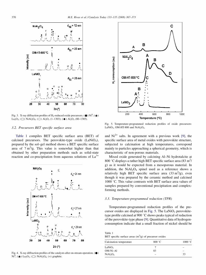
Fig. 3. X-ray diffraction profiles of H2-reduced oxide precursors. (*) Ni0; ($)
La2O3; (&) NiAl2O4; (*) Al2O3 (1–1303); (^) Al2O3 (80–1385).
Fig. 5. Temperature-programmed reduction profiles of oxide precursors:
LaNiO3, OM-HT-800 and NiAl2O4.
M.E. Rivas et al. / Catalysis Today 133–135 (2008) 367–373370
3.2. Precursors BET specific surface area
Table 1 compiles BET specific surface area (BET) of
calcined precursors. The perovskite-type oxide (LaNiO3),
prepared by the sol–gel method shows a BET specific surface
area of 7 m2/g. This value is somewhat higher than that
obtained by other preparation methods such as solid-state
reaction and co-precipitation from aqueous solutions of La3+
Fig. 4. X-ray diffraction profiles of the catalysts after on-stream operation. (*)
Ni0; ($) La2O3; (&) NiAl2O4; (+) graphite.
and Ni2+ salts. In agreement with a previous work [9], the
specific surface area of metal oxides with perovskite structure,
subjected to calcination at high temperatures, correspond
mainly to particles approaching a spherical geometry, which is
characteristic of non-porous materials.
Mixed oxide generated by calcining Al–Ni hydrotalcite at
800 8C displays a rather high BET specific surface area (83 m2/
g) as it would be expected from a mesoporous material. In
addition, the NiAl2O4 spinel used as a reference shows a
relatively high BET specific surface area (33 m2/g), even
though it was prepared by the ceramic method and calcined
1000 8C. This value contrasts with BET surface area values of
samples prepared by conventional precipitation and complex-
forming methods.
3.3. Temperature-programmed reduction (TPR)
Temperature-programmed reduction profiles of the pre-
cursor oxides are displayed in Fig. 5. The LaNiO3 perovskite-
type profile calcined at 900 8C shows peaks typical of reduction
of the perovskite-type phase [9]. Quantitative data of hydrogen-
consumption indicate that a small fraction of nickel should be
Table 1
BET specific surface areas (m2/g) of precursor oxides
Calcination temperature 800 8C 1000 8C
LaNiO3 7 –
OM-Ni–Al 83 –
NiAl2O4 – 33

Fig. 6. Phoelectron spectra of the Ni2p core-level of oxide precursors: LaNiO3,
OM-HT-800 and NiAl2O4.
M.E. Rivas et al. / Catalysis Today 133–135 (2008) 367–373 371
segregated as a separate NiO phase. This result is consistent with
X-ray diffraction profiles where lines of a minor NiO phase
accompanying those of a major LaNiO3 phase were observed.
The reduction process proceeds in three steps: a first one taking
place within the 250–350 8C range attributed to the reduction of
the minor NiO phase (labelled A) segregated on the surface of
LaNiO3. The second reduction peak (labelled B) corresponds to
the reduction of Ni3+ ions of LaNiO3 perovskite into an
intermediate brownmillerite-type La2Ni2O5 structure in which
nickel is present as Ni2+ ions (LaNiO3! La2Ni2O5). The third
peak (marked as C) is placed around 450 8C and corresponds to
the reduction of Ni2+ ions in the brownmillerite to metallic Ni0.
Thus, upon reduction of the LaNiO3 at temperatures above
500 8C, metal Ni0 particles are generated and remain dispersed
on the lanthanum phase (Ni0/La2O3), which is the active phase in
the methane decomposition reaction.
The reduction profile of the Al–Ni hydrotalcite precursor
calcined at 800 8C (OM-HT-800) also displays four H2-
consumption peaks, attributed to nickel reduction phases with
different morphology and degree of interaction with the
supports, as reflected in the diffraction profile of this precursor
(Fig. 5). The first H2-consumption peak at around 420 8C is
assigned to reduction of dispersed and well-crystallized NiO
particles (labelled A). The second reduction within the
temperature range 500–700 8C corresponds to reduction of
NiO particles strongly interacting with the Al2O3 substrate
(labelled B and C) [10]. Finally, the reduction peak at
temperatures about 800 8C is attributed to reduction of Ni2+
ions incorporated into the major NiAl2O4 spinel phase (labelled
D). The maximum H2-consumption peak placed around 850 8Cis assigned to reduction of NiAl2O4 phase into metallic Ni0. In
addition, a small reduction peak placed around 245 8C is
associated to reduction of a very small fraction of nickel present
as a separate NiO phase and deposited on the NiAl2O4 surface.
Similarly, another very weak H2-consumption peak appears
around 390 8C, which is also associated to NiO particles of
smaller size and/or interacting more strongly with the major
NiAl2O4 substrate.
3.4. Photoelectron spectroscopy (XPS)
XPS spectra of the Ni 2p core-level were recorded for the
three oxide precursors (LaNiO3, OM-HT-800 and NiAl2O4) to
determine both chemical state of nickel and surface concentra-
tion of the elements.
Fig. 6 displays XPS spectra of Ni 2p core-levels of calcined
samples and Table 2 compiles the binding energies (eV) of
Ni2p3/2, O1s and La3d5/2 or Al2p core-levels. There is a strong
overlapping in the spectrum of Ni 2p and La 3d levels in
LaNiO3 sample not observed in OM-HT-800 and NiAl2O4
samples. However, quantification is possible since the less
intense Ni 2p1/2 level of the Ni 2p doublet appears sufficiently
separated from the most intense Ni 2p3/2 one, which is strongly
overlapped with the La3d3/2 component. There is a good fitting
of binding energies of Ni2p3/2 level (855.3 eV) and La3d5/2
(834.8 eV) in LaNiO3 sample (Table 2) with the values
previously reported for these perovskites (1–4).
The BE’s values of Ni 2p3/2 level of Ni2+ ions in OM-HT-800
and NiAl2O4 samples are higher (856.1–856.2 eV) showing
that Ni2+ ions are mainly coordinated to oxide ions in a
tetrahedral environment. However, it is inferred that a minor
proportion of NiO species should also be present since the
intensity ratio between each satellite line (the fingerprint of
Ni2+ ions) and the main line is lower than expected for a
NiAl2O4 spinel with 100% of Ni2+ ions in a tetrahedral
environments of oxide ions.
It is interesting to note the presence of three O1s components
characteristic of perovskite structures (1, 4). The first
component at 529.0 eV is usually assigned to unsaturated
O2� ions on the perovskite surface. The second component at
530.6 eV corresponds to Ni–O–La bonds, and the third one
located at 531.9 eV comes from surface CO32� and/or hydroxyl
groups developed on the exposed La3+ ions. Another important
observation to be considered in the XPS analysis is the
difference in the Ni/Al atomic ratio in the NiAl2O4 sample. The
experimental value of the Ni/Al ratio for this sample is 0.073,
much lower than 0.500 expected from the nominal composition

Fig. 7. CH4 conversion as a function of temperature for catalysts derived from
LaNiO3, OM-HT-800 and NiAl2O4 precursors.
Table 2
Binding energies (eV) of core-levels of precursor oxides
Ni 2p3/2 O 1s La3d5/2 Ni/Al at Ni/La at
NiAl2O4 856.1 531.3 – 0.073 –
OMNiAl 856.2 529.9, 531.7 – 0.589 –
LaNiO3 855.3 529.0, 530.6, 531.9 834.8 – 1.13
M.E. Rivas et al. / Catalysis Today 133–135 (2008) 367–373372
of Ni/Al ratio in pure NiAl2O4. This result indicates,
undoubtedly, that a certain fraction of nickel exists in a
separate phase, no detected by X-ray diffraction, probably
because it is in an amorphous structure deposited on the surface
of the NiAl2O4 spinel, which determines a very low surface
exposure in this sample. On the contrary, the LaNiO3 sample
shows a surface ratio Ni/La = 1.13, which is close to the
nominal Ni/La = 1.00 atomic ratio in pure LaNiO3.
3.5. Catalytic activity
Prior to catalytic measurements, the LaNiO3, OM-HT-800
and NiAl2O4 precursors were reduced within the reactor at
750 8C for 1.5 h. After cooling to room temperature, a flow of
7% CH4/N2 mixture was introduced and activity behaviour was
examined by increasing temperature from room to 850 8C. The
performance of nickel catalysts was found to be quite different.
CH4 conversion profiles as a function of reaction temperature
are shown in Fig. 7. At temperatures higher than 400 8C, the
three Ni catalysts were active in the methane decomposition
reaction.
The catalyst derived from OM-HT-800 precursor was the
most active in the reaction since CH4 conversion starts at
temperature around 410 8C. The one derived from NiAl2O4
spinel is also quite active though reaction starts at temperature
somewhat above, near 450 8C. The less active catalyst was that
obtained from LaNiO3 oxide-type perovskite, activity was
observed only at temperatures above 550 8C. All catalysts
reached almost complete CH4 conversion at reaction tempera-
tures close to 750 8C, though their stability was quite different.
Particularly, the catalyst derived from the NiAl2O4 precursor
deactivated rapidly with activity dropping to ca. 20% at of
800 8C.
One of the reasons of the better catalytic performance
observed with the activated OM-HT-800 catalyst is its much
higher specific surface area, which may yield in parallel a high
dispersion of Ni0 crystallites on the catalyst surface upon
activation with the subsequent improvement in catalyst
performance. The relatively good stability of this catalyst
can be due to interaction of Ni0 particles generated along the
activation process with alumina surface which may inhibit the
sintering of metal particles. On the contrary, the catalyst derived
from the NiAl2O4 spinel shows only a very small fraction of
reduced nickel (Ni0) (cf. Fig. 5) at rather low temperatures. This
fraction comes from the reduction of the minor separate NiO
phase of the oxide precursor. Moreover, the diffraction profiles
of this catalyst used in reaction indicate that the Ni0 particles
became markedly sinterized along the course of the reaction
(Figs. 3 and 4). This would explain the drastic drop of CH4
conversion once the catalyst has been severely sinterized
(Fig. 7), due to the fact that aggregated Ni0 particles facilitate
the formation of coke residues which encapsulate or cover
metallic Ni particles, and hence the catalyst became deactivated
[11,12].
Concerning the catalyst stability, the system derived from
the LaNiO3 precursor displays an exceptional behaviour. This
system shows complete and maintained CH4 conversion at
temperatures above 750 8C. As it has been previously
documented (1, 2), one of the properties of the metallic
particles generated during the reduction of cation at position B
in the perovskite structure (Ni3+ in this case) is that surface and
bulk diffusion of nickel atoms once generated is inhibited as a
consequence of the physical barriers established by the La2O3
particles simultaneously produced along the reduction of
LaNiO3 crystallite precursor. Therefore, the metallic Ni0
crystallites maintain a good dispersion on the La2O3 surface
still keeping a low BET specific surface area. On the basis of
this argument, it can be concluded that the good stability of the
catalyst derived upon activation of LaNiO3 precursor is mainly
due to the ability to stabilize the Ni0 crystallites in a high
dispersion degree on a La2O3 matrix, thus limiting the extent of
sintering of metallic particles.
4. Conclusions
(1) X-ray diffraction and temperature-programmed reduction
reveal that the methodologies of preparation of catalyst
precursors result in highly crystalline and homogeneous
oxide structures.
(2) T
he type of nickel precursor influences to a large extent thecatalytic performance for methane decomposition reaction.
Catalyst prepared from mixed oxide derived from hydro-
talcite precursor is the most active in the target reaction.
This behaviour is mainly due to the high specific area of the
oxide precursor.
(3) T
he most stable catalyst is the one derived from the LaNiO3perovskite. This catalyst maintains complete conversion

M.E. Rivas et al. / Catalysis Today 133–135 (2008) 367–373 373
levels at temperatures above 750 8C. The stability of the
LaNiO3 catalyst is determined by the formation of highly
dispersed nickel crystallites, obtained upon H2-reduction, in
close contact with the La2O3 substrate.
Acknowledgments
MER gratefully acknowledges financial support for a
doctoral fellowship (I3P-program) from the European Social
Fund. Authors also acknowledge financial support from MEC,
Spain (Project ENE2004-07345-C03-01/ALT).
References
[1] M.A. Pena, J.P. Gomez, J.L.G. Fierro, Appl. Catal. A: Gen. 144 (1996) 7,
and references therein see, for instance.
[2] L.G. Tejuca, J.L.G. Fierro, J.M.D. Tascon, Adv. Catal. 36 (1989) 385.
[3] M.A. Pena, J.L.G. Fierro, Chem. Rev. 101 (2001) 1981.
[4] M.R. Goldwasser, M.E. Rivas, E. Pietri, M.J. Perez-Zurita, M.L. Cubeiro,
A. Griboval-Constant, G. Leclercq, J. Mol. Catal. A: Gen. 228 (2005)
325.
[5] S. Ponce, M.A. Pena, J.L.G. Fierro, Appl. Catal. B: Environ. 24 (2000)
193–205.
[6] K. Takeira, T. Shisido, P. Wang, T. Kosaka, K. Takaki, J. Catal. 221 (2004)
43–54.
[7] M.P. Pechini, US Patent 3,330,673, 1967.
[8] F. Cavani, F. Trifino, A. Vaccari, Catal. Today 11 (2) (1991) 173.
[9] L. Bedel, A.C. Roger, C. Estournes, A. Kinnemann, Catal. Today 85 (2–4)
(2003) 207.
[10] H. Provendier, C. Petit, C. Etournes, S. Libs, A. Kinnemann, Appl. Catal.
A: Gen. 180 (1999) 163.
[11] G. Li, L. Hu, C. Estournes, J.M. Hill, Appl. Catal. A: Gen. 301 (2006)
16–24.
[12] J.I. Villacampa, C. Royo, E. Romeo, J.A. Montoya, Appl. Catal. A: Gen.
252 (2003) 363.