Student Mathematicians Developed through Formative Assessment Cycles
Upload
independentCategory
view
0download
0
Investigation of Nickel Product Structures Developed duringthe Gaseous Reduction of Solid Nickel Oxide
T. HIDAYAT, M.A. RHAMDHANI, E. JAK, and P.C. HAYES
The product microstructures developed during the reduction of dense synthetic nickel oxide inH2-N2 and H2-H2O mixtures between 300 �C and 1000 �C are reported. A number of distinctlydifferent types of nickel product structures have been identified, namely, coarse fibrous nickelwith fissures, fine porous nickel-planar interface, large porous nickel-irregular interface, anddense nickel layer. The influences of gas composition and temperature on the conditions forformation of these microstructures, and their evolution with temperature and time, have beensystematically investigated. The condition for formation of the various microstructure types wassummarized on morphology maps as functions of reducing gas partial pressure, thermodynamicdriving force, and reaction temperature.
DOI: 10.1007/s11663-009-9247-x� The Minerals, Metals & Materials Society and ASM International 2009
I. INTRODUCTION
NICKEL metal has been used for many purposesand applications because of its high melting point, itsresistance to corrosion, and its catalytic properties.[1]
The principal source of primary nickel metal at presentis sulfide ore; however there is an increasing trend in thefurther use of laterite ores. Nickel hydroxides, nickelcarbonate, and nickel oxide are produced industrially asintermediate products in nickel laterite processing. Toobtain a high grade nickel metal from this intermediateproduct, effective and controlled reduction processesneed to be carried out. The reduction of solid NiO byusing hydrogen gas is one of the options. The ability toconduct the process at a rapid rate, generate finalproduct with high purity, and avoid the emission ofgreenhouse gases, as would be produced by otherreducing agents, are some of the positive features ofthe hydrogen reduction process.[2]
The overall reduction reaction of solid NiO withhydrogen gas can be expressed as follows:
NiO sð Þ þH2 gð Þ ! Ni sð Þ þH2O gð Þ ½1�
The level of residual oxygen in the nickel metal productdepends on the effectiveness of the hydrogen reductionprocess in the final stages of nickel processing. SinceNiO is a known carcinogen, new regulations limitingoxygen contents of nickel products have been intro-duced by the European Union.[3] Careful control and
further improvements are needed to ensure these newtargets are achieved in industrial practice.Many experimental studies have been carried out to
investigate the gaseous reduction of nickel oxide withhydrogen;[4–13] however, there are only a limited numberof investigations providing the information on theproduct structures formed during the reduction process.The detailed investigation of the product microstructureis certainly important, since it is associated with theoverall reduction rate and the residual NiO in the finalreduction product, as demonstrated in recent publica-tions by Rhamdhani et al.[14,15] To ensure continued safeproduction of nickel using this process, further funda-mental studies on the product structures formed duringthe reduction process need to be carried out.
II. EXPERIMENTAL TECHNIQUES
Details of the experimental technique have beendescribed in a previous publication by the authors.[16]
Dense nickel oxide sheets were prepared by oxidizing10 9 10 mm pure nickel metal sheet with startingthickness of 0.5 mm (99.98 pct Ni, Sigma-Aldrich,NSW, Australia). The oxidation was carried out in airin a muffle furnace at initial temperature of 900 �C. Thetemperature of oxidation was slowly increased to1435 �C and held at this point for 1 week. The oxidationproduces NiO sample with thickness twice that of theoriginal Ni, i.e., 1 mm. The NiO sample was thenmounted in epoxy resin and cut to a size of 2 9 2 mmusing a fine-bladed diamond saw. The nickel oxideproduced using this technique has NiO grain size ofapproximately 40-lm diameter with no pre-existingpores; as a result, any change in macro- or microstruc-tures that are detected by metallographic examinationcan be directly ascribed to the reduction process.The reduction of the samples was carried out one
at a time in a specially designed apparatus shown
T. HIDAYAT, Postgraduate Research Student, E. JAK, Director,and P.C. HAYES, Xstrata Professor of Metallurgical Engineering, arewith the Pyrometallurgy Research Centre, The University of Queens-land, Brisbane, QLD 4072, Australia. M.A. RHAMDHANI, formerlyPostdoctoral Research Fellow, with the Pyrometallurgy ResearchCentre, The University of Queensland, is Lecturer, the Faculty ofEngineering and Industrial Sciences, Swinburne University ofTechnology, Melbourne, VIC 3122, Australia. Contact e-mail:[email protected]
Manuscript submitted August 24, 2008.Article published online May 27, 2009.
462—VOLUME 40B, AUGUST 2009 METALLURGICAL AND MATERIALS TRANSACTIONS B
schematically in Figure 1. The gas flow rate wascontrolled accurately using differential pressure typeflow meters and set to a total flow rate of 1 L/min. Eachsample was directly introduced into the hot zone ofreduction tube through an airlock entrance at the top ofthe apparatus. The sample fell under gravity and wascaptured and held in the reduction tube at a predeter-mined position on an alumina base attached to analumina rod. This position was designed to ensuremaximum linear gas velocity over the sample surfaceduring the reaction, hence maximizing the gas-phasemass-transfer rate between bulk gas and reactioninterface. After a selected reduction period, the samplewas retrieved by lowering the alumina rod, which allowsthe sample to fall under gravity into a bath of liquidnitrogen. The use of liquid nitrogen provides both athermal quench through cooling of the small sample anda chemical quench by creating a large volume of neutralnitrogen gas around the sample. The rapid quenchingusing liquid nitrogen enables the preservation of themorphology developed during the reduction process.
To investigate the evolution of nickel product withtemperature and time, a separate series of experimentswas carried out by heating prereduced samples between600 �C and 1000 �C under an inert atmosphere (0.15 pctH2-N2) for selected times. The preceding prereducedsamples were inserted into the furnace and quenchedusing the same technique as described for the reductionexperiments.
The sample preparation technique enables the exam-ination of the metal product structure, in particular, theNi-NiO interface, to be performed without significantalteration to the structure.[16,17] This was achieved byfracturing the partially reduced samples in half by
cutting perpendicular to the sample surface using ascalpel. These fractured samples were coated withplatinum using a Eiko IB-5 Sputter Coater (Eiko Co.Ltd., Hitachinaka, Japan) and examined using a coldfield emission scanning electron microscope (SEM)JEOL 6400F*. By using a secondary electron detector
in the SEM, the morphology of the reduced samples canbe acquired at a high resolution and high magnification.The examination of product microstructure using anSEM is carried out on the area within a single NiOgrain. By doing so, any uncertainties resulting frompreferential reduction of NiO at microcracks or grainboundaries are eliminated.Selected samples were also examined using transmis-
sion electron microscopy (TEM) Philips Tecnai F20(Philips is currently part of FEICompany,Hillsboro,Or).To avoid any alteration on the fragile sample, the TEMsample was prepared from fragments of reduction prod-uct dislodged following ultrasonic vibration in an alcoholsolution. The fragments were supported on a carbon gridand subjected to TEM analysis without any coating.
III. RESULTS AND DISCUSSION
A. The Influence of Reduction Conditionson the Microstructures of Ni Product
The reduction of dense synthetic nickel oxide sampleswas carried out in the temperature range of 300 �C to
Fig. 1—Arrangement of reduction apparatus used in the current study.
*JEOL is a trademark of Japan Electron Optics Ltd., Tokyo.
METALLURGICAL AND MATERIALS TRANSACTIONS B VOLUME 40B, AUGUST 2009—463
1000 �C in selected pure H2, H2-N2, and H2-H2O gasmixtures. Four types of nickel product structuresdeveloped during the reduction process were identi-fied,[16] namely,
(1) coarse fibrous nickel with fissures,(2) fine porous nickel-planar interface,(3) large porous nickel-irregular interface, and(4) dense nickel layer.
The microstructures formed have been found in thepresent study to be strongly dependent on the reductionconditions; reaction temperature, hydrogen partialpressure, and H2-H2O ratio have all been shown to bekey parameters determining the microstructures of thereduction product. The effect of these process variableson the product microstructures will be outlined in thefollowing sections.
In a previous article,[16] it was demonstrated thatchanges to microstructure of the Ni-NiO interface cantake place even though the reduction reaction is stillproceeding. An example of changes to the microstruc-ture of Ni-NiO interface with the progress of time inNiO reduction carried out at 800 �C using pure hydro-gen is provided in Figure 2. It can be seen that in amatter of seconds the interface of Ni-NiO has changedfrom initially planar interface (Figures 2(a) and (b)) toirregular interface (Figures 2(c) and (d)). These changescan be the result of changes to gas composition at thereaction interface.
To minimize the influence of product layer and its rolein altering the gas composition at the reaction interfacefrom that arriving at the outer surface of the oxidesample, several series of tests were carried out atdecreasing reaction times. Reaction time as small as 1second can be readily achieved with the current exper-imental apparatus at selected temperatures and gascompositions. The initial structure present at the short-est possible reaction time is deemed to be representativeof that formed in the corresponding bulk gas conditions.
1. Effect of temperatureA series of reduction experiments were carried out to
investigate the effect of reduction temperature on theproduct microstructure. In this section, reduction under100 pct H2 (1 atm) is selected as an example. Figure 3shows the microstructures developed during the reduc-tion of dense synthetic NiO at various temperatures. Itcan be seen that when the NiO reduction is carried outat 300 �C for 5 minutes a coarse fibrous nickel withfissures structure is formed (Figure 3(a)). A carefulexamination of the cross section shows that the structureconsists of fiber or flakelike pieces of nickel metal,separated by fissures that appear to originate from thepoint of initial nucleation of the metal. The cross sectionof the structure indicates that the fissures or cracks givepreferential access for the transfer of gaseous reactant tothe reaction interface. Viewed from the outer surface ofthe sample, this structure corresponds to the circular
Fig. 2—Reaction interface structures formed during the reduction of dense synthetic nickel oxide at 800 �C in pure H2 as a function of time(P total = 1 atm): (a) and (b) fine porous nickel with planar interface, and (c) and (d) large porous nickel with irregular interface.
464—VOLUME 40B, AUGUST 2009 METALLURGICAL AND MATERIALS TRANSACTIONS B
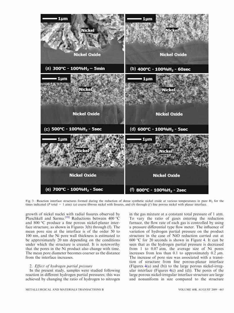
growth of nickel nuclei with radial fissures observed byPluschkell and Sarma.[18] Reductions between 400 �Cand 800 �C produce a fine porous nickel-planar inter-face structure, as shown in Figures 3(b) through (f). Themean pore size at the interface is of the order 50 to100 nm, and the Ni pore wall thickness is estimated tobe approximately 20 nm depending on the conditionsunder which the structure is created. It is noteworthythat the pores in the Ni product also change with time.The mean pore diameter becomes coarser as the distancefrom the interface increases.
2. Effect of hydrogen partial pressureIn the present study, samples were studied following
reaction in different hydrogen partial pressures; this wasachieved by changing the ratio of hydrogen to nitrogen
in the gas mixture at a constant total pressure of 1 atm.To vary the ratio of gases entering the reductionfurnace, the flow rate of each gas is controlled by usinga pressure differential type flow meter. The influence ofvariation of hydrogen partial pressure on the productstructure in the case of NiO reduction carried out at600 �C for 20 seconds is shown in Figure 4. It can beseen that as the hydrogen partial pressure is decreasedfrom 1 to 0.07 atm, the average size of Ni poresincreases from less than 0.1 to approximately 0.2 lm.The increase of pore size was associated with a transi-tion of structure from fine porous-planar interface(Figures 4(a) and (b)) to the large porous nickel-irreg-ular interface (Figures 4(c) and (d)). The pores of thelarge porous nickel-irregular interface structure are largeand nonuniform in size compared to the structure
Fig. 3—Reaction interface structures formed during the reduction of dense synthetic nickel oxide at various temperatures in pure H2 for thetimes indicated (P total = 1 atm): (a) coarse fibrous nickel with fissures, and (b) through (f ) fine porous nickel with planar interface.
METALLURGICAL AND MATERIALS TRANSACTIONS B VOLUME 40B, AUGUST 2009—465
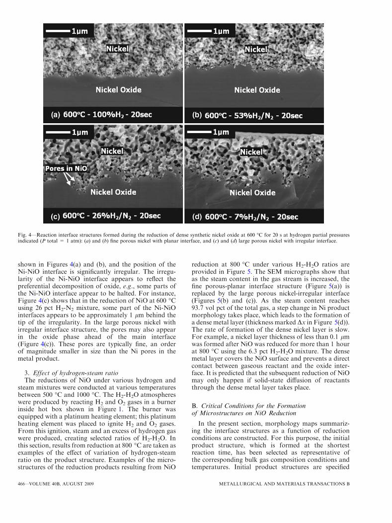
shown in Figures 4(a) and (b), and the position of theNi-NiO interface is significantly irregular. The irregu-larity of the Ni-NiO interface appears to reflect thepreferential decomposition of oxide, e.g., some parts ofthe Ni-NiO interface appear to be halted. For instance,Figure 4(c) shows that in the reduction of NiO at 600 �Cusing 26 pct H2-N2 mixture, some part of the Ni-NiOinterfaces appears to be approximately 1 lm behind thetip of the irregularity. In the large porous nickel withirregular interface structure, the pores may also appearin the oxide phase ahead of the main interface(Figure 4(c)). These pores are typically fine, an orderof magnitude smaller in size than the Ni pores in themetal product.
3. Effect of hydrogen-steam ratioThe reductions of NiO under various hydrogen and
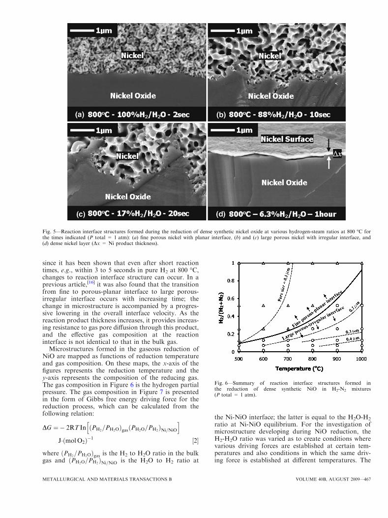
steam mixtures were conducted at various temperaturesbetween 500 �C and 1000 �C. The H2-H2O atmosphereswere produced by reacting H2 and O2 gases in a burnerinside hot box shown in Figure 1. The burner wasequipped with a platinum heating element; this platinumheating element was placed to ignite H2 and O2 gases.From this ignition, steam and an excess of hydrogen gaswere produced, creating selected ratios of H2-H2O. Inthis section, results from reduction at 800 �C are taken asexamples of the effect of variation of hydrogen-steamratio on the product structure. Examples of the micro-structures of the reduction products resulting from NiO
reduction at 800 �C under various H2-H2O ratios areprovided in Figure 5. The SEM micrographs show thatas the steam content in the gas stream is increased, thefine porous-planar interface structure (Figure 5(a)) isreplaced by the large porous nickel-irregular interface(Figures 5(b) and (c)). As the steam content reaches93.7 vol pct of the total gas, a step change in Ni productmorphology takes place, which leads to the formation ofa dense metal layer (thickness marked Dx in Figure 5(d)).The rate of formation of the dense nickel layer is slow.For example, a nickel layer thickness of less than 0.1 lmwas formed after NiO was reduced for more than 1 hourat 800 �C using the 6.3 pct H2-H2O mixture. The densemetal layer covers the NiO surface and prevents a directcontact between gaseous reactant and the oxide inter-face. It is predicted that the subsequent reduction of NiOmay only happen if solid-state diffusion of reactantsthrough the dense metal layer takes place.
B. Critical Conditions for the Formationof Microstructures on NiO Reduction
In the present section, morphology maps summariz-ing the interface structures as a function of reductionconditions are constructed. For this purpose, the initialproduct structure, which is formed at the shortestreaction time, has been selected as representative ofthe corresponding bulk gas composition conditions andtemperatures. Initial product structures are specified
Fig. 4—Reaction interface structures formed during the reduction of dense synthetic nickel oxide at 600 �C for 20 s at hydrogen partial pressuresindicated (P total = 1 atm): (a) and (b) fine porous nickel with planar interface, and (c) and (d) large porous nickel with irregular interface.
466—VOLUME 40B, AUGUST 2009 METALLURGICAL AND MATERIALS TRANSACTIONS B
since it has been shown that even after short reactiontimes, e.g., within 3 to 5 seconds in pure H2 at 800 �C,changes to reaction interface structure can occur. In aprevious article,[16] it was also found that the transitionfrom fine to porous-planar interface to large porous-irregular interface occurs with increasing time; thechange in microstructure is accompanied by a progres-sive lowering in the overall interface velocity. As thereaction product thickness increases, it provides increas-ing resistance to gas pore diffusion through this product,and the effective gas composition at the reactioninterface is not identical to that in the bulk gas.
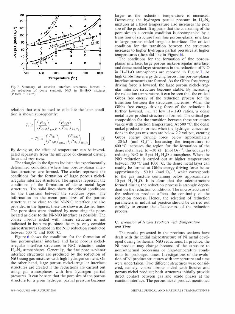
Microstructures formed in the gaseous reduction ofNiO are mapped as functions of reduction temperatureand gas composition. On these maps, the x-axis of thefigures represents the reduction temperature and they-axis represents the composition of the reducing gas.The gas composition in Figure 6 is the hydrogen partialpressure. The gas composition in Figure 7 is presentedin the form of Gibbs free energy driving force for thereduction process, which can be calculated from thefollowing relation:
DG ¼� 2RT In PH2=PH2Oð Þgas PH2O=PH2
ð ÞNi=NiO
h i
J� molO2ð Þ�1 ½2�
where PH2=PH2Oð Þgas is the H2 to H2O ratio in the bulk
gas and PH2O=PH2ð ÞNi=NiO is the H2O to H2 ratio at
the Ni-NiO interface; the latter is equal to the H2O-H2
ratio at Ni-NiO equilibrium. For the investigation ofmicrostructure developing during NiO reduction, theH2-H2O ratio was varied as to create conditions wherevarious driving forces are established at certain tem-peratures and also conditions in which the same driv-ing force is established at different temperatures. The
Fig. 5—Reaction interface structures formed during the reduction of dense synthetic nickel oxide at various hydrogen-steam ratios at 800 �C forthe times indicated (P total = 1 atm): (a) fine porous nickel with planar interface, (b) and (c) large porous nickel with irregular interface, and(d) dense nickel layer (Dx = Ni product thickness).
Fig. 6—Summary of reaction interface structures formed inthe reduction of dense synthetic NiO in H2-N2 mixtures(P total = 1 atm).
METALLURGICAL AND MATERIALS TRANSACTIONS B VOLUME 40B, AUGUST 2009—467
relation that can be used to calculate the later condi-tion is shown subsequently:
T1 lnPH2
PH2O
� �
gas;T1
PH2O
PH2
� �
int;T1
" #
¼ T2 lnPH2
PH2O
� �
gas;T2
PH2O
PH2
� �
int;T2
" #½3�
By doing so, the effect of temperature can be investi-gated separately from the influence of chemical drivingforce and vice versa.
The triangles in the figures indicate the experimentallydetermined conditions where fine porous-planar inter-face structures are formed. The circles represent theconditions for the formation of large porous nickel-irregular interface structures. The squares represent theconditions of the formation of dense metal layerstructures. The solid lines show the critical conditionsfor the transition between the structure types. Theinformation on the mean pore sizes of the porousstructure at or close to the Ni-NiO interface are alsoprovided in the figures; these are shown as dashed lines.The pore sizes were obtained by measuring the poreslocated as close to the Ni-NiO interface as possible. Thecoarse fibrous nickel with fissure structure is notindicated in both maps, since the maps only considermicrostructures formed in the NiO reduction conductedbetween 500 �C and 1000 �C.
Figure 6 shows the conditions for the formation offine porous-planar interface and large porous nickel-irregular interface structures in NiO reduction underH2-N2 atmospheres. Generally, the fine porous-planarinterface structures are produced by the reduction ofNiO using gas mixtures with high hydrogen content. Onthe other hand, large porous nickel-irregular interfacestructures are created if the reductions are carried outusing gas atmospheres with low hydrogen partialpressures. It can be seen that the pore size of the porousstructure for a given hydrogen partial pressure becomes
larger as the reduction temperature is increased.Decreasing the hydrogen partial pressure in H2-N2
mixtures at a fixed temperature also increases the poresize of the product. It appears that the coarsening of thepore size to a certain condition is accompanied by atransition of structure from fine porous-planar interfaceto large porous nickel-irregular interface. The criticalcondition for the transition between the structuresincreases to higher hydrogen partial pressures at highertemperatures (the solid line in Figure 6).The conditions for the formation of fine porous-
planar interface, large porous nickel-irregular interface,and dense metal layer structures in the reduction of NiOin H2-H2O atmospheres are reported in Figure 7. Athigh Gibbs free energy driving forces, fine porous-planarinterface structures are formed. As the Gibbs free energydriving force is lowered, the large porous nickel-irreg-ular interface structure becomes stable. By increasingthe reduction temperature, it can be seen that the criticalGibbs free energy of the reduction process for thetransition between the structures increases. When theGibbs free energy driving force of the reduction isfurther lowered, i.e., at low H2-H2O ratios, a densemetal layer product structure is formed. The critical gascomposition for the transition between these structuresvaries with reduction temperature. At 500 �C, the densenickel product is formed when the hydrogen concentra-tions in the gas mixtures are below 2.2 vol pct, creatingGibbs energy driving force below approximately�20 kJ Æ (mol O2)
�1. Increasing the temperature to600 �C increases the region for the formation of thedense metal layer to �30 kJ Æ (mol O2)
�1; this equates toreducing NiO in 5 pct H2-H2O atmosphere. When theNiO reduction is carried out at higher temperaturesbetween 700 �C and 1000 �C, the dense metal layer canreadily be formed at Gibbs energy driving force belowapproximately �50 kJ Æ (mol O2)
�1, which correspondsto the gas mixture containing below approximately10 pct H2-H2O. It is clear that the microstructureformed during the reduction process is strongly depen-dent on the reduction conditions. The microstructure ofthe reduction product affects the continuity of thereduction process. Hence, the selection of reductionparameters in industrial practice should be carried outcarefully to ensure the effectiveness of the reductionprocess.
C. Evolution of Nickel Products with Temperatureand Time
The results presented in the previous sections havedealt with the initial microstructure of Ni metal devel-oped during isothermal NiO reductions. In practice, theNi product may change because of the exposure tononisothermal processing or high-temperature condi-tions for prolonged times. Investigations of the evolu-tion of Ni product structures with temperature and timewere undertaken. Two different structures were consid-ered, namely, coarse fibrous nickel with fissures andporous nickel product; both structures initially providedirect contact between gas and oxide phases at thereaction interface. The porous nickel product mentioned
Fig. 7—Summary of reaction interface structures formed inthe reduction of dense synthetic NiO in H2-H2O mixtures(P total = 1 atm).
468—VOLUME 40B, AUGUST 2009 METALLURGICAL AND MATERIALS TRANSACTIONS B
in the present section represents the fine porous-planarinterface and large porous nickel-irregular interfacestructures. It is important to establish how theserespective structures change with temperature and time.
1. Effect of heating on coarse fibrous nickelwith fissures
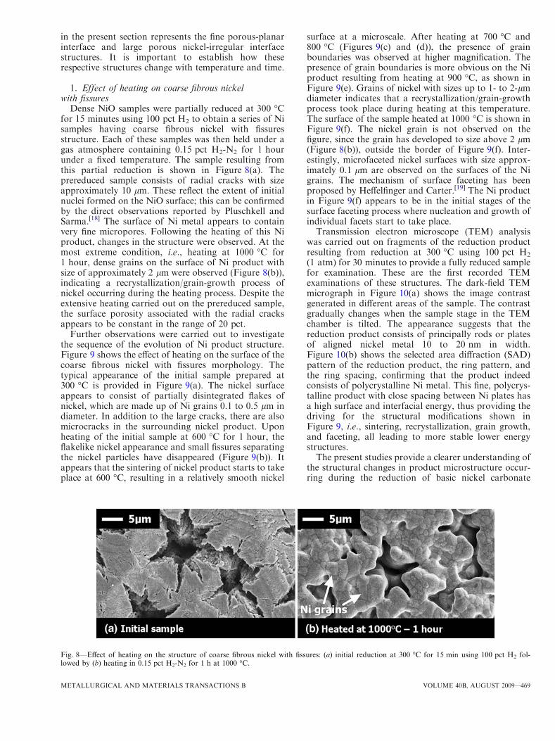
Dense NiO samples were partially reduced at 300 �Cfor 15 minutes using 100 pct H2 to obtain a series of Nisamples having coarse fibrous nickel with fissuresstructure. Each of these samples was then held under agas atmosphere containing 0.15 pct H2-N2 for 1 hourunder a fixed temperature. The sample resulting fromthis partial reduction is shown in Figure 8(a). Theprereduced sample consists of radial cracks with sizeapproximately 10 lm. These reflect the extent of initialnuclei formed on the NiO surface; this can be confirmedby the direct observations reported by Pluschkell andSarma.[18] The surface of Ni metal appears to containvery fine micropores. Following the heating of this Niproduct, changes in the structure were observed. At themost extreme condition, i.e., heating at 1000 �C for1 hour, dense grains on the surface of Ni product withsize of approximately 2 lm were observed (Figure 8(b)),indicating a recrystallization/grain-growth process ofnickel occurring during the heating process. Despite theextensive heating carried out on the prereduced sample,the surface porosity associated with the radial cracksappears to be constant in the range of 20 pct.
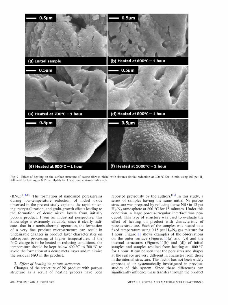
Further observations were carried out to investigatethe sequence of the evolution of Ni product structure.Figure 9 shows the effect of heating on the surface of thecoarse fibrous nickel with fissures morphology. Thetypical appearance of the initial sample prepared at300 �C is provided in Figure 9(a). The nickel surfaceappears to consist of partially disintegrated flakes ofnickel, which are made up of Ni grains 0.1 to 0.5 lm indiameter. In addition to the large cracks, there are alsomicrocracks in the surrounding nickel product. Uponheating of the initial sample at 600 �C for 1 hour, theflakelike nickel appearance and small fissures separatingthe nickel particles have disappeared (Figure 9(b)). Itappears that the sintering of nickel product starts to takeplace at 600 �C, resulting in a relatively smooth nickel
surface at a microscale. After heating at 700 �C and800 �C (Figures 9(c) and (d)), the presence of grainboundaries was observed at higher magnification. Thepresence of grain boundaries is more obvious on the Niproduct resulting from heating at 900 �C, as shown inFigure 9(e). Grains of nickel with sizes up to 1- to 2-lmdiameter indicates that a recrystallization/grain-growthprocess took place during heating at this temperature.The surface of the sample heated at 1000 �C is shown inFigure 9(f). The nickel grain is not observed on thefigure, since the grain has developed to size above 2 lm(Figure 8(b)), outside the border of Figure 9(f). Inter-estingly, microfaceted nickel surfaces with size approx-imately 0.1 lm are observed on the surfaces of the Nigrains. The mechanism of surface faceting has beenproposed by Heffelfinger and Carter.[19] The Ni productin Figure 9(f) appears to be in the initial stages of thesurface faceting process where nucleation and growth ofindividual facets start to take place.Transmission electron microscope (TEM) analysis
was carried out on fragments of the reduction productresulting from reduction at 300 �C using 100 pct H2
(1 atm) for 30 minutes to provide a fully reduced samplefor examination. These are the first recorded TEMexaminations of these structures. The dark-field TEMmicrograph in Figure 10(a) shows the image contrastgenerated in different areas of the sample. The contrastgradually changes when the sample stage in the TEMchamber is tilted. The appearance suggests that thereduction product consists of principally rods or platesof aligned nickel metal 10 to 20 nm in width.Figure 10(b) shows the selected area diffraction (SAD)pattern of the reduction product, the ring pattern, andthe ring spacing, confirming that the product indeedconsists of polycrystalline Ni metal. This fine, polycrys-talline product with close spacing between Ni plates hasa high surface and interfacial energy, thus providing thedriving for the structural modifications shown inFigure 9, i.e., sintering, recrystallization, grain growth,and faceting, all leading to more stable lower energystructures.The present studies provide a clearer understanding of
the structural changes in product microstructure occur-ring during the reduction of basic nickel carbonate
Fig. 8—Effect of heating on the structure of coarse fibrous nickel with fissures: (a) initial reduction at 300 �C for 15 min using 100 pct H2 fol-lowed by (b) heating in 0.15 pct H2-N2 for 1 h at 1000 �C.
METALLURGICAL AND MATERIALS TRANSACTIONS B VOLUME 40B, AUGUST 2009—469
(BNC).[14,15] The formation of nanosized pores/grainsduring low-temperature reduction of nickel oxideobserved in the present study explains the rapid sinter-ing, recrystallization, and grain-growth effects leading tothe formation of dense nickel layers from initiallyporous product. From an industrial perspective, thisknowledge is extremely valuable, since it clearly indi-cates that in a nonisothermal operation, the formationof a very fine product microstructure can result inundesirable changes in product layer characteristics onsubsequent processing at higher temperatures. If theNiO charge is to be heated in reducing conditions, thetemperature should be kept below 600 �C to 700 �C toavoid the formation of a dense metal layer and minimizethe residual NiO in the product.
2. Effect of heating on porous structuresChanges of the structure of Ni product with porous
structure as a result of heating process have been
reported previously by the authors.[16] In this study, aseries of samples having the same initial Ni porousstructure was prepared by reducing dense NiO in 13 pctH2-N2 atmosphere at 600 �C for 15 minutes. Under thiscondition, a large porous-irregular interface was pro-duced. This type of structure was used to evaluate theeffect of heating on product with characteristic ofporous structure. Each of the samples was heated at afixed temperature using 0.15 pct H2-N2 gas mixture for1 hour. Figure 11 shows examples of the observationson the outer surface (Figures 11(a) and (c)) and theinternal structures (Figures 11(b) and (d)) of initialsamples and samples resulted from heating at 1000 �Cfor 1 hour. It can be seen that the pore sizes and shapesat the surface are very different in character from thosein the internal structure. This factor has not been widelyappreciated or systematically investigated in previousstudies of this system. Since these differences cansignificantly influence mass transfer through the product
Fig. 9—Effect of heating on the surface structure of coarse fibrous nickel with fissures (initial reduction at 300 �C for 15 min using 100 pct H2
followed by heating in 0.15 pct H2-N2 for 1 h at temperatures indicated).
470—VOLUME 40B, AUGUST 2009 METALLURGICAL AND MATERIALS TRANSACTIONS B

layer, the changes on the outer surface and in theinternal structure of the porous product were measuredin the present study and are discussed subsequently.
The effect of heating temperature on the outer surfaceof Ni porous product is shown in Figure 12. Generally,it can be seen that heating the nickel product at higher
temperature increased the mean pore size of the nickelsurface. The coarsening of the pore size was accompa-nied by a decrease of number of pores on the nickelsurface (Figure 12(a)). Data of the pore size and numberof pores on the nickel surface were used to calculatesurface porosity. It appears that heating of the nickel
Fig. 10—Nickel particle resulting from reduction at 300 �C using 100 pct H2 for 30 min: (a) TEM dark-field image and (b) TEM selected areadiffraction pattern.
Fig. 11—Effect of heating temperature on the Ni product with porous structure: (a) and (c) outer metal surface, (b) and (d) internal porousproduct structure. (a) and (b) Initial samples resulting from reduction at 600 �C for 15 min using 13 pct H2-N2 atmosphere, and (c) and (d) sam-ples resulting from further heating of prereduced samples at 1000 �C for 1 h in 0.15 pct H2-N2.
METALLURGICAL AND MATERIALS TRANSACTIONS B VOLUME 40B, AUGUST 2009—471
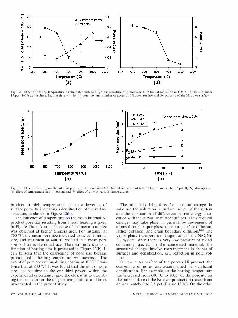
product at high temperatures led to a lowering ofsurface porosity, indicating a densification of the surfacestructure, as shown in Figure 12(b).
The influence of temperature on the mean internal Niproduct pore size resulting from 1 hour heating is givenin Figure 13(a). A rapid increase of the mean pore sizewas observed at higher temperatures. For instance, at700 �C, the mean pore size increased to twice its initialsize, and treatment at 800 �C resulted in a mean poresize of 4 times the initial size. The mean pore size as afunction of heating time is presented in Figure 13(b). Itcan be seen that the coarsening of pore size becamepronounced as heating temperature was increased. Theextent of pore coarsening during heating at 1000 �C wastwice that at 800 �C. It was found that the plot of poresizes against time to the one-third power, within theexperimental uncertainty, gave the closest fit to describ-ing the behavior for the range of temperatures and timesinvestigated in the present study.
The principal driving force for structural changes insolid are the reduction in surface energy of the systemand the elimination of differences in free energy asso-ciated with the curvature of free surfaces. The structuralchanges may take place, in general, by movements ofatoms through vapor phase transport, surface diffusion,lattice diffusion, and grain boundary diffusion.[20] Thevapor phase transport is not significant in the NiO/Ni/H2 system, since there is very low pressure of nickelcontaining species. In the condensed material, thestructural changes involve rearrangement in shapes ofsurfaces and densification, i.e., reduction in pore vol-ume.On the outer surface of the porous Ni product, the
coarsening of pores was accompanied by significantdensification. For example, as the heating temperaturewas increased from 600 �C to 1000 �C, the porosity onthe outer surface of the Ni layer product decreased fromapproximately 8 to 0.5 pct (Figure 12(b)). On the other
Fig. 12—Effect of heating temperature on the outer surface of porous structure of prereduced NiO (initial reduction at 600 �C for 15 min under13 pct H2-N2 atmosphere, heating time = 1 h): (a) pore size and number of pores on Ni outer surface and (b) porosity of the Ni outer surface.
Fig. 13—Effect of heating on the internal pore size of prereduced NiO (initial reduction at 600 �C for 15 min under 13 pct H2-N2 atmosphere):(a) effect of temperature at 1 h heating and (b) effect of time at various temperatures.
472—VOLUME 40B, AUGUST 2009 METALLURGICAL AND MATERIALS TRANSACTIONS B
hand, the porosity of the internal structure was found tobe constant at approximately 50 pct despite the increasein the pore size. It can be seen from the present resultsthat the mean pore sizes on the outer surface of Niporous product are approximately 5 to 10 times smallerthan those of the internal pores (Figures 11(a) and (b)).It appears that on the outer surface of Ni, where thepores are finer than those in the bulk Ni, the extent andrate of densification of the surface layer are greater thanthe bulk. The differences in pore size between surfaceand bulk Ni clearly appear to influence the extent andrate of structural changes.
IV. SUMMARY
By systematically examining the reduction productformed during the reduction of dense synthetic NiO inH2-N2 and H2-H2O atmospheres, four types of distinctlydifferent Ni microstructures have been identified,namely, coarse fibrous nickel with fissures, fine porousnickel-planar interface, large porous nickel-irregularinterface, and dense nickel layer. The conditions underwhich these microstructures are formed have beenidentified, and it has been shown that the microstruc-tures of the reduction product are strongly affected bythe reduction conditions, i.e., temperature, hydrogenpartial pressure, and hydrogen-steam ratio. The transi-tion from the coarse fibrous nickel with fissures towardthe fine porous nickel-planar interface and large porousnickel-irregular interface structures is promoted by theincrease of temperature and the decrease of hydrogenpartial pressure. Furthermore, the increase of steamcontent in the reducing gas results in the formation of adense nickel layer. The condition for formation of thevarious microstructure types were summarized on mor-phology maps as functions of reducing gas partialpressure, thermodynamic driving force, and reactiontemperature.
Systematic examination of the evolution of Ni metalproducts with temperature and time has been carriedout. It was found that the modification of Ni productwith coarse fibrous nickel with fissures structure duringheating takes place through several steps involvingsintering, recrystallization, grain growth, and facetingof nickel. In the case of the internal porous Ni product,the heating process results in the increase of the pore sizeand the decrease of the number of pores, however littledensification. The structure of pores on the outersurfaces of the nickel product has been shown to besignificantly different to internal pores, and densificationhas been observed on heating the outer surface of theporous Ni product. The results of this study have addeda great deal to the fundamental understanding of the
process occurring during the reduction of nickel oxideand demonstrate the complexity of the transformationtaking place in these systems.
ACKNOWLEDGMENTS
The authors thank the BHP Billiton Yabulu Refin-ery and Australian Research Council Linkage programfor the financial support, and AusAid for providing ascholarship. The authors also acknowledge Mr. JohnFittock and Dr. Joy Morgan (BHP Billiton Yabulu)for their valuable help and critical discussions. Theauthors also thank Messrs. Yanan Guo and JiangChen for carrying out TEM analysis.
REFERENCES1. W. Betteridge: Nickel and Its Alloys, John Wiley & Sons Inc.,
Brisbane, 1984, pp. 171–74.2. S. Luidold andH.Antrekowitsch:JOM, 2007, vol. 59 (6), pp. 20–26.3. L.L. Bergeson: Chem. Process. Mag., 2003, Oct., http://www.
chemicalprocessing.com/articles/2003/143.html?page=print (accessedSeptember 19, 2007).
4. A. Kivnick and N. Hixson: Chem. Eng. Prog., 1952, vol. 48 (8),pp. 394–400.
5. Y. Iida and K. Shimada: Bull. Chem. Soc. Jpn., 1960, vol. 33 (6),pp. 790–93.
6. J. Bandrowski, C.R. Bickling, K.H. Yang, and O.A. Hougen:Chem. Eng. Sci., 1962, vol. 17, pp. 379–90.
7. H. Mine, M. Tokuda, and M. Ohtani: Jpn. Inst. Met., 1970,vol. 34, pp. 814–20.
8. T. DebRoy and K.P. Abraham: Proc. Physical Chemistry ofProcess Metallurgy: The Richardson Conf., Institute of Mining andMetallurgy, 1973, pp. 85–93.
9. J.W. Evans, S. Song, and C.E. Leon-Sucre: Metall. Mater. Trans.B, 1976, vol. 7B, pp. 55–65.
10. A.H. Rashed and Y.K. Rao: Chem. Eng. Commun., 1996, vol. 156,pp. 1–30.
11. Y.K. Rao and A.H. Rashed: Trans. Inst. Min. Metall. (Sect. C:Mineral Process. Extr. Metall.), 2001, vol. 110, pp. 1–6.
12. J.T. Richardson, R. Scates, and M.V. Twigg: Appl. Catal. A-Gen.,2003, vol. 246, pp. 137–50.
13. T.A. Utigard, M. Wu, G. Plascencia, and T. Marin: Chem. Eng.Sci., 2005, vol. 60 (7), pp. 2061–68.
14. M.A. Rhamdhani, E. Jak, and P.C. Hayes: Metall. Mater. Trans.B, 2008, vol. 39B, pp. 218–33.
15. M.A. Rhamdhani, E. Jak, and P.C. Hayes: Metall. Mater. Trans.B, 2008, vol. 39B, pp. 234–45.
16. T. Hidayat, M.A. Rhamdhani, E. Jak, and P. Hayes: Miner. Eng.,2008, vol. 21 (2), pp. 157–66.
17. S.P. Matthew, D.H. St. John, J.V. Hardy, and P.C. Hayes:Metallography, 1985, vol. 17, pp. 367–79.
18. W. Pluschkell and B.V.S. Sarma: Arch. Eisenhuttenwes., 1974,vol. 45 (1), pp. 23–31.
19. J.R. Heffelfinger and C.B. Carter: Surf. Sci., 1997, vol. 389 (1–3),pp. 188–200.
20. W.D. Kingery, H.K. Bowen, and D.R. Uhlman: Introduction toCeramics, 2nd ed., John Wiley & Sons, Sydney, 1976, pp. 474–75.
METALLURGICAL AND MATERIALS TRANSACTIONS B VOLUME 40B, AUGUST 2009—473
Copyright © 2022 FDOKUMEN