An experimental investigation of acoustic cavitation in gaseous liquids
Upload
khangminh22Category
view
0download
0
/ / ¿'¿¿¡¿-у eu / /7 >a//¿
PROCEEDINGS OF A SY M P O S IU M , VIENNA, 18-22 FEBRUARY 1980
JOINTLY ORGANIZED BY IAEA AND NEA (OECD) / лО ъ rftO
Management ^ of Gaseous Wastes from Nuclear Facilities
INTERNATIONAL ATOMIC ENERGY AGENCY, V IENNA, 1980

MANAGEMENT OF GASEOUS WASTES
FROM NUCLEAR FACILITIES


PROCEEDINGS SERIES
MANAGEMENT OF GASEOUS WASTES
FROM NUCLEAR FACILITIESPROCEEDINGS OF AN INTERNATIONAL SYMPOSIUM ON
MANAGEMENT OF GASEOUS WASTES FROM NUCLEAR FACILITIES
JOINTLY ORGANIZED BY THE INTERNATIONAL ATOMIC ENERGY AGENCY
AND THENUCLEAR ENERGY AGENCY OF THE OECD
AND HELD IN VIENNA, 18-22 FEBRUARY 1980
INTERNATIONAL ATOMIC ENERGY AGENCY VIENNA, 1980

MANAGEMENT OF GASEOUS WASTES FROM NUCLEAR FACILITIES IAEA, VIENNA, 1980
STI/PUB/561 ISBN 9 2 -0 -0 2 0 3 8 0 -9
(C) IA EA , 1980
Perm ission to rep ro d u ce o r transla te the in fo rm atio n co n ta in ed in th is pub lica tion m ay be o b ta ined by w riting to th e In te rn a tio n a l A tom ic Energy A gency, W agram erstrasse 5, P.O. Box 100, A -1400 V ienna, A ustria.
P rin ted by the IA EA in A ustria D ecem ber 1980
FOREWORD
During the course of the various functions performed in the nuclear fuel cycle, such as the routine operation of nuclear power reactors, fuel reprocessing, incineration and liquid waste solidification, different radioactive wastes and effluents are generated, containing radionuclides produced from fission and neutron activation. Minimizing the release of these airborne radionuclides into the environment so that they are kept down to well below acceptable limits is a safety measure of great importance in assuring the protection of man and his environment. With the increasing use of nuclear energy for electric power generation, continuing and close attention has to be given to the appropriate management of the gaseous wastes and effluents.
The last international forum dealing specifically with the management of gaseous wastes from nuclear facilities was the 1968 IAEA Symposium on Operating and Developmental Experience in the Treatment of Airborne Radioactive Wastes, held in New York in co-operation with the USAEC and Harvard University. Since then, much research has been done and considerable operating experience has been gained. To provide the scientists, engineers and other experts involved in gaseous radioactive waste management with an opportunity for exchanging ideas, information and experience, the IAEA and the Nuclear Energy Agency of OECD organized in Vienna on 18—22 February 1980 the Symposium on the Management of Gaseous Wastes from Nuclear Facilities. The programme of the symposium covered the following topics: general aspects of the management of gaseous wastes from nuclear facilities; sources and characteristics of off-gases from nuclear facilities; removal and retention of radioiodine, tritium and carbon-14; removal and retention of noble gases; filtration, sampling and monitoring of airborne effluents; off-gas cleaning systems operation; off-gas cleaning systems design; storage and disposal.
The Symposium was attended by 175 scientists from 25 countries and two international organizations. The forty-three papers presented, together with discussions, are published in the present proceedings, which provide a broad synthesis of current practice and the latest developments.

EDITORIAL NOTE
The papers and discussions have been edited by the editorial sta ff o f the International Atomic Energy Agency to the extent considered necessary for the reader’s assistance. The views expressed and the general style adopted remain, however, the responsibility o f the named authors or participants. In addition, the views are not necessarily those o f the governments o f the nominating Member States or o f the nominating organizations.
Where papers have been incorporated into these Proceedings without resetting by the Agency, this has been done with the knowledge o f the authors and their government authorities, and their cooperation is gratefully acknowledged. The Proceedings have been printed by composition typing and photo-offset lithography. Within the limitations imposed by this method, every effort has been made to maintain a high editorial standard, in particular to achieve, wherever practicable, consistency o f units and symbols and conformity to the standards recommended by competent international bodies.
The use in these Proceedings o f particular designations o f countries or territories does not imply any judgement by the publisher, the IAEA, as to the legal status o f such countries or territories, o f their authorities and institutions or o f the delimitation o f their boundaries.
The mention o f specific companies or o f their products or brand names does not imply any endorsement or recommendation on the part o f the IAEA.
Authors are themselves responsible for obtaining the necessary permission to reproduce copyright material from other sources.
CONTENTS
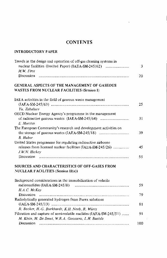
Trends in the design and operation of off-gas cleaning systems innuclear facilities (Invited Paper) (IAEA-SM-245/62) ......................... 3M. W. FirstDiscussion .................................................................................................... 20
GENERAL ASPECTS OF THE MANAGEMENT OF GASEOUS WASTES FROM NUCLEAR FACILITIES (Session I)
IAEA activities in the field of gaseous waste management(IAEA-SM-245/63) ...................................................................................... 25Yu. Zabaluev
OECD Nuclear Energy Agency’s programme in the managementof radioactive gaseous wastes (IAEA-SM-245/64) ............................... 31E. Maestas
The European Community’s research and development activities onthe storage of gaseous wastes (IAEA-SM-245/18) ................................ 39B. Huber
United States programme for regulating radioactive airbornereleases from licensed nuclear facilities (IAEA-SM-245/26) ................ 45J. W.N. HickeyDiscussion ................................................................................................... 55
SOURCES AND CHARACTERISTICS OF OFF-GASES FROM NUCLEAR FACILITIES (Session 11(a))
Background considerations in the immobilization of volatileradionuclides (IAEA-SM-245/8) ............................................................ 59H.A.C. McKayDiscussion .................................................................................................... 79
Radiolytically generated hydrogen from Purex solutions(IAEA-SM-245/13) ...................................................................................... 81R. Becker, H.-G. Burkhardt, K.H. Neeb, R. Wiirtz
Filtration and capture of semi-volatile nuclides (IAEA-SM-245/51) ....... 91M. Klein, M. De Sm et, W.R.A. Goossens, L.H. BaetsleDiscussion .................................................................................................... 100
INTRODUCTORY PAPER

Removal of nitrogen oxides, volatile radionuclides and aerosols formed in laboratory-scale denitration, calcination andsolidification of simulated high-level wastes (IAEA-SM-245/54)......... 101F. Kepák, V. Pecák, E. Uher, J. Kahka, S. Koutová,V. MatousDiscussion ................................................................................................... I l l
REMOVAL AND RETENTION OF RADIOIODINE, TRITIUM AND CARBON-14 (Sessions 11(b) and III)
Применение кремнийорганических жидкостей в качестве поглотителейпри абсорбционном способе улавливания 129J (IAEA-SM-245/65) ......... 115И Е. Нахутин, Л.Н.Растунов, Н.М. Смирнова,
Г. А. Лошаков, Г.А.Лаушкина
(The use o f silicon-organic liquids as absorbents fo r the retention o f 1291: I.E. Nakhutin, L.N. Rastunov,N.M. Smirnova, G.A. Loshakov, G.A. Laushkina)Discussion ................................................................................................... 122
Radioiodine in gaseous effluents from nuclear power plants(IAEA-SM-245/30) ..................................................................................... 123H. TillDiscussion ................................................................................................... 136
Improved procedures for efficient iodine removal from fuelsolutions in reprocessing plants (IAEA-SM-245/16) ............................ 139E. Henrich, R. Hüfner, A. SahmDiscussion ................................................................................................... 156
Separation of tritium from reprocessing effluents(IAEA-SM-245/52) ..................................................................................... 157A. Bruggeman, W. Doyen, R. Harnie, R. Leysen,L. M eynendonckx, M. Monsecour, W.R.A. Goossens,L.H. BaetsleDiscussion ................................................................................................... 173
The concentration of tritium in the aqueous and solid waste ofLWR fuel reprocessing plants (IAEA-SM-245/15) ................................. 177E. Henrich, H. Schmieder, K.H. NeebDiscussion ................................................................................................... 189
Processes for the control of 14C 02 during reprocessing(IAEA-SM-245/29) ..................................................................................... 191K.J. Notz, D.W. Holladay, C.W. Forsberg, G.L. HaagDiscussion ................................................................................................... 209
Retention of carbon-14 in nuclear facilities (IAEA-SM-245/9) ............... 211H. Braun, H. Bonka, D. Gründler, H. Gutowski, J. WeberDiscussion ................................................................................................... 225

REMOVAL AND RETENTION OF NOBLE GASES (Session IV)
Catalytic reduction of 0 2 and NOx : A critical pretreatment stepfor the cryogenic retention of krypton-85 (IAEA-SM-245/12) .......... 229R. von A m m on, G. Knittel, E. H utterDiscussion ................................................................................................... 242
Removal of noble gases by selective absorption(IAEA-SM-245/53) ...................................................................................... 243J.R. Merriman, M.J. Stephenson, B.E. Kanak, D.K. L ittleDiscussion ................................................................................................... 260
Containment of krypton in a metallic matrix by combined ionimplantation and sputtering (IAEA-SM-245/7) ..................................... 263D.S. Whitmell, R.S. Nelson, M.J. S. Sm ithDiscussion .................................................................................................... 277
Solid state containment of noble gases in sputter deposited metalsand low density glasses (IAEA-SM-245/31) .......................................... 279G.L. Tingey, E.D. McClanahan, M.A. Bayne, W.J. Gray
Long-term storage of krypton-85 in zeolites (IAEA-SM-245/10) ............ 291R.-D. Penzhorn, P. Schuster, H.E. Noppel, L.M. HellwigDiscussion ................................................................................................... 299
FILTRATION, SAMPLING AND MONITORING OF AIRBORNE EFFLUENTS (Session V)
Testing of high-efficiency aerosol filters by using a scintillationparticle counter (IAEA-SM-245/35) ...................................................... 303W. Ullmann, S. PrzyborowskiDiscussion ................................................................................................... 312
Essais in situ et en laboratoire des filtres à iode en Italie(IAEA-SM-245/45 ) ...................................................................................... 315S. Lanza, M. Mazzini, U. PisaniDiscussion ..................................................................................................... 330
Studies on sand-bed air filters for the treatment of fuelreprocessing dissolver off-gases (IAEA-SM-245/39) .......................... 333J.C. Kapoor, C. Srinivas, A .A . Khan, K.T. ThomasDiscussion ................................................................................................... 345
The estimation of tritium, sulphur-35 and carbon-14 in reactorcoolant gas and gaseous effluents (IAEA-SM-245/33) .......................... 347A.R . Doyle, K. H am mondDiscussion .................................................................................................... 360
An improved Kanne tritium monitoring system(IAEA-SM-245/19) ...................................................................................... 363D.F. Anderson, R.D. HiebertDiscussion ................................................................................................... 370

Behaviour of selected contaminants in spray calciner/in-canmelter waste vitrification off-gas (IAEA-SM-245/24) .......................... 371M.S. Hanson, R.W. Goles, D.C. HamiltonDiscussion ................................................................................................... 390
Application of membranes to monitoring for tritiated watervapour (IAEA-SM-245/57) ....................................................................... 393R. V. Osborne, R. G. C. McElroyDiscussion ................................................................................................... 407
OFF-GAS CLEANING SYSTEMS OPERATION (Session VI)
Fifteen years experience filtering N-reactor gaseous wastes(IAEA-SM-245/22) ..................................................................................... 411K.L. FowlerDiscussion ................................................................................................... 428
Performances de la distillation cryogénique pour l’épuration de la couverture d’argon d’un réacteur à neutrons rapides(IAEA-SM-245/41) ...................................................................................... 431G. Bon Mardion, B. Dewanckel, A. Lafon, J. Verdier,J.-L. Violet, Y. DepierreDiscussion ................................................................................................... 442
Policy, testing and acceptance standards for treatment plant for gaseous discharges from CEGB nuclear power stations(IAEA-SM-245 /34) ...................................................................................... 445D.J. Groom, C.W. Fern, B.A. WilkinsonDiscussion ................................................................................................... 461
Experience gathered in monitoring the emissions from an incineration facility for radioactive wastes(IAEA-SM-245/4) ...................................................................................... 463L.A. Kônig, H. Schüttelkopf, B. FessierDiscussion ................................................................................................... 479
Operational experience with a 25 m3 - h ' 1 simulated dissolveroff-gas purification loop (IAEA-SM-245/49) ....................................... 481G.E.R. Collard, P.J. Vaesen, W.R.A. Goossens, L.H. BaetsleDiscussion ................................................................................................... 493
OFF-GAS CLEANING SYSTEMS DESIGN (Session VII)
Some aspects of the treatment of typical off-gas streams fromreprocessing plants (IAEA-SM-245/37) .................................................. 497S.A.K. Jeelani, G.R. BalasubramanianDiscussion ................................................................................................... 516
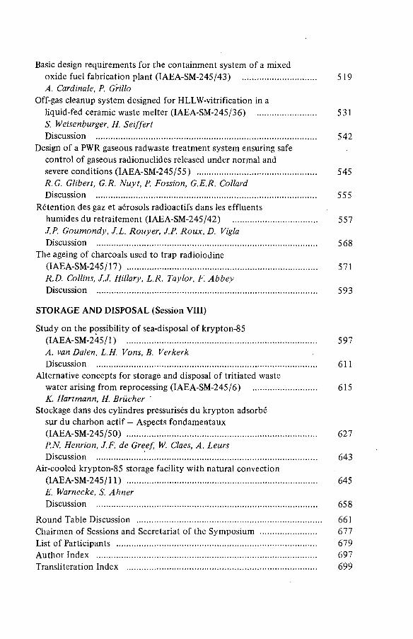
Basic design requirements for the containment system of a mixedoxide fuel fabrication plant (IAEA-SM-245/43) ................................. 519A. Cardinale, P. Grillo
Off-gas cleanup system designed for HLLW-vitrification in aliquid-fed ceramic waste melter (IAEA-SM-245/36) .......................... 531S. Weisenburger, H. SeiffertDiscussion ................................................................................................... 542
Design of a PWR gaseous radwaste treatment system ensuring safe control of gaseous radionuclides released under normal andsevere conditions (IAEA-SM-245/55) ...................................................... 545R.G. Glibert, G.R. N uyt, P. Fossion, G.E.R. CollardDiscussion ................................................................................................... 555
Rétention des gaz et aérosols radioactifs dans les effluentshumides du retraitement (IAEA-SM-245/42) ...................................... 557J.P. Goumondy, J.L. Rouyer, J.P. R oux, D. ViglaDiscussion ............................................................................................ :..... 568
The ageing of charcoals used to trap radioiodine(IAEA-SM-245/17) ...................................................................................... 571R.D. Collins, J.J. Hillary, L.R. Taylor, F. A bbeyDiscussion ................................................................................................... 593
STORAGE AND DISPOSAL (Session VIII)
Study on the possibility of sea-disposal of krypton-85(IAEA-SM-245/1) ..................................................................................... 597A. van Dalen, L.H. Vons, B. VerkerkDiscussion ................................................................................................... 611
Alternative concepts for storage and disposal of tritiated wastewater arising from reprocessing (IAEA-SM-245/6) ............................. 615K. Hartmann, H. Brücher
Stockage dans des cylindres pressurisés du krypton adsorbé sur du charbon actif — Aspects fondamentaux(IAEA-SM-245/50) ..................................................................................... 627PN. Henrion, J.F. de Greef, W. Claes, A. LeursDiscussion ................................................................................................... 643
Air-cooled krypton-85 storage facility with natural convection(IAEA-SM-245/11) ...................................................................................... 645E. Warnecke, S. AhnerDiscussion ................................................................................................... 658
Round Table Discussion ................................................................................... 661Chairmen of Sessions and Secretariat of the Symposium ......................... 677List of Participants .......................................................................................... 679Author Index ................................................................................................... 697Transliteration Index ..................................................................................... 699


INTRODUCTORY PAPER


IAEA-SM-245/62
Invited Paper
TRENDS IN THE DESIGN AND OPERATION OF OFF-GAS CLEANING SYSTEMS IN NUCLEAR FACILITIES
M.W. FIRST Harvard Air Cleaning Laboratory, Harvard School of Public Health, Boston, Massachusetts, United States of America
Abstract
TRENDS IN THE DESIGN AND OPERATION OF OFF-GAS CLEANING SYSTEMS IN NUCLEAR FACILITIES.
Trends in the design and operation of off-gas cleaning systems in nuclear facilities reflect the normal development by manufacturers of new and improved equipment and the demand for more safety, greater reliability, and higher collection efficiency as an aftermath of the well publicized accident at Three Mile Island. The latter event has to be viewed as a watershed in the history of off-gas treatment requirements for nuclear facilities. It is too soon to predict what these will be with any degree of assurance but it seems reasonable to expect greatly increased interest in containment venting systems for light water and LMFBR nuclear power reactors and more stringent regulatory requirements for auxiliary off-gas cleaning systems. Although chemical and waste handling plants share few characteristics with reactors other than the presence of radioactive materials, often in large amounts, tighter requirements for handling reactor off-gases will surely be transferred to other kinds of nuclear facilities without delay. Currently employed nuclear off-gas cleaning technology was largely developed and applied during the decade of the 1950s. It was highly successful; so much so that few fundamental changes have been introduced in the intervening years, although neither interest in the subject nor research funds have been lacking. It is regrettable that the most efficient and most economical off-gas treatment systems do not always yield the best waste forms for storage or disposal. It is even more regrettable that waste management has ceased to be solely a technical matter but has been transformed instead into a highly charged political posture of major importance in many western nations. Those with rational plans for the permanent and safe disposal of radioactive wastes have had far less success in the political arena than they have had with their technical colleagues who have generally been in agreement with them.Little reinforcement has been provided by detailed studies of off-gas treatm ent equipment failures that show that approximately 13% of over 9000 licensee event reports to the United States Nuclear Regulatory Commission pertained to failures in ventilating and cleaning systems and their monitoring instruments. Of this number, a substantial fraction was associated with personnel error and this gets us back to the very beginning — the lessons of Three Mile Island.
3

4 FIRST
In the opening address of the 1968 Symposium entitled, Operating and Developmental Experience in the Treatment of Airborne Radioactive Wastes, very special mention was made of the "remarkably good... safety record of the (nuclear power and atomic energy) industry.” But then a cautionary note was added to the effect that should this remarkably good record serve to "color the view of the atomic energy industry", it would become "a source of potential d a n g e r . I t may be inferred that the speaker had in mind the predictable consequences of overweening pride. Although the safety record of the atomic energy industry remains unblemished, having operated for more than 25 years without a single public casualty from an accident, public confidence in the safe operation of nuclear facilities has been shaken since the 1968 Symposium by destructive fires in a military nuclear materials processing facility at Rocky Flats, Colorado and a Browns Ferry civilian power plant, and most recently, by a loss-of-coolant accident at Three Mile Island civilian nuclear power plant No. 2 (TMI-2). Although none of these events has exposed the surrounding populations to significant radiation (indeed, the U.S. President's investigating Commission^ found that the major impact the accident had on the health of residents was nervous strain caused by confusion over what was happening), public fears persist and TMI-2 must be considered a watershed event in the history of nuclear safety. Before, it was possible to point to the fact that no serious operating reactor accident had ever occurred; after, it has become necessary to cite what remedial steps will be taken to prevent a recurrence.
As well as I can determine at this time, the consequences of TMI-2 will not call for the development of a whole new gaseous waste treatment technology but, instead, there will be an urgent requirement for greater reliability, higher efficiency, and more extensive application of gaseous waste treatment, applied perhaps to emission sources considered trivial up to now. This judgment is based on a comparison of the concerns that were expressed in the presentations and discussions recorded in the Proceedings of the 1968 IAEA Symposium and those that will be offered for our consideration at this 1980 renewal. In both, presentations on pârticle filtration, radioiodine, noble gas removal, and the especially troublesome offgases from waste processing are well represented, indicating that these topics remain matters of critical concern even after 12 additional years of research and development.
Improvements have been made in the nuclear air cleaning devices and systems that were then widely employed, but few of the innovative ideas discussed at that time have been generally applied up to the present. The twin restraining influences of a greatly heightened concern for public safety and greatly increased costs of innovation have tended to discourage the introduction of new technology until it has been proven by years of prior satisfactory service. In the U.S.A., at least, the slowdown in fast breeder and fuel reprocessing programs has seriously reduced funds for research on handling nuclear waste gases.
Operating plant experiences have a prominent place in the program of both Symposia; as well they might, considering the urgent need to demonstrate to a highly concerned public that reliable functioning of systems and equipment is the norm in all atomic energy facilities. A few differences are equally noteworthy. In the current Symposium, treatment methods for tritium, carbon-14, and oxides of nitrogen have a prominent place; whereas in 1968, concerns about confining and treating radioactive gaseous wastes from nuclear energy earth-moving projects, underground mining activities, and aircraft or spacecraft propulsion systems have passed into oblivion - along with the programs with which they were associated. Finally,
I . INTRODUCTION

IAEA-SM-245/62 5
appropriate methods for storing the radioactive residues extracted from
gaseous wastes - absent from the prior session - have been given well d e
served prominence in this Symposium.
I w ish n ow to turn to the technical aspects of my subject.
II. AEROSOL FILTRATION
The HEPA (high efficiency particulate air) filter had its origin as a
military countermeasure during WWII and was greatly improved during the
next decade by the U.S. Naval Research Laboratory's development of high ef
ficiency all-glass fiber filter papers that substantially exceeded then-
current filter performance standards. This all-glass fiber filter paper
was pleated between corrugated spacers that held the folds of the paper about
9 m m apart on the up and downstream sides and the pack was sealed into an
open-ended wood or metal box to form the filter cartridge. Using this paper
and cartridge design, manufacture of noncombustible, all-mineral H EPA fil
ters for service in hazardous locations became a reality. U.S. and U.K.
filters were very similar and they became the mainstay of the nuclear in
dustry for the past three decades, experiencing only minor modifications in
materials and construction. This is understandable as these filters reached
a state of near perfection with respect to retention of submicrometer p art
icles when filter manufacturers found ways of improving their assembly tech
niques to the degree that they were routinely able to turn out filters that
exceeded required particle retention efficiency by an order of magnitude,
i.e. from 99.97% efficiency to 99.997%. In addition, the filters exhibit
notable resistance to chemicals, flame, high temperature, and radiation.
To an important degree, the establishment of USAEC Quality Assurance
(QA) Filter Test Stations in 1960 made it imperative for filter manufactur
ers to institute their own rigid quality control practices to avoid product
rejection
By 1978, the rejection rate had declined to a point where the U.S.
Nuclear Regulatory Commission was willing to forego Q A Filter Test Station
review for filters intended for use as engineered safety feature (ESF) sys
tems in commercial nuclear power plants on the basis that the marginal in
crease in the reliability of tested filters no longer justified the addi
tion of 30% to filter costs^. Although the ESF filters at TMI have not yet
been examined, two 30 000 ft3/min non-ESF filter systems installed in the a ux
iliary building were called into service and they "removed essentially all
of the particulates generated" in spite of the fact that these systems had
never been retested since their installation^.
A number of European manufacturers have been making a different design
of high efficiency filter cartridges for the past several years with US-
manufactured paper. Instead of filter paper pleats that extend the full
depth of the filter cartridge, their paper is folded into mini-pleats about
20 m m deep with a pitch of 3 mm. Adjacent pleats are separated by ribbons
of foam, plastic, asbestos, or glued-on threads. A full size filter cart
ridge is assembled from several panels of this construction, arranged in a
zig-zag fashion. This design allows considerably more filter paper to be
incorporated into a given volume, making it possible for a standard US fil
ter cartridge of 24 in. x 24 in. x 11*5 in. to handle 1800— 2000 ft3/min instead
of 1000 ft3/minat a clean filter resistance of 1 in. H 2 0 and to meet the
maximum DOP penetration standard of 0.03% at this higher volumetric flow rate.

6 FIRST
When one of these 1 8 0 0 ft3/min rated mini-pleat filters is substituted
for a US-design filter of equal size, the airflow resistance of the m ini
pleat filter for the same air flow rate will be reduced to 55% of that of
the US filter it replaces. As there is almost double the amount of filter
paper in the mini-pleat filter, dust will have a greater surface on which
to deposit and the filter resistance increase from dust deposits will be
only 55% as rapid as for the US filter cartridge of equal size. Combining
these two effects, theory predicts that the overall rate of resistance in
crease of the mini-pleat filter will be only 30% as rapid (i.e., 0.55 x
0.55 = 0.3). N ot o n iy does this mean that the European style filters will
last longer, but, in addition, the number of filters discarded will be re
duced proportionately. Inasmuch as the cost of nuclear waste disposal ser
vices has made it more costly to discard used filters than to purchase and
install them, this is an important consideration and tests have been under
way for the past three years at the Harvard Air Cleaning Laboratory to
learn if theory can be confirmed by experiment7. Although the total study
is not yet completed, it appears that the mini-pleat filters will not ful
fil their theoretical promise of more than three times service life be
cause the narrow air passages between the mini-pleats bridge over with dust
and fibers earlier than do the wider spaced pleats of the US design. H o w
ever, double service life seems to be achievable and even this is a w orth
while improvement, in spite of the present much higher purchase cost of European mini-pleat filters. US filter producers have already recognized
these advantages and at least two have begun manufacturing mini-pleat HEPA
filters in the USA8.
There is currently much interest in prolonging the service life of
H E P A filters with the use of low resistance prefilters, some of which have
attained greatly improved particle retention characteristics by the appli
cation of electrostatics. One such prefilter used the electrostatic pro
perties of electret fibers that carry a permanent electric charge^ and a no
ther employs a non-ionizing electric field in combination w ith a fibrous
filter-*- . Both developments are reported to give a spectacular improve
ment in filter efficiency with no increase in air flow resistance, either
initially or as dust accumulates in the fiber structure. Use of prefilters
is planned for the Harvard Air Cleaning Laboratory HEPA filter comparison
study discussed earlier.
Another significant difference between filter practice in some Euro
pean countries and U.S. is the method used to test filter efficiency in the
factory (test stand) and in the field. In the U.S., a 0.3 vim monodisperse DOP aerosol is used for factory and QA Test Station filter testing-*-^, but
a 0.8 pm polydisperse DOP aerosol is used for in-place filter t e s t i n g - * - ^ .
Light scattering photometry is used for both. In Britain, a polydisperse
sodium chloride aerosol generated from dried brine droplets is used for fac
tory testing and a flame-generated polydisperse salt aerosol of about 0.3 pm
is used by some installations for in-place testing. Measurement is by sod
ium flame photometry for both. However, the UKAEA uses nuclei, generated
by a burner, and a Poliak nuclei counter for their in-place filter t e s t s ^3.
In France, the test aerosol contains polydisperse liquid-spray-generated
uranine particles having a count mean diameter of 0.08 pm. Measurement is
by spectrofluorimetryl^1.
Considerable effort has been expended over many years with only partial
success to discover conversion factors that would make it possible to con
vert filter efficiency measurements by one method to an equivalent value
when measured by the others. Although it would be very convenient if every
one used the identical filter test method, this is unlikely to occur in the

IAEA-SM-245/62 7
foreseeable future. Lest this be considered an overly serious matter, it
should be kept in mind that whatever bench test is used, it merely provides
a convenient and standardized "index of filter efficiency" that is unlikely
to be duplicated by the aerosols that will be encountered when this same
filter is used in nuclear facilities, i.e. the size, shape, and specific
gravity of plant aerosol particles are likely to differ substantially from
those in the test aerosol. We expect that plant aerosols will be more ea
sily filtered than our bench test aerosols, but this is not inevitable.
Therefore, a search for precise equivalence between bench test results and
field results is unlikely to be rewarding.
Interpretation of in-place tests in terms of filter efficiency is fraught with even greater uncertainty inasmuch as the original intent of
these tests was a search for installation defects rather than an attempt to
quantify p e n e t r a t i o n T h e decision of the USNRC to by-pass the QA-Filter
Test Stations in favor of in-place tests for ESF system filters, and an em
phasis on the use of very challenging aerosols in the British thermal sodium
chloride test and the French uranine test (both of which use very m uch smal
ler particles than are needed for spotting gross defects) suggest that in-
place testing is being transformed in a gradual manner into an efficiency
test that seems likely to become the primary reference standard for nuclear
filtration systems instead of placing sole reliance on manufacturers' fil
ter test results. As a further manifestation of this trend, the use of in
tercavity laser single particle counting and sizing devices has recently
been proposed for in-place testing as an alternate U.S. Standard. A ccu
rate measurement of the particle size efficiency of a filter system after
installation provides the kind of information most likely to satisfy regu
latory agencies and reassure the general public but, regrettably, little
attention has been given to quantifying the reliability of in-place tests
in comparison with bench or laboratory testing. Therefore, we should make
a searching study of each proposed test method in the laboratory and in the field to evaluate error functions and to determine whether such a change
in in-place test methods will, indeed, produce significant net benefits
over currently used test methods.
A discussion of aerosol filtration in the nuclear industry, even a
brief one, would be incomplete without a look at the current status of.sand
filters and their future prospects. A number of large units were c onstruc
ted at Hanford and Savannah Works by DuPont in the late 1 9 4 0 's and early
1950's that closely followed the deep bed, graded granule techniques that
had become widely accepted for building sand filters used for the purifica
tion of municipal drinking water supplies-^. These filters had .collection
efficiencies for particles greater than 0.5 pm that compared favorably with
the best fibrous filters then available and,in addition, had long service
life, were non flammable, and largely unaffected by condensed water and
strong acids. However, they were large, expensive, and non-disposable.
The rapidly emerging glass fiber technology of that period shifted atten
tion to the use of very deep beds (several feet thick) of graded glass fi
bers as a satisfactory substitute for sand filters when treating the gaseous
effluents from chemical operations and little interest remained in sand
filters for about two decades. Experimentation with sodium aerosols asso
ciated with liquid metal fast breeder reactor developments revealed how dif
ficult it will be to provide adequate storage space in conventional filters
for these chemically reactive and closely packing particles^®. As a conse
quence, there has been renewed interest in sand filters for engineered
safety systems associated with liquid sodium cooled reactors because of
their nonflammability and nonreactivity in contact with s o d i u m ^ . Their
potential for storing large amounts of sodium in the interstices of the
8 FIRST
size-graded granules is highly regarded, in contrast to HEPA filters that
retain particles on the paper surface and rapidly accummulate a high re
sistance filter cake. It is possible, therefore, that deep sand filters
m a y become the aerosol filter of choice for the liquid metal cooled fast
breeder reactor. I will refer to sand filters again in another context.
Ill RADIOIODINE COLLECTION
Preventing the release of volatile radioiodine is of major importance
in the design of nuclear reactors because of the very low value that has
been assigned for the ma x i m u m permissible body b u r d e n‘d . This makes radioiodine the single most important fission product to be considered when d e
signing engineered safety systems for control of gaseous emission. The
great concern over the presence of radioactive iodine in the atmosphere is
brought out clearly by the enormous attention that was given to the release
of 15 curies of iodine-131 from TMI-2 compared to the attention given to
release of two and a half million curies of radiokrypton and xenon. For
tunately for emission control, most of the fission product iodine is ele
mental, a form that is easy to extract from an inert carrier gas stream.
But a minor fraction, composed of organic and oxygenated iodine species,
is less easily captured and these components have been the focus of radio
iodine removal efforts over the past two decades.
M o s t of the basic knowledge we currently possess concerning the chem
ical and physical behavior of fission product iodine and its removal from
air and gas streams was already known at the time the IAEA Symposium on
the Treatment of Radioactive Wastes was held in 1968. The ability of chem
ical absorbents, chemisorbents containing silver, and activated charcoal
to extract iodine from waste gas streams was recognized then and all three
were under vigorous investigation. Activated charcoal was often the p re
ferred m edium because of its unexcelled retention capability when fresh and
dry. It was observed frequently that when activated charcoal beds were
called into service they had become badly degraded from prior deposition of
organic solvents and water vapor. Such degradation of charcoal has by now
become such a widespread phenomenon that an inverse relationship has been
noted between the life span of installed charcoal beds and the cleanliness
of the facilities they serve; the shortest-lived beds resulting from the most frequent use of cleaning chemicals and paints^-*-.
By 1968, it was already well known that the disastrous effects of m o i
sture on the efficiency of activated charcoal for organic iodides (princi
pally methyl iodide) could be at least partially overcome by charcoal im
pregnation, either with inorganic iodides such as KI or K I 3 to provide io-
dine-131/iodine-127 isotopic exchange capability , or with highly reactive
amines, such as hexamethylenetetramine and triethylenediamine (TEDA). At
present, both imprégnants are being added to the same nuclear grade char
coal; the preferred form of the inorganic exchange iodide often being p o
tassium triodide (KI 3). But difficulties remain because charcoal degradation can occur as a result of the volatilization of the TEDA imprégnant
and from the deposition of water and organic solvents or other compounds
that are held on the carbon tenaciously and block the deposition sites for
methyl iodide. These effects are generally referred to as aging, w eather
ing, and poisoning. Storage in sealed containers has little effect on char
coal; whereas weathering, i.e., passage of air through the charcoal contain
ing water vapor and a variety of air contaminants such as N 0 X , SO2 , and O 3 can result in adsorption of water vapor, erosion of the charcoal surface,

IAEA-SM-245/62 9
and volatilization of i m p r é g n a n t s " ^ . Poisoning occurs when unintended c om
ponents are picked up by the charcoal that prevent later adsorption and re
tention of methyl iodide. Remedial actions call for the development of or
ganic imprégnants that are less volatile than TEDA, yet retain equal or bet
ter chemical reactivity for organic iodides. One such compound receiving at
tention at this time is quinuclidine and, doubtless others are being sought.
Impregnated charcoal beds intended for methyl iodide removal can be
protected from poisoning by placing thin layers of unimpregnated, and hence
far cheaper, charcoal upstream of the impregnated beds^3. Such an u nim
pregnated charcoal guard bed need not meet nuclear standards to be fully
capable of removing all of the easily adsorbed compounds that can poison
the nuclear-qualified impregnated charcoal bed and render it inefficient
for methyl iodide. The guard bed can, of course, be changed out as often
as needed to maintain its protective function. It is not clear to this ob
server why the use of guard beds has not yet become universal for nuclear
installations concerned with radioiodine retention. Perhaps recent events
will hasten its adoption. Although the activated charcoal beds that became
the primary iodine barrier at TMI were not included in the engineered safe
ty systems for this reactor, the charcoal was nuclear grade and the instal
lation had been leak tested when installed. Nevertheless, it became clear
following the reactor accident that these beds had become seriously degraded
through weathering and poisoning over the brief period of reactor service;
one of the four installed banks retaining a mere 49% of the methyl iodide
entering it6 . It is probable that had there been a guard bed in place, it
would have maintained the design efficiency of the impregnated charcoal
bed that followed it.
It seems clear from the TMI-2 experience that the U.S. Nuclear R egula
tory Commission will be inclined to eliminate distinctions between safety
grade and non-safety grade waste gas treatment systems in commercial power
stations, including requirements for periodic surveillance testing. It is
doubtful that guard beds will be required in addition to more frequent test
ing, but the economics of a choice between use and nonuse of guard beds
should make plant owners more receptive to this addition - even in the ab
sence of a specific regulatory requirement.
The combustible nature of activated charcoal troubled nuclear safety engineers from the beginning. It is well known that should a fire start in
a charcoal bed, it can be extinguished °Oly by heroic means, e.g., total and prolonged immersion in water or nitrogen . It was feared that if all the
decay heat were to be concentrated in a thin layer inside the charcoal b e d ,
it would be capable of initiating local combustion that could spread rapidly,
and this sequence of events was readily demonstrated in the laboratory using
adsorbed radioactive elements and stagnant beds of charcoal. It was also found that the presence of organic solvents on poisoned charcoal signifi
cantly lowered ignition temperature. This, incidentally, appears to be still another reason for insisting on the use of guard beds. Nevertheless, addi
tional study has demonstrated that even a modest gas flow through the c har
coal bed is more than sufficient to carry off all the decay heat that can be
generated by adsorbed fission products. This has made it essential to p ro
vide for continuous gas flow through charcoal beds during and following the
release of adsorbable radioactivity to prevent local overheating that would
first, cause desorption of the more volatile components and later, cause ig
nition that would free the entire contents of the charcoal bed. This precau
tion has been incorporated into all engineered safety systems'^.
As an additional precaution in the event of a charcoal fire, a deep bed
of silver plated copper ribbon was installed downstream of the charcoal in
10 FIRST
the waste gas system of the Nuclear Ship Savannah^*). It was intended to
function as an efficient chemisorbent when its temperature was elevated by
hot gases from the burning charcoal and was expected to pick up all iodine
desorbed from the charcoal.
Because fears of carbon ignition persist, there has been a continuing
interest in non-combustible substitutes. A number of,inorganic adsorbents
have been investigated but silver-substituted zeolites have received the
most attention because of their high efficiency for iodine and methyl io
dide and their good iodine retention characteristics at temperatures up to
1000°C.27 However, there was considerable scepticism expressed about the
practicality of silver-substituted zeolites, considering their cost, when
the subject was discussed at the 1968 IAEA meeting. More recently this objection has been countered by a plan to reactivate saturated silver-sub
stituted zeolites by transferring the adsorbed radioiodine to lead-substi
tuted zeolites for permanent disposal by long term s t o r a g e ^ , but the cur
rent price of silver on the international market does not make the use of
silver-substituted zeolites attractive for any purposes for which a reason
able substitute is available and it is unlikely that silver will receive
serious consideration as a universal substitute for activated charcoal un
til the cost of silver declines.
A significant development in charcoal adsorption technology for the
capture of radioiodine since the earlier IAEA Symposium on the Treatment
of Airborne Radioactive Wastes, has been the introduction of dumped, deep
beds of charcoal, 6 or more inches thick, often called gasketless charcoal
beds, as a substitute for p r e p a c k a g e ^ t r a y s or cells containing a 2 in.
thickness of tightly-packed charcoal . The Reactor Safety Commission of
the Federal Republic of G e r m a n y 30 n o w requires a 20 cm thickness of charcoal
and is considering increasing depth to 50 cm. These deep beds can be p ro
vided with automatic, remotely controlled mechanical means to change the
charcoal filling, thereby eliminating human exposure to the collected ra
diation. The thickness of the charcoal in the direction of airflow compen
sates for an inability to vibrate these beds to achieve maximum packing
density of the granules and provision is made to overfill the beds so that in the event of settling, there will always be an excess of charcoal to
fill the voids. Nevertheless, it has proven very difficult to locate and eliminate leaks in these deep beds when revealed by Freon leak testing and
often it is necessary to withdraw the charcoal completely and refill the
bed repeatedly before a satisfactory fill can be achieved. The principal
difficulty associated with these beds, however, is an inability to withdraw
a representative sample of charcoal from the bulk filling for the required
periodic residual life tests.
Unlike HEPA filters for which the integrity of the installation can be
determined by an in-place leak test and the residual service life by m e a
surement of pressure drop at design airflow rate, only the leak tightness
of charcoal beds can be determined without extracting a representative
sample of the adsorbent and subjecting it to laboratory analysis for resi
dual retention capacity - a very awkward arrangement. This is especially so as the charcoal must be carefully moisture-equilibrated before a measure
ment is made and this procedure has a potential for changing the retention
properties of the carbon sample relative to the installation from which it
was extracted. A significant advance in the measurement of the residual capacity of charcoal that was used for the TMI-2 charcoal beds was to pre
serve the original geometry of the sample in transit and to divide it in
the laboratory into a number of incremental slices, front to back, and then
to analyse each slice as an independent sample for residual capacity. Be
cause of the nature of charcoal to adsorb incrementally, front to back,

IAEA-SM-245/62 11
this method of analysis is best able to reconstruct the prior exposure his
tory of the charcoal and, by difference, to estimate the residual capacity.
Nevertheless, there is no question that the single most urgent need for pro
perly managing radioiodine retention systems is a reliable in situ method
for determining the residual life of adsorption beds. It is regrettable
that no serious proposals for performing this essential test have been re
ported during the three decades that this critical need has been recognized.
I regret I can give you no clues as to how this might be accomplished but
I strongly recommend that substantial research funds be made availabe to
those who may be able to solve this difficult technical problem. In my op
inion, it is of major importance.
Of next importance, in my opinion, is the need to devise a simple means
of reactivating a weathered and poisoned charcoal bed in place. Although
this need was noted in 1968, it has not been addressed to this time and it,
also, remains a major technical challenge. It would be useful, though not
necessarily vital, to resolve differing national preferences for leak test
ing with highly volatile, non-radioactive Freons (US Practice) versus the
use of iodine-131-tagged methyl iodide that remains permanently in the ad
sorption bed (European practice). I hope my own viewpoint is not unduly in
fluenced by my national origin but it seems to me that no more information
about leakage paths is derived from the use of permanently deposited radio
active iodine than from the use of nonradioactive volatile Freons: whereas
the use of radioactive iodine is associated with obvious disadvantages.
Whichever test is used, it is ultimately necessary at this time to remove
some of the charcoal for laboratory testing to establish residual service life.
IV KRYPTON AND XENON COLLECTION
Large amounts of noble gas radioactivity have been vented to the at
mosphere since the beginning of the atomic age and it continues to the pre
sent time. Because these gases have little biological activity and most
have a short half-life, they have not been considered a serious problem up
to the present; although it is recognized that evèr-increasing discharges
of these radioactive gases to the atmosphere may result, eventually, in an excessive worldwide external radiation dose to populations.
Three distinct systems have been developed for removing noble gases
from waste gas streams: 1) absorption in cooled fluorocarbon l i q u i d s 31,
2) low temperature adsorptig^ on activated charcoal at elevated p r e s s u r e ^
and 3) cryogenic separation . Cryogenic separation has become the method
of choice at fuel reprocessing plants in the Federal Republic of Germany,
and perhaps elsewhere in Europe. A low temperature - high pressure char
coal adsorption unit has been installed at the Fast Flux Test Facility
(FFTF), scheduled to begin operations soon at Hanford, Washington, to free
the helium cover gases of krypton and xenon. Fluorocarbon absorption has
failed to attract users and, for the moment at least, is in eclipse, leav
ing the entire field to charcoal and cryogenic separation. All of the sep
aration systems provide a means of concentrating krypton-85 as a prepara
tory step for extraction, compression, and long storage in pressure cylin
ders.
Each of the three methods that have been developed to separate noble
gases requires a considerable capital investment in equipment and substan
tial operating costs for temperature and pressure regulation. As a conse
quence, they can be applied most efficiently to concentrated waste gas
streams such as those that result from spent fuel processing. To date, noble
12 FIRST
gas treatment of gaseous effluents from light water reactors has generally consisted of brief holdup in charcoal beds operated at atmospheric temperature and pressure to permit decay of those isotopes having a short half-life, e.g., holdup of 1-3 days for krypton, 10-25 days for xenon. Up to the present, the events at TMI-2 have failed to generate strong opinions for change but should it become desirable to reduce emissions of noble gas activity to the atmosphere from- power reactors, there appears to be a satisfactory technological basis for removing them from all waste gas streams that contain sufficient radioactivity to make extraction worthwhile.
V TRITIUM AMD CARBON-14 REMOVAL
Gaseous releases of tritium from light water reactors have not been a serious problem but the increased emphasis on minimizing radioactive effluents, i.e., the ALARA principle (as low as reasonably achievable)34 initiated by the USAEC and continued by NRC, has stimulated interest in removing even small amounts prior to the discharge of waste gases. The methods that may be used for removing tritium involve straightforward chemical reactions that involve catalytic oxidation of uncombined tritium, cooling to condense tritiated water or to adsorb it on molecular sieves, and reduction back to elemental form to produce a highly concentrated tritium stream for storage in compressed gas c y l i n d e r s ^ . Numerous variations of this basic treatment process are employed by operators of heavy water cooled reactors and fuel reprocessing plants, and interest in the recovery and recycling of heavy hydrogen is associated with the fusion energy program. For all these applications, the technological basis for removal of tritium from waste gas streams seems to be sufficiently well developed to be satisfactory for the years ahead.
The technology available for extracting carbon-14 from waste gas streams also appears to be adequate for the years ahead. In general, it, like tritium extraction, involves straightforward inorganic chemical reactions, e.g., oxidation of all carbon compounds to carbon dioxide and extraction of the resulting CO2 in reactive solutions or on solid chemisorbents from which it can be desorbed in concentrated form for final disposal
I would now like to turn to a consideration of "systems."
VI GAS CLEANING REQUIREMENTS FOR VENTED CONTAINMENT
When a decision was reached during the design stage of the Clinch River Breeder Reactor demonstration plant to utilize vented containment in the event of a serious loss-of-coolant accident, this represented a departure from the past policy of total containment and now the events at TMI-2 have generated serious reconsideration of vented containment for light-water reactors, as well. The reason for this radical change in thinking about containment venting for light-water reactors was the report of a hydrogen bubble substantially in excess of 100 000 standard cubic feet in the containment vessel of TMI-2. Burning of hydrogen is believed to have been responsible for a 28 lbf/in2 (gauge) pressure spike that was observed^. A more severe coolant loss might have resulted in hydrogen production rates 3 to 4 times those that were estimated for TMI-2 and if these ignited, the temperatures and pressures produced would be likely to exceed the strength of the containment vessel. The option of containment venting is thought to be essential to prevent such an occurrence and gas venting rates of 30 000 to 100 000 ft3/minare being considered. A 1979 UCLA concept study^ indicated that a sand filter in excess of a quarter of a million cubic feet
IAEA-SM-245/62 13
would be required for this purpose and would have to contain a hydrogen ignition chamber followed by cooling chambers, HEPA filters, and charcoal banks of appropriate gas flow capacity. These are large air cleaning systems, estimated to cost ten million US dollars or more.
During the period that the nuclear rocket engine program was underway in the US, studies were made of the feasibility of using a large floating roof gas storage vessel to capture the brief, high volume gas emissions from the engine and to retain them until a small capacity, high collection efficiency air cleaning system slowly (days) purified the confined gases prior to release to the atmosphere^®. Long period holdup has an added advantage of allowing much short-lived noble gas activity to decay. This overcomes a deficiency of prompt gas cleaning systems that incorporate no significant gas retention period. Now may be a time to re-examine this concept as an alternative to large capacity, once-through air cleaning systems for containment venting.
VII DECONTAMINATION OF GASEOUS EFFLUENTS FROM WASTE TREATMENT PROCESSES
Incineration of a wide selection of solid wastes contaminated with radioactive materials of many kinds has been practiced widely for the past three decades^. in the U.S., experience with decontaminating incinerator offgases was so unsatisfactory and costly that compaction and ground burial at specially prepared and guarded sites became the preferred disposal method in the 1950's, and solid waste incineration ceased. In Europe, perhaps because of the much greater difficulty in finding suitable remote burial sites, incinerator operation has been continuous.
The offgas cleaning systems employed for the early waste incinerators characteristically contained numerous stages in series and usually included: 1) one or more quenching and coarse particle collecting water scrubbers, 2) one or more stages of high efficiency small particle collectors, 3) a gas reheat stage to lower the relative humidity of the gases,
and 4) one or more banks of HEPA filters for the final cleaning stages. Charcoal filters might be added if radioiodine was thought to be present in a form that would not be collected by the wet stages. These gas cleaning trains became thoroughly contaminated with radioactive solids, making maintenance, of which there was a great deal, difficult. They discharged the collected radioactivity in many separate waste streams which usually required further processing - often of a very difficult nature. And finally, destruction of the HEPA filters after they became clogged often demanded a substantial fraction of incinerator working time. A more rational incinerator offgas train was designed by the Harvard Air Cleaning Laboratory for Edgewood Arsenal, Md^O. It was constructed at the arsenal site but never used. Gas cooling was accomplished by modulated air dilution and the gas cleaning train contained only dry dust collecting stages consisting of a cyclone, an electrostatic precipitator, and HEPA filters, in that order, so that all of the radioactive waste collected from the system was in the form of dry, solid particles.
Interest in solid waste incineration to reduce bulk in preparation for storage has been rekindled in the U.S. in response to the widespread closing down of waste disposal sites and a substantial increase in the cost of burial services. This renewed interest has taken two forms: a revival of the unsatisfactory systems in use 30 years ago, and the development of new types of burning chambers and offgas cleaning systems. The incinerator development at Rocky Flats, Colorado, will serve as an example of the new breed
14 FIRST
of incineration facility for contaminated solid wastes.^1. It utilizes fluid- ized bed combustion and requires waste shredding as a preparation step.Because a sizable fraction of the waste consists of PVC items that form hydrogen chloride on burning, the fluidized bed is composed of sodium carbonate pellets that react with hydrogen chloride as it evolves from the waste. The hot gases pass through a cyclone collector where pellet fragments and coarse ash particles are extracted and then to sintered metal tubular filters where the bulk of the remaining dust is removed. Individual sintered metal tubes are cleaned periodically by reverse pulses of compressed air that dislodge the filter cake without interrupting gas flow.The cleaned gases are then cooled in a heat exchanger and passed through HEPA filters for removal of all residual dust. This all-dry system avoids the corrosion that occurs when handling hydrogen chloride gas by wet collection devices, delivers a reduced volume of dry particulate waste for disposal, and performs high efficiency cleaning of the waste gas stream.
Reverse jet-cleaned sintered metal tubular dust filters are also being used in the gas cleaning train of the spray drying units operated at Hanford, Washington,for drying and then sintering high level liquid wastes derived from fuel processing. For both operations, granular moving bed filters are being investigated as a substitute for the sintered metal tubular filters that have high airflow resistance (>20 in.H20) because they behave as sieves rather than as true filters and have a tendency to become permanently clogged. Granular beds act as true filters, have large voids for storing large amounts of filtered dust at low pressure rise, and, when cold pellets are cycled through the apparatus countercurrent to hot gases containing fine particles, the thermophoretic separating forces that are generated have a potential for greatly increasing collection efficiency for particles substantially below 1 дш.42 Not only does such a filter act as a heat exchanger as well as a filter, thereby eliminating one piece of equipment, it also prolongs the service life of the HEPA filters that follow because of its ability to remove the finest particles that would otherwise clog the final stage of HEPA filters.
VIII OPERATION OF NUCLEAR OFFGAS CLEANING SYSTEMS
Numerous studies of reportable failures of gas cleaning and other safety systems in U.S. commercial nuclear power stations have been published since 1974. They cover the 12-year period from 1966 to 1978^3-45. A l
though only U.S. power station failures were covered in the studies, there is reason to assume that the findings have relevance to offgas cleaning systems designed and used in nuclear systems engaged in different operations. The objective was to identify those failures that have reactor safety implications for the purpose of finding ways to eliminate them from future operations insofar as that may be possible. Many of the offgas system failures had serious safety implications that were easily recognized, whereas most seemed insignificant individually, but when considered in the aggregate, indicated that more serious events could have followed had operating conditions at the time been less favorable. Surprisingly, in the most recent of these studies^, 50% of reported failures were attributed to human errors in the design, operation, and maintenance of reactor components and systems. The next most numerous category was the failure of instruments that were installed to monitor and control abnormal environmental conditions. During 1975-1978, approximately 13% of all reports pertained to failures in air monitoring, air cleaning, and ventilation systems and over half of these in boiling water reactors related to failures in equipment for monitoring the performance of air cleaning systems rather than to failures in the systems

IAEA-SM-245/62 15
themselves. For pressurized water reactors, the percentage was 32%. This indicates an urgent need for research to develop more reliable monitoring instruments for air cleaning systems. For example, set point drift was a frequent source of these reported failures, indicating a serious lack of reliability in the vital information about equipment performance available to operators and often leading to false alarms that disrupted normal plant functioning. One of the most distressing aspects of the record is the frequency with which a defective monitoring instrument was patched up and put back on line only to have the identical failure repeated one or more times without a search being made to discover the root cause of the failures and then to institute corrective measures of a permanent nature.
Many other lessons have been learned from an examination of the accumulated record of serious and trivial failures and this activity now seems to be firmly adopted by the NRC. Already, development of new educational and training programs for reactor and other operators are underway to try to reverse the frequency with which "personnel error" appears as a cause of failures. One of the clear messages that emerges from such a study of failure modes is the great value of passive gas cleaning systems as the ultimate barrier to the emission of radioactivity-containing gases to the atmosphere.
The predictive value analysis of reported failures is less clear, both with respect to the probability of a single reactor having a serious failure or of an industry-wide system being more or less vulnerable to avoidable breakdown. It is by no means certain that the events at TMI-2 could have been predicted or avoided by a close study of its brief record of reported failures prior to March 1979 but this is obviously the sort of information that has to be sought in the record if maximum value is to be derived from such an exercise and it will be most interesting to observe what benefits will result from this new interest in analyzing routine failure modes.
Let me conclude by briefly reviewing some current trends in waste gas treatment.
IX TRENDS IN WASTE GAS TREATMENT
In addition to the current reexamination of gas cleaning systems for containment venting following a major loss-of-coolant accident, it seems likely that the major effort for the decade of the 80's in the development of new and improved waste gas cleaning technology will be for liquid metal fast breeder reactors and for fuel reprocessing applications. Activity in both of these latter two areas is continuing at a rapid pace and in a highly productive manner in Western Europe but little has been accomplished with either in the U.S. the past three years. This has been a politcal decision rather than a failure of technology. However, the forces for change appear to be unusually strong at this time. A very recent National Academy of Sciences study^ô, the most exhaustive it has ever done on future electricity demand, has concluded that despite the risk of proliferation, nuclear-generated electricity represents the best option for the next 30 years and that the U.S. must resume development of the fast breeder reactor at a purposeful rate. At about the same time, it was announced that the 60-Nation International Fuel Cycle Evaluation Study^, commissioned by the U.S., would soon report that there is no superior alternative to the plutonium-fueled fast breeder reactor or any other adequate technical solution to future electricity requirements. These are encouraging recommendations for those who continue to believe in a need for nuclear energy as the world's present best hope for adequate and renewable energy sources for the foreseeable future.
16 FIRST
This means, I think,that there is a good chance that the U.S. will soon again participate fully in this important effort and, we hope, encourage
the Federal Republic of Germany and Japan to do likewise.
Most of the requirements for conventional gas cleaning technology have already been mentioned in one context or another. Perhaps it would be useful to mention a couple of the fresh and innovative ideas for decontaminating nuclear waste gases that were conceived and investigated by my late colleague, Leslie Silverman, during the early I960's. They included (1) the use of chemically reactive foams that could be released to fill an entire containment vessel; thereby encapsulating radioiodine and aerosols in tiny cells for retention and transformation to non-volatile forms^® and(2) lining the ceiling and walls of containment vessels with a structure he called a "diffusion board" that incorporated absolute filters and charcoal adsorbers as a passive barrier to penetration of radioactive aerosols and iodine through a failed containment shell^. Another innovative control device of that same era was the floating roof containment vessel mentioned earlier that was designed to provide long period leak-tight retention of waste gases and the option of decontaminating them in small scale apparatus that has a potential for greatly reducing the capital cost of gas cleaning
systems capable of handling the maximum instantaneous emission rate.
More recently, investigations at the Harvard Air Cleaning Laboratory to develop simple, yet effective and less costly, gas cleaning methods have included the use of sonic energy, gas turbulence, and additions of large amounts of inert dusts to create a settling-cloud effect-’®. All of these methods proved very effective in the laboratory for rapidly reducing airborne concentrations of freshly formed sodium oxide aerosols and they have real potential for reducing the particle load on the filters that are designed to remove the final vestiges of the residual dust. Doubtless, many other innovative and effective new waste gas cleaning methods could be cited to reinforce my belief that the future for the management of nuclear offgases never looked brighter.
References
1. Abbatt, J.D., World health considerations in airborne pollution with special reference to radioactive wastes (Opening Address), Proceedings, Treatment of Airborne Radioactive Wastes, IAEA,Vienna 1968 (p.l).
2. Kemeng, J.G., Chairman, Report of the President's Commission on The Accident at Three Mile Island, U.S. Government Printing Office, 1979.
3. First, M.W., Filters, Prefilters, High Capacity Filters, and HighEfficiency Filters; Review and Projection, Proc. Tenth AEC Air Cleaning Conf., NTIS, Springfield, VA, 1968 (p. 65).
4. Gilbert, H., Octennial History of the Development and Quality of High-Efficiency Filters for the U.S. Atomic Energy Program, Proc. Treatment of Airborne Radioactive Wastes, IAEA, Vienna, 1968(p. 227).

IAEA-SM-245/62 17
5. Collins, J.T., Bellamy, R.P., and Allen, J.R. Evaluation of Data from HEPA Filter Quality Assurance Testing Stations, Proc. 15th DOE Nuclear Air Cleaning Conf., NTIS, Springfield, VA, 1979(p. 1159).
6. Rogorin, M. and Frampton, G.T. Jr., Three Mile Island, A Report to the Commissioners and the Public, Nuclear Regulatory Commissions, Vol. II, NTIS, Springfield, VA, January 1980.
7. First, M.W. and Rudnick, S.N., Performance of 1,000 and 1,800 CFMHEPA Filters on Long Exposure to Low Atmosphere Dust Loadings, Proc. Second World Filtration Cong., Filtration Soc., Croydon, Eng., 1979 (p. 283).
8. Rose, C.E. and Rivers, R.D., Performance and Environmental Characteristics of a Compact, High-Capacity HEPA Filter Design, Proc. 15th DOE Nuclear Air Cleaning Conf., NTIS, Springfield, VA, 1979 (p. 1176).
9. van Tumhout, J. and Albers, J.H.M., Electret Filters for High- Efficiency Air Cleaning, Proc. Second World Filtration Cong., Filtration Soc., Croydon, Eng., 1979 (p. 521).
10. Bergman, W., et al., Electrostatic Filters Generated by Electric Fields, Proc. Second World Filtration Cong., Filtration Soc., Croydon, Eng. 1979 (unpaged).
11. U.S. Military Standard, MIL-STD-282, Filter Units, Protective Clothing, Gas Mask. Components and related products; Performance- test methods. Edgewood Arsenal, Md.
12. Am. Soc. Mechanical Eng., Testing of Nuclear Air Cleaning Systems, ANSI/ASME N510-1980, Am. Soc. Mech. Eng., New York City, 1980.
13. Dorman, R.G., Edwards, J., and Poynting, R., The Sodium Chloride Aerosol Test for High Efficiency Air Filter Installations,Proc. Seminar on High Efficiency Aerosol Filtration in the Nuclear Industry, Commission of the European Communities, Luxembourg, 1976 (p. 127).
14. Briand, A. and Dupoux,J., Mesure In-situ de l'Efficacité des Installations Filtrantes dans l'Industrie Nucléaire par la Méthode a l'Aerosol de Fluorescéine sodée (uranine), Proc. Seminar on High Efficiency Aerosol Filtration in the Nuclear Industry, Comm, of the European Communities, Luxembourg, 1976 (p. 179).
15. Parish, E.C. and Schneider, R.W., In-place testing of High Efficiency Filters at ORNL, Proc. Eighth AEC Air Cleaning Conf. , NTIS, Springfield, VA, 1963 (p. 484).
16. Lapple, C.E., Deep-bed sand and glass fiber filters, Proc. Air Cleaning Seminar, Ames Lab., Sept. 15-17, 1952, Wash-149, Tech. Info. Ser., AEC Oak Ridge, Tenn., March 1954 (p. 98).
17. Blazewitz, A.G., Dissolver Off-gas Filtration, Proc. Air Cleaning Seminar, Ames Lab., Sept. 15-17, 1952. Wash-149, Tech. Info. Ser., AEC Oak Ridge, Tenn., March 1954, (p. 66).

18 FIRST
18. First, M.W., High Efficiency Filtration of Liquid-Metal-GeneratedAerosols, Proc. Seminar on High Efficiency Aerosol Filtrations in the Nuclear Industry, Commission of the European Communities, Luxembourg, 1976 (p. 519).
19. Bohm, L., Jordan, J. and Schikarski, W., Sandbettfilter als Aero- solfilter Hoher Abscheideleistung in Kerntechnischen Anlagen,Proc. Seminar on High Efficiency Aerosol Filtration in the Nuclear Industry, Commission of the European Communities, Luxembourg, 1976 (p. 661).
20. NCRP, Maximum Permissible Body Burdens and Maximum Permissible Concentrations of Radionuclides in Air and in Water for Occupational Exposure, Nat'l Council on Rad. Protection and Meas., Wash. D.C.,1963.
21. Burchsted, C.A., Fuller, A.B. and Kahn, J.E., Nuclear Air Cleaning Handbook, ERDA 76-21, NTIS, Springfield, VA, 1976 (p. 56).
22. Ackley, R.D. and Adams, R.E., Ageing and Weathering of Impregnated Charcoals used for Trapping Radioiodine (An Interim Report) . Proc.Tenth AEC Air Cleaning Conf., NTIS, Springfield, VA, 1968 (p. 170).
23. ibid., p. 182.
24. Murrow, J.L., Carbon Adsorber Fire Extinguishment Tests, Proc.Eleventh AEC Air Cleaning Conf., NTIS, Springfield, VA., 1970 (p. 807).
25. Lorenz, R.A., Martin, W.J., and Nogao, H . , The Behavior of Highly Radioactive Iodine on Charcoal, Proc. Thirteenth AEC Air Cleaning Conf., NTIS, Springfield, VA, 1975 (p. 707).
Am. Soc. Mech. Eng., Nuclear Power Plant Air Cleaning Units and Components, ANSI/ASME N509-1976, Am. Soc. Mech. Eng., New York City, 1976 (para. 4.9).
26. Dennis, R.> Silverman, L., and Stein, F., Iodine Collection Studies,Proc. Seventh AEC Air Cleaning Conf., NTIS, Springfield, VA, 1962 (p. 327).
27. Maeck, W.J., Pence, D.T., and Keller, J.H., A Highly Efficient Inorganic Adsorber for Airborne Iodine Species (Silver Zeolite Development Studies), Proc. Tenth AEC Air Cleaning Conf., NTIS, Springfield, VA, 1968 (p. 185).
28. Thomas, T.R., Staples, B.A., and Murphy, L.P., The Development of Ag°Z for Bulk 129j Rem0val from Nuclear Fuel Reprocessing Plants and PbX for 129i Storage, Proc. 15th DOE Nuclear Air Cleaning Conf., NTIS, Springfield, VA. 1979 (p. 394).
29. Stiehl, H.H., Neumann, М., Sinhuber, D., Air Filtration Plants of Wall-Type for Separation of Fission Iodine in Nuclear Reactors.Proc. Fourteenth ERDA Air Cleaning Conf., NTIS, Springfield, VA,1977 (p. 381).
30. Verordnung uber den Schütz vor Schaden durch ionisierende Strahlen (Strahlenschutzverordnung), Bundesrepublik Deutschland, 1976.
IAEA-SM-245/62 19
31. Merrlman, J.R., et. al., Removal of Radioactive Krypton and Xenon from Contaminated Off-gas Streams, Proc. Eleventh AEC Air Cleaning Conf., NTIS, Springfield, VA, 1970 (p. 175).
32. Ratney, R.S. and Underhill, D.W., The Effect of High Pressure and Low Temperature on the Adsorption of Xenon and Krypton from Helium and Argon Streams, Proc. 12th AEC Air Cleaning Conf., NTIS, Springfield, VA, 1973 (p. 48).
33. Kanazawa, T. et al., Development of the Cryogenic Selective Ad- sorption-Desorption Process on Removal of Radioactive Noble Gas, Proc. 14th ERDA Air Cleaning Conf., NTIS, Springfield, VA, 1977 (p. 964).
34. Regulatory Guide 8.8, Information Relevant to Ensuring that Occupational Radiation Exposures at Nuclear Power Stations will be As Low as is Reasonably Achievable, Off. of Standards Devel., USNRC, Rev. 3, June 1978.
35. Lamberger, P.H. and Gibbs, G.E., Tritium Effluent Removal System,Proc. 15th DOE Nuclear Air Cleaning Conf., NTIS, Springfield, VA,1979 (p. 133).
36. Kabat, M.J., Monitoring and Removal of Gaseous Carbon-14 Species,Proc. 15th DOE Nuclear Air. Cleaning Conf., NTIS, Springfield, VA., 1979 (p. 208).
37. Gossett, B. et al., Post-Accident Filtration as a Means of Improving Containment Effectiveness, Dept. Chem. Nuclear, and Thermal Eng., U. Cal., Los Angeles, unpublished study, 1977.
38. First, M.W., Silverman, L., et al., Floating Roof Containment Vessels, Proc. Ninth AEC Air Cleaning Conf., NTIS, Springfield,VA, 1967 (p. 371).
39. NCRP Report No. 37, Incineration of Radioactive Wastes, NationalCouncil on Rad. Prot. and Meas., Wash. D.C., Draft Report, 1968.
40. Dennis, R. and Silverman, L., Radioactive Waste Incinerator Design and Operational Experience - A Review, Proc. Seventh AEC Air Cleaning Conf., NTIS, Springfield, VA, 1962 (p. 416).
41. Ziegler, D.L. and Johnson, A.L., Fluidized Bed Incinerator Development, Proc. 14th ERDA Air Cleaning Conf., NTIS, Springfield, VA, 1977 (p. 70).
42. Rudnick, S.N. and First, M.W., Moving Granular Bed Filtration, Report COO 3049-10 prepared by the Harvard Air Cleaning Laboratory for the U.S. Dept, of Energy, December 1979.
43. Moeller, D.W., Problems in Nuclear Air-Cleaning Systems, NuclearSafety, 16:469 1975.
44. Moeller, D.W., Failures in Air-Monitoring, Air-Cleaning and Ventilation Systems in Commercial Nuclear Power Plants (January 1, 1975- June 30, 1978), Nuclear Safety, 20:176, 1979.
45. ACRS, Review of Licensee Event Reports (1976-1978), USNRC, NUREG- 0572, NTIS, Springfield, VA, 1979.
2 0 FIRST
46. National Academy of Science, National Research Council, Energy in Transition 1985-2010. Final Report Committee on Nuclear and Alternative Energy Systems, Washington, D.C., 1979. Published by W.H. Freeman Co., San Francisco, California.
47. International Nuclear Fuel Cycle Evaluation Report STI/PUB/534, 9 volumes, International Atomic Energy Agency, Vienna, 1980.
48. Yoder, R.E. and Silverman, L., Foam Suppression of RadioactiveIodine and Particulates, Proc. Eighth AEC Air Cleaning Conf., NTIS,Springfield, VA, 1963 (p. 297).
49. Silverman, L., Performance of Diffusion Boards for Radioactive Gases and Particulates, Proc. Eighth AEC Air Cleaning Conf., NTIS, Springfield, VA, 1963 (p. 177).
Foam and Diffusion Board Approaches to Containment of Reactor Releases, Third Conf. on Nuclear Reactor Chem., USAEC, TID 7641,1963 (p. 169).
50. Hinds, W.C., Mallove, E.F., and First, M.W., Evaluation of In-Vessel Air Cleaning Systems for an LMFBR, Proc. 14th ERDA AirCleaning Conf., NTIS, Springfield, VA, 1977 (p. 927).
DISCUSSION
H. DEUBER: You mentioned that following the TMI accident, venting containment was being reviewed in the United States of America. Extreme conditions will have to be dealt with, and I would like to know what approach you intend to adopt. Will you attempt to moderate these extreme conditions or will you try to improve the present removal systems (e.g. HEPA filters) so that they will perform sufficiently well under the conditions in question?
M.W. FIRST : Containment venting following a severe loss-of-coolant accident is complicated by the presence of a large volume of combustible hydrogen gas. I mentioned two approaches in my talk: the first is the UCLA concept that includes a deep sand filter to take the initial surge followed by hydrogen burners and gas coolers and then a conventional gas cleaning train of HEPA filters and iodine adsorbers; the second is a floating roof gas holder to take the entire vented volume initially and then clean it up over a long period. Doubtless, additional designs are under active review. I don’t think that, to date, any firm decisions have been reached as to which design will provide the greatest safety at an acceptable cost.
R.D. COLLINS: In your paper you ask why guard beds are not used in front of charcoal traps. Is there any evidence that such an arrangement is better than using a corresponding deeper charcoal bed? Or were you suggesting a re-usable bed of a material other than charcoal?

IAEA-SM-245/62 21
M.W. FIRST: It is intended that the guard bed will be a thin (2-in.) layer of unimpregnated charcoal aimed solely at removing organic compounds from lubricating oils, cleaning solvents, etc. before they reach the iodine-adsorbing charcoal. Such a guard bed has several advantages: first, unimpregnated, nonnuclear grade charcoal is a third to a quarter the cost of nuclear grade; secondly, the guard bed need not be qualified by in-place tests; and thirdly, it need not undergo the frequent, rigorous testing required of the iodine-removal charcoal. Such a bed would be easy to change and would be capable of protecting the nuclear-grade bed from weathering and poisoning for an extended period. The choice should be made on the basis of a cost-benefit analysis and doubtless there will be individual cases where a guard bed will not be favoured. However, I anticipate many cases where it will be.

Session I
GENERAL ASPECTS OF THE MANAGEMENT OF GASEOUS WASTES
FROM NUCLEAR FACILITIES

Chairman
I. ZHELUDEVIAEA

IAEA-SM-24S/63
IAEA ACTIVITIES IN THE FIELD OF GASEOUS WASTE MANAGEMENT
Yu. ZABALUEV Division of Nuclear Safety and
Environmental Protection,International Atomic Energy Agency,Vienna
Abstract
IAEA ACTIVITIES IN THE FIELD OF GASEOUS WASTE MANAGEMENT.Since its inception the IAEA has consciously given considerable attention to the treatment
of radioactive gaseous wastes and effluents produced by nuclear facilities as it is a key safety element to ensure the protection of the environment during normal operation and under accident conditions. Within the IAEA’s radioactive waste management programme the treatm ent of gaseous wastes and effluents from nuclear facilities forms an essential part of the Agency’s activities. The work is effected by organized technical committee meetings and symposia to promote the exchange of information between Member States, as well as by inviting expert consultants to help prepare IAEA publications in the field. The present paper discusses the results o f a number of technical committee meetings held during 1976—1979 on gaseous radionuclides retention and gives a short overview of the methods and techniques available in this field. Finally, it includes a brief review of recently launched IAEA-coordinated research programmes and the envisaged programme on gaseous waste management.
INTRODUCTION
The protection of man and his environment from harmful concentrations of radionuclides has been the primary objective of radioactive waste management activities since the beginning of the nuclear industry. The treatment of gaseous wastes and effluents produced by nuclear facilities is a key safety element during both normal operation and under accident conditions.
Prime attention is paid to limiting the discharge into the environment of those radionuclides which, owing to the magnitude of their long half-lives and their fairly rapid and widespread dispersion in the environment, will accumulate and may constitute significant long-term sources of irradiation to regional and world populations. The principal radionuclides concerned are krypton-85, tritium, carbon-14 and radioiodine.
Since its inception the IAEA has consciously given considerable attention to various aspects of managing radioactive gaseous wastes. Within the waste management programme, the treatment of gaseous wastes and effluents from nuclear facilities forms an essential part in the Agency’s activities.
25
2 6 ZABALUEV
In September 1976 the IAEA convened a Technical Committee Meeting on Removal, Storage and Disposal of Gaseous Radionuclides from Airborne Effluents which reviewed the present technology and practices for controlling the off-gas emissions from fuel reprocessing. Experts from 12 Member States identified a need for co-operation in the field of gaseous waste management and recommended that available technology and techniques for removal and storage of all long-lived isotopes should be reviewed. Emphasis should be placed on iodine, noble gases and tritium. In order to implement these recommendations the IAEA convened experts’ meetings during 1977—79 to discuss these problems.
KRYPTON REMOVAL
An experts meeting on Krypton-85 Separation, Storage and Disposal reviewed the technical means available for the retention of this radionuclide and its immobilization, storage and disposal, with regard to the radiological hazards. The main conclusions reached at the meeting were as follows:
Despite the relatively small impact of krypton-85 on man, the trapping of fission krypton from the off-gas at fuel reprocessing plants must be considered. In addition.by allowing xenon to decay, retention of krypton-85 seems to be feasible, if necessary, also at nuclear power plants. For the separation and concentration of krypton from off-gas the cryogenic distillation process is favoured worldwide becaue this technology has been proven over decades in air liquefaction and separation plants, though some adaptation may be necessary. However, there are some problems which are specific to highly concentrated fission krypton that need further research and development activity. Besides the cryogenic processes, a liquid adsorption process for gases from reprocessing plants and charcoal adsorption, and membrane processes for cleaning up reactor off-gas are being developed in some countries.
The extracted krypton can be stored in pressurized containers with air- or water-cooling. The containers can be kept in engineered storage facilities for an intermediate period, or until the krypton-85 has decayed. Alternatively, the krypton may be encapsulated in a solid.
The impact of accidental release of krypton-85 from nuclear installations can be limited to an acceptable level by technical means. Special methods for the rétention of krypton-85 from accidents are not then necessary.
IODINE REMOVAL
A Technical Committee Meeting on Radioiodine Removal in Nuclear Facilities, which was held in November 1978, evaluated the current state of

IAEA-SM-24S/63 27
radioiodine control technology under normal and emergency conditions, and reviewed the technical means available for the retention of this radioisotope and its immobilization, storage and disposal.
The meeting noted that impregnated charcoal filters are nearly always . acceptable for trapping the iodine released under either normal or accident conditions by nuclear power plants.
In the case of reprocessing plants, it is clear that they should be operated in such a way as to ensure that a high proportion (hopefully > 90%) of the iodine from the reprocessed fuel appears in the head-end and dissolver off-gases from which the iodine should be removed before the gases are discharged. It will generally be necessary to remove residual iodine from other gaseous effluents from the plant as well.
Various aqueous scrubbing techniques are available for trapping iodine from the head-end and dissolver off-gases, and a number of solid adsorbents for iodine are also available, which may be used to clean up other gaseous streams. The solid adsorbents may also be used to back up the iodine scrubbers, or even to replace them.
Some doubts exist about the iodine remaining in the dissolver. Even if, as hoped, this amounts to < 1%, it may still need to be trapped. This might involve either treating the dissolver solution, or removing iodine from the off- gases emitted during treatment of the highly active waste.
The Committee stressed that storage and disposal of 1291 presents a special problem in view of the exceptionally long half-life of this species (16 X lOVa).It appears meanwhile that the best procedure may be to immobilize the 129I and place it in an engineered store from which it should be retrievable when a satisfactory long-term disposal method has been developed. Various methods of immobilization of 129I have been proposed but these require further investigation into methods for converting trapped 129I into immobilized forms.
There is also a need for continued research and development on the monitoring of radioiodine in airborne effluents, particularly at the low levels encountered in the off-gases after highly efficient iodine retaining steps.
TRITIUM REMOVAL
In December 1978, a Technical Committee Meeting was convened by the IAEA to discuss the problems associated with the Handling of Tritium-Bearing Wastes. The state of tritium management technologies was evaluated. The experts reviewed the technical means available for tritium separation and enrichment, as well as its storage and disposal.
It was indicated that processes such as water distillation, direct electrolysis and electrolysis with cryogenic distillation could be used for the removal of

2 8 ZABALUEV
tritium at nuclear reactors. The combination of processes — conversion to tritiated hydrogen and subsequent cryogenic distillation - has the great advantage that the enrichment of tritium is in the less radiologically hazardous form.
During the reprocessing of the irradiated fuel three principal options are currently considered for the recovery of tritium. They are: (l)voloxidation and collection of tritium from the chopped fuel before dissolution,(2) isotopic enrichment from aqueous effluents and aqueous recycle with eventual removal, and(3)solidification of a small side stream. These techniques are at various stages of development and the continuation of these developments is desirable.
Several technologies have been proposed to treat tritium bearing compounds in order to reduce the likelihood of their release and to prepare them for some form of storage or disposal. The prime candidate technique for immobilizing of tritiated hydrogen (HT) is a chemical combination with various metals to form tritiated metal hydrides (MTX). This technique effectively converts the tritium from the gas phase to the solid phase.
Tritiated water can be immobilized for storage by adsorption on drying agents, formation of hydrate compounds such as cements, chemical incorporation into organic polymers and conversion to tritiated hydrogen.
The major options for tritium bearing waste disposal are disposal in geological formations and sea dumping, or dispersion in the atmosphere and surface waters. The Committee suggested further international co-operation in the problem of tritium treatment.
Following the recommendations of the meeting the IAEA has initiated a co-ordinated research programme on handling tritium-contaminated effluents and wastes. Five research institutes have joined these internationally co-ordinated research studies so far.
CONCLUSIONS
The results of IAEA meetings on the handling of krypton-85, radioiodine and tritium are being published in the Agency’s Technical Reports Series.
In June 1979 the IAEA convened a Technical Committee Meeting in Moscow on Retention of Gaseous Radionuclides from Nuclear Power Plants under Normal and Accident Conditions. The objective of this meeting was to exchange information on the above subject for the preparation of a publication in the IAEA’s Technical Reports Series.
Although many problems have been solved, new questions and new challenges continue to have an impact in this field. These concerns include, in particular, review of current data to update models for estimating fission product releases during accident conditions, development of safety guides for the evaluation and testing of removal systems for gaseous radionuclides and airborne particulates,
IAEA-SM-245/63 29
and, not least, the protective measures that should be taken to control the release of airborne radionuclides and to confine the concentrates resulting from their removal from the effluents.
The Committee reviewed present technology for the retention of gaseous radionuclides and radioactive aerosols under normal and emergency situations.Such questions as chemical composition of gaseous effluents, emergency situations and accidents, and probabilities of their occurrences, quantities and composition of gaseous radioactive releases, methods for radioactive-aerosols removal, and design features of off-gas cleaning systems for nuclear power plants were discussed. The IAEA plans to continue this work. In September 1980 an Advisory Group Meeting will be convened to finalize the existing draft document which could then be used as a manual by the countries now embarking on nuclear energy programmes.
A co-ordinated research programme on Carbon-14 from Nuclear Facilities has recently been initiated by the IAEA, based on recommendations resulting from previous meetings related to this subject. This programme is concerned with the release to the environment of 14C generated in nuclear reactors, and its subsequent behaviour. Carbon-14, with a half-life of 5.7 X 10³ years, may constitute a longterm source of irradiation to both regional and world populations. Although routine 14C-releases contribute little to the local dose, control may need to be implemented to limit its accumulation in the general environment over extended time periods, particularly in the context of a rapidly expanding nuclear power programme.
The objectives of the IAEA’s co-ordinated research programme are to identify and quantify sources and chemical forms for 14C generated in nuclear reactors, to determine possible 14C control methods, and to improve knowledge on the behaviour of 14C in the environment and its incorporation into man. This broad programme is envisaged to last for five to six years.
Another IAEA co-ordinated research programme in the field of gaseous releases concerns particulate filter testing methods. The objective of this programme is to compare the existing filter testing methods and to develop a manual containing test procedures for this operation which could be used by operators.To date, six research institutes are participating in these investigations. Results of the programme will be discussed and possibly published in 1982.
Gaseous waste treatment will be of continuing importance in view of its particular role in protecting the environment from airborne releases under both normal and accident conditions. The IAEA’s future efforts will concentrate on the review of methods and procedures for the testing and in-plant monitoring of offgas cleaning systems, and on the experience and requirements for the operation of off-gas cleaning systems at nuclear facilities. Experts meetings on these problems are envisaged by the IAEA in the next years.
Investigations will continue to be promoted on the characterization of sources for airborne radionuclides and the removal of these radionuclides and particulates from the effluents.
3 0 ZABALUEV
Questions concerning gaseous radionuclides releases and retention have become international in scope and are a matter of interest for international co-operation. The IAEA is also collaborating with other international organizations in the field of gaseous waste management, in particular with the Organization for Economic Co-operation and Development/Nuclear Energy Agency (OECD/NEA). Thus, the IAEA, jointly with NEA, has carried out an enquiry on the position in the field of sampling and measurement of off-gases from nuclear facilities in 1977. The IAEA has also participated in some technical meetings organized by the NEA. The present symposium typifies the co-operation between the two Agencies.
BIBLIOGRAPHY
INTERNATIONAL ATOMIC ENERGY AGENCY, Removal, Storage and Disposal of Gaseous Radionuclides from Airborne Effluents, Technical Document No.209, IAEA, Vienna (1978).INTERNATIONAL ATOMIC ENERGY AGENCY, Separation, Storage and Disposal of Krypton-85, Technical Reports Series No. 199, IAEA, Vienna (1980). INTERNATIONAL ATOMIC ENERGY AGENCY, Radioiodine Removal in Nuclear Facilities: Methods and Techniques for Normal and Emergency Situations, Technical Reports Series No. 201, IAEA, Vienna (1980).INTERNATIONAL ATOMIC ENERGY AGENCY, Handling of Tritium-Bearing Wastes, Technical Reports Series No. 203, IAEA, Vienna (in press).INTERNATIONAL ATOMIC ENERGY AGENCY, Monitoring of Releases of Carbon-14 from Nuclear Facilities, Technical Reports Series, IAEA, Vienna (in preparation). ZABALUEV, Y., Management of Radionuclides from Reprocessing Plant Gaseous Effluents, IAEA Bulletin 21 1 (1979) 23.

IAEA-SM-24S/64
OECD NUCLEAR ENERGY AGENCY’S PROGRAMME IN THE MANAGEMENT OF RADIOACTIVE GASEOUS WASTES
E. MAESTASNuclear Energy Agency of the OECD,Paris
Abstract
OECD NUCLEAR ENERGY AGENCY’S PROGRAMME IN THE MANAGEMENT OF RADIOACTIVE GASEOUS WASTES.
The management of gaseous radioactive effluents from nuclear facilities in Member countries of the OECD/NEA is receiving increased attention as a larger number of nuclear facilities become operational. The increased attention centres about the concern for population and occupational exposure to radiation caused by normal and accidental effluent releases.Three NEA Committees have endorsed programmes of work involving different aspects of the management of gaseous effluents. A description of a number of activities underway which are related to the management of these effluents is presented in this paper. Included will be a description of the NEA report on long-lived effluent releases from the nuclear fuel cycle, the safety programme on the behaviour of off-gas and ventilation systems from both nuclar power stations and fuel cycle facilities under accident conditions, the status of a survey on the performance of off-gas monitoring and sampling systems and, finally, a description of the recently launched programme of dosimetry and monitoring of radon and its daughter products.
INTRODUCTION
In the context of an expanding nuclear fuel cycle, where more and more electrical power is being generated by nuclear fission, increased attention is being focused on the releases of radioactive gaseous effluents to the environment. To assist the national authorities who have the responsibility to restrict the discharge of effluents for the purpose of limiting population exposure, the international organisations have undertaken p r o - ^ . grammes to collect and disseminate information and j provide internationally accepted recommendations j upon which national regulations can be derived. /
The Nuclear Energy Agency of the OECD is an intergovernmental body concerned, by definition, with the problems confronting governments in the nuclear
31

32 MAESTAS
field. A primary objective is to promote cooperation between its 23 Members on various aspects of nuclear e n e r g y development. The NEA has a programme of work covering different facets of radioactive gaseous effluents. Organisationally, the NEA's work is implemented through Committees whose memberhsip is drawn from Member governments. The Committees having endorsed programmes of work of interest to this meeting are the Committee on Radiation Protection and Public Health, the Committee on the Safety of Nuclear Installations and the Radioactive Waste Management Committee. The programmes are executed through different means such as the convening of Expert Groups to prepare state-of-the-art assessments, the organisation of symposia, specialist meetings and workshops on specific topics and by the use of consultants to prepare status reports which examine one segment of activity or topic followed by recommendations to national authorities as to where further research and development should be directed. The present paper reviews the status and preliminary results of several programmes underway and provides an indication of the availability of reports recently or soon to be published.
RADIOLOGICAL SIGNIFICANCE AND MANAGEMENT OF FOUR HAUlONUKLlUJar AK15INCTTRDM"THE’ NUULEAK FUEL" (JVÜLE
In the course of its programme, the NEA Committee on Radiation Protection and Public Health decided in I976 to set up an Expert Group to consider four long-lived radionuclides identified as being the nuclides present in effluents arising from the nuclear fuel cycle, and having significance for the long term exposure of large populations. The result of their study is a report entitled "Radiological Significance and Management of *h, l^C,85Kr and 129i Arising from the Nuclear Fuel Cycle" which considered the problems and costs associated with their control and retention. The report is /д\ now completed and awaiting approval for publication: }
The main objective of the report is to provide OECD Member countries with information and recommendations on an optimum, uniform management strategy for Зн,14C, 85кг and 129i . An optimum strategy is defined

IAEA-SM-245/64 33
as the strategy that results in the best combination of cost and detriment to society consistent with an acceptably low risk to the maximally exposed individuals.
Secondary objectives are to identify areas where lack of knowledge or lack of a proven technology limit attainment of the main objective, and to clarify the value judgements that have to be made in choosing an optimum strategy.
The study is an analysis of the quantitative factors pertinent to the management of these four radionuclides within the boundaries provided by current radiation protection principles. It makes no judgements as to acceptability of the various management alternatives that emerge from the analysis but is intended to clarify their implications.
The report also discusses control alternatives and relationship between control costs and the risk reductions available through their use.
The results of the study are presented in a format that allows the radiological and monetary implications of the choice of a particular management strategy as applied to reference facilities to be readily apparent. From these results the formulation of a general policy for establishing recommended measures for radiation protection in the management of these gaseous waste streams can be made.A decision-making authority following a similar analysis for a specific facility and using site specific values may know the implications of its decision within the framework of the study.
The study deals with the following concepts in detail which are stated here as an indication of the reporté content.
a. The Source Term
The activities of each of the above-mentioned nuclides that are produced and emitted in normal operations from reference light-water reactors, heavy-water reactors,gas-cooled reactors and fuel reprocessing facilities are summarised.

3 4 MAESTAS
b . Environmental Modelling and Dosimetry
The distribution pathways 011 local, regional and global scales are specified for each nuclide.
c. Maximum Dose Rates
The maximum dose rates to the most exposed individuals from particular local nuclear facilities and from regional and global distributions of a representative mixture of nuclear facilities are estimated.
d. Collective Dose Commitments
The appropriate collective dose commitments for each of the nuclides are calculated for unit energy production or capacity for each kind of nuclear facility studied.
e. Methods and Costs of Control
The methods available and costs for capturing, retaining and storing the nuclides are reviewed.
f . Cost Effectiveness
Control methods are selected from feasible possibilities by identifying those that could be optimal for some particular selected expenditure to save unit collective dose commitments.
g. Uncertainties
The overall ranges of uncertainty in the estimates of maximum dose rates and cost-effectiveness are discussed.
BEHAVIOUR OF OFF-GAS AND VENTILATION SYSTEMS UNDER ACCIDENT CONDITIONS AND NUCLEAR AEROSOLS
The NEA Committee on the Safety of Nuclear Installations is charged to provide a mechanism for exchanging information on different aspects of nuclear safety, to examine results generated in safety research programmes in different countries and to identify for national authorities nuclear safety questions needing further
IAEA-SM-245/64 35
research or analysis. This Committee sponsored a specialist meeting last autumn devoted to a review of the behaviour of off-gas and ventilation systems under accident conditions of both nuclear power stations and fuel cycle facilities. In this meeting a number of significant conclusions were reached which are relevant to this meeting.These are briefly summarised below.
a. Radioiodine Retention
Power plants can be designed to trap radioiodine adequately in accident situations. However, there are data available showing serious in-service deterioration of charcoal adsorbers. A prime example of this was observed at TMI where a significant fraction of the iodine which reached the charcoal bed passed through it. In this case the explanation lies in the combination of imprégnants and in-service exposure conditions. Arising from this, a number of items should be especially emphasized in research programmes:
1 . ageing, weathering, poisoning and desorption;
2 . alternative imprégnants and adsorbents ;
3 . test procedures.
Increasing the residence time and bed depth has been shown to improve the trapping capability, and could be implemented immediately.
b. HEPA Filter Performance
HEPA filters will only perform adequately under a limited range of environmental parameters, which may not be maintained under some accident conditions.For such conditions there are two possible approaches, either to protect the filters from environmental conditions or to devise alternative filters which could withstand the predicted conditions.
There is a need for a better definition of accident conditions, recognising the differences between the various types of nuclear facilities, for an evaluation of the complete range of existing HEPA filters, and
3 6 MAESTAS
for the development of additional suitable filters. For this, representative testing procedures should be established aiming at a better evaluation of the combined effects of, for instance, high temperature, humidity, corrosiveness, loading of liquids and solids, pressure, etc.
As a follow-up to the above conclusions, the CSNI has set up a mechanism to continue exchanges of information among representatives from countries with active research programmes in this broad field of air cleaning.
Another CSNI programme of interest is the work on nuclear aerosols in reactor safety. In 1978 the CSNI established a group of experts on nuclear aerosols in reactor safety and directed the group to prepare a state-of-the-art report on this subject. The report has been completed and is being issued by the O E C D . (2) The report summarises the state of knowledge of nuclear aerosols and identifies areas where limited information is available, areas where good progress has been made, and unresolved areas where additional research would be useful.
As a follow-up to the report, a specialist meeting will be held in April 1980, which will focus on new developments in aerosol technology.
OFF-GAS MONITORING
During 1977 the NEA Radioactive Waste Management Committee carried out in cooperation with the IAEA an enquiry on the state-of-the-art of sampling and measurement of airborne radioactive effluents released from nuclear facilities. The results of this enquiry identified areas where further considerations were warranted. In particular, the problems of representative sampling and of performance of monitoring systems for the detection of accidental releases from nuclear facilities were identified. On this basis the NEA has launched a follow-up enquiry to provide data for compilation of statistical information as the quantitative basis of a report on the status of representative sampling techniques and of

IAEA-SM-245/64 37
monitoring for accident conditions. Replies are being compiled and a technical report is planned for publication in 1980.
DOSIMETRY AND MONITORING OF RADON AMD ITS DAUGHTER PRODUCTS
The NEA Committee on Radiation Protection and Public Health has had a programme of activity on dosimetry and monitoring of radon and radon daughters since 19 76 and has held Specialist Meetings on this subject in 1 9 76 (Elliot Lake) and in 1978 (Paris/La Crouzille). The programme focuses on the radiological problems associated with radon and radon daughters in uranium mining and milling. The Committee recently agreed to concentrate effort on a number of elements listed as follows:
a. review radon and radon daughter dosimetry, and in particular, to examine analytical models for dose assessment; to identify parameters which should be measured for dosimetric purposes; and, to examinethe adequacy of the "working level" as a physical correlative of the biological effects ;
b. review the objectives and scope of monitoring required for or associated with uranium mining and milling facilities, and environmental applications;
c. establish criteria for the standardisation of data to be recorded for epidemiological study purposes, and the development of a normalised protocol for radon and radon daughter measurement ; and
d. review the state-of-the-art of personnel dosimetry, area monitoring and continuous/ automatic system monitoring with a viewto developing guidelines for the operation of monitoring systems.
To carry out the above activities, a group of experts is being established to undertake the work beginning this year. The results of the expert group are

3 8 MAESTAS
expected to provide guidance to national licensing and regulatory authorities on those particular problem areas.
CONCLUSIONS
A brief summary of several activities in the management of gaseous effluents being conducted under the auspices of the OECD Nuclear Energy Agency has been described. From the interest in this field, as indicated by the involvement of three different NEA Committees, the management of gaseous effluents from nuclear power stations and nuclear facilities during both normal operations and non-routine situations has become an important part of the waste management strategy. The nuclear fuel cycle can be expected to devote more attention in the future to this problem where it is envisaged that international cooperation will continue in the identification and resolution of problem areas, so that man can be best protected from exposure to radioactivity stemming from these effluents.
REFERENCES
U J "Radiological Significance and Management of Зн, °5кг and 129i Arising from the Nuclear Fuel Cycle", OECD, under preparation.
(2) "Nuclear Aerosols in Reactor Safety", OECD,1979.

IAEA-SM-245/18
THE EUROPEAN COMMUNITY’S RESEARCH AND DEVELOPMENT ACTIVITIES ON THE STORAGE OF GASEOUS WASTES
B. HUBERCommission of the European Communities,Brussels
Abstract
THE EUROPEAN COMMUNITY’S RESEARCH AND DEVELOPMENT ACTIVITIES ON THE STORAGE OF GASEOUS WASTES.
The European Community’s activities on the storage of gaseous wastes include 18 research contracts, most of them cost-sharing, with organizations in the member countries. The activities under the first programme were started in 1977 and will be completed in 1980. KFA Jülich, Federal Republic of Germany (FRG), is designing a large storage facility for krypton contained in pressurized cylinders. The design study is supported by experiments on specific areas such as heat transfer and corrosion of cylinder materials. The CEN/SCK Mol (Belgium) has examined various types of active charcoal with a view to their use as an absorbent of krypton in pressurized cylinders. The incorporation of krypton into a metal matrix by combined ion implantation and sputtering using a glow discharge is being developed by the AERE Harwell (United Kingdom). The KFK (FRG) is investigating the encapsulation of krypton in zeolites. Harmonized feasibility studies on the sea disposal of krypton in pressurized containers are being carried out by the ECN Petten (Netherlands) and KFA Jülich. Research on the immobilization of tritium for long-term storage is performed by the AERE Harwell. After completion of a theoretical screening study of candidate matrix materials, the experimental investigation of the materials found to be most promising and of the techniques for loading them with tritium has been started. Isotope separation of tritium by catalytic isotope exchange between water and hydrogen is being developed by the CEN/SCK Mol and by the University of Karlsruhe (FRG).
1. INTRODUCTION
Under the first programme of the European Community on radioactive waste management and storage, research and development on the immobilization and storage of gaseous wastes was started in 1977. Eighteen contracts, most of them cost-sharing, have been concluded with research organizations in the member countries. A few of these contracts have already been completed and the others will be terminated in the course o f 1980 [1 ,2 ].
This research is planned to be pursued and enlarged with a view to industrial application under a second programme (1980—1984), the adoption of which is expected soon.
39

40 HUBER
The pathway of the noble gas krypton through a reprocessing plant is well known: it is released with the shear and dissolver off-gas and, when not retained by special techniques, leaves the plant through the stack. In the atmosphere krypton-85 is rapidly distributed over the globe; consequently, the main concern about krypton release is the global dose commitment rather than the maximum dose to individuals.
At present, krypton is not retained at plants within the Community and there is even a shortage of krypton-85 for experimental purposes. On a small scale the retention of krypton-85 will be demonstrated in a few years at the Federal German reprocessing plant WAK. As regards future large reprocessing plants, krypton retention had been required and planned for the Federal German project. If development proves successful, its incorporation in the THORP has been recommended in the United Kingdom, and this recommendation has been adopted by the government. It appears from this that krypton is likely to be retained in the future in spite of a recent tendency to place less importance on the skin dose.
Krypton-85 poses special storage problems, because of the impossibility of converting this gas into a solid chemical compound and because of its significant decay heat production.
The storage of krypton in pressurized cylinders is being developed at the KFA Jülich, Federal Republic of Germany (FRG). This work comprises the design of a storage facility for krypton arising from the reprocessing of 1400 t/a of light water reactor fuel for a period of 15 years, and experiments on particular aspects such as heat transfer, corrosion of cylinder materials by the decay product rubidium and the use of adsorbents to increase the krypton density within the cylinders. The concept of krypton storage involves a strong-walled concrete building held at sub-atmospheric pressure and containing shielded cells in which the krypton cylinders are stored in a vertical position. The cylinders are cooled by natural convection of the air enclosed within the cells, whereas the cells are cooled by natural convection of ambient air.
It is already obvious that the high degree of redundant safety achieved with this concept is to be paid for with considerable investment cost of the storage facility. This underlines the need to develop alternative concepts to the storage of krypton in pressurized cylinders.
Basic aspects of the storage of krypton adsorbed on active charcoal in pressurized cylinders have been studied at the CEN/SCK, Mol (Belgium) [3].The adsorption of krypton on various commercial types of charcoal has been measured and dense beds of charcoal have been prepared and their thermal conductivity has been determined. The use of charcoal would result in a substantial reduction of the pressure in the storage cylinders, in particular, if small cylinders
2. K R Y P T O N -8 5

IAEA-SM-245/18 41
are used. Whether this advantage would allow great simplifications in the design of a storage facility has still to be assessed.
The incorporation of krypton into a metal matrix is being developed at the AERE Harwell (United Kingdom) [4]. The process consists of alternate ion implantation of krypton and sputtering of metal, using a glow discharge. A thick matrix layer is built up on the inside wall of a cylindrical container. The krypton is dispersed throughout the matrix in the form of bubbles of diameter less than 2 nm with a concentration of 170 litres (STP) of gas per litre of metal. Copper and other metals have been studied as candidate matrix materials. No krypton is released from copper up to 500°C. The process parameters have been optimized using a small-scale rig, and a half-scale (50 kW) pilot-plant has been built.
This conditioning process appears very attractive, since it involves no particular hazards and yields an excellent product. The electricity consumption is significant — in the order of 100 kW h per litre (STP) of krypton- but it is a minor expense compared to the savings which can be expected from the immobilization, if the storage of krypton in pressurized cylinders is taken as a reference.
The encapsulation of krypton in zeolites is being developed at the KFK (FRG), with the objective of investigating and optimizing material and process characteristics. The high temperature (650°C) and pressure (about 300 bar) required for the encapsulation are a drawback, the importance of which could only be assessed after a future design study.
Harmonized feasibility studies on the sea disposal of krypton-85 in pressurized containers have been carried out at the ECN Petten (Netherlands) and KFA Jülich. As the transport of large quantities of a radioactive heat-producing gas poses novel safety problems, a substantial effort has been devoted to the design of containers. Spherical double-walled transport and disposal containers with integrated shielding are proposed by the ECN, whereas cylindrical disposal containers and re-usable transport casks are being studied by the KFA.
The radiological impact of krypton-85 release at the deep sea bottom should be small because of the short half-life of krypton-85 compared with residence times of deep ocean water. Furthermore, disposal containers may be designed for a lifetime sufficient for decay.
Because of the gaseous nature of krypton-85 and its large amount of radioactivity, the sea disposal of krypton-85 in pressurized containers is not possible under present international standards for sea dumping of radioactive waste. An amendment of these standards could only be proposed on the basis of a thoroughly construed case; this would involve the need for more information on the transport of krypton in the sea and from there to the atmosphere, on the feasibility of alternative management modes and on comparative costs.
An up-to-date study of the management modes for krypton-85 has been started jointly by the CEA (France) and the University of Pisa (Italy).

4 2 HUBER
3. TRITIUM
Tritium, to the extent that it is not fixed in Zircaloy claddings, remains in reprocessing plants mainly in the aqueous effluents. At suitable coastal sites it may be discharged into the sea, as practised at existing commercial plants as well as those planned for the future. On-site deep well injection of tritiated water might be another inexpensive disposal mode. Where neither of these options is available, other schemes have to be considered, all of which require, for economic reasons, that the initial arisings of tritiated water at the reprocessing plant are kept below a few cubic metres per tonne of fuel processed. Such schemes include tank storage of tritiated water, incorporation of tritiated water into concrete followed by sea disposal, and isotopic enrichment of tritium followed by immobilization in a solid and storage or disposal, etc. A decisive economic advantage cannot be asserted at present for any of these schemes; the latter is being developed under the Community programme.
Laboratory studies on a tritium enrichment process, using catalytic isotope exchange between water and hydrogen combined with electrolysis, are being carried out at the CEN/SCK Mol and at the University of Karlsruhe (FRG). This work includes the preparation and testing of hydrophobic catalysts and the optimization of process parameters.
Tritium immobilization is being studied at the AERE Harwell. A review study of candidate immobilization materials has been completed [5]. As the preceding isotope enrichment leads to a very small volume of tritiated water — in the order of one litre per kilo-Curie — the immobilization material may be chosen on technical rather than cost grounds. Calcium phosphate and hydroxylapatite hydrates and zirconium hydride have been identified as the most promising materials. These materials are now being studied experimentally with regard to the techniques for tritium incorporation and to the quality of tritium fixation.
4. IODINE-129
The release of iodine-129 from reprocessing plants to the atmosphere is limited to a small fraction of the plant throughput, primarily to reduce the local dose rate. To avoid the spread of iodine into multiple plant streams, modern reprocessing head-ends are designed for driving the iodine out of the dissolver liquor into the off-gas, in order to collect it from there. Caustic scrubbing is already practised as well as planned for future plants, to remove the bulk of iodine from the off-gas and to discharge it to the sea, where this possibility exists. Other off- gas treatment techniques are planned, either to complete the iodine removal after caustic scrubbing or where scrubbing is not applied. Among these techniques, filtering by silver-impregnated absorbents, as successfully demonstrated at the WAK plant, is widely considered.

IAEA-SM-245/18 4 3
Because of the long-life of iodine-129, storage can only be interim, and the conditioning method has to be chosen and justified with regard to disposal. The immobilization of iodine by incorporation into low melting fluoride glasses has been studied by the University of Rennes (France); it appeared, however, that these glasses are not satisfactory with respect to leach resistance.
In order to orientate the future work on iodine-129, a review study of possible management modes has been started jointly by the CEA (France), the UKAEA and the NRPB (United Kingdom).
5. CARBON-14
Retention of carbon-14 at reprocessing plants is at present neither practised nor firmly planned. When not retained, the bulk of the carbon-14 throughput may be released into the atmosphere or, where caustic scrubbing of the dissolver off-gas is applied, it may be discharged with aqueous effluents.
No activity on carbon-14 has been undertaken under the first Community programme; such activity could, however, be included in future work if the discharge of carbon-14 proved to be inappropriate. It should be noted that it is generally considered that conditioning of carbon-14 for disposal would not pose great problems.
6. RADIONUCLIDE DISTRIBUTION IN REPROCESSING HEAD-END OPERATIONS
To improve the knowledge on the distribution of gaseous radionuclides in reprocessing head-end operations, experiments in a specially equipped hot cell are being carried out by the CEA. Five fuel rods from a PWR fuel assembly irradiated to an average burn-up of about 30 GW-d/t are separately cut and dissolved. Iodine, tritium, xenon, krypton and carbon-14 contents are determined in the off-gas, in the dissolver solution and in the hulls and undissolved residues.
REFERENCES
[ 1 ] COMMISSION OF THE EUROPEAN COMMUNITIES, The Community’s R and DProgramme on Radioactive Waste Management and Storage (Second Annual Progress Report), Commission of the European Communities, Brussels, EUR-6128 EN (1978).
[2] COMMISSION OF THE EUROPEAN COMMUNITIES, The Community’s R and DProgramme on Radioactive Waste Management and Storage (Third Annual Progress Report), Commission of the European Communities, Brussels, EUR-6550 EN (in print).

[3] HENRION, P.N., et al., “Stockage dans des cylindres pressurisés du krypton adsorbé sur du charbon actif — Aspects fondamentaux”, Eur. Appl. Res. Rep. — Nucl. Sci. Technol. 1 5 (1979) 1085.
[4] WHITMELL, D.S., et al., Immobilisation of Krypton by Incorporation into a Metallic Matrix by Combined Ion Implantation and Sputtering, UKAEA Research Group, Harwell, Rep. AERE-R-9314(1979).
[5] McKAY, H.A.C., Tritium immobilisation, Eur. Appl. Res. Rep. — Nucl. Sci.Technol. 1 3 (1979) 599.
4 4 HUBER
LIST OF ABBREVIATIONS USED IN THE TEXT
KFA Kernforschungsanlage Jülich GmbH, Federal Republic ofGermany.
CEN/SCK Centre d’étude de l’énergie nucléaire/Studiecentrum voorKernenergie, Mol, Belgium.
AERE Atomic Energy Research Establishment, UKAEA Research Group,Harwell, United Kingdom.
ECN Netherlands Energy Research Foundation, Petten, Netherlands.KFK Kernforschungszentrum Karlsruhe GmbH, Karlsruhe, Federal
Republic of Germany.WAK Deutsche Gesellschaft zur Wiederaufarbeitung von Kernbrenn-
stoffen mbH, Karlsruhe, Federal Republic of Germany.THORP Thermal Oxide Reprocessing Plant.CEA Commissariat à l’Energie Atomique (Centre d’études nucléaires de
Fontenay-aux-Roses), France.NRPP National Radiological Protection Board, Harwell, United Kingdom.
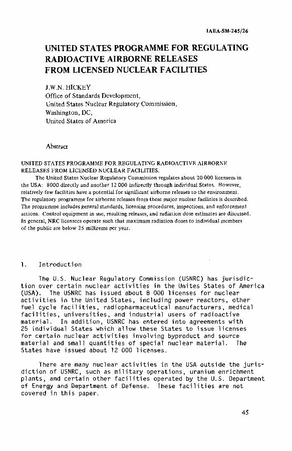
IAEA-SM-245/26
UNITED STATES PROGRAMME FOR REGULATING RADIOACTIVE AIRBORNE RELEASES FROM LICENSED NUCLEAR FACILITIES
J.W.N. HICKEYOffice of Standards Development,United States Nuclear Regulatory Commission,Washington, DC,United States of America
Abstract
UNITED STATES PROGRAMME FOR REGULATING RADIOACTIVE AIRBORNE RELEASES FROM LICENSED NUCLEAR FACILITIES.
The United States Nuclear Regulatory Commission regulates about 20 000 licensees in the USA: 8000 directly and another 12 000 indirectly through individual States. However, relatively few facilities have a potential for significant airborne releases to the environment.The regulatory programme for airborne releases from these major nuclear facilities is described. The programme includes general standards, licensing procedures, inspections, and enforcement actions. Control equipment in use, resulting releases, and radiation dose estimates are discussed. In general, NRC licensees operate such that maximum radiation doses to individual members of the public are below 25 millirems per year.
1. Introduction
The U.S. Nuclear Regulatory Commission (USNRC) has jurisdiction over certain nuclear activities in the Unites States of America (USA). The USNRC has issued about 8 000 licenses for nuclear activities in the United States, including power reactors, other fuel cycle facilities, radiopharmaceutical manufacturers, medical facilities, universities, and industrial users of radioactive material. In addition, USNRC has entered into agreements with 25 individual States which allow these States to issue licenses for certain nuclear activities involving byproduct and source material and small quantities of special nuclear material. The States have issued about 12 000 licenses.
There are many nuclear activities in the USA outside the jurisdiction of USNRC, such as military operations, uranium enrichment plants, and certain other facilities operated by the U.S. Department of Energy and Department of Defense. These facilities are not covered in this paper.
45

4 6 HICKEY
The USNRC does not have exclusive jurisdiction in regulating radioactive airborne releases from its licensees. The relationship between the USNRC program and other United States government programs is discussed below.
Of the thousands of licensees under USNRC jurisdiction, relatively few have a potential for significant releases of radioactivity to the environment with resulting radiation doses to the public. These facilities include about 100 fuel cycle facilities (including about 70 power reactors) and other facilities possessing relatively large amounts of dispersible radioactive materials, such as universities and radiopharmaceutical manufacturers
2. General Standards
2.1 USNRC Regulations
USNRC regulations restricting effluents from nuclear facilities are contained in Title 10 of the U.S. Code of Federal Regulations[1]. (U.S. radiation standards have not yet been converted to theInternational System of Units.)
Radiation protection standards applicable to all licensees are contained in 10 CFR Part 20. These standards restrict annual whole body doses to any individual member of the public to 500 millirems or less. Appendix В of 10 CFR Part 20 contains limits for concentrations of individual radionuclides in effluents to unrestricted areas.
Section 20.1(c) of 10 CFR Part 20 requires that releases and resulting doses be "as low as is reasonably achievable." While this requirement applies to all licensees, so far it has been quantified for light water power reactors only. Appendix I of 10 CFR Part 50 specifies that calculated gaseous releases from reactors should be such that the annual total body dose to any individual in an unrestricted area does not exceed 5 millirems, and that annual doses to any organ of a member of the public from radioactive iodine and particulates in airborne releases should not exceed 15 millirems.
2.2 USEPA Standards
2.2.1 Federal Guidance
Under U.S. law, the U.S. Environmental Protection Agency (USEPA) has responsibility for establishing guidance to all Federal agencies with respect to formulation of radiation standards. Current USNRC regulations are consistent with this guidance, and it is expected
that in the future USNRC regulations will be modified as appropriate to incorporate any new USEPA guidance.
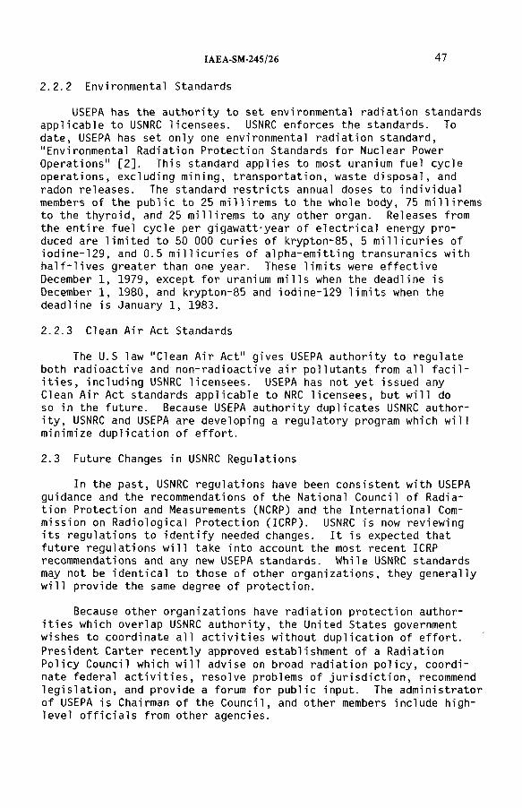
IAEA-SM-245/26 4 7
2.2.2 Environmental Standards
USEPA has the authority to set environmental radiation standards applicable to USNRC licensees. USNRC enforces the standards. To date, USEPA has set only one environmental radiation standard, "Environmental Radiation Protection Standards for Nuclear Power Operations" [2]. This standard applies to most uranium fuel cycle operations, excluding mining, transportation, waste disposal, and radon releases. The standard restricts annual doses to individual members of the public to 25 millirems to the whole body, 75 millirems to the thyroid, and 25 mi Hirems to any other organ. Releases from the entire fuel cycle per gigawatt-year of electrical energy produced are limited to 50 000 curies of krypton-85, 5 millicuries of iodine-129, and 0.5 millicuries of alpha-emitting transuranics with half-lives greater than one year. These limits were effective December 1, 1979, except for uranium mills when the deadline is December 1, 1980, and krypton-85 and iodine-129 limits when the deadline is January 1, 1983.
2.2.3 Clean Air Act Standards
The U.S law "Clean Air Act" gives USEPA authority to regulateboth radioactive and non-radioactive air pollutants from all facilities, including USNRC licensees. USEPA has not yet issued any Clean Air Act standards applicable to NRC licensees, but will do so in the future. Because USEPA authority duplicates USNRC authority, USNRC and USEPA are developing a regulatory program which will minimize duplication of effort.
2.3 Future Changes in USNRC Regulations
In the past, USNRC regulations have been consistent with USEPA guidance and the recommendations of the National Council of Radiation Protection and Measurements (NCRP) and the International Commission on Radiological Protection (ICRP). USNRC is now reviewing its regulations to identify needed changes. It is expected that future regulations will take into account the most recent ICRPrecommendations and any new USEPA standards. While USNRC standardsmay not be identical to those of other organizations, they generally will provide the same degree of protection.
Because other organizations have radiation protection authorities which overlap USNRC authority, the United States government wishes to coordinate all activities without duplication of effort. President Carter recently approved establishment of a Radiation Policy Council which will advise on broad radiation policy, coordinate federal activities, resolve problems of jurisdiction, recommend legislation, and provide a forum for public input. The administrator of USEPA is Chairman of the Council, and other members include high- level officials from other agencies.
48 HICKEY
3.1 Regulatory Process
Organizations wishing to conduct nuclear activities under the jurisdiction of USNRC must apply for a license. The application must include a description of control and monitoring equipment for airborne releases, and estimates of projected releases and resulting radiation doses to the public. USNRC conducts a review of the application, which includes independent assessments of projected releases and doses, and grants a license if the facility is expected to meet applicable standards. This review process can be complicated and takes up to several years for large facilities such as power reactors.
USNRC regulations do not specify the control equipment to beused by the licensee. This is determined by the applicant and theUSNRC licensing staff on a case-by-case basis according to what is necessary to meet applicable requirements.
Licensee operations are inspected periodically by the USNRC staff to assure that control equipment is properly maintained and operated, that required monitoring programs are carried out, and that airborne releases meet applicable standards. Violations of USNRC requirements may result in orders to correct deficiencies, monetary fines, or orders to cease operations.
Following is a discussion of airborne releases from power reactors, uranium mills, uranium hexafluoride plants, fuel fabrication plants, and byproduct material facilities regulated by USNRC according to the process described above.
3.2 Power Reactors
3.2.1 Generating Capacity
There are currently 70 power reactors licensed to operate in the USA, including 26 boiling water reactors, 43 pressurized water reactors, and 1 high temperature gas reactor. These reactors have a generating capacity of about 5.1 x 10⁴ megawatts, or about 9.2 percent of the electrical generating capacity in the United States. About 100 reactors are under construction. If all are completed and operational, they will generate about 1.5 x 10⁵ megawatts.
3.2.2 Sources of Airborne Releases, Controls, and Monitoring
Tables I and II show sources of airborne releases, control systems, and monitors for typical boiling water and pressurized water reactors. All significant release pathways are monitored.High efficiency particulate air (HEPA) filters and charcoal absorbers
3. Regulation of Airborne Releases
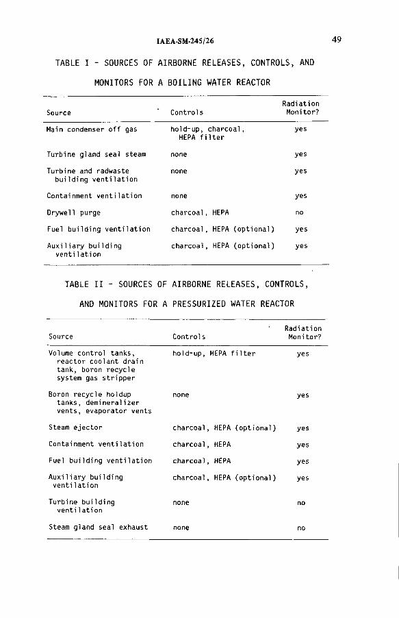
TABLE I - SOURCES OF AIRBORNE RELEASES, CONTROLS, AND
MONITORS FOR A BOILING WATER REACTOR
IAEA-SM-245/26
Source ControlsRadiationMonitor?
Main condenser off gas hold-up, charcoal, HEPA filter
yes
Turbine gland seal steam none yes
Turbine and radwaste building ventilation
none yes
Containment ventilation none yes
Drywell purge charcoal, HEPA no
Fuel building ventilation charcoal, HEPA (optional) yes
Auxiliary building ventilation
charcoal, HEPA (optional) yes
TABLE II - SOURCES OF AIRBORNE RELEASES, CONTROLS,
AND MONITORS FOR A PRESSURIZED WATER REACTOR
Source ControlsRadiationMonitor?
Volume control tanks, reactor coolant drain tank, boron recycle system gas stripper
hold-up, HEPA filter yes
Boron recycle holdup tanks, demineralizer vents, evaporator vents
none yes
Steam ejector charcoal, HEPA (optional) yes
Containment ventilation charcoal, HEPA yes
Fuel building ventilation charcoal, HEPA yes
Auxiliary building ventilation
charcoal, HEPA (optional) yes
Turbine building ventilation
none no
Steam gland seal exhaust none no
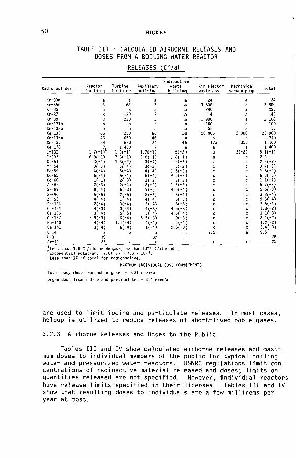
50 HICKEY
TABLE III - CALCULATED AIRBORNE RELEASES AND DOSES FROM A BOILING WATER REACTOR
RELEASES (Ci/a)
RadionuclidesReactorbuilding
Turbinebuilding
Auxiliarybuilding
Radioactivewaste
buildinqAir ejector waste qas
Mechanical vacuum pump
Total
Kr-83m a a a a 24 а 24Kr-85m 3 68 3 a 3 800 а 3 800Kr-85 a a a a 290 а 290Kr-87 3 130 3 a 4 а 140Kr-88 3 230 3 a 1 900 а 2 100Xe-131m a a a a 100 а 100Xe-133m a a a a 55 а 55Xe-133 66 250 66 10 20 000 2 300 23 000Xe-135m 46 650 46 a a а 740Xe-135 34 630 34 45 17a 350 1 100Xe-138 7h 1,400 7 a a а 1 4001-131 1.7(-l) 1.9C-1) 1.7C-1) 5(-2) a 3(-2) 6.К-1)1-133 6.8(-l) 7.6Í-1) 6.8C-1) 1.8(-1) a а 2.3Cr-51 3(-4) 1.3(-2) 3(-4) 9(-3) с с 2.3(-2)Mn-54 3(-3) 6(-4) 3(-3) 3(-2) с с 3.7(-2)Fe-59 4(-4) 5(-4) 4(-4) 1.5(-2) с с 1.6(-2)Co-58 6(-4) 6(-4) 6(-4) 4.5(-3) с с б.З(-З)Co-60 K - i ) 2(-3) K - 2 ) 9(-2) с с 1.1(-1)Zn-65 2(-3) 2(-4) 2(-3) 1.5(-3) с с 5.7(-3)Sr-89 9(-4) 6Í-3) 9(-5) 4.5(*4) с с 5.5С-3)Sr-90 5('6) 2(-5) 5(-6) 3(-4) с с 3.3(-4)Zr-95 4(-4) K - 4 ) 4(-4) 5(-5) с с 9.5(-4)Sb-124 2(“4) 3(-4) 2(-4) 5(-5) с с 7.5(-4)Cs-134 4(-3) 3Í-4) 4(-3) 4.5(-3) с с 1.3(-2)Cs-136 3("4) 5(-5) 3(-4) 4.5(-4) с с 1.1С-3)Cs-137 5.5(-3) 6(-4) 5.5(-3) 9(-3) с с 2.1С-2)Ba-140 4(“4) l.K-4) 4(-4) K - 4 ) с с 1.2(-2)Ce-141 K - 4 ) 6(-4) K - 4 ) 2-5(-3) с с 3.4(-3)С-14 a a a a 9.5 а 9.5H-3Ar-41
39 . 25 с
39с с с с
7825
.Less than 1.0 Ci/a for noble gases, less than 10"4 Ci/а for iodine. Exponential notation: 7.0(-3) = 7.0 x 10⁻³ .Less than 1% of total for radionuclide.
MAXIMUM INDIVIDUAL DOSE COMMITMENTS
Total body dose from noble gases - 0.31 mrein/a
Organ dose from iodine and particulates * 3.4 mrem/a
are used to limit iodine and particulate releases. In most cases, holdup is utilized to reduce releases of short-lived noble gases.
3.2.3 Airborne Releases and Doses to the Public
Tables III and IV show calculated airborne releases and maximum doses to individual members of the public for typical boiling water and pressurized water reactors. USNRC regulations limit concentrations of radioactive material released and doses; limits on quantities released are not specified. However, individual reactors have release limits specified in their licenses. Tables III and IV show that resulting doses to individuals are a few millirems per year at most.
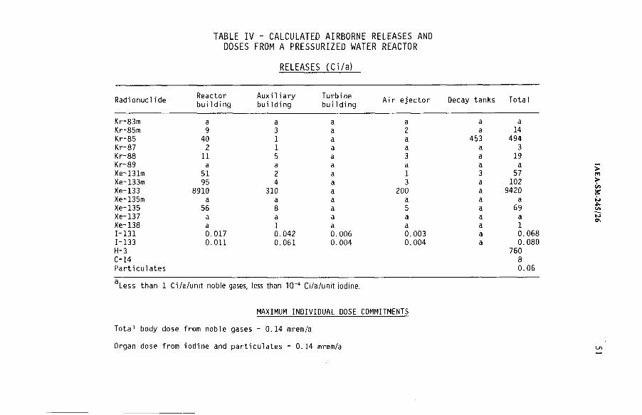
TABLE IV - CALCULATED AIRBORNE RELEASES AND DOSES FROM A PRESSURIZED WATER REACTOR
RELEASES (Ci/a)
RadionuclideReactorbuilding
Auxiliarybuilding
Turbi ne building
Air ejector Decay tanks Total
Kr-83m a a a a a aKr-85m 9 3 a 2 a 14Kr-85 40 1 a a 453 494Kr-87 2 1 a a a 3Kr-88 11 5 a 3 a 19Kr-89 a a a a a aXe-131m 51 2 a 1 3 57Xe-133m 95 4 a 3 a 102Xe-133 8910 310 a 200 a 9420Xe~135m a a a a a aXe-135 56 8 a 5 a 69Xe-137 a a a a a aXe-138 a 1 a a a 11-131 0.017 0.042 0.006 0.003 a 0.0681-133H-3C-14Particulates
0.011 0.061 0.004 0.004 a 0.080760
80.06
a Le ss than 1 C i /а/unit noble gases, less than 1 0 '4 Ci/а /unit iodine.
MAXIMUM INDIVIDUAL DOSE COMMITMENTS
Total body dose from noble gases - 0.14 mrem/a
Organ dose from iodine and particulates - 0.14 mrem/a
52 HICKEY
3.2.4 The Three Mile Island Accident
The previous discussion applies to normal releases from reactors. In 1979 the Three Mile Island #2 pressurized water reactor experienced an accident resulting in serious damage to its fuel. During the accident, reactor coolant and excessive gases reached the auxiliary building, resulting in releases of radioactive material to the atmosphere.
Most of the releases passed through HEPA filters and charcoal adsorbers. Therefore, most of the resulting offsi te radiation doses were from direct gamma radiation from xenon-133 and xenon-135.
Many of the radiation monitors at the reactor went offscale during the accidental releases, and it has been recommended that high-range monitors should be installed in reactors [3]. However, based on analyses of offsite radiation measurements and meteorological data, an estimate of quantities of noble gases released was provided to USNRC by the reactor operator [4] as follows:
xenon-133: 8.3 x 10⁶ curies
xenon-135: 1.5 x 10⁶ curies
The USNRC staff has made estimates of doses received by the public as a result of the accident, based primarily on thermoluminescent dosimeters placed around the site [5]. It is estimated that the maximum individual whole body dose was 83 millirems, and the population dose to the two million people within 80 kilometres of the site was 3.3 x 10³ man-rems.
3. 3 Uranium Mi 11s
There are 20 operating uranium mills in the USA. Airborne radioactive effluents are uranium and its daughter products, including thorium-230, radium-226, radon-222, and radon daughters.Air samples are collected from stacks and at the site boundary and analyzed periodically.
Because uranium milling operations constitute an area source, including ore piles and tailings, it is difficult to estimate quantities of radioactive material released. USNRC staff studies using calculational models show that maximum annual doses to offsite individuals for some operating mills are on the order of 100 millirems, with doses to the bronchial epithelium from radon daughters even higher. Therefore, the staff conducted an analysis of milling operations to determine what additional emission controls should be required to comply with USEPA standards [6]. The study concludes that typical uranium mills should use scrubbers and filters to reduce
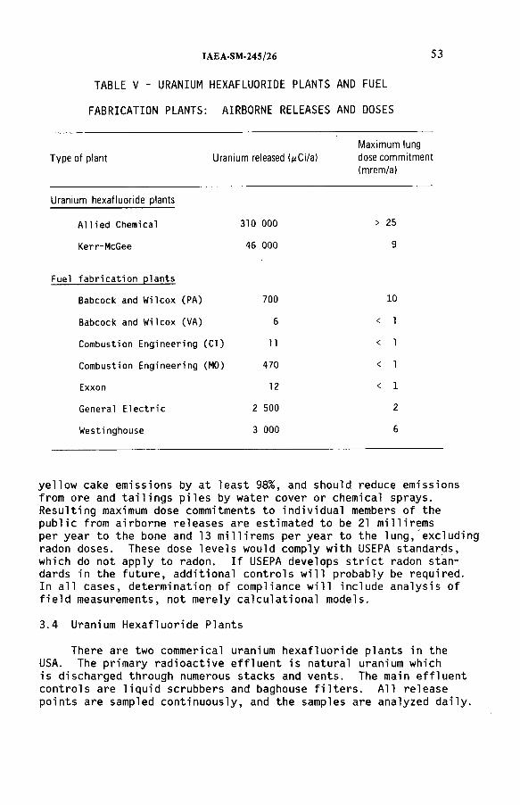
IAEA-SM-245/26 53
TABLE V - URANIUM HEXAFLUORIDE PLANTS AND FUEL
FABRICATION PLANTS: AIRBORNE RELEASES AND DOSES
Type of plant Uranium released (^Ci/a)
Maximum lung
dose commitment
(mrem/a)
Uranium hexafluoride plants
Allied Chemical 310 000 > 25
Kerr-McGee 46 000 9
Fuel fabrication plants
Babcock and Wilcox (PA) 700 10
Babcock and Wilcox (VA) 6 < 1
Combustion Engineering (CT) 11 < 1
Combustion Engineering (MO) 470 < 1
Exxon 12 < 1
General Electric 2 500 2
Westi nghouse 3 000 6
yellow cake emissions by at least 98%, and should reduce emissions from ore and tailings piles by water cover or chemical sprays. Resulting maximum dose commitments to individual members of the public from airborne releases are estimated to be 21 millirems per year to the bone and 13 millirems per year to the lung, excluding radon doses. These dose levels would comply with USEPA standards, which do not apply to radon. If USEPA develops strict radon standards in the future, additional controls will probably be required.In all cases, determination of compliance will include analysis of field measurements, not merely calculational models.
3.4 Uranium Hexafluoride Plants
There are two commerical uranium hexafluoride plants in the USA. The primary radioactive effluent is natural uranium which is discharged through numerous stacks and vents. The main effluent controls are liquid scrubbers and baghouse filters. All release points are sampled continuously, and the samples are analyzed daily.

54 HICKEY
Table V includes USNRC staff estimates of quantities of airborne uranium released and resulting maximum annual offsite doses. The estimated dose for the Allied Chemical plant may exceed USEPA standards, so further studies of this facility are being conducted in order to determine if additional controls will be required.
3.5 Fuel Fabrication Plants
There are seven commercial uranium fuel fabrication plants in the USA. The primary radioactive effluent is enriched uranium.The main effluent controls are HEPA filters and scrubbers. All release points are sampled continuously, and the samples are analyzed daily. Major effluent streams are continuously monitored. Table V includes USNRC staff estimates of quantities of airborne uranium released and resulting maximum annual offsite doáes.
3.6 Byproduct Material Facilities
There are thousands of radioactive byproduct material licensees in the USA, including radiopharmaceutical manufacturers, hospitals, universities, and research institutions. Each facility is required to measure and keep records of its airborne effluents. However,USNRC does not retain copies of these records.
The USNRC has recently initiated a program to determine whether emissions from large byproduct material facilities should be further reduced according to the "as low as is reasonably achievable" regulation. Preliminary visits to 12 large facilities indicated that emissions controls generally reduce effluent concentrations in unrestricted areas to less than one percent of 10 CFR Part 20 concentration limits which would correspond to individual doses of a few millirems per year. A larger survey of 1200 licensees is planned to obtain more emission data.
4. Conclusion
USNRC regulates airborne radioactive effluents from thousands of licensed operations through a comprehensive program of standards, licensing procedures, inspections, and enforcement action. Applicable standards specify emission and dose limits, but do not designate the control equipment to be used by the licensee. In general, USNRC licensees operate such that maximum radiation doses to individual members of the public are kept below 25 millirems per year.
REFERENCES
[1] Code of Federal Regulations, Title 10, U.S. Government Printing Office, Washington (1979).
IAEA-SM-245/26 55
[2] Code of Federal Regulations, Title 40, U.S. Goverment Printing Office, Washington (1979).
[3] TMI-2 Lessons Learned;Task Force Status Report and Short-Term Recommendations, NUREG-0578, U.S. Nuclear Regulatory Commission, Washington (1979).
[4 ] Investigation into the March 28, 1979 Three Mile Island Accident by Office of Inspection and Enforcement, NUREG-0600, U.S. Nuclear Regulatory Commission, Washington (1979).
[5] Population Dose and Health Impact of the Accident at the Three Mile Island Nuclear Station, U.S. Goverment Printing Office, Washington (1979).
[6] Draft Generic Environmental Impact Statement on Uranium Milling, NUREG-0511, U.S. Nuclear Regulatory Commission, Washington (1979).
DISCUSSION
H. DEUBER: Do you think that existing devices are adequate for monitoring gaseous radioactive effluents in accident conditions?
J.W.N. HICKEY : As a result of the Three Mile Island accident, the Nuclear Regulatory Commission has recognized that monitoring systems are inadequate for accidents, and a complete review of requirements is being conducted.
R. BROWN: You stated that the NRC has no standards covering total releases and control methods. Your emphasis is on the limitation of local doses. However, the United States Environmental Protection Agency (EPA) has issued 40 CFR 190 (Code of Federal Regulations), which establishes release limits for 85Kr (50 kCi/GW(e) a), 129I (5 mCi/GW(e)a) and plutonium (0.5 mCi/GW(e)-a). These are based on global dose commitment estimates.
Does not the NRC have responsibility for enforcing 40 CFR 190, i.e. for regulating total releases?
J.W.N. HICKEY: Yes, it does; NRC is indeed enforcing 40 CFR 190.


Session 11(a)
SOURCES AND CHARACTERISTICS OF OFF-GASES FROM NUCLEAR FACILITIES

Chairman
M. MAZZINIItaly
IAEA-SM-24S/8
BACKGROUND CONSIDERATIONS IN THE IMMOBILIZATION OF VOLATILE RADIONUCLIDES
H.A.C. McKAYAtomic Energy Research Establishment,Harwell, Didcot, Oxfordshire,United Kingdom
Abstract
BACKGROUND CONSIDERATIONS IN THE IMMOBILIZATION OF VOLATILE RADIONUCLIDES.
The aim of this paper is to compare and contrast the volatile species, 3H, 14C, 85Kr, and 129I in relation to their immobilization for storage and/or disposal. The significance of the nuclear properties of these species is discussed in relation to the duration of immobilization necessary, the permissible leakage rates from a store or disposal site, the health hazards, and the radiation effects, as well as the quantities arising in reactors. Their behaviour in reactors and reprocessing plants is also discussed, especially as regards the quantities appearing in different effluents. Methods of trapping from the effluents are listed. The principal desiderata of an immobilized form are: (a) Stability (thermal, chemical, radiolytic); (b) High degree of immobilization; (c) Good preparative route, giving a high percentage incorporation of the volatile species; (d) low cost. Proposed immobilization methods are indicated. A brief comparison is made of natural and of reactor production of volatile radionuclides and of the contribution from nuclear explosions, and some comments are made on the relative merits of discharge and storage/disposal of these species.
1. Introduction
The principal volatile radionuclides it may be desired to immobilise
are ^H, ^ C , ^ K r , and ^ ^ 1 . Shorter-lived species, such as and
'^'bce, may need to be held for a limited period to decay, but are un
likely to be converted to special forms for immobilisation purposes.
The four species listed are remarkably diverse. They differ
strikingly in their nuclear and chemical properties.
2. Nuclear Aspects
2.1 Half-lives and Decay Rates
The first point to be noted from Table 1 is that, whereas any con
tamination of the environment by or ^"*Kr will largely disappear by
radioactive decay within a human lifetime, that due to or ^^1
59
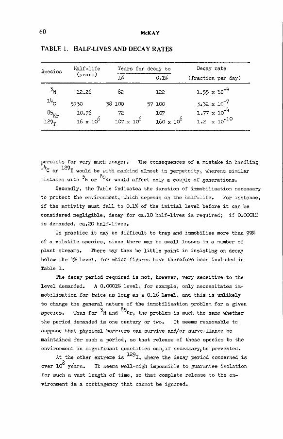
60 McKAY
T ABLE 1. H A L F-LIV E S AN D D E C AY R A T E S
SpeciesHalf-life(years)
Years for
1%decay to
0.1#
Decay rate
(fraction per day)
lifc
85кг129x
12.26
5730
10.76
16 x 106
82
38 100
72
107 x 106
122
57 100
107
160 x 106
1.55 x 10_If
3.32 x 10⁻⁷
1 .7 7 x lO-^ 1 .2 x 10"10
persists for very much longer. The consequences of a mistake in handling 129
C or I would be v/ith mankind almost in perpetuity, whereas similar 3 85
mistakes with H or Kr would affect only a couple of generations.
Secondly, the Table indicates the duration of immobilisation necessary
to protect the environment, which depends on the half-life. For instance,
if the activity must fall to 0.1% of the initial level before it can be
considered negligible, decay for ca.10 half-lives is required; if 0.0001%
is demanded, ca .20 half-lives.
In practice it may be difficult to trap and immobilise more than 99%
of a volatile species, since there may be small losses in a number of
plant streams. There may then be little point in insisting on decay
below the 1% level, for which figures have therefore been included in
Table 1.
The decay period required is not, however, very sensitive to the
level demanded. A 0.0001% level, for example, only necessitates im
mobilisation for twice as long as a 0.1% level, and this is unlikely
to change the general nature of the immobilisation problem for a given«2 O r
species. Thus for H and Kr, the problem is much the same whether
the period demanded is one century or two. It seems reasonable to
suppose that physical barriers can survive and/or surveillance be
maintained for such a period, so that release of these species to the
environment in significant quantities can,if necessary, be prevented.129
At the other extreme is I, where the decay period concerned is gover 10 years. It seems well-nigh impossible to guarantee isolation
for such a vast length of time, so that complete release to the en
vironment is a contingency that cannot be ignored.
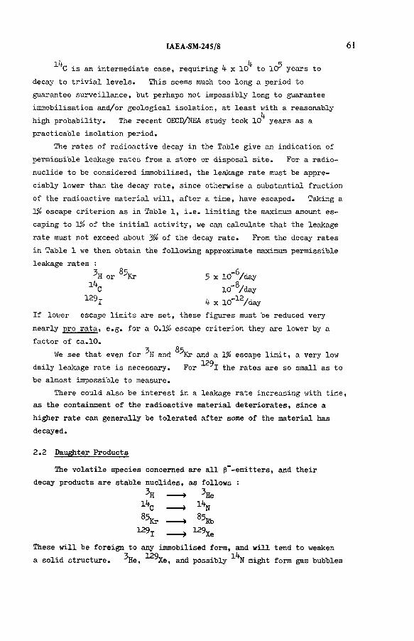
C is an intermediate case, requiring x 10 to 1Cr years to
decay to trivial levels. This seems much too long a period to
guarantee surveillance, but perhaps not impossibly long to guarantee
immobilisation and/or geological isolation, at least with a reasonably1,.
high probability. The recent OECD/NEA study took 10 years as a
practicable isolation period.
The rates of radioactive decay in the Table give an indication of
permissible leakage rates from a store or disposal site. For a radio
nuclide to be considered immobilised, the leakage rate must be appre
ciably lower than the decay rate, since otherwise a substantial fraction
of the radioactive material will, after a time, have escaped. Taking a
1$ escape criterion as in Table 1, i.e. limiting the maximum amount es
caping to 1% of the initial activity, we can calculate that the leakage
rate must not exceed about У/о of the decay rate. From the decay rates
in Table 1 we then obtain the following approximate maximum permissible
leakage rates :
or K r 5 x 10"^/day
1¿fC 10-8/ day
129X k x 10"12/day
If lower escape limits are set, these figures must be reduced very
nearly pro rata, e.g. for a 0.1$ escape criterion they are lower by a
factor of ca.10.3 85
We see that even for H and Kr and a 1% escape limit, a very low129
daily leakage rate is necessary. For I the rates are so small as to
be almost impossible to measure.
There could also be interest in a leakage rate increasing with time,
as the containment of the radioactive material deteriorates, since a
higher rate can generally be tolerated after some of the material has
decayed.
2.2 Daughter Products
The volatile species concerned are all p“-emitters, and their
decay products are stable nuclides, as follows :
3H --- »
lifc --- »SSfc ------ » 8 5 ^129, --- „ 129Xe
These will be foreign to any immobilised form, and will tend to weaken3 129 14
a solid structure. He, Xe, and possibly N might form gas bubbles
IAEA-SM-245/8
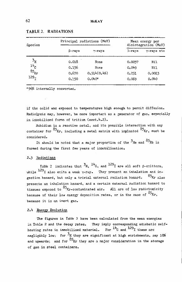
62 McKAY
T ABLE 2 . R AD IAT IO N S
SpeciesPrincipal radiations (MeV) Mean energy per
disintegration (MeV)
(3-rays Y-rays p-rays Y-rays etc
O.OI8 None O.OO57 Nil
lifc O.I56 None 0.0^9 Nil
85Kr O.67O 0 . 5 1 M 0 . W O.251 O.OO23129 j О.15О O.OifO3 0.069 0.0¡K)
a96/á internally converted.
if the solid was exposed to temperatures high enough to permit diffusion.
Radiolysis may, however, be more important as a generator of gas, especially
in immobilised forms of tritium (sect.^.2).
Rubidium is a reactive metal, and its possible interaction with any
container for ^Kr, including a metal matrix with implanted ^Kr, must be
considered.3 85
It should be noted that a major proportion of the He and Rb is
formed during the first few years of immobilisation.
2.3 Radiations
■x i и 129Table 2 indicates that H, C, and I are all soft (3-emitters,
129while I also emits a v/eak y-ray. They present an inhalation and in-Oqgestion hazard, but only a trivial external radiation hazard» Kr also
presents an inhalation hazard, and a certain external radiation hazard toO r
tissues exposed to Kr-contaminated air. All are of low radiotoxicity
because of their low energy deposition rates, or in the case of ^Kr,
because it is an inert gas.
2 Л Energy Evolution
The figures in Table 3 have been calculated from the mean energies
in Table 2 and the decay rates. They imply corresponding adiabatic self-1¿* 129
heating rates in immobilised material. For С and I these are
negligibly low; for they are significant at high enrichments, say 105»O r
and upwards; and for Kr they are a major consideration in the storage
of gas in steel containers.

IAEA-SM-245/8 6 3
TA BLE 3. EN E RG Y EVOLUTION
SpeciesRate of energy
evolution (J/s per g-atom)
Total energy content
(GJ per g-atom)
3H 0.99 0.55
0.018 't.?
8^Kr 52 2k.k
129 j 0.0001*+ 10.5
A further effect is radiolysis. This is considered in sect.k.k.2,
but it may be noted here that radiolysis will generally impose a limit on
tritium levels in immobilised forms which may be as low as 0.СЯ%, so that
self-heating will not be important; cooling could in any case be provided.
2.5 Production Routes in Reactors
^ K r and 1 are formed in reactors exclusively by fission, whilelij. 3
С is almost entirely an activation product, and H is formed by both
routes. Fission occurs solely in the fuel, while activation occurs
largely elsewhere, in the coolant, moderator, control rods, or structural
materials. Activation may involve either the reactor materials them
selves, or minor impurities present in them.
is formed^ in reactors by neutron activation of ^H, ^He, Li,
and ^B, and is thus produced in the following reactor materials :
Water coolant/moderator (LWRs)
Heavy water coolant/moderator (HWRs)
Helium coolant (HTRs)
Boron control rods (many reactor types)
Dissolved boric acid in moderator (PWRs, HWRs)
as well as in impurities in the following :
Graphite moderator (Li impurity - GCRs, HTRs)
UO^/PuO^ core and UO^ breeder fuel (Li and В impurities - FBRs)
14 (2) 13 i4 17С is similarly formed by neutron activation of C, N, and 0,
and to a minor extent in FBRs, of and 0 , hence in carbon-
containing materials, viz.
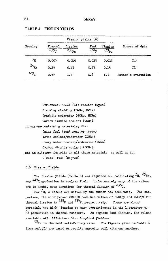
6 4 McKAY
TA BLE 4. FISSIO N Y IE LD S
Species
Fission yields {%)
Source of dataThermal fission Fast fission235u 2^ Pu 23bu 239pu
0.009 0.010 0.020 0.022 (1)
S5Kr 0.29 0.13 0.23 0.15 (3)
129j0.57 1.5 0.6 1.3 Author's evaluation
Structural steel (all reactor types)
Zircaloy cladding (LWRs, HWRs)
Graphite moderator (GCKs, HTRs)
Carbon dioxide coolant (GCRs)
in oxygen-containing materials, viz.
Oxide fuel (most reactor types)
Water coolant/moderator (XAffis)
Heavy water coolant/moderator (HWRs)
Carbon dioxide coolant (GCRs)
and in nitrogen impurity in all these materials, as well
U metal fuel (Magnox)
2.6 Fission Yields
The fission yields (Table k) are required for calculating ^H, 85Kr, 129
and I production in nuclear fuel. Unfortunately many of the values
are in doubt, even sometimes for thermal fission of 235U.
For '’h , a recent evaluation by the author has been used. For com
parison, the widely-used ORIGEN code has values of 0.013$ and 0.025% for
thermal fission in and 2"^Pu,respectively. These are almost
certainly too high, leading to many overestimates in the literature of
production in thermal reactors. As regards fast fission, the values
available are little more than inspired guesses.O r
Kr is the most satisfactory case. The figures given in Table k
from ref.(3) are based on results agreeing well with one another.

IAEA-SM-245/8 65
T AB L E 5. ESTIM ATED PRODUCTION R A T E S
SpeciesProduction rate (kCi/GW(e) a)
Thermal reactors Fast reactors
l*t 20
85Kr 350 200129-,- 0.0015 0.0015
For ■*‘1, only the value for thermal fission in 235g can be regarded
as at all reliable. Some of the calculations in the literature for
thermal reactors appear to be based solely on the contribution from 23%
239fission, ignoring that from Pu fission, and so may considerably under-
129estimate I production. Fission yields in the FISPIN code, while
diverging from those in Table h, probably make reasonable allowance 239
for Pu fission.
Net production rates in reactors must take into account
destruction of the species concerned by neutron capture. For this
is insignificant, and for ®"*Kr quite small. For ^ ^ 1 the relevant
cross-sections are 27 bams for thermal fission and about 0.3 barn for
fast fission, corresponding to destruction half-periods of roughly 30
and 15 years, respectively. The effect on the net production rates is
only of the order of 5%, w h i c h is well within the uncertainties in our
knowledge of the fission yields.
Estimates of production rates based on Table k are shown in Table 5.
2.7 Cross-sections of Activation Reactions
Table 6 gives cross-sections for the more significant activation 3 l*freactions in which H and С are produced. The values refer to
typical neutron spectra for thermal and fast reactors,respectively.l^f 10 7 **5
These for С production are from ref.(2). The two-stage B(n,a)'Li(n,naKH
route only occurs to a very minor extent in thermal reactors, because the
second stage has a threshold of 2.8 MeV.
Estimates of production rates based on Table 6 are subject to a
number of complications, e.g.

66 McKAY
T A B L E 6. CRO SS-SECTIO N S OF ACTIVATIO N REACTION S
Nuclear Cross-section (barns)
reaction Thermal neutrons Fast neutrons
2H(n,r)3H O.OOO5 -
3He(n,p)3H b800 -
^Li(n,a)3H 8^5 1.1
^LiintnoO^H - 0.001
10B(n,a)7Li 3^00 2.8
^B(n,2a)3H - O.OO15
13C(n,Y)lifC 0.0010 0.5 x 10'6
]\(n,p)lifC 1.5 О.О13
170(n,a)lifC 0.18 0.00012
(1) Minor species are often involved, either as impurities or
added deliberately, and their concentrations may vary.
(2) Species of high cross-section gradually burn out. This
applies to ^Li impurity in graphite (half-period, 320 days
at 3 x 10^ n/(cm2 s)) and 10B as a criticality control material
(half-period, 80 days at 3 x 1СГ*"3 n/(cm2 s)). Here, however,
there is the further complication of partial replacement of
graphite or boron during the life of the reactor.
(3) The exposure of boron control rods varies according to their
usage.
It is therefore only possible in many cases to give "broad brush" values.
This has been done -¡_n Ta^le 7 ; the values for 3H under "Fuel" are
for fission from Table 5.
In addition there is of the order of 5 kCi/GW(e)a of3H in the boron
control rods of such reactors as use them (i.e. nearly all, except forЗА
PWRs), and significant amounts of С in Zircaloy fuel cladding and( 2 )structural stainless steel# For LWRs the latter are estimated to
be roughly :

IAEA-SM-245/8
T ABLE 7. PRODUCTION R A T E S
Reactor typeProduction rate (kCi/GW(e) a)
Coolant Moderator Fuel
PWR 1 coolant serves
BWR low as moderator
3ЯHWR 50 l*t00 • l*f
GCR low 5 falling to zero
HTF 5 2 falling to 0.5
FBR 2 no moderator 20
PWR 0.006a coolant serves 0.015
BWR 0.008a as moderator 0.015
iVHWR 0.02 O A 0.015
сGCR 0.006 0.25 0.05
HTR - 0.05 0.015
FBR - no moderator 0.005
a Values based on measured discharge rates.
Zircaloy cladding : PWH, 0.010 BWR, 0.014
Stainless steel : PWR, 0.027 BWR, 0.037
1^The largest С contribution comes in all cases from nitrogen impurity,
13together with an important contribution from the C(n,у) С reaction
in the case of graphite moderator.
3. Chemical Aspects
3.1 General
Krypton has scarcely any chemistry, while the other three elements
all have a varied and interesting chemistry. Hydrogen and carbon are
mainly but not exclusively single-valency elements, while iodine is
multivalent. In the case of hydrogen (tritium) we are most often con
cerned with it in the form of water and,in the case of carbon, in the
form of carbon dioxide.
3*2 Behaviour in Reactors^'
The volatile species in a reactor may :
(l) Remain where they are formed, accumulating until the reactor
is decommissioned. This is shown in Table 8.

68 McKAY
TABLE 8. ACCUMULATION OF VOLATILE SPECIES IN VARIOUS REACTOR COMPONENTS
Species Reactor Component Quantity on Decommissioning (kCi/GW(e))
Heavy water coolant/moderator (HWRs) 20 000
Graphite moderator (GCRs,HTRs) 1
Boron control rods 50
Cold traps (FBRs) 300a
Heavy water coolant/moderator (HWRs) 10
Graphite moderator (GCRs,HTRs) 5
Zircaloy cladding (LVffis,HWRs) 0.3
Stainless steel 1
a Transferred from fuel, sect. 3.2(2).
The estimates of the quantities must be regarded as very rough.
(2) Transfer within the reactor. The most important movement is
diffusion of a proportion of the from the fuel either into Zircaloy
cladding where it is trapped (most water reactors) or through stainless
steel cladding into the coolant (AGRs, FERs); very little escapes
from Magnox fuel elements. The proportion trapped in Zircaloy cladding
is typically 15-60S¡á, while say 3<$ passes into the AGR coolant and V95%
into the KBR (sodium) coolant. The last mentioned accumulates in the
cold traps in the sodium circuit, and has therefore been included in
Table 8.
There are also transfers of small amounts of activity from leaky
fuel elements to the coolant. These can vary enormously from reactor
to reactor, being very low in reactors with on-load refuelling, such as
AGRs, in which defective elements can be quickly replaced. They are 3 l f
not significant for H and C, since they add little to the concen
trations of these nuclides already present in the coolant. In the caseО с
of Kr they result in the emission of an average of 0.1# of this species
in the gaseous effluent from LWRs, though much higher figures occasionally

IAEA-SM-245/8 69
occur. For I it may be presumed on chemical grounds that the pro-O r
portion leaking will be less than that for Kr, i.e. <0.1% on an average,
though no experimental information is available.3 lif
A further transfer is of H and С from the graphite moderator of
GCRs and HTRs to the coolant, owing to corrosion of the former.
(3) Accompany discharged material. The fuel discharged from14 85 129
reactors will contain nearly all the C, Kr, and I produced there,
i.e. the quantities indicated in Tables 5 and 7, less probably '0.1% lost
from leaky fuel elements as just discussed. The same is true for ^H in
most thermal reactors, but in AGRs only about 10 kCi/GW(e)a remains in the
fuel and cladding, and in EBRs only about 1 kCi/GW(e) a, the balance passing
into the coolant, as noted under (2).
Other discharges include the light water coolant/moderator of LWRs,
which goes to the environment from time to time, bearing with it the ^H1^
and С quantities indicated in Table 7, and a limited amount of graphite3 l faccompanying GCR and HTR fuel, again containing some H and C, and
going to store. A proportion of the heavy water coolant/moderator of
HWRs may also be withdrawn for detritiation before return to the reactor,3 14
but this is not yet general practice, and the fate of the H and С
during recycling cannot be defined.
(*t) Leak from the reactor, either in leaking coolant or other
wise. This is of particular concern for HWRs, which may loose 0.5-3%
of their heavy water per annum, involving up to 20 kCi/GW(e)a of 3H and
up to O.OO5 kCi/GW(e) • a of 14C.
From this discussion, it appears that 99*9% immobilisation of
^ K r and "*" 91 -¡_s potentially achievable by attention to the spent fuel
during storage and/or reprocessing, and that this figure might be raised
by improvements in fuel element integrity and reactor operation. On 3 1^the other hand for H and С it seems essential to treat reactor as
well as reprocessing plant effluents to obtain a high degree of im
mobilisation, as well as certain reactor materials on decommissioning.
(1 k - 7 )З.З Behaviour in Reprocessing ’
All four species reach reprocessing plants in the fuel, and % also
arrives trapped in Zircaloy cladding. During dissolution in nitric
acid, ^ С (as ^CO.) and ^ K r come off as gases. ^H may come off to a 3
limited extent as HH from metal fuel, but most of it mixes isotopically
with the water and nitric acid of the dissolver solution; that in
129
70 McKAY
Zircaloy cladding remains there. ^ ^ x partly volatilises and partly
remains behind in the dissolver solution. The proportion volatilising
depends on how the dissolver is operated, and can vary from ca.lCÇà with
a high degree of refluxing to >99% with air sparging.
The dissolver off-gases are at present usually passed through
caustic scrubbers before discharge to stack. These remove most of the129 l^t
I, and presumably most of the CO.,, and will pick up some of the
^HHO, but the and l-\<2/o of the -*- 9j discharged with the
gaseous effluents. Major development work on improved methods is in
progress.3 129
The H and I remaining in the dissolver solution distribute
over many plant streams, making recovery for immobilisation difficult.3
In the case of H it is proposed to alleviate the problem by segregation
and recycling of plant streams, leading to a single aqueous bleed stream
containing essentially all the at a relatively high concentration. In 129
the case of I, it is considered desirable to remove as much as pos
sible of the species from the dissolver solution before the subsequent
reprocessing steps, but appreciable amounts may nevertheless be found
in process vessel off-gases and other streams, in addition to the
dissolver off-gases.
A further possibility is an initial step to remove volatiles before
dissolution of the fuel. The principal proposal of this kind is
voloxidation, in which oxide fuel is heated to ^50-500°С in a current of air, when UO^ oxidises to U^Og. It was originally hoped that the
breaking down of the UO^ lattice would release all the volatiles, but
this has not been achieved. However, virtually complete release of3 85 129
the H can be obtained, along with a proportion of the Kr and I.
The engineering problems are considerable, and most countries favour
other methods of dealing with the tritium problem.
^H in Zircaloy cladding is firmly held, and remains there during
and after dissolution of the fuel. The discarded cladding will
probably be decontaminated from superficial activity and then stored,
possibly in concrete, bitumen, or lead. Measures taken to cope v/ith
other activities on or in the cladding will probably suffice to control
\ also.
3.^ Distribution in Effluent Streams
From the discussion above it is clear that, apart from reactor
accidents, ^ K r and ^ ^ 1 are almost exclusively spent fuel storage and/

IAEA-SM-245/8 71
or reprocessing plant problems, since’>99*9$ of these species is present-5 i if
in the discharged fuel. H and C, on the other hand, constitute
important problems at the reactor as well.
The ^ K r case is particularly simple, since there is total release
in the reprocessing plant dissolver. Virtually all of it at present
discharges up the stack with the gaseous reprocessing plant effluents.129I behaves in a more complicated way in reprocessing, and dis-
(7)tributes over a variety of gaseous and liquid effluents. In future
it may be possible to simplify the situation by routing >99$ of it to
the dissolver off-gases, and trapping it essentially completely from
this gas stream.
For 3H it is possible to construct a table of approximate discharge
rates from data given in ref. (4) (see Table 9).
This shows that, apart from HWRs, the main concern is with reprocessing
plants, although PWR liquid discharges are also important, l i t
For C, Table 7 indicates that the situation is probably similar
to that for 3H, viz. releases are several-fold greater at reprocessing
plants than at reactors, but reactor releases cannot be ignored. Itl*f
is usually assumed, moreover, that all the С in the spent fuel is
released during dissolution and is trapped in the caustic scrub, butl i t
there are no actual data for С in reprocessing plants, so these con
clusions are speculative.
From the point of view of immobilisation, attention solely to the
reprocessing plant, ignoring reactor releases, would limit inmobilisation
to the following approximate percentages :
9<$
lifc 7 OH,
85Kr >99-9^129-j- >99-9^
129For I, > 99% may be achievable by attention solely to the dissolver 3 l*foff-gases. For H and С the principal further discharges, on a
global basis, are those of LWR coolant. It would be possible to re- lit 3
cover С from these bulky discharges, but the H is so diluted iso-
topically that its recovery would be quite uneconomic. Fortunately,
however, it is the local effects of 3H discharges that are important,
and at any one reactor site these are relatively low.

7 2 McKAY
T A B L E 9. APPR O X IM AT E 3H D ISCH ARG E R A T E S
Discharge rate (kCi/GW(e) a)
FacilityGaseouseffluents
Liquideffluents
PWR (Zircaloycladding)
0.1 0.7
BWR 0.05 0.1
HWR 20 5
GCR 0.2 0.3
Reprocessing plant 1 10
3.5 Trapping
If environmental discharges are to be limited it is necessary to
trap the volatile radionuclides, especially those in the dissolver off-
gases from reprocessing plants, and to a lesser extent those in other
streams.3 (1)H is here a special case. The first problem is to avoid too
high a degree of isotopic dilution. This can be achieved in a re
processing plant by segregation and recycling of plant streams.
Provided this is done, the tritiated aqueous stream obtained can be
isotopically enriched at a reasonable cost, giving a small volume of
material for immobilisation.O r
Trapping of Kr is also exceptional in that it must be carried out (g )by physical methods. The following have been proposed :
Cryogenic distillation.
Liquid absorption, especially in Freons or liquid carbondioxide.
Charcoal adsorption.
Membrane diffusion.
The first two especially are in an advanced state of development.14 129
С and I can be trapped chemically. It is usually assumed14
that the former occurs almost entirely as CO^ in the dissolver off-
gases, but this has not been proved. Suggested trapping methods for
are :
Caustic scrubbing.
Adsorption on a molecular sieve.
Absorption in a Freon.

IAEA-SM-245/8 73
л LIn each case the CO., can readily be released again for conversion to
an immobilised form.
Trapping of 12^I has been the subject of much research and develop
ment , 7l*4>ccasioned largely by the fact that a considerable proportion
of the iodine occurs in organic forms, which are much less reactive than
elemental iodine. Suggested methods include :
Absorption in liquids
Caustic scrubs
Hyperazeotropic (>22M) nitric acid ("Iodox" process)
Mercuric nitrate/nitric acid ("Mercurex" process)
Fluorocarbon absorption
Sorption on solids
Silver (and other metal) zeolites
Silver-impregnated silica, alumina etc.
Of these, caustic scrubs constitute current practice, but are ineffective
for organic iodine compounds. Of the remainder, the use of the silver-
impregnated silica in the form of the German product AC 6120 can be re
garded as established technology, but all the others require further
development.
Trapping is usually a prelude to immobilisation. The trapped
material generally requires processing to convert it to a suitable im
mobilisation form, and the choice of trapping method is therefore in
fluenced by the subsequent immobilisation step.
k. Immobilisation
*4-.l General
Immobilisation in a solid form is one of the options for dealing
with radioactive wastes. Physical barriers may also be provided to
hinder the escape of activity to the environment, but even if this is
done, it is desirable to achieve a high degree of immobilisation in
the solid itself.
A long list of criteria for choosing a suitable immobilisation form
could be given, but the following are suggested as the most important:
Stability (thermal, chemical, radiolytic).
Leakage rate of radioactive species.
Method of incorporating the radioactive species.
Cost.
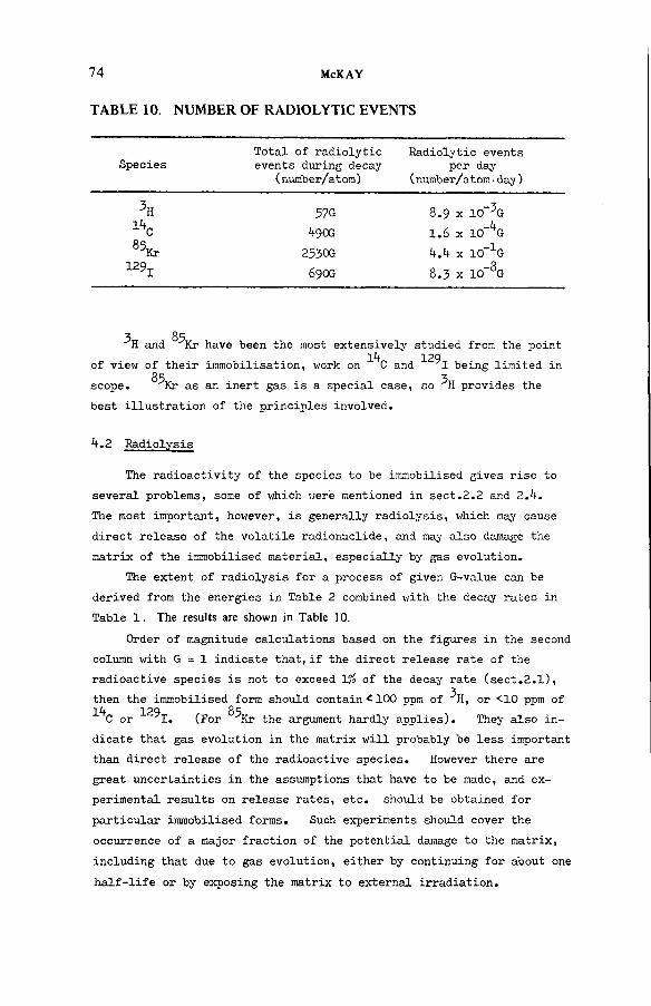
7 4 McKAY
TABLE 10. NUMBER OF RADIOLYTIC EVENTS
SpeciesTotal of radiolytic events during decay
(number/atom)
Radiolytic events per day
(number/atom■day )
57G 8.9 x 10_3G
lifc ^9Ш 1.6 x 10-i+G
85Kr 2530G l+Л x 10-1G129-,- 690G 8.3 x 10_8G
OrH and Kr have been the most extensively studied from the point
l/f 129of view of their immobilisation, work on С and I being limited in
35 3scope. Kr as an inert gas is a special case, so H provides the
best illustration of the principles involved.
k.2 Radiolysis
The radioactivity of the species to be immobilised gives rise to
several problems, some of which were mentioned in sect.2.2 and Z.h.The most important, however, is generally radiolysis, which may cause
direct release of the volatile radionuclide, and may also damage the
matrix of the immobilised material, especially by gas evolution.
The extent of radiolysis for a process of given G-value can be
derived from the energies in Table 2 combined with the decay rates in
Table 1. The results are shown in Table 10.
Order of magnitude calculations based on the figures in the second
column with G = 1 indicate that, if the direct release rate of the
radioactive species is not to exceed 1% of the decay rate (sect.2.1),then the immobilised form should contain <100 ppm of 3H, or <10 ppm of1¿I 129 85
С or I. (For Kr the argument hardly applies). They also in
dicate that gas evolution in the matrix will probably be less important
than direct release of the radioactive species. However there are
great uncertainties in the assumptions that have to be made, and ex
perimental results on release rates, etc. should be obtained for
particular immobilised forms. Such experiments should cover the
occurrence of a major fraction of the potential damage to the matrix,
including that due to gas evolution, either by continuing for about one
half-life or by exposing the matrix to external irradiation.
IAEA-SM-24S/8 75
A further point to note is that the quantity of radiolytic gas will3 1 4 129
generally far exceed that of He, N, or Xe formed by decay, since
the figures in the second column of Table 10 generally far exceed unity.
4.3 Tritium
Several authors have listed possible candidate materials for im
mobilising tritium. The principal categories, in provisional merit
order, are :
(1) Insoluble hydrates and desiccants.
(2) Metal hydrides.
(3) Organic polymers.
(4) Cement.
In category (l) are such hydrates as Ca^CPO^^.S^O, which is in
soluble and only begins to dehydrate at 800 C. Tritiated water can
probably be incorporated by a simple heating/dehydration - cooling/
rehydration cycle. There are no obvious disadvantages, but it remains
to be demonstrated that the tritium is in fact sufficiently immobilised.
In category (2), titanium and zirconium hydrides provide sufficient
immobilisation, but a disadvantage is the necessity of using tritiated
hydrogen at, say, 600°C in their preparation.
Category (3) is not generally very favourable. Organic compounds
are subject to various types of instability, and organic preparative
reactions seldom give anything like lOC^á yield. As a result the desired
product is nearly always accompanied by tritiated by-products, which must
be burned and recycled.
Finally, cement has the virtue of low cost, but it does not actually
immobilise its water content very well, even when impregnated with polymer.
A Other Volatile Radionuclides
14 (q) 129 (7 )Immobilisation of С and I has been but little considered.
14The usual suggestions are to incorporate them in cement as Ca CO., and
I 29 ^Ba( 10^)^ respectively. The latter have been subjected to leach
tests, and gave leach rates many orders of magnitude greater than that
indicated as necessary in sect.2.1, even when impregnated with polymer.1 2 9
Other proposals for I include copper(I) and lead (II) iodides, in
corporation in special glasses, and direct packaging of the solid silver-
based sorbents mentioned in sect.3.5* However, work in this area is
still only of a preliminary nature.

7 6 McKAY
TABLE 11. INVENTORY IN MOST SIGNIFICANT COMPARTMENT
SpeciesCompartment considered
(Northern hemisphere)
Inventory (MCi)
Natural Reactor Explosion
Atmosphere + terrestrial
biosphere + surface oceans
50 10 100
Atmosphere + labile
terrestrial biosphere
3 0.0CA- 0.3
Atmosphere small 100 1
129-,- Atmosphere + terrestrial
biosphere + surface oceans
small 5 xOO 6 x ID’7
O r / Q \
Kr forms no significant chemical compounds. The main methods
proposed for its immobilisation are :
Storage in pressurised containers, with or without sorbing agents in the containers.
Encapsulation in a metal matrix, which can be achieved by an ion implantation/sputtering technique.
Encapsulation in molecular sieves.
Encapsulation as a foam in glass.
The first of these is largely a matter of engineering design, in
volving some difficult heat transfer problems, and necessitating in
vestigation of rubidium (decay product) corrosion of the containers.
The second appears very promising in the laboratory, and is in process
of being scaled up. The last two are less promising.
5. Environmental Considerations
5-1 Comparison of Natural, Reactor, and Explosion Production
Movements of volatile radionuclides in the environment are often
complicated. However, many of the most significant features are
brought out in Table 11 '°:
The compartment considered in each case is one in'which the species i
question is at a fairly uniform specific activity, and includes man, his
atmosphere, and his major food supplies. The reactor inventories assume
25O GW(e) world installed nuclear capacity, which is somewhat above the
present level.
OrIt appears that, currently, reactor production predominates for Kr
129 3 i¿fand I, but is relatively unimportant for H and C. It can be con
fidently asserted that the contribution from reactors will continue to85 129 3
dominate for Kr and I, and will increase in importance for H andl i i
C, v /h ile th e contribution from explosions from the last two will decrease owing
to decay and transfer to other reservoirs, especially the deep ocean
(assuming that there are no more explosions). By the year 2000^^
the reactor contribution to the inventory may be about level v/ith
the natural contribution, and will exceed that from explosions. Naturall 2*
production will still dominate for C, by at least an order of mag
nitude, but the reactor contribution will be about level v/ith that from
explosions.
These considerations are relevant to global dose rates. They
show that for ®^Kr and ^"^1, reactor production is the major factor; the
same will probably be true next century for ^H. Control, if required,
should be at reprocessing plants, and for also at reactors (sect.3.^).
5*2 Discharge versus Storage/Disposal
Trapping, immobilisation, and storage/disposal of à radionuclide
involve potential operator and accident hazards, which have to be weighed
against the prospective benefits. In some cases it may be preferable to
discharge the radionuclide to the environment. These are issues for
professional health physicists, but a few comments relevant to the vola
tile radionuclides may be made.
In the case of ^H, if direct discharge into the ocean as tritiated
water is possible, a high degree of isotopic dilution occurs in a short
time, and it seems highly probable that a detailed analysis would show
this to be the safest option. Other management methods may, however,
be necessary at inland sites, especially reprocessing sites.14
In the case of C, discharges to atmosphere might be of local sig
nificance, but on a global basis would only make a small addition to theIn
natural С inventory. The correct philosophy to adopt is then a matter
for argument. On the one hand, a small increase in the natural back
ground is no more than one would suffer by moving, say, from the
Netherlands to Sweden, but on the other, any reasonably possible reduc
tion in emissions should perhaps be implemented.129
In the case of I, the half-life is so long that isolation from
man until the level has fallen to a trivial value can hardly be guaran
teed. Ultimate dispersal over all available reservoirs seems probable.
IAEA-SM-245/8 77
78 McKAY
Fortunately it turns out that the oceans, which are probably the largest
available reservoir, have the capacity to absorb all the ^ 9 j f r o m a v e r yg
large nuclear power programme, say 10 GW(e) a, without appreciably in-129
creasing thyroid doses. (If some of the I is incorporated in freshly
forming sedimentary rocks, which constitute a still larger iodine reser
voir, the situation becomes even more favourable). The further argument129
can then be advanced that, if the ultimate fate of I is dispersal
in the ocean, it may be desirable to discharge it immediately into the
ocean, gaining the benefit of the very high isotopic dilution factor.
Naturally the discharge would have to be carried out in such a way that129
excessive local concentrations of I did not occur during dispersal.
The concept seems to be one for further study.
References
(1) H.A.C. McKay, Tritium Immobilisation, EUR 6270 EN (1979).
(2) W. Davis, Jr., Carbon-l^ Production in Nuclear Reactors, ORNV^JRBG/TM-12 ( 1977) .
(3) M.E. Meek, B.F. Rider, Compilation of Fission Product Yields,
№¡2)0-1215*1—1 (197*0.
(k) UNSCEAR-77 (Sources and Effects of Ionizing Radiation, UNScientific Committee on the Effects of Atomic Radiation, 1977 report).
(5) Grathwohl, G., ErzeHgung und Freisetzung von Tritium durch Reaktoren und Wiederaufarbeitungsanlagen, KFK-Ext. Ber.,
V73-76 (1973).
(6) G.N. Kelly, J.A. Jones, P.M. Bryant, F. Morley, The Predicted Radiation Exposure of the Population of the European Community resulting from Discharges of Krypton-85. Tritium, Carbon-l^and Iodine-129 from the Nuclear Power Industry to the Year 2000, Doc. V/2676/75 (1975).
(7) Methods and Techniques for Radioiodine Removal in Nuclear Facilities, Report of IAEA Technical Committee Meeting, Vienna 1978, to be published.
(8) Separation, Storage and Disposal of Krypton-85, Report of IAEATechnical Committee Meeting, Vienna 197°, to be published.
(9) R.A. Brown, Management of Tritium and Carbon-1*)-, CONF-76-O7I,p. 364 (19767;
(10) I.F. White, personal communication.
(11) D.W. Holladay, A Literature Survey : Methods for the Removal ofIodine Species from Off-Gases and Liquid Waste Streams of Nuclear Power sind Nuclear Fuel Reprocessing Plants, with Emphasis on Solid Sorbents. 0RHI/TM-6350, (1979).
IAEA-SM-24S/8 79
DISCUSSION
R. B R O W N : The head end recycle of tritium will involve significant design
and operating problems, including an increased potential for occupational
radiation exposure as 3H concentrations increase. The isotopic enrichment of
tritium can be both technically difficult and costly, especially at low concentrations.
What is the basis for your assertion that recycle and isotopic enrichment can be
achieved at reasonable cost?
H.A.C. M c K A Y : I agree with your remarks about operational exposures.
Segregation/recycling and isotopic enrichment are discussed in m y report quoted
in Ref. [3] of the paper. Immobilization even as cement is too expensive without
segregation/recycling. After segregation/recycling to reduce the volume, enrich
ment costs are not excessive. In the above-mentioned report they are estimated as
£3 0 0—1000/m3 water (1978 £s), and in the most favourable segregation/recycling
scheme this corresponds to only £ 600—2000/t U.
The cost of segregation/recycling has not been estimated. In a new
reprocessing plant it would probably not be very expensive, if included in the
design from the start.
I.F. WHITE: I would like to mention some health physics aspects of your
presentation, which I discussed with you during the preparation of your paper.
Decisions on management strategies for tritium, carbon-14, krypton-85 and
iodine-129 will eventually have to be made on the basis of radiological assessments
of the resulting health detriment and assessments of the cost — and indeed the
practicability — of reducing that detriment. According to the precepts of ICRP,
comparisons with natural background radiation are not an adequate basis for such
assessments.
N E A and C E C are supporting studies in this area, one of which is being
carried out by m y organization (the National Radiological Protection Board) in
collaboration with yours and the CEA. W e should be careful not to prejudge the
outcome of such studies before they are completed.
H.A.C. M c K A Y : I am, of course, well aware of the type of calculations you
refer to, and I know that the natural background does not enter into them. I am,
however, by no means convinced that it makes sense to put effort into reducing
contamination levels when the individual doses from them are very small compared
with those from the background. Such efforts may in some cases introduce new
potential hazards, for instance by producing a new radioactive waste form. I know
from various conversations that others at this Symposium share m y doubts on this
point.
P. PATEK: I a m surprised at the values given for krypton losses. 0.1% is
perhaps possible for coated-particle fuel, but for the B W R s and P W R s at present
installed in most cases, values between 1 or 2% are reported as average. Also 0.1%
for losses in reprocessing operations seems too small given the present state of the
8 0 McKAY
technique for the treatment of off-gases from plants and the purification steps for
concentrated 85Kr.H.A.C. M c K A Y : According to UNSCE A R - 7 7 (Ref.[4] of the paper),85 Kr is gene
rated in P W R s at a rate of 37 5 Ci/MW(e) • a, while the normalized average releases from
PWRsin 1970—74 were 0.17 Ci/MW(e)-a; the percentage release was thus about 0.05%.
For B W R s the normalized average releases were admittedly much higher at
30 Ci/MW(e)-a, but this was due to very large releases from just three reactors.
Any figure for the efficiency of 8sKr trapping at a reprocessing plant is
speculative at present, and m y paper does not actually give one. In m y oral
presentation I think I was over-optimistic in suggesting 99%, with 99.9% as an
ultimate practical limit. 90—95% may be more realistic.
H. B R Ü C H E R : Instead of immobilizing tritiated aqueous waste from
reprocessing, one might consider releasing tritium in gaseous form (HT or T 2) to
the atmosphere. By so doing, the local dose — and perhaps the global and
occupational doses - might be reduced. What is your opinion of this alternative?
H.A.C. M c K A Y : One cannot compare the two alternatives until they are
more fully defined. In particular, the storage or disposal step that follows
immobilization must be specified.
I can see that, at an inland site, disposal as tritiated hydrogen gas may be an
attractively simple option compared with, say, isotopic enrichment followed by
immobilization and storage. It should achieve fairly rapid initial dispersion.
Relatively soon, however, the tritium will enter water molecules and will get into
the circulating water. This may be less desirable than disposal in the ocean — for
instance as tritiated concrete — when isotopic dilution will be much greater.
However, a quantitative study for particular sites is needed before definite
conclusions can be reached.

IAEA-SM-245/13
RADIOLYTICALLY GENERATED HYDROGEN FROM PUREX SOLUTIONS
R. B E C K E R , H.-G. B U R K H A R D T
Institut für Heisse Chemie,
Kernforschungszentrum Karlsruhe G m b H ,
Karlsruhe
K.H. NEEB, R. W Ü R T Z
Kraftwerk Union AG,
Erlangen,
Federal Republic of Germany
Abstract
RADIOLYTICALLY GENERATED HYDROGEN FROM PUREX SOLUTIONS.Until recently rates for the release of radiolytically formed hydrogen from nitric acid
solutions were known only from laboratory experiments with simulated solutions, or with solutions not characteristic for Purex conditions. By measuring the hydrogen release in the nitric acid solution of a dissolved fuel pin (burn-up 30 000 MW-d/t; cooling time 420 d) the first laboratory experiments with real process solutions could be performed. The uranium, nitric acid and fission product concentration, as well as the thermic power of this solution, correspond to the fuel solutions and to the highly active fission product solution of the Purex process, respectively. Determination of the hydrogen was carried out by mass spectrometry.For the fuel solution a GH -value (= molecules generated/100 eV) of 1.4 X 10⁻³ was found, and the measurement variation was ±20%. The value for the hydrogen release of the waste solution was in the same order of magnitude. Hydrogen release rates considerably lower than those in laboratory experiments were found in the highly active waste tank of the WAK. The value determined as <5 X 10⁻⁵ was even four orders of magnitude lower than the value for the 7-radiolysis of pure water. The difference between these measurements and the laboratory experiments may be explained by the influence of the completely different solution volumes (130 ml and 44 m3). The question as to whether the hydrogen release is diminished by chemical or radiolytical attack during the longer hydrogen residence time in the larger volume, is being studied in laboratory experiments.
1. I N T R O D U C T I O N
Under the influence of ionizing radiation on aqueous solutions different
radical primary products are generated. In further reactions these radicals build
up the final products H 2 and H 20 2; the latter may decay into H 20 and 0 2 to some extent (Fig. 1 ). In solutions containing nitrate ions and tritium, e.g. in
solutions from the reprocessing of spent fuels, N 2, N O x, H N 0 2 and various hydrogen containing compounds in tritiated form are generated, besides the
products already mentioned.
81
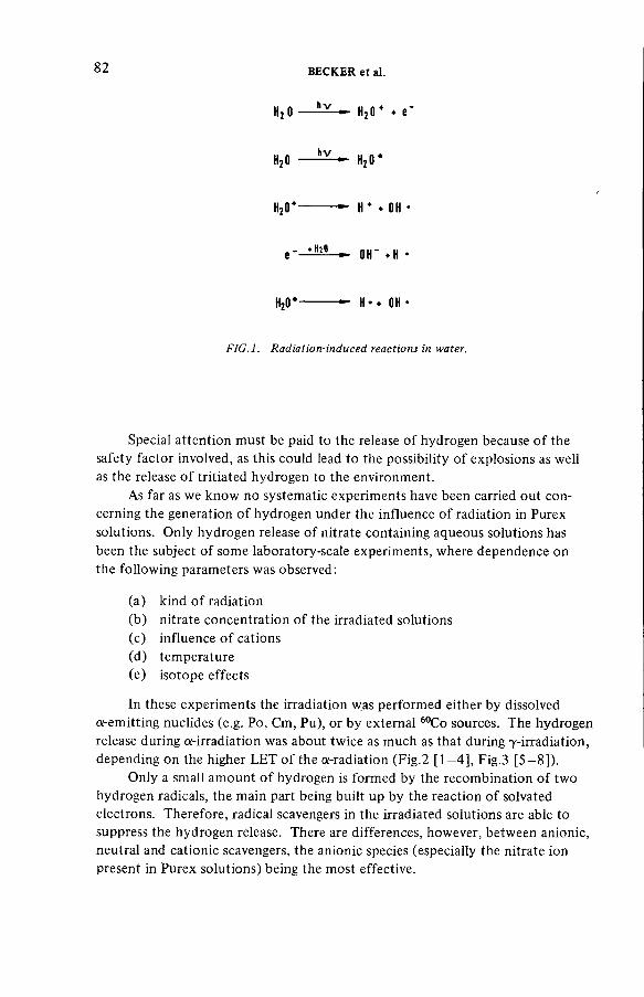
8 2 BECKER et al.
H2 0 — Н2 0 * ♦ e '
H20 h v H2 0 *
H20* H * ♦ ОН
Н20* Н -- он
FIG.l. Radiation-induced reactions in water.
Special attention must be paid to the release of hydrogen because of the
safety factor involved, as this could lead to the possibility of explosions as well
as the release of tritiated hydrogen to the environment.
As far as we know no systematic experiments have been carried out con
cerning the generation of hydrogen under the influence of radiation in Purex
solutions. Only hydrogen release of nitrate containing aqueous solutions has
been the subject of some laboratory-scale experiments, where dependence on
the following parameters was observed:
(a) kind of radiation
(b) nitrate concentration of the irradiated solutions
(c) influence of cations
(d) temperature
(e) isotope effects
In these experiments the irradiation was performed either by dissolved
a-emitting nuclides (e.g. Po, Cm, Pu), or by external 60Co sources. The hydrogen
release during a-irradiation was about twice as much as that during 7-irradiation, depending on the higher L E T of the a-radiation (Fig.2 [1—4], Fig.3 [5-8]).
Only a small amount of hydrogen is formed by the recombination of two
hydrogen radicals, the main part being built up by the reaction of solvated
electrons. Therefore, radical scavengers in the irradiated solutions are able to
suppress the hydrogen release. There are differences, however, between anionic,
neutral and cationic scavengers, the anionic species (especially the nitrate ion
present in Purex solutions) being the most effective.

IAEA-SM-245/13 83
Cations have less influence on the release of hydrogen although experiments
have only taken into account the effect of special cations. It is difficult therefore
to transfer these results to Purex solutions containing more than 30 different
elements.
Moreover, the following parameters also have some influence on the
hydrogen generation:
(a) temperature of the solution
(b) motion of the solution
(c) gas atmosphere over the solution
In irradiated deuterium containing solutions a significant isotopic effect
is observed. This leads to the conclusion that the relative tritium concentration
in the gaseous radiolysis products is probably distinctly below that of the solution.
2. E X P E R I M E N T S W I T H P U R E X S O L U T I O N S
The following experiments report the release of radiolytically generated
hydrogen from nitric acid solutions of the Purex process containing a spectrum
of realistic fission products (Table I):
(a) laboratory-scale experiments with a Purex fuel solution
(b) technical-scale experiments with a Purex waste solution
(c) laboratory-scale experiments with simulated Purex waste solutions.
2.1. Purex fuel solution
The U 0 2 material from a spent K W O (345 M W P W R Obrigheim/Federal
Republic of Germany) fuel pin with a burn-up of about 30 GW-d/t H M was used
for preparing a fuel solution. The decay time of this fuel pin was longer than
420 d; 42.9 g were dissolved in 130 ml solution with a final concentration of
1.2 moles U 0 2( N 0 3)2 and about 4 moles H N 0 3 per litre. The dose rate of0.25 W consisted of 5 % a-radiation by transuranium nuclides and 95% j3,7-radiation by the fission products. The experiments lasted 15 to 110 hours during which
time the solution was not stirred or moved, except by thermal convection.
The generated hydrogen was analysed by a Varian-MAT-GD-150 mass
spectrometer which was equipped with a molecular inlet system. The detection
limit for these analyses was about 100 p p m with a standard deviation of about ±20%.
During a sampling time of about 100 hours approximately 250 д1 H 2 were generated. Thus, by absorption of an energy of 50 Mrad, a G^-value of
1.4 X 10⁻³ was found. This value is more than 20 times less than the G-values reported for solutions containing nitrate only (Fig.4).
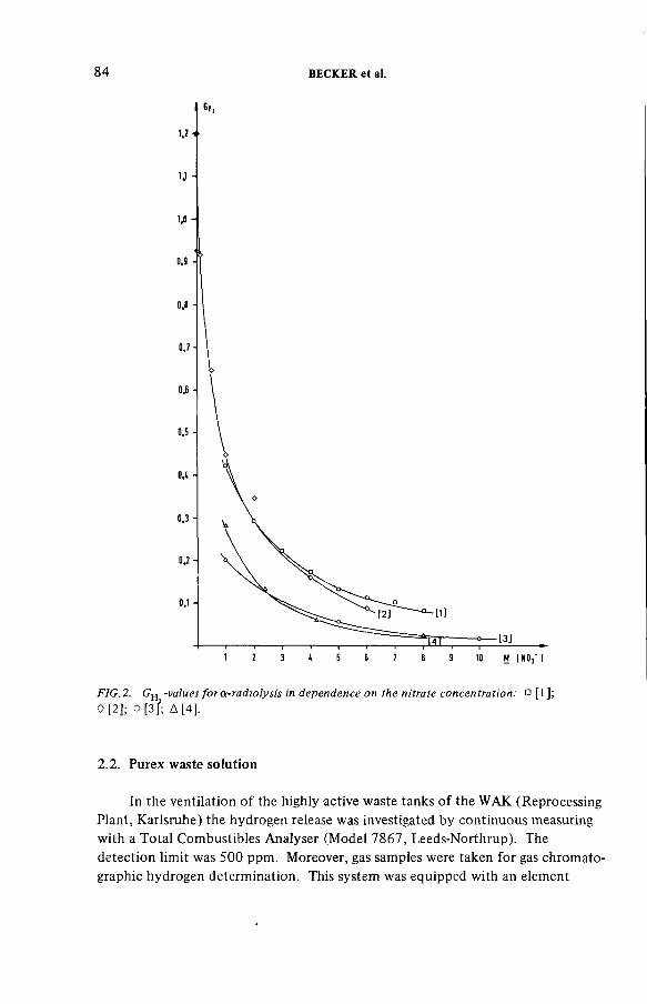
8 4 BECKER et al.
FIG.2. GH -values forat-radiolysis in dependence on the nitrate concentration: D [l];0 [2]; 0 [ 3 f ; Д [4].
2.2. Purex waste solution
In the ventilation of the highly active waste tanks of the W A K (Reprocessing
Plant, Karlsruhe) the hydrogen release was investigated by continuous measuring
with a Total Combustibles Analyser (Model 7867, Leeds-Northrup). The
detection limit was 500 ppm. Moreover, gas samples were taken for gas chromato
graphic hydrogen determination. This system was equipped with an element
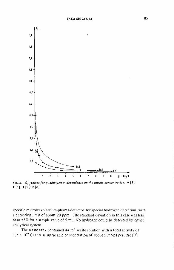
IAEA-SM-245/13 85
FIG.3. GH -values fo r y-radiolysis in dependence on the nitrate concentration: ■ [5];♦ [ 6]; • [ ? ] ; a [8].
specific microwave-helium-plasma-detector for special hydrogen detection, with
a detection limit of about 20 ppm. The standard deviation in this case was less
than ±5% for a sample value of 5 ml. N o hydrogen could be detected by either
analytical system.
The waste tank contained 44 m 3 waste solution with a total activity of1.7 X 107 Ci and a nitric acid concentration of about 5 moles per litre [9].

8 6 BECKER et al.
T A B L E I. R E S U L T S O F E X P E R I M E N T S W I T H P U R E X S O L U T I O N S
NO3concentration(mol./ltr)
Height/Volume of solution GH value
Purex fuel solution 5.2 ~ 4 cm/130 ml 1.4 X 10"3
Purex waste solution (WAK)
5 225 cm/44 X 10s ml 5 X 10' 5
Purex waste solution (simulated)
2.5 2 cm/101 ml 5 cm/340 ml
12 cm /731 ml 16 cm/954 ml
1.7 X 10' 3 7.4 X 10' 4 4.3 X 10' 4 3.9 X 10' 4
16 cm/954 ml (stirred)
~2 X 10' 3
As far as the dose rate of the solution, the detection limit of the gas chromato
graphy, and the other parameters are concerned, the highest possible hydrogen
release value that can be calculated is 5 X 1СГ5 molecules H 2 per 100 eV absorbed energy. This is about 30 times less than in the experiments with the fuel solution
(Fig.4).
This value is to be considered to be specific for the plant. There are several
explanations for the decrease of the G-value compared with laboratory-scale
experiments. Besides plant-specific influences on H 2-release, secondary radiation chemical reactions might also lower the amount of hydrogen formed because of
the longer residence time in the liquid phase.
2.3. Simulated Purex waste solutions
Irradiation experiments with simulated waste solutions should answer the
question as to whether the hydrogen release rate might vary with different depths
of the liquid phase, i.e. with different residence times of H 2 in the liquid.W e have studied this dependence with simulated waste solutions containing
a fission product concentration corresponding to a burn-up of 36 G W -d/t HM.
The nitrate concentration was 2.5 moles per litre. The irradiations were carried
out by a 60Co source in vessels of different volumes and of identical diameter.
The dose rate was 75 000 rad/h. The hydrogen was determined gas chromato-
graphically with a thermal conductivity detector. Nitrogen was used as carrier
gas. The detection limit of this method was about 10 p p m H 2 for a sample volume of 5 ml. The standard deviation was ±15%. The layer depth of solution
varied from 2, 5, 12 to 16 cm, the absorbed dose from 1 to 2.4 Mrad.
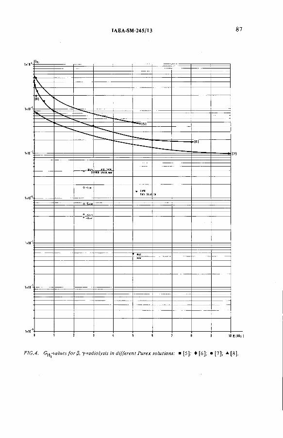
IAEA-SM-245/13 87
FIG.4. Gft-values for ¡3, y-radiolysis in different Purex solutions: ■ [5]; ♦ [6]; • [7]; * [8].
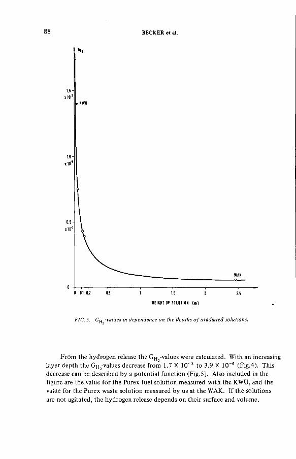
88 BECKER et al.
H E I G H T OF S O L U T I O N ( m )
FIG.5. G ^-values in dependence on the depths o f irradiated solutions.
From the hydrogen release the G H2-values were calculated. With an increasing
layer depth the Gj^-values decrease from 1.7 X 10~3 to 3.9 X 10⁻⁴ (Fig.4). This decrease can be described by a potential function (Fig.5). Also included in the
figure are the value for the Purex fuel solution measured with the K W U , and the
value for the Purex waste solution measured by us at the W A K . If the solutions
are not agitated, the hydrogen release depends on their surface and volume.
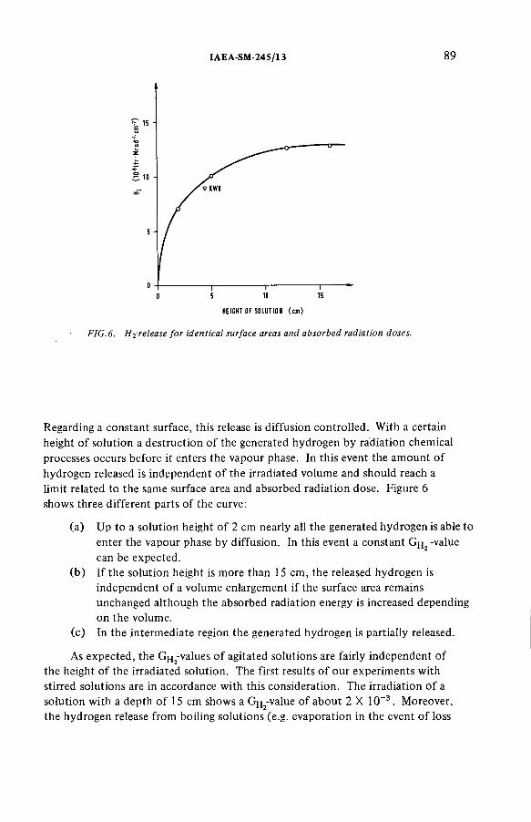
IAEA-SM-245/13 89
HE IGHT OF SOLUT ION ( c m )
FIG.6. H^-release for identical surface areas and absorbed radiation doses.
Regarding a constant surface, this release is diffusion controlled. With a certain
height of solution a destruction of the generated hydrogen by radiation chemical
processes occurs before it enters the vapour phase. In this event the amount of
hydrogen released is independent of the irradiated volume and should reach a
limit related to the same surface area and absorbed radiation dose. Figure 6 shows three different parts of the curve:
(a) U p to a solution height of 2 cm nearly all the generated hydrogen is able to
enter the vapour phase by diffusion. In this event a constant Gfj2 -value can be expected.
(b) If the solution height is more than 15 cm, the released hydrogen is
independent of a volume enlargement if the surface area remains
unchanged although the absorbed radiation energy is increased depending
on the volume.
(c) In the intermediate region the generated hydrogen is partially released.
As expected, the G H2-values of agitated solutions are fairly independent of
the height of the irradiated solution. The first results of our experiments with
stirred solutions are in accordance with this consideration. The irradiation of a
solution with a depth of 15 cm shows a G H2-value of about 2 X 10⁻³. Moreover,
the hydrogen release from boiling solutions (e.g. evaporation in the event of loss
9 0 BECKER et al.
of codant) are of particular interest. In addition, investigations on the influence
of cations on hydrogen release are planned with special regard to Redox systems
(e.g. Ce3+/Ce4+).
REFERENCES
[1] BIBLER, N.E., J. Phys. Chem. 78(1974) 221.[2] SAVEL’EV, A., et al.,Radiokhimiya9 (1967) 221.[3] KAZANJIAN, A.R., HORREL, D.R., Radiat. Eff. 13(1972) 227.[4] SHEPPARD, D., Battelle, Pacific Northwest Lab., Richland, WA, Rep.
BNWL-751.[5] BAKH, N.A., et al. (Proc. 1st All Union Conf. Rad. Chem.) 39 (1957).[6] MAHLMANN, W., J. Chem. Phys. 35 (1961) 936.[7] KAZANJIAN, N.E., et al., Trans. Faraday Soc. 66 (1970) 2192.[8] SAUER, et al., Argonne National Lab., Rep. ANL-76-46.[9] BEAUJEAN, H.W.R., TILLESSEN, U„ BURKHARDT, H.-G., ATW 24 (1979) 135.

IAEA-SM-245/S1
FILTRATION AND CAPTURE OF SEMI-VOLATILE NUCLIDES
M. KLEIN, M. D E SMET,
W.R.A. G O O S S E N S , L.H. B A E T S L E
Studiecentrum voor Kernenergie/
Centre d’étude de l’énergie nucléaire,
Mol,
Belgium
Abstract
FILTRATION AND CAPTURE OF SEMI-VOLATILE NUCLIDESVolatilization of ruthenium in various steps of the nuclear fuel cycle calls for adequate
filtration or adsorption units. The experimental set-up includes a ruthenium tetroxide generator able to give a stable production from 3 to 50 mg-h-1, a moisture generator and a nitric acid calciner capable of varying water vapour and nitrous oxide concentrations over a large range. Sintered stainless steel porous disc filters give excellent decontamination factors (DFs).Different pore sizes from 3 to 45 цт have been tested at a superficial velocity of about 3 cm-s”1 at temperatures from 50 to 300°C. In order to get DFs higher than 100, a minimum temperature of 150° С is necessary. The optimum pore size is a compromise between pressure drop, temperature and desired efficiency. From a dry gas containing ruthenium tetroxide, silica-gel adsorbs gaseous RUO4 with an experimentally obtainable DF higher than 103, but the reduction of adsorbed ruthenium tetroxide into solid dioxide occurs only very slowly so that the capture bed works like a delay bed. In the tests performed with a high water vapour concentration in the gas neither the capacity nor the DF reached satisfactory values. It is planned to clarify this discrepancy with literature data by adding nitrous oxides to the gas stream. Ferric oxide silica-gel catalysts gave high DFs and high capacities when operated at temperatures equal to or higher than 200° C. A first-order decomposition reaction model seems to match the experimental results of the reduction reaction which has an apparent activation energy of 13 kcal-mol-1. Tracer experiments are planned in order to determine DFs higher than 104. A unit with a throughput of 10 m3-h-1 is in the planning phase to test aerosol filtration systems and to demonstrate the feasibility of ruthenium decontamination systems.
1. I N T R O D U C T I O N
Solid radioactive aerosols and semi-volatile fission products, e.g. Ru, Cs and
Sb, are generated during fuel cycle operations, such as fuel fabrication, spent fuel
reprocessing, medium-level waste incineration and high-level waste calcination
and vitrification [1 ].In this paper attention is drawn to the capture of semi-volatile fission products,
particularly the retention of ruthenium because of its strong tendency to form
volatile compounds in oxidative media. The range of valencies and the resulting
91

9 2 KLEIN et al.
variety of ruthenium compounds make this fission product one of the least
predictable with respect to removal efficiency in filtration systems.
The present study is limited to ruthenium tetroxide volatilization and to the
understanding of capture phenomena in various experimental circumstances.
Depending on the age of the spent fuel element (1 to 10 years after reactor
discharge), the target decontamination factor (DF) may vary from around 100
to 106.
2. T H E E X P E R I M E N T A L RIG
A n experimental set-up has been constructed in order to match various gas
compositions. It is composed of a R u 0 4 generator, a nitric acid calcinator and a moisture control unit.
The R u 0 4 generator is based on the principle of ruthenium oxidation with K I 04 (potassium periodate) in a 6N sulphuric acid medium at room temperature.
The generated R u 0 4 vapour is entrained with nitrogen gas sparging through the liquid. The R u 0 4 evolution is directly proportional to the amount of ruthenium in the medium and to the flow rate of the sparging gas through the liquid. A stable
production is obtained when the input to the generator (RuCl3 solution is fed with a peristaltic pump) is, on a molar basis, equal to the output of R u 0 4; in
this case the amount of Ru in the solution remains constant throughout the
generation process.
A stable evolution of 3 to 50 mg-h -1 can be obtained by adjusting the operating conditions of the generator to the required value. The gas flow rate
varies from 12 to 60 ltr-h-1 (dry gas basis at 10s Pa and 20°C) and the liquid
flow rate into the generator ranges from 20 to 100 mltr h "1 at a RuCl3 concentration of 0.1 to 0.5 g-ltr-1. The resulting R u 0 4 concentration in the gas phase ranged experimentally from 50 to 830 m g -пГ3 (11 to 184 vpm (parts per million by volume)).
The nitric acid calciner is a 1 m long quartz tube heated to 500°C in which
vaporization and decomposition occurs. For a feed rate of 50 to 100 mltr h -1 6N H N 0 3 the composition of the gas generated ranges between 45 and 80 vol.% water vapour, 5 to 9 % ( N 02 + NO) and 1.3 to 2.3 vol.% oxygen; the remainder is nitrogen carrier gas.
A moisture generator allows the dewpoint of the carrier gas to be varied
up to 80°C. The test section attached to the generator is composed of:
(a) Glass and stainless steel columns for testing adsorbents
(b) A filter support for testing disc filters with a surface of 3 c m 2(c) Wash bottles for absorption with NaOH-NaOCl solution
(d) A spectrophotometer for the analysis of perruthenate which can
be detected to 0.05 mg/100 ml at 3850 Â (corresponding to a D F
of 1000) for a generation of 50 mg.

IAEA-SM-245/51 9 3
3. F I L T R A T I O N O F R u 0 4 O N S I N T E R E D S TAINLESS S T E E L P O R O U S
DISC FILTERS
Sintered stainless steel porous disc filters can be used in off-gas loops
and during pretreatment of fuel (voloxidation) from calcination and vitrification
facilities [2, 3]. The purpose of the present investigation was to determine the
efficiency of these filter materials for R u 0 4 vapour. Different pore sizes from
3 to 45 цт have been tested at temperatures ranging from 50 to 300°C.
The filter material is a commercial Poral disc with a surface of 3.8 c m 2,
the gas flow rate is kept between 40 and 48 ltr-h-1 and results are summarized in Table I. Several parameters, e.g. concentration (C), decontamination factor
(DF) and pressure drop (ДР), are given for two time periods: one at the start
of the run (T=0) and one at a time interval where the decontamination factor
reached its m a x i m u m value.
For all the porosities mentioned, except the largest pore-size material
(class 30), the D F increases with time, i.e. with the amount of ruthenium
deposited on the filter surface. Correspondingly, the pressure drop increases
with the increase of the DF. For Poral classes 3 to 10 (smallest pore sizes),
an initial D F of 10 increasing to 500 is obtained when operating at 150°C;
below 100°C no reasonable D F was recorded.
With larger pore sizes increasing temperatures are required which indicate
that a thermal decomposition of R u 0 4 to R u 0 2 is responsible for the filtering process. However, the optimum pore size is a compromise between efficiency,
temperature and pressure drop.
The quantity of R u 0 2 deposited inside the filter material cannot be removed by blow-back but has to be washed out chemically.
4. F I L T R A T I O N O F R U T H E N I U M O N SILICA-GEL
Silica-gel is generally considered to be one of the best materials for the
adsorption of R u 0 4 during calcination of H L W [4]. To obtain some basic
data, tests were made with the R u 0 4 generator on silica-gel of the type F 125 from the Grace Company (particle size between 1 and 3 mm).
4.1. Dry carrier gases
Pretreatment of fuel before dissolution in nitric acid may involve operations
in a dry atmosphere. Such treatment, e.g. crushing at relatively high tempera
tures or a temperature excursion in powdered fuel, may lead to partial
volatilization of R u 0 4. It has been suggested that under so-called ‘voloxidation ’
conditions large amounts (up to 30%) of the ruthenium is vaporized as R u 0 4 [5].

T A B L E I. R E S U L T S O F S IN T E R E D S T A IN L E S S S T E E L P O R O U S D IS C S F O R R u 0 4 R E M O V A L40
RunPoralclassnumber
Poresize(Mm)
Filterthickness(mm)
Cin(mg-m 3)
^out(m g m 3) t = 0
DF
t = 0
DF
t = tmax
ДР (Pa) t = 0
ДР(Pa)
* - *max
Qf(mg-cm 2)
TF(°C)
1 03 3 2 125 13 10 100 7 X 10³ 1.2 X 10⁴ 6 150
2 05 8 2 150 15 10 300 1.8 X 10³ 104 11 150
3 07 14 2 320 8 40 500 103 6.5 X 10⁴ 6 150
2.5 3.5 X 10⁴ 8 90
4 10 20 2 200 2 100 1000 7 X 10² 3 X 10⁴ 13 150
40 3 X 10⁴ 14 125
2 3 X 10⁴ 15 75
5 20 35 2 240 240 1 2.5 3.5 X 10² 6 X 10² 11 150
400 8 X 10³ 31 200
6 30 45 3 260 40 6.5 1.2 2.7 X 10² 7 X 10² 8 150
2 1.2 X 10³ 11 200
30 5 X 10³ 23 250
100 1.7 X 10⁴ 35 300
KLEIN et
al.
IAEA-SM-245/51 95
Therefore, it is important to search for adsorbing materials capable of operating
in dry atmospheres. Simulated tests were carried out with dry carrier gas flowing
through the ruthenium generator and passing a dry silica-gel column filled with
60 g of material.
The experimental conditions of the runs were as follows:
(a) Concentration range: 10 to 180 vpm ruthenium
(b) Linear gas velocity: 2.52, 1.26 cm-s ' 1 (at 1 bar, 20°C, empty bed)
(c) Bed temperature: 22, 45, 70°C.
Gas bubbling through the generator solution was assumed to be saturated
in water vapour at the generator temperature (22°C); a mass flow of water of
1.16 and 0.58 g-h_1, respectively, was sent through the adsorbent bed in this way.
The adsorption capacity of silica-gel for water vapour is 40 wt% at room
temperature and the adsorption heat is 14 kcal mol -1 of water. From the manufacturer’s data it was possible to determine in this way the degree of
saturation of the bed in water vapour for each run.
The main data and results are given in Table II where the following para
meters are listed:
D gas flow of nitrogen (ltr-h_1 at 1 bar, 20°C)
T F bed temperature (°C)
C P R u 0 4 concentration (mg m ~3 or vpm)W weight of silica-gel (g)
Qo.i capacity at 10% break-through (mg-g_1)
DFmax m a x i m u m value of the D F measured during a run
% Q H T percentage water saturation degree of the bed
The results at the two gas velocities 30 and 60 ltr-h"1 do not differ significantly and data fitting was carried out with a linear-adsorption isotherm
model. The use of the Langmuir adsorption isotherm did not prove to be
necessary.
The adsorption heat was determined by using data at 45 and 70°C and
by plotting them on an Arrhenius graph. The adsorption constant (in m 3 g_1) decreases with increasing temperatures from 8.62 X 10⁻³ at 22°C to 4.46 X 10"3 at 45°C and 1.67 X 1 0 -3 at 70°C. The resulting adsorption heat amounts to
6.7 kcal-тоП1 (or 29 kJ-mol-1) which is typical for a physical adsorption phenomenon. In order to test this physicochemical interpretation, desorption
tests were carried out after saturation of the bed. Whe n this treatment was
carried out immediately after saturation, all ruthenium was quantitatively
removed; when desorption was started half a day after termination of the
saturation process, a considerable amount (25 to 37% Ru) remained on the bed,
probably as R u 0 2.
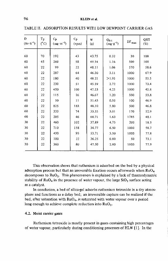
T A B L E II. A D S O R P T I O N R E S U L T S W I T H L O W D E W P O I N T C A R R I E R G A S
9 6 KLEIN et al.
D( l tr -h '1)
T F
(°C )
CP(mg - m’ 3)
CP(vpm)
W(g)
Q o.i(mg-g-1) DFmax
QHT(%)
60 70 192 43 43.75 0.32 30 10060 45 260 58 49.14 1.16 500 10060 22 99 22 48.11 1.06 570 58.6
60 22 287 64 46.30 3.11 1000 67.9
60 22 180 40 48.21 >1.95 1000 55.5
60 22 230 51 45.59 2.72 1000 73.4
60 22 450 100 47.53 4.25 1000 45.8
60 22 115 26 46.67 1.20 330 53.8
60 22 50 11 51.43 0.35 100 46.9
60 22 825 183 48.10 5.80 500 46.8
60 22 333 74 33.55 3.01 170 52.9
60 22 205 46 68.71 1.63 1785 48.1
30 22 460 102 37.89 4.75 200 18.5
30 22 710 158 34.77 6.50 1000 58.7
30 22 430 95 53.71 3.50 1000 77.8
30 22 100 22 36.25 0.80 50 73.1
30 22 360 80 47.50 2.80 1000 77.9
This observation shows that ruthenium is adsorbed on the bed by a physical
adsorption process but that an irreversible fixation occurs afterwards when R u 0 4 decomposes to R u 0 2. This phenomenon is explained by a lack of thermodynamic
stability of R u 0 4 in the presence of water vapour, the large Si02 surface acting as a catalyst.
In conclusion, a bed of silica-gel adsorbs ruthenium tetroxide in a dry atmos
phere and functions as a delay bed; an irreversible capture can be realized if the
bed, after saturation with R u 0 4, is saturated with water vapour over a period
long enough to achieve complete reduction into R u 0 2.
4.2. Moist carrier gases
Ruthenium tetroxide is mostly present in gases containing high percentages
of water vapour, particularly during conditioning processes of H L W [1 ]. In the

IAEA-SM-24S/51 9 7
presence of moisture the adsorbent bed must work at a temperature higher than
the dewpoint of the gas to avoid water condensation on the silica-gel but also to
speed up the partial reduction of R u 0 4. Therefore a series of experimental tests
have been set up to investigate the influence of a dewpoint temperature between
34 and 80°C and of a column temperature between 50 and 150°C. The ruthenium
concentration ranges from 5 to 26 v p m and the silica-gel bed varied from 50 to 60 g.
In all the tests performed, neither the bed capacity nor the decontamination
factor reached satisfactory values. The capacity never exceeded a value of
0.1 mg-g"1 and the decontamination factor consequently dropped rapidly to a value close to 1.
In all the tests performed, the ruthenium could easily be desorbed from
the bed with a high efficiency, namely always more than 80% of the ruthenium
adsorbed was desorbed with nitrogen sparging. These results showed that only
a partial reduction of ruthenium tetroxide occurred during the run. This con
clusion was also confirmed by visual examination of the silica-gel bed: a dark
deposit (probably R u 0 2) was observed mainly in the first layers of the bed,
but the major part of the bed had a yellow colour, a sign of the presence of
ruthenium tetroxide.
The discrepancy between published data where high DFs are reported and
the present results could be explained by the absence of N O x gases, which
probably play an important role in R u 0 4 decomposition.To clarify this matter experiments are in progress to simulate the conditions
occurring in calcination and vitrification of H L W solutions.
5. T H E C A T A L Y T I C R E D U C T I O N O F R u 0 4 W I T H F E R R I C O X I D E O N
SILICA-GEL
According to Donato et al. [6], silica-gel intimately mixed with ferric oxide is a very efficient material for trapping gaseous R u 0 4.
A parametric investigation of this R u 0 4 trapping process has been started in the apparatus described in section 2. Later, confirmation tests under optimized
conditions are planned with the use of tracers to measure the high decontamination
factors expected.
5.1. Parametric investigation with inactive ruthenium
The parametric investigation has been started using as bed material the
9 to 24 mesh (+0.7, —2.0 m m ) size fraction of a crushed ferric oxide silica-gel
catalyst prepared according to the method of Grover [6]. This bed material has

9 8 KLEIN et al.
an apparent density of 0.95 g-cm -3 in a small column with a cross-section of 3 c m 2. The tests performed to date covered bed heights between 7 and 15 cm,
bed temperatures between 97 and 220°C, total gas flow rates between 12 and
145 ltr-h-1 (wet gas at 10s Pa and 20°C), dewpoints from 1 to 82.3°C and R u 0 4 concentrations from 4 to 130 v p m (or 35 to 604 m g - m -3 dry gas or 18 to 585 m g - m -3 wet gas).
5.1.1. The e ffec t o f bed tem perature
These experimental runs showed that high decontamination factors are
obtainable at bed temperatures above 200°C. For instance, at 200°C no break
through was observed after an operation time of 52 h with an inlet R u 0 4 concentration of 15 vpm, resulting in an equivalent ruthenium load of 13 m g per
gram of catalyst. At temperatures lower than 150°C rapid saturation of the bed
occurred, according to an adsorption capacity of 0.2 mg-g-1.T w o series of runs with variations of the bed temperature from 100 to
220°C were performed to estimate the apparent activation energy. The first
series was performed at a flow rate of 72 ltr-h-1 at a bed load of 34 g and a water content of 0.5 vol.%; the second series at a flow rate of 108 ltr-h-1 at a bed load of 24 g and a water content of 28.2 vol.%. The apparent kinetic
constant was derived on the basis of an overall mass balance for a plug flow
reactor with a chemical reaction of the first order related to the ruthenium
content. The slope of an Arrhenius plot gave an activation energy of 13 kcal-mol-1,
a value which is lower than the activation energy values obtained by Ortner [6]
for the R u 0 4 decomposition reaction in the presence of R u 0 2 (Eact= 30.5 kcal • mol-1) or silica-gel (Eact = 22 kcal-mol-1). Additional experiments are necessary to
clarify the reasons for this low experimental value.
5.1.2. The influence o f R u 0 2 deposits on the catalyst
The experimental investigation revealed that, at constant temperature and
inlet concentration, the apparent reaction rate increases with time to reach an
asymptotic value. This observation suggests that the R u 0 2 formed by the catalytic decomposition of R u 0 4 enhances the reaction rate. Therefore, a confirmation run at 210°C and at a constant space velocity of 0.88 c m 3-s-1-g-1 was performed.It demonstrated that the apparent kinetic constant expressed in c m 3 of gas per second per gram of catalyst increases from 0.76 for the fresh catalyst to 1.7 after
a deposit of 1.15 m g R u 0 2 per gram of catalyst. A n overnight interruption causes a drop to 0.96 which is rapidly recovered to get an apparent kinetic constant value
of 2.5 after a supplementary ruthenium loading of 0.3 mg-g-1, with a constant
space velocity of 0.59 c m 3-s-1-g-1. Finally, the apparent kinetic constant stabilizes at a mean value of 2.7 c m 3-s-1-g-1.

IAEA-SM-24S/51
5.1.3. The effect o f the gas f lo w rate
99
During a run at 150°C the gas flow rate was varied in the range of 12 to
74 ltr-h-1. Although the apparent first-order kinetic constant appeared to
decrease with decreasing flow rate, this decrease was not proportional to the flow
decrease. Hence, mass transfer limitation through the film could occur, giving
some hint as to why the apparent activation energy was found to be so low.
5.1.4. Conclusions
The observations made during this orientative experimental programme
indicate the necessity for further systematic investigation in order to clarify the
real kinetic mechanisms, i.e. trying to determine the rate-determining step of this
heterogeneous catalytic reaction under various working conditions.
5.2. Experimental set-up for the tracer experiments
The new experimental set-up for the use of tracers is under construction
in a glove-box to permit the determination of DFs higher than 104.
The main options taken for the design are as follows:
(a) A generation of 50 juCi-h-1 (1.85 M B q - h -1) corresponding to a total activity in the generator feed of 6 mCi for a 5-day work period.
(b) The activity in the feed gas will be measured continuously in an annular
Nal(Tl) detector with a 25 c m 3 volume, or measured discontinuously by absorption in basic absorbing solution.
(c) The gases at the exit of the filter under test are cooled in a condenser;
the condensate will be discontinuously purged and its activity measured.
(d) After the condenser, the remaining R u 0 4 is absorbed in basic absorbing solution; the activity of the absorbing solution is measured continuously
by air lift closed circuit circulation in a well-type Nal(Tl) counter with
a 20 c m 3 volume.
Tests with this set-up are foreseen during the first half of 1980.
6. C O N C L U S I O N S
Although the experimental data obtained so far gave interesting qualitative
indications on the way in which volatile R u 0 4 can be trapped, it is clear that a great deal remains to be learnt about the behaviour of ruthenium during the
different steps of the nuclear fuel cycle.
Our future programme will be focused on confirming the phenomena so far
observed.

1 0 0 KLEIN et al.
The aim is to determine the capture mechanism of ruthenium tetroxide in
various environments and to confirm these results by demonstration runs using
tracers allowing the measurement of high DFs.
A laboratory pilot installation at a normal flow rate of 10 m 3 - h -1 (STP), allowing operation with representative off-gas streams, will be constructed to
verify all the technological impacts of the proposed R u capture techniques.
R E F E R E N C E S
[1] EICHHOLZ, G., “ Hazards and control of ruthenium in the nuclear fuel cycle” , Prog.Nucl. Energy 2(1978) 29.
[2] HANSON, M.S., Semi Volatile Fission Product Behaviour in High Level Waste Solidification, Battelle-Northwest, Richland, WA, Pacific Northwest Lab., Rep. BNWL-SA-6461 (1978).
[3] BJORKLUND, J., Development and Use of Sintered Metal Filters with Fluidized Bed and Spray Calcination of Simulated High Level Waste, Battelle-Northwest, Richland, WA, Pacific Northwest Lab., Rep. BNWL-2074 (July 1976).
[4] NEWBY, B., et al., Volatile Ruthenium Removal from Calciner Off-Gas Using Solid Sorbents, Allied Chemical Corps., Idaho Falls, ID, Rep. ICP-1078 (July 1975).
[5] CHRISTIAN, J.D., “Process behaviour and control of ruthenium and cesium” , Controlling Airborne Effluents from Fuel Cycle Plants (Proc. ANS-AIChE Topical Meeting Sun Valley, 1976), American Nuclear Society, Hinsdale (1976).
[6] DONATO, A., et al., Contribution to studies on gaseous R u04 removal by means of ferric oxide-silica filters, Energ. Nucl. (Milan) 18 6 (1971) 353.
DISCUSSION
H. D E U B E R : Experiments on the removal of gaseous ruthenium using
pure silica-gel and ferric oxide on silica-gel have been performed for many years.
D o you know of, or have you attempted to find, any adsorbents which are more
suitable for trapping gaseous ruthenium? Also, as we know, ruthenium is
pharmacologically very toxic. Did you have to perform your tests with inactive
ruthenium in glove boxes?
M. KLEIN: Since ferric oxide on silica-gel produces very satisfactory results,
we have no intention of looking for other materials. W e tested only materials
which can be incorporated directly into glass.
As regards your second question, we carried out our tests in a ventilated
hood.
A.J. WILLIAMS: W h y should one consider putting 106Ru into glass after
trapping it on a silica-gel/ferric-oxide mixture? Is it because the R u is rapidly
lost by some means and therefore the medium cannot just be left for a few years
for Ru decay?
M. KLEIN: In most cases R u is present together with other radionuclides
which have longer half-lives, such as fission products (Cs) or a-emitters.
IAEA-SM-24S/S4
REMOVAL OF NITROGEN OXIDES,VOLATILE RADIONUCLIDES AND AEROSOLS FORMED IN LABORATORY-SCALE DENITRATION, CALCINATION AND SOLIDIFICATION OF SIMULATED HIGH-LEVEL WASTES
F. KEPÁK, V. PECÁK, E. U H E R ,
J. K A Ñ K A , S. K O U T O V Á , V. M A T O U S
Nuclear Research Institute,
fíez,
Czechoslovakia
Abstract
REMOVAL OF NITROGEN OXIDES, VOLATILE RADIONUCLIDES AND AEROSOLS FORMED IN LABORATORY-SCALE DENITRATION, CALCINATION AND SOLIDIFICATION OF SIMULATED HIGH-LEVEL WASTES.
An apparatus and procedure for the purification of gaseous effluents formed in the denitration, calcination and solidification of simulated high-level wastes were proposed and tested in a laboratory-scale apparatus. The purification procedure consisted of absorption and decomposition of nitrogen oxides, sorption of I06RuO4 and I37Cs vapour, and filtration of 106Ru, 137Cs and 85Sr aerosols. The absorption solution used was ammonium oxalate.As an inorganic sorbent silica-gel was used, as well as molecular sieves, ceramics and charcoal.A high efficiency filter made of glass and organic polymer (perchlorvinyl) microfibres, and a prefilter made of glass fibres, were used for filtration. In addition to the laboratory-scale apparatus for absorption and decomposition of the nitrogen oxides, a semipilot-plant-scale apparatus was proposed and constructed. By successive absorption, adsorption and filtration processes the concentrations of 106Ru, 137Cs and 85Sr were reduced by more than 4, 4 to 6 and more than 3 orders of magnitude, respectively; the efficiency of the removal of nitrogen oxides was 95 to 100%.
1. I N T R O D U C T I O N
During the denitration, calcination and solidification of high-level wastes,
nitrogen oxides and vapour and aerosols of radionuclides are formed [ 1 ]. The
differences in the physico-chemical forms of individual components require
special separation procedures to reduce their concentrations to the permitted
levels. Both ‘wet’ and ‘dry’ procedures were applied [1 ] to purify the gaseous
effluents formed in the denitration, calcination and solidification processes.
In our laboratory the processing of high-level wastes was simulated in a
laboratory-scale apparatus. The removal of 106Ru, 137Cs and 8sSr (the first two
101
1 0 2 KEPÁK et al.
both as vapour and as aerosols, the third as an aerosol only) was studied in a
laboratory-scale apparatus. The laboratory procedure developed for the removal
of N O x was transferred to a semipilot-plant-scale apparatus.
2. E X P E R I M E N T A L P R O C E D U R E S
To remove the nitrogen oxides, a procedure involving their absorption in a
solution of a m m o n i u m salts and their subsequent decomposition to N 2 and N 20
was developed [2—5]. The main ammonium salt used was 2% aqueous ammonium
oxalate and the solution was electrolytically regenerated and activated on a
continuous basis. The removal of 106R u O 4 and 137Cs vapours was performed by adsorption in a column packed with the inorganic sorbent silica-gel, in addition
to molecular sieves, ceramics and charcoal. The 106Ru, ,37Cs and 85Sr aerosols were separated by filtration through a high efficiency filter. In the case of 137Cs, a prefilter was also used. The prefilter was made of glass fibres (RA-1), and the
high efficiency filter of glass microfibres (RA-2) and organic polymer (perchlorvinyl)
microfibres of Soviet origin (FPP 15-6.0). Both glass materials (RA-1 and RA-2)
have recently been developed in Czechoslovakia. The aim of the testing was
to determine their suitability for the separation of aerosols from gaseous effluents
formed in the processing of simulated high-level wastes. When these purification
procedures are applied on a larger scale, the following sequence is presumed:
removal of N O x, followed by the sorption of vapour phase radionuclides and,
finally, by the filtration of aerosols.
3. A P P A R A T U S
The semipilot-plant-scale apparatus for the removal of N O x is shown in
Fig.l. The principal part of the apparatus is a conical-based absorber (I), divided
at the top into six independent separators (11—66). The separators are connected
to the cover of the absorber; the gas enters through the inlet tube in the cover
of the first separator (11) and leaves through the outlet tube in the cover of the last separator (66). There is a free volume in the lower part of the separator.This is partly filled with the absorption solution, whose surface forms a
‘gas seal’ at approximately one third of the height of the absorber above the
cone-shaped portion. The absorption solution (total volume 140 ltr) is
recirculated uniformly to the six ejectors by means of p u m p II, working
at an overpressure of 0.4 to 0.6 MPa and at a flow rate of 1 to 2 m 3/h.The suction end of the first ejector is connected to the source of the
nitrogen oxides. The gas leaving the first separator ( 11 ) is sucked off by the
second ejector (2) and the gas from the second separator (22) by the third ejector (3); finally the sixth ejector (6) blows the purified gas out of the last

IAEA-SM-24S/54 10 3
FIG.l. Semipilot-plant-scale apparatus for NO x removal: I conical absorber; II pump; 1 - 6 ejectors; 7 gas inlet; 8 gas outlet; 9 tube with circulating solution; 10 pressure gauge; 1 1 -6 6 absorber separators.
separator (66). With this apparatus 1 to 2 m 3 of the gaseous effluent can be treated per hour. The nitrogen oxides used to test the apparatus were produced
by the decomposition of nitrite. There are no pressure losses in the apparatus.
The absorbent can be regenerated electrolytically.
Release and capture of 106R u O 4 and 137Cs vapour produced during calcination was carried out in a laboratory-scale apparatus consisting of a
condenser, two bubblers filled with an a m m o n i u m oxalate solution, a column
packed with silica-gel (6 g of grain size 0.4 to 0.5 mm), and a holder supporting a highly efficient disc-shaped filter material. T w o further bubblers filled with
N a O H solution served to capture the radionuclides which penetrated the
purification system. The apparatus is shown schematically in Fig.2. The flow
rate of the gas through the column was lOcm-s"1. Denitration and calcination

104 KEPÁK et al.
FIG. 2. Schematic diagram o f the laboratory-scale purification apparatus for gases from calcination: 1 solution reservoir; 2 calcination test tube; 3 heating coil; 4 condenser; 5 condensate trap; 6, 7 bubblers with oxalate solution; 8 silica-gel column; 9 high efficiency filter; 10,11 bubblers with NaOH solution; 12 flowmeter; 13 pump.
FIG. 3. Schematic diagram o f the laboratory-scale apparatus for purification o f gases from solidification: 1 furnace; 2 quartz test tube; 3 filter for filtration o f inlet air; 4 high efficiency filter; 5 membrane ultrafilter; 6, 7 bubblers; 8 flowmeter; 9 pump.
were performed in a quartz test tube at 550°C. Ten cubic centimetres of
simulated solution were treated in a single run and the gases were pumped off.
The solidification of the simulated high-level radioactive solution after
the preliminary denitration and calcination was carried out in a quartz test tube
in a laboratory oven at a temperature of 1100°C. The outlet gases were passed
either directly through a high efficiency filter and then through a membrane
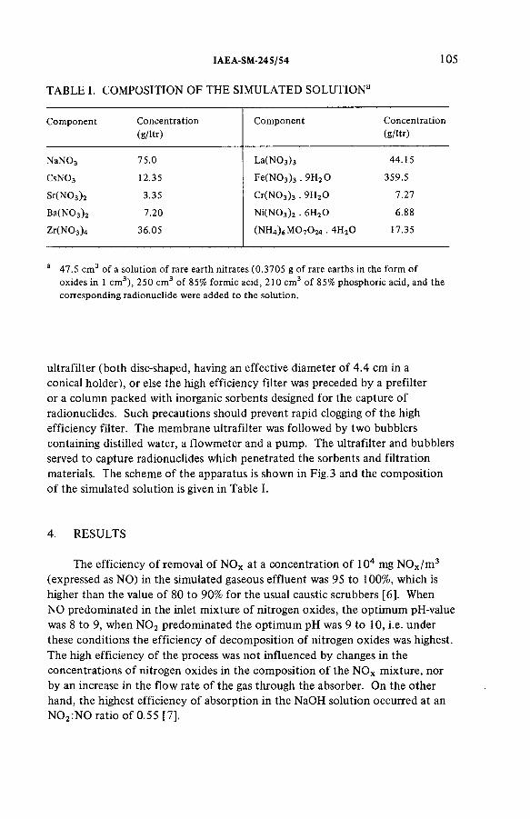
I AE A-SM-24 5/54
T A B L E I. C O M P O S IT IO N O F T H E S IM U L A T E D S O L U T IO N 2
105
Component Concentration(g/ltr)
Component Concentration(g/ltr)
N aN03 75.0 La(N 03)3 44.15
CsN03 12.35 Fe(N 03)3 . 9H20 359.5
Sr(N03)2 3.35 Cr(N 03)3 . 9H20 7.27
Ba(N03)2 7.20 Ni(N03)2 . 6H20 6.88
Zr(N 03)4 36.05 (Ш ^ М С Ь О м . 4H20 17.35
a 47.5 cm3 of a solution of rare earth nitrates (0.3705 g of rare earths in the form of oxides in 1 cm3), 250 cm3 of 85% formic acid, 210 cm3 of 85% phosphoric acid, and the corresponding radionuclide were added to the solution.
ultrafilter (both disc-shaped, having an effective diameter of 4.4 c m in a
conical holder), or else the high efficiency filter was preceded by a prefilter
or a column packed with inorganic sorbents designed for the capture of
radionuclides. Such precautions should prevent rapid clogging of the high
efficiency filter. The membrane ultrafilter was followed by two bubblers
containing distilled water, a flowmeter and a pump. The ultrafilter and bubblers
served to capture radionuclides which penetrated the sorbents and filtration
materials. The scheme of the apparatus is shown in Fig.3 and the composition
of the simulated solution is given in Table I.
4. R E S U L T S
The efficiency of removal of N O x at a concentration of 104 m g N O x/ m3 (expressed as NO) in the simulated gaseous effluent was 95 to 100%, which is
higher than the value of 80 to 90% for the usual caustic scrubbers [6]. When N O predominated in the inlet mixture of nitrogen oxides, the optimum pH-value
was 8 to 9, when N 0 2 predominated the optimum p H was 9 to 10, i.e. under these conditions the efficiency of decomposition of nitrogen oxides was highest.
The high efficiency of the process was not influenced by changes in the
concentrations of nitrogen oxides in the composition of the N O x mixture, nor
by an increase in the flow rate of the gas through the absorber. O n the other
hand, the highest efficiency of absorption in the N a O H solution occurred at an
N 0 2:N0 ratio of 0.55 [7].
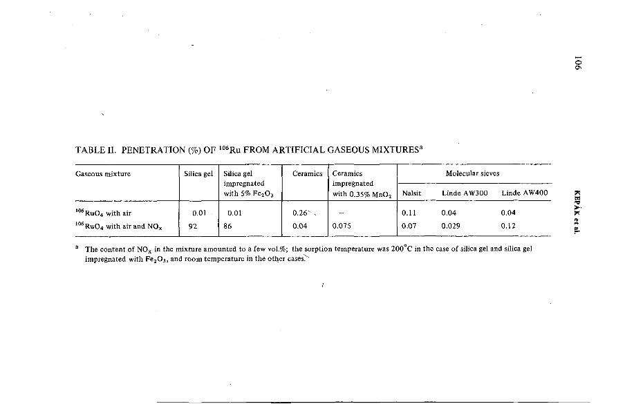
оON
T A B L E II. P E N E T R A T I O N (%) O F 106R u F R O M ARTIFICIAL G A S E O U S M I X T U R E S 3
Gaseous mixture Silica gel Silica gel impregnated with 5% Fe20 3
Ceramics Ceramics impregnated with 0.35% M n02
Molecular sieves
Nalsit Linde AW300 Linde AW400
106RuO4 with air 0.01 0.01 0 .2 6 ' - - 0.11 0.04 0.04
106RuO4 with air and NOx 92 86 0.04 0.075 0.07 0.029 0.12
a The content of NOx in the mixture amounted to a few vol.%; the sorption temperature was 200°C in the case of silica gel and silica gel impregnated with Fe20 3) and room temperature in the otlier cases'^
i
KEPÁK et al.

T A B L E III. R E M O V A L O F 106R u F R O M T H E G A S E O U S E F F L U E N T F O R M E D IN L A B O R A T O R Y C A L C I N A T I O N 3
Separation step
1
Separation or penetration (%) in experiment No.
2 3 4
Condensation 96.6 (3.4) 97.1 (2.9) 98.1 (1.9) 98.0 (2.0)
Absorption 1.15 (66) 0.32 (89) 0.37 (81) 0 .26(87)
Sorption 1.10(51) 2.19 (14) 1.20 (24) 1.58 (8)
Filtration 1.10(4) 0 .4 5 -« 2 ) 0.37 (<3) 0.14 (<7)
Total penetration through the system (%)
0.05 < 0.01 < 0.01 < 0.01
a The values without brackets: the separation of 106 Ru in the given step in % related to the total content of 106 Ru in the gaseous sample entering the purification apparatus.The values in brackets: the penetration of 106Ru through the corresponding part of the apparatus in % related to the amount of 106Ru entering this step.Sorption temperature was 150°C.
о
IAEA
-SM-24S/S4

10 8 KEPÁK et al.
T A B L E IV. R E M O V A L O F 137Cs F R O M T H E G A S E O U S E F F L U E N T
F O R M E D IN L A B O R A T O R Y C A L C I N A T I O N 3
Separation step Separation or penetration (%) in experiment No.
1 2
Condensation 86.7 (13.3) 88.1 (11.9)
Absorption 9.6 (28) 8.4 (90)
Sorption 1.1 (69) 0.68 (89)
Filtration 2.5 (<1) 2.9 « 0 .3 )
Total penetration through the system (%)
0.02 < 0.01
a The values with and without brackets have the same meaning as in Table III.
The penetration values of 106 Ru from an artificial gaseous mixture of 106R u O 4 with air, or of 106R u O 4 with air and N O x, through inorganic sorbents
are given in Table II. It can be seen that the sorption of 106R u O 4 on silica-gel, or silica-gel impregnated with ferric oxide, is considerably worsened by the
presence of nitrogen oxides. The sorption properties of the other sorbents are
either not at all or only slighly sensitive to N O x.
The results for the separation of vapour and aerosols of 106R u (106R u O 4) and 137Cs which were transferred to the gaseous phase during calcination are
summarized in Tables III and IV, respectively. For the separation system as a
whole, the concentrations of 106R u and 137Cs in the gaseous phase were reduced
to <0.01% of their original concentrations when entering the apparatus. The
efficiency of the sorption of 106Ru and 137Cs on the sorption column was low.
According to the literature [8], the sorption of 106Ru on silica gel should be considerably higher. The sorption efficiency was still low even when ceramics
were used. In the case of 85 Sr, the concentration was lowered to less than0.1 % of the initial concentration in the gas by the same separation system. The
sensitivity of the determination of the radioactivity of 8sSr was lower than the
sensitivities for 106Ru and 137Cs determinations. The efficiency of the final
filtration of aerosols of 106Ru, 137Cs and 85Sr through a high efficiency filter was lower than that achieved with a simulated NaCl aerosol (its concentration
was reduced by as much as four orders of magnitude [9]): it was also less than
figures given in the literature [ 1 ]. The release of ruthenium and of caesium
into the gaseous phase relative to their masses in the calcine amounted to
6 to 12% and 0.3 to 0.6%, respectively.

T A B L E V. S E P A R A T I O N O F 137Cs F R O M T H E G A S E O U S E F F L U E N T F O R M E D IN T H E L A B O R A T O R Y
SOLIDIFICATION P R O C E S S 3
Samplenumber
Sorbent orprefiltermaterial
Separation(%)
High efficiency filter material
Penetration through high efficiency filter material (%)
Total penetration (%)
1 - - RA-2 < 3 .1 X 10"4 -
2 - - RA-2 < 6 X 10“5 -
3 - - RA-2 < 6 X 10“5 -
4 - - FPP 15-6 .0 2.7 X 10^ -5 RA-1 90.25 RA-2 9.8 X 10~3 9.6 X 1 0 ^
6 RA-1 90.08 RA-2 4.4 X 10“3 4.3 X 10"47 Silica gel 98.55 RA-2 < 0.1 < 1.6 X 1 0 ^
8 Zinc ferrocyanide 99.90 RA-2 < 0 .3 < 3 .1 X 10"*
9 Activated charcoal 89.61 RA-2 < 6 .3 X IQ-4 < 6.6 X 10“5
a Sorbent volume was about 6 cm3; zinc ferrocyanide, silica gel and activated charcoal grain sizes were 0.2—0.8, 0.2—0.8 and 0.6—1.4 mm, respectively. The flow rate through the filter materials was 0.55 cm s_I. The flow rate through the sorbents was 16.7 cm s"1.
1AEA
-SM-24S/S4
109

1 1 0 KEPÁK et al.
The results for the sorption and filtration of 137Cs escaping as a vapour or
as an aerosol during the solidification of simulated high-level wastes are given
in Table V. In the one-step separation process using a high efficiency filter, the
concentration of 137Cs was reduced by as much as six orders of magnitude, i.e.
the efficiency was higher than that in the filtration of the simulated NaCl
aerosol [9]. When a prefilter or a sorbent was used ahead of the high efficiency
filter — with the exception of one experiment — approximately the same
purification effect was obtained for the two steps as when the high efficiency
filter was used alone, i.e. the sorbents or the prefilter removed more than 90%
of the 137Cs, but the total separation effect was not increased. When a pre-purification procedure was applied, the high efficiency filter of glass microfibres
was less efficient than when it was used alone.
5. S U M M A R Y
The experimental study on the development of a procedure and an apparatus
for the removal of N O x, volatile radionuclides and radioactive aerosols formed
during the processing of high-level wastes has not been completed. A n efficiency
of 95 to 100% for the removal of N O x was achieved. In the case of 106Ru and
137Cs, the concentrations were reduced by more than four orders of magnitude, in the case of 85 Sr by more than three orders of magnitude, using a multi-step separation system, with final filtration through a high efficiency filter produced
in Czechoslovakia. The results obtained with both the laboratory-scale and the
semipilot-plant-scale apparatus suggest that, by a suitable combination of
absorption, sorption and filtration stages, it will be possible to reduce the
concentrations of harmful components in the gaseous effluent from the
processing of high-level wastes to the permissible levels.
R E F E R E N C E S
[1] CHRISTIAN, J.D., PENCE, D.T., Critical Assessment of Methods for Treating Airborne Effluents from HLLW-Solidification Processes, Battelle Pacific Northwest Labs., Richland, WA, Rep. PNL-2486 (1977).
[2] MATOUS, V., PECÁK, V., Czechoslovak Patent 191614 (1977/1979).[3] PECÁK, V., MATOUS, V., Czechoslovak Patent 191634 (1977/1979).[4] MATOUS, V., PECÁK, V., Czechoslovak Patent 196819 (1977/1979).[5] PECÁK, V., MATOUS, V., Patent application PV 3 -7 9 (1979).[6] GOVOROV, V.G., USSR Patent 392, 958 (1973).[7] OZASA, M., et al., Natl. Techn. Rep. (Matsushita Electr. Ind. Co., Osaka) 20 (1974) 580.[8] ANDERSON, F.M., et al., “ Design criteria for the new waste calcining facility at the
Idaho chemical processing plant” , Management of Radioactive Wastes from the Nuclear Fuel Cycle (Proc. Symp. Vienna, 1976), IAEA, Vienna (1976) 325.
[9] KEPÁK, F., KAÑKA, J., BINKOVÁ, B„ BINEK, B., Jad. Energ. 25 (1979) 294.

IAEA-SM-245/54 1
DISCUSSION
M. KLEIN: What was the bed temperature in the adsorbing column for
ruthenium removal?
F. KEP Á K : In the case of silica-gel and silica-gel impregnated with ferric
oxide, the temperature was 1 50 or 200°C, and it was room temperature when
other sorbents were used.


Sessions 11(b) and III
REMOVAL AND RETENTION OF RADIOIODINE, TRITIUM AND CARBON-14

Chairman
R.V. O S B O R N E
Canada

IAEA-SM-24S/65
ПРИМЕНЕНИЕ КРЕМНИЙОРГАНИЧЕСКИХ ЖИДКОСТЕЙ
В КАЧЕСТВЕ ПОГЛОТИТЕЛЕЙПРИ АБСОРБЦИОННОМ СПОСОБЕ УЛАВЛИВАНИЯ 129 J
И.Е.НАХУТИН, Л.Н.РАСТУНОВ, Н.М.СМИРНОВА,Г.А. ЛОШАКОВ, Г .А .ЛАУШКИНА Государственный комитет по использованию атомной энергии СССР,Москва,Союз Советских Социалистических Республик
Abstract- Аннотация
THE USE OF SILICON-ORGANIC LIQUIDS AS ABSORBENTS FOR THE RETENTION OF 129I.
An absorption technique for iodine retention using silicon-organic liquids has been developed. The resistance of certain silicon-organic compounds to nitrogen peroxide is studied. The polymethylsiloxane liquids PMS-10, PMS-20 and PMS-40 were found to be resistant to NO2. The radiation stability of certain silicon-organic liquids was studied. The maximum solubilities of iodine in PMS-10, PMS-40 and PEhS-7 are 4.38, 4.56 and 4.32 kg/m3, respectively. The equilibrium distribution coefficients of iodine between air and the liquid PMS-10 at 20, SO and 70°C are (1.34 + 0.05) X 103, (4.5 ± 0.2) X 102 and (2.4 ± 0.2) X 102, respectively. The elimination of iodine from gaseous wastes using a silicon-organic liquid involves the following processes: iodine absorption, blowing off of nitric oxides dissolved in the silicon-organic liquid and regeneration of the liquid by extracting the iodine from it into an alkaline solution. By passing air containing approximately 200 mg/m3 iodine at a rate of 2 -1 1/min (3.0—1.5 cm/s) through a system of three linked bubblers in sequence simulating three bubbling plates through which the liquid PMS-10 passed at rates of 2.8 and 3.2 ml/min, mean decontamination coefficients of 15 (v = 2.0 1/min and L = 2.8 ml/min) and 150 (v = 1.0 1/min and L = 3.2 ml/min) were obtained. Experiments have shown that, by blowing off iodine from PMS-10 with a current of pure air at a temperature of 90°C and regenerating the liquid PMS-10 containing iodine with a 2—10% solution of caustic soda, the iodine is almost completely removed from the silicon-organic liquid PMS-10.
П Р И М Е Н Е Н И Е К Р Е М Н И Й О Р Г А Н И Ч Е С К И Х Ж И Д К О С Т Е Й В К А Ч Е С Т В Е П О Г Л О Т И Т Е Л Е Й П Р И
А Б С О Р Б Ц И О Н Н О М С П О С О Б Е У Л А В Л И В А Н И Я 129J .
Р азр аб о тан аб со р б ц и о н н ы й м е то д у л а в л и в а н и я й о д а с п о м о щ ь ю к р е м н и й о р га н и ч е с к и х ж и д
к о с те й . И зуч ен а с т о й к о с т ь н е к о т о р ы х к р е м н и й о р га н и ч е с к и х соединений к д в у о к и с и а зо та . П оли-
м е ти л с и л о к с а н о в ы е ж и д к о с т и П М С -1 0 , П М С -2 0 и П М С -4 0 о к а з а л и с ь с т о й к и м и к д е й ств и ю N 0 , .
И зу ч а л а с ь р ад и ац и о н н ая с т о й к о с т ь н е к о т о р ы х к р е м н и й о р га н и ч е с к и х ж и д к о с те й . П р е д ел ь н ая рас
тв о р и м о с ть й о д а в П М С -1 0 , П М С -4 0 и П Э С -7 р авна 4 ,3 8 ,4 ,5 6 и 4 ,3 2 к г / м 3 , с о о тв е тс тв е н н о . Р ав
н о в е сн ы е к о э ф ф и ц и е н ты р а сп р ед е лен и я йода м е ж д у в о з д у х о м и ж и д к о с ть ю П М С -1 0 пр и 2 0 , 5 0 и
7 0 ° С и м е ю т зн ач ен и я , р ав н ы е (1 ,3 4 ± 0 ,0 5 ) - 1 0 3 , (4 ,5 ± 0 ,2 ) 1 0 г и ( 2 ,4 ± 0 ,2 ) ■ 1 0 2, с о о тв е тс тв е н н о .
О ч и с тк а г а з о в ы х в ы б р о с о в о т й о д а с п о м о щ ь ю к р е м н и й о р га н и ч е с к о й ж и д к о с т и в к л ю ч а е т в себ я
сл е д у ю щ и е п р о ц е с с ы : аб со р бц ию й о д а , о т д у в к у р а ств о р е н н ы х в к р е м н и й о р га н и к е о к и с л о в а зо та ,
115

1 1 6 НАХУТИН и др.
р егенер ацию ж и д к о с т и п у т е м и зв л е ч ен и я из нее й о д а в р а ств о р щ ело чи . П р и п р о п у с к а н и и в о з д у
х а , с о д е р ж ащ е го ~ 2 0 0 м г / м 3 й о д а со ск о р о с ть ю 2-1 л /м и н (3 ,0 - 1 ,5 с м / с ) , через с и с те м у из тр е х
п о с л е д о в а те л ь н о со е д и н е н н ы х б ар б о тер о в , и м и ти р о в а в ш и х тр и б а р б о таж н ы е т а р е л к и , через к о
то р ы е о с у щ е с т в л я л с я п р о т о к ж и д к о с т и П М С -1 0 со ск о р о с ть ю 2 ,8 и 3 ,2 м л / м и н , б ы л и п о л уч е н ы
средн и е зн ач ен и я к о э ф ф и ц и е н то в о ч и с тк и , р авны е 15 (v = 2 ,0 л /м и н и L = 2 ,8 м л /м и н ) и
150 О = 1 ,0 л /м и н и L = 3 ,2 м л / м и н ) . О п ы т ы п о к а з а л и , что к а к в р е зу л ь та те о т д у в к и й о д а из
П М С -1 0 т о к о м ч и с то го в о з д у х а п р и те м п е р а тур е 9 0 ° С , т а к и в р е зу л ь та те о б р а б о тк и ж и д к о с ти
П М С -1 0 , со де р ж ащ е й й о д , 2-10 % -н ы м р а ств о р о м е д к о го н а тр а , и м е е т м е с то п р а к ти ч е с к и по лн о е
уд ал е н и е й о д а из к р е м н и й о р га н и ч е с к о й ж и д к о с т и П М С -1 0 .
1. ВВЕДЕНИЕ
В последние годы большое внимание уделяется вопросам улавливания 129 J из газовых выбросов, образующихся в процессе регенерации ядерного горючего. Следует отметить, что очистка газовых выбросов от этого радионуклида занимает особое место в проблеме удаления радиоактивного йода. Это связано с тем, что при переработке отработанных твэлов энергетических реакторов выделяются значительные весовые количества 129J. Например, на стандартном заводе с производительностью 1400 т/год необходимо ежегодно улавливать окло 370 кг 129 J [1 ].
Кроме того, так как 129 J имеет чрезвычайно большой период полураспада (1,62-107 лет), возникает необходимость перевода его в такую форму, которую было бы удобно и безопасно хранить в течение длительного времени.
Для улавливания йода из газовых выбросов, образующихся при переработке ядерного горючего, используются колонны с сорбентом, содержащим соли серебра, или колонны с серебряными цеолитами [1-4]. Эти колонны могут работать в хроматографическом или радиохроматографическом режимах. Радиохроматографический режим может быть осуществлен только для 131J и других более короткоживущих изотопов йода. Для 129J возможен только режим фронтальной хроматографии.
Такие колонны работают достаточно надежно и обеспечивают высокие коэффициенты очистки в течение длительного времени. Однако, при переработке значительных количеств отработанного ядерного горючего с большим выгоранием, когда в газовую фазу выделяются большие весовые количества 129 J , применение хроматографических колонн влечет за собой образование значительных количеств твердых отходов, включающих в себя, помимо 129J, еще объем самого сорбента.
Для улавливания 129J целесообразно использовать двухступенчатую схему очистки газовых выбросов. На первой ступени (предварительной очистки газа) должна улавливаться основная масса (90 % и более) 129J и выделяться в виде твердых труднорастворимых соединений, пригодных для захоронения. В качестве предварительной очистки газовых выбросов можно использовать жидкостные методы улавливания йода. На второй ступени для окончательной очистки газа целесообразно применять колонны с твердыми сорбентами, импрегнированными солями серебра. При любых неполадках на первой ступени очистки эти колонны могут временно принять на себя дополнительную нагрузку.

IAEA-SM-245/65 117
В настоящее время известны различные жидкостные способы улавливания радиоактивного йода. Это — щелочные скрубберы [5 ] ,’’меркурекс-процесс” [1 ,6 -8 ] , ’’йодокс-процесс” [1 ,5 ] .
Наши исследования показали, что в качестве поглотителя йода можно также использовать кремнийорганические жидкости, например, полиметипсилоксановые жидкости с небольшим молекулярным весом.
2. ИЗУЧЕНИЕ ФИЗИКО-ХИМИЧЕСКИХ СВОЙСТВ НЕКОТОРЫХКРЕМНИЙОРГАНИЧЕСКИХ ЖИДКОСТЕЙ
К достоинствам ряда кремнийорганических жидкостей следует отнести их химическую инертность, низкое давление насыщенных паров, радиационную стойкость, стойкость к термоокислению, нетоксичность, а также малую зависимость вязкости и плотности в широком интервале температур [9].
Кремнийорганические жидкости ПМС-10, ПМС-40и ПЭС-7 достаточно хорошо растворяют йод, причем предельная растворимость йода в этих жидкостях при 20°С равна 4,38 к г /м 3, 4,56 к г /м 3 и 4,32 к г /м 3, соответственно.
К ак показали исследования, разбавленные растворы йода в ПМС-10 подчиняются закону Генри. Полученные при разных температурах зависимости С ? = f (C i ) ,
где C f и C ï — равновесные концентрации йода в жидкости и газе, линейны в изучен-J 2 «Ч
ной нами области концентрации йода в воздухе (до 500 м г/м 3) . Равновесные коэф
фициенты распределения (К с) йода между газовой и жидкой фазами при температурах 25, 50 и 70°С равны (1 ,34± 0 ,05 )-103, (4,5 ± 0 ,2 )-102 и (2 ,4 ± 0 ,2 )-102, соответственно. Рассчитанная на основании значений К с теплота растворения йода в
ПМС-10 равна Д Н = (34 ,8 ±2,9) и в интервале температур 20-70°С не зависит от температуры.
Нами была изучена стойкость некоторых кремнийорганических соединений к двуокиси азота. Из испытанных кремнийорганических соединений, таких, как поли- метилтвенилсилоксановая жидкость ПМТС-2/250 ВВ, полихлорсилоксановая жидкость ХС-2-1 ВВ, полиметилбетацианэтилсилоксановая жидкость НПС-50, полиме- тилфенилсилоксановая жидкость ПФМС-10, полиэтилсилоксановая жидкость ПЭС-7 и полиметипсилоксановые жидкости ПМС-15, ПМС-10, ПМС-20 и ПМС-40, только жидкости ПМС-10, ПМС-20 и ПМС-40 оказались стойкими к действию N 0 2 . Остальные жидкости либо осмолялись, либо разлагались под действием N 0 2 при комнатной температуре.
Изучалось влияние облучения на изменение вязкости жидкостей ПМС-10, ПМС-40 и ПЭС-7. Жидкости облучали на 60Со-источнике с мощностью дозы N =2,13 ■ 107эВ/мл-мин. С увеличением дозы облучения вязкость исследованных кремнийорганических жидкостей возрастала (табл.1) .
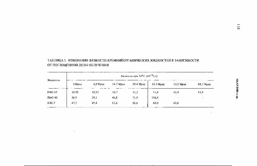
oo
ТАБЛИЦА I. ИЗМЕНЕНИЕ ВЯЗКОСТИ КРЕМНИЙОРГАНИЧЕСКИХ ЖИДКОСТЕЙ В ЗАВИСИМОСТИ ОТ ПОГЛОЩЕННОЙ ДОЗЫ ОБЛУЧЕНИЯ
Ж и д к о с ть
В я з к о с т ь п р и 2 0 ° С (1 0 2С т )
О М рад 4 ,9 М рад 14 ,7 М рад 2 9 4 М рад 3 9 ,3 М рад 5 3 ,8 М рад 6 8 ,7 М рад
П М С -10 10 ,05 1 0 ,5 2 10 ,7 11 ,2 1 1 ,4 1 2 ,4 1 3 ,9
П М С -4 0 36 ,9 39 ,1 4 6 ,8 7 1 ,0 1 3 6 ,4 - -
П Э С -7 4 7 ,7 4 9 ,4 5 1 ,6 5 6 ,6 6 0 ,0 6 3 ,6 -
НА
ХУ
ТИ
Н
и д
р.
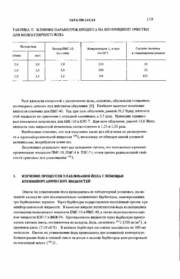
IAEA-SM-24S/65 119
ТАБЛИЦА II. ВЛИЯНИЕ ПАРАМЕТРОВ ПРОЦЕССА НА КОЭФФИЦИЕНТ ОЧИСТКИ ДЛЯ МОЛЕКУЛЯРНОГО ЙОДА
Р а с х о д га заР а с х о д П М С -1 0 ,
(м л /м и н )
К о н ц е н тр а ц и я J 2 в га зе
(м г / м 3)
С р едн и е зн ач ен ия
в стац и о н ар н о м р еж и м ел /м и н см /с
2 ,0 3 ,0 2 ,8 2 1 0 15
1 ,0 1,5 2 ,8 2 0 0 55
1 ,0 1,5 3 ,2 164 153
Рост вязкости жидкостей с увеличением дозы, вероятно, обусловлен сшиванием полимерных цепочек под действием облучения [9]. Наиболее заметное изменение вязкости отмечено для ПМС-40. Так при дозе облучения, равной 39,3 Мрад, вязкость этой жидкости по сравнению с исходной изменилась в 3,7 раза. Примерно одинаковые показатели получились для ПМС-10 и ПЭС-7. При дозе облучения, равной 53,8 Мрад, вязкость этих жидкостей изменилась соответственно в 1,23 и 1,33 раза.
Необходимо отметить, что для получения таких доз облучения от растворенного в кремнийорганической жидкости 129J , поскольку он обладает малой удельной активностью, потребуются сотни лет.
Полученные результаты дают все основания считать, что испытанные кремний- органические жидкости ПМС-10, ПМС-4 и ПЭС-7 с точки зрения радиационной стой-
129 ткости пригодны для улавливания J.
3. ИЗУЧЕНИЕ ПРОЦЕССОВ УЛАВЛИВАНИЯ ЙОДА С ПОМОЩЬЮКРЕМНИЙОРГАНИЧЕСКИХ ЖИДКОСТЕЙ
Опыты по улавливанию йода проводились на лабораторной установке, вклю чавшей каскад из трех последовательно соединенных барботеров, имитировавших три барботажные тарелки. Через барботеры осуществлялся постоянный проток кремнийорганической жидкости. В качестве жидких поглотителей йода испытывались полиметилсилоксановые жидкости ПМС-10 и ПМС-40, а также полиэтилсилоксано- вые жидкости ПЭС-7 и ВКЖ-94. Противотоком жидкости через барботеры пропускалась газовая смесь, составленная из воздуха, йода, меченного 131J (200 м г/м 3) , и двуокиси азота (7-10 об %) . В каждом барботере постоянно находилось по 100 мл жидкости. Опыты по улавливанию йода проводились при комнатной температуре. Концентрацию йода в газовой смеси на входе и выходе барботеров контролировали по изотопной метке ( 1Э1 J) .
1 2 0 НАХУТИН и др.
Как показали опыты, коэффициенты очистки (Коч) газа от йода зависят от ф акторов, определяющих условия массообмена. К оч растет с уменьшением скорости газового потока и с увеличением скорости потока жидкости (табл. II) . Аналогичные зависимости наблюдались в опытах с ПМС-40, ПЭС-7 и ВКЖ-94. Вероятно, превышение скорости газового потока в 300-500 раз по отношению к скорости потока жидкости можно считать приемлемым для промышленных абсорбционных аппаратов, которые могут быть использованы для предварительной очистки газовых выбросов от 129J.
В процессе отдувки окислов азота при комнатной температуре током чистого воздуха со скоростью 2 л/мин (3 см/с) в течение 10 мин из ПМС-10, содержащей N 02 ~ 50 мг/мл и йода 0,1-0,12 мг/мл, в газовую фазу выделялось также от 14 до 20 % йода, а содержание остававшейся в ПМС-10 двуокиси азота было меньше 1 мг/мл.
С целью регенерации жидкого поглотителя, извлечение йода из ПМС-10 проводилось двумя способами: путем отдувки йода воздухом при температуре 90°С и путем обработки жидкости ПМС-10, содержащей йод, 2-10 %-ным раствором едкого натра. Как в том, так и в другом случаях имело место практически полное удаление йода из кремнийорганической жидкости. Остаточная концентрация йода в жидкости была на уровне предела чувствительности радиометрической аппаратуры.
4. ПРИНЦИПИАЛЬНАЯ СХЕМА ПРЕДВАРИТЕЛЬНОЙ ОЧИСТКИ ГАЗА ОТ ЙОДАС ПОМОЩЬЮ КРЕМНИЙОРГАНИЧЕСКОЙ ЖИДКОСТИ
Очистка газовых выбросов от йода с помощью кремнийорганической жидкости (абсорбент) включает в себя следующие процессы (рис. 1) :
1 ) абсорбцию йода из газа и концентрирование его в кремнийорганической жидкости;
2) отдувку растворенных в кремнийорганике окислов азота;3) регенерацию абсорбента путем извлечения излего йода в раствор щелочи.Газовые выбросы, очищенные от аэрозолей, приводятся в контакт с кремний
органической жидкостью (абсорбентом) в абсорбционной колонне. При этом происходит концентрирование йода в кремнийорганике и очистка газовых выбросов от йода. Из колонны жидкость с растворенными в ней йодом и окислами азота поступает в аппарат для отдувки окислов азота. Так как в процессе отдувки окислов азота из жидкости в газовую фазу будет выделяться небольшая часть йода, отдуваемый поток газа направляется на вход абсорбционной колонны. Вследствие этого в стационарном режиме между аппаратом для отдувки окислов азота и абсорбционной ко лонной (несколько первых тарелок) будет циркулировать некоторое постоянное количество йода и окислов азота. Освобожденная от N 02 кремнийорганическая жидкость затем поступает в аппарат, в котором осуществляется извлечение йода и регенерация абсорбента. Регенерацию абсорбента можно производить посредством отдувки йода азотом при повышенной температуре в раствор щелочи, либо путем ре-

IAEA-SM-245/65 121
аб со р б е н т
Рис. I . П ринципиальная схема предварительной очистки га зо вы х вы б росов от 129 J .
экстракции йода раствором щелочи. Регенерированный абсорбент (кремнийоргани- ческая жидкость) возвращается в абсорбционную колонну, а отработанный раствор щелочи, содержащий 129J, направляется на переработку для последующего захоронения.
ЛИТЕРАТУРА
[1] Removal, Storage and Disposal o f Gaseous Radionuclides from A irborne Effluents, IAEA-209, IAEA,
Vienna (1978).[2] NAKHUTIN, I.E., e t al., “ Removal o f radioactive iodine from gases” , 4 th Int. Conf. Peaceful Uses At.
Energy (Proc. Conf. Geneva, 1971) 11, IAEA (1972) 399.
[3] YARBO, O.O., G ROEUIER, W.S., STEPHENSON, M.I., C O N F -760806-6 , 1976.
[4] BROOTHAERTS, I., GOOSSENS, W., et al., BLG -481/73, Brussel, SCK/CEN, 1974.[5] “ Airborne Waste Recovery and Im m obilization” , ERD A -76/43, 2 (May 1976).
[6] GRAY, I.H., e t al., Trans. Am. Nucl. Soc. 15 1 (1972).[7] MIKNEL, P., e t al., Trans. Am. Nucl. Soc. 20 1 (1 975).
[8] COLLARD, G., e t al., Trans. Am. Nucl. Soc: 20 1 (1 9 7 5 ).
[9] Ч А Р Л ЗБ И , А ., Я дерны е И злучения и П олим еры , ИИЛ, М ., 1962.
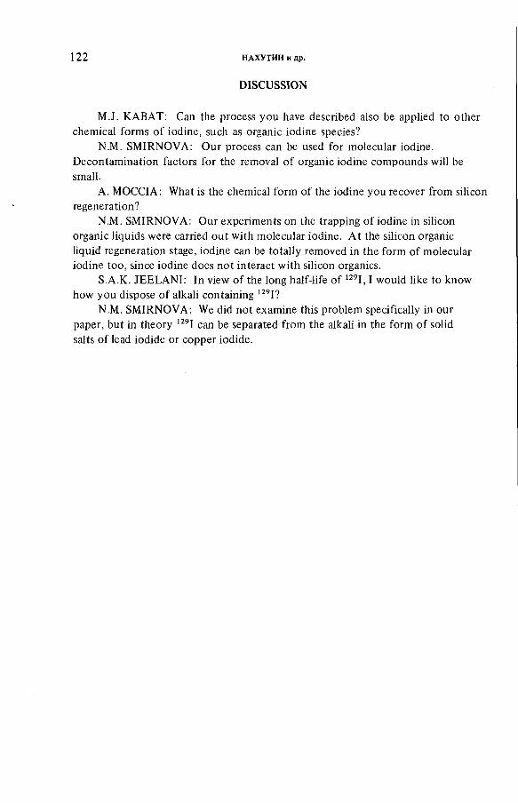
1 2 2 НАХУТИН и др.
DISCUSSION
M.J. КАВАТ: Can the process you have described also be applied to other
chemical forms of iodine, such as organic iodine species?
N.M. S M I R N O V A : Our process can be used for molecular iodine.
Decontamination factors for the removal of organic iodine compounds will be
small.
A. MO C C I A : What is the chemical form of the iodine you recover from silicon
regeneration?
N.M. S M I R N O V A : Our experiments on the trapping of iodine in silicon
organic liquids were carried out with molecular iodine. At the silicon organic
liquid regeneration stage, iodine can be totally removed in the form of molecular
iodine too, since iodine does not interact with silicon organics.
S.A.K. JEELANI: In view of the long half-life of 129I, I would like to know
how you dispose of alkali containing 129I?
N.M. S M I R N O V A : W e did not examine this problem specifically in our
paper, but in theory 129I can be separated from the alkali in the form of solid
salts of lead iodide or copper iodide.

IAEA-SM-245/30
RADIOIODINE IN GASEOUS EFFLUENTS FROM NUCLEAR POWER PLANTS
H. TILL
Electric Power Research Institute,
Palo Alto, California,
United States of America
Abstract
RADIOIODINE IN GASEOUS EFFLUENTS FROM NUCLEAR POWER PLANTS.Understanding more about the appearance and behaviour of iodine-131 in nuclear
power plants is essential for developing the capability of effectively controlling it and accurately determining its potential dose impact. Based on the above concerns, a multi-faceted programme studying the emanation and transport of radioiodine both in-plant and in the environment has been sponsored by the Electric Power Research Institute (EPRI). Objectives addressed specific areas where information is needed such as: identifying important in-plant sources, determining annual average releases, establishing the chemical forms of the iodine and determining their persistence in the environment, and determining the long-term efficiency of charcoal filters, surface interaction, spiking during estimating typical releases from plants currently operating and for experience in making similar evaluations of future plants. These studies have provided the following information concerning iodine-131 : (i) Releases during routine operations from unplanned pathways are relatively small, (ii) The majority of in-plant sources are locally treatable, (iii) This study found the magnitude of power and pressure transient induced iodine spikes to be roughly a factor of ten. (iv) Charcoal adsorbers remain efficient over a relatively long period of time for elemental and inorganic forms of iodine but may not necessarily remain so for organic forms, (v) Surfaces can effect iodine releases significantly, (vi) In the environment iodine tends to convert to organic forms.
1. INTRODUCTION
Knowledge of the appearance and behavior of iodine-131 in nuclear power plants is essential for developing the capability of effectively managing it. One of the principal objectives of doing so is to maintain the health and safety of the public. Iodine-131 has the potential of producing significant radiation exposure to the public. There are many factors that have an effect on how much escapes operating nuclear power plants, and what its exposure potential is.This article will address some of those factors.
Based on the above concerns, a multi-faceted program characterizing the emanation and transport of radioiodine both in-plant and in the environment has been sponsored by the Electric Power Research Institute (EPRI). Measurements at
1 2 3
124 TILL
operating plants and data analysis were performed by Nuclear Environmental Services, a division of Science Applications, Inc. Objectives addressed specific areas where information is needed, such as: identifying important in-plant sources,determining the annual average releases, establishing the prevalent chemical forms which the iodine exists as, and studying the persistence of the chemical forms in the environs surrounding the plant subsequent of release. Other projects supporting the above goals that were conducted involved: determining the long-term efficiency of charcoal filters, surface interactions, coolant spiking during power and pressure transients, and water-air partitioning. The data were modeled for estimating typical releases from plants currently operating, and for experience in making similar evaluations for future plants.
Since it is volatile, radioiodine in gaseous effluents is directly related to its concentration in the reactor coolant. The radioiodine in the coolant escapes the plant confines by two types of releases, the planned and the unplanned. The planned pathways have been effectively treated to minimize their emissions by backfitting and design changes. Planned pathways are now treated by augmented gas treatment systems, and auxiliary steam. The residual problem of radioiodine emission is now with the unplanned pathways, which are principally releases occurring from chronic and acute leakage of primary coolant from valves and pumps.
2. ANNUAL AVERAGE RELEASES
Radioactive iodine in gaseous effluents is directly related to its concentration in the reactor coolant water because of its volatile nature. It enters the coolant as a result of microscopic defects in the fuel cladding and from trace quantities in "tramp" uranium on the outer cladding surfaces. Most of the iodine is removed by passing the coolant through cleanup systems.
There are two types of releases: the unplanned and thosethat, although undesirable, are to be expected in present plants. The latter sources from Boiling Water Reactors (BWR) are:
• Off-gases from the condensing steam in the turbine condenser. This gaseous waste is treated principally by a delay technique which permits radioactive decay. New plants will have augmented waste gas treatment systems that will virtually eliminate this source; operating plants are being back fitted to incorporate these systems.
IAEA-SM-24S/30 125
• In some older plants, steam extracted from the main steam line to the turbine is used for the turbine gland sealing system. Fission and activation gases that are not condensed are held up for a time to permit decay of the shorter-lived products, then discharged. In newer plants, auxiliary steam that does not contain radioactive materials is used.
• To maintain the vacuum on the main condenser during plant shutdown (and in some cases during startup), a mechanical vacuum pump is used, the exhaust from which is usually not treated. This usually becomes the principal source of radioactive discharge during shutdown.
In Pressurized Water Reactors (PWR) radioactive gases removed from the primary coolant are normally collected in pressurized storage tanks to allow for decay of radioactivity prior to recycle or release to the environment. Gases that collect in the containment building are periodically purged through air treatment filters to the atmosphere.
The unplanned radioactive iodine that appears in the building ventilation usually comes from leakage of reactor coolant water from valves and pumps. In some cases, these leaks can be reduced by special design features, use of auxiliary steam, or increased maintenance. As the leaked water evaporates, the contained radioactive iodine becomes airborne. Its quantity usually depends on the location of the leak.
The majority of iodine released to the environment from unplanned pathways emanates from a few major locations. The major locations for BWR's were found to be: valves on steamlines, reactor coolant cleanup pumps, coolant sampling extraction lines, gland seal exhaust, and liquid radwaste handling.'1 ' During plant outages the mechanical vacuum pump exhaust could be a major source. For PWR’s the major sources are charging pumps, sump pumps, and vents on tanks such as decay tanks, demineralizer tanks, chemical drain tanks, blowdown condenser surge tanks, and volume control tanks. The containment purge can be a significant source,jf tbe charcoal filters are not of sufficient efficiency.^) Typicalannual average release rates, derived from measurements at six plants, including the chemical forms, are given in Table I.
In-plant emanations were directly related to the reactor coolant concentration, the coolant to steam iodine carryover, and the magnitude of the leak. A model to provide a more realistic prediction approach for release rates was developed by normalizing the release to the reactor coolant. Normalizing release rates combines the reactor coolant water leakage rate into the building, and the partitioning of the radioiodine between the water phase of the leakage and the gas
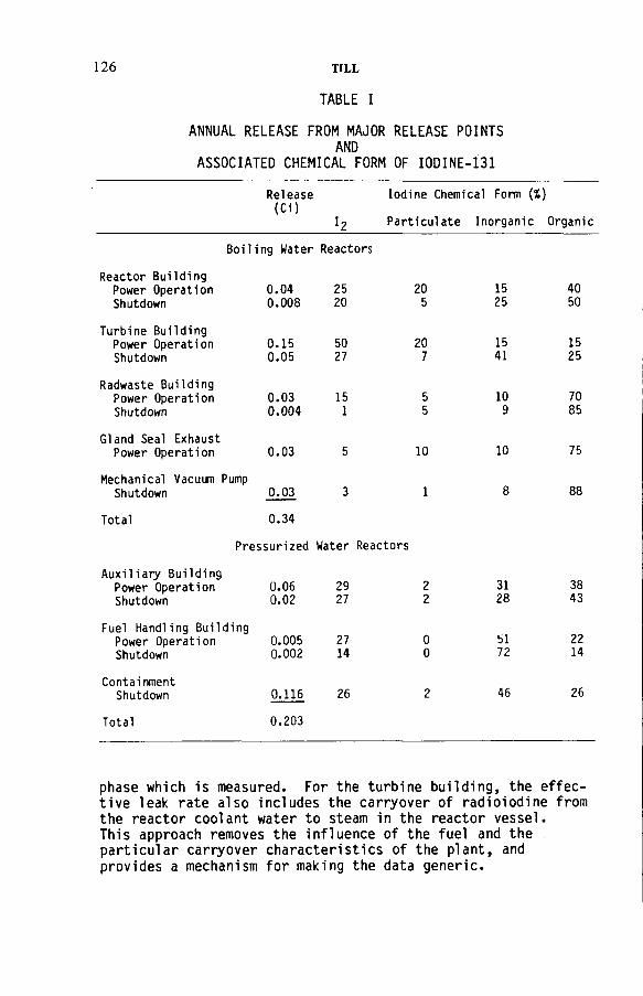
126 TILL
ANNUAL RELEASE FROM MAJOR RELEASE POINTS AND
ASSOCIATED CHEMICAL FORM OF IODINE-131
TABLE I
Release(Ci)
Iodine Chemical Form (%)
Particulate Inorganic Organic
Boiling Water Reactors
Reactor Building Power Operation 0.04 25 20Shutdown 0.008 20 5
Turbine BuildingPower Operation 0.15 50 20Shutdown 0.05 27 7
Radwaste Building Power Operation 0.03 15 5Shutdown 0.004 1 5
Gland Seal Exhaust Power Opération 0.03 5 10
Mechanical Vacuum PumpShutdown 0.03 3 1
Total 0.34
Pressurized Water Reactors
Auxiliary Building Power Operation 0.06 29Shutdown 0.02 27
Fuel Handling Building Power Operation 0.005 27Shutdown 0.002 14
ContainmentShutdown 0.116 26
1525
1541
109
10
8
3128
bl72
46
4050
1525
7085
75
88
3843
2214
26
Total 0.203
phase which is measured. For the turbine building, the effective leak rate also includes the carryover of radioiodine from the reactor coolant water to steam in the reactor vessel. This approach removes the influence of the fuel and the particular carryover characteristics of the plant, and provides a mechanism for making the data generic.

IAEA-SM-24S/30 127
The results indicate a realistically conservative release rate based on current operating plants, and a shift from the more reactive chemical forms of iodine-131 such as the I2 form, to the less active inorganic and organic forms, such as HIO CH3 I, respectively, as the iodine transports through the plant system.
3. PLANT TRANSIENT EFFECTS
The rapid increase in the coolant concentration of fission products has long been noted following power and pressure transients. It has been hypothesized that the mechanism causing this is the flushing out of water soluble radionuclides through minute defects in the fuel cladding. During decreasing power transients, steam bubbles in the defects collapse allowing water to come in contact with the inner surfaces of the cladding and the fuel. Due to the depressurization, this water is forced out.
The available data on iodine spiking indicates that the magnitude and timing varies widely among reactors; however, the spikes experienced by a particular plant during a given fuel cycle exhibit very similar characteristics. Based on this, it is deduced that the size, type, and location of the defect in the fuel cladding is an important factor in defining the magnitude and timing of the fission product spike.
Iodine-131 spikes usually occur about one hour after the transient in a PWR and slightly longer for BWR's. Its decrease is a combined function of its radiological half-life and the purification cleanup rate. Less significant plant transients, such as small power adjustments, repositioning of control rods, and pressure changes, also can cause spikes, but of smaller magnitude. The time between transients also appears to play a role in the magnitude of the spike. Iodine spikes of smaller magnitude also occur one to two hours after start-up.
Extensive measurements, of fission products in the primary coolant, were.performed at two operating PWR's following s h u t d o w n . T h e release rate of iodine-131, in both cases, reached a maximum of approximately one hour after the shutdown. This can be seen in Figure 1. In one of the plants, the pressure was reduced approximately eight hours after the power was reduced, and it produced a second iodine spike. In both cases the shutdowns were initiated from power levels of greater than 90% of rated power. Also, in both cases, the maximum spiking concentrations were approximately a factor of ten greater than the steady-state coolant concentration levels that existed prior to the shutdown.

128 TILL
Time (hours)
FIG.I. Primary coolant iodine-131 concentrations as a function o f time after shutdown for two different power plants.
Spiking occurrences become relevant when considering releases of iodine-131 during accidents. If there is a breach of containment accident, such as a steam generator tube rupture, the release of activity to the secondary will be aggravated by the increased radioactive material concentration levels.
4. RADIOIODINE AIR/WATER PARTITIONING
Iodine evolution from water to air depends on water parameters such as temperature, pH, concentrations, and the contaminants it may contain. This occurs from fuel pools, suppression pools, and from pools of stored water such as sumps and that which is contained in various types of tanks.In order to control this transfer, the variables affecting it must be understood. The volatilization of iodine from aqueous solutions is not characterized by a simple exchange. It is a chemically reactive element in water and may exist in many forms depending on the conditions.
Partition coefficients are used to predict the concentration of iodine in the air phase relative to given concentrations in the aqueous phase. Iodine can occur in many chemical states, some volatile, such as 1£, HOI, CH3 I, and HI, and some nonvolatile, such as I", I3 , 10" , I03".

Parti
tion
Coe
ffici
ent
(air/
wat
er)
IAEA-SM-245/ 30 1 2 9
Iodine Concentration (mg(¿)
FIG.2. Partition coefficient for total iodine at 25°С.
The partition coefficients normally stated are for steady-state equilibrium conditions. But this ideal condition would be highly unusual under reactor operating conditions. Therefore, rather than measure partition coefficients in the conventional way, they were inferred using mass transfer reí ationshi ps.W
The results of the partition coefficient (air/water) as a function of concentration are given in Figure 2, and as a function of temperature with pH in Table II.(5
In order to reduce iodine-131 airborne activity, the results indicate that the following factors are significant:
1. Water pools at high temperature may volatilize iodine more readily than cooler pools.
2. Water at high pH will tend to volatilize less iodine than water with lower pH. This is due principally to the formation of more iodine radicals such as iodate.
3. The partition coefficient is independent of concentrations for the dilute solutions that normally exist in power plants.
4. The air space above sumps and pools should be kept to a minimum, and variations in the liquid level minimized to avoid exposing contaminated surfaces.
5. CHARCOAL FILTER EFFICIENCY
The establishment of criteria to keep radiological exposure to the public negligible from radioactive materials has made airborne effluent control systems an important part of nuclear power plants. Filtering effluent gases through charcoal adsorbers is one of the major methods of reducing radioiodine discharges. To ensure public safety and reduce
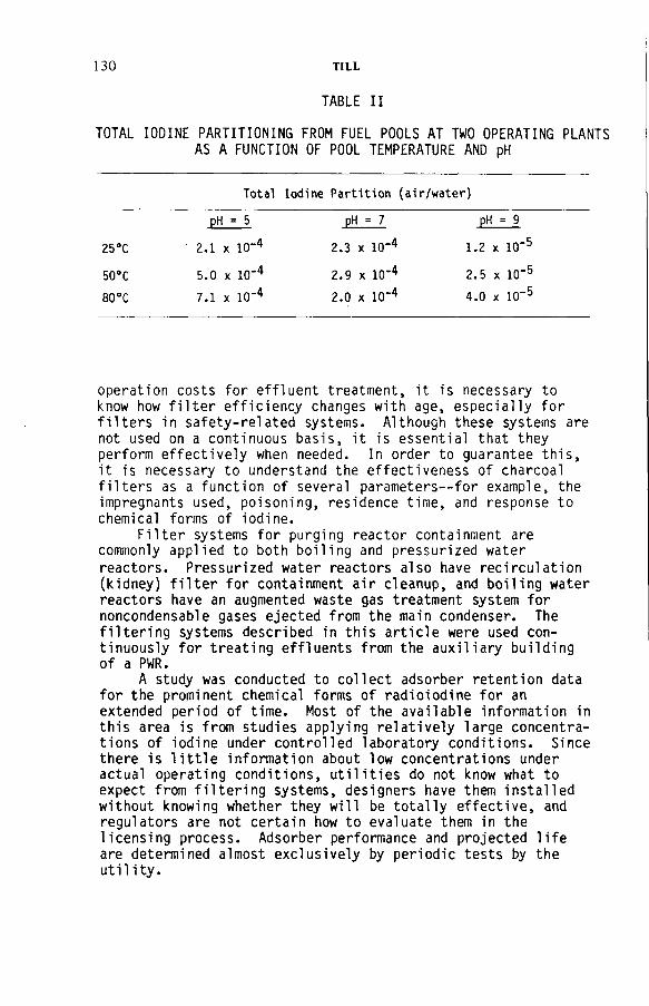
130 TILL
TOTAL IODINE PARTITIONING FROM FUEL POOLS AT TWO OPERATING PLANTS AS A FUNCTION OF POOL TEMPERATURE AND pH
TABLE II
Total Iodine Partition (ai r/water)
£ H j = 5 -EÜJ= 7 pH == 9
25°C 2.1 x 10⁻⁴ 2.3 x 10⁻⁴ 1.2 x 10’5
50°C 5.0 x io-4 2.9 x 10⁻⁴ 2.5 x 10"5
80 °C 7.1 x 10⁻⁴ 2.0 x 10⁻⁴ 4.0 x 10"5
operation costs for effluent treatment, it is necessary to know how filter efficiency changes with age, especially for filters in safety-related systems. Although these systems are not used on a continuous basis, it is essential that they perform effectively when needed. In order to guarantee this, it is necessary to understand the effectiveness of charcoal filters as a function of several parameters—for example, the imprégnants used, poisoning, residence time, and response to chemical forms of iodine.
Filter systems for purging reactor containment are commonly applied to both boiling and pressurized water
reactors. Pressurized water reactors also have recirculation (kidney) filter for containment air cleanup, and boiling water reactors have an augmented waste gas treatment system for noncondensable gases ejected from the main condenser. The filtering systems described in this article were used continuously for treating effluents from the auxiliary building of a PWR.
A study was conducted to collect adsorber retention data for the prominent chemical forms of radioiodine for an extended period of time. Most of the available information in this area is from studies applying relatively large concentrations of iodine under controlled laboratory conditions. Since there is little information about low concentrations under actual operating conditions, utilities do not know what to expect from filtering systems, designers have them installed without knowing whether they will be totally effective, and regulators are not certain how to evaluate them in the licensing process. Adsorber performance and projected life are determined almost exclusively by periodic tests by the utility.
IAEA-SM-245/30 131
Continuous measurements of the efficiency of two charcoal filters for adsorbing iodine-131 in.ventilation exhaust air were made at a nuclear power plant.' ' Measurements were made for 416 days. During the last 280 days efficiencies for the chemical forms of iodine-131 were measured. Measurements for one charcoal installation were started at the time new charcoal was installed. The other filter contained charcoal which had been exposed for two years prior to the initiation of the measurements. The results of these measurements for the decontamination factors (DF) are shown in Tables III and IV.
The new filter, with the 4700 ft3/min flow rate, experienced no appreciable loss efficiency for the first year of use for all of the major chemical forms of iodine. The old filter, with the 25 000 ft3/min flow rate, showed a loss of efficiency for the organic forms, as indicated by measurements in the second to third years of service life. This is shown in Figure 3. From measurements that did indicate a reliable DF, the efficiency of the older filter for the elemental and inorganic forms of iodine remained high for the three-year period.. In most cases, minimum values were indicated because the inlet concentrations were too low and none was detected downstream of the filters. The new filter, which had no high efficiency particulate (HEPA) adsorber preceding it, has a low DF for the particulate forms of iodine. The older filter did have a HEPA preceding it, and its DF for particulate iodine remained reasonably high.
6 . SURFACE EFFECTS
Changes occurring during the transit of iodine-131 in air ventilation systems have long been noted. Two phenomena occur: 1 ) the ratios of the quantities of the isotopes ofradioiodine (1-131, 1-132, 1-133, 1-134, 1-135) show a reduction in the ratio of the shorter half-lives to the longer ones compared to similar ratios at the sources, and 2 ) there is a shift in the concentrations of the chemical forms from the more.reactive elemental form to the less reactive organic f o r m s . S i n c e the only explanation for such occurrences involves the deposition and resuspension from surfaces along the flow path, a study was conducted to verify these findings, and to determine if it could be applied advantageously to affect releases of iodine. Interactions were studied as a function of: surface material (concrete, painted coatings,aluminum, and galvanized steel), chemical form and concentration of the iodine, relative humidity effects, ventilation flow rates and turbulence, and the surface-to-volume ratio.An experiment was conducted in which elemental iodine interacted with surface material and the chemical form of the

1 3 2 TILL
TABLE III
DECONTAMINATION FACTORS FOR IODINE-131 LARGE FILTER (25 000 ft3/min)(9)
Time (a) I2 (CdI2 ) HOI(IPH) Organic (Char.) Total
2.22 > 4.6 > 13 3.1 27.
2.58 >85 >364 2.0 6.7
2.61 (1) (1) 3.8 5.1
2.66 1300 730 1.9 4.1
2.71 >59 > 89 2.4 7.0
2.77 >14 > 21 2.0 5.0
2.81 >10 > 84 1.7 2.9
2.89 > 7 > 50 2.3 4.7
2.93 9.5 > 88 2.4 4.8
2.99 > 3.1 > 50 1.9 6.5
3.06 (2) (2) 1.9 8.4
Note: The quantity of iodine- 131 measured at the outlet of the smallfilter was greater than that measured for the total quantity.
(1) Species were not measured at the outlet of the small filter,only the total 1311. jhe quantity was small in relation to that measured in the combined outlet from both filters. The 131l in the combined outlet was all on the charcoal filter (i.e. organic).
(2) Probe for sample at outlet from the small filter was brokensometime during the sampling period. The DF for organic 131I(charcoal) is estimated using input to small filter and measured species in outlet.
resuspended iodine was determined. The results, as shown in Table V, indicated that the material that had the largest effect was concrete.(10)
The effect of humidity was to increase the deposition velocity and increase the conversion to the organic form. It appeared to have no effect on the resuspension rate. The surfaces that had the largest effect on the iodine were concrete and those that were painted.
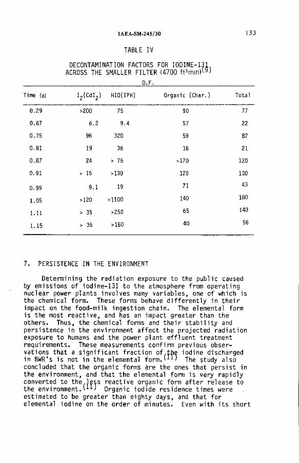
IAEA-SM-24S/30 133
TABLE IV
DECONTAMINATION FACTORS FOR IODINE-131 ACROSS THE SMALLER FILTER (4700 ft3 min)(9 )
D.F.
Time (a) I2 (CdI2 ) HIO(IPH) Organic (Char.) Total
0.29 >200 75 90 77
0.67 6.2 9.4 57 22
0.75 96 320 59 82
0.81 19 36 16 21
0.87 24 > 75 >170 120
0.91 > 15 >130 120 130
0.99 9.1 19 71 43
1.05 >120 >1100 140
О00
pH
1.11 > 35 >250 65 140
1.15 > 35 >160 40 56
7. PERSISTENCE IN THE ENVIRONMENT
Determining the radiation exposure to the public caused by emissions of iodine-131 to the atmosphere from operating nuclear power plants involves many variables, one of which is the chemical form. These forms behave differently in their impact on the food-milk ingestion chain. The elemental form is the most reactive, and has an impact greater than the others. Thus, the chemical forms and their stability and persistence in the environment affect the projected radiation exposure to humans and the power plant effluent treatment requirements. These measurements confirm previous observations that a significant fraction of.the iodine discharged in BWR1s is not in the elemental f o r m . T h e study also concluded that the organic forms are the ones that persist in the environment, and that the elemental form is very rapidly converted to the.less reactive organic form after release to the environment.'11' Organic iodide residence times were estimated to be greater than eighty days, and that for elemental iodine on the order of minutes. Even with its short
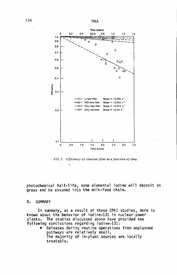
134 T IL L
Time (years)
Time (years)
FIG.3. E fficiency o f charcoal filter as a function o f tim e .
photochemical half-life, some elemental iodine will deposit grass and be assumed into the milk-food chain.
8. SUMMARY
In summary, as a result of these EPRI studies, more is known about the behavior of iodine-131 in nuclear power plants. The studies discussed above have provided the following conclusions regarding iodine-131:
• Releases during routine operations from unplanned pathways are relatively small.The majority of in-plant sources are locally treatable.

TABLE V
IA E A -S M -2 4 5 /3 0 135
ELEMENTAL IODINE SURFACE INTERACTIONS
Deposition Velocity, Vd (cms_1)
Resuspension Rate(s->)
Resuspended : Chemical Forms
(%)
LowHumidity
HighHumidity
l2 HOI Organic
A1uminum 0.075 0.43 1.6 X 10'5 85.1 8.1 6.1
Galvanized Steel 0 .1 1 4.7 x 10⁻⁶ 82.8 10.1 7.1
Concrete 0.36 0.51 1.9 x 10⁻⁶ 44.2 16.4 39.4
Paint (mil. spec.)a 0.029 0.3 <1.7 x 10⁻⁶ 85.8 8.6 5.5
Paint (patent)b 0.063 0.78 4.8 x 10'7 88.6 3.9 7.5
“Military Specification Paint (Mil-P-24441) is a polyamide epoxy.
bPatent paint (#3 730 833) is 25% genamid, 25% epon, 50% titanium dioxide pigment.
® Releases during accidents will temporarily be at increased levels due to power and pressure transient effects on the fuel. These studies indicate the increased levels to be roughly a factor of 10.
• Many factors can affect the air/water partitioning of iodine, such as the water temperature, pH, and the concentration of iodine. The partition coefficent which is in common use of 10“4 (air/water), appears to be a reasonable number.
• Charcoal adsorbers appear to remain sufficiently efficient for the elemental and inorganic forms of iodine for periods up to three years. Such filters can become inefficient with time for the organic forms.
® Building surfaces and humidity have an effect on the chemical form of the iodine. Both could have a significant effect in converting the reactive elemental form into nonreactive organic forms.
® After release to the environment reactive elemental iodine will tend to convert to nonreactive organic forms, but the conversion rate is such that some elemental iodine will deposit on pasture and agricultural land in the vicinity of nuclear power pi ants.

136 T IL L
REFERENCES
[1] PELLETIER, C., BAREFOOT, E., CLINE, J., HEMPHILL, R . , EMEL, W., and VOILLEQUE, P., "Sources of Radioiodine at Boiling Water Reactors", EPRI NP-495, February 1978.
[2] PELLETIER, C., CLINE, J., BAREFOOT, E., HEMPHILL, E., VOILLEQUE, P., EMEL, W., "Sources of Radioiodine at Pressurized Water Reactors", EPRI NP-939, November 1978.
[3] DYER, N.C., J.H. KELLER, et al., "In-Plant Source Term Measurements at Fort Calhoun Station Unit 1", NUREG/CR-0140, July 1978.
[4] DYER, N.C., J.H. KELLER, et al., "In-Plant Source Term Measurements at Zion Station", NUREG/CR-0715, February 1979.
[5] PELLETIER, C., HEMPHILL, R.T., "Nuclear Power Plant Related Iodine Partition Coefficients", EPRI NP-1271, January 1980.
[6] YUILL, W.A., et al., "Release of Radioiodine from Open Pools", UC-80, IN-1449, December 1970.
[7] LIN, C.C., RODGERS, D.N., DUTINA, D., "Iodine Partition Between Aqueous Solution and Gas Phase", NEDE 12558, January 1975.
[8] DIFFEY, H.R., et al., "Iodine Cleanup with A Steam Suppression System", AERE-R-4482, 1965.
[9] PELLETIER, C., BAREFOOT, E., HEMPHILL, R., FREDERICKSON J., "Long-Term Performance of Charcoal Absorbers for Removing Radioiodine in Ventilation Exhaust Air", EPRI NP-534, July 1978.
[10] HEMPHILL, R., PELLETIER, C., "Surface Effects in the Transport of Airborne Radioiodine at Light Water Nuclear Power Plants", EPRI NP-876, September 1978.
[11] VOILLEQUE, P., "Persistence of the Chemical Forms of Iodine in the Environment". EPRI NP-1269, January 1980.
DISCUSSION
R.D. COLLINS: When you say that elemental and reactive forms convert to less reactive forms rather than the reverse and that organically bound iodine makes no contribution to critical milk pathway dose, do you really mean that at distances where reaction iodine is not found there is no important pick-up on grass, or only that the rate o f reconversion o f m ethyl iodide to reactive forms is too low to give measurable concentrations as a result o f the rapid deposition o f reactive forms? In the latter case the escape o f organic iodides may still have an important effect on milk.

IA E A -S M -2 4 S /3 0 137
H. TILL: The data does not exclude the possibility that som e elemental iodine will adhere to the grass in the vicinity o f the power plant, but it does indicate that the preferential direction for the conversion o f iodine in the atmosphere because o f photodissociation is toward the organic forms and not the elem ental form. With the organic forms having the potential to travel greater distance, you are correct in saying that some will be converted to the elemental form and that the result will possibly be collection in milk. However, given the concentrations involved, I question whether this will be o f much importance.
F. CEJNAR: I would like to ask tw o questions. The first concerns the data in Table I which indicates that there is a difference between the quantities o f iodine chemical forms at the release points during reactor operation and after shutdown. Can you com m ent on this difference?
Secondly, what type o f procedure do you use for the determination o f chemical forms o f iodine?
H. TILL: The dominant emission points change as a function o f power operation and plant shutdown. A lso the iodine has time to interact chemically, and it becom es more organic.
Regarding your second question, a sequentially selective sampler used in the first filter cartridge, which is cadmium iodide, removes the elem ental iodine.The second cartridge, which is iodophenol, removes the hypoiodous acid. The third filter, which can be either silver zeolite or impregnated charcoal, removes the organic forms. There is a backup charcoal filter to determine whether sampler failure has occurred.
H. DEUBER: I would like to add a few remarks on the two preceding questions. First, w ith reference to Mr. Collins’ question, our experim ents on the behaviour o f airborne radioiodine confirm the tendency o f elem ental iodine to convert to low-reactive forms, i.e. organic iodine.
With regard to Mr. Cejnar’s second question, according to our experience radioiodine species fractionation by means o f samplers is not yet a com pletely reliable process, especially as far as hypoiodous acid is concerned.
As regards determination o f radioiodine sources and species fractionation,I would like to know whether your measurements have resulted in any immediate or foreseeable consequences, and also whether the measurements will be continued.
H. TILL: One concrete result is the use o f normalized release rates for estimating emissions, where the com plication o f fuel performance is removed from the prediction process. This is shown in ANSI Standard N -237. In addition, we now know more about radioiodine behaviour in nuclear power plants than we did previously. We know what the important ventilation sources are, that many are locally treatable and that it would in fact be cost effective to eliminate them in that fashion. From a normal routine operation standpoint, total building filtration would be too costly, since costs rise proportionately to the air flow rate. O f course, from an accident view point, a different perspective should be applied.

138 T IL L
In answer to your second question, the measurements are continuing, but are now being aimed at accident-related fission product behaviour. We are currently studying fission product behaviour resulting from steam generation tube rupture accidents.
H.A.C. McKAY: Is it possible to calculate from your results what proportion o f the 131I formed in the fuel is lost in the reactor effluents? Any necessary corrections for 131I decay should o f course be made. This might give us a useful indication o f the proportion o f 129I that is released at the reactor, a value for which I have never com e across any estimates.
H. TILL: I think this could be done since we in fact measured and followed the reactor coolant iodine concentrations very closely.
F. LUYKX: 131I discharges given in your paper are relatively high in comparison with discharges from European PWR and BWR plants. Reports published periodically by the European Commission show that these plants discharge at least one order o f magnitude less iodine — indeed, many have discharge limits which are lower than the average annual discharges given in your paper.
I would like to ask two questions — first, what is the average power output o f the US plants shown in Table I and, secondly, does the fact that most o f the iodine discharged from the PWRs in Table I comes from the containm ent purge after shutdown mean that this air is not filtered before discharge?
H. TILL: The BWRs were not in the 1000 MW(e) class, and in fact ranged in power levels from 500 to 800 MW(e). O f the PWRs examined, two were in the 1000 MW(e) category and one had a power output o f approximately 600 MW(e).
With regard to your second question, the containm ent purge is filtered in all nuclear power plants in the USA. The annual average release given is derived from measurements made in ducts upstream o f the filter beds.
IA E A -S M -2 4 5 /1 6
IMPROVED PROCEDURES FO R EFFICIEN T IODINE REMOVAL FROM FUEL SOLUTIONS IN REPROCESSING PLANTS
E. HENRICH, R. HÜFNER Institut für Heisse Chemie,Kernforschungszentrum Karlsruhe GmbH,Karlsruhe
A. SAHMGesellschaft zur Wiederaufarbeitung
von Kernbrennstoffen mbH,Karlsruhe,Federal Republic o f Germany
Abstract
IMPROVED PROCEDURES FOR EFFICIENT IODINE REMOVAL FROM FUEL SOLUTIONS IN REPROCESSING PLANTS.
Procedures for an efficient fission iodine removal from reactor fuel solutions into the dissolver off-gas have been investigated on laboratory and pilot-plant scales. The iodine desorption by boiling the fuel solution under reflux with a small amount o f carrier gas leaving the reflux condenser was found to be compatible with the process. Vigorous N0 2 -sparging towards the end and after fuel dissolution, plus addition o f an iodate carrier towards the end of the desorption process, were found necessary to obtain fission iodine concentrations in the fuel solution well below 10" 6 mol/ltr I2. Iodine removal systems with decontamination factors better than 103 are available for the relatively small volumes o f dissolver off-gas. Routine iodine removal from the large volumes of vessel off-gas does not seem necessary if an efficient iodine removal from the fuel solution is supported by process modifications which limit the iodine contamination to the plant area connected to the dissolver off-gas (DOG) system.Organic impurities in the recycled acid should be restricted. For a 40 GW(e) reprocessing plant, using spent LWR fuel cooled for a year or longer, the 129I emission, using the proposed treatment, is expected to be less than 0.2 Ci/а, which would be in accordance with the recommended values.
1. FISSION PRODUCT IODINE IN SPENT FUEL
Most o f the retention technologies for fission product iodine during reprocessing were developed for 131I (half-life 8 days) in short-cooled and low burnup reactor fuel [1 ,2 ] . Today the reprocessing o f high burnup fuel from power reactors, especially o f the LWR-type with longer cooling times, is
139

140 H E N R IC H e t al.
important. About one year after discharge from the reactor the 1311 has decayed and only the long-lived (1 .7 X 107/a) 129I is o f radiological importance. One tonne o f uranium in spent LWR-fuel with a burnup o f 36 GW -d/t then contains about0.3 kg o f fission product iodine with about 85% 129I, corresponding to an activity o f 41 mCi [3].
2. RADIOLOGICAL ASPECTS
Natural iodine contains a fraction between about 10- 9—10~12 o f 129I, depending on the source [4, 8]. An isotopic dilution o f fission product iodine by a factor o f 103 gives about one half o f the maximum permissible thyroid dose o f 90 mrem/a given by the Federal German Strahlenschutzverordnung [5]. Because the large amount o f natural iodine, about 2 X 10⁹ t in the upper layer o f the oceans, is available for isotopic dilution o f the very much smaller amounts o f fission product iodine, 129I is not expected to be a global problem [6]. Calculations o f Koelzer [7] and Schiittelkopf [8] show that even without taking into consideration the iodine concentration in the air, in the vicinity o f a 200 m stack from a 40 GW(e) LWR reprocessing plant the maximum permissible thyroid dose will be met with a retention factor o f about 102. Therefore, efficient iodine retention is necessary for inland reprocessing plants to produce only low fission product iodine concentrations in the air. For plants situated near the sea, sufficient isotopic dilution may be possible even w ithout iodine retention [6 , 8].
The Reactor Safety Comm ission/Radiation Protection Commission (RSK/SSK) for the Federal German ‘Entsorgungszentrum’ recommended that the 129I emission should be limited to 0 .2 Ci/a [9]. This corresponds to a plant retention factor o f about 300 for a 40 GW(e) LWR reprocessing plant. This retention factor has been used as a guideline for our investigations; 0 .2 Ci/а 129I is contained in a fuel solution with a concentration o f about 10-6 m ol/ltr fission product iodine.
3. FISSION PRODUCT IODINE BEHAVIOUR DURING DISSOLUTION
3.1. Iodine in spent fuel
In spent PWR fuel with a typical average linear heat rating o f 200 W/cm the fission product iodine is contained in the pellet and is distributed nearly hom ogeneously. This is expected for stoichiom etric oxide fuel where iodide ions are supposed to be the stable species [10, 11]. Fission product iodine in the gas plenum was found to be below the detection limit o f 10_2% [ 12], and the

Dissolution reactions:
U 0 2 + 4H N 0 3 -*■ U 0 2 (N 0 3 ) 2 + 2 N 0 2 + 2 H 20 (1)
3 U 0 2 + 8 HNO3 3 U 0 2 (N 0 3 ) 2 + 2NO + 4H20 (2)
2 U 0 2 + 6 HNO3 -* 2 U 0 2(N 0 3 ) 2 + NO + N 0 2 + 3H20 (3)
Nitrous acid formation:
NO + N 0 2 + H20 -»■ 2 H N 0 2 (4)
2 N 0 2 + H20 -*■ H N 0 2 + H N 0 3 (5)
Nitrous acid decomposition:
3H N 0 2 -> 2 N 0 + HNO3 + H20 ( 6 )
Iodide oxidation:
2H+ + 2 Г + 2H N 0 2 -» 2NO + I2 + 2H20 (7)
2H+ + 21“ + HNO3 ->-HN02 + I 2 + H 20 ( 8 )
Iodate reduction:
2H+ + 2103 + 5H N 0 2 5H N 0 3 + I2 + H20 (9)
IA E A -S M -2 4 5 /1 6 141
TABLE I. IODINE REACTIONS IN THE FUEL SOLUTION
liberation into the shear off-gas during chopping is expected to be low. At higher fuel temperatures the iodine starts to diffuse radially from the hot axis to the colder parts.
3 .2 . Iodine reactions in the fuel solution (see Table I)
During fuel dissolution in 2—7M nitric acid, the volatile elementary iodine is the most stable species. Both the hot nitric acid and the nitrous acid, which is produced in equilibrium with the nitrogen oxides evolved during the dissolution reaction, cause a rapid oxidation o f iodide to elementary iodine.
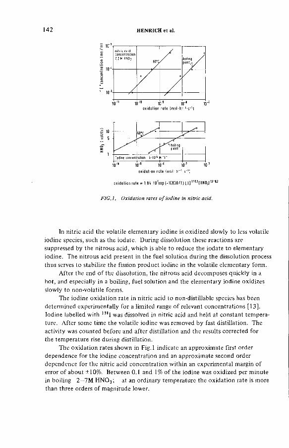
142 H E N R IC H e t a l.
—
boilingpoint
Iodine concentration 5* 1Û*4 M " Г ---------------------- 1---------------------1— -------
o x id a t io n ra te { m o M t r 1-s ‘ 1)
o x id a t io n ro te я U U O ' e x p ( - 1 0 Ш / Т 1 [ I ] 1 ! °-11HHOJ1лгол
F IG .l. Oxidation rates o f iodine in nitric acid.
In nitric acid the volatile elementary iodine is oxidized slowly to less volatile iodine species, such as the iodate. During dissolution these reactions are suppressed by the nitrous acid, which is able to reduce the iodate to elementary iodine. The nitrous acid present in the fuel solution during the dissolution process thus serves to stabilize the fission product iodine in the volatile elementary form.
After the end o f the dissolution, the nitrous acid decom poses quickly in a hot, and especially in a boiling, fuel solution and the elementary iodine oxidizes slowly to non-volatile forms.
The iodine oxidation rate in nitric acid to non-distillable species has been determined experimentally for a limited range o f relevant concentrations [13]. Iodine labelled with 131I was dissolved in nitric acid and held at constant temperature. After some time the volatile iodine was removed by fast distillation. The activity was counted before and after distillation and the results corrected for the temperature rise during distillation.
The oxidation rates shown in F ig.l indicate an approximate first order dependence for the iodine concentration and an approximate second order dependence for the nitric acid concentration within an experimental margin o f error o f about ±10%. Between 0.1 and 1% o f the iodine was oxidized per minute in boiling 2 —7M H N 0 3; at an ordinary temperature the oxidation rate is more than three orders o f magnitude lower.
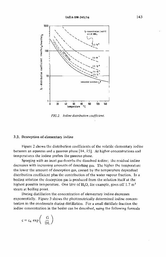
IA E A -S M -2 4 5 /1 6 143
tem perature *C
FIG.2. Iodine distribution coefficient.
3.3. Desorption o f elementary iodine
Figure 2 shows the distribution coefficients o f the volatile elementary iodine between an aqueous and a gaseous phase [14, 15]. At higher concentrations and temperatures the iodine prefers the gaseous phase.
Sparging with an inert gas desorbs the dissolved iodine; the residual iodine decreases with increasing amounts o f desorbing gas. The higher the temperature the lower the amount o f desorption gas, caused by the temperature dependent distribution coefficient plus the contribution o f the water vapour fraction. In a boiling solution the desorption gas is produced from the solution itself at the highest possible temperature. One litre o f H20 , for exam ple, gives o ff 1.7 m 3 steam at boiling point.
During distillation the concentration o f elementary iodine decreases exponentially. Figure 3 shows the photom etrically determined iodine concentration in the condensate during distillation. For a small distillate fraction the iodine concentration in the boiler can be described, using the following formula

144 H E N R IC H e t al.
d is ti Ilote fraction 7 .
FIG.3. Iodine concentration
I2 concen tration in solution during desorption
XС : Co e' 0 L
simplified for stepwise calculation
c , Co iod ine concentration
V, L volume of vapour and (¡quid
D(c,T) iodine d is trib u tio n coeffic ient aqueous /gaseous
T desorption tem perature
distillation in the distillate.
where c, c0 is the I2-concentration, G, L is the volume o f steam and liquid, and D is the Ij-distribution coefficient (see Fig.2). Since the distribution coefficient is concentration dependent and the liquid volume decreases during distillation, the simple formula has to be applied stepwise for làrger distillation rates.
The diagram in Fig.4 shows how much fuel solution has to be distilled to halve the elementary iodine concentration. The full line was calculated from the distribution coefficients, the points are experimental values from pilot-plant scale experiments. The comparison shows that a precalculation should be possible with reasonable accuracy. Moreover, it can be deduced that the fission product iodine removal from a fuel solution with 10-3— 10-4 m ol/ltr I2 to about 10~6 m ol/ltr I2 is possible with a distillate fraction o f less than 10%, as long as the iodine is in the elementary form.
The volatile elementary iodine is carried away by all gases that leave the fuel solution. Typically, it can be estimated that about 100 m 3 o f NOx escapes from 3 m 3 o f fuel solution during dissolution .1 Iodine enters the fuel solution in proportion to the dissolution rate and a large part is carried away with the nitrous fumes. The higher the dissolution temperature the more the water vapour expands the NOx volum e, and the iodine desorption is accelerated correspondingly.
Air sparging to produce stirring effects enlarges the volume o f desorption gas appreciably, but the largest effect is produced by boiling.
Towards and after the end o f dissolution the nitrous acid concentration drops drastically in the boiling fuel solution. The elementary iodine still present is either desorbed or oxidized. If not enough nitrous acid is available, a high boil- up rate shortens the residence time available for oxidation.
1 All gaseous volumes are reduced to STP.

IA E A -S M -2 4 5 /1 6 145
I¡ - concen tratio n (m o l/ltr)
FIG .4. Distillate fraction removing 50% I i (distillation o f a typical fu e l solution).
The am ount o f fission product iodine present in the fuel solution after dissolution does not only depend on the details o f the dissolution procedure but also on the amount o f iodine-containing condensates and scrub acids from the dissolver off-gas system recycled to the dissolver.
The fumeless dissolution process in Windscale-2 with a small amount o f dissolver off-gas (DOG) retains about 95% o f the fission product iodine ( 131I) in the fuel solution; in the WAK (reprocessing plant, Karlsruhe), more than 99% o f the fission product iodine ( 129I) is desorbed from the fuel solution into the DOG.
3.4. Behaviour o f residual iodine in the fuel solution
The residual fission product iodine species remaining in the fuel solution are distributed in the subsequent extraction process operations by solubility and vapour pressure, and they contaminate a number o f different aqueous, organic and gaseous process streams [16]. Therefore, iodine retention, especially for the longer-lived 129I, becom es necessary for the large volumes o f vessel off-gas in reprocessing and waste treatment plants where the removal is complicated by the large dilution and the presence o f volatile organic iodine com ponents formed in the extraction part o f the plant. Therefore, routine iodine removal from the vessel off-gas must be planned for every oxide plant [17—20].

146 H E N R IC H e t al.
Iodine control in reprocessing plants can be simplified if provisions are made for certain slight and process-compatible m odifications, limiting the iodine contam ination to a small head-end part o f the plant. The aim o f restricting excessive contamination to a rather small plant region at the beginning o f the process is not only necessary for iodine but also for other fission products. Since part o f the iodine is already desorbed into the dissolver off-gas during dissolution, it seems reasonable to com plete the desorption after dissolution by boiling or steam sparging to produce a feed for extraction which is sufficiently free from fission product iodine. This strategy was proposed more than 10 years ago by the Oak Ridge National Laboratory [21—23]. Alternative procedures, for example the precipitation o f iodine with fission product palladium as insoluble Pdl2 by addition o f hydroxylamm onium nitrate reductant to the fuel solution [24] or by the removal o f iodine during voloxidation before dissolution [25], are less attractive at the present stage o f development.
The conclusion that can be drawn from the hot and cold experiments reported in the literature is that the desorption o f elementary iodine is not the main problem, but additional chemical treatment is necessary to keep all the iodine in elementary form and additional process m odifications are also necessary to limit the contamination to a small head-end part in a large plant.
Therefore, iodine desorption from a simulated fuel solution into the dissolver off-gas and additional processes connected with the iodine behaviour in the dissolver off-gas system were investigated on both laboratory and pilot-plant scales. The aim was to select procedures compatible with the other process operations.
4 .1 . Experimental m odes
Two different operational m odes were tested for iodine desorption from a simulated fuel solution. Figure 5 shows the simplified equipment scheme; the figure has only one scale, thus allowing size comparisons.
The left side shows the iodine desorption by distillation. The boiled-off liquid is continuously replaced by fresh dilute acid; the desorbed iodine is distributed between the distillate from the downdraft condenser and the fraction carried directly into the dissolver off-gas. The right side shows the iodine desorption by boiling under reflux. Acid vapour was condensed in an updraft condenser in countercurrent contact with the returning condensate. The desorbed iodine was carried out into the DOG by unabsorbed nitric oxides or additional carrier gas.
Fission product iodine transfer to the fuel solution is proportional to the dissolution rate and was simulated by injecting a KI-solution labelled with 123I.
4. STRATEGY FOR FISSION PRODUCT IODINE TREATMENT

IA E A -S M -2 4 5 /1 6 147
iteam <
a ir,H Ü 2
11
fuelbasket
heater
fu e l so lu tio n | f
A o ff gas
downdraftcondenser
u p d ra ft J condenser Г
cocurren tflow
countercurrent1' - ¡ f low
¡ 1Г off gas
water t=c j[j
d is tilla teh
I
11
fuel so lution | f
bailing under refluxd is t i l la t ion
FIG. 5. Iod ine desorption fro m the fu e l solution.
A fast and reliable iodine determination in the large equipment without time- consuming separation procedures was only possible by using labelled 123I, which has a half-life o f only 13 h. It is produced in the Karlsruhe Isochroncyclotron on a routine basis in biomedical purity [26]. At a specific activity o f 1 mCi/g a direct 7 -spectrometric determination down to concentrations o f 1СГ8 m ol/ltr I2 was possible in 10 ml samples o f the simulated fuel solution. Thus, the detection limit corresponds to an iodine decontamination factor o f about 104. Figure 6 shows an example o f the 7 -spectra taken with a Ge/Li detector.
4.1.1. Iodine desorption by distillation
The typical behaviour o f iodine during a distillation can be explained by using the example in Fig.7. To the boiling simulated fuel solution (3 —4M H N 0 3,

148 H E N R IC H e t a l.
7 -,
5 -1-123 159keV
[HHOj]IU 0 2 (HD3)2 ]ILiHCy[I21sp ecific a c tiv ityvolumetim esam ple volume d etec to r
(.1 M 0.8 H 1 M 9x 10'7M9 .2 x10’2m C i /g I ¡130 I6 .25 h1 0m lGeLi
U-235 .163keV .......... . .
......I 1 " i l 'T'ï 1' i i I I160 170
1 ' 1111 11 111 11 "■180 190 keV
i 1 I i i I U I
UO 150
F IG .6. y-spectrum o f I in UN-solution.
about 1M U 0 2( N 0 3)2) iodide was added at a constant rate. A large fraction o f iodine was removed by distillation but a smaller fraction was oxidized in parallel reactions to non-distillable compounds. There was no equilibrium iodine concentration obtained during constant addition and, after a further hour o f distillation, about 7% o f the total iodine remained in the boiling solution. The oxidized fraction increased with the nitric acid concentration, the temperature and the mean residence time o f elementary iodine being approximately inversely proportional to the distillation rate.
The example in Fig.7 shows that, with a typical fuel solution com position and a distillation rate o f 10% per hour, the desorption rate exceeds the oxidation rate by a factor o f 10 or more.
When the addition equals the distillation rate, the concentration o f elementary iodine in equilibrium can be calculated from the distribution co efficients in Fig.2. The experimental values, corresponding to the concentration decrease between iodine addition and N 0 2-sparging, in our example0.5 — 1 X 10~5 m ol/ltr I2, are reproduced approximately.
The iodine concentration in equilibrium and the iodine addition rate give the mean residence time available for oxidation, 2 —4 min in our example. An estimation o f the fraction oxidized, using the oxidation rates from F ig .l , also shows approximate agreement with the experimental results.
More precise predictions will be possible with more accurate kinetic and distribution data.
Most o f the non-volatile residual iodine was desorbed by vigorous sparging with concentrated nitric oxides, the steep decrease o f the iodine concentration
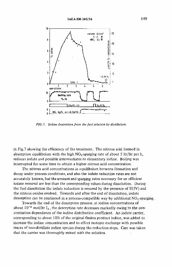
ÏA E A -S M -2 4 S /1 6 149
g p e r o u o n s :
1К'тг ‘\Ги~i m-ш П 5q КЮ]
КО; kq/h, ai г -*0.?m3/h Г
FIG. 7. Iodine desorption from the fu e l solution by distillation.
in Fig.7 showing the efficiency o f the treatment. The nitrous acid formed in absorption equilibrium with the high N 0 2-sparging rate o f about 5 ltr/ltr per h, reduces iodate and possible intermediates to elementary iodine. Boiling was interrupted for som e tim e to obtain a higher nitrous acid concentration.
The nitrous acid concentrations in equilibrium between formation and decay under process conditions, and also the iodate reduction rates are not accurately known, but the am ount and sparging rates necessary for an efficient iodate removal are less than the corresponding values during dissolution. During the fuel dissolution the iodate reduction is ensured by the presence o f U(IV) and the nitrous oxides evolved. Towards and after the end o f dissolution, iodate desorption can be continued in a process-compatible way by additional N 0 2-sparging.
Towards the end o f the desorption process, at iodine concentrations o f about 10-6 m ol/ltr I2 , the desorption rate decreases markedly owing to the concentration dependence o f the iodine distribution coefficient. An iodate carrier, corresponding to about 10% o f the original fission product iodine, was added to increase the iodine concentration and to effect isotopic exchange with possible traces o f non-distillate iodine species during the reduction steps. Care was taken that the carrier was thoroughly mixed with the solution.
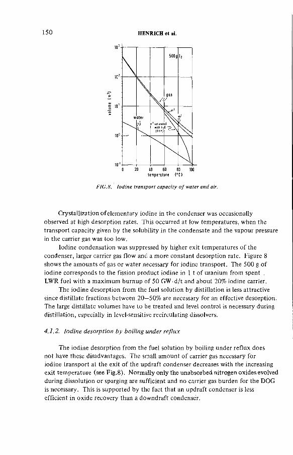
150 H E N R IC H e t al.
te m p e ra tu re ( eC)
FIG .8. Iodine transport capacity o f water and air.
Crystallization o f elementary iodine in the condenser was occasionally observed at high desorption rates. This occurred at low temperatures, when the transport capacity given by the solubility in the condensate and the vapour pressure in the carrier gas was too low.
Iodine condensation was suppressed by higher exit temperatures o f the condenser, larger carrier gas flow and a more constant desorption rate. Figure 8 shows the amounts o f gas or water necessary for iodine transport. The 500 g o f iodine corresponds to the fission product iodine in 1 t o f uranium from spent .LWR fuel with a maximum burnup o f 50 GW -d/t and about 20% iodine carrier.
The iodine desorption from the fuel solution by distillation is less attractive since distillate fractions between 2 0 —50% are necessary for an effective desorption. The large distillate volumes have to be treated and level control is necessary during distillation, especially in level-sensitive recirculating dissolvers.
4.1.2. Iodine desorption by boiling under reflux
The iodine desorption from the fuel solution by boiling under reflux does not have these disadvantages. The small amount o f carrier gas necessary for iodine transport at the exit o f the updraft condenser decreases with the increasing exit temperature (see F ig.8). Normally only the unabsorbed nitrogen oxides evolved during dissolution or sparging are sufficient and no carrier gas burden for the DOG is necessary. This is supported by the fact that an updraft condenser is less efficient in oxide recovery than a downdraft condenser.
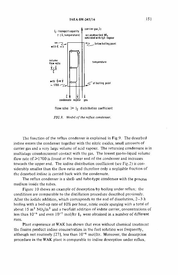
IA E A -S M -2 4 5 /1 6 151
I ¡ - transport capacity f ( G ,tem p era tu re )
oo——pw ith С -» о
volume flow ratio
V*J3С
with G- * V ~ 1700 ?
fi==7\
c a r r ie r g a s .h
a ir,unabsorbed N0, saturated w ith H2O - vapour
„ below boiling point
tem perature
at boiling point
С _ condensate vapour gas
f low ratio > Ij distribution coefficient
FIG. 9. M odel o f the reflux condenser.
The function o f the reflux condenser is explained in Fig.9. The desorbed iodine enters the condenser together with the nitric oxides, small amounts o f carrier gas and a very large volume o f acid vapour. The returning condensate is in m ultistage countercurrent contact with the gas. The lowest gas-to-liquid volume flow rate o f > 1 7 0 0 is found at the lower end o f the condenser and increases towards the upper end. The iodine distribution coefficient (see Fig.2) is considerably smaller than the flow ratio and therefore only a negligible fraction o f the desorbed iodine is carried back with the condensate.
The reflux condenser is a shell- and tube-type condenser with the process medium inside the tubes.
Figure 10 shows an example o f desorption by boiling under reflux; the conditions are comparable to the distillation procedure described previously. After the iodide addition, which corresponds to the end o f dissolution, 2—3 h boiling with a boil-up rate o f 10% per hour, nitric oxide sparging with a total o f about 15 m 3 N 0 2/m 3 and a twofold addition o f iodate carrier, concentrations o f less than 10-6 and even 10-7 m ol/ltr I2 were obtained in a number o f different runs.
Plant experience at WAK has shown that even without chemical treatment the fission product iodine concentration in the fuel solution was frequently, although not routinely [27], less than 10-6 m ol/ltr. Moreover, the desorption procedure in the WAK plant is comparable to iodine desorption under reflux,
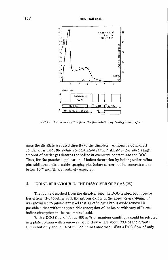
152 H E N R IC H e t a l.
operations:
boiling r i te
V . / h
I 60а m -и» I П 5оКЮз П5оКЮз
® 1 Н О ; kg/h, air^0.?m3/h I I I
FIG .10. Iodine desorption from the fu e l solution by boiling under reflux.
since the distillate is routed directly to the dissolver. Although a downdraft condenser is used, the iodine concentration in the distillate is low since a large amount o f carrier gas desorbs the iodine in cocurrent contact into the DOG.Thus, for the practical application o f iodine desorption by boiling under reflux plus additional nitric oxide sparging plus iodate carrier, iodine concentrations below 10~6 m ol/ltr are routinely expected.
5. IODINE BEHAVIOUR IN THE DISSOLVER OFF-GAS [28]
The iodine desorbed from the dissolver into the DOG is absorbed more or less efficiently, together with the nitrous oxides in the absorption column. It was shown up to pilot-plant level that an efficient nitrous oxide removal is possible either w ithout appreciable absorption o f iodine or with very efficient iodine absorption in the recombined acid.
With a DOG flow o f about 400 m 3/t o f uranium conditions could be selected in a plate column with a one-way liquid flow where about 99% o f the nitrous fumes but only about 1% o f the iodine was absorbed. With a DOG flow o f only

IA E A -S M -2 4 5 /1 6 153
F IG .l l . Iodine-contam inated p lant region.
100 m 3/t o f uranium conditions could be selected in a plate column with a precooler where more than 99.9% o f the nitrous oxides and m ore than 99.9% o f the iodine were absorbed together.
Large iodine fractions in the recombined acid must be removed before recycling. This can be done in the same way as for the fuel solution, but for the salt- and solids-free acid a countercurrent desorption with a desorption gas or with water vapour, proved to be more efficient. The nitrous acid present in the recombined acid stabilized the absorbed iodine in the elementary form.
6 . ADDITIONAL MODIFICATIONS IN THE PROCESS
Although efficient iodine removal from the fuel solution is the central part o f the proposed iodine treatment, some additional m odifications are necessary in the process limiting the iodine contam ination to a small area o f the plant. The iodine-contam inated plant area is shown in F ig .l 1.
The iodine is introduced into the dissolver with the chopped fuel. During and after dissolution, the fission iodine is removed into the DOG by boiling under reflux, nitric oxide sparging and carrier iodate addition. The iodine can be removed from the DOG with decontam ination factors > 1 0 3, using proven m ethods [29].
154 H E N R IC H e t al.
6.1. Recycling o f iodine-contaminated acids
The iodine-contaminated acids from the DOG-system are recycled to the dissolver and not to the iodine-free acid-recovery system; this is compatible with the acid and water balance in the head-end. If these acids carry a large iodine fraction they must be desorbed within the DOG-system before recycling, to avoid disturbing iodine accumulation. The storage tank for the dissolution acid should be connected to the DOG-system.
6.2. Iodine control o f discharged liquids
The iodine-free fuel solution is the only liquid discharged from the iodine- contaminated plant area and it should be controlled analytically. Batchwise control within a few hours is possible with several millilitres o f the sample. After isotopic exchange the fission product iodine is separated by using an iodine carrier, and the residual 129I determined directly by 7 -spectroscopy. The detection limit corresponds to a fission product iodine concentration more than one order o f magnitude less than recommended.
6.3. Completion and control o f iodine removal
There are several reasons why the com pletion and control o f the iodine removal procedure should be carried out in the catch or accountability tank following the dissolver. Within the dissolver dead volumes do not take part in the desorption step, undissolved fuel may dissolve during the transfer process, and com plete fuel dissolution without afterdissolution using fresh acid will increase the cycle time as well as the time o f a few hours necessary for iodine control before discharge to iodine-free plant areas. The tank following the dissolver should be equipped with a reflux condenser, heating and cooling coils and a sparging device, and it should be connected to the dissolver off-gas system. Sucking-in o f iodine-contaminated DOG after stopping the boil-up or during transfer can be prevented by a corresponding gas input or by other means.
6.4. Control o f acid input
The input o f fresh or especially recycled acid should be checked for organic impurities since some difficult-to-treat organic iodine com pounds may disturb the desorption process [22]. This may becom e o f special importance if large recycle factors are necessary for the aqueous phases in the head-end, to minimize the volume o f tritiated waste water [30].
IA E A -S M -2 4 5 /1 6 155
Undissolved fuel in the leached hulls, with the corresponding amount o f fission product iodine, can be reduced by an afterdissolution with the following acid batch. Small am ounts o f volatile iodine can be removed by boiling under reflux, using a small amount o f carrier gas. Non-volatile iodine is removed by rinsing with iodine-free water before discharge.
Using the proposed treatments in a large reprocessing plant, the I29I emission is expected to be less than 0 .2 Ci/a, which would be in accordance with the recommended values.
6.5. Discharge of leached hulls
REFERENCES
[1] LONG, J.T., Engineering for Nuclear Fuel Reprocessing, Gordon and Breach, New York (1967) 681.
[2] ANDERS, G., SCHWARZBACH, R., Staatliche Zentrale für Strahlenschutz, Berlin (German Democratic Republic), Rep. SZS-159 (1974).
[3] HAUG, H., Kernforschungszentrum Karlsruhe GmbH, Karlsruhe, Rep. KFK-1945.[4] BRAUER, F .P., SOLDAT, J.K., TENNY, H., STREBIN, R.S.,Jr„ “Natural iodine and
iodine-129 in mammalian thyroids and environmental samples taken from sites in the USA”, Environmental Surveillance Around Nuclear Installations (Proc. Symp. Warsaw, 1973), IAEA, Vienna (1974) 43.
[5] SCHÜTTELKOPF, H., Kernforschungszentrum Karlsruhe GmbH, Karlsruhe, Rep. KFK-2266 (1976).
[ [ 6 ] SCHÜTTELKOPF, H., Chemie der Nuklearen Entsorgung (BAUMGARTNER, F., Ed.)1, Verlag Thimig, Munich (1978) 155.
[7] KOELZER, W., Chemie der Nuklearen Entsorgung (BAUMGARTNER, F., Ed.)1, Verlag Thimig, Munich (1978) 139.
[ 8 ] SCHÜTTELKOPF, H„ KFK Nachr. 4 (1 9 7 5 ) 14.[9] GESELLSCHAFT FÜR REAKTORSICHERHEIT mbH, Kôln, Grundsâtzliche Sicher-
heitstechnische Realisierbarkeit des Entsorgungszentrums. Beurteilung und Empfehlungen der Reaktor-Sicherheitskommission (RSK) und der Strahlenschutzkommission (SSK) (20.10.1977).
[ 10] NEEB, K.H., Chemie der Nuklearen Entsorgung (BAUMGARTNER, F., Ed.) 1, Verlag Thimig, Munich, 1 (1978) 65.
[11] NEEB, K.H., et al., J. Radioanal. Chem. 3 2 (1 9 7 6 ) 523.[12] ANDRIESSEN, H., Kernforschungszentrum Karlsruhe GmbH, Karlsruhe (1978)
(unpublished).[13] SCHLICH, E., HEN RICH, E., Kernforschungszentrum Karlsruhe GmbH, Karlsruhe (1978)
(unpublished).[14] PARSLY, L.F., Oak Ridge National Lab., TN, Rep. ORNL-TM-2412, part IV.[15] OAK RIDGE NATIONAL LAB., TN, Rep. ORNL-TM-3180.[16] BRYANT, P.M., WARNER, B.F., “Control o f radioiodine release from reprocessing
plants”, Control of Iodine in the Nuclear Industry, Technical Reports Series No. 148, IAEA, Vienna (1973) 29.
156 H E N R IC H e t al.
[17] EUROPEAN COMPANY FOR THE CHEMICAL PROCESSING OF IRRADIATED FUELS, Safety Analysis, Eurochemic, Mol, Belgium (Nov. 1965).
[18] GENERAL ELECTRIC CO., RICHLAND, WA, HANFORD ATOMIC PRODUCTS OPERATION, Purex Technical Manual, HW-31000 (March 1955).
[19] NUCLEAR FUEL SERVICES, INC., West Valley, NY, Safety Analysis Report, docket 50, 201.
[20] ALLIED-GENERAL NUCLEAR SERVICES, Barnwell, SC, Safety Analysis Report, docket 50, 332.
[21] FERGUSON, D.E., et al., Oak Ridge National Lab., TN, Chemistry Technology Division, Annual Progress Report, Rep. ORNL-4272 (1968).
[22] CATHERS, G.I., SHIPMAN, C.J., US Patent 3 .803.295, Patented 9.4.1974.[23] OAK RIDGE NATIONAL LAB., TN, Rep. ORNL-TM-4394 (Feb. 1974).[24] MAILEN, J.C., HORNER, D.E., Nucl. Technol. 33 (1977) 260.[25] GOODE, J.H., Oak Ridge National Lab., TN, Rep. ORNL-TM-3723 ( 1973).[26] ASSMUS, K.H., JAGER, K., SCHÜTZ, R., SCHULZ, F., SCHWEICKERT, H., Institute
o f Electrical and Electronics Engineers, Inc., New York, Trans. Nucl. Sci. 26 2 (1979).[27] BERG, R., SCHÜTTELKOPF, H., Radioactive Effluents from Reprocessing Plants,
Seminar Karlsruhe (Nov. 1977) 189.[28] HENRICH, E., Kernforschungszentrum Karlsruhe, Karlsruhe, KFK-PWA Status Report (1979).[29] WILHELM, J.G., FURRER, J., Radioactive Effluents from Reprocessing Plants, Seminar
Karlsruhe (Nov. 1977) 9.[30] HENRICH, E., et al., Chemie der Nuklearen Entsorgung (BAUMGARTNER, F., Ed.)
1, Verlag Thimig, Munich (1978).
DISCUSSION
H.A.C. McKAY: We may wish to recycle nitric acid from the first solvent extraction contactor back to the dissolver, for tritium control. There is then a possibility that some iodine species formed, for instance, by reaction with the solvent will also recycle and build up. The factor involved could be as large as, say, 20. Can you com m ent on this?
E. HENRICH: Impurity levels may increase with the recycle factor, lowering the decontam ination factors and increasing product losses during extraction and possibly also disturbing the removal o f fission product iodine from the fuel solution. Acid and water recovery from the highly active waste should be done in such a way that the recycled acid is sufficiently free from disturbing organic impurities. We do not know exactly if an additional step for organics removal will be necessary in order to obtain recycle factors o f 10—15. The total organics concentration in our experim ents ranged from very low to approximately 10 mg/ltr. Values for organics concentration in the fuel solution o f theWAK plant are not available.
IA E A -S M -2 4 5 /5 2
SEPARATION OF TRITIUM FROM REPROCESSING EFFLUENTS
A. BRUGGEMAN, W. DOYEN, R. HARNIE,R. LEYSEN, L. MEYNENDONCKX, M. MONSECOUR,W.R.A. GOOSSENS, L.H. BAETSLE Studiecentrum voor Kernenergie/
Centre d ’étude de l’énergie nucléaire,Mol,Belgium
Abstract
SEPARATION OF TRITIUM FROM REPROCESSING EFFLUENTS.For several years tritium retention has been studied at the Belgian Nuclear Research Centre,
SCK/CEN; initially attention was focused on the removal o f tritium from gaseous reprocessing effluents. If tritium can be released from the spent fuel into the gaseous phase before any aqueous operation, adsorption on molecular sieves after some isotopic dilution with hydrogen and after complete conversion to (tritiated) water is the most practical collection method.A once-through 15 m3 -h_1 oxidation-adsorption unit with a closed regeneration system and with a decontamination factor o f 1 0 0 0 at total (tritiated) hydrogen and water inlet concentrations down to 1 0 0 0 vpm (parts per million by volume) has been constructed and tested at SCK/CEN and it is described in the text. If no special head-end treatment is used an appropriate liquid management inside the reprocessing plant restricts the volume of tritiated aqueous effluents to about 3 m3 per tonne of LWR fuel processed. However, for further reduction an isotope separation process becomes necessary. Within the framework o f the indirect action programme o f the European Communities, SCK/CEN is developing the ELEX process, which is a combination of water ELectrolysis and tritium Exchange between hydrogen and water, the exchange being promoted by a hydrophobic catalyst. A survey is given of the experimental work carried out to date on the single constituent steps o f this process. For electrolysis under normal conditions an elementary tritium separation factor o f 11.6 with a standard deviation of 6 % was obtained. As concerns the exchange step a hydrophobic catalyst has been developed which yields for the flow rates used at atmospheric pressure and at 20° С an overall exchange rate constant o f 9 m ol-s_I-m - 3 in a countercurrent trickle-bed reactor. At present an integrated bench scale de-tritiation unit is being built for further tests and for a dynamic demonstration of the ELEX process.
1. INTRODUCTION
Inside the fuel elem ents o f present light water reactors about 0.75 PBq (20 kCi) tritium is formed per GW (e)-a, m ostly by ternary fission. Depending on the time-temperature history in the reactor, a smaller or a larger part o f this tritium diffuses out o f the fuel and is fixed by the Zircaloy cladding. When the spent fuel is reprocessed this latter fraction is retained in solid wastes. However,
157

ACСCCCRHHRM
PPC
|7цишшр~]., r - g g • Г iffi'Am
S □ ¡ ОADSORPTION COLUMN A IR COOLER.COOLER CONDENSER C A TA LYTIC REACTOR RESISTANCE HEATER HEAT RECOVERY UNIT MIXING CHAMBER PUMPPACKAGE C H ILLER
AIR
oo
AC 2
FIG. 1. Schem atic flo w sheet o f the oxidation-adsorption installation fo r separation o f tritium fro m gas streams.
BRU
GG
EMA
N
et al.

IA E A -S M -2 4 5 /S 2 159
the remainder o f the tritium, which represents 50% or more, is not immobilized and if no special treatment is used it ends up nearly quantitatively as НТО in the aqueous effluents o f the reprocessing plant.
With the increase in nuclear power and in the corresponding reprocessing capacity, release o f these tritium-bearing effluents by discharge into local rivers or evaporation to the atmosphere will have to be restricted. For some suitable reprocessing plant sitings alternative low cost management schemes for tritiated aqueous wastes may be possible, such as direct disposal into the ocean or on-site deep well injection. At most inland plants, however, decay storage on site or transport to a repository will be required and in both cases the tritium must be im mobilized, probably in a solid form, from which it does not leak or leach [ 1 ]. To minimize the cost o f im mobilization and long-term storage, previous concentration o f tritium in a small volume will be necessary.
At the Belgian Nuclear Research Centre, SCK/CEN, separation o f tritium has therefore been studied for several years. Initially, attention was focused on the removal o f tritium from gaseous effluents. Later, within the framework o f the indirect action programme o f the European Communities, isotopic separation o f tritium from aqueous effluents became a point o f research and development. The developm ent stage o f both m ethods will be discussed in this paper.
2. SEPARATION OF TRITIUM FROM GAS STREAMS
One o f the general tritium management m ethods proposed relies on the removal o f tritium from the spent fuel before any aqueous operation. This removal is carried out by som e high-temperature treatment o f the fuel, voloxidation for instance [2]. For practical reasons the tritium released into the gaseous phase is isotopically diluted with an excess o f added hydrogen. Adsorption on molecular sieves is then the most practical collection m ethod, if com plete conversion to tritiated water has been assured.
At SCK/CEN experimental investigation was performed on catalytic oxidation o f hydrogen at concentrations o f 100 to 1000 vpm (parts per million by volume) and on adsorption o f water on molecular sieves. Following these laboratory tests, the results o f which have been reported earlier [3], a once-through catalytic tritium oxidation-adsorption unit with a nominal flow rate o f 15 m 3 -h _1 and a target decontamination factor o f 1000 at total (tritiated) hydrogen and water inlet concentrations down to 1000 vpm was designed, constructed and tested.
The oxidation-adsorption installation is schematically shown in F ig .l.The mixture o f tritium in hydrogen and purified dry air is preheated in a heat

160 B R U G G E M A N e t al.
exchanger and brought to the required temperature by an electric heater. The heated gas mixture enters the catalytic reactor where com plete oxidation to (tritiated) water takes place. The hot gases leaving the catalytic oxidation furnace are cooled by the incoming gases and finally by water from a cooling unit before being sent to one o f the two adsorption columns o f an atmospheric drying unit where the (tritiated) water is removed down to 0.5 vpm, the tritium- free air being sent to the stack. For continuous operation the drier is fitted with a closed regeneration system based on temperature swing operation.Part o f the dry air leaving the column in adsorption is sucked in an opposite direction through the column in regeneration, and after passing a cooler condenser it is recycled to the main stream at the entrance o f the column in adsorption. Temperature, pressure, hydrogen, water and tritium content o f the gas stream are measured at several points in the installation.
After some adaptations this oxidation-adsorption unit, which was installed in a walk-in processing hood, is now being integrated as a recombiner in a bench-scale test and demonstration installation for the removal o f tritium from aqueous effluents, described in section 7.
3. THE ELEX PROCESS FOR SEPARATION OF TRITIUM FROMAQUEOUS EFFLUENTS
For present and future reprocessing plants a normal chop and leach process is still preferred in which, starting with the dissolution, the tritium in the fuel is repeatedly diluted isotopically as aqueous reagents are introduced. To confine the tritium into a relatively small volume, several schemes for segregation and recycling o f the tritiated plant streams and decontamination o f the process reagents have been studied and proposed [2 ,4 ] . At future reprocessing plants the volume o f tritiated aqueous effluents might thus be reduced to about 3 m 3 per tonne o f light water reactor fuel processed, with a tritium level o f the order o f 3.7 TB q-m ' 3 (100 Ci m"3) [5]. In many cases a further reduction o f the waste volume will, however, be required in view o f the cost o f im mobilization and long-term storage.
An ELectrolysis-EXchange process for isotopic enrichment and separation o f tritium from the aqueous effluents o f a reprocessing plant has been proposed [6 , 7]. The ELEX process is a com bination o f water electrolysis and tritium exchange between hydrogen and water, the exchange being promoted by a hydrophobic catalyst. The process is thus based on two large isotope effects: the equilibrium isotope effect in the reaction
HTgas HîOliquid И 2 gas + Н Т О ц д ц к ] (1)
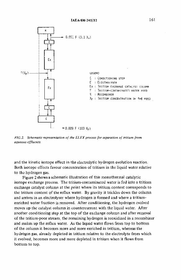
IA E A -S M -2 4 5 /5 2 161
0 . 9 9 1 F ( 0 , 1 X F )
L E G E N D
C : C o n d i t i o n i n g s t e p
E : E l e c t r o l y s e r
Ex : T r i t i u m e x c h a n g e c a t a l y s t c o lu m n
F : T r i t i u m - c o n t a m i n a t e d w a t e r f e e d
R : R e c o m b i n e r
X p : T r i t i u m c o n c e n t r a t i o n o f t h e f e e d
E
-----------------* " 0 . 0 0 9 F ( 1 0 0 X p )
FIG .2. Schem atic representation o f the E L E X process fo r separation o f tritium from aqueous effluents.
and the kinetic isotope effect in the electrolytic hydrogen evolution reaction. Both isotope effects favour concentration o f tritium in the liquid water relative to the hydrogen gas.
Figure 2 shows a schematic illustration o f this m onothermal catalytic isotope exchange process. The tritium-contaminated water is fed into a tritium exchange catalyst column at the point where its tritium content corresponds to the tritium content o f the reflux water. By gravity it trickles down the column and arrives in an electrolyser where hydrogen is formed and where a tritium- enriched water fraction is removed. After conditioning, the hydrogen evolved moves up the catalyst colum n in countercurrent with the liquid water. After another conditioning step at the top o f the exchange colum n and after removal o f the tritium-poor stream, the remaining hydrogen is reoxidized in a recombiner and makes up the reflux water. As the liquid water flows from top to bottom o f the column it becom es more and more enriched in tritium, whereas the hydrogen gas, already depleted in tritium relative to the electrolyte from which it evolved, becom es more and more depleted in tritium when it flows from bottom to top.

162 B R U G G E M A N e t al.
Assuming an elementary tritium-protium separation factor o f 10 for the water electrolysis and an exchange temperature o f 50°C, the ELEX process needs only five overall exchange transfer units to concentrate 90% o f the original tritium in 1 % o f the original volume. On these assumptions a technico- econom ical comparison o f the ELEX process with two other possible m ethods for isotopic enrichment and separation o f tritium from aqueous reprocessing effluents, namely water distillation and water electrolysis, shows that the total operating costs per year for the ELEX m ethod can be expected to be about twice as low as the water electrolysis m ethod and about four times lower than the water distillation m ethod [7].
4. EXPERIMENTAL STUDY OF ELECTROLYTIC DE-TRITIATION
As indicated in section 3 water electrolysis is an essential part o f the ELEX process which is being developed at SCK/CEN. At the bottom o f the exchange column the cntaminated feed plus the reflux water have to be nearly com pletely converted from liquid water to gaseous hydrogen. Furthermore, the water electrolysis itself adds to the isotope separation since the electrolytically produced hydrogen contains less tritium than the aqueous solution from which it came.
The (elementary) electrolytic tritium-protium separation factor during hydrogen evolution from water with a protium atom ic fraction o f Z and a tritium atom ic fraction o f X is defined as
where U(H) and U(T) are partial uni-directional rates o f the overall hydrogen evolution reaction for H (protium) and T (tritium), respectively, in terms o f numbers o f hydrogen atoms transferred per unit time. For the experiments described later, where Z = 1 and X 1 and where only a short tim e period is considered during which the quantity o f water that has undergone transformation to hydrogen is small enough with respect to the total quantity o f water, the preceding equation can be approximated by
a = x /y (3)
where x is the m ole fraction o f НТО in the water and у the m ole fraction o f HT in the hydrogen produced.
For the study o f electrolytic de-tritiation a test installation was constructed in a walk-in processing hood. This installation, which is shown schematically
( 2)

IA E A -S M -2 4 5 /5 2 163
in Fig.3, consists essentially o f a transformer rectifier which is allowed to work in constant current m ode, a small (1 .4 kW) but still industrial type o f electrolyser with peripheric equipm ent for the conditioning o f electrolyte and gases, and a sampling train for (tritiated) hydrogen. The electrolyser is o f the bipolar and atmospheric pressure type and is com posed o f 12 cells in series. As the cathodes are made o f mild steel, rather high tritium separation factors could be expected, especially at lower temperatures [8].
The separation factor was measured at different temperatures and current densities. After homogenizing and therm ostatically controlling the electrolyte solution, to which an am ount o f tritiated water had been added, electrolysis was started. E lectrolyte and hydrogen were sampled as soon as the electrolysis conditions had been stabilized at the required operating temperature and current density. Liquid sample points were foreseen at the bottom o f the electrolyser and at the cooler condensers in the hydrogen and oxygen lines. Hydrogen could be sampled after the hydrogen flow integrator. Therefore part o f the hydrogen was further purified; by passing it through a liquid-nitrogen-cooled trap, it was quantitatively oxidized in a copper oxide filled furnace at 600°C and the water formed was quantitatively collected. The tritium content o f the samples was determined by liquid scintillation counting.
From a comparison o f the tritium content o f the water electrolysed and the tritium content o f the hydrogen produced, the tritium-protium separation factor for the electrolysis installation described and for a 25% potassium hydroxide solution was determined at current densities from 370 to 2595 A m ' 2 and at temperatures from 20 to 60°C. The cell voltage that had to be applied was also measured and it increased from 1.85 to 2.23 V with increasing current density and with decreasing temperature. All experim ents carried out yielded high separation factors, i.e. larger than 10. For ‘normal’ working conditions, i.e. current densities from 1480 to 2595 A m -2 and temperatures from 40 to 60°C (cell tension 2.06 to 2.21 V), a mean separation factor o f 11.6 with a standard deviation o f 6%, was obtained. At lower current densities and at lower temperatures less reproducible but higher separation factors were obtained, but econom ically these working conditions are less attractive.
5. PREPARATION AND SELECTION OF TRITIUM EXCHANGE CATALYSTS
In water-hydrogen isotope exchange, tritium is concentrated in the water. The elementary separation factor is given by the equilibrium constant К of reaction equation (1) (see section 3). К equals the product o f the equilibrium

A T : A D S O R P T I O N TR A P FI : F L O W I N T E G R A T O RCC • C O O L E R C O N O E N S E R LC : L E V E L C O N T R O LCT • C O L D TR A P OR . O V ER P RE S SU R E R E L I E F TR A PС . CO ND EN SE R P : PRESSURE I N D I C A T O RD . DE M IS T E R T : T E M P E R A T U R E I N D I C A T O RE E L E C T R O L Y S E R ТВ ' T H E R M O S T A T I C A L L Y C O N T R O L L E D B A T HES . E L E C T R O L Y T E S O L U T I O N TC . T E M P E R A T U R E C O N T R O LF : F I L T E R TR : T R A N S F O R M E R , R E C T I F I E R
FIG.3. Installation fo r the s tudy o f electrolytic de-tritiation.

IA E A -S M -2 4 5 /5 2 165
constant for the analogous gas-gas reaction and the separation factor for water distillation, both o f which are given in the literature as a function o f temperature [9,10]. К has a value o f about 7.16 at 20°C and it decreases with increasing temperature. The isotope exchange is thus carried out at rather low temperatures and a catalyst is needed to obtain a sufficiently high exchange rate.
Effective catalysts for hydrogen isotope (m ostly deuterium) exchange between hydrogen and water vapour have been known for many years [11], but they all lost their activity when in contact with liquid water and therefore they could only be used to catalyse the steam-hydrogen exchange, an econom ically less attractive process due to the lower separation factor at the higher temperature and the difficulty in obtaining a countercurrent flow. To overcom e this problem Canadian research workers, in search o f alternative heavy-water production processes, proposed the use o f a hydrophobic catalyst which would allow the exchange reaction to be carried out in a normal countercurrent trickle-bed reactor with direct contact between descending water, ascending hydrogen and catalyst bed [12, 13].
At SCK/CEN about 30 different types o f hydrophobic catalysts were prepared and tested. Following the Canadian ideas [ 14] a first category o f catalysts was prepared by coating commercially available noble metal on alumina catalysts with a very thin layer o f a water-repellent material such as dimethyldichlorosilane, which was deposited from the vapour phase. As this wet-proofing was not very effective, the noble metal was directly deposited on a hydrophobic matrix, namely porous polytetrafluorethylene [15, 16]. Although the latter catalysts performed rather well, even better results were obtained with a third category o f catalysts which were prepared on the basis o f existing fuel cell technology at SCK/CEN. Inside the porous multilayer anode o f hydrogen-air fuel cells som e kind o f triple contact gas (H 2)-catalyst- liquid (electrolyte solution) is realized by using a catalytic layer com posed o f Pt, Pt-Pd or Ni deposited on activated carbon and m ixed with polytetrafluor- ethylene, which is used as a bonding hydrophobic agent [17]. Analogous catalysts for tritium exchange between hydrogen and water were prepared by mixing home-made or commercially available Pt, Pd, Ni, Pt-Pd or Pt-Ni impregnated carbon with granular Teflon 6N (Dupont) in different ratios.A number o f mechanical treatm ents were carried out on this mixture, resulting in cylindrical pellets with a diameter o f 3 mm or 1.9 mm and a height o f 2 mm.
The activity o f the prepared hydrophobic catalysts in the presence o f liquid water was tested by bubbling hydrogen, at atmospheric pressure, through a batch o f catalyst immersed in water with a known tritium content by measuring the tritium activity o f the dried hydrogen after exchange at different hydrogen flow rates, corresponding to linear velocities o f 0 .62 to 3.7 c m -s '1. The apparatus used is shown schematically in Fig.4.

LEGEND
A, A' MASS FLOW METERSВ THERMOSTATICALLY
CONTROLLED COLUMNС, С', 1, I' COLD TRAPSD MIXING CHAMBERE PROPORTIONAL COUNTERF ELECTRONICS
G ROTAMETER
H CuO FURNACE1,2,5,6,7 Y-VALVES8 3-WAY VALVE3, 4,9, 10, 11 STRAIGHT VALVES
F IG .4. Installation for catalyst screening.
166 BRUGGEMAN et
al.

IA E A -S M -2 4 5 /5 2 167
The activity o f a catalyst at a specified temperature and hydrogen flow rate was expressed by the degree o f exchange 77, a number between 0 and 1, which, for the small concentrations o f HT and НТО involved, is given by
Уout К у outr? = ------- = --------- (4)
Уе x
where x : m ole fraction o f НТО in the water (x 1)y e : m ole fraction o f HT in hydrogen in equilibrium with water
containing a m ole fraction x o f НТО у out ■ m ole fraction o f HT in the hydrogen after leaving the column K: equilibrium constant o f the exchange reaction (E q .(l)).
The most active catalyst was the one that yielded in otherwise constant conditions the highest reaction rate or the highest value for r¡.
The m ost promising results for the tritium exchange between hydrogen and liquid water were obtained with hydrophobic ‘Pt on С plus T eflon’ catalysts.The results o f a few experim ents on these platinum catalysts, carried out at a linear gas velocity o f 3 .7 c m -s '1, are shown in Fig.5. For otherwise constant conditions ana for platinum concentrations up to at least 0.5 wt%, the degree o f exchange and thus the catalytic activity increased with the increasing amount o f platinum present. In these bubble-bed tests polytetrafluorethylene, which served as both a bonding and a wet-proofing agent, was preferably present in a concentration o f 60 to 80 wt%. However, a catalyst with a lower polytetrafluorethylene content is probably more appropriate for use in a trickle-bed reactor.As theoretically expected, the degree o f exchange increased with increasing temperature, at least between 1°C and 60°C, but above 40°C this increase was only marginal; beyond 60°C the degree o f exchange decreased.
6. TRITIUM EXCHANGE EXPERIMENTS IN A TRICKLE-BED REACTOR
The ELEX process requires the m ultiplication o f the elementary separation factor for the solid catalysed tritium exchange between hydrogen and liquid water. This will be realized in a countercurrent three-phase packed-bed reactor in which the liquid water drips downwards through a fixed bed o f hydrophobic catalyst particles, probably m ixed with hydrophilic inerts, while the hydrogen gas, saturated with water vapour, moves upwards through the catalyst column.
For these trickle-bed experim ents a test installation was constructed, which is shown schematically in Fig.6. The exchange colum n, a Plexiglas cylinder fitted externally with thermostats, had an inner diameter o f 20 mm and a length o f 1.80 m. It comprised a catalytic section 1.2 m high with, at each
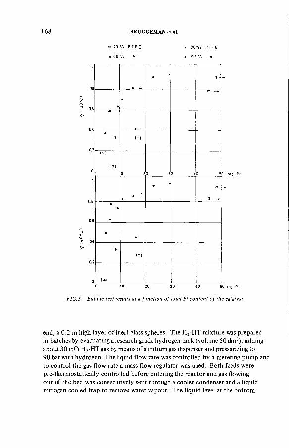
168 B R U G G E M A N e t al.
® 4 О * /. P T F E
• 6 0"/. n
. 8 0 * / . PTF E
t 92 7 . I/
0.8
0.6
0.4
0.2
0.8
0.6
0.4
0.2
(s)
(®)
(a)
20___________ 30 40___________ 50 m g Pt
•
• Э ■
••
•A
©(©)
( ©)0 10 20 3 0 40 50 mg Pt
FIG. 5. Bubble test results as a fu n ctio n o f total Pt co n ten t o f the catalyst.
end, a 0 .2 m high layer o f inert glass spheres. The H2-HT mixture was prepared in batches by evacuating a research-grade hydrogen tank (volum e 50 dm3), adding about 30 mCi H 2-HT gas by means o f a tritium gas dispenser and pressurizing to 90 bar with hydrogen. The liquid flow rate was controlled by a metering pump and to control the gas flow rate a mass flow regulator was used. Both feeds were pre-thermostatically controlled before entering the reactor and gas flowing out o f the bed was consecutively sent through a cooler condenser and a liquid nitrogen cooled trap to remove water vapour. The liquid level at the bottom
IA E A -S M -2 4 5 /5 2 169
o f the column was kept constant with the aid o f a double-level controller acting on a magnetic valve between the reactor and the water collecting tank. In a revised version a level controlling pump was used and the water leaving the colum n pre-saturated the hydrogen feed. Water samples for tritium determination by liquid scintillation counting were withdrawn before and after the reactor and from the condensate. The dry hydrogen before the reactor or after the liquid nitrogen cooled trap was continuously sampled and measured by proportional counting.
Neglecting the presence o f water vapour and considering a small height o f catalyst packing dZ (m) where the mole fraction o f HT in the gaseous hydrogen is y and the m ole fraction o f НТО in the liquid water is x, the exchange rate per unit colum n area can be written as
where G': gas (hydrogen) flow rate per unit column area in moi s x-m 2 k: overall exchange rate constant in mol ■ s -1 • m -3 .
with К the tritium exchange separation factor or equilibrium constant as defined previously in section 3 (reaction E q .(l)) and in section 5 (Eq.(4)). Rearrangement and integration o f the total column, with the assumption that G '/k is constant throughout the colum n, yield the next expression for the catalyst packing height Z
G' dy = к ( y - y e) dZ (5)
(7)
Defining:
number o f overall exchange transfer units
(8)
^out
_ G'Hqg = — = height o f an overall exchange transfer unit
к(9)

F WT
Пат
LEGEND
ДР1 D IF F E R E N T IA L PRESSURE IN D IC A TO R WMP W ATER M ETE R IN G PUMP VS SO LEN O ID V A L V ETBR TR IC K LE -B E D REACTOR ТВ T H E R M O S T A T IC A L L Y
C O N T R O LLE D BA TH SP SAMPLE PO INT ‘PI PRESSURE IN D IC A TO RPC PR O P O R TIO N A L CO UNTER LC L E V E L C O NTRO LHE H E A T EXCH ANG ERFWT FEED W ATE R T A N K FC FLOW C O NTRO LCWT CO LLECTED W ATER T A N K CT CO LD TR A PС CONDENSERCC COOLER CONDENSERВ BURETTEA T "ADSO RPTIO N TR AP
FIG. 6. Installation fo r the s tudy o f tritium exchange in a countercurrent trickle-bed reactor.
170 BRUGGEMAN et
al.
IA E A -S M -2 4 5 /5 2 171
equation (7) is simplified to:
z ~ H 0G ' n 0 G (10)
In the tritium exchange experim ents all concentrations involved remain low, and over the range o f concentrations considered the equilibrium curve is a straight line. It can be demonstrated [18] that
where ( y - y e)gm is the logarithmic mean value o f the driving concentration difference y —ye .
According to Eqs (11) and ( 10) experimental data obtained in specific working conditions in a countercurrent trickle-bed reactor with a given height o f catalyst packing Z thus allow the height o f an overall exchange transfer unit, Ho g > f ° r these conditions to be deduced. Afterwards, the height o f catalyst packing Z required under the same conditions for a required separation duty can be calculated, using these same equations.
Table I shows the results o f a few experim ents using tritium-free water and tritium-containing hydrogen as feeds, carried out at a pressure o f 10s Pa and at a temperature o f 20°C. The catalytic section o f the bed was com posed o f a mixture o f 1 part cylindrical catalyst particles with a diameter o f 1.9 mm, a height o f 2 mm and a com position o f 40% polytetrafluorethylene and 60% activated carbon loaded with 3% platinum, and 2 parts glass spheres with a diameter o f 3 mm. This ratio was derived from previous hydrodynamic experiments. For m ost experim ents it took several hours at constant feed conditions before the effluent tritium concentrations had been stabilized and before the amount o f tritium leaving the colum n equalled the am ount o f tritium entering it. At the rather low flow rates used the height o f an overall exchange transfer unit H o g decreased only very slightly with an increasing liquid flow rate L' but it was roughly proportional to the gas flow rate G', as can be seen from Table I. At 20°C and under the working conditions described, the overall exchange rate constant к was thus almost not affected by changes in the gas or liquid flow rate. The mean value o f к was 9 m o l s - 1 m -3 , with a standard deviation o f 10%, which corresponds to a H o g value o f 1 m at a hydrogen flow rate o f 9 mol ■ s-1 • irT2. Higher values o f к and corresponding smaller heights o f a transfer unit are expected at higher temperatures.
( 11)
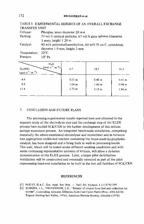
172 B R U G G E M A N e t al.
TABLE I. EXPERIMENTAL HEIGHTS OF AN OVERALL EXCHANGE TRANSFER UNITColumn: Plexiglas, inner diameter 20 mmPacking: 33 vol.% catalyst particles, 67 vol.% glass spheres (diameter
3 mm), height 1.20 m Catalyst: 40 wt% polytetrafluorethylene, 60 wt% Pt on C, cylindrical,
diameter 1.9 mm, height 2 mm Temperature: 20°C Pressure: 10s Pa
H20
H2 (HT) 1 • m '2) (m ol-s- 1 m '2) -----
6.7 10.7 16.2
4.4 0.51 m 0.48 m 0.41 m
8.9 1.04 m . 1 . 0 0 m 0.90 m
17.4 1.75 m 2.18 m 1.94 m
7. CONCLUSION AND FUTURE PLANS
The promising experimental results reported here and obtained in the separate study o f the electrolysis step and the exchange step o f the ELEX process have incited SCK/CEN to the further developm ent o f this tritium isotope separation process. An integrated bench-scale installation, comprising essentially the above-mentioned electrolyser and recombiner and in between two appropriate trickle-bed reactors containing the home-made hydrophobic catalyst, has been designed and is being built in walk-in processing hoods.This unit, which will be tested under different working conditions and with water containing representative amounts o f tritium, will allow a dynamic demonstration o f the ELEX process. Later, a larger pilot de-tritiation installation will be constructed and eventually operated as part o f the pilot reprocessing head-end installation to be built in the hot cell facilities o f SCK/CEN.
REFERENCES
[1] McKAY, H.A.C., Eur. Appl. Res. Rep. - Nucl. Sci. Technol. 1 3 (1979) 599.[2] BURGER, L.L., TREVORROW, L.E., “Release of tritium from fuel and collection for
storage”, Controlling Airborne Effluents from Fuel Cycle Plants (Proc. ANS-AIChE Topical Meeting Sun Valley, 1976), American Nuclear Society, Hinsdale (1976).

IA E A -S M -2 4 5 /5 2 173
[3] BROOTHAERTS, J., et al., “Treatment and control o f gaseous effluents from light water reactors and reprocessing plants” , Management o f Radioactive Wastes from the Nuclear Fuel Cycle (Proc. Symp. Vienna, 1976), IAEA, Vienna (1976) 101.
[4] MIQUEL, P., GOUMONDY, J.P., SCHNEIDER, E., “Maîtrise du tritium dans les usines de retraitement” , Radioactive Effluents from Nuclear Fuel Reprocessing Plants (Proc. CEC Seminar Karlsruhe, 1977), Commission o f the European Communities, Luxembourg (1978) 497.
[5] BAETSLE, L.H., BROOTHAERTS, J., “ Reprocessing off-gas treatment research in Belgium” , Radioactive Effluents from Nuclear Fuel Reprocessing Plants (Proc. CEC Seminar Karlsruhe, 1977), Commission of the European Communities, Luxembourg (1978) 421.
[6 ] BIXEL, J.C., HARTZELL, B.W., PARK, W.K., “Experimental determination of reaction rates o f water-hydrogen exchange of tritium with hydrophobic catalysts” ,Proc. 14th ERDA Air Cleaning Conf. Sun Valley, 1976, Vol.2, National Technical Information Service, Springfield (1977) 1065.
[7] BRUGGEMAN, A., et al., “Assessment o f some methods for the separation of tritium from the aqueous effluents o f a reprocessing plant” , Reprocessing of Spent Nuclear Fuel (Proc. Tripartite Symp. Mol, 1978), SCK/CEN, Mol, Internal report R .2604 (1978) 110.
[8 ] VILLANI, S., Isotope Separation, American Nuclear Society (1976).[9] JACOBS, D.G., Sources o f Tritium and its Behavior upon Release to the Environment,
USAEC Technical Information Center, Oak Ridge, TN, Rep. TID-24635 (1968).[ 10] NATIONAL COUNCIL ON RADIATION PROTECTION AND MEASUREMENTS,
Tritium in the Environment, NCRP Rep. 62, Washington, DC (1979).[11] Production o f Heavy Water (MURPHY, G.H., UREY, H.C., et al., Eds), McGraw-Hill,
New York (1955).[12] BUTLER, J.P., ROLSTON, J.H., STEVENS, W.H., “Novel catalysts for isotopic
exchange between hydrogen and liquid water” , Separation of Hydrogen Isotopes (Proc. Symp. Montreal, 1977), ACS Symposium Series 6 8 , Washington, DC (1978) 93.
[13] HAMMERLI, М., STEVENS, W.H., BUTLER, J.P., “Combined electrolysis catalytic exchange (CECE) process for hydrogen isotope separation” , Separation o f Hydrogen Isotopes (Proc. Symp. Montreal, 1977), ACS Symposium Series 6 8 , Washington, DC (1978) 110.
[14] STEVENS, W.H., Canadian Patent N o.907,292 (15 Aug. 1972).[15] ROLSTON, J.H., et al., Canadian Patent No.941 134 (5 Feb. 1974).[16] ROLSTON, J.E., den HARTOG, J., BUTLER, J.P., J. Phys. Chem. 8 0 (1 9 7 6 ) 1064.[17] SPAEPEN, G.F.J., et al., Belgian Patent No. 787 570 ( 14 Aug. 1972).[18] COULSON, J.M., et al., Chemical Engineering, Vol. 2, Unit Operations, 3rd ed.,
Pergamon Press, Oxford (1978) 529.
DISCUSSION
R. KROEBEL: Have you used the Canadian catalyst and, if so, how does it compare with the catalyst you have developed at SCK/CEN?
A. BRUGGEMAN: As we could not obtain a sample o f the Canadian catalyst for comparative tests, only a rough comparison o f the activities o f the two types o f catalyst is possible. On the basis o f published values for the
174 B R U G G E M A N e t al.
hydrophobic catalyst developed by A tom ic Energy o f Canada Limited, i.e. those obtained at the Mound Facility (MLM -2620), it can be said — with the necessary reserve - that in terms o f overall exchange rate constants, the activities o f the two catalysts are competitive.
Y. NISHIWAKI: The tritium-protium separation factor with the electrolytic m ethod depends not only on the temperature and the electric current density but also on electrolyte concentration and electrode surface conditions.You m ention in section 4 o f your paper that a mean separation factor o f11.6, with a standard deviation o f 6%, was obtained for ‘normal’ working conditions. May I ask what the electrolyte concentration range under ‘normal’ working conditions was and whether you paid special attention to maintaining stable electrode surface conditions during electrolysis? You also m entioned that a large tritium-protium separation factor was obtained with your methods. What would the deuterium-protium or tritium-deuterium separation factor be with the different m ethods you tested?
A. BRUGGEMAN: With reference to your first question, the tritium- protium separation factor during water electrolysis does indeed depend on a lot o f factors, the stability o f which cannot always be guaranteed in an industrial-type electrolyser. For the experiments described, the KOH concentration was 25 wt%, as is normal for hydrogen production by water electrolysis. We do not expect the electrolyte concentration to influence greatly the electrolytic separation factor. Nevertheless, experiments at a lower KOH concentration and experim ents with NaOH are planned. We did not take special precautions to maintain stable electrode surface conditions during electrolysis. Apart from variations in temperature and electric current density, the electrolyser was deliberately used in the manner recommended for hydrogen production.
In answer to your second question I would say that because o f the smaller relative mass difference, the kinetic isotope effect for electrolytic hydrogen evolution as well as the equilibrium isotope effect for hydrogen isotope exchange between hydrogen gas and liquid water will result in smaller values for the deuterium-protium and the tritium-deuterium separation factors than for the tritium-protium separation factor. Some o f these values can be found in the literature. (ROLSTON, J.H., den HARTOG, J., BUTLER, J.P., J.Phys. Chem. 8 0 (1 9 7 6 ) 1064.)
H. GUTOWSKI: What tritium inlet concentration values did you use for your experim ents and what concentration values have been achieved at the bottom o f the exchange column?
A. BRUGGEMAN: Up till now we have studied only the separate constituent steps o f the ELEX process. In the electrolysis experiments continuous tritium enrichment in the electrolyser was avoided by the addition o f tritium-free water.In the countercurrent exchange experiments the column was used in a stripping and not an enrichment mode. For these exchange experim ents the inlet con-

IA E A -S M -2 4 5 /5 2 175
centration o f tritium in the hydrogen was 0.1 to 0.2 mCi (3 .7 to 7.4 MBq) per mole, which is about 10 times lower than the expected tritium concentration in aqueous reprocessing plant effluents. The outlet concentration o f tritium in the hydrogen (and in the water) depended on the working conditions. In our1.2 m stripping column, decontam ination factors o f up to ~ 2 0 were obtained for the hydrogen under the working conditions mentioned above.
L.P. BUCKLEY : I have three questions. First, could you com m ent on the effects o f ageing and radiation on your catalyst? Second, have you performed extended experim ents to determine if there is a loss o f catalyst activity? Finally, do you expect to see any loss o f catalyst activity with prolonged exposure o f the catalyst to tritium?
A. BRUGGEMAN: With reference to your first question, in the course o f several m onths o f experim ents carried out in a countercurrent packed-bed reactor filled with the batch o f catalyst referred to in our paper, the overall exchange rate constant did not decrease — or at all events any decrease was smaller than our measurements could reproduce. The effects o f ageing were thus very small. In answer to your second question, com plete desactivation was obtained when the catalyst was saturated and impregnated with water after being com pletely degasified for 3 days at 120°C (and 10 -1 Pa). Lastly, we did not study the radiation stability o f the hydrophobic catalyst. In the absence o f other radioisotopes the radiation stability o f the catalyst becomes important only at very high tritium concentrations, which we do not expect when applying the ELEX process in the manner described in the paper.
H.K. KRETSCHMER: Could you specify which type o f solution can be treated by your method? I am thinking in particular o f the possibility o f radiation damage or poisoning.
A. BRUGGEMAN: So far we have used demineralized water for the tritium exchange experiments. The influence o f impurities will be tested at a later stage. For practical applications the presence o f significant amounts o f chemical or radiochemical impurities will have to be avoided. But if I am not mistaken, it can be expected that tritiated aqueous reprocessing plants will show a rather high degree o f purity.

IA E A -S M -2 4 5 /1 5
THE CONCENTRATION OF TRITIUM IN THE AQUEOUS AND SOLID WASTE OF LWR FUEL REPROCESSING PLANTS
E. HENRICH, H. SCHMIEDER Institut für Heisse Chemie,Kernforschungszentrum Karlsruhe GmbH,Karlsruhe
K.H. NEEB Kraftwerk Union AG,Erlangen,Federal Republic o f Germany
Abstract
THE CONCENTRATION OF TRITIUM IN THE AQUEOUS AND SOLID WASTE OF LWR FUEL REPROCESSING PLANTS.
About 60% o f the tritium formed in a typical PWR fuel rod was found in the leached hulls. About 40% o f the tritium was contained in the fuel and formed water НТО and nitric acid TNO3 during dissolution; less than 0.5% escaped as molecular hydrogen HT. To confine the tritium dissolved in the fuel solution, slight modifications o f the conventional Purex flowsheets seem to be an attractive way to restrict the tritium contamination to a small area o f the plant, and to concentrate the tritium in a small volume o f tritiated waste water. To prevent the distribution o f tritium, the tritium area o f the plant should be equipped with its own tritiated acid- and water-recovery system. Excess tritiated waste water will be discharged from the recovery system. Before re-extraction the dissolved and entrained tritiated aqueous phase in the organic product stream must be removed with a non-tritiated scrub acid in a special tritium scrubber. To reduce the volume of tritiated waste water, the tritiated aqueous phases will be recycled as far as reasonably possible. The consequences o f the proposed flowsheet modifications are discussed.
1. PRODUCTION OF TRITIUM IN LWR FUEL
In LWRs tritium is produced in about every 10"4th fission by ternary fission events [1]. As was reported [2], only 0.1 — 1% penetrates the Zircaloy cladding and contributes to the tritium in the primary coolant. The contribution o f the fissionable U and Pu isotopes to tritium production in thermal and some fast fission can be calculated [3 ,4] within an accuracy o f about ± 10%. Spent LWR fuel with a burnup o f 36 GW • d /t was calculated to contain about 750 Ci/t and corresponds to about 75 m g/t o f uranium or 0 .56 ltr tritiated hydrogen gas HT or 0 .46 ml tritiated water НТО.
177

178 H E N R IC H e t al.
The emission o f tritium, which has a low radiotoxicity, will not present a global hazard [5 ,6] since the large inventory o f water on the earth surface will be available for isotopic dilution and a quasistationary equilibrium will be established between production and decay o f the 12 year half-life nuclide.
The emission o f this tritium as water vapour through the stack o f a reprocessing plant will enhance the whole-body dose in the vicinity o f the plant. Complete tritium emission from a 200 m stack in a 40 GW(¿) reprocessing plant has been calculated [7,8] to contribute less than 30 mrem/a, the whole-body maximum permissible dose required by the Federal German Radiation Protection Law (StrlSchV). Among the recomm endations o f the Federal German Reactor Safety Comm ission/Radiation Protection Commission (RSK/SSK) to the Federal German ‘Entsorgungszentrum’ was that tritium emission should be limited to 2 X 10s Ci/a. This corresponds to a plant retention factor o f about 5 for a 40 GW(e) reprocessing plant.
The distribution o f tritium in a reprocessing plant and the large amount o f tritiated waste water are the main problems that arise in econom ic tritium control. Voloxidation [9] o f the chopped fuel before dissolution has been proposed to concentrate about 99% o f the tritium in a small plant area and in a very small water volume. At present, voloxidation is not commercially developed, som e o f the problems being the behaviour o f certain fission products and the solubility o f plutonium.
It was therefore proposed [10] that slight m odifications o f the conventional Purex flowsheets should be made to allow a concentration o f tritium in a relatively small volume o f tritiated waste water and the leached hulls. The behaviour o f the tritium in such a m odified process and the consequences thereof will be discussed below.
2. RADIOLOGICAL ASPECTS
3. DISTRIBUTION AND BEHAVIOUR OF TRITIUM IN THEFUEL ELEMENTS AND DURING FUEL DISSOLUTION
The tritium distribution between cladding and fuel was determined with a typical PWR fuel rod with a known burnup history ; the mean burnup was 30 GW • d /t and the average linear heat rating 200 W/cm. Different samples were taken along the axis o f the fuel rod. The tritium distribution is shown in F ig .l, indicating no special dependence on local burnup. The fraction o f tritium remaining in the fuel has been reported to depend on the fuel rod temperature [1 1 ,1 2 ]; the higher the temperature the more the tritium will diffuse from the fuel into the Zircaloy hulls. About 37 ± 5% tritium remained on average in the fuel,the rest being found in the hulls, with the total corresponding to the calculated figures.
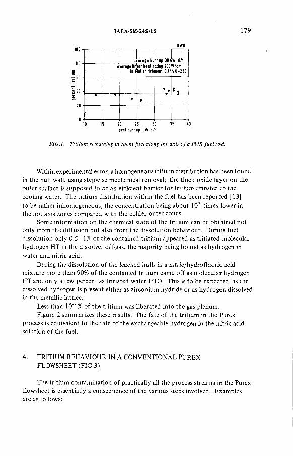
IA E A -S M -2 4 5 /1 5 179
100
80
I 60
¡toa*&
20
010 15 20 25 30 35 10
local burnup G W -d /t
F IG .l. Tritium remaining in spent fu e l along the axis o f a PWR fu e l rod.
Within experimental error, a hom ogeneous tritium distribution has been found in the hull wall, using stepwise mechanical removal; the thick oxide layer on the outer surface is supposed to be an efficient barrier for tritium transfer to the cooling water. The tritium distribution within the fuel has been reported [ 13] to be rather inhom ogeneous, the concentration being about 103 times lower in the hot axis zones compared with the colder outer zones.
Some information on the chemical state o f the tritium can be obtained not only from the diffusion but also from the dissolution behaviour. During fuel dissolution only 0 .5—1% o f the contained tritium appeared as tritiated molecular hydrogen HT in the dissolver off-gas, the majority being bound as hydrogen in water and nitric acid.
During the dissolution o f the leached hulls in a nitric/hydrofluoric acid mixture more than 90% of the contained tritium came o ff as molecular hydrogen HT and only a few percent as tritiated water НТО. This is to be expected, as the dissolved hydrogen is present either as zirconium hydride or as hydrogen dissolved in the metallic lattice.
Less than 10'3% o f the tritium was liberated into the gas plenum.Figure 2 summarizes these results. The fate o f the tritium in the Purex
process is equivalent to the fate o f the exchangeable hydrogen in the nitric acid solution o f the fuel.
4. TRITIUM BEHAVIOUR IN A CONVENTIONAL PUREX FLOWSHEET (FIG.3)
The tritium contamination o f practically all the process streams in the Purex flowsheet is essentially a consequence o f the various steps involved. Examples are as follows:
KWU
d e ra q e bulnup 30 G W -d /t
-overage Un
! m itear heat r ial enrich
ating 200 ment 3.1°
if/cm/.U -2 3 5
• •• •
-

180 H E N R IC H e t a l.
sh e a r o f f -g a str it ia te d w a te r and m ole cu la r hydrogen
d isso lve r o ff-g a s tr it ia te d m o le cu la r hydrogen
fu e l so lutiontr it ia te d vioter and n it r ic acid
leached h u lls zirconium hydrides
<10'3 •/.
0.2 -0.4 V,
3 7 1 5 V.
63 s 5 7.
FIG. 2. Tritium behaviour during dissolution of PWR fuel.
input , output n itric acid t fiss ion products
w a te r ] I t r it ia te d w astew ater
e x tra c tio n ^ reextraction extraction / reextrac tio ndissolved and entrained 'e x tra c to raqueous phase in organic product stream - 1 Val 7o
I R I Regeneration of aqueous and organic solvent for recycle
product
O.Pu
FIG.3. Simplified Purex flowsheet.
(a) Contact between areas o f different tritium contam ination levels.(b) Interconnection o f various aqueous cycles containing different levels o f
tritium, owing to com m on acid and water recovery systems.(c) Cross contam ination due to recycling.(d) Contact o f nitric acid solutions with organic phases during extraction
giving rise to dissolved and entrained contaminants which are carried by the organic phases [14] to the following aqueous cycles. (Note: as solubility and entrainment depend on temperature, com position and purity o f both phases, usually about 1% o f the organic volume is soluble and entrained aqueous solution; the entrainment is about 0.1%).
(e) The large volum es o f vessel off-gas can be more or less saturated with tritiated water and nitric acid vapour. Although removal o f this vapour, e.g. by condensing, freezing, drying or washing with non-tritiated acid solutions in plate colum ns [15 ], does not present any problem,it can produce econom ic

IA E A -S M -2 4 5 /1 5 181
penalties in dealing with large off-gas volumes. If the emission o f large volumes o f water vapour is avoided, then aqueous waste streams will arise in many plant areas with different degrees o f tritium contam ination which will com plicate storage, conditioning and final disposal.
5. ADAPTATION OF THE PUREX FLOWSHEET
A better control o f tritium will be obtained if the following conditions are adhered to in designing the flowsheet:
(a) the tritium contam ination should be restricted to a small area o f the plant,and
(b) the tritium should be confined in a small volum e o f tritiated waste water.
These conditions apply not only for tritium but also for all the other waste nuclides.
Figure 4 shows the flowsheet adaptations in a simplified form. This includes a suitable plant area for concentrating the tritium in the first aqueous cycle in the head-end. This area should be equipped with its own tritiated acid and water recovery system . Additionally, the dissolved and entrained tritiated aqueous phase in the organic product stream HSP must be removed before re-extraction to avoid tritium carry-over to the second cycle. This is achieved by scrubbing the organic product stream with non-triatiated nitric acid in a countercurrent contactor, where the tritiated phase is replaced by the non-tritiated scrub acid. This can be done by using a large excess o f non-tritiated acid together with the usual fission product scrub HS, or in a separate tritium scrubber HT with only a small excess o f acid.By these actions the tritium contamination in the plant is restricted and only part o f the vessel off-gas from the first aqueous cycle and the highly active waste treatment are contaminated with tritiated water vapour.
The concentration o f tritium in a small volum e o f tritiated waste water is obtained by recycling the aqueous phase to a reasonable degree (see Fig.5). Since the aqueous exchangeable hydrogen inventory o f the tritiated plant region is constant, the input equals the output. By limiting the water input the waste water output is reduced correspondingly. Recycling o f the purified aqueous and organic solvents is a general principle in waste volume reduction. The recycle factor R indicates how frequently the solvent is re-used before being discarded.
The tritium concentration and inventory in the first aqueous cycle increases proportionally to the recycle factor. Therefore, the small sinks o f water in the system , e.g. in the organic product stream and the vessel off-gas, becom e more important and the increasing tritium loss must be com pensated for by better retention.

182 H E N R IC H e t al.
input output
• nitric acid I 4 - fiss ion products•w a te r I I • tr it ia ted waste water
> 'I^recycled triliated water
tritium free organic product stream
to reextraction
extractioncycle
1BX
I B S
I
L f ^ solvent , wash
iiit™
11 1C
ii
I T ■1 to second
I 1 U-CYcte
to second Pu cycle
FIG.4. S im plified Purex flow sheet adapted to confinem ent o f tritium.
6. BEHAVIOUR OF TRITIUM IN A MODIFIED PUREX FLOWSHEET
The behaviour o f tritium in a standard Purex process supplemented by a tritium scrub and a separate acid and water recovery is explained in Fig.6. A tritium scrubber HT is added to the usual double scrub for Zr and Ru with high and low acid. The flows are given in m 3/t o f uranium and the proposed organic to aqueous flow ratio is 25 for the tritium scrubber. The organic phase is assumed to carry 1 vol.% o f dissolved and entrained aqueous phase, corresponding to0.1 m 3/t o f uranium.
Without recycling acid and water from the recovery system the tritium is scrubbed very efficiently in each o f the three scrub sections and is contained in 6 m 3/t o f uranium o f the highly active waste.
On recycling 15 times, the tritium concentration in the recycled HSS scrub acid will be about 15 times higher; the tritium corresponding to 1 t o f uranium is contained

IA E A -S M -2 4 5 /1 5 183
I in fu e l
H2Ow a te r
HNO3 (RH)n i t r i c ac id (re d u c ta n ts )
F (H ) fe e d f lo w = W (H) w a s te f lo w
„ i , . R (H ) re c y c le f lo wR re cyc le fa c to r = - --------------------------------
F (H ) fe e d f lo w
FIG .5. Recycling, a principle o f waste volum e reduction.
in 0.4 m 3 o f tritiated waste water. The 0.1 m 3/t o f uranium carried by the organic product stream then corresponds to 25% o f the tritium present in the fuel or 10% o f the total tritium, assuming 60% tritium removal with the leached hulls. If less than 0.1% should be carried to the 2 and 3 aqueous cycles, this corresponds to a decontam ination factor o f 100 for the tritium scrubber. The larger the recycle factor the better the decontam ination factor o f the tritium scrubber should be.
6.1. Determination o f exchangeable hydrogen
A m ethod has been developed which picks up all the exchangeable hydrogen in the organic solution. A few millilitres o f 99.7% heavy water or nitric acid solution are shaken with a few millilitres o f organic product solution in a closed optical cell. The extracted light hydrogen from the organic phase can be determined spectrophotom etrically in the aqueous phase by the light water absorption in the near infra-red. Figure 7 shows the light water spectrum in heavy water, the calibration curve being approximately linear up to about 10 mol%.
Using HSP samples from the reprocessing plant in Karlsruhe (WAK) with 4 0 —60 g U /ltr in 30% TBP/dodecane, the amount o f exchangeable hydrogen determined by this m ethod was usually found to correspond to about 9 ml o f water per litre o f solvent, including entrainment and acid solubility [16].

184 H E N R IC H e t al.
• nitrogen dioxide•100V. HIM,
• nontritioted waterГ
• tr i t ia te d waste water IV . T
i:
ij i * ir i il a te a was le v1er I n 0 . lm 3 /t_U -
M , НПО] recover jr system Ш
ЩьО100V.T. T750 Ci i i ® : :
recycle «
tactori
leached hulls] Т - 6 0 ' / .
1 8 7 . T Н А Г
1.1HAS
HIS
!ТШ;
тж
tritium scrubber ilow rô tie 25 I stages
~ fa
W№ГЙАХ
¥1 НА
HS
Т
• 4 «Т
medium active waste i«10-! '/ .I
l,-I '1
radiolytic^exchange1 1C
i:recycle factor10’
1В X
JLHIP
- je t t ra n s te rs with tr it ia te d steam I- n eg lig ib le loss of tr it ia te d vapours with the VOG
- no hydrogen containing denitration reagents I x approximate flow in m ] /tU
IBS
I________ I
(accumulated .organic ,I tr itiu m -1 0 '2 ,/ Л
i !1-0.1 dissolvedl i and entrained i ' aqueous phase I in H S P -1 0 7 .il I organic solvent]
to second Pu cycle
0. 1 7 .T
FIG. 6. Behaviour of tritium in a simplified Purex flowsheet.
6.2. The tritium scrubber
The volume o f the non-tritiated scrub acid should be small since it contributes to the output o f tritiated waste water. The necessary minimum o f scrub acid for com plete exchange equals the amount in the organic product solution.In this case at an organic to aqueous flow ratio o f about 100, an infinite number o f stages is necessary in the scrubber. For a finite and practicable number o f stages, an excess o f scrub acid is necessary. The decontam ination factor o f a tritium scrubber calculated for a 1.5 to eightfold excess o f scrub acid is shown in Fig.8.
For the extrem e flow ratios, the axial mixing effects caused by the slow linear flow o f the aqueous phase may cause problems in practical extractioñ equipment. For technical application the flow ratio should be markedly less than 100. It has been reported [12] that mixer settlers, especially o f the Holley- Mott type, as well as pulsed columns, are suitable for flow ratios up to 100.

extin
ctio
n
IA E A -S M -2 4 5 /1 5
wave (ength jim
FIG. 7. Spectrum o f H 20 in D 20.
number of stagesg . e»chanqeablc H in »crub acid
* exchangeable H in organic solution
FIG.8. Decontamination factor o f a tritium scrubber.
186 H E N R IC H e t al.
Tritium exchange with the organic hydrogen in TBP and the diluent in a radiation field was reported to be small [17]. At a radiation dose o f 106 rad, corresponding to som e ten extraction cycles, only about 3 X 10"3% o f the tritium was found to be inextractable with 3M nitric acid; about 2 X 10'3% was removed by 0.5M Na2C 0 3 , indicating a tritium preference for the carbonate soluble degradation products.
From these data it may be assumed that even with a recycle factor o f 15 for the first aqueous cycle, less than 10'2% o f the tritium input o f LWR fuel passes the tritium scrubber in organic form. Most o f this tritium will be removed with the medium active waste from the solvent wash. The inextractable tritium will accumulate in the recirculating solvent, eventually attaining fairly high concentrations for organic recycle factors o f about 103 . Radiolytic leaking o f organic tritium into the Pu or U cycles is expected to be low , because o f the lower dose rates in the re-extraction.
6.3. Radiolytic exchange o f tritium
7. SOURCES OF EXCHANGEABLE HYDROGEN FOR THE TRITIATED PLANT AREA
A controlled discharge o f tritiated waste water will be made only from the acid- and water-recovery system. The water is separated by distillation and rectification from the fission products and the nitric acid in the highly active waste stream.
Important sources o f non-tritiated water and nitric acid for the tritium plant area are listed below . For sim plicity, the hydrogen in nitric acid is expressed as water.
(a) The non-tritiated scrub acid for a tritium scrubber with an organic-to- aqueous flow ratio between 10—100 corresponds to a water input o f about0.1 — 1 m 3/t o f uranium. For more accurate calculations the differencein the acid and water content o f loaded and unloaded organic phases should be considered.
(b) Two m oles o f nitrate per m ole o f uranium are removed as uranyl-nitrate with the organic product. The acid has to be replaced; the higher the concentration the lower the water input.
Concentrated nitric acid Fuming (100%) nitric acid Nitrogen dioxide
0.36 m 3/t U 0.075 m 3/ t U 0 m 3/t U

IA E A -S M -2 4 5 /1 5 187
An appreciable fraction o f the acid required may be necessary for N 0 2- sparging at the fuel solution for efficient fission product iodine removal [18]. Apart from the low hydrogen content, fuming nitric acid [19] offers additional advantages, which can be summarized as follows: the acid concentration in hot cells is replaced by the concentration outside at very much simpler conditions.
(c) A steam jet transfer dilutes the fuel solution by about 6 vol.%. Assuming only 3 transfers with non-tritiated steam, this introduces about 0.6 m 3/t o f uranium. This considerable source o f water can only be eliminated by using a separate steam generation system for tritiated water, or by a transfer using pumps, air lifts, etc.
(d) Denitration reactions in the highly active waste concentrates, using hydrogen containing reductants such as formol, form ic acid or sugar, contribute their own reaction water, e.g. CH20 + 2 H N 0 3 -*■ C 0 2 + NO + N 0 2 + 2H20 ;the destruction o f 4 m oles H N 0 3 per m ole o f uranium results in, for example, about 0.15 m 3/t o f uranium.
(e) Recycling, especially o f waste concentrates from the non-tritiated second and third extraction cycles, may be useful in reducing the waste volumesand product losses. In principle, suitable recycled streams (aqueous raffinates, especially from the second Pu-cycle, containing the tritium in case o f a breakdown o f the tritium scrubber) may be used also for the tritium scrub.
(f) Usually a large volum e o f vessel off-gas becom es an appreciable sink for tritiated water vapour especially when using large recycle factors. Since the tritium is concentrated together with the fission products, the off-gas from the storage tanks o f the highly active liquid waste should be reduced to the amount necessary to dilute the radiolytically produced hydrogen. Fortunately, realistic hydrogen production rates in highly active process solutions are more than two orders o f magnitude lower than those from pure water [20].
Assuming a total o f only 103m 3 vessel off-gas/t o f uranium and a water vapour concentration o f 1% by volum e (corresponding to a dew point o f 7°C) this gives a loss o f 8 ltr/t o f uranium. The replacement o f the tritiated vapour by washing with about a fourfold volum e o f water in a countercurrent plate colum n will result in an addition o f about 24 Itr/t o f uranium.
A very crude estim ation o f the possibilities for minimizing these water sources may give about 0.5 m 3/t o f uranium tritiated waste water, corresponding to a recycle factor o f about 12, depending on the flowsheet.
188 H E N R IC H e t al.
8. DISADVANTAGES CONNECTED WITH THE FLOWSHEET MODIFICATIONS
The main disadvantages o f the discussed flowsheet are connected with the high recycle factors necessary for the tritium concentration in a small volume of waste water.
(a) An additional tritium scrubber with an extreme flow ratio is necessary to minimize the volum e o f tritiated waste water.
(b) The decontam ination factor necessary for the tritium scrubber increases in proportion to the recycle factor.
(c) The tritium emission in the off-gas system s increases in proportion to the recycle factor; even small leaks in the system may cause large fractional losses o f tritium. Scrubbing the off-gas with non-tritiated water might remove the tritiated water vapour almost com pletely.
(d) Steam jets should be operated with tritiated steam generated from a separate system or they should be replaced by pumps, air lifts, etc.
(e) Impurity levels may increase with the recycle factor, lowering the decontamination factors and increasing product losses during extraction, and they may also disturb the fission product iodine removal from the fuel solution.
(f) Inventory and concentration o f tritium in the head-end increases the local safety problems for the plant personnel.
9. INTERACTION WITH TRITIUM WASTE TREATMENT
Recycling as far as possible is not necessarily a virtue. Econom ic justification for the additional com plication o f the Purex flowsheet or even further physicochemical procedures to concentrate the tritium depend on the conditioning and the final storage o f the tritiated water.
If large volumes o f tritiated water were allowed to be placed directly into the deep isolated underground or the sea, extrem e recycling would be unnecessary. Alternatively, if an extrem ely good and expensive conditioning o f tritium water is necessary for transport or final storage then recycling in the plant, as far as achievable, will becom e important.
Possible optional flowsheets will have to await a decision on final storage.
REFERENCES
[ l] ALBESENIUS, E.L., ODREJCIN, R.S., Nucleonics 18 (1960) 100.[2] SMITH, J.M., GILBERT, R.S., Trans. Am. Nucl. Soc. 14 (1971) 160.
LOCANTE, J., Trans. Am. Nucl. Soc. 14 (1971) 161.
IA E A -S M -2 4 5 /1 5 189
[3] HAUG, H., Kemforschungszentrum Karlsruhe, Karlsruhe, Rep. KfK-1945 and Rep. KfK-2022 (1975).
[4] MEEK, M.E., RIDER, B.F., General Electric Co., San Jose, CA, GE-Report NEDO-12154-1 (1974).
[5] SCHNEZ, H., LASER, M., MERZ, E., Kemforschungsanlage Jülich GmbH.,Rep. Jül-1099-СТ (1974).
[6 ] DOLLE, L., BAZIN, J., Technische Vereinigung der Grosskraftwerksbetreiber e.V.,Essen, VGB-Speisewassertagung (1978) 50.
[7] KOELZER, W., Chemie der Nuklearen Entsorgung (BAUMGARTNER, F., Ed.) 65,Verlag Thimig, M unich(1978) 139.
[8 ] BAUMGARTNER, F., et al., Kernforschungszentrum Karlsruhe, Karlsruhe, KfK-PWA Status Report (1977).
[9] GOODE, J.H., Oak Ridge National Lab., TN, Rep. ORNL-TM-3723 (1973).[10] BERNARD, C., Brevet francis N o .7 .318.073 (1973).[11] NEEB, K.H., Chemie der Nuklearen Entsorgung (BAUMGARTNER, F., Ed.) 65, Verlag
Thimig (1978) 56.[12] MIQUEL, P., GOUMONDY, J.P., SCHNEIDER, E., Radioactive Effluents from
Reprocessing Plants, Seminar Karlsruhe (Nov. 1977) 497.[13] NEEB, K.H., et al., J. Radioanal. Chem. 3 2 (1976) 523.[14] STOLLER, S.M., RICHARDS, R.B., (Eds), Reactor Handbook II, 2nd Rev. Edn,
Interscience, New York (1961).[15] HENRICH, E., Kemforschungszentrum Karlsruhe, Karlsruhe (unpublished).[16] BURKHARDT, H.G., HENRICH, E., KNITTEL, G., FANG, D., Kernforschungszentrum
Karlsruhe, Karlsruhe (1979) (unpublished results).[17] SAMEH, A., et al., KFK Nachr. 3 (1979) 37.[18] HENRICH, E., HÜFNER, R., SAHM, A., “Improved procedures for efficient iodine
removal from fuel solutions in reprocessing plants” , Management o f Gaseous Wastes from Nuclear Facilities, these Proceedings, IAEA-SM-245/16.
[19] HENRICH, E., et al., Reaktortagung Düsseldorf (1976).[20] BECKER, R., BURKHARDT, H.G., NEEB, K.H., WÜRTZ, R., “ Radiolytically
generated hydrogen from Purex solutions” , these Proceedings, IAEA-SM -245/13.
DISCUSSION
H. BRÜCHER: Did you investigate the tritium distribution within the outer and inner oxide layers? Why does tritium enter the Zircaloy cladding but does not exchange with the reactor cooling circuit?
E. HENRICH: The tritium distribution within the oxide layers was not determined. I think Dr. Kroebel may be able to reply to your second question.
R. KROEBEL: A possible answer may be that the first process involves HT capture by Zircaloy, whereas the exchange between zirconium hydride and water requires H20 or НТО exchange.

IA E A -S M -2 4 5 /2 9
PROCESSES FO R THE CONTROL OF 14C 0 2 DURING REPROCESSING*
K.J. NOTZ, D.W. HOLLADAY,C.W. FORSBERG, G.L. HAAG Oak Ridge National Laboratory,Oak Ridge, Tennessee,United States o f America
Presented by M.J. Stephenson
Abstract
PROCESSES FOR THE CONTROL OF 14C 0 2 DURING REPROCESSING.The fixation of 14COj may be required at some future time because of the significant
fractional contribution of 14C, via the ingestion pathway, to the total population dose from the nuclear fuel cycle, even though the actual quantity o f this dose is very small when compared to natural background. The work described here was done in support o f fuel reprocessing development of both graphite fuel (HTGRs) and metal-clad fuel (LWRs and LMFBRs), and was directed to the control o f 14СОг released during reprocessing operations. However, portions of this work are also applicable to the control of 14СОг released during reactor operation. The work described falls in three major areas: (i) The application o f liquid-slurry fixation with Ca(OH)2, which converts the CO2 to СаСОэ, carried out after treatment of the C0 2 -containing stream to remove other gaseous radioactive components, mainly 8sKr. This approach is primarily for application to HTGR fuel reprocessing, (ii) The above process for C 0 2 fixation, but used ahead of krypton removal, and followed by a molecular sieve process to take out the 85Kr.This approach was developed for use with HTGR reprocessing, but certain aspects also have application to metal-clad fuel reprocessing and to reactor operation, (iii) The use o f solid Ba(OH) 2 hydrate, reacting directly with the gaseous phase. This process is generally applicable to both reprocessing and to reactor operation.
1. INTRODUCTION
During operation of nuclear reactors, some 14C is produced, primarily via neutron activation of 14N, *5N, 160, and 0, with activation of 13C becoming significant in HTGRs [1]. The 11+C may be formed (a) in the fuel from the nitrogen and oxygen reactions and (b) in the moderator from oxygen in water-cooled reactors or from carbon (and nitrogen) in graphite-moderated, helium-cooled reactors. Some 14C is also formed in the metal clad and core hardware, but this is retained in the metal and not released [1]. Table I summarizes the calculated quantities.
* Research sponsored by the Office o f Nuclear Waste Management, United States Department o f Energy, under contract W-7405-eng-26 with Union Carbide Corporation.
191

192 N O T Z e t al.
T a b l e I . p r o d u c e d i n d i f f e r e n t r e a c t o r s
11+C produced [Ci/GW(e)-
Reactor typeIn the fuel
In metal clad and hardware
In the moderator
LWR (water moderated) 20 30-60 8-16
LMFBR (sodium moderated)
6 13
HTGR (graphite
moderated)
12 37-190
Based on the nitrogen contents specified in ref. [1].
The 14С formed in the water of water-moderated LWRs is released during reactor operation as a mixture of CO2 and hydrocarbons,
with CO2 predominant in BWRs and CHi). and C2Hg predominant in PWRs [1]. The reported releases of llfC from Russian reactors
are much higher, 200 to 800 Ci/GW(e)-a, and are apparently due to use of nitrogen gas for pressurization and to use of hydra
zine and ammonium hydroxide in the primary cooling water [1]•In terms of reprocessing plants, the total annual curies of 14C for plants serving 45-GW(e) generating capacity are shown in Table II. The 1¿tC present in the fuel or in the graphite moderator is released primarily as CO2 during reprocessing and
is diluted with varying amounts of air, noble gases, and small amounts of other gases; the 11+C in the metal clad and hardware
is not released.
If released, 14С02 constitutes a small hazard because it can enter the food chain via photosynthesis [2]. The incremental relative global 1L,C hazard from this source, if it were released, can be roughly estimated from these two facts: (a)the natural production rate of 14C (from cosmic-ray-induced
reactions) is about 27 000 Ci /а, and (Ь) contributes about 1% of the natural radiation background [3]. Thus, a
reprocessing plant of the Barnwell type and size would add about 3 x 10"^ fraction to natural background per year of
operation, or about 1% over a 40-year lifetime. In terms of local impact from 14C release, the effects could be greatly reduced by holding 11+C02 during the day and releasing it at night when the photosynthetic uptake of CO2 is essentially nil [4].

IA E A -S M -2 4 5 /2 9 193
Table II. 14С entering reprocessing plants serving
45-GW(e) generating capacity0-
Reactor type
Metric tonnes of
heavy metal per year
In the fuel
14C (Ci/a)
In the hardware or graphite moderator
LWR (Barnwell plant)
1500 ^800 1400-2700
LMFBR (core and blanket)
1500 ^300 600
HTGR (highly enriched)
450 500 1700-7300
^Adapted from ref. [1].
This report summarizes developmental studies done at ORNL
on the control of 1¡*C02 which are applicable to the reprocessing of both metal-clad and graphite-matrix fuels. Some aspects of
this work, primarily that described in Sects. 3 and 4 of this report, are also applicable to the control of 14С02 released during reactor operation.
Our initial studies were carried out in support of HTGR
reprocessing, wherein the off-gas consists of very large amounts of CO2 containing trace amounts of ltfC0 2 , small
amounts of krypton, xenon, and CO, and varying amounts of oxygen and nitrogen. As originally conceived, burner off-gas
(after processing to remove particulates, iodine, water, and
tritium) would first be treated by the krypton absorption in liquid CO2 (KALC) process to remove 85Kr along with other noble
gases [5,6]. The clean CO2 could then either be discharged or, if required, converted to a stable solid form for isolation.The process developed at ORNL for fixation of CO2 is conversion to СаСОз via slurry reaction with slaked lime. This process was shown to be effective in achieving fixation of >99% of the CO2 while also attaining >90% utilization of the slaked lime [7]. Details of this work are described in Sect. 2 of this report.
In a paper study, it was shown that economical disposal of the СаСОз requires that it be low-level waste [8], and this in turn
requires that the prior steps be effective in removing radionuclides other than 1¿tC.

194 N O T Z e t al.
An alternative concept for processing of HTGR off-gas was considered, wherein the СаСОз process precedes 85Kr removal.
This approach greatly simplifies the krypton removal step because the gross amounts of CO2 are no longer present. However,
it places a heavy burden on the carbonate fixation process in that >99% of the 85Kr must pass through so that the СаСОз will
not be escalated out of the low-level category. Therefore, scoping tests were conducted to determine the holdup of 85Kr
on the СаСОз during CO2 fixation [9], as summarized in Sect. 2.It was shown to be feasible to do the carbonate fixation first, keeping the 85Kr retention to <1%, by appropriate sparging.
Because this sequence leaves the krypton diluted primarily by oxygen, the more-complex KALC process, required in the presence
of large amounts of CO2 , is in principle no longer required.The feasibility of using molecular sieves, even in the presence
of some CO2 and xenon, was shown in laboratory tests [10] using a frontal displacement technique, which is described in Sect. 3.
Currently, an alternative process for the CO2 fixation step is under development, based on the gas-phase reaction of
CO2 with Ba(0H)2 hydrate [11]. The key to this reaction is use of an expanded hydrate, which reacts rapidly and completely
at moderate temperature and pressure and is effective to low CO2 concentrations. Details of this work are reported in Sect.4.
2. FIXATION OF CO2 IN ALKALINE SLURRIES
The very large volumes of CO2 arising during reprocessing of HTGR fuel from combustion of the graphite blocks require a
process amenable to these large quantities, both technologically and economically. The rate of off-gas generation is about 30 m 3/min (1000 ft3/min (STP)) in a commercial-scale plant [450 metric tonnes of heavy metal (MTHM) per year], and this gas is largely CO2 • The reference off-gas cleanup scheme for such a plant followed this sequence [12]:
1. oxidation (of any CO or tritium),2. iodine removal (with zeolites),
3. radon holdup for decay of 220Rn (with type 5A
molecular sieve),4. tritiated water removal (with type ЗА molecular
sieve), and5. removal of krypton (via the KALC process).
In the reference process, clean CO2 containing only 14C radioactivity was discharged to the atmosphere. However, it was
recognized that at some future date the fixation of llfC might be required, and therefore the work described in this section

IAEA-SM-245/29 195
was carried out. It had been determined in a paper study [8] that fixation as СаСОз provided a suitable end product, that direct reaction with a Ca(0H)2 slurry should be acceptable, and that the CO2 must be essentially free of any radioactivity other than ltfC to avoid escalating the solid product out of the low- level waste category, which would create a major economic impact. Prior work on this reaction had focused on the production of СаСОз and not on the efficiency of CO2 utilization, which was our interest. Therefore, work was done to obtain data on this latter point. In addition, studies were also done to determine the feasibility of fixing the CO2 as СаСОз prior to the removal of 85Kr; this requires a high decontamination factor (DF) for krypton separation from the СаСОз, but if this can be achieved, subsequent krypton concentration can be performed on a much smaller gas stream using molecular sieves (Sect. 3) rather than the more complex KALC process. Data were also obtained on dilute CO2 streams (about 0.1%) which will derive from LWR fuel reprocessing. Some studies were also made with Ba(0H)2 slurries and with other alkalies.
2.1 The fixation of CO2 with Са(0Н)г from simulated HTGR fuelreprocessing off-gas
The feed gases (pure CO2 down to 5% СОг/95% O2) were contacted with the Ca(0H)2 in a single-stage, 19.6-cm-ID agitated contactor with a quiescent slurry volume of 6.7 liters [7]. The contactor, mechanical drive, and impeller were designed according to the standard criteria [13-15]. The contactor schematic is shown in Fig. 1. The C02~Ca(OR) 2 slurry reaction was studied to determine DFs and values of the interfacial area as a function of impeller speed, gas composition, gas flow rate, Ca(0H)2 concentration, and temperature. These operational parameters were studied for the following ranges: (a) impeller speed, 100 to 1800 rpm;1 (b) gas composition, 100, 87.5, 33.6, and 4.7% CO2 (balance as O2); (c) gas flow rate, 0.85 to 50 ltr/min (STP) (slm); (d) Ca(0H)2 slurry concentration,0.50 to 2.0 M; and (e) temperature, 21 to 46°C. Gas samples were analyzed by a combination of gas chromatography, infrared spectroscopy, flow metering, and mass balances.
The rate at which CO2 transferred to the slurry, the DF, and the pH of the slurry (o,12.5) remained constant even at very high gas flow rates until 90% of the Ca(0H)2 had been utilized (for batch operation); then the pH and the DF decreased rapidly.
1 rp m = re v /m in .

196 N O T Z etal.
FIG.l. Cutaway view o f stirred-cell contactor.
The DF for the C02-Ca(0H)2 reaction varied inversely with gas flow rate and directly with impeller speed and CO2 concentration in the feed gas. Pure CO2 was completely reacted at 10 slm for an impeller speed of 1700 rpm and at 5 slm for 800 rpm. The DF was >3000 for 87.5% CO2 feed at 3.5 slm and 500 for 4.7% CO2 feed at 1 slm. Results of tests showed that DFs of >104 were feasible by operating stirred contactors in series.
The rate of reaction was concluded to be liquid-phase controlled for the feed composition studied and the gas flow rates

IAEA-SM-24S/29 197
studied. By assuming the applicability of the model for gas absorption accompanied by pseudo-first-order reaction, mass transfer coefficients and interfacial areas were calculated for both the plug flow and perfectly backmixed gas models. The interfacial area calculated from the chemical reaction model with plug flow ranged from 0.2 to 3.0 cm2/cm3, depending on superficial velocity and impeller speed. The mass transfer rate was only slightly affected by Са(0Н)г concentration from0.50 to 1.50 M. The mass transfer rate and the DF were virtually independent of temperature over the range 21 to 46°C.
The settling rate of the СаСОз product was dependent onoperating conditions and was measured to provide a qualitative indication of particle size for estimating its separation from - the slurry. The settling rate was found to vary directly with impeller speed and temperature and inversely with gas flow rate.
2.2 The fixation of CO2 from simulated LWR fuel reprocessingoff-gas using alkaline slurries
For this work a dilute C02 stream was used (0.03% C02 inair; also 3% CO2) • In addition to Ca(0H)2, the barium and magnesium hydroxides were also tested. The same general approach was used as before, but the analytical technique was modified because of the very low С0 2 content in the effluent gas; a larger (16-liter) stirred-tank reactor was also used [16].
Decontamination factors and interfacial areas were obtained for the following operating conditions: gas composition, 0.033and 3.0% C02 (balance as air); slurry concentration, 0.4 to 1.5 M; slurry type, Са(0Н)г, Ва(0Н)г‘8Н20, and Mg(OH)2; impeller speed, 325 and 650 rpm; and gas flow rate, 10 to 80 slm. Gas samples were analyzed primarily by infrared spectroscopy because it was the more dependable method for measuring CO2 at the 1 ppm level and below.
Under equivalent operating conditions the DFs for CO2 increased in the same order as the solubilities:
Mg(OH) 2 « Ca(OH) 2 << Ba(0H)2‘8H20 < NaOH (1 N solution) .
The DF for Ba (OH) 2 * 8 ^ 0 is about ten times greater than for Са(0Н)г> which is in turn about ten times greater than for
Mg(OH) 2 (Fig. 2). Although Ba(0H) 2 is more expensive than Ca(0H)2* the total amount of C02 given off during LWR reprocessing is much less than for HTGR reprocessing, thus allowing the economical use of the more expensive reagent. There were no significant differences in DFs obtained for CO2 removed via either semibatch or continuous slurry operation.

DFc
d,
DE
CO
NTA
MIN
ATI
ON
FA
CTO
R FO
R C
02
lMol
C
02
in IN
FLU
EN
T GA
S /
Mol
C
02
In E
FF
LUE
NT
G
AS
)
198 N O T Z etal.
IM P E L L E R S P EED (rpm)
P E R C E N TC02
S LU R R YMOLAR ITY
IM P E L L E ROIA. (cm)
IOOOO —о 650 0.033 0.67 M Bo(OH)2 - SH2 0 137
— ▼ 325 3 000 0.4 OM Bo(OH)2 - 8 H 2 0 12.7
~ Д 650 0.033 i .o o m Co(OH)2 12.7
— A 650 0033 0.50 M Co(0H)2 12.7
— V 350 0 0 3 3 0.50 M Co(OH)2 12.7
— ■ 6S0 0 0 3 3 i oo m Mg(OH)2 12.7
_ • 6 5 0 3 0 0 0 I.OOM Co(OH)2 12 7
Ю00 —
100 —
2 0 4 0 6 0 8 0 100
S U PE R FIC IAL V E L O C IT Y . v .(c m /m m )
140
FIG.2. Decontamination factors for removal o f СОг p o m dilute streams under various conditions and with different reagents.

IAEA-SM-24S/29 199
For the same operating conditions (impeller speed, superficial velocity, temperature, etc.) the DFs in the dilute (0.033% C02) gas were as much as a factor of 5 less than those obtained for a 90% C02~air feed. Based on a plug flow model with a log- mean pressure driving force, interfacial areas varied directly with superficial velocity over the range 0.2 to 2 cm2/cm3. For fixation of CO2 from simulated LWR fuel reprocessing off-gases, it appears feasible to obtain DFs for C02 of 102 to lO4 with Са(0Н)г or barium hydroxide. It was determined that the DFs for C02 removal from LWR-type off-gases:
1. varied directly with impeller speed and impeller diameter;2. varied inversely with slurry concentration and gas flow rate
(however, for Ва(0Н)г slurries, DF varied directly with slurry concentration);
3. varied directly with temperature for slurries in which the solubility of the solids increases with temperature; and
4. varied directly with concentration of C02 in the feed.
Again, the rate of C02 removal was liquid-phase controlled [17,18]. It was possible to model Са(0Н)г slurry reaction by accounting for both the interfacial area and degree of mixing as a function of the hydrodynamic parameters. However, Ва(0Н)г slurries could not be characterized using simple plug flow or backmix models.
2.3 Fixation of CO2 as СаСОз in the presence of krypton
These studies were conducted with gas mixtures that approximated the HTGR off-gas composition of 90% CO2 , 7.5% O2, 2.5% N 2, 16 ppm total Kr, 1.0 ppm 85Kr, and 61 ppm Xe [19]. The ranges of variables studied for the HTGR off-gas processing were (a) impeller speed, 650 and 800 rpm; (b) CO2 feed gas concentration, 88 to 97%; (c) superficial gas velocity, 10 to 110 cm/min; (d) Ca(0H)2 slurry concentration, 0.5, 1.0, and2.0 M; (e ) krypton feed-gas concentration, 18 to 180 ppm; (/) temperature, 20 to 60°C; and (g) both batch and single and series continuous stirred-tank operation. The stirred-tank reactor used was the same as that described in Sect. 2.1. The xenon concentration was <60 ppm. It was the specific goal of these studies to determine the feasibility of removing CO2 from HTGR fuel reprocessing off-gas prior to krypton removal, with conditions of operation developed to minimize the krypton retention in the СаСОз slurry. Experiments were conducted to determine the distribution of krypton. These DFs and separation factors (SFs) were defined:

200 NOTZ et al.
тлт. c ™ moles of CO? into contactor in feed gasDF for CO? = ------;-----r „r,-----7—:---------TT-,-- 1-“— ,moles of CO2 out m effluent gas ’
SF for Kr = m°les Kr lilt о contactor in feed gasmoles of Kr remaining in the slurry
Thus, a high DF for CO2 indicates effective fixation while a high SF for krypton indicates good decontamination of the CaC03 from krypton. Decontamination factors for CO2 in the 102 to 103 range were feasible for CO2 removal in single-stage contactors and DFs for CO2 of 103 to lO1* were feasible for two-stage contactor operation. Separation factors for krypton were 100 to 200 for the primary contactor operation, and add-on SFs for krypton of an additional 100 could be readily obtained by evacuation or sparging of the stirred product slurry. Thus, total SFs for krypton of 10^ to 105 could be obtained by using a combination of primary processes and add-on treatments.
Experimentally, the following parametric relationships were established:
1. The DFs for CO2 varied inversely with gas superficial velocity, while the SFs for krypton had a slight direct variation with superficial velocity.
2. The DFs for CO2 varied inversely with slurry molality, while the SFs for krypton varied directly with slurry molality.
3. The DFs for CO2 had a slight direct variation with temperature, while the SFs for krypton were not
affected.4. The DFs for CO2 varied directly with impeller speed.5. The DFs for CO2 varied directly with CO2 mole
fraction in the feed gas, while the SFs for kryptonvaried inversely with CO2 mole fraction in the feed gas.
6. With two contactors in series, the overall DFs forCO2 varied directly with the extent of the conversion of CO2 that occurred in tank 2, while the overall SFsfor krypton varied inversely with the extent of CO2conversion in tank 2.
The development of the most useful models for prediction of DFs for CO2 and krypton or for prediction of scaled-up contactor dimensions was dependent on expressions for the interfacial area. Interfacial area could be estimated either from a general hydrodynamic correlation or from an expression constructed from the experimental data of the bench-scale contactors of this study. The general rate expression was patterned after the studies of Juvekar and Sharma [20], in which the reaction is basically pseudo-first order with control in the liquid phase.
IAEA-SM-245/29 201
Molecular sieves were investigated experimentally for the separation of krypton and C02 from dry off-gas streams of the type that would result from separations such as those described in Sect. 2. Molecular sieves are a class of highly inert, inorganic zeolites which can adsorb ^100 cm3 (STP)/g of certain gases and be regenerated by heating or depressurization. A potential difficulty is that C02 and krypton have very similar sorptive properties. A series of calculations and experiments were conducted to determine the value of molecular sieves for this application. The two most successful approaches are described below.
For selective removal of C02 from off-gas streams containing krypton, molecular sieve 4A was found to perform adequately. Adsorption by molecular sieves depends on the molecule to be adsorbed having both the proper size and geometry to fit within the molecular sieve lattice and having appropriate intermolecular attractive forces between the molecule and sieve. Molecular sieve ЗА has too small a lattice to adsorb C02 , whereas molecular sieve 5A was found to adsorb both CO2 and krypton. Molecular sieve size 4A has been reported to adsorb krypton at high pressures and moderate temperatures [21], but the rate of adsorption appears near zero when operating pressures are1 x 105 to 3 x 10⁵ Pa and the operating temperature is near 0°C.
A series of experiments using a 95-cm-long molecular sieve adsorption column was conducted to obtain the above results.The commercial 4A molecular sieve used in these tests was in the bead form as manufactured by Linde Division of Union Carbide Corporation. All experiments used a premixed feed gas of 93.1% CO2, 5.4% 02 , and 1.5% Kr. The krypton concentrations were measured using 85Kr tracer; the C02 content was measured with an infrared analyzer. Tests were conducted at 0°C over the pressure range 1.0 x 10 to 2.3 x 10⁵ Pa. The measured C02 levels in the gas after passing through the molecular sieve were <10 ppm — the limit of detection for C02 of the analyticalequipment that was used. The bed was easily regenerated byheating to 200°C. The length of the mass transfer zone for C02 adsorption varied from 11.8 cm at a gas flow rate of 7.22 cm3/cm2 'min at 1.01 x 10⁵ Pa to 4.3 cm with a flow rate of 10.32 cm3/cm2,min at 1.7 x 10^ Pa. The mass transfer zone isdefined herein as the distance through the bed where the- C02concentration in the gas phase changed by 80% of the difference between the feed gas and outlet gas concentrations.
To separate krypton and C02 from the off-gas and from each other, experiments showed that molecular sieve 5A used as a
3. SEPARATION OF 14C02 AND 85Kr VIA MOLECULAR SIEVES
202 NOTZ et al.
frontal analysis gas phase chromatograph provided good separations. The principle of operation of this device is as follows. If a gas mixture of krypton, oxygen, and CO2 flows through a bed of 5A molecular sieve near atmospheric pressure at 0°C, both CO2 and krypton will be adsorbed. Carbon dioxide is, however, more strongly adsorbed than krypton and thus will displace krypton gas from the bed. In examining a long molecular sieve bed supplied with a feed gas of oxygen, krypton, and С0г> one observes that the zone of the molecular sieve bed nearest the feed point is saturated with CO2 while the gas phase contains the feed gas. At the end of this zone, there is a transition region where CO2 is being adsorbed onto the bed and krypton is being displaced from the bed into the gas phase. Beyond this first transition region is a zone where adsorbed krypton is being held by the bed and only oxygen and krypton exist in the gas phase. At the end of this zone lies a second transition region where krypton is being adsorbed onto the bed. Beyond the latter region are found only oxygen and a molecular sieve bed with very little adsorbed gas.
If the gas mixture is fed continuously to the bed and the gas exiting the bed is analyzed, a "bubble" of oxygen is first observed, followed by and pushed out successively by a bubble of krypton containing some oxygen and by the feed gas. At the end of this process, the bed is saturated with CO2 . Heat is generated during the process; therefore, provisions for heat dissipation must be included since the bed must be kept at constant temperature to ensure good separations. With two or more beds, continuous operation can be provided.
The above separation approach was verified experimentally with the equipment and feed gas described earlier. The molecular sieve was in the form of 1/16-in. pellets as supplied by Linde.A series of ten runs was made with pressures from 1.0 x 10⁵ to 2.36 x 10^ Pa and gas flow rates from 7.6 to 152.9 cm3/cm2,min. The results of a typical run are shown in Fig. 3. In the single molecular sieve bed, krypton was concentrated from 1.5% to 52 to 62% depending on the experiment. The length of the mass transfer zone between the krypton and CO2 varied from 1.0 to 3.1 cm. Theoretical calculations of krypton, oxygen, and CO2 separations with this process were made and agreed with the experimental values obtained. Additional experiments with xenon added as an impurity indicated that this impurity presented no problem. As with earlier experiments, CO2 levels were reduced below 10 ppm in the krypton and oxygen product streams.
Molecular sieves offer a simple way to separate dilute CO2 from an off-gas stream. When the molecular sieve is regenerated,

IAEA-SM-245/29 203
0 . 9СОcdu 0 . 8
S o-Tш<*-. 0.6 о
С 0 . 5 о
o O . hя)и0 . 3
V? 0 . 2
i . о
0.1
о 15 30 U 5 60 75 90 1 0 5 1 2 0 1 3 5 1 5 0
T i m e f r o m S t a r t o f E x p e r i m e n t ( m i n ) « G a s F l o w i n t o B e d
M o l e c u l a r S i e v e :
F e e d G a s :B e d C o n d i t i o n s :
F e e d G a s F l o w :
B e d L e n g t h :
L i n d e 5A9 3 . 0 9 ? C 0 2 , 5 - *• 35È 0 2 , 1.1*8? Kr
0°C, 1 . 1 6 x 1 0 5 P a d . l i t a t m ) 1*8.9 c m 3 ( S T P ) • cm'2 • m i n"'
9 1*. 6 c m ( 3 7 . 2 5 in.)
FIG.3. Gas composition from molecular sieve bed versus time.
a concentrated CO2 stream is generated. For separating С02 and krypton from other gases, particularly if the krypton has been partially concentrated, molecular sieves show potential as a separation device for small to intermediate gas flow rates.For large gas flows with high C02 levels, molecular sieves may not be appropriate because of excessive bed size and/or heat loads.
4. FIXATION OF C02 ON SOLID Ba(0H)2 HYDRATE
Fixation of C02 on beds of Ba(0H)2 hydrate has many attractive features [11]. This process would eliminate the need for liquid-solid separation equipment, the handling of liquid streams, and when operated in a packed-bed mode, it would be considerably simpler. Use of Ba(0H)2 hydrate is superior to other solids, most notably CaO or Ca(0H)2, as the reaction has been shown to be kinetically possible at ambient conditions with final reactant
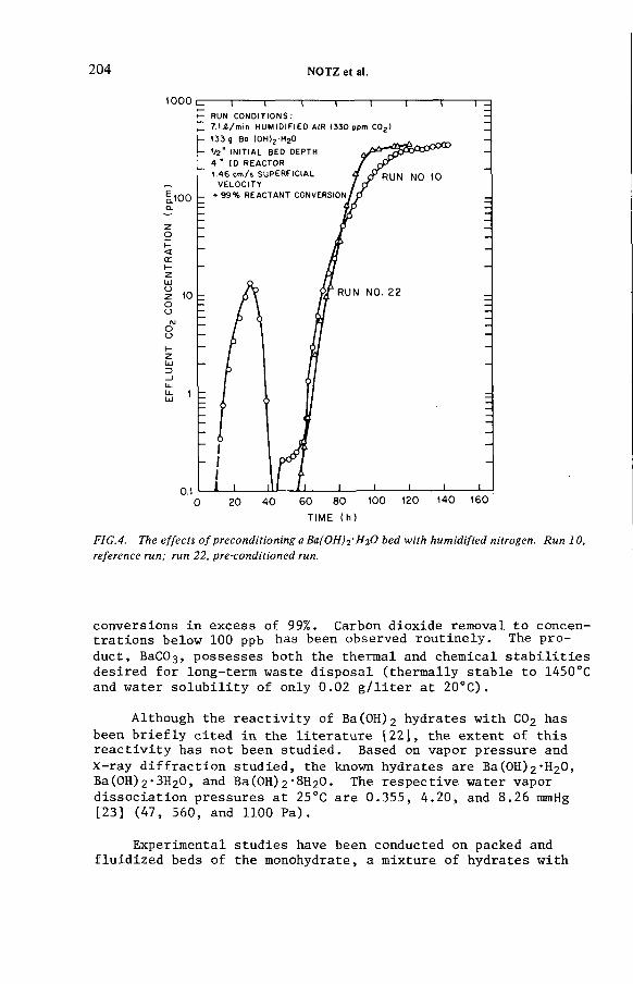
204 NOTZ et al.
TIME (h )
FIG.4. The effects o f preconditioning а Ва(ОН)г'НгО bed with humidified nitrogen. Run 10, reference run; run 22, pre-conditioned run.
conversions in excess of 99%. Carbon dioxide removal to concentrations below 100 ppb has been observed routinely. The pro
duct, ВаСОз, possesses both the thermal and chemical stabilities desired for long-term waste disposal (thermally stable to 1450°C and water solubility of only 0.02 g/liter at 20°C).
Although the reactivity of Ba(0H )2 hydrates with С02 has been briefly cited in the literature [22], the extent of this reactivity has not been studied. Based on vapor pressure and X-ray diffraction studied, the known hydrates are Ba(0H)2 "H20, Ba(0H)2 -3H 20, and Ba(0H)2 ’8H 2 0. The respective water vapor dissociation pressures at 25°C are 0.355, 4.20, and 8.26 mmHg [23] (47, 560, and 1100 Pa).
Experimental studies have been conducted on packed and fluidized beds of the monohydrate, a mixture of hydrates with
IAEA-SM-24S/29 205
an overall stoichiometry of Ba(OH)2 *5^0, and the octahydrate.The packed-bed concept is preferred from an operational perspective due to the overall simplicity. Experimental studies have concentrated primarily on the treatment of high volumetric air gas streams containing a low concentration of CO2 (330 ppm). Brief studies have been conducted on gas streams containing 5 and 88% C02 .
Results have indicated that although Ba(0H)2 "H20 is unreactive toward CO2 in a dry air stream, the material expands and becomes quite active when the water vapor pressure of the surrounding gas exceeds the dissociation vapor pressure of Ba(OH) 2 *8^0.The resulting formation of Ва(0Н)2 *8Нг0 has been confirmed by X-ray diffraction patterns. As shown by run 10 (Fig. 4) a bed of Ba(0H)2 *H2Û undergoes a conditioning period when contacted with a humid, C02~bearing gas. During this period, the activity of the bed decreases and then increases. The initially high reactivity is attributed to residual Ba (OH) 2 ‘8 ^ 0 which may be present in the bed. The subsequent improvement in reactivity is due to the hydration of Ba(0H)2 *H2Û to Ba(0H )2 ‘8^ 0 . As indicated by run 2 2, it is possible to precondition a bed by contacting it with a humid, inert gas. In both cases, a bed volume increase of ^150% was observed due to the formation of Ba (OH) 2 *8^ 0 , and final reactant conversions in excess of 99% were obtained. The ВаСОз product is friable, and excessive pressure drop could be an operational problem. Studies conducted in the fluidized-bed mode have been promising although the entrainment of fines has been a problem.
A brief examination of gas streams with a higher CO2 content has been conducted. As shown in Fig. 5, beds of -5 +20 mesh Ba(OH)2 'hydrate containing an inert diluent are capable of high CO2 removal efficiencies during the treatment of an 88% CO2 gas stream. However, due to the overall stoichiometry of the reaction,
Ba(0H) 2 ’8H20 + C02 -»■ BaC03 + 9H20 ,
nine water molecules are released for each CO2 molecule that reacts. Therefore, for the treatment of a C02~rich gas stream, the feed gas will quickly become water saturated. Because the remainder of the water product cannot leave the system as vapor, thereby carrying a heat load with it, the reaction shifts from 81.9 kcal/ g-mol. endothermie to 12.7 kcal/g-mol. exothermic. Cooling capabilities or dispersion of the reactant will then be required during large-bed applications to avoid melting of the reactant (MP of the octahydrate is 78°C). Condensed water has been observed within the reactor vessel although no deleterious effect on the overall reaction has been noted. For treatment of gas streams rich in CO2 with beds of Ba(0H)2 ‘H 2 0, no preconditioning

206 NOTZ et al.
ELAPSED TIME (min)
FIG.5. Reaction o f BafOH)^' H2O with humidified 88% COj.
step is required; the reaction is driven by the high CO2 level at the inlet end, liberating water which hydrates (and activates) the downstream end of the bed. Work in progress has shown that intermediate hydration provides a suitable compromise between volume change and chemical reactivity.
5. SUMMARY
The work described outlines methods applicable to the fixation of ll4C-containing CO2 evolved during the reprocessing of both graphite-based and metal-clad fuel. Some of these methods

IAEA-SM-245/29 207
are also applicable to control of 11+C evolved during reactor operation, particularly BWRs. In summary:
• For C02~rich off-gas from HTGR fuel reprocessing, the wet slurry process using Ca(0H )2 is both effective and economical. Although initially developed for use after 85Kr removal, it was shown that C02 fixation can be done first, leaving a relatively small gas stream to be treated for concentration of the krypton.
• For C02-dilute off-gas from LWR (and LMFBR) fuel reprocessing, the wet slurry process is also effective, with Ba(0H)2 hydrate being more effective than Ca(0H)2- The much smaller amount of total CO2 in this case allows use of the more expensive reagent.
• Molecular sieves can be used to separate krypton and C02 from each other in dilute, air-like streams resulting from reprocessing operations. This approach is also suitable to reactor off-gases.
• A solid-gas phase reaction using Ва(0Н)г hydrates to remove CO2 from gas streams is very effective. This approach is applicable to all of the sources mentioned above except the high-volume, high-concentration C02 from HTGR fuel reprocessing.
REFERENCES
[1] DAVIS, W. JR., Carbon-14 Production in Nuclear Reactors, ORNL/NUREG/TM-12 (February 1977).
[2] KILLOUGH, G. G., A Diffusion-Type Model of the GlobalCarbon Cycle for the Estimation of Dose to the WorldPopulation from Releases of Carbon-14 to the Atmosphere, ORNL-5269 (May 1977).
[3] KILLOUGH, G. G., TILL, J. E., Scenarios of ll+C releasesfrom the world nuclear power industry from 1975 to 2020and the estimated radiological impact, Nucl. Saf. 19_ 5 (1978) 602.
[4] SNIDER, J. W . , KAYE, S. V., "Process Behavior and Environmental Assessment of 14С Releases from an HTGR Fuel Reprocessing Facility," presented at a Topical Meeting of the American Nuclear Society — American Institute of Chemical Engineers, Sun Valley, Idaho, Aug. 5-6, 1976; proceesings have been published.
[5] GILLIAM, Т. М., FOWLER, V. L., INMAN, D. J., Krypton Absorption in Liquid C02 (KALC): Effects of the Minor Components N2 , CO, and Xe, ORNL/TM-6270 (February 1979).

[6] GLASS, R. W . , BARKER, R. E., A G e n e r a l i z e d C o m p u t e r M o d e l
for the K A L C Process, O R N L / T M - 6 2 4 2 (April 1978).
[7] H O L L A D A Y , D. W. , E x p e r i m e n t s w i t h a L i m e Sl u r r y in a Stirred
T a n k for the F i x a t i o n of C a r b o n - 1 4 - C o n t a m i n a t e d C O 2 from
S i m u l a t e d H T G R F u e l R e p r o c e s s i n g Off-Ga s, O R N L / T M - 5 7 5 7
(March 1978).
[8] CROFF, A. G., A n E v a l u a t i o n of O p t i o n s R e l a t i v e to the
F i x a t i o n and D i s p o s a l of ll,C - C o n t a m i n a t e d C O 2 as СаСОз,
O R N L / T M - 5 1 7 1 (April 1976).
[9] FORSB E R G , C. W., T h e o r e t i c a l A n a l y s i s a n d P r e l i m i n a r y
E x p e r i m e n t s on the F e a s i b i l i t y of R e m o v i n g CO? C o n t a i n i n g
1¿tC S e l e c t i v e l y w i t h а Са(0Н)г Slu r r y f r o m a ® 5K r -
C o n t a m i n a t e d H T G R R e p r o c e s s i n g Pl a n t O f f - G a s Stream,
O R N L / T M - 5 8 2 5 (October 1977).
[10] FORSBER G, C. W., S e p a r a t i o n of R a d i o a c t i v e K r y p t o n f r o m
C a r b o n D i o x i d e a n d O x y g e n w i t h M o l e c u l a r Sieves,
O R N L / T M - 5 8 2 6 (October 1977).
[11] HOLLA D A Y , D. W., HAAG, G. L., M e t h o d s of I m m o b i l i z i n g
C a r b o n D i o x i d e f r o m Gas Streams, U.S. P a t e n t 4 , 162,2 98,
J u l y 24, 1979.[12] NOTZ, K. J., A n O v e r v i e w of H T G R F u e l R e c ycle, O R N L / T M -
4747 (January 1976).
[13] RUSHTON, J. H., COSTICH, E. W . , EVERETT, H. J., Power
c h a r a c t e r i s t i c s of m i x i n g impellers, p a r t s 1 a n d 2, Chem.
Eng. Prog. 46^ (1950).
[14] V A L E N T I N , F. H. H., A b s o r p t i o n in G a s - L i q u i d D i s persion:
Some A s p e c t s of B u b b l e T e c hnology, W i l l m e r Bros., Ltd.,
L o n d o n (1967).
[15] ME H T A , V. D., SHARMA, М. М., M a s s t r a nsfer in m e c h a n i c a l l y
a g i t a t e d g a s - l i q u i d c o n tactors, Chem. Eng. Sci. 26^ (1971)
461.
[16] H O L L A D A Y , D. W . , HAAG, G. L., R e m o v a l of llfC - C o n t a m i n a t e d
C O 2 f r o m S i m u l a t e d L W R F u e l R e p r o c e s s i n g O f f - G a s by
U t i l i z i n g the R e a c t i o n B e t w e e n C O 2 a nd A l k a l i n e H y d r o x i d e s
in E i t h e r S l u r r y or Solid F o r m (Proceedings of the 15th
D O E A i r C l e a n i n g C o n ference, Harvard, Feb. 1979) C O N F -
78 0 8 1 9 (February 1979) 547-69.
[17] SHEPPARD, N. F., R I Z O - P A T R O N , R, C., SUN, W, H., A n a l y s i s
of S t i r r e d - T a n k C a r b o n a t i o n React o r s , O R N L / M I T - 2 8 1
(November 21, 1978).
[18] PATCH, K, D., HART, R. P., SCHU M A C H E R , W. A., A n a l y s i s of B a r i u m H y d r o x i d e and H y d r o x i d e S l u r r y C a r b o n a t i o n Reactors,
O R N L / MIT-ЗОО (October 22, 1979).
[19] H O L L A D A Y , D. W., A n E x p e r i m e n t a l I n v e s t i g a t i o n of the
D i s t r i b u t i o n of K r y p t o n F r o m S i m u l a t e d H T G R F u e l R e p r o c e s s
ing O f f - G a s D u r i n g the R e m o v a l and F i x a t i o n of C O 2 B y the
C 0 2 ~ C a ( 0 H ) 2 Sl u r r y Reaction, O R N L / T M - 6 5 3 9 (in press).
[20] JUVEKAR, V. A., SHARMA, М. М., A b s o r p t i o n of C 0 2 in a
s u s p e n s i o n of lime, Chem. Eng. Sci. 28^ (1973) 825.
208 NOTZ et al.
I AE A-SM-24 5/29 209
[21] BROWN, R. A., HOZA, М., KNECHT, D. A., 85K r S t o r a g e by
Z e o l i t e E n c a p s u l a t i o n (Pr o c e e d i n g s of the 14th E R D A Air
C l e a n i n g Co nf e r e n c e , Sun V a l l e y , Idaho, Aug. 2-4, 1976)
C O N F - 7 6 0 8 2 2 (1976).
[22] M E L L O R , J. W., A C o m p r e h e n s i v e T r e a t i s e on I n o r g a n i c and
T h e o r e t i c a l C hemistry , Vol. Ill, Lon gm a n , G r e e n & Co.
(1923) 817.
[23] KO NDA K O V , B. A., K O V T U N E N K O , P. V., B UNDEL, A. A.,
E q u i l i b r i a b e t w e e n g a s e o u s and c o n d e n s e d p h a s e s in the
b a r i u m o x i d e - w a t e r system, Russ. J. Phys. Chem. ^ 1
(1964) 99-102.
DISCUSSION
M.J. KABAT: You say in the paper that barium hydroxide is superior to calcium hydroxide because it does not need an elevated temperature for efficient C 0 2 absorption. Does this also apply to C 0 2 removal from HTGR graphite com bustion, where the gas temperature is sufficiently high?
M.J. STEPHENSON: It is more econom ical to use Ca(OH)2. As the feed gas C 0 2 concentration falls so the reactivity o f the Ca(OH)2 system drops sharply. In order to retain a relatively reactive system for low C 0 2 contents, the Ba(OH)2 system is needed. The amount o f C 0 2 that has to be fixed is relatively small in this case, thus partly justifying the use o f the more expensive system.
W.R.A. GOOSSENS: I have two questions relating to the Ba(OH)2 experim ents. First, is there a difference in size between the barium hydroxide granules used in the fluid-bed and in the fixed-bed experiments? Secondly, is this a commercially available com pound with a technical degree o f purity or a specially prepared laboratory solid with a high degree o f purity?
M.J. STEPHENSON: The Ba(OH)2 hydrate used in the fluid-bed experiments was in the form o f 25—50 mesh particles, while the fixed-bed experiments used flaked material.
With reference to your second question, commercially prepared Ba(OH)2 hydrate is available from several sources. For prices and suppliers I would refer you to the paper by D.W. Holladay and G.L. Haag presented at the 15th DOE Nuclear Air Cleaning Conference, Boston, MA (1978).
H. RINGEL: Is any further work planned at Oak Ridge on 85Kr retention after C 0 2 fixation in Ca(OH) or Ba(OH)2 which would eliminate the need for the KALC-process? Is any work being carried out at Oak Ridge on the cleaning o f HTGR burner off-gas?

210 NOTZ et al.
M.J. STEPHENSON: A 5 A molecular sieve bed after the slurry reactor has already been used to separate Kr from the off-gas, and in theory could be used to replace KALC. No further work is planned in this area.
Regarding your second question, no work is currently being performed at Oak Ridge which deals specifically with HTGR burner off-gas. The Ba(OH)2 hydrate work is continuing as part o f the Waste Isolation Programme.
IAEA-SM-245/9
RETENTION OF CARBON-14 IN NUCLEAR FACILITIES*
H. BRAUNFederal Ministry o f the Interior,Bonn
H. BONKA, D. GRÜNDLERRheinisch-Westfalische Technische Hochschule Aachen,Aachen
H. GUTOWSKI, J. WEBER Linde AG,Hollriegelskreuth,Federal Republic o f Germany
Abstract
R E T E N T IO N O F C A R B O N -1 4 IN N U C L E A R F A C IL IT IE S .As a resu lt o f n e u tro n reactions large q u a n titie s o f 14C are p roduced in nuc lear po w e r
s ta tions, pa rt o f w h ic h is e m itte d b y the p o w e r s ta tions o r b y reprocessing p lan ts. Because o f its long h a lf- life , 14C accum ulates in the a tm osphere. G iven the present re te n tio n fac to rs o f ra d ioac tive m a te ria l, 14C makes th e h ighest c o n tr ib u t io n to the co lle c tive dose. F o r ra d ia tio n p ro te c t io n reasons w o rk has been carried o u t on the re te n tio n o f 14C. The process w ith a caustic scrubber and a d jo in in g s o lid if ic a tio n as C a C 0 3 is considered to be the m o s t favourab le . Such a fa c il i ty was designed in de ta il, w ith inves tm en t costs o f D M 4.5 m il l io n and annual costs o f a b ou t D M 800 000. A test fa c i l i ty was also b u il t to ga in op e ra tio n a l experience over longer periods. W hen eva lua ting the fa c i l i ty w ith a cos t-ben e fit analysis, as recom m ended by the In te rn a tio n a l C om m iss ion o n R ad io log ica l P ro te c tio n (IC R P -P ub-26), i t was ascertained th a t a p p ro x im a te ly 90% o f the 14C shou ld be re ta ined in reprocessing p lan ts fo r LW R fu e l elem ents.
1. INTRODUCTION
Until about 1972 it was not known that larger amounts o f 14C were produced in nuclear reactors [1, 2]. The 14C produced in the coolant o f water- and sodium- cooled reactors is totally em itted from nuclear reactors, whereas 14C produced in the fuel elem ents and the fuel elem ent graphite o f HTRs is released from reprocessing plants if no special retention facilities are installed. Measurements
* Th is w o rk was sponsored b y th e Federa l M in is te r o f the In te r io r u n de r C o n tra c t No. S t.Sch.680a.
211

TABLE I. PRODUCTION OF I4C IN DIFFERENT REACTOR TYPES IN Ci/GW(e) PER YEAR
14C -p ro d u c tio n in C i/G W (e ) pe r yearS p e c ifica tio n BW R PWR H W R M A G N O X A G R H T R F B R
O u te r surface o f pressure vessel
,4 n 5 X 10⁻⁴ 0 .005 0.005 5 X 1 0 ^ 0.001 0 .005 1
!3С 7 X 10"7 8 X 10~7 3 X 10~5 0.06 0 .06 4 X 1 0“7 5 X 1 0“7
C oo la n t 14n 0.6 0.8 25 7.3 7.1 0.02 0.02
170 5.1 6.2 175 1.1 1 5 X 10'6 2 X 10'6
Fission 0.6 0.6 0.6 0.6 0.5 0.5 0.5
с<us
Fue
l п с
i4 N
2 X 10'4
7.6
2 X 10⁻⁴
7.8
7 X 10“4
26
8 X 10~4
130
2 X 10’4
13
9 X 1 0‘5
3.1
1 X 10'5
2
J- 170 4.4 4.5 13 0.01 3.3 1.6 3
3U. 00с
13с 3 X 10⁻⁴ 5 X 10“4 7 X 10'4 4 X 10~4 6 X 10"4 - 1 X 10 “ sдс 14n 17 2 0 34 35 32 - 8
и I7o 0.015 0 .02 0.03 0.003 0 .003 - 2 X 10" 1
13с - - - 1 1 0 35 32 -
G ra ph item o de ra to r
14n
I7o
—
-
180
0.02
59
7 X 10⁻⁴
54
7 X 10“4 -
T o ta l p ro d u c t io n rate 34 40 274 500 85 91 15
212 BRAUN
et al.

IAEA-SM-245/9 213
TABLE II. PRODUCTION RATES Ci/a AND THE RESULTING MAXIMUM TOTAL BODY DOSES (mrem/a) OF DIFFERENT REACTOR TYPES (1000 MW(e)) AND REPROCESSING PLANTS (40 000 MW(e))X ioo= 1-9 E - 7 s/m 3 X200 = 3-3 E - 8 s/m 3
N uclea r fa c ilit ie sP ro d u c tio nrate(C i/a )
C 0 2
(% )
M a x im u m to ta l bo d y dose (m re m /a )
H = 100 m H = 200 m
BW R 6 - 1 0 95 0 .0 4 2 -0 .0 7 0 .0 7 -0 .0 1 2
R eactor PWR 7 10 5.2 E-3 9 .0 E-4
H T R 1 1 0 0 7.4 E-3 1.3 E-3
R epro. LW R 500 1 0 0 3.7 0 .64
p la n t H T R 3600 1 0 0 27 4.6
have largely confirm ed these theoretical predictions [ 3 -7 ] . It is now acknowledged that 14C has the greatest radiological importance o f all radionuclides that are em itted from nuclear facilities, assuming actual retention techniques [8]. For radiation protection reasons, the government o f the Federal Republic o f Germany (FRG) is sponsoring work on 14C retention in nuclear facilities.
2. PRODUCTION RATES, EMISSION RATES AND RADIOLOGICALIMPORTANCE OF 14C
In reactors 14C is mainly produced by neutron reactions with 13C, 14N and 170 . Table I shows the different production rates o f 14C and their place o f origin within the reactor [9]. Table II shows the emission rates, without retention, for nuclear facilities and reprocessing plants estim ated by using the production rates in Table I. The 14C is mainly em itted via outgoing air as C 0 2, CO and alkanes. For LWRs the emission rate via the waste water is less than 1%. Measurements have shown that in BWRs more than 95% o f the 14C is em itted as C 0 2, in PWRs less than 10%, and in reprocessing plants for LWR fuel elements without catalytic treatment o f the waste gas more than 99% [3 —7]. In PWRs 14C is mainly released as CH4 and C2H6 [3, 4].
For these emission rates the maximum possible individual doses have been estim ated and are presented in Table II, using the specific activity m odel and the data in R ef.[10]. Figure 1 shows the dose distribution in the main wind direction o f a reprocessing plant for LWR fuel elem ents, assuming emission
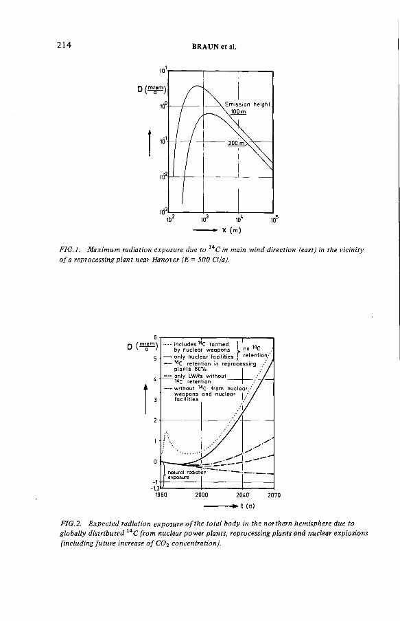
214 BRAUN et al.
FIG.l. Maximum radiation exposure due to 14C in main wind direction (east) in the vicinity o f a reprocessing plant near Hanover (E = 500 Cija).
— ■■ I......includes 14C form ed 1
no 14Cby nuclear weapons I— only nuclear facilities J retention*'—— '^C retention in reprocessing •' /
p lan ts 80%— only LWRs w ith ou t
14c retention—- w ith ou t from nuclear •* /
weapons and nuclearfa c il it ie s .• /
/
s '
/------<TlJ____— '
I notural rodiotion —..Г exposure
1960 2000 2040 2070
--------► t (a)
FIG.2. Expected radiation exposure o f the total body in the northern hemisphere due to globally distributed 14C from nuclear power plants, reprocessing plants and nuclear explosions (including future increase o f CO2 concentration).

IAEA-SM-245/9 215
FIG.3. Total collective effective dose equivalent com mitm ent S j from globally distributed 14C in dependence o f integration time at a world population o f 1 X IO 10. (Assumption: C 0 2 concentration in air doubles in 2 0 0 years).
heights o f 100 and 200 m. The individual dose is considerably reduced by raising the stack, as can be seen in Fig. 1, whereas the collective dose remains practically unchanged. The 14C is concentrated in the atmosphere due to its long half-life o f 5730 years. Thus, the individual dose increases when more nuclear energy is used because o f the globally distributed 14C. Figure 2 shows the increase o f radiation exposure in the northern hemisphere due to globally distributed 14C from nuclear facilities. The future nuclear power capacity in the world was assumed to be 2 X 10⁸ MW(th) in approximately 100 years [11].
The collective dose via the first pass exposure is about 3 m an-rem/Ci for sites in the FRG. For sites in other countries, such as the United Kingdom, the collective dose is about 30% less. The global contribution depends on the time for which 14C is considered. For an integration time o f 500 years the contribution is about 55 man-rem/Ci, for 10 000 years about 370 m an-rem/Ci, and for an integration time until total disintegration o f 14C (approxim ately 5 X 10⁴ years) about 520 man-rem/Ci, assuming a population o f 1010 persons (Fig.3). Furthermore, it was assumed that the C 0 2 percentage o f the atmosphere is doubled due to the com bustion o f fossile fuels not containing 14C.
3. POSSIBLE PROCESSES FOR 14C RETENTION
For physical and chemical reasons C 0 2 is the carbon com pound that can best be separated from other gases. It is therefore sensible to oxidize other 14C com pounds (see section 2) into C 0 2 before retention. Different m ethods o f
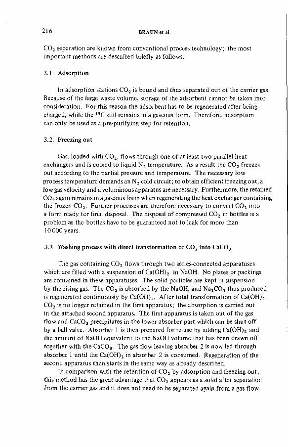
216 BRAUN et al.
C 0 2 separation are known from conventional process technology; the most important methods are described briefly as follows.
3.1. Adsorption
In adsorption stations C 0 2 is bound and thus separated out o f the carrier gas. Because o f the large waste volume, storage o f the adsorbent cannot be taken into consideration. For this reason the adsorbent has to be regenerated after being charged, while the 14C still remains in a gaseous form. Therefore, adsorption can only be used as a pre-purifying step for retention.
3.2. Freezing out
Gas, loaded with C 0 2, flows through one o f at least two parallel heat exchangers and is cooled to liquid N 2 temperature. As a result the C 0 2 freezes out according to the partial pressure and temperature. The necessary low process temperature demands an N 2 cold circuit; to obtain efficient freezing out, a low gas velocity and a voluminous apparatus are necessary. Furthermore, the retained C 0 2 again remains in a gaseous form when regenerating the heat exchanger containing the frozen C 0 2. Further processes are therefore necessary to convert C 0 2 into a form ready for final disposal. The disposal o f compressed C 0 2 in bottles is a problem as the bottles have to be guaranteed not to leak for more than 10 000 years.
3.3. Washing process with direct transformation o f C 0 2 into C aC 03
The gas containing C 0 2 flows through two series-connected apparatuses which are filled with a suspension o f Ca(OH)2 in NaOH. N o plates or packings are contained in these apparatuses. The solid particles are kept in suspension by the rising gas. The C 0 2 is absorbed by the NaOH, and N a2C 0 3 thus produced is regenerated continuously by Ca(OH)2. After total transformation o f Ca(OH)2, C 0 2 is no longer retained in the first apparatus; the absorption is carried out in the attached second apparatus. The first apparatus is taken out o f the gas flow and C aC 03 precipitates in the lower absorber part which can be shut o ff by a ball valve. Absorber 1 is then prepared for re-use by adding Ca(OH)2 and the amount o f NaOH equivalent to the NaOH volume that has been drawn o ff together with the C aC 03. The gas flow leaving absorber 2 is now led through absorber 1 until the Ca(OH)2 in absorber 2 is consumed. Regeneration o f the second apparatus then starts in the same way as already described.
In comparison with the retention o f C 0 2 by adsorption and freezing o u t , this m ethod has the great advantage that C 0 2 appears as a solid after separation from the carrier gas and it does not need to be separated again from a gas flow.
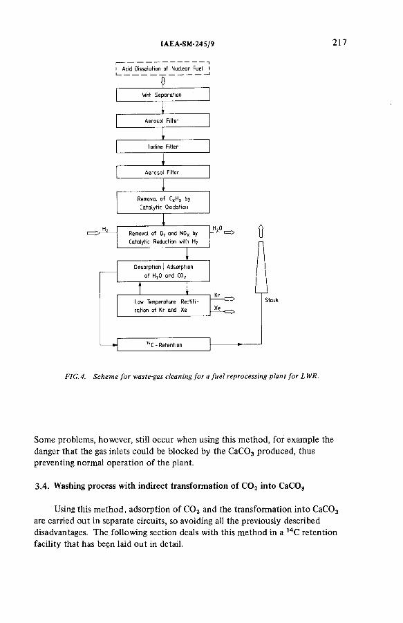
IAEA-SM-24S/9 217
I Acid Dissolution of Nuclear Fuel I
FIG. 4. Scheme for waste-gas cleaning for a fuel reprocessing plant for L WR.
Some problems, however, still occur when using this m ethod, for example the danger that the gas inlets could be blocked by the C aC 03 produced, thus preventing normal operation o f the plant.
3.4 . Washing process with indirect transformation o f C 0 2 into C aC 03
Using this m ethod, adsorption o f C 0 2 and the transformation into C aC 03 are carried out in separate circuits, so avoiding all the previously described disadvantages. The following section deals with this m ethod in a 14C retention facility that has been laid out in detail.
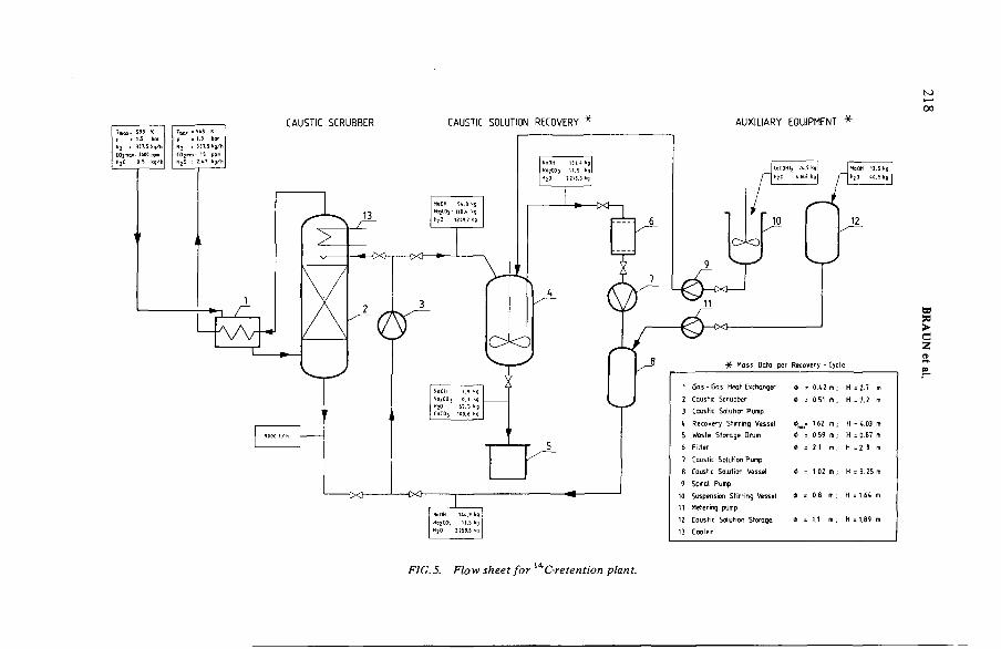
, № , S9Î Кp s 1.S bern2 . 337.5 kg/hCOjiïm ЛЬООppnH20 ол kg/h
Tratu -- 568 KP : 1.Î borM? 337.5 kg/ht o 7 ™or 15 ppmHjO M 7 Vg/h
CAUSTIC SOLUTION RECOVERY * AUXILIARY EQUIPMENT
-#■ M ass Data per Recovery - Cycle
1 Gas • Gas Heat Exchanger <t> 0.42 m ; H = 2 .7 m
2 Caustic Scrubber Ф * 0.S1 m ; H = 7 .2 m
3 CQustic Solution Pump
u Recovery S t ir r in g Vessel *ma*s 1.62 m ; H = ¿.03 m
Waste S torage Drum Ф 0.59 m ; H = 0.87 m
F ilte r 4 = 2.1 m ; H = 2.8 in1 Caustic Solution Pump
8 Caustic Solution Vessel Ф = 1.02 m ; H = 3 .25 m
9 Spira l Pump
10 Suspension S tirr in g Vessel Ф = 0.6 m ; H *1 .6 4 m
11 M etering pump
12 Caustic So lution Storage Ф = 1.1 m ; H =1.89 m
13 C ooler
FIG. 5. Flow sheet for 14С-retention plant.
218 BRAUN
et al.
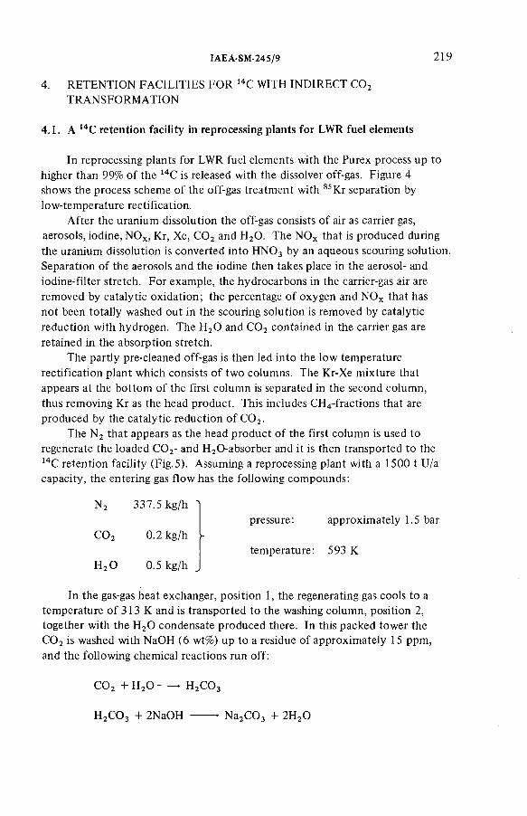
IAEA-SM-245/9 219
4. RETENTION FACILITIES FOR 14C WITH INDIRECT C 0 2TRANSFORMATION
4.1 . A 14C retention facility in reprocessing plants for LWR fuel elem ents
In reprocessing plants for LWR fuel elem ents with the Purex process up to higher than 99% o f the 14C is released with the dissolver off-gas. Figure 4 shows the process scheme o f the off-gas treatment with 85Kr separation by low-temperature rectification.
After the uranium dissolution the off-gas consists o f air as carrier gas, aerosols, iodine, NOx, Kr, Xe, C 0 2 and H20 . The NOx that is produced during the uranium dissolution is converted into H N 0 3 by an aqueous scouring solution. Separation o f the aerosols and the iodine then takes place in the aerosol- and iodine-filter stretch. For exam ple, the hydrocarbons in the carrier-gas air are removed by catalytic oxidation; the percentage o f oxygen and NOx that has not been totally washed out in the scouring solution is removed by catalytic reduction with hydrogen. The H20 and C 0 2 contained in the carrier gas are retained in the absorption stretch.
The partly pre-cleaned off-gas is then led into the low temperature rectification plant which consists o f two columns. The Kr-Xe mixture that appears at the bottom o f the first column is separated in the second column, thus removing Kr as the head product. This includes CH4-fractions that are produced by the catalytic reduction o f C 0 2.
The N 2 that appears as the head product o f the first colum n is used to regenerate the loaded C 0 2- and H20-absorber and it is then transported to the 14C retention facility (F ig .5). Assuming a reprocessing plant with a 1500 t U/a capacity, the entering gas flow has the following compounds:
N 2 337.5 kg/h 'pressure: approximately 1.5 bar
C 0 2 0.2 kg/h -temperature: 593 К
H20 0.5 kg/h J
In the gas-gas heat exchanger, position 1, the regenerating gas cools to a temperature o f 313 К and is transported to the washing colum n, position 2, together with the H20 condensate produced there. In this packed tower the C 0 2 is washed with NaOH (6 wt%) up to a residue o f approximately 15 ppm, and the following chemical reactions run off:
C 0 2 + H 20 ------• H2C 0 3
H2C 0 3 + 2NaOH ------- - N a2C 0 3 + 2H20

220 BRAUN et al.
At the head o f the colum n the gas flow is cooled to 288 К by 3600 Itr/h cold water, thus condensing the transported H20 to saturation point. The cold, cleaned gas is then led to the heat exchanger, position 1, where it cools the entering loaded regenerating gas in reverse current to approximately 313 K. At the exit o f the retention facility the cleaned gas has the following com ponents:
N 2 337.5 kg/h 'pressure: 1.47 bar
C 0 2 0.01 kg/h ►temperature: 568 К
H20 2.47 kg/h „
The lye circuit is maintained by a caustic solution pump, position 3 and the total lye volum e that is transported in the washing circuit is about 2250 litres.
After about nine days ~ 62% o f the lye is used and the water loss due to evaporation is about 423 litres. Up to this point it is guaranteed that the C 0 2 content in the cleaned gas is not more than 15 ppm.
The caustic solution, 62% o f which has been used, is transported via the caustic solution pump, position 3, into the recovery stirring vessel, position 4. Following this, a second charge o f NaOH is drawn from the caustic solution vessel, position 8, using the same pump, thereby maintaining the washing circuit.
In the suspension stirring vessel, position 10, 74.5 kg o f Ca(OH)2 are suspended in 436 .4 kg H 20 which is then transported into the recovery stirring vessel, position 4, by the spiral pump, position 9. Together with the contained used caustic solution, the following chemical reaction runs off:
Na2C 0 3 + Ca(OH)2 -------- - 2NaOH + C aC 03
To prevent possible blockage o f the caustic scrubber by non-reacting Ca(OH)2 that remains in the caustic solution, the addition o f approximately 90% Ca(OH)2 is carried out non-stoichiom etrically. Consequently, a residue o f Na2C 0 3 can be detected in the regenerated caustic solution.
When stirring is com pleted, the crystallized C aC 03 floating in the caustic solution precipitates to the bottom o f the recovery stirring vessel, position 4.The regenerated caustic solution is pumped into the caustic solution vessel, position 8, via a suction pipe with the aid o f the pump, position 7, except for a residue o f 69 .4 litres (the remainder as moisture in the C aC 03 and caustic solution above the C aC 03). The non-deposited C aC 03 particles are retained in the filter, position 6.
As a substitute for the remainder o f the lye in the recovery stirring vessel,42.1 litres o f soda lye (25 wt%) is pumped into the caustic solution storage, position 12, by the metering pump, position 11. Thus, a 6 wt% NaOH is at disposal for the next washing cycle.
IAEA-SM-245/9 221
The C aC 03 fraction that remains in the recovery stirring vessel after separation o f the regenerated caustic solution is emptied into the waste storage drum, position 5, by a filling apparatus placed under the recovery stirring vessel, and then solidified with cement.
The investm ent costs am ounted to DM 4.5 m illion, detailed as follows:
Technical equipm ent 1 500 000
Mounting and start-up 4 0 0 000
Engineering 800 000
Quality assurance 500 000
Building 1 0 0 0 0 0 0
Unforeseen expenditure 3 0 0 0 0 0
Total DM 4 500 000
The annual costs am ounted to DM 813 000, com posed as follows:
Water, energy, chemicals 20 000
Maintenance 23 000
Staff 320 000
Capital costs 4 5 0 000
Total DM 813 000
4.2. A 14C retention facility in reprocessing plants for HTR fuel elem ents
An amount o f 3 6 0 0 Ci 14C per annum, together with approximately 107 m 3 CO2 per annum, is em itted from a reprocessing plant for HTR fuel elem ents with a burn-leach head-end with a capacity o f 40 000 MW(e) [12].Using the 14C retention m ethod described in sub-section 4 .1 , around 5 X 10 7 kg C aC 03 Per annum was produced. Basically, a caustic scrubber can also be used, but taking into account the large volume o f waste it seems to be more advantageous to change the head-end in such a way that the carbon com pounds which have to be processed can be stored as graphite.
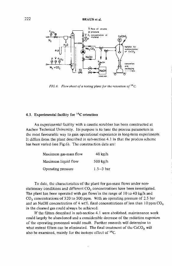
222 BRAUN et al.
V if lo w o f volum e p : pressure
H 20_Т - -
Др
P V сс0.
N , . С О .
reservoir
FIG. 6. Flow sheet o f a testing plant for the retention o f 14C.
4.3. Experimental facility for 14C retention
An experimental facility with a caustic scrubber has been constructed at Aachen Technical University. Its purpose is to tune the process parameters in the most favourable way to gain operational experience in long-term experiments. It differs from the plant described in sub-section 4.1 in that the process scheme has been varied (see Fig.6). The construction data are:
To date, the characteristics o f the plant for gas-mass flows under non- stationary conditions and different C 0 2 concentrations have been investigated.The plant has been operated with gas flows in the range o f 10 to 40 kg/h and C 0 2 concentrations o f 320 to 500 ppm. With an operating pressure o f 2.5 bar and an NaOH concentration o f 4 wt%, final concentrations o f less than 1 0 p p m C 0 2 in the cleaned gas could always be achieved.
If the filters described in sub-section 4.1 were abolished, maintenance work could largely be abandoned and a considerable decrease o f the radiation exposure o f the operating personnel would result. Further research will determine to what extent filters can be eliminated. The final treatment o f the C aC 03 will also be exam ined, mainly for the isotope effect o f 14C.
Maximum gas-mass flow 40 kg/h
Maximum liquid flow 500 kg/h
Operating pressure 1 .5 -3 bar
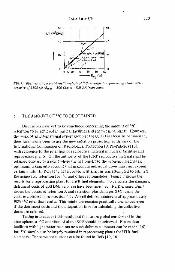
IAEA-SM-245/9 223
60
40
20
X+Y
Gro
.— Y
phs from(UJ5]
■ & У
Value ' sub-s
/s takeect. u:
n from
60
АО
20
О 10 20 ДО 60 80 100
FIG. 7. First result o f a cost-benefit analysis o f С-retention in reprocessing plants with acapacity o f 1500 t/а (En '- 500 G /а, a = DM 200/man- rem).
5. THE AMOUNT OF 14C TO BE RETAINED
Discussions have yet to be concluded concerning the amount o f 14C retention to be achieved in nuclear facilities and reprocessing plants. However, the work o f an international expert group at the OECD is about to be finalized, their task having been to use the new radiation protection guidelines o f the International Commission on Radiological Protection (ICRP-Pub-26) [13], with reference to the retention o f radioactive material in nuclear facilities and reprocessing plants. On the authority o f the ICRP radioactive material shall be retained only up to a point where the net benefit to the econom y reaches an optim um, taking into account that maximum individual doses must not exceed certain limits. In Refs [14, 15] a cost-benefit analysis was attem pted to estimate the achievable retention for 14C and other radionuclides. Figure 7 shows the results for a reprocessing plant for LWR fuel elements. To calculate the damages, detriment costs o f 200 DM /man-rem have been assumed. Furthermore, Fig.7 shows the points o f retention X and retention plus damages X+Y, using the costs established in sub-section 4.1. A well defined minimum o f approximately 90% 14C retention results. This minimum remains practically unchanged even if the detriment costs and the integration time for calculating the collective doses are reduced.
Taking into account this result and the future global enrichment in the atmosphere, a 14C retention o f about 90% should be achieved. For nuclear facilities with light water reactors no such definite statem ent can be made [16], but 14C should also be largely retained in reprocessing plants for HTR fuel elements. The same conclusions can be found in Refs [12, 16].
REFERENCES
224 BRAUN et al.
[ 1] B O N K A , H ., S C H W A R Z, G ., W IB B E , H .-B ., B Ó H N E R T , R ., C o n ta m in a tio n o f the en v iro n m e n t b y ca rb o n -14 produced in h ig h tem pera tu re reactors, K e rn te ch n ik 15 7 (1 9 7 3 ) 297.
[2 ] B O N K A , H ., B R Ü S S E R M A N N , K ., L A S E R , М ., S C H N E Z, H ., U m w e ltb e las tu ng du rch R a d io k o h le n s to ff aus ke rn techn ischen A nlagen, R eakto rtagung 1974, B e rlin (1 9 7 4 ) 454.
[3 ] K U N Z , C., M A H O N E Y , W .E ., M IL L E R , T .W ., “ 14C gaseous e ff lu e n t fro m pressurized w a te r reactors” , P op u la tio n Exposures (P roc. S ym p. K n o x v ille , 1974), H ea lth Physics S oc ie ty , East W eym o u th , M A (1 9 7 5 ).
[4 ] K U N Z , C., M A H O N E Y , W .E., M IL L E R , T .W ., “ 14C gaseous e fflu e n ts fro m b o ilin g w ate r reacto rs” , T ransactions o f the A m erica n N uc lea r S oc ie ty 1975 A n n u a l M eeting, New O rleans (1 9 7 5 ).
[5 ] R IE D E L , H ., G E S EW S KY , P., S C H W IB A C H , J., U nte rsuchungen über die Em ission von K o h le n s to ff-1 4 m it der A b lu f t aus K e rn k ra ftw e rk e n , In s t itu t fü r S trah lenhyg iene des Bundesgesundheitsam tes, B e rlin , N euherberg, S T H -B erich t 13 /76 (D ecem ber 1976).
[ 6 ] R IE D E L , H ., G E S EW S KY , P., Z w e ite r B e ric h t über Messungen z u r E m iss ion von K o h le n s to ff-1 4 m it der A b lu f t aus K e rn k ra ftw e rk e n m it Le ich tw asserreaktoren in der B und esrep ub lik D eutsch land , In s t itu t fü r S trah lenhyg iene des Bundesgesundheitsam tes, B e rlin , Neuherberg , S TH -B erich t 13 /77 (A ug us t 1977).
[7 ] S C H Ü T T E L K O P F , H ., D ie E m iss ion von 14C 0 2 m it der A b lu f t ke rn techn ischer A nlagen, Rep. F fK 2421 (1 9 7 7 ).
[ 8 ] U N IT E D N A T IO N S S C IE N T IF IC C O M M IT T E E O N T H E E FFEC TS O F A T O M IC R A D IA T IO N (U N S C E A R ), Sources and E ffec ts o f Io n iz in g R a d ia tion , 1977 R epo rt to the G enera l A ssem bly (w ith A nnexes) U N , N ew Y o rk (1 9 7 7 ).
[9 ] B O N K A , H ., P ro d u k tio n un d F re isetzung von 3H und 14C du rch K ernw affenversuche, Testexp los ionen und kern techn ische A nlagen, e in sch lie filich W iederaufarbe itungsanlagen, M eeting o f the Bundesgesundheitsam t, 1 4 -1 6 N ovem ber 1979, B e rlin (Proceedings to be pub lished .).
[1 0 ] B O N K A , H ., B erechnung der Dosisw erte nach dem spezifischen A k tiv ità ts m o d e ll fü r 3H u n d 14C, M eeting o f the Bundesgesundheitsam t, 14—16 N ovem ber 1979, B e rlin , (P roceedings to be pub lished .).
[1 1 ] B O N K A , H ., G R Ü N D L E R , D ., H E S E L , D ., M Ü N S T E R , М ., S C H M ID T L E IN , P., S Ü N D E R , B ., “ R adio log ische A u sw irkun gen der Em issionen aus W iederaufarbe itungsanlagen im bestim m ungsgem afien B e tr ie b ” , R ad ioactive E fflu e n ts fro m N uclea r Fue l and Reprocessing P lants, C om m iss ion o f the E uropean C om m un itie s Sem inar, K arlsruhe (1 9 7 7 ) 219.
[1 2 ] S C H M ID T , P.C., A lte rn a tiv e n z u r V e rm in de rung de r C -14 E m issionen bei de r W ieder- a u fa rb e itun g von H T R -B renne lem en ten , Rep. JÜ L -1 5 6 7 (1 9 7 9 ).
[1 3 ] IN T E R N A T IO N A L C O M M IS S IO N O N R A D IO L O G IC A L P R O T E C T IO N , R ecom m enda tions o f the In te rn a tio n a l C om m iss ion o n R ad io log ica l P ro te c tio n , IC R P -P ub-26, Pergamon Press, L o n d o n (1 9 7 7 ).
[1 4 ] B O N K A , H ., G R Ü N D L E R , D ., H O R N , H .-G ., “ A nw end ung von O p tim ie rungsm e thoden a u f dem G eb ie t des S trah lenschutzes be i ke rn techn ischen A nlagen” , M e thods fo r O p tim iz in g P ro te c tio n in the N uc lea r In d u s try (P roc. CEC Sem inar, L u xe m b o u rg , 1979), C om m iss ion o f th e E uropean C om m un itie s , Brussels (1 9 7 9 ).

IAEA-SM-245/9 225
[1 5 ] B O N K A , H ., G R Ü N D L E R , D ., H O R N , H .-G ., “ P rob lem s o ccu rrin g w h ile ca rry in g o u t cos t-ben e fit analysis fo r 3H , 14C, 85K r, io d in e and aerosols in nuc lear fa c ilit ie s ” , A p p lic a t io n o f the Dose L im ita t io n System fo r R a d ia tio n P ro te c tio n (P roc. T o p ica l S em inar V ienna , 1979), IA E A , V ienna (1 9 7 9 ) 317.
[1 6 ] T IS C H E R , H ., W irbe lsch ich tve rb rennung in e ine r H TR -W iederaufarbe itungsan lage, K F A -Jah resb e rich t 1 9 78 /7 9 , Jü lich (1 9 7 9 ) 25.
DISCUSSION
K. FISCHER: Have you made any estim ates concerning the radiation dose rates to which personnel involved in maintaining 14C retention equipm ent and handling retention process residues will be exposed?
D. GRÜNDLER: To date no such detailed study has been carried out. An exact evaluation will be made when construction o f the retention facility is com pleted, and that will be at about the end o f March 1980. Because o f the low /3-de cay energy o f 14C, additional dose rates are assumed to be very low.
F. CEJNAR: I would like to make a com m ent which also concerns paper SM-245 /29 , just presented. There are some cases where 14C may be present in effluents in the form o f CO as well as C 0 2. As CO has a substantially lower absorption coefficient in alkaline solutions than C 0 2, this may result in a reduction in the decontam ination factor for these effluents. Did you consider such cases?
J. WEBER: The retention plant described in the paper was not designed for CO. The entering loaded gas from a reprocessing plant for LWR fuel elem ents shows only very low concentrations o f CO, and so cases involving CO were n ot considered.
M.J. STEPHENSON: In the case o f HTGR processing, the am ount o f CO present in the off-gas is a function o f the oxygen content. The bulk o f the 14C will be in the form o f C 0 2, and only at certain times during the burning operation might a sizeable fraction o f CO be found. There is no provision that I am aware o f in the off-gas system to guarantee the C 0 2 form. In the case o f LWR off-gas reprocessing, there is some concern that perhaps other carbon forms such as m ethane or CO might occur and som e off-gas system s are probably utilizing a catalytic oxidiser to guarantee a C 0 2 form.
A.J. WILLIAMS: Can you give me any information on the type o f cement you intend to use for incorporating calcium carbonate or on the proposed mixing m ethod? It was intim ated that mixing would take place in the waste drum.
J. WEBER: I cannot add anything at the m om ent. Detailed information will be available in the final report on 14C retention, which can be ordered as from May 1980 directly from Linde AG, Werksgruppe TUT München,D-8023 Hôllriegelskreuth.

226 BRAUN et al.
H. DEUBER: I am surprised at your statement that o f the radionuclides released from nuclear facilities 14C is the m ost important from a radioecological viewpoint. From the preceding papers one gets the impression that 14C is of minor importance. Could you elaborate on this?
J. WEBER: Perhaps I could again call on Dr. Gründler to answer.D. GRÜNDLER: Today retention facilities have been provided for every
radionuclide o f radiological importance except 14C. Doses due to these radionuclides have thus been reduced, whereas the dose due to 14C remains unchanged and produces both the highest individual dose in the vicinity o f a reprocessing plant and the highest collective dose com m itment.

Session IV
REMOVAL AND RETENTION OF NOBLE GASES

Chairman
W.R.A. GOOSSENSBelgium
IAEA-SM-245/12
CATALYTIC REDUCTION OF 0 2 AND NOxA critical pretreatment step for the cryogenic retention o f krypton-85
R. von AMMON, G. KNITTEL Institut für Heisse Chemie,Kernforschungszentrum Karlsruhe GmbH,Karlsruhe
E. HUTTERHauptabteilung Ingenieurtechnik,Kernforschungszentrum Karlsruhe GmbH,Karlsruhe,Federal Republic o f Germany
Abstract
C A T A L Y T IC R E D U C T IO N O F 0 2 A N D N O x : A C R IT IC A L P R E T R E A T M E N T STEP F O R T H E C R Y O G E N IC R E T E N T IO N O F K R Y P T O N -8 5 .
T he c a ta ly tic re d u c tio n step, w h ic h is inc luded in the reprocessing o ff-gas p u r if ic a tio n concep t at K F K preceding the c ryogen ic separation o f the rare gases, is re qu ired to reduce 0 2
and N O x w ith H 2 to levels as lo w as possib le and also to m in im ize the fo rm a tio n o f N H 3 , C H 4
and CO in pa ra lle l reactions. T h e reason is th a t some o f these im p u ritie s cannot e ffe c tive ly be re ta ined b y adsorp tive m e thods b u t w i l l accum ula te in the cryogen ic co lu m n near the rad ioac tive k ry p to n . There , chem ica l reactions induced b y ra d ia tio n are an tic ip a ted . R u th e n iu m , f in e ly dispersed o n A120 3 o f re la tive ly lo w spec ific surface (c irca 1 0 m 2/g ) , fu lf i ls the re q u ire m ents as an e ffe c tive re d u c tio n ca ta lys t fo r the fo llo w in g reasons: at tem pera tures > 3 5 0 С it is active in reduc ing 0 2 and N O x at ca ta lys t loads be tw een 5 and 1 5 m 3/ l t r - h (S TP ) and gas ve loc ities betw een 17 and 50 cm /s; i t is h ig h ly spec ific in reduc ing N O x to N 2, thus fo rm in g l i t t le N H 3; and i t is re la tive ly stable against po iso n ing b y H 20 , 1 2 and tr ib u ty lp h o s p h a te . Fo r th e rm o d yn a m ic reasons, fo rm a tio n o f N H 3 and C H 4 ( f r o m C 0 2) is decreased b y increasing the tem pera ture . L im ita t io n o f H 2 co n ce n tra tio n to a s ligh t excess above s to ich io m e try m in im izes the fo rm a tio n o f CO and, a d d it io n a lly , o f N H 3 and C H 4 . The effectiveness o f th is cata lyst was dem onstra ted on a la b o ra to ry scale in tw o flow sheets, one using a single bed, the o th e r using a doub le bed w ith a Pt ca ta lys t preceding the R u ca ta lyst. F ro m a feed-gas co n ta in in g up to 18 vo l.% 0 2, u p to 5% NO and 40 0 vpm (p a rts pe r m ill io n b y vo lum e) C 0 2 in N 2, e x it con cen tra tion s beh ind the R u ca ta lys t were: 0 2, NO < 1 ppm , N H 3 10 pp m , CO < 25 ppm and C H 4 < 0.5 ppm .
229

230 Von AMMON et al.
100 120 НО 160 180 200 Temperature IК )
FIG.l. Experimental temperature and concentration profiles (Ar, Kr, Xe, Oi ) in the first cryogenic column o f the KRETA plant at 5 bar.
1. INTRODUCTION
The separation o f the rare gases krypton and xenon by low-temperature distillation has been demonstrated successfully at KFK on a semiscale level (50 m 3/h gas throughput) in the KRETA plant which is operated with synthetic gas mixtures [1 ,2 ] . Decontam ination factors for krypton o f > 103 were obtained in the first cryogenic column at 5 bar pressure when rectifying the system Nj-Ar-Kr-Xe, even with xenon concentrations in the feed-gas o f up to 5000 vpm (parts per m illion by volume) [3, 4].
Our present concern aims at the behaviour in the cryogenic column o f certain impurities whose boiling point is close to that o f krypton. These impurities thus tend to accumulate in the krypton-rich parts o f the column giving rise to radiation-induced chemical reactions. One exam ple is the form ation o f ozone from oxygen [2].
The accum ulation o f 0 2 in the first KRETA-column is shown in Fig. 1. Whereas its concentration in the feed-gas is only 10 vpm, the maximum concentration in the gas phase o f the seventh practical plate amounts to 3 vol.%. Other possible candidates which can be present in reprocessing off-gases are

IAEA-SM-245/12 231
TABLE I. BOILING POINTS (K AT 5 BAR) OF SEVERAL OFF-GAS COMPONENTS PERTINENT FOR THE CRYOGENIC COLUMNS OF A KRYPTON SEPARATION UNIT
n 2 93.9 C H 4 135
C O 98 N O 139
Ar 105.7 Kr 144.9
0 2 108 Xe 199.2
m ethane, CH4, and nitrogen m onoxide, NO (Table I). These com pounds also have a pronounced tendency to undergo radiolytic reactions [5]. It is not known at present what the final reaction products in a real krypton separation unit will be if all these impurities are present, and which concentrations can be tolerated w ithout loss o f safety.
None o f the three com pounds, 0 2, CH4 and NO, can be effectively retained by the adsorption bed preceding the cryogenic unit [6]. Therefore, it has to be postulated that they are separated from the off-gas as effectively as possible by another pretreatment step ( 0 2 , NO ), or that they are prevented from being formed (CH4). We decided to use catalytic reduction w ith H2 as pretreatment [7] and this paper describes the results o f our laboratory investigations.
2. EXPERIMENTAL
The experimental apparatus (Fig. 2) consisted o f a gas-mixing station, two catalyst beds (C l and C2), and a gas loop for the dilution o f the feed-gas below the explosion limits (4% H 2 in air). The feed-gas flow was between 0.5 and1.0 m3/h (STP) and the dilution loop could be varied by the blower (V I) up to 10 m 3/h. The feed-gas contained concentrations o f 0 2 up to 18 vol.%, o f NO up to 5 vol.% and about 400 vpm o f C 0 2. The H2 was fed into the dilution loop before the gas heater. Unless otherwise stated, the excess above the stoichiom etric amount was kept at < 1000 vpm by manual control. The catalyst load was varied between 3 and 19 m 3/ltr h (STP).
Sampling points were in the gas loop before, between and after the catalyst beds, and in the off-gas. The catalysts used in this study were either noble metals (Pt, Ru) or oxides (Cr20 3). The data o f three typical types are listed in Table II.

B1 Condensate collector C1 Catalyst bed 1 C2 Catalyst bed 2 V1 Blower W1 Feed-gas warming
(waste heat economizer) W2 Reaction-water condenser R1 Gas mixer (static)
FIG.2. Flowsheet of the laboratory catalytic test loop.
232 Von
AMMON
et al.
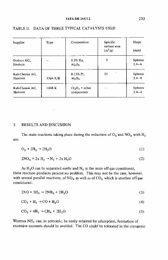
IAEA-SM -245/12 233
TABLE II. DATA OF THREE TYPICAL CATALYSTS USED
S upp lie r T yp e C o m p o s itio n S pec ific surface area (m 2 /g )
Shape
(m m )
D odu co K G , S inshein
- 0.3% Ru, A I2O 3
9 Spheres2 .4 - 4
K a li-C hem ie A G , H anover 3366 K /R
0 .1 3 % P t,а 12 0 3
25 Spheres2 .4 - 4
K a li-C hem ie A G , Hanover
1008 К Сг2 0 з + o th e r com ponents
- Spheres2 .4 - 4
3. RESULTS AND DISCUSSION
The main reactions taking place during the reduction o f 0 2 and NO x with H2are:
0 2 + 2H 2 -*■ 2H 20 (1)
2NOx + 2x H2 ->■ N 2 + 2x H 20 (2)
As H 20 can be separated easily and N 2 is the main off-gas constituent, these reaction products present no problem. This may not be the case, however, with several parallel reactions, o f N O x as well as o f C 0 2 which is another off-gasconstituent:
2NO + 5H2 -> 2N H 3 + 2H 20 (3)
C 0 2 + H2 -> CO + H20 (4)
C 0 2 + 4H 2 -> CH4 + 2H 20 (5)
Whereas N H 3 can, in principle, be easily retained by adsorption, form ation o f excessive am ounts should be avoided. The CO could be tolerated in the cryogenic

234 Von AMMON et al.
column because o f its low boiling point (Table I), but the formation o f CH4 must be prevented. The catalyst, therefore, should fulfil the following requirements:
(a) high activity for reduction o f 0 2 an dN O x ;(b) low activity for reduction o f C 0 2;(c) high selectivity for formation o f N 2 from NO x ;(d) if C 0 2 is reduced, high selectivity for formation o f CO;(e) high thermal stability;(f) low sensitivity against poisoning by H20 , I2 and organic phosphates.
3.1. Reduction o f 0 2
The activity o f the catalysts can best be described by their minimal working temperatures. For the three types described in Table II the temperatures are approximately:
Pt 130°CRu 290°CCr20 3 330°C
Thus, Pt has the highest activity.O f essential importance for high yields, besides the temperature, is the
catalyst gas load and the linear gas velocity. While the catalyst load can be varied between 5 and 19 m 3/ltr h w ithout loss o f yield, the gas velocity is somewhat more critical. This is made plausible by treating the ‘burning zon e’ in a catalyst bed in the same way as a hom ogeneous flame [8]. If the gas velocity is either too high or too low , the ‘burning zone’ moves out o f the back- or front-end o f the bed, with consequent loss o f yield. It stays fixed at som e point in the bed only in a certain range o f gas velocities.
We achieved com plete reaction with all 0 2 concentrations in the feed-gas and low H 2 excess « 1000 vpm) only in the range o f linear gas velocities between about 17 and 48 cm /s referred to the free tube diameter. For the catalyst gas loads stated, these velocities could be obtained only if the catalyst vessel had a minimum diameter o f 10 cm; data are shown in Table III. Under these conditions 0 2 was reduced for all feed concentrations down to the sensitivity o f analysis ( < 1 vpm, Model Oxanal, Gebhardt).
3.2 . Reduction o f NO
The reduction o f NO (up to 5 vol.% in the feed-gas) is also com plete down to the sensitivity o f analysis « 1 vpm, Chemolum inescence, Model 951 , Beckman)
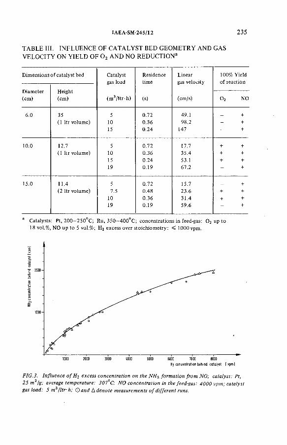
IAEA-SM-245/12 235
TABLE III. INFLUENCE OF CATALYST BED GEOMETRY AND GAS VELOCITY ON YIELD OF 0 2 AND NO REDUCTION3
D im ensions o f ca ta lys t bed C ata lyst Residence L inear 100% Y ie ld
D iam e te r H e igh t
gas load tim e gas v e lo c ity o f re ac tion
(cm ) (cm ) (m 3 / l t r - h ) (s) (cm /s) o2 NO
6.0 35 5 0.72 49.1 _ +
( 1 l t r vo lum e) 10 0.36 98.2 - +
15 0 .24 147 — +
10.0 12.7 5 0.72 17.7 + +
( 1 l t r vo lum e) 10 0.36 35.4 + +
15 0.24 53.1 + +19 0.19 67.2 - +
15.0 11.4 5 0.72 15.7 +(2 l t r vo lum e) 7.5 0.48 23 .6 ■ +
10 0.36 31 .4 + +19 0.19 59.6 - +
a C ata lysts: P t, 2 0 0 —2 5 0 °C ; R u, 3 5 0 —4 0 0 °C ; con cen tra tion s in feed-gas: 0 2 up to 18 vo l.% , N O u p to 5 vo l.% ; H 2 excess ove r s to ic h io m e try : < 1000 vpm .
1000 2000 3000 1.000 5000 6000 7000 8000
H2 concentration behind catalyst [vpm]
FIG.3. Influence o f H2 excess concentration on the NH-¡ formation from NO; catalyst: Pt, 25 m 2/g; average temperature: 307°C; NO concentration in the feed-gas: 4000 vpm; catalyst gas load: 5 m 3/ltr -h; Q and Л denote measurements o f different runs.
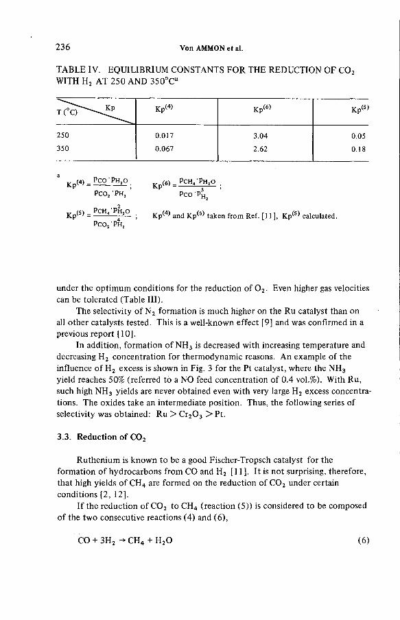
236 Von AMMON et al.
TABLE IV. EQUILIBRIUM CONSTANTS FOR THE REDUCTION OF C 0 2 WITH H , AT 250 AND 350°C a
K p (4) = Pc q Ph . o
PCOj P h 2
Kp'(5) = Pc h 4 Ph 2o
Pc O , 'P h ,
Kp(6>_ Pc h 4 Ph , o
K p ^ and K p w t a k e n f ro m Ref. [11 ] , K p^-1 calculated
Pco-Pu
(5)
under the optim um conditions for the reduction o f 0 2. Even higher gas velocities can be tolerated (Table III).
The selectivity o f N 2 formation is much higher on the Ru catalyst than on all other catalysts tested. This is a well-known effect [9] and was confirmed in a previous report [10].
In addition, form ation o f N H 3 is decreased with increasing temperature and decreasing H 2 concentration for thermodynamic reasons. An example o f the influence o f H2 excess is shown in Fig. 3 for the Pt catalyst, where the NH 3 yield reaches 50% (referred to a NO feed concentration o f 0 .4 vol.%). With Ru, such high NH 3 yields are never obtained even with very large H2 excess concentrations. The oxides take an intermediate position. Thus, the following series o f selectivity was obtained: Ru > Cr20 3 > Pt.
3.3. Reduction o f C 0 2
Ruthenium is known to be a good Fischer-Tropsch catalyst for the formation o f hydrocarbons from CO and H 2 [11]. It is not surprising, therefore, that high yields o f CH4 are formed on the reduction o f C 0 2 under certain conditions [2, 12].
If the reduction o f C 0 2 to CH4 (reaction (5)) is considered to be com posed o f the tw o consecutive reactions (4) and (6),
CO + 3H 2 ->CH 4 + H 20 ( 6 )

IAEA-SM-245/12 237
Temperature PC]
FIG. 4. Influence o f temperature on the yields o f CO and CH4 from the reduction o f CO2 with t f 2 at a Ru catalyst; molar ratio [H 2 ] / [C 0 2] = 7.5; catalyst: Ru, 9 m 2/g; CO2 concentration in the feed-gas: 600 vpm; catalyst gas load: 5 m 3 jltr-h.
then from thermodynamics the equilibrium constant o f reaction (5 ) is given by the expression:
Kp(5) = PcH* Ph i ° = Kp(4> • Kp(6)P C O j P h 2
From this expression the strong dependence o f CH4 formation on the partial pressures o f H 2 and H 20 is evident: low H 2 pressure and high H 20 pressure minimize CH4 formation.
From known values o f Kp*-4-* and Kp1-6-* [11] at various temperatures, the value o f K p ^ and its temperature dependence can be deduced [2]. These data, as shown in Table IV, indicate an increasing formation o f CH4 on increase o f the temperature. Actually, we have found the opposite to be true (Fig. 4): at the constant and rather high molar ratio [H2]/[C 0 2] = 7 .5 , the CH4 yield was highest at 320°C , but on the decrease at higher temperatures. At 420°C , CH4 could no longer be detected (sensitivity < 0.5 vpm, gas chromatography with flame ionization detector). The temperature dependence o f CO form ation is positive, as expected.
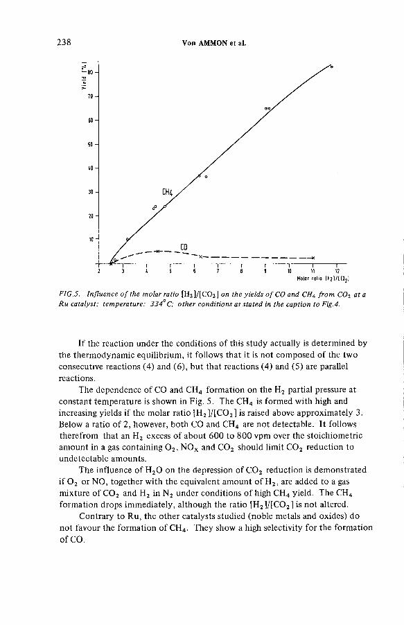
238 Von AMMON et al.
Molar ra tio tH î l / l tO ^ ]
FIG.5. Influence o f the molar ratio [H 2 ] / [C 0 2] on the yields o f CO and CH4 from C02 at a Ru catalyst; temperature: 334° C; other conditions as stated in the caption to Fig.4.
If the reaction under the conditions o f this study actually is determined by the therm odynamic equilibrium, it follow s that it is not com posed o f the two consecutive reactions (4) and (6), but that reactions (4) and (5) are parallel reactions.
The dependence o f CO and CH4 formation on the H2 partial pressure at constant temperature is shown in Fig. 5. The CH4 is formed with high and increasing yields if the molar ratio [H2]/[C 0 2] is raised above approximately 3. Below a ratio o f 2, however, both CO and CH4 are not detectable. It follows therefrom that an H2 excess o f about 600 to 800 vpm over the stoichiom etric amount in a gas containing 0 2, NO x and C 0 2 should limit C 0 2 reduction to undetectable amounts.
The influence o f H20 on the depression o f C 0 2 reduction is demonstrated i f 0 2 or NO, together with the equivalent amount o f H2, are added to a gas mixture o f C 0 2 and H2 in N 2 under conditions o f high CH4 yield. The CH4 formation drops im m ediately, although the ratio [H2]/[C 0 2] is not altered.
Contrary to Ru, the other catalysts studied (noble metals and oxides) do not favour the form ation o f CH4. They show a high selectivity for the formation o f CO.

IAEA-SM-245/12 239
TABLE V. INFLUENCE OF H 20 ON N H 3-FORMATION DURING CATALYTIC REDUCTION OF NOa
C ata lys t H 20 c o n ce n tra tio n (vo l.% )
N H 3 c o n ce n tra tio n (vp m )
- 65
R u 2.5 809 m 2/g 5.0 130
7.5 140
— 1160
Pt 2.5 1 2 0 0
25 m 2/g 5.0 1160
7.5 1 1 0 0
a Feed-gas c o m p o s itio n : 0 .75 vol.% 0 2> 0.5 vol.% N O , 2 .75 vol.% H 2 ; tem pera tu re : 34 0°C ; ca ta lys t lo a d : 5 m 3/ l t r h.
3.4. Stability o f catalysts
A series o f noble metal catalysts has been tested with respect to their stability against excessive heating, and against poisoning by H 20 , iodine (I2) and tributylphosphate (TBP). Som e o f these results have been reported previously [2, 10]; therefore only a short summary is given in this context.
Short-time heating o f a Ru catalyst up to 1000°C (6 hours at 50°C intervals) did not deteriorate the quantitative yield o f 0 2 and NO reduction. However, an increase o f the minimal reaction temperature at the catalyst from 300 to 420°C was noticed, probably due to sintering, indicating a decreased activity.N o indication for a volatilization o f Ru due to oxide form ation was noticed [13].
Poisoning o f noble metal catalysts, by adding I2 in well-defined amounts to the gas stream or by impregnating the catalysts before the test with a TBP solution [10], gave rise to the following effects: the activity o f Pt and Pd towards reduction o f 0 2 and NO was definitely reduced, e.g. by iodine loadings > 1 mg/g. Ruthenium, on the other hand, retained its activity even at iodine loadings as high as 40 mg/g. However, its selectivity for the formation o f N 2 from NO was som ewhat deteriorated. This effect increased with increasing specific surface o f the catalyst. The I2 had a stronger effect than TBP. Part o f the iodine was reduced to HI.

240 Von AMMON et al.
FIG. 6. Flowsheets o f the single bed (Ru) and the double bed (Pt and Ru) versions for the catalytic reduction o f 0 2 and NO with H 2 ; gas composition and conditions as stated.
The presence o f H20 has a similar effect: the activity o f Pt and Pd catalysts o f large specific surface area for the reduction o f 0 2 and NO definitely deteriorates, in som e cases irreversibly. This was not observed with the catalysts o f low surface area discussed here. However, the high selectivity o f Ru for N 2 formation from NO is again som ewhat decreased by increasing H20 partial pressure in the gas stream (Table V).
3.5. Conclusion and integral tests
On the basis o f these results it can be concluded that the essential com ponent o f the catalyst bed should be ruthenium. This recom m endation holds, although this catalyst is the only one with a high selectivity for CH4 formation. As this drawback is overcom e simply by keeping the temperature above 450°C , it is outweighed by several advantages. A satisfactory performance can be predicted with an off-gas containing 0 2, NO x , H20 , C 0 2, and traces o f I2 and TBP, if the following conditions are sustained:
(a) The linear gas velocity should lie within a favourable range to ensure com plete reduction o f 0 2 (17 to 50 cm /s in the case o f the Ru catalyst used in this study);
(b) The temperature should be not lower than 450°C to minimize formation o f N H 3 and CH4 , but n ot higher than 600°C to prevent sintering and volatilization o f Ru as a long-term effect;

IAEA-SM-245/12 241
(c) H2 excess should be less than 1000 vpm to minimize formation o f CO, and as an auxiliary provision, also to minimize formation o f CH4 and N H 3
(d) The specific surface area o f the catalyst should not be higher than 30 m 2/g to minimize the sensitivity against poisoning.
Bearing these prerequisites in mind, integral tests were carried out with a gas mixture containing 0 2, NO and C 0 2, using two catalyst bed versions:
(a) A single bed containing a Ru catalyst (9 m 2/g specific surface area), and
(b) a double bed containing a Pt catalyst (25 m2/g) and a consecutive Ru catalyst (9 m 2/g).
The double bed offers the possibility o f a more econom ical start-up operation because reduction o f 0 2 sets in at a lower temperature in the first bed (Pt), thus needing less external heating than the Ru catalyst. The heat o f reaction is then used to heat the second bed (Ru). The bulk amount o f N H 3 formed on Pt will be decom posed in the Ru bed. It is also to be expected that the first bed will effectively protect the Ru catalyst against poisoning, thus possibly ensuring longer operation periods.
The results are shown in Fig. 6. Both versions gave equally satisfactory results: 0 2, NO and CH4 concentrations in the off-gas were below the sensitivity o f analysis; formation o f CO and NH 3 was tolerable, although large amounts o f NH 3 were present between the two beds, as expected. The H 2 excess over stoichiom etry was kept at 800 vpm. A fast and safe control o f H2 dosage upon quick changes in 0 2 and NO x concentrations still has to be demonstrated. This will be done in forthcoming work with a semiscale plant, where behaviour o f the catalyst beds during longer operation periods will also be tested.
REFERENCES
[1 ] A M M O N , R .von , H U T T E R , E ., L E IC H S E N R IN G , C .H ., W E IN L Á N D E R , W., R adioactive E fflu e n ts fro m N uclea r F u e l Reprocessing P lants (P roc. CEC Sem inar, Lu xe m b o u rg , 1978), C om m iss ion o f th e E uropean C om m un itie s , Brussels (1 9 7 8 ) 535.
[2 ] A M M O N , R .von , B U R K H A R D T , H .G ., H U T T E R , E ., N E F F E , G ., P roc. 15 th N uc l. A ir C lean ing C o n f., B oston , 1978, US D epa rtm e n t o f E nergy, W ashing ton, DC (1 9 7 8 ) 640.
[3 ] A M M O N , R .von , B U M IL L E R , W ., B U R K H A R D T , H .G ., H U T T E R , E ., N E F F E , G., K F K -N a ch r. 11 (1 9 7 9 ) 19.
[4 ] A M M O N , R .von , B U R K H A R D T , H .G ., H U T T E R , E ., N E F F E , G ., Ber. Bunsenges. Phys. Chem . 8 3 (1 9 7 9 ) 1143.
[5 ] S P IN K S , J.W .T ., W O O DS, R .J., A n In t ro d u c t io n to R a d ia tio n C hem is try , John W iley and Sons, In c ., N ew Y o rk (1 9 6 4 ).

242 Von AMMON et al.
[ 6 ] G R U B N E R , О ., J IR U , P., R Á L E K , M . (F o r 0 2 and C H 4), M o leku la rs iebe , V E B Deutscher V erlag de r W issenschaften, B e rlin (1 9 6 8 ); A M M O N , R .von , F R A N Z , G. (F o r N O ),Rep. K F K -2 3 7 5 (N o v .1 9 7 6 ) 183.
[7 ] A M M O N , R .von , W E IN L A N D E R , W., H U T T E R , E ., N E F F E , G ., L E IC H S E N R IN G , C .H ., K F K -N a ch r. 7 (1 9 7 5 ) 63.
[8 ] W IC K E , E „ P A D B E R G , G „ C hem .-Ing.-Tech. 40 (1 9 6 8 ) 1033.[9 ] S H E L E F , М ., C ata l. Rev. 11 (1 9 7 5 ) 1, and lite ra tu re c ited the re in .
[1 0 ] A M M O N , R .von , S T R A U C H , K ., W E IN L A N D E R , W., W U R S T E R , W., Rep. K F K -2 4 3 7 . (M a y 1977).
[1 1 ] U llm anns E ncyk lo p á d ie der Technischen C hem ie, 4 th E dn, V o l. 14, C hem ie, W einhe im (1 9 7 7 ) 329.
[1 2 ] A M M O N , R .von , e t a l., Rep. K F K -2 7 0 0 (N o v . 1978) 4600.[1 3 ] B E L L , W .E ., T A G A M I, М ., J. Phys. Chem. 67 (1 9 6 3 ) 2432.
DISCUSSION
J.A. WILSON: In the data on gas com position given in Figure 1, results were expressed in terms o f mol % totalling slightly more than 100%. What was the accuracy o f each determination?
R. von AMMON: The total gas com position, o f course, never exceeds 100 mol%. The analytical determination o f 0 2, Ar, Kr and Xe had an accuracy o f ± 2% and is better than the stability o f the column conditions. Because o f fluctuations, the scatter o f concentrations may be large in parts o f the column where steep concentration gradients occur. In those parts where accumulation takes place — o f 0 2 for example — I estimate the accuracy in the steady state to be ± 5%.
D.T. PENCE: Can you say what fraction o f the off-gas stream you expect to be required for recycle through the catalyst?
R. von AMMON: This depends on the concentration o f 0 2 and NOx . For an off-gas which is essentially air (20% 0 2), a recycle factor o f at least 10 (12 — 15 is better) is required to dilute the necessary H2 concentration to less than the explosion lim it ( < 4%).
C.H. LEICHSENRING: In relation to the last question, the circulation stream o f the catalytic facility is some 8 to 10 times the primary gas flow. This circulation is necessary to bring the original 0 2 (and NO x) content down to ~ 2%.

I AE A-SM-24S/S3
REMOVAL OF NOBLE GASES BY SELECTIVE ABSORPTION*
J.R. MERRIMAN, M.J. STEPHENSON,B.E. KANAK, D.K. LITTLE Oak Ridge Gaseous Diffusion Plant,Union Carbide Corporation,Nuclear Division,Oak Ridge, Tennessee,United States o f America
Abstract
R E M O V A L O F N O B L E GASES B Y S E L E C T IV E A B S O R P T IO N .In the 1968 jo in t IA E A /U S A E C S ym pos ium on T re a tm en t o f A irb o rn e R ad ioactive
Wastes the in it ia t io n o f a deve lopm ent program m e o n rem ova l o f ra d ioac tive nob le gas using a selective a b so rp tio n tech n ique was o u tlin e d . S ince th a t tim e , deve lopm ent o f th is ab so rp tio n process has been essentia lly com p le ted . Process pe rfo rm ance and re lia b il i ty have been dem onstra ted o n an engineering scale w ith ten years o f p ilo t p la n t o p e ra tio n , in c lu d in g extended tes tin g w ith 85K r , 133X e, and 131I. The selective a b so rp tio n process is based on e x p lo ita t io n o f s o lu b il ity d iffe rences w h ic h ex is t am ong th e nob le gases and o th e r gas-phase co n s titu e n ts in a f lu o ro c a rb o n so lven t. M u ch in fo rm a t io n no w exists on th e s o lu b ilit ie s o f various com ponents in CC12F 2 , w h ic h is the re ference so lven t, and on o th e r aspects o f th is f lu o ro c a rb o n system . The e ffec ts o f ca rrie r gas co -abso rp tion and so lven t va p o riza tio n /co n d e n sa tio n o n n o b le gas mass tra ns fe r ins ide the a b so rp tio n and s tr ip p in g zones have been de te rm ined . The e ffec ts o f co lum n size on mass tra ns fe r have also been measured and rigo rou s engineering m odels have been derived fo r the process hardw are. M any im p rovem en ts and s im p lif ic a tio n s have been made to the o rig in a l vers ion o f th e process and, depend ing up o n the separation task, a v a r ie ty o f system co n fig u ra tio n s is possib le. The selective a b so rp tio n process is app licab le to essentia lly a ll types o f nuclear fa c ilit ie s , and several gas cleanup tasks have been considered. One o f these, po s tacc ident re a c to r cleanup, is described because i t is o f cu rre n t in te res t and also serves to illu s tra te the process a p p lic a tio n area.
I N T R O D U C T I O N
The Oak Ridge Gaseous Diffusion Plant (ORGDP) has been actively engaged in the development of the fluorocarbon-based selective absorption process for noble gas removal since 1967. A test facility was built at that time to establish general process feasibility. Details of the program were first described in the 1968 joint IAEA/USAEC Symposium on the Treatment of Airborne Radioactive Wastes. Initially, the program was focused on reactor
* O perated fo r the U n ite d States D epa rtm e n t o f E nergy b y U n io n C arb ide C o rp o ra tio n , N uclea r D iv is io n , under co n tra c t W -7405 eng 26.
243

244 MERRIMAN et al.
safety issues, including routine cleanup of reactor off-gas during normal operation and also post-accident decontamination[6]. In support of this latter program area, a preliminary design was prepared for a mobile processing system which could be transported to the site of a crippled reactor shortly after an accident to recover the noble gases that might be released to the containment vessel.
Pilot plant tests demonstrated the overall capability of the fluorocarbon process and showed that more than 99,9 percent of the Kr and Xe could be removed from a wide variety of off-gases, such as air, N2, Ar, He, and H 2 at feed concentrations as low as 50 ppb to over 1000 ppm[7]. Based on the demonstrated pilot plant performance, operability, and, in particular, apparent tolerance for various feed gas impurities, efforts were initiated in 1971 to adapt the fluorocarbon process to Kr removal from fuel reprocessing plant off-gases. Subsequently, a more versatile, second generation test facility was proposed for the expanded program as part of the Liquid Metal Fast Breeder Reactor (LMFBR) Fuel Recycle Program at the Oak Ridge National Laboratory (ORNL). A new pilot plant was designed in 1972 and put into operation late in 1974 to simulate the expected reprocessing plant service.
Allied-Gulf Nuclear Services (AGNS) conducted a study of the application of advanced fission gas retention systems to the Barnwell Nuclear Fuel Plant. Flow sheets incorporating the fluoro- carbon-based Kr absorption process were subsequently developed and modifications to the Barnwell plant necessary to' implement the control technology were identified[10]. Nuclear Fuel Services (NFS) performed a similar study for the West Valley reprocessing planttll]. These two studies concluded that the fluorocarbon process could be retrofitted to the existing commercial plants but, in the opinion of the two companies involved, sufficient environmental justification could not be found to warrant installation of such equipment at that time. In 1975, the Environmental Protection Agency (EPA) ruled, to the contrary, that the accumulation of 85Kr in the atmosphere from nuclear power operations could not be allowed on a long term basis and since the necessary control technology was either available or nearly so, they would mandate 85Kr removal by 1983. The standard, as finally adopted by the EPA, calls for approximately 87 percent of the fission product Kr to be removed from the LWR uranium fuel cycle[2]. This burden appears to be primarily on the shoulders of the fuel reprocessor.
Because of the direct applicability and versatility of the fluorocarbon technology, as well as obvious safety advantages over other removal methods, a joint fluorocarbon absorption process development program was formulated between ORGDP, ORNL, and the Savannah River Laboratory (SRL) which would address the 85Kr recovery needs of both the LMFBR and LWR fuel cycles. During this

IAEA-SM-24S/S3 245
same time, it became obvious that the fluorocarbon process being developed for 85Kr removal could also be used for effective, simultaneous removal of 1ЦС, as CO2 and as a backup system for elemental and organic iodine recovery. Consequently, the scope of the fluorocarbon process development effort was broadened to include further definition of this, general capability of the process for application to LMFBR and LWR reprocessing plants[15].
All nuclear fuel reprocessing work funded by the United States Department of Energy is currently being managed by ORNL under the Consolidated Fuel Reprocessing Program. The ORGDP fluorocarbon development is now part of this overall effort. The primary objective of the ORGDP fuel recycle work is to complete all process' development activities necessary to allow the design of a demonstration off-gas decontamination facility applicable to several types of reprocessing plants. This goal has nearly been realized through the essential completion of the work in four major areas: (1)process development, (2) process application, (3) solvent chemistry, and (4) reliability analysis. All process development activities have been conducted in the ORGDP development facilities. This work has generated the technology required to completely define the fluorocarbon-based process and all associated peripheral equipment. Process application studies have provided the engineering models required for process optimization and demonstration plant design. This work has also identified flow sheet options and system trade-offs. The solvent chemistry effort is primarily responsible for the current level of knowledge of the physical and chemical behavior of various off-gas constituents in fluorocarbon solution. Vapor-liquid distribution relationships, component solubilities, phase relationships, component interactions, and corrosion characteristics of the fluorocarbon solutions have been defined. The process reliability studies were added to assess component and overall process reliability and identify necessary flow sheet redundancy and backup support systems to ensure a high process on-line efficiency.
With the near completion of the technology development program, a design effort is now under way at Oak Ridge to provide the construction details of a 200 m 3/h (STP) "hot" demonstration offgas system to be located at a DOE facility. Furthermore, in the wake of the Three Mile Island accident, renewed interest has been expressed in the mobile concept proposed previously and design of a large emergency decontamination process is again being considered for power reactor application.
PROCESS BASIS
The basis for selective absorption is of course the solubility differences which exist among the various feed gas components and the particular solvent chosen for the process. The solvent used in most of the Oak Ridge work is dichlorodifluoromethane, CCI2F 2,
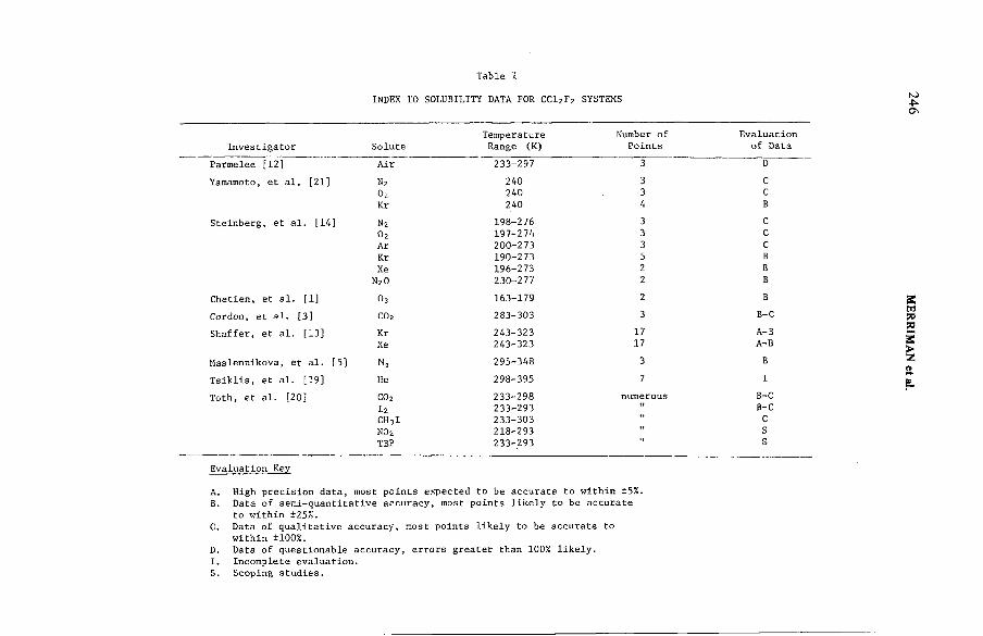
Table I
INDEX TO SOLUBILITY DATA FOR CC12F 2 SYSTEMS
Temperature Number of Evaluation
Investigator Solute Range (K) Points of Data
Parmelee [12] Air 233-297 3 D
Yamamoto, et al. [21] n 2 240 3 C
0 2 240 3 C
Kr 240 4 B
Steinberg, et al. [14] N 2 198-276 3 C
0 2 197-274 3 C
Ar 200-273 3 C
Kr 190-273 5 B
Xe 196-273 2 B
N 20 230-277 2 B
Chetien, et al. [1] 0 3 163-179 2 B
Gordon, et al. [3] СО 2 283-303 3 B-C
Shaffer, et al. [13] Kr 243-323 17 A-B
Xe 243-323 17 A-B
Maslennikova, et al. [5] n 2 295-348 3 B
Tsiklis, et al. [19] Не 298-395 7 I
Toth, et al. [20] СО 2 233-298 numerous B-C
I2 233-293t* B-C
CH3I 233-303 M cNO2 218-293
M S
TBP 233-293 " s
Evaluation Key
A. High precision data, most points expected to be accurate to within ±5%.B. Data of semi-quantitative accuracy, most points likely to be accurate
to within ±25%.C. Data of qualitative accuracy, most points likely to be accurate to
within ±100%.D. Data of questionable accuracy, errors greater than 100% likely.I. Incomplete evaluation.S. Scoping studies.
246 M
ERRIMAN
et al.
IAEA-SM-245/53 247
commonly referred to as refrigerant-12. This particular solvent was first selected by Steinberg, primarily because of its noble gas capacity, noble gas/bulk gas separation factors, and relatively good thermal and radiation stability, as well as overall process safety and economic considerations[14]. Refrigerant-12 is one of the major evaporative coolants used in commercial and home refrigeration units, and consequently, a substantial amount of detailed thermodynamic and physical property data are available for the process solvent.
The vapor-liquid distribution of a gaseous component dissolved in a liquid solvent depends upon the nature and concentration of the component, the particular solvent, the type and concentration of other solutes, and the system temperature and pressure. For a nonideal liquid solution in contact with a nonideal gas phase, the general expression for the equilibrium coefficient, Кj , is:
K. = f Y /x . = у.ф.Р/х. = y.f?L3 3 3 - 3 3 3 J J
whereKj = equilibrium coefficient of component j , atm,
vf. = gas phase fugacity, atm,
x = mole fraction in liquid phase,
= mole fraction in vapor phase,
ф_. = fugacity coefficient,
P = system pressure, atm,
Yj = liquid phase activity coefficient, and
f°k = standard state (liquid phase) fugacity, atm.
Table I is an index to the available phase equilibrium data for CCI2F 2 solutions. While the various data points are of mixed quality, there is certainly an acceptable base for design work.The University of South Carolina is currently making additional measurements for CCI2F2 binary solutions with N2, O2, and Ar.A critical review discussing most of the published data has been made by Merriman[9].
The most important components are Kr and Xe. A considerable amount of equilibrium vapor-liquid data of generally high quality now exists for solutions of these two gases in CCI2F2. The initial work was performed at the Brookhaven National Laboratory (BNL) by Steinberg[14]. Later work was reported from the University of Tokyo (UT) by Yamamoto and Takeda[21]. The most recent data are

248 MERRIMAN et al.
200
100
80
60
40
10
8
6
4
25.3 5.4 5.5 5.6 5.7 5.8
In T ( К)
FIG .l. Distribution coefficients fo r krypton and xenon in CCli F г ■
given by Shaffer[13] at ORNL as part of the fluorocarbon development program solvent chemistry task. Distribution coefficient estimates based on experimental solubility/entropy of solution data for similar gas-liquid systems and on Hildebrand's regular solution theory are given by Merriman[9]. All available data and Merriman's estimates are presented in Figure 1. All investigators show good agreement.
In another Oak Ridge laboratory investigation of the fluorocarbon system, Toth, et al., conducted scoping studies of the chemical and physical behavior of various off-gas impurities in CCI2F2 solution to determine their effects on the fluorocarbon process. Solubility, phase relationships, and distribution coefficients were determined for CO2, I2, CH3I, NO2, and TBP in CCl2F2[2 0]. Chemical interactions between the solvent and various solute components were also examined. Toth's work confirmed that

IAEA-SM-245/53 249
the presence of feed gas impurities such as I2 and N0X present no adverse chemistry that might jeopardize the fluorocarbon process safety or efficiency. This tolerance to impurities is one of the major process advantages.
The vapor-liquid equilibrium data for various CCI2F2 binary solutions are summarized in Figure 2.
PROCESS DESCRIPTION
Figure 3 is a schematic of the selective absorption process as it was originally conceived. The process serves to remove
volatile radioactive contaminants from nuclear facility off-gas streams and subsequently concentrate the contaminants for longterm radioactive waste storage. Absorption, intermediate stripping, and final stripping steps are performed in order to accomplish these two process objectives. The main separation of radioactive components from the bulk gas is effected in the absorber. The intermediate or fractional stripper serves to remove the coabsorbed carrier gas from the solvent, thereby enriching the remaining dissolved gas in the more soluble components. The final stripper removes all remaining gas from the process solvent for collection and regenerates the solvent for recycle to the absorber. The absorption section consists of a packed column for gas-liquid contacting. The intermediate and final strippers are each composed of a packed column, a reboiler, and an overhead condenser. Support equipment items for the basic process include a process gas compressor, feed gas heat exchanger, solvent pump, solvent cooler, storage tanks, and several refrigeration compressors.If the feed gas contains significant quantities of high boiling components, a solvent purification still can be added as an inline option to prevent these materials from accumulating in the recirculating solvent. Also, a product purification system can be added if desired to provide a Kr product of particularly high purity, recover Xe for industrial use, or fix the product CO2 as СаСОз or ВаСОз for storage.
Typically, the absorber might operate at a pressure of 8 atm (abs), a temperature of about 248 K, and a solvent-to-gas molar flow ratio of 10 to 15. The intermediate stripper is normally operated at substantially less pressure than the absorber, e.g.,4.4 atm (abs). A liquid-to-vapor molar flow rate ratio of approximately 6 to 8 is required at the bottom of•the column to desorb the coabsorbed carrier gas. The intermediate reboiler and corresponding upflowing vapor are maintained essentially at the saturation temperature of the solvent, which is 248 К for a total pressure of 4.4 atm. By operating the final stripping column under an even lower pressure than that used in the intermediate column, e.g., 2 atm (abs), and with a lower liquid-to-vapor flow rate ratio, e.g., 3 to 5, the remainder of the absorbed gas can be driven from the solvent.

EQU
ILIB
RIU
M
CO
NS
TA
NT
, at
m
250 MERRIMAN et al.
T E M P ER A T U R E, К
FIG.2. Equilibrium distribution coefficients for various feed gas components in R-12.

IAEA-SM-245/S3 251
DECONTAMINATED VENT GAS
FIG.3. Schematic o f the fluorocarbon process.
Figure 4 shows a photograph of the second ORGDP selective absorption pilot plant. This particular plant was put into operation in 1974 and operated for approximately four years. Detailed engineering drawings and descriptions of the facility are available elsewhere[16]. The plant is designed on the basis of handling a nominal 25 m 3/h (STP) of contaminated gas. The nominal process solvent flow rate is 5.7 liters/h. The absorber column is 7.6 cm in diameter and contains 2.7 m of high efficiency wire mesh column packing. The intermediate column is also 7.6 cm in diameter and contains 2.3 m of packing. The stripping column is somewhat larger 15 cm diameter, and contains 3.6 m of packing.
In the course of the pilot plant operation and data analysis, a soluble gas peak was observed in the intermediate column owing to gross internal condensation of the upflowing stripping vapor[18] Further definition of the internal peaking phenomenon showed that when the internal condensation zone was raised in the column, the magnitude of the soluble gas concentration peak increased dramatically. It became apparent that if sufficient stripping stages were provided below the condensation zone, the final stripping section of the three-column process could be eliminated with the product being collected as a side stream. Furthermore, it also seemed feasible to place the intermediate section directly below the absorber and operate the entire assembly at a common pressure. Subsequently, a single column was designed that combines the three functional steps of absorption, fractional stripping,
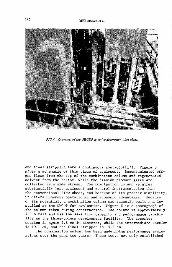
252 MERRIMAN et al.
FIG.4. Overview o f the ORGDP selective absorption pilot plant.
and final stripping into a continuous contactor[17]. Figure 5 gives a schematic of this piece of equipment. Decontaminated off- gas flows from the top of the combination column and regenerated solvent from the bottom, while the fission product gases are collected as a side stream. The combination column requires substantially less equipment and control instrumentation than the conventional flow sheet, and because of its greater simplicity, it offers numerous operational and economic advantages. Because of its potential, a combination column was recently built and installed at the ORGDP for evaluation. Figure 6 is a photograph of the column taken during construction. The column is approximately7.3 m tall and has the same flow capacity and performance capability as the three-column development facility. The absorber section is again 7.6 cm in diameter, while the intermediate section is 10.1 cm, and the final stripper is 15.2 cm.
The combination column has been undergoing performance evaluations over the past two years. These tests not only established

IAE A-SM-24S /53 253
DECONTAMINATED VENT GAS
CONTAMINATED FEED GAS
VOLATILE SOLUBLE COMPONENTS Kr, Xe, C02
FC -F L O W CONTROLLER TC -TEM PERATURE CONTROLLER LC - LEVEL CONTROLLER ДРС - DIFFERENTIAL PRESSURE
CONTROLLER PC -PR ESSU R E CONTROLLER CC -COMPOSITION CONTROLLER R -R EFR IG ER AT IO N SUPPLY
FIG.5. Schematic o f the combination column.
the overall feasibility of the concept, but showed conclusively that the combination column could perform essentially as well as the separate three columns. On the basis of a comparison of the two options, the combination column was recently selected as the preferred version of the process for the reprocessing plant application and for the mobile emergency unit.

254 MERRIMAN et al.
v
FIG. 6. Overall view o f the combination column during construction.
PROCESS DESIGN CONSIDERATIONS
Fluorocarbon process performance and general versatility have been well demonstrated on an engineering scale with 10 years of pilot plant operation using three different experimental facilities. Virtually all aspects of the process and many different process options and variations have been examined. Extended pilot plant tests have been conducted with 85Kr, 133Xe, and 1311, with and without various feed gas impurities such as CO2, NO2, N 2O, NO, and H2O. These tests show that better than 99 percent of the noble gas can be efficiently removed from such carrier gases as air, N2, Ar, He, and Нг[15]. Feed gas impurities had little discernible effect on either the process operability or noble gas removal performance.
IAEA-SM-245/53 255
This feature of the process in particular gives the fluorocarbon- based technology a decided advantage over other removal schemes. Furthermore, a fluorocarbon process designed to remove a certain fraction of Kr can also simultaneously remove at least as much 11+С as CO2. Pilot plant CO2 removals in excess of 99.9 percent were easily obtained[15]. Because of this added removal capability
and in view of probable l4 C standards, the Kr removal system being designed for the Consolidated Fuel Reprocessing Program will also be the primary control process for removing 1!tC from reprocessing off-gases. The CO2 will accumulate in the product stream along with the noble gas and then will be fixed as a carbonate for long term storage. The noble gas, on the other hand, will be temporarily collected as a concentrated gas in pressurized gas cylinders. Side-stream products containing over 90 percent total Kr and Xe have been withdrawn from the pilot plant combination column. Work is currently being performed to separate the Xe and other diluents from the combination column side-stream and thereby produce an arbitrarily pure Kr product. Additionally, a Xe by-product will be generated. Oak Ridge is not engaged in the development of krypton fixation methods.
Tests conducted with elemental and organic iodine have suggested yet another application of the fluorocarbon process: namely,the process can also be relied upon as an effective secondary iodine trap. I2 and CH3I removals in excess of 99.99 percent were measured in the pilot plant[15]. This is particularly significant since the noble gas recovery process is to be located at the end of an integrated chain of processes designed to collectively decontaminate the reprocessing plant off-gas. Because of its strategic position, the fluorocarbon process can be confidently used as a backup system for the primary iodine removal equipment.
There are no critical feed gas pretreatments necessary to the safe and continuous operation of the fluorocarbon process. In comparison, cryogenic distillation is a well-developed commercial process for air component separation in the absence of radiation effects. When processing radioactive noble gas, however, O 3 formation due to irradiation of condensed O2 poses a threat to the continuous, safe operation of the cryogenic equipment. Consequently, catalytic O2 removal is an essential cryogenic plant design consideration. Other feed gas pretreatment steps are also necessary to assure the exclusion of hydrocarbon and nitrogen oxide impurities and CO2 from the feed of the cryogenic system. It should be stressed that oxygen does not have to be excluded from the fluorocarbon process because internal process 0 3 formation is not likely due to the highly dilute nature of the O 2 and Kr solutions. Even if present, ozone poses no particular threat to the process. Ozone is chemically compatible with most fluorocarbons and, in fact, is commonly dissolved in CCIF3 , refrigerant-13, for shipment because of the stability and general safety of the fluorocarbon solution.
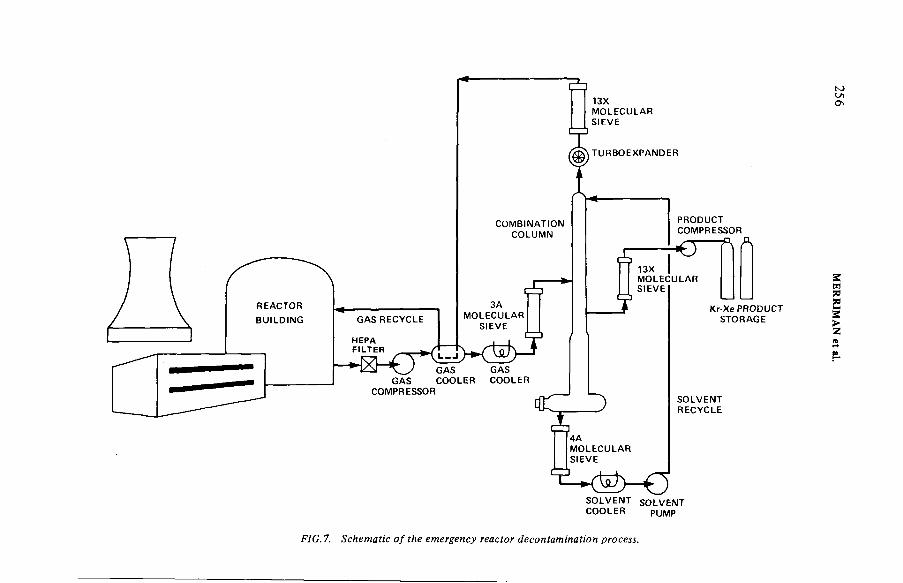
COOLER PUMP
FIG.7. Schematic o f the emergency reactor decontamination process.

IAEA-SM-245/53 257
Xenon plugging has proven to be a problem with the cryogenic equipment where the amount of xenon in the feed gas is large relative to that of krypton, such as is characteristic of fission product noble gas. Some cryogenic systems include, therefore, a xenon adsorber before the primary krypton scrubbing column to reduce the xenon imbalance. Unfortunately, a significant amount of 85Kr is also lost on the adsorbent and the Xe has to be sent to long-term storage or further treated in additional equipment.Again, these problems are absent in the fluorocarbon process.
Design of the selective absorption process requires specific and detailed knowledge of packed column contactors. Column design involves two separate considerations: the hydraulics of packedtower operation, and the fundamentals of simultaneous interphase mass and heat transfer. Column pressure drop, liquid holdup, and gas throughput can be estimated for columns packed with the wire mesh, high efficiency packing used in the Oak Ridge work from correlations given by Stephenson[18J . Rigorous packed column design models are given by Merriman[8] and Kanak[4] to describe the mass transfer phenomenon occurring in the fluorocarbon process absorber. One of the more distinguishing features of the selective absorption process is the substantial and unusual amount of carrier gas which coabsorbs with the noble gas. Merriman described how the absorption of Kr is enhanced by carrier gas coabsorption.Kanak confirmed Merriman's work and also showed how the reverse is also true, i.e., how, under certain conditions, solvent vaporization can inhibit noble gas transfer. Both of these effects are important considerations for the absorber design. A design model for the intermediate and final stripper columns is given by Stephenson[18]. This model takes simultaneous heat and multi- component mass transfer into account. Analysis of the intermediate column led to the conceptualization of the combination column and forms the theoretical basis for this device. Kanak examined the effect of column diameter on process scaleup. No wall effects were found and Kanak concluded that performance data collected at the ORGDP pilot plant can confidently be extrapolated for the design of a larger facility[4]. With these existing column performance models, there is an ample base for the rigorous design of a fluorocarbon system for virtually any application.
PROCESS APPLICATION
The selective absorption process is applicable to essentially all types of nuclear facilities, and several gas cleanup tasks have been considered. One of these, post-accident reactor cleanup, is described in this paper because it is of current interest and also serves to illustrate the process application area. A schematic of a typical processing system is shown in Figure 7. The decontamination process throughput, single pass fission product removal efficiency, and noble gas product purity have to be

258 MERRIMAN et al.
specified before the design can be fixed. Usually, an economic balance would be established between the cost of removing the noble gas from the reactor following an accident and the cost of reactor downtime. In this case, however, there may be overriding safety and social ramifications which dictate that the decontamination process proceed as fast as possible. If the decontaminated gas is recycled to the reactor containment, lower single-pass decontamination factors are permissible. Also, if the concentrated radioactive product is relatively pure, fewer gas cylinders will be generated for long term radwaste storage.
The contaminated gas, withdrawn from the reactor containment, turbine, and/or auxiliary buildings, would first be filtered to remove particulates and then dried. Next, the gas would be compressed to around 8 atm (abs) and then cooled to 240 K. Trace amounts of water remaining in the feed gas would be adsorbed on molecular sieves. Next, the reactor gas would be fed into the absorption section of the combination column and contacted counter- currently with downflowing CCI2F 2 solvent. The decontaminated gas leaving the top of the column, containing 5 to 10% CCI2F 2, would be passed through a turboexpander and 13X molecular sieve bed for solvent recovery. Alternatively, a low temperature condenser might be used to effect the same separation. The process off-gas could be either recycled or vented at this point, depending upon the noble gas concentration. Initially, all gas would probably be recycled. The solvent containing the dissolved gases would subsequently flow into the intermediate and final stripper sections of the column. Regenerated solvent would be pumped to the top of the column. If the solvent contains trace quantities of water and iodine, a 4A molecular sieve and/or silver impregnated zeolite would be used to further decontaminate the solvent prior to recycle. The amount of noble gas that has to be handled by the removal process would depend upon the fuel exposure and the reactor specific operating power level prior to the reactor shutdown.After 500 days of service, for example, a typical PWR operating at a power level of 30.0 MW/t U would contain approximately 4900 liters of Kr and 40 000 liters of Xe. Most of the Kr and Xe would be stable and isotopic decay would have little effect on the bulk concentrations. The noble gas would be collected as a combination column side stream and solvent removal could be achieved by adsorption on 13X molecular sieves[15]. One method for management of the gaseous waste, at least for the short term, is encapsulation in high-pressure cylinders and interim storage in a suitable repository.
CONCLUSIONS
An extensive amount of laboratory and pilot plant effort has gone into the verification and analysis of the fluorocarbon-based selective absorption process for removing 85Kr and llfC from various nuclear facility off-gases. The pilot plant effort has spanned
IAEA-SM-245/S3 259
a 10-year period and has involved three different test facilities. The process has an especially large tolerance for feed gas impurities and does not rely upon critical feed gas pretreatment steps. Ozone formation is not a problem, nor is xenon plugging. Substantial improvements and simplifications have been made to the original version of the process and rigorous engineering models have been developed for process design. Essentially all of the process development work has been completed and the design of a demonstration plant to be operated in conjunction with a DOE reprocessing facility is in progress. Additionally, an emergency decontamination process applicable to power reactor cleanup is being considered.
REFERENCES
[1] Chetien, A., et al., "Low temperature solubility of ozone in various freons," Bull. Soc. Chim. France, (I960) 49.
[2] Environmental Protection Agency [40 CFR Part 190], Federal Register 4 ), 104 (May 29, 1975) 23420.
[3] Gordon, A. R., and MacWilliam, E. A., "The vapor pressure of solutions of carbon dioxide in difluorodichloromethane,"Can. J. Res. 24B (1946) 292.
[4] Kanak, В. E., Analysis of a Gas Absorption Column with Soluble Carrier Gas and Volatile Solvent, USDOE Rep. K-2007 (1979).
[5] Maslennikova, V. Ya., Goryunova, N. P., and Tsiklis, D. S., "Phase equilibria in nitrogen/freon-12 and nitrogen/freon-22 systems," Zhur. Fiz. Khim. 4d (1967) 735.
[6] Merriman, J. R., Pashley, J. H., and Smiley, S. H., Engineering Development of an Absorption Process for the Concentrationand Collection of Krypton and Xenon, USDOE Rep. K-1725 (1967).
[7] Merriman, J. R . , Stephenson, M. J., Dunthorn, D. I., and Pashley, J. H . , Removal of 85Kr from Reprocessing Plant Off- Gas by Selective Absorption, USDOE Rep. K-L-6201 (1972).
[8] Merriman, J. R., Analysis of a Multicomponent Gas Absorption System with Carrier Gas Coabsorption, USDOE Rep. KY-G-300 (1975).
[9] Merriman, J. R., The Solubility of Gases in CCI2F 2: ACritical Review, USDOE Rep. KY-G-400 (1977).
[10] Murbach, E. W . , et al., Fission Product Gas Retention Process and Equipment Design Study, USDOE Rep. ORNL-TM-4560 (1974).
[11] North, E. D., and Booth, R. L., Fission Product Gas Retention Study Final Report, USDOE Rep. ORNL-TM-4409 (1973).
[12] Parmelee, H. М., "Solubility of air in 'freon-12 and freon-22'," Refrigerating Engineering, June (1951).
[13] Shaffer, J. H., Shockley, W. E., and Greene, С, E., The Solubility of Krypton and Xenon at Infinite Dilution in Dichloro- difluoromethane, USDOE Rep. ORNL-TM-6652 (1978).

260 MERRIMAN et al.
[14] Steinberg, М., and Manowitz, В., "Recovery of fission product noble gases," Ind. Engr. Chem., 5^, (1959) 1.
[15] Stephenson, M. J., and Eby, R. S., Development of the FASTER Process for Removing Krypton-85, Carbon-14, and Other Contaminants from the Off-Gas Fuel Reprocessing Plants,USDOE Rep. K-GD-1398 (1976).
[16] Stephenson, M. J., Eby, R. S., and Huffstetler, V. C.,ORGDP Selective Absorption Pilot Plant for Decontaminationof Fuel Reprocessing Plant Off-Gas, USDOE Rep. K-1876 (1977).
[17] Stephenson, M. J., and Eby, R. S., Gas Absorption Process,U. S. Patent 4,129,425 (1978).
[18] Stephenson, M. J., Analysis of a Fractional Gas Stripper, USDOE Rep. K-1895 (1978).
[19] Tsiklis, D. S., Maslennikova, V. Ya., and Goryunova, N. P., "Limited mutual solubility of gases in helium, and fluorine compound mixtures," Zhur. Fiz. Khim. j41 (1967) 1804.
[20] Toth, L. М., Bell, J. T., and Fuller, D. W , , Chemical and Physical Behavior of Some Contaminants in the R-12 Off-Gas Process, USDOE Rep. ORNL-TM-6484 (1978).
[21] Yamamoto, Y., and Takeda, H., "Solubility of 85Kr in some organic solvents," J. Fac. Eng. U. Tokyo A-7 (1970) 44.
DISCUSSION
R.-D. PENZHORN: It has often been m entioned that the radiolysis products from freons could lead to corrosion problems w ith your process.Have you carried out any work on this problem?
M.J. STEPHENSON: The degradation products o f CC12F 2 are other fluorocarbons, namely C2C13F 3, C2C12F 4, CC1F3 and Cl2 .
F 2 has not been found in radiolytic products. If water is present in the system , HC1 could form and so construction materials have to be selected carefully.
H.A.C. M cKAY: Can you use your solvent for ever? I f not, what will you do with it, bearing in mind that it may be radioactively contaminated, for instance w ith ruthenium?
M.J. STEPHENSON: We can use our solvent virtually for ever if the various feed gas impurities are periodically removed via distillation or solid sorbent trap. If a solvent purification system is not used, the solvent will have to be replaced sooner or later depending upon the level o f contamination. If the feed gas to the fluorocarbon system is as clean as that required for the cryogenic system , the solvent should last for a long time w ithout treatment. I f the solvent has to be disposed of, it could.be destroyed by burning. We plan to purify the solvent utilized in the dem onstration facility for reuse.
IAEA-SM-245/53 261
J.L. KOVACH: I have four questions: Have you run the system w ith the full expected activity for all the com ponents? How will you deal w ith 14C 0 2- fluorocarbon isotope exchange? Where will the iodine go in the combination column? And lastly, do you expect to use this as a post-accident containm ent venting system?
M.J. STEPHENSON: With regard to your first question, we have not yet done so. The ‘h o t’ demonstration facility will provide the first opportunity to expose the process to ‘real’ levels o f activity.
Regarding your second question, isotopic exchange will probably occur but I do not know to what extent. But we are not particularly concerned because the solvent will not be released to the environment.
Thirdly, you ask where the iodine will go. It will remain in the solvent unless removed. A silver exchanged zeolite bed can be used in the solvent circuit as m entioned in the paper.
Finally, we do expect to use our system in the way you m ention.R. BROWN: Do you anticipate any problems with selective desorption
and subsequent im m obilization o f 14C 0 2 ? At the full design operating rate, what is the expected xenon to krypton product ratio in the case o f reprocessing prior to any additional purification steps?
M.J. STEPHENSON: We do not expect any problems in that area. As to your second question, the ratio will be the same as for the feed gas.
H. GUTOWSKI: What will the 85Kr activity holdup be in the column for a 200 m 3/h plant?
M.J. STEPHENSON: The holdup will depend upon the process throughput. Typically the process will contain about 1 hour’s activity.
R.F. ABRAMS: Have you made any preliminary cost estim ates for the 200 m 3/h system?
M.J. STEPHENSON: Yes, the cost o f a total mobile system including all the equipm ent is estim ated at about US$ 10 000 000.

IAEA-SM-24S/7
CONTAINMENT OF KRYPTON IN A METALLIC MATRIX BY COMBINED ION IMPLANTATION AND SPUTTERINGD.S. WHITMELL, R.S. NELSON,M.J.S. SMITHAtom ic Energy Research Establishment,Harwell, D idcot, Oxfordshire,United Kingdom
Abstract
CONTAINMENT OF KRYPTON IN A METALLIC MATRIX BY COMBINED ION IMPLANTATION AND SPUTTERING.
A process fo r the im m obilization o f k ryp ton in a metallic m atrix is being developed to give a safe m ethod for the containm ent o f th e radioactive k ry p to n arising from the reprocessing of nuclear fuel. The process consists essentially o f using a sw itched glow discharge to im plant the gas in to a m etal layer deposited on the inside o f a vessel and th en to coat the layer w ith m etal sputtered from another electrode. By repeating the sw itching process, a thick layer is built up w ith the k ryp ton dispersed th roughout th e m etallic m atrix as bubbles o f diam eter less than 20 Â at a concentra tion of 5 at.%, equivalent to 170 litres o f gas at STP per litre o f m etal. Following low power laboratory experim ents, a 50 kW inactive pilot plant has been built and is being commissioned in order to dem onstrate the process on a scale com parable w ith that required for an industrial plant. Details o f the pilot plant are given. Experim ental m easurem ents carried ou t w ith copper, iron, alum inium and m onel m atrices have shown th a t the process may be operated w ith a wide variety o f materials. K rypton may be incorporated at efficiencies of 1 kW -h per curie. It is stable in copper to tem peratures o f the order o f 600°C and to correspondingly higher tem peratures in m ore refractory metals. An assessment of the stability of the k ryp ton indicates th a t, since th e gas is im m obilized as bubbles em bodied w ithin a solid metallic m atrix , significant am ounts o f gas will no t be released during an accident. Corrosion resistance may be provided by suitable choice o f m aterials. This process offers suitable containment to satisfy the safety requirem ents for transport, storage and disposal.
1. INTRODUCTION
8 SAny method of containing the radioactive krypton released
during fuel reprocessing must provide reliable isolation from the biosphere for about 100 years.
Krypton could be stored as a gas in high pressure cylinders but this method is not desirable for the entire
263
264 WHITMELL et al.
period because of the dangers of the escape of the gas if the cylinder or its valve is damaged or corroded. The cylinder would therefore have to be placed within expensive, specially designed buildings, and it may be necessary to provide for inspection of the cylinders throughout their life.
Improved reliability can be provided by immobilising the gas in a solid matrix. The choice of process will depend on the integrity of this matrix and on other factors such as gas capacity, cost, availability of material, ease of manufacture, and avoidance of active effluents.
Storage in zeolites and glasses is being investigated both in Europe and the U.S.A. but the high temperature and pressures required to entrap the krypton are undesirable for a process involving radioactive gas.
Immobilisation of krypton as minute gas bubbles in a metal matrix so that the gas is embodied within the solid, offers an ideal method of storage. Krypton may be injected into a metal by high energy ion implantation but the range of the ions is too small for a sufficient quantity of gas to be stored by ion implantation alone. A process has therefore been devised(l) where krypton is implanted into a thin layer as low energy ions from a glow discharge and then a fresh surface layer is built up by coating the implanted layer. A thick deposit containing gas can then be formed by repeating the process.
Various experimental arrangements were tried initially.The process being developed was selected as the optimum to comply with the requirements stated above for the immobilisation of a radioactive gas. In particular, the process was chosen in order that it could be operated with an unrestricted range of metals so that metals could be selected to provide the environmental resistance for different methods of storage and disposal as required. Attention was given to keeping the process as simple as possible in order to achieve a high reliability since servicing and repairs will not be easily carried out on an active plant.
(2 31After successful low power experiments '• ’ J a pilot plant
has been built and is being commissioned to demonstrate the process on a scale comparable with that required for an industrial plant. This pilot plant is being operated with inactive gas to give the information required to design a large plant and to produce representation samples of gas-filled deposit for assessment.
Alternative m e t h o d s ^ using variants of the technique have recently been investigated e lsew here( 4 , 5 ) t

IAEA-SM-24S/7 265
I IMPLANT П COAT
FIG .l. Principles o f the process.
2. THE IMMOBILISATION PROCESS
The underlying principles of the process selected for the storage of radiokrypton are shown in Figure 1. A glow discharge is obtained between the two cylindrical electrodes by applying a negative potential of 3-5 kV to either of the electrodes in the presence of krypton at a pressure of 0 . 1 torr (10 Pa). The glow discharge is used as a source of ions which bombard the negative electrode and cause both ion implantation and sputtering of the electrode material. Gas is implanted into the outer electrode by applying the negative potential to this electrode. The implanted gas is then coated with a layer of metal sputtered from the inner electrode by switching the negative potential to the inner electrode. By repeating the switching process a thick layer of deposit is built up on the inside wall of the electrode. The net deposition and incorporation of krypton into this matrix is achieved by controlling the relative times used for each phase.
The envisaged industrial plant has a cylindrical form as shown schematically in Figure 2- Krypton, separated from the other gaseous fission products will be admitted to the vessel at sub-atmosphere pressure and implanted into the matrix deposited on the inside of the water-cooled walls which form the outer electrode, and coated with a suitable metal sputtered from the central electrode. When a gas-filled matrix of suitable thickness has been built up, a sealing layer containing inactive gas will be deposited onto the matrix by continuing operation with an inactive gas. The water, gas and electrical supplies to the vessel will
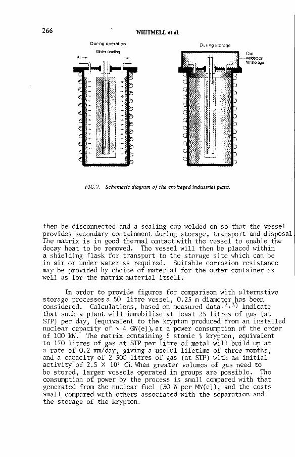
266 WHITMELL et al.
FIG.2. Schematic diagram o f the envisaged industrial plant.
then be disconnected and a sealing cap welded on so that the vessel provides secondary containment during storage, transport and disposal The matrix is in good thermal centact with the vessel to enable the decay heat to be removed. The vessel will then be placed within a shielding flask for transport to the storage site which can be in air or under water as required. Suitable corrosion resistance may be provided by choice of material for the outer container as well as for the matrix material itself.
In order to provide figures for comparison with alternative storage processes a 50 litre vessel, 0.25 m diameter has been considered. Calculations, based on measured data(2>3) indicate that such a plant will immobilise at least 25 litres of gas (at STP) per day, (equivalent to the krypton produced from an installed nuclear capacity of ъ 4 GW(e)), at a power consumption of the order of 100 kW. The matrix containing 5 atomic % krypton, equivalent to 170 litres of gas at STP per litre of metal will build up at a rate of 0.2 mm/day, giving a useful lifetime of three months, and a capacity of 2 500 litres of gas (at STP) with an initial activity of 2.5 X 10s Ci. When greater volumes of gas need to be stored, larger vessels operated in groups are possible. The consumption of power by the process is small compared with that generated from the nuclear fuel (30 W per MW(e)), and the costs small compared with others associated with the separation and the storage of the krypton.

IAEA-SM-245/7 267
Following low power laboratory experiments, a 50 kW pilot plant has been built to demonstrate the process on a scale comparable with that of an industrial plant. It is now being commissioned and operated with inactive gas to obtain the information required to design a large plant, and to produce representative samples of gas-filled matrix for assessment. The samples are being examined metallographically and the stability of gas determined in terms of time and temperature, leaching / corrosion and radiation stability. The current work programme also includes further experiments to provide information on various candidate matrix metals, including alloys, to test electrode designs and to determine the optimum values for various process parameters.
The main elements of the pilot plant are shown schematically in Figure 3. The pilot plant is designed to operate at power levels of up to 50 kW. The process vessel, high voltage supplies and the reversing switch are contained within a high voltage enclosure for personnel protection, with the remaining equipment outside.
A schematic drawing of the module currently used is shown schematically in Figure 4. The outer stainless steel electrode has a diameter of 260 mm and is 300 mm long. It is cooled by water flowing at high velocity in a spiral path. The central electrode is 190 mm in diameter machined from oxygen-free copper. Other materials could also be used. Sample specimens of the deposit may be obtained from the four cooled or heated blocks mounted on side ports positioned at various places along the length of the chamber. The module, being experimental, is demountable using copper gaskets or Viton "0" rings rather than being permanently welded as would be the case with industrial plant.
Before operation, the module is baked to 150°C to give pressures of the order of 10“6 torr. Gas is then admitted to give a constant pressure in the module using a solenoid or piezo-electric leak valve controlled by a Pirani gauge. The gas flow is measured by the pressure drop across a capillary tube by a capacitance manometer. The gas can be spectroscopically analysed by using a mass spectrometer. The module may be dynamically pumped by trapped diffusion and rotary pumps, or isolated, relying solely upon its own pumping action.
The provision of switched high voltage supplies to the electrodes provided some novel problems. Thyratrons (English Electric BT69) are used both as switches and as half-wave
3. INACTIVE PILOT PLANT

J
FIG.3. Layout o f the half-scale pilot plant.

IAEA-SM-24S/7 269
FIG.4. Schematic section o f the pilot plant module.
rectifiers to connect the three-phase 5 or 10 kV high voltage power transformer to the electrodes. One set of thyratrons are switched on to provide the negative potential to the outer electrode for implantation and a second set are switched on for the coating phase when the negative potential is applied to the central electrode. The firing of the thyratrons is controlled by a solid state timer driving conventional thyrister firing circuits modified for high voltage use. The thyratrons can also be turned on at various points on the sinusoidal voltage cycles, allowing conduction during only part of the cycle.This process of phase angle firing allows some control over the voltages and currents on the module. Further control of the

270 WHITMELL et al.
voltage is obtained by using a motorised variable Brentford regulator, rated at 70 kW which currently limits the output
capacity of the power supply.
This electrical system provides a simple protection system against electrical overloads should the stable glow discharge change into a local arc. If an arc is detected by the current measuring circuits, it may be quenched by switching off the thyratrons temporarily. An automatic control and monitoring system is currently being developed.This system, based upon a microprocessor, will be programmed to monitor data and to control the thyratron switch, gas pressure, power and voltage so that the entire process may be controlled automatically.
4. SUMMARY OF EXPERIMENTAL MEASUREMENTS AND RESULTS
As the pilot plant is commissioned, the operating power and running times are being increased. It is now being run continuously for periods over 120 hours, at power levels up to 25 kW. Operation overnight and at weekends requires no attention. The operating conditions are similar to those predicted from the earlier low power laboratory measurements ’ in which the gas incorporation into copper, iron, aluminium and monel matrices was studied.
The optimum conditions were determined by measuring the gas flow into the system and also by measuring the concentration of gas in the samples. The samples were examined, weighed and then melted in a furnace in an ultra-high vacuum system and the amount of krypton released as a function of time and temperature was measured using a calibrated mass spectrometer.
During these measurements, it has been demonstrated that the module acts as its own pump, incorporating gaseous impurities into the deposit, so that no external pumping is required, thus avoiding the emission of process effluents. Fully radioactive krypton has also been used in a preliminary experiment with a small module for a short period of time to show that the discharge is unaffected by 3 activity in the gas.
The rate at which gas is incorporated in the matrix and the concentration of gas in the deposit are dependent upon the coat and implant times and also the ion energies. The variation with implant time (for a fixed cycle time) for copper and iron are shown in Figure 5. The amount of gas incorporated in the deposit initially increases with implant time, reaches a maximum and then decreases to zero due to the sputtering process during

IAEA-SM-245/7 271
FIG.5. Variation o f the gas incorporation rate with implant time for copper and iron. The figures indicate the measured gas concentrations in the deposits in the central and end regions o f the cylinder.
implantation eroding the deposited layer. As the deposited layer becomes thinner, the gas concentration in the deposit rises to over 51 for both copper and iron. The first and second figures indicated by arrows in the figure, refer to the gas concentrations found in the deposit in the central end regions of the outer electrodes respectively. These measurements show that krypton can be incorporated into copper at concentrations greater than 5 atomic I with efficiencies better than 10“2 litres (at STP) p e r k W h, and that at a similar concentration the efficiency for iron is only slightly lower. Similar results have been obtained for aluminium and monel. The gas incorporation rate is also dependent on the ion energy. The rate initially rises with energy, but the optimum energy depends upon the balance between the increasing ion trapping efficiency and the decreasing sputtering efficiency with energy. Since these are dependent upon the material, each material has its own optimum working voltage.

272 WHITMELL et al.
MODULENo. I п Ш
DATE 1 9 7 6 1978 1 97 9POWER
DENSITYWATTS/cm2
1 5 5
2
I 15CL1—(Л
È
О 1 0>осo>о
'Sо) 0 5аЕэ
Q-
-*
о i I I I
о СП 5P o w e r ( kW )
10 5
FIG. 6. Variation o f efficiency with increasing power levels for copper measured using different pumping modules.
The variation of the maximum pumping speed measured for copper as the total discharge power has been increased is shown in Figure 6. These values have been derived over a long period of time starting with the earliest laboratory scale pumping module up to the present pilot plant and illustrate that,as the power levels have been increased by two orders of magnitude, the measured efficiency of the process has remained unaltered. Since the recent results are preliminary and do not relate to the optimum overall conditions, it is possible that an improvement in efficiency may be obtained.
The deposited metal is evenly distributed and adherent to the electrode. Samples of the deposits, taken from the sample holders have been examined by scanning and transmission electron microscopy. The surface is then seen to be relatively smooth with a grain size typically 1-5 um. The bubbles in a copper matrix as normally deposited, are extremely small and cannot be identified unambiguously when examined in the transmission electron microscope. However, if the deposit is subsequently annealed, the bubbles grow and they become identifiable after

IAEA-SM-24S/7 273
FIG. 7. Krypton bubbles in a copper matrix subsequently annealed to 500 C. Transmission electron micrograph, original magnification X 100 ООО, overfocused so that the bubbles appear dark.
annealing to temperatures around 300°C. Figure 7 shows bubbles 20-80 Â diameter revealed after annealing copper to 500°C for one hour. Similar bubbles can be seen by heating the substrate to 220 С during deposition.
The temperature at which the krypton is released is characteristic of the metal but also depends on the deposit thickness, heating rate, and implantation temperature. The bulk of the gas is released from thin copper samples deposited at ambient temperatures between 600°C and 700°C. If the deposit is formed at higher temperatures (100-250°C), the release continues beyond 700°C. Iron retains krypton to 550°C. The release temperature from more refractory materials is correspondingly higher, for example, molybdenum and tantalum have been found to retain the gas to 950°C and 1200°C,respectively. A small amount of gas is released at slightly lower temperatures, which is apparent when samples are thin, because the release is from the surface region. This has been demonstrated using an argon-filled deposit as a surface coating. Figure 8 shows the gas released

274 WHITMELL et al.
T e m p e r a t u r e °C
FIG. 8. Release o f argon and krypton as a function o f temperature from a 1-mm-thick krypton- filled copper matrix, coated with a 50 ¡xm argon-filled layer.
from a sample 1 mm thick which was finally coated with an argon- filled layer 50 ym thick. A small section was cut and then melted with the release of krypton and argon being monitored simultaneously. The argon, being closer to the surface was released first, and the krypton was retained to a signficantly higher temperature (save for a small amount released with the argon which was emitted from the uncoated cut edges of the sample). This illustrates that a final ^^krypton-free coating will prevent the release of activity from the surface layer.
5. DISCUSSION
The main criterion for any process for immobilising radiokrypton is that no significant amount should be released even
under abnormal conditions. Circumstances which might lead to the loss of krypton .are:
(1) mechanical damage
(2) corrosion: by the environment or internally by contaminants or the decay product rubidium.

IAEA-SM-245/7 275
(3) temperature rise due to self-heating or exposureto fire.
(4) radiation effects due to В decay.
Each of these will be considered briefly.
Since krypton is insoluble in metals, the most stable sites for the implanted gas are within gas bubbles. The number and size of the bubbles will depend largely upon the conditions during deposition. At the high gas concentrations present within the matrix, all the krypton will be incorporated within the bubbles.The krypton cannot escape thereafter from the bubbles, and will remain within them until the bubbles themselves diffuse at temperatures close to the melting point, or are swept out by processes such as dislocation movement or recrystallisation which occur at temperatures characteristic of the metal.
Therefore, if the matrix is mechanically damaged, only gas in bubbles intersected by the fracture surface will be released.If a matrix with gas in 20 A diameter bubbles is fractured into pieces 1 cm cube, only 3 ml of gas (0.3 Curies) will be released from the cylinder.
The release of krypton by environmental corrosion may be minimised by the choice of suitable material for the outer container vessel and for the matrix itself. The matrix will be subjected to attack only after the outer vessel is penetrated and any resulting release of krypton will be proportional to the amount of matrix destroyed by corrosion which should be very small with the appropriate choice of metal.
The matrix also provides protection against any corrosive attack by the rubidium decay product. The krypton is dispersed as small bubbles, each of which contains only about 50 krypton atoms. As the 8%.rypton decays, only ^ 3 rubidium atoms will be produced in each bubble. The rubidium is therefore dispersed through the metal rather than accumulated in bulk quantities as in a gas cylinder and any corrosion or embrittlement processes will be less serious.
Gas will be released if the matrix temperature rises to the order of 600°C for copper or to correspondingly higher temperatures for more refractory materials. The self-heating caused by the decay of ^ k r y p t o n 25-50 m W / c m 2 but the good thermal conductivity of the matrix and its good contact with the wall of the vessel enable this heat to be removed with only a temperature drop of a few degrees. For transport, the vessel will be placed in a suitable flask with fire resistance being provided by conventional means.

276 WHITMELL et al.
During storage, the irradiation of the matrix by the0.6 MeV 3 particles will cause the metal atoms to be displaced. The initial displacement rate will be ^ 2 X 10⁻³ at./at. per year, so that after all the krypton has decayed, 2% of the copper atoms will have been displaced, which is very small compared with the number displaced during deposition. Any krypton ejected from the bubbles will be trapped by a neighbouring bubble.
The choice of a process also depends upon the ease of immobilisation, its reliability, gas capacity and lack of effluent. The process has been designed to be able to operate remotely, under automatic control and to be as simple as possible to avoid active maintenance. Since the process vessel becomes the secondary container, and is removed without dismantling, there will be no other contaminated equipment for disposal and the handling cell should remain free of contamination.
The operating conditions of ambient temperature and sub-atmospheric pressure are suitable for active gases. The manufacturing requirements are conventional.
As impurities in the gas are also incorporated, the process requires no external pumping, thus avoiding effluents. Also, it will not be necessary to remove all contaminants from the active feed gas.
The choice of metal is not restricted by the process or by power consumption and a material may be selected to satisfy storage requirements. The amount of gas stored in a vessel is similar to that possible in a pressurised cylinder. Additional capacity may be achieved by larger modules or by parallel operation.
6. CONCLUSIONS
The immobilisation of krypton in a metallic matrix by combined ion implantation and sputtering promises to offer an ideal method of containing ^bfoypton and has several advantages over other immobilisation processes.
The construction and operation of a pilot plant is demonstrating that the process is viable on a large scale.It will provide samples of the product on which the required wide range of environmental tests may be carried out.
The small scale experiments have shown that the rate of incorporation of gas, the electrical efficiency and the operating characteristics are suitable.

IAEA-SM-245/7 277
A study of the properties of the metal matrix has shown that this form of containment offers much greater security than pressurized gas cylinders for storage, transport and disposal, and therefore may reduce the overall costs of ^ k r y p t o n waste management. The freedom of choice of matrix material enables the optimum material to be chosen to give the required environmental protection.
ACKNOWLEDGEMENTS
The assistance of R. Williamson in carrying out the experimental work is gratefully acknowledged. G. J. Bauer and K. J. Hill have given considerable engineering support to this work, particularly in the development of the high voltage switch and power supplies. J. Muncie and J. H. Evans have carried out some of the metallurgical examinations.
REFERENCES
(1) Nelson, R. S., Pugh, S. F., Smith, M. J. S. and Clelland D. W. British Patent No. 1,485,266. Filed 1974.
(2) Whitmell, D. S., Williamson, R., Nelson, R. S. ProceedingsIPAT '77 CEP Consultants (1977) 202.
(3) Whitmell, D. S., Nelson, R. S., Williamson, R., Smith, M. J. S.Nuclear Energy, 1^ (1979) 349.
(4) Bayne, M. A., Moss, R. W., McClanahan, E. D. BattellePacific Northwest Labs. PNL-SA-7274 (1979).
(5) Henrich, E. - Private Communication
DISCUSSION
R. BROWN: D o you foresee problems arising in terms o f waste volume with co-im plantation o f xenon, and have you observed any selective implantation o f xenon?
D.S. WHITMELL: We are confident that xenon will implant with the krypton, and at a rate close to that o f the krypton. The presence o f the xenon will therefore not give rise to operational problems but will increase the volume o f gas to be im m obilized, thus producing a roughly proportionate increase in the size and power consum ption o f the plant. Hence separation o f the krypton from the bulk o f the xenon is likely to be econom ically desirable.

278 WHITMELL et al.
R. BROWN: Have you carried out any long-term observation o f leakage with radioactive krypton?
D.S. WHITMELL: Long-term measurements will be started soon. The effects o f irradiation will be determined by irradiating samples containing inactive krypton rather than by using radioactive krypton.
R.-D. PENZHORN: How critical is the change in configuration that takes place when an implantation unit is operated for several m onths or more?
D.S. WHITMELL: The changes in the electrodes are relatively small, the diameter o f the outer electrode reducing from 25 cm to 21 cm, for example.An autom aticcontrol system which will be able to com pensate for this is being developed.
P. PATEK: Do you have any figures on the unit costs o f the ion implantation process?
D.S. WHITMELL: Detailed cost estim ates have not yet been made. However, preliminary estimates indicate that the costs for electrical power will be ~ £ 0.02 per curie (at £ 0 .0 2 perkW -h). The cost o f the storage vessel will be somewhat less. In comparison, the cost o f matrix metal, labour, power supply and switch will be insignificant, this having been confirmed in the construction o f the pilot plant. The cost o f the remote handling system and shielding is more uncertain.We expect that the containm ent provided by the metal matrix method will result in substantially lower costs for transport, storage and disposal. The total costs may therefore be less than for other processes.
F. CEJNAR: Besides the noble gases, are there any special requirements relating to the presence o f impurities such as oxygen, nitrogen, etc. in the krypton gas?
D.S. WHITMELL: No. Impurities in the gas at loads o f a few per cent will simply be incorporated in the matrix with the krypton.
M.W. FIRST : Can you give any comparative figures on the volume and metal weight o f packages placed in storage for both sputtering and compressed gas storage on an equal Kr volume basis?
D.S. WHITMELL: Details are given in Section 2 o f the paper. They show that the volume, weight and gas content are similar to the proposed high-pressure krypton gas cylinders.

IAEA-SM-245/31
SOLID STATE CONTAINMENT OF NOBLE GASES IN SPUTTER DEPOSITED METALS AND LOW DENSITY GLASSES*
G.L. TINGEY, E.D. McCLANAHAN,M.A. BAYNE, W.J. GRAYBattelle Pacific Northwest Laboratories,Richland, Washington,United States o f America
Abstract
SOLID STATE CONTAINMENT OF NOBLE GASES IN SPUTTER DEPOSITED METALS AND LOW DENSITY GLASSES.
Two techniques have been developed for the solid state storage of the radioactive inert gases. The first technique involves ion im plantation of gaseous ions during the spu tter deposition of a m etal m atrix. This technique yields a deposited m etal containing th e im planted gas atom ically dispursed th roughout the m atrix. Relatively pure m etals such as Fe, Al, Ni, and Ti have been spu ttered with Kr to yield a crystalline p roduct containing up to 5 at.% Kr. Metal alloys, which sp u tter to yield a glassy structu re , have been shown to accept a Kr a tom more readily and contain up to 10 at.% Kr. One o f the m ore prom ising glassy alloys studied has an empirical form ula Feo.79Yo.uKro.0 9- This deposit appears to release the Kr a t elevated tem perature following the rate equation R Kr = 2.5 X 10⁷exp ( —42 000/R T ), where R Kr is th e fractional release o f Kr per m inute, R is the gas constant in cal/m ol-K , and T is the tem perature in K. Long-term release m easurem ents indicate th a t less than 2% of the Rr would be released in 10 years at 3 00°C. O ther m etal alloys show even lower Kr release rates. A second process under investigation at our laboratory for storing radioactive inert gases involves dissolution and /o r trapping in the very fine pores o f a low density glass m atrix. Although the quan tity dissolved in fully dense glasses is so small as n o t to be of interest, the same process yields up to 7 cm 3 of Kr(STP)/g o f glass (~ 2 at.%) in glasses with about 30% open porosity when loaded at about 35 MPa pressure. Porous S i0 2 samples (~30% porosity , ~ 1 00 m2/g surface area) were placed in a pressure vessel, pressurized to 35 MPa with Kr, and heated to 850—900 C. The samples were held at the high pressure-high tem perature condition for a period long enough to sinter to 10—20% porosity and cooled under pressure. The fractional Kr release rate from these S i0 2
samples was determ ined isotherm ally to be abou t 3 X 10"9/m inute a t 4 2 0 °C. E xtrapolation o f this rate yields a to ta l release o f abou t 1 . 8% in the first 1 0 years at 420°C.
1. INTRODUCTION
There are a large number of isotopes of krypton and xenon included in the fission chains of nuclear power reactor fuels [1]. However, with the exception of Kr-85, with a half-life of 10.73
* W ork supported by the U nited States D epartm ent o f Energy, under C ontract EY-76-C-06-1830.
279

280 TINGEY et al.
years, all isotopes have sufficiently short half-lives to decay almost completely in less than three or four months after they are discharged from the reactor. Thus, for ultimate storage, Kr-85 is the only inert gas fission product of any consequence. During decay, Kr-85 yields Rb-85 with the release of a beta particle with a maximum energy of 0.66 MeV and a very low flux of 0.52 MeV gamma rays.
The biological effects of radioactive Kr are minimized because of its chemical inertness, and the small quantities released from the nuclear fuel cycle have generally been released to the atmosphere. However, recent regulations [2] in the United States will limit the release of Kr-85 to 50 000 Ci/GW-a of electrical power generation. This regulation, to take effect in January 1983, will limit the release to about 15% of the Kr-85 generated in light water reactor fuels or 8% of that generated in high-temperature gas-cooled reactor fuels. Thus, the imposition of these restrictions have led to an evaluation of various methods of separation and storage.
At present, the only tested technique for storage of radioactive inert gases is containment in cylinders at pressures from 3.5 to 14 MPa. The concern for a potentially rapid release of relatively large quantities of Kr and the cost of continuous monitoring of the gas has provided sufficient incentive for the U.S. Department of Energy to examine several solid state storage schemes. Of these, two are currently under investigation at our laboratory; namely, ion implantation of Kr in sputter deposited metals and dissolution in low density glasses. The purpose of this paper is to report on the current results of this work.
2. GAS TRAPPING IN SPUTTER DEPOSITED METALS
Metals, metal alloys, and, in some instances, other solids have been successfully deposited by sputtering. In this process highly energetic gaseous ions are accelerated towards a solid target. Upon impact, they knock atoms from the target which are then deposited on any other surface contacted. Using this technique, in conjunction with simultaneous ion implantation of Kr+ into the deposit, we have prepared metal alloy deposits containing up to 10 atom% Kr.
2.1 Sputtering Apparatus and Process
A schematic of the sputtering process is shown in Figure 1.In contrast to other ion implantation schemes [3] for storing Kr-85 which use a glow discharge, our system uses a thermionically supported plasma in which electrons accelerated from a hot W

IAEA-SM-245/31 281
VACUUM CHAMBER (PRESSURE 0.6 Pa)
© K R Y P T O N ION 0-50 VDC
О ELECTRON
FIG.l. Thermionically supported plasma sputtering/ion implantation system.
filament to an anode collide with the low pressure Kr gas to form positive Kr ions. The ions are accelerated toward a negatively charged target surface where they transfer momentum to the target and "sputter" atoms from the surface with a cosine spatial distribution. The sputtered metal atoms are then deposited on any surface within their path. Simultaneous with the sputtering process, a negative bias is placed on the deposit surfaces so that Kr+ ions are also accelerated toward the deposit. Some are embedded a few  into the deposit and are subsequently covered with additional sputtered metal. Since this also causes sputtering from the deposit, a net mass transport to the deposit is maintained either by pulsing the substrate bias at a specified frequency or by applying a much lower voltage to the substrate than to the target. The gas trapping rate for this process depends on the sputtering yield from the target, the bombarding ion energy and current, the sputtering geometry, and the sticking coefficient for the Kr+ to the deposit. The cylinderical sputtering apparatus with the target being surrounded by a deposition substrate and the sputtering parameters have been described in detail previously [4,5].
Target materials for producing crystalline deposits were commercially available metals. The glassy alloys were deposited from targets fabricated by drilling small holes into a pipe made of the major component and inserting plugs of the minor component

TABLE I. Krypton Loadings in Sputter-Deposited Metals
Krypton Content
TargetMaterial
Sputtered3Product
cm3 of Kr(STP) q of Deposit
cm3 of Kr(STP) cmJ of Deposit
PressureEquivalent
(MPa)
Substrate Bias Voltage
(V)
DepositionRate(nm/s)
Ni-200 Ni0.95Kr0.5 Crystal 1 ine
16.9 135 13.8 -1500Pulsed
6.05
Al A10.96^0 -04 Crystalline
30.1 75 7.8 -1300Pulsed
5.0
A-108 Steel Fe0.95KrQ.05Crystalline
19.8 140 13.8 -2500 Pul sed
2.7
Ti I10.96^0.04 Crystal! m e
17.0 70 6.9 -2300Pulsed
4.1
316SS £е0.69^0.22Н10.09Кг0.02Crystalline
8 60 6.0 -2500Pulsed
7.8
Steel/Y Plugs F?0.79Y0.12Kr0.09Glassy
30 189 19.3 -225Continuous
8.0
Steel/Zr Plugs Fe0.76Zr0.19Kr0.05Mixed
17 120 12.1 -240 Conti nuous
15.0
Zircaloy IV/Fe Plugs
Zr0.68Fe0.24Kr0.08Glassy
22 143 14.5 -160Continuous
11.0
Steel/Zr/Ta Fe0.70Zr0.20Ta0.05Kr0.05Glassy
16 110 11.0 -220Continuous
11.0
316SS/Y Plugs Fe0.60Cr0.20Ni0.06Y0.10-Kr0.04Mixed
15 100 9.7 -250Continuous
12
Ni-200/Y Plugs
Ni0.76Y0.17Kr0 .07 Glassy
23 160 16.5 -250Continuous
10
aComposition not specifically determined; previous experimental results show that metal deposit composition is approximately the same as the target. Glassy--no crystals greater than 30 Д; mixed--glassy with crystalline phases.
282 TINGEY
et al.

IAEA-SM-245/31 283
into these holes. In some instances, small wafers of a third component were spot welded onto the target surface to produce ternary metal alloys.
2.2 Krypton Content in Deposited Metals
A variety of deposits have been produced to determine the optimum sputtering parameters yielding a product with the following properties: (1) High krypton concentration, (2) very low kryptonrelease rates at expected storage temperatures and minimum release rates at high temperatures, (3) stable alloys resistant to corrosion, and (4) easily sputtered at minimum cost. The deposits most nearly meeting these criteria are shown in Table I along with their nominal composition, krypton contents, and sputtering parameters.
The first five deposits listed in the table were tests of crystalline metal deposits. In general, the krypton content is about 4 to 5 atom% of the deposit. For these materials, a negative bias voltage of 1 to 3 kV applied to the substrate was required to obtain a significant Kr content. Therefore, the bias voltage was pulsed to give a net deposit. Thus, a somewhat lower deposition rate is achieved.
The other experiments were attempts to yield an amorphous or glassy deposit. In those instances where the deposits were not glassy or contained both crystalline and glassy phases, the Kr content was very low. With the glassy deposits, a content of up to 10 atom% is achieved using a substrate bias of less than 300 V. Thus, the bias can be maintained continuously without a significant reduction in net sputtering rate. Also listed in the table for comparison are the gas pressures required in gas phase storage to yield the same concentration of Kr assuming ideal behavior and 25°C
2.3 Deposit Properties and Gas Release
Thus far no systematic study of the physical and mechanical properties of the sputtered product has been attempted. In general, the deposits have been tightly adherent metallic deposits with a relatively smooth finish. As expected for metals containing from 5 to 10 atom% Kr, they are very brittle compared to the initial target. We also expect some decrease in thermal and electrical conductivity,, and preliminary results indicate this to be so.
By far the most important property of the Kr containing sputtered deposits is the potential for release of the gas. We have, therefore, measured the release rates as a function of time and temperature for a variety of the deposits. Generally speaking,

284 TINGEY et al.
the sputter deposited metals show very little krypton release at temperatures below 500°C. Specifically, release rates of Kr from Fe or Ni deposits are very low up to 600°C, with a similar rate for Al occurring at about 300°C.
The metal alloys which sputtered to yield a glassy structure were even more resistant to gas release. For example, Figure 2 shows the Kr release rate from Feo.79Yo.i2Kr0.09 as a function of reciprocal temperature. The high temperature portion of the curve fits the Arrhenius type equation:
RKr = 2.Б x l o V 42 000/RT
where R|/r is the fractional release of Kr per minute, R is the gas constant (1.987 cal/mol-K), and T is the temperature in K.
Figure 2 shows a large deviation from the high temperature curve at temperatures below about 500°C. We interpret this to indicate that at least two mechanisms exist for Kr release from the glassy metal. Perhaps the Kr released at lower temperatures is trapped in pores near the surface or otherwise bound more loosely than the average. The low temperature release rate decreases with time, so that extrapolation of short-time data predicts a much higher total release than actually occurs. To get accurate release rates for long times, we have heated samples isothermally for periods in excess of 60 days. Analysis of these data show that about 0.12% of the Kr was released during the first 57 days at 300°C. Extrapolation for the next 10 years yields a total Kr release of 2.06% if no further decrease in rate occurs. Since the rate appears to be continuing to decrease with time, the total release of Kr from a deposit of Feg^gYo. 12^0.09 is expected to be considerably less than 2% for the'first 10 years from a sample held at 300°C.
Similar studies on the deposit, F e p ^ Z r o j 9^ 0 .05» yields a high temperature release equation of
RKr = 6-7 x 10³e-36 500/RT/minute.
This deposit also shows low temperature release behavior similar to that observed for the Fe-Y alloy, but the rates are significantly lower. Since extrapolation of the release data to periods extending from 10 to 100 years is required to thoroughly evaluate the effectiveness of the deposits, we are extending our tests to much longer periods of time. The data taken to date, however, give substantial confidence that temperatures of 300 to 400°C can be maintained for many years without concern for hazardous Kr-85 release.
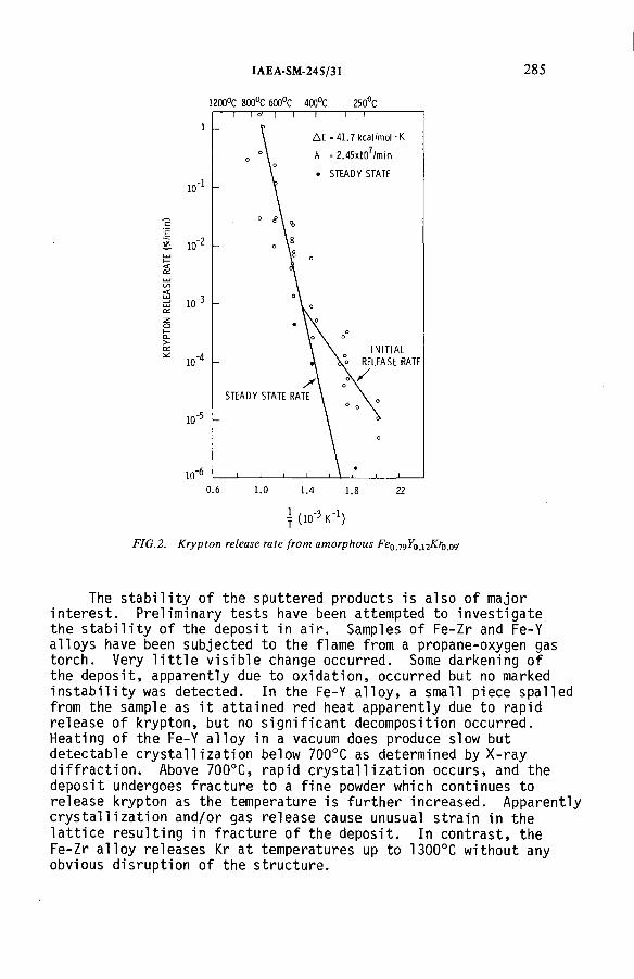
IAEA-SM-245/31 2 8 5
1200°C 800°C 600°C 400°C 250°C
T ( i o'3 к"1)
F IG .2. K r y p to n re lease ra te f r o m a m o rp h o u s Р е019У0Л2Кг0 0д-
The stability of the sputtered products is also of major interest. Preliminary tests have been attempted to investigate the stability of the deposit in air. Samples of Fe-Zr and Fe-Y alloys have been subjected to the flame from a propane-oxygen gas torch. Very little visible change occurred. Some darkening of the deposit, apparently due to oxidation, occurred but no marked instability was detected. In the Fe-Y alloy, a small piece spalled from the sample as it attained red heat apparently due to rapid release of krypton, but no significant decomposition occurred. Heating of the Fe-Y alloy in a vacuum does produce slow but detectable crystallization below 700°C as determined by X-ray diffraction. Above 700°C, rapid crystallization occurs, and the deposit undergoes fracture to a fine powder which continues to release krypton as the temperature is further increased. Apparently crystallization and/or gas release cause unusual strain in the lattice resulting in fracture of the deposit. In contrast, the Fe-Zr alloy releases Kr at temperatures up to 1300°C without any obvious disruption of the structure.
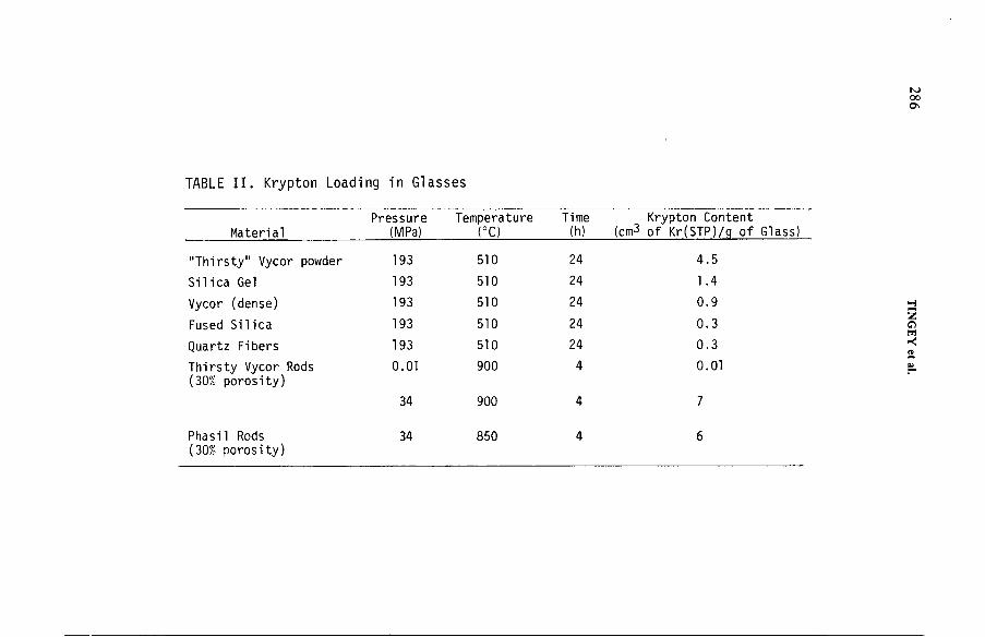
TABLE II. Krypton Loading in Glasses
MaterialPressure
(MPa)Temperature
(°C)Time(h)
Krypton Content (cm3 of Kr(STP)/q of Glass)
"Thirsty" Vycor powder 193 510 24 4.5
Silica Gel 193 510 24 1.4
Vycor (dense) 193 510 24 0.9
Fused Silica 193 510 24 0.3
Quartz Fibers 193 510 24 0.3
Thirsty Vycor Rods (30% porosity)
0.01 900 4 0.01
34 900 4 7
Phasil Rods (30% porosity)
34 850 4 6

IAEA-SM-245/31 287
The solubility of gas in glass is a well-known phenomenon in glass technology often used as a parameter for tailoring the properties of glass. Shelby [6] has reviewed the solubility, diffusivity, and permeability of low molecular weight inert gases (He, Ne, Ar) in glasses as a function of glass composition. These data provided the encouragement to evaluate Kr solubility in glass as a method for long-term storage of Kr-85.
3. DISSOLUTION OF KRYPTON IN LOW DENSITY GLASS
3.1 Krypton Loading Process
Because of the very low expected diffusivity of Kr in glasses, initial studies were conducted on glass powders and porous materials such as silica gels to minimize the diffusion path length. Some tests were initially made at atmospheric pressures, but we found that it was necessary to test at high pressure to obtain measurable gas quantities. Thus, a variety of glass types were subjected to Kr gas at 193 MPa pressure and 510°C for 24 hours. The Kr solubility, even at these high pressures, was disappointingly low so further tests were conducted on low density glasses. Glass rods were obtained which contained about 30% open porosity and a surface area of 100-200 nr/g. These samples were loaded with Kr by heating them in a Kr atmosphere to 900°C and maintaining the temperature for a period of time sufficient to condense the glass to 80-90% of theoretical density. Tests were conducted at Kr pressures of about 0.1 MPa and at about 35 MPa. A summary of the Kr loadings achieved in these studies is given in Table II.
The Kr content of samples loaded at 193 MPa and 510°C was considered too low or at best marginal for storage of radioactive gas. On the other hand, the samples heat treated at lower pressures, but at temperatures of 850-900°C, show significantly higher Kr loadings, especially if one considers the lower Kr pressure during loadings. In addition, the Kr retention is significantly improved by the higher heat treatments due to sintering of the glasses, thus increasing the diffusion path length. Dilatometric measurements were made to determine the sintering rates of the porous glasses and used to determine the temperature required to obtain densification of the samples within a four-hour period.The heat treatment temperatures were selected accordingly. Krypton loadings of 7 cm^ at STP/g of glass currently appear to be sufficient for Kr-85 storage. Further increases could be achieved by increasing the loading pressure. However, we presently believe that the benefits of higher loadings do not justify the increased costs and safety hazards in going to significantly higher pressures.

288 TINGEY et al.
Gas release measurements have been conducted on the Kr containing glass samples by heating at a rate of about 100°C/hour, while monitoring both the gas pressure and composition. Under these test conditions, properly densified glasses release less than 1% of the total Kr below 900°C. Long-term tests of Kr release rate have also been conducted at 420°C for over 400 hours. A plot of the fractional release (R) as a function of time appears to be linear with the square root of time (t^/2) and is expressed by R = 1.0 x 10⁻⁵t1/2s where t is in hours. Extrapolation of this curve yields a release of 0.3% of the Kr in the first 10 years.
The form of krypton in the Si02 matrix has not been conclusively determined. Two possibilities are considered: (1) Truedissolution in the glass and (2) trapping of Kr in the very small, connected porosity of the sample. Differentiating between the two cases is not an easy task, and perhaps the differences are not significant for radioactive waste storage. We have, however, attempted to shed some light on the subject. If all of the Kr were trapped in the pores of the sample, the pressure in the pores at 900°C would be 50 to 100 MPa (i.e., somewhat higher than the Kr pressure in the system). Only two possibilities are apparent. First, Kr permeates into the pores during cool down or the pores close and then continue to shrink against the gas pressure due to surface tension. To further test the form of the Kr in the solid, we have ground the sample into a fine powder. If the gas were contained in the pores, some would be released during the grinding process due to fracture of the pore. Initial results of such an experiment show essentially no reduction in Kr content with grinding to particle sizes down to 72 ym. However, when the particle size is further reduced to 40 ym, approximately 40% of the Kr was released. Although we do not consider these data conclusive at present, it now appears that both forms may be involved, i.e., some dissolved Kr and some trapped in the remaining pore volume. The release appears to suggest a diffusion mechanism for release. Work is currently underway to determine the effective diffusion coefficients for Kr in the glass matrix.
3.2 Krypton Trapping Mechanism and Release Rates
4. CONCLUSIONS
The advantages of solid state storage of radioactive inert gases are evident. We have now shown the feasibility of two such techniques. Ion implanted Kr in sputter deposited metal matrices have the significant advantage of operation at temperatures at or a little below ambient and at pressures of the order of 1 Pa.
IAEA-SM-245/31 289
These conditions greatly reduce, if not entirely eliminate, the hazards of radioactive gas release during the solidification process. The sputtering process also appears to be readily adaptable to remote or hot cell operation,if necessary. It has the further advantage of yielding a stable solid product with a relatively high thermal conductivity and thus can accommodate higher heat loadings and still maintain temperatures below those where release rates exceed acceptable values.
Dissolution in low density glasses also appears to be an acceptable process if pressures of the order of 35-40 MPa and temperatures of 800-900°C are acceptable. The Kr release rates from the sintered glasses appear to be the lowest of any form considered. This, in conjunction with the expected low corrosion rates, would rate the glass as perhaps the safest waste form for Kr-85 available to use at present.
Further work on these concepts is required, some of which is presently in progress. Specifically, there is a need to examine the effect of the decay product Rb on the materials properties.In sputter deposits it is possible to sputter an appropriate fraction of Rb into the structure and thus examine directly the effect without having to wait for several years for Kr-85 decay.We have recently prepared such a sample and examinations are currently underway. The effect of irradiation also needs to be examined. Additional understanding of the physical, electrical, and mechanical properties of the solids needs to be sought.Finally, development of the processes on a commercial scale is an area which must be addressed before the benefits of these approaches can be realized.
ACKNOWLEDGEMENT
The authors acknowledge P.J. Raney for analytical work on gas release.The high pressure loadings of glass were done by K. Wheeler at our laboratory and D. Knecht at Exxon Nuclear Idaho Company.
REFERENCES
[1] FRIEDLANDER, G., KENNEDY, J. W., Nuclear and Radiochemistry, John Wiley and Sons, New York (1955) 74.
[2] "Environmental radiation protection standards for nuclear power operations," Federal Register, 42 (9), Title 40, Part 190 (January 13, 1977).
290 TINGEY et al.
[3] WHITMELL, D. S., NELSON, R. S., WILLIAMSON, R., SMITH, M. J. S.Nucl. Energy 1_8 (1979) 349.
[4] BAYNE, M. A., MOSS, R. W., MCCLANAHAN, E. D., Thin Solid Films 54 (1978) 327.
[5] BAYNE, M. A., MOSS, R. W., MCCLANAHAN, E. D., Thin Solid Films 63 (1979) 137.
[6] SHELBY, J. E., A Comprehensive Review of Gas Permeation, Diffusion, and Solubility in Inorganic Glasses, SLL-73-0259 (August 1973).

IAEA-SM-245/10
LONG-TERM STORAGE OF KRYPTON-85 IN ZEOLITES*R.-D. PENZHORN, P. SCHUSTER,H.E. NOPPEL, L.M. HELLWIG Institut für Radiochemie,Kernforschungszentrum Karlsruhe GmbH,Karlsruhe,Federal Republic o f Germany
Abstract
LONG-TERM STORAGE OF KRYPTON-85 IN ZEOLITES.K rypton-85 is a gaseous waste p roduct from nuclear industry th a t will have to be stored
over m any decades before its release in to the atm osphere. One long-term storage alternative consists in the encapsulation o f this radioactive noble gas in zeolites. In this w ork results are presented th a t con tribu te to m aking this alternative considerably m ore attractive. Major im provem ents have been achieved regarding fixation conditions (zeolite loadings above 20 cm 3/g (STP) now seem possible at pressures well below 300 bar) and the therm al stabiUty of the encapsulated gas. F rom extensive screening studies w ith argon and kryp ton , em ploying zeolites having different crystallite size, various form s of aggregation, d ifferent chemical com position, etc., it was discovered th a t type 5A zeolites are particularly suitable as m atrices for the im m obilization o f 85Kr. It is postu lated th a t this is due to the a/|3-cage structu re of these zeolites. At a tem perature o f 520°C fixation occurs — w ith high yield - alm ost exclusively in to the /З-cages. When a fast tem perature program m e was em ployed to determ ine the leak rate , it was found th a t the bulk o f the encapsulated k ryp ton was only liberated in the tem perature range 900 to 1100°C. No significant leakage was apparent from zeolite 5A samples containing betw een 19 and 57 cm 3 Kr/g (STP) kep t at 200°C fo r up to 2500 h and at 400°C for up to 3500 h. In addition , 5A samples loaded w ith k ryp ton or argon were found to be resistant to liquid H20 and 7 -irradiation (approxim ately 103 k J/k g -h over 1704 h).
1. INTRODUCTION
With the increasing contribution o f nuclear power to global energy production, it will becom e necessary to recover and store the 85Kr released during fuel reprocessing in order to lim it the exposure o f the local population and the radioactive background throughout the world. Krypton-85 storage o f the order o f 100 years is required in view o f the half-life o f 10.8 years o f this nuclide.
In recent years much experience has been accumulated on the handling o f liquid and solid radioactive waste, but there is still need for the developm ent o f technology for the ‘Entsorgung’ o f such radioactive waste gases as 85Kr [1 ].
* Supported in part by the Commission of the E uropean Com m unities under its program m e on radioactive waste and storage.
2 91

2 9 2 PENZHORN et al.
Although 85Kr could be transported and stored under pressure in steel cylinders, several problems still need to be solved to ensure long-term safety during storage,1.e. selection o f corrosion-resistant materials, sudden release o f large inventories, etc. One o f several alternatives that seems attractive to explore is the fixation o f the noble gas in zeolites (crystalline aluminosilicates that contain a regular arrayo f cavities joined by pores o f a characteristic size). According to present knowledge, however, very high pressures and temperatures are required to achieve adequate gas sorption into the cavities and, o f the zeolites proposed so far for 85Kr conditioning, namely type ЗА, sodalite, etc., all appear to have too high a leak rate o f encapsulated gas at temperatures relevant to final storage [2 , 3].
The object o f this investigation was to optim ize the process for krypton fixation and to improve the thermal stability o f the encapsulated gas. The variables that were considered to be pertinent and to be within the realm o f this study were the chemical com position, pretreatment, form o f aggregation and crystallite size o f the zeolites; the fixation temperature and pressure; the effect o f atomic radiations; water; rubidium; etc.
2. EQUIPMENT
For the encapsulation o f noble gases two types o f autoclaves were employed, namely, a cold wall autoclave designed for 15 00° С and 1000 bar having a useful volume o f 4 ltr, and four autoclaves having a volum e o f 10 cm 3 and designed for 7000 bar and 700°C , each o f which is provided with a temperature as well as a pressure sensor.
For the static long-term leakage experim ents quartz tubes with a break-seal were em ployed. The gas phase above these samples was analysed by mass spectrometry and gas chromatography. Some zeolite samples containing encapsulated gas were simply stored in an oven at an elevated temperature. The zeolites were analysed in either one or other o f two flow systems consisting o f a large reservoir containing a carrier gas with an internal standard, a fully programmable Heraeus oven and an analysing instrument (either a Balzers Quadrupole mass spectrometer, Type QMG 311 or a Hewlett-Packard autom ated gas chromatograph, Type 5840A ).
Irradiation was carried out by placing the samples in closed quartz tubes in the vicinity o f 12 burned reactor fuel elem ents (7 -dose rate between 102 and 103 J/kg-h).
3. GAS FIXATION
Screening tests were carried out with argon or krypton at 1000 bar and 520°C with more than 30 different natural and synthetic zeolites. After a sorption time
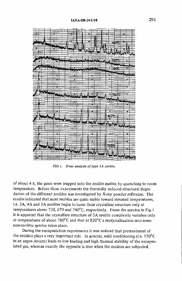
IAEA-SM -245/10 2 9 3
FIG.l. X-ray analysis o f type 5A zeolite.
o f about 4 h, the gases were trapped into the zeolite matrix by quenching to room temperature. Before these experim ents the thermally induced structural degradation o f the different zeolites was investigated by X-ray powder reflexion. The results indicated that m ost zeolites are quite stable toward elevated temperatures, i.e. ЗА, 4A and 5A zeolites begin to loose their crystalline structure only at temperatures above 720, 670 and 7 4 0 °C, respectively. From the spectra in Fig. 1 it is apparent that the crystalline structure o f 5A zeolite com pletely vanishes only at temperatures o f about 780°C and that at 820°C a recrystallization into some non-zeolitic species takes place.
During the encapsulation experim ents it was noticed that pretreatment o f the zeolites plays a very important role. In general, mild conditioning (i.e. 150°C in an argon stream) leads to low loading and high thermal stability o f the encapsulated gas, whereas exactly the opposite is true when the zeolites are subjected,

TABLE I. LOADING CAPACITY OF VARIOUS ZEOLITES3
294 PENZHORN et al.
Zeolite
Loading (cm 3/g (STP ))*3
Argon K rypton
Zeolon 200 H 0.9
Zeolon 900 Na 19.7 -
Zeolon 500 5.3 -
10A - 4.3
13X - 6.7
SK 40 - 1
SK 41 - 1
4A 2.4 -
ЗА 50.7 7 -2 2 .5
Sodalite 34.4 3 1 .3 -5 0 .7
5A 2 0 .6 -7 1 .9 3 9 -5 2 .8
a Conditions: Pressure: 1000 bar; Tem perature: 520°C.k Loading is strongly dependent upon the m anufacturer (cationic com position), form of
aggregation (pow der, pellets, e tc .), pre treatm ent (generally 150°C under argon stream ), etc.
before gas fixation, to evacuation at a temperature o f 600°C. N oble gas loadings o f som e o f the more interesting zeolites are summarized in Table I. The wide loading ranges observed are due to variations in the cation com position (characteristic to each manufacturer), form o f aggregation (powder, size and form o f pellet, binder, etc.), crystallite size, pretreatment, etc. A system atic dependency, however, was neither noticed between the loading capacity o f type 4A zeolite and the crystallite size (2 —15 jum) nor between the loading capacity o f 5A and the pellet size or form.
As is apparent from Fig.2, loading o f type 5 A zeolite is strongly dependent upon the temperature at which fixation occurs. The aluminosilicate framework o f zeolite A can be described in terms o f tw o types o f polyhedra; one is a simple cubic arrangement o f eight tetrahedra, and the other is the truncated octahedron o f 24 tetrahedra ((3-cage). When each com er o f the cube is occupied by a truncated octahedron an additional cavity is formed (a-cage). The framework thus consists o f two interconnecting channel system s built up o f connected
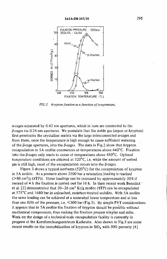
IAEA-SM-245/10 295
FIXATION TEMPERATURE [ "C ]
FIG. 2. Krypton fixation as a function o f temperature.
а-cages separated by 0 .42 nm apertures, which in turn are connected to the |3-cages via 0 .24 nm apertures. We postulate that the noble gas (argon or krypton) first penetrates the crystalline matrix via the large interconnected a-cages and from there, once the temperature is high enough to cause sufficient widening o f the j3-cage apertures, in to the /З-cages. The data in Fig.2 show that krypton encapsulation in 5A zeolite com m ences at temperatures above 440°C . Fixation in to the j3-cages only starts to occur at temperatures above 450°C . Optimal temperature conditions are attained at 520°C, i.e. while the am ount o f sorbed gas is still high, m ost o f the encapsulation occurs into the (3-cages.
Figure 3 shows a typical isotherm (520°C ) for the encapsulation o f krypton in 5A zeolite. At a pressure above 2500 bar a saturation loading is reached ( > 8 0 cm 3/g (STP)). These loadings can be increased by approximately 30% if instead o f 4 h the fixation is carried out for 16 h. In their recent work Benedict et al. [2] demonstrated that 2 0 —26 cm 3 Kr/g zeolite (STP) can be encapsulated at 575°C and 1680 bar in unleached, moisture-treated sodalite. With 5A zeolite the same loading can be achieved at a som ewhat lower temperature and at less than one fifth o f the pressure, i.e. < 3 0 0 bar (Fig.3). By simple PVT considerations it appears that in 5A zeolite the fixation o f krypton should be possible w ithout mechanical compression, thus making the fixation process simpler and safer.Work on the design o f a technical-scale encapsulation facility is currently in progress at the Kemforschungszentrum Karlsruhe. A lso shown in Fig.3 are som e recent results on the im m obilization o f krypton in S i0 2 w ith 30% porosity [4].

2 9 6 PENZHORN et al.
FIG.3. Krypton fixation as a function o f pressure.
Even though the thermal stability o f the resulting product seems to be adequate, the krypton loading is too low to be practicable (6 cm 3 Kr/g (STP)). The high fixation temperature (900°C ) is also cause for concern.
4. LEAKAGE MEASUREMENTS
If a 5A zeolite sample loaded with krypton or argon is placed in an oven and heated by a fast temperature programme, it is observed that leakage o f gas com m ences at 490°C if the fixation temperature is 475°C , and at 850°C if the fixation temperature is 520°C. A t the latter fixation temperature the bulk o f the gas, mainly im m obilized in the /З-cages, is only freed at temperatures above 900°C (see F ig.4). At fixation temperatures below 520°C the sorbed inventory is lower and the fraction encapsulated in a-cages appreciable. A comparison between the krypton leak rates from 5A zeolite and sodalite when heated with a fast temperature programme can be seen in Fig. 5. Krypton clearly desorbs from 5A zeolite at much higher temperatures than from sodalite. The astonishing thermal stability o f argon and krypton encapsulated in 5A zeolite was corroborated with experim ents involving long-term exposure to high temperatures. A number o f ЗА, 5A and sodalite samples containing between 19.1 and 57.3 cm 3 Kr/g zeolite (STP) were kept at 200°C for up to 2500 h, as well as at 400°C for up to 3500 h, and analysed periodically. The results have been summarized in Fig.6 . Whereas only a very small fraction o f the encapsulated gas is freed from type 5A zeolite after nearly 5 m onths at 400°C (it is believed that this leakage originates from krypton loosely adsorbed in а -cages), approximately 50% o f the conditioned

IAEA-SM-245/10 2 9 7
FIG.4. Krypton leakage from a 5 A zeolite.
t im e [m in]
_ О ' X ' 8 ‘ 12 ' 16 ' 20 ' 24 ' 30С
FIG.5. Krypton leakage from 5A zeolite and sodalite.
gas is desorbed from sodalite and ЗА after 1100 h at 200°C . A t 400°C practically all the gas ‘solidified’ in ЗА, and sodalite is liberated in less than a day.
Follow ing a procedure suggested by Barrer and Vaughan [5], the activation energy was determined for the diffusion o f argon out o f ЗА (7 2 —94 kJ/m ol) and 5A (6 8 4 —876 kJ/m ol), as well as that o f krypton out o f sodalite (126 kJ/m ol) and 5A (6 3 0 kJ/m ol). Considering that factors such as gas loading, pretreatment, water content, etc. have a marked effect on these measurements, it can be concluded that the E<üff measured for ЗА zeolite and sodalite agree reasonably well with similar data from literature [2, 6 , 7]. To the best o f our knowledge, no activation energies have been measured for the activated diffusion o f krypton or argon out o f 5A zeolite. The values found in this work are abnormally high. More work on this aspect is presently being carried out.

298 PENZHORN et al.
T im e lh )
Sodalite 1080
200“ C [ ЗА 1080
W/777/////77//////////Á Ьк'77777Л 2520
□ Sodalite 15
¿00°cl I ЗА 18
У / / / / / / / / / / / / / / / / / / / . 'ЫкУ/У/Л 3500
0 20 ¿0 60 80 100 % encapsulated noble gas
FIG. 6. Long-term leakage o f encapsulated noble gas.
5. EFFECT OF IRRADIATION AND WATER
The resistance to 7 -irradiation o f ЗА, 5A zeolites as well as sodalite, containing various amounts o f encapsulated argon or krypton in closed glass ampoules was investigated at room temperature. The samples were irradiated either under air or under neon. The total energy dose (1 0 6 kJ/kg) was applied over a period o f about 2 m onths, simulating a 85Kr storage period o f approximately 2.7 m onths. A small fraction o f the encapsulated noble gas was freed from all samples (< 1 %). Only 0.009% o f the originally encapsulated krypton leaked out o f a 5A sample loaded with 37 .2 cm 3/g (STP). Hydrogen could not be detected in samples irradiated under a Ne atmosphere. When the irradiation was carried out under am bient air, up to 2% H2 was found in the gas phase. It was possibly generated via radiolytic decom position o f H 20 .
The encapsulated noble gases were found to be stable toward H20 . When, for instance, a 5A zeolite sample loaded with 37 .2 cm 3 Kr/g (STP) or а ЗА zeolite sample loaded with 51.5 cm 3 Ar/g (STP) was stored under water for weeks, no significant gas desorption was apparent.
6 . STORAGE VOLUME
Krypton loadings o f 22 to 77 cm 3/g (STP) would provide a final storage volum e that is comparable to that expected from krypton in a pressurized cylinder (see Table II). While the relatively low thermal conductivity o f the zeolites is considered to be a factor that lim its the maximum allowable loading, it may be ascertained that this restriction is considerably less stringent when krypton is im m obilized in 5A zeolite instead o f ЗА or sodalite.
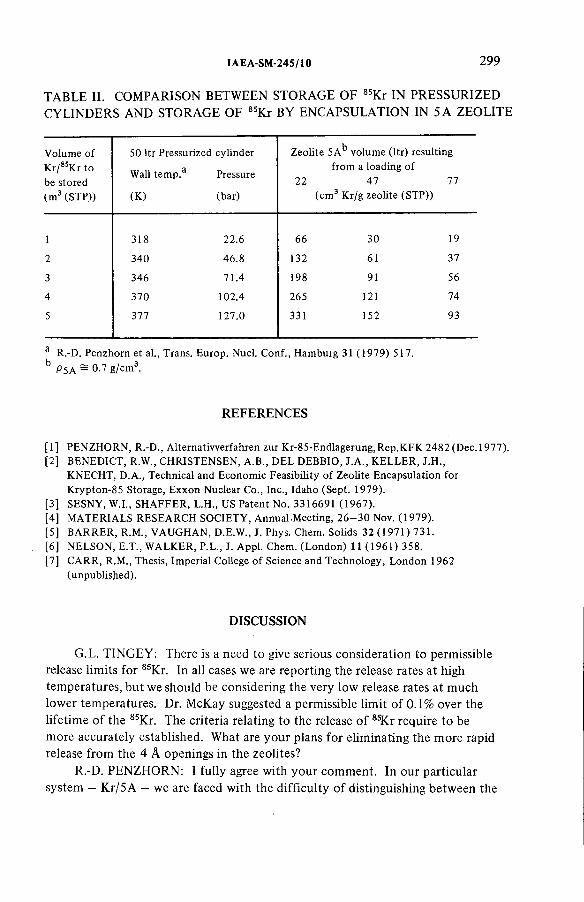
IAEA-SM -245/10 299
TABLE II. COMPARISON BETWEEN STORAGE OF 85Kr IN PRESSURIZED CYLINDERS AND STORAGE OF 8SKr BY ENCAPSULATION IN 5 A ZEOLITE
Volum e of K r/85Kr to be stored (m 3 (STP))
50 ltr Pressurized
Wall tem p .3
(K)
cylinder
Pressure
(bar)
Zeolite 5A*3 volum e (ltr) resulting from a loading of
22 47 77 (cm 3 Kr/g zeolite (STP))
1 318 22.6 66 30 19
2 340 46.8 132 61 37
3 346 71.4 198 91 56
4 370 102.4 265 121 74
5 377 127.0 331 152 93
a R.-D. Penzhorn et al., Trans. Europ. Nucl. Conf., Ham burg 31 (1979) 517.
Ь P 5A - ° - 7 g /cm 3.
REFERENCES
[1] PENZHORN, R.-D., A lternatiw erfahren zur K r-85-Endlagerung,Rep.K FK 2482 (D e c .l977).[2] BENEDICT, R.W., CHRISTENSEN, A.B., DEL DEBBIO, J.A ., KELLER, J.H .,
KNECHT, D.A., Technical and Econom ic Feasibility o f Zeolite Encapsulation for K rypton-85 Storage, Exxon Nuclear Co., Inc., Idaho (Sept. 1979).
[3] SESNY, W.I., SH AFFER, L.H., US Patent No. 3316691 (1967).[4] MATERIALS RESEARCH SOCIETY, Annual.M eeting, 2 6 - 3 0 Nov. (1979).[5] BARRER, R.M., VAUGHAN, D.E.W., J. Phys. Chem. Solids 32 (1971) 731.[6 ] NELSON, E.T., WALKER, P.L., J. Appl. Chem. (L ondon) 11 (1961) 358.[7] CARR, R.M., Thesis, Im perial College o f Science and T echnology, L ondon 1962
(unpublished).
DISCUSSION
G.L. TINGEY: There is a need to give serious consideration to permissible release limits for 85Kr. In all cases we are reporting the release rates at high temperatures, but we should be considering the very low release rates at much lower temperatures. Dr. McKay suggested a permissible limit o f 0.1% over the lifetim e o f the 85Kr. The criteria relating to the release o f 8sKr require to be more accurately established. What are your plans for eliminating the more rapid release from the 4 Â openings in the zeolites?
R.-D. PENZHORN: I fully agree with your com m ent. In our particular system - Kr/5A - we are faced with the difficulty o f distinguishing between the
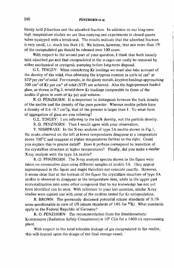
300 PENZHORN et al.
firmly held infraction and the adsorbed fraction. In addition to our long-term high temperature studies we are thus carrying out experiments in closed quartz tubes equipped with a break-seal. The results indicate that the adsorbed fraction is very small, i.e. much less than 1%. We believe, however, that not more than 1% o f the encapsulated gas should be released over 100 years.
With respect to the second part o f your question, I think that both loosely held adsorbed gas and that encapsulated in the а -cages can easily be removed by either mechanical or cryogenic pumping before long-term disposal.
G.L. TINGE Y: When considering Kr loadings we must also take account o f the density o f the solid, thus obtaining the krypton content in units o f cm 3 at STP per cm 3 o f solid. For exam ple, in the glassy metals, krypton loadings approaching 200 cm 3 o f Kr per cm 3 o f solid (STP) are achieved. Also the high-pressure loaded glass, as shown in Fig.3, would show Kr loadings comparable to those o f the zeolite if given in units o f Kr per unit volume.
R.-D. PENZHORN: It is important to distinguish between the bulk density o f the zeolite and the density o f the pure powder. Whereas zeolite pellets have a density o f 0 .6 —0.7 cm 3/g, that o f the powder is larger than 1. To what form o f aggregation o f glass are you referring?
G.L. TINGEY: I am referring to the bulk density, not the particle density.R.-D. PENZHORN: Then I would agree with your observation.Y. NISHIWAKI: In the X-ray analysis o f type 5A zeolite shown in F ig .l,
the peaks observed on the left at lower temperatures disappear at a temperature above 700°C and reappear at higher temperatures further to the right. Could you explain this in greater detail? Does it perhaps correspond to transition o f the crystalline structure at higher temperatures? Finally, did you make a similar X-ray analysis with the type ЗА zeolite?
R.-D. PENZHORN: The X-ray analysis spectra shown in the figure were taken on consecutive days using different samples o f zeolite 5A. They appear supraimposed in the figure and might therefore not coincide exactly. However, it seems clear that at the bottom o f the figure the crystalline structure o f type 5A zeolite is observed to disappear as the temperature rises, while in the upper part recrystallization into som e other com pound that to my knowledge has not yet been identified can be seen. With reference to your last question, similar X-ray studies were carried out with m ost o f the zeolites tested for Kr encapsulation.
R. BROWN: The previously discussed potential release standards o f 0.1% seem questionable in view o f US release standards o f 14% for 85Kr. What standards apply in the Federal Republic o f Germany?
R.-D. PENZHORN: The recom m endation from the Strahlenschutz- Kom m ission (Radiation Safety Commission) is 106 Ci/a for a 1400 t/а reprocessing plant.
With respect to the total tolerable leakage o f gas encapsulated in the zeolite, this will depend upon the design o f the final storage vessel.

Session VFILTRATION, SAMPLING AND MONITORING
OF AIRBORNE EFFLUENTS

Chairman
H. DEUBERFederal Republic o f Germany
IAEA-SM-24S/35
TESTING OF HIGH-EFFICIENCY AEROSOL FILTERS BY USING A SCINTILLATION PARTICLE COUNTERW. ULLMANN, S. PRZYBOROWSKI National Board o f Nuclear Safety
and Radiation Protection,Berlin,German Dem ocratic Republic
Abstract
TESTING O F HIGH-EFFICIENCY AEROSOL FILTERS BY USING A SCINTILLATION PARTICLE COUNTER.
In the Germ an Dem ocratic R epublic the penetration o f high-efficiency aerosol filters is measured for rad iation-protection-type testing and licensing purposes by m eans o f the SARTORIUS scintillation particle coun ter and o f NaCl test aerosols. The aerosol m easurem ent is based on the light emission of atom ic Na vapour which is excited in an air-hydrogen flame. In contrast to a flame p h o tom eter the aerosol particles are fed in to the flame individually and successively. Scintillation particle counters allow m easurem ents o f the penetration P o f aerosol filters as a function o f particle size d. The penetration value corresponding to the m axim um o f the function P = f(d) may be used as a basis for safety considerations. The test stands for filters w ith a m axim um air flow-rate o f 5000 m 3 /h , as well as for filter m aterials, are described w ith special em phasis on th e technique o f diluting upstream sample volumes.Some results o f filter testing are discussed. A m odified version o f the scintillation particle coun ter w ould be suitable for perform ing in-situ tests.
1. INTRODUCTION
In nuclear power plants and nuclear facilities as well as in the handling o f radioactive materials in research institutions etc., radioactive materials may be released as aerosols, gases and vapour. These can be detected by measuring devices and separated in suitably dimensioned filtration systems. Aerosol filters are among the main com ponents o f such systems. Their main parameter is the penetration for the aerosol to be separated. For aerosol filtration various deposition mechanisms are used (inertia, sedim entation, interception and diffusion), which are partly directly and partly inversely proportional to particle size and flow velocity. Thus, functions with a maximum are obtained for penetration P in dependence on particle size d and flow velocity.
To test aerosol filters, test aerosols with exactly defined and reproducible properties were mainly used. In most cases the aerosol occurring in practice is not suited for this purpose. The penetration o f the filter is determined by
303

304 ULLMANN and PRZYBOROWSKI
measuring the particle concentration or particle size distribution o f the test aerosol before and after the filter to be tested. In the case o f high-efficiency filters a concentration difference o f several orders o f magnitude can thus be obtained. The measuring value also depends on the lower and upper detection limit for particle size o f the aerosol measuring device.
To determine the protection effect o f an aerosol filter in quantitative terms the follow ing testing m ethods are considered.
1.1. Measurement o f penetration for a constant particle size
It appears appropriate in the case o f filters that safety considerations be based on the maximum o f the function P = f(d), corresponding to the greatest hazard. This is the basis o f testing m ethods using a mono-disperse aerosol [1 ,2]. From previous calculations it was concluded that the maximum lies at a particle size o f 0.3 ¡Xm. However, recent theoretical and experimental studies have shown that the maximum frequently lies at smaller particle sizes. This shift can be partly explained by the use o f increasingly thinner fibres for the filter material. On the other hand, owing to the improvement o f the theoretical bases o f filtration, and particularly to the developm ent o f aerosol measuring devices for the sub-micron range, a more exact determination o f the penetration maximum has now becom e possible. Owing to the above-mentioned shift, the testing m ethod does not generally yield the maximum value o f penetration, but smaller ones compared with those occurring in practice. Thus, a too high protection factor is assumed, which contradicts the usual safety criteria.
1.2. Measurement o f total penetration
The total penetration value o f the filter depends on the upper and lower detection limit o f the device and the particle-size distribution lying in this range. Depending on the measuring principle o f the device, the distribution o f particle number, mass or activity is o f concern. To make it possible for conclusions for the protection factor to be reached in practice, both the principle and the measuring range o f the aerosol-measuring device, as well as the respective particle size distribution o f the test aerosol, should satisfactorily approximate practical conditions. However, as experience has shown, considerable deviations from testing conditions must be expected involving certain over- or under-assessments o f the protection effect o f the filters.
1.3. Measurement o f penetration as a function o f particle size
If the testing m ethod determines the course o f the function P = f(d), statements on the protection effect o f the filter can be made. By means o f the maxi-
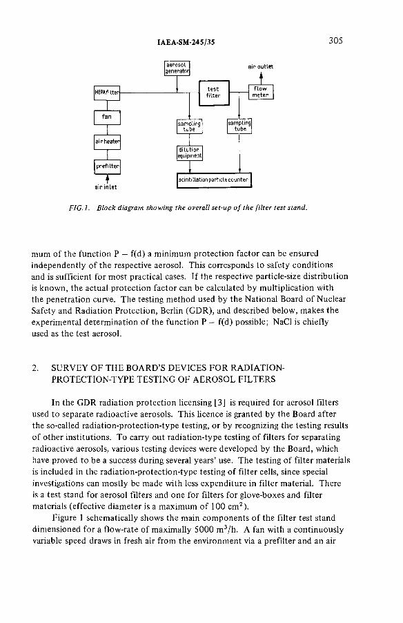
IAEA-SM-24S/35 305
FIG.l. Block diagram showing the overall set-up o f the filter test stand.
mum o f the function P = f(d) a minimum protection factor can be ensured independently o f the respective aerosol. This corresponds to safety conditions and is sufficient for most practical cases. If the respective particle-size distribution is known, the actual protection factor can be calculated by m ultiplication with the penetration curve. The testing m ethod used by the National Board o f Nuclear Safety and Radiation Protection, Berlin (GDR), and described below , makes the experimental determination o f the function P = f(d) possible; NaCl is chiefly used as the test aerosol.
2. SURVEY OF THE BOARD’S DEVICES FOR RADIATION-PROTECTION-TYPE TESTING OF AEROSOL FILTERS
In the GDR radiation protection licensing [3] is required for aerosol filters used to separate radioactive aerosols. This licence is granted by the Board after the so-called radiation-protection-type testing, or by recognizing the testing results o f other institutions. To carry out radiation-type testing o f filters for separating radioactive aerosols, various testing devices were developed by the Board, which have proved to be a success during several years’ use. The testing o f filter materials is included in the radiation-protection-type testing o f filter cells, since special investigations can m ostly be made with less expenditure in filter material. There is a test stand for aerosol filters and one for filters for glove-boxes and filter materials (effective diameter is a maximum o f 100 cm 2).
Figure 1 schematically shows the main com ponents o f the filter test stand dimensioned for a flow-rate o f maximally 5000 m 3/h. A fan with a continuously variable speed draws in fresh air from the environment via a prefilter and an air
306 ULLMANN and PRZYBOROWSKI
heater. Using a HEPA filter a very good filtration o f ingoing air is achieved. If necessary, the air can be humidified. Owing to the different dimensions o f test filters, there are different, exchangeable clamping devices. The clamping flanges have ring-like grooves. If these are subject to a slight excess o f pressure, the tightness o f clamping can be easily checked with a manometer. Besides, leakages can be quickly localized. The flow-rate through the filter to be tested is measured with exchangeable Venturi nozzles [4]. The test stand also includes devices for measuring and registering the pressure drop o f the test filter and various control devices. The HEPA filter and the following part o f the filter test stand are subject to excessive pressure to prevent the entry o f air contamination into the filter test stand, and thus disturbances o f aerosol measurement.
The outlet o f the aerosol fed into the system before the test filter is arranged in the axis o f the piping in the direction o f flow. By a homogenizing device the aerosol is hom ogeneously distributed over the cross-section o f the piping. For the purpose o f hom ogenization a so-called twist nozzle has proved a success [5]. A second nozzle o f the same type is built in after the test filter. Thus, important prerequisites for a representative sampling before and after the test filter are created. To study the action o f the two nozzles both the velocity distribution and the distribution o f the test aerosol at the sampling levels were determined. Even under highly unfavourable conditions, e.g. in the event o f leakage at the extreme edge o f the test filter, only slight differences o f measuring values could be detected at individual measuring points.
To measure penetration in dependence on the particle size o f the test aerosol, aerosol samples are continuously taken before and after the test filter. Both sampling tubes have the same dimensions. Owing to the excessive pressure in the filter test stand, the aerosol flows through the sampling tubes. A t their upper end the aerosol flow branches. Only a small portion is required for aerosol measurement. The major part is drawn o ff with the exhaust air. Thus, the stay period o f the aerosol in the sampling tubes can be reduced to a minimum.
The device for diluting the aerosol sample taken before the test filter and the scintillation particle used for aerosol measurement are described in section 3. This equipment is also used for the test stand to investigate filters for glove-boxes and filter materials. The set-up o f this test stand largely corresponds to the scheme shown in F ig .l .
3. MEASUREMENT OF THE TEST AEROSOL BEFORE ANDAFTER THE TEST FILTER
Figure 2 shows the principal set-up o f the aerosol measuring device. The aerosol measurement is based on the light emission o f atom ic Na vapour which is excited in an air-hydrogen flame. In contrast to the flame-photometric deter-
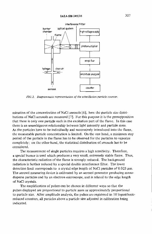
IAEA-SM-245/35 307
i nterference f i Iter
FIG.2. Diagrammatic representation o f the scintillation particle counter.
m ination o f the concentration o f NaCl aerosols [6], here the particle size distributions o f NaCl aerosols are measured [7]. For this purpose it is the presupposition that there is only one particle each in the excitation part o f the flame. In this case there is an unambiguous relationship between light intensity and particle mass.As the particles have to be individually and successively introduced into the flame, the measurable particle concentration is limited. On the one hand, a minimum stay period o f the particle in the flame has to be observed for the particles to vaporize com pletely; on the other hand, the statistical distribution o f aerosols has to be considered.
The measurement o f single particles requires a high sensitivity. Therefore, a special burner is used which produces a very small, extrem ely stable flame. Thus, the characteristic radiation o f the flame is strongly reduced. The background radiation is further reduced by a special double interference filter. The lower detection limit corresponds to a crystal edge length o f NaCl particles o f 0 .025 цт. The aerosol measuring device is calibrated by an aerosol generator producing m ono- disperse particles and by an electron microscope, and is related to the edge length o f NaCl crystals.
The amplification o f pulses can be chosen in different ways so that the pulses displayed are proportional to particle mass or approximately proportional to particle size. After amplitude analysis, the pulses are registered in 10 logarithmic- reduced counters, all particles above a particle size adjusted in calibration being indicated.

308 ULLMANN and PRZYBOROWSKI
i sampling tube before the test fitter iI-------------------------- 1___________________ I
n
П
—^measuring nozzle]---—
measuri ig nozzle |
V
— mixin 9 device
H
d ilu tion fa c to r : f " ( V + V f ) / V
J__aerosol concentration = n+- n / fV + V F I
i sc in tilla tion pa rtic le counter ii________________________ i
FIG.3. Block diagram showing the design o f the dilution equipment.
The scintillation particle counter sucks a constant amount o f air if the inlet pressure is kept at zero. Since, owing to the observance o f isokinetic sampling conditions higher pressures may also occur, adjustable openings have been arranged at the aerosol inlet part through which the excessive part o f the aerosol sample can be blown off.
With the SARTORIUS scintillation particle counter used at present maximally 3000 particles/min can be counted. Without additional dilution this corresponds to a concentration o f 15 particles/m 3 at an intake volume o f 200 cm 3/m in. If the dilution equipment built into the device is used, this value will increase to about 30 000 particles/min (about 150 particles/cm3). In testing high-efficiency aerosol filters, however, considerably higher aerosol concentrations before the test filter are required to still obtain a sufficient particle concentration after the filter (a compensation is possible only to a certain extent by extending measuring time). Therefore, the aerosol sample taken before the test filter has to be diluted in a defined way. For this purpose a partial flow V is taken from the aerosol sample and mixed with filtered air (partial flow VF). Figure 3 schematically shows the dilution equipment used. The assignment to the test stand follows from F ig .l .
To measure partial flows, special calibrated measuring nozzles are used. Two different mixing devices were studied. Design A is a cylindrical tube combined with the measuring nozzle for partial flow VF . Aerosol feeding is perpendicular to the tube axis, aerosol outlet in the direction o f the axis. Design В is a fiat cylindrical container. Partial flow is fed tangentially to the circumference o f the container. The opening for aerosol feeding is arranged in such a way that both partial flows meet at a right angle. The aerosol outlet is in the middle o f the container front.The theoretical value o f the dilution factor is given by f =(V + V p )/V . Both mixing devices were designed for f-values o f about 200.

IAE A-SM-245/35 309
Using the NaCl test aerosols according to section 4, the two m ixing devices were studied by the scintillation particle counter. In mixing device В changes o f particle size distribution occurred at f > 100 for particle sizes o f above 0.5 ;um. For mixing device A there was a sufficient agreement at f < 200 between the theoretical and practical values o f the dilution factor. Therefore, the filter test stands were equipped with mixing devices o f design A. Work on further improvement o f design has been scheduled.
4. GENERATION OF THE TEST AEROSOL
For the testing m ethod applied by the Board a poly-disperse aerosol is required. An aerosol hom ogeneously distributed over the entire particle size range would be most favourable to keep the statistical counting error over the entire range equally low. In practice, however, this idealized aerosol is difficult to generate. In the relatively long tubings losses by sedim entation and other factors cannot be avoided. It is therefore difficult to obtain large particles in sufficient numbers.
Figure 4 schematically shows the aerosol generator used for filter testing.In its developm ent particular emphasis was laid on simple design and simple operation. The generator consists o f a cylindrical vessel partly filled with an aqueous NaCl solution. The compressed air fed in at the bottom bubbles through the NaCl solution and thus produces liquid drops. These are partly precipitated at the walls and the lid o f the vessel, and partly taken along with the air-flow out o f the generator. After mixing with the testing air flow , which is far greater, the water evaporates. Therefore, the filters are tested with dry NaCl crystals. The concentration and size distribution o f the particles supplied by the aerosol generator mainly depend on the geom etric dimensions o f the vessel, the diameter o f the compressed air inlet, the working pressure, the liquid level in the vessel and the concentration o f the aqueous solution (e.g. 2.5% aqueous NaCl solution). Thus, it is possible to adjust optim al conditions for the respective testing task.
Figure 4 shows the particle size distributions o f two different test aerosols. Both aerosols have proved a success in the practical testing o f filters and filter materials. If the particle size distributions are approximated by logarithmic normal distributions, the following values for the median value dg (50% value) related to the particle number and for the geom etric standard deviation ag are obtained:
Aerosol 1 Aerosol 2
d g in ¿urn 0.09 0.23
2.1 2.6

310 ULLMANN and PRZYBOROWSKI
TJA
Iо
£caQ.4-oc_0>jOEэс
’fe
FIG.4. Particle size distribution o f two NaCl test aerosols used for filter testing (X = aerosol 1,• = aerosol 2).
As measurements are made alternatively before and after the test filter, longterm variations do not influence the measured penetration. The extrem ely good long-term constancy o f the generator, both with respect to concentration and to size distribution, facilitates the practical performance o f filter testing.
5. MEASURING RESULTS AND CONCLUSIONS
The efficiency o f the testing m ethod is demonstrated by way o f the measuring results obtained for an aerosol filter produced in the GDR. This flat filter cell o f glass fibre material has an effective filter area o f 9 .4 m2 . Its nominal flow is 500 m 3/h. The test was made at 300 , 500, 700 and 1000 m 3/h. This corresponds to the deviations from nominal flow possible in practice which, for example, can occur in the event o f maladjusted ventilation system s and increasing aerosol loading.
Figure 5 shows the absolute value o f penetration P in dependence on particle size d in log-log co-ordinates for the above-mentioned air flows. The histogram representation shows the influence o f the grading in particle-size intervals given by the measuring device on the measuring results. Penetration is the quotient o f
ЭМ-,
50-W-X -
20-
1 0 -
5-
02-01-
005-00? -
NaClsolution
t:r
compressed a ir
Ш
г s -10“ ‘ 5 io“ г ;Particle size d , um

IAEA-SM-245/35 311
ГГ?10 ю- 1
700--. . . .
t00— t
— ,
n-3
r
a"
Ю0
mfyh
I
I
n*-
I
—1----1-I0'2 2 3 I 6 8 Ю '1 2 3 4 6 8 1 0 11
-------------Particle size d , pm
FIG.5. Measuring results for an aerosol filter produced in the GDR.
the particle numbers measured at the respective intervals before and after the test filter. The results are corrected for the dilution factor in measurement before the filter and the different measuring times before and after the filter.
From Fig.5 it follow s that:
(a) the dependence o f penetration on particle size increases with increasing air flow (one order o f magnitude at the lowest, nearly two orders at the highest air flow); and
(b) the dependence o f penetration on air flow is largest for smallest particle sizes and is about one order o f magnitude.
The example shows that, with the measuring method described, a realistic assessment o f the protection factor is possible also for very different conditions in the practical use o f filters. Principally, the m ethod can also be applied for in-situ testing o f aerosol filters. For this purpose, however, further development work is necessary with regard to both the test aerosol and the aerosol measuring device.The preliminary work for developing a portable scintillation particle counter has already been done.
312 ULLMANN and PRZYBOROWSKI
REFERENCES
[ 1 ] INTERNATIONAL ATOMIC ENERGY AGENCY, Air Filters for Use at Nuclear Facilities, Technical R eports Series No. 122, IAEA, Vienna (1970).
[2] USSR, Soviet Standard GOST 20810 (1975).[3] STAATLICHES AMT FÜRATOMS1CHERHEIT UND STRAHLENSCHUTZ, BERLIN,
GDR, Richtlinie über die Strahlenschutzbauart-Zulassung von F iltern zur Abscheidung radioaktiver Aerosole, M itteilungen des SAAS 11 (1974) 2.
[4] GERMAN DEMOCRATIC REPUBLIC, GDR Standard TGL 0 -1 9 5 2 (1 9 7 1 ).[5] HAMEL, P., Staatliches Amt für A tom sicherheit und Strahlenschutz, Rep.SAAS-224
(1977) 51.[6 ] BRITISH STANDARDS INSTITUTION, British Standard BS-2831 (1965).[7] BINEK, B., DOHNALOVA, B., PRZYBOROWSKI, S., ULLMANN, W., Staub,
Reinhalt. Luft 27 (1967) 379.
DISCUSSION
K. FISCHER: If I understood you correctly you tested the efficiency o f aerosol filters in terms o f the size distribution o f the aerosol particles. Is it correct that particle radioactivity is a function o f particle size? What has been your experience with this?
W. ULLMANN: In principle it is necessary to determine the penetration in terms o f the activity o f the aerosol particles. The activity distribution as a function o f particle size, however, may vary considerably under working conditions and as yet we have no idea how to make allowance for this as part o f a procedure for the type testing o f aerosol filters.
M.W.FIRST: What is the shape o f your particles when you examine them under the electron microscope? I ask this question because we have observed that salt particles generated from solution are difficult to dry and are likely to be present, initially, as slush-like irregular particles. Later, they form cubes. Thus, if cubes are seen under the m icroscope, these same particles may not have been present in the aerosol used for filter testing. Could you com m ent on this?
W. ULLMANN: This question has been carefully investigated in our laboratory and in that o f a co-operating group in Prague. Results showed that NaCl indeed forms cubes soon after generation under well-defined conditions, namely, the absence o f other particles in the air, purity o f NaCl solution and controlled evaporation.
M.W. FIRST : With regard to your final statement that you anticipate using this same system for in-place testing, I would like to make three com m ents. First, NaCl is corrosive to m etals and becom es wet and sticky when the filter is exposed to m oist gas; DOP and uranine do not have this disadvantage. Secondly, the dilution step is subject to serious error. Lastly, if a filter is acceptable on the basis o f a bench test it is acceptable after installation unless it has been damaged during installation.
IAEA-SM-245/3S 313
Therefore, all that is required is a search for defects - not another bench test that is especially difficult to conduct under field conditions. Searches for defects can be successfully conducted by much simpler means.
W. ULLMANN: We believe that filters should be tested four times: by the manufacturer before shipment, by a com petent authority for type testing, for transport damage before installation, and lastly in situ after installation and subsequently at certain intervals. I agree with you that testing for damage can be performed with simple methods. For type testing and in-situ testing, however, m ethods are required which take into account the dependency o f penetration on particle size. In my paper I proposed this in detail only for type testing.Further research is required to develop an appropriate m ethod for in-situ testing in which corrosion, hum idity and impurities will be taken into consideration.
A.J. WILLIAMS: I am afraid I cannot agree with your proposition, Dr. First, that if a filter yields good performance in a bench test then it will perform well in a plant. This is not so; at Windscale the majority o f faults arise as a result o f gasket and seating difficulties, particularly in highly active facilities where remedial work is very difficult. I would agree, on the other hand, that the use o f NaCl in stainless steel facilities must be considered very carefully. At Windscale, Pollack condensation nucleus counting is used as it has advantages, particularly in high flow system s, where generation o f sufficient quantities o f test aerosol may be difficult.
R.D. COLLINS: In relation to the risk o f corrosion with installed plant, what is the quantity o f NaCl introduced in each test?
W. ULLMANN: Although no substance for in-situ testing has yet been selected, the amount o f NaCl used in bench tests ranges typically from 0.1 to10 m g/m 3 , depending on the efficiency o f the aerosol filter and the particle size distribution o f the test aerosol.
E. PALACIOS: You said that the particle counter was calibrated by means o f a monodisperse aerosol and an electron microscope. Could you com m ent on the m ethod by which these particles are generated and fixed for subsequent electron m icroscope analysis?
W. ULLMANN : The monodisperse aerosol used for calibrating the scintillation particle counter was generated with a special device produced by Sartorius (FRG). A needle, about 10 jum in thickness, dips periodically into an aqueous NaCl solution, thus generating small drops. After controlled water evaporation, dry NaCl cubes are obtained from which a sample is taken with a special impactor. The particles are then deposited directly onto the grid which is used for electron m icroscope measurement.

IAEA-SM-245/45
ESSAIS IN SITU ET EN LABORATOIRE DES FILTRES A IODE EN ITALIES. LANZA, M. MAZZINI Istituto di Impianti Nucleari,Université de Pise,Pise
U. PISANIEnte Nazionale per l’Energia Elettrica,Centrale Elettronucleare di Trino Vercellese,Trino Vercellese,Italie
Abstract-Résumé
IN SITU AND LABORATORY TESTING OF IODINE FILTERS IN ITALY.This paper reports on the latest results from efficiency tests perform ed on iodine
adsorption system s in Italy . In situ and laboratory trials were organized. A description is given of the results o f trials with ICH3 at Saluggia using zeolite beds and at Ispra using activated charcoal rod assemblies. A study is also made of the experience acquired using freon to check the filtering system in the Trino Vercellese nuclear pow er plant. Laboratory tests were carried ou t in parallel by the Istitu to di Im pianti Nucleari at the University o f Pisa. Lastly, the paper presents and com m ents upon the results o f efficiency tests on a num ber o f activated charcoals, including those used at Ispra and Trino Vercellese.
ESSAIS IN SITU ET EN LABORATOIRE DES FILTRES A IODE EN ITALIE.Ce mém oire rend com pte de l’expérience la plus récente concernant les tests d’efficacité
des systèmes d ’adsorption de l’iode effectués en Italie. Des essais in situ e t en laboratoire ont été réalisés. On décrit les résultats des essais faits à Saluggia avec de l’iodure de m éthyle sur des lits de zéolithes e t à Ispra sur des ensembles de cartouches de charbon actif. On exam ine ensuite l’expérience acquise de l’utilisation de fréon pour le contrôle du système de filtration de la centrale nucléaire de Trino Vercellese. Parallèlement, des essais en laboratoire on t été entrepris par l’Is titu to di Im pianti Nucleari de l’Université de Pise. Les résultats obtenus dans la déterm ination de l’efficacité de nom breux charbons actifs, dont ceux des installations d ’Ispra e t de Trino Vercellese, sont enfin rapportés et comm entés.
1. INTRODUCTION
L’iode radioactif, moléculaire ou sous forme de com posé volatil présent dans les effluents gazeux des installations nucléaires, est normalement piégé au moyen de lits granulaires dé matériaux adsorbants.
315
316 LANZA et al.
Parmi ces matériaux, celui qui a trouvé le plus d’applications est le charbon actif, auquel on ajoute souvent des imprégnants afin d ’en augmenter l’efficacité dans des conditions plus sévères d’emploi.
D ’autres matériaux inorganiques imprégnés à l’Ag, com m e les zéolithes ou le produit AC 6120 [1], sont au contraire particulièrement aptes à travailler dans des conditions d’atmosphère oxydante ou de températures élevées.
La large utilisation et l’importance de ces pièges, visant à limiter les émissions de radioactivité dans des conditions de fonctionnem ent normales ou accidentelles, a amené les autorités de contrôle à exiger de la part de l’exploitant des plans de contrôle périodique de l’efficacité des systèm es de piégeage de l’iode en plus du contrôle initial.
L’objectif minimal de ces essais périodiques est de vérifier si l ’efficacité totale du systèm e de piégeage de l’iode répond aux prescriptions indiquées dans le rapport de sûreté.
Une m éthode d ’essai (par exem ple avec ICH3 marqué [2 à 7]) permettant de mesurer cette efficacité de façon globale peut être considérée comme suffisante. Par contre, il faut préciser que, dans le cas d’une anomalie, cette m éthode seule ne permet pas d’estimer si la diminution d’efficacité est due à la détérioration du matériau adsorbant ou à celle d’autres éléments du systèm e de filtration (en particulier des joints).
Ces renseignements sont utiles pour le rétablissement des conditions conformes aux prescriptions et pour la détermination des causes probables de la détérioration en vue de leur élimination définitive.
C’est pourquoi il est souhaitable de procéder à un contrôle périodique des pièges tém oins du matériau adsorbant soumis aux mêmes conditions que le filtre tout entier.
Il est également évident que ce contrôle devient nécessaire quand la procédure d’essai ne permet d’évaluer que des pertes d’efficacité dues à des cheminements préférentiels (par exem ple avec les fréons [8 ,9 ]).
En Italie, on estim e que ces deux modalités d’exploitation seront bientôt réglementées par une norme technique UNICEN [2]. Mais, pour faire appliquer les prescriptions d’une norme, il faut pouvoir démontrer que les techniques qu’elle envisage sont effectivem ent praticables.
Depuis 1967, le CNEN,1 en collaboration avec l’Istituto di Impianti Nucleari (IIN) de l’Université de Pise, encourage l’élaboration de m éthodes de contrôle in situ de l’efficacité de l’iode pour les circuits de filtration. Ces m éthodes, adaptées aux conditions des installations nucléaires en Italie, peuvent représenter un point de repère pour les exploitants qui sont d’ailleurs responsables de la conduite de ces essais.
1 CNEN: C om itato nazionale per l ’energia nucleare.

IAEA-SM-245/4S 317
Le CNEN a également patronné la formation et le fonctionnement, auprès du même institut, d’un laboratoire pour l’exploitation d’essais d’efficacité de matériaux adsorbants. Cela a permis, d’une part, de disposer en Italie d’appareils appropriés et de personnel qualifié pour l’exploitation d’essais très importants pour le fonctionnement des installations nucléaires dans des conditions de sûreté et, d’autre part, d’impliquer l’université qui peut jouer le rôle d’un arbitre impartial entre les parties directement concernées (exploitants et autorité de contrôle).
2. APPAREILS ET METHODES D’ESSAI
L’efficacité des lits granulaires pour retenir les composés iodés volatils peut être évaluée en laboratoire ainsi que in situ en injectant l’ICH3 marqué (ou parfois de l’iode moléculaire) en amont du système adsorbant et en procédant ensuite à des prélèvements simultanés d’échantillons d’air en amont et en aval au moyen de cartouches adsorbantes. Celles-ci sont ensuite soumises à un comptage par spectrométrie 7 .
L’utilisation pratique de cette technique a été effectuée systématiquement en Italie [ 10], au fur et à mesure qu’on a disposé d’appareils et d’instruments qui, bien que susceptibles d’être améliorés, ont permis de faire des essais d’efficacité au moyen d’iode moléculaire ou d’ICH3 en laboratoire et in situ.
L’application d’une telle méthode exige la possibilité de disposer de laboratoires de radiochimie et, en particulier, d’un personnel expert dans la manipulation de l’iode marqué (pour les phases de préparation de la solution marquée, son transport vers le circuit, l’injection et le démontage ultérieur des cartouches); en outre, l’injection d’iode radioactif dans le circuit est prévue par cette méthode.
Pour ces raisons, il est parfois préférable d’utiliser un produit non radioactif pour la détermination des chemins préférentiels du système filtrant. Cela comporte bien sûr la nécessité d’envoyer des échantillons du matériau adsorbant à un laboratoire pour la détermination de son efficacité.
Une évaluation des résultats de ces deux essais nous permettra d’avoir une valeur approximative de l’efficacité totale du système.
Des composés organiques halogénés tels que les fréons, conseillés par Muhlbaier [9] et qui peuvent être facilement détectés par chromatographie gazeuse, ont été utilisés [ 1] pour certaines installations, en vue d’obtenir soit une détermination de leur efficacité, soit une évaluation de la validité pratique de la méthode employée.
Les résultats de la mise au point de ces différentes méthodes [1 ], satisfaisants dans leur ensemble, ont toutefois montré qu’il faudrait disposer de systèmes de génération des vapeurs des traceurs de poids et de dimensions plus limités pour en permettre un emploi plus facile, particulièrement en ce qui concerne le transport

318 LANZA et al.
ENTREE
A RACCORD RAPIDE ENTRESOURCE ET BO 171 DE COMMANDE
B RACCORD RAPIDE DE LIAISON A LA LIGNE D 'AIR COMPRIME
C VANNE DE BY-PASS F DEBITMETRE
FIG.l. Schéma du dispositif de commande et de la source de fréon F-112.
ALIMENTATION ELECTRIQUE DES ELECTROVANNES
1
BOITE DE COMMANDE
ENCEINTE DU № MARQUE
VERS LE POINT D INJECTION
"D E S VAPEURS DE ICH3 MARQUE
LEGENDE
1 2345
ENCEINTE EXTERIEURE ENCEINTE INTERIEURE BUSESOLUTION ORGANIQUE DE ICH3PIEGE A CHARBON ACTIF COMMANDE DES ELECTROVAN fÆS TRANSFORMATEUR REDRESSEUR
DEBITMETRE
MANOMETRE
POf'PE A VIDE
7Q0 ©f t COMMANDE ELECTRIQUE
VANNE DE NCM-RETOUR -C&J- VANNE DE REGLAGE
VANNE D'ISOLEMENT
AMPEREMETRE
FIG.2. Dispositif de génération des vapeurs d ’iodure de méthyle marqué.
de la solution active, dans des conditions de sûreté, du laboratoire jusqu’au point d’injection du traceur.
Ces dispositifs, projetés et réalisés par l’IIN et améliorés pendant ces dernières années [11 à 13], doivent être prochainement brevetés par le CNEN.
Les figures 1 et 2 montrent les schémas des sytèmes de génération de l’ICH3 et de F-l 12, dont les tableaux I et II indiquent les principales données techniques.
On précise que le transport du matériel radioactif a été effectué sous un emballage (type CF6 [14]) répondant aux normes AIEA pour les emballages du type B.

IAEA-SM-24S/4S 319
TABLEAU I. PRODUCTION DE VAPEURS D ’ICH3 (m g/m in) DANS DEUXCONCENTRATIONS DIFFERENTES D ’ICH3 EN SOLUTION ORGANIQUE(0 ,4 et 4 m g/cm 3)*
* Les ch iffre s en tre parenthèses son t re la tifs à la co n ce n tra tio n de 4 m g /cm 3.
TABLEAU II. PRODUCTION DE VAPEURS DE FREON F-l 12 (g/h)
ч D é b it d ’a ir vQ /m in )
Tem péra tu re ».(°C )
1 2 5 10
15 33 60 127 205
17,5 - 84 - 265
2 0 58 96 2 0 0 325
2 2 75 136 250 360
3. ESSAIS IN SITU
Il s’agit d’une expérience acquise au cours d’un petit nombre d’essais mais celle-ci, tant pour les valeurs du débit (Ispra) que pour les conditions expérimentales et le type d’adsorbant (Eurex), nous a mis en présence des problèmes les plus significatifs qui surgissent quand on doit vérifier in situ l’efficacité des systèmes de piégeage de l’iode.
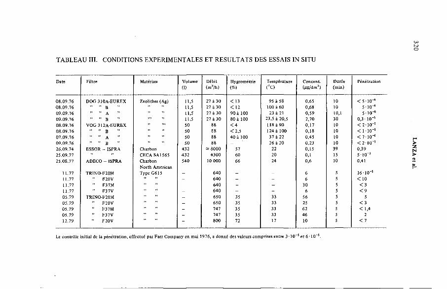
U)юо
TABLEAU III. CONDITIONS EXPERIMENTALES ET RESULTATS DES ESSAIS IN SITU
D ate F iltre M atériau V olum e
(1)
D ébit(m 3/h )
H ygrom étrie(%)
T em p éra tu re(°C )
C o n cen t.(M g/dm3)
D urée(m in )
P én é tra tio n
0 8 .0 9 .7 6 D O G 310A -E U R E X Z eolithes (A g) 11,5 27 à 30 < 13 95 à 58 0,65 10 < 5 1 0 '60 8 .0 9 .7 6 ” ” B 11,5 27 à 30 < 12 100 à 60 0,68 10 5 ■ 1 0 '609 .0 9 .7 6 ” ” A 11,5 27 à 30 9 0 à 100 23 à 21 0 ,59 10,1 5 ■ 10 -60 9 .0 9 .7 6 ” ” B ” 11,5 27 à 30 80 à 100 23,5 â 20 ,5 2 ,70 30 0 , 3 - 10"60 8 .0 9 .7 6 V O G 312A -E U R E X 50 88 < 4 118 à 90 0 ,17 10 < 2 - 1 0 ' s0 8 .0 9 .7 6 ” ” B 50 £8 < 2 ,5 124 à 100 0 ,18 10 < 1 -1 0 -50 7 .0 9 .7 6 ” ” A 50 88 4 0 à 100 37 à 22 0 ,45 10 < 7 • 10 -609 .0 9 .7 6 ” ” B 50 88 - 26 à 20 0,23 10 < 2 1 0 " s2 6 .0 9 .7 4 ESSO R - ISPRA C harbon 4 32 = 80 0 0 57 22 0 ,15 39 0 ,392 5 .0 9 .7 7 ” CECA SA 1565 432 4 3 0 0 60 20 0,1 15 5 10"32 5 .0 8 .7 7 ADECO - ISPRA C harbon
N o rth A m erican540 10 0 00 66 24 0,6 10 0,41
11.77 T R IN O -F20M T ype G 615 - 640 - - 6 5 16 - 10 -511.77 ” F20V - 640 - - 6 5 < 1011.77 ” F37M - 640 - - 30 5 < 311.77 ” F37V - 6 4 0 - - 6 5 < 905 .7 9 TRINO-F2ÛM - 6 50 35 33 56 5 505 .7 9 ” F 20V - 650 35 33 25 5 < 305 .7 9 F37M - 747 35 33 62 5 < 1,405 .79 F 37V - 747 35 33 46 5 212.79 F 20V - 800 72 17 10 5 < 7
Le co n trô le in itia l de la p én é tra tio n , e ffec tué pa r F a rr C om pany en m ai 1976, a don n é des valeurs com prises e n tre 3 • 1 0 '5 e t 6 • 10“s .
LANZA et al.

IAEA-SM-245/45 321
3.1. Essais des lits de zéolithes à Saluggia
Une détermination de l’efficacité des 4 lits de zéolithes imprégnés à l’Ag, montés sur le circuit d’épuration de l’installation Eurex de Saluggia, a été faite en utilisant la méthode à l’ICH3 marqué.
On devait faire deux séries d’essais dont la première à = 20°C et la deuxième à = 100°C c’est-à-dire à la température de fonctionnement normal du système.
La solution de ICH3, préparée dans le laboratoire de l’IIN a été transportée au lieu d’essai dans une voiture. Le reste de la solution a été restitué au laboratoire de l’IIN de la même façon à la fin des essais.
Pour l’injection de cette solution, on a utilisé le dispositif de génération de la figure 2, alimenté par l’air provenant du circuit de distribution d’air comprimé de l’installation Eurex.
Pour les prélèvements d’échantillons en amont et en aval, on a utilisé deux lignes installées par le personnel d’Eurex dans une salle à côté du circuit à essayer.
Une caractéristique remarquable de ce système réside dans le fait qu’il est possible de prélever en aval un débit jusqu’à 200 fois plus élevé que celui en amont.
L’activité des cartouches de piégeage a été comptée par un scintillateur préalablement calibré.
Toutes les opérations de manipulation relatives aux pièges et le comptage lui-même ont été réalisés par le personnel et dans les laboratoires d’Eurex.
Le tableau III montre les conditions expérimentales ainsi que les résultats de ces essais.
On a pu obtenir différentes valeurs de la concentration de l’ICH3 en amont par simple variation du débit de l’air qui alimente le dispositif de génération.
Les lits de zéolithes choisis après un long travail de sélection [15] ont mis en évidence une très haute efficacité, toujours supérieure à 99,998%, et cela sous les deux température réalisées.
L’efficacité élevée démontrée par les lits de zéolithes a, par ailleurs, conditionné négativement la précision de la mesure de l’échantillon en aval; en prolongeant délibérément2 la durée de prélèvement, cette mesure a pu être mieux déterminée et l’efficacité obtenue a tourné autour de 99,9995%.
Ces valeurs ne doivent pas nous étonner dans la mesure où les temps de passage dans les lits sont assez longs (autour de 10 secondes).
3.2. Essais au CCR Euratom d’Ispra
A l’aide de la méthode précisée ci-dessus, on a fait un contrôle d’efficacité in situ des filtres installés dans le circuit de ventilation dé l’enceinte de confinement du réacteur ESSOR, ainsi que des pièges du laboratoire ADECO.
2 C ette p rocédure n ’a été suivie que peu de fo is a fin de m a in te n ir au-dessous de 1 0 0 nCi l ’a c tiv ité de l ’ iode q u i d o it ê tre in jec té dans chacun des essais.
322 LANZA et al.
Ces filtres sont constitués de cartouches cylindriques remplies de charbon actif d’une épaisseur de 5 cm. Le débit nominal est de 8000 et 10 000 m3/h respectivement.
Un premier essai préliminaire avait été conduit en 1974 sur le filtre d’ESSOR afin de vérifier l’applicabilité de cette méthode à un filtre dans des conditions de débit très élevé. La valeur de l’efficacité mesurée fut particulièrement basse ( s 60%).
Des essais en laboratoire montraient que ce résultat était dû à la détérioration des caractéristiques du charbon et cela nous a permis de passer à des essais définitifs.
Dans ces essais, on a utilisé le système de génération déjà employé à Eurex, mais dans ce cas la solution radioactive d’ICH3 a été préparée au CCR Euratom en présence du personnel de ce centre à des fins de formation.
Les prélèvements ont été effectués avec un système similaire à celui adopté à Eurex, mais, à la différence de ce dernier, amovible.
Les modalités du comptage y effectué en collaboration avec le personnel d ’Ispra ont été les mêmes que celles suivies à Eurex.
Le tableau III montre les conditions expérimentales ainsi que les résultats obtenus.
On peut remarquer que le nouveau type de charbon employé à ESSOR a une efficacité satisfaisante et aussi que le charbon des filtres d’ADECO était détérioré.
On peut d’ailleurs constater que les dispositifs employés dans ces essais ont permis de réaliser dans le circuit une concentration de 0,1 à 0,6 mg/m3 et de mesurer une efficacité de 99,5% par l’injection d’une activité totale d’environ1 mCi.
3.3. Essais à la centrale nucléaire de Trino Vercellese
En 1976, sur le circuit de ventilation de secours de la zone annulaire de l’enceinte de confinement de la centrale nucléaire de Trino, on a installé deux groupes de filtration. Chacun d’eux est une série composée d’un préfiltre, d’un filtre absolu, de 2 pièges à charbon actif et d’un filtre absolu final.
Six pièges témoins sont montés de façon à suivre en permanence l’évolution du charbon actif des pièges principaux. Le schéma du système est représenté dans la figure 3.
Conformément aux prescriptions imposées par l’autorité de contrôle, l’efficacité globale du circuit doit être soumise à vérification tous les 18 mois.
On a choisi comme méthode celle consistant à mesurer la perte d’efficacité due à des chemins préférentiels, au moyen du F-l 12, et, en même temps, à envoyer au laboratoire de 1TIN un des six pièges témoins pour vérifier l’efficacité propre du charbon actif. Cela a conduit à mettre au point une technique opérationnelle afin de détecter les «pénétrations au fréon» inférieures à 0,03% (limite d’acceptabilité pour l’installation).

IAEA-SM-245/45 323
1
F IL T R E HEPA
F IL T R E HEPA
P R E F IL T R E
RECHAUFFEUR
1
i г
F IL T R E HEPA
F IL T R E HEPA
RECHAUFFEUR
if
FIG.3. Schéma du groupe de filtration de secours de Trino.
On a utilisé deux groupes de sept ampoules de 50 cm3 (fig.4), afin de prélever simultanément les échantillons en amont et en aval du piège à contrôler.
L’air des ampoules a été ensuite analysé en laboratoire par le chromatographe (P.E. F17 avec détecteur №63) précédemment calibré [16]. La sensibilité du système a permis de mesurer des pénétrations de 0,003%, ce qui représente un dixième de la limite d’acceptabilité citée ci-dessus.
Il faut préciser que les échantillons en amont ont été dilués avant d’être analysés.
Quant à la génération du fréon, elle a été effectuée au moyen du dispositif décrit en [17] qui a permis de produire quelques g/min de vapeurs suffisant pour les essais. Ce dispositif a présenté, dans le rythme de génération, une instabilité qui n’a d’ailleurs pas affecté les résultats grâce à la technique du prélèvement simultané.
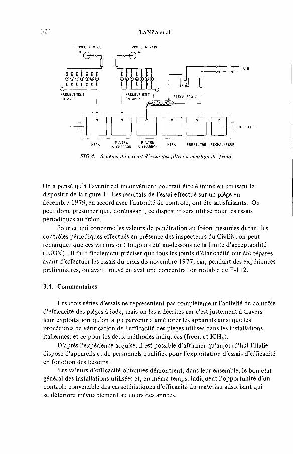
324 LANZA et al.
POMPE A V ID E POMPE A V ID E
HEPA A C H A TRBON A CHARBON HEPA ^ F I L T R E RECHAUFFEUR
FIG.4. Schéma du circuit d ’essai des filtres à charbon de Trino.
On a pensé qu’à l’avenir cet inconvénient pourrait être éliminé en utilisant le dispositif de la figure 1. Les résultats de l’essai effectué sur un piège en décembre 1979, en accord avec l’autorité de contrôle, ont été satisfaisants. On peut donc présumer que, dorénavant, ce dispositif sera utilisé pour les essais périodiques au fréon.
Pour ce qui concerne les valeurs de pénétration au fréon mesurées durant les contrôles périodiques effectués en présence des inspecteurs du CNEN, on peut remarquer que ces valeurs ont toujours été au-dessous de la limite d’acceptabilité (0,03%). Il faut finalement préciser que tous les joints d’étanchéité ont été réparés avant d’effectuer les essais du mois de novembre 1977, car, pendant des expériences préliminaires, on avait trouvé en aval une concentration notable de F-l 12.
3.4. Commentaires
Les trois séries d’essais ne représentent pas complètement l’activité de contrôle d’efficacité des pièges à iode, mais on les a décrites car c’est justement à travers leur exploitation qu’on a pu parvenir à améliorer les appareils ainsi que les procédures de vérification de l’efficacité des pièges utilisés dans les installations italiennes, et ce pour les deux méthodes indiquées (fréon et ICH3).
D’après l’expérience acquise, il est possible d’affirmer qu’aujourd’hui l’Italie dispose d’appareils et de personnels qualifiés pour l’exploitation d’essais d’efficacité en fonction des besoins.
Les valeurs d’efficacité obtenues démontrent, dans leur ensemble, le bon état général des installations utilisées et, en même temps, indiquent l’opportunité d’un contrôle convenable des caractéristiques d’efficacité du matériau adsorbant qui se détériore inévitablement au cours des années.

IAEA-SM-245/45 325
L’importance du contrôle des caractéristiques d’efficacité du matériau adsorbant, plusieurs fois rappelée [6, 10] et mise en évidence au cours des essais au CCR Euratom d’Ispra, a conduit le CNEN et l’IIN à créer, dans le laboratoire de l’IIN lui-même, une section spécialisée dans la vérification de l’efficacité des matériaux adsorbants en conditions expérimentales strictement contrôlées.
4. ESSAIS EN LABORATOIRE
4.1. Appareils et circuits (pour les essais d’efficacité de matériaux adsorbants)
Le Laboratoire Scalbatraio [18] de l’IIN de Pise dispose actuellement:— d’un circuit équipé pour la détermination de l’efficacité des matériaux adsorbants en conditions strictement contrôlées;— d’un circuit pour l’exploitation d’essais d’efficacité de filtres commerciaux pour le piégeage de l’iode.
4.1.1. Circuit équipé pour la détermination des caractéristiques d ’efficacité des matériaux adsorbants
Le circuit, représenté dans la figure 5, est constitué des principales unités fonctionnelles suivantes:— section pour le traitement du gaz porteur qui permet le réglage des débits de vapeur d’eau et de gaz;— chambre de conditionnement où est placé le matériau adsorbant à essayer et où les conditions de température et pression sont fixées;— unité d’injection du traceur qui permet d’en fixer, et éventuellement d’en régler, la quantité injectée en amont du matériau adsorbant;— section finale où le mélange gazeux (après le passage à travers le filtre pour mesurer l’efficacité de l’adsorbant essayé) est déshumidifié et est envoyé à l’extérieur après avoir passé un filtre de sécurité.
Avec ce circuit, des essais d’efficacité des matériaux adsorbants peuvent être effectués dans les conditions suivantes:
VitesseTempératurePressionConcentrationHygrométrie
1 à 100 cm /s ambiante à 150°C 0,9 à 5 atm 0,3 à 30 Atg/dm3 Oà 100%
Le système de traitement du gaz porteur ne permet pas toujours de réaliser les valeurs maximales de l’hygrométrie et de la vitesse indiquées; cela dépend des valeurs de la température, de la pression, ainsi que de la section du lit à essayer.

326 LANZA et al.
~ fa A IR DE PRODUCTION Y Y DE VAPEURS D6 CH3I — I----- ra .. S-
UNITE DE GENERATION DU TRACEUR
1 FILTRE Œ L W N ET A CHARBON2 HUMIDIFICATION3 BAIN THERMDSTATIQUE4 CONDENSEUR5 FÍLTRE A POUSSIERE6 ECHANTILLON7 PIEGE A CHARBON8 CONDENSEUR9 VANNE DE SECURITE
10 VANNE DE SECURITE11 BOUTEILLES D 'A IR SS12 SOURCE DE CH?I
Q CEB 1 W E THE ® HYGROMETRE ® MANOMETRE© MESURE DE TEMPERATURE -3 COMMANDE E LECTROMAGNE T I QUE Л VAWNE A TROIS VOIES Cfa VANNE DE REGLAGE A VANNE D 'iSO LEÆ N T ^ DOUCHE ■3 PRECHAUFFEUR II INDICATEUR DE NIVEAU
- 0 POMPE D BUSE
FIG.5. Schéma du circuit pour les essais des matériaux adsorbants.
2 0 Ц0 60 80 1 0 0 1 2 0T e m p e r a t u r e ( ° C )
FIG.6. Courbe des conditions expérimentales limites q u ’on peut réaliser dans le circuit d'essai des matériaux adsorbants.

IAEA-SM-245/45 327
4.1.2. Circuit d ’essai d ’efficacité de pièges à iode
Ce circuit est actuellement le seul en Italie permettant d’effectuer des essais d’efficacité de filtres pour le piégeage de l’iode.
Il a été obtenu en modifiant le circuit de recirculation et de dépressurisation de la cuve PSICO 10 [19,20] et il s’adapte aux filtres HEPA de dimensions nominales de 60 X 60 X 30 cm pour les essais d’efficacité. Cette disposition permet également de procéder à des essais à des températures variant de la température ambiante à 100°C environ, sous des pressions comprises entre 0,9 et = 2 atm, avec des débits du gaz porteur allant jusqu’à 1000 m3/h et une hygrométrie poussée jusqu’à saturation.
La possibilité pour le circuit de fonctionner en dépression a permis l’utilisation d’aérosols radioactifs [21 ] et la mise au point des méthodes d’essai de pièges à iode [22].
4.2. Résultats des essais
Le circuit d’essai des matériaux adsorbants a été réalisé, équipé et calibré de façon à réduire le plus possibles les variations non désirées des paramètres expérimentaux et le manque de précision dans leur mesure.
Ces améliorations ont été réalisées au cours de la série d’essais effectués dans le cadre du programme de comparaison entre plusieurs laboratoires européens, programme qui a été organisé par la CCE à la suite du Séminaire de Karlsruhe [23].
On devait déterminer l’indice de performance3 de différents types d’adsorbants (mis chaque fois à disposition par différents fournisseurs européens) en contrôlant le plus souvent possible la température, l’hygrométrie et la vitesse du gaz porteur.La comparaison des résultats des différents laboratoires, effectuée à l’occasion de réunions périodiques à la CCE, a montré la congruence des résultats obtenus en Italie (voir tableau IV) avec ceux de la plupart des autres laboratoires participant au programme.
La figure 6 représente les courbes limites pour la condition normalement réaliséedans le circuit, c ’est-à-dire pour une pression de 760 mm Hg et un diamètre desection de 4,8 cm.
3 L ’ind ice de pe rfo rm ance K d ’un m a té riau adsorbant dans le piègeage de l ’ IC H 3 (ou pa rfo is de l ’iode [1 , 5 ]) est d é fin i pa r la fo rm u le
T, lo g jo 1 /p K -
T
vo lum e du l i t de charbondans laquelle : т = ------------------------------------------
dé b itp = p é n é tra tio n
328 LANZA et al.
En [24] on trouvera un examen rapide des résultats de ces essais, tandis qu’en [11,12,13] sont détaillées les conditions opérationnelles.
On a ainsi confirmé la précision des mesures avec l’appareillage mis aux point ainsi que la possibilité de les répéter, et on a, en même temps, obtenu une précieuse expérience opérationnelle.
Cette expérience a joué un rôle très important pour le contrôle de l’efficacité des matériaux adsorbants du réacteur ESSOR et des laboratoires ADECO du CCR Euratom Ispra ainsi que de la centrale nucléaire de Trino Vercellese.
Ces derniers essais ont souligné qu’il est possible d’effectuer des essais d’efficacité dans des conditions assez différentes et qu’on peut reproduire, de façon satisfaisante, aussi bien ces conditions que les résultats conséquents.
Quant aux valeurs de l’indice de performance obtenues, on peut remarquer que, même si peu de types de matériaux adsorbants on été essayés, leur dispersion est assez large, ce qui montre l’importance d’un contrôle sévère des paramètres qui affectent le plus l’efficacité des systèmes de piégeage de l’iode.
En particulier, on a mis en évidence que le charbon d’Ispra est très sensible aux conditions d’hygrométrie et qu’il a montré une perte importante d’efficacité avec le temps.
5. CONCLUSIONS
Les essais effectués à l’IIN et les contrôles périodiques des installations ont mis en évidence la validité des appareils et des méthodes mis au point pour la détermination de l’efficacité des installations destinées au piégeage de l’iode.
Celle-ci a été également confirmée dans des conditions expérimentales particulièrement sévères de débit et d’efficacité au cours d’essais in situ ou en laboratoire.
Les deux essais d’efficacité effectués sur les filtres installés au CCR Euratom d’Ispra ont souligné, une fois de plus, la nécessité de vérifier périodiquement le comportement des systèmes filtrants afin de pouvoir procéder aux interventions d’entretien et de substitution éventuelles.
En se fondant sur l’expérience acquise au cours de tous ces essais, on peut résumer les principales caractéristiques d’une méthode de contrôle des filtres à iode:
1) facilité d’emploi: les appareils nécessaires doivent être aisément transportables et permettre d’effectuer des mesures suffisamment rapides;
2) économie: les essais ne doivent pas représenter un coût excessif en personnel et en moyens, y compris le coût des appareils;
3) permettre que les essais soient effectués dans des conditions de fonctionnement effectif du système filtrant;
4) les essais doivent être effectués de manière à éviter toute détérioration des filtres ou, sinon, à en limiter l’étendue;

IAEA-SM-24S/45 329
5) les mesures doivent être caractérisées par une précision raisonnable et doivent pouvoir être répétées.
Ces caractéristiques sont importantes tant pour les essais in situ que pour ceux en laboratoire, même si la mobilité des appareils représente un aspect moins important en laboratoire.
REFERENCES
f 1 ] W IL H E L M , J.G ., Io d in e F ilte rs in N uc lea r Pow er S ta tions, K F K 2 4 49 , K arls ruhe (1 9 7 7 ).[2 ] U N IC E N , F i l t r i a carbone a tt iv o in s ta lla ti ne i c irc u it i d i ven tila z ione degli im p ia n ti
nu c le a ri, M anuale d i in fo rm a z io n e F A C IN IV , R om e (1 9 7 6 ).[3 ] T A Y L O R , L .R ., T A Y L O R , R ., «The ageing o f im pregnated charcoals», P roceedings o f
the Sem inar on Io d in e F ilte r Testing , K arls ruhe Dec. 1973, CEC D oc. V /5 5 9 /7 4 , L u xe m b o u rg (1 9 7 4 ) 121.
[4 ] S IG L I, P., T R E H E N , L ., «C o n trô le des pièges à iode des centrales nucléaires», CEC D oc. V /5 5 9 /7 4 , L u xe m b o u rg (1 9 7 4 ) 259.
[5 ] H IL L A R Y , J.J ., « Io d in e s o rp tio n p la n t test procedures in the U n ite d K in g d o m » , CEC D oc. V /5 5 9 /7 4 , L u xe m b o u rg (1 9 7 4 ) 237.
[ 6 ] H E S B Ô L, R ., e t al., « Io d in e f i l te r tes tin g in Sweden», CEC D oc. V /5 5 9 /7 4 , L u xe m b o u rg , (1 9 7 4 ) 329.
[7 ] V A N D E R L U G T , G ., S C H O LT E N , L .C ., «M ethods used at K E M A fo r measuring iod in e a d so rp tio n on charcoal and experiences w ith charcoal f ilte rs ins ta lled at a nuclear p o w e r p la n t» , CEC D oc. V /5 5 9 /7 4 , L u xe m b o u rg (1 9 7 4 ) 315.
[8 ] U S N R C , Design, Testing and M ain tenance C rite r ia fo r E ngineered-S afe ty Feature A tm osphere C leanup System A ir F i l t ra t io n and A d s o rp tio n U n its o f LW C ooled NPP, R egu la to ry G u ide 1.52 Rev. 1 (1 9 7 6 ).
[9 ] M U H L B A IE R , D .R ., S tandard ized N on D es truc tive Test o f C arbon Beds fo r Reactors C o n fin e m e n t A p p lica tio n s , U S A E C , DP 1082 (1 9 6 7 ).
[1 0 ] M E S SO RE , G ., e t a l., «T esting m ethods fo r io d in e f i lte rs o f nuclear p lan ts» , CEC D oc. V /5 5 9 /7 4 , L u xe m b o u rg (1 9 7 4 ) 271.
[1 1 ] L A N Z A , S., et al., «G estione de l c irc u ito p rova f i l t r i e prosecuzione de l re la tivo program m a spe rim en ta le» , A t t i d e ll’ Is t i tu to d i Im p ia n ti N uc lea ri d e ll’ U n ive rs ité d i Pisa, R L 21 1 (75 ), Pise (1 9 7 5 ).
[1 2 ] L A N Z A , S., M A Z Z IN I, М ., « C o m p o rta m e n to de i s is tem i d ir ite n z io n e d e llo io d io » ,A t t i d e ll’ Is t i tu to d i Im p ia n t i N u c le a ri d e ll’ U n ive rs ité d i Pisa, R L 2 5 2 (7 6 ), Pise (1 9 7 6 ).
[1 3 ] L A N Z A , S., M A Z Z IN I, M ., « C o m p o rta m e n to de i s istem i d i r ite n z io n e de llo io d io » ,A t t i d e ll ’ Is t i tu to d i Im p ia n ti N uc lea ri d e ll’ U n ivers ité d i Pisa, R L 2 8 8 (7 7 ), Pise (1 9 7 7 ).
[1 4 ] C IT T I, P., e t a l., T raspo rto d i m a teria le ra d io a tt iv o : a ttrezza tu re d i co lla u d o ed esperienze eseguite su p ro to t ip o de l co n te n ito re C F 6 , Is t i tu to d i Im p ia n ti N uc lea ri d e ll’ U n ive rs ité d i Pisa, R L 11 3 (72 ), T ip og ra fía E d itr ic e Pisana, Pise (1 9 7 2 ).
[1 5 ] L A N Z A , S., M A Z Z IN I, М ., In flu e n za d e ll’ a w e le nam en to con va p o ri n i t r ic i sulla r ite n z io n e d i C H 3I da pa rte d i z e o lit i argentate, Is t i tu to d i Im p ia n ti N u c le a ri d e ll’U n ive rs ité d i Pisa, R L 11 1 (72 ), T ip og ra fía E d. Pisana, Pise (1 9 7 2 ).
[1 6 ] C E N T R A L E E L E T T R O N U C L E A R E E N R IC O F E R M I, S istema d i ven tila z io n e de lla zona anulare de l c o n te n ito re , Manuale d i is tru z io n e (1 9 7 6 ).
[1 7 ] E N E L - C o m p a rtim e n to d i T o r in o SPT/ST, C E N T R A L E E L E T T R O N U C L E A R E E N R IC O F E R M I, V e r if ic a de lla ten u ta de i f i l t r i a carbone in s ta lla ti sulle u n itá f i l t r a n t i del c irc u ito d i ven tilaz ione d i emergenza deH’in te rcaped ine anulare del co n te n ito re d e ll’ im p ia n to (1 9 7 7 ).
[1 8 ] G U E R R IN I, B ., et a l., Scalbatra io C enter fo r Research in N uc lea r S a fe ty , N uc l. T echno l.10 4 (1 9 7 1 ) .
[1 9 ] M A Z Z IN I, М ., « In s itu and in la b o ra to ry tes ting o f H E P A f ilte rs in I ta ly » , Proceedings o f the Sem inar on H igh E ffic ie n c y A eroso l F ilt ra t io n , A ix-en-Provence N ov. 1976.CEC D oc. V /8 3 5 /7 7 , L u xe m b o u rg ( 1977).
[2 0 ] G U E R R IN I, B ., e t al., L ’apparecch ia tu ra sperim entale PSICO 10, N o tiz ia r io del CN EN 18 1 0 (1 9 7 2 ).
[2 1 ] M A Z Z IN I, M ., e t al., «E xpe rim en ts on h igh e ff ic ie n cy aerosol f i l t ra t io n » , CEC D oc. V /8 3 5 /7 7 , L u xe m b o u rg (1 9 7 7 ).
[2 2 ] L A N Z A , S., M A Z Z IN I, М ., II c o n tro llo dei f i l t r i a io d io in s ta lla ti sug li im p ia n ti nuc lea ri, N o tiz ia r io de l C N E N 19 6 (1 9 7 3 ).
[2 3 ] D IR E C T O R A T E O F H E A L T H P R O T E C T IO N CEC, R epo rt on the P re lim in a ry Discussions o f a Program m e fo r the C om para tive Testing o f A c tiva te d Charcoal, D oc. No.9 0 2 /7 4 e E A H /fK , L u xem bo u rg (1 9 7 4 ).
[2 4 ] L A N Z A , S., M A Z Z IN I, М ., « L ’apparecch ia tu ra per la m isura in la b o ra to rio delle ca ra tte ris tiche d i e ffic ie nza d i m a te ria li asso rb ito ri de llo io d io ra d io a tt iv o » , A t t i d e ll’ Is t i tu to d i Im p ia n ti N uc lea ri d e ll’ U n ivers ité d i Pisa, RP 34 9 (7 9 ), Pise (1 9 7 9 ).
330 LANZA et al.
DISCUSSION
M.A. MOLINARI: Do you make any special effort to maintain constant upstream iodine concentration in your iodine tests, and what order of magnitude do you estimate for concentration variations? Secondly, what do you consider to be the most important causes of variations in experimental efficiency values?
S. LANZA: Because of the design of the generation device described in my paper no special effort is required to maintain constant iodine concentration.In our tests only rather small fractions of CH3I were stripped and so variations in solution concentration resulting from continuous stripping did not substantially affect the generation rate of CH3I vapours. If you want a specific estimate, I would say variations were certainly less than 20%.
With reference to your second question I would reply that these problems arise principally with those experimental parameters which affect the behaviour of the granular material and which are the most difficult to control. These are water content and its distribution on the granular bed at the moment of tracer injection and the water content and flow rate of the carrier gas. Our experience in the laboratory is that this control becomes more and more difficult when temperature and pressure are increased beyond 100°C and 1 atm. respectively up to experimental conditions similar to those of an accident situation.
IAEA-SM-245/4S 331
F. LUYKX: You mentioned a CEC intercomparison programme on charcoal testing. As nothing has yet been published on this programme, I would like to provide some information on it. The programme, in which seven European and two US institutes participated, started after the seminar on ‘Iodine Filter Testing’ organized by the European Commission in December 1973. The aim was to carry out laboratory tests on charcoal and other iodine retention adsorbents under a set of standard conditions and to see to what extent the results were comparable. Five different tests were performed. The results were very promising although the standardization of certain parameters gave rise to some problems. The European Commission intends to organize another seminar on iodine filter testing early next year, at which the results of the intercomparison programme and further work in this field will be presented.
J.L. KOVACH: As you are aware, Mr. Lanza, it takes several weeks to strip Freon-112 from the carbon. What do you do if you find a leak and have to re-test? It is because of difficulties with this that we are now switching in the USA to refrigerant 11 instead of 112.
S. LANZA: I agree that in general this is a real problem. In the particular case of the Trino Power Plant ventilation system, however, we are dealing with an emergency system normally used as a standby. It consists of two filtering units in parallel, both equipped with preheaters which can rapidly increase air temperature to 135°C. The air flow rate can also be increased, and this by a factor of 2.5. Although I cannot give any experimental data, I believe that in the above- mentioned conditions the F-l 12 desorption time is certainly not a matter of weeks, and satisfactory conditions for repeating a Freon test can easily be found.

IAEA-SM-245/39
STUDIES ON SAND-BED AIR FILTERS FOR THE TREATMENT OF FUEL REPROCESSING DISSOLVER OFF-GASES
J.C. KAPOOR, C. SRINIVAS,A.A. KHAN, K.T. THOMAS Bhabha Atomic Research Centre,Bombay,India
Presented by S.A.K. Jeelani
Abstract
S T U D IE S O N S A N D -B E D A IR F IL T E R S F O R T H E T R E A T M E N T O F F U E L R E PR O C E S SIN G D IS S O L V E R O FF-G A S ES .
Off-gases be ing released fro m the d issolver in fu e l reprocessing p lan ts co n ta in n o t o n ly h igh spec ific a c t iv ity b u t also a large a m o u n t o f w a te r in the fo rm o f vap ou r and en tra ined drop le ts . In a d d it io n , considerable am ounts o f corrosive fum es o f n it r ic acid and n itro g e n ox ides are also present. F o r the tre a tm e n t o f th is gas stream a tra in o f e q u ip m e n t consisting o f an a lk a li gas-washer, a de -en tra ine r, a dem iste r, a ch ille r , a heater and a deep-bed f i l te r is be ing used in m ost o f the fu e l reprocessing p lan ts. The fin a l f i l te r is genera lly a deep-bed glass-fibre f i l te r (D B G F ). E xperience has show n th a t th is typ e o f system su ffe rs ow in g to the inhe ren t d if f ic u lt ie s in o p e ra tio na l c o n tro l o f th is m u lt ip le eq u ip m e n t u n de r surging o p e ra tio na l co n d itio n s . D B G F f ilte rs have in v a r ia b ly n o t pe rfo rm ed acco rd ing to design expecta tions. Th is is due to fib re coalescence and sagging w hen the e ff ic ie n cy o f the f i l te r decreases and the pressure d ro p increases. In a d d it io n , th e y also requ ire fre q u e n t rep lacem ent, re su lting in h igh costs and large ra d ia tio n exposures. O u r search fo r m ore dependable eq u ip m e n t fo r th e tre a tm e n t o f d isso lver off-gases ind ica ted th a t p ro p e r ly designed sand-bed a ir f ilte rs (S B A F s) m ay be b e tte r su ited fo r th is purpose. F u r th e r investiga tions on the characte ris tics o f a sand bed as a gas washer fo r ab so rp tio n o f n itro g e n ox ides, as a device fo r the de -en tra inm en t o f w ate r d rop le ts , and as an e ff ic ie n t p a rticu la te a ir f i l te r have proved th a t i t fu lf i ls a ll the basic re qu ire m ents o f c lean ing d issolver off-gases in fu e l reprocessing p lan ts. T h is paper covers the results o f la b o ra to ry - and p ilo t-p la n t stud ies carried o u t on the s u ita b ility o f an S B A F fo r the above purpose.
1. INTRODUCTION
Although sand-bed air filters (SBAFs) have been used in the nuclear industry their utilization has been mostly as back-up filters in fuel reprocessing plants, radiochemical laboratories [1,2] and fast breeder reactors [3,4]. Development work carried out in this laboratory covering various aspects of an SBAF, e.g.
333

ACIDTANK
* ъHEPA
'A
--- T P-.
DILUTION
h-&-V
,V VP
I30-0
Itr/min
CONTROL VALVES
ROTAMETERS
SAMPLING POINTS
PRESSURE TAPS
INDICATOR
0 — SILICA GEL COLUMN
NEBULIZER
NO* GENERATOR
FIG.l. Schematic diagram of the experimental set-up.
IAEA-SM-245/39 335
characteristics of particulate filtration, flow [5], packed columns, gas washers and corrosion of various types of sand, indicated that this equipment may serve as a compact, multi-purpose and efficient device for the treatment of all gas- streams containing high specific activity as well as high moisture loading and corrosive fumes. It was also noted that most of the operational problems encountered in the dissolver off-gas treatment system incorporating deep-bed glass-fibre filters (DBGFs) can be avoided by using an SBAF because of its inherently better physical stability under the specific operating conditions.
This paper covers details of the laboratory- and pilot-plant studies carried out to evaluate the important characteristics of an optimized SBAF. An SBAF was charged with off-gases from a small dissolver operating under conditions similar to those in a fuel reprocessing plant. However, to avoid handling radioactivity copper was dissolved in nitric acid to produce the desired simulated gas stream. The performance of the SBAF was studied with regard to the following parameters:
(a) Pressure drop characteristics covering variations under different operating conditions and time of operation.
(b) Collection efficiency for sub-micrometre aerosols under the simulated operating conditions.
(c) Collection efficiency for the removal of entrained water droplets.
(d) Gas washing characteristics for the removal of nitrogen oxides.
(e) Extent of liquid waste generation.
2. EXPERIMENTAL SET-UP
Figure 1 shows the experimental set-up utilized for the evaluation of an SBAF. It consists of an NOx-generator, a nebulizer for generating liquid droplets, mixing chambers'for producing a homogeneous mixture of air, NOx and water droplets,and a sand filter column. Necessary arrangements for the sampling of NOx and liquid droplets in the air before and after passing through the SBAF were also provided.
2.1. Sand-bed air filter
Details of the design of the SBAF are shown in Fig.2. The gas, bearing NOx and water droplets, is fed to the filter from the bottom so that it is successively passed from the coarser to the finer grades of sand layers. The face velocity of the

336 KAPOOR et al.
FIG. 2. Details o f a sand-bed air filter column.
gas is maintained at 2.85 cm/s in the sand bed. This is based on earlier studies on the filtration of the sand beds [5]. A drain has been provided at the bottom of the SBAF column to remoVe the condensate. The cross-sectional area of the bed was 176.6 cm2 and the flow rate was maintained at 30.0 ltr/min.
2.2. Generation of nitrogen oxides
NOx is generated by the reaction of copper turnings with nitric acid in an NOx-generator and it is then fed to the mixing chamber to adjust the concentration of the gas to the desired levels.
IAEA-SM-24S/39 337
2.3. Aerosol generation
To test the particulate removal efficiency of the SBAF, standard uranine aerosol with a mass median diameter of 0.52 /urn and a geometric standard deviation of 2.1 was used. This was generated by atomizing a 1.0% solution of uranine at 30 lbf/in2 and allowing the droplets to evaporate, thereby generating solid uranine particles.
2.4. Droplet generation
Water droplets were generated by using a X/70 Retec-type nebulizer operated at 20 lbf/in2 air pressure and 5 ltr/min air flow. Under these operating conditions droplets with a mass median diameter of 5.1 jum and a standard deviation of 2.1 were generated and an output of 60 mg/ltr was obtained [6,7].
2.5. Sampling arrangements
Arrangements for the sampling of air to determine the concentration of aerosol, NOx and water droplets were provided both upstream and downstream of the SBAF as well as at various locations along the height of the bed, as shown in Fig. 2.
3. EXPERIMENTAL PROCEDURE
The experimental set-up shown in Fig.l was operated to evaluate the SBAF under different operating conditions with respect to varying the droplet loading and the NOx concentration in the simulated off-gas stream.
3.1. Measurement of particulate collection efficiency
To measure its particulate removal efficiency, the concentration of uranine aerosol was determined upstream and downstream of the SBAF. This was done by passing a known volume of air through a membrane filter of 0.3 д т pore size and subsequent fluorimetric analysis of the wash solution. Assessment of removal efficiency was also carried out both before and after loading the SBAF with water droplets.
338 KAPOOR et al.
3.2. Measurement of droplet collection efficiency
The concentration of liquid droplets in the air passing through the SBAF was determined at various locations along the height of the filter, as shown in Fig.2. The total mass concentration of the droplets was estimated by measuring the amount of the uranine collected on the membrane filter. The droplets used in this case were generated from a dilute solution of uranine. The efficiency of the different layers of sand in the SBAF for droplet removal was evaluated.
3.3. Monitoring of pressure drop
The pressure drops across the SBAF as well as across the pre-filtration and high efficiency filtration layers were monitored continuously during the water droplet loading period. The concentration of water droplets was computed from the nebulizer, as described in sub-section 2.4. To study the effect of dissolved materials in the water droplets on the pressure drop across the SBAF, the filter was loaded with droplets of a dilute solution of barium nitrate.
3.4. Measurement of NOx removal efficiency
The SBAF was evaluated for its NOx removal efficiency under the specific operating conditions by measuring the NOx concentration upstream and downstream of the filter. The concentration of NOx was measured by scrubbing a known volume of gas through an NaOH solution. This assessment was made for a droplet loading of 14 mg/ltr and 20 mg/ltr of air and for an NOx concentration varying from 1.8 to 71.7 vol.%.
3.5. Measurement of condensate
The volume of condensate at the bottom of the SBAF under various operating conditions was also collected and its quantity measured.
4. EXPERIMENTAL RESULTS
The experimental set-up for evaluation of the SBAF as a device for cleaning simulated off-gases from dissolvers in fuel reprocessing plants was operated under varying conditions, as described in section 3. The results of the experiments are summarized and discussed in the following sub-sections.
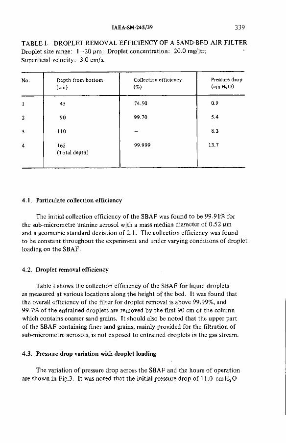
IAEA-SM-245/39 339
TABLE I. DROPLET REMOVAL EFFICIENCY OF A SAND-BED AIR FILTERDroplet size range: 1 - 2 0 jum; Droplet concentration: 20.0 mg/ltr; 4Superficial velocity: 3 .0 cm/s.
N o. D e p th fro m b o tto m (cm )
C o lle c tio n e ff ic ie n cy
(% )
Pressure d rop (cm H 2 0 )
1 45 74.50 0.9
2 90 99 .70 5.4
3 1 1 0 - 8.3
4 165(T o ta l d e p th )
99 .999 13.7
4.1. Particulate collection efficiency
The initial collection efficiency of the SBAF was found to be 99.91% for the sub-micrometre uranine aerosol with a mass median diameter of 0.52 jum and a geometric standard deviation of 2.1. The collection efficiency was found to be constant throughout the experiment and under varying conditions of droplet loading on the SBAF.
4.2. Droplet removal efficiency
Table I shows the collection efficiency of the SBAF for liquid droplets as measured at various locations along the height of the bed. It was found that the overall efficiency of the filter for droplet removal is above 99.99%, and 99.7% of the entrained droplets are removed by the first 90 cm of the column which contains coarser sand grains. It should also be noted that the upper part of the SBAF containing finer sand grains, mainly provided for the filtration of sub-micrometre aerosols, is not exposed to entrained droplets in the gas stream.
4.3. Pressure drop variation with droplet loading
The variation of pressure drop across the SBAF and the hours of operation are shown in Fig.3. It was noted that the initial pressure drop of 11.0 cmH20

стН
лО
u>-Р>О
FIG.3. Pressure drop and condensate volume from filtration o f off-gases loaded with droplets, using a sand-bed air filter.
CON
DEN
SATE
C
OLL
EC
TE
D(m
l/h)

IAE A-SM-24 S/39 341
TABLE II. N 0 X-REMOVAL EFFICIENCY OF A SAND-BED AIR FILTERDroplet loading o f the gas stream: 14 mg/ltr; Superficial velocity: 2.85 cm /s
No. N O x co n ce n tra tio n (vo l.% )
R em oval e ff ic ie n c y
(%)
1 2.1 87.2
2 2.7 65.2
3 5.2 93 .0
4 8.6 78.9
5 10.1 77.6
6 10.9 91.1
7 16.4 89.7
increases to 13.5 cmH20 on saturation with water droplets, and there was no further rise during the next 175 h of operation. The same pattern of pressure- drop change was observed up to 295 h when the liquid droplets from a barium nitrate solution were fed to the filter instead of water droplets.
4.4. NOx removal
The results of the experiments indicating the degree of NOx removal by the SBAF are given in Tables II and III. It is clear from these results that the SBAF could achieve high NOx removal efficiencies, comparable to those normally obtained from the best designs of sieve-plate type gas absorbers [8].
No correlation was observed between the removal efficiency and concentration of NOx in the gas stream. However, higher removal efficiencies were achieved by increasing the water-droplet loading of the gases.
4.5. Volume of liquid waste generated
The liquid waste generated from the SBAF consists mainly of the water introduced into the system in the form of droplets for the removal of NOx .It was observed that to achieve higher removal efficiencies for NOx, the liquid waste generation was also proportionately more. It was noted that the rate of liquid-waste generation was of the order of 14.0 and 21.0 ml/m3 gas for achieving
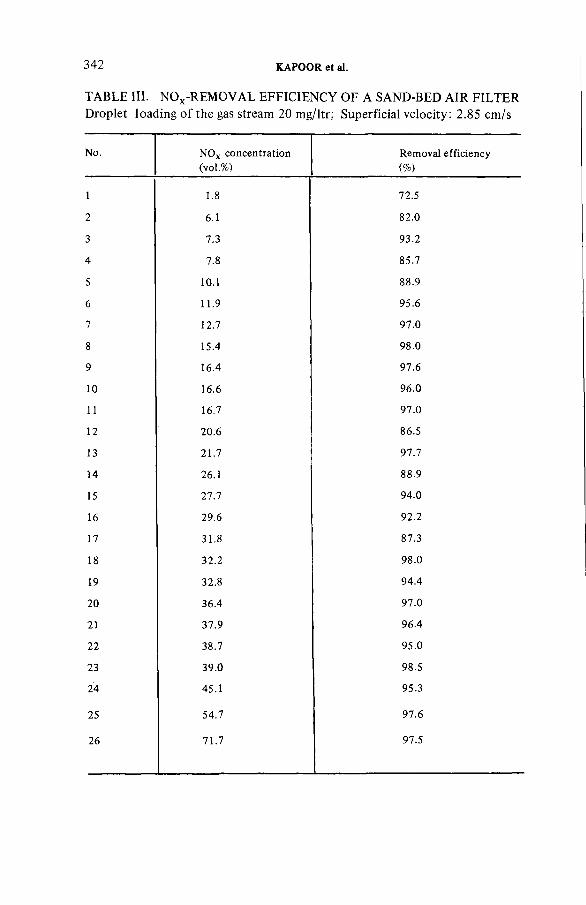
342 KAPOOR et al.
TABLE III. NOx-REMOVAL EFFICIENCY OF A SAND-BED AIR FILTERDroplet loading o f the gas stream 20 mg/ltr; Superficial velocity: 2.85 cm /s
No. N O x co n cen tra tion (vo l.% )
R em oval e ff ic ie n c y(%)
1 1.8 72.5
2 6.1 82 .0
3 7.3 93.2
4 7.8 85.7
5 10.1 88.9
6 11.9 95 .6
7 12.7 97 .0
8 15.4 98.0
9 16.4 97.6
10 16.6 96 .0
11 16.7 97 .0
12 20.6 86.5
13 21.7 97 .7
14 26.1 88.9
15 27.7 94 .0
16 29.6 92.2
17 31.8 87.3
18 32.2 98 .0
19 32.8 94 .4
2 0 36 .4 97 .0
21 37.9 96 .4
2 2 38.7 95.0
23 39.0 98.5
24 45.1 95.3
25 54.7 97.6
26 71.7 97.5

IAEA-SM-24S/39 343
FIG.4. Simulated dissolver off-gas set-up.
O P E R A TIO N A L PERIOD ( A rb itra ry u n its )
FIG. 5. Variation o f collection efficiency and pressure drop in a sand-bed air filter with time o f operation.
344 KAPOOR et al.
a removal efficiency of 80 and 95% for NOx . It is understood that the liquid- waste generation in a conventional fuel reprocessing plant using a sieve-plate type gas absorption column is of the order of 4000 ml/m3 for 95% removal of NOx [8].
5. SIMULATED DISSOLVER OFF-GAS PILOT-PLANT SET-UP
A pilot-plant set-up for the evaluation of an SBAF against simulated dissolver off-gases was also operated and the following observations were made. Figure 4 shows that this set-up consisted of a dissolver, a gas washer and an SBAF. To generate the simulated off-gas stream a known amount of copper was dissolved in nitric acid and the aerosols and the nitrogen oxides so generated were led to an alkali washer, using sodium hydroxide as the absorbing medium. The outlet gases from the gas washer were led to the SBAF column.
The pressure drop and collection efficiency of the SBAF were measured periodically. Results are shown in Fig.5. The bed configuration of the SBAF is also shown in this figure. The results indicate that the pressure drop as well as the collection efficiency increase continuously with time. However, a decline in the rate of increase of pressure drop is clearly observed after prolonged operation. The amount of condensate collected in this case was very low.
6. CONCLUSIONS
The following conclusions can be drawn from the results of the studies presented:
(a) A suitably designed SBAF can be used as an efficient equipment for the removal of nitrogen oxides in the presence of water droplets.
(b) An SBAF can also serve as an efficient de-entrainer and demister for the removal of airborne liquid droplets and mists.
(c) An SBAF also offers removal efficiency as high as 99.9% for submicrometre solid aerosols, as well as simultaneous removal of water droplets and NOx .
(d) Compared with the conventional dissolver off-gas cleaning systems, it was observed that the amount of liquid waste generated by the SBAF is negligible.
(e) The pressure drop across that part of the SBAF which acts as the de- entrainer and demister rises marginally and remains constant owing to its saturation with water droplets under dynamic equilibrium.
IAEA-SM-245/39 345
From these conclusions, it was realized that multiple-equipment systems used for fuel reprocessing dissolver off-gas cleaning can be replaced by a single SBAF. This proposition is significant from the aspect of a considerable reduction in the liquid waste generated from this system. It may also result in a reduction in operational problems, personnel radiation exposure, cost and space.
REFERENCES
[1 ] M O Y E R , R .A ., Sand-Bed F il te r a t Savannah R ive r L a b o ra to ry , U S A E C Techn ica lIn fo rm a tio n C enter, O ak R idge, T N , Rep. C O N F-740 807 (1 9 7 5 ).
[2 ] O R T H , D .A ., e t al., SRP S and -F ilte r; M ore Than a P ile o f Sand, U S A E C Techn ica lIn fo rm a tio n C enter, O ak R idge, T N , Rep. C O N F-760 822 (1 9 7 6 ).
[3 ] C H E E V E R , C .L ., e t a l., ZPPR R o o f Sand F ilt ra t io n o f U ra n iu m , P lu to n iu m and U ran ineA eroso ls , U S AE C Te chn ica l In fo rm a tio n C enter, O ak R idge, T N , Rep. C O N F -660 904 (1 9 6 7 ).
[4 ] B O H M , L ., e t al., The O ff-G as F il te r System o f S N R -300, U S A E C Te chn ica l In fo rm a tio n C enter, O ak R idge, T N , Rep. C O N F -760 822 (1 976 ).
[5 ] K A P O O R , J.C ., e t a l., A e ro so l F il t r a t io n C haracteristics o f Sand-Beds, B habha A to m ic Research C entre , B om b ay, Rep. B A R C -7 44 and Rep. B A R C -7 45 , Parts 1 and 2 (1 9 7 5 ).
[ 6 ] B U R N S , H .L ., N ebu lize r eva lua tion by the dew p o in t m e th o d , Resp. T herapy (S e p t./O c t. 1972).
[7 ] R A A B E , O .G ., O pe ra tio na l C haracteris tics o f Compressed A ir N e b u lize r Used in In h a la tio n Programs, Lovelace F o u n d a tio n fo r M ed ica l E duca tion and Research, A lb u q u e rq u e , N M , A n n u a l R e p o rt 1 9 7 1 -1 9 7 2 , LF -45 (1 9 7 2 ).
[ 8 ] C O U N C E , R .M ., e t a l., N itro g e n -O x id e A b s o rp tio n in to W ate r and D ilu te N it r ic A c id in an E ngineering Scale Sieve-Plate C o lum n w ith Plate Designed fo r H ig h Gas L iq u id In te rfa c ia l A rea , U S A E C T e chn ica l In fo rm a tio n C enter, O ak R idge, T N , Rep.C O N F -780 819 (1 9 7 9 ).
DISCUSSION
A.J. WILLIAMS: Have any experiments been conducted in an attempt to establish the possibility of backwashing material such as general radioactive aerosols or the uranium mentioned in your paper from the sand-bed filter?
S.A.K. JEELANI: Not yet. However, I believe that there are plans for carrying out such experiments in the future.

IAEA-SM-245/33
THE ESTIMATION OF TRITIUM, SULPHUR-35 AND CARBON-14 IN REACTOR COOLANT GAS AND GASEOUS EFFLUENTSA.R. DOYLE, K. HAMMOND Central Electricity Generating Board,Wylfa Power Station,Cemaes Bay,Gwynedd,United Kingdom
Abstract
T H E E S T IM A T IO N O F T R IT IU M , S U LP H U R -35 A N D C A R B O N -14 IN R E A C T O R C O O L A N T G A S A N D G A S EO U S E F F L U E N T S .
D eta ils o f eq u ipm e n t and techn iques th a t have been developed fo r the s im ultaneous es tim a tion o f 3sS, t r i t iu m and 14C in re ac to r coo la n t gas and gaseous e ff lu e n ts are presented. The eq u ipm e n t design is s im ple , ro b u s t and p o rtab le . The techniques have a m in im u m num ber o f c r it ic a l a n a ly tica l stages to a llo w accurate estim ates to be made by in d u s tr ia l s ta ff. Results o f exp e rim e n ta l w o rk are given to show th a t the com p le te separation o f 35S and 14C is achieved du rin g sam pling and th a t th e tech n ique fo r the es tim a tion o f 14C is specific fo r th a t nuclide . Measurements taken at fo u r M agnox re ac to r sites are presented. The p ro d u c tio n o f 14C in th is typ e o f carbon d io x id e coo led , g raph ite m odera ted re ac to r is discussed.
1. INTRODUCTION
The Central Electricity Generating Board operate, or have under construction, twelve nuclear power stations all graphite moderated and carbon dioxide cooled. Some of the more significant isotopes present in the coolant and emitted during normal discharges are Ar-41, S-35, tritium and C—14. This paper considers a reasonably simple system, using a single item of sampling equipment, which can be used to estimate tritium, S-35 and C-14 in gaseous discharges from the reactors and from associated plant.
The technique developed has a minimum number of critical analytical stages allowing accurate estimates to be made by industrial staff. The equipment is simple and robust and can be readily transported to different sampling locations. Measurements of the radioactive species have been made and results are given. Details are presented which indicate that the concentrations of C-14 observed are related to the irradiation times of the individual reactors, and the production processes of C-14 in carbon dioxide cooled graphite moderated
347
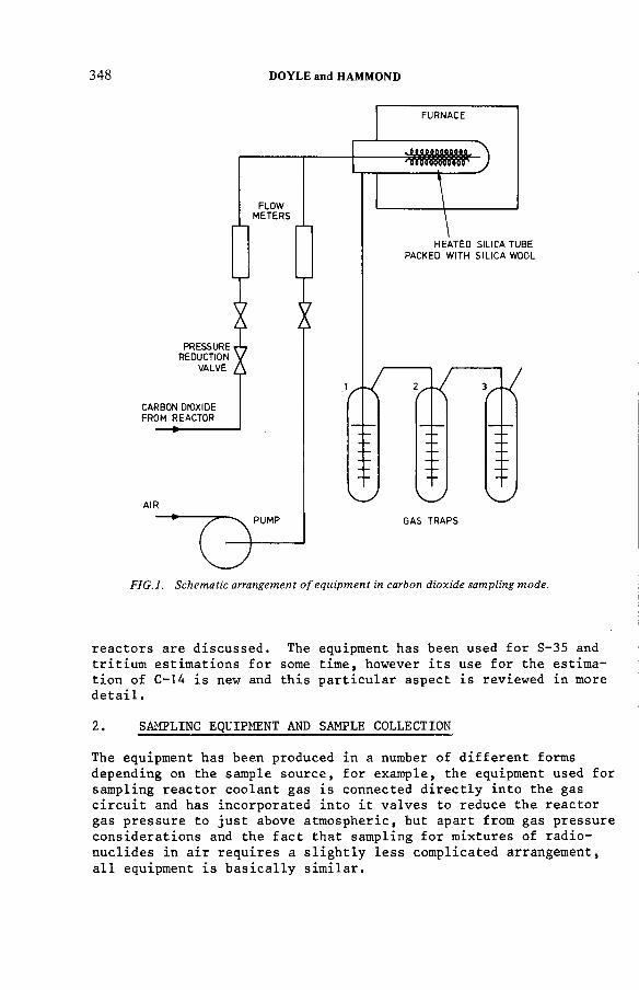
348 DOYLE and HAMMOND
reactors are discussed. The equipment has been used for S-35 and tritium estimations for some time, however its use for the estimation of C-14 is new and this particular aspect is reviewed in more detail.
2. SAMPLING EQUIPMENT AND SAMPLE COLLECTION
The equipment has been produced in a number of different forms depending on the sample source, for example, the equipment used for sampling reactor coolant gas is connected directly into the gas circuit and has incorporated into it valves to reduce the reactor gas pressure to just above atmospheric, but apart from gas pressure considerations and the fact that sampling for mixtures of radionuclides in air requires a slightly less complicated arrangement, all equipment is basically similar.

IAEA-SM-245/33 349
Sample gas and air are mixed and passed through a silica tube which is heated externally to 1000°C, the oxidised species are trapped using gas bubblers. The first stage traps НТО and 35sû2 in water, the second stage trap also containing water, is to prevent possible carry-over of 35gQ2 t0 the third stage, which absorbs reactor coolant and other oxidised carbon species as CO2 including ^ C Û 2 stoichiometrically in aqueous sodium hydroxide. It should be noted that if the equipment is being used to sample the mixture of radionuclides in air, such as in ventilation systems, when the CO2 concentrations are low, then apart from there being no need for a separate air supply for oxidation, the absorption of CO2 in the hydroxide will be non-stoichiometric and a modifying factor must be introduced in order to calculate the C-14 concentration. No modifying factors are required when calculating S-35 and tritium concentrations. Schematic arrangements of the equipment for

350 DOYLE and HAMMOND
«
<
Í Щ -V - " f e
i - 5 « '
i
ÉÉÈÊÊêSÊÊÊÊÉ
reactor gas sampling and for air sampling are given in Figs. 1 and The photograph in Fig. 3 shows the equipment being used to sample reactor coolant. The portable version, used for sampling from nonpressurised systems, is approximately half this size.
■3. ANALYTICAL DETAILS
The equipment as described samples for the three nuclides simultaneously. Bubbler 1 collects S-35 and tritium as 35g02 an^ НТО and bubbler 3 collects C-14 as '^C02* S-35 and C-14 are both purebeta emitters with similar energy spectra and cannot be separated

IAEA-SM-245/33 351
electronically by liquid scintillation counting. Separation must therefore be effected at the sampling stage and proof of this separation is presented in the sub-section dealing with C-14.
3.1. Sulphur-35 and Tritium
The analysis for S-35 using the total oxidation technique has been described in detail by Pick and Brookes (1) and (2) and the collection of oxidised species of tritium in water bubblers, as НТО, is well documented. It can be shown that if the gas sampling rates, sampling times, bubbler volumes etc, given below are adhered to then collection efficiencies of greater than 98% for S-35 and tritium in this first bubbler can be expected.
The furnace temperature is set to 1000°C, and 1 litre per min of reactor coolant gas plus 0.25 litre per min of air is passed through a silica tube and into a Gage bubbler containing 30 ml of water. The gas is sampled for 30 minutes.
A 1 ml aliquot from the bubbler is added to liquid scintillator solution and the mixture counted on liquid scintillation counting equipment for a fixed time. The activity of the sample is compared with that of standardised solutions of S-35 and tritium. The final result is calculated by reference to the total volume of gas sampled.
The S-35 can be estimated in the presence of tritium by virtue of the difference in beta energy spectra. This is achieved by setting the discriminator on the liquid scintillation counting equipment to a point just above the max. beta energy equivalent of tritium. Interference from S-35 when counting for tritium cannot be eliminated because of the continuous nature of beta spectra, however, in most reactors operated by the C.E.G.B. the ratio of tritium to S-35 is high and interference from S-35 can be accepted as it does not make a significant difference to the final result, this means that concentrations of tritium and S-35 can be obtained rapidly from a single sample aliquot.
In cases where the interference from S-35 is significant then separation of tritium and S-35 has to be effected before the counting stage. This separation can be achieved by distillation of the sample after first fixing the absorbed SO2 as H2SO4 by the addition of hydrogen peroxide. A simple and rapid method of distillation using disposable polystyrene petri dishes can be performed. The technique involves placing a covered petri dish plus solution onto a warm surface. Condensate forms on the lid of the dish and can be removed by pipette after inverting the lid. The method of analysis described has a sensitivity of approx. 100 Bq per m^ for both S-35 and tritium when sampling from air or CO2 with counting times of less than 15 minutes. A more sensitive technique (4) is available

352 DOYLE and HAMMOND
for the detection of S-35 down to concentrations of 0.13 Bq per m^. In this technique S-35 is collected as the SO4 ion, precipitated (after the addition of carrier) as BaSO^ and then resuspended in a gel scintillator before counting.
3.2. Carbon -14
The method for the estimation of C-14 is new and is described in some detail below. It is used primarily for the estimation of C-14 in reactor coolant gas but with simple modifications it can be used to estimate C-14 in air.
Reactor gas at 1 litre per minute, plus air at 0.25 litre per minute is sampled via a heated silica tube as described previously. Oxidation of gaseous carbon compounds (methane, carbon monoxide etc.) to carbon dioxide; sulphur compounds to sulphur dioxide; and hydrogen compounds to water vapour is achieved. Bubblers 1 and 2 each contain 30 ml of water. Bubbler 1 is used to trap 35g02 and НТО quantitatively and bubbler 2 is included as an added precaution against possible carry-over of ^^S02 and НТО to Bubbler 3.
Bubbler 3 contains 30 ml of molar sodium hydroxide. Sampling is carried out for sufficient time to ensure the stoichiometric absorption of carbon dioxide by the measured quantity of sodium hydroxide, thereby fixing the weight of reactor gas sampled. A sampling time of between 8 and 10 minutes is found to be optimum.
A 3 ml aliquot of the solution from Bubbler 3 is added to 17 ml of NE260 scintillator liquid (Nuclear Enterprises U.K.) contained in a 20 ml vial. Counting can be delayed for twenty four hours to allow for the decay of short lived contaminants such as Ar-41 which may be present as a dissolved gas. Background samples are prepared by passing clean carbon dioxide through a molar solution of sodium hydroxide and treating as above. Efficiencies are determined by spiking a prepared background solution with labelled sodium carbonate, Na2'^CO;3.
A standardised solution of labelled sodium carbonate can be obtained from the Radiochemical Centre, Amersham, U.K., product ref. no.CFY 44.
The counting equipment used is a two-channel liquid scintillation counter type LSC 1 (Nuclear Enterprises Ltd., U.K.) Instrument settings are such that there is no interference from tritium in the channel used for C-14 counting,i.e. the lower discriminator is set above the maximum energy of tritium beta emission.
The most obvious question to be raised concerning the method is whether the activity detected is actually due to C-14 and not to

IAEA-SM-245/33 353
TABLE 1. Results of Experimental Work
Samplingtime(min)
Weight of CC2 absorbed
(g)
Activity in sample aliquot
(counts/s)
Precision - 2 V
(counts/s)
0.5 0.31 0.47 0.22
1.0 0.64 0.80 0.23
1.5 0.72 0.99 0.23
2 0.81 1 .33 0.23
3 0.91 1.39 0.23
4 1.10/1 .16
1.60 0.25
5 1 .70 0.25
6 1 .29 1 .77 0.25
7 1 .28 1 .77 0.25
8 1 .33 1 .88 0.25
9 1 .27 1 .77 0.25
10 1.31 1 .66 0.25
15 1 .28 1 .78 0.25
25 1.27 1 .73 0.25
Notes
All samples were taken as described in the text. The weight gain, i.e. the weight of CO2 absorbed in 30ml of molar hydroxide, was arrived at by weighing the complete bubbler, plus solution, before and after sampling. The counting sample represents one tenth of the weight of CO2 absorbed. For routine determinations the weight of CO2 absorbed would be assumed to be constant after 8 minutes sampling, at 1.32 g, this being the weight for the stoichiometric formation of bicarbonate in 30ml of molar sodium hydroxide.
The two graphs in Fig.4, showing weight gain v time and activity increase v time, probably illustrate more clearly than the table that the activity increase is proportional to the weight of CO2 absorbed and that it is independent of the total volume of gas passed, thus proving that the activity counted is C-14 as *^C02.
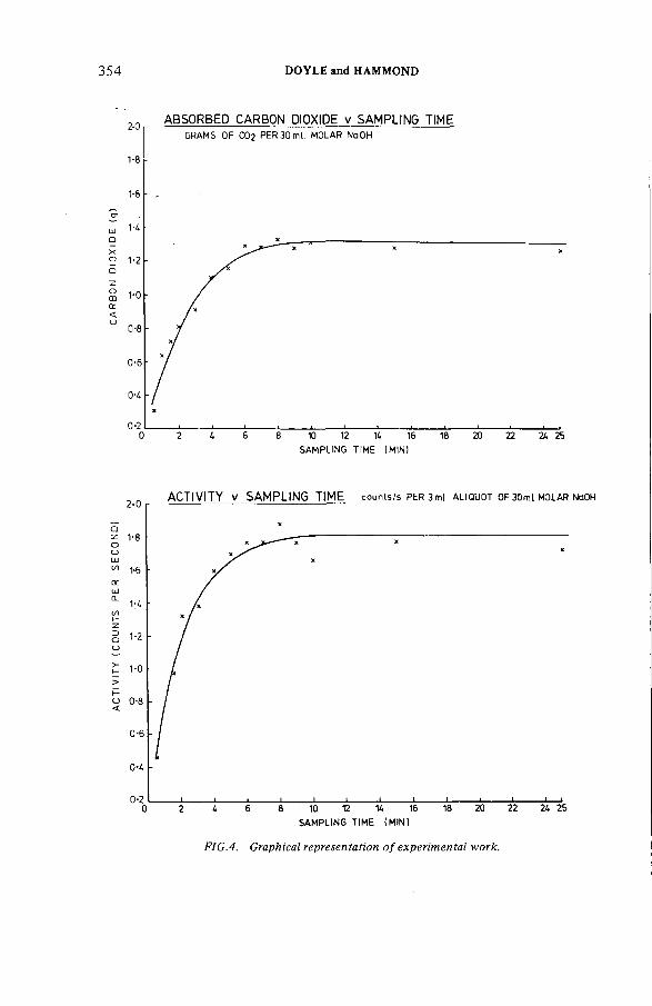
AC
TIV
ITY
(C
OU
NTS
PER
SE
CO
ND
I C
ARBO
N
DIO
XID
E
(g)
354 DOYLE and HAMMOND
SAMPLING TIME (MINI
FIG.4. Graphical representation of experimental work.

IAEA-SM-24S/33 355
other radionuclides. The logic applied is as follows: the principal interfering isotopes, S-35 and tritium, are scrubbed out by the first two bubblers. Previous work (2) on S-35 determinations has shown that this isotope is removed quantitatively before the third stage bubbler. Carry-over of tritium as НТО to the third stage is very low for the sampling times recommended and, in any case, activity due to tritium is eliminated electronically at the counting stage.
After oxidation all carbon species in the gas phase will appear as carbon dioxide which will be uniformly labelled with the C-14.It is reasonable to expect that once the reaction between hydroxide and carbon dioxide is complete irrespective of how much more carbon dioxide is passed through the solution, the measured activity would not increase if there was no interference from S-35. It is also reasonable to expect that the observed count rate due to C-14 would be proportional to the weight of carbon dioxide absorbed at any particular time. To this end an experiment was devised to confirm the above assumptions. In the experiment reactor gas was sampled via the equipment shown in Fig. 1 at 1 litre per min for various times from 0.5 min to 25 min. After each period the hydroxide solution was weighed and the increase in weight noted, and a sample was taken for scintillation counting. Results are given in Table 1 and expressed graphically in Fig. 4.
It can be seen from these results that the assumptions are correct and it can be concluded that the method is specific for C-14.
3.3. Modifications to Methods to Allow for Sampling in Air
The general arrangement of the equipment for sampling in air is given in Fig. 2 and, apart from there being no need to add air to effect oxidation, the sampling and analytical details for the estimation of S-35 and tritium are as described earlier in this section.
In the case of C-14 a modifying factor must be applied in the final calculation which takes account of the non-stoichiometric absorption of CO2 when sampling low concentrations of this gas in air. All C-14 will be present as ^ C Û 2 after oxidation.
This modifying factor is obtained by preparing curves of the absorption rate of CO2 in molar hydroxide from CO2 in air mixtures at the prescribed sampling rate. If the CO2 in air concentration is determined at the time of sampling, for example by a portable analyser, then this figure can be matched to a curve to find the appropriate modifying factor. A curve for the absorption of CO2 v time from a concentration 0.33%,i.e. the
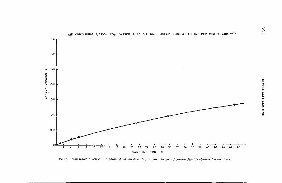
CAR
BON
O
IOX
IDE
(g
)
A IR C O N T A IN IN G 0 . 0 3 3 V . C 0 2 P A SSE D TH R O U G H 3 0 m l M O L A R NaOH AT 1 L ITR E PER M IN UTE A N D 20°C.
FIG. 5. Non stoichiometric absorption o f carbon dioxide from air. Weight o f carbon dioxide absorbed versus time.
356 DO
YLE and
HAMMOND

IAEA-SM-24S/33 357
normal atmospheric concentration of CO2 , is given in Fig. 5. This curve will be appropriate for most sampling situations on installations not using large quantities of carbon dioxide.
4. PREDICTED AND MEASURED CONCENTRATIONS OF C-14 IN REACTOR COOLANT
The predicted modes of production of C-14 in graphite moderated, carbon dioxide cooled reactors are neutron activation of the
N-14 and 0- 17 according to the reactions:
,3c ) u c cr =-4
9 x 10 barns
14n (n. P) 14c CT = 1 .8 barns
170 (n,<*. ) 14c or = 0.24 barns
The reaction cross-sections quoted are for thermal neutrons of energy 0.0253 eV (5).
Neutron activation of the C-13 in the graphite moderator produces C-14 and oxidation of the graphite according to the reaction:
С + C02 Ç=£ 2 CO (3)
releases C-14 into the coolant gas. There is an additional small contribution from neutron activation of C-13 in the carbon dioxide coolant. The N-14 exists as an impurity in both the reactor coolant and in the graphite moderator.
The 0--17 occurs in the carbon dioxide coolant and this is the only significant source of the nuclide. Predictions of the concentrations and sources of C-14 in the coolant gas of the Wylfa reactors are given below. Assumptions made in the calculations are:
(i) A daily release and make-up rate of 12 tonnes of coolantper reactor,i.e. 5% of the total coolant content.
(ii) A nitrogen impurity in the coolant of 50 volumes per million.
(iii) Equal contributions of C-14 from the activation-of C-13in the graphite moderator and from activation of the N-14 impurity in the moderator. (4)
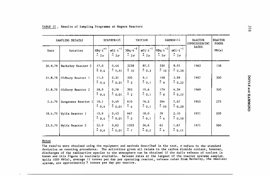
TABLE II . Results of Sampling Programme at Magnox Reactors
SAMPLING DETAILS SULPHUR-35 TRITIUM CARBON-14 REACTOR REACTORCOMMISSIONING POWER
_ j _ j _ 1 _ j DATES
Date Location MBq ■ t_ j
mCi • t MBq ; t mC i •, t MBq* t mCi?t MW(e)
- la 1 + Ю 4 - la - la - la - го-
30.8.78 Berkeley Reactor 2 17.0 0.46 3238 87.5 330 s.91 1962 138
- 0.4 - 0.01 - 10 - 0.3 - 10 - 0.28
31.8.78 Oldbury Reactor 1 11.5 0.31 335 9.1 148 3.99 1967 300
- 0.4 - 0.01 - 1 - 0.1 - 8 - 0.22
31.8.78 Oldbury Reactor 2 28.9 0.78 393 10.6 170 4.59 1968 300
- 0.4 - 0.01 - 2 - 0.1 - 8 - 0.22
2.4.79 Dungeness Reactor 1 18.1 0.49 610 16.5 284 7.67 1965 275
- 0.4 - 0.01 - 4 - 0.1 - 10 - 0.28
18.4.79 Wylfa Reactor 1 15.9 0.43 667 18.0 78 2.10 1971 500
- 0.4 - 0.01 i 5 - 0.1 - 4 - 0.10
23.5.79 Wylfa Reactor 2 22.9 0.62 1353 36.6 62 1 .67 1971 500
- 0.4 - 0.01 Í 7 - 0.2 - 4 - 0.11
Notes
The results were obtained using the equipment and methods described in the text, o'refers to the standard deviation on counting procedures. The activities given all relate to the carbon dioxide coolant, however, discharges of ttje radioactive species to the atmosphere can be obtained if the daily release of coolant is known and this figure is routinely available. Release rates at the largest of the reactor systems sampled. Wylfa 1000 M W ( e ) , average 12 tonnes per day per operating reactor, release rates from Berkeley, the smallest system, are approximately 5 tonnes per day per reactor.
358 DOYLE and
HAMMOND

IAEA-SM-24S/33 359
Predicted concentrations of C-14 in Wylfa coolant, MBq per tonne :
Source Reactor 1 Reactor 2
Graphite moderator 24.1 17.0
(С—13 and N-14)
Coolant carbon 0.7 0.7
Coolant oxygen 9.6 9.6
Nitrogen impurity 10.0 10.0in coolant
Total 44.4 37.3
The largest single contribution of C-14 is from the moderator and this will increase with time while the contribution from the coolant precursors will remain constant. The oxidation of the moderator graphite by the previously mentioned equilibrium reaction
С + C02 2 CO
could suggest that all the C-14 from graphite oxidation is presentin the coolant as '^CO and that it may be possible therefore to accurately estimate the contribution of C-14 from graphite by isolating the monoxide or indeed to equate the monoxide concentration with the C-14 concentration. Work by Wickam et al. (3) hasshown however that there is a rapid exchange of C-14 and C-12 inmixtures of carbon dioxide and monoxide at reactor operating conditions and that C-14 would be distributed proportionally between the monoxide and dioxide before separation of these gases could be effected.
Table II presents the results of a sampling programme conducted at four U.K. Magnox reactor sites. It can be seen that for the Wylfa reactors the predicted C-14 activities are lower than the measured activities. However, the differences (44.4 MBq per tonne predicted versus 77.7 MBq per tonne measured on Reactor 1 and 37.3 MBq per tonne predicted versus 61.8 MBq per tonne measured on Reactor 2) can be explained by nitrogen impurity levels different from values assumed in the calculations. It can also be seen from Table II that the concentration of C-14 in reactor coolant increases with the age of the reactors. This can be explained by the increasing C-14 inventory of the graphite moderator with reactor operating time. It would be, again, difficult to support the experimental results with theoretical

360 DOYLE and HAMMOND
calculations without an accurate knowledge of the nitrogen impurity levels in the graphite. This nitrogen impurity figure is not readily available, calculations however show that an impurity level of 7 ppm in graphite would give a concentration of C-14 in coolant equivalent to that from C-13, and, as the graphite moderator is probably the largest contributor of C-14 in coolant gas,it can be seen that even slight variations in nitrogen impurity would make accurate predictions impossible.
REFERENCES
(1) M.E. PICK RD/B/N3375 Berkeley Nuclear Laboratories, C.E.G.B.. U.K. 1976.
The Chemical Form of S-35 in the CO- Coolant of Magnox and A.G.R. Stations:its Significance and Determination.
(2) M.E. PICK, I.R. BROOKES RD/B/N3046 Berkeley NuclearLaboratories, C.E.G.B.,U.K. 1974.
Development of a Total Oxidation Method for S-35 Estimation at Hinkley Point "B" Power Station.
(3) A.J. WICKAM ,J.B. BEST, C.J.WOOD, Radiat. Phys. Chem.10 (107-117) 1977.
Recent Advances in the Theories of Carbon Dioxide Radiolysis and Radiolytic Graphite Corrosion.
(4) A.R. DOYLE W3650, Wylfa Power Station, C.E.G.B.,U.K. 1974.
A sensitive Technique for the Analysis of S-35 in Gaseous Effluents.
(5) KELLY, JONES, BRYANT AND MORELY. Commission of the EuropeanCommunities Luxembourg 1975 DOC, V/1676/75.
The predicted radiation exposure of the population of the European Community resulting from discharges of Krypton-85, Tritium, Carbon-14 and Iodine-129 from the nuclear power industry to the year 2000.
DISCUSSION
K. FISCHER: What is the lower limit of detection of your equipment regarding the 14C concentration in the effluents?
A.R. DOYLE: The lower limit of detection is approximately 0.1 juCi/m3 of C 02. For effluents not comprised totally of CO2 the lower limit of detection will

IAEA-SM-245/33 361
depend on the C 02 concentration. If, for example, the C 0 2 concentration is 1% then the lower limit of detection will be 0.001 ¿iCi/m3. Sampling times will have to be increased, of course, to collect the required amount of C 0 2.
J.A. WILSON: Can the measuring technique for 14C determination proposed by the CEGB be used to assess the extent and/or rate of graphite corrosion in Magnox and AGR reactors?
A.R. DOYLE: A different section within the CEGB is dealing with the problem of graphite corrosion. However, the 14C concentrations obtained from various reactor sites using this equipment will be of use to the section in question and results obtained to date have been passed on.
G.L. TINGEY: You said that an impurity level of 7 ppm N in the moderator graphite would double the generation rate of 14C. How does this compare with the effect of N2 impurity in the C 02 coolant?
A.R. DOYLE: Equal contributions of 14C from the activation of 13C in graphite and from 14N impurity are predicted. For the first reactor at Wylfa, 14C from nitrogen impurity in the graphite amounts to 12 MBq/t in coolant, and from nitrogen impurity in coolant it is 10 MBq/t. The contribution from the graphite will increase with time.


IAEA-SM-245/19
AN IMPROVED KANNE TRITIUM MONITORING SYSTEM
D.F. ANDERSON, R.D. HIEBERTLos Alamos Scientific Laboratory,Los Alamos, New Mexico,United States of America
Abstract
A N IM P R O V E D K A N N E T R IT IU M M O N IT O R IN G S YS TEM .A K anne cham ber has been redesigned to reduce its se n s it iv ity to such con tam ina n ts as
t r i t iu m w a te r vapour and tr it ia te d o il. The h igh voltage e lectrode has been replaced b y a w ire cy lin d e r and the c o lle c tio n e lectrode has been reduced in d iam eter. The se n s it iv ity to c o n ta m in a tio n o f the cham ber has been reduced b y about a fa c to r o f 40 . The design a llow s fo r de co n ta m in a tio n o f the cham ber in place. The im proved e lec tron ics used is also discussed.
Introduction
The Kanne chamber has been used for over two decades to monitor radioactive gases. The advantage of this chamber is the high sensitivity due to its large active volume. A conventional 51.5 liter Kanne chamber, as described by Hoy,EU is shown in Fig. 1. It consists of three concentric cylinders, with the inner and outer cylinders at ground potential while the intermediate cylinder is operated at about 200 V. The region between the outer and intermediate cylinders serves as an ion trap. The inner region (shown dotted) is the ion chamber, with the inner cylinder acting as the collector electrode.
Under normal operating conditions, using filtered air, contamination is not a major problem. However, when exposed to high concentrations of some radioactive gases such as НТО, or contamination with tritiated oil, there tends to be a buildup of activity which greatly reduces the sensitivity of the chamber at low tritium concentrations. This residual activity can often be removed by several hours of air purging. Heat has been successfully used for decontamination and so has disassembly and cleaning. Occasionally, chambers must be permanently removed from service due to contamination.
The standard techniques for measuring the signal from the Kanne chamber have changed little in the last 20 years. The current is typically measured with an electrometer with a
363
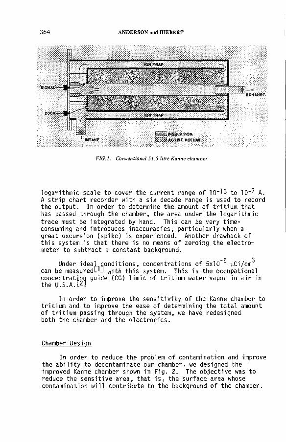
364 ANDERSON and HIEBERT
F IG .l. Conventional 51.5 litre Kanne chamber.
logarithmic scale to cover the current range of 1 C H 3 to 10"? A. A strip chart recorder with a six decade range is used to record the output. In order to determine the amount of tritium that has passed through the chamber, the area under the logarithmic
trace must be integrated by hand. This can be very time- consuming and introduces inaccuracies, particularly when a great excursion (spike) is experienced. Another drawback of this system is that there is no means of zeroing the electrometer to subtract a constant background.
“6 3Under ideal conditions, concentrations of 5x10" yCi/cm
can be measured^] w ith this system. This is the occupational concentration guide (CG) limit of tritium water vapor in air in the U.S.A.[2]
In order to improve the sensitivity of the Kanne chamber to tritium and to improve the ease of determining the total amount of tritium passing through the system, we have redesigned both the chamber and the electronics.
Chamber Design
In order to reduce the problem of contamination and improve the ability to decontaminate our chamber, we designed the improved Kanne chamber shown in Fig. 2. The objective was to reduce the sensitive area, that is, the surface area whose contamination will contribute to the background of the chamber.
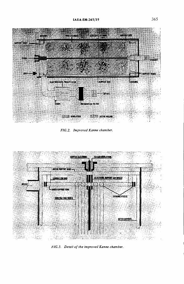
IAEA-SM-245/19 365
FIG.3. Detail of the improved Kanne chamber.
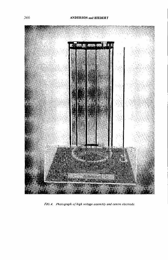
3 66 ANDERSON and HIEBERT
FIG.4. Photograph o f high voltage assembly and centre electrode.

IAEA-SM-245/19 367
The high voltage cylinder of the conventional Kanne was replaced by a wire cylinder 78.7 cm long and 30.5 cm in diameter, made of forty-five 0.2 mm diameter nichrome wires running parallel to the center electrode. The wires are spaced every 10.7 mm. The conventional 76 mm diameter central collector electrode was replaced with a 6.4 mm diameter aluminum rod with a sensitive length of 77.2 cm. Figure 3 shows a detail drawing of the intake end of this chamber. The wires are stretched between ninety ceramic pieces on two inner support rings. These rings are connected to outer support rings by six short rods. The outer support rings are themselves supported by eight connecting rods fastened to the exhaust end of the chamber. All rings and rods are held at ground potential. A photograph of the high voltage assembly and center electrode is shown in Fig. 4.
The maximum energy of a tritium beta is 18 keV with a mean energy of 5.6 keV. Thus, the betas have a maximum range in air of about 7 mm under standard conditions, with the mean range a little over 1 mm. At Los Alamos, New Mexico, U.S.A., where the pressure is only about 70% of an atmosphere, the maximum range is about 10 mm. For this reason, all surfaces outside of the high voltage cylinder (i.e., connecting rods and chamber wall) are greater than 1 cm from the wires. Since the support rings are grounded, the majority, if not all, of the ionization due to their contamination will terminate in the ring. Thus, this contamination will not contribute to the signal. The supported end of the collector electrode is shielded to prevent detection of contamination from the support rings or the chamber end.The sensitive area of the improved Kanne is less than 266 cm2 while the sensitive area of a conventional Kanne chamber is about l.lxl0^ cm^. This is a reduction in sensitive area by a factor of 40.
This new design greatly improves the ability of the chamber to be decontaminated, if need be. The high voltage wires can be decontaminated in place by passing a heating current through them. The center electrode is mounted by four external screws and can be easily removed. This electrode can be either replaced or decontaminated with a mild caustic solution. Decontamination can be accomplished in a few minutes without removal of the chamber from the system.
Since this design does not include an internal deionizer, an external deionizer is provided. It consists of 0.8 mm thick stainless steel plates (20) spaced at 3.2 mm centers. Alternate plates are connected to the same high voltage supply as the Kanne chamber, with the remaining plates at ground potential.An external HEPA filter is used to remove dust and oil.
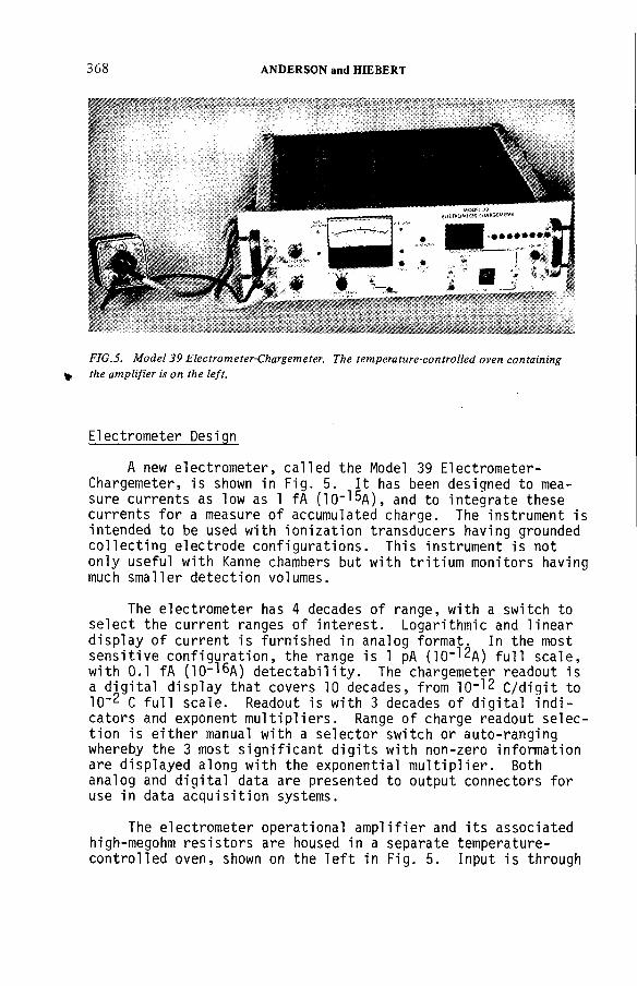
368 ANDERSON and HIEBERT
FIG.5. Model 39 Electrometer-Chargemeter. The temperature-controlled oven containing the amplifier is on the left.
Electrometer Design
A new electrometer, called the Model 39 Electrometer- Chargemeter, is shown in Fig. 5. It has been designed to measure currents as low as 1 fA (ICH^A), and to integrate these currents for a measure of accumulated charge. The instrument is intended to be used with ionization transducers having grounded collecting electrode configurations. This instrument is not only useful with Kanne chambers but with tritium monitors having much smaller detection volumes.
The electrometer has 4 decades of range, with a switch to select the current ranges of interest. Logarithmic and linear display of current is furnished in analog format. In the most sensitive configuration, the range is 1 pA (lcH^A) full scale, with 0.1 fA (10-16д) detectability. The chargemeter readout is a digital display that covers 10 decades, from 10 -^2 с/digit to 10"2 С full scale. Readout is with 3 decades of digital indicators and exponent multipliers. Range of charge readout selection is either manual with a selector switch or auto-ranging whereby the 3 most significant digits with non-zero information are displayed along with the exponential multiplier. Both analog and digital data are presented to output connectors for use in data acquisition systems.
The electrometer operational amplifier and its associated high-megohm resistors are housed in a separate temperature- controlled oven, shown on the left in Fig. 5. Input is through
IAEA-SM-245/19 369
a coaxial connector. This configuration allows the shortest distance from the collector of the tritium chamber to the amplifier. There is insignificant variation in gain or instrument zero with changes in ambient temperature. The power and control lines for this assembly are carried in a multiconductor cable, with the output signal on a separate coaxial connector. The circuit design allows a steady-state background of an instrument to be suppressed. Thus, the constant background due to contamination will not contribute to the integrated charge measured by the instrument.
Performance
To calibrate this tritium monitoring system, the improved Kanne was placed in series with a conventional 51.5 liter Kanne chamber in an operating environment. The air passes through the improved chamber before entering the latter. The calibration for the improved chamber was found to be 1.8xl07 yCi/cm3 per amp compared to 2x1 O'7 yCi/cm3 per amp for the conventional chamber. This implies an effective volume of 56.6 liters for the improved chamber.
The air system in which the two chambers operated was very contaminating. The background of the conventional chamber varied from about 1 .4х1 0_^д to 2 .8x 1 0“ a after use for about one month on the system. This corresponds to a background of 2 . 8 x 1 0 - 5 to 5 . 6 x 1 0 " 5 yCi/cm3 . When the improved Kanne was introduced, the background in the conventional chamber averaged about 2х1СН2д but with less variation. This is probably due to the better filtering of the first chamber. Upon installation of the new tritium monitor, the electrometer was zeroed. After 16 weeks of constant use, the zero still did not require adjustment. With this system, steady-state concentrations of about 1x10"? yCi/cm3 (about 5х10-15д) should be measurable, even under the contaminating environment of the test situation. It was found that when measuring concentrations on the order of 10-3 yCi/cm3 , the new chamber read slightly lower (^2%) than the conventional Kanne. This is undoubtedly due to the smaller collecting electrode which allows more recombination at high concentrations.
Conclusion
The improved Kanne tritium monitoring system described above should greatly improve the monitoring capability of low concentrations of tritium, particularly in contaminating environments. With the improved electronics, the volume of

370 ANDERSON and HIEBERT
the monitor can be greatly reduced while maintaining high sensitivity. Concentrations of 10-6 yCi/cm3 may be measured with a 1-1 iter chamber in a short period of time. The reduction of sensitive surface area is also adaptable to smaller chambers. These smaller instruments will have much faster response time and much less bulk, making them more convenient than Kanne systems. Smaller instruments can also be designed which, besides being less susceptible to contamination, will also be linear over a very large dynamic range. The improved electronics and the idea of reduction of sensitive area opens the avenue to much improved tritium monitoring.
References
[1] Hoy, J. E., Health Physics 6 (1961) 203
[2] U.S.D.O.E. Manual Chapter #0524, Standards for Radiation Protection, April, 1977
DISCUSSION
R.V. OSBORNE: I would like to compliment you on the instrument you have described, which appears to offer an elegant solution to several of the problems that plague tritium monitors. One question I have concerns microphonics. Do you find that vibrations in the many wires and the framework present any problem?
D.F. ANDERSON: We worried about this at first but found that it was not a problem.
F. CEJNAR: Do you have any data on the sensitivity of the Kanne system for tritium in the presence of radioactive noble gases such as 8sKr?
D.F. ANDERSON: I’m afraid not. We worked only with tritium.
IAEA-SM-245/24
BEHAVIOUR OF SELECTED CONTAMINANTS IN SPRAY CALCINER/IN-CAN MELTER WASTE VITRIFICATION OFF-GAS*
M.S. HANSON, R.W. GOLES, D.C. HAMILTON Battelle Pacific Northwest Laboratories,Richland, Washington,United States of America
Abstract
B E H A V IO U R O F S E LE C T E D C O N T A M IN A N T S IN S P R A Y C A L C IN E R /IN -C A N M E L T E R W AS TE V IT R IF IC A T IO N O F F-G A S .
P rod uc t loss fro m spray ca lc ine r/in -can m e lte r v it r i f ic a t io n o f h igh-leve l wastes was evaluated w ith respect to vo la t ile , gaseous and p a rticu la te m a teria ls . Investiga tions o f the o f f - gases in a no n-ra d ioa c tive system are discussed, in c lu d in g gaseous con s tituen ts , p a rticu la te size d is tr ib u tio n s and load ings. M o n ito r in g o f gases leaving the o ff-gas system d u rin g spray ca lc in a tio n /in -ca n m e ltin g o f rad ioac tive waste gave m a te ria l con cen tra tion s and m a te ria l fo rm s in the gases. The m o st s ig n ifica n t con c lu s ion d raw n fro m these stud ies was th a t p a rticu la te loss accounts fo r a s ig n ifica n t p o r t io n o f the fiss ion p ro d u c ts in the o ff-gas system .
1.0 INTRODUCTION
As experience throughout the world has been accrued with high-level nuclear waste immobilization systems, it has become obvious that a major portion of the necessary processing is and will be related to the cleaning of the off gases from these systems. A large amount of operational experience with waste immobilization, particularly vitrification, has been gained at Battelle's Pacific Northwest Laboratory (PNL).
Although the decision in the United States on the type of waste form and process to be required has not been finalized, a primary contender in the field of waste immobilization is the spray calcination/in-can melting process. This process, developed over the past years at PNL, has been the subject of intense study. An area closely related to the process is that of off- gas control.
Off-gas cleanup requirements will specify the level of treatment necessary as well as the hardware to be used in immobilization facilities. These cleanup requirements primarily
* Prepared fo r the U n ite d States D e p a rtm e n t o f E nergy un d e r co n tra c t E Y -76-C -06-1830.
371
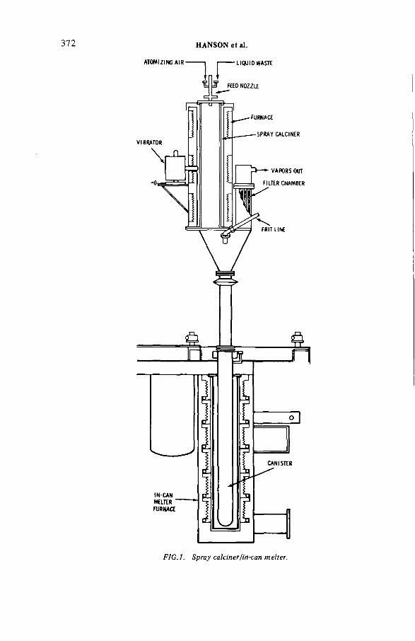
372 HANSON et al.
FIG.l. Spray calciner/in-can melter.

TABLE I . Pilot-Scale Spray Calciner Design Features
IAEA-SM-24S/24 373
Spray Calciner Components Design Specifications
Calciner Chamber IDHeightTotal heat-transfer areaMateri alWall thickness
53 cm 198 cm 3.3 m2310 stainless steel 0.95 cm
Furnace
F i 1ters
Vibrators
Type
Control
PowerHeating elements Maximum temperature
Atomizing Nozzles Type
Atomizing gas Air cap material
Liquid orifice dia Air cap orifice dia
Total number Di a LengthTotal surface area Mean pore size Materi al
Type
Location
Electrical resistance, 2 zones,3 phase, 240 voltsSilicon controlledrectifier80 kW (40 kW/zone)Ni chrome1100°C
Pneumatic, internalmixAir303 stainless steel with or without 96% alumina insert 0.64 cm 0.64 cm
155 cm 0.6 m 2.39 m2 65 ym315 stainless steel, internally reinforced
Pneumatic, drylubricantSide
depend on two specifications: the source terms generated at theimmobilization equipment, and the allowable release rates. The work described in this paper delineates the source terms that can be expected in the use of a spray calcination/in-can melting vitrification system.
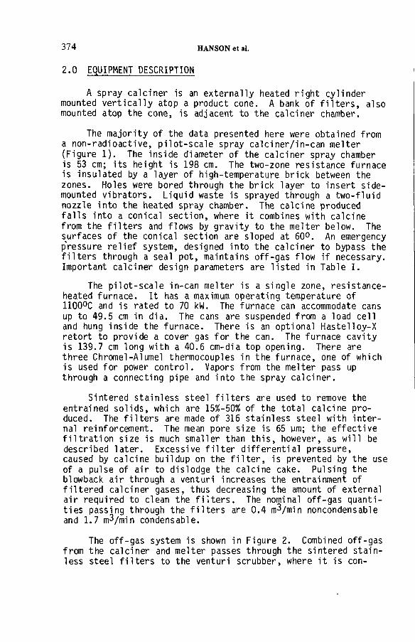
374 HANSON et al.
A spray calciner is an externally heated right cylinder mounted vertically atop a product cone. A bank of filters, also mounted atop the cone, is adjacent to the calciner chamber.
The majority of the data presented here were obtained from a non-radioactive, pilot-scale spray calciner/in-can melter (Figure 1). The inside diameter of the calciner spray chamber is 53 cm; its height is 198 cm. The two-zone resistance furnace is insulated by a layer of high-temperature brick between the zones. Holes were bored through the brick layer to insert side- mounted vibrators. Liquid waste is sprayed through a two-fluid nozzle into the heated spray chamber. The calcine produced falls into a conical section, where it combines with calcine from the filters and flows by gravity to the melter below. The surfaces of the conical section are sloped at 60°. An emergency p'ressure relief system, designed into the calciner to bypass the filters through a seal pot, maintains off-gas flow if necessary. Important calciner design parameters are listed in Table I.
The pilot-scale in-can melter is a single zone, resistance- heated furnace. It has a maximum operating temperature of1100°C and is rated to 70 kW. The furnace can accommodate cansup to 49.5 cm in dia. The cans are suspended from a load cell and hung inside the furnace. There is an optional Hastelloy-Xretort to provide a cover gas for the can. The furnace cavityis 139.7 cm long with a 40.6 cm-dia top opening. There are three Chromel-Alumel thermocouples in the furnace, one of which is used for power control. Vapors from the melter pass up through a connecting pipe and into the spray calciner.
Sintered stainless steel filters are used to remove the entrained solids, which are 15%-50% of the total calcine produced. The filters are made of 316 stainless steel with internal reinforcement. The mean pore size is 65 ym; the effective filtration size is much smaller than this, however, as will be described later. Excessive filter differential pressure, caused by calcine buildup on the filter, is prevented by the use of a pulse of air to dislodge the calcine cake. Pulsing the blowback air through a venturi increases the entrainment of filtered calciner gases, thus decreasing the amount of external air required to clean the filters. The nominal off-gas quantities passing through the filters are 0.4 m 3/min noncondensable and 1.7 m^/min condensable.
The off-gas system is shown in Figure 2. Combined off-gas from the calciner and melter passes through the sintered stainless steel filters to the venturi scrubber, where it is con-
2.0 EQUIPMENT DESCRIPTION
IAEA-SM-245/24 375
M A G N E T ICF L O W M E T E R A T O M IZ IN G
F E E DS T R A IN E R
V E N T U R IC O N D E N S E R
S T A C K
FILTERB L O W B A C K
AIR
r a nчхни S IN T E R E D '
S T A IN L E S S S T E E L FILTE R S
C A L C IN E T O M E LTE R
F E E DT A N K
Г
S C R U B B E R
1
V E N T U R IT A N K
C O N D E N S A T ET A N K
C A U S T ICT A N K
FIG.2. Flow diagram for non-radioactive process off-gas system.
tacted with weak (0.1M) nitric acid. The gas then passes to a tube-and-shel1, single-pass, down-draft condenser. Next is a caustic scrubber, which is a tower packed with stainless steel raschig rings 2.5 cm in dia. This scrubber is topped with a wire-mesh mist eliminator. Finally the gas passes through a heater and a HEPA filter before going to a blower and the stack.
3.0 WASTE COMPOSITIONS AND OPERATING CONDITIONS
A variety of high-level waste compositions have been calcined. Some of the compositions are shown in Table II.
Calcine particle size distributions are shown as histograms in Figure 3. These histograms were obtained by U.S. Standard sieve analysis, Fisher subsieve analysis, Zeiss particle size analysis, and Quantimet 720 projection size distributions.Table III lists some typical physical characteristics of the calcine product. Particle densities were measured by the helium displacement technique.
The off-gas from the calciner consists primarily of condensable components. Air is used to atomize the feed and blow back the filters.

376 HANSON et al.
TABLE II. Compositions of Six Representative High-Level Radioactive Wastes as Liquids
Concentration, Molarity at 378 ltr/t UInerts PW-4b PW-7 PW-7 a PW-7b PW-7c PW-8a
HN03 1.0 2.0 2.0 2.0 7.0 2.0
Na — 0.01 0.586 0.586 — 1.20
Fe 0.05 0.10 0.10 0.586 1.32 0.902
Cr 0.012 0.012 0.012 0.012 0.040 0.040
Ni 0.005 0.005 0.005 0.005 0.020 0.020
P°4 0.025 0.10 0.236 0.236 0.050 0.050
Gd — 0.151 0.151 0.151 ___ ___
FissionProducts
Rb 0.010
Sr 0.027
Y 0.014
Zr 0.106
Mo 0.095
Tc 0.022
Ru 0.059
Rh 0.010
Pd 0.032
Ag 0.002 Concentration of fission products
Cd 0.002 is the same for all six wastes.
Te 0.012
Cs 0.054
Ba 0.027
La 0.024
Ce 0.051
Pr 0.023
Nd 0.071
Pm 0.0019
Sm 0.014
Eu 0.003
Gd 0.002
Actinides
u 0.110 0.110 0.110 0.110 0.052 0.110
Np 0.0085 0.0085 0.0085 0.0085 0.0085 0.0085
Pu 0.0001 0.001 0.001 0.001 0.0005 0.0017
Am 0.0018 0.0018 0.0018 0.0018 0.0018 0.0018
Cm 0.0004 0.0004 0.0004 0.0004 0.0004 0.0004

IAEA-SM-245/24 377
1 10 100
PARTICLE DIAMETER (/an)
FIG.3. Typical spray calcine size distribution.
TABLE III. Physical Properties of RepresentativeSpray Calcined High-Level Wastes
Waste Calcine TypesCharacteristic PW-4b PW-7a
Density, g/cm
Aerated bulk 0.85 0.69-0.92
Working bulk 0.97 0.87-1.04
Packed bulk 1.24 1.15-1.33
Particle 4.4 5.1
Compressibility 32% 40X-31%
Angle of repose 42° -P*
CO О 1 -pb
ГОо
Surface area, m2/g 20 14
Nitrate content, wt% <1 2
Moisture content, wt% <1 <1-4
Equilibrium aqueous slurry pH 4.5 —

TABLE IV. Ruthenium and Cesium Losses
4. Feed %( a )Temperature % Lost to Process Off-Gas
Run Number Feed H Ru Cs (°C) Ru Cs Other
DSS-29 PW-8a 2.6M 11 100 750-800 0.029 0.045 _
D S S - 3 3 ^ PW-8a 2.2M 20 100 575 0.0075 0.0028 --
DSS-34 PW-7 “ — 10 100 775 0.0010 Notdetectable
”
DSS-35 PW-4b 1.0M 100 100 740 0 . 0 0 1 1 0.0018 --
DSS-44 PW-7c — 10 100 800 0.16 0.087 —
DSS-48 PW-7c — 100 100 800 0 . 0 1 1 — —
DSS-52 PW-7 a -- 100 100 800 0.023 — —
DSS-58^) PW-7 a 3.75N 30 800 0 . 0 1 1 — —
DSS-60^b ^ PW-8 5M 100 100 750 0.018 0.01 —
DSS-62^) PW-8 5M 100 100 750 0.084 0.013
DSS-63 PW-4b 5.5N 100 — 660-840 0.144 — 0.042 Sr
(a) Feed % is percent of defined flowsheet content used in the given run.(b) Spray calciner connected to in-can melter.
IAEA-SM-245/24 379
Calciner furnace operating temperatures vary from about 500°C-800°C, depending upon the objectives of the run. In-can melter temperatures are generally about 1050°C at the melt level. Off-gas temperatures vary with the calciner temperature and the feed rate. Gas temperatures in the filter housing may be 250°C-450°C, while the temperatures in the filter plenum downstream of the filters is 150°C-250°C.
4.0 RUTHENIUM AND CESIUM LOSSES
Attention has been placed on determining ruthenium and cesium losses from the spray calciner and in-can melter systems. A variety of feeds containing ruthenium and cesium were processed at several different temperatures. Table IV gives the general results of the tests. Overall average total ruthenium
and cesium losses were 0.045% and 0.02%, respectively, for all tests. Ruthenium losses varied from 0.001% to 0.16% and cesium losses from not detectable to 0.087%. Except for run number DSS-29, correlations between volatility and H+ content, or volatility and operating temperatures were not possible due to the large number of variables. The calciner feedstock in half
of run DSS-29 contained 2M H+ and half contained 6M H+ . No differences in volatilities were noted in either half.
A number of the runs were made with the in-can melter coupled to the spray calciner. When the volatilities during these runs are compared to those during runs with the spray cal
ciner only, no differences are detected. This is to be expected since in the in-can melter a cold cap of unmelted calcine and glass-former materials rests on top of the melt surface and condenses many of the volatile materials. Thus, the in-can melting process actually gives far lower volatilities than those from an uncovered molten glass surface.
The significance of the losses is apparent: considerableoff-gas cleanup is necessary. The ruthenium has a high specific activity but a relatively short half-life. Designs will have to allow for potential blockages due to plateout and maintenance of highly active equipment.
5.0 PARTICLE SIZE ANALYSIS AND PARTICLE LOADINGS
Calcine penetration through the sintered stainless steel filters is a source of fission products in the off-gas system. Because the filter pores are larger than the calcine particles,
380 HANSON et al.
some calcine can pass through the filter. The buildup of a calcine filter cake provides the filter efficiency needed during spray calciner/in-can melter operation. With new or recently cleaned filters, an average decontamination factorU) of about
700 is obtained over the first few hours of operation. Overall average decontamination factors are 10^ to 10^.
Because of its importance in relation to the filtration of fission products from the calciner off-gas stream, the size distribution of entrained calcine was studied. The study was performed using a classical aerosol scattering spectrometer to determine the distributions. The spectrometer uses a 5-mW, He-Ne, high-order, multi-mode laser and silicon photodiode
detectors. An 11-element, high-resolution imaging system in the collection optics allows for particle trajectory analysis as well as light gathering. The scattered light from the laser is collected and reimaged within a dark field at lOx magnification or greater. The transmitted laser beam is dumped at a central stop on the first lens element. A masked beam-splitter derives
two signals, which, in conjunction with double-pulse height analysis, provides a means of determining a particle's position as well as the center of the laser beam; this region has an area of 0.018 mm^. A 10/1 accelerator produces a flow rate of 6.15 m/s intersecting a portion of the laser beam 3 cm long.The sample volume is positioned at the center of the flow. The
output from the spectrometer is recorded with a digital data- acquisition system.
The output from the digital data-acquisition system is automatically transferred to disc memory on a computer. Since the data-acquisition system outputs sets of data acquired in a
batch mode, a large number of batches are stored on the disc.A data analysis program is then used to normalize and average the data sets. Gas flow rates and sampling time intervals are then put in and the program calculates masses, particle counts, and mass percentages as functions of particle size ranges. The program then plots all available data.
The data from run DSS-49, which is typical of all operations, will be discussed here. Particle sizes were analyzed by isokinetically pulling a side stream sample from the off-gas line leaving the spray calciner sintered-filter plenum. The plenum is a common area where all filters exhaust to the off- gas line. When the sample was taken, the spray calciner was
(1) Decontamination factor is defined here as the ratio of the
theoretical weight of oxide material entering the calciner to the weight of the material leaving the sintered stainless
steel filters.

IAEA-SM-245/24 381
100
AVERAGED DATA,TIME INTERVAL NORMALIZED TO 100 SECONDS
0.378 0.436 0.494 0.552 0.610 0.668 0.726
0.349 0.407 0.465 0.523 0.581 0.639 0.697 0.755
PARTICLE SIZE RANGE (цт)
FIG.4. Particle size distribution 0.35 - 0.75 \im.
800
7 00
600
SOO
400
300
200
100
AVERAGE DATA; TIME INTERVAL NORMALIZED TO 5 MINUTES
L b0 .5 0 0 .8 0 1 .10 1 .40 1 .70 2 .00
PARTICLE SIZE l^m)
2 .30 2.60
FIG.5. Particle size distribution 0.5-2. 75 щп.
being operated at a feedrate of 15 l/h using PW-7a waste. The
gas temperature was 210°C; the spectrometer and sample lines were also operated at 210°C to prevent any temperature effects. The sample stream volume was 0.77 m^/min at standard conditions12.3 cm^/min was actually detected by the laser beam. During this time, the sintered-metal filters were blown back by 1/4-s pulses of air (at 500 cmHg pressure) every 15 min. The spray chamber vibrators operated for 3 s every 2 min.

382 HANSON et al.
300кzо 200 и1U-JОP 100 <0.
о
FIG. 6. Particle size distribution 1-7.75 ym.
AVERAGED DATA; TIMEINTERVAL NORMALIZEDTO 10 MINUTES
-
,-----<------ 1 i I i------1 i1 .00 2 .5 0 4 .0 0 5 .50 7 .0 0
PARTICLE SIZE (//m)
22 -
20 ■
18 ■
16 ■
14
12
10 ■
8
6
4
2
0 .
AVERAGED DATA; TIME INTERVAL NORMALIZED TO 10 MINUTES
— I— I— i _L _L _L_ _1_
2 0 4 .4 6 .8 9 .2 11.6 14.0
PARTICLE SIZE (Aim)
16.4 18.8
FIG. 7. Particle size distribution 2—20 fm.
Figures 4 through 9 show a set of typical size distributions obtained from the analysis of the side stream sample. Figure 4 shows the particle distribution in the size range of 0.35 to 0.755 urn and shows size distribution averaged over the run. The time interval was normalized to 100 s. The numerical particle loading in the off gas was quite high, 1.59 x 10? particles/m^. Using a weighted average particle diameter of 0.43 ym (as was found in this analysis) and assuming a partiel density of 4 g/cm3, a mass loading of 2.56 x 10"6 g/щЗ was obtained.

IAEA-SM-245/24
TIME INTERVAL NORMALIZED TO 30 SECONDS
• 0 .3 2 -0 .7 5 5 /m i
о 0 .5 • 2 .75 fitn
■ 1 .00-12 .25 um
a 2 .0 -20 .0 /¿m
100.0
о
-ЛСО-10.0 1.0
PARTICLE SIZE (д о )
0.1
FIG.8. Overall particle size distribution 0.35-20.0 ¡Jm .
SIZE (/on)
FIG.9. Mass per cent distribution.
In the size range of 0.50 to 2.75 pm, particle loadings3.0 x lO'/nW were detected. The weighted average particle diameter for this range was 0.84 ym, which gives a mass loadi in this range of 3.71 x 10"5 g/m3 . The size distribution for this range, with a normalized time interval of 5 min, is shown in Figure 5.

384 HANSON et al.
Figure 6 shows the distribution of particles in the 1.0- to 7.75-мш range. Loadings of 2.67 x 10° particles/m3 were seen for this group. Using a weighted average particle diameter of 1.54 nm, the mass loadings in the off gas were determined to be 2.05 x 10"5 g/m3 . In the largest size range of 2.0 to20.0 ym, 2.11 x 10^ particles/m3 were seen. The weighted average particle diameter was 3.16 um. The mass loading was 1.41 x 10⁻⁵ g/m3 . Figure 7 shows the size distribution.
The data for the four size ranges were integrated by normalizing the time interval and the band width. This was done by dividing the observed particle count by the individual size channel width. Figure 8 gives the integrated multi-range data. Overall particle loadings in the off gas for the size range of 0.35 to 20.0 um was 4.18 x 10^ particles/m3 , with a mass loading of 8.00 x 10"5 g/cm3 . These measurements do not include material smaller than 0.35 um. However, the mass percent distribution shown in "Figure 9 indicates that the majority of the mass was centered around the 1.0- to 2.0-um range, trailing off toward .the 0.5-um range. Thus, from the standpoint of mass, the particles smaller than 0.35 um were insignificant. Based on the particle size data, the gross solids de-entrainment efficiency of the sintered filters was 99.99%.
Since it appeared as though a large portion of the particles was being released during filter blowback and vibrator operation, a sample was taken with both filter blowback and vibrator off. The results indicate that only about one-third of the number of particles detected during normal operation could be accounted for. In the normalized time interval of 1 min,10 613 particles were seen in the range of 0.32 to 0.755 um.The loadings were 6.97 x 10⁵ particles/m3 and 5.47 x 10“8 g/m3 .
Essentially no particles larger than about 0.5 um were found in the off gas when the blowback and vibrator were not operating. Greater particle penetration of the filter was caused by the blowback than was caused by the vibrators. This penetration may occur because as the blowback cleans the filters, some particles pass through the filter before the filter cake builds up again.
The most significant conclusions that can be drawn from the filter penetration studies are that: 1) particulate lossaccounts for a significant portion of the fission products that reach the off-gas system, but 2) the majority of the mass penetrating the filters lies in a size range that is controllable using present technology.
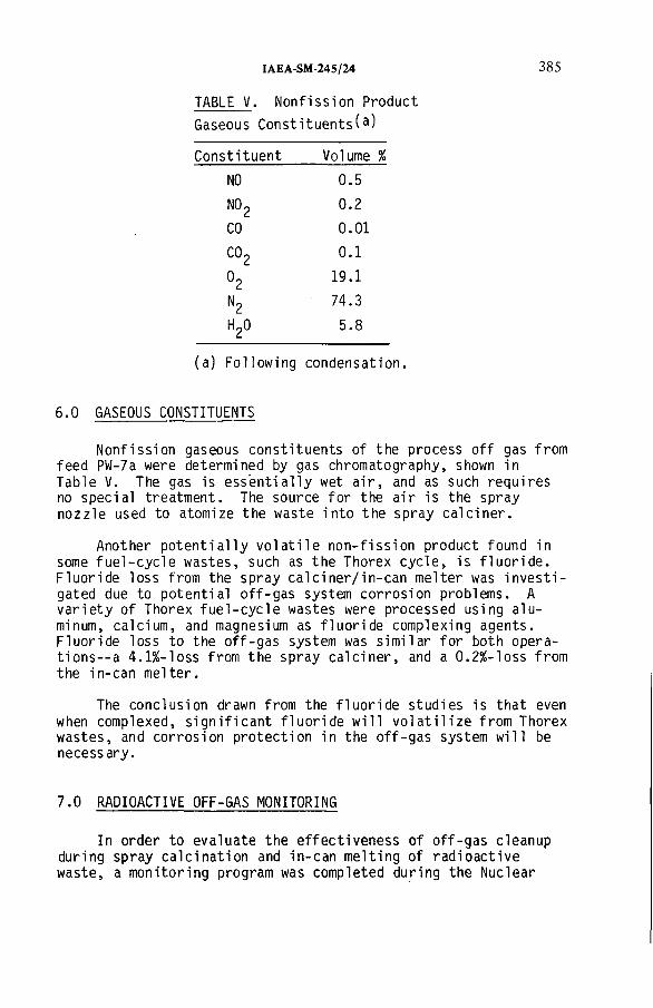
IAEA-SM-24S/24 385
TABLE V . Nonfission Product
Gaseous Constituents^)
Constituent Volume %
N0 0.5
N0? 0.2
CO 0.01
C0? 0.1
19.1
N2 74.3
H20 5.8
(a) Following condensation.
6.0 GASEOUS CONSTITUENTS
Nonfission gaseous constituents of the process off gas from feed PW-7a were determined by gas chromatography, shown in Table V. The gas is essentially wet air, and as such requires no special treatment. The source for the air is the spray nozzle used to atomize the waste into the spray calciner.
Another potentially volatile non-fission product found in some fuel-cycle wastes, such as the Thorex cycle, is fluoride. Fluoride loss from the spray calciner/in-can melter was investigated due to potential off-gas system corrosion problems. A variety of Thorex fuel-cycle wastes were processed using aluminum, calcium, and magnesium as fluoride complexing agents. Fluoride loss to the off-gas system was similar for both operations-^ 4.1%-loss from the spray calciner, and a 0.2%-loss from the in-can melter.
The conclusion drawn from the fluoride studies is that even when complexed, significant fluoride will volatilize from Thorex wastes, and corrosion protection in the off-gas system will be necessary.
7.0 RADIOACTIVE OFF-GAS MONITORING
In order to evaluate the effectiveness of off-gas cleanup during spray calcination and in-can melting of radioactive waste, a monitoring program was completed during the Nuclear
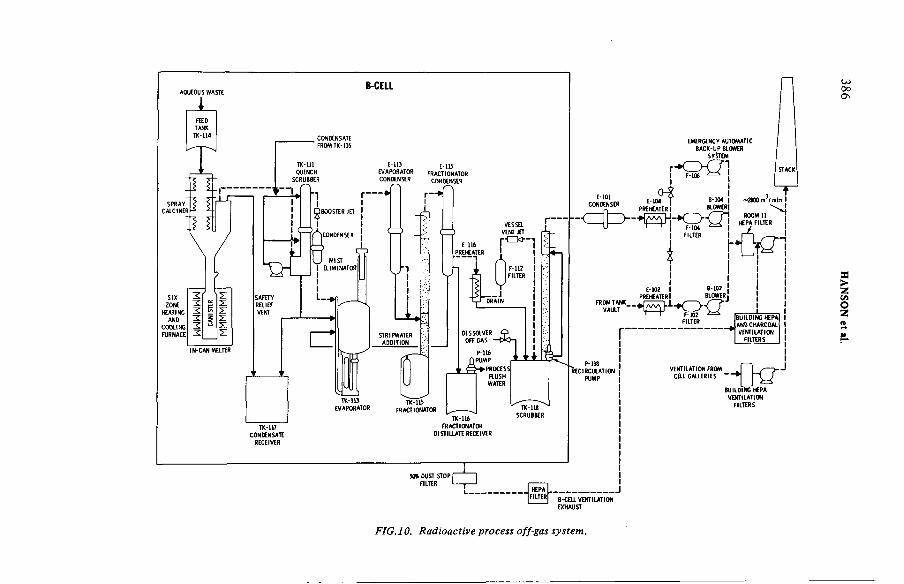
BCELL
EMERGENCY AUTOMATIC BACK-UP SLOWER
SYSTEM
r - o Q 4I F-106
E-101 CONKNSER
< = í > -
т■2800 m-'/min IE-104 j
PREHEATER I8 104
BLOWER
E 102 I PREfCATERl
6-102 BLOWER
• f c i
PRDCATtRI I
102FILTER
P-118 RECIRCULATION
PUMP
TK-115FRACTIONATOR -------- ^
TK-116 FRACTIONATOR
DISTILLATE RECEIVER
50% OUST STOP I IFILTER I----------- ,-------------------»
HEPAFILTER
BUILDING *P A É AND CHARCOAL 9 VENTILATION
FILTERS
VENTILATION FROM COL GALLERIES
BUILOING HEPA VENTILATION
FILTERS
B-COL VENTILATION EXHAUST
FIG. 10. Radioactive process off-gas system.
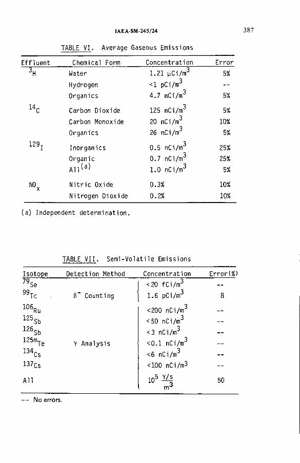
IAEA-SM-245/24 387
TABLE VI. Average Gaseous Emissions
Effluent Chemical Form Concentration Error
3H Water 1.21 uCi/m3 5%
Hydrogen <1 pCi/m3 --
Organics 4.7 nCi/m3 5%
14C Carbon Dioxide 125 nCi/m3 5%
Carbon Monoxide 20 nCi/m3 10%
Organics 26 nCi/ш3 5%
129 jInorganics 0.5 nCi/m3 25%
Organic 0.7 nCi/m3 25%
All^a 1.0 nCi/m3 5%
NOxNitric Oxide 0.3% 10%
Nitrogen Dioxide 0.2% 10%
(a) Independent determination.
TABLE VII. Semi-Volatile Emissions
Isotope Detection Method Concentration . Error(%)
79Se <20 fCi/m3 - -
99Tc
_
B" Counting 1.6 pCi/m3 8
106Ru <200 nCi/m3 _ _
125Sb <50 nCi/m3 _
126Sb <3 nCi/m3 - -
125mTeY Analysis <0.1 nCi/m3 —
134Cs <6 nCi/m3 —
137CS <100 nCi/m3 —
All 105 Щm
50
- - No errors.

TABLE VIII. Radionuclide Content of Particulate Matter
388 HANSON et al.
IsotopeConcentrati on
(nCi/m^) Error (%)
l06Ru 44.0 10
125Sb 0.52 10
125mTe 1.7 15
134Cs 7.8 10
137Cs 52.0 10
144Ce 0.82 10
154Eu 0.28 30
155Eu 0.18 15
241Am 0.19 20
TABLE IX. Particulate Size Distribution Analysis
P a r a m e t e r ^ Empirical Log Normal
Geometric mean dia 0.13 ym 0.10 ym
Geometric standard deviation 1.51 2.01
Correlation coefficient — 0.975
Mass mean dia — 0.55 ym
Particle concentration 168/cm3 —
Particle mass concentration^ 84.7 pg/cm3 —
(a) All parameters relate to undiluted process off gas before final HEPA filtration.
(b) Assumed calcine density - 3 g/cnP.
Waste Vitrification Program Ll]. A PW-8 type waste was processed and the off gas was cleaned in a spray calciner/in-can melter system, shown in Figure 10. Monitoring was done immediately outside the hot cell but prior to final absolute filtration. A variety of sampling methods were used [2]. The concentrations and forms of some typical gaseous effluents are shown in Table VI. Table VII shows the semi-volatile species monitored in the stream.
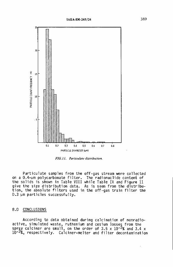
25
IAEA-SM-245/24 389
0.1 0.2 0.3 0.4 0.5 0.6
PARTICLE DIAMETER (цт)
0.7 0.8
FIG.ll. Particulate distribution.
Particulate samples from the on a 0.4-ym polycarbonate filter, the solids is shown in Table VIII give the size distribution data tion, the absolute filters used0.3 ym particles successfully.
off-gas stream were collected The radionuclide content of
while Table IX and Figure 11 As is seen from the distribu-
in the off-gas train filter the
8.0 CONCLUSIONS
According to data obtained during calcination of nonradioactive, simulated waste, ruthenium and cesium losses from the spray calciner are small, on the order of 3.5 x 10_2% and 3.4 x 10“2%, respectively. Calciner-melter and filter decontamination
390 HANSON et al.
factors for ruthenium and cesium averaged 3.6 x 10⁴ and 3.9 x 10⁴ , respectively. Particulate decontamination factors of 10-3 to 10^ have been obtained using sintered stainless steel filters. Thus, particle penetration of the filters accounts for a significant portion of the ruthenium and cesium lost to the process off-gas system. Particles penetrating the filters have a mass distribution centering about a size large enough to control with available technology.
Processing wastes containing fluoride will probably volatilize the fluoride to the off-gas system, thus increasing the probability of corrosion problems.
Monitoring off-gases from a radioactive processing system following cleanup shows that, even with losses from the spray calciner/in-can melter system, significant decontamination of the gas is attainable.
REFERENCES
[1] WHEELRIGHT, E.J., et al., "Technical Summary Nuclear Waste Vitrification Project," PNL-3038, Pacific Northwest Laboratory, Richland, Washington, May 1979.
[2] GOLES, R.W., HAMILTON, O.C., BRAUER, F.P., RIECK, OR.,H.G., ROBERTSON, D.M., GORDON, R.L., KAYE, J.H., "Characterization of Gaseous and Particulate Effluents from the Nuclear Waste Vitrification Project," PNL-3181, Pacific Northwest Laboratory, Richland, Washington.
DISCUSSION
E. PALACIOS: What collection and detection m ethod for aerosol samples was used in your experim ents when analysing the particle spectrum beyond the filters?
M.S. HANSON: The m ethod used was electron m icroscopic counting.D.T. PENCE: What was the basis o f your selection o f 65 д т porosity sinter
metal filters? If smaller porosity filters were used, would you expect greater particle removal efficiencies?
M.S. HANSON: The original choice was made on the basis o f the availability o f commercially manufactured filters. Other pore size filters have been tried, but the filtration efficiency is about the same. The filter cake actually does the filtration, with the sintered metal providing the support.

IAE A-SM-24 5/24 391
R.D. COLLINS: Does your experience with penetration after blowback lead you to favour two filters in series blown back at different times?
M.S. HANSON: N o, one set o f filters gives sufficient particulate control.An off-gas system com ponent such as a venturi scrubber which is capable o f handling high solid loadings may be used as a backup, but a second set o f filters is unnecessary.
W.R.A. GOOSSENS: What is the size distribution o f the ruthenium penetrating the sintered metal filters?
M.S. HANSON: The ruthenium decontamination factors given in m y paper are for volatile species. The ruthenium penetrating the filters as a solid is included in the particulate size distribution.
P. PATEK: What was your reason for not measuring the behaviour o f strontium in the off-gas?
M.S. HANSON: Ruthenium can be considered to be the m ost problematic material, and our experience has shown that if it is controlled, then the other fission products will also be controlled.
B.W. WATSON: Does the volatile ruthenium oxide condense and precipitate within the sinter pores, in particular after blowback, thus reducing the effective pore-size?
M.S. HANSON: No. We have destructively tested a sintered filter to look for ruthenium in the pores and none could be found. However, ruthenium enrichment on the filter cake has been observed.


IAEA-SM-245/57
APPLICATION OF MEMBRANES TO MONITORING FO R TRITIATED WATER VAPOUR
R.V. OSBORNE, R.G.C. McELROY A tom ic Energy o f Canada Limited,Chalk River Nuclear Laboratories,Chalk River, Ontario,Canada
Abstract
APPLICATION OF MEMBRANES TO M ONITORING FO R TRITIA TED WATER VAPOUR.Nafion, a copolym er o f tetrafluoroethy lene and various perfluoro-sulphonic acids, is very
perm eable to w ater com pared w ith o th er polymers. In the form o f tubing, it allows th e transfer o f tritia ted w ater vapour (НТО) from samples o f gaseous effluents to a counter-current gas stream th a t passes to a radiation detector. The perm eation rates for tritia ted hydrogen (HT) and radioxenons (Xe) are approxim ately 10 -3 and 10-4 th a t fo r НТО. The results o f m easurem ents w ith an assembly of Nafion tubes have dem onstrated th a t, by careful selection o f sample and de tecto r flow rates, discrim ination factors against HT and Xe o f these orders m ay be attained. A t th e same tim e the concentration of НТО in the gas passing to the de tector is w ithin a few per cent o f th e concentra tion in the air sample. Direct capture o f airborne НТО by perm eation th rough a Nafion tube in to liquid scintillator has also been dem onstrated. With a m ixture o f 20% w ater in liquid scintillator and a m ixture flow o f only 0.1 cm 3/m in, concentrations o f НТО in air down to 250 B q/m 3 (7 nC i/m 3) may be measured.
1. INTRODUCTION
Polymeric materials that are permeable to water were considered in the 1950's [1] as a means of separating tritiated water vapour (НТО) from a sample gas stream but only recently has the availability of very permeable materials allowed such application to be practical. Examples of two such materials are dimethyl-silicone [2] and Nafion [3]. The latter, a copolymer of tetrafluoroethylene and various per- fluorosulphonic acids, is a chemically stable, cation-exchange material that was developed [4] for applications in electrochemistry. The quoted permeation constants of these materials are substantially greater than those of common polymers as is illustrated in Table I.
As discussed in earlier papers [e.g.[5]) the presence of noble gas fission products (e.g. ^3’xe, °7Kr) and the activation product, 41Ar, in air that is being monitored for tritium interferes with the measurement of the tritium. Also, distinction between НТО and tritiated hydrogen (HT) is important for radiological purposes. Materials that
393

394 OSBORNE and McELROY
TABLE I. RELATIVE PERMEATION CONSTANTS OF VARIOUS POLYMERS TO WATER VAPOURThe last two values are typical o f values quoted in various handbooks
Order of Magnitude of Relative Permeation Constants for Water
Polymer Vapour
Nafion 1 [3]Di-methyl silicone 10_1 [2]Cellulose acetate -, Silicone rubber
10"2
Polyethylene 10"-
are very permeable to water vapour may be used to separate НТО from HT or noble gas fission products if such materials are relatively impermeable to these contaminants. This paper outlines the results of measurements on Nafion tubing which indicate that very large discrimination factors ( 10^) may be attained.
The collection of airborne НТО in a flow of liquid scintillator has been demonstrated [6] to provide a very sensitive method of detection, compared with other on-line monitors such as ionization chambers. Because of the cost of liquid scintillator, low flow rates (less than 10 mnr/s) were necessary for any practical effluent monitoring. The method was also applicable to monitoring water effluents for tritium. For this a sample of the water was transferred in the vapour phase to the liquid scintillator. Contaminants - radioactive, chemical and biological - which cause problems in on-line water monitors are thereby left behind. Mixing the low flow rates of liquid scintillator with relatively large volumes of air was accomplished but the specially designed glass mixing apparatus was by far the most fragile part of the equipment. Nafion tubing offers an alternative way of achieving the mixing. This paper outlines the results of measurements of the effectiveness of Nafion tubing for collecting tritiated water vapour in liquid scintillator which indicate that low concentrations of НТО in air (^300 Bq/m3; M O nCi/m^) may be detected with such an arrangement.

IAEA-SM-245/S7 395
DETECTOR SAM PLEFLOW OUT FLOW OUT t
! 1“ Г
г i—DETECTOR
PERMEABLE FLOW INSAMPLE FLOW MEM BRANE
IN
FIG.l. Arrangement of the counter-current sample and detector flows. The equations derived are symmetrical in the quantities associated with the flows and in some measurements the sample flow was the inner one.
2. THEORY
2.1 General analysis
An effective method of transferring a component from one fluid stream to another by permeation through a membrane in the form of tubing is to arrange the flows to be counter- current. Such an arrangement is shown in Fig. 1. With this arrangement the ratio of concentrations of НТО in the detector stream and the sample stream are determined by the flow rates of the two fluids, the solubility of НТО in the membrane and the diffusion constant of НТО in the membrane. The relation
iS i Ф
Cd/Cs =AjLjS— г (1)fd/fs “ e
where ф = -jp---- (1 - fd/fs ) (2)d
,/ _ 2irmDSl nsand - loge Cb/a) (3>
The symbols are identified in Table II. The relation in Eq.1 follows from classical diffusion theory applied to steady state conditions with the arrangement of flows shown in Fig. 1. The geometry is assumed to be such that mixing within the fluid flows is complete in the radial direction and may be ignored in the longitudinal direction. The diffusion coefficient, D, is assumed to be constant along the tube as is the solubility, S, which is also assumed to be the same at both surfaces.
The variations in the ratio C<j/Cs with the ratio fs/fdfor various values of the dimensionless quantity K/fd are shown in Fig. 2.

396 OSBORNE and McELROY
TABLE II. SYMBOLS, QUANTITIES AND UNITS USED IN THE PAPER A prim ed sym bol indicates that the quantity refers to a contaminant other than НТО
a inner diameter of the tubing
b outer diameter of the tubing
С , concentration of the permeatingchemical species in the detector flow at the outlet
С concentration of the permeatings chemical species in the sample
at the inlet
D diffusion coefficient of thechemical species in the tube walls
f , detector flow ratea
f sample flow rate
К permeation constant for the tube assembly, defined by Eq. 3
1 exposed length of tube
m number of tubes exposed
N minimum detectable counting ratein the detector
S ratio of the concentration of thechemical species in the tube material at the surface to the concentration in the fluid contacting that surface (solubility coefficient)
V scintillator flow cell volume cm3
e scintillation detector counting. efficiency
Д difference between C, and С as afraction of Cg
НТО tritiated water
HT tritiated hydrogen
LSI dioxane-based liquid scintillator
LS2 Ready-Solve VI liquid scintillator(Beckman)
Xe mixture of radioactive xenons
cm
cm
Bq/cm3
Bq/cm3
cm2/s
cm3/s
cm3/s
cm3/s
cm
counts/s

IAEA-SM-245/S7 397
W'd
FIG.2. Variations of the ratio of the concentration of a permeating nuclide or chemical in the detector flow output to that in the sample flow input with ratio of flows. The curves are for various values of the ratio of permeation constant to detector flow.
2.2 Practical considerations
Various limiting values are important in considering theapplications of such a tube assembly to separating НТО fromHT and other radioactive nuclides.
From Eqs 1 and 2, if fs/f<j is large,
Cd/Cs - 1 - e’(K/fd) (4)
and if the ratio of К to f^ is also large,
Cd/CS - 1 (5)
If, on the other hand, K/fj is small compared to 1,
Cd/Cs - K/fd (6)
These limits are illustrated on Fig. 2.The relation in Eq. 5 is important because, with these conditions (fs/^d anc* K/fd large), the ratio of concentrations in the two flows is close to unity and is insensitive to changes in the solubilities and diffusion coefficient that might occur in Nafion with changes in relative humidity and temperature.
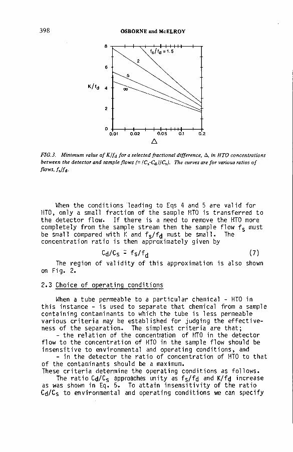
398 OSBORNE and McELROY
K / f d 4
8
2
6
0 ■1--1 I I I II I0.01 0.02 0 .05 0.1 0.2
Д
FIG.3. Minimum value of K/f¿ fora selected fractional difference, A, in НТО concentrations between the detector and sample flows (= (C%-C&)ICS). The curves are for various ratios of flows, fjfd.
When the conditions leading to Eqs 4 and 5 are valid for НТО, only a small fraction of the sample НТО is transferred to the detector flow. If there is a need to remove the НТО more completely from the sample stream then the sample flow fs must be small compared with К and fs/fd must be small. The concentration ratio is then approximately given by
The region of validity of this approximation is also shown on Fig. 2.
2.3 Choice of operating conditions
When a tube permeable to a particular chemical - НТО in this instance - is used to separate that chemical from a sample containing contaminants to which the tube is less permeable various criteria may be established for judging the effectiveness of the separation. The simplest criteria are that;
- the relation of the concentration of НТО in the detector flow to the concentration of НТО in the sample flow should be insensitive to environmental and operating conditions, and
- in the detector the ratio of concentration of НТО to that of the contaminants should be a maximum.These criteria determine the operating conditions as follows.
The ratio Cd/Cs approaches unity as fs/fd and K/fd increase as was shown in Eq. 5. To attain insensitivity of the ratio Cd/Cs to environmental and operating conditions we can specify
Cd/Cs - fs/fd (7)

IAEA-SM-245/57 399
Cd/Cdк/к1
FIG.4. Discrimination against a contaminant that can be attained when the concentration of НТО in the detector flow is required to be within a given fraction from the concentration of НТО in the sample. The curves are for selected values of the fractional difference, A, in НТО concentrations between the detector and sample flows, (Cs-C¿j/Cs. The maximum detector flow /d, as given in Fig.3, consistent with the value of A has been assumed.
that Cd/Cs should be within a given (small) percentage of unity. From this requirement the limits on fs/fd and K/fd can be determined. Examples are shown in Fig. 3.
If the permeability constant (K1 ) for a contaminant is small compared with that for НТО (К) and if the detector.flow (fd) is limited to values that are large compared with К then, from Eq. 6, the concentration of ^he contaminant in the detector flo\¡/ will be proportional to К /fd. This condition on fd (fd>;,K ) may be combined with those in the previous paragraph that determine the accuracy of the ratio of НТО concentrations, Cd/Cs. The result is a relation between the attainable values of the discrimination factor between НТО and the contaminant and the acceptable ratios of flows for given deviations of the tritium concentration ratio from unity. Such relations are shown in Fig. 4. For example, if the device is operated so that the concentration of НТО in the detector flow is within 5% of that in the sample then the maximum discrimination against a contaminant is 32% of the ratio of permeability constants of the device for НТО and for the contaminants. To attain the particular concentration ratio, fd must be less than К by the factor shown on Fig. 3 for the
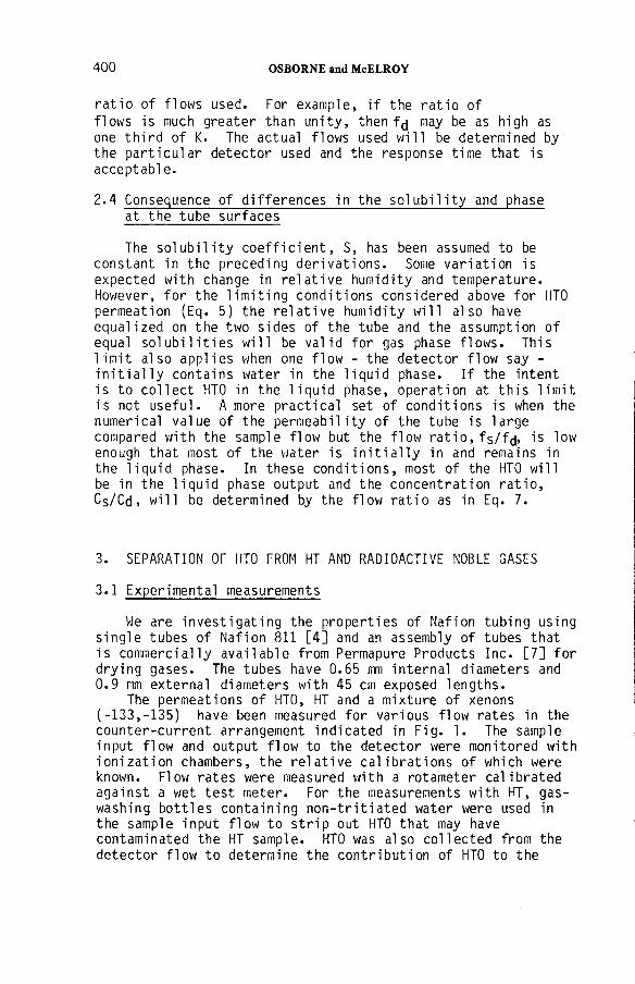
400 OSBORNE and McELROY
ratio of flows used. For example, if the ratio of flows is much greater than unity, then fd may be as high as one third of K. The actual flows used will be determined by the particular detector used and the response time that is acceptable.
2.4 Consequence of differences in the solubility and phaseat the tube surfaces
The solubility coefficient, S, has been assumed to be constant in the preceding derivations. Some variation is expected with change in relative humidity and temperature. However, for the limiting conditions considered above for НТО permeation (Eq. 5) the relative humidity will also have equalized on the two sides of the tube and the assumption of equal solubilities will be valid for gas phase flows. This limit also applies when one flow - the detector flow say - initially contains water in the liquid phase. If the intent is to collect НТО in the liquid phase, operation at this limit is not useful. A more practical set of conditions is when the numerical value of the permeability of the tube is large compared with the sample flow but the flow ratio, fs/fd, is low enough that most of the water is initially in and remains in the liquid phase. In these conditions, most of the НТО will be in the liquid phase output and the concentration ratio, Cs/Cd, will be determined by the flow ratio as in Eq. 7.
3. SEPARATION OF НТО FROM HT AND RADIOACTIVE NOBLE GASES
3.1 Experimental measurements
We are investigating the properties of Nafion tubing using single tubes of Nafion 811 [4] and an assembly of tubes thatis commercially available from Permapure Products Inc. [7] fordrying gases. The tubes have 0.65 mm internal diameters and 0.9 mm external diameters with 45 cm exposed lengths.
The permeations of НТО, HT and a mixture of xenons(-133,-135) have been measured for various flow rates in the counter-current arrangement indicated in Fig. 1. The sample input flow and output flow to the detector were monitored with ionization chambers, the relative calibrations of which were known. Flow rates were measured with a rotameter calibrated against a wet test meter. For the measurements with HT, gas- washing bottles containing non-tritiated water were used in the sample input flow to strip out НТО that may have contaminated the HT sample. НТО was also collected from the detector flow to determine the contribution of НТО to the

IAEA-SM-24S/S7 40 1
FIGS. Observed concentration ratios (C¿/Cs) for НТО, HT and radioxenons with various flow ratios (fs/f¿). Open circles are for detector flow, f¿, constant at 130 cm3/s; closed symbols are for sample flow, fs, constant at 75 cm3/s.
detector signal. In practice, we found that the activity of НТО collected was a small fraction of the HT activity permeating the tube.
Fig. 5 shows the ratio of concentrations Cd/Cs observed in one series of measurements with the tube assembly. The results for НТО are in the region where Cd/Cs depends strongly on the permeation constant (i.e., neither of the limits leading to Eqs 5 or 7 apply) so that its value may be estimated with Eq. 1. For HT and xenon the results are in the region where Cd/Cs varies with К /f¿ (as given by Eq. 6 with К instead of K). The estimates of the effective permeation constants for the multitube assembly are given in Table III.
The range of values observed for НТО reflect the variation of permeation rates with the humidities of the two flows, higher values being observed at higher humidities. The results shown in Fig. 5 are for flows with intermediate (^55%) relative humidity. These variations are not important, as was discussed in Section 2, provided that the operating conditions ensure that K/fj and fs/fd are large enough to set the value of Cd/Cs sufficiently close to unity.

402 OSBORNE and McELROY
TABLE III. PERMEATION CONSTANTS OF AN ASSEMBLY OF 100 NAFION TUBES FOR НТО, HT AND XENON
Gas Permeation constant(cm3/s)
НТО 90-270HT 0.017Xenon 0.0044
3.2 Application
With these estimates of permeation constants, the discrimination between НТО and the other gaseous contaminants that niay be attained with a practical monitoring device can be determined.
If the concentration of НТО in the flow to the detector has to be within 5% of the sample concentration then, from Fig. 3, the detector flow should be less than 30 cm^/s for very high values of fs/fd. [K is taken as 90 cm^/s]. From Fig. 4 it is apparent that for ratios of fs/fd greater than 5 there is little improvement in the discrimination ratio; values of 125 cm^/s and 25 cm^/s therefore appear reasonable for the minimum sample and detector flows fs. With these values, the discrimination factors that are attained are as given in Table IV.
4. COLLECTION OF НТО VAPOUR IN LIQUID SCINTILLATOR
4.1 Experimental measurements
A single tube of Nafion 811 with the same diameters as described in the previous section and 35 cm long was mounted in a glass tube, internal diameter 0.4 cm, so that liquid scintillator (or water) could pass as the detector flow down the centre of the Nafion tube and air (as the sample flow) down the volume between the tubes. The arrangement of flows was counter-current as shown in Fig. 1. The liquid flow was controlled by a positive displacement metering pump. The flow was measured by timing the change of level of scintillator in a burette that acted as the reservoir. The sample air flow was controlled by a needle valve on a regulated supply and was metered both with a rotameter and a wet test meter.

IAEA-SM-245/57 403
TABLE IV. THE DISCRIMINATION FACTORS ATTAINABLE WITH AN ASSEMBLY OF NAFION TUBES
Relative Concentration
НТО 1HT >1400Xenon >5400
N ote: The factors are expressed as the relative concentrations o f НТО, HT and xenons in the sample flow that would be required to produce equal concentrations in the flow to the detector. The de tecto r flow is less than 25 cm3/s; the sample flow is at least five tim es the detector flow. The sample and detector flows are chosen to ensure th a t the concentrations o f НТО in the detecto r flow is w ithin 5% of th a t in the sample flow.
Concentrations of tritium were measured in air with an ionization chamber and in the liquid either by collecting the samples serially in vials for subsequent counting or (for liquid scintillator only) by flowing the scintillator flow directly through a flow cell. The ionization chamber sensitivity and flow cell sensitivities were calibrated with the same tritium standard.
The wide range of concentrations of НТО observed in the liquid flow to the detector is shown in Fig. 6. The large values of Cd/Cs compared with the values presented in the previous section, result from the density difference between the two fluids. It is immediately apparent that НТО is very efficiently collected in the flow range shown when water is the detector flow. The permeation constant is at least lOcm^/s. It is also apparent that the accumulation of НТО in liquid scintillator is very much reduced unless water is added to the scintillator before passing through the tube. The permeation is roughly proportional to the initial water content of the liquid scintillator. A water content of 20% was the practical upper limit for pumping the mixture through the tube.
As was noted in section 2.4 practical operating conditions are those for which the concentration ratios are determined by the ratio of flow rates only. On the log-log plot of Fig. 6 slopes of unity indicate that the concentration ratio is proportional to the flow ratio; all the НТО is captured by the liquid stream and Eq. 7 is valid.
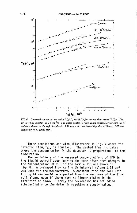
404 OSBORNE and McELROY
hi fd , 1Ó3FIG. 6. Observed concentration ratios (C¿/C%) for НТО for various flow ratios (fjf¿). The air flow was constant at 10 cm 3/s. The water content of the liquid scintillator for each set of points is shown at the right hand side. LSI was a dioxane-based liquid scintillator. LS2 was Ready-Solve VI (BeckmanJ.
These conditions are also illustrated in Fig. 7 where the detector flow, fd , is constant. The dashed line indicates where the concentration in the detector is proportional to the flow ratio.
The variations of the measured concentrations of НТО in the liquid scintillator leaving the tube after step changes in the concentration of НТО in the sample air are shown in Fig. 8. A U-shaped flow cell with internal volume 1.34 cm3 was used for the measurement. A constant rise and fall rate taking 14 min would be expected from the response of the flow cell alone, even if there were no linear mixing in the direction of flow. Clearly the permeation has not added substantially to the delay in reaching a steady value.
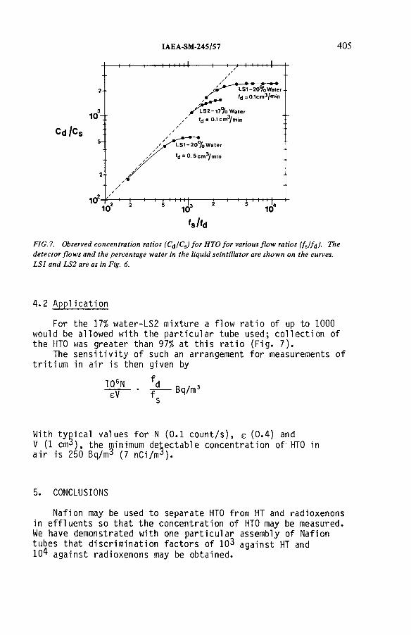
IAEA-SM-24S/57 405
FIG. 7. Observed concentration ratios (C¿/Cs) for НТО for various flow ratios (fjf¿). The detector flows and the percentage water in the liquid scintillator are shown on the curves. LSI and LS2 are as in Fig. 6.
4.2 Application
For the 17% water-LS2 mixture a flow ratio of up to 1000 would be allowed with the particular tube used; collection of the НТО was greater than 97% at this ratio (Fig. 7).
The sensitivity of such an arrangement for measurements of tritium in air is then given by
106NeV
Bq/m2
With typical values for N (0.1 count/s), e (0.4) andV (1 cm3 ), the minimum detectable concentration of’ НТО in air is 250 Bq/m3 (7 nCi/m3 ).
CONCLUSIONS
Nafion may be used to separate НТО from HT and radioxenons in effluents so that the concentration of НТО may be measured. We have demonstrated with one particular assembly of Nafion tubes that discrimination factors of 103 against HT and 104 against radioxenons may be obtained.

406 OSBORNE and McELROY
I----------- 1-----------1-----------1-----------1-----------1-----------1-----------1----------- 1-----------1-----------(■0 20 4 0 6 0 80 100
TIME AFTER START OF C LEAN OUT ( M in u te s )
FIG.8. Variation in the counting rate from a scintillation counter flow cell, attached to the detector flow from the Nafion tube, following step increases and decreases in the concentration of НТО in the sample flow. The detector flow was 0.1 cm3/min and the flow cell internal volume was 1.4 cm3.
The direct collection of airborne НТО in a liquid scintillator may also be effected through the use of Nafion tubes. We have demonstrated that scintillator flows of the order of 0.1 cm3/min may be used with a single tube and a flow cell to measure concentrations of НТО in air down to 250 Bq/m3 (7 nCi/m^).
ACKNOWLEDGEMENTS
We acknowledge the assistance of T. Elsdon and P. Celliers in obtaining the data reported here.

IAEA-SM-245/57 407
REFERENCESV
[1] JONES, A.R., Atomic Energy of Canada Limited, Unpublished Report (1959).
[2] HOWELL, R.H., CATE, J.C., WONG, C., Separation of HT, noble gases and НТО vapour with semipermeable membranes, Nucl. Instrum. Methods 124 (1974) 579.
[3] ROBERTS, R.S., FERNANDEZ, S.J., "Radioactive .gaseous effluent monitoring under high humidity conditions", Radiation Instrumentation (Proc. Health Phys. Soc. Symp., San Diego, USA, 1978), WADMAN, W.W., Ed, (1978) 170.
[4] E.I. DUPONT DE NEMOURS, Nafion Information Bulletin, Wilmington, USA (1976).
[5] OSBORNE, R.V., COVEART, A.S., "A transportable monitor for tritiated water vapour", Proc. IV International Congress of the International Radiation Protection Association, Paris, France, 1977 (BRESSON, G., Secretary), Fontenay-aux-Roses, France (1977).
[6] OSBORNE, R.V., TEPLEY, N.W., "Monitoring tritiated water in air and water effluents", Radiation Instrumentation (Proc. Health Physics Soc. Symp. San Diego, USA, 1978), WADMAN, W.W., Ed., (1978) 203.
[7] PERMAPURE PRODUCTS INC., New Jersey, USA.
DISCUSSION
A. BRUGGEMAN : Is there any isotope effect when water permeates through Nafion? I f so, can this bias your tritium measurements?
R.V. OSBORNE: There will be differences in the permeation rates and the solubilities o f Nafion for water vapour with the various hydrogen isotopes — protium, deuterium and tritium. For our purposes, however, such effects are not important and do not result in any bias in the measurements. The check on this is that, for any o f the applications, the calibration can be performed with tritiated water vapour.


Session VI
OFF-GAS CLEANING SYSTEMS OPERATION

Chairman
P.H.J.M. SIGLIFrance

IAE A-SM-24S/22
FIFTEEN YEARS EXPERIENCE FILTERIN G N-REACTOR GASEOUS WASTES
K.L. FOWLER UNC Nuclear Industries,Richland, Washington,United States o f America
Abstract
FIFTEEN YEARS EXPERIENCE FILTERIN G N-REACTOR GASEOUS WASTES.The N-reactor exhaust gas filtering system consists o f roughing filters, particulate filters,
and charcoal filters, in th a t order. The basic particulate and charcoal filters consist o f 0.46 m 3/s, 60 cm X 60 cm X 30 cm filter canisters installed four canisters wide by ten canisters high in rem ovable filter frames. The roughing filter canisters are about tw ice as wide and high as th e o th er canisters bu t fit in to similar fram es o f th e same size. There are tw o side by side frames of each ty p e of filter in each cell for a to ta l design flow o f 37 m 3/s. The reactor and prim ary pipe space air has tw o cells fo r norm al operation and one cell reserved for th e accident case. One cell w ithout roughing filters is used fo r the first buffer zone air around the reactor. Initially, the particulate filters were tested one canister at a tim e. However, exposure rates forced developm ent o f a m ethod o f testing an entire cell at a tim e. This was done by a local governm ent contractor. Particulate filters have had lives o f 40 m onths o r more. Accidental actuation o f filter sprays w ith air flow through the filters has occasionally damaged th e filters and required their replacem ent. The charcoal filters have been tested one o r m ore cells at a tim e w ith radioactive iodine. This inplace test is corrected fo r accident conditions by the difference betw een laboratory tests at accident and am bient conditions. The filter lives have ranged from four to nine years. Test data indicate the inplace tests are m ore reliable th an the laboratory tests. F ilter contam ination has occurred from leaks in th e cell gate hydraulic system. C ontam ination by infrequent painting during reactor outages has been avoided by venting exhaust air directly to th e atm osphere. F ilter testing and system leak ra te testing is perform ed every six m onths. Filtering costs reported in 1974 were US$40 000.
1.0 INTRODUCTION
This paper has been prepared in the hope that our operating experience with a particulate and charcoal filtering system on the exhaust gasses of a pressurized water cooled reactor will be of value to others. Test data for particulate and charcoal filters has been plotted to determine their value in forecasting the life of filters.The life for both filters is reported along with special experiences and comments.
411

412 FOWLER
N Reactor, a graphite-moderated, light water pressurized tube reactor, is located on the Hanford Site in the State of Washington. Hanford is the location of nine World War II and Post-War light water cooled, graphite-moderated plutonium production reactors.
Filter cells were designed and added onto the production plants between the reactor building exhaust fans and the 61 m high dispersion stacks. These filters consist of inline banks of particulate and charcoal filters downstream of exhaust fans. The installation work was initiated in 1958 and continued through 1961 for eight reactors. N Reactor was designed during this same time and the same arrangement was used.
The N Reactor filter cells are each designed for a flow of 37 щЗ/s. There are two active cells and one reserve cell for the reactor space air and one cell (C) for intermediate space air.
Three of the cells have a roughing filter, a particulate filter, and a charcoal filter. Cell С has no roughing filter. There are two si de-by-si de (2.4 m x 6 m) filter frames for each filter unit. They are installed and removed by a portable crane.
2.0 ROUGHING FILTERS
The roughing filter is a mat of aluminum turnings or shavings which act as mist separators. Washdown sprays for the roughing filters are installed in one cell as an experiment. Most of the gamma-emitting radioactive isotopes are collected on the roughing filters.
Contact exposures are approximately 1 rem/h at the roughing filters, 200 mrem/h at the particulate filters, and 50 mrem/h at the charcoal filters.
3.0 PARTICULATE FILTERS
The particulate filters are High Efficiency Particulate Air (HEPA) filters placed in a wood canister 60 cm x 60 cm X 30 cm. They are installed in an aluminum frame, four canisters iwide and ten canisters high. Each filter canister has a flow capacity of 0.46 щЗ/s, resulting in 18.5 m^/s per frame or 37 m^/s per cell. The canisters are tested at

IAEA-SM-24S/22 413
a government station to meet requirements of 99.97% efficiency. Safety analysis takes credit for a filter efficiency of 99.95% which is the operating limit for the fi1ters.
3.1 Initial Testing
During the initial and subsequent annual plant testing, the canisters were tested, in place, one at a time, by use of Dioctyl phthalate (DOP) aerosol generated by compressed air nozzles.
A cone shaped paper or sheet metal adapter on the end of the aerosol generator hose directed the "smoke" to the individual filter to be tested. On the downstream side of the filter, a similar shaped collector directed the penetrating DOP to the detector.
The detectors were early models of a linear- readout, forward light-scattering photometer developed by the U.S.Navy Research Laboratory.
This method allowed the changeout of individual filter canisters as leaks were located. The source of the leak could frequently be located by probing with a hose rather than using the cone shaped collector. However, this method required permanent or temporary installation of scaffolding on both sides of the filter to enable access to all filter canisters.
In 1969, radiation exposure rates for work around the filter were such that sampling could not be scheduled as frequently as needed. Consideration was then given to some means of testing an entire filter cell at one time.
Whole cell testing had been attempted with an electrostatic nuclei detector. The detector could measure salt nuclei from a salt solution spray or nuclei from smoke.A number of tests were made but the results were usually lower than the established DOP method and did not compare well with it. One of the problems was to obtain a high enough initial concentration of salt nuclei. The manpower was not available to adequately test a new method.
3.2 Revised Testing
Talks with Hanford Environmental Health Foundation (HEHF) personnel revealed they had equipment and interest to do a whole cell DOP test. A trial test was considered
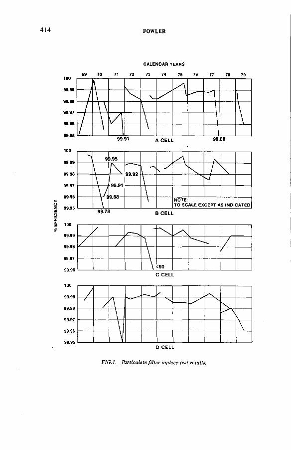
% E
FFIC
IEN
CY
414 FOWLER
CALENDAR YEARS
С CELL
FIG.l. Particulate filter inplace test results.
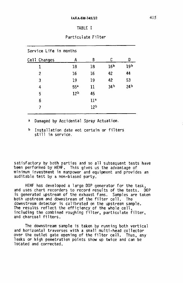
IAEA-SM-245/22
TABLE I
Particulate Filter
4 1 5
Service Life
Cell Changes
in months
A В С D
1 18 18 16b igb
2 16 16 42 44
3 19 19 42 53
4 55a 11 34 b 24 b
5 12b 45
6 IIa
7 l2b
a Damaged by Accidental Spray Actuation.
b Installation date not certain or filters still in service.
satisfactory by both parties and so all subsequent tests have been performed by HEHF. This gives us the advantage of minimum investment in manpower and equipment and provides an auditable test by a non-biased party.
HEHF has developed a large DOP generator for the task, and uses chart recorders to record results of the tests. DOP is generated upstream of the exhaust fans. Samples are taken both upstream and downstream of the filter cell. The downstream detector is calibrated on the upstream sample.The results reflect the efficiency of the whole cell, including the combined roughing filter, particulate filter, and charcoal filters.
The downstream sample is taken by running both vertical and horizontal traverses with a small multi-head collector over the outlet gate opening of the filter cell. Thus, any leaks or high penetration points show up twice and can be located and corrected.

416 FOWLER
A preliminary high side efficiency result is given at the time of the test. Later, the area under the curve on the recorder charts is measured and a refined final answer is reported.
The results are believed to be accurate to plus or minus 0.005% efficiency. This may seem to be very high accuracy. However, it should be kept in mind that the quantity measured is penetration. Since the penetration values are so small, 10% accuracy of penetration will provide 0.005% or better accuracy for the efficiency values. Test results are plotted against time for each cell in Figure 1. Filter life is shown in Table I.
3.3 Filter Sprays
Early in the life of the plant, concern developed about the amount of heat which might be generated in the filters as a result of fission product deposition from a postulated fuel melt. To control this heat and prevent a fire or heat generated re-emission of the fission products, sprays were installed to cool both the particulate and charcoal filters. These are controlled by thermocouples attached to both filters and the concrete walls. The controllers turn on the sprays at a temperature of 115°C and turn them off at a temperature of 102°C.
Recent studies have shown a greater percent of the fission products will plate out on the walls and be washed out by sprays before reaching the filters. These studies indicate the sprays are not needed to protect the filters.The sprays are a hazard to the particulate filters and may damage them if activated when there is air flow through the filters. Plans for the filter sprays are now under study.
3.4 Conclusions
As can be seen from Table I, it is possible to have a service life of 40 or more months for HEPA filters. This is dependent upon good filter care and the particulate loading placed on the filters.
Water or spray alone does not appear to damage the filters. We have had experience with a few accidental spray actuations on the HEPA filters. We believe damage is caused by high air flow blowing the spray drops with such velocity as to harm the filters.
IAEA-SM-245/22 417
It is claimed that HEPA filter tests cannot be used to forecast future filter conditions, but can only tell its condition at the time of the test. The data tend to confirm such a conclusion. However, there seems to be no basic reason why the tests should not provide at least short-range forecasts of filter conditions.
4.0 CHARCOAL FILTERS
N Reactor uses 2.5 cm thick charcoal filters in a pleated design to remove radioactive iodine. Each 60 cm x 60 cm filter canister is designed for 0.46 m3/s throughput, the same as the particulate filters. The canisters are filled with charcoal while vibrated to eliminate voids. They are then placed in a frame four canisters wide and ten high. Two filter frames are installed side by side per cell.
4.1 Inplace Tests
When installed, the cell is tested by injecting iodine tagged with radioactive iodine-131 upstream of the filter cell. The iodine not adsorbed on the charcoal filter is sampled at the exit gate of the filter cell. The sampler consists of a charcoal-impregnated paper, a silver membrane, two 2.5 cm beds, and a 5 cm bed of potassium-iodide impregnated charcoal. Molecular iodine collects on the charcoal-impregnated filter paper and the silver membrane. Methyl iodide (CH3 I) collects on the charcoal beds and
tends to move through the beds depending upon the elution time. The molecular iodine is more firmly held and does not noticeably elute. Samples are taken upstream and downstream of the filter cell and then analyzed for presence of 1-131 to determine the efficiency of the charcoal filters in removing iodine. Inplace tests were originally made annually for each cell. During 1969-1970 the testing frequency was increased to once every six months.
4.2 Laboratory Tests
The inplace test is corrected for accident conditions by a laboratory test. Initially, a 60 cm x 60 cm filter canister was replaced and a charcoal sample drawn from the removed filter canister. In 1971, special sampling canisters were installed in each filter cell in place of one of the charcoal filter canisters.
Each sampling canister contains 16 removable sampling elements. Each element is divided into six sections, any one of which can be sampled without disturbing the other five
418 FOWLER
samples. The individual sampling elements require only 10 minutes for replacement in the sample canister. The sample canister has the same 2.5 cm deep charcoal bed and 0.46 m3/s flow rate as the regular charcoal filter canisters.
The sample canisters are used both for tests of special charcoals to determine the ones best suited for use at N Reactor, and also for testing the condition of the charcoal in use for the whole cell. Tests have been made of two parameters. The first parameter is the atmosphere; that is, ambient conditions versus accident conditions. The second parameter measured is bed loading in milligrams of iodine per gram of charcoal.
Tests have been made of loadings at 0.025, 0.125, 0.5 and 1.0 mg/g. These tests help to forecast charcoal deterioration. The 0.025 mg/g loading is the expected accident condition loading. The laboratory accident atmosphere used is 100°C temperature and 100% relative humidity. To approximate the plant ambient conditions, the ambient condition of the laboratory is used. The same sampler is used for the laboratory tests, except the filter and silver screen are not used and the first 2.5 cm bed consists of the test charcoal. The difference in efficiency between the laboratory ambient and hot tests is subtracted from the plant ambient inplace test to determine an accident efficiency for the installed filters.
4.3 Test Data
The data were collected for two different purposes and by two different methods. The first purpose of sampling was to regularly measure the efficiency of inplace filters to ensure more than 95% efficiencies. The second sampling program was initiated in 1971 to test and analyze various types of candidate charcoal for N Reactor filter replacement.
Most of the tests were made by running an inplace test, laboratory ambient, and laboratory accident condition tests.A number of tests were made by running both laboratory ambient and laboratory accident tests at four increasing stepwise loadings to determine loading capacities. The data are presented in this report to draw some conclusions regarding charcoal life and our ability to forecast that life.
Text cont. on page 423

% E
FFIC
IEN
CY
IAEA-SM-245/22 419
CALENDAR YEARS
FIG.2. Charcoal filter inplace tests.
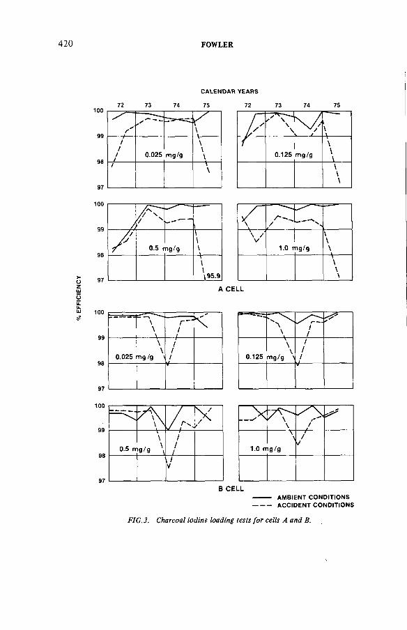
FOWLER
CALENDAR YEARS
7 2 73 74 7 5 72 7 3 7 4 75
A CELL
В CELL---------- AM BIENT CONDITIONS---------- ACCIDENT CONDITIONS
FIG.3. Charcoal iodine loading tests for cells A and B.

% E
FFIC
IEN
CY
IAEA-SM-245/22
CALENDAR YEARS
NOTE: ----------- AM BIENT CONDITIONSTO SCALE EXCEPT AS INDICATED ------------ACCIDENT CONDITIONS
FIG. 4. Charcoal iodine loading tests for cells С and D.
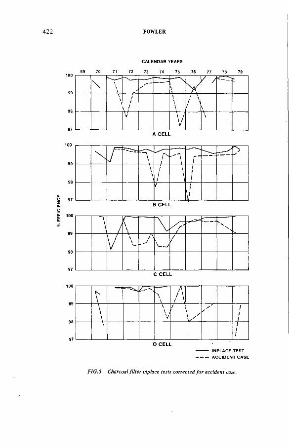
% E
FFIC
IEN
CY
422 FOWLER
CALENDAR YEARS
A CELL
В CELL
С CELL
D CELL---------- INPLACE TEST----------ACCIDENT CASE
FIG.S. Charcoal filter inplace tests corrected for accident case.

IAEA-SM-24S/22 423
The charcoal inplace tests are plotted against time for each cell. (See Figure 2.) Filter life by cells has been as follows:
Cell А В C DFilter Life-Years 6 9 4 6
The loading tests are plotted separately for each loading with ambient and accident conditions compared against time in Figures 3 and 4.
In Figure 5, the projected accident efficiencies arecompared with the inplace tests.
4.4 Charcoal Filter Conclusions
Inplace tests of charcoal filters are generally considered only a "Go - No Go" type test to determine the leak rate of the filtering system.
Those experienced in working with charcoal filtersconsider a laboratory test of a charcoal sample necessary todetermine qualitatively the adsorption capabilities of new or used charcoal.
Inplace test data are expected to be random and laboratory tests are expected to be orderly. The laboratory ambient and accident case data should be fairly consistent and predictable.
Examination of the inplace tests (Figure 2) as compared to the adjusted accident case (Figure 5) shows the inplace test data are more consistent and appear to more closely approach expected real conditions. The adjusted accident
case data have wide fluctuations and do not necessarily trend as might be expected.
Flow through the filters has been measured to be streamline even through the gates which are only one-fifth the area of the filters. Radiation measurements of the filters give higher readings at the center than at the edges. This would be expected based upon a streamline flow profile rather than a turbulent flow profile.
Examination of the laboratory tests of ambient versus accident conditions when plotted against time (Figures 3 and 4) is also confusing. Some of the loading test data gives general trends as would be expected but with wide

424 FOWLER
fluctuations. Other data such as for Cell A is not logically explained.
In 1977, samples were twice sent to an independent laboratory where both ambient and accident case samples were run. These compared favorably with the inplace and laboratory tests made at the plant.
We can conclude that the problems with the plant inplace test are no greater, and perhaps less, than with the laboratory tests. Because of the streamline flow and difficulties obtaining a representative charcoal sample of the whole bed, the inplace test is the best measure of the condition of our charcoal filters. Of course, frequent inspections are needed to detect charcoal settling, and canister or gasket deterioration.
5.0 FILTER CONTAMINANTS
Filter contaminants have been a concern in our experience with charcoal, particulate, and roughing filters.
5.1 Freon
Primary loop valve and piping repairs frequently require freezing the contents of a pipe to stop flow to the repair zone. The freezing is accomplished with a mixture of dry ice and freon. The freon is a trichloro-trifluoro-ethane (CC13CF 3).
Tests were run and it was determined that although the freon is readily picked up on the charcoal, it is soon eluted off by normal air flow and has no lasting effects. Within afew hours after use of freon, our filters are restored toprevious capacity. Thus, our only precaution is to be sure charcoal filter tests are not run at the same time freon is
being used in the system.
5.2 Hydraulic Oil
The gates to the filter cells are operated by hydraulic cylinders. Occasionally the cylinders have sprayed oil on the walls and on the roughing, particulate, and charcoal filters. The oil, in addition to collecting dirt, willabsorb iodine from the tests. Its most undesirable effect isthe contamination of the charcoal and severe reduction of iodine holding capability.

IAEA-SM-24S/22 425
The only answer to this problem is to clean up the oil and replace filters. We have been able to keep our cylinder malfunctions to a minimum and have not had further problems with oil in the charcoals. It might pay to avoid use of hydraulic actuators in a new design.
5.3 Paint
We have had occasion to repair the elastomer coatings within the reactor building. This is usually done by spray painting. To avoid loading our filters with paint particles and solvents, we close off the filter cells and exhaust the building air to atmosphere.
5.4 Atmospheric Dust
All of our ventilation air is washed prior to use. This removes the atmospheric dust and we have very little dust collecting on our particulate filters.
5.5 Radioactive Isotopes
It was mentioned earlier that radiation exposures were such in the filter cells to hinder our original DOP tests of the particulate filters. The isotopes consist mostly of Zr-Nb-95, Co-60 with lesser amounts of Mn-54. The working exposures which appeared to be at equilibrium in 1969 are as foilows:
Before Roughing Filter 300 mrem/hBetween Roughing & Particulate Filter 200 mrem/hBetween Particulate & Charcoal Filter 70 mrem/hAfter Charcoal Filter 30 mrem/h
The contact readings on the Roughing Filter were 1 rem or greater. Washing down the filter with water has achieved some exposure reduction. Chemical decontamination is also helpful. With our whole cell filter testing methods', there has been little incentive for additional decontamination.
6.0 MONITORING
6.1 Initial Monitoring
When the plant was started in 1963, we had analyzers for monitoring both radioactive iodine and particulates. Primary loop piping seepage rates resulted in a very wet exhaust gas. The analyzers became flooded with condensate. To
426 FOWLER
correct this problem, a copper condenser was installed ahead of the analyzer. Later, when thoroughly checking the system, we found the copper condenser was plating out the iodine and the condensate was capturing any remaining iodine and most of the particulates. Heating of the samples and various other methods of overcoming the problem were tried. The analyzers were eventually abandoned because their range was too low to provide meaningful information for an accident case.
6.2 Operating Case
For monitoring of normal operating conditions, samplers have been installed similar to the charcoal filter samplers. These contain both particulate and charcoal filters. The samplers can be replaced whenever desired and analyzed for particulates and iodine collected during the sample period. Normally, these samplers are changed each week.
A gamma monitor next to the sampler keeps a runningrecord of the sampler collection rate. To relate thisinformation to air flow, an anemometer has been installed in the stack and calibrated for the stack profile. The gamma monitor and anemometer are recorded at the sampler location.
6.3 Accident Case
For the accident case, large ion chamber gamma detectors are installed at the base of the stack. One is for the lowerrange and two are for high range release readings. One highrange gamma detector and the anemometer data are recorded in the reactor control room.
7.0 CONFINEMENT LEAK TESTING
The N Reactor confinement system operates on the principle of releasing the initial burst of steam from a pipe break and then sealing the building before fission products from melted fuel can reach the building atmosphere. The confiner is built to withstand 34.5 kPa. Once the confinement pressure has been reduced to about atmospheric pressure, the gasses are released to atmosphere through the fil ter.
The confiner leak test is conducted by measuring the air injection rate necessary to maintain a steady pressure and equal the leak rate. In practice, the change in pressure is measured for a number of injection rates.
IAEA-SM-245/22 427
The filter cells to the outlet gate are included in the confiner leak rate test made every six months. The leak rate is maintained below 5% of the flow rate.
8.0 GENERAL COMMENTS
Based upon N Reactor experience filtering reactor exhaust gases, the following suggestions are made to those who are designing new systems or currently maintaining reactor filter systems similar to ours.
8.1 Fans Downstream of Filters
Fans should be located downstream of filters. The downstream location will keep the fans relatively clean of radioactivity and will simplify all maintenance work. Also, it will avoid leakage to atmosphere at the filters.
8.2 Design for Filter Testing
Filter testing plans should be included in filter system design. Provide means for injecting the test material and then provide sampling systems upstream and downstream of the filters. The sampling system could possibly be a normal monitoring system.
8.3 Filter Tests During Reactor Operation
We have talked about the possibility of inplace filter tests during reactor operation. The main advantage of such a test is a possible saving of outage time. We have the capability of making such an iodine test of the charcoal filters. We could develop the capability for the DOP test of the particulate filters.
8.4 Costs of Maintaining Filters
Our annual filtering costs, reported in early 1974, are as follows:
Maintenance Filter Replacement Surveil 1ance
$ 3 000 $18 000 $19 000 $40 000
428 FOWLER
DISCUSSION
A.J. WILLIAMS: You stated that filter frames are sealed within the system using ‘bicycle inner tube’ type seals. Can I therefore take it that your safety analysis assumes that high temperatures within the system need not be considered?
K.L. FOWLER: That is correct. Our accident conditions are steam at atmospheric conditions, i.e. 100% humidity at 100°C, to which our seals are resistant.
R.D. COLLINS: You used NaCl for some filter tests. How many o f these tests were there and did you find that salt deposits produced any corrosion problems either at the time or subsequently?
K.L. FOWLER: There were 2 or 3 filter tests using salt nuclei. We are not aware o f any problems with salt deposits at the time or since, although some carbon steel corrosion was found which we attributed to the high-humidity atmosphere. There have been no problems with stainless steel equipment.However, we would probably not consider the use o f chlorides in the future because o f the hazard o f stainless steel corrosion.
R. BROWN: In Figures 3 and 4, what is the significance o f the time series variation o f % efficiency for accident conditions with charcoal filters? Are the variations correlated with event in your facility?
K.L. FOWLER: I have no definite explanation for the variation you mention, although it may well be related to sampling problems. The answer to your second question is that they are not.
R. BROWN: I f the variation does indeed represent experimental error or som e other random event, the data might be better represented as a distribution than as a tim e series.
K.L. FOWLER: This may be the case.A. McNAIR: We too have made a large number o f tests o f charcoal filter
efficiencies and have observed long term variations where, for exam ple, the efficiency recovers after a period o f decline. I wonder if anyone has an explanation for such observations.
T.E. BLACKMAN: One suggestion for the variable performance o f charcoal filters with time is that it is due to the adsorption and desorption o f poisoning agents. I think the experience reported by Mr. Fowler is repeated by other users o f charcoal filters w ho have also observed that a deterioration in filter performance is som etim es follow ed by an improvement for reasons which are often uncertain but appear to be related to such incidents as painting operations, oil spillages and so on.
K.L. FOWLER: We have tried to eliminate the incidents you have just m entioned as a contributing factor, but we are still not satisfied with our current explanations o f the variations.

IAEA-SM-24S/22 429
J.A. WILSON: In view o f the variations in charcoal filter life o f four to nine years which you m ention in your abstract, is it possible to establish a routine programme o f testing and inspection to optim ize labour and maintenance costs?
K.L. FOWLER: We base our sampling rate on experience to insure that charcoal degradation is detected before efficiency falls below 95%. We increased our initial sampling rate from once to four times per year, and then relaxed it to twice a year. We will continue to evaluate the sampling rate on the basis o f our experience.
M.W. FIRST: How did you verify that the reliability o f your DOP in-place test was ± 0.005%? If you merely verify that repeat tests give values ± 10%, this simply verifies repeatability, not accuracy.
K.L. FOWLER: The judgement o f the testing station was that the results are accurate to ± 0.005%, but we have not verified the accuracy.
P.H.J.M. SIGLI (Chairman): I was surprised at the long lives o f the activated charcoal filters which you said lasted for between four and nine years in the case o f a one-inch charcoal bed. Were these maintained as stand-by filters or as filters continually in service?
K.L. FOWLER: These filters are continuously in service during reactor operation in order to be available for accident cases. They are taken out o f service during reactor shutdown only when maintenance is required, which is infrequently.

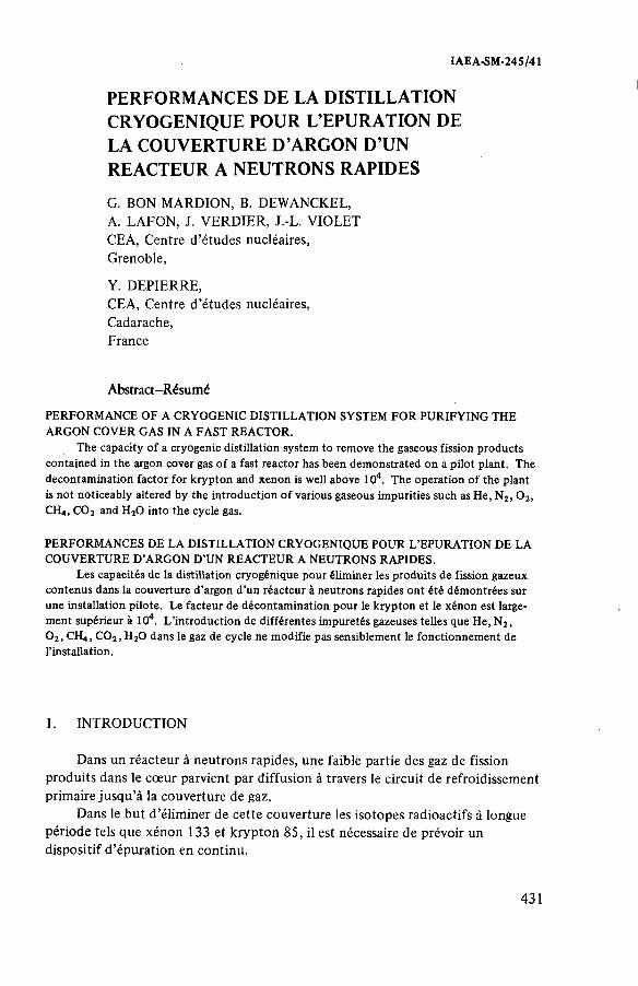
IAEA-SM-245/41
PERFORMANCES DE LA DISTILLATION CRYOGENIQUE POUR L’EPURATION DE LA COUVERTURE D ’ARGON D’UN REACTEUR A NEUTRONS RAPIDES
G. BON MARDION, B. DEWANCKEL,A. LAFON, J. VERDIER, J.-L. VIOLET CEA, Centre d’études nucléaires,Grenoble,
Y. DEPIERRE,CEA, Centre d ’études nucléaires,Cadarache,France
Abstract-Résumé
PERFORMANCE OF A CRYOGENIC DISTILLATION SYSTEM FO R PURIFYING THE ARGON COVER GAS IN A FAST REACTOR.
The capacity o f a cryogenic distillation system to remove the gaseous fission products contained in the argon cover gas o f a fast reactor has been dem onstrated on a pilot p lant. The decontam ination factor for k ryp ton and xenon is well above 104. The operation o f the plant is n o t noticeably altered by the in troduction o f various gaseous im purities such as He, N2, 0 2, C H 4, CO2 and H20 in to th e cycle gas.
PERFORMANCES DE LA DISTILLATION CRYOGENIQUE POUR L’EPURATION DE LA COUVERTURE D ’ARGON D ’UN REACTEUR A NEUTRONS RAPIDES.
Les capacités de la distillation cryogénique pour élim iner les produits de fission gazeux contenus dans la couverture d ’argon d ’un réacteur à neutrons rapides on t été dém ontrées sur une installation p ilote. Le facteur de décontam ination pour le k ryp ton et le xénon est largem ent supérieur à 104. L ’in troduction de d ifférentes im puretés gazeuses telles que He, N2,0 2, CH4 , C 0 2, H 20 dans le gaz de cycle ne m odifie pas sensiblem ent le fonctionnem ent de l’installation.
1. INTRODUCTION
Dans un réacteur à neutrons rapides, une faible partie des gaz de fission produits dans le cœur parvient par diffusion à travers le circuit de refroidissement primaire jusqu’à la couverture de gaz.
Dans le but d ’éliminer de cette couverture les isotopes radioactifs à longue période tels que xénon 133 et krypton 85, il est nécessaire de prévoir un dispositif d ’épuration en continu.
431
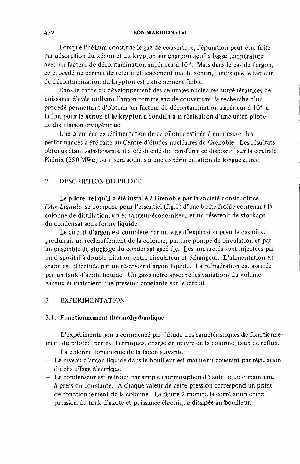
432 BON MARDION et al.
Lorsque l’hélium constitue le gaz de couverture, l’épuration peut être faite par adsorption du xénon et du krypton sur charbon actif à basse température avec un facteur de décontamination supérieur à 10 3 . Mais dans le cas de l’argon, ce procédé ne permet de retenir efficacem ent que le xénon, tandis que le facteur de décontamination du krypton est extrêmement faible.
Dans le cadre du développement des centrales nucléaires surgénératrices de puissance élevée utilisant l’argon comme gaz de couverture, la recherche d ’un procédé permettant d’obtenir un facteur de décontamination supérieur à 104 à la fois pour le xénon et le krypton a conduit à la réalisation d’une unité pilote de distillation cryogénique.
Une première expérimentation de ce pilote destinée à en mesurer les performances a été faite au Centre d’études nucléaires de Grenoble. Les résultats obtenus étant satisfaisants, il a été décidé de transférer ce dispositif sur la centrale Phénix (250 MWe) où il sera soumis à une expérim entation de longue durée;
2. DESCRIPTION DU PILOTE
Le pilote, tel qu’il a été installé à Grenoble par la société constructrice l ’Air Liquide, se com pose pour l’essentiel (fig. 1 ) d ’une b oîte froide contenant la colonne de distillation, un échangeur-économiseur et un réservoir de stockage du condensât sous forme liquide.
Le circuit d’argon est com plété par un vase d’expansion pour le cas où se produirait un réchauffement de la colonne, par une pompe de circulation et par un ensemble de stockage du condensât gazéifié. Les impuretés sont injectées par un dispositif à double dilution entre circulateur et échangeur. L’alimentation en argon est effectuée par un réservoir d’argon liquide. La réfrigération est assurée par un tank d’azote liquide. Un gazomètre absorbe les variations du volume gazeux et maintient une pression constante sur le circuit.
3. EXPERIMENTATION
3.1. Fonctionnement thermohydraulique
L’expérim entation a comm encé par l’étude des caractéristiques de fonctionnement du pilote: pertes thermiques, charge en oeuvre de la colonne, taux de reflux.
La colonne fonctionne de la façon suivante:— Le niveau d ’argon liquide dans le bouilleur est maintenu constant par régulation
du chauffage électrique.— Le condenseur est refroidi par simple thermosiphon d’azote liquide maintenu
à pression constante. A chaque valeur de cette pression correspond un point de fonctionnem ent de la colonne. La figure 2 montre la corrélation entre pression du tank d’azote et puissance électrique dissipée au bouilleur.
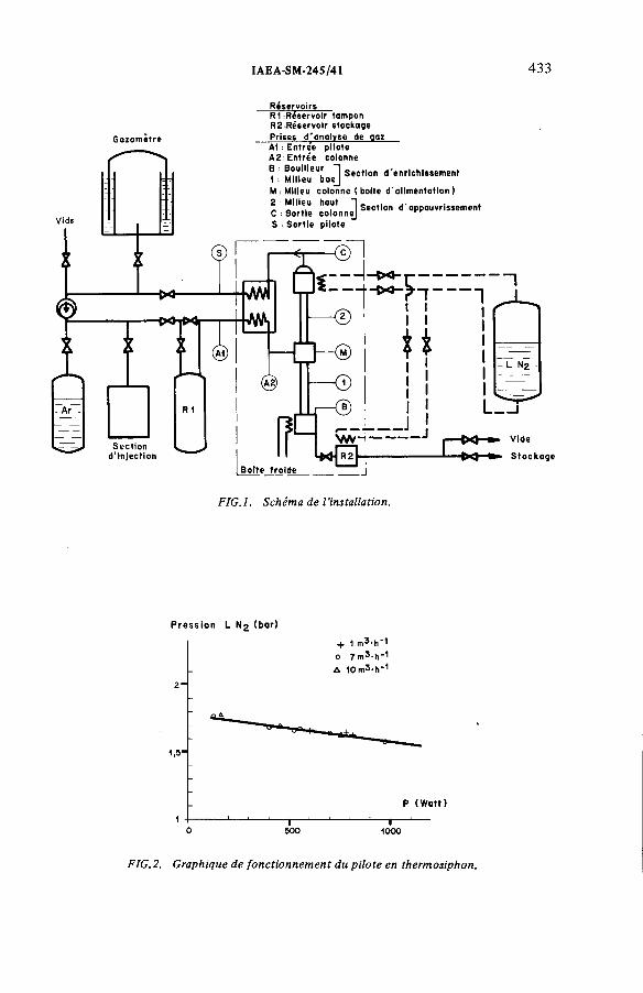
IAEA-SM-245/41 433
G a z o m e tre
R é se rv o irs R1 R éservo ir tam pon R 2 .R é se rv o ir sto ckage Prises d 'a n a ly s e de gaz A1 : E n tre e p ilo te A 2 : E n tré e colonne
B f i m llleU k "1 S e c tio n d 'e n r ic h is s e m e n t M ilie u b a e j: M ilieu colonn e (b o ite d 'a l im e n ta t io n )
M ilie u haut 1 s e c tio n d 'a p p a u v riss e m e n t ; S o rt ie c o lo n n e] r
S to c k a g e
FIG.l. Schéma de l'installation.
Pre ssion L (bar)
+ 1оA 10m3-h‘ 1
P (Watt)
—I--5 0 0
—I--1000
FIG.2. Graphique de fonctionnement du pilote en thermosiphon.

434 BON MARDION et al.
Y
FIG.3. Concentrations en krypton des phases vapeur et liquide au bouilleur.
3.2. Mesure des performances
L’expérim entation proprement dite sur la distillation des impuretés gazeuses de l’argon s’est déroulée en deux parties, l’une concernant le mélange binaire argon-krypton, l’autre des mélanges plus com plexes.
3.2.1. Distillation du binaire Ar-Kr
La distillation du binaire argon-krypton a été étudiée pour des concentrations volumiques en krypton de 5 X 10⁻⁹ à 5 X 1СГ7 à l’entrée du pilote. Pour rendre l’analyse accessible à de si faibles concentrations, on a utilisé com m e traceur l’isotope 8sKr à 4 % en volume dans le krypton injecté. La mesure des concentrations a été obtenue par circulation, dans des chambres d ’ionisation, de prélèvements effectués sur la phase gazeuse aux différents points indiqués sur la figure 1. Pour les concentrations comprises entre 10-7 et 1СГ12, on a utilisé des chambres différentielles de grand volume (10 dm3); pour les concentrations plus fortes une petite chambre (65 cm 3) a suffi; en dessous de 10-12 et jusqu’à 10-14 environ,

IAEA-SM-245/41 435
д Schm idt O M astero
FIG.4. Déterminations expérimentales du coefficient de volatilité.
on a dû recourir à des m éthodes d ’échantillonage et de reconcentration soit sur charbon actif, soit sur tamis moléculaire.
Le calcul du rapport de la somme des fractions de krypton collectées au bouilleur à la mesure de la concentration en krypton dans le gaz du bouilleur à permis de vérifier (fig.3) la valeur du coefficient de volatilité du krypton dans l’argon. Ce rapport a été comparé aux données de la littérature [1 —4] (fig.4).La valeur utilisée dans la suite est de 12,5 pour les conditions de l’expérim entation.
Un m odèle mathématique simplifié, qui donne les concentrations en krypton dans la colonne, a été établi à partir des conditions de fonctionnem ent du pilote.
Il s’écrit pour la phase gaz:
YB N a n - ly = — — + ---------a n G a n( « - l )
dans la zone d ’enrichissement, et
dans la zone d’appauvrissement;
436 BON MARDION et al.
Kr Essai 11 Kr Essai 70
101
10‘ 5— <.i * # Alim.
\- \ 0 .A lim . -
• % о 4
- ° \ \4------------ \ -10 4\ — 10 — \
\ \ -
Л o \ ]N ■ * i
\ 1
*
• i
1 1 1
1 1 o, f
1 i iB 1 M 2 С B 1 M 2 C
B BouilleurM Milieu - — - - C a l c u lC Condenseur
Essoi 80 Essai 96Kr Kr (ovec Xenon)
FIG.5. Concentrations en krypton de la phase vapeur.
Pour la phase liquide:
xn = «Уп
avec:
Ум et yB : concentrations du Kr respectivement au milieu de colonne et au bouilleur
n: numéro du plateau théorique à partir du bouilleur ou de la boîte d’alim entation (non com ptés)
a: coefficient de volatilité relative du krypton dans l’argon N: nombre de m oles de krypton injectées par unité de temps G: débit de gaz dans la zone d’enrichissement en krypton, calculé d’après
la puissance thermique délivrée et pris égal au débit inverse de liquide G' et L1: débits de gaz et de liquide dans la zone d’appauvrissement de la
colonne.
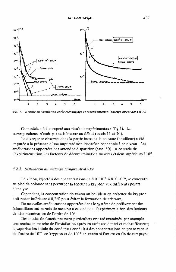
IAEA-SM-245/41 437
FIG. 6. Remise en circulation après réchauffage et recondensation (passage direct dans R 1.)
Ce m odèle a été comparé aux résultats expérim entaux (fig .5). La correspondance n’était pas satisfaisante au début (essais 11 et 70).
La divergence observée dans la partie basse de la colonne (bouilleur) a été imputée à la présence d ’une impureté non identifiée condensée à ce niveau. Les améliorations apportées ont amené sa disparition (essai 80). A ce stade de l’expérim entation, les facteurs de décontam ination mesurés étaient supérieurs à 104 .
3.2.2. Distillation du mélange ternaire Ar-Kr-Xe
Le xénon, injecté à des concentrations de 8 X 10⁻⁸ à 8 X 10⁻⁶, se concentre au pied de colonne sans perturber la teneur en krypton aux différents points d’analyse.
Cependant, la concentration de xénon au bouilleur en présence de krypton doit rester inférieure à 0 ,2 % pour éviter la formation de cristaux.
De nouvelles améliorations apportées dans le systèm e de prélèvement des échantillons ont permis de mesurer à ce stade de l’expérim entation des facteurs de décontam ination de l’ordre de 105.
Des m odes de fonctionnem ent particuliers ont été examinés, par exem ple une remise en marche de l’installation après un arrêt accidentel et réchauffement; la vaporisation totale du condensât conduit à des concentrations en phase vapeur de l’ordre de 10-4 en krypton et de 10-3 en xénon si l’on est en fin de campagne.

438 BON MARDION et al.
10" ’
10‘10
0,01
10-5
0,01 Concentration en krypton f---. »
I111) t f I t I
1 (1)IîIII_l__
HAUT COLONNE ( Chambre 101 )
(2 ) < 1 0
MILIEU h4AUT ( Chambre 101)
(2) < 10
(1 ) Injection calculée à l'entrée pilote .12) Mesure.(3) Mesure corrigée
FIG. 7. Injection de fortes bouffées de krypton.
La recondensation de ces impuretés ne pose aucun problème (fig.6): le fonctionnement de l’installation en circuit fermé dans des conditions normales après remise en froid permet de retrouver en quelques heures un niveau de concentration adéquat en sortie de colonne.
La rupture simultanée de plusieurs gaines de combustible dans le réacteur entraînerait un accroissement momentané des concentrations en gaz de fission à l’entrée de l’installation de purification; une estimation de la concentration maximale typique en krypton serait de l’ordre de 10 vpm dans le ciel de pile.Pour vérifier la réponse de l’installation à un tel accroissement, on a procédé à des injections de courte durée, avec une concentration à l’entrée inférieure à celle envisagée ci-dessus. Dès le milieu de la section d’appauvrissement (fig.7), la concentration en krypton devient inférieure à 10-10, donc sans doute très inférieure à cette valeur à la sortie de la colonne.
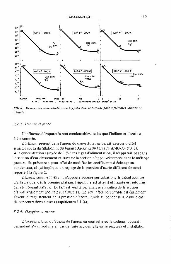
IAEA-SM-245/41 439
Bouillax Mlieu bas Milieu В Mb M B Mb M* : Kr _ о-. Kr + He _ V:Kr+He+Xe _ ¿iKr*He+Xe bouilleur charge en Xe
FIG.8. Mesures des concentrations en krypton dans la colonne pour différentes conditions d ’essais.
3.2.3. Hélium et azote
L’influence d’impuretés non condensables, telles que l’hélium et l’azote a
été examinée.
L’hélium, présent dans l’argon de couverture, ne paraît exercer d’effet sensible sur la distillation ni du binaire Ar-Kr ni du ternaire Ar-Kr-Xe (fig.8).A la concentration essayée de 1 % dans le gaz d’alimentation, il n’apparaît pas dans
la section d’enrichissement et traverse la section d’appauvrissement dans le mélange
gazeux. Sa présence a pour effet de modifier les coefficients d’échange au
condenseur, ci qui implique un réglage de la pression d’azote différent de celui
reporté à la figure 2.L ’azote, c o m m e l’hélium, n’apporte aucune perturbation; le calcul montre
d’ailleurs que, dès le premier plateau, l’équilibre est atteint et l’azote est retourné
dans le courant gazeux. Le fait est vérifié par analyse en milieu de la section
d’appauvrissement (point 2 sur figure 1). Le seul effet perceptible est également
l’éventuel réajustement de la pression d’azote liquide au condenseur, dans le cas
de concentrations élevées (supérieures à 1 %).
3.2.4. Oxygène et ozone
L’oxygène, bien qu’absent de l’argon en contact avec le sodium, pourrait cependant s’y introduire en cas de fuite accidentelle entre réacteur et installation

440 BON MARDION et al.
FIG.9. Concentration en oxygène dans la colonne.
de purification. Le risque présenté par la concentration de cette impureté est sa
transformation en ozone en présence des gaz de fission. L’expérimentation a
montré qu’il s’établit un équilibre aux différents niveaux de la colonne, fonction
de la teneur en oxygène dans le gaz d’alimentation (fig.9); l’absence de l’oxygène
dans ce dernier entraîne sa disparition progressive dans toute la colonne. Le
calcul du coefficient de volatilité de l’oxygène dans l’argon à partir des résultats
expérimentaux permet de retrouver les données de la littérature [5].
La teneur en ozone dans le liquide du bouilleur mesurée en fin d’essai a été trouvée égale à 1 X 10⁻⁶. Ceci est très inférieur à ce que l’on pouvait supposer
après avoir laissé séjourner pendant 6 mois quelques centaines de vpm d’oxygène en présence d’une source de 10 Ci; la concentration, estimée d’après les rares
données de la littérature [6, 7], aurait pu être de l’ordre de quelques 10~4.

IAEA-SM-245/41 441
Le méthane, s’il est présent dans le gaz d’alimentation, est accumulé dans le bouilleur où il finit par provoquer avec krypton et xénon des phénomènes
de cristallisation (concentration supérieure à 2 X 10⁻³). L’accumulation simultanée
mais peu probable de méthane et d’ozone pourrait présenter un risque qui n’a
pas été évalué dans cette expérimentation.
Le gaz carbonique et l ’eau peuvent être introduits dans le gaz d’alimentation en m ê m e temps qu’azote et oxygène de l’air. Le premier a été injecté à la con
centration de 3 X 10⁻³; la majeure partie est condensée dans l’échangeur, une
faible fraction passe dans la colonne où elle est retenue. L’eau introduite à la
concentration de 2 X 1СГ4 est retenue dans l’échangeur. Ni l’un ni l’autre n’induisent de perturbation visible dans le fonctionnement du pilote.
3.2.5. M éthane, gaz carbonique e t eau
4. C O N C L U S I O N
Le pilote de distillation des gaz de couverture a fonctionné de façon très
satisfaisante pendant toute la durée des essais (1,5 a). O n a pu montrer que le
facteur de décontamination était supérieur à 105 avec une concentration en krypton inférieure ou égale à 10-14 à la sortie de la colonne, aux limites des possibilités actuelles de l’analyse. L’indifférence du fonctionnement à l’égard
des impuretés véhiculées par le gaz d’alimentation, m ê m e en fortes bouffées à des
concentrations de plusieurs centaines, voire de milliers de vpm, montre bien la
souplesse du procédé. Les seules difficultés rencontrées au cours de l’expérimen
tation ont été des problèmes de cristallisation au bouilleur qui n’apparaîtront sans
doute pas dans l’exploitation sur réacteur, compte tenu des niveaux de concen
tration en impuretés du gaz à traiter. En définitive, ce procédé d’épuration de
l’argon, d’un fonctionnement simple, fiable et performant,paraît être bien adapté
au problème posé de la purification de l’argon de couverture des réacteurs sur
générateurs.
R E M E R C I E M E N T S
Les auteurs expriment leurs plus vifs remerciements à Messieurs Brosson
(CEN Cadarache, DSN/SESTR) et Charrier (CEN Bruyère-le-Châtel, SRDE)
pour leur contribution aux analyses des très faibles concentrations en krypton.
442 BON MARDION et al.
R E F E R E N C E S
[1] SCHMIDT,H., Z .Phys. Chem. (Frankfurt) 24 (I960) 265.[2] SEEMEYER, D., Verdampfungsgleichgewichte in den Systemen Stickstoff-Sauerstoff,
Argon-Krypton und Krypton-Xenon, Institut für Physikalische Chemie der Universitàt Gôttingen (1965).
[3] SCHOUTEN, J.A., DEERENBERG, A., TRAPPENIERS, N.J., Physica A 81 (1975) 151.[4] MASTERA, S.-G.J., Dampf-Flüssig-Gleichgewichtsdaten der Systeme Ar-N2 , Kr -Ar,
Kr-N2 und Xe-Kr sowie Lôslichkeitsgrenzen des festen Xenons und des festen Kryptons in flüssigen Luftkomponent, Kernforschungsanlage Jülich (1977).
[5] BURN, J., DIN, F., Trans. Faraday Soc. 58 (1962) 1341.[6] DMITRIEV, M.T., J. Appl. Chem. USSR 41 1 (1968).[7] RILEY, J.F ., in Oak Ridge National Laboratory reports: ORNL-3320 (1962) 43,
ORNL-3488 (1963) 42, ORNL-3650 (1963) 147.
DISCUSSION
G.E.R. C O L L A R D : The experimental values of the relative volatilities shown
in Figure 4 relate to krypton concentrations of between 5 and 95%, corresponding
to temperatures above the krypton triple point. Did you determine the values for
lower temperatures and, if so, what were they?
B. D E W A N C K E L : W e simply attempted to determine the volatility rate in
the experimental conditions, which were 87°K at atmospheric pressure and
extremely low concentration.
G.A. H U B E R T : If you have an accident involving serious fuel element failure
which caused severe contamination in the top part of the reactor and a high
release rate (a thermal transient, for example), the activated charcoals which are
at present designed to trap the Xe will rapidly become saturated. D o n’t you
think that your process would also be subject to saturation in such an accident
situation? What is its capacity to deal with the high activity in the top of the
reactor resulting from a large release of this type?
B. D E W A N C K E L : Our process, unlike activated charcoals, is not subject
to saturation. A serious accident could very probably be contained provided
that release rates were compatible with the facility and that the necessary extraction
operations were carried out to prevent possible blocking of the outlet channels.
R. von A M M O N : I have two questions; first, what will the m a x i m u m
krypton and xenon concentrations in your boiler liquid be before you transfer
the liquid to storage, and what kind of storage are you considering as an alternative
to controlled release to the environment? Secondly, could you provide some
information on the height, diameter and type of column you are using; does it
use plates or is it a packed column?

IAEA-SM-245/41 443
В. D E W A N C K E L : With reference to your first question, the normal period
between the beginning of the campaign and transfer from the boiler is about
one year, at the end of which I would estimate the concentrations to be some
10-3 for xenon and some 1СГ4 for krypton. The question of storage was not studied in this experiment, which was concerned solely with the process performance.
The solution we envisage for the Phénix reactor is controlled release.
Regarding your second question, we used a packed column with an overall
height of about 2 m and a diameter of less than 10 cm.


IAEA-SM-245/34
POLICY, TESTING AND ACCEPTANCE STANDARDS FOR TREATMENT PLANT FOR GASEOUS DISCHARGES FROM CEGB NUCLEAR POWER STATIONS
D.J. G R O O M
Central Electricity Generating Board,
Health and Safety Department,
London
C.W. FERN, B.A. W I L K I N S O N
Central Electricity Generating Board,
South Eastern Region
Scientific Services Department,
Gravesend, Kent,
United Kingdom
Abstract
POLICY, TESTING AND ACCEPTANCE STANDARDS FOR TREATMENT PLANT FOR GASEOUS DISCHARGES FROM CEGB NUCLEAR POWER STATIONS.
To minimize the radiological impact of releases o f gaseous waste under normal operation and accident conditions, various types o f gaseous waste treatm ent plant are installed at the CEGB’s nuclear power stations. For some time now it has been CEGB policy to routinely test HEPA filters and iodine sorption plant. Testing is undertaken by experienced teams specifically assigned to the task. The test methods adopted are described in detail and the current acceptance standards are given. The experience gained in testing HEPA filter installations using the condensation nucleus test method, and the difficulties presented by inadequate thought at the design stage, are highlighted. Methods of overcoming some of these difficulties are described, together with views concerning improvements in product specification which will be required in the future. Similarly, details are given on the experience gained from routinely testing iodine sorption plant using radioactive methyl iodide and the standard of acceptance required. Mention is made of a modular charcoal filter which has recently been developed to fit into a HEPA filter housing. Finally, it is concluded that routine testing of gaseous waste treatment plant is required to demonstrate assumed efficiencies exist in practice. The use of experienced teams assigned specifically to the task has been most effective. An element of independency between the test team and the station operator has public relations advantages.
1. INTRODUCTION
The Central Electricity Generating Board employs graphite moderated, carbon dioxide gas-cooled reactors for the generation of electricity from nuclear sources.
445

446 GROOM et al.
Two types of reactor are currently in operation. The earlier type are called Magnox and they had their reactor contained in a steel pressure vessel; the last two Magnox stations and all the later Advanced Gas- cooled Reactors (AGR) utilise a pre-stressed concrete pressure vessel.
The pressure of the CO2 in the Magnox reactors is in the range 9*3 bar to 27*5 bar and between 31 bar and 4l.3 bar for the AGR's.
One of the major sources of radioactive gaseous waste which requires treatment is inadvertent leakage and deliberate blowdown to atmosphere of the reactor coolant gas itself. Under normal operational conditions this contains neutron activated particulate and gaseous products together with very small amounts of fission products. The reactors are capable of being refuelled on-load and it is policy for fuel failures to be removed quickly from the core.
Ventilation air which is drawn from areas where radioactive materials are handled represents another major source of radioactive gaseous waste which has to be treated prior to discharge.
2. PROVISION OF TREATMENT PLANT
Different types of filtration and sorption plant is used to reduce the amount of radioactivity discharged in gaseous waste to as low a level as is reasonably achievable.
(i) Deliberate releases of reactor coolant are subject to filtration by ceramic candle or sintered metal type filters having typical design filtration efficiencies of 100% down to 5 micron and 95% for 2 micron particulates.
(ii) In the unlikely event of significant fission products being present in the reactor coolant provision is made to permit the reactor to be depressurised to atmosphere via iodine sorption plant which consists of deep, activated charcoal beds and high efficiency particulate filters.
(iii) Inadvertent, chronic leakage of reactor coolantis in the main swept into ventilation/cooling air
systems which are provided with particulate filters.
(iv) Ventilation air, drawn from areas where radioactive materials are handled, is subject to HEPA

IAEA-SM-245/34 447
filtration prior to it being discharged to atmosphere. In certain instances iodine sorption plant is also provided, particularly where the ventilation system serves areas in which irradiated fuel is handled.
The CEGB performs a comprehensive environmental sampling programme around each one of its nuclear power stations. The results of this programme show that the gaseous waste treatment plant which has been provided is effective in dealing with discharges during normal operation.
Plant provided to cater for the accident situation is related to the probability of occurrence and the magnitude of the resultant radiological impact. In the United Kingdom the Medical Research Council has issued recommendations (Ref. l) to assist operators in deciding what emergency actions would be appropriate in protecting members of the general public after an accidental escape of radioactive material. The recommendations relate to emergency reference levels (ERL's) of dose to which members of the general public may be exposed in the accident situation. The ERL's of dose are given for both the whole body (0.1 Sv.) and certain specific organs (e.g. Thyroid, Lung 0.3 Sv.).
The ERL is defined as:
An emergency reference level of dose is the radiation dose below which counter measures are unlikely to be justified. When the dose seems likely to exceed the ERL, counter measures should be taken if a substantial reduction of dose is likely to be achieved and if the counter measures can be carried out without undue risk to the community. The counter measures appropriate to doses only moderately in excess of the ERL should be such that they do not» involve appreciable risk to the community. Counter measures involving greater hazards should be called for only if radiation exposures would othe.rwise be considerable.
3. POLICY OF TESTING
A condition attached to each gaseous waste discharge Authorisation requires the emission of particulate material to be continuously sampled, assayed and reported. In this way a check is kept on the continuing effectiveness of operation of the particulate filtration plant provided to treat the waste stream given in 2 (i) and (iii). Under these circumstances no special test
448 GROOM et al.
procedure has been instituted to periodically prove the performance efficiency.
Iodine sorption plant is provided to deal primarily with the accident situation. This plant is routinely tested once every two years using radioactive methyl iodide. This test provides an absolute measure of the efficiency of the plant for the removal of the most penetrating speciejof radioactive iodine. Acceptance standards are based on the removal efficiency demanded by the radiological safety case plus an allowance for the reduction of efficiency caused by now well established charcoal ageing effects.
HEPA filter installations are also tested once every two years using the condensation nucleus test method. It is debatable whether this method provides a quantitative measure of filtration efficiency. What is sure, however, is that the method demonstrates the absence of leak paths around or through holes in the filters themselves and since only HEPA filters which have been individually tested to British Standard (BS)3928 (Ref. 2) are employed, the efficiency of the installation is established as at least 99«95%.
Re-tests within the two year period are demanded if engineering work has been carried out on these plants or installations such that it may have had a deleterious effect on their performance. This is also true if it is thought possible that iodine sorption plant may have been exposed to known "poisons" such as oil or paint fumes.
k . DETAILS OF TEST METHOD AND PROCEDURE
¿t. 1 HEPA Filters
Three main types of fil^ter system (Canister, Unipack and Ladderack) are installed at the CEGB nuclear plants, see Figs. 1 to 3* To meet the policy outlinedthe test
procedure must be capable of identifying system leaks. Consequently, the test is based on the philosophy of accepting the filter at its certified penetration efficiency and then ensuring that no additional leaks are present or introduced in the system as a result of the fitting operation. In order to achieve the maximum sensitivity a test aerosol is required which will:
(i) be completely removed by a sound filter correctly fitted in its housing, but which
(ii) would give a positive indication of gasket leakage and/or filter damage.

IAEA-SM-245/34 449
FIG.l. Canister system.
FIG.2. Multiple unipack system.
FIG.3. Ladderack system.
In 1972 an evaluation of the available test methods was carried out within the CEGB research organisation and this indicated that these conditions could be obtained by utilising condensation nuclei (CN) as the test aerosol. Detection of CN with adequate sensitivity is achieved using Pollack-Nolan counters. The test equipment is shown in Fig. 4 and Fig. 5 shows a schematic of the test procedure. The basic procedure is as follows:
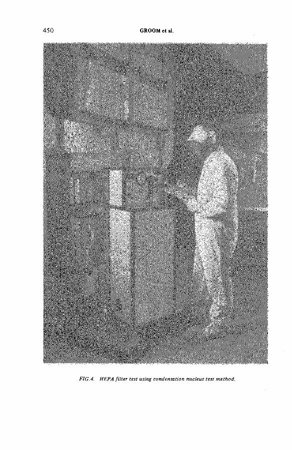
4 5 0 GROOM et al.
FIG.4. HEPA filter test using condensation nucleus test method.

CN Injection
IAEA‘SM -245/34 451
HEPAFilter Fan
PollackNolan counter
c.
FIG.5. Schematic o f filter test arrangement.
PollackNolan counter
A. B.
(a) Determine the background concentration of naturally occurring CN at the filter/fan exhaust (Point C,Fig. 5). This should be less than 100 nuclei-cm“3.If this value is exceeded it indicates the presence of duct leaks downstream of the filter. These leaks must be sealed before proceeding with the test; this is often a time consuming task.
(b) Introduce a very high concentration of CN at the filter inlet (Point A, Fig. 5). Typically, concentrations between 0 . 2 5 x 10® nuclei■cm-3 and k x 10^ nuclei cm"3 are achieved (at point B) in practice. If a measure of the percentage penetration is required then the 0.25 x 10 nuclei-cm-3 figure becomes a maximum as this is the highest concentration which can be measured quantitatively by the counter.
(c) Re-determine the concentration of CN at the filter/fan exhaust (Point C). No significant increase in the background level indicates a leak tight and satisfactory system. A significant increase (see later) above the background concentration indicates a system leak.
If a leak is identified, isolation of individual filters is carried out until the fault has been located and the filter either refitted or replaced as necessary. The method of filter isolation depends upon the type of installation under test.
Canister systems are the easiest as they consist of individual filters each capable of isolation. Unipack systems are more difficult because the discharge side is common. However drilling a number of 9 mm diameter holes
452 GROOM et al.
(plugged when not in use) along each side of the outlet duct allows a series of samples to be taken. If the holes are positioned 80 to 100 mm below the joining faces of adjacent filters as shown in Fig. 2 and if sampling commences at the downstream end of the system and progresses upstream, sufficiently representative samples are obtained such that the high reading falls when the faulty filter has just been passed. For confirmation this procedure is repeated down the other side of the filter bank.
Ladderack systems are extremely difficult to test as a unit and filter isolation poses significant difficulties. This is particularly true where the system discharges directly to atmosphere such as occurs when the plant has been incorporated into the building wall. When the Ladderack unit discharges into a downstream duct, identification of individual filter leaks can only be achieved by a process of elimination. Such a procedure is extremely time consuming and can create leaks in the process. In an attempt to overcome these difficulties, major modifications involving the fitting of extension ducts which incorporate multiple-orifice sample probes are currently being tested.
As stated in 4.1 (c) a significant increase in the background concentration of CN indicates a leak within the system. The current standard of acceptance used by the CEGB requires the CN concentration to increase by no more than 25 nuclei-ст-З above the previously measured background. Such an increase would indicate a penetration above the certified level of approximately 0.01%. In practice HEPA filters are supplied with certified efficiencies of better than 99*95%. Use of the current standard of acceptance provides a workable basis for the test teams and demonstrates a high filtration efficiency exists consistent with the manufacturer's claimed efficiency.
To demonstrate that the manufacturer's claimed filtration efficiency for each filter is being maintained, spot checks are performed on filter units as supplied; the test procedure being that required under BS 3928 against which the manufacturer issues his certificate of efficiency. In addition experimental work is programmed within the CEGB to determine whether any correlation exists between the various filter testing methods currently available, and in particular between the CN method and the established quantitative methods employing either sodium chloride or dioctyl phthalate (DOP) aerosol. Studies on the effect of
leak size on apparent efficiency are at an early stage, as are the methods of identifying individual filter leaks in Ladderack systems.

IAEA-SM-245/34 453
FIG.6. Typical arrangement o f iodine sorption plant - Magnox reactor.
k.2 Iodine Sorption Plant
Each of the CEGB nuclear power stations has at least one iodine sorption plant which is capable of serving both reactors. At the earlier Magnox stations this type of plant was provided to cater for the accident situation where a significant release of fission products could occur to the reactor coolant circuit in the unlikely event of massive fuel clad failure. To minimise the release of these fission products to atmosphere the coolant from each reactor can be discharged through gaseous treatment plant which■consists of coarse and fine particulate filters and a deep charcoal bed. The charcoal bed is intended to remove radioactive iodine and a typical design is shown in Fig. 6.
A bed of charcoal approximately 300 mm deep is contained in a flanged basket which is supported by and bolted to a flange welded round the circumference of the containing pressure vessel. A gasket is sandwiched
454 GROOM et al.
between the flanges and effects a seal to prevent gas bypassing the charcoal. The gas flow is downwards throughthe charcoal and a metal mesh grid placed above the charcoal prevents any displacement.
A plate to which are fitted high efficiency particulate filters is positioned over the charcoal basket and a further gasket sandwiched between the upper face of the basket flange and this cover plate prevents gas by-passing the filters. All free space inside the pressure vessel is filled with copper or silver plated copper knit-mesh to remove elemental iodine vapour. Coarse ceramic prefilters are usually housed in a separate pressure vesselupstream of the charcoal bed.
The iodine sorption plant is designed so that the maximum linear face velocity of gas incident on the charcoal is 0.6 m • s"l giving a minimum gas stay time in the charcoal of 0.5 s which is sufficient to remove with high efficiency the penetrating species,methyl iodide. The total reactor coolant charge of some 100 t. of carbon dioxide can be de-pressurised through this plant within a day.
The provision of iodine sorption plant is more extensive at the later stations, particularly the AGR's .At these stations fission product contamination of the main reactor circuit cannot at this stage be ruled out due to the use of much higher rated fuel and consequently routine treatment of reactor coolant discharges for iodine removal has been provided.
The charcoal used in all CEGB iodine sorption plant is an activated coal-based type manufactured by Sutcliffe Speakman & Co. Ltd. (Type 207B) which is of 8/12 B.S.S. mesh size (1.4 to 2 mm diameter granules); the base material is spray impregnated to 1.5% by weight with potassium iodide. Experience has shown this material to possess very high decontamination ability for methyl iodide, typical decontamination factors in the range of 105 to 10° are measured with freshly produced material. This type of charcoal has been in use for over a decade and its ageing characteristic is well known.
Safety assessments of the effects of releases of radio-iodine on members of the general public in the immediate environment following postulated accidents lead to the conclusion that it is desirable for the iodine sorption plant to have a minimum decontamination factor of around 200 to ensure that one ERL is not exceeded off-site. Using ageing data derived from research performed by the United Kingdom Atomic Energy Authority (UKAEA) at Windscale (Ref. 3) it can be shown that the decontamination factor of charcoal stored in a static air atmosphere will fall from

IAEA-SM-245/34 455
Glove box
FIG. 7. Schematic arrangement o f m ethyl iodide injection rig.
106 to 200 in approximately six years and from 103 to 200 in approximately two years. In practice the charcoal bed is maintained under an atmosphere of carbon dioxide and this has been found to retard the ageing process. However, consistent with the worst ageing experienced the acceptance standard on test has been set at a minimum decontamination factor of 1 0З.
The actual testing procedure requires an equilibrium flow of reactor carbon dioxide of about 5 t •h - 1 to be established by passing some reactor coolant through the plant whilst maintaining the reactor gas pressure by makeup with fresh carbon dioxide. A sample of iodine-131 labelled methyl iodide is injected into the circuit upstream of the charcoal bed by means of special equipment developed at the UKAEA establishment atWindscale and shown schematically in Fig. 7- The injection is made from a pressurised system which is contained in a glove box and suitably connected to an injection point. A capsule containing the methyl iodide is broken by means of a crushing valve and the released methyl iodide is blown into the carbon dioxide by maintaining a flow of nitrogen or- helium at ambient temperature through the equipment from a gas bottle. The equipment permits injection up to full reactor operating pressure.
Samples of the coolant are continuously taken from positions immediately upstream and downstream of the
456 GROOM et al.
charcoal bed. The samples are passed through 18/52 B.S.S. mesh (O.5 to O.85 mm diameter), type 207B, impregnated charcoal contained in special sampling holders. The sampling flow rates are kept equal by appropriate flow control instrumentation.
The charcoal in the sampling holders is usually changed after 30 min, then after 1 h, then again after 2 h. a total sampling period of 3 h 30 min. The charcoal samples are counted on a suitably calibrated gamma spectrometer and the ratio between total activity of inlet and outlet samples obtained.
Three tests are usually carried out:
(a) A preliminary test using no injected methyl iodide in order to check flow rates, injection equipment, and to establish the background. The duration of this test is about 1 h.
(b) A test using about 0.1 mCi of iodine-131 labelled methyl iodide to give a preliminary estimate of the decontamination efficiency of the charcoal bed. The test duration is again of 1 h.
(c) A test using approximately 10 mCi of iodine-131 labelled methyl iodide. This is the main test and it takes about 3 h 30 min. The test is performed under flow conditions which produce the shortest gas stay time in the bed which is likely to occur in an accident situation so that a conservative assessment of the performance of the plant is obtained.
5. OPERATING EXPERIENCE
5.1 HEPA Filter Installations
In general terms the CEGB Magnox power stations were designed in the late 1 9 5 0's, early 1 9 6 0's and the technology applied to the treatment of gaseous wastes was based very much on the then best available conventional ventilation plant principles together with the use of absplute filters. No detailed attention was paid to the design from testing aspects and no routine testing was undertaken until the mid-1970’s. To overcome some of the practical problems and to achieve the high standards currently required the CEGB utilise specialist HEPA filter test teams.
The practical problems encountered are associated with filter fitting, the design of filter and housing, and their physical location. Fitting problems arise from the requirement to observe contamination controls which imposes a semi-remote handling technique. This is made more

IAEA-SM-245/34 457
difficult by ambiguous markings on the filter which can result in the filter being fitted incorrectly i.e. upside down or with the air flow going in the wrong direction. Problems also arise when fitting high temperature filters which use fibre glass gaskets. Gasket residues can be left on the filter housing causing sealing difficulties.
Removal of the extraneous material is made difficult and time consuming due to the necessity to take precautions against possible radioactive contamination.
Basic design faults are apparent in most systems.Filter construction provides little or no protection for the filter element and generally their handleability is poor. As a consequence finger hole damage occurs all too frequently. Manufacturing tolerance in both filter and housing are generous resulting in poor sealing from looseness of fit or misalignment of the sealing faces. In many instances the clamping systems rely on a simple cam arrangement which is incapable of adjustment and hence of accommodating the range of tolerances experienced in practic e.
Finally, problems have occurred from inadequate thought being given to the requirement to test. Such problems are mainly concerned with ease of access and suitable provision for test aerosol injection and sampling. In a limited number of cases because of high radiation dose rates access to the plant is restricted to periods when the reactor is off load.
Because of the difficulties experienced and the increasingly stringent reliability demanded of such plant, the CEGB is placing considerably more emphasis on the initial design aspects of gaseous waste treatment systems, utilising the experience gained by incorporating practical advice from the test teams. Provisions are now made for sampling and injection systems to be fitted simply and with adequate access. The use of Ladderack type installations will only be accepted when no other alternative is practicable and means of filter isolation are incorporated. Minor modifications to the Unipack system are being investigated with the manufacturer with the aim of segregating individual filter flows.
In addition the CEGB is reviewing its purchasing and specification policy for filter installations covering both the filter and its housing. In this way it is hoped to achieve a standard filter with improved handling characteristics and more definitive fitting instructions. Higher constructional standards will be required and tolerances tightened thus reducing fitting and sealing problems.
458 GROOM et al.
By these means it is hoped that routine maintenance and testing of CEGB HEPA filter installations will be improved such that the task is less onerous and more readily accepted.
5.2 Iodine Sorption Plant
In 1969 the CEGB started a programme of routine in-situ testing of iodine sorption plant installed at its Magnox nuclear power stations. Difficulties were experienced in obtaining satisfactory decontamination factors for this plant due mainly to leakage past seals which resulted in the gas by-passing the charcoal bed. Details of the problems encountered and the remedial measures which were taken have been previously reported (Ref. 4).
The results of in-situ tests performed during the past six years have shown that the engineering remedies adopted have been effective. Also during this period a major change in the method of testing was instituted. A contract was negotiated with the UKAEA (Nuclear Power Development Laboratories, Windscale) to carry out all the in-situ testing of the CEGB's iodine sorption plants. A team of technically well qualified and experienced personnel have been assigned to this task. The current test programme requires an in-situ test to be carried out at least once every two years on 33 iodine sorption plants. The tests are performed according to an agreed programme; the team visits each nuclear power station in a mobile test laboratory which has been purpose built for the j.ob and makes the team self sufficient except for electrical power supplies. To date no test has shown a plant decontamination factor less than 1000, and in most cases measured decontamination factors have been far in excess of this figure.
The design of the iodine sorption plant installed at the AGR power stations has benefited from the experience gained with the earlier Magnox type. Details of the engineering changes incorporated into the later designs have been reported elsewhere (Ref. 5)» Routine in-situ tests carried out on these later plants have shown the improvements to have been effective in achieving consistently high measured decontamination factors.
It should be noted that most of the iodine sorption plants installed at the CEGB power stations are maintained on a standby basis for use under accident conditions. In this mode the charcoal is stored under clean dry carbon dioxide. Experience has shown that under such conditions the useful life of the charcoal is extremely long and some charcoal beds have shown no effective deterioration of performance over a period of nine years.

IAEA-SM-245/34 459
Based on experience the CEGB consider that there is great advantage in having a single group assigned to carrying out in-situ tests on iodine sorption plant. A uniform test procedure is performed by experts which
allows the results of tests to be directly compared. The test team is independent of the operators and this element has public relations value particularly since the plant being tested is provided to deal with the accident situation.
A few years ago the requirement to provide some iodine sorption capacity for ventilation systems serving areas in which irradiated fuel was handled, became apparent. This led to the development of a modular charcoal filter which was capable of fitting into the standard HEPA filter housing. A number of these types of plant have recently been installed at the Magnox power stations. Tests performed on these installations have shown initial decontamination factors in excess of 5000. It is too early to be able to predict how the in-service sorption performance will vary with time. The design specification, which took into account experimental ageing data in air, was drawn up to provide an operational life expectancy of at least two years. The performance of this modular charcoal filter will be subject to an extensive investigational programme incorporating both rig and in-situ plant measurements.
6. CONCLUSIONS
6.1 A comprehensive environmental monitoring programme is performed around each of the CEGB nuclear power stations. This programme starts at least one year prior to station commissioning and continues throughout the station's operating lifetime. The results from this programme continue to demonstrate that the effect of discharging gaseous wastes are negligible; and in the early stages, based on this evidence, no routine testing of gaseous waste treatment plants was undertaken. It became apparent, however, that under accident conditions, plant efficiency was being assumed but this was not being practically demonstrated. This led to the adoption in 1969 of a policy of routinely testing iodine sorption plant and later, HEPA filter installations. The CEGB adopted existing test methods and instituted a routine testing policy of its own volition; conditions are now being attached to new radioactive gaseous discharge Authorisations which statutorily require such testing to be performed and reported.
6.2 Experience gained over the past 17 years has shown inadequacies in the design of certain types of gaseous waste treatment plant both from the performance and test aspects. For HEPA filters, whilst the

460 GROOM et al.
performance of the filter material itself is not in question, the robustness of the filter unit and the standard of construction of the housing will have to be improved in future to meet the greater reliability which will be demanded. Similarly, whilst the performance of the activated charcoal for the retention of radioactive iodine has been shown to be very satisfactory,under simulated conditions which approach predicted accident situations as closely as the plant will allow, the engineering design of the charcoal beds themselves, particularly the method of sealing, was shown by testing to be inadequate. These inadequacies have now been overcome by engineering remedies at the earlier stations and by fundamental changes in design at the later ones.
6.3 To ensure gaseous treatment plant is supplied which is capable of fulfilling its design intent and which is capable of being operated, maintained and tested to meet CEGB requirements, it will be necessary to issue new and tighter specifications which will cover the detailed design of HEPA filter units and their housing. The provision of engineering features which will readily permit tests tobe performed will be a requirement in accepting the design of future gaseous waste treatment plant.
6.4 The employment of experienced teams assigned to test HEPA or iodine sorption plant has been shown to be most effective. An element of independency is obtained between the tester and the operator by employing teams drawn from CEGB Regional Scientific Service Departmentsto test HEPA filter installations. Complete independency in testing iodine sorption plant has been obtained by employing an experienced team supplied under contract from the United Kingdom Atomic Energy Authority. The public relations aspect of this can only be advantageous.
REFERENCES
1. H.M.S.O. (1 9 7 5) Medical Research Council Criteria for controlling radiation doses to the public after accidental escape of radioactive material.
2. British Standards Institute BS 3928 (1969) Method for sodium flame test for air filters.
3. TAYLOR L.R. and TAYLOR R. UKAEA TRG Report 2483(W) (November 1973)The ageing of impregnated charcoals.
IAEA-SM-245/34 461
4. STEAD M. CEC Seminar on Iodine Filter Testing, Karlsruhe, Dec. 1973*Experience in testing iodine sorption plants associated with CEGB gas-cooled reactors.
5. PASSANT F.H. CEC Seminar on Iodine Filter Testing, Karlsruhe, Dec. 1973*The design of iodine trapping plants in the UK for CEGB gas-cooled reactor use.
DISCUSSION
H. DEUBER: Why do you use copper knitmesh which in practice retains only elemental iodine? If the activated charcoal retains the methyl iodide, then it will retain the elemental iodine sufficiently well also.
D.J. GROOM: Copper knitmesh was incorporated into the iodine sorption plants of the early Magnox stations as a precautionary measure. Experience gained from subsequent research work and during reactor operation has shown the inclusion of copper knitmesh to be unnecessary and it is not present in the later designs.
K. FISCHER: Did you investigate the size distribution of the aerosol particles contained in the coolant in operational conditions, and do you assume that the decontamination factor for the aerosol particles is the same as that for the radioactivity to be retained?
D.J. GROOM: No detailed investigations have been carried out to my knowledge. Under normal operating conditions existing plant performs satisfactorily. The more important aspect, I would suggest, is the size distribution of aerosol under accident conditions. For radiological impact calculations it is assumed that radioactive aerosols penetrate the filter at its certified value. For HEPA filters this is obtained by measurement using the standard sodium chloride test method. The CEGB purchase only certified HEPA filters with efficiencies of 99.95% or better.
J.A. WILSON: Is any work being done on the control of discharges o f 35S to the atmosphere?
D.J. GROOM: During the design stage it was predicted that greater quantities of 35 S would occur in the gaseous wastes from AGR stations than from the earlier Magnox type. Some work on possible ways of trapping 35 S was conducted and outline plant designs were produced. Activated charcoal was demonstrated to trap 35 S with high efficiency.
To date routine measurements of the amount of 3sS released and its behaviour in the environment have shown that it has an insignificant impact. In the absence of need, the work on 35 S trapping has now ceased. Although no trapping plant

462 GROOM et al.
has been installed to co n tro l35 S releases, space has been left for its installation should the need arise in the future.
E. PALACIOS: With reference to absolute filters, I would like to have some information on your experience of testing new filters. Have you observed much damage as a result of transport?
D.J. GROOM: A good standard of packaging is used for the transport of HEPA filters from the manufacturer to the power station. Filters are unpacked just before they are fitted into the housing and a visual inspection for damage is carried out. Very few filters are found to be damaged.
Following replacement of a filter, a retest of the installation is performed using the CN method. This would indicate any damage which was not visible.

IAEA-SM-245/4
EXPERIENCE GATHERED IN MONITORING THE EMISSIONS FROM AN INCINERATION FACILITY FOR RADIOACTIVE WASTES
L.A. KÔNIG, H. SCHÜTTELKOPF,B. FESSLERHauptabteilung Sicherheit, Radioôkologie,Kernforschungszentrum Karlsruhe GmbH,Karlsruhe,Federal Republic of Germany
Abstract
EXPERIENCE GATHERED IN MONITORING THE EMISSIONS FROM AN INCINERATION FACILITY FOR RADIOACTIVE WASTES.
The FERAB incineration facility for combustible radioactive wastes processes materials of very heterogeneous compositions and, accordingly, the off-gases are very complicated in composition. The temperature of 240°C, the presence of tar and other organic substances, aerosol and gaseous radioactivity, high humidity of the air, and corrosive gases impede monitoring of the activity in this exhaust air system. Exhaust air monitoring includes the continuous and discontinuous measurement of a- and (3-activities, the measurement of 1311,129I and 12SI, the measurement of 3H, plutonium and ^ S r, and the analysis of gamma emitters by spectrometry. Problems arose in the past as regards all these methods of measurement but they have now been solved. Any values exceeding the activity limit values are generally due to incineration material incorrectly specified. This leads to the introduction of inadmissibly high activities in the incineration facility. The comprehensive experience collected in careful monitoring of the FERAB exhaust air had such a positive effect on the operation that the radioactivity of the flue gas can now be perfectly monitored without trouble and the number of cases in which the extremely low maximum permissible monthly values are exceeded remains very small.
1. THE FERAB FACILITY
The FERAB facility has been operated since 1971 on the site of the Karlsruhe Nuclear Research Centre as an incineration facility for solid radioactive wastes [1 ,2]. It serves the purpose of reducing the volumes and masses of these wastes and of providing residues suitable for ultimate disposal. The operational temperature in the furnace varies from 1 0 0 0 -1 100°C, the throughput amounts to 50—70 kg/h and the ratio of volume reduction lies between 1:50 and 1:100. The ratio of weight reduction is around 1:15. The material to be incinerated includes contaminated residues produced at the Karlsruhe Nuclear Research
463
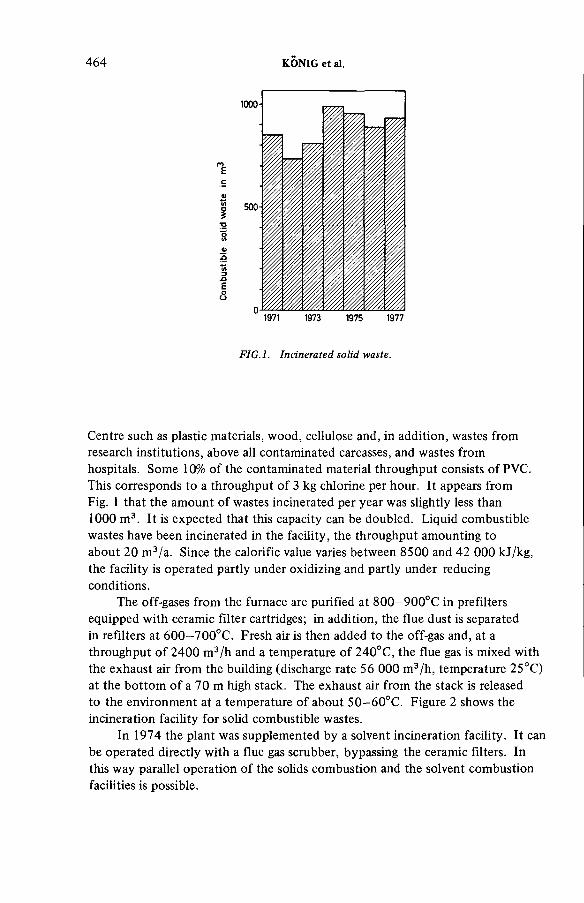
464 KÔNIG et al.
FIG.l. Incinerated solid waste.
Centre such as plastic materials, wood, cellulose and, in addition, wastes from research institutions, above all contaminated carcasses, and wastes from hospitals. Some 10% of the contaminated material throughput consists of PVC. This corresponds to a throughput of 3 kg chlorine per hour. It appears from Fig. 1 that the amount of wastes incinerated per year was slightly less than 1000 m3. It is expected that this capacity can be doubled. Liquid combustible wastes have been incinerated in the facility, the throughput amounting to about 20 m3/a. Since the calorific value varies between 8500 and 42 000 kJ/kg, the facility is operated partly under oxidizing and partly under reducing conditions.
The off-gases from the furnace are purified at 800—900°C in prefilters equipped with ceramic filter cartridges; in addition, the flue dust is separated in refilters at 600—700°C. Fresh air is then added to the off-gas and, at a throughput of 2400 m3/h and a temperature of 240°C, the flue gas is mixed with the exhaust air from the building (discharge rate 56 000 m3/h, temperature 25°C) at the bottom of a 70 m high stack. The exhaust air from the stack is released to the environment at a temperature of about 50—60°C. Figure 2 shows the incineration facility for solid combustible wastes.
In 1974 the plant was supplemented by a solvent incineration facility. It can be operated directly with a flue gas scrubber, bypassing the ceramic filters. In this way parallel operation of the solids combustion and the solvent combustion facilities is possible.

® Thermocouple@ Pressure d ifference (g ) ph- Indication
0 Throttle gatef t Motor drive for0 th ro ttle
A Hand waive^ Valve «with m otor drive
Check valve
@ B low er0 Temp, m easurer
ф Press Indicator
R e s trk to f-F lo w
В Monitor
R efiltering
FIG.2. Incineration installation at the Nuclear Research Centre, Karlsruhe,
IAEA
-SM-245/4
465

466 KONIG et al.
^ '«<=flowmeter' condensate collecting
vessel
x—valve•T I
)-pump
cryom at
FIG.3. Sampling device for tritium-bearing condensate.
2. ACTIVITY MONITORING IN THE FERAB EXHAUST AIR
To monitor the exhaust air system samples are taken continuously. The activity is monitored continuously as regards a- and |3-activities and, in a discontinuous mode as regards a- and ^-activities, 3H, radioiodine, 90Sr, plutonium and significant 7-emitters.
Up to 1972 the sample gas was directly collected from the flue gas;2 m3/h was cooled to room temperature via a cooling system and the cooled gas was sucked through glass fibre filters 20 cm in diameter. However, this method has not stood the test owing to the nature of the flue gas; the temperature of the off-gas to be monitored was 240°C, it contained tar and other organic substances, radioactive aerosols and gases, as well as corrosive gases such as Cl2 and HC1.
The formation of condensates greatly disturbed the monitoring of activity. Since 1972 the flue gas has been mixed with the exhaust air of the building and 20 m3/h was taken from this mixture and supplied to a glass fibre filter 20 cm in diameter.
A pseudocoincidence system is used for continuous measurement of the aerosol filters exposed in the exhaust air collecting station [3—5]. The exposed glass fibre filters are removed every working day and measured in a large area flow counter for low-level measurements to determine their a- as well as their ^-activities.
In the off-gas of the incineration facility 3H occurs primarily as НТО. For sampling, a 1.9 m3/h bypass stream of the exhaust air flow is cooled in a coil condenser to a temperature near the freezing point. The condensate drops into a collector from which samples can be taken at any time (see Fig. 3). The tritium concentration in the condensate is measured by means of the liquid scintillation technique [6].
A 5 m3/h bypass stream is passed through an activated carbon filter to monitor the radioiodine present in the exhaust air. The activated carbon and the aerosol filters are measured by gamma spectrometry.
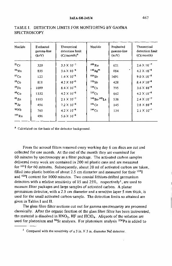
IAEA-SM-24S/4 467
TABLE I. DETECTION LIMITS FOR MONITORING BY GAMMA SPECTROSCOPY
Nuclide Evaluatedgamma-line(keV)
Theoretical detection limit (Ci/ month)3
Nuclide Evaluatedgamma-line(keV)
Theoretical detection limit (Ci/month)
51 Cr 320 3.5 X 10' 7 106 Ru 621 2.6 X 10~754Mn 835 3.6 X 10~8 noAgm 884 4.2 X 10' 8S7Co 122 1.4 X 10~8 124Sb 1691 9.0 X 10' 858 Co 811 4.2 X 10~8 125Sb 428 8.4 X 10' 8s9Fe 1099 8.4 X 10~s 134Cs 795 3.6 X 10~860Co 1332 4.2 X 10"8 137Cs 662 4.2 X 10' 865 Zn 1115 2.1 X 10' 7 140Ba-140La 538 2.4 X 10' 795 Zr 456 7.2 X 10' 8 141 Ce 145 2.8 X 10' 895 Nb 765 4.2 X 1 O’ 8 144 Ce 134 2.1 X 10' 7103 Ru 496 5.6 X 10"8
3 Calculated on the basis of the detector background.
From the aerosol filters removed every working day 6 cm discs are cut and collected for one month. At the end of the month they are examined for 60 minutes by spectroscopy as a filter package. The activated carbon samples delivered every week are contained in 200 ml plastic cans and are measured for 131I for 60 minutes. Subsequently, about 20 ml of activated carbon are taken, filled into plastic bottles of about 2.5 cm diameter and measured for their 125I and 129I content for 1000 minutes. Two coaxial lithium-drifted germanium detectors with a relative sensitivity of 15 and 25%, respectively1, are used to measure filter packages and large samples of activated carbon. A planar germanium detector, with a 2.5 cm diameter and a sensitive layer 5 mm thick, is used for the small activated carbon sample. The detection limits so attained are given in Tables I and II.
The glass fibre filter sections cut out for gamma spectrometry are processed chemically. After the organic fraction of the glass fibre filter has been incinerated, the material is dissolved in H N 03, HF and HC104. Aliquots of the solution are used for plutonium and 90Sr analyses. For plutonium analysis 236Pu is added to
1 Compared with the sensitivity of a 3 in. X 3 in. diameter Nal detector.

T A B L E II. D E T E C T I O N LIMITS F O R R A D I O I O D I N E
468 KÔNIG et al.
Nuclide Evaluated gamma-line (keV)
Theoretical detection limit (Ci/week)a
Type of detector used
131 j 364.5 4 X 1 0 '7b coaxial Ge(Li) detectors125 j 35.5 7 X 10~6 high purity planar Ge
detector129 j 39.6 6 X 10' 6 high purity planar Ge
detector
a Calculated on the basis of the detector background. b Detection limit for the detector with the lowest sensitivity.
Eш
1Ô2-
10 -
Л 10 -
10-5
й 1n-6« 10 ■
10
Facilityshutdown
1971 1973 1975 1977 1979
FIG.4. Rates o f alpha activity emission in the FERAB exhaust air.
allow determination of the chemical yield and, after extraction with trioctyl
phosphine oxide, LaF3 co-precipitation, anionic exchange, electroplating and a-speccrometry are performed [7]. The activities of 238Pu and 239+240pu are calculated from the alpha spectrum. The 90Sr is separated from another aliquot
by precipitation yielding SrS04. It is purified by further precipitations by means
of F e ( O H )3 and BaCr04, and the 90Sr content is determined by /3-activity measurements of an SrS04 preparation.
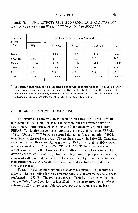
IAEA-SM-245/4 469
T A B L E III. A L P H A - A C T I V I T Y R E L E A S E D F R O M F E R A B A N D P O R T I O N S
C O N T R I B U T E D B Y T H E 210Po, 239+240Pu A N D 238Pu N U C L I D E S
Samplingperiod(1972)
Alpha-activity released (¿iCi/month)
210Po 2 3 9 + 2 4 0 p u 2 3 8 p u Identified Total
January 16.5 13.0 3.49 33.0 35.0
February 24.2 167 10.4 202 207
March 2.84 41.8 6.16 51.0 44.1a
April 6.22 92.4 22.8 121 115a
May 12.8 745 212 970 1070
June 4.11 74 ± 5 23 ± 5 102 ± 11 92.2a
a The partly higher values for the identified alpha-activity as compared to the total alpha-activity result from the sediments present in nearly all the samples. In the analysis the alpha-activity contained is almost completely dissolved; in the measurement of the total alpha-activity the individual granules cause self-absorption which is difficult to evaluate.
3. R E S U L T S O F ACTI V I T Y M O N I T O R I N G
The results of а-activity monitoring performed from 1971 until 1979 are
represented in Fig. 4 and Ref. [8]. The monthly rates of emission vary over three orders of magnitude, which is typical of all radioactivity releases from
FERAB. To identify the «-emitters constituting the а-emission from FER A B ,
210Po, 238Pu and 239+240pu were measured during the first six months of 1972, in addition to the total а-activity. The results are shown in Table III. Generally,
the identified «-activity constitutes more than 90% of the total а-activity found
on the exposed filters. Since 197 6 238Pu and 239+240pu have been measured monthly in the F E R A B exhaust air. The results are listed in Figs 5 and 6. The development of activity of the plutonium isotopes runs largely parallel; however,
compared with the results obtained in 1972, the sum of plutonium «-activities
is frequently only a very small fraction of the total а-activity emitted in the
respective month.
Figure 7 shows the monthly rates of /З-activity emission. To identify the
radionuclides responsible for these emission rates, a 7-spectrometry analysis was performed in 1972 [8]. The results are given in Table IV. They show that, on average, 70% of the |3-activity was identified by 7-spectrometry. Since 1976 the exhaust air filters have been subjected to 7-spectrometry on a routine basis.

4 7 0 KÔNIG et al.
E
о
FIG.5. Rates o f 23SPu emission in the FERAB exhaust air.
-5
° 10
о - 7is 10 ■
.-8101976 1977 1978 1979
FIG.6. Rates o f 239+2AOPu emission in the FERAB exhaust air.
The main fraction of /З-activity stems from radionuclides that are volatile under
the F E R A B operating conditions.. The identified radionuclides have been
106Ru/106Rh, 137Cs, 134Cs, 125 Sb, 6sZn, 110Agm , and 60Co. The latter radionuclide has usually been found irregularly only and then at very low activity
concentrations. Moreover, on account of the high radiotoxicity, the rate of
90Sr emission in the F E R A B exhaust air was determined. While the volatile
radionuclides make up the major part of j3-activity, the fraction of j3-activity of
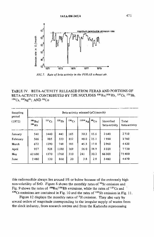
IAEA-SM-24S/4 471
Eш
ю1
-210.3
10.4
10
.510-6
10
IITOximumj^missible em¡5s¡on rate
f i
1971 1973 1975 1977 1979
FIG. 1. Rate o f beta activity in the FERAB exhaust air.
T A B L E IV. BETA-ACTIVITY R E L E A S E D F R O M F E R A B A N D P O R T I O N S O F
BETA-ACTIVITY C O N T R I B U T E D B Y T H E N U C L I D E S 106Ru/106Rh, 137Cs, 125Sb, 134Cs, 110Agm ; A N D 60Co
Sampling Beta-activity released (/¿Ci/month)
(1972) 106 Ru/ 106 Rh
I37Cs 125 Sb 134Cs 110mAg s о о Identifiedbeta-activity
Totalbeta-activity
January 541 1440 441 165 30.3 15.6 2 640 2710
February 566 885 333 112 40.0 25.1 1 930 3 760
March 672 1290 748 185 45.3 17.8 2 960 4420
April 957 928 1180 169 56.0 38.9 3 320 7 720
May 62 600 1370 1760 310 241 30.2 66 300 71400
June 2 480 120 860 20 3.8 2.8 3 480 4 670
this radionuclide always lies around 1% or below because of the extremely high
non-volatility of SrO. Figure 8 shows the monthly rates of 90Sr emission and Fig. 9 shows the rates of 106Ru/106R h emissions, while the rates of 137Cs and 134Cs emissions are contained in Fig. 10 and the rates of 125 Sb emission in Fig. 11.
Figure 12 displays the monthly rates of 3H emission. They also vary by
several orders of magnitude corresponding to the irregular supply of wastes from
the clock industry, from research centres and from the Karlsruhe reprocessing
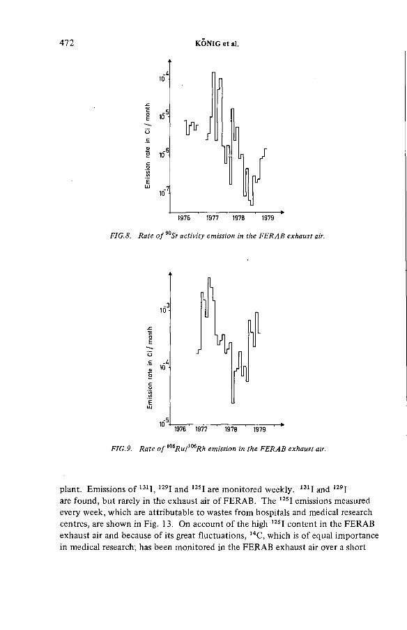
472 KÔNIG et al.
о
E
ELU
ю5
.„-6
P
J
1976 1977 1978 1979
FIG.8. Rate o f Sr activity emission in the FERAB exhaust air.
10
Ю5!
и
“I
1976 1977 1978 1979
FIG.9. Rate o f i0iR u /m Rh emission in the FERAB exhaust air.
plant. Emissions of 131I, 129I and 125I are monitored weekly. 131I and 129I are found, but rarely in the exhaust air of FERAB. The 12SI emissions measured
every week, which are attributable to wastes from hospitals and medical research
centres, are shown in Fig. 13. O n account of the high 12SI content in the F E R A B
exhaust air and because of its great fluctuations, 14C, which is of equal importance in medical research, has been monitored in the F E R A B exhaust air over a short

IAEA-SM-245/4 473
.310 ■
Ъ
Eш
10
h
î! "
1/
137,Cs
i rJ M }
I I
134,Cs
1976 1977 1978 1979
FIG.10. Rates o f 137Ci and lMCs emission in the FERAB exhaust air.
1 0 1
Л10- IIr
-510 1976 1977 1978 1979
F IG .ll. Rate o f Sb emission in the FERAB exhaust air.
time interval [9]. The 14C 0 2 from the exhaust air was scrubbed with a basic scrubber, and 14C was prepared to become B a C 0 3 and its -activity was subsequently measured. The results are shown in Table V.
4. E X P E R I E N C E G A T H E R E D IN INCIDENTS
Some incidents occurred during operation of the incineration facility which
can be classified into four groups. Table VI gives a survey of these incidents.

474 KÔNIG et al.
FIG. 12. Rate o f 3# emission in the FERAB exhaust air.
. 210-
-3 10 ■
-4
-5
ELU
..-61977 1978 1979
FIG. 13. Rate o f I emission in the FERAB exhaust air.
Incidents of group 1 are the most probable incidents to be expected. Since
the incineration facility accepts wastes of different origins, complete information
must be given in the accompanying documents and this must be taken into
account when charging the furnace. The activity cannot be measured before
incineration since the material to be incinerated is very heterogeneous and, besides,
radionuclides not emitting 7-rays cannot be measured. Values exceeding the monthly limit values, as listed in Table VII and related to this group, consist
mainlyof values exceeding the limits set for 3H and 125I.

IAEA-SM-24S/4 475
T A B L E V. ACTI V I T Y C O N C E N T R A T I O N S O F 14C 0 2 IN T H E S T A C K E X H A U S T AIR O F F E R A B
For comparison, the emission during the period of sampling was extrapolated to
the annual emission
Sampling 1976 14C 02 concentration in Extrapolated annualthe exhaust air emission
From To (pCi/m3) (Ci/a)
16.7. - 19.7. 167 ^
19.8. - 25.8 18 800
2 5 .8 ,- 1.9. 1 770
1.9. - 8.9. 232 > about 2
8.9. - 15.9. 385
15.9. - 22.9. < 166a
22.9. - 28.9. 2 180 >
a 2 a detection limit calculated on the basis of the counting statistics.
In February 1972 an unidentified input of 1 Ci of 239Pu was followed by
the monthly limit values being exceeded through 239Pu emission. Values in
excess of the limit values, which occurred in April and May of the same year,
are most probably likewise attributable to an excessive plutonium input into
the furnace. In Fig. 14 emission rates exceeding the alpha activity values during
May 1972 are plotted. The exact measurement of the emission rates during
incidents of group 1 is guaranteed, the more so since the definite emission values are assessed by measurement of samples collected continuously.
The release of collectable, visible particles during incidents of group 2,
mostly related to incidents of group 3, results in an exposure of a relatively
restricted surface area in the vicinity of the exhaust air stack. In such a case
representative sampling is not possible in exhaust air monitoring so that the
activity released can be estimated only with the tools available in environmental
monitoring. Since particles of that size cannot be inhaled, a risk to persons can
be ruled out. Moreover, such incidents occurred only during the phase of
commissioning.
Group 3 of the incidents so far considered includes superheating of the
furnace chamber by incineration of excessive amounts of material with high
calorific values. This relates above all to kerosene incinerations performed in

T A B L E VI. S U R V E Y O F INCIDENTS O C C U R R E D
4 7 6 KÔNIG et al.
Group Cause of incidents Consequences Countermeasures
1 Unduly high supply of volatile radionuclides
Exceeding permissible value of activity release (but no inadmissibly high impact on the environment)
Waste delivering institutions urged to make more precise statements on the activity content.
2 Vibrations of blower due to mechanical defect (corrosion damage)
Soot and coating peel-off from the brick lining. Release into the immediate vicinity of particles up to 10 mm in diameter with a beta activity up to 40 nCi per particle.
Installation of new blowers; improved maintenance of blowers; decontamination measures.
3 Unduly high furnace temperatures due to solvent incineration
Exceeding permissible value of release (but no inadmissibly high impact on the environment)
Reduction of solvent incineration. Installation of a solvent incineration facility.
4 Unduly high supply of organic solvents in closed bottles
Deflagration; little mechanical damage; contamination within the building.
Admonishing delivering institutions; technical measures to avoid damage in case of deflagration.
F E R A B for the Karlsruhe nuclear reprocessing plant. Such cases of superheating
resulted, on the one hand, in the volatilization of a major fraction of radionuclides
from the furnace chamber and, on the other hand, in the production of condensates.
The main volatile elements are Ru, Cs and Sb. However, it must be mentioned
that, under the temperature conditions prevailing in F E R A B , a considerable
fraction of the elements is already volatile in their elemental states or as oxides
and chlorides. In addition, very low vapour pressures of so-called ‘non-volatile’
compounds may already result in rather high release rates. For example, a vapour
pressure of 10"8 torr of a plutonium compound already implies that m a x i m u m permissible monthly emission rates are exceeded.
Incidents relating to group 4 occurred only during the initial phase of
operation and they can be avoided by inspection of the waste and by care taken
on the part of the delivering institution.
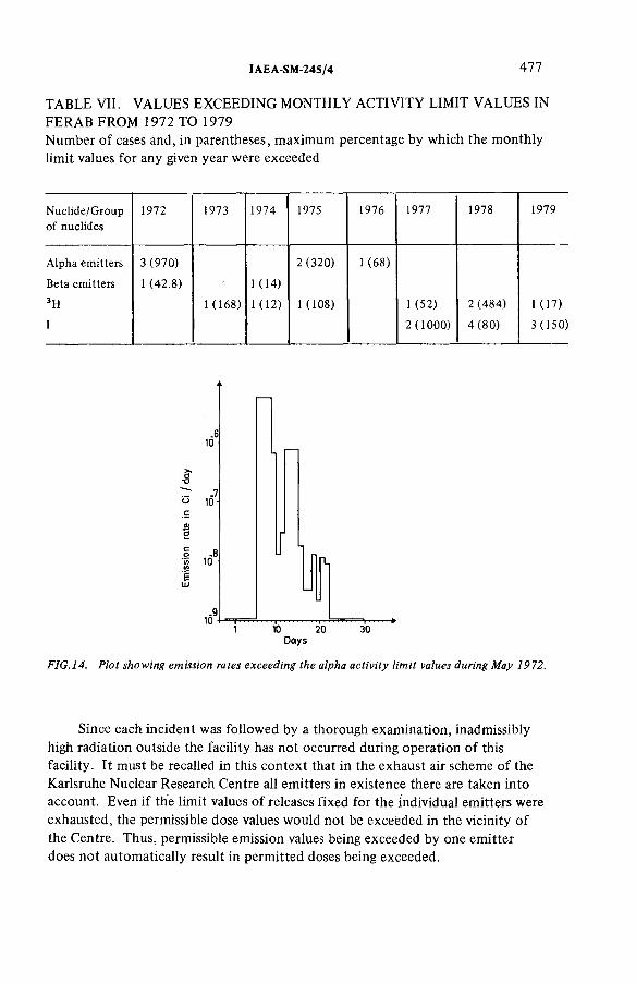
IAEA-SM-245/4 A l l
T A B L E VII. V A L U E S E X C E E D I N G M O N T H L Y ACTI V I T Y LIMIT V A L U E S IN
F E R A B F R O M 1972 T O 1979
Number of cases and, in parentheses, ma x i m u m percentage by which the monthly
limit values for any given year were exceeded
Nuclide/Group of nuclides
1972 1973 1974 1975 1976 1977 1978 1979
Alpha emitters
Beta emitters
3H
I
3 (970)
1 (42.8)
1 (168)
1 (14)
1 ( 12)
2 (320)
1 (108)
1 (68)
1 (52)
2 ( 1000)
2 (484)
4 (80)
1 (17)
3 (150)
FIG.14. Plot showing emission rates exceeding the alpha activity limit values during May 1972.
Since each incident was followed by a thorough examination, inadmissibly
high radiation outside the facility has not occurred during operation of this
facility. It must be recalled in this context that in the exhaust air scheme of the
Karlsruhe Nuclear Research Centre all emitters in existence there are taken into
account. Even if the limit values of releases fixed for the individual emitters were
exhausted, the permissible dose values would not be exceeded in the vicinity of
the Centre. Thus, permissible emission values being exceeded by one emitter
does not automatically result in permitted doses being exceeded.
478 KÔNIG et al.
Cases in which the permissible monthly values have been exceeded during
F E R A B ’s operation period have been compiled in Table VII. Only in 1972 was
the permissible annual value of а-activity exceeded in FER A B , by 74% to be
exact. However, this did not affect the values permitted for the Nuclear Research
Centre as a whole.
To summarize, it can be stated that the radioactivity of the flue gas can now
be perfectly monitored without trouble, and that the number of cases in which
the extremely low ma x i m u m permissible monthly values are exceeded remains
very small.
R E F E R E N C E S
[1 ] BÀHR, W., HEMPELMANN, W., KRAUSE, H., Incineration Plant for Radioactive Waste at the Nuclear Research Centre Karlsruhe, Kernforschungszentrum Karlsruhe, Karlsruhe,Rep. KFK-2418 (1977).
[2] HEMPELMANN, W., The Incineration of Low Level Radioactive Waste, Meeting of the American Association of Mechanical Engineers, Zürich (October 1978).
[3] JEHANNO, C., BLANC, A., LALLEMENT, C., ROUX, G., «Appareils récents et méthodes nouvelles pour la mesure de la concentration des produits radioactifs dans l’atmosphère», Peaceful Uses of Atomic Energy (Proc. 2nd Int. Conf. Geneva, 1958) 23,UN, New York (1958) 372.
[4] RANKIN, N.O., Nucl. Instrum. Methods 24 (1963) 221.[5] BERTHOLD, F., “High sensitivity а-0-aerosol monitor with novel pseudo-coincidence
circuitry for compensation of natural radioactivity” , Assessment of Airborne Radioactivity (Proc. Symp. Vienna, 1967), IAEA, Vienna (1967) 597.
[6] KÔNIG, L.A., WILHELM, J.G., DILLMANN, H.G., a) Atomwirtsch. Atomtech. 18 (1973) 582. b) “Continuous sampling for detection of water-bound tritium in exhaust air” , Monitoring of Radioactive Effluents (OECD/NEA Seminar Karlsruhe, 1974), Zentralstelle für Atomkernenergie-Dokumentation, Eggenstein-Leopoldshafen,Rep. AED-Conf-74-157-006 (1974).
[7] SCHÜTTELKOPF, H., “Bestimmung von Plutonium in Probematerialien der Umgebungs- überwachung” , Rapid Methods for Measuring Radioactivity in the Environment(Proc. Symp. Neuherberg, 1971), IAEA, Vienna (1971) 183.
[8] KÔNIG, L.A., et al., Contributions to the Annual Reports of the Hauptabteilung Sicherheit (formerly Abteilung Strahlenschutz und Sicherheit) (KIEFER, H., KOELZER, W., Eds): KFK-1565 (1971); KFK-1818 (1972); KFK-1973 (1973); KFK-2155 (1974); KFK-2266 (1975); KFK-2433 (1976); KFK-2620 (1977); KFK-2775 (1978).
[9] SCHÜTTELKOPF, H., Die Emission von MC 02 mit den Abluftkerntechnischen Anlagen, Kemforschungzentrum Karlsruhe, Karlsruhe, Rep. KFK-2421 (1977).

IAEA-SM-245/4 479
DISCUSSION
W.R.A. G O O S S E N S : What is the efficiency of the sampling and measuring
system for the (3-emitters present in the off-gas? More specifically, have you
measured the trapping efficiency of the /3-monitoring system for radionuclides
such as ruthenium which could be present as volatile species?
L.A. KONIG: For aerosols the trapping efficiency of our glass fibre filters
is better than 99%. Sampling is carried out at ambient temperature which
improves the efficiency for volatile nuclides by comparison with that at the
temperature of the flue gas. Measurement for 7-radiation of the charcoal cartridges used for iodine sampling, and measurement of the condensate for
monitoring tritium release will give some additional information.
S.A.K. JEELANI: You mentioned that the fans frequently suffered
mechanical failure and had to be replaced. I would like to know whether you
think it would be possible to replace the fans with steam jet ejectors.
L.A. KÔNIG: I do not believe that this would be feasible.
R. K I R C H M A N N (IAEA): In Table VI you say that the impact on the
environment of the atmospheric releases from the F E R A B facility was not
inadmissibly high. I should like to know what biological criteria are taken into
consideration in evaluating the impact on the environment.
L.A. KÔNIG: The criteria we take into account with respect to activity
releases are based on compliance with the German Radiation Protection Ordinance,
which prescribes m a x i m u m permissible values for the exposure of the population to
ionizing radiation, for example, 30 mrem/a whole body, 90 mrem/a thyroid, and
so on. In addition, there are regulations relating to the performance of dose
calculations. These have to consider the area with the highest exposure including
allowance for the food chain, and without reference to real population density.
In the case of the Karlsruhe Nuclear Research Centre there is no population in
this area as the Centre is surrounded by forest. Our dose calculations are there
fore very conservative.
G.R. N U Y T : Did you have any particular problems with prefiltration
at 900°C? Secondly, what techniques did you use to clear clogged filters and
were there any difficulties there?
L.A. KÔNIG: Regarding your first question, we did not encounter any
particular difficulties. Depending on the mode of operation, the life of the
ceramic elements in the prefilters is between 300 and 600 hours. Operation in
three shifts greatly increases this figure.
With référencé to your second question, cleaning of the filters causes no
special problems. O n the hot surface of the filter elements in the prefilters,
unburnt particles in the flue gas are burnt. The ashes produced fall off during
combustion and collect in the bottom part of the filter housing.
480 KÔNIG et al.
R.A. DAVIES: Table III refers to the alpha activity release from the incinerator.
What is the concentration of alpha activity in the feed and what limitation is
applied to this value?
L.A. KÔNIG: The feed concentration is limited by the m aximum
permissible alpha emitter release rate (2 X 10“3Ci/a) and by the alpha emitter decontamination factor attained (103 —104).
R. BOGE: From your Table V we can see that, apart from tritium, 14C
has the highest yearly releases (2 Ci/а). Have you calculated the collective dose
commitment for this release and do you monitor 14C in the stack? If not, how
do you estimate the input of 14C to the incinerator?
L.A. KÔNIG: W e do not carry out routine 14C monitoring because of the
serious difficulties involved as a result of the specific chemical properties of the
off-gas. However, 14C releases can be assessed by assuming the 14C input to the
furnace on the basis of the values given in the documents which accompany the
waste. 14C is taken into account in the dose calculations for the research centre
environment.

IAEA-SM-24S/49
OPERATIONAL EXPERIENCE WITH A 25 m3 -h-1 SIMULATED DISSOLVER OFF-GAS PURIFICATION LOOP
G.E.R. C O L L A R D , P.J. V A ESEN,
W.R.A. G O O SSENS, L.H. B A E T S L E
Studiecentrum voor Kernenergie/
Centre d’étude de l’énergie nucléaire,
Mol,
Belgium
Abstract
OPERATIONAL EXPERIENCE WITH A 25 m’ -h ' 1 SIMULATED DISSOLVER OFF-GAS PURIFICATION LOOP.
The first part of this paper lists and briefly describes the different methods studied at SCK/CEN, Belgium, for the removal of different gaseous fission compounds from the airborne effluents of reprocessing plants. A summary is given of the performances of these units and the practical experience gained. The second part describes the flowsheet of the removal units in an integrated gas purification loop and more specifically those of iodine, nitrogen oxides, oxygen, water, carbon dioxide and the noble gases krypton and xenon. In the near future an active gas purification system, based on this experience-and the ensuing results, will be built on a Head-End Research Mock-up Engineering Scale called HERMES, in which 10 kg batches of either Pu recycled LWR fuel or LMFBR fuel will be treated.
1. I N T R O D U C T I O N
For several years the SCK/CEN, in collaboration with Belgonucléaire,
has studied different steps of the dissolver off-gas purification [ 1 ].Laboratory and technological research was performed in the field of fission
gas trapping and gaseous effluent control. Particular attention was devoted to
iodine and krypton trapping, as well as to the conditioning operations for
krypton removal by cryogenic distillation.
The technological investigation started on individual cleaning units with
a nominal gas throughput of 8.7 X 10 “3 kg-s'1. These units were constructed in such a way that they could be interconnected at a later date into a complete
gas purification loop called GAS-TON.
Parametric studies of different units were performed by adding constant
concentrations of various gaseous components in the carrier gas. Moreover,
batch dissolution conditions were obtained by dissolving U 0 2 in nitric acid and by adding large ‘pulses’ of different components such as iodine, methyliodide,
krypton and xenon.
481

AT ABSORPTION TOWER G GENERATOR 0 OVEN V e n t V EN TIL A T IO NBD BRIN K DEM ISTER GB GLOVE-BOX P PUMP VS VENTURY SCRUBBERС COLUMN GS GAS SAMPLING R ROTAMETER W WASTE TANKD DEM ISTER HE HEAT EXCHANGER RV REACTION V ESSELDT D ISSO LV ER TANK LC L IQ U ID CONDENSER s SCRUBBING SOLUTION txj VALVEDU DRYING U N IT LS L IQ U ID SAM PLING ST SAFETY TRAPS ® 3-WAY VALVEF S F IL T R A T IO N SYSTEM LT L IQ U ID TANK TT TRANSPORT TANK
-----GAS L IN E L IQ U ID L IN E
FIG.l. Wet section for iodine removal.
482 CO
LLARD
et
al.
IAEA-SM-245/49 483
The experience gained to date with the trapping of iodine, nitrogen oxides
and krypton is discussed.
2. T R A P P I N G M E T H O D S
2.1. Iodine removal
Iodine compounds are removed in two steps. The first step consists of
their adsorption in a liquid scrubber and the second step of their chemical
adsorption on silvered sorbents.
The washing solution for the scrubber is an acid solution of mercuric
nitrate which was preferred to a caustic solution studied in the earlier stages of
this research programme [2].Silvered sorbents used in the second removal step are either a silver-exchanged
molecular sieve or a catalyst carrier impregnated with silver nitrate.
2.2. Nitrogen oxides removal
Nitrogen oxides are also removed in two steps consisting of a washing
column where the washing solution is water, and a fixed catalyst bed reactor.
T w o methods are studied for the catalytic destruction of the remaining
nitrogen oxides. The first foresees the simultaneous reaction of oxygen and
nitrogen oxides with hydrogen and can be used when oxygen is not desired in
the krypton removal unit. The second involves elimination of N O x by
selective catalytic reaction with N H 3 [3] and can be applied when large amounts of oxygen are tolerated in the krypton removal unit.
2.3. Krypton removal
Krypton, together with xenon, is removed by distillation-rectification of
the effluent previously dried and prepurified in a conditioning section. Xenon
and krypton are separated from each other in batches in a second distillation
column.
At the S C K / C E N it was decided to remove oxygen from the gases to be
distilled [4] at a low temperature.
3. G E N E R A L D E S C R I P T I O N O F T H E I N T E G R A T E D L O O P
The integrated loop consists of three main parts, namely, a wet section,
a conditioning section, and a cryogenic section.
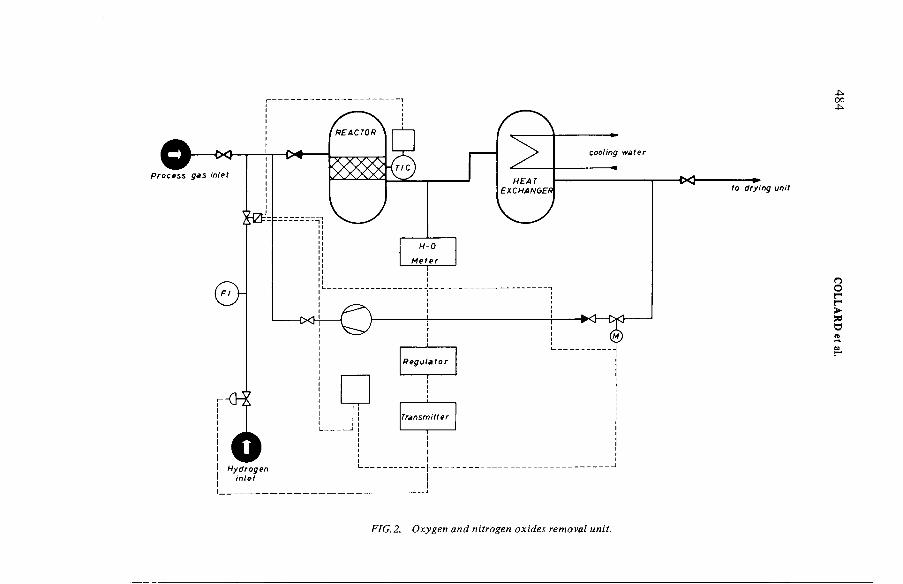
to drying unit
FIG.2. Oxygen and nitrogen oxides removal unit.
484 C
OLLA
RD
et
al.
IAEA-SM-245/49 485
3.1. Wet section
The wet section (Fig. 1), described in Ref.[5], consists mainly of a mock-up
dissolver, a first washing column for N O x removal, a second washing column
for the retention of iodine compounds, a demister and two fixed beds for the
adsorption of the remaining iodine compounds. At this point, decontamination
factors of 103 to 10s are achieved for the iodine compounds and the remaining
concentration of N O x is of about 2 vol.%-
3.2. Conditioning section
In the conditioning section the gaseous effluent is at first compressed to
0.5 MPa. Oxygen is then removed from the effluents, together with the
remaining nitrogen oxides, by means of a catalytic reaction with hydrogen
(Fig. 2). The gaseous stream passes through fixed beds of molecular sieves
where water and carbon dioxide are removed (Fig.3). After compression to a
pressure of 1 MPa, the gaseous effluents are passed to the cryogenic section.
At this point, the gaseous effluent consists mainly of nitrogen containing
1% argon, 1000 v p m (parts per million by volume) of xenon and 100 v p m of krypton, the concentration of the other components being lower than 1 vpm.
To date, the selective N O x destruction unit is not integrated in the loop,
but it could be used if oxygen was tolerated in the cryogenic unit. Moreover,
it could be placed on the regeneration loop of the drying unit to destroy the
traces of N H 3 which are eventually formed in the oxygen removal unit and adsorbed on the drying beds.
3.3. Cryogenic section
The cryogenic section (Fig.4) consists mainly of two heat exchangers
where the effluents are cooled, a first distillation column where xenon and
krypton are separated from the carrier gas, and a second column where they
are separated from each other and bottled [5].
4. O P E R A T I O N A L E X P E R I E N C E
4.1. Iodine behaviour and removal
4.1.1. Iodine release from the dissolver
Some experiments were performed to study the release of iodine from the
dissolver during batch dissolutions. Uranium oxide (3.5 to 4.5 kg) and sodium

to cryogenic dstHation
FIG. 3. Simplified flo wsheet o f the drying unit.
486 C
OLLA
RD
et al.

IAEA-SM-24S/49 487
iodide (3.5 g) labelled with 131I (100 to 150 mCi) were added to nitric acid
(23 to 25 d m 3), and the iodine concentration was followed in the dissolver and
in the gas stream. Iodine was measured in the different solutions and in the
condensates of the wet section so that it was possible to follow its total activity
along the loop.
In the dissolver, iodine concentration rapidly decreases during the first 4 h
and then tails off very slowly to the end of the run. After 8 h, 0.5 to 3 % of the total iodine remains in the dissolver, and 0.5 to 1.5% after 100 h.
It seems likely that the elution of iodine is accelerated by the emission of
N 0 2 due to the U 0 2 dissolution. The iodine concentration then decreases more slowly and finally remains constant in the solution.
4.1.2. Absorption of iodine in the NOx washing column
The N O x washing column is operated with recycled water which becomes
enriched in H N 0 3.
During the first hour of the dissolution, the activity increases in the washing
solution because of the large amounts of iodine in the gas phase. Iodine is then
eluted but desorption is not completed even after more than 100 h. At this
time, the iodine concentration in the washing solution is larger than that in
the dissolver.
4.1.3. Absorption o f iodine in the Mercurex column
The Mercurex washing column is operated with a recycled acid solution
of mercuric nitrate (1M H N 0 3, 0.1M H g ( N 0 3)2).
During the first hours of the runs, the iodine activity in the gas phase
decreases slowly between the two columns, although the iodine leaving the
dissolver decreases rapidly. This is due to the behaviour of the N O x washing
column (see sub-section 4.1.2). During this period, the decontamination factor
obtained with the Mercurex column decreases rapidly at first and then more slowly.
It was assumed that the chemical form of the iodine leaving the first column was
more difficult to wash out with the mercuric solution than with the elemental iodine.
During all the runs covering a period of three months, the activity measured
in the gas downstream from the silvered products was not higher than the
background. Nevertheless, ageing and poisoning of these products are still
being studied.
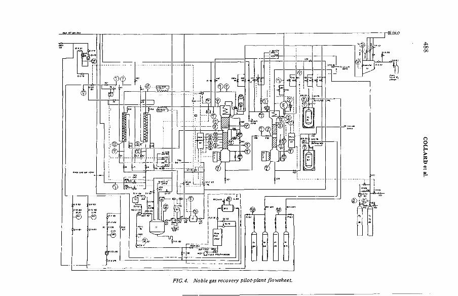
FIG. 4. Noble gas recovery pilot-plant flowsheet.
488 COLLARD
et al.
IAEA-SM-245/49 489
4.2.1. Oxygen removal
The elimination of 0 2 by reaction with hydrogen has been studied in a Deoxo unit manufactured by Hereaus. Nitrogen, with a flow rate up to
8.7 X 1СГ3 kg-s' 1 containing 1.7 to 4.42 wt% oxygen, was treated in this unit under a pressure of 0.5 MPa.
The purified gas was partially recycled to maintain the oxygen concentration
at a low enough level to avoid too high a temperature. Hydrogen was measured
with a H-0 meter also manufactured by Hereaus, analysis being based on the
exothermicity of the reaction between 0 2 and H 2.
Some problems did occur when the oxygen concentration or the gas flow
rate variations were high, owing to the large response time of the analysis device.
A n abrupt increase of one of these parameters was followed by a breakthrough
of oxygen. This inconvenience was corrected in the loop by permitting only
smooth variations. In a full-scale gas purification loop it would imply the use
of buffer tanks (or mixing tanks).
Although no parametric study was performed with this unit, it was found
that the residual oxygen concentration can be kept between 0 and 5 v p m for
a temperature of 300°C in the reactor, an excess of hydrogen greater than
1000 v p m and a gas flow rate of 8.3 X 10~4 kggas ■ kg 'V ata ly s t'S_1 (at a pressure of 0.5 MPa).
Simultaneous removal of N O x and 0 2 by reaction with H 2 has not been studied.
4.2. Conditioning section
4.2.2. Selective removal o f NOx from air
Although the C E N / S C K opted for the removal of oxygen before the
removal of noble gases by cryogenic distillation, the selective removal of N 0 2 and N O from gaseous effluents containing oxygen was also studied.
After a short study on laboratory scale, removal of N O x by reaction with
N H 3 catalysed by H from mordenite was selected.From our studies it seems that oxygen must be present in the gas to get a
reaction. Thus, the reactions would be the following:
4 N H 3 + 2 N 0 2 + 0 2 ^ 3 N 2 + 6 H 20 (1)
and 4 N H 3 + 4 N O + 0 2 4 N 2 + 6 H 20 (2)
2 NH3 4- 1 ^ 0 2 ^ N 2 + 3 H 20 (3)
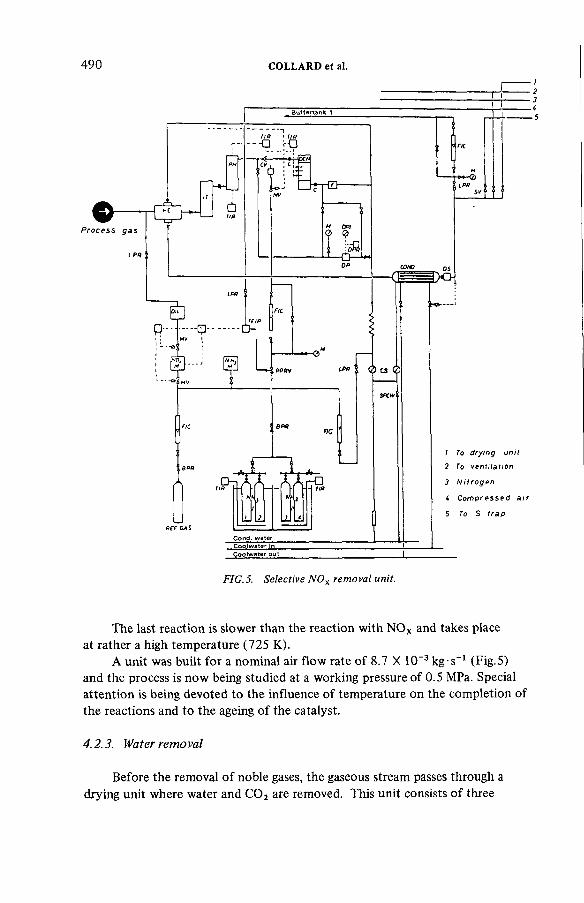
490 COLLARD et al.
FIG.5. Selective NOx removal unit.
The last reaction is slower than the reaction with N O x and takes place
at rather a high temperature (725 K).
A unit was built for a nominal air flow rate of 8.7 X 10"3 kg s' 1 (Fig.5) and the process is n o w being studied at a working pressure of 0.5 MPa. Special
attention is being devoted to the influence of temperature on the completion of
the reactions and to the ageing of the catalyst.
4.2.3. Water removal
Before the removal of noble gases, the gaseous stream passes through a
drying unit where water and C 0 2 are removed. This unit consists of three
IAEA-SM-24S/49 491
fixed beds of acid-resistant molecular sieves. The gases are dried at room
temperature under a pressure of 0.5 MPa, and the saturated beds are regenerated
at 475 К under a pressure of 0.2 M P a with part of the dried stream. Desorbed
water is condensed and carbon dioxide is absorbed on a fixed bed of calcium
hydroxide. The regeneration stream is then added to the mean flow upstream
of the compression devices.
Some improvements proved to be necessary to avoid diffusion of water
vapour from the wet to the dry streams and water condensation in the pipes
during regeneration. Problems of sealing also had to be solved, due to the
temperature cycles of the unit.
With a charge of 58 kg of zeolite in each bed, water and C 0 2 concentrations can easily be maintained under the p p m level with cycles of 24 h, at a nominal
gas flow rate of 8.7 X 10~3 kg s-1.
4.3. Krypton removal
Krypton and xenon are removed from the main stream and separated from
each other by cryogenic distillation. A detailed description of the unit and of
its performance has already been given elsewhere [5]. The unit consists
mainly of:
(a) T w o heat exchangers in which the feed is cooled by treated effluent
and vapour of the cooling nitrogen
(b) A first distillation-rectification column in which liquid nitrogen is
refluxed with a view to separating krypton and xenon from nitrogen
and argon
(c) A second column which receives in batches the krypton and xenon
previously accumulated in the bottom of the first column and
in which these two noble gases are separated from each other by
discontinuous distillation
(d) T w o cold bottles where krypton on the one hand and xenon on the
other hand are stored in solid form at 77 К before disposal in other
bottles in gaseous form.
The separation operations are carried out almost completely automatically
by means of a hybrid regulation system consisting of conventional regulation
devices and a microcomputer.
Under nominal working conditions, summarized in Table I, the unit
worked for more than 400 d with a total unavailability time of only 14 h
(availability factor of 98.85%).
Decontamination factors (DFs) higher than 1000 were achieved for krypton
under these conditions even in the case of rapid variation of the gas flow rates.
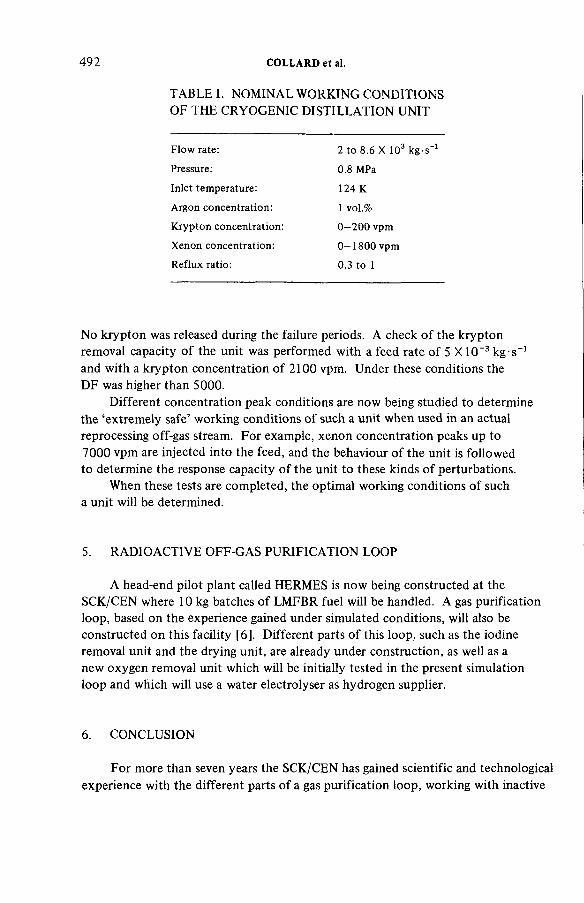
492 COLLARD et al.
T A B L E I. N O M I N A L W O R K I N G C O N D I T I O N S
O F T H E C R Y O G E N I C DISTILLATION UN I T
Flow rate: 2 to 8.6 X 10³ kg s"1Pressure: 0.8 MPa
124 K
1 vol.%
Inlet temperature:
Argon concentration:
Krypton concentration:
Xenon concentration:
Reflux ratio:
0—200 vpm
0-1 8 0 0 vpm
0.3 to 1
N o krypton was released during the failure periods. A check of the krypton
removal capacity of the unit was performed with a feed rate of 5 X 10"3 kg s"1 and with a krypton concentration of 2100 vpm. Under these conditions the
D F was higher than 5000.
Different concentration peak conditions are n o w being studied to determine
the ‘extremely safe’ working conditions of such a unit when used in an actual
reprocessing off-gas stream. For example, xenon concentration peaks up to
7000 v p m are injected into the feed, and the behaviour of the unit is followed
to determine the response capacity of the unit to these kinds of perturbations.
When these tests are completed, the optimal working conditions of such
a unit will be determined.
5. R A D I O A C T I V E O F F - G A S P U RIFICAT ION L O O P
A head-end pilot plant called H E R M E S is n o w being constructed at the
S C K / C E N where 10 kg batches of L M F B R fuel will be handled. A gas purification
loop, based on the experience gained under simulated conditions, will also be
constructed on this facility [6]. Different parts of this loop, such as the iodine removal unit and the drying unit, are already under construction, as well as a
new oxygen removal unit which will be initially tested in the present simulation
loop and which will use a water electrolyser as hydrogen supplier.
6. C O N C L U S I O N
For more than seven years the SC K / C E N has gained scientific and technological
experience with the different parts of a gas purification loop, working with inactive

IAEA-SM-245/49 493
or lightly labelled gases. In the future, this experience will be applied to a semi-
pilot head-end plant working under actual conditions and handling L W R and
L M F B R fuel.
R E F E R E N C E S
[1] BROOTHAERTS, J., et al., “Treatment and control of gaseous effluents from light water reactors and reprocessing plants” , Management of Radioactive Wastes from the Nuclear Fuel Cycle (Proc. Symp. Vienna, 1976), IAEA, Vienna (1976) 110.
[2] CLAES, J., et al., “ Boucle d’essai pour la purification des gas d’une usine de retraitement de combustible irradié” , Proc. Int. Chem. Eng. Conf. (Paris, June 1974), La Société de Chemie Industrielle (1974).
[3] BRUGGEMAN, A., et al., “ Elimination of NOx by selective reduction with NH3” ,(Proc. 15th DOE Nuclear Air Cleaning Conf., 1978), Department of Energy, Washington, DC (1978).
[4] COLLARD, G., et al., “Cryogenic distillation unit for xenon and krypton removal from gaseous effluents” , Trans. 2nd Eur. Nucl. Conf. (Hamburg, 1979), Deutsches Atomforum e.V., Bonn (1979).
[5] GOOSSENS, W.R.A., et al., “Experience with pilot scale iodine and krypton retention facilities under simulated conditions” , Radioactive Effluents from Nuclear Reprocessing Plants (Proc. Seminar Karlsruhe, 1977), CEC/GRS/KFK, Karlsruhe (1977).
[6] BAETSLE, L., et al., “Technological study of the head-end steps of mixed oxide fuel reprocessing” , Trans. 2nd Eur. Nucl. Conf. (Hamburg, 1979), Deutsches Atomforum e.V., Bonn (1979) 506.
DISCUSSION
H. D E U B E R : I have two questions on iodine removal. First, there have been
problems in the past with secondary waste treatment in the Mercurex process.
Have these been solved? M y second question concerns the solid sorbent used for
iodine trapping. In view of the recent jump in the price of silver, have you
considered recovering the silver or using a different metal?
G.E.R. C O L L A R D : With reference to your first question, the separation of
iodine and mercury without the formation of supplementary solid or liquid waste
has been studied on a laboratory scale, combining electrolysis and extraction.
The process has still to be demonstrated in the presence of other fission products.
As regards your second query, the recovery of silver and/or the regeneration
of silvered sorbent followed by adsorption of iodine on — or reaction with —
other metals will perhaps be performed on a separate loop in order to avoid
the use of a hazardous gas, such as hydrogen, in close proximity to the dissolver.
E. HENRI C H : What is the availability you expect for the whole serially
connected dissolver off-gas system? I a m thinking particularly of the precleaning
steps before cryogenic separation.
G.E.R. C O L L A R D : The whole loop is designed to deal with unavailability
for one day, during which time the effluents can be stored in an intermediate

494 COLLARD et al.
storage tank and recycled when the loop is available again. In addition, all the
mechanical and electrical devices on the loop are duplicated, thus reducing the
possibility of unavailability.
Y. DEPIERRE: Could you give more details on the concentrations
you obtained at different levels in the first column or, alternatively, on the
activity in the boiler?
G.E.R. C O L L A R D : Since we worked in non-active conditions, there was no
activity in the boiler. The concentration profile in the enrichment zone can be
summarized as follows, starting from the feed point and moving down towards
the boiler:
Argon in nitrogen (+ traces of Xe and Kr) - 20 c m
Pure argon (+ traces of Kr and Xe) - 5 to 10 c m
Krypton in argon (+ traces of Xe) - 5 cm
Pure krypton (+ traces of Xe) - 20 c m
Xenon in krypton - ~5 c m
90% xenon and 10% krypton - boiler.
A.J.L. L E U D E T : You are currently examining the effect of high xenon
concentrations on the operation of the cryogenic distillation unit. Have you
observed xenon crystallization during these disturbances and what methods do
you employ to detect it if it occurs?
G.E.R. C O L L A R D : Xenon crystallization cannot be avoided on walls which
have not been moistened by nitrogen or argon near the column inlet and in the
exchangers. A n increase in pressure has only a small effect on the dewpoint
of the mixture to be treated and a proportionate effect on the partial pressure
of the Xe, and thus serves only to increase crystallization. It does, however,
considerably improve the solubility of the mixtures. So, as long as excessive crystallization in the exchangers is avoided — for example by designing them
in such a way that they are capable of operating for an adequately long period
without the danger of blockages due to xenon peaks — an increase in pressure
will be of benefit to the behaviour of the facility by enhancing the solubility
range of the components.
M.J.S. SMITH: Regarding the selective removal of nitrogen oxides by
reaction with ammonia, there have been suggestions of a risk of explosion due
to the formation of a m m o n i u m nitrate. Could you comment on this?
G.E.R. C O L L A R D : At a temperature higher than 620 К for any mixtures
containing less than 5% of N 0 2 and N H 3 by volume, the a m m o n i u m nitrate formed is not stable and decomposes.
Cold points which have no gas flow or mixing are to be avoided so that
no accumulation of a m m o n i u m nitrate can take place.
D. G R Ü N D L E R : Is there any C 0 2 in the gas flow and do you have data on h o w much of the C 0 2 is converted to C O and alkanes?
G.E.R. C O L L A R D : There is C 0 2 because air is used, but to date no monitoring of C O has been performed.
Session VII
OFF-GAS CLEANING SYSTEMS DESIGN

Chairman
D.T. P E N C E
United States of America
IAEA-SM-245/37
SOME ASPECTS OF THE TREATMENT OF TYPICAL OFF-GAS STREAMS FROM REPROCESSING PLANTS
S.A.K. JEELANI, G.R. B A L A S U B R A M A N I A N
Reactor Research Centre,
Kalpakkam,
Tamil Nadu,
India
Abstract
SOME ASPECTS OF THE TREATMENT OF TYPICAL OFF-GAS STREAMS FROM REPROCESSING PLANTS.
The development of a fluidized sand-bed filter for filtration of particulate activity as applied to the process off-gas systems in fuel reprocessing plants, and an evaluation of its efficiency, is described. A comparative statement of the relative merits of various other filtration systems, such as the deep-bed glass fibre filters and the fixed sand-bed filters for such application, is made and a composite filtration system consisting of a fluidized sand-bed pre-filter and a final glass fibre polishing filter is recommended. Also included are studies carried out on the use of stainless steel sieve plates as de-entrainers, proposing a correlation for efficiency.
1. I N T R O D U C T I O N
Large volumes of air that are exhausted from the stack of a reprocessing plant
are an amalgamation of multiple streams of off-gases that differ widely in origin
and nature and which are subject to various treatment processes, such that the
environment is protected from pollution by gaseous and particulate activity of both
a chemical and radioactive nature to the best standards postulated. While the bulk
of the large volumes of gases discharged is contributed by the air exhausted from
cells and occupied working areas of the plant, which are the least offenders from
the contamination point of view, the off-gases that emanate from the dissolver,
process vessels, liquid transfer systems and high-level liquid waste storage tanks are
of relatively small volume. However, they are of serious concern as they are
carriers of the major radioactivity released. Development efforts directed towards
the treatment of these off-gases and the containment of radioactivity in the small
local systems can contribute to a reduction in the cost of treatment. This concept
of treatment and containment at the source assumes greater importance in the
case of off-gas systems of reprocessing plants treating highly irradiated fuels.
Present work covers the development of suitable systems of filtration for contain
ment of the particulate activity in such vital systems.
497

T A B L E I. SIZE D I S TRIBUTION O F A E R O S O L S O F T Y P I C A L O F F-GAS
S Y S T E M S
4 9 8 JEELANI and BALASUBRAMANIAN
Mass median diameter of the aerosols(Mm)
Standarddeviation
Nature of operation carried out
1.6 3.4 Transfer of solution
1.4 3between vessels by steam-jet ejector
0.9
1.4
2.3
3.9Dissolution of fuel
2.8 2.7 Vessel off-gas system
3.8 2.2when no other operationsare carried out
2. N A T U R E A N D S O U R C E O F C O N T A M I N A T I O N IN P R O C E S S O F F-GAS
S Y S T E M S
The dissolver is a source of significant concern because it releases substantial
amounts of radioactive gases and volatile fission products, apart from large
quantities of corrosive acid fumes, nitrogen oxides and entrained droplets of liquids
during the process of fuel dissolution. The use of liquid transfer systems, such as air
lifts and steam jets, sparging of the vessels for sampling, continuous agitation systems
in waste storage tanks, pulsing systems for solvent contactors, liquid evaporation
and acid destruction in evaporators, and various other operations that lead to the
formation of aerosols, result in contamination of the respective off-gas systems.
The characteristics of the off-gas differ markedly, depending upon the source and
mode of generation, and they have not yet been fully established. The results of
a study on aerosols [ 1 ] in some off-gas systems of a reprocessing plant are shown in Table I. In certain studies the particles in a vessel off-gas system in some radio
chemical plants are found to be in a sub-micrometre range [2]. However, it is felt
that,if a filtration system could be tested for 99.99% filtration efficiency for
particles of mass median diameter of 0.7 fim, then the system may meet the
containment requirements of the various off-gas systems even though the size
distribution of their aerosols has not been fully established [3]. Before these off-
gases are passed through the system it is necessary to treat them for the removal
IAE A-SM-24S/37 499
of radioactive gases, such as iodine existing in different chemical forms, volatile
fission products (e.g. ruthenium) and nitrogen oxides, and subsequently to
dehumidify them. A good deal of work has been published [4—6] on such systems
but it is beyond the scope of this paper, which mainly deals with the development
of fluidized sand-bed filters for the filtration of particulate activity and their
relative merits compared with other systems. The scope of the present work also
includes studies carried out on the use of sieve plates as de-entrainers.
3. D E V E L O P M E N T O F A M U L T I - S T A G E F L U I D I Z E D S A N D - B E D F I L T E R
Since the early days of the nuclear industry [3,7], deep-bed glass fibre filters
and fixed sand-bed filters have found application for filtration of particulate
activity. The merits and disadvantages of these systems are discussed at length in
sections 14 and 13, respectively, of this paper. Fluidized sand-bed filters, in which
sand is in a constant state of fluidization, eliminate problems of early filter clogging
and sand agglomeration, which leads to the increased life of a filter, and they also
offer remote removal of used sand for disposal and fresh sand replacement. These
characteristics of the fluidized sand-bed system appear to be favourable for their
application in reprocessing plants for the process of off-gas filtration systems.
High collection efficiency can be attained by the use of a multi-stage shallow
fluidized sand-bed filter, the efficiency in a single-stage deep fluidized sand-bed
filter being low due to the by-passing collection mechanism by gas bubbles. These
filters have found recent application in conventional chemical industries. A three-
stage shallow fluidized sand-bed filter (see Fig.l) has been used for the containment
of phosphoric acid mist [8]. The development efforts were initiated with 7.5 and 30 c m diameter three-stage fluidized sand-bed filters.
4. A T H R E E - S T A G E F L U I D I Z E D S A N D - B E D F I L T E R O F 7.5 c m D I A M E T E R
The filter used for the experiment was made of Perspex and had three stages
spaced equally 15 c m apart. A Taylor mesh No. 200 stainless steel wire cloth was
used as a distributor, no specifically designed one being necessary. Details of the
sand used are shown in Table II and it was fluidized by means of compressed air.
The air flow rates were measured by means of a calibrated orifice meter and the
air samples were drawn by a vacuum p u m p through a calibrated rotameter. The
filtration efficiency tests were carried out with a Collison’s Atomizer with 1 %
methylene blue dye in distilled water, which gave a mono-dispersed aerosol with a
mass median diameter of 0.7 /im of standard deviation of 1.1 (as per British
Standard BS 2831). The data on the collection efficiency of a single-stage and a
three-stage fluidized sand-bed filter are also shown in Table II. It was found that

500 JEELANI and BALASUBRAM ANIAN
A IR
t
tA IR
FIG.l. Three-stage test fluidized sand-bed filter.
the single-stage efficiency was of the order of 50%, while with three stages it was as high as 90% with a 6.6 cm thick bed. It was also found that efficiency decreases with superficial velocity below minimum fluidization velocity. The three-stage collection efficiency at a minimum fluidization velocity of 6.8 cm/s was 87%, which is comparable to the data reported in the literature [8]. Experiments were conducted to study the feasibility of remote sand transport of the fluidized sand bed by vacuum and also the degree of re-entrainment of the loaded activity during the process of transfer. It was found that the sand could be easily transported out of the filter to a separate container simulating the disposal system. It was also found that when the sand was transported through the ejector about 4% activity was released, but the release was of negligible magnitude when a vacuum was created in the receiving container. This test was conducted with methylene blue aerosol.
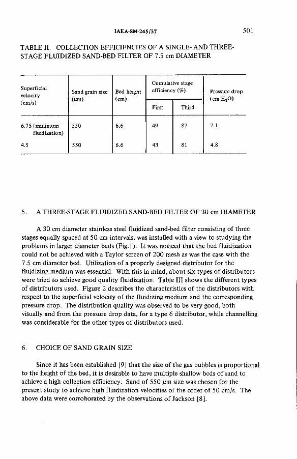
IAEA-SM-245/37 501
TABLE II. COLLECTION EFFICIENCIES OF A SINGLE- AND THREE- STAGE FLUIDIZED SAND-BED FILTER OF 7.5 cm DIAMETER
S u p e rfic ia lv e lo c ity(cm /s )
Sand g ra in size (jim)
Bed he igh t (cm )
C um u la tive stage e ff ic ie n c y (%) Pressure d ro p
(cm H 20 )
F irs t T h ird
6.75 (m in im u m 550 6.6 49 87 7.1f lu id iz a t io n )
4.5 550 6.6 43 81 4.8
5. A THREE-STAGE FLUIDIZED SAND-BED FILTER OF 30 cm DIAMETER
A 30 cm diameter stainless steel fluidized sand-bed filter consisting of three stages equally spaced at 50 cm intervals, was installed with a view to studying the problems in larger diameter beds (Fig.l). It was noticed that the bed fluidization could not be achieved with a Taylor screen of 200 mesh as was the case with the 7.5 cm diameter bed. Utilization of a properly designed distributor for the fluidizing medium was essential. With this in mind, about six types of distributors were tried to achieve good quality fluidization. Table III shows the different types of distributors used. Figure 2 describes the characteristics of the distributors with respect to the superficial velocity of the fluidizing medium and the corresponding pressure drop. The distribution quality was observed to be very good, both visually and from the pressure drop data, for a type 6 distributor, while channelling was considerable for the other types of distributors used.
6. CHOICE OF SAND GRAIN SIZE
Since it has been established [9] that the size of the gas bubbles is proportional to the height of the bed, it is desirable to have multiple shallow beds of sand to achieve a high collection efficiency. Sand of 550 fim size was chosen for the present study to achieve high fluidization velocities of the order of 50 cm/s. The above data were corroborated by the observations of Jackson [8].
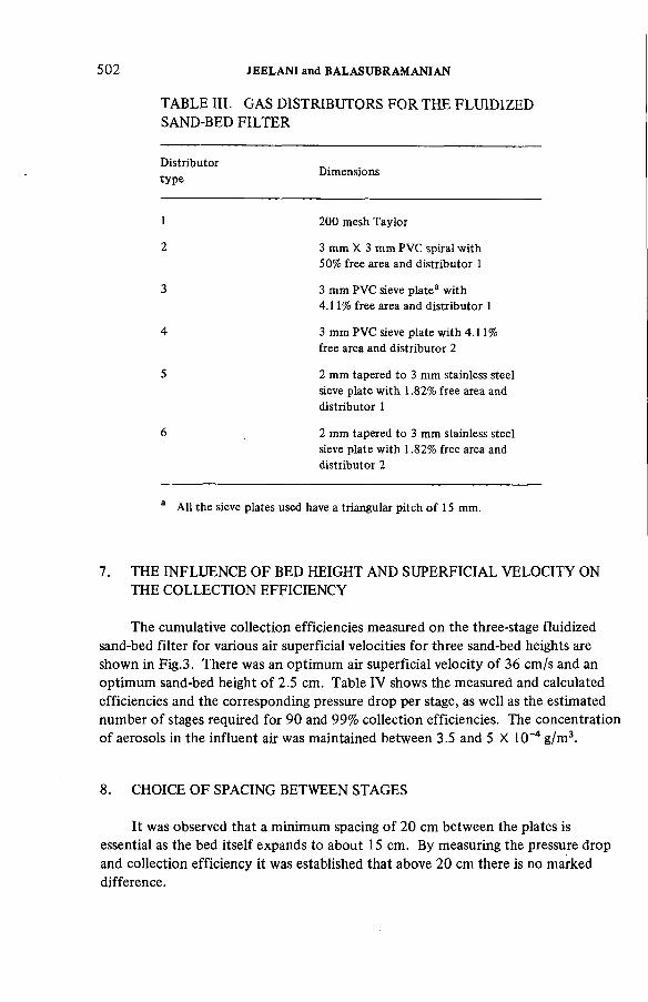
5 0 2 JEELANI and BALASUBRAMANIAN
TABLE III. GAS DISTRIBUTORS FOR THE FLUIDIZED SAND-BED FILTER
D is tr ib u to rty p e
D im ensions
1 200 mesh T a y lo r
2 3 m m X 3 m m P VC sp ira l w ith 50% free area and d is tr ib u to r 1
3 3 m m PVC sieve p la te 3 w ith 4 .1 1% free area and d is tr ib u to r 1
4 3 m m PVC sieve p la te w ith 4.11% free area and d is tr ib u to r 2
5 2 m m tapered to 3 m m stainless steel sieve p la te w i th 1.82% fre e area and d is tr ib u to r 1
6 2 m m tapered to 3 m m stainless steel sieve p la te w ith 1.82% free area and d is tr ib u to r 2
a A l l the sieve plates used have a tr ia n g u la r p itc h o f 15 m m .
7. THE INFLUENCE OF BED HEIGHT AND SUPERFICIAL VELOCITY ONTHE COLLECTION EFFICIENCY
The cumulative collection efficiencies measured on the three-stage fluidized sand-bed filter for various air superficial velocities for three sand-bed heights are shown in Fig.3. There was an optimum air superficial velocity of 36 cm/s and an optimum sand-bed height of 2.5 cm. Table IV shows the measured and calculated efficiencies and the corresponding pressure drop per stage, as well as the estimated number of stages required for 90 and 99% collection efficiencies. The concentration of aerosols in the influent air was maintained between 3.5 and 5 X 10⁻⁴ g/m3.
8 . CHOICE OF SPACING BETWEEN STAGES
It was observed that a minimum spacing of 20 cm between the plates is essential as the bed itself expands to about 15 cm. By measuring the pressure drop and collection efficiency it was established that above 20 cm there is no marked difference.

IAEA-SM-245/37 5 0 3
9. DUST HOLDING CAPACITY
Experiments were conducted to ascertain the sensitivity of the bed with respect to the pressure drop for increased dust loading. Experiments were conducted by injecting chalk powder into the influent air. The capacity of beds to hold an additional charge of sand was also tested. It was observed that after injecting about 36 g of chalk powder the change in pressure drop was of the order

504 JEELANI and BALASUBRAMANIAN
FIG.3. Cumulative efficiencies for the test fluidized sand-bed filter.
of 0.3 cm per stage of the filter. It was also observed that the bed may support 1 kg of additional sand, increasing the pressure drop by 0.6 cm. The comparative value of loading capacity of deep-bed glass fibre filters as reported is 130 g/m2 for a change in pressure drop of 12.5 cm with methylene blue aerosol [3]. It was reported that the capacity of a sand-bed filter is much less compared with that of a deep-bed glass fibre filter, though contradiction exists in this regard [10]. The above values do, however, indicate that fluidized sand-bed filters have a high loading capacity. This statement is confirmed by other workers [11].
10. SCALE-UP PROBLEMS
It was observed both in the small filter and in the 30 cm diameter filter that high collection efficiency is maintained as long as good fluidizing conditions are maintained, which means the maintenance of uniform distribution of the fluidizing medium in the filter at the required optimum velocity. It indicates that in very small diameter beds, e.g. 7.5 cm, the use of a distributor may not be

IAE A-SM-24S /37 5 0 5
warranted, although use of a good distributor may improve the quality of fluidization and thereby operating velocities, with a likely marginal increase in pressure drop. For the larger diameter fluidized sand beds, which are about 30 cm, the use of a well designed distributor is essential. From experience in the chemical industry, the uniformity of flow could be expected for the sieve plate type of distributor up to about 1.5 m diameter, extrapolating the data obtained on a 30 cm diameter bed. Experiments are planned to verify the validity of extension of these data beyond this limit. It should be mentioned that the pressure drops encountered with the present distributor design were rather high, but there is scope for its reduction with the development of appropriate type of distributors to meet the specific purpose.
11. TESTING OF A GLASS FIBRE FILTER
A filter with a diameter of 50 cm, a depth of 1 m and with four layers of Owens-Corning glass fibre (Fig.4) was tested for its filtration efficiency by the method already described. The test results, with details of the fibre used, are shown in Tables VA and VB. The results agree with published data [3]. The experiments conducted with humidified air indicated no deterioration in the efficiency. The performance of fluidized sand-bed filters was also insensitive to such humidity changes in the ranges tested in the glass fibre filter.
12. ANALYSIS OF RELATIVE MERITS OF VARIOUS TYPES OF FILTERSTO BE USED IN THE FILTRATION OF AEROSOLS FROM LOCALOFF-GAS SYSTEMS
The following are the few filters worth considering for such an application: fixed sand-bed filters, deep-bed glass fibre filters, completely fluidized sand-bed filters, a composite filter with a fluidized sand-bed pre-filter, and glass fibre polishing filters. The HEPA filter is not of use due to its sensitivity to moisture and a corrosive atmosphere. Before considering the relative merits of various types of filters, it is necessary to consider the desirable characteristics of the ideal filter for such an application, namely:
(a) High collection efficiency(b) Low pressure drop, hence lower operating cost(c) Flexibility in layout with respect to location(d) Resistance of the filter medium to acid fumes, humid gases and to fire(e) High dust loading capacity and long-life(f) Freedom from mechanical failures and frequent maintenance

TABLE IV. TEST DATA ON THE 30 cm DIAMETER FLUIDIZED SAND-BED FILTER Sand-bed height: 2.5 cm; Sand grain size: 550 цт
A ir sup e rfic ia lv e lo c ity(cm /s )
C um u la tive e ff ic ie n cy
(% )E ff ic ie n c y per stage
(% )
N u m b e r o f stages re qu ire d fo r e ff ic ie n c y
Pressure d rop per stage (cm H 20 )
F irs tstage
Second stageT h irdstage 90% 99%
Measured C alcula ted
21.1 27.2 41.5 40 .0 53 .4 22 .48 9.0 18.00 6.1
32 .54 36 .4 46 .0 55 .0 71 .0 33 .74 5.6 11.2 9.9
40.1 36.1 51.0 54.5 69 .4 32 .62 5.8 11.6 12.2
43 .8 20.8 41 .0 50 .0 65 .7 30 .0 6.5 13.00 13.5
55 .0 14.9 40.7 39.2 52.6 22.0 9.3 18.6 18.1
506 JE
ELA
NI
and B
AL
AS
UB
RA
MA
NIA
N
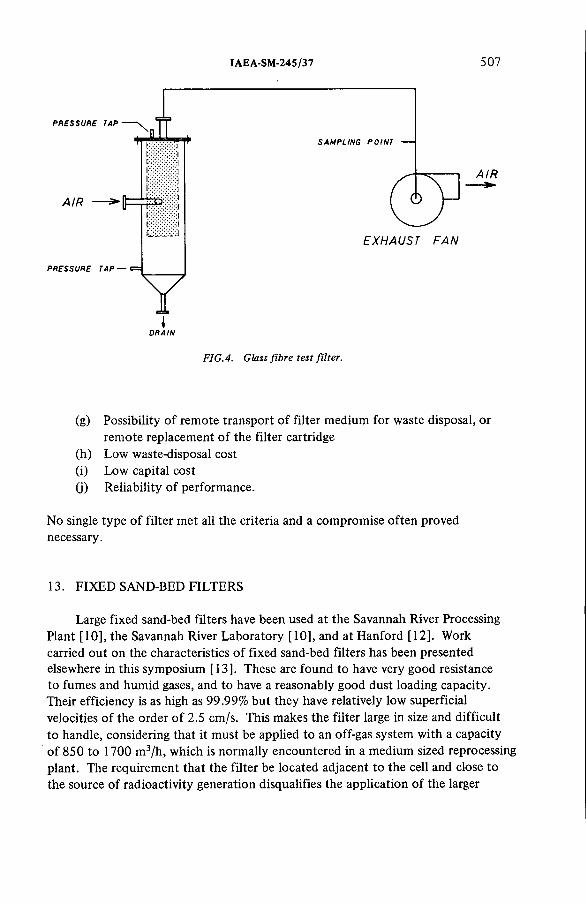
IAE A-SM-245/37 5 0 7
PRESSURE TAP
SAMPLING POINT
A IR
A IR — >*
i iE X H A U S T F A N
PRESSURE TAP — e s
YDRAIN
FIG.4. Glass fibre test filter.
(g) Possibility of remote transport of filter medium for waste disposal, or remote replacement of the filter cartridge
(h) Low waste-disposal cost(i) Low capital cost0) Reliability of performance.
No single type of filter met all the criteria and a compromise often proved necessary.
13. FIXED SAND-BED FILTERS
Large fixed sand-bed filters have been used at the Savannah River Processing Plant [10], the Savannah River Laboratory [10], and at Hanford [12]. Work carried out on the characteristics of fixed sand-bed filters has been presented elsewhere in this symposium [13]. These are found to have very good resistance to fumes and humid gases, and to have a reasonably good dust loading capacity. Their efficiency is as high as 99.99% but they have relatively low superficial velocities of the order of 2.5 cm/s. This makes the filter large in size and difficult to handle, considering that it must be applied to an off-gas system with a capacity of 850 to 1700 m3/h, which is normally encountered in a medium sized reprocessing plant. The requirement that the filter be located adjacent to the cell and close to the source of radioactivity generation disqualifies the application of the larger
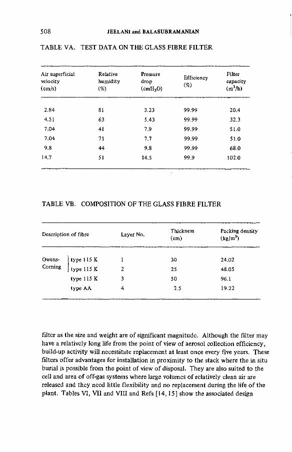
5 0 8 JEELANI and BALASUBRAMANIAN
T A B L E V A . TEST D A T A ON THE G L A S S FIBRE FILTER
A ir su p e rfic ia l R ela tive Pressure . F ilte rv e lo c ity h u m id ity d rop . . capacity(cm /s ) (% ) (cm H 20 ) ° (m 3/h )
2 .84 81 3.23 99.99 20 .4
4.51 63 5.43 99.99 32.3
7 .04 41 7.9 99.99 51.0
7 .04 71 7.7 99 .99 51.0
9.8 44 9.8 99.99 68.0
14.7 51 14.5 99 .9 102.0
TABLE VB. COMPOSITION OF THE GLASS FIBRE FILTER
D e sc rip tio n o f f ib re La yer N o.Th ickness(cm )
Packing de ns ity (k g /m 3)
Owens-C orn ing
ty p e 115 К
ty p e 115 К
ty p e 115 К
ty p e A A
30
25
50
2.5
24.02
48.05
96.1
19.22
filter as the size and weight are of significant magnitude. Although the filter may have a relatively long life from the point of view of aerosol collection efficiency, build-up activity will necessitate replacement at least once every five years. These filters offer advantages for installation in proximity to the stack where the in situ burial is possible from the point of view of disposal. They are also suited to the cell and area of off-gas systems where large volumes of relatively clean air are released and they need little flexibility and no replacement during the life of the plant. Tables VI, VII and VIII and Refs [14,15] show the associated design
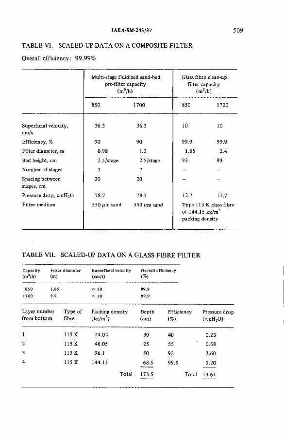
TABLE VI. SCALED-UP DATA ON A COMPOSITE FILTER
Overall efficiency: 99.99%
IAEA-SM-24S /37 5 0 9
M ulti-s tage flu id iz e d sand-bed p re - f ilte r capac ity
(m 3/h )
Glass f ib re clean-up f i l te r capac ity
(m 3/h )
850 1700 850 1700
S u p e rfic ia l v e lo c ity , cm /s
36.3 36.3 10 10
E ffic ie n c y , % 90 90 99 .9 99 .9
F ilte r d iam ete r, m 0.98 1.3 1.85 2 .4
Bed h e ig h t, cm 2 .5 /stage 2.5/stage 93 93
N u m b e r o f stages 7 7 - -
Spacing be tw een stages, cm
2 0 2 0 — -
Pressure d ro p , cm H 20 78.7 78.7 12.7 12.7
F ilte r m ed ium 550 Aim sand 550 д т sand T yp e 115 К glass f ib re o f 144.15 k g /m 3
packing de ns ity
TABLE VII. SCALED-UP DATA ON A GLASS FIBRE FILTER
C apacity Filter diam eter Superficial velocity Overall efficiency(m 3/h ) (m) (cm /s) (% )
850 1.85 ~ 10 99.91700 2.4 ~ 10 99.9
La ye r n u m ber T yp e o f Packing de n s ity D e p th E ff ic ie n c y Pressure d ropfro m b o tto m fib re (k g /m 3) (cm ) (% ) (cm H 20 )
1 115 К 24 .02 30 40 0 .23
2 115 К 48.05 25 55 0.58
3 115 К 96.1 50 93 3.60
4 115 К 144.15 68.5 99.5 9.20
Total 173.5 Total 13.61

TABLE VIII. SCALED-UP DATA ON A FIXED SAND-BED FILTER3
5 10 JEELANI and BALASUBRAMANIAN
Capacity Filter diam eter Superficial velocity Overall efficiency(m 3/h) (m) (cm /s) (%)
850 3.5 ~ 2.5 99.91700 4.9 ~ 2.5 99.9
La yer num ber f ro m b o tto m
Mesh sizeSand gra in size (m m )
D ep th(cm )
E ffic ie n c y
(%)
Pressure d rop (cm H 20 )
1 - 1 0 + 14 1.705 2.5 17.4 0 .097
2 - 1 4 + 30 1.0 5.0 46.6 0 .050
3 - 3 0 + 40 0.5075 7.5 74.1 2 .543
4 - 4 0 + 50 0.3585 25.91 99 .234 16.000
5 - 3 0 + 40 0.5075 7.5 74.1 2 .543
6 - 1 4 + 3.0 1.0 5.0 46.6 0 .050
7 - 1 0 + 14 1.705 2.5 17.4 0.097
T o ta l 55.93 T o ta l 21.30
a The scaling-up is based o n the test da ta reported in Refs [1 4 ,1 5 ].
scaled-up data for the three filters and Table IX shows the relative cost estimate of different filters. Costs are based on the prevailing local rates for construction and materials. Although the absolute value of the cost may be approximate, it provides the relative orders of magnitude. The cost comparison does not include handling and disposal, which is of significant magnitude. It presumes replacement of filter cartridges twice in the lifetime of the plant for the fixed sand-bed filter, owing to the activity considerations.
14. GLASS FIBRE FILTERS
Glass fibre filters, as mentioned in sections 3 and 10, are used in a large number of radiochemical installations. The multi-layer filter has a high particulate efficiency and an acceptable velocity. Hence, its size lies between that of the fixed sand-bed filter and the fluidized sand-bed filter. Glass fibre filters have a relatively low mechanical strength and their capital cost is lower than that of the sand-bed
IAEA-SM-24S/37 511
filters. They offer low pressure drops compared with fixed sand-bed filters and fluidized sand-bed filters, and they have a relatively low fire resistance. As far as their application to the local off-gas system is concerned, they also suffer from the same disadvantage as that of fixed sand-bed filters because of their size and the difficulty in replacing them at least once every five years due to the build-up of activity. This applies particularly to plants treating highly irradiated higher plutonium content fuel as these local filters also need installation near the source and flexibility in location. It may be seen from Table IX that the total cost, excluding the handling and waste disposal costs of these filters, is comparable to that of fixed sand-bed filters.
15. MULTI-STAGE FLUIDIZED SAND-BED FILTERS
Fluidized sand-bed filters are of recent origin and are used in chemical industries but they lack operational experience. They operate at high superficial velocities and have a long life, but the efficiency of the single stage is much lower and needs as much as 13 stages for collection efficiencies of 99%. They have a high pressure drop and hence a high operating cost. They have favourable feasibility characteristics for remote transport of the medium for waste disposal, even with alpha containment. However, they suffer from far higher operating costs than the two filter systems already described.
16. COMPOSITE FILTER
Considering the characteristics of the above filter, it is proposed to evolve a system incorporating the favourable characteristics into an integrated composite filter. The filter will contain a 7-stage fluidized sand-bed pre-filter and a final polishing glass fibre filter of Owens-Corning type 115 К (Table VI). As the sand can be remotely transported for disposal and refilled in the pre-filter of a fluidized sand-bed which traps 90% of the activity, the life of the polishing filter can be extended to the life of the plant, and the composite system can be located near the source of radioactivity generation, thus obviating handling. The cost of the system would appear to be cheaper.
17. DE-ENTRAINMENT EQUIPMENT
Air lift pumps, evaporators and gas sparged vessels are sources of entrainment of liquid droplets into the off-gas system. It is necessary to de-entrain the off-gases to protect the off-gas treatment equipment, such as the iodine removal system,

TABLE IX. COMPARISON OF ESTIMATED COSTS3 Efficiency: 99.99%; Costs: In thousands of rupees
C om posite f i l te r capac ity (m 3/h
Glass f ib re f i l te r capac ity (m 3/h )
F ixe d sand-bed f i l te r capac ity
(m 3/h
850 1700 850 1700 850 1700
F ilte r cost 6 6 (F lu id ize dp re -filte r )
1 0 0 234 297 278 418
128 (P o lish ing f ib re f i l te r )
183 234 297 278 418
Fan cost 62 124 2 0 38 29 54
Fan op e ra tin g cost 206 412 69 137 69 137
R eplaced f i l te r cost N eglig ib le N eg lig ib le 326 392 236 304
T o ta l cost 462 819 649 864 612 913
F ilte r d iam ete r, m 1.85 (P o lish ingf i l te r )
2 .4 1.85 2 .4 3.5 5.0
0.98 (F lu id ize df i l te r )
1.3 1.85 2 .4 3.5 5.0
H e igh t o f f i l te r , m 0.9 (P o lish ingf i l te r )
0 .9 1.8 1.8 0.6 0.6
W eight to be hand led , t 1.2 (P o lish ingf i l te r )
2 .4 2.5 3.2 4 .0 6.5
a The p la n t l ife is assumed to be IS years and the fre q u e n cy o f rep lacem ent o f the glass f ib re and fix e d sand-bed f i lte rs is assumed to be 5 years each. D isposa l costs are n o t inc luded .
512 JEELANI and
BALASUBRAMANIAN

TABLE X. PARAMETERS FOR A SIEVE PLATE DE-ENTRAINER
IAE A-SM-24S/37 5 1 3
V ariab le Range
V D e-en tra inm en t e ff ic ie n cy , % 2 6 .3 -9 9 .0
I T S u p e rfic ia l v e lo c ity o f in f lu e n t gas, cm /s 1 .3 2 -3 2 .8
с Clearance be tw een the o rif ice s o f the p la te , cm 0 .3 - 1 .0
d D iam e te r o f the o r ifice s , cm 0 .2 —0.3
dp Mean d iam ete r o f liq u id d ro p le ts3, cm 43.5 X 10'4
m N um b er o f o rif ice s per p la te 1 8 -5 6
n N um b er o f sieve plates 2 - 9
h Plate spacing, cm 5
D D iam e te r o f the sieve plates, cm 4.95
N L iq u id d ro p le t co n ce n tra tio n o f the d ro p le t laden vapour, cm -3 0 .3 8 -1 6 .9
Pi D ens ity o f liq u id d rop le ts , g /cm 3 1.368
Pv D ens ity o f vapour, g /cm 3 1.1648 X 10~3
Ml V isco s ity o f liq u id d rop le ts , g /cm -s 0 .02
Mv V iscos ity o f vapour, g /cm -s 1.8 X 10'4
a lv Surface tens ion be tw een liq u id and vapour, d yn e /cm 68.3
g A cce le ra tion due to g ra v ity , cm /s2 981
3 Th is mean d rop size is ob ta ined b y sparging a ir th ro u g h the n it r ic acid so lu t io n a t a ra te o f 60 bubbles per m in u te o f 5 m m size (R e f. [1 8 ]) .
etc., and also to reduce the radioactivity that would otherwise be deposited on the off-gas filters. Glass wool and metal mesh [16] and bubble caps [17] have been used for de-entrainment of liquid droplets from off-gases.
The present work describes the development of a correlation for the de-entrainment efficiency with the various design parameters listed in Table X by dimensional analysis. The acidity of the influent and effluent streams is measured to determine the efficiency. Figure 5 shows the experimental set-up used. The

5 14 JEELANI and BALASUBRAMANIAN
ORIFICE METER
FIG.5. De-entrainment test set-up.
correlation below fits the data within ± 10%, although a more generalized correlation could be obtained by trying various other systems:
I? = 0.564253Г— V 0 0048 ^ r 28” 3 ( _ a - Y ° ' 3134,3 Vgc / \gpiC2/ Vpicu/
/ \ 0.226672 / D \ 0.45877 / d \ - 0 .8 / h \-0 .2 6 3 3
\ P v C U / V c / v c y \c)
/ r f n \ -0 0 0 3 1 7 4 / n \ 0-2951 / i \ -0 .9 6 5 3 6
Чт) Ü (J

IAEA-SM-245/37
18 . CONCLUSIONS
5 1 5
With the necessity of reprocessing highly irradiated fuels of higher plutonium content, the complexities of treating off-gas from process systems are likely to multiply and pose a challenge to the technology of air cleaning in the context of a growing concern that the discharge of radioactive gases to the environment should be limited to the lowest possible level. Multi-stage fluidized sand-beds for filtration of particulate activity are likely to find application due to their favourable characteristics. Our study with inactive aerosols indicated that they show promise for their application as a pre-filter. However, there is scope for improvement in their characteristics, especially as regards a reduction of pressure drop, which at present may limit their application. Studies of alternative media, which may easily lend themselves for vitrification, may also be of interest in the future providing containment of particulate activity is combined with other functions, e.g. adsorption of radioactive gases such as iodine. A great deal more work needs to be done on experiments in actual radiochemical installations before these media can be recommended for larger scale use in plants.
ACKNOWLEDGEMENTS
The authors gratefully acknowledge the valuable guidance provided and thekeen interest shown by N. Srinivasan, Project Director, Reactor Research Centre,Kalpakkam, and the assistance rendered by B. Ramamurthy and others inconducting the experiments.
REFERENCES
[1 ] S U N D A R A R A J A N , A .R ., M.Sc. Thesis, U n ive rs ity o f B om bay (1 9 7 4 ) (u n pub lished ).[2 ] F R IE D L A N D E R , S .K ., S IV E R M A N , L ., D R IN K E R , P., F IR S T , M .N ., H a n d b o o k on
A ir C leaning (P a rticu la te R em ova l), H arva rd U n ive rs ity A ir C leaning L a b o ra to ry , USAEC Rep. A E C D -3361 (A p r il 1952).
[3 ] S C H M ID T , W .C ., “ T re a tm e n t o f gaseous e ff lu e n ts ” , Reprocessing o f Irra d ia te d Fuels (P roc. S ym p. Brussels, 1957), U SAEC T e chn ica l In fo rm a tio n C enter, O ak R idge, U SAEC Rep. T ID -7 5 3 4 (B o o k 1) (1 9 5 7 ) 362.
[4 ] M A E C K , W .J., P EN C E, D .T ., “ A p p lic a t io n o f m e ta l zeo lites to ra d io io d in e a ir cleaning p rob lem s” (P roc. 1 1 th A E C A ir C leaning C on f. 1970), E nergy Research and D eve lopm ent A d m in is tra tio n , W ashing ton, DC, C O N F 700-816 , 2 (1 9 7 0 ) 607.
[5 ] M cC O R M A C K , J .D ., “ Some observations o n io d in e re m ova l f ro m p la n t streams w ith cha rcoa l” (P roc. 8 t h A E C A ir C lean ing C on f. 1963), U S A E C T e chn ica l In fo rm a tio n C enter, O ak R idge, Rep. T ID -7 6 7 7 (1 9 6 3 ) 35.
[ 6 ] M IL H A M , R .C ., JO N ES, L .R ., Io d in e and N ob le Gas R e te n tio n S tudies, Progress R epo rt (O ct.-D ec. 1966), D u P o n t de N em ours (E .I . ) and C o., A ik e n , Savannah R ive r Lab .,Rep. D P -1209 (1 9 6 6 ).
[7 ] S Y K E S , G .H ., H A R P E R , J .A ., Design and O p e ra tio n o f a Large Sand Bed fo r A ir F ilt ra t io n , D u P ont de N em ours (E .I.) and Co., A ike n , Savannah R iver P lant,Ref. S M -110 /44 .
[8 ] P A T T E R S O N , R .G ., JA C K S O N , M .L ., “ S ha llow m u ltis tage flu id ise d beds fo r pa rtic le c o lle c tio n ” (P roc. A N S -A IC h E T o p ica l M eeting Sun V a lle y , 1977), A m erican N uclear S oc ie ty 73 161 (1 9 7 7 ) 64.
[9 ] G E L D A R T , G ., Types o f gas flu id is a tio n , P ow der Techno l. 7 (1 9 7 3 ) 285.[1 0 ] S C H U R R , G .A ., Z IP P LE R , D .B ., G U Y T O N , D .C ., “ Deep-bed f i l te r pe rfo rm ance tests”
(P roc. 1 2 th A E C A ir C leaning C on f. 1972), USAEC T echn ica l In fo rm a tio n C enter,Oak R idge, Rep. C O N F -720823 2 (A ug . 1972).
[1 1 ] G U T F IN G E R , C., A B U A F , N ., T A R D O S , G ., “ A flu id ise d bed dust f i l t e r ” (P roc. 6 th Sci. C on f., T e l A v iv , 1975), Israel E co log ica l S oc ie ty , T e l A v iv (June 1975).
[1 2 ] W O R K , J .B ., D e co n ta m in a tio n o f S eparation P lan t V e n tila t io n A ir , G eneral E le c tr ic Co., R ich lan d , H a n fo rd A to m ic P roducts O pe ra tio n , U SAEC Rep. H W -11529 (N ov . 1948).
[1 3 ] K H A N , A .A ., K A P O O R , J.C ., T H O M A S , K .T ., “ S tudies o n sand-bed a ir f ilte rs fo r the tre a tm e n t o f fu e l reprocessing off-gases” , these Proceedings, IA E A -S M -2 4 5 /3 9 .
[1 4 ] K A P O O R , J.C ., S U B R A M A N IA N , K .G ., K H A N , A .A ., A e ro so l F ilt ra t io n C haracteristic o f Sand, P a rt-I, Bhabha A to m ic Research C entre , B om bay, Rep. B A R C -7 44 (1974 ).
[1 5 ] K A P O O R , J.C ., S U B R A M A N IA N , K .G ., K H A N , A .A ., A e ro so l F i l t ra t io n Characteristics o f Sand, P a rt- II, Bhabha A to m ic Research C entre, B om b ay, Rep. B A R C -745 (1974 ).
[1 6 ] K E A R S L E Y , G .W .T ., Use o f an A ir L i f t as a M e tering Pum p fo r R adioactive S o lu tio n , O ak Ridge N a tio n a l La b ., USAEC Rep. O R N L-2 175 (O c t. 1956).
[1 7 ] S C H E LE A , C.S., W A L S H , J.P., In d . Eng. Chem . 53 (1 9 6 1 ) 695.[1 8 ] N E W IT T , D .M ., D O M B R O W S K I, N ., K N E L M A N , F .H ., Trans. In s t. Chem. Eng.
(L o n d o n ) 3 2 (1 9 5 4 ) 244.
5 16 JEELANI and BALASUBRAMANIAN
DISCUSSION
K. FISCHER: Do you have any information concerning the size distribution of the particles whose mean radii were presented in terms of the related sources?I presume that the distribution was not a single Gaussian one but rather a supraposition of different Gaussian distributions.
S.A.K. JEELANI: In the simulated studies listed in Table I, size distributions are of the unimodal Gaussian type.
M.W. FIRST: It was not clear from your presentation whether the fluidized sand-bed filter is intended for droplets or solids. If it is for the latter, how are the collected particles removed from the system?
S.A.K. JEELANI: As I said in my presentation, the fluidized sand-bed filter is intended for particulate aerosols. When the sand becomes saturated with solid aerosols, it will be transferred remotely into a tank which is equipped with an air jet ejector.
M.W. FIRST : Some of your size data were associated with very large geometric standard deviations — up to 3.9 — indicating large numbers of very small particles that would tend to penetrate your shallow fluidized beds. Further, the sizes

IAEA-SM-245/37 517
penetrating the first stage would tend to penetrate all later stages and it is not correct to take the efficiency from one or a few stages and calculate to reach 99% unless you are dealing with a monodisperse aerosol.
S.A.K. JEELANI: The high standard deviations you mention refer to the simulated studies and not the actual operating conditions. However, we tested the fluidized sand-bed filter for submicron particles of 0.7 д т mass median diameter with a standard deviation of 1.1, which ensures high collection efficiencies for larger particulates. As for estimating the number of stages required for 99% efficiency, the methylene blue aerosol generator we used gave monodispersed solid aerosols of 0.7 д т mass median diameter with a standard deviation of 1.1. And, as you know, for monodispersed solid aerosols, the cumulative collection efficiency of n stages rjn is given by
T}n = 1 — pn where p is the penetration per stage.
We also found with our three-stage fluidized sand bed filter that the penetrations for all three stages were virtually identical.
W.R.A. GOOSSENS: I have two questions. First, what is the fibre size of the fibre glass filters you used? Secondly, what is the maximum permissible load for these three types of filter in terms of weight of aerosols per area of filtering material?
S.A.K. JEELANI: The glass fibre size can be observed from Table V-B of the paper. Regarding your second question, if you mean dust holding capacity, the maximum load is 600 g/m2 per stage of the seven-stage fluidized sand-bed prefilter, 130 g/m2 for a glass fibre filter and still less for fixed sand-bed filters. These are typical values. However, the allowable pressure drops will decide the maximum permissible dust loadings.
H. DEUBER: I presume that prior to removal of solid particles you will remove the droplets. If this is so, what devices will you use to retain the coarse and fine droplets?
S.A.K. JEELANI: We tested the three-stage fluidized sand-bed filter for particulate collection only. However, we would like to test the filter with liquid droplets also. Until we do so, conventional de-entrainers such as demisters have to be used to remove the liquid droplets.


IAEA-SM-245/43
BASIC DESIGN REQUIREMENTS FOR THE CONTAINMENT SYSTEM OF A MIXED OXIDE FUEL FABRICATION PLANT
A. CARDINALE, P. GRILLO SF-Combustibili per Reattori Veloci SpA,Milan,Italy
Abstract
B A S IC D E S IG N R E Q U IR E M E N T S F O R T H E C O N T A IN M E N T S YS TEM O F A M IX E D O X ID E F U E L F A B R IC A T IO N P L A N T .
Th is paper describes the upda ted basic design re qu ire m en ts fo r th e co n ta in m e n t system o f a m ixe d o x id e fu e l fa b r ic a tio n p la n t. The design has been developed on the basis o f sa fe ty goals, ta k in g in to accoun t the en v iro n m e n ta l c o m p a tib il ity u n d e r b o th n o rm a l and acc ident co n d itio n s . The d if fe re n t sources o f r is k , w h ich m ig h t cause a m ixe d o x id e release to the en v iro n m e n t, are analysed w ith regard to the system perform ances. In p a rtic u la r , th is paper describes b o th the op e ra tio n a l co n ta in m e n t leakages and the basic accidents th a t co u ld occu r, such as a f ire causing p r im a ry co n ta in m e n t u n a v a ila b ility . In each possib le acc iden t s itu a tio n a fa u lt tree analysis was developed w ith the a im o f d e fin in g the a v a ila b ility re qu ire m en ts o f the m ost im p o r ta n t com ponen ts re levant to nuc lea r sa fe ty . The s tu d y p o in ts o u t th a t nuclear sa fe ty goals are a tta ined using in d u s tr ia l process com ponen ts , w h ile a h igh e r q u a lity leve l is re qu ire d o n ly fo r com ponen ts p e rfo rm in g p ro te c tio n fu n c tio n s . F in a lly , a general discussion is carried o u t to p rove the a tta in m e n t o f the p rev ious ly sta ted goals, on the basis o f the eva lu a tion o f releases and o f th e ir p ro b a b ility . The con c lu s ion reached was th a t the e n v iro n m e n ta l im p a c t o f a m ixe d o x id e fu e l fa b r ic a tio n p la n t can be k e p t a t a ve ry lo w level.
1. INTRODUCTION
This paper describes the basic design requirements for the containment system of a plant where mixed oxide fuel elements are manufactured. In addition, it states the compliance of the above requirements with the previously fixed safety criteria. The plant under consideration belongs to SF-Combustibili per Reattori Veloci, a company of the Ente Nazionale Idrocarburi (ENI) group, and within the framework of the International Union of Producers and Distributors of Electrical Energy (UNIPEDE) agreements, it has been designed to supply the Superphenix Reactor fuel elements.
The main features of the plant are as follows:
Capacity: 20 t/aMaximum enrichment, Pu02/(U 02 + Pu02): 20%Plutonium physical form: Pre-calcined powderUranium isotopic composition: Natural uranium.
5 1 9
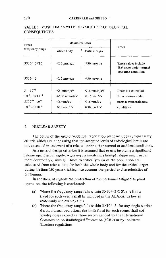
520 CARDINALE and GRILLO
TABLE I. DOSE LIMITS WITH REGARD TO RADIOLOGICAL CONSEQUENCES
E ventfre que ncy range
M a x im um dosesN otes
W hole bo d y C rit ic a l organ
З Х К Я -З Х Ю 1
з х ю ' - з
< 1 0 m rem /a
< 1 0 m rem /a
< 3 0 m rem /a
< 3 0 m rem /a
These values inc lude discharges un de r no rm a l opera ting co n d itio n s
3 - 10’1
К Г ’ - З Х Ю '3
З Х 1 0 '3- 1 0 '4
10~4- 3 X 1 0 '6
< 5 m rem /e V
< 5 0 0 m rem /e V
< 5 re m /e V
< 1 0 re m /e V
< 1 5 m rem /e V
< 1 .5 re m /e V
< 1 5 re m /e V
< 3 0 re m /e V
Doses are estim ated
fro m releases under
n o rm a l m e teo ro log ica l
con d itions
2. NUCLEAR SAFETY
The design of the mixed oxide fuel fabrication plant includes nuclear safety criteria which aim at ensuring that the accepted levels of radiological limits are not exceeded in the event of a release under either normal or accident conditions.
As a general design criterion it is assumed that events involving a significant release might occur rarely, while events involving a limited release might occur more commonly (Table I). Doses to critical groups of the population are calculated from release data for both the whole body and for the critical organ during lifetime (50 years), taking into account the particular characteristics of plutonium.
In addition, as regards the protection of the personnel assigned to plant operation, the following is considered:
(a) Where the frequency range falls within 3X10²—3X101, the limits fixed for such events shall be included in the ALARA (as low as reasonably achievable) aims
(b) Where the frequency range falls within 3X101—3 for any single worker during normal operations, the limits fixed for such events shall not involve doses exceeding those recommended by the International Commission on Radiological Protection (ICRP) or by the latest Euratom regulations

IAEA-SM-245/43 521
(c) Where the frequency range falls within 3—10_1 for any single worker, the limits fixed for abnormal and exceptional events (Euratom regulations) shall not be reached and only a few operators shall be involved
(d) Where the frequency range falls within 10- 1—ЗХ10-3, the limits fixed for exceptional events shall not be exceeded as regards all the personnel assigned to the plant operation and/or maintenance
(e) For all other events, it shall be possible for all personnel to leave the plant.
3. BASIC DESIGN
3.1. Process building zones
Four zones are recognized within the process building, each of which is characterized by a different level of contamination risk. The relevant containments are defined as follows:
(a) Primary containment (Zone I): It consists of those barriers which are in direct contact with plutonium, and the relevant ventilation system
(b) Secondary containment (Zone II): It consists of those barriers which include a primary containment, and the relevant ventilation system
(c) Third containment (Zone III): It consists of those barriers which include the secondary containment, and the relevant ventilation system
(d) Fourth containment (Zone IV): It consists of the zones included between the third containment and the outside walls of the building which act as a physical barrier.
3.2. Basic choices
Zone I is equipped with an inert-gas closed-circuit ventilation system, while Zone II is equipped with its own ventilation system which is separated from those belonging to Zones III and IV and is independent of them.
Figure 1 shows the preliminary flow sheet of the containment systems in Zones II and III. As regards Zone II, which can be considered as potentially contaminated, the air flow design provides for air supply and extraction and a partial recirculation is foreseen. The extent of recirculation is stated taking into account economic factors and nuclear safety requirements. In Zone III the air flow design provides for air recirculation; this is for economic reasons and involves heat recovery. The air supply unit consists of three centrifugal electric fans, one of which is redundant.

5 2 2 CARDINALE and GRILLO
PROCESS BUILDING
I , rD
-¡h -
-If- -$-N-
STAND BY 50%
FILTERPROTECTIONDEVICE
1 PLENUM J
f4 4CHIMSJEY .
PSTAND-BY 50%
AIR INTAKE
IQH> i rD &■{)
CONDITION.
STAND BY 50%Й
I
50% 50%
AUXILIARY BUILDING
________I
FIG.l. Preliminary flow sheet o f the containment system in Zones IIa n d III.

IAEA-SM-24S/43 523
The two circuits can either share this unit, as shown in Fig. 1, or each circuit can be equipped with one single unit; should this be the case, the unit shall be equipped with an interlocking system to avoid air supply in Zone II when Zone III supply electric fans are out of order. Fans are equipped with plenum both in the inlet and outlet sections, which acts as a stabilizer and therefore reduces noise.
As regards electric fans in Zone II, it is necessary to install upstream of the fans a further air intake which is normally not connected with the suction duct and is equipped with plenum. This air intake avoids a reverse flow of the air from Zone II to the atmosphere in the event of accidents caused by a tornado, and, when this occurs, it always keeps the fan operating parameters in line with the design standards, thus avoiding instability.
The supply ducts are circular in the Zone II circuit and rectangular in the Zone III circuit. It is easier to install the latter ducts but they show a low function rate when radioactive particulates deposit. Both air supply and extraction are performed in parallel in the various zones.
In Zone II the air supply ducts are equipped with three absolute filtering units (HEPA) which can retain radioactive particulates with an efficiency not lower than 99.99%. These units are located as follows:
(a) One absolute filtering unit at each cell extraction. Its function is to prevent the spread of radioactive contamination in the duct downstream of the filter. This unit shall be equipped with a pre-filter to clean the air.
(b) A second absolute filtering unit is located either in an intermediate position along the exhaust duct or in a final position upstream of the extraction fans. This unit is to be considered as redundant equipment in the event of malfunction of the filtering unit located in the cell, and to improve the filtering efficiency value keeping it above the aforestated level.
(c) A third absolute filtering unit is located upstream of the extraction fans. This unit is necessary to ensure the aforestated efficiency.
One stage of the absolute filtering unit (either the intermediate or the final one) is equipped with a redundant device. The extraction fan unit consists of three electric fans in parallel, of which two operate and one is redundant; these fans are equipped with plenum both upstream and downstream of the inlet and outlet section and their function is to reduce noise. The first plenum can be located upstream of the last filtering stage, should this become necessary to improve the filtering unit efficiency. The stack represents the second plenum.
In Zone III only one absolute filtering unit is foreseen and it will be located at the end of the duct upstream of the extraction fans. The characteristics of this unit are the same as those mentioned previously. It is equipped with redundant devices and a pre-filter located in front of it to perform an initial
5 2 4 CARDINALE and GRILLO
cleaning of the air. In this Zone one part of the air is recirculated and one part is discharged to the atmosphere; it is not necessary to dilute it and it can be discharged to the atmosphere through a normal chimney.
The extraction and/or recycle unit consists of three electric fans of which two operate and one is redundant. They are equipped with plenum both upstream and downstream of the inlet and outlet sections for the same reasons as already stated. Reliability requirements justify the presence of two electric fans in parallel and of a redundant one, the reason for this being that under emergency conditions in both Zones II and III it is possible to reduce air flow but not depression.
Thus, the most severe condition expected to occur is when only one fan operates; air flow is reduced by 50% and the depression value remains unchanged. Because of their location, filters and any shutdown device are considered as radioactive, while both extract and air supply fans and the air conditioning units are considered as non-radioactive.
It is necessary to dilute the air discharged to the atmosphere from Zone II and therefore the outflow shall be performed through a stack, whereas it is not necessary to dilute the air discharged to the atmosphere from Zone III and the outflow is passed through chimneys located near the buildings.
3.3. Design criteria
The main design criteria adopted are the following [1 ]:
(a) A depression gradient is provided in accordance with the existing or possible contamination levels in the various areas, to avoid uncontrolled air exchanges.
(b) The number of air changes per hour is equal to 8—10 in Zone II and 2—3 in Zone III.
(c) Containment barriers are designed to withstand the design basic earthquake; the outer containment barriers are designed to withstand even a tornado.
(d) The primary containment barriers, which consist mainly of glove-boxes, are designed to withstand the most severe conditions as regards radioactive release caused by the malfunction of the process components. No particular measures have been taken as regards explosion, as an explosion is unlikely to occur. Glove-boxes and the relevant internal components are designed to reduce the fire load to under 1 kg/m2, while cells and the relevant ventilation system are designed to avoid fire propagation to the surrounding areas.
(e) All cells in Zone II and Zone III are ventilated in parallel.

IAEA-SM-245/43 5 2 5
Further criteria of the design are the following:
(i) Under all operating and accident conditions, the non-achievement of surge conditions is guaranteed for both air supply and extraction equipment.
(ii) One fan of the Zone II extraction circuit and one fan of the Zone III extraction circuit are supplied with level I emergency power. One fan for each Zone II supply circuit and one Zone III supply fan are supplied with level II emergency power.
(iii) The absolute filtering units retain an efficiency that is not lower than 99.97% up to a temperature equal to 300°C and for a period of time that is not less than 1000 hours.
(iv) Should an accident occur, protection systems are provided to guarantee that the nuclear safety requirements are met. They consist mainlyof the maintenance of the design depression value, the containment of radioactive releases to the atmosphere, and the containment of radioactive releases within the plant.
4. CONTAMINATION SOURCES
4.1. Normal conditions
Inside Zone II the following contamination conditions are considered:
(a) 0 index conditions with an average concentration of 1 / 10 MPC.(b) 1 index conditions with an average concentration of 10 MPC X 20 h/a
or 100 MPC X 2 h/a.
As far as the release to the atmosphere is concerned, Pu releases can be limited to a rate under 0.7 mg for both 0 and 1 conditions.
4.2. Accident conditions
4.2.1. Fire
A fire occurring only in one cell of the plant is considered where the combustible material, which consists of gloves, plastics, Kleenex, etc., does not exceed 30 kg and the fire is deemed to last 2 h. The maximum amount of Pu02—U 0 2 that can be reduced to aerosol is 27 kg of mixture, the maximum Pu02 enrichment being 20%. The aerosol factor (the amount of mixed oxide powder reduced to aerosol in 1 h) is assumed to be 10"3 h”1 [2]. This value has

526 CARDINALE and GRILLO
been assumed on the basis of the higher limit of measurement carried out in the air at 1000°C, velocity being equal to 100 cm/s, and also by taking into consideration the fact that powder is never in direct contact with the air but is kept in containment vessels which slow down the progress of the phenomenon.
The total filtering unit efficiency is assumed to be 99.90% in case of exceptional events affecting the efficiency of one section of the filtering unit. Under these conditions and should a fire occur in one cell, the release to the atmosphere would be equal to 10 mg of Pu at most.
4.2.2. Criticality
A critical range of 1018 fissions is considered as credible [3]. The energy generated essentially originates à heat transfer to the environment and a light over-pressure during the first phase. The primary containment failure and the preservation of the secondary containment functions are considered. The Pu quantity suspended because of this event is assumed to be equal to the quantity which is necessary to saturate one volume of air in the cell (100 mg/m3), i.e. approximately 60 g in this particular case. If the temperature does not increase, a condition which might affect filters, total efficiency reaches 99.99%, and the Pu release to the atmosphere is thus lower than 6 mg. Fission products, as shown in Table II, are to be added to the Pu released.
5. FAULT TREE ANALYSIS
The analysis of the physical trend of those hazards which might affect thesystem, i.e. those which might occur because of the failure of any component,is carried out by starting from the first cause, usually the malfunction of a processcomponent, and by considering the possibility of using protection systems in orderto keep any possible consequence within certain limits [4]. The failure of aprocess component is characterized by the relevant failure rate; the failure ofprotection systems is characterized by the relevant unavailability; both parameters have a range of values corresponding to the relevant reliability level.
Table III shows the characterization data. As regards probabilities, theresulting hazard is characterized by its own frequency range. The operatingdevelopment of the event tree is performed by combining an index with everyspecific function of the process and protection systems in accordance with therelevant reliability level; thus, any possible fault can be given an overall index number which is obtained from the accident progress sequence. Consequently, this index number corresponds to an overall probability; it is then possible to use it to state whether, in accordance with the aforestated criteria, the radiological consequences are acceptable.

IAEA-SM-245/43 5 2 7
TABLE II. FISSION PRODUCTS GENERATED DURING A CRITICALITY ACCIDENT
Fissionp roduc ts
A c t iv ity
(C i)
F issionp roduc ts
A c t iv ity(C i)
83K r m 3.77 131X e m 1.5X 10 -3
85K r m 13.5 133X e m 8 .6 X 1 0”2
85K r 1.4X1 O'4 133Xe 1.8
87K r 96.3 135X em 21.1
88K r 66.7 I35Xe 15.7
137Xe 2830
138Xe 1173
131 x 0 .635 89Sr 0 .207
132i2.6 “ Sr 1 .2X 10'3
133t 14.7
134t 194 137Cs 1 .2X 10'3
135» 48.1 -
When the system reliability level is stated, an analysis is carried out to state the component reliability level through the fault tree technique which is similar to the event tree technique.
6. USE OF THE FAULT TREE ANALYSIS AND DEFINITION OF THE COMPONENT QUALITY REQUIREMENTS
As regards the malfunction of any component of the system, through use of the event tree technique, it is possible to show an overall accident trend, and of all accidents fire (see Fig. 2) is considered to be the one which causes the highest release. For the sake of brevity other accident trends are not shown. Should all protection systems fail, release is assumed to equal approximately 1 mg of Pu.

TABLE III. FAILURE RATE AND UNAVAILABILITY DATA
5 2 8 CARDINALE and GRILLO
R e lia b ilityleve l
Fa ilu re rate Ind exClass o f u n a v a ila b ility
U n a va ila b ilityvalue
Index
L O 1 0 _1 — 1 0 C O 1 0 ' 1 0
L 1 01 K> 1 О1
1 С 1 1 0“2 1
L 2 1 0 ' 3 - 1 0 ' 2 2 С 2 1 0’3 2
L 3 1 0 ~4 - 1 0 ~ 3 3
M a lfu n c tio n S ym bo l Index
Process system com pone n t L x M x
F irs t p ro te c tio n system Cy M y
Second p ro te c tio n system Cz Mz
T h ird p ro te c tio n system Cw M w
In c id e n ta l event S ym bo l Index
a) F irs t p ro te c t io n system operates L x M x
b ) F irs t p ro te c tio n system o u t o f o rd e r; second p ro te c tio n system operates L x C y M x + M y
c) F irs t and second p ro te c t io n systems o u t o f o rd e r; th ird p ro te c tio n system operates L x C y C z M x+ M y+ M z
d) N o p ro te c tio n system in op e ra tio n L x C y C z C w M x + M y + M z+ M w
Under extremely conservative conditions and with the lowest efficiency value of filtering units being 99.90%, release is assumed to be equal to 10 mg of Pu (see sub-section 4.2.1 ). Should a release of this order occur, the radiation doses for critical population groups around the proposed site for the plant would be approximately 100 mrem. Considering the safety criteria mentioned in section 2,

IAEA-SM-245/43 529
Initial event
Consequences
FIG.2. Fire accident.
the result is an overall index of event probability equal to 2, i.e. an event which might occur once in a century.
Two independent protection systems are foreseen which consist of a fire extinguisher and a protection system for final absolute filtering units to ensure their efficiency. As regards other accidents, two further independent protection systems are foreseen to detect and carry out the relevant intervention. As fire causes the highest radiological effects, it has been taken as an overall reference as far as the component quality level is concerned. If the component failures that cause accidents are normal and if the relevant componfnts show an industrial quality level, then the protection system unavailability is typically 10"1. Thus, with two independent protection systems an overall unavailability index and,
5 3 0 CARDINALE and GRILLO
in this case, an overall probability index (as regards release, equal to 2) are obtained, as laid down by the nuclear safety requirements for a fire involving the highest release.
Regarding other malfunctions of the containment systems, only one protection system showing a typical unavailability equal to 10_1 is necessary.As the two systems to be used in the event of fire can be adopted, with some additional but minor components, for use in the event of other types of malfunctioning (detection always being referred to the circuit pressure and flow parameters), event trees usually include two protection systems.
In particular we think it necessary to point out that the circuit active components can show a normal industrial level. This result, which was proposed during design and confirmed by safety analysis, is considered of great importance, when we encounter technical and economic difficulties, in obtaining components showing a different, i.e. a higher, quality level. A second and similar result is that the protection system unavailability standard shows a 0 index [6 ].
The above does not involve an industrial quality level for all the relevant components but it does leave out those components which show a high quality level. All quality levels are exactly defined through fault trees which are worked out in accordance with the component detailed design and/or with the protection system line. The low unavailability value reduces design and production costs as well as maintenance and handling costs during the plant operation. Finally, this setting out of the system design, which aims at ensuring operations using both active and protection components showing an almost standard quality level, is deemed to be more functional, and the system itself appears to be more qualified and reliable.
REFERENCES
[1 ] S F -C O M B U S T IB IL I PER R E A T T O R I V E L O C I, P roge tto d i Massima Im p ia n to Fabbricaz ione C o m b u s tib ile O ssidi M is ti U ran io P lu to n io , M ilan (1 9 7 8 ).
[2 ] Ç O G L IA T I, G ., E V A N G E L IS T I, R ., Esame Conseguenze Ince nd io in u n L a b o ra to rio Im p ia n to P lu to n io , CSN-Casaccia, C o m ita to N azionale pe r l ’ Energia Nucleare, R om e,Rep. C N E N -IP U 1 0 (1 9 7 6 ).
[3 ] S F -C O M B U S T IB IL I PER R E A T T O R I V E L O C I, R a p p o rto P re lim m are Sicurezza Im p ia n to Fabbricaz ione C o m b u s tib ili Ossidi M is ti U ran io P lu to n io , M ilan (1 9 7 8 ).
[4 ] F E L IC E T T I, F ., G A L V A G N I, R ., Z A P P E L L IN I, G ., A n a lis i d i S icurezza M e todo log ía S em ip roba b ilis tica e suo S v ilu ppo A p p lic a tiv o , C o m ita to N aziona le pe r l ’Energia Nucleare, R om e, C N E N In te rn a l R epo rt (1 9 7 8 ).
0

IAEA-SM-245/36
OFF-GAS CLEANUP SYSTEM DESIGNED FOR HLLW VITRIFICATION IN A LIQUID-FED CERAMIC WASTE MELTER
S. WEISENBURGER, H. SEIFFERT Institut für Nukleare Entsorgungstechnik,Kernforschungszentrum Karlsruhe GmbH,Karlsruhe,Federal Republic of Germany
Abstract
O F F -G A S C L E A N U P SYS TEM D E S IG N E D F O R H L L W V IT R IF IC A T IO N IN A L IQ U ID -F E D C E R A M IC W A S T E M E L T E R .
In the In s t itu t fü r N ucleare E ntso rgungstechn ik ( IN E ) , a v it r i f ic a t io n process fo r h igh-leve l l iq u id waste (H L L W ) is un d e r deve lopm ent w h ic h is p r im a r ily based on a co n tin u o u s liq u id -fe d ceram ic m e lte r. T h is paper describes the o ff-gas system specia lly designed fo r the process off-gas o f such a ty p e o f m e ltin g u n it . O p e ra tio n a l experience ind ica tes th a t process c o n d itio n s at the glass p o o l surface have a s ig n ifica n t in flu e n ce o n the load ing o f the o ff-gas stream w ith p a rticu la te o r v o la t ile m a te ria l. L o w off-gas load ing can be observed w hen the m o lte n glass p o o l is covered as c o m p le te ly as possib le w ith a l iq u id waste so lu tio n . F o r the off-gas cleanup system , a w e t f i l t r a t io n device was chosen. The e ff ic ie n c y o f th is device fo r the rem ova l o f p a rtic u la te and v o la t ile m a te ria l is evaluated and the resu lts are discussed. T h e v i t r i f ic a t io n process u n de r inactive deve lopm ent at IN E w il l be ra d io a c tive ly dem onstra ted in a p ilo t-sca le v it r i f ic a t io n p la n t to be b u il t a t the E u ro chem ic site a t M o l, B e lg ium .
1. INTRODUCTION
In a nuclear waste vitrification process the high-level liquid waste (HLLW) is dried, calcined and melted, together with suitable glass additives, to form the final waste glass. The process off-gas arising includes, in addition to steam and oxides of nitrogen, variable concentrations of radioactive nuclides, which are contained either in particulate or volatile material. The effluents of concern vary individually from one type of vitrification process to another. The off-gas loading depends also, within a given process, on actual process condition and operational parameters. The off-gas treatment system must be able to remove as completely as reasonably possible all the radioactivity that enters from the process facilities into the off-gas stream. Due to significant differences in off-gas loadings among the various types of vitrification processes, the cleanup system must be adequately designed for each process. The design requires not only high removal efficiency but it must also avoid operational and maintenance problems which can be caused by solids deposition in the off-gas line.
531

532 WEISENBURGER and SEIFFERT
HLLW ^ GLASS FRIT
BOILING LIQUID
SOLID LAYER
GLASS MELT
■Ф OFF GAS
CERAMIC
INSULATION
POWER ELECTRODE
STEEL BOX
il WASTE GLASS 47 DRAINING
FIG.l. Schematic concept o f a liquid-fed ceramic melter with Joule-heating o f the glass pool.
The present paper deals with an off-gas line designed for the process off-gas from a liquid-fed ceramic waste melter. HLLW vitrification in such a unit is a relatively new technique which has been under pilot-scale development in the Institut fürNukleare Entsorgungstechnik (INE) since 1976. With respect to off-gas treatment, such types of melters impose special consideration. Liquid-fed ceramic melters usually have a large glass pool surface on the order of 1 m2 and are operated at a high temperature level between 1150-1250°C to achieve sufficiently high feed throughputs of 30—60 ltr/h. It is this large glass pool surface as well as the high operational temperatures which can create a variety of different process conditions at the molten glass pool surface, and these in turn have a very significant influence on both solids carry-over and generation of vaporized or volatile material. These facts must be carefully taken into account when choosing an appropriate off-gas system to be coupled to a liquid-fed ceramic waste melter.
2. CONCEPT OF A NUCLEAR CERAMIC WASTE MELTER FOR HLLW VITRIFICATION
The fundamental concept of a nuclear ceramic waste melter is shown in Fig.l. The molten borosilicate glass is contained in a high temperature refractory ceramic material and heating of the glass is accomplished by passing an alternating
IAE A-SM-245/36 5 3 3
current between electrodes submerged in the melt. The HLLW is mixed with powdered glass frit and then fed directly to the molten glass pool where it is continuously evaporated, calcined and melted into the glass pool, together with the added glass frit powder. At steady-state conditions and for moderate feed rates, one or more layers of calcined or sintered materials are formed at the molten glass pool. They are either covered with boiling liquid or they will gradually dry when they move away from the central aqueous zone. The process off-gas leaving the melter is directed without any prefiltration to the off-gas cleanup device.
Details of the melter technology and process performance have been reported previously in Ref. [ 1 ]. A photograph of an advanced ceramic melter unit, designated K-2, is shown in Fig. 2.
3. IMPORTANT ASPECTS IN DESIGNING AN OFF-GAS DEVICE SUITABLE FOR A LIQUID-FED CERAMIC MELTER
One of the primary attractions of the vitrification process described is the fact that a high feed-rate capacity can be achieved, despite the energy-consuming process steps of drying and calcining which take place in the melter itself and, thus, a separate and somewhat complex calcining unit is not required. The two main factors determining the feed-rate capacity and glass production rate, namely glass pool surface and current density at the electrode surface, have practically no limit for this melter system if they are properly designed. Regarding the off-gas loading, the expected advantage of liquid feeding is the elimination of any process step associated with the formation of dust. Because of the low solid loading of the off-gas, there is no need to pass it through a highly efficient particulate filtration unit, for example sintered metal filters, before it leaves the melter exit.
However, because carry-over of dust is not completely suppressed despite liquid feeding, and because the remaining dust in the off-gas is not retained at the melter exit, even low solid loadings of the off-gas stream can be significantly important in the overall process performance.
3.1. Aspects of solid loadings of the melter off-gas
Operational experience with an inactively operated vitrification plant at INE revealed a carry-over of particulate material between 0.5 — 12 wt% (referred to the total amount of calcine to be melted into the glass pool). Carry-over depends strongly on a number of factors, including the degree of coverage of the glass pool with liquid and the solid layers. It also depends on pressure levels in the melter and the associated air leakage rates.

5 3 4 WEISENBURGER and SEIFFERT
FIG.2. Advanced ceramic waste melter (K 2 ) installed at the inactive vitrification plant mock-up at the Institu t fü r Nukleare Entsorgungstechnik (INE). (outside dimensions: 1.6 m X 1.6 m X 1.85 m ; glass pool surface: 0 .64 m 2 ; electrodes: Inconel 690, air-cooled; maximum power: 150 kW ; draining system: bottom drain freeze valve).
The lowest solid loading of the off-gas, corresponding to only 0.5 wt% material loss from the melter, was observed when complete flooding of the glass pool surface occurred, as schematically indicated in Fig.3. The carry-over increased to approximately 4 wt% when the glass pool was continuously covered to only 70—90% of its total surface. Even larger (> 10 wt%) carry-over of particulate material occurred when about 50% of the surface was free from liquid waste.

IAEA-SM-245/36 535
a )
LOW CONTINUOUS FEED RATE
-UNCOVERED MELT
-DRY SOLID LAYERS
-LIQUID COVERED AREA
Ы
MEDIUM FEED RATE
-FEED STREAM
FIG.3. Schematic view from the top o f the melter on to the glass pool surface while maintaining low, medium and maximum feed throughputs.
At the glass pool surface three zones can be distinguished during operation, as shown in Fig.3. Their extent and formation depends on the feed rate applied. Although complete flooding of the total glass pool with HLLW would lead to minimum off-gas loading with particulate material (and also volatile compounds), it is not the preferred operational mode for a liquid-fed ceramic melter. The reasons are outlined in detail in Ref. [ 1 ]. Operational experience indicates that the melter works best at a feed rate by which about 90% of the total glass pool surface is covered with a liquid waste solution. In this operation the increased material loss, compared with the minimum loss for the flooded glass pool, is acceptable. The loading level is nevertheless still low enough not to need a high-load dust removal device.
Consequently, for the first stage of off-gas treatment, a wet-scrubbing dust removal device will be adequate and will scrub out most of the dust, which is at a low level anyway, from the off-gas stream. However, special care is necessary to avoid solids deposition in the pipe connecting the melter with this first device of the off-gas cleanup system. It may be advantageous to use a short and straight pipe to minimize any potential area for solids deposition in the pipe, otherwise the part of the off-gas line immediately following the melter could become a problem area because of remote maintenance requirements.
536 WEISENBURGER and SEIFFERT
3.2. Aspects of off-gas loading with volatilized solid material
Because of the large glass pool surface needed for a liquid-fed ceramic melter, it would be impractical to operate it with too low feed rates for which large areas of the pool remain uncovered with liquid waste. The subsequent vaporization of melt from the uncovered hot zone would lead to intolerable material loss. A similar situation would exist when the melter is put into an idling or non-glass- producing state due to process shutdown or melter maintenance. For the same reasons, the glass pool must not be kept in this state at normal operating temperatures. It must be shifted to significantly lower temperature levels, i.e. in the order of 800°C. Restarting of operations from this temperature level can then be easily carried out.
During operation the vaporization of potential candidate materials can be kept sufficiently low because of the cold cap of the liquid waste, with the exception of ruthenium. Unfortunately, for the optimum process conditions outlined in sub-section 3.1, the melter is a fairly effective generator for volatile ruthenium compounds. Preliminary experience has shown that approximately 17 wt% of the total ruthenium fed to the melter enters the off-gas stream under these conditions (total nitrate concentration of simulated feed: 3.4M).
3.3. Aspects of additional off-gas streams entering the melter system
An advantageous feature of the process is the inherent low off-gas flow rate. Process additives, for instance those needed in other vitrification processes for atomizing the HLLW, for heating or for fluidizing a calciner bed are not necessary. However, the inner ceramic core of the melter and the heat insulation must be carefully sealed by a steel box encasing the whole melter unit, otherwise there would be significant flow rates of leakage air in the off-gas system because the melter will be operated at about 20—50 mmH20 below normal pressure.
Leakage air flow rates between 30—60 m3/h can occur if the steel box is not carefully designed for encasing the melter unit. Such high flow rates have the additional disadvantage that they can significantly enhance the off-gas loading with particulate materials. These flow rates must therefore be as low as reasonably possible.
3.4. Typical off-gas composition from a liquid-fed ceramic melter
Table I summarizes what should be expected in the off-gas stream of a liquid- fed ceramic waste melter during melter operation. The data given are based on a continuous feed rate of 30 ltr/h, with a simulated feed having a total nitrate concentration of 3M and a solid concentration of about 100 g/ltr (expressed as oxides after calcination). As can be seen, the main gaseous components of the

IAEA-SM-245/36 537
TABLE I. TYPICAL MELTER OFF-GAS GENERATED IN A LIQUID-FED CERAMIC WASTE MELTEROperation with a simulated solution at a feed rate of 30 ltr/h, total nitrate content 3M, and the melt surface assumed to be covered to between 70—90% with liquid feed
P aram eter o r co n s tituen ts
V a lue at m e lte r e x it
Param eter
O ff-gas v e lo c ity at m e lte r e x it 2.1 m /s aO ff-gas tem pera tu re 180—250°CPressure 2 0 —40 m m be low n o rm a l
pressure
Condensable co n s tituen ts
Steam 26 m 3 /h bN O x 2 m 3/hV apo urized solids (Cs20 fo r exam ple) 0.5 w t% °R eaction p ro d u c ts ( R u 0 4) 1 2 -1 6 w t%
N on-condensable co n s tituen ts
Leakage air 5 m 3/hN itro g e n < 0.5 m 3/hO xygen < 0 .5 m 3/h
P artic le load ing
D ust 3 - 5 w t% dAeroso ls n o t y e t de te rm ined
a Refers to an e x it d iam e te r o f 100 m m . b A l l gaseous vo lum es are reduced to STP.c Depends s tro n g ly on process c o n d it io n a t m e lt surface; w t% re fe rs to the to ta l ra te o f
the co n s titu e n ts fed to the m e lte r. d C orrespond ing to a load ing o f ab ou t 3.5 g /m 3.
off-gas, apart from steam, are the leakage air, the NOx formed by the thermal decomposition of nitrates, and ruthenium tetroxide. The NOx is predominantly in the form of N 0 2 and thus can be easily recombined by wet scrubbing to form nitric acid.
Based on operational experience at INE and on the typical data given in Table I, an advanced off-gas treatment system has been designed and constructed.

Dust removal Condenser NOx absorberw et scrubber
FIG.4. Advanced off-gas system designed and installed in the inactive mock-up vitrification plant at INE.
538 W
EISENBU
RGER
and SE
IFFER
T
IAEA-SM-24S/36 5 3 9
4. OFF-GAS SYSTEM DESIGNED AT INE FOR A LIQUID-FED CERAMIC MELTER
The off-gas system installed at INE in the inactive vitrification mock-up for the radioactive demonstration plant at Mol is shown in Fig.4. It consists of a dust removal wet scrubber, a ruthenium adsorber bed, a condenser, NOx-absorber columns, a further ruthenium filter, and finally two HEPA filters.
The melter off-gas is passed through a straight pipe 100 mm in diameter and0.5 m in length into the dust removal wet scrubber. The primary aim o f the first stage of off-gas treatment is the removal of dust particles. Approximately 120 g of solid particulate material must be removed in one hour at a feed throughput of 30 ltr/h. The scrub solution is circulated by an airlift device at a flow rate of 350 ltr/h over six special column plates, and the particles in the countercurrent off-gas stream are trapped with an efficiency of about 90—95%. The collected dust is discontinuously routed back to the feed system with part of the scrub solution, using another airlift, and this recycled scrub solution is replaced by fresh water.
Under normal operational conditions, the melter off-gas entrains the dust scrubber at a temperature of 220°C. To prevent the steam in the off-gas from undesirable pre-condensation in the dust scrubber, a heating device surrounding the scrub solution vessel maintains it at 85—90°C. Because the scrubber can create significant amounts of aerosols, these can be largely removed by a demister device fitted at the top of the column.
Operational experience shows that the scrubber removes not only dust particles but also the major part of the volatile ruthenium compounds contained in the off-gas. Detailed data and analysis are given in Ref. [2]. However, despite this advantageous Ru-removal feature, the ruthenium amount leaving the dust scrubber is still significant enough (about 0.5—1 wt% of the Ru, fed to the melter) to justify the installation of a ruthenium adsorber bed immediately after the dust scrubber, to remove the remaining ruthenium before the off-gas is directed to the condenser. However, the use of a ruthenium filter is still an option for the radioactive plant and it is presently undergoing inactive tests. After condensation of the steam in the condenser, the remaining NOx is absorbed in two packed columns, which are continuously fed with a low flow rate of fresh water. The scrub is discontinuously and partially routed to a storage vessel for later concentration, together with the condensate.
Whether a ruthenium adsorber between dust scrubber and condenser is used or not, a final ruthenium barrier will in any case follow the NOx-absorber. This filter is made of silica-gel grade 40 and will be operated at about 75°C, with an average gas velocity in the packed bed of less than 5 cm/s. Increasing the superficial gas velocity has the effect of reducing the sorption capacity which, at 5 cm/s, is in the order above 3 -4 kg Ru/m3 silica-gel grade 40.
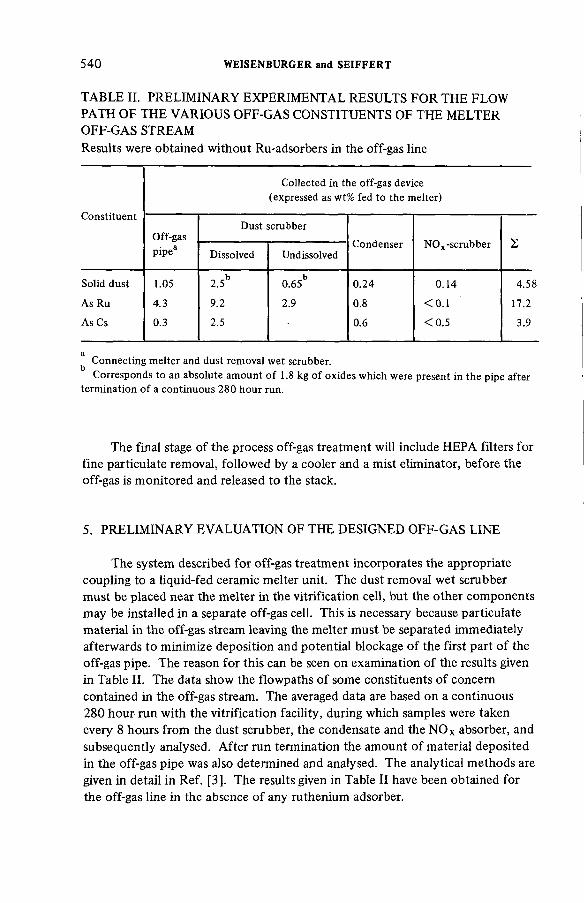
5 4 0 WEISENBURGER and SEIFFERT
TABLE II. PRELIMINARY EXPERIMENTAL RESULTS FOR THE FLOW PATH OF THE VARIOUS OFF-GAS CONSTITUENTS OF THE MELTER OFF-GAS STREAMResults were obtained without Ru-adsorbers in the off-gas line
C o n s titu e n t
C o llec ted in the o ff-gas device (expressed as w t% fed to the m e lte r)
O ff-gasD ust scrubber
Condenser N O x -scrubberp ipe3 Dissolved Undissolved
S o lid dust 1.05 2 .5bb
0.65 0.24 0.14 4.58
As R u 4.3 9.2 2.9 0.8 < 0.1 17.2
As Cs 0.3 2.5 - 0.6 < 0 .5 3.9
aC onn ec ting m e lte r and dust rem ova l w e t scrubber.C orresponds to an absolu te am oun t o f 1.8 kg o f ox ides w h ic h were present in th e p ipe a fte r
te rm in a tio n o f a co n tin u o u s 280 h o u r run .
The final stage of the process off-gas treatment will include HEPA filters for fine particulate removal, followed by a cooler and a mist eliminator, before the off-gas is monitored and released to the stack.
5. PRELIMINARY EVALUATION OF THE DESIGNED OFF-GAS LINE
The system described for off-gas treatment incorporates the appropriate coupling to a liquid-fed ceramic melter unit. The dust removal wet scrubber must be placed near the melter in the vitrification cell, but the other components may be installed in a separate off-gas cell. This is necessary because particulate material in the off-gas stream leaving the melter must be separated immediately afterwards to minimize deposition and potential blockage of the first part of the off-gas pipe. The reason for this can be seen on examination of the results given in Table II. The data show the flowpaths of some constituents of concern contained in the off-gas stream. The averaged data are based on a continuous 280 hour run with the vitrification facility, during which samples were taken every 8 hours from the dust scrubber, the condensate and the NOx absorber, and subsequently analysed. After run termination the amount of material deposited in the off-gas pipe was also determined and analysed. The analytical methods are given in detail in Ref. [3]. The results given in Table II have been obtained for the off-gas line in the absence of any ruthenium adsorber.
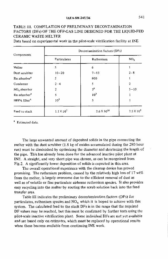
IAEA-SM-245/36 541
TABLE III. COMPILATION OF PRELIMINARY DECONTAMINATION FACTORS (DFs) OF THE OFF-GAS LINE DESIGNED FOR THE LIQUID-FED CERAMIC WASTE MELTERData based on experimental work in the pilot-scale vitrification facility at INE
C om ponentsD e co n ta m in a tio n fac to rs (D F s)
P articu la tes R u th e n iu m XОz
M e lte r 5 6 1
D ust scrubber 1 0 - 2 0 7 - 1 3 2 - 8
R u adsorber2 5 800 1
Condenser 2 - 4 5 2
N O x absorber 2 3a 5 - 1 0
R u adsorber3 5 1 0 3 1
H E P A f i l te r 3 1 0 3 5 1
Feed to stack 1.1 X 10⁷ 2.6 X 10¹⁰ 7.5 X 101
3 E s tim a ted data.
The large unwanted amount of deposited solids in the pipe connecting the melter with the dust scrubber ( 1.8 kg of oxides accumulated during the 280 hour run) must be diminished by optimizing the diameter and shortening the length of the pipe. This has already been done for the advanced inactive pilot plant at INE. A straight, and very short pipe was chosen, as can be recognized from Fig. 2. A significantly lower deposition of solids is expected in this area.
The overall operational experience with the cleanup device has proved promising. The ruthenium problem, caused by the relatively high loss of 17 wt% from the melter, is largely overcome due to the efficient removal of dust as well as of volatile or fine particulate airborne ruthenium species. It also provides easy recycling into the melter by routing the scrub solution back into the feed transfer area.
Table III indicates the preliminary decontamination factors (DFs) for particulates, ruthenium species and NOx which it is hoped to achieve with this system. The calculated feed to the stack DFs is in the range that the required DF values may be reached, but this must be confirmed by further tests using the pilot-scale inactive vitrification plant. Some individual DFs are not yet available and are based only on estimates, which must be replaced by operational results when these become available from continuing INE work.
5 4 2 WEISENBURGER and SEIFFERT
The presently available results are based on vitrification of the simulated waste solution, the composition of which corresponds to a standardized Purex- HLLW. Future operational tests at INE will include vitrification of simulated LEWC waste solution (Low Enriched Waste Concentrate). The LEWC stored at the Eurochemic site in Mol, Belgium, will be used as the active feed for the liquid-fed ceramic melter in the new hot vitrification plant to be built at Mol. The LEWC contains some individual constituents whose off-gas behaviour may be of some concern. This will be tested in future runs in inactive tests at INE.
REFERENCES
[ 1 ] W E IS E N B U R G E R , S., “ V it r i f ic a t io n o f H L L W in a con tin u o u s liq u id -fe d ceram ic m e lte r” , Ceram ics in N uc lea r Waste Managem ent (P roc. C on f. C in c in n a ti, 1979), U S AE C T e chn ica l In fo rm a tio n C enter, O ak R idge, T N , C O N F -7904 20 (1 9 7 9 ) 8 6 .
[2 ] W E IS E N B U R G E R , S., W EISS, K ., “ R u th e n iu m v o la t i l i ty behav iou r d u rin g H L L W - v it r i f ic a t io n in a l iq u id -fe d ceram ic waste m e lte r” , Science U n d e rly in g N uc lea r Waste M anagem ent (P roc. C on f. B oston , 1979) ( to be pub lished).
[3 ] H E N T S C H E L , D ., W E IS E N B U R G E R , S., M E IN K A , W ., G A N T N E R , H ., E insatz ana lytischer M e thod en zu r P rozessiiberwachung einer in a k tive n HAW -Verglasungsanlage, K F K N achr. 3 (1 9 7 9 ) 57.
DISCUSSION
B.W. WATSON: I would like to ask you two questions. How do you prevent the melter off-gas pipe blocking at the point where it enters the wet scrubber? Have you considered the possibility of a thermal interaction between the aqueous and the glass melt which could give rise to near-instantaneous (explosive) boiling?
H. SEIFFERT : Regarding your first question, if we use a short, straight off-gas pipe we do not expect any blocking. In case of difficulties, however, we can exchange the short pipe rapidly by remote handling.
With reference to your second question, a liquid-fed ceramic melter has a relatively large glass pool surface which differs from the conditions in the pot process or similar processes. Besides, the preferred operational mode is that the glass pool is continuously covered with liquid only to 90% of its total surface. We neither observed nor expected thermal interaction between the aqueous and the glass melt.
W.R.A. GOOSSENS: What design criteria did you take into account in choosing a plate-type scrubber? Why didn’t you use a venturi type scrubber, for example, since theoretically it also has a relatively low pressure drop?
H. SEIFFERT : The design criteria of the wet scrubber were as follows: to obtain dust particle removal of more than 90% in the first stage; to achieve an
IAEA-SM-24S/36 5 4 3
acceptable loss quantity of about 300 ltr/h wash solution, transferred by an air-lift device; and to limit part of this scrub solution which is recycled with a fresh water addition of about 2 ltr/h. Finally, the height at the racks should not be more than 2.70 m, in which case about six plates inside the column are sufficient. We did not use a venturi scrubber because of the low quantity of off-gas.
L.P. BUCKLEY: Could you provide additional details on the ruthenium filter and in particular on the capacity and expected servicing time? What will be done with the spent filter?
H. SEIFFERT: As shown in Table II, one advantage of this filter is that more than 90% of the ruthenium is collected in the wet scrubber unit. The bulk of the ruthenium is already removed from the off-gas stream. The ruthenium filter filled with silica-gel grade 40 is 400 mm in diameter and 1200 mm in height.During operation the temperature is about 75°C, and the capacity is approximately 3—4 kg Ru/m3 silica-gel. It is planned to regenerate the filter material by sparging with H N03 to keep the servicing times to a minimum. The spent filter material can be packed into drums in a concrete matrix and then sent to intermediate storage. After about ten years the ruthenium radioactivity is of little significance.
J.L. ROUYER: Have you considered using polyethylene for Ru trapping, and electrostatic precipitation as a method of prefiltration?
H. SEIFFERT : We have not used polyethylene. As regards the second part of your question, we did not use electrostatic prefiltration because of the considerable quantities of steam and dust in the off-gas stream of a ceramic melter. An additional disadvantage for application in a highly radioactive gas stream is the (3- and 7-activity, which ionizes the gas.
R. KROEBEL: I would like to add a general comment on some of the previous questions. At Karlsruhe we are going to use a wet dust scrubber, the sump of which is recycled to the ceramic melter. Some ruthenium — approximately0.5% or less — escapes the wet scrubber and enters the first silica-gel Ru filter.We hope that this filter, which has not yet been fully tested, will take out most of the ruthenium. The filter is either washed out for re-use or disposed of after overgrouting inside a normal waste drum. After the acid recovery system, a final back-up Ru filter, probably with different operational parameters (still to be developed), will ensure that the required decontamination factor is achieved.


IAE A-SM-24 5/55
DESIGN OF A PWR GASEOUS RADWASTE TREATMENT SYSTEM ENSURING SAFE CONTROL OF GASEOUS RADIONUCLIDES RELEASED UNDER NORMAL AND SEVERE CONDITIONS
R.G. GLIBERT, G.R. NUYT, P. FOSSION Belgonucléaire,Brussels
G.E.R. COLLARD Studiecentrum voor Kernenergie/
Centre d’étude de l’énergie nucléaire,Mol,Belgium
Abstract
D E S IG N O F A PW R G A S EO U S R A D W A S T E T R E A T M E N T S YS TEM E N S U R IN G S A F E C O N T R O L O F G A S EO U S R A D IO N U C L ID E S R E L E A S E D U N D E R N O R M A L A N D S E V E R E C O N D IT IO N S .
The concep tua l design o f a gaseous radwaste tre a tm e n t system adapted to a PWR design, w h ich inc ludes doub le co n fin e m e n t and engineered sa fe ty re la ted systems, is presented. The system is based o n the use o f a de lay line consis ting o f pressurized storage tanks and charcoal beds, a hyd roge n re com b in e r and p a rticu la te f ilte rs . A f te r presenting a fu n c t io n a l d e scrip tion o f the sa fe ty re la ted systems, the tre a tm e n t system is evaluated un de r n o rm a l and severe co n d itio n s on the basis o f data given in the lite ra tu re and experience gained w ith a de m o n s tra tio n gaseous tre a tm e n t fa c i l i ty (e xp e rim e n ta l PWR B R -3 , M o l, B e lg ium ). I t is shown th a t un de r no rm a l co n d itio n s the system o ffe rs good op e ra tin g f le x ib i l i ty and sa fe ty characte ristics. U nde r severe co n d itio n s i t cou ld be used in c o n ju n c tio n w ith the v e n tila tio n system to re ta in sh o rtlived rad ionuc lides.
1. INTRODUCTION
The gaseous radwaste treatment system controls the discharge of activity waste gases to the atmosphere. These waste gases are generated from the primary coolant and are primarily hydrogen containing fission gases such as xenon, krypton and iodine.
Under normal operation on a PWR the gaseous effluents containing waste gases are decontaminated with a high efficiency by the treatment system.
545

546 GLIBERT et al.
In the event of incidents or abnormal situations occurring, most of the time a considerable amount of gaseous radionuclides will disperse into a large volume of gas ventilation.
The gaseous radwaste treatment system described here is not only designed to perform the decontamination of the gaseous effluent produced under normal operation on a PWR, but also to participate with minimum adaptation to the control of gaseous radionuclides released under severe conditions.
2. GASEOUS STREAMS FROM PWR
Gaseous streams from a PWR containing a major amount of gaseous radionuclides are dependent on the conditions of operation and plant design.
2.1. Normal operating conditions
Under normal operating conditions the main active gaseous streams (primary coolant gases) consist of gases stripped from the shim bleed (chemical and volume control loop), of cover gas of equipment devoted to the treatment of the primary coolant and of gases originated from the volume control tank (shutdown and starting periods).
Flow rates of these streams may be discontinuous or continuous, depending on plant design. However, only the intermittent case will be considered here.
Regarding a 1000 MW(e) power plant operated on a full power base, the amount of gases entering the primary off-gas system is evaluated as being 4200 m3/a (design data used for a Belgian PWR)! of which about 4000 m3/a originate from the cover gas of equipment provided for the treatment of the primary coolant and 200 m3/a from the stripper, the volume control tank and the drain tank [1 ].
Peak values of 100 m3/h, with a maximum volume of 200 m3, and 12 m3/h [ 1 ] are current values for the cover gases and the other sources, respectively.
2.2. Abnormal and accidental situations
A great number of abnormal and accidental situations will generate a large volume of contaminated gaseous effluents. Most of the time the primary coolant leaks into the reactor or auxiliary buildings where it is degassed and partly volatilized.
A series of postulated accident situations and their corresponding release modes, or incidents such as the Three Mile Island (TMI) event, have been reviewed and described in the literature [2 , 3].
1 A l l gaseous vo lum es are re fe rred to STP.

IAEA-SM-245/55 5 4 7
However, the amount of gaseous effluents involved and the qualitative and quantitative aspects of the activity sources are strongly dependent on the reactor design and particularly on the engineered safety systems.
In the present case a reactor building with double containment, including an annular space and automatic isolation from the outside when a high level of radiation is detected inside the building, will be considered. It is thus assumed that no activity transfer occurs.
In this situation it should be noted that the potential activity source constituted by the radwaste equipment in the auxiliary building will be less important than the corresponding one in the reactor building.
In the most severe post-accident situation, such as loss-of-coolant accident or meltdown, the potential contribution of the auxiliary building to the stack effluent as an activity source would be negligible.
3. FUNCTIONAL DESCRIPTION OF OFF-GAS AND VENTILATION SYSTEMS
Primary off-gas and ventilation systems operate independently under normal conditions. Each system with its respective decontamination capacity for gaseous effluents ensures the control of gaseous radionuclides discharged through the stack.
By means of a suitable design of the primary off-gas system, both systems can be associated to mitigate the consequences to the environment of a major release of radionuclides into the reactor building.
The various treatment steps of gaseous effluents of a PWR equipped with double confinement are shown in Fig.l. The treatment includes not only cleanup systems required under normal conditions, but also engineered safety related systems put into operation in a post-accident situation.
Under normal conditions the primary off-gas treatment system, described in section 4, provides the recombination of hydrogen contained in hydrogenated effluents, an activity reduction (iodine, xenon, aerosols), and a nitrogen source for re-use in the reactor plant.
Ventilation effluents originate from the annular space, the auxiliary building and purge gases from the reactor building. All three streams, containing minor amounts of gaseous wastes under normal conditions, are filtered through a train consisting of HEPA filters and charcoal adsorbers.
In this way an aerosol and iodine decontamination of the ventilation effluents is carried out before release through the stack.
In a severe post-accident situation where major amounts of waste gases (xenon, krypton, iodine, hydrogen) are released into the reactor building and when it is isolated from the outside, purging of the building via the filter train is no longer allowed, i.e. the waste gases are confined inside the reactor building.
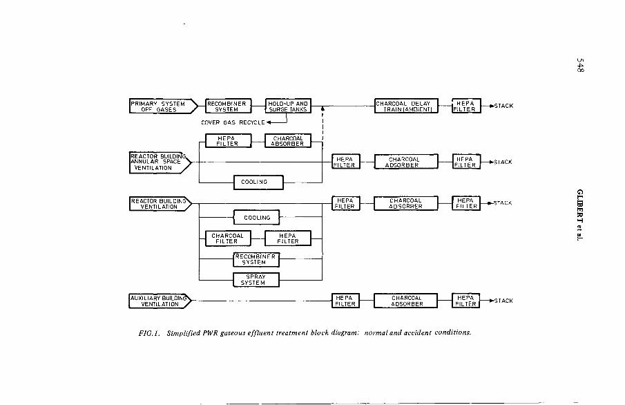
FIG .l. Simplified PWR gaseous effluent treatment block diagram: normal and accident conditions.
548 G
LIBE
RT
et al.

IAEA-SM-24S/S5 549
Depending on the post-accident situation a number of treatments can be applied to the confined gaseous effluents, for example:
(a) A cooling system also operating under normal conditions will decrease the pressure by internal recirculation
(b) A spray system will remove an important amount of radionuclides from the gaseous effluents
(c) A recombiner unit will control the hydrogen buildup(d) Active charcoal filters will trap iodine by internal recirculation.
At the same time as a severe post-accident situation is detected inside the reactor building, the normal ventilation circuit of the annular space is interrupted and the annular space is isolated and depressurized.
The annular space collects the radioactive material passing through the confinement of the reactor building. Part of this radioactive material is fixed on active charcoal beds included in an internal circuit. The other part contained in the air extracted from the annular space by the depressurizing circuit is sent for subsequent treatment.
As regards the reactor building, a cooling system (emergency system) is included in the reactor building annular space. Regarding the auxiliary building ventilation effluent, as long as the containment isolation system is operated with great reliability, no primary liquid will pass through the reactor building barrier in a post-accident situation and generate by degassing a large amount of waste gases. However, the leakage of radwaste treatment equipment will remain a potential radioactivity source. Ventilation effluent will be decontaminated by iodine trapping on a charcoal filter and by aerosol removal through HEPA filters.
4. DESCRIPTION OF THE PROPOSED GASEOUS RADWASTE TREATMENT SYSTEM
Figure 2 shows the various steps of treatment of the proposed gaseous radwaste treatment system.
Primary system off-gases are sent to a surge tank where they are diluted with internally recirculated nitrogen, avoiding excessive hydrogen content.
Oxygen is added if required, to give a stoichiometric H2/ 0 2 mixture. The effluent may then be preheated before passing through a catalyst bed where the hydrogen reacts with the oxygen supplied. Water vapour is condensed and evacuated as liquid radwaste. The hydrogen-free gaseous effluent is compressed and stored in hold-up and surge tanks.
After a certain decay time, the gaseous effluent can be recycled as cover gas or sent for subsequent treatment. This treatment consists of cooling, followed

550 GLIBERT et al.
COVER GAS
INPUT STREAM FROM VENTILATION SYSTEM UNDER SEVERE CONDITIONS
FIG.2. PWR gaseous radwaste treatment system.
by a desiccant drying to dehumidify the gas stream before it flows through charcoal adsorption beds operated at ambient temperature to allow for additional decay of the short-lived radionuclides. Liquid resulting from the water removal step is discarded as liquid radwaste.
At the outlet of the delay beds a HEPA filter is provided to remove particulates from the gas stream.
Under severe conditions connection to the ventilation system is made at the inlet of the charcoal beds. Exceptional gas streams from this system, requiring a high decontamination factor (DF), can be treated by the charcoal delay beds and the HEPA filter before being released through the stack.
5. EVALUATION OF THE PROPOSED GASEOUS RADWASTE TREATMENT SYSTEM
The proposed system uses the following basic elements, namely, recombiner, decay tank, delay bed, which are included in various current typical flow sheets for PWRs, or are foreseen for the future. However, the characteristics of the design presented here are of interest under normal conditions, and especially under severe conditions.

IAEA-SM-245/55 5 5 1
5.1. Normal conditions
The system has a design performance equal to that of other systems, such as decay tank or delay bed based flow sheets, i.e. a 60-day delay time for shortlived radionuclides, while providing all the advantages associated with each individual element of the delay line, namely:
(a) Decay tanks in which all the gases (waste and carrier) are compressed and stored for decay provide surges of hydrogen-free gas for cover-gas recycle and a buffer capacity for intermittent peak streams.
(b) Delay beds providing selective retention of gases continuously decontaminate the influent stream and allow large volumes of gas to be handled. In addition, the considerable thickness of the charcoal beds ensures a high decontamination factor for the iodine, which is almost completely adsorbed on the initial layers of the charcoal beds [4].
Regarding the safety aspect of this design it should be noted that the hydrogen recombiner located at the head of the system controls the level of hydrogen in the gaseous stream and reduces the H2 explosion risk down the circuit. On the other hand, the operation of the delay beds at ambient temperature is a safety factor.
5.2. Severe conditions
As regards severe conditions in the system, two cases should be considered, namely, an abnormal increase in the amount of the primary system off-gases, and the possible handling by delay beds of highly contaminated effluents from the annular space (ventilation system).
Both cases can be treated in the same way. Indeed, if the overflow of primary system off-gases cannot be handled by the buffer capacity at the time of the incident, then, despite an increase in the treatment capacity of the system, the situation can be represented as being the response of delay beds to an input stream containing water vapour and having a relatively high overflow.
In the case of iodine decontamination, the DF will slowly decrease with the progression of a humid front through the charcoal beds. However, it should be noted that owing to the appreciable thickness of the charcoal this decrease will be small, and at the beginning the nominal design DF will be maintained.
For rare gas decontamination, the hold-up time (tH) and the DF will vary according to the following equations:
where tH = hold-up time (h) M = weight of charcoal (t)К = dynamic adsorption coefficient (m3/t) F = off-gas flow rate (m3/h)

TABLE I. K DESIGN VALUES USED IN VARIOUS PLANT FACILITIES AS A FUNCTION OF HUMIDITY CONDITIONS
H u m id ity co n d itio n s P lan t fa c i l i ty References K DXe(m 3/kg )
N o te
M o is tu re co n te n t o f the charcoal = 0 (d ry gas) P ilo t fa c i l i ty [5 ] 0 .7 Measured value
««Saturated stream (n o d ry in g ) PW R (B R -3 ) [6 ] > 0.12 Measured value
M o is tu re co n te n t o f the charcoal = 0 H W LW R [7 ] 0.445 Measured value
R ela tive h u m id ity o f the in f lu e n t stream : 70% H W LW R [7 ] 0.085 Measured value
D ry in g o f the in f lu e n t stream D ew p o in t — 2 0 °С BW R И ] 0.24 C alcu la ted value
D ry in g o f the in f lu e n t stream D ew p o in t —20°C BW R [8 ] 0.47 E stim a ted value
D ry in g o f the in f lu e n t stream D ry in g o f the charcoal BW R [9 ] 0.77 E stim a te d value
D ry argon as ca rrie r gas a t 38°C L M F B R [ 1 0 ] 0.5 Measured value
552 G
LIB
ER
Te
tal.

IAEA-SM-245/55 5 5 3
and DF = = —AO
where Al = radioactivity at charcoal bed inlet (Bq/m3)AO = radioactivity at charcoal bed outlet (Bq/m3)X = decay constant (1/h)
A knowledge of the dynamic adsorption coefficient (K) is essential in order to estimate the performance of delay beds.
Considerable experimental data and operational experience have been acquired on the К value and the behaviour of charcoal beds under various conditions.
At the Belgian Nuclear Research Centre (CEN/SCK, Mol) a laboratory-scale study followed by a demonstration in the gaseous treatment facility of the experimental pressurized water reactor BR-3 provided К value data and experience in the field of delay bed design. This study confirmed the dependency of the adsorption coefficient of a charcoal bed operated at a given temperature and pressure on its humidity content and ageing parameter.
In addition, KDx e values for plant design were established; these are presented in Table I as a function of humidity. The table also includes a comparison with some other significant KDXe values given in the literature or estimated on the basis of other data reported. From this table the reduction coefficient of Kj)Xe> following operation with a gaseous stream containing water vapour, can be estimated to be about 5.
Using these data the behaviour of delay beds under severe conditions can be illustrated from computation of the hold-up time, assuming that the nominal design of the delay beds is as follows: tH is 30 days and the off-gas flow rate F is 50 m3/h.
With an annular space peak value of 200 m3/h, for example, the hold-up time of xenon isotopes will be reduced to 7.5 days. This value will progressively decrease with the humidity content of the charcoal to 1.5 days.
Combining these values with Fig.3, which gives the assumed radioactive release rate of noble gases as a function of decay time for a Light Water Reactor (LWR), it can be seen that delay beds thus afford a substantial reduction in the rare gas radioactivity released to the environment via the annular space.
This is particularly important when very short-lived isotopes are involved.Such a situation can occur after severe incidents such as primary coolant leakage, loss of coolant, etc.
6. CONCLUSIONS
The conceptual design for a gaseous radwaste treatment system is particularly well adapted to a PWR design involving double confinement and engineered safety related systems.

FIG.3. Radioactive release rate o f noble gases as a function o f decay time for a light water reactor o f 1 ООО MW(e).
IAEA-SM-245/55 5 5 5
With a design performance equal to that of other systems, under normal conditions it presents good operating flexibility and safety characteristics.
Under severe conditions it participates to some extent, in conjunction with the ventilation system, in retaining short-lived radionuclides, thereby helping to mitigate the environmental consequences of potential severe accidents. *
REFERENCES
[ 1 ] A M E R IC A N N A T IO N A L S T A N D A R D S IN S T ., IN C ./A M E R IC A N N U C L E A R S O C IE TY , Gaseous R ad ioactive Waste Processing Systems fo r L ig h t W ater R eac to r P lants, R ep. A N S I/A N S 5 5 .4 (1 9 7 9 ) .
[2 ] U N IT E D S T A TE S A T O M IC E N E R G Y C O M M IS S IO N , The S a fe ty o f N uc lea r P ow er R eactors (L ig h t W ater-C oo led) and R ela ted F a c ilit ie s , R ep. W A S H -1250 (J u ly 1973).
[3 ] N U C L E A R R E G U L A T O R Y C O M M IS S IO N , W A S H IN G T O N , D C ., O F F IC E O F N U C L E A R R E A C T O R R E G U L A T IO N , T M I.2 . Lessons learned, Task Fo rce S tatus R e p o rt and S h o rt-te rm R ecom m enda tions, R ep. N U R E G -0 5 7 8 (J u ly 1979).
[4 ] S C H R O E D E R , J., O ff-gas fa c il i ty at the G undrem ingen nuc lea r p o w e r p la n t, K e rn te c h n ik 13 5 (1 9 7 1 )2 0 5 .
[5 ] C O L L A R D , G .E .R ., e t a l., “ The de lay o f xen on o n charcoa l beds” (P roc. 14 th E R D A A ir C leaning C o n f. Sun V a lle y , 19 76 ) V o l. 2, N a tio n a l Techn ica l In fo rm a tio n Service, S p ring fie ld (1 9 7 7 ) 947.
[ 6 ] C O L L A R D , G .E .R ., P riva te c o m m u n ica tio n .[7 ] B L A C K M A N , T .E ., “ E xperience w ith th e W in fr i th re a c to r v e n tila tio n and o ff-gas system s” ,
K arls ruhe (O c t. 1979).[ 8 ] C A S T E L L A N I, A ., e t a l., “ Caorso off-gas system : acceptance test o f the n o b le gases de lay
beds” (P roc . 5 th In t . F a ir (N U C L E X 7 8 ) Basle, 1978), Swiss Ind us trie s F a ir, Basle (1 9 7 9 ).[9] LO O S E R , W ., “ A c tiva te d charcoa l vessel equ ipped fo r changing the charcoal fo r off-gas
system ” (P roc . 5 th In t . F a ir (N U C L E X 7 8 ) Basle, 1978), Swiss Industries F a ir. Basle (1 9 7 9 ).[1 0 ] F IR S T , M .W ., e t al., H arva rd A ir C lean ing L a b o ra to ry , S em i-A nnua l Progress R e p o rt,
1 M a rch —31 A ugu s t 1971, U S A E C N ew Y o rk O pe ra tions O ffic e , N Y , R ep. N Y O -841-25 (1 9 7 1 ) 19.
DISCUSSION
J.L. KOVACH: The system is approximately an order of magnitude oversized for normal operation and an order of magnitude undersized for accident conditions. Why did you select this size?
R.G. GLIBERT: The normal design flow rate of the delay bed (50 m3/h (STP)) is only given to indicate the value of such a system under normal and accident conditions. No optimization of this unit has been carried out. However, even if this preliminary design value is oversized under normal conditions, the flow rate selected seems suitable for an accident situation, since we have some evidence that there is a tendency for the leak-tightness of the annular space to improve. In addition the flow rate finally selected for the delay bed will in all cases be a compromise because of economic considerations.
J.L. KOVACH: Why use a recombiner with the pure hydrogen stream which comes from the PWR degasifiers?

556 G LIBERT et al.
R.G. GLIBERT: In the plant design we described, the pure hydrogen stream from the degasifiers is mixed with the other active gaseous streams. H2 recombination of the mixed streams is required to reduce the H2 explosion risk down the circuit.
F. CEJNAR: K-values — dynamic adsorption coefficient values — are strongly dependent on temperature. To which temperatures are the К-values in your paper related and what do you expect the real temperature in the adsorption bed to be during reactor operation?
R.G. GLIBERT : The К-values given in Table II are related to ambient temperature. The temperature of the influent stream passing through the delay beds will be ambient since it will be cooled before entering them.
K.O. BERGMAN: May I draw attention to the well-known fact that there are a large number of paths connecting the reactor building and the auxiliary building which bypass the annular space. Thus the chances of a leak to the auxiliary building are somewhat greater than to the annular space. What is the basis o f your choice of delaying the gases in the annular space rather than in the auxiliary building?
R.G. GLIBERT: There are many safety features built into modern PWRs to isolate the reactor building from the auxiliary building in the event of an accident. In such conditions the annular space will collect leaks of highly contaminated gases from the reactor building.
M. KOMURKA: In Table I, what is the meaning of ‘calculated K-value’, and how do you explain the difference between the К-values taken from Ref.[4] and Ref.[8], given that drying was carried out at — 20°C in both cases?
R.G. GLIBERT : ‘Calculated value’ means that delay time and charcoal mass were given by the authors, along with the mean gas flow rate. К-values were computed by using the equations mentioned in the paper plus these data. Items such as pressure profile in the bed, pressure drop and temperature of the room when ‘room temperature’ is assumed were generally not mentioned in the papers given in the references.
M. KOMURKA: What is the temperature before the recombiner, and the concentration of hydrogen before and after the recombiner? Finally, is oxygen required in the system?
R.G. GLIBERT : The temperature at the inlet of the recombiner was 50—60°C. Preheating is required to avoid condensation on the catalyst. Concentration of H2 at the inlet will vary depending on the PWR operating conditions. However, the maximum vol.% of hydrogen in the gas will be 4%. Recycling is provided for safety reasons. At the outlet of the recombiner the maximum H2 content will be 0 .1%.
In reply to your last question, 0 2 is required to obtain a stoichiometric H2/ 0 2 mixture. Excess H2 in the primary off-gases is due to the presence of H2 in the reactor coolant — about 35 cm3 of hydrogen per kg of water.

IAEA-SM-24S/42
RETENTION DES GAZ ET AEROSOLS RADIOACTIFS DANS LES EFFLUENTS HUMIDES DU RETRAITEMENTJ.P. GOUMONDY*, J.L. ROUYER***,J.P. ROUX**, D. VIGLA***Commissariat à l’énergie atomique,France
Abstract-Résumé
R E T E N T IO N O F R A D IO A C T IV E GASES A N D A E R O S O LS IN S A T U R A T E D R E PR O C E S SIN G E F F L U E N T S .
The process gases re su ltin g fro m reprocessing opera tions are genera lly saturated w ith m o is tu re . F o r f in a l f i l te r in g o f th e rad ioac tive aerosols and gases con ta ined in the m , the re la tive h u m id ity o f the e ff lu e n ts m ust have been reduced to 70% o r less and the y m ust have undergone one or m ore clean ing opera tions be fo re ve ry -h ig h -e ffic ie n cy (V H E ) f ilte r in g . In o rde r to o p tim ize the system fo r processing th is ty p e o f e ff lu e n t, a know ledge is re qu ired o f the phys ico -chem ica l tra n s fo rm a tio ns w h ic h occur be tw een the p o in t o f em ission and fin a l f ilte r in g . The f irs t p a rt o f the paper describes the present state o f know ledge concern ing the behav iou r o f v o la t ile aerosols and com pounds, such as ru th e n iu m , w h ich are bo rne b y the process gases d u rin g th e ir passage th roug h the p la n t. The results are based on pub lished data and measurements carried o u t b y the au thors in an active m ed ium . Reference is made to sam pling p rob lem s and to the systems w h ic h have been developed. O n th e basis o f th is know ledge , the best m e thods fo r cleaning p r io r to V H E fi lte r in g are de fined fo r ty p ic a l gaseous effluen ts . Several systems (w ash ing, m is t separators, p re -filte r in g ) are exam ined and th e ir re la tive pe rfo rm ance com pared. M e thods fo r tes tin g th e ir e ff ic ie n cy are described. The advantages and disadvantages o f using test aerosols are also discussed, tog e the r w ith the p rob lem s o f testing in a rad ioac tive env ironm ent.
R E T E N T IO N DES G A Z E T A E R O S O L S R A D IO A C T IF S D A N S LE S E F F L U E N T S H U M ID E S D U R E T R A IT E M E N T .
Les gaz de procédé du re tra ite m e n t sont généra lem ent saturés d ’h u m id ité . La f i l t r a t io n fin a le des aérosols e t des gaz ra d io a c tifs q u ’ils co n tie n n e n t im pose que l ’h u m id ité re la tive de ces e ff lu e n ts a it été ramenée à 70% o u m o ins et q u ’ils a ien t sub i une ou p lusieurs épura tions
* D épa rtem ent de génie ra d io a c tif,Centre d ’études nucléaires de Fontenay-aux-R oses, Fontenay-aux-R oses
* * D épa rtem ent de génie ra d io a c tif,Centre de M arcoule ,Bagnols-sur-Cèze
* * * D épa rtem ent de p ro te c tio n ,C entre d ’études nucléaires de Fontenay-aux-R oses, Fontenay-aux-R oses
557
5 5 8 GOUMONDY et al.
avant f i l t r a t io n de très ha u te e ff ica c ité (T H E ). P ou r o p tim ise r le systèm e de tra ite m e n t de ce ty p e d ’e ff lu e n ts , i l est p réa lab lem en t nécessaire de co n na ître les tra n s fo rm a tio n s ph ys ico ch im iques en tre le u r lie u d ’ém ission e t la f i l t r a t io n u lt im e . L ’o b je t de la prem ière p a rtie du m ém oire est de fo u rn ir l ’é ta t des connaissances du com p o rte m e n t des aérosols et composés vo la tils , te ls le ru th é n iu m , po rtés pa r les gaz de procédé lo rs de le u r chem inem ent dans l ’usine. Cet exposé résu lte de données publiées e t de mesures fa ites pa r les auteurs en m ilie u a c t if . On in d iq u e les prob lèm es de pré lèvem ent et les d ispo s itifs q u i o n t été m is au p o in t. Sur la base de ces connaissances, on d é fin it les m e illeurs m oyens d ’é p u ra tio n avant f i l t r a t io n T H E po u r des cas typ iq u e s d ’e ff lu e n ts gazeux. P lusieurs d ispo s itifs (lavage, dévésiculeurs, p ré f ilt ra t io n ) son t analysés e t leurs pe rform ances re la tives com parées. Les m éthodes d ’essai de le u r e ff ica c ité son t décrites. O n in d iq u e les avantages e t inconvén ien ts de l ’u til is a t io n d ’aérosols tests et les prob lèm es d ’essais en m ilie u ra d io a c tif.
1. PRESENTATION DE L’EXPOSE
L’objectif de cet exposé est de définir les moyens d’une maîtrise de la contamination véhiculée par les effluents gazeux du retraitement. La présentation s’effectuera en trois étapes:— définition des principes généraux de traitement des gaz humides et description
d’un schéma de principe,— étude du comportement des aérosols et composés volatils dans les effluents
humides du retraitement,— analyse des dispositifs d’épuration de ces effluents gazeux.
On s’efforcera dans cet exposé de montrer les difficultés rencontrées dans ce domaine de la rétention des effluents gazeux radioactifs et de dégager des priorités en matière de recherche et développement.
2. PRINCIPES GENERAUX DE TRAITEMENT DES GAZ HUMIDES DE PROCEDE
Les principes généraux à appliquer pour le traitement des gaz humides du retraitement ont été élaborés par un groupe de travail pluridisciplinaire du CEA. Ils consistent à:
— C lasser les e fflu en ts, par leur activité et par leur composition chimique.
Le classement par niveau d’activité paraît évident, dans la mesure où on pourra éventuellement réunir et traiter de la même manière des effluents très contaminés et ne pas augmenter inutilement les débits de gaz à traiter; de cette manière, on limitera le nombre de barrières éventuellement contaminées (batteries de filtres par exemple), leur importance et le volume de déchets à éliminer.
IAEA-SM-24S/42 5 5 9
Le classement par composition chimique ne s’imposera que chaque fois qu’un traitement spécifique devra être pris en compte avant rejet en cheminée (traitement ultime des oxydes d’azote, ammoniac, vapeurs de solvants, etc.).
— Etablir des barrières au plus près de la source
Chaque fois que ce sera possible, on devra traiter les gaz le plus près possible du point où ils sont générés; de cette manière, on évitera une dispersion de la contamination et un dépôt non contrôlé dans les gaines.
Ce traitement pourra, suivant les cas, aller jusqu’au traitement de très haute efficacité, notamment lorsqu’un traitement spécifique chimique est nécessaire sur l’effluent.
— Abaisser l ’hum idité relative ou la teneur en eau de l ’e ff lu e n t ,
L’hypothèse de base est que le gaz, à la sortie de l’installation, est un gaz saturé en vapeur d’eau; dans ces conditions, et afin d’éviter les condensations intempestives dans les canalisations ou sur les dispositifs d’épuration, il est recommandé:
• soit d’augmenter la température du gaz; dans ce cas, on diminuera l’humidité relative à masse d’eau constante; il faut alors augmenter la température d’une quantité telle que, compte tenu du trajet du gaz et de la température ambiante où plonge le circuit, l’échange thermique ne risque pas de ramener le gaz à la température de rosée; à titre d’exemple, pour une température de rosée de 30°C, un écart de température de 6,5°C amènerait le gaz aux environs de 70% d’humidité relative;
• soit d’abaisser l’humidité relative par une dilution avec de l’air sec;• soit d’abaisser la teneur en eau, par une condensation (sur batterie froide par
exemple). L’air sortant saturé à une température inférieure à 30°C sera réchauffé de manière à obtenir l’humidité relative désirée; cette solution est recommandée lorsqu’il y a risque de corrosion par condensation aux points froids.
Ces principes généraux conduisent à définir un schéma type de traitement à la source des effluents gazeux de procédé. Ce schéma type est donné à la figure 1; il comprend:— un traitem ent spécifique chimique en tête; ce traitement a pratiquement
toujours lieu dans une colonne;— un dévésiculeur intégré au dernier appareillage chimique, dont le rôle est
d’éliminer les gouttelettes d’eau entraînées mécaniquement; la connaissance de la taille des gouttelettes en conditionnera le choix;
— une batterie fro ide e t un dévésiculeur pour obtenir une élimination supplémentaire pour le piégeage des aérosols formés par condensation, à condition que le rapport efficacité-coût de cette épuration complémentaire soit favorable;
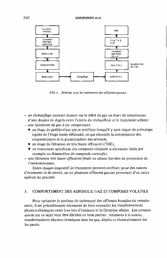
5 6 0 GOUMONDY et al.
FIG .l. Schéma type de traitement des effluents gazeux.
— un réchauffage pouvant donner sur le débit de gaz un écart de température d’une dizaine de degrés entre l’entrée du réchauffeur et le traitement ultime;
— une épuration du gaz à sec comprenant:• un étage de préfiltration qui se justifiera lorsqu’il y aura risque de colmatage
rapide de l’étage haute efficacité, ce qui nécessite la connaissance des concentrations et la granulométrie des aérosols,
• un étage de filtration de très haute efficacité (THE),• un traitement spécifique des composés résiduels si nécessaire (iode par
exemple ou élimination de composés corrosifs).— une filtration très haute efficacité finale en ultime barrière de protection de
l’environnement.Entre chaque dispositif de traitement peuvent confluer, pour des raisons
d’économie et de sûreté, un ou plusieurs effluents gazeux provenant d’un autre endroit du procédé.
3. COMPORTEMENT DES AEROSOLS, GAZ ET COMPOSES VOLATILS
Pour optimiser le système de traitement des effluents humides du retraitement, il est préalablement nécessaire de bien connaître les transformations physico-chimiques entre leur lieu d’émission et la filtration ultime. Les connaissances sur ce sujet vont être divisées en trois parties: émissions à la source, transformations physico-chimiques dans les gaz, dépôts et réentraînement sur les parois.
IAEA-SM-245/42 561
De nombreuses expérimentations en laboratoire et sur pilotes permettent de connaître de mieux en mieux les émissions de radionucléides, pour plusieurs types de combustibles et en fonction de diverses conditions opératoires. Les radionucléides les plus étudiés sont ceux qui entraînent les risques radiologiques les plus grands et ceux qui présentent des difficultés particulières de rétention: iode, krypton, ruthénium, plutonium ,. ..
A titre d’exemple, on décrira sommairement ci-après le comportement de l’iode lors du cisaillage et de la dissolution des combustibles à eau légère, exemple qui montre combien les émissions dépendent des conditions opératoires à la dissolution.
Lors du cisaillage de combustibles de réacteurs à eau légère, l’iode volatil n’est pas décelable et on estime à moins de 1 %o la quantité d’iode volatilisé; pour les combustibles rapides, la fraction d’iode libéré est de l’ordre de 1% et varie selon les techniques utilisées.
Les problèmes véritables se posent à la dissolution. En effet, il est nécessaire de séparer l’iode de la solution de nitrate d’uranyle avant les extractions, car l’iode s’extrait partiellement et on risque de le retrouver dans l’ensemble de l’usine. Afin d’éviter le traitement d’un volume important de solution, on a donc intérêt à le séparer de la solution de nitrate d’uranyle lors de la dissolution. Cette désorption de la solution de dissolution nécessite un effluent gazeux porteur de composition telle qu’il n’y ait pas formation d’iodate. C’est le rôle des vapeurs nitreuses portées par un air de balayage.
L’efficacité de la désorption dépend de paramètres opératoires tels que: taux d’ébullition, débit de gaz porteur, etc., paramètres qui ont des limites dans leur variabilité selon les techniques de dissolution utilisées. Ainsi, la dissolution discontinue permet de bénéficier d ’une période d’ébullition prolongée pendant laquelle on peut épuiser la solution en iode; la dissolution continue ne permet pas cet épuisement car il entre une quantité d’iode constante qui se répartit entre deux flux, l’un gazeux, l’autre liquide, le partage dépendant des conditions de température et du débit de gaz.
De nombreux essais effectués en actif sur la cellule Gascogne du Département de génie radioactif (Service d’étude des procédés) de Fontenay-aux-Roses ont permis de mesurer les facteurs d’émission en iode pour divers combustible et conditions de dissolution. Cela a été fait également pour le ruthénium dans des conditions particulières. On a ainsi suivi le taux de ruthénium passant dans les gaz en fonction de la durée d’ébullition après la période de dissolution proprement dite qui durait environ 1 h 3/4. On a obtenu les valeurs reproduites au tableau I.
Parfois, étant donné l’activité des solutions, on ne peut, à prix raisonnable, étudier les émissions à la source de certaines parties du procédé dans certaines conditions de fonctionnement. C’est ainsi que le Service de protection technique
3.1. Emissions à la source
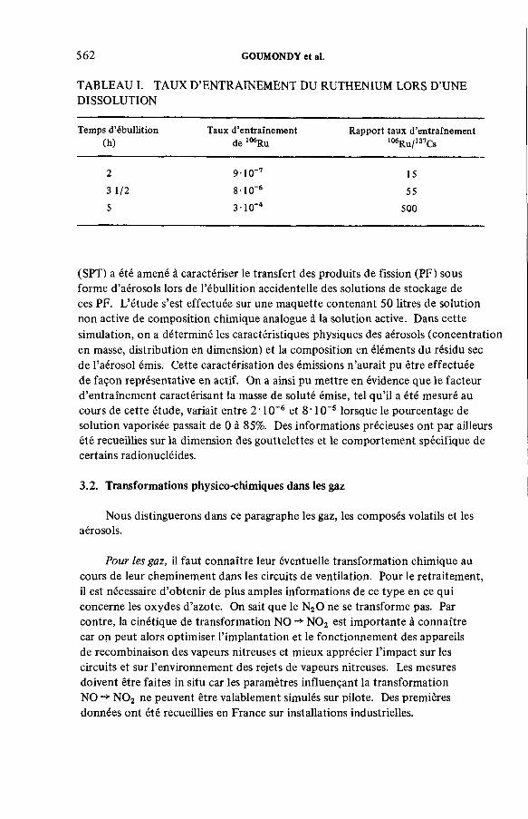
562 GOUMONDY et al.
TABLEAU I. TAUX D’ENTRAINEMENT DU RUTHENIUM LORS D’UNE DISSOLUTION
Tem ps d ’é b u llit io n (h )
Taux d ’en tra în em e nt de 106R u
R a p p o rt ta u x d ’en tra în em e n t 106R u /137Cs
2 9 -1 0 ~7 15
3 1 /2 8 • 10 -6 55
5 3 -1 0 '4 500
(SPT) a été amené à caractériser le transfert des produits de fission (PF) sous forme d’aérosols lors de l’ébullition accidentelle des solutions de stockage de ces PF. L’étude s’est effectuée sur une maquette contenant 50 litres de solution non active de composition chimique analogue à la solution active. Dans cette simulation, on a déterminé les caractéristiques physiques des aérosols (concentration en masse, distribution en dimension) et la composition en éléments du résidu sec de l’aérosol émis. Cette caractérisation des émissions n’aurait pu être effectuée de façon représentative en actif. On a ainsi pu mettre en évidence que le facteur d’entraînement caractérisant la masse de soluté émise, tel qu’il a été mesuré au cours de cette étude, variait entre 2 ' 10-6 et 8 * 10-5 lorsque le pourcentage de solution vaporisée passait de 0 à 85%. Des informations précieuses ont par ailleurs été recueillies sur la dimension des gouttelettes et le comportement spécifique de certains radionucléides.
3.2. Transformations physico-chimiques dans les gaz
Nous distinguerons dans ce paragraphe les gaz, les composés volatils et les aérosols.
Pour les gaz, il faut connaître leur éventuelle transformation chimique au cours de leur cheminement dans les circuits de ventilation. Pour le retraitement, il est nécessaire d’obtenir de plus amples informations de ce type en ce qui concerne les oxydes d’azote. On sait que le N20 ne se transforme pas. Par contre, la cinétique de transformation NO -*• N 02 est importante à connaître car on peut alors optimiser l’implantation et le fonctionnement des appareils de recombinaison des vapeurs nitreuses et mieux apprécier l’impact sur les circuits et sur l’environnement des rejets de vapeurs nitreuses. Les mesures doivent être faites in situ car les paramètres influençant la transformation NO N 02 ne peuvent être valablement simulés sur pilote. Des premières données ont été recueillies en France sur installations industrielles.
IAEA-SM-24S/42 563
Pour les volatils, qui sont des corps pouvant changer d’état physique lors de leur cheminement (passage de l’état gazeux à l’état condensé ou vice versa), il faut éviter que ces changements d’état ne s’effectuent en des endroits non prévus. Pour cela, le contrôle des variations de température au-dessus ou au-dessous d’une température seuil est primordial. Les volatils à prendre en compte sont principalement l’iode, le ruthénium (sous forme R u04) et les solvants.
En ce qui concerne les composés du ruthénium, il s’agit de la transformation chimique R u04 -* R u02 dont on connaît approximativement la cinétique de transformation en fonction de la température.
Pour l’iode, il ne semble pas qu’on le rencontre sous forme d’aérosols; nous ne l’avons pas observé pour notre part sur les effluents de réacteurs.
Pour les aérosols, le comportement mécanique dépendant de leur taille, il importe de maîtriser ce paramètre pour autant qu’on puisse le faire.
L’humidité joue un rôle double: évaporation qui peut faire diminuer le diamètre de la vésicule liquide jusqu’à celui du résidu sec en cas d’abaissement d’hygrométrie; condensation en cas contraire, qui peut faire grossir la vésicule jusqu’à possibilité d’éclatement; la nature chimique de l’aérosol importe dans la mesure où un composé soluble permet une condensation à une humidité plus basse que s’il s’agit d’un composé insoluble. Des modèles de calcul de grossissement des vésicules existent; ils sont utilisables lorsque les paramètres caractérisant l’effluent gazeux sont bien définis; il faut être prudent en pratique à cause des fluctuations et incertitudes concernant ce type d’effluent.
Enfin, il est de plus en plus urgent à notre avis de mieux connaître les phénomènes électrostatiques dans ces effluents car ils influencent le comportement des aérosols et l’efficacité de leur rétention.
3.3. Dépôts et réentraînements sur les parois
B est très important de prendre en compte les phénomènes de dépôts et réentraînements sur les parois car ils contribuent à établir des puits et sources de contamination dans des endroits a priori non désirés. Mieux connaître ces phénomènes permet de limiter les transferts de contamination ainsi générés et, en tout cas, de mieux les évaluer.
Pour les gaz et composés volatils, l’adsorption sur les parois dépend de la nature des parois et de la manière dont le flux gazeux lèche celles-ci. L’influence de la nature des parois peut être extrêmement forte pour certains composés; ainsi, l’inox favorise le dépôt de ruthénium sous forme de R u02 alors que le titane ne le piège pas; des traces d’huiles sur les parois constituent un excellent piège à iode (et à ruthénium). Mais, au-delà de ces constatations élémentaires, trop peu de données existent sur le taux de rétention des parois, et surtout sur la charge en œuvre de celles-ci et la désorption.

564 GOUMONDY et al.
Pour les aérosols, en régime permanent et dans un conduit de petites dimensions, on arrive par contre à prévoir les dépôts sur les parois; même si la formulation des mécanismes de dépôt n’est pas tout à fait satisfaisante sur le plan de la théorie en mécanique des aérosols, les calculs sont vérifiés expérimentalement avec une excellente précision. C’est ce qu’a montré récemment le Service de protection technique sur des conduits de prélèvement dans une installation industrielle de retraitement. Par contre, les données et la théorie font défaut lorsqu’on quitte le régime permanent et lorsque la géométrie diffère de celle du conduit. Un effort expérimental est nécessaire dans ce domaine.
3.4. Mesures sur effluents gazeux radioactifs
Après cette revue rapide des transformations physico-chimiques lors du cheminement des effluents gazeux, il faut mettre l’accent sur ce qui permet d’appréhender ces transformations, à savoir la mesure des composés radioactifs.
Celle-ci se fait principalement par prélèvement et par analyse de ce qui a été prélevé.
Pour les gaz et composés volatils, les méthodes d’analyse sont au point (sauf pour la mesure de l’iode 129 en continu) mais la représentativité du prélèvement des composés volatils doit être améliorée.
Pour les aérosols, les conditions à respecter pour le prélèvement sont bien connues. D reste à les faire respecter chaque fois que c’est possible sur les installations de taille industrielle. Par contre, un effort certain doit être accompli pour obtenir une séparation par classe granulométrique de l’activité portée par les aérosols. D’après les premiers résultats de mesures granulométriques en actif, il semble en effet que certains radionucléides sont portés de préférence à d’autres par les aérosols fins, ce qui entraîne des conséquences quant à la conception des dispositifs d’épuration.
Le SPT est en train de mettre au point des systèmes d’impacteurs jetables après mesure sur effluents actifs.
En ce qui concerne les mesures sans prélèvement, nous croyons que la télémesure sur effluents radioactifs connaîtra un grand développement à l’avenir; les premiers essais effectués par notre équipe avec des radiomètres sont prometteurs; il reste à prouver la faisabilité de mesures en continu sur des conduits d ’effluents radioactifs.
D’autres mesures que celles de l’activité des contaminants radioactifs sont nécessaires pour mieux appréhender les transferts de contamination. Nous en citerons deux:— la mesure de la masse d’eau transférée par les vésicules: sous certaines hypothèses,
il est préférable de la déduire de la mesure de la masse et de la granulométrie du résidu sec;

IAEA-SM-245/42 565
— la mesure des débits: pour les effluents de ce type, l’utilisation de l’hélium comme gaz traceur nous semble la technique la plus performante et la plus adaptable aux cheminements variés de ces gaz de procédé.
4. DISPOSITIFS D’EPURATION DES EFFLUENTS GAZEUX
La connaissance du comportement des effluents gazeux humides du retraitement permet d’aborder maintenant la question de leur épuration.
Comme nous l’avons annoncé au début, nous étudierons plus particulièrement les cas «difficiles», à savoir l’iode et le ruthénium d’une part, les aérosols d’autre part.
4.1. Iode et ruthénium
Le traitement chimique que subissent les gaz de cisaillage et de dissolution véhiculant la majeure partie de l’iode comprend une série de dispositifs spécifiques d’abord aux vapeurs nitreuses, puis à l’iode (colonne de lavage à la soude). Il est important de connaître l’efficacité de ces dispositifs vis-à-vis des divers contaminants principaux, en particulier le ruthénium.
Des essais ont été faits en inactif, et sur installations de laboratoire, mais c’est en actif et vraie grandeur que l’on doit trouver les valeurs à retenir pour les installations de taille industrielle et ceci pour les diverses conditions opératoires.A titre indicatif nous présentons, sous forme de graphe, un condensé de résultats de mesures qui mettent en évidence un comportement spécifique du ruthénium et du cérium pour des gaz de dissolution (Fig. 2). Av gaz représente le coefficient de variation (écart type sur moyenne) de huit ratios de l’activité volumique de l’isotope sur l’activité volumique du 137Cs dans les gaz. Av sol représente le coefficient de variation des ratios équivalents au niveau de la solution de dissolution. Av gaz/Av sol est le rapport des deux coefficients de variation pour un isotope donné.
Des résultats plus nombreux de ce type doivent être obtenus pour une optimisation de l’efficacité du traitement chimique; les améliorations doivent être d’abord recherchées sur pilote en inactif (par exemple, recherche de fonctionnement et formes optimales pour les colonnes de lavage) et contrôlées ensuite en actif.
Après traitement chimique et dévésiculage de finition, on aborde le traitement physique.
Pour les gaz de cisaillage et dissolution, une épuration complémentaire de l’iode est nécessaire pour la protection et la sûreté de l’environnement. Cette épuration est obtenue par adsorption sur supports imprégnés à l’argent. Ces matériaux coûtant cher, il importe de ne les changer que lorsque l’imprégnant est

566 GOUMONDY et al.
FIG. 2. Echelle de comportement aléatoire de quelques produits de fission.
saturé en iode et non pas à cause d’une irradiation excessive créée par les autres contaminants, et principalement le ruthénium. Ceci pose la nécessité d’une épuration quasi complète en aérosols et en ruthénium avant le piège à iode. L’ensemble batterie froide — dévésiculeur, dans l’état actuel du développement décrit ci-dessous, permet d’atteindre un niveau convenable d’épuration en aérosols. D reste à lui adjoindre, avec la filtration THE, un piègeage du ruthénium suffisamment fiable et économique pour protéger efficacement le piège à iodes. Les études sont en cours à ce sujet.
4.2. Aérosols
L’effort de nos équipes a porté récemment sur l’ensemble batterie froide — dévésiculeur car il nous est apparu essentiel d’améliorer les performances des dispositifs existants pour pouvoir se passer d’une pré-filtration à sec avant la filtration THE.
L’ensemble batterie froide — dévésiculeur est spécialement intéressant du point de vue de la gestion des déchets puisqu’il permet le recyclage, dans le procédé, des aérosols liquides véhiculant la contamination. Il était donc important de pousser au maximum les performances de cet ensemble.

IAEA-SM-24S/42 567
Rétention
----------------Rétention calculée
FIG. 3. Pouvoir d ’arrêt d *un dévésiculeur.
C’est ce que nous sommes en train de faire et nous allons décrire un peu plus en détail la méthode de test utilisée pour comparer les efficacités de plusieurs dévésiculeurs.
La méthode test est une génération de gouttelettes monodispersées de solution de sel ammoniacal de fluorescéine. En fonction de la concentration de la solution, on obtient un résidu sec monodispersé dont le diamètre peut varier de 0,6 jum à 15 ¡xm. L’efficacité de rétention est mesurée par prélèvement amont et aval. Le bilan en fluorescéine peut être bouclé par lavage des dépôts sur l’appareillage testé.
Nous avons comparé l’efficacité de plusieurs dévésiculeurs et sélectionné un dévésiculeur basé sur le principe de sédimentation (batterie de canaux rectangulaires en parallèle). Les résultats expérimentaux obtenus pour ce dernier sont conformes à la théorie. C’est ce que montrent les courbes de la figure 3 correspondant à l’efficacité de rétention par sédimentation calculée et celle obtenue expérimentalement, la sédimentation expérimentale s’obtenant en faisant fonctionner le dévésiculeur en position horizontale, puis en position verticale.
Ce genre de courbes permet de dimensionner la batterie froide de façon à grossir les aérosols liquides jusqu’au niveau d’efficacité voulu pour le dévésiculeur.
568 GOUMONDY et al.
L’épuration en aérosols et autres composés ne se limite pas à ces efforts de mise au point. D’autres procédés d’épuration doivent être améliorés, approfondis, voire développés. Il en est ainsi de la précipitation électrostatique qu’il nous paraît essentiel d ’utiliser, ne serait-ce qu’en complément d’un autre système d’épuration.
Pour parer à certaines situations accidentelles, le développement de filtres à lits de matériaux résistant à des conditions d’ambiance extrêmes doit être également examiné.
CONCLUSION
En conclusion de cet exposé nécessairement partiel sur la rétention des gaz et aérosols radioactifs dans les effluents humides du retraitement, nous insisterons sur deux points;— la nécessité de mettre au point de nouveaux moyens de mesure (télémesure)
et d’épuration (précipitation électrostatique);— la nécessité de tenir compte de toutes les conditions de fonctionnement de
l’installation (de la situation normale à la situation accidentelle).
DISCUSSION
A.J. WILLIAMS: The determination of droplet size distribution in a wet system is notoriously difficult, particularly in a fully active system. Can you tell me anything about the type of methods which you are developing for this purpose?
J.L. ROUYER: We are developing disposable impactors to measure the size distribution on the dry residue. With some theoretical calculation of the ratio of soluble to insoluble salts in the liquid, we can approximate the size distribution of the droplets.
A.J. WILLIAMS: Your preferred system for decontamination in a wet air stream combines cooling, demisting, reheating and HEPA filtration. Experiments in the United Kingdom have demonstrated problems of re-entrainment from the cooler of droplets which are less than 5 jum with subsequent difficulties in demisting, particularly when dealing with droplets contaminated with caustic soda from scrubbers. Have you observed this problem and, if so, have you considered the possibility of droplet growth demisting techniques, whereby a portion of demisted gas is cooled and recycled to an earlier part of the ventilation system in order to promote droplet growth and increase demisting efficiency?
IAEA-SM-24S/42 569
J.L. ROUYER: We have not experimented with coolers and so have not observed this phenomenon. However, we are very interested in your work and in the demisting technique that you propose.
M.W. FIRST: Could you please give a fuller explanation of Fig. 2?J.P. GOUMONDY: The aim of Fig. 2 is to show that the behaviour of some
fission products with respect to their division between the dissolving solution and the gas released can be reproduced. This is so for zirconium and niobium which are transported essentially as droplets. However, with others such as antimony and especially ruthenium, entrainment takes place in the gas in the form both of droplets and the release of volatile compounds such as R u04.Their behaviour is thus less predictable and more uncertain. The result with cerium is more surprising and we have not yet come up with a satisfactory explanation.


IAEA-SM-245/17
THE AGEING OF CHARCOALS USED TO TRAP RADIOIODINE
R.D. COLLINS, J.J. HILLARY,L.R. TAYLOR, F. ABBEYUnited Kingdom Atomic Energy Authority,Windscale Nuclear Power Development
Laboratories,Windscale Works,Sellafield, Seascale, Cumbria,United Kingdom
Abstract
T H E A G E IN G O F C H A R C O A L S U S ED T O T R A P R A D IO IO D IN E .Present deve lopm ent w o rk is described re la tin g to the ageing characte ris tics o f B r it is h
im pregna ted charcoals u n de r storage co n d itio n s . E xp e rim e n ta l w o rk has been carried o u t in a va r ie ty o f gaseous atm ospheres, p r in c ip a lly w e t and d ry a ir , d ry argon and d ry h yd ro g e n , w ith po tassium io d id e ( K I ) and trie th y le n e -d ia m in e (T E D A ) im pregna ted coal-based charcoal. The pe rfo rm ance o f the charcoals has been m o n ito re d against the standard h ig h h u m id ity test w ith m e th y l iod id e -1 31 . The m a in im p lic a tio n s o f th is w o rk are th a t:(a ) the re is a c lear in d ic a tio n o f an o x id a tive m echanism in the ageing process; (b ) i f oxygen o r w a te r are n o t present the n the loss o f pe rfo rm ance o f K I-im p regn a ted charcoals d u rin g storage is reduced i f n o t e lim in a te d ;(c ) T E D A -im pregn a ted charcoa l shows less ageing; (d ) the re is evidence th a t the e ffe c t o f w a te r (w h ic h can re a d ily be adsorbed o r desorbed) on the pe rfo rm ance o f K I-im p regn a ted charcoal is n o t de te rm in ed so le ly by the w a te r c o n te n t a t th e tim e o f the test.
1 . INTRODUCTION
The control of gasborne radio-iodine in nuclear plant can be a problem particularly under accident conditions, since the low MPC in air requires the trapping of all constituents to be highly effective. Since inorganic forms are well trapped by a combination of an aerosol filter and a charcoal bed the behaviour of organic iodides of which methyl iodide is usually the most important can determine the overall effectiveness of the system. Under relatively dry conditions good trapping of methyl iodide is obtainable from charcoal but charcoal which has been exposed to wet air normally allows adsorbed methyl iodide to desorb again to an unacceptable extent. Two methods of impregnating charcoal are in use to prevent this, one using a chemically active imprégnant such as TEDA1which reacts with
1 US P aten t 345380 7 U K A E A . T E D A = tr ie th y le n e d iam ine .
5 7 1
572 COLLINS et al.
methyl iodide the other consisting of an inorganic iodide sometimes combined with excess iodine. Although the latter method would Ъе prefered on account of its chemical stability, wide temperature range and insensitivity to carbon dioxide the mechanism by which it operates is not clear, the material is subject to serious ageing effects and there are long-time variations in the performance achieved by products manufactured by the same process, and marketed under the same name. Since it is crucially important to be able to rely on the performance of trapping plant under any of a wide range of conditions interest attaches to the ageing behaviour of impregnated charcoals not only for its own sake but for the light such behaviour may ultimately throw on the mechanisms which control iodine retention.
1.1 Types of ageing
There are several ways in which the performance of a charcoal can deteriorate. A condensible vapour may be extracted from the atmosphere by physical absorption and reduce the available area of active surface or a specific poison may react chemically to reduce the beds ability to retain organic iodides permanently. The design and operation of the plant must be such as to protect the charcoal against both possibilities though an oversize bed is relatively insensitive to the first since it is itself an effective trap for condensible vapours. This paper however is concerned with two other types of deterioration, that with no flow through the charcoal bed and that caused by reaction between the charcoal and major constituents of the atmosphere in which they are aged. The atmospheres concerned were air, which is an oxidising atmosphere, argon which is inert, and hydrogen which could have a reducing effect. In addition carbon dioxide was studied both for its importance in UK reactors and because of its mild acidic properties. Since water vapour is a normal constituent both of air and impregnated charcoals its presence and absence was also studied.
In all the ageing tests described whether the charcoal had been stored wet or dry, and whether or not it had been dried or heated after storage, the charcoal was subjected for 16 hours to a flow of gas at 98$ RH. The purpose of this was to test the bed under the most stringent conditions for methyl iodide removal. Apart from the intrinsic interest of these conditions they accentuate the contribution of the charcoal surface to the effectiveness of the bed as opposed to that of mixing in the gas phase. Some evidence for this is first considered.

TABLE I
Summary of face velocity and, performance data
IAEA-SM-245/17 573
CharcoalRelativehumidity
M
Vol. of charcoal
(cm3)
Numberof
pointsa
Correlation coeff.
Remarks
Charcoal A 98 38.6 13 0.17 0.97 WNL dataKI-impregnated » 27.0 5 0.13 0.99 (current study++)(lignite-based) " 19-3 3 0.20 -
Includes addi" All tests 24 0.18 0.9771 38.6 8 0.21 0.96 tional tests40 39.6 16 0.29 0.97 with different" и 8 0.22+ 0.99 volumes of
Dry 19-3 88
0.480.47+
0.990.99
ч charcoal.
NORIT RKJ0.8 High - 7 0.21 0.96 Van der Lugt/# \ and Scholten
Charcoal В 98 38.6 14 0.30 0.98 WNL dataKI-impregnated " 27.0 8 0.29 0.88 (current study++)(bitumen-based) " 19.3 6 0.25 0.98
" All tests 29 0.28 0.97 / Includes addi-78 38.6 8 0.34 0.97 ] tional test,40 38.6 8 0.26 0.97 I charcoal volume
Dry 19.3
8
50.23+0.57
0.970.99
= 13cm3
KI-impregnated 98 38.6 39 0.18 0.90 WNL datacoal-based 207B, 8 to 12 BSS mesh
Dry 19.3 8 0.45 0.95
Kl-impregnated 207B 98 19.3 14 0.15 0.87 WNL data18 to 52 BSS mesh Dry 19.3 6 0.77 0.99
Coconut shell 98 38.6 8 0.18 0.93 WNL databased 208C K l y
impregnatedDry 19.3 8 0.41 0.99
Coal- and Coconut- based, mixed imprégnants
90-95 Multiple
shallowbeds
0.45 >0.99 Deitz and Jonas
t o
Kl-impregnated 207B 94 Multiple 2 0.24 _ May and Polson(2)
8 to 12 BSS mesh 30 shallowbeds
2 0.55 - sample exhibited generally poor
TEDA-impregnated 207B, 8 to 12 BSS mesh
94
С 1
22
0.27
0.51
performance
♦VAN DER LUGT, G.and SCHOLTEN, L.C. , Methods used at KEMA for measuring iodine adsorptionon charcoal and experiences with charcoal filters installed at a nuclear power plant.Seminar on Iodine Filter Testing, Karlsruhe, W Germany 4 - 6 December 1973 p315 - 328.+ Five hour extended test period.++ This work was carried out for CEC Luxembourg, under Contract No. 1139-78-11L/V.
1.2 Face velocity effect
If К is defined as
l°g-]Q (Decontamination factor of bed)
staytime of gas in bed
Deitz and Jona s ^ \ following Wheeler's model have suggested the relationship
К = constant x V a
to account for the effect of gas velocity and on this model a value of or = 0.5 is predicted when gas transfer dominates and a lower value when it does not. Table I shows results obtained at WNL and by other workers. While Deitz and Jonas found a = 0.45 appropriate over a range of EE 90 - 95$ our results show similarly high values of a with dry charcoal but lower values (0.18 - 0.3) with the standard 98$ RH test. May and Polson's(2) results are similar to ours but in their case the low values are attributed to partial poisoning of the charcoal bed. The discrepancy between Deitz and Jonas' and our results is not explained though the wider size range of their charcoal may be relevant. Whatever the reason it appears wise to check the value of a for the material and conditions of test in use if it is important.
2. AGEING RESULTS
As previously mentioned the test method in all the following experiments was the same (see Appendix) and involved passing 98Ío RH air through the bed for 16 hours before loading with methyl iodide (staytime 0.2 secs; face velocity = 36 cm-s’1) and eluting for two hours. Two types of storage conditions were used closed and purged.
2.1 Closed storage conditions
A simple apparatus has been developed based on a storage flask (Figure 1 ) so designed that samples of charcoal can be removed without disturbance of the gas in the containing space.
With this system, ageing of the charcoal can be studied in a controlled environment. The flask, a 1750 cm3 cylindrical glass vessel, contained a 40 mm diameter sintered glass disc at its base which supported 800 cm3 of the test charcoal, an amount sufficient for approximately twenty measurements. Purge gas was fed under controlled conditions through the test charcoal via two 2 mm bore high vacuum stopcocks (Apiezon-M greased) situated at the inlet and outlet of the flask. In order to fill the sample arm for extraction of a sample the flask was removed from the storage framework, the charcoal mixed by gentle tumbling and then inverted to fill the side arm to the required volume. The flask was returned to a vertical position, re-installed on the storage flask framework, and purging commenced.
5 7 4 COLLINS et al.
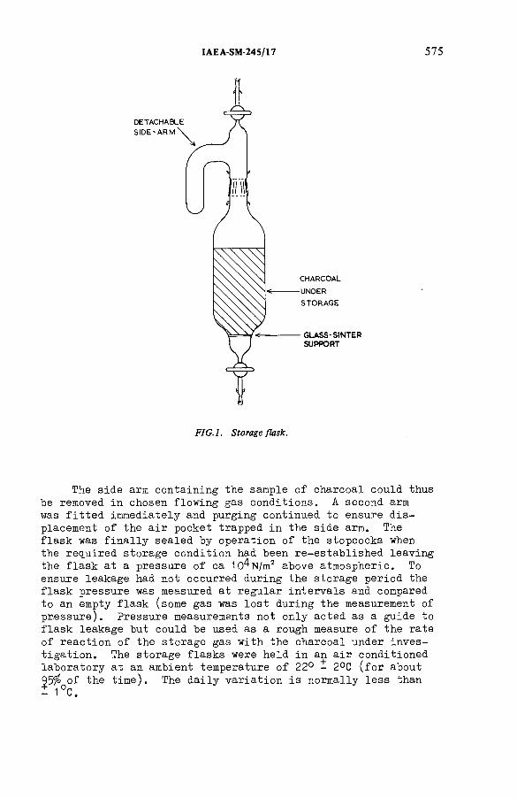
IAEA-SM-245/17 575
i
FIG .l. Storage flask.
The side arm containing the sample of charcoal could thus be removed in chosen flowing gas conditions. A second arm was fitted immediately and purging continued to ensure displacement of the air pocket trapped in the side arm. The flask was finally sealed by operation of the stopcocks when the required storage condition had been re-established leaving the flask at a pressure of ca lO^N/m2 above atmospheric. To ensure leakage had not occurred during the storage period the flask pressure was measured at regular intervals and compared to an empty flask (some gas was lost during the measurement of pressure). Pressure measurements not only acted as a guide to flask leakage but could be used as a rough measure of the rate of reaction of the storage gas with the charcoal under investigation. The storage flasks were held in an air conditioned laboratory at an ambient temperature of 22° - 2°C (for about 95% of the time). The daily variation is normally less than I 1°C.

576 COLLINS et al.
The KI impregnated charcoal used in these tests was all taken from the same material which had lain in a sealed drum since its manufacture in 1474.. It was transferred
carefully Ъу scoop to large glass bottles so that the 1st bottle contained material from the top of the drum the second from the layer immediately beneath and so on. The contents of the third bottle were then transferred to the flasks in which the ageing was to be studied and from which samples have been taken for test. Samples of TEDA-impregnated and unimpregnated material were also taken from single drums.
The grain size distribution of each charcoal was measured on receipt utilising an automatic sieve shaker for a standard ten minute run. Since the index of performance varies with the grain size distribution it is important to ensure adequate control of this variable. 207B charcoals were shown to be nominally 8 - 1 2 mesh size BSS with a slight bias to the smaller (10 - 12 mesh) size range; the 208C material was of somewhat larger size.
A variety of charcoal storage conditions were studied:
2.1.1 Without -pre-treatment
(a) "As received" charcoal - sealed bottle storage
This method had been used in early studies. The 'as received' charcoal is that material despatched from the manufacturer which is in transit for installation into a full scale plant. Since the charcoal is impregnated by an aqueous spray impregnation process by the manufacturer this charcoal contains 1 0 - 2 0 percent adsorbed water which is present on receipt.
(b) "As received" charcoal - argon storage and carbon dioxidestorage
After filling with charcoal the flask was purged with storage gas at 4 l/min for 25 minutes. This volume of gas was sufficient to remove voidage air but not to substantially reduce absorbed water on the activated charcoal.
(c ) "As received" charcoal - air storage plus water va-pour
The charcoal was purged as in (b) with dry air. The storage flask side-arm was filled with distilled water to maintain moist conditions (so simulating storage of charcoal in leaking drums at high humidity) in a reproducible, simple fashion.

IAEA-SM-245/17 577
2.1.2 With pre-trea trient by gas -purge to equilibrium
(d) Dry charcoal - dry air
Each flask was purged initially with anhydrone-dried air to dry the charcoal until moisture was not detectable by a standard anhydrone U-tube weighing technique (30 minute sample) downstream of the charcoal. Subsequent purge rates of 4 l/min for 25 minutes were maintained during sample removal.
(e) Dry charcoal - argon storage
Each flask was again purged initially with anhydrone-dried air until the downstream flow was free from moisture.
The flask was then purged with argon at 4 l/min for 25 minutes.
(f) Dry charcoal - dry hydrogen
The charcoal was air dried as in (d) above then purged with argon at 4 l/min for 25 minutes followed by hydrogen at this standard purge rate for a similar period of time. An intermediate argon purge was used to avoid the possibility of potentially explosive oxygen/hydrogen mixtures occurring which could conceivably be triggered by adsorption processes producing localised heating on the charcoal. All subsequent purges were carried out using this argon blanket technique.
(g) High humidity equilibrated charcoal - high humidity air
The 'as received' charcoal was loaded into the storageflasks and an air purge at 98$ RH was carriedout at 6 l/min for 40 hours (about 18 000 air changes) to equilibrate the whole mass of charcoal to constant humidity. Purging was discontinued when the downstream and upstream humidity were the same. High humidity conditions were maintained in the flask by filling the side-arm with water. A gross loss of water which could have been detected by observation of the water level, did not occur. Subsequent purging during sample removal was with 98$RH air at 4 l/min for 25 minutes.
2.1.3 Elevated temperature pre-treatment
(h) Oven-dried charcoal - air storage
After eighteen hours oven drying in air at a nominal 120°C the hot charcoal was transferred to a storage flask andallowed to cool, followed by addition of dry air when cold.

578 COLLINS et al.
(i) Oven dried, charcoal - vacuum storage
After oven drying for eighteen hours at a nominal 120°C the hot charcoal was transferred to a vacuum desiccator and pressure reduced immediately to 10^ N/m^. The charcoalwas maintained at this pressure for the required storage period.
(j ) Oven dried charcoal - dry carbon dioxide storage
TheQcharcoal was dried for twenty four hours at a nominal 200 С transferred to the storage flask while still hot and purged with dry carbon dioxide. The flask was sealed and repressurised after cooling.
2.2 Experiments with gentle gas purge
Subsequent to the identification of an effect of oxygen and water in the static system a second series of experiments was carried out in which the storage flask containing the charcoal sample was purged with a very small flow of oxygen (-^O cm^/hr) to replenish the reactants which were removed from the gas phase. The oxygen was first saturated with water by bubbling it through a flask containing water. Any liquid water droplets which may have become entrained in the oxygen were removed by passing the gas through a high efficiency particulate filter.
Two additional charcoal samples were employed in these experiments, an unimpregnated type 207B material of identical history to the KI and TEDA impregnated samples (from which the latter were made up) and a potassium iodide and iodine-nominally KI.,-impregnated coconut charcoal of slightly larger BSS mesh size (Table II).
2.5 Ageing procedure
The ageing of charcoals is measured by repeating the standard methyl iodide- 1 5 1 test procedure on samples taken from the storage flasks at intervals of time which are relevant to the particular problem under investigation. To ensure that operational faults on the test rig do not produce non-standard errors or a bias to a group of results, control charcoals are included simultaneously with the charcoals under investigation. If these measurements on the control samples deviate from a known value of penetration then the results of that test run are discarded. Each charcoal was thoroughly tested on receipt to provide a well substantiated initial К value (Table II) with which later results could be compared. Each sample of charcoal was removed from the storage flask and equilibrated to 9S^ relative humidity

TABLE II
Charcoal performance prior to storage
IAEA-SM-245/17 579
C h arco a lM ethyl io d id e 3
p e n e t r a t io n(56)
К S td bW ater
conS ie v e a n a l y s i s
Dev(K ) m te n t( «
BSS Mesh Cut {%)
207B -1. 5$CI Commercial " a s re c e iv e d "
4 .1 9 ,3 .9 6 ,4 .0 6 3 .8 7 ,3 .4 6 ,3 .6 3 4 . 2 4 ,4 . 2 0 ,3 /8 0 4 . 0 2 ,4 . 3 ',4 . 4 6
6 .9 8 0 .0 4 6 16 .2 <3 3 -10
10-12 J 2-1 6 >16
1 .123.1 67 .3
7 .9 0 .5
207B-1.5$KICommerciala i r - d r i e d c
2 . 1 1 , 2 . 2 3 8 .3 2 - -
207B-5ÇÉTEDA Commercial " a s re c e iv e d "
1 .0 1 .0 .9 5 .0 .7 91 .0 4 .0 .9 9 .0 .7 9 1 .1 4 ,0 .9 7 ,0 .9 5 1 .7 0 ,1 .5 3
9 .8 9 0 .1 6 0 11 .8 < 8 8-10
10-12 12-16 >16
2 .73 8 .65 5 .2
3 .30 .4
207B-1.5$KI L a b o ra to ry - im p reg n a ted , a i r d r ie d
2 .8 8 ,2 .7 7 ,2 .7 0 2 .5 7 ,1 .6 6 ,1 .5 81 .9 1 .1 .7 2 .2 .6 92 .6 9
8 .2 3 0.167 2 .5 < 88-10
10-1212-1414-16>16
1 .7 2 0 .6 5 2 .5 2 1 .8
2 .3 1 .2
208С-5$С1з "a s re c e iv e d "
5 .2 2 ,5 .7 5 ,6 .1 6 , 5 .7 3 ,5 .5 3 ,5 .0 0 ,4 .3 4 , 4.21 ,4 .5 6 ,5 .6 8 ,5 .0 0 5 .6 6 ,5 .7 8 ,5 .5 8 ,6 .8 3 5 .8 8
6 .3 4 0.070 3 .0 < 88 -10
10-1212-1414-16>16
17 .93 4 .630.115 .2
2 .0 0 .2
a Stay-tíme (t) = 0.2 s.k The standard deviation o f the mean value (Km) is the standard deviation o f К divided by
(number o f results)^. c Dried before performance test.Note: These charcoals are products o f Sutcliffe, Speakman Limited, Leigh, Lancashire,
United Kingdom.
for the standard penetration test except for some of the charcoals stored under high humidity conditions. Two of these high humidity equilibrated samples per flask were pre-dried by a dry air purge after storage prior to equilibration, for comparability with samples stored under dry conditions.
2 .4 Mass spectrographic an a lysis
Samples were withdrawn from the storage flasks into small evacuated glass bulbs for transfer to the mass spectrometer.
580 COLLINS et al.
The instrument used, was a standard double focussing machine equipped with a gas inlet system. Relative sensitivity factors are obtained by calibration with samples of each pure gas (of research grade > 99.995$ pure). Additionally standard gas mixtures are also tested to ensure validity of results.
2.5 Supplementary kinetic studies
The closed storage flask conditions (wet charcoal in contact with wet air)which led to oxygen removal from the gas phase were given further study. Flasks were filled with wet air and connected to a liquid water surface. Samples of charcoal were added which had been equilibrated with high humidity air and the flasks connected to water manometers. The latter gave a pressure measurement which, combined with the known volume of the flask served as a direct and continuous measure of the oxygen removed under these conditions. This work has given results which indicate that the initial (ie maximum) rate of oxygen removed for the freshly prepared coal-based materials is approximately 2 mg per g charcoal per day. The removal rate reduces with time in the static system as the partial pressure of oxygen falls. Kinetic data is being collected which may lead to a correlation between oxygen uptake (and age of the charcoal) and methyl iodide trapping efficiency.
3. RESULTS AND DISCUSSION
The results of the ageing programme2 are presented in terms of a К value or index of performance for a particular sample of charcoal such that
log1 DF 1K = — ^ - s - 1 ( 1 )
where t is the test bed staytime in seconds.DF is the test bed decontamination factor which is thereciprocal of the fractional penetration.The mean К value (K ) is the arithmetic mean of thecalculated indexes m of performance.
Charcoal ageing is presented in terms of a derived static ageing coefficient (Ref. 3 ).
2 The results w ere presented in greater d e ta il in a paper to th e C S N I (O E C D ) Specia list M eeting on the B ehav iou r o f O ff-G as and V e n tila t io n Systems un de r A cc id e n t C o nd itions , K arls ru he , F .R . o f G erm any, 24 to 26 O ctober, 1979.

IAEA-SM-245/17 581
log,0K" - log,0K o- C ^ (2)
where K q is the index of performance at start of ageing.
K" is the index of performance after T"* weeks.T is the charcoal age in weeks.С is the static ageing coefficient.
c = ± ü i ¿ o l ^ £ i c r (3)
3.1 Static system
The experiments which were carried out in closed flasks under dry conditions, employing either dry KI- or TEDA impregnated 207B (coal-based) charcoal gave performance data which are presented graphically at Figures 2, 3 and 4. Data on the performance of these charcoals prior to contact with the storage gases are given at Table II . Individual feed gas supplies were of high quality (>99.-9$). "Dry" air supply was mains compressed air cleaned by passage through a charcoal bed with a relative humidity of '■-5$.
It is evident that over a period of about two years (but with only occasional replacement of the storage gas, ie when sampling was undertaken) little significant change of the charcoal performance in trapping methyl iodide was observed with the dry gases studied, viz; air, argon hydrogen, carbon dioxide. The corresponding gas composition measurements also showed little change over the storage period. A dry sample of the KI-impregnated material stored under nominal vacuum conditions showed no deterioration (Figure 3).
Under wet air conditions the water-saturated KI material showed a marked deterioration in performance (Figure 5). The К value had fallen from 6.7 to 3.1 for the "as received" material and for predried material the decrease was from 7.7 (after 130 days storage) to 4.8. These decreases were accompanied by the r e m o v a l of most of the oxygen from the storage gas (Table III)
as evidenced by the corresponding fall in storage flask pressure measurements. The gas analysis also indicated the presence of a small proportion of carbon dioxide and the data on pressure and total (final) N2 and CO content and initial composition (air) led to an indication that some CO may also have been formed.
It was clear, however, that the majority of the oxygen had been removed from the gas phase and had probably been taken up on the surface of the charcoal, otherwise there would have been no reduction in gas pressure. It should be noted that oxygen,
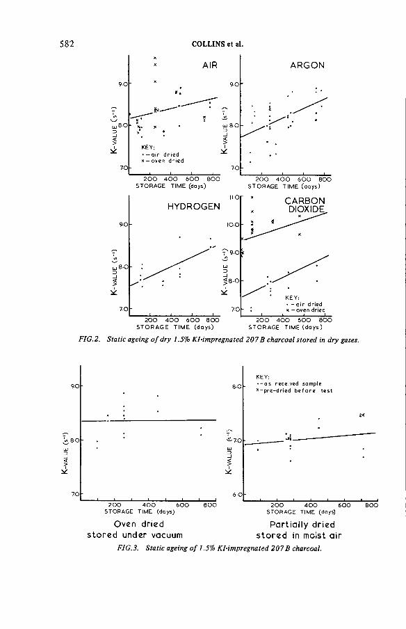
K-VA
LUE
(s'1)
582 COLLINS et al.
STORAGE TIME (days) STORAGE TIM E (days)
STO RAG E TIM E (days) STORAGE TIME (d a ys )
FIG.2. Static ageing o f dry 1.5% KI-impregnated 207 В charcoal stored in dry gases.
STORAGE TIME (days) STORAGE TIME (days)
Oven dried Partially driedsto re d under vacuum sto re d in moist air
FIG.3. Static ageing o f 1.5% KI-impregnated 2 0 7 В charcoal.
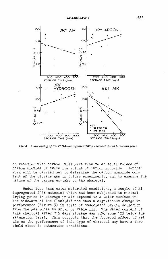
IAEA-SM-245/17 583
STORAGE TIME (days) STORAGE TIME (d ays)
FIG.4. Static ageing o f 5% TEDA-impregnated 207 В charcoal stored in various gases.
on reaction with carbon, will give rise to an equal volume of carbon dioxide or twice its volume of carbon monoxide. Further work will be carried out to determine the carbon monoxide content of the storage gas in future experiments, and to examine the nature of the oxygen up-take on the charcoal.
Under less than water-saturated conditions, a sample of KI- impregnated 207B material which had been subjected to minimal drying prior to storage in air exposed to a water surface in the side-arm of the flask,did not show a significant change in performance (Figure 3) in spite of associated oxygen depletion from the gas phase as shown by Table III. The water content of this charcoal after 7 1 5 days storage was 26$, some 10$ below the saturation level. This suggests that the observed effect of wet air on the performance of this type of charcoal may have a threshold close to saturation conditions.

584 COLLINS et al.
FIG.5. Static ageing o f wet 1.5% KI-impregnated 207 В charcoal stored in wet air.
In contact with wet air, water saturated TEDA-impregnated 207B charcoal exhibits a similar propensity for oxygen removal (Table III) but shows a small change in performance (Figure 4): the К-value changed from 10.3 to 9.0 or 10.1 to 8.6 if pre-dried prior to testing with methyl iodide, ie about one half of that observed with water saturated KI-impregnated material.
The above effects on trapping performances are more clearly demonstrated, in a comparative sense, in Figure 6, in which the data for the KI- and TEDA-impregnated carbons are plotted for the range of wet and dry storage conditions employed.
A secondary effect has become apparant during these studies. The pretreatment of the charcoal samples by purging with dry
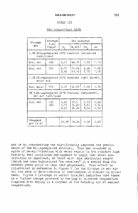
TABLE III
Gas composition data
IAEA-SM-245/17 585
■
StorageStoragetime
(days)
Gas analysis
gas°2
n 2+ c o co2 Ar
1 .5% Kl-impregnated 207.B charcoal (saturated conditions)
Air, wet 500 2.51 94.75 1 .63 1.10
Air, wet 785 6.713.96
87.29
89.76
4.965.23
1 .03
1 .05
1 . 5Í° Kl-impregnated 207B charcoal moist air
(part dried),
Air, moist 715 0.07 94.52 4.24 1.13
5fo TEDA-impregnated 207B Charcoal (saturated), wet air conditions
Air, wet 495780
0.66
0.030.07
97.5 95.23 95.28
0.753.553.54
0.92 1.14 1 .12
Standard gas (air) 20.95 78.09 0.03 0.93
gas or by oven-heating has significantly improved the performance of the Kl-impregnated material. This has occurred in spite of re-equilibration with water vapour in the standard high humidity test conditions and appears to imply that water distribution is important, at least with this particular sample (which had been bulk-stored "as received" in a sealed drum for several years prior to this test programme). This effect is illustrated by reference to Figure 5 for the Kl-type in wet air but the rate of deterioration of performance is similar in either case. Figure 2 (storage in carbon dioxide) indicates that there is a further change produced by heating at elevated temperature compared with drying in a current of low humidity air at ambient temperature.
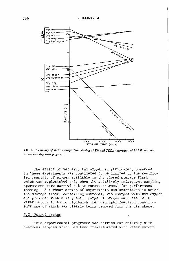
586 COLLINS et al.
STORAGE TIM E (d a ys )
FIG.6. Summary o f static storage data. Ageing o fK I- and TEDA-impregnated 207 В charcoal in wet and dry storage gases.
The effect of wet air, and oxygen in particular, observed in these experiments was considered to be limited by the restricted quantity of oxygen available in the closed storage flask, which was replenished only when the relatively infrequent sampling operations were carried out to remove charcoal for performance- testing. A further series of experiments was undertaken in which the storage flask, containing charcoal, was charged with wet oxygen and provided with a very small purge of oxygen saturated with water vapour so as to replenish the principal reaction constituents one of which was clearly being removed from the gas phase.
3.2 Purged system
This experimental programme was carried out entirely with charcoal samples which had been pre-saturated with water vapour

IAEA-SM-245/17 587
STORAGE TIME (days)
FIG. 7. Ageing o f wet Kl-impregnated 207 В charcoal stored in wet oxygen (purged).
from the gas phase and stored in wet oxygen with a small purge of the same gas. The purge rate was ca 20 cm^/h and was in excess of the expected oxygen uptake on the charcoal. After intervals of time samples of each charcoal were subjected to the standard high humidity test with methyl iodide. The charcoals which were studied comprised samples of:
(a) 1 .5$ Kl-impregnated 207B (coa l-b ased ).
(b) 5 TEDA-impregnated 207B (coa l-b ased ).
(c ) Unimpregnated 207B (coa l-b ased ).
This material was impregnated to 1.5$ KI by a standardised soaking technique and pre-dried prior to testing with methyl iodide.
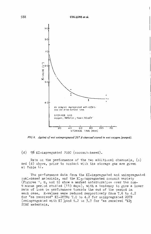
588 COLLINS et al.
FIG.8. Ageing o f wet unimpregnated 207 В charcoal stored in wet oxygen (purged).
(d) 5$ KI-impregnated 208C (coconut-based).
Data on the performance of the two additional charcoals, (c) and (d) above, prior to contact with the storage gas are given at Table I I .
The performance data from the KI-impregnated and unimpregnated coal-based materials, and the Kl^-impregnated coconut variety (Figures 7, 8 , and 9) show a marked deterioration over the continuous period studied ( 1 1 0 days), with a tendency to give a lower rate of loss in performance towards the end of the period in each case. К-values were reduced respectively from 7.6 to 4.2 for "as received" KI-207B; 7.0 to 4.2 for unimpregnated 2Ô7B (reimpregnated with KI );and 6.2 to 3.7 for "as received "KI3 208C materials.

IAEA-SM-245/17 589
FIG.9. Ageing o f wet 5% K I3-impregnated 208 С charcoal stored in wet oxygen (purged).
By contrast, data from the TEDA-impregnated 207B sample, stored in this gently purged system (Figure Ю), showed a small change in performance, the К-value falling from 8.7 to 7.8 for "as received" material.
At the present early stage of these experiments no measurements have been made on the oxygen leaving each flask, but it is the intention to examine this gas stream for components such as carbon monoxide and dioxide.
5.5 General discussion
Other work on the ageing of KI and TEDA-impregnated 207B material was interpretated in terms of a combination of static and

590 COLLINS et al.
STORAGE TIME (days)
FIG.10. Ageing o f wet 5% TEDA-impregnated 207 В charcoal stored in w et oxygen (purged).
dynamic effects. The former suggested the possibility of change within the charcoal, eg the migration of a component which removed sites reactive to methyl iodide whilst the latter appeared to be more consistent with the filtration or sorption of a gas-borne species (ie a poisoning agent) or alternatively a direct (slow) chemical reaction which might also apply in the static condition.
The principal features of the present studies may be summarised:
(a) Little change in the charcoal performance is observed over storage periods of up to two years or so in dry condition whether air, argon, carbon dioxide or hydrogen, or in the absence of oxygen.
(b) Substantial deterioration in performance was found in wet conditions (ie charcoal saturated from the gas phase) in the presence of oxygen whether the charcoal was unimpregnated coal-based 207B, KI-207B, or KI 3 impregnated coconut based material. In the closed system this was associated with oxygen loss from the gas phase.

IAEA-SM-245/17 591
(с) Only small effects on performance were observed in wet air or oxygen when the coal-based 207B material was impregnated with TEDA, even though this was associated in the closed system with oxygen removal from the storage gas.
In general it is clear that the observed oxygen removal under wet conditions is a common characteristic with the range of materials studied, but that the application of TEDA substantially reduces the rate of deterioration in performance. This implies that the different trapping mechanisms which these charcoals exhibit for methyl iodide may have important significance. In the cases where oxygen uptake (on the charcoal) gives rise to deterioration in trapping performance the charcoals in question depend upon either a catalytic (ie active site) or catalytic/ isotopic exchange reaction. If the effect of oxygen is simple, ie a single reaction mechanism, it appears likely that it affects the catalytic potential of the charcoal since this is the single common feature of the charcoals exhibiting this effect. It is also to be noted that similar behaviour has been observed with other KI-impregnated charcoals.
On the other hand, since impregnation with the organic material, triethylene-diamine, inhibits the effect this may be connected with its ability to react in a more direct fashion, chemically with methyl iodide, and that in this case the charcoal acts principally as an extended surface for the dispersion of the imprégnant. In other words there is not such a significant catalytic or synergistic effect as observed in its absence.
As well as representing a contribution to the knowledge and understanding of the ageing characteristics of impregnated charcoals, this study indicates some of the requirements for improved storage and operational conditions. It is clearly advantageous to exclude oxygen and water during storage. It is also important to exclude these components from dynamic gas operating conditions, with the further implication that a charcoal bed plant which is required to operate in flowing wet air should for example be kept on "stand-by" in static conditions (ie valved off) for as high a proportion of its life as possible. The results of this study may also help in resolving certain anomalies observed in previous work. Occasionally, high deterioration rates have been measured (Ref. 4 ) which may have been partly attributable to inadvertent exposure to wet air.
It is apparent, compared with earlier studies (Ref. 3) that the presently observed ageing rates are more rapid. This is illustrated for "as received" KI-impregnated 207B material in Figure 8, and is expected if the rate is dependent on the availability of oxygen and degree of water saturation.

592 COLLINS et al.
It should, be noted that the observed oxidative effect is not exclusive to other factors such as poisoning which may arise in other circumstances which have not been studied in the present work.
4. CONCLUSIONS
1 . With wet charcoals in wet oxygen containing atmospheres there is evidence for an oxidative mechanism in the ageing process, at least in the case of saturated material.
2. If oxygen or water is excluded then the performance of Kl-impregnated charcoals during storage may not deteriorate significantly.
3. TEDA-impregnation is advantageous during storage even in the presence of water and oxygen. Combined with other data it is considered that this type of imprégnant merits greater interest for plant usage, subject to certain limitations on gas temperature and composition.
A P P E N D IX I.
STANDARD LABORATORY PENETRATION TEST
The standard laboratory penetration test with methyl iodide -131 has been fully described elsewhere (Ref. 5 ) but a brief description is included here to afford a convenient reference to the essentials of the procedure.
3Each sample of 38.6 cm of charcoal measured by a standard
settling technique is pre-equilibrated for a period of about 16 hours with downwards flowing air at 98$ RH, atmospheric pressure and at a temperature of about 22°C. Methyl iodide labelled with iodine - 1 3 1 prepared from the reaction between aqueous sodium iodide - 1 3 1 and dimethyl sulphate is then loaded over a period of ten minutes in air under the same conditions but with the flowrate (1 1 . 6 l/min or face velocity, 36 cm/sec) fully controlled so that the charcoal bed staytime is 0.20 seconds. Staytime is defined as the ratio of the volume of the charcoal bed to the volumetric gas flowrate. The quantity of inactive methyl iodide is such that the average final concentration on the charcoal granules is 50 ng/g charcoal. After loading of methyl iodide is complete the high humidity air-flow is continued for a total elution period of two hours. Any methyl iodide-131 which penetrates

IAEA-SM-245/17 593
during loading or elution phases is removed on full-flow small mesh Kl-impregnated charcoal traps. The penetration is determined by measuring the iodine - 1 3 1 content of the traps and of the test bed by conventional gamma spectrometry techniques using a sodium iodide crystal-photomultiplier based system.
REFERENCES
1. DEITZ, V R and JONAS, L A. Dependence of gas penetration of charcoal beds on residence time and linear velocity
NIJCL.TECH._27. 59, 1978.
2. MAY, F G and POLSON, H J. Methyl iodide penetration oncharcoal beds: variation with relative humidity and facevelocity. AAEC Report E322 1974.
3a. TAYLOR, L R and TAYLOR, R. The ageing of impregnated charcoals. TRG Report 2483(W) 1973, also presented at the CECSeminar on Iodine Filter Testing, Karlsruhe, December 1973: C0NF-73-636-026, p1 21 .
3b. HYAM, E D. The ageing of impregnated charcoals: astatistical re-appriasal of the reported data.TRG Report 2483(W), Part 2 - December 1975.
4. HILLARY, J J and TAYLOR, L R. The Performance of commercially prepared impregnated charcoals for the trapping of methyl iodide. TRG Report 2906(W) November 1977.
5. HILLARY, J J. Iodine sorption plant test procedures inthe United Kingdom TRG Report 2497(W), Part 1, 1974, alsopresented at the CEC seminar on Iodine Filter Testing Karlsruhe. December 1973: C0NF-73-636-O26, p237.
DISCUSSION
J.L. KOVACH: I believe that the use of stay time as a constant in your equations is wrong. At constant stay time, doubling the velocity and bed depth, for example, produces a significant increase in DF. Secondly, in coal-base carbons such as 207 В sulphur is present which oxidizes in wet air to produce S02, thus acidifying the carbon and lowering the DF. The same is the case with KI3 on all carbons; in wet air storage, iodine is liberated by the acidification process.
R.D. COLLINS: Your first observation is quite correct; both stay time and face velocity must be specified to define performance conditions.

594 COLLINS et al.
Your second comment is interesting. Early work showed that washing out alkalinity — to increase ignition temperature — had a bad effect on performance, and coconut-base charcoals are high in alkali metal constituents. Our early work (TRG 1300) suggested that coconut charcoals were inferior to coal-base types as regards trapping methyl iodide, and since then we have done little work with them.
J.L. KOVACH: I now have a couple of questions. Have you measured the pH of the carbons over the ageing process, and have you detected any gases other than those reported in your mass spectra measurements?
R.D. COLLINS: The answer to your first question is that we have not done so. I think that perhaps we should. As regards your second question, except for the ageing atmosphere and constituents of air, no gases except C 02 were found. S02 in particular was not detected. The analysis did not distinguish between N2 and CO.
T.E. BLACKMAN: Mr. Fowler’s paper (SM-245/22) and our own experience show that it is difficult to extrapolate from normal working conditions to accident conditions. What is your view on the use of an analytical expression such as that suggested by May and Poison (Ref. [2] of the paper) to carry out this extrapolation?
Also, your data show a reduction in К-value by 3 or 4 due to ageing but the final value is still ~3 or 4, which is equivalent to a DF of 103 — 104 in our case.We have noted that our measured in situ DFs fall by a factor of ~102 over a period of about 2 years, presumably because of poisoning as well as water adsorption. Would you care to comment? I should perhaps also point out that while the in situ DFs are affected by mechanical leakage, tests also indicate falls in K-value by a total of ~7 over 2 years.
R.D. COLLINS: With reference to your first point, I think it is very difficult to deduce from one test the result which would have been obtained had a test under different conditions been made. Table I shows that different values of a fit different experiments.
Regarding your second query, the stay time in your beds is, I believe, 0.5 s. Thus a drop in the DF by a factor of 102 corresponds to a drop in К of four times, which agrees with Fig.5. However, your beds contain TEDA as well as KI- impregnated charcoal, and they do not operate at 98% relative humidity. On the other hand they are continuously in use and may be subject to poisoning by impurities in your containment air. I think the agreement is fortuitous.

Session VIII
STORAGE AND DISPOSAL

Chairman
H.A.C. McKAYUnited Kingdom
IAEA-SM-245/1
STUDY ON THE POSSIBILITY OF SEA-DISPOSAL OF KRYPTON-85
A. van DALEN, L.H. VONS, B. VERKERK Netherlands Energy Research Foundation ECN,Petten,Netherlands
Abstract
S T U D Y O N T H E P O S S IB IL IT Y O F S E A -D IS P O S A L O F K R Y P T O N -85 .R esults o f a fe a s ib ility s tu d y , p e rfo rm ed un d e r a Contract w ith the C om m ission o f the
E uropean C om m un itie s , regard ing tech n ica l and ra d io lo g ica l aspects o f sea-disposal o f a ll k ry p to n -8 5 re ta ined in a large fu e l reprocessing fa c il i ty , are presented. T h e design o f a doub le -w a lled , essentia lly spherica l co n ta in e r is described th a t p rov ides b o th doub le con ta inm e n t o f the com pressed gas and pe rm anent ‘ d isposable ’ ra d ia tio n sh ie ld ing. Th ree sizes have been s tud ied , i.e. w ith in te rn a l vo lum es o f 0 .0 1 , 0 .05 and 0.1 m 3, each designed to h o ld 0.1 m 3 (STP) o f k ry p to n , and each co n ta in in g ~ 4 0 0 TB q o f 85K r pe r 0.001 m 3 sphere vo lum e. Th is results in an in te rn a l heat p ro d u c t io n o f 17.5 k W /m 3. C a lcu la tions o f tem pera tures and stresses th a t w o u ld resu lt fro m the c o n d itio n s o f the requ ired f ire test fo r B (U ) tra nspo rt packages showed th a t th e design w o u ld a llo w the con ta iners to pass th is test. R ad io log ica l consequences have been considered fo r d isposal o f pe tabecquere l am oun ts o f 8sK r as a fu n c tio n o f undam aged co n ta in e r l ife t im e on the sea bed. F in a lly , an in d ic a tio n is given o f the necessary am endm ents to the L o n d o n C o n ve n tio n in o rd e r to a llo w sea-disposal o f these large am oun ts o f ra d ioac tive k ry p to n .
1. INTRODUCTION
Retention of 85Kr in future reprocessing plants will probably be a requirement for licensing such a facility. The Environmental Protection Agency (EPA) in Washington, DC, has already suggested radiation standards for the uranium fuel cycle [1] that would limit 85Kr release to 1850 TBq/GW a, which is about 15% of the amount produced.
In his contribution to this symposium Maestas [2] announced the publication of an OECD/NEA experts group report on the radiological significance of airborne releases from nuclear facilities. Therefore, no motivation for krypton retention will be given here. Of the various possibilities for capture of the gas, cryogenic capture has been assumed in our study, although other techniques presented at this meeting could ultimately prove to be better.
Surface storage of the captured gas in a compressed form has been foreseen in various studies, but ultimate disposal has not been extensively considered.
597

TABLE I. KRYPTON ISOTOPES PER Mg OF SPENT FUEL
598 VAN DALEN et al.
Iso tope (T B q ) (g) Heat (W )
83 K r stable 40.8 —
84 K r stable 111.0 -
85 K r 400 27.6 17.3
86 K r stable 192.0 -
T o ta l 37 1 .4 g o r0 .098 m 3 (STP)
One reason for this is that disposal in a geologic repository is not advocated by the potential operators of such facilities unless the krypton is lowered into the repository only at the end of its useful life. Such a disposal option would imply a rather prolonged surface storage that might also present a radiological risk.
Therefore, the concept of sea-disposal was studied although at present disposal of large amounts of krypton in the ocean would not be permitted under the terms of the London Convention. For safe handling, intermediate storage and transport a special, essentially spherical, fully welded container was designed, which is surrounded by a mild steel ‘disposable’ radiation shield. In addition, this fully-welded shielding acts as a double containment. A small nitrogen filled gap between the two vessels allows for the detection of a leaking inner container by increased surface radiation.
The work described here was performed under contract 052-78-5 WAS N with the Commission of the European Communities in the framework of their indirect action programme on radioactive waste management. However, views expressed in this paper concerning sea-disposal should not be considered to be the views of the Commission.
2. KRYPTON PRODUCTION
Table I shows the amounts of krypton isotopes per megagram of spent fuel [3] that are present in a LWR fuel after 33 000 MW - d/Mg burnup and after one year of cooling before reprocessing.
In a 1500 Mg/a reprocessing plant we therefore collected 600 PBq, with 25 kW heat production in a volume (undiluted with krypton from the air and assuming a full cryogenic separation of argon, krypton and xenon) of 150 m3 (STP).
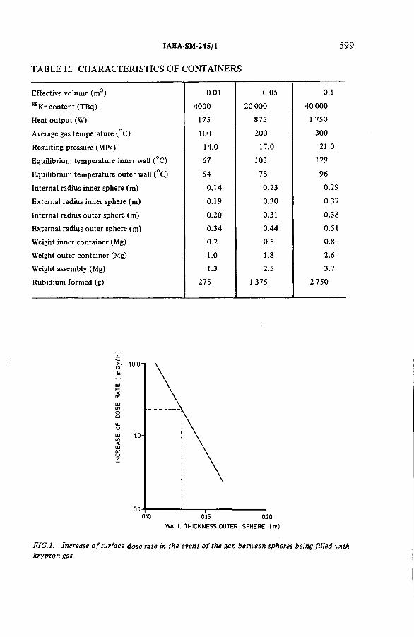
IAEA-SM-245/1
TABLE II. CHARACTERISTICS OF CONTAINERS
599
E ffe c tive vo lum e (m 3) 0.01 0.05 0.1
85K r c o n te n t (T B q ) 4 0 0 0 2 0 0 0 0 40 000
Heat o u tp u t (W ) 175 875 1 750
Average gas tem pe ra tu re (°C ) 1 0 0 2 0 0 300
R esu lting pressure (M Pa) 14.0 17.0 21.0
E q u ilib r iu m tem pera tu re in n e r w a ll (°C ) 67 103 129
E q u ilib r iu m tem pera tu re o u te r w a ll (°C ) 54 78 96
In te rn a l rad ius in n e r sphere (m ) 0 .14 0.23 0.29
E x te rn a l rad ius in n e r sphere (m ) 0.19 0 .30 0.37
In te rn a l rad ius o u te r sphere (m ) 0.20 0.31 0.38
E x te rn a l rad ius o u te r sphere (m ) 0 .34 0 .44 0.51
W eight in n e r co n ta in e r (M g) 0.2 0.5 0.8
W eight o u te r co n ta in e r (M g) 1.0 1.8 2.6
W eight assembly (M g) 1.3 2.5 3.7
R u b id iu m fo rm e d (g) 275 1 375 2 750
WALL THICKNESS OUTER SPHERE |m ]
FIG. 1. Increase of surface dose rate in the even t of the gap between spheres being filled with krypton gas.

600 VAN DALEN et al.
OIMENSIONS IN mm
FIG.2. Krypton (isKrj transport container, volume 0.05 m 3.

IAEA-SM-245/1 601
GAS INLET
OPEN CLOSED
FIG.3. Detail o f non-return valve.
3. DESIGN OF CONTAINER
Three container sizes of 0.01, 0.05 and 0.1 m3 effective volume were studied, each designed to hold 0.1 m 3 (STP) of gas containing ~ 400 TBq of 85 Kr per 0.001 m3 sphere volume. The resulting initial heat production therefore was 17.5 kW/m3 sphere volume. Table II shows the main characteristics of the containers. It should be noted that the calculated equilibrium temperatures are based on an ambient temperature of 38°C, as required for calculations concerning B(U) type transport containers [4]. Required shielding thicknesses are also based on this transport regulation. The wall thickness of the inner sphere is dictated by the maximum gas pressure and steel temperature that will prevail under the conditions of the fire test according to Ref.[4]. The inner sphere is made of stainless steel and the outer container consists of low alloy ferritic steel.
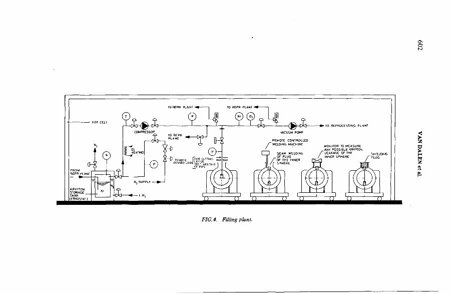
C\оК)
<►Zв►rи2¡
FIG. 4. Filling plant.

IAEA-SM-24S/1 603
The inner sphere is filled with explo-foil to provide better heat transfer. The 1 cm nitrogen-filled gap between spheres has the dual purpose of a heat barrier during exposure to a fire, and a leak detection device. A leaking inner container will cause krypton to enter the gap giving rise to a measurably larger surface radiation rate, as indicated in Fig. 1. The tight outer sphere provides the mechanical strength necessary to contain the high pressure gas in case of failure of the inner vessel.
The mechanical strength of the container is sufficient to withstand an external overpressure equivalent to a sea-depht of more than 12 000 m.
In the early stages of the study the design called for cryogenic filling with liquid krypton. To this end, the inner sphere contained a Dewar vessel that retained the liquid sufficiently long to allow for pressureless weld-closure of the container. This system was later abandoned in favour of filling under pressure, using a non-return valve that also allowed for pressureless welding of the inlet tube.
A 0.05 m3 container is shown in Fig. 2, while Fig.3 presents a detailed sketch of the non-return valve. This valve has a ‘non-activated’ open position for flushing and evacuation purposes. By pressing down the inner tube the valve snaps into its operational position, making it a non-return valve.A double О-ring seal around the inlet tube allows this tube to be pushed down twice, the first time after flushing and the second time after welding to enable the top cap to be welded.
The filling and welding sequence in the hot cell is illustrated in Fig.4.The cap on the outer sphere is welded outside the cell because the shielding plug, mounted in-cell, gives sufficient radiation protection.
Since the rubidium formed during decay of the 85 Kr can be more corrosive to stainless steel as an oxide than as a metal, the container is flushed with pure nitrogen before filling.
4. IAEA TRANSPORT CONTAINER TESTS
An important question in the design of the gas container was whether it would be able to pass the stringend IAEA tests for type B(U) containers, such as the fire test, the drop test and the immersion test. Mainly the fire test, where the container should be able to withstand the impact of a fire at a temperature of 800°C for 30 min and natural cooling thereafter for 3 h, would be a severe test for a container holding a heat-producing gas under high pressure.
Computer calculations of temperatures and stresses resulting from the conditions of the fire test have been made showing that the containers, for each size studied, would easily pass the test. Figure 5 shows the temperature

604 VAN DALEN et al.
THERMAL TEST A R T IF IC IA L COOLING, f ~ a IR COOLING , A IR COOLINGh—+------—------------ —+-----------------
FIG. 5. Temperature history for a 0.05 m 3 krypton sphere.
history during and after the thermal test for a 0.05 m3 container, and in Table III some relevant values of temperatures, gas pressures and stresses are collected.
5. SAFETY ASPECTS
This is not the place for a detailed discussion on the safety of the above spherical containers. From the point of view of risk limitation the use of small containers may be advantageous. If a container should rupture and the gas initially disperse to a limited volume of, for example, 1000 m3, the immersion

IAEA-SM-245/1 605
TABLE III. MAXIMUM TEMPERATURES, PRESSURES AND STRESSES DURING AND AFTER THERMAL TEST
D urin g A fte r D u rin g A fte r D urin g A fte r
C on ta ine r vo lum e (m 3) 0.01 0.05 0.1
G as-tem pera ture (°C ) 150 300 230 360 320 440
Gas-pressure (M Pa) 16.0 21.0 19.0 24 .0 22.0 27 .0
Tem pera tu re in n e r w a ll (°C ) 115 264 133 262 152 270
Tem pera tu re o u te r w a ll (°C ) 432 241 434 241 437 246
M echanica l stress in n e r sphere (M Pa) 24 32 33 42 42 51
T h e rm a l stress in n e r sphere (M Pa) 13 < 1 0 16 < 1 0 16 < 1 0
M echanica l stress o u te r sphere (M Pa) 6 8 15 19 23 29
T h e rm a l stress o u te r sphere (M Pa) 263 < 1 0 252 < 1 0 252 < 1 0
dose rate in the case of a 0.01 m3 container would be about 2 Sv/h and for the 0.1 m 3 flask naturally 10 times as high. Another aspect may be that in order to ensure that the transport of large amounts of compressed radioactive gases is safe even under severe accident conditions, the requirements for integrity tests, such as the drop and fire tests, might become more stringent than for usual В-containers filled with solids.
6. RADIOLOGICAL ASPECTS OF SEA-DISPOSAL
Krypton is soluble in water to the extent shown in Table IV, at a partial gas pressure of 0.1 MPa [5].
At low temperatures and high pressures krypton can enter into a crystalline hydrate, of theoretical formula 8Kr.48H20 . Dissociation pressures are shown in Table V [6].
The conditions existing in a deep ocean dumping site (>4000 m depth, 2°C) will therefore lead to a complete dissolution of the krypton in the event of container failure on the ocean floor. Normal container lifetime, however, may be estimated from corrosion rates measured by BMI [7] for various steels in ocean waters at a depth of 1700 m over a period of 4 years.

606 V A N D A L E N e t al.
TABLE IV. SOLUBILITY OF KRYPTON GAS IN WATER
Tem p. (°C ) 0 10 20
S o lu b il ity (m 3 K r /m 3 H 20 ) 0.121 0 .092 0.073
30
0.068
TABLE V. DISSOCIATION PRESSURES OF KRYPTON HYDRATE
Tem p. (°C ) 0 4 .8 10.3
Diss. pressure (M Pa) 1.47 2 .38 3.92
12.5
4.81
An average uniform corrosion rate of ~50 /лт/a can be derived, which will lead to a container lifetime of more than 300 years, taking into account that a decrease of wall thickness of 0.05 m will be allowed before the container cap undergoes plastic deformation by the seawater pressure at a depth of 4500 m.
Studies on the consequences of ocean dumping of radioactive materials have in common the assumed continuous release of the radioisotopes from the containers; an incidental dumping is of no interest to a practical way of disposing of radioactive materials. The practice at present is limited to a relatively large mass of material with a low content of radioactive matter.
Before permission will be granted for sea-disposal of 85 Kr from reprocessing nuclear fuel, the advantage of this technique compared with other disposal methods has also to be demonstrated, together with convincing arguments that a possible release of 85Kr will not harm man. The activity of 85Kr in the containers envisaged is much higher than that stated in the present definitions and recommendations for dumping.
In accordance with the general practice for calculations of radiological consequences, a release rate of 0.037 TBq/s of 8sKr at the dumping site is assumed in our considerations. Several models have been used to calculate radionuclide concentrations that are relevant to the food-chain on the fishing grounds. The surface concentrations for a nuclide with a half-life of 10 years according to four models are:
(a) 481 Bq/m3 Webb-Morley [8](b) 48 Bq/m3 Webb-Grimwood [9](c) 260 Bq/m3 well-mixed agerage(d) 0.2 Bq/m3 Shepherd ‘best estimate’ [10]
IAEA-SM-245/1 607
The surface concentrations are calculated on the basis of a state of equilibrium, with a release rate of 0.037 TBq/s on the ocean bed and at a depth of at least 4000 m. The models cited are listed according to the date of their publication. The difference between the last model listed and the other three is remarkably large.
The dose rate in water of the ocean surface and in marine organisms can be calculated, assuming that the concentration ratio of krypton in the marine organisms and the surrounding sea water does not significantly deviate from unity. Krypton does not form compounds under surface oceanic conditions, thus the concentration ratio depends only on the solubility ratio. Krypton is slightly more soluble in lipids than in water, thus the concentration in living organisms may be slightly higher than in the surrounding water, but not significantly so. According to Woodhead [11] the dose rate (mGy/h) is calculated as follows:
Dp(oo) = 576 E|3 • С
E(j = average ¡3 energy per disintegration in MeVС = concentration of 8sKr in TBq/m3The 0.51 MeV gamma ray (0.43%) can be neglected.Ejj is about one-third of m ax (0.672 MeV) = 0.22 MeV.
The dose rate for 85Kr also equals:
D^oo) =127 mGy/h per TBq/m3
The four estimated concentrations result in the following dose rates:
(a) 6.1 X 10“8 mGy/h(b) 6.1 X 10~9 mGy/h(c) 3.5 X 10"8 mGy/h(d) 2.5 X 10"n mGy/h
The release rate of 0.037 TBq/s and the reprocessing capacity, or nuclear power production, can be related as a function of the corrosion resistance of the containers at the ocean bed. The release rate of 0.037 TBq/s or1.15 X 106 TBq/a means that the same amount can be disposed of in one year if the release is practically immediate after reaching the ocean bed, and that 3 X 10⁷ TBq can be disposed of annually when the mean life of the containers is 50 years and 7.5 X 10⁸ TBq in the case of 100 years for decay inside the container.
With a production of 400 TBq of 8sKr per Mg fuel at a burnup of 33 GW-d/Mgand the fact that about 30 Mg of spent fuel results from the

608 VAN DALEN et al.
TABLE VI. RELATION BETWEEN MEAN CONTAINER LIFE AND SIZE OF ‘NUCLEAR ECONOMY’
Assumed 85K r release ra te = 0 .037 T B q /s
M ean l ife o fco n ta in e r
(a )
8SK r dum ped
(T B q /a )
Reprocessing capac ity o f U (M g/a )
Ins ta lled elec. capacity (G w (e ))
0 1.15 X 10⁶ 3 X 10³ 1 0 2
50 3 X 10⁷ 8 X 10⁴ 2.7 X 10³
1 0 0 7 .4 X 108 2 X 10⁶ 6.7 X 10⁴
production of 1 GW(e) • a, the relation between the mean lifetime of the containers at the ocean bed, the amount to be disposed, the reprocessing capacity and the installed nuclear power at the postulated release rate of0.037 TBq/s is given in Table VI.
From this table it can be seen that if 85 Kr sea-disposal containers only start to leak significantly after 50 years all the krypton-85 produced in a large nuclear economy can be disposed of in the ocean, if the assumed leakage rate is limiting.
7. LEGAL SITUATION CONCERNING SEA-DISPOSAL
Sea-disposal of radioactive wastes was practised by the United States of America between 1946 and 1965 and for a number of years but on a small scale by the United Kingdom, both for low active materials. The USA disposed of about 76 000 drums of 0.2 m3 with an activity at the time of packaging of 2150 TBq [12].
In 1965 the Nuclear Energy Agency (NEA) started an international activity on this matter and an initial safety assessment was made [13]. From the beginning there was strong opposition to sea-disposal by a number of countries, and this situation still persists. In fact, the opposition on principle of some countries has strongly influenced further legal and institutional arrangements concerning sea-disposal. Since 1967 sea-disposal operations have been carried out regularly, first once every second year, then annually, by the United Kingdom, Belgium, the Netherlands and, later, Switzerland. In the first experimental dumping as it was called, the Federal Republic of Germany and
IAEA-SM-245/1 609
France also participated [13]. As a result of growing concern about pollution of the oceans and seas, a maritime conference was held in London in 1972 which adopted the ‘International Convention on the Prevention of Marine Pollution by Dumping of Wastes and Other Matter’, later referred to as the London Convention. Radioactive wastes were included in the provisions, with the task of the International Atomic Energy Agency (IAEA) to set up recommendations on the kinds and amounts of radioactive matter ‘unsuitable for dumping’.
In the early years the international sea-disposal operations were carried out under the aegis of the NEA. Later this organization assigned itself the task of surveying the operations. To this end the ‘Multilateral Consultation and Surveillance Mechanism for Sea Dumping of Radioactive Waste’ was set up and introduced formally by an OECD Council Decision [14], accepted by all but four member countries.
In annexes to the London Convention materials have been listed that were forbidden to be dumped or that could only be dumped under restricting rules. Radioactive wastes of high level activity were mentioned in Annex 1 to the Convention concerning substances unsuitable for dumping.
The IAEA was given the task of defining what exactly high level radioactive waste would be and of making recommendations for sea-disposal operations, including a set of activity limits for various radionuclides.
To arrive at the requested definition and recommendations it was necessary to determine the uptake capacity of the ocean for many radionuclides, and to this end oceanographic and radiological models have been developed with which this capacity could be estimated [8- 10, 15, 16].
Based on these estimates limiting quantities were indicated for various categories, such as alpha-emitters, beta-emitters and tritium. The most recent oceanographic model of Shepherd [10] is based on release rates and it finally indicates limiting annual releases instead of limiting the quantities to be dumped. This last refinement has not yet been incorporated into the London Convention but it is generally felt that limiting the releases is a better criterion than simply limiting the quantities dumped. Unfortunately, 8sKr was not considered in the calculations of the Shepherd-model, so that at present the limiting release quantities for 85 Kr are not known.
It is clear that the permission of krypton sea-disposal as described in this report would require an amendment to the London Convention, or, at least, a clear recommendation by the IAEA that even very large amounts of 85Kr would not be considered high-level radioactive matter unsuitable for dumping.
To arrange for such an amendment the Shepherd model should be extended to incorporate krypton. Radiologically this should not be too difficult, but it would probably need an adequate description of the behaviour of the element in water once it has escaped from the container. Krypton is reasonably
610 VAN DALEN et al.
soluble in water and it would most probably remain in the dissolved condition; consequently it can be considered similar to any other radionuclide that went into true solution.
The behaviour of noble gases in the human body is also sufficiently understood to allow conclusions about radiological consequences of krypton intake along the aqueous route or perhaps along the seafood pathway.
Assuming that in this way limiting release rates can be established, a country intending to use sea-disposal for retained krypton should advise the IAEA that in its forthcoming revision of the recommendations it should include krypton in the list of radionuclides considered.
8. COSTS
Only a very preliminary indication can be given here of the costs involved when practising sea-disposal of retained 85 Kr. Besides the cryogenic separation plant, which is necessary anyway when krypton is retained, a hot-cell facility is needed to encapsulate the gas in the spherical transport containers. Since these are transport packages they can be easily stored in a shed or even in the open air until they are transported to the ocean. Finally, trucks must be rented and a suitable ship chartered.
As the total number of krypton containers to be transported would be small, the cheapest way to carry out the sea-disposal would be to simply add these containers to a consignment of low- and medium-active wastes as regularly disposed, at a price of approximately US $ 100/Mg, not including land transport. The cost therefore will mainly be made up of the container costs and capital plus operational costs of a hot-cell line.
Based on an indicative quotation for a container and a rough cost estimate for the hot-cell facility and its operation, the sum arrived at for 85 Kr disposal was of the order of US $2 X 10s per GW(e) a, which is a negligible addition to overall reprocessing costs.
REFERENCES
[1 ] R IC H A R D S O N , A .C .B ., C o n tro llin g A irb o rn e E fflu e n ts fro m F u e l C ycle P lants (P roc. A N S /A IC h E T o p ica l M eeting Sun V a lle y , 1976), A m erica n N uc lea r S oc ie ty , H insdale (1 9 7 6 ) 12.
[2 ] M A E S T A S , E ., “ O EC D N uc lea r E nergy A gency’s program m e in th e managem ent o f rad ioac tive gaseous wastes” , these Proceedings, IA E A -S M -2 4 5 /6 4 .
[3 ] H E Y B O E R , R .J., O R IG E N ru n w ith o rig in a l data lib ra ry .[4 ] IN T E R N A T IO N A L A T O M IC E N E R G Y A G E N C Y , R egu la tions fo r the Safe T ransp o rt
o f R ad ioactive M ateria ls , S a fe ty Series No. 6 , 1973 Revised E d it io n , IA E A , V ienna ( 1973).

IAEA-SM-245/1 611
[5 ] M E L L O R , J.W ., In o rg . T heor. Chem . 7 (1 9 5 7 ) 942.[ 6 ] P A S C A L, P., Nouveau T ra ité de C h im ie M iné ra le , Paris 1 (1 9 5 6 ) 1066.[7 ] B A T T E L L E M E M O R IA L IN S T ., C o lum bus, The C orros ion o f M etals in M arine
E nv iron m en ts , Rep. B M IC -245 (M a y 1970).[ 8 ] W EBB, G .A .M ., M O R L E Y , F ., A M o de l fo r the E va lu a tio n o f the Deep Ocean D isposal
o f R ad ioactive W aste, N a tio n a l R a d io log ica l P ro te c tio n B oard , H a rw e ll, Rep. N R P B -R 14 (1 9 7 3 ).
[9 ] W EBB, G .A .M ., G R IM W O O D , P .D ., A Revised O ceanographic M o d e l to C alcu la te the L im it in g C apac ity o f the Ocean to A ccep t R ad ioactive Waste, N a tio n a l R ad io log ica l P ro te c tio n B oard , H a rw e ll, Rep. N R P B -R 58 (1 9 7 6 ).
[1 0 ] S H E P H E R D , J .G ., A s im p le m o d e l fo r the d ispe rs ion o f ra d ioac tive wastes dum ped o n the deep-sea bed, M ar. Sci. C om m . 4 4 (1 9 7 8 ) 293.
[1 1 ] W O O D H E A D , D .S., “ Levels o f ra d io a c tiv ity in the m arine e n v iro n m e n t and th e dose c o m m itm e n t to m arine organism s” , R ad ioactive C o n ta m in a tio n in th e M arine E n v iro n m e n t (P roc. S ym p. V ienna , 1973), IA E A , V ienna (1 9 7 3 ) 499.
[1 2 ] D Y E R , R .S., “ E n v iro n m e n ta l surveys o f tw o deepsea rad ioac tive waste d isposal sites using subm ersib les” , M anagem ent o f R ad ioactive Wastes fro m the N uc lea r F u e l C ycle (P roc. S ym p. V ienna , 19 76 ) V o l.2 , IA E A , V ienna (1 9 7 6 ) 317.
[1 3 ] O E C D /E U R O P E A N N U C L E A R E N E R G Y A G E N C Y , R ad ioactive Waste D isposal O pe ra tio n in to the A t la n t ic 1967, O E C D , Paris (1 9 6 8 ).
[1 4 ] O E C D /N U C L E A R E N E R G Y A G E N C Y , C o u n c il D ec is ion o f 22 J u ly 1977, reproduced as an A n n e x to the N E A S ix th A c t iv i ty R e p o rt, O E C D , Paris (1 9 7 8 ).
[1 5 ] IN T E R N A T IO N A L A T O M IC E N E R G Y A G E N C Y , T h e O ceanographic Basis o f the IA E A Revised D e fin it io n and R ecom m endations C once rn ing H igh -Leve l R adioactive Waste U nsu ita b le fo r D u m p in g at Sea, T e chn ica l D o cum en t N o .210 , IA E A , V ienna (1 9 7 8 ).
[1 6 ] IN T E R N A T IO N A L A T O M IC E N E R G Y A G E N C Y , T h e R ad io log ica l Basis o f the IA E A Revised D e fin it io n and R ecom m endations C oncern ing H igh -Leve l R ad ioactive Waste U nsu ita b le fo r D u m p in g a t Sea, T e chn ica l D ocum en t N o .2 1 1 , IA E A , V ienna (1 9 7 8 ).
DISCUSSION
M.J.S. SMITH: There has been no work reported at this meeting on the possibility of liquid metal embrittlement of construction materials by rubidium. We believe that this is a possibility which should not be ignored. The phenomenon of liquid metal embrittlement is quite distinct from corrosion or stress corrosion, and a different type of test is needed. It can cause fracture of metals below their engineering yield strain, and it could occur in krypton separation plants, handling systems and storage containers. Special tests for investigating liquid metal embrittlement have been developed at Harwell and we are hoping to start a programme to test the susceptibility of metals proposed for radiokrypton systems.
Have you considered the possibility of liquid metal embrittlement of your vessels and do you know of any current studies dealing with this subject?
B. VERKERK: No work on rubidium corrosion or embrittlement was included in our research. However, I believe that corrosion experiments have

612 VAN DALEN et al.
been planned at the Jülich Nuclear Research Centre but I do not know whether embrittlement behaviour was studied.
H. BRÜCHER: The corrosion experiments conducted at Jülich do not cover metal embrittlement phenomena. However, we have recently made a study of the literature which revealed that certain stainless steels may survive metal embrittlement attacks.
R. BROWN : The study of high-temperature corrosion - for rubidium and rubidium oxides — of both process and storage materials has been under way for three years at the Idaho National Engineering Laboratory. While I cannot specifically say that this study has considered embrittlement, corrosion studies have been extensive and I imagine that embrittlement effects may be apparent from them. Several reports and papers have been published.
F. CEJNAR: Mr. Verkerk, at what ocean depths do you propose to store the cylinders containing 85 Kr?
B. VERKERK: As is the current practice, we are considering an ocean depth of about 4000 m for disposal.
K. FISCHER: Does your cost assessment take into account the costs of the collective dose to operational personnel?
B. VERKERK: No. We calculated the material costs only.Y. NISHIWAKI: You repeatedly stressed in your paper the stringent IAEA
Regulations for the Safe Transport of Radioactive Materials. These must be complied with, of course, for the transport of radioactive waste, but they do not seem to guarantee the safety of radioactive waste packages during and after dumping. For instance, the water immersion test in the Regulations requires that the specimen shall be immersed under a head of water of at least 15 m for a period of not less than eight hours. In the IAEA Revised Recommendations for the London Dumping Convention, however, there is an additional immersion test requirement which states that the packages shall be designed to ensure that the contents are retained within them during descent to the sea-bed. Although the massive shielded cask could withstant immersion at far greater depths without collapse, the fact that there are differences between the two sets of requirements should be made clear when discussing the safety of deep-sea dumping of radioactive wastes.
B. VERKERK: We are aware of the distinction between requirements for transport containers and sea-disposal packages. In our case we had to consider two main effects — that of the fire test on the one hand, and that of the external pressure at the ocean floor on the other.
Y. NISHIWAKI: I would like to make one more point. In the IAEA Recommendations regarding the London Dumping Convention, it is stated that the waste in the package shall be either solid, solidified or absorbed in a solid substrate. Gases are not explicitly excluded and therefore different methods of solidification or absorption of noble gases on solid substrates have been tested

IAEA-SM-245/1 6 1 3
in Japan, such as kryptonation of metals, fixation in zeolite, etc. The capture of radioactive noble gases by the clathrate method was studied by H. Shimojima, Y. Nakayama, K. Matsumoto and H. Hyodo of the NAIG Nuclear Research Laboratory (Toshiba). With this method it was possible to trap the noble gases corresponding to 80 atm.
B. VERKERK: The IAEA Recommendations for the London Convention do indeed forbid the dumping of liquids but not gases. As I indicated in our paper, we proposed the filling of containers with high pressure gas from a cryogenic separation plant, but admitted that other methods might ultimately be better, for instance your incorporation o f 85 Kr in clathrates.


IAEA-SM-245/6
ALTERNATIVE CONCEPTS FOR STORAGE AND DISPOSAL OF TRITIATED WASTE WATER ARISING FROM REPROCESSING*
K. HARTMANN, H. BRÜCHER Institut für Chemische Technologie,Kernforschungsanlage Jülich GmbH,Jülich,Federal Republic of Germany
Abstract
A L T E R N A T IV E CONCEPTS F O R S T O R A G E A N D D IS P O S A L O F T R IT IA T E D W ASTE W A T E R A R IS IN G F R O M R E PRO C ESSING .
Federa l regu la tions fo r fu tu re reprocessing p lan ts w i l l p ro b a b ly re q u ire c o lle c tio n and storage o r d isposal o f the tr it ia te d w a te r (Н Т О ) aris ing fro m reprocessing o f spent nuclear fue l. Assum ing some k in d o f re cyc lin g in w h ic h n it r ic ac id is recovered and re-used, a p p ro x im a te ly 3000 m 3 o f Н Т О co n ta in in g 0 .5 M C i 3H m ay be expected fo r a 1500 t /а reprocessing p lan t.The Federa l R epu b lic o f G erm any in tends in je c tin g Н Т О in to deep po rous stra ta. A lth o u g h tech n o lo g y is ava ilable, the m a in p ro b le m m ay w e ll be lega l and re g u la to ry co n s tra in ts and i t the re fo re seems necessary to evaluate a lte rna tive schemes, nam e ly : (a ) 3H -en richm en t by re cyc lin g and 3H -scrubb ing fo llo w e d b y im m o b iliz a t io n (ce m ent), packaging and deep-sea d isposal; (b ) 3H -en richm en t b y re cyc lin g and 3H -scrubbing fo llo w e d b y in -s itu s o lid if ic a tio n (ce m en t) and underg rou nd storage in a salt cavern; (c ) 3H -en richm en t by is o to p ic separation fo llo w e d b y in c o rp o ra tio n o f 3H-gas in to m etals and above g round storage. T h e spec ific costs fo r disposal o f 1 m 3 t r i t ia te d w ate r analysed on the basis o f 3000 m 3/a w ith a spec ific 3H -a c tiv ity o f 166 m C i/ l t r are es tim ated to be a b ou t US $ 1 8 0 0 fo r deep-sea disposal, US $1450 fo r in -s itu s o lid if ic a tio n , and US $2250 fo r above g ro u n d storage. F ro m a q u a lita tive eva lua tion , deep-sea disposal seems to be a p rom is ing a lte rna tive as regards sa fe ty and fe a s ib ility .
1. INTRODUCTION
In the Federal Republic of Germany the word ‘Entsorgung’ has been created to characterize the back-end of the fuel cycle. The safe disposal of tritiated waste water is a sub-project of the planned integrated ‘Nuclear Entsorgungs Centre’ for spent fuel elements from nuclear power stations in the FRG. In this connection, injection of 3H-containing waste water in deep geological strata is regarded as a reference method [1].
* W o rk sponsored b y the Federa l M in is te r o f the In te r io r un de r C o n tra c t N o. SR 0164.
6 1 5

FIG .l. Tritium-waste management alternatives.
61 6
HA
RT
MA
NN
and
BR
ÜC
HE
R

IAEA-SM-245/6 6 17
TABLE I. ASSUMED DATA FOR THE DESCRIPTION OF 3H-WASTE MANAGEMENT ALTERNATIVES
Reprocessing cap ac itya ( tU /a ) 1500
3H -in ve n to ry o f the spent LW R -fu e l elem ents
(M O /a ) 1
3H -in ve n to ry o f the c ladd ing h u lls (M C i/a ) 0.5
3H -in ve n to ry o f f ir s t so lven t e x tra c tio n (M C i/a ) 0.5cyc leb
V o lu m e o f t r it ia te d waste w ater (1 6 m G / lt r )
V o lu m e o f t r it ia te d waste w ate r
(m 3/a ) 32 X 103
w ith re cyc lin g and 3H -scrubbing (166 mCi/ltr)
(m 3/a ) 3000
/З/7 -a c t iv ity o f the tr it ia te d w ate r (3 0 0 0 m 3/a )
Heavy m e ta l in v e n to ry o f the
(m C i/ lt r ) 0.1
t r it ia te d w a te r (U ra n iu m ) (g /m 3) 1
(P lu to n iu m ) (m g /m 3) 1
(w a te r/ce m e n t) ra tio ( - ) 0.5
a C orrespond ing to 50 000 M W (e) capac ity ins ta lled .b To be o n the safe side w hen designing a lte rna tive concepts i t is assumed th a t the t r i t iu m
fra c tio n le f t in the o rgan ic stream o f e x tra c tio n cyc le and in th e H igh A c tiv e Waste (H A W ) o r released to the en v iro n m e n t w ith the o ff-gas is n e g lig ib ly sm all, so th a t a to ta l o f 0.5 M G /a m ust be desposed o f.
In 1978 the Nuclear Research Centre in Karlsruhe (KfK), within the scope of their research and development activities, applied for a licence for injecting 500 m3 of 3H-containing water per year, with a tritium activity of 20 Ci/m3 and a fission product activity of less than 10 -6 Ci/m3. To date, however, no licence has been granted nor is it likely to be granted in the near future due to the fact that the depleted petroleum lens selected is no longer available since it is being used for other purposes.
From the technological point of view, injection is not expected to pose any major problems. This method of low-active waste water disposal has been applied in the USA since 1952 [2] and in the USSR since the early 1960s [3].
Owing to the uncertainties existing in connection with the licensing of 3H-containing water injection in the FRG, alternatives have to be developed to provide for fixation of tritiated water in a solid matrix, and subsequent storage (approximately 100 years), until radioactive decay of the tritium to an acceptable level has occurred.

G\00
cleaning liquid
cement(6000t/a)H-3 water(3000m3/a)aggregates
dosing tank H -3
200 Itr drum-storage
filling J sealing curing leakage CoMoiner intermediate storage tronsport by train
(120 drums/d ) ( 20 h } test preparing (2250 container / а ) ( 12 f а ) 1 sea transport / а
FIG.2. Treatment o f tritiated aqueous waste: deep-sea disposal.
HA
RT
MA
NN
and
BR
ÜC
HE
R
IAEA-SM-245/6 619
Various alternatives for tritium disposal are shown in Fig. 1, including those already in use as well as future methods that are still in the experimental stage.In particular, the technical and economic aspects of alternatives (4), (5) and (6) will be dealt with in this paper. Work is being carried out within the scope of a study entitled ‘Safety and Risk Analysis for the Storage of Tritiated Waste Water’, which is sponsored by the Federal Minister of the Interior. Alternative (8) provides for the release to the atmosphere of gaseous tritium as HT or T2 from reprocessing plants.
The question as to the extent to which the dose commitment, resulting from the emission of HT as compared to that of НТО, can be reduced on a local and global basis will be examined at the Nuclear Research Centre in Jülich. This will be carried out within the scope of a special study sponsored by the Federal Ministry of Research and Technology. A release of HT is expected to exhibit more favourable results, but the technical expenditure required for this purpose is likely to be significant.
2.1. Design data
The alternative concepts for the disposal of tritiated waste water, described in Fig. 1, are based on the design data specified in Table I.
2.2. Deep-sea disposal
The tritiated waste water from the first extraction cycle, reduced to 3000 m3/a, is stored in steel containers with a 6-month storage capacity before being converted into a form suitable for ultimate storage. Figure 2 shows a schematic diagram of a plant for conditioning 3H-containing waste water for deep-sea disposal.
The tritiated water is conveyed to the cementing station via pipes and it is then pumped into a dosing tank where fresh concrete is made (tank contents: 760 ltr).The cement is fed pneumatically from the feed tank via a screw conveyer to the corresponding dosing tank (tank contents: 1520 ltr).
The batches of tritiated water and cement are mixed in the mixer to form homogeneous cement grouts. Loading, mixing and unloading are assumed to take a maximum of 20 min, so that a fresh concrete throughput of 3 m 3/h is achieved.The fresh concrete is filled into a buffer tank, from where it is distributed simultaneously into 200-ltr carbon steel drums (Type A containers) via five radially arranged telescopic tubes. The throughput rate is 15 200-ltr drums per hour, or 120 drums per day, in a single-shift operation. The 200-ltr drums are transported to their respective positions on a special rail carriage.
After filling, the drums are sealed and passed to a curing zone where they remain for at least 20 h. Following a leak test and when the drums are externally free of
2. ALTERNATIVES OF TRITIUM DISPOSAL
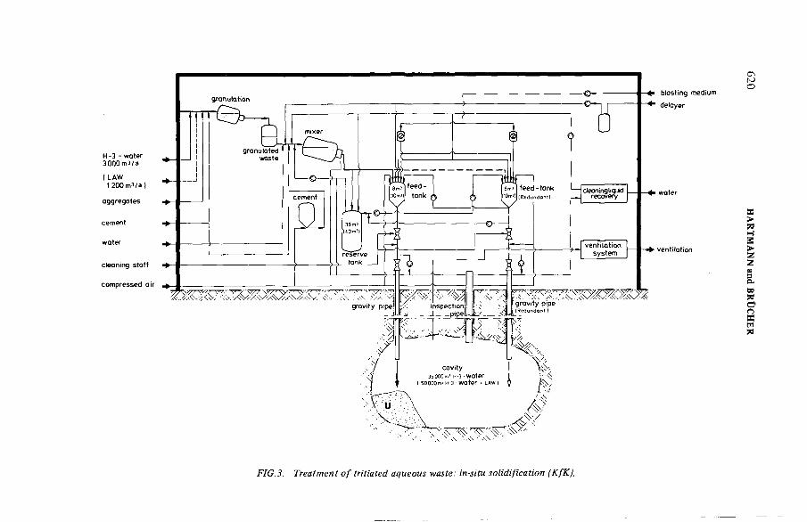
FIG.3. Treatment o f tritiated aqueous waste: in-situ solidification (KfK).
620 H
AR
TM
AN
N
and B
RÜ
CH
ER

IAEA-SM-245/6 621
contamination, ten 200-ltr drums at a time are loaded into a freight container of the Federal Railways and stored at the intermediate storage zone for not more than12 months. The storage facility has a capacity of at least 2250 containers.
This method enables clearance of the storage facility via two loading ramps within 6 days, and transport of containers (five containers per goods wagon and a total of 12 goods trains of 40 wagons each) from the waste disposal centre to the transatlantic harbour. The loading speed in Federal German ports is specified as 1000 t per shift (1 shift = 8 h), so that a 12 000-t ship can be loaded within 1 week.
Sea transport to the dumping site and back is estimated to take 15 to 20 days, depending on weather conditions, for it must be borne in mind that unloading is only possible in late spring or summer when the sea is calm, and that a barge carrier has a maximum speed of only 10 km/h in rough sea conditions (wind speed >5) as compared to 15 km/h in calm weather.
The charter costs for a transport vessel of this size range between US $ 11 000 to 17 000. This sum comprises rental costs, bunker fuel costs, port charges and loading costs, including quayage.
This procedure does not require any intermediate storage at the harbour. The containers are re-used, and a smooth and rapid loading and unloading of the goods wagons is ensured. The tritium content of one 200-ltr drum is approximately 16 Ci.
According to the international Convention on the Prevention of Marine Pollution by Dumping of Wastes and other Matter (London Convention, 1972), the discharge and dumping of matter in the deep sea is only permitted if such matter cannot be disposed of on land without impairing the welfare of the general public, or if such disposal would involve a disproportionately high expenditure.
This means that the alternative of dumping solidified tritiated waste water in the deep sea cannot be applied unless proof has been furnished to the effect that the waste disposal alternatives of in-situ solidification and engineered storage above ground are not practicable, from either a technical, an economical, an ecological or a radiological point of view.
2.3. In-situ solidification
The proposal on in-situ solidification of tritiated waste water had as its origin a study made by the Karlsruhe Nuclear Research Centre on the storage and solidification of low- and medium-active waste in underground cavities. The reference system A [4], dates from the year 1978. In contrast, the plant scheme represented in Fig. 3 provides for the production of granulated material with tritiated water only, i.e. without Low Active Waste (LAW).
Filling of the voids, on the other hand, is effected with tritium-free cement slurry to create an additional barrier against tritium leaching. The granulated waste material in the mixer is processed to free-flowing concrete with the tritium-free water-cement suspension and charged into the cavern via a gravity pipe.
6 2 2 HARTMANN and BRÜCHER
This seems to be the best way of securing the formation of a monolithic ultimate storage block. A total of 3000 m3 tritiated waste water per year can be processed to obtain a pourable granulated product, using hydraulic binders.
For a water/cement value of 0.5 and a cement slurry density of 2.3 g/cm3, a volume of about 4500 m3/a is calculated for the tritiated cement slurry. Compared to suspension storage, the storage of granulated material requires a 40% larger cavity volume due to the filling of fraction voids.
The cavern is only 90% filled so that a volume of 7000 m3 is required for the storage of an annual charge of 3H-containing waste water, resulting in a total volume of 105 000 m3 for a 15-year operating period of the reprocessing plant. In the Asse salt dome, only chambers of an order of magnitude between 30 000 and 50 000 m3 have so far proved to be stable over several decades, although they exhibit less favourable geometry conditions with regard to rock mechanics than the caverns.For this reason, a cavern size of 35 000 m3 is being proposed, corresponding to a 5-year capacity.
Practical experience with this storage technique has not yet been accumulated in the FRG. The only technique known to date is the experimental storage of drums containing low- and medium-active wastes in underground cavities of the Asse salt mine.
2.4. Storage above ground
Container storage above ground only appears viable if the 3000 m3 tritiated waste water can again be reduced by a factor of 1000.
The enrichment processes considered to be best suited for commercial operation [5] are:
(a) fractionated water distillation(b) hydrogen distillation(c) chemical H2/H2О exchange(d) electrolysis of tritiated water.
Water distillation has the disadvantage of requiring a very large plant, bearing in mind the high degree of enrichment called for.
In the three remaining isotope separation processes hydrogen is produced, wich requires specific safeguards in the event of the tritium upgrading system being built on the site of the reprocessing plant.
Electrolysis of the water requires, moreover, a large amount of energy, and experience with high throughput rates has so far only been made in the field of water distillation.
The solidification process proposed involves the incorporation of the 3H-gas into metals in the form of metal hydrides, e.g. ZrH2, TiH2 or YH2 [6].

IAEA-SM-245/6 6 2 3
TABLE II. ESTIMATED COST OF 3H-WATER TREATMENT SCHEMES BASED ON 3000 m3/a
3H-water treatm ent schemes
Deep-seadisposal
In-situsolidification
Engineeredstorage
Capital charges 11% 45% 38%
Running costs 5% 35% 51%
Service and repairing costs 12% 20% 13%
Packaging costs
T ransport costs (500 km )
60% — —
Train (car) 7% (11%) - -
Sea 5% - -
T otal annual (US $ 10 6/a) 6 4 .5a 7 b
cost (1 0 0 % ) (US $/m 3) 1800 1450 2250
a The value includes only the cost o f excavating the storage cavern, w ithou t shafts and underground tunnels.
b The estim ate is based on values which were determ ined for 3H-enrichm ent techniques in 1978 in the United Kingdom [7]. The figure represents the costs when applying the m ost econom ical enrichm ent technique (cryogenic hydrogen distillation). Using electrolysis the to ta l cost would be in the range of US $5000/m 3. Zirconium m etal was chosen as the solidification m aterial. A dditional costs fo r above ground storage, e g. safeguarding and decommissioning, are n o t included in this am ount.
About 15 t of Zr metal, or 2.35 m3 (Pzr= 6-52 g/cm3), are required to completely bind the entire hydrogen gas as ZrH2, which is contained in the waste water volume reduced to 3 m3 НТО/a. This method of incorporating the tritium in a metal lattice is presently regarded as being the safest procedure. The leaching rates are 4—5 orders of magnitude below those measured for cement at STP.
Owing to the high specific 3H-activity of more than 210 Ci/ltrzr, a Type В package is prescribed for any transportation of 3H-containing metal hydride pieces (plates or cylinders) on public traffic ways. Engineered storage above ground has the advantage of potential retrievability, which would permit recovery of the tritium still available at a later date for future technical application; this may be done by heating the metal hydrides and, thus, redissolving the tritium gas from the metal lattice.

6 2 4 HARTMANN and BRÜCHER
3. COST ESTIMATES
The specific cost estimates for disposal of one volume unit of tritium waste water from a reprocessing plant were performed on the basis of 3000 m3/a with a specific 3H-activity of 166 mCi/ltr.
Table II gives a survey of the different cost fractions involved in the alternatives presented here.
4. STATUTORY LICENSING ASPECTS
4.1. Deep-sea disposal
Deep-sea dumping of solidified radioactive wastes is possible according to the present position and providing certain national and international legal provisions1 are adhered to.
The most important provisions applicable to the transport and dumping of tritium adsorbed on a solid carrier (cement) may be summarized as follows:
(a) The maximum amount of tritium must not exceed 1000 Ci (Type A Package) and 50 000 Ci (Type В Package).
(b) The specific gravity of the package must be more than 1.2 t/m3 to ensure that it sinks to the bottom.
(c) The package should be strong enough to withstand damage during transport, handling and descent to the sea bed, and to remain intact upon impact on the sea floor and for a period of time thereafter.
(d) The activity concentration of the solidified tritiated waste water to be dumped must not exceed:
1 Convention on the Prevention of Marine Pollution by Dumping of Wastes and other M atter (draw n up at th e Intergovernm ental Conference on the Dumping of Wastes a t Sea, London, 1972). Revised NEA guidelines for sea dumping packages o f radioactive waste, OECD/NEA,Paris 1978. Vorschriften für die Befôrderung gefàhrlicher G üter mit der Eisenbahn [Anlage С zur Eisenbahn-Verkehrsverordnung (EVO)] vom 1. April 1967. Die Internationale Ordnung für die Befôrderung gefàhrlicher G üter m it der Eisenbahn [Anlage I (R ID ) zum Internationalen Über- einkom m en über den E isenbahnfrachtverkehr (CIM)] vom 1. April 1967. Verordnung über die Befôrderung gefàhrlicher G üter auf der Strasse vom 10. Mai 1973. Das Europâische Überein- kom m en vom 30. Septem ber 1957 über die Internationale Befôrderung gefàhrlicher G üter auf der Strasse (ARD). Die Verordnung über gefâhrliche Seefrachtgüter vom 4. Januar 1960 in der Fassungvom 29. Màrz 1972. § 8—10 der Verordnung über den Schütz vor Schàden durch ionisierende Strahlen (Strahlenschutzverordnung) vom 13. O ktober 1976. § 4 des Gesetzes über die friedliche Verwendung der Kernenergie und den Schütz gegen ihre Gefahren (Atom gesetz) vom 31. O ktober 1976.

IAEA-SM-245/6 6 2 5
(i) 106 C i3H/t,(ii) 103 Ci |3/7-activity (except 3H), but with a limitation for 90Sr and
137Cs to a maximum of 102 Ci/t, and(iii) 10 Ci a-activity/t for isotopes with a half-life of more than 50 years.
(e) The maximum amount of waste dumped at any one site is limited to100 000 t per year (i.e. a maximum of 10n Ci 3H/a).
(f) The dumping site under consideration must be more than 4000 m deepand sufficiently far away from the continental shelf. It must be ensuredfurthermore that this area is free from fishing and spawning grounds and undersea cables currently in use. Areas where it is known that sea bed resources will be developed shall be avoided.
At present, the Federal Republic of Germany is not able to participate in dumping actions because the revised NEA guidelines for sea dumping of packages have not yet been ratified.
Licences for the transport o f radioactive substances as well as for dumping must be granted by the com petent federal or state authorities.
4.2. In-situ solidification
An essential prerequisite for the adequacy of this method of underground solidification and ultimate storage of 3H-containing waste water is an appropriate insulation of the cavity with watertight layers against ground-water flows, so that tritium leaching can be avoided. Moreover, this process requires a cavity ventilation system above ground for the time from filling to sealing of the gravity pipe; this system must ensure that the tritium (HT, НТО) produced by radiolysis and set free during curing of the cement does not entail an unreasonably high exposure of the operating personnel and the environment.
Within the scope of the project ‘Storage and Solidification of MAW/LAW in Underground Cavities’ implemented by the Karlsruhe Nuclear Research Centre, a cavern in the Asse salt dome was opened up and explored for the construction of a prototype plant. The second project phase is scheduled to last until the end of 1980 and it is expected to furnish definite statements on the technical feasibility of the project.
4.3. Storage above ground
The granting of a licence for tritium disposal depends chiefly on the following items:
(a) Safe handling of the highly-enriched tritiated hydrogen gas.
(b) Development of fixation and canning materials which, in conjunction with the off-gas purification system of the tritium storage facility, will

6 2 6 HARTMANN and BRÜCHER
ensure a minimum tritium release even beyond the 15 to 20-year period of filling the engineered storage facility.
(c) The possibility of safeguarding the storage facility against impact from outside, if need be for a period of about 100 years in the event of the option of tritium recovery not being pursued.
5. CONCLUSIONS
From the economical aspect, none of the three tritium disposal alternatives described seems to offer any significant advantage. From the technical point of view, however, the method of deep-sea disposal seems to pose no problems; the same may be valid for the concept of in-situ solidification, but this has to be further investigated and demonstrated. On the other hand, storage above ground still requires a relatively high research and development expenditure until proof is furnished of the technical feasibility of tritium enrichment and fixation in the form of metal hydrides (handling of highly enriched 3H-containing hydrogen gases).
In the final analysis, the ecological and radiological implications, both on a local and global basis, as well as the safety-related aspects, are likely to be decisive for the selection of one of the three alternatives.
REFERENCES
[ 1 ] DEUTSCHE GESELLSCHAFT ZUR W IEDERAUFARBEITUNG VON KERNBRENN- STOFFEN, Bericht über das in der Bundesrepublik Deutschland geplante Entsorgungs- zentrum fü r ausgediente Brennelem ente aus K ernkraftw erken, Deutsche Gesellschaft für W iederaufarbeitung von K ernbrennstoffen mbH, Hanover (1977).
[2] ROBERTSON, J.B., JACOB, М., SCHOEN, R., The Influence of Liquid Waste Disposal on the G eochem istry o f W ater a t the National R eactor Test Station, Idaho, USAEC Idaho O perations Office, Rep. IDO 22053. Waste Disposal and Processing, .USAEC Technical Inform ation Center, Oak Ridge, TN, Rep. TID 4500 (1974).
[3] SPITSYN, V.I., PIMENOV, M.K., YUDIN, F.R ., BALUKOVA, V.D., “ Scientific basing and prerequisites fo r utilizing deep-lying form ations fo r burying liquid radioactive wastes”, Disposal o f Radioactive Wastes in to the Ground (Proc. Symp. Vienna, 1967), IAEA,Vienna (1967) 563.
[4] KÔSTER, R., KRAMER, R., KROEBEL, R., Lagerung und Verfestigung von MAW/LAW in untertágigen Hohlráum en, KfK, Karlsruhe (1978).
[5] BURGER, L.L., TREVORROW , L.E., “ Release o f tritium from fuel and collection for storage”, ANS-AICHE Meeting on Controlling Airborne E ffluents from Fuel Cycle Plants,Sun Valley, Idaho, 5 - 6 Aug. 1976 (1977).
[6] COLOMBO, P., JOHNSON, R., Tritium Storage Developm ent Progress R eport No. 14, Brookhaven National L aboratory, Rep. BNL 50780 (O ct.—Dec. 1977).
[7] McKAY, H.A.C., “ Tritium im m obilisation”, European Applied Research R eport, Nucl.Sci. Technol. 1 3 (1979) 599.
IAEA-SM-24S/S0
STOCKAGE DANS DES CYLINDRES PRESSURISES DU KRYPTON ADSORBE SUR DU CHARBON ACTIF* Aspects fondamentaux
P.N. HENRION, J.F. DE GREEF,W. CLAES, A. LEURSCentre d’étude de l’énergie nucléaire,Mol,Belgique
Présenté par W.R.A. Goossens
Abstract-Résumé
STORAGE O F KRYPTON ADSORBED ON ACTIVATED CHARCOAL IN PRESSURIZED CYLINDERS - FUNDAM ENTAL ASPECTS.
At pressures o f a few kgf/cm 2 the adsorption rates for k ryp ton on activated charcoal are already considerable. This adsorbent can be used to advantage in the storage o f k ry p to n in pressurized cylinders and so could be a feature in the design of a controlled fission k ryp ton store. However, no im m ediate evaluation of th e concept can be m ade because fission kryp ton acts as a heat source, and its adsorption is b o th pressure- and tem perature-dependent. The aim of this study was, therefore, to exam ine the adsorption properties o f the activated charcoals available on the m arket and to estim ate the density and therm al conductivity o f fixed beds made from these m aterials. The heat transfer is estim ated by means of a simple m athem atical m odel. On th e basis o f values selected from the above data , practical exam ples were analysed and explicit relationships found betw een the wall tem perature, pressure and realistic k ryp ton loading values. The effect o f specific activity was also exam ined. The study showed th a t the diam eter o f the pressurized container is o f fundam ental im portance. The authors recom m end the use o f specially designed, light-weight and ra ther narrow cylinders. The affinity o f rubidium fo r charcoal was also dem onstrated experim entally. The fixation of a reasonable qu an tity of rubid ium on the activated charcoal does no t m odify its capacity to adsorb krypton.
STOCKAGE DANS DES CYLINDRES PRESSURISES DU KRYPTON ADSORBE SUR DU CHARBON ACTIF - ASPECTS FONDAMENTAUX.
Pour des pressions de quelques kgf/cm 2 l’adsorption du k ryp ton sur le charbon actif est déjà considérable. La présence de cet adsorbant influence favorablem ent les aspects du stockage du kryp ton en cylindres pressurisés de sorte que l’o n peu t songer à cette procédure dans la conception d ’un stockage contrôlé de k ryp ton de fission. L’évaluation précise du concept n ’est cependant pas im m édiate car le k ry p to n de fission fonctionne com m e source de chaleur en m êm e tem ps que son adsorption dépend à la fois de la tem pérature e t de la
* Travaux exécutés dans le cadre du program m e d’action indirecte (1 9 7 5 —1979) de la Com m unauté européenne de l’énergie atom ique: «Gestion et stockage des déchets radioactifs».
6 2 7
628 HENRION et al.
pression. Le bu t de cette étude était donc d ’exam iner les types de charbons actifs disponibles sur le m arché, pour leurs propriétés adsorbantes, et d ’estim er la densité ainsi que la conductivité therm ique de lits fixes form és à l ’aide de ces m atériaux. Le transfert de la chaleur est évalué sur la base d ’un m odèle m athém atique simple et, à l’aide de valeurs sélectionnées parmi les données m entionnées plus haut, des exemples pratiques on t été analysés conduisant à des relations explicites entre la tem pérature de paroi, la pression et des valeurs réalistes de charge en kryp ton . L’influence de l’activité spécifique a également été examinée. L’étude a révélé l ’im portance fondam entale du diam ètre du conteneur pressurisé. Les auteurs recom m andent l’em ploi de cylindres spécialem ent conçus, légers et relativem ent étroits. L’affinité du rubidium pour le charbon a été dém ontrée expérim entalem ent. La présence d ’une quantité réaliste de Rb fixée sur le charbon actif ne m odifie pas l ’adsorption du k ryp ton sur ce dernier.
1. INTRODUCTION
Le krypton 85 apparaissant comme produit de la fission nucléaire est couramment rejeté dans l'atmosphère. Toutefois, dans le cadre d'une industrie nucléaire en extension l'idée de séparer le krypton et de le conserver aussi longtemps que se poursuit sa décroissance s'est maintenant imposée. Le but est non seulement de prévenir la montée progressive du niveau d'activité ambiante, mais surtout d'éviter les dépassements locaux des niveaux limites de radiation dans les zones où l'activité nucléaire est concentrée.
Diverses méthodes de séparation ont été étudiées et ont fait l'objet de rapports circonstanciés [l]. La séparation quantitative du krypton de fission, enrichi vers 5 % en isotope 85 et pratiquement exempt d'autres espèces gazeuses (Xe, O 2 ,N 2 , ...) semble un fait technique établi. La présente étude qui
se propose d'examiner exclusivement le stockage du krypton peut donc, avec réalisme, admettre une relative pureté du krypton
parmi ses hypothèses de départ. Des quantités modérées d'impuretés sont cependant compatibles avec le procédé décrit.
Trois techniques principales de stockage ont été considérées, notamment : l'enrobage en zéolithes, l'inclusion par ion sputtering du krypton dans une matrice métallique (U.K.) et la conservation en cylindres sous pression (Allemagne et U.S.A.). Cette dernière méthode possède l'attrait de la simplicité. Elle ne fait appel à aucun raffinement technique. Le cas échéant, la matière conservée peut être transférée ou récupérée. Un sérieux inconvénient l'entache toutefois. Suite au transfert limité de la chaleur à la paroi, la température du gaz s'élève et une pression élevée en résulte que seule une recherche assez laborieuse permet de préciser. La haute pression limite la concentration en krypton et conditionne directement le taux de fuite.De plus, la permanence du refroidissement doit être garantie.La prise en considération de ces dangers potentiels conduit à

IAEA-SM-245/50 6 2 9
u n e i n s t a l l a t i o n de s t o c k a g e c o n t r ô l é d e c o n c e p t i o n t r è s é l a b o
r é e et, p a r c o n s é q u e n t , c o û t e u s e [ 2 ] [ з ] . Il n e f a u t , à n o t r e
a v i s , p a s c h e r c h e r a i l l e u r s l a r a i s o n d e l ' i n t é r ê t q u i a é t é
t é m o i g n é a u x a l t e r n a t i v e s .
Les propriétés adsorbantes du charbon actif ont été très tôt considérées dans les problèmes de séparation de déchets nucléaires gazeux mais, en dehors de la purification des effluents gazeux des réacteurs, la méthode cryogénique a pris le pas sur l'adsorption. Jusqu'en 1976 il ne semble pas que l'on ait songé au charbon actif pour résoudre le problème du stockage du krypton. Suite à une affinité prononcée, l'introduction de charbon actif dans un cylindre abaisse la pression du krypton.E n o u t r e , l a p h a s e s o l i d e r e l è v e n o t a b l e m e n t l a c o n d u c t i v i t é
t h e r m i q u e d e l ' e n s e m b l e f a v o r i s a n t a i n s i la d i s s i p a t i o n d e la
c h a l e u r e t le m a i n t i e n d e t e m p é r a t u r e s m o d é r é e s .
Dans la présente étude ces paramètres ont été mesurés. Ensuite, à l'aide d'un modèle conçu pour évaluer la dissipation de la chaleur dans le système cylindre - krypton - adsorbant les conditions à réunir en vue de la conception d'un stockage ont été déterminées. En pratique, plusieurs types de charbons actifs commercialisés se sont révélés aptes à satisfaire ces conditions. Le modèle confirme encore ce que l'on pouvait intuitivement apprécier, à savoir la grande importance du rayon du cylindre en
tant que paramètre.
L a p r o c é d u r e o f f r e é g a l e m e n t u n e s o l u t i o n é l é g a n t e a u t r a n s
f e r t d u k r y p t o n v e r s le c y l i n d r e .
F i n a l e m e n t , le r u b i d i u m , q u e l ' o n c r a i n t p o u r s o n a c t i o n
c o r r o s i v e é v e n t u e l l e , e s t i r r é v e r s i b l e m e n t c a p t é p a r le c h a r b o n
a c t i f a u x p l u s b a s s e s p r e s s i o n s p a r t i e l l e s .
2. MODELE POUR EVALUER LA DISSIPATION DE LA CHALEUR PRODUITE DANS UN LIT CYLINDRIQUE DE CHARBON ACTIF PAR UNE CHARGE DE KRYPTON DE FISSION
Le calcul suivant est destiné à évaluer l'équilibre thermique qui s'établit dans un lit cylindrique de charbon actif contenant du krypton de fission. Cette information associée à laloi d'adsorption propre au charbon considéré (Chap. 3) permet le calcul de la charge en krypton compatible avec les données du problème. Le lit adsorbant est constitué de granules et de poudre, consolidés, et occupant au moins 75 % du volume (quand les grains eux-mêmes sont considérés comme non poreux). Dans ces conditions la convection gazeuse est considérablement amoindrie et seule la conductivité thermique a été prise en considération dans le transfert de chaleur. Nous avons également admis l'absence de gradient interfacial de température à l'interface lit-paroi métallique.

6 3 0 HENRION et al.
L'enrichissement voisin de 6 % en isotope 85 a été admis pour la charge en krypton [l]. Pour fixer les idées, une concentration de 100 g*ltr - 1 correspond à 2360 Ci ou 3,82 W par litre de lit. (La demi-vie de 8 Kr est 10,73 années). La puissance dégagée par gramme de krypton en début de stockage est0,038 W . A partir de cette valeur maximum le dégagement d'énergie s'atténue rapidement.
A l'inverse de la pression la température n'est pas homogène dans le lit. Elle décroît vers la périphérie et le krypton plus fortement adsorbe à basse température tend à s'accumuler dans cette zone. Toute estimation de dissipation de chaleur dans un tel système requiert donc au préalable la détermination de la loi d 1adsorption 0 (P, T) du krypton. Si, à saturation, la masse W s de krypton peut être emmagasinée dans l'espace microporeux d'un gramme de charbon actif, nous désignerons par 0 la fraction de W s adsorbée sur le charbon à la température T(K) en équilibre avec le krypton gazeux à la pression P.
La chaleur produite, et donc dégagée, par seconde dans un élément de cylindre d'épaisseur dr et de hauteur h est
dq = p 2 - n t L h . d / L 84 г P 10k e (t, p) x- 3
(7!
expression dans laquelle le premier terme représente la chaleur libérée par le krypton adsorbe et le second la chaleur dégagée par le krypton gazeux dans le volume interstitiel 2 n A h . d/l e- k est la quantité (constante pour un lit donné) de charbon
actif par c m 3 de conteneur
- £ est le coefficient de porosité du lit actif
- 84 est le poids atomique et R est la constante des gaz en litre-atmosphère
- p est la puissance dégagée par un gramme de krypton
- pour 0, nous avons montré l'applicabilité de la relation de Dubinin [4][5j et précisé son domaine d'utilisation :
= e
RT „ vi Т Ы Т = z
2,303 RT 4t 104 - log ?(2 )
Ps est la pression de saturation, à la température T, du krypton à l'état condensé. (Si T > Tc cet état condensé est un état hypothétique) et E est une énergie libre caractéristique de la paire adsorbant-adsorbat.
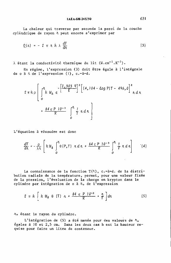
IAEA-SM-24S/S0 631
La chaleur qui traverse par seconde la paroi de la couche cylindrique de rayon fi peut encore s'exprimer par
QJ/t) = - 2 fi h \ ^ (:
X étant la conductivité thermique du lit (W.cm :.K 1).
En régime, l'expression (3) doit être égale à l'intégrale de о à 4 de l'expression (1), c.-à-d.
2 ïï h p k W¿ e.2,303 R
E [4,104 - I o q ? )T - 496,0- ftdft
84 e P 10~ 3 ffl
L'équation à résoudre est donc
dTЖ
_P_\fi
3*
1
f \ ( P , T ) f t d f t ^ 4 ^ 10"' K j
tj* к d. к
? C
■(4 )
La connaissance de la fonction TOt), c.-à-d. de la distribution radiale de la température, permet, pour une valeur fixée de la pression, l'évaluation de la charge en krypton dans le cylindre par intégration de о à 4 0 de l'expression
k lil¿ 6 (T) fi + 84 e P 10~3 fiT dfi (5)
ft о étant le rayon du cylindre.L'intégration de (5) a été menée pour des valeurs de ft0
égales à 10 et 2,5 cm. Dans les deux cas h est la hauteur requise pour faire un litre de conteneur.

6 3 2 HENRION et al.
TABLEAU I. DENSITE AU MERCURE (densité apparente) DES CHARBONS ACTIFS EXAMINES
TYPE DENSITE g/cm3 ASPECT
NORITR 3020 0,80 cylindres extrudés é 3-4 mmRBL 4 0,65 cylindres extrudés ф = 4 mmELORIT 0,58 poudre grossière
JOHNSON-MATTHEYRR 213 0,81 cylindres extrudés é ^ 3 mm
CHEMVIRONPCN 8 x 1 6 0,97 grains millimétriques
3. EXPRESSION DE L'ADSORPTION DU KRYPTON EN FONCTION DE P ET T
3.1. L'équation de Dubinin
Le renseignement recherché au sujet d'un charbon actif est la loi de variation de la quantité de krypton adsorbée avec la température et la pression. La mesure directe effectuée dans les domaines appropriés de P et T est toutefois limitée car, à pression élevée, ces mesures réclament des appareillages très spéciaux [б][7].
Cependant, à partir de nos résultats expérimentaux d'adsorption de krypton entre 0 et 900 mm Hg (de -10 à 52 °C) les paramètres a0 et E de l'équation empirique de Dubinin peuvent être évalués à l'aide de sa transformée
¿OQ a = log a.o - 0,434 '2,303 R T' P aIlog -f {6)
Selon Dubinin, a0 varie peu avec la température et E serait sensiblement constant. Mais aux températures qui nous intéressent, bien supérieures à la température critique, nos résultats expérimentaux, ainsi que des calculs exposés antérieurement, montrent que ces paramètres varient avec T et qu'un choix plus ou moins arbitraire de a0 et E doit être effectué en vue de conduire les calculs dictés par le modèle [8].
Dans le domaine de température le plus intéressant pour
nous, c.-à-d. de 20 à 60 °C, les calculs peuvent être menés

IAEA-SM-245/50 6 3 3
avec une précision suffisante en adoptant pour a0 et E les valeurs suivantes :
a0 ( m g K r g - 1 ch.) E (Joules)
RBL 3 (RBL 4) 650 10 680PCN 8 x 16 600 10 680Carbosieve B 840 11 310Les autres charbons ont été écartés.
En réalité, les extrapolations menées sur les droites en provenance de l'équation (6) sont moins osées qu'il n'y paraît car, nous le verrons plus loin, le domaine de P et T réellement utile dans le confinement du krypton est limité à des pressions de quelques atmosphères et des températures dépassant â peine 100 °C.
4. CARACTERISATION DE CHARBONS ACTIFS
4.1. Méso- et Macropores
A côté de leurs micropores les charbons actifs développent encore un réseau de macropores dont l'abondance diffère largement d'un type à l'autre. Ce réseau de transport est particulièrement utile car, dans la plupart des applications le charbon actif est le siège d'échanges dynamiques avec une phase gazeuse. A l'opposé, l'application que nous envisageons est de nature statique. Le temps requis pour qu'un lit de charbon absorbe une charge déterminée de krypton actif est sans importance pour autant qu'il reste pratique. L'adsorption de krypton dans les méso- et macropores est entièrement négligeable aux températures usuelles. En outre, leur présence en grands nombres, abaissant notablement la densité des granules de charbon peut effectivement réduire la capacité du lit en micropores, donc en krypton. L'extension du réseau des macropores dans les divers charbons a été déterminée par porosimétrie à mercure et par des mesures de densité à mercure. Ces informations sont essentielles pour la sélection de nos adsorbants. Les valeurs du Tableau I donnent une idée des variations de densité rencontrées.
4.2. Formation de lits denses d 1adsorbant
En vue de conférer au cylindre de stockage une capacité élevée en krypton et une conductivité thermique favorable il est important de former le charbon actif en lits aussi denses que possible. Après des essais dans diverses directions nous avons adopté une méthode de compaction par vibration de granulométries différentes basée sur les travaux de Mc Geary [9]. Les détails peuvent être trouvés dans le rapport clôturant cette recherche [5]. Quelques exemples sélectionnés constituent le Tableau II.

TABLEAU II. PROPRIETES DES CHARGES DE LIT
COMPOSITION DU LITDENSITE EN CHARBON
ACTIF g/ltrCAPACITE LIMITE
g PAR LITREENDE
KRYPTONLIT
RBL 4 cylindres extrudes 435 304
Réseau RBL 4 + RBL 4 broyé 75< <178 (24,2 wt.%) 549 357
PCN 8 x 16 > 1,7 mm 545 327
Réseau PCN 8 x 16 > 1,7 mm +RBL 4 broyé 75< <178 pm (15 wt. %) 621 377
Réseau PCN 8 x 16 > 1,7 mm +PCN 8 x 1 6 broyé 178< <300 pm (28 wt. %) 747 448
634 H
ENRIO
N
et al.
IAEA-SM-24S/S0 6 3 5
Les charbons actifs commercialisés étant de types très différents et les modèles théoriques décrivant la conductivité thermique de matériaux fragmentés étant soit approximatifs soit difficiles à appliquer, nous avons été conduits à mesurer directement cette propriété sur les charbons [lO][ll]. L'appareillage a été décrit en [5].
Les résultats sont présentés au tableau III. Ils ont été obtenus à partir de lits à distribution granulométrique simple ou bimodale de charbon actif. Des gains de performance ont également été recherchés par l'emploi, pour la phase fine ou interstitielle, de graphite.
Conformément à l'expectative, les lits les plus denses se révèlent aussi dans l'ensemble les plus conducteurs. Du point de vue restreint de la conductivité thermique, les combinaisons les plus heureuses paraissent être celles d'un réseau PCN 8 x 1 6 avec PCN broyé, ou encore d'un réseau RBL 4 ou PCN avec des paillettes de graphite S1425.
Toutefois, le graphite n'étant pas adsorbant,son emploi est pénalisé par une perte de capacité en krypton (celle-ci se réduit pour le cas "a" du tableau III de 448 g par litre à 313 g pour le cas "d"). Ces tendances concurrentes peuvent être départagées grâce au modèle de calcul (voir chap. 5).
Ces valeurs sont considérablement plus élevées que celles correspondant à la seule conductivité thermique de la phase gazeuse (y 2.10-1* W.cm- 1 .K-1). Cependant le gaz joue un rôle essentiel dans le transfert de chaleur qui s'opère dans la proximité immédiate des points de contact entre particules solides. Pour cette raison, le remplacement de l'azote par une phase krypton réduit les valeurs de conductivité d'un tiers environ (comparer les lignes e et d ) .
4.3. Conductivité thermique des lits adsorbants
4.4. Remarque concernant l'humidité dans le lit adsorbant
La conductivité thermique du lit n'est pas modifiée de façon appréciable par la présence de 3 % en poids d'humidité dans le charbon actif. Toutefois, l'eau est à éliminercar, préférentiellement adsorbée, elle se substituera au krypton sur les sites d'adsorption les plus actifs. L'opération même de vibration de la phase fine en position interstitielle doit être
menée avec des poudres très sèches sous peine de voir les particules s'agglomérer et leur infiltration ralentie ou bloquée.

TABLEAU III. CONDUCTIVITE THERMIQUE DE LITS DE CHARBON
COMPOSITION DU LITDENSITE EN CHARBON
ACTIF g/ltrCONDUCTIVITE THERMIQUE
W .cm- 1.K- 1 x ÎO1*
a . Réseau PCN 8 x 16 > 1,7 mm +PCN broyé 178< <297 ym (28 wt.%) 747 46
b. Réseau RBL 4 + graphite S 1425 (199,1 g-ltr-1) tout venant 410 57
c. Réseau RBL 4 + graphite S 1425 (218,6 g-ltr-1) 75< <178 pm 412 62,5
d. Réseau PCN 8 x 16 > 1,7 mm +
graphite S 1425 75< <178 pm (240,3 g-ltr"1) 521 59
e. idem à d mais sous atm. de krypton 521 37

IAEA-SM-245/S0 6 3 7
5. APPLICATIONS. EXEMPLES DE RELATIONS ENTRE LA CHARGE ENKRYPTON, LA PRESSION ET LA TEMPERATURE DE PAROI D'UN CYLINDRE DE STOCKAGE
Alimenté par les données de conductivité thermique (chap. 4)et de capacité en krypton (chap. 3 et 4), le modèle de calcul(chap. 2) permet la construction d'abaques illustrant la relation entre la pression dans un cylindre, sa charge utile en kryptonet la température à laquelle est maintenue sa paroi (fig. 1).
Pour concrétiser l'étude qui précède nous avons retenu comme adsorbant type le charbon actif Chemviron PCN 8 x 16. A une valeur convenable de E(10680 J) , s'ajoute, рал lÁJjiZ. di ZáX, un volume microporeux considérable. L'obtention commerciale est sans problème et la combinaison des granulés PCN avec des fractions interstitielles bien choisies conduit à des valeurs relativement élevées de la conductivité thermique (Tableau III).Le lit-type, étudié en détail, est donc défini comme suit :
PCN 8 x 16 0,52 g/cm3 de lit (symbole k dans les expressions(1)(4) et (5) au chap. 2)
+ graphite S 1425 interstitiel suivant les indications dutableau III
capacité moyenne en krypton a 0 = 0,6 g Kr.g-1 PCN
coefficient de porosité e = 0,4
conductivité en atmosphère de krypton X = 37 x 10-1* W.cm-1.K-1.
Deux diamètres (20 et 5 cm) de conteneurs cylindriques ont été considérés.
Enfin, en prévision de répercussions éventuelles sur les aspects pratiques du stockage, l'influence de la puissance spécifique de la charge a également été examinée.
5.1. Conditions Initiales
Une puissance thermique de 0,042 W par gramme de krypton a été considérée. Elle correspond à l'intensité maximum de rayonnement compatible avec les hypothèses du chap. 2 et effective au moment initial du stockage seulement.
$Les calculs et abaques présentés dans les rapports d'avancement étaient basés sur la valeur 0, 042 W au lieu de 0t058 W. Ces calculs sont reproduits dans le présent rapport et, pour la comparaison après une période de décroissance équivalant à une demi-vie, la valeur 0,021 W a été utilisée.
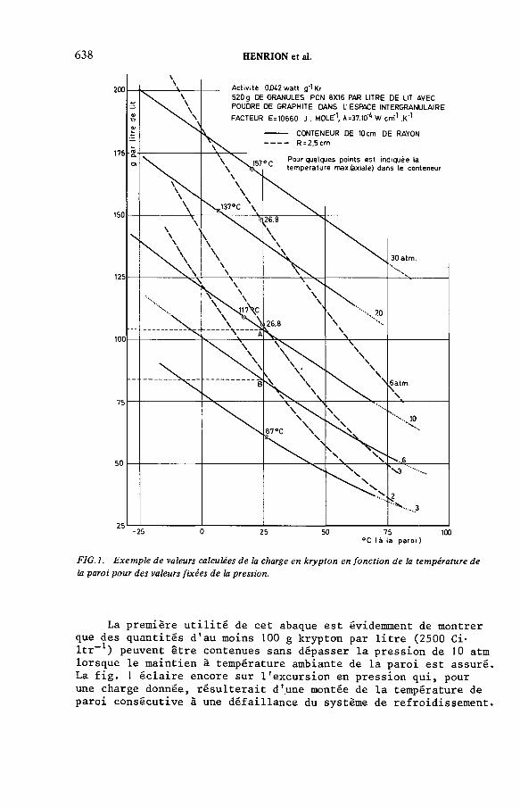
6 3 8 HENRION et al.
F IG .l. E xem ple de valeurs calculées de la charge en kryp ton en fo n ctio n de la tem pérature de la paroi pour des valeurs fixées de la pression.
La première utilité de cet abaque est évidemment de montrer que des quantités d'au moins 100 g krypton par litre (2500 Ci- ltr-1) peuvent être contenues sans dépasser la pression de 10 atm lorsque le maintien à température ambiante de la paroi est assuré La fig. 1 éclaire encore sur l'excursion en pression qui, pour une charge donnée, résulterait d'une montée de la température de paroi consécutive à une défaillance du système de refroidissement
IAEA-SM-24S/50 6 3 9
A cet égard, l'avantage du cylindre de diamètre réduit est évident. Sa capacité (g krypton-ltr-1) est également bien plus grande. Les écarts entre les températures de paroi et les températures axiales ne sont que de quelques degrés.
Il n'est point non plus besoin de concevoir ce récipient comme une "bombe" dotée d'une épaisse paroi d'acier. Pour s'en convaincre il suffit de considérer les valeurs suivantes (en kgf- cm-2) des pressions maximales adxriLbb-LblzA dans un cylindre métallique de 50 mm de diamètre utile.
Epaisseur de paroi (mm) 1 2
Cuivre 14 28
Inox 304 L 38 74
Notons que les pressions de rupture des tubes sont encore au moins trois fois plus élevées.
En troisième lieu la fig. 1 révèle la facilité avec laquelle une charge de krypton peut être transférée à un cylindre donné. Une compression de quelques atmosphères couplée à une réfrigération très modérée suffit à assurer le remplissage. De plus, les conditions (T et P) de remplissage déterminent la grandeur de la charge et dispensent d'installer un système séparé d'évaluation de celle-ci.
A la fig. 2 sont comparés deux lits de charbon actif PCN 8 x 16. Le premier correspond à la description donnée ci-dessus. Le second s'en différencie par la phase intergranulaire, absorbante, et constituée par la fraction 178 - 300 pm de granulés PCN 8 x 16 broyés.
La capacité en krypton est accrue car k atteint 0,740 g/cm3. Par contre, le remplacement du graphite entraîne une perte de conductivité (de 37.10— 4 à 28.10-1* W.cm- 1 . K-1) en présence de
krypton.
Avec les présentes données le lit à plus haute teneur en adsorbant présente la capacité la plus élevée vis-à-vis du krypton pour des valeurs fixées de la pression et de la température de paroi. Toutefois, dans ce lit la température axiale est plus élevée. On le voit, la réponse technologique au problème de capacité d'un lit de stockage n'est pas nécessairement unique et le modèle révèle toute son utilité en départageant des alternatives peu parlantes intuitivement.
La comparaison est complétée dans la fig. 3 qui rassemble les répartitions radiales de température et de charge en krypton pour les deux cas. Elle montre clairement le désavantage inhérent aux cylindres de dimension standard. Suite à la température élevée de la zone centrale, la moitié intérieure du volume du lit (R = 7 cm) est peu efficace ; elle ne recèle que 32 % du krypton.

6 4 0 HENRION et al.
. (g ranu lés* poudre) PCN 8X16 740 g. Г
A = 28.10 4 'W. cm"' . K"1
°C (à la paroi )
F IG .2. Variation de la charge en kryp ton avec la nature du lit adsorbant.
Ces performances (fig. 1), déjà très intéressantes, sont encore susceptibles d'amélioration. De nouveaux types de charbons actifs, tels que Carbosieve (Supelco) obtenu par décomposition de polymères, et les tout récents charbons superactivés de Amoco Research Corporation, Chicago, doués de propriétés adsor- bantes exceptionnellement favorables [l2], mériteraient d'être évalués, suivant la méthode décrite dans ce travail. Le coût de ces substances risque toutefois d'être élevé.
5.2. Evolution du système après 10,7 années de refroidissement
L'abaissement global de température survenu dans le cylindre ne peut qu'entraîner le décalage vers le haut des isobares de la fig. 1. Cette prévision se réalise pour les cylindres de grand diamètre (R = 10 cm). Ainsi aux charges de 103,5 g et 83 g de krypton, respectivement sous 10 et 6 atm (points A et B de la figure), correspondent encore approximativement 6 et 4 atm au

IA E A -S M -2 4 5 /5 0 641
------- Granulés PCN 8X16* PCN en poudre
FIG.3. E xem ples de distribution radiale de la tem pérature e t de la charge en kryp ton dans un cylindre de 10 cm de rayon (pression: 6 atm).
terme d'une demi-vie. Dans le cas des cylindres minces (R =2,5 cm), la dissipation de la chaleur est si efficace que la température interne s'élève à peine au-dessus de celle de la paroi. La décroissance se poursuit donc à pression quasi sta- tionnaire.
6. RETENTION DU RUBIDIUM SUR UN LIT DE CHARBON ACTIF
Au terme de la décroissance du krypton 85 la quantité de rubidium est de l'ordre de 10,6 mg par gramme de charbon (cette évaluation est basée sur un lit-type dans lequel 110 g de krypton enrichi à 5 % de 85Kr sont adsorbés sur 520 g de charbon actif). Cette quantité de Rb est très faible en regard de la quantité de krypton et en regard de la capacité moyenne du charbon actif pour ce gaz (600 mg*g-1). La probabilité d'une interférence du Rb avec 1'adsorption même du krypton se réduit encore quand on considère qu'à l'accroissement du Rb dans le temps correspond une baisse de température moyenne qui favorise 1'adsorption. Une revue récente des connaissances relatives à la corrosion des aciers par le rubidium ne comporte aucune donnée alarmante [l3] .

6 4 2 HENRION et al.
La plupart des atomes de Rb naissent directement dans les micropores. La surface, pourtant considérablement moindre, délimitant les méso- et les macropores est encore environ 106 fois plus étendue que l'aire de la paroi métallique du conteneur.Dans de telles conditions, à moins d'une affinité particulière du Rb pour le matériau de la paroi, la contamination (et donc le danger de corrosion) de la paroi est extrêmement faible.
Dans l'optique du stockage du krypton le charbon actif semble bien constituer le piège définitif du rubidium. Après adsorption sur du PCN 8 x 16 à 125 °C (sous 8.10-1* mm Hg) d'une quantité soigneusement prédéterminée de Rb, un chauffage progressif mené jusqu'à 400 °C n'a produit aucune désorption. Le danger d'interaction entre la paroi métallique et le rubidium issu de la décroissance du krypton adsorbé paraît donc inexistant.. De plus, l'adsorption subséquente de krypton ne s'est pas modifiée [5].
CONCLUSION
La présente étude montre qu'une variante à la fois très simple et peu coûteuse du confinement en cylindre pressurisé réunit les propriétés requises pour l'élaboration d'un stockage sûr.
Le coût du stockage du krypton, construction et fonctionnement, est tout entier dam l e yiivtau. de. complexJjté de. V i.vu ,ta l- hxtioYi résultant des exigences de sécurité. Dans ces conditions il nous semble avantageux de tourner résolument le dos aux cylindres haute pression standards et d'adopter l'emploi de cylindres à la fois légers et réduits en diamètre. Si en outre dans le lit adsorbant, on se contente d'une concentration modérée en krypton un stockage particulièrement favorable sous l'angle du coût de fonctionnement aurait de sérieuses chances de se matérialiser.
REFERENCES
[1] Pour une revue générale voir: «Alternatives fo r Managing Wastes from R eactors and Post-Fission Operations in the L.W.R. Fuel-Cycle», ERDA 76-43, chap. 13.1 à 11 (1976).
[2] LASER, М., «Separation storage and disposal o f 8SKr, Status and Project», Personal com m unication to the Technical Com m ittee on Removal, Storage and Disposal o f Gaseous Radionuclides from A irborne E ffluents (Rep. Techn. Com m ittee Meeting, Vienna, 1976), IAEA Technical D ocum ent 209 (1978).
[3] LASER, М., BEAUJEAN, H., BOHNENSTINGL, J., FILSS, P., HEIDENDAEL, М., MASTERA, St., MERZ, E., VYGEN, H., «Off-gas trea tm en t and kryp ton disposal in HTGR-fuel e lem ent reprocessing», Management o f Radioactive Wastes from Fuel Reprocessing (C.R. Coll. AIEA/AEN, Paris, 1972), OCDE/AEN, Paris (1973).
IA E A -S M -2 4 5 /5 0 6 4 3
[4] DUBININ, М., Progress in Surface and Membrane Science, Vol. 9, Academic Press (1975) 1 -7 0 .
[5] R apport EUR 6419 (Publication en cours).[6] OZAWA, S., KUSUMI, S., OGINO, Y., J. Colloid Interface Sci. 56 1 (1976) 83.[7] MENON, P.G., Chemical Rev. 6 8 (1 9 6 8 ) 277.[8] CENTRE D’ETUDES DE L’ENERGIE NUCLEAIRE/SCK, Mol (Belgique), R apport
R-2600.[9] McGEARY, R.K., J . Am. Ceram. Soc. 44 1 0 (1 9 6 1 ) 513.
[10] LUIKOV, A.V., SHASHKOV, A.G., VASILIEV, L.L., Int. J . Heat Mass Transfer 11 (1968) 117.
[11] SCHUMANN, T.E.W., VOSS, V., Fuel 13 8 (1 9 3 4 ) 249.[12] HARRISON, B.N., BARTON, S.S., DACEY, J.R ., SELLORS, J.R ., J. Colloid Interface
Sci. 71 2 (1 9 7 9 ) 3 6 7 -3 7 4 .[13] PENZHORN, R .D., A lternatiw erfahren zur Kr-85 Endlagerung, R apport KFK 2482,
(déc. 1977).
DISCUSSION
R.-D. PENZHORN: I think you are correct to expect less corrosion in cylinders containing charcoal, but this is due not so much to a lower free inventory of rubidium but rather to the considerably reduced tensile stress on the cylinder wall. After all, a few grams of rubidium are sufficient to cause corrosion. They may deposit on the inner wall of the cylinder even if most of the krypton is adsorbed. One must also bear in mind that adsorption is a reversible process.
We have been investigating the corrosion effect of rubidium on two types of stainless steel and one low alloy steel since 1977, from which we have discovered that deterioration in the mechanical properties, possibly because of embrittlement, cannot be ruled out if the specimen is subject to tensile stress.
W.R.A. GOOSSENS: I agree. A decrease in tensile stress is a major advantage with this technique.
R. BROWN: I would just like to point out that the nature of the geological storage medium will be a limiting factor in terms of the temperature rise. Klett of the Sandia Laboratory in the USA is publishing several reports in this connection. Also, both the capital and operating costs of engineered storage may be prohibitive. One further comment I would like to make is that the carbon adsorbent will not provide any additional container safety.
W.R.A. GOOSSENS: The authors implicitly assumed an engineered storage.I cannot comment on the cost as we have no figures for it.
I disagree with your final observation. Since the gas pressure is considerably reduced, the leak rate of gas cylinders containing active carbon is almost negligible.

6 4 4 HENRION et al.
H.A.C. McKAY (C h a irm a n ): I would like to see a direct comparison of krypton storage with and without charcoal in the cylinders. Optimized schemes should be considered in such a comparison, with, for example, the cylinders having different dimensions in the two cases.
W.R.A. GOOSSENS: This is a very interesting suggestion, which highlights the need for more conceptual work on the charcoal system.

IA E A -S M -2 4 5 /11
AIR-COOLED KRYPTON-85 STORAGE FACILITY WITH NATURAL CONVECTION
E. WARNECKEPhysikalisch-Technische Bundesanstalt,Braunschweig
S. AHNERNuklear-Chemie und -Metallurgie GmbH (NUKEM),Hanau,Federal Republic of Germany
Abstract
AIR-COOLED KRYPTON-85 STORAGE FACILITY WITH NATURAL CONVECTION.In the Federal R epublic o f G erm any’s ‘Entsorgungskonzept’ k ryp ton has to be separated
from the dissolver off-gas in the reprocessing p lan t and stored to await decay of the krypton-85. It is planned to fill krypton-85 in stainless-steel pressure cylinders. In an air-cooled storage facility the decay heat from the steel cylinders will be carried off by natural convection. Five cylinders are stacked in vertical shafts arranged in a storage rack. A m bient air en ters the building through air inlet channels. I t then flows through the annular space betw een the pressure cylinders and the storage shaft, and the heated air leaves the building via air outle t channels. The pressure cylinders in the storage rack are p ro tec ted by the building against earthquakes and an aircraft crash. The dimensions o f the building are 23 X 23 X 27 m, with a capacity o f 800 k ry p to n cylinders. The results o f the conceptual design study of the air- cooled krypton-85 storage facility with natural convection will be presented w ith regard to therm al aspects, radiation exposure and barrier system , and accident conditions. A lthough some safety aspects need m ore detailed investigation, the present results show th a t the facility can principally be built in such a way as to m eet the basic requirem ents fo r the licensing procedure.
1. INTRODUCTION
By the 1976 amendment of the Atomic Law the Physikalisch-Technische Bundesanstalt (PTB) was made responsible for the long-term storage and final disposal of radioactive wastes in the Federal Republic of Germany (FRG). This means that the PTB has to build and run facilities for the following:
(a) long-term storage of krypton-85 above ground(b) storage of fixed high-level wastes above ground(c) disposal of all types of radioactive waste in geological formations.
6 4 5

6 4 6 WARNECKE and AHNER
Ж cap (welded over the valve)
locking device
1- ф ж ~ ' ~ jressu re cylinder
I (noil thickness 20mm )
j - — shipping support
F IG .l. K rypton-85 pressure cylinder w ith shipping support.
To deal with the long-term storage of krypton-85 it was decided to plan a storage facility with natural air cooling above ground, to be developed by the Nuklear-Chemie und -Metallurgie GmbH (NUKEM). Krypton-85 separation and long-term storage is necessary in the FRG because of a decision by the Reactor Safety Commission (RSK) and the Radiation Protection Commission (SSK) during the planning of a fuel cycle centre in Gorleben, which restricted the release of krypton-85 to below the limits of the Radiation Protection Order,i.e. 106 Ci per year.
2. BASIC DATA OF THE STORAGE FACILITY
2.1. Krypton-85 waste form
After a cryogenic separation process it is planned to fill krypton-85 into 50 ltr pressure cylinders. The main data of the pressure cylinder are presented in Fig. 1 and Table I. After about 50 to 100 years the activity and the heat produced will have decreased to a negligible amount (Fig. 2). Construction material for the pressure cylinders has not been finally selected. This is the object of research and development work on the corrosion resistance against rubidium.
2.2. Storage facility
The main part of the storage facility (Fig. 3) is the storage cell. Five cylinders are stacked, with their shipping support, in a vertical shaft arranged in a storage rack. The total capacity of the facility is about 820 pressure cylinders. To ensure
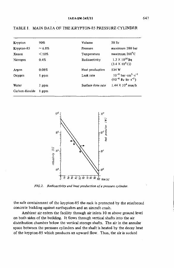
TABLE I. MAIN DATA OF THE KRYPTON-85 PRESSURE CYLINDER
IAEA-SM-245/11 6 4 7
K rypton 90% Volume 50 ltr
Krypton-85 ~ 6.8% Pressure m axim um 200 bar
Xenon < 10% Tem perature m axim um 200°C
Nitrogen 0.4% R adioactivity 1.3 X 10¹⁶Bq (3.4 X 10⁵Ci)
Argon 0.08% Heat production 534 W
Oxygen 1 ppm Leak rate 10~8 bar cm3 s_1 (10~6 P a - l tr - s '1)
W ater 1 ppm Surface dose ra te 1.44 X 10⁴ rem /h
Carbon dioxide 1 ppm
FIG.2. R adioactivity and heat production o f a pressure cylinder.
the safe containment of the krypton-85 the rack is protected by the reinforced concrete building against earthquakes and an aircraft crash.
Ambient air enters the facility through air inlets 10 m above ground level on both sides of the building. It flows through vertical shafts into the air distribution chamber below the vertical storage shafts. The air in the annular space between the pressure cylinders and the shaft is heated by the decay heat of the krypton-85 which produces an upward flow. Thus, the air is sucked

648 WARNECKE and AHNER
v -Ш60
•10.50
air■ outlet
•6.50
g * 0.(10
и -6.40
-J «_
-Л/Л-
>torogeshafts
air distribution chamber
FIG.3. K rypton-85 storage facility.
uniformly from the air distribution chamber into the storage shafts to cool the pressure cylinders. The heated air leaves the building via the craneway through air outlets on the top of the storage facility.
The main dimensions of the facility, including the operation rooms, are30.5 m long, 23 m broad, and 23 m high.
2.3. Handling of the pressure cylinders
The principal steps for handling the pressure cylinders in the storage facilityare:
(a) Transport in a shielding container into the facility(b) Connection of the transfer canal with the container(c) Opening of the container and removal of the cylinder, including the
shipping support(d) Closing of the container and decoupling of the transfer canal(e) Visual control and registration of the cylinder(f) Transport of the cylinder through a lifting gate into the preselected
position of the storage facility.
2.4. Layout of the facility
The layout of the storage facility is based on the licensing requirements for nuclear power stations in the FRG as laid down by the Federal Ministry of the Interior. This paper deals with the regular operation of the facility and the following possible accidents:
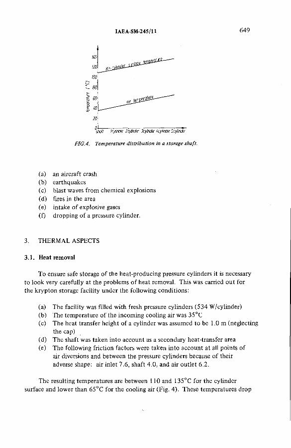
IAEA-SM-245/11 6 4 9
(a) an aircraft crash(b) earthquakes(c) blast waves from chemical explosions(d) fires in the area(e) intake of explosive gases(f) dropping of a pressure cylinder.
3. THERMAL ASPECTS
3.1. Heat removal
To ensure safe storage of the heat-producing pressure cylinders it is necessary to look very carefully at the problems of heat removal. This was carried out for the krypton storage facility under the following conditions:
(a) The facility was filled with fresh pressure cylinders (534 W/cylinder)(b) The temperature of the incoming cooling air was 35°C(c) The heat transfer height of a cylinder was assumed to be 1.0 m (neglecting
the cap)(d) The shaft was taken into account as a secondary heat-transfer area(e) The following friction factors were taken into account at all points of
air diversions and between the pressure cylinders because of their adverse shape: air inlet 7.6, shaft 4.0, and air outlet 6.2.
The resulting temperatures are between 110 and 135°C for the cylinder surface and lower than 65°C for the cooling air (Fig. 4). These temperatures drop

6 5 0 WARNECKE and AHNER
FIG.5. Time dependence o f temperatures.
F IG .6. Tim e dependence o f air throughput and air velocity.
within 50 years to between 38 and 47°C (Fig. 5). After 70 years the increase of temperature for the cooling air is about 1 °C and it will be possible to close the facility because the heat output, totalling 4838 W, can be dispersed through the walls.
Owing to the decrease of heat production in the air-cooled system with natural convection, the air throughput and the air velocity in the shaft decreases from 0.09 kg/s to 0.03 kg/s and from 0.79 m/s to 0.27 m/s, respectively, after 50 years (Fig. 6). The Reynolds number of more than 2800 indicates the turbulent flow of the air in the first period of 50 years. After 70 years the flow is laminar.
3.2. Temperature gradient in the pressure cylinder
The calculations for the temperature gradient under non-stationary conditions in the pressure cylinders have been carried out for a cylinder of 1 m height and0.26 m diameter, with a linear temperature profile of T= 5.1°C along the cylinder.

IAE A-SM-24S/11 651
isotherms streamlines
FIG. 7. Temperature gradient and streamlines in the pressure cylinder.
Under stationary conditions the isotherms (Fig. 7) show a maximum temperature gradient of 32.6°C at the central top of the cylinder, a steep temperature gradient at the mantle, and a relatively constant temperature towards the centre. The error in the energy balance is not more than 6%, which means that the temperature gradient could be underestimated by 1.8°C. The maximum central temperature at the top of the shaft in the krypton cylinder is about 165°C and the corresponding pressure is 153 bar. One right-hand convection eddy, with a thin boundary film, is a result o f the temperature gradient in the pressure cylinder.
3.3. Problems of heat removal
A study was made as to whether difficulties in heat removal can result from insulating layers on the heat transfer surface of the waste form, or by blockage of the air inlet by wind, fire in the area, ice formation, etc.
A very careful evaluation of the influence of dust in the cooling air was also carried out. In 7 to 8 years 1 mm thick dust layers can build up locally in the air distribution chamber below the storage shafts. If necessary, this dust can be removed by a vacuum cleaner. Dust sedimentation in the storage shafts is less than 0.1% of the total incoming dust, and it decreases with time. Within the expected storage time of 100 years a maximum dust layer of 57 ц m is expected but this can have only a negligible effect on the heat transmission.
As the air inlet channels are on opposite sides of the building it has been evaluated that wind always contributes to the cooling efficiency. In spite of this a sensitivity analysis for the influence of wind on the storage temperatures has been carried out by simulating the resulting pressure differences between air inlet and air outlet. The resulting temperature increase can be tolerated up to pressure differences of about 6 N/m2 before 200°C is reached (Fig. 8).
6 52 WARNECKE and AHNER
In the event of a fire in the area high temperatures would be reached. Because of the shape of the air inlet the ascending hot gases prevent the entrance of cold and hot air into the storage facility. Although complete blockage of the whole facility is inconceivable, conservative temperature calculations show that a thermally-insulated shaft reaches the maximum permissible temperature for the storage cylinder after 2 1/4 hours.
To verify the influence of wind and fire, as well as to optimize the shape of the building, a research and development programme on aerodynamics is planned for 1980.
The influence of leaves, ice and snow, which could hinder the natural convection by obstruction of the grid at the air inlet, was also examined. These problems were solved by suitable construction of the air inlet.
4. RADIATION EXPOSURE AND BARRIER SYSTEM
4.1. Dose rates from krypton-85 releases
The release of krypton-85 from the storage facility was calculated with the following data:
10-8 bar-cm3 s_1 130 bar3.4 X 10s Ci 820 cylinders
41 cylinders/a 20 years
Specified leak rate Pressure in the cylinder Radioactivity Storage capacity Storage frequency Filling time of the facility
The time dependence of the inventory and the release rate of krypton-85 are shown in Fig. 9. The maximum data of 1.62 X 10⁸ Ci for the inventory and 7.86 Ci/a for the release rate are reached after 20 years. At a distance of 100 m from the emitter the local dose rates resulting from this release rate were calculated to be 7.4 X 10⁻³ mrem/a for the |3 dose rate to the skin, and 6.7 X 10~7 mrem/a for the whole body y dose rate, in accordance with a recommendation by the Federal Ministry of the Interior (Figs 9, 10).
An accidental release of the total inventory of a pressure cylinder cannot be completely excluded, although a very careful programme for the quality assurance of a pressure cylinder, valve and welded cap, as well as a selection and dimensioning of the materials, will minimize this possibility.
Assuming that the total inventory of a pressure cylinder is released from the storage facility, the resulting dose to the skin due to the j3 dose rate is 4.8 rem at a distance of 100 m from the facility. This is sufficiently below the permissible limit of 30 rem to the skin under accident conditions.

IAEA-SM-245/11 6 5 3
FIG. 8. In fluence o f pressure differences on temperatures.
101
-10
r №
~1 Î3
FIG .9. Inven tory and release rate o f krypton-85.
4.2. Scattered radiation
Additionally, the scattered radiation at the air inlets and outlets has been estimated by calculating the j dose rate of the storage cell as a function of the distance from the source (Fig. 11), and the reflection conditions of the radiation for the prevailing geometry. The dose rate due to scattered radiation is conservatively estimated to be < 0.5 mrem/h at the air outlet and < 0.1 mrem/h at the air inlet.

654 WARNECKE and AHNER
FIG. 10. Local dose rate fro m krypton-85 release.
distance lm ]
F IG .l l . y dose rate o f the kryp ton-85 storage cell.
4.3. Monitoring system
A monitoring system for the krypton-85 release rates and for the detection of leaking cylinders has been drafted. The radioactivity concentration of krypton-85 in the off-gas is about 1.8 X 10⁻⁸ Ci/m3 under regular conditions.It is almost time independent. Krypton-85 can be detected by a gas-flow proportional-counter. Representative sampling can be carried out as follows (Fig. 12):

air outlet
IAEA-SM-245/11 6 5 5
Л
FIG .12. M onitoring system fo r krypton-85 release.
(a) Cooling air is sampled at five points of each air outlet and the air flows measured
(b) Samples of all air outlets are collected and mixed(c) A partial flow of 20 m3/h is taken, cleaned on aerosol filters and
mixed with methane(d) The sample passes the proportional counter.
The detection limit of this device is about 10-8 Ci/m3 for krypton-85.If the counting rate exceeds a preselected limit leaking cylinders have to
be detected (Fig. 13). This can be done by closing a storage shaft and measuring the radioactivity of the air in a similar way to that described above. If the leaking bottle is found it can, for example, be canned or refilled in a new cylinder.
4.4. Dropping of a cylinder
To guarantee the integrity of a pressure cylinder, the shipping support has been designed to withstand an accidental drop from a maximum height of9.5 m, which can occur if the cylinder falls from the crane into the storage shaft.
The dimensions of the shock absorber of the shipping support were determined by a finite-element computer program. It consists of a tube ferrule as a deformable zone and a stand ring to distribute the locally occurring forces of the drop on the three-armed supporting cross at the bottom of the shaft. These forces are distributed uniformly to the deformable zone. The shock absorber guarantees the integrity of the cylinder and the safe containment of the krypton-85.
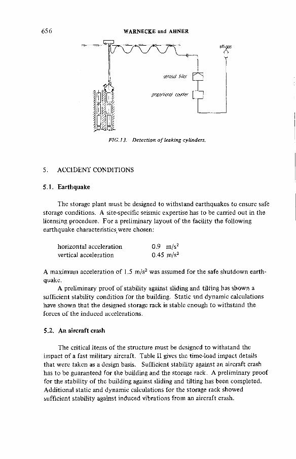
6 56 WARNECKE and AHNER
5. ACCIDENT CONDITIONS
5.1. Earthquake
The storage plant must be designed to withstand earthquakes to ensure safe storage conditions. A site-specific seismic expertise has to be carried out in the licensing procedure. For a preliminary layout of the facility the following earthquake characteristics were chosen:
horizontal acceleration 0.9 m/s2vertical acceleration 0.45 m/s2
A maximum acceleration of 1.5 m/s2 was assumed for the safe shutdown earthquake.
A preliminary proof of stability against sliding and tilting has shown a sufficient stability condition for the building. Static and dynamic calculations have shown that the designed storage rack is stable enough to withstand the forces of the induced accelerations.
5.2. An aircraft crash
The critical items of the structure must be designed to withstand the impact of a fast military aircraft. Table II gives the time-load impact details that were taken as a design basis. Sufficient stability against an aircraft crash has to be guaranteed for the building and the storage rack. A preliminary proof for the stability of the building against sliding and tilting has been completed. Additional static and dynamic calculations for the storage rack showed sufficient stability against induced vibrations from an aircraft crash.

TABLE II. TIME/IMPACT LOAD OF AN AIRCRAFT CRASH
IAEA-SM-245/11 6 5 7
Tim e (ms) Im pact load (MN)
0 0
10 55
30 55
40 110
50 110
70 0
The outer structural shell of the storage building is specially designed to prevent kerosene inflow into the storage cell, and an adequately dimensioned draining system is planned to drain the kerosene from the roof.
5.3. Blast waves from chemical explosions
Calculations have shown that the impacts of earthquakes and of an aircraft crash cover the impacts of chemical explosions. Furthermore, a blast wave cannot damage the storage rack and the krypton cylinders because the channels for the cooling air are specially constructed.
5.4. Explosive gas mixtures
It has to be shown that it is possible to protect the facility from penetrating explosive gas mixtures, or how to control penetration.
The first method of protecting the storage facility from explosive gas mixtures is by maintaining large distances from possible explosive materials. The necessary distance depends, for example, on the quality and quantity of the gas, the storage conditions and site-specific data such as the field features and the dominant wind direction. A second method is to eliminate ignition sources in the storage facility and in the surrounding environment. Because of surface temperatures, the krypton cylinders could possibly be an ignition source for some gas mixtures.
If a site has unchangeable limiting conditions that do not sufficiently guarantee proof against primary and secondary explosions, additional safety requirements can become necessary. If required, the admission channels could be equipped with gas detectors that close automatically. Such a total blockage of the cooling air is possible for more than two hours.

658 WARNECKE and AHNER
The main features of the conceptual design of the storage facility for krypton-85 with natural air cooling have been presented in a condensed form. Though some safety aspects need more detailed investigation, the present results show that it is possible for the facility to be constructed in such a way as to meet the basic requirements for the licensing procedure of nuclear facilities. The detailed layout of the facility will be carried out in the next few years.
6. CONCLUSIONS
DISCUSSION
K. FISCHER: Can you give us figures for the dose rates received by operating personnel? Also, do you think that your concept of cooling by natural convection will be able to satisfy the demands of politicians and the public for protection against ‘maximum credible accidents’?
E. WARNECKE: The figures you ask for in your first question have not yet been calculated. The detailed layout of the building including the design of the relevant shielding parameters will be carried out in the next programme.
As for your second question, the main object of this paper was to demonstrate the capacity of the layout of the storage facility to withstand severe accidents. Although some safety aspects need more detailed investigation, the facility can be built in such a way that it will meet the licensing requirements if a suitable waste form can be found. In essence this means that the pressure cylinder corrosion experiments must produce positive results and that very good quality control is necessary for the pressure cylinders.
R.V. OSBORNE: Have you estimated the costs of the storage facility?E. WARNECKE: Preliminary cost estimates have been carried out, but these
could change drastically when the facility layout is designed in detail.R. BROWN: We have completed a cost estimate for engineered storage in
Idaho. The estimate is so high that I hesitate to mention it.While different national requirements and regulations may affect final
judgements, additional consideration should be given to the advantages of geological storage. The long-term custodial and economic requirements of an engineered storage system would seem to make the latter alternative unattractive.
M.J.S. SMITH: In connection with Mr. Brown’s comments on the high costs of krypton storage and the need to consider the relative merits of storage and of geological and deep ocean disposal, we at Harwell believe that the immobilization of krypton, for instance in a metal matrix, will not only improve the safety of krypton containment but will probably reduce the cost of krypton waste management overall by enabling less expensive storage or disposal methods to be employed.

IAEA-SM-245/11 6 5 9
E. WARNECKE: This question can only be answered once overall cost estimates have been carried out for krypton-85 waste management alternatives which meet the same level of safety requirements.
R.D. COLLINS: Should one cylinder fail explosively, could it produce missiles or itself become a missile that might break other cylinders and thus convert a single cylinder failure into a general failure? Any embrittlement of the cylinder metal would be an important feature in this respect.
E. WARNECKE: If one cylinder failed explosively, the maximum possible damage it could cause would be to destroy the inventory of one storage shaft.The resulting dose rates would be below the limits of the radiation protection regulations for accident conditions.
H.A.C. McKAY ( C h a irm a n ): Have you considered combining your concept with that contained in the previous paper (IAEA-SM-245/50), in which the cylinders are filled with charcoal?
E. WARNECKE: It is, of course, possible to store different krypton-85 waste forms in the storage facility described, and charcoal-filled pressure cylinders are only one such alternative. Even more promising is krypton-85 fixation in a metal matrix as developed at Harwell, Richland and Karlsruhe, and in zeolites as developed at Karlsruhe and Idaho.
H.A.C. McKAY Y C h a irm a n ): Have you confidence in your heat transfer calculations? I believe that the problem of heat transfer from a gas which generates heat and is subject to convection is a novel one. I understand you have attempted to simulate this situation experimentally, but with a liquid medium. Can you be sure about the applicability of the results to a gaseous medium?
E. WARNECKE: Calculations of the temperature gradient in a pressure cylinder are in agreement with the experimental results of Dr. Briicher at Jülich.I believe he may be able to answer your question in greater detail.
H. BRÜCHER: Our way of simulating the situation is certainly not an ideal one, but it is assumed to be the best one available for the time being. We use a cylinder filled with a liquid electrolyte and simulate the equally distributed heat source with an a.c. We then measure the axial and radial heat distribution. Our results are transferred from the liquid to the gaseous phase by means of a similarity theory. This theory was specifically developed to transfer experimental geometrical and physical data relating to the medium, and therefore we are quite sure that we can transfer our results to a gaseous medium.
From our experiment we derive that, for a 50 litre pressurized gas cylinder containing 200 000 Ci krypton-85, a temperature difference of nearly 30°C between the wall and the centre of the cylinder may be expected. This work was conducted under a CEC contract and will be published in the near future.


ROUND TABLE DISCUSSION
Chairman: M.W. FIRST (United States of America)
Round Table: M. MAZZINI (Italy)R.V. OSBORNE (Canada)W.R.A. GOOSSENS (Belgium)H. DEUBER (Federal Republic of Germany) P.H.J.M. SIGLI (France)D.T. PENCE (United States of America) H.A.C. McKAY (United Kingdom)
M.W. FIRST ( C h a irm an ) : This is to be a round table discussion intended to offer: ( 1) a brief review and distillation of ideas from each of the sessions by the session Chairmen; (2) a last chance to put questions which have not yet been asked; (3) an opportunity for Symposium participants to present their own conclusions; and (4) an attempt to reach a consensus on what new information has come out of this Symposium and on the direction in which we, who are concerned with the management of nuclear waste gases, should aim our future research and development efforts. This amounts to asking what material needs are still to be tackled. If nothing but an answer to that question came out of this Symposium, the meeting would have been a success because we would then be focussing our attention on the real problem areas.
The format for the discussion will be as follow: each session Chairman in turn will present his summary, and when they have all done so I shall call for questions and comments from the floor.
Before calling on our first Chairman I would like to make a few brief comments on Session I, in which we heard from Mr. Zabaluev about the current activities of the IAEA in gaseous waste management, from Mr. Maestas about the present waste management programme of the Nuclear Energy Agency (NEA), from Mr. Huber about the European Community’s work in relation to the storage of gaseous wastes, and from Mr. Hickey, representing the Office of Standards Development of the United States Nuclear Regulatory Commission on US programmes for regulating airborne releases of radioactivity. Although Mr. Hickey’s review pertained specifically to current US regulatory activities, it is reasonable to assume that identical activities are underway in all countries represented here and that similar new regulations will be developed in each of them. His paper may therefore be considered as an example. To an important extent his presentation also reflects a worldwide effort to find a happy medium between protective regulations and the economical production of nuclear power.
661

662 ROUND TABLE DISCUSSION
When reviews of the activities of the three agencies represented by Messrs. Zabaluev, Maestas and Huber are presented one after the other, as they were in the first session, they cannot fail to impress us with the enormous amount of work being carried out to promote safety in nuclear development and utilization.Mr. Huber made a special point regarding the vast amount of documentation available from his agency, and of course this is true for the others as well. Many of these publications are found in every institution dealing with nuclear affairs, and rightly so, as they represent an invaluable storehouse of essential information.I do hope that it will be possible to prepare new editions of some of the more valuable publications, so as to incorporate information developed since they were first issued. This is obviously a difficult task in this rapidly developing field, but it is an essential one.
Now to the session Chairmen and their reports. Our first speaker is Professor Mazzini from the University of Pisa, Italy.
M. MAZZINI: As you know, I am to review session 11(a) on the sources and characteristics of off-gases from nuclear facilities. Only some of the papers were strictly related to the title of the session. Others dealt rather with the removal of particular radionuclides and in principle should have been included in other sessions. These other sessions, however, also contributed considerably to the identification of sources of gaseous wastes and to their characterization, from which we can see that the whole Symposium has helped to increase our knowledge of the field under discussion.
A few words now on the individual reports. Mr. McKay’s paper was noteworthy for its data bringing up to date the inventories of long-lived radionuclides in nuclear facilities. These inventories and their comparison with the natural background, as well as the indication of reasonable goals for leak rates under conditions of waste immobilization, are of particular interest to those who decide on research and development policy in this field.
A point in the paper by Mr. Becker which was of particular note was the reduction of about 2 to 4 orders of magnitude in the radiolysis constant under field conditions as compared with water radiolysis for gamma radiation under laboratory conditions. This result is still to be confirmed and theoretically supported, of course, but nonetheless it may contribute greatly to solving the problem of tritium release in gaseous wastes from reprocessing plants. There is, after all, no better solution to a problem than to eliminate its cause.
The last two papers, by Messrs. Klein and Kepak respectively, dealt with the treatment of ruthenium and other radionuclides present as aerosols in gaseous effluents. As well as providing satisfactory solutions to this problem, they helped to improve our knowledge of related phenomena.
R.V. OSBORNE: For tritium handling, if some form of on-site disposal is not available then concentration of tritiated waste is usually required. Two papers dealt with particular aspects of two general methods that have been proposed for

ROUND TABLE DISCUSSION 6 6 3
such concentration — recycle at the front end of an FRP, and enrichment by some combination of catalytic exchange, electrolysis and cryogenic distillation.
In the first, Mr. Henrich and his colleagues at Karlsruhe discussed the modifications to the Purex process which would be required in order to introduce recycling at an FRP.
In the second, Mr. Bruggeman and his colleagues at Mol described the results of enrichment experiments obtained with a liquid phase catalyst plus an electrolyser.
For carbon-14 capture and retention, caustic scrubbing or molecular sieves are usually proposed. There is a fair amount of industrial experience with C 02 removal processes and Mr. Weber et al. from Linde AG have been able to propose a detailed design for a double caustic scrubber which uses NaOH and CaOH for C02 removal. This is for a plant which reprocesses LWR fuel and, in their particular process, iodine and krypton were taken out before the carbon.
For the specific problem of HTGR fuel reprocessing where large amounts of C 02 are evolved, Mr. Notz and his colleagues at ORNL have been studying the possibilities of a single stage wet slurry using Ca(OH)2 for C 02 removal. Here the carbon dioxide is taken out before the krypton. This illustrates a general point, namely that studies or expert laboratory measurements should not ignore how other nuclides affect, or are affected by, a particular process - here we have the cases of Kr and 14C. We see this also with front-end recycle processes where both iodine and tritium are affected.
Methods that are usually proposed for iodine capture and retention involve silver impregnated absorbents of some kind. Mr. Hüfner et al. at Karlsruhe have shown at the pilot plant stage that with reflux boiling of the fuel solution just after dissolution, iodine may be carried over in a very small volume of carrier gas, which permits easy capture.
Mrs. Smirnova and colleagues in Moscow suggest that, on the basis of their laboratory measurements, various polymethyl silicones might be substituted for silver compounds, at least as a first stage capture process.
The behaviour of iodine if it is released is obviously of interest. Mr. Till described the EPRI programme, which involved not only study of the iodine release rates from LWRs but also investigation of the variables that are important in determining the behaviour of released iodine; the results of this should have direct practical application. Particularly of note here is the data he presented on organic/inorganic conversion.
To sum up, then, for the three nuclides iodine, tritium and carbon-14 we heard of actual or potential improvements in capture technology in terms of more effective capture, concentration prior to capture or cost reduction. These are the important variables — cost and effectiveness. Pertinent questions are: what is going to determine how effective a process has to be, and how much should we pay? One determinant is clearly the fence-post dose from a release, but the

6 6 4 ROUND TABLE DISCUSSION
optimum may be determined by additional considerations of population detriment and cost. What guidance, we may ask, do designers have for this?
One requirement, clearly, is for operating data at the pilot plant scale. This would allow a realistic estimation of costs, reliability and effectiveness.
Finally, as we know, the purpose of capture is to reduce emissions and thereby eliminate radiation doses. Plant designers have to keep in mind, however, that in-plant doses can offset some of this saving. For example, water highly enriched in tritium may be very difficult to handle. Actual operating experience at pilot plant stages is needed.
W.R.A. GOOSSENS: As stated in the survey paper by Mr. McKay in Session 11(a), the immobilization of 85Kr seems to be almost exclusively a reprocessing problem, as more than 99% of this species is present in the discharged fuel. In fact, 85Kr can be narrowed down even further to a head-end problem since it is released during the chopping and dissolution operation. At sesssion IV of the Symposium, which is the subject of my review, two main items were discussed - the trapping of 85Kr from dissolver off-gases and its immobilization after trapping.
Two processes for 85Kr trapping were described. First, the Karlsruhe group of Messrs. von Ammon, Hutter and Knittel stressed the precautions that have to be taken to allow the application of the cryogenic separation process for noble gases from dissolver off-gases. These authors described in some detail the catalytic reduction of oxygen and NOx by hydrogen combined with a minimization of the formation of disturbing components such as NH3, CH4 and CO in parallel reactions. Similar experience was reported, inter alia, by Mr. Collard on the operational experience gained with a 25 m3 ' h"1 simulated dissolver off-gas purification loop at Mol.
The second 85Kr trapping process described was selective absorption by a fluorocarbon solvent. Messrs. Merriman and Stephenson of Oak Ridge indicated that over a ten-year development period many improvements and simplifications had been made to the original version of the fluorocarbon process. In particular, they claimed that the scope of this process could be expanded to trap both 14C as C02 and various species of 131I, and that this process is applicable essentially to all types of nuclear facility situations, including post-accident reactor cleanup. Further, they stated that it has an especially large tolerance for feed gas impurities, with no problems of ozone formation or xenon plugging. The waste aspects of the process are still to be solved.
Regarding the immobilization of trapped 85Kr, basic data were given for krypton containment on a metallic matrix, in low density glasses and on zeolites. The Harwell group of Messrs. Whitmell, Nelson and Smith described how krypton can be incorporated in a metallic matrix by combined ion implantation and sputtering at an equivalent of 170 litres of gas per litre of metal using copper, iron, aluminium and monel matrices.
ROUND TABLE DISCUSSION 6 6 5
Mr. Tingey from the Pacific Northwest Laboratory described the implantation of krypton ions during the sputter deposition of metals such as iron, aluminium and nickel. However, the metallic alloy of iron, yttrium and krypton showed the best performance with a release rate of less than 2% of the krypton within ten years at 300°C. A still lower release rate of only 1.8% in the first ten years at 420°C was claimed for porous silica samples sufficiently sintered at 900°C at 35 mPa krypton pressure.
The conditions for krypton immobilization on 5A zeolites were described by Mr. Penzhorn and colleagues from Karlsruhe. Zeolite loadings above 20 cm3/g (STP) now seem possible at pressures well below 300 bar. No significant leakage was apparent at temperatures of 400°C while resistance to liquid water and gamma irradiation was excellent.
In conclusion, I would suggest that at the moment there seem to be enough basic data available for us to start on process analysis techniques in order to compare the theoretical reliability and safety of the different processes proposed both for the trapping and the immobilization of 8sKr. This comparative exercise should end with cost estimates based on the experimental experience gained in technical installations.
H. DEUBER: In Session V papers were presented on: performance of sand-bed filters; testing of particulate and iodine filters; monitoring of gaseous radionuclides; and the behaviour of radionuclides in vitrification plant off-gases.
P erfo rm a n ce o f sand-bed filters. In one paper studies were presented on the performance of sand-bed filters for the treatment of the dissolver off-gas of reprocessing plants. It was concluded in the paper that sand-bed filters may advantageously be used for the treatment of the off-gas in question. However, it seems that in general sand-bed filters are more attractive for filtration under accident conditions.
Testin g o f p a rticu la te filters. One paper demonstrated a method for the determination of the removal efficiency of particulate filters by using a scintillation counter. The conclusion was that with certain modifications the method could be used for in-situ tests.
Several methods are available for the in-situ determination of the removal efficiency of particulate filters under normal conditions. The results of the IAEA comparison measurements presently being carried out with different methods will be most valuable.
However, it should be mentioned that two differing views exist concerning in-situ particulate filter testing. According to one view, determination of the removal efficiency should be performed. According to the other, surveillance of the leak-tightness should suffice.
As regards testing of particulate filters under extreme conditions (high temperature and relative humidity), no methods are at present available.
T estin g o f io d in e f ilte rs. In one paper it was shown that satisfactory surveillance of iodine filters is possible with the current in-situ and laboratory

6 6 6 ROUND TABLE DISCUSSION
tests. In these in-situ tests fréons and radioactively labelled methyl iodide are used. Another in-situ test method was not dealt with, which consists of determining the removal efficiencies of the iodine filter for the iodine-131 species to be found in the ventilation air. This method requires reliable radioiodine species samplers.
M o n ito rin g o f gaseous radionuclides. In two papers it was demonstrated that modern equipment is available for sensitive and continuous monitoring of tritium in gaseous effluents. In one paper an apparatus was described for monitoring tritium, sulphur-35 and carbon-14.
Monitoring of other radionuclides, such as iodine-129, was not discussed.As regards iodine-129, development of continuous monitors is known to be in progress.
B e h a v io u r o f ra d io n u clid es in v itrifica tio n p la n t off-gases. In one paper studies were presented on the behaviour of radionuclides in spray calciner in-can melter off-gases. It was shown (a) that particle loss accounts for a significant portion of the fission products that reach the off-gas system, and (b) that particles released to the off-gas system have a mass distribution centring about a size that is controllable using present technology.
The difficulties encountered in the development of efficient filters for gaseous ruthenium, which is of primary concern, have been dealt with in other sessions.
P.H.J.M. SIGLI: I have tried to group the five papers presented in Session VI according to their subject matter and I will discuss them in the following order: first, the two papers dealing with the operation of filtration systems in nuclear reactors with specific reference to HEPA filtration and iodine trapping; secondly, two papers on gas purification by cryogenic process; and lastly, the paper on the experience gathered in monitoring emissions from a waste incinerator.
In his paper, Mr. Groom underlined how difficult it was many years ago to meet the specification required for the absolute filtration of aerosols. In particular, there were problems with housings, seals, filter fitting and damage to filters during fitting and even during transport. In addition, the old reactor designs made little provision for test circuits. All these difficulties were taken into account to improve new systems.
There was a discrepancy between the results quoted by Messrs. Groom and Fowler for iodine trapping. The main problem was that of the ageing of activated charcoal. In the United Kingdom a 30 cm layer of activated charcoal gave a lifetime of several years in the case of a standby trap in a carbon dioxide atmosphere. The lifetime claimed by Mr. Fowler for a 2.5 cm layer of charcoal used in the N reactor was between six and nine years. This figure is somewhat surprising by comparison with results recorded elsewhere. The problem of charcoal ageing is of concern to all those who are in charge of facilities. Other problems we have found relate to charcoal storage, which Mr. Collins discussed at another session, and the operating mode of a system — either standby, which

ROUND TABLE DISCUSSION 6 6 7
is preferable if it is at all possible, or in continuous operation. We must seek solution to these difficulties either, as Mr. First suggested in his paper, by using a guard bed to protect the charcoal bed or else by trying to improve existing absorbents, which is more difficult.
The second group of papers focussed on a common topic, namely the cryogenic purification of gases. One system was designed to purify the argon blanket of a fast reactor while the other system simulated dissolution off-gas purification in fuel reprocessing. Here we have two different aims and two different designs, but nonetheless they have one thing in common — proof that the cryogenic methods of off-gas purification now really are operational, and I think that this is a point which should be emphasized. The inherent difficulties of this technology — in particular the problem of xenon crystallization — seem to have been solved. Decontamination factors are high and pilot facilities are thus ready to be tried out in industrial-scale experiments. The system described by Mr. Dewanckel is now going to be installed at the Phénix reactor for experimental purposes.
In addition to describing the cryogenic purification of gas, Mr. Collard in his paper outlined the experience gathered on dissolver off-gas purification.A new system for recovering the mercury from the operation of a Mercurex column is being investigated and, subject to confirmation which further work should provide, this recovery system may well renew interest in the Mercurex process.
In conclusion, a few words on Mr. Kônig’s paper. This paper made the excellent point that surveillance of a facility can contribute greatly to distinguishing between different species of radionuclides. This enabled a remarkable follow-up programme to be carried out on wastes from 1972 onwards, which made it possible to analyse incidents in incinerator operation (the presence of sorbents, for example). Only rare instances of low releases have been recorded, and once again this demonstrates the maturity of operations in the nuclear industry.
D.T. PENCE: I will not try to attempt to summarize the wide diversity of papers presented at Session VII, the process design session, but will instead offer a few general observations and comments regarding the session as a whole. The results of the reported studies re-emphasized that: (1) many radioactive species behave differently under different operation conditions; (2) certain control techniques that work well in one particular set o f operating conditions do not necessarily work as well when the conditions change slightly; (3) despite the extensive research performed on the ageing of charcoals used for radioiodine removal, we still have much to learn about this process; (4) the development of effective aerosol control procedures appears to be receiving more attention than in the past and we are making good progress in developing effective control measures; (5) the somewhat anomalous behaviour of certain of the semi-volatile fission products continues to plague us and, although we have made progress in

6 6 8 ROUND TABLE DISCUSSION
controlling them, we have some way to go, especially with respect to HLLW solidification; and (6) the design of reactor off-gas treatment systems capable of handling the wide variety of potential accident situations represents a formidable challenge since the postulated off-gas flows and compositions vary enormously, but the design and installation of such systems appears to be inevitable, at least for some reactors.
The papers given on both operational experience and design of radioactive gaseous control systems emphasize that we, as developers and designers, have more of an obligation than simply to show that a control system is technically feasible. There are a number of questions we must ask ourselves: Is our control system the simplest adequate design? Does it lend itself to easy and safe maintenance? Does it generate secondary waste product streams that will be difficult to treat? Will the system design stand up under a thorough risk and reliability analysis such as the fault tree analysis described by Mr. Paolo? Is the design cost effective?
Perhaps the most difficult question for us to answer is: Will the system operate satisfactorily over a long period of time? I think we all recognize that when we base our designs on data obtained from long-term pilot-plant demonstrations under the closest practicable anticipated operating conditions, the reliability of the design is greatly enhanced. Although the job of convincing the appropriate people that such demonstrations are important is frequently very difficult because of the high costs involved, the potentially disastrous consequences of inadequate design and testing make it imperative that we do all we can to develop and demonstrate fully the safety and reliability of our designs before they are put into actual operation.
H.A.C. McKAY: In session VIII we had one paper on the storage and disposal of tritium and three on krypton, but none on carbon or iodine, though there were occasional references to the latter in earlier sessions.
The tritium paper was from Jülich, and listed several possible schemes suitable for an inland reprocessing plant, before finally concentrating on three specific ones. Two involve immobilization as cement and one as zirconium tritide, for which preliminary isotopic enrichment is necessary to reduce costs. Tritiated cement may be disposed of either to sea, or injected into a salt cavern, where it solidifies. Zirconium tritide would be stored on the surface.
On cost grounds, all three methods appear to be acceptable on the basis of a preliminary study. As regards their state of development, deep-sea disposal appears straightforward, injection into a salt cavern needs to be demonstrated, and surface storage as zirconium tritide would require considerable research and development.
The three krypton papers dealt respectively with disposal to the deep ocean in massive steel spheres (Netherlands), surface storage in cylinders in an air-cooled store relying on natural convection (FRG), and storage in cylinders filled with charcoal (Belgium). Presumably the second and third might be combined, and one would like to see a direct comparison of cylinders with and without charcoal.

ROUND TABLE DISCUSSION 6 6 9
Dispersion of the decay heat is in all cases an important consideration — indeed, a limiting factor determining the dimensions of the containers. The calculations for the case of absence of charcoal are somewhat unusual and difficult, because one has to allow for krypton convection in a system in which the gas itself is evolving heat. This particular difficulty is overcome when the cylinders are filled with charcoal.
The rubidium decay product must also be considered in all cases. Its effect on the metal of the containers is not yet fully known. This particular effect is, however, avoided with charcoal which retains the rubidium without deleterious effect.
The Netherlands paper on sea disposal has a long section on the legal position. It is argued that since the radiological consequences of sea disposal appear to be trivial, the London Convention should be modified to permit disposal by this method.
The Federal German paper on surface storage considers a number of accident conditions, and concludes that the basic licensing requirements can be met.
M.W. FIRST ( Cha irm an) : Thank you, gentlemen, I will now throw open the discussion to the floor.
K. FISCHER: During this Symposium a great deal of distinguished scientific work has been presented on the retention of, in particular, krypton-85 and carbon-14. However, I personally am interested mainly in radioprotection, and I was disappointed that there has been no assessment of the dose rate received by plant workers. I am afraid that in the final analysis the retention of, for instance, krypton and carbon will be required for the sake of reducing a somewhat hypothetical global collective dose at the cost of increasing the personal risk to workers. I wonder if you could comment on this, Dr. Osborne, and, if possible, also say something about the results of the work on radiological significance and management in which you have been involved.
R.V. OSBORNE: I share your concern. The report on this particular work indeed acknowledges that regional and global doses are not the only detriment which must be considered in a cost effectiveness analysis. I think the problem we had in writing the report, a problem which I believe still exists, is that very little is known about these in-plant doses. Searching through the literature, one sees that it is not the sort of thing that people tend to write about. So one can but make estimates of what the dosage and risks to workers might be in a particular krypton storage facility. I can’t make any comment on how important quantitatively they might be, but they certainly should be taken into consideration. I think it would be hopeless in the time available to try and summarize the results of the OECD report. Maybe I can just tell you a little about the methodology we adopted. The report sets out to analyse thè individual and collective doses from tritium, carbon-14, krypton and iodine-129 in the case of reference facilities for fuel reprocessing plants for various kinds of power reactors. It also looks at

6 7 0 ROUND TABLE DISCUSSION
the possibilities for controlling these nuclides - capture, retention, disposal, storage - and the costs of these alternatives were assessed. At the end, the report surveys the cost effectiveness of any particular waste management procedure and carries out, or at least it shows how one can carry out, a marginal cost effectiveness analysis. In other words, you list all the possibilities, their costs and their effectiveness in terms of dose reduction. The report then arranges the marginal costs and the marginal dose reductions in such a way that if you or your national authority decide what value you or it is prepared to place on a man ■ rem, then you can see which particular process might be the optimum one. The other condition, of course, is that of limiting the individual doses. What this report does is estimate the fence doses, i.e. the dose to the maximally exposed individual, and assess what demands would be placed on retention and waste management procedures in order to limit individual doses. The final summary of the report shows what processes can be applied to a particular facility with given releases, and also indicates which of these processes is to be used if one wishes to limit the individual doses to so many millirems or to spend so many dollars per man-rem. In some cases no additional process will be needed.
H.K. KRETSCHMER: Mr. Chairman, a question to anybody who feels himself competent to reply. In the nuclear fuel cycle you have three nuclides of interest — tritium, carbon-14 and iodine-129. Nature itself possesses large quantities of the inactive species hydrogen, carbon-12 and iodine-127. The human body absorbs both the inactive and the active components, and so we must ask ourselves whether it is really necessary to make such great efforts to separate and treat these nuclides, especially in view of their low radiation and of the necessity to treat both the active and inactive parts in the waste.
H. DEUBER: As far as iodine-129 is concerned, one must take into account the doses at the plant perimeter. There cannot be much doubt that, to keep this dose at a sufficiently low level, treatment, by filter for example, is necessary.Of course, this might depend on the size of the plant — if you have a plant with a capacity of, for example, 1500 tonnes per year, then normally you must have a retention factor, let’s say, of 100. But in the case of global doses, because inactive material is present to such a high extent in the ocean, for example, there is probably no cause for concern nor any need to make allowance for any detriment.
K. FISCHER: I should like to make a couple of comments on iodine-129 and carbon-14. The measurements made by Mr. Schüttelkopf at Karlsruhe have shown that the biological availability of iodine decreases by a half-life of about one third of a year. Secondly, the carbon-14 dose is dependent on the specific activity, i.e. on the ratio of carbon-14 to inactive carbon. The amount of inactive carbon will increase in the near future because of the burning of conventional fuels with the result that the collective dose rate for carbon-14 will decrease, despite the continuing expansion of nuclear energy.
ROUND TABLE DISCUSSION 671
H.A.C. McKAY: I think one of the things which must be aimed at if one is going to disperse any of these radionuclides into the enrivonment and make use of this isotopic dilution, is to get them.quickly enough into a sufficiently large reservoir. In the case of iodine, I think the only reservoir big enough is the ocean, and so you must devise a method which puts iodine into the ocean and disperses it widely very rapidly. Similarly, if you put tritium into the ocean you have an enormous reservoir of isotopic dilution, but if you try and dispose of it elsewhere you may have to worry about much higher concentrations. I think the same kind of thing is true of carbon-14.
R. KROEBEL: If I may introduce a new topic, I would like to point out that this Symposium has highlighted a problem which has not been tackled up till now. If we knew what disposal method was going to be used for these gaseous effluents then we would be in a position to develop far better methods for their capture and intermediate treatment. I think that in the near future we should carefully consider the subject mentioned by Dr. Verkerk this morning and reiterated by Dr. McKay a moment ago, namely that if it is in fact possible to dispose of tritium, iodine and maybe even krypton into the sea, then we should change the present situation and make it legally possible to do so. This is undoubtedly the best disposal method because it requires no further maintenance or surveillance, which is the ultimate goal of all nuclear waste disposal methods.At present we are doing just the opposite of this; the disposal method described by Dr. Warnecke (IAEA-SM-245/11) will probably be legal, but it is certainly not satisfactory. We should now move away from such methods and pool all the scientific and technical possibilities available to us with the aim of introducing better disposal methods which do not require surveillance. We should then go and develop the processes to make use of these methods.
M.W. FIRST ( Chairm an)'. Thank you for your comment on a very important topic. If I understand you correctly, you are telling the Symposium that we must first develop disposal methods that are satisfactory before we can then proceed with the job of developing ways of collecting the material and preparing it for storage — in other words, that we are at present putting the cart before the horse. Is that a fair statement?
R. KROEBEL: I would say that this is perhaps going too far, because we cannot afford to wait until we have disposal methods available, but I believe we should now put much more emphasis on finding disposal methods so that we can then choose from the wide variety of processes described at this Symposium.
I.F. WHITE: I would agree with much of what the previous speaker has said, but would perhaps draw attention to the point that the development of treatment and disposal methods is an iterative process in which we look at what treatment methods are available, we look at what disposal methods are available, and then we go round and refine our options.
A.A. BAPTISTA: I would like to put a question on a different theme to Dr. Osborne. We have heard a lot this week about off-gas purification in light

6 7 2 ROUND TABLE DISCUSSION
water and graphite moderated reactors but there has been nothing on heavy water moderated reactors. I wonder if there have been any developments in this respect in Canada with CANDU type reactors, particularly as regards tritium removal and disposal?
R.V. OSBORNE: Indeed there have, but I think my colleague Mr. Vivian could better answer your question.
G.A. VIVIAN: There is a proposal to proceed with a tritium removal plant which would probably operate in an on-line mode at the Pickering station. The tentative schedule is 1984—1985 but I should warn that funds are not really committed at the moment. Two main options are being examined, one of which would utilize an integrated upgrading facility, i.e. upgrading of heavy water and tritium removal, while the other envisages two separate facilities. The method of product storage for the first plant would very likely be gaseous form storage, although there has been a substantial amount of success, particularly at the Chalk River Laboratories of Atomic Energy of Canada, with hydrate storage.
J.F. HAMARD: I wonder to what extent the devices we have heard described this week could be used in the case of an accident as serious as if not more serious than that at Three Mile Island? If not, would it be possible to design devices to reduce the radioactive releases in an accident situation? I am thinking particularly of iodine which would contribute very considerably to population dose.
D.T. PENCE: Just such a situation is at present being studied by the NRC in the United States of America. The Sandia Laboratories are conducting an investigation — in which I am participating — into various designs that might be able to cope with the large-scale accident. This is a very difficult task, as you might expect, because in order to tackle the problem of clean-up systems, we must first decide what we are going to design against; there is a very wide variety of potential accidents to consider, involving release rates varying from a few cubic metres per hour to thousands. I am not sure what the result of the study will be. I think we will have to decide what we are willing to pay for and assume the risks at some point, but where is that point? Mr. Collard offered one approach yesterday (IAEA-SM-245/49). Is this acceptable? Is this a large enough unit or must we design for total meltdown?
J.P. OLIVIER: The OECD has just set up a group to study the extent to which filtration systems can help to reduce population doses following major accidents. There was a meeting last October in Karlsruhe which dealt with both reactor problems and possible accidents in fuel cycle facilities. After a preliminary discussion, an expert group was established within the OECD. This group has not yet met but will do so this year and will probably begin its work by looking at typical accident situations with a view to determining more precisely what burdens accidents impose on filtration systems. It is difficult for me to say any more at the moment, but this is a worrying problem and perhaps we will be able to discuss it again in two or three years’ time when the conclusions of this group are available to us.
ROUND TABLE DISCUSSION 6 7 3
J.L. KOVACH: On the basis of the experience at Three Mile Island, I think it is possible to design and build systems to deal with post-accident clean-up. However, we had better build these before the next accident occurs — our biggest problem at Three Mile Island was that we had to start building a system after the accident, which is a little more difficult than the very leisurely planning we are discussing here. I get somewhat distressed when I hear about such long-drawn- out two- or three-year projects, where we agree to meet again next year to discuss what we will be talking about the year after. We must make arrangements for much faster availability of mobile hardware and other materials, so that we don’t have to start purloining refrigerated milk trucks in order to build filter systems. The concept of using mobile units or having extra units available on site for venting is, I believe, a necessity for all reactors, regardless of type. We must also make sure that we design for credible accidents, because the tendency I see now is to design for the maximum incredible accident, against which nothing can really be done. We should concentrate on the type of accidents which do actually occur, the Three Mile Island type where a combination of operator error and equipment malfunction results in significant dose releases if there are no emergency systems available. It was very fortunate at Three Mile Island that some non-safety systems were available. Most of the iodine removed was actually removed by systems which were not designed to be used for accidents, but nothing else was available. To some extent that too was lucky because a later review of the quality of the charcoal in the emergency systems showed that it was worse than that in those actually used, which would have meant an even higher release if the emergency systems had been utilized. This again illustrates the extreme importance of surveillance and I think that we may be misleading ourselves in some cases by reporting very high and very good values for charcoals. We should be a little more conservative in this respect; I personally have not seen any charcoal in continuous operation that lasted longer than about eight months or a year in typical reactor environments, and we must guard against setting up unrealistic test conditions which produce efficiencies which are not obtainable under accident conditions.
G.E.R. COLLARD: I would like to draw attention to the radiological consequences of an accident — Three Mile Island — which, though serious, was not a maximum credible accident. Given the present state of our knowledge — and I am sure the members of the OECD group will agree with me — a rapid solution to this problem, even by adapting existing reactors, is practically impossible. However, there are a number of useful measures which could be taken but which would require political and scientific courage. I was very surprised to hear that at Three Mile Island potassium iodide tablets were distributed two days after the accident, when we all know that these tablets are effective only if they are taken within an hour after the active iodine is absorbed. By way of contrast,I read somewhere that the Swedish Government had decided to give the people living near reactors clear and specific information, a decision which involves a
6 7 4 ROUND TABLE DISCUSSION
certain degree of political courage. In addition, these people were issued with free potassium iodide tablets to be taken in the minutes following an accident or at least in the minutes following radiation dispersion from an accident. This is a very simple method for iodine and, given our present knowledge, it is one of the few easy steps which can be taken.
M.W. FIRST ( Cha irm an) : It occurred to me during our discussions this week that it would be most helpful with respect to adsorbents and activated charcoal if we had an agreed glossary which would precisely define the words ‘ageing’, ‘weathering’ and ‘poisoning’. Perhaps some of our discussions would thus be a little less obscure than they sometimes now are. It would be of great benefit if the ISO undertook to define an international standard for testing charcoal, both in-situ and in the laboratory, so that when we have international meetings, or even national ones, we would all be talking about the same thing.
Does anyone have further comments to make on any particular subject?D.J. GROOM: I want to comment first of all on the question of cost. The
only costs I have managed to work out have been related to disposal, where tritium has first been removed from a process stream. I used the data from the paper given on the Eluex plant which was claimed to be the cheapest and the data on disposal from the paper presented this morning (IAEA-SM-245/6). My back-of-an-envelope calculations show that if you were to dispose of tritium into a river which was a potable water supply for a great many people, you would conclude that the dose detriment in terms of man-rem and the cost of reducing that dose detriment would amount to about the sum necessary to save that detriment. The figure I used is about £ 100/man-rem. In that case one questions whether any action is justified from the radiological protection point of view, and it occurs to me that we have here been devising schemes which will be publicly acceptable but not acceptable on radiological grounds. How do we get international agreement on management requirements since disposal within national boundaries would be acceptable under existing dose limits? Who lays down the control levels? Who approves the disposal methods? What concerns me a little is that precedents are perhaps already being set — one paper indicated that a limit on tritium disposal is to be established in 1983, which is only three years away from now.
M.W. FIRST ( Chairm an)-. I think it is unfair to imply that everyone is in agreement that the current standards are excessively severe. This is not to say that I personally disagree with what you have said, but rather to make the point that there is a wide spectrum of concern even among very well-established and respected health physicists and others who work in this area. We may have a group which is quite convinced of its position and which can produce considerable scientific backing for very low emission standards.
H.A.C. McKAY: There is one point that may be worth mentioning. I don’t think it really affects what you have said in scientific terms but rather in terms of political practicality. If you dispose of tritium to a river, you may be disposing
ROUND TABLE DISCUSSION 6 7 5
it to a river that runs through several countries, for example, and one could imagine that in trying to reach agreement on discharges to the Rhine, the legal battle would be very fierce indeed.
R.V. OSBORNE: I think that what Mr. Groom has said emphasizes the importance of obtaining reliable cost figures for all these processes. Then you have a scale whereby you — or the politicians — can judge whether that money should be spent. If all we have is the idea of individual limits, then perhaps the judgement may be made that the farther you are below these the better. There is no monetary scale and, of course, the farther you go, the more money you are obliged to spend. The cost effectiveness analysis does allow you to introduce some scale. I think this is very important because it does permit the problems presented by the nuclear power industry to be brought into perspective with the problems from conventional chemical industries.
M.W. FIRST ( C h a irm a n): One of the features that greatly impressed me in hearing the papers this week was the fact that we had discussions on experiments and other activities which covered the whole range from bench-scale to large- scale operations. We seem to be very well along in our technology, and I wonder about the scale-up factors we should be considering with bench-scale experiments which are intended to reflect what might happen in a large reactor situation. How reliable are the scale-up factors? There has been a lot of work done in the last 35 years, as I hardly need remind this audience, and, if I might make a suggestion,I think it would be of great benefit if, in the future, we were to look at the record specifically in order to find information on the reliability of scale-up factors.This might then be a guide to us in the scale of operations we wish to adopt.
A. MACKELLAR: We already have some experience of the financial scale-up factor. We built a small pilot-plant and followed it up with the main plant. The cost as built was roughly what was estimated, but what changed was the attitude to legislation as a result of which the cost of the plant has, I believe, been more than tripled. This is a very small example but it does illustrate the point that time and changing rules can put the cost up to an extent out of all proportion with the initial estimates.
H. DEUBER: Mr. Chairman, in your paper you referred to the improvement in iodine filtration in recent years, especially in Europe, as a result of the introduction of dispatch iodine filters. If I understood you correctly you had some doubts as to whether representative samples could be taken, which you felt might be a disadvantage. However, these dispatch iodine filters are very often used as accident filters and are not normally in operation, so sampling would seem to present little difficulty. Of course, this might perhaps be more difficult in the case of filters which are in continuous operation but even there you have the possibility of bypass, so this problem does not seem to be too great.
M.W. FIRST ( Chairm an)'. I think it is fair to say that even the standby systems do have to be tested periodically to see whether or not they have aged, weathered

6 7 6 ROUND TABLE DISCUSSION
or poisoned, which means that at intervals samples must be taken. The nearest analogy I can think of to sampling one of these guard beds is to take a representative sample of coal from a multi-ton hopper car. Although the difficulty is not quite as great, it is not so far off it. How does one get a representative sample from this large mass? And, after removing a sample, how does one repair the gap in the filter? I was not suggesting that this is by any means impossible or impractical, but I thought that in comparing the systems it was something which required serious attention.
H. DEUBER: I did not mean that there is no need to test accident filters which is, of course, very important. The point I was making was that if you have bypass filters for testing filters which are not in continuous operation then the flow through the bypass will definitely be typical. The reason I mention this is that the representativeness of the bypass has often caused concern. Sampling a bypass is, of course, the most common method of testing these filters, and I agree that it is difficult to take a sample from a big volume without any mixing.
R.D. COLLINS: One approach is to arrange for thief samples in the bed; these should be the same depth, filled with the same material at the same time, subject to the same flow rate, and capable of periodic removal, with the space occupied by them then being sealed off. This is not strictly a sample, but it does seem to cover the problem of obtaining an in-lab test. Of course, the difficulty is that the designer must put them in when the plant is designed.
M.W. FIRST ( Cha irm an) : One of the things which impresses me in this matter is the large number of designs proposed in the literature for doing precisely what you are saying. These do not all agree, however, which raises the question of whether they are all right or all wrong.
W.R.A. GOOSSENS: I would like to draw your attention to a different problem. This Symposium has discussed the management of gaseous waste and, while it is normal to have different sessions speaking about particular units in the whole line, it seems to me that the term management means that we should not be considering units such as the filter separately. I look forward to the development of complete systems encompassing trapping immobilization and final storage. Coming back to the earlier suggestion of Mr. Kroebel, any unit being developed at present should be seen as part of the overall scheme. We should analyse the entire system under both accident and normal conditions, as well as examining the environmental aspects and the impact on plant workers.
H.A.C. McKAY: It is perhaps worth mentioning that the CEC has placed a contract with UKAEA, the French CEA and the National Radiological Protection Board in the United Kingdom to do just that in the case of iodine-129.
M.W. FIRST (C h a irm a n ): To conclude this discussion, I would like to thank my colleagues at the Round Table who have done such an excellent job in presenting their reviews to us as well as in responding to the various questions from the floor.

CHAIRMEN OF SESSIONS
Session I I. ZHELUDEV IAEA
Session 11(a) M. MAZZINI Italy
Session 11(b) 1R.V. OSBORNE Canada
Session III J
Session IV W.R.A. GOOSSENS Belgium
Session V H. DEUBER Federal Republic of Germany
Session VI P.H.J.M. SIGLI France
Session VII D.T. PENCE United States of America
Session VIII H.A.C. McKAY United Kingdom
SECRETARIAT OF THE SYMPOSIUM
ScientificSecretaries:
Yu. ZABALUEV
E. MAESTAS
Division of Nuclear Safety and Environmental Protection, IAEA
OECD/NEA
AdministrativeSecretary:
E. PILLER Division of External Relations, IAEA
Editor: B. KAUFMANN Division of Publications, IAEA
Records Officer: M. TIGAR Division of Languages, IAEA
6 7 7

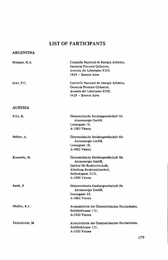
ARGENTINA
Molinari, M.A.
Soto, P.G.
AUSTRIA
Fritz, К.
Hefner, A.
K om urka, M.
Patek, P.
Pfeiffer, K.J.
Tschurlovits, M.
LIST OF PARTICIPANTS
Comisión Nacional de Energía Atóm ica, Gerencia Procesos Químicos,Avenida del L ibertador 8250,1429 — Buenos Aires
Comisión Nacional de Energía A tóm ica, Gerencia Procesos Químicos,Avenida del L ibertador 8250,1429 — Buenos Aires
Osterreichische Studiengesellschaft für A tom energie GmbH,
Lenaugasse 10,A -108 2 Vienna
Osterreichische Studiengesellschaft für A tom energie GmbH,
Lenaugasse 10,A-1082 Vienna
Osterreichische Studiengesellschaft für A tom energie GmbH,
Institu t fü r R eaktortechnik ,A bteilung R eaktorsicherheit,Sobieskigasse 21/3 ,A-1090 Vienna
Osterreichische Studiengesellschaft für A tom energie GmbH,
Lenaugasse 10,A-1082 Vienna
A tom institu te der O sterreichischen Hochschulen, Schüttelstrasse 115,A-1020 Vienna
A tom institu te der O sterreichischen Hochschulen, Schüttelstrasse 115,A-1020 Vienna
6 7 9
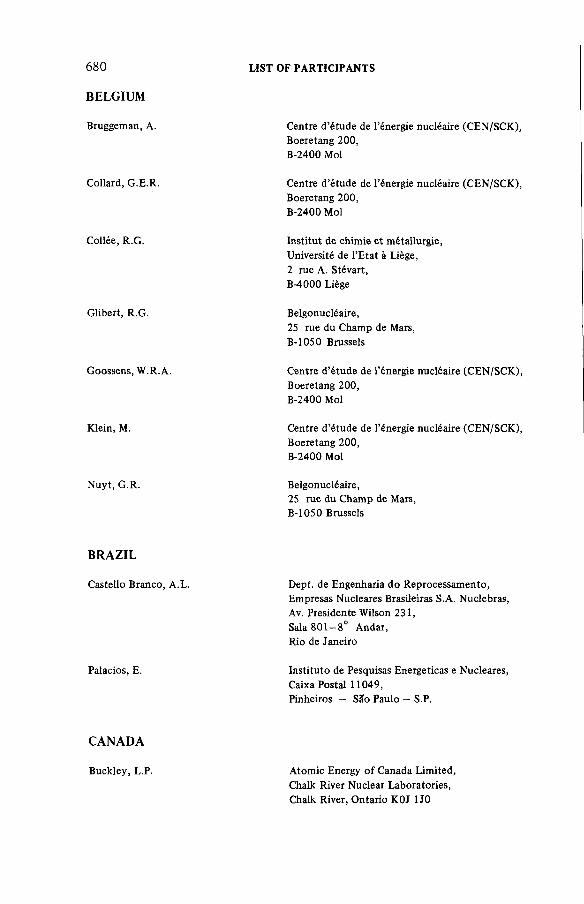
6 8 0 LIST OF PARTICIPANTS
BELGIUM
Bruggeman, A.
Collard, G.E.R.
Collée, R.G.
Glibert, R.G.
Goossens, W.R.A
Klein, M.
N uyt, G.R.
BRAZIL
Castello Branco,
Palacios, E.
CANADA
Centre d’étude de l’énergie nucléaire (CEN/SCK), Boeretang 200,B-2400 Mol
Centre d ’étude de l’énergie nucléaire (CEN/SCK), Boeretang 200,B-2400 Mol
Institu t de chimie e t métallurgie,Université de l’E ta t à Liège,2 rue A. Stévart,B-4000 Liège
Belgonucléaire,25 rue du Champ de Mars,B-1050 Brussels
Centre d’étude de l’énergie nucléaire (CEN/SCK), Boeretang 200,B-2400 Mol
Centre d’étude de l’énergie nucléaire (CEN/SCK), Boeretang 200,B-2400 Mol
Belgonucléaire,25 rue du Champ de Mars,B-1050 Brussels
A.L. Dept. de Engenharia do Reprocessam ento,Empresas Nucleares Brasileiras S.A. Nuclebras, Av. Presidente Wilson 231,Sala 801—8° Andar,Rio de Janeiro
Institu to de Pesquisas Energéticas e Nucleares, Caixa Postal 11049,Pinheiros — Sao Paulo — S.P.
Buckley, L.P. Atom ic Energy o f Canada Lim ited, Chalk River Nuclear Laboratories, Chalk River, Ontario K0J 1J0

LIST OF PARTICIPANTS
Glass, R.W.
Kabat, M.J.
Osborne, R.V.
Pollock, R.W.
Vivian, G.A.
CZECHOSLOVAKIA
Cejnar, F.
Feik, K.
Kepák, F.
Kortus, J.
S to rch ,O .
FINLAND
O ntario Hydro,800 Kipling Avenue,T oronto , O ntario M8Z 5S4
Ontario Hydro,Central Safety Service,P.O. Box 160,Pickering, O ntario L1V 2R5
A tom ic Energy o f Canada Lim ited,Chalk River Nuclear Laboratories,Chalk River, O ntario KOJ 1 JO
Atom ic Energy of Canada Lim ited, W hiteshell Nuclear Research Establishm ent, Pinawa, M anitoba ROE 1L0
O ntario Hydro,700 University Avenue,T oron to , O ntario M5G 1X6
Institu te o f Radiation Dosim etry o f the Academ y of Sciences,
Na Truhlárce 39/2a,CSSR-180 86 Prague 8
A tom ic Power Station Bohunice, CSSR-919 31 Jaslovské Bohunice
Nuclear Research Institu te , Rez, CSSR-250 68 Rez
Chem oprojekt,Stepánská 15,CSSR-Prague 2
Research Institu te fo r Air Engineering, Malesice, Pocernická 96,CSSR - Prague 10
Bergman, K.O. Institu te o f Radiation Protection , P.O. Box 268,SF-00101 Helsinki 10

FINLAND (cont.)
R uokola, E.J.
Silvennoinen, S.M.
Tuom inen, J.P .J.
FRANCE
Beunardeau, M.
B ouhet, J.C.S.H.
Calando, J.P.G.
Cohen, P.
Depierre, Y.
Dewanckel, B.
6 8 2 LIST OF PARTICIPANTS
Technical Research Centre o f Finland, R eactor Laboratory ,O takaari 3 A,SF-02150 Espoo 15
TVO Power Com pany,SF-27160 O lkiluoto
Im atran Voim a Oy,P.O. Box 138,SF-00101 Helsinki 10
Electricité de France,Service de la p roduction therm ique, D épartem ent E xploitation,Division Environnem ent-Sécurité,3 rue de Messine,F-75008 Paris
CEA, Centre d’études nucléaires de F ontenay-aux-Roses,
B.P. 6,F-92260 Fontenay-aux-Roses
CEA, Centre d’études de Bruyères-le-Châtel, B.P. 61,F-92542 M ontrouge Cedex
CEA, Centre d ’études nucléaires de Fontenay-aux-Roses,
B.P. 6,F-92260 Fontenay-aux-Roses
CEA, Centre d ’études nucléaires de Cadarache, B.P. 1,F-13115 Saint-Paul-lez-Durance
CEA, Centre d ’études nucléaires de Grenoble, 85 X,F-38041 G renoble Cedex
Elberg, S. CEA, Centre d’é tudes nucléaires de Grenoble, 85 X,F-38041 Grenoble Cedex

LIST OF PARTICIPANTS 683
Gaudiau, J. CEA, Centre d’études nucléaires de F ontenay-aux-Roses,
B.P. 6,F-92260 Fontenay-aux-Roses
Geneau, P. CEA, Service de protection sur les sites, B.P. 17,F-91310 Montlhéry
Giroux, P.J.M. CEA, Centre d’études de Valduc, B.P. 14,F-21120 Is-sur-Tille
Goumondy, J. P. CEA, Centre d’études nucléaires de Fontenay-aux-Roses,
B.P. 6,F-92260 Fontenay-aux-Roses
Hamard, J.F. CEA, Centre d’études nucléaires de F ontenay-aux-Roses,
B.P. 6,F-92260 Fontenay-aux-Roses
Hubert, G.A. Electricité de France — NERSA, 177 rue Garibaldi,B.P. 505,F-69217 Lyon Cedex 1
Leudet, A.J.L. CEA, Centre d’études nucléaires de Fontenay-aux-Roses,
B.P. 6,F-92260 Fontenay-aux-Roses
Maury, R.D.Y.F. Electricité de France — SOFINEL, Tour Fiat, 1 Place de la Coupole, B.P. 27079,F-92084 Paris la Défense
Méline, F. Socitété générale pour les techniques nouvelles, B.P. 30,F-78184 Saint-Quentin-en-Yvelines Cedex
Métairie, C.J.F. Electricité de France, Tour EDF-GDF, F-92080 Paris la Défense Cedex 08
Miquel, H.J.G. Electricité de France, 22—30 Avenue de Wagram, F-75008 Paris
684 LIST OF PARTICIPANTS
FRANCE (cont.)
Richter, R. Société générale pour les techniques nouvelles, B.P. 30,F-78184 Saint-Quentin-en-Yvelines Cedex
Rouyer, J. L. CEA, Centre d’études nucléaires de Fontenay-aux-Roses,
B.P. 6,F-92260 Fontenay-aux-Roses
Séguy, M. R. CEA, Centre d’études nucléaires de Saclay, B.P. 2,F-91190 Gif-sur-Yvette
Sigli, P.HJ.M. CEA, Centre d’études nucléaires de Saclay, B.P. 2,F-91190 Gif-sur-Yvette
Tibi, A. CEA, Centre d’études nucléaires de Cadarache, B.P. 1,F-13115 Saint-Paul-lez-Durance
Uzzan, G. CEA, Centre d’études nucléaires de F ontenay-aux-Roses,
B.P. 6,F-92260 Fontenay-aux-Roses
GERMAN DEMOCRATIC REPUBLIC
Herrmann, D. Staatliches Amt für Atomsicherheit und Strahlenschutz der DDR,
Waldo wallee 117,GDR-1157 Berlin
Ullmann, W. Staatliches Amt für Atomsicherheit und Strahlenschutz der DDR,
Waldowallee 117,GDR-1157 Berlin
GERMANY, FEDERAL REPUBLIC OF
Ammon, R. von Institut für Heisse Chemie, Kernforschungszentrum Karlsruhe GmbH, Postfach 3640,D-7500 Karlsruhe 1

LIST OF PARTICIPANTS 685
Baukal, W. Battelle-Institut eV, Postfach 900160,D-6000 Frankfurt a.M. 90
Becker, R. Institut für Heisse Chemie, Kernforschungszentrum Karlsruhe GmbH, Postfach 3640,D-7500 Karlsruhe 1
Braun, H. Bundesministerium des Innem, Référât RS II 4,Postfach 170 290,D-5300 Bonn 1
Brücher, H. Institut für Chemische Technologie, Kernforschungsanlage Jülich GmbH, Postfach 1913,D-5170 Jülich
Burkhardt, H.-G. Institut für Heisse Chemie, Kernforschungszentrum Karlsruhe GmbH, Postfach 3640,D-7500 Karlsruhe 1
Deuber, H. Laboratorium für Aerosolphysik und Filtertechnik II (LAF II),
Kernforschungszentrum Karlsruhe GmbH, Postfach 3640,D-7500 Karlsruhe 1
Eichberger, К. Institut für Strahlenhygiene des Bundesgesundheitsamtes,
Ingolstâdtër Landstrasse 1, D-8041 Neuherberg
Fischer, K. Deutsche Gesellschaft für Wiederaufarbeitung von Kembrennstoffen mbH,
Buenteweg 2,D-3000 Hanover 71
Frankenfeld, K. Physikalisch-Technische Bundesanstalt, Bundesallee 100,D-3300 Braunschweig
Godoy, M.L. Institut für Heisse Chemie, Kernforschungszentrum Karlsruhe GmbH, Postfach 3640,D-7500 Karlsruhe

686 LIST OF PARTICIPANTS
Gründler, D.
Gutowski, H.
Hartmann, K.
Henrich, E.
Hüfner, R.
Hutter, E.
Israel, G.
Knoll, D.
Kônig, L.A.
GERMANY, FEDERAL REPUBLIC OF (cont.)
Lehrstuhl für Reaktortechnik, Rheinisch-Westfalische Technische Hochschule
Aachen,Eilfschomsteinstrasse 18,D-5100 Aachen
LINDE AG,Werksgruppe TUT München,Dr. Carl von Linde Stresse 6—14,D-8023 Hollriegelskreuth
Institut für Chemische Technologie, Kemforschungsanlage Jülich GmbH,Postfach 1913,D-5170 Jülich
Institut für Heisse Chemie, Kemforschungszentrum Karlsruhe GmbH, Postfach 3640,D-7500 Karlsruhe
Institut für Heisse Chemie, Kemforschungszentrum Karlsruhe GmbH, Postfach 3640,D-7500 Karlsruhe
Hauptabteilung Ingenieurtechnik, Kemforschungszentrum Karlsruhe GmbH, Postfach 3640,D-7500 Karlsruhe
Piojektbereich WAG,Kemforschungszentrum Karlsruhe GmbH, Postfach 3640,D-7500 Karlsruhe
Technischer Uberwachungsverein Norddeutschland eV,
Grosse Bahnstrasse 31,D-2000 Hamburg 54
Hauptabteilung Sicherheit, Kemforschungszentrum Karlsruhe GmbH, Postfach 3640,D-7500 Karlsruhe
LIST OF PARTICIPANTS 687
Kretschmer, H.K. KEWA GmbH, Hildesheimerstrasse 47, D-3000 Hanover
Kroebel, R. Projekt Wiederaufarbeitung und Abfallbehandlung (Projektleitung),
Kernforschungszentrum Karlsruhe GmbH, Postfach 3640,D-7500 Karlsruhe
Leichsenring, C.H. Projekt Wiederaufarbeitung und Abfallbehandlung (Projektleitung),
Kernforschungszentrum Karlsruhe GmbH, Postfach 3640,D-7500 Karlsruhe
Lessmann, E.E. Kemforschungszentrum Karlsruhe GmbH, Postfach 3640,D-7500 Karlsruhe
Patzelt, A. LINDE AG,Dr. Carl von Linde Strasse 6—14, D-8023 Hôllriegelskreuth
Penzhorn, R.-D. Institut für Radiochemie, Kemforschungszentrum Karlsruhe GmbH, Postfach 3640,D-7500 Karlsruhe
Ringel, H. Institut für Chemische Technologie, Kemforschungsanlage Jülich GmbH, Postfach 1913,D-5170 Jülich
Rosenbaum, O.E.R. Ministerium für Arbeit, Gesundheit und Soziales des Landes Nordrhein-Westfalen,
Harianplatz la,D-4000 Düsseldorf
Schatte, W. Technischer Überwachungsverein Hannover eV, Loccumer Strasse 63,D-3000 Hanover 81
Schneider, G.E. Kernforschungszentrum Karlsruhe GmbH, Postfach 3640,D-7500 Karlsruhe
Seiffert, H. Kemforschungszentrum Karlsruhe GmbH, Postfach 3640,D-7500 Karlsruhe

688 LIST OF PARTICIPANTS
GERMANY, FEDERAL REPUBLIC OF (cont.)
Tschulena, G. Battelle-Institut eV, Am Rômerhof 35, D-6000 Frankfurt 90
Wamecke, E. Physikalisch-Technische Bundesanstalt, Bundesallee 100,D-3300 Braunschweig
Weber, J. LINDE AG,Dr. Carl von Linde Strasse 6—14, D-8023 Hollriegelskreuth
Wille, H. Kraftwerk Union, Hammerbacher Strasse 12-14 , D-8520 Erlangen
Wüsteneck, A. SYSTEC GmbH, Wildenbruchstrasse 28, D-4000 Düsseldorf 11
HOLY SEE
Kratschmann, H. Nuntiatur,Theresianumgasse 31, A -l040 Vienna, Austria
INDIA
Jeelani, S.A.K. Department of Atomic Energy, Reprocessing Development Laboratory, Reactor Research Centre,Kalpakkam 603102,Tamil Nadu
ITALY
Ameglio, P. University of Genoa,V. Balbi 5,Genoa
Curzio, G.G. Istituto di Impianti Nucleari, Via Diotisalvi 2,1-56100 Pisa

LIST OF PARTICIPANTS 689
Gagliardi, S. Comitato Nazionale per l’Energia Nucleare, Viale Regina Margherita 125,1-00198 Rome
Grillo, P. SF-Combustibili per Reattori Veloci SpA, Corso di Porta Romana 68,1-20100 Milan
Lanza, S. Istituto di Impianti Nucleari, Université di Pisa,Via Diotisalvi 2,1-56100 Pisa
Laraia, M. Comitato Nazionale per l’Energia Nucleare, (DISP),Viale Regina Margherita 125,1-00198 Rome
Manilia, E. Comitato Nazionale per l’Energia Nucleare, Via le Regina Margherita 125,1-00198 Rome
Mazzini, M. Istituto di Impianti Nucleari, Université di Pisa,Via Diotisalvi 2,1-56100 Pisa
Moccia, A. Comitato Nazionale per l’Energia Nucleare, CSN-Casaccia,Via Anguillarese Km 1.3,Rome
Molina, L. SIGEN,Via Caboto 5, Corsico (MI)
Pedicchio, V. Termokimik Corporation, Via Flumendosa 13,1-20100 Milan
Russino, G. Direzione delle Costruzioni,Ente Nazionale per l’Energia Elettrica, Via G.B. Martini 3,Rome

690 LIST OF PARTICIPANTS
Abe, S.
Hiiota, K.
Motegi, M.
Nagino, Y.
Nishiwaki, Y.
JAPAN
1st Laboratory of Environmental Health, Division of Environmental Health,National Institute of Radiological Sciences, 9 -1 Anagawa-4, Chiba-shi, 260
Radioactive Waste Management Center, Mori Building 15,8—10, Toranomon 2-chome,Minato-ku, Tokyo
Mitsui Mining and Smelting Co., Ltd,2-chome Nihonbashi, Muromachi,Chuo-ku, Tokyo
Kansai Electric Power Company, Inc.,3—3—22 Nakano-Shima,Kita-ku, Osaka
Atomic Energy Research Institute of Kinki University,
3—4—1 Kowakae, Higashi, Osaka City, Osaka
NETHERLANDS
Van der Werf, B. Nuclear Department,Directoraat-Generaal van de Arbeid,Balen van Andelplein 2,NL-2273 KH Voorburg
Verkerk, B. Netherlands Energy Research Foundation ECN,3 Westerduinweg, Postbus 1,NL-1755 ZG Petten
NORWAY
Michelsen, H.M. Norwegian Nuclear Energy Authority,Norges Hóyesterett, Tinghuset,Oslo Department,Oslo
LIST OF PARTICIPANTS
PAKISTAN
Mirza, K.F. Karachi Nuclear Power Plant,P.O. Box 3183,Karachi
POLAND
Tykal, A. Radioactive Waste Disposal Department,Institute of Nuclear Research,PL-05-400 Swierk-Otwock
PORTUGAL
Baptista, A.A. Electricidade de Portugal,Rúa de Conde Redondo, 145-4-, P-l 100 Lisbon
SPAIN
Brincones, M. Junta de Energía Nuclear,Avenida Complutense, 22, Madrid-3
Censóla, F.F. Junta de Energía Nuclear,Avenida Complutense, 22, Madrid-3
Diaz de la Cruz, F. Junta de Energía Nuclear,Avenida Complutense, 22, Madrid-3
SWEDEN
Boge, R. National Institute of Radiation Protection,P.O. Box 60204,S-10401 Stockholm
Hesbtfl, R. Studsvik Energiteknik AG, FACK,S-61182 Nykóping
692 LIST OF PARTICIPANTS
SWITZERLAND
Brélaz, P. Division pour la sécurité des installationsnucléaires,
CH-5303 Würenlingen
UNION OF SOVIET SOCIALIST REPUBLICS
Smirnova, N.M. USSR State Committee on the Utilizationof Atomic Energy,
Staromonetnyj 26,Moscow
UNITED KINGDOM
Atherton, R.S. Health & Safety Directorate, R 102, British Nuclear Fuels Ltd,Risley, Warrington,Cheshire WA3 6AS
Blackman, T.E.
Brazendale, P.R.D.
United Kingdom Atomic Energy Authority, Atomic Energy Establishment Winfrith, Winfrith, Dorchester, Dorset
Environmental Protection Group,Nuclear Wastes Division,Department of the Environment,R 420 A Becket House,1, Lambeth Palace Road,London SE1 7ER
Carr, J.A. Ministry of Agriculture, Fisheries and Food, 7th floor,65 Romney Street,London SW1P 3RD
Collins, R.D.
Davies, R.A.
United Kingdom Atomic Energy Authority, Windscale Nuclear Power Development
Laboratories,Windscale Works,Sellafield, Seascale,Cumbria CA20 1PF
United Kingdom Atomic Energy Authority, Dounreay Nuclear Power Development
Establishment,Dounreay, Thurso,Caithness, Scotland

LIST OF PARTICIPANTS 693
Doyle, A.R. Central Electricity Generating Board, Wylfa Power Station,Cemaes Bay, Gwynedd LL67 ODH
Fern, C.W. Central Electricity Generating Board, South Eastern Region Scientific Services
Department,Canal Road,Gravesend, Kent DA 12 2RS
Groom, D.J. Central Electricity Generating Board, Health and Safety Department,18, Warwick Lane,London EC4P 4EB
Knight-Sweeney, B. H.M. Nuclear Installations Inspectorate, Thames House North, Millbank,London SW1P4Q5
Mackellar, A. Nuclear Power Company Ltd, Warrington Road,Risley, Warrington, Cheshire WA3 6B3
Marshall, M. Atomic Energy Research Establishment, Harwell, Didcot, Oxon 0X11 ORA
McKay, H.A.C. Atomic Energy Research Establishment, Harwell, Didcot, Oxon 0X11 ORA
McNair, A. The Radiochemical Centre,White Lion Road,Amersham, Buckinghamshire HP7 9LL
McQuillan, C.W.
Meggitt, G.C.
British Nuclear Fuels Ltd,Salwick, Preston, Lancashire PR4 OXJ
United Kingdom Atomic Energy Authority, Safety and Reliability Directorate,Wigshaw Lane, Culcheth, Warrington WA3 4NE
Milne, D. British Nuclear Fuels Ltd,Rutherford House,Warrington Road,Risley, Warrington, Cheshire WA3 6B3
Pick, M.E. Central Electricity Generating Board, Berkeley Nuclear Laboratories, Berkeley, Gloucestershire GL13 9PB

694 LIST OF PARTICIPANTS
Smith, M.J.S.
Smitton, C.
UNITED KINGDOM (cont.)
Solan, P.A.
Watson, B.W.
White, I.F.
Whitmell, D.S.
Williams, A.J.
Wilson, J.A.
Chemical Technology Division,Atomic Energy Research Establishment, Harwell, Didcot, Oxon 0X11 ORA
Central Electricity Generating Board,North Western Region,Scientific Services Centre,Timpson Road,Manchester M23 9LL
Nuclear Power Company Ltd,Warrington Road,Risley, Warrington, Cheshire WA3 6BZ
United Kingdom Atomic Energy Authority, Safety and Reliability Directorate,Wigshaw Lane, Culcheth, Warrington WA3 4NE
National Radiological Protection Board, Harwell, Didcot, Oxon 0X11 ORQ
Atomic Energy Research Establishment, Harwell, Didcot, Oxon 0X11 ORA
British Nuclear Fuels Ltd,Windscale & Calder Works,Sellafield, Seascale, Cumbria CA20 IPG
Scottish Development Department,H.M. Industrial Pollution Inspectorate,Pentland House, 47,Robb’s Loan,Edingburgh EH14 1TY
UNITED STATES OF AMERICA
Abrams, R J . Helix Process Systems,Walkup Drive,West borough, MA 01581
Allen, W.B. Pacific Gas & Electric,77 Beale Street,San Francisco, CA 94106

LIST OF PARTICIPANTS 695
Anderson, D.F. Los Alamos Scientific Laboratory, P.O. Box 1663, Mail Stop-401,Los Alamos, NM 87545
Brown, R. Exxon Nuclear Idaho Co., P.O. Box 2800,Idaho Falls, ID 83401
First, M.W. Department of Environmental Health Sciences, Harvard University, School of Public Health, 665, Huntington Avenue,Boston, MA 02115
Fowler, K.L. UNC Nuclear Industries,P.O. Box 490, 100-N Area 1100 Building, Richland, WA 99352
Hanson, M.S. Battelle Pacific Northwest Laboratories, P.O. Box 999,Richland, WA 99352
Hickey, J.W.N. Office of Standards Development,United States Nuclear Regulatory Commission, Washington, DC 20555
Higgins, W.K. Helix Process Systems, Walkup Drive, Westborough, MA 01581
Kovach, J.L. Nuclear Consulting Services, P.O. Box 29151,Columbus, OH 43229
Pence, D.T. Science Applications, Inc.,4030 Sorrento Valley Boulevard, San Diego, CA 92121
Schuette, O.F. Department of Physics, University of South Carolina, Columbia, SC 29208
Skinner, S.B. The University of South Carolina, Coastal Carolina College,Conway, SC 29526
Stephenson, M.J. Oak Ridge Gaseous Diffusion Plant, Union Carbide Corporation,P.O. Box X,Oak Ridge, TN 37830

696 LIST OF PARTICIPANTS
UNITED STATES OF AMERICA (cont.)
Thompson, M.C. E.I. du Pont de Nemours, Savannah River Laboratory, Aiken, SC 29801
Till, H. Electric Power Research Institute, 3412, Hillview Avenue,P.O. Box 10412,Palo Alto, CA 94303
Tingey, G.L. Battelle, Pacific Northwest Laboratories, P.O. Box 999,Richland, WA 99352
YUGOSLAVIA
Strohal, P. Permanent Mission of Yugoslavia the the IAEA, Rennweg, 3,A-l 030 Vienna, Austria
ORGANIZATIONS
COMMISSION OF THE EUROPEAN COMMUNITIES (CEC)
Huber, B.
Luykx, F.
CEC,Rue de la Loi 200, DG XII-D-1, B-1049 Brussels, Belgium
CEC,Direction Santé et Sécurité,Div. V/E/2 - A2-079,Bâtiment Jean Monnet, Luxembourg
OECD NUCLEAR ENERGY AGENCY (OECD/NEA)
Olivier, J.-P. OECD/NEA,38 Boulevard Suchet, F-75016 Paris,France

AUTHOR INDEX
Italic Arabic numerals refer to the first page of a paper by the author concerned. Arabic numerals denote questions and comments in discussions.
Abbey, F.: 571 Abrams, R.F.: 261 Ahner, S.: 645Am m on, R. von: 229, 242 , 442 Anderson, D.F.: 363, 370 Baetsle, L.H.: 9 1 ,1 5 7 ,4 8 1 Balasubramanian, G.R.: 497 Baptista, A.A.: 671 Bayne, M.A.: 279 Becker, R.: 81 Bergman, K.O.: 556 Blackman, T.E.: 4 2 8 ,5 9 4 Boge, R.: 480 Bonka, H.: 211 Bon Mardion, G.: 431 Braun, H.: 211Brown, R.: 5 5 ,7 9 ,2 6 1 ,2 7 7 ,2 7 8 ,
300, 4 2 8 ,6 1 2 ,6 4 3 ,6 5 8 Brücher, H.: 80 , 189, 612, 615,
659Bruggeman, A .: 757, 173, 174,
1 7 5 ,4 0 7 Buckley, L.P.: 1 7 5 ,5 4 3 Burkhardt, H.-G.: 81 Cardinale, A. : 519 Cejnar, F.: 1 3 7 ,2 2 5 ,2 7 8 ,3 7 0 ,
5 5 6 ,6 1 2 Claes, W.: 627Collard, G.E.R.: 442, 481, 49'3, 494 ,
545, 673 Collins, R.D.: 2 0 ,1 3 6 ,3 1 3 ,3 9 1 ,
4 2 8 ,5 7 7 ,5 9 3 , 594 , 6 5 9 ,6 7 6
Davies, R.A.: 480 De Greef, J.F.: 627 Depierre, Y.: 4 3 1 ,4 9 4 De Smet, М.: 91Deuber, H.: 20 , 55, 100, 137, 226,
4 6 1 ,4 9 3 ,5 1 7 , 6 6 5 ,6 7 0 , 675 , 676 Dewanckel, B.: 431, 4 4 2 ,4 4 3 Doyen, W.: 157 D oyle, A .R .: 347, 3 6 0 ,3 6 1 Fern, C.W. : 445 Fessier, В.: 463First, M.W.: 5 ,2 0 ,2 1 ,2 7 8 ,3 1 2 ,
429 , 516 , 569 , 661, 669 , 671 , 674,6 7 5 ,6 7 6
Fischer, К.: 2 2 5 ,3 1 2 ,3 6 0 ,4 6 1 , 5 1 6 ,6 1 2 ,6 5 8 ,6 6 9 ,6 7 0
Forsberg, C.W.: 191 Fossion, P.: 545 Fowler, K .L .: ¥ 7 7 ,4 2 8 ,4 2 9 Glibert, R.G. : 5 4 5 ,5 5 5 ,5 5 6 Goles, R.W.: 371 Goossens, W.R.A.: 91, 157, 209,
3 9 1 ,4 7 9 ,4 8 1 , 5 1 7 ,5 4 2 , 643,644 , 664 , 676
Goum ondy, J .P .: 557, 569 Gray, W.J.: 279 Grillo, P.: 519Groom, D.J.: 4 * 5 ,4 6 1 ,4 6 2 ,6 7 4 Gründler, D.: 211, 225 , 226 , 494 G utow ski, H. : 1 7 4 ,2 7 7 ,2 6 1 Haag, G.L. : 191 Hamard, J.F.: 672
697
698 AUTHOR INDEX
Hamilton, D.C.: 371 Hammond, K.: 347 Hanson, M.S.: 371, 390 , 391 Harnie, R.: 157 Hartmann, K.: 615 Hellwig, L.M.: 291 Henrich, E.: 139, 156 ,177 , 189,
493Henrion, P.N.: 627 Hickey, J.W.N.: 45, 55 Hiebert, R.D.: 363 Hillary, J.J.: 571 Holladay, D.W.: 191 Huber, B.: 39 Hubert, G.A. : 442 Hüfner, R.: 139 Hutter, E. : 229 Jeelani, S.A.K.: 122, 345 , 479 ,
497, 5 1 6 ,5 1 7 Kabat, M.J.: 1 2 2 ,2 0 9 Kanak, B.E.: 243 Kanka, J.: 101 Kapoor, J.C.: 333 Kepák, F.: 101, 111 Khan, A .A.: 333 Kirchmann, R.: 479 Klein, М.: 91, 100, 111 Knittel, G.: 229 Komurka, М.: 556 Kônig, L.A.: 463, 479 , 480 Koutová, S.: 101 Kovach, J.L.: 2 6 1 ,3 3 1 ,5 5 5 ,5 9 3 ,
594, 673 Kretschmer, H.K.: 1 7 5 ,6 7 0 Kroebel, R.: 1 7 3 ,1 8 9 ,5 4 3 ,6 7 1 Lafon, A.: 431 Lanza, S.: 315, 330, 331 Laushkina, G.A. : 115 Leichsenring, C.H.: 242 Leudet, A.J.L.: 494 Leurs, A.: 627 Leysen, R.: 157
Little, D.K.: 243 Loshakov, G.A.: 115 Luykx, F.: 1 3 8 ,331 Mackellar, A.: 675 Maestas, E.: 31 Matous, V. : 101 Mazzini, М.: 315, 662 McClanahan, E.D.: 279 McElroy, R.G.C.: 393 McKay, H.A.C.: 59, 79 , 80 , 138,
156, 260, 644, 659, 668, 671,6 7 4 ,6 7 6
McNair, A.: 428 Merriman, J . R. : 243 M eynendonckx, L.: 157 Moccia, A.: 122 Molinari, M.A.: 330 Monsecour, M. : 157 Nakhutin, I.E.: 115 Nishiwaki, Y.: 1 7 4 ,3 0 0 ,6 1 2 .Neeb, K.H.: 8 1 ,1 7 7 Nelson, R.S.: 263 Noppel, H.E.: 291 N otz, K.J.: 191 Nuyt, G.R.: 4 7 9 ,5 4 5 Olivier, J.P.: 672Osborne, R.V.: 370, 393, 407 , 658,
6 6 2 ,6 6 9 ,6 7 2 , 675 Palacios, E.: 313, 390, 462 Patek, P .: 7 9 ,2 7 8 ,3 9 1 Pecák, V.: 101Pence, D.T. : 242, 390, 667, 672 Penzhorn, R.-D.: 260 , 278, 291,
2 9 9 ,3 0 0 , 643 Pisani, U.: 315 Przyborowski, S.: 303 Rastunov, L.N.: 115 Ringel, H. : 209 Roux, J.P.: 5 5 7Rouyer, J.L.: 5 4 3 ,5 5 7 , 568 , 569 Sahm, A.: 139 Schmieder, H.: 177
AUTHORINDEX 699
Schuster, P.: 291 Schüttelkopf, H. : 463 Seiffert, H.: 531, 542, 543 Sigli, P.H.J.M.: 4 2 9 ,6 6 6 Smirnova, N.M.: 115, 122 Smith, M.J.S.: 263, 494 , 611, 658 Srinivas, C. : 333 Stephenson, M .J.: 2 0 9 ,2 1 0 ,2 2 5 ,
243, 2 6 0 ,2 6 1 Taylor, L.R.: 571 Thomas, K.T.: 333 Till, H.: 123, 137, 138 Tingey, G.L.: 279, 299 , 300 , 361 Uher, E.: 101Ullmann, W .: 303, 312 , 313 Vaesen, P.J.: 481 Van Dalen, A.: 597 Verdier, J.: 431
Verkerk, B.: 597, 611 , 612 , 613 Vigía, D.: 557 Violet, J.-L.: 431 Vivian, G.A.: 672 Vons, L.H.: 597 Warnecke, E.: 6 4 5 ,6 5 8 ,6 5 9 Watson, B.W.: 3 9 1 ,5 4 2 Weber, J.: 211, 225, 226 Weisenburger, S.: 531 White, I.F.: 7 9 ,6 7 1 Whitmell, D .S .: 263, 277 , 278 Wilkinson, B.A.: 445 Williams, A.J.: 1 0 0 ,2 2 5 ,3 1 3 ,3 4 5 ,
4 2 8 ,5 6 8 Wilson, J.A.: 2 4 2 ,3 6 1 ,4 2 9 ,4 6 1 Würtz, R.: 81 Zabaluev, Yu.: 25
TRANSLITERATION INDEX
Л а у ш к и н а , Г . A .
Л о ш а к о в , Г . A .
Н а х у т и н , И .Е .
Р а с т у н о в , Л .Н .
С м и р н о в а , Н .М ,
Laushkina, G.A. Loshakov, G.А. Nakhutin, I.E. Rastunov, L.N. Smirnova, N.M.
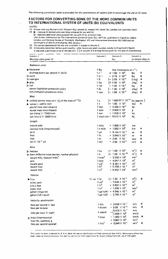
FACTORS FOR CONVERTING SOME ОТ THE MORE COMMON UNITS TO INTERNATIONAL SYSTEM OF UNITS (SI) EQUIVALENTS
NOTES'.(1) SI base units a r ç th e m etre (m ), kilogram (kg), second <s), am pere (A), kelvin (K l, candela <cd> and mole (mol).(2) ► indicates SI derived units and those accepted fo r use w ith SI;
C> indicates additional units accepted for use w ith SI for a lim ited tim e.[For further information see The International System o f Units (SI), 1977 ed., published in English by HMSO,London, and National Bureau o f Standards, Washington. DC, and International Standards ISO-1000 and the several parts o f ISO-31 published by ISO, Geneva. )
(3) The correct abbreviation for th e un it in co lum n 1 is given in colum n 2.(4) -)fr indicates conversion factors given exactly ; o th e r factors are given rounded , m ostly to 4 significant figures.
= indicates a defin ition of an SI derived unit: [ ] in colum n 3+4 enclose facto rs given for th e sake of com pleteness.
The fo llow ing conversion table is provided fo r the convenience o f readers and to encourage the use o f SI units.
C o lu m n 1
Multiply data given in:C o lu m n 2 C o lu m n 3
by:C o lu m n 4to obtain data in:
Radiation units
^ becquerel 1 Bq (has dimensions of s 1 )disintegrations per second {= dis/s) 1 s_1 = 1.00 X 10° Sq *
> curie 1 Ci - = 3.70 X 10¹⁰ Bq *> roentgen 1 R i.= 2.68 X 10⁻⁴ C/kgJ *► gray 1 Gy I;= roo x io° J/kgJ *> rad 1 rad = 1.00 X 10'2 Gy *
sievert (radiation protection only) 1 Sv [ = 1.00 x io° J/kg] *rem (radiation protection only} 1 rem (= 1.00 X 10‘ 2 J/kgj *Mass
► unified atomic mass unit (- of the mass of 52C) 1 u I[= 1.660 57 X 10“ 27 kg, approx. ]^ tonne (= metric ton) 1 t I[= 1.00 X 10³ kg] *
pound mass (avoirdupois) 1 Ibm = 4.536 X 1 0 '1 kgounce mass (avoirdupois) 1 ozm = 2.835 X 101 9ton (long) (= 2240 Ibm) 1 ton = 1.016 X 10³ kgton (short) (= 2000 Ibm) 1 short ton = 9.072 X 10² kg
Length
statute mile 1 mile = 1.609 X 10° kmnautical mile (international) 1 n mile = 1.852 X 10° km ■*yard 1 yd = 9.144 X 10_1 m ■*foot 1 ft = 3.048 X 10*' m *inch 1 in = 2.54 X 101 mm #mil (= 10-3 in) 1 mil = 2.54 X 10"2 mm *
Area
> hectare 1 ha [= 1.00 X 10⁴ m2] *> barn (effective cross-section, nuclear physics) 1 b [= 1.00 X 10 '28 m21 *
square mile, (statute mile)2 1 mile2 = 2.590 X 10° km2acre 1 acre = 4.047 X 10³ m2square yard 1 yd2 = 8.361 X 10 '1 m2square foot 1 ft2 = 9.290 X 10'2 m2square inch 1 in2 = 6.452 X 102 mm2
Volume
► litre 1 I or 1 )tr [= 1.00 X 1 0 '3 m3] *
cubic yard 1 yd3 = 7.646 X 1 0 '1 m3
cubic foot 1 ft3 = 2.832 X 10 '2 m3
cubic inch 1 in3 = 1.639 X 10" mm3gallon (imperial) 1 gal (UK) = 4.546 X 10 '3 m3gallon (US liquid) 1 gal (US) = 3.785 X 10⁻³ m3
Velocity, acceleration
foot per second (= fps) 1 ft/s = 3.048 X 10“ ‘ m/s *foot per minute 1 ft/min = 5.08 X 10 '3 m/s *
mile per hour (= mph) 1 mile/hÍ4.470 X 10“'
= \l .609 X 10°m/skm/h
> knot (international) 1 knot = 1.852 X 10° km/h *free fall, standard, g foot per second squared 1 ft/s2
= 9.807 X 10° = 3.048 X 10"'
m/s2m/s2 *
T h is ta b le has be e n p re p a re d b y E .R .A . B eck <or use b y th e D iv is io n o f P u b lic a t io n s o f th e IA E A . W h ile e ve ry e ff o rt has b e e n m ad e to e n s u re a c c u ra c y , th e A g e n c y c a n n o t b e h eld re sp o n sib le f o r e rro rs a ris in g fro m th e u se o f th is tab le .
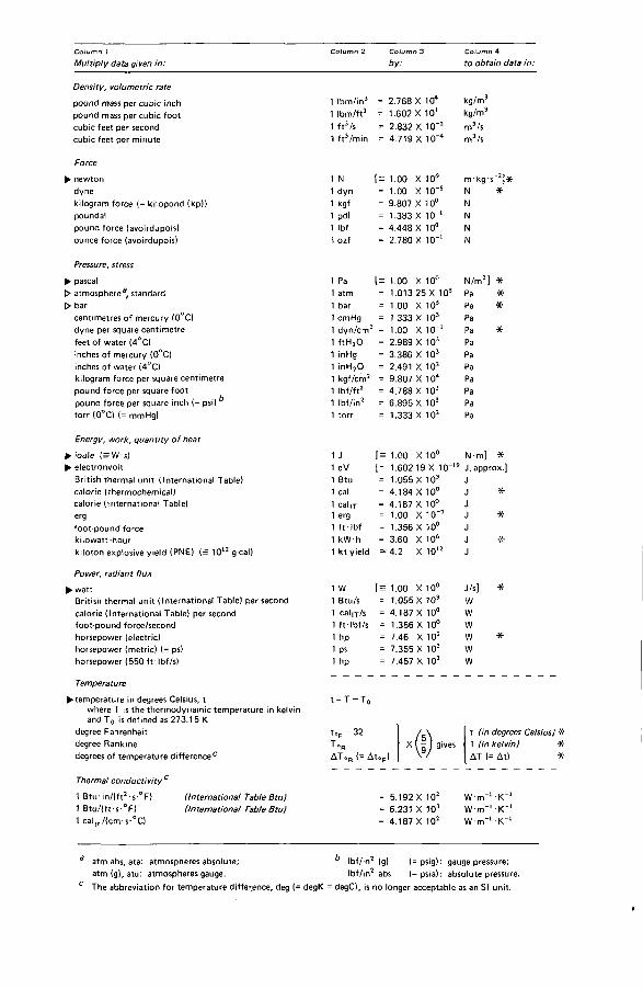
C o lu m n 1Multiply data given in: C o lu m n 2 C o lu m n 3 C o lu m n 4by: to obtain data in:Density, volumetric ratepound mass per cubic inch 1 lbm/in3 = 2.768 X 10⁴ kg/m3
pound mass per cubic foot 1 lbm/ft3 = 1.602 X 10' kg/m3
cubic feet per second 1 ft3/s = 2.832 X 10⁻² m3/scubic feet per minute 1 ft3/min = 4.719 X 10~4 m3/s
Force► newton 1 N 1.00 X 10° m-kg s 3] *
dyne 1 dyn = 1.00 X 10"s N *kilogram force (= kilopond (kp)) 1 kgf = 9.807 X 10° Npoundal 1 pdl = 1.383 X 10_l Npound force (avoirdupois) 1 Ibf = 4.448 X 10° Nounce force (avoirdupois) 1 ozf = 2.780 X 1 0 '1 N
Pressure, stress► pascal 1 Pa (= 1.00 X 10° N/m2] *> atmosphere® standard 1 atm = 1.013 25 X 10s Pa ■sf> bar 1 bar = 1.00 X 10s Pa *
centimetres of mercury (0°C) 1 cmHg = 1.333 X 10³ Padyne per square centimetre 1 dyn/cm2 = 1.00 X 10"] Pa *feet of water (4°C) 1 ft Hj 0 = 2.989 X 10³ Painches of mercury (0°C) 1 inHg = 3.386 X 10³ Painches of water (4°C) 1 inHjO = 2.491 X 10² Pakilogram force per square centimetre 1 kgf/cm2 = 9.807 X 10⁴ Papound force per square foot 1 lbf/ft2 = 4.788 X 10' Papound force per square inch (= psi) ^ 1 lbf/in2 = 6.895 X 10³ Patorr (0°C) (= mmHg) 1 torr = 1.333 X 10² Pa
Energy, work, quantity of heat► joule (= W s) 1 J [= 1.00 X 10° N-mJ *► electronvolt 1 eV [= 1.602 19 X 10" 19 J , approx.]
British thermal unit (International Table) 1 Btu = 1.055 X 10³ Jcalorie (thermochemical) 1 cal = 4.184 X 10° J *calorie (international Table) 1 cal it = 4.187 X 10° Jerg 1 erg = 1.00 X 10“7 J *
foot-pound force 1 ft-Ibf = 1.356 X 10° Jkilowatt-hour 1 kW h = 3.60 X 10⁶ J •X-kiloton explosive yield (PNE) (= 1012 g-cal) 1 kt yield = 4.2 X 10¹² J
Power, radiant flux► watt 1 W [= 1.00 X 10° J/s] *
British thermal unit (International Table) per second 1 Btu/s = 1.055 X 10³ Wcalorie (International Table) per second 1 cal if/s = 4.187 X 10° Wfoot-pound force/second 1 ft*Ibf/s = 1.356 X 10° Whorsepower (electric) 1 hp = 7.46 X 10² W *horsepower (metric) (= ps) 1 ps = 7.355 X 10² Whorsepower (550 f t • Ibf/s) 1 hp = 7.457 X 10² W
Temperature► temperature in degrees Celsius, t
where T is the thermodynamic temperature in kelvin andT0 is defined as 273.15 К
degree Fahrenheit degree Rankinedegrees of temperature difference c
t = T - T 0
toF -3 2
T°RД Т .Я <= Д ц ]
X ( It (in degrees Celsius) * T (in kelvin} *ДТ (= At) *
Thermal conductivity1 B tu in / (ft2-s-°F)1 8 tu / ( f t s ° F )1 calrr/(cnvs-°C)
(International Table Btu) (International Table Btu} = 5.192 X 1СГ = 6.231 X 103 = 4.187 X 10²
W m '1 K" W m -1 K" W m_l K"
atm abs, ata: atmospheres absolute; lbf/in2 (g) (= psig) : gauge pressure;atm (g), atü: atmospheres gauge. (bf/in2 abs (= psia) : absolute pressure.The abbreviation for temperature difference, deg (= degK = degC), is no longer acceptable as an SI unit.

HOW TO ORDER IAEA PUBLICATIONSAn exclusive sales agent for IA EA publications, to whom all orders
and inquiries should be addressed, has been appointed in the following country:
U N IT E D S T A T E S O F A M E R IC A U N IP U B , 345 Park Avenue South , New Y o rk , N Y 10010
In the following countries IA E A publications may be purchased from the sales agents or booksellers listed or through your major local booksellers. Payment can be made in local currency or with UN ESCO coupons.
A R G E N T IN A
A U S T R A L IAB EL G IU M
C Z E C H O S L O V A K IA
F R A N C E
H U N G A R Y
IN D IA
IS R A E L
IT A L Y
JA PA NN E T H E R L A N D S
P A K IS T A NPO LA N D
RO M A N IA SO U TH A F R IC A
SPA IN
SW ED EN
U N IT E D K IN G D O M
U .S .S .R .Y U G O S L A V IA
Comisión Nacional de Energía A tóm ica, Avenida del Libertador 8250, RA-1429 Buenos AiresHunter Publications, 58 A Gipps Street, Collingwood, V icto ria 3066Service Courrier U N ESC O , 202 , Avenue du R o i, B-1060 BrusselsS .N .T .L . , Spálená 51, CS-113 02 Prague 1A lfa , Publishers, Hurbanovo námestie 6 , CS-893 31 BratislavaO ffice International de Documentation et L ib ra irie , 48, rue Gay-Lussac,F-75240 Paris Cedex 05Ku ltu ra , Hungarian Foreign Trading Company P.O . Box 149, H-1389 Budapest 62O xford Book and Stationery Co ., 17, Park Street, Calcutta-700 016 Oxford Book and Stationery Co ., Scind ia House, New Delhi-110 001 Heiliger and Co ., L td ., Sc ien tific and Medical Books, 3 , Nathan Strauss Street, Jerusalem 94227Librería Sc ientifica , Dott. Lucio de Biasio "ae io u".V ia Meravigli 16, 1-20123 MilanMaruzen Com pany, L td ., P .O . Box 5050, 100-31 T o kyo International Martinus N ijhoff B .V ., Booksellers, Lange Voorhout 9-11, P .O . Box 269, NL-2501 The HagueMirza Book Agency, 65, Shahrah Quaid-e-Azam, P.O . Box 729, Lahore 3 A rs Polona-Ruch, Céntrala Handlu Zagranicznego,Krakow skie Przedmiescie 7, PL-00-068 Warsaw lle x im , P.O . 8 o x 136-137, BucarestVan Schaik 's Bookstore (P ty) L td ., L ib ri Building, Church Street,P.O . Bo x 724, Pretoria 0001Diaz de Santos, Lagasca 95, Madrid-6Diaz de Santos, Balmes 417 , Barcelona-6A B C .E . F ritzes Kungl. Hovbokhandel, Fredsgatan 2, P .O . Box 16356, S-103 27 StockholmHer Majesty's Stationery O ffice , Agency Section P D IB , P .O .B o x 569, London SE1 9NH
Mezhdunarodnaya Kniga, Smolenskaya-Sennaya 32-34, Moscow G-200 Jugoslovenska Knjiga, Terazije 27 , P .O . Box 36 , Y U -1 1001 Belgrade
Orders from countries where sales agents have not yet been appointed and requests for information should be addressed directly to:
t í 4 Division of Publicationsg International Atomic Energy Agency
Wagramerstrasse 5, P.O. Box 100, A-1400 Vienna, Austria

80- 0 1 4 7 3


I N T E R N A T I O N A L A T O M I C E N E R G Y A G E N C Y V I E N N A , 1980
S U B J E C T G R O U P : IIN uclear Safe ty and Environm en tal Protection/Waste Management P R I C E : Austr ia n Schillings 1 0 00,—
Copyright © 2022 FDOKUMEN