Vertical comb-finger capacitive actuation and sensing for CMOS-MEMS
Upload
independentCategory
view
5download
0
J Neurosurg / Volume 115 / September 2011
J Neurosurg 115:561–569, 2011
561
IntracranIal pressure monitoring is central to the care of patients at risk for intracranial hypertension, and the effective management of elevated ICP reduces
the mortality rate.36 The gold-standard for ICP monitor-ing remains the measurement of intraventricular pressure through a fluid-filled catheter connected to an external transducer.3 However, difficulties with accurate place-ment into small ventricles, maintenance of patency, and risk of infection as well as progressive miniaturization of pressure sensors have led to the development of devices small enough to allow intraparenchymal implantation.
Currently, 2 ICP sensors are commonly used in clini-cal practice; they have both been extensively evaluated in in vivo and in vitro studies.2,5,6,13,14,19,23,24,26,27,31,37,39,41–44 Several problems, principally related to silent zero drift and robustness in the clinical environment, have been identified with these systems. The Codman microsen-sor (Johnson and Johnson Professional, Inc.) is a sili-
cone strain-gauge system in which pressure exerted on a side-mounted diaphragm at the tip of the device changes its electrical resistance. The Camino fiberoptic device (Camino Laboratories) senses changes in the amount of light reflected from a pressure-sensitive diaphragm at the tip of a fiberoptic catheter.29 Two other sensors, the Spie-gelberg (Aesculap, Inc.) and the Neurovent-P (Raumedic AG), have also undergone extensive bench and clinical evaluation.8,9,33 Similar to the Codman system, the Neu-rovent-P is a strain-gauge piezoresistive sensor mounted at the tip of a catheter (outside diameter 1.6 mm).9 The Spiegelberg sensor measures the pressure in a small bal-loon inserted intracranially, containing 0.1 ml of air, and is the only sensor capable of self-recalibration after im-plantation.33
Although capacitive transducer systems have long been used to measure pressure extracranially, particu-larly for hemodynamic and orthopedic applications, only
Preliminary evaluation of a novel intraparenchymal capacitive intracranial pressure monitor
Laboratory investigationKristian aquilina, F.r.C.s.(neurosurg),1,2 Marianne thoresen, M.D., Ph.D.,1,3 ela ChaKKaraPani, M.r.C.P.C.h.,1 ian K. PoPle, F.r.C.s.(neurosurg), M.D.,1,2 hugh B. CoaKhaM, F.r.C.s.,1,2 anD riCharD J. eDwarDs, F.r.C.s.(neurosurg), M.D.1,2
1University of Bristol and 2Department of Neurosurgery, Frenchay Hospital, Bristol, United Kingdom; and 3Institute of Basic Medical Sciences, University of Oslo, Norway
Object. Intracranial pressure (ICP) monitors are currently based on fluid-filled, strain gauge, or fiberoptic tech-nology. Capacitive sensors have minimal zero drift and energy requirements, allowing long-term implantation and telemetric interrogation; their application to neurosurgery has only occasionally been reported. The aim of this study was to undertake a preliminary in vitro and in vivo evaluation of a capacitive telemetric implantable ICP monitor.
Methods. Four devices were tested in air- and saline-filled pressure chambers; long-term capacitance-pressure curves were obtained. Devices implanted in a gel phantom and in a piglet were placed in a 3-T MR unit to evaluate MR compatibility. Four devices were implanted in a piglet neonatal hydrocephalus model; output was compared with ICP obtained through fluid-filled transduction and a strain-gauge ICP monitor.
Results. The capacitance-pressure relationship was constant over 4 weeks, suggesting minimal zero drift during this period. There were no temperature changes around the monitor. Signal loss at the sensor was minimal in both the phantom and the piglet. Over 114,000 measurements were obtained; the difference between mean capacitive ICP and fluid-transduced ICP was 1.8 ± 1.42 mm Hg. The correlation between ICP from the capacitive sensor and fluid-filled transducer (r = 0.97, p < 0.0001) or strain-gauge monitor (r = 0.99, p < 0.0001) was excellent. In vivo monitoring was restricted to 48 hours due to problems with robustness in the clinical environment.
Conclusions. This preliminary study demonstrates minimal long-term zero drift in vitro, good MR compatibility, and good correlation with other methods of ICP monitoring in vivo in the short term. Further long-term in vivo study is required. (DOI: 10.3171/2011.4.JNS101920)
Key worDs • capacitive pressure sensor • intracranial pressure monitor • piglet model of intraventricular hemorrhage • telemetric monitoring • zero drift
561
Abbreviations used in this paper: ICP = intracranial pressure; PCB = printed circuit board; VAD = ventricular access device.
This article contains some figures that are displayed in color on line but in black and white in the print edition.

K. Aquilina et al.
562 J Neurosurg / Volume 115 / September 2011
one study has evaluated their use for neurosurgical prac-tice.7,11,18,20,28,32,34,46,47 Another recently described capaci-tive sensor is too large for intraparenchymal implantation and requires the attachment of a fluid-filled catheter to expose its pressure-sensitive components to ICP.25 Ca-pacitive sensors differ from strain-gauge systems in that the applied pressure causes a displacement of, rather than a stress within, the sensing membrane. As a result, these sensors are more sensitive, less susceptible to zero drift, and have lower power consumption, raising the possibil-ity of long-term implantation and telemetric function.45
The ideal specifications for an ICP monitoring system were defined by Hulme and Cooper in 1966.30 They stated that the method must be simple, reliable, and able to func-tion efficiently in a wide variety of conditions for pro-longed periods, continuously or intermittently, with only occasional expert supervision and causing no discomfort or risk to the patient. Disconnection from the recording apparatus should be simple, without imposing restrictions or interfering with other investigations or treatment. In addition, it must yield the maximum information regard-ing variations in ICP.
The objectives of this study were 1) to design an ICP monitor based on a capacitive sensor, suitable for intra-parenchymal ICP monitoring, with telemetric capability; 2) to define its long-term zero drift characteristics in an in vitro study; 3) to evaluate its basic MR compatibility profile; and 4) to perform preliminary short-term in vivo studies in a large animal model addressing its pressure transduction accuracy and potential for telemetric mea-surement.
MethodsIntracranial Pressure Monitor Design
The ICP monitor consists of measurement and telem-etry units connected by a lead (Fig. 1). The measurement tip comprises a capacitive absolute pressure sensor, a ref-erence capacitor, and a signal-processing chip mounted onto a 65-mm-long highly flexible PCB. The capacitor consists of a silicone diaphragm and an underlying elec-trode. The pressure to be measured is applied across the diaphragm, displacing it toward the electrode and increas-ing the capacitance of the system. Proximally, the lead is connected to a flat-flange PCB containing the electronics for telemetric function. The planar antenna coil is inte-grated into the PCB and allows wireless data and power transmission. The electronic components are coated with a passivation layer of Parylene C (polyparaxylylene), a recognized US Pharmacopeia Class VI polymer. It is characterized by low permeability, chemical inertness, high electrical insulation, and the ability to form a con-formal and adhesive surface film. It has been widely used as a protective barrier for implantable medical devices such as vascular stents. The passivation layer isolates the electronics from biological fluids and prevents potentially harmful substrates from leeching out.
The monitor transmits pressure data from the an-tenna in the flange to a coil in the external reader device, while being powered from the coil by inductive coupling. Thus, the implant does not need an internal battery, al-
lowing a potentially indefinite lifespan. The external reader device, which is placed over the scalp, subtracts the barometric pressure from the absolute pressure and produces data representative of ICP. The data are logged into a spreadsheet on a personal computer at 50 readings per second. The real-time ICP waveform is also displayed on the screen.
The complete implant is molded into medical-grade unrestricted silicone rubber (NuSil Technology Europe) apart from the measurement tip. A bag out of the same silicone rubber is formed and slipped over the free pres-sure sensor tip. The bag is filled with medical-grade unre-stricted silicone gel (NuSil MED6300). This high purity, optically clear soft gel is a 2-component system of low viscosity liquids and is ideally suited to couple external pressure to the pressure sensor. The silicone bag is linked to the silicone bulk with medical-grade unrestricted sil-icone glue (NuSil MED1511). The sensing tip is 3 mm in diameter, comparable to conventional fluid-filled ICP monitoring catheters. Silicone rubber was selected as the coating material in view of its chemical stability and its biocompatibility with reference to breast implants, pace-makers, and other devices such as vagus nerve stimula-tors. All NuSil silicones for the medical device industries are thoroughly tested regarding safety in humans, accord-ing to US Pharmacopeia Class VI and International Or-ganization for Standardization standard 10993.
In Vitro EvaluationFour ICP monitors were evaluated in a custom-built
saline-filled pressure chamber. Pressure was applied and measured through an independently calibrated moving diaphragm and sensor system set up within a fluid-filled side port. Fluid temperature was maintained at 37°C. The devices were suspended within the chamber for a total of 4 weeks. Devices were evaluated before and after the sen-sor was encapsulated within a soft silicone cover. Chang-es in capacitance at the sensor tip in relation to serial changes in pressure were evaluated at weekly intervals.
Magnetic Resonance EvaluationThe ICP monitor was evaluated in an agar gel phan-
tom and after intracranial implantation in a piglet. A 3-T Signa HDx MR scanner (GE Medical Systems) was used. Standard sequences supplied by the scanner manufac-turer, including fast spoiled gradient echo (TR 7.8 msec, TE 3.1 msec, 20° flip angle, 512 × 256 data matrix) and
Fig. 1. Photograph showing principal components of the capacitive ICP monitor. The diameter of the tip is 3 mm; the total length of the device is 65 mm.

J Neurosurg / Volume 115 / September 2011
Capacitive intracranial pressure monitoring
563
T2 fast spin echo (TR 5000 msec, TE 102 msec, 20° flip angle, 512 × 256 data matrix) were obtained using the de-fault parameters. Two agar gel phantoms (5% agar) were produced in a 2-stage process. The first half of the gel was heated to 120°C and cooled to room temperature to set. The implant was placed on the set agar gel. A second gel was produced by the same method, cooled to 50°C, and poured onto the first layer of gel. A blank gel was pro-duced by the same method without the implant in place. The extent of signal drop out caused by the implant was evaluated. The ICP monitor was subsequently implanted in the head of a euthanized piglet, through a right frontal bur hole. The sensor was positioned in the piglet brain at a depth of 2 cm. The flange of the monitor containing the antenna coil and the telemetric unit was positioned superficial to the cranium, deep to the skin, as in the in vivo evaluation.
Temperature changes due to the presence of the ICP monitor during MR imaging were studied in a gelatin phantom. Two 0.5-L gelatin phantoms were produced, one with and one without the monitor placed at the cen-ter of the phantom. The gelatin concentration was 5% by weight, giving electrical conductivity and permittivity similar to that of human tissue.35 The phantoms were re-moved from the refrigerator 2 hours prior to imaging. To test the effect of high radiofrequency power deposition, a standard clinical fast spin echo sequence (XL, gradient echo) was used. The temperature of the gelatin phantom alone and the gelatin phantom along with the ICP moni-tor was continuously measured using an MR-compatible temperature probe. The temperatures were logged at the center of the gelatin phantom and at the center of the body of the ICP device. The temperature of a second phantom, not within the scanner magnetic field, was used as a con-trol.
In Vivo Evaluation Using the Long-Term Survival Piglet Intraventricular Hemorrhage Model
All interventions on live animals were performed un-der United Kingdom Home Office regulations. The ICP monitor was evaluated in vivo using the neonatal piglet model of posthemorrhagic hydrocephalus.1 This model is based on the injection of homologous blood into the ventricular system within 12–36 hours of birth. It demon-strates marked ventricular dilation within 7–10 days. The animals do not develop a significant neurological deficit and survive for several weeks.
Seven to 10 days after the injection of intraventricu-lar blood, 7 animals underwent insertion of a VAD (12-mm diameter, 2-cm catheter) under general anesthesia. Ultrasonography through a surgically fashioned fontanel over the coronal suture was used to confirm that the tip of the ventricular catheter was correctly positioned within the lateral ventricle.
For insertion of the ICP monitor, piglets were anes-thetized and prophylactic antibiotics were administered. A low frontal bur hole was drilled; a small durotomy permitted intraparenchymal insertion of the sensor. The flange of the device was inserted through a curvilinear in-cision along the left side of the back of the head (Fig. 2A). The 2 incisions were connected subcutaneously. In this
way, the flange of the monitor could be positioned over the posterior half of the skull and the anterior neck, with the lead curving toward the right side, down to the bur hole site. A subcutaneous pocket was fashioned over the nuchal attachment of the neck muscles to the skull. The curvature of the lead was maintained using a 3-0 nylon suture tied loosely between the lead and the temporalis muscle on the right.
Intracranial pressure was measured through the VAD and from the ICP monitoring device under general anesthesia. Under sterile conditions, one 25-gauge but-terfly needle preprimed with normal saline was inserted into the VAD. The tubing of the needle was connected to a fluid-filled transducer, in turn connected to a pressure monitor. The transducer was zeroed at the level of the middle of the head, representing the zero pressure point of the ventricular system. Transduction of an appropri-ate ICP waveform confirmed continuity of the needle, the reservoir, and the ventricular catheter with the ventricular fluid. At the end of the recording period, an intrathecal dose of vancomycin and gentamicin was administered. Data were transferred from the pressure monitor to the ICM+ software running on a dedicated personal comput-er. The external reading device was used to obtain pres-sure readings through the telemetric monitor; data were transferred to the same personal computer.
Intracranial pressure was measured over a 48-hour period postimplantation using 4 devices in 6 animals. A total of 63 recording epochs were obtained; the total number of data points evaluated across all the recording sessions for both systems was 114,343. As a fluid-filled pressure transduction system may not faithfully repro-duce rapid changes in pressure,45 a commercially avail-able Codman intraparenchymal ICP monitor was used during separate sessions to evaluate the response of the capacitive ICP monitor to rapid rises in ICP.
Statistical AnalysisSynchronized data sets obtained during the in vivo
evaluation were exported to a statistical package (Graph-Pad Prism, 4.0). The mean, standard deviation, and stan-dard error of the mean were calculated for each system in each epoch as well as for the complete data; mean dif-ferences and 95% confidence intervals were determined. All sets of results were evaluated with the 2-tailed t-test to identify statistically significant differences. Linear re-gression analysis was used to calculate the correlation be-tween ICP values obtained with the capacitive and fluid-filled ICP monitors. Bland-Altman plots were calculated for each epoch and for the overall results. Statistical sig-nificance was assumed at p < 0.05.
ResultsIn Vitro Evaluation
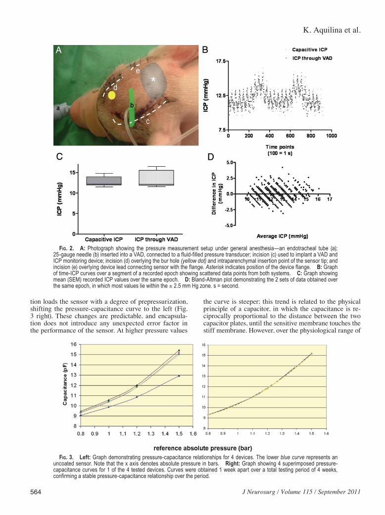
Figure 3 left shows the values obtained for one of the devices along its whole range of pressure measure-ments, from 0.8 to 1.6 bar. The three curves are identical, confirming that the relationship between capacitance and pressure did not change over 4 weeks; this is the basis for the low zero drift of the device. Silicone gel encapsula-
K. Aquilina et al.
564 J Neurosurg / Volume 115 / September 2011
tion loads the sensor with a degree of prepressurization, shifting the pressure-capacitance curve to the left (Fig. 3 right). These changes are predictable, and encapsula-tion does not introduce any unexpected error factor in the performance of the sensor. At higher pressure values
the curve is steeper; this trend is related to the physical principle of a capacitor, in which the capacitance is re-ciprocally proportional to the distance between the two capacitor plates, until the sensitive membrane touches the stiff membrane. However, over the physiological range of
Fig. 2. A: Photograph showing the pressure measurement setup under general anesthesia—an endotracheal tube (a); 25-gauge needle (b) inserted into a VAD, connected to a fluid-filled pressure transducer; incision (c) used to implant a VAD and ICP monitoring device; incision (d) overlying the bur hole (yellow dot) and intraparenchymal insertion point of the sensor tip; and incision (e) overlying device lead connecting sensor with the flange. Asterisk indicates position of the device flange. B: Graph of time-ICP curves over a segment of a recorded epoch showing scattered data points from both systems. C: Graph showing mean (SEM) recorded ICP values over the same epoch. D: Bland-Altman plot demonstrating the 2 sets of data obtained over the same epoch, in which most values lie within the ± 2.5 mm Hg zone. s = second.
Fig. 3. Left: Graph demonstrating pressure-capacitance relationships for 4 devices. The lower blue curve represents an uncoated sensor. Note that the x axis denotes absolute pressure in bars. Right: Graph showing 4 superimposed pressure-capacitance curves for 1 of the 4 tested devices. Curves were obtained 1 week apart over a total testing period of 4 weeks, confirming a stable pressure-capacitance relationship over the period.
J Neurosurg / Volume 115 / September 2011
Capacitive intracranial pressure monitoring
565
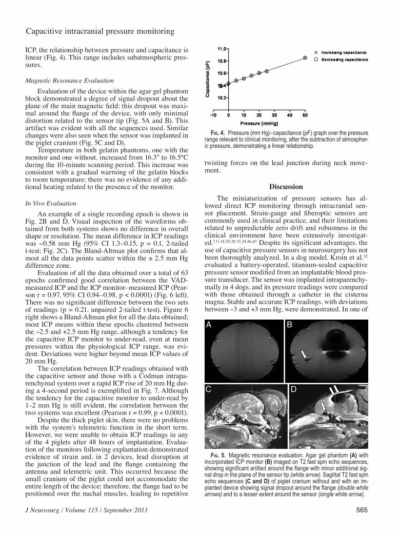
ICP, the relationship between pressure and capacitance is linear (Fig. 4). This range includes subatmospheric pres-sures.
Magnetic Resonance EvaluationEvaluation of the device within the agar gel phantom
block demonstrated a degree of signal dropout about the plane of the main magnetic field; this dropout was maxi-mal around the flange of the device, with only minimal distortion related to the sensor tip (Fig. 5A and B). This artifact was evident with all the sequences used. Similar changes were also seen when the sensor was implanted in the piglet cranium (Fig. 5C and D).
Temperature in both gelatin phantoms, one with the monitor and one without, increased from 16.3° to 16.5°C during the 10-minute scanning period. This increase was consistent with a gradual warming of the gelatin blocks to room temperature; there was no evidence of any addi-tional heating related to the presence of the monitor.
In Vivo EvaluationAn example of a single recording epoch is shown in
Fig. 2B and D. Visual inspection of the waveforms ob-tained from both systems shows no difference in overall shape or resolution. The mean difference in ICP readings was -0.58 mm Hg (95% CI 1.3–0.15, p = 0.1, 2-tailed t-test; Fig. 2C). The Bland-Altman plot confirms that al-most all the data points scatter within the ± 2.5 mm Hg difference zone.
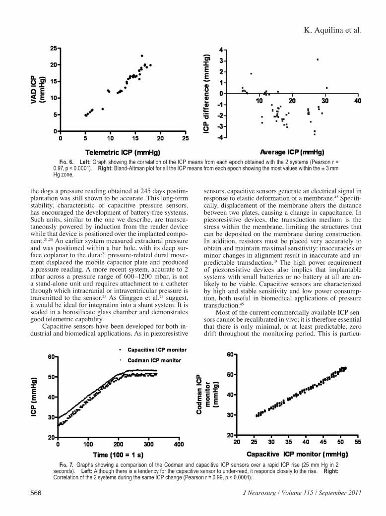
Evaluation of all the data obtained over a total of 63 epochs confirmed good correlation between the VAD-measured ICP and the ICP monitor–measured ICP (Pear-son r = 0.97, 95% CI 0.94–0.98, p < 0.0001) (Fig. 6 left). There was no significant difference between the two sets of readings (p = 0.21, unpaired 2-tailed t-test). Figure 6 right shows a Bland-Altman plot for all the data obtained; most ICP means within these epochs clustered between the -2.5 and +2.5 mm Hg range, although a tendency for the capacitive ICP monitor to under-read, even at mean pressures within the physiological ICP range, was evi-dent. Deviations were higher beyond mean ICP values of 20 mm Hg.
The correlation between ICP readings obtained with the capacitive sensor and those with a Codman intrapa-renchymal system over a rapid ICP rise of 20 mm Hg dur-ing a 4-second period is exemplified in Fig. 7. Although the tendency for the capacitive monitor to under-read by 1–2 mm Hg is still evident, the correlation between the two systems was excellent (Pearson r = 0.99, p < 0.0001).
Despite the thick piglet skin, there were no problems with the system’s telemetric function in the short term. However, we were unable to obtain ICP readings in any of the 4 piglets after 48 hours of implantation. Evalua-tion of the monitors following explantation demonstrated evidence of strain and, in 2 devices, lead disruption at the junction of the lead and the flange containing the antenna and telemetric unit. This occurred because the small cranium of the piglet could not accommodate the entire length of the device; therefore, the flange had to be positioned over the nuchal muscles, leading to repetitive
twisting forces on the lead junction during neck move-ment.
DiscussionThe miniaturization of pressure sensors has al-
lowed direct ICP monitoring through intracranial sen-sor placement. Strain-gauge and fiberoptic sensors are commonly used in clinical practice, and their limitations related to unpredictable zero drift and robustness in the clinical environment have been extensively investigat-ed.7,11,18,20,28,32,34,46,47 Despite its significant advantages, the use of capacitive pressure sensors in neurosurgery has not been thoroughly analyzed. In a dog model, Kroin et al.32 evaluated a battery-operated, titanium-sealed capacitive pressure sensor modified from an implantable blood pres-sure transducer. The sensor was implanted intraparenchy-mally in 4 dogs, and its pressure readings were compared with those obtained through a catheter in the cisterna magna. Stable and accurate ICP readings, with deviations between -3 and +3 mm Hg, were demonstrated. In one of
Fig. 4. Pressure (mm Hg)–capacitance (pF) graph over the pressure range relevant to clinical monitoring, after the subtraction of atmospher-ic pressure, demonstrating a linear relationship.
Fig. 5. Magnetic resonance evaluation. Agar gel phantom (A) with incorporated ICP monitor (B) imaged on T2 fast spin echo sequences, showing significant artifact around the flange with minor additional sig-nal drop in the plane of the sensor tip (white arrow). Sagittal T2 fast spin echo sequences (C and D) of piglet cranium without and with an im-planted device showing signal dropout around the flange (double white arrows) and to a lesser extent around the sensor (single white arrow).
K. Aquilina et al.
566 J Neurosurg / Volume 115 / September 2011
the dogs a pressure reading obtained at 245 days postim-plantation was still shown to be accurate. This long-term stability, characteristic of capacitive pressure sensors, has encouraged the development of battery-free systems. Such units, similar to the one we describe, are transcu-taneously powered by induction from the reader device while that device is positioned over the implanted compo-nent.21,25 An earlier system measured extradural pressure and was positioned within a bur hole, with its deep sur-face coplanar to the dura;21 pressure-related dural move-ment displaced the mobile capacitor plate and produced a pressure reading. A more recent system, accurate to 2 mbar across a pressure range of 600–1200 mbar, is not a stand-alone unit and requires attachment to a catheter through which intracranial or intraventricular pressure is transmitted to the sensor.25 As Ginggen et al.25 suggest, it would be ideal for integration into a shunt system. It is sealed in a borosilicate glass chamber and demonstrates good telemetric capability.
Capacitive sensors have been developed for both in-dustrial and biomedical applications. As in piezoresistive
sensors, capacitive sensors generate an electrical signal in response to elastic deformation of a membrane.45 Specifi-cally, displacement of the membrane alters the distance between two plates, causing a change in capacitance. In piezoresistive devices, the transduction medium is the stress within the membrane, limiting the structures that can be deposited on the membrane during construction. In addition, resistors must be placed very accurately to obtain and maintain maximal sensitivity; inaccuracies or minor changes in alignment result in inaccurate and un-predictable transduction.10 The high power requirement of piezoresistive devices also implies that implantable systems with small batteries or no battery at all are un-likely to be viable. Capacitive sensors are characterized by high and stable sensitivity and low power consump-tion, both useful in biomedical applications of pressure transduction.45
Most of the current commercially available ICP sen-sors cannot be recalibrated in vivo; it is therefore essential that there is only minimal, or at least predictable, zero drift throughout the monitoring period. This is particu-
Fig. 6. Left: Graph showing the correlation of the ICP means from each epoch obtained with the 2 systems (Pearson r = 0.97, p < 0.0001). Right: Bland-Altman plot for all the ICP means from each epoch showing the most values within the ± 3 mm Hg zone.
Fig. 7. Graphs showing a comparison of the Codman and capacitive ICP sensors over a rapid ICP rise (25 mm Hg in 2 seconds). Left: Although there is a tendency for the capacitive sensor to under-read, it responds closely to the rise. Right: Correlation of the 2 systems during the same ICP change (Pearson r = 0.99, p < 0.0001).

J Neurosurg / Volume 115 / September 2011
Capacitive intracranial pressure monitoring
567
larly important when ICP monitors with the potential for long-term monitoring are used. Zero drift has been studied extensively for the commonly used ICP sensors in both nonclinical and clinical studies. The manufactur-er’s specification for the Camino fiberoptic ICP monitor (Camino Laboratories), for example, is ± 2 mm Hg for the first day and ± 1 mm Hg for every thereafter. However, in a study of 50 Camino sensors used in patients with head injuries, 50% of the sensors demonstrated absolute drift beyond 3 mm Hg over a median period of 3 days.42 One hundred thirty-six Camino sensors evaluated in another clinical study showed an average daily drift rate of 3.2 mm Hg.39 The range of zero drift for 83 Camino devices measured at a median of 66 hours postinsertion was -12 to +14 mm Hg. Reportedly, this drift tends toward the overestimation of ICP in some studies and to its under-estimation in others.2 Several authors suggest that chang-ing the monitor should be considered if a “long” period of monitoring is expected; although most authors did not clarify the duration, the monitoring period was defined as more than 3 days in one study.22,30 Clinical evaluation of the Codman microsensor ICP transducer has shown a lower extent of zero drift.27,31 In one study, the mean zero drift was 0.2 ± 0.5 mm Hg, but the monitors were replaced if it was necessary to continue monitoring be-yond 7 days.27 Although the capacitive pressure sensor we describe has demonstrated excellent stability in vitro, fur-ther in vivo evaluation is required before long-term clini-cally relevant accuracy can be confirmed.
Telemetric capability, easily possible with capaci-tive ICP monitors, allows the development of fully im-plantable devices, which, if stable enough, can function for several years. Although a number of telemetric ICP monitors have been developed over the last 30 years, none have become commercially available. Earlier devices used radio telemetry technology, in which the position of a moving diaphragm changed in response to the applied pressure, causing a change in the resonating frequency of the circuit. This change in frequency was then picked up by a sweeping grid dip circuit in the external receiv-ing device.4,17,21 Some devices measured extradural pres-sure.16,48 Other devices were incorporated into shunt sys-tems.12,38 The Osaka device was evaluated in 94 patients; over a mean period of 14.5 months, a comparison of the sensor’s output with pressure values obtained from direct puncture of an in-line shunt valve demonstrated an an-nual drift of up to 25 mm Hg.38 Implant protective pack-aging has also been a difficult problem throughout the development of ICP telemetry. In the system we describe, the flange containing the electronic components, as well as the lead to the sensor, is coated with Parylene C and an outer layer of NuSil silicone; this composite coating is cheaper to manufacture and bond than inert metallic seals, such as titanium, and is equally effective at pre-venting entry of moisture. The stability of the sensor in a water medium, confirmed on bench testing, demonstrates that the silicone gel around the sensor is also impervious to water.
This monitor has potential for long-term implanta-tion and monitoring; patients likely to benefit from this device are also likely to require regular MR imaging. Analyzing safety and image preservation on MR imaging
is therefore an important component of the preliminary evaluation. Although we did not determine the function-ality of the sensor during and after MR imaging in this study, we did demonstrate that although significant signal dropout occurs in relation to the flange containing the an-tenna coil and the telemetric unit at 3 T, very minimal image distortion is induced by the sensor itself. We were unable to detect any thermogenic effect in relation to the sensor within the gelatin phantom. Our MR configura-tion, however, included only a transmit-and-receive coil. A recent study has identified a thermogenic risk specific to the use of separate transmit body coils and receive-only head coils with the Codman ICP transducer.40 This effect, related to resonance, would probably also apply to the capacitive transducer.
The capacitive transducer samples ICP at a frequency of 50 Hz. This rate maintains excellent waveform reso-lution and allows waveform spectral analysis, enabling calculation of the pressure-volume compensatory reserve and cerebrovascular pressure reactivity; the prognostic values of these indices, derived directly from the ICP waveform, are becoming evident.15 The transducer is also capable of recording rapid changes in ICP (Fig. 7). In this situation, comparisons were made with a Codman intra-parenchymal sensor rather than a fluid-filled transducer through the VAD, as fluid-filled systems are well known not to replicate rapid dynamic pressure changes well.45 In addition, the sensor’s ability to measure negative pres-sures is particularly relevant to the investigation of dif-ficult chronic hydrocephalus problems, such as low pres-sure hydrocephalus, shunt overdrainage, and slit ventricle syndrome.
In the in vivo study, we were unable to obtain ICP readings in any of the 4 piglets beyond 48 hours of im-plantation. As the piglet head is small in both the antero-posterior and lateral dimensions, the device, designed with reference to the human head, was too long to lie com-pletely over the cranium and extended onto the anterior neck. Because the piglets were unrestrained in between monitoring periods, head and neck movements caused damage to the connecting leads between the transducer in the brain and the telemetric unit and antenna in the flange on the skull. Lead damage is unlikely to be a problem in a larger animal model, but clearly the system’s robustness needs to be addressed before any studies are performed within a clinical environment.
Our device satisfies the requirements stated by Hulme and Cooper in 1966.30 Although the device tip is larger than those of the Codman and Camino sensors (outside diameter of 1.3 mm), at 3 mm it is identical to the tip of a ventricular drain, allowing it to be inserted in the ven-tricular system or the brain parenchyma. The sensor does not need to be in line with a fluid column; it is implanted independently of CSF diversion devices and is free from error related to progressive obstruction of a fluid-filled catheter. As it does not require a battery, it is potentially capable of long-term implantation. Further in vivo evalu-ation, ideally in a large animal model, is required before its full potential can be analyzed.
Disclosure
Kristian Aquilina was financially supported by the consortium

K. Aquilina et al.
568 J Neurosurg / Volume 115 / September 2011
“Healthy Aims,” within the 6th EU Framework Programme for Re search and Technological Development (IST-2002-1-001837), which also funded the costs related to development and evaluation of the device. The United Kingdom charities SPARKS, Action Medical Research, and The Wellcome Trust supported staff working on the laboratory in vivo component of the project. The authors are also grateful for the financial and other contributions made by Campus Microtechnology, Bremen, Germany, related to development and in vitro testing of the device.
Author contributions to the study and manuscript preparation include the following. Conception and design: Edwards, Aquilina, Pople, Coakham. Acquisition of data: Aquilina. Analysis and inter-pretation of data: Aquilina. Drafting the article: Aquilina. Critically revising the article: Pople, Edwards. Statistical analysis: Aquilina.
Acknowledgments
The authors are grateful for the contributions of Manfred Frischholz, Matthias Wenzel, Alex Tucker, and Thomas Wood.
References
1. Aquilina K, Hobbs C, Cherian S, Tucker A, Porter H, Whitelaw A, et al: A neonatal piglet model of intraventricular hemor-rhage and posthemorrhagic ventricular dilation. J Neurosurg 107 (2 Suppl):126–136, 2007
2. Bavetta S, Norris JS, Wyatt M, Sutcliffe JC, Hamlyn PJ: Pro-spective study of zero drift in fiberoptic pressure monitors used in clinical practice. J Neurosurg 86:927–930, 1997
3. Brain Trauma Foundation. American Association of Neuro-logical Surgeons. Joint Section on Neurotrauma and Critical Care: Guidelines for the management of severe head injury. J Neurotrauma 17:449–555, 2000
4. Brindley GS, Polkey CE, Cooper JD: Technique for very long-term monitoring of intracranial pressure. Med Biol Eng Comput 21:460–464, 1983
5. Chambers IR, Mendelow AD, Sinar EJ, Modha P: A clini-cal evaluation of the Camino subdural screw and ventricular monitoring kits. Neurosurgery 26:421–423, 1990
6. Chambers KR, Kane PJ, Choksey MS, Mendelow AD: An evaluation of the camino ventricular bolt system in clinical practice. Neurosurgery 33:866–868, 1993
7. Choi HS, Park HD, Lee KJ: Motion artifact reduction in blood pressure signals using adaptive digital filter with a capacitive sensor. Conf Proc IEEE Eng Med Biol Soc 2007:3285–3287, 2007
8. Citerio G, Piper I, Chambers IR, Galli D, Enblad P, Kiening K, et al: Multicenter clinical assessment of the Raumedic Neu-rovent-P intracranial pressure sensor: a report by the BrainIT group. Neurosurgery 63:1152–1158, 2008
9. Citerio G, Piper I, Cormio M, Galli D, Cazzaniga S, Enblad P, et al: Bench test assessment of the new Raumedic Neurovent-P ICP sensor: a technical report by the BrainIT group. Acta Neurochir (Wien) 146:1221–1226, 2004
10. Clark SK, Wise KD: Pressure sensitivity in anisotropically etched thin-diaphragm pressure sensors. IEEE Trans Elec-tron Dev 26:1887–1896, 1979
11. Cobb J, Claremont DJ: Transducers for foot pressure measure-ment: survey of recent developments. Med Biol Eng Comput 33:525–532, 1995
12. Cosman ER, Zervas NT, Chapman PH, Cosman BJ, Arnold MA: A telemetric pressure sensor for ventricular shunt sys-tems. Surg Neurol 11:287–294, 1979
13. Crutchfield JS, Narayan RK, Robertson CS, Michael LH: Evaluation of a fiberoptic intracranial pressure monitor. J Neu rosurg 72:482–487, 1990
14. Czosnyka M, Czosnyka Z, Pickard JD: Laboratory testing of three intracranial pressure microtransducers: technical re-port. Neurosurgery 38:219–224, 1996
15. Czosnyka M, Smielewski P, Timofeev I, Lavinio A, Guazzo E, Hutchinson P, et al: Intracranial pressure: more than a num-ber. Neurosurg Focus 22(5):E10, 2007
16. de Jong DA, Maas AI, den Ouden AH, de Lange SA: Long-term intracranial pressure monitoring. Med Prog Technol 10:89–96, 1983–1984
17. de Jong DA, Ouden AH, van de Boon TA, Yeskoot F, Maas A: Telemetred epidural pressure. Biotelemetry 2:257–264, 1975
18. Dias JF, Karrer HE, Tykulsky A: Capacitive blood pressure transducer. ISA Trans 19:19–23, 1980
19. Fernandes HM, Bingham K, Chambers IR, Mendelow AD: Clinical evaluation of the Codman microsensor intracranial pressure monitoring system. Acta Neurochir Suppl (Wien) 71:44–46, 1998
20. Frobenius WD, Sanderson AC, Nathanson HC: A micromin-iature solid-state capacitive blood pressure transducer with improved sensitivity. IEEE Trans Biomed Eng 20:312–314, 1973
21. Fryer TB, Corbin SD, Silverberg GD, Schmidt EV, Ream AK: Telemetry of intracranial pressure. Biotelem Patient Monit 5:88–112, 1978
22. Gambardella G, d’Avella D, Tomasello F: Monitoring of brain tissue pressure with a fiberoptic device. Neurosurgery 31:918–922, 1992
23. Gambardella G, Zaccone C, Cardia E, Tomasello F: Intracra-nial pressure monitoring in children: comparison of external ventricular device with the fiberoptic system. Childs Nerv Syst 9:470–473, 1993
24. Gelabert-González M, Ginesta-Galan V, Sernamito-García R, Allut AG, Bandin-Diéguez J, Rumbo RM: The Camino intra-cranial pressure device in clinical practice. Assessment in a 1000 cases. Acta Neurochir (Wien) 148:435–441, 2006
25. Ginggen A, Tardy Y, Crivelli R, Bork T, Renaud P: A telemet-ric pressure sensor system for biomedical applications. IEEE Trans Biomed Eng 55:1374–1381, 2008
26. Gopinath SP, Cherian L, Robertson CS, Narayan RK, Gross-man RG: Evaluation of a microsensor intracranial pressure transducer. J Neurosci Methods 49:11–15, 1993
27. Gopinath SP, Robertson CS, Contant CF, Narayan RK, Gross-man RG: Clinical evaluation of a miniature strain-gauge transducer for monitoring intracranial pressure. Neurosur-gery 36:1137–1141, 1995
28. Heywood E, Jeutter D, Harris G: Tri-axial plantar pressure sensor: design, calibration and characterization. Conf Proc IEEE Eng Med Biol Soc 3:2010–2013, 2004
29. Hollingsworth-Fridlund P, Vos H, Daily EK: Use of fiber-optic pressure transducer for intracranial pressure measurements: a preliminary report. Heart Lung 17:111–120, 1988
30. Hulme A, Cooper R: A technique for the investigation of in-tracranial pressure in man. J Neurol Neurosurg Psychiatry 29:154–156, 1966
31. Koskinen LO, Olivecrona M: Clinical experience with the intraparenchymal intracranial pressure monitoring Codman MicroSensor system. Neurosurgery 56:693–698, 2005
32. Kroin JS, McCarthy RJ, Stylos L, Miesel K, Ivankovich AD, Penn RD: Long-term testing of an intracranial pressure moni-toring device. J Neurosurg 93:852–858, 2000
33. Lang JM, Beck J, Zimmermann M, Seifert V, Raabe A: Clini-cal evaluation of intraparenchymal Spiegelberg pressure sen-sor. Neurosurgery 52:1455–1459, 2003
34. Mahnken AH, Urban U, Fassbender H, Schnakenberg U, Schoth F, Schmitz-Rode T: Telemetric catheter-based pres-sure sensor for hemodynamic monitoring: experimental expe-rience. Cardiovasc Intervent Radiol 32:714–719, 2009
35. Marchal C, Nadi M, Tosser AJ, Roussey C, Gaulard ML: Di-electric properties of gelatine phantoms used for simulations of biological tissues between 10 and 50 MHz. Int J Hyper-thermia 5:725–732, 1989
36. Marshall LF, Smith RW, Shapiro HM: The outcome with ag-
J Neurosurg / Volume 115 / September 2011
Capacitive intracranial pressure monitoring
569
gressive treatment in severe head injuries. Part I: the signifi-cance of intracranial pressure monitoring. J Neurosurg 50: 20–25, 1979
37. Martínez-Mañas RM, Santamarta D, de Campos JM, Ferrer E: Camino intracranial pressure monitor: prospective study of accuracy and complications. J Neurol Neurosurg Psychia-try 69:82–86, 2000
38. Miyake H, Ohta T, Kajimoto Y, Matsukawa M: A new ven-triculoperitoneal shunt with a telemetric intracranial pressure sensor: clinical experience in 94 patients with hydrocephalus. Neurosurgery 40:931–935, 1997
39. Münch E, Weigel R, Schmiedek P, Schürer L: The Camino intracranial pressure device in clinical practice: reliability, handling characteristics and complications. Acta Neurochir (Wien) 140:1113–1120, 1998
40. Newcombe VF, Hawkes RC, Harding SG, Willcox R, Brock S, Hutchinson PJ, et al: Potential heating caused by intraparen-chymal intracranial pressure transducers in a 3-tesla magnetic resonance imaging system using a body radiofrequency reso-nator: assessment of the Codman MicroSensor Transducer. J Neurosurg 109:159–164, 2008
41. Ostrup RC, Luerssen TG, Marshall LF, Zornow MH: Continu-ous monitoring of intracranial pressure with a miniaturized fiberoptic device. J Neurosurg 67:206–209, 1987
42. Piper I, Barnes A, Smith D, Dunn L: The Camino intracranial pressure sensor: is it optimal technology? An internal audit with a review of current intracranial pressure monitoring technologies. Neurosurgery 49:1158–1165, 2001
43. Piper IR, Miller JD: The evaluation of the wave-form analysis capability of a new strain-gauge intracranial pressure Micro-Sensor. Neurosurgery 36:1142–1145, 1995
44. Poca MA, Sahuquillo J, Arribas M, Báguena M, Amorós S,
Rubio E: Fiberoptic intraparenchymal brain pressure monitor-ing with the Camino V420 monitor: reflections on our experi-ence in 163 severely head-injured patients. J Neurotrauma 19:439–448, 2002
45. Puers R: Capacitive sensors: when and how to use them? Sen-sors Actuators A: Phys 37–38:93–105, 1993
46. Rikli DA, Honigmann P, Babst R, Cristalli A, Morlock MM, Mittlmeier T: Intra-articular pressure measurement in the ra-dioulnocarpal joint using a novel sensor: in vitro and in vivo results. J Hand Surg Am 32:67–75, 2007
47. Wuelker N, Roetman B, Roessig S: Coracoacromial pressure recordings in a cadaveric model. J Shoulder Elbow Surg 4: 462–467, 1995
48. Zervas NT, Cosman ER, Cosman BJ: A pressure-balanced radio-telemetry system for the measurement of intracranial pressure. A preliminary design report. J Neurosurg 47:899–911, 1977
Manuscript submitted November 12, 2010.Accepted April 4, 2011.Early portions of this work were presented at the annual meeting
of the American Association of Neurological Surgeons held in San Francisco, California, in April 2006, and subsequently at the spring meeting of the Society of British Neurological Surgeons held in Cam bridge, United Kingdom, in March 2009.
Please include this information when citing this paper: published online May 27, 2011; DOI: 10.3171/2011.4.JNS101920.
Address correspondence to: Richard J. Edwards, F.R.C.S.(Neu-rosurg), M.D., Department of Neurosurgery, Frenchay Hospital, Bristol, BS16 1LE, England. email: [email protected].
Copyright © 2022 FDOKUMEN