Numerical and experimental studies of molten pool formation during an interaction of a pulse laser...
11
Numerical and experimental studies of molten pool formation during an interaction of a pulse laser (Nd:YAG) with a magnesium alloy Kamel Abderrazak a,c, , Wassim Kriaa a , Wacef Ben Salem b , Hatem Mhiri a , Georges Lepalec c , Michel Autric c a Unite´ de Thermique et Thermodynamique des Proce ´de´s Industriels, Ecole Nationale d’Inge ´nieurs de Monastir, Avenue Ibn El Jazzar, 5019 Monastir, Tunisia b Laboratoire de Ge ´nie Me´canique, Ecole Nationale d’Inge ´nieurs de Monastir, Avenue Ibn Jazzar, 5019 Monastir, Tunisia c Institut de Me ´canique de Marseille, 60, rue Joliot-Curie, Technopo ˆle de Cha ˆteau-Gombert, 13453 Marseille Cedex 13, France article info Article history: Received 18 December 2007 Received in revised form 26 July 2008 Accepted 28 July 2008 Available online 25 September 2008 Keywords: Nd:YAG laser Magnesium alloy Marangoni flow abstract A pulse laser (Nd:YAG) interaction with an AZ91 magnesium alloy has been experimentally and numerically studied. A two-dimensional (2D) axisymmetric model of a molten pool created by a laser heat source has been developed. The elaborated model solves the coupled equations of a laminar fluid flow and heat transfer to demonstrate the flow behavior in the pool. This model takes into account the coupled effects of buoyancy and Marangoni forces, the thermophysic variation properties with temperature, and the radiation and convection heat losses. Concerning numerical results, the molten temperature distribution, velocity field and molten shape were discussed. It was noted that the Marangoni flow significantly alters the characteristics of the thawing and solidifying processes, and makes the molten pool wider and shallower. On the other hand, the experimental results showed that the material thermal properties have significant effects on the transport phenomena which takes place in the molten pool, and consequently on the formation as well as the shape of the pool. Finally, a comparison between the numerical and experimental results exhibited a good agreement. & 2008 Elsevier Ltd. All rights reserved. 1. Introduction In automotive and aerospace industries, because of the con- sideration of fuel economy, lightweight alloys have been adopted and are expected to be extensively used in the future. Magnesium alloys are among the promising materials, due to their lightweight and good mechanical properties. The use of magnesium alloys in the automobile industry encompasses parts, such as steering wheels, steering column parts, instrument panels, seats, gear boxes, air intake systems, stretchers, gearbox housings, tank covers, etc. Magnesium-based alloys have been used for numerous non- automotive applications, for instance in hobby equipment to make bicycle frames. Interesting applications in communication en- gineering are realized where light weight is required as well as a screening against electro-magnetic radiation, which plastic ma- terials cannot offer. The major driving force for development is the automobile industry. Although some interesting developments have been achieved for space, aircraft and other applications, we have witnessed successful applications in automobile industry compo- nents such as steering wheels, steering column parts, instrument panels, seats, gearboxes and air intake systems. Future develop- ments will include large body parts, cylinder blocks, door frames and petrol tank covers. The vast majority of magnesium applica- tions are covered by AZ91, a die-casting alloy. However, if the usefulness of these alloys is to be reached, successful joining methods are required. Laser welding is an important method. Laser beam welding is a field of growing importance in industry. Pulsed laser welding offers the advantage of a very low heat input to the weld, resulting in a low distortion and the ability to weld heat-sensitive components. While there have been several numerical and analytical models that have sought to elucidate the physical mechanisms involved in the continuous-laser wave welding process, there are few models of pulsed laser welding. These models are reviewed in Section 2 of this paper. The main reason for this apparent scarcity lies in the complexity of the laser–material interaction process. Pulsed laser welding in this article refers to the low repetition rate regime in which significant resolidification of the workpiece occurs between laser pulses. As the laser beam intermittently interacts with the workpiece over very short time intervals, very rapid heating and cooling cycles occur. The weld bead is the product of a number of overlapping spot welds, and every point in the weld area experiences a complex series of thermal cycles during the passage of the laser ARTICLE IN PRESS Contents lists available at ScienceDirect journal homepage: www.elsevier.com/locate/optlastec Optics & Laser Technology 0030-3992/$ - see front matter & 2008 Elsevier Ltd. All rights reserved. doi:10.1016/j.optlastec.2008.07.012 Corresponding author at: Unite ´ de Thermique et Thermodynamique des Proce ´de ´ s Industriels, Ecole Nationale d’Inge ´nieurs de Monastir, Avenue Ibn El Jazzar, Monastir 5019, Tunisia. Tel.: +21673348773; fax: +2167350 0514. E-mail address: [email protected] (K. Abderrazak). Optics & Laser Technology 41 (2009) 470–480
-
Upload
independent -
Category
Documents
-
view
0 -
download
0
Transcript of Numerical and experimental studies of molten pool formation during an interaction of a pulse laser...
ARTICLE IN PRESS
Optics & Laser Technology 41 (2009) 470–480
Contents lists available at ScienceDirect
Optics & Laser Technology
0030-39
doi:10.1
� Corr
Procede
Jazzar, M
E-m
journal homepage: www.elsevier.com/locate/optlastec
Numerical and experimental studies of molten pool formation during aninteraction of a pulse laser (Nd:YAG) with a magnesium alloy
Kamel Abderrazak a,c,�, Wassim Kriaa a, Wacef Ben Salem b, Hatem Mhiri a,Georges Lepalec c, Michel Autric c
a Unite de Thermique et Thermodynamique des Procedes Industriels, Ecole Nationale d’Ingenieurs de Monastir, Avenue Ibn El Jazzar, 5019 Monastir, Tunisiab Laboratoire de Genie Mecanique, Ecole Nationale d’Ingenieurs de Monastir, Avenue Ibn Jazzar, 5019 Monastir, Tunisiac Institut de Mecanique de Marseille, 60, rue Joliot-Curie, Technopole de Chateau-Gombert, 13453 Marseille Cedex 13, France
a r t i c l e i n f o
Article history:
Received 18 December 2007
Received in revised form
26 July 2008
Accepted 28 July 2008Available online 25 September 2008
Keywords:
Nd:YAG laser
Magnesium alloy
Marangoni flow
92/$ - see front matter & 2008 Elsevier Ltd. A
016/j.optlastec.2008.07.012
esponding author at: Unite de Thermique
s Industriels, Ecole Nationale d’Ingenieurs
onastir 5019, Tunisia. Tel.: +216 7334 8773;
ail address: [email protected] (K. A
a b s t r a c t
A pulse laser (Nd:YAG) interaction with an AZ91 magnesium alloy has been experimentally and
numerically studied. A two-dimensional (2D) axisymmetric model of a molten pool created by a laser
heat source has been developed. The elaborated model solves the coupled equations of a laminar fluid
flow and heat transfer to demonstrate the flow behavior in the pool. This model takes into account the
coupled effects of buoyancy and Marangoni forces, the thermophysic variation properties with
temperature, and the radiation and convection heat losses. Concerning numerical results, the molten
temperature distribution, velocity field and molten shape were discussed. It was noted that the
Marangoni flow significantly alters the characteristics of the thawing and solidifying processes, and
makes the molten pool wider and shallower. On the other hand, the experimental results showed that
the material thermal properties have significant effects on the transport phenomena which takes place
in the molten pool, and consequently on the formation as well as the shape of the pool. Finally, a
comparison between the numerical and experimental results exhibited a good agreement.
& 2008 Elsevier Ltd. All rights reserved.
1. Introduction
In automotive and aerospace industries, because of the con-sideration of fuel economy, lightweight alloys have been adoptedand are expected to be extensively used in the future. Magnesiumalloys are among the promising materials, due to their lightweightand good mechanical properties. The use of magnesium alloys in theautomobile industry encompasses parts, such as steering wheels,steering column parts, instrument panels, seats, gear boxes, airintake systems, stretchers, gearbox housings, tank covers, etc.
Magnesium-based alloys have been used for numerous non-automotive applications, for instance in hobby equipment to makebicycle frames. Interesting applications in communication en-gineering are realized where light weight is required as well as ascreening against electro-magnetic radiation, which plastic ma-terials cannot offer.
The major driving force for development is the automobileindustry. Although some interesting developments have beenachieved for space, aircraft and other applications, we have
ll rights reserved.
et Thermodynamique des
de Monastir, Avenue Ibn El
fax: +216 7350 0514.
bderrazak).
witnessed successful applications in automobile industry compo-nents such as steering wheels, steering column parts, instrumentpanels, seats, gearboxes and air intake systems. Future develop-ments will include large body parts, cylinder blocks, door framesand petrol tank covers. The vast majority of magnesium applica-tions are covered by AZ91, a die-casting alloy. However, if theusefulness of these alloys is to be reached, successful joiningmethods are required. Laser welding is an important method.
Laser beam welding is a field of growing importance inindustry. Pulsed laser welding offers the advantage of a very lowheat input to the weld, resulting in a low distortion and the abilityto weld heat-sensitive components. While there have been severalnumerical and analytical models that have sought to elucidate thephysical mechanisms involved in the continuous-laser wavewelding process, there are few models of pulsed laser welding.These models are reviewed in Section 2 of this paper. The mainreason for this apparent scarcity lies in the complexity of thelaser–material interaction process. Pulsed laser welding in thisarticle refers to the low repetition rate regime in which significantresolidification of the workpiece occurs between laser pulses. Asthe laser beam intermittently interacts with the workpiece oververy short time intervals, very rapid heating and cooling cyclesoccur. The weld bead is the product of a number of overlappingspot welds, and every point in the weld area experiences acomplex series of thermal cycles during the passage of the laser

ARTICLE IN PRESS
Nomenclature
I laser power density (W)P peak value of laser power (W)A laser radiation absorption factorRF radius of beam laser (m)Cp specific heat of constant pressures (J (kg K)�1)k thermal conductivity (W (m K)�1)hC combined heat transfer coefficient (W (m2 K)�1)T temperature (K)DHF latent heat of fusion (J kg�1)f fractionAs constant gradient of surface tension (N (m K)�1)
Greek letters
r density (kg m�3)
e surface emissivitym dynamic viscosity (kg (m s)�1)s surface tension (N m�1)s0 surface tension at melting point (N m�1)a coefficient of volumic expansion (K�1)
Indices
L liquidusS solidusm melting pointtrans transitionalamb ambient
K. Abderrazak et al. / Optics & Laser Technology 41 (2009) 470–480 471
beam. This complexity implies that analytical modeling techni-ques are almost difficult. The numerical model, therefore, is thepreferred option, although the analysis requires a very largenumber of small time steps much smaller than those needed forthe continuous analysis. In order to optimize the costs ofexperimental achievements, the numerical simulation madepossible by the development of strong computing powers,becomes a particularly interesting tool to predict the parametersresulting from welding.
Nevertheless, the modeling of this problem type presentsseveral difficulties related to
1.
The strong thermal gradients present in short distances whichlead to the deformation of the free surface.2.
The appearance of a keyhole like a cavity when the recoilpressure becomes particularly high.3.
The Marangoni forces initiated by the surface tension gradientswhich have a considerable effect on the thermal transfer in themelted pool and consequently, on its enlargement.The main objective of this work is to develop a numericalmodel, which enables the simulation of all thermal history for atwo-dimensional (2D) space with any boundary conditions till thereturn to the thermal equilibrium at cooling. In this model, thelatent heat of fusion is introduced into the heat equation as a heatsource term, the Navier–Stokes equations are amended todescribe the flow in the liquid–solid zone. This model takes alsointo account the nonlinearities of the thermophysic propertiesvariation with temperature, and the losses of heat by radiationand convection.
Compared with several contributions in this subject, thismodel should give a more subtle approach, which gets free fromclassical simplifying assumptions. The discussion about theobtained results will be related to the effects of heat conduction,Marangoni flow and thermal buoyancy on the melting process andthe molten pool shape. These results will be compared with theexperimental outcome to validate the numerical techniques andreveal the fundamentals of laser processing.
2. Experimental and numerical reviews
2.1. Laser welding of magnesium alloys
The effectiveness of laser welding depends greatly on thephysical properties of the material to be welded. Magnesium
alloys possess certain inherent characteristics such as lowabsorptivity of laser beams, strong tendency to oxidize,high thermal conductivity, high coefficient of thermal expansion,low melting and boiling temperatures, wide solidificationtemperature range, high solidification shrinkage, a tendency toform low melting-point constituents, low viscosity, low surfacetensions, high solubility for hydrogen in the liquid state, andabsence of color change at the melting point temperature. Duringthe laser welding of magnesium alloys, therefore, some processingproblems and weld defects can be encountered, such as anunstable weld pool, substantial spatter [1–4], strong tendency todrop-through for large weld pools [3], sag of the weld pool(especially for thick workpiece), undercut [5], porous oxideinclusions, loss of alloying elements [1,2], excessive pore forma-tion (particularly for die castings) [6,7], and liquation andsolidification cracking [8]. Nonetheless, crack-free laser-weldedjoints, with low porosity and good surface quality, can be achievedfor wrought magnesium alloys using appropriate laser-processingconditions [9].
Magnesium alloy welding has been insufficiently documented[10] but the relative arc weldability of most magnesium alloys hasbeen rated based largely on the susceptibility to cracking and tosome extent on joint efficiency [11]. The relative laser weldabilityof magnesium alloys, however, has not been systematicallyinvestigated yet. Research into stable laser welding has involvedidentifying and controlling the processing parameters influencingprocess stability and reproducibility to reliably produce defect-free welds at high welding speeds.
Two main types of lasers, CO2 and Nd:YAG with wavelengths of10.6 and 1.06mm, respectively, have been used to investigate theweldability of magnesium alloys. The CO2 laser has a highpower output, high efficiency, proven reliability and safety [12].With the recent development of high-output power, the improve-ment of beam quality and the possibility of glass fiber delivery,the Nd:YAG laser has entered the fields dominated by the CO2
laser. The weldability of magnesium alloys was reported to besignificantly better with the Nd:YAG laser due to its shorterwavelength, which in turn reduced the threshold irradiancerequired for keyhole mode welding and produced a morestable weld pool [1,2,4]. Compared with CO2 lasers, Nd:YAG laserbeams have a higher welding efficiency [4,13]. In addition, it waspossible to use shear cut edges in the Nd:YAG case, whereasmilled edges were required for CO2 laser [4,13]. This is because forgiven power and focusing conditions poor fit-up is of a moreserious concern for a smaller beam diameter CO2 lasers thanNd:YAG lasers [1,2,4].

ARTICLE IN PRESS
K. Abderrazak et al. / Optics & Laser Technology 41 (2009) 470–480472
Nowadays, the two main types of industrial lasers, both CO2
and Nd:YAG, have been used to investigate the weldability ofmagnesium alloys. Crack-free laser-welded joints with lowporosity and good surface quality can be obtained for somemagnesium alloys, in particular wrought material, using appro-priate laser-processing parameters. Due to their inherent proper-ties, however, magnesium alloys may exhibit some processingproblems and weld defects, such as unstable weld pool,substantial spatter, strong tendency to drop-through, sag, under-cut, porosity, liquation and solidification cracking, oxide inclu-sions and loss of alloying elements. In the future, scientificinvestigation is still needed to understand and overcome thesebasic weldability problems of magnesium alloys [14].
2.2. Previous models
Rosenthal’s solutions [15] represent the starting point ofanalytical solutions applied to welding techniques in general. Itwas not until 1973 that Swift-Hook and Gick [16] developed thefirst heat transfer model for continuous laser welding. In a similarmanner to Rosenthal, the laser beam was modeled as a movingline source. It was assumed that the melting temperatureisotherm determined the location and shape of the fusion zone.The width and depth of the fusion zone were then related to thelaser power and velocity of the workpiece. Since the formation ofa keyhole was neglected, their model produces only a partialagreement with the experimental results and applies mainly tothe conduction laser welding. Convective flow in the weld poolwas not considered.
In 1976, Klemens [17] produced a more sophisticated model ofthe continuous laser welding process. The model assumes aplasma-filled keyhole, held open by a balance between vaporpressure within the keyhole, surface tension and hydrodynamicpressure in the molten region surrounding the keyhole.
The 3D convective flow in the weld pool was extensivelyinvestigated in 1976 by Andrews and Atthey [18]. Although fourdistinct driving forces for weld pool convection exist (buoyancy,gravity, surface tension and plasma forces), this model incorpo-rates only the effects of gravity and surface tension. The under-lying assumptions are that the vapor pressure inside the keyholeis taken to be equal to the atmospheric pressure and 100% of theincident power is absorbed at the surface of the workpiece. Inpractice, the former assumption is valid only for shallow keyholes,whereas the latter simplification is unjustified. Absorptivity is afunction of a number of variables, such as the nature of thesurface, level of oxidation, surface temperature, power density ofthe beam and amount of plasma present. The assumption of aconstant absorptivity is unlikely to be realistic.
In 1977, Cline and Anthony [19] integrated the point sourceover the workpiece surface to yield a Gaussian power distribution,eliminating singularities in the temperature calculations andshowing that the spot size has a strong influence on the maximumtemperature attained by the workpiece. The model assumes 100%absorption and calculates an exponential decrease of thetemperature in the vertical direction. Conduction and keyholewelding conditions were both considered, whereas weld poolconvection was not included in the model.
In 1986, convective flow was examined by Davis et al. [20].Their model starts with the basic assumption that the Pecletnumber, which is the ratio of convected to conducted heat issmall. It also assumes a 2D convective flow, independent of thekeyhole depth, modeled by solving the Navier–Stokes equations ofmotion. A simpler approach is to compensate for the weld poolconvective heat transfer with an artificially high thermal con-ductivity for the material in the weld pool. Typically, a thermal
conductivity of as much as 10 times its actual value at the solidustemperature has been used in conventional welding models [21].Unfortunately, this means that various values of conductivity forthe molten material must be tried until a reasonable weld poolshape is obtained. Anisotropic conductivities can also be used forthis purpose, but have not been applied to laser welding models.Other significant modeling efforts are also presented [22–27].
The difficulties associated with analytical models of the laserwelding process may be partially overcome by employingnumerical rather than purely analytical techniques. Detailedinformation on temperature-dependent thermophysical proper-ties is difficult to obtain, however, most numerical modelingefforts have used constant or assumed values for selectedthermophysical properties.
Mazumder and Steen [28] developed the first numerical modelof the continuous laser welding process. This model implementsthe finite difference technique for a Gaussian beam intensitydistribution and starts with the assumption that the absorptivityof the incident radiation below the boiling point is 20%. While theconvective flow in the weld pool and the temperature dependenceof the thermophysical properties are not considered, the non-linearities of convection and radiation to the surroundings areincluded in the model. The absorptivity of the laser radiation isconsidered to be 100% when the temperature exceeds the boilingpoint. As a result, the matrix points remain in the conductingnetwork at fictitiously high temperatures to simulate the convec-tion and radiation heat transfer mechanisms within the plasma.Beer–Lambert’s Law describes attenuation of the laser radiationwithin the keyhole. The model can be used to predict temperaturedistributions, the size and shape of fusion and heat-affectedzones, maximum welding speeds and the effect of the workpiecethickness. Other published numerical/analytical models are alsolisted [29–33].
During pulsed laser welding, the material is heated intermit-tently with a succession of short-duration pulses to produce aseries of overlapping spot welds. Consequently, the material issubjected to a large number of thermal cycles. Predictions ofaccurate heating and cooling rates using analytical methods arevery difficult to obtain. Therefore, a 2D numerical model employ-ing the finite difference technique was developed by Zachariaet al. [34]. This model describes the 2D convective flow and heattransfer in the fusion zone for a Gaussian heat source, assumingthat the flow is primarily driven by the gradient of the surfacetension and that vaporization effects are negligible. This numer-ical model correlates calculated thermal cycles and cooling rateswith features of the solidification structure. Temperature-dependent thermophysical properties are not included in thismodel. This added complexity was only partially considered byRusso et al. [35]. Their 2D numerical analysis of the pulsed laserwelding process assumes the surface tension to vary linearly withthe temperature, while the kinematic viscosity is assumed to varyexponentially with temperature.
Vishnu et al. [36] developed a 3D solution for the temperaturedistribution due to an instantaneous stationary Gaussian heatsource. This solution was then extended to consider a singlemoving heat source, and finally a series of heat pulses. Thesetheoretical calculations were compared with empirical results forgas tungsten arc (GTA) welds, but may be used to describe pulsedlaser welding. Gellert and Egli [37] developed a basic 1D modelthat describes the melting of copper by a pulsed heat source. Jetteand Benson [38] constructed a 1D model of pulsed laser heating ofoptical surfaces, while Arutyunyan et al. [39] developed athermohydrodynamic model of the interaction of pulsed-periodicradiation with matter. Other authors [40–44] studied the shapeand size of the weld pool in relation to various laser parameterswith a non-deformable weld pool surface. Recently, Marathe and

ARTICLE IN PRESS
K. Abderrazak et al. / Optics & Laser Technology 41 (2009) 470–480 473
Ravi [45] performed numerical modeling of Marangoni convectionwith free surface in the Arbitrary Lagrangian–Eulerian frame.However, the effects of free surface evolution and dimensionlessparameters during laser welding have not been extensivelyexamined up to now. Shanping et al. [46] developed the effectsof oxygen in the weld pool. They also discussed the pattern andmagnitude of the Marangoni convection on the weld shape. Wanget al. [47] developed how the moving keyhole in the molten poolacts on the fluid flow during the full deep penetration of laserwelding. These authors determined also the pressure distributionaround the keyhole using the melting/solidification model ofFLUENT software. Xu and Dong [48] discussed the sensitivity ofthe Marangoni convection and weld shape to oxide flux inNimonic 263 A-TIG welding.
A previously published work indicates that several improve-ments can be made:
(1)
Experimental determination of the intensity profile of thelaser beam, which is then incorporated into the model.(2)
Minimization of the mesh size near the heat source. (3)Table 1
Implementation of finite element codes such as Ansys, Abaqusor Nastran to develop adaptive meshing and remeshingschemes.
Thermal physical properties of AZ91 magnesium alloy
(4) Development of more hybrid analytical/numerical models.Properties Values
Specific heat at constant pressure (J kg�1 K�1) 1000
Solidus temperature (K) 763
Liquidus temperature (K) 883
Latent heat of fusion (J kg�1) 362,000
Surface tension coefficient (N m�1) 37.61
The main objective of this work is to simulate the completeprocess of laser sheet welding. The present task consists instudying the impact of only one laser pulse on the AZ91magnesium alloy and the formation of the molten pool. Anumerical model based on a finite element method is developed.The found numerical results are compared to the experimentaldata issued from the experimental configuration.
Table 2
Temperature (K) Density (kg dm�3)
273 1.735
323 1.725
373 1.72
423 1.709
473 1.692
523 1.688
573 1.679
623 1.675
3. Model description
The processing of an AZ91 magnesium alloy plate, sized20 mm�10 mm�3 mm, was considered in this work. The heatsource was located at point (0, 0) which is the center of theworkpiece. The equations are written in a Cartesian coordinatesystem. Fig. 1 illustrates a schematic representation of thegeometry, coordinate and region on which laser beam directlyacts.
Fig. 1. Schematic represent
The solid metal is melted by a high-energy density laser beam.During this process, an initial molten pool zone is formed.The hydrodynamics in this zone are very complex. Severalphenomena come together: Marangoni convection due to surfacetension gradients, recoil pressure initiated by the fusion of themetal, etc.
Furthermore, this type of problem is very strongly non-linearfor the following reasons: most of the thermophysical parameters,such as thermal conductivity and density depend on temperature(Tables 1–3). These parameters exhibit a quite drastic change,once the material fusion temperature is reached. Strong convec-tional movements appear in the melted pool, which has asignificant influence on thermal transfer. This phenomenon iscalled Marangoni effect, and it has a crucial importance in thepenetration and enlargement of the melted pool. It derives fromthe surface tension gradients induced by the temperaturegradients along the free surface. A surface flow velocity of onlysome meters per second is noticeable. Another particular featureof laser welding is the strong thermal gradients over shortdistances.
ation of the geometry.

ARTICLE IN PRESS
Table 3
Temperature (K) Thermal conductivity (W m�1 K�1)
298 47.1
323 50.4
348 51.3
373 53.8
398 58
423 60.5
448 62.2
473 63.9
498 66.4
523 68.1
548 71.4
573 73.9
598 74.8
623 76.5
648 78.2
673 80.7
Laser fiux I
y
X
K. Abderrazak et al. / Optics & Laser Technology 41 (2009) 470–480474
In building the model, the following assumptions wereintroduced:
�
The problem is 2D and instationary. � The flow is laminar and incompressible. � The buoyancy force effect has been included in the momentumbalance using the Boussinesq approximation. This force isintroduced in the Navier–Stockes equation as: F ¼ agr(T�TL).
�Fig. 2. Laser mode and power Gaussian distribution.
As far as the thermo-physics properties are concerned, theabsorptivity was taken constant and equal to 70% [49]. Thedensity and the thermal conductivity are depended on thetemperature (Tables 2 and 3) and the total heat capacity isequal to Cp+N(DHF).
� The laser energy density distribution is Gaussian.3.1. Laser density and repartition
In this study, the considered laser surface power density for a2D system is given by the following relation:
I ¼ AP
2pR2F
exp �x2
2R2F
!(1)
Fig. 2 shows that the distribution is Gaussian and the lasermode is TEM00.
3.2. Governing equation
The equations of continuity and momentum governing theflow in the melted pool are written into the following way:
r~u ¼ ~0 (2)
r q~uqtþ ð~u~rÞ~u
� �¼ �~rpþ mr~uþ~F � m
K~u (3)
~F is the volume force at the origin of the natural convection.The last term of the momentum equation represents the
resistance to the liquid flow through the mushy region. It is inthe form of a Darcy-like resistant source, and tends to zeroas the liquid volume fraction in its end. So, the mixturevelocity approaches that of the solid. Permeability K is relatedto the liquid volume fraction via the Kozeny–Carman [50]equation:
1
K¼
Dð1� f LÞ2
f 3L
(4)
The constant D is dependent upon the morphology of themushy region or particular solidifying material. It was taken equalto 1010 m�2.
The liquid fraction fL is deduced from temperature, andassumed to vary linearly between the solidus and liquidustemperatures. The solid and liquid fractions fS and fL can bedefined as
T4TL; f L ¼ 1 (5)
TSpTpTL; f L ¼ðT � TSÞ
ðTL � TSÞ(6)
f S ¼ 1� f L (7)
The heat equation is used with an extra source term (N(DHF)) totake account of the latent heat of fusion
rðCp þ NðDHFÞÞqT
qtþ ~rð�k~rTÞ ¼ 0 (8)
N is a normalization around the transitional temperature Ttrans,and can be defined by using a Gauss-pulse as
N ¼expð�ðT � TtransÞ
2=ðdTÞ2ÞffiffiffiffiffiffiffiffiffiffiffiffiffiffiffipðdTÞ2
q with dT ¼ 50 (9)
The value of dT is very important for the convergence model.
3.3. Boundary conditions
The boundary conditions are written in the following way:At the upper surface of the melted pool
�kðTÞ~rT~n ¼ I � hCðT � TambÞ (10)
where hC is the combined heat transfer coefficient for theradiative and convective boundary conditions. It can be calculated
ARTICLE IN PRESS
K. Abderrazak et al. / Optics & Laser Technology 41 (2009) 470–480 475
from the relation given by Goldak [51]:
hC ¼ 24:1� 10�4�T1:61 (11)
The surface tension or Marangoni-driven flow is described by[52,53]
�m qu
qz¼qsqT
qT
qx; v ¼ 0; w ¼ 0 (12)
where s is the surface tension, which varies linearly accordingto the temperature. It is modeled using the following relation-ship [54]:
sðTÞ ¼ s0 � AsðT � TmÞ (13)
At the lower surface of the melted pool
�kðTÞ~rT~n ¼ �hCðT � TambÞ (14)
Along the vertical plane (X ¼75 mm, Y, Z ¼ 0), the boundaryconditions for the velocity components were defined as
qu
qz¼qv
qz¼ 0; w ¼ 0 (15)
4. Numerical method
The numerical resolution of Eqs. (2), (3) and (8) associated totheir boundary conditions (10), (12), (14) and (15) were carriedout using a ‘‘home-made’’ code based on a finite element method.The investigation domain dimensions according to X and Y are,respectively, equal to 10 and 3 mm.
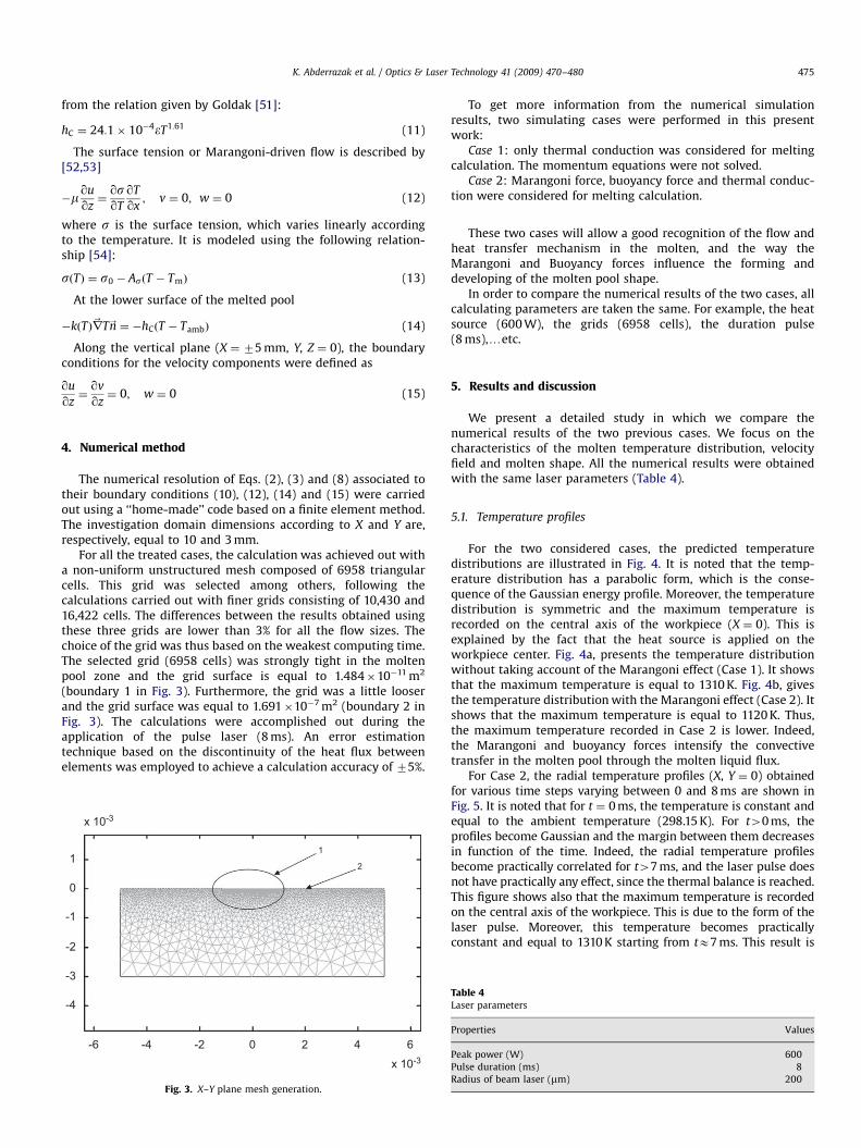
For all the treated cases, the calculation was achieved out witha non-uniform unstructured mesh composed of 6958 triangularcells. This grid was selected among others, following thecalculations carried out with finer grids consisting of 10,430 and16,422 cells. The differences between the results obtained usingthese three grids are lower than 3% for all the flow sizes. Thechoice of the grid was thus based on the weakest computing time.The selected grid (6958 cells) was strongly tight in the moltenpool zone and the grid surface is equal to 1.484�10�11 m2
(boundary 1 in Fig. 3). Furthermore, the grid was a little looserand the grid surface was equal to 1.691�10�7 m2 (boundary 2 inFig. 3). The calculations were accomplished out during theapplication of the pulse laser (8 ms). An error estimationtechnique based on the discontinuity of the heat flux betweenelements was employed to achieve a calculation accuracy of 75%.
x 10-3
1
0
-1
-2
-3
-4
-6 -4 -2 0 2 4 6
x 10-3
1
2
Fig. 3. X–Y plane mesh generation.
To get more information from the numerical simulationresults, two simulating cases were performed in this presentwork:
Case 1: only thermal conduction was considered for meltingcalculation. The momentum equations were not solved.
Case 2: Marangoni force, buoyancy force and thermal conduc-tion were considered for melting calculation.
These two cases will allow a good recognition of the flow andheat transfer mechanism in the molten, and the way theMarangoni and Buoyancy forces influence the forming anddeveloping of the molten pool shape.
In order to compare the numerical results of the two cases, allcalculating parameters are taken the same. For example, the heatsource (600 W), the grids (6958 cells), the duration pulse(8 ms),yetc.
5. Results and discussion
We present a detailed study in which we compare thenumerical results of the two previous cases. We focus on thecharacteristics of the molten temperature distribution, velocityfield and molten shape. All the numerical results were obtainedwith the same laser parameters (Table 4).
5.1. Temperature profiles
For the two considered cases, the predicted temperaturedistributions are illustrated in Fig. 4. It is noted that the temp-erature distribution has a parabolic form, which is the conse-quence of the Gaussian energy profile. Moreover, the temperaturedistribution is symmetric and the maximum temperature isrecorded on the central axis of the workpiece (X ¼ 0). This isexplained by the fact that the heat source is applied on theworkpiece center. Fig. 4a, presents the temperature distributionwithout taking account of the Marangoni effect (Case 1). It showsthat the maximum temperature is equal to 1310 K. Fig. 4b, givesthe temperature distribution with the Marangoni effect (Case 2). Itshows that the maximum temperature is equal to 1120 K. Thus,the maximum temperature recorded in Case 2 is lower. Indeed,the Marangoni and buoyancy forces intensify the convectivetransfer in the molten pool through the molten liquid flux.
For Case 2, the radial temperature profiles (X, Y ¼ 0) obtainedfor various time steps varying between 0 and 8 ms are shown inFig. 5. It is noted that for t ¼ 0 ms, the temperature is constant andequal to the ambient temperature (298.15 K). For t40 ms, theprofiles become Gaussian and the margin between them decreasesin function of the time. Indeed, the radial temperature profilesbecome practically correlated for t47 ms, and the laser pulse doesnot have practically any effect, since the thermal balance is reached.This figure shows also that the maximum temperature is recordedon the central axis of the workpiece. This is due to the form of thelaser pulse. Moreover, this temperature becomes practicallyconstant and equal to 1310 K starting from tE7 ms. This result is
Table 4Laser parameters
Properties Values
Peak power (W) 600
Pulse duration (ms) 8
Radius of beam laser (mm) 200

ARTICLE IN PRESS
Max:1.31e + 003
1300
1200
1100
1000
900
800
700
600
500
400
300Min: 300
Max:1.12e + 003
1100
1000
900
800
700
600
500
400
300Min: 300
x 10-3
543210X axis Coord. (m)
-1-2-3-4-5
-4
-3
-2
-1
Y ax
is C
oord
. (m
) 0
1
x 10-3
x 10-3
1
0
-1
Y ax
is C
oord
. (m
)
-2
-3
-4
-5 -4 -3 -2 -1 0 1 2 3 4 5
x 10-3X axis Coord. (m)
Fig. 4. Contours of temperature on heated surface at t ¼ 8 ms: (a) Case 1 and (b) Case 2.
1400
1200
1000
800
600
400
2000 0.2 0.4 0.6 0.8 1
x 10-3X axis Cood. (m)
t = 0s
Tem
pera
ture
(K)
Time : 1 → 8ms
Fig. 5. Peak temperature distribution according to the pulse shape: peak power of
600 W and duration of 1–8 ms.
K. Abderrazak et al. / Optics & Laser Technology 41 (2009) 470–480476
in agreement with the maximum temperature evolution presentedin Fig. 7. It is also noted that the temperature decreases in functionof X whatever t; this is also explained by the form and the mode ofthe used laser pulse (Fig. 2).
For Case 2, the centerline temperature evolution (X ¼ 0, Y) forvarious time steps varying between 0 and 8 ms are traced in Fig. 6.It is noted that for t ¼ 0 ms, the temperature is constant andequal to the ambient temperature (298.15 K). For t40 ms, thetemperature is maximum at the application point of thelaser pulse (X ¼ 0, Y ¼ 0), then decreases quickly in function ofX i.e. far from the pulse application point. It is also noticed that,more the process approaches the thermal balance (t ¼ 7 ms),more the difference between the profiles decreases and tendstowards 0.
For Case 2, Fig. 7 gives the temperature evolution at the impactpoint of the laser pulse. It is noted that for tp2 ms, the growth rateof the temperature is rather important. Indeed, the temperaturereaches 1150 K in 2 ms. For t42 ms, the temperature increasesslightly and tends to a maximum temperature equal to 1310 Kcalled thermal balance temperature.

ARTICLE IN PRESS
1400
1200
1000
Tem
pera
ture
(K)
800
600
400
2000
t = 0s
0.2 0.4Depth (m)
0.6 0.8x 10⁻³
1
Time : 1 → 8ms
Fig. 6. Peak temperature distribution according to the pulse shape: peak power of
600 W and duration of 1–8 ms.
1400
1200
1000
800
Tem
pera
ture
(K)
600
400
2000 1 2 3 4
Time (S)5 6 7
x 10-38
Fig. 7. Thermal cycle during the welding.
Fig. 8. Velocity distribution at X–Y plane.
Fig. 9. Velocity profile at the cross-section.
K. Abderrazak et al. / Optics & Laser Technology 41 (2009) 470–480 477
5.2. Velocity field
In this section, Case 2 was considered to study the velocityfields’ distribution. It is known that the surface tension(Marangoni effects) and buoyancy forces enhance the heattransfer in the molten pool by driving the molten liquid flow.Fig. 8 gives the velocity distribution at XY plane, at the end of thelaser pulse duration (t ¼ 8 ms). It is noted that the molten liquid atthe free surface flows from the central outwards to thesolid–liquid interface and forms two vortexes in the molten pool.These two recirculation zones modified the molten pool shapewhich became wider and shallower.
Fig. 9 shows the evolution of the velocity profile for Y ¼ 0(workpiece surface), at the end of the laser pulse duration(t ¼ 8 ms). It is observed that the maximum velocity (0.377 m/s)is reached between the molten pool center and the solid–liquidinterface. On the other hand, the minimum velocity (0.12 m/s) islocated in the molten pool center.
Fig. 10. Shapes of molten pool at the cross-section: (a) Case 1 and (b) Case 2.
5.3. Molten pool shapeFor the two considered cases, Fig. 10 illustrates the molten poolshapes at the XY plane, at the end of the laser pulse duration(t ¼ 8 ms). It is noted that the molten pool of Case 2 (Fig. 10b) iswider and shallower than that of Case 1 (Fig. 10a). This is due to
the Marangoni and buoyancy forces. Consequently, in theprocesses, some appropriate activity elements can be added inthe process material to change its surface tension characters, andget a molten pool with a large ratio of width to depth. For a

ARTICLE IN PRESS
K. Abderrazak et al. / Optics & Laser Technology 41 (2009) 470–480478
forthcoming comparison with the experimental results, it isnecessary to release the molten pool dimensions. Fig. 8 showsthat the penetration depth is equal to 0.48 mm and the beadwidth is equal to 1.8 mm.
6. Experiment and metallograph
6.1. Experiment apparatus and technique
The experimental investigation of punching and welding usingYAG solid laser apparatus was conducted to display the funda-mental features, and to validate the numerical predictions. Theexperimental rig is shown in Fig. 11. The machine can provide a500 W pulse laser beam and the digital control system is LASMA1054 system. It can be used for punching, incision, jointing and
Fig. 11. CNC table TRUMPF HAAS LASMA 1054, the laser head, the coaxial nozzle.
Fig. 12. Metallograph of molten
surface treatment. The main performance parameters includepulse bandwidth 0.1–20 ms, pulse frequency o300 Hz and pulseenergy �50 J.
The experiment explored the characteristics of two kinds of amolten pool: molten pool of two different materials and an initialmolten pool in punching. The sample segments were cut andrubbed to the central cross-section, and the metallograph wasobtained by corrosion. Since the metal crystal structure changedafter condensation, we can clearly observe the molten pool shape.From metallographers, the effects of thermophysical properties onthe characteristics of the molten pool can be analyzed.
6.2. Comparison with numerical simulation
Fig. 12 illustrates the metallographers of the molten pools(light zones) of two different materials: the left is 304 stainlesssteel (Fig. 12a) and the right side is AZ91 magnesium alloy(Fig. 12b). The speckled zones are the metal parts which did notundergo a phase change during the processing. It is noted that themolten pool is wider and deeper for AZ91 magnesium alloy.Indeed, the materials properties have significant effects on themolten pool shape. Since the heat capacity of AZ91 is smaller thanthat of 304 stainless steel (the ratio is 500:1000), and heatconductivity (at 100 1C) is larger (the ratio is 16:53).
Fig. 13 presents the molten pool shape of an AZ91 magnesiumalloy, obtained by a laser pulse interaction characterized by afrequency equal to 20 Hz, duration of 8 ms and average power of300 W. The light zone is the metal part without phase changeoccurring during the processing. The molten pool is deeper in thecentral part (C) compared with the two sides (A and B). This is dueto the power density distribution of the laser beam. Indeed,the energy density at the center is maximum and larger than104 W/cm2, which makes the local temperature higher than themelting point magnesium alloy (650 1C). Interfacial shape ofregions A and B obviously exhibits the flow effects on thedevelopment of the molten pool. This figure shows also that the
pool joint of two materials.

ARTICLE IN PRESS
Fig. 13. Metallograph of initial molten pool in punching.
K. Abderrazak et al. / Optics & Laser Technology 41 (2009) 470–480 479
maximum width of the molten pool is 2.2 mm and the maximumdepth is 0.68 mm.
Comparing Fig. 13 with Fig. 10b qualitatively, the results show areasonable agreement. Indeed, the molten pool shapes obtainedby the numerical calculation and the experiment are generallysimilar, except for a slight deviation noted at the two sides A and Bof the molten pool metallograph (Fig. 13), which was not seen bythe numerical model. Quantitatively, the numerical results under-estimate the molten pool dimensions with 18% for the bead widthand 29% for the penetration depth. The main reasons are theassumption of Gaussian distribution of laser energy density andthe heat loss associated with metal vaporization, which was notincluded in the numerical model.
Thus, the numerical model developed in the present work is ableto describe reasonably the internal flow and the transportphenomena in the molten pool. It provides a very good predictionof the different physical fields of a laser pulse processing. Certainly,the simulation of all the welding process requires some modifica-tions, such as the phase of vaporization, the welding speed, and theenergy loss caused by metal vaporization, which should be includedin the numerical model to improve the prediction.
7. Conclusion
In this study, a 2D numerical model is developed to investigatethe interaction of a pulse laser (Nd:YAG) with a magnesium alloy.The confrontation with the experimental results proved that theproposed computational procedure predicts well the dynamic andthermal fields of a laser pulse processing. According to thesimulated and experimental results, the main conclusions can besummarized as follows:
(1)
According to the simulated results, the temperature distribu-tion around the impact point has a parabolic form, which isthe consequence of the Gaussian energy profile.(2)
The Marangoni flow and buoyancy forces enhance the heattransfer in the molten pool by driving the molten liquid flow.Indeed, the molten liquid at the free surface flows from thecentral outwards to the solid–liquid interface and forms twovortexes in the molten pool. These two recirculation zonesmodified the molten pool shape, which became wider andshallower.(3)
The 2D numerical model predicts well the temperaturedistribution and velocity fields in the molten pool, which arein good agreement with the experimental results.(4)
The experimental results showed that the materials’ proper-ties have important effects on the transport phenomena in themolten pool, and consequently on the molten pool shape.The main objective of this work was to simulate the process oflaser sheet welding by studying the impact of only one laser pulseon the AZ91 magnesium alloy and the formation of the moltenpool. In the future, it will be followed by a more complex model tosimulate all process, to take account of the others weldingparameter like welding speed, shielding gas and a continuouslaser power. Contingently, the effect of these parameters on theshape and the size of the molten pool will be discussed.
Acknowledgments
The authors wish to thank the support staffs of the MechanicalInstitute of Marseille, the Diagnostics and Imaging of IndustrialProcesses laboratory of the National Engineering School in Saint-Etienne and the MecaSurf team for their assistance in theexperimental work.
References
[1] Sanders PG, Keske JS, Leong KH, Kornecki G. High power Nd:YAG and CO2
laser welding of magnesium. J Laser Appl 1999;11:96–103.[2] Leong KH, Kornecki G, Sanders PG, Keske JS. Laser beam welding of
AZ31B-H24 alloy. In: ICALEO 98: laser materials processing conference,Orlando, FL, 1998, p. 28–36.
[3] Haferkamp H, Goede M, Bormann A, Cordini P. Laser beam welding ofmagnesium alloys—new possibilities using filler wire and arc welding. ProcLANE: Laser Assist Net Shape Eng 2001;3:333–8.
[4] Watkins KG. In: Kaplan HI (Ed.), Laser welding of magnesium alloys. In:Magnesium technology 2003, TMS annual meeting and exhibition, San Diego,CA, 2003, p. 153–6.
[5] Lehner C, Reinhart G, Schaller L. Welding of die cast magnesium alloys forproduction. J Laser Appl 1999;11(5):206–10.
[6] Pastor M, Zhao H, DebRoy T. Continuous wave—Nd:yttrium–aluminium–garnet laser welding of AM60B magnesium alloys. J Laser Appl 2000;12(3):91–100.
[7] Zhao H, DebRoy T. Pore formation during laser beam welding of die castmagnesium alloy AM60B—mechanism and remedy. Weld J 2001;80(8):204S–10S.
[8] Marya M, Edwards GR. The laser welding of magnesium alloy AZ91. WeldWorld 2000;44(2):31–7.
[9] Weisheit A, Galun R, Mordike BL. Weldability of various magnesium alloysusing a CO2-laser IIW seminarb. Trends Weld Light Weight Automob RailroadVehicles 1997:28–41.
[10] Marya M, Edwards G, Marya S, Olson DL. Fundamentals in the fusion weldingof magnesium and its alloys. In: Proceedings of the seventh JWS internationalsymposium, Kobe, 2001, p. 597–602.

ARTICLE IN PRESS
K. Abderrazak et al. / Optics & Laser Technology 41 (2009) 470–480480
[11] Avedesian MM, Baker H. Magnesium and magnesium alloys. ASM SpecialtyHandbook; 1999.
[12] Sprow EE. The laser-welding spectrum: what it has to offer you. Tool Prod1988;54(3):560–3.
[13] Haferkamp H, Burmester I, Niemeyer M. Laser beam welding of magnesiumalloys. Technological developments and advances for Australian industry. In:Proceedings of the 1997 international welding and joining researchconference, 1997.
[14] Cao X, Jahazi M, Immarigeon JP, Wallace W. A review of laser weldingtechniques for magnesium alloys. J Mater Process Technol 2006;171:188–204.
[15] Rosenthal D. The theory of moving sources of heat and its application to metaltreatments. Trans ASME 1946;43:849–66.
[16] Swift-Hook DT, Gick AEF. Penetration welding with lasers. Weld J 1973;52:492–9.
[17] Klemens PG. Heat balance and flow conditions for electron beam and laserwelding. J Appl Phys 1972;47:2165–74.
[18] Andrews JG, Atthey DR. Hydrodynamic limit to penetration of a material by ahigh-power beam. J Phys D: Appl Phys 1976;9:2181–94.
[19] Cline HE, Anthony TR. Heat treating and melting material with a scanninglaser or electron beam. J Appl Phys 1977;48:3895–900.
[20] Davis M, Kapadia P, Dowden J. Modelling the fluid flow in laser beam welding.Weld J 1986;65:167–74.
[21] Weckman DC, Mallory LC, Kerr HW. A technique for the prediction of averageweld pool width and depth for GTA welds on stainless steels. Z Metallkd1989;80:459–68.
[22] Steen WM, Dowden J, Davis M, Kapadia P. A point and line source model oflaser keyhole welding. J Phys D: Appl Phys 1988;21:1255–60.
[23] Akhter R, Davis M, Dowden J, Kapadia P, Ley M, Steen WM. A method forcalculating the fused zone profile of laser keyhole welds. J Phys D: Appl Phys1989;22:23–8.
[24] Dowden J, Kapadia P, Postacioglu N. An analysis of the laser–plasmainteraction in laser keyhole welding. J Phys D: Appl Phys 1989;22:741–9.
[25] Finke BR, Kapadia PD, Dowden JM. A fundamental plasma based model forenergy transfer in laser material processing. J Phys D: Appl Phys 1990;23:643–54.
[26] Tosto S. Modelling of the thermal field induced by laser irradiation in thepresence of heat sinks or sources. Lasers Eng 1993;2:61–74.
[27] Kaplan A. A model of deep penetration laser welding based on calculation ofthe keyhole profile. J Phys D: Appl Phys 1994;27:1805–14.
[28] Mazumder J, Steen WM. Heat transfer model for CW laser materialprocessing. J Appl Phys 1980;51:941–7.
[29] Paul A, DebRoy T. Free surface flow and heat transfer in conduction modelaser welding. Metall Trans 1988;19B:851–8.
[30] Molino G, Penasa M, Perlini G, Tiziani A, Zambon A. Thermal modelling of thelaser welding process using a realistic power distribution of the beam. In:Bergmann H, Kupfer R, editors. Proceedings of the third European conference onlaser treatment of materials. Sprechsaal Publishing Group; 1990. p. 195–205.
[31] Gratzke U, Kapadia PD, Dowden J. Heat conduction in high-speed laserwelding. J Appl Phys D: Appl Phys 1991;24:2125–34.
[32] Aden M, Beyer E, Herziger G, Kunze H. Laser-induced vaporization of a metalsurface. J Appl Phys D: Appl Phys 1992;25:57–65.
[33] Dowden J, Chang WS, Kapadia P, Strange C. Dynamics of the vapour flow inthe keyhole in penetration welding with a laser at medium welding speeds.J Appl Phys D: Appl Phys 1991;24:519–32.
[34] Zacharia T, David SA, Vitek JM, DebRoy T. Heat transfer during Nd:YAG pulsedlaser welding and its effect on solidification structure of austenitic stainlesssteels. Metall Trans 1989;20:957–67.
[35] Russo AJ, Akau RL, Jellison JL. Thermocapillary flow in pulsed laser beam weldpools. Weld J 1990;69:23–9.
[36] Vishnu PR, Li WB, Easterling KE. Heat flow model for pulsed welding. J MaterSci Technol 1991;7:49–659.
[37] Gellert B, Egli W. Melting of copper by an intense and pulsed heat source.J Appl Phys D: Appl Phys 1988;21:1721–6.
[38] Jette AN, Benson RC. Modeling of pulsed-laser cleaning of metal opticalsurfaces at cryogenic temperatures. J Appl Phys 1994;75:3130–41.
[39] Arutyunyan RV, Baranov VY, Bol’shov LA, Malyuta DD, Mezhevov VS,Pis’mennyi VD. Thermohydrodynamic models of the interaction of pulsed-periodic radiation with matter. Sov J Quantum Electron 1987;17:163–8.
[40] Duley WW. Laser welding. New York: Wiley; 1999.[41] Chan C, Mazumder J, Chen MM. Two-dimensional transient model for
convection in laser melted pool. Metall Trans A 1984;15A:2175–84.[42] Basu S, Debroy T. Liquid metal expulsion during laser irradiation. J Appl Phys
1992;72:3317–22.[43] Kim WS, Sim BC. Study of thermal behavior and fluid flow during laser surface
heating of alloys. Numer Heat Transfer 1997;A31:703–23.[44] Robert A, Debroy T. Geometry of laser spot welds from dimensionless
numbers. Metall Trans B 2001;32B:941–7.[45] Marathe AG, Ravi MR. Simulation of laser and electron beam melting
problems. In: XVII national and VI ISHMT/ASME heat and mass transferconference. Kalpakkam: IGCAR; 2004. p. 57–62.
[46] Shanping L, Hidetoshi F, Kiyoshi N. Sensitivity of Marangoni convection andweld shape variations to welding parameters in O2–Ar shielded GTA welding.Scripta Mater 2004;51:271–7.
[47] Wang H, Shi Y, Gong S. Effect of pressure gradient driven convection in themolten pool during the deep penetration laser welding. J Mater ProcessTechnol 2007;184:386–92.
[48] Xu YL, Dong ZB, Wei YH, Yang CL. Marangoni convection and weld shapevariation in A-TIG welding process. Theor Appl Fract Mech 2007;48:178–86.
[49] Ignata S, Sallamand P, Grevey D, Lambertin M. Magnesium alloys (WE43 andZE41) characterisation for laser applications. Appl Surf Sci 2004;233:382–91.
[50] Voller VR, Swaminathan CR. General source-based method for solidificationphase change. Numer Heat Transfer Part B 1991;19:175–89.
[51] Goldak J. Computer modeling of heat flow in welds. Metall Trans 1986:17–26.[52] Ha EJ, Kim WS. A study of low-power density laser welding process with
evolution of free surface. Int J Heat Fluid Flow 2005;26:613–21.[53] Fan HG, Tsai HL, Na SJ. Heat transfer and fluid flow in a partially or fully
penetrated weld pool in gas tungsten arc welding. Int J Heat Mass Transfer2001;44:417–28.
[54] Zacharia T, David SA, Vitek JM, Debroy T. Weld pool development during GTAand laser beam welding of type 304 stailess steel, Part I—theoretical analysis.Weld J Res Supply 1989:499–509.