
Minimizing the levelized cost of electricity production from low ...
17
Minimizing the levelized cost of electricity production from low-temperature geothermal heat sources with ORCs: water or air cooled? ✩ Dani¨ el Walraven a,c , Ben Laenen b,c , William D’haeseleer a,c,* a University of Leuven (KU Leuven) Energy Institute - TME branch (Applied Mechanics and Energy Conversion), Celestijnenlaan 300A box 2421, B-3001 Leuven, Belgium b Flemish Institute for Technological Research (VITO), Boeretang 200, B-2400 Mol, Belgium c EnergyVille (Joint Venture of VITO and KU Leuven), Dennenstraat 7, B-3600 Genk, Belgium Abstract A system optimization of ORCs cooled by air-cooled condensers or wet cooling towers and powered by low-temperature geothermal heat sources is performed in this paper. The configuration of the ORC is optimized together with the geometry of all the components. The objective is to minimize the levelized cost of electricity (LCOE) and the performance of ORCs with different types of cooling systems are compared to each other. The results show that it is economically more interesting to use mechanical-draft wet cooling towers instead of air-cooled condensers. The difference in performance is especially large for a low brine-inlet temperature. The investment cost of wet cooling towers is much lower than the one of air-cooled condensers, so the discount rate has less influence on the former type of cooling. The effect of the water price and the climate conditions on the economics of ORCs is also investigated. Both the brine-inlet temperature and the dry-bulb temperature of the surroundings have a strong influence and values of the optimized LCOE between about 55 and 185 A C/MWh are obtained. Keywords: ORC, geothermal, air-cooled condenser, wet cooling tower, economics, optimization 1. Introduction It is expected that low-temperature geothermal heat sources will be used more often in the future for elec- tricity production [1, 2]. One issue with these sources is that the conversion efficiency to electricity is low due to the low temperature of the source. Many researchers have tried to maximize this efficiency by opti- mizing the performance of organic Rankine cycles (ORCs), but the absolute efficiency remains low due to the Carnot limit. Most of the research on ORCs focuses on the optimization of the thermodynamic cycle. Simple cycles, recuperated cycles and cycles with turbine bleeding are proposed, they can be subcritical or transcritical and have one or more pressure levels [3–11]. In most cases, the components in these cycles are assumed to be ideal or they are modeled very simplistically. Some researchers have already taken the influence of the sizing of the components into account. Madhawa Hettiarachchi et al. [12] have minimized the ratio of the total heat exchanger surface and the net power produced by the cycle. Franco and Villani [13] have optimized the cycle and the heat exchangers separately, but used an iteration to make the connection between the system level and the component level. Walraven et al. [14] have shown that it is possible to optimize the configuration of shell-and-tube heat exchangers together with the configuration of the cycle, which was extended in Walraven et al. [15], in which an air-cooled condenser was included. ✩ Published version: http://dx.doi.org/10.1016/j.apenergy.2014.12.078 * Corresponding author. Tel.: +32 16 32 25 11; fax: +32 16 32 29 85. Email addresses: [email protected] (Dani¨ el Walraven), [email protected] (Ben Laenen), [email protected] (William D’haeseleer) Preprint submitted to Applied Energy January 7, 2015
-
Upload
khangminh22 -
Category
Documents
-
view
0 -
download
0
Transcript of Minimizing the levelized cost of electricity production from low ...

Minimizing the levelized cost of electricity production fromlow-temperature geothermal heat sources with ORCs: water or air cooled?I
Daniel Walravena,c, Ben Laenenb,c, William D’haeseleera,c,∗
aUniversity of Leuven (KU Leuven) Energy Institute - TME branch (Applied Mechanics and Energy Conversion),Celestijnenlaan 300A box 2421, B-3001 Leuven, Belgium
bFlemish Institute for Technological Research (VITO), Boeretang 200, B-2400 Mol, BelgiumcEnergyVille (Joint Venture of VITO and KU Leuven), Dennenstraat 7, B-3600 Genk, Belgium
Abstract
A system optimization of ORCs cooled by air-cooled condensers or wet cooling towers and powered bylow-temperature geothermal heat sources is performed in this paper. The configuration of the ORC isoptimized together with the geometry of all the components. The objective is to minimize the levelized costof electricity (LCOE) and the performance of ORCs with different types of cooling systems are comparedto each other. The results show that it is economically more interesting to use mechanical-draft wet coolingtowers instead of air-cooled condensers. The difference in performance is especially large for a low brine-inlettemperature. The investment cost of wet cooling towers is much lower than the one of air-cooled condensers,so the discount rate has less influence on the former type of cooling. The effect of the water price and theclimate conditions on the economics of ORCs is also investigated. Both the brine-inlet temperature andthe dry-bulb temperature of the surroundings have a strong influence and values of the optimized LCOEbetween about 55 and 185 AC/MWh are obtained.
Keywords: ORC, geothermal, air-cooled condenser, wet cooling tower, economics, optimization
1. Introduction
It is expected that low-temperature geothermal heat sources will be used more often in the future for elec-tricity production [1, 2]. One issue with these sources is that the conversion efficiency to electricity is lowdue to the low temperature of the source. Many researchers have tried to maximize this efficiency by opti-mizing the performance of organic Rankine cycles (ORCs), but the absolute efficiency remains low due tothe Carnot limit. Most of the research on ORCs focuses on the optimization of the thermodynamic cycle.Simple cycles, recuperated cycles and cycles with turbine bleeding are proposed, they can be subcritical ortranscritical and have one or more pressure levels [3–11]. In most cases, the components in these cyclesare assumed to be ideal or they are modeled very simplistically. Some researchers have already taken theinfluence of the sizing of the components into account. Madhawa Hettiarachchi et al. [12] have minimized theratio of the total heat exchanger surface and the net power produced by the cycle. Franco and Villani [13]have optimized the cycle and the heat exchangers separately, but used an iteration to make the connectionbetween the system level and the component level. Walraven et al. [14] have shown that it is possible tooptimize the configuration of shell-and-tube heat exchangers together with the configuration of the cycle,which was extended in Walraven et al. [15], in which an air-cooled condenser was included.
IPublished version: http://dx.doi.org/10.1016/j.apenergy.2014.12.078∗Corresponding author. Tel.: +32 16 32 25 11; fax: +32 16 32 29 85.Email addresses: [email protected] (Daniel Walraven), [email protected] (Ben Laenen),
[email protected] (William D’haeseleer)
Preprint submitted to Applied Energy January 7, 2015
A consequence of the low conversion efficiency of heat into electricity is that most of the heat, which isadded to the cycle, has to be dumped into the environment. The cooling system is therefore very importantin power plants powered by low-temperature heat sources. Power plants can be cooled in three ways: aircooling, water cooling with a cooling tower and direct cooling with water, of which the two first options aremost often used. The auxiliary power consumption of air-cooled condensers (ACC) is about twice as high asthat one for mechanical-draft wet cooling towers (WCT) used for low-temperature geothermal power plants[16]. When low condensing temperatures are used in these plants, the investment cost of a binary plant withan ACC can be 50% higher than that of a plant with a wet cooling tower for the same conversion efficiency[16]. The disadvantage of using a wet cooling tower is of course that water is consumed, which is a bigdrawback when water is scarce. The type of the cooling method is therefore very important in the designof a geothermal binary power plant.
The comparison between air cooling and wet cooling has already been performed in the literature. Barigozziet al. [17] developed a model of a cogeneration power plant powered by burning waste, while the coolingsystem consists of both an ACC and a WCT. They found that when the environmental temperature is below15◦C, it is best to use the ACC. When the environmental temperature is higher than 15◦C, both the ACCand the WCT are used. First, the ACC is used to cool down the steam and afterwards the WCT is used tocool it further down. These results are valid for high-temperature heat sources (turbine-inlet-temperatureof 450◦C). Mendrinos et al. [16] compared cooling methods for geothermal binary plants. They concludedthat wet cooling towers are the best choice, except when water is a very scarce product or when the climaticconditions are extreme.
The above mentioned works often use simplified models of the cooling system. Other researchers haveoptimized the configuration of the cooling system itself. Rubio-Castro et al. [18] used the work of Klop-pers and Kroger [19] to simulate and optimize the performance of a mechanical-draft wet cooling towerand compared the Merkel to the Poppe method. They repeated the optimization for different fill types.Serna-Gonzalez et al. [20] performed a similar research, but defined the problem as a MINLP (Mixed Inte-ger Non-Linear Problem) in which the type of packing and the type of draft were the integer optimizationvariables. They used the Merkel method to calculate the heat and mass transfer in the cooling tower.
In this work we combine the three above mentioned research areas: optimization of ORCs, comparisonbetween cooling systems and optimization of cooling systems; all at once simultaneously. In our previouswork [15] we maximized the net present value of an air-cooled ORC, in which the parameters of the ORC,the configuration of the heat exchangers and the configuration of an ACC are optimized together. In thispaper we add a model for a wet cooling tower based on the work of Kloppers [21] and minimize the levelizedcost of electricity production (LCOE)1 for both water-cooled and air-cooled ORCs. The results of bothtypes of cooling are compared to each other and the influence of the brine-inlet temperature, brine-outlettemperature, discount rate and water price on the performance of the power plant are investigated.
2. Physical model
2.1. Organic Rankine cycle
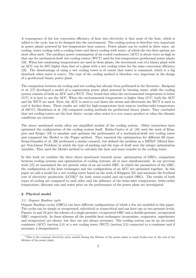
Organic Rankine cycles (ORCs) can have different configurations of which a few are modeled in this paper.The cycles can be simple or recuperated, subcritical or transcritical and can have one or two pressure levels.Figures 1a and 1b give the scheme of a single-pressure, recuperated ORC and a double-pressure, recuperatedORC, respectively. In these schemes all the possible heat exchangers (economizer, evaporator, superheaterand recuperator) are shown, but they are not always necessary. The cooling system can be an air-cooledcondenser (ACC) (section 2.4) or a wet cooling tower (WCT) (section 2.5) connected to a condenser and ifnecessary a desuperheater.
1This is the constant electricity price needed during the lifetime of the power plant to reach brake-even at the end of thelifetime of the power plant.
2
Heat source inHeat source out
1
2
3
4 56
7
8
Cooling system
(a) Single-pressure
Heat source in
Hea
tso
urc
eou
t
4b 5b 6b
1a2a 4a 5a 6a
1
2
3 7
8
Cooling system
(b) Double-pressure
Figure 1: Scheme of a single-pressure, recuperated (a) and double-pressure, simple (b) ORC.
It is assumed that state 1 is saturated liquid and that the isentropic efficiency of the pump is 80%. Moreinformation about the modeling of the cycle can be found in Walraven et al. [11].
2.2. Heat exchangers
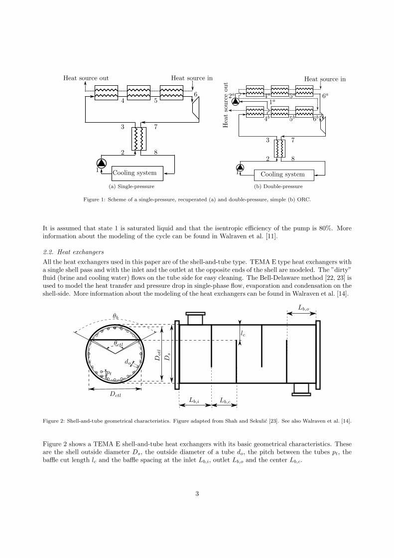
All the heat exchangers used in this paper are of the shell-and-tube type. TEMA E type heat exchangers witha single shell pass and with the inlet and the outlet at the opposite ends of the shell are modeled. The ”dirty”fluid (brine and cooling water) flows on the tube side for easy cleaning. The Bell-Delaware method [22, 23] isused to model the heat transfer and pressure drop in single-phase flow, evaporation and condensation on theshell-side. More information about the modeling of the heat exchangers can be found in Walraven et al. [14].
Lb,cLb,i
Lb,o
Ds
lc
pt
Dotl
θb
θctl
do
Dctl
Figure 2: Shell-and-tube geometrical characteristics. Figure adapted from Shah and Sekulic [23]. See also Walraven et al. [14].
Figure 2 shows a TEMA E shell-and-tube heat exchangers with its basic geometrical characteristics. Theseare the shell outside diameter Ds, the outside diameter of a tube do, the pitch between the tubes pt, thebaffle cut length lc and the baffle spacing at the inlet Lb,i, outlet Lb,o and the center Lb,c.
3

2.3. Turbine
The turbine used in this paper is an axial-inflow, axial-outflow turbine. The results of Macchi and Perdichizzi[24] are used to predict the isentropic efficiency of a turbine stage as done in Walraven et al. [15].
2.4. Air-cooled condenser
The cooling system in figure 1 can be an air-cooled condenser (ACC). Different type of ACCs exist, but inthis paper only A-frame ACCs with flat tubes and corrugated fins are used. This type is most often usedin power plants because the pressure drop on the air side is lower than the one in ACCs with round tubes[25, 26]. The geometry of such an ACC and the bundle geometry of flat tubes with corrugated fins areshown in figure 3.
vapor duct
condensate head
fan
finned tube bundles
air flow
θ
Wl
Lt
(a) A-frame
condensate
vapor
Ws H
S
Lt
(b) Tube bundle
Figure 3: Geometry of an A-frame air-cooled condenser (a) and the bundle geometry of flat tubes with corrugated fins (b).
The tube-bundle geometry is determined by the tubes’ small width Ws, the fin height H, the fin pitchS, the tubes’ large width Wl and the length of the tubes Lt. In an A-frame ACC the tube bundles areplaced at an angle θ with the horizontal. The vapor/two-phase fluid enters the condenser at the top in thevapor duct, flows down the tubes, in which it condenses, and the condensate is collected at the bottom inthe condensate head. A fan at the bottom blows air over the tube bundles. The model of Yang et al. [25]is used to predict the pressure drop and heat transfer of the air-side as explained in Walraven et al. [15].
2.5. Wet cooling tower
Another cooling option is to use a desuperheater and a condenser, coupled to a wet cooling tower (WCT).Natural-draft cooling towers are not modeled in this paper, because they are typically used for large cool-ing needs. For lower cooling loads, mechanical-draft cooling towers are better suited. Both induced andforced-draft towers exist. In the former type, the fan is located downstream (at the exit of the air) of thetower, while the fan is located upstream (at the inlet of the air) in forced-draft towers. The velocity of theair at the outlet is higher for induced-draft towers and the chance of recirculation of wet air is thereforelower. This is the reason why induced-draft towers are more often used and are the focus in this work.Such an induced-mechanical-draft tower is shown in figure 4. The warm cooling water enters the tower inthe sprayers in which it is sprayed over the fill. The fill is used to increase the contact surface between
4

droplets and air in order to increase the heat and mass transfer. At the bottom the cooled water is caughtand it is sent back to cool the ORC condenser. The air flows in the other direction; it enters the towerfrom the sides at the bottom and flows through the inlet louvers. These louvers are used to prevent theinflow of unwanted elements, to prevent water splash and to decrease the amount of sunlight irradiation.When flowing upwards in the tower, the air heats up and the humidity increases. The drift eliminatorsare used to decrease the number of water droplets taken by the airflow. The height of the inlet Hi, theheight of the fill Hfi, the height of the spray zone Hsp and the width of the tower Wt are shown in the figure.
Inlet louvers
Fill
Drift eliminators
Fan
Sprays
Rain zone
Spray zone
Water basin
Hi
Wt
Hfi
Hsp
Figure 4: Geometry of an induced mechanical-draft wet cooling tower. Figure adapted from Kloppers [21].
In this paper, only square towers with a film fill packing are modeled. The model of the cooling toweris based on the work of Kloppers [21]. He developed empirical correlations for the performance of differentfill types and used a fourth order Runge-Kutta method to solve the Poppe equations. The pressure drop ofthe air in the tower is also based on the above mentioned work.
For a given inlet temperature and required outlet temperature of the cooling water, the required Merkelnumber2 is calculated. Based on the geometry of the tower, the properties of the air and the water, theMerkel number in the spray zone and the rain zone can be calculated. From this the required Merkel numberin the fill follows and the height of the fill can be calculated. To calculate the electrical power consumptionof the fan, the pressure drop of the air in the inlet zone, the inlet louvers, rain zone, fill support structure,fill, spray zone, water distribution, drift eliminator and fan upstream are calculated [21]. It is assumed thatthe fan has an efficiency of 60%.
2The Merkel number is a non-dimensional parameter describing the transfer characteristics in the cooling tower, defined as
Me =hdapaLpa
Gwwith hd the mass transfer coefficient, apa the area density of the packing and Gw the mass velocity of the
water.
5
3. Economics
3.1. Levelized cost of electricity
The levelized cost of electricity (LCOE) is the constant electricity price needed during the lifetime of thepower plant to reach break even over the lifetime of the project. The LCOE is calculated in AC/MWh as [27]
LCOE =CEPC +
∑tLT
t=1 [(CO&M,t + Cwater,t) (1 + i)−t]∑tLT
t=1 Wnet N (1 + i)−t, (1)
with CEPC the engineering, procurement & construction overnight cost (EPC) of the installation, tLT thelifetime of the installation, CO&M,t the operations and maintenance cost in year t which is assumed to be
2.5% of the investment cost of the ORC per year [2], Cwater,t the water cost in year t, Wnet the net electricpower output, which takes an electric generator efficiency of 98% into account, expressed in MWe, N thenumber of full-load hours per year (an availability of 95% is assumed) and i the discount rate. The EPCcost consists of two parts: the cost of the drilling Cdrilling and the cost of the ORC CORC (see section 3.2).
3.2. Cost of ORC
The overnight EPC investment cost of the ORC, CORC , can be calculated as:
CORC =∑i
(fM,ifP,ifT,i + fI)CE,i, (2)
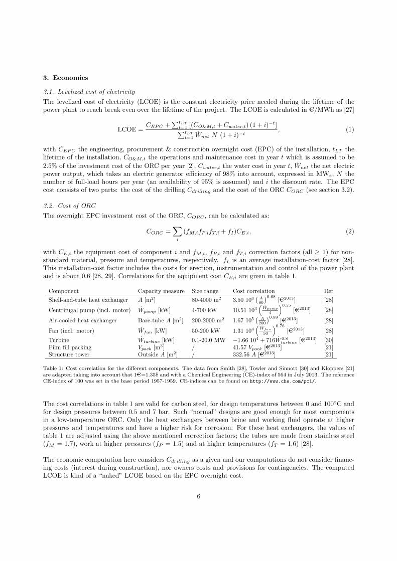
with CE,i the equipment cost of component i and fM,i, fP,i and fT,i correction factors (all ≥ 1) for non-standard material, pressure and temperatures, respectively. fI is an average installation-cost factor [28].This installation-cost factor includes the costs for erection, instrumentation and control of the power plantand is about 0.6 [28, 29]. Correlations for the equipment cost CE,i are given in table 1.
Component Capacity measure Size range Cost correlation Ref
Shell-and-tube heat exchanger A [m2] 80-4000 m2 3.50 104(A80
)0.68[AC2013] [28]
Centrifugal pump (incl. motor) Wpump [kW] 4-700 kW 10.51 103(
Wpump
4
)0.55[AC2013] [28]
Air-cooled heat exchanger Bare-tube A [m2] 200-2000 m2 1.67 105(
A200
)0.89[AC2013] [28]
Fan (incl. motor) Wfan [kW] 50-200 kW 1.31 104(
Wfan
50
)0.76[AC2013] [28]
Turbine Wturbine [kW] 0.1-20.0 MW −1.66 104 + 716W 0.8turbine [AC2013] [30]
Film fill packing Vpack [m3] / 41.57 Vpack [AC2013] [21]Structure tower Outside A [m2] / 332.56 A [AC2013] [21]
Table 1: Cost correlation for the different components. The data from Smith [28], Towler and Sinnott [30] and Kloppers [21]are adapted taking into account that 1AC=1.35$ and with a Chemical Engineering (CE)-index of 564 in July 2013. The referenceCE-index of 100 was set in the base period 1957-1959. CE-indices can be found on http://www.che.com/pci/.
The cost correlations in table 1 are valid for carbon steel, for design temperatures between 0 and 100◦C andfor design pressures between 0.5 and 7 bar. Such “normal” designs are good enough for most componentsin a low-temperature ORC. Only the heat exchangers between brine and working fluid operate at higherpressures and temperatures and have a higher risk for corrosion. For these heat exchangers, the values oftable 1 are adjusted using the above mentioned correction factors; the tubes are made from stainless steel(fM = 1.7), work at higher pressures (fP = 1.5) and at higher temperatures (fT = 1.6) [28].
The economic computation here considers Cdrilling as a given and our computations do not consider financ-ing costs (interest during construction), nor owners costs and provisions for contingencies. The computedLCOE is kind of a “naked” LCOE based on the EPC overnight cost.
6

4. Optimization
The objective of the optimization is to minimize the levelized cost of electricity (LCOE), by finding theoptimal conversion cycle parameters and sizing. This optimization is performed with the use of the CasADi[31] and WORHP [32] software. The models themselves are developed in Python and the fluid properties areobtained from REFPROP [33]. We perform a system optimization which means that the cycle parametersand the configuration of all the components are optimized together.
4.1. Optimization variables and constraints
The optimization variables of a single-pressure, recuperated cycle are the temperature before the turbine,the saturation temperature at the pressure before the turbine, the pressure at the inlet of the pump, themass flow of the working fluid and the effectiveness of the recuperator. For double-pressure cycles, the tem-perature before the second turbine, the saturation temperature at the pressure before the second turbineand the mass flow rate through the second turbine are added. More information about these optimizationvariables can be found in Walraven et al. [14].
The optimization variables of each shell-and-tube heat exchanger are the shell diameter Ds, tube-outsidediameter do, tube pitch pt, baffle cut lc and the distance between the baffles Lb,c [14].
The fin height H, the fin pitch S, the air velocity at the minimum cross section VAmin and the num-ber of tubes ntubes are the optimization variables of the ACC and a non-linear constraint is used to limitthe length of the tubes, as done in Walraven et al. [15].
Table 2 shows the optimization variables used for the wet cooling tower and their lower and upper bounds.Twb is the wet-bulb temperature. The height of the spray zone Hsp is fixed at 0.5 m. The height of the fillHfi is a result of the cooling-tower model and is therefore not an optimization variable.
Optimization variable Lower boundary Upper boundaryTower width Wt 1 m 40 mInlet height Hi 1 m 20 mRelative air mass flow mair/mbrine 1.5 500Relative cooling fluid mass flow mcf/mbrine 1.5 500Minimum cooling-fluid temperature Tmin
cf Twb /
Table 2: Optimization variables used for the wet cooling tower and their lower and upper boundaries.
5. Results
5.1. Parameters of the reference case
The parameters of our ”reference” case are given in table 3, which are based on a proposed geothermaldemonstration project in Belgium. In the next subsections, the influence of many of these parameters(brine-inlet temperature, brine-outlet temperature, number of pressure levels, water price, yearly water-price evolution and climate conditions) on the performance of the ORC is investigated. For each of theparameter variations, a new design optimization is performed with the optimization variables described insection 4.1 to obtain the minimum LCOE.Many of the above mentioned economic parameters used in this paper are based on the literature andthe economic analysis is therefore not detailed enough to be used for a business plan. We only focus onelectricity production, while using the geothermal source for heating purposes can improve the economicsof the project.
7

Well parametersBrine wellhead temperature 125◦CBrine production 194 kg/sWell pumps consumption 600 kWe
Wells cost 27.5 MAC
Economic parametersLifetime plant 30 yearsDiscount rate 4%/yearWater price 0.5AC/m3
Environmental conditionsDry-bulb temperature 10.3◦CWet-bulb temperature 8.6◦CAir pressure 1016hPa
Table 3: Parameters of the reference case
5.2. Influence of the brine-inlet temperature
The influence of the brine-inlet temperature on the levelized cost of electricity production for ORCs withair cooling and water cooling are shown in figures 5a and 5b, respectively.
100 110 120 130 140 150
50
100
150
200
Brine-inlet temperature [◦C]
LCOE
[AC/M
Wh]
Isobutane Propane
R134a R218
R227ea R245fa
R1234yf RC318
(a) Single-pressure recuperated cycle with ACC
100 110 120 130 140 150
50
100
150
200
Brine-inlet temperature [◦C]
LCOE
[AC/M
Wh]
Isobutane Propane
R134a R218
R227ea R245fa
R1234yf RC318
(b) Single-pressure recuperated cycle with WCT
Figure 5: LCOE of a single-pressure recuperated ORC with an ACC (a) and a WCT (b) powered by geothermal heat, forvarious thermodynamic-cycle fluids and for varying inlet temperatures of the brine.
The LCOE decreases with increasing brine-inlet temperature as expected, influenced by the net electricpower produced by the installation (figure 6) and thus the investment cost of the installation (specific costof the ORCs are shown in figure 7). Clearly, the net electric power production increases strongly with thebrine-inlet temperature because of the increased plant efficiency, which results in a higher gross turbinepower and lower cooling needs.
The comparison of figures 5a and 5b shows clearly that the LCOE for ORCs with a WCT is lower thanthe one for ORCs with an ACC, and especially for lower brine-inlet temperatures. The net electric powerproduction of ORCs with a WCT (figure 6b) is (slightly) higher than the one with an ACC (figure 6a)because of the lower condenser temperature and the lower auxiliary power consumption, but it is especiallythe lower (specific) investment cost which results in a better LCOE for the ORCs with a WCT. Indeed, thecomparison of figures 7a and 7b shows that the specific cost of ORCs with a WCT is often less than 50% ofthe specific cost of ORCs with an ACC. This is caused by the high investment cost of an ACC.
8

100 110 120 130 140 150
2
4
6
8
10
Brine-inlet temperature [◦C]
Net
electric
pow
erproduction[M
We]
Isobutane Propane
R134a R218
R227ea R245fa
R1234yf RC318
(a) Single-pressure recuperated cycle with ACC
100 110 120 130 140 150
2
4
6
8
10
Brine-inlet temperature [◦C]Net
electric
pow
erproduction[M
We]
Isobutane Propane
R134a R218
R227ea R245fa
R1234yf RC318
(b) Single-pressure recuperated cycle with WCT
Figure 6: Net electric power production of a single-pressure recuperated ORC with an ACC (a) and a WCT (b) powered bygeothermal heat, for various thermodynamic-cycle fluids and for varying inlet temperature of the brine.
100 110 120 130 140 150
2,000
4,000
6,000
8,000
10,000
Brine-inlet temperature [◦C]
Sp
ecifi
cco
stO
RC
[AC/k
We] Isobutane Propane
R134a R218
R227ea R245fa
R1234yf RC318
(a) Single-pressure recuperated cycle with ACC
100 110 120 130 140 150
2,000
4,000
6,000
8,000
10,000
Brine-inlet temperature [◦C]
Sp
ecifi
cco
stO
RC
[AC/k
We] Isobutane Propane
R134a R218
R227ea R245fa
R1234yf RC318
(b) Single-pressure recuperated cycle with WCT
Figure 7: Specific cost of a single-pressure recuperated ORC with an ACC (a) and a WCT (b) powered by geothermal heat,for various thermodynamic-cycle fluids and for varying inlet temperature of the brine.
Figures 8a and 8b show the distribution of the specific and absolute cost of an ORC with isobutane anda brine-inlet temperature of 125◦C. Two big differences catch the eye. The first one is the very high costof the ACC in comparison with the WCT. The cost of the ACC accounts for about 80% of the total costof the ORC, while the cost of the WCT is about one third of the total cost if that option is chosen. Thecost of the ORC accounts for 41% and 24% of the total project cost (including the costs of the wells) forair cooling and water cooling, respectively. The second notable result is the absence of a recuperator in the
9

ORC with a WCT. The installation of a recuperator can decrease the cooling needs, which results in a lowerinvestment and operational cost of the cooling installation as explained in Walraven et al. [15]. The extracost of the recuperator is compensated for by the lower cost of the cooling system when an ACC is used,but not when a WCT is used.
The turbine costs about 1.2 and 1.3 MAC for the ORC with an ACC and a WCT, respectively. Anotherexpensive component, apart from the cooling system, is the economizer, which costs about 1.3MAC for bothcases. The evaporator is relatively inexpensive (0.7 MAC) because of the high heat transfer coefficient dur-ing evaporation (see for example Walraven et al. [14]) and the high average temperature difference in theevaporator.
ACC WCT0
1,000
2,000
3,000
4,000
Sp
ecifi
cco
stO
RC
[AC/k
We]
Recuperator
ACC/WCTCondenserDesuperheaterEconomizerEvaporatorTurbinePump
(a) Specific cost
ACC WCT0
5
10
15
20
Absolute
cost
ORC
[MAC]
(b) Absolute cost
Figure 8: Distribution of the specific cost (a) and the absolute cost (b) for single-pressure, simple and recuperated ORCs withisobutane as the working fluid for a brine-inlet temperature of 125◦C. The cost of the superheater is very small in all cases andis not shown in the figure.
5.3. Influence of the brine-outlet temperature
In this section the effect of a constraint on the brine-outlet temperature is investigated, although only elec-tricity production from the geothermal source is taken into account and direct use of the geothermal sourcefor heating purposes is not considered in this paper.
Figures 9a and 9b show the influence of the brine-outlet-temperature constraint on the LCOE for ORCs withan ACC and a WCT, respectively. The LCOE remains constant for both cooling methods up to a brine-outlet temperature of about 60-70◦C, which is the optimal brine-outlet temperature when no constraint isused. For higher values of the constraint, the LCOE starts to increase and it becomes interesting to use arecuperator in all cases. Such a recuperator can increase the cycle efficiency and when the heat input to thecycle is limited (constraint on brine-outlet temperature), the net power output can also increase [11]. Thislast effect is more important than the increase in cost due to the extra heat exchanger.
5.4. Impact of 2 pressure levels
One way to improve the efficiency of a single-pressure ORC is by using more than one pressure level [11]. Inthis section double-pressure ORCs are compared to single-pressure ones and the influence of the brine-inlettemperature is investigated.
10

40 50 60 70 80 90
80
100
120
140
Brine-outlet temperature [◦C]
LCOE
[AC/MW
h]
Isobutane Propane
R134a R218
R227ea R245fa
R1234yf RC318
(a) Single-pressure recuperated cycle with ACC
40 50 60 70 80 90
80
100
120
140
Brine-outlet temperature [◦C]
LCOE
[AC/MW
h]
Isobutane Propane
R134a R218
R227ea R245fa
R1234yf RC318
(b) Single-pressure recuperated cycle with WCT
Figure 9: LCOE of a single-pressure recuperated ORC with an ACC (a) and a WTC (b) powered by geothermal heat, forvarious thermodynamic-cycle fluids and for varying outlet temperatures of the brine.
100 110 120 130 140 150
50
100
150
200
Brine-inlet temperature [◦C]
LCOE
[AC/M
Wh]
Isobutane Propane
R134a R218
R227ea R245fa
R1234yf RC318
(a) Double-pressure recuperated cycle with ACC
100 110 120 130 140 150
50
100
150
200
Brine-inlet temperature [◦C]
LCOE
[AC/M
Wh]
Isobutane Propane
R134a R218
R227ea R245fa
R1234yf RC318
(b) Double-pressure recuperated cycle with WCT
Figure 10: LCOE of a double-pressure recuperated ORC with an ACC (a) and a WCT (b) powered by geothermal heat, forvarious thermodynamic-cycle fluids and for varying inlet temperatures of the brine.
Figures 10a and 10b show the influence of brine-inlet temperature on the LCOE of double-pressure ORCswith an ACC and a WCT, respectively. Comparison with figure 5 shows that the LCOE of double-pressurecycles is considerably lower than the one of single-pressure cycles, because the net electric power outputof the ORC can increase by adding another pressure level [11]. This effect is more important than theadditional cost of the extra pressure level.
11

5.5. Influence of the discount rate
A geothermal power plant requires a high investment in the beginning of the project and the revenues areobtained in the (far) future. The discount rate is therefore an important economic factor. In this section thediscount rate is varied between 0 and 10%, while using for all other parameters the reference value (table 3).
0 2 4 6 8 10
60
80
100
120
140
160
Discount rate [%]
LCOE
[AC/MW
h]
Isobutane Propane
R134a R218
R227ea R245fa
R1234yf RC318
(a) Single-pressure recuperated cycle with ACC
0 2 4 6 8 10
60
80
100
120
140
160
Discount rate [%]
LCOE
[AC/MW
h]
Isobutane Propane
R134a R218
R227ea R245fa
R1234yf RC318
(b) Single-pressure recuperated cycle with WCT
Figure 11: LCOE of a single-pressure recuperated ORC with an ACC (a) and a WTC (b) powered by geothermal heat, forvarious thermodynamic-cycle fluids and for varying discount rates.
As seen from figure 11, the value of the discount rate has a very strong influence on the LCOE, espe-cially for ORCs cooled by an ACC. ORCs with an ACC require a higher investment cost than ORCs with aWCT (figure 7) and the effect of the discount rate is therefore more important if an ACC is used. For lowvalues of the discount rate, the LCOE of an ORC with an ACC is only slightly higher than the one of anORC with a WCT, while the difference is much larger for high values of the discount rate.
The results show that the optimal configuration of the power plant – and therefore also the net electricpower output, investment cost, etc. – is almost independent of the discount rate. This is again due to thehigh investment cost and the low operational cost. As seen from equation (1), minimizing the LCOE isalmost equal to minimizing the fraction of the investment cost to the net electric power production whenthe operational cost is low. Consequently, the discount rate influences only the value of the LCOE, but hasalmost no influence on the optimal configuration of the power plant.
5.6. Influence of the water price and yearly water-price evolution
A WCT consumes water and the water price and the yearly water-price evolution have therefore an influenceon the power plant. These parameters have no effect on the performance of an ACC and only the results ofORCs with a WCT are therefore given in this section.Figures 12a and 12b show the influence of the water price and the yearly water-price evolution on the LCOEof the power plant. The LCOE increases as expected if water becomes more expensive (now and/or in thefuture). Comparing figure 12a to figure 5a shows that ORCs with an ACC can become more interestingthan ORCs with a WCT when water is expensive; in this reference case, if water were to cost more than1AC/m3.
If water becomes more expensive, cooling in general costs more. To counteract this, the optimizer tries
12

0 0.2 0.4 0.6 0.8 1
60
80
100
120
Water price [AC/m3]
LCOE
[AC/MW
h]
Isobutane Propane
R134a R218
R227ea R245fa
R1234yf RC318
(a) Influence water price
0 1 2 3 4 5
60
80
100
120
Yearly water price evolution [%]LCOE
[AC/MW
h]
Isobutane Propane
R134a R218
R227ea R245fa
R1234yf RC318
(b) Influence yearly water price evolution
Figure 12: LCOE of a single-pressure recuperated ORC with a WTC powered by geothermal heat, for various thermodynamic-cycle fluids and for varying water price (a) and yearly water price evolution (b). The dashed vertical line represents the referencevalue of the water price.
to reduce the water consumption by reducing the cooling needs and by consuming less water in the coolingtower. The first effect is obtained by increasing the cycle efficiency and by increasing the brine-outlet tem-perature. The drawbacks are that the plant efficiency, and therefore also the net power output, decreasesslightly and that the investment cost increases. To reduce the water consumption in the cooling tower, themass flow rate of cooling water is reduced. To compensate for the negative effect this has on the performanceof the ORC [34], the minimum cooling-water temperature is reduced. In order to obtain this, the height ofthe packing is increased, resulting in a higher investment cost and a higher pressure drop (auxiliary powerconsumption).
5.7. Influence of the climate conditions
In this section, the influence of the climate conditions on the performance of the power plant is investigated.The dry-bulb temperature is varied between 0 and 35◦C, while keeping the relative humidity constant at80% as in the reference case. All other parameters are the reference ones, as given in table 3. The effect ofthe dry-bulb temperature on the LCOE of the investigated ORCs is shown in figure 13. For the wet-cooledORCs, the LCOE is given as a function of the wet-bulb temperature, because this temperature is mostdetermining for wet cooling.
Comparison of figures 13b and 13b shows that the LCOE is always lower for water-cooled ORCs thanfor air-cooled ORCs for the investigated climate conditions. Especially for high dry-bulb temperatures, theORCs with a WCT perform much better than ORCs with an ACC. This is again due to the very high in-vestment cost for ACCs. For low dry-bulb temperatures, the difference between air cooling and wet coolingis much lower because of two reasons. First, the lower the dry-bulb temperature, the lower the condensa-tion temperature and the higher the cycle efficiency. So, less cooling is needed. Second, the cooling-watertemperature in the wet-cooled ORCs is limited from below to avoid freezing. In this paper, the minimumallowed cooling-fluid temperature is 5◦C. So, the condensation temperature of ORCs with a WCT has alower limit, while this is not the case for ORCs with an ACC.
13

0 10 20 30
100
150
200
Dry-bulb temperature [◦C]
LCOE
[AC/MW
h]
Isobutane PropaneR134a R218R227ea R245faR1234yf RC318
(a) Single-pressure recuperated cycle with ACC
0 10 20 30
100
150
200
Wet-bulb temperature [◦C]LCOE
[AC/MW
h]
Isobutane PropaneR134a R218R227ea R245faR1234yf RC318
(b) Single-pressure recuperated cycle with WCT
Figure 13: LCOE of a single-pressure recuperated ORC with an ACC (a) or a WCT (b) powered by geothermal heat, for variousthermodynamic-cycle fluids and for varying dry-bulb temperature and a constant relative humidity (80%). The results for theORCs with a WCT are given as a function of the wet-bulb temperature. The dashed vertical line represents the reference valueof the water price.
6. Conclusions
In this paper, a system optimization of both air-cooled and water-cooled ORCs power by geothermal heatis performed. In order to achieve the minimum levelized cost of energy (LCOE), the cycle parameters ofthe ORC, the geometry of the heat exchangers and the geometry of the cooling system are optimized together.
Comparison of water cooling to air cooling in ORCs shows that the former type results in better economics,because of the increased net electric power output and especially because of the much lower investment cost.This higher investment cost also results in a much higher impact of an increasing discount rate on the LCOE.
The difference between the two types of cooling decreases with increasing brine-inlet temperature. Thisis because the efficiency of the ORC increases and the cooling needs decrease (relatively speaking). Aircooling can become interesting if water is very expensive (more than 1AC/m3 in our reference case).
The brine-inlet temperature and the dry-bulb temperature of the surroundings are the most influencingparameters. If the brine-inlet temperature increases from 100 to 150◦C, The LCOE decreases from about170 to about 60 AC/MWh for air-cooled ORCs and from about 140 tot about 55 AC/MWh for water-cooledORCs for the investigated reference parameters. For the dry-bulb temperature increasing from -5 to 35◦C,the LCOE increases from about 70 to about 185 AC/MWh and from about 65 to about 125 AC/MWh forair-cooled and water-cooled ORCs, respectively.
It is also shown that the addition of an extra pressure level can improve the economics and that a con-straint on the brine-outlet temperature can have a negative influence on the economics of the electric powerplant. For air-cooled ORCs with dry fluids a recuperator is always useful. For the other types of cycles, arecuperator only becomes interesting when the constraint on the brine-outlet temperature is high enough.
14
Nomenclature
Greek Roman
η Efficiency [-]θ Tube bundle angle [◦]
A Surface area [m2]C Cost [AC]do Tube outside diameter [m]Ds Shell diameter [m]f Correction factor [-]H Fin height [m]Hx Height of x [m]i Discount rate [%]I Income [AC]lc Baffle cut length [m]Lb Baffle spacing [m]LCOE Levelized cost of electricity [AC/MWh]Lt Length of the tubes (ACC) [m]m Mass flow [kg/s]MINLP Mixed integer non-linear problemN Number of full load hours [-]ntubes Number of tubes [-]ORC Organic Rankine cyclep Price [AC]pt Tube pitch [m]S Fin pitch [m]T Temperature [◦C]t Time [year]VAmin Velocity at minimum flow area [m/s]
W Mechanical power [kW]Ws Tube small width [m]Wt Tower width [m]Wl Tube large width [m]
15

Sub-and superscripts
air Airbrine Brinedrilling DrillingE Equipmentel ElectricalEPC Engineering, Procurement and Constructionfan FanI Installationin InletLT lifetimeM Materialnet NettOM Operation and maintenanceORC ORCP Pressurepump PumpT Temperatureturbine Turbine
Acknowledgments
Daniel Walraven is supported by a VITO doctoral grant.
References
[1] J. Tester, B. Anderson, A. Batchelor, D. Blackwell, R. DiPippo, E. Drake, J. Garnish, B. Livesay, M. Moore, K. Nichols,The Future of Geothermal Energy: Impact of Enhanced Geothermal Systems (EGS) on the United States in the 21stCentury, Tech. Rep., Massachusetts Institute of Technology, Massachusetts, USA, 2006.
[2] IEA, Technology Roadmap: Geothermal Heat and Power, Tech. Rep., International Energy Agency, 2011.[3] F. Heberle, D. Bruggemann, Exergy based fluid selection for a geothermal Organic Rankine Cycle for combined heat and
power generation, Applied Thermal Engineering 30 (11-12) (2010) 1326–1332.[4] P. Mago, L. Chamra, K. Srinivasan, C. Somayaji, An examination of regenerative organic Rankine cycles using dry fluids,
Applied thermal engineering 28 (8-9) (2008) 998–1007.[5] M. Yari, Exergetic analysis of various types of geothermal power plants, Renewable Energy 35 (1) (2010) 112–121.[6] B. Saleh, G. Koglbauer, M. Wendland, J. Fischer, Working fluids for low-temperature organic Rankine cycles, Energy
32 (7) (2007) 1210–1221.[7] M. Astolfi, M. C. Romano, P. Bombarda, E. Macchi, Binary ORC (Organic Rankine Cycles) power plants for the exploita-
tion of medium–low temperature geothermal sources–Part A: Thermodynamic optimization, Energy 66 (2014) 423–434.[8] E. Cayer, N. Galanis, H. Nesreddine, Parametric study and optimization of a transcritical power cycle using a low
temperature source, Applied Energy 87 (4) (2010) 1349–1357.[9] M. Kanoglu, Exergy analysis of a dual-level binary geothermal power plant, Geothermics 31 (6) (2002) 709–724.
[10] Z. Gnutek, A. Bryszewska-Mazurek, The thermodynamic analysis of multicycle ORC engine, Energy 26 (12) (2001) 1075–1082.
[11] D. Walraven, B. Laenen, W. Dhaeseleer, Comparison of thermodynamic cycles for power production from low-temperaturegeothermal heat sources, Energy Conversion and Management 66 (2013) 220–233.
[12] H. Madhawa Hettiarachchi, M. Golubovic, W. M. Worek, Y. Ikegami, Optimum design criteria for an organic Rankinecycle using low-temperature geothermal heat sources, Energy 32 (9) (2007) 1698–1706.
[13] A. Franco, M. Villani, Optimal design of binary cycle power plants for water-dominated, medium-temperature geothermalfields, Geothermics 38 (4) (2009) 379–391.
[14] D. Walraven, B. Laenen, W. D’haeseleer, Optimum configuration of shell-and-tube heat exchangers for the use in low-temperature organic Rankine cycles, Energy Conversion and Management 83 (C) (2014) 177–187.
[15] D. Walraven, B. Laenen, W. D’haeseleer, Economic system optimization of air-cooled organic Rankine cycles poweredby low-temperature geothermal heat sources, accepted for publication in Energy (editor: Giampaolo Manfrida), doi:10.1016/j.energy.2014.11.048, 2014.
16

[16] D. Mendrinos, C. Karytsas, E. Kontoleontos, Geothermal binary plants: water or air cooled?, in: Proceedings of theENGINE 2nd Workpackage Meeting, Strasbourg, 2006.
[17] G. Barigozzi, A. Perdichizzi, S. Ravelli, Wet and dry cooling systems optimization applied to a modern waste-to-energycogeneration heat and power plant, Applied Energy 88 (4) (2011) 1366–1376.
[18] E. Rubio-Castro, M. Serna-Gonzalez, J. M. Ponce-Ortega, M. A. Morales-Cabrera, Optimization of mechanical draftcounter flow wet-cooling towers using a rigorous model, Applied Thermal Engineering 31 (16) (2011) 3615–3628.
[19] J. C. Kloppers, D. Kroger, A critical investigation into the heat and mass transfer analysis of counterflow wet-coolingtowers, International Journal of Heat and Mass Transfer 48 (3) (2005) 765–777.
[20] M. Serna-Gonzalez, J. M. Ponce-Ortega, A. Jimenez-Gutierrez, MINLP optimization of mechanical draft counter flowwet-cooling towers, Chemical Engineering Research and Design 88 (5) (2010) 614–625.
[21] J. C. Kloppers, A critical evaluation and refinement of the performance prediction of wet-cooling towers, Ph.D. thesis,Department of Mechanical Engineering, University of Stellenbosch, 2003.
[22] G. F. Hewitt, Hemisphere handbook of heat exchanger design, Hemisphere Publishing Corporation New York, 1990.[23] R. K. Shah, D. P. Sekulic, Fundamentals of heat exchanger design, John Wiley and Sons, Inc., 2003.[24] E. Macchi, A. Perdichizzi, Efficiency prediction for axial-flow turbines operating with nonconventional fluids, Journal for
Engineering for Power 103 (4) (1981) 718–724.[25] L. Yang, H. Tan, X. Du, Y. Yang, Thermal-flow characteristics of the new wave-finned flat tube bundles in air-cooled
condensers, International Journal of Thermal Sciences 53 (2012) 166–174.[26] J. R. Thome, Engineering Databook III, Wolverine Tube, Inc., 2010.[27] W. D’haeseleer, Synthesis on the Economics of Nuclear Energy, Study for the European Commission, DG Energy, avail-
able at: http://ec.europa.eu/energy/nuclear/forum/doc/final_report_dhaeseleer/synthesis_economics_nuclear_
20131127-0.pdf, 2013.[28] R. Smith, Chemical process design and integration, Wiley New York, 2005.[29] R. K. Sinnott, Chemical Engineering Design, Butterworth-Heinemann, 1999.[30] G. Towler, R. Sinnott, Chemical engineering design: principles, practice and economics of plant and process design,
Butterworth-Heinemann, 2008.[31] J. Andersson, J. Akesson, M. Diehl, CasADi – A symbolic package for automatic differentiation and optimal control, in:
S. Forth, P. Hovland, E. Phipps, J. Utke, A. Walther (Eds.), Recent Advances in Algorithmic Differentiation, vol. 87 ofLecture Notes in Computational Science and Engineering, Springer Berlin Heidelberg, 297–307, 2012.
[32] C. Buskens, D. Wassel, The ESA NLP Solver WORHP, in: Modeling and Optimization in Space Engineering, Springer,85–110, 2013.
[33] E. Lemmon, M. Huber, M. Mclinden, NIST Reference Fluid Thermodynamic and Transport Properties REFPROP, TheNational Institute of Standards and Technology (NIST), version 8.0, 2007.
[34] D. Walraven, B. Laenen, W. D’haeseleer, Comparison of shell-and-tube with plate heat exchangers for the use in low-temperature organic Rankine cycles, Energy Conversion and Management 87 (C) (2014) 227–237.
17