Elements of Electricity
269
This is a reproduction of a library book that was digitized by Google as part of an ongoing effort to preserve the information in books and make it universally accessible. https://books.google.com
-
Upload
khangminh22 -
Category
Documents
-
view
0 -
download
0
Transcript of Elements of Electricity

This is a reproduction of a library book that was digitized by Google as part of an ongoing effort to preserve the information in books and make it universally accessible.
https://books.google.com


TK


I

ELEMENTS OF ELECTRICITY
A PRACTICAL DISCUSSION OF THE FUNDAMENTAL LAWS
AND PHENOMENA OF ELECTRICITY AND THEIR
PRACTICAL APPLICATIONS IN THE BUSI
NESS AND INDUSTRIAL WORLD
ROBERT AlTMILLIKAN, Ph.D., Sc. D.
PROFESSOR OF PHYSICS, UNIVERSITY OF CHICAGO
CO-AUTHOR OF "FIRST COURSE IN PHYSICS"
AUTHOR OF "MECHANICS, MOLECULAR PHYSICS, AND HEAT"
AND CO-AUTHOR OF "ELECTRICITY, BOUND, AND LIGHT"
MEMBER, AMERICAN PHYSICAL SOCIETY
AND
E. S. BISHOP, Ph. D.
INSTRUCTOR IN PHYSICS, UNIVERSITY HIGH SCHOOL
UNIVERSITY OF CHICAGO
ILLUSTRATED
AMERICAN TECHNICAL SOCIETY
CHICAGO
1917

COPYRIGHT, 1917, BY
AMERICAN TECHNICAL SOCIETY
COPYRIGHTED IN GREAT BRITAIN
ALL RIGHTS RESERVED

INTRODUCTION
' I 'HE subject of electricity is so fascinating and it covers so many
important and interesting applications that a study of the laws
under which this mysterious force moves is not only attractive but
is fundamental in its character. Since the beginnings of our
electrical knowledge the great minds of science have struggled to
determine the nature and origin of electricity but the problem is
not yet solved. We know, however, how electricity behaves and
we can harness it and make it do our will as is evidenced by the
fact that our electric lights burn with perfect reliability; our street
and interurban cars carry thousands of people day after day;
our countless motors turn the wheels of our factories week in and
week out, while our telephones and telegraphs perform their
wonderful service in our business and social lives without inter
ruption.
<I This work is not intended as an unsystematic and popularized
treatise on electricity but is worked out in a thorough and careful
manner. Many problems are given under the various topics and
copious illustrations have been used to make the points clear.
In order to show how the various laws and principles have been
applied to our everyday life, practical applications have been
made throughout the treatise such as the commercial current
measuring instruments, telegraphy both wire and wireless, X-Ray
and radioactivity. Another unique feature of the book is the
elementary presentation of the laws of the alternating-current
circuit.
<$ The authors are authorities in the electrical field, not only from
the scientific but also from the teaching standpoint. It is the
hope of the publishers that the volume will prove valuable as a
text and as a source of interesting information for the general
reader. V f72 \ I )


CONTENTS
BEGINNINGS OF ELECTRICITYPAGE
Magnetism J
Natural and artificial magnets 1
Poles of a magnet *
Laws of magnetic attraction and repulsion 2
Magnetic induction 4
Retentivity and permeability 5
Magnetic fields of force. 6
Molecular nature of magnetism j>
Saturated magnets JO
Declination ly
Inclination or dip JJ
Earth's inductive action 13
Static electricity J *
Electrification by friction 14
Positive and negative electricity 15
Laws of electrical attraction and repulsion 15
Coulomb's law J«
Conductors and insulators 1 '
Electrostatic induction 18
Two-fluid theory of electricity 19
Electron theory 20
Gold-leaf electroscope 21
Charging by induction 21
Lightning and lightning rods 26
Smoke and fume condenser 27
Electrical potential 29
Unitofp.d |1
Condensers *j
Leyden jar 34
Electrophorus ^5
Electricity in motion—electrical currents 40
Magnetic effect due to charge in motion 40
Galvanic cell 41
Shape of magnetic field about a current 44
Galvanometers 45
Measuring of electric current 47
Unit of current—the ampere 47
Commercial ammeter 48
Electromotive force and its measurements 49
Volt : 51
Electromotive forces of galvanic cells ||
Electrical resistance 53
Ohm's law J4
Primary cells *>6
Action of a simple cell 5b
Polarization 58
Bichromate cell °9
Daniell cell
Leclanchfe cell 61
Dry cell 62
Combination of cells °3

CONTENTS
MEASUREMENT AND APPLICATIONS OF THE ELECTRIC CURRENT
PACE
Ohm's law 67
Electromotive force 67
Current 68
Resistance 68
Volt, ampere, and ohm 68
Ohm's law defined 69
Series circuits 0
Divided circuits 74
Battery circuits '9
Electrolysis—measurement of current strength 86
Electric current conducted through liquid 86
Electrolysis of water 87
International method of measuring the ampere 90
Laws of resistance 93
Conductance 94
Proportional to length 94
Inversely proportional to cross-section 95
Specific resistance 96
Conductivity 96
Calculation of resistance 97
Resistance tables 103
Measurement of p.d 105
Absolute electrometer and electrostatic voltmeter 106
Measurement of p.d. by calorimetric method 107
Measurement of e.m.f. of a cell by potentiometer method 109
Measurement of resistance 112
By substitution 112
By voltmeter-ammeter method 114
By Wheatstone bridge 116
Electromagnetism 123
Magnetic properties of a loop 123
Magnetic properties of a helix 123
Electromagnet 125
Applications of electromagnets 126
Electric bell 126
Electric tuning-fork 127
Telegraph 127
Relay and sounder 129
Plan of telegraph system 130
Chemical effects of the electric current 133
Electroplating 133
Electrotyping 134
Refining of metals 135
Chemical method of measuring current .' 135
Storage batteries 135
Edison storage battery 137
Heating effects of electric current 137
Energy relations of electric current 138
Calories of heat developed in a wire 138
Incandescent lamps 139
Arc light 140
Cooper-Hewitt mercury lamp 141
Protection of circuits against overheating 145

CONTENTS
INDUCED CURRENTS AND ELECTRIC POWER
General Principles ri.0E
Faraday's discovery "7
Induction of currents by magnets 147
Dynamo, or "right-hand," rule 151
Principle of the dynamo 152
Principle of the electric motor 153
Induction coil and its uses 156
Currents induced by currents 156
E.M.F. of secondary 158
Self-induction 159
Laminated cores 163
Induction-coil discharge phenomena 164
Physiological effects 164
Heating effects 164
Mechanical and chemical effects 165
Cathode rays 168
X-rays m
Radioactivity 173
Radium 173
Nature of Becquerel rays 1 ' 4
Crookes' spinthariscope 174
Radiotelegraphy 176
Electric waves 178
Coherer 180
Simple wireless outfit 180
Modem wireless outfit 181
Telephone J£<j
Simple telephone without batteries 183
Modern transmitter 185
Wireless telephone 187
Automatic enunciator 188
Dynamo-electric machines 191
Principle of a.e. generator 191
Simple a.c. dynamo 195
Simple d.c. dynamo 196
Direct-current generators 198
Methods of exciting generator fields . 200
Setting brushes to agree with point of commutation 204
Direct-current motors 206
Reversing motor • 211
Efficiency of motor 212
Alternating-current generators 214
Multipolar alternator 214
Cycle, frequency, and period .„•'. 215
Alternating-current motors 220
Synchronous motor 220
Single-phase-series motors 221
Induction motor 221
Measurement and transmission of a.c. power 223
Comparison of a.c. and d.c. e.m.f. and currents 223
Comparison of power in a.c. and d.c. circuits 224
Watt-hour meters 225
Transmission of electric power 227
Electrical transmission of power 22J
Long-distance transmission of power 230
Spot welder 232


ELEMENTS OF ELECTRICITY
AND MAGNETISM*
PART I
BEGINNINGS OF ELECTRICITY
MAGNETISM
1. Natural and Artificial Magnets. It has been known for
many centuries that some specimens of the ore known as magnetite
(Fe304) have the property of attracting small bits of iron and steel,
Fig. 1. This ore probably received its
name from the fact that it is abundant
in |the province of Magnesia in Thes-
saly, although the Latin writer Pliny says
that the word magnet is derived from the
name of the Greek shepherd Magnes, who,
on the top of Mount Ida, observed the
attraction of a large stone for his iron
crook. Pieces of ore which exhibit this
attractive property for iron or steel are
known as natural magnets.
It was also known to the ancients
that artificial magnets may be made by
stroking pieces of steel with natural mag
nets, but it Was not Until the twelfth Fig. l. Natural Magnet or
century that the discovery was made
that a suspended magnet would assume a north-and-south position.
Because of this property, natural magnets came to be known as
lodestones (leading stones); and magnets, either artificial or natural,
began to be used for determining directions. The first mention
*This article is a modification and extension of the treatment of Magnetism and Elec
tricity found in Millikan and Gale's "First Course in Physics" (Ginn & Co., Boston), to which
Ih3 student is referred for additional problems and applications.

2 ELECTRICITY AND MAGNETISM
Fig. 2. Bar Magnet
Fig. 3. Horseshoe Magnet
of the use of a compass in Europe is in 1190. It is thought to have
been introduced from China.
Artificial magnets are now made either by repeatedly stroking
a bar of steel, first from the middle to one extremity with one of
the ends, or poles, of a magnet,
and then from the middle to the
other extremity with the other
pole; or else by passing electric
currents about the bar in a manner to be described later. The
form shown in Fig. 2 is called a bar magnet, that shown in Fig. 3
is a horseshoe magnet.
2. Poles of a Magnet. If
a magnet is dipped into iron
filings, the filings are observed to
cling in tufts near the ends, but
scarcely at all near the middle,
Fig. 4. These places near the ends of the magnet, in which its
strength seems to be concentrated, are called the poles of the mag
net. It has been decided to call the
end of a freely suspended magnet
which points to the north, the north-
seeking or north pole, and it is com
monly designated by the letter N, The
other end is called the south-seeking or
south pole, and is designated by the
letter S. The direction in which the
compass needle points is called the
magnetic meridian.
3. Laws of Magnetic Attraction
and Repulsion. In the experiment
with the iron filings, no particular
difference was observed between the
action of the two poles. That there
is a difference, however, may be shown
by experimenting with two magnets,
either of which may be suspended, Fig. 5. If two N poles are
brought near each other, each is found to repel the other. The S
poles likewise are found to act in the same way. But the N pole
Fig. 4. Location of Poles of aMagnet

ELECTRICITY AND MAGNETISM 3
of one magnet is found to be attracted by the S pole of the other.
The results of these experiments may be summarized in a general
law: Magnet poles of like kind repel each other, while poles of unlike
kind attract.
This force of attraction or repulsion between poles is found,
like gravitation, to vary inversely as the square of the distance
between the poles; that is, separating two poles to twice their original
distance reduces the force acting between them to one-fourth its
original value, separating them to three times their original distance,
reduces the force to one-ninth its original value, etc.
4. Magnetic Pole of Unit Strength. A pole is said to be of unit
strength when it will repel with a force of one dyne, an exactly equal and
similar pole placed one centimeter away in
air. The number of units of magnetism in
any pole is, then, equal to the number
of dynes of force which it exerts upon a
unit pole placed 1 cm. from it. Thus, if
this force is found to be 100 dynes we
say that the pole contains 100 units of
magnetism, etc.
If, now, we were to place a pole
containing 2 units of magnetism, 1 cm.
from the pole containing 100 units of
magnetism, the force acting between
them would be found to be 200 dynes;
i.e., the force of attraction or repul
sion between magnetic poles is directly
proportional to the product of the strengths of the two poles.
This force F, directly proportional to the product of the pole
strengths Pi and P2 of the two poles and inversely proportional
to the square of the distance d between the poles, may then be
expressed by the equation
Fig. 5. Experiment Proving theLaw of Magnetic Attraction
and Repulsion
F =Pi P2
d*
Example. An N pole of strength 150 is placed 25 centimeters
from an S pole of strength 200. With what force do they act upon
each other?
4 ELECTRICITY AND MAGNETISM
F=150X200
25a=48 dynes (force of attraction)
Ans. 48 dynes
5. Magnetic Substances. Iron and steel are the only common
substances which exhibit magnetic properties to a marked degree.
Nickel and cobalt, however, are also attracted appreciably by
strong magnets. Bismuth, antimony, and a number of other sub
stances are actually repelled instead of attracted, but the repulsion
is very small. Until quite recently, iron and steel were the only
substances whose magnetic properties were sufficiently strong to
make them of any value as magnets. Recently, however, it has
been discovered that it is possible to make rather strongly magnetic
alloys out of non-magnetic materials. For example, a mixture of
65 per cent copper, 27 per cent manganese, and 8 per cent aluminum
is rather strongly magnetic. These metals are known as the Heussler
alloys.
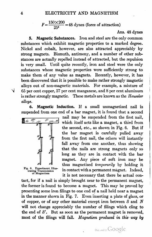
6. Magnetic Induction. If a small unmagnetized nail is
suspended from one end of a bar magnet, it is found that a second
nail may be suspended from the first nail,
which itself acts like a magnet, a third from
the second, etc., as shown in Fig. 6. But if
the bar magnet is carefully pulled away
from the first nail, the others will instantly
fall away from one another, thus showing
that the nails are strong magnets only so
long as they are in contact with the bar
magnet. Any piece of soft iron may be
thus magnetized temporarily by holding it
in contact with a permanent magnet. Indeed,
it is not necessary that there be actual con
tact, for if a nail is simply brought near to the permanent magnet,
the former is found to become a magnet. This may be proved by
presenting some iron filings to one end of a nail held near a magnet
in the manner shown in Fig. 7. Even inserting a plate of glass, or
of copper, or of any other material except iron between S and N
will not change appreciably the number of filings which cling to
the end of S'. But as soon as the permanent magnet is removed,
most of the filings will fall. Magnetism produced in this way by
<0s
?'//,.
Fig. 6. Expiiting Tr;of Magnetism
Experiment Illustrating Transmission

ELECTRICITY AND MAGNETISM 5
the mere presence of adjacent magnets, with or without contact, is
called induced magnetism. If the induced magnetism of the nail
in Fig. 7 is tested with a compass needle, it is found that the remote
induced pole S' is of the same kind as the inducing pole S, while
the near pole N is of unlike kind. This is the general law of mag
netic induction
Magnetic induction explains the fact that a magnet attracts an
unmagnetized piece of iron, for it first magnetizes the iron by induc
tion, so that the near pole is unlike the inducing pole, and the remote
pole like the inducing pole, and then, since the two unlike poles
are closer together than the like poles, the attraction overbalances
the repulsion and the iron is drawn toward the magnet. Magnetic
induction also explains the formation of the tufts of iron filings
shown in Fig. 4, each little filing becoming
a temporary magnet such that the end which
points toward the inducing pole is unlike this
pole, and the end which points away from
it is like this pole. The bush-like appear
ance is due to the repulsive action which
the outside free poles exert upon each other.
V 7. Retentivity and Permeability. A
piece of soft iron will very easily become a
strong temporary magnet, but when removed. i • n vi .1 Fig. 7. Experiment Illus-trom the influence or the magnet, it loses trating Magnetic
Induction
practically all of its magnetism. On the other
hand, a piece of steel will not be so strongly magnetized as the soft
iron, but it will retain a much larger fraction of its magnetism after
it is removed from the influence of the permanent magnet. This
power of resisting either magnetization or demagnetization is called
retentivity. Thus, steel has a much greater retentivity than wrought
iron, and, in general, the harder the steel the greater its retentivity.
A substance which has the property of becoming strongly
magnetic under the influence of a permanent magnet, whether it
has a high retentivity or not, is said to possess permeability in large
degree. Thus iron is much more permeable than nickel. Per
meability is measured by the amount of magnetization which a
substance is able to receive; while retentivity is measured by the
tenacity with which it holds this magnetization.

6 ELECTRICITY AND MAGNETISM
Fig. 8. Plotting Lines of Force in aMagnetic Field
8. Magnetic Lines of Force. If we could separate the N
and S poles of a small magnet so as to obtain an independent N
pole, and were to place this N pole near the N pole of a bar magnet,
it would move over to the S pole of the bar magnet, along a curved
path similar to that shown in Fig.
8. The reason that the motion is
along a curved rather than along a
straight path is that the free pole is
at one and the same time repelled
by the N pole of the bar magnet
and attracted by its S pole, and
the relative strengths of these two forces' are continually changing
as the relative distances of the moving pole from these two poles
are changed.
It is not difficult to test this conclusion experimentally. Thus,
if a bar or a horseshoe magnet is placed just beneath a flat dish
containing water, Fig. 9, and a cork carrying a magnetized needle
is placed near the N pole in the manner shown rn the figure, the
cork will actually be found to move in a curved path from the N
pole around to the S pole of the bar magnet. In this case the cork
and the needle actually move as would an independent pole, since
the upper pole of the needle is so much farther from the magnet
than the lower pole that the influence of the former on the motion
is very small.
Any path which an independent N pole would take in going
from N to S is called a line of magnetic force. The simplest way of
finding the direction of this path at any point near a magnet is to
hold a compass needle at the point considered, for the needle must
.1 I at gg
Fig. 9.
si
obviously set itself along the
line in which its poles would
move if independent, that is,
along the line of force which
passes through the given
point, C, Fig. 8.
9. Magnetic Fields of Force. The region about a magnet in
which its magnetic forces can be detected is called its field of force.
The simplest method to gain an idea of the way in which the lines
of force are arranged in the magnetic field about any magnet is
Experimental Proof of Magnetic Actionalong Lines of Force

ELECTRICITY AND MAGNETISM 7
to sift iron filings upon a piece of paper placed immediately over
the magnet. Each little filing becomes a temporary magnet by
induction and there
fore, like the compass
needle, sets itself in the
direction of the line of
force at that point.
Fig. 10 shows the shape
of the magnetic field
about a bar magnet.
Fig. 1 1 shows the direc
tion of the lines offorce
about a horseshoe magnet. Fig. 12 is the ideal diagram corre
sponding to Fig. 10 and showing the lines of force emerging from
the N pole and passing around in curved lines to the S pole.
This way of imagining the lines of force to be closed curves passing
on the outside of the magnet from N around to S, and on the inside
of the magnet from S back to N, was introduced by Faraday about
Fig. 10. Magnetic Field of Bar Magnet
Fig. 11. Magnetic Field of Horse-shod Magnet
\ v ! / /
\ \ \ \ v \ \ |
1 X
•» \i ; ./ / / /
' ' ' / I V\s- --'/ 1 I i N X X s
i i i \ v / I 1 1 i ii- i l i \ ~ / /111
Fig. 12. Ideal Magnetic Field for Bar Magnet
1830, and has been found of great assistance in correlating the facts
of magnetism.
10. Strength of a Magnetic Field. The strength of a magnetic
field at any point near a magnet is defined as the number of dynes
of force which a unit magnet pole would experience at the point

8 ELECTRICITY AND MAGNETISM
considered. Thus, if at some point between N and S of a horseshoe
magnet, Fig. 13, a unit N pole were pushed by the field from
N toward S with a ' force of one dyne, then the magnetic field
at that point would be a "field of unit strength", or a "unit magnetic
field". In electrical engineering, such a field strength would be
called one gauss. If the unit N pole were pushed from N toward
iS with a force of 1,000 dynes, then the field strength would be one
of 1,000 gausses, etc.
If we wish to represent graphically a field of unit strength,
i.e., 1 gauss, we draw one line per square centimeter through a
surface such as ABCD, taken at right angles to the lines of force.
A field of strength 2, i.e., 2 gausses, would be represented by two
lines per square centimeter, a field strength of n gausses, by n lines
per square centimeter, etc.; i.e., field strengths are represented by
the number of lines of force drawn
to the square centimeter.
1 1 . Molecular Nature of Mag=
netism. If a small test tube full
of iron filings be stroked from one
end to the other with, a magnet, it
will be found to behave toward a
compass needle as if it were itself
a magnet, but it will lose its mag
netism as soon as the filings are
shaken up. If a magnetized needle is heated red hot, it is found
to lose its magnetism completely. Again, if any magnet is jarred,
hammered, or twisted, the strength of its poles, as measured by
their ability to pick up tacks or iron filings, is found to be greatly
diminished.
These facts point to the conclusion that magnetism has some
thing to do with the arrangement of the molecules, since causes
which violently disturb the molecules of the magnet weaken its
magnetism. Again, if a magnetized needle is broken, each part
will be found to be a complete magnet. That is, two new poles
will appear at the point of breaking, a new N pole on the part
which has the original S pole, and a new S pole on the part which
has the original N pole. The subdivision may be continued indefi
nitely, but always with the same result, as indicated in Fig. 14.
Fig. 13. Diag:Measuring Si
gram Illustrating Method ofStrength of Magnetic Field

ELECTRICITY AND MAGNETISM 9
This points to the conclusion that the molecules of a magnetized
bar are themselves little magnets arranged in rows having their
opposite poles adjacent.
If an unmagnetized piece of hard steel is pounded vigorously
while it lies between the poles of a magnet, or if it is heated to
redness and then allowed g
to cool in this position, ^ft
it will be found to have s~ N <.
become magnetized. The B * * ' *
pounding, or heating, ^ ^ *H=2k
which is nothing but „. t. XTi ,° Fig. 14. Magnetic Nature of Fragments of Bar Magnet
molecular bombardment,
aids all of the little molecular magnets to turn and point in the
direction of the magnetic field, just as tapping a compass needle
supported on a dull pivot aids the compass in taking up the direc
tion of the field. This points to the conclusion that the molecules
of the steel are magnets
even when the bar as
a whole is not mag
netized, and that mag
netization consists in , „ t. n ....Fig. 15. Molecular Nature of Magnetism. Condition
Causing these molecular of Molecules in Unmagnetized Bar
magnets to arrange themselves in rows, end to end.
In an unmagnetized bar of iron or steel, then, it is probable
that the molecules themselves are tiny magnets which are arranged
either haphazard or in little closed groups or chains, as in Fig. 15,
so that, on the whole,
opposite poles neutralize
each other throughout
the bar. But when the
bar is brought near a
magnet the molecules 1(>. Condition of Molecules of Bar after Being° 3 Magnetized
are swung around by the
outside magnetic force into some such arrangement as that shown by
Fig. 16, in which the opposite poles completely neutralize each other
only in the middle of the bar. According to this view, the reason that
heating and jarring weaken a magnet is that disturbances of this sort
tend to shake the molecules out of alignment. On the other hand,
6 %%%*^*=im=im3m^'D^ %

10 ELECTRICITY AND MAGNETISM
[iaEiatiLiaLiLiLioiciaaiciLaa
aaaiaaiaaiacaEaaaaaaacB
aciDiaCiFianciociacBciciciai
nanciaiaacaaiaacBcaaicnaia
heating and jarring facilitate magnetization when an unmagnetized
bar is between the poles of a magnet, because they assist the magnetiz
ing force in breaking up the molecular groups or chains and in getting
the molecules into alignment. Soft iron, then, has higher per
meability than hard steel, merely because the molecules of the former
substance do not offer so much resistance to a force tending to swing
them into line as do those of the latter substance. Steel has, on
the other hand, a much greater retentivity than soft iron, merely
because its molecules are not so easily moved out of position when
once they have been aligned.
12. Saturated Magnets. Strong evidence for the correctness
of the above view is found in the fact that a piece of iron or steel
cannot be magnetized beyond a certain limit, no matter how strong
the magnetizing force.
This limit probably cor
responds to the condition
in which the axes of
all the molecules are
Fig. 17. Supposed Condition of Molecules in Saturated brought into parallelism,Magnet ° r
Fig. 17. The magnet is
then said to be saturated, since it is as strong as it is possible to make it.
13. Earth's Magnetism. The fact that a compass needle
always points north and south, or approximately so, indicates that
the earth itself is a great magnet, having an S pole near the geo
graphical north pole and an N pole near the geographical south
pole ; for the magnetic pole of the earth which is near the geographical
north pole must of course be unlike the pole of a suspended magnet
which points toward it, and the pole of the suspended magnet which
points toward the north is the one which by convention it has been
decided to call the north pole. The magnetic pole of the earth
which is near the north geographical pole was found in 1831 by
Sir James Ross in Boothia Felix, Canada, latitude 70° 30' N.,
longitude 95° W. It was located again in 1905 by Captain Amund
sen at a point a little farther west. Its approximate location is
70° 5' N., and 96° 46' W. It is probable that it slowly shifts its
position.
14. Declination. It is, of course, on account of the fact
that the earth's magnetic and geographical poles do not altogether

ELECTRICITY AND MAGNETISM 11
coincide, that the magnetic needle does not point exactly north,
and also that the direction in which it does point changes as the
needle is moved about over the earth's surface. This last fact
was first discovered by Columbus on his voyage to America, and
caused great alarm among his sailors. There are other local causes,
however, such as large deposits of iron ore, which cause local devia
tions of the needle from the true north. The number of degrees
by which the needle varies from the north and south line at a given
point, is called the declination at that point.
Fig. 18. Map Showing Lines of Equal Declination
Many of the early compass surveys made in the laying out of
section lines, etc., are in error because the declination of the locality
was not accurately known. Mariners also must have an accurate
knowledge of the declination at all times in order to keep in their
course. On this account, the United States Coast and Geodetic
Survey in this country and similar departments of the governments
of other countries spend thousands of dollars annually in collecting
the data for maps which show the declination of any locality. Such
a map is shown in Fig. 18, and the declinometer used for this work
is shown in Fig. 19.
15. Inclination or Dip. Let an urtmagnetized knitting needle
a, Fig. 20, be thrust through a cork, and let a second needle b be

12 ELECTRICITY AND MAGNETISM
passed through the cork at right angles to a. Let the system be
adjusted by means of wax or a pin c, until it is in neutral equilibrium
about b as an axis, when a is pointing east and west. Then let a
Fig. 19. Standard Declinometer Used in Coast Survey Work
Courtesy of V. S. Coast & Geodetic Survey, Washington, D. C.
be strongly magnetized by stroking one end of it from the middle
out with the N pole of a strong magnet, and the other end from
the middle out with the S pole of the same magnet. When this
improvised dipping needle is re
placed on its supports and turned
into a north-and-south line with its
N pole toward the north, it will be
found, in the north temperate zone,
to dip so as to make an angle of
Kg. 20. simple Experiment uius- from 60° to 75° with the horizontal.trating Dip
This shows that in the latitudes
mentioned the earth's magnetic lines are not at all parallel to the
earth's surface. The angle between these lines and the earth's sur
face is called the dip, or inclination, of the needle. At Washington

ELECTRICITY AND MAGNETISM 13
it is 71° 5'; at Chicago, 72° 50'; at the magnetic poles it is of
course 90°; and at the so-called magnetic equator—an irregular
curved line passing through the tropics—the dip is 0°. The dipping
needle used by the United States Coast and Geodetic Survey for
these observations is shown in Fig. 21.
16. Earth's Inductive Action. A very instructive way of
showing that the earth acts like a great magnet is to hold any ordinary
iron or steel rod parallel to the earth's magnetic lines, that is, about
in the geographical meridian, but with the north end slanting down
at an angle of say 70°, and then
to strike one end a few blows
with the hammer. The rod will
be found to have become a mag
net with its upper end an S pole,
like the north pole of the earth,
and its lower end an N pole.
If the rod is reversed and tapped
again with the hammer, its mag
netism will be reversed. If
held in an east-and-west positon
and tapped, it will become de
magnetized, as is shown by the
fact that both ends of it will
attract either end of a compass
needle
EXAMPLES FOR PRACTICE
1. If a bar magnet is
floated On a piece of COrk, will it Fi8. 21. Standard Dipping Needle Used in1 Coast Survey Work
tend tO float toward the north? Courtesy of U. S. Coast & Geodetic Survey,Washington, D. C.
Why?
2. Will a bar magnet pull a floating compass needle toward
it? Compare the answer to this question with that to the preced
ing one.
3. Why should the needle, a, Fig. 20, be placed east and
west, when adjusting for neutral equilibrium, before it is magnetized?
4. The dipping needle is suspended from one arm of a steel-
free balance and carefully weighed. It is then magnetized. Will
its apparent weight increase?

14 ELECTRICITY AND MAGNETISM
5. Does it matter whether a pocket compass is mounted in a
brass case or an iron one?
6. When a piece of soft iron is made a temporary magnet by
bringing it near the N pole of a bar magnet, will the end of the iron
nearest the magnet be an N or an S pole?
7. Devise an experiment which will show that a piece of iron
attracts a magnet just as truly as the magnet attracts the iron.
8. How would an ordinary compass needle act if placed
over one of the earth's magnetic poles? How would a dipping needle
act at this point?
9. With what force will an N magnetic pole of strength 6
attract, at a distance of 5 cm., an S pole of strength 1 ? Of strength
9? Ans. .24 dyne, 2.16 dynes
10. A magnetic N pole of the strength of 50 units is repelled
by a second pole 10 cm. away with a force of 30 dynes. Find the
strength of the second pole. Is it an N or an S pole?
Ans. 6O units. N pole
STATIC ELECTRICITY
17. Electrification by Friction. Let a hard rubber (ebonite)
rod be rubbed with flannel or cat's fur and then be brought near
some dry pith balls or bits of
paper, Fig. 22. These light
bodies are found to be first
attracted to the rod and then,
after having been in contact
with it for a very short time,
to be repelled by it. These
experiments may be easily
tested at home by rubbing a
hard rubber comb on the
coat sleeve.
This sort of attraction
was observed by the Greeks as early as 6OO B.C., when it was found
that amber which had been rubbed with silk attracted various sorts
of light bodies. It was not, however, until 1600 A. D. that Dr.
William Gilbert, physician to Queen Elizabeth, and sometimes called
the father of the modern science of electricity and magnetism,
Fig. 22. Experiment Illustrating Electrificationby Friction
ELECTRICITY AND MAGNETISM 15
discovered that the effect could be produced by rubbing together
a great variety of other substances besides amber and silk, such,
for example, as glass and silk, sealing wax and flannel, and hard
rubber and cat's fur,
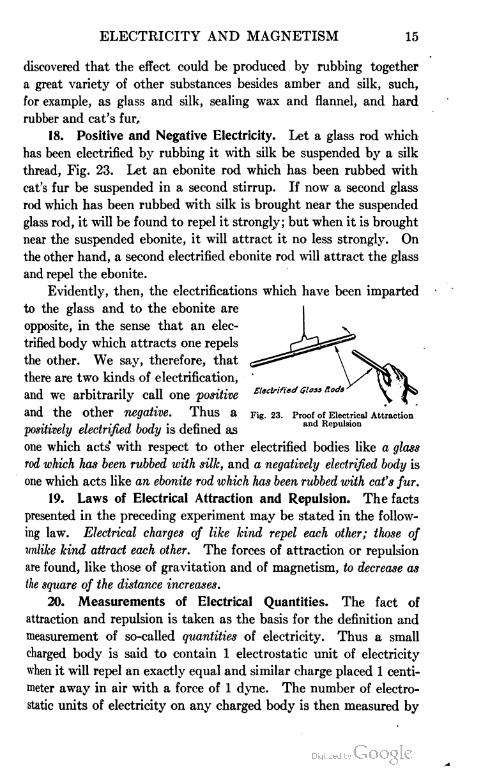
18. Positive and Negative Electricity. Let a glass rod which
has been electrified by rubbing it with silk be suspended by a silk
thread, Fig. 23. Let an ebonite rod which has been rubbed with
cat's fur be suspended in a second stirrup. If now a second glass
rod which has been rubbed with silk is brought near the suspended
glass rod, it will be found to repel it strongly; but when it is brought
near the suspended ebonite, it will attract it no less strongly. On
the other hand, a second electrified ebonite rod will attract the glass
and repel the ebonite.
Evidently, then, the electrifications which have been imparted
to the glass and to the ebonite are
opposite, in the sense that an elec
trified body which attracts one repels
the other. We say, therefore, that
there are two kinds of electrification,
and we arbitrarily call one positive
and the Other negative. Thus a Fig. 23. Proof of Electrical Attraction
positively electrified body is defined as an ^p"i31011
one which acts' with respect to other electrified bodies like a glass
rod which has been rubbed with silk, and a negatively electrified body is
one which acts like an ebonite rod which has been rubbed with cat's fur.
19. Laws of Electrical Attraction and Repulsion. The facts
presented in the preceding experiment may be stated in the follow
ing law. Electrical charges of like kind repel each other; those of
mlike kind attract each other. The forces of attraction or repulsion
are found, like those of gravitation and of magnetism, to decrease as
the square of the distance increases.
20. Measurements of Electrical Quantities. The fact of
attraction and repulsion is taken as the basis for the definition and
measurement of so-called quantities of electricity. Thus a small
charged body is said to contain 1 electrostatic unit of electricity
when it will repel an exactly equal and similar charge placed 1 centi
meter away in air with a force of 1 dyne. The number of electro
static units of electricity on any charged body is then measured by

16 ELECTRICITY AND MAGNETISM
the number of dynes of force which it exerts upon a unit static
charge placed at a given distance from it. For example, a charge
which at a distance of 10 centimeters repels a unit charge with a
force of 1 dyne contains 100 electrostatic units of electricity.
21. Coulomb's Law. The above laws were first quantitatively
proved by Coulomb who used a torsion balance to measure the
forces of attraction. He found that the force of attraction or repul
sion, in dynes, between two charged bodies is given by the equation
F=- (Coulomb's Law)
Fig. 24. Field of Force between Two Charged Bodiesof Opposite Sign
F =(+12)X(-18)
62
where Qi and Q2 represent
the number of electrostatic
units of electricity upon the
two charged bodies, respec
tively, and D represents
their distance apart in cen
timeters.
Example. With what
force will a positive charge
of 12 electrostatic units of
electricity act upon a neg
ative charge of 18 units
when placed 6 cm. apart?
= -6
F= a force of attraction of 6 dynes
Ans. 6 dynes
Evidently the force is one of attraction whenever, as above,
the result is minus, and one of repulsion whenever the result is
plus, i.e., for like charges.
22. Electrical Field. If the two small bodies, A and B,
Fig. 24, are given equal charges of positive and negative electricity,
it is evident that a third small body with a positive charge when
placed in the region about A and B would be repelled by A and
attracted by B. Any line, such as ACB, Fig. 24, along which a
plus charge would move in going from A to B is called an electrical
line of force. The electrical field is the whole region about A and
B in which a unit plus test charge would indicate any force acting

ELECTRICITY AND MAGNETISM 17
Fig. 25. Field of Force between Two ChargedBodies of the Same Sign
upon it. The strength of the electrical field is represented by
drawing as many electrical lines of force through each square centi
meter as a unit plus test charge would experience dynes of force
when placed in that local
ity. When A and B are
alike in sign, say positive,
the electrical field takes the
form shown in Fig. 25.
Example. How many
ergs of work must be done
against the electrical field,
Fig. 24, in carrying a unit
plus electrostatic charge
from B to A, if the average
force acting on this test
charge is 2 dynes and the
distance from B to A is 15 cm.? (An erg is a measure of the work
done when a force of one dyne moves its point of application one
centimeter.)
r work = forceX distance
= 2X15
= 30 ergs Ans. 30 ergs
23. Conductors and Insulators. If a pith ball is in contact
with a metal body A, Fig. 26, and if this body is connected by a
wire to another metal body B, then, when B is rubbed with an
electrified glass rod, A will be found immediately to repel the pith
ball from itself. That is, a portion of the charge communicated
to B evidently passes instantly over the wire to A. If the experiment
is repeated when A and B are
connected by a thread of silk,
of by a rod of wood instead of
metal, no effect will be observed
at all upon the pith ball. If a
moistened thread connects A
and B, the pith ball will be affected, but not so soon as when A and
B are connected by a wire.
These experiments make it clear that while electric charges
pass with perfect readiness through a wire, they are quite unable
6 00-
Fig. 26. Experiment Illustrating Conductorsand Nonconductors

18 ELECTRICITY AND MAGNETISM
to pass along dry silk or wool, while they pass with considerable
difficulty along moist silk. We are therefore accustomed to divide
substances into two classes, conductors and nonconductors or insii-
lators, according to their ability to transmit electrical charges from
point to point. Thus, metals and solutions of salts and acids in water
are all conductors of electricity, while glass, porcelain, rubber,
mica, shellac, wood, silk, vaseline, turpentine, paraffin, and oils
generally are insulators. No hard and fast line, however, can be
drawn between conductors and nonconductors, since all so-called
insulators conduct to some extent, while the so-called conductors
differ greatly among themselves in the facility with which they
transmit charges.
The fact of conduction brings out sharply one of the most
essential distinctions between electricity and magnetism. Magnetic
poles exist only in iron and steel, while electrical charges can be
communicated to any body whatsoever, provided they are insulated.
These charges pass from point to point over conductors, and can
be transferred by contact from one body to any other, while mag
netic poles remain fixed in position, and are wholly uninfluenced
by contact with other bodies, unless these bodies themselves are
magnets.
24. Electrostatic Induction. If a metal ball A, Fig. 27, is
strongly charged by rubbing it with a charged rod, and then brought
of B have received electrical charges because of the presence of A>
while the failure of b to diverge will show that the middle of B is
uncharged. Further, the rod which charged A will be found to repel
c but to attract a. When A is removed, all evidences of electri
fication in B will disappear.
From experiments of this sort, we conclude that when a con
ductor is brought near a charged body the end away from the
charged body becomes electrified with the same kind of electricity
as that on the charged body, while the end near the charged body
receives a charge of opposite sign. This method of producing elec-
Fig. 27. Electrostatic Induction
near an insulated metal body
B, which is provided with pith
balls or strips of paper, a, b, c,
as shown, the divergence of a
and c, will show that the ends

ELECTRICITY AND MAGNETISM 19
trification by the mere influence which an electric charge has upon
a conductor placed in its neighborhood, is called electrostatic induc
tion. The fact that as soon as A is removed, a and c collapse,
shows that this form of electrification is only a temporary phe
nomenon.
25. Two=Fluid Theory of Electricity. We can describe the
facts of induction conveniently by assuming that in every conductor
there exists an equal number of positively and negatively charged
corpuscles, which are very much smaller than atoms and which
are able to move about freely among the molecules of the con
ductor. According to this view, when no electrified body is near the
conductor B, it appears to have no charge at all, because all of the
little positive charges within it counteract the effects upon outside
bodies of all the little negative charges. But as soon as an electrical
charge is brought near B, it drives as far away as possible the little
corpuscles which carry charges of sign like its own, while it attracts
the corpuscles of unlike sign. B, therefore, becomes electrified like A
at its remote end, and unlike A at its near end. As soon as the
inducing charge is removed, B immediately becomes neutral again
because the little positive and negative corpuscles come together
under the influence of their mutual attraction. This picture of the
mechanism of electrification by induction is a modern modification
of the so-called two-fluid theory of electricity, which conceived of all
conductors as containing equal amounts of two weightless electrical
fluids, called positive electricity and negative electricity. Although
it is extremely doubtful whether this theory represents the actual
conditions within a conductor, yet we are able to say with perfect
positiveness that the electrical behavior of a conductor is exactly what
it would be if it did contain equal amounts of positive and negative
electrical fluids, or equal numbers of minute positive and negative
corpuscles which are free to move about among the molecules of
the conductor under the influence of outside electrical forces. Fur
thermore, since the real nature of electricity is as yet unknown, it
has gradually become a universally recognized convention to speak
of the positive electricity within a conductor as being repelled to
the remote end, and the negative electricity as being attracted to
the near end by an outside positive charge, and vice versa. This
does not imply the acceptance of the two-fluid theory. It is merely

20 ELECTRICITY AND MAGNETISM
a way of describing the fact that the remote end does acquire a
charge like that of the inducing body, and the near end a charge
unlike that of the inducing body.
26. Electron Theory. A slightly different theory is quite
generally accepted by most physicists of high standing at the present
time. According to this, a certain amount of positive electricity is
supposed to constitute the nucleus of the atom of every substance.
About this positive charge are grouped a number of very minute
negatively charged corpuscles or electrons, the mass of each of
which is approximately ttVit of that of the hydrogen atom. The
sum of the negative charges of these electrons is supposed to be just
equal to the positive charge of the atom, so that in its normal con
dition, the whole atom is neutral and uncharged. But in the jos-
tlings of the molecules of the conductor, electrons are continually
getting loose from the atoms, moving about freely among the mole
cules, and re-entering other atoms which have lost their electrons.
Therefore, at a given instant, there are always in every conductor
a large number of free negative electrons and an exactly equal
number of atoms which have lost electrons and which are therefore
positively charged. Such a conductor would, as a whole, show no
charge of either positive or negative electricity. But if a body
charged, for example, negatively, were brought near such a body,
the negatively charged electrons would stream away to the remote
end, leaving behind them the positively charged atoms which are
not supposed to be free to move from their positions. On the
other hand, if a positively charged body is brought near the con
ductor, the negative electrons are attracted and the remote end is
left with the immovable positive atoms.
The only advantage of this theory over that suggested in the
preceding section, in which the existence of both positive and nega
tive corpuscles is assumed, is that there is much direct experimental
evidence for the existence of free negatively charged corpuscles of
about -rAff the mass of the hydrogen atom, but no direct evidence
as yet for the existence of positively charged bodies smaller than
atoms.
The charge of one electron is called the elementary electrical
charge. Its value has recently (1913) been accurately measured,
and found to be very nearly one two-billionth part of the electro

ELECTRICITY AND MAGNETISM 21
static unit of charge defined in section 20. Every electrical charge
consists of an exact number of these elementary electrical charges
(atoms of electricity) scattered over the surface of the charged body.
27. Gofd=Leaf Electroscope. One of the most sensitive and
convenient instruments for detecting the presence of an electrical
charge upon a body and for determining the sign of that charge, is
the gold-leaf electroscope, Fig. 28. It consists of a glass jar, through
the neck of which passes a metal rod supported by a rubber stopper
or some other insulated material, and carrying at its lower end two
gold leaves or strips of aluminum foil. To detect with this instru
ment the presence of an electrical charge, it is only necessary to
bring near the upper end
of the electroscope the
body which is to be
tested. If it is charged,
it will repel electricity of
the kind which it possesses
to the leaves, and draw
the unlike kind to the
upper end. The leaves
under the influence of the
like charges which they
possess will stand apart or diverge. If the body is not charged, the
gold leaves will not be affected at all.
To determine the sign of an unknown charge with an electro
scope, we first impart a charge of known sign to the electroscope by
touching it, for example, with a piece of sealing wax, which has been
rubbed with cat's fur. This charges the leaves negatively and causes
them to diverge. The unknown charge is then slowly brought near
the upper end of the electroscope ; and if the divergence of the leaves
is increased, the sign of the unknown charge is negative, for the
increased divergence means that more negative electricity has been
repelled to the leaves. If the divergence is decreased instead of
increased, the sign of the unknown charge is positive, for the decreased
divergence of the leaves means that a part of the negative electricity
already on the leaves has been drawn to the upper end.
28. Charging by Induction. If a positively charged body C,
Fig. 29, is brought near two conductors A and B in contact, we
Fig. 28. Gold-Leaf Electroscope

22 ELECTRICITY AND MAGNETISM
have seen that a positive charge will appear upon A and a negative
charge upon B. If C were removed these charges would recombine
and A and B both become neutral. But if, before C has been
removed, A and B are separated, and if then C is removed, there
is no opportunity for this recombination. Hence A is left per
manently charged positively, and B negatively. These charges
can be easily detected by bring
ing A and B into the neigh
borhood of a charged electro
scope. One will cause the diver
gence of the leaves to increase,
Fig. 29. Charging Two Conductors by the Other will CaUSe it to de-Induction
crease.
Again, if a positively charged body C, Fig. 30, is brought near
the conductor B, and if, while C is still in position, the finger is
touched anywhere to the conductor B and then removed, then,
when C is removed, B is found to be negatively charged. In this
case the body of the experimenter corresponds to the conductor A
of the preceding experiment, and removing the finger from B corre
sponds therefore to separating the two conductors A and B. In
the use of this method of charging a single body by induction, it
makes no difference with the sign of the charge left upon B where
the finger touches the body B, whether at a or at b or at any other
point, Sot it is always the kind of electricity which is like that on
the charging body C that is repelled off to earth through the finger;
while the charge which is
(+ 3 —) unlike that upon C is drawn
v£ to the part of B which is
next to C, and as soon as
C is removed this spreads
Fig. 30. Charging a Single Conductor by OVer the whole body B.
Induction .-TT1 . . .
Whenever, then, a single
body is charged by induction in this manner, the sign of the charge
left upon it is always opposite to that of the inducing charge.
Thus, if we wished to charge the electroscope, Fig. 31, nega
tively by induction from a positively charged glass rod, we should
first bring the rod near the knob of the electroscope, tnus causing
the leaves to diverge because of the positive electricity which is

ELECTRICITY ANJ> MAGNETISM 23
repelled to them. Then while the rod is still in position near the
electroscope, if we should touch the knob of the latter with the finger
the leaves would at once collapse. This is because the positive
electricity on the electroscope passes off to earth through the finger,
while the negative is held attracted to the knob of the electroscope
by the positive charge on the rod. In this condition the negative
is sometimes said to be bound by the attraction of the positive
charge on C. We should then remove the finger and finally the
rod. The negative would then be free to pass to the leaves and
cause them to diverge. The electroscope would thus be charged
negatively. This is often one of the most convenient methods
of charging an electroscope. It should always be used where it
is desired to obtain a charge
of sign opposite to that of the
charging body. If it is desired
to obtain a charge on the elec
troscope of sign like to that
of the charging body we sim
ply touch the body directly to
the knob of the electroscope,
and thus charge it by conduc
tion rather than by induction.
One advantage of charging by induction lies in the fact that
the charging body loses none of its own charge, whereas, in charging
by conduction, the charging body must of course part with a portion
of its charge.
29. Appearance of Positive and Negative Electricities Simul
taneous and in Equal Amounts. If a strip of flannel is stuck fast
to one side of a rod of sealing wax and rubbed back and forth over
a second rod of sealing wax, and if then the two bodies are brought
near the knob of a charged electroscope before they are separated,
it is found that they give no evidence at all of electrification. But
if they are separated and brought in succession to the knob of the
electroscope, they will exhibit positive and negative charges of
equal strength, the flannel being positive, and the bare sealing wax
negative. Similarly, when a glass rod is charged positively by
rubbing it with silk, the silk when tested is always found to possess
a negative charge. These experiments show that in producing
Fig. 31. Charging an Electroscope by Induction
24 ELECTRICITY AND MAGNETISM
electrification by friction, positive and negative charges appear
simultaneously and in equal amount. This confirms the view,
already brought forward in connection with induction, that the
process of electrification always consists in a separation of positive
and negative charges which already exist in equal amounts within
the bodies in which the electrification is developed. Certain it
is that it is never possible to produce in any way whatever, one kind
of electricity without producing at the same time an equal amount
of the opposite kind.
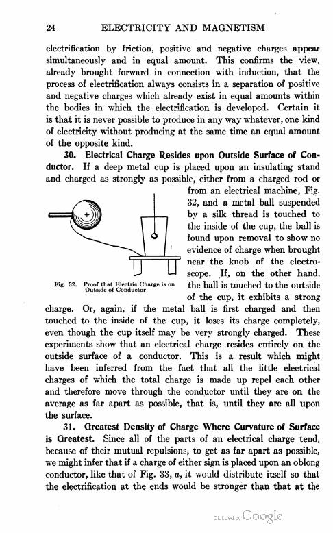
30. Electrical Charge Resides upon Outside Surface of Con=
ductor. If a deep metal cup is placed upon an insulating stand
and charged as strongly as possible, either from a charged rod or
Fig. 32. Proof that Electric Charge is on the ball is touched to the OUtside
charge. Or, again, if the metal ball is first charged and then
touched to the inside of the cup, it loses its charge completely,
even though the cup itself may be very strongly charged. These
experiments show that an electrical charge resides entirely on the
outside surface of a conductor. This is a result which might
have been inferred from the fact that all the little electrical
charges of which the total charge is made up repel each other
and therefore move through the conductor until they are on the
average as far apart as possible, that is, until they are all upon
the surface.
31. Greatest Density of Charge Where Curvature of Surface
is Greatest. Since all of the parts of an electrical charge tend,
because of their mutual repulsions, to get as far apart as possible,
we might infer that if a charge of either sign is placed upon an oblong
conductor, like that of Fig. 33, a, it would distribute itself so that
the electrification at the ends would be stronger than that at the
from an electrical machine, Fig.
32, and a metal ball suspended
by a silk thread is touched to
the inside of the cup, the ball is
found upon removal to show no
evidence of charge when brought
near the knob of the electro
scope. If, on the other hand,
Outside of Conductor
of the cup, it exhibits a strong

ELECTRICITY AND MAGNETISM 25
middle. The correctness of this inference is easy to verify experi
mentally, for it is only necessary to attach a penny to the end of
a piece of sealing wax and touch it first to the middle of a long
charged conductor, next to bring it over the knob of the electroscope;
and then to repeat the operation when the penny is touched to
the end of the conductor. The electroscope
will be affected much more strongly in the /<r~ —
latter case than in the former. If we should f ))
test in this way the distribution on a pear-
shaped body, Fig. 31, b, we should find the ^
density of electrification considerably greater if b ^
on the small end than on the large end. By ^^^r^^—
, t i , .„ .. . . ,, ... Fig. 33. Distribution of Chargedensityor electrification is meantthe quantity on Different shaped.... . p i p Conductors
of electricity on a umt-area or the surface.
32. Discharging Effect of Points. It might be inferred from
the above that if one end of a pear-shaped body is made more and
more pointed, then, when a charge is imparted to the body, the
electric density on the small end will become greater and greater as
the curvature of this end is made sharper and sharper. That this
is the case is indicated by the effect which experiment shows that
points have upon electrical charges; for if a very sharp needle is
attached to any insulated conductor which is provided with paper
or pith ball indicators (see B of Fig. 27), it is found impossible to
impart to B a permanent charge; that is, if one attempts to charge it
by rubbing over it a charged glass rod or other charged body, the
indicators will be found to collapse as soon as the rod is removed.
That this is due to an effect of the point can be proved either by
removing the needle, or by covering up the point with wax, when
the charge will be retained, as in the case of any insulated body.
The probable explanation of the phenomenon is as follows:
The density of the charge becomes so intense upon the point that the
molecules of air immediately adjoining the point are broken apart into posi
tive and negative parts, and portions which are of unlike sign to the charge on
the point are attracted to it, thus neutralizing the charge upon the body, while
portions of like sign are repelled.
The effect of points upon an electrical charge may be strikingly
shown by holding a very sharp needle in the hand and bringing
it toward the knob of a charged electroscope. The leaves will
fall together rapidly. Or, if the needle is brought near a tassel of

26 ELECTRICITY AND MAGNETISM
tissue paper which is attached to an electrified conductor, Fig. 34,
the electrified streamers, which stand out in all directions because
of their mutual repulsions, will at once fall together. In both of
these cases, the needle becomes
electrified by induction and dis
charges to the knob of the elec
troscope or to the tassel electric
ity of the opposite sign to that
which it contains, thus neutral
izing its charge.
An interesting variation of
the last experiment is to mount
an electric whirl, Fig. 35, upon
Fig. 34. Electrified Tassel Discharged by one knob of an electrical machine.Needle Point
As soon as the machine is
started, the whirl will rotate rapidly in the direction of the arrow.
The explanation is as follows: On account of [the great magnitude
of the electric force near the points, the molecules of the gas just
in front of them are broken into positive and negative parts. The
part of sign unlike that of the charge on the points is drawn to
them, while the other part is repelled. But since this repulsion
is mutual, the point is pushed back with the same force with
which the particles are pushed forward; hence the rotation. The
repelled particles in their turn drag the air with them in their
Fig. 35. Action of Electric Fig. 30. Example of "ElectricWhirl Wind"
forward motion, and thus produce the electric wind, which may be
detected easily by the hand or by a candle held in front of the
point, Fig. 36.
33. Lightning and Lightning Rods. It was in 1752 that
Franklin, during a thunderstorm, sent up his historic kite. This

ELECTRICITY AND MAGNETISM 27
kite was provided at the top with a pointed wire. As soon as the
hempen kite string had become wet, he succeeded in drawing ordi
nary electric sparks from a key attached to the lower end. This
experiment demonstrated for the first time that thunderclouds
carry ordinary electrical charges which may be drawn from them
by points, just as the charge was drawn from the tassel in the experi
ment of Section 32. It also showed that lightning is nothing but
a huge electric spark. Franklin applied this discovery in the
invention of the lightning rod. The way in which the rod discharges
the cloud and protects the building is as follows: As the charged
cloud approaches the building, it induces an opposite charge in
the rod. This induced charge escapes rapidly and quietly from
the sharp point in the manner n
an electrical machine. When the Fig. 37. Experiment Illustrating Action
pass from C to E, but if a point p is connected to E, the sparking
will cease; that is, the point will protect E from the discharges,
even though the distance Cp be considerably greater than CE.
The lower end of a lightning rod should be buried deep enough
so that it will always be surrounded by moist earth, since dry earth
is a poor conductor. It will be seen, therefore, that lightning rods
protect buildings not because they conduct the lightning to earth,
but because they prevent the formation of powerful charges in the
neighborhood of buildings on which they are placed.
34. Smoke and Fume Condenser. An interesting application
of the discharge from points can be made in connection with the
precipitation of smoke and injurious fumes from factories, smelters,
etc. If in Fig. 37, the plate C and the point p were placed over an
aperture through which fumes or smoke were passing so that the
fumes would have to pass between the point and the plate, and if,
at the same time, by means of some source of electricity the point
and plate were kept oppositely charged, a peculiar effect would be
explained above and thus neutral
izes the charge of the cloud.
Example. Let a metal plate
C, Fig. 37, be supported above
a metal ball E, and let C and E
be attached to the two knobs of
machine is started, sparks will
of Lightning Rod

28 ELECTRICITY AND MAGNETISM
noticed. As the discharge from the point p was continuous, the
effect would be to strongly charge all particles in the space with the
same kind of electricity as that coming from the point p. All of
these particles so charged would immediately move toward the plate
C and would condense upon it, thereby removing these particles from
the air or gas passing out of the aperture.
A commercial application of this principle has been made in a great many
smelters and other factories where obnoxious or injurious fumes are the result
of some chemical or other operation in the factories. By suitably equipping the
chimney or other passageway through which the fumes are carried wjitJ^-a-plate
and with discharge points at a proper distance away from this plate, and heavily
charging the apparatus with a high electrical potential, very effective precipita
tion of these injurious fumes and smoke can be brought about. The potential
must be very high, this being brought about, as will be learned later in the study
of electricity, by using an alternating current of the usual voltage and trans
forming this current to a voltage of 20,000 to 75,000. By a suitable revolving
commutator the current is made into a high potential direct current which
charges the points and the plate. The discharge points are obtained by using
asbestos or mica wool held between twisted strands of wire which carry the current,
the many streamers of asbestos wool or. the fine edges of the mica providing the
great number of discharge points necessary. This apparatus has been found
very effective in most cases but will precipitate only material particles. In other
words, if the temperature of the gases emitted is so high that certain objectionable
solids are in the vapor state (as arsenic, for example), this dangerous fume will
pass through without being precipitated. By providing a second device after the
fumes have cooled, the arsenic will be condensed. The device- can easily be
applied to the precipitation of coal smoke but some method must be provided
for removing the particles of soot which gather upon the charged plate and
interfere with the proper working of the apparatus.
35. Electrical Screens. We have seen that if a positively
charged body A, Fig. 38, is brought near an uncharged conductor
B, negative electricity is attracted
H. \ f 7\ to the near end of the conductor
+(- I 5 and positive electricity appears at
Fig. 38. Electric Condition at any Point the remote end, this separationInside a Conductor - . . . -
of the positive and negative
charges being dependent upon the presence of the charged con
ductor A. Let us see how this known fact as to the condition of
the charges may be used to determine the electrical condition at
any point p within the conductor. Since the electricity within the
conductor is free to move under the influence of any electrical force
which is acting upon it, it is clear that the accumulation of nega

ELECTRICITY AND MAGNETISM 29
Fig. 39. Use of Electric Screens
tive electricity at one end and of positive at the other will cease
only when all electrical forces inside the conductor are reduced to
zero, that is, when the charges on A and
B, acting jointly, neutralize one another
completely at any point p within the
conductor. It appears, therefore, that
the distribution of the induced charge on
the surface of a conductor in the electri
cal field of a charged body must always
be such that there is no force whatever
inside the body. This theoretical con
clusion was first experimentally verified
by Faraday, who coated a large box with
tinfoil and went inside the box with delicate electroscopes. He
found that these electroscopes showed no effects whatever, even
when powerfully charged bodies were brought near the outside
of the box. The experiment is often repeated in a small way by
placing an electroscope under a wire cage of rather small mesh, Fig.
39. A charged rod brought near the cage will produce no effect
whatever upon the electroscope. We thus learn that electrical
influences can be completely cut off from a body by surrounding
it on all sides with a conductor.
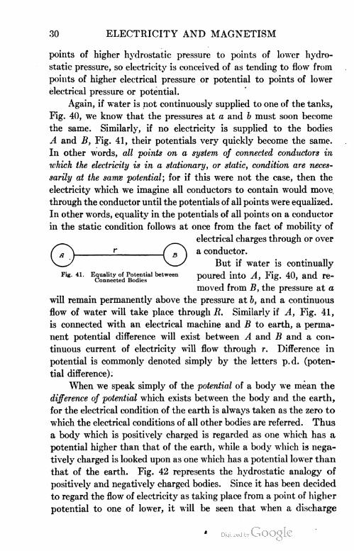
36. Electrical Potential. There is a very instructive analogy
between the use of the word potential in electricity and pressure
in hydrostatics. For example, if water will flow from tank A, Fig.
40, to tank B through the connecting pipe R, we infer that the
hydrostatic pressure at a must be greater than that at b, and we
attribute the flow directly to this difference in pressure. In pre
cisely the same way, if, when
two bodies A and B, Fig. 41,
are connected by a conducting
wire r, a charge of positive elec
tricity is found to pass from A
to B, or of negative from B to
A, we are accustomed to say
that the electrical potential is
higher at A than at B, and we assign this difference of potential
as the cause of the flow. Thus, just as water tends to flow from
Fig. 40. Water Analogy IllustratingElectric Potential
30 ELECTRICITY AND MAGNETISM
points of higher hydrostatic pressure to points of lower hydro
static pressure, so electricity is conceived of as tending to flow from
points of higher electrical pressure or potential to points of lower
electrical pressure or potential.
Again, if water is not continuously supplied to one of the tanks,
Fig. 40, we know that the pressures at a and b must soon become
the same. Similarly, if no electricity is supplied to the bodies
A and B, Fig. 41, their potentials very quickly become the same.
In other words, all points on a system of connected conductors in
ichich the electricity is in a stationary, or static, condition are neces
sarily at the same potential; for if this were not the case, then the
electricity which we imagine all conductors to contain would move,
through the conductor until the potentials of all points were equalized.
In other words, equality in the potentials of all points on a conductor
in the static condition follows at once from the fact of mobility of
electrical charges through or over
£ f B\ a conductor.
V_y But if water is continually
Fig. 41. Equality of Potential between poured into A, Fig. 40, aild re-Connected Bodies r 'or
moved from B, the pressure at a
will remain permanently above the pressure at b, and a continuous
flow of water will take place through R. Similarly if A, Fig. 41,
is connected with an electrical machine and B to earth, a perma
nent potential difference will exist between A and B and a con
tinuous current of electricity will flow through r. Difference in
potential is commonly denoted simply by the letters p.d. (poten
tial difference).
When we speak simply of the potential of a body we mean the
difference of potential which exists between the body and the earth,
for the electrical condition of the earth is always taken as the zero to
which the electrical conditions of all other bodies are referred. Thus
a body which is positively charged is regarded as one which has a
potential higher than that of the earth, while a body which is nega
tively charged is looked upon as one which has a potential lower than
that of the earth. Fig. 42 represents the hydrostatic analogy of
positively and negatively charged bodies. Since it has been decided
to regard the flow of electricity as taking place from a point of higher
potential to one of lower, it will be seen that when a discharge

ELECTRICITY AND MAGNETISM 31
takes place between a negatively charged body and the earth, we
must regard the positive electricity as passing from the earth to
the body, rather than the negative as passing from the body to the
earth. This is, indeed, a mere convention, but it is one which it is
very important to remember in connection with the study of current
electricity. From the point of view of the electron theory, Section
26, it would be natural to invert this convention exactly, since this
theory regards the negative electricity alone as moving through con
ductors. But since the opposite convention has become established,
it will not be wise to attempt to change it until the electron theory
has become more thoroughly established than is at present the case.
37. Unit of P. D. The difference in the pressures produced by
the water in tank A and in tank B, in grams per square centimeter,
Fig. 40, is numerically
equal to the work done +\
in gram-centimeters, in
carrying 1 cubic cen
timeter of water from
the level of the water in
tank B up to the level
of the water in tank A.
This is true if any liquid
other than water be
taken. Thus the work done in carrying unit volume of the liquid
from one level to the other against the force of gravity may be taken
as a measure of the difference in pressure produced by the two col
umns of liquid. Similarly in Fig. 24, the difference in electrical
pressure between A and B may be measured by the amount of
work done when a unit plus charge is carried against the electrical
field from B to A. The number of absolute units of p.d. between
A and B is then taken to be equal to the number of ergs of work
required to carry the unit plus charge from B to A.
The absolute unit of p.d. is too large for practical purposes
and as large a unit has been chosen for the practical unit of
p. d. and is called the volt in honor of the famous Italian physicist,
Allessandro Volta (1745-1827), who about 1800, at the University
of Pavia, first made quantitative measurements upon the potentials
of charged bodies.
Fig. 42. Water Analogy of High and Low Potentials

32 ELECTRICITY AND MAGNETISM
A volt is then defined as the p. d*. between two charged bodies when
it requires 7{j of an erg of work to carry a unit plus electrostatic charge
from one body to the other against the electrical field existing between
the two bodies.
The volt is approximately equal to the electrical pressure
between the ends of a strip of copper and a strip of zinc immersed
in dilute sulphuric acid. (See Fig. 53.)
Examples. 1. If in the problem given at the end of Section
22, it required 30 ergs of work to carry a unit plus electrostatic
charge from B to A, what was the p.d. between A and B, first, in
absolute units of p.d., and second, in volts?
Since the potential difference in absolute units is numerically
equal to -the work done in ergs in carrying a unit plus charge from
B to A, therefore the p.d. is 30 absolute units of p.d. The volt
being only 3 1? as large as the absolute unit there will be 300 times
as many units to express the same quantity or
300X30 = 9,000 volts Ans. 9,000 volts
2. The quantity of electricity which passes through the fila
ment of a certain 16-candle-power tungsten (Mazda) lamp is 540,-
000,000 electrostatic units per second. How many ergs of work
are done per second in forcing this electricity through the lamp if "
the p.d. across the lamp is 112 volts? What is the rating of the
lamp in watts?
The number of ergs of work done per second i
540,000,000X112 = 2Q1,6()0,0()0
300
Since 107 ergs per second, or 1 joule per second, is 1 watt, the rating
of the lamp is
201,600,000 h-107 = 20.16 watts Ans. 20.16 watts
Note : A 16-candle-power Mazda lamp is rated at 20 watts by the makers.
38. Some Methods of Measuring Potentials. One of the
simplest methods of comparing the potential difference which exists
between any two charged bodies and the earth, is to connect the
charged bodies successively to the knob of an electroscope which
has an outside case of metal or metal strips, as shown in Fig. 28,
connected electrically to earth. The amount of separation of
the gold leaves is then a measure of the p.d. between the earth
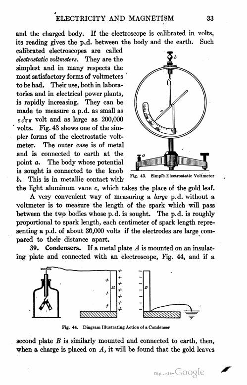
ELECTRICITY AND MAGNETISM 33
and the charged body. If the electroscope is calibrated in volts,
its reading gives the p.-d. between the body and the earth. Such
calibrated electroscopes are called
electrostatic voltmeters. They are the
simplest and in many respects the
most satisfactory forms of voltmeters
to be had. Their use, both in labora
tories and in electrical power plants,
is rapidly increasing. They can be
made to measure a p.d. as small as
to\tt volt and as large as 200,000
volts. Fig. 43 shows one of the sim
pler forms of the electrostatic volt
meter. The outer case is of metal
and is connected to earth at the
point a. The body whose potential
is sought is connected to the knob
b. This is in metallic contact with
the light aluminum vane c, which takes the place of the gold leaf.
A very convenient way of measuring a large p.d. without a
voltmeter is to measure the length of the spark which will pass
between the two bodies whose p.d. is sought. The p.d. is roughly
proportional to spark length, each centimeter of spark length repre
senting a p.d. of about 30,000 volts if the electrodes are large com
pared to their distance apart.
39. Condensers. If a metal plate A is mounted on an insulat
ing plate and connected with an electroscope, Fig. 44, and if a
Fig. 43. Simple Electrostatic Voltmeter
Fig. 44. Diagram Illustrating Action of a Condenser
second plate B is similarly mounted and connected to earth, then,
when a charge is placed on A, it will be found that the gold leaves

34 ELECTRICITY AND MAGNETISM
fall together as B approaches A and diverge farther as B recedes
from A. This shows that the potential of A is diminished by
bringing B close to it, in spite of the fact that the quantity of elec
tricity on A has remained unchanged. If we convey additional
plus charges to A, we find that many times the original amount
of electricity may be placed on A when B is close to it, before the
leaves return to their original divergence, that is, before the body
regains its original potential.
We say, therefore, that the capacity of A for holding electricity
has been very greatly increased by bringing near it another conductor
which is connected to earth. It is evident from this statement that
we measure the capacity of a body by the amount of the electricity which
must be put upon it in order to raise its potential to a given point.
The explanation of the increase of capacity in this case is obvious.
As soon as B was brought near to A , it became charged, by induc
tion, with electricity of sign opposite to that of A, the electricity
of sign like that of A being driven off to earth through the con
necting wire. The attraction between these opposite charges on
A and B drew the electricity on A to the face nearest to B, and
removed it from the more remote parts of A, so that it became
possible to put a very much larger charge on A before the tendency
of the electricity on A to pass over to the electroscope became as
great as at first, that is, before the potential of A rose to its original
value. Under circumstances of this sort the electricity on A is
said to be bound by the opposite electricity on B.
An arrangement of this sort consisting of two conductors
separated by a nonconductor is called a condenser. If the con
ducting points are very close together and one of them is joined
to earth, the capacity of the system may be thousands of times
as great as that of one of the plates alone.
40. Leyden Jar. The most common form of condenser is
a glass jar coated with tinfoil part way to the top inside and outside,
Fig. 45. The inside coating is connected by a chain to the knob,
while the outside coating is connected to earth. Condensers of
this sort first came into use in Leyden, Holland, in 1745. Hence they
have since been called Leyden jars.
Such a jar is charged by holding the knob in contact with one
terminal of an electrical machine and connecting the outer coat to

ELECTRICITY AND MAGNETISM 35
earth either by a wire or simply by holding it with the hand. As
fast as electricity passes to the knob, it spreads to the inner coat of
the jar, where it attracts electricity
of the opposite kind from the earth
to the outer coat, repelling elec
tricity of the same kind. If the
inner and outer coatings are now
connected by a discharging rod,
Fig. 45, a very powerful spark will
be produced. If a charged jar is
placed on a glass plate so as to insu
late the outer coat, the knob may
be touched with the finger and no « T j .° Fig. 45. Discharge of a Leyden Jar
appreciable discharge noticed. Sim
ilarly the outer coat may be touched with the finger with the
same result. But if the inner and outer coats are connected with
the discharge, a powerful spark passes.
The experiment shows that it is impossible to discharge one
side of the jar only, for practically all of the charge is bound by
the opposite charge on the other coat. Therefore, the full discharge
can occur only when the inner and outer coats are connected.
ELECTRICAL GENERATORS
41. Electrophorus. The electrophorus is a simple electrical
generator which illustrates well the principle underlying the action
of all electrostatic machines. All such machines generate electricity
primarily by induction, not by friction.
B, Fig. 46, is a hard rubber plate which
is first charged by rubbing it with fur
or flannel . A is a metal plate provided
with an insulating handle. When the
plate A is placed upon B, touched with
the finger, and then removed, it is found
possible to draw a spark from it, which
in dry weather may be a quarter of an, -ii mi Fig. 46. Charging an Electrophorus
inch or more in length, ihe process
may be repeated an indefinite number of times without producing
any diminution in the size of the spark which may be drawn from A.

36 ELECTRICITY AND MAGNETISM
a.
If the sign of the charge on A is tested by means of an electro
scope, it will be found to be positive. This proves that A has been
charged by induction, not by contact with B, for it is to be
remembered that the latter is charged negatively. The reason
for this is that even when A rests upon B it is in reality separated
from it, at all but a very few points, by an insulating layer of air;
and, since B is a nonconductor, its charge cannot pass off appreciably
through these few points of contact. It simply repels negative
electricity to the top side of the metal plate A, and draws positive
to the lower side of this plate. The negative passes off to earth
when the plate is touched with the finger. Hence, when the finger
is removed and A lifted, it possesses a strong positive charge.
42. Source of the Energy of the Charge Obtained from an
Electrophorus. Although an indefinite amount of electricity may
be developed by an electrophorus and stored
up, for example, in a Leyden jar, without
diminishing at all the charge on B, yet this
electrical energy does not come into exist
ence without the expenditure of a corre
sponding amount of mechanical work; for
each time that the plate A is removed from
B it must be lifted against the attrac
tions of the opposite charges on A and B,
Fig. 47.
According to the principle of the con
servation of energy, the energy in one
charge on the plate A is then exactly equal
to the work done against these electrical
attractions in lifting the plate. This elec
trical energy is transformed into heat energy in the spark which is
produced by the discharge.
If a bunsen burner is held in the hand, and a spark allowed
to pass off the edge of A to the top of the burner while the gas is
turned on, the gas will be instantly ignited by the spark.
43. Toepler=Holtz Static Machine. The ordinary static
machine is nothing but a continuously acting electrophorus. Fig.
48 represents one type of such machine. Upon the back of the
stationary glass plate E are pasted paper sectors, beneath which
1
(E+ + +)Ji
Fig. 47. Action on Conductorwhen Charged byElectrophorus

ELECTRICITY AND MAGNETISM 37
are strips of tinfoil AB and CD, called inductors. In front of E
is a revolving glass plate carrying disks I, m, n, o, p, and q, called
Fig. 48. Toepler-Holtz Static Machine
carriers. To the inductors AB and CD are fastened metal arms
t and u, which bring these inductors into electrical contact with
disks I, m, n, o, p, and q, when these disks pass beneath the tinsel
brushes carried by t and u. A stationary metallic rod rs carries
at its ends stationary brushes as well as sharp-pointed metallic
combs. The two knobs
R and S have their ca-
pacity increased by the
Leyden jars V and L.
The action of the
machine is best under
stood from the diagram,
Fig. 49. Suppose that
a small + charge is orig
inally placed on the in
ductor CD. Induction
takes place in the me
tallic system consisting of the disks I and o and the rod rs, I becoming
negatively charged, and o positively charged. As the plate carrying
I, m, n, o, p, q rotates in the direction of the arrows, the negative
charge on I is carried over to the position m, where a part of it passes
Fig. 49. Diagram Illustrating Toepler-Holtz Machine

38 ELECTRICITY AND MAGNETISM
over to the inductor A B, thus charging it negatively. When I reaches
the position n, the remainder of its charge, being repelled by the
negative which is not on AB, passes over into the Leyden jar L.
When I reaches the position o, it again becomes charged by induction,
this time positively, and more strongly than at first, since now the
negative on AB, as well as the positive on CD, is acting inductively
upon the rod rs. When I reaches the position u, a part of its now
strong positive charge passes to CD, thus increasing the positive
charge upon this inductor. In the position v, the remainder of the
positive charge on I passes over to V. This completes the cycle for I.
by means of a piece of sealing wax or a glass rod before the machine
will work.
44. Wimshurst Electrical Machine. The essential difference
between the Toepler-Holtz, Fig. 48, and the Wimshurst electrical
machine, Fig. 50, is that the latter has two plates revolving in opposite
directions and that these plates carry a large number of tinfoil
strips which act alternately as inductors and as carriers, thus dis
pensing with the necessity of separate inductors. The action of
the machine may be understood readily from Fig. 51. Suppose
that a small negative charge is placed on a. This, acting inductively
on the rod rs, charges a' positively. When a' in the course of the
rotation reaches the position b', it acts inductively upon the rod
Thus, as the rotation con
tinues, AB and CD acquire
stronger and stronger charges,
the inductive action upon rs
becomes more and more in
tense, and positive and nega
tive charges are continuously
imparted to L and L' until a
discharge takes place between
the knobs R and S.
Fig. 50. Wimshurst Static Machine
There is usually suffi
cient charge on one of the
inductors to start the ma
chine, but in damp weather
it is often found necessary to
apply a charge to one of them

ELECTRICITY AND MAGNETISM 39
s'r' and thus charges the disk b negatively. It will be seen that
henceforth all the disks in the inner circle receive + charges as
they pass the brush r, and that all the disks in the outer circle, i.e.,
on the back plate, receive — charges as they pass the brush
Similarly, on the lower half of the plates all the disks on the inner
circle receive — charges as they pass the brush s, and all the disks
on the outer circle receive + charges as they pass the brush r'.
When the positive charges on the inner disks come opposite
the combs c, they pass off to the + knob of the machine or to the
Leyden jar connected with it. The same process is occurring on
the other side, where — charges are being taken off. When a
spark passes, the Leyden jars and the connecting system of con
ductors are restored to their
initial conditions and
process begins again.
the
Fig. 51. Diagram of Action of Wimshurst Machine
EXAMPLES FOR PRACTICE
1. If an electrified rod
is brought near to a pith ball
suspended by a silk thread,
the ball is first attracted to
the rod and then repelled
from it. Explain.
2. Two like metal spheres are charged with +20 and —10
electrostatic units of electricity. With what force will they attract
each other when placed 5 cm. apart in air? Ans. 8 dynes
3. If the two spheres of the previous problem are made to
touch and are then returned to their former positions, with what
force will they act on each other? Will this force be attraction or
repulsion? Ans. 1 dyne. Repulsion
4. If you hold a brass rod in the hand and rub it with silk,
the rod will show no sign of electrification; but if you hold the brass
rod with a piece of sheet rubber and then rub it with silk, you will
find it electrified. Explain.
5. If you are given a positively charged insulated sphere,
how could you charge two other spheres, one positively and the
other negatively, without diminishing the charge on the first
sphere?

40 ELECTRICITY AND MAGNETISM
6. Given a gold-leaf electroscope, a glass rod, and a piece
of silk, how, in general, would you proceed to test the sign of the
electrification of an unknown charge?
7. When a negatively electrified cloud passes over a house
provided with a lightning rod, positive electricity passes into
the cloud and negative electricity to the rod. Where do these
charges which pass into the cloud and to the rod come from, and
what effect do they have on the p. d. between the cloud and the
earth?
8. If an electroscope is placed in a cage of wire netting and
an electrified glass rod brought near it, will any effect be observed?
Explain.
9. The heating coil of a certain electric teakettle has a p.d.
of 110 volts applied to it and consumes energy at the rate of 440
watts. How many electrostatic units of electricity pass through
the coil per second? To how many elementary charges (atoms of
electricity) is this equivalent?
10. Why is the capacity of a conductor greater when another
conductor connected to the earth is near it, than when it stands
alone?
ELECTRICITY IN MOTION—ELECTRICAL CURRENTS
45. Magnetic Effect Due to a Charge in Motion. An electrical
charge at rest produces no magnetic effort whatever. This can
be proved by bringing a charged body near a compass needle or a
suspended magnet. It will attract both ends equally well by virtue
of the principle of electrostatic induction. If the effect were mag
netic, one end should be repelled and the other attracted. Again,
if a sheet of zinc, aluminum, or copper is inserted between the
deflected needle and the charge, all effect which was produced upon
the needle by the charge will be cut off, for the metallic sheet will
act as an electric screen, cf. Section 35. But if such a metal screen
is inserted between a compass needle and a magnet, its insertion
has no effect at all on the magnetic forces, cf. Section 6.
If, however, a charged Leyden jar is discharged through a coil
which surrounds an unmagnetized knitting needle in the manner
12X109 electrostatic units
24X 1018 atoms of electricity

ELECTRICITY AND MAGNETISM 41
shown in Fig. 52, the needle will be found after the discharge to have
become distinctly magnetized. If the sign of the charge on the
jar is reversed, the poles will, in general, be reversed also.
This experiment demonstrates the existence of some connection
between electricity and magnetism. Just what this connection is,
is not yet known with certainty; but it is known that magnetic
effects are always observable near the path of a moving electrical charge,
while no such effects can ever be observed near a charge at rest.
An electrical charge in motion is called an electrical current,
and the presence of such a current in a conductor is most commonly
detected by the magnetic effect which it produces.
Fig. 52. Experiment to Prove That a Moving StaticCharge Is a Current
46. Galvanic Cell. When a Leyden jar is discharged, but
a very small quantity of electricity passes through the connecting
wires, since the current lasts but a small fraction of a second. If
we could .keep the current flowing continuously through the wire,
we should expect the magnetic effect to be more pronounced. This
might be done by discharging Leyden jars in rapid succession through
the wire. In 1786, however, Galvani, an Italian anatomist at
the University of Bologna, accidentally discovered that there is
a chemical method for producing such a continuous current. His
discovery was not understood, however, until Volta, professor of
physics at Como, devised an arrangement which is now known
sometimes as the voltaic, sometimes as the galvanic cell.
Such a cell consists in its simplest form of a strip of copper
and a strip of zinc immersed in dilute sulphuric acid, Fig. 53. If

42 ELECTRICITY "AND MAGNETISM
Fig. 53. Simple GalvanicCell
the wires leading from the copper and the zinc are connected for
a few seconds to the end of the coil of Fig. 52, when an unmagnetized
needle lies within this coil, the needle will be found to be much
more strongly magnetized than it was when
the Leyden jar was discharged through the
coil. Or, if the wire connecting the copper
and zinc is simply held above the needle in
the manner shown in Fig. 54, the latter will
be found to be strongly deflected. It is evi
dent from these experiments that the wire
which connects the terminals of a galvanic cell
carries a current of electricity. Historically,
the second of these experiments, performed by
the Danish physicist Oersted in 1819, preceded
the discovery of the magnetizing effect of currents upon needles.
It created a great deal of excitement at the time because it was
the first clew to the relationship between electricity and magnetism
which had been found.
It might be inferred
from the above experi
ments that the two
plates of a galvanic cell
when not connected by
a wire, carry static posi
tive and negative charges
just as do the two coats
of a Leyden jar before it is discharged through the wire. This
inference can be easily verified with an electroscope.
Thus, if a metal plate A, Fig. 55, covered with shellac on its
lower side and provided with an insulating handle, is placed upon
a similar plate B which is in contact with the knob on an electroscope ;
and if the copper plate, for example, of a galvanic cell is connected
to A and the zinc to B; then, when the connecting wires are removed
and the plate A lifted away from B, the leaves of the electroscope
will diverge and when tested will be found to be negatively charged.
If the deflection observed in the leaves of the electroscope is too
small for purposes of demonstration, the conditions can be bettered
by using a battery of from five to ten cells instead of the single cell.
Fig. 54. Action of a Wire Bearing a Current onMagnetic Needle|
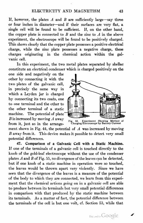
ELECTRICITY AND MAGNETISM 43
If, however, the plates A and B are sufficiently large—say three
or four inches in diameter—and if their surfaces are very flat, a
single cell will be found to be sufficient. If, on the other hand,
the copper plate is connected to B and the zinc to A in the above
experiment, the electroscope will be found to be positively charged.
This shows clearly that the copper plate possesses a positive electrical
charge, while the zinc plate possesses a negative charge, these
charges originating in the chemical action within the gal
vanic cell.
In this experiment, the two metal plates separated by shellac
constitute an electrical, condenser which is charged positively on the
one side and negatively on the
other by connecting it with the
two plates of the galvanic cell,
in precisely the same way in
which a Leyden jar is charged
by connecting its two coats, one
to one terminal and the other to
the other terminal of a static
machine. The potential of plate
B is increased by moving A away
from it, just as in the arrange- Charging Electroscope by Battery Current
ment shown in Fig. 44, the potential of A was increased by moving
B away from it. This device makes it possible to detect very small
potential differences.
47. Comparison of a Galvanic Cell with a Static Machine.
If one of the terminals of a galvanic cell is touched directly to the
knob of the gold-leaf electroscope without the use of the condenser
plates A and B of Fig. 55, no divergence of the leaves can be detected,
but if one knob of a static machine in operation were so touched,
the leaves would be thrown apart very violently. Since we have
seen that the divergence of the leaves is a measure of the potential
of the body to which they are connected, we learn from this experi
ment that the chemical actions going on in a galvanic cell are able
to produce between its terminals but very small potential differences
in comparison with that produced by the static machine between
its terminals. As a matter of fact, the potential difference between
the terminals of the cell is but one volt, cf. Section 53, while that
Experiment Showing Method of

44 ELECTRICITY AND MAGNETISM
between the terminals of an electrical machine may be several
hundred thousand volts.
On the other hand, if the knobs of the static machine aie con
nected to the ends of the wire shown in Fig. 54, and the machine
operated, the current will not be large enough to produce any
appreciable effect upon the needle. Since, under these same cir
cumstances the galvanic cell produced a very large effect upon
the needle, we learn that although the cell develops a much smaller
p.d. than does the static machine, it nevertheless sends through
the wire a very much larger amount of electricity per second. This
means merely that the chemical actions which are going on within
the cell are able to recharge the plates, when they become discharged
through the electric wire,
far more rapidly than the
static machine is able to re
charge its terminals after
they have once been dis
charged.
48. Shape of Mag=
netic Field about a Current.
If we place the wire which
connects the plates of a gal
vanic cell in a vertical posi
tion, Fig. 56, and explore
with a compass needle the
shape of the magnetic field
about the current, we find that the magnetic lines are concen
tric circles lying in a plane perpendicular to the wire and having
the wire as their common center. If we reverse the direction
of the current, we find that the direction in which the com
pass needle points reverses also. If the current is very strong,
say 40 amperes (Section 50), this shape of the field can be shown
by scattering iron filings on a plate through which the current
passes, in the manner shown in Fig. 56. The relation between
the direction in which the current flows and the direction in which
the positive end of the needle points (this is, by definition, the
direction of the magnetic field) is given in the following convenient
rule : If the right hand grasps the wire as in Fig. 57, so that the thumb
Fig. 56. Magnetic Field about a Wire Bearinga Current

ELECTRICITY AND MAGNETISM 45
Fig. 57. Direction of Flow of Magnetic Linesabout a Wire
Fig. 58. Field aboutCurrent
Flowing towardObserver
a Wire.
points in the direction in which the positive electricity is moving, that
is, in the direction from the copper toward the zinc, then the magnetic
lines encircle the wire in the
same direction as do the
fingers of the hand. Another
way of stating this rule is
as follows: The relation
between the direction of the
current in a wire and the direction of the magnetic lines about it, is
the same as the relation between the direction of the forward motion of
a right-hand screw and the direction of rotation
when it is being driven in. In this form the rule
is known as the right-hand screw rule.
Fig. 58 shows the shape of the magnetic
field about a wire in which the current is flowing
toward the observer, "out" from the plane of
the figure, and Fig. 59 shows the shape of the
magnetic field when the current is flowing away
from the observer, "in" or back from the plane
of the figure.
49. Galvanometers. When the terminals of
a simple cell are connected to the ends of a coil
which passes around a magnetic needle as in Fig.
60, the needle will be deflected more strongly
than when a single wire was used, as in the
experiment illustrated in Fig. 54, for, in accord
ance with the right-hand rule, both the upper
and the lower portions of the coil tend to make
the needle turn in the same direction.
It will come to rest in a position at
right angles to the plane of the coil.
Again, let a coil of say 200 turns
of No. 30 copper wire be suspended be
tween the poles of a magnet NS, as in
Fig. 61. The suspending wires should
be cf No 40 copper wire. As soon as
the current from the galvanic cell is sent through the coil, it will
turn so as to set itself at right angles to the line connecting N and
Fig. 59. Field about aWire. Current Flow
ing away fromObserver
Fig. 00. Simple Galvanometer

46 ELECTRICITY AND MAGNETISM
*7
6
S, i.e., at right angles to the lines of force of the magnet. The
only essential difference between the two experiments is that in
the first the coil is fixed and the magnet free
to turn, while in the second the magnet is
fixed and the coil is free to turn. In both
cases, the passage of the current tends to
cause the suspended system to rotate through
90 degrees.
These two experiments illustrate the
principle underlying nearly all current-measur
ing instruments or galvanometers. Instru
ments of the suspended-coil type are the more
11 it common and the more convenient. They
are usually called D'Arsonval galvanometers.
Fig. 62 represents one form of such a gal
vanometer used for laboratory experiments,
and Fig. 63 shows a some
what modified form suitable
for classroom experiments.
The current in passing through
such an instrument enters
through the suspending wire,
encircles the coil, and then
Fig. 61. Principle ofD'Arsonval Galvanometei
Fig. 62. Commercial D'ArsonvalGalvanometer
Courtesy of Wm. Gaertner & Company, Chicago
Fig. 63. Lecture D'Arsonval
Galvanometer

ELECTRICITY AND MAGNETISM 47
passes out through the fine spiral coil shown below the movable
coil, or vice versa. The strength of the field in which the coil
rotates is considerably increased by placing a soft iron cylinder in
the space inside the movable coil, thus causing the instrument to
respond to very much smaller currents.
Fig. 64. Magnetic Field about a Coil
MEASURING OF ELECTRIC CURRENT
50. Unit of Current—the Ampere. Ampere was the first
investigator who made quantitative measurements on continuous
currents by means of their
magnetic effects. Hence
the practical unit of cur
rent is named, in honor of
him, the ampere. It may
be defined as the current
which, when flowing through
a circular coil of 100 turns
and a radius of 10 centi
meters, will produce at its center a magnetic field of strength equal
to 2ir dynes. Fig. 64 shows the shape of the magnetic field about
such a coil. The ampere is approximately the same as the current
which, flowing through a circular coil of 3 turns and a radius of 10
centimeters, set in a north-and-south plane, will produce a deflection
of 45 degrees in a
small compass needle
placed at its center as
in Fig. 64.
A-very ingenious
method used by Lord
Ilayleigh for measur
ing the strength of an
electric current is
shown in Fig. 65.
The coils A, C, and
D are connected in
series, that is, so that the same current which is being measured
passes through each coil successively. Coil A is first balanced by
weights placed in pan E. The current to be measured is then sent
Fig. 65. Lord Rayleigh's Method of Measuring the Strengthof an Electric Current

48 ELECTRICITY AND MAGNETISM
through the coils in such a way that coil A is attracted by coil D
and repelled by coil C and the total force due to the magnetic
action between the coils is then equal to the weight which must
be added to pan E in order to maintain a balance. This force can
also be calculated in terms of the current and the dimensions of the
coil. Hence from the measured force, i.e., the weight added to pan
E to maintain a balance, and the dimensions of the coil, the current
can be calculated.
By sending the same current which passed through the coils
of Fig. 65, also through a plating solution of silver nitrate, Lord
Rayleigh found that a current of one ampere deposited 0.0011179
gram of silver in one second. By international agreement, the ampere
is now defined as the current which will deposit silver at the rate of
0.001118 gram per second.
51. Commercial Ammeter. Fig. 66 shows the construction
of the usual form of ammeter, which is really nothing but a shunted
of high resistance compared to the coils r, and the coils r have
a very small resistance. By connecting the coils r (shunt coils)
in the proper way, the instrument is sometimes made so that
the same full-scale deflection may read, for example, 1.5, 15.0, or
30 amperes.
Fig. 66. Diagram of Ammeter
moving -coil galvanometer.
The coil c is pivoted on
jewel bearings and is held
at its zero position by a
spiral spring p. When a
current flows through the
instrument, were it not for
the spring p the coil would
turn through about 120
degrees, or until its N pole
came opposite the S pole
of the magnet. This zero
position is chosen because
with pole pieces shaped as
in the figure, it enables the
scale divisions to be nearly
equal. The coil c is always

ELECTRICITY AND MAGNETISM 49
52. Illustrations of the Ampere. When the electrodes of a
new dry cell are touched to an ammeter, a current of from 20 to
30 amperes will flow. A telegraph relay and a telephone will operate
on about one-tenth of an ampere. Electrical welders require from
a few amperes to several hundred, depending on the character of
the work. A 16-candle-power tungsten lamp takes about .18 of an
ampere to light it while a 16-candle-power carbon filament lamp
takes about .5 of an ampere. Fan motors, sewing-machine motors,
and washing-machine motors operated on 110 volts take less than
1 ampere, while street-car motors require about 50 amperes.
EXAMPLES FOR PRACTICE
1. How could you test whether or not the strength of an
electric current is the same in all parts of a circuit?
2. Under what conditions will an electric charge produce a
magnetic effect?
3. How would you prove that a static charge does not produce
a magnetic effect?
4. In what direction will the north pole of a magnetic needle
be deflected if it is held above a current flowing from north to south?
5. A man stands beneath a north-and-south trolley line and
finds that a magnetic needle in his hand has its north pole deflected
toward the east. What is the direction of the current flowing in
the wire?
6. A loop of wire lying on the table carries a current which
flows around it in a clockwise direction. Would a north magnetic
pole at the center of the loop tend to move up or down?
7. How would you make a simple galvanometer that would
enable you to tell which of a number of cells would give the most
current?
53. Electromotive Force and Its Measurements. The potential
difference which a galvanic cell or any other generator of electricity
is able to maintain between its terminals when these terminals are
not connected by a wire, i.e., the total electrical pressure which the
generator is capable of exerting, is commonly called its electromotive
force, usually abbreviated e.m.f. The e.m.f. of an electrical
generator may then be defined as its capacity for producing electrical
pressure, or p. d. This p. d. might be measured, as in Section 38 by

50 ELECTRICITY AND MAGNETISM
the deflection produced in an electroscope, or an electrostatic volt
meter, when one terminal was connected to the case of either instru
ment and the other terminal to the knob. Potential differences
are in fact measured in this way in all so-called electrostatic volt
meters, which are now coming more and more into use.
The more common type of potential-difference measurers,
so-called voltmeters, consists, however, of an instrument made similar
to an ammeter, save that the voltmeter does not have a shunt toil,
but, instead, has a coil made of an enormous number of turns of
extremely fine wire placed in series with the movable coil, so that
it carries a very small current,
(see Fig. 70).
The amount of current which
it does carry, however, and there
fore the amount of deflection of its
needle is taken as proportional to
the difference in electrical pressure
existing between its ends, when
these are touched to the two points
whose p.d. is sought. The princi
ple underlying this type of volt
meter will be better understood
from a consideration of the follow
ing water analogy. If the stop
cock K, Fig. 67, in the pipe con
necting the water tanks C and D,
is closed, and if the water wheel
A is set in motion by applying a
weight W, the wheel will turn until it creates such a difference in
the water levels between C and D that the back pressure against
the left face of the wheel stops it and brings the weight W to rest.
In precisely the same way, the chemical action within the' galvanic
cell whose terminals are not joined, Fig. 68, develops positive and
negative charges upon these terminals, that is, creates a p.d. between
them, until the back electrical pressure through the cell due to this
p. d. is sufficient to put a stop to further chemical action.
Now, if the water reservoirs, Fig. 67, are put in communication
by opening the stopcock K, the difference in level between C and D
Fig. 67. Hydrostatic Diagram Illustrating Effect of Potential Difference

ELECTRICITY AND MAGNETISM 51
Fig. 68. Chemical Action inSimple Cell Creates a
P. D. in Circuit
will begin to fall, and the wheel will begin to build it up again. But
if the carrying capacity of the pipe ab is small in comparison with
the capacity of the wheel to remove water from D and to supply
it to C, then the difference of level which per
manently exists between C and D when K is
open will not be appreciably smaller than
when it is closed. In this case the current
which flows through AB may obviously be
taken as a measure of the difference in pres
sure which the pump is able to maintain
between C and D when K is closed.
In precisely the same way, if the termi
nals C and D of the cell, Fig. 68, are con
nected by attaching to them the terminals a
and b of any conductor, they at once begin
to discharge through this conductor, and
their p. d. therefore begins to fall. But if the
chemical action in the cell is able to recharge
C and D very rapidly in comparison with the ability of the wire to
discharge them, then the p.d. between C and D will not be appre
ciably lowered by the presence of the connecting conductor. In this
case the current which flows through the conducting coil, and there
fore the deflection of the needle at its center, may be taken as a
measure of the electrical pressure developed
by the cell, that is, of the p.d. between its
unconnected terminals.
54. Volt. On account of the fact that
the volt as defined in Section 37 is so diffi
cult to reproduce or to use as a standard, it
is highly desirable to have a standard p.d.
which can be easily and accurately repro
duced. For this purpose the Weston normal
cell has been chosen. This cell, Fig. 69, con
sists of a positive electrode of mercury in a
paste of mercurous sulphate, and a negative
electrode of cadmium amalgam in a saturate solution of cadmium
sulphate. It is so easily and exactly reproducible and has an e.m.f.
of such extraordinary constancy, that it has been taken by inter
Fig. 69. Construction ofWeston Standard
Cell

52 ELECTRICITY AND MAGNETISM
national agreement as the standard in terms of which all e.m.f.'s
and p.d.'s are rated. Careful experiments show that the e.m.f. of
a Weston normal cell at 20° C, measured in volts as defined in
Section 37, is- 1.0183 volts.
The legal definition of the volt is, then", an electrical pressure
equal to t.ttt^j of that produced by a Weston normal cell at 20° C.
55. Commercial Voltmeter. Fig. 70 shows the construction
of the usual type of voltmeter, which is really a high-resistance
moving-coil galvanometer. It
differs from the ammeter of
Section 51 in the following
respects: Instead of the
shunt coils r which are in
parallel with the moving coil
c, a coil of high resistance R
is placed in series with c so
that the instrument, instead
of having a negligible resist
ance as in the case of the
ammeter, has a high resist
ance. The full-scale deflec
tion can be made to represent
different voltages such as 1 .0,
10, or 150 volts by using coils
similar to R placed in series with the instrument.
56. Illustrations of the Volt. The Weston Standard cell,
Fig. 69, produces an e.m.f. of 1.0183 volts at 20° C, a dry cell
about 1.45 volts, and a lead storage cell about 2.1 volts. The
p.d. between two light mains is usually 110 volts but is often 220
volts. The p.d. between a street-car trolley line and the earth is
about 550 volts. The p.d. between the electrodes of a spark-coil
used to transmit transatlantic radiograms is several million volts.
57. Electromotive Forces of Galvanic Cells. When a volt
meter of any sort is connected to the terminals of a galvanic cell,
it is found that the deflection produced is altogether independent
of the shape or size of the plates or of their distance apart. But if the
nature of the plates is changed, the deflection changes. Thus, while
copper and zinc in dilute sulphuric acid have an e.m.f. of one volt,
Fig. 70. Diagram of Voltmeter Principle

ELECTRICITY AND MAGNETISM 53
carbon and zinc show an e.m.f. of at least 1.5 volts, while carbon and
copper will show an e.m.f. of very much less than a volt. Similarly,
by changing the nature of the liquid in which the plates are immersed,
we can produce changes in the deflection of the voltmeter. We learn
therefore that the e.m.f. of a galvanic cell depends simply upon
the materials of which the cell is composed and not at all upon the shape,
size, or distance apart of the plates.
58. Electrical Resistance. If the terminals of a galvanic cell
are connected first to ten feet of No. 30 copper wire, and then
to ten feet of No. 30 German-silver wire, it is found that a compass
needle placed at a given distance from the copper wire will show a
much larger deflection than when placed the same distance from
the German-silver wire. A cell, therefore, which is capable of
developing a certain fixed electrical pressure is able to force very
much more current through a given wire of copper than through
an exactly similar wire of German silver. We say, therefore, that
German silver offers a higher resistance to the passage of electricity
than does copper. Similarly, every particular substance has its
own characteristic power of transmitting electrical currents. Silver
is the best conductor of any of the known substances. The resist
ances of different substances are commonly referred to silver as a
standard, and the ratio between the resistance of a given wire of
any substance and the resistance of an exactly similar silver wire is
called the specific resistance of that substance. The specific resist
ances of some of the commoner metals are given below:
Silver 1.00 Soft iron 7.40 German silver, 18 per cent nickel. . 18.0
Copper 1.13 Nickel 7.87 Hard steel 21.0
Aluminum. . .2.00 Platinum 9.00 Mercury 62.7
The unit of resistance is the resistance at 0 degrees C of a column
of mercury 106.3 cm. long and 1 sq. mm. in cross-section. It is called
an ohm, in honor of the great German physi-
of about one ohm. Copper wire of the size shown in Fig. 71 has a
resistance of about 2.62 ohms per mile.
The resistances of all metals increase with a rise in temperature.
The resistances of liquid conductors, on the other hand, usually
cist, Georg 0hm (1 789-1854) . A length of 9.35
feet of No. 30 copper wire, or 6.2 inches of
No. 30 German-silver wire, has a resistance
Fig. 71. Copper Conductor

54 ELECTRICITY AND MAGNETISM
decrease with a rise in temperature. Carbon and a few other solids
show a similar behavior: the carbon-filament incandescent lamp has
only about half the resistance when hot that it has when cold. The
resistances of wires of the same material are found to be directly
proportional to their lengths, and inversely proportional to their
cross-sections.
59. Ohm's Law. In 1827 Ohm announced the discovery that
the currents furnished by different galvanic cells, or combinations of
cells, are always directly proportional to the e.m.f.'s existing in the
circuits in which the currents flow, and inversely proportional to the
total resistances of these circuits; i.e., if I represents the current in
amperes, E the e.m.f. in volts, and R the resistance of the circuit
in ohms, then Ohm's law as applied to the complete circuit is:
'-I (i)
that is, current equals electromotive force divided by resistance.
As applied to any portion of an electrical circuit, Ohm's law is:
I=vA (2)
that is, current equals potential difference divided by resistance,
where p. d. represents the difference of potential in volts between any
two points in the circuit, and r the resistance in ohms of the conductor
connecting these two points. This is one of the most important
laws in physics.
Both of the above statements of Ohm's law are included in the
equation :
volts ,_Namperes = - ( 3 )
ohms v '
60. Internal Resistance of a Galvanic Cell. If the zinc and the
copper plates of a simple galvanic cell are connected to an ammeter,
and the distance between the plates then increased, the deflection
of the needle is found to decrease; or if the amount of immersion is
decreased, the current also will decrease. But since the e.m.f. of
a cell was shown in Section 57 to be wholly independent of the area
of the plates immersed or of the distance between them, it will be
seen from Ohm's law that the change in the current in these cases
must be due to some change in the total resistance of the circuit.

ELECTRICITY AND MAGNETISM 55
Since the wire which constitutes the outside portion of the circuit
has remained the same, we must conclude that the liquid within the
cell, as well as the external wire, offers resistance to the passage of the
current. This internal resistance of the liquid is directly propor
tional to the distance between the plates, and inversely proportional
to the area of the immersed portion of the plates. If, then, we
represent the external resistance of the circuit of a galvanic cell
by Re and the internal by 2?;, then Ohm's law as applied to the
entire circuit takes the form:
'TO w
Thus, if a simple cell has an internal resistance of 2 ohms and
an e.m.f. of 1 volt, the current which will flow through the circuits
when its terminals are connected by 9.3 ft. of No. 30 copper wire
(1 ohm), is r~~^ = -33 ampere. This is about the current which is
usually obtained from an ordinary Daniell cell, see Section 65.
EXAMPLES FOR PRACTICE
1. If the potential difference between the terminals of a cell
on open circuit is to be measured by means of a galvanometer, why
must the galvanometer have a high resistance?
2. How would you make a simple voltmeter if you had some
wire and a horseshoe magnet?
3. How long a piece of No. 30 copper wire will have the same
resistance as a meter of No. 30 German-silver wire? See Section 58.
4. How many ohms' resistance in each of the wires in
problem 3?
5. The resistance of a certain copper wire is 1 ohm. What
wall be the resistance of another copper wire of the same length, but
of one-half the diameter?
6. A voltmeter reads 2 volts when connected to two points
9.35 feet apart on a No. 30 copper wire which is carrying a current.
What is the strength of the current in amperes?
7. In Example 6 what would the voltmeter read if attached
to two points which were 1.87 feet apart?
8. A current which is passed through an ammeter and then
through a silver-plating solution for 25 minutes is found to deposit
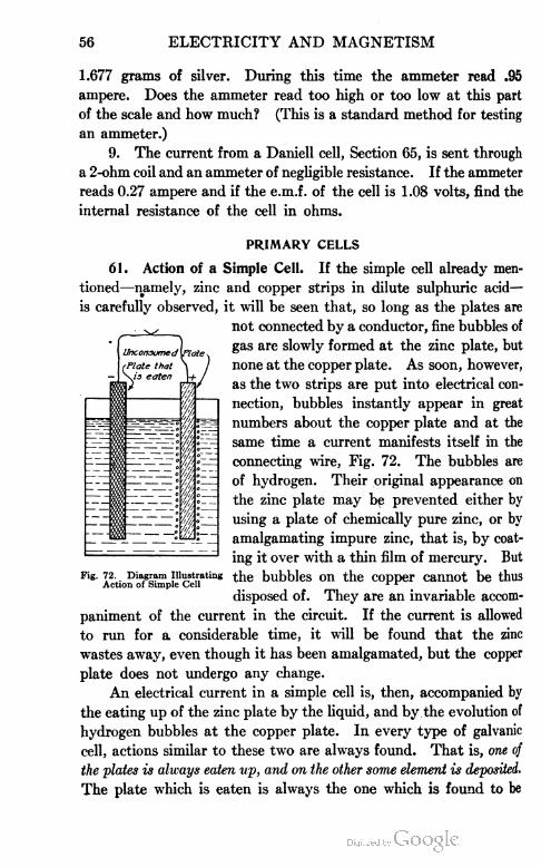
56 ELECTRICITY AND MAGNETISM
1.677 grams of silver. During this time the ammeter read .95
ampere. Does the ammeter read too high or too low at this part
of the scale and how much? (This is a standard method for testing
an ammeter.)
9. The current from a Daniell cell, Section 65, is sent through
a 2-ohm coil and an ammeter of negligible resistance. If the ammeter
reads 0.27 ampere and if the e.m.f. of the cell is 1.08 volts, find the
internal resistance of the cell in ohms.
PRIMARY CELLS
61. Action of a Simple Cell. If the simple cell already men
tioned—namely, zinc and copper strips in dilute sulphuric acid—
is carefully observed, it will be seen that, so long as the plates are
not connected by a conductor, fine bubbles of
gas are slowly formed at the zinc plate, but
none at the copper plate. As soon, however,
as the two strips are put into electrical con
nection, bubbles instantly appear in great
numbers about the copper plate and at the
same time a current manifests itself in the
connecting wire, Fig. 72. The bubbles are
of hydrogen. Their original appearance on
the zinc plate may be prevented either by
using a plate of chemically pure zinc, or by
amalgamating impure zinc, that is, by coat
ing it over with a thin film of mercury. But
rig. 72. Diagram illustrating the bubbles on the copper cannot be thusAction of Simple Cell r r
disposed of. They are an invariable accom
paniment of the current in the circuit. If the current is allowed
to run for a considerable time, it will be found that the zinc
wastes away, even though it has been amalgamated, but the copper
plate does not undergo any change.
An electrical current in a simple cell is, then, accompanied by
the eating up of the zinc plate by the liquid, and by the evolution of
hydrogen bubbles at the copper plate. In every type of galvanic
cell, actions similar to these two are always found. That is, one of
the plates is always eaten up, and on the other some element is deposited.
The plate which is eaten is always the one which is found to be

ELECTRICITY AND MAGNETISM 57
negatively charged, while the other is always found to be positively
charged; so that in all galvanic cells, when the terminals are connected
through a wire, the positive electricity flows through this wire from
the uneaten plate to the eaten plate. It will be remembered that the
direction in which the positive electricity flows is taken for convenience
as the direction of the current, see Sections 25 and 36.
62. Theory of Action of a Simple Cell. A simple cell may be
made of any two dissimilar metals immersed in a solution of any
acid or salt. For simplicity, let us examine the action of a cell
composed of plates of zinc and copper immersed in a dilute solution
of hydrochloric acid. The chemical formula for hydrochloric acid
is HC1. This means that each molecule of the acid consists of one
atom of hydrogen combined with one atom of chlorine. In accord
ance with the theory now in vogue
among physicists and chemists, when
hydrochloric acid is mixed with
water so as to form a dilute solu
tion, the HCI molecules split up into
two electrically charged parts, called
ions, the hydrogen ion carrying a
positive charge and the chlorine ion
an equal negative charge, Fig. 73.
This phenomenon is known as dis
sociation. The solution as a whole
is neutral; i.e., it is uncharged,
because it contains just as many positive as negative ions.
When a zinc plate is placed in such a solution, the acid attacks
it and pulls zinc atoms into solution. Now, whenever a metal
dissolves in an acid, its atoms, for some unknown reason, go into
solution bearing little positive charges. The corresponding negative
charges must be left on the zinc plate in precisely the same way in
which a negative charge is left on silk when positive electrification
is produced on a glass rod by rubbing it with the silk. It is in this
way, then, that we attempt to account for the negative charge which
we find upon the zinc plate in the experiment described in Section 46.
The passage of positively charged zinc ions into solution gives
a positive charge to the solution about the zinc plate, so that the
hydrogen ions tend to be repelled toward the copper plate. When

58 ELECTRICITY AND MAGNETISM
these repelled hydrogen ions reach the copper plate, some of them
give up their charges to it and then collect as bubbles of hydrogen
gas. It is in this way that we account for the positive charge which
we find on the copper plate in the experiment described in Section 46.
If the zinc and copper plates are not connected by an outside
conductor, this passage of positively charged zinc ions into solution
continues but a very short time, for the zinc soon becomes so strongly
charged negatively that it pulls back on the plus zinc ions with as
much force as the acid is pulling them into solution. In precisely
the same way, the copper plate soon ceases to take up any more
positive electricity from the hydrogen ions, since it soon acquires
a large enough plus charge to repel them from itself with a force
equal to that with which they are being driven out of solution by
the positively charged zinc ions. It is in this way that we account
for the fact that on open circuit no chemical action goes on in the
simple galvanic cell, the zinc and copper plates simply becoming
charged to a definite difference of potential which is called the
e.m.f. of the cell.
When, however, the copper and zinc plates are connected by a
wire, a current at once flows from the copper to the zinc, and the
plates thus begin to lose their charges. This allows the acid to pull
more zinc into solution at the zinc plate, and allows more hydrogen
to go out of solution at the copper plate. These processes, therefore,
go on continuously so long as the plates are connected. Hence, a
continuous current flows through the connecting wire until the zinc
is all eaten up or the hydrogen ions have all been driven out of the
solution, i.e., until either the plate or the acid has become exhausted.
63. Polarization. If the simple cell which has been described
is connected to an ammeter through a resistance of about .5 ohm,
i.e., by about 5 feet of No. 30 copper wire, and the deflection observed
for. a few minutes, it is found to produce a current of continually
decreasing strength; but if the hydrogen is removed from the copper
plate by taking out the plate and drying it, the deflection returns
to its first value. This phenomenon is called polarization.
The presence of the hydrogen on the positive plate causes a
diminution in the strength of the current for two reasons: First,
since hydrogen is a nonconductor, by collecting on the plate it
diminishes the effective area of the plate and therefore increases the

ELECTRICITY AND MAGNETISM 59
internal resistance of the cell ; second, by collecting upon the copper
plate it lowers the e.rh.f. of the cell, because it virtually substitutes
a hydrogen plate for the copper plate, and we have already seen,
Section 57, that a change in any of the materials of which a cell
is composed changes its e.m.f.
The several forms of galvanic cells in common use differ chiefly
in various devices employed either for disposing of the hydrogen
bubbles or for preventing their formation. The most common
types of such cells are described in the following sections.
64. Bichromate Cell. The bichromate cell, Fig. 74, consists
of a plate of zinc immersed in sulphuric acid between two plates
of carbon, carbon being used instead of copper because it gives a
greater e.m.f. In the sulphuric acid is
dissolved some bichromate of potassium
or sodium, the function of which is to
unite chemically with the hydrogen as
fast as it is formed at the positive plate,
thus preventing its accumulation upon
this plate.* Such a cell has the high
e.m.f. of 2.1 volts. Its internal resist
ance is low, from .2 to .5 ohm, since the
plates are generally large and close to
gether. It will be seen, therefore, that
when the external resistance is very
small it is capable of furnishing a current
of from 5 to 10 amperes. Since, how
ever, the chromic acid formed by the
union of the sulphuric acid with the bichromate attacks the zinc
even when the circuit is open, it is necessary to lift the zinc from
the liquid by the rod A, when the cell is not in use. Such cells
are useful where large currents are needed for a short time. The
great disadvantages are that the fluid deteriorates rapidly, and that
the zinc cannot be left in the liquid.
65. Daniell Cell. The Daniell cell consists of a zinc plate
immersed in zinc sulphate, and a copper plate immersed in copper
sulphate, the two liquids being kept apart either by means of a porous
Fig. 74. Bichromate Cell
*To set up a bichromate cell, dissolve 12 parts, by weight, of sodium bichromate in 180
parta of boiling water. After cooling, add 25 parts of commercial sulphuric acid.

60 ELECTRICITY AND MAGNETISM
Fig. 75. Section and Complete View of Daniell Cell
* earthen cup, as in the type shown in Fig. 75, or else by gravity, as in
the type shown in Fig. 76. This last type, commonly called the
gravity or crowfoot type,
is used almost exclu
sively on telegraph
lines. The copper sul
phate, being the heavier
of the two liquids, re
mains at the bottom
about the copper plate,
while the zinc sulphate
remains at the top about
the zinc plate.
In this cell, polar
ization is almost en
tirely avoided, for the
reason that no opportunity is given for the formation of hydrogen
bubbles. For, just as the hydrochloric acid solution described in
Section 62 consists of positive hydrogen ions and negative chlorine
ions in water, so the zinc sulphate (ZnSO4) solution consists of
positive zinc ions and negative SO4 ions. Now the zinc of the zinc
plate goes into solution in the zinc sul
phate in precisely the same way that
it goes into solution in the hydro
chloric acid of the simple cell de
scribed in Section 62. This gives a
positive charge to the solution about
the zinc plate, and causes a move
ment of the positive ions between
the two plates from the zinc toward
the copper, and of negative ions in
the opposite direction, both the Zn
and the SO4 ions being able to pass
through the porous cup. Since the
positive ions about the copper plate
consist of atoms of copper, it will be
seen that the material which is driven out of solution at the copper
plate, instead of being hydrogen, as in the simple cell, is metallic
Crowfoot or Gravity Cell

ELECTRICITY AND MAGNETISM 61
copper. Since, then, the element which is deposited on the copper
plate is the same as that of which it already consists, it is clear that
neither the e.m.f . nor the resistance of the cell can be changed because
of this deposit; i.e., the cause of the polarization of the simple cell
has been removed.
The advantage of the Daniell cell lies in the relatively high
degree of constancy in its e.m.f. (1.08 volts). It has a comparatively
high internal resistance (one to six ohms) and is therefore incapable
of producing a very large current, about one ampere at most. It
will furnish a very constant current, however, for a great length
of time; in fact, until all of the copper is driven out of the copper
sulphate solution. In order to keep
a constant supply of the copper ions
in the solution, copper sulphate crys
tals are kept in the compartment S
of the cell of Fig. 75, or in the bot
tom of the gravity cell. These dis
solve as fast as the solution loses its
strength through the deposition of
copper on the copper plate.
The Daniell is a so-called closed-
circuit cell, i.e., its circuit should be
left closed (through a resistance of
thirty or forty ohms) whenever the
cell is not in use. If it is left on open circuit, the copper sulphate
diffuses through the porous cup, and a brownish muddy deposit of
copper or copper oxide is formed upon the zinc. Pure copper is
also deposited in the pores of the porous cup. Both of these actions
damage the cell. When the circuit is closed, however, since the
electrical forces always keep the copper ions moving toward the
copper plate, these damaging effects are to a large extent avoided.
66. Leclanche Cell. The Leclanche cell, Fig. 77, consists of a
zinc rod in a solution of ammonium chloride (150 g. to a liter of
water), and a carbon plate placed inside of a porous cup which is
packed full of manganese dioxide and powdered graphite or carbon.
As in the simple cell, the zinc dissolves in the liquid, and hydrogen is
liberated at the carbon, or positive, plate. Here it is slowly attacked
by the manganese dioxide. This chemical action, however, is not
Fig. 77. Lcclanchd Cell

62 ELECTRICITY AND MAGNETISM
quick enough to prevent rapid polarization when large currents are
taken from the cell. The cell slowly recovers when allowed to
stand for a while on open circuit. The e.m.f. of a Leclanche cell is
about 1.5 volts, and its initial internal resistance is somewhat less
than an ohm. It therefore furnishes a momentary current of from
one to three amperes.
The great advantage of this type of cell lies in the fact that
the zinc is not at all eaten by the ammonium chloride when the
circuit is open, and that, therefore, unlike the Daniell or bichromate
cells, it can be left for an indefinite time on open circuit without
deterioration. Leclanche cells are used almost exclusively where
momentary currents only are needed, as, for example, on doorbell
circuits. The cell requires no attention for years at a time, other
than the occasional addition of water to replace loss by evaporation,
and the occasional addition of ammonium chloride (NH4C1) to keep
positive NH4 and negative CI ions in the solution.
67. Dry Cell. The dry cell, Fig. 78, is only a modified form
of the Leclanche cell. It is not really dry, since the carbon plate is
imbedded in a moist paste contained in
a cylindrical can made of zinc. The
paste consists usually of crystals of am
monium chloride, three parts of plaster
of Paris, one part of zinc oxide, one part
of zinc chloride, and two parts of water.
The plaster of Paris is used to give the
paste rigidity. As in the Leclanche cell,
it is the action of the ammonium chloride
upon the zinc which produces the cur
rent. The dry cell must not be left on
closed circuit and consequently is used
largely for so-called open-circuit work,
i.e., work requiring a current for short intervals of time, such as ring
ing doorbells, operating spark-coils for gaslighters and for exploding
the gas mixture in the cylinders of gas engines on boats, aero
planes, automobiles, etc. An old cell which has lost its strength
may be greatly improved by punching a hole in the top and pour
ing in some water which has been saturated with ammonium chlo
ride (sal ammoniac).
Fig. 78. Typical Dry Battery

ELECTRICITY AND MAGNETISM 63
Fig. 79. Diagram of Cells in Series
68. Combination of Cells. There are two ways in which cells
may be combined: First, in series; and second, in parallel. When
they are connected in +
series, the zinc of one
cell is joined to the cop
per of the second, the
zinc of the second to the
copper of the third, etc.,
the copper of the first
and the zinc of the last
being joined to the ends
of the external resist
ance, Fig. 79. The
e.m.f. of such a combination is the sum of the e.m.f.'s of the single
cells. The internal resistance of the combination is also the sum of
the internal resistances of the single cells. Hence, if the external
resistances are very small, the current furnished by the combination
will not be larger than that furnished by a single cell, since the
total resistance of the circuit has been in
creased in the same ratio as the total e.m.f.
But if the external resistance is large, the
current produced by the combination will be
very much greater than that produced by a
single cell. Just how much greater can
always be determined by applying Ohm's
law, for if there are n cells in series, and E
is the e.m.f. of each cell, the total e.m.f. of
the circuit is nE. Hence if Re is the external
resistance and i?,- the internal resistance of a
single cell, then Ohm's law gives
l_ nE
Re+nlU
If the n cells are connected in parallel,
that is, if all the coppers are connected and all
the zincs, as in Fig. 80, the e.m.f. of the com
bination is only the e.m.f. of a single cell, while
the internal resistance is -~ of that of a single cell, since connecting
Fig. 80. Diagram of Celtain Parallel

64 ELECTRICITY AND MAGNETISM
the cells in this way is simply the equivalent to multiplying the area
of the plates n times. The current furnished by such a combination
will be given by the formula:
E1=
n
If, therefore, Re is negligibly small, as in the case of a heavy
copper wire, the current flowing through it will be n times as great as
that which could be made to flow through it by a single cell. These
considerations show that the rules which should govern the com
bination of cells are as follows:
When the external resistance is large in comparison with the
internal resistance of a single cell, the cells should be connected in
series.
When the external resistance is small in comparison with the
internal resistance of a single cell, the cells should be connected in
parallel.
The applications of Ohm's law to electric circuits are so numerous
and varied that they will be more fully treated in the next book of
this series on "Electrical Measurements and Applications of the
Electric Current". In order better to understand Ohm's law as
applied to what has preceded, however, a few illustrative examples,
and examples for practice are given.
EXAMPLES FOR PRACTICE
1. A Daniell cell is found to send a current of 0.5 ampere
through an ammeter of negligible resistance. What is the internal
resistance of the cell?
T E . 1.08I = . „ or .5 = -
Re+Ri 0+Rt
*=MS=2.16
.5
Therefore, the internal resistance of the cell is 2.16 ohms.
2. What is the resistance of a lamp filament if a p.d. of 110
volts applied to its terminals sends a current of 0.5 ampere through
it?
ELECTRICITY AND MAGNETISM 65
r P-d. - HOi=-r-°t-5=-r
R= 112 = 220 ohms
.5
Therefore, the lamp filament has a resistance of 220 ohms.
3. How much current will 20 Daniell cells in series send through
a telegraph line having a resistance of 300 ohms, if the internal
resistance of each cell is 4 ohms, and its e.m.f. 1.08 volts?
,_ NE _ 20X1.08
Re+NRi 300 + (20 X4)
21.6 nr.T .= 380 (approx.)
Therefore, the current is .057 ampere.
4. What current will the 20 cells of Example 3 arranged in
parallel send through the same telegraph line?
7 E 1.08
300+A
1 08
=30bT=-0036 (approx-)
Therefore, the current is .0036 ampere.
5. What current will one of the Daniell cells of Example 3 send
through the same telegraph line?
E 1.08
1=
Re+Ri 300+4
1 08-=.0036 (approx.)
304
Therefore, the current is .0036 ampere.
6. Would it be possible to increase appreciably the current
through the above telegraph line by connecting a very large number
of Daniell cells in parallel? (Compare answers to Examples 4
and 5.)
7. When the external resistance is large in comparison with
that of a single cell, what method of connecting the cells yields the
largest current?
8. What current will the 20 cells of Example 3, arranged in
parallel, send through an ammeter which has a resistance of 0.05

ELECTRICITY AND MAGNETISM
ohm? What current would the 20 cells in series send through the
same ammeter? What current would a single cell send through
the same ammeter?
9. From the answers obtained in the different parts of
Example 8, decide whether, in order to yield as large a current as
possible, cells should be connected in series or in parallel, when the
external resistance is small in comparison with that of a single cell.
10. Why is a Daniell cell a very poor one to use on a doorbell
circuit? Why is a Leclanche a good one for the same purpose?
11. Where and for what purpose have you seen dry cells
used?
12. A given new dry cell has an e.m.f. of 1 .5 volts and gives
a current of 25 amperes when short-circuited with a coarse copper
wire. What is its internal resistance? After this cell was used
on a doorbell circuit for one year, it gave only 1 ampere; what was
its internal resistance then?
13. Why will two dry cells run a toy motor very rapidly,
while three gravity cells having the same voltage as the two dry
cells may not even move it?


ELEMENTS OF ELECTRICITY
AND MAGNETISM
PART II
MEASUREMENT AND APPLICATIONS OF
THE ELECTRIC CURRENT
OHM'S LAW
69. Introduction. A thorough mastery of Ohm's law bears
the same relationship to the electrical engineer and his work, that
the skillful manipulation of the hammer, saw, and square, does to
the carpenter and his work. For this reason the quantities, electro
motive force, current, and resistance, which were explained in Part I,
are briefly reviewed here. Again, Ohm's law is used so extensively
in the development of methods for comparing and measuring elec
tromotive forces, currents, and resistances, that many of the appli
cations of the law have been given in the following pages, with the
double purpose in view, first, of acquiring ability to apply Ohm's
law to practical problems; and, second, of familiarizing the student
with the law in order that he may readily understand its application
in developing the methods used in comparing electromotive forces
with the potentiometer, in comparing resistances with the Wheatstone
bridge, and so on.
70. Electromotive Force. When a difference of electrical
potential exists between two points, there is said to exist an electro
motive force, or a tendency to cause a current to flow from one point
to the other. In the voltaic cell, one plate is at a different potential
from the other, which gives rise to an electromotive force between
them. In the induction coil, also, an electromotive force is created
in the secondary circuit caused by the action of the primary. This
electromotive force is analogous to the pressure caused by a differ
ence in level of two bodies of water connected by a pipe. The

68 ELECTRICITY AND MAGNETISM
pressure tends to force the water through the pipe, and the electro
motive force tends to cause an electric current to flow.
The terms potential difference and electromotive force are
commonly used with the same meaning, but strictly speaking the
electromotive force gives rise to the potential difference. Electro
motive force is commonly designated by the letters e.m.f. or simply
E. It is also referred to as pressure or voltage.
71. Current. A current of electricity flows when two points
at a difference of potential are connected by a wire, or when the
circuit is otherwise completed. Similarly, water flows to a lower
level when a path is provided. In either case, the flow can take
place only when the path exists. Hence, to produce a current, it is
necessary to have an electromotive force and a closed circuit. The
current continues to flow only as long as the electromotive force and
closed circuit exist.
The strength of a current in a conductor is defined as the quan
tity of electricity which passes any point in the circuit in a unit
of time.
Current is sometimes designated by the letter C, but the letter
I will be used for current throughout this and following sections.
The latter symbol was recommended by the International Electrical
Congress held at Chicago in 1893, and has since been universally
adopted.
72. Resistance. Resistance is that property of matter by
virtue of which bodies oppose or resist the free flow of electricity.
Water passes with difficulty through a small pipe of great length
or through a pipe filled with stones or sand, but very readily
through a large clear pipe of short length. Likewise a small
wire of considerable length and made of poor conducting material
offers great resistance to the passage of electricity, but a good
conductor of short length and large cross-section offers very little
resistance.
Resistance is designated by the letter R.
Volt, Ampere, and Ohm. The volt is the practical unit of
electromotive force.
The ampere is the practical unit of current.
The ohm is the practical unit of resistance. The microhm is
one-millionth of an ohm and the megohm is one million ohms.

ELECTRICITY AND MAGNETISM 69
The standard values of the above units were very accurately
determined by the International Electrical Congress in 1893, and
are as follows:
The International ohm, or true ohm is, as nearly as known,
the resistance of a uniform column of mercury 106.3 centimeters
long and 14.4521 grams in mass, at the temperature of melting
ice.
The ampere is the strength of current, which, when passed
through a solution of silver nitrate under suitable conditions, deposits
silver at the rate of .001118 gram per second. Current strength
may be very accurately determined by electrolysis, and it is used
therefore in determining the standard unit.
The volt is equal to the e.m.f. which, when applied to a con
ductor having a resistance of one ohm, will produce in it a current
of one ampere. One volt equals tftIt of the e.m.f. of a standard
Weston cell at 20° C.
73. Ohm's Law Denned. The current is directly proportional
to the electromotive force, and inversely proportional to the resistance.
That is, if the electromotive force applied to a circuit is in
creased, the current will be increased in the same proportion, and
if the resistance of a circuit is increased, then the current will be
decreased proportionally. Likewise a decrease in the electromotive
force causes a proportional decrease in current and a decrease in
resistance causes a proportional increase in current. The current
depends only upon the electromotive force and resistance and in
the manner expressed by the above simple law. The law may be
expressed algebraically as follows:
The units of these quantities, the ampere, the volt, and the ohm,
have been so chosen that an electromotive force of 1 volt applied
to a resistance of 1 ohm, causes 1 ampere of current to flow. Ohm's
law may therefore be expressed by the following equation
current varies aselectromotive force
resistance
amperesvolts
ohms
or
I
R

70 ELECTRICITY AND MAGNETISM
where / is the current in amperes, E the electromotive force in volts,
and R the resistance in ohms.
It is therefore evident, that if the electromotive force and the
resistance are known, the current may be found, or if any two of
the three quantities are known, the third may be found. If the
current and the resistance are known, the electromotive force may
be found from the formula
E = RI
and if the current and the electromotive force are known, the resist
ance may be found from the formula
74. Simple Applications. The following examples are given
to illustrate the simplest applications of Ohm's law.
Examples. 1. If the e.m.f. applied to a circuit is 4 volts and
its resistance is 2 ohms, what current will flow?
By the formula for current
E 4/ = -^. =—=2 amperes Ans. 2 amperes
2. What voltage is necessary to cause a current of 23 amperes
to flow through a resistance of 820 ohms?
By the formula for e.m.f.
E = RI= 820X23 = 18,860 volts
Ans. 18,860 volts
3. The e.m.f. applied to a circuit is 110 volts, and it is desired
to obtain a current of .6 ampere. What should be the resistance of
the circuit?
By the formula for resistance
R = -r= —„- = 183+ohms Ans. 183 ohms
1 .o
75. Series Circuits. A circuit made up of several parts all
joined in series with each other, is called a series circuit and the
resistance of the entire circuit is of course the sum of the separate
resistances. In calculating the current in such a circuit, the total
resistance must first be obtained, and the current may then be

ELECTRICITY AND MAGNETISM 71
found by dividing the applied or total e.m.f. by the total resistance.
This is expressed by the formula
7 = L-
ri+r2+r3+etc.
Examples. 1. . Three resistance coils are connected in series
with each other and have a resistance of 8, 4, and 17 ohms, respec
tively. What current will flow if the e.m.f. of the circuit is 54 volts?
By the preceding formula
t E 54 54 11 = = -— — =—= 1 .8+ amperesri+r2+ri 8+4 + 17 29 H
Ans. 1.8 amperes
2. Six arc lamps, each having a resistance of 5 ohms, were
connected in series with each. other, and the resistance of the con
necting wires and other apparatus was 3.7 ohms. What must have
been the pressure of the circuit to give a desired current of 9.6
amperes?
The total resistance of the circuit was i? = (6X5) +3.7 = 33.7
ohms and the current was to be 7 = 9.6 amperes. Hence by the
formula for e.m.f.
£ = #7=33.7X9.6 = 323+ volts Ans. 323 volts
3. The current passing in a certain circuit was 12 amperes
and the e.m.f. was 743 volts. The circuit was made up of 4 sections
all connected in series, and the resistance of three sections was 16,
9, and 26 ohms, respectively. What was the resistance of the fourth
section?
Leta;=the resistance of the fourth section, then R = 16+9+26+a;
=51+a;, 7 = 12, and £ = 743. By the formula for resistance
E 743i? =—, or 51+2 =— =61.9 ohms (approx.)
L i£
If 51+2 = 61.9 we have, by transposing 51 to the other side of
the equation
a: = 61.9-51 = 10.9 ohms Ans. 10.9 ohms
4. A current of 54 amperes flowed through a circuit when the
e.m.f. was 220 volts. What resistance should be added in series
with the circuit to reduce the current to 19 amperes?

72 ELECTRICITY AND MAGNETISM
The resistance in the first case was
220
7? - —— . 4.07 ohms (approx.)
54
The resistance in the second must be
R=—= 11.58 ohms (approx.)
The requireil resistance to insert in the circuit is the difference
of these two resistances, or 11.58 — 4.07 = 7.51 ohms.
Ans. 7.51 ohms
76. Fall of Potential in a Circuit. Fig. 81 illustrates a series
circuit in which the resistances A, B, C, D, and E are connected in
series with each other and with the source of electricity. If the
e.m.f. is known, the current may be found by dividing the e.m.f. by
.WWW— if—2 WMAA
vwwwwv
Fig. SI. Diagram of Series Circuit Illustrating Fall Potential
the sum of all the resistances. Ohm's law may, however, be applied
to any part of a circuit separately, as well as to the complete circuit.
Suppose the resistances of A, B, C, D, and E are 4, 3, 6, 3, and 4
ohms, respectively, and assume that the source has no resistance.
Suppose the current flowing to be 12 amperes. The e.m.f. neces
sary to force a current of 12 amperes through the resistance A of 4
ohms is, by applying Ohm's law, equal 'to E= #7=4X12 = 48 volts.
Hence, between the points a and b outside of the resistance A, there
must be a difference of potential of 4S volts to force the current
through this resistance. Also, to force the same current through
B, the voltage necessary is 3 X 12 = 36. Similarly, for each part C,
D, and E, there are required 72, 36, and 48 volts, respectively.
As 4S volts are necessary for part A, and 36 volts for part B,
it is evident that to force the current through both parts a difference

ELECTRICITY AND MAGNETISM 73
of potential of 48+36 = 84 volts is required; that is, the voltage
between the points a and c must be 84 volts. For the three parts
A, B, and C, 48+36+72 = 156 volts are necessary, and for the
entire circuit, 240 volts must be applied to give the current of 12
amperes. From the above it is evident that there is a gradual fall
of potential throughout the circuit, and if the voltage between any
two points of the circuit be measured, the e.m.f. obtained would
depend upon the resistance included between these two points.
For example, the voltage between points b and d would be found
to be 72+36 = 108 volts, or between d and e 36 volts, etc. From
the preceding it is apparent that the fall of potential in a part of a
circuit is equal to the current multiplied by the resistance of that
part.
This gradual fall of potential, or drop as it is commonly called,
throughout a circuit, enters into the calculations for the size of
conductors or mains supplying current to distant points. The
resistances of the conductors cause a certain drop in transmitting
the current, depending upon their sizes and lengths, and it is there
fore necessary that the voltage of machines at the supply station
shall be great enough to give the voltage necessary at the receiving
stations as well as the additional voltage lost in the conducting
mains.
For ^example, in Fig. 81 the voltage necessary between the
points e and b is 144 volts, but to give this voltage, the source must
supply in addition the voltage lost in parts A and E, which equals
96 volts.
Examples. 1. The voltage required by 17 arc lamps con
nected in series is 782 volts and the current is 6.6 amperes. The
resistance of the connecting wires is 7 ohms. What must be the
e.m.f. applied to the circuit.
The drop in the connecting wires is E = RI = 7X6.6 = 46.2 volts.
The e.m.f. necessary is therefore 782+46.2 = 828.2 volts.
Ans. 828.2 volts
2. A source of e.m.f. supplies 114 volts to a circuit made
up of incandescent lamps and conducting wires. The lamps require
a voltage of 110 at their terminals, and take a current of 12 amperes.
What should be the resistance of the conducting wires in order that
the lamps may receive the necessary voltage?

74 ELECTRICITY AND MAGNETISM
The allowable drop in the conducting wires is 114 — 110 = 4
volts. The current to pass through the wires is 12 amperes. Hence
the resistance must be
# =A = i =.33 ohm
Ans. .33 ohm
77. Divided Circuits. When a circuit divides into two or more
parts, it is called a divided circuit and each part will transmit a
portion of the current.
Such a circuit is illustrated in Fig. 82, the .two branches being
represented by b and c. The current passes from the positive pole
of the battery through a and then divides; part of the current passing
through b and part through c. The current then unites and passes
through d to the negative pole of the battery. The part c may be
considered as the main part
of the circuit and b as a by
pass about it. A branch
which serves as a by-pass to
another circuit is called a
— a shunt circuit, and the two
branches are said to be con
nected in parallel.
Amount of Current in Each Circuit. In considering the passage
of a current through a circuit of this sort, it may be necessary to
determine how much current will pass through one branch and how
much through the other. Evidently this will depend upon the
relative resistance of the two branches, and more current will pass
through the branch offering the lesser resistance than through the
one offering the greater. If the two parts have equal resistances,
then one-half of the total current will pass through each branch.
If one branch has twice the resistance of the other, then only
one-half as much of the total current will pass through that
branch as through the other; that is, J of the total current will
pass through the first branch and the remaining § will pass through
the second.
The relative strength of current in the two branches will be inversely
proportional to their resistances, or directly proportional to their con
ductances.
Fig. 82. Diagram Showing Divided Circuits

ELECTRICITY AND MAGNETISM 75
Suppose the resistance of one branch of a divided circuit is
ri, Fig. 83, and that of the other is r2. Then by the preceding
law
* • current in n : current in r2 : : r2 : n
and
current in n : total current : : r2 : ?"i+r2
and
current in r2 : total current : : n : ri+r2
Let / represent the total current, ii the current through the
resistance n, and £2 the current through the resistance r2. Then
Fig. S3. Diagram of Two Resistances in Parallel
the two preceding proportions are expressed by the following
formulas
. In j . Inii = —.— and i2 = -
ri+r2 ri+r2
Example. The total current passing in a circuit is 24 amperes.
The circuit divides into two branches having resistances of 5 and 7
ohms, respectively. What is the current in each branch?
In this case 7=24, n = 5, and r2 = 7. Substituting these values
in the above formulas, we have
and
ii = ——= - , - = 14 amperes
n+r2 5+7
In 24X512 =rZT"= T~TT = 10 amperes
n+n 5+7
fin 5-ohm branch, 14 amperes
\ln 7-ohm branch, 10 amperes
78. Joint Resistance of Divided Circuits. As a divided circuit
offers two paths to the current, it follows that the joint resistance
of the two branches will be less than the resistance of either branch
alone. The ability of a circuit to conduct electricity is repre
sented by its conductance, which is the reciprocal of resistance;
and the conductance of a divided circuit is equal to the sum of
the conductances of its parts.
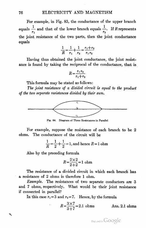
76 ELECTRICITY AND MAGNETISM
For example, in Fig. 83, the conductance of the upper branch
equals — and that of the lower branch equals —. If R represents
the joint resistance of the two parts, then the joint conductance
equals
1 _ 1 | 1 afi+fi
R ri r2 rxr2
Having thus obtained the joint conductance, the joint resist
ance is found by taking the reciprocal of the conductance, that is
R =^-
ri+r2
This formula may be stated as follows:
The joint resistance of a divided circuit is equal to the product
of the two separate resistances divided by their sum.
Fig. 84. Diagram of Three Resistances in Parallel
For example, suppose the resistance of each branch to be 2
ohms. The conductance of the circuit will be
-^- = -^-+-^- = 1, and hence R = l ohm
Also by the preceding formula
2+2
The resistance of a divided circuit in which each branch has
a resistance of 2 ohms is therefore 1 ohm.
Example. The resistances of two separate conductors are 3
and 7 ohms, respectively. What would be their joint resistance
if connected in parallel?
In this case ri = 3 and r% = 7. Hence, by the formula
R = |t^ = 2.1 ohms Ans. 2.1 ohms
o-\-7

ELECTRICITY AND MAGNETISM 77
Calculating Joint Resistance of Three Conductors. Suppose, as
illustrated in Fig. 84, the conductors having resistances equal to
Ti, r2, and r3, respectively, are connected in parallel. The joint
total conductance will then be equal to
1 _ 1 | 1 | 1 _r2r3+rir8+rir8
R ri |r2 r3 ri r2r3
and as the joint resistance is the reciprocal of the joint conduct
ance, the joint resistance R of the three branches is expressed by
the formula
n r2 r3
•.n+rir3+rir2
Example. What is the joint resistance when connected in
parallel, of three wires whose resistances are 41, 52, and 29 ohms,
respectively?
In this case ri = 41, r2 = 52, and r3 = 29. Hence, by the pre
ceding formula
D 41X52X29 100. .R = 52X29+41X29+41X52 = 12"8+ °hmS
Ans. 12.8+ ohms
Joint Resistance of Any Number of Conductors. In general,
for any number of conductors connected in parallel, the joint resist
ance is found by taking the reciprocal of the sum of the reciprocals
of the separate resistances.
Example. A circuit is made up of five wires connected in
parallel, and their separate resistances are, respectively, 12, 21, 28,
8, and 42 ohms. What is the joint resistance?
The sum of the conductances is
12+21 28 8 42 168
Hence, the joint resistance equals
168= = 3.1+ ohms Ans. 3.1+ ohms
56
Calculating Current in Each Conductor. If the resistance of
each branch is known, and also the potential difference between
the points of union, then the current in each branch may be found
by applying Ohm's law to each branch separately. For example,

78 ELECTRICITY AND MAGNETISM
if this potential difference were 96 volts, and the separate resistances
of the 4 branches were 8, 24, 3, and 48 ohrns, respectively, then the
current in the respective branches would be 12, 4, 32, and 2 amperes,
respectively.
If the current in each branch is known, and also the potential
difference between the points of union, then the resistance of each
branch may likewise be found from Ohm's law.
In general, if several resistances are connected in parallel, the
following method will be found very practical and is just as accurate
as the values of the individual resistances:
Example. Four incandescent lamps, having resistances of
220, 109, 605, and 297 ohms, respectively, are connected in parallel.
What is their joint resistance?
In this case n = 220, r2 = 109, r3 = 605, r4 = 297.
The sum of the conductances -jr is
. R 220 109 605 297
= .00455+.00917+.00166+ .00336
= .01874
fl=mk=53-4ohms
Ans. 53 . 4 ohms (approx.)
EXAMPLES FOR PRACTICE
1. Two conductors having resistances of 71 and 19 ohms,
respectively, are connected in parallel, and the total current pass
ing through the circuit is 37 amperes. What is the current in the
conductor whose resistance is 71 ohms? Ans. -7.8+ amperes
2. What is the joint resistance of two wires connected in
parallel if their separate resistances are 2 and 8 ohms, respectively?
Ans. 1.6 ohms
3. What is the joint resistance of three wires when connected
in parallel, whose separate resistances are 5, 7, and 9 ohms, respec
tively? Ans. 2.2+ ohms
4. Three wires, the respective resistances of which are 8, 10,
and 20 ohms, are joined in parallel. What is their joint resistance?
Ans. 3.6+ ohms

ELECTRICITY AND MAGNETISM 79
5. Four wires are joined in parallel, and their separate resist
ances are 2, 4, 6, and 9 ohms, respectively. What is the joint
resistance of the conductor thus formed? Ans. .97+ ohm
6. Four lamps are joined in parallel, and their separate resist
ances are 209, 107, 583, and 275 ohms, respectively. What is their
joint resistance? Ans. 51.3+ ohms
79. Battery Circuits. Single Cell in Series with Resistance.
Fig. 85 illustrates a simple circuit having a single cell C connected
in series with a resistance. This is the customary manner of repre
senting a cell, the short heavy line representing the zinc and the
long light line representing the copper or carbon plate. In determin
ing the amount of current which will flow in such a circuit, the total
resistance of the circuit must be considered. This is made up of
the external resistance R and the internal resistance r or the resist
ance of the cell itself. If E
represents the total e.m.f. of y 1|
the cell, then the current if c \
which will flow is expressed by 1 J
the formula S
R-\-T Fig. 85. Simple Battery Circuit
It has been shown that whenever a current passes through
any resistance, there is always a certain drop or fall of potential.
The total e.m.f. above referred to expresses the total potential
difference between the plates of the cell and is the e.m.f. of the cell
on open circuit. When the current flows, however, there is a fall
of potential or loss of voltage within the cell itself, and hence the
e.m.f. of the cell on closed circuit is less than that on open circuit.
That is, if the voltage be measured when the cell is supplying cur
rent, it will be found to be less than when the voltage is measured
on open circuit, or when the cell is supplying no current. The
voltage on closed circuit is that available for the external circuit,
and is therefore called the external or available voltage or e.m.f.
The external e.m.f. depends of course upon the strength of
current the cell is supplying, and may be calculated as follows:
If the current passing is I, and the resistance of the cell is
r, then, according to Ohm's law, the voltage lost in the cell equals

80 ELECTRICITY AND MAGNETISM
+
— 1 1 11 1 1
Fig. 86. Diagram of Three Cells in Series
rl. If E represents the total e.m.f. of the cell, and Ei the external
e.m.f. then
Ei = E-rI
The e.m.f. of a cell is understood to be the total e.m.f. unless
otherwise stated.
Two or More Cells in Series. When two or more cells are inter
connected they are said to form
a battery.
Fig. 86 illustrates three cells
connected in series with each
other and with the external cir
cuit. That is, the positive ter
minal of one cell is connected to
the negative of the next, and the positive of that cell to the nega
tive of the adjacent, etc. By this method of connecting, the e.m.f.
of each cell is added to that of the others, so that the total e.m.f.
of the circuit is three times that of a single cell. If one of the cells
were connected so that its e.m.f. opposed that of the other two, it
would offset the e.m.f. of one of the cells and the resultant e.m.f.
would be that of a single cell. The connecting of cells in series as
in Fig. 86 not only increases the e.m.f. of the circuit but also
increases the internal resistance, the resistance of each cell being
added to that of the others. If E equals the e.m.f. of each cell, r
the internal resistance of each, and R the external resistance, then the
current that will flow is expressed by the formula
T= SE
R+2r
or for n cells connected
in series the formula for
current is
Fig. 87. Diagram of Two Cells in Parallel R+nr
Two or More Cells in Parallel. Fig. 87 illustrates two cells
connected in parallel, and supplying current to, an external circuit.
Here the two positive terminals are connected with each other and the
two negative are also connected with each other. The e.m.f. sup
plied to the circuit is equal to that of a single cell only. In fact,

ELECTRICITY AND MAGNETISM 81
connecting cells in parallel is equivalent to enlarging the plates,
and the only effect is to decrease the internal resistance. It is
evident that coupling two cells in parallel affords two paths for the
current and so decreases the resistance of the two cells to one-half
that of a single cell. The formula expressing the current that would
flow in the external circuit with two cells in parallel is, therefore,
/=■ E
or for n cells connected in parallel, the formula for current is
E7 = -
n
Combination of Cells in Series and in Parallel. Fig. 88 represents
a combination of the series and the parallel methods of connecting,
four files of cells being
joined in parallel, each
file having four cells con
nected in series. The
e.m.f. of each file and
consequently of the cir
cuit is AE. The resist
ance of each file is 4r,
and that of all the files
4r-j-. Hence, the formula for current is
Fig. 88. Group of Cells in Series-Parallel Circuit
7 =4E
If there were m files connected in parallel, and n cells were
connected in series in each file, the formula expressing the current
in the external circuit would be
nE1 =
R+
nr
m
where E is the e.m.f. of each cell, R the external resistance, and r
the internal resistance of each cell.

82 ELECTRICITY AND MAGNETISM
Method of Connecting Cells for Giving Best Results. The most
advantageous method of connecting cells depends upon the results
desired, the resistance of the cell, and the external resistance. Sup
pose it is desired to pass a current through an external resistance of
2 ohms, and that Daniell cells are to be used each having an e.m.f.
of 1 volt and an internal resistance of 3 ohms. With one cell only
in the circuit, the current will be
*Tr=2Tr-2 amperC
and with 5 cells all in series, the current will be
5F 5R+^rz+rr-* ampere (approx0
Therefore, with 5 cells in series, the current is only .1 ampere greater
than that with a single cell, and with 100 cells in series the current
is only
100 £ 100imoo7=2T30o=-33ampere
Hence, with a comparatively low external resistance, there is but
little gain in current strength by the addition of cells in series.
This is due to the fact that, although the e.m.f. is increased by 1
volt for each cell, the resistance is increased by 3 ohms.
Now suppose 5 Daniell cells to be connected in parallel with
the external circuit of 2 ohms. The e.m.f. of the circuit will then
be that of a single cell, and the current will be
E 1
r 3
= .4 ampere (approx.)
and with 100 cells connected in parallel the current will be
E 1= .5 ampere (approx.)
A larger current is therefore obtained in this case by connecting
the cells in parallel than by connecting them in series.
With a large external resistance, on the other hand, a larger
current is obtained by connecting the cells in series. For example,
suppose the external resistance to be 500 ohms. One cell will
then give a current of .00198+ ampere, and 5 cells in series will

ELECTRICITY AND MAGNETISM S3
give about .0097 ampere, whereas 100 cells will give .125 ampere.
With 5 cells connected in parallel, the current will be .00199+
ampere, and with 100 cells the current will amount to approximately
002 ampere. With an external resistance of 500 ohms, there is
practically no advantage in connecting the cells in parallel. The
only effect of the latter method is to decrease the internal resistance
which is almost negligible in comparison with the external resistance.
It may be shown mathematically that for a given external
resistance and a given number of cells, the largest current is obtained
when the internal resistance is equal to the external resistance.
In order to obtain this result, the values of m and n in the formula
TITon page 81, should be so chosen that — equals R. This arrange-
m
ment, although giving the largest current strength, is not the most
economical. With the internal resistance equal to the external,
there is just as much energy used up in the battery itself as is
expended usefully in the external circuit.
In order to obtain the most economical arrangement, the
internal resistance should be made as small as possible, that is,
all the cells should be connected in parallel. The loss of power
in the battery is then the smallest amount possible.
In order to obtain the quickest action of the current, the cells
should be connected in series. When the external circuit possesses
considerable self-induction, as is the case when electromagnets are
connected in the circuit, the action of the current is retarded, since,
as will be shown later, the self-induction acts like a counter e.m.f.
in the circuit. This retardation must be overcome by having a high
e.m.f., which is obtained by connecting the cells in series.
Examples. 1. Sixteen cells, each having an internal resist
ance of .1 ohm are to be connected with a circuit whose resistance
is .4 ohm. How should the cells be connected to obtain the greatest
current?
Here the external resistance R equals .4 ohm and the resist
ance r of each cell equals .1 ohm. For maximum current
nr .1/1 .— = R, or = .4
m m
Therefore
.ln. = .4m, or n=4m

84 ELECTRICITY AND MAGNETISM
and as mn = 16, the only values of m and n which will be true for
both of these equations are n=8 and m=2. Hence there must
be 2 files of cells, with 8 cells in series in each file.
Ans. 2 files, 8 cells in each
2. The external resistance in a circuit is 4 ohms. The cells
used each have an e.m.f. of 1.2 volts and an internal resistance of
3.8 ohms. If 20 cells were used, which method of connecting would
supply the larger current, 5 files with 4 cells in series, or 4 files
with 5 cells in series?
(a) Applying the formula on page SI, we have R— 4, £ = 1.2,
r = 3.8; and with 5 files and 4 in series, n = 4 andrrc = 5. Hence,
the current is
nE 4X1.2
R+JE. M 4X3 8
= .681+ ampere
m 5
With 4 files and 5 cells in series. n = o and »i = 4. Hence the
current is
5X1.2
5X3.8
= .685+ ampere
The larger current is therefore supplied by having 4 files with
5 cells in series. Ans. 4 files with 5 cells in series
(b) The maximum current is supplied when the internal resist
ance equals the external resistance, or when
m
With 5 files and 4 cells in series
nr 4 X3.8
= 3.04 ohms
m 5
and with 4 files and 5 cells in series
nr 5X3.8 . „ ,
— =—.— = 4./5 ohms
m 4
The latter value is nearer to 4 ohms, which is the external resist
ance, than is 3.04. Hence, the larger current will be supplied with
4 files and 5 cells in series. Ans. 4 files with 5 cells in series

ELECTRICITY AND MAGNETISM 85
3. It is desired to pass a current of .025 ampere through an
external resistance of 921 ohms. The cells are to be connected
in series and each has an e.m.f. of .8 volt and an internal resistance
of 1.3 ohms. What number of cells must be used?
From page 80, the general formula for cells in series is
I= nE
R+nr
and in this case 7 = .025; E = .8', ' #=921; and r = 1.3. Substi
tuting these values gives
.025= nX-8
921 + nl.3
Multiplying by 921+ 1.3n gives
23.025+.0325re = .8w
Transposing .0325 n gives
.8/1 -.0325re= 23.025
.7675re= 23.025
re = 30 Ans. 30 cells
EXAMPLES FOR PRACTICE
1. Ten cells in series have an e.m.f. of 1 volt each and an
internal resistance of .2 ohm. The external resistance is 3 ohms.
What is the current? Ans. 2 amperes
2. Six cells, each of which has an e.m.f. of 1.2 volts and a
resistance of 2 ohms, are connected in parallel. With an external
resistance of 10 ohms, what is the current? Ans. .116+ ampere
3. What is the current supplied by the same cells if they are
joined in series and the external resistance is 20 ohms?
Ans. .225 ampere
4. A single cell whose e.m.f. on open circuit is 1.41 volts and
whose internal resistance is .5 ohm is supplying a current of .3
ampere. Determine the value of the available e.m.f. of the cell?
Ans. 1.26 volts
5. What would be the available e.m.f. with 8 of the cells
referred to in example 4, when connected in series and supplying
the same current? Ans. 10.08 volts
6. Eight Daniell cells (e.m.f. = 1.05, resistance = 2.5 ohms
each) are joined in series. Three wires A, B, and C of 9, 36, and

86 ELECTRICITY AND MAGNETISM
72 ohms resistance, respectively, are arranged to be connected to
the poles of the battery. Find the current when each wire is inserted
separately, and when all three wires are connected in parallel.
Ans. Through A, .29 ampere approx.; through B, .15 ampere;
through C, .091+ ampere; and through all three, .31+ ampere.
7. A battery of 28 bunsen cells (e.m.f. = 1.8, resistance =
.1 ohm each) are to supply current to a circuit having an external
resistance of 30 ohms. Find the current (a) when all the cells are
joined in series, (b) when all the cells are in parallel, (c) when there
are 2 files each having 14 cells in series, (d) when there are 7 files
each having 4 cells in series.
Ans. (a) 1.53+ ; (b) .06 nearly; (c) .82+; (d) .23+ ampere.
ELECTROLYSIS~ MEASUREMENT OF CURRENT
STRENGTH
80. Electric Current Conducted through Liquid. The way in
which a current is conducted through a liquid is very beautifully
shown by the following experiment: Pre
pare an infusion of purple cabbage either by
steeping the cabbage thoroughly in water,
or by grinding the cabbage and then press
ing out the juice and adding water. To a
portion of this infusion add a very small
quantity of caustic soda (NaOH), or any
other alkali, and the infusion will be turned
green. To another portion of the infusion,
add a few drops of sulphuric acid (H2S04),
or any other acid, and the infusion will be
turned red. We now know that an alkali
will turn the infusion green and that an acid
will turn it red, so that we may use this fact as a test for an alkali
or an acid. Now take a third portion of the infusion and pour
enough of it into a solution of sodium sulphate (Na2S04) to give
it a decided purple color. Place this solution in a U or a V tube,
Fig. 89, insert the platinum electrodes A and B and send a current
from three or four dry cells connected in series through it. The
solution near the pole at which the current enters the liquid,
called the anode, will presently be seen to turn red; while that
Fig. 89. Diagram ofElectrolytic Cell

ELECTRICITY AND MAGNETISM 87
near the pole at which the current leaves the liquid, called the
cathode, will turn green.*
These facts are explained by the theory of dissociation, see Sec
tion 62. Here the Na2SO4 when it goes into solution dissociates, i.e.,
it breaks up into negatively charged SO4 ions and positively charged
Na ions. Hence, as soon as the platinum plates A and B became
positively and negatively charged, respectively, by being attached
to the + and — plates of the battery, the negative SO4 ions were
at once attracted toward A and the positive NA ions toward B.
When they reached the plates, they gave up their charges to them,
and were then in condition to attack the water of the solution,
forming H2S04 at one plate and sodium hydroxide (NaOH) at the
other.
All conduction in liquids, molten metals excepted, is thought
to be due to a mechanism similar to that described above, i.e., it
is thought to consist in the migration through the liquid of a swarm
of positively charged ions in the direction in which the electric
current is supposed to flow and of a corresponding swarm of nega
tively charged ions in the other direction. As soon as the ions give
up their charges to the plates, such charges are either deposited
upon these plates or else act chemically either upon the solution
or upon the plate, so as to form new compounds. Strong evidence
for the correctness of this view as to the nature of conduction in
liquids is found in the fact that pure liquids, such as carefully dis
tilled water, alcohol, etc., do not conduct electricity, but are, in
every case, rendered conductors by dissolving salts or acids in them;
and again, by the further fact that whenever an electric current is
passed through such a conducting liquid, the two constituents of
the substance in solution are found to appear at the two plates.
All liquids which conduct in this manner are called electrolytes,
and the process of separating the two constituents of the substance
in solution by means of an electric current is called electrolysis.
81. Electrolysis of Water. If two platinum electrodes, sealed
into bent glass tubes e and /, Fig. 90, are inserted into two inverted
*This test may be made equally well with litmus in place of the cabbage infusion,
but in this case it must be made in two parts. In the first part, the solution is first turned red with
a few drops of acid; the passage of the current then causes it to turn blue about the cathode. In
the second part, the solution is first turned blue by an excess of alkali (NaOH) ; the passage of the
current then causes it to turn red about the anode.

88 ELECTRICITY AND MAGNETISM
test tubes, the test tubes and the vessel in which they stand being
filled with about one part of sulphuric acid to forty parts of water,
and if then two or three dry cells are connected in series to the
terminals A and B, gases will immediately be seen rising from the
two platinum electrodes and collecting in the top of the tubes.
One tube will be found to fill twice as rapidly as the other.* If a
lighted match is held in front of the tube II after it has been com
pletely filled and removed, it will be found that this gas burns with
a blue flame showing that it is hydrogen. If the gas in the tube 0
is tested by introducing into it a glowing splinter, the splinter will
take fire and burn vigorously, showing that this tube contains
oxygen.
The water has been decomposed by the electric current into
its two elements, hydrogen and oxygen. According to our theory
this decomposition has been effected as
follows: The positively charged hydro
gen ions of the sulphuric acid (H2SO4)
solution were driven by the electric forces
to the negative electrode, where they
gave up their charges and appeared at
once as hydrogen gas; while the negative
SO4 ions migrated to the positive elec
trode, where they gave up their charges
to it and then acted upon the water
(H20), forming more sulphuric acid and liberating oxygen.
If the electrolysis of water is produced in the hydrogen voltam
eter of Fig. 91, it is found that 1 coulomb of electricity will liberate
.0000104 gram of hydrogen, or .1156 cc. of hydrogen at 0°C. and
760 mm. pressure.
If we let V be the observed volume of hydrogen, V0 the volume
at zero, by the laws of Boyle and Charles (see Practical Physics)
Fig. 90. Experiment ShowingElectrolysis of Water
760 273 + i
in which P = ^-^+^ — P^- B *s the barometer reading in mm., h is
*The oxygen will be absorbed by electrodes other than platinum, so that its volume will
be much less than one-half that of the hydrogen.

ELECTRICITY AND MAGNETISM 89
the height in mm. of the acid solution in R above that in H, and p
is the vapor pressure of saturated water vapor in mm. of mercury
at the given temperature f C. Since the acid solution is about
one-twelfth as heavy as mercury, h in the last equation is divided
by 12 to reduce the pressure produced by this column of acid
to mm. of mercury.
V0 having been found, the
formula for the number of cou
lombs of electricity which passes
through the voltameter is
coulombs = . - °
.115b
and since
coulombs = amperes X seconds
if we know how many seconds
the current is on and the num
ber of coulombs of electricity
which pass through the voltam
eter, the current is at once given
by
coulombsamperes =
seconds
If an ammeter is connected
in series with the hydrogen
voltameter, and the reading kept
constant by means of a control
resistance, Fig. 96, the ammeter
will read the same as the am
perage computed in the manner
above, if the ammeter is correct
and the experiment is carefully performed. This method is
often used to make a direct test of the graduations on an
ammeter.
Data Illustrating an Ammeter Test
The current supplied by a storage battery was run through an ammeter,
a hydrogen voltameter, and a control resistance, and the ammeter reading was
Fig. 91. Measuring Relative Quantity of Hydrogen and Oxygen on Decomposition

90 ELECTRICITY AND MAGNETISM
kept constant at .330 ampere, or 330 milliamperes, for 10 minutes. The follow
ing values were obtained:
y=25.4cc. B = 745 mm.
«=20°C. fc = 180mm.
p - 17A mm.
i on
P = 745 +^.-17.4 =742.6 mm.
Fu =25.4x7-^x|| = 23.12cc.
coulombs23.12
1156 .1156
coulombs 200
= 200
= .333
or
amperes sccontis 600
milliamperes = 333
Error in ammeter at this part of the scale = —3 milliamperes
Correction to apply to ammeter reading at
this part of the scale — +3 milliamperes
82. International Method of Measuring the Ampere. Silver
Voltameter. In 1834, Faraday found that a given current of elec
tricity, flowing for a
given time, always de
posits the same amount
of a given element from
a solution, whatever be
the nature of the solu
tion which contains the
element. For example,
one ampere always de
posits in one hour 4.0125
g. of silver, whether tie
solution is of silver
nitrate, silver cyanide, or any other silver compound. This is
equivalent to .001118 g. or 1.118 milligrams in one second, 30
that the International Electrical Congress held at Chicago in
1893 defined the ampere to be the strength of current which will deposit
.001118 g. of silver per second. The apparatus used to deposit t ie
silver, Fig. 92, is called a silver voltameter or coulombmeter since it
really measures coulombs. The cathode C is made of silver or pla ;i-
num. The anode A is a disk of silver. The porous cup P simil ir
to that in a Daniell cell separates the anode and cathode and pie-
vents pieces (especially pieces of peroxide) from falling off the ano le
Fig. 92. Section of Silver Voltameter in Action

ELECTRICITY AND MAGNETISM 91
onto the cathode and thus introducing an error into the true weight
of the silver deposited on the cathode. The form of coulombmeter
used in the U. S. Bureau of Standards is shown in Fig. 93. After a
test, the silver anode carries a crust of disintegrated silver as shown
Fig. 93. Type of Silver Voltameter Used in U. S. Bureau of Standards Showing Conditionof Anode after a Test
Courtesy of U. S. Bureau of Standards, Washington, D. C.
in the right view of Fig. 93. The pure metallic silver has been
deposited on the platinum dish.
Illustrative Example—Ammeter Test Using Silver Voltameter
Mass of platinum cathode C = 40.1036 g.
Mass of platinum cathode C
after current flowed 30
minutes =41.1098 g.
Mass of silver deposited = 1.0062 g.
Since
g. of silver deposited = .001 118XamperesX seconds
1 .0062 = .001 1 18XamperesX 1800
1.0062
amperes =.001118xl8()0 = .5
or 500 milliamperes

92 ELECTRICITY AND MAGNETISM
Ammeter read 502 milliamperes
Error in ammeter at this part of the scale = +2 milliamperes
Correction to apply to ammeter reading
at this part of the scale = — 2 milliamperes
The electrochemical equivalents for several of the elements, that
is, the weight in grams deposited by 1 ampere in 1 second or in
other words by 1 coulomb, are found in Table I.
TABLE I
Electrochemical Equivalents
Element Valency Equivalent o.per coulomb
Element Valency Equivalent o.per coulomb
Aluminum 3 .0000936 Iron 3 .0001929
Antimony 3 .0004153 Lead 2 .0010731
Antimony 5 .0002492 Magnesium 2 .0001260
Bismuth 3 .0007185 Mercury 1 .0020788
Cadmium 2 .0005824 Mercury 2 .0010394
Chromium 3 .0001796 Nickel 2 .0003040
Cobalt 2 .0003055 Oxygen 2 .0000829
Copper 1 .0006588 Platinum 2 .0010104
Copper 2 .0003294 Silver 1 .0011180
Gold 3 .0006812 Tin 2 .0006166
Hydrogen 1 .0000104 Tin 4 .0003083
Iron 2 .0002893 Zinc 2 .0003387
The mass M in grams of any one of the above elements which
will be deposited by electrolysis is given by the equation
M= elt
in which e is the electrochemical equivalent in grams per ampere
second, i.e., in grams per coulomb, I is the current in amperes, and
t is the time the current is on in seconds.
EXAMPLES FOR PRACTICE
1. It is desired to make for experimental purposes 500 cc. of
dry hydrogen at 22° C. and 75 cm. pressure. How long will it take
to make the hydrogen by electrolysis using a current of 1 .5 amperes?
(Take P = 75 as p is here equal to zero.) Ans. 43 min. 54 sec.

ELECTRICITY AND MAGNETISM 93
2. How many grams of hydrogen will be liberated in one hour
by electrolysis using a current of 2 amperes? (Use equation,
M = elt; also see Table of Electrochemical Equivalents, p. 92.)
Ans. 0.07488 g.
3. If the hydrogen produced in problem 2 were dried and
brought to a pressure of 0° C. and 76 cm., its density would be
.00008984. How many cc. would it occupy? Ans. 833.3 cc.
4. How long will it take a current of 2 amperes to deposit 2
grams of silver from a solution of silver nitrate?
5. How much copper will be deposited per day of 24 hours in
a large copper-refining vat if a current of 400 amperes flows through
the vat between the plates? This method is used extensively in
the production of pure copper. (Use electrochemical equivalent
for copper corresponding to valency 2.)
6. In calibrating an ammeter, the current which produces a
certain deflection is found to deposit 2.5155 g. of silver in 15 minutes
on the cathode of a silver voltameter which is connected in series
with the ammeter. What was the strength of the current used and
what correction should be applied to the ammeter reading at this
part of the scale if the ammeter read 2.55 amperes?
83. Introduction. The different factors which affect the
resistance of a conductor were briefly treated in Part I, but are of
such importance that they will be more fully discussed in the follow
ing pages.
All substances resist the passage of electricity, but the resist
ance offered by some is very much greater than that offered by
others. Metals have by far the least resistance and of these, silver
possesses the least of any. In other words, silver is the best con
ductor. If the temperature remains the same, the resistance of a
conductor is not affected by the current passing through it. A
Ans. 14 min. 54 sec.
Ans. 2.5 amperes
Correction .05 amperes
LAWS OF RESISTANCE

94 ELECTRICITY AND MAGNETISM
current of ten, twenty, or any number of amperes may pass through
a circuit, but its resistance will be unchanged with constant tem
perature. Resistance is affected by the temperature and also by
the degree of hardness. Annealing decreases the resistance of a
metal.
84. Conductance. Conductance is the inverse of resistance;
that is, if a conductor has a resistance of R ohms, its conductance
is equal to Thus, we may think of resistance as the difficulty
K
which the current meets or overcomes, and conductance as the ease
with which it flows. The unit of conductance is the mho (the ohm
spelled in reverse order). Thus we see that
11 mho =
1 ohm
Consequently, a wire that has a conductance of 3 mhos has
a resistance of J ohm and a wire that has a resistance of 5 ohms has
a conductance of ^ mho, etc.
85. Resistance Proportional to Length. The resistance of a
conductor is directly proportional to its length. Hence, if the
length of a conductor is doubled, the resistance is doubled, or if
the length is divided, say into three equal parts, then the resist
ance of each part is one-third the total resistance.
Examples. 1. The resistance of 1283 feet of a certain
wire is 6.9 ohms. What is the resistance of 142 feet of the same
wire?
As the resistance is directly proportional to the length, we have
the proportion
required resistance : 6.9 : : 142 : 1283
required resistance _ 142
6i9 _1283
142required resistance = 6.9 X^r^
= .76 ohm (approx.)
Ans. .76 ohm (approx.)
2. The resistance of a wire having a length of 521 feet is .11
ohm. What length of the same wire will have a resistance of .18
ohm?
ELECTRICITY AND MAGNETISM 95
As the resistance is proportional to length, we have the
proportion
required length : 521 : : .18 : .11
required length _.18
521 ~A1
18required length= 521 X
= 852 feet (approx.)
Ans. 852 feet
86. Resistance Inversely Proportional to Cross=Section. The
resistance of a conductor is inversely proportional to its cross-
sectional area. Hence, the greater the cross-section of a wire the less
is its resistance. Therefore, if two wires have the same length,
but one has a cross-section three times that of the other, the resist
ance of the former is one-third that of the latter. (In hydrostatics
this is analogous to saying that, under a given pressure, a water main
having a cross-section of three square feet will carry three times as
much water, i.e., will offer one third as much resistance, as one
having a cross-section of one square foot.)
Examples. 1. The ratio of the cross-sectional area of one
257wire to that of another of the same length and material is The
resistance of the former is 16.3 ohms. What is the resistance of
the latter?
As the resistances are inversely proportional to the cross-
sections, the smaller wire has the greater resistance, and we have
the proportion
required resistance : 16.3 : : 257 : 101
required resistance _ 257
16.3 ~ibl
257required resistance = 16.3X^
=41.5 ohms (approx.)
Ans. 41.5 ohms
2. If the resistance of a wire of a certain length having a
cross-sectional area of .0083 square inch is 1.7 ohms, what would
he its resistance if the area of its cross-section were .092 square
inch?

26 * ELECTRICITY AND MAGNETISM
Since increasing the cross-sectional area of a wire decreases
its resistance, we have the proportion
required resistance : 1.7 : : .0083 : .092
required resistance _ .0083
1.7 ~ .092
• j • A - - .0083required resistance = 1 .7 X nno
= .15 ohm (approx.)
Ans. .15 ohm
As the area of a circle is proportional to the square of its diam
eter, it follows that the resistances of round conductors are inversely
proportional to the squares of their diameters.
3. The resistance of a certain wire having a diameter of .1
inch is 12.6 ohms. What would be its resistance if the diameter
were increased to .32 inch?
The resistances being inversely proportional to the squares of
the diameters, we have
required resistance : 12.6 : : .l2 : .322
required resistance _ .l2
' 12~6 i322
.l2
required resistance = 12.6X
= 12.6 X .01
.1024
= 1.23 ohms (approx.)
Ans. 1.23 ohms
87. Specific Resistance. The specific resistance of a substance
is the resistance of a portion of that substance of unit length and
unit cross-section at a standard temperature. The units commonly
used are the centimeter or the inch, and the temperature that of
melting ice. The specific resistance may therefore be said to be
the resistance (usually stated in microhms) of a centimeter cube or
of an inch cube at the temperature of melting ice. If the specific
resistances of two substances are known, then their relative resist
ance is given by the ratio of the specific resistances.
88. Conductivity is the reciprocal of specific resistance.
Example. A certain copper wire at the temperature of melting
ice has a resistance of 29.7 ohms. Its specific resistance (resistance

ELECTRICITY AND MAGNETISM 97
of 1 centimeter cube in microhms) is 1.594, and that of platinum is
9.032. What would be the resistance of a platinum wire of the
same size and length of the copper wire, and at the same tem
perature?
The resistance would be in direct ratio to the specific resist
ances, and we have the proportion
required resistance : 29.7 : : 9.032 : 1.594
required resistance = 29.7 X s^r.
1.594
= 168.2 ohms (approx.)
Ans. 168.2 ohms
89. Calculation of Resistance. From the preceding pages, it
is evident that resistance varies directly as the length, inversely as
the cross-sectional area, and depends upon the specific resistance
of the material. This may be expressed conveniently by the
formula
n L
K=s—
A
in which R is the resistance, L the length of the conductor, A the
area of its cross-section, and s the specific resistance of the material.
Example. A telegraph relay is wound with 1,800 feet of wire
.010 inch in diameter, and has a resistance of 150 ohms. What
will be its resistance if wound with 400 feet of wire .022 inch in
diameter?
If the wires were of equal length, we should have the pro
portion
required resistance : 150 : : (.010)2 : (.022)2
or
( 010)2
required resistance = 150X7-^— = 30.99+ ohms
{.Oil)2
For a wire 400 feet long, we have, therefore, by direct proportion
required resistance = -^^ X30.99= 6.88+
1 ,800
Ans. 6.88+ ohms
If a circuit is made up of several different materials joined in
series with each other, the resistance of the circuit is equal to the
sum of the resistances of its several parts. In calculating the

98 ELECTRICITY AND MAGNETISM
resistance of such a circuit, the resistance of each part should first
be calculated, and the sum of these resistances will be the total
resistance of the circuit.
In Table II are given the resistances of chemically pure sub
stances at 0° centigrade or 32° Fahrenheit in International ohms.
The first column of numbers gives the relative resistances when
that of annealed silver is taken as unity. For example, mercury
has 62.73 times the resistance of annealed silver. The second and
third columns give, respectively, the resistances of a foot of wire
.001 inch in diameter, and of a meter of wire 1 millimeter in diameter.
The fourth and fifth columns give, respectively, the resistance in
microhms of a cubic inch and cubic centimeter, that is, the specific
resistances.
TABLE II
Resistance of Chemically Pure Substances at 32° Fahrenheit in
International Ohms
Resistance Resistance Resistance in
Relative of a wire of a wire Microhms
Metal Resistance 1 foot long 1 meter long
.001 inch in 1 millimeter Cubic Cubic Cen
diameter in diameter Inch timeter
Silver, annealed 1.000 9.023 .01911 .5904 1.500
Copper, annealed
Silver, hard drawn
1.063 9.585 .02028 .6274 1.594
1.086 9.802 .02074 .6415 1.629
Copper, hard drawn
Gold, annealed
1.086 9.803 .02075 .6415 1.629
1.369 12.35 .02613 .8079 2.052
Gold, hard drawn 1.393 12.56 .02661 .8224 2.088
Aluminum, annealed 1.935 17.48 .03700 1.144 2.904
Zinc, pressed 3.741 33.76 .07143 2.209 5.610
Platinum, annealed 6.022 54.34 .1150 3.555 9.032
Iron, annealed 6.460 58.29 .1234 3.814 9.689
Lead, pressed 13.05 117.7 .2491 7.706 19.58
German silver 13.92 125.5 .2659 8.217 20.87
Platinum-silver alloy
(J platinum, § silver) 16.21 146.3 .3097 9.576 24.32
Mercury 62.73 570.7 1.208 37.05 94.06
It should be noted that the resistances in Table II are for
chemically pure substances, and these also at 32° Fahrenheit.
A very small portion of foreign matter mixed with a metal greatly
increases its resistance. An alloy of two or more metals always
has a higher specific resistance than that of any of its constituents.
For example, the conductivity of silver mixed with 1.2 per cent in
volume of gold, will be 59 when that of pure silver is taken as 100.
Annealing reduces the resistance of metals.

ELECTRICITY AND MAGNETISM 99
The following examples are given to illustrate the use of
Table II in connection with the formula on page 97, and to show
the application of preceding laws.
Examples. 1. From the specific resistance of annealed alumi
num as given in the next to the last column of Table II, calculate
the resistance given in the second column of figures for that substance.
The resistance in microhms of a cubic inch of annealed
aluminum at 32° F. is 1.144, which is equal to .000001144 ohm.
The resistance of a wire 1 foot long and .001 inch in diameter
is required. In the formula on page 97 we have s = .000001 144,
L=l foot = 12 inches and
. vd* 3.1416X.0012 nnnnnn70,,A=—= = .00000078o4 sq. in.
4 4
Substituting these values in the formula
we have
12R = .000001 144 X-
.0000007854
= 17.48 ohms Ans. 17.48 ohms
2. The resistance in microhms of a cubic centimeter of annealed
platinum at 0° C. is 9.032. What is the resistance of a wire of the
same substance one meter long and one millimeter in diameter at
the same temperature?
In the formula for resistance, we have the quantities s = 9.032
michroms = .000009032 ohm; i= l meter = 100 centimeters; and
. wd* 3.1416X.12 ^-o-.A = ——= = .007854 sq. cm.
4 4
the diameter being equal to 1 millimeter = .1 cm.
Substituting these values we have
tf = .000009032X-^
= .1150 ohm Ans. .115 ohm
3. From Table II the resistance of 1 foot of pure annealed
silver wire .001 inch in diameter at 32° F. is 9.023 ohms. What is
the resistance of a mile of wire of the same substance .1 inch in
diameter at that temperature?

100 ELECTRICITY AND MAGNETISM
As the resistance of wires is directly proportional to their length
and inversely proportional to the squares of their diameters, the
required resistance is found by multiplying the resistance per foot
by 5,280 and the product by the inverse squares of the diameters.
R = 9.023 X 5,280 X
= 4.76 ohms (approx.)
Ans. 4.76 ohms
4. A mile and one-half of an annealed wire of pure iron has
a resistance of 46.1 ohms. What would be the resistance of hard-
drawn wire of pure copper of the same length and diameter, assuming
each to be at the temperature of melting ice?
The only factor involved in this example is the relative resist
ance of the two metals. From Table II, annealed iron has 6.460
and hard-drawn copper 1.086 times the resistance of annealed silver.
Hence, the resistance of the copper is to that of the iron as 1.086
is to 6.460, and the required resistance is
fl = 46.1X^||p7.75 ohms (approx.)
Ans. 7.75 ohms
5. If the resistance of a wire 7,423 feet long is 18.7 ohms,
what would be its resistance if its length were reduced to 6,253
feet and its cross-section made one-half again as large?
As resistance is directly proportional to the length, and inversely
proportional to the area of the cross-section, the required resistance is
i? = 18.7x^fx^-= 10.5 ohms (approx.)
Ans. 10.5 ohms
From the preceding analysis, it will readily be seen that if we
represent the resistance of a wire 1 foot long and .001 inch in diam
eter by k (the values of k are given in column 2 of Table II),
the length of the wire by L, and the diameter of the wire in mils
(1 mil = .001 inch) squared, by C. M. (circular mils), then the resist
ance of any wire is given by the equation

ELECTRICITY AND MAGNETISM 101
TABLE III
Temperature Coefficients
Material Rise in R. of 1 Ohm When Heated:
it. rc.
Platinoid
Platinum silver
German silver
Platinum
Silver
Copper, aluminum
Iron
.00012
.00014
.00022
.0019
.0021
.0022
.0026
.00022
.00025
.00040
.0035
.0038
.0040
.0046
Example. Find the resistance of a hard-drawn copper wire
500 feet long which has a diameter of .020 inch?
Since the diameter is equal to 20 mils
C.M. = (20)2=400
From Table II, k = 9.803 ohms
90. Resistance Affected by Heating. The resistance of metals
depends upon the temperature, and the resistance is increased by
heating. The heating of some substances, among which is carbon,
causes a decrease in their resistance. The resistance of the fila
ment of a lighted incandescent lamp is half as great as the resistance
of the same filament when cold. All metals, however, have their
resistance increased by a rise in temperature. The percentage
increase in resistance with rise of temperature varies with the differ
ent metals, and slightly for the same metal at different tempera
tures. The increase is practically uniform for most metals through
out a considerable range of temperature. The resistance of copper
increases about .4 per cent per degree centigrade, or about .22 per
cent per degree Fahrenheit. The percentage increase in resistance
for alloys is much less than that for the simple metals. Standard
resistance coils are therefore made of alloys, as it is desirable that
their resistance should be as nearly constant as possible.
The change in resistance of one ohm per degree rise in tem
perature for a substance is called the temperature coefficient for
that substance. Table III gives the temperature coefficients for a
few substances.
R =9.803X500
400
= 12.25+ ohms
Ans. 12.25+ ohms

102 ELECTRICITY AND MAGNETISM
If the resistance of a conductor at a certain temperature is
known, the resistance the conductor will have at a higher tem
perature may be found by multiplying the temperature coefficient
for the substance by the number of degrees of increase and by the
resistance at the lower temperature, and by adding to this result
the resistance at the lower temperature. The product of the tem
perature coefficient and the increase in the number of degrees gives
the increase in resistance of one ohm through that number of degrees,
and multiplying this product by the number of ohms gives the
increase in resistance for the conductor. The result obtained is
practically correct for moderate ranges of temperature.
The dbove method of calculating the resistance of conductors
at increased temperatures is conveniently expressed by the follow
ing formula
Rt^Riil+at)
where i?2 is the resistance at the higher temperature, Ri that at
the lower temperature, a the temperature coefficient for the sub
stance, and t the change in the number of degrees.
From the preceding formula it follows that if the resistance
at the higher temperature is known, that at the lower temperature
will be given by the formula
In calculating resistances at different temperatures, the tem
perature coefficient based on the Fahrenheit scale should be used
if the change in the number of degrees is given in degrees Fahrenheit,
and that based on the centigrade scale if the change is given in
degrees centigrade.
Examples. 1. The resistance of a coil of German-silver wire
at 12° C. is 1,304 ohms. What would be its resistance at a tem
perature of 60° C?
From the statement of the example i?i = 1304, t = 60 -12=48,
and from Table III, a = .0004. Substituting these values in the
first of the preceding formulas, we have
R2 = 1304(1 + .0004X48)
= 1304X1.0192
= 1329 ohms (approx.) Ans. 1329 ohms

ELECTRICITY AND MAGNETISM 103
TABLE IV
American Wire Gage (B. & S.)
Diameter in Ohms Diameter in Ohmsper
1000 Ft.No.
Mils Mm.
CircularMila
per1000 Ft.
No.
Mila Mm.
CircularMils
0000 460.00 11.684 211600.0 .051 19 35.89 .912 1288.0 8.617
000 409.64 10.405 167805.0 .064 20 31.96 .812 1021.5 10.566
00 364.80 9.266 133079.4 .081 21 28.46 .723 810.1 13.323
0 324.95 8.254 105592.5 .102 22 25.35 .644 642.7 16.799
1 289.30 7.348 83694.2 .129 23 22.57 .573 509.5 21.185
2 257.63 6.544 66373.0 .163 24 20.10 .511 404.0 26.713
3 229.42 5.827 52634.0 .205 25 17.90 .455 320.4 33.684
4 204.31 5.189 41742.0 .259 26 15.94 .405 254.0 42.477
5 181.94 4.621 33102.0 .326 27 14.19 .361 201.5 53.563
6 162.02 4.115 26250.5 .411 28 12.64 .321 159.8 67.542
7 144.28 3.665 20816.0 .519 29 11.26 .286 126.7 85.170
8 128.49 3.264 16509.0 .654 30 10.03 .255 100.5 107.391
9 114.43 2.907 13094.0 .824 31 8.93 .227 79.7 135.402
10 101.89 2.588 10381.0 1.040 32 7.95 .202 63.2 170.765
11 90.74 2.305 8234.0 1.311 33 7.08 .180 50.1 215.312
12 80.81 2.053 6529.9 1.653 34 6.30 .160 39.7 271.583
13 71.96 1.828 5178.4 2.084 35 5.61 .143 31.5 342.4*3
14 64.08 1.628 4106.8 2.628 36 5.00 .127 25.0 431.712
15 57.07 1.450 3256.7 3.314 37 4.45 .113 19.8 544.287- - 16 50:82 1.291 2582.9 4.179 38 3.96 .101 15.7 686.511
17 45.26 1.150 2048.2 5.269 39 3.53 .090 12.5 865.04618 40.30 1.024 1624.1 6.645 40 3.14 .080 9.9 1091.865
2. If the resistance of a copper conductor at 95° F. is 48.2
ohms, what would be the resistance of the same conductor at 40° F.?
In this case i?2=48.2, t = 95 -40 = 55, and from Table III,
a = .0022. Substituting these values in the formula on page 102,
we have
p 48.2 = 48.2
1 1+.0022X55 1.121
=43 ohms (approx.) Ans. 43 ohms
91. Resistance Tables. Table IV gives the resistance of the
most common sizes of copper wire according to the American or
Brown and Sharpe (B. & S.) gage. The resistance given is for pure
copper wire at a temperature of 75° F. or 24° C.
The first column gives the number of the wire, the second
the diameter in thousandths of an inch or mils, and the third the
diameter in millimeters. The fourth column gives the equivalent
number of wires each one mil or one-thousandth of an inch in diam
eter. This is called the size of the wire in circular mils and is equal
to the square of the diameter in mils. The fifth column gives the
ohms per thousand feet, and the resistance per mile is found by
multiplying these values by 5.28. Ordinary commercial copper
has a conductivity of from 95 per cent to 97 per cent of that of

104 ELECTRICITY AND MAGNETISM
pure copper. The resistance of commercial wire is therefore from
3 per cent to 5 per cent greater than the values given in Table III.
The resistance for any metal other than copper may be found by
multiplying the resistance given in Table III by the ratio of the
specific resistance of the given metal to the specific resistance of
copper.
Table V gives the size of the English or Birmingham wire gage.
The B. & S. is however much more frequently used in this country.
The Brown and Sharpe gage is a little smaller than the Birmingham
for corresponding numbers.
TABLE V
Stubs' or Birmingham Wire Gage (B. W. Q.)
No.
Diameter inNo.
DlAMETER INNo.
Diameter in
Mils Mm. Mils Mm. Mils Mm.
0000 454 11.53 8 165 4.19 18 49 1.24
00 380 9.65 10 134 3.40 20 35 0.89
1 300 7.62 12 109 2.77 24 22 0.55
4 238 6.04 14 83 2.11 30 12 0.31
6 203 5.16 16 65 1.65 36 4 0.10
EXAMPLES FOR PRACTICE
1. What is the resistance of an annealed silver wire 90 feet
long and .2 inch in diameter at 32° F? Ans. .02+ ohm
2. What is the resistance of 300 meters of annealed iron
wire 4 millimeters in diameter when at a temperature of 0° C?
Ans. 2.31+ ohms
3. What is the resistance of 2 miles of No. 27 (B. & S.) pure
copper wire at 75° F.? Ans. 565+ ohms
4. The resistance of a piece of copper wire at 32° F. is 3 ohms.
What is its resistance at 49° F.? Ans. 3.11+ ohms
5. The resistance of a copper wire at 52° F. is 7 ohms. WTiat
is its resistance at 32° F.? Ans. 6.70+ ohms
6. What is the resistance of 496 ft. of No. 10 (B. & S.) pure
copper wire at 45° F.? Ans. .483+ ohm
7. What is the conductance of a wire which has a resistance
of .05 ohm? Ans. 20 mhos
8. The resistance of a certain piece of German-silver wire is
180 ohms. What will the resistance be of another piece of the same
length but of three times the diameter? Ans. 20 ohms

ELECTRICITY AND MAGNETISM ' 105
9. How many feet of No. 40 copper wire would it take to have
the same resistance as a mile of a street-car trolley line made of
No. 0000 copper wire? Ans. .247 ft., or 2.96 in.
MEASUREMENT OF P.D. AND E.M.F.
92. Measurement of P.D. In Section 37, Part I, the volt
was defined as the p. d. between two charged bodies when it requires
— of an erg of work to carry a unit plus electrostatic charge from
uUU
one body to the other against the electrical field existing between
the two bodies. If we apply the same definition to the case of a
circuit in which an electric current is flowing, Fig. 94, and remember
that there is a continuous fall in potential along the wire in going
from the plus electrode of the battery, or other generator, on the
Fig. 94. Simple Battery Circuit Illustrating Fall of Potential
circuit ABCD to the negative electrode, it is evident that a p.d.
of 1 volt between two such points as A and D exists if it takes —!—
oUU
of an erg of work to carry a unit plus electrostatic charge from D to
A. This work so done may be proved to be the same whether the
unit plus charge is moved directly from D across to A or taken along
the path DCBA. On the other hand, the work done by a unit
plus charge in flowing from A to D along the path ABCD will be
~ of an erg when the potential drop (p. d.) from A to D along the
circuit ABCD is 1 volt.
If the current, in going along the path ABCD, flows through
nothing besides a conductor, then all of the work done by the current
will be used in overcoming the friction in the wire (resistance) and
will appear as heat energy. However, if a little motor or an elec
trolytic cell is interposed in the path ABCD, then the work done
by the electric current will be equal to the mechanical equivalent

106 ELECTRICITY AND MAGNETISM
of the heat produced plus the work done by the motor, or plus the
energy required to produce the chemical changes in the electro
lytic cell.
93. Absolute Electrometer and Electrostatic Voltmeter. In
the diagram shown in Fig. 95, it is evident that, since the charges
on the plates a and b are static, and since these plates are connected
to the points A and B, the potentials of the plates a and b must
be the same as the potentials of the points A and B. Hence
the p.d. between a and b is the same as the p.d. between A and B.
If the apparatus is balanced with no current flowing in the circuit,
and then again when the current is 'flowing, the weight added to
maintain equilibrium when the current is made will give the force
I 1 | . 1
Fig. 95. Diagrammatic Illustration of Principle of Absolute Electrometer
of attraction between the plates a and b. From this force the
strength of the electrostatic field between the plates is easily com
puted. This strength of field multiplied by the distance between
plates in cm. will give the number of ergs of work necessary to carry
a unit plus electrostatic charge from b to a. This number of ergs
divided by --— (or multiplied by 300) will give the p.d. between
a and b and consequently between A and B in volts.
The above explanation illustrates the principle of the "absolute
electrometer" which is used to make direct measurements of p. d.
The principle of the electrostatic voltmeter, Fig. 43, Part I, is very
similar to the above. Such a voltmeter, however, is calibrated by
attaching its terminals to a source whose p.d. is accurately known,
and marking the given p. d. opposite the deflection of the movable
pointer of voltmeter. By marking several known p.d.'s on the
instrument at intervals along the scale, and then dividing the space

ELECTRICITY AND MAGNETISM 107
between these into smaller divisions, the instrument may be very
accurately calibrated. Since no current flows through the instru
ment, it does not tend to lower the p. d. between the points of a
circuit to which it is attached as does the ordinary voltmeter, and
for this reason, together with the fact that the range of p.d. which
it can measure is easily made very large, it is coming more and more
into use.
94. Measurement of P.D. by Calorimetric Method. This
method consists in measuring the number of calories of heat devel-
Fig. 9G. Assembly of Apparatus for Measurement of P. D. by Calorimetric Method
oped in a coil such as that immersed in the calorimeter C, Fig. 96,
when a known quantity of electricity is measured in coulombs.
(Remember that a coulomb is the quantity of electricity which
passes through a conductor in 1 sec. when a current of 1 ampere is
flowing. It is also equivalent to 3 billion, i.e., 3X10⁹, electrostatic
units of electricity passing through the conductor per sec.) If we
let the current flowing along the circuit ABCD, Fig. 94, be 1 am
pere, then in one second, 3 billion electrostatic units of electricity
pass from A around to D. If the p.d. between A and D is 1 volt,
then the work done by each electrostatic unit in flowing from A
to D is r— erg, see Section 92, and the work done by 3 billion elec

108 ELECTRICITY AND MAGNETISM
trostatic units, i.e., by 1 coulomb or 1 ampere-second, will be 3 billion
times — or 10 million ergs. Thus the work done in 1 second
when 1 ampere flows between two points whose p.d. is 1 volt, is 10
million (107) ergs, or 1 joule. Evidently when the p.d., current, and
time are not unity, the work will be given by the equation
joules = volts X amperes X seconds
= p.d.X7X<
In the following test, the circuit ABCD of Fig. 94 is replaced
by the platinum coil immersed in the calorimeter C, Fig. 96. The
current flowing from the storage battery B is regulated and kept
constant by the variable resistance R and is accurately measured by
the ammeter A which has been previously tested by comparison
with the silver voltameter, Section 82. The voltmeter to be cali
brated, or tested if previously calibrated, is shunted across the
platinum coil. The mass of the water in grams plus the water
equivalent of the thermometer, stirrer, coil, and calorimeter, multi
plied by the number of degrees centigrade through which the water
is raised, gives the number of calories of heat developed by the
current. And since it takes 4.19 joules of work to produce 1 calorie,
the mechanical equivalent of this heat will be
joules = 4.19 X calories = 4.19 H
and equating the work done by the current in joules to the mechanical
equivalent of the heat produced, also in joules, we have
volts X amperes X seconds = 4 . 1 9 X calories
or
p.d.X7X< = 4.19#
Hence the p.d. as read on the voltmeter, if correct, should be
, 4.19 H
v IXt
Therefore
, 4.19 (332X11) Qnn ,,P'd-= 5.1X100 =30-Oyolts
The average reading of the voltmeter was 30.1 volts. It there
fore read .1 volt, or J per cent too high.
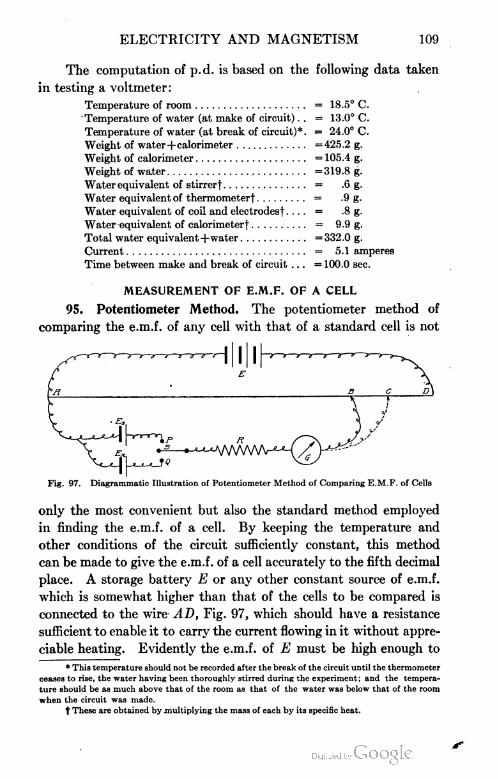
ELECTRICITY AND MAGNETISM 109
The computation of p.d. is based on the following data taken
in testing a voltmeter:
Temperature of room = 18.5° C.
Temperature of water (at make of circuit) . . = 13.0° C.
Temperature of water (at break of circuit)*. = 24.0° C.
Weight of water+calorimeter =425.2 g.
Weight of calorimeter = 105.4 g.
Weight of water = 319.8 g.
Water equivalent of stirrerf = .6 g.
Water equivalent of thermometerf = .9 g.
Water equivalent of coil and electrodesf .... = .8 g.
Water equivalent of calorimeter! = 9.9 g.
Total water equivalent+water =332.0 g.
Current = 5.1 amperes
Time between make and break of circuit ... = 100.0 sec.
MEASUREMENT OF E.M.F. OF A CELL
95. Potentiometer Method. The potentiometer method of
comparing the e.m.f. of any cell with that of a standard cell is not
Fig. 97. Diagrammatic Illustration of Potentiometer Method of Comparing E.M.F. of Cells
only the most convenient but also the standard method employed
in finding the e.m.f. of a cell. By keeping the temperature and
other conditions of the circuit sufficiently constant, this method
can be made to give the e.m.f. of a cell accurately to the fifth decimal
place. A storage battery E or any other constant source of e.m.f.
which is somewhat higher than that of the cells to be compared is
connected to the wire A D, Fig. 97, which should have a resistance
sufficient to enable it to carry the current flowing in it without appre
ciable heating. Evidently the e.m.f. of E must be high enough to
* This temperature should not be recorded after the break of the circuit until the thermometer
ceases to rise, the water having been thoroughly stirred during the experiment; and the tempera
ture should be as much above that of the room as that of the water was below that of the room
when the circuit was made.
t These are obtained by multiplying the mass of each by its specific heat.

110 ELECTRICITY AND MAGNETISM
maintain a p.d. between A and D greater than the e.m.f. of either
cell. The standard cell Es, and the cell Ex, whose e.m.f. is unknown,
are connected to a double throw switch S, so that either one can be
put in series with the resistance R, the galvanometer G, and a mov
able wire which can be put in contact with the wire AD at any such
point as B. Since B is at a higher potential than A, if the switch
were on P, a current would flow along BGRP to A were it not for
the cell, Es; if, however, the e.m.f. of Es is exactly equal to the
p.d. from B to A, the electrical pressure tending to send a current
in the opposite direction, i.e., along APRG to B, will exactly
offset the p. d. from B to A along the potentiometer wire, so that
no current will flow in the galvanometer circuit. Evidently under
these conditions the e.m.f. of Es is exactly equal to the p.d. from
B to A and is proportional to the length of the wire AB. When
the movable wire is to the right of B, the p.d. along the wire will
be greater than that of Es and a current will flow through the gal
vanometer to the left; likewise, if the movable wire is to the left
of B, the e.m.f. of E3 would be greater than the p.d. along BA and
a current would flow through the galvanometer to the right. Evi
dently, then, some current will be drawn from E, while the position
of B for no deflection of the galvanometer is being found. In order
then to protect Es and also to prevent polarization, this current
should be made extremely small by having R very large, say 20,000
to 30,000 ohms. This large resistance will also protect the galva
nometer G. When the point of balance B has been found, R may
be made very small or even cut out of the circuit entirely, thus
enabling one to locate the point B more accurately. In exactly
the same way, the point C is found when the switch is on Q thus
cutting Es out of the circuit and throwing Ex into the circuit. The
e.m.f. of Ex is then equal to the p.d. from C to A, and is proportional
to the length of the wire AC. Then, with a perfectly uniform wire,
the following equation evidently is true:
.E„_p.d. from 2? to A _ length AB
Ex p.d. from C to A length AC
The following data taken to find the e.m.f. of a given Leclanche"
cell by comparison with a Weston standard cell will serve to illus
trate. The temperature of the room was 25° C. The e.m.f. of

ELECTRICITY AND MAGNETISM 111
the Weston standard cell at 20° C. is 1.0183 volts and at any other
temperature near that is given by the equation:
E= 1.0183 - 0.00004 (t- 20)
Hence Ea = 1.0181 volts. With Es in the circuit, the galvanometer
showed no deflection when A B was 40.05 cm. When the Leclanche"
cell was in the circuit, a similar balance was obtained when AC was
61.95 cm. Substituting these values in the above equation gives
1.0181 40.05
e.m.f. of Leclanche cell 61 .95
Hence the e.m.f. of the Leclanche' cell = 1 •0181X61.95
40.05
= 1.575 volts
Ans. 1.575 volts
EXAMPLES FOR PRACTICE
1. 'If in Fig. 94, the work required to carry a unit+ electro
static charge from D to A is 0.01 of an erg, what is the p.d. between
A and D along ABCD1 Ans. 3 volts
2. (a) If a current of 1.5 amperes flows in the circuit of Ex
ample 1, how many ergs of work will be done by the current in
5 sec? (Note.—An ampere equals 3 billion electrostatic units per
second passing through the circuit.) Ans. 225,000,000 ergs
(b) To how many joules of work is this equivalent?
Ans. 22.5 joules
(c) What is the rate of expenditure of energy in the portion
of the circuit ABCD, in watts? (Note.—1 watt equals 1 joule
per sec.) Ans. 4.5 watts
(d) In any portion of an electric circuit how may we obtain
the rate of expenditure of energy in watts?
Ans. (p. d. in volts) X (I in amperes)
3. With a standard Weston cell at Es, Fig. 97, the galvanometer
showed no deflection when AB was 35.15 cm., the temperature of
the room being 22.5° C. When the switch S was thrown over to Q
with a dry cell at Ex there was no deflection of the galvanometer
when AC was 51.04 cm. Find the e.m.f. of the dry cell used. First
find the e.m.f. of the Weston cell at the given temperature.
fe.m.f. of Weston cell at 22.5° C. = 1.0182 volts
\e.m.f. of dry cell used =1.478 volts
Ans. < 6
le

112 ELECTRICITY AND MAGNETISM
4. The following data was taken on a voltmeter test by the
calorimetric method of Section 94. Compute the p. d. across the
coil used; compare this p.d. with the voltmeter reading, and give
the error of the voltmeter for this part of the scale in volts.
Temperature of room 20° C.
Temperature of water (at make of circuit) 11.8° C.
Temperature of water (at break of circuit) 28.0° C.
Weight of water +calorimeter 481.2 g.
Weight of calorimeter 110.1 g.
Water equivalent of stirrer 1.1 g.
Water equivalent of thermometer 1.2 g.
Water equivalent of coil and electrodes 9 g.
Water equivalent of calorimeter 10.5 g.
Ammeter reading 7.2 amperes
Average voltmeter reading 40.4 volts
Time between make and break of circuit 90 sec.
(Computed p.d. across coil is 40.3 volts
\ Error in voltmeter is +.1 volt
MEASUREMENT OF RESISTANCE
96. Resistance by Substitution. It is evident from Ohm's
law, 7 = J7r, or amperes = V.° *S , that if the current 7 and the e.m.f.
R ohms
E of two circuits are the same, then the resistance R of each circuit
must be the same. Let the current from the battery E, Fig. 98,
Fig. 98. Diagram of Circuit for Measurement of Resistance by Substitution
be passed through the coil whose resistance X is to be measured
through an ammeter A and through a variable control resistance
jRi. It is evident that if for a second circuit we use the same cir
cuit, except that we replace X by an adjustable known resistance
R, then R will be equal to X when the proper resistance has been

ELECTRICITY AND MAGNETISM 113
taken out of R to just make the ammeter reading the same as it was
when X was in the circuit. In taking the data, then, one has only
to observe the ammeter reading when the switch S is on M; then to
turn the switch on to N and adjust R until the ammeter reads the
same as before. Since the cell E in the meantime may have polarized
somewhat, the switch should be thrown back to M to see that the
current has not changed. If it has, the ammeter reading should
again be carefully noted and the switch again thrown over to N and
R adjusted to give this latter ammeter reading. These adjustments
should be repeated until, when the switch is thrown from M to N,
Fig. 99. Standard Plug-Type Resistance Box and Wheatstone Bridge
Courtesy of Leeds and Northrwp Company, Philadelphia
the ammeter reading does not change. Under these conditions,
R = X. When the circuit is first closed through X, all of the con
trol resistance Ri should be reduced until a convenient ammeter
reading is obtained, using a current which is not large enough to
heat X appreciably. The contact points of the switch should be
scrupulously clean, as a poor contact has the same effect as putting
resistance into the circuit. The points may be cleaned with benzine.
The plugs of the resistance box should also be thoroughly cleaned
with benzine. One of the most common forms of resistance box
which may be used for this work is shown in Fig. 99, the principle
of which is illustrated in Fig. 100. The current in passing through
the box, from P to Q, or vice versa, must traverse the coil below the
plug B, but not the plugs A and C since these plugs are in. Hence,

114 ELECTRICITY AND MAGNETISM
Fig. 100. Section Showing Typical Constructionof Resistance Box
at any time the resistance of the box through which the current flows
is given by the sum of the ohms marked on the box by each plug
which is out. The low re
sistances are made of short
pieces of heavy manganin
wire, the higher ones of
longer pieces of fine wire,
which, when a considerable
length has to be used, are
wound on a spool such as S
in the figure. Manganin
wire is used because it has an extremely low temperature coefficient,
about .00001 per degree C, and because, with proper use, its
resistance will remain practically constant for years. For these
reasons, its use has been recommended for all standard resistances
by the German Physikalische Technische Reichsanstalt which corre
sponds to our Bureau of Standards at Washington.
97. Resistance by VoItmeter=Ammeter Method. Whenever
an accurate voltmeter and ammeter are available, the following
method for finding the value of an unknown resistance will be found
very convenient and expeditious, and is the method much used by
the practical engineer. If the accuracy of the instruments is not
known, they should be compared with standard instruments and
their errors noted, or else should be calibrated according to one of
the methods previously
v \\ ~f" given. . The conductor
whose resistance X is to
be found is connected in
series with a battery E,
or other generator, and
an ammeter A, and the
voltmeter is shunted
across X as in Fig. 101.
According to Ohm's law,
r_p.d.
Fig. 101. Diagram for Obtaining Resistance by. Voltmeter-Ammeter Method
R
we then have
R=?f or ohms =
volts
amperes'
so that the resistance of the coil X in

ELECTRICITY AND MAGNETISM 115
ohms is simply the voltmeter reading in volts divided by the am
meter reading in amperes. Obviously the ammeter, when connected
as above, registers the
combined current flowing
through the conductor X
and the voltmeter V, and
we have applied Ohm's
law as though all of this
current flowedthrough X
and none througli the
voltmeter; however, the
error thus introduced is
negligible, providing the
current carried by the
voltmeter is very small in comparison to that carried by X, and this
will be the case when X is small in comparison to the voltmeter
resistance. If X is more than 1 per cent of the voltmeter resistance
and results are to be expected within 1 per cent, the apparatus must
then be connected as in Fig. 102. We are now measuring a resist
ance X which is very large in comparison to the resistance of the
ammeter so that the p. d. across X is practically the same as it is across
both X and A, and the ammeter registers the current flowing through
X only. Hence we may
apply Ohm's law as before: —(f +
X (in ohms) =
Fig. 102. Diagram of Circuit for Method of Fig. 101When Unknown Resistance Approaches That of
Voltmeter
\±
A'wUvWWv—
p.d. (in volts)
/ (in amperes)
The value of X thus
obtained evidently in
cludes the resistance of
the ammeter, which,
however, may usually be
neglected in any prac
tical problem of this sort.
However, if one wishes
to correct X by sub
tracting the ammeter resistance, it also may be found by the
same method. Connect the voltmeter across the ammeter as in
Fig. 103. Vary the resistance of R until the ammeter reading is
Fig. 103. Diagram of Circuit for . Finding theResistance of Ammeter

116 ELECTRICITY AND MAGNETISM
as large, or nearly as large, as the ammeter registers. Since the
ammeter registers the current through itself and the voltmeter gives
the p. d. across the ammeter, evidently the resistance of the ammeter
is the voltmeter reading in volts divided by the ammeter reading
in amperes. However, the p.d. across the ammeter will be very
small since its resistance is small and consequently the voltmeter
to be used should be a millivoltmeter, i.e., one reading to thousandths
of a volt.
98. Resistance by Wheatstone Bridge. Discussion of Method.
When a high degree of accuracy in resistance measurements is desired,
the Wheatstone bridge is the instrument which is much employed,
It is used in testing laboratories when the previous methods are not
sufficiently accurate, and when the larger currents and voltages
used in these methods are objectionable on account of heating
Fig. 104. Water Analogy Illustrating Principle of Wheatstone Bridge
effects and consequent changes in resistance. Its value will be even
more appreciated after we have learned how it is used in locating
faults and grounds in telegraph and telephone circuits.
The water analogy of Fig. 104 will help to make clear the theory
of the Wheatstone bridge. Suppose a current of water which is
flowing in the pipe P, divides at A, part of the current I, flowing
through the upper branch which consists of pipes Pi and P2 to B
and on; the other part of the current 72 flowing through the lower
branch which consists of pipes P3 and P4 to B and on. The differ
ence in pressure at the ends of the branch ACBis evidently the same
as the difference in pressure at the ends of the branch ADB, since
their ends have a common meeting point. Since then the decrease
in hydrostatic pressure is the same along ACB as along ADB,
it follows that for any point C in the upper branch which has a given

ELECTRICITY AND MAGNETISM 117
pressure there must be some point D in the lower branch having
the same pressure. Hence, if a pipe be connected between two
such points as C and D, no current will flow through it.
Similarly, if we consider a current of electricity flowing from
the battery E of Fig. 105, dividing at A, and let Ii be the part of it
which flows through Ri and R2 to B and back to E, and let 72 be
the other part which flows through R3 and i?4 to B and back to E,
it is evident that no current will flow from C to D through the
galvanometer G, if C and D are at the same electrical pressure,
Fig. 105. Standard Diamond Diagram Illustrating Principle of Wheatstone Bridge
i.e., the same potential. Let C and D in Fig. 105, be two such
points. Then from Ohm's law we have
p.d.i = 7!.Ri = /2 R3
and
p.d.2 = h R2 = h Ri
and dividing the former of these equations by the latter we have
R_y_Rj
R* R*
If any one of these resistances is unknown, it may be computed if
the other three resistances are known. Thus if R2, Ra, and Ri are
6, 8, and 12 ohms, respectively, then
6 12
Ri= -~~: = i ohms
1 u
Ans. 4 ohms

118 ELECTRICITY AND MAGNETISM
If Ri, R2, and i?3 are 5, 10, and 15 ohms, respectively, then
J5_ = 15
10 Ri
Ans. 30 ohmsRi== 15X10 = 3Q ohms
"Slide-Wire Bridge". If we examine carefully the slide-wire
bridge shown in Fig. 106 and compare the relative position of resist
ances, galvanometer, etc., with 'the corresponding positions which
these occupy in Fig. 105, we shall find everything essentially the
same. Heavy strips, having negligible resistance, and to which the
connections are made, are mounted on a board for the sake of con-
WffOTWO'
21
I
5) (£
LiLiililliJ I i^tliiuti iiilimiu ill nli i nlnyi i ml I I
5j AV
Fig. 106. Typical Diagram of Slide-Wire Bridge
venience. A German-silver wire mounted above a meter stick
constitutes the lower branch of the bridge through which the current
h flows; this is divided electrically into the resistances, Ri and Rt,
by the sliding contact D. The resistance to be measured is placed
at either of the positions, Ri or R2, Fig. 106. Since the resistance
of a uniform wire is proportional to its length, in place of the
ratio —3, we may substitute in the equation developed for the
Ri
bridge, the ratio jen£th of R3 as reaj dipg^jy on tjje meter stick
length or ii4
beneath the wire. In using the bridge, Ki should always be closed
-.

ELECTRICITY AND MAGNETISM 119
first, and then A"2 when the bridge is being balanced. The reason
for this will be explained when the subject of self-induction is treated.
For this purpose a double contact key like that shown in Fig. 107
is very convenient. A disk of insulating material at M, Fig. 108,
prevents any connection between the battery and the galvanometer
circuits. While balancing the bridge, much time will be saved with
most types of galvanometers if a so-called damping key, K3, is con
nected to wires running to the two terminals of the galvanometer.
When this is closed, the galvanometer will be brought to rest in
a comparatively short time. For this purpose a single-contact
key is used.
Illustrative Example. The conductor whose resistance X was
to be measured was placed at Ru Fig. 106, and the sliding contact S
was placed so that D was on the 50 cm. mark of the meter stick.
With no plugs out of the resistance box placed at R2, the galvanometer
was deflected strongly in one direction when Ki and K2 were closed.
These keys were then opened and the galvanometer brought to rest
by closing Ar3. Then 10 ohms were taken out of the box at i?2 and
a test for a balance showed a deflection of the galvanometer in the
same direction. With 20
ohms out of the box, the ^
Opposite direction. Hence Fig. 108. Double Contact Key Showing Method of
the resistance X must lie
between 20 and 30 ohms since R3 and i?4 are now equal. By repeat
ing the above tests, it was found that 25 ohms at i?2 produced a
Fig. 107. Standard Double-Circuit Key
Courtesy of Leeds and Northrup Co., Philadelphia, Pa.
deflection was still in the
same direction, but with
30 ohms it was in the

120 ELECTRICITY AND MAGNETISM
deflection one way, while 26 ohms produced a deflection the opposite
way. [Hence the resistance X must lie between 25 and 26 ohms.
Then with 25 ohms at i?2, a balance would be obtained by sliding
S a little to the right, since R2 is now less than X and therefore i?4
must be less than R3. A few trials showed the position of D for a
balance to be at 50.8 cm., or the length of R3 was 50.8 cm., and the
length of Ri was 49.2 cm. Therefore
Z_50.8
25
X=
49.2
25X50.8
49.2
= 25.81 ohms
In order to eliminate any bridge errors due to nonuniformity
in the wire, etc., the unknown resistance was then placed at R2 and
1) IT1000 10 10
II1000
II II
II
II400
2 3
R4
I) 11
11 <x
40II
31
30
II II
Fig. 109. Diagram of "Post-OfEce Box" Bridge
the resistance box at Ri with 25 ohms out. A balance was obtained
when D was at 49.12 cm., so that the length of R3 was 49.12 cm.
and that of Ri was 50.88 cm. Hence, for this balance X is given by
25 = 49.12
X~ 50.88
Where3r=25X50 88=25 89 ohms
49.12
The mean of these two determinations gives the correct value
of X as 25.85 ohms. Ans. 25.85 ohms

ELECTRICITY AND MAGNETISM 121
"Post-0ffice Box" Bridge. The following convenient and much
used form of the Wheatstone bridge derived its name from the fact
that it was first used by the telegraph department of the British
post-office. As in the previously discussed forms of the bridge, it
will be noted in Fig. 109, which shows the post-office box diagram-
matically, that the current from E flows to A when key Ki is closed
and there divides, part flowing through Ri and R2 back to the bat
tery and part through i?3 and Ri back to the battery. As before,
the galvanometer is connected between C and D. Fig. 99 shows the
post-office box as it appears in actual form. The resistance to be
measured is always placed at R2. For convenience we will use
the equation
lh = Rj
R2 Ra
in the following equivalent form
R1=R}
Ra R3
The easiest way to find the unknown i?2, is first to make i?i
equal to i?3, say 10 ohms each, and then adjust Ri until an increase of
1 ohm will cause an opposite deflection of the galvanometer. We
know, then, that the value of the unknown is within 1 ohm of the
value of R^ If, for example, we take as the unknown resistance
the coil used in the illustrative example, page 119, when i?4 was
25 ohms, the galvanometer would deflect one way and when Ra
was 26 ohms, it would deflect the opposite way. If, then, Ri is
made 10 ohms and R3 is made 100 ohms, or a ratio of 10 : 100 is
used, it is evident that a balance would now be obtained for some
value of Ra between 250 and 260 ohms. Suppose that 258 ohms
at Ra caused the galvanometer to deflect one way, and 259 ohms
caused it to deflect the other way. If, then, we use 10 : 1,000 for the
ratio Ri : i?3, we should get a balance when R4 is between 2,580
ohms and 2,590 ohms. Practically no deflection of the galva
nometer was observed when Ri was 2,586 ohms. Hence the resist
ance R2 of the coil is given by
i?2 ^ 10
2,586 1,000
R2 = 25.86 ohms Ans. 25.86 ohms

122 ELECTRICITY AND MAGNETISM
EXAMPLES FOR PRACTICE
1. In measuring the resistance of the coils of wire on the
electromagnet of an electric bell, "by substitution" it was found that
when the bell was placed at X, Fig. 98, and the clapper held so that
a continuous current flowed through the bell, that the ammeter
reading remained the same, when the switch S was thrown from
M to N, if R was made 1.25 ohms. What was the resistance of
the electric bell? Ans. 1.25 ohms
2. An ammeter placed in series with a 16 c-p. carbon filament
lamp reads 0.5 ampere while a voltmeter connected across the lamp
reads 110 volts. What is the resistance of the lamp? Ans. 220 ohms
3. When the ammeter was placed in series with a 16 c-p.
tungsten filament, it read 0.182 ampere, while the voltmeter con
nected across the lamp read 110 volts. What was the resistance
of this lamp? Ans. 604+ ohms
4. An ammeter and a millivoltmeter when connected as in
Fig. 103 are found to read 5 amperes and 250 millivolts, respectively.
What is the resistance of the ammeter? (1 millivolt = .001 volt.)
Ans. 0.05 ohm
5. A voltmeter and a milliammeter, when connected in series
to the lighting circuit, read 110 volts and 55 milliamperes, respec
tively. What is the resistance of the voltmeter? (Remember that
when connected this way the ammeter reads the current through
the voltmeter and the voltmeter, of course, always reads the p. d.
between its own terminals. Also 1 milliampere = .001 ampere.)
Ans. Resistance of voltmeter = 2000 ohms
6. In Fig. 102 a telegraph relay, Section 107, is placed at X,
2 storage cells at E, a milliammeter at A, and an ordinary voltmeter
at V. The ammeter reads 21 milliamperes and the voltmeter reads
4.2 volts. What is the resistance of the windings on the relay?
Ans. 200 ohms
7. In Example 6 we neglected the ammeter resistance, why is
this permissible? Why, in the same problem, must the voltmeter
be shunted across both the relay and the ammeter?
8. Diagram and explain how to find an unknown resistance:
(a) by substitution; (b) by the voltmeter-ammeter method when the
unknown resistance is small in comparison to that of the voltmeter,
and also when it is large; (c) by the Wheatstone bridge method.

ELECTRICITY AND MAGNETISM 123
ELECTROMAQNETISM
99. Magnetic Properties of a Loop. We have seen in Part I,
Section 48, that an electrical current is surrounded by a magnetic
field the direction of which is given by the right-hand rule—namely,
that if the wire is grasped with the right hand, the thumb pointing
along the wire in the direction in which the current is flowing, then
the fingers will encircle the wire in the same direction as the magnetic
lines of force. We have seen also that a loop or a coil of wire through
which a current flows produces a magnetic field of the shape shown
in Fig. 110. Now if such a loop is suspended* in the manner shown
in Fig. Ill, while a current
from a dry cell B is sent
through it, the loop will turn
and come to rest in an east-
and-west plane, so that the
face of the loop from which
the magnetic lines emerge
is toward the north. (See
right-hand rule mentioned
above and also Fig. 110.)
In other words, the loop
will be found to behave
with respect to the earth
or to any other magnet,
precisely as though it were
a flat magnetic disk whose boundary is the wire, the face which
turns toward the north, that is, that from which the magnetic lines
emerge, being an N pole and the other an S pole.
100. Magnetic Properties of a Helix. If a wire carrying a
current be wound in the form of a helix and held near a suspended
magnet as in Fig. 112, the coil will be found to act in every respect
like a magnet, with an N pole at one end and an S pole at the other.
This result might have been predicted from the fact that a single
*To make the apparatus of Fig. Ill, slide a piece of rubber tubing R over a U-shapedtube U and then slide the same end of the LT-tube into a thistle tube T of such a size that the piece
of rubber tubing forms a joint between the two tubes, preventing the mercury from running out.
The top end of the U-tube should be placed in a flame and allowed to contract, but should still
permit the wire dipping into it to fit loosely—this prevents the wire from sticking to the sides of
the tube and hence allows it to turn very freely. For the suspension of the loop, untwist a foot
of silk twist and use one of the strands.
Fig. 110. Diagram of Lines of Force Passing througha Coil Bearing a Current

124 ELECTRICITY AND MAGNETISM
loop is equivalent to a flat-disk magnet. For when a series of such
disks is placed side by side, as in the helix, the result must be the
same as placing a series of disk magnets
in a row, the N pole of one being directly
in contact with the S pole of the next,
etc. These poles therefore all neutralize
each other except at the two ends. We
therefore get a magnetic field of the
shape shown in Fig. 113. Such a helix
may be made by threading a copper wire
through a cardboard or a sheet of cellu
loid. If iron filings are then sifted onto
the cardboard, and the board is tapped
gently while a strong current is sent
through the helix, the iron filings will
become little induced magnets and point
in the direction of the magnetic field. It
will be noticed that not all of the "mag
netic flux" of lines of force is through the
coil, but that some of the lines encircle
each wire where it passes to the outside of
the coil and hence do not add to the mag
netic strength of the helix. This flux of
Fig. 111. section of Apparatus lines between the wires is known as the
Showing Magnetic Properties "laoVorro fluv"of a Suspended Coil leakage HUX .
Fig. 112. Experiment Showing Magnetic Properties of Helix
101. Rules for North and South Poles of a Helix. The right-
hand rule, as given in Part I, Section 48, is sufficient in every case

ELECTRICITY AND MAGNETISM 125
Fig. 113. Magnetic Field of a Helix Bearinga Current
^Direction of Magnetic Force
to determine which is the N and which the S pole of a helix, i.e.,
from which end the lines of magnetic force emerge from the helix
and at which end they enter
it. But it is found conven
ient, in the consideration of
coils, to restate the right-hand
rule in a slightly different way,
thus:
If the coil is grasped in
the right hand in such a way
that the fingers point in the direc
tion in which the current is
flowing in the wires, the thumb
will point in the direction of the north pole of the helix, Fig. ltJ±.
Similarly, if the sign of the poles is known, but the direction of
the current unknown, the latter may
be determined as follows :
If the right hand is placed with
the palm against the coil and with
the thumb pointing in the direction of
the lines of force (i.e., toivard the
north pole of the helix) , the fingers will
pass around the coil in the direction
in which the current is flowing.
102. The Electromagnet. If a core of soft iron be inserted in
the helix, Fig. 115, the poles will be found to be enormously stronger
than before. This is because the
core is magnetized by induction from
the field of the helix in precisely the
same way in which it would be mag
netized by induction if placed in the
field of a permanent magnet. The
new field strength about the coil is
now the sum of the field due to the
core and that due to the coil. The
introduction of the iron core into the helix almost entirely prevents
the "leakage flux" so that this also adds to the strength of the
magnet. If the current is broken, the core will at once lose the
'oo of Curre'1
Fig. 114. Diagram Showing Rule forDetermining Polarity of a Helix
Fig. 115. Simple Electromagnet

126 ELECTRICITY AND MAGNETISM
greater part of its magnetism. If the current is reversed, the polar
ity of the core will be reversed. Such a coil with a soft-iron core
is called an electromagnet.
The strength of an electromagnet can be very greatly increased
by giving it such form that the magnetic lines can remain in iron
throughout their entire length instead of emerging into air, as they
do in Fig. 115. For this reason electromagnets are usually built in
the horseshoe form and provided with an armature A, Fig. 116,
through which a complete iron path for the lines of force is estab
lished, as shown in Fig. 117. The strength of such a magnet depends
chiefly upon the cross-section of the iron core and the number of
ampere-turns which encircle it, the expression ampere-turns denoting
the product of the number of turns of wire about the magnet by the
Fig. 116. Electromagnet with Armature Fig. 117. Section of ElectromagnetShowing Magnetic Circuit
number of amperes flowing in each turn. Thus a current of ttt
ampere flowing 1,000 times around a core will make an electromag
net of precisely the same strength as a current of 1 ampere flowing 10
times about the core.
APPLICATIONS OF ELECTROMAGNETS
103. The Electric Bell. The electric bell, Fig. 118, is one of
the simplest applications of the electromagnet. When the button P
is pressed, the electric circuit of the battery is closed, and a current
flows in at A, through the magnet, over the closed contact C, and
out again at B. But no sooner is this current established than the
electromagnet E pulls over the armature a, and in so doing breaks the
contact at C. This stops the current and demagnetizes the magnet

ELECTRICITY AND MAGNETISM 127
E. The armature is then thrown back against C by the elasticity of
the spring s which supports it. No sooner is the contact made at C
than the current again begins to flow and the former operation is
repeated. Thus the circuit
is automatically made and
broken at C and the ham
mer H is in consequence set
into rapid vibration against
the rim of the bell.
104. Electric Tuning=
Fork. It is often desirable
to keep a tuning-fork in a
uniform state of vibration.
For this purpose an elec
trically driven fork like that
of Fig. 119 is used. When
the battery is connected to
A and B, the current flows
through the electromagnet M, thus attracting both prongs' of the
fork and at the same time breaking the circuit at C. The elasticity
of the prongs then throws them back making the circuit at C and
the operation is repeated the number of times per second equal to
the frequency of the fork. Thus the operation of such a fork is
exactly the same as that of the electric bell.
Fig. 118. Adaptation of Electromagnet to SimpleElectric Bell
Fig. 119. Electric Tuning-Fork
Courtesy of Central Scientific Company, Chicago, Illinois
1 05. The Telegraph. The electric telegraph is another simple
application of the electromagnet. The principle is illustrated in
Fig. 120. As soon as the key K at Chicago, for example, is closed,

128 ELECTRICITY AND MAGNETISM
the current flows over the line to New York, we will say. There it
passes through the electromagnet m, and thence back to Chicago
through the earth. The armature b is held down by the electro
magnet m as long as the key K is kept closed. As soon as the cir
cuit is broken at K, the armature is pulled up by the spring d. By
means of a clockwork device, the tape e is drawn along at a uniform
rate beneath the pencil or the pen carried by the armature b. A
very short time of closing of K produces a dot upon the tape, ?
longer, time a dash. As the Morse, or telegraphic, alphabet consists
Fig. 120. Simple Diagram of Telegraph Circuit between Chicago and New York
of certain combinations of dots and dashes, any desired message
may be sent from Chicago and recorded in New York.
AMERICAN MORSE CODE
A * Mi J S • • •
B — • • • K — • — T —
C • • • L U 4 • . • • —
D — • • M V • • • — 5
E • N — • w
F • — ' .0 • • X • — • • 7 ..
G —— • P Y • • • • 8 — • • • •
H • • • • Q • • — • Z • • • * 9
I • • R • • • 1 0 - "
In modern practice the message is not ordinarily recorded on a
tape, for operators have learned to read messages by ear, a very short
interval between two clicks being interpreted as a dot, a longer
interval as a dash.
The first commercial telegraph line was built between Balti
more and Washington by S. F. B. Morse. It was opened on May 24,
1844, with the now famous message : "What hath God wrought?"

ELECTRICITY AND MAGNETISM 129
106. The Relay and the Sounder. On account of the great
resistance of long lines, the current which passes through the electro
magnet is so weak that the armature of this magnet must be made
Fig. 121. Telegraph Relay
very light in order to respond to the action of the current. The
clicks of such an armature are not sufficiently loud to be read easily
by an operator. Hence, at each station there is introduced a local
circuit which contains a local battery, and a second and heavier
electromagnet which is called a sounder. The electromagnet on
Fig. 122. Standard Morse Local Sounder
Courtesy of Postal Telegraph-Cable Company
the main line is then called the relay, see Figs. 121, 122, and 123.
The sounder has a very heavy armature, A, Fig. 122, which is so
arranged that it clicks both when it is drawn down by its electro

130 ELECTRICITY AND MAGNETISM
magnet against the stop S and when it is pushed up again by its
spring, on breaking the current, against the stop t. The interval
which elapses between those two clicks indicates to the operator
whether a dot or a dash is sent. The current in the main line simply
serves to close and open the circuit in the local battery which operates
the sounder, see Fig. 123. The electromagnets of the relay and the
sounder differ in that the former consists of many thousand turns
of fine wire, usually having a resistance of about 150 ohms, while
the latter consists of a few hundred turns of coarse wire having
ordinarily a resistance of about 4 ohms.
107. Plan of Telegraph System. The actual arrangement of
the various parts of a telegraphic system is shown in Fig. 123. When
an operator at Chicago wishes to send a message to New York, he
Fig. 123. Actual Arrangement of Parts of Long Distance Telegraphio System
first opens the switch which is connected to his key, and which is
always kept closed except when he is sending a message. He then
begins to operate his key, thus controlling the clicks of both his own
sounder and that at New York. When the Chicago switch is closed
and the one at New York open, the New York operator is able to
send a message back over the same line. In practice a message is
not usually sent as far as from Chicago to New York over a single
line, save in the case of transoceanic cables. Instead, it is auto
matically transferred at, say Cleveland, to a second line which
carries it on to Buffalo, where it is again transferred to a third line
which carries it on to New York. The transfer is made in precisely
the same way as the transfer from the main circuit to the sounder
circuit. If, for example, the sounder circuit at Cleveland is length
ened so as to extend to Buffalo, and if the sounder itself is replaced

ELECTRICITY AND MAGNETISM 131
by a relay, called in this case a repeater, and the local battery by a
main battery, then the sounder circuit has been transformed into a
repeater circuit, and all the conditions are met for an automatic
transfer of the message at Cleveland to the Cleveland-Buffalo line.
There is, of course, no time lost in this automatic transfer.
The necessity of using relays rather than sounders in the line
on any long-distance circuit will be clearer after a study of the fol
lowing examples:
Examples. 1. Ordinary No. 9 telegraph wire has a resist
ance of 20 ohms to the mile, (a) What current will 100 Daniell
cells send through 200 miles of such wire, if there is included at each
end of the line, a relay of a resistance of 150 ohms? (Assume for
each cell an e.m.f. of 1.05 volts and an internal resistance of 5 ohms.)
(b) If the electromagnet in one of the above relays had 10,000 turns
of wire on its windings, how many ampere-turns were effective in
magnetizing it?
(a) Since the external resistance, 4000 ohms for the line and
300 ohms for the relays, is large in comparison to the internal
resistance, the cells should be connected in series. Hence
I= 100X1.05
(200 X20) + (2 X 150) + (100 X 5)
= .0219 Ans. 0.0219 ampere
(b) Ampere-turns = amperesXturns
= .0219X10,000 = 219
= 219 ampere-turns
Ans. 219 ampere-turns
2. If sounders having a resistance of 4 ohms each and 600
turns on the electromagnet had been used in place of the relays on
the above telegraph line, how many ampere-turns would have been
effective in magnetizing their electromagnets?
T= 100X1.05
~ (200X20) + (2X4)+ (100X5)
= .0233
or current = .0233 ampere
ampere-turns = .0233 X600 = 13.98 Ans. 13.98 ampere-turns
The two examples just given show that the current is nearly
as large with relays in the line as with sounders, but with sounders

132 ELECTRICITY AND MAGNETISM
in the line, the ampere-turns are not sufficient to magnetize their
electromagnets due to the small number of turns on a sounder,
whereas with relays in the line the ampere-turns are sufficient to
magnetize the electromagnet of the relay enough to actuate a light
armature which operates the local sounder circuit. Hence, we see
that on long lines relays must be used in the main line rather than
sounders.
EXAMPLES FOR PRACTICE
1. The plane of a suspended loop of wire is north and
south. A current is sent around the loop, passing from north to
south on the upper side. When the loop comes to rest, will the
face of the loop which was originally toward the east be toward
the north?
2. If one looks down on the ends of a U-shaped electromagnet,
does the current encircle the two coils in the same direction or in
opposite directions? Does it encircle the N pole in a clockwise or
counter-clockwise direction?
3. Draw a diagram of a short-distance telegraph line where
sounders are used without relays.
4. Draw a diagram of a long-distance telegraph line showing
how the relays and sounders operate.
5. How would you measure the resistance of the windings
on a sounder? On a relay?
6. If a telegraph line between Chicago and Milwaukee (85
miles) is built of No. 9 telegraph wire which has a resistance of
20 ohms per mile, what current will 40 Daniell cells send through
the line, if at each end there is connected a relay having a resistance
of 140 ohms? (Assume each cell to have an e.m.f. of 1 volt and an
internal resistance of 4.5 ohms.) Ans. 0.0185 ampere
7. *If in Example 6, sounders of a resistance of 5 ohms each
had been used at each end of the line, what current would the 40
Daniell cells have sent through the line? Ans. 0.0212 ampere
8. Find how many ampere-turns were effective in magnetiz
ing the electromagnet of one of the relays in Example 6, if the relay
had 10,500 turns of wire on it? Ans. 193+ ampere-turns
9. How many ampere-turns were effective in magnetizing
the electromagnet of one of the sounders in Example 7, if the sounder
had 600 turns of wire on it? Ans. 12.7 ampere-turns

ELECTRICITY AND MAGNETISM 133
10. Compare the answers to Examples 8 and 9 and explain
why relays, rather than sounders, must be placed "in the line"
on long telegraph lines.
108. Other Applications of Electromagnet. The electromagnet
is used in so many ways besides those already given that only men
tion of some of their uses will be made here, the applications being
left for the next paper. Telephone instruments, dynamos, motors,
induction-coils, automatic oper
ating switches, signalling devices,
etc., all utilize the electromagnet
in their construction. Strong
electromagnets are used exten
sively in foundries and other
places where large masses of
iron, rolled plates, steel beams,
pig iron, etc., are to be lifted.
Fig. 124 shows a large electro
magnet employed in the loading
of wire scrap.
CHEMICAL EFFECTS OF THE
ELECTRIC CURRENT
109. Electroplating. If the
tube of Fig. 89 is filled with a
solution of copper sulphate
(CuS04), platinum electrodes
being used, and the current from
one or two dry cells is sent
through it, the negative electrode
will soon be found to be covered
with a bright coat of copper.
The reason for this is obvious if
one remembers, from the treatment of batteries in Part I, that
all metallic ions in solution carry + charges of electricity. In
this case, then, the + charged copper ion is repelled by the positive
electrode and attracted by the negative electrode where it gives up its
charge to the plate and is deposited as metallic copper. Similarly, the
— charged S04 ion goes to the + plate where it unites with the H»
Fig. 124. Electromagnet Loading WireScrap
Courtesy of Link Belt Company, Chicago, Illinois

134 ELECTRICITY AND MAGNETISM
of the water forming H2S04, sulphuric acid, and thus frees the oxygen
of the water which rises as a gas to the surface. Reversing the cur
rent through the U-tube would cause copper to be deposited on the
other electrode and remove the copper from the one already plated,
since the copper-plated electrode is now the plus electrode and as
soon as the SO4 ions reach it, they unite with the copper and form
CuS04, copper sulphate.
The above experiment illustrates the whole process of electro
plating—a process which is used very extensively for obtaining
gold- and silver-plated ware; for nickel-plating iron so as to prevent
it from rusting; for copper-plating electric-light carbons so as to
increase their conductivity, and so on. In commercial work, the
positive plate, that is, the plate at which the current enters the
bath, is always made from the same metal as that which is to be
Fig. 125. Section of Silver-Plating Bath
deposited from the solution; for, in this case, the SO4 or other nega
tive ions dissolve this plate as fast as the metal ions are deposited
upon the other. The strength of the solution, therefore, remains
unchanged. In effect, the metal is simply taken from one plate
and deposited on the other. Fig. 125 represents a silver-plating
bath. The bars joined to the anode A are of pure silver. The
spoons to be plated are connected to the cathode K. The solution
consists of 500 g. of potassium cyanide and 250 g. of silver cyanide
in 10 1. of water.
110. Electrotyping. In the process of electrotyping, the page
is first set up in the form of common type. A mold is then taken in
wax or gutta-percha. This mold is then coated with powdered
graphite to render it a conductor, after which it is ready to be sus
pended as the cathode in a copper-plating bath, the anode being a

ELECTRICITY AND MAGNETISM 135
plate of pure copper and the liquid a solution of copper sulphate.
When a sheet of copper as thick as a visiting card has been deposited
on the mold, the latter is removed and the wax replaced by a type-
metal backing, to give rigidity to the copper films. From such a
plate, as many as a hundred thousand impressions may be made.
Practically all books which run through large editions are printed
from such electrotypes. The printed matter which you are now
reading was printed from such electrotypes, and yet the printing
is so distinct that the average reader would naturally think it had
been printed from the actual type used in setting up the original
form for the printed page.
111. Refining of Metals. If the solution consists of pure
copper sulphate, it is not necessary that the anode be of chemically
pure copper in order to obtain a pure copper deposit on the cathode.
Electrolytic copper, which is the purest copper on the market, is
obtained as follows: The unrefined copper is used as an anode. As
it is eaten up, the impurities contained in it fall as a residue to the
bottom of the tank and pure copper is deposited on the cathode
by the current. This method is also extensively used in the refin
ing of metals other than copper.
112. Chemical Method of Measuring Current. An ampere
will deposit in an hour 1.181 g. of copper, 1.203 g. of zinc, etc.
This fact is made use of in calibrating fine ammeters, since it
is possible to compute with great accuracy the strength of a current
which has deposited a given weight of metal in a known length of
time. This method of calibrating an ammeter has been treated in
Section 82.
113. Storage Batteries. A simple storage cell can be made
with two six-inch by eight-inch lead plates, screwed to a half-inch
strip of some insulating material, as in Fig. 126, and immersed in a
solution consisting of one part of sulphuric acid to ten parts of water.
Let a current from two bichromate cells C be sent through this
arrangement, an ammeter A or any low-resistance galvanometer
being inserted in the circuit. As the current flows, hydrogen bub
bles will be seen to rise from the cathode (the plate at which the
current leaves the solution), while the positive plate, or anode, will
begin to turn dark brown. At the same time the reading of the
ammeter will be found to decrease rapidly. The brown coating is

136 ELECTRICITY AND MAGNETISM
Fig. 126. Circuit Showing Simple Method of MakingStorage Battery
a compound of lead and oxygen called lead peroxide, Pb02, which
is formed by the action upon the plate of the oxygen which
is liberated precisely as in the experiment on the electrolysis of water,
Section 81. Now let the
Sav ^1 batteries be removed from
the circuit by opening the
key Ki, and let an electric
bell B be inserted in their
place by closing the key
K2. The bell will ring and
the ammeter A will indi
cate a current flowing in a
direction opposite to that of
the original current. This current will rapidly decrease as the
energy which was stored in the cell by the original current is expended
in ringing the bell.
This experiment illustrates the principle of the storage battery.
Properly speaking, there has been no storage of electricity, but only
a storage of chemical energy.
Two similar lead plates have been changed by the action of the
current into two dissimilar plates, one of lead, and one of lead peroxide.
In other words, an ordinary galvanic cell has been formed, for any
two dissimilar [metals in an electrolyte con
stitute a primary galvanic cell. In this case
the lead peroxide plate corresponds to the
copper of an ordinary cell, and the lead plate
to the zinc. This cell tends to create a cur
rent opposite in direction to that of the
charging current; i.e., its e.m.f. pushes back
against the e.m.f. of the charging cells. It
was for this reason that the ammeter reading
fell. When the charging current is removed,
this primary galvanic cell will furnish a cur
rent until the thin coating /of peroxide is used
up. The only important difference between
a commercial storage cell, Fig. 127, and the one which we have
here used is that the former is provided in the making with a much
thicker coat of the "active material", lead peroxide, on the positive
Fig. 127. Typical StorageBattery Plates

ELECTRICITY AND MAGNETISM 137
plate and a porous spongy lead on the negative, than can be formed
by a single charging such as we used. This material is pressed into
interstices in the plates, as shown in Fig. 127. The e.m.f. of the
storage cell is about 2 volts. Since the plates are always very
close together and may be given any desired size, the internal
resistance is usually small, so that the currents furnished may
be very large. They are sometimes as high as several thousand
amperes when many files of cells are connected to form a battery.
The usual efficiency of the storage cell is about 75 per cent,
i.e., but three-fourths as much electrical energy can be obtained from
it as is put into it.
114. Uses of Storage Battery. The storage battery is probably
most often thought of in connection with its use in electric automo
biles for power and lighting, and its use in gasoline-driven cars for
lighting, ignition, and self-starting devices. Its use, however, in
electric power plants is fully as important. In some power plants,
the generators are not large enough to supply the highest demand
for current during the day, at which time the storage batteries are
used to furnish part of the current, the storage batteries being
charged by the generator during that portion of the day when
the load is light. In some of the small power plants in small cities,
the current required for use in the daytime is so small that the
generator is not run at all, the power being supplied, during this
time of light load, by the storage batteries.
115. Edison Storage Battery. The new Edison storage
battery has about twice the output for the same weight as the lead
storage battery and is therefore eminently suited for traction pur
poses. The positive plate is made of nickel oxide, the negative is
pure iron in a steel frame, and the electrolyte is a solution of caustic
potash. It has an e.m.f. of about 1.2 volts, and an internal resist
ance somewhat higher than that of the lead cell and is consequently
not quite as efficient. Whether or not it will supplant the lead
storage battery is difficult to predict.
HEATING EFFECTS OF ELECTRIC CURRENT
116. Heat Developed in Wire by Electric Current. Let the
terminals of two or three dry cells in series be touched to a piece
of No. 40 iron or German-silver wire and the length of wire between

138 ELECTRICITY AND MAGNETISM
these terminals shortened to one-fourth inch or less. The wire
will be heated to incandescence and probably melted.
The experiment shows that just as in the charging of a storage
battery, the energy of the electric current was transformed into the
energy of chemical separation, so here in the passage of the current
through the wire, 'the energy of the electric current is transformed
into heat energy.
117. Energy Relations of Electric Current. If the energy
expended on a water turbine were measured, it would be found to
equal the quantity of water passing through the turbine, multiplied
by the difference in level through which the water falls. In just
the same way, it is found that when a current of electricity passes
through a conductor, the energy expended is equal to the quantity
of electricity passing, multiplied by the difference in potential between
the ends of the conductor. If the quantity of electricity is expressed
in coulombs and the p. d. in volts, the energy is given in joules, and
we have
volts X coulombs = joules
Since the number of coulombs is equal to the number of amperes
of current multiplied by the number of seconds
volts X amperes X seconds = joules
But a watt is defined as a joule per second, see Section 94. Hence,
the energy expended per second by the current, that is, the power
of the current, is given by the formula
volts X amperes = watts
118. Calories of Heat Developed in a Wire. The electrical
energy may be expended in a variety of ways when a current flows
between points of given p.d. For example, it may be spent in
producing chemical separation, as in the charging of a storage cell;
it may be spent in doing mechanical work, as is the case when the
current flows through an electric motor; or it may be spent wholly
in heating the wire, as was the case in the experiment of Section 116.
It will always be expended in the latter way when no chemical or
mechanical changes are produced by it. The number of calories
of heat produced per second in the wire of the last experiment is
found, then, by multiplying the number of joules expended by the
current per second, by the heat equivalent of the joule in calories,

ELECTRICITY AND MAGNETISM 139
that is, .24 calorie, since 1 calorie is 4.2 joules. Therefore when all
of the electrical energy of a current is transformed into heat energy,
we have
calories per second = volts X amperes X .24
The total number of calories II developed in t seconds will
be given by
tf = p.d.xCX<X-24
Thus a current of 10 amperes flowing in a wire whose terminals
are at a potential difference of 12 volts will develop in 5 minutes
10X 12 X 300 X.24 = 8640 calories.
Since by Ohm's law p.d. = CxR, we have, by substituting CR
for p.d. in the above formula
H = C2RXtXM
or, the heat generated in a conductor is proportional to the time, to the
resistance, and to the square of the current. This is known as Joule's
law, from the name of the man who first announced it as the result
of his experimental researches.
119. Incandescent Lamps. The ordinary incandescent lamp
consists of a carbon filament heated to incandescence by an electric
current, Fig. 128. Since the carbon would burn
instantly in air, the filament is placed in a highly
exhausted glass bulb. Even then it disintegrates
slowly. The normal life of a 16-candle-power lamp
filament is from 1,000 to 2,000 working hours. The
filament is made by carbonizing a special form of
cotton thread. The ends of the carbonized thread
are attached to platinum wires which are sealed
into the glass walls of the bulb, and which make
contact, one with the base of the socket and the
other with its rim, these being electrodes through
which the current enters and leaves the lamp.
The ordinary 16-candie-power lamp is most
commonly run on a circuit which maintains a potential difference
of either 110 or 220 volts between the terminals of the lamp. In
the former case, the lamp carries about .5 ampere of current, and
in the latter case, about .25 ampere. It will be seen from these
Fig. 128. SimpleCarbon Filament
IncandescentLamp

140 ELECTRICITY AND MAGNETISM
figures that the rate of consumption of energy is about 3.4 watts
per candle-power.
A customer usually pays for his light by the "kilowatt hour",
a kilowatt hour being the energy furnished in one hour by a current
whose rate of expenditure of energy is one kilowatt. Thus the rate
at which energy is consumed by a 16-candle-power lamp is
110X.5 = 55 watts, or .055 kilowatt. One such lamp running for
ten hours would therefore consume 550 watt hours of energy or
.55 kilowatt hour.
At the present time tungsten filaments are being used very
largely for incandescent lamps. They are nearly three times as
efficient as the carbon lamps, the "Mazda" form taking but 1.25
watts per candle. This is because they can be operated at much
higher temperatures than carbons can. They are, however, some
what more expensive.
120. Arc Light. When two carbon rods are placed end to end
in the circuit of a powerful electric generator, the carbon about the
point of contact is heated red hot. If, then,
the ends of the carbon rods are separated
one-fourth inch or so, the current will still
continue to flow, for a conducting layer of
incandescent vapor called an electric arc is
produced between the poles. The appearance
of the arc is shown in Fig. 129. At the +
pole a hollow, or crater, is formed in the car
bon, while the — carbon becomes cone shaped,
as in the figure. The carbons are consumed
at the rate of about an inch an hour, the +
carbon wasting away about twice as fast as
the — one. The light comes chiefly from the
+ crater, where the temperature is about
3,800° C, the highest attainable by man.
All known substances are volatilized in the electric arc.
The ordinary arc requires a current of 10 amperes and a p.d.
between its terminals of about 50 volts. Such a lamp produces
about 500* candle-power, and therefore consumes energy at the
*This is the so-called "mean spherical" candle-power. The candle-power in the direction
of maximum illumination is from 1,000 to 1,200.
Fig. 129. Arc Formation in
Arc Lamp

ELECTRICITY AND MAGNETISM 141
rate of about 1 watt per candle-power. This makes an arc light
about 3.5 times as efficient as an incandescent light. The recently
invented flaming arc, produced between carbons which have a com
posite core consisting of carbon, lime, magnesia, silica, or other
light-giving minerals, sometimes reaches an efficiency as high as
.27 watt per candle-power.
121. Arc=Light Automatic Feed. Since the two carbons of
the arc gradually waste away, they would soon become so far sepa
rated that the arc could not longer be maintained were it not for an
automatic feeding device which keeps the distance between the
carbon tips very nearly constant. Fig. 130 shows the essential
features of one form of this device. When no current is flowing
through the lamp, gravity holds the
carbon tips at e together; but as soon
as the current is thrown on, it ener
gizes the low-resistance electromag
net M, which is in series with the
carbons. This draws down the iron
plunger c, which acts upon the lever
L, and "strikes the arc" at e. But
the introduction of the resistance of
the arc into the circuit sABMt raises
the p.d. between s and t and thus
causes an appreciable current to flow
through the high-resistance magnet
N, which is shunted across this cir
cuit. This tends to raise the plunger c and thus to shorten the arc.
There is thus one particular length of arc for which equilibrium
exists between the effects of the series magnet M and the shunt
magnet N. This length the lamp automatically maintains. The
magnet 0 is the so-called "cut-out" inserted so that, if the lamp gets
out of order and the arc burns out, a current at once flows through
N and 0 of a strength sufficient to close the contact points at r
and thus permit the main current to flow on to the next lamp over
the path PrRQ.
122. Cooper=Hewitt Mercury Lamp. The Cooper-Hewitt mer
cury lamp, Fig. 131, is the most efficient of all electric lights, unless
it be the flaming arc. It differs from the arc lamp in that the incan
Fig. 130. Diagram of AutomaticFeed in Arc Lamp

142 ELECTRICITY AND MAGNETISM
descent body is a long column of mercury vapor instead of an incan
descent solid. The lamp consists of an exhausted tube three or four
feet long, the positive electrode at the top being a plate of iron,
and the negative electrode at the bottom a small quantity of mer
cury. Under a sufficient difference of potential between these
terminals, a long mercury-vapor arc is formed which stretches from
terminal to terminal in the tube. This arc emits a very brilliant
light, but it is almost entirely wanting in red rays. The efficiency
of the lamp is very high, since it requires but .3 watt per candle-
power. It is rapidly finding important commercial uses, especially
in photography. The
chief objection to it arises
from the fact that, on
account of the absence of
red rays, the light gives
objects an unnatural
color.
123. Household
and Artisans' Devices.
The application of elec
tric currents to heating
in recent years has taken
a veryprominent place in
Fig. 131. Cooper-Hewitt Mercury Lamp a multitude of devices
used in the trades and
in the home. Our highest temperatures are obtained in the electric
arc and the electric furnace. Electric disk stoves, teakettles, egg-
cookers, toasters, chafing-dishes, percolators, grills, water-heaters,
immersion coils, flatirons, curling-irons, mangles, foot-warmers,
radiators, shaving-mugs, milk-warmers, and sterilizers are some of
the household conveniences. Electric soldering-pots, soldering-irons,
glue-cookers, gluepots for cabinet-makers, melting-pots for lead alloys,
instantaneous heaters for soda fountains, mangles, fluting-irons,
automobile-tire vulcanizers, and electric welders are some of the
commercial applications of heating by the electric current.
The designer and the producer of these useful appliances are
interested in increasing the percentage of the energy of the electric
current which is transformed into heat available for the intended

ELECTRICITY AND MAGNETISM 143
purpose. The ratio of this available heat energy, or output,
to the electric energy, or input, for any of these devices is its
efficiency.
The consumer or user of these appliances is interested, not only
in their efficiency and cost of operation, but also in their convenience.
124. Efficiencies of
Household Water - Heaters.
The most commonly used
electric devices for heating
small quantities of water in
the home are the disk stove,
teakettle, and immersion
heater, similar to those shown
in Figs. 132, 133, and 134.
To find the efficiency of the heater use about 500 grams of water which
is 12° or 15° C. below room temperature; connect the heater, as shown
in Fig. 135, in series with an ammeter in the line and a voltmeter across
the line. Then turn on the current and stir the water continually,
observing the exact time when the water attains a temperature which
is 10° C. below room temperature, and again when the water attains
Fig. 132. Simple Electric Stove
Fig. 133. Electric Teapot Fig. 134. Electric Immersion Heater
a temperature which is 10° C. above room temperature. The useful
heat obtained, the output, during the observed time, is then expressed
in calories by multiplying the weight of the water in grams by its rise
in temperature in degrees centigrade. The corresponding electrical

144 ELECTRICITY AND MAGNETISM
energy used, the input, also expressed in calories, is given by any one
of the following equations : >
H = .24C*xRXt
H= .24CxExt
H= .2iXwattsX seconds
The efficiency, as in all machines, is then given by the equation:
. outputhiinciencv = ——-—
input
which in this case becomes
. grams of waterXdegrees centigrade rise in temperature
.24X watts X seconds
Example. A certain electric teakettle carrying 4.2 amperes
on a 110-volt circuit, which will heat 500 grams of water from
14° C. to 34° C. in 2 minutes has an efficiency of
500X20 . _K ,,24X4.2Xll0Xl20 = -75+' or75+Percent
Ans. .75+, or 75+ per cent
In exactly the same way the efficiency of heating water in an
ordinary teakettle with the disk stove of Fig. 132 may be found.
Fig. 135. Typical Circuit for Investigating Efficiency of Electric Heating Apparatus
In this case, however, the heating unit is not a part of the teakettle
so that a much larger portion of the heat is lost and consequently
its efficiency is much lower, being about 40 per cent. If the immer
sion heater of Fig. 134 is used, the heating unit is then completely
surrounded by water so that only a very small portion of the heat
is lost, and its efficiency is therefore very high, being about 95 per
cent when used with an ordinary dish to contain the wa'ter.

ELECTRICITY AND MAGNETISM 145
Fig. 136. Simple Wire Fuse
\ { { {
F: if 1 ""^^
WW iWO )
125. Protection of Circuits against Overheating. Fuses and
Circuit Breakers. If an electric-lighting circuit were to become
short-circuited accidentally, for example, by the wearing off of the
insulation on the drop-cord lead
ing to an electric lamp, the cur
rent flowing would be so large
that either the wiring in the
house, or the drop-cord, would
be melted at some point and the
heat would in many cases be sufficient to set fire to the building.
To protect circuits against accidents of this sort, fuses are intro
duced into the circuit. The fuse is made of a strip or a wire of
alloy of such a current-carrying capacity that it will melt from the
heat produced by a current
which is much in excess of that
marked on the fuse by the
maker. Thus the circuit is
automatically broken in the
"fuse box" and no harm can
result to other parts of the cir
cuit. Fig. 136 shows the simple wire fuse, Fig. 137 the "cartridge
fuse", which is protected by an asbestos covering, and Fig. 138 the
"plug fuse", which is placed inside a hollow porcelain container
and is then screwed into a socket similar to a lamp socket.
Where large currents are
being used in power stations,
and for running street cars, etc.,
protection against excessive cur
rents is secured by means of the
circuit breaker, which is noth
ing but an electromagnet about
which the current passes and
which will be strong enough to open a switch, thus automatically
breaking the circuit when the current rises to a certain maximum load.
A circuit breaker on a street car will prevent a motorman from send
ing enough current through the motor, when starting, to heat the
windings of the armature and field coils, up to a temperature which
would burn the insulation of the wires and completely ruin the motor.
Fig. 137. Cartridge Fuse
Standard Plug Fuse

146 ELECTRICITY AND MAGNETISM
EXAMPLES FOR PRACTICE
1. An electric foot-warmer carries 1.2 amperes on a 110-volt
circuit. What does it cost per hour to run it at 8 cents per kilowatt
hour for the electricity? Ans. 1.06 cents
2. An electric flatiron carries 4.4 amperes on a 110-volt circuit.
What does it cost per hour to run it at 8 cents per kilowatt hour for
the electricity? Ans. 3.87 cents
3. How many calories of heat are developed per hour by the
flatiron in Example 2? Ans. 418,176 calories
4. How long will it take an electric teakettle which has an
efficiency of 70 per cent and which carries a current of 4 amperes on a
110-volt circuit, to heat 2 liters (2.11 quarts or 2,000 grams) from
10° C. to 80° C? • Ans. 31 min. 34 sec.
5. How long would it take the heater of Example 4 to heat 500
grams of water (about 1 pint) through the same range of tempera
ture? Ans. 7 min. 54 sec.
6. Why is electricity not more generally used for heating
water?

s


ELEMENTS OF ELECTRICITY
AND MAGNETISM
PART III
INDUCED CURRENTS AND ELECTRIC POWER
126. Faraday's Discovery. The production of currents of elec
tricity by electromagnetic induction was first accomplished in 1831
by Michael Faraday (1791-1867). At the age of thirteen, Faraday
was apprenticed to a London bookbinder with whom he worked
nine years; in 1813, he obtained a position in Sir Humphry Davy's
laboratory at the Royal Institution, of which he became director
in 1825; in 1831, he discovered electromagnetic induction, the
climax to a series of experiments upon which he had been working
for six years in an attempt to find the laws of the actions of magnets
on currents; later, he made the first dynamo; in 1833, he announced
the laws of electrolysis, now known as Faraday's laws; in his honor,
the practical unit of electricity, the farad, has been named. The
great scientist, Tyndall, pronounced Faraday's discovery of electro
magnetic induction to be the greatest experimental result ever
obtained. Its discovery made possible the modern age of elec
tricity, for without the dynamo we should have to depend upon
batteries for all of our electric currents, the cost of which, when pro
duced by primary cells, would be prohibitive on account of the high
cost of zinc. The cost of operating storage batteries for electric
vehicles would also prohibit their use if charged by primary batteries,
but since these are charged by induced currents produced by the
dynamo, the cost is enormously reduced. Without dynamo electric
machinery, in fact, we would not be enjoying our modern systems of
electric lighting, our shops equipped with motor-driven machinery,
our motor vehicles, or the thousand and one electrical household
conveniences or artisan's appliances which we have today.
127. Induction of Currents by Magnets. The principle of
electromagnetic induction may be simply shown by a home-made

148 ELECTRICITY AND MAGNETISM
apparatus, Fig. 139. Wind 400 or 500 turns of No. 22 copper wire
into a coil C about two and one-half inches in diameter. Connect
this coil with a lecture-table galvanometer, Fig. 150, or to a simple
detector, Fig. 139. The coil of the detector may be made with
about 100 turns of the same wire, and should be placed with its plane
in the magnetic meridian; its magnetic needle may be made of any
magnetized piece of steel suspended by one strand of silk-twist
thread, or it may be an ordinary compass. Thrust the coil C sud
denly over the N pole of a strong horseshoe magnet. The deflec
tion of the needle of the detector will indicate a momentary current
flowing through the coil of the detector. If the coil C is held sta
tionary over the magnet, the needle will be found to come to rest
in its natural position. If the coil C be removed suddenly from the
Fig. 139. Illustrating Principle of Electromagnetic Induction
pole, the needle will move in a direction opposite to that of its first
deflection, showing that a reverse current is now being generated
in the coil.
We learn, therefore, that a current of electricity may be induced in a
conductor by causing the latter to move through a magnetic field, while a
magnet has no such influence upon a conductor which is at rest with
respect to the field.
128. Direction of Induced Current. Lenz's Laic. In order
to find the direction of the currents induced in the coil C, we may
apply a very small p. d. from a galvanic cell to the terminals of the
coil of the detector, and note the direction in which the needle moves
when the current encircles the detector coil in the given direction.
(This could be determined easily without a voltaic cell by applying
either Ampere's right-hand rule or the helix rule to the current flow
ing in the detector coil.) This will at once show in what direction
the current was flowing in the coil C when it was being thrust over

ELECTRICITY AND MAGNETISM 149
the N pole. By a simple application to C of the right-hand helix rule,
Section 101, we can then tell which was the N and which the S face
of the coil when the induced current was flowing through it. In
this way it will be found that if the coil was being moved past the
N pole of the magnet, the current induced in it was in such a direc
tion as to make the lower face of the coil an N pole during the down
ward motion and an S pole during the upward motion. In the first
case, the repulsion of the N pole of the magnet and the N pole of
the coil opposed the motion of the coil while it was moving from a
to b; and the attraction of the N pole of the magnet and the S pole
of the coil opposed the motion while it was moving from b to c. In
the second case, when the coil C is removed from the magnet, the
repulsion of the two N poles opposed the upward motion from c to b,
and the attraction between the N pole of the magnet and the S pole
of the coil opposed the upward motion from b to a. In every case,
therefore, the motion is made against an opposing force.
From these and similar experiments, we arrive at the following
law: Whenever a current is induced by the relative motion of a magnetic
field and a conductor, the direction of the induced current is always such
as to set up a magnetic field which opposes the motion. This law is
known as Lenz's law. It might have been predicted at once from
the principle of the conservation of energy; for this principle tells
us that since an electric current possesses energy, such a current can
appear only through the expenditure of mechanical work or of some
other form of energy. Thus if the induced currents in the coil C
had been in such a direction as to set up a magnetic field which aided
the motion instead of opposing it, the coil C would move without
external force being applied to it and we would have energy in the
form of electric current produced without any expenditure of energy,
or in other words, we would have perpetual motion. Thus again a
law of Physics points to the fallacy of the perpetual-motion idea.
129. Conditions Necessary for an Induced E.M.F. If the
coil C be held in the position shown in Fig. 140, and then be moved
back and forth parallel to the magnetic field, that is, parallel to the
line NS, no current will be induced. If a strong electromagnet is
available, this experiment is more instructive if performed, not with
a coil, as in Fig. 140, but with a straight rod, Fig. 141, to the ends
of which are attached wires leading to a galvanometer. Whenever

150 ELECTRICITY AND MAGNETISM
the rod moves parallel to the lines of magnetic force, there will be
no induced e.m.f. and therefore no deflection of the galvanometer,
but whenever it moves across the lines, the galvanometer needle will
at once move.
By experiments of this sort, it is found that an e.m.f. is induced in
a coil only when the motion takes place in such a way as to change the
total number of magnetic lines of force which are inclosed by the coil.
Or, to state this rule in more general form, an e.m.f. is induced in
any element of a conductor when, and only when, that element is moving
in such a way as to cut magnetic lines of force.
It will be noticed that the first statement of the rule is included
in the second, for whenever the number of lines of force which pass
Fig. 140. Conductor Cutting Lineaof Force to Induce an E.M.F.
Fig. 141. E.M.F. Induced by StraightConductor Cutting Magnetic Lines
through a coil changes, some lines of force must cut across the coil
from the inside to the outside, or vice versa.
In stating these rules, we have used the expression induced
e.m.f. instead of induced current for the reason that whether or not
a continuous current flows in a conductor in which an e.m.f. (i.e.,
a pressure tending to produce a current) exists, depends simply on
whether or not the conductor is a portion of a closed electrical circuit.
In our experiment, the portion of the wire in which the e.m.f. was
being generated by its passage across the lines of force running from
N to S was a part of such a closed circuit, and hence a current
resulted. If we had moved a straight conductor like that shown in
Fig. 142, the e.m.f. would have been induced precisely as before;
but since the circuit would then have been open, the only effect of
this e.m.f. would have been to establish a p.d. between the ends of

ELECTRICITY AND MAGNETISM 151
the wire, i.e., to cause a positive charge to appear at one of its ends
and a negative charge at the other, in precisely the same way that
the e.m.f. of a battery causes positive and negative charges to appear
on the terminals of the battery when it is on open circuit.
130. Strength of the Induced E.M.F. The strength of an
induced e.m.f. is found to depend simply upon the number of lines
offorce cut per second by the conductor, or, in the case of a coil, upon
the rate of change in the number of lines of force which pass through
the coil. The strength of the current which flows is then given by
Ohm's law, i.e., it is equal to the induced e.m.f. divided by the
resistance of the circuit. The number of
lines of force which the conductor cuts per
second may always be determined if we
know the velocity of the conductor and the
strength of the magnetic field through which
it moves.*
In a conductor which is cutting lines at
the rate of 100,000,000 lines per second,
there is an induced electromotive force of
exactly one volt.
131. Dynamo, or "Right=Hand", Rule.
Since Fig. 139 shows that reversing the
direction in which a conductor is cutting lines
of force also reverses the direction of the induced electromotive
force, it is clear that a fixed relation must exist between these two
directions and the direction of the magnetic lines. What this
relation is may be obtained easily from Lenz's law. When the con
ductor was moving upward, Fig. 141, the current .flowed in such a
direction as to oppose the motion, that is, so as to make the lower
face of the coil an S pole. This means that in the portion of the
conductor between N and S where the e.m.f. was being generated,
Direction of Induced Currents for Given
Direction of Motion
*A magnetic pole of unit strength is by definition a pole, which, when placed at a distance
of one centimeter from an exactly similar pole, repels it with a force of one dyne (about one thou
sandth of a gram, or ssioo of an ounce). A magnetic field of unit strength is, by definition, a
field in which a unit pole is acted upon by a force of one dyne. Hence, if a unit pole is found
in a given field to be acted upon by a force of one thousand dynes, we say that the field strength
is one thousand units. Now, it is customary to represent a magnetic field by drawing as many
lines per square centimeter taken at right angles to the direction of the field as the field has units
of strength. Thus, a field of unit strength is said to contain one line per square centimeter, a field
of the strength of a thousand units, a thousand lines per square centimeter, etc. The magnetic
fields used in powerful dynamos will have sometimes as high as 20,000 lines per square centimeter.

152 ELECTRICITY AND MAGNETISM
Fig. 143. Illustrating the Dynamo, orRight-Hand, Rule
its direction was from back to front, that is, toward the reader, as
the arrow indicates, Fig. 141. We therefore set up the following
rule, which is found to apply in every case :
// the forefinger of the right hand
points in the direction of the magnetic
lines, Fig. 143, and the thumb in the
direction in which the conductor is cut
ting these lines, then the middle finger,
held at right angles to both thumb and
forefinger, will point in the direction
of the induced current.
This rule is known as the dynamo
rule.
132. Principle of the Dynamo. A dynamo
is essentially nothing but a coil of wire rotating
continuously between the poles of a magnet. Thus,
suppose that starting with the coil in the position
shown in Fig. 144, it be rotated through 180
I a j u degrees from left to right as one looks down upon
V J B it. During the first half of the revolution, the
^ S wires on the right side of the loop are cutting the
lines of force while moving toward the reader,
while the lines on the left side are cutting the
same lines while moving away from the reader.
Hence, by applying the dynamo rule, we find that
a current is being generated which flows down on
the right side of the coil and up on the left side.
It will be seen that both currents flow around the
coil in the same direction. The induced current
is strongest when the coil is in the position shown
in Fig. 145, because there the lines of force are
being cut most rapidly. Just as the coil is being
moved into or out of the position shown in Fig.
144, it is moving parallel to the lines of force and
hence no current is induced, since no lines of force are being cut.
As the coil is now moved through the last 180 degrees of a com
plete revolution, both sides are cutting the same lines of force
as before, but they are cutting them while moving in a direction
Fig. 144. Position ofCoil for WeakestInduced Current
Fig. 145.Coil for Strongest
Position ofStrongest
Induced Current

ELECTRICITY AND MAGNETISM 153
Lin33
opposite to that in which they were first moving, hence the cur
rent generated during this last half is opposite in direction to
that of the first half. If the coil is continuously rotated in the
field, therefore, an alternating current is set up in it, which reverses
direction every time the coil passes through the position shown in
Fig. 144. This is the essential principle of the alternating-current
dynamo. The direct-current dynamo differs from the alternating-
current dynamo, only in that a so-called commutator is used for the
purpose of changing the direction
of the current in the external cir
cuit, every time the coil passes
through the position shown in
Fig. 144, so that the current
always flows in the same direc
tion through this external por
tion of the circuit in spite of the
fact that in the rotating coil it
changes direction every half-
revolution.
133. Principle of the Elec=
trie Motor. If a vertical wire
ab is made to pass between the
poles of a magnet in the manner
shown in Fig. 146, and the cur
rent from an outside source—for example, a Leclanche cell—sent
through it from a to b, the wire ab will be found to move through
the mercury, into which its lower end dips, in the direction indi
cated by the arrow /, namely, at right angles to the direction of
the lines of magnetic force. If the direction of the current in ab
is reversed, the direction of the motion of the wire will be found
to be reversed also. This experiment shows that a wire carry
ing a current in a magnetic field tends to move in a direction at right
angles both to the direction of the field and to the direction of- the
current. The experiment illustrates the essential principle of the
electric motor.
Motor, or "Left- Hand", Rule. The relation between the direc
tion of the magnetic lines, the direction of the current, and the direc
tion of the force, is often remembered by means of the motor rule.
Fig. 146. Illustrating Principle ofElectric Motor

154 ELECTRICITY AND MAGNETISM
It differs from the dynamo rule, only in that it is applied to the fingers
of the left hand instead of to those of the right.
Let the forefinger of the left hand point in the direction of the
magnetic lines of force and the middle finger in the direction of
the current sent through the wire; the thumb will then point in
the direction of the mechanical force acting to move the wire. (See
Fig. 146.)
In practice, the motor does not differ in construction at all from
the dynamo. Thus, if a current is sent into the right side of the coil,
Fig. 145, and out of the left side, the wires on the left side of the coil
will be seen, by an application of the motor rule, to be urged toward
the reader, while the wires on the right side are urged away from
the reader; hence the coil begins to rotate. After it has rotated
through the position shown in Fig. 144, if the direction in which the
current flows through it were not changed, it would be urged to
rotate back to the position of Fig. 144; but in the actual motor, at
the instant at which the coil passes through the position shown in
Fig. 144, the commutator reverses the direction of the current as it
enters the coil; hence, the coil is always impelled to rotate in the
same direction.
134. Faraday's Conception of the Motor and the Dynamo
Principles. Faraday thought of the lines of force as acting like
stretched rubber bands, a conception which sometimes enables
one to picture to himself more clearly, for example, just why a
motor runs.
If the field of a magnet alone is represented by Fig. 147 and
that due to the current alone by Fig. 148, then the resultant field
when the current-bearing wire is placed between the poles of the
magnet is that shown in Fig. 149, for the strength of the field above
the wire is now the sum of the two separate fields, while the strength
below it is their difference. If, now, we think of the lines of force
as acting like stretched rubber bands, as did Faraday, then we say
that the wire in Fig. 149 would be pushed down. In the case of
the dynamo principle, when a wire is moved through a magnetic field,
the current induced in it must be in such a direction as to oppose the
motion; therefore, the induced current will be in such a direction
as to increase the number of lines on the side toward which it is
moving.

ELECTRICITY AND MAGNETISM 155
EXAMPLES FOR PRACTICE
1. Under what conditions may an electric current be produced
by a magnet?
2. State Lenz's law, and show by the principle of the con
servation of energy that this law must be true.
3. A current is flowing up in a vertical wire. In what direction
will the wire tend to move on account of the earth's magnetic field?
(In solving think only of the horizontal component of the earth's
field, since this is the part of the field at right angles to the
wire.)
4. A train is moving toward the north. In doing so, the axis of
each truck cuts the earth's magnetic field. Do the currents so
generated flow in the axis toward the east or toward the west?
Fig. 147. Field of Magnet Fig. 148. Field of Fig. 149. Combined Field of
Alone Current Alone Magnet and Current
(In solving think only of the vertical component of the earth's field,
since this is the part of the field at right angles to the direction of
motion of the axis.)
5. If the coil of a sensitive galvanometer is set to swinging
while the circuit through the coil is open, it will continue to swing
for a long time; but if the coil is shortcircuited, it will come to rest
after a very few oscillations. Why? (The experiment may easily
be tried. Remember that an e.m.f. is induced in the moving coil.
Apply Lenz's law.)
6. A coil of 500 turns of No. 22 copper wire, having a diameter
of 30 cm., is held in a vertical plane. If the terminals of" the coil
are connected to a galvanometer, and the coil is then rotated about
a vertical axis, will the current in the coil alternate, as shown by the

156 ELECTRICITY AND MAGNETISM
galvanometer, when the plane of the coil is east and west, or when
it is north and south? (The coil in this problem is cutting the
horizontal component of the earth's field.)
7. A coil is thrust over the N pole of a magnet. Is the direc
tion of the induced current clockwise or counter-clockwise as you
look down upon the pole?
8. A ship having an iron mast is sailing west. Will the top
of the mast be + or — due to the induced e.m.f.? If a wire is brought
from the top of the mast to the bottom, no current will flow through
the circuit. Why?
9. When a wire is cutting lines of force at the rate of 100,000,000
per second, there is induced in it an e.m.f. of 1 volt. A certain
dynamo armature has 50 coils of 5 loops each and makes 600 revo
lutions per minute. Each wire cuts 2,000,000 lines of force twice
in a revolution. What is the e.m.f. developed?
INDUCTION COIL AND ITS USES
135. Currents Induced by Currents. In Section 127, currents
were induced by the relative motion of a permanent magnet and a
coil C, Fig. 139. Since the electromagnet A of Fig. 150 can be
made many times as strong as the permanent magnet of Fig. 139,
the induced e.m.f.'s and consequently the induced currents in the
coil C of Fig. 150 can be made correspondingly greater. According
to Lenz's law, when the coil A is lowered into the coil C, the induced
current must set up a field which opposes the motion and hence the
current in C under these conditions must flow in a direction opposite
to the current in A. For the same reasons, when A is withdrawn
from C, the current in C will flow in the same direction as that in A.
The same effects may be produced by making and breaking the
circuit at the switch S, while the coil A is inside the coil C; for
making the circuit in A creates exactly the same magnetic flux
through C as does thrusting A into C, and breaking the current in
A destroys exactly the same magnetic flux through C, as does remov
ing A from C. Thus if A is left inside of C and an intermittent
current is sent through A by continuously making and breaking
the current at S, a current will be induced in C which changes direc
tion at each make and break of the current in A. The current so
induced in C is an alternating current. The coil A, in which the

ELECTRICITY AND MAGNETISM 157
inducing current flows, is called the primary; and the coil C, in which
the induced current flows, is called the secondary.
If a rheostat (variable resistance) be placed in the primary
circuit, and the resistance of the circuit be made less, more current
will flow through A, thus putting more magnetic flux through C
and inducing a current in C opposite to that in A . If the resistance
of the rheostat in the circuit be made greater, the current in A will
be made less, thus decreasing the magnetic flux through C and
inducing in C a current in the same direction as that in A. If the
resistance of the rheostat in the circuit be left unchanged, the mag
netic flux through C will be unchanged and no current will be induced
Fig. 150. Experiment Illustrating Currents Induced by Currents
in C. Thus we see that the induced currents in C depend entirely
upon the changes in magnetic flux through C, which in turn depends
upon the changes of current in A. Steady currents (d.c. or direct
currents), therefore, cannot be employed when it is desired to trans
form current from a primary to a secondary. Intermittent currents
may be used on the primary, and for this purpose steady currents
are made intermittent by various forms of interrupters. The
alternating current (a.c.) is the most desirable form of current
to use on a primary for many purposes. The a.c. does not necessi
tate the use of any sort of interrupter, since the current is constantly
changing, the flow of the current in one direction putting the desired

158 ELECTRICITY AND MAGNETISM
magnetic flux through the secondary, thus inducing a current in it,
and the flow in the opposite direction immediately following creating
a magnetic flux through the secondary in the opposite direction, thus
inducing a current in the secondary in the opposite direction. Hence,
we have an a.c. produced in the secondary by an a.c. in the primary.
If, while coil A is inside of C and a steady current is flowing in
A, we insert a core of soft iron into A, we shall make A into a very
strong electromagnet, thus greatly increasing the magnetic flux
through C and inducing in C a current which opposes these magnetic
changes, that is, a current in C opposite to that in A. Upon removal
of the soft iron core, the induced current in C, for the same reason,
will flow in the same direction as that in A. Thus we see that the
currents induced in C are made greater by using stronger currents
in A and by using a soft iron core in A.
In all cases, the induced current in a coil is due to the change in
the number of lines of magnetic force (flux) through the coil.
On making the current in the primary, the current induced in the
secondary is opposite in direction to that in the primary.
On breaking the current in the primary, the current induced in the
secondary is in the same direction as that in the primary.
136. E.M.F. of the Secondary. If half of the turns of the
secondary C, Fig. 150, are unwrapped, the deflection will be found
to be just half as great as before. Since the resistance of the circuit
has not been changed, we learn from this that the e.m.f. of the second
ary is proportional to the number of turns of wire upon it—a result
which follows also from Section 130. If, then, we wish to develop
a very high e.m.f. in the secondary, we have only to make it of a very
large number of turns of fine wire. The wire must not, however,
be wrapped so far from the core as to include the lines of force which
are returning through the air, for when this happens, the coils are
threaded in both directions by the same lines, and hence have no
currents induced in them.
137. E.M.F. at Make and Break. If the secondary coil C,
Fig. 150, be made of 5,000 to 10,000 turns of fine wire, No. 36
or No. 40 copper, and its terminals connected to two small metal
cylinders and held in the moistened hands, when the switch S is
closed, no shock whatever will be felt, but when the switch is opened,
a very strong one will be felt. The experiment shows that the

ELECTRICITY AND MAGNETISM 159
e.m.f. developed at the break of the circuit is enormously greater
than that at the make. The explanation is found in the fact that the
e.m.f. developed in a coil depends upon the rate at which the number
of lines of force passing through it is made to change, Section 130.
At make of the circuit of the primary, the current required an appreci
able time, perhaps a tenth of a second, to rise to its full value, just
as a current of water, started through a hose, requires an appreciable
time to rise to its full height on account of the inertia of the water.
An electrical current possesses a property similar to inertia. Hence,
the magnetic field about the primary also rises equally gradually
to its full strength, and therefore its lines pass into the coil com
paratively slowly. At break, however, by separating the contact
points very quickly, we can make the current in the primary fall to
zero in an exceedingly short time, perhaps not more than .00001
second; i.e., we can make all of its lines pass out of the coil in this
time. Hence, the rate at which lines thread through or cut the
secondary is perhaps 10,000 times as great at break as at make,
and therefore the e.m.f. is also something like 10,000 times as great.
It should be remembered, however, that in a closed secondary, the
make current lasts as much longer than the break as its e.m.f. is
smaller; hence the total energy of the two is the same, as was indeed
indicated by the equal deflections in Section 135, when the current
in the primary was made and when it was broken.
138. Selfinduction. We saw in Section 137 that the induced
e.m.f. in the secondary at the break of the primary circuit was many
times as large as at the make of the primary circuit. Indeed, if the
coil C had been made a part of the same circuit as the coil A, the
e.m.f.'s induced in C by the changes in the magnetism of the core
would of course have been just the same as above. In other words,
when a current starts in a coil, the magnetic field which it itself
produces tends to induce a current opposite in direction to that of
the starting current, that is, tends to oppose the starting of the
current; and when a current in a coil stops, the collapse of its own
magnetic field tends to induce a current in the same direction as that
of the stopping current, that is, tends to oppose the stopping of the
current. This means merely that a current in a coil acts as though
it had inertia, and opposes any attempt to start or to stop it. Th'a
inertia-like effect of a coil upon itself is called self-induction.

160 ELECTRICITY AND MAGNETISM
One of the most instructive and striking proofs of the e.m.f. of
self-induction is the following experiment: Connect a 110-volt lamp
L, a large electromagnet M, a battery B of from 25 to 50 volts, and a
key K, Fig. 151. When the key K is closed, the current divides at
A, part flowing through the lamp and part energizing the magnet M,
and unites at D returning to the battery. Under these conditions,
the glow of the lamp will be very little if any. When K is opened,
however, the e.m.f. of self-induction will send a large momentary
current through the lamp causing it to glow brightly. The arrow at
which is produced under these conditions, since the time required
for the collapse of the magnetic field has been greatly reduced thus
lowering the rate of cutting of the magnet coils by the lines of force.
On the other hand, increasing the suddenness of the break at K
decreases the time required for the magnetic field to collapse, and
hence increases the rate of cutting of lines of force by the coil. This
may be accomplished by breaking the circuit at K with a very
quick motion, in which case the lamp will be seen to glow with
considerably greater brilliancy.
Fig. 151. Diagram Showing the E.M.F.of Self-Induction
the left of the lamp, Fig. 151,
shows the direction of the cur
rent from the battery through
the lamp when the key is
closed. The arrow at the right
of the lamp shows the direc
tion of the current through the
lamp which is produced by the
e.m.f. of self-induction of the
magnet coils when the key is
opened. The e.m.f. of self-
induction produces a spark at
the contact points of K, and
if K is opened slowly, this
spark will be gradually drawn
out producing an arc of resist
ance sufficient to make the
current due to the e.m.f. of
self-induction small. It is also
a small e.m.f. of self-induction

ELECTRICITY AND MAGNETISM 161
139. Self=Induction Applied to Make=and=Break Ignition.
While the magneto, Section 175, has been the time-honored device
for gas ignition in engines, yet there is another device much cheaper
which is just as satisfactory where reliable potentials for operating
it are available. This consists of a
coil M, Fig. 152, of many turns of
wire wound on an iron core in order to
have a large self-induction and there
fore produce a spark when the current
from a battery B, passing through it
is broken by the rotating contact C.
This produces the spark at S when the
gas and air mixture is under compres
sion, the explosion driving the piston
downward.
The Remy jump-spark coil is sim
ilar in operation but is really an in
duction coil without an interrupter, Section 140, the current being
broken by a device like that used above. Gas lights are often
arranged so that when a chain is pulled the gas is turned on, and at the
same time a current from dry cells is made and broken in a coil which
produces a spark between points placed just to the sides and a little
above the tip of the gas burner, thus automatically lighting the gas.
Fig. 152.and-Break Ignition in Gas Engines
Diagram Showing Make-En "
Fig. 153. Section and Fully Assembled View of Induction Coil
140. Construction of the Induction Coil. The induction coil,
as usually made, is indicated in Fig. 153 (a) and (b). Fig. 153 (a)
shows that it consists of (1) a soft iron core C, composed of a bundle
of soft iron wires; (2) a primary coil p wrapped around this core, and
consisting of, perhaps 200 turns of coarse copper wire, e.g., No. 16,

162 ELECTRICITY AND MAGNETISM
which is connected into the circuit of a battery through the contact
point at the end of the screw d; (3) a secondary coil s surrounding
the primary in the manner indicated in the diagram, and consisting
generally of between 30,000 and 1,000,000 turns of No. 36 copper
wire, the terminals of which are the points t and t'\ and (4) a hammer
b, or other automatic arrangement for making and breaking the
circuit of the primary.
Let the hammer b be held away from the opposite contact point
by means of the finger, then touched to this point, then pulled quickly
away. A spark ivill be found to pass between t and t' at break only^
never at make. This is because, on account of the opposing influence
at make of self-induction in the primary, the magnetic field about
the primary rises very gradually to its full strength, and hence its
lines pass into the secondary coil comparatively slowly. At break,
however, by separating the contact points very quickly we can
make the current in the primary fall to zero in an exceedingly short
time, perhaps not more than .00001 second; that is, we can make
all of its lines pass out of the coil in this time. Hence the rate at
which lines thread through or cut the secondary is perhaps 10,000
times as great at the break as at make, and therefore the e.m.f. is
also something like 10,000 times as great. In the normal use of the
coil, the circuit of the primary is automatically made and broken
at b by means of the magnet and the spring r, precisely as in the case
of the electric bell. Let the student analyze this part of the coil
for himself. The condenser, shown in the diagram, with its two
sets of plates connected to the conductors on either side of the spark
gap between r and d, is not an essential part of a coil, but when it is
introduced, the length of the spark which can be sent across between
t and t' is found to be considerably increased. The reason is as follows :
When the circuit is broken at b, the inertia, or the self-induction, of
the primary current, tends to make a spark jump across from dtob;
and if this happens, the current continues to flow through this spark,
or arc, until the terminals have become separated through a con
siderable distance. This makes the current die down gradually
instead of suddenly, as it ought to do to produce a high e.m.f. But
when a condenser is inserted, as soon as b begins to leave d, the
current begins to flow into the condenser, and this gives the hammer
time to get so far away from d that an arc cannot be formed. This

ELECTRICITY AND MAGNETISM 163
Fig. 154. Section ofLaminated Core to
Prevent EddyCurrents
means a sudden break and a high e.m.f. Since a spark passes between
t and t' only at break, it must always pass in the same direction.
Coils which give 24-inch sparks (perhaps 500,000 volts) are not
uncommon. Such coils usually have hundreds of
miles of wire upon their secondaries.
141. Laminated Cores. Foucault Currents.
The core of an induction coil should always be
made of a bundle of soft iron wires insulated from
one another by means of shellac or varnish, Fig.
154; for whenever a current is started or stopped
in the primary p of a coil furnished with a solid
iron core, Fig. 155, the change in the magnetic
field of the primary induces a current in the con
ducting core C for the same reason that it induces one in the sec
ondary s. This current flews around the body of the core in the same
direction as the induced current in the secondary, i.e., in the direction
of the arrows. The only effect of these so-called
eddy or Foucault currents is to heat the core.
This is obviously a waste of energy. If we can
prevent the appearance of these currents, all of
the energy which they would waste in heating the
core may be made to appear in the current of the
secondary. The core is therefore built of var
nished iron wires, which run parallel to the axis of
the coil, i.e., perpendicular to the direction in
which the currents would be induced. The induced e.m.f., there
fore, finds no closed circuits in which to set up a current, Fig. 154.
It is for the same reason that the iron cores of dynamo and motor
armatures, instead of being
solid, consist of iron disks
placed side by side, as shown
in Fig. 156, and insulated
from one another by films
of oxide. A core of this
kind is called a laminated
core. It will be seen that in all such cores the spaces or slots between
the laminae must run at right angles to the direction of the induced
e.m.f., i.e., perpendicular to the conductors upon the core.
Fig. 155. DiagramShowing Eddy Currents in Solid Core
Fig. 156. Laminated Drum Armature Core
104 ELECTRICITY AND MAGNETISM
EXAMPLES FOR PRACTICE
1. Does the spark of an induction coil occur at make or at
break? Why?
2. Explain why an induction coil is able to produce such an
enormous e.m.f.
3. Draw a diagram to illustrate the method of operation of the
induction coil and fully explain its action.
4. Why should the core of an induction coil be made up of
iron wires insulated from each other, rather than of a solid piece
of iron?
5. Why will an induction coil work better, giving a higher
e.m.f. and a "fatter" spark, when a condenser is connected across
the terminals of the interrupter?
INDUCTION-COIL DISCHARGE PHENOMENA
142. Physiological Effects. Physicians use small induction
coils for various treatments. If the electrodes of the secondary of
such a coil are held in the hands, a muscular contraction is produced,
the intensity of which is varied as the patient becomes accustomed
to it. Large coils produce a dangerous shock on account of the high
e.m.f. which they produce, but when such coils are operated with
high-frequency alternating currents, the danger is decreased in
proportion to the increase in the number of times per second which
the current alternates.
Hence it is that performers on the stage are able to light lamps
through their finger tips, draw off long sparks from their noses,
etc., these experiments being performed with high-frequency cur
rents, of the sort mentioned above.
143. Heating Effects. The heating effects of the discharge are
employed in the vibrator of automobiles for ignition purposes. If
the terminals of the secondary of the induction coil are separated
about 2 centimeters and a bunsen burner is brought up to the gap
when the gas is turned on, the passage of the spark through the gas
will light the burner. If a spoon containing some ether is placed
in the spark gap, the ether will be ignited. Induction coils are also
used for igniting at a distance the explosives used for sending off
projectiles.

ELECTRICITY AND MAGNETISM 165
144. Mechanical and Chemical Effects. If a piece of cardboard
is placed across the path of the spark, the cardboard will be burred
on both sides. Thin plates of any insulating material will be pierced
by the discharge. If Leyden jars are placed across the secondary
terminals of a very high voltage transformer, say 60,000 volts, the
discharge will often break the glass of the Leyden jars.
A very entertaining experiment may be performed in the follow
ing way: Moisten a strip of white blotting paper with a solution of
potassium iodide and starch paste and place it on a glass plate.
Attach one terminal of the induction coil to the blotting paper and
the other end to an insu
lating handle. The lat
ter is then used when the
coil is operating to write
or draw with the free
terminal of the coil upon
the blotting paper. A
blue mark will be traced
on the blotting paper due
to the decomposing ac
tion of the spark upon the
potassium iodide, the
blue resulting from the
action of the iodine on
the starch.
The induction-coil
discharge when passed
through a sealed tube
containing air will produce nitrous acid, by causing the nitrogen
and oxygen in the air to unite. This is the principle involved in
one of the greatest chemical discoveries of the age, the taking of
nitrogen from the inexhaustible supply of air to form ammonia and
nitric acid, the basis of innumerable industrial compounds and
commercial fertilizers, thus enormously increasing the profits which
may be made from our agricultural fields.
145. Discharges in Partial Vacua. Gassiut's Cascade. The
discharge in a partial vacuum is very strikingly shown by lining a
vase V, Fig. 157, with tinfoil about halfway to the top. The vase
Fig. 157. Gassiot's Cascade Showing Discharge inPartial Vacua

166 ELECTRICITY AND MAGNETISM
is then placed under the receiver of an air-pump, the receiver being
provided with a sliding rod R, or a rod with chain attached to make
electrical contact with the tinfoil of the vase. The terminals S and S'
of an induction coil are connected to the rod R and the plate P of
the air-pump. If S and S' are a few centimeters apart, the dis
charge will take place between S and S' before any air is exhausted,
this being the shorter path over which the discharge will pass. When
the air is partially exhausted, however, the discharge will take place
between the inside of the vase and the plate P, passing over the top
edge of the vase. The latter path is much longer than the path SS'
showing that a discharge takes place through a partial vacuum much
more easily than through air at atmospheric pressure. On account of
its resemblance to a cascade and in honor of the originator of the
experiment, the phenomenon is called Gassiot's Cascade. As the
Other color effects are also produced by admitting other gases into the
receiver, such as oxygen, hydrogen, or nitrogen, and again exhausting.
The preceding experiment may be shown in principle with the
simple tube of Fig. 158, not so strikingly, however, as the cascade
effect of the discharge is lacking. Such tubes are made by sealing
platinum electrodes into the ends of the glass tube. To get the
best result of the luminous discharge, the tube should be exhausted
to a pressure of about two millimeters.
Geissler Tubes. Geissler tubes are tubes like that of Fig. 158
except that they are twisted into many fantastic shapes, are made
of different kinds of glass, and often surrounded with fluorescent
liquids which produce beautiful color effects. Uranium glass, for
example, produces a yellow phosphorescence, iron glass produces
green, and lead glass, blue. The fluorescent liquids most commonly
used to surround the tube are eosin, kerosene, aesculin, uranin,
and quinine. A set of Geissler tubes is shown in Fig. 159. The
air is more nearly ex
hausted, the character
and beauty of the dis
charge will vary. If the
vase is made of uranium,
Fig. 158. Simple Geissler Tube for Spark Discharge
iron, or lead glass, differ
ent color effects will be
produced in each case.

ELECTRICITY AND MAGNETISM 167
stratifications, or striae, shown in the second tube of Fig. 159, are seen
to be portions of the illuminated gases which are bright, followed
by portions which are dark. Their
explanation is beyond the scope of
this treatise. They have been pro
duced in tubes fifty feet long.
Discharge of Geissler Tube Is
Intermittent. From a sheet of black
paper cut disks one-half an inch in
diameter. Paste these disks in con
centric circles and equally spaced on
a larger white disk about ten inches
in diameter, Fig. 160, and with the
aid of a whirling table or motor rotate
the disk in front of a Geissler tube
in action in a darkened room. Since
the flashes are practically instantaneous, each will give a sharp out
line of the position of each spot at that
instant. If for any circle of dots the
speed of rotation causes the disk to
rotate through an angle such that a
dot moves through the angle between
one or more dots in that circle in the
time between flashes, the row of dots
will appear to be stationary. If the
disk moves through a somewhat larger
Fig. 159. Typical Geiasler Tubea
Fig. 100. Disk for ProvingOscillatory Discharge in
Geissler Tubes
Fig. 161. Motor Driven Apparatusfor Displaying Geissler Tubes
angle in the same time, the row of spots in this circle will appear
to rotate forward, and if it moves slowly, to rotate backward. Thus,

168 ELECTRICITY AND MAGNETISM
at the proper speed, the spots in one circle will stand still and in the
other circles will appear to be rotating forward or else backward.
The especially constructed apparatus shown in Fig. 161 enables
one to send a discharge through a Geissler tube while it is being
rotated by a motor. The tube will then be seen in a different
position for each flash of the light and cross-shaped figures can be
produced, the number of images in the cross depending on the speed
of rotation of the Geissler tube and the time between flashes in
it, the latter depending on the time of vibration of the circuit
interrupter.
146. Cathode Rays. When a tube similar to the above is
exhausted to a very high degree, say to a pressure of about .001
millimeters of mercury, the character of the dis
charge changes completely. The glow almost
entirely disappears from the residual gas in the
tube, and certain invisible radiations called cathode
rays begin to be emitted by the cathode (the ter
minal of the tube which is connected to the neg
ative terminal of the coil or static machine).
These rays manifest themselves, first, by the bril
liant fluorescent effects which they produce in the
glass walls of the tube, or in other substances
within the tube upon which they fall; second, by
powerful heating effects; and third, by the sharp
shadows which they cast.
Thus if the negative electrode is concave, as
in Fig. 162, and a piece of platinum foil is placed
at the center of the sphere of which the cathode
is a section, the rays will come to a focus upon a
small part of the foil and will heat it white hot, thus showing that the
rays, whatever they are, travel out in straight lines at right angles to
the surface of the cathode. This may also be shown nicely by an
ordinary bulb of the shape shown in Fig. 164. If the electrode A is
made the cathode, and B the anode, a sharp shadow of the piece of
platinum in the middle of the tube will be cast on the wall opposite to
A, thus showing that the cathode rays, unlike the ordinary electric
spark, do not pass between the terminals of the tube, but pass out
in a straight line from the cathode surface.
Fig. 162. HeatingEffect of Cathode
Rays

ELECTRICITY AND MAGNETISM 1G9
Nature of the Cathode Rays. The nature of the cathode rays
was a subject of much dispute between the years 1875, when they
first began to be carefully studied, and 1898. Some thought them
to be streams of negatively charged particles shot off with great
speed from the surface of the cathode, while others thought they
were waves in the ether—some sort of invisible light. The following
experiment furnishes very convincing evidence
that the first view is correct.
NP, Fig. 163, is an exhausted tube within
which has been placed a screen sf coated with
some substance like zinc sulphide which fluor
esces brilliantly when the cathode rays fall upon
it; mn is a mica strip containing a slit s. This
mica strip absorbs all the cathode rays which
strike it; but those which pass through the slit
s travel the full length of the tube, and although
they are themselves invisible, their path is com
pletely traced out by the fluorescence which
they excite upon sf as they graze along it. If
a magnet M is held in the position shown, the
cathode rays will be seen to be deflected, and
in exactly the direction to be expected if they
consisted of negatively charged particles.
When, in 1895, J. J. Thomson of Cam
bridge, England, proved that the cathode rays
were also deflected by electric charges, as was
to be expected if they consist of negatively charged particles, and
when Perrin in Paris had proved that they actually impart negative
charges to bodies on which they fall, all opposition to the projected-
particle theory was abandoned.
Size and Velocity of Cathode-Ray Particles. The most remarkable
result of the experiments upon cathode rays is the conclusion that the
rapidly moving particles of which they consist are not ordinary atoms
or molecules, but are, instead, bodies whose mass is onlyabout one two-
thousandth the mass of the lightest atom known, namely the atom of
hydrogen. Moreover, the velocity with which these particles are pro
jected through the tubes sometimes reaches the stupendous value of
100,000 miles per second, i.e., about one-half the velocity of light.
Fig. 163. Deflection ofCathode Rays by a
Magnet

170 ELECTRICITY AND MAGNETISM
147. New Theories as to the Constitution of Matter. Further
more, since experiments of the kind mentioned in Section 146 always
lead to the same value for the mass of the cathode-ray particle,
no matter what may be the nature of the gas which is used in the
bulb, and no matter what may be the nature of the metal which
constitutes the cathode, physicists have been forced to the conclusion
that these minute particles are constituents of each and every one
of the different metallic elements, at least, and probably of all other
elements also. It is largely because of these discoveries that the
electron theory already referred to has been advanced by several of
the greatest living physicists. According to J. J. Thomson's formu
lation of this theory, these cathode particles are the primordial
particles out of which the seventy-odd atoms known to chemistry are
built up, the chief differences between the various atoms of chemistry
consisting in the number of these particles which enter into them.
The hydrogen atom, for example, is supposed to contain about 2,000
of these so-called electrons, the oxygen atom 32,000, the mercury
atom 400,000, and so on. But since the atoms themselves are
probably electrically neutral, it is necessary to assume that they
contain equal amounts of positive and negative electricity. Since,
however, no evidence has yet appeared to show that positively
charged electrons ever become detached from molecules, Thomson
brings forward the hypothesis that perhaps the positive charges
constitute the nucleus of the atom about the center of which the
negative electrons are rapidly rotating.
According to this hypothesis, then, an atom is a sort of infini
tesimal solar system whose members, the electrons, are no bigger
with respect to the diameter of the atom than is the earth with
respect to the diameter of the earth's orbit. Furthermore, according
to this hypothesis, it is the vibrations of these electrons which, give
rise to light and heat waves; it is the streaming through conductors
of electrons which have become detached from atoms which con
stitutes an electric current in a metal; an excess of electrons upon
a body constitutes a static negative charge, and a deficiency of
electrons constitutes a positive charge, Section 26, Part I.
This theory undoubtedly contains many germs of truth. As
yet, however, it is in the formative stage and ought to be regarded
as a profoundly interesting speculation brought forward by men

ELECTRICITY AND MAGNETISM 171
high in authority in the scientific world, rather than as an established
doctrine. However, that such things as negatively charged cor
puscles exist, and that they have a mass which is much smaller than
that of an atom is now
universally admitted.
148. X=Rays. It
was in 1895 thatthe Ger
man physicist, Rontgen,
first discovered that
wherever the cathode
rays impinge upon the
walls of a tube, or upon
any obstacles placed inside the tube, they give rise to another type
of invisible radiation which is now known under the name of X-rays,
or Rontgen rays. In the ordinary X-ray tube, Fig. 164, a thick
piece of platinum P is placed in the center to serve as a target for
the cathode rays, which, being emitted at right angles to the con-
Fig. 164. Typical X-Ray Bulb
Fig. 165. X-Ray Pictures of Human Hands. Note that Tip of Middle Finger of theHand at the Right Has Been Cut Off in a Lathe
cave surface of the cathode C, come to a focus at a point on the
surface of this plate. This is the point at which the X-rays are gen
erated and from which they radiate in all directions. : : ....

172 ELECTRICITY AND MAGNETISM
In order to convince oneself of the truth of this statement, it is
only necessary to observe an X-ray tube in action. It will be seen
to be divided into two hemispheres by the plane which contains the
platinum plate, Fig. 164. The hemisphere which is facing the
source of the X-rays will be aglow with a greenish fluorescent light,
while the other hemisphere, being screened from the rays, is darker.
The fluorescence is due to an effect which the X-rays have upon the
glass. In this respect they are like cathode rays. By moving a
fluoroscope (a zinc-sulphide screen) about the tube, it will be made
evident that the rays which render the bones visible, Fig. 165,
come from P.
149. Nature of X=Rays. While X-rays are like cathode rays in
producing fluorescence, and also in that neither of them can be
reflected, refracted, or polarized, as is light, they nevertheless differ
from cathode rays in several important respects. First, X-rays
penetrate many substances which are quite impervious to cathode
rays; for example, they pass through the walls of the glass tube,
while cathode rays ordinarily do not. Again, X-rays are not deflected
either by a magnet or by an electrostatic charge, nor do they carry
electrical charges of any sort. Hence, it is certain that they do not
consist, like cathode rays, of streams of electrically charged particles.
Their real nature is still unknown, but they are at present generally
regarded as irregular pulses in the ether, set up by the sudden stopping
of the cathode-ray particles when they strike an obstruction.
150. X=Rays Render Gases Conducting. One of the notable
properties which X-rays possess in common with cathode rays is
the property of causing any electrified body on which they fall to
lose its charge slowly.
To demonstrate the existence of this property, let any X-ray
bulb be set in operation within five or ten feet of a charged gold-leaf
electroscope. The leaves at once begin to fall together.
The reason for this is that the X-rays shake loose electrons from
the atoms of the gas and thus fill it with positively and negatively
charged particles, each negative particle being at the instant of
separation an electron and each positive particle an atom from which
an electron has been detached. Any charged body in the gas, there
fore, draws toward itself charges of sign opposite to its own, and thus
becomes discharged.

ELECTRICITY AND MAGNETISM 173
151. X=Ray Pictures. The most striking property of X-rays
is their ability to pass through many substances which are wholly
opaque to light, such, for example, as cardboard, wood, leather,
flesh, etc. Thus, if the hand is held close to a photographic plate
and then exposed to X-rays, a shadow picture of the denser portions
of the hand, i.e., the bones, is formed upon the plate. In Fig. 165
are shown copies of such pictures.
RADIOACTIVITY
152. Discovery of Radioactivity. In 1896, Henri Becquerel
performed the following experiment in Paris. He wrapped up a pho
tographic plate in a piece of perfectly opaque black paper, laid a coin
on top of the paper, and suspended above the coin a small quantity
of the mineral uranium. He then set the whole away in a dark room
and let it stand for several days. When he developed the photo
graphic plate, he found upon it a shadow picture of the coin similar
to an X-ray picture. He concluded, therefore, that uranium pos
sesses the property of spontaneously emitting rays of some sort which have
the power of penetrating opaque objects and of affecting photographic
plates just as X-rays do. He also found that these rays, which
he called uranium rays, are like X-rays in that they discharge
electrically charged bodies on which they fall. He discovered, too,
that the rays are emitted by all uranium compounds.
153. Radium. It was but a few months after Becquerel's
discovery that Madame Curie began an investigation in Paris of all
the known elements, to find whether any of the rest of them possessed
the remarkable property which had been found to be possessed by
uranium. She found that one of the remaining known elements,
namely thorium, the chief constituent of Welsbach mantles, is
capable, together with its compounds, of producing the same effect.
After this discovery, the rays from all this class of substances began
to be called Becquerel rays, and all substances which emitted such
rays were called radioactive substances.
But, in connection with this investigation, Madame Curie
noticed that pitchblende, the crude ore from which uranium is
extracted, consisting largely of uranium oxide, would discharge her
electroscope about four times as fast as pure uranium. She
inferred, therefore, that the radioactivity of pitchbs&nde could

174 ELECTRICITY AND MAGNETISM
not be due solely to the uranium contained in it, and that pitch
blende must contain some hitherto unknown element which has
the property of emitting Becquerel rays more powerfully than
uranium or thorium. After a long and difficult search, she suc
ceeded in separating from several tons of pitchblende a few hun-
dreths of a gram of a new element which was capable of discharging
an electroscope more than a million times as rapidly as either uranium
or thorium. She named this new element radium.
154. Nature of Becquerel Rays. That these rays which are
spontaneously emitted by radioactive substances are not X-rays,
in spite of their similarity in affecting a photographic plate, in causing
fluorescence, and in discharging electrified bodies, is proved by the
fact that they are found to be deflected by both magnetic and electric
fields, and further by the fact that they impart electric charges to
bodies upon which they fall. These properties constitute strong
evidence that radioactive substances project from themselves electrically
charged particles.
Experiments by Rutherford and others have established that
these rays consist of three different types, with very distinctive
properties. A further study of them is not deemed wise; however,
the fundamental idea of the actual projection, from a mass of
radium, of material particles of almost infinitesimal size at enor
mous velocities can .easily be grasped, and serves to give the student
an idea of how the modern scientist is broadening
our knowledge of those phenomena which used to
be called the "mysteries" of Nature.
155. Crookes' Spinthariscope. In 1903, Sir
William Crookes devised a little instrument called
the spinthariscope, which furnishes very direct
and striking evidence that particles are being con
tinuously shot off from radium with enormous
velocities. Radium itself glows in the dark with
a light which resembles that of the glowworm,
Fig. 166. Crookes' an(l when placed near certain substances like zinc
spinthariscope sulphide, it causes them to light up with a glow
which is more or less brilliant, according to the amount of radium at
hand. In the spinthariscope a tiny speck of radium 7?, Fig. 166, is
placed about: a millimeter above a zinc-sulphide screen S, and the

ELECTRICITY AND MAGNETISM 175
latter is then viewed through a lens L, which gives a magnification
of from ten to twenty diameters. The continuous soft glow of
the screen, which is all one sees with the naked eye, is resolved
by the microscope into a thousand tiny flashes of light. The
appearance is as though the screen were being fiercely bombarded
by an incessant rain of projectiles, each impact being marked by a
flash of light, just as sparks fly from a flint when struck with steel.
The experiment is a very beautiful one, and it furnishes very direct
and convincing evidence that radium is continually projecting
particles from itself at stupendous speed.
156. The Disintegration of Radioactive Substances. What
ever may be the cause of this ceaseless emission of particles exhibited
by radioactive substances, it is certainly not due to any ordinary
chemical reactions; for Madame Curie showed, when she discovered
the activity of thorium, that the activity of all the radioactive
substances is simply proportional to the amount of the active element
present, and has nothing whatever to do with the nature of the
chemical compound in which the element is found. Thus, thorium
may be changed from a nitrate to a chloride or a sulphide, or it may
undergo any sort of chemical reaction, without any change whatever
being noticeable in' its activity. Furthermore, radioactivity has
been found to be independent of all physical as well as chemical
conditions. The lowest cold or the greatest heat does not appear to
affect it in the least. Radioactivity, therefore, seems to be as
unalterable a property of the atoms of radioactive substances as is
weight itself. For this reason Rutherford has advanced the theory
that the atoms of radioactive substances are slowly disintegrating
into simpler atoms. Uranium and thorium have the heaviest atoms
of all the elements. For some unknown reason they seem not infre
quently to become unstable and project off a part of their mass.
What is left of the atom is a new substance with chemical properties
different from those of the original atom. This new atom is, in
general, also unstable and breaks down into something else. This
process is repeated over and over again until some stable form of
atom is reached. Somewhere in the course of this atomic catastrophe
some electrons leave the mass.
According to this point of view, which is now generally accepted,
radium is simply one of the stages in the disintegration of the uranium

176 ELECTRICITY AND MAGNETISM
atom. The atomic weight of uranium is 238.5, that of radium about
226, that of helium 3.994. Radium would then be uranium after
it had lost 3 helium atoms. The further disintegration of radium
through four additional transformations has been traced. It has
been conjectured that the fifth and final one is lead. If we subtract
8X3.994 from 238.5, we obtain 206.5, which is very close to the
accepted value for lead, namely 207. In a similar way, six successive
stages in the disintegration of the thorium atom (atomic weight 232)
have been found, but the final product is unknown.
157. Energy Stored Up in the Atoms of the Elements. In
1903, the two Frenchmen, Curie and Labord, made an epoch-marking
discovery. It was that radium is continually evolving heat at the
rate of about 100 calories per hour per gram. (More recent measure
ments have given 118 calories.) This result was to have been antici
pated from the fact that the particles which are continually flying
off from the disintegrating radium atoms subject the whole mass to
an incessant internal bombardment which would be expected to
raise its temperature. This measurement of the exact amount of heat
evolved per hour enables us to estimate how much heat energy is
evolved in the disintegration of one gram of radium. It is about
two thousand million calories—fully three hundred thousand times
as much as is evolved in the combustion of one gram of coal. Fur
thermore, it is not impossible that similar enormous quantities of
energy are locked up in the atoms of all substances, existing there
perhaps in the form of the kinetic energy of rotation of the electrons.
The most vitally interesting question which the physics of the future
has to face is : Is it possible for man to gain control of any such store
of subatomic energy and to use it for his own ends? Such a result
does not now seem likely or even possible; and yet the transforma
tions which the study of physics has wrought in the world within a
hundred years were once just as incredible as this.
RADIOTELEQRAPHY
1 58. Proof That the Discharge of a Leyden Jar Is Oscillatory.
It is a well-known fact that the sound waves sent out by a sounding
tuning-fork will set into vibration a similar fork placed a few feet
away, provided the latter fork has the same natural period as the
former. The following is the complete electrical analogy of this

ELECTRICITY AND MAGNETISM 177
experiment: Connect the inner and the outer coats of a Leyden jar A,
Fig. 167, by a loop of wire cdef, the sliding cross-piece de being arranged
so that the length of the loop may be altered at will. Also let a strip
of tinfoil be brought over the edge of this jar from the inner coat
to within about 1 millimeter of the outer coat at C. Connect the
two coats of an exactly similar jar B with the knobs n and n' by a
second similar wire loop of fixed length. Place the two jars side by
Fig. 167. Illustrating Tuning of Electrical Vibration
side with their loops parallel, and charge and discharge the jar B
successively, by connecting its coats with a static machine or an
induction coil. At each discharge of jar B through the knobs n
and n', a spark will appear in the other jar at C, provided the cross-
piece de is so placed that the areas of the two loops are the same. When
de is slid along so as to make one loop considerably larger or smaller
than the other, the spark at C disappears. The natural period of

178 ELECTRICITY AND MAGNETISM
two circuits is the same whenever the product of the capacity and
the inductance of one circuit is equal to that of the other.
The experiment, therefore, demonstrates that two electrical
circuits, like two tuning-forks, can be tuned so as to respond to
each other sympathetically, and that just as the tuning-forks "wall
cease to respond as soon as the period of one is slightly altered, so
this electrical resonance disappears when the exact symmetry of the
two circuits is destroyed. Since, obviously, this phenomenon of
resonance can occur only between systems which have natural
periods of vibration, the experiment proves that the discharge of a
Leyden jar is a vibratory, i.e., an oscillatory, phenomenon. As a
matter of fact, when such a spark is viewed in a rapidly revolving
mirror, it is actually found to consist of from ten to thirty flashes
following at equal intervals of about .0000001 of a second. Fig. 168
is a photograph of such a spark.
In spite of these oscillations,
the whole discharge may be made
to take place in the incredibly
short time of .0000001 of a sec-
Fig. 168. Oscillation, of an Electric Spark 0nd' This fort COUpled With the
extreme brightness of the spark
has made possible the surprising results of so-called instantaneous
electric-spark photography, as shown by Fig. 169, which is a series of
photographs of the passage of a bullet through a soap bubble.
The film was rotated continuously instead of intermittently, as in
ordinary moving-picture photography. The illuminating flashes,
5,000 per second, were so nearly instantaneous that the outlines
are not blurred.
159. Electric Waves. The experiment described in Section
158 demonstrates not only that the discharge of a Leyden jar is
oscillatory, but also that these electrical oscillations set up in the
surrounding medium are disturbances, or waves of some sort, which
travel to a neighboring circuit and act upon it precisely as the air
waves acted on the second tuning-fork in the sound experiment.
Whether these are waves in the air, like sound waves, or disturbances
in the ether, like light waves, can be determined by measuring
their velocity of propagation. The first determination of this
velocity was made by Heinrich Hertz in Germany in 1888. He

ELECTRICITY AND MAGNETISM 179
found it to be precisely the same as that of light, i.e., 300,000 kilo
meters per second. This result shows, therefore, that electrical oscil
lations set up waves in the ether. These waves are now known as
Hertz waves.
The length of the waves in the experiment described in Section
300,000,000158 must evidently have been very great, viz, about
10,000,000
a.*
m B. ■
•>'*
s
«
■
* •
j
m
■
/*•*
■ m
«
*
»
Fig. 169. Moving Picture of Soap Bubble Punctured by a Bullet.Exposures Made under Electric Spark Discharge
From "Moving Pictures" by F. A. Talbot, Courtesy ofJ . B. Lippincott Company
30 meters, since the velocity of light is 300,000,000 meters per
second, and since there are 10,000,000 oscillations per second;
for we know that for any wave motion, wave length is equal to
velocity divided by the number of oscillations per second. By
diminishing the size of the jar and the length of the circuit, the length
of the waves may be greatly reduced. By causing the electrical
discharges to take place between two balls, only a fraction of a

ISO ELECTRICITY AND MAGNETISM
millimeter in diameter, instead of between the coats of a condenser,
electrical waves have been obtained as short as .3 centimeter only
fifty times as long as the longest measured heat waves. If the
discharge is made to take place between large spheres and a long
spark gap, the electrical waves sent off are often many miles in
length. It is this latter type of electrical wave which is used in long
distance radiotelegraphy.
160. Coherer. In the experiment described in Section 158,
we detected the presence of the electrical waves by means of a smajl
spark gap C, in a circuit almost identical with that in which the
oscillations were set up. This same means may be employed for
the detection of waves many feet away from the source, but the
instrument which was early used for this purpose is the coherer. Its
principle is illustrated in the following experiment:
Let a glass tube several centimeters long and 6 or 8 millimeters
in diameter be filled with fine brass or nickel filings, and let copper
wires be thrust into these filings to within a distance of about a
centimeter of each other. Let these wires be connected in series
with a Daniell cell and a simple D'Arsonval galvanometer. The
resistance of the loose contacts of the filings will be so great that very
little current will flow through the circuit. Now let the static
machine or induction coil be started a few feet away. The gal
vanometer will show a strong deflection as soon as a spark passes
between the knobs of the electrical machine. This is because the
electric waves, as soon as they fall upon the filings, cause them to
cohere or cling together, so that the electrical resistance of the tube
of filings is reduced to a small fraction of what it was before. If the
tube is tapped with a pencil, the old resistance will be restored,
because the filings have been broken apart by the jar. The experi
ment may then be repeated.
161. Simple Wireless Outfit. The experiment described in Sec
tion 160 illustrates completely the method of transmitting messages
by wireless telegraphy. The transmitter, or oscillator, consists of an
induction coil, Fig. 170, between the knobs of which, n and n', the
oscillatory electric spark passes as soon as the circuit of the primary is
closed by depressing the key K. This spark sends out waves into
the ether, which are detected at the receiving station, in some cases
thousands of miles away, by means of a coherer not differing at all

ELECTRICITY AND MAGNETISM 181
To Earths
Fig. 170. Wireless Transmitting Apparatus
in principle from that described in the last paragraph. This coherer
C, Fig. 171, is in circuit with a relay R. When the electrical waves
fall upon the coherer cir- .
cuit, the resistance of this fcTL^£l»2i*
circuit is greatly reduced,
and hence the battery B
pulls down the armature
A and thus closes the cir
cuit ofthe bell, or sounder
D, through the contact
point P. Hence the bell
starts at once to ring. But
in this operation of ringing, the clapper M strikes against the coherer
tube C and thus causes the filings to de-cohere. The spring S then
draws back the armature A, and the instrument is in condition to
receive another signal. Thus, for every spark which is sent out by
the coil at the sending station there is a click of the bell, or sounder,
at the receiving station. It is found that the efficiency of both
transmitter and receiver is very greatly increased by grounding one
terminal of each, and connecting to the other terminal a wire which
runs up vertically into the air (dotted lines, Figs. 170 and 171). This
wire is sometimes between one hundred and two hundred feet high.
For sending signals across a schoolroom, wires ten or twelve feet high
will be found an advantage, though they are not essential. Silver or
nickel filings will be found , " /^nr^y^n^nnnpy^
y.To Aerial Wire
to work best in the co
herer. One L«clanche or
dry cell is sufficient for
B and B'.
162. Modern Wire=
less Outfit.* The last
experiment illustrates
completely the method of
transmitting wireless
messages during the first decade after Marconi, in 1896, had realized
commercial wireless telegraphy. At present the essential elements
of the Marconi system of wireless telegraphy are as follows:
*For one of several practical treatises on Wireless Telegraphy, the reader is referred to
"Experimental Wireless Stations", by Philip £. Edelmann, Minneapolis, Minnesota.
Ground
Fig. 171. Wireless Receiving Apparatus
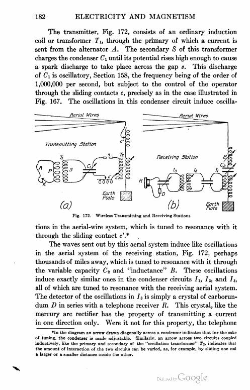
182 ELECTRICITY AND MAGNETISM
The transmitter, Fig. 172, consists of an ordinary induction
coil or transformer Ti, through the primary of which a current is
sent from the alternator A. The secondary S of this transformer
charges the condenser Ci until its potential rises high enough to cause
a spark discharge to take place across the gap s. This discharge
of Ci is oscillatory, Section 158, the frequency being of the order of
1,000,000 per second, but subject to the control of the operator
through the sliding contacts c, precisely as in the case illustrated in
Fig. 167. The oscillations in this condenser circuit induce oscilla-
Fig. 172. Wireless Transmitting and Receiving Stations
tions in the aerial-wire system, which is tuned to resonance with it
through the sliding contact c'.*
The waves sent out by this aerial system induce like oscillations
in the aerial system of the receiving station, Fig. 172, perhaps
thousands of miles away, which is tuned to resonance with it through
the variable capacity C2 and "inductance" B. These oscillations
induce exactly similar ones in the condenser circuits Ji, l2, and h,
all of which are tuned to resonance with the receiving aerial system.
The detector of the oscillations in 13 is simply a crystal of carborun
dum D in series with a telephone receiver R. This crystal, like the
mercury arc rectifier has the property of transmitting a current
in one direction only. Were it not for this property, the telephone
*In the diagram an arrow drawn diagonally across a condenser indicates that for the sake
cf tuning, the condenser is made adjustable. Similarly, an arrow across two circuits coupled
inductively, like the primary and secondary of the "oscillation transformer" T2, indicates that
the amount of interaction of the two circuits can be varied, as, for example, by sliding one coil
a larger or a smaller distance inside the other.

ELECTRICITY AND MACNETISM 183
could not be used as a detector because the frequency is so high—
of the order of a million. In view of this property, however, while
the oscillations of a given spark last, an intermittent current passes
in one direction and then ceases until the oscillations of the next
spark arrive. Since from 300 to 1,000 sparks pass at s per second .
when the key K is closed, the operator hears a musical note of this
frequency as long as K is depressed. Long and short notes then
correspond to the dots and dashes of ordinary telegraphy.
The stretching of the aerial wires horizontally instead of ver
tically, as was formerly done, permits to some extent of directive
sending and receiving, for as in the experiment of Section 158, the
sending and receiving wires work best when they are parallel.
The three tuned circuits, Iu 12, 13, are used because such a
series of tuned circuits does not pick up waves of other periods. For
"nonselective" receiving these circuits are omitted and the detector
and telephone are placed directly across the condenser C2. The
resistance of the telephone is so high that it does not interfere with
the oscillations of the condenser system across which it is placed.
163. Electromagnetic Theory of Light. The study of electro
magnetic radiations like those discussed in the preceding paragraphs,
has shown not only that they have the speed of light, but that they
are reflected, refracted, and polarized; in fact, that they possess all
the properties of light waves, the only apparent difference being in
their greater wave length. Hence modern physics regards light as
an electromagnetic phenomenon; that is, light waves are thought to be
generated by the oscillations of the electrically charged parts of the
atoms. It was as long ago as 1864 that Clerk Maxwell, of Cam
bridge, England, one of the world's most brilliant physicists and
mathematicians, showed that it ought to be possible to create ether
waves by means of electrical disturbances. But the experimental
confirmation of his theory did not come until the time of Hertz's
experiments in 1888. Maxwell and Hertz together, therefore,
share the honor of establishing the modern electromagnetic theory
of light.
TELEPHONE
164. Simple Telephone without Batteries. The telephone
was invented in 1875 by Elisha Gray, of Chicago, and Alexander
Graham Bell, of Washington. In its simplest form it consists, at

184 ELECTRICITY AND MAGNETISM
Fig. 173. Simple Telephone
WAV
each end, of a permanent bar magnet A, Fig. 173, surrounded by a
coil of fine w ire B, in series with the line, and an iron disk, or dia
phragm E mounted close to one end of the magnet. When a sound
is made in front of the dia
ller' phragm, the vibrations pro
duced by the sounding body
are transmitted by the air to
the diaphragm, thus causing
the latter to vibrate back and
forth in front of the magnet.
These vibrations of the diaphragm produce slight backward and
forward movements of the lines of force which pass into the disk
from the magnet in the manner shown in Fig. 174. Some of these
lines of force, therefore, cut across the
coil B, Fig. 173, first in one direction
and then in the other, and in so doing
induce currents in it. These induced
currents are transmitted by the line
to the receiving station, where those
in one direction pass around B' in
such a way as to increase the strength
of the magnet A', and thus increase
the pull which it exerts upon E' ; while
the opposite currents pass around B' in the opposite direction, and
therefore u'eaken the magnet A' and diminish its pull upon E'.
When, therefore, E moves in one direction, E' also moves in one
direction, and when E reverses its
motion, the direction of motion
of E' is also reversed. In other
words, the induced currents,
transmitted by the line cause E'
to reproduce the motions of E.
E' therefore sends out sound
waves exactly like those which fell
upon E. In exactly the same way, a sound made in front of E'
is reproduced at E. Telephones of this simple type will work satis
factorily for a distance of several miles. This simple form of instru
ment is still used at the receiving end of the modern telephone, the
Fig. 174. Magnetic Field in a Telephone Receiver
Fig. 175. Section of Modern Telephone
Receiver
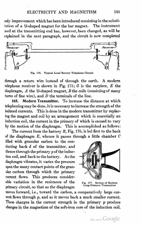
ELECTRICITY AND MAGNETISM 185
only improvement which has been introduced consisting in the substi
tution of a U-shaped magnet for the bar magnet. The instrument
used at the transmitting end has, however, been changed, as will be
explained in the next paragraph, and the circuit is now completed
Fig. 176. Typical Local Battery Telephone Circuit
through a return wire instead of through the earth. A modern
telephone receiver is shown in Fig. 175; G is the earpiece, E the
diaphragm, A the U-shaped magnet, B the coils (consisting of many
turns of fine wire), and D the terminals of the line.
165. Modern Transmitter. To increase the distance at which
telephoning may be done, it is necessary to increase the strength of the
induced currents. This is done in the modern transmitter by replac
ing the magnet and coil by an arrangement which is essentially an
induction coil, the current in the primary of which is caused to vary
by the motion of the diaphragm. This is accomplished as follows:
The current from the battery B, Fig. 176, is led first to the back
of the diaphragm E, whence it passes through a little chamber C
filled with granular carbon to the con
ducting back d of the transmitter, and
thence through the primary p of the induc
tion coil, and back to the battery. As the
diaphragm vibrates, it varies the pressure
upon the many contact points of the gran
ular carbon through which the primary
current flows. This produces consider
able variation in the resistance of the
primary circuit, so that as the diaphragm
moves forward, i.e., toward the carbon, a comparatively large cur
rent flows through p, and as it moves back a much smaller current.
These changes in the current strength in the primary p produce
changes in the magnetism of the soft-iron core of the induction coil.
Fig. 177. Section of ModernLong-Distance Transmitter

186 ELECTRICITY AND MAGNETISM
Currents are therefore induced in the secondary s of the induction
coil, and these currents pass over the line and affect the receiver
at the other end in the manner explained in Section 40. Fig. 177
shows the cross-section of a complete long-distance transmitter.
166. Subscriber's Telephone Connections. In the most recent
practice of the Bell Telephone Company, the local battery at the
subscriber's end is done away with altogether and the primary cur
rent is furnished by a 24-volt battery at the central station. Fig.
178 shows the essential elements of such a system. When the
subscriber wishes to call up central, he has only to lift the receiver
from the hook. This closes the line circuit at t, and the direct
current which at once begins to flow from the battery B through
the electromagnet g, closes the circuit of B through the glow
lamp /, and the contact point r. This lights up the lamp I which
Subscribers Line Central
Fig. 178. Modern Central-Station Telephone Circuit
is upon the switchboard in front of the operator. Upon seeing
this signal, the latter inserts the answering plug P into the sub
scriber's "jack" J and connects her own receiver R' into the line
by pressing the listening key k. The operation of inserting the
plug P extinguishes the lamp I by disconnecting the contact points
o. The battery B' is, however, now upon the line {B and B' are,
in fact, one and the same battery, shown here as separate, only for
the sake of simplifying the diagram). As, now, the subscriber talks
into the transmitter T, the strength of the direct current from the
battery B' through the primary p is varied by the varying pressure
of the diaphragm E upon the granular carbon c, and these variations
induce in the secondary s the talking currents which pass over the
line to the receiver R' of the operator. Although with this arrange
ment the primary and secondary currents pass simultaneously over
the same line, speech is found to be transmitted quite as distinctly

ELECTRICITY AND MAGNETISM 187
as when the two circuits are entirely separate, as is the case with
the arrangement of Fig. 176. When the operator finds what number
the subscriber wishes, she inserts the calling plug P' into the proper
line and presses the ringing key k'. This cuts out the first subscriber,
while the ringing is going on, by opening the contact points o' and
closing the points o". When the person called answers, the ringing
key k' is released, and the two subscribers are thus connected and
the magneto M, which actually runs all the time, is disconnected from
both lines. Also, the operator releases her key k and thus cuts out
her receiver while the conversation is going on. When one of the
subscribers "hangs up", another lamp like I is lighted by a mechanism
not shown here, and the operator then pulls out both plugs P and P'.
The bell b rings when an alternating p.d. is thrown upon the
line, because, although the circuit is broken at t, an alternating cur
rent will surge into the condenser C and out of it and thus pull the
armature first toward m and then toward n. The bell could not,
of course, be rung by a direct current.
167. Wireless Telephone.* The principles employed in wire
less telegraphy (radiotelegraphy) and telephone practice are com
bined in the wireless telephone. In Section 162 we saw that the
detector had the property of transmitting current through it in one
direction and that when the telephone was connected across the
detector a musical note was heard whose frequency was the same
(about 300 to 1,000) as that of the sending station, so that the
receiver produced long or short notes for dashes and dots and these
notes were of constant pitch. In wireless telephony the sending
apparatus is so modified, that instead of sending out a succession
of waves at equal intervals, it radiates a series of waves which
correspond to the fundamentals and partials of the human voice.
When this train of waves strikes the receiving station of any ordinary
wireless station like that of Fig. 172 (b), it reproduces the human
speech, since the diaphragm of the receiver is actuated by a series
of currents the wave form of which corresponds to the wave form
sent out by the sending station. Any wireless station, properly
tuned, can "pick up" wireless telephone messages. Compared to
wireless telegraphy, its operation is practical only over comparatively
short distances and its uses as yet are quite limited.
* For one of several practical treatments of this subject, the reader is referred to
"Experimental Wireless Stations", by Philip E. Edelmann, Minneapolis, Minnesota.

188 ELECTRICITY AND MAGNETISM
168. Automatic Enunciator. The transmitter, Fig. 179, of
the automatic enunciator or loud speaking telephone is very
similar to that used in the ordinary telephone. It differs in that
Transmitter
Neutral or Ground Wires
l1O Volts Direct
Current. Either
Lighting System or
Motor Generator Set
Line to ReproducerHorns1
Fig. 179. Complete Automatic Enunciator System Showing Connections
Courtesy of Winkler and Reichmann, Chicago
the varying current through the transmitter passes from carbon
disks placed both in front and in back of another carbon disk, to this
latter disk, the disks being separated by granular carbon. One side
of the transmitter is connected to one side of three condensers C
-©-
-©-
Neutral or Ground Wt're^
ifi jjjg
Fig. 180. Diagram of Automatic Enunciator System
in parallel, the other side of the three condensers running to one of
the lines for the reproducer horns. Likewise, the other side of the
transmitter is connected to one side of another three condensers C

ELECTRICITY AND MAGNETISM 189
in parallel, the other side of these three condensers running to the
other line for the reproducer horns.
When the sound vibrations from the voice strike the trans
mitter T, Fig. 180, a varying current through it results. This varies
the potential of points 1 and 3 which are
connected to the condenser system and
consequently a varying potential is pro
duced on the one side of the condenser
systems C and C. This varying poten
tial induces a varying potential on the
other side of the condensers to which the
reproducer lines are attached, thus send
ing the talking current through the repro- Fis- 181- . ^ftphr°H"rc^r ComPlete
duCerS. Courtesy of Winkler and Reichmann,Chicago
The complete reproducer is shown in
Fig. 181 and its working parts are shown in Fig. 182. The reproducers
are connected by the terminals MM' across the reproducer line, as
many as fifty being connected in parallel in different parts of a building.
When the speaking current passes through the reproducer, it
energizes the magnet and the iron core C acts upon the soft-iron
armature B to which is attached the lever E. The lever E is attached
to the lever D, and D to F, while F is attached to a light mica dia-
Fig. 182. Section Showing Working Parts of Reproducer
Courtesy of Winkler and Reichmann, Chicago
phragm 0. Thus the motion of the armature due to the speaking
currents is communicated by a system of levers to the mica dia
phragm which reproduces the voice in any desired intensity depend
ing upon the energy sent through the transmitter. For reproducing
190 ELECTRICITY AND MAGNETISM
in a low voice, 10-watt lamps (high resistance) are placed at L,
Fig. 180, in the transmitter circuit and for reproducing in a loud
voice 60-watt lamps (low resistance) are used. A, I, and A", Fig.
182, are adjusting screws for the purpose of properly adjusting the
air gap between B and C, and the lever system.
The automatic enunciator is used largely for quickly locating
doctors, internes, and nurses in hospitals; for paging guests in
hotels, members in clubs, etc.; for announcing trains in passenger
terminals; for announcing umpires' decisions, and results in baseball
parks and athletic fields, etc.
EXAMPLES FOR PRACTICE
1. Describe each of the following induction-coil discharge
effects: (a) physiological, (b) heating, (c) mechanical, (d) chemical,
(e) Gassiot's cascade, (f) in Geissler tubes, in X-ray tubes, (g) those
applied to tuned circuits, Fig. 167, those applied to a wireless send
ing station, Fig. 171, and Fig. 172 (a).
2. Is the discharge through a Geissler tube intermittent or
steady? How can this be shown? Give two ways.
3. What are cathode rays? Give two experiments which
prove that they are negatively charged particles.
4. Give several differences between cathode rays and X-rays.
5. Describe how an X-ray picture of the hand is taken.
6. What is meant by a radioactive substance?
7. Describe Crookes' spinthariscope.
8. Describe the action of the coherer in a simple wireless
outfit; of the detector in a modern wireless outfit.
9. What is the relation between the inductance and the
capacity of the transmitting and receiving stations in a modern
wireless outfit?
10. Explain the action of the simple telephone, Fig. 173.
11. Explain the use of the modern transmitter in connection
with the telephone circuit (local-battery system, Fig. 176).
12. What is the difference in the train of waves sent out by a
wireless-telegraph and a wireless-telephone sending station?
13. Can the same apparatus be used for receiving wireless-
telephone messages that is used for receiving wireless-telegraph
messages?

ELECTRICITY AND MAGNETISM 191
DYNAMOELECTRIC MACHINES
169. Classification. All dynamo-electric machines are com
mercial applications of Faraday's discovery of induced currents in
1831. They are all designed to transform the mechanical energy
of a steam engine, a waterfall, a gasoline engine, etc., into the energy
of an electric current. Whenever large currents are required—for
example, in running street cars; in systems of lighting and heating;
in the smelting, welding, and refining of metals; the charging of
storage batteries, etc.—they are always produced by dynamo-
electric machines.
There are two kinds of generators (1) d. c, or those producing a
unidirectional (direct) current, that is, one which always flows in
the same direction in the external circuit, and (2) a. c, or those
producing an alternating current, that is, one which reverses in
direction continuously throughout the entire circuit.
170. Principle of the A.C. Generator. The simplest form of
a.c. generator consists of a single loop of wire in which an e.m.f. is
generated by rotating the . ^
force, Section 130. Starting with the loop in the position shown in
Fig. 183, and rotating the loop counter-clockwise about the axis xy will
cause an induced current to flow in the direction indicated by the
arrows according to Fleming's dynamo rule, Fig. 143, and rule at the
end of Section 131. The e.m.f.'s induced in AB and CD for the posi
tion shown will have their maximum values since the wires are then
cutting the magnetic flux at right angles and are consequently cutting
more lines of force per second than in any other part of the revolution.
Note that as CD moves up, AB moves down (and vice versa) across
the magnetic flux so that the induced e.m.f.'s in all parts of the loop at
any instant cause a current in the loop at that instant in one direction.
As the coil moves from the position shown to a position 90 degrees
farther on (one-fourth turn), the wires cut the magnetic flux at angles
The magnitude of the
induced e.m.f. at any instant
will, of course, depend upon
the rate of cutting of lines of
coil in a magnetic field, thus
causing the wires to cut lines
of force.
y
S
Fig. 183. Diagram of Simple A.C. Generator

192 ELECTRICITY AND MAGNETISM
between 90 degrees and 0 degree so that the induced e.m.f . falls from a
maximum to zero during this quarter turn. During the next quarter
turn (90 degrees to 180 degrees) the wires are cutting the lines of
force at angles varying from 0 degree to 90 degrees and the induced
1+ \
1 \
1+ + 1
o° . ad\ hao" £TO° J60° 540° 630° 7Z0°
\
Fig. 184. E.M.F. Curve of Simple A.C. Generator
e.m.f.'s change from zero to a maximum in the opposite direction.
During the next quarter turn (180 degrees to 270 degrees) the wTires
are cutting the magnetic flux at angles varying from 90 degrees to
0 degree so that the induced e.m.f. falls from a maximum to zero
but has been in the same direction as the quarter turn from 90 degrees
to 180 degrees. During the next quarter turn (270 degrees to 360
degrees) the wires are cutting lines of force at angles varying from 0
degree to 90 degrees so that the induced e.m.f. varies from zero to a
Fig. 185. Simple Generator for Plotting E.M.F. Curve
maximum in the same direction as at the starting-point. It will be
noted that the current changes direction (alternates) every time
the plane of the loop is in the vertical position, since, as it passes
through this position, the wires change from cutting up across the

ELECTRICITY AND MAGNETISM 193
magnetic flux to cutting down across the magnetic flux, or vice
versa. At this instant of change, the induced e.m.f. and current
has zero value. Thus the current alternates twice during a revolu
tion, reaching two maximum values which are in opposite directions,
and two zero values.
These relations are shown by the curve in Fig. 184 for two
revolutions (720 degrees) for a simple a. c. generator. If we consider
the e.m.f. positive for the interval 0 degree to 90 degrees, then it
would be negative for the interval 90 degrees to 270 degrees, posi
tive again for the interval 270 degrees to 450 degrees, etc. Thus
Fig. 186. E.M.F. Curve Plotted from Observation with Apparatus Shown in Fig. 185
the e.m.f. alternates from one sign to the other and the current
which it produces is called an alternating current.
An e.m.f. curve like that shown in Fig. 184 may be very beauti
fully obtained experimentally with the aid of the simple a. c. gener
ator devised by Professor R. A. Millikan for this purpose and shown
in Fig. 185. A coil of wire is rotated in a very uniform field pro
duced by placing horseshoe magnets end-on, as shown in the figure.
By rotating the crank K clockwise, the ratchet R is released and a
spring rotates the coil through one of the ten-degree intervals into
which the wheel W is divided by the stops placed around its circum
ference. As the coil rotates through one of these ten-degree intervals,
an e.m.f. is induced which corresponds to the average angular dis

194 ELECTRICITY AND MAGNETISM
placement of the coil during this rotation of ten degrees. If a
suitable galvanometer be put in circuit and the deflections thus
obtained be plotted as ordinates, and the corresponding angular
displacements of the coil as abscissas, the smooth curve shown in
Fig. 187. Commutator Changes Alternating Current in Armature to DirectCurrent in External Circuit
Fig. 186 will result. Since the induced e.m.f.'s are proportional to
the deflections, the curve has the exact form of the e.m.f. curve.
This curve is theoretically a sine wave and made with this special
apparatus it is practically a sine wave.
Commutator. By the use of the commutator, it is possible to
transform a current which is alternating in the coils of the armature,
to one which is a direct current, i.e., always flowing in the same
direction in the external portion of the circuit. The simplest possible
form of such a commutator is shown in Fig. 187 in connection with a
single loop of wire, the simplest a. c. generator. The commutator
consists of a metallic tube split into two semicircular segments and
insulated from each other. One end of the rotating loop (or coil, if
more turns are used as in Figs. 191 and 192) is soldered to one of these
semicircles, and the other end to the other semicircle. The brushes
Fig. 188. E.M.F. Curve with Commutator on Armature
are set in such a position that they lose contact with one semicircle
and make contact with the other at the instant at which the current
changes direction in the armature. The current therefore always
passes out to the external circuit through the same brush, and is
said to be a rectified, commutated, or unidirectional current. When

ELECTRICITY AND MAGNETISM 195
Fig. 189. Ring-Wound Armature
a single loop or coil is used with the commutator, the current is not
steady but pulsates with the e.m.f., rising to two maximum values
and falling to zero value twice during each revolution. Thus the
e.m.f. curve, Fig. 184, for the
simplest single-loop a. c. gener
ator becomes, when a commu
tator is used, the pulsating,
unidirectional e.m.f. curve of
Fig. 188.
171. Simple A. C. Dyna=
mo. The simplest form of
commercial dynamo consists
of a coil of wire so arranged as
to rotate continuously between
the poles of a powerful elec
tromagnet, Fig. 189.
In order to make the mag
netic field in which the conductor is moved as strong as possible,
the coil is wound upon an iron core C. This greatly increases the
total number of lines of magnetic force which pass between N and
S, for the core offers an iron path, as shown in Fig. 190, instead of
an air path from N to S. .
The rotating part, consisting of the coil with its core, is called
the armature. If the coil is wound in the manner shown in Figs.
189 and 190, the armature is said to
be of the ring type.
One end of the coil is attached
to the insulated metal ring R, which
is attached rigidly to the shaft of the
armature and therefore rotates with
it, while the other end of the coil is
attached to a second ring R'. The
brushes b and V, which constitute the Fig- 19a End View of Ring Armature
terminals of the external circuit, are always in contact with these
rings, which rings are characteristic of all a. c. generators and are
called the collecting rings.
As the coil rotates, an induced alternating current passes
through the circuit. This current reverses direction as often as the

196 ELECTRICITY AND MAGNETISM
coil passes through the position shown in Fig. 190, i.e., the position
in which the conductors are moving parallel to the lines of force;
for at this instant the conductors which have been moving up begin
to move down, and those which have been moving down begin to
Fig. 191. Diagram of Two-Coil Armature Fig. 192. Diagram of Four-Coil Armature
move up. The current reaches its maximum value when the coils
are moving through a position 90 degrees farther on than that
shown in the figures, for then the lines of force are being cut most
rapidly by the conductors on both sides of the coil. The e.m.f.
curve of this generator is therefore like the one shown in Fig. 184.
172. Simple D. C. Dynamo. A simple two-coil armature used
in connection with a commutator is shown in Fig. 191. The dis
advantage here encountered is the pulsating character of the current,
both coils reaching a maximum and minimum e.m.f., at the same
time giving the e.m.f. curve of Fig. 188. This pulsating effect
is avoided and a steady current produced in the commercial direct-
current dynamo by building a commutator of a large number of
segments and connecting the segments across small portions of the
armature coil. Even a four-coil armature with four segments on the
Fig. 193. E.M.F. and Current Curve for Four-Coil Armature
commutator will, in a large measure, overcome the pulsating effect
of the current as can be seen from the following considerations.
Starting with the coils A, B, C, and D, Fig. 192, in the positions
shown, the e.m.f. induced in the coils A and B will be a maximum at

ELECTRICITY AND MAGNETISM 197
this instant shown by the e.m.f. curve marked AB in Fig. 193, and
the e.m.f. induced in the coils C and D at the same instant will be
zero. A quarter of a turn lateF, the e.m.f. in A and B will be zero
and in C and D will be a
maximum. Since the
e.m.f. curve for the ex
ternal portion of the cir
cuit is the sum of these
or the curve ABCD, it
will be seen that at no
place does this curve fall
to zero; this means that
the pulsations of current are smaller than they would be for a single
loop, the current of this four-coil armature being very nearly steady.
The four coils of Fig. 192 are in series and may be thought of as
one coil with four connecting wires running to the four segments of
the commutator. In practice, the coil is thus divided into a very
large number of parts, a hundred or more, so that some portion of
the coil is always having a maximum e.m.f. induced in it, thus
making the undulations (pulses) which are superimposed on the
steady current so small that some special device such as the tele
phone must be used to detect them. Fig. 194 shows a single gramme-
Fig. 194. Single Gramme-Ring Winding
Fig. 195. Complete Gramme-Ring Armature
ring winding. The ring as will be seen in the diagram is really a
hollow cylinder, which in all the previous diagrams has been shown
only in cross-section. Fig. 195 is a typical commercial gramme-ring

198 ELECTRICITY AND MAGNETISM
armature. The commutator is not always built on next to the shaft
but is sometimes built around the periphery of the armature itself
so that the outside of the ring forms the commutator.
196. Two-Pole Direct-CurrentDynamo Diagram
DIRECT-CURRENT GENERATORS
173. Ring=Armature Direct=Current Dynamo. Fig. 196 is a
diagram illustrating the construction of a commercial two-pole
direct-current dynamo of the
ring-armature type. The figure
represents an end view of a core
like that shown in Fig. 189. The
coil is wound continuously around
the core, each segment being con
nected to a corresponding seg
ment of the commutator, in the
manner shown in the figure. At
a given instant, currents are being
induced in the same direction in all the conductors on the outside
of the core on the left half of the armature. The cross on these
conductors, representing the tail of a retreating arrow, is to indicate
reader. No e.m.f.'s are
induced in the conduc
tors on the inner side of
the ring, since these con
ductors cut no lines of
force, Fig. 190; nor are
currents induced in the
conductors at the top and
bottom of the ring where
the motion is parallel to
the magnetic lines. The
currents from the two
halves of the ring pass
out at b through the line
and back at b'. This con
dition always exists, no
matter how fast the rotation; for it will be seen that as each loop
rotates into the position where the direction of its current reverses
that these currents flow away from the
Fig. 197. Four-Pole Direct-CurrentShowing Direction of Lines of
.mo Diagramorce

ELECTRICITY AND MAGNETISM 199
Fig. 198. Two-Pole Direct-Current Generator withDrum Winding
it passes a brush and therefore at once becomes a part of the circuit
on the other half of the ring where the currents are all flowing in
the opposite direction.
If the machine is of
the four-pole type, like
that shown in Fig. 197,
the currents flow toward
two neutral points, .pp,
or points of no induction,
instead of toward one, as
in two - pole machines.
Hence there are four
brushes, two positive and
two negative, as in the
figure. Since the two
positive and the two negative brushes are connected as shown, both
sets of currents flow off to the external circuit on a single wire. The
figure with its arrows will explain completely the generation of cur
rents by a four-pole machine.
174. Drum=Armature Direct=Current Dynamo. The drum-
wound armature, shown in section in Fig. 198, has an advantage over
the ring armature in that, while
the conductors on the inside of
the latter never cut lines of force
and are, therefore, always idle,
in the former all of the con
ductors are cutting lines of force
except when they are passing
the neutral points. In theory,
however, the operation of the
drum armature is precisely the
same as that of the ring arma
ture. All the conductors on the
left side of the line connecting
the brushes, Fig. 198, carry
induced currents which flow in one direction, while all the conductors
on the right side of this line have opposite currents induced in them.
It will be seen, however, in tracing out the connections 1, 1u 2, 2u
Fig. 199. Modern Four-Pole Direct-CurrentGenerator with Interpoles

200 ELECTRICITY AND MAGNETISM
S, Si, etc., of the figure (the dotted lines representing connections at
the back of the drum), that the coil is so wound about the drum
that the currents in both halves are always flowing toward one
brush b, from which they are led
to the external circuit. Fig. 199
shows a typical modern four-pole
generator, and Fig. 200 the corre
sponding drum-wound armature.
Fig. 156 illustrates nicely the
method of winding such an arma
ture, each coil beginning on one
segment of the commutator and
ending on the adjacent segment.
1 75. Methods of Exciting Qen=
erator Fields and Their Applications. Magneto. To generate an e.m.f.,
conductors must cut across a magnetic flux. In the magneto, the
magnetic flux is produced by permanent magnets. Since permanent
magnets are much bulkier than electromagnetic ones of the same
strength, it is impractical to use permanent magnets on large genera-
Fig. 200. Drum-Wound Armature forGenerator Shown in Fig. 199
Fig. 201. Typical Ignition Wiring Diagram
Courtesy of Thomas B. Jeffery Company, Kenosha, Wisconsin
tors on account of the massive magnets which would have to be used.
For this reason, they are used only where a small amount of power is
required, for example, in the ringing of bells on some telephone systems

ELECTRICITY AND MAGNETISM 201
Fig. 202. Direct-Current Generator withSeparately Excited Fields
and in producing the spark for ignition in internal-combustion engines.
Fig. 201 shows how the magneto M is connected for ignition purposes
to the four cylinders of an automobile. The car is usually started
by using the spark from a set of
about four dry cells B andthen the
switch is thrown over to connect
the spark-plugs to the magneto.
Separately Excited Field.
Here the magnetic flux is pro
duced by an electromagnet, the
current for which is furnished
either by a set of cells or another
d. c. generator, Fig. 202. This
system of field excitation is used
seldom in direct-current work ex
cept when voltages greater than
about 800 volts are to be 'ob
tained, or when a great many gen
erators are in operation at once. It is, however, very largely used
for alternating-current generators, since a unidirectional magnetic flux
must be produced, and the alternating current will not produce it.
The magnitude of the induced
e.m.f. in this type of generator is
controlled by varying the current
which flows around the field mag
nets, or else by varying the number
of turns on the solenoids of the field
magnets. These would naturally
be the means to employ, since the
strength of a magnet depends on the
ampere-turns encircling it. Its
e.m.f. might also be controlled by
changing the speed of the rotation
of the armature, but this is not
found to be a practical way. It
can also be controlled by changing the point of commutation, that
is, by rotating the brushes forward in the direction of rotation to a
point beyond that at which commutation of the current in the
Fig. 203. Series-Wound Direct-CurrentGenerator

202 ELECTRICITY AND MAGNETISM
coil takes place. The latter method is impractical since it produces
bad sparking at the brush contact with the commutator.
Self-Excited Fields. Series Winding. In almost all direct-cur
rent machines, the field magnet NS, Fig. 203, is excited by the cur
rent which the dynamo itself produces. In all self-exciting machines
there is enough residual magnetism left in the iron cores after stop
ping, to start feeble induced currents when started up again. These
currents immediately increase the strength of the magnetic field,
and so the machine quickly builds up its current until the limit of
magnetization is reached. In the series-wound dynamo, Fig. 203,
the windings on the field magnet consist of a few turns of heavy
wire in series with the "main
circuit" so that all of the current
generated flows around the sole
noids of the field magnet. A
decrease in the external resist
ance would cause more current
to flow, producing a stronger
field, so that if the dynamo were
driven at constant speed, the
e.m.f. would be increased. Like
wise, an increase in the external
resistance would cause a decrease
in the e.m.f. produced by the
dynamo. In practice, arc light
ing is the only use for which
series-wound dynamos are employed, since for any system of art-
lights the voltage and load are both constant. About fifty lamps are
commonly fed by one machine. This requires a dynamo capable of
producing a voltage of 2500 volts, since each lamp requires a pres
sure of about 50 volts. Since an arc lamp requires a current of about
10 amperes, such a dynamo must have a power of 2500X10 = 25,000
watts, or 25 kilowatts. This is equivalent to about 33.5 horsepower.
Shunt Winding. In the so-called shunt-wound machines a
small portion of the current is led off from the brushes through the
shunt circuit, Fig. 204, which consists of many turns of fine wire which
encircle the core of the field magnet, while the rest of the current
flows through the main circuit. Since the shunt circuit and the main
Fig. 204. Shunt-Wound Direct-CurrentGenerator

ELECTRICITY AND MAGNETISM 203
circuit are in parallel, the resistance of the shunt circuit must be high
compared with that of the main circuit. The ampere-turns encircling
the field magnet are the same as in a similar-series dynamo in order
to produce a given magnetic flux. The magnetic flux may be
increased by decreasing the resistance in the shunt circuit, thus
increasing the magnetizing current. This dynamo, if properly
designed, has a fairly constant e.m.f. within certain limits, but if
overloaded, that is, if too large currents are drawn from it, the
external resistance under these conditions will be too small so that
not enough current will flow through the shunt circuit to energize
the magnets and the e.m.f. generated will drop to zero. Thus we
have seen that increasing the
load on a series dynamo in
creases the e.m.f. and on a shunt-
wound dynamo decreases the
e.m.f. A combination of these
two windings, then, in the proper
way should enable us to get a
constant e.m.f. for any load.
This is accomplished by the aid
of the so-called compound
winding.
CompoundWinding. Inthe
compound-wound dynamo, Fig.
205, the field magnet is energized
by the current from a shunt cir
cuit like that in the shunt-wound dynamo. It is also energized by the
current which flows in the main circuit which is led around the field
magnet. This latter set of windings is called the series winding
since they are in series with the main circuit. When the load on this
dynamo is increased, that is, when the resistance of the main circuit
is made less, this larger current flows around the field magnet thus
producing a stronger magnetic flux for the armature to cut, and thus
preventing the e.m.f. from decreasing as in the case of the shunt-
wound motor. By properly proportioning the ampere-turns in the
shunt winding and the series winding, it is possible to have the e.m.f.
produced by this compounding remain constant, decrease, or increase,
as the dynamo load is changed from no load to full load. Hence
C Main Circuit
Fig. 205. Compound-Wound Direct-CurrentGenerator
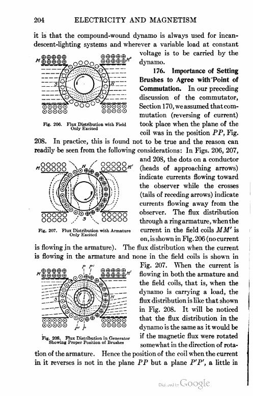
204 ELECTRICITY AND MAGNETISM
000©©
©0000
oooo0©0©0
©0000
Fig. 200. Flux Distribution with FieldOnly Excited
it is that the compound-wound dynamo is always used for incan
descent-lighting systems and wherever a variable load at constant
voltage is to be carried by the
dynamo.
176. Importance of Setting
Brushes to Agree with"Point of
Commutation. In our preceding
discussion of the commutator,
Section 170,weassumedthatcom-
mutation (reversing of current)
took place when the plane of the
coil was in the position PP, Fig.
208. In practice, this is found not to be true and the reason can
readily be seen from the following considerations: In Figs. 206, 207,
,. and 208, the dots on a conductor
„ooooo \ tf / ooooow, ,, , , . ."OOOOO. Aflwuk OOOOO-rc (heads ot approaching arrows)
indicate currents flowing toward
the observer while the crosses
(tails of receding arrows) indicate
currents flowing away from the
observer. The flux distribution
through a ring armature, whenthe
current in the field coils MM' is
on, is shown in Fig. 206 (no current
is flowing jn the armature) . The flux distribution when the current
is flowing in the armature and none in the field coils is shown in
Fig. 207. When the current is
flowing in both the armature and
the field coils, that is, when the
dynamo is carrying a load, the
flux distribution is like that shown
in Fig. 208. It will be noticed
that the flux distribution in the
dynamo is the same as it would be
if the magnetic flux were rotated
somewhat in the direction of rota
tion of the armature. Hence the position of the coil when the current
in it reverses is not in the plane PP but a plane P'P', a little in
Fig. 207. Flux Distribution with ArmatureOnly Excited
-\0\
©©©©e-''0/©:©®"
©©©©© j,,
0©©©0
©000©
Fig. 208. Flux Distribution in GeneratorShowing Proper Position of Brushes

ELECTRICITY AND MAGNETISM 205
advance of PP. The brushes, therefore, should be set to make con
tact with the commutator in the plane P'P'. In the case of the
motor, however, the reverse is true, so that the brushes, instead of
being rotated forward, should be rotated backward. A failure to
thus set the brushes on dynamos and motors is often a serious source
of sparking* at the brushes. In the case of drum-wound armatures
the amount which the brushes need to be rotated is much less,
because the self-induction of the armature is less and hence com
mutation takes place more quickly.
EXAMPLES FOR PRACTICE
1. Diagram and explain a simple a.c. generator. Draw the
e.m.f. curve for such a generator.
2. Explain with the aid of a diagram how the commutator
changes the current in the external circuit from an alternating to a
direct current.
3. With the aid of the dynamo rule, explain why, in Fig. 197,
the current in the conductors under the south poles is moving toward
the observer, and that in the conductors under the north poles away
from the observer. Explain in a similar way the direction of the
currents in Figs. 196 and 198.
4. If a direct-current dynamo of the type shown in Fig. 197
had ten poles, how many brushes would the commutator require?
5. A ring armature which develops the same e.m.f. as a drum
armature has nearly twice as much wire and therefore nearly twice
as much resistance. Why?
6. If a series-wound dynamo is running at a constant speed,
what effect will be produced on the strength of the field magnets
by diminishing the external resistance and thus increasing the
current? What will be the effect on the e.m.f.? (Remember that
the whole current goes around the field magnets.)
7. If a shunt dynamo is run at constant speed, what effect
will be produced on the strength of the field magnets by reducing
the external resistance? What effect will this have on the e.m.f.?
(Remember that reducing the external resistance causes a smaller
fraction of the current to flow through the shunt.)
8. In an incandescent-lighting system the lamps are connected
*For other causes and methods of preventing sparking during commutation the reader is
referred to the literature on the subject of "Dynamo Electric Machinery".
S

206 ELECTRICITY AND MAGNETISM
in parallel across the mains. Every lamp which is turned on, then,
diminishes the external resistance. Explain from a consideration
of Examples 6 and 7 why a compound-wound dynamo keeps the
p.d. between the mains constant.
9. Single dynamos often operate as many as 10,000 incan
descent lamps at 110 volts. If these lamps are all arranged in
parallel and each requires a current of .5 ampere, what is the total
current furnished by the dynamo? What is the activity of the
machine in kilowatts and in horsepower?
10. How many 110-volt lamps can be lighted by a 12,000-
kilowatt generator?
11. Should the brushes on a dynamo be rotated forward or
backward to make contact at the instant of commutation in the
coils? Is the same true with regard to setting the brushes on a motor?
12. Why does it take twice as much work to keep a dynamo
running when 1,000 lights are on the circuit as when only 500 are
turned on?
DIRECT-CURRENT MOTORS
177. Dynamo Used as a Motor. In construction the motor*
differs in no essential respect from the dynamo. To analyze the
operation, as a motor, of such a machine as that shown in Fig. 196,
suppose a current from an outside source is first sent around the coils
of the field magnets and then into the armature at V . Here it will
divide and flow through all the conductors on the left half of the ring
in one direction, and through all those on the right half in the oppo
site direction. Hence, in accordance with the motor rule, all the
conductors on the left side are urged upward by the influence of the
field, and all those on the right side are urged downward. The
armature will therefore begin to rotate, and this rotation will con
tinue so long as the current is sent in at V and out at b. For as
fast as coils pass either b or V, the direction of the force acting on
them changes. The left half is therefore always urged up and the
right half down. The greater the strength of the current, the
greater the force acting to produce rotation.
If the armature is of the drum type, Fig. 198, the conditions are
not essentially different. For, as may be seen by following out the
*Before reading the following pages on d. c. motors, the student should familiarize himself
with the contents of Articles 133 and 134, especially the motor rule in Section 133.

ELECTRICITY AND MAGNETISM 207
windings, the current entering at b' will flow through all the con
ductors on the left half in one'direction and through those on the right
Fig. 209. Allis-Chalmera Interpole Railway Motor
half in the opposite direction. The commutator keeps these con
ditions always fulfilled. The analysis of the operation of a four-
pole dynamo, Fig. 197, as a motor is equally simple.
S

ELECTRICITY AND MAGNETISM
178. Street=Car Motors. Electric street cars are nearly all
operated by direct-current series-wound motors placed under the
cars and attached by gears to the axles. Fig. 209 shows a typical
street-car motor of the compensating-pole type. The upper field
poles with their interpoles are raised with the case when the motor
is opened for inspection, as in the figure. The current is generally
supplied by compound-wound dynamos which maintain a constant
potential of about 500 volts between the trolley, or third rail, and the
track which is used as the return circuit. The cars are always
operated in parallel, as shown in Tig. 210. In a few instances, street
cars are operated upon alternating- instead of upon direct-current
circuits. In such cases the motors are essentially the same as direct-
current series-wound motors; for since in such a machine the current
must reverse in the field magnets at the same time that it reverses
in the armature, it will be seen that the armature is always impelled
generator at
Power Station \i ii H ii i r
□ □ • □ a
I II 11 II II I]
Track fcgn
Fig. 210. Typical Street-Car Circuit
to rotate in one direction, whether it is supplied with a direct or with
an alternating current.
179. Back E.M.F. in Motors. When an armature is set into
rotation by sending a current from some outside source through it,
its coils move through a magnetic field as truly as if the rotation
were produced by a steam engine, as is the case in running a dynamo.
An induced e.m.f. is therefore set up by this rotation. In other
words, while the machine is acting as a motor, it is also acting as a
dynamo. The direction of the induced e.m.f. due to this dynamo
effect will be seen from Lenz's law, or from a consideration of the
dynamo and motor rules, to be opposite to the outside p. d. which
is causing current to pass through the motor. The faster the motor
rotates, the faster the lines of force are cut, and hence the greater
the value of this so-called back e.m.f. If the motor were doing no
work, the speed of rotation would increase until the back e.m.f.
reduced the current to a value sufficient simply to overcome friction.
It will be seen, therefore, that, in general, the faster the motor goes,

ELECTRICITY AND MAGNETISM 209
the less the current which passes through its armature, for this
current is always due to the difference between the p. d. applied at the
brushes—500 volts in the case of trolley cars—and the back e.m.f.
When the motor is starting, the back e.m.f. is zero, and hence, if the
full 500 volts were applied to the brushes, the current sent through
would be so large as to ruin the armature through overheating.
T.o prevent this, each car is furnished with a controller (starting-box,
Fig .211. Typical Street-Car Control Apparatus
Fig. 211) which enables the motorman to throw resistance into series
with the two motors with which a car is usually equipped. As the
controller lever is rotated, this resistance is cut out of the circuit
leaving the two motors in series, each receiving one-half of the line'
voltage and therefore running at half-speed. The next position of
the controller lever either shunts the fields or short-circuits part of
them, again increasing speed. Further rotation removes the shunt
and connects the motors in parallel, but with a resistance in the
circuit which is again cut out by further rotation of the controller

210 ELECTRICITY AND MAGNETISM
lever, leaving each motor to receive the full-line voltage. Finally
the last position of the controller either shunts the fields or short-
circuits part of them, and the motor is then running at full speed.
The series-wound motor is also used on electric automobiles
and other motor vehicles. These motors have a large starting force,
proportional to the square of the current, whereas in shunt-wound
motors with constant fields, the starting force is proportional to the
current sent through the armature.
180. Shop Motors. The shunt-wound motor is the one most
commonly used in shops on account of the fact that its speed is nearly
-Line Hrn% FieldA
Main SwitchStarting 3ok
IMIMJU
Shunt Field
Fig. 212. Wiring Connections for Starting Box of aShunt-Wound Motor
constant for all loads. Fig. 212 shows the wiring connections for
the starting box of such a motor. If it is desirable to vary the speed
of the motor, this may be accomplished by placing a variable resist
ance in series with the field and when this is done, the ordinary shunt-
wound motor may satisfactorily be made to vary about thirty per
cent in speed.
In starting the motor, the main switch, Fig. 212, is first closed,
then the arm switch is slowly moved to the right, thus gradually
cutting out the starting resistance as the motor acquires its running

ELECTRICITY AND MAGNETISM 211
speed. The arm switch is held in position then by the release magnet
until the motor is again stopped by opening the main switch, when
the current in the field gradually falls to zero and the release magnet
weakens, allowing the spring in the arm switch to throw it to the
"off" position.
In the running of textile machinery, where a very constant speed
for variable loads is required, the differential motor is used, which is
nothing but a compound dynamo used as a motor. For operating
Fig. 213. Field Frame and Coils of a Typical Interpole Motor
derricks, cranes, and machinery requiring a large starting force
(starting torque), the series-wound motor is used.
181. Reversing Motor. The reversing of a motor is accom
plished, first, by stopping the motor, then, by putting resistance in
the line, and finally, by reversing the current through the armature
of the motor by means of a reversing switch. Since the position
of the brushes for "no-sparking" commutation is not the same for a
load as for the "no-load" position, Section 176, it is evident that to
set the brushes properly for the motor to run in one direction would
make them spark very badly when the motor was reversed; hence
for a reversing motor the brushes should be set for the no-load

212 ELECTRICITY AND MAGNETISM
position, i.e., in the plane PP, Fig. 208. The so-called commutating
pole used on interpole dynamos, Fig. 213, and motors produces a
magnetic field which aids the current in reversing and prevents
sparking through a very wide range of load. It also allows the field
to be made very much weaker than ordinary motors and thus the
range of speed can be made 4 to 1 by using control resistance in
series with the field. Since sparking during commutation is elim-
Fig. 214. Set-Up for Obtaining Efficiency Brake Test of Electric Motor
inated, this type of motor is well adapted to work requiring the
reversing of the motor.
182. Efficiency of the Motor. The efficiency of the electric
motor, as for all machines, is defined to be the ratio of output to
input, or
„ . outputemciency = ——-—
input
A simple form of brake, Fig. 214, consists of a belt passing under
the pulley on the motor shaft and connected to the spring balances B.
The friction between the belt and the pulley will cause one balance-
reading to increase and the other to decrease, when the motor is
running, so that the pull on the belt equals the difference between

ELECTRICITY AND MAGNETISM 213
the two balance-readings, or in the case of the modified Prony
brake, Fig. 215, it is equal to the single balance-reading minus the
weight W. The pull on the belt in pounds multiplied by the circum
ference of the pulley in feet gives the number of foot-pounds of
work done by the motor in one revolution. The work per revolution
multiplied by the r.p.m. (revolutions per minute) gives the work done
per minute which, divided by 33,000, gives the horsepower of the
motor (1 h.p. =33,000 foot-pounds per
minute).
The input, or rate at which energy is
supplied to the motor by the electric current,
expressed in watts, is equal to the number
of volts p. d. across the motor multiplied by
the current through the motor in amperes.
The input in horsepower equals watts divided
by 746 (1 h.p. = 746 watts).
Therefore
„. . ft. Ib. per revolution X r.p.m. , 746
efficiency = -—:—-—: - X—
volts X amperes 33,000
A motor can be designed to have its
highest efficiency when carrying a small load,
or when carrying a large load, or when running at low speed or at high
speed. Hence, it is very important to know the speed and load for
which it is most efficient and to design it accordingly. Good motors
have efficiencies from 75 per cent to 90 per cent and therefore trans
form electrical energy into mechanical work with but little loss of
energy. This fact coupled with their safety and convenience is rap
idly transforming shops from a confusion of belts and dangerous
transmission shafting to safe and orderly motor-equipped shops.
Fig. 215. Simple Modification of Prony Brake
EXAMPLES FOR PRACTICE
1. A current is flowing from top to bottom in a vertical wire.
In what direction will the wire tend to move on account of the earth's
magnetic field?
2. If a current is sent into the armature of Fig. 196 at b',
and taken out at b, which way will the armature revolve?
3. When an electric fan is first started, the current through

214 ELECTRICITY AND MAGNETISM
it is much greater than it is after the fan has attained its normal
speed. Why?
4. If, in the machine of Fig. 197, a current is sent in on the
wire marked +, what will be the direction of rotation?
5. Would an armature wound on a wooden core be as effec
tive as one made of the same number of turns wound on an iron core?
6. Will it take more work to rotate a dynamo armature when
the circuit is closed than when it is open? Why?
7. Show that if the reverse of Lenz's law were true, a motor
once started would run of itself and do work, i.e., it would furnish
a case of perpetual motion.
8. Explain why a series-wound motor can run either on a
direct or an alternating circuit.
9. If the pressure applied at the terminals of a motor is 500
volts, and the back pressure, when running at full speed, is 450 volts,
what is the current flowing through the armature, its resistance being
10 ohms?
10. An electric automobile is run for five hours. During this
time the motor delivers energy at an average rate of 2 h.p. If the
motor has an efficiency of 90 per cent and the storage batteries an
efficiency of 75 per cent, how much does it cost to charge the storage
batteries sufficiently for this trip, if the cost of the electricity used
in charging the batteries is 4 cents per kilowatt hour?
ALTERNATING=CURRENT GENERATORS
183. Multipolar Alternator. For most commercial purposes
it is found desirable to have 120 or more alternations of current per
second. This could not be attained easily with two-pole machines
like those sketched in Figs. 183, 189, and 191. Hence, commercial
alternators are usually built with a large number of poles alternately
N and S, arranged around the circumference of a circle in the manner
shown in Fig. 216. The dotted lines represent the direction of the
lines of force through the iron. It will be seen that the coils which
are passing beneath N poles have induced currents set up in them,
the direction of which is opposite to that of the currents which are
induced in the conductors passing beneath S poles. Since, however,
the direction of the winding of the armature coils changes between
each two poles, all the inductive effects of all the poles are added

ELECTRICITY AND MAGNETISM 215
together in the coil and constitute at any instant one single current
flowing around the complete circuit in the manner indicated by the
arrows in the diagram. This current reverses direction at the instant
at which all the coils pass the midway points between the N and
S poles. The number of alter
nations per second is equal to the
number of poles multiplied by
the number of revolutions per
second. The field magnets N
and S of such a dynamo are
usually excited by a direct cur
rent from some other source.
If, instead of rotating the
armature inside the field, we
rotate the field inside of the
armature, the Same result Will be Fig. 216. Diagram of Revolving-Armature Alternator
obtained.. How this is accom
plished is shown diagrammatically in Fig. 217 and a commercial
revolving-field alternator is shown in Fig. 218. Several poles of
the rotating field inside of the armature of a multipolar alternator
are shown in Fig. 219.
184. Cycle, Frequency, and Period of Alternating Current.
The electromotive force of a loop or a coil of wire rotating between
two poles as we have seen
produces a set of + and —
values during each revolu
tion, Fig. 184. This com
plete set of + and — values
of the e.m.f. produced in a
coil during one revolution
(360 degrees) of a bipolar
machine is called a cycle.
In the same time, the cur
rent alternates twice, soFig. 217. Diagram of Revolving-Field Alternator
that for any machine the
number of cycles per second is equal to one-half the number of alter
nations per second. In the case of the multipolar alternators,
Figs. 216 to 219, the cycle will take place while one coil is moving

216 ELECTRICITY AND MAGNETISM
from underneath one N to the position underneath the next N pole
as in doing so the e.m.f. passes through the same set of values as
it does for a complete revolution in a bipolar machine. Hence the
rotation from one N pole to the next N pole, Fig. 184, is called 360
electrical degrees.
The frequency of an alternating current is the number of cycles
per second through which the current passes and is therefore equal
Fig. 218. Typical Revolving-Field Alternator
Courtesy of Electric Machinery Company
to the number of poles, both N and S, which the coil passes per
second, divided by two. The frequency is also stated often as the
number of alternations per second, which is equal to the number of
poles, both N and S, which the coil passes per second. Thus a
frequency of 60 cycles per second, and one of 120 alternations per
second are the same. It is, however, better usage to state the fre
quency in cycles per second. The frequency used on lighting cir

ELECTRICITY AND MAGNETISM 217
cults is about 60 cycles per second, while for power circuits they
are often as low as 15 cycles per second.
If we let / be the frequency in cycles per second and T be the
time in seconds required to complete one cycle, then
so that the period T of a 60-cycle current is one-sixtieth of a second.
185. Single=Phase Circuit. If the armature shown in Fig. 220
be rotated inside a field having a pole corresponding to each coil on
Fig. 219. Close View of Armature and Field Coilsof G. E. Alternator
the armature, the conditions will be the same as in Figs. 216 to 219
with regard to the character of the induced e.m.f. The induced
currents in all of the coils at any instant will be in the same direction
and all will reach their maximum and minimum values at the same
time, and are therefore added to each other. The resulting current
in the external circuit is a single-phase alternating current.
186. Polyphase Circuit. If, instead of having the number
of coils on the armature equal to the number of poles on the field, as
in the case of the single-phase alternator, we have three coils on the
armature to one pole on the field as in Fig. 221, we can obtain three

218 ELECTRICITY AND MAGNETISM
separate currents from the alternator by connecting up the coiis
of the armature in the following manner:
Fig. 220. Coils Mounted on Rotor of Single-Phase Alternator
Let all of the windings marked Oi, a2, a3, etc., be connected in
series to one pair of collecting rings; the wires in ai would pass
up through the slot, in a2 down through the slot, in a3 up, etc. Like
wise in slot bi the wires pass up, in b2 down, etc., and in Ci up, in c2
down, etc. In all, six col
lecting rings are required if
the three currents A, B, and
C are to be entirely independ
ent of each other. The three
currents A, B, and C will not
reach their maximum values
at the same time but will be
120 electrical degrees apart,
as shown by the curves in
Fig. 222. The curve marked
A is the sum of the induced
electromotive forces in the
wires which are contained in
the slots, au a2, a3, etc., of
the armature. The B curve
represents the resultant e.m.f. induced in the wires in the slots by bi,
bi, bi, etc., and similarly for the C curve. Fig. 222 represents the
Fig. 221. Arrangement of Coils in PolyphaseAlternator

ELECTRICITY AND MAGNETISM 219
conditions in the three circuits while Oi is rotating from the position
shown in a clockwise direction to the position occupied by a&, that
is, through 720 degrees or two cycles.
If we take Oi as passing through a positive maximum to start
with, as shown in Figs. 221 and 222, and remember that the wires
/Cyclti ICycl
C
e
n 13 H B H
\ I\£4C7
\360j \480j\60d1
V
Fig. 222. E.M.F. Curve for Three-Phase Alternator
pass up through the slots with odd subscripts and down through the
slots with even subscripts, then when bg has reached the position of
ai in Fig. 221, a rotation of 60 degrees, the induced e.m.f. will be a
maximum but will be negative, since the wires in this slot pass down
instead of up. Thus the curve B reaches a maximum negative value
at this instant. A further rotation of 60 degrees brings c7 to the posi
tion occupied by a\ and it will have a + maximum induced in it and
likewise all of the c coils so that the C curve reaches a + maximum
120 degrees after the A curve
reaches it. Similarly the B
curve reaches a + maximum
120 degrees farther on in the
rotation. The number of
electricaldegrees between two
+ maxima on the curves A
and C is 120 which is called
their phase difference. Thus the three-phase alternator produces three
currents which with the same external conditions will differ in phase
from each other by 120 degrees, and whose sum at any instant, as will
be seen from Fig. 222 is zero. The current C has a lag of 120
degrees on current A, and a lead of 120 degrees on current B, since
Fig. 223. Collector Ring System for Three-Phase Alternator

220 ELECTRICITY AND MAGNETISM
it reaches its maximum 120 electrical degrees after A does, and 120
electrical degrees before B does.
In a three-phase four-wire system the coils are connected as in
Fig. 223, the wire numbered 4 serving as a return wire for each of the
three mains marked 1, 2, and 3.
It will be remembered that inductance in an a.c. circuit behaved
like inertia in mechanics, retarding the current and producing a lag.
Capacity, on the other hand, produced a lead of the current over the
e.m.f. In the "balanced system" of wiring for the three-phase
alternator the three receiving circuits each have the same resistance,
and the same reactance. They will have the same reactance when the
inductance and capacity in each of the three circuits is such as to
produce currents which are 120 electrical degrees apart, each current
lagging by the same amount behind the e.m.f. producing it. When
a circuit is so balanced, wire 4 may be dispensed with and either the
"Y" or "A" scheme shown in Figs. 224 and 225 may be used.
This system is commonly used for transmitting high-tension currents
(currents transmitted at high voltage).
187. Synchronous Motor. A synchronous motor and an a.c.
generator bear the same relation to each other as do the d. c. motor
and dynamo. When the a. c. generator is used as a motor, it must first
be brought into synchronism with the current supplied to it, that is,
it must be in step with the generator. It is therefore not used for
ordinary purposes since it is not self-starting. Its main use is for
driving d.c. dynamos in substations.
Fig. 224. Y-Diagram for Three-PhaseAlternating Circuit
Fig. 225. A-Diagram for Three-PhaseAlternating Circuit
ALTERNATING-CURRENT MOTORS
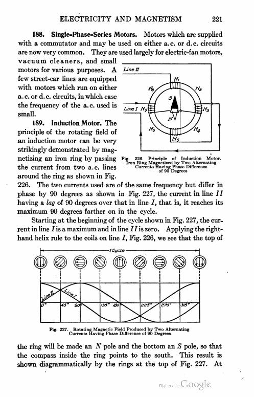
ELECTRICITY AND MAGNETISM 221
188. SingIe=Phase=Series Motors. Motors which are supplied
with a commutator and may be used on either a. c. or d. c. circuits
are now very common . They are used largely for electric-fan motors,
vacuum cleaners, and small
motors for various purposes. A
few street-car lines are equipped
with motors which run on either
a. c. or d. c. circuits, in which case
the frequency of the a. c. used is
small.
189. Induction Motor. The
principle of the rotating field of
an induction motor can be very
strikingly demonstrated by mag
netizing an iron ring by passing Fig. 220.
the current from two a.c. lines
around the ring as shown in Fig.
226. The two currents used are of the same frequency but differ in
phase by 90 degrees as shown in Fig. 227, the current in line II
having a lag of 90 degrees over that in line I, that is, it reaches its
maximum 90 degrees farther on in the cycle.
Starting at the beginning of the cycle shown in Fig. 227, the cur
rent in line J is a maximum and in line is zero. Applying the right-
hand helix rule to the coils on line I, Fig. 226, we see that the top of
Principle of Induction Motor.Iron Ring Magnetized by Two Alternating
CurrentB Having Phase Differenceof 90 Degrees
Fig. 227. Rotating Magnetic Field Produced by Two AlternatingCurrents Having Phase Difference of 90 Degrees
the ring will be made an N pole and the bottom an S pole, so that
the compass inside the ring points to the south. This result is
shown diagrammatically by the rings at the top of Fig. 227. At

222 ELECTRICITY AND MAGNETISM
the end of one-eighth of a cycle, the current in line I has decreased
and in line 77 has increased, causing the N pole on the ring to travel
from Ni to N2, Fig. 226. At the end of one-fourth of a cycle, the
current in line 7 is zero and in line II is a maximum so that the right
side of the ring is an N pole and the left side an S pole, and so on.
Thus the N pole during one cycle travels around the ring occupying
in succession the positions Nu Nt, . . . Ng, and all of the intervening
points, i.e., the motion of. N is continuous and not by jumps as was
necessary in studying the experiment. Thus the field on the inside
Fig. 228. Stator of Polyphase Induction Motor
Courtesy of Burke Electric Company
is made to rotate continuously through the directions indicated in
the circles at the top of Fig. 227, and a magnet on the inside of the
ring in Fig. 226 will rotate with the field; in other words, we have a
motor of the two-phase type.
A typical commercial induction motor is shown in Figs. 228 and
229. Fig. 228 shows the stationary primary member (stator or field)
after the coils have been fastened in place. This produces the
rotating field. The secondary member (or rotor) is shown in Fig.
229. The conductors are rectangular bars which are placed in slots
around the iron core and project over the ends where they are

ELECTRICITY AND MAGNETISM • 223
rigidly attached to massive rings of copper thus forming a short-
circuited winding. This type of winding is called a squirrel-cage
rotor. The rotating field of the stator sweeps across the heavy
rectangular-bar windings of the
rotor and induces in them strong
currents which magnetize the iron
core of the rotor and the rotating
field drags this magnetized core
around just as the rotating field
in our model induction motor of
Fig. 226 dragged the magnetic
needle around. The squirrel-
• j , • , , Fig. 229. Rotor of Burke Induction Motorcage induction motor runs at very
nearly constant speed for all loads, requires practically no attention,
is very simple to operate so that any one can run it, and requires no
accessories as does the synchronous motor. For these reasons its
use is rapidly increasing for nearly all purposes.
MEASUREMENT AND TRANSMISSION OF POWER IN AN
ALTERNATING-CURRENT CIRCUIT
190. Comparison of A.C. and D.C. Electromotive Forces and
Currents. Since the e.m.f. or the current curve for alternating
currents is a sine wave with an equal number of + and — values,
it is evident that the average e.m.f. or the average current throughout
one cycle or any number of cycles is zero, but that during the positive
(or negative) part of the cycle, it is not zero. This latter average
value is spoken of as the "average value" or "mean value".
If we let i be the value of the alternating current at any instant
the heating effect produced will be Ri2 and the average rate at which
heat will be generated during one or more cycles will be R multiplied
by the average i2 (remember this is the average of the squares and not
the square of the average). The effective value of the alternating cur
rent is then equal to the direct current which will produce the same
heating effect, or it is equal to Vaverage i2. This is about .7 of the
maximum value of the alternating current. Similarly the effective
e.m.f. in an a.c. circuit is about .7 of the maximum e.m.f. Volt
meters and ammeters with alternating currents record the effective
values of the e.m.f. and current, respectively.

224 ELECTRICITY AND MAGNETISM
191. Comparison of Power in A.C. and D.C. Circuits. For
the d. c. circuit the power delivered by the circuit in watts is
watts=voltsXamperes
Fig. 230. E.M.F., Current, and Power Curve, for Circuits where E.M.F. and CurrentAre in Phase
For the a.c. circuit, if we let e be the instantaneous value of
the e.m.f. and i the corresponding value of the current, then the
power delivered by the circuit at that instant in watts is
watts = ei
and the average of ei taken over one complete cycle is the "average
power," or simply the "power" delivered by the circuit in watts.
For a non-inductive circuit without capacity, the e.m.f. and
current will be in phase, in which case the power is given by
watts = effective e.m.f. Xeffective amperes
The conditions in such a circuit, a lamp for example, are shown
in Fig. 230, in which case the watts consumed by the lamp are equal
to the a. c. voltmeter reading multiplied by the a. c. ammeter reading.
It will be noted that the power curve is always positive.
Fig. 231. E.M.F., Current, and Power Curve, for Circuits where CurrentLags behind E.M.F.
If, however, the current is not in phase with the e.m.f. but lags
behind it as in Fig. 231, then the instantaneous values of ei are as
indicated by the fine dotted line showing the power curve. It will
be seen that this curve is not always positive but is negative for a
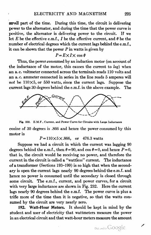
ELECTRICITY AND MAGNETISM 225
sirall part of the time. During this time, the circuit is delivering
power to the alternator, and during the time that the power curve is
positive, the alternator is delivering power to the circuit. If we
let E be the effective e.m.f., 7 be the effective current, and 6 be the
number of electrical degrees which the current lags behind the e.m.f.,
it can be shown that the power P in watts is given by
P=EXIX cos 0
Thus, the power consumed by an induction motor (on account of
the inductance of the motor, this causes the current to lag) when
an a.c. voltmeter connected across the terminals reads 110 volts and
an a. c. ammeter connected in series in the line reads 5 amperes will
not be 110X5, or 550 watts, since the current lags. Suppose the
current lags 30 degrees behind the e.m.f. in the above example. The
Fig. 232. E.M.F., Current, and Power Curve for Circuits with Large Inductance
cosine of 30 degrees is .866 and hence the power consumed by this
motor is
P = 110X5X.866, or 476.3 watts
Suppose we had a circuit in which the current was lagging 90
degrees behind the e.m.f., then 0 = 90, and cos 0 = 0, and hence P=0,
that is, the circuit would be receiving no power, and therefore the
current in the circuit is called a "wattless" current. The inductance
of a transformer (Sections 193-199) is so high that when the second
ary is open the current lags nearly 90 degrees behind the e.m.f. and
hence no power is consumed until the secondary is closed through
some circuit. The e.m.f., current, and power curves, for a circuit
with very large inductance are shown in Fig. 232. Here the current
lags nearly 90 degrees behind the e.m.f. The power curve is plus a
trifle more of the time than it is negative, so that the watts con
sumed by the circuit are very nearly zero.
192. Watt=Hour Meters. It should be kept in mind by the
student and user of electricity that wattmeters measure the power
in an electrical circuit and that watt-hour meters measure the amount

226 ELECTRICITY AND MAGNETISM
of electrical energy passing through the circuit. Thus if a watt
meter indicated that a lamp circuit was receiving 1 kilowatt, a watt-
hour meter left in the same circuit for 30 minutes would indicate
.5 of a kilowatt-hour. The kilowatt registered by the wattmeter
shows that work is being done on the lighting circuit at the rate of
| h.p., while .5 of a kilowatt-hour shows that during the 30 minutes
33,000X30X1, or 1,320,000 foot-pounds of work have been trans
formed into the energy of the electric current which was registered
by the watt-hour meter as .5 of a kilowatt-hour.
The instrument placed in the basement of buildings for measur
ing the amount of electricity consumed is the watt-hour meter. A
Fig. 233. Diagram Showing Principle of Watt-Hour Meter
type of watt-hour meter, which may be used on either d.c. or a,c.
circuits, is shown in Fig. 233. It is built on the principle of the
shunt motor and revolves at a rate depending upon the amount of
electrical energy passing through it. On the armature shaft is a
worm-gear which turns the dials from which the monthly readings
are taken for the purpose of computing the electric-light bills.
The field coils BB of this motor, Fig. 233, are connected in series
with the circuit CC, in which the energy to be measured is expended.
The armature A, together with an auxiliary non-inductive resistance
R, is shunted across the main circuit CC, as shown. Current is led
into the armature by means of the brushes dd pressing on a small
silver commutator e. Hence the moving force (torque) acting on

ELECTRICITY AND MAGNETISM 227
the armature is proportional to the product of volts multiplied by
amperes, that is, it is proportional to watts. In order that the speed
of the armature and hence the reading of the instrument may be
proportional to this torque, an aluminum disk / is mounted on the
armature shaft so as to rotate between the poles of the permanent
magnets M. The induced eddy currents in this disk set up a field
opposing its motion, so that the driving torque is always propor
tional to the speed. . While this instrument may be used for either
a. c. or d. c. circuits, it is generally used on d. c. work. For alternat
ing currents a watt-hour meter,* which is in reality a small induction
motor, is generally used.
TRANSMISSION OF ELECTRIC POWER
Fig. 234. Diagram of SimpleTransformer
193. Transformer. The commercial transformer is a modified
form of the induction coil. The chief difference is that the core It,
Fig. 234, instead of being straight, is
bent into the form of a ring, or is given
some other shape such that the magnetic
lines of force have a continuous iron
path, instead of being obliged to push out
into the air, as in the induction coil.
Furthermore, it is always an alternating
instead of an intermittent current which
is sent through the primary A. Sending such a current through A is
equivalent to first magnetizing the core in one direction, then demag
netizing it, then magnetizing it in the opposite direction, etc. The
results of these changes in the magnetism of the core is, of course, an
induced alternating current in the secondary B.
194. Use of the Transformer. The use of the transformer
is to convert an alternating current from one voltage to another
which for some reason is found to be more convenient. For example,
in electric lighting where an alternating current is used, the e.m.f.
generated by the dynamo is usually either 1,100 or 2,200 volts, a
voltage too high to be introduced safely into private houses. Hence,
transformers are connected across the main conductors in the manner
shown in Fig. 235. The current which passes into the houses to
*See "Induction Watt-Hour Meters" in any standard reference work.

228 ELECTRICITY AND MAGNETISM
supply the lamps does not come directly from the dynamo. It is
an induced current generated in the transformer.
195. Pressure in Primary and Secondary. If there are a
few turns in the primary and a large number in the secondary, the
transformer is called a step-up
transformer, because the p. d.
produced at the terminals of
the secondary is greater than
that applied at the terminals
of the primary. Thus, an in
duction coil is a step-up trans
former. In electric lighting,
however, transformers are
mostly of the step-down type;
i.e., a high p.d., say 2,200
volts, is applied at the termi
nal of the primary, and a lower p.d., say 110 volts, is obtained at
the terminals of the secondary. In such a transformer the primary
will have twenty times as many turns as the secondary. In general,
the ratio between the voltages at the terminals of the primary and the
secondary is the ratio of the number of turns of wire upon the two.
196. Efficiency of the Transformer. In a perfect transformer
the efficiency would be unity. This means that the electrical energy
Fig. 235. Alternating Current Circuit ContainingTransformers
Fig. 236. TransformerShowing Windings
and Core
Fig. 237. Cross-Section of TransformerShowing Shape of Magnetic
Field
put into the primary, i.e., the volts applied to its terminals, multi
plied by the amperes flowing through it, would be exactly equal to
the energy taken out in the secondary, i.e., the volts generated in it

ELECTRICITY AND MAGNETISM 229
multiplied by the strength of the induced current; and, in fact, in
actual transformers the latter product is often more than 97 per cent
of the former, i.e., there is less than 3 per cent loss of energy in the
transformation. This lost energy appears as heat in the transformer.
This transfer, which goes on in a big transformer, of huge quantities
of power from one circuit to another entirely independent circuit,
without noise or motion of any sort and almost without loss, is one
of the most wonderful phenomena of modern industrial life.
197. Commercial Transformers. Fig. 236 illustrates a com
mon type of transformer used in electric lighting. The core is built
Fig. 238. Typical Transformer Casing
up of sheet-iron laminas about .5 millimeter thick. Fig. 237
shows a section of the same transformer. The closed magnetic circuit
of the core is indicated by the arrows. The primary and the two
secondaries, which can furnish either 52 or 104 volts, are indicated
by the letters p, Si, and S2. Fig. 238 is the case in which the trans
former is placed. Such cases may be seen attached to poles, Fig.
239, outside of houses in any district where alternating currents
are used for electric-lighting purposes.
198. Electrical Transmission of Power. Since the electrical
energy produced by a dynamo is equal to the product of the e.m.f.

230 ELECTRICITY AND MAGNETISM
generated by the current furnished, it is evident that in order to
transmit from one point to another a given number of watts, say
10,000, it is possible to have either an e.m.f. of 100 volts and a cur
rent of 100 amperes, or an e.m.f. of 1,000 volts and a current of 10
amperes. In the two cases, however, the loss of energy in the wire
which carries the current from the place where it is generated to the
place where it is used will be widely different. If R represents
the resistance of this transmitting wire, the so-called "line", and
C the current flowing through it, the heat developed in it will be
proportional to C2R. Hence,
the energy wasted in heating
the line will be but .01 as much
in the case of the high-voltage,
10-ampere current, as in the
case of the lower-voltage, 100-
ampere current. Hence, for
long-distance transmission,
where line losses are consider
able, it is important to use the
highest possible voltages.
On account of the diffi
culty of insulating the commu
tator segments from one an
other, voltages higher than 700
or 800 cannot be obtained with
direct-current dynamos of the
kind which have been de-
Fig. 239. Transformer Mounted on Electric SCribed. With alternators,Light Pole
however, the difficulties of insu
lation are very much less on account of the absence of a commutator.
The large 10,000-horsepower alternating-current dynamos on the
Canadian side of Niagara Falls generate directly 12,000 volts. This
is the highest voltage thus far produced by generators. In all cases
where these high pressures are employed, they are transformed down
at the receiving end of the line to a safe and convenient voltage
(from 50 to 500 volts) by means of step-down transformers.
199. Long=Distance Transmission of Power. It will be seen
from the above facts that only alternating currents are suitable for

ELECTRICITY AND MAGNETISM 231
long-distance transmission. Plants are now in operation which
transmit power over 100 miles and use pressures as high as 100,000
volts. In all such cases step-up transformers, situated at the power
house, transfer the electrical energy developed by the generator to
the line, and step-down transformers, situated at the receiving end,
Fig. 240. Typical Electric Spot Welder
Courtesy of National Electric Welder Company
transfer it to the motors, or lamps, which are to be supplied. The
generators used on the American side of Niagara Falls produce a
pressure of 2,300 volts. For transmission to Buffalo, twenty miles
away, this is transformed up to 22,000 volts. At Buffalo, it is trans
formed down to the voltages suitable for operating the street cars,
lights, and factories of the city. On the Canadian side, the genera

232 ELECTRICITY AND MAGNETISM
tors produce currents at 12,000 volts, as stated, and this is "stepped-
up" for transmission to 22,000, 40,000, and 60,000 volts. .
200. Spot Welder. A very extensive application of the step-
down transformer has been made in recent years in connection with
electrical-welding machines. These are made to operate on 110,
220, or higher voltages, but more commonly on 220 volts. The
primary of the transformer is connected across the main line, and
from the secondary is drawn the current for operating the welder.
The voltage in the secondary is only about 3 to 5 volts and the current
sufficient to make the power somewhere between 1 h.p. for small
work and 200 h.p. for large work. Thus the currents used are very
large, a fact which is desirable, of course, since the heat produced is
equal to PR. A typical spot welder is shown in Fig. 240.
EXAMPLES FOR PRACTICE
1. A multipolar alternator has 20 poles and makes 200 r.p.m.
How many alternations per sec. will be produced in the circuit?
2. Two successive coils on the armature of a multipolar alter
nator are cutting lines of force which run in opposite directions.
How does it happen that the currents generated flow through the
wires in the same direction? (See Figs. 216 and 217.)
3. What is the period of the alternating current mentioned
in Example 1? How many cycles per second in the same current?
4. What happens in the armature of an alternator while it
rotates through 360 electrical degrees?
5. What relation exists between the e.m.f.'s induced in the
three sets of coils of a three-phase generator? (See Fig. 222.)
6. What is meant by a "balanced system" in connection with
a three-phase generator? When the generator is used on a balanced
system, how may the coils be connected to the mains to save one wire?
7. What is a synchronous motor?
8. Explain the operation of the induction motor.
9. The watts in an a.c. circuit are not, in general, equal to the
product of volts multiplied by amperes. Why not?
10. What relation must exist between the number of turns on
the primary of a transformer which feeds 110-volt lamps from a
main line whose conductors have a p.d. of 2,300 volts?
11. Why not use a step-up transformer for electrical welders?

INDEX.


INDEX
PAGE
A
A.C. and D.C. circuits, comparison of power - 224
A.C. and D.C. electromotive forces and currents, comparison 223
A.C. dynamo (simple) 195
A.C. generator, principle 191
Alternating-current generators 214
cycle, frequency, and period of alternating current 215
multipolar alternator 214
polyphase circuit 217
Alternating-current motors 220
induction motor 221
single-phase-series motors 221
synchronous motor 220
American Morse code 128
Ammeter, commercial 48
Ampere illustrations 49
Ampere, international method of measuring 90
Arc formation in arc lamp 140
Arc light 140
Arc-light automatic feed 141
Armature 195
Automatic enunciator 188
B
Back e.m.f. in motors 208
Becquerel rays 174
Bichromate cell 59
C
Calories of heat developed in wire 138
Cartridge fuse. 145
Cathode rays 168
nature 169
size and velocity of cathode-ray particles 169
Cells, combination 63
Chemical energy 136
Coherer 180
Collecting rings 195
Commercial transformers 229
Commutator 194
Condensers 33
Conductance 94
Conductivity 96

2 INDEX
PAGE
. Conductors and insulators 'Jti — 17
Cooper-Hewitt mercury lamp 141
Coulomb's law 16
Crookes' spinthariscope 174
Crowfoot.or gravity cell 60
Currents induced by currents j 156
Cycle, frequency, and period of alternating current 215
D
Daniell cell 59
D.C. dynamo (simple) 196
Direct-current generators 198
drum-armature direct-current dynamo 199
importance of setting brushes to agree with point of commutation 204
methods of exciting generator fields and their applications. 200
ring-armature direct-current dynamo 198
Direct-current motors 206
back e.m.f. in motors 208
dynamo used as motor 206
efficiency of motor 212
reversing motor 211
shop motors 210
street-car motors 208
Drum-armature direct-current dynamo 199
Dry cell 62
Dynamo, principle of 152
Dynamo, or "right-hand," rule 151
Dynamo used as motor 206
Dynamo-electric machines 191
alternating-current motors 220
D.C. dynamo (simple) 195
direct-current generators 198
direct-current motors 206
measurement and transmission of power in an alternating-current
circuit 223
principle of A.C. generator - - 191
E
Edison storage battery 137
Electric bell I26
Electric current, chemical effects 133
Edison storage battery I37
electroplating 133
electrotyping 134
measuring current, chemical method 135
metals, refining 135
storage batteries 135
Electric current, energy relations 138
Electric current, heat developed in wire by 137

INDEX 3
PAGE
Electric current, heating effects 137
arc light 140
arc-light automatic feed 141
calories of heat developed in wire I38
Cooper-Hewitt mercury lamp 141
electric current, energy relations I38
fuses and circuit breakers 145
heat developed in wire by electric current 137
household and artisans' devices 142
household water-heaters, efficiencies of 143
incandescent lamps 139
protection of circuits against overheating 145
Electric current, measurements and applications 67
electrolysis—measurement of current strength 86
electromagnetism "3
electromagnets, applications 126
laws of resistance 93
Ohm's law 67
p.d. and e.m.f., measurement of 105
resistance, measurement 112
Electric current, measuring 47
ampere illustrations 49
commercial ammeter 48
commercial voltmeter 52
electrical resistance 53
electromotive force and its measurements 49
electromotive forces of galvanic cells 52
internal resistance of galvanic cell 54
Ohm's law 54
unit of current—the ampere 47
unit of e.m.f.—the volt 51
Electric heating apparatus, typical circuit for investigating efficiency of 144
Electric immersion heater 143
Electric motor, principle of I 153
Electric power, transmission 227
electrical transmission of power 229
long-distance transmission of power 230
pressure in primary and secondary 228
spot welder 232
transformer 227
Electric stove (simple) 143
Electric teapot 143
Electric tuning-fork 127
Electric waves I78
Electrical attraction and repulsion, laws : 15
Electrical field W
Electrical generators * 35
electrophorus 35
source of energy of charge obtained from electrophorus 36

4 INDEX
PAGE
Electrical generators (continued)
Toepler-Holtz static machine 36
Wimshurst electrical machine 38
Electrical potential 29
Electrical quantities, measurements 15
Electrical resistance 53
Electrical screens 28
Electrical transmission of power 229
Electricity and magnetism, elements 1-232
beginnings 1
dynamo-electric machines 191
electric current, chemical effects 133
electric current, heating effects 137
electric current, measurement and application 67
electrical generators 35
electricity in motion—electrical currents 40
induced currents and electric power 147
induction coil and its uses 156
magnetism 1
primary cells 56
radioactivity 1'3
radiotelegraphy 1*6
static electricity 14
telephone 183
transmission of electric power 227
Electricity in motion—electrical currents 40
comparison of galvanic cell with static machine 43
galvanic cell 41
galvanometers 45
measuring of current 47
shape of magnetic field about current 44
Electricity (positive and negative) 15
Electrification by friction 14
Electrolysis—measurement of current strength 86
electric current conducted through liquid 86
international method of measuring ampere 90
of water 87
Electrolysis of water 87
Electromagnet 125
Electromagnetic induction, illustrating principle 148
Electromagnetic theory of light 183
Electromagnetism 123
electromagnet 125
magnetic properties of helix 123
magnetic properties of loop 123
north and south poles of helix, rules for 124
Electromagnets, applications - 126
electric bell 126
electric tuning-fork 127

INDEX 5
PAGE
Electromagnets, applications (continued)
other applications -
relay and sounder 129
telegraph **'
telegraph system 130
Electromotive force 67
Electromotive force and its measurements 49
Electromotive forces of galvanic cells T 52
Electron theory
Electrophorus 35
Electroplating 133
Electrostatic induction I 18
Electrostatic voltmeters 33
Electrotyping 134
E.M.F. of cell, measurement 109
potentiometer method 109
E.M.F. at make and break 1°°
E.M.F. of secondary of induction coil 158
F
Faraday's conception of motor and dynamo principles 154
Faraday's discovery 147
Foucault currents r 163
Frequency of alternating currents 215
Fuses and circuit breakers 145
G
Galvanic cell -
galvanic cell, internal resistance 54
Galvanometers 45
Gassiot's cascade 165
Geissler tubes 166
Gold-leaf electroscope 21
Gravity cell 60
H
Helix, magnetic properties "123
Household and artisans' devices 142
Household water-heaters, efficiencies of 143
I
Incandescent lamps 139
Induced current, direction 148
Induced currents and electric power 147
dynamo, principle of 152
dynamo, or "right-hand," rule 151
electric motor, principle of 153
Faraday's conception of motor and dynamo principles 154
Faraday's discovery 147

6 INDEX
PAGE
Induced currents and electric power (continued)
induced current, direction 148
induced e.m.f., conditions necessary 149
induced e.m.f., strength of 151
induction of currents by magnets 147
Induced e.m.f., conditions necessary 149
Induced e.m.f., strength of 151
Induction, charging by 21
Induction coil and its uses 156
construction of 161
currents induced by currents 156
discharge phenomena 164
e.m.f. at make and break 158
e.m.f. of secondary 158
laminated cores 163
self-induction 159
self-induction applied to make-and-break ignition 161
Induction coil discharge phenomena 164
cathode rays 168
discharges in partial vacua 165
heating effects 164
mechanical and chemical effects 165
new theories as to constitution of matter 170
physiological effects 164
X-rays 171
Induction of currents by magnets 147
Induction motor 221
Insulators . "
L
Laminated cores 163
Laminated drum armature core 163
Laws of resistance 93
calculation of resistance 97
conductance 94
conductivity 96
resistance affected by heating 101
resistance inversely proportional to cross-section 95
resistance proportional to length 94
resistance tables 163
specific resistance 96
Leclanch6 cell 61
Lenz's law 1^8
Leyden jar, proof that discharge is oscillatory 176
Leyden jars
Lightning and lightning rods 26
Long-distance transmission of power 230
Loop, magnetic properties 123
v.

INDEX 7
PAGE
M
Magnetism 1
declination 10
earth's inductive action 13
earth's magnetism 10
inclination dip H
laws of magnetic attraction and repulsion 2
magnet poles 2
magnetic field, strength '
magnetic fields of force 6
magnetic induction 4
magnetic lines of force 6
magnetic pole of unit strength 3
magnetic substances 4
molecular nature 8
natural and artificial magnets 1
retentivity and permeability 5
saturated magnets 10
Measurement and transmission of power in an alternating-current circuit. . 223
comparison of a.c. and d.c. electromotive forces and currents 223
comparison of power in a.c. and d.c. circuits 224
watt-hour meters 225
Measuring current, chemical method 135
Mercury Lamp, Cooper-Hewitt 141
Metals, refining 135
Motor, efficiency of 212
Multipolar alternator 214
O
Ohm's law 54, 67
current 68
definition 69
divided circuits 74
electromotive force 67
fall of potential in circuit 72
joint resistance of divided circuits 75
resistance 68
series circuits 70
simple applications 70
volt, ampere, and ohm 68
P
P.D. and E.M.F. measurement of 105
absolute electrometer and electrostatic voltmeter 106
measurement of e.m.f. of cell 109
p.d. measurement 105
p.d. measurement by calorimetric method 107
Period of alternating current 215
Polarization 58

8 . INDEX
PAGE
Polyphase circuit 217
"Post-office box" bridge 121
Potentials, methods of measuring 32
Primary cells 56
action of simple cell 56
bichromate cell 59
cells, combination 63
crowfoot or gravity cell 60
Daniell cell 59
dry cell 62
Leclanche cell 1 61
polarization 58
theory of action of simple cell 57
R
Radioactivity ►— 1*3
Becquerel rays 174
Crookes' spinthariscope 174
discovery - 173
disintegration substances of 175
energy stored up in atoms of elements 176
radium 173
Radiotelegraphy 176
coherer 180
electric waves r ; 178
electromagnetic theory of light 183
modern wireless outfit 181
proof that discharge of Leyden jar is oscillatory 176
simple wireless outfit 180
Radium 173
Relay and sounder 129
Resistance, measurement 112
resistance by substitution 112
resistance by voltmeter-ammeter method 114
resistance by Wheatstone 116
Reversing motor 211
Ring-armature direct-current dynamo 198
S
Self-induction 159
applied to make-and-break ignition 161
Shop motors 210
Silverrplating bath, section of 134
Single-phase-series motors 221
Slide-wire bridge 118
Smoke and fume condenser 27
Spinthariscope, Crooke's 174
Spot welder 232
Squirrel-cage rotor . 223

INDEX 9
PAGE
Standard plug fuse 145
Static electricity 14
appearance of positive and negative electricities simultaneous and in
equal amounts 23
charging by induction 21
condensers 33
conductors and insulators 17
Coulomb's law 16
discharging effect of points 25
electrical charge resides upon outside surface of conductor 24
electrical field '- . 16
electrical potential 29
electrical screens 28
electrification by friction 14
electron theory 20
electrostatic induction ' 18
gold-leaf electroscope 21
greatest density of charge where curvature of surface is greatest 24
laws of electrical attraction and repulsion 15
Leyden jars 34
lightning and lightning rods 26
measurements of electrical quantities 15
positive and negative electricity 15
potentials, method of measuring 32
smoke and fume condenser 27
two-fluid theory of electricity 19
unit of p.d 31
Step-down transformers 231
Storage batteries 135
uses of 137
Storage battery plates (typical) 136
Street-car motors 208
Synchronous motor 220
T
Tables
American wire gage 103
electrochemical equivalents 92
resistance of chemically pure substances at 32° Fahrenheit in inter
national ohms 98
Stubs' or Birmingham wire gage (B. W. G.) 104
temperature coefficients 101
Telegraph 127
system 130
Telephone 183
automatic enunciator 188
modern transmitter 185
simple 183.
subscriber's telephone connections - 186

10 INDEX
PAGE
Telephone (continued)
wireless 187
Toepler-Holtz static machine 36
Transformer 227
commercial 229
efficiency 228
step-down 231
use 227
Two-fluid theory of electricity 19
U
Unit of p.d 31
V
Volt 51
illustrations of 52
Voltmeter, commercial 52
W
Watt-hour meters 225
Wheatstone bridge, resistance by 116
Wimshurst electrical machine 38
Wire fuse (simple) 145
Wireless outfits 180
Wireless telephone 187
X
X-rays 171
nature 172
pictures 173
render gases conducting 172
APR 'I 7 1917


UNIVERSITY OF MICHIGAN
BOUND
JAN 20 1947
UNIV. OF MICH.
LIBRARY
3 9015 03961 0756