DOMESTICE ELECTRICITY
53
. "-J i I C \ Domestic Electricity A507.12TAY
-
Upload
khangminh22 -
Category
Documents
-
view
2 -
download
0
Transcript of DOMESTICE ELECTRICITY

."-J i I
C
\
Domestic Electricity
A507.12TAY

Project Director John Taylor
Editorial TeamJackie Hardie Peter Llewellyn Col urn Quinn Keith Roberts
Language Consultant Grahame Mitchell
Contents
1 Plugs and sockets 12 Fuses 53 Household lighting
circuits 114 Household power circuits 175 Buzzers and bells 246 Water heaters 27
Acknowledgements — inside back cover
This book from an original manuscript by R. Alien and R. Josephy.
The publishers wish to thank the Electricity Council for their help in preparing this book and supplying many of the photographs.
12786603TELEPEN
? 1979 by Addison-Wesley Publishers Limited West End 'House. 11 Hills Place. London W1R 2LR. Philippines copyright 1979 by Addison-Wesley Publishers Limited.
All rights reserved. No part of this publication may be reproduced, stored in a retrieval system, or transmitted in any form or by any means, electronic, mechanical, photocopying, recording or otherwise, without prior written permission of the publisher.
ISBN 201 14012 8
Designed, set and illustrated by Parkway Group and printed in Great Britain by Pindar Print, Scarborough.
ABCDEF79
LIBRARY
COLLEGE OF!i!GHE* EDUCATION
READING
ACCESS No;
.. (j, O— ————— -4- CLAS5 No: |

1 Plugs and socketsInformation: Plugs and sockets
A 240 volt shock can kill you. You must disconnect the appliance or switch off the supply at the meter before you do any work on mains voltage equipment. In the experiments in this book a low voltage supply must be used.
screw tohold the back on
|L Live pin
The outside of a plug
Neutral terminal^^•BBEarth terminal
terminalnmm^n
The inside of a plug
E Earth socket
screws
N Neutral socket
L Live socket
The outside of a socket
E Earth terminal
L Live terminal
N Neutral terminal
The inside of a socket
The mains voltage (240 volts) is connected to the Live and Neutral wires. These are the wires that supply current to an appliance. The Neutral wire is connected to Earth at the electricity sub-station. This means it is at the same voltage as Earth. The Live wire is at a high voltage (240 volts). The Live wire is dangerous to touch. The Earth wire is only for safety. It is connected to earth at the building to which the electricity is supplied. Any appliance that has a metal case, such as an iron, should have an Earth wire connected to its metal case. If the metal case is properly connected to the Earth wire, it is impossible to get a shock from it.
Colours of wires in cables
System now
brown = Live blue = Neutral yellow/green
= Earth
Old system(before 1975)
red = Live black = Neutral green = Earth
Q1 What is the voltage of mains electricity in this country?
Q2 Which two wires supply the electric current to an appliance?
Q3 What is the Earth wire connected to?
Q4 What is the Earth wire for?National STEM Centre
N23567

Plugs and sockets
Connecting a flex to a plug and socket
Apparatus
* 3-core flexible cable * 3-pin plug* scissors * wire strippers
* socket * screwdriver
You are going to wire up a plug and a socket. Your plug and socket may look different from these, but they all work in the same way.
A Using scissors, carefully slit about 5 cm down the outer cover of some 3-core cable.Take care not to cut the coloured wires. Cut off the cover you have slit.
B Unscrew the top of the plug provided. Take out the fuse.
C Undo the cable grip. Put the cable in the plug, as shown. Put back the cable grip and screw it tight.
D Cut the 3 wires so that they reach just beyond the terminals of the plug.
•E Using wire strippers, strip about 1 cm of the insulation (the coloured cover) from each wire.
F Make sure the brown wire goes to the Live terminal (the one with the fuseholder). The green/ yellow wire goes to the Earth terminal. The blue wire goes to the Neutral terminal.

Plugs and sockets
G Twist each wire. Attach the wires to the correct terminals. Replace the fuse. Check the wires are firmly screwed in.
H Replace the back of the plug. Tighten the screws.
1 Prepare the other end of the cable as in step A. Unscrew the back of the socket provided.
J Thread the cable through the inlet in the back of the socket. Cut the wires so that they reach just past the terminals.
K Strip 1 cm of insulation from each wire. Attach the brown wire to terminal L, the blue wire to terminal N and the green/ yellow wire to terminal E.
L Replace the front of the socket. Tighten the screws. Show the finished plug and socket to your teacher for inspection and testing.
Q5 What does the letter N on the Inside of a socket mean?
Q6 Which colour wire carries a high voltage when the electricity is switched on?
Q7 Which colour wire does not usually carry electricity?
Plugs and sockets
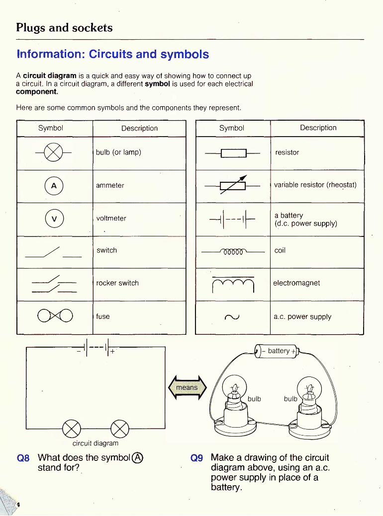
Information: Circuits and symbolsA circuit diagram is a quick and easy way of showing how to connect up a circuit. In a circuit diagram, a different symbol is used for each electrical component.
Here are some common symbols and the components they represent.
Symbol
oo
Description
bulb (or lamp)
ammeter
voltmeter
switch
rocker switch
fuse
circuit diagram
Q8 What does the syml stand for?
Symbol
r~^rw~^\
Description
resistor
variable resistor (rheostat)
a battery(d.c. power supply)
coil
electromagnet
a.c. power supply
Q9 Make a drawing of the circuit diagram above, using an a.c. power supply in place of a battery.

2 FusesChecking a fuseApparatus
* fuseholder * 1 A fuse * 12 V 0.1 A lamp in holder* low voltage power supply
You are going to build a circuit to check a fuse.
* wire
A Build this circuit. Use a low voltage power supply, set at 6 V.
6 volt d.c. supply
B Switch on the electricity. The lamp should light.
C Switch off the electricity. Put a 1 amp fuse into a fuseholder.
D Build this circuit. Switch on the electricity. Watch what happens to the lamp.
6 volt d.c. supply ————————I __.
Q1 Draw the final circuit diagram.
Q2 If the fuse was blown, what would happen when the electricity was turned on?
Q3 What could you use instead of a lamp to check the fuse?

Fuses
Finding the current at which a fuse blows
Apparatus
* fuseholder * 1 A fuse * ammeter * rheostat (variable resistor)* wire * low voltage power supply
You are going to build a circuit and find the current that blows the fuse.
A Build this circuit. Do not switch on the electricity yet. Use a low voltage power supply, set to 4 volts.
4 volt d.c. supply ————————I —-
©
B Make sure the ammeter is wired up correctly, as shown.
to
to + terminal of power supply
C Set the rheostat to the highest resistance. Switch on the electricity. Move the slider on the rheostat a short distance. Read the ammeter.
low
D Reading the ammeter all the time, slowly move the slider to a lower resistance. When the fuse is overloaded, it will blow. Note this reading on the meter.
to - terminal of power supply to + terminal of power supply
Q4 What happened to the reading on the ammeter when the fuse blew?
Q5 How much current will a 1 amp fuse let through before it blows?

Fuses
Using a fuse with too high a current rating
Apparatus
* fuseholder * 5 A fuse * ammeter * 4.7 ohm resistor * wire* low voltage power supply * 2 crocodile clips * heatproof mat
You are going to find out what happens when you use a fuse with too high a current rating.
A Build this circuit. Do not switch on the electricity yet. Put a 5 amp fuse in a fuseholder.
12 volt d.c. supply
0-C
B Check that the voltage is set to 12 V. Make sure the ammeter is wired up, as shown.
C Put a heatproof mat under the resistor. D Switch on the electricity. Watch what happens to the ammeter and resistor.
Q6 Draw the circuit diagram.
Q7 How much current flowed around the circuit when you switched on?
Q8 What happened to the resistor?
Q9 Did the fuse protect the resistor?

Fuses
Information: Fuses
Fuses are put into electrical circuits for safety. Under normal conditions, a fuse does not affect the current flowing in a circuit.A fuse is a thin pice of wire. It melts if too much current passes through it. This stops the current flowing to the appliance. A 5 amp fuse will blow (melt) if more than 5 amps pass through it. The level at which a fuse blows is called its current rating.
cartridge fuseThere are two types of fuse. One is a cartridge fuse. If this blows it has to be replaced. The other type has renewable fuse wire.
fuse with renewable wireIn modern houses, fuses are found in plugs (cartridge fuses) and in the fuse box (several renewable fuses).
Replacing a fuse
blown fuse repairing a fuse
replacing a cartridge fuse in a plug
A fuse blows if something is wrong with the circuit. For example, the circuit may be overloaded with too many electrical appliances. When the fault has been put right, the fuse can be replaced or repaired.
Q10 What is the job of a fuse? Q11 What would happen if a 5 amp fuse was used to protect an appliance which took 7 amps?

Fuses
Information: Fuses circuit breakers
MCB J (or fuse board in older house)
In most houses, there is a set of fuses on a board near the mains switch. In the modern system of wiring, each fuse controls one part of the system. For example, one fuse controls the electricity to all the downstairs lights.Many modern homes now have miniature circuit beakers (MCB) instead of fuses. These are easier to use. If the circuit is overloaded, the circuit breaker will automatically switch off that circuit. The fault in the circuit has to be put right. Then the circuit breaker can be switched back on by hand.
These photos show another type of modern circuit breaker. If a circuit is overloaded, its circuit breaker pops out.
When the fault has been put right, the circuit breaker can be put back into place and the current switched back on.
What do the numbers on the circuit breakers show?
Q13 Why are circuit breakers easier to use than fuses?

Fuses
Information: Which fuse should I use?
The current rating of the fuse needed to protect an electrical appliance can be calculated. This is done by dividing the power (in watts) of the appliance by the mains voltage (240 V). The power (in watts) is usually given somewhere on an electrical appliance. The result of the calculation gives the current (in amps) the appliance uses.
For example, a 3 kW (3000 watts) heater draws 3000
240= 12 1/2 amps
The heater will need a 13 amp fuse in the plug. If you are in doubt about the correct fuse to use, read the manufacturer's instructions for the appliance.
Q14 What would happen if a 3 A fuse was used in the plug attached to an electric fire?
Q15 Many plugs are sold with 13 A fuses already in them. Why should you change this fuse if you want to use the plug for a record player?
Q16 With a mains voltage of240 V, calculate the correct fuse to use with a 2.4 kW storage radiator.
10

3 Household lighting circuitsBuilding a model of a household lighting circuitApparatus
*
/ \pfjui ctiuo
* large circuit board * three 12 V bulbs in holders * 1 A fuse * scissors* fuseholder * 3 small rocker switches * large 2-way rocker switch* brown wire * blue wire * 6 plastic junctions* blue wire * 6 plastic junctions
strippers * screwdriverbrown wire « uiue wire T*.O\
* low voltage power supply * wire* nuts and bolts
You are going to build a model household lighting circuit, This activity may take severallessonsto complete.
A You are going to build this circuit.
12 volt d.c. supply
B Put the rocker switches and bulbs (in holders) in place on the circuit board, as shown. Fix them to the board with nuts and bolts.
front of board
switches
bulbs
large switch.
C Fix a fuseholder in place underneath the board, as shown. Join the fuseholder to the large rocker switch with brown wire.
back of board
'fuseholder'
D Fix a piece of brown wire to the fuseholder. It must reach round the board to the last switch. Fix a piece of blue wire the same length to the rocker switch.
back of board
l>11

Household lighting circuits
E Cut the Live (brown) wire in front of the first small switch. Fix the cut ends to a plastic junction. Join a short piece of brown wire to the other end of the junction.
back of board
unction
F Fix the other end of the short brown wire to the first small rocker switch.
back of board
G Join the first small rocker switch to the first bulb with a short piece of brown wire. You will have to thread the wire through holes in the board.
H Cut a piece of blue wire long enough to join the first bulb to the Neutral wire above it. Use a plastic junction to make the connection as you did in steps E and F.
back of board
back of board
I Repeat steps E to H to join up the other bulbs and single switches, as shown.
J Check your wiring against this circuit diagram.
back of board
12
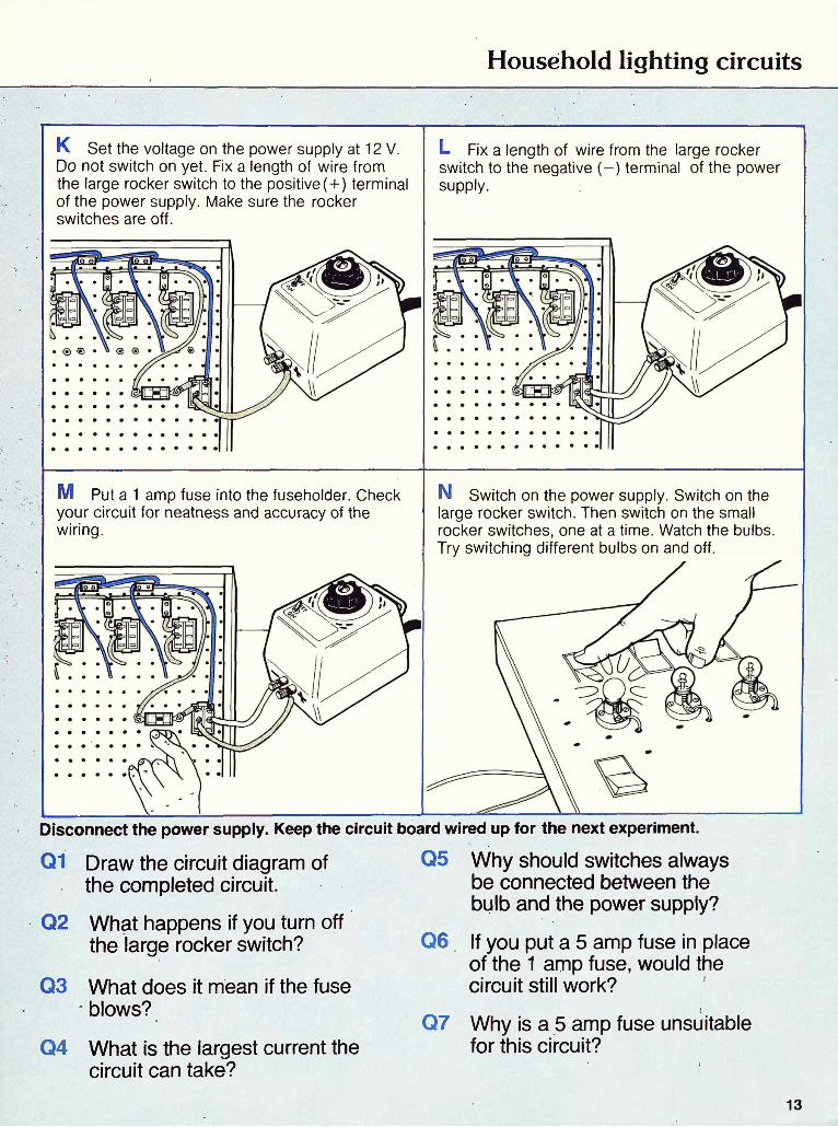
Household lighting circuits
K Set the voltage on the power supply at 12 V. Do not switch on yet. Fix a length of wire from the large rocker switch to the positive (+) terminal of the power supply. Make sure the rocker switches are off.
L Fix a length of wire from the large rocker switch to the negative (-) terminal of the power supply.
M Put a 1 amp fuse into the fuseholder. Check your circuit for neatness and accuracy of the wiring.
N Switch on the power supply. Switch on the large rocker switch. Then switch on the small rocker switches, one at a time. Watch the bulbs. Try switching different bulbs on and off.
Disconnect the power supply. Keep the circuit board wired up for the next experiment.
Q1 Draw the circuit diagram of the completed circuit.
Q2 What happens if you turn off the large rocker switch?
Q3 What does it mean if the fuse blows?
Q4 What is the largest current the circuit can take?
Why should switches always be connected between the bulb and the power supply?
Q6 If you put a 5 amp fuse in place of the 1 amp fuse, would the circuit still work?
Q7 Why is a 5 amp fuse unsuitable for this circuit?
13
Household lighting circuits
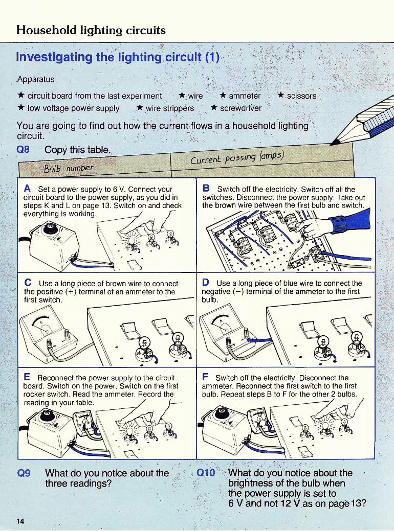
Investigating the lighting circuit (1)Apparatus
* circuit board from the last experiment * wire * ammeter* low voltage power supply * wire strippers * screwdriver
* scissors
You are going to find out how the current flows in a household lighting circuit.Q8 Copy this table.———•—',—~
bulb number
A Set a power supply to 6 V. Connect your circuit board to the power supply, as you did in steps K and L on page 13. Switch on and check everything is working.
B Switch off the electricity. Switch off all the switches. Disconnect the power supply. Take out the brown wire between the first bulb and switch.
C Use a long piece of brown wire to connect the positive (+) terminal of an ammeter to the first switch.
D Use a long piece of blue wire to connect the negative (-) terminal of the ammeter to the first bulb.
E Reconnect the power supply to the circuit board. Switch on the power. Switch on the first rocker switch. Read the ammeter. Record the reading in your table.
F Switch off the electricity. Disconnect the ammeter. Reconnect the first switch to the first bulb. Repeat steps B to F for the other 2 bulbs.
Q9 What do you notice about the three readings?
Q10 What do you notice about the brightness of the bulb when the power supply is set to 6V and not 12 V as on page 13?
14

Household lighting circuits
Investigating the lighting circuit (2)Apparatus
* your circuit board from the last experiment * wire * ammeter* low voltage power supply * scissors * wire strippers * screwdriver
You are going to find out how the current is affected by the number of bulbs connected.
Q11 Copy this table.
A Set a power supply to 6 V. Wire your circuit board to the power supply. Switch on and check everything is working. ' '
B Switch off the electricity. Switch off all the switches. Disconnect the power supply. Take out the brown wire between bulb 3 and switch 3.
C Connect an ammeter between bulb 3 and switch 3 as you did in steps C and D on page 14.
D Reconnect the board to the power supply. Switch on the electricity and all the rocker switches. Record in your table the reading on the ammeter.
E Switch off the electricity. Take out the first bulb. Switch on. Record in your table the reading on the ammeter.
F Switch off the electricity. Take out the second bulb. Switch on. Record in your table the reading on the ammeter.
Q12 What happened to thereading on the ammeter after you removed bulb 1 ?
Q13 As you took out more bulbs, did the current get bigger, smaller or stay the same?
15

Household lighting circuits
Information: Light power
The power (in watts) is printed on top of a bulb.
very bright bright dim
starter switch
tube
Fluorescent lights are glass tubes coated on the inside with a special chemical. When the electricity is switched on it makes the chemical glow. Fluorescent tubes last longer than ordinary lamps. They also give out more light. A 60 W lamp is quite dim. A 60 W fluorescent tube is enough to light a kitchen. The electrical parts needed to make a fluorescent tube glow are quite complicated. If a fluorescent light goes wrong, and the ends of the tube are not blackened, it is quite likely to be only the starter switch that needs replacing.
Q14 How many 100 W light bulbs would it take to use as much electricity as a 1 kW fire?
What are the advantages of fluorescent lighting?
16
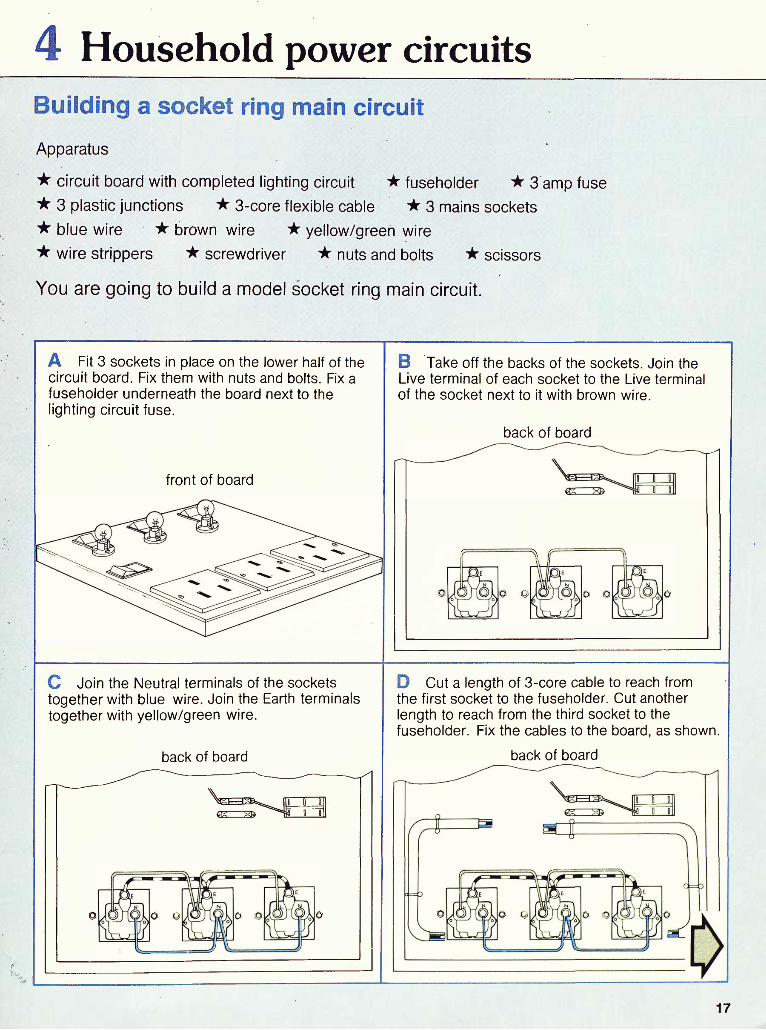
4 Household power circuitsBuilding a socket ring main circuitApparatus
* circuit board with completed lighting circuit * fuseholder * 3 amp fuse* 3 plastic junctions * 3-core flexible cable * 3 mains sockets* blue wire * brown wire * yellow/green wire* wire strippers * screwdriver * nuts and bolts * scissors
You are going to build a model socket ring main circuit.
A Fit 3 sockets in place on the lower half of the circuit board. Fix them with nuts and bolts. Fix a fuseholder underneath the board next to the lighting circuit fuse.
front of board
B Take off the backs of the sockets. Join the Live terminal of each socket to the Live terminal of the socket next to it with brown wire.
back of board
C Join the Neutral terminals of the sockets together with blue wire. Join the Earth terminals together with yellow/green wire.
back of board
D Cut a length of 3-core cable to reach from the first socket to the fuseholder. Cut another length to reach from the third socket to the fuseholder. Fix the cables to the board, as shown.
back of board
17

Household power circuits
E Join the lengths of 3-core cable together near the fuseholder. Fix the 2 brown wires with one plastic junction, the blue wires with another and the green/yellow wires with a third plastic junction.
back of board
F Join the other ends of the 3-core cable to the first and third sockets. Make sure the wires go to the correct terminals.
back of board
G Join the brown wire from the plastic junction to the fuseholder with brown wire. Join the fuseholder to the Live terminal of the rocker switch with brown wire.
back of board
H Join the blue wire from the plastic junction to the Neutral terminal of the rocker switch with blue wire. Put the fuse in the fuseholder.
back of board
Keep the circuit board wired up to be tested in the next experiment.
Q1 Draw a circuit diagram for the circuit you have made.
Q2 What do the letters L, N and E on the back of a socket mean?
Q3 Why should you use a 3 amp fuse for the power circuit?
Q4 In a house what would the yellow/green Earth wire be fixed to?
18

Household power circuits
Investigating the Live and Neutral circuits
Apparatus
* circuit board with lighting and power circuits wired up * three 3-pin plugs* three 24 W bulbs in holders * ammeter * low voltage power supply* 2-core cable * brown wire * blue wire * scissors* wire strippers * screwdriver * 3 labels
You are going to test the Live and Neutral parts of the socket ring main circuit.
Current passing (amps}
Q5 Copy this table.
A Label each bulb holder power circuit.Connect each 24 W bulb to a 3-pin plug. Use 2-core cable. Only the Live and Neutral circuits are to be tested.
B Using brown wire, connect an ammeter to the positive (+) terminal of a low voltage power supply.
C Use a long piece of brown wire to connect the negative (-) terminal of the ammeter to the Live terminal of the large rocker switch on your circuit board.
D Use blue wire to join the negative(—) terminal of the low voltage power supply to the Neutral terminal of the large rocker switch.
19

Household power circuits
E Join the green/yellow wire from your power circuit on the circuit board to a suitable Earth point. The metal case of the power supply will do.
F Set the voltage on the low voltage power supply to 6 V. Check that the power circuit has a 3 A fuse. Check that the lighting circuit has a 1 A fuse. Use this diagram to check your wiring.
6 volt d.c. supply A
lighting circuit
G Switch on the electricity. Plug a bulb into the first socket. Read the ammeter. Record the reading in your table.
H Plug in the second and third bulbs. Each time, record in your table the reading on the ammeter. Then switch on the lighting circuit as well. Read the ammeter.
Q6 What is the current if the power and lighting circuits are both switched on?
Q7 Does any current flow through the Earth wire?
Q8 Draw the circuit diagram for the power and lighting circuits.
20
Household power circuits
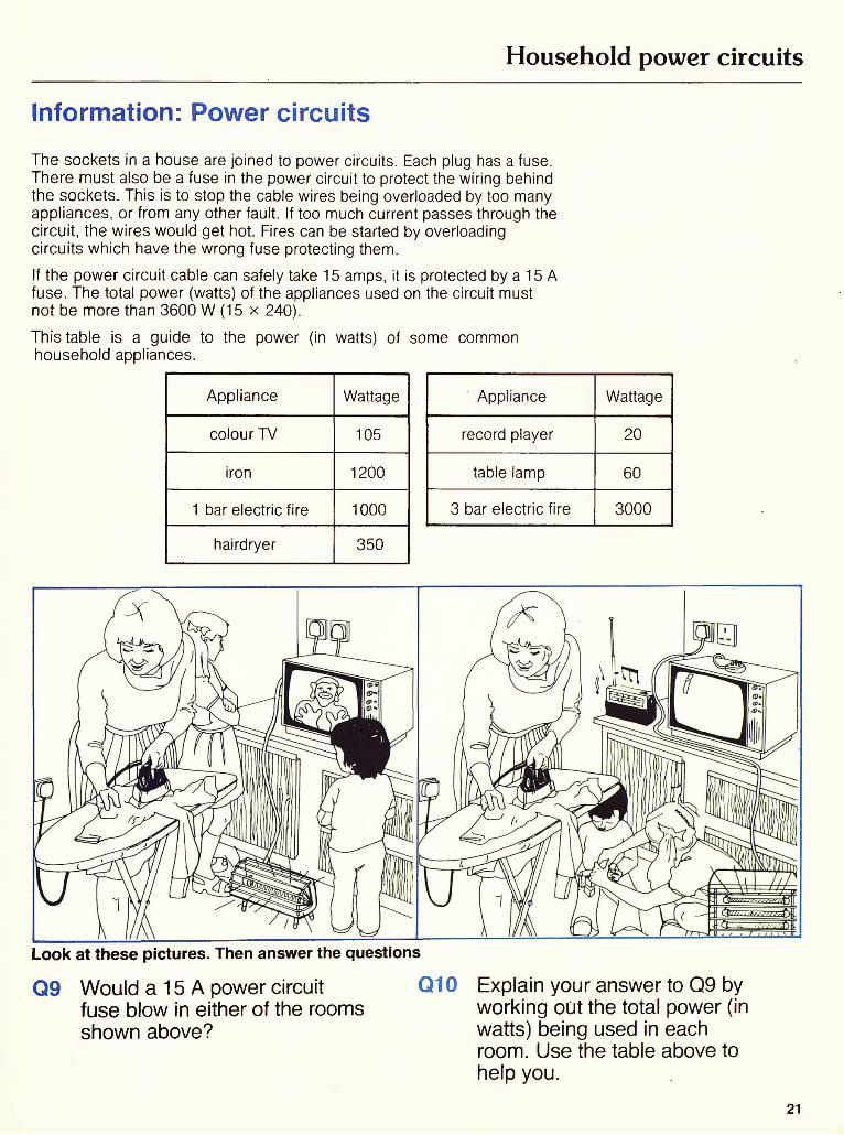
Information: Power circuitsThe sockets in a house are joined to power circuits. Each plug has a fuse. There must also be a fuse in the power circuit to protect the wiring behind the sockets. This is to stop the cable wires being overloaded by too many appliances, or from any other fault. If too much current passes through the circuit, the wires would get hot. Fires can be started by overloading circuits which have the wrong fuse protecting them.If the power circuit cable can safely take 15 amps, it is protected by a 15 A fuse. The total power (watts) of the appliances used on the circuit must not be more than 3600 W (15 x 240).This table is a guide to the power (in watts) of some common household appliances.
Appliance
colour TV
iron
1 bar electric fire
hairdryer
Wattage
105
1200
1000
350
Appliance
record player
table lamp
3 bar electric fire
Wattage
20
60
3000
Look at these pictures. Then answer the questions
Q9 Would a 15 A power circuit fuse blow in either of the rooms shown above?
Q10 Explain your answer to Q9 by working out the total power (in watts) being used in each room. Use the table above to help you.
21

Household power circuits
Information: Household circuits—new and old
consumer unit (containing miniature circuit breakers and main switch)
All modern domestic electrical power circuits are wired on a ring sub-circuit,often called a ring main. The picture shows how the wires from power sockets are connected on to a ring main circuit.
cable carrying 3 wires
consumer unit
This is a circuit diagram for a ring main circuit with 4 power sockets. In a household circuit, one cable carries 3 wires: Live, Neutral and Earth.
The main advantages of the ring sub-circuit are:1 It generally uses less wire than older wiring systems.2 It is easier to add extra sockets without major wiring.3 Each plug has its own fuse.
Fuses and switches are always fitted in the Live wire of the circuit. This makes the circuit safe when switches are off or if a fuse blows.
A typical modern house would have 4 separate ring sub-circuits: one each for upstairs lights, downstairs lights, upstairs sockets and downstairs sockets. The cooker and immersion heater are wired separately on radial circuits because they draw very large currents.
22

Household power circuits
consumer unit
Many older houses have radial wiring. This means that each socket is connected to a separate cable going right back to the fuse box.
cable carrying 3 wires
consumer unit
fuses<
to mains supply T
This is a circuit diagram for radial wiring with 4 power sockets.
Q11 Why should fuses and Q13 switches always be in the Live wire of the circuit?
Q12 Which type of circuit, radial orring, uses more wire? Q14
If a typical modern house has an electric cooker and an immersion heater, how many circuits would there be?
Why is it more difficult to add extra sockets on a radial wiring system than on a ring main?
23

5 Buzzers and bellsMaking and investigating an electric buzzerApparatus .
* C-shaped piece of iron * rheostat * ammeter * crocodile clips* piece of hacksaw blade * 15 cm long piece of spring steel * G clamp* low voltage power supply * 50 cm x 25 cm (approx) piece of wood* clamp boss and stand * thin wire * thick wire * nut and bolt
You are going to make an electric buzzer and find out how it works.
A You are going to build this circuit.
hacksaw blade 12 volt d.c. supply i
spring steel
electromagnet
B Wind some thin wire 30 times around a C-shaped piece ot iron. Leave a length ot wire free at each end. This makes an electromagnet.
C Put a bolt through the hole in a piece of hacksaw blade. Fix it in place with a nut.
D Use a G-clamp to fix one end of the spring steel to a wooden block on the bench. Put the electromagnet under the other end of the steel.
- 1/2 cmgap
bench
E Put the hacksaw blade in a ciamp. Attach the clamp to a boss and stand.
F Move the hacksaw blade up or down until the bolt just touches the spring steel.
24

Buzzers and bells
G Set a low voltage power supply to 12 V d.c. Do not switch it on yet. Using thick wire, join the negative (-) terminal of the power supply to the hacksaw blade.
H Join the wire from the electromagnet to the spring steel. Fix it in place with a crocodile clip.
I Join the other end of the wire from the electromagnet to the negative (-) terminal of an ammeter.
J Using thick wire, join the positive (+) terminal of the ammeter to a rheostat. Join the rheostat to the positive (+) terminal of the power supply.
K Set the rheostat to its highest resistance.Switch on the electricity. Slowly push the sliding contact on the rheostat until the buzzer buzzes.
sliding contact
L Switch off the electricity. Disconnect the electromagnet. Wind the wire around the electromagnet 20 more times. Repeat the experiment.
Q1 Draw the circuit diagram.
Q2 What happened when the electricity was switched on?
Q3 What happened when the current was increased (when you pushed the sliding contact along the rheostat)?
Q4 What happened to the buzzer when you wound more wire around the electromagnet?
25
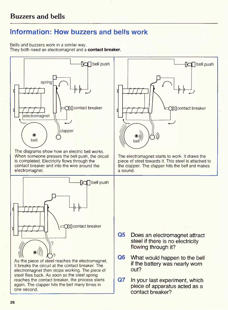
Buzzers and bells
Information: How buzzers and bells workBells and buzzers work in a similar way.They both need an electromagnet and a contact breaker.
1 ——— Qc push
contact breaker
The diagrams show how an electric bell works. When someone presses the bell push, the circuit is completed. Electricity flows through the contact breaker and into the wire around the electromagnet.
bell push
contact breaker
The electromagnet starts to work. It draws the piece of steel towards it. This steel is attached to the clapper. The clapper hits the bell and makes a sound.
1——OcQ bell push
contact breaker
As the piece of steel reaches the electromagnet, it breaks the circuit at the contact breaker. The electromagnet then stops working. The piece of steel flies back. As soon as the steel spring reaches the contact breaker, the process starts again. The clapper hits the bell many times in one second.
Q5 Does an electromagnet attract steel if there is no electricity flowing through it?
Q6 What would happen to the bell if the battery was nearly worn out?
Q7 In your last experiment, which piece of apparatus acted as a contact breaker?
26

6 Water heatersMaking a low voltage immersion heaterApparatus
* ammeter * rheostat * low voltage power supply * thermometer* glass rod * newspaper * 2 elastic bands * 100 cm 3 beaker* thin, medium and thick enamelled eureka wire * 10 cm long (approx) piece of wood* 2 drawing pins * clamp with boss and stand * measuring cylinder* stop clock * ruler
You are going to make a low voltage immersion heater. This experiment can only be done safely at a low voltage.
Q1 Copy this table.
A You are going to build this circuit.
12 volt d.c. supply
-T&mperabureJi^cAer 1O m,nuL<LS
B Wind some thick enamelled eureka wire around a glass rod. Remove the rod. This makes a coil.
C Put 2 drawing pins 3 cm away from each other at one end of a piece of wood. Wind the ends of the coil around the drawing pins.
D Wrap several pieces of newspaper around an empty 100 cm 3 beaker to insulate it. Use elastic bands to hold the newspaper in place.
27

Water heaters
E Carefully, fill the beaker with cold water to within 5 mm of the top. Do not spill any on the newspaper.
F Put the piece of wood into a clamp. Adjust the height of the wood so that as much of the coil as possible is in the water.
G Use wire to join one end of the coil to the negative (-) terminal of an ammeter. Join the other end of the coil to a rheostat.
H Set a low voltage power supply to 12 V. Do not switch it on yet. Use wire to join the positive (+) terminals of the ammeter and the power supply. Join the negative (-) terminal of the power supply to the rheostat.
I Take the temperature of the water. Record it in your table. Switch on the electricity. Quickly, move the slider on the rheostat until the ammeter reads 2 amps exactly.
J After 10 minutes, switch off the electricity. Stir the water and record its temperature in your table. Empty the beaker. Repeat steps B to J with medium enamelled wire. Then repeat steps B to J with thin enamelled wire. (The lengths of the wires are equal.)
Q2 Draw the circuit diagram.Q3 Which thickness of wire heated
the water to the highest temperature?
Q4 Why did you refill the beaker each time with cold water?
Q5 Why is it very dangerous to try and build an immersion heater like this and connect it to a voltage higher than 12 V?
28

Water heaters
Investigating immersion heaters using different currentsApparatus -" ^ :
* ammeter * rheostat * low voltage power supply * thermometer* glass rod * newspaper * elastic bands * thin enamelled eureka wire* 100 cm 3 beaker * piece of wood (approx) 10 cm long * 2 drawing pins* clamp with boss and stand * measuring cylinder * stop clock * ruler
You are going to make an immersion heater and find out the effect of passing different currents through it. Never do this experiment with a mains voltage supply.
\"C) after 1D rnifnite.sQ6 Copy this table.
.————————-
Curre.nL
A Use thin enamelled eureka wire to make a coil. Follow steps B to H of the last experiment to set up the apparatus.
B Record in your table the temperature of thewater.
C Switch on the electricity. Quickly, move the slider on the rheostat so the reading on the ammeter is 2 amps. After 10 minutes, stir the water and record its temperature in your table.
D Switch off the electricity. Empty the beaker. Refill it with fresh water. Repeat steps B and C, adjusting the rheostat so that 1.5 amps go through the coil. Then repeat so that 1 amp goes through the coil.
Q7 Which current heated the water to the highest temperature?
Q8 Would it matter if the amount of water in the beaker were different each time? Explain your answer.
29

Water heaters
Information: Immersion heaters
Immersion heaters are used to heat water in storage cylinders or tanks. The heater is made of a coil of resistance wire insulated in a protective metal sheath. An electric current passes through the coil and makes it hot. The heat is passed from the coil to the water via the metal sheath.
The immersion heater is controlled by a thermostat. The thermostat switches off the electricity when the water has reached the required (needed) temperature. The water cylinder should be lagged against heat loss. It should be surrounded by a jacket to keep the heat in. Some hot water cylinders have two heaters so that water heated during the night can be charged at a cheaper rate than during the day.
day rate heater
-- lagging jacket - at least 75 mm thick
night rate heater
Other appliances in common use in the home use immersion heaters. The picture shows some examples.
electric kettle washing machine
Q9 Why is it necessary to have a thermostat controlling an immersion heater?
Q10 Would you expect to get an electric shock from touching the metal cylinder?
Q11 Why is it necessary to lag the tank of an immersion heater?
30

Water heaters
Information: Reading an electricity meterAn electricity meter tells you how much electricity you have used. It measures the electricity in kilowatt hours. One kilowatt hour is the amount of electricity used to run a 1000 watt appliance for 1 hour without being switched off.
There are two kinds of electricity meter: the digital meter and the dial meter. The row offigures on a digital meter shows the number of units of electricity used. The white meter shown in the photo has a reading for daytime use and a second reading for the lower-priced night rate.
It is a little more difficult to take a reading from a dial meter. You should only read dials marked 10 000, 1000, 100, 10 and kWh per division. If the pointer on any dial is between two numbers, read the smaller number. The reading on this meter is 47 536 units.
The difference between the last reading and the present one on your meter gives the number of units used in that period.
Q12 Work out the reading on this meter.
31

Water heaters
Information: The cost of electricityEarly in 1979, electricity cost 2.83p per unit.
Q13 What does electricity cost now, per unit?
Q14 Copy this table.Work out the electricity cost per week for each appliance.
Appliance
Immersion heater
Electric blanket
Electric cooker
Freezer
Hair dryer
Electric fire
Electric lights
Colour TV
Automatic washing machine
Tumble dryer
Vacuum cleaner
Units used per week
85 (if tank well lagged)
1 (underblanket) 3 (overblanket)
20 (3 meals per day)
9 (6 cubic feet)
1 (3 hours' use)
20 (2 bar fire for 10 hours' use)
6 (six 1 00 W bulbs for 1 0 hours each)
2 (12 hours' viewing)
9 (weekly wash for 4 people) ;
2 (1 hours' drying)
1 (2 hours' cleaning)
Cost per unit Cost per week
Q15 What is the total electricity bill for one week?
Information: The dangers of electricity.As you have now worked through this book, you may feel able to carry out electrical repairs. Be warned!Working with mains electricity is totally different from your experiments. People have died from shocks of only 100 volts. Mains electricity is at 240 volts.
The golden rule is to unplug or disconnect the appliance and switch off at the mains fuseboard before trying any inspection or minor repair. Some appliances, such as TV sets, have electricity stored in them after they have been switched off. If you are not absolutely sure of what you are doing — don't start. Get a qualified electrician to do it for you.
32

Teachers' Guide to Domestic Electricity
IntroductionThe unitsScience at Work is a series of 18 science units for 14-16 year old, less able pupils. Each unit consists of a pupils' book and a teachers' guide. Each provides a complete half- term's course of study. The units are self-contained, and can be taken in any order.
The pupils' booksThe pupils', books provide information, practical investi gations and questions. Pupils are thus able to work from the books at their own pace; generally, the v/ork becomes more difficult towards the end of each book and the weakest pupils are not expected to finish every unit. The material has been checked by a language specialist, who has ensured that the reading level is as low as possible.
INVESTIGATIONSEach investigation begins with a list of the apparatus required. The purpose is then stated, and instructions for the investigation given (in words and pictures). Finally, the pupils are asked questions which help them record their results and draw conclusions. (Throughout the books a pupil is expected to make a written response each time a 'Q' appears.)
INFORMATIONAppropriate information from the real world follows most investigations, in most cases from the world of work. Questions are also asked about these information sections.
The teachers' guidesEach unit has a teachers' guide. This contains record sheets and information for the teacher.
RECORD SHEETSRecord sheets in the form of masters are provided in each guide. These sheets will save pupils copying tables, and will help them write answers to questions as complete sentences. One record sheet is provided for each chapter of the pupils' book. Teachers may decide to give record sheets only to those pupils who have difficulty with writing; alternatively, they may be given to all pupils.
OTHER RESOURCES FOR THE TEACHEREach teachers' guide contains:course and unit objectiveshints on introducing and teaching the unitan apparatus list (for technicians)safety proceduresnew scientific words (which pupils may have difficulty
reading)answers to questions in the pupils' book a resource list. Specimen questions for a post-unit test are also included.
Examining the courseScience at Work is derived from a successful and well- proven modular scheme developed by teachers in Manchester LEA. Most of the pupils following the course in Manchester gain a CSE Mode III certificate in science. A paper giving information on CSE Mode III construction for this course is available from J. C. Taylor, Senior District Inspector, Education Office, Crown Square, Manchester M60 3BB.
Aims of the course1. To provide a flexible science course based on non
sequential study units. Though developed predominantly for less able pupils, the course can cater for pupils capable of CSE grade I by the addition of suitable extension work.
2. To develop pupils' thinking in scientific methodology and the approach to problem solving.
3. To give knowledge and understanding of science rele vant to pupils' interests, environment, and future work and leisure needs.
4. To develop,pupils' interest in science and enjoyment of science.
5. To provide a wide range of practical experiences and develop practical skills.
6. To develop the ability to work both independently and as a member of a team.
1

General objectives of the course
1. To develop the ability to carry out experimental pro cedures and written work according to instructions.
2. To develop manipulative skill in handling equipment and an awareness of safe practice.
3. To develop powers of accurate observation.4. To develop the ability to check statements and asser
tions against tests of observation and experiment.5. To develop skill in handling the interpretation of data.
6. To develop the ability to look for and make generali sations (this objective is likely to be achieved by only the ablest pupils).
7. To be able to understand and recall the factual content of the material.
8. To develop communication skills—verbal, written, and mathematical.
9. To develop the ability to apply knowledge gained.10. To encourage pride in neatly and accurately produced work.11. To develop awareness of the responsible use of science and technology.
Objectives of the Domestic Electricity unitWhen they have completed the unit, pupils will have prac tised the following skills: the use and manipulation of screw-drivers, wire cutters and
strippersthe handling of simple circuit components the interpretation of circuit diagrams and component
symbolsthe setting up and testing of electrical circuits the reading of scales on ammeters and thermometers
In their work on Domestic Electricity, pupils will becomeaware:that live and neutral wires are required to supply electric
current to an appliance . that the earth wire is a safety device that wires are colour codedthat an ammeter measures the flow of electric current that fuses are safety devices, they are used to prevent
damage to appliances
that fuses melt or blow if too much current passes through them
of the current rating of fusesthat resettable circuit breakers are more convenient to use
in domestic wiringthat rheostats can be adjusted to change the amount of
current flowing through a circuitthat switches break a circuitthat power can be expressed in watts and kilowattsthat the amount of current used by appliances can be cal
culated ($= A)of the power rating of appliancesof circuits and sub-circuits in domestic wiringof the differences between ring main and radial wiringof how to make an electromagnetof the application of an electromagnet in a buzzerof the use of contact breakers in a buzzerof how water heaters workof how the use of electricity is monitored and a meter is
readof how an electricity bill is calculated.
Teaching the Domestic Electricity unitIntroducing the unit Teaching the unitThe reliance we place on electrical appliances can be de monstrated by having a display of photographs and items such as hair drier, spin drier, washing machine, soldering iron, light bulbs (different wattages), fridge, freezer, cooker hair rollers, power drill, lawn mower, iron, radio, television, record players etc, etc.Posters could be on display: many visual aids are available either free or for a small charge from The Electricity Council, 30, Millbank, London SW1P 4RD Some titles are detailed in the lesson notes. Before experimental work starts teachers should check that children can read scales by using a display ammeter or similar device. Some teachers may prefer to teach the slightly easier investigations (buzzer and water heater) before the ones that demand delicate manipulative skills (construction of model household circuits). 2
The pupils' book contains 6 chapters.Each chapter has practical and information sections. Thereare sequential questions within each chapter: these indicatewhen a student has to write in a notebook. For slow readersand writers, there are record sheets to each chapter. Therecord sheets are copyright free and are contained withinthis teacher's guide (pages 8-15).Samples of the type of questions that may be used forassessment when pupils have completed the unit are onpage 16.In the pages which follow, each chapter is discussed withreference to: apparatus per working group; new scientificwords; safety and teaching hints; answers to practicaland information page questions; resources.

Detailed teaching notesIt is essential that the plugs and sockets used in the experiments are incompatible with the mains plugs and sockets in the laboratory. (Any incompatible 3-pin plug is suitable.) Otherwise, there is a danger of electrocution. Alternatively, batteries may be used in series as a power source and the mains supply to the laboratory cut off.Throughout the pupils' hook all the drawings of plugs and sockets on practical pages are drawn Incorrectly' for this reason.Pupils should be made aware of the potential danger from the outset of the unit.Strictly, the brown/blue/yellow-green coding applies only to flexible cables. The wiring "behind the socket" is coded red/black/green.
1 PLUGS AND SOCKETS
CONNECTING A FLEX TO A PLUG AND SOCKET (pupils' book page 2)
Apparatus: 3 core flexible cable; 3 pinplug; socket; screwdriver; scissors; wirestrippersNew Words: cable, fuse, terminals,insulation, wire, earth, neutral, live
In the first exercise it will be necessary to check that the pupils can use screw drivers and wire strippers. Also that they understand the need for 2 wires, the live and neutral, to supply electric current to an appliance, and a 3rd wire, the earth wire, used as a safety device should an appliance become faulty. Ql 240 volts. Q2 The live and neutral wire. Q3 It is connected to the earth. Q4 It is to stop the possibility of an electric shock if the metal case of an
appliance becomes live. Q5 Neutral Q9 Q6 Brown Q7 Green/Yellow Q8 AmmeterThe Electricity Council have a film "Living with Electricity" which outlines Ihe importance of correct plug wiring. It is available on free loan.
2 FUSES
CHECKING A FUSE (pupils ' book page 5)
Apparatus: fuseholder; 1A fuse; 12V 0.1 A lamp in holder; connecting wire
FINDING THE CURRENT A T WHICH A FUSE BLOWS (pupils' book page 6)
Apparatus: fuseholder; 1A fuse; ammeter (0-5A); rheostat (0-1 Solini); wire; low voltage power supply New Words: rheostat, variable resistor, ammeter, resistance, overloaded, voltage
Pupils will need help in interpreting circuit diagrams.Fuses in which the wire can be seen are most suitable. Some 'blown' fuses could be made available for comparison.12V 0.1 A bulbs (M.E.S. cap), bulbholders, fuses and chassis-mounted fuse- holders are available from R. S. Components Ltd., Fitzroy House, Epworth Street, London E.C.2. Q2 The lamp would not light.Q3 Any electric appliance such as an electric bell or a heater, etc. The Electricity Council have information sheets called "Plugs and Fuses" and a 35 mm film strip-"From Socket to Appliance".
It will be necessary to check that the ammeter is connected round the right way before pupils switch on the power supply. Many rheostats have 3 ter minals so the teacher will have to check that the connections to this are correct. Also pupils may experience difficulty in knowing which way to move the slider of the rheostat to decrease resistance. It may be necessary to teach pupils how to read the ammeter scale, using a display ammeter. Q4 It returned to zero. Q5 1 amp.
3

USING A FUSE WITH TOO HIGH A CURRENT RATING (pupils'book page 7)
Apparatus: fuseholder; 5A fuse; ammeter (0- 5A); 4.7 ohm resistor; connecting wire; low voltage power supply; 2 crocodile clips; heatproof mat New Words: ohm, current rating
3 HOUSEHOLD LIGHTING CIRCUITS
BUILDING A MODEL OF A HOUSEHOLD LIGHTING CIR CUIT (pupils' book page 11)
Apparatus: large circuit board;3 12V 0.1 A bulbs in holders; 1A fuse;fuseholder; scissors; 3 small rockerswitches; large 2-way rocker switch;brown plastic-coated connecting wire;blue plastic-coated connecting wire;6 plastic junctions; low voltage powersupply; wire strippers; screwdriver; nutsand boltsNew Words: rocker switch
Pupils must be warned not to touch the resistor as it will get very hot.Q6 12V Q7 2.5A (approx.)
Q8 It smoked and melted.Q9 No.Q10 A fuse prevents too much cur-
___ rent flowing to an appliance. Ql 1 The fuse would blow and current would not flow to the appliance. Q12. The current rating. Q13 Circuit breakers can be reset but fuses have to be replaced when the
circuit has been overloaded. Q14 The fuse would blow. Q15 The current required for a record player is very much lower than ISA,
so if a fault occurred in the circuit the record player would be damagedbefore the fuse blew.
Q16 Power (watts)Voltage (volts)
2400 ^ .'. _ .„ = Current in amps.
.'. Current = 10A.So fuse required = ISA.
The Electricity Council (free loan) 16mm film "Circuits and Connection" plus their 35 mm film strip "Behind the Socket", may be useful.
Pupils will probably have difficulty in constructing this circuit so will require help. The circuit board can be built from pegboard, 60 cms square, supported about 4.5 cms off the ground by a wooden frame. Suitable pegboard is hard- board drilled with 5 mm diameter holes, 2 cms apart. The frame can be made from wood approximately 4.5 cm by 1.5 cm, in Lengths that should be se curely nailed to the edge of the pegboard. Rectangular gaps to hold the rocker switches can be cut out beforehand using a sharp modelling knife and a narrow saw-blade. Bulbs in holders, fuses and fuseholders are as the experi ment "Checking a fuse", pupils' book page 5.R. S. Components Ltd. supply the large rocker switch (a double pole, double throw switch.) The small rocker switches are single pole, single throw and can be obtained from Bi Pak Semiconductors, PO Box 6, Ware, Herts. (Large rocker switches can be used throughout but the pupils may have more diffi culty understanding how to connect them). The plastic junctions are made from one plastic-coated terminal block which is a set of 12 junctions. These can easily be cut apart to form 12 separate screw-connectors.
Q2 The lamps do not light.Q3 Too much current is flowing.Q4 1A.Q5 So each bulb can be switched
on and off independently.Q6 Yes.Q7 The circuit can be overloaded
without blowing the fuse. (Only 0.1 A is required for each lamp, giving a total of 0.3A.)
12 volt d.c. supply

INVESTIGA TING THE LIGHTING CIRCUIT (1) (pupils'book page 14)
Apparatus: circuit board from last experiment, connecting wire; ammeter (0-1 A); scissors; low voltage power supply; wire strippers; screwdriver
Q9 They are equal.Q10 The bulbs are less bright on 6V than 12V.
INVESTIGA TING THE LIGHTING CIR CUIT (2) (pupils' book page 15)
Apparatus: circuit board from the last experiment; wire; ammeter (0—1 A); low voltage power supply; scissors; wire strippers; screwdriver
4 HOUSEHOLD POWERCIRCUITS_____________
BUILDING A SOCKET RINGMAIN (pupils'book page 17)
Apparatus: circuit board with completed lighting circuit; fuseholder; 3A fuse; 3 plastic junctions; 3-core flexible cable; 3 mains sockets; blue wire; brown wire; yellow/green wire; wire strippers; screw driver; nuts and bolts; scissors New Words: ring main
Q12 It stayed the same. Q13 It stayed the same. Q14 10 light bulbs.Q15 Fluorescent tubes last longer than ordinary lamps. They also give out
more light.
(Strictly, the correct name is a ring sub-circuit.)In earlier editions of the pupils' book, there is no connection from the neutral terminal or the fuseholder. This has been corrected in later editions. Pupils may need considerable help and encouragement to finish this. A board should be already wired up for reference.To answer Question 1 students may need a lot of help—a duplicated incom plete diagram may help.
^ THE POWER CIRCUIT
E E E N L NL NIT IT T
—— 4 — 4 — L
L
1<r1
_/• \fTo Earth
HH'
1
N°°°
Q2 Live, Neutral, Earth.Q3 So that no more than 3A can flow.Q4 It is connected to Earth.
The Electricity Council 16 mm film "Switches and Controls" and 35 mm film strip "Switches and Controls" may be useful.
INVESTIGA TING THE LIVE AND NEUTRAL CIRCUITS (pupils' book page 19)
Apparatus: circuit board with lighting and power circuits wired up; three 3-pin plugs; three 24W bulbs in holders; ammeter (0 —10A); low voltage power supply; 2-core cable; brown plastic-coated connecting wire; blue plastic-coated connecting wire; scissors; wire strippers; screwdriver, 3 labels
24W 2A bulbs and holders are available from Griffin and George Ltd.Pupils will need help with Question 8. A duplicated incomplete sheet wouldhelp.Please notice that the latest colour TVs use 175 W (information page 21).
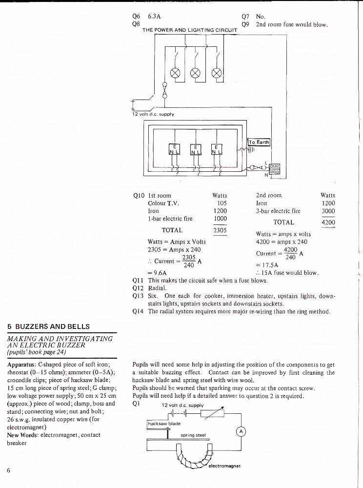
Q6 6.3A Q8
THE POWER AND LIGHTING CIRCUIT
Q7 No.
Q9 2nd room fuse would blow.
1 2 volt d.c. supply
tN L
11V
E N L
ttE
N L
((-^
_/" Y/
|~To Earth
lln
-OX>f5ool
N 1?22j
5 BUZZERS AND BELLS_____
MAKING AND INVESTIGATING A N ELECTR 1C B UZZER (pupils' book page 24)
Apparatus: C-shaped piece of soft iron; rheostat (0-15 ohms); ammeter (0-5 A); crocodile clips; piece of hacksaw blade; 15 cm long piece of spring steel; G clamp; low voltage power supply; 50 cm x 25 cm (approx.) piece of wood; clamp, boss and stand; connecting wire; nut and bolt; 26 s.w.g. insulated copper wire (for electromagnet)New Words: electromagnet, contact breaker
Q10 1st room Colour T.V. Iron 1-bar electric fire
TOTAL
Watts = Amps x Volts 2305 = Amps x 240
:. Current = ——— A
Watts105
12001000
2305
2nd room WattsIron 12003-bar electric fire 3000
TOTAL 4200
Watts = amps x volts 4200 = amps x 240
r , 420D A Current = ——— A
= 17.5A.'. 15A fuse would blow.= 9.6 A
Ql 1 This makes the circuit safe when a fuse blows.Q12 Radial.Q13 Six. One each for cooker, immersion heater, upstairs lights, down
stairs lights, upstairs sockets and downstairs sockets.Q14 The radial system requires more major re-wiring than the ring method.
Pupils will need some help in adjusting the position of the components to get a suitable buzzing effect. Contact can be improved by first cleaning the hacksaw blade and spring steel with wire wool.Pupils should be warned that sparking may occur at the contact screw. Pupils will need help if a detailed answer to question 2 is required.Ql 12 volt d.c. supply
electromagnet

6 WATER HEATERS
MAKING A LOW VOLTAGE IMMER SION HE A TER(pupils' book page 2 7)
Apparatus: ammeter (0—5 A); rheostat (0—15 ohms); low voltage power supply; thermometer (0—110°C); glass rod; news paper; 2 elastic bands; 100 cm 3 beaker; approx. 30 cm lengths of 22, 26, 34 s.w.g. eureka wire (enamelled); 10 cm long (approx.) piece of wood; 2 drawing pins; clamp with boss and stand; measuring cylinder (0—150 cm 3); stop clock; ruler
INVESTIGATING IMMERSION HE A TERS USING DIFFERENT CURRENTS (pupils book page 29)
Apparatus: as previous experiment but only thin enamelled eureka wire is required.
Q2 The apparatus started buzzing. (The spring steel was attracted to the electromagnet breaking the circuit. No current is then flowing so the electromagnet stops attracting the spring steel. This makes the steel spring back up forming a circuit once more. This series of events re peats quickly so a buzzing noise is heard.)
Q3 The buzzing noise gets louder.Q4 The buzzing noise was louder
with more wire on the electro magnet.
Q5 No.Q6 It would ring faintly or not
at all.Q7 The bolt.
The voltage for this experiment must not be greater than 12V. The pupils should be warned that the coil can get hot quickly when left out of the water. The may need help reading the thermometer. 20 cm lengths of wire of the three guages stated give a temperature range between 2°C and 10°C in about 10 minutes each. The coils must not touch or shorting will occur. To avoid this the wire should be enamelled by dipping it into shellac varnish; the ends must be left bare or cleaned before use with sandpaper.Q2
12 volt d.c. supply
Q3 Thin wire.Q4 So that the water had the
same starting temperature.Q5 Because the current would be
too high and there would be a danger of overheating or pos sibly an electric shock.
Q7Q8Q9Q10QllQ12
2A.Yes. In 10 minutes more water would not heat up so much.So that the water is only heated to the required temperature.No.So that as little heat as possible is lost from the tank.94794.
The Electricity Council 35 mm film strip "Basic Electrical Effect" and their 24-page booklet "Electric Water Heating" may be of use. Other helpful visual aids from the Electricity Council include: 16 mm film—"Measuring the Usage" (free loan) 35 mm film strip—"Living with Electricity"Information Sheets-"Guide to Running Costs", "How to Read Your Meter", "Safety in the Home". Wallchart-"Electricity Distribution".

RECORD SHEET Domestic Electricity
1 Plugs and socketsINFORMATION: PLUGS AND SOCKETS (page 1)
Q1 The voltage of mains electricity in this country is .........................................
Q2 The two wires that supply the electric current to an appliance are .............................
Q3 The Earth wire is connected to
Q4 The Earth wire is for .......
CONNECTING A FLEX TO A PLUG AND SOCKET (page 2)
Q5 The letter N on the inside of a socket means ................................
Q6 The colour of the wire that carries a high voltage when the electricity is switched on is
Q7 The colour of the wire that usually does not carry electricity is ..................
INFORMATION: CIRCUITS AND SYMBOLS (page 4)
Q8 The symbol (A) stands for ..............................................
Q9 In the space below draw a circuit diagram showing two bulbs and an a.c. power supply.
Copyright free

RECORD SHEET Domestic Electricity
2 FusesCHECKING A FUSE (page 5)
Q1 On the back of this sheet of paper draw the final circuit diagram. It should show a 6 volt d.c. power supply (battery), a lamp and a fuse.
Q2 If the fuse was blown the lamp would/would not light, when the electricity was turned on.
Q3 To check a fuse a person could use a .................................... instead of a lamp.
FINDING THE CURRENT AT WHICH A FUSE BLOWS (page 6)
Q4 When the fuse blows, the reading on the ammeter .........................................
Q5 A one amp fuse will let ..................... through before it blows.
USING A FUSE WITH TOO HIGH A CURRENT RATING (page 7)
Q6 On the back of this sheet of paper draw the circuit diagram. It should show a d.c. power supply (battery), an ammeter, a 4.7 ohm resistor and a fuse.
Q7 The current flowing round the circuit measured ........ amps.
Q8 During the experiment the resistor .....................................................
Q9 The fuse did/did not protect the resistor.
INFORMATION: FUSES (page 8)
Q10 The job of a fuse is to ...............................................................
Q11 If a 5 amp fuse was used to protect an appliance that took 7 amps ...........................
INFORMATION: FUSES AND CIRCUIT BREAKERS (page 9)
Q12 The numbers on the circuit breakers show .....................
Q13 Circuit breakers are easier to use than fuses because ..............
INFORMATION: WHICH FUSE SHOULD I USE? (page 10)
Q14 If a 3A fuse was used in the plug attached to an electric fire, it would
Q15 Fora record player, I would change the 13Afuse in a plug because . .
Q16 A 2.4kW storage radiator takes a current of ...... amps. So the fuse required will be a ..... fuse.Copyright free
RECORD SHEET Domestic Electricity
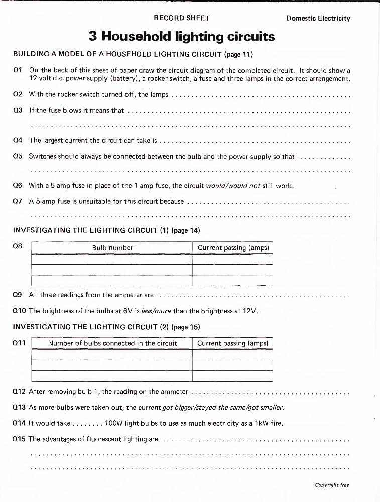
3 Household lighting circuitsBUILDING A MODEL OF A HOUSEHOLD LIGHTING CIRCUIT (page 11)
Q1 On the back of this sheet of paper draw the circuit diagram of the completed circuit. It should show a 12 volt d.c. power supply (battery), a rocker switch, a fuse and three lamps in the correct arrangement.
Q2 With the rocker switch turned off, the lamps .............................................
Q3 If the fuse blows it means that ........................................................
Q4 The largest current the circuit can take is ................................................
Q5 Switches should always be connected between the bulb and the power supply so that .............
Q6 With a 5 amp fuse in place of the 1 amp fuse, the circuit would/would not still work.
Q7 A 5 amp fuse is unsuitable for this circuit because .........................................
INVESTIGATING THE LIGHTING CIRCUIT (1) (page 14)
Bulb number Current passing (amps)
Q9 All three readings from the ammeter are ............................
Q10 The brightness of the bulbs at 6V is less/more than the brightness at 12V.
INVESTIGATING THE LIGHTING CIRCUIT (2) (page 15)
Q11 Number of bulbs connected in the circuit Current passing (amps)
Q12 After removing bulb 1, the reading on the ammeter ........................
Q13 As more bulbs were taken out, the current got bigger/stayed the same/got smaller.
Q14 It would take ........ 100W light bulbs to use as much electricity as a 1kW fire.
Q15 The advantages of fluorescent lighting are ...............................
Copyright free

RECORD SHEET
4 Household power circuitsDomestic Electricity
BUILDING A SOCKET RING MAIN CIRCUIT (page 17)
Q1 On the back of this sheet of paper draw the circuit diagram. It should show three sockets, the Earth wiring, the Live wiring, the Neutral wiring, a fuse and the plastic junction. The sockets and plastic junction can be drawn as shown below.
socket plastic junction
Q2 The letters on the back of a socket mean the following: L = .............
N= ................................... E= ................
Q3 A 3 amp fuse must be used for the power circuit because ...............
Q4 In a house the yellow/green Earth wire is connected to Earth by fixing it to .
INVESTIGATING THE LIVE AND NEUTRAL CIRCUITS (page 19)
Q5 _____________________________________________ ___ Number of bulbs plugged in Current passing (amps)
Q6 If both the power and lighting circuits are switched on, the current is ...... amps.
Q7 Current does/does not flow through the Earth wire.
Q8 On the back of this sheet of paper draw the circuit diagram for the power and lighting circuits. It will be a combination of two circuit diagrams you have already drawn.
INFORMATION: POWER CIRCUITS (page 21)
Q9 A 15 amp fuse would/would not blow in the first room. A 15 amp fuse would/would not blow in the second room.
Q10 The total power (in watts) being used in the first room is ........ watts. The total power being used
in the second room is ........ watts.
Q11 Fuses and switches should always be in the Live wire of the circuit because .....................
Q12 The type of circuit which uses more wire is the ...........................................
Copyright free

RECORD SHEET Domestic Electricity
4 Household power circuits (continued)Q13 In a typical modern house there would be ........ circuits.
Q14 It is more difficult to add extra sockets on a radial wiring system because .......................
Copyright free

RECORD SHEET Domestic Electricity
5 Buzzers and bellsMAKING AND INVESTIGATING AN ELECTRIC BUZZER (page 24)
Q1 In the space below draw the circuit diagram of the electric buzzer.
Q2 When the electricity was turned on
Q3 When the current was increased
Q4 When more wire was wound round the electromagnet
INFORMATION: HOW BUZZERS AND BELLS WORK (page 26)
Q5 An electromagnet with electricity flowing through it does/does not attract steel.
Q6 If the battery was nearly worn out the bell .............................
Q7 In the experiment where a buzzer was made the .......................... acted as the contactbreaker.
Copyright free

Domestic Electricity
The colour coding for the wiring in this book does not apply to flexible cords and house- wiring cables and is intended only for school use.
Only low voltages (12 V or less) should be used for practical wiring circuits.
Page 5 of the Teachers' Guide states that the earth wire in a house should be connected to a water pipe. This is dangerous. Earth connections should only be made to special earth terminals.

RECORD SHEET
6 Water heatersMAKING A LOW VOLTAGE IMMERSION HEATER (page 27)
Q1
Domestic Electricity
Thickness of wire Starting temperature (°C) Temperature (°C) after 10 minutes)
Q2 In the space below draw the circuit diagram. It should show the 12 volt d.c. power supply (battery), an ammeter, a rheostat, and a coil.
Q3 The wire that heated the water to the highest temperature was the thick/medium/thin wire.
Q4 The beaker was refilled with cold water each time because .........................
Q5 It is very dangerous to build an immersion heater like this using a voltage higher than 12 volts. This is
because ..........................................................................
INVESTIGATING IMMERSION HEATERS USING DIFFERENT CURRENTS (page 29)
Q6
Current used (amps) Starting temperature (°C) Temperature (°C) after 10 minutes
Q7 The current that heated the water most was ........ amps.
Copyright free

RECORD SHEET Domestic Electricity
6 Water heaters (continued)Q8 It would/would not matter if the amount of water in the beaker was different each time. This is
because ..........................................................................
INFORMATION: IMMERSION HEATERS (page 30)
Q9 It is necessary to have a thermostat controlling an immersion heater because
Q10 I would/would not expect to get an electric shock from touching the metal cylinder.
Q11 It is necessary to lag the tank of an immersion heater so that ...................
INFORMATION: READING AN ELECTRICITY METER (page 31)
Q12 The reading on this meter is ............................
INFORMATION: THE COST OF ELECTRICITY (page 32)
Q13 Electricity now costs ..........................
Q14
Appliance
Immersion heater
Electric blanket
Electric cooker
Freezer
Hair dryer
Electric fire
Electric lights
Colour TV
Automatic washing machine
Tumble dryer
Vacuum cleaner
Units used per week
85 (if tank well lagged)
1 (underblanket) 3 (overblanket)
20 (3 meals per day)
9 (6 cubic feet)
1 (3 hours' use)
20 (2 bar fire for 1 0 hours' use)
6 (six 100W bulbs for 10 hours each)
2(12 hours' viewing)
9 (weekly wash for 4 people)
2 (1 hour's drying)
1 (2 hours' cleaning)
Cost per unit Cost per week
Q15 The total electricity bill for one week isCopyright free

Specimen post-unit questions1) The colours of the wires in modern flexible cables are
green/yellow, blue or brown. Put the correct colour by the names of the wires below.a) Liveb) Earthc) Neutral
2) Match each name below with its correct circuit symbol.a) lamp
b) ammeter
c) battery or power supply
d) variable resistor (rheostat)
e) switch
f) fuse 6),| 11—1| - ij-
3) The circuit was set up as shown in the diagram.———'!--'!———i
4)
When the switch was closed the lamp did not light. Which of the following would you not have to do when you checked the circuit? (Tick (V) the answer.)a) Check all the wiring connections.b) Alter the rheostat.c) Remove the fuse.d) Clean the contacts in the switch.e) Screw the bulb tightly in the holder.
4) Which units are used to show the power of an ap pliance? (Tick (V) the answer.) a) ohm b) watt c) volt d) amp
5) A house had a lighting circuit of 3 bulbs. If one blew, what would happen to the other 2 bulbs? (Tick (V) the answer.)a) They would get brighter.b) Both would go out.c) They would get dimmer.d) They would stay the same brightness.
6) Which would use the least electricity in 5 minutes? (Tick (V) the answer.)a) An ordinary 100W lamp.b) An ordinary ISOWlamp.c) A fluorescent 60W lamp.d) A fluorescent 100W lamp.e) An ordinary 40Wlamp.
7) Which of the following can be used to vary the amount of electricity flowing through a circuit? (Tick (V) the answer.)a) lampb) ammeterc) fused) rheostate) battery
8) The power used by an electrical appliance can be worked out. Which of the following would you use for the calculation? (Tick (V) the answer.)a) watts = volts — ampsb) watts = volts x ampsc) watts = volts + ampsj\ ^ VOltSd) watts = ——
amps
9) Which of the following appliances contains an electro magnet? (Tick (V) the answer.)a) an electric fireb) an electric kettlec) a table lampd) an electric bell
10) Which of the following contains an immersion heater? (Tick (V) the answer.)a) an electric kettleb) an electric bellc) a fan heaterd) an electric firee) a table lamp
11) Which of the following is an advantage of a ring main? (Tick (V) the answer.)a) It is easy to add extra sockets to the circuit.b) It uses more cable than radial wiring.c) It uses cheaper 2-core cable instead of 3-core cable.d) It does not need fuses at every socket.
12) Which of the sentences below explains the job of the Earth wire? (Tick (V) the answer.)a) It stops the current flowing if the plug is overloaded.b) It controls the voltage of the mains.c) It makes any bare metal parts of an appliance safe.d) It brings more current to the appliance when
needed.
ISBN 201 140128 ©Addison-Wesley Publishers Limited 1979

Project Director
John Taylor
The books in this series are:
Fibres and Fabrics Electronics Forensic Science Photography Gears and Gearing Cosmetics Body Maintenance Pollution Building Science Food and Microbes Domestic Electricity Dyes and Dyeing
Addison-Wesley Publishers Limited 0 201 14012 8