NEPAL ELECTRICITY AUTHORITY
391
NEPAL ELECTRICITY AUTHORITY (An Undertaking of Government of Nepal) Project Management Directorate BORANG - NAUBISE (RATMATE) 220 kV TRANSMISSION LINE PROJECT A Component of Electricity Grid Modernization Project BIDDING DOCUMENT FOR Design, Supply, Installation, Testing and Commissioning of 132 kV Borang - Lapang and 220 kV Lapang - Naubise (Ratmate) 220 kV Transmission Line and Associated Substations (Procurement of Plant) Single Stage, Two - Envelope Bidding Procedure (OCB) Issued on: Invitation for Bids No.: OCB No.: Employer: Country: 03 rd March, 2021 PMD/EGMP/BNRTLSS-077/78-01 PMD/EGMP/BNRTLSS-077/78-01 Nepal Electricity Authority Nepal VOLUME:- II(A) OF III March 2021 Borang - Naubise (Ratmate) 220 kV Transmission Line Project Project Management Directorate Kharipati, Bhaktapur, Nepal Telephone: +977-01-6620421 Email address: [email protected]
-
Upload
khangminh22 -
Category
Documents
-
view
1 -
download
0
Transcript of NEPAL ELECTRICITY AUTHORITY

NEPAL ELECTRICITY AUTHORITY (An Undertaking of Government of Nepal)
Project Management Directorate
BORANG - NAUBISE (RATMATE) 220 kV TRANSMISSION
LINE PROJECT
A Component of
Electricity Grid Modernization Project
BIDDING DOCUMENT
FOR
Design, Supply, Installation, Testing and Commissioning of 132 kV Borang - Lapang
and 220 kV Lapang - Naubise (Ratmate) 220 kV Transmission Line and Associated
Substations
(Procurement of Plant)
Single Stage, Two - Envelope
Bidding Procedure (OCB)
Issued on:
Invitation for Bids No.:
OCB No.:
Employer:
Country:
03rd March, 2021
PMD/EGMP/BNRTLSS-077/78-01 PMD/EGMP/BNRTLSS-077/78-01 Nepal Electricity Authority
Nepal
VOLUME:- II(A) OF III
March 2021
Borang - Naubise (Ratmate) 220 kV Transmission Line Project
Project Management Directorate
Kharipati, Bhaktapur, Nepal
Telephone: +977-01-6620421
Email address: [email protected]


Preface
This Bidding Document for Procurement of Plant – Design, Supply, and Installation, has been prepared by Nepal Electricity Authority and is based on the Standard Bidding Document for Procurement of Plant – Design, Supply, and Installation (SBD Plant) issued by the Asian Development Bank dated June 2018. ADB’s SBD Plant has the structure and the provisions of the Master Procurement Document entitled “Procurement of Plant – Design, Supply, and Installation”, prepared by multilateral development banks and other public international financial institutions except where ADB-specific considerations have required a change.

Table of Contents - Summary Description PART I BIDDING PROCEDURES
Section 1 - Instructions to Bidders (ITB) ------------------------------------------------ 1-1 This section specifies the procedures to be followed by Bidders in the preparation and submission of their Bids. Information is also provided on the submission, opening, and evaluation of bids and on the award of contract.
Section 2 - Bid Data Sheet (BDS) ---------------------------------------------------------- 2-1 This section consists of provisions that are specific to each procurement and supplement the information or requirements included in Section 1 (Instructions to Bidders). Section 3 - Evaluation and Qualification Criteria (EQC) --------------------------- 3-1 This section contains the bid evaluation criteria to determine the lowest evaluated bid and lists the necessary qualifications of Bidders.
Section 4 - Bidding Forms (BDF) ---------------------------------------------------------- 4-1 This section contains the forms which are to be completed by the Bidder and submitted as part of its Bid. Section 5 - Eligible Countries (ELC) ------------------------------------------------------ 5-1 This section contains the list of eligible countries.
PART II REQUIREMENTS
Section 6 - Employer’s Requirements (ERQ) ------------------------------------------ 6-1 This section contains the Scope of Supply of Plant and Services,Specifications, the Drawings, and Supplementary Information that describe the Facilitiesto be procured, Personnel Requirements, Equipment Requirements, Certificates, and Change Orders.
PART III CONDITIONS OF CONTRACT AND CONTRACT FORMS
Section 7 - General Conditions of Contract (GCC) ---------------------------------- 7-1 This section contains the general clauses to be applied in all contracts. These Conditions are subject to the variations and additions set out in Section 8 (Special Conditions of Contract). Section 8 - Special Conditions of Contract (SCC) ----------------------------------- 8-1 This section contains provisions that are specific to each contract and that modify or supplement the GCC. Whenever there is a conflict, the provisions herein shall prevail over those in the GCC. The clause number of the SCC is the corresponding clause number of the GCC.
Section 9 - Contract Forms (COF) --------------------------------------------------------- 9-1 This section contains forms, which, once completed, will form part of the Contract.The forms for Performance Security and Advance Payment Security, when required, shall only be completed by the successful Bidder after contract award.
Section 6: Employer’sRequirements
OCB No. PMD/EGMP/BNRTLSS-077/78-01 Procurement of Plant Single-Stage: Two-Envelope
Section 6: Employer’sRequirements
IIA-1

Section 6: Employer’sRequirements
OCB No. PMD/EGMP/BNRTLSS-077/78-01 Procurement of Plant Single-Stage: Two-Envelope
IIA-2

Section 6: Employer’sRequirements/Project Specific Requirement(PSR for TL)
OCB No. PMD/EGMP/BNRTLSS-077/78-01 Procurement of Plant Single-Stage: Two-Envelope
VOLUME II(A)
CHAPTER - 1
PROJECT SPECIFIC REQUIRMENT
FOR
TRANSMISSION LINE
IIA-3

Section 6: Employer’sRequirements/Project Specific Requirement(PSR for TL)
OCB No. PMD/EGMP/BNRTLSS-077/78-01 Procurement of Plant Single-Stage: Two-Envelope
CHAPTER 1- PROJECT SPECIFIC REQUIREMENT
1.0 GENERAL
1.1.1 Nepal Electricity Authority is establishing new 132/33/11 kV AIS Substation at Borang, 132 kVTransmission Line from Borang substation to Lapang, Biharthok substation, new 220/132/33/11 kVGIS Substation at Lapang, Biharthok and 220 kV Transmission Line from Lapang, Biharthok s/s toRatmate s/s of Dhading and Nuwakot District under Borang - Naubise (Ratmate) 220 kV TransmissionLine Project. The above project is being implemented by Nepal Electricity Authority funded fromAsian Development Bank, as part of the above Transmission Line project.
Design, engineering, drawing and construction of works shall satisfy the general technicalrequirements specified in the Specification or implied as per relevant IEC/IEEE/ IS/ASTM/Britishstandard codes (B S Codes)/ equivalent International Standards.
1.1.2 Associated System:
The following system is envisaged under Borang - Naubise (Ratmate) 220 kV Transmission LineProject as per present scope.
Transmission lines
1. Construction of Borang Naubise (Ratmate) D/C Transmission Line: 48 km, of which Borang-Lapang section is 24 km (132 kV line with ACSR "BEAR" conductor along with OPGW) andLapang-Ratmate section is 24 km. (220 kV line with twin ACSR "MOOSE" conductor along withOPGW)
Substations
1. Construction of 132/33/11 kV new AIS substation at Borang.2. Construction of 220/132/33/11 kV new GIS substation at Lapang, Biharthok.
This Volume II'A' of the bidding document covers the technical requirement for construction of 132kV transmission line of ACSR BEAR conductor from Borang s/s to Lapang, Biharthok s/s and 220kV transmission line of twin ACSR MOOSE conductor from Lapang, Biharthok s/s to Ratmate s/s inDhading and Nuwakot district
1.2 Intent of the Specification
This part of the specification is intended to cover the design, manufacture, engineering, inspectionand testing at Bidder's work(s), packaging, forwarding to site, unloading, erection, testing,commissioning, performance testing and handing over of 132kV and 220 kV Double CircuitTransmission Line from Borang s/s to Lapang, Biharthok s/s and Lapang, Biharthok s/s to Ratmates/s in Dhading and Nuwakot District.
This specification shall be read and construed in conjunction with the drawings and annexure todetermine the scope of work and terminal points. The quantities shown on drawings and annexure
IIA-4

Section 6: Employer’sRequirements/Project Specific Requirement(PSR for TL)
OCB No. PMD/EGMP/BNRTLSS-077/78-01 Procurement of Plant Single-Stage: Two-Envelope
are indicative. Any variation arising during detailed engineering stage will be taken into account by the Bidder without any extra cost and time to the Employer.
Bidder shall be responsible for providing all material, equipment and services, specified or otherwise which are required to complete the scope and fulfill the intent of ensuring efficiency, operability, maintainability and the reliability of the complete work covered under this specification. It is not the intent to specify completely herein, all aspects of design and construction of equipment. Nevertheless, the equipment shall conform in all respects to high standards of engineering, design and workmanship and shall be capable of performing continuous commercial operation, in a manner acceptable to Employer, who will interprete the meaning of the specification, drawings, requirements of operation, maintenance redundancy etc. and shall have a right to reject or accept any work or material which in his assessment is not complete to meet the requirements of this specification and/or applicable International standards mentioned elsewhere in the specification.
Bidder’sarerequestedtocarefullyexamineandunderstandthespecifications and seek clarifications, if required, to ensure that they have understood the specifications. The bidder's offer should clearly bring out the technical deviation and commercial deviation (If any) that the Bidder is taking. No other clarification, interpretation and assumption shall be considered for evaluation. In the event of conflict between the requirements of any two clauses of this specification or requirements of different codes/standards, the more stringent requirement shall govern, unless confirmed otherwise by the Employer in writing before the award of this Contract, based on a written request from the bidder for such a clarification. However, if the bidder feels that, in his opinion, certain features brought out in his offer are superior to what has been specified, these may be highlighted separately.
Bidder may also make alternate offers provided such offers are superior in his opinion, in which case, adequate technical information, operating feedback data, etc. shall be enclosed with the offer, to enable the Employer to assess the superiority and reliability of the alternatives offered. In case of each alternate offer, its implications on the performance, guaranteed efficiency etc. shall be clearly brought out for the Employer to make an overall assessment. In any case, the base offer shall necessarily be in line with the specifications. Whenever a material or article is specified or described by the name of a particular brand, manufacturer or trade mark, the specific items shall be understood as established type/make, meets functional requirement and of required quality. Other manufacturer’sproductsmayalsobeconsidered provided sufficient information is furnished so as to enable the Employer to determine that the products are proven and equivalent or superior to those named.
1.3 Scope of Work
The scope of works covering design, engineering, procurement, inspection & testing at manufacturer’s works, supply, insurance, receipt at site, storage and preservation at site, site transportation, construction, erection, commissioning, trial operation, handing over to Employer, guarantee all equipment, spares and material, catalogues, drawings, documents and services including consumables for the proposed 132 kV Double Circuit Transmission Line from Borang s/s to Lapang, Biharthok s/s and 220 kV Double Circuit Transmission Line from Lapang, Biharthok s/s to Ratmate s/s is inclusive of all mechanical, electrical and civil, structural & architectural works on basis of single point responsibility.
IIA-5

Section 6: Employer’sRequirements/Project Specific Requirement(PSR for TL)
OCB No. PMD/EGMP/BNRTLSS-077/78-01 Procurement of Plant Single-Stage: Two-Envelope
The scope of work shall include but not limited to the following:
· Detailed survey and check survey including route alignment and profiling, right of way identification and clearance, tower spotting, optimization of tower locations, soil resistivity measurement and geotechnical investigation.
· Preparation of Land Parcel Data from tower spotting for land acquisition and RoW Land data · Numbering and Marking of Tress and Forest clearance proposal preparation for submission to the
concerned forest office · Prototype testing of DA type towers for 220 kV transmission line at manufacturing plant of the
Contractor. · Any study through which the capacity and rating of equipment offered shall be proved for the main &
on analysis of site location and attitude. · Submission of manuals, engineering & construction drawings, design basis reports, optimization study
reports, design calculations, quality assurance plans, testing procedures, operation and maintenance manuals, commissioning procedures, etc.
· Obtaining of any consents, licenses and approvals from relevant statutory authorities, other than those obtained by the Employer and required as per law. The scope of Bidder also covers extending necessary assistance wherever logically required to enable Employer to obtain the requisite approval.
· Quality assurance of all work related to scope of work of the Bidder. · Submission of schedule of work from zero date to handing over to Employer complete plant and
equipmentintheformofchart,‘S’-curve; write up etc for Employer’sapproval.Submissionofmonthly progress reports, photographs, graphs etc for engineering, supply, construction and commissioning for all major works with suggestions and plans for making up back log if any for review of Employer. To attend meetings, review, discussion etc for resolving all issues.
· Submission of shipping schedule of equipment and material from country of origin up to receipt at site for off shore supply and ex-works to site for on-shore supply matching with schedule of work for approval of Employer.
· Manufacture, fabrication, quality control, shop testing of equipments and material after approval of required technical data and drawings by Employer. To furnish notice to Employer for inspection.
· Packing, forwarding, shipment and transportation (including port handling and custom clearance) from the manufacturer’s works to site Comprehensive marine/transit-cum-storage-cum-erection insurance coverage of all equipment from Nepal Border / ex-works to project site till the equipment supplied is taken over by Employer. Preservation of all equipment during transportation till testing and commissioning stage.
· Hiring of a suitable storing area which shall be approved by the Employer, · Receipt at site, unloading, movement to proper storage, carriage to storage area / interim / final
foundation location, security, preservation and conservation of equipment at the site. · Supply of spares parts. · Supply any other equipment including special tools & tackles, for operation, capital maintenance · Supply of all manuals covering erection and commissioning, performance testing, operation,
preservation, and capital maintenance including supply of as-built drawings and services required for satisfactory completion of the project.
· Supply of all construction consumables, e.g., welding electrodes, cleaning agents, diesel oil as well as materials required for temporary supports, scaffolding, storage tanks, illumination as necessary.
· Deployment of all skilled and unskilled manpower required for erection, commissioning, testing, etc, supervision of erection, commissioning, testing etc for services to be rendered.
· Deployment of all erection tools & tackles adequate number and capacity of cranes, construction machinery, transportation vehicles, and all other implements in adequate number, capacity and size.
IIA-6

Section 6: Employer’sRequirements/Project Specific Requirement(PSR for TL)
OCB No. PMD/EGMP/BNRTLSS-077/78-01 Procurement of Plant Single-Stage: Two-Envelope
Any other tools, tackles and resources required to complete the Contract with required quality and with the schedule. Major Equipment and Works The following list of the major plant items and systems shall be includedintheBidder’sscopeofwork. This list is not exhaustive and is without prejudice to the more fundamental responsibility of the Bidder for completeness of 132 kV Double Circuit Transmission Line from Borang s/s to Lapang, Biharthok s/s and 220 kV Double Circuit Transmission Line from Lapang, Biharthok s/s to Ratmate s/s.
a) Conductors and Accessories
- Line Conductor (ACSR "BEAR" and ACSR "MOOSE") and accessories - Ground wire and accessories - Optical fibre ground wire (OPGW) and accessories - Optical Distribution Frame at Borang, Lapang, Biharthok and Ratmate Substations - Insulator, hardware Fittings and other accessories b) Tower and Tower Accessories
- All types of transmission line towers including bolts, nuts and washers, hangers, D-shackles
and - All types of tower accessories like phase plate, circuit plate, number plate, danger plate, anti
climbing device, bird guard, aviation signals, painting of towers etc. c) Foundations
- classification of foundations for different soil conditions for different type of towers and casting of foundation for tower footings including stub setting d) Grounding of each towers
e) Other items not specified above but required to complete the transmission line as per technical
specifications, Bid Forms & Price Schedules. 1.4 Exclusions
The following items shall be excluded from the scope of supply by the Bidder:
· Cutting of the trees under the Right of Way of the Transmission Line
· Land Acquisition for tower Pads and Right of way clearance 1.5 Terminal Points
The Bidder’s scope of work shall terminate at the points as shown on the table below. These interconnectionpointsrepresent thephysicalboundarypointsof theBidder’s scopeofworks.They do not necessarily define the operational responsibilities between the Bidder and the third parties.
IIA-7

Section 6: Employer’sRequirements/Project Specific Requirement(PSR for TL)
OCB No. PMD/EGMP/BNRTLSS-077/78-01 Procurement of Plant Single-Stage: Two-Envelope
System Terminal Points
Termination of Line Conductor Borang, Lapang, and Ratmate Substation
132 kV Line Bay at Borang s/s, 132 kV and 220 kV Line Bay at Lapang, Biharthok s/s and 220 kV Line Bay at Ratmate s/s. Connection with the Gantryincluding supply of string insulators hard ware and other accessories areincluded in the scope of work of this specification.
Termination of OPGW Optical Distribution Box (ODF) shall be supplied and installed at each endof the substation
1.6 Additional Responsibilities of the Contractor
The Contractor shall take care of the following during execution of the works under the Contract.
1.6.1 Existing Fences
Where it is necessary to operate equipment through existing fences, the Contractor shall install suitable temporary gates. The temporary gates shall be constructed of materials and to standards equal to those of the existing fence. Before cutting the fences for the installation of temporary gates, the Contractor shall install adequate braces and additional posts, if necessary, on each side of the opening and shall fully anchor the fence so that all wires will maintain their original tension after opening is cut. Except when equipment is passing, such gates shall be kept closed. After completion of the work, the fence shall be restored as nearly as practicable to its original condition. Deviation from the above requirement will be permitted only where the Contractor furnishes advanced written approval from the landowner or landowners for a different method of operation. Where it is necessary for the Contractor to remove or to alter portions of existing fences to permit construction, temporary fence protection shall be provided at all times during construction and upon completion of the construction, the fence shall be rebuilt in its original or relocated position. The cost of all work herein described shall be borne by the Contractor. Should the contractor refuse or neglect to perform any work required by the above provisions within twenty-four hours after notification by the Employer to do so, the Employer reserves the right to perform the work and the cost thereof will be deducted from payment due to the Contractor.
1.6.2 Transmission, Telegraph and Telephone Lines:
The Contractor shall make all necessary or required provisions concerning any interference with the operation or maintenance of traffic or service of any transmission, telegraph or telephone lines existing on the date of receiving bids, caused by the work of the Contractor under this Contract, all in a manner satisfactory to the Employers or operators and to the Employer. The Contractor shall notify the Employers of such facilities of any damage, which is his responsibility and shall promptly settle proper claims. Pending settlement of such claims by the Contractor, an appropriate sum as determined by the Employer may be withheld from payments due to the Contractor until the matter is settled. The cost of providing and maintaining all necessary or required watchmen, signals, guards and temporary structures, of making any necessary repairs, replacements, or similar operations and all or any other costs required by this Sub-Clause shall be borne by the Contractor.
IIA-8

Section 6: Employer’sRequirements/Project Specific Requirement(PSR for TL)
OCB No. PMD/EGMP/BNRTLSS-077/78-01 Procurement of Plant Single-Stage: Two-Envelope
1.6.3 Operation and Maintenance
The Contractor shall provide at least one operating and maintenance expert at the site for a continuous period of Six (6) months or any extension required thereof because of serious breakdown or any extensions of warranty period, from the commencement of the Defect Liability Period to train the local staff on the maintenance of the Line.
1.6.4 Pre-Commissioning and Commissioning
The Contractor shall provide sufficient, properly qualified personnel; shall supply and make available all raw materials, utilities, lubricants, chemicals, catalysts, other materials and facilities; and shall perform all work and services of whatsoever nature required to properly carry out Pre-commissioning, Commissioning and Guarantee Test all in accordance with the provisions of the Contract Agreement.
1.6.5 Other Responsibilities
a) The Contractor shall be responsible for selecting and constructing appropriate communication means necessary for the executing of the project at his own expense. If required, the Employer will assist the Contractor in obtaining licences/permits from the concerned government agencies.
b) Gasoline, oil and lubricants for construction equipment and vehicles are available in Nepal and the Contractor will not be permitted to import such products for use on the work.
c) The Contractor shall be responsible for the arrangement of water supply for drinking and construction purposes at his own cost.
d) The Contractor shall be responsible for the arrangement of electricity supply for construction and any other purposes at his own cost.
e) Training at Manufacturer’sworks. The Contractor shall include in the training charges payment of per Diem allowance to NEA trainees @ USD 150 per day per trainee for the duration of training abroad towards accommodation, meals and other incidental expenses and to and fro economy class air ticket from Nepal to place of training. The duration of training shall be excluding travelling period.
The trainingshallbeprovided inthefieldofdesign, testingandmaintenanceatManufacturer’sworks as per following:- 1. PLS-CADD Software: 10 Days (5 No. Trainee) 2. PLS-TOWER Software: 10 Days (5 No. Trainee)
1.7 Required Completion Schedule
The scope under Volume – II (A) and Volume – II (B) of the bidding document includes following component of Borang - Naubise (Ratmate) 220 kV transmission line project: a. Design, manufacturing, supply, construction, installation, testing and commissioning of 132 kV
and 220 kV Double Circuit Transmission Line from Borang to Lapang & Lapang to Ratmate Substation
b. Design, manufacturing, supply, construction, installation, testing and commissioning of
132/33/11kV Borang AIS Substation.
IIA-9

Section 6: Employer’sRequirements/Project Specific Requirement(PSR for TL)
OCB No. PMD/EGMP/BNRTLSS-077/78-01 Procurement of Plant Single-Stage: Two-Envelope
c. Design, manufacturing, supply, construction, installation, testing and commissioning of
220/132/33kV Lapang, Biharthok GIS Substation. All works under the scope shall be completed within 3 years from the effective date of the Contract.
IIA-10

Section6:Employer’sRequirements/GeneralInformationandScope
OCB No.: PMD/EGMP/BNRTLSS -077/78-01 Procurement of plant Single-Stage, Two-Envelope
SECTION-I General Information and Scope
IIA-11

Section6:Employer’sRequirements/GeneralInformationandScope
OCB No.: PMD/EGMP/BNRTLSS -077/78-01 Procurement of plant Single-Stage, Two-Envelope
IIA-12

Section6:Employer’sRequirements/GeneralInformationandScope
OCB No.: PMD/EGMP/BNRTLSS -077/78-01 Procurement of plant Single-Stage, Two-Envelope
SECTION-I
CONTENTS
Cl. Description Page No.
1.0 General Information and Scope 14
2.0 Transmission towers and Line data 20
3.0 Line Data: 24
4.0 Service Conditions: 26
IIA-13

Section6:Employer’sRequirements/GeneralInformationandScope
OCB No.: PMD/EGMP/BNRTLSS -077/78-01 Procurement of plant Single-Stage, Two-Envelope
TECHNICAL SPECIFICATIONS
SECTION-I
GENERAL INFORMATION AND SCOPE
1.0 General Information and Scope
1.1 Scope
1.1.1 The following transmission lines are included in the scope of the Contractor: 1. 220 kV Double Circuit Lapang – Naubise (Ratamate)
with twin bundled (ACSR Moose conductor) approx. 24 km
2. 132 kV Double Circuit Borang - Lapang transmission line with ACSR Bear conductor.
approx. 24 km
1.1.2 This Specification covers the following scope of works:
(i) Detailed survey including route alignment, profiling (where ever route change is required), tower spotting, optimization of tower locations, soil resistivity measurement & geotechnical investigation (including special foundation locations viz. pile/well foundation locations, whenever applicable & covered under BPS); The use of Drone is envisaged for and survey work.
(ii) Check survey and Cadastral Survey including land parcel data preparation;
(iii) Design Review and proto type testing, fabrication and supply of all type of 220 kV and 132 kV double circuit transmission line towers including River crossing towers (whereverapplicable) asperEmployer’sdesign/drawingsincluding bolts, nuts and washers, step bolts, hangers, D-shackles etc.;
(iv) Supply of all types of tower accessories like phase plate, circuit plate (where ever applicable), number plate, danger plate, anti-climbing device, Bird guard (where ever applicable);
(v) Supply of
a) ACSR BEAR conductor, ACSR MOOSE Conductor, Earth Wire &
Composite Long Rod Insulators
b) Hardware Fittings, Clamp fittings & accessories for HTLS Conductor
c) Hardware Fittings & accessories for ACSR Conductor & Earth Wire
d) OPGW & associated fittings & accessories.
(vi) Design of foundations, classification of foundation for different type of towers and casting of foundation for tower footings as per Employer’sfoundations drawing for DA, DB, DC and DD towers;
(vii) Supply & Installation of Tower Earthling;
(viii) Erection of towers, tack welding of bolts and nuts including supply and application of zinc rich paint, fixing of insulator strings, stringing of
IIA-14

Section6:Employer’sRequirements/GeneralInformationandScope
OCB No.: PMD/EGMP/BNRTLSS -077/78-01 Procurement of plant Single-Stage, Two-Envelope
conductors and earth wires/OPGW along with all necessary line accessories;
(viii) For transmission lines, to promote mechanization and safe working conditions, use of crane is being promoted. Erection of towers, tack welding of bolts and nuts including supply and application of zinc rich paint, fixing of insulator strings, stringing of conductors and earth wires/OPGW along with all necessary line accessories by using crane (wherever feasible). However, where usage of crane is not possible, erection of towers has to be carried out by conventional method i.e. using Gin pole, Derrick, Centre mast etc. through usage of Power Operated Winch Machines. No tractor shall be allowed for tower erection. The use of drone is envisaged in the stringing work.
(ix) Supervision of stringing of ACSR BEAR and MOOSE conductors & associated hardware fittings, clamps & accessories.
(x) Painting of towers & supply and erection of span markers, obstruction lights (wherever applicable) for aviation requirements (as required)
(xi) Testing and commissioning of the erected transmission lines
(xii) Other items not specifically mentioned in this Specification and/or BPS but are required for the successful commissioning of the transmission line, unless specifically excluded in the Specification.
1.1.2.1 Employer shall provide structural drawings, shop drawings & Bill of Materials of DB, DC and DD type of standard transmission line towers and their extensions, river crossing towers/ special towers as required to the Contractor after placement of award, in sequence, suiting the project requirement. The drawings for all type of foundations for the towers shall also be provided by Employer to the Contractor.
During execution of the project, if any specific designs viz. +18/+25/+30M extensions, other equal/unequal leg extensions, cross-arm strengthening, auxiliary cross-arms, raised chimney foundations etc. are required as per site conditions, Single Line Diagram/Design Drawing shall be provided by the Employer. The contractor shall be required to develop the corresponding structural drawings, BOM & Shop drawings etc. without any financial implication to Employer.
1.1.2.2 (a) The provisional quantities of fabricated & galvanized steel parts required for towers, concrete, excavation volume & reinforcement steel for foundation and other items are given in appropriate Schedule of Bid Proposal Sheet (BPS) for respective packages. However, the work shall be executed as per approved construction drawings.
(b)The various items of work are described very briefly in the appropriate Schedule of BPS. The various items of the BPS shall be read in conjunction with the corresponding sections in the Technical Specifications including amendments and,additions,ifany.TheBidder’squotedratesshallbebasedonthedescriptionof activities in the BPS as well as other necessary operations required to complete the works detailed in these Technical Specifications.
IIA-15

Section6:Employer’sRequirements/GeneralInformationandScope
OCB No.: PMD/EGMP/BNRTLSS -077/78-01 Procurement of plant Single-Stage, Two-Envelope
(c) The Unit rates quoted shall include minor details which are obviously and fairly intended, and which may not have been included in these documents but are essential for the satisfactory completion of the various works.
(d) The unit rate quoted shall be inclusive of all plant equipment, men, material skilled and unskilled labor etc. essential for satisfactory completion of various works.
(e) All measurements for payment shall be in S.I. units, lengths shall be measured in meters corrected to two decimal places. Areas shall be computed in square meters & volume in cubic meters, rounded off to two decimals.
The Bidder shall submit his offer taking into consideration that the tower and foundation designs/drawings shall be developed/ provided by Employer and design rights will be strictly reserved with Employer. Bidder shall quote the unit rates for various items of towers and foundations as per units mentioned in appropriate schedule of (BPS). However, payment of these items identified in the schedule of prices shall be made as follows:
TOWER
Supply items : On supply of respective complete tower
Erection items : On erection of respective complete tower
Foundation items : On completion of respective foundation in all respect
Towers to be supplied by the contractors/Tower Manufacturers shall be dispatched Panel wise as per mutually agreed procedure with Employer Quality Assurance & Inspection Department.
The payment to be made for towers/foundations shall be worked out based on the unit rates and approved Bill of Materials (BOM) for towers and quantities/volumes as per approved tower foundation drawings.
1.1.3 This specification also includes the supply of the following items, as detailed in the specification. (a) ACSR BEAR Conductor, ACSR MOOSE Conductor, Earth Wire &
Composite Long Rod Insulators
(b) Hardware fittings, Clamp fittings & accessories for HTLS Conductor.
(c) Hardware Fittings & accessories for ACSR Conductor & Earth Wire
(d) OPGW & associated fittings and accessories
Contractor shall clearly indicate in their offer, the sources from where they propose to procure these materials in appropriate Schedule of BPS. The technical descriptions of these items are given in relevant sections of this Volume .
IIA-16

Section6:Employer’sRequirements/GeneralInformationandScope
OCB No.: PMD/EGMP/BNRTLSS -077/78-01 Procurement of plant Single-Stage, Two-Envelope
1.1.4 TheContractor shall take delivery of the Employer’s suppliedmaterials at thestores established by the contractor in consultation with the Employer and ensure their safe custody and shall install the same in the transmission lines as stipulated in this specification.
1.1.5 In case, part quantity of Tower/Tower Parts are supplied by the Employer or other Supplier, the contractor shall take delivery, carry out (unloading & stacking), ensure safe custody of materials at their stores including insurance cover as required &install the same in the transmission lines as stipulated in this specification.
1.1.6 The installation/stringing of OPGW cable along with associated fittings & accessories shall be carried out by the contractor. The scope of installation/stringing shall include Splicing, termination, testing, demonstration for acceptance & commissioning as well as documentation. Splicing is preferred to be carried out at Tension towers locations. However, it shall be permitted at Suspension Tower locations also as required due to site conditions. The installation/stringing and Splicing shall be carried out as per owner guidelines (provided as part of TS). The FODP & Approach cable shall also be installed by the Contractor.
1.1.7 All the raw materials such as steel, zinc for galvanising, reinforcement steel and cement for tower foundation, coke and salt for tower earthing etc., bolts, nuts, washers, D-shackles, hangers, links, danger plates, phase plates, number plates. Circuit Plates, anti-climbing device, bird guards, aviation signals, etc., required for tower manufacture and erection shall be included in the Contractor’sscope of supply. Bidder shall indicate in the offer, the sources from where they propose to procure the raw materials and the components.
1.1.8 Stringing
a) For Earth wire:
The entire stringing work of earth wire shall be carried out by standard stringing practice
b) For OPGW:
The entire stringing work of OPGW shall be carried out by power operated winch machines. No tractor shall be allowed for stringing of OPGW.
c) For Bundle Conductor per phase:
The entire stringing work of conductor shall be carried out by tension stringing technique. The bidder shall indicate in their offer, the sets of tension stringing equipment in their possession and the sets of stringing equipment he would deploy exclusively for each package. However, it should not be less than the number and capacity requirement indicated in Qualifying Requirements for Bidder. The period of deployment of tension stringing equipment shall be as per actual site requirement. No tractor shall be allowed for final sagging.
To promote mechanization, for better safe working condition at site the contractor shall mandatorily provide at site for each package (i) requisite numbers (minimum two) of sagging bridges/working platform with pull lifts for facilitating sagging & dead end jointing (ii) requisite numbers (minimum four) of power operated winch machines for carrying out final sagging (iii) requisite numbers (minimum four) ladders with suitable hooks and
IIA-17

Section6:Employer’sRequirements/GeneralInformationandScope
OCB No.: PMD/EGMP/BNRTLSS -077/78-01 Procurement of plant Single-Stage, Two-Envelope
attachment arrangement to facilitate worker movement on insulators strings and (iv) adequate number of walkie- talkies. In case more number of sagging bridges/working platform, power operated winch machines etc. are required for stringing of transmission line in accordance with time schedule, the same shall be provided by the Contractor. Further, use of tractor for final sagging shall not be permitted. The Contractor shall use power operated winch machines only.
Power line crossing, river crossings, valley crossings, other single span sections where deployment of tension stringing machine is not warranted and in hilly terrain, thick forest or areas with site constraints, where deployment of tension stringing machine is not feasible, manual stringing may be adopted after getting approval of Employer’s site engineer. The contractor shall deploy appropriatetools / equipment / machinery to ensure that the stringing operation is carried out without causing damage to conductor/earth wire/OPGW which are installed at the prescribed sag-tension as per the approved stringing charts.
However, the Bidder having requisite experience may use helicopter and drone for stringing. The Bidder intending to use helicopter shall furnish detailed description of the procedure, type & number of helicopter & accessories etc., to be deployed for stringing operation.
The payment for stringing shall be done as per the unit rates of stringing under the contract irrespective of the methodology adopted for stringing.
1.1.9 This specification also includes the supply of Conductor, Insulators, Earthwire, hardware fittings, all type of accessories for conductor and earth wire and OPGW and its associated hardware & accessories as detailed in the specification. Contractor shall clearly indicate in their offer, the sources from where they propose to procure these materials in appropriate Schedule of BPS. The technical descriptions of these items are given in relevant section of this Volume of the bidding documents. The use of helicopter for transportation of goods is envisaged.
1.1.10 Location Details and Terminal Points The 132 kV (ACSR BEAR conductor along with OPGW) transmission line shall
emanate from Borang Substation at Borang of Dhading District and shall terminate at Lapang Substation of Dhading District. The 220 kV (twin ACSR MOOSE Conductor) transmission line shall emanate from Lapang substation and shall terminate at Ratamate Substation of Nuwakot district. The transmission line shall be passing mainly through hilly & mountainous areas. The Contractor shall have to construct the above transmission lines completely up to dead end towers on either end. Stringing shall also be carried out from dead end tower to terminal arrangements/terminal points of the Ratamate Substation.
1.2 Details of Transmission Line Routes and Terrain
Detailed survey including route alignment and profiling have been carried out by the Owner and these are not expected to vary substantially. The contractor has to carry out the tower spotting, optimization of tower locations, soil resistivity measurement & geotechnical investigation etc.
However, certain quantity of detailed survey including route alignment, profiling, tower spotting, optimization of tower locations soil resistivity measurement & geotechnical investigation etc. have been kept in the scope of the contractor for changes in the route, if any, necessitated during execution stage.
IIA-18
Section6:Employer’sRequirements/GeneralInformationandScope
OCB No.: PMD/EGMP/BNRTLSS -077/78-01 Procurement of plant Single-Stage, Two-Envelope
The details collected through detailed survey viz, route alignment maps, detailed survey reports etc. are enclosed with this specification. Bidders may visit the line route to acquaint themselves with terrain conditions and associated details of the proposed transmission lines.
The employer will organize site visit for the bidders so that bidders may acquaint themselves with terrain conditions and associated details of the proposed transmission lines.
1.3 Access to the Line and Right of Way
Right of way and way leave clearance shall be arranged by the Owner in accordance with work schedules. Owner will secure way leave and Right of way in the Forest area.
1.4 Contractor Execution Plan
After award of the contract, the contractor shall submit a detailed plan for resources mobilization & execution of various activities under the project scope along with the L2 network to be approved by owner. The detail should also cover the locations and size of stores to be established by the contractor. The contractor shall be required to open at least three offices with stores.
The contractor shall deploy a Project Manager at site who shall not be allowed to be changed without the consent from NEA, once deployed. The work at site shall be carried out after permission from the Site-in-charge and with proper consent of land owners and forest officials.
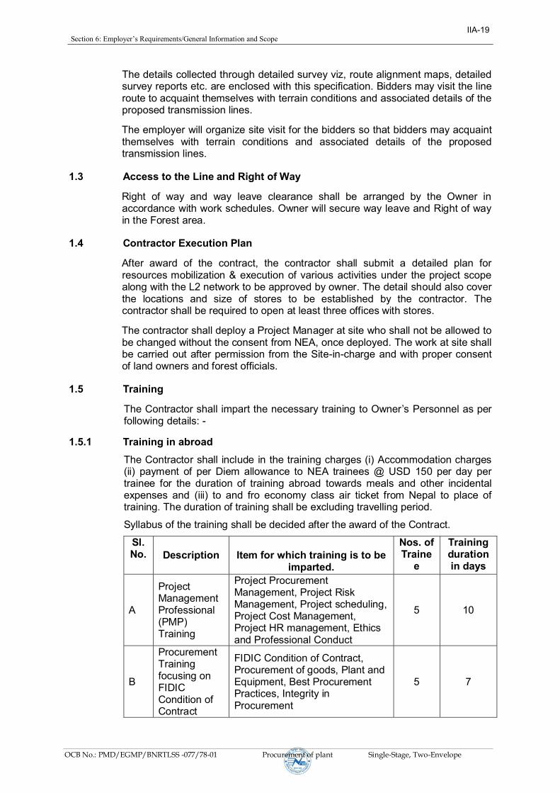
1.5 Training
The Contractor shall impart the necessary training to Owner’sPersonnelasperfollowing details: -
1.5.1 Training in abroad
The Contractor shall include in the training charges (i) Accommodation charges (ii) payment of per Diem allowance to NEA trainees @ USD 150 per day per trainee for the duration of training abroad towards meals and other incidental expenses and (iii) to and fro economy class air ticket from Nepal to place of training. The duration of training shall be excluding travelling period.
Syllabus of the training shall be decided after the award of the Contract.
Sl. No.
Description
Item for which training is to be
imparted.
Nos. of Traine
e
Training duration in days
A
Project Management Professional (PMP) Training
Project Procurement Management, Project Risk Management, Project scheduling, Project Cost Management, Project HR management, Ethics and Professional Conduct
5 10
B
Procurement Training focusing on FIDIC Condition of Contract
FIDIC Condition of Contract, Procurement of goods, Plant and Equipment, Best Procurement Practices, Integrity in Procurement
5 7
IIA-19

Section6:Employer’sRequirements/GeneralInformationandScope
OCB No.: PMD/EGMP/BNRTLSS -077/78-01 Procurement of plant Single-Stage, Two-Envelope
1.5.2 On Job Training in Nepal The traveling and living expenses of Owner’s personnel for the trainingprogramme conducted in Nepal shall be borne by the Owner.
The training shall be provided to Employer’s personnel in the field of erection,testing, operation and maintenance at each substation site (i.e. At substations (i.e. Borang substation & Lapang Substation) as per following:-
Sl. No.
Description of the Test
Item for which training is to be imparted.
Training duration in days
1 ACSR BEAR and ASCR MOOSE Conductor Installation, O&M for 20 Supervisors
ACSR BEAR and MOOSE Conductor Installation Operation and Maintenance
21
2 UAV hands on operation and training for Transmission line stringing, O & M for 10 persons
12
3 UAV hands on operation and training to conduct the survey of Transmission line for 10 persons
12
2.0 Transmission towers and Line data
2.1 General Description of the Tower
2.1.1 The transmission towers are of self-supporting hot dip galvanized lattice steel type, designed to carry the line conductors with necessary insulators, OPGW and all fittings under all loading conditions. Outline diagram of towers are enclosed with the Specification.
2.1.2 The towers shall have mild steel or/and high tensile steel sections and shall be fully galvanized as specified in relevant clauses in section-IV. Bolts and nuts with spring washer are to be used for connections.
2.1.3 The towers are of the following types: A) Double Circuit
2.2 Classification of Towers
2.2.1 The towers for 132 and 220 kV Double Circuit Lines are classified as given below:
Type of Tower
Deviation Limit
Typical Use
B/DB 0 deg. To be used as Section Tower.
B/DB 0 - 15 deg. a) Angle towers with tension Insulator string.
b) Also to be used for uplift force resulting from an uplift span up to 360m under broken wire conditions.
c) Also to be used for Anti Cascading Condition.
C/DC 0 deg. To be used as Section Tower.
IIA-20

Section6:Employer’sRequirements/GeneralInformationandScope
OCB No.: PMD/EGMP/BNRTLSS -077/78-01 Procurement of plant Single-Stage, Two-Envelope
C/DC 15 - 30 deg. a) Angle tower with tension insulator string.
b) Also to be used for uplift forces resulting from an uplift span up to 360m under broken wire condition.
c) Also to be used for anti-cascading condition.
D/DD 30 - 60 deg. a) Angle tower with tension insulator string.
b) Also to be used for uplift forces resulting from an uplift span up to 600m under broken wire condition.
c) Dead end with 0 deg to 15 deg deviation both on line side and sub-station side (slack span)
D/DD 0 deg. a) Complete Dead end
b) For river crossing anchoring with longer wind span & 0 deg. deviation on crossing span side and 0 deg to 30 deg. deviation on other side.
Note:
1. The above towers can also be used for longer span with smaller angle of deviations without infringement of ground clearance.
2. The above table provides indicative classification of Towers. Tower spotting data for various towers to be used in the transmission lines under the specific package shall be given to the contractor during execution stage.
3. The employer shall provide approved design and drawings for tower types DB, DC and DD.
Transposition tower for Lines
For transposition of transmission line if required suitable tension type tower with modifications shall be used for transposition of the line maintaining all the required electrical clearances and shielding. Indicative sketches for single and double circuit transposition towers are enclosed in drawing section of this specification.
Two numbers of transposition towers shall be required in a double circuit transmission line and three number of transposition towers shall be required in a single circuit transmission line having horizontal configuration of towers. Location of transposition towers shall be selected by the contractor during detailed survey in consultation with site in charge.
Single tension strings, Single suspension pilot strings and T-connectors/PG Clamp as indicated in the sketches shall be used for maintaining the requisite electrical clearances under normal and swing conditions.
2.2.2 Special Towers The towers which will be specially designed for very long spans which cannot be
crossed by normal tower with extensions as given in cl.no.3.2.4 like Major River crossings etc. shall be treated as special towers.
IIA-21
Section6:Employer’sRequirements/GeneralInformationandScope
OCB No.: PMD/EGMP/BNRTLSS -077/78-01 Procurement of plant Single-Stage, Two-Envelope
2.2.3 Extensions
2.2.3.1 The towers are generally designed so as to be suitable for-6.0/-4.5/-3.0/-1.5/±0.0/+1.5/+3.0/+6.0/+7.5/+9.0/+18/+25/+30Mbody truncations/extensions/leg extensions for maintaining adequate ground clearances without reducing the specified factor of safety in any manner.
2.2.3.2 The provision for addition of 18/25/30M body extension to tower types B/DB and D/DD (as specified in tower spotting data given to the contractor during execution stage) is also kept. For Power Line Crossing or any other obstacle crossing, tower types B/DB or D/DD can be used with 18/25 M extensions depending, upon the merit of the prevailing site condition. The maximum reduced spans for B/DB and D/DD type towers shall be mentioned in the tower spotting data.
2.2.3.3 The towers have been designed for providing unequal leg extensions. The details of unequal leg extensions provided in the design shall be furnished to the contractor during execution stage, so that proper optimization of benching / revetment requirement can be done accordingly by the contractor. The towers are designed for unequal leg extensions of -6.0/-4.5/-3.0/-1.5/±0.0/+1.5/+3.0 /+6.0/+7.5/+9.0M generally with 3M maximum leg differential and in specific cases with 6m maximum leg differential. In situations where difference in leg differential does not suit the standard unequal leg extension provisions on the tower mentioned above, suitable chimney extensions can be provided to reduce benching/revetment requirement.
2.2.3.4 All above extension provisions to towers and foundations shall be treated as part of normal towers and foundations only.
2.2.3.5 The leg extensions, unequal leg extensions, chimney extensions and / or a combination of these suitable for a tower location shall be selected on the basis of techno-economic evaluation.
2.3 Span and Electrical clearances
Span and clearances given in following clauses are indicative. Span & Clearances to be adopted for the specific package shall be as per Tower Spotting Data to be given to the contractor during execution stage.
2.3.1 Ground Clearance
The minimum ground clearance from the bottom conductor shall not be less than 7500 mm for 220 KV lines and 6100 mm for 132 KV lines at the maximum sag conditions and maximum operating temperature for ACSR MOOSE and ACSR BEAR conductor and still air or as per BS standard or equivalent to it.
a) An allowance of 150 mm shall be provided to account for errors in stringing.
b) Conductor creep shall be compensated by over tensioning the conductor at a suitable temperature, lower than the stringing temperature.
2.3.2 Power Line Crossing
Minimum clearance between power lines to power line crossing should be 4580 mm.
IIA-22

Section6:Employer’sRequirements/GeneralInformationandScope
OCB No.: PMD/EGMP/BNRTLSS -077/78-01 Procurement of plant Single-Stage, Two-Envelope
2.3.3 Live Metal Clearance
The minimum live metal clearance to be provided between the live parts and steel work of superstructure shall be as given in Table 1.2
TABLE 1.2
DESCRIPTION SWING ANGLE LIVE METAL CLEARENCE -------------------- --------------------- -----------------------------------
2000 M EL ----------------------------------- Suspension String NIL 2400 mm (Single / Double) 15 Degree 2230 mm 30 Degree 2060 mm 45 Degree 1885 mm Tension String -- 2400 mm (Single / Double) Jumper NIL 2400 mm 10 Degree 2400 mm 20 Degree 2060 mm
NOTE: in case of pilot insulator strings, the angle of swing of the jumper alongwith the pilot string shall be considered as 15 deg.
Bidder shall adopt same cross arm design where jumper is projecting outside of cross-arm for DD/DDE type tower, used as dead end and angle tower. For computing the live metal clearances, the dimensions of Single Suspension, Double Suspension, Single Suspension Pilot, Single Tension and Double Tension strings shall be taken as given in enclosed drawings. The design of the tower shall be such that it should satisfy all the above conditions when clearances are measured from any live point of the strings. As the Contractor may use & supply insulator strings with disc insulators or long rod insulators or polymer insulators, the tower design shall be such that it satisfies the clearance requirements in that particular case. Cross arm projections for Dead end towers shall be fixed in such a way that it can accommodate a condition of 15 degree deviation of conductors towards tower at both Left and right side cross arms on slack span side and 0-15 degrees deviation on line side.
2.3.4 Angle of Shielding
The angle of shielding is defined as the angle formed by the line joining the centre lines of the earthwire and outer power conductor in still air at tower supports, to the vertical line through the centre line of the earthwire. Bidders shall design the tower in such a way that the angle of shielding does not exceed 20 deg for all towers. The drop of the earthwire clamp equal to 150 mm should be considered while calculating the minimum angle of protection.
2.3.5 Mid Span Clearance
The minimum vertical mid span clearance between the earthwire and the nearest power conductor shall not be less than 8.5 metre, which shall mean the vertical clearance between earthwire and the nearest conductor under all temperatures and still air condition in the normal ruling span. Further, the tensions of the
IIA-23

Section6:Employer’sRequirements/GeneralInformationandScope
OCB No.: PMD/EGMP/BNRTLSS -077/78-01 Procurement of plant Single-Stage, Two-Envelope
earthwire and power conductor shall be so co-ordinated that the sag of earthwire shall be at least 10% less than that of power conductors under all temperature loading conditions.
2.3.6 Normal Span
The normal ruling span of the line is 400m for Lapang – Ratamate Section with ACSR MOOSE of 220 KV, 350m for Borang Lapang Section with ACSR BEAR conductor of 132 KV lines.
2.3.7 Wind Span
The wind span is the sum of the two half spans adjacent to the support under consideration. For normal horizontal spans this equals to normal ruling span.
2.3.8 Weight span
The weight span is the horizontal distance between the null points of the conductors on the two spans adjacent to the tower. For spotting of structures, the span limits are given in following table:
TOWER TYPE NORMAL CONDITION BROKEN WIRE CONDITION
MAX. (m) MIN. (m) MAX. (m) MIN. (m)
DB, DC 600 -600 360 -360
DD 1000 -1000 600 -600
DD SPECIAL 1500 -1500 900 -900
MD 1000 -1000 600 -600
Note: - Weight span may vary from the specified condition for DD Special tower. In that case, tower shall be designed for weight span as per site condition.
2.3.9 In case at certain locations, actual spans are found to be exceeding the design spans and cross-arms/other members of towers are required to be modified/reinforced, the tower shall be modified/reinforced by the contractor based on drawings supplied to the Contractor.
3.0 Line Data:
3.1 Electrical System Data:
1. Nominal Voltage kV 220 132
2. Maximum system voltage kV 245 145
3. BIL (Impulse) kV (Peak) 1250 650
4. Power frequency withstand voltage (Wet) kV (rms) 460 275
5. Minimum Corona extinction voltage at 50 Hz AC system under dry condition
kV (rms) phase to earth.
154 (Min)
105 (Min)
6. Radio interference voltage at one MHz for phase to earth voltage of 154 KV under dry condition.
Micro Volts 1000 (Max)
500 (Max)
IIA-24

Section6:Employer’sRequirements/GeneralInformationandScope
OCB No.: PMD/EGMP/BNRTLSS -077/78-01 Procurement of plant Single-Stage, Two-Envelope
3.2 Details of Line Materials
A. Conductor and earth wire for lines
Sl. No.
Description Conductor 132 kV line
Conductor 220 kV line
Earthwire/ OPGW
1. Type ACSR ‘BEAR’conductor
ACSR ‘MOOSE’conductor
GS EW / OPGW
2. wireandStrandingdiameter
Aluminium / Al. Alloy 30/3.35 Aluminium
54/3.53 Aluminium
-
Core 7/3.35 7/3.53 7/3.35
3. Conductor per phase 1 2 NA
4. betweenSpacingsameofconductor
conductorphase(subspacing)(mm)
NA 450 for twin bundle
NA
5. Configuration Vertical Vertical One each to run
horizontally on top
6. Overall Diameter (mm) 23.45 31.77 10.05
7. Unit mass (kg/km) 1214 2004 483
8. Min. UTS (kN) 161.6 161.6 61.1
3.3 Details of Insulator Strings with composite long rod insulators
SL. No
Type of String
Size of Composite Insulator (Core dia x Nominal length) (mm)
Minimum Creepage Distance (mm) per unit
No. of individual Units per String (Nos.)
Electro- Mechanical Strength of Insulator Unit (KN)
Mechanical Strength of Insulator String along with Hardware Fittings (KN)
FOR 220 kV AC TRANSMISSION LINES
1. Double Suspension
24x2320 5355 2 x 1 120 2 x 120
2. Double Tension
24x2890 5355 2 x 1 160
2 x 160
3. Double Tension
24x4610 5355
2 x 1 210 2 x 210
4. Single I Suspension ‘Pilot’
24x2320 5355 1 x 1 120 120
FOR 132 kV AC TRANSMISSION LINES
1. Single I Suspension ‘Pilot’
20x1305 4495 1 x 1 90 90
IIA-25

Section6:Employer’sRequirements/GeneralInformationandScope
OCB No.: PMD/EGMP/BNRTLSS -077/78-01 Procurement of plant Single-Stage, Two-Envelope
2. Single Tension
20x1450 4495
1 x 1 120 120
3. Double Tension
20x1450 4495
2 x 1 120 2x 120
3.4 Insulator String Hardware (As may be applicable)
a) Anchor Shackle b) Chain Link c) Ball Clevis d) Arcing horn holding plate e) Yoke plate f) Socket clevis g) Arcing horns h) Corona control ring/grading ring. i) Clevis Eye j) Free center type/Armor grip suspension clamp for suspension strings. k) Compression type dead end clamp. l) Sag adjuster. m) Balancing weight
3.5 Accessories for Conductor & Earth wire (As may be applicable)
a) Preformed Armour rods b) Mid Span compression joint c) Repair Sleeves d) Flexible copper bonds e) Vibration dampers f) Rigid Spacers g) Suspension clamp for earth wire. h) Tension clamp for earth wire.
4.0 Service Conditions:
Equipment/material to be supplied against this specification shall be suitable for satisfactory continuous operation under tropical conditions as specified below:
Maximum ambient temperature (Degree Celsius) : 45
Minimum ambient temperature (Degree Celsius) : 1
Relative humidity (% range) : 10-100
Wind zone (as per IS: 875) : 4
Maximum wind velocity (m/sec.) : 47 m/sec
Maximum altitude above mean sea level (Meters) : 1400 m
Isoceraunic level (days/years) : 60
Climate varies from moderately hot and humid tropical climate to cold climate.
IIA-26

Section6:Employer’sRequirements/GeneralTechnicalConditions
OCB No.: PMD/EGMP/BNRTLSS -077/78-01 Procurement of plant Single-Stage, Two-Envelope
SECTION-II General Technical Conditions
IIA-27

Section6:Employer’sRequirements/GeneralTechnicalConditions
OCB No.: PMD/EGMP/BNRTLSS -077/78-01 Procurement of plant Single-Stage, Two-Envelope
SECTION-II
CONTENTS
Cl. Description Page No.
1.0 General Technical Conditions 29
2.0 Environmental Mitigation Measures 39
Annexure-I 40
Annexure- II 41
IIA-28

Section6:Employer’sRequirements/GeneralTechnicalConditions
OCB No.: PMD/EGMP/BNRTLSS -077/78-01 Procurement of plant Single-Stage, Two-Envelope
TECHNICAL SPECIFICATION
SECTION-II
1.0 General Technical Conditions
1.1 General
The following provisions shall supplement all the detailed technical specifications and requirements brought out herein. The contractor’ssubmission shall be based on the use of materials complying fully with the requirements specified herein.
1.2 Drawings
1.2.1 All relevant standard drawings for all the towers/stubs and their extensions shall be furnished to the Contractor by the Employer which shall include structural drawings/erection drawings and / or shop fabrication drawings, Bill of Materials for all the towers and their extensions as well as construction drawings for foundations.
1.2.2 The tower members can be directly fabricated from the structural/erection drawings wherever the required fabrication details are provided on the same or shop fabrication drawings. However, if the contractor is required to prepare shop fabrication drawings, of their own, in addition to the structural/ erection drawings with required fabrication details, they may prepare the same without any additional financial implication to Employer.
1.2.3 Apart from the standard drawings mentioned above, some other drawings and documents, such as BOM, Shop drawings, structural drawings for towers/extensions may need to be developed based on single line diagram given by the Employer, which are required for the project. These drawings, BOM, shop sketches shall be developed by the Contractor. However, no extra cost on this account shall be payable to the Contractor.
1.2.4 After development, these drawing shall be submitted to the Employer in triplicate for approval. In ordinary circumstances, the contractor should submit these drawings for approval within 15 days of receipt of the single line drawing from the employer.
1.2.5 Such drawings/documents developed by the Contractor shall necessarily have sufficient detail to indicate the type, size, arrangement, dimensions, material description, Bill of Materials, weight of each component break-up for packing and shipment, fixing arrangement required, the dimensions required for installation and any other information specifically requested in the specifications.
1.2.6 Each drawing developed by the Contractor shall be clearly marked with the name of the Employer, the specification title, the specification number and the name of the Project. All titles, noting, markings and writings on the drawing shall be in English. All the dimensions should be to the scale and in S.I. units.
1.2.7 The drawings submitted by the Contractor shall be reviewed by the Employer as far as practicable within 15 days and shall be modified by the Contractor if any modifications and/or corrections are required by the
IIA-29

Section6:Employer’sRequirements/GeneralTechnicalConditions
OCB No.: PMD/EGMP/BNRTLSS -077/78-01 Procurement of plant Single-Stage, Two-Envelope
Employer. The Contractor shall incorporate such modifications and/or corrections and submit the final drawings for approval. Any delays arising out of failure by the Contractor to rectify the drawings in good time shall not alter the contract completion date.
The drawings submitted for approval to the Employer shall be in triplicate.
One print of such drawings shall be returned to the Contractor by the Employermarked “approved/approved with corrections”. The contractorshall there upon furnish the Employer additional prints as may be required along with soft copy (in PDF/AutoCAD format) of the drawings after incorporating all corrections.
1.2.8 The work shall be performed by the Contractor strictly in accordance with the standard/approved drawings and no deviation shall be permitted without the written approval of the Employer, if so required.
1.2.9 All manufacturing, fabrication work under the scope of Contractor, prior to theapprovalofthedrawingsshallbeattheContractor’srisk.Thecontractormay incorporate any changes in the design, which are necessary to conform to the provisions and intent of the contract and such changes will again be subject to approval by the Employer.
1.2.10 The approval of the documents and drawings by the Employer shall mean that the Employer is satisfied that:
(a) The Contractor has completed the part of the Works covered by the
subject document (i.e. confirmation of progress of work).
(b) The Works appear to comply with requirements of Specifications. In no case the approval by the Employer of any document does imply compliance with all technical requirements or the absence of errors in such documents.
If errors are discovered any time during the validity of the contract, then the Contractor shall be responsible for consequences.
1.2.11 All drawings shall be prepared using AutoCAD software version 2000 or later only. Drawings, which are not compatible to AutoCAD software version 2000 or later, shall not be accepted. After final approval all the drawings ( the soft copy as well as hard copies of structural drawings, BOMs ,shop sketches, and all the drawings required to complete the work shall be submitted to the Employer in CDs or by any other electronic devices.)
A copy of each drawing reviewed will be returned to the Contractor
as stipulated herein.
1.2.12 Copies of drawings returned to the Contractor will be in the form of a print withtheEmployer’s marking, or a print made from a microfilm of the marked up drawing.
1.2.13 The following is the general list of the documents and drawings that are to be approved by the Employer.
a) Work Schedule (Master Network) Plan using latest software.
b) Detailed survey report and profile drawings showing ground clearance
and tower locations (as applicable).
IIA-30

Section6:Employer’sRequirements/GeneralTechnicalConditions
OCB No.: PMD/EGMP/BNRTLSS -077/78-01 Procurement of plant Single-Stage, Two-Envelope
c) Tower schedule and foundation classification for individual tower
locations.
d) All drawings/documents which are developed by the contractor based
upon the single line drawing given by the Employer.
e) Soil Investigation report.
f) Tower footing earthing drawing.
g) Stringing procedure
h) Tower accessories drawings like danger plate, name plate etc.
i) Quality plans for fabrication and site activities including Quality System.
j) Sub-vendors approval. m) Line material drawings .
n) Type test report for line materials.
1.2.14 All rights of the design/drawing for all types of towers shall be strictly reserved with the Employer only and any designs/drawings/data sheets submitted by the contractor from time to time shall become the property of the Employer. Under no circumstances, the Contractor shall be allowed to user/offer above designs/drawings/data sheets to any other authority without prior written permission of the Employer. Any deviation to above is not acceptable and may be a cause for rejection of the bid.
1.3 Design Improvements
1.3.1 The Employer or the Contractor may propose changes in the specification and if the parties agree upon any such changes and the cost implication, the specification shall be modified accordingly.
1.4 Design Co-ordination
Wherever, the design is in the scope of Contractor, the Contractor shall be responsible for the selection and design of appropriate material/item to provide the best coordinated performance of the entire system. The basic design requirements are detailed out in this Specification. The design of various components, sub-assemblies and assemblies shall be so done that it facilitates easy field assembly and maintenance.
1.5 Design Review Meeting
The contractor may be called upon to attend design review meetings with the Employer, and the consultants of the Employer during the period of Contract. The contractor shall attend such meetings at his own cost at the Corporate Office of the Employer or at mutually agreed venue as and when required.
1.6 Engineering Data
1.6.1 The furnishing of engineering data by the Contractor shall be in accordance with the Schedule as specified in the Bidding Document. The review of
IIA-31

Section6:Employer’sRequirements/GeneralTechnicalConditions
OCB No.: PMD/EGMP/BNRTLSS -077/78-01 Procurement of plant Single-Stage, Two-Envelope
these data by the Employer will cover only general conformance of the data to the specifications and not a thorough review of all dimensions, quantities and details of the materials, or items indicated or the accuracy of the information submitted. This review by the Employer shall not be considered by the Contractor, as limiting any of his responsibilities and liabilities for mistakes and deviations from the requirements, specified under these specifications.
1.6.2 All engineering data submitted by the Contractor after review by the Employer shall form part of the contract document.
1.7 Quality Assurance, Inspection & Testing
1.7.1 Quality Assurance
To ensure that the supply and services under the scope of this Contract whethermanufacturedorperformedwithintheContractor’sworksorathisSub-Contractor’s premisesor at siteorat anyother placeofwork are inaccordance with the specifications. The Contractor shall adopt suitable quality assurance programme to control such activities at all points necessary. Such programme shall be broadly outlined by the Contractor and shall be finalized after discussions before the award of Contract. The detailed programme shall be submitted by the contractor after the award of contract and finally accepted by the Employer after discussion. A quality assurance programme of the Contractor shall generally cover but not limited to the following:
(a) His organization structure for the management and implementation of the proposed quality assurance programme.
(b) Documentation control System.
(c) QualificationdataforContractor’skeypersonnel.
(d) The procedure for purchase of materials, parts components and selection of sub-Contractor’s services including vendor analysis, sourceinspection, incoming raw material inspection, verification of material purchases etc.
(e) System for shop manufacturing including process controls and fabrication and assembly controls.
(f) Control of non-conforming items and system for corrective action.
(g) Control of calibration and testing of measuring and testing equipment.
(h) Inspection and test procedure for manufacture.
(i) System for indication and appraisal of inspection status.
(j) System for quality audits.
(k) System for authorizing release of manufactured product to the Employer.
(l) System for maintenance of records.
(m) System for handling storage and delivery and
(n) A quality plan detailing out the specific quality control procedure adopted for controlling the quality characteristics relevant to critical and important items of supply.
The Quality plan shall be mutually discussed and approved by the Employer after incorporating necessary corrections by the Contractor as may be required.
IIA-32

Section6:Employer’sRequirements/GeneralTechnicalConditions
OCB No.: PMD/EGMP/BNRTLSS -077/78-01 Procurement of plant Single-Stage, Two-Envelope
1.7.1.1 Quality Assurance Documents
The Contractor shall be required to submit all the Quality Assurance Documents as stipulated in the Quality Plan at the time of Employer's inspection of equipment/material.
1.7.1.2 The Employer or his duly authorized representatives reserves the right to carry out Quality Audit and quality surveillance of the systems and procedures of the Contractor's/his vendor's Quality Management and Control Activities.
1.7.2 Employer's Supervision
1.7.2.1 To eliminate delays and avoid disputes and litigation to the Contract, all matters and questions shall be resolved in accordance with the provisions of this document.
1.7.2.2 The manufacturing of the product shall be carried out in accordance with the specifications. The scope of the duties of the Employer, pursuant to the contract, will include but not be limited to the following.
a) Interpretation of all the terms and conditions of these Documents and Specifications.
b) Review and interpretation of all the Contractor's drawings, engineering data etc.
c) Witness or authorize his representative to witness tests at the manufacturer's works or at site, or at any place where work is performed under the contract.
d) Inspect, accept or reject any equipment, material and work under the Contract, in accordance with the Specifications.
e) Issue certificate of acceptance and/or progressive payment and final payment certificate.
f) Review and suggest modification and improvement in completion schedules from time to time, and
g) Supervise the Quality Assurance Programme implementation at all stages of the works.
1.7.3 Inspection & Inspection Certificate
1.7.3.1 The Employer, his duly authorized representative and/or outside inspection agency acting on behalf of the Employer shall have, at all reasonable times, access to the premises and /or works of the contractor and/or their sub-contractor(s)/sub-vendors and shall have the right, at all reasonable times, to inspect and examine the materials and workmanship of the product during its manufacture.
1.7.3.2 The Contractor shall give the Employer's Inspector fifteen (15) days (in case of domestic testing and thirty (30) days (in case of foreign testing), as the case may be, written notice of any material being ready for testing. In case of turnkey contract, the turnkey contractor shall give the notice for inspectionandshallassociateintheinspectionwithEmployee’s inspector.All such inspections shall be to the Contractor's account except for the expenses of the Employer’s inspector. The Employer’s inspector, unlesswitnessing of the tests is virtually waived, will attend such tests within fifteen
IIA-33

Section6:Employer’sRequirements/GeneralTechnicalConditions
OCB No.: PMD/EGMP/BNRTLSS -077/78-01 Procurement of plant Single-Stage, Two-Envelope
(15) days (in case of domestic testing) and thirty (30) days in (in case of foreign testing) of the date of which the equipment is notified as being ready for test/inspection or on a mutually agreed date, failing which the Contractor may proceed with the test which shall be deemed to have been made in the inspector's presence and he shall forthwith forward to the inspector duly certified copies of test reports / certificates in triplicate.
1.7.3.3 The Employer’s Inspector shall, within fifteen (15) days from the date ofinspection, give notice in writing to the Contractor, of any objection to any drawings and all or any equipment and workmanship which in his opinion is not in accordance with the Contract. The Contractor shall give due consideration to such objections and shall make the modifications that may be necessary to meet the said objections.
1.7.3.4 When the factory tests have been completed at theContractor’s or Sub-Contractor’sworks,theEmployer’sinspectorshallissueacertificatetothiseffect within fifteen (15) days after completion of tests but if the tests are not witnessedbytheEmployer’sinspector,thecertificateshallbeissuedwithinfifteen (15) days of receipt of the Contractor’s Test Certificate by theEmployer’s Inspector. The completion of these tests or the issue of thecertificate shall not bind the Employer to accept the equipment should it, on further tests after erection, be found not to comply with the Contract.
1.7.3.5 In all cases where the Contract provides for test whether at the premises or works of, the Contractor or of any Sub-Contractor, the Contractor except where otherwise specified shall provide free of charge such item as labor, materials, electricity, fuel, water, stores, apparatus and instruments as may be reasonably demanded by the Employer’s inspector or his authorized representative to carry out effectively such tests of the equipment in accordance with the Contract and shall give facilities to the Employer’sInspector or to his authorized representative to accomplish testing.
1.7.3.6 The inspection by Employer and issue of Inspection Certificate thereon shall in no way limit the liabilities and responsibilities of the Contractor in respect of the agreed Quality Assurance Programme forming a part of the Contract.
1.7.3.7 a) The Contractor shall keep the Employer informed in advance about the time of starting and of the progress of manufacture and fabrication of various parts at various stages, so that arrangements could be made for inspection.
b) The acceptance of any part of items shall in no way relieve the Contractor of any part of his responsibility for meeting all the requirements of the Specifications.
1.7.3.8 The Employer or his representative shall have free access at all reasonable timestothosepartsoftheContractor’sworkswhichareconcernedwiththefabricationoftheEmployer’smaterialforsatisfyinghimthatthefabricationis being done in accordance with the provisions of the Specifications.
1.7.3.9 Unless specified otherwise, inspection shall be made at the place of manufacture prior to dispatch and shall be concluded so as not to interfere unnecessarily with the operation of the work.
1.7.3.10 Should any member of the structure be found not to comply with the supplied design, it shall be liable to rejection. No member once rejected
IIA-34

Section6:Employer’sRequirements/GeneralTechnicalConditions
OCB No.: PMD/EGMP/BNRTLSS -077/78-01 Procurement of plant Single-Stage, Two-Envelope
shall be resubmitted for inspection, except in cases where the Employer or his authorized representative considers that the defects can be rectified.
1.7.3.11 Defect which may appear during fabrication shall be made good with the consent of, and according to the procedure proposed by the Contractor and approved by the Employer.
1.7.3.12 All gauges and templates necessary to satisfy the Employer shall be supplied by the contractor.
1.7.3.13 The specified grade and quality of steel shall be used by the Contractor. To ascertain the quality of steel used, the inspector may at his discretion get the material tested at an approved laboratory.
1.7.4 Tests and Standards
1.7.4.1 Tests
The type, acceptance and routine tests and tests during manufacture shall be carried-out on the material and shall mean as follows:
1.7.4.1.1 Type Tests shall mean those tests which are to be carried out to prove the process of manufacture and general conformity of the material to this Specification. These tests shall be carried out on samples prior to commencement of commercial production against the order. The Bidder shall indicate his schedule for carrying out these tests.
1.7.4.1.2 Acceptance Tests shall mean those tests which are to be carried out on samples taken from each lot offered for pre-dispatch inspection, for the purposes of acceptance of that lot.
1.7.4.1.3 Routine Tests shall mean those tests, which are to be carried out on the material to check requirements which are likely to vary during production.
1.7.4.1.4 Tests during manufacture shall mean those tests, which are to be carried out during the process of manufacture and end inspection by the Contractor to ensure the desired quality of the end product to be supplied by him.
1.7.4.1.5 The norms and procedure of sampling for these tests will be as per the Quality Assurance Programme to be mutually agreed to by the Contractor and the Employer or as per the BS code or equivalent to it.
The standards and norms to which these tests will be carried out are listed against them. Where a particular test is a specific requirement of this Specification, the norms and procedure of the test shall be as specified in Annexure-A or as mutually agreed to between the Contractor and the Employer in the Quality Assurance Programme.
For all type and acceptance tests, the acceptance values shall be the values specified in this Specification or guaranteed by the Bidder, as applicable.
1.7.4.2 Standards
The Codes and/or standards referred to in the specifications shall govern, in all cases wherever such references are made. In case of a conflict between such codes and/or standards and the specifications, the latter shall govern. Such codes and/or standards, referred to shall mean the
IIA-35

Section6:Employer’sRequirements/GeneralTechnicalConditions
OCB No.: PMD/EGMP/BNRTLSS -077/78-01 Procurement of plant Single-Stage, Two-Envelope
latest revisions, amendments/changes adopted and published by the relevant agencies unless otherwise specified.
1.7.4.2.1 Other internationally accepted standards which ensure equal or better performance than those specified shall also be accepted, subject to prior approval by the *Owner/*Employer/*Employer.
1.7.4.2.2 The standards are available from
Reference/Abbreviation Name and address from which the Standards/guides are available
IS Bureau of Indian Standards Manak Bhawan, 9, Bahadur Shah Zafar , Marg, New Delhi India.
ISO International Organization for Standardisation, Danish Board for Standardisation, Dansk Standardising Sraat, Aurehoegvei-12 DK-2900 Hellepruip DENMARK
CSA Canadian Standard Association 178,Rexadale Boulevard, Rexdale(Ontario) Canada M9W 1R3
DIN Deutsches Institute Fiir Normung Burggrafenstrassee 4-10 Post Fach 1107 D-1000, Berlin-30 GERMANY
ASTM American Society for Testing and Material 1916 Race Street Philadelphia.PA 19103-1187 USA
Indian Electricity Rules Kitab Mahal Regulation for Baba Kharak Singh Marg Crossing New Delhi-110001 of Railway Tracks INDIA
ASCE American Society of Civil Engineers 345 East 47th Street New York, NY 10017-2398 USA
IEEE Institute of Electrical and Electronics Engineers 445 Hoes Lane Piscataway, NJ 0085-1331 USA
IEC International Electrotechnical Commission Bureau Central de la Commission 1 rue, de varembe, Geneva Switzerland.
IIA-36
Section6:Employer’sRequirements/GeneralTechnicalConditions
OCB No.: PMD/EGMP/BNRTLSS -077/78-01 Procurement of plant Single-Stage, Two-Envelope
1.8 Standard Technical Particulars
1.8.1 The Standard Technical Particulars of the various items are given in the relevant schedule of the specification. The bidder is required to comply with the same.
1.9 Packing
1.9.1 All the materials shall be suitably protected, coated, covered or boxed and crated to prevent damage or deterioration during transit, handling and storage at Site till the time of erection. The Contractor shall be responsible for any loss or damage during transportation, handling and storage due to improper packing.
1.9.2 The Contractor shall include and provide for securely protecting and packing the materials so as to avoid loss or damage during transport by air, sea, rail and road.
1.9.3 All packing shall allow for easy removal and checking at site. Wherever necessary, proper arrangement for attaching slings for lifting shall be provided.Allpackagesshallbeclearlymarkedforwithsignsshowing‘up’and‘down’onthesidesofboxes,andhandlingandunpackinginstructionsas considered necessary. Special precaution shall be taken to prevent rusting of steel and iron parts during transit by sea.
1.9.4 The cases containing easily damageable material shall be very carefully packed and marked with appropriate caution symbols, i.e. fragile, handle with care, use no hook etc. wherever applicable.
1.9.5 Each package shall be legibly marked by the Contractor at his expenses showing the details such as description and quantity of contents, the name of the consignee and address, the gross and net weights of the package, the name of the Contractor etc.
1.9.6 Angle section shall be wire bundled.
1.9.7 Cleat angles, gusset plates, brackets, fillet plate, hanger and similar loose pieces shall be tested and bolted together in multiples or securely wired through holes.
1.9.8 Bolts, nuts washers and other attachments shall be packed in double gunny bags accurately tagged in accordance with the contents.
1.9.9 The packing shall be properly done to avoid losses & damages during transit.
Each bundle or package shall be appropriately marked.
1.10 Storage of Material under Transmission Line Package.
Brief guidelines including typical drawing for storage of different type
of construction material used in the transmission line projects are as under:
1.10.1 Cement Storage:
Cement received at site should be stored in a building or shed which is dry, leak proof and moisture proof. The building should have minimum numbers of windows. Cement bags stored and stacked off the floor
IIA-37

Section6:Employer’sRequirements/GeneralTechnicalConditions
OCB No.: PMD/EGMP/BNRTLSS -077/78-01 Procurement of plant Single-Stage, Two-Envelope
on wooden planks in such a way so as to keep about 150 mm to 200 mm clearance from the ground. The floor may be of lean cement concrete or two layers of dry bricks laid on well consolidated earth. A minimum space of 600 mm shall be kept around and between the exterior walls and the stacks. In stacks, bags shall be kept close together to reduce air circulation. The height of the stack shall not be more than 12 bags and the width of the stack shall not be more than four bags or 3 meters. For extra safety during monsoon, or when it is expected to store for an unusually long period, the stack shall be completely enclosed by a waterproofing membrane such as polyethylene etc. Different type and make of cement shall be stacked and stored separately.
1.10.2 Aggregates:
Aggregates shall be stored at site on a hard dry and level patch of ground. If such a surface is not available, a platform of planks or old corrugated iron sheets, or floor bricks or a thin layer of lean concrete shall be made so as to prevent contamination with clay, dust, vegetable and other foreign matter.
The stacks of fine and coarse aggregates shall be kept in separate stock piles sufficiently removed from each other to prevent the material at the edges of the piles from getting intermixed. Fine aggregate shall be stacked in a place where loss due to the effect of wind is minimum.
1.10.3 Reinforcement Steel
For each classification of steel, separate areas shall be earmarked. It is desirable that ends of bars and sections of each class be painted in distinct separate colors. Steel reinforcement shall be stored in such a way as to avoid distortion and to prevent deterioration and corrosion. It is desirable to coat reinforcement with cement wash before stacking to prevent scaling and rusting in case of storage time exceeding one month. In store, reinforcement bars shall be stacked above ground level by at least 150 mm either on brick/cement/stone platform or concrete/bricks planks.
1.10.4 Structural Steel Or Tower Parts
The structural steer of different classification, sizes and lengths shall be stored separately. These shall be stored above ground level at least 150 mm upon platforms, skids or any other suitable supports to avoid any distortion of sections. Also, in order to prevent white rust formation sufficient care should be exercised while storing, handling and transporting galvanized products. The structural steel/tower parts shall be stored in an adequately ventilated area. The article shall be stored with spacers in between them and kept at an inclination to facilitate easy drainage of any water collected on the structural steel/tower parts.
1.10.5 Conductor & Earth wire Drums
It is essential to save the conductor drums from damage during storage and transportation and the wooden battens and main wheel should be intact so that same can be successfully mounted on the conductor jacks
IIA-38
Section6:Employer’sRequirements/GeneralTechnicalConditions
OCB No.: PMD/EGMP/BNRTLSS -077/78-01 Procurement of plant Single-Stage, Two-Envelope
to release the conductor during stringing. All the conductor and earth wire drums should be stored on a proper hard platform above ground to avoid deterioration of the drum and further avoiding the damage of conductor. The conductor & earth wire drums should be stored in such a manner that each drum can be accessed at any time for inspection purposes.
1.10.6 Hardware fitting, Accessories & Insulators
All the hardware fittings, accessories and insulators should be stored on raised platform above ground so as not to damage the packaging and to avoid further damage or denting on the fittings and chipping of insulators. All the aluminum parts should be stored on a plain/raised platform under a cover shed in such a way that the aluminum fittings cannot be distorted during storage.
2.0 Environmental Mitigation Measures
2.1 Physical Environment
The following mitigation measures shall be undertaken to reduce the
adverse impacts on the physical environment during construction of the transmission line.
1. Discharge of cement slurry, garbage and other solid wastes generated
by the construction activities and workforce should be avoided where possible.
2. Chemical and other hazardous materials should be dumped safely far away from the water bodies.
3. Disposal material of substation should be carried out within the acquired land for substation. The waste materials of the substation shall be minimized to avoid separate land for disposal.
2.2 Biological Environment
None
2.3 Socio-economic and cultural Environment
In the construction phase following mitigation measures shall be adopted in
accordance with the Environmental Impact Assessment (EIA) and Resettlement Action Plan (RAP) final report to minimize the impacts:
· Control of adverse socio interactions between local communities and
construction work force. · Awareness program regarding health and safety of transmission line. · Awareness program for workforce. · Insurance against health and safety.
2.4 Employment
The job preferences shall be given to local project affected family people.
2.5 The contractor shall appoints social mobiliser to address and manage the social issues during construction.
IIA-39

Section6:Employer’sRequirements/GeneralTechnicalConditions
OCB No.: PMD/EGMP/BNRTLSS -077/78-01 Procurement of plant Single-Stage, Two-Envelope
Annexure-I
Page 1 of 1
Assessment report from Contractor for proposed sub-vendor along with following enclosures (to the extent available):
1. Registration / License of the works 2. Organization chart with name and qualification of key persons 3. List of Plant and Machinery. 4. List of testing equipment with their calibration status. 5. List of Raw material, bought out items with sourcing details 6. List of out-sourced services with sourcing details. 7. List of supply in last three years. 8. Third party approval, if any (viz. ISO, BIS), 9. Pollution clearance wherever applicable 10. Energy Conservation & Efficiency report
(Applicable to industries having contract load more than 100 KVA) 11. Formats for RM, in process and acceptance testing 12. Type test approvals conducted in last 5 years, if applicable 13. Performance Certificates from customers 14. Photographs of factory, plant and machinery & testing facilities
IIA-40

Section 6: Employer’s Requirements/General Technical Conditions
OCB No.: PMD/EGMP/BNRTLSS -077/78-01 Procurement of plant Single-Stage, Two-Envelope
Annexure- II
MANUFACTURING QUALITY PLAN Page 1 of 2
Manufacturers Details
(Name, Works Address etc.)
Customer
NEA
Vendor's
Code:
Item: Q.P. No.
Rev. No.
Date:
Valid
From:
Valid
Upto:
Sr.
No.
Components /
Operations &
Description of Test
Type of
check
Quantum of
Check
/
Sampling
with
basis
Reference
document for
Testing
Acceptance
Norms
Format of
Record Applicable Codes Remarks
1 2 3 4 5 6
A. Section: RAW MATERIAL
INSPECTION
B. Section : IN PROCESS
INSPECTION
C. Section: FINAL TESTING D.
Section: PACKING &
DISPATCH
IIA-41

Section 6: Employer’s Requirements/General Technical Conditions
OCB No.: PMD/EGMP/BNRTLSS -077/78-01 Procurement of plant Single-Stage, Two-Envelope
MANUFACTURING QUALITY PLAN Page 2 of 2
Manufacturers Details
(Name, Works Address etc.)
Customer
NEA
Vendor's
Code:
Item: Q.P. No.
Rev. No.
Date:
Valid From:
Valid Upto:
Indicates place where testing is planned to be performed i.e.
Code 1 Inspection location
A At Equipment Manufacturer's works B
At Component Manufacturer's works
C At Authorised Distributor's place
D At Independent Lab
E At Turn Key Contractor's location
F Not specified
Code 2 Indicates who has to perform the tests i.e. Testing Agency
J The Equipment Manufacturer
K The Component Manufacturer
L The Third Party
M The Turnkey Contractor
Code 3 Indicates who shall witness the tests i.e. Witnessing Agency
P Component Manufacturer itself
Q Component Manufacturer and Equipment Manufacturer
Component Manufacturer, Equipment Manufacturer and
R Contractor
S Equipment Manufacturer itself
T Equipment Manufacturer and Contractor
U Equipment Manufacturer, Contractor and POWERGRID V
Third Party itself
Review of Test
Code 4 Reports/Certificates
By Equipment manufacturer during raw material/bought out component
W Inspection.
X By Contractor during product/process inspection
Y By NEA/ POWERGRID during product/process inspection
Z By Contractor and/or NEA / POWERGRID during product/process inspection
Whether specific approval of sub-vendor / Component make is
Code 5 envisaged?
E Envisaged
Not Envisaged
Whether test records required to be submitted after final inspection for
Code 6 issuance of CIP/MICC
Y Yes
N No
IIA-42

Section6:Employer’sRequirements/SurveySoilInvestigation
OCB. No PMD/EGMP/BNRTLSS-077/078-01 Procurement of plant Single-Stage, Two-Envelope
SECTION-III Survey & Soil Investigation
IIA-43

Section6:Employer’sRequirements/SurveySoilInvestigation
OCB. No PMD/EGMP/BNRTLSS-077/078-01 Procurement of plant Single-Stage, Two-Envelope
SECTION-III
CONTENTS
Cl. Description Page No.
1. General Information & Scope Of Work....................................................... 45
2. Route Alignment..........................................................................................46
3. Detailed Survey ...........................................................................................47
4. Geotechnical Investigations........................................................................ 56
5. STATUTORY REGULATIONS AND STANDARDS ................................... 75
IIA-44

Section6:Employer’sRequirements/SurveySoilInvestigation
OCB No.: PMD/EGMP/BNRTLSS -077/78-01 Procurement of plant Single-Stage, Two-Envelope
1.
1.1
1.1.1
1.2
1.3
1.4
TECHNICAL SPECIFICATION
SECTION - III
SURVEY & SOIL INVESTIGATION
General Information & Scope of Work
The technical specifications covers detailed survey including routealignment, profiling, tower spotting, optimization of locations, check survey,contouring, and soil investigation for the transmission lines / part of thetransmission lines covered under this specification as included in the BPS.Detailed survey along the route alignment has been carried out and profile hasbeen plotted on the drawings by the Employer. However, the Provisional quantityfor detailed survey & check survey has been indicated in Price Schedule. Thefinal quantity for the detailed survey shall be the route length along the revisedroute alignment, if any, and final quantity of check survey shall be the route lengthalong the final route alignment. Details of angle of deviation and section lengthsalong with route alignment drawings have been given in Section-XIV of Vol-IIA.
The scope of work inter-alia shall include the following: -
a. Detailed Survey using Total Work stations or alternatively using ALTM(Airborne Laser Terrain Modeling) techniques, inter-alia including:
i. Digitized profiling along the selected route along with plan details.
ii. Computer aided tower spotting & optimization
iii. Soil resistivity measurement along the route
b. Check survey including digitized contouring at undulated / hilly tower
locations.
c. Soil Investigation
d. Preparation of Survey reports including estimation of Bill ofQuantities, identification and explanation of route constraints (like Forest,Animal/Bird sanctuary, reserve coal belt areas, oil pipe line/undergroundinflammable pipe lines etc.), infrastructure details available enroute etc.
The Provisional quantities for the scope of work are indicated in relevantPrice Schedules of BPS. The final quantities for route alignment, detailed surveyand check survey (quantities in “kms” unit) shall be as approved by SiteEngineer-in-charge and shall be along the approved route alignment. Forcontouring at undulated/hilly tower locations and soil investigations (quantities in“Locs.” unit), the actual quantities to be executed shall be decided by SiteEngineer-in-charge during execution stage and the final quantities shall be asapproved by Site Engineer-in-charge. The route alignment, detailed survey,including profiling & tower spotting, contouring, soil investigation, check surveyetc. shall be carried out by the Contractor as per the technical specificationsstipulated herein.
The Contractor must note that the Employer shall not be responsible for lossordamagetoproperties,treesetc.duetocontractor’sworkduringsurvey.The Contractor shall indemnify the Employer for any loss or damage toproperties, trees etc. during the survey work.The Contractor should note that Employer will not furnish topographicalmaps prepared by survey of Nepal but will make available assistance that may be
IIA-45

Section6:Employer’sRequirements/SurveySoilInvestigation
OCB No.: PMD/EGMP/BNRTLSS -077/78-01 Procurement of plant Single-Stage, Two-Envelope
required in obtaining these by providing letters of recommendation to the concerned authorities. Further, in case the contractor opts for use of ALTM techniques for detailed survey, he shall be responsible for obtaining necessary clearances/permissions, as may be required from concerned authorities. The Employer will provide assistance that may be required in obtaining these clearances / permissions by providing letters of recommendation to the concerned authorities.
1.5 The work shall be carried out by the contractor using modern surveying
techniques. The bidder shall indicate in his offer, the detailed description of the procedure to be deployed. The details of the equipment & facilities including software for image processing, computer aided tower spotting etc. available with the bidder or his associates shall also be furnished with the bid.
1.6 The Contractor shall also engage services of a reputed geo-technical consultant
or experts from independent educational/research institutions for examining stability aspects of the selected transmission line route/locations in hilly terrain wherever required.
1.7 After carrying out the detailed survey and soil investigations, the contractor shall
submit complete BOQ of the transmission lines, Tower schedule, Profiles, Survey reports and other details as per technical specification requirements to the Employer.
2. Route Alignment
2.1 The route Alignment shall be carried out by the contractor using Survey of Nepal topographical maps.
2.2 Requirement of Transmission Line Routing
2.2.1 The Re-alignment/routing, if any required, of the transmission line shall be most economical from the point of view of construction and maintenance. The contractor shall identify & examine alternative route alignments and suggest to the Employer the optimal route alignment.
2.2.2 Routing/Re-routing of transmission line through protected/reserved forest area should be avoided. In case it is not possible to avoid the forests or areas having large trees completely, then keeping in view of the overall economy, the route should be aligned in such a way that involvement of forest area and cutting of trees is minimum.
2.2.3 The route should have minimum crossings of Major river, Railway lines, National/State highways, overhead EHV power line and communication lines.
2.2.4 The number of angle points shall be kept to minimum.
2.2.5 The distance between the terminal points specified shall be kept shortest possible, consistent with the terrain that is encountered.
2.2.6 Marshy and low lying areas, river beds and earth slip zones shall be avoided to minimize risk to the foundations.
2.2.7 It would be preferable to utilize level ground for the alignment.
IIA-46

Section6:Employer’sRequirements/SurveySoilInvestigation
OCB No.: PMD/EGMP/BNRTLSS -077/78-01 Procurement of plant Single-Stage, Two-Envelope
2.2.8 Crossing of power lines shall be minimum. Alignment of a transmission line with respect to existing line will be kept considering ROW and tower falling distance.
2.2.9 Crossing of communication line shall be minimized and it shall be preferably at right angle. Proximity and parallelism with telecom lines shall be eliminated to avoid danger of induction to them.
2.2.10 Areas subjected to flooding such as nalah shall be avoided.
2.2.11 Restricted areas such as civil and military airfield shall be avoided. Care shall also be taken to avoid aircraft landing approaches.
2.2.12 All alignment should be easily accessible both in dry and rainy seasons to enable maintenance throughout the year.
2.2.13 Certain areas such as quarry sites, tea, tobacco and saffron fields and rich plantations, gardens & nurseries which will present the Employer problems in acquisition of right of way and way leave clearance during construction and maintenance should be avoided.
2.2.14 Angle points during survey should be selected such that shifting of the point within 100 m radius is possible at the time of construction of the line.
2.2.15 The line routing should avoid large habitations, densely populated areas, Forest, Animal/Bird sanctuary, reserve coal belt areas, oil pipe line/underground inflammable pipe lines etc. to the extent possible.
2.2.16 The areas requiring special foundations and those prone to flooding should be avoided.
2.3 For examination of the alternatives & identification of the most appropriate route, besides making use of information/data/details available/extracted through Survey of Nepal Topographical maps, the contractor shall also carryout reconnaissance/preliminary survey as may be required for verification & collection of additional information /data /details.
2.4 The contractor shall submit his preliminary observations & suggestions along with various information/data /details collected, topographical map data marked with the alternative routes etc. The final evaluation of the alternative routes shall be conducted by the contractor in consultation with Employer’s representatives and optimal route alignment shall be proposed by the contractor. Site visit and field verification shall be conducted by the contractor jointly with the Employer’s representative fortheproposedroutealignment.
2.5 Final route alignment drawing with latest topographical and other details/features including all rivers, railway lines, canals, roads etc. up to 8 kms on both sides of selected route alignment shall be submitted by the contractor for Employer’s approval along with report containing other information/details asmentioned above.
2.6 Changes in the route alignment, if any, during detail survey, shall be incorporated in the final route alignment drawings.
3. Detailed Survey
3.1 The detailed survey shall be carried out using Total stations etc. along the approved route alignment. As an alternative, the contractor may also use ALTM
IIA-47

Section6:Employer’sRequirements/SurveySoilInvestigation
OCB No.: PMD/EGMP/BNRTLSS -077/78-01 Procurement of plant Single-Stage, Two-Envelope
(Airborne Laser Terrain Modeling) techniques of equal or better accuracy for the detailed survey.
3.2 Soil resistivity, along the route alignment shall be measured in dry weather by four electrode method keeping inter-electrode spacing of 50 mtrs. For calculating soil resistivity formula 2 ar (Where a=50 m and r= megger reading in ohms) shall be adopted. Measurement shall be made at every 2 to 3 km along the length of the route. In case soil characteristics changes within 2 to 3 km, values shall have to be measured at intermediate locations also. Megger reading and soil characteristics should also be indicated in the soil resistivity results.
3.3 Route Marking
3.3.1 The route of the transmission line shall be recorded using GPS/DGPS of positional accuracy less than 3m.
3.3.2 The co-ordinates of all the angle points as well as other important crossings, landmarks etc. shall be recorded using GPS for easy relocating.
3.3.3 At the starting point of the commencement of route survey a suitable peg/spike shall be driven firmly into the ground to indicate location of the survey instrument. The co-ordinates of the location of the survey instrument shall also be recorded. Further, the co-ordinates at prominent position at intervals of not more than 750 meter along the transmission line to be surveyed up to the next angle point shall also be recorded. Wooden peg of 50 x 50 x 650mm size shall also be driven at prominent position at intervals of not more than 750 meter along the transmission line to be surveyed up to the next angle point. Wire nails of 50 mm length should be fixed on the top of these pegs to show the location of instrument. The pegs shall be driven firmly into the ground to project 100mm only above ground level. Wherever the line alignment crosses the EHT line, Railway line, P&T line or roads, the contractor shall record co- ordinates on the points of crossing. Wherever line route alignment passes over permanent land marks such as rock, boulders, culverts etc. suitable white paint marks with directional and NEA/ PSC SITE ENGG. markings shall be made and co-ordinates recorded. At angle positions stone / concrete pillars of 150 x 150 x 1000mm in size with NEA/ PSC SITE ENGG. marked on them shall be embedded into the ground for easy identification.
3.4 Profiling
3.4.1 The complete profiling along the route shall be carried out using modern surveying equipment viz. total stations. Reference levels at every 20 metres along the route are to be recorded. R/Ls at other undulations along the route as well as in the route plan and other enroute details viz. crossings, building & structures, trees & other infrastructure etc. shall also be recorded. Areas along the route, which in the view of the contractor, are not suitable for tower spotting, shall also be marked.
3.4.2 The complete profiling details shall be digitized and the data shall be prepared &stored in the format compatible to computer-aided tower spotting software.
3.4.3 A printed/plotted output of the digitized profiling shall be submitted by the contractor to Employer’s site-in-charge for review before taking up computer-aided tower spotting.
3.5 Optimization of Tower Location / Tower Spotting
3.5.1 Optimization of tower locations including profiling shall be done by the contractor using computer-aided tower spotting software - PLSCADD and shall furnish
IIA-48

Section6:Employer’sRequirements/SurveySoilInvestigation
OCB No.: PMD/EGMP/BNRTLSS -077/78-01 Procurement of plant Single-Stage, Two-Envelope
sample calculations and manual tower spotting drawings for some typical sections.
3.5.2 The sag-tension characteristics of the conductor as well as tower spotting data shall be furnished by the Employer to the contractor during execution stage. Sag template curves, if any required for tower spotting, shall be prepared by the contractor and two sets of sag-template curves shall be given to NEA/ PSC SITE ENGG. for checking of profile.
3.5.3 General description of towers is indicated in Section – I of this specification for information of the Bidders.
3.5.4 Tower Spotting
While profiling & spotting the towers, the following shall be borne in mind: a) Span
The number of consecutive spans between the section points shall not exceed 15 spans or 5 Km in plain terrain and 10 spans or 3km in hilly terrain. A section point shall comprise of tension point with B/DB/QB type or C/DC/QC type or D/DD/QD type towers as applicable.
b) Extension/Truncation
An individual span shall be as near to the normal design span as possible. In case an individual span becomes too short with normal supports on account of undulations in ground profile, one or both the supports of the span may be extended by inserting standard body/leg extension. In case of locations where the ground clearance is available, truncated towers may be spotted. The provisions kept in the design of towers w.r.t. body/leg extensions, truncations shall be intimated to the contractor by the Employer during execution stage.
c) Loading
There shall not be any upward force on suspension towers under normal working conditions and the suspension towers shall support at least the minimum weight span as provided in the designs. In case uplift is unavoidable, it shall be examined if the same can be overcome by adding standard body extensions to the towers failing which tension towers designed for the purpose shall be deployed at such positions.
d) Road Crossing
At all important road crossings, the tower shall be fitted with normal suspension and tension insulator strings depending on the type of tower, but the ground clearance at the roads under maximum temperature and in still air shall be such that even with conductor broken in adjacent span, ground clearance of the conductor from the road surfaces will not be less than specified minimum ground clearances. At all national highways, D/DD/QD type towers tension insulator strings shall be used and crossing span will not be more than 250 meters, unless higher span is permitted by national highways authority in case of highways having more lanes.
e) Railway Crossings
All the railway crossings coming-enroute the transmission line shall be identified by the Contractor. At the time of detailed survey, the railway crossings shall be finalized based on the following and also confirming to the regulation laid down by the Railway Authorities.
IIA-49

Section6:Employer’sRequirements/SurveySoilInvestigation
OCB No.: PMD/EGMP/BNRTLSS -077/78-01 Procurement of plant Single-Stage, Two-Envelope
i) The crossings shall be supported on D/DD/QD type tower on
either side.
ii) The crossing shall normally be at right angle to the railway track.
iii) The minimum horizontal distance measured at right angles from the center of nearest track to any part of a structure (all structures shall be rigid and well founded), carrying electrical conductors crossing a railway shall be equal to the height of the structure in meters above normal ground level plus 6 meters.
iv) No crossing shall be located over a booster transformer, traction switching station, traction sub-station, Overlap Section or a track cabin location in an electrified area.
v) The crossing span will be limited to 300 meters or 80 % of the normal span for which the structure are designed whichever is less. vi) Minimum ground clearance between crossing conductor under condition of maximum sag and railway line shall maximum of following : (a) For Electrified Section:
Minimum clearances from Rail Level
At OHE Structures At Mid OHE Span
Above 66 kV & up to 132 kV 15.56 m 12.994 m
Above 132 kV & up to 220 kV 16.46 m 14.524 m
Above 220 kV & up to 400 kV 18.26 m 15.534 m
Above 400 kV & up to 500 kV 19.16 m 17.884 m
Above 500 kV & up to 800 kV 21.86 m 17.884 m
(b) For Non Electrified Section:
Minimum clearances from Rail Level
Above 66 kV & up to 132 kV 15.56 m
Above 132 kV & up to 220 kV 16.46 m
Above 220 kV & up to 400 kV 18.26 m
Above 400 kV & up to 500 kV 19.16 m
Above 500 kV & up to 800 kV 21.86 m
(c) Minimum Clearances betw een Highest Traction Conductor & Lowest Crossing Conductor
Above 66 kV & up to 132 kV 3.05 m
IIA-50

Section6:Employer’sRequirements/SurveySoilInvestigation
OCB No.: PMD/EGMP/BNRTLSS -077/78-01 Procurement of plant Single-Stage, Two-Envelope
Above 132 kV & up to 220 kV 4.58 m
Above 220 kV & up to 400 kV 5.49 m
Above 400 kV & up to 500 kV 7.94 m
Above 500 kV & up to 800 kV 7.94 m
f) River Crossings
In case of major river crossing, river crossing towers shall be of suspension type along with anchor towers of D/DD/QD type tower on either side of the main river crossing. Alternately on the basis of economics and / or site/ execution constraints crossing of rivers using normal extended angle towers (+18/+25/+30M Extns.) also shall be considered. For navigable rivers, clearance required by navigation authority shall be provided. For non-navigable river, clearance shall be reckoned with respect to highest flood level (HFL).
g) Power line Crossings
Where the line is to cross over another line, towers with suitable extensions may be used, depending upon the merit of the prevailing site condition.
For power line crossing of 400 kV or above voltage level, large angle & dead end towers (I.e D/DD/QD) shall be used on either side of power line crossing (i.e D/DD/QD- D/DD/QD arrangement).
For power line crossing of 132 kV and 220 kV voltage level, angle towers (B/C/D/DB/DC/DD/ QB/QC/QD) shall be used on either side of power line crossing depending upon the merit of the prevailing site condition and line deviation requirement.
For power line crossing of 66 kV and below voltage level, suspension/tension towers shall be provided on either side of power line crossing depending upon the merit of the prevailing site condition and line deviation requirement.
In case of crossing with B/C/DB/DC/QB/QC towers proper guying shall be provided to facilitate stringing of the power line crossing sections separately on obtaining line shutdowns.
Clearance between lines crossing each other shall be kept in accordance with the CEA (Measures Relating to Safety and Electric Supply) Regulations, 2010 as amended up-to-date. In order to reduce the height of the crossing towers, it may be advantageous to remove the ground-wire of the line to be crossed (if this is possible and permitted by the Employer of the line to be crossed)
S.N Nominal System Voltage
110-132KV
220KV 400KV 765 KV 500 KV HVDC
800 KV HVDC
1200 KV HVDC
1 110-132KV 3.05 4.58 5.49 7.94 6.86 9.04 10.44
2 220KV 4.58 4.58 5.49 7.94 6.86 9.04 10.44
IIA-51

Section6:Employer’sRequirements/SurveySoilInvestigation
OCB No.: PMD/EGMP/BNRTLSS -077/78-01 Procurement of plant Single-Stage, Two-Envelope
Minimum clearance in meters between lines when crossing each other:
h) Telecommunication Line Crossings
The angle of crossing shall be as near to 90 degrees possible. However, deviation to the extent of 30 degrees may be permitted under exceptionally difficult situations.
When the angle of crossing has to be below 60 degrees, the matter will be referred to the authority in charge of the telecommunication System. On a request from the Contractor, the permission of the telecommunication authority may be obtained by the Employer.
Also, in the crossing span, power line support will be as near the telecommunication line as possible, to obtain increased vertical clearance between the wires.
i) Details Enroute
All topographical detai ls , permanent features, such as trees, building etc. 44.5m (1200 kV S/C), 33.5m (765kV D/C), 32m (765kV S/C Delta), 42.5m (765kV S/C Horz.), 34.5m (+/- 800kV HVDC), 26m (400kV S/C), 23m (400KV D/C), 26m (+/- 500kV HVDC), 17.5m (220KV), 13.5m (132 KV) on either side of the alignment shall be detailed on the profile plan.
3.6 Clearance from Ground, Building, Trees etc.
Clearance from ground, buildings, trees and telephone lines shall be provided in conformity with the CEA’s Regulations 2010 (Measures relating to Safety and Electric Supply).
3.6.1 The Contractor shall count, mark and put proper numbers with suitable quality of paint at his own cost on all the trees that are to be cut by the Employer at the time of actual execution of the work as detailed below. Contractor may please note that Employer shall not pay any compensation for any loss or damage to the propertiesorfortreecuttingduetoContractor’swork.
3.6.2 To evaluate and tabulate the trees and bushes coming within 44.5m (1200 kV S/C), 33.5m (765kV D/C), 32m (765kV S/C Delta), 42.5m (765kV S/C Horz.), 34.5m (+/-800kV HVDC), 26m (400kV S/C), 23m (400KV D/C), 26m (+/- 500kV HVDC), 17.5m (220KV), 13.5m (132 KV) on either side of the central line alignment the trees will be numbered and marked with quality paint serially from angle point 1 (I) onwards and the corresponding number will be painted on the
3 400KV 5.49 5.49 5.49 7.94 6.86 9.04 10.44
4 765KV 7.94 7.94 7.94 7.94 7.94 9.04 10.44
5 500KV HVDC
6.86 6.86 6.86 6.86 7.94 9.04 10.44
6 800KV HVDC
9.04 9.04 9.04 9.04 9.04 9.04 10.44
7 1200 KV 10.44 10.44 10.44 10.44 10.44 10.44 10.44
IIA-52

Section6:Employer’sRequirements/SurveySoilInvestigation
OCB No.: PMD/EGMP/BNRTLSS -077/78-01 Procurement of plant Single-Stage, Two-Envelope
stem of trees at a height of 1 meter from ground level. The trees list should contain the following:
a) Girth (circumstances) measured at a height of 1 meter from ground level.
b) Approximate height of the tree with an accuracy of +2 meters.
c) Name of the type of the species/tree.
d) The bushy and under growth encountered within the 8 9 m (1200 kV S/C) , 67m (765kV D/C), 64m (765kV S/C Delta), 85m (765kV S/C Horz.), 69m (+/- 800kV HVDC), 52m (400kV S/C), 46m (400KV D/C), 52m (+/- 500kV HVDC), 35m (220KV), 27m (132 KV) line should also be evaluated with its type, height, girth and area in square meters, clearly indicating the growth in the tree/bush statement.
3.6.3 The contractor shall also intimate the Employer, his assessment about the likely amount of tree & crop compensation etc. required to be paid by the employer during execution stage. This assessment shall be done considering prevailing practices/guidelines, local regulations and other enquiries from local authorities.
3.6.4 The Contractor shall also identify the forest/non forest areas involved duly authenticated by concerned authorities.
a) A statement of forest areas with survey/compartment Nos. (all type of forest RF/PF/Acquired forest/Revenue forest/Private forest/Forest as per dictionary meaning of forest etc.)
b) A statement of non-forest areas with survey/compartment nos.
c) Tree cutting details (Girth wise & specie wise)
d) Marking o f f o r es t a r e a s with category on topo sheets 1:2,50,000 showing complete line route, boundaries of various forest divisions and their areas involved.
e) Village forest maps of affected line and affected forest area and marking of the same.
f) Forest division map showing line and affected forest area.
3.6.5 The Contractor shall finalize the forest clearance proposal on the prescribed format, as per requirements of the state / MOE & F, duly completed in all respects for submission by the Employer to the Forest Department.
3.7 Preliminary Schedule
The profile sheets showing the locations of the towers together with preliminary schedules of quantities indicating tower types, wind & weight spans, angle of deviation, crossing & other details etc. shall be submitted by the contractor for review & approval by Employer’s site-in-charge.
IIA-53

Section6:Employer’sRequirements/SurveySoilInvestigation
OCB No.: PMD/EGMP/BNRTLSS -077/78-01 Procurement of plant Single-Stage, Two-Envelope
3.8 Check Survey of Tower Locations
3.8.1 The check survey shall be conducted to locate tower locations on ground conforming to the approved profile and tower schedule.
3.8.2 The co-ordinates of all the tower locations shall also be recorded using GPS / DGPS of positional accuracy less than 3m for easy relocating. The position of all tower locations shall be marked in the final digitized route alignment drawing with relative distances from any permanent bench mark area.
3.8.3 The contractor shall also collect required data at each tower location in respect of soil strata, ground water level, history of water table in adjacent areas/surface water, distance from permanent bench mark (these details to be furnished in a tabulated form) and classify the suitable type of foundation at each tower location based on the data collected at each location and detailed soil investigations carried out at selected locations etc.
3.9 Contouring at hilly/undulated locations
3.9.1 The levels up or down of each pit center with respect to center of tower location shall be recorded at intervals of 2m using total stations/GPS/digital theodolite and digitized contour plans shall be made. Based on the digitized elevation plans, the quantities of benching & protection work vis-à-vis possible unequal leg extensions shall be optimized using suitable computer-aided techniques/software or manual method. Required tower and foundation details, cost data for comparative evaluation for benching & protection work vis-à-vis unequal leg extensions shall be provided by the Employer to the Contractor during execution stage.
3.10 The changes desired by the Employer in the preliminary tower schedule or as may be required based on detailed survey of tower locations & contouring by the contractor, shall be carried out by the contractor and the final tower schedule shall be submitted for approval of Employer. The tower schedule shall show position of all type of towers, span length, type of foundation for each tower, benching & revetment requirement, unequal leg extensions, deviation at all angles, crossings & other details etc.
3.11 Survey Methodology & Precision
3.11.1 All elevations shall be referenced to benchmarks established by the survey of Nepal. Survey operations shall begin and end at benchmarks approved by the Employer.
3.11.2 During the leveling of the profile, check surveys will be effected at intervals not exceeding 50kms. with benchmarks of known elevations. The difference in elevations as surveyed by the contractor and as declared by Survey of Nepal for these benchmarks shall not exceed the precision required for 3rd ordersurveyse≤24kwherekisthedistancebetweenbenchmarksinkmandeis the difference between elevations in mm.
3.11.3 In the absence of suitable benchmarks the leveling shall be done by two independent leveling parties working in opposite directions along the same line. The difference in elevations between the two surveys shall not exceed the precision required for 3rd order surveys as stated above.
3.11.4 All important objects and features along the transmission line centerline (railways, highways, roads, canals, rivers, transmission lines, distribution lines, telephone
IIA-54

Section6:Employer’sRequirements/SurveySoilInvestigation
OCB No.: PMD/EGMP/BNRTLSS -077/78-01 Procurement of plant Single-Stage, Two-Envelope
lines etc.) shall be surveyed and located with a positional accuracy of 1:2000 between points of known horizontal position.
3.12 Survey Report
3.12.1 Complete BOQ of the transmission lines as per format enclosed with this technical specification at Annexure-A shall be furnished in the survey report.
3.12.2 Each angle point locations shall be shown with detailed sketches showing existing close by permanent land marks such as specific tree(s), cattle shed, homes, tube wells, temples, electric pole/tower, telephone pole, canal, roads, railway lines etc. The relative distance of land marks from the angle points and their bearings shall be indicated in the sketch. These details shall be included in the survey report.
3.12.3 Information w.r.t infrastructure details available enroute, identification and explanation of route constraints, etc. shall also be furnished in the Survey report and shall inter-alia include the following:
3.12.3.1 Information regarding infrastructural facilities available along the final route alignment like access to roads, railway stations, construction material sources (like quarry points for stone, sand and availability of construction water), labor, existing transport facilities, fuel availability etc. shall be furnished in the survey report.
3.12.3.2 All observations which the Contractor thinks would be useful to the construction of the transmission lines mentioned under scope of work are to be reported.
3.12.3.3 Suggestions regarding the number of convenient zones (line segments / portions) in which the entire alignment can be divided keeping in view the convenience of construction/project implementation are to be given.
3.12.3.4 Suggestions regarding location for setting up stores during line construction in consultation with Employer’s representative shall also be provided by thecontractor.
3.12.3.5 Working months available during various seasons along the final route alignment, with period, time of sowing & harvesting of different type of crops and the importance attached to the crops particularly in the context of way leave problems and compensation payable shall be stated by the Contractor.
3.12.3.6 Some portions of the line may require clearance from various authorities. The Contractor shall indicate the portion of the line so affected, the nature of clearance required and the name of concerned organizations such as local bodies, municipalities, P&T (name of circle), Inland navigation, Irrigation Department, Electricity Boards and Zonal railways, Divisional Forest Authorities etc.
3.12.4 All the requisite data for processing the case for statutory clearances such as PTCC, Forest and Railway shall be provided along with the report.
3.12.5 The contractor shall also collect & report (as per Formats enclosed at B) details pertaining to pollution levels envisaged along the transmission line.
Four copies of survey reports shall be furnished by the contractor to the Employer.
IIA-55
Section6:Employer’sRequirements/SurveySoilInvestigation
OCB No.: PMD/EGMP/BNRTLSS -077/78-01 Procurement of plant Single-Stage, Two-Envelope
4. Geotechnical Investigations
4.1 General
4.1.1 Employer requires that a detailed Geotechnical investigation be carried out at various tower locations to provide the designer with sufficiently accurate information, both general and specific, about the sub-strata profile and relevant soil and rock parameters at site on the basis of which the foundation of transmission line towers can be classified and designed rationally.
4.1.2 These specifications provide general guidelines for geotechnical investigation of normal soils. Cases of marshy locations and locations affected by salt water or saltpeter shall be treated as special locations and the corresponding description in these specifications shall apply. Any other information required for such locations shall be obtained by Contractor and furnished to Employer.
4.2 Scope
4.2.1 The scope of work includes detail soil investigations and furnishing bore log data at various tower locations. The provisional quantities have been indicated in Bill Of Quantities. However, during actual execution of work, the quantities shall be decided by the Engineer - in - Charge, depending upon the soil strata and terrain. Based on the bore log data / soil parameter /soil investigation results, the Contractor shall recommend the type of foundations suitable for each locations and the same shall be got approved by the Employer. For other locations, trial pit is to be done in every location for foundation classification up to foundation depth. No separate payment for trail pit shall be done.
4.2.2 These specifications cover the technical requirements for a detailed Geotechnical investigation and submission of a detailed Geotechnical Report. The work shall include mobilization of all necessary tools and equipment, provision of necessary engineering supervision and technical personnel, skilled and unskilled labor, etc. as required to carry out the entire field investigation as well as laboratory tests, analysis and interpretation of data collected and preparation of the Geotechnical Report. Contractor shall also collect data regarding variation of subsoil water table along the proposed line route. The aforementioned work shall be supervised by a graduate in Civil Engineering having at least 5 years of site experience in geotechnical investigation work.
4.2.3 Contractor shall make his own arrangements to establish the co-ordinate system required to position boreholes, tests pits and other field test locations as per the drawings/sketches supplied by Employer. Contractor shall determine the reduced levels (R.L’s) at theselocations with respect to benchmarksused in the detailed survey. Two reference lines shall be established based on survey data/details. Contractor shall provide at site all required survey instruments to the satisfactions of the Employer so that the work can be carried out accurately according to specifications and drawings. Contractor shall arrange to collect the data regarding change of course of rivers, major natural streams and nalas, etc., encountered along the transmission line route from the best available sources and shall furnish complete hydrological details at the tower location including maximum velocity discharge, highest flood level (H.F.L), scour depth etc. of the concerned rivers, major streams and nalas (canals).
4.2.4 The field and laboratory data shall be recorded on the proforma recommended in relevant Indian Standards. Contractor shall submit to Employer two copies of field bore logs (one copy each to Employer site and Corporate Office) and all the field
IIA-56

Section6:Employer’sRequirements/SurveySoilInvestigation
OCB No.: PMD/EGMP/BNRTLSS -077/78-01 Procurement of plant Single-Stage, Two-Envelope
records (countersigned by the Employer) soon after the completion of each boreholes/test.
4.2.5 Whenever Contractor is unable to extract undisturbed samples, he shall immediately inform the Employer. Payment for boring charges shall be subject to Employer being satisfied that adequate effort has been made to extract undisturbed samples. Special care shall be taken for locations where marshy soils are encountered and Contractor in such cases shall ensure that specified number of vane shear tests are performed and the results correlated with other soil parameters.
4.2.6 One copy of all field records and laboratory test results along with soil investigation report, shall be sent to Employer. Employer may observe, at the laboratory testing procedures.
4.2.7 The Contractor shall interact with the Employer to get acquainted with the different types of structures envisaged and in assessing the load intensities on the foundation for the various types of towers in order to enable him to make specific recommendation for the depth, founding strata, type of foundation and the allowable bearing pressure.
4.2.8 AfterreviewingContractor’sgeotechnicalinvestigationdraftreport,Employer will call for discussions, to be held normally within one week at Employers site Office, inordertocommentonthereport inthepresenceofContractor’sGeotechnical Engineer. Any expenditure associated with the redrafting and finalizing the report, traveling etc. shall be deemed included in the rates quoted for the geotechnical investigations.
4.2.9 Contractor shall carry out all work expressed and implied in these specifications in accordance with requirements of the specification.
4.2.10 The contractor shall prepare and submit soil profile along the transmission line route ( in digitized form, with digitized route alignment drawing as base) indicating salient soil characteristics / features, water table etc based on detailed soil investigations and other details / information collected during detailed survey.
4.3 General Requirements 4.3.1 Wherever possible, Contractor shall research and review existing local
knowledge, records of test pits, boreholes, etc., types of foundations adopted and the behavior of existing structures, particularly those similar to the present project.
4.3.2 Contractor shall make use of information gathered from nearby quarries, unlined wells excavation etc. Study of the general topography of the surrounding areas will often help in the delineation of different soil types.
4.3.3 Contractor shall gather data regarding the removal of overburden at the tower location area either by performing test excavations, or by observing soil erosion or landslides in order to estimate reconsolidation of the soil strata. Similarly, data regarding recent landfills shall be studied to determine the characteristics of such land fill as well as the original soil strata.
4.3.4 The water level in neighboring streams and water courses shall be noted. Contractor shall make enquiries and shall verify whether there are abandoned underground works e.g. worked out ballast pits, quarries, old brick fields, mines, mineral workings etc.
4.3.5 It is essential that equipment and instruments be properly calibrated at the commencement of the work. If the Employer so desires. Contractor shall arrange for having the instruments tested at an approved laboratory at its cost and shall submit the test reports to the Employer. If the Employer desires to witness such tests, Contractor shall arrange for the same.
IIA-57

Section6:Employer’sRequirements/SurveySoilInvestigation
OCB No.: PMD/EGMP/BNRTLSS -077/78-01 Procurement of plant Single-Stage, Two-Envelope
4.4 Codes and Standards for Geotechnical Investigations
4.4.1 All standards, specifications and codes of practice referred to herein shall be the latest editions including all applicable official amendments and revisions. In case of conflict between the present specifications and those referred to herein, the former shall prevail. Internationally accepted standards which ensure equal or higher performance than those specified shall also be accepted. All work shall be carried out in accordance with the following Indian Standards and Codes:
Indian Standards (IS)
Title International Standard/Code
IS:1080-1990 Codes of Practice for Design and Construction of Simple Spread Foundations.
IS:1498-1992 Classification and Identification of Soils for General Engineering purposes.
ASTM D 2487 ASTM D2488
IS:1892-1992 Code of Practice for Subsurface Investigation for Foundation
IS:1892-1992 Code of Practice for Subsurface Investigation for Foundation
IS:1904-1986 Code of Practice for Design and Construction of foundation in Soils: General Requirements.
IS:2131-1992 Method of Standard Penetration Test for Soils ASTM D 1586
IS:2132-1992 Code of Practice for Thin Walled Tube Sampling of Soils
ASTM D 1587
IS:2720-1992 Method of Test for Soils(Relevant Parts) ASTM D 420
IS:2809-1991 Glossary of Terms and symbols Relating to Soil Engineering
ASTM D 653
IS:2911-1980 Code of Practice for Design and construction of Pile Foundations (Relevant Parts).
IS:3025 Methods of Sampling and Testing(Physical and Chemical) for water used in Industry
IS:3043-1991 Code of Practice for Earthling
IS:4078-1990 Code of Practice for Indexing and Storage of Drill Cores.
IS:4091-1987 Code of Practice for Design and Construction of Foundations for Transmission Line Towers and Poles.
IS:4434-1992 Code of Practice for In-situ Vane Shear Test for Soils
ASTM D 2573 ASTM D 4648
IS:4453-1992 Code of Practice for Exploration by Pits, Trenches, Drifts and Shafts.
IIA-58
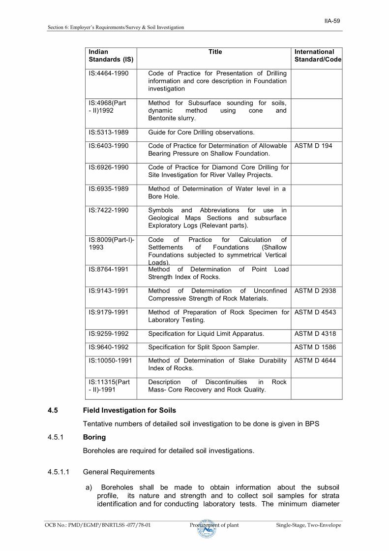
Section6:Employer’sRequirements/SurveySoilInvestigation
OCB No.: PMD/EGMP/BNRTLSS -077/78-01 Procurement of plant Single-Stage, Two-Envelope
Indian Standards (IS)
Title International Standard/Code
IS:4464-1990 Code of Practice for Presentation of Drilling information and core description in Foundation investigation
IS:4968(Part- II)1992
Method for Subsurface sounding for soils, dynamic method using cone and Bentonite slurry.
IS:5313-1989 Guide for Core Drilling observations.
IS:6403-1990 Code of Practice for Determination of Allowable Bearing Pressure on Shallow Foundation.
ASTM D 194
IS:6926-1990 Code of Practice for Diamond Core Drilling for Site Investigation for River Valley Projects.
IS:6935-1989 Method of Determination of Water level in a Bore Hole.
IS:7422-1990 Symbols and Abbreviations for use in Geological Maps Sections and subsurface Exploratory Logs (Relevant parts).
IS:8009(Part-I)- 1993
Code of Practice for Calculation of Settlements of Foundations (Shallow Foundations subjected to symmetrical Vertical Loads).
IS:8764-1991 Method of Determination of Point Load Strength Index of Rocks.
IS:9143-1991 Method of Determination of Unconfined Compressive Strength of Rock Materials.
ASTM D 2938
IS:9179-1991 Method of Preparation of Rock Specimen for Laboratory Testing.
ASTM D 4543
IS:9259-1992 Specification for Liquid Limit Apparatus. ASTM D 4318
IS:9640-1992 Specification for Split Spoon Sampler. ASTM D 1586
IS:10050-1991 Method of Determination of Slake Durability Index of Rocks.
ASTM D 4644
IS:11315(Part- II)-1991
Description of Discontinuities in Rock Mass- Core Recovery and Rock Quality.
4.5 Field Investigation for Soils
Tentative numbers of detailed soil investigation to be done is given in BPS
4.5.1 Boring
Boreholes are required for detailed soil investigations.
4.5.1.1 General Requirements
a) Boreholes shall be made to obtain information about the subsoil profile, its nature and strength and to collect soil samples for strata identification and for conducting laboratory tests. The minimum diameter
IIA-59

Section6:Employer’sRequirements/SurveySoilInvestigation
OCB No.: PMD/EGMP/BNRTLSS -077/78-01 Procurement of plant Single-Stage, Two-Envelope
of the borehole shall be 150mm and boring shall be carried out in accordance with the provisions of IS:1892 and the present specification:
b) All boreholes shall be 10m deep for normal soil conditions. The depth of boreholes at river crossings and special locations shall be 40m. If a strata is encountered where the Standard Penetration Test Records N values greater than 100, with characteristics of rock, the borehole shall be advanced by coring at least 3m further in normal locations and at least 7m further for the case of river crossing locations with prior approval of the Employer. When the boreholes are to be terminated in soil strata an additional Standard Penetration Test shall be carried out at the termination depth. No extra payment shall be made for carrying out Standard Penetration Tests.
c) Casing pipe shall be used when collapse of a borehole wall is probable. The bottom of the casing pipe shall at all times be above the test of sampling level but not more than 15cm above the borehole bottom. In case of cohesion less soils, the advancement of the casing pipe shall be such that it does not disturb the soil to be tested or sampled. The casing shall preferably be advanced by slowly rotating the casing pipe and not by driving.
d) In-situ tests shall be conducted and undisturbed samples shall be obtained in the boreholes at intervals specified hereafter. Representative disturbed samples shall be preserved for conducting various identification tests in the laboratory. Water table in the bore hole shall be carefully recorded and reported following IS:6935. No water or drilling mud shall be used while boring above ground water table. For cohesion less soil below water table, the water level in the borehole shall at all times be maintained slightly above the water table.
e) The borehole shall be cleaned using suitable tools to the depth of testing or sampling, ensuring least or minimum disturbance of the soil at the bottom of the borehole. The process of jetting through an open tube sampler shall not be permitted. In cohesive soils, the borehole may be cleaned by using a bailer with a flap valve. Gentle circulation of drilling fluid shall be done when rotary mud circulation boring is adopted.
f) On completion of the drilling, Contractor shall backfill all boreholes as directed by the Employer.
4.5.1.2 Auger Boring
Auger boring may be employed in soft to stiff cohesive soils above the water table. Augers shall be of helical or post hole type and the cuttings brought up by the auger shall be carefully examined in the field and the description of all strata shall be duly recorded in the field bore log as per IS:1498. No water shall be introduced from the top while conducting auger boring.
IIA-60

Section6:Employer’sRequirements/SurveySoilInvestigation
OCB No.: PMD/EGMP/BNRTLSS -077/78-01 Procurement of plant Single-Stage, Two-Envelope
4.5.1.3 Shell and Auger Boring
4.5.1.3.1 Shell and auger boring may be used in all types of soil which are free from boulders.
For cohesion less soil below ground water table, the water level in the borehole shall always be maintained at or above ground water level. The use of chisel bits shall be permitted in hard strata having SPT-N value greater than 100 Chisel bits may also be used to extend the bore hole through local obstructions such as old construction. Boulders rocky formations, etc. The requirements in Clause 4.5.1.2 shall apply for this type of boring also.
4.5.1.3.2 Rotary method may be used in all types of soil below water table. In this method the boring is carried out by rotating the bit fixed at the lower end of the drill rod. Proper care shall be taken to maintain firm contact between the bit and the bottom of the borehole. Bentonite or drilling mud shall be used as drilling fluid to stabilize and protect the inside surface of the borehole. Use of percussion tools shall be permitted in hard clays and in dense sandy deposits.
4.5.2 Standard Penetration Test (SPT)
4.5.2.1 This test shall be conducted in all types of soil deposits encountered within a borehole, to find the variation in the soil stratification by correlating with the number of blows required for unit penetration of a standard penetrometer. Structure sensitive engineering properties of cohesive soils and sifts such as strength and compressibility shall not be inferred based on SPT values.
4.5.2.2 The test shall be conducted at depths as follows:
Location Depths (m)
Normal Soils 2.0, 3.0, 5.0, 7.0, 10.0
River crossings and special Locations. 2.0, 3.0, 5.0, 7.0, 10.0 and thereafter at the rate of 3m intervals to 40m
4.5.2.3 The spacing between the levels of standard penetration test and next undisturbed sampling shall not be less than 1.0m. Equipment, accessories and procedures for conducting the test and for the collection of the disturbed soil samples shall conform to IS:2131 and IS:9640 respectively. The test shall be conducted immediately after reaching to the test depth and cleaning of bore hole.
4.5.2.4 The test shall be carried out by driving a standard split spoon sampler in the bore hole by means of a 650N hammer having a free fall of 0.75 m. The sample shall be driven using the hammer for 450mm recording the bumper of blows for every 150mm. The number of blow for the last 300mm drive shall be reported as N value.
4.5.2.5 This test shall be discontinued when the blow count is equal to 100 or the penetration is less than 25 mm for 50 blows. At the level where the test is discontinued, the number of blows and the corresponding penetration shall be reported. Sufficient quantity of disturbed soil samples shall be collected from the split spoon sampler for identification and laboratory testing. The sample
IIA-61

Section6:Employer’sRequirements/SurveySoilInvestigation
OCB No.: PMD/EGMP/BNRTLSS -077/78-01 Procurement of plant Single-Stage, Two-Envelope
shall be visually classified and recorded at the site as well as properly preserved without loss of moisture content and labeled.
4.5.3 Sampling
4.5.3.1 General
a) Sufficient number of soil samples shall be collected. Disturbed soil samples shall be collected for soil identification and for conducting tests such as sieve analysis, index properties, specific gravity, chemical analysis etc. Undisturbed samples shall be collected to estimate the physical bearing capacity and settlement properties of the soil.
b) All accessories and sampling methods shall conform to IS:2132: all disturbed and undisturbed samples collected in the field shall be classified at site as per IS:1498
c) All samples shall be identified with date, borehole or test pit number, depth of sampling, etc. The top surface of the sample in-situ shall also be marked. Care shall be taken to keep the core and box samples vertical, with the mark directing upwards. The tube samples shall be properly trimmed at one end and suitably capped and sealed with molten paraffin wax. The Contractor shall be responsible for packing, storing in a cool place and transporting all the samples from site to the laboratory within seven days after sampling with probe, protection against loss and damage.
4.5.3.2 Disturbed Samples
a) Disturbed soil samples shall be collected in boreholes at regular intervals. Jar samples weighing approximately 1 kg shall be collected at 0.5m intervals starting from a depth of 0.5m below ground level and at every identifiable change of strata to supplement the boring records. Samples shall be stored immediately in air tight jars which shall be filled to capacity as much as possible.
b) In designated borrow areas, bulk samples, from a depth of about 0.5m below ground level shall be collected to establish the required properties for use as a fill material. Disturbed samples weighing about 25kg (250N) shall be collected at shallow depths and immediately stored in polythene bags as per IS:1892. The bags shall be sealed properly to preserve the natural moisture content of the sample and placed in wooden boxes for transportation.
4.5.3.3 Undisturbed Samples
In each borehole undisturbed samples shall be collected at every change of strata and at depths as follows:
Location Depths (m)
Normal Soils 1.0, 4.0, 6.0, 8.0
Special Locations 1.0, 4.0, 6.0, 8.0,11.0 and thereafter at the rate of 3 m intervals up to 33m
4.5.3.3.1 The spacing between the top levels of undisturbed sampling and standard penetration testing shall not be less than 1.0m. Undisturbed samples
IIA-62

Section6:Employer’sRequirements/SurveySoilInvestigation
OCB No.: PMD/EGMP/BNRTLSS -077/78-01 Procurement of plant Single-Stage, Two-Envelope
shall be of100mm diameter and 450mm in length. Samples shall be collected in a manner to preserve the structure and moisture content of the soil Accessories and sampling procedures shall conform to IS:1892 and IS:2132
a) Undisturbed sampling in cohesive soil :
Undisturbed samples in soft to stiff cohesive soils shall be obtained using a thin walled sampler. In order to reduce the wall friction, suitable precautions, such as oiling the surfaces shall be taken. The sampling tube shall have a smooth finish on both surfaces and a minimum effective length of 450mm. The area ratio of sampling tubes shall be less than 12.5%. However, in case of very stiff soils area ratio up to 20% shall be permitted.
b) Undisturbed sampling in very loose, saturated, sandy and silty soils and very soft clays :
Samples shall be obtained using a piston sampler consisting of a cylinder and piston system. In soft clays and silty clays, with water standing in the casing pipe, piston sampler shall be used to collect undisturbed samples in the presence of expert supervision.
Accurate measurements of the sampling depth, dimensions of sampler, stroke and length of sample recovery shall be recorded. After the sampler is pushed to the required depth, the cylinder and piston system shall be drawn up together, preventing disturbance and changes in moisture content of the sample;
c) Undisturbed sampling in cohesion less soils
Undisturbed samples in cohesion less soils shall be obtained in accordance with IS:8763. Sampler operated by compressed air shall be used to sample cohesion less soils below ground water table.
4.5.4 Ground Water
4.5.4.1 One of the following methods shall be adopted for determining the elevation of ground water table in boreholes as per IS:6935 and the instructions of the Employer:
a) In permeable soils, the water level in the borehole shall be allowed to stabilize after depressing it adequately by bailing before recording its level. Stability of sides and bottom of the boreholes shall be ensured at all times.
b) For both permeable and impermeable soils, the following method shall be suitable. The borehole shall be filled with water and then bailed out to various depths. Observations on the rise or fall of water level shall be made at each depth. The level at which neither fall nor rise is observed shall be considered the water table elevation and confirmed by three successive readings of water level taken at two hours interval.
4.5.4.2 If any variation of the ground water level is observed in any specific boreholes, the water level in these boreholes shall be recorded during the course of the filed investigation. Levels in nearby wells, streams, etc., if any, shall also be noted in parallel.
4.5.4.3 Subsoil water samples
a. Subsoil water samples shall be collected for performing chemical analysis. Representative ground water samples shall be collected when
IIA-63
Section6:Employer’sRequirements/SurveySoilInvestigation
OCB No.: PMD/EGMP/BNRTLSS -077/78-01 Procurement of plant Single-Stage, Two-Envelope
first encountered in boreholes and before the addition of water to aid boring or drilling.
b. Chemical analysis of water samples shall include determination of pH value, turbidity, Sulphate, carbonate, nitrate and chloride contents, presence of organic matter and suspended solids. Chemical preservatives may be added to the sample for cases as specified in the test methods or in applicable Indian Standards. This shall only be done if analysis cannot be conducted within an hour of collection and shall have the prior written permission and approval of the Employer.
4.5.5 Dynamic Cone Penetration Test (only at Special locations)
a) With bentonite slurry Dynamic cone penetration test shall be conducted to predict stratification, density, beating capacity of granular soils, etc. The test shall be conducted to the specified depth or refusal, whichever comes first. Refusal shall be considered when the blow count exceeds 100 for 300mm penetration. Equipment, accessories test procedures, field observations and reporting of results shall conform to IS:4968, Part-II. The driving system shall comprise of a 650 N weight hammer having a free fall of 750mm. The cone shall be of 600 and of 65mm diameter provided with vents for continuous flow of bentonite slurry through the cone and rods in order to avoid friction between the rods and soil. On completion of the test the results shall be presented as a continuous record of the number of blows required for every 300mm penetration of the cone into the soil in a suitable chart supplemented by a graphical plot of blow count for 300mm penetration vs. depth. On completion of the test, the results shall be presented on the preform approved by the Employer.
IIA-64

Section6:Employer’sRequirements/SurveySoilInvestigation
OCB No.: PMD/EGMP/BNRTLSS -077/78-01 Procurement of plant Single-Stage, Two-Envelope
b) Without bentonite slurry
This test shall be conducted with 50mm diameter 600 cone fitted loosely to the driving rod through a cone adopter. The cone shall be driven in to the soil by allowing 650 N weight hammer top fall freely through a height of 750mm each time. The number of blows for every 75mm penetration shall be recorded. The process shall be repeated till the cone is driven to the required depth. The penetration depth shall be limited to 5m in cohesion less soil and 10m in mixed soil with some binding material. The cone driving rods, driving head, hoisting equipment shall conform to IS: 10589. The test report should be prepared as per guidelines of IS: 4968 (Part I).
4.5.6 Vane Shear Test. (required for boreholes where UDS is not possible) (Only at Special Locations)
4.5.7 Field vane shear test shall be performed inside the borehole to determine the shear strength and bearing capacity of cohesive soils, especially of soft and sensitive clays, which are highly susceptible to sampling disturbance. Equipment, accessories, test procedures, field observations shall correspond to IS:4434. Tests may also be conducted by direct penetration from ground surface. If the cuttings at the test depth in the borehole show any presence of gravel, sand shells, decomposed wood, etc., which are likely to influence the test results substantially, the test at that particular depth may be omitted with the permission of the Employer. However, the test shall be conducted at a depth where these obstructions cease to occur. On completion of the test, the results shall be reported in an approved proforma as specified in IS:4434, Appendix - A.
4.6 Field Investigation for Rock
4.6.1 Rock Drilling
4.6.1.1 If, during the investigations, large hard fragments or natural rock beds are encountered, work shall proceed with core drilling methods. The equipment and procedures for this operation shall conform to IS:1892. The starting depth of drilling in rock shall be certified by the Employer. At the end of the investigation, the hole drilled in rock shall be backfilled with grout consisting of 1 part cement and 3 parts sand by weight.
4.6.1.2 Drilling shall be carried out with NX size tungsten carbide (TC) or diamond tipped drill bits, depending on the type of rock and according to IS:6926. Suitable type of drill bit (TC/Diamond) and core catchers shall be used to ensure continuous and good core recovery. Core barrels and core catchers shall be used for breaking off the core and retaining it when the rods are withdrawn. Double tube core barrels shall be used to ensure better core recovery and to retrieve cores from layers of bedrock. Water shall be circulated continuously in the hollow rods and the sludge conveying the rock cuttings to the surface shall be collected. A very high core recovery ratio shall be aimed at in order to obtain a satisfactory undisturbed sample. Attempt shall be made to recover cores of 1.5m in length. Normally TC bit shall be used. Change over to a diamond bit shall require the specific written approval of the Employer, and his decision as to whether a TC or a diamond bit is to be used shall be final and binding on Contractor.
4.6.1.3 No drilling run shall exceed 1.5 m in depth. if the core recovery is less than 80% in any run, the length of the subsequent run shall be reduced to 0.75m. During drilling operations observations on return water, rate of penetration etc. shall be made recorded and recorded as per IS:5313.
IIA-65

Section6:Employer’sRequirements/SurveySoilInvestigation
OCB No.: PMD/EGMP/BNRTLSS -077/78-01 Procurement of plant Single-Stage, Two-Envelope
a) The colour of return water at regular intervals, the depth at which any change of colour of return water is observed, the depth of occurrence and amount of flow of hot water, if encountered, shall be recorded.
b) The depth through which a uniform rate of penetration was maintained, the depth at which marked change in rate of penetration or sudden fail on drill rod occurs, the depth at which any blockage of drill bit causing core loss, if any, shall be recorded.
c) Any heavy vibration or torque noticed during the drilling should be recorded together with the depth of occurrence.
d) Special conditions like the depth at which grouting was done during, drilling, presence of artesian conditions, loss of drilling fluid, observations of gas discharge with return water, etc., shall also be observed and recorded.
e) All the observations and other details shall be recorded as per daily drill and reported in a proforma as given in IS:5313, Appendix A.
4.6.2 Core Sampling
4.6.2.1 Core samples shall be extracted by the application of a continuous pressure at one end of the core with the barrel held horizontally without vibration. Friable cores shall be extracted from the barrel directly into a suitably sized half round plastic channel section. Care shall be taken to extrude the samples in the direction of coring to avoid stress reversal.
4.6.2.2 Immediately after withdrawal from the core barrel, the cores shall be placed in a tray and transferred to boxes specially prepared for this purpose. The boxes shall be made from seasoned timber or any other durably material and shall be indexed on top of the lid according to IS:4078. The cores shall be numbered serially and arranged in the boxes in a sequential order. The description of the core samples shall be recorded as instructed in IS:4464. Where no core is recovered, it shall be recorded as specified in the standard. Continuous record of core recovery and rock quality designation (RD/DD/QD) are to be mentioned in the bore log in accordance with IS:11315(Part-II).
4.7 Laboratory Testing
4.7.1 Essential Requirements
a) Depending on the types of substrata encountered, appropriate laboratory tests shall be conducted on soil and rock samples collected in the field. Laboratory tests shall be scheduled and performed by qualified and experienced personnel who are thoroughly conversant with the work. Tests indicated in the schedule of items shall be performed on soil, water and rock samples as per relevant IS codes. One copy of all laboratory test data records shall be submitted to Employer progressively every week. Laboratory tests shall be carried out concurrently with the field investigations as initial laboratory test results could be useful in planning the later stages of field work. A schedule of laboratory tests shall be established by Contractor to the satisfaction of the Employer within one week of completion of the first borehole;
b) Laboratory tests shall be conducted using approved apparatus complying with the requirements and specification of Indian Standards or other approved standards for this type of work. It shall be checked that the apparatus are in good working condition before starting the laboratory
IIA-66

Section6:Employer’sRequirements/SurveySoilInvestigation
OCB No.: PMD/EGMP/BNRTLSS -077/78-01 Procurement of plant Single-Stage, Two-Envelope
tests. Calibration of all the instruments and their accessories shall be done carefully and precisely at an approved laboratory.
c) All samples, whether undisturbed or disturbed shall be extracted, prepared and examined by competent personnel properly trained and experienced in soil sampling. examination, testing and in using the apparatus in conformance with the specified standards;
d) Undisturbed soil samples retained in liners or seamless tube samplers shall be removed, without causing any disturbance to the samples, using suitably designed extruders just prior to actual testing. If the extruder is horizontal, proper support shall be provided to prevent the sample from breaking. For screw tube extruders, the pushing head shall be free from the screw shaft so that no torque is applied to the soil sample in contact with the pushing head. For soft clay samples, the sample tube shall be cut by means of a high speed hacksaw to proper test length and placed over the mould before pushing the sample into it with a suitable piston;
e) While extracting a sample from a liner or tube, care shall be taken to assure that its direction of movement is the same as that during sampling to avoid stress reversal;
4.7.2 Tests
4.7.2.1 Tests as indicated in these specifications and as may be requested by the Employer, shall be conducted. These tests shall include but may not be limited to the following :
a) Tests of undisturbed and disturbed samples
Visual and engineering classification;
Sieve analysis and hydrometric analysis;
Liquid, plastic and shrinkage limits;
Specific gravity;
Chemical analysis
Swell pressure and free swell index determination
Proctor compaction
test. b) Tests of undisturbed
samples:
Bulk density and moisture content;
Relative density(for sand),
Unconfined compression test;
Box shear test (for sand);
Triaxle shear tests (depending on the type of soil and field conditions on undisturbed or remolded samples):
i. Unconsolidated undrained;
ii. Consolidated drained test;
Consolidation.
IIA-67

Section6:Employer’sRequirements/SurveySoilInvestigation
OCB No.: PMD/EGMP/BNRTLSS -077/78-01 Procurement of plant Single-Stage, Two-Envelope
c) Tests on rock samples
Visual classification; Moisture content , porosity and density;
Specific gravity;
Hardness
Stake durability
Unconfined compression test (both saturated and at in-situ water content);
Point load strength index;
Deformability test(both saturated and dry samples).
d) Chemical analysis of sub soil water.
4.7.3 Salient Test Requirement
a) Triaxle shear tests shall be conducted on undisturbed soil samples, saturated by the application of back pressure. Only if the water table is at sufficient depth so that chances of its rising to the base of the footing are small or nil, the triaxle tests shall be performed on specimens at natural moisture content. Each test shall be carried out on a set of three test specimens from one sample at cell pressures equal to 100, 200 and 300 KPa respectively or as required depending on the soil conditions:
b) Direct shear test shall be conducted on undisturbed soil samples. The three normal vertical stresses for each test shall be 100, 200 and 300 KPa or as required for the soil conditions;
c) Consolidation test shall have loading stages of 10, 25, 50, 75, 100, 200, 400 and
800 KPa. Rebound curve shaft be recorded for all samples by unloading the specimen at its in-situ stress. Additional rebound curves shall also be recorded wherever desired by the Employer;
d) Chemical analysis of subsoil shaft include determination of PH value, carbonate, sulphate (both SO3 and SO4). chloride and nitrate contents, organic matter, salinity and any other chemicals which may be harmful to the foundation material. Their contents in the soil shall be indicated as percentage(%);
e) Chemical analysis of subsoil water samples shall include the determination of properties such as colour, odour, turbidity, PH value and specific conductivity, the last two chlorides, nitrates, organic matter and any other chemical harmful to the foundation material. The chemical contents shall be indicated as parts per million (PPM) based on weight.
4.8 Geotechnical Investigation Report
4.8.1 General
Contractor shall submit a formal report containing geological information of the region, procedures adopted for geotechnical investigation, field observations, summarized test data, conclusions and recommendations. The report shall also include detailed bore logs, subsoil sections, field test results, laboratory observations and test results both in tabular as well as graphical form,
IIA-68

Section6:Employer’sRequirements/SurveySoilInvestigation
OCB No.: PMD/EGMP/BNRTLSS -077/78-01 Procurement of plant Single-Stage, Two-Envelope
practical and theoretical considerations for the interpretation of test results, supporting calculations for the conclusions drawn, etc. Initially, Contractor shall submit three copies of the report in draft form for Employer’s review;
a) Contractor’s Geotechnical engineer shall visit Employer’s Corporate Office for a detailed review based on Employer’s comments in order to discuss the nature of modifications, if any, to be done in the draft report. Contractor shall incorporate in the report the agreed modifications and resubmit the revised draft report for approval. Ten copies of the detailed final approved report shall be submitted to Employer together with one set of reproducible of the graphs, tables etc.
b) The detailed final report based on field observations, in-situ and laboratory tests shall encompass theoretical as well as practical considerations for foundations for different types of structures.
4.8.2 Data to be furnished
4.8.2.1 The report shall also include the following
a) A plot plant/location plan showing the locations and reduced levels of all field test e.g. boreholes, trial pits, static cone penetration tests, dynamic cone penetration tests, etc., property drawn to scale and dimensioned with reference to the established grid lines;
b) A true cross section of all individual boreholes and test pits with reduced levels and co-ordinates showing the classification and thickness of individual stratum, position of ground water table, various in-situ tests conducted, samples collected at different depths and the rock stratum, if encountered;
c) Geological information of the area including geomorphology, geological structure, lithology, stratigraphy and tectonics, core recovery and rock quality designation (RD/DD/QD), etc.,
d) Observations and data regarding change of course of rivers, velocity, scour depths, slit factor, etc., and history of flood details for mid stream and river bank locations;
e) Past observations and historical data, if available, for the area or for other areas with similar soil profile, or with similar structures in the surrounding areas;
f) Plot of Standard Penetration Test (uncorrected and corrected N values) with depth for each test site;
g) Results of all laboratory test summarized according to Table 4.0 (i) for each sample as well as (ii) for each layer, along with all the relevant charts, tables, graphs, figures, supporting calculations, conclusions and photographs of representative rock cores,
h) For all triaxle shear tests, stress vs. strain diagrams as well as Mohr’s circle envelopes shall be furnished. If back pressure is applied for saturation, the magnitude of the same shall be indicated. The value of modulus of elasticity (E) shall be furnished for all tests along with relevant calculations;
i) For all consolidation tests, the following curves shall be furnished i. e
vs. log p;
ii. e vs. p;
IIA-69

Section6:Employer’sRequirements/SurveySoilInvestigation
OCB No.: PMD/EGMP/BNRTLSS -077/78-01 Procurement of plant Single-Stage, Two-Envelope
iii. Compression vs log t or vs t
depending upon the shape of the plot, for proper determination of coefficient of consolidation.
The point showing the initial condition (e0, p0) of the soil shall be marked on the curves;
j) The procedure adopted for calculating the compression index from the field curve and settlement of soil strata shall be clearly specified. The time required for 50% and 90% primary consolidation along with secondary settlements, if significant, shall also be calculated.
IIA-70

Section 6: Employer’s Requirements/Survey & Soil Investigation
OCB No.: PMD/EGMP/BNRTLSS -077/78-01 Procurement of plant Single-Stage, Two-Envelope
Table 4.0
A. SUMMARY OF RESULTS OF LABORATORY TESTS ON SOIL
Date of Boring : Name of the Project : B o r e h o l e n o . :
Ground elevation:
(R.L. in m.)
Co-ordinates: Termination Depth: Water table:
Soil details Grain Size Distribution
Atterberg limits
Soil Density (kg / m3
) Moisture content
Triaxle /
Direct shear
Test
Remarks
De
pth
S
am
ple
no
s.
& t
yp
e
IS C
lassific
atio
n o
f so
il
De
scri
ption
of
laye
rs
N –
Va
lue
(o
bse
rve
d)
N –
Va
lue
(co
rre
cte
d)
Sp
ecific
Gra
vity
Gra
ve
l S
an
d
Silt
C
lay
Liq
uid
Lim
it
Pla
stic L
imit
Pla
sticity i
nd
ex
Bu
lk /
Na
tura
l D
en
sity
Dry
De
nsity
Su
bm
erg
ed
De
nsity
Pro
cto
r D
en
sity
Re
lative D
en
sity
Na
tura
l
Op
tim
um
Co
nfin
ing P
ressu
re
Co
-he
sio
n
An
gle
of
Re
po
se
Following additional information should also be provided:
(i) Maximum expected yearly rise / fall of water table
(ii) General topography of the location : whether cultivated or barren, hilly / plain location, river bank location
etc. Note : where ever undisturbed sampling is not possible, reasons must be clearly indicated and all the tests shall be
conducted
on re- moulded samples
(Signature) (Signature) (Signature)
Prepared by Checked & Reviewed by Checked & Approved by
Soil investigator Line Contractor NEA/ PSC Site Engg.
IIA-71

Section6:Employer’sRequirements/SurveySoilInvestigation
OCB No.: PMD/EGMP/BNRTLSS -077/78-01 Procurement of plant Single-Stage, Two-Envelope
(Signature) (Signature) (Signature) Prepared by Checked & Reviewed by Checked & Approved by Soil investigator Line Contractor NEA/ PSC site Engg.
B. SUMMARY OF ULTIMATE BEARING CAPACITIES CONSIDERING MAXIMUM RISE OF WATER TABLE
Location no.
Foundation Classification
Depth of footing considered for
bearing capacity calculatio
Size of footing considered for bearing capacity calculation
Bearing capacity*
Based on settlement criteria (for 40mm
Based on shear failure criteria
3.0m 3.0m x 3.0m
3.0m 5.0m x 5.0m
3.0m 7.0m x 7.0m
3.0m 9.0m x 9.0m
3.5m 3.0m x 3.0m
3.5m 5.0m x 5.0m
3.5m 7.0m x 7.0m
3.5m 9.0m x 9.0m
* Detailed calculations of all the bearing capacities should be enclosed
with soil investigation reports.
C. For Chemical Test
As per Specifications - Clause 4.8.4
4.8.3 Recommendations
4.8.3.1 Recommendations shall be provided for each tower location duly considering soil type and tower spotting data. The recommendations shall provide all design parameters and considerations required for proper selection, dimensioning and future performance of tower foundations and the following
a) The subsurface material must provide safe bearing capacity and uplift resistance by incorporating appropriate safety factors thereby avoiding rupture under ultimate loads;
b) Movement of the foundation, including short and long term components under transient and permanent loading, shall be strictly controlled with regard to settlement, uplift, lateral translation and rotation:
c) Co-efficient of permeability of various sub soil and rock strata based on in-situ permeability tests.
Core resistance, frictional resistance total resistance, relation between core resistance, Standard Penetration Test N value, and settlement analysis for different sizes of foundation as specified in para 4.1.8.3 (I) based on static cone penetration test.
d) For shallow foundation the following shall be indicated with comprehensive supporting calculations:
IIA-72

Section6:Employer’sRequirements/SurveySoilInvestigation
OCB No.: PMD/EGMP/BNRTLSS -077/78-01 Procurement of plant Single-Stage, Two-Envelope
i. Net Safe allowable bearing pressure for isolated square footing of sizes 4.0, 5.0, 6.0 & 7. m at three different founding depths of 1,2 and 3 & 3.5m below
ground level considering both shear failure and settlement criteria giving reasons for type of shear failure adopted in the calculation.
ii. Net safe allowable bearing pressure for raft foundations of widths greater than 5m at 2.0, 3.0 and 4.0m below ground level considering both shear failure and settlement criteria.
iii. Rate and magnitude of settlement expected of the structure. iv. Net safe bearing capacity for foundation sizes mentioned in para(i)
above, modulus of sub grade reaction, modules of elasticity from plate load test results along with time settlement curves and load settlement curve in both natural and log graph, variation of Modulus of sub grade reaction with size, shape and depth of foundation.
e) The stable slopes for shallow and deep excavations, active and passive
earth pressure at rest and angle of repose for sandy soils shall be furnished. The loading of the foundations shall not compromise the stability of the surrounding subsurface materials and the stability of the foundation shall be ensured against sliding or overturning:-
f) Depending on the subsurface material, water table level and tower type, either reinforced concrete isolated pad and chimney, cast-in-situ bored pile of special foundations shall be installed at a given location.
g) Net Safe allowable bearing pressure and uplift resistance shall be provided for the various sizes of isolated square footings founded at various depths below ground level considering both shear failure and movement criteria; rate and magnitude of movement expected of the structure (settlement, uplift, rotation) shall also be given.
h) In cases where normal open cast/pile foundations appear to be
impractical, special pile foundations shall be given due consideration along with the following:
i. Type of pile foundation and reasons for recommending the same duly considering the soil characteristics.
ii. Suitable founding strata for the pile: iii. Estimated length of pile for 500, 750 and 1000 KN and 4500 KN capacities;
end bearing and frictional resistance shall be indicated separately:
iv. Magnitude of negative skin friction or uplift forces due to soil swelling.
i) Where the subsoil water and soil properties are found to be chemically aggressive. Contractor shall take suitable precautions during construction including any protective coating to be applied on the foundations; susceptibility of soil to termite action and remedial measures for the same shall be dealt with;
j) Suitability of locally available soils at site for filling, backfilling and adequate compaction shall be investigated.
k) If expansive soil such as black cotton soil is encountered recommendation of removal or retainment of the same shall be given in the latter case, detailed specifications of special requirements shall also be given;
l) Susceptibility of subsoil strata to liquefaction in the event of earthquake and remedial measures, if required, shall be considered.
IIA-73

Section6:Employer’sRequirements/SurveySoilInvestigation
OCB No.: PMD/EGMP/BNRTLSS -077/78-01 Procurement of plant Single-Stage, Two-Envelope
4.8.4
4.8.4.1
4.9
4.9.1
4.10
4.10.1
4.10.2
4.10.2.1
4.10.2.2
4.10.2.3
m) Any other information of special significance such as dewatering schemes, etc.which may have a bearing on the design and construction shall be provided.
n) Recommendations for additional soil investigations, beyond the scope ofthe present work, shall be given if Contractor considers such investigationsnecessary.
Hydrogeological Conditions
The maximum elevation of ground water table, amplitudes of its fluctuations anddata on water aggressivity with regard to foundation structure materials shall bereported. While preparing ground water characteristics the following parametersshould be specified for each aquifer:
a) bicarbonate alkalinity mg-eq/(deg),b) pH valuec) content of aggressive carbon dioxide, mg/l;d) content of magnesia salts. mg/l, recalculated in terms of ions Mg+2;e) content of ammonia salts, mg/l, recalculated in terms of ions NH4+f) content of caustic alkalis, mg/l, recalculated in terms of ions Na+ and K+g) contents of chlorides,mg/l recalculated in terms of ions Cl-h) contents of sulphates, mg/l, recalculated in terms of ions SO4-2i) aggregate content of chlorides, sulphates, nitrates, carbonates and other
salts. mg/l.Rates and Measurements
Rates
The contractor’s quoted rates shall be inclusive of making observations,establishing the ground level and co-ordinates at the location of each borehole,test pit etc. No extra payments shall be made for conducting Standard PenetrationTest, collecting, packing, transporting of all samples and cores, recording andsubmittal of results on approved formats.
Specific Requirements for Geotechnical Investigation at River Crossings.
The entire soil investigation work at river crossing locations (if required) shall becarried out in accordance with the relevant parts of the specifications forgeotechnical investigation modified to the extent given below.
Requirements
Boreholes shall be executed to specified depth of 40m (refer clause 4.5.1.1 b). Ifrefusal strata is reached (i.e. SPT-N value is greater than 100 continuously for 5mdepth) with characteristics of rock the borehole may be terminated at shallowerdepth i.e. at 5m in refusal strata, with prior approval of the Employer.
Laboratory testing shall be conducted on all soil samples to determine grain sizedistribution, liquid limit and plastic limit of the different soil strata encountered.
Geotechnical Report must furnish the following:
a) Geotechnical investigation scheme;b) Bore-logs indicating soil stratification, with IS classification, sampling details and
SPI‘N’values.
IIA-74

Section6:Employer’sRequirements/SurveySoilInvestigation
OCB No.: PMD/EGMP/BNRTLSS -077/78-01 Procurement of plant Single-Stage, Two-Envelope
c) Soil cross-sections along various boreholes in two orthogonal directions indicating soil stratification based on field and laboratory tests;
d) size distribution curves. e) IS classification of soils. f) Shear tests (UU) to be done on saturated soil samples; g) Bearing capacity of soil at different levels; h) Highest flood level (H.F.L.); i) Maximum discharge, velocity etc. (from authenticated source such as
CWC or appropriate State authorities) j) Recommendations regarding type of foundation to be adopted at the location.
4.10.3 A check list for reporting results of river crossing locational details, detailed soil investigation and river values for river crossing locations is enclosed at Annexure-C.
4.11 Special Terms and conditions for Geotechnical Investigation in the River bed
4.11.1 Contractor is required to mobilize a suitable arrangement (floating pontoon, plant, equipment etc.) to carry out geotechnical investigation work in creek/river locations identified by the Employer.
4.11.2 In the event of storm or stoppage of work, etc., Contractor shall not be paid extra for mobilization / remobilization of floating pontoon, plant, equipment, etc.
4.11.3 Contractor shall fully satisfy himself about the conditions of creek/river (depth of water, wave currents, wind conditions, etc.) prevailing in the area of proposed investigation and plan the necessary tools and plant to be deployed before quoting. Any claim resulting from lack of data collection in this respect shall not be entertained.
4.11.4 Contractor shall make his own arrangements for locating the coordinates and position of boreholes in creek/river with respect to two grid-lines indicated by Employer.
4.11.5 Boring in creek or river shall be payable only below the bed level and no payment shall be made for lowering the casing in water.
4.11.6 Contractor shall arrange for necessary transportation on water (e.g. motor boat) to facilitate the supervision of work by officials of Employer at its own cost.
4.11.7 Full details of the construction plant, proposed working method for boring and sampling in water shall be submitted along with the Tender.
4.11.8 The unit rate quoted for underwater boring shall include complete work required as per specification and no separate payment shall be made on any account.
5. STATUTORY REGULATIONS AND STANDARDS
5.1 Contractor is required to follow statutory regulations stipulated in Electricity Act 2003, Indian Electricity Rules and other local rules & regulations.
5.2 The codes and standards referred to in these specifications shall govern. In case of a conflict between such codes/standards and these specifications, the provisions of the specifications shall prevail. Such codes, standards referred to shall mean latest revisions, amendments, changes adopted and published by relevant agencies.
5.3 Other Internationally acceptable standards which ensure equivalent or better performance than those specified shall also be acceptable.
IIA-75

Section 6: Employer’s Requirements/Survey & Soil Investigation
OCB. No. PMD/EGMP/BNRTLSS - 077/078-01 Procurement of plant Single-Stage, Two-Envelope
Sl. No. Description Unit Quantity
9 Tower Protection a) Random rubble m3 b) Stone Bound m3 c) Back Filling m3 d) M-15 Cover seal m3
10 Aviation Requirements a) Painting of towers No. b) Unit wt. of Towers to be painted MT b) Span marks No. c) Aviation Lights
i) 1 Medium+2 low intensity No. ii) 1 Medium+ 4 low intensity No. 11 Wind measuring equipment No. 12 No. of Transposition towers No. 13 Road/Railway Crossings
a) Road Crossings (NH/SH) No. b) Power Line Crossings (132kV & above) No. c) Railway Crossing-electrified No. d Railway Crossing-non- electrified No.
14 Forest Details: a) Reserved Forest kms b) Protected Forest kms c) Social/Revenue Forest kms d) Other Area kms
15 Power Line Crossings a) 765 KV No. b) 400 KV No. c) 220 KV No. d) 132 KV No.
BOQ FORMAT FOR TRANSMISSION LINE PACKAGE Annex-A (1/2)
Name of line : ------------ KV ------------------ -------------------------------- associated with ----------
Sl. No. Description Unit Quantity
1 Line length KM a) Plain Terrain KM b) Hilly Terrain KM
States a) ………. KM b) ………. KM c) ………. KM d) ………. KM
2 Length of RC section KM 3 No of Circuits No. 4 No. of bundle Conductor No. 5 Earthing
a) Pipe type Earthing No. b) Counterpoise Earthing No. c) Earthing for RC Location No.
6 Survey a) Detailed survey KM b) Check Survey KM
7 Soil Investigation a) All kind of soil except FR & HR Loc. b) Fissured rock Loc. c) Rocky Soil Loc. d) River Crossing Location Loc.
8 Benching a) All kind of soil except FR & HR m3 b) Fissured rock m3 c) Hard rock m3
IIA-76

Section 6: Employer’s Requirements/Survey & Soil Investigation
OCB. No. PMD/EGMP/BNRTLSS - 077/078-01 Procurement of plant Single-Stage, Two-Envelope
Name of line : ------------ KV ------------------ -------------------------------- associated with ----------
Annex-A (2/2)
Tower Type Unit Quantity Foundation classification
Dry Wet PS FS WBC DFR WFR SFR HR Sandy Well
A/DA/QA Type tower Nos. 0 0 0 0 0 0 0 0 0 0 0
Normal Tower Nos +3M Extn Nos +6M Extn Nos +9M Extn Nos +18M Extn Nos +25M Extn Nos
B/DB/QB Type tower Nos. 0 0 0 0 0 0 0 0 0 0 0
Normal Tower Nos +3M Extn Nos +6M Extn Nos +9M Extn Nos. +18M Extn Nos +25M Extn Nos
C/DC/QC Type tower Nos. 0 0 0 0 0 0 0 0 0 0 0
Normal Tower Nos +3M Extn Nos +6M Extn Nos +9M Extn Nos
D/DD/QD Type tower Nos. 0 0 0 0 0 0 0 0 0 0 0
Normal Tower Nos +3M Extn Nos +6M Extn Nos +9M Extn Nos +18M Extn Nos +25M Extn Nos Gantry Nos.
Total 0 0 0 0 0 0 0 0 0 0 0
D/C M/C TOTAL
Total suspension Towers 0 0 0
Total Tower Type 'D/DD/QD' 0 0 0
Total Tension Towers 0 0 0
total Normal Towers 0 0 0
Total Anchor Towers Total RC Towers Total Towers 0 0 0
IIA-77
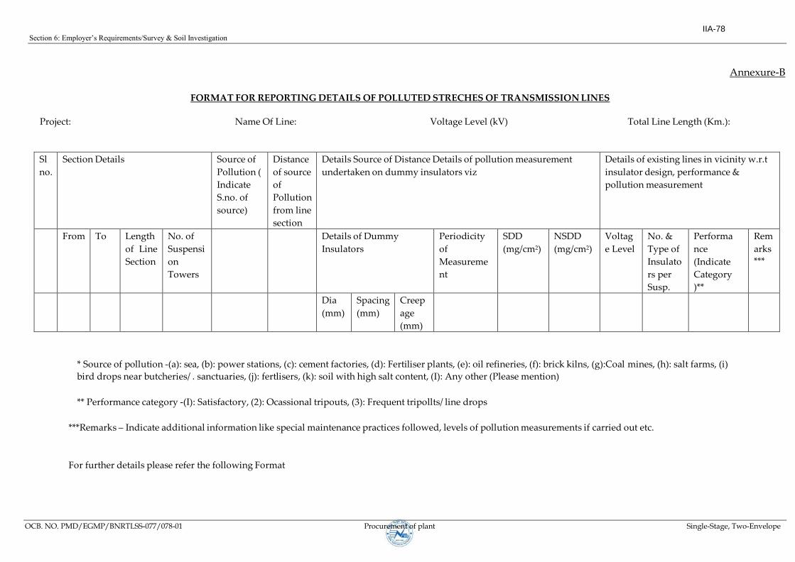
Section 6: Employer’s Requirements/Survey & Soil Investigation
OCB. NO. PMD/EGMP/BNRTLSS-077/078-01 Procurement of plant Single-Stage, Two-Envelope
Annexure-B
FORMAT FOR REPORTING DETAILS OF POLLUTED STRECHES OF TRANSMISSION LINES
Project: Name Of Line: Voltage Level (kV) Total Line Length (Km.):
Sl
no.
Section Details Source of
Pollution (
Indicate
S.no. of
source)
Distance
of source
of
Pollution
from line
section
Details Source of Distance Details of pollution measurement
undertaken on dummy insulators viz
Details of existing lines in vicinity w.r.t
insulator design, performance &
pollution measurement
From To Length
of Line
Section
No. of
Suspensi
on
Towers
Details of Dummy
Insulators
Periodicity
of
Measureme
nt
SDD
(mg/cm2)
NSDD
(mg/cm2)
Voltag
e Level
No. &
Type of
Insulato
rs per
Susp.
String
Performa
nce
(Indicate
Category
)**
Rem
arks
***
Dia
(mm)
Spacing
(mm)
Creep
age
(mm)
* Source of pollution -(a): sea, (b): power stations, (c): cement factories, (d): Fertiliser plants, (e): oil refineries, (f): brick kilns, (g):Coal mines, (h): salt farms, (i) bird drops near butcheries/ . sanctuaries, (j): fertlisers, (k): soil with high salt content, (I): Any other (Please mention)
** Performance category -(I): Satisfactory, (2): Ocassional tripouts, (3): Frequent tripollts/ line drops
***Remarks – Indicate additional information like special maintenance practices followed, levels of pollution measurements if carried out etc.
For further details please refer the following Format
IIA-78

Section6:Employer’sRequirements/SurveySoilInvestigation
OCB. No. PMD/EGMP/BNRTLSS - 077/078-01 Procurement of plant Single-Stage, Two-Envelope
QUESTIONNAIRE FOR COLLECTION OF POLLUTION DATA IN RESPECT OF TRANSMISSION
LINES
1. Distance from sea-Coast (Route alignment indicating distances from sea coast may be :
enclosed)
2. Details of industries along the proposed route (Power stations, Cement factories, Fertilizer :
plants, Oil refineries Brick-kiln’s, Coal mines, Salt Forn1s etc.)
a. Type of Industry :
b. Distance from the proposed route (please mark position of industries in the route :
map)
c. Nature of pollutants. :
d. Details of stretches of lines (in kms) expected to be affected by above industries). :
3. Details of proposed industries along the Proposed route (Data may be collected From :
concerned authorities)
a. 4. Details of existing lines in the vicinity Of proposed route alignment
a. Name of line, voltage level, Utility
b. How long in service.
C Type of insulators used (Standard! Antifog)
d. Details of insulator strings . (Nos. per string)
e. Has ever pollution measurement carried out by the utility. :
f. Any specific steps being taken to counter pollution problems (Like hot line :
washing, insulator surface coating, cleaning of insulators etc.)
g. Performance of line (No. of ; tripouts/flashovers, failure of insulators etc. as :
collected from concerned utility)
h. Approx. distance between the Line and proposed route. :
i. Any other information (Corrosion of insulator pin, towers, line drops etc.) :
5. Any butcheries / Bird sanctuaries along the route Alignment where bird drops may be :
anticipated (indicate position of the route map)
6. Vicinity of highways :
a. Distance from proposed route. :
b. Length of parallelism :
7. Any specific area along the route alignment where soil may have salt content which may :
affect the insulator performance (Identify area on route maps)
8. Details of cultivated fields where fertilizers are frequently used (Identify areas on the route :
maps)
IIA-79

Section6:Employer’sRequirements/SurveySoilInvestigation
OCB. No. PMD/EGMP/BNRTLSS - 077/078-01 Procurement of plant Single-Stage, Two-Envelope
9. Details of natural rain :
a. Duration of rainy season :
b. Extent of rain. :
10. Details of thunderstorm conditions (Very frequent/frequent/less frequent) :
11. Details of Pollution measurement if any, carried out using dummy insulators/ existing lines :
nearby:-
i. Measurement conducted on insulator - Type, dia, spacing & creepage :
ii. SDD , :
iii. NSDD :
iv. Type of pollutant :
v. Periodicity of measurement: Values corresponding to :
a. Quarterly :
b. Half yearly :
c. Yearly :
d. Two yearly :
12. Any other information. :
IIA-80
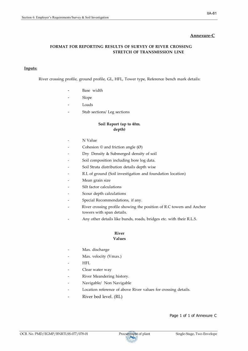
Section6:Employer’sRequirements/Survey & Soil Investigation
OCB. No. PMD/EGMP/BNRTLSS-077/078-01 Procurement of plant Single-Stage, Two-Envelope
Annexure-C
FORMAT FOR REPORTING RESULTS OF SURVEY OF RIVER CROSSING
STRETCH OF TRANSMISSION LINE
Inputs:
River crossing profile, ground profile, GL, HFL, Tower type, Reference bench mark details:
- Base width
- Slope
- Loads
- Stub sections/ Leg sections
Soil Report (up to 40m.
depth)
- N Value
- Cohesion © and friction angle (Ø)
- Dry Density & Submerged density of soil
- Soil composition including bore log data.
- Soil Strata distribution details depth wise
- R.L of ground (Soil investigation and foundation location)
- Mean grain size
- Silt factor calculations
- Scour depth calculations
- Special Recommendations, if any.
- River crossing profile showing the position of R.C towers and Anchor
towers with span details.
- Any other details like bunds, roads, bridges etc. with their R.L.S.
River
Values
- Max. discharge
- Max. velocity (Vmax.)
- HFL
- Clear water way
- River Meandering history.
- Navigable/ Non Navigable
- Location reference of above River values for crossing details.
- River bed level. (RL)
Page 1 of 1 of Annexure C
IIA-81

Section 6: Employer’s Requirements/Survey & Soil Investigation
OCB No.: PMD/EGMP/BNRTLSS -077/78-01 Procurement of plant Single-Stage, Two-Envelope
Annexure-D
FIELD QUALITY PLAN FOR TRANSMISSION LINES
Document No. C/A/DA/QA&I/SFQP/TL/030, Rev 01
S.No. Descriptio
n n of
Activity
Items to be
Checked
Tests/Checks
to be done
Ref documents Check/Testing Counter
Check/Test
By Employer
Accepting
authority in
Employer
Agency Extent
1. Detailed
Survey
a. Route
alignment
Optimisation of
route length
a. Preliminary
survey.
b. Topographical
map
c. Tower
spotting
data’s given
by
Engg.
Contractor
- do -
- do -
100% at Field
- do -
- do -
100% based
on record
documents
- do -
Project
in
charge
b. Route
profiling &
tower spotting
1. Ground
clearance.
2. Cold Wt.
Span
3. Hot Wt.
Span
4. Sum of Adj
span (wind
span)
5. Angle of
Devn.
a. Sag template
b. Tower
Spotting data
c. Route
alignment
Contractor
- do -
- do -
- do -
- do -
- do -
- do -
- do -
- do -
- do -
100% based
on record
documents
- do -
- do -
- do -
- do -
Line in
charge
Page 1 of 2 of Annexure D
IIA-82

Section 6: Employer’s Requirements/Survey & Soil Investigation
ICB/PMD/MCTLP/018/19-01 Procurement of plant Single-Stage, Two-Envelope
2 Check
Survey
Tower Location
& Final Length
i. Alignment
ii. Final Length
a. Route
alignment
b. Tower
Schedule
c. Profile
Contractor 100% at Field i). All angle
towers in
plains and
50% in hilly
terrains
ii). Final
length to be
checked on
100% basis
based on
records/docum
ents
Section
In charge
3. Details Soil
Investigation
a. Bore log 1. Depth of
bore log.
2. SPT Test
3. Collection of
samples
As per Employer
Specification
Contractor 100% at Field To witness
20% at Field
Section
in
charge.
b. Tests on
samples
As per tech.
Specs
- do - Lab appd
by
Employer
100% by
testing lab
Review of lab
test results
Line in
charge
based on
the report
review by
CC Engg.
Page 2 of 2 of Annexure D
IIA-83

Section 6: Employer’s Requirements/Standardised Field Quality Plan (Appendix-I)
OCB. No. PMD/EGMP/BNRTLSS – 077/078-01 Procurement of plant Single-Stage, Two-Envelope
STANDARDISED FIELD QUALITY PLAN
S.
No.
Description of
Activity
Items to be Checked Tests/Checks to be done
Ref. documents Check/Testing
Counter Check/Test by
EMPLOYER
Accepting
authority of
EMPLOYER Agenc
y Extent
1. Preliminary
/Detailed
Survey
a) Route alignment Optimization of
route length
a. Preliminary survey.
b. Topographical
map c. Tower
spotting data
given by Engg.
Contractor 100% at Field 100% based on
record documents
Project In-charge
b) Route profiling &
tower spotting.
1. Ground clearance.
2. Cold wt. Span
3. Hot wt. Span
4. Sum of Adj. Span
(wind span)
5. Angle of Devn.
6. Suitability of
Tower spotting in
hilly area
a. Sag template
b. Tower Spotting
data c. Route
alignment
Contractor
-do-
-do-
-do-
-do-
-do-
100% at Field
-do-
-do-
-do-
-do-
-do-
100% based on
record documents
-do-
-do-
-do-
Verification of 100% at Field
Site In-charge
2. Check Survey Tower Location & Final
Length
i) Alignment
ii) Final Length
iii) Angel of deviation &
pit marking-
a. Route
alignment b.
Tower Schedule c.
Profile
Contractor
-do-
100% at Field
-do-
i) All angle towers in
plains and 50% in hilly
terrains.
ii) Final length to be
checked on 100% basis
based on
records/documents 20
% test check at site for
physical verification.
Site Engineer
3. Detailed Soil
Investigation
a) Bore log 1. Depth of bore log
2. SPT Test
3. Collection of samples
As per Specification Contractor 100% at Field To witness 20% at Field Site Engineer
IIA-84

Section 6: Employer’s Requirements/Standardised Field Quality Plan (Appendix-I)
OCB. No. PMD/EGMP/BNRTLSS – 077/078-01 Procurement of plant Single-Stage, Two-Envelope
STANDARDISED FIELD QUALITY PLAN
S.
No.
Description
of Activity
Items to be Checked Tests/Checks to be
done
Ref. documents Check/Testing Counter Check/Test by
EMPLOYER
Accepting
authority of
EMPLOYER Agency Extent
b) Tests on samples As per tech. Specs. As per Specification Contractor
(Testing in NEA accepted
Lab)
100% by testing lab
(Reports to be signed by
Testing person & Checking
person)
Review of lab test results
(All soil reports to have
signature of EMPLOYER
executive reviewing the
report )
Site In-charge
based on the guide
line issued by
EMPLOYER as
Annex-6
c) Special foundations As per tech. Specs As per Specification Contractor
(Testing of samples in
NEA accepted Lab)
100% by testing lab
(Reports to be signed by
Testing person & Checking
person)
Review of lab test results
(All soil reports to have
signature of EMPLOYER
executive reviewing the
report )
Site In-charge
based on the guide
line issued by
EMPLOYER as
Annex-6
4 Revetment RR Masonry a) Size of Stone CPWD Spec. Contractor 100% physical
verification per source
Physical verification on
random basis
Site Engineer
b) Water absorption -Do- -Do-
(Testing in NEA accepted
Lab)
1 sample/ source Review of Lab Test results -Do-
c) Cement : sand
ratio in mortar
As per Specification Contractor 100% Physical verification in
random.
-Do-
IIA-85

Section 6: Employer’s Requirements/Standardised Field Quality Plan (Appendix-I)
OCB. No. PMD/EGMP/BNRTLSS – 077/078-01 Procurement of plant Single-Stage, Two-Envelope
STANDARDISED FIELD QUALITY PLAN
S.
No.
Description
of Activity
Items to be Checked Tests/Checks to be
done
Ref. documents Check/Testing Counter Check/Test by
Employer
Accepting
authority in
Employer Agency Extent
5 Benching Checking of Reduced
Level
Reduced Level As per approved
drawings
Contractor 100% 100% by Site Engineer and
20% by Line In-charge
Site In-charge
6. Tower
Foundation
A) Materials
1. Cement
1. Brand approval Cement of NEA
approved brands may
be procured.
Contractor 100% Any new brand cement
proposed by Contractor shall
be assessed by NEA.
NEA
2. Physical tests As per document at
Annexure-I of this FQP
Contractor
Samples to be taken jointly
with Employer and tested
at NEA approved lab
Review of 100% MTC’s
and one sample for every
batch number of
manufacturer.
100% review of lab test
results and MTC.
Test results shall be sent by
the Lab. by E-mail directly to
Employer; further, hard copy
of test certificate shall also
be sent by the Lab directly to
Employer by postal Address.
Site In-charge
3. Chemical Tests
Chemical
composition of
Cement
-do- Contractor Review of all MTC’s 100% review of MTC test
results
Site In-charge
IIA-86

Section 6: Employer’s Requirements/Standardised Field Quality Plan (Appendix-I)
OCB. No. PMD/EGMP/BNRTLSS – 077/078-01 Procurement of plant Single-Stage, Two-Envelope
STANDARDISED FIELD QUALITY PLAN
S.
No.
Description
of Activity
Items to be Checked Tests/Checks to
be done
Ref. documents Check/Testing Counter Check/Test by
EMPLOYER
Accepting
authority of
EMPLOYER Agency Extent
2. a) Reinforcement
Steel
1. Source
approval
May be procured either
from main producers
directly or through the
authorized dealers who
can produce MTC from
main producers with
traceability.
Contractor 100% Material shall be supplied
from Main Producers /
authorized dealers.
Site In-charge
2. Physical and
Chemical
analysis test
As per annexure-2 of this
FQP
Contractor to submit MTC 100% MTC’s
One sample* / 500MT /
Manufacturer shall be
jointly sealed by Employer
and tested at NEA
approved Lab. * Note: All
sizes of 10mm and above
shall be taken for testing
in every 500MT.
100% review of MTC.
Review of Lab test results.
Test results shall be sent by
the Lab. by E-mail directly to
NEA; further, hard copy of
test certificate shall also be
sent by the Lab. directly to
NEA by postal Address.
Site In-charge
2. b) Miscellaneous
structural steel .
Source Approval. Source with material
meeting Specification
contractor As proposed by
contractor
To verify documents. Site In charge
IIA-87

Section 6: Employer’s Requirements/Standardised Field Quality Plan (Appendix-I)
OCB. No. PMD/EGMP/BNRTLSS – 077/078-01 Procurement of plant Single-Stage, Two-Envelope
STANDARDISED FIELD QUALITY PLAN
S.
No.
Description
of Activity
Items to be Checked Tests/Checks to be
done
Ref. documents Check/Testing Counter Check/Test by
EMPLOYER
Accepting
authority of
EMPLOYER Agency Extent
3. Coarse
Aggregates
1. Source approval Source with materials
meeting Specification
Contractor Proposed by the
Contractor, indicating the
location of the quarry and
based on the test results of
Joint samples tested at
NEA accepted Lab.
To review the proposal
based on the documents
Site In-charge
Once approved, the
particular quarry
shall be used for all
the running
contracts under
various packages.
2. Physical tests As per document at
Annexure-3 of this FQP
Contractor One sample per 1000 cum
or part thereof per source
for 765KV & above TL and
One sample per 500 cum
or part thereof per source
for 500KV & below TL ,
Samples to be tested by
Contractor in NEA
approved lab
100% review of lab test
results.
Out of these 100% samples,
Employer shall witness at
TPL, 5 samples selected at
random, spread during the
overall execution period of
contract.
Site In charge.
4. Fine aggregate 1. Source approval Source with materials
meeting Specification
Contractor Proposed by the
Contractor, indicating the
location of the quarry and
based on the results of
Joint samples tested in
NEA accepted lab.
To review the proposal
based on the documents.
Project In-charge
Once approved, the
particular quarry
shall be used for all
the running
contracts under
various packages.
IIA-88

Section 6: Employer’s Requirements/Standardised Field Quality Plan (Appendix-I)
OCB. No. PMD/EGMP/BNRTLSS – 077/078-01 Procurement of plant Single-Stage, Two-Envelope
STANDARDISED FIELD QUALITY PLAN
S.
No.
Description
of Activity
Items to be Checked
Tests/Checks to
be done
Ref. documents Check/Testing Counter Check/Test by
EMPLOYER
Accepting authority
of EMPLOYER
Agency Extent
2. Physical test As per Annexure-4
of this FQP
Contractor One sample per 1000 cum or
part thereof per source for
765KV & above TL and One
sample per 500 cum or part
thereof per source for 500KV
& below TL , Samples to be
tested by Contractor in
NEA approved lab
100% review of lab test
results.
Out of these 100%
samples, NEA shall
witness at TPL, 5 samples
selected at random,
spread during the overall
execution period of
contract.
Site In charge.
5. Water 1. Cleanliness (Water
shall be fresh &
clean)
Specification Contractor 100% visual check at
Field
Verification at random Site Engineer
2. PH Value
- do -
Contractor at site with calibrated PH meter or any other approved method
One sample per source
100% review of the
test results
Ph not less than 6
Site Engineer
IIA-89

Section 6: Employer’s Requirements/Standardised Field Quality Plan (Appendix-I)
OCB. No. PMD/EGMP/BNRTLSS – 077/078-01 Procurement of plant Single-Stage, Two-Envelope
S.
No.
Description
of Activity
Items to be Checked
Tests/Checks to
be done
Ref. documents Check/Testing Counter Check/Test by
EMPLOYER
Accepting authority
of EMPLOYER
Agency Extent
B) Foundation
Classification
1. Visual
observation of
soil strata
2. Ground
water level
3. History of
water table in
adj.
Area/surface
water
4. Soil Investigation
wherever
required
Specification Contractor 100% at Field 100% at Field a. [other than b & c
locations below]
Recommendation by Site
Engineer to be approved
by Site in- charge after
visiting at least 5%
locations
b. In case of
WBC/SFR/FS / ULE
/ Raised Chimney based
on recommendation by
Site In-charge, to be
approved by NEA after
visiting at least
5% locations.
c. For Spl. Fdns.
(shallow depth, pile
foundation, well
foundation etc.)
Acceptance by
Regional head.
IIA-90

Section 6: Employer’s Requirements/Standardised Field Quality Plan (Appendix-I)
OCB. No. PMD/EGMP/BNRTLSS – 077/078-01 Procurement of plant Single-Stage, Two-Envelope
STANDARDISED FIELD QUALITY PLAN
S.
No.
Description
of Activity
Items to be Checked Tests/Checks to be
done
Ref. documents Check/Testing Counter Check/Test by
EMPLOYER
Accepting authority of
EMPLOYER Agency Extent
C) Concrete
Works
a)Before
concreting
1. Bottom of
excavated earth
Depth of foundation Construction Drawings. Contractor 100% at Field 100% check by Employer
Site Engineer
2.P.C.C Grade ,
thickness & Size
3. Stub setting
4.Reinforcement steel
Completeness
1) Centre Line
2) Diagonals
3) Level of stubs
Placement
IS:456 and NEA
approved construction
drawings & specification.
Construction Drawings
-do-
-do-
Bar bending schedule.
Joint Inspection by NEA and
CONTRACTOR
-do-
-do-
-do-
-do-
For all locations
-do-
-do-
-do-
-do-
For all locations
-do-
-do-
-do-
-do-
Site Engineer
*_* -do-
*_* -do-
*_* -do-
*_* -do-
*_* At least 5% locations
shall be cross verified by
immediate
Reporting Officer / Site In-
charge, at random with
respect to stub setting and
reinforcement steel
placement.
IIA-91

Section 6: Employer’s Requirements/Standardised Field Quality Plan (Appendix-I)
OCB. No. PMD/EGMP/BNRTLSS – 077/078-01 Procurement of plant Single-Stage, Two-Envelope
STANDARDISED FIELD QUALITY PLAN
S.
No.
Description
of Activity
Items to be Checked Tests/Checks to be
done
Ref. documents Check/Testing Counter Check/Test by
EMPLOYER
Accepting
authority of
EMPLOYER Agency Extent
b) During
concreting
1. Workability Slump test Range 25 mm to 55 mm
refer document at
Annexure-5 of this FQP
Contractor Minimum One per day per
location
check at random Site Engineer
2. Concrete Strength Cubes Comp Strength As per annexure-5 of
this FQP
Contractor
Casting of cubes at site.
Cubes to be tested for 28
days strength at NEA
approved. Lab /NEA Lab/At
site (if testing machine
installed by contractor is
duly calibrated by NABL
Lab.)
Cubes at 100% location
are to be taken in presence
of Employer officials
One sample of 3 cubes in
each tower locations if all
the legs are cast
continuously without
interruption. If otherwise,
additional 3 cubes to be
taken for every subsequent
continuous casting case.
Note: It is to be ensured
that in every case 3
samples shall be selected
in such a way that one
each from start, middle and
end of the casting process.
Normally testing shall be
carried out at the cube
Testing Facility installed by
contractor at NEA premises,
in the witness of Employer.
Alternatively, samples shall
be tested at NEA approved
Labs/ NEA Lab. In this case,
test results shall be sent by
the Lab, by E-mail directly to
NEA; further, hard copy of
Test Certificate shall also be
sent by the Lab directly to
NEA by Postal Address.
Further, Employer to witness
testing on 20% samples and
also to review 100% test
results.
Site Engineer.
Out of testing on
10% samples to be
witness at TPL by
Employer Site
Engineer and at
least 5% samples at
random, shall be
witnessed by Site
In-charge.
In-case of Site/ NEA
Lab, 100% witness
by Employer
Representative.
IIA-92

Section 6: Employer’s Requirements/Standardised Field Quality Plan (Appendix-I)
OCB. No. PMD/EGMP/BNRTLSS – 077/078-01 Procurement of plant Single-Stage, Two-Envelope
STANDARDISED FIELD QUALITY PLAN
S.
No.
Description
of Activity
Items to be Checked Tests/Checks to be
done
Ref. documents Check/Testing Counter Check/Test by
EMPLOYER
Accepting
authority of
EMPLOYER Agency Extent
3.Chimney Concrete Top level of chimney
concrete w.r.t GL
Approved. Drawings.
Contractor 100% at Field 100% check by Employer Site Engineer
c) After
Concreting
Back filling Completeness As per Specification Contractor 100% 100% Site Engineer
7. Pile
Foundations
Refer FQP OF
TRANSMISSION
LINE PILE
FOUNDATION
8. Tower
Erection
1. Materials of
Tower member/bolts
&
nuts/washers/accesso
ries
Visual checking for
1. Stacking
2. Cleanliness
3. Galvanizing
4. Damages
Approved. Drawings./BOM
Contractor 100% at stores 100% verification of records Site Engineer
2. Erection of Super-
structure
1. Sequence of
erection
As per Approved. Drawings. /
specification
Contractor 100% at field Random Site Engineer
2. Check for
completeness
As per Approved. Drawings. /
specification
Contractor 100% at field 25% by Site Eng. and random
by Site In charge.
Site In charge
IIA-93

Section 6: Employer’s Requirements/Standardised Field Quality Plan (Appendix-I)
OCB. No. PMD/EGMP/BNRTLSS – 077/078-01 Procurement of plant Single-Stage, Two-Envelope
STANDARDISED FIELD QUALITY PLAN
S.
No.
Description
of Activity
Items to be Checked Tests/Checks to be
done
Ref. documents Check/Testing Counter Check/Test by
EMPLOYER
Accepting
authority of
EMPLOYER Agency Extent
3. Tightening of
nuts and bolts
-do- -do- -do- -do- -do-
4. Check for
verticality
-do- -do- -do- -do- -do-
5. Tack welding for
bolts & nuts
Specification Contractor 100% at Field -do- Site Engineer
3. Tower footing
resistance (TFR)
TFR at locations
before and after
earthing.
Specification Contractor 100% at Field 20% locations to be verified Site In-charge
9 Earthing Pipe Type Salt & charcoal As per approved
drawings
Contractor 100% Checking of record 100%
and physical verification in
Random
Site Engineer
Counterpoise Type Length & Depth of
earth electrode.
As per approved
drawings
Contractor 100% ---do--- Site Engineer
IIA-94

Section 6: Employer’s Requirements/Standardised Field Quality Plan (Appendix-I)
OCB. No. PMD/EGMP/BNRTLSS – 077/078-01 Procurement of plant Single-Stage, Two-Envelope
STANDARDISED FIELD QUALITY PLAN
S.
No.
Description
of Activity
Items to be Checked Tests/Checks to be
done
Ref. documents Check/Testing Counter Check/Test by
EMPLOYER
Accepting
authority of
EMPLOYER Agency Extent
10 Stringing 1. Materials
a) Insulators 1. Visual check for
cleanliness/glazing/
cracks/and white
spots.
Specification Contractor 100% at Field 100% verification of records
and to carry Physical
verification random checks
10%
Site Engineer
2. IR Value Minimum acceptable
value 2000 Mega
ohm
-do- Test shall be carried on
100% insulators using
5/10 kV (DC) Megger
100 % by Contractor and
record review by Employer
and joint witnessing by
Employer on 05% insulator
Site In-charge
3. Traceability
(Make/batch
No./Locations
where installed)
Packing list/CIP Contractor 100% at field 100% Review of records Site Engineer
IIA-95

Section 6: Employer’s Requirements/Standardised Field Quality Plan (Appendix-I)
OCB. No. PMD/EGMP/BNRTLSS – 077/078-01 Procurement of plant Single-Stage, Two-Envelope
STANDARDISED FIELD QUALITY PLAN
S.
No.
Description
of Activity
Items to be Checked Tests/Checks to be
done
Ref. documents Check/Testing Counter Check/Test by
EMPLOYER
Accepting
authority of
EMPLOYER Agency Extent
b) Conductor On receipt,
1. Visual check of
drum.
Packing list/CIP Contractor 100% at stores 20% check Site Engineer
2. Check for seals
and Employer
signed sticker on
outer end
-do- -do- -do- -do- -do-
3. Check depth
from top of flange
to the top of the
outer most layer
-do- -do- -do- -do- -do-
c) Earth wire Check for seals at
both ends
Packing list/ CIP Contractor 100% at stores 20% check -do-
2. Field activity
a) Before Stringing Readiness for
stringing
Stringing procedures
as per specification
Contractor Readiness certificate to
be submitted by the
Contractor
Review of Certificate Site In-charge
IIA-96

Section 6: Employer’s Requirements/Standardised Field Quality Plan (Appendix-I)
OCB. No. PMD/EGMP/BNRTLSS – 077/078-01 Procurement of plant Single-Stage, Two-Envelope
STANDARDISED FIELD QUALITY PLAN
S.
No.
Description
of Activity
Items to be Checked Tests/Checks to be
done
Ref. documents Check/Testing Counter Check/Test by
EMPLOYER
Accepting
authority of
EMPLOYER Agency Extent
b) During stringing (Conductor/Earth-
wire)
1. Scratch/cut
check (Visual)
Approved.
Drawings/
Specn.
Contractor 100% at Field 100% verification of record &
20% Field check
Site Engineer
2. Repair sleeve -do- -do- -do- -do- -do-
3. Mid span Joints -do- -do- -do- -do- -do-
4. Guying (in case
of towers not
designed for one
side stringing)
Approved. Guying
arrangement/ Specn.
-do- -do- 100% Site Engineer
c) After stringing Check for,
1. Sag/Tension Stringing Chart /
tower Spotting data
-do- -do- 100% verification of record &
20% field check
Site Engineer
2. Electrical
clearances
As per Approved. Drawings./
specifications
-do- -do- -do- -do-
IIA-97

Section 6: Employer’s Requirements/Standardised Field Quality Plan (Appendix-I)
OCB. No. PMD/EGMP/BNRTLSS – 077/078-01 Procurement of plant Single-Stage, Two-Envelope
STANDARDISED FIELD QUALITY PLAN
S.
No.
Description
of Activity
Items to be Checked Tests/Checks to be
done
Ref. documents Check/Testing Counter Check/Test by
EMPLOYER
Accepting
authority of
EMPLOYER Agency Extent
i) Ground
clearance
-do- -do- -do- -do- -do-
ii) Live metal
clearance etc.
-do- -do- -do- -do- -do-
3. Jumpering -do- -do- -do- -do- -do-
4. Copper bond As per Approved.
Drawings./Specific
ation
Contractor 100% at Field 100% record & Field
Check 20%
Site Engineer
5a). Placement
of spacer/damper
As per Specification/Drawings/
placement chart
-do- -do- -do- -do-
5b) Tightening of
bolts & nuts as per
manufacturer
recommendations.
-do - -do- 100% with fixed torque
wrench.
-do- -do-
11. Final Testing
a) Pre-
commissioning
ng of lines
a) Readiness of
lines for pre-
commissioning
1. Completeness of
line.
2. Meggar test of
line
latest pre-
commissioning
procedures
Joint inspection by
Employer and
Contractor
100% 100% Site In-charge
IIA-98

Section 6: Employer’s Requirements/Standardised Field Quality Plan (Appendix-I)
OCB. No. PMD/EGMP/BNRTLSS – 077/078-01 Procurement of plant Single-Stage, Two-Envelope
STANDARDISED FIELD QUALITY PLAN
S.
No.
Description of
Activity
Items to be
Checked
Tests/Checks to be
done
Ref. documents Check/Testing Counter Check/Test by
EMPLOYER
Accepting
authority of
EMPLOYER Agency Extent
b)Commissioni
ng of line
Readiness of
lines for
commissioning
1. Digital
photograph of each
tower to ascertain
the completeness
of tower.
a) Latest pre-
commissioning
procedures
b) Pre-
commissioning
Report
c) NEA clearance
-do- -do- -do- -do-
IIA-99
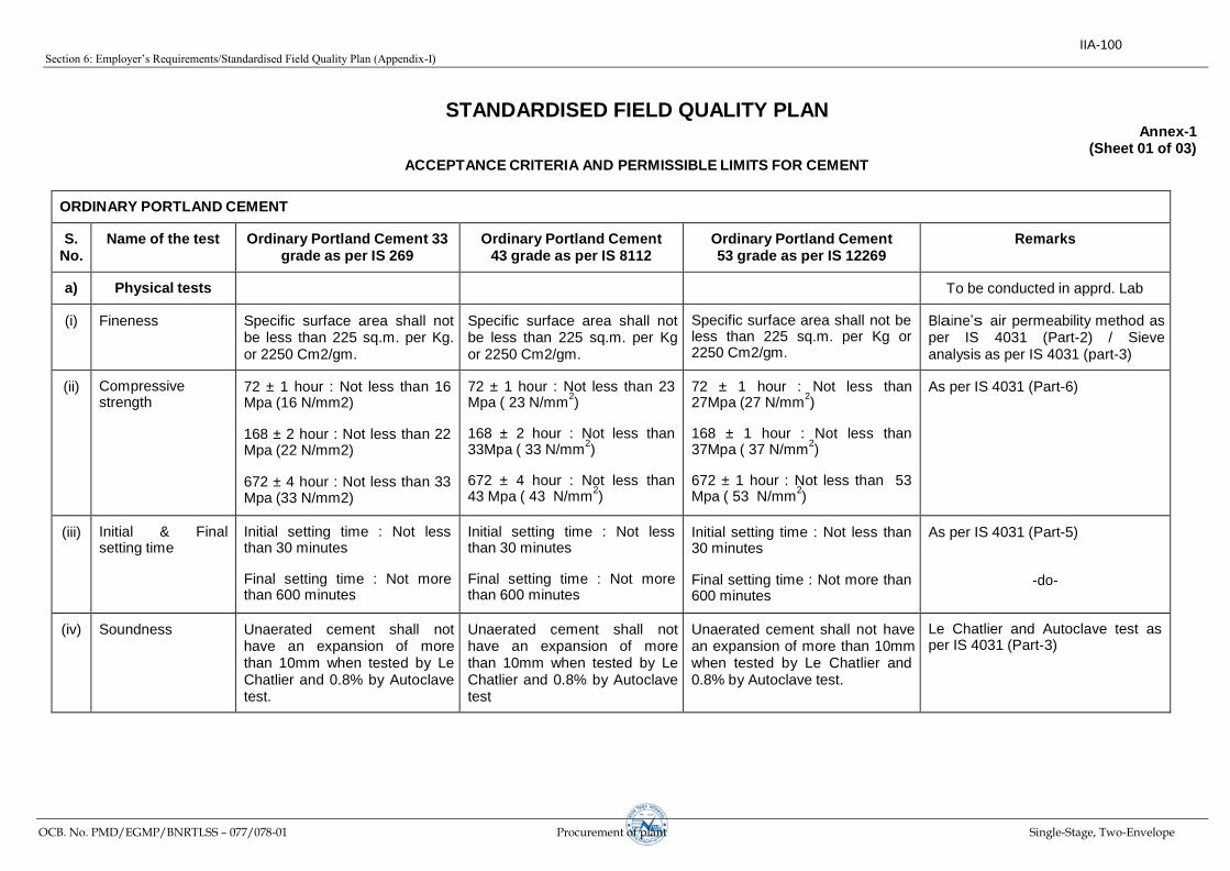
Section 6: Employer’s Requirements/Standardised Field Quality Plan (Appendix-I)
OCB. No. PMD/EGMP/BNRTLSS – 077/078-01 Procurement of plant Single-Stage, Two-Envelope
STANDARDISED FIELD QUALITY PLAN
ACCEPTANCE CRITERIA AND PERMISSIBLE LIMITS FOR CEMENT
Annex-1 (Sheet 01 of 03)
ORDINARY PORTLAND CEMENT
S. No.
Name of the test Ordinary Portland Cement 33 grade as per IS 269
Ordinary Portland Cement 43 grade as per IS 8112
Ordinary Portland Cement 53 grade as per IS 12269
Remarks
a) Physical tests
To be conducted in apprd. Lab
(i) Fineness Specific surface area shall not be less than 225 sq.m. per Kg. or 2250 Cm2/gm.
Specific surface area shall not be less than 225 sq.m. per Kg or 2250 Cm2/gm.
Specific surface area shall not be less than 225 sq.m. per Kg or 2250 Cm2/gm.
Blaine’s air permeability method as per IS 4031 (Part-2) / Sieve analysis as per IS 4031 (part-3)
(ii)
Compressive strength
72 ± 1 hour : Not less than 16 Mpa (16 N/mm2)
168 ± 2 hour : Not less than 22 Mpa (22 N/mm2)
672 ± 4 hour : Not less than 33 Mpa (33 N/mm2)
72 ± 1 hour : Not less than 23 Mpa ( 23 N/mm
2)
168 ± 2 hour : Not less than 33Mpa ( 33 N/mm
2)
672 ± 4 hour : Not less than 43 Mpa ( 43 N/mm
2)
72 ± 1 hour : Not less than 27Mpa (27 N/mm
2)
168 ± 1 hour : Not less than 37Mpa ( 37 N/mm
2)
672 ± 1 hour : Not less than 53 Mpa ( 53 N/mm
2)
As per IS 4031 (Part-6)
(iii)
Initial & Final setting time
Initial setting time : Not less than 30 minutes
Final setting time : Not more than 600 minutes
Initial setting time : Not less than 30 minutes
Final setting time : Not more than 600 minutes
Initial setting time : Not less than 30 minutes
Final setting time : Not more than 600 minutes
As per IS 4031 (Part-5)
-do-
(iv) Soundness Unaerated cement shall not have an expansion of more than 10mm when tested by Le Chatlier and 0.8% by Autoclave test.
Unaerated cement shall not have an expansion of more than 10mm when tested by Le Chatlier and 0.8% by Autoclave test
Unaerated cement shall not have an expansion of more than 10mm when tested by Le Chatlier and 0.8% by Autoclave test.
Le Chatlier and Autoclave test as per IS 4031 (Part-3)
IIA-100

Section 6: Employer’s Requirements/Standardised Field Quality Plan (Appendix-I)
OCB. No. PMD/EGMP/BNRTLSS – 077/078-01 Procurement of plant Single-Stage, Two-Envelope
S. No.
Name of the test
Ordinary Portland Cement 33 grade as per IS 269
Ordinary Portland Cement 43 grade as per IS 8112
Ordinary Portland Cement 53 grade as per IS 12269
Remarks
b)
Chemical composition tests
Review of MTCC only
a) Ratio of percentage of lime
to percentage of silica, alumina & iron oxide 0.66 to 1.02
a) Ratio of percentage of lime to percentage of silica, alumina & iron oxide 0.66 to 1.02
a) Ratio of percentage of lime to percentage of silica, alumina & iron oxide 0.80 to 1.02%
b) Ratio of percentage of
alumina to that of iron oxide Minimum 0.66%
a) Ratio of percentage of alumina to that of iron oxide Minimum 0.66
a) Ratio of percentage of alumina to that of iron oxide Minimum 0.66%
c) Insoluble residue, percentage by mass Max. 4.00%
c) Insoluble residue, percentage by mass Max. 2.00%
c) Insoluble residue, percentage by mass Max. 2.00%
d) Magnesia percentage by mass Max. 6%
d) Magnesia percentage by mass Max. 6%
d) Magnesia percentage by mass Max. 6%
e) Total sulphur content
calculated as sulphuric anhydride (SO3),
percentage by mass not more than 2.5 and 3.0 when tri-calcium aluminate percent by mass is 5 or less and greater than 5 respectively.
e) Total sulphur content calculated as sulpuric anhydride (SO3),
percentage by mass not more than 2.5 and 3.0 when tri-calcium aluminate percent by mass is 5 or less and greater than 5 respectively.
e) Total sulphur content calculated as sulpuric anhydride (SO3), percentage
by mass not more than 2.5 and 3.0 when tri-calcium aluminate percent by mass is 5 or less and greater than 5 respectively.
f) Total loss on ignition shall not be more than 5 percent
f) Total loss on ignition shall not be more than 5 percent
f) Total loss on ignition shall not be more than 5 percent
STANDARDISED FIELD QUALITY PLAN
Annex-1 (Sheet 02 of 03)
IIA-101

Section 6: Employer’s Requirements/Standardised Field Quality Plan (Appendix-I)
OCB. No. PMD/EGMP/BNRTLSS – 077/078-01 Procurement of plant Single-Stage, Two-Envelope
S. No.
Name of the test
Remarks
2. PORTLAND POZZOLANA CEMENT AS PER IS 1489/2005
a) Physical tests i) Fineness Specific surface area shall not be less than 300 sq.m. per Kg. or 3000 Cm
2/gm
To be conducted in NEA
approved Lab
ii) Compressive strength a) 72 ± 1 hour : Not less than 16 Mpa (16 N/mm
2)
b) 168 ± 2 hour : Not less than 22 Mpa (22 N/mm2)
c) 672 ± 4 hour : Not less than 33 Mpa (33 N/mm2)
iii) Initial & Final setting time Initial setting time : Not less than 30 minutes
Final setting time : Not more than 600 minutes
iv) Soundness
Un aerated cement shall not have an expansion of more than 10mm Le chatlier test and 0.8% by Autoclave test as per IS 4031 (Part-3)
b) Chemical composition tests
a) Magnesia percentage by mass Max. 6% Review of MTCC only
b) Insoluble material, percentage by mass x + 4 (100-x)/100 where x is the declared % of pozzolana
in the PPC -do-
c) Total sulphur content calculated as sulpuric anhydride (SO3), percentage by mass not more than
3.0 -do-
Total loss on ignition shall not be more than 5 percent
STANDARDISED FIELD QUALITY PLAN
Annex-1 (Sheet 03 of 03)
IIA-102

Section 6: Employer’s Requirements/Standardised Field Quality Plan (Appendix-I)
OCB. No. PMD/EGMP/BNRTLSS – 077/078-01 Procurement of plant Single-Stage, Two-Envelope
STANDARDISED FIELD QUALITY PLAN
ACCEPTANCE CRITERIA AND PERMISSIBLE LIMITS FOR REINFORCEMENT STEEL AS PER IS 1786-1985 Edition-4.3 (2004-12)
Annex-2
S. No.
Name of the test Fe 415 Fe 500
i) Chemical analysis test Carbon
0.30 Percent Maximum
0.30 Percent Maximum
Sulphur
0.060 Percent Maximum 0.055 Percent Maximum
Phosphorus
0.060 Percent Maximum 0.055 Percent Maximum
Sulphur & Phosphorus
0.11 Percent Maximum 0.105 Percent Maximum
ii) Physical tests
a) Tensile Strength Minimum
10% more than actual 0.2% proof stress but not less than 485 N/Sq.mm.
8 % more than actual 0.2% proof stress but not less than 545 N/Sq.mm
b) 0.2% of proof stress/Yield stress Minimum, N/mm
2
415 500
c) Elongation percent , Minimum 14.5 12
iii) Bend & Rebend tests Pass Pass
IIA-103
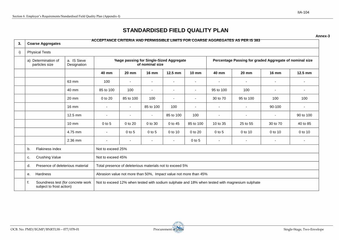
Section 6: Employer’s Requirements/Standardised Field Quality Plan (Appendix-I)
OCB. No. PMD/EGMP/BNRTLSS – 077/078-01 Procurement of plant Single-Stage, Two-Envelope
3. Coarse Aggregates
i) Physical Tests
a) Determination of particles size
a. IS Sieve Designation
%age passing for Single-Sized Aggregate of nominal size
Percentage Passing for graded Aggregate of nominal size
40 mm 20 mm 16 mm 12.5 mm 10 mm 40 mm 20 mm 16 mm 12.5 mm
63 mm 100 - - - - - - - -
40 mm 85 to 100 100 - - - 95 to 100 100 - -
20 mm 0 to 20 85 to 100 100 - - 30 to 70 95 to 100 100 100
16 mm - - 85 to 100 100 - - - 90-100 -
12.5 mm - - - 85 to 100 100 - - - 90 to 100
10 mm 0 to 5 0 to 20 0 to 30 0 to 45 85 to 100 10 to 35 25 to 55 30 to 70 40 to 85
4.75 mm - 0 to 5 0 to 5 0 to 10 0 to 20 0 to 5 0 to 10 0 to 10 0 to 10
2.36 mm - - - - 0 to 5 - - - -
b. Flakiness index
Not to exceed 25%
c. Crushing Value Not to exceed 45%
d. Presence of deleterious material Total presence of deleterious materials not to exceed 5%
e. Hardness Abrasion value not more than 50%, Impact value not more than 45%
f. Soundness test (for concrete work subject to frost action)
Not to exceed 12% when tested with sodium sulphate and 18% when tested with magnesium sulphate
STANDARDISED FIELD QUALITY PLAN
ACCEPTANCE CRITERIA AND PERMISSIBLE LIMITS FOR COARSE AGGREGATES AS PER IS 383
Annex-3
IIA-104

Section 6: Employer’s Requirements/Standardised Field Quality Plan (Appendix-I)
OCB. No. PMD/EGMP/BNRTLSS – 077/078-01 Procurement of plant Single-Stage, Two-Envelope
STANDARDISED FIELD QUALITY PLAN
Annex-4
ACCEPTANCE CRITERIA AND PERMISSIBLE LIMITS FOR FINE AGGREGATES AS PER IS 383
4. Fine aggregates
i) Physical Tests
IS Sieve Designation
Percentage passing for
a) Determination of particle size F.A. Zone I F.A. Zone II F.A. Zone III
10 mm 100 100 100
4.75 mm 90-100 90-100 90-100
2.36 mm 60-95 75-100 85-100
1.18 mm 30-70 55-90 75-100
600 microns 15-34 35-59 60-79
300 microns 5 to 20 8 to 30 12 to 40
150 microns 0-10 0-10 0-10
b) Silt content
Not to exceed 8% Not to exceed 8% Not to exceed 8%
c) Presence of deleterious material
Total presence of deleterious materials shall not exceed 5%
d) Soundness Applicable to concrete work subject to frost action
12% when tested with sodium sulphate and 15% when tested with magnesium sulphate
IIA-105

Section 6: Employer’s Requirements/Standardised Field Quality Plan (Appendix-I)
OCB. No. PMD/EGMP/BNRTLSS – 077/078-01 Procurement of plant Single-Stage, Two-Envelope
STANDARDISED FIELD QUALITY PLAN
Annex-5
ACCEPTANCE CRITERIA AND PERMISSIBLE LIMITS FOR CONCRETE WORK
1) Concrete a) Workability Slump shall be recorded by slump cone method and it shall between 25-55 mm.
b) Compressive strength For nominal (volumetric) concrete mixes compressive strength for 1:1.5:3 (Cement : Fine aggregates : Coarse aggregates) concrete 28 days strength
shall be min 265Kg/cm2 and for 1:2:4 (Cement: Fine Aggregate: Coarse
Aggregate) nominal mix concrete 28 days strength shall be min 210Kg/cm2.
Notes:
1) ACCEPTANCE CRITERIA BASED ON 28 DAYS COMPRESSIVE STRENGTHS FOR NOMINAL MIX CONCRETE:
a) On the basis of mandatory lab test result, in case of actual average compressive strength being less than specified strength but up to 70% of specified strength, concrete may be accepted and the rate payable shall be in the same proportion as the actual average compressive strength bears to specified compressive strength.
However, in case cube strength of any one leg of any location is found to be between 70% to 100% of specified value, all four legs of the respective location shall be analyzed. Root cause analysis has to be carried out with NDT method to verify the quality and strength of the foundations. If the results are not acceptable penalty such as re-doing of complete foundation/legs, cost towards supervision charges shall be levied from the contractor towards the sub-standard work, with the approval of Regional Head.
b) If the actual average strength of accepted sample is less than 70% of specified strength, the Site -in-charge shall reject the defective portion of work represent by sample and nothing shall be paid for the rejected work. Remedial measures necessary to retain the structure shall be taken at the risk and cost of contractor. If, however, the Engineer-in-charge / Project In-charge so desires, he may order additional tests to be carried out to ascertain if the structure can be retained/rectified. All the charges in connection with these additional tests shall be borne by the Contractor.
2) 53 Grade cement shall be used after obtaining specific approval of the Engineer in charge.
3) Portland slag cement conforming to IS:455 may be used as per Technical Specification.
IIA-106

Section 6: Employer’s Requirements/Standardised Field Quality Plan (Appendix-I)
OCB. No. PMD/EGMP/BNRTLSS – 077/078-01 Procurement of plant Single-Stage, Two-Envelope
STANDARDISED FIELD QUALITY PLAN
General Notes:
1) This standard Field Quality Plan is not to limit the supervisory checks which are otherwise required to be carried out during execution of work as per drawings/Technical specifications etc.
2) Contractor shall be responsible for implementing/documenting the SFQP. Documents shall be handed over by the contractor to Employer after the completion of the work.
3) Acceptance criteria and permissible limits for tests are indicated in the Annexures. However for further details/tests specification and relevant Indian standards shall be referred.
4) Tests as mentioned in this FQP shall generally be followed.
IIA-107

Section6:Employer’sRequirements/Tower,Foundation,Erection,StringingandCommissioningofLine
OCB. No. PMD/EGMP/BNRTLSS-077/078-01 Procurement of plant Single-Stage, Two-Envelope
SECTION-IV
TOWER, FOUNDATION, ERECTION, STRINGING
AND COMMISSIONING OF LINE
IIA-108

Section6:Employer’sRequirements/Tower,Foundation,Erection,StringingandCommissioningofLine
OCB.No. PMD/EGMP/BNRTLSS-077/078-01 Procurement of plant Single-Stage, Two-Envelope
SECTION-IV
CONTENTS
Cl. Description Page No.
1.0 Transmission Tower .........................................................................................................110
2.0 Foundation .....................................................................................................................129
3.0 Tower Erection, Stringing and Installation of Line Materials ...........................................139
4.0 Field Quality Plan ..............................................................................................................148
5.0 Manufacturing Quality Plan .............................................................................................148
6.0 Design Requirement for DD Spl and MD towers ..............................................................148
7.0 Tower Load Test .............................................................................................................152
IIA-109

Section6:Employer’sRequirements/Tower,Foundation,Erection,StringingandCommissioningofLine
OCB. No. PMD/EGMP/BNRTLSS-077/078-01 Procurement of plant Single-Stage, Two-Envelope
SECTION IV
TOWER, FOUNDATION, ERECTION, STRINGING
AND COMMISSIONING OF LINE
1.0 Transmission Tower
The general description of towers applicable for the package and technical
particulars thereof are indicated in Section – I of this Specification.
1.1 Design and Drawings
1.1.1 The relevant drawings for all the towers and their extensions shall be furnished to the Contractor by the Employer which shall include structural drawings/erection drawings and / or shop fabrication drawings, Bill of Materials for all the towers and their extensions as well as construction drawings for foundations.
Bidders shall review the design drawings provided by the Employer. In case any modification is required to the designs made available, all further designs shall be carried out as per requirement of Clause 2.0 Transmission Towers and line data of Section-I and Clause 6.0 Design Requirement for DD Special and MD towers of this Section, Volume II of the Bidding document. Design of Special Towers and Multi circuit towers shall also be carried out as per requirement of Clause 2.0 Transmission Towers and line data of Section-I and Clause 6.0 Design Requirement for DD Special and MD towers of this Section, Volume II of the Bidding document.
1.1.2 The tower members can be directly fabricated from the structural/erection drawings wherever the required fabrication details are provided on the same or shop fabrication drawings. However, if the contractor is required to prepare shop fabrication drawings, of their own, in addition to the structural/ erection drawings with required fabrication details, they may prepare the same without any additional financial implication to Employer.
Proto Assembly:
(i) Contractors, who have not done the proto-assembly of the towers / tower extensions or have not supplied the same towers / tower extensions against any earlier EMPLOYER’sproject,shallbeforetakingupmassfabrication,theContractorshall arrange for one number proto assembly for each type of towers and extensions. EMPLOYER reserves the right to get the same witnessed by their representative. After proto-assembly, the contractors, shall incorporate revisions in the drawings / documents if any on account of proto corrections, and make necessary endorsement with reference to the respective packages / Letter of Awards. The revised drawing/documents shall be submitted in 3 (three) copies for final approval by the Employer.
(ii) The contractors who have already done the proto-assembly of the towers / tower extensions or have supplied the same towers / tower extensions against any earlier EMPLOYER’sprojectneednotdotheprotoassembly. They shall submit documentary evidence viz. proto-inspection reports, supply records etc. in its support. However, they may do the proto-assembly for their verification and satisfaction. Further, they shall submit 10 copies of the structural
IIA-110

Section6:Employer’sRequirements/Tower,Foundation,Erection,StringingandCommissioningofLine
OCB. No. PMD/EGMP/BNRTLSS-077/078-01 Procurement of plant Single-Stage, Two-Envelope
drawings and BOM of tower / tower extensions after endorsing the projects name for further distribution by Employer.
No payment shall be made to the contractor on the account of proto-assembly in either of the cases mentioned at (i) or (ii).
In any case, the onus of correct fabrication / fitment of tower parts shall lie with contractor. Any defect, if found during erection at site, the same has to be rectified by the contractor without any additional financial implication to EMPLOYER.
1.1.3 All the drawings shall have a proper name plate clearly displaying the name of EMPLOYER on right hand bottom corner. The exact format of the nameplate shall be handed over to the successful bidder for incorporation of the same on all the drawings. Also all the drawings shall carry the following statement and shall be displayed conspicuously on the drawing:
WARNING : THIS IS PROPRIETORY ITEM AND DESIGN RIGHT IS STRICTLY RESERVED WITH EMPLOYER. UNDER NO CIRCUMSTANCES THIS DRAWING SHALL BE USED BY ANYBODY WITHOUT PRIOR PERMISSION FROM THE OWNER IN WRITING.
1.1.4 While submitting the structural drawings, bill of materials, shop drawings and any other drawings pertaining to the subject transmission line, the Contractor shall clearly indicate on each drawing EMPLOYER Specification No., Name of the specific Transmission line and project, letter reference no. and date on which the submission are made. The same practice is also to be followed while submitting distribution copies.
1.1.5 The tower accessories drawings like Number plate, Danger plate, phase plate, Circuit Plate, Step Bolt, Anti-climbing device, pole plate and Earthing Arrangement have been standardized (except Bird guard) are enclosed in drawing section of this specification. The contractor is required to submit distribution copies of the above drawings after endorsing the name of the projects. However, drawing of Bird Guard, D-shackle etc. shall be prepared by the Contractor and shall be submitted to the Employer, in three (3) copies for approval. This drawing shall be prepared in A4 size only
1.1.6 The drawings submitted by the Contractor shall be approved/commented by the Employer as the case may be within fifteen (20) days of receipt of drawings in his office. If the designs/drawings are commented by the Employer, the Contractor shall submit revised design/drawings duly incorporating all comments within fifteen (15) days of date of issue of comments. The Contractor shall submit 15 copies of all tower accessories for further distribution by the Employer.
The mass fabrication shall be taken up from the standard shop drawings. The overall responsibility of fabricating tower members correctly lies with the Contractor only and the Contractor shall ensure that all the tower members can be assembled/ fitted while erecting without any undue strain on them.
1.1.7 Other than the items indicated above some other drawings and documents, such as BOM, Shop drawings, structural drawings for towers/extensions based on single line diagram given by the Employer, which are required for the project, shall also be
IIA-111

Section6:Employer’sRequirements/Tower,Foundation,Erection,StringingandCommissioningofLine
OCB. No. PMD/EGMP/BNRTLSS-077/078-01 Procurement of plant Single-Stage, Two-Envelope
developed by the Contractor. However, no extra cost on this account shall be payable to the Contractor.
1.2 Materials
1.2.1 Tower Steel Sections
IS Steel Sections of tested quality of conformity with IS: 2062:2011 grade E250 (Designated Yield Strength. 250 MPa) and/ or grade E350 (Designated Yield Strength 350 MPa) are to be used in towers, extensions, stubs and stub setting templates. For Snow Zone towers MS & HT Steel Sections shall conform to E250 Grade-C & E350 Grade-C respectively. The Contractor can use other equivalent grade of structural steel angle sections and plates conforming to latest International Standards viz BSEN 10025. However, use of steel grade having designated yield strength more than that of EN 10025 grade S355 JR/JO (designated yield strength 355 MPa) is not permitted, unless otherwise indicated in this specification.
Steel plates below 6mm size exclusively used for packing plates/packing washers produced as per IS: 1079 (Grade-0) are also acceptable. However, if below 6mm size plate are used as load bearing plates viz gusset plates, joint splices etc. the same shall conform to IS: 2062 or equivalent standard meeting mechanical strength/metallurgical properties corresponding to grade E250 or above grade (designated yield strength not more than 355MPa), depending upon the type of grade incorporated into design. Flats of equivalent grade meeting mechanical strength/ metallurgical properties may also be used in place of plates for packing plates/ packing washers. The chequered plates shall conform to IS: 3502. SAILMA 350HI grade plate can also be accepted in place of HT plates (EN 10025 grade S355 JR/JO / IS 2062:2011 – grade E350, as applicable) provided SAILMA 350HI grade plate meet all the mechanical properties of plate as per EN 10025 grade S355 JR/JO (designated yield strength 355 MPa) / IS 2062: 2011 – grade E350.
For designing of towers, preferably rationalised steel sections have been used. During execution of the project, if any particular section is not available, the same shall be substituted by higher section/Grade. Any cost on account of the same shall be borne by the Contractor. However, design approval for such substitution shall be obtained from the Employer before any substitution and records of such substitutions shall be maintained by the Contractor
1.2.2 Fasteners: Bolts, Nuts and Washers.
1.2.2.1 All tower members shall be joined together with Hexagonal Bolts and nuts. All hexagonal bolts and nuts shall conform to IS-12427. They shall have hexagonal head and nuts, the heads being forged out of the solid, truly concentric, and square with the shank, which must be perfectly straight.
All bolts and nuts shall be galvanized as per IS:1367 (Part-13)/IS:2629.
1.2.2.2 The bolt shall be of 16/24 mm diameter and of property class 5.6 as specified in IS:1367 (Part-III) and matching nut of property class 5.0 as specified in IS:1367 (Part-VI).
1.2.2.3 Bolts up to M16 and having length up to 10 times the diameter of the bolt should be manufactured by cold forging and thread rolling process to obtain good and reliable mechanical properties and effective dimensional control. The shear strength of bolts
IIA-112

Section6:Employer’sRequirements/Tower,Foundation,Erection,StringingandCommissioningofLine
OCB. No. PMD/EGMP/BNRTLSS-077/078-01 Procurement of plant Single-Stage, Two-Envelope
for 5.6 grade should be 310 MPa minimum as per IS:12427. Bolts should be provided with washer face in accordance with IS:1363 (Part-I) to ensure proper bearing.
1.2.2.4 Nuts for hexagonal bolts should be double chamfered as per the requirement of IS:1363 Part-III. It should be ensured by the manufacturer that nuts should not be over tapped beyond 0.4mm oversize on effective diameter for size up to M16.
1.2.2.5 Fully threaded bolts shall not be used. The length of bolts shall be such that the threaded portion will not extend into the place of contact of the members.
1.2.2.6 All bolts shall be threaded to take the full depth of the nuts and threaded for enough to permit firm gripping of the members, but not further. It shall be ensured that the threaded portion of each bolt protrudes not less than 3mm and not more than 8mm when fully tightened. All nuts shall fit tight to the point where the shank of the bolt connects to the head.
1.2.2.7 Flat and tapered washers shall be provided wherever necessary. Spring washers shall be provided for insertion under all nuts. These washers shall be steel electrogalvanized, positive lock type and 3.5mm in thickness for 16mm dia bolt and 4.5mm for 24mm bolt.
1.2.2.8 To avoid bending stress in bolts or to reduce it to minimum, no bolt shall connect aggregate thickness of members more than three (3) times its diameter.
1.2.2.9 The bolt positions in assembled towers shall be as per structural drawing.
1.2.2.10 Bolts at the joints shall be so staggered that nuts shall be tightened with spanners without fouling.
1.2.2.11 To ensure effective in-process Quality control it is desirable that the manufacturer should have in house testing facility for all tests like weight of zinc coating, shear strength and other tests etc. The manufacturer should also have proper Quality Assurance System which should be in line with the requirement of this specification and IS: 9001 series Quality System Standard.
1.3 Tower Accessories
Arrangement shall be provided for fixing of all tower accessories to the tower at a height between 2.5 meters and 3.5 meters above the ground level.
1.3.1 Step Bolts & Ladders
Each tower shall be provided with step bolts as per drawing enclosed in the section of drawing. The step bolts conforming to IS:10238 of not less than 16mm diameter and 175mm long, spaced not more than 450mm apart and extending from 2.5 meters above the ground level to the top of the tower. However, the head diameter shall be 35mm as indicated in the enclosed drawing. The step bolt shall be fixed on two diagonally opposite legs up to top of the towers for single, double and multi circuit towers. Each step bolt shall be provided with two nuts on one end to fasten the bolt securely to the tower and button head at the other end to prevent the feet from slipping away. The step bolts shall be capable of withstanding a vertical load not less than 1.5 KN. For special river crossing towers, ladders alongwith protection rings as per the Employer approved design shall be provided in continuation of the step bolts on one face of the tower from 30 meters above
IIA-113

Section6:Employer’sRequirements/Tower,Foundation,Erection,StringingandCommissioningofLine
OCB. No. PMD/EGMP/BNRTLSS-077/078-01 Procurement of plant Single-Stage, Two-Envelope
ground level to the top of the special structure. From 2.5m to 30m height of super structure step bolts shall be fixed on two diagonally opposite legs. Suitable platform using 6mm thick perforated chequered plates along with suitable railing for access from step bolts to the ladder and from the ladder to each cross-arm tip and the ground wire support shall also to be provided. The platform shall be fixed on tower by using counter-sunk bolts.
1.3.2 Insulator Strings and Earth wire Clamps Attachments
a) For the attachment of suspension Insulator string, if required a suitable dimensioned swinging hanger on the tower shall be provided so as to obtain specified clearances under respective swinging condition of the strings. The hanger, extensions links, D-shackles etc. as required shall be of same rating/strength as that of corresponding rating/ Ultimate tensile Strength of Insulator string. The design and supply of hanger, D-shackles, strain plate, extension link etc. are also in the scope of Contractor.
b) At tension towers, strain plates of suitable dimensions under each cross-arm tip, shall be provided for taking the hooks or D-shackles of the tension insulator strings. Full details of the attachments shall be provided to the contractor. To achieve requisite clearances, if the design calls for providing extra D-shackles, link plate etc. before connecting the insulator string the same shall be supplied by the Contractor. These item shall be same rating/strength as that of as that of corresponding rating/ Ultimate tensile Strength of Insulator string.
c) D shackles, if required for attachment of Insulator strings, shall be supplied by the contractor from the identified and approved sub-vendor / supplier of Hardware fittings.
1.3.3 Earth wire Clamps Attachments
For Suspension and tension clamp for attachment of earthwire Wherever required, the Contractor shall supply U – bolts, D – Shackles etc. for attachment of clamp to the tower. Full details of the attachments shall be provided to the contractor. These items shall be same rating/strength as that of corresponding rating/ Ultimate tensile Strength of earthwire suspension/tension clamp.
1.3.4 Anti-climbing Device
Barbed wire type anti climbing device, as per enclosed drawing shall be provided and installed by the Contractor for all towers. The barbed wire shall conform to IS-278 (size designation A1). The barbed wires shall be given chromating dip as per procedure laid down in IS:1340
1.3.5 Danger, Number, Circuit and Phase plate
Danger Plates, Circuit plates, Phase Plates and Number plates shall be provided and installed by the Contractor. These Danger/Number/Phase/ Circuit Plate shall be as per the drawings enclosed in the section of drawing. The contractor shall submit distribution copies of the same endorsing the package details (i.e. line name, LOA No. etc) and installed by the Contractor.
a) Each tower shall be fitted with a danger plate, number plate, circuit plate and a set of phase plates for single circuit tower and two sets of phase plates for double circuit tower. The transposition towers should have provision of fixing phase plates on both the transverse faces.
IIA-114

Section6:Employer’sRequirements/Tower,Foundation,Erection,StringingandCommissioningofLine
OCB. No. PMD/EGMP/BNRTLSS-077/078-01 Procurement of plant Single-Stage, Two-Envelope
b) The letters, figures and the conventional skull and bones of danger plates shall conform to IS-2551 and shall be in a signal red on the front of the plate.
c) The corners of the danger, number and circuit plates shall be rounded off to remove sharp edges.
d) The letters of number and circuit plates shall be red enameled with white
enameled background.
1.3.5.1 Bird Guard
To prevent birds perching immediately above the suspension insulator strings ( I type / V type) and fouling the same with dropping, suitable bird guards shall be provided on all suspension towers. In case of I string Bird Guard as per IS 5613 shall be provided at cross arm tips. In case of V string, saw type Bird Guard shall be provided on all the members/redundant members provided on Top and Bottom plan of cross arm/Girder/BOOM/Beam of Suspension. The typical drawing of Bird guard is attached at the drawing section of this specification. Suitable provision of cleat / plate to be provided on all Suspension towers facilitating installation of bird guard after stringing.
1.3.6 Aviation Requirements
1.3.6.1 Aviation requirements viz Span marker, night marker (obstruction light) and painting of towers conforming to IS: 5613 shall be in the scope of Contractor, wherever indicated in BPS.
1.3.6.2 Night Markers (Obstruction lights)
1.3.6.2.1 The scope of night markers covers the design, manufacture, testing at manufacturers works, if any, supply, delivery, erection, testing and commissioning of medium intensity, low intensity, lights along with storage battery & solar panel, control panel, cables, clamps other accessories etc. as per the provision of IS-5613 (Part-II/ section-I), 1989, amendment no. 1, July’94 regarding night day visualaids for denoting transmission line structures as per the requirement of directorate of flight safety.
1.3.6.2.2 The detail of each component of medium intensity, low intensity lights & associated accessories to be provided on the towers shall be as per the technical specifications given in the preceding clauses and IS/ICAO, International Standards recommended practices.
1.3.6.2.3 One set of Aviation Lights shall consist of one medium intensity light & two/four (as applicable) low intensity lights along with all accessories such as solar panel, control panel, batteries, cables etc.
1.3.6.2.4 Medium Intensity Light
Medium Intensity light shall be provided on the top of each tower. The medium light should have night time intensity as per ICAO requirements in international Standards Recommended Practices. The light on top of the structure should flash at the rate of 20 sequences per minute. The effective intensity during night time for the medium flashing light shall be 1600 CD. The light shall conform to ICAO requirements/BS 3224a and shall have weather protection conforming to IP-55. The above lights conforming to ICAO specifications flashing red lights shall be DC operated through a suitably sized battery bank at the operating voltage 12V/24V DC. The burning life of the lamps shall be maximum possible in view of the
IIA-115

Section6:Employer’sRequirements/Tower,Foundation,Erection,StringingandCommissioningofLine
OCB. No. PMD/EGMP/BNRTLSS-077/078-01 Procurement of plant Single-Stage, Two-Envelope
maintenance hazard of H.T. live but in no case it should be less than 15,000 burning hours. In case of failure of the lamp before 15,000 burning hours, the same shall have to be replaced by the Contractor free of cost even if the pendency of contract expires. The light shall be equipped with radio suppression facility conforming to BS800 in order to avoid any interference with signals of PLCC etc.
1.3.6.2.5 Low Intensity Lights
Two/four (as applicable) nos. of low intensity lights are required to be put on each of the towers. Placement drawing for the same shall be submitted by the bidder Contractor.
The light shall be stationary lamp with minimum effective intensity of 10 CD. of red light. The lamps shall conform to the ICAO requirement/relevant BS and shall have weather protection of minimum IP-55 class.
Two/four nos. of L.I. lamp required for each tower shall be operated through a suitable size common battery bank solar panel as per the requirement of operating voltage and load current of the type of lamps being offered.
The burning life of the lamps shall be maximum possible in view of the maintenance hazard of H.T live line, but in no case it should be less than 15,000 burning hours. In case of failure of the lamp before 15,000 hrs, the same shall have to be replaced by the Contractor free of cost even if the pendency of contract expires. Performance certificate of the lamps to be offered shall be furnished by the Contractor.
The low intensity lamp shall not generate any R.F. which can interfere with the PLCC signals.
1.3.6.2.6 Storage Battery
Storage Battery required for the above purpose shall be sealed maintenance free, valve regulate lead acid and suitable for mounting on the top of the transmission line towers. Contractors shall offer the most optimum capacity of the Battery Bank at 120 hour discharge rate (considering 80 % percentage usage) matching with the load requirement of the type of lamps being offered including any power loss in the associated cables. The battery sizing shall conform to JISC 8707/relevant Indian Standard or any other internationally recognized standard. The battery shall be hermetically sealed explosion proof and self-resealing type and free from orientation constraints. The working temperature ranges shall be minimum 0 degree centigrade and maximum 50degree centigrade. Performance certificate of the offered batteries shall be submitted by the Contractor.
1.3.6.2.7 Battery Box
The battery box suitable for mounting on 220kV power transmission tower shall be robust construction suitable to accommodate desired number of SOLAR BATTERIES WITH proper clearance between the batteries. The sides and the top of the battery box shall be made from MS sheets not less than 14 SWG thickness duly mounted on MS angle frame. The bottom of the battery box shall have suitably designed MS structure to freely hold the total weight of the batteries. The batteries should be placed on insulated base with proper drainage holes. Lifting lugs shall be provided. Dust and vermin proof lockable doors shall be provided for safety and easy access to the batteries for the maintenance. The battery box should incorporate the design for proper ventilation system in order to prevent a gas concentration inside the box. The ventilation opening shall be protected against
IIA-116

Section6:Employer’sRequirements/Tower,Foundation,Erection,StringingandCommissioningofLine
OCB. No. PMD/EGMP/BNRTLSS-077/078-01 Procurement of plant Single-Stage, Two-Envelope
rain/splash water and dust. The inside of the battery box shall be lined with insulating polyurethane plating and the exterior painted with weather proof polyurethane paint. The cable entry into the battery box shall be through suitable cable glands.
1.3.6.2.8 Solar Modules
Solar module required for the system shall be suitable for mounting on the transmission line towers and shall be designed for high performance, maximum reliability and minimum maintenance and shall be installed below bottom cross arms levels. The solar modules shall be IP 55 grade protection class. These should be highly resistant to water, abrasion, nail, impact and other environmental factors.
These should be placed on the tower at a most optimum angle so as to harness the maximum solar energy and facilitate self cleaning and shall conform to relevant Indian/International Standards.
Module mounting frames shall be weather proof suitable for mounting on tall towers. Details of mounting frames shall be furnished by the Contractor.
Junction box shall be provided with weather proof hinged lid with provision for cable glands entry and protections grade of class IP-55.
The Contractor shall submit the basis of selecting the numbers of solar modules.
The provision for design, supply & erection of mounting arrangements for photovoltaic modules on the transmission towers in a suitable manner to harness maximum solar energy shall be in the scope of the Contractor.Provision for design, supply & erection of resting platform for the erection of battery bank in a closed enclosure with safety arrangement on the transmission towers shall also be in the scope of the Contractor the design and load consideration for safety of towers due to additional plate form shall be kept in view while designing, selecting the above.
1.3.6.2.9 Control Panels
Control panels shall consist of solar charge controller, flasher unit, sensor, isolator, MCB, Voltmeter, Ammeter and other control gears. Panel enclosure shall be fabricated out of 14 SWG CRCA sheet and thoroughly treated and painted. Suitable neoprene rubber gasket and pad locking device shall be provided and the protection class shall be of IP-55 class.
The Solar charge controller shall be most efficient and preferably fully solid state. It shall be provided with protection to load against increase in temperature, Surge, automatic low voltage and automatic disconnection and reconnection during high inrush current and normalcy respectively.
The flash regulator shall be provided for regulating light flashing. The same shall be completely solid state and provided with flash rate set points. The protection against overload current shall also be provided.
Necessary sensor/timer shall be provided in the system to “switch on” the lightautomatically in the evening and poor visibility period and switch off the same during day time and normal visibility period.
IIA-117
Section6:Employer’sRequirements/Tower,Foundation,Erection,StringingandCommissioningofLine
OCB. No. PMD/EGMP/BNRTLSS-077/078-01 Procurement of plant Single-Stage, Two-Envelope
1.3.6.2.10 Cables, Cable Glands, Conduits and Accessories
The cable to be supplied and erected shall be of multi strands copper conductor, weather proof, PVC insulated PVC sheathed, armoured 1.1 KV grade. The same shall conform to IS:1554.
All the cable accessories such as thimble, glands etc. shall be in the scope of supply and erection of the Contractor.
Supply and erection of all the PVC conduits and accessories shall be in the scope of the contract. All the conduit and accessories shall be as per the relevant ISS or ISI brand.
The inter-connection cable/conduit will be clamped in a secured manner with the tower members and any interconnection should be made only inside the environmentally protected junction box.
1.3.6.2.11 Earthing
All the installations on the tower shall be securely and properly earthed with the tower body by using flexible copper braided wire. Cost of earthing material shall deemed to be included in the total cost.
1.4 Tower Fabrication
The fabrication of towers shall be in conformity with the following:
1.4.1 Except where hereinafter modified, details of fabrication shall conform to IS:802 (Part-II) or the relevant international standards.
1.4.2 The tower structures shall be accurately fabricated to connect together easily at site without any undue strain on the bolts.
1.4.3 No angle member shall have the two leg flanges brought together by closing the angle.
1.4.4 The diameter of the hole shall be equal to the diameter of bolt plus 1.5mm.
1.4.5 The structure shall be such that all parts are accessible for inspection and cleaning. Drain holes shall be provided at all points where pockets of depression are likely to hold water.
1.4.6 All steel sections before any work is done on them, shall be carefully leveled, straightened and made true to detailed drawings by methods which will not injure the materials so that when assembled, the adjacent matching surfaces are in close contact throughout. No rough edges shall be permitted in the entire structure.
IIA-118

Section6:Employer’sRequirements/Tower,Foundation,Erection,StringingandCommissioningofLine
OCB. No. PMD/EGMP/BNRTLSS-077/078-01 Procurement of plant Single-Stage, Two-Envelope
1.4.7 Drilling and Punching
1.4.7.1 Before any cutting work is started, all steel sections shall be carefully straightened and trued by pressure and not by hammering. They shall again be trued after being punched and drilled.
1.4.7.2 Holes for bolts shall be drilled or punched with a jig but drilled holes shall be preferred. The punching may be adopted for thickness up to 12 mm. Tolerances regarding punch holes are as follows:-
a) Holes must be perfectly circular and no tolerances in this respect are permissible.
b) The maximum allowable difference in diameter of the holes on the two
sides of plates or angle is 0.8mm. i.e. the allowable taper in a punched holes should not exceed 0.8mm on diameter.
c) Holes must be square with the plates or angles and have their walls
parallel.
1.4.7.3 All burns left by drills or punch shall be removed completely. When the tower members are in position the holes shall be truly concentric/matching to each other. Drilling or reaming to enlarge holes shall not be permitted.
1.4.8 Erection mark
1.4.8.1 Each individual member shall have erection mark conforming to the component number given to it in the fabrication drawings. The mark numbers shall be marked with marking dies of 16mm size before galvanising and shall be legible after galvanising,
1.4.8.2 Erection Mark shall be A-BB-CC-DDD
A=Employer’scodeassignedtotheContractors- Alphabet
BB =Contractor’sMark-Numerical
CC = Tower Type Alphabet.
DDD = Number mark to be assigned by Contractor - Numerical.
Erectionmarkforhightensilesteelmembersshallbeprefixedbytheletter“H”
1.5 Quantities and weights
1.5.1 The quantities of the following items have been envisaged in Metric Tonne (MT) in the relevant price Schedules for various types of towers:-
i) Basic Body. ii) Body Extensions. iii) Leg Extension.
IIA-119
Section6:Employer’sRequirements/Tower,Foundation,Erection,StringingandCommissioningofLine
OCB. No. PMD/EGMP/BNRTLSS-077/078-01 Procurement of plant Single-Stage, Two-Envelope
iv) Stubs & Cleats v) Bolts & Nuts including spring washers and step bolts etc.
During detailed engineering, proto corrected shop drawings shall be released by EMPLOYER for fabrication and manufacturing as per the Technical Specification to the Contractor. The contractor shall carry out proto-assembly after fabrication from the Employer’s shop drawing for his verification / satisfaction prior to massproduction of the tower.
The manufacturing of the above items shall be taken up in such a manner that the Equipment/Material offered for inspection to EMPLOYER are on completed tower basis for each type of tower, completed Stubs & Cleats set basis so as to facilitate availability of erectable tower of each type and erectable stubs & cleats set for casting of foundation. After inspection of the offered Equipment/Material by EMPLOYER representative(s), Inspection Certificate shall be issued by EMPLOYER for the material meeting the Technical Specification. However, DA (DISPATCH AUTHORISATION) shall be issued only on Completed Tower Basis for each type of tower (comprising the required Basic Body, body extensions wherever required, four (4) equal or defined unequal Leg Extension, Bolts & Nuts along with D-shackles,Hangers, Packing and Spring Washers) and on completed Stubs & Cleats set basis for each type of tower foundations (comprising a set of stubs & Cleats, required Bolts and Nuts along with Spring Washers).
Towers to be supplied by the contractors/Tower Manufacturers shall be dispatched Panel wise as per mutually agreed procedure with Employer Quality Assurance & Inspection Department.
Accordingly, the payment shall be released on completed Tower Basis for each type of tower (comprising the Basic Body, body extensions, wherever applicable, bolts & nuts along with spring washer and step bolts, unequal leg extensions wherever applicable for a completed tower) and on completed Stubs and Cleats set basis for each type of foundation (comprising a set of stubs & cleats, required Bolts and nuts along with Spring Washers) based on the weight of the tower parts as calculated as per Clause 1.5.3 and fasteners based on the unit rates incorporated in the contract.
1.5.2 The provisional quantities required (including provisional spare tower quantity) are mentioned in the respective Schedules of BPS, Annexure 1 and 2 of this Section. Final quantities shall be determined after completion and approval of the detailed route survey. The final quantities of tower including spare towers shall be confirmed by the Employer/Site in charge based on the requirement of quantities of various towers furnished by the Contractor after completion of detailed survey. Hence it will be responsibility of the Contractor to intimate the exact requirement of all towers and various line materials required for line immediately after the survey.
The Employer reserves the right to order the final quantities including required quantities of spares for which the rates quoted in the Bid shall be valid. Regarding quantity variation the provisions of relevant clauses of SCC shall apply.
1.5.3 The estimated total weight of tower/tower parts as well as bolts & nuts along with spring washers and step bolts to be supplied by the Contractor under various packages have been envisaged in the relevant Price Schedule. Though fully galvanised tower parts are to be supplied, the weight of tower shall mean the
IIA-120

Section6:Employer’sRequirements/Tower,Foundation,Erection,StringingandCommissioningofLine
OCB. No. PMD/EGMP/BNRTLSS-077/078-01 Procurement of plant Single-Stage, Two-Envelope
weight of tower calculated by using the black sectional (i.e. ungalvanised) weight of steel members of the size indicated in the approved fabrication drawings and bill of materials, without taking into consideration the reduction in weights due to holes, notches and bevel cuts etc. but taking into consideration the weight of the D shackles, hangers, strain plates, pack plates, gusset plates, extension link/plates and pack washers etc. The weight of stub and cleats also shall be calculated in similar manner. The weight of strain plates, pack plates, extension link and gusset plates shall mean the weight of its circumscribing rectangle, without taking into considerations the reductions in weight due to holes, notches etc. The weight of D-shackles, hangers and pack washers shall be net actual weight taking into consideration reduction due to holes. For bolts and nuts along with spring washers and step bolts, the weight per tower shall be calculated from the bolt schedule applicable to each type of towers and body extensions as approved by the Employer. The rate quoted by the bidder for tower/tower parts supply, is deemed to be inclusive of galvanising charges including the cost of zinc.
1.5.4 The contractor is permitted to get inspected and supply upto 2.5% extra fasteners to take care of losses during erection. No payment shall be admissible for these extra supplies.
1.6 Galvanising
1.6.1 Fabricated Tower Parts & Stubs The tower parts, stubs and pack washers shall be hot dip galvanized. The galvanization shall be done as per requirements of IS 4759 after all fabrication work is completed. The contractor shall also take guidelines from the recommended practices for hot dip galvanizing laid down in IS 2629 while deciding and implementing galvanizing procedure. The mandatory requirements however, are specified herein.
The fabricated tower parts and stubs shall have a minimum overall Zinc coating of 610 gms per sq. m of surface area except for plates & sections below 5mm which shall have Zinc coating of 460 gms per sq. m of surface area. The average zinc coating for all sections and plates 5mm & above shall be maintained as 87 microns and that for plates & sections below 5mm shall be maintained as 65 microns.
However, under marine environment, as specifically mentioned in BPS the fabricated tower parts and stubs shall have a minimum overall zinc coating of 900 gms / sq m of surface area except for plates and sections below 5mm which shall have a minimum overall zinc coating of 610gms/ sqm of surface area. The average zinc coating for all sections and plates 5mm and above shall be maintained as 127 microns and that for plates and sections below 5mm shall be maintained as 87 microns. The zinc coating shall be adherent, reasonably uniform, smooth, continuous and free from imperfections such as black/ bare spots, ash rust strains, bulky white deposits / wet storage strains and blisters. The surface preparation for fabricated tower parts and stubs for hot dip galvanizing shall be carried out as indicated herein below:
(i) Degreasing& Cleaning of Surface: Degreasing and cleaning of surface, wherever required, shall be carried out in accordance with clause 4.1 of IS 2629-1985.After
IIA-121

Section6:Employer’sRequirements/Tower,Foundation,Erection,StringingandCommissioningofLine
OCB. No. PMD/EGMP/BNRTLSS-077/078-01 Procurement of plant Single-Stage, Two-Envelope
degreasing the article shall be thoroughly rinsed. However, if acidic degreasers are used rinsing is not required.
(ii) Pickling: Pickling shall be done using either hydrochloric or sulphuric acid as
recommended at clause 4.3 of IS 2629 -1985. The actual concentration of the acids and the time duration of immersion shall be determined by the Contractor depending on the nature of material to be pickled. Suitable inhibitors also shall be used with the acids to avoid over pickling. The acid concentration, inhibitors used, and maximum allowable iron content shall form part of plant standard to be formulated and submitted to employer along with Quality Assurance Program.
(iii) Rinsing: After pickling, the material shall be rinsed, preferably in running water to
remove acid traces, iron particles or any other impurities from the surface. Two rinse tanks are preferable, with water cascading from the second tank to the first to ensure thorough cleaning. Wherever single tank is employed, the water shall be periodically changed to avoid acid contamination, and removal of other residue from the tank.
(iv) Fluxing: The rinsed article shall be dipped in a solution of Zinc ammonium chloride.
The concentration and temperature of the flux solution shall be standardized by the contractor depending on the article to be galvanized and individual circumstances. These shall form part of plant standard to be formulated and submitted to employer along with Quality Assurance Program. The specific gravity of the flux solution shall be periodically monitored and controlled by adding required quantity of flux crystals to compensate for drag-out losses. Free acid content of the flux solution also shall be periodically checked and when it is more than two (2) grams of free acid per litre of the solution, it shall be neutralized. Alternatively, Ph value should be monitored periodically and maintained between 5.0 to 5.5.
(v) Drying: When dry galvanizing is adopted the article shall be thoroughly dried after fluxing. For the purpose of drying, the contractor may use hot plate, air oven or any other proven method ensuring complete drying of the article after fluxing and prior to dipping in the molten zinc bath. The drying process shall be such that the article shall not attain a temperature at which the flux shall get decomposed. The article thus dried shall be galvanized before the flux coating picks up moisture from the atmosphere or the flux layer gets damaged or removed from the surface. The drying procedure, time duration, temperature limits, time lag between fluxing, drying, galvanizing etc shall form part of plant standard to be formulated and submitted to employer along with Quality Assurance Program.
(vi) Quality of Zinc: Any one or combination of the grades of zinc specified in IS 209 or
IS 13229 or other comparable international standard shall be used for galvanizing. The contractor shall declare the grade(s) of zinc proposed to be used by them for galvanizing. The molten metal in the zinc bath shall contain minimum 98.5 % zinc by mass. It shall be periodically measured and recorded. Zinc aluminum alloy shall be added as per IS 2629.
(vii) Dipping Process: The temperature of the galvanizing bath shall be continuously
monitored and controlled. The working temperature of the galvanizing bath shall be maintained at 450+/ - 10 degree C .The article should be immersed in the bath as rapidly as possible without compromising on safety aspects. The galvanizing bath temperature, immersion angle & time, time duration of immersion, rate of withdrawal etc shall be monitored and controlled depending upon the size , shape,
IIA-122

Section6:Employer’sRequirements/Tower,Foundation,Erection,StringingandCommissioningofLine
OCB. No. PMD/EGMP/BNRTLSS-077/078-01 Procurement of plant Single-Stage, Two-Envelope
thickness and chemical composition of the article such that the mass of zinc coating and its uniformity meets the specified requirements and the galvanized surface is free from imperfections and galvanizing defects.
(viii) Post Treatment: The article shall be quenched in water. The quench water is to be changed / drained periodically to prevent corrosive salts from accumulating in it. If water quenching is not done then necessary cooling arrangements should be made. The galvanized articles shall be dipped in chromating solution containing sodium dichromate and sulphuric acid or chromic acid base additive at a predetermined concentration and kept at room temperature to retard white rust attack. The temperature of the chromate solution shall not exceed 65-degree C. The articles shall not be stacked immediately after quenching and dichromating. It shall be ensured that the articles are dry before any further handling operation.
(ix) Storing, Packing and Handling: In order to prevent white rust formation sufficient care should be exercised while storing handling and transporting galvanized products. The articles shall be stored in an adequately ventilated area. The articles shall be stored with spacers in between them and kept at an inclination to facilitate easy drainage of any water collected on the articles. Similar care is to be taken while transporting and storing the articles at site.
The Contractor shall prepare a detailed galvanizing procedure including Flow Chart with control parameters and all plant standards as required above and submit to EMPLOYER for approval as part of Quality Assurance Plan.
1.6.2 Fasteners.
For fasteners, the galvanizing shall conform to IS-1367(Part-13). The galvanizing shall be done with centrifuging arrangement after all mechanical operations are completed. The nuts, may however be tapped (threaded) or rerun after galvanizing and the threads oiled .The threads of bolts & nuts shall have a neat fit and shall be such that they can be turned with finger throughout the length of the threads of bolts and they shall be capable of developing full strength of bolts. Spring washers shall be electro galvanized as per Grade-IV of IS-1573.
1.7 Earthing
Each tower shall be earthed. The tower footing resistance shall not exceed 10 ohms. The Contractor shall measure the tower footing resistance (TFR) of each tower during dry weather after it has been erected and before the stringing of the earth wire. Pipe type earthing and counter poise type earthing shall be done as required in accordance with the following standards:
IS: 3043 Code of practice for Earthing.
IS:5613 Code of practice for Design, Installation and maintenance (Part-II/Section-2) of overhead power lines.
1.7.1 The drawings for pipe & counterpoise type earthing are enclosed with these specifications.
1.7.2 For pipe type earthing, length of flat indicated in the drawing in Section-XI is indicative only and actual length shall vary depending on site requirement (to avoid fouling of pipe type earthing with foundation base slab). The payment for
IIA-123

Section6:Employer’sRequirements/Tower,Foundation,Erection,StringingandCommissioningofLine
OCB. No. PMD/EGMP/BNRTLSS-077/078-01 Procurement of plant Single-Stage, Two-Envelope
the pipe type earthing shall be as per the unit rates in the BPS irrespective of the length of flat
1.7.3 For counterpoise type earthing, the earthing will vary depending on soil resistivity. For soil resistivity less than 1500 ohms-meter, earthing shall be established by providing 4 lengths of 30m counterpoise wire. Otherwise, for soil resistivity greater than 1500 ohms meter earthing shall be established by providing 4 length of 70m counterpoise wire. The contractor shall also measure tower footing impedance using high frequency Tower footing impedance measurement kit, an addition to Tower footing resistance (TFR). The value of Tower footing resistance as well as tower footing impedance shall not exceed 10 Ohms.
1.7.4 The provisional quantities for pipe type earthings and counterpoise earthing are indicated in the BPS. The bidders are required to quote unit rates for the same in appropriate schedule of BPS. The quoted price shall include fabrication, supply and installation of earthing material including supply of coke, salt etc. In case of counterpoise type earthing, the unit rates shall correspond to 120/280 meters of counterpoise wire per tower.
1.7.6 Earthing for River Crossing Towers /Pile foundation
Galvanised earthing strip of flat 50 x 6 mm is to be provided in two legs of tower for each location with proper arrangement of connecting these strips by 16mm bolts shall be provided in the stubs. For pile foundation, the strip has to be taken up to scour level along the concrete of pile foundations. Only bolted connections are allowed for connecting this strip to achieve desired length. Contractor shall submit the detailed drawing for approval of Owner before installations.
1.7.7 Additional earthing shall be provided on every 7 to 8 kms distance at tension tower (exact quantity & location to be decided by Site In-charge) for direct earthing of both shield wires (earhwire/OPGW). Indicative drawing of shield wire earthing arrangement is enclosed at relevant section (Drawing) of technical specification. The scope of work shall inter-alia include supply & installation of PG clamp & down lead clamps and supply & installation of additional earthing (pipe type or counter poise type) depending upon soil resistivity. Additional earthwire bits required for down leads connecting shield wires with the earthing shall be either supplied by Owner separetly (as Owner supplied material) or shall be supplied by contractor (payable as per unit rate of GS Earthwire under the contract),as may be decided by Site In charge.
1.7.8 Additional Rod type earthing shall be provided in one of the foundation pit (diagonally opposite to pipe type earthing) of all the transmission line towers in normal soil (i.e Dry, Wet cultivated, Wet, PS, FS & Black Cotton soil) in addition to pipe type earthing. This additional earthing MS Rod of 40 mm dia & 3.0 M length shall be driven after excavation of foundation pit and connected to stub cleat. The indicative drawing of Rod type earthing is enclosed in the section of drawing.
1.8 Standards
1.8.1 The design, manufacturing, fabrication, galvanising, testing, erection procedure and materials used for manufacture and erection of towers, design and construction of foundations shall conform to the following Indian Standards (IS)/International Standards which shall mean latest revisions, with amendments/changes adopted and published, unless specifically stated otherwise in the Specification. In the event of supply of material conforming to
IIA-124

Section6:Employer’sRequirements/Tower,Foundation,Erection,StringingandCommissioningofLine
OCB. No. PMD/EGMP/BNRTLSS-077/078-01 Procurement of plant Single-Stage, Two-Envelope
Standards other than specified, the Bidder shall confirm in his bid that these Standards are equivalent to those specified. In case of award, salient features of comparison between the Standards proposed by the Bidder and those specified in this document will be provided by the Contractor to establish their equivalence.
1.8.2 The material and services covered under these specifications shall be performed as per requirements of the relevant standard code referred hereinafter against each set of equipment and services. Other internationally acceptable standards which ensure equal or higher performance than those specified shall also be accepted.
1. IS:209-1992 Specification for Zinc ISO/R/752
ASTM B6
2. IS 278-1991 Galvanised Steel Barbed wire ASTM A131
3. IS 800-1991 Code of Practice for General Building CSA 6.1
Construction in Steel
4(a). IS:802(Part 1) Code of Practice for General Building ASCE 52
Sec 1-1995 Construction in Steel in Overhead IEC 826
Sec 2-1992 Transmission Line Tower : BS 8100
Materials, loads and Permissible Stress
Section- 1: Materials and loads
Section-2 : Permissible stresses.
4(b). IS:802(Part 2)- Code of Practice for use of structural ASCE 52 1990 steel in Overhead Transmission Line : Fabrication, Galvanising, inspection & Packing 4(c). IS:802(Part 3)- Code of Practice for use of structural ASCE 52 1990 steel in Overload Transmission Line: IEC 652 Tower testing 5. IS:808-1991 Dimensions for Hot Rolled Steel Beam, Column, Channel and Angle Sections. 6. IS:875-1992 Code of Practice for Design Loads (other than Earthquakes) for Buildings and Structures. 7. IS:1363-1990 Hexagon Nuts (size range M5 to M36)
TitleIndian
Standard
SI.
No
.
International
Standard
IIA-125

Section6:Employer’sRequirements/Tower,Foundation,Erection,StringingandCommissioningofLine
OCB. No. PMD/EGMP/BNRTLSS-077/078-01 Procurement of plant Single-Stage, Two-Envelope
4(b). IS:802(Part 2)- Code of Practice for use of structural ASCE 52
1990 steel in Overhead Transmission Line :
Fabrication, Galvanising, inspection &
Packing
4(c). IS:802(Part 3)- Code of Practice for use of structural ASCE 52
1990 steel in Overload Transmission Line: IEC 652
Tower testing
5. IS:808-1991 Dimensions for Hot Rolled Steel Beam,
Column, Channel and Angle Sections.
6. IS:875-1992 Code of Practice for Design Loads
(other than Earthquakes) for Buildings
and Structures.
7. IS:1363-1990 Hexagon Nuts (size range M5 to M36)
8. IS:1367-1992 Technical Supply Conditions for
Threaded Steel/ Fasteners
9. IS:1477-1990 Code of practice for Painting of Ferrous
Metals in Buildings:
Part-I: Pre-treatment
Part-II: Painting.
10. IS:1573-1991 Electro-Plated Coatings of inc on iron
and Steel
11. IS:1852-1993 Rolling and Cutting Tolerances of Hot
Rolled Steel Products
12. IS-1893-1991 Criteria for Earthquake Resistant IEEE 693
Design of Structures
13. IS:2016-1992 Plain Washers ISO/R887
ANSIB18-22.1
14. IS:2062-1992 Steel for general structural purposes
15. IS:2074-1992 Ready Mixed Paint. Air Drying, Oxide.
Zinc Chrome, Priming Specification.
16. IS:2551-1990 Danger Notice Plates
Title
No. Standard
IndianSl. International
Standard
IIA-126

Section6:Employer’sRequirements/Tower,Foundation,Erection,StringingandCommissioningofLine
OCB. No. PMD/EGMP/BNRTLSS-077/078-01 Procurement of plant Single-Stage, Two-Envelope
Sl. Indian Title International
No. Standard Standard
17. IS:2629-1990 Recommended Practice for Hot Dip
Galvanising of iron and steel.
18. IS:2633-1992 Method of Testing Uniformity of ASTM A123
Coating of Zinc Coated Articles CSA G164
19. IS:3043-1991 Code of Practice for Earthing
20. IS:3063-1994 Single coil Rectangular section Spring DIN-127
Washers for Bolts, Nuts Screws
21. IS:3757-1992 High Strength Structural Bolts
22. IS:4759-1990 Specification for Hot zinc coatings on
structural steel and other Allied
products
23. IS:5369-1991 General Requirements for Plain
24. IS:5613-1993 Code of Practice for Design installation
and Maintenance of Overhead Power
Lines
Section-1: Design Part 2,
Section-2: Installation and
Maintenance
25. IS:6610-1991 Specification for Heavy Washers for
Steel structures
26. IS:6623-1992 High Strength Structural Nuts
27. IS:6639-1990 Hexagon Bolts for Steel Structure. ASTM A394
ASTM A90
28. IS:6745-1990 Method for Determination of weight of ASTM A90
Zinc coated iron and Steel Articles.
29. IS:8500-1992 Specification for Weldable Structural
Steel (Medium & High Strength
Qualities)
30. IS:10238-1989 Step Bolts for Steel Structures
31. IS:12427-1988 Bolts for Transmission Line Towers
32. Indian Electricity Rules.
33. Publication Regulation for Electrical Crossing of
No. 19(N)/700 Railway Tracks
IIA-127

Section6:Employer’sRequirements/Tower,Foundation,Erection,StringingandCommissioningofLine
OCB. No. PMD/EGMP/BNRTLSS-077/078-01 Procurement of plant Single-Stage, Two-Envelope
The standards mentioned above are available from
Reference Abbreviation Name and Address
BIS/IS Bureau Of Indian Standards.
Manak Bhavan,
9, Bahadur Shah Zafar Marg,
New Delhi - 110001.
INDIA
ISO International Organisation for
Standardization.
Danish Board of Standardization
Danish Standardizing Sraat,
Aurehoegvej-12
DK-2900, Heeleprup,
DENMARK.
CSA Canadian Standard Association
178, Rexadale Boulevard,
Rexdale (Ontario)
Canada, M9W 1R3
DIN Deutsches Institute fiir Normung,
Burggrafenstrassee 4-10
Post Farh 1107
D-1000, Berlin 30
GERMANY
ASTM American Society for testing and Material
1916 Race Street
Philadelphia. PA
1903-1187
USA
Indian electricity Rules Kitab Mahal Regulation for electricity crossing Baba Kharak singh Marg
of railway Tracks New Delhi-110001
INDIA
ASTM American Society of civil Engineers
345 East 47th Street
New York, NY
10017-2398
USA
Name and AddressReference
IIA-128

Section6:Employer’sRequirements/Tower,Foundation,Erection,StringingandCommissioningofLine
OCB. No. PMD/EGMP/BNRTLSS-077/078-01 Procurement of plant Single-Stage, Two-Envelope
IEEE Institute of Electrical and Electronics
Engineers 445 Hoes LanePiscataway,
NJ
0085-1331, USA
IEC
International Electro technical
Commission,
Bureau Central de la Commission,
electro Technique international,
1 Rue de verembe,
Geneva
SWITZERLAND
2.0 Foundations
2.1 Foundation includes supply of all labour, tools & machineries, materials such as cement, sand, coarse aggregates and reinforcement steel and all associated activities, such as, excavation, concreting and back filling etc.
2.2 Type of Foundations
The foundation shall generally be of open cast type. Plain Cement Concrete/Reinforced Cement Concrete footing shall be used for all type of normal towers. All the four footings of the tower and their extensions shall be similar for a particular location, except where soil condition and or water table are different at different legs. The total depth of foundation, below ground level shall generally be 3.0 meters. For Hard Rock type and also where specific site conditions / properties demand foundation of different depths (lower or higher), the same shall be adopted. Further, for multi-circuit tower foundations, the foundation depth shall be 3.5 meters and for river crossing open cast foundations, the foundation depth shall be more than 3.5 meters.
2.3 Classifications of Foundations: The foundation designs shall depend upon the type of soil, sub soil water level and the presence of surface water which have been classified as follows (except pile foundations which is described in relevant section of this specification).
2.3.1 Normal dry
To be used for locations where normal dry cohesive or non-cohesive soils are met. Foundations in areas where surface water encountered from rain runoff shall also be classified as normal dry.
2.3.2 Sandy Dry Soil To be used for locations where cohesion less pure sand or sand with clay content less than 10% met in dry condition. If the clay content is more than 10 % met in dry condition, the foundation shall be classified as Normal Dry.
Name and AddressReference Abbreviation
IIA-129

Section6:Employer’sRequirements/Tower,Foundation,Erection,StringingandCommissioningofLine
OCB. No. PMD/EGMP/BNRTLSS-077/078-01 Procurement of plant Single-Stage, Two-Envelope
2.3.3 Wet To be used for locations where sub-soil water table is met between 1.5 meters from ground level and the depth of foundation below the ground level. 2.3.4 Wet Cultivated
To be used for locations where there is no sub-soil water within the foundation depth but which are in surface water for long period with water penetration not exceeding one meter below the ground level e.g paddy fields/cultivated field. However, if water penetration due to surface water is more than one meter below ground level, the adoption of suitable foundation shall be decided by site In-charge in consultation with corporate engineering deptt.
2.3.5 Partially Submerged To be used at locations where sub-soil water table is met between 0.75 meter and 1.5metre below the ground level. 2.3.6 Fully Submerged To be used at locations where sub-soil water table is met at less than 0.75 meter
below the ground level. 2.3.7 Black Cotton Soil To be used at locations where soil is clayey type, not necessarily black in colour, which shrinks when dry and swells when wet, resulting in differential movement. For designing foundations, for such locations, the soil is considered submerged in nature. 2.3.8 Fissured - Rock
To be used at locations where decomposed or fissured rock, hard gravel, kankar, limestone, laterite or any other soil of similar nature is met. Under cut type foundation is to be used for fissured rock locations.
In case of fissured rock locations, where water table is met at 1.5M or more below ground level, wet fissured rock foundations shall be adopted. Where fissured rock is encountered with subsoil water table less than 1.5 meter below ground level, submerged fissured rock foundations shall be adopted. In case of dry locations dry fissured rock foundations shall be adopted.
2.3.9 Hard Rock The locations where chiseling, drilling and blasting is required for excavation for monolithic rock for a particular leg/tower, Hard rock type foundations are to be used. For these locations rock anchoring is to be provided to resist uplift forces.
2.3.10 The sub-soil water table is not constant and its level changes during different seasons due to various factors. In case during soil investigation/trial pit or during excavation, if wet soil / fissures rock is encountered within the foundation depth, it is to be considered that water table has been encountered (considering that water table had reached that level sometime in past) and accordingly type of foundation shall be classified.
2.3.11 Where soil is of composite in nature, classification of foundation shall be according to the type of soil predominant in the foundation pit.
IIA-130

Section6:Employer’sRequirements/Tower,Foundation,Erection,StringingandCommissioningofLine
OCB. No. PMD/EGMP/BNRTLSS-077/078-01 Procurement of plant Single-Stage, Two-Envelope
2.3.12 The foundation classification at any particular location shall be based on the type of
soil (clay / sandy / silt / fissured rock etc.) and water table, presence of surface water, etc. at the location. However, in case of locations which are in vicinity of rivers, depending upon case to case, type of foundation is to be decided considering other aspects also e.g. in case RL (reduced level) of a location in comparison to the HFL is lower and there is possibility of submergence at the time of floods due to absence of river bunds / protection etc., FS type foundation with suitable raised chimney is to be adopted. Further in case there is a possibility of change in river course, considering the nature and turbulence of probable water flow and subsequent scouring of soil, pile type or special foundation may be considered for these locations.
2.4 Design of Foundations 2.4.1 Design of foundations as classified under Cl. 2.3 for all towers and towers with
extensions shall be furnished by the Employer based on the standard soil properties. The indicative shape of foundation is also enclosed in this specification.
Bidders shall review the design drawings for the foundation works provided by the Employer. In case any modification is required to the designs made available, all further designs shall be carried out as per requirement of Clause 2.0 Transmission Towers and line data of Section-I and Clause 6.0 Design Requirement for DD Special and MD towers of this Section, Volume II of the Bidding document. Design of Special Towers shall also be carried out requirement of Clause 2.0 Transmission Towers and line data of Section-I and Clause 6.0 Design Requirement for DD Special and MD towers of this Section, Volume II of the Bidding document.
2.4.2 In case of normal foundation, minimum clearance between chimney concrete level and ground level shall be 225 mm. Based on specific site condition to avoid rusting of stubs, foundation with 500 mm clearance between concrete level and ground level may be used on case to case basis as may decide by Site In-charge.
2.4.3 Depending on the site conditions other types of foundations shall also be designed and provided by the Employer suitable for Intermediate conditions under the above classifications to effect more economy or to suit specific site conditions encountered.
The proposal for these types of foundations shall be submitted by the Contractor based on the detailed soil investigation and duly recommended by Engineer-in-charge.
2.4.4 The construction drawings /working drawings of all type of foundations classified as in clause 2.3 shall be provided to the contractor progressively during execution stage. The drawings for other foundations designed for specific site conditions shall be provided based on actual site requirements only.
2.4.5 The special foundations like pile foundations and combined raft foundation if required shall be designed by the Contractor based on detailed soil investigation report. The working drawing of these foundations shall be developed by the Contractor during execution stage based on requirements. For detailed specification for pile foundations relevant section of this specification shall apply. The rates quoted in the BPS shall be inclusive of all such Design Costs.
IIA-131

Section6:Employer’sRequirements/Tower,Foundation,Erection,StringingandCommissioningofLine
OCB. No. PMD/EGMP/BNRTLSS-077/078-01 Procurement of plant Single-Stage, Two-Envelope
2.4.6 The provisional quantities of excavation, concreting and reinforcement steel required for the project are furnished in the BPS.
2.5 Soil Investigation
The Contractor may be required to undertake soil investigation as per clause 4 of Section III at some tower locations as required by the Employer. The provisional numbers of soil testing locations are furnished in BPS. However, contractor shall take reference to the soil investigations wherever already carried out by the Employer.
2.6 Properties of Concrete 2.6.1 For open cast type foundation
The cement concrete used for the foundations shall generally be of grade M-20 having 1:1.5:3 nominal volumetric mix ratio with 20mm coarse aggregate for chimney portion and 20mm/40mm aggregates for pyramid or slab portion. All the properties of concrete regarding its strength under compression, tension, shear, punching and bending etc. as well as workmanship will conform to IS:456.
2.6.2.1 The Quantity of minimum cement to be used per unit quantity of consumption for different mix (nominal mix) of concrete should be as follows:
Sl.no. Description Unit Quantity of Minimum cement to
be used per Unit quantity of work
(in kgs)
1. 1:1.5:3 nominal mix concrete Cu.m. 400
2. 1:2:4 nominal mix concrete Cu.m. 320
3. 1:3:6 nominal mix concrete Cu.m. 220
4. Random Rubble Masonry with Cu.m. 83
1:6 cement mortar
In this regard utilization record is to be maintained at site.
2.6.2.2 Alternatively, Ready Mix concrete (RMC) from batching plant as per IS 4925 can also be used with no extra payment and without any recovery. However, Cement content shall be as per IS 456. The ready mix concrete shall conform to IS:4926. The selection and use of Materials for the ready mix concrete shall be in accordance with IS:456. The concrete shall be of M20 grade design mix as per IS:456. The transport of concrete and transportation time shall be as per IS: 4926.The use of RMC pumping with the help of appropriate crane as per site/ terrain/location is also envisaged.
2.6.3 Cement used shall be ordinary Portland Cement, unless mentioned otherwise, conforming to the latest Indian Standard Code IS:269 or IS:8112 or IS:12269.
Alternatively, other varieties of cement other than ordinary Portland Cement such as Portland Pozzolana Cement conforming to IS;1489 (latest edition) or Portland Slag Cement conforming to IS:455 (Latest edition) can also be used. The Contractor shall submit themanufacturer’s certificate, for each consignment of cement procured, to the Employer. However, Employer reserves the right to direct the Contractor to conduct tests for each batch/lot of cement used by the Contractor and Contractor will conduct those tests free of cost at the laboratory so directed by the Employer. The
IIA-132
Section6:Employer’sRequirements/Tower,Foundation,Erection,StringingandCommissioningofLine
OCB. No. PMD/EGMP/BNRTLSS-077/078-01 Procurement of plant Single-Stage, Two-Envelope
Contractor shall also have no claim towards suspension of work due to time taken in conducting tests in the laboratory. Changing of brand or type of cement within the same structure shall not be permitted without the prior approval of the Employer. Sulphate Resistant Cement shall be used if Sulphate content is more than the limits specified in IS:456, as per Geotechnical investigation report.
Ordinary Portland Cement (OPC) and Portland Pozzolana Cement (PPC) or Portland Slag Cement are Technically Equivalent and there would not be any financial implication / or recovery to be borne by Employer / Contractor. However the minimum cement content shall be as per above table for nominal mix concrete.
The curing Time of cement shall be as per IS 456.
2.6.4 Concrete aggregates shall confirm to IS:383.
2.6.5 The water used for mixing concrete shall be fresh, clean and free from oil, acids & alkalis, organic materials or other deleterious substances.
2.6.6 Reinforcement shall confirm to IS:1786 for deformed and cold twisted bars (Fe 500). If mentioned in BPS, epoxy coated reinforcement conforming to IS 13620 shall be used. Thermo Mechanically Treated (TMT) bars (equivalent grade) in place of cold twisted bars are also accepted. Hard drawn steel wire shall conform to IS 432. All reinforcement shall be clean and free from loose mill scales, dust, loose rust and coats of paint, oil or other coatings, which may destroy or reduce bond. Contractor shall supply, fabricate and place reinforcement to shapes and dimensions as indicated or as required to carry out the intent of approved foundation drawings and Specifications. Spacers, chairs, stays, hangers, overlaps and annealed steel wire for binding etc. as may be necessary, should be used for proper completion of the foundation job as per requirement. Spacers or chairs should be placed at a maximum spacing of 1m and closer spacing shall be provided wherever necessary.
2.7 Construction of Tower Foundation, Stub Setting and Earthing
2.7.1 Excavation
2.7.1.1 The excavation work for foundations shall be taken up by the contractor progressively stretch wise / section wise after obtaining approval from Employer for the proposed stretch wise / section wise tower schedule, profile etc. as per detailed survey along the approved route alignment.
2.7.1.2 Except as specifically otherwise provided, all excavation for footings shall be made to the lines and grades of the foundations. The excavation wall shall be vertical and the pit dimensions shall be based on an assumed clearance of 150mm on all sides of the foundation pad. For footings with undercut, care shall be taken to carry out excavation as per drawing without any side clearance. All excavation shall be protected so as to maintain a clean sub grade and provide worker safety until the footing is placed, using timbering, shoring, shuttering, dewatering etc. as approved by the Employer. Contractor shall especially avoid disturbing the bearing surface of the pad. Any sand, mud, silt or other undesirable materials which may accumulate in the excavated pit or borehole shall be removed by Contractor before placing concrete.
IIA-133

Section6:Employer’sRequirements/Tower,Foundation,Erection,StringingandCommissioningofLine
OCB. No. PMD/EGMP/BNRTLSS-077/078-01 Procurement of plant Single-Stage, Two-Envelope
2.7.1.3 Keeping in view of safety aspect, in case any sloped/stepped excavation is required the same shall be done by the contractor. Payment of excavation in such cases shall be limited to design volume of excavation.
2.7.1.3 The soil to be excavated for tower foundations shall be classified as follows depending upon the physical state of the soil at the time of excavation irrespective of the type of foundation installed.
a) Dry Soil
Soil removable either manually, by means of a spade and shovel or mechanically by back hoes, excavators etc.
Excavation done in dry soil for wet, partially submerged, fully submerged and wet black cotton type of foundations shall also be covered under this.
b) Wet Soil
During excavation, if wet soil is encountered within the foundation depth, the type of soil shall be considered as Wet irrespective of whether pumping / bailing out of water is required or not. The excavation done in wet soil in case of wet, wet cultivated, partially submerged, fully submerged and wet black cotton type of foundation shall also be covered under this.
c) Dry Fissured Rock
Limestone, laterite, hard conglomerate or other soft or fissured rock in dry condition which can be quarried or split with crowbars, wedges, pickaxes etc. However, if required, light blasting may be resorted to for loosening the material but this will not in any way entitle the material to be classified as hard rock.
d) Wet Fissured Rock
Above fissured rock, when encountered with subsoil water within the range of foundation depth or land where pumping or bailing out of water is required, shall be treated as wet fissured rock.
e) Hard Rock
Any rock excavation, other than specified under fissured rock above, for which blasting, drilling, chiseling are required. The unit rate quoted for hard rock excavation shall be inclusive of all costs for such drilling (including drilling required for anchoring), chiseling and blasting, etc. The payment for soil excavation shall be done on quantity calculated as per design volume. The bidder shall quote single item of excavation in BPS irrespective of type of soil.
2.7.1.4 No extra payment shall be admitted for the removal of fallen earth into a pit or borehole once excavated.
2.7.1.5 Where rock is encountered, the holes for tower footings shall preferably be drilled. Blasting where resorted to as an economy measure, shall be done with utmost care to minimize fracturing rock and using extra concrete for filling the blasted area subject to
IIA-134
Section6:Employer’sRequirements/Tower,Foundation,Erection,StringingandCommissioningofLine
OCB. No. PMD/EGMP/BNRTLSS-077/078-01 Procurement of plant Single-Stage, Two-Envelope
approval from concerned authorities. All necessary precautions for handling and use of blasting materials shall be taken. In case where drilling is done, the stubs may be shortened suitably with the approval of the Employer.
In cases where unnecessarily large quantities are excavated/blasted for fissured rock/hard rock, resulting in placement of large volumes of concrete, payment of concrete shall be limited to design volumes of excavation, concreting, reinforcement etc.
2.7.1.6 The Contractor shall arrange & supply requisite blasting material, and be responsible for its storage and use, without any extra cost to the Employer.
2.7.1.7 Indian Standard IS:3764 shall be followed regarding safety of excavation work.
2.8 Unit Rates and Measurement for Foundation
2.8.1 The indicative shape of foundations is enclosed in this Specification. The bidder is required to quote the unit rates for different foundation activity namely, excavation for different types of soils, concreting, supply and placement of reinforcement steel in the BPS. Cost of Stub setting of different types of tower shall be included in the price of foundation items and shall not be paid as separate item.
2.8.2 The unit rates of excavation for each type of soil shall include excavation along with all associated activities like shoring, shuttering, dewatering till completion of foundation work stock piling, dressing, back filling of foundations after concreting with excavated/borrowed earth (irrespective of lead) and consolidation of earth, carriage of surplus earth to the suitable point of disposal as required by the Employer or any other activity required for to completion of foundation work in all respect.
The measurement for excavation shall be made on the basis of design excavation
volume arrived at considering dimension of pit leaving 150mm gap around (except for undercut foundations) the base pad or actually excavated whichever is less and the unit rate of this item as indicated in Letter of Award. The payment for excavation shall be made as per actual type of soil encountered at the time of excavation, but the total payment for excavation portion shall not exceed the amount as payable for excavation considering the soil type same as that of foundation classification. The decision of the Employer shall be final and binding with respect to classification of soil and foundations.
2.8.3 Form boxes shall be used for casting of foundations (except under cut portion of foundation). The unit rate of concreting shall include the cost of supply, fabrication and placement of form boxes, cement, water, coarse and fine aggregates mixing and placing of concrete, curing of concrete and any other activities related / required for completion of concreting works of foundation. The payment for this item shall be made as per the actual volumes of concreting completed but limited to design volume based on unit rates indicated in the letter of award.
2.8.4 The unit rate of ‘Reinforcement Steel’ shall include supply and placement of
reinforcement steel, stirrups, wire for binding the reinforcement, chairs, etc. The payment of reinforcement steel shall be made based on the working drawing. In case of actual unit weight of the reinforced steel is found less that standard unit weight, but within acceptable tolerance variation as per applicable standard, the same shall be accepted without any compensation/deduction. However, if unit weight is found to be beyond the negative (-ve) tolerance limits specified in IS, the material shall be
IIA-135

Section6:Employer’sRequirements/Tower,Foundation,Erection,StringingandCommissioningofLine
OCB. No. PMD/EGMP/BNRTLSS-077/078-01 Procurement of plant Single-Stage, Two-Envelope
rejected. Wastage overlaps, spacer bars, chairs, stays, hangers and annealed steel wire, etc. shall not be measure for the payment and cost of these items shall be deemed to be included in the rates of reinforcement.
No payment shall be made on account of overlaps for joining the reinforcement in any type of foundations except for Pile & Combined Raft Foundation.
2.9 Setting of Stubs 2.9.1 The stubs shall be set correctly and precisely in accordance with approved method at
the exact location, alignment and levels with the help of stub setting templates and leveling instruments. Minimum clearance between chimney concrete level and ground level shall be ensured as per foundation drawing. Stubs setting shall be done in the presenceofEmployer’srepresentativeavailableatsitewhere requiredandforwhichadequate advance intimation shall be given to Employer by Contractor. Tolerances as per provisions of IS:5613 shall be allowed for stub setting.
2.9.2 Setting of stub at each location shall be approved by Employer.
2.9.3 However, towers with unequal leg extensions, for Multi circuit tower, for towers with +18/25/30 m Extensions, for raised chimney foundations, for river crossing towers, Anchor tower and for foundations in highly collapsible soils, props may be used with complete accuracy and high skilled supervision, subject to prior approval from Employer. No recovery shall be made on account of using Props for stub setting.
2.9.4 Stub Setting Templates / Props
2.9.4.1 Stub setting templates shall be arranged by the Contractor at his own cost for all heights of towers. Stub templates shall be of adjustable type. The Contractor shall also arrange for props for setting of stubs at specific locations where use of prop is approved by the Employer. Stub templates / props should be painted.
2.9.4.2 The Contractor shall deploy sufficient number of templates / props for timely
completion of the line without any extra cost to Employer.
2.9.4.3 However, the number of template to be deployed shall depend upon type of terrain condition, number of types of towers etc hence the quantity of template to be deployed for timely completion of the line shall be finalized in consultation with site In charge without any extra cost to the Employer.
The number of sets of prop (if permitted) to be arranged, will depend as per actual site condition and completion schedule of line.
2.9.4.4 One set of each type of stub setting template / props (if used) shall be supplied to the Employer, on completion of the project, at no extra cost to Employer.
2.10 Mixing, Placing and Compacting of Concrete
2.10.1 The concrete shall be mixed in the mechanical mixer. However, in case of difficult terrain, hand mixing may be permitted at the discretion of the Employer. The water for mixing concrete shall be fresh, clean and free from oil, acids and alkalis. Saltish or blackish water shall not be used.
Alternatively, Ready Mix concrete from batching plant as per IS 4925 can also be used used with no extra payment and without any recovery. However, Cement content shall be as per IS 456. The ready mix concrete shall conform to IS:4926. The selection and use of Materials for the ready mix concrete shall be in accordance with
IIA-136

Section6:Employer’sRequirements/Tower,Foundation,Erection,StringingandCommissioningofLine
OCB. No. PMD/EGMP/BNRTLSS-077/078-01 Procurement of plant Single-Stage, Two-Envelope
IS:456. The concrete shall be of M20 grade design mix as per IS:456. The transport of concrete and transportation time shall be as per IS:4926.
2.10.2 Mixing shall be continued until there is uniform distribution of material and mix is uniform in colour and consistency, but in no case the mixing be carried out for less than two minutes. Normal mixing shall be done close to the foundation but exceptionally, in difficult terrain, the concrete may be mixed at the nearest convenient place. The concrete shall be transported from the place of mixing to the place of final deposit as rapidly as practicable by methods which shall prevent the segregation or loss of any ingredient. The concrete shall be placed and compacted before setting commences.
2.10.3 To avoid the possibility of reinforcement rods being exposed due to unevenness of the bottom of the excavated pit, a pad of lean concrete 50mm thick and corresponding to a 1:3:6 nominal mix shall be provided at the bottom of the pad. The coarse aggregate shall be of 20mm size and shall conform to IS:383.
2.10.4 Form boxes shall be used for casting all types of foundations except at an undercut interface for which the adjoining subsurface material shall provide adequate support.
2.10.5 The concrete shall be laid down in 150mm layers and consolidated well, so that the cement cream works, up to the top and no honey-combing occurs in the concrete. A mechanical vibrator shall be employed for compacting the concrete. However, in case of difficult, terrain, manual compaction may have permitted at the discretion of the Employer. Monolithic casting of foundations must be carried out. However, in case of unavoidable circumstances, a key construction joint can be provided at the chimney-pad interface subject to approval of the Employer. However, nothing extra shall be paid to the Contractor for providing such construction joints. For raised chimney, joint in concrete shall be of 3 m in chimney portion if casting of full chimney is not possible in one stretch.
2.10.6 After concreting the chimney portion to the required height, in the top 50 mm portion between CL & GL coping shall be done after erection of tower and the top surface should be finished smooth with a slight slope towards the outer edge for draining rain water.
Further, in case of Wet, Wet cultivated, PS,FS & WBC foundation before coping of chimney top portion, three coats of anti-corrosive paint (As recommended by paint manufacture for structural steel application) of minimum 30-35 microns dry film thickness each shall be applied on the stub in the 50 mm coping portion as well as upto 350 mm above CL portion. Cost of supply and application of anti-corrosive paint shall be deemed to include in the unit rate of concreting.
2.10.7 Wet locations shall be kept completely dewatered, both during and 24 hours after placing the concrete, without disturbance of the concrete.
2.10.8 If minor defects in concrete surface is found after the form work has been removed, the damage shall be repaired with a rich cement sand mortar to the satisfaction of the Employer before the foundation is back filled.
2.11 Curing
The concrete shall be cured by maintaining the concrete wet for a period of at least 10 days after placing. Once the concrete has set for 24 hours the pit may be backfilled
IIA-137

Section6:Employer’sRequirements/Tower,Foundation,Erection,StringingandCommissioningofLine
OCB. No. PMD/EGMP/BNRTLSS-077/078-01 Procurement of plant Single-Stage, Two-Envelope
with selected moistened soil and well consolidated in layers thereafter both the backfill earth and exposed chimney shall be kept wet for the remainder of the prescribed 10 days. The exposed concrete chimney shall also be kept wet by wrapping gunny bags around it and wetting the bags continuously during the initial 10 days period.
2.12 Backfilling and Removal of Stub Templates
2.12.1 After opening of formwork and removal of shoring, shuttering etc., backfilling shall be done with the excavated soil, unless it consists of large boulders / stones, in which case the boulders / stones shall be broken to a maximum size of 80 mm or disposed of. At locations where borrowed earth is required for backfilling, Contractor shall bear the cost of the borrowed earth irrespective of leads & lift.
2.12.2 The backfilling materials shall be clean and free from organic or other foreign materials. The earth shall be deposited in various layers, levelled, wetted if necessary and shall be fully compacted. All excavated earth shall be placed over the filled in pit to allow further settlement, if any, by gravity.
2.12.3 The backfilling and grading shall be carried to an elevation of about 75mm above the finished ground level to drain out water. After backfilling 50mm high, earthen embankment (band) will be made along the sides of excavation pits and sufficient water will be poured in the backfilling earth for at least 24 hours. After the pits have been backfilled to full depth the stub template can be removed.
2.13 Benching
When the line passes through hilly/undulated terrain, levelling the ground may be required for casting of tower footings. All such activities shall be termed benching and shall include cutting of excess earth and removing the same to a suitable point of disposal as required by Employer. Benching shall be resorted to only after approval from Employer. Volume of the earth to be cut shall be measured before cutting and approved by Employer for payment purposes. Further, to minimize benching, unequal leg extensions/raised chimney shall be considered and provided if found economical. The proposal shall be submitted by the Contractor with detailed justification to the Employer.
2.14 Protection of Tower and Tower Footing
2.14.1 Tower shall be spotted such that the quantities of revetment are optimum. For tower locations in undulated terrain such as hill / mountain slopes, options like use of unequal leg extensions for towers, unequal chimney extensions etc. shall be explored by the contractor for optimizing the need for revetment & benching.
2.14.2 The work shall include all necessary stone revetments, concreting and earth filling above ground level, the clearing from site of all surplus excavated soil, special measures for protection of foundation close to or in nalas, river bank / bed, undulated terrain, protection of uphill / downhill slopes required for protection of tower etc., including suitable revetment or galvanised wire netting and meshing packed with boulders. The top cover of stone revetment shall be sealed with 1:2:4 nominal mix concrete. Contractor shall recommend protection at such locations wherever required. Details of protection of tower/tower footing are given in drawing enclosed with these specifications for reference purpose only.
IIA-138

Section6:Employer’sRequirements/Tower,Foundation,Erection,StringingandCommissioningofLine
OCB. No. PMD/EGMP/BNRTLSS-077/078-01 Procurement of plant Single-Stage, Two-Envelope
2.14.3 Tower footings shall generally be backfilled using soil excavated at site unless unsuitable for backfilling. In the latter case, backfilling shall be done with borrowed earth of suitable quality irrespective of leads and lift. The unit rate for backfilling quoted in BPS shall include the required lead and consolidation and leveling of earth after backfilling.
2.14.4 The provisional quantities for protection work of foundations are furnished in BPS. The unit rates shall also be applicable for any quantity variations during execution. The same unit rates shall hold good for protection work carried out on down hills or up hills slopes applicable for the tower locations.
2.14.5 The unit rates for random rubble masonry revetment quoted in price schedule shall also include excavation & (1:5) random masonry and unit rate for top sealing with M-15 concrete. For payment purposes the volume of random rubble masonry revetment shall be measured from bottom to top sealing coat and paid at the unit rates indicated in the Letter of Award.
No extra payment shall be made for allied works such as excavation for revetment, packed stone at head of weep holes etc. However, no deduction shall be made for the volume enclosed by weep holes.
2.14.6 For some of the locations in nalas, river bed or undulated terrain etc., boulders of minimum. 150mm size bounded and packed in galvanised wire net/mesh of 8 SWG wire and 152 square (maxm.) mesh are to be provided. These stones shall be provided in crates size of 2.0mx2.0m or as deemed suitable for a particular location. Measurement shall be taken in cubic meters and 15% deduction will be made for void from cage/stack measurements.
3.0 Tower Erection, Stringing and Installation of Line Materials
3.1 General
3.1.1 The scope of erection work shall include the cost of all labour, tools and plant such as sagging bridges/working platform, power operated winch machines, cranes of suitable capacity and height (wherever feasible), tension stringing equipment, mechanized rope way wherever required for hilly areas for transportation of materials and all other incidental expenses in connection with erection and stringing work. The stringing equipment shall be of sufficient capacity to string the bundle conductors of specified size. Use of Tractor for tower erection & final sagging shall not be permitted.
3.1.2 The Contractor shall be responsible for transportation to site of all the materials to be supplied by the Contractor as well as proper storage and preservation of the same at his own cost, till such time the erected line is taken over by the Employer. Similarly, the Contractor shall be responsible for transportation, proper storage, safe custody, andlossordamageofallEmployer’ssupplieditemsforincorporationinthelinesandshall maintain and render proper account of all such materials at all times. The Contractor shall reimburse the cost of any of the materials lost or damaged during storage and erection over and above specified and permitted in Cl 3.13.2 of this section.
3.1.3 Contractor shall set up required number of stores along the line and the exact location of such stores shall be discussed and agreed upon with the Employer. Employer during the kick off meeting at site supplied items shall be dispatched to the stores set up by the Contractor.
IIA-139

Section6:Employer’sRequirements/Tower,Foundation,Erection,StringingandCommissioningofLine
OCB. No. PMD/EGMP/BNRTLSS-077/078-01 Procurement of plant Single-Stage, Two-Envelope
3.1.4 Payment for stringing shall be done on the basis of per kilometer and irrespective of number of tension/suspension towers. However, stringing for river crossing spans with special towers (Anchor to Anchor) have been given separately in the BPS. The units of measurement for tower erection and other line materials, like, earth wire, Hardware fittings and Accessories for conductor & earth wire are indicated in the BPS.
3.1.5 While handing over the owner supplied OPGW drums, the testing (fibre loss and length measurement using OTDR) of OPGW in each drum shall be carried out by Contractor in presence of OPGW supplier and/or Employer representatives.
3.1.6 After installation of OPGW, the testing of each section shall be carried out by Contractor in presence of Employer representatives. In case of any damage /high loss in the fiber, the total length of that particular section/portion of OPGW shall be replaced by the contractor and in such case, the de-stringing & re-stringing shall be carried out by the contractor without any extra cost to Employer and cost of additional OPGW cable, hardware fittings and joint box, if any, for replacement of damaged OPGW etc. shall be recovered from the contractor. However introduction of additional joints in the links due to replacement of OPGW in damaged portion shall be allowed subject to meeting the optical link budget.
3.1.7 In case FO Cabling (OPGW, Approach cable etc.) installation is covered under the scope of package, Site Acceptance Testing (SAT) for FO Cabling shall be carried out by contractor.
3.2 Treatment of Minor Galvanization Damage
Minor defects in hot-dip galvanized members shall be repaired by applying zinc rich paint to the satisfaction of the Employer before erection.
3.3 Assembly
The Contractor shall give complete details of the erection procedures he proposes to follow. For erection of towers using crane (wherever feasible) Cranes of suitable capacity along with other necessary T&P, power operated winches, Gin pole etc. shall be deployed by the Contractor accordingly.
3.3.1 The method for the erection of towers shall ensure the following:
a) Straining of the members shall not be permitted for positioning. It may, however, be necessary to match hole positions at joints using tommy bars not more than 450mm in length;
b) Prior to erection of an upper section, the lower sections shall be completely braced,
and all bolts provided tightened adequately in accordance with approved drawings to prevent any mishap during tower erection;
c) All plan diagonals, oblique bracings etc for relevant section of tower shall be in place
prior to assembly of an upper Section; d) The bolt positions in assembled towers shall be as per IS-5613 (Part II/Section 2); e) Tower shall be fitted with number, danger, Bird guard, circuit plate, pole plate and
phase plates as well as anti-climbing device, as described;
IIA-140
Section6:Employer’sRequirements/Tower,Foundation,Erection,StringingandCommissioningofLine
OCB. No. PMD/EGMP/BNRTLSS-077/078-01 Procurement of plant Single-Stage, Two-Envelope
f) After complete erection of the tower, all blank holes, if any, except for universal plates are to be filled by bolts and nuts of correct size.
g) The towers shall not be out of vertical by more than 1 in 360 before stringing is carried out.
3.4 Tightening of Bolts and Nuts 3.4.1 All nuts shall be tightened properly using torque wrench, applying the torque
recommended by manufacturer of bolts & nuts and proper tightening of bolts & nuts shall be checked by Site-Engineer randomly. Before tightening, it will be verified that filler washers and plates are placed in relevant gap between members, bolts of proper size and length are inserted, and one spring washer is inserted under each nut. In case of step bolts, spring washers shall be placed under the outer nuts. The tightening shall progressively be carried out from the top downwards, care being taken that all bolts at every level are tightened simultaneously. The threads of bolts projecting outside the nuts shall be punched at their position on the diameter to ensure that the nuts are not loosened in course of time. If, during tightening, a nut is found to be slipping or running over the bolt threads, the bolt together with the nut shall be replaced.
3.4.2 The threads of all the bolts projected outside the nuts shall be welded at two
diametrically opposite places; the circular length of each welding shall be at least 10mm. The welding shall be provided from ground level up to waist level for single circuit towers and up to bottom cross arm level for double circuit towers and S/C vertical configuration towers subject to maximum 30 m height from ground level. After welding the surface of welding shall be cleaned, dried and made free of oil, grease and corrosion product and on this surface Zinc –Rich Paint shall be applied by means of a brush according to the paint manufacturer’s recommendations. ZincRichPaint,Pre- mixed type paint, based on organic/inorganic binders specially formulated for steel surfaces may be used. The dried film of Zinc Rich Paint should contain a minimum of 92 percent Zinc Dust by mass. The cost of welding and paint including application of paint shall be deemed to be included in the erection price.
3.5 Insulator Hoisting Suspension insulator strings shall be used on Suspension towers and tension insulator
strings on angle and dead end towers. These shall be fixed on all the towers just prior to the stringing. Damaged insulators and strings, if any, shall not be employed in the assemblies. Prior to hoisting, all insulators shall be cleaned in a manner that will not spoil, injure or scratch the surface of the insulator, but in no case shall any oil be used for that purpose. Also for checking the soundness of Disc insulators, IR measurement using 10 kV (DC) Megger shall be carried out on 100% insulators (Not applicable for
porcelain long rod insulators/Composite long rod insulators). Corona control rings/arcing horn shall be fitted in an approved manner. Torque wrench shall be used for fixing various line materials and components, such as suspension clamp for conductor and earth wire, etc., whenever recommended by the manufacturer of the same.
3.6 Handling of Conductor and Earth wire
3.6.1 Running Out of the Conductors
IIA-141
Section6:Employer’sRequirements/Tower,Foundation,Erection,StringingandCommissioningofLine
OCB. No. PMD/EGMP/BNRTLSS-077/078-01 Procurement of plant Single-Stage, Two-Envelope
3.6.1.1 The conductors shall be run out of the drums from the top in order to avoid damage. The Contractor shall be entirely responsible for any damage to tower or conductors during stringing.
3.6.1.2 A suitable braking device shall be provided to avoid damaging, loose running out and kinking of the conductors. Care shall be taken that the conductors do not touch and rub against the ground or objects which could scratch or damage the strands.
3.6.1.3 The sequence of running out shall be from the top down i.e. the earth wire shall be run out first followed in succession by the conductors. Unbalanced loads on towers shall be avoided as far as possible. Inner phase of line conductors shall be strung before the stringing of the outer phases is taken up.
3.6.1.4 The Contractor shall take adequate steps to prevent clashing of sub conductors until installation of the spacers/spacer dampers. Care shall be taken that sub conductors of a bundle are from the same Contractor and preferably from the same batch so that creep behavior of sub conductors remains identical. During sagging, care shall be taken to eliminate differential sag in sub-conductors as far as possible. However, in no case shall sag mismatch be more than 25mm.
3.6.1.5 Towers not designed for one sided stringing shall be well guyed and steps taken by the Contractor to avoid damage. Guying proposal along with necessary calculations shall be submitted by the Contractor to Employer for approval. All expenditure related to this work is deemed to be included in the bid price and no extra payment shall be made for the same.
3.6.1.6 When the transmission lines runs parallel to existing energized power lines, the Contractor shall take adequate safety precautions to protect personnel; from the potentially dangerous voltage built up due to electromagnetic and electrostatic coupling in the pulling wire, conductors and earth wires during stringing operations.
3.6.1.7 The Contractor shall also take adequate safety precautions to protect personnel from potentially dangerous voltage build up due to distant electrical storms.
3.6.2 Running Blocks
3.6.2.1 The groove of the running blocks shall be of such a design that the seat is semicircular and larger than the diameter of the conductor/earth wire and it does not slip over or rub against the slides. The grooves shall be lined with hard rubber or neoprene to avoid damage to conductor and shall be mounted on properly lubricated bearings.
3.6.2.2 The running blocks shall be suspended in a manner to suit the design of the cross-
arm. All running blocks, especially at the tensioning end will be fitted on the cross-arms with jute cloth wrapped over the steel work and under the slings to avoid damage to the slings as well as to the protective surface finish of the steel work.
3.6.3 Repairs to Conductors 3.6.3.1 The conductor shall be continuously observed for loose or broken strands or any other
damage during the running out operations. 3.6.3.2 Repairs to conductor if accidentally damaged, shall be carried out with repair sleeve.
IIA-142
Section6:Employer’sRequirements/Tower,Foundation,Erection,StringingandCommissioningofLine
OCB. No. PMD/EGMP/BNRTLSS-077/078-01 Procurement of plant Single-Stage, Two-Envelope
3.6.3.3 Repairing of the conductor surface shall be carried out only in case of minor damage, scuff marks, etc. The final conductor surface shall be clean, smooth and free from projections, sharp points, cuts, abrasions, etc.
3.6.3.4 The Contractor shall be entirely responsible for any damage to the towers during
stringing. 3.6.4 Crossings Derricks or other equivalent methods ensuring that normal services need not be
interrupted nor damage caused to property shall be used during stringing operations where roads, channels, telecommunication lines, power lines and railway lines have to be crossed. However, shut down shall be obtained when working at crossings of overhead power lines. The Contractor shall be entirely responsible for the proper handling of the conductor, earth wire and accessories in the field.
3.7 Stringing of Conductor and Earth wire 3.7.1 The stringing of the conductor shall be done by the control tension method. The
equipment shall be capable of maintaining a continuous tension per bundle such that the sag for each conductor is about twenty percent greater than the sags specified in the stringing sag table.
3.7.2 The contractor shall give complete details of the stringing methods he proposes to
follow. Prior to stringing the Contractor shall submit the stringing charts for the conductor and earth wire showing the initial and final sags and tension for various temperatures and spans alongwith equivalent spans in the lines for the approval of the Employer.
3.7.3 A controlled stringing method suitable for simultaneous stringing of the sub conductors shall be used. The conductors making up one phase bundle shall be pulled in and paid out simultaneously. The synchronous stringing of one phase with six bundle conductors may be carried out by using one TSE of adequate capacity , However, two pullers of adequate capacity ,towing (4+2) or (3+3) conductors combined with two sets of tensioners may also be used. These conductors shall be of matched length. Conductors or earth wires shall not be allowed to hang in the stringing blocks for more than 96 hours before being pulled to the specified sag. Conductor creep are to be compensated by over tensioning the conductor at a temperature of 300 C for ACSR BERSIMIS, SNOWBIRD & LAPWING / 260 C for MOOSE lower than the ambient temperature or by using the initial sag and tensions indicated in the sag and tension chart.
3.8 Jointing 3.8.1 When approaching the end of a drum length at least three coils shall be left in place
when the stringing operations are stopped. These coils are to be removed carefully, and if another length is required to be run out, a joint shall be made as per the specifications.
3.8.2 Conductor splices shall not crack or otherwise be susceptible to damage in the
stringing operation. The Contractor shall use only such equipment/methods during conductor stringing which ensures complete compliance in this regard.
IIA-143

Section6:Employer’sRequirements/Tower,Foundation,Erection,StringingandCommissioningofLine
OCB. No. PMD/EGMP/BNRTLSS-077/078-01 Procurement of plant Single-Stage, Two-Envelope
3.8.3 All the joints on the conductor and earth wire shall be of the compression type, in accordance with the recommendations of the manufacturer, for which all necessary tools and equipment like compressors, dies etc., shall be obtained by the contractor. Each part of the joint shall be cleaned by wire brush till it is free of dust or dirt etc., and be properly greased with anti-corrosive compound. If required and as recommended by the manufacturer, before the final compression is carried out with the compressors.
3.8.4 All the joints of splices shall be made at least 30 meters away from the tower
structures. No joints or splices shall be made in spans crossing over state/National highway, railways, power lines and major river crossing. Not more than one joint per sub conductor per span shall be allowed. The compression type fittings shall be of the self centering type or care shall be taken to mark the conductors to indicate when the fitting is centered properly. During compression or splicing operation; the conductor shall be handled in such a manner as to prevent lateral or vertical bearing against the dies. After compressing the joint the aluminium sleeve shall have all corners rounded, burrs and sharp edges removed and smoothened.
3.8.5 During stringing of conductor to avoid any damage to the joint, the Contractor shall use a suitable protector for mid span compression joints in case they are to be passed over pulley blocks/aerial rollers. The pulley groove size shall be such that the joint alongwith protection can be passed over it smoothly.
3.9 Tensioning and Sagging Operations
3.9.1 The tensioning and sagging shall be done in accordance with the approved stringing chartsorsagtables.The“initial”stringingchartshallbeusedfor theconductorandfinal stringing chart for the earth wire. The conductors shall be pulled up to the desired sag and left in running blocks for at least one hour after which the sag shall be rechecked and adjusted, if necessary, before transferring the conductors from the running blocks to the suspension clamps. The conductor shall be clamped within 96 hours of sagging in.
3.9.2 The sag will be checked in the first and the last section span for sections up to eight spans, and in one additional intermediate span for sections with more than eight spans. The sag shall also be checked when the conductors have been drawn up and transferred from running blocks to the insulator clamps.
3.9.3 The running blocks, when suspended from the transmission structure for sagging, shall be so adjusted that the conductors on running blocks will be at the same height as the suspension clamp to which it is to be secured.
3.9.4 At sharp vertical angles, conductor and earth wire sags and tensions shall be checked for equality on both sides of the angle and running block. The suspension insulator assemblies will normally assume verticality when the conductor is clamped.
3.9.5 Tensioning and sagging operations shall be carried out in calm whether when rapid changes in temperature are not likely to occur.
3.10 Clipping In
3.10.1 Clipping of the conductors into position shall be done in accordance with the manufacturer’srecommendations.
IIA-144

Section6:Employer’sRequirements/Tower,Foundation,Erection,StringingandCommissioningofLine
OCB. No. PMD/EGMP/BNRTLSS-077/078-01 Procurement of plant Single-Stage, Two-Envelope
3.10.2 Jumpers at section and angle towers shall be formed to parabolic shape to ensure maximum clearance requirements. Pilot suspension insulator strings shall be used, if found necessary, to restrict jumper swing to design values.
3.10.3 Fasteners in all fittings and accessories shall be secured in position. The security clip shall be properly opened and sprung into position.
3.11 Fixing of Conductors and Earth wire/OPGW Accessories and Bird Guard
Conductor and earth wire/OPGW accessories including spacers, spacer dampers (for bundle conductor) and vibration dampers shall be installed by the Contractor as per the design requirements and manufacturer’s instruction within 24 hours of theconductor/earth wire clamping. While installing the conductor and earth wire accessories, proper care shall be taken to ensure that the surfaces are clean and smooth and that no damage occurs to any part of the accessories or of the conductors. Torque wrench shall be used for fixing the Dampers/Spacer Dampers, Suspension Clamps etc. and torque recommended by the manufacturer of the same shall be applied. Bird guard as per Cl no. 1.3.5.1 of Sec-IV shall be installed on all suspension towers. Stringing shall not be considered completed without installation of Bird guard and all Conductors and Earth wire/OPGW Accessories.
3.12 Replacement
If any replacement is to be effected after stringing and tensioning or duringmaintenance, leg member and bracing shall not be removed without first reducing thetension on the tower by proper guying techniques or releasing of the conductor. Forreplacement of cross arms, the conductor shall be suitably tied to the tower at tensionpoints or transferred to suitable roller pulleys at suspension points.
3.13 Permitted Extra Consumption of Line materials
3.13.1 The quantity of conductor and earth wire to be incorporated in the line shall be worked as per the following norms.
Quantity of Conductor = Line length* as per detailed survey x 3 phases x Nos. of conductor per phase (for Single Circuit Line)
= Line Length* as per detailed survey x 3 phases x Nos. of conductor per phase x 2 (for Double Circuit Line)
Quantity of Earthwire = Line length* as per detailed survey x Nos. of Ground wires
Quantity of OPGW = Line length* as per detailed survey x no. of OPGW
*For calculation of conductor & Earth wire requirement in hilly stretches, inclined distance between the towers shall be considered instead of horizontal distance (considered for line length).
3.13.2 The Contractor shall make every effort to minimize breakage, losses and wastage of the line materials during erection. However, the Contractor shall be permitted and extra consumption of line materials up to the limits specified in Table 5.1 and shall be permitted to dispose of the scrap, if any at the end.
IIA-145

Section6:Employer’sRequirements/Tower,Foundation,Erection,StringingandCommissioningofLine
OCB. No. PMD/EGMP/BNRTLSS-077/078-01 Procurement of plant Single-Stage, Two-Envelope
Table 5.1 : Permitted extra consumption of line materials
Item % of permitted extra consumption
Conductor & earth wire 1
Insulators 1*
OPGW (Plain area) 5
OPGW (Hilly area) 7
* will be applicable whenever Insulators are supplied by owner. In case of Composite Long Rod Insulators, permitted extra consumption will be subject to
physical evidence of damaged insulators otherwise excess insulators are required to be returned to EMPLOYER.
3.13.3 In case of conductor and earth wire, the permitted extra consumption limit of one percent is inclusive of sag, jumpering, damage, loss and wastage etc.
3.13.4 The Conductor can be supplied in Wooden drums/ steel drums and hybrid drum and the following methodology/procedure to be followed:-
In case of wooden drums for conductor and earthwire , the Contractor shall not be required to return empty wooden drums to the Employer. The empty drums shall dispose off by the contractor at his cost.
In case of steel drums and hybrid drums for conductor, the Ownership of the empty conductor drums shall lie with the conductor supplier who shall ultimately take back the empty conductor drum from the Project site(s). Accordingly, erection Contractor is required to return the drums to the Conductor Supplier at erection contractor’sdesignated stores after the running out of conductor from the drum.
The erection contractor shall intimate the Conductor supplier and Employer regarding empty steel drums at their designated stores. Necessary coordination for taking back the empty steel/hybrid drums in this regard shall be carried out by the Conductor Supplier with the erection Contractor. The erection Contractor shall handle the Steel/Hybrid Drums in a manner so that these drums can be reused. All efforts shall be made by the erection Contractor to use the Conductor at the earliest.
Erection Contractor is required to return all the empty steel/hybrid drums. However, 2% wastage due to transportation & handling etc. of steel/hybrid drums is allowed. The wastage beyond 2% has to be reimbursed by Erection Contractor.
3.13.5 Any conductor and earth wire drum which has been opened by the Contractor shall not be taken back by Employer and the unused conductor or earth wire in such drums may be treated as waste permissible within the overall limits specified in Table 5.1.
3.13.6 The Contractor shall return to the Employer all Employer supplied material not incorporated in the works, except those permitted by Employer as scrap in terms of Table 5.1. Otherwise, the Contractor shall pay in respect of such excess materials which he is unable to return at rates corresponding to the actual cost of procurement plus (i) 15% for OSM procured under domestically funded packages; and (ii) 26.5%
IIA-146

Section6:Employer’sRequirements/Tower,Foundation,Erection,StringingandCommissioningofLine
OCB. No. PMD/EGMP/BNRTLSS-077/078-01 Procurement of plant Single-Stage, Two-Envelope
for OSM procured against packages funded by multilateral funding agencies. The “cost of procurement” for theabove purposeshall beFORdestinationsitecostofOSM as per LOA of the respective packages plus taxes & duties plus price variation (if positive) applicable as on the date of issuance of TOC for Tower Package. In case of contract in Foreign currency, Bills clearing (BC) Selling, Market Rate of Exchange (MRE) established by State Bank of India (SBI) as prevalent on date of TOC shall be applicable for converting into Indian Rupees.
3.13.7 The quantities of line materials to be supplied by the contractor (i.e. earth wire and/or OPGW, Hardware fittings & accessories) as indicated in the bill of quantities are provisional and the actual quantity shall depend upon detailed survey. Contractor shall be responsible for regulating the supplies of contractor supplied materials on the basis of actual requirements. The Employer shall have right, not to take any surplus contractor supplied line materials.
3.13.8 OPGW shall be supplied as per standard length of 5 kms in plain area and 3 kms in hilly area
3.14 Final checking, Testing and Commissioning
After completion of the works, final checking of the line shall be carried out by the Contractor to ensure that all foundation works, tower erection and stringing have been done strictly according to the specifications and as approved by the Employer. All the works shall be thoroughly inspected in order to ensure that:
a) Sufficient backfilled earth covers each foundation pit and is adequately compacted;
b) Concrete chimneys and their copings are in good condition and finely shaped. c) All tower members are used strictly according to final approved drawing and are
free of any defect or damage whatsoever. d) All bolts are properly tightened, punched, tack welded and painted with zinc rich
paint;
e) The stringing of the conductors and earth wire has been done as per the approved sag and tension charts and desired clearances are clearly available;
f) All conductor and earth wire accessories are properly installed; g) All other requirements for completion of works such as fixing of danger plate,
phase plate, number plate, anti-climbing device and aviation signal have been fulfilled.
h) Wherever required, that proper revetment (erosion protection) is provided; i) The original tracings of profile and route alignment as well as tower design,
structural drawings, bill of material and shop drawings of all towers are submitted to the Employer for reference and record.
j) The insulation of the line as a whole is tested by the Supplier through provision of
his own equipment, labour etc., to the satisfaction of the Employer. k) All towers are properly grounded. l) The line is tested satisfactorily for commissioning purpose.
IIA-147
Section6:Employer’sRequirements/Tower,Foundation,Erection,StringingandCommissioningofLine
OCB. No. PMD/EGMP/BNRTLSS-077/078-01 Procurement of plant Single-Stage, Two-Envelope
3.14.1 The contractor shall submit minimum 4 nos. of high resolution (min. 20MP) geo tagged photographs of each tower after completion of stringing. Stringing shall not be considered completed without submission of soft copy of following photographs of each tower.
i. Complete tower ii. Close up on Cross arms covering insulators, Hardware etc. iii. Forward span focusing on Conductor & corridor iv. Foundation
3.14.2 The contractor should also fulfill the requirements of pre-commissioning procedure.
4.0 Field Quality Plan
All field activity shall be carried out in accordance with Standard Field Quality plan as given in Appendix – I to this Specification.
5.0 Manufacturing Quality Plan
Tower manufacturing shall be carried out in accordance with Standardized Manufacturing Quality plan.
6.0 Design Requirement for DD Special and MD towers
6.1 Normal Loading Conditions
6.1.1 Loads at Conductor and Earthwire Points
Employer has calculated the ultimate external loadings at conductor and earthwire points and is enclosed along with the specification. The Contractor shall develop the tower designs based on the loadings given by the Employer only.
6.1.2 Wind Loads on Tower Body
The wind load on tower body shall be calculated by the Contractor as per clause 9.1 of IS 802(Part 1/Sec 1):1995. The following data shall be considered for calculating wind load on tower body. However, Reliability level 3 shall be adopted for MD towers as per of IS 802(Part 1/Sec 1): 1995.
a) Dynamic reference wind pressure shall be considered as 71.5 Kg/m2.
b) Terrain category shall be considered as 2.
c)TheangleofincidenceofWindθ(Theta)=0Degree.
6.1.3 Maximum Tension
6.1.3.1 Max. tension shall be based on either
a) at 0 deg C with 36 percent full wind pressure, or
b) at 32 deg C with full wind pressure whichever is more stringent.
6.1.3.2 Employer has calculated sag tension calculation for a normal span of 350 meters for the purpose of tower design. Sag tensions calculations are furnished alongwith the specification.
IIA-148

Section6:Employer’sRequirements/Tower,Foundation,Erection,StringingandCommissioningofLine
OCB. No. PMD/EGMP/BNRTLSS-077/078-01 Procurement of plant Single-Stage, Two-Envelope
6.1.3.3 The initial conductor and earthwire tension (maximum) at 32ºC and without wind shall be 22% of the ultimate tensile strength of the conductor and 20% of the ultimate tensile strength of the earthwire.
6.1.4 Limiting Tensions of Conductor & Earthwire
The ultimate tension of conductor and earthwire shall not exceed 70 per cent of the ultimate tensile strengths.
6.1.5 Broken Wire Condition
6.1.5.1 Tower Type DD SPECIAL
Breakage of all the three phases (both sub-conductors) on the same side and on the same span or breakage of two phases (both sub-conductors) and one earthwire on the same side and on the same span, whichever combination is more stringent for a particular member.
6.1.5.2 Tower Type MD
Breakage of all the three phases (both sub-conductors) on the same side and on the same span or breakage of two phases (both sub-conductors) and one earthwire on the same side and on the same span, whichever combination is more stringent for a particular member.
6.2 Design of Towers
6.2.1 Design Criteria
Towers shall be designed based on spans and clearances as per Clause 1.3 & 1.4 and loading conditions as per Clause 1.5 above.
6.2.2 Design Temperatures
The following temperature range for the conductors and ground wires shall be adopted for line design:
i) Minimum Temperature : 0 deg.C
ii) Every day temperature of conductor : 32 deg.C
iii) Max. temperature of
a) Conductor : The designed maximum temperature (i.e. the steady state conductor temperature corresponding to 1200 A)
b) Earthwire exposed to sun : 53 deg.C
6.2.3 Conductor and Earthwire Configuration
For double circuit/multi-circuit towers the three phases shall be in vertical formation. The phase to phase spacing for conductors shall be not less than 8.30 meters for MD tower and 11.80 meters for DD Special tower. However, the minimum horizontal separation between phase conductors of two circuits shall be 8.4 meters.
6.2.4 Redundant Design
6.2.4.1 All redundant in the tower are to be triangulated.
IIA-149

Section6:Employer’sRequirements/Tower,Foundation,Erection,StringingandCommissioningofLine
OCB. No. PMD/EGMP/BNRTLSS-077/078-01 Procurement of plant Single-Stage, Two-Envelope
6.2.4.2 All bracing and redundant members of the towers which are horizontal or inclined up to 15º from horizontal shall be designed to withstand an ultimate vertical load of 1500 N considered acting at centre independent of all other loads. The bending moment for designing of redundant members shall be considered as WL/4 irrespective of end connections and continuity. The contractor has to furnish the calculations for the same (whereWisultimateloadof1.5kNand‘L’isthelengthofredundantfrombolttobolt).
6.2.4.3 All redundant shall be designed individually for 2.5% of maximum axial load of connecting members (i.e. leg members, bracing members etc.) as per drawing no. M-K-U/220kV/005A. The contractor has to furnish the calculations for the same.
6.2.4.4 Connection of single Redundant to leg member having a section of 110 x 110 x 10 and above shall be done with minimum of 2 bolts.
6.2.5 THICKNESS OF MEMBERS
The minimum thickness of angle sections used in the design of towers, unless otherwise specified elsewhere in this Specification, shall be kept not less than the following values:
a) Main corner leg members including the : 5 mm earthwire peak and main cross arm b) For all other members : 4 mm
6.2.6 BOLTS AND NUTS
6.2.6.1 The minimum bolt spacing and rolled edge distance and sheared edge distance from the centers of bolt holes to be maintained are given in Table 1.3
TABLE 1.3 Diameter of Hole Min. Bolt Min. Rolled Min. Sheared Bolt Diameter Spacing Distance Edge Distance (mm) (mm) (mm) (mm) (mm) ------------------------------------------------------------------------------------------------------
16 17.5 40 20 23
24 25.5 60 33 38
------------------------------------------------------------------------------------------------------
Bolts sizes mentioned above shall only be used. The minimum width of the flanges without bolt holes shall be 30 mm
6.2.6.2 For the purpose of calculating shearing stress and bearing stress for bolts clause 5.4 of IS: 802 (Part-1/Sec 2):1992 shall be referred.
6.2.7 SLENDERNESS RATIO
Slenderness ratio for members shall be computed in accordance with clause 6.4 of IS: 802 (Part-1/Sec 2):1992.
IIA-150

Section6:Employer’sRequirements/Tower,Foundation,Erection,StringingandCommissioningofLine
OCB. No. PMD/EGMP/BNRTLSS-077/078-01 Procurement of plant Single-Stage, Two-Envelope
6.2.7.1 802(Part-1) 1977. Slenderness ratio for compression and tension members shall not exceed the values specified therein.
6.2.7.2 The following maximum limit of the slenderness ratio i.e. the ratio of unsupported length of the section in any plane to the appropriate radius of gyration will be adopted:
VALUE OF KL/R
a) For main corner leg members including the corner members of earth wire peak and the lower corner 120
members of the cross-arms b) For other members having calculated stresses 200
c) For redundant members 250
d) For members having tensile stress only 375
6.2.8 ERECTION STRESS
Where erection stress combined with other permissible co-existent stresses could produce a working stress in any members appreciably above the specified working stress, such other provision are to be made as may be necessary to bring the working stress within the specified limit.
6.2.9 STRUCTURAL ARRANGEMENT OF MEMBERS IN A TOWER
6.2.9.1 Lifting Points shall be provided in the tension tower and shall be designed for a load of 1020 kg assumed as acting at a 600 mm distance from the tip of the cross arm.
6.2.9.2 Internal angle between two members shall not be less than 15 degrees.
6.2.10 Design Calculation and Drawings
6.2.10.1 The following design calculation and drawings are required to be furnished to the Employer:
A) Along with the bid:
Detailed design calculations and drawings for MD type tower only.
B) After award of contract:
The Contractor shall submit detailed design of tower & extension alongwith stress diagram / computer output together with sample calculations for few critical members etc., stub templates and loading / rigging arrangement of tower testing to enable the Employer to make a preliminary check regarding structural stability of tower (before) tests.
6.2.10.2 After successful testing of tower and subsequent approval of design, drawings and bill of materials, the Contractor shall furnish the following in ten (10) copies to the Employer for necessary distribution with in fifteen(15) days after approval of drawings:
a) Detailed design calculation and drawing for towers and foundations.
b) Detailed structural drawings indicating section size, length of members, sizes of plates along with hole to hole distance & joint details etc.
c) Bill of materials, indicating cutting and bending details against each member.
IIA-151

Section6:Employer’sRequirements/Tower,Foundation,Erection,StringingandCommissioningofLine
OCB. No. PMD/EGMP/BNRTLSS-077/078-01 Procurement of plant Single-Stage, Two-Envelope
d) Shop drawings showing all details relevant to fabrication.
e) All the drawings for the tower accessories.
6.2.10.3 The Contractor is required to submit four copies of the drawings as mentioned in clause 1.6.10.2 for Employer’s approval. While submitting the designs, structuraldrawings bill of materials and any other drawing pertaining to the subject transmission line, the Contractor shall clearly indicate on each drawing NEA Specification No., Name of the transmission line and project , letter reference No. and date on which the submission are made. The same practice is also to be followed while submitting distribution copies.
6.2.10.4 The design and drawings as covered in clause 1.6.10.1 (B) above shall be approved / commented by the Employer as the case may be within twenty eight (28) days of receipt of design / drawings in NEA office. If the design / drawings are commented by the Employer, the Contractor shall submit revised designs / drawings with in fifteen (15) days of date of issue of comments.
6.2.10.5 The Contractor is required to furnish the progress of submissions and approvals of designs and drawings on twenty fifth day of every month till the completion of all the design activities..
The details shall include description of design / drawing, schedule date of submission, actual date of submission schedule date of approval ,actual date of approval, schedule date of submission of distribution copies, actual date of submission of distribution copies,scheduledateof tower test,actualdateof tower testand ‘Remarks’column.Provision of six additional columns shall also be made in the above progress report to indicate date of comments issued by the Employer and details of submission of revised designs / drawings.
6.2.10.6 The tower accessories drawings like name plate, danger plate, phase plate, circuit plate, anti-climbing device, step bolt, D-shackle etc. shall also be prepared by the Contractor and shall be submitted to the Employer, in three copies, along with one reproducible, for record. These drawings shall be prepared in A4 size only.
6.2.10.7 All the drawings shall have a proper name plate clearly displaying the name of Employer on right hand bottom corner. The approval for exact format of the nameplate shall be obtained by the successful bidder from the Employer for adopting the same on all the drawings. Also all the drawings shall carry the following statement and shall be displayed conspicuously on the drawing:
WARNING: THIS IS PROPRIETORY ITEM AND DESIGN RIGHT IS STRICTLY RESERVED WITH NEPAL ELECTRICITY AUTHORITY (NEA). UNDER NO CIRCUMSTANCES THIS DRAWING SHALL BE USED BY ANYBODY WITHOUT PRIOR PERMISSION FROM NEA IN WRITING.
7.0 Tower Load Tests
7.1 Testing of Tower
A Galvanized tower of each type complete with 9 M extension shall be subjected to design and destruction tests by first applying test loads applied in a manner approved by the Employer. The tower shall withstand these tests without showing any sign of failure or permanent distortion in any part. Thereafter the tower shall be subjected to
IIA-152

Section6:Employer’sRequirements/Tower,Foundation,Erection,StringingandCommissioningofLine
OCB. No. PMD/EGMP/BNRTLSS-077/078-01 Procurement of plant Single-Stage, Two-Envelope
destruction by increasing the loads further in an approved manner till it fails. The tower shall be tested for all the conditions considered for the design of tower. The Contractor shall submit to the Employer, for approval, the detailed programme and proposal for testing the towers showing the methods of carrying out the tests and manner of applying the loads. After the Employer has approved the test procedures and programmes the Contractors will intimate the Employer about carrying out the tests at least 30 days in advance of the scheduled date of tests during which the Employer will arrange to depute his representative to be present at the time of carrying out the tests. Six copies of the test reports shall be submitted. The Contractor shall submit one set of shop drawings alongwith the bill of materials at the time of prototype tower testing for checking the tower material. Further at the time of submitting test report, the contractor has to submit the final drawings of shop drawings and Bill of materials for Employer’s reference and record. The type testing charges shall bereleased only after approval of test report, structural drawings, bill of material and shop drawings of tower.
7.1.1 In case of premature failure the tower shall be retested and steel already used in the earlier test shall not be used again. However, in case of minor failures, the contractor can replace the members with higher section and carry out the testing. The Contractor shall provide facilities to the Employer or their representatives for inspection of materials during manufacturing stage and also during testing of the same.
7.1.2 In case of any premature failure even during waiting period, the tower is to be retested with rectified members. However, if the failures are major in nature and considerable portion of tower is to be re-erected, in such cases all the tests which has been carried out earlier are required to be re-conducted again in compliance with Specification.
7.1.3 No part of any tower subject to test shall be allowed to be used on the line. The price for the tower tests will be quoted after allowing rebate for the scrap value of the tower material which will be retained by the Contractor.
7.1.4 The Contractor shall ensure that the specification of materials and workmanship of all towers actually supplied conform strictly to the towers which have successfully under gone the tests. In case any deviation is detected, the Contractor shall replace such defective towers free of cost to the Employer. All expenditure incurred in erection, to and fro transportation and any other expenditure or losses incurred by Employer on this account shall be full born by the Contractor. No extension in delivery time shall be allowed on this account.
7.1.5 Each type of tower to be tested shall be a full scale prototype galvanized tower and shall be erected vertically on rigid foundation of the stub protruding above ground level as provided in the design/drawing between ground level and concrete level. This portion of the stub shall be kept un-braced while testing. The tower erected on test bed shall not be out of plumb by more than 1 in 360.
IIA-153
Section6:Employer’sRequirements/Tower,Foundation,Erection,StringingandCommissioningofLine
OCB. No. PMD/EGMP/BNRTLSS-077/078-01 Procurement of plant Single-Stage, Two-Envelope
7.1.6 All the measuring instruments shall be calibrated in systematic / approved manner with the help of standard weight / device. Calibration shall be done before commencing the test of each tower up to the maximum anticipated loads to be applied during testing.
7.1.7 The suspension tower is to be tested with an arrangement similar to ‘I’ string. The tension tower is to be tested with strain plate as per approved design / drawings.
7.1.8 The sequence of testing shall be decided by the Employer at the time of approving the rigging chart / test data sheet.
7.1.9 The Employer may decide to carry out the tensile test, bend test etc. as per the relevant IS on few members of the test tower after completion of the test or in case of any premature failure. The Contractor shall make suitable arrangement for the same without any extra cost to the Employer.
7.1.10 Prefix ‘T’ shall be marked on all members of test tower in addition to the Mark No. already provided.
7.2 Method of Load Application
7.2.1 Loads shall be applied according to the approved rigging arrangement through normal wire attachments angles on bent plates.
7.2.2 The various types of loads, transverse, vertical and longitudinal shall be applied in such a way that there is no impact loading on the tower due to jerks from the winches.
7.2.3 All the loads shall be measured through a suitable arrangement of strain devices or by using weights. Positioning of the strain devices shall be such that the effect of pulley friction is eliminated. In case the pulley friction cannot be avoided, the same will be measured by means of standards weights and accounted for in the test loads.
7.3 Tower Testing Procedure
The procedure for conducting the tower test shall be as follows:
7.3.1 Bolt Slip Test In a bolt slip test the 50% test loads shall be gradually applied up to the of design
loads under normal condition, kept constant for two (2) minutes at that loads and then released gradually.
For measurement of deflection the initial and final readings on the scales(in transverse & longitudinal directions) before application and after the release of Loads respectively shall be taken with the help of theodolite. The difference between readings gives the values of the bolt slip.
7.3.2 Normal Broken Wire Load Tests All the loads, for a particular load-combination test, shall be applied gradually upto the
full design loads in the following steps and shall also be released in the similar manner:
25 percent,
50 percent,
75 per cent,
90 percent,
IIA-154

Section6:Employer’sRequirements/Tower,Foundation,Erection,StringingandCommissioningofLine
OCB. No. PMD/EGMP/BNRTLSS-077/078-01 Procurement of plant Single-Stage, Two-Envelope
95 percent and
100 percent
7.3.3 Observation Periods Under normal and broken wire load tests, the tower shall be kept under observation for
sign of any failure for two minutes (excluding the time of adjustment of loads) for all intermediate steps of loading up to and including 95 percent of full design loads.
For normal, as well as broken wire tests, the tower shall be kept under observation for five (5) minutes (excluding the time for adjustment of loads) after it is loaded up to 100 percent of full design loads.
While the loading operations are in progress, the tower shall be constantly watched, and if it shows any tendency of failure anywhere, the loading shall be immediately stopped, released and then entire tower shall be inspected. The reloading shall be started only after the corrective measures are taken.
The structure shall be considered to be satisfactory, if it is able to support the specified full design loads for five (5) minutes, with no visible local deformation after unloading (such as bowing, buckling etc.) and no breakage of elements or constitute parts.
Ovalization of holes and permanent deformation of bolts shall not be considered as failure.
7.3.4 Recording The deflections of the tower in transverse and longitudinal directions shall be recorded
at each intermediate and final stage of normal load and broken wire load tests by means of a theodolite and graduated scale. The scale shall be of about one meter long with marking up to 5 mm accuracy.
7.3.5 Destruction Test The destruction test shall be carried out under normal condition or broken wire
condition. Under which load condition the destruction test is to be carried out shall be intimated to the contractor at the time of approving rigging chart / test data sheet.
The procedure for application of load for normal/broken wire test shall also be applicable for destruction test. However, the load shall be increased in steps of five (5) per cent after the full design loads have been reached.
IIA-155

Section6:Employer’sRequirements/ACSRConductor
OCB. No. PMD/EGMP/BNRTLSS-077/078-01 Procurement of plant Single-Stage, Two-Envelope
SECTION-V ACSR Conductor
IIA-156

Section6:Employer’sRequirements/ACSRConductor
OCB. No. PMD/EGMP/BNRTLSS-077/078-01 Procurement of plant Single-Stage, Two-Envelope
TECHNICAL SPECIFICATIONS
SECTION-5C
CONTENTS
Clause No. Description Page No.
1.0
Technical Description of ACSR Conductor
2.0
Tests and Standards
3.0
Annexure-A : Tests on Conductor
4.0
Annexure-B : Standard Technical Particulars
158
160
169
171
IIA-157

Section6:Employer’sRequirements/ACSRConductor
OCB. No. PMD/EGMP/BNRTLSS-077/078-01 Procurement of plant Single-Stage, Two-Envelope
TECHNICAL SPECIFICATIONS
SECTION-5
1. Technical Description of ACSR Conductor 1.1 Details of Conductor 1.1.1 The ACSR BEAR Conductor shall generally conform to IEC: 1089/ IS: 398
except where otherwise specified herein. 1.1.2 The salient parameters of the ACSR Bear Conductor are indicated below.
ACSR Bear
a) Stranding and wire diameter 30/3.35mmAl +7/3.35 mm steel
b) Number of Strands
1st steel layer 1
2nd steel layer 6
1st Aluminium layer 12
2nd Aluminium layer 18
c) Sectional area of Aluminium 264.4
d) Total sectional area 326.1
1.1.3 The ACSR MOOSE Conductor shall generally conform to IEC: 1089/ IS: 398
except where otherwise specified herein. 1.1.4 The salient parameters of the ACSR Moose Conductor are indicated below.
ACSR Moose
a) Stranding and wire diameter 54/3.53mmAl +7/3.53 mm steel
b) Number of Strands
1st steel layer 1
2nd steel layer 6
1st Aluminium layer 12
2nd Aluminium layer 18
3rd Aluminium layer 24
c) Sectional area of Aluminium 528.5
d) Total sectional area 597.0
1.1.5 Standard Technical Particulars 1.1.3.1 The Standard Technical Particulars (STP) of the ACSR conductor are
enclosed at Annexure-B of this section. The values indicated in the STP are the minimum and/or maximum values required to be met by the Supplier.
IIA-158

Section6:Employer’sRequirements/ACSRConductor
OCB. No. PMD/EGMP/BNRTLSS-077/078-01 Procurement of plant Single-Stage, Two-Envelope
1.2 Workmanship 1.2.1 All the Aluminium and steel strands shall be smooth, uniform and free from all
imperfections, such as spills and splits, die marks, scratches, abrasions, etc., after drawing and also after stranding.
1.2.2 The finished conductor shall be smooth, compact, uniform and free from all
imperfections including kinks (protusion of wires), wire cross over, over riding, looseness (wire being dislocated by finger/hand pressure and/or unusual bangle noise on tapping), material inclusions, white rust, powder formation or black spot (on account of reaction with trapped rain water etc.), dirt, grit etc.
1.2.3 The steel strands shall be hot dip galvanised and shall have a minimum zinc
coating as indicated in the STP. The zinc coating shall be smooth, continuous, of uniform thickness, free from imperfections and shall withstand number of dips in standard Preece test as indicated in STP. The steel wire rods shall be of such quality and purity that, when drawn to the size of the strands specified and coated with zinc, the finished strands and the individual wires shall be of uniform quality and have the same properties and characteristics as prescribed in IEC: 888.
1.2.4 The steel strands shall be preformed and post formed in order to prevent
spreading of strands in the event of cutting of composite core wire. Care shall be taken to avoid, damages to galvanisation during pre-forming and post-forming operation.
1.3 Joints in Wires
1.3.1 Aluminium Wires
1.3.1.1 During stranding, no aluminium wire welds shall be made for the purpose of achieving the required conductor length.
1.3.1.2 No joints shall be permitted in the individual wires in the outer most layer of
the finished conductor. However joints are permitted in the inner layer of the conductor unavoidably broken during stranding, provided such breaks are not associated with either inherently defective wire or with the use of short lengths of aluminium wires. Such joints shall not be more than four (4) per conductor length and shall not be closer than 15 meters from joint in the same wire or in any other aluminium wire of the completed conductor.
1.3.1.3 Joints shall be made by cold pressure butt welding and shall withstand a
stress of not less than the breaking strength of individual strand guaranteed. 1.3.2 Steel Wires There shall be no joint of any kind in the finished wire entering into the
manufacture of the strand. There shall also be no strand joints or strand splices in any length of the completed stranded steel core of the conductor.
1.4 Tolerances The manufacturing tolerances to the extent indicated in the STP shall be
permitted in the diameter of individual aluminium and steel strands and lay-ratio of the conductor.
IIA-159

Section6:Employer’sRequirements/ACSRConductor
OCB. No. PMD/EGMP/BNRTLSS-077/078-01 Procurement of plant Single-Stage, Two-Envelope
1.5 Materials
1.5.1 Aluminium
The aluminium strands shall be hard drawn from electrolytic aluminium rods having purity not less than 99.5% and a copper content not exceeding 0.04%. They shall have the same properties and characteristics as prescribed in IEC: 889.
1.5.2 Steel
The steel wire strands shall be drawn from high carbon steel wire rods produced by either the acid or the basic open-hearth process, the electric furnace process, or the basic oxygen process and shall conform to the chemical composition indicated in the STP.
The Steel wire strands shall have the same properties and characteristics as
prescribed for regular strength steel wire in IEC : 888. 1.5.3 Zinc
The zinc used for galvanizing shall be electrolytic High Grade Zinc of 99.95% purity as per IS209. It shall conform to and satisfy all the requirements of IS:209.
1.6 Standard Length
1.6.1 The standard length of the conductor shall be as indicated in the STP. All lengths outside this limit of tolerance shall be treated as random lengths. Not less than 90% of the total quantity of the conductor shall be supplied in standard lengths.
1.6.2 Random lengths will be accepted provided no length is less than 70% of the
standard length and the total quantity of such random lengths shall not be more than 10% of the total quantity ordered. When one number random length has been manufactured at any time, five (5) more individual lengths each equivalent to the above random length with a tolerance of +/- 5% shall also be manufactured and all the above six random lengths shall be despatched in the same shipment. At no point, the cumulative quantity supplied of such random lengths shall not be more than 12.5% of the total cumulative quantity supplied including such random lengths. However, the last 20% of the quantity ordered shall be supplied only in standard lengths as specified.
1.6.3 The Employer reserves the right to place orders for the lengths above the
standard length on the same terms and conditions applicable for the standard lengths during the pendency of the Contract.
2.0 Tests and Standards 2.1 Type Tests The following tests shall be conducted on samples of conductor from each
manufacturing facility:
a) DC resistance test on stranded conductor As per Annexure-A
IIA-160

Section6:Employer’sRequirements/ACSRConductor
OCB. No. PMD/EGMP/BNRTLSS-077/078-01 Procurement of plant Single-Stage, Two-Envelope
b) UTS test on stranded conductor
c) Radio interference voltage test (dry)
d) Corona extinction voltage test (dry)
2.2 Acceptance Tests
a) Visual and dimensional check on drum
As per Annexure-A
b) Visual check for joints scratches etc. and length measurement of conductor by rewinding
c) Dimensional check on Steel and Aluminium strands
d) Check for lay-ratios of various layers
e) Galvanizing test on steel strands
f) Torsion and Elongation tests on steel strands
g) Breaking load test on steel and Aluminium strands
h) Wrap test on Steel & Aluminium strands IEC : 888 & 889
i) DC resistance test on Aluminium strands IEC : 889
j) Procedure qualification test on welded joint of Aluminium strands
Annexure-A
k) Barrel Batten strength test Annexure-A Note : All the above tests except (j) shall be carried out on Aluminium and
steel strands after stranding only. 2.3 Routine Test
a) Check to ensure that the joints are as per Specification
b) Check that there are no cuts, fins etc., on the strands.
c) Check that drums are as per Specification
d) All acceptance test as mentioned above to be carried out on each coil/ drum (as applicable)
2.4 Tests During Manufacture
a) Chemical analysis of zinc used for galvanizing
As per Annexure-A b) Chemical analysis of Aluminium used for
making Aluminium strands
c) Chemical analysis of steel used for making steel strands
IIA-161

Section6:Employer’sRequirements/ACSRConductor
OCB. No. PMD/EGMP/BNRTLSS-077/078-01 Procurement of plant Single-Stage, Two-Envelope
2.5 Testing Expenses 2.5.1 The break-up of the testing charges for the type tests specified shall be
indicated separately. 2.5.2 Bidder shall indicate the laboratories in which they propose to conduct the
type tests. They shall ensure that adequate facilities are available in the laboratories and the tests can be completed in these laboratories within the time schedule guaranteed by them.
2.5.3 In case of failure in any type test the Supplier is either required to
manufacture fresh sample lot and repeat all the test successfully once or repeat that particular type test three times successfully on the sample selected from the already manufactured lot at his own expenses. In case a fresh lot is manufactured for testing then the lot already manufactured shall be rejected.
2.5.4 The entire cost of testing for the acceptance and routine tests and Tests
during manufacture specified herein shall be treated as included in the quoted unit price of conductor, except for the expenses of the inspector/Employer's representative.
2.5.5 In case of failure in any type test, if repeat type tests are required to be
conducted, then all the expenses for deputation of Inspector/Employer's representative shall be deducted from the contract price. Also if on receipt of the Supplier's notice of testing, the Employer's representative does not find 'plant' to be ready for testing the expenses incurred by the Employer for re-deputation shall be deducted from contract price.
2.6 Additional Tests 2.6.1 The Employer reserves the right of having at his own expenses any other
test(s) of reasonable nature carried out atSupplier’s premises, at site or inany other place in addition to the aforesaid type, acceptance and routine tests to satisfy himself that the materials comply with the Specifications.
2.6.2 The Employer also reserves the right to conduct all the tests mentioned in this
specification at his own expense on the samples drawn from the site at Supplier’s premises or at any other test centre. In case of evidence of non compliance, it shall be binding on the part of Supplier to prove the compliance of the items to the technical specifications by repeat tests, or correction of deficiencies, or replacement of defective items all without any extra cost to the Employer.
2.7 Sample Batch For Type Testing 2.7.1 The Supplier shall offer material for selection of samples for type testing only
after getting Quality Assurance Plan approved from Employer’s QualityAssurance Deptt. The sample shall be manufactured strictly in accordance with the Quality Assurance Plan approved by Employer.
2.7.2 The Supplier shall offer at least three drums for selection of sample required
for conducting all the type test.
IIA-162

Section6:Employer’sRequirements/ACSRConductor
OCB. No. PMD/EGMP/BNRTLSS-077/078-01 Procurement of plant Single-Stage, Two-Envelope
2.7.3 The Supplier is required to carry out all the acceptance tests successfully in presence of Employer’srepresentativebeforesampleselection.
2.8 Test Reports 2.8.1 Copies of type test reports shall be furnished in at least six copies alongwith
one original. One copy will be returned duly certified by the Employer only after which the commercial production of the material shall start.
2.8.2 Record of routine test reports shall be maintained by the Supplier at his works
for periodic inspection by the Employer’srepresentative. 2.8.3 Test Certificates of tests during manufacture shall be maintained by the
Supplier. These shall be produced for verification as and when desired by the Employer.
2.9 Inspection 2.9.1 The Employer’srepresentativeshallatalltimesbeentitledtohaveaccessto
the works and all places of manufacture, where conductor shall be manufactured and representative shall have full facilities for unrestricted inspectionoftheSupplier’sworks,rawmaterialsandprocessofmanufacturefor conducting necessary tests as detailed herein.
2.9.2 The Supplier shall keep the Employer informed in advance of the time of
starting and of the progress of manufacture of conductor in its various stages so that arrangements can be made for inspection.
2.9.3 No material shall be dispatched from its point of manufacture before it has
been satisfactorily inspected and tested, unless the inspection is waived off by the Employer in writing. In the latter case also the conductor shall be dispatched only after satisfactory testing for all tests specified herein have been completed.
2.9.4 The acceptance of any quantity of material shall in no way relieve the Supplier
of any of his responsibilities for meeting all requirements of the Specification, and shall not prevent subsequent rejection it such material is later found to be defective.
2.10 Test Facilities 2.10.1 The following additional test facilities shall be available at the Supplier’s
works: a) Calibration of various testing and measuring equipment including tensile
testing machine, resistance measurement facilities, burette, thermometer, barometer , digital ohm metre etc.
b) Standard resistance for calibration of resistance bridges. c) Finished conductor shall be checked for length verification and surface
finish on separate rewinding machine at reduced speed (variable from 8 to 16 meters per minute). The rewinding facilities shall have appropriate clutch system and free of vibrations, jerks etc. with traverse laying facilities.
IIA-163

Section6:Employer’sRequirements/ACSRConductor
OCB. No. PMD/EGMP/BNRTLSS-077/078-01 Procurement of plant Single-Stage, Two-Envelope
2.11 Packing 2.11.1 The conductor shall be supplied in non-returnable, strong, wooden drums
provided with lagging of adequate strength, constructed to protect the conductor against all damage and displacement during transit, storage and subsequent handling and stringing operations in the field. The Supplier shall be responsible for any loss or damage during transportation handling and storage due to improper packing. The drums shall generally conform to IS:1778, except as otherwise specified hereinafter.
2.11.2 The drums shall be suitable for wheel mounting and for letting off the
conductor under a minimum controlled tension of the order of 5 KN. 2.11.3 The general outline of the drum for conductor shall be as in the annexed
drawings. The Bidder should submit their proposed drum drawings along with the bid.
2.11.4 For conductor, one standard length shall be wound on each drum. 2.11.5 All wooden components shall be manufactured out of seasoned soft wood
free from defects that may materially weaken the component parts of the drums. Preservative treatment shall be applied to the entire drum with preservatives of a quality which is not harmful to the conductor.
2.11.6 The flanges shall be of two ply construction with each ply at right angles to the
adjacent ply and nailed together. The nails shall be driven from the inside face flange, punched and then clenched on the outer face. The thickness of each ply shall not vary by more than 3mm from that indicated in the figure. There shall be at least 3 nails per plank of ply with maximum nail spacing of 75mm. Where a slot is cut in the flange to receive the inner end of the conductor the entrance shall be in line with the periphery of the barrel.
2.11.7 The wooden battens used for making the barrel of the conductor shall be of
segmental type. These shall be nailed to the barrel supports with at least two nails. The battens shall be closely butted and shall provide a round barrel with smooth external surface. The edges of the battens shall be rounded or chamfered to avoid damage to the conductor.
2.11.8 Barrel studs shall be used for the construction of drums. The flanges shall be
holed and the barrel supports slotted to receive them. The barrel studs shall be threaded over a length on either end, sufficient to accommodate washers, spindle plates and nuts for fixing flanges at the required spacing.
2.11.9 Normally, the nuts on the studs shall stand protruded of the flanges. All the
nails used on the inner surface of the flanges and the drum barrel shall be counter sunk. The ends of barrel shall generally be flushed with the top of the nuts.
2.11.10 The inner cheek of the flanges and drum barrel surface shall be painted with a
bitumen based paint. 2.11.11 Before reeling, card board or double corrugated or thick bituminised water-
proof bamboo paper shall be secured to the drum barrel and inside of flanges of the drum by means of a suitable commercial adhesive material. After
IIA-164
Section6:Employer’sRequirements/ACSRConductor
OCB. No. PMD/EGMP/BNRTLSS-077/078-01 Procurement of plant Single-Stage, Two-Envelope
reeling the conductor, the exposed surface of the outer layer of conductor shall be wrapped with water proof thick bituminised bamboo paper to preserve the conductor from dirt, grit and damage during transport and handling.
2.11.12 A minimum space of 75 mm for conductor shall be provided between the inner
surface of the external protective tagging and outer layer of the conductor. 2.11.13 Each batten shall be securely nailed across grains as far as possible to the
flange, edges with at least 2 nails per end. The length of the nails shall not be less than twice the thickness of the battens. The nails shall not protrude above the general surface and shall not have exposed sharp, edges or allow the battens to be released due to corrosion.
2.11.14 The nuts on the barrel studs shall be tack welded on the one side in order to
fully secure them. On the second end, a spring washer shall be used. 2.11.15 A steel collar shall be used to secure all barrel studs. This collar shall be
located between the washers and the steal drum and secured to the central steel plate by welding.
2.11.16 Outside the protective lagging, there shall be minimum of two binder
consisting of hoop iron/galvanised steel wire. Each protective lagging shall have two recesses to accommodate the binders.
2.11.17 The conductor ends shall be properly sealed and secured on the side of one
of the flanges to avoid loosening of the conductor layers during transit and handling.
2.11.18 As an alternative to wooden drum Bidder may also supply the conductors in
non-returnable painted steel drums. After preparation of steel surface according to IS:9954, synthetic enamel paint shall be applied after application of one coat of primer. Wooden/Steel drum will be treated at par for evaluation purpose and accordingly the Bidder should quote in the package.
2.12 Marking Each drum shall have the following information stenciled on it in indelible ink
along with other essential data : (a) Contract/Award letter number.
(b) Name and address of consignee.
(c) Manufacturer’snameandaddress.
(d) Drum number
(e) Size of conductor
(f) Length of conductor in meters
(g) Arrow marking for unwinding
(h) Position of the conductor ends
(i) Distance between outer-most Layer of conductor and the inner surface of lagging.
(k) Barrel diameter at three locations & an arrow marking at the location of the measurement.
IIA-165

Section6:Employer’sRequirements/ACSRConductor
OCB. No. PMD/EGMP/BNRTLSS-077/078-01 Procurement of plant Single-Stage, Two-Envelope
(l) Number of turns in the outer most layer.
(m) Gross weight of drum after putting lagging.
(n) Tear weight of the drum without lagging.
(o) Net weight of the conductor in the drum.
(p) CIP/MICC No.
The above should be indicated in the packing list also. 2.13 Verification of Conductor Length The Employer reserves the right to verity the length of conductor after
unreeling. The quantity for verification shall be between a minimum of five percent (5%) to a maximum of ten percent (10%)of the drums in a lot offered for inspection. The actual quantity will be discussed and mutually agreed to by the Supplier & Employer in the Quality Assurance Programme.
2.14 Standards 2.14.1 The conductor shall conform to the following Indian/International Standards,
which shall mean latest revisions, with amendments/changes adopted and published, unless specifically stated otherwise in the Specification.
2.14.2 In the event of the supply of conductor conforming to standards other than
specified, the Bidder shall confirm in his bid that these standards are equivalent to those specified. In case of award, salient features of comparison between the standards proposed by the Supplier and those specified in this document will be provided by the Supplier to establish their equivalence.
Sl. No.
Indian Standard
Title International Standard
1. IS: 209-1992 Specification for zinc BS:3436-1986
2. IS: 398 Part-I -1996
Specification for Aluminium Conductors for Overhead Transmission Purposes
IEC:1089-1991 BS:215-1970
3. IS:398 Part-II -1996
Aluminum Conductor Galvanised Steel Reinforced
BS;215-1970 IEC:1089-1991
4. IS:398 Part-V -1992
Aluminum Conductor Galvanised Steel- Reinforced For Extra High Voltage (400 KV) and above
IEC:1089-1991 BS:215-1970
5. IS : 1778-1980 Reels and Drums for Bare Conductors
BS:1559-1949
6. IS : 1521-1991 Method of Tensile Testing of Steel Wire
ISO 6892-1984
7. IS : 2629-1990 Recommended Practice for Hot Dip Galvanising of Iron and Steel
8. IS : 2633-1992 Method of Testing Uniformity of Coating on Zinc Coated Articles
9. IS : 4826-1992 Galvanised Coating on Round Steel Wires
IEC : 888-1987 BS:443-1969
10. IS : 6745-1990 Methods of Determination of Weight of Zinc Coating of Zinc Coated Iron
BS:433-1969 ISO 1460 -
IIA-166

Section6:Employer’sRequirements/ACSRConductor
OCB. No. PMD/EGMP/BNRTLSS-077/078-01 Procurement of plant Single-Stage, Two-Envelope
and Steel Articles
1973
11. IS : 8263-1990 Method of Radio Interference Tests on High Voltage Insulators
IEC:437-1973 NEMA:107-1964 CISPR
12. Zinc Coated steel wires for stranded Conductors
IEC : 888-1987
13. Hard drawn Aluminium wire for overhead line conductors
IEC : 889-1987
IIA-167

Section6:Employer’sRequirements/ACSRConductor
OCB. No. PMD/EGMP/BNRTLSS-077/078-01 Procurement of plant Single-Stage, Two-Envelope
The standards mentioned above are available from:
Reference Abbreviation
Name and Address
BS British Standards, British Standards Institution 101, Pentonvile Road, N - 19-ND UK
IEC/CISPR International Electro technical Commission, Bureau Central de la Commission, electro Technique international, 1 Rue de verembe, Geneva SWITZERLAND
BIS/IS Beureau Of Indian Standards. Manak Bhavan, 9, Bahadur Shah Zafar Marg, New Delhi - 110001. INDIA
ISO International Organisation for Standardization. Danish Board of Standardization Danish Standardizing Sraat, Aurehoegvej-12 DK-2900, Heeleprup, DENMARK.
NEMA National Electric Manufacture Association, 155, East 44th Street. New York, NY 10017 U.S.A.
IIA-168
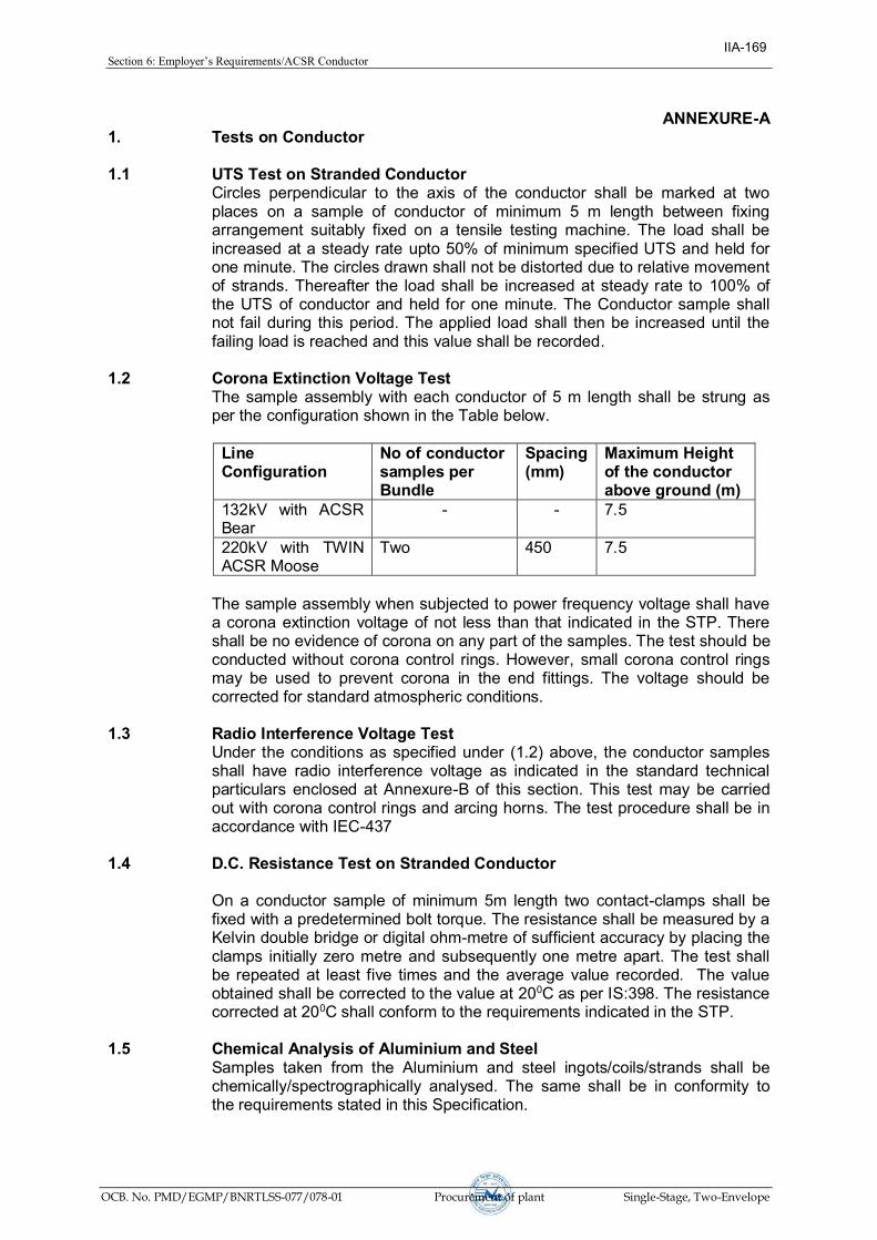
Section6:Employer’sRequirements/ACSRConductor
OCB. No. PMD/EGMP/BNRTLSS-077/078-01 Procurement of plant Single-Stage, Two-Envelope
ANNEXURE-A 1. Tests on Conductor 1.1 UTS Test on Stranded Conductor Circles perpendicular to the axis of the conductor shall be marked at two
places on a sample of conductor of minimum 5 m length between fixing arrangement suitably fixed on a tensile testing machine. The load shall be increased at a steady rate upto 50% of minimum specified UTS and held for one minute. The circles drawn shall not be distorted due to relative movement of strands. Thereafter the load shall be increased at steady rate to 100% of the UTS of conductor and held for one minute. The Conductor sample shall not fail during this period. The applied load shall then be increased until the failing load is reached and this value shall be recorded.
1.2 Corona Extinction Voltage Test The sample assembly with each conductor of 5 m length shall be strung as
per the configuration shown in the Table below.
Line Configuration
No of conductor samples per Bundle
Spacing(mm)
Maximum Height of the conductor above ground (m)
132kV with ACSR Bear
- - 7.5
220kV with TWIN ACSR Moose
Two 450 7.5
The sample assembly when subjected to power frequency voltage shall have
a corona extinction voltage of not less than that indicated in the STP. There shall be no evidence of corona on any part of the samples. The test should be conducted without corona control rings. However, small corona control rings may be used to prevent corona in the end fittings. The voltage should be corrected for standard atmospheric conditions.
1.3 Radio Interference Voltage Test Under the conditions as specified under (1.2) above, the conductor samples
shall have radio interference voltage as indicated in the standard technical particulars enclosed at Annexure-B of this section. This test may be carried out with corona control rings and arcing horns. The test procedure shall be in accordance with IEC-437
1.4 D.C. Resistance Test on Stranded Conductor On a conductor sample of minimum 5m length two contact-clamps shall be
fixed with a predetermined bolt torque. The resistance shall be measured by a Kelvin double bridge or digital ohm-metre of sufficient accuracy by placing the clamps initially zero metre and subsequently one metre apart. The test shall be repeated at least five times and the average value recorded. The value obtained shall be corrected to the value at 200C as per IS:398. The resistance corrected at 200C shall conform to the requirements indicated in the STP.
1.5 Chemical Analysis of Aluminium and Steel Samples taken from the Aluminium and steel ingots/coils/strands shall be
chemically/spectrographically analysed. The same shall be in conformity to the requirements stated in this Specification.
IIA-169

Section6:Employer’sRequirements/ACSRConductor
OCB. No. PMD/EGMP/BNRTLSS-077/078-01 Procurement of plant Single-Stage, Two-Envelope
1.6 Visual and Dimensional Check on Drums The drums shall be visually and dimensionally checked to ensure that they
conform to the requirements of this Specification. 1.7 Visual Check for Joints, Scratches etc. Conductor drums shall be rewound in the presence of the Employer. The
Employer shall visually check for scratches, joints etc. and that the conductor generally conform to the requirements of this Specification. Five percent (5%) to ten percent (10%) drums from each lot shall be rewound in the presence of the Employer's representative. The actual quantity will be discussed and mutually agreed to by the Supplier & Employer in the Quality Assurance Programme.
1.8 Dimensional Check on Steel and Aluminium Strands The individual strands shall be dimensionally checked to ensure that they
conform to the requirement of this Specification. 1.9 Check for Lay-ratios of Various Layers The lay-ratios of various layers shall be checked to ensure that they conform
to the requirements of this Specification. 1.10 Procedure Qualification test on welded Aluminium strands. Two Aluminium wire shall be welded as per the approved quality plan and
shall be subjected to tensile load. The breaking strength of the welded joint of the wire shall not be less than the breaking strength of individual strands.
1.11 Chemical Analysis of Zinc Samples taken from the zinc ingots shall be chemically/ spectrographically
analyzed. The same shall be in conformity to the requirements stated in the Specification.
1.12 Galvanizing Test The test procedure shall be as specified in IEC : 888. The material shall
conform to the requirements of this Specification. The adherence of zinc shall be checked by wrapping around a mandrel four times the diameter of steel wire.
1.13 Torsion and Elongation Tests on Steel Strands The test procedures shall be as per clause No. 10.3 of IEC : 888. In torsion
test, the number of complete twists before fracture shall not be less than that indicated in the STP. In case test sample length is less or more than 100 times the stranded diameter of the strand, the minimum number of twists will be proportioned to the length and if number comes in the fraction then it will be rounded off to next higher whole number. In elongation test, the elongation of the strand shall not be less than 4% for a gauge length of 250 mm.
1.14 Check on Barrel Batten strength of Drums The details regarding barrel batten strength test will be discussed and
mutually agreed to by the Supplier & Employer in the Quality Assurance Programme.
IIA-170

Section6:Employer’sRequirements/ACSRConductor
OCB. No. PMD/EGMP/BNRTLSS-077/078-01 Procurement of plant Single-Stage, Two-Envelope
Annexure-B
STANDARD TECHNICAL PARTICULARS OF ACSR MOOSE CONDUCTOR
Sl. Description Unit Guaranteed
Values 1.0 Raw Materials
1.1 Steel Wire / Rods
1.1 Aluminium
a) Minimum purity of Aluminium % 99.50
b) Maximum copper content % 0.04
1.2 Steel wires/ rods
a) Carbon % 0.50 to 0.85
b) Manganese % 0.50 to 1.10
c) Phosphorous % Not more than 0.035
d) Sulphur % Not more than 0.045
e) Silicon % 0.10 to 0.35 (Max.)
1.3 Zinc
a) Minimum purity of Zinc .% 99.95
2.0 Aluminum strands after stranding
2.1 Diameter
a) Nominal mm 3.53
b) Maximum mm 3.55
c) Minimum mm 3.51
2.2 Minimum breaking load of strand
a) Before stranding KN 1.57
b) After stranding KN 1.49
2.3 Maximum resistance of 1 m length of strand at 20 deg. C
Ohm 0.002921
3.0 Steel strand after stranding
2.1 Diameter
a) Nominal mm 3.53
b) Maximum mm 3.59
c) Minimum mm 3.47
3.2 Minimum breaking load of strand
a) Before stranding KN 12.63
b) After stranding KN 11.99
IIA-171

Section6:Employer’sRequirements/ACSRConductor
OCB. No. PMD/EGMP/BNRTLSS-077/078-01 Procurement of plant Single-Stage, Two-Envelope
STANDARD TECHNICAL PARTICULARS OF ACSR MOOSE CONDUCTOR
Sl. Description Unit Guaranteed
Values 3.3 Galvanising
a) Minimum weight of zinc coating per sq.m.
gm 250
b) Minimum number of dips that the galvanised strand can withstand in the standard preece test
Nos. 2 dips of one minute & 1 dip of half minute
c) Min. No. of twists in guage length equal 100 times the dia. of wire which the strand can withstand in the torsion test (after stranding)
Nos 16
4. Stranded Conductor
4.1 UTS of the conductor kN 161.20 (Min.)
4.2 Lay length of outer steel layer mm Max Min
a)
Outer Steel layer mm 18 16
b) 12 wire Aluminium layer mm 14 12
c) 18 wire Aluminium layer mm 13 11
d) 24 wire Alumimium Layer mm 12 10
4.3 DC resistance of the conductor at 20°C
ohm/km
0.05552
4.4 Minimum corona Extinction Voltage (line to Earth) under Dry condition
kV (rms)
320
4.5 RIV at 1 Mhz at 305 kv (line to earth) under Dry condition
Micto Volts
Below 1000
4.6 Standard length of the conductor m 1800
4.7 Tolerance on Standard length % (+/-) 5
4.8 Direction of lay of outer layer Right Hand
4.9 Linear mass of the conductor
a) Standard kg/km 2004
b) Minimum kg/km 1969
c) Maximum kg/km 2040
IIA-172
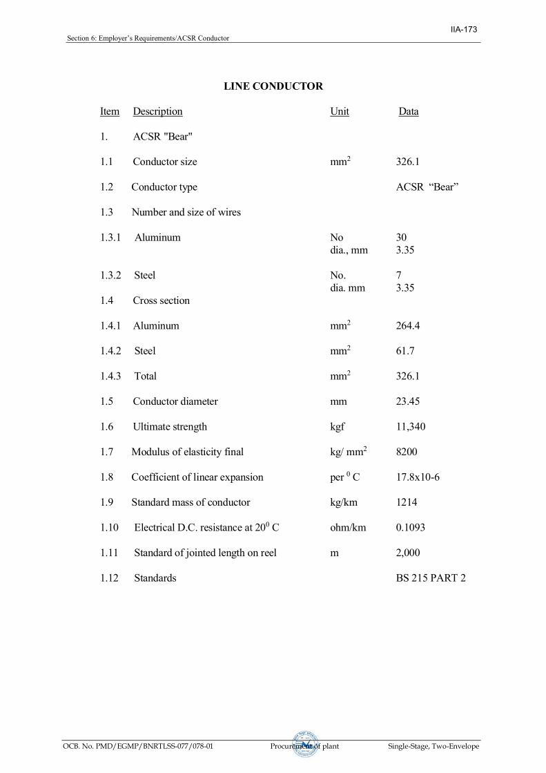
Section6:Employer’sRequirements/ACSRConductor
OCB. No. PMD/EGMP/BNRTLSS-077/078-01 Procurement of plant Single-Stage, Two-Envelope
LINE CONDUCTOR
Item Description Unit Data
1. ACSR "Bear" 1.1 Conductor size mm2 326.1 1.2 Conductor type ACSR “Bear” 1.3 Number and size of wires 1.3.1 Aluminum No 30 dia., mm 3.35 1.3.2 Steel No. 7 dia. mm 3.35 1.4 Cross section
1.4.1 Aluminum mm2 264.4 1.4.2 Steel mm2 61.7 1.4.3 Total mm2 326.1 1.5 Conductor diameter mm 23.45 1.6 Ultimate strength kgf 11,340 1.7 Modulus of elasticity final kg/ mm2 8200 1.8 Coefficient of linear expansion per 0 C 17.8x10⁻⁶ 1.9 Standard mass of conductor kg/km 1214 1.10 Electrical D.C. resistance at 200 C ohm/km 0.1093 1.11 Standard of jointed length on reel m 2,000 1.12 Standards BS 215 PART 2
IIA-173

Section6:Employer’sRequirements/EarthWire
OCB. No. PMD/EGMP/BNRTLSS-077/078-01 Procurement of plant Single-Stage, Two-Envelope
SECTION-VI EARTH-WIRE
IIA-174

Section6:Employer’sRequirements/EarthWire
OCB. No. PMD/EGMP/BNRTLSS-077/078-01 Procurement of plant Single-Stage, Two-Envelope
SECTION-VI
CONTENTS
Cl. Description Page No.
1.0 Technical Description of Galvanised Steel Earth wire 180
2.0 Standard Technical Particulars 177
3.0 Tests and Standards 177
Annexure-A 185
IIA-175

Section6:Employer’sRequirements/EarthWire
OCB. No. PMD/EGMP/BNRTLSS-077/078-01 Procurement of plant Single-Stage, Two-Envelope
TECHNICAL SPECIFICATIONS SECTION - VI
1.0 Technical Description of Galvanised Steel Earth wire
1.1 Details of Earth wire
1.11 The galvanised steel earth wire shall generally conform to the specification of ACSR core wire as mentioned in IS: 398 (Part-II)-1976 except where otherwise specified herein.
1.1.2 The details of the earth wire for 220 kV are tabulated below:
a) Stranding and wire : 7/3.35 mm steel diameter
b) Number of strands
Steel core : 1
Outer steel layer : 6
c) Total sectional area : 61.7 sqmm.
Other technical details are furnished in the section–I of this Specification.
1.2 Workmanship
1.2.1 All steel strands shall be smooth, uniform and free from all imperfections, such as spills and splits, die marks, scratches, abrasions and kinks after drawing and also after stranding.
1.2.2 The finished material shall have minimum brittleness as it will be subjected to appreciable vibration while in use.
1.2.3 The steel strands shall be hot dip qalvanised and shall have minimum Zinc coating after stranding, as stipulated in Cl. 2.0 of this section of the Specification. The zinc coating shall be smooth, continuous, of uniform thickness, free from imperfections. The steel wire rod shall be of such quality and purity that, when drawn to the size of the strands specified and coated with zinc, the finished strands shall be of uniform quality and have the same properties and characteristics as prescribed in ASTM designation B498-M.
1.2.4 The steel strands shall be preformed and post formed in order to prevent spreading of strands while cutting of composite earth wire. Care shall be taken to avoid damage to galvanisation during preforming and postforming operation.
1.2.5 To avoid susceptibility towards wet storage stains (white rust), the finished material shall be provided with a protective coating of boiled linseed oil.
1.3 Joints in Wires
There shall be no joint of any kind in the finished steel wire strand entering into the manufacture of the earth wire. There shall be no strand joints or strand splices in any length of the completed stranded earth wire.
1.4 Tolerances
The manufacturing tolerance to the extent of the limits as stipulated in Clause 2.0, Table 1 of this section of the Specification only shall be permitted in the diameter of the individual steel strands and lay length of the earth wire:
IIA-176

Section6:Employer’sRequirements/EarthWire
OCB. No. PMD/EGMP/BNRTLSS-077/078-01 Procurement of plant Single-Stage, Two-Envelope
1.5 Materials 1.5.1 Steel
The steel wire strands shall be drawn from high carbon steel rods and the chemical composition shall conform to the requirements as stipulated in Clause 2.0, Table 1 of this section of the Specification.
1.5.2 Zinc
The zinc used for galvanising shall be electrolytic High Grade Zinc and shall conform to the requirements of IS 209.
1.6 Standard Length
1.6.1 The standard length of the earth wire shall be as stipulated in Clause 2.0, Table 1 with the specified tolerance on standard length.
1.6.2 Random length will be accepted provided no length is less than 70% of standard length and the total quantity of random lengths is not more than ten (10) percent of the total quantity in each shipment.
2.0 Standard Technical Particulars
2.1 The standard Technical Particulars to be adhered by the contractor/ manufacturer are furnished in Annexure-B if this section.
3.0 Tests and Standards
3.1 Type Tests on Earthwire 3.1.1 The required type tests on earthwire are stipulated hereunder. The specified type
tests under the following clause shall not be required to be carried out if a valid test certificate is available for the same earthwire. The tests certificate shall be considered valid if: i. Tests conducted earlier is either conducted in accredited laboratory (accredited based on ISO/IEC vide 25/17025 or EN 45001 by the National accreditation body of the country where laboratory is located) or witnessed by the representative(s) of any utility and ii. Tests have been conducted not prior to 5 (five) years from the date of bid opening. In case the test have been conducted earlier than the above stipulated period or in the event of any discrepancy in the test report (i.e., any test not applicable due to any design/manufacturing change including substitution of components or due to non-compliance with the requirement stipulated in the Technical Specifications), the tests shall be conducted by the Supplier at no extra cost to the Purchaser.
3.1.2 The following tests are required on samples of earthwire from each manufacturing works:-
a) UTS test : As per Annexure - A
b) DC resistance test : As per Annexure - A
IIA-177

Section6:Employer’sRequirements/EarthWire
OCB. No. PMD/EGMP/BNRTLSS-077/078-01 Procurement of plant Single-Stage, Two-Envelope
3.2 Acceptance Tests on Earthwire
a) Visual and dimensional check on drum
: As per Annexure - A
b) Visual check for joints scratches etc. and lengths of earthwire
: As per Annexure - A
c) Dimensional check : As per Annexure - A
d) Lay length check : As per Annexure - A
e) Galvanising test : As per Annexure - A
f) Torsion test : As per Annexure - A
g) Elongation test : As per IS:398 (Part-II)
h) Wrap test : As per IS:398 (Part-II)
i) DC resistance test : As per IS:398 (Part-II)
j) Breaking load test : As per IS:398 (Part-II)
k) Chemical Analysis of steel : As per Annexure - A
3.3 Routine Tests on Earthwire
a) Check for correctness of stranding : As per Annexure - A
b) Check that there are no cuts, fins etc. on the strands.
: As per Annexure - A
c) Check that drums are as per Specification.
: As per Annexure - A
3.4 Tests During Manufacture Earthwire
a) Chemical analysis of zinc used for galvanising
: As per Annexure - A
b) Chemical analysis of steel : As per Annexure - A
3.5 Testing Expenses
3.5.1 No type test charges shall be payable to the supplier.
3.5.2 Bidders shall indicate the laboratories in which they propose to conduct the type tests. They shall ensure that the tests can be completed in these laboratories within the time schedule guaranteed by them.
3.5.3 In case of failure in any type test the Contractor is either required to manufacture fresh sample lot and repeat all the test successfully once or repeat that particular type test three times successfully on the sample selected from the already manufactured lot at his own expenses. In case fresh lot is manufactured for testing then the lot already manufactured shall be rejected. The decision of the Purchaser in this regard shall be final and binding on Contractor.
IIA-178

Section6:Employer’sRequirements/EarthWire
OCB. No. PMD/EGMP/BNRTLSS-077/078-01 Procurement of plant Single-Stage, Two-Envelope
3.5.4 The entire cost of testing for the acceptance and routine tests and tests during manufacture specified herein shall be treated as included in the quoted unit price except for the expenses of the inspector/ Employer’s representative.
3.5.5 In case of failure in any type test, repeat type tests are required to be conducted, then all the expenses for deputation of Inspector/ Employer's representative shall be deducted from the contract price. Also if on receipt of the Contract's notice of testing the Employer's representative/Inspector does notfind‘materialsandfacilities’tobereadyfortesting,theexpensesincurredby the Employer for re-deputation shall be deducted from the contract price.
3.6 Additional Tests
3.6.1 The Owner reserves the right of having at his own expenses any other test(s) of reasonablenature carriedoutatContractor’s premises,atsite, or inanyother place in addition to the aforesaid type, acceptance and routine tests to satisfy himself that the materials comply with the Specifications.
3.6.2 The Owner also reserves the right to conduct all the tests mentioned in this specification at his own expense on the samples drawn from the site at Contractor’spremisesoratanyothertestcenter.Incaseofevidenceofnoncompliance, it shall be binding on the part of Contractor to prove the compliance of the items to the technical specifications by repeat tests, or correction of deficiencies, or replacement of defective item all without any extra cost to the Owner.
3.7 Sample Batch for Type Testing
3.7.1 The Contractor shall offer material for selection of samples for type testing only after getting Quality Assurance Plan approved from Owner’s QualityAssurance Deptt. The sample shall be manufactured strictly in accordance with the Quality Assurance Plan approved by Owner.
3.7.2 The Contractor shall offer at least three drums for selection of sample required for conducting all the type test.
3.7.3 The Contractor is required to carry out all the Acceptance tests successfully in presenceofOwner’srepresentativebeforesampleselection.
3.8 Test Reports
3.8.1 Copies of type test reports shall be furnished in at least six copies along with one original. One copy will be returned duly certified by the Owner only after which the commercial production of the material shall start.
3.8.2 Record of routine test reports shall be maintained by the Contractor at his works for periodic inspection by the Owner's representative.
3.8.3 Test Certificates of tests during manufacture shall be maintained by the Contractor. These shall be produced for verification as and when desired by the Owner.
3.9 Inspection
3.9.1 The Owner 's representative shall at all times be entitled to have access to the works and all places of manufacture, where earth wire shall be manufactured and representative shall have full facilities for unrestricted
IIA-179

Section6:Employer’sRequirements/EarthWire
OCB. No. PMD/EGMP/BNRTLSS-077/078-01 Procurement of plant Single-Stage, Two-Envelope
inspection of the Contractor’s works, raw materials and process ofmanufacture for conducting necessary tests as detailed herein.
3.9.2 The Contractor shall keep the Owner informed in advance of the time of starting and of the progress of manufacture of earth wire in its various stages so that arrangements can be made for inspection.
3.9.3 No material shall be dispatched from its point of manufacture before it has been satisfactorily inspected and tested, unless the inspection is waived off by the Owner in writing. In the latter case also the earth wire shall be dispatched only after satisfactory testing for all tests specified herein have been completed.
3.9.4 The acceptance of any quantity of material shall in no way relieve the Contractor of any of his responsibilities for meeting all requirements of the Specification, and shall not prevent subsequent rejection if such material is later found to be defective.
3.10 Test Facilities
3.10.1 The following additional test facilities shall be available at the Contractor’sworks :
a) Calibration of various testing and measuring equipment including tensile testing machine, resistance measurement facilities, burette, thermometer, barometer etc.
b) Standard resistance for calibration of resistance bridges.
c) Finished Earth wire shall be checked for length verification and surface finish on separate rewinding machine at reduced speed (variable from 8 to 16 meters per minute). The rewinding facilities shall have appropriate clutch system and free of vibrations, jerks etc., with traverse laying facilities.
3.11 Packing for Earth wire
3.11.1 The Earth wire shall be supplied in non-returnable, strong, wooden drums and provided with lagging of adequate strength, constructed to protect the Earth wire against all damage and displacement during transit, storage and subsequent handling and stringing operations in the field. The Contractor shall be responsible for any loss or damage during transportation handling and storage due to improper packing. The drums shall generally conform to IS 778-1980, except as otherwise specified hereinafter.
3.11.2 The drums shall be suitable for wheel mounting and for letting off the earth wire under a minimum controlled tension of the order of 5 kN
3.11.3 The general outline of the drum for Earth wire shall be as per annexed drawing. The Contractor should submit their proposed drum drawings along with the bid.
3.11.4 For Earth wire, two standard lengths shall be wound on each drum.
3.11.5 For Earth wire, each strand shall be individually welded to prevent parting of two lengths at a tension less than 15 kN. The two ends where the first length finishes and the second length starts, shall be clearly marked with adhesive tape and no weld should be present outside these marks. The length between the two marks shall be treated as scrap and will not be taken into account for measurement purposes.
IIA-180

Section6:Employer’sRequirements/EarthWire
OCB. No. PMD/EGMP/BNRTLSS-077/078-01 Procurement of plant Single-Stage, Two-Envelope
3.11.6 All wooden components shall be manufactured out of seasoned softwood free from defects that may materially weaken the component parts of the drums. Preservative treatment shall be applied to the entire drum with preservatives of a quality which is not harmful to the earth wire.
3.11.7 The flanges shall be of two ply construction with each ply at right angles to the adjacent ply and nailed together. The nails shall be driven from the inside face flange, punched and then clenched on the outer face. The thickness of each ply shall not vary by more than 3 mm from that indicated in the figure. There shall be at least 3 nails per plank of ply with maximum nail spacing of 75 mm. Where a slot is cut in the flange to receive the inner end of the earth wire the entrance shall be in line with the periphery of the barrel.
3.11.8 The wooden battens used for making the barrel of the earth wire shall be of segmental type. These shall be nailed to the barrel supports with at least two nails. The battens shall be closely butted and shall provide a round barrel with smooth external surface. The edges of the battens shall be rounded or chamfered to avoid damage to the earth wire.
3.11.9 Barrel studs shall be used for the construction of drums. The flanges shall be holed and the barrel studs shaft be threaded over a length on either end, sufficient to accommodate washers, spindle plates and nuts for fixing flanges at the required spacing.
3.11.10 Normally, the nuts on the studs shall stand protruded of the flanges. All the nails used on the inner surface of the flanges and the drum barrel shall be counter sunk. The ends of barrel shall generally be flushed with the top of the nuts.
3.11.11 The inner cheek of the flanges and drum barrel surface shall be painted with a bitumen based paint.
3.11.12 Before reeling, cardboard or double corrugated or thick bituminous waterproof bamboo paper shall be secured to the drum barrel and inside of flanges of the drum by means of a suitable commercial adhesive material. After reeling the earth wire, the exposed surface of the outer layer of earth wire shall be wrapped with water proof thick bituminous bamboo paper to preserve the earth wire from dirt, grit and damage during transport and handling.
Medium grade craft/crepe/polythene paper shall be used in between the layers.
3.11.13 A minimum space of 50 mm for earth wire shall be provided between the inner surface of the external protective lagging and outer layer of the earth wire.
3.11.14 Each batten shall be securely nailed across grains as far as possible to the flange, edges with at least 2 nails per end. The length of the nails shall not be less than twice the thickness of the battens. The nails shall not protrude above the general surface and shall not have exposed sharp edges or allow the battens to be released due to corrosion.
3.11.15 The nuts on the barrel studs shall be tack welded on the one side in order to fully secure them. On the second end, a spring washer shall be used.
3.11.16 Outside the protective lagging there shall be minimum of two binder consisting of hoop iron/galvanised steel wire. Each protective lagging shall have two recesses to accommodate the binders.
IIA-181

Section6:Employer’sRequirements/EarthWire
OCB. No. PMD/EGMP/BNRTLSS-077/078-01 Procurement of plant Single-Stage, Two-Envelope
3.11.17 The earth wire ends shall be properly sealed and secured on the side of one of the flanges to avoid loosening of the earth wire layers during transit and handling.
3.12 Marking
Each drum shall have the following information stenciled on it in indelible ink along with other essential data
(a) Contract/Award letter number.
(b) Name and address of consignee.
(c) Manufacturer’snameandaddress.
(d) Drum number
(e) Size of earth wire
(f) Length of earth wire in meters
(g) Gross weight of drum with earth wire & lagging
(h) Weight of empty drum with lagging
(i) Arrow marking for unwinding
(j) Position of the earth wire ends
(k) Number of turns in the outer most layer
(l) Distance between outer most layer of Earth wire and the inner surface of lagging
(n) Barrel diameter at three locations and an arrow marking at the location of measurement
3.13 Verification of Earth wire Length
The Owner reserves the right to verify the length of earth wire after unreeling atlest ten (10) percent of the drums in a lot offered for inspection.
3.14 Standards
The earth wire shall conform to the following Indian/ International Standards, which shall mean latest revisions, amendments/changes adopted and published, unless otherwise in the Specification.
In the event of the supply of earth wire conforming to standards other than specified, the Contractor shall confirm in his bid that these standards are equivalent to those specified. In case of award salient features of comparison between the standards proposed by the Contractor and those specified in this documents will be provided by the Contractor to establish their equivalence.
Sl. No.
Indian Standard
Title International Standard
1. IS: 209-1992 Specification for zinc BS:3436-1986
2. IS: 398-1990 Specification for Aluminium Conductors for Overhead Transmission Purposes
IEC:1089-1991 BS:215-1970
IIA-182

Section6:Employer’sRequirements/EarthWire
OCB. No. PMD/EGMP/BNRTLSS-077/078-01 Procurement of plant Single-Stage, Two-Envelope
3. IS:398-1998 Part-II
Aluminum Conductor Galvanised Steel Reinforced
BS;215-1970 IEC:1089-1991
4. IS :398-1996 Part-IV
Aluminum Alloy stranded conductor
BS-3242-1970 ASTM-8399 M86 IEC:1089-1991
5. IS:398-1992 Part-V
Aluminum Conductor Galvanised Steel- Reinforced For Extra High Voltage (400 KV) and above
IEC:1089-1991 BS:215-1970
6. IS : 1778-1997
Reels and Drums for Bare Conductors BS:1559-1949
7. IS : 1521-1991
Method of Tensile Testing of Steel Wire ISO 6892-1984
8. IS : 2629-1990
Recommended Practice for Hot Dip Galvanising of Iron and Steel
9. IS : 2633-1992
Method of Testing Uniformity of Coating on Zinc Coated Articles
10. IS : 4826-1992
Galvanised Coating on Round Steel Wires
IEC : 888-1987 BS:443-1969
11. IS : 6745-1991
Methods of Determination of Weight of Zinc Coating of Zinc Coated Iron and Steel Articles
BS:433-1969 ISO 1460 - 1973
12. IS : 8263-1991
Method of Radio Interference Tests on High Voltage Insulators
IEC:437-1973 NEMA:107-1964 CISPR
13. IS : 9997-1991
Aluminium Alloy Redraw Rods IEC 104 - 1987
14. Zinc Coated steel wires for stranded Conductors
IEC : 888-1987
15. Hard drawn Aluminium wire for overhead line conductors
IEC : 889-1987
IIA-183

Section6:Employer’sRequirements/EarthWire
OCB. No. PMD/EGMP/BNRTLSS-077/078-01 Procurement of plant Single-Stage, Two-Envelope
The standards mentioned above are available from:
Reference Abbreviation
Name and Address
BS British Standards, British Standards Institution 101, Pentonvile Road, N - 19-ND UK
IEC/CISPR International Electro technical Commission, Bureau Central de la Commission, electro Technique international, 1 Rue de verembe, Geneva SWITZERLAND
BIS/IS Beureau Of Indian Standards. Manak Bhavan, 9, Bahadur Shah Zafar Marg, New Delhi - 110001. INDIA
ISO International Organisation for Standardization. Danish Board of Standardization Danish Standardizing Sraat, Aurehoegvej-12 DK-2900, Heeleprup, DENMARK.
NEMA National Electric Manufacture Association, 155, East 44th Street. New York, NY 10017 U.S.A.
IIA-184

Section6:Employer’sRequirements/EarthWire
OCB. No. PMD/EGMP/BNRTLSS-077/078-01 Procurement of plant Single-Stage, Two-Envelope
Annexure-A
1.0 Tests on Earth wire
1.1 UTS Test
Circles perpendicular to the axis of the earth wire shall be marked at two places on a sample of earth wire of minimum 5 m length suitably compressed with dead end clamps at either end. The load shall be increased at a steady rate up to 50% of UTS and held for one minute. The circles drawn shall not be distorted due to relative movement of strands. Thereafter the load shall be increased at steady rate to 100% of UTS and held for one minute. The earth wire sample shall not fail during this period. The applied load shall then be increased until the failing load is reached and the value recorded.
1.2 D.C. Resistance Test
On a earth wire sample of minimum 5m length two contact clamps shall be fixed with a predetermined bolt torque. The resistance shall be measured by a Kelvin double bridge by placing the clamps initially at zero meter and subsequently one meter apart. The test shall be repeated at least five times and the average value recorded. The value obtained shall be corrected to the
value at 200C. The resistance corrected at 200C shall conform to the requirements of this Specification.
1.3 Chemical Analysis of Zinc
Samples taken from the zinc ingots shall be chemically/ spectrographically analysed. The same shall be in conformity to the requirements stated in the Specification.
1.4 Chemical Analysis of Steel
Samples taken from the steel ingots/coils/strands shall be chemically/spectrographically analysed. The same shall be in conformity to the requirements stated in this Specification.
1.5 Visual and Dimensional Check on Drums and its barrel strength test.
The drums shall be visually and dimensionally checked to ensure that they conform to the requirements of this Specification. The details regarding barrel strength test will be discussed and mutually agreed to by Contractor and Owner in the quality assurance programme.
1.6 Visual Check for Joints, Scratches etc. and Length of Earth wire
Ten percent drums from each lot shall be rewound in the presence of the Owner. The Owner shall visually check for scratches, joints etc. and see that the earth wire generally conforms to the requirements of this Specification. The length of earth wire wound on the drum shall be measured with the help of counter meter during rewinding.
1.7 Dimensional Check
The individual strands shall be dimensionally checked to ensure that they conform to the requirement of this Specification.
IIA-185

Section6:Employer’sRequirements/EarthWire
OCB. No. PMD/EGMP/BNRTLSS-077/078-01 Procurement of plant Single-Stage, Two-Envelope
1.8 Lay Length Check
The lay length shall be checked to ensure that they conform to the requirements of this Specification.
1.9 Galvanising Test
The test procedure shall be as specified in IS 4826-1979. The material shall conform to the requirements of this Specification. The adherence of zinc shall be checked by wrapping around a mandrel four times the diameter of steel wire.
1.10 Torsion Test
The minimum number of twists which a single steel strand shall withstand during torsion test shall be eighteen for a length equal to 100 times the standard diameter of the strand. In case test sample length is less or more than 100 times the stranded diameter of the strand the minimum number of twists will be proportioned to the length and if number comes in the fraction then it will be rounded off to next higher whole number.
IIA-186

Section6:Employer’sRequirements/EarthWire
OCB. No. PMD/EGMP/BNRTLSS-077/078-01 Procurement of plant Single-Stage, Two-Envelope
Annexure-B
A) Standardized Technical Particulars of 7/3.35 mm Galvanised Steel Earth wire
Sl. no.
Description Unit Standard Values
1.0 Raw Materials
1.1 Steel wires / rods
a) Carbon % Not more than 0.55 b) Manganese % 0.40 to 0.90 c) Phosphorous % Not more than 0.04 d) Sulphur % Not more than 0.04 e) Silicon % 0.15 to 0.35
1.2 Zinc
a) Minimum purity of Zinc % 99.95 2.0 Steel strands
2.1 Diameter
a) Nominal mm 3.35 b) Maximum mm 3.40 c) Minimum mm 3.30
2.2. Minimum breaking load of strand
a) After stranding KN 8.98
2.3 Galvanising
a) Minimum weight of zinc coating per sq.m. after stranding
Gms. 275
b) Minimum number of dips that the galvanized strand can withstand in the standard preece test
Nos. 3 dips of 1 minute and one dip of ½ minute
c) Minimum number of twists in a gauge length equal to 100 times diameter of wire which the strand can withstand in the torsion test, after stranding
Nos. 18
3.0 Stranded Earth wire
3.1 UTS of Earth wire KN 61.1 (min.)
3.2 Lay length of outer steel layer
a) Standard mm 181 b) Maximum mm 198 c) Minimum mm 165
3.3 Maximum DC resistance of earth wire at 200 C
Ohm/km
2.5
3.4 Standard length of earth wire M 2000 3.5 Tolerance on standard length % ±5 3.6 Direction of lay for outside layer Right hand 3.7 Linear mass
a) Standard Kg/km 482
IIA-187

Section6:Employer’sRequirements/EarthWire
OCB. No. PMD/EGMP/BNRTLSS-077/078-01 Procurement of plant Single-Stage, Two-Envelope
Sl. no.
Description Unit Standard Values
b) Maximum Kg/km 496 c) Minimum Kg/km 468
IIA-188

Section6:Employer’sRequirements/CompositeInsulator
OCB. No. PMD/EGMP/BNRTLSS-077/078-01 Procurement of plant Single-Stage, Two-Envelope
SECTION-VII Composite Insulator
IIA-189

Section6:Employer’sRequirements/CompositeInsulator
OCB. No. PMD/EGMP/BNRTLSS-077/078-01 Procurement of plant Single-Stage, Two-Envelope
SECTION-7
TECHNICAL SPECIFICATIONS
SECTION-VII
CONTENTS
Cl. Description Page No.
1.0 Technical Description of Composite Long Rod Insulators.....................................191
2.0 Equipment Marking ................................................................................................195
3.0 Bid Drawings ..........................................................................................................195
4.0 Tests and Standards................................................................................................196
ANNEXURE-A ................................................................................................................204
IIA-190

Section6:Employer’sRequirements/CompositeInsulator
OCB. No. PMD/EGMP/BNRTLSS-077/078-01 Procurement of plant Single-Stage, Two-Envelope
TECHNICAL SPECIFICATIONS
SECTION-VII
1.0 Technical Description of Composite Long Rod Insulators 1.1 Details of Composite Long Rod Insulators 1.1.1 The insulators strings shall consist of composite long rod insulators for a three phase,
50 Hz, effectively earthed 132 kV and 220 kV transmission system application in a lightly polluted environment. Couplings shall be ball and socket type.
1.1.2 Bidder shall quote such composite insulators which have proven use under
foggy/humid operational conditions in lightly polluted industrial environment combined with smoke and dust particles. The Bidder shall furnish evidence in the form of certification from the power utilities that the similar type of product supplied to them had been performing satisfactory. The Bidder shall also submit certified test report for an accelerated ageing test of 5000 hours such as that described in Appendix-C of IEC-61109.
1.1.3 Insulatorsshallhaveshedsofthe“openaerodynamicprofilewithoutanyunderribs”
with good self-cleaning properties. Insulator shed profile, spacing projection etc. shall be strictly in accordance with the recommendation of IEC-60815.
1.1.4 The size of long rod insulator, minimum creepage distance, the number to be used in
different type of strings, their electromechanical strength and mechanical strength of insulator string alongwith hardware fittings shall be as follows:
S.
No Type of String *Size of
Composite Insulator
(Core dia x Nominal length) (mm)
Minimum Creepage Distance (mm) per
unit
No. of individual Units per
String (Nos.)
Electro- Mechanical Strength
of Insulator
Unit (kN)
Mechanical Strength
of Insulator
String along with Hardware Fittings
(kN) FOR 132kV AC TRANSMISSION LINES WITH BEAR CONDUCTOR
1. Single Suspension ‘Pilot’
20x1305 4495 1x1 90 90
2. Single Tension 20x1450 4495
1x1 120 120
3. Double Tension 20x1450 4495
2x1 120 2x120
FOR 220kV AC TRANSMISSION LINES WITH TWIN MOOSE CONDUCTOR 1. Single
Suspension ‘Pilot’
24x2320 5355 1x1 120 120
2. Double Suspension
24x2320 5355
2x1 120 2x120
3. Double Tension 24x2890 5355
2x1 160 2x160
IIA-191

Section6:Employer’sRequirements/CompositeInsulator
OCB. No. PMD/EGMP/BNRTLSS-077/078-01 Procurement of plant Single-Stage, Two-Envelope
3. Double Tension 24x4610 5355
2x1 210 2x210
4. Triple Tension 24x2890 5355
3x1 160 3x160
1.2 1.2.1
1.2.2
1.3
1.4
1.5
1.6
Note: *The core dia of composite insulators mentioned at column No.3 &4 is for indicative purpose. The bidder shall offer composite long rod insulators of suitable core dia to meet specified E&M and torsion strength requirements. For offered core dia, less than indicated in table above the bidder shall submit documentary evidence of past supplies & satisfactory operation of the same for minimum period of three years. However, the overall string length shall be within the limits specified in the drawing.
Pin and Cap
Pin and cap shall be designed to transmit the mechanical stress and develop uniformmechanical strength in the insulator. The cap shall be circular with the inner andouter surfaces concentric of such design that it will not yield or distort under loadconditions.
The design shall be such as to permit easy removal of replacement of either insulatorunits or fittings under the live line conditions.
Ball and Socket Designation
The dimensions of the Ball and Socket shall be of 20 mm & 24 mm designation for120kN 160 kN and 210 kN Insulators in accordance with the standard dimensions,stated in IEC:60120/ IS:2486 (Part-II).
Dimensional Tolerance of Composite Insulators
The tolerances on all dimensions e.g. diameter, length shall be allowed as follows:± (0.04d+1.5) mmwhend≤300mm.± (0.025d+6) mm when d>300 mm.Where, d being the dimensions in millimeters for diameter, length as the case maybe.
The tolerance in creepage distance shall be based on design dimensions and theirtolerances. However, no negative tolerance shall be applicable to creepage distancespecified in clause 1.1.4.
Interchangeability
The composite long rod insulators inclusive of the ball & socket connection shall bestandard design suitable for use with the hardware fittings of any make conforming torelevant IEC standards.
Corona and RI Performance
All surfaces shall be clean, smooth, without cuts, abrasions or projections. No partshall be subjected to excessive localized pressure. The insulator and metal partsshall be so designed and manufactured that it shall avoid local corona formation andshall not generate any radio interference beyond specified limit under the operatingconditions.
IIA-192

Section6:Employer’sRequirements/CompositeInsulator
OCB. No. PMD/EGMP/BNRTLSS-077/078-01 Procurement of plant Single-Stage, Two-Envelope
1.7 Maintenance 1.7.1 The long rod insulators offered shall be suitable for employment of hot line
maintenance technique so that usual hot line operation can be carried out with ease, speed and safety.
1.7.2 All insulators shall be designed to facilitate cleaning and insulators shall have the
minimum practical number of sheds and grooves. All grooves shall be so proportioned that any dust deposit can be removed without difficulty either by wiping with a cloth or by remote washing under live line condition.
1.8 Materials 1.8.1 Core
It shall be a glass-fiber reinforced (FRP rod) epoxy resin rod of high strength. The rod shall be resistant to hydrolysis. Glass fibers and resin shall be optimized. The rod shall be electrical grade corrosion resistant (ECR), boron free glass and shall exhibit both high electrical integrity and high resistance to acid corrosion.
1.8.2 Housing & Weathersheds
The FRP rod shall be covered by a seamless sheath of a silicone rubber compound of a thickness of minimum 3mm. The housing & weathersheds should have silicon content of minimum 30% by weight. It should protect the FRP rod against environmental influences, external pollution and humidity. It shall be extruded or directly molded on the core. The interface between the housing and the core must be uniform and without voids. The strength of the bond shall be greater than the tearing strength of the polymer. The manufacturer shall follow non-destructive technique (N.D.T.) to check the quality of jointing of the housing interface with the core. The technique to be followed with detailed procedure and sampling shall be furnished by the Supplier and finalized during finalization of MQP. The weathersheds of the insulators shall be of alternate shed profile. The weathersheds shall be vulcanized to the sheath (extrusion process) or molded as part of the sheath (injection moulding process) and free from imperfections. The vulcanization for extrusion process shall be at high temperature and for injection moulding shall be at high temperature & high pressure. Any seams / burrs protruding axially along the insulator, resulting from the injection moulding process shall be removed completely without causing any damage to the housing. The track resistance of housing and shed material shall be class 1A4.5 according to IEC60587. The strength of the weathershed to sheath interface shall be greater than the tearing strength of the polymer. The composite insulator shall be capable of high pressure washing.
1.8.3 End Fittings
End fittings transmit the mechanical load to the core. They shall be made of malleable cast iron spheroidal graphite or forged steel. They shall be connected to the rod by means of a controlled compression technique. The manufacturer shall have in-process Acoustic emission arrangement or some other arrangement to ensure that there is no damage to the core during crimping. This verification shall be in-process and done on each insulator. The system of attachment of end fitting to the rod shall provide superior sealing performance between housing and metal connection. The gap between fitting and sheath shall be sealed by a flexible silicone
IIA-193

Section6:Employer’sRequirements/CompositeInsulator
OCB. No. PMD/EGMP/BNRTLSS-077/078-01 Procurement of plant Single-Stage, Two-Envelope
rubber compound. The sealing shall stick to both housing and metal end fitting. The sealing must be humidity proof and durable with time. End fittings shall have suitable provisions for fixing grading rings at the correct position as per design requirements.
1.8.4 Grading Rings
Grading rings shall be used at both ends of each composite insulator unit for reducing the voltage gradient on and within the insulator and to reduce radio and TV noise to acceptable levels. The size and placement of the metallic grading rings shall be designed to eliminate dry band arcing/corona cutting/ exceeding of permissible electrical stress of material. The insulator supplier shall furnish design calculations using appropriate electric field software showing electric field at surface of housing, inside housing & core and at the interface of housing and metal fittings with the proposed placement and design of corona ring. Grading rings shall be capable of installation and removal with hot line tools without disassembling any other part of the insulator assembly.
The design & supply of grading rings shall be in the scope of the composite insulator supplier.
1.9 Workmanship 1.9.1 All the materials shall be of latest design and conform to the best modern practices
adopted in the extra high voltage field. Bidders shall offer only such insulators as are guaranteed by him to be satisfactory and suitable for transmission lines specified and will give continued good service.
1.9.2 The design, manufacturing process and material control at various stages shall be
such as to give maximum working load, highest mobility, best resistance to corrosion, good finish and elimination of sharp edges and corners to limit corona and radio interference.
1.9.3 The design of the insulators shall be such that stresses due to expansion and
contraction in any part of the insulator shall not lead to deterioration. 1.9.4 The core shall be sound and free of cracks, impurities and voids that may adversely
affect the insulators. 1.9.5 Weathersheds / Housing shall be uniform in quality. Weathersheds / Housing shall be
clean, sound, smooth and free from gross defects, voids, impurities and excessive flashing at parting lines.
1.9.6 End fittings shall be free from cracks, seams, shrinks, air holes and rough edges.
End fittings should be effectively, sealed to prevent moisture ingress, effectiveness of sealing system must be supported by test documents. All surfaces of the metal parts shall be perfectly smooth with the projecting points or irregularities which may cause corona. All load bearing surfaces shall be smooth and uniform so as to distribute the loading stresses uniformly.
1.9.7 All ferrous parts shall be hot dip galvanized to give a minimum average coating of
zinc equivalent to 600 gm/sq.m. and shall be in accordance with the requirement of ISO:1461 (E) and shall satisfy the tests mentioned in ISO:1460 (E). The zinc used for galvanizing shall be of purity of 99.95%. The zinc coating shall be uniform,
IIA-194

Section6:Employer’sRequirements/CompositeInsulator
OCB. No. PMD/EGMP/BNRTLSS-077/078-01 Procurement of plant Single-Stage, Two-Envelope
adherent, smooth, reasonably bright continuous and free from imperfections such as flux, ash rust stains, bulky white deposits and blisters. The galvanized metal parts shall be guaranteed to withstand at least six successive dips each lasting for one (1) minute duration under the standard preece test. The galvanizing shall be carried out only after any machining.
1.9.8 The supplier shall guarantee that there shall not be any failure/ decapping / breaking
of insulators on line under normal operating condition. In the event of any failure/ decapping /breaking of insulators during the first ten years of service, Supplier shall supply to the Purchaser free of cost spare insulators equal to 10 times the failed insulator quantity. Further, in case of decapping / Breaking and subsequent line drop, during the first ten years of service, the supplier shall also have to pay Rs 100000/ (Rs one lakh only) per dropped string towards expenditure to be incurred by NEA for this line repair
2.0 Equipment Marking 2.1 Each composite long rod unit shall be legibly and indelibly marked with the trade
mark of the manufacturer, name of NEA and month & year of manufacture. The guaranteed combined mechanical and electrical strength shall be indicated in kilo Newtonfollowedbytheword‘kN’tofacilitateeasyidentificationandtoensureproperuse.
2.2 One 10 mm thick ring or 20 mm thick spot of suitable quality of paint shall be marked on the cap/end fitting of each composite long rod of particular strength for easy identification of the type of insulator. The paint shall not have any deteriorating effect on the insulator performance. Following codes shall be used as identification mark :
For 90 kN Long rod unit : Red
For 120 kN Long rod unit : Yellow
For 160 kN Long rod unit : Green
For 210 kN Long rod unit : Blue
3.0 Bid Drawings 3.1 The Bidder shall furnish full description and illustration of the material offered.
3.2 The Bidder shall furnish along with the bid the outline drawing of each insulator unit along with grading rings including a cross sectional view of the long rod insulator unit. The drawing shall include but not limited to the following information:
(a) Major Dimensions with manufacturing tolerances
(b) Minimum Creepage distance with positive tolerance
(c) Protected creepage distance
(d) Unit mechanical and electrical characteristics
(e) Size and weight of ball and socket parts
(f) Weight of composite long rod units
(g) Materials
3.3 After placement of award, the Supplier shall submit full dimensioned insulator drawings containing all the details as given in Clause No. 3.2 above, in four (4)
IIA-195

Section6:Employer’sRequirements/CompositeInsulator
OCB. No. PMD/EGMP/BNRTLSS-077/078-01 Procurement of plant Single-Stage, Two-Envelope
copies to Purchaser for approval. After getting approval from Purchaser and successful completion of all the type tests, the Supplier shall submit 10 more copies of the same drawing along with a soft copy to the Purchaser for further distribution and field use at Purchaser's end.
3.4 After placement of award the Supplier shall also submit fully dimensioned insulator crate drawing for different type of insulators.
4.0 Tests and Standards 4.1 Type Tests
The required type tests on composite longrod units, components, materials and complete strings are stipulated hereunder. The specified type tests under the following clause shall not be required to be carried out if a valid test certificate is available for a similar design. The tests certificate shall be considered valid if: i. Tests conducted earlier is either conducted in accredited laboratory (accredited
based on ISO/IEC vide 25/17025 or EN 45001 by the National accreditation body of the country where laboratory is located) or witnessed by the representative(s) of any utility and
ii. Tests have been conducted not prior to 5 (five) years from the date of bid
opening.
In case the test have been conducted earlier than the above stipulated period or in the event of any discrepancy in the test report (i.e., any test not applicable due to any design/manufacturing change including substitution of components or due to non-compliance with the requirement stipulated in the Technical Specifications), the tests shall be conducted by the Supplier at no extra cost to the Purchaser.
4.1.1 On the complete composite Long Rod Insulator String with Hardware Fittings
For 132 kV AC Transmission Lines with Bear Conductor and 220 kV AC Transmission Lines with Twin Moose Conductor Strings on
which test to be conducted
(a) Power frequency voltage withstand test with corona control rings/grading ring and arcing horns under wet condition
IEC:383-1993/ Annex-A
SISP, DT, TT
(b) Switching surge voltage withstand test under wet condition
IEC:383-1993
SISP, DT, TT
(c) Impulse voltage withstand test under dry condition
IEC:383-1993
SISP, DT, TT
(d) Corona and RIV test under dry condition
Annex-A SISP, DT, TT
IIA-196

Section6:Employer’sRequirements/CompositeInsulator
OCB. No. PMD/EGMP/BNRTLSS-077/078-01 Procurement of plant Single-Stage, Two-Envelope
(e) Mechanical Strength test Annex-A SISP, DT, TT
(f) Vibration test Annex-A DT
(g) Salt-fog pollution withstand test Annex-A DT
SISP : Single I Suspension Pilot; DT: Double Tension, TT : Triple Tension
4.1.2 On Composite Insulator Units
(a) Tests on interfaces and connections of metal fittings IEC: 61109-2008
(b) Assembled core load time test IEC: 61109-2008
(c) Damage limit proof test and test of tightness of interface between end fittings and insulator housing.
IEC: 61109-2008
(d) High Pressure washing test Annexure-A
(e) Brittle fracture resistance test Annexure-A
(f) Dye penetration test IEC: 61109-2008
(g) Water diffusion test IEC: 61109-2008
(h) Tracking and erosion test IEC: 61109-2008
(i) Hardness test IEC: 61109-2008
(j) Accelerated weathering test IEC: 61109-2008
(k) Flammability test IEC: 61109-2008
(l) Silicone content test Annexure-A
(m) Recovery of Hydrophobicity test Annexure-A
(n) Torsion test Annexure-A
4.1.5 Hardness test, Accelerated weathering test & Flammability test specified under
Clause No. 4.1.2 above shall be conducted on housing/ weather shed of either 120kN or 160kN composite long rod for the same type of material.
4.2 Acceptance Tests:
4.2.1 For Composite Long Rod Insulators
a) Verification of dimensions IEC : 61109-2008
b) Galvanising test IEC : 60383
c) Verification of end fittings IEC: 61109 -2008
IIA-197

Section6:Employer’sRequirements/CompositeInsulator
OCB. No. PMD/EGMP/BNRTLSS-077/078-01 Procurement of plant Single-Stage, Two-Envelope
d) Recovery of Hydrophobicity Annexure-A
e) Verification of tightness of interface between end fittings and insulator housing and of specified mechanical load
IEC : 61109-2008
f) Tests on interfaces and connections of metal fittings
IEC: 61109-2008
g) Silicone content test Annexure-A
h) Brittle Fracture Resistance Test Annexure-A
i) Dye Penetration Test IEC :61109-2008
j) Water Diffusion Test IEC : 61109-2008
The tests mentioned at 4.2.1.(f) to (j) shall be carried out as acceptance tests on any one lot.
In the event of failure of the sample to satisfy the acceptance test(s) specified in 4.2 above, the retest procedure shall be as per IEC 61109.
4.3 Routine Tests
4.3.1 For Composite Long Rod Insulator Units
a) Visual Examination As per IEC:61109-2008
b) Mechanical routine test As per IEC:61109 -2008
4.4 Tests During Manufacture
On all components as applicable
a) Chemical analysis of zinc used for galvanising As per Annexure-A
b) Chemical analysis, mechanical, metallographic test and magnetic particle inspection for malleable castings.
As per Annexure-A
c) Chemical analysis hardness tests and magnetic particle inspection for forgings
As per Annexure-A
d) Tracking and erosion test on insulating material IEC 60587
4.5 Testing Expenses
4.5.1 As mentioned under clause 4.1 above, no type test charges shall be payable to the supplier.
4.5.2 For Type Tests which involves the tests on the complete insulator string with hardware fitting, standard hardware fittings similar to existing insulator strings shall be arranged and used by the insulator supplier at his own cost.
IIA-198

Section6:Employer’sRequirements/CompositeInsulator
OCB. No. PMD/EGMP/BNRTLSS-077/078-01 Procurement of plant Single-Stage, Two-Envelope
4.5.3 In case of failure in any type test the supplier is either required to modify the design of the material & successfully carryout all the type tests as has been detailed out in Clause 4.1 of this specifications or to repeat that particular type test at least three times successfully at his own expenses.
4.5.4 Bidder shall indicate the laboratories in which they propose to conduct the type tests. They shall ensure that adequate facilities are available in the laboratory and the tests can be completed in these laboratories within the time schedule guaranteed by them in the appropriate schedule.
4.5.5 The entire cost of testing for acceptance and routine tests and tests during manufacture specified herein shall be treated as included in the quoted Ex-works/CIF Price.
4.5.6 In case of failure in any type test, if repeat type tests are required to be conducted, then all the expenses for deputation of Inspector/ Owner's representative shall be deducted from the contract price. Also if on receipt of the Supplier's notice of testing, the Owner's representative does not find the material or test setup / equipments to be ready for testing, the expenses incurred by the Owner for re-deputation shall be deducted from contract price.
4.5.7 The Supplier shall intimate the Owner about carrying out of the type tests alongwith detailed testing programme at least 3 weeks in advance (in case of testing in India) and at least 6 weeks advance (in case of testing abroad) of the scheduled date of testing during which the Owner will arrange to depute his representative to be present at the time of carrying out the tests.
4.6 Sample Batch for Type Testing
4.6.1 The Supplier shall offer material for sample selection for type testing only after getting Quality Assurance Programme approved by the Purchaser. The Supplier shall offer at least three times the quantity of materials required for conducting all the type tests for sample selection. The sample for type testing will be manufactured strictly in accordance with the Quality Assurance Programme approved by the Purchaser.
4.6.2 Before sample selection for type testing, the Supplier shall be required to conduct all the acceptance tests successfully in presence of Purchaser's representative.
4.7 Schedule of Testing
4.7.1 The Bidder has to indicate the schedule of following activities in their bids:
a) Submission of drawing for approval.
b) Submission of Quality Assurance Programme for approval.
c) Offering of material for sample selection for type tests.
d) Type testing.
4.8 Additional Tests
4.8.1 The Purchaser reserves the right of having at his own expenses any other test(s) of reasonable nature carried out at Supplier's premises, at site, or in any other place in addition to the aforesaid type, acceptance and routine tests to satisfy himself that the material comply with the Specifications.
4.8.2 The Purchaser also reserves the right to conduct all the tests mentioned in this specification at his own expense on the samples drawn from the site at Supplier's premises or at any other test centre. In case of evidence of non compliance, it shall
IIA-199

Section6:Employer’sRequirements/CompositeInsulator
OCB. No. PMD/EGMP/BNRTLSS-077/078-01 Procurement of plant Single-Stage, Two-Envelope
be binding on the part of the Supplier to prove the compliance of the items to the technical specifications by repeat tests or correction of deficiencies or replacement of defective items, all without any extra cost to the Purchaser.
4.9 Guarantee
The Supplier of insulators shall guarantee overall satisfactory performance of the insulators.
4.10 Test Reports
4.10.1 Copies of type test reports shall be furnished in at least six (6) copies along with one original. One copy shall be returned duly certified by the Purchaser only after which the commercial production of the concerned material shall start.
4.10.2 Copies of acceptance test reports shall be furnished in at least six (6) copies. One copy shall be returned duly certified by the Purchaser, only after which the material shall be dispatched.
4.10.3 Record of routine test reports shall be maintained by the Supplier at his works for periodic inspection by the Purchaser’srepresentative.
4.10.4 Test certificates of test during manufacture shall be maintained by the Supplier. These shall be produced for verification as and when desired by the Purchaser.
4.11 Inspection
4.11.1 The Purchaser’s representative shall at all timesbeentitled to have access to the works and all places of manufacture, where insulator, and its component parts shall be manufactured and the representatives shall have full facilities for unrestricted inspectionoftheSupplier’sandsub-Supplier’sworks,rawmaterials,manufacture of the material and for conducting necessary test as detailed herein.
4.11.2 The material for final inspection shall be offered by the Supplier only under packed condition as detailed in clause No.4.12 of the specification. The Purchaser shall select samples at random from the packed lot for carrying out acceptance tests. The lot should be homogeneous and should contain insulators manufactured in 3-4 consecutive weeks.
4.11.3 The Supplier shall keep the Purchaser informed in advance of the time of starting and the progress of manufacture of material in their various stages so that arrangements could be made for inspection.
4.11.4 No material shall be dispatched from its point of manufacture before it has been satisfactorily inspected and tested unless the inspection is waived off by the Purchaser in writing. In the latter case also the material shall be dispatched only after satisfactory testing for all tests specified herein have been completed.
4.11.5 The acceptance of any quantity of material shall be no way relieve the Supplier of his responsibility for meeting all the requirements of the specification and shall not prevent subsequent rejection, if such material are later found to be defective.
4.12 Packing and Marking
4.12.1 All insulators shall be packed in suitable PVC/ plastic tubes/any other suitable packing. The packing shall provide protection against rodent. The Supplier shall
IIA-200

Section6:Employer’sRequirements/CompositeInsulator
OCB. No. PMD/EGMP/BNRTLSS-077/078-01 Procurement of plant Single-Stage, Two-Envelope
furnish detailed design of the packing. For marine transportation, crates shall be palleted.
4.12.2 The packing shall be of sufficient strength to withstand rough handling during transit, storage at site and subsequent handling in the field.
4.12.3 Suitable cushioning, protective padding, or dunnage or spacers shall be provided to prevent damage or deformation during transit and handling.
4.12.4 All packing cases shall be marked legibly and correctly so as to ensure safe arrival at their destination and to avoid the possibility of goods being lost or wrongly dispatched on account of faulty packing and faulty or illegible markings. Each case/crate shall have all the markings stenciled on it in
4.12.5 The Supplier shall guarantee the adequacy of the packing and shall be responsible for any loss or damage during transportation, handling, storage and installation due to improper packing. indelible ink.
4.13 Standards
The insulator strings and its components shall conform to the following Indian/ International Standards which shall mean latest revision, with amendments/ changes adopted and published, unless specifically stated otherwise in the Specification.
4.13.1 In the event of supply of insulators conforming to standards other than specified, the Bidder shall confirm in his bid that these standards are equivalent or better to those specified. In case of award, salient features of comparison between the standards proposed by the Bidder and those specified in this document will be provided by the Supplier to establish equivalence.
Sl. No. Indian
Standard Title International
Standard
1. IS:209-1992 Specification for zinc BS:3436 2. IS:406-1991 Method of Chemical Analysis of Slab
Zinc BS:3436
3. IS:731-1991 Porcelain insulators for overhead Power lines with a nominal voltage greater than 1000 V
BS:137- (I&II) IEC:60383
4. IS:2071 Part (I) – 1993 (Part(II)- 1991 Part(III)- 1991
Methods of High Voltage Testing IEC:60060-1
5. IS:2486 Part- I-1993 Part- II-1989 Part-III-1991
Specification for Insulator fittings for Overhead Power Lines with a nominal voltage greater than 1000V General Requirements and Tests Dimensional Requirements Locking Devices
BS:3288 IEC:60120 IEC:60372
6. IS:2629- Recommended Practice for Hot, Dip ISO-1461 (E)
IIA-201

Section6:Employer’sRequirements/CompositeInsulator
OCB. No. PMD/EGMP/BNRTLSS-077/078-01 Procurement of plant Single-Stage, Two-Envelope
Sl. No. Indian Standard
Title International Standard
1990 Galvanisation for iron and steel 7. IS:2633-
1992 Testing of Uniformity of Coating of zinc coated articles
8. IS:6745-1990
Determination of Weight of Zinc Coating on Zinc coated iron and steel articles
BS:433-1969 ISO:1460-1973
9. IS:8263-1990
Methods of RI Test of HV insulators IEC:60437 NEMA Publi- cation No.07/ 1964/ CISPR
10. IS:8269-1990
Methods for Switching Impulse test on HV insulators
IEC:60506
11. Thermal Mechanical Performance test and mechanical performance test on string insulator units
IEC: 60575
12. Salt Fog Pollution Voltage Withstand Test
IEC:60507
13. Composite insulators for A.C. Overhead lines with nominal voltage greater than 1000V – Definitions, test methods and acceptance criteria
IEC 61109
14. Selection and dimensioning of high voltage insulators intended for use in polluted conditions: Polymer Insulators for AC systems
IEC:60815-3
15. Tests on insulators of Ceramic material or glass or glass for overhead lines with a nominal voltage greater than 1000V
IEC:60383
16. Composite string insulator units for overhead lines with a nominal voltage above 1000V : Standard strength classes and end fittings
IEC 61466-1
17. Composite string insulator units for overhead lines with a nominal voltage above 1000V : Dimensional and electrical characteristics
IEC 61466-2
18 Electrical Insulating materials used under severe ambient conditions –Test methods for evaluating resistance to tracking and erosion
IEC 60587
19 Polymeric insulators for indoor and outdoor use with nominal voltage greater than 1000V- General definitions, tests, methods and acceptance criteria.
IEC 62217
IIA-202

Section6:Employer’sRequirements/CompositeInsulator
OCB. No. PMD/EGMP/BNRTLSS-077/078-01 Procurement of plant Single-Stage, Two-Envelope
The standards mentioned above are available from:
Reference Abbreviation
Name and Address
BS British Standards, British Standards Institution 101, Pentonvile Road, N - 19-ND, UK
IEC/CISPR International Electro technical Commission, Bureau Central de la Commission, electro Technique international, 1 Rue de verembe, Geneva, SWITZERLAND
BIS/IS Beureau Of Indian Standards. Manak Bhavan, 9, Bahadur Shah Zafar Marg, New Delhi - 110001. INDIA
ISO International Organisation for Standardization. Danish Board of Standardization Danish Standardizing Sraat, Aurehoegvej-12 DK-2900, Heeleprup, DENMARK
NEMA National Electric Manufacture Association, 155, East 44th Street. New York, NY 10017 U.S.A.
ASTM American Society for Testing and Materials, 1916 Race St. Philadelphia, PA19103 USA
IIA-203

Section6:Employer’sRequirements/CompositeInsulator
OCB. No. PMD/EGMP/BNRTLSS-077/078-01 Procurement of plant Single-Stage, Two-Envelope
ANNEXURE-A
1.0 Tests on Complete Strings with Hardware Fittings
1.1 Corona Extinction Voltage Test (Dry) The sample assembly when subjected to power frequency voltage shall have
a corona extinction voltage of not less than 154 kV (rms) line to ground under dry condition for 132 kV and 220 kV line. There shall be no evidence of corona on any part of the sample. The atmospheric condition during testing shall be recorded and the test results shall be accordingly corrected with suitable correction factor as stipulated in IEC : 60383.
1.2 RIV Test (Dry) Under the conditions as specified under (1.2) above, the insulator string along
with complete hardware fittings shall have a radio interference voltage level below 1000 micro volts at one MHz when subjected to 50 Hz AC voltage of 154 kV line to ground under dry condition for 132 kV and 220 kV line. The test procedure shall be in accordance with IS:8263/IEC : 60437.
1.3 Mechanical Strength Test The complete insulator string along with its hardware fitting excluding arcing
horn, corona control ring, grading ring and suspension assembly/dead end assembly shall be subjected to a load equal to 50% of the specified minimum ultimate tensile strength (UTS) which shall be increased at a steady rate to 67% of the minimum UTS specified. The load shall be held for five minutes and then removed. After removal of the load, the string components shall not show any visual deformation and it shall be possible to disassemble them by hand. Hand tools may be used to, remove cotter pins and loosen the nuts initially. The string shall then be reassembled and loaded to 50% of UTS and the load shall be further increased at a steady rate till the specified minimum UTS and held for one minute. No fracture should occur during this period. The applied load shall then be increased until the failing load is reached and the value recorded.
1.4 Vibration Test The suspension string shall be tested in suspension mode, and tension string
in tension mode itself in laboratory span of minimum 30 metres. In the case of suspension string, a load equal to 600 kg shall be applied along the axis of the suspension string by means of turn buckle. The insulator string along with hardware fittings and the sub-conductors (each tensioned at 25% of UTS of Conductor) shall be secured with clamps. The system shall be suitable to maintain constant tension on each sub-conductor throughout the duration of the test. Vibration dampers shall not be used on the test span. All the sub-conductors shall be vertically vibrated simultaneously at one of the resonance frequencies of the insulators string (more than 10 Hz) by means of vibration inducing equipment. The peak to peak displacement in mm of vibration at the antinode point, nearest to the string, shall be measured and the same shall
not be less than 1000/f1.8 where f is the frequency of vibration in cycles/sec. The insulator string shall be vibrated for not less than 10 million cycles without any failure. After the test the insulators shall be examined for looseness of pins and cap or any crack in the cement. The hardware shall be examined for looseness, fatigue failure and mechanical strength test. There shall be no
IIA-204

Section6:Employer’sRequirements/CompositeInsulator
OCB. No. PMD/EGMP/BNRTLSS-077/078-01 Procurement of plant Single-Stage, Two-Envelope
deterioration of properties of hardware components and insulators after the vibration test. The insulators shall be subjected to the Mechanical performance test followed by mechanical strength test as per relevant standards.
1.5 Salt-fog pollution withstand test
This test shall be carried out in accordance with IEC: 60507. The salinity level for composite long rod insulators shall be 40 Kg/m3 NACL.
2.0 Composite Longrod Insulator Units 2.1 Brittle Fracture Resistance Test
The test arrangement shall be according to Damage limit proof test with simultaneous application of 1N-HNO3 acid directly in contact with naked FRP rod. The contact length of acid shall not be less than 40mm and thickness around the core not less than 10mm.The rod shall withstand 80% of SML for 96 hours.
2.2 Recovery of Hydrophobicity Test
(1) The surface of selected samples shall be cleaned with isopropyl alcohol. Allow the surface to dry and spray with water. Record the HC classification. Dry the sample surface.
(2) Treat the surface with corona discharges to destroy the hydrophobicity. This
can be done utilizing a high frequency corona tester, Holding the electrode approximately 3mm from the sample surface, slowly move the electrode over anareaapproximately1”x1”.Continuetreatingthisareafor2– 3 minutes, operating the tester at maximum output.
(3) Immediately after the corona treatment, spray the surface with water and
record the HC classification. The surface should be hydrophilic, with an HC value of 6 or 7. If not, dry the surface and repeat the corona treatment for a longer time until an HC of 6 or 7 is obtained. Dry the sample surface.
(4) Allow the sample to recover and repeat the hydrophobicity measurement at
several time intervals. Silicone rubber should recover to HC 1 – HC 2 within 24 to 48 hours, depending on the material and the intensity of the corona treatment.
2.3 Silicone content test
Minimum content of silicone as guaranteed by supplier shall be verified through FT-IR spectroscopy & TGA analysis or any other suitable method mutually agreed between Purchaser & Supplier in Quality Assurance Programme .
2.4 High Pressure washing test
The washing of a complete insulator of each E&M rating is to be carried out at 3800 kPa with nozzles of 6 mm diameter at a distance of 3m from nozzles to the insulator, the washing shall be carried out for 10minutes. There shall be
IIA-205

Section6:Employer’sRequirements/CompositeInsulator
OCB. No. PMD/EGMP/BNRTLSS-077/078-01 Procurement of plant Single-Stage, Two-Envelope
no damage to the sheath or metal fitting to housing interface. The verification shall be 1 minute wet power frequency withstand test at 460 kV r.m.s.
2.6 Torsion Test
Three complete insulators of each E&M rating shall be subjected to a torsional load of 55Nm. The torsional strength test shall be made with test specimen adequately secured to the testing machine. The torsional load shall be applied to the test specimen through a torque member so constructed that the test specimen is not subjected to any cantilever stress. The insulator after torsion test must pass the Dye Penetration Test as per IEC 61109.
3. Tests on All components (As applicable)
3.1 Chemical Analysis of Zinc used for Galvanizing
Samples taken from the zinc ingot shall be chemically analysed as per IS:209-1979. The purity of zinc shall not be less than 99.95%.
3.2 Tests for Forgings
The chemical analysis hardness tests and magnetic particle inspection for forgings, will be as per the internationally recognized procedures for these tests. The sampling will be based on heat number and heat treatment batch. The details regarding test will be as discussed and mutually agreed to by the Supplier and Purchaser in Quality Assurance Programme.
3.3 Tests on Castings The chemical analysis, mechanical and metallographic tests and magnetic,
particle inspection for castings will be as per the internationally recognized procedures for these tests. The samplings will be based on heat number and heat treatment batch. The details regarding test will be as discussed and mutually agreed to by the Supplier and Purchaser in Quality Assurance Programme.
IIA-206

Section6:Employer’sRequirements/HardwareFittings
OCB. No. PMD/EGMP/BNRTLSS-077/078-01 Procurement of plant Single-Stage, Two-Envelope
SECTION-VIII ACSR Hardware Fittings
IIA-207

Section6:Employer’sRequirements/HardwareFittings
OCB. No. PMD/EGMP/BNRTLSS-077/078-01 Procurement of plant Single-Stage, Two-Envelope
SECTION-VIII
CONTENTS
Cl. Description Page No.
1.0 Technical Description of Hardware Fittings................................................................209
2.0 Accessories for Conductor ..........................................................................................221
3.0 G.S. Earth wire Accessories 232..........................................................................................
4.0 Standard Technical Particulars ...................................................................................235
5.0 Tests and Standards.....................................................................................................235
ANNEXURE - A ...................................................................................................................250
ANNEXURE-B......................................................................................................................260
Annexure-C............................................................................................................................263
IIA-208

Section6:Employer’sRequirements/HardwareFittings
OCB. No. PMD/EGMP/BNRTLSS-077/078-01 Procurement of plant Single-Stage, Two-Envelope
TECHNICAL SPECIFICATION
SECTION - VIII
1.0 Technical Description of Hardware Fittings 1.1 Details of Hardware Fittings
1.1.1 The hardware fittings shall be suitable for use with composite long rod insulators
having ball and socket fittings. The hardware fittings shall be as per the
specification drawings enclosed with the section of drawing of the specification.
Each hardware fitting shall be supplied complete in all respects and shall include
the following hardware parts:-
1.1.2 Suitable arcing horn as specified in clause 1.8 hereinafter.
1.1.3 Suitable yoke plates complying with the specifications given hereinafter.
1.1.4 Corona control rings/grading ring with fittings for attachment to line side yoke
plate.
1.1.5 Sag adjustment plate for double tension Hardware fittings for 220 kV(Twin) line
and turn buckle for single tension hardware fittings (for 132 kV & above).
1.1.6 Suspension and dead end assembly to suit conductor size as detailed in clause
1.13, 1.14 and 1.15 hereinafter.
1.1.7 Provisions for attaching balancing weights on the line side yoke plate of single
suspension pilot hardware fittings (for 132 kV & above).
1.1.8 Other necessary fittings viz D-shackles, eye links, extension links, ball clevis,
socket clevis, clevis eye, U clevis and chain link etc. to make the hardware fittings
complete.
1.1.9 2.5% extra fasteners.
1.2 Dimensions of Insulator String Along with Hardware Fitting
The various limiting dimensions of the insulator strings along with hardware
fittings shall be as per the specification drawings enclosed in section of drawings
of this specification.
1.3 Interchangeability
1.3.1 The hardware for insulator strings with disc insulators / porcelain long rod
insulators together with ball and socket fittings shall be of standard design, so
that these hardware are inter- changeable with each other and suitable for use
with insulators of any make conforming to relevant Indian/International
Standard.
IIA-209

Section6:Employer’sRequirements/HardwareFittings
OCB. No. PMD/EGMP/BNRTLSS-077/078-01 Procurement of plant Single-Stage, Two-Envelope
1.4 Corona and RI Performance
Sharp edges and scratches on all the hardware fittings shall be avoided. All
surfaces must be clean, smooth, without cuts and abrasions or projections. The
Contractor must give suitable assurance about the satisfactory corona and radio
interference performance of the materials offered by them.
1.5 Maintenance
1.5.1 The hardware fittings offered shall be suitable for employment of hot line
maintenance technique so that usual hot line operations can be carried out with
ease, speed and safety. The technique adopted for hot line maintenance shall be
generally bare hand method & hot stick method. The Bidder should clearly
establish in the bid, the suitability of his fittings for hot line maintenance.
1.5.2 The line side yoke plate shall have a notch & a working hole of suitable size. The
design of corona control rings/grading ring shall be such that it can be easily
replaced by employing hot line maintenance technique.
1.6 Designation
1.6.1 Ball and Socket Designation
The dimensions of the ball and socket are furnished in section–VIII of this
Specification. The designation should be in accordance with the standard
dimensions stated in IS 2486(Part-II)/IEC 20. The dimensions shall be checked by
the appropriate gauge after galvanising only.
1.7 Security Clips and Split Pins
1.7.1 Security clips for use with ball and socket coupling shall be R-shaped, hump type
which provides positive locking of the coupling as per IS:2486(Part-III)/ IEC :
372. The legs of the security clips shall be spread after assembly in the works to
prevent complete withdrawal from the socket. The locking device should be
resilient, corrosion resistant and of suitable mechanical strength. There shall be
no risk of the locking device being displaced accidentally or being rotated when
in position. Under no circumstances shall the locking devices allow, separation of
fittings.
1.7.2 The hole for the security clip shall be countersunk and the clip should be of such
design that the eye of clip may be engaged by a hot line clip puller to provide for
disengagement under energised conditions. The force required to pull the
security clip into its unlocked position shall not be less than 50 N (5 kg) or more
than 500 N (50 kg).
1.7.3 Split pins shall be used with bolts & nuts.
1.8 Arcing Horn/Intermediate Arcing Horn
1.8.1 The arcing horn / Intermediate Arcing Horn shall be either ball ended rod type or
tubular type.
IIA-210

Section6:Employer’sRequirements/HardwareFittings
OCB. No. PMD/EGMP/BNRTLSS-077/078-01 Procurement of plant Single-Stage, Two-Envelope
1.8.2 The arcing horn shall be provided as shown on the drawing of the hardware
fittings, in this specification.
1.8.3 The air gap shall be so adjusted to ensure effective operation under actual field
conditions.
1.9 Yoke Plates
The strength of yoke plates shall be adequate to withstand the minimum ultimate
tensile strength as specified in the bid drawings.
The plates shall be either triangular or rectangular in shape as may be necessary.
The design of yoke plate shall take into account the most unfavorable loading
conditions likely to be experienced as a result of dimensional tolerances for disc
insulators as well as components of hardware fittings within the specified range.
The plates shall have suitable holes for fixing corona control rings/grading
ring/arcing horn. All the corners and edges should be rounded off with a radius
of atleast 3 mm. Design calculations i.e. for bearing & tensile strength, for
deciding the dimensions of yoke plate shall be furnished by the bidder. The holes
provided for bolts in the yoke plate should satisfy shear edge condition as per
10.2.4 of IS:800-2007.
1.10 Corona Control Rings/Grading Ring (For 220 kV & above voltage level line)
1.10.1 The Corona control rings/grading ring shall be provided with hardware fittings
and shall be of such design that it should cover at least one disc insulator in disc
insulator strings so that they will reduce the voltage across the insulator units. It
shall also improve corona and radio interference performance of the complete
insulator string along with hardware fittings.
1.10.2 The corona control rings/grading ring shall be made of high strength heat treated
aluminium alloy tube of minimum 2.5 mm wall thickness. If mild steel brackets
are used then the brackets shall not be welded to the pipe but shall be fixed by
means of bolts and nuts on a small aluminium plate attachment welded to the
pipe. The welded center of the corona control ring/grading ring shall be grinded
before buffing. Alternately, Aluminium tube/flats of suitable dimensions welded
to the corona control rings/grading rings may be used for connection to yoke
plate.
1.10.3 The Corona control rings/grading ring should have a brushed satin finish and not
a bright glossy surface. No blemish should be seen or felt when rubbing a hand
over the metal.
1.10.4 The limiting dimensions of corona control ring shall be as per the specification
drawings.
1.10.5 Bidder may quote for grading ring with armour grip suspension assembly. The
grading ring shall be of open type design with a gap of 125 mm. The open ends
shall be suitably terminated. The outside diameter of the tube shall be 60 mm for
220 kV and below lines. The ends of grading ring tube shall be sealed with
welded aluminium cap duly buffed.
IIA-211

Section6:Employer’sRequirements/HardwareFittings
OCB. No. PMD/EGMP/BNRTLSS-077/078-01 Procurement of plant Single-Stage, Two-Envelope
1.11 Sag Adjustment Plate (For 220 kV & above voltage level line)
1.11.1 The sag-adjustment plate to be provided with the double tension hardware
fitting shall be of three plate type. The sag adjustment plate shall be provided
with a safety locking arrangement. The device shall be of such design that the
adjustment is done with ease, speed and safety.
1.11.2 The maximum length of the sag adjustment plate from the connecting part of the
rest of the hardware fittings shall be 520 mm. The details of the minimum and
maximum adjustment possible and the steps of adjustment shall be clearly
indicated in the drawing. An adjustment of 150 mm minimum at the interval of 6
mm shall be possible with the sag adjustment plate.
1.11.3 Design calculations for deciding the dimensions of sag adjustment plate shall be
furnished by bidder. The hole provided for bolts should satisfy shear edge
condition as per Clause No. 10.2.4 of IS:800-2007.
1.12 Turn Buckle (For 220 kV & above voltage level line)
1.12.1 The turn buckle is to be provided with single tension hardware fitting. The
threads shall be of sufficient strength to remain unaffected under the specified
tensile load.
1.12.2 The maximum length of the turn buckle from the connecting part of the rest of
the hardware fittings shall be 520 mm. The details of the minimum and
maximum adjustment possible shall be clearly indicated in the drawing. An
adjustment of 150 mm minimum shall be possible with turn buckle.
1.13 Suspension Assembly
1.13.1 The suspension assembly shall be suitable for the specific conductor as given in
Section–I of this Specification.
1.13.2 The suspension assembly shall include free center type suspension clamp along
with standard preformed armour rods or armour grip suspension clamp; except
for Pilot insulator string for which only suitable Envelope type suspension clamp
shall be used.
1.13.3 The suspension clamp along with standard preformed armour rods set shall be
designed to have maximum mobility in any direction and minimum moment of
inertia so as to have minimum stress on the conductor in the case of oscillation of
the same.
1.13.4 The suspension clamp along with standard preformed armour rods/ armour grip
suspension clamp set shall have the slip strength not less than that specified in
the Standard Technical Particulars.
1.13.5 The suspension assembly shall be designed, manufactured and finished to give it
a suitable shape, so as to avoid any possibility of hammering between suspension
assembly and conductor due to vibration. The suspension assembly shall be
smooth without any cuts, grooves, abrasions, projections, ridges or excrescence,
which might damage the conductor.
IIA-212

Section6:Employer’sRequirements/HardwareFittings
OCB. No. PMD/EGMP/BNRTLSS-077/078-01 Procurement of plant Single-Stage, Two-Envelope
1.13.6 The suspension assembly/clamp shall be designed so that it shall minimise the
static & dynamic stress developed in the conductor under various loading
conditions as well as during wind induced conductor vibrations. It shall also
withstand power arcs & have required level of Corona/RIV performance.
1.13.7 The magnetic power loss shall not be more than that stipulated in the Standard
Technical Particulars.
1.13.8 Free Center Type Suspension Clamp
For the Free Center Suspension Clamp seat shall be smoothly rounded and
curved into a bell mouth at the ends. The lip edges shall have rounded bead.
There shall be at least two U-bolts for tightening of clamp body and keeper pieces
together.
1.13.10 Standard Preformed Armour Rod Set
1.13.10.1 The Preformed Armour Rods Set, suitable for specific Conductor, shall be used to
minimise the stress developed in the sub-conductor due to different static and
dynamic loads because of vibration due to wind, slipping of conductor from the
suspension clamp as a result of unbalanced conductor tension in adjacent spans
and broken wire condition. It shall also withstand power arcs. chafing and
abrasion from suspension clamp and localised heating effect due to magnetic
power losses from suspension clamps as well as resistance losses of the
conductor.
1.13.10.2 The preformed armour rods set shall have right hand lay and the inside diameter
of the helices shall be less than the outside diameter of the conductor to have
gentle but permanent grip on the conductor. The surface of the armour rod when
fitted on the conductor shall be smooth and free from projections, cuts and
abrasions etc.
1.13.10.3 The pitch length of the rods shall be determined by the Bidder but shall be less
than that of the outer layer of conductor and the same shall be accurately
controlled to maintain uniformity and consistently reproducible characteristic
wholly independent of the skill of linemen.
1.13.10.4 The length of each rod along with permissible tolerances shall be as stipulated in
the Standard Technical Particulars. The end of armour rod shall be parrot billed.
1.13.10.5 The number of armour rods in each set shall as stipulated in the Standard
Technical Particulars. Each rod shall be marked in the middle with paint for easy
application on the line.
1.13.10.6 The armour rod shall not loose their resilience even after five applications.
1.13.10.7 The conductivity of each rod of the set shall not be less than 40% of the
conductivity of the International Annealed Copper Standard (IACS).
1.13.11 Armour Grip Suspension Clamp
IIA-213

Section6:Employer’sRequirements/HardwareFittings
OCB. No. PMD/EGMP/BNRTLSS-077/078-01 Procurement of plant Single-Stage, Two-Envelope
1.13.11.1 The armour grip suspension clamp shall comprise of retaining strap, support
housing, elastomer inserts with aluminium reinforcements and AGS preformed
rod set.
1.13.11.2 Elastomer insert shall be resistant to the effects of temperature up to 95oC,
Ozone, ultraviolet radiations and other atmospheric contaminants likely to be
encountered in service. The physical properties of the elastomer shall be of
approved standard. It shall be electrically shielded by a cage of AGS performed
rod set. The elastomer insert shall be so designed that the curvature of the AGS
rod shall follow the contour of the neoprene insert.
1.13.11.3 The AGS preformed rod set shall be as detailed in clause 1.13.10.4 to 1.13.10.7 in
general except for the following.
1.13.11.4 The length of the AGS preformed rods shall be such that it shall ensure sufficient
slipping strength as detailed under clause 1.13.4 and shall not introduce
unfavorable stress on the conductor under all operating conditions. However the
length of AGS preformed rods shall not be less than that stipulated in the
Standard Technical Particulars.
1.14 Envelope Type Suspension Clamp
1.14.1 The seat of the envelope type suspension clamp shall be smoothly rounded &
suitably curved at the ends. The lip edges shall have rounded bead. There shall
be at least two U-bolts for tightening of clamp body and keeper pieces together.
Hexagonal bolts and nuts with split-pins shall be used for attachment of the
clamp.
1.15 Dead end Assembly
1.15.1 The dead end assembly shall be suitable for specific Conductor.
1.15.2 The dead end assembly shall be compression type with provision for comprising
jumper terminal at one end. The angle of jumper terminal to be mounted should
be 30° with respect to the vertical line. The area of bearing surface on all the
connections shall be sufficient to ensure positive electrical and mechanical
contact and avoid local heating due to I2R losses. The resistance of the clamp
when compressed on Conductor shall not be more than 75% of the resistance of
equivalent length of Conductor.
1.15.3 Die compression areas shall be clearly marked on each dead-end assembly
designedforcontinuousdiecompressionsandshallbearthewords‘OM PRESS
IRST’suitablyinscribednearthepointoneachassemblywherethecompression
begins. If the dead end assembly is designed for intermittent die compressions it
shall bear identification marks ‘OMPRSSION ZON’ N ‘NON-
OMPRSSION ZON’ distinctlywith arrowmarks showing the direction of
compressions and knurling marks showing the end of the zones. The letters,
number and other markings on the finished clamp shall be distinct and legible.
The dimensional tolerances of the cross section of Aluminium and steel dead end;
IIA-214

Section6:Employer’sRequirements/HardwareFittings
OCB. No. PMD/EGMP/BNRTLSS-077/078-01 Procurement of plant Single-Stage, Two-Envelope
for dead end assembly for the specific conductor shall be as stipulated in the
Standard Technical Particulars.
1.15.4 The assembly shall not permit slipping of, damage to, or failure of the complete
conductor or any part there of at a load less than 95% of the ultimate tensile
strength of the conductor.
1.16 Balancing Weights (for 220 kV & above voltage level line)
For holding the single suspension pilot insulator string (for 220 kV & above
voltage level line) used for jumper connections at the transposition towers from
excessive deflection, suitable balancing weights, weighing 200 kg. are to be
suspended through the line side yoke plate. It shall consist of four weights, each
weighing 50 Kgs. and shall be connected to the yoke plate by means of eye bolt
and shackle arrangement. The bottom weight shall be provided with recess to
shield the ends of eye bolts. The same shall be suitable for use on specific
transmission lines.
1.17 Fasteners : Bolts, Nuts and Washers
1.17.1 All bolts and nuts shall conform to IS 6639. All bolts and nuts shall be galvanised
as per IS 367 (Part 13)/ IS 2629. All bolts and nuts shall have hexagonal heads, the
heads being forged out of solid truly concentric, and square with the shank,
which must be perfectly straight.
1.17.2 Bolts up to M16 and having length up to 10 times the diameter of the bolt should
be manufactured by cold forging and thread rolling process to obtain good and
reliable mechanical properties and effective dimensional control. The shear
strength of bolt for 5.6 grade should be 310 MPa minimum as per IS 12427. Bolts
should be provided with washer face in accordance with IS 1363 (Part-1) to
ensure proper bearing.
1.17.3 Nuts should be double chamfered as per the requirement of IS:1363 Part-III. It
should be ensured by the manufacturer that nuts should not be over tapped
beyond 0.4 mm oversize on effective diameter for size up to M16.
1.17.4 Fully threaded bolts shall not be used. The length of the bolt shall be such that
the threaded portion shall not extend into the place of contact of the component
parts.
1.17.5 All bolts shall be threaded to take the full depth of the nuts and threaded enough
to permit the firm gripping of the component parts but no further. It shall be
ensured that the threaded portion of the bolt protrudes not less than 3 mm and
not more than 8 mm when fully tightened. All nuts shall fit and tight to the point
where shank of the bolt connects to the head.
1.17.6 Flat washers and spring washers shall be provided wherever necessary and shall
be of positive lock type. Spring washers shall be electro-galvanised. The
thickness of washers shall conform to IS 2016:1967.
IIA-215

Section6:Employer’sRequirements/HardwareFittings
OCB. No. PMD/EGMP/BNRTLSS-077/078-01 Procurement of plant Single-Stage, Two-Envelope
1.17.7 The Bidder shall furnish bolt schedules giving thickness of components
connected. The nut and the washer and the length of shank and the threaded
portion of bolts and size of holes and any other special details of this nature.
1.17.8 To obviate bending stress in bolt, it shall not connect aggregate thickness more
than three time its diameter.
1.17.9 Bolts at the joints shall be so staggered that nuts may be tightened with spanners
without fouling.
1.17.10 To ensure effective in-process Quality control it is essential that the
manufacturer should have all the testing facilities for tests like weight of zinc
coating, shear strength, other testing facilities etc, in-house. The manufacturer
should also have proper Quality Assurance system, which should be in line with
the requirement of this specification and IS-.14000 services Quality System
standard.
1.17.11 Fasteners of grade higher than 8.8 are not to be used.
1.18 Materials
The materials of the various components shall be as specified hereunder. The
Bidder shall indicate the material proposed to be used for each and every
component of hardware fittings stating clearly the class, grade or alloy
designation of the material, manufacturing process & heat treatment details and
the reference standards.
1.18.1 The details of materials for different component are listed as in Table-I
TABLE-1 : (Details of Materials)
Sl.
No.
Name of item Material treatment Process of
Standard
Reference Remarks
1. Security Clips Stainless Steel/
Phospher Bronze
- AISI 302 or
304-L/ IS-1385
2. Arcing Horn Mild Steel Rod/
Tube Type
Hot dip
galvanised
As per IS-226
or IS-2062
3. Ball Fittings,
Socket, all
shackles links
cleves
Class-IV Steel Drop forged &
normalized Hot
dip galvanised
As per IS: 2004
4. Yoke Plate Mild Steel Hot dip
galvanized
As per IS-226
or IS-2062
5. Sag Adjustment
plate
Mild Steel Hot dip
galvanized
As per IS-226
or IS-2062
6(a). Corona Control
ring/ Grading
ring
High Strength Al.
Alloy tube (6061/
6063/1100 type or
65032/ 63400 Type)
Heat treated Hot
dip galvanized
ASTM-B429 or as
per IS
Mechanical
strength of
welded joint shall
not be less than
20 KN
6(b). Supporting
Brackets &
Mounting Bolts
High Strentgth Al
Alloy 7061/ 6063/
65032/ 63400 Type)
or Mild Steel
Heat treated Hot
dip galvanized
ASTM-B429 or as
per IS:226 or
IS:2062
IIA-216

Section6:Employer’sRequirements/HardwareFittings
OCB. No. PMD/EGMP/BNRTLSS-077/078-01 Procurement of plant Single-Stage, Two-Envelope
TABLE-1 : (Details of Materials)
Sl.
No.
Name of item Material treatment Process of
Standard
Reference Remarks
7. Turn Buckle Class-II Steel Forged hot dip
galvanized
IS:2004
8(a). Free centre type
clamp/ Envelope
type Clamp:
Clamp Body,
Keeper Piece
High Strength Al.
Alloy 4600/ LM-6
or 6061/ 65032
Casted or forged
& Heat treated
IS:617 or ASTM-
B429
8(b) Envelope type
Clamp: Cotter
bolts/ Hangers,
Shackles,
Brackets
Mild Steel Hot dip
galvanised
As per IS-226
or IS-2062
8(c) Envelope type
Clamp:
U Bolts
Stainless Steel
or High Strength
Al alloy 6061/ 6063
or 65032/ 63400
Forged & & Heat
treated
AISI 302 or 304-L
ASTM-B429
9. P. A. rod High strength Al
alloy type 6061 or
equivalent
Heat treatment
during
manufacturing
ASTM:B429 Min. tensile
strength of 35
kg/mm2
10. AGS clamp
(a) Supporting
house
High strength
corrosion resistant
Al. alloy LM6, 4600
or equivalent 6061
Cast/forged heat
treated.
IS:617 or
equivalent
(b) Al insert and
retaining strap
High strength Al
alloy type 6061 or
equivalent
Forged and Heat
treated
ASTM:B429
(c) Elastomer
cushion
Moulded on Al
reinforcement
11(a). Dead End
Assembly: Outer
Sleeve
EC grade Al of
purity not less than
99.50%
11(b). Steel Sleeve Mild Steel Hot Dip
Galvanised
IS:226/IS-2062
12. Balancing
weights
Cast iron MCI/
machined Mild
Steel
Hot dip
galvanised
IS:226/2062 or
equivalent
Note : Alternate materials conforming to other national standards of other countries also may be
offered provided the properties and compositions of these are close to the properties and compositions
of material specified. Bidder should furnish the details of comparision of material offered viz a viz
specified in the bid or else the bids are liable to be rejected.
1.19 Workmanship
1.19.1 All the equipment shall be of the latest design and conform to the best
modern practices adopted in the Extra High Voltage field. The Bidder shall offer
only such equipment as guaranteed by him to be satisfactory and suitable for the
rated transmission lines and will give continued good performance.
1.19.2 The design, manufacturing process and quality control of all the materials shall
be such as to give the specified mechanical rating, highest mobility, elimination
IIA-217

Section6:Employer’sRequirements/HardwareFittings
OCB. No. PMD/EGMP/BNRTLSS-077/078-01 Procurement of plant Single-Stage, Two-Envelope
of sharp edges and corners to limit corona and radio-interference, best resistance
to corrosion and a good finish.
1.19.3 All ferrous parts including fasteners shall be hot dip galvanised, after all
machining has been completed. Nuts may, however, be tapped (threaded) after
galvanising and the threads oiled. Spring washers shall be electro galvanised.
The bolt threads shall be undercut to take care of the increase in diameter due to
galvanising. Galvanising shall he done in accordance with IS 2629:1985/ IS 1367
(Part 13) and shall satisfy the tests mentioned in IS 2633: 1986.
1.19.4 Before ball fittings are galvanised. all die flashing on the shank and on the
bearing surface of the ball shall be carefully removed without reducing the
dimensions below the design requirements.
1.19.5 The zinc coating shall be perfectly adherent, of uniform thickness, smooth,
reasonably bright, continuous and free from imperfections such as flux, ash rust,
stains, bulky white deposits and blisters. The zinc used for galvanising shall be
Zinc of any grade in IS 209:1992 ingot (fourth revision) or IS 13229:1991.
1.19.6 Pin balls shall be checked with the applicable “O” gauges in at least two
directions. one of which shall be across the line of die flashing, and the other 90o
to this line. "NO GO" gauges shall not pass in any direction.
1.19.7 Socket ends, before galvanising, shall be of uniform contour. The bearing surface
of socket ends shall be uniform about the entire circumference without
depressions of high spots. The internal contours of socket ends shall be
concentric with the axis of the fittings as per IS:2486/IEC : 120.
The axis of the bearing surfaces of socket ends shall be coaxial with the axis of the
fittings. There shall be no noticeable tilting of the bearing surfaces with the axis
of the fittings.
1.19.8 In case of casting, the same shall be free from all internal defects like shrinkage,
inclusion, blow holes, cracks etc. Pressure die casting shall not be used for casting
of components with thickness more than 5 mm.
1.19.9 All current carrying parts shall be so designed and manufactured that contact
resistance is reduced to minimum.
1.19.10 No equipment shall have sharp ends or edges, abrasions or projections and cause
any damage to the conductor in any way during erection or during continuous
operation which would produce high electrical and mechanical stresses in
normal working. The design of adjacent metal parts and mating surfaces shall be
such as to prevent corrosion of the contact surface and to maintain good electrical
contact under service conditions.
1.19.11 All the holes shall be cylindrical, clean cut and perpendicular to the plane of the
material. The periphery of the holes shall be free from burrs.
1.19.12 All fasteners shall have suitable corona free locking arrangement to guard against
vibration loosening.
IIA-218

Section6:Employer’sRequirements/HardwareFittings
OCB. No. PMD/EGMP/BNRTLSS-077/078-01 Procurement of plant Single-Stage, Two-Envelope
1.19.13 Welding of aluminium shall be by inert gas shielded tungsten arc or inert gas
shielded metal arc process. Welds shall be clean, sound, smooth, uniform without
overlaps, properly fused and completely sealed. There shall be no cracks, voids
incomplete penetration, incomplete fusion, under-cutting or inclusions. Porosity
shall be minimised so that mechanical properties of the aluminium alloys are not
affected. All welds shall be properly finished as per good engineering practices.
1.20 Bid Drawings
1.20.1 The Bidder shall furnish full description and illustrations of materials offered.
1.20.2 Fully dimensioned drawings of the complete insulator string hard wares and
their component parts showing clearly the following arrangements shall be
furnished along with the bid. Weight, material and fabrication details of all the
components should be included in the drawings.
(i) Attachment of the hanger or strain plate.
(ii) Suspension or dead end assembly.
(iii) Arcing horn attachment to the string as specified in clause 1.8 of this
technical Specification.
(iv) Yoke plates
(v) Hardware fittings of ball and socket type for inter connecting units to the
top and bottom Yoke plates.
(vi) Corona control rings/grading ring attachment to conductor and other small
accessories.
(vii) Links with suitable fittings.
(viii) Details of balancing weights and arrangements for their attachment in the
single suspension pilot insulator string.
1.20.3 All drawings shall be identified by a drawing number and contract number. All
drawings shall be neatly arranged. All drafting & lettering shall be legible. The
minimum size of lettering shall be 3 mm. All dimensions & dimensional
tolerances shall be mentioned in mm.
The drawings shall include :
(i) Dimensions and dimensional tolerance.
(ii) Material, fabrication details including any weld details & any specified
finishes & coatings. Regarding material designation & reference of
standards are to be indicated.
(iii) Catalogue No.
(iv) Marking
(v) Weight of assembly
IIA-219

Section6:Employer’sRequirements/HardwareFittings
OCB. No. PMD/EGMP/BNRTLSS-077/078-01 Procurement of plant Single-Stage, Two-Envelope
(vi) Installation instructions
(vii) Design installation torque for the bolt or cap screw.
(viii) Withstand torque that may be applied to the bolt or cap screw without
failure of component parts.
(ix) The compression die number with recommended compression pressure.
(x) All other relevant terminal details.
1.20.4 After placement of award, the Contractor shall submit fully dimensioned
drawing including all the components in four (4) copies to the Owner for
approval. After getting approval from the Owner and successful completion of
all the type tests, the Contractor shall submit thirty (30) more copies of the same
drawings to the Owner for further distribution and field use at Owner's end.
IIA-220

Section6:Employer’sRequirements/HardwareFittings
OCB. No. PMD/EGMP/BNRTLSS-077/078-01 Procurement of plant Single-Stage, Two-Envelope
2.0 Accessories for Conductor
2.1 General
2.1.1 This portion (under clause 2.0) details the technical particulars of the accessories
for Conductor.
2.1.2 2.5% extra fasteners and retaining rods shall be provided.
2.2 Mid Span Compression Joint
2.2.1 Mid Span Compression Joint shall be used for joining two lengths of conductor.
The joint shall have a resistively less than 75% of the resistivity of equivalent
length of conductor. The joint shall not permit slipping off, damage to or failure
of the complete conductor or any part there of at a load less than 95% of the
ultimate tensile strength of the conductor.
2.2.2 The joint shall be made of steel and aluminium sleeves for jointing the steel core
and aluminium wires respectively. The steel sleeve should not crack or fail
during compression. The steel sleeve shall be hot dip galvanised. The
aluminium sleeve shall have aluminium of purity not less than 99.5%. The
dimensions and dimensional tolerances of mid span compression joint shall be as
per Standard Technical Particulars.
2.3 T-Connector
T-Connector of compression type shall be used for jumper connection at
transposition tower . It shall be manufactured out of 99.5% pure aluminium and
shall be strong enough to withstand normal working loads. The T-connector shall
have a resistivity across jumper less than 75% resistivity of equivalent length of
conductor. The T-connector shall not permit slipping off, damage to or failure of
complete conductor. The welded portions shall be designed for 30 kN axial
tensile load. Leg sleeve of T-connector should be kept at an angle of 15 deg. from
vertical and horizontal plane of the conductor in order to minimise jumper pull at
the welded portion. The dimensions and dimensional tolerances of T-connector
shall be as per Standard Technical Particulars.
2.4 Repair Sleeve
Repair Sleeve of compression type shall be used to repair conductor with not
more than two strands broken in the outer layer. The sleeve shall be
manufactured from 99.5% pure aluminium and shall have a smooth surface. The
repair sleeve shall comprise of two pieces with a provision of seat for sliding of
the keeper piece. The edges of the seat as well as the keeper piece shall be so
rounded that the conductor strands are not damaged during installation. The
dimensions and dimensional tolerances of repair sleeve shall be as per Standard
Technical Particulars.
2.5 Vibration Damper
2.5.1 Vibration dampers of 4R-stockbridge type with four (4) different resonances
spread within the specified aeolian frequency band width corresponding to wind
IIA-221

Section6:Employer’sRequirements/HardwareFittings
OCB. No. PMD/EGMP/BNRTLSS-077/078-01 Procurement of plant Single-Stage, Two-Envelope
speed of 1 m/s to 7 m/s shall be used at suspension and tension points on each
conductor in each span along with bundle spacers (only applicable for twin
bundle configuration lines) to damp out aeolian vibration as mentioned herein
after.
2.5.2 lternatedampingsystemsor“ogbone”dampersofferingequivalentorbetter
performance also shall be accepted provided the manufacturer meets the
qualifying requirements stipulated in the Specifications. Relevant technical
documents to establish the technical suitability of alternate systems shall be
furnished by the Bidder along with the bid.
2.5.3 One damper minimum on each side per Conductor/Sub-conductor for
suspension points and two dampers minimum on each side per conductor/sub-
conductor for tension points shall be used for ruling design span a given in
relevant clause of section-I.
2.5.4 The Bidder may offer damping system involving more number of dampers per
ruling design span than the specified. However suitable price compensation shall
be considered for evaluation. For the purpose of price compensation 80% of the
towers as suspension locations and 20% of the towers as tension locations and all
the spans shall be assumed to be ruling design spans.
2.5.5 The clamp of the vibration damper shall be made of high strength aluminium
alloy of type LM-6. It shall be capable of supporting the damper and prevent
damage or chaffing of the conductor during erection or continued operation. The
clamp shall have smooth and permanent grip to keep the damper in position on
the conductor without damaging the strands or causing premature fatigue failure
of the conductor under the clamp. The clamp groove shall be in uniform contact
with the conductor over the entire clamping surface except for the rounded
edges. The groove of the clamp body and clamp cap shall be smooth, free from
projections, grit or other materials which could cause damage to the conductor
when the clamp is installed. Clamping bolts shall be provided with self locking
nuts and designed to prevent corrosion of threads or loosening in service.
2.5.6 The messenger cable shall be made of high strength galvanised steel/stain less
steel. It shall be of preformed and post formed quality in order to prevent
subsequent droop of weight and to maintain consistent flexural stiffness of the
cable in service. The messenger cable other than stainless steel shall be hot dip
galvanised in accordance with the recommendations of IS:4826 for heavily coated
wires.
2.5.7 The damper mass shall be made of hot dip galvanised mild steel/cast iron or a
permanent mould cast zinc alloy. All castings shall be tree from defects such as
cracks, shrinkage, inclusions and blow holes etc. The surface of the damper
masses shall be smooth.
2.5.8 The damper clamp shall be casted over the messenger cable and offer sufficient
and permanent grip on it. The messenger cable shall not slip out of the grip at a
load less than the mass pull-off value of the damper. The damper masses made of
material other-than zinc alloy shall be fixed to the messenger cable in a suitable
IIA-222

Section6:Employer’sRequirements/HardwareFittings
OCB. No. PMD/EGMP/BNRTLSS-077/078-01 Procurement of plant Single-Stage, Two-Envelope
manner in order to avoid excessive stress concentration on the messenger cables
which shall cause premature fatigue failure of the same. The messenger cable
ends shall be suitably and effectively sealed to prevent corrosion. The damper
mass made of zinc alloy shall be casted over the messenger cable and have
sufficient and permanent grip on the messenger cable under all service
conditions.
2.5.9 The damper assembly shall be so designed that it shall not introduce radio
interference beyond acceptable limits.
2.5.10 The vibration damper shall be capable of being installed and removed from
energised line by means of hot line technique. In addition, the clamp shall be
capable of being removed and reinstalled on the conductor at the designated
torque without shearing or damaging of fasteners.
2.5.11 The contractor must indicate the clamp bolt tightening torque to ensure that the
slip strength of the clamp is maintained between 2.5 kN and 5 kN. The clamp
when installed on the conductor shall not cause excessive stress concentration on
the conductor leading to permanent deformation of the conductor strands and
premature fatigue failure in operation.
2.5.12 The magnetic power loss of vibration damper shall not exceed the limit as
stipulated in the Standard Technical Particulars.
2.5.13 The vibration analysis of the system, with and without damper and dynamic
characteristics of the damper as detailed under Annexure-A, shall have to be
submitted. The technical particulars for vibration analysis and damping design of
the system are as follows:
Sl.
No.
Description Technical particulars
1. Span length in meters
i) Ruling design span As given in section-I
ii) Maximum span 1100 meters
iii) Minimum span 100 meters
2. Configuration As per Section-I of this specification
3. Tensile load in each sub-
Conductor at temperature of 0
deg. C and still air
As per sag tension calculations.
4. Armour rod used Standard Preformed armour rods/ AGS
4. Maximum permissible dynamic
strain
+/- 150 micro strains
2.5.14 The damper placement chart for spans ranging from 100m to 1100m shall be
submitted by the Bidder. Placement charts should be duly supported with
relevant technical documents and sample calculations.
IIA-223

Section6:Employer’sRequirements/HardwareFittings
OCB. No. PMD/EGMP/BNRTLSS-077/078-01 Procurement of plant Single-Stage, Two-Envelope
2.5.15 The damper placement charts shall include the following
(1) Location of the dampers for various combinations of spans and line
tensions clearly indicating the number of dampers to be installed per
conductor per span.
(2) Placement distances clearly identifying the extremities between which the
distances are to be measured.
(3) Placement recommendation depending upon type of suspension clamps
(viz Free center type/Armour grip type etc.)
(4) The influence of mid span compression joints, repair sleeves and armour
rods (standard and AGS) in the placement of dampers.
2.6 Bundle Spacer
2.6.1 Armour grip bundle spacers shall be used to maintain the spacing of 450 mm (for
220 kV voltage level line twin bundle conductor) between the two sub-
conductors of each bundle under all normal working conditions.
2.6.2 Spacers offering equivalent or better performance shall also be accepted provided
offer meets the qualifying requirements stipulated in the Specification.
2.6.3 The offer shall include placement charts recommending the number of spacers
per phase per span and the sub span lengths to be maintained between the
spacers while installing on the twin bundle conductors.
2.6.3.1 The placement of spacers shall be in such a way that adjacent sub spans are
sufficiently detuned and the critical wind velocity of each sub span shall be kept
more than 30 km/hr and to avoid clashing of sub conductors. The placement shall
ensure bundle stability under all operating conditions.
2.6.3.2 The placement chart shall be provided for spans ranging from 100 m to 1100m.
The number of spacers recommended for a ruling design span of 400m shall
however be seven with no sub-span greater than 70m and no end sub-span
longer than 40m.
2.6.3.3 The Bidder may offer more number of spacers per ruling design span than the
specified. However, in such case, suitable price compensation shall be considered
for evaluation. For the purpose of price compensation, all the spans shall be
assumed to be ruling design spans.
2.6.3.4 The Bidder shall also furnish all the relevant technical documents in support of
their placement charts along with the bid.
2.6.4 Jumpers at tension points shall be fitted with spacers so as to limit the length of
free conductor to 3.65 m and to maintain the sub conductor spacing of 450 mm
for 220 kV (twin) line. Bidder shall quote for rigid spacer for jumper. It shall
meet all the requirements of spacer used in line except for its vibration
performance. Spacers requiring retaining rods shall not be quoted for jumpers.
2.6.5 The spacer offered by the Bidder shall satisfy the following requirements.
IIA-224

Section6:Employer’sRequirements/HardwareFittings
OCB. No. PMD/EGMP/BNRTLSS-077/078-01 Procurement of plant Single-Stage, Two-Envelope
2.6.5.1 Spacer shall restore normal spacing of the sub conductors after displacement by
wind, electromagnetic and the electrostatic forces under all operating conditions
including the specified short circuit level without permanent deformation
damage either to conductor or to the assembly itself. They shall have uniform
grip on the conductor
2.6.5.2 For spacer requiring retaining rods, the retaining rods shall be designed for the
specified conductor size. The preformed rods shall be made of high strength,
special aluminium alloy of type 6061/65032 and shall have minimum tensile
strength of 35 kg/sq.mm. The ends of retaining rods should be ball ended. The
rods shall be heat-treated to achieve specified mechanical properties and give
proper resilience and retain the same during service.
2.6.5.3 Four number of rods shall be applied on each clamps to hold the clamp in
position. The minimum diameter of the rods shall be 7.87 + 0.1 mm and the
length of the rods shall not be less than 1100 mm.
2.6.5.4 Where elastomer surfaced clamp grooves are used, the elastomer shall be firmly
fixed to the clamp. The insert should be forged from aluminium alloy of type
6061/65032. The insert shall be duly heat treated and aged to retain its consistent
characteristics during service.
2.6.5.5 Any nut used shall be locked in an approved manner to prevent vibration
loosening. The ends of bolts and nuts shall be properly rounded for specified
corona performance or suitably shielded.
2.6.5.6 Clamp with cap shall be designed to prevent its cap from slipping out of position
when being tightened.
2.6.5.7 The clam grooves shall be in uniform contact with the conductor over the entire
surface, except for rounded edges. The groove of the clamp body and clamp cap
shall be smooth and free of projections, grit or other material. which cause
damage to the conductor when the clamp is installed.
2.6.5.8 For the spacer involving bolted clamps, the manufacturer must indicate the
clamp bolt tightening torque to ensure that the slip strength of the clamp is
maintained between 2.5 kN and 5 kN. The clamp when installed on the
conductor shall not cause excessive stress concentration on the conductor leading
to permanent deformation of the conductor strands and premature fatigue failure
in operation.
2.6.5.9 Universal type bolted clamps, covering a range of conductor sizes, will not be
permitted.
2.6.5.10 No rubbing, other than that of the conductor clamp hinges or clamp swing bolts,
shall take place between any parts of the spacer. Joint incorporating a flexible
medium shall be such that there is no relative slip between them.
2.6.5.11 The spacer shall be suitably designed to avoid distortion or damage to the
conductor or to themselves during service.
IIA-225

Section6:Employer’sRequirements/HardwareFittings
OCB. No. PMD/EGMP/BNRTLSS-077/078-01 Procurement of plant Single-Stage, Two-Envelope
2.6.5.12 Rigid spacers shall be acceptable only for jumpers.
2.6.5.13 The spacer shall not damage or chafe the conductor in any way which might
affect its mechanical and fatigue strength or corona performance.
2.6.5.14 The clamping system shall be designed to compensate for any reduction in
diameter of conductor due to creep.
2.6.5.15 The spacer assembly shall not have any projections, cuts, abrasions etc. or
chattering parts which might cause corona or RIV.
2.6.516 The spacer tube shall be made of aluminium alloy of type 6061/65032. If fasteners
of ferrous material are used, they shall conform to and be galvanised conforming
to relevant Indian Standards. The spacer involving ferrous fasteners shall not
have magnetic power loss more than one watt at 600 Amps 50 Hz alternating
current per sub conductor.
2.6.5.17 Elastomer, if used, shall be resistant to the effects of temperature up to 95 deg.C,
ultraviolet radiation and other atmospheric contaminants likely to be
encountered in service. It shall have good fatigue characteristics. The physical
properties of the elastomer shall be of approved standard.
2.6.5.18 The spacer assembly shall have electrical continuity. The electrical resistance
between the sub-conductor across the assembly in case of spacer having
elastomer clamp grooves shall be suitably selected by the manufacturers to
ensure satisfactory electrical performance and to avoid deterioration of elastomer
under all service conditions.
2.6.5.19 The spacer assembly shall have complete ease of installation and shall be capable
of removal/reinstallation without any damage.
2.6.5.20 The spacer assembly shall be capable of being installed and removed from the
energised line by means of hot line technique.
2.7 Spacer Damper (for twin bundle conductor)
2.7.1 Suitable spacer dampers for twin bundle ACSR MOOSE conductor for 220 kV
(Twin) line shall be offered. The spacer damper covered by this specification shall
be designed to maintain the bundle spacing of 450 mm under all normal
operating conditions and to effectively control Aeolian vibrations as well as sub
span oscillation and to restore conductor spacing after release of any external
extraordinary load. The nominal sub conductor spacing shall be maintained
within ±5 mm.
2.7.2 The spacer damper shall restore the normal sub-conductor spacing due to
displacement by wind, electromagnetic and electrostatic forces including the
specified short circuit level without permanent deformation or damage either to
bundle conductors or to spacer damper itself.
2.7.3 The design offered shall be presented as a system consisting of spacer dampers
and their staggering scheme for spans ranging from 100 m to 1100 m. A vibration
IIA-226

Section6:Employer’sRequirements/HardwareFittings
OCB. No. PMD/EGMP/BNRTLSS-077/078-01 Procurement of plant Single-Stage, Two-Envelope
performance test shall be carried out on an experimental test line. The systems
tested should be those specified by the Supplier for the 220 kV line conditions.
Only systems satisfying the performance criteria under Annexure-A shall be
submitted by Bidder along with bid.
The test line selected for the performance evaluation shall have been designed for
that purpose, be adequately exposed to wind and properly instrumented.
Sl. Description Technical Particulars
1. Configuration Double circuit for 220 kV (Twin) line
Four ACSR MOOSE conductor bundle per
phase and all three phases in vertical
configuration. Refer section–I for
mechanical properties of conductor
2. Span length in metres
i) Ruling design span
ii) Maximum span
iii) Minimum Span
400 metres
1100 metres
100 metres
3. Tensile load in each sub-
conductor
25% of RBS of the conductor
4. Armour rods used
Yes
5. Maximum permissible
dynamic strains
± 150 micro strains
2.7.4 Under the operating conditions specified, the spacer damper system shall
adequately control Aeolian vibrations throughout the life of the transmission line
with wind velocity ranging from 0 to 30 km per hour in order to prevent damage
to conductor at suspension clamps, dead end clamps and spacer damper clamps.
2.7.5 The spacer damper system shall also control the sub-span oscillations in order to
prevent conductor damage due to chaffing and severe bending stresses at the
spacer damper clamps as well as suspension and dead end clamps and to avoid
wear to spacer damper components.
2.7.6 The spacer damper shall consist of a rigid central body called the frame linked to
the conductor by four articulated arms terminated by suitable clamping system.
The articulation shall be designed to provide elastic and damping forces under
angular movement of the arms. The dynamic characteristics of the articulations
shall be maintained for the whole life of the transmission line.
2.7.7 The clamping system shall be designed to provide firm but gentle and permanent
grip while protecting the conductor against local static or dynamic stresses
IIA-227

Section6:Employer’sRequirements/HardwareFittings
OCB. No. PMD/EGMP/BNRTLSS-077/078-01 Procurement of plant Single-Stage, Two-Envelope
expected during normal operating conditions. The clamping system shall be
designed to compensate for any reduction of conductor diameter due to creep.
2.7.8 Bolted type clamps shall allow installation without removal of the bolts or the
clamps from clamp body. Locking mechanism shall be suitable to prevent bolt
loosening. Clamp locking devices with small loose components shall not be
accepted. Nut cracker, hinged open or boltless type clamps are acceptable
provided adequate grip can be maintained on the conductor.
2.7.9 Bolts and nuts shall be of mild steel, stainless steel, or high strength steel in
accordance with the design of the spacer damper.
2.7.10 Where elastomer surfaced clamps are used, the elastomer elements shall be
firmly fixed to the clamp. The insert should be forged from aluminium alloy of
type 6061 or equivalent aluminium alloy having minimum tensile strength of 25
kg/mm2. The insert shall be moulded on the insert surface. The insert shall be
duly heat treated and aged to retain its consistent characteristics during service.
The grain flow of the forged insert shall be in the direction of the maximum
tension and compression loads experienced.
2.7.11 If clamps involving preformed rods are used, these rods shall be designed for
specific conductor size. They shall be made of high strength aluminium alloy of
type 6061 or equivalent aluminium alloy having a minimum tensile strength of 35
kg/mm3. The rods shall be ball ended. The rods shall be heat treated and aged to
achieve specified mechanical properties and to retain the same during service.
The length of the rods shall be such that the ends fall inside the imaginary square
whose sides are vertical and horizontal outer tangents to the conductor sections.
2.7.12 The spacer damper body shall be cast/forged from suitable high strength
corrosion resistant aluminum alloy. The aluminium alloy shall be chosen in
relation with the process used.
2.7.13 The rubber components involved in the design such as damping elements shall
be made with rubber compound selected specifically for that particular
application. The Bidder shall submit a complete list of physical and mechanical
properties of the elastomer used. This list shall make reference to all applicable
ASTM standards.
2.7.14 The rubber components used shall have good resistance to the effects of
temperature up to 95°C and to ultraviolet radiation, ozone and other atmospheric
contaminants. The rubber shall have good wear and fatigue resistance and shall
be electrically semi-conductive.
2.7.15 The spacer damper involving ferrous material shall not have magnetic power loss
more than that stipulated in the Standard Technical Particulars at 500 A, 50 Hz
alternating current per sub-conductor.
IIA-228

Section6:Employer’sRequirements/HardwareFittings
OCB. No. PMD/EGMP/BNRTLSS-077/078-01 Procurement of plant Single-Stage, Two-Envelope
2.7.16 The spacer damper assembly shall have electrical continuity. The electrical
resistance between the sub-conductors across the assembly in case of spacer
damper involving elastomer surfaced clamps shall be suitably selected by the
manufacturer to ensure satisfactory electrical performance and avoid
deterioration of elastomer under service conditions.
2.7.17 The spacer damper assembly shall have complete ease of installation and shall be
capable of removal/reinstallation without any damage.
2.7.18 The spacer damper assembly shall be capable of being installed and removed
from the energized line by means of hot line techniques. The Bidder shall supply
with the bid the complete description of the installation, removal and
reinstallation procedure.
2.7.19 The Bidder shall recommend the staggering scheme for installation of spacer
dampers on the line which shall ensure most satisfactory fatigue performance of
the line as specified. The scheme shall indicate the number of spacer dampers
per phase per span and the sub span lengths to be maintained between spacer
dampers while installing on the four bundle conductors.
2.7.20 The staggering scheme shall be provided for spans ranging from 100 m to 1100
m. The number of spacer dampers for a nominal ruling span of 400 m shall not
be less than six.
2.7.21 No sub span shall be greater than 70 m and no end sub span shall be longer than
40 m.
2.7.22 The staggering scheme shall be such that the spacer dampers be unequally
distributed along the span to achieve sufficient detuning of adjacent subs pans
for oscillations of sub span mode and to ensure bundle stability for wind speeds
up to 60 km/hr.
2.7.23 The Bidder shall furnish all the relevant technical documents in supports of the
staggering scheme recommended for the spacer damper.
2.8 Material and Workmanship
2.8.1 All the equipment shall be of the latest proven design and conform to the best
modern practice adopted in the extra high voltage field. The Bidder shall offer
only such equipment as guaranteed by him to be satisfactory and suitable for
transmission line application of the rated voltage with bundle conductors and
will give continued good performance.
2.8.2 The design, manufacturing process and quality control of all the materials shall
be such as to achieve requisite factor of safety for maximum working load,
highest mobility, elimination of sharp edges and corners, best resistance to
corrosion and a good finish.
IIA-229
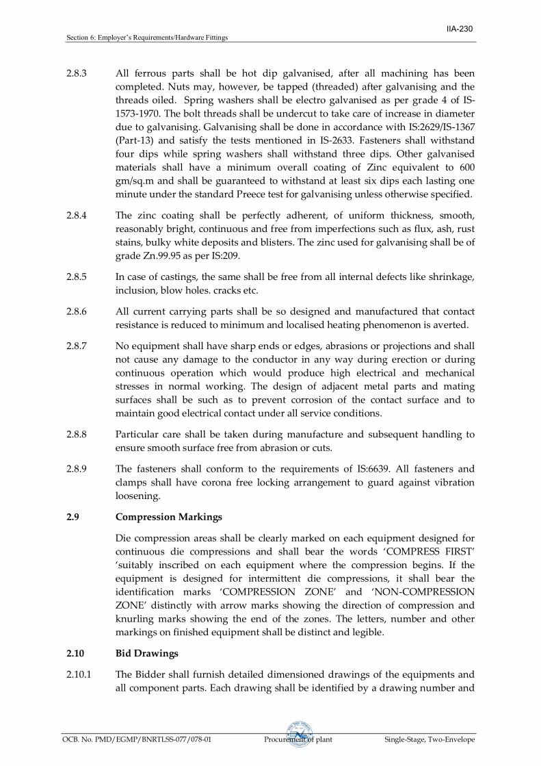
Section6:Employer’sRequirements/HardwareFittings
OCB. No. PMD/EGMP/BNRTLSS-077/078-01 Procurement of plant Single-Stage, Two-Envelope
2.8.3 All ferrous parts shall be hot dip galvanised, after all machining has been
completed. Nuts may, however, be tapped (threaded) after galvanising and the
threads oiled. Spring washers shall be electro galvanised as per grade 4 of IS-
1573-1970. The bolt threads shall be undercut to take care of increase in diameter
due to galvanising. Galvanising shall be done in accordance with IS:2629/IS-1367
(Part-13) and satisfy the tests mentioned in IS-2633. Fasteners shall withstand
four dips while spring washers shall withstand three dips. Other galvanised
materials shall have a minimum overall coating of Zinc equivalent to 600
gm/sq.m and shall be guaranteed to withstand at least six dips each lasting one
minute under the standard Preece test for galvanising unless otherwise specified.
2.8.4 The zinc coating shall be perfectly adherent, of uniform thickness, smooth,
reasonably bright, continuous and free from imperfections such as flux, ash, rust
stains, bulky white deposits and blisters. The zinc used for galvanising shall be of
grade Zn.99.95 as per IS:209.
2.8.5 In case of castings, the same shall be free from all internal defects like shrinkage,
inclusion, blow holes. cracks etc.
2.8.6 All current carrying parts shall be so designed and manufactured that contact
resistance is reduced to minimum and localised heating phenomenon is averted.
2.8.7 No equipment shall have sharp ends or edges, abrasions or projections and shall
not cause any damage to the conductor in any way during erection or during
continuous operation which would produce high electrical and mechanical
stresses in normal working. The design of adjacent metal parts and mating
surfaces shall be such as to prevent corrosion of the contact surface and to
maintain good electrical contact under all service conditions.
2.8.8 Particular care shall be taken during manufacture and subsequent handling to
ensure smooth surface free from abrasion or cuts.
2.8.9 The fasteners shall conform to the requirements of IS:6639. All fasteners and
clamps shall have corona free locking arrangement to guard against vibration
loosening.
2.9 Compression Markings
Die compression areas shall be clearly marked on each equipment designed for
continuous die compressions and shall bear the words ‘OMPRSS IRST’
‘suitably inscribed on each equipment where the compression begins. If the
equipment is designed for intermittent die compressions, it shall bear the
identification marks ‘OMPRSSION ZON’ and ‘NON-COMPRESSION
ZON’ distinctlywith arrow marks showing the direction of compression and
knurling marks showing the end of the zones. The letters, number and other
markings on finished equipment shall be distinct and legible.
2.10 Bid Drawings
2.10.1 The Bidder shall furnish detailed dimensioned drawings of the equipments and
all component parts. Each drawing shall be identified by a drawing number and
IIA-230

Section6:Employer’sRequirements/HardwareFittings
OCB. No. PMD/EGMP/BNRTLSS-077/078-01 Procurement of plant Single-Stage, Two-Envelope
Contract number. All drawings shall be neatly arranged. All drafting and
lettering shall be legible. The minimum size of lettering shall be 3 mm. All
dimensions and dimensional tolerances shall be mentioned in mm.
2.10.2 The drawings shall include
(i) Dimensions and dimensional tolerances
(ii) Material. fabrication details including any weld details and any specified
finishes and coatings. Regarding material, designations and reference of
standards are to be indicated.
(iii) Catalogue No.
(iv) Marking
(v) Weight of assembly
(vi) Installation instructions
(vii) Design installation torque for the bolt or cap screw
viii) Withstand torque that may be applied to the bolt or cap screw without
failure of component parts
(ix) The compression die number with recommended compression pressure.
(x) All other relevant technical details
2.10.3 Placement charts for spacer and damper
2.10.4 The above drawings shall be submitted with all the details as stated above along
with the bid document. After the placement of award. the Contractor shall again
submit the drawings in four copies to the Purchaser for approval. After
Purchaser’s approval and successful completion of all type tests, 10 (ten) more
sets of drawings shall be submitted to Purchaser for further distribution and field
useatPurchaser’send.
IIA-231

Section6:Employer’sRequirements/HardwareFittings
OCB. No. PMD/EGMP/BNRTLSS-077/078-01 Procurement of plant Single-Stage, Two-Envelope
3.0 G.S. Earth wire Accessories
3.1 General
3.1.1 This portion Specify the details of the technical particulars of the accessories for
Galvanised Steel Earth wire.
3.1.2 2.5% extra fasteners shall be supplied.
3.2 Mid Span Compression Joint
Mid Span Compression Joint shall be used for joining two lengths of earth wire.
The joint shall be made of mild steel with aluminium encasing. The steel sleeve
should not crack or fail during compression. The Brinnel Hardness of steel
should not exceed the value as stipulated in the Standard Technical Particulars.
The steel sleeve shall be hot dip galvanised. The aluminium sleeve shall have
aluminium of purity not less than that stipulated in the Standard Technical
Particulars. Filler aluminium sleeve shall also be provided at the both ends. The
joints shall not permit slipping off, damage to or failure of the complete earth
wire or any part thereof at a load not less than 95% of the ultimate tensile
strength of the earth wire. The joint shall have resistivity less than 75% of
resistivity of equivalent length of earth wire. The dimensions and the
dimensional tolerances of the joint shall be as stipulated in the Standard
Technical Particulars.
3.3 Vibration Damper
3.3.1 Vibration dampers of 4R-Stockbridge type with four (4) different frequencies
spread within the specified aeolian frequency band-width corresponding to wind
speed of 1 m/s to 7 m/s shall be used for suspension and tension points on each
earth wire in each span to damp out aeolian vibrations as mentioned herein after.
3.3.2 lternatedampingsystemsor“ogbone”dampersofferingequivalentorbetter
performance also shall be acceptable provided the manufacturer meets the
qualifying requirements stipulated in the Specifications. Relevant technical
documents to establish the technical suitability of alternate systems shall be
furnished by the Bidder along with the bid.
3.3.3 One damper minimum on each side per earth wire at suspension points and two
dampers on each side per earth wire at tension points shall be used for ruling
design span as given is relevant clause of Section-I.
3.3.4 The Bidder may offer damping system involving more number of dampers per
ruling design span than the specified. However suitable price compensation shall
be considered for evaluation. For the purpose of price compensation 80% of
towers as suspension locations and 20% of the towers as tension locations and all
the spans assumed to be ruling design spans.
3.3.5 The clamp of the vibration damper shall be made of aluminium alloy. It shall be
capable of supporting the damper during installation and prevent damage or
chaffing of the earth wire during erection or continued operation. The clamp
IIA-232
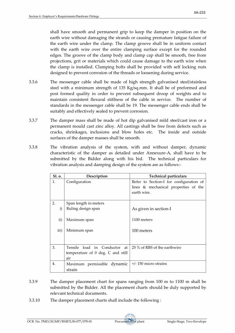
Section6:Employer’sRequirements/HardwareFittings
OCB. No. PMD/EGMP/BNRTLSS-077/078-01 Procurement of plant Single-Stage, Two-Envelope
shall have smooth and permanent grip to keep the damper in position on the
earth wire without damaging the strands or causing premature fatigue failure of
the earth wire under the clamp. The clamp groove shall be in uniform contact
with the earth wire over the entire clamping surface except for the rounded
edges. The groove of the clamp body and clamp cap shall be smooth, free from
projections, grit or materials which could cause damage to the earth wire when
the clamp is installed. Clamping bolts shall be provided with self locking nuts
designed to prevent corrosion of the threads or loosening during service.
3.3.6 The messenger cable shall be made of high strength galvanised steel/stainless
steel with a minimum strength of 135 Kg/sq.mm. It shall be of preformed and
post formed quality in order to prevent subsequent droop of weights and to
maintain consistent flexural stiffness of the cable in service. The number of
standards in the messenger cable shall be 19. The messenger cable ends shall be
suitably and effectively sealed to prevent corrosion.
3.3.7 The damper mass shall be made of hot dip galvanised mild steel/cast iron or a
permanent mould cast zinc alloy. All castings shall be free from defects such as
cracks, shrinkages, inclusions and blow holes etc. The inside and outside
surfaces of the damper masses shall be smooth.
3.3.8 The vibration analysis of the system, with and without damper, dynamic
characteristic of the damper as detailed under Annexure-A, shall have to be
submitted by the Bidder along with his bid. The technical particulars for
vibration analysis and damping design of the system are as follows:-
Sl. o. Description Technical particulars
1. Configuration Refer to Section-I for configuration of
lines & mechanical properties of the
earth wire.
2. Span length in meters
i) Ruling design span As given in section-I
ii) Maximum span 1100 meters
iii) Minimum span 100 meters
3. Tensile load in Conductor at
temperature of 0 deg. C and still
air
25 % of RBS of the earthwire
4. Maximum permissible dynamic
strain
+/- 150 micro strains
3.3.9 The damper placement chart for spans ranging from 100 m to 1100 m shall be
submitted by the Bidder. All the placement charts should be duly supported by
relevant technical documents.
3.3.10 The damper placement charts shall include the following :
IIA-233

Section6:Employer’sRequirements/HardwareFittings
OCB. No. PMD/EGMP/BNRTLSS-077/078-01 Procurement of plant Single-Stage, Two-Envelope
(1) Location of the dampers for various combinations of spans and line tensions
clearly indicating number of dampers to be installed per earth wire per span.
(2) Placement distances clearly identifying the extremities between which the
distances are to be measured.
(3) Placement recommendation depending upon type of suspension clamps (viz,
free center type/trunion type etc.)
(4) The influence of mid span compression joints in the placement of dampers.
3.4 Flexible Aluminium Bond
The flexible aluminium bond shall be manufactured from multi strand multi wire
fatigue resistant Aluminium alloy to IEC 60104 9Type-b)/ IS 398 (Part-4) with a
minimum cross sectional area of 95 sq.mm and not less than 750 mm in length
The bond shall be flexible so as not to interfere with the clamp movement, shall
be terminated with copmresed lugs. One lug shall be suitable for 12 mm, dia. bolt
and the other for 16 mm dia bolt. The complete assembly shall also include one
16 mm dia., 40 mm long HRH MS Bolt hot dip galvanised with nut and lock
washer.
3.5 Suspension Clamp
3.5.1 Standard anchor shackle/twisted shackle for earth wire suspension clamp shall be
supplied for attaching to the hanger plate of tower.
3.5.2 At all suspension towers, suitable suspension clamps shall be used to support the
required earth wire. The clamps shall be of either free center type or trunion type
and shall provide adequate area of support to the earth wire. The groove of the
clamp shall be smooth, finished in an uniform circular or oval shape and shall
slope downwards in a smooth curve to avoid edge support and hence to reduce
the intensity of bending moment on earth wire.
3.5.3 There shall be no sharp point in the clamps coming in contact with earth wire.
There shall not be any displacement in the configuration of the earth wire strands
nor shall the strands be unduly stressed in final assembly during working
conditions.
3.5.4 The clamping piece and the clamp body shall be clamped by at least two U-bolts
of size not less than 10 mm diameter having one nut and one 3 mm thick lock nut
with washer on each of its limbs. Suspension clamps shall be provided with
inverted type U-bolts. One limb of the U-bolt shall be long enough to
accommodate the lug of the flexible copper bond.
3.5.5 The Contractor shall supply all the components of the suspension assembly
including shackles, bolts, nuts, washers, split pin etc. The total drop of the
suspension assembly from the center point of the attachment to the center point
of the earth wire shall not exceed 150 mm. The design of the assembly shall be
such that the direction of run of the earth wire shall be same as that of the
conductor.
IIA-234

Section6:Employer’sRequirements/HardwareFittings
OCB. No. PMD/EGMP/BNRTLSS-077/078-01 Procurement of plant Single-Stage, Two-Envelope
3.5.6 The complete assembly shall be guaranteed for slip strength of not less than 12
KN and not more than 17 kN for 7/3.66 mm GS Earthwire and not less than 9 KN
and not more than 14 KN for 7/3.15 mm GS Earthwire. The breaking strength of
the assembly shall not be less than 25 kN.
3.6 Tension Clamp
3.6.1 At all tension towers suitable compression type tension clamps shall be used to
hold the required galvanised steel earth wire. Anchor shackle shall be supplied
which shall be suitable for attaching the tension clamp to strain plates.
3.6.2 The clamps shall have adequate area of bearing surface to ensure positive
electrical and mechanical contact and shall not permit any slip to the earth wire
under working tension and vibration conditions. The angle of jumper terminal to
be mounted should be 30 deg. with respect to the vertical line.
3.6.3 The clamps shall be made of mild steel with aluminium encasing. The steel
should not crack or fail during compression. The Brinnel hardness of steel sleeve
shall not exceed 200. The steel sleeve shall be hot dip galvanised. The aluminium
encasing shall have aluminium of purity not less than 99.5%. Filler aluminium
sleeve shall also be provided at the end.
3.6.4 The complete assembly shall be so designed as to avoid undue bending in any
part of the clamp and shall not produce any hindrance to the movements of the
clamps in horizontal or vertical directions.
3.6.5 The slip strength of the assembly shall not be less than 95% of the ultimate
strength of the earth wire.
3.6.6 The clamps shall be complete with all the components including anchor shackle,
bolts, nuts, washers, split pin, jumper arrangement etc.
3.7 Material and Workmanship
Same as Clause 2.8 of this section
3.8 Compression Marking
Same as Clause 2.9 of this section
3.9 Bid Drawings
3.1.1 Same as Clause 2.10 of this section
4.0 Standard Technical Particulars 4.1 The Standard technical particulars to adhered by the contractor / manufacturer
are furnished in annexure-C of this section.
5.0 Tests and Standards
5.1 Type Tests
5.1.1 On the complete Insulator String with Hardware Fittings
IIA-235

Section6:Employer’sRequirements/HardwareFittings
OCB. No. PMD/EGMP/BNRTLSS-077/078-01 Procurement of plant Single-Stage, Two-Envelope
a) Power frequency voltage withstand test with
corona control rings/grading ring and arcing horns
under wet condition
: As per IEC:383
b) Switching surge voltage withstand test under wet
condition (for 220 kV & above voltage level line
only)
: As per IEC:383
c) Impulse voltage withstand test under dry condition : As per IEC:383
d) Corona and RIV test under dry condition (for 220
kV & above voltage level line only)
: As per Annexure-A
e) Mechanical Strength test : As per Annexure-A
f) Vibration test : As per Annexure-A
Note:
1) All the type test given in Clause No. 5.1.1 shall be conducted on following
insulator string along with hardware fittings:-
A) On insulator strings along with hardware fittings for 200 kV line with
twin bundle conductor:-
§ Single 'I' suspension &
§ Double Tension insulator string.
B) On insulator strings along with hardware fittings for 220 kV line:-
§ Single 'I' suspension &
§ Single Tension insulator string.
C) On insulator strings along with hardware fittings for 132 kV line:-
§ Single 'I' suspension &
§ Single Tension insulator string.
2)All the type tests given under Clause No. 5.1.1.1 (a) to (e) for composite
long rod insulator string for lines upto 220 kV shall also be conducted
following insulator string along with hardware fittings:-
A) On insulator strings along with hardware fittings for 220 kV line with
twin bundle conductor:-
§ Single suspension Pilot &
§ Single Tension insulator string.
§ ouble‘V’Suspensionforrivercrossingtowers
§ Triple Tension for river crossing towers
B) On insulator strings along with hardware fittings for 220 line:-
§ Single suspension Pilot insulator string,
§ ouble‘I’suspension insulator string &
IIA-236

Section6:Employer’sRequirements/HardwareFittings
OCB. No. PMD/EGMP/BNRTLSS-077/078-01 Procurement of plant Single-Stage, Two-Envelope
§ Double Tension insulator string.
C) On insulator strings along with hardware fittings for 132 line:-
§ ouble‘I’suspensioninsulatorstring&
§ Double Tension insulator string.
5.1.2 On Suspension Hardware Fitting only
a) Visual examination & Dimensional and
material Verification
: IEC:61824, Clause 7 & 8
b) Magnetic power loss test for suspension
clamp
: As per Annexure-A
c) Clamp slip test for suspension clamp : IEC:61824, Clause 11.4.2
d) Vertical damage load & Failure load test
for suspension clamp
: IEC:61824, Clause 11.4.1
e) Ozone resistance Test on elastomer : IEC:61824
5.1.3 On Tension Hardware Fitting only
a) Visual examination & Dimensional and
material Verification
: IEC:61824, Clause 7 & 8
b) Heating cycle test for dead end Assembly : IEC:61824, Clause 13
c) Mechanical Damage & Failure load Test
(excluding clamp)
: IEC:61824, Clause 11.5.2
d) Tensile test for dead-end clamp : IEC:61824, Clause 11.5.1
5.1.4 On Mid Span Compression Joint for Conductor and Earthwire
a) Visual examination & Dimensional and
material Verification
: IEC:61824, Clause 7 & 8
b) Heating cycle test : IEC:61824, Clause 13
c) Tensile test : IEC:61824, Clause 11.5.1
d) Corona extinction voltage test (dry) (for
220 kV & above voltage level line only)
: As per Annexure-A
e) Radio interference voltage test (dry) (for
220 kV & above voltage level line only)
: As per Annexure-A
Note: Tests mentioned at (b), (d) & (e) are not applicable for Mid Span
Compression Joints for earthwire.
IIA-237

Section6:Employer’sRequirements/HardwareFittings
OCB. No. PMD/EGMP/BNRTLSS-077/078-01 Procurement of plant Single-Stage, Two-Envelope
5.1.5 On T-Connector for Conductor
a) Visual examination & Dimensional and
material Verification
: IEC:61824, Clause 7 & 8
b) Heating cycle test :IEC:61824, Clause 13
c) Tensile test :IEC:61824, Clause 11.6.2
d) Axial tensile load test on welded portion : As per Annexure-A
e) Corona extinction voltage test (dry) : As per Annexure-A
f) Radio interference voltage test (dry) : As per Annexure-A
5.1.6 On Repair Sleeve for Conductor
a) Visual examination & Dimensional and
material Verification
: IEC:61824, Clause 7 & 8
b) Tensile test : IEC:61824, Clause 11.6.1
c) Corona extinction voltage test (dry) (for
220 kV & above voltage level line only)
: As per Annexure-A
d) Radio interference voltage test (dry) (for
220 kV & above voltage level line only)
: As per Annexure-A
5.1.7 On Flexible Aluminium Bond
a) Visual examination & Dimensional and
material Verification
: IEC:61824, Clause 7 & 8
a) Slip strength test : As per Annexure-A
5.1.8 On Vibration Damper for Conductor and Earthwire
a) Visual examination & Dimensional and
material Verification
:IEC:61897, Clause 7.1 &
7.2
b) Dynamic characteristics test : As per Annexure-A
c) Vibration analysis : As per Annexure-A
d) Clamp slip test :IEC:61897, Clause 7.5
e) Clamp bolt tightening test :IEC:61897, Clause 7.7
f) Attachment of weights to messenger cable :IEC:61897, Clause 7.8
g) Attachment of clamp to Messenger cable :IEC:61897, Clause 7.8
IIA-238

Section6:Employer’sRequirements/HardwareFittings
OCB. No. PMD/EGMP/BNRTLSS-077/078-01 Procurement of plant Single-Stage, Two-Envelope
h) Fatigue tests : As per Annexure-A
i) Magnetic power loss test : As per Annexure-A
j) Corona extinction voltage test (dry) (for
220 kV & above voltage level line only)
: As per Annexure-A
k) Radio interference voltage test (dry) (for
220 kV & above voltage level line only)
: As per Annexure-A
l) Damper effectiveness evaluation :IEC:61897, Clause 7.11.3.2
Note: Tests mentioned at (i), (j) & (k) are not applicable for Vibration Damper
for earthwire.
5.1.9 On Spacer/Rigid Spacer for bundle conductor
a) Visual examination & Dimensional and
material Verification
:IEC:61854, Clause 7.1 &
7.2
b) Clamp slip test : As per Annexure-A
c) Clamp bolt tightening test (if applicable) :IEC:61854, Clause 7.3
d) Vibration test : As per Annexure-A
i) Vertical Vibration
ii) Longitudinal Vibration
iii) Sub span oscillation
e) Magnetic power loss test (if applicable) : As per Annexure-A
f) Tension-compression Test : As per Annexure-A
g) Corona extinction voltage test (dry) : As per Annexure-A
i) Radio interference voltage test (dry) : As per Annexure-A
h) Ozone test IEC:61854, Clause 7.3
Note: Tests mentioned at (d) & (i) are not applicable for Rigid Spacer
5.1.10 On Spacer Damper for Line (For twin bundle conductor)
a) Visual examination & Dimensional and
material Verification
:IEC:61854, Clause 7.1 &
7.2
b) Clamp slip test : As per Annexure-A
c) Clamp slip test : As per Annexure-A
d) Clamp bolt tightening test (if applicable) :IEC:61854, Clause 7.3
IIA-239

Section6:Employer’sRequirements/HardwareFittings
OCB. No. PMD/EGMP/BNRTLSS-077/078-01 Procurement of plant Single-Stage, Two-Envelope
i) Aeolian
ii) sub span oscillations
e) Magnetic power loss test : As per Annexure-A
f) Characteristics of the Elastic & Damping
Properties
g) Fatigue (Sub span Oscillation) test :IEC:61854, Clause 7.5.7.2
h) Tension-compression Test : As per Annexure-A
i) Corona extinction voltage test (dry) : As per Annexure-A
j) Radio interference voltage test (dry) : As per Annexure-A
k) Ozone test on elastomer :IEC:61854, Clause 7.6.3
5.1.11 On Earthwire Suspension clamp Assembly
a) Visual examination & Dimensional and
material Verification
: IEC:61824, Clause 7 & 8
c) Vertical damage load & Failure load test
for suspension clamp
: IEC:61824, Clause 11.4.1
c) Clamp slip test for suspension clamp : IEC:61824, Clause 11.4.2
5.1.12 On Earthwire Tension clamp Assembly
a) Visual examination & Dimensional and
material Verification
: IEC:61824, Clause 7 & 8
b) Mechanical Damage & Failure load Test
(excluding clamp)
: IEC:61824, Clause 11.5.2
5.1.13
c) Tensile test for dead-end clamp : IEC:61824, Clause 11.5.1
Type tests specified under Clause 5.1.1 to 5.1.12 shall not be required to be
carried out if a valid test certificate is available for a similar design, i.e., tests
conducted earlier should have been conducted in accredited laboratory
(accredited based on ISO/IEC guide 25/17025 or EN 45001 by the National
Accreditation body of the country where laboratory is located) or witnessed by
the representative (s) of NEA/POWERGRID or Utility.
In the event of any discrepancy in the test report (i.e., any test report not
applicable due to any design / material/manufacturing process change
including substitution of components or due to non compliance with the
requirement stipulated in the Technical Specification) the tests shall be
conducted by the Contractor at no extra cost to the Owner.
IIA-240
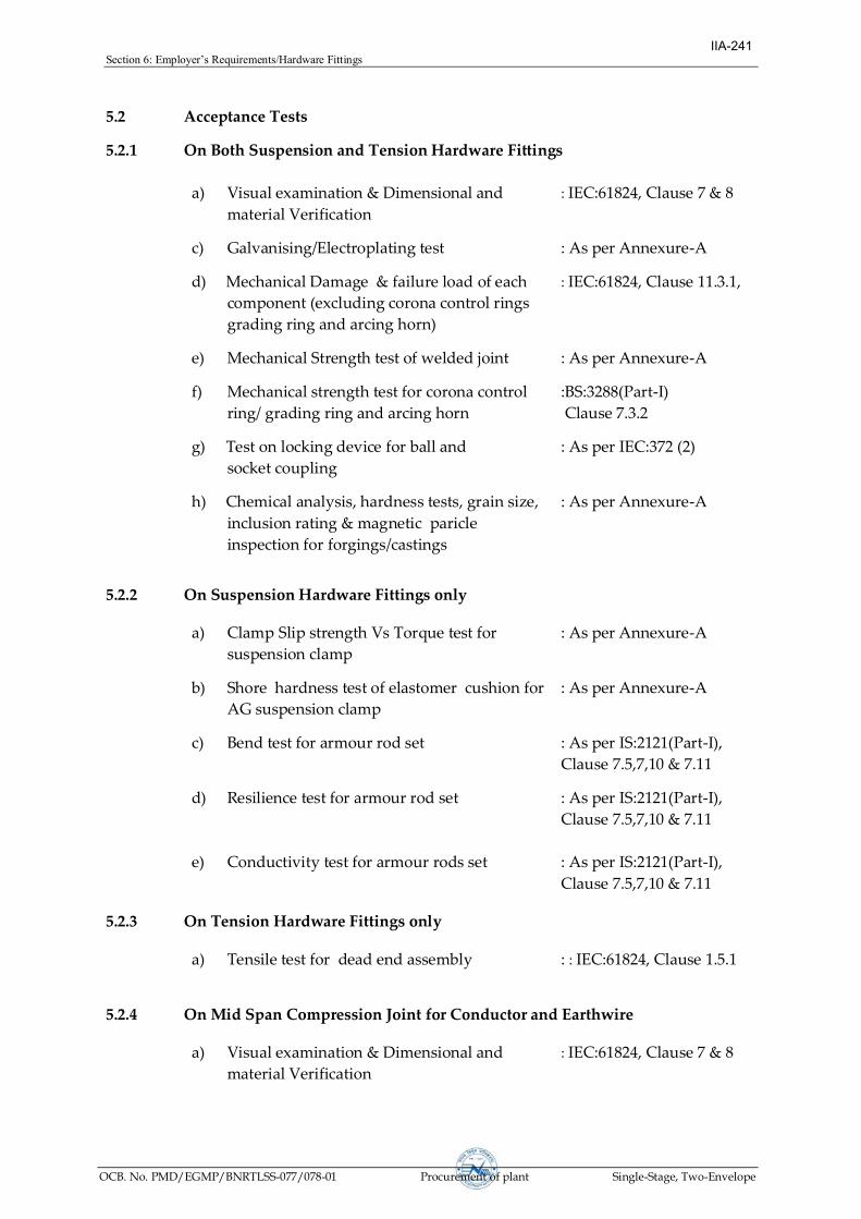
Section6:Employer’sRequirements/HardwareFittings
OCB. No. PMD/EGMP/BNRTLSS-077/078-01 Procurement of plant Single-Stage, Two-Envelope
5.2 Acceptance Tests
5.2.1 On Both Suspension and Tension Hardware Fittings
a) Visual examination & Dimensional and
material Verification
: IEC:61824, Clause 7 & 8
c) Galvanising/Electroplating test : As per Annexure-A
d) Mechanical Damage & failure load of each
component (excluding corona control rings
grading ring and arcing horn)
: IEC:61824, Clause 11.3.1,
e) Mechanical Strength test of welded joint : As per Annexure-A
f) Mechanical strength test for corona control
ring/ grading ring and arcing horn
:BS:3288(Part-I)
Clause 7.3.2
g) Test on locking device for ball and
socket coupling
: As per IEC:372 (2)
h) Chemical analysis, hardness tests, grain size,
inclusion rating & magnetic paricle
inspection for forgings/castings
: As per Annexure-A
5.2.2 On Suspension Hardware Fittings only
a) Clamp Slip strength Vs Torque test for
suspension clamp
: As per Annexure-A
b) Shore hardness test of elastomer cushion for
AG suspension clamp
: As per Annexure-A
c) Bend test for armour rod set : As per IS:2121(Part-I),
Clause 7.5,7,10 & 7.11
d) Resilience test for armour rod set : As per IS:2121(Part-I),
Clause 7.5,7,10 & 7.11
e) Conductivity test for armour rods set : As per IS:2121(Part-I),
Clause 7.5,7,10 & 7.11
5.2.3 On Tension Hardware Fittings only
a) Tensile test for dead end assembly : : IEC:61824, Clause 1.5.1
5.2.4 On Mid Span Compression Joint for Conductor and Earthwire
a) Visual examination & Dimensional and
material Verification
: IEC:61824, Clause 7 & 8
IIA-241

Section6:Employer’sRequirements/HardwareFittings
OCB. No. PMD/EGMP/BNRTLSS-077/078-01 Procurement of plant Single-Stage, Two-Envelope
b) Galvanising test : As per Annexure-B
c) Hardness test : As per Annexure-B
5.2.5 T-Connector for Conductor
a) Visual examination & Dimensional and
material Verification
: IEC:61824, Clause 7 & 8
b) Tensile test : IEC:61824, Clause 11.6.2
c) Axial tensile load test for welded portion : As per Annexure-A
5.2.6 Repair Sleeve for Conductor
a) Visual examination & Dimensional and
material Verification
: IEC:61824, Clause 7 & 8
b) Tensile test : IEC:61824, Clause 11.6.1
5.2.7 Flexible Aluminium Bond
a) Visual examination & Dimensional and
material Verification
: IEC:61824, Clause 7 & 8
b) Slip strength test : As per annexure-B
5.2.8 Vibration Damper for Conductor and Earthwire
a) Visual examination & Dimensional and
material Verification
: IEC:61897, Clause 7.1 &
7.2
b) Galvanising test : IEC:61897, Clause 7.3
(i) On damper masses
ii) On messenger cable
c) Clamp slip test :IEC:61897, Clause 7.5
d) Clamp bolt tightening test :IEC:61897, Clause 7.7
e) Attachment of weights to messenger cable :IEC:61897, Clause 7.8
f) Attachment of clamp to Messenger cable :IEC:61897, Clause 7.8
g) Verification of resonance frequencies : As per Annexure-B
h) Strength of the messenger cable : As per Annexure-B
i) Dynamic characteristics test : As per Annexure-B
IIA-242

Section6:Employer’sRequirements/HardwareFittings
OCB. No. PMD/EGMP/BNRTLSS-077/078-01 Procurement of plant Single-Stage, Two-Envelope
5.2.9 Spacer Damper/ Bundle Spacer for line / Rigid spacer for Jumper
a) Visual examination & Dimensional and
material Verification
: IEC:61854, Clause 7.1 &
7.2
b) Galvanising test : As per Annexure-B
c) Movement test (except for spacer jumpers) : As per Annexure-B
d) Clamp slip test : As per Annexure-B
e) Clamp bolt tightening torque : IEC:61854, Clause 7.5.3
f) Compression-tension test : As per Annexure-B
g) Assembly torque test : As per Annexure-B
h) Hardness test for elastomer ( if applicable) : As per Annexure-B
i) UTS of retaining rods( if applicable) : As per Annexure-B
5.2.10 Earthwire Tension Clamp Assembly
a) Visual examination & Dimensional and
material Verification
: IEC:61824, Clause 7 & 8
b) Galvanising test : As per Annexure-A
c) Slip strength test for tension clamp : As per Annexure-A
d) Mechanical Damage & failure load of each
component (excluding corona control rings
grading ring and arcing horn)
: IEC:61824, Clause 11.3.1,
5.2.11 Earthwire Suspension Clamp Assembly
a) Visual examination & Dimensional and
material Verification
: IEC:61824, Clause 7 & 8
b) Galvanising test : As per Annexure-A
c) Clamp slip strength test : As per Annexure-A
d) Mechanical Damage & failure load of each
component (excluding clamp)
: IEC:61824, Clause 11.5.1
5.3 Routine Tests
5.3.1 For Hardware Fittings
IIA-243
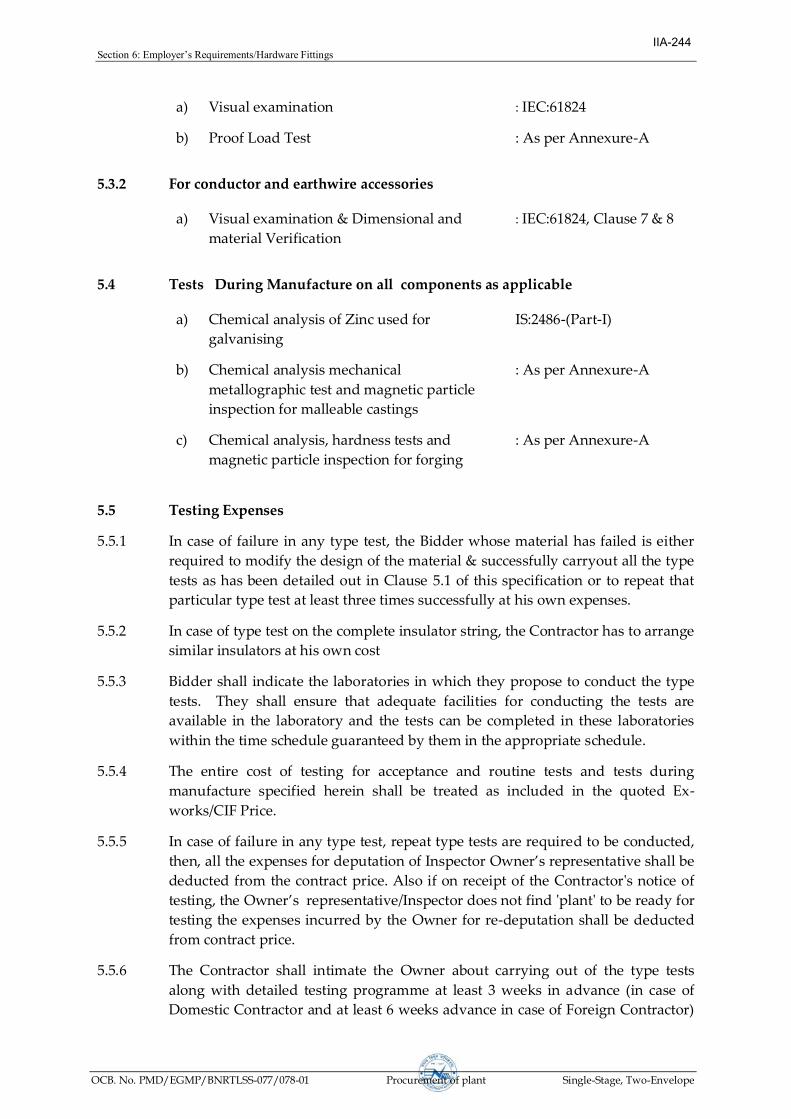
Section6:Employer’sRequirements/HardwareFittings
OCB. No. PMD/EGMP/BNRTLSS-077/078-01 Procurement of plant Single-Stage, Two-Envelope
a) Visual examination : IEC:61824
b) Proof Load Test : As per Annexure-A
5.3.2 For conductor and earthwire accessories
a) Visual examination & Dimensional and
material Verification
: IEC:61824, Clause 7 & 8
5.4 Tests During Manufacture on all components as applicable
a) Chemical analysis of Zinc used for
galvanising
IS:2486-(Part-I)
b) Chemical analysis mechanical
metallographic test and magnetic particle
inspection for malleable castings
: As per Annexure-A
c) Chemical analysis, hardness tests and
magnetic particle inspection for forging
: As per Annexure-A
5.5 Testing Expenses
5.5.1 In case of failure in any type test, the Bidder whose material has failed is either
required to modify the design of the material & successfully carryout all the type
tests as has been detailed out in Clause 5.1 of this specification or to repeat that
particular type test at least three times successfully at his own expenses.
5.5.2 In case of type test on the complete insulator string, the Contractor has to arrange
similar insulators at his own cost
5.5.3 Bidder shall indicate the laboratories in which they propose to conduct the type
tests. They shall ensure that adequate facilities for conducting the tests are
available in the laboratory and the tests can be completed in these laboratories
within the time schedule guaranteed by them in the appropriate schedule.
5.5.4 The entire cost of testing for acceptance and routine tests and tests during
manufacture specified herein shall be treated as included in the quoted Ex-
works/CIF Price.
5.5.5 In case of failure in any type test, repeat type tests are required to be conducted,
then, all the expenses for deputation of Inspector Owner’s representative shall be
deducted from the contract price. Also if on receipt of the Contractor's notice of
testing, the Owner’s representative/Inspector does not find 'plant' to be ready for
testing the expenses incurred by the Owner for re-deputation shall be deducted
from contract price.
5.5.6 The Contractor shall intimate the Owner about carrying out of the type tests
along with detailed testing programme at least 3 weeks in advance (in case of
Domestic Contractor and at least 6 weeks advance in case of Foreign Contractor)
IIA-244

Section6:Employer’sRequirements/HardwareFittings
OCB. No. PMD/EGMP/BNRTLSS-077/078-01 Procurement of plant Single-Stage, Two-Envelope
of the scheduled date of testing during which the Owner will arrange to depute
his representative to be present at the time of carrying out the tests.
5.6 Sample Batch For Type Testing
5.6.1 The Contractor shall offer material for sample selection for type testing only after
getting Quality Assurance Programme approved by the Owner. The Contractor
shall offer at least three times the quantity of materials required for conducting
all the type tests for sample selection. The sample for type testing will be
manufactured strictly in accordance with the Quality Assurance Programme
approved by the Owner.
5.6.2 Before sample selection for type testing the Contractor shall be required to
conduct all the acceptance tests successfully in presence of Owner's
representative.
5.7 Schedule of Testing and Additional Tests
5.7.1 The Bidder has to indicate the schedule of following activities in their bids
(a) Submission of drawing for approval.
(b) Submission of Quality Assurance programme for approval.
(c) Offering of material for sample selection for type tests.
(d) Type testing.
5.7.2 The Owner reserves the right of having at his own expense any other test(s) of
reasonable nature carried out at ontractor’s premises, at site, or in any other
place in addition to the aforesaid type, acceptance and routine tests to satisfy
himself that the material comply with the specifications.
5.7.3 The Owner also reserves the right to conduct all the tests mentioned in this
specification at his own expense on the samples drawn from the site at
ontractor’s premises or at any other test center. In case of evidence of non
compliance, it shall be binding on the part of Contractor to prove the compliance
of the items to the technical specifications by repeat tests, or correction of
deficiencies, or replacement of defective items, all without any extra cost to the
Owner.
5.8 Co-ordination for testing
The Contractors shall have to co-ordinate testing of their hardware fittings with
insulators to be supplied by other Supplier to the Owner and shall have to also
guarantee overall satisfactory performance of the hardware fittings with the
insulators.
5.9 Test Reports
5.9.1 Copies of type test reports shall be furnished in at least six copies along with one
original. One copy shall be returned duly certified by the Owner, only after
which the commercial production of the concerned material shall start.
IIA-245

Section6:Employer’sRequirements/HardwareFittings
OCB. No. PMD/EGMP/BNRTLSS-077/078-01 Procurement of plant Single-Stage, Two-Envelope
5.9.2 Copies of acceptance test report shall be furnished in at least six copies. One copy
shall be returned, duly certified by the Owner, only after which the materials
will be dispatched.
5.9.3 Record of routine test report shall be maintained by the Contractor at his works
for periodic inspection by the Owner's representative.
5.9.4 Test certificates of tests during manufacture shall be maintained by the
Contractor. These shall be produced for verification as and when desired by the
Owner.
5.10 Inspection
5.10.1 The Owner's representative shall at all times be entitled to have access to the
works and all places of manufacture, where the material and/or its component
parts shall be manufactured and the representatives shall have full facilities for
unrestricted inspection of theontractor’s,sub-ontractor’sworksrawmaterials.
manufacturer’sofallthematerialandforconductingnecessarytestsasdetailed
herein.
5.10.2 The material for final inspection shall be offered by the Contractor only under
packed condition as detailed in clause 5.11 of this part of the Specification. The
engineer shall select samples at random from the packed lot for carrying out
acceptance tests.
5.10.3 The Contractor shall keep the Owner informed in advance of the time of starting
and of the progress of manufacture of material in its various stages so that
arrangements could be made for inspection.
5.10.4 Material shall not be despatched from its point of manufacture before it has been
satisfactorily inspected and tested unless the inspection is waived off by the
Owner in writing. In the latter case also the material shall be despatched only
after all tests specified herein have been satisfactorily completed.
5.10.5 The acceptance of any quantity of material shall in no way relieve the Contractor
of his responsibility for meeting all the requirements of the Specification, and
shall not prevent subsequent rejection, if such material are later found to be
defective.
5.11 Packing and Marking
5.11.1 All material shall be packed in strong and weather resistant wooden cases/crates.
The gross weight of the packing shall not normally exceed 200 Kg to avoid
handling problems.
5.11.2 The packing shall be of sufficient strength to withstand rough handling during
transit, storage at site and subsequent handling in the field.
5.11.3 Suitable cushioning, protective padding, dunnage or spacers shall be provided to
prevent damage or deformation during transit and handling.
IIA-246
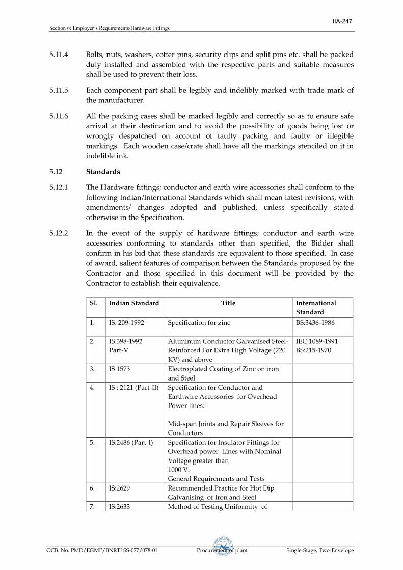
Section6:Employer’sRequirements/HardwareFittings
OCB. No. PMD/EGMP/BNRTLSS-077/078-01 Procurement of plant Single-Stage, Two-Envelope
5.11.4 Bolts, nuts, washers, cotter pins, security clips and split pins etc. shall be packed
duly installed and assembled with the respective parts and suitable measures
shall be used to prevent their loss.
5.11.5 Each component part shall be legibly and indelibly marked with trade mark of
the manufacturer.
5.11.6 All the packing cases shall be marked legibly and correctly so as to ensure safe
arrival at their destination and to avoid the possibility of goods being lost or
wrongly despatched on account of faulty packing and faulty or illegible
markings. Each wooden case/crate shall have all the markings stenciled on it in
indelible ink.
5.12 Standards
5.12.1 The Hardware fittings; conductor and earth wire accessories shall conform to the
following Indian/International Standards which shall mean latest revisions, with
amendments/ changes adopted and published, unless specifically stated
otherwise in the Specification.
5.12.2 In the event of the supply of hardware fittings; conductor and earth wire
accessories conforming to standards other than specified, the Bidder shall
confirm in his bid that these standards are equivalent to those specified. In case
of award, salient features of comparison between the Standards proposed by the
Contractor and those specified in this document will be provided by the
Contractor to establish their equivalence.
Sl. Indian Standard Title International
Standard
1. IS: 209-1992 Specification for zinc BS:3436-1986
2. IS:398-1992
Part-V
Aluminum Conductor Galvanised Steel-
Reinforced For Extra High Voltage (220
KV) and above
IEC:1089-1991
BS:215-1970
3. IS 1573 Electroplated Coating of Zinc on iron
and Steel
4. IS : 2121 (Part-II) Specification for Conductor and
Earthwire Accessories for Overhead
Power lines:
Mid-span Joints and Repair Sleeves for
Conductors
5. IS:2486 (Part-I) Specification for Insulator Fittings for
Overhead power Lines with Nominal
Voltage greater than
1000 V:
General Requirements and Tests
6. IS:2629 Recommended Practice for Hot Dip
Galvanising of Iron and Steel
7. IS:2633 Method of Testing Uniformity of
IIA-247

Section6:Employer’sRequirements/HardwareFittings
OCB. No. PMD/EGMP/BNRTLSS-077/078-01 Procurement of plant Single-Stage, Two-Envelope
Sl. Indian Standard Title International
Standard
Coating on Zinc Coated Articles
8. Ozone test on Elastomer ASTM- D1 171
9. Tests on insulators of Ceramic material
or glass for overhead lines with a
nominal voltage greater than 1000V
IEC:383-1993
10. IS:4826 Galvanised Coating on Round Steel
Wires
ASTM A472-729
BS:443-1969
11. IS:6745 Methods of Determination of Weight of
Zinc Coating of Zinc Coated Iron and
Steel Articles
BS:433
ISO : 1460 (E)
12. IS:8263 Method of Radio Interference Tests on
High Voltage Insulators
IEC:437
NEMA:107
CISPR
13. IS:6639 Hexagonal Bolts for Steel Structures ISO/R-272
14. IS:9708 Specification for Stock Bridge Vibration
Dampers for Overhead Power Lines
15. IS:10162 Specification for Spacers Dampers for
Twin Horizontal Bundle Conductors
The standards mentioned above are available from:
Reference Abbreviation
Name and Address
BS British Standards,
British Standards Institution
101, Pentonvile Road,
N - 19-ND
UK
IEC/CISPR International Electro technical Commission,
Bureau Central de la Commission,
electro Technique international,
1 Rue de verembe,
Geneva
SWITZERLAND
BIS/IS Beureau Of Indian Standards.
Manak Bhavan,
9, Bahadur Shah Zafar Marg,
New Delhi - 110001.
INDIA
IIA-248

Section6:Employer’sRequirements/HardwareFittings
OCB. No. PMD/EGMP/BNRTLSS-077/078-01 Procurement of plant Single-Stage, Two-Envelope
ISO International Organisation for
Standardization.
Danish Board of Standardization
Danish Standardizing Sraat,
Aurehoegvej-12
DK-2900, Heeleprup,
DENMARK.
NEMA National Electric Manufacture Association,
155, East 44th Street.
New York, NY 10017
U.S.A.
IIA-249

Section6:Employer’sRequirements/HardwareFittings
OCB. No. PMD/EGMP/BNRTLSS-077/078-01 Procurement of plant Single-Stage, Two-Envelope
ANNEXURE - A
1.0 Tests on Complete Strings with Hardware Fittings
1.1 Corona Extinction Voltage Test (Dry)
The sample assembly when subjected to power frequency voltage shall have a
corona Extinction voltage, line to ground under dry condition shall not be less
than following value for different voltage level lines. . There shall be no evidence
of corona on any part of the sample. The atmospheric condition during testing
shall be recorded and the test results; shall be accordingly corrected with suitable
correction factor as stipulated in IEC:60383.
SL. NO. VOLTAGE LEVEL OF LINE MINIMUM CORONA
EXTINCTION VOLTAGE
1. 765 kV 510 kV line to ground
2. 400 kV 320 kVine to ground
3. 220 kV NA
4. 132 kV NA
1.2 RIV Test (Dry)
Under the conditions as specified under (1.2) above, the insulator string along
with complete hardware fittings shall have a radio interference voltage level
below 1000 micro volts at one MHz when subjected to 50 Hz AC voltage of 510
kV line to ground for 765 kV lines and 305 kV line to ground under dry condition
for 220 kV line. The test procedure shall be in accordance with IS:8263/IEC:437.
1.3 Mechanical Strength Test (for line upto 220 kV voltage level only)
The complete insulator string along with its hardware fitting excluding arcing
horn, corona control ring, grading ring and suspension assembly/dead end
assembly shall be subjected to a load equal to 50% of the specified minimum
ultimate tensile strength (UTS) which shall be increased at a steady rate to 67% of
the minimum UTS specified. The load shall be held for five minutes and then
removed. After removal of the load, the string components shall not show any
visual deformation and it shall be possible to disassemble them by hand. Hand
tools may be used to remove cotter pins and loosen the nuts initially. The string
shall then be reassembled and loaded to 50% of UTS and the load shall be further
increased at a steady rate till the specified minimum UTS and held for one
minute. No fracture should occur during this period. The applied load shall
then be increased until the failing load is reached and the value recorded.
IIA-250

Section6:Employer’sRequirements/HardwareFittings
OCB. No. PMD/EGMP/BNRTLSS-077/078-01 Procurement of plant Single-Stage, Two-Envelope
1.4 Vibration Test
The suspension string shall be tested in suspension mode, and tension string in
tension mode itself in laboratory span of minimum 30 meters. In the case of
suspension string a load equal to 600 kg shall be applied along the axis of the
suspension string by means of turn buckle. The insulator string along with
hardware fittings, with each sub conductor tensioned at 25 % of RTS of the
conductor, shall be secured them with clamps. The system shall be suitable to
maintain constant tension on each sub-conductors throughout the duration of the
test. Vibration dampers shall not be used on the test span. Both the sub-
conductors shall be vertically vibrated simultaneously at one of the resonance
frequencies of the insulators string (more than 10 Hz) by means of vibration
inducing equipment. The peak to peak displacement in mm of vibration at the
antinode point nearest to the string shall be measured and the same shall not be
less than 1000/f18 where f is the frequency of vibration in cycles/sec. The
insulator string shall be vibrated for not less than 10 million cycles without any
failure. After the test the hardware shall be examined for looseness, fatigue
failure and mechanical strength test. There shall be no deterioration of properties
of hardware components after the vibration test.
1.5 Assembly Test
This test shall be carried out to ensure that the cotter pins, bolts, clamps etc., fit
freely and properly.
2.0 Tests on Hardware Fittings
2.1 Magnetic Power Loss Test for Suspension Assembly
2.1.1 For 220 kV line with Twin ACSR MOOSE conductor, four hollow aluminium
tubes of 32 mm diameter shall be placed 457 mm apart. An alternating current
over the range of 400 to 800 Amps for shall be passed through each tube. The
reading of the wattmeter with and without two suspension assemblies along
with line side yoke plate, clevis eye shall be recorded. Not less than three
suspension assemblies shall be tested. The average power loss for suspension
assembly shall be plotted for each value of current. The value of the loss
corresponding to 600 amperes shall be read off from the graph.
2.1.2 One hollow aluminium tubes of 30 mm diameter shall be used. An alternating
current over the range of 300 to 700 amps shall be passed through each tube. The
reading of the wattmeter with and without two suspension assemblies alongwith
line side yoke plate, clevis eye shall be recorded. Not less than three suspension
assemblies shall be tested. The average power loss for suspension assembly shall
be plotted for each value of current. The value of the loss corresponding to 500
amperes shall be read off from the graph.
2.1.3 One hollow aluminium tubes of 21 mm diameter shall be used. An alternating
current over the range of 200 to 500 amps shall be passed through each tube. The
reading of the wattmeter with and without two suspension assemblies alongwith
IIA-251

Section6:Employer’sRequirements/HardwareFittings
OCB. No. PMD/EGMP/BNRTLSS-077/078-01 Procurement of plant Single-Stage, Two-Envelope
line side yoke plate, clevis eye shall be recorded. Not less than three suspension
assemblies shall be tested. The average power loss for suspension assembly shall
be plotted for each value of current. The value of the loss corresponding to 350
amperes shall be read off from the graph.
2.2 Galvanising/Electroplating Test
The test shall be carried out as per Clause no. 5.9 of IS:2486-(Part-1) - 1972 except
that both uniformity of zinc coating and standard preecee test shall be carried out
and the results obtained shall satisfy the requirements of this specification.
2.3 Mechanical Strength Test of Welded Joint
The welded portion of the component shall be subjected to a Load of 2000 kgs for
one minute. Thereafter, it shall be subjected to die-penetration/ultrasonic test.
There shall not be any crack at the welded portion.
2.4 Shore Hardness Test for Elastomer Cushion for AG Suspension Assembly
The shore hardness at various points on the surface of the elastomer cushion shall
be measured by a shore hardness meter and the shore hardness number shall be
between 65 to 80.
2.5 Proof Load Test
Each component shall be subjected to a load equal to 50% of the specified
minimum ultimate tensile strength which shall be increased at a steady rate to
67% of the UTS specified. The load shall be held for one minute and then
removed. After removal of the load the component shall not show any visual
deformation.
2.6 Tests for Forging Casting and Fabricated Hardware
The chemical analysis, hardness test, grain size, inclusion rating and magnetic
particle inspection for forging, castings and chemical analysis and proof load test
for fabricated hardware shall be as per the internationally recognised procedures
for these tests. The sampling will be based on heat number and heat treatment
batch. The details regarding test will be as in the Quality Assurance programme.
3.0 Tests on Conductor and Earth wire Accessories
3.1 T-Connector for Conductor
(a) Axial Tensile Load Test for Welded Portion
The sleeve portion of the T-Connector shall be compressed on conductor. The
compressed portion shall be held rigidly on some fixtures and axial load shall be
applied along with the jumper terminal The load shall be increased gradually till
breaking of welded joint occurs. The breaking load should be above 30 kN.
3.2 Flexible Aluminium Bond for earthwire
Slip Strength Test
IIA-252

Section6:Employer’sRequirements/HardwareFittings
OCB. No. PMD/EGMP/BNRTLSS-077/078-01 Procurement of plant Single-Stage, Two-Envelope
On applying a load of 3 kN between the two ends, stranded flexible copper cable
shall not come out of the connecting lugs and none of its strands shall be
damaged. After the test, the lugs shall be cut open to ascertain that the gripping
of cable has not been affected.
3.3 Vibration Damper for conductor and earth wire
(a) Dynamic Characteristics, Test
The damper shall be mounted with its clamp tightened with torque
recommended by the manufacturer on shaker table capable of simulating
sinusoidal vibrations for aeolian vibration frequency band range as per table 3.4
for vibration damper for different type of conductor/ earthwire. The damper
assembly shall be vibrated vertically with a + 1 mm amplitude from 5 to 15 Hz
frequency and beyond 15 Hz at ± 0.5mm to determine following characteristics
with the help of suitable recording instruments:
(i) Force Vs frequency
(ii) Phase angle Vs frequency
(iii) Power dissipation Vs frequency
The Force Vs frequency curve shall not show steep peaks at resonance
frequencies and deep troughs between the resonance frequencies. The resonance
frequencies shall be suitably spread within the aeolian vibration frequency-band
between the lower and upper dangerous frequency, limits determined by the
vibration analysis of conductor/earth wire without dampers.
Acceptance criteria for vibration damper.
(i) The above dynamic characteristics test on five damper shall be
conducted.
(ii) The mean reactance and phase angle Vs frequency curves shall be drawn
with the criteria of best fit method.
(iii) The above mean reactance response curve should lie within limits as per
table 3.4.
(iv) The above mean phase angle response curve shall be between 25o to
130o within the frequency range of interest.
(v) If the above curve lies within the envelope, the damper design shall be
considered to have successfully met the requirement.
(vi) Visual resonance frequencies of each mass of damper is to be recorded
and to be compared with the guaranteed values.
Table 3.3
Conductor name Range of vibration
frequency for dynamic
Range of mean
reactance
IIA-253

Section6:Employer’sRequirements/HardwareFittings
OCB. No. PMD/EGMP/BNRTLSS-077/078-01 Procurement of plant Single-Stage, Two-Envelope
characteristic test
ACSR MOOSE 5 Hz to 40 Hz 0.191 f to 0.762 f
ACSR ZEBRA 5 Hz to 40 Hz 0.135 f to 0.540 f
ACSR PANTHER 5 Hz to 40 Hz 0.0991 f to 0.495 f
7/3.66 mm GS EARTHWIRE 5 Hz to 40 Hz 0.060 f to 0.357 f
7/3.15 mm GS EARTHWIRE 5 Hz to 40 Hz 0.050 f to 0.300 f
(b) Vibration Analysis
The vibration analysis of the conductor/earthwire shall be done with and without
damper installed on the span. The vibration analysis shall be done on a digital
computer using energy balance approach. The following parameters shall be
taken into account for the purpose of analysis :
(i) The analysis shall be borne for single conductor/earthwire without
armour rods as per the parameters given under clause 2.5.13 and 3.3.8 of
this part of the Specification. The tension shall be taken as 25 % of RBS of
the conductor/earthwire for a span ranging from 100 m to 1100 m.
(ii) The self damping factor and flexural stiffness (El) for
conductor/earthwire shall be calculated on the basis of experimental
results. The details of experimental analysis with these data should be
furnished.
(iii) The power dissipation curve obtained from Dynamic Characteristics Test
shall be used for analysis with damper.
(iv) Examine the aeolian vibration level of the conductor/earthwire with and
without vibration damper installed at the recommended location or wind
velocity ranging from 0 to 30 Km per hour, predicting amplitude,
frequency and vibration energy input.
(v) From vibration analysis of conductor/earthwire without damper,
antinode vibration amplitude and dynamic strain levels at clamped span
extremities as well as antinodes shall be examined and thus lower and
upper dangerous frequency limits between which the aeolian vibration
levels exceed the specified limits shall be determined.
(vi) From vibration analysis of conductor/earthwire with damper/dampers
installed at the recommended location, the dynamic strain level, at the
clamped span extremities, damper attachment point and the antinodes on
the conductor/earthwire shall be determined. In addition to above
damper clamp vibration amplitude and antinode vibration amplitudes
shall also be examined.
IIA-254

Section6:Employer’sRequirements/HardwareFittings
OCB. No. PMD/EGMP/BNRTLSS-077/078-01 Procurement of plant Single-Stage, Two-Envelope
The dynamic strain levels at damper attachment points, clamped span
extremities and antinodes shall not exceed the specified limits. The
damper vibration amplitude shall not be more than that of the specified
fatigue limits.
c) Fatigue Tests
(i) Test Set Up
The fatigue tests shall be conducted on a laboratory set up with a
minimum effective span length of 30 m. The conductor/earthwire shall
be tensioned at 25 % of RBS of the conductor/earthwire and shall not be
equipped with protective armour rods at any point. Constant tension
shall be maintained within the span by means of lever arm arrangement.
After the conductor/earthwire has been tensioned, clamps shall be
installed to support the conductor/earthwire at both ends and thus
influence of connecting hardware fittings are eliminated from the free
span. The clamps shall not be used for holding the tension on the
conductor/ earthwire. There shall be no loose parts, such as suspension
clamps, U bolts on the test span supported between clamps mentioned
above. The span shall be equipped with vibration inducing equipment
suitable for producing steady standing vibration. The inducing
equipment shall have facilities for stepless speed control as well as
stepless amplitude arrangement. Equipment shall be available for
measuring the frequency, cumulative number of cycles and amplitude of
vibration at any point along the span.
(ii) Fatigue Test
The vibration damper shall be installed on the test span with the
manufacturer’s specified tightening torque. It shall be ensured that the
damper shall be kept minimum three loops away from the shaker to
eliminate stray signals influencing damper movement.
The damper shall then be vibrated at the highest resonant frequency of
each damper mass. For dampers involving torsional resonant
frequencies, tests shall be done at torsional modes also in addition to the
highest resonant frequencies at vertical modes. The resonance frequency
shall be identified as the frequency at which each damper mass vibrates
with the maximum amplitude on itself. The amplitude of vibration of the
damper clamp shall be maintained not less than ± 25/f mm, where f is the
frequency in Hz.
The test shall be conducted for minimum ten million cycles at each
resonant frequency mentioned above. During the, test if resonance shift is
observed the test frequency shall be tuned to the new resonant frequency.
The clamp slip test as mentioned hereinabove shall be repeated after
fatigue test without retorquing or adjusting the damper clamp, and the
IIA-255

Section6:Employer’sRequirements/HardwareFittings
OCB. No. PMD/EGMP/BNRTLSS-077/078-01 Procurement of plant Single-Stage, Two-Envelope
clamp shall withstand a minimum load equal to 80% of the slip strength
for a minimum duration of one minute.
After the above tests, the damper shall be removed from
conductor/earthwire and subjected to dynamic characteristics test. There
shall not be any major deterioration in the characteristic of the damper.
The damper then shall be cut open and inspected. There shall not be any
broken, loose, or damaged part. There shall not be significant
deterioration or wear of the damper. The conductor/earthwire under
clamp shall also be free from any damage.
For the purpose of acceptance, the following criteria shall be applied.
(1) There shall not be any frequency shift by more than
+2 Hz for frequencies lower than 15 Hz and ± 3 Hz for frequencies
higher than 15 Hz.
(2) The force response curve shall generally lie within guar anteed %
variation in reactance after fatigue test in comparison with that
before fatigue test by the Contractor.
(3) The power dissipation of the damper shall not be less than
guaranteed % variation in power dissipation before fatigue test by
the Contractor. However, it shall not be less than minimum power
dissipation which shall be governed by lower limits of reactance and
phase angle indicated in the envelope.
3.4 Spacer Damper
(a) Performance Test
One very important quality of a spacer damper is its ability to control Aeolian
vibrations and sub-span oscillations within acceptable limits. Performance testing
shall be carried out on an experimental test line, as described in Clause 2.5.3,
Section-VI. After testing, there shall not be any slippage greater than 3mm on
conductors, loosening of components or damage to conductors or spacer damper
components.
i) Aeolian Vibrations
Under the specified operating conditions, the spacer damper shall control
Aeolian vibrations in order to prevent damage to conductors either at
suspensions clamp or at the spacer damper clamps.
For measurements and evaluation purpose, the following criteria shall
apply:
- The peak to peak amplitude of any vibration cycle shall never exceed
1.5Yb,whereYbisthesafe“endingmplitude”.
IIA-256

Section6:Employer’sRequirements/HardwareFittings
OCB. No. PMD/EGMP/BNRTLSS-077/078-01 Procurement of plant Single-Stage, Two-Envelope
- The RMS value of any vibration measurement sample shall be lower
than 0.6 Yb/2, at 89mm from last point of contact with suspension or
spacer clamp.
ii) Sub-span Oscillations
The spacer damper system shall control sub-span oscillations in order to
prevent conductor damage due to clashing or to severe bending stresses at
the spacer damper clamp, and avoid wear of spacer dampers elements.
In order to achieve that performance level, sub-span oscillation shall be
controlled within the following limits, for any wind speed below 60 km/hr.
- In any individual sub-span, the peak to peak amplitude of each sub-
conductor shall never exceed 350mm.
- In any individual sub-span, the RMS value (Y rms) of each oscillation
measurement sample shall be such that:
f.Yrms < 80 mm/sec.
Where
Y (rms) = anti node amplitude (mm)
f = frequency of the oscillation (cycle/sec.)
f = (1/2L) sqrt (T/m)
L = sub-span length (m)
T = Conductor tension (N)
m = conductor mass (kg/m)
For any set of 10 or more measurement samples associated with a
given wind sector and a given sub-span, the Y rms value shall be such
that:
f. Yrms <70 mm/sec.
The wind sector is defined as a combination of 5 km/hr wind speed
range and 10º wind direction range.
Each measurement sample shall be at least one (1) minute long.
(b) Clamp Slip Test (for spacer/ Rigid spacer also)
The longitudinal slip strength shall be carried out. The test shall be carried out as
per IEC 61854 (Fig 1a). The minimum slip under longitudinal pull varies with
clamp type according to the following table.
CLAMP TYPE LONGITUDINAL
LOAD (kN)
MAXIMUM
SLIP(mm)
IIA-257

Section6:Employer’sRequirements/HardwareFittings
OCB. No. PMD/EGMP/BNRTLSS-077/078-01 Procurement of plant Single-Stage, Two-Envelope
Metal-Metal bolted 6.5 1
Rubber loaded
Clamp using
2.5 2.5
Preformed rods 2.5 12
In order to determine the effect of conductor creep with the spacer dampers only,
the conductor shall be re-tensioned to 35 of RBS of the conductor without further
tightening the spacer damper clamps and the clamp slip test shall be re-
performed. The minimum slip under longitudinal loads shall not be less than
80% of the values given in the above table.
Similar testing shall be performed of the other clamps of the same sample. For
spacer dampers only, such clamp slip tests shall also be conducted after each of
the vibration tests mentioned in Clause 3.5 (b) but under longitudinal loading
corresponding to 80% of the values given in the above table.
c) Compression and Tensile Tests
Three samples of spacer dampers shall be subjected to a tension compression test.
The load shall be applied between each pair of diagonally opposed conductors.
Under the compressive load, the arms shall be allowed to rotate until they reach
their mechanical stops. A compressive load of 15 kN shall first be applied and
held for five minutes. Then a tensile load of 5 kN shall be applied on the same
pair of arms. The test shall be repeated on the other pair of arms. After the test,
the spacer damper must be dismantled and the components examined. There
should not be any failure of components or damage impairing the reusability of
the spacer damper such as permanent deformation. The spacer geometry shall be
maintained within 5% of the original dimensions.
3.5 Magnetic Power Loss Test for Spacer Damper/Spacer for jumper
The sample involving ferrous parts shall be tested in a manner to simulate service
conditions for 50 Hz pure sine-wave. The test should be carried out at various
currents ranging from 400 amperes to 800 amperes for 220 kV line and the
magnetic power loss at various currents should be specified in tabulated
graphical form. The difference between the power losses without and with
sample at room temperature shall be limited to 1 watt for 600 amperes current
(rms) for ACSR MOOSE Conductor. The losses shall be determined by
averaging the observations obtained from at least four samples.
3.7 Corona Extinction Voltage Test (Dry)
The sample when subjected to power frequency voltage shall have a corona
extinction voltage of not less than 320 kV (rms) line to ground for 220 kV lines
under dry condition. There shall be no evidence of corona on any part of the
sample. The atmospheric condition during testing shall be recorded and the test
IIA-258

Section6:Employer’sRequirements/HardwareFittings
OCB. No. PMD/EGMP/BNRTLSS-077/078-01 Procurement of plant Single-Stage, Two-Envelope
results shall be accordingly corrected with suitable correction factor as stipulated
in IS:731.
3.8 Radio Interference Voltage Test (Dry)
Under the conditions as specified under (3.8) above, the sample shall have a radio
interference voltage level below 1000 micro volts at one MHz when subjected to
50 Hz AC voltage of 305 kV rms line to ground under dry condition for 220 kV
line. The test procedure shall be in accordance with IS 8263.
3.9 Chemical Analysis Test
Chemical analysis of the material used for manufacture of items shall be
conducted to check the conformity of the same with Technical Specification and
approved drawing.
4.0 Tests on All components (As applicable)
4.1 Chemical Analysis of Zinc used for Galvanizing
Samples taken from the zinc ingot shall be chemically analysed as per IS-209-
1979. The purity of zinc shall not be less than 99.95%.
4.2 Tests for Forgings
The chemical analysis hardness tests and magnetic particle inspection for
forgings, will be as per the internationally recognised procedures for these tests.
The, sampling will be based on heat number and heat treatment batch. The
details regarding test will be as discussed and mutually agreed to by the
Contractor and Purchaser in Quality Assurance Programme.
4.3 Tests on Castings
The chemical analysis, mechanical and metallographic tests and magnetic particle
inspection for castings will be as per the internationally recognised procedures
for these tests. The samplings will be based on heat number and heat treatment
batch. The details regarding test will be as discussed and mutually agreed to by
the Contractor and Purchaser in Quality Assurance Programme.
IIA-259

Section6:Employer’sRequirements/HardwareFittings
OCB. No. PMD/EGMP/BNRTLSS-077/078-01 Procurement of plant Single-Stage, Two-Envelope
ANNEXURE-B
Acceptance Tests
1 Mid Span Compression Joint for Conductor and Earthwire
(a) Hardness Test
The Brinnel hardness at various points on the steel sleeve of conductor core and
of the earthwire compression joint and tension clamp shall be measured.
2. T-Connector for Conductor
(a) Axial Tensile Load Test for Welded Portion
Same as clause 3.1 of Annexure-A .
3. Flexible Aluminium Bond
(a) Slip Strength Test
Same as clause 3.2 of Annexure - A.
4. Vibration Damper for Conductor/ Earthwire
(a) Verification of Resonance Frequencies
The damper shall be mounted on a shaker table and vibrate at damper clamp
displacement of +/-0.5 mm to determine the resonance frequencies. The
resonance shall be visually identified as the frequency at which damper mass
vibrates with maximum displacement on itself. The resonance frequency thus
identified shall be compared with the guaranteed value. A tolerance of ± 1 Hz at
a frequency lower than 15 Hz and ± 2 Hz at a frequency higher than 15 Hz only
shall be allowed.
(d) Strength of the Messenger Cable
The messenger cable shall be fixed in a suitable tensile testing machine and the
tensile load shall be gradually applied until yield point is reached. Alternatively,
each strand of message caste may be fixed in a suitable tensile testing machine
and the tensile load shall be gradually applied until yield point is reached. In
such a case, the 95% of yield strength of each wire shall be added to get the total
strength of the caste. The load shall be not less than the value guaranteed by the
Contractor
(f) Dynamic Characteristics Test
The test will be performed as acceptance test with the procedure mentioned for
type test with sampling mentioned below:-
Vibration Damper:
- 1 Sample for 1000 Nos. & below Conductor
- 3 Samples for lot above 1 000 & up to 5000 nos.
- Additional 1 sample for every additional 1500 pieces above 5000.
IIA-260

Section6:Employer’sRequirements/HardwareFittings
OCB. No. PMD/EGMP/BNRTLSS-077/078-01 Procurement of plant Single-Stage, Two-Envelope
The acceptance criteria will be as follows
(i) The above dynamic characteristics curve for reactance & phase angle will be
done for frequency range for vibration damper as per Table 3.4 of Annexure-
A for different type of conductor/earthwire.
(ii) If all the individual curve for dampers are within the envelope as already
mentioned for type test for reactance & phase angle, the lot passes the test.
(iii) If individual results do not fall within the envelope, averaging of
characteristics shall be done.
(a) Force of each damper corresponding to particular frequency shall be
taken & average force of three dampers at the frequency calculated.
(b) Similar averaging shall be done for phase angle.
(c) Average force Vs frequency and average phase Vs frequency curves
shall be plotted on graph paper. Curves of best fit shall be drawn for
the entire frequency range.
(d) The above curves shall be within the envelope specified.
5. Spacer Damper/ Spacer for jumper
(a) Dynamic Characteristic Test
The test shall be carried out as per clause 3.3 (c) of Annexure-A.
(b) Movement Test
The spacer assembly shall be capable of the following movements without
damaging the conductor, assuming one conductor is fixed and the other
moving :
(i) Longitudinal movement ± 50 mm
parallel to the conductor
(ii) Vertical movement in a ± 25 mm
vertical direction at right
angle to the conductor
(iii) Torsional movement/angular ± 5 deg.
movement in a vertical plane
parallel to the conductor
(c) Hardness test for Elastomer
The shore hardness at different points on the elastomer surface of cushion
grip clamp shall be measured by shore hardness meter. They shall lie
between 65 to 80.
(d) UTS of Retaining Rods
IIA-261

Section6:Employer’sRequirements/HardwareFittings
OCB. No. PMD/EGMP/BNRTLSS-077/078-01 Procurement of plant Single-Stage, Two-Envelope
The ultimate tensile strength of the retaining rods shall be measured. The
value shall not be less than 35 kg/sq.mm.
IIA-262

Section6:Employer’sRequirements/HardwareFittings
OCB. No. PMD/EGMP/BNRTLSS-077/078-01 Procurement of plant Single-Stage, Two-Envelope
Annexure-C
Standardised Technical Particulars
Hardware Fittings and Accessories for 220 kV Transmission Line
SUSPENSIONHRDWREFITTINGSFORTWINCSR/CSR‘MOOSE’CONDUCTOR
Sl. Description Unit Particulars/ Value
Single suspension Pilot Fitting with
Envelope
clamp
1. Maximum magnetic power loss of one suspension assembly at sub-conductor current of 600 amperes
Watt 8
2. Slipping strength of suspension assembly
KN 20-29
3. Particulars of standard/ AGS preformed armour rod set for suspension assembly
a) No. of rods per set No. NA
b) Direction of lay NA
c) Overall length after fitting on conductor
mm NA
d) Diameter of each rod mm NA
e) Tolerance in
i) Diameter of each rod ±mm NA
ii) Length of each rod ±mm NA
iii) Difference of length between the longest and shortest rod in a set
±mm NA
f) Type of Aluminium alloy used for manufacture of PA rod set
NA
g) Minimum UTS of each rod Kg/mm2
NA
4.
a) Type of elastomer NA
b) Shore hardness of elastomer NA
c) Temperature range for which elastomer is designed
NA
d) Moulded on insert NA
5. Mechanical strength of suspension fitting(excluding
KN 120
IIA-263

Section6:Employer’sRequirements/HardwareFittings
OCB. No. PMD/EGMP/BNRTLSS-077/078-01 Procurement of plant Single-Stage, Two-Envelope
suspension clamp)
6. Mechanical strength of suspension clamp
KN 70
7. Galvanising
a) Minimum weight of Zinc coating for steel parts
gm/m2
600
b) Purity of Zinc used for galvanising % 99.95 (IS 209) or 98.5 (IS 13229)
c) Min. No. of dips in standard preece test the ferrous parts can withstand
No. a) Fasteners: 4 dips of 1 minute b) Spring washers: 3 dips of 1 minute c) all others: 6 dips of 1 minute
TENSION HARDWARE FITTINGS TWIN AACSR/ ACSR MOOSE CONDUCTOR
Sl. Description Unit Particulars/ Value
Single Tension
Double Tension
Triple
Tension
1. Mechanical strength of Tension fitting(excluding dead end clamp)
KN 120 2x160 3 x 160
2. Type of dead end assembly Compression
3. Compression pressure MT 100
4. Maximum electrical resistance of dead end assembly as a percentage of equivalent length of Conductor
% 75
5. Slip strength of dead end assembly KN 153.2 214
6. Galvanising
a) Minimum weight of Zinc coating for steel parts
gm/m2
600
b) Purity of Zinc used for galvanising % 99.95 (IS 209) or 98.5(IS 13229)
c) Min. No. of dips in standard preece test the ferrous parts can withstand.
Nos. a) Fasteners: 4 dips of 1 minute b) Spring washers: 3 dips of 1 minute c) all others: 6 dips of 1 minute
Mid span compression Joint for ACSR MOOSE Conductor
Sl. Description Unit Particulars/ Value
Aluminium Sleeve
Steel Sleeve
1. Material of Joint Aluminium of purity 99.5%
Mild Steel(Fe-410, IS:2062)
2. Range of Hardness of the steel sleeve (Brinnel hardness)
BHN From 100 to 200
3. Weight of Zinc coating for steel sleeve gm/m2 610
IIA-264

Section6:Employer’sRequirements/HardwareFittings
OCB. No. PMD/EGMP/BNRTLSS-077/078-01 Procurement of plant Single-Stage, Two-Envelope
4. Dimension of sleeve Before compression
Aluminum sleeve
Steel sleeve
i) Inside diameter mm 34.00 ± 0.5 11.50 ± 0.2
ii) Outside diameter mm 54.00 ± 1.0 21.00 ± 0.5
iii) Length mm 735 ± 5 250 ± 5
5. Dimensions of Sleeve after compression
Aluminum sleeve
Steel sleeve
i) Outside dimension(Corner to corner) mm 53.00 ± 0.5 20.20 ± 0.5
ii) Outside dimension ( face to face) mm 46.00 ± 0.5 17.50 ± 0.5
iii) Length mm 785 (approx) 286 (approx)
5. Slip strength KN 153.2
6. Maximum resistance of the compressed unit expressed, as percentage of the resistance of equivalent length of bare conductor.
% 75
7. Minimum corona Extinction voltage kV (rms) under dry condition
kV 320
8. Maximum Radio Interference Voltage at 1 MHz for phase to earth voltage of 305 kV (rms) under dry condition
Micro Volts
1000
Repair sleeve for ACSR MOOSE Conductor
Sl. Description Unit Particulars/ Value
1. Material Aluminium of minimum purity 99.5%
2. Dimension of Aluminum sleeve Before compression
i) Inside diameter mm 34.00 ± 0.5
ii) Outside diameter mm 54.00 ± 1.0
iii) Length mm 300.00 ± 5.0
3. Dimensions of Aluminum Sleeve after compression
i) Outside dimension(Corner to corner) mm 53.00 ± 0.5
ii) Outside dimension (face to face) mm 46.00 ± 0.5
iii) Length mm 330.00(Approx.)
4. Minimum corona Extinction voltage kV (rms) under dry condition
kV 320
5. Maximum Radio Interference Voltage at 1 MHz for phase to earth voltage of 305 kV (rms) under dry condition
Micro Volts
1000
T-connector for ACSR MOOSE Conductor
Sl. Description Unit Particulars/ Value
1. Material Aluminium of purity 99.5%
2. Dimension of Aluminum sleeve Before compression
IIA-265
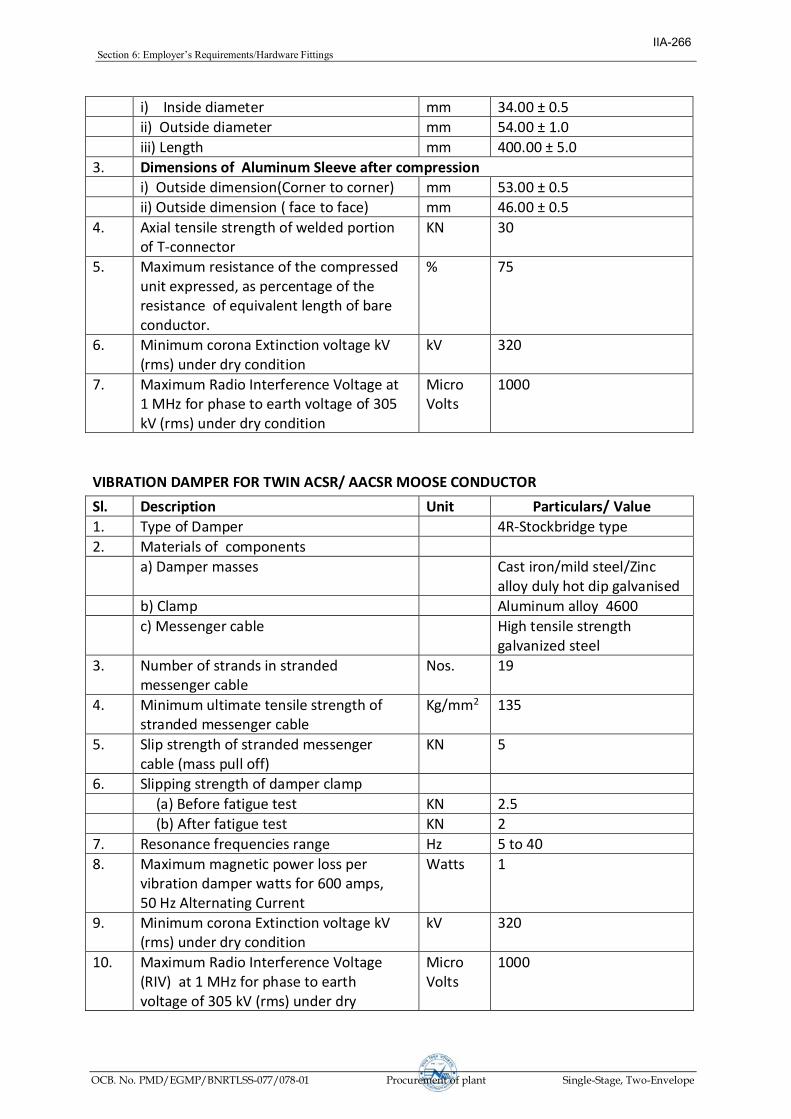
Section6:Employer’sRequirements/HardwareFittings
OCB. No. PMD/EGMP/BNRTLSS-077/078-01 Procurement of plant Single-Stage, Two-Envelope
i) Inside diameter mm 34.00 ± 0.5
ii) Outside diameter mm 54.00 ± 1.0
iii) Length mm 400.00 ± 5.0
3. Dimensions of Aluminum Sleeve after compression
i) Outside dimension(Corner to corner) mm 53.00 ± 0.5
ii) Outside dimension ( face to face) mm 46.00 ± 0.5
4. Axial tensile strength of welded portion of T-connector
KN 30
5. Maximum resistance of the compressed unit expressed, as percentage of the resistance of equivalent length of bare conductor.
% 75
6. Minimum corona Extinction voltage kV (rms) under dry condition
kV 320
7. Maximum Radio Interference Voltage at 1 MHz for phase to earth voltage of 305 kV (rms) under dry condition
Micro Volts
1000
VIBRATION DAMPER FOR TWIN ACSR/ AACSR MOOSE CONDUCTOR
Sl. Description Unit Particulars/ Value
1. Type of Damper 4R-Stockbridge type
2. Materials of components
a) Damper masses Cast iron/mild steel/Zinc alloy duly hot dip galvanised
b) Clamp Aluminum alloy 4600
c) Messenger cable High tensile strength galvanized steel
3. Number of strands in stranded messenger cable
Nos. 19
4. Minimum ultimate tensile strength of stranded messenger cable
Kg/mm2 135
5. Slip strength of stranded messenger cable (mass pull off)
KN 5
6. Slipping strength of damper clamp
(a) Before fatigue test KN 2.5
(b) After fatigue test KN 2
7. Resonance frequencies range Hz 5 to 40
8. Maximum magnetic power loss per vibration damper watts for 600 amps, 50 Hz Alternating Current
Watts 1
9. Minimum corona Extinction voltage kV (rms) under dry condition
kV 320
10. Maximum Radio Interference Voltage (RIV) at 1 MHz for phase to earth voltage of 305 kV (rms) under dry
Micro Volts
1000
IIA-266

Section6:Employer’sRequirements/HardwareFittings
OCB. No. PMD/EGMP/BNRTLSS-077/078-01 Procurement of plant Single-Stage, Two-Envelope
condition
11. Percentage variation in reactance after fatigue test in comparison with that . before fatigue test
% +/-40 (Maximum)
12. Percentage variation in power dissipation after fatigue test in comparison with that before fatigue test
% +/-40 (Maximum)
13. Galvanising
a) Minimum weight of Zinc coating for steel parts
gm/m2 600
b) Purity of Zinc used for galvanising % 99.95 (IS 209) or 98.5(IS 13229)
c) Min. No. of dips in standard preece test the ferrous parts can withstand.
Nos. a) Fasteners: 4 dips of 1 minute b) Spring washers: 3 dips of 1 minute c) all others: 6 dips of 1 minute
BUNDLE SPACER FOR TWIN ACSR/ AACSR MOOSE CONDUCTOR
Sl. Description Unit Particulars/ Value
1. Type of Bundle Spacer Armour grip type
2. Insert Main body
Retaining rods (if any)
(i) Materials of components
Aluminum alloy 6061/65032
Tube Aluminum alloy 6063/63400; 6061/65032
Aluminum alloy 6061/65032
(ii) Manufacturing process of component parts
Forged Tube- extrusion
Heat treatment during manufacturing
3. Retaining rods (if used)
(a) Number of retaining rods used for each spacer
no. 8
(b) Diameter mm 7.87 ± 0.1
(c) Length mm 1100+15
(d) Minimum UTS of rods Kg/mm2 35
4. Elastomer
(a) Type Chloroprene/Neoprene
IIA-267

Section6:Employer’sRequirements/HardwareFittings
OCB. No. PMD/EGMP/BNRTLSS-077/078-01 Procurement of plant Single-Stage, Two-Envelope
(c) Moulded on insert Yes
(d) Shore hardness 65 to 80
(e) Thickness on insert mm 5(Average)
(f) Temp. range for which designed °C 95
5. Minimum ultimate tensile strength of spacer
(a) Compressive load kN 14
(b) Tensile load kN 7
6. Slipping strength of spacer clamp
a) Before vibration test KN 2.5
b) After vibration test KN 2
7. Minimum corona Extinction voltage kV (rms) under dry condition
kV 320
8. Maximum Radio Interference Voltage (RIV) at 1 MHz for phase to earth voltage of 305 kV (rms) under dry condition
Micro volts
1000
RIGID SPACER FOR JUMPER FOR TWIN ACSR/ AACSR MOOSE CONDUCTOR
Sl. Description Unit Particulars/ Value
1. Type of Spacer Rigid type without retaining rods
2. Material of component parts
(a) Clamp Aluminum alloy (4600)
(b) Main body Aluminum alloy 6063/63400 ; 6061/65032
3. Manufacturing process of component parts
(a) Clamp Die-casting
(b) Main body Aluminum extrusion
4. Minimum ultimate tensile strength of spacer
(a) Compressive load kN 14
(b) Tensile load kN 7.0
5. Slipping strength of spacer clamp kN 2.5
6. Maximum Magnetic power loss per spacer for 600 Amps, 50 Hz Alternating Current
Watts 1
7. Minimum corona Extinction voltage kV (rms) under dry condition
kV 320
8. Maximum Radio Interference Voltage (RIV) at 1 MHz for phase to earth voltage of 305 kV (rms) under dry condition
Micro volts
1000
Standardised Technical Particulars of Accessories of Earthwire
Flexible Copper Bond for GS / AACSR Earthwire
Sl. Description Unit Particulars/ Value
1. Stranding 37/7/0.417
IIA-268

Section6:Employer’sRequirements/HardwareFittings
OCB. No. PMD/EGMP/BNRTLSS-077/078-01 Procurement of plant Single-Stage, Two-Envelope
2. Cross sectional area Sq.mm 35.4
3. Minimum copper equivalent area Sq.mm 34
4. Length of copper cable mm 500 + 5
5. Material of lugs Tinned copper
6. Bolt Size
i) Diameter mm 16
ii) Length mm 40
Mid span compression Joint for GS Earthwire
Sl. Description Unit Particulars/ Value
Aluminium / Filler Sleeve
Steel Sleeve
1. Material of Joint Aluminium of minimum purity 99.5%
Mild Steel(Fe-410, IS:2062)
2. Range of Hardness of the steel sleeve (Brinnel hardness)
BHN From 100 to 200
3. Weight of Zinc coating gm/m2 610
4. Dimension of sleeve Before compression
Aluminium Sleeve
Steel Sleeve
Alu filler sleeve
i) Inside diameter mm 22.00 ± 0.5
11.05 ± 0.2
11.50 ± 0.2
ii) Outside diameter mm 32.00 ± 0.5
21.00 ± 0.5
21.00 ± 0.5
iii) Length mm 400 ± 5 230 ± 5 60 ± 5
5. Dimensions of Sleeve after compression
Aluminium Sleeve
Steel Sleeve
i) Outside dimension(Corner to Corner) mm 29.40 ± 0.5 20.20 ± 0.5
ii) Outside dimension (face to face) mm 25.00 ± 0.5 17.50 ± 0.5
iii) Length mm 430 (approx) 265 (approx)
6. Slip strength KN 65
7. Maximum resistance of the compressed unit expressed, as percentage of the resistance of equivalent length of bare Earthwire
% 75
Vibration Damper for GS Earthwire
Sl. Description Unit Particulars/ Value
IIA-269

Section6:Employer’sRequirements/HardwareFittings
OCB. No. PMD/EGMP/BNRTLSS-077/078-01 Procurement of plant Single-Stage, Two-Envelope
1. Type of Damper 4R-Stockbridge type
2. Materials of components
a) Damper masses Cast iron/mild steel/Zinc alloy duly hop dip galvanised
b) Clamp Aluminum alloy 4600
c) Messenger cable High tensile strength galvanized steel
3. Number of strands in stranded messenger cable
Nos. 19
4. Minimum ultimate tensile strength of stranded messenger cable
Kg/mm2 135
5. Slip strength of stranded messenger cable (mass pull off)
kN 2.5
6. Slipping strength of damper clamp
(a) Before fatigue test kN 2.5
(b) After fatigue test kN 2
7. Resonance frequencies range Hz 10 to 60
8. Percentage variation in reactance after fatigue test in comparison with that . before fatigue test
% +/-40 (Maximum)
9. Percentage variation in power dissipation after fatigue test in comparison with that before fatigue test
% +/-40 (Maximum)
Suspension Clamp for GS Earthwire
Sl. Description Unit Particulars/ Value
1. Material of components
(a) Shackle Forged Steel
(b) Clamp Body & Keeper Malleable cast iron / SGI
(c) U- Bolt Mild Steel
2. Total Drop (Maximum) mm 150
3. Breaking Strength (Minimum) kN 25
4. Slipping Strength kN 12 to 17
Tension Clamp for GS Earthwire
Sl. Description Unit Particulars/ Value
1. Material of components
(i) Anchor Shackle Forged Steel
(ii) Compression Clamp
a) Steel Sleeve Mild Steel
b) Aluminium sleeve Aluminium of purity 99.5%
c) Aluminium Filler sleeve Aluminium of purity 99.5%
3. Range of Hardness of the steel sleeve (Brinnel hardness)
BHN 120-200
4. Dimension of sleeve Before compression
IIA-270

Section6:Employer’sRequirements/HardwareFittings
OCB. No. PMD/EGMP/BNRTLSS-077/078-01 Procurement of plant Single-Stage, Two-Envelope
Aluminium Sleeve
Steel Sleeve
Alu filler sleeve
i) Inside diameter mm 22.00 ± 0.5
11.05 ± 0.2
11.50 ± 0.2
ii) Outside diameter mm 32.00 ± 0.5
21.00 ± 0.5
21.00 ± 0.5
iii) Length mm 245 ± 5 205 ± 5 25 .0
5. Dimensions of Sleeve after compression
Aluminium Sleeve
Steel Sleeve
i) Outside dimension(Corner to Corner) mm 29.40 ± 0.5 20.20 ± 0.5
ii) Outside dimension (face to face) mm 25.00 ± 0.5 17.50 ± 0.5
6. Slip strength KN 65
7. Minimum Breaking strength of assembly (excluding clamp)
KN 70
8. Compression Pressure Ton 100
IIA-271

Section 6: Employer’sRequirements/OPGW
OCB. No. PMD/EGMP/BNRTLSS-077/078-01 Procurement of plant Single-Stage, Two-Envelope
Technical Specifications for Optical Ground Wire (OPGW) Cable
Contents
Section– 9(a) : Specification for OPGW cabling & associated hardware & fittings
Section– 9(b) : Inspection & Testing Requirement
Section– 9(c) : Installation for OPGW Cabling Appendix : Appendix – A : General Requirements Appendix – B: Data Requirement Sheets (DRS)
IIA-272

Section 6: Employer’sRequirements/OPGW
OCB. No. PMD/EGMP/BNRTLSS-077/078-01 Procurement of plant Single-Stage, Two-Envelope
Section-9(a)
Specification for OPGW cabling & associated hardware & fittings
Table of Content
1.0 FIBRE OPTIC CABLING .........................................................................................................275
1.1 REQUIRED OPTICAL FIBRE CHARACTERISTICS ..............................................................275
1.1.1 PHYSICAL CHARACTERISTIC..............................................................................................275
1.1.2 ATTENUATION ..........................................................................................................................275
1.2 FIBRE OPTIC CABLE CONSTRUCTION.................................................................................276
1.2.1 OPTICAL FIBRE CABLE LINK LENGTHS.........................................................................277
1.2.2 OPTICAL FIBRE IDENTIFICATION....................................................................................277
1.2.3 BUFFER TUBE...........................................................................................................................277
1.2.4 OPTICAL FIBRE STRAIN & SAG-TENSION CHART.......................................................277
1.2.5 CABLE MATERIALS ..................................................................................................................278
1.2.5.1 FILLING MATERIALS ............................................................................................................278
1.2.5.2 METALLIC MEMBERS ...........................................................................................................279
1.2.6 MARKING, PACKAGING AND SHIPPING..........................................................................279
1.3. OPTICAL GROUND WIRE (OPGW) .....................................................................................279
1.3.1 CENTRAL FIBRE OPTIC UNIT .............................................................................................279
1.3.2 BASIC CONSTRUCTION.........................................................................................................280
1.3.3 BREAKING STRENGTH..........................................................................................................280
1.3.4 ELECTRICAL AND MECHANICAL REQUIREMENTS....................................................280
1.3.5 OPERATING CONDITIONS....................................................................................................281
IIA-273

Section 6: Employer’sRequirements/OPGW
OCB. No. PMD/EGMP/BNRTLSS-077/078-01 Procurement of plant Single-Stage, Two-Envelope
1.4 INSTALLATION HARDWARE ..................................................................................................281
1.5 FIBRE OPTIC SPLICE ENCLOSURES (JOINT BOX) ...........................................................284
1.5.1 OPTICAL FIBRE SPLICES ....................................................................................................284
1.6 FIBRE OPTIC APPROACH CABLES ...................................................................................284
1.6.1 BASIC CONSTRUCTION........................................................................................................285
1.6.2 JACKET CONSTRUCTION & MATERIAL ........................................................................285
1.6.3 OPTICAL, ELECTRICAL AND MECHANICAL REQUIREMENTS ..............................285
1.7 FIBRE OPTIC DISTRIBUTION PANEL...............................................................................285
1.7.1 OPTICAL FIBRE CONNECTORS ...........................................................................................285
1.8 SERVICE LOOPS .....................................................................................................................285
1.9 TEST EQUIPMENT..................................................................................................................286
2.0 APPLICABLE STANDARDS .......................................................................................................287
I.10 REFERENCES.............................................................................................................................288
IIA-274
Section 6: Employer’sRequirements/OPGW
OCB. No. PMD/EGMP/BNRTLSS-077/078-01 Procurement of plant Single-Stage, Two-Envelope
Section-9(a)Specification for OPGW cabling and associated hardware & fittings
The broad scope of this specification include the survey, planning, design, engineering,manufacturing, supply, transportation, insurance, delivery at site, unloading, handling,storage, , installation, splicing, termination, testing, demonstration for acceptance andcommissioning and documentation for:
a) OPGW fibre optic cable including all associated hardware, accessories & fittingsb) Fibre Optic approach cable including installation materialc) Fibre Optic Distribution Panels (FODP) & Joint Boxd) Supply of sparese) Supply of test equipmentsf) All other associated work/items described in the technical specifications.
This section of the technical specification describes the functional and technicalspecifications of OPGW cabling and associated hardware and fittings.
1.0 Fibre Optic Cabling
In this section of the technical specification, the functional & technical specifications of OPGW cable, associated hardware & fittings for the requirements for G.652D Dual-window Single mode (DWSM) telecommunications grade fibre optic cable is mentioned. Bidders shall furnish with their bids, detailed descriptions of the fibres & cable(s) proposed. All optical fibre cabling including fibre itself and all associated installation hardware shall have a minimum guaranteed design life span of 25 years.Documentary evidence in support of guaranteed life span of cable & fibre shall be submitted by the Contractor during detailed engineering.
1.1 Required Optical Fibre Characteristics
The optical fibre to be provided should have following characteristics :
1.1.1 Physical Characteristic
Dual-Window Single mode (DWSM), G.652D optical fibres shall be provided in the fibre optic cables. DWSM optical fibres shall meet the requirements defined in Table 1-1(a).
1.1.2 Attenuation
The attenuation coefficient for wavelengths between 1525 nm and 1575 nm shall not exceed the attenuation coefficient at 1550 nm by more than 0.05 dB/km. The attenuation coefficient between 1285 nm and 1330 nm shall not exceed the attenuation coefficient at 1310 nm by more than 0.05 dB/km. The attenuation of the fibre shall be distributed uniformly throughout its length such that there are no point discontinuities in excess of 0.10 dB. The fibre attenuation characteristics specified in table 1-1 (a) shall be “guaranteed”fibreattenuationofany & every fibre reel.
The overall optical fibre path attenuation shall not be more than calculated below : Maximum attenuation @ 1550 nm : 0.21 dB/km x total km + 0.05 dB/splice x no. of splices + 0.5 dB/connector x no. of connectors.
IIA-275
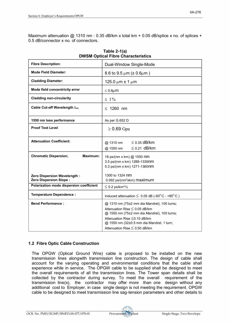
Section 6: Employer’sRequirements/OPGW
OCB. No. PMD/EGMP/BNRTLSS-077/078-01 Procurement of plant Single-Stage, Two-Envelope
Maximum attenuation @ 1310 nm : 0.35 dB/km x total km + 0.05 dB/splice x no. of splices + 0.5 dB/connector x no. of connectors.
1.2 Fibre Optic Cable Construction
The OPGW (Optical Ground Wire) cable is proposed to be installed on the new transmission lines alongwith transmission line construction. The design of cable shall account for the varying operating and environmental conditions that the cable shall experience while in service. The OPGW cable to be supplied shall be designed to meet the overall requirements of all the transmission lines. The Tower span details shall be collected by the contractor during survey. To meet the overall requirement of the transmission line(s), the contractor may offer more than one design without any additional cost to Employer, in case single design is not meeting the requirement. OPGW cable to be designed to meet transmission line sag-tension parameters and other details to
Table 2-1(a)
DWSM Optical Fibre Characteristics Fibre Description:
Dual-Window Single-Mode Mode Field Diameter:
8.6 to 9.5 mm (± 0.6mm ) Cladding Diameter:
125.0 mm ± 1 mm Mode field concentricity error
£ 0.6mm Cladding non-circularity
£1 Cable Cut-off Wavelength cc
£1260 nm
1550 nm loss performance
As per G.652 D
Proof Test Level
³ 0.69 Gpa
Attenuation Coefficient:
@ 1310 nm £ 0.35 dB/km
@ 1550 nm £ 0.21 dB/km Chromatic Dispersion; Maximum: Zero Dispersion Wavelength : Zero Dispersion Slope :
18 ps/(nm x km) @ 1550 nm 3.5 ps/(nm x km) 1288-1339nm
5.3 ps/(nm x km) 1271-1360nm
1300 to 1324 nm 0.092 ps/(nm2xkm) maximum
Polarization mode dispersion coefficient £ 0.2 ps/km^½ Temperature Dependence :
Induced attenuation £ 0.05 dB (-60°C - +85°C ) Bend Performance :
@ 1310 nm (75±2 mm dia Mandrel), 100 turns;
Attenuation Rise £ 0.05 dB/km @ 1550 nm (75±2 mm dia Mandrel), 100 turns;
Attenuation Rise £0.10 dB/km @ 1550 nm (32±0.5 mm dia Mandrel, 1 turn;
Attenuation Rise £ 0.50 dB/km
IIA-276

Section 6: Employer’sRequirements/OPGW
OCB. No. PMD/EGMP/BNRTLSS-077/078-01 Procurement of plant Single-Stage, Two-Envelope
be provided by Transmission Line contractor. Any other details, as required for cable design etc. shall be collected by the Contractor during survey.
1.2.1 Optical Fibre Cable Link Lengths
The estimated optical fibre link lengths are provided in Appendices as transmission line route length. However, the Contractor shall supply the OPGW cable as required based on the tower schedule. The Contractor shall verify the transmission line route length during the survey and the Contract price shall be adjusted accordingly. For the purpose of payment, the optical fibre link lengths are defined as transmission line route lengths from Gantry at one terminating station to the Gantry in the other terminating station. The actual cable lengths to be delivered shall take into account various factors such as sag, service loops, splicing, working lengths & wastage etc. and no additional payment shall be payable in this regard. The unit rate for FO cable quoted in the Bid price Schedules shall take into account all such factors.
1.2.2 Optical Fibre Identification
All optical fibres shall be individually coated. Individual optical fibres within a fibre unit and fibre units shall be identifiable in accordance with EIA/TIA 598 or IEC 60304 or Bellcore GR-20 colour-coding scheme. Colouring utilized for colour coding optical fibres shall be integrated into the fibre coating and shall be homogenous. The colour shall not bleed from one fibre to another and shall not fade during fibre preparation for termination or splicing. Each cable shall have traceability of each fibre back to the original fibre manufacturer's fibre number and parameters of the fibre. If more than the specified number of fibres is included in any cable, the spare fibres shall be tested by the cable manufacturer and any defective fibres shall be suitably bundled, tagged and identified at the factory by the vendor.
1.2.3 Buffer Tube
Loose tube construction shall be implemented. The individually coated optical fibre(s) shall be surrounded by a buffer for protection from physical damage during fabrication, installation and operation of the cable. The fibre coating and buffer shall be strippable for splicing and termination. Each fibre unit shall be individually identifiable utilizing colour coding. Buffer tubes shall be filled with a water-blocking gel.
1.2.4 Optical Fibre Strain & Sag-Tension chart
The OPGW cable shall be designed and installed such that the optical fibres experience no strain under all loading conditions of transmission lines. Zero fibre strain condition shall apply even after a 25 year cable creep. For the purpose of this specification, the following definitions shall apply:
· Maximum Working Tension (MWT) is defined as the maximum cable tension at
which there is no fibre strain.
IIA-277
Section 6: Employer’sRequirements/OPGW
OCB. No. PMD/EGMP/BNRTLSS-077/078-01 Procurement of plant Single-Stage, Two-Envelope
· The no fibre strain condition is defined as fibre strain of less than or equal to 0.05%, as determined by direct measurements through IEC/ ETSI (FOTP) specified optical reflectometry
· The Cable strain margin is defined as the maximum cable strain at which there is no fibre strain.
· The cable Maximum Allowable Tension (MAT) is defined as the maximum tension experienced by the Cable under the worst case loading condition.
· The cable max strain is defined as the maximum strain experienced by the Cable under the worst case loading condition.
· The cable Every Day Tension (EDT) is defined as the maximum cable tension on any span under normal conditions.
· The Ultimate /Rated Tensile Strength (UTS/ RTS/ breaking strength) is defined as the maximum tensile load applied and held constant for one minute at which the specimen shall not break.
While preparing the Sag-tension charts for the OPGW cable the following conditions shall be met:
· The Max Allowable Tension (MAT) / max strain shall be less than or equal to the
MWT/ Strain margin of the cable. · The sag shall not exceed the earth wire sag in all conditions. · The Max Allowable Tension shall also be less than or equal to 0.4 times the UTS. · The 25 year creep at 25% of UTS (creep test as per IEEE 1138) shall be such that
the 25 year creep plus the cable strain at Max Allowable Tension (MAT) is less than or equal to the cable strain margin.
· The everyday tension (EDT) shall not exceed 20% of the UTS for the OPGW cable.
The Sag-tension chart of OPGW cable indicating the maximum tension, cable strain and sag shall be calculated and submitted along with the bid under various conditions as per tower design of the transmission line.
The size of OPGW shall be selected such that max. tension and sag at specified temperature and wind condition remains within the limits of transmission line tower design.
1.2.5 Cable Materials
The materials used for optical fibre cable construction, shall meet the following requirements:
1.2.5.1 Filling Materials
The interstices of the fibre optic unit and cable shall be filled with a suitable compound to prohibit any moisture ingress or any water longitudinal migration within the fibre optic unit or along the fibre optic cable. The water tightness of the cable shall meet or exceed the test performance criteria as per IEC 60794-1-F-5. The filling compound used shall be a non-toxic homogenous waterproofing compound that is free of dirt and foreign matter, non-hygroscopic, electrically nonconductive and non-nutritive to fungus. The compound shall also be fully compatible with all cable components it may come in contact with and shall inhibit the generation of hydrogen within the cable.
IIA-278

Section 6: Employer’sRequirements/OPGW
OCB. No. PMD/EGMP/BNRTLSS-077/078-01 Procurement of plant Single-Stage, Two-Envelope
The waterproofing filling materials shall not affect fibre coating, colour coding, or encapsulant commonly used in splice enclosures, shall be dermatologically safe, non-staining and easily removable with a non-toxic cleaning solvent.
1.2.5.2 Metallic Members
When the fibre optic cable design incorporates metallic elements in its construction, all metallic elements shall be electrically continuous.
1.2.6 Marking, Packaging and Shipping
This section describes the requirements for marking, packaging and shipping the overhead fibre optic cable.
(a) Drum Markings: Each side of every reel of cable shall be permanently marked in
white lettering with the vendorsaddress, thePurchaser’sdestination address, cable part number and specification as to the type of cable, length, number of fibres, a unique drum number including the name of the transmission line & segment no., factory inspection stamp and date.
(b) Cable Drums: All optical fibre cabling shall be supplied on strong drums provided with
lagging of adequate strength, constructed to protect the cabling against all damage and displacement during transit, storage and subsequent handling during installation. Both ends of the cable shall be sealed as to prevent the escape of filling compounds and dust & moisture ingress during shipment and handling. Spare cable caps shall be provided with each drum as required.
The spare cable shall be supplied on sturdy, corrosion resistant, steel drums suitable for long periods of storage and re-transport & handling.
There shall be no factory splices allowed within a continuous length of cable. Only one continuous cable length shall be provided on each drum. The lengths of cable to be supplied on each drum shall be determined by a "schedule" prepared by the Contractor and approved by the owner.
1.3. Optical Ground Wire (OPGW)
OPGW cable construction shall comply with IEEE-1138, 2009. The cable provided shall meet both the construction and performance requirements such that the ground wire function, the optical fibre integrity and optical transmission characteristics are suitable for the intended purpose. The cable shall consist of optical fibre units as defined in this specification. There shall be no factory splices within the cable structure of a continuous cable length. The composite fibre optic overhead ground wire shall be made up of multiple buffer tubes embedded in a water tight aluminium/aluminium alloy protective central fibre optic unit surrounded by concentric-lay stranded metallic wires in single or multiple layers. Each buffer tube shall have maximum 12 no. of fibres. All fibres in single buffer tube or directly in central fibre optic unit is not acceptable. The dual purpose of the composite cable is to provide the electrical and physical characteristics of conventional overhead ground wire while providing the optical transmission properties of optical fibre.
1.3.1 Central Fibre Optic Unit
IIA-279

Section 6: Employer’sRequirements/OPGW
OCB. No. PMD/EGMP/BNRTLSS-077/078-01 Procurement of plant Single-Stage, Two-Envelope
The central fibre optic unit shall be designed to house and protect multiple buffered optical fibre units from damage due to forces such as crushing, bending, twisting, tensile stress and moisture. The central fibre optic unit and the outer stranded metallic conductors shall serve together as an integral unit to protect the optical fibres from degradation due to vibration and galloping, wind and ice loadings, wide temperature variations, lightning and fault current, as well as environmental effects which may produce hydrogen. The OPGW design of dissimilar materials for stranded wires and tubes are not allowed. Central fibre optic unit may be of aluminium / aluminium alloy tube. There shall be no exposed areas of tubing that can make electrical contact either directly or indirectly through moisture, contamination, protrusions, etc with the surrounding stranded wires. The tube may be fabricated as a seamless tube, seam welded, or a tube without a welded seam.
1.3.2 Basic Construction
The OPGW cable construction shall conform to the applicable requirements of this specification, applicable clauses of IEC 61089 related to stranded conductors and Table 1.2(a) OPGW Mechanical and Electrical Characteristics. In addition, the basic construction shall include bare concentric-lay-stranded metallic wires with the outer layer having left hand lay. The wires may be of multiple layers with a combination of various metallic wires within each layer. The direction of lay for each successive layer shall be reversed. The finished wires shall contain no joints or splices unless otherwise agreed to by the Employer and shall conform to all applicable clauses of IEC 61089 as they pertain to stranded conductors. The wires shall be so stranded that when the complete OPGW is cut, the individual wires can be readily regrouped and then held in place by one hand.
1.3.3 Breaking Strength
The rated breaking strength of the completed OPGW shall be taken as no more than 90 percent of the sum of the rated breaking strengths of the individual wires, calculated from their nominal diameter and the specified minimum tensile strength. The rated breaking strength shall not include the strength of the optical unit. The fibre optic unit shall not be considered a load bearing tension member when determining the total rated breaking strength of the composite conductor.
1.3.4 Electrical and Mechanical Requirements
Table 1-2(a) provides OPGW Electrical and Mechanical Requirements for the minimum performance characteristics. Additionally, the OPGW mechanical & electrical characteristics shall be similar to that of the earthwire being replaced such that there is no or minimal consequential increase in stresses on towers. OPGW installation sag & tension charts shall be as per transmission line requirement. For the OPGW cable design selection and preparation of sag tension charts, the limits specified in this section shall also be satisfied. The Bidder shall submit sag-tension charts for the above cases with their bids.
Table 1.2(a)
OPGW Electrical and Mechanical Requirements
(1)
Everyday Tension
≤ 20% of UTS of OPGW
(2)
D.C. Resistance at
< 1.0 ohm/Km or Employer provided values
IIA-280

Section 6: Employer’sRequirements/OPGW
OCB. No. PMD/EGMP/BNRTLSS-077/078-01 Procurement of plant Single-Stage, Two-Envelope
Table 1.2(a)
OPGW Electrical and Mechanical Requirements
20ºC:
(3) Short Circuit Current
≥ 6.32 kA for 1.0 second or Employer provided values
Bidder may offer separate design for each short circuit rating however OPGW design with higher short circuit level shall be acceptable.
1.3.5 Operating conditions
Since OPGW shall be located at the top of the transmission line support structure, it will be subjected to Aeolian vibration, Galloping and Lightning strikes. It will also carry ground fault currents. Therefore, its electrical and mechanical properties shall be same or similar as those required of conventional ground conductors.
1.4 Installation Hardware
The scope of supply includes all required fittings and hardware such as Tension assembly, Suspension assembly, Vibration dampers, Reinforcing rods, Earthing clamps, Downlead clamps, splice enclosure etc. The Bidder shall provide documentation justifying the adequacy and suitability of the hardware supplied. The quantity of hardware & fittings to meet any eventuality during site installation minimum@ 1% shall also be provided as part of set/km for each transmission line without any additional cost to Employer.
The OPGW hardware fittings and accessories shall follow the general requirements regarding design, materials, dimensions & tolerances, protection against corrosion and markings as specified in clause 4.0 of EN 61284: 1997 (IEC 61284). The shear strength of all bolts shall be at least 1.5 times the maximum installation torque. The OPGW hardware & accessories drawing & Data Requirement Sheets (DRS) document shall consist of three parts: (1) A technical particulars sheet (2) An assembly drawing i.e. level 1 drawing and (3) Component level drawings i.e. level 2 & lower drawings. All component reference numbers, dimensions and tolerances, bolt tightening torques & shear strength and ratings such as UTS, slip strength etc shall be marked on the drawings.
The fittings and accessories described herein are indicative of installation hardware typically used for OPGW installations and shall not necessarily be limited to the following:
(a) Suspension Assemblies: Preformed armour grip suspension clamps and
aluminium alloy armour rods/ reinforcing rods shall be used. The suspension clamps shall be designed to carry a vertical load of not less than 25 KN. The suspension clamps slippage shall occur between 12kN and 17 kN as measured.
The Contractor shall supply all the components of the suspension assembly
including shackles, bolts, nuts, washers, split pins, etc. The total drop of the suspension assembly shall not exceed 150 mm (measured from the centre point of attachment to the centre point of the OPGW). The design of the assembly shall be such that the direction of run of the OPGW shall be the same as that of the conductor.
(b) Dead End Clamp Assemblies: All dead end clamp assemblies shall preferably be of performed armoured grip type and shall include all necessary hardware for
IIA-281

Section 6: Employer’sRequirements/OPGW
OCB. No. PMD/EGMP/BNRTLSS-077/078-01 Procurement of plant Single-Stage, Two-Envelope
attaching the assembly to the tower strain plates. Dead end clamps shall allow the OPGW to pass through continuously without cable cutting. The slip strength shall be rated not less than 95% of the rated tensile strength of the OPGW.
(c) Clamp Assembly Earthing Wire: Earthing wire consisting of a 1500 mm length of
aluminium or aluminium alloy conductor equivalent in size to the OPGW shall be used to earth suspension and dead end clamp assemblies to the tower structure. The earthing wire shall be permanently fitted with lugs at each end. The lugs shall be attached to the clamp assembly at one end and the tower structure at the other.
(d) Structure Attachment Clamp Assemblies: Clamp assemblies used to attach the
OPGW to the structures, shall have two parallel grooves for the OPGW, one on either side of the connecting bolt. The clamps shall be such that clamping characteristics do not alter adversely when only one OPGW is installed. The tower attachment plates shall locate the OPGW on the inside of the tower and shall be attached directly to the tower legs/cross-members without drilling or any other structural modifications.
(e) Vibration Dampers: Vibration dampers type 4R Stockbridge or equivalent, having
four (4) different frequencies spread within the Aeolian frequency bandwidth corresponding to wind speed of 1m/s to 7 m/s, shall be used for suspension and tension points in each span. The Contractor shall determine the exact numbers and placement(s) of vibration dampers through a detailed vibration analysis as specified in technical specifications.
One damper minimum on each side per OPGW cable for suspension points and two dampers minimum on each side per OPGW cable for tension points shall be used for nominal design span of 400 meters. For all other ruling spans, the number of vibration damper shall be based on vibration analysis.
The clamp of the vibration damper shall be made of high strength aluminum alloy of type LM-6. It shall be capable of supporting the damper and prevent damage or chaffing of the conductor during erection or continued operation. The clamp shall have smooth and permanent grip to keep the damper in position on the OPGW cable without damaging the strands or causing premature fatigue failure of the OPGW cable under the clamp. The clamp groove shall be in uniform contact with the OPGW cable over the entire clamping surface except for the rounded edges. The groove of the clamp body and clamp cap shall be smooth, free from projections, grit or other materials which could cause damage to the OPGW cable when the clamp is installed. Clamping bolts shall be provided with self locking nuts and designed to prevent corrosion of threads or loosening in service.
The messenger cable shall be made of high strength galvanised steel/stain less steel. It shall be of preformed and post formed quality in order to prevent subsequent droop of weight and to maintain consistent flexural stiffness of the cable in service. The messenger cable other than stainless steel shall be hot dip galvanised in accordance with the recommendations of IS: 4826 for heavily coated wires.
The damper mass shall be made of hot dip galvanised mild steel/cast iron or a permanent mould cast zinc alloy. All castings shall be free from defects such as cracks, shrinkage, inclusions and blow holes etc. The surface of the damper masses shall be smooth.
IIA-282

Section 6: Employer’sRequirements/OPGW
OCB. No. PMD/EGMP/BNRTLSS-077/078-01 Procurement of plant Single-Stage, Two-Envelope
The damper clamp shall be casted over the messenger cable and offer sufficient and permanent grip on it. The messenger cable shall not slip out of the grip at a load less than the mass pull-off value of the damper. The damper masses made of material other-than zinc alloy shall be fixed to the messenger cable in a suitable manner in order to avoid excessive stress concentration on the messenger cables which shall cause premature fatigue failure of the same. The messenger cable ends shall be suitably and effectively sealed to prevent corrosion. The damper mass made of zinc alloy shall be casted over the messenger cable and have sufficient and permanent grip on the messenger cable under all service conditions.
The contractor must indicate the clamp bolt tightening torque to ensure that the slip strength of the clamp is maintained between 2.5 kN and 5 kN. The clamp when installed on the OPGW cable shall not cause excessive stress concentration on the OPGW cable leading to permanent deformation of the OPGW strands and premature fatigue failure in operation.
The vibration analysis of the system, with and without damper and dynamic characteristics of the damper as detailed in Technical Specification, shall have to be submitted. The technical particulars for vibration analysis and damping design of the system are as follows:
Sl. No. Description Technical Particulars
1 Span Length in meters
(i) Ruling design span:
(ii) Maximum span:
(iii) Minimum Span:
400 meters
1100 meters
100 meters
2 Configuration: As per Specifications
3 Tensile load in each: As per sag tension calculations
4 Armour rods used: Standard preformed armour rods/AGS
5 Maximum permissible dynamic strain:
+/- 150 micro strains
The damper placement chart for spans ranging from 100m to 1100m shall be submitted by the Contractor. Placement charts should be duly supported with relevant technical documents and sample calculations.
The damper placement charts shall include the following
(1) Location of the dampers for various combinations of spans and line tensions clearly indicating the number of dampers to be installed per OPGW cable per span.
(2) Placement distances clearly identifying the extremities between which the distances are to be measured.
IIA-283

Section 6: Employer’sRequirements/OPGW
OCB. No. PMD/EGMP/BNRTLSS-077/078-01 Procurement of plant Single-Stage, Two-Envelope
(3) Placement recommendation depending upon type of suspension clamps (viz Free center type/Armour grip type etc.)
(4) The influence of mid span compression joints, repair sleeves and armour rods (standard and AGS) in the placement of dampers
1.5 Fibre Optic Splice Enclosures (Joint Box)
All splices shall be encased in Fibre Optic Splice Enclosures. Suitable splice enclosures shall be provided to encase the optical cable splices in protective, moisture and dust free environment. Splice enclosures shall comply with ingress protection class IP 66 or better. The splice enclosures shall be designed for the storage and protection of required number of optical fibre splices and equipped with sufficient number of splice trays for splicing all fibres in the cable. No more than 12 fibres shall be terminated in a single splice tray. They shall be filled with suitable encapsulate that is easily removable should re-entry be required into the enclosures. Splice enclosures shall be suitable for outdoor use with each of the cable types provided under this contract. Splice enclosures shall be appropriate for mounting on transmission line towers above anti-climb guard levels at about 10 metres from top of the tower and shall accommodate pass-through splicing. The actual mounting height and location shall be finalised after Survey. Contractor shall be responsible for splicing of fibres and installation of splice enclosures.
1.5.1 Optical Fibre Splices
Splicing of the optical fibre cabling shall be minimized through careful Contractor planning. There shall be no mid-span splices allowed. All required splices shall be planned to occur on tower structures. All optical fibre splicing shall comply with the following:
(a) All fibre splices shall be accomplished through fusion splicing.
(b) Each fibre splice shall be fitted with a splice protection sheath fitted over the final
splice.
(c) All splices and bare fibre shall be neatly installed in covered splice trays.
(d) For each link, bi-directional attenuation of single mode fusion splices, shall not average more than 0.05 dB and no single splice loss shall exceed 0.1 dB when measured at 1550 nm.
(e) For splicing, fibre optic cable service loops of adequate length shall be provided so
that all splices occurring at tower structures can be performed at ground level.
1.6 Fibre Optic Approach Cables
For purposes of this specification, a fibre optic approach cable is defined as the Armoured underground fibre optic cable required to connect Overhead Fibre Optic Cable (OPGW) between the final in line splice enclosure on the gantry / tower forming the termination of the fibre cable on the power line and the Fibre Optic Distribution Panel (FODP) installed within the building. The estimated fibre optic approach cabling length requirements are indicated in the appendices. However, the Contractor shall supply & install the optical fibre approach cable as required based on detailed site survey to be carried out by the Contractor during the project execution and the Contract price shall be adjusted
IIA-284

Section 6: Employer’sRequirements/OPGW
OCB. No. PMD/EGMP/BNRTLSS-077/078-01 Procurement of plant Single-Stage, Two-Envelope
accordingly.
1.6.1 Basic Construction
The cable shall be suitable for direct burial, laying in trenches & PVC/Hume ducts, laying under false flooring and on indoor or outdoor cable raceways.
1.6.2 Jacket Construction & Material
The Approach Cable shall be a UV resistant, rodent proof, armoured cable with metallic type of armouring. The outer cable jacket for approach cable shall consist of carbon black polyethylene resin to prevent damage from exposure to ultra-violet light, weathering and high levels of pollution. The jacket shall conform to ASTM D1248 for density.
1.6.3 Optical, Electrical and Mechanical Requirements
Approach cable shall contain fibres with identical optical/ physical characteristics as those in the OPGW cables. The cable core shall comprise of tensile strength member(s), fibre support/bedding structure, core wrap/bedding, and an overall impervious jacket.
1.7 Fibre Optic Distribution Panel
Fibre Optic Distribution Panels is required for each location for termination of fibres in a manner consistent with the following:
(a) FODPs shall be suitable for use with each of the cable types provided as part of this
contract. FODPs shall accommodate pass-through splicing and fibre terminations.
(b) FODPs for indoor use shall be supplied in suitable cabinets/racks with locking arrangement
(c) All FODPs shall be of corrosion resistant, robust construction and shall allow both top or bottom entry for access to the splice trays. Ground lugs shall be provided on all FODPs and the Contractor shall ensure that all FODPs are properly grounded. The FODP shall meet or exceed ingress protection class IP55 specifications.
1.7.1 Optical Fibre Connectors
Optical fibres shall be connectorised with FC-PC type connectors preferably. Alternatively connector with matching patch cord shall also be acceptable. Fibre optic couplings supplied with FODPs shall be appropriate for the fibre connectors to be supported. There shall be no adapters.
1.8 Service Loops
For purposes of this specification, cable and fibre service loops are defined as slack (extra) cable and fibre provided for facilitating the installation, maintenance and repair of the optical fibre cable plant.
(a) Outdoor Cable Service Loops: In-line splice enclosures installed outdoors and
mounted on the utility towers shall be installed with sufficient fibre optic cable service loops such that the recommended minimum bend radius is maintained while allowing for installation or maintenance of the cable to be performed in a controlled
IIA-285

Section 6: Employer’sRequirements/OPGW
OCB. No. PMD/EGMP/BNRTLSS-077/078-01 Procurement of plant Single-Stage, Two-Envelope
environment at ground level. (b) Indoor Cable Service Loops: FODPs shall provide at least three (3) metres of cable
service loop. Service loops shall be neatly secured and stored, coiled such that the minimum recommended bend radius' are maintained.
(c) Fibre Units Service Loops: For all fibre optic cable splicing, the cable shall be stripped
back a sufficient length such that the fan-out of fibre units shall provide for at least one (1) metre of fibre unit service loop between the stripped cable and the bare fibre fan-out.
(d) Pigtail Service Loops : Connectorised pigtails spliced to bare fibres shall provide at
least 1 metre of service loop installed in the FODP fibre organizer and at least one (1) metre of service loop to the couplings neatly stored behind the FODP coupling panels.
(e) Fibre Service Loops : At least 0.5 metre of bare fibre service loop shall be provided
on each side of all fibre splices. The bare fibre service loops shall be neatly and safely installed inside covered splice trays.
1.9 Test Equipment
The table 1.3 below provides mandatory test equipment requirements, to be provided as applicable as per BoQ. The parameters / features of the mandatory equipments are enumerated as follows :
Table 1.3
S. No. Test equipment Parameter
A. Test Equipments for OPGW cable
1 OTDR (Optical Time Domain Reflectometer) for 1310/1550 nm with laser source.
Equivalent to Anritsu MW9076B1 or better.
2 Optical Attenuators (variable 1310/1550nm).
Equivalent to JDSU OLA55 or better.
3 Optical Power meter (1310/1550nm)
Equivalent to JDSU OLP55 or better
4 Optical Talk set
Equivalent to JDSU OTS55 or better.
5 Optical Fibre Fusion Splicer incl. Fibre cleaver
Equivalent to Sumitomo T-39-SE or better.
6 Calibrated Fibre
7 Connectorization kit FIS – FI-0053-FC-INST or equivalent
8 Splice kit FIS – FI-0053-FF or equivalent
9
Optical test accessory kit including all necessary connectors, adaptors, cables, terminations and other items required for testing
FIS – FI-0053-TS-ST or equivalent
In case the offered make/model of test equipment has multiple options for the parameters, the option of higher range shall be acceptable. The supplied test equipment shall be suitable
IIA-286

Section 6: Employer’sRequirements/OPGW
OCB. No. PMD/EGMP/BNRTLSS-077/078-01 Procurement of plant Single-Stage, Two-Envelope
for use in the high EMI/EMC environment. The Contractor shall submit performance certificate for offered test equipment from at least one customer. The Contractor shall offer only reputed make test equipment such as Acterna (JDSU)/Anritsu/Sumitomo/Agilent/EXFO etc.
2.0 Applicable Standards The following standards and codes shall be generally applicable to the equipment and works supplied for OPGW and associated Items
(1) American Society for Testing and Materials ASTM ASTM-B415 Standard Specification for Hard-Drawn Aluminium-
Clad Steel Wire (2) Bell Communication Research GR-20 Generic requirements for optical fibre and
optical fibre cable (3) ITU-T/CCITT Recommendations
G.650 Definitions and test methods for the
relevant parameters of single-mode fibres G.652 Characteristics of a single-mode optical
fibre cable (4) IEEE
IEEE-1138 IEEE Standard Construction of Composite Fibre
Optic Ground Wire (OPGW) for Use on Electric Utility power Lines
(5) Telecommunication Industry Association EIA/TIA
EIA/TIA-455-3 Procedure to Measure Temperature Cycling Effects on
Optical Fibres, Optical Cable, and Other Passive Fiber Optic Components
EIA/TIA-455-16 Salt Spray (Corrosion) Test for Fibre Optic Components EIA/TIA-455-20 Measurement of Change in Optical Transmittance EIA/TIA-455-25 Repeated Impact Testing of Fibre Optic Cables and Cable
Assemblies EIA/TIA-455-32 Fibre Optic Circuit Discontinuities EIA/TIA-455-33 Fibre Optic Cable Tensile Loading and Bending Test EIA/TIA-455-41 Compressive Loading Resistance of Fibre Optic Cables EIA/TIA-455-59 Measurement of Fibre Point Defects Using an OTDR EIA/TIA-455-62 Measurement of Optical Fibre Macrobend Attenuation EIA/TIA-455-78 Spectral Attenuation Cutback Measurement for Single-
Mode Optical Fibres EIA/TIA-455-80 Measurement of Cut-Off Wavelength of Single-Mode Fibre
by Transmitted Power EIA/TIA-455-81 Compound Flow (Drip) Test for Filled Fibre Optic Cable EIA/TIA-455-82 Fluid Penetration Test for Fluid-Blocked Fibre optic Cable
IIA-287

Section 6: Employer’sRequirements/OPGW
OCB. No. PMD/EGMP/BNRTLSS-077/078-01 Procurement of plant Single-Stage, Two-Envelope
EIA/TIA-455-91 Fibre Optic Cable Twist-Bend Test EIA/TIA-455-164 Single-Mode Fibre, Measurement of Mode Field Diameter
by Far-Field Scanning EIA/TIA-455-167 Mode Field Diameter Measurement, Variable Aperture
Method in the Far-Field EIA/TIA-455-168 Chromatic Dispersion Measurement of Multimode Graded
Index and Single-Mode Optical Fibres by Spectral Group Delay Measurement in the Time Domain
EIA/TIA-455-169 Chromatic Dispersion Measurement of Single-Mode Optical Fibres by the Phase-Shift Method
EIA/TIA-455-170 Cable Cut-off Wavelength of Single-Mode Fibre by Transmitted Power
EIA/TIA-455-174 Mode Field Diameter Measurement EIA/TIA-455-175 Chromatic Dispersion Measurement of Single-Mode
Optical Fibres by the Differential Phase-Shift Method EIA/TIA-455-176 Method of Measuring Optical Fibre Cross-Sectional
Geometry by Automated Grey-Scale Analysis EIA/TIA-598 Optical Fibre Cable Colour Coding (6) International Electrotechnical Commission IEC
standards IEC-60793-1 series Optical fibres – Generic & product specifications,
measurement methods & test procedures specification IEC-60794-1-1 Optical fibre cables – Generic specification IEC-60794-1-2 Optical fibre cables – Basic optical cable test procedure IEC-60794-3 Optical fibre cables – Duct, buried and aerial
cables – sectional specification IEC-60794-4 Optical fibre cables – Overhead cables IEC-61089 Round wire concentric lay overhead electrical
stranded conductors IEC-61232 Aluminium-clad steel wires for electrical purposes IEC-61284 Overhead lines-Requirements and tests for fittings IEC-61395 Overhead electrical conductors – Creep test
procedures for stranded conductors
Specifications and codes shall be the latest version, inclusive of revisions, which are in force at the date of the contract award. Where new specifications, codes, and revisions are issued during the period of the contract, the Contractor shall attempt to comply with such, provided thatnoadditionalexpensesarechargedtotheEmployerwithoutEmployer’swrittenconsent. In the event the Contractor offers to supply material and/or equipment in compliance to any standard other than Standards listed herein, the Contractor shall include with their proposal, full salient characteristics of the new standard for comparison. In case values indicated for certain parameters in the specifications are more stringent than those specified by the standards, the specification shall override the standards.
I.10 References
(1) CIGRE Guide for Planning of Power Utility Digital Communications Networks
IIA-288

Section 6: Employer’sRequirements/OPGW
OCB. No. PMD/EGMP/BNRTLSS-077/078-01 Procurement of plant Single-Stage, Two-Envelope
(2) CIGRE Optical Fibre Planning Guide for Power Utilities (3) CIGRE New Opportunities for Optical Fibre Technology in Electricity Utilities (4) CIGRE guide to fittings for Optical Cables on Transmission Lines
…………………….……..…End of this Section……………………………...
IIA-289

Section 6: Employer’sRequirements/OPGW
OCB. No. PMD/EGMP/BNRTLSS-077/078-01 Procurement of plant Single-Stage, Two-Envelope
Section- 9(b)Inspection & Testing Requirement
Table of Content
2.1 Testing Requirements..........................................................................................291
2.3.1 Type Testing ......................................................................................................291
2.1.1 Type Test Samples .....................................................................................292
2.1.2 List of Type Tests.........................................................................................2922.1.2.1 Type Tests for Optical Fibres ...................................................................2932.1.2.2 Type Tests for OPGW Cables..................................................................2932.1.2.3 Type Test on OPGW Cable Fittings ........................................................2972.1.2.4 Type Test on Vibration Damper ...............................................................3002.1.2.5 Type Tests for Splice Enclosures (Joint Box) ...........................................3032.1.2.6 Type Tests for Fibre Optic Approach Cable .............................................304
2.2 Factory Acceptance Tests .................................................................................305
2.2.1 Sampling for FAT ........................................................................................305
2.2.2 Production Testing ......................................................................................306
2.2.3 Factory Acceptance Tests on Optical Fibre to be supplied with OPGW.......306
2.2.4 Factory Acceptance Test on OPGW Cable .................................................307
2.2.5 Factory Acceptance Test on OPGW Fittings ...............................................307
2.2.6 Factory Acceptance Test on Approach Cable .............................................308
2.2.7 Factory Acceptance Test on Splice Enclosure (Joint Box) /FODP...............309
2.2.8 Factory Acceptance Test on Test Equipment & other items ........................309
2.3 Site Acceptance Tests .......................................................................................309
2.3.1 Minimum Site Acceptance Testing Requirement for FO Cabling .................3092.3.1.1 Phases of Site Acceptance Testing..........................................................309
IIA-290

Section 6: Employer’sRequirements/OPGW
OCB. No. PMD/EGMP/BNRTLSS-077/078-01 Procurement of plant Single-Stage, Two-Envelope
Section - 9(b)Inspection & Testing Requirement
All materials furnished and all work performed under this Contract shall be inspected andtested. Deliverables shall not be shipped until all required inspections and tests havebeen completed, and all deficiencies have been corrected to comply with thisSpecification and approved for shipment by the Employer.
Except where otherwise specified, the Contractor shall provide all manpower andmaterials for tests, including testing facilities, logistics, power and instrumentation, andreplacement of damaged parts. The costs shall be borne by the Contractor and shall bedeemed to be included in the contract price.
The entire cost of testing for factory, production tests and other test during manufacturespecified herein shall be treated as included in the quoted unit price of materials, exceptfortheexpensesofInspector/Employer’srepresentative.
Acceptance or waiver of tests shall not relieve the Contractor from the responsibility tofurnish material in accordance with the specifications.
All tests shall be witnessed by the Employer and/or its authorized representative(hereinafter referred to as the Employer) unless the Employer authorizes testing toproceed without witness. The Employer representative shall sign the test form indicatingapproval of successful tests.
Should any inspections or tests indicate that specific item does not meet Specificationrequirements, the appropriate items shall be replaced, upgraded, or added by theContractor as necessary to correct the noted deficiencies at no cost to the Employer.After correction of a deficiency, all necessary retests shall be performed to verify theeffectiveness of the corrective action.
The Employer reserves the right to require the Contractor to perform, at the Employer'sexpense, any other reasonable test(s) at the Contractor's premises, on site, or elsewherein addition to the specified Type, Acceptance, Routine, or Manufacturing tests to assurethe Employer of specification compliance.
2.1 Testing Requirements
Following are the requirements of testing :
1. Type Testing
2. Factory Acceptance Testing
3. Site Acceptance Testing
2.3.1 Type Testing
"Type Tests" shall be defined as those tests which are to be carried out to prove thedesign, process of manufacture and general conformity of the materials to thisSpecification. Type Testing shall comply with the following:
(a) All cable & equipment being supplied shall conform to type tests as per technical specification.
(b) The test reports submitted shall be of the tests conducted within last seven
(7) years for OPGW cable prior to the date of proposal/offer submitted. In case the test reports are older than seven (7) years for OPGW cable on the
IIA-291

Section 6: Employer’sRequirements/OPGW
OCB. No. PMD/EGMP/BNRTLSS-077/078-01 Procurement of plant Single-Stage, Two-Envelope
date of proposal/offer, the Contractor shall repeat these tests at no extra cost to the Employer.
(c) The Contractor shall submit, within 30 days of Contract Award, copies of
test reports for all of the Type Tests that are specified in the specifications and that have previously ( before Contract award) been performed. These reports may be accepted by the Employer only if they apply to materials and equipment that are essentially identical to those due to be delivered under the Contract and only if test procedures and parameter values are identical to those specified in this specifications carried out at accredited labs and witnessedbythirdparty/customer’srepresentatives.
In the event of any discrepancy in the test reports or any type tests not
carried out, same shall be carried out by Contractor without any additional cost implication to the Employer.
In case the Type Test is required to be carried out, then following shall be
applicable:- (d) Type Tests shall be certified or performed by reputed laboratories using
material and equipment data sheets and test procedures that have been approved by the Employer. The test procedures shall be formatted as defined in the technical specifications and shall include a complete list of the applicable reference standards and submitted for Employer approval at least four (4) weeks before commencement of test(s). The Contractor shall provide the Employer at least 30 days written notice of the planned commencement of each type test.
(e) The Contractor shall provide a detailed schedule for performing all specified
type tests. These tests shall be performed in the presence of a representative of the Employer.
(f) The Contractor shall ensure that all type tests can be completed within the
time schedule offered in his Technical Proposal. (g) In case of failure during any type test, the Supplier is either required to
manufacture a fresh sample lot and repeat all type tests successfully or repeat that particular type test(s) at least three times successfully on the samples selected from the already manufactured lot at his own expenses. In case a fresh lot is manufactured for testing then the lot already manufactured shall be rejected.
2.1.1 Type Test Samples
The Contractor shall supply equipment/material for sample selection only after the Quality Assurance Plan has been approved by the Employer. The sample material shall be manufactured strictly in accordance with the approved Quality Assurance Plan. The Contractor shall submit for Employer approval, the type test sample selection procedure. The selection process for conducting the type tests shall ensure that samples are selected at random. For optical fibres/ Fibre Optic cables, at least three reels/ drums of each type of fibre/cable proposed shall be offered for selection. For FO cable installation hardware & fittings at least ten (10) samples shall be offered for selection. For Splice enclosures at least three samples shall be offered for selection.
2.1.2 List of Type Tests
The type testing shall be conducted on the following items
IIA-292

Section 6: Employer’sRequirements/OPGW
OCB. No. PMD/EGMP/BNRTLSS-077/078-01 Procurement of plant Single-Stage, Two-Envelope
(a) Optical fibres
(b) OPGW Cable
(c) OPGW Cable fittings
(d) Vibration Damper
(e) Splice Enclosure (Joint Box)
(f) Approach Cable
2.1.2.1 Type Tests for Optical Fibres
The type tests listed below in table 2-1 shall be conducted on DWSM fibres to be supplied as part of overhead cables. The tests specific to the cable type are listed in subsequent sections.
Table 2-1 Type Tests For Optical Fibres
S. No.
Test Name
Acceptance Criteria
Test procedure
1
Attenuation
As per Section-01 of TS
IEC 60793-1-40
Or EIA/TIA 455-78A
2 Attenuation Variation with Wavelength
As per Section-01 of TS
IEC 60793-1-40
Or EIA/TIA 455-78A
3 Attenuation at Water Peak
As per Section-01 of TS
As per Section-01 of TS
As per Section-01 of TS
As per Section-01 of TS
As per Section-01 of TS
As per Section-01 of TS
As per Section-01 of TS
IEC 60793-1-40
Or EIA/TIA 455-78A
4 Temp. Cycling (Temp dependence of Attenuation)
IEC 60793-1-52
Or EIA/TIA 455-3A, 2 cycles
5
Attenuation With Bending (Bend Performance)
IEC 60793-1-47
Or EIA/TIA 455-62A
6 Mode Field dia.
IEC 60793-1-45 Or EIA/TIA 455- 164A/167A/174
7
Chromatic Dispersion
IEC 60793-1-42 Or EIA/TIA 455- 168A/169A/175A
8
Cladding Diameter
IEC 60793-1-20 Or EIA/TIA 455-176
9
Point Discontinuities of attenuation
IEC 60793-1-40 Or EIA/TIA 455-59
10
Core -Clad concentricity error
IEC 60793-1-20 Or EIA/TIA 455-176
11
Fibre Tensile Proof Testing
As per Section-01 of TS
IEC 60793-1-30
Or EIA/TIA 455-31B
-End Of table-
2.1.2.2 Type Tests for OPGW Cables
IIA-293

Section 6: Employer’sRequirements/OPGW
OCB. No. PMD/EGMP/BNRTLSS-077/078-01 Procurement of plant Single-Stage, Two-Envelope
The type tests to be conducted on the OPGW cable are listed in Table 2-2 Type Tests for OPGW Cables. Unless specified otherwise in the technical specifications or the referenced standards, the optical attenuation of the specimen, measured during or after the test as applicable, shall not increase by more than 0.05 dB/Km.
Table 2-2 Type tests for OPGW Cable
S. No.
Test Name
Test
Description
Test Procedure
1
Water Ingress Test
IEEE 1138-2009
IEEE 1138-2009 (IEC 60794-1-2 Method F5 or EIA/TIA 455-82B) : Test duration : 24 hours
2
Seepage of filling compound
IEEE 1138-2009
IEEE 1138-2009 (EIA/TIA 455-81B)
Preconditioning period:72 hours.
Test duration: 24 hours.
3 Short Circuit Test
IEEE 1138-2009
IEEE 1138-2009
Fibre attenuation shall be continuously monitored and recorded through a digital data logging system or equivalent means. A suitable temperature sensor such as thermocouple shall be used to monitor and record the temperature inside the OPGW tube in addition to monitoring & recording the temperatures between the strands and between optical tube and the strand as required by IEEE 1138. Test shall be conducted with the tension clamps proposed to be supplied. The cable and the clamps shall be visually inspected for mechanical damage and photographed after the test.
Or
IEC60794-4-10 /
IEC 60794-1-2 (2003)
Method H1
Initial temperature during the test shall be greater than or equal to ambient field temperature.
4
Aeolian Vibration Test
IEEE 1138-2009
Or
IEC60794-4-10 /
IEC 60794-1-2, Method E19
IEEE 1138-2009
Fibre attenuation shall be continuously monitored and recorded through a digital data logging system or equivalent means. The vibration frequency and amplitude shall be monitored and recorded continuously. All fibres of the test cable sample shall be spliced together in serial for attenuation monitoring.
IIA-294
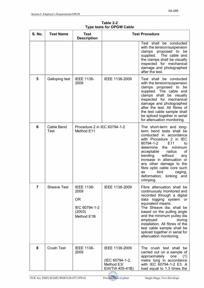
Section 6: Employer’sRequirements/OPGW
OCB. No. PMD/EGMP/BNRTLSS-077/078-01 Procurement of plant Single-Stage, Two-Envelope
Table 2-2
Type tests for OPGW Cable
S. No.
Test Name
Test Description
Test Procedure
Test shall be conducted with the tension/suspension clamps proposed to be supplied. The cable and the clamps shall be visually inspected for mechanical damage and photographed after the test.
5
Galloping test
IEEE 1138-2009
IEEE 1138-2009
Test shall be conducted with the tension/suspension clamps proposed to be supplied. The cable and clamps shall be visually inspected for mechanical damage and photographed after the test. All fibres of the test cable sample shall be spliced together in serial for attenuation monitoring.
6
Cable Bend Test
Procedure 2 in IEC 60794-1-2 Method E11
The short-term and long-term bend tests shall be conducted in accordance with Procedure 2 in IEC 60794-1-2 E11 to determine the minimum acceptable radius of bending without any increase in attenuation or any other damage to the fibre optic cable core such as bird caging, deformation, kinking and crimping.
7
Sheave Test
IEEE 1138-2009 OR IEC 60794-1-2 (2003)
Method E1B
IEEE 1138-2009
Fibre attenuation shall be continuously monitored and recorded through a digital data logging system or equivalent means. The Sheave dia. shall be based on the pulling angle and the minimum pulley dia employed during installation. All fibres of the test cable sample shall be spliced together in serial for attenuation monitoring.
8 Crush Test
IEEE 1138-2009
IEEE 1138-2009 (IEC 60794-1-2, Method E3/ EIA/TIA 455-41B)
The crush test shall be carried out on a sample of approximately one (1) metre long in accordance with IEC 60794-1-2 E3. A load equal to 1.3 times the
IIA-295

Section 6: Employer’sRequirements/OPGW
OCB. No. PMD/EGMP/BNRTLSS-077/078-01 Procurement of plant Single-Stage, Two-Envelope
Table 2-2
Type tests for OPGW Cable
S. No.
Test Name
Test Description
Test Procedure
weight of a 400-metre length of fibre optic cable shall be applied for a period of 10 minutes. A permanent or temporarily increase in optical attenuation value greater than 0.1 dB change in sample shall constitute failure. The load shall be further increased in small increments until the measured attenuation of the optical waveguide fibres increases and the failure load recorded along with results.
9
Impact Test
IEEE 1138-2009
IEEE 1138-2009, (IEC 60794-1-2 E4/ EIA/TIA 455-25B)
The impact test shall be carried out in accordance with IEC 60794-1-2 E4. Five separate impacts of 0.1-0.3kgm shall be applied. The radius of the intermediate piece shall be the reel drum radius ± 10%. A permanent or temporary increase in optical attenuation value greater than 0.1 dB/km change in sample shall constitute failure.
10
Creep Test
IEEE 1138-2009
IEEE 1138-2009
As per Aluminium Association Method, the best-fit straight line shall be fitted to the recorded creep data and shall be extrapolated to 25 years. The strain margin of the cable at the end of 25 years shall be calculated. The time when the creep shall achieve the strain margin limits shall also be calculated.
11
Fibre Strain Test
IEEE 1138-1994
IEEE 1138-1994
12
Strain Margin Test
IEEE 1138-2009
IEEE 1138-2009
13
Stress strain Test
IEEE 1138-2009
IEEE 1138-2009
IIA-296

Section 6: Employer’sRequirements/OPGW
OCB. No. PMD/EGMP/BNRTLSS-077/078-01 Procurement of plant Single-Stage, Two-Envelope
Table 2-2
Type tests for OPGW Cable
S. No.
Test Name
Test Description
Test Procedure
14 Cable Cut-off wavelength Test
IEEE 1138-1994
IEEE 1138-1994
15
Temperature Cycling Test
IEEE 1138-2009
IEEE 1138-2009 Or IEC 60794-1-2, Method F1
16
Corrosion (Salt Spray) Test
EIA/TIA 455-16A
17
Tensile Performance Test
IEC 60794-1-2 E1 / EIA/TIA 455-33B
The test shall be conducted on a sample of sufficient length in accordance with IEC 60794-1-2 E1. The attenuation variation shall not exceed 0.05 dB/Km up to 90% of RTS of fibre optic cable. The load shall be increased at a steady rate up to rated tensile strength and held for one (1) minute. The fibre optic cable sample shall not fail during the period. The applied load shall then be increased until the failing load is reached and the value recorded.
18
Lightning Test
IEC 60794-4-10 / IEC 60794-1-2 (2003)
The OPGW cable construction shall be tested in accordance with IEC 60794-1-2, Method H2 for Class 1.
19
DC Resistance Test
(IEC 60228)
On a fibre optic cable sample of minimum 1 metre length, two contact clamps shall be fixed with a predetermined bolt torque. The resistance shall be measured by a Kelvin double bridge by placing the clamps initially zero metre and subsequently one metre apart. The tests shall be repeated at least five times and the average value recorded after correcting at 20°C.
-End Of Table-
2.1.2.3 Type Test on OPGW Cable Fittings
The type tests to be conducted on the OPGW Cable fittings and accessories are listed below: (i) Mechanical Strength Test for Suspension/Tension Assembly Applicable Standards: IEC 61284, 1997.
IIA-297
Section 6: Employer’sRequirements/OPGW
OCB. No. PMD/EGMP/BNRTLSS-077/078-01 Procurement of plant Single-Stage, Two-Envelope
Suspension Assembly The armour rods /reinforcement rods are assembled on to the approved OPGW using the Installation Instructions to check that the assembly is correctly fitted and is the same that will be carried out during installations. Part 1: The suspension assembly shall be increased at a constant rate up to a load equal to 50% of the specified minimum Failure Load increased and held for one minute for the test rig to stabilise. The load shall then be increased at a steady rate to 67% of the minimum Failure Load and held for five minutes. The angle between the cable, the Suspension Assembly and the horizontal shall not exceed 16o. This load shall then be removed in a controlled manner and the Protection Splice disassembled. Examination of all the components shall be made and any evidence of visual deformation shall be documented. Part 2: The Suspension clamp shall then be placed in the testing machine. The tensile load shall gradually be increased up to 50% of the specified Minimum Failure Load of the Suspension Assembly and held for one minute for the Test Rig to stabilise and the load shall be further increased at a steady rate until the specified minimum Failure Load is reached and held for one minute. No fracture should occur during this period. The applied load shall then be increased until the failing load is reached and the value shall be documented. Tension Assembly The Tension Assembly is correctly fitted and is the same that will be carried out during installations. Part 1: The tension assembly (excluding tension clamp) shall be increased at a constant rate up to a load equal to 50% of the specified minimum Failure Load increased at a constant rate and held for one minute for the test rig to stabilise. The load shall then be increased at a steady rate to 67% of the minimum Failure Load and held for five minutes. This load shall then remove in a controlled manner and the Tension Assembly disassembled. Examination of the Tension Dead-End and associated components shall be made and any evidence of visual deformation shall be documented. Part 2: The Tension Dead-End and associated components shall then be reassembled and bolts tightened as before. The tensile load shall gradually be increased up shall gradually be increased up to 50% of the specified Minimum Failure Load of the Tension Assembly and held for one minute for the Test Rig to stabilise and the load shall be further increased at a steady rate until the specified minimum Failure Load is reached and held for one minute. No fracture should occur during this period. The applied load shall then be increased until the failing load is reached and the value shall be documented. Acceptance Criteria for Tension/Suspension Assembly: - No evidence of binding of the Nuts or Deformation of components at end of Part 1 of Test. - No evidence of Fracture at the end of one minute at the minimum failure load during Part 2 of the Test. Any result outside these parameters shall constitute a failure. (ii) Clamp Slip Strength Test for Suspension Assembly
IIA-298

Section 6: Employer’sRequirements/OPGW
OCB. No. PMD/EGMP/BNRTLSS-077/078-01 Procurement of plant Single-Stage, Two-Envelope
The suspension assembly shall be vertically suspended by means of a flexible attachment. A suitable length fibre optical cable shall be fixed in the clamps. Once the Suspension Clamp has been assembled, the test rig is tensioned to 1 kN and the position scaleontherecorder‘zeroed’.Thetestrig isthentensionedto2.5kNandtherelative positions of the Reinforcing Rods, Armour Rods and Suspension Clamp shall be marked by a suitable means to confirm any slippage after the test has been completed. The relative positions of the helical Armour Rods and associated Reinforcing Rods at each end shall be marked and also 2 mm relative position between clamp body and Armour Rods shall be marked on one side. The load shall be increased to 12 kN at a loading rate of 3 kN/min and held for one minute. At the end of this one minute period, the relative displacement between clamp body and the armour rods shall be observed. If the slippage is 2 mm or above, the test shall be terminated. Otherwise, at the end of one minute the position of the clamp body and 2 mm. relative positions between clamp body and armour rods shall be marked on the other side. After the one minute pause, the load shall be further increased at a loading rate of 3 kN/min, and recording of load and displacement shall continue until either the relative Position displacement between clamp body and armour rods reaches more than 2 mm or the load reaches the maximum slip load of 17 kN. On reaching either of the above values the test is terminated. Visual examination of all paint marks shall be recorded, and a measurement of any displacement recorded in the Table of Results. Acceptance Criteria: The Suspension Clamp has passed the Slip Test if the following conditions are met: · No slippage* shall occur at or below the specified minimum slip load.
* Definition of no slippage in accordance with IEC 61284, 1997:- Any relative movement less than 2 mm is accepted. The possible couplings or elongations produced by the cable as a result of the test itself are not regarded as slippage.
· Slippage shall occur between the specified maximum and minimum slip load of 12
- 17 kN. · There shall be no slippage of the Reinforcing Rods over the cable, and no slippage
of the Armour Rods over the Reinforcing Rods. · The relative movement (i.e. more than 2 mm between Armour Rods & Clamp
body) between minimum 12 kN and maximum slip 17 kN, shall be considered as slip.
· The Armour Rods shall not be displaced from their original lay or damaged**.
** Definition of no damage in accordance with convention expressed in IEC 61284: 1997 no damage, other than surface flattening of the strands shall occur.
Any result outside these parameters is a failure. (iii) Slip Strength Test of Tension Clamp Tension clamps shall be fitted on an 8 m length of fibre optic cable on both ends. The assembly shall be mounted on a tensile testing machine and anchored in a manner similar to the arrangement to be used in service. A tensile load shall gradually be applied up to 20 % of the RTS of OPGW. Displacement transducers shall be installed to measure the relative movement between the OPGW relative to the Reinforcing Rods and Tension Dead -End relative to Reinforcing Rods. In addition, suitable marking shall be made on the OPGW and Dead-End to confirm grip. The load shall be gradually increased at a constant rate up to 50 % of the UTS and the position scale of the recorder
IIA-299

Section 6: Employer’sRequirements/OPGW
OCB. No. PMD/EGMP/BNRTLSS-077/078-01 Procurement of plant Single-Stage, Two-Envelope
is zeroed. The load shall then gradually increased up to 95 % of the UTS and maintained for one minute. After one minute pause, the load shall be slowly released to zero and the marking examined and measured for any relative movement. Acceptance Criteria: - No movement* shall occur between the OPGW and the Reinforcing Rods, or between
the Reinforcing Rods and the Dead-End assembly. - No failure or damage or disturbance to the lay of the Tension Dead-End, Reinforcing
Rods or OPGW. * Definition of no movement as defined in IEC 61284: Any relative movement less than 2 mm is accepted. The possible couplings or elongations produced by the conductor as a result of the test itself are not regarded as slippage. Any result outside these parameters shall constitute a failure. (iv) Grounding Clamp and Structure Mounting Clamp Fit Test For structure mounting clamp, one series of tests shall be conducted with two fibre optic cables installed, one series of tests with one fibre optic cable installed in one groove, and one series of tests with one fibre optic cable in the other groove. Each clamp shall be installed including clamping compound as required on the fibre optic cable. The nut shall be tightened on to the bolt by using torque wrench with a torque of 5.5 kgm or supplier's recommended torque and the tightened clamp shall be held for 10 minutes. After the test remove the fibre optic cable and examine all its components for distortion, crushing or breaking. Also the fibre optic cable shall be checked to ensure free movement within the core using dial callipers to measure the diameter of the core tube. The material shall be defined as failed if any visible distortion, crushing, cracking or breaking of the core tube is observed or the fibre optic cable within the core tube is not free to move, or when the diameter of the core tube as measured at any location in the clamped area is more than 0.5 mm larger or smaller of the core diameter as measured outside the clamped area. (v) Structure Mounting Clamp Strength Test The clamp and mounting assembly shall be assembled on a vertical 200 mm x 200 mm angle and a short length of fibre optic cable installed. A vertical load of 200 kg shall be applied at the end of the mounting clamp and held for 5 minutes. Subsequently, the load shall be increased to 400 kg and held for 30 seconds. Any visible distortion, slipping or breaking of any component of the mounting clamp or assembly shall constitute failure. 2.1.2.4 Type Test on Vibration Damper
The testing standard of vibration damper for OPGW shall be as per applicable international standard i.e. IEC 61897. (a) Dynamic Characteristic Test The damper shall be mounted with its clamp tightened with torque recommended by the manufacturer on shaker table capable of simulating sinusoidal vibrations for Critical Aeolian Vibration frequency band ranging from 0.18/d to 1.4/d – where d is the OPGW cable diameter in meters. The damper assembly shall be vibrated vertically with a ±1 mm amplitude from 5 to 15 Hz frequency and beyond 15 Hz at 0.5 mm to determine following characteristics with the help of suitable recording instruments.
(i) Force Vs frequency
(ii) Phase angle Vs frequency
IIA-300

Section 6: Employer’sRequirements/OPGW
OCB. No. PMD/EGMP/BNRTLSS-077/078-01 Procurement of plant Single-Stage, Two-Envelope
(iii) Power dissipation Vs frequency The Force Vs frequency curve shall not show steep peaks at resonance frequencies and deep troughs between the resonance frequencies. The resonance frequencies shall be suitably spread within the Aeolian vibration frequency-band between the lower and upper dangerous frequency limits determined by the vibration analysis of fibre optic cable without dampers. Acceptance criteria for vibration damper:
(i) The above dynamic characteristics test on five damper shall be conducted.
(ii) The mean reactance and phase angle Vs frequency curves shall be drawn with the criteria of best fit method.
(iii) The above mean reactance response curve should lie within following limits:
V.D. for OPGW - 0.060 f to 0.357 f kgf/mm*
Where f is frequency in Hz.
(iv) The above mean phase angle response curve shall be between 25o to 130o within the frequency range of interest.
(v) If the above curve lies within the envelope, the damper design shall be considered to have successfully met the requirement.
(vi) Visual resonance frequencies of each mass of damper is to be recorded and to be compared with the guaranteed values.
(b) Vibration Analysis The vibration analysis of the fibre optic cable shall be done with and without damper installed on the span. The vibration analysis shall be done on a digital computer using energy balance approach. The following parameters shall be taken into account for the purpose of analysis.
(i) The analysis shall be done for single fibre optic cable without armour rods. The tension shall be taken as 25% of RTS of fibre optic cable for a span ranging from 100 m to 1100 m.
(ii) The self damping factor and flexural stiffness (EI) for fibre optic cable shall
be calculated on the basis of experimental results. The details to experimental analysis with these data shall be furnished.
(iii) The power dissipation curve obtained from Damper Characteristics Test
shall be used for analysis with damper.
(iv) Examine the Aeolian Vibration level of the fibre optic cable with and without vibration damper installed at the recommended location or wind velocity ranging from 0 to 30 Km per hour, predicting amplitude, frequency and vibration energy input.
(v) From vibration analysis of fibre optic cable without damper, antinode
vibration amplitude and dynamic strain levels at clamped span extremities as well as antinodes shall be examined and thus lower and upper dangerous frequency limits between which the Aeolian vibration levels exceed the specified limits shall be determined.
(vi) From vibration analysis of fibre optic cable with damper(s) installed at the
recommended location, the dynamic strain level at the clamped span extremities, damper attachment point and the antinodes on the fibre optic
IIA-301

Section 6: Employer’sRequirements/OPGW
OCB. No. PMD/EGMP/BNRTLSS-077/078-01 Procurement of plant Single-Stage, Two-Envelope
cable shall be determined. In addition to above damper clamp vibration amplitude and antinodes vibration amplitudes shall also be examined.
The dynamic strain levels at damper attachment point, clamped span extremities and antinodes shall not exceed the specified limits. The damper clamp vibration amplitude shall not be more than that of the specified fatigue limits.
(c) Fatigue Tests (i) Test Set Up The fatigue tests shall be conducted on a laboratory set up with a minimum effective span length of 30m. The fibre optic cable shall be tensioned at 25% of RTS of fibre optic cable and shall not be equipped with protective armour rods at any point. Constant tension shall be maintained within the span by means of lever arm arrangement. After the fibre optic cable has been tensioned, clamps shall be installed to support the fibre optic cable at both ends and thus influence of connecting hardware fittings are eliminated from the free span. The clamps shall not be used for holding the tension on the fibre optic cable. There shall be no loose parts, such as suspension clamps, U bolts, on the test span supported between clamps mentioned above. The span shall be equipped with vibration inducing equipment suitable for producing steady standing vibration. The inducing equipment shall have facilities for step less speed control as well as step less amplitude arrangement. Equipment shall be available for measuring the frequency, cumulative number of cycles and amplitude of vibration at any point along the span. (ii) Fatigue Test The vibration damper shall be installed on the test span with the manufacturer's specified tightening torque. It shall be ensured that the damper shall be kept minimum three loops away from the shaker to eliminate stray signals influencing damper movement. The damper shall then be vibrated at the highest resonant frequency of each damper mass. For dampers involving torsional resonant frequencies, tests shall be done at torsional modes also in addition to the highest resonant frequencies at vertical modes. The resonance frequency shall be identified as the frequency at which each damper mass vibrates with the maximum amplitude on itself. The amplitude of vibration of the damper clamp shall be maintained not less than ±25/f mm where f is the frequency in Hz. The test shall be conducted for minimum ten million cycles at each resonant frequency mentioned above. During the test, if resonance shift is observed, the test frequency shall be tuned to the new resonant frequency. The clamp slip test as mentioned herein shall be repeated after fatigue tests without retorquing or adjusting the damper clamp, and the clamp shall withstand a minimum load equal to 80% of the slip strength for a minimum duration of one minute. After the above tests, the damper shall be removed from fibre optic cable and subjected to dynamic characteristics test. There shall not be any major deterioration in the characteristics of the damper. The damper then shall be cut open and inspected. There shall not be any broken, loose, or damaged part. There shall not be significant deterioration or wear of the damper. The fibre optic cable under clamp shall also be free from any damage. For purposes of acceptance, the following criteria shall be applied:
(1) There shall not be any resonant frequency shift before and after the
IIA-302

Section 6: Employer’sRequirements/OPGW
OCB. No. PMD/EGMP/BNRTLSS-077/078-01 Procurement of plant Single-Stage, Two-Envelope
test by more than ± 20% (2) The power dissipation of the damper before and after test at the
individual resonant frequencies do not differ by more than ± 20% Beside above tests, the type tests listed below in the table shall also be conducted on Vibration Damper
Sl No.
Test Name Test Procedure
1 Visual examination & Dimensional and material verification
IEC 61897 Clause 7.1 & 7.2
2 Clamp Slip test IEC 61897 Clause 7.5 3 Clamp bolt tightening test IEC 61897 Clause 7.7
4 Attachments of weights to messenger cable
IEC 61897 Clause 7.8
5 Attachment of clamps to messenger cable
IEC 61897 Clause 7.8
6 Damper effectiveness evaluation IEC 61897 Clause 7.11.3.2
2.1.2.5 Type Tests for Splice Enclosures (Joint Box)
Following Type tests shall be demonstrated on the Splice Enclosure(s) (Splice Enclosure/Box). For certain tests, lengths of the fibre optic cable shall be installed in the splice box, and the fibres must be spliced and looped in order to simulate conditions of use. The attenuation of the fibres shall be measured, during certain tests, by relevant Fibre Optic Test Procedures (EIA/TIA 455 or IEC 60794-1 procedures). (i) Temperature Cycling Test FO cable is installed in the splice enclosure and optical fibres spliced and looped. The box must be subjected to 5 cycles of temperature variations of -40°C to +65°C with a dwell time of at least 2 hours on each extreme. Fibre loop attenuation shall be measured in accordance with EIA 455-20 / IEC 60794-1-C10. The variation in attenuation shall be less than ±0.05dB. The final humidity level, inside the box, shall not exceed the initial level, at the closing of the box. (ii) Humid Heat test The sealed splice enclosure, with fibres spliced and looped inside, must be subjected to a temperature of +55°C ±2°C with a relative humidity rate of between 90% and 95% for 5 days. The attenuation variation of the fibres during the duration of the test shall be less than ±0.05dB, and the internal humidity rate measured, less than 2%. (iii) Rain Withstand Test / Water Immersion test The splice enclosure with optical fibres cable installed and fibres spliced fixed, shall be subjected to 24 hours of simulated rain in accordance with IEC 60060 testing requirements. No water seepage or moisture shall be detected in the splice enclosure. The attenuation variation of the fibres after the test shall be less than ±0.05dB. (iv) Vibration Test The splice enclosure, with fibres united inside, shall be subjected to vibrations on two axes with a frequency scanning of 5 to 50 Hz. The amplitude of the vibrations shall be constant at 0.450mm, peak to peak, for 2 hours, for each of the vibrations' axes. The
IIA-303

Section 6: Employer’sRequirements/OPGW
OCB. No. PMD/EGMP/BNRTLSS-077/078-01 Procurement of plant Single-Stage, Two-Envelope
variation in attenuation, of the fibres, shall be less than ±0.05dB. The splice enclosure shall be examined for any defects or deformation. There shall be no loosening or visible damage of the FO cable at the entry point. (v) Bending and Torsion test The splice enclosure, with fibres spliced inside, shall be firmly held in place and be subjected to the following sequence of mechanical stresses on the cable: a) 3 torsion cycles of ±180° shall be exercised on the cable. Each cycle shall be less
than one minute. b) 3 flexure cycles of the cable, of ±180° with one cycle less than one minute. The variation in the attenuation, of the fibres, shall be less than ±0.05dB. The cables connection ring shall remain securely fixed to the box with the connection maintained firmly. No defects/fissures shall be noted on the joint ring or on the splice enclosure (vi) Tensile test The splice enclosure with cable fixed to the boxes shall be subjected to a minimum tension of 448 N for a period of two minutes. No fissure shall be noted in the connections or on the box. (vii) Drop Test With 2 lengths of 11 metres of cable fixed to the box, it shall be dropped five times from a height of 10 metres. There shall be no fissure, at all, of the box, and the connections shall remain tight. The test surface shall be carried out in accordance with IEC 60068-2-32. 2.1.2.6 Type Tests for Fibre Optic Approach Cable The type tests to be conducted on the Fibre Optic Approach cable are listed in Table 2-3: Type Tests for Fibre Optic Approach Cable. Unless specified otherwise in the technical specifications or the referenced standards, the optical attenuation of the specimen, measured during or after the test as applicable, shall not increase by more than 0.05 dB/Km.
Table 2-3: Type Tests Fibre Optic Approach Cable
S.NO.
Test Name
Test Procedure
1
Water Ingress Test
(IEC 60794-1-F5 / EIA 455-82B) Test duration : 24 hours
2
Seepage of filling compound
(EIA 455-81A)
Preconditioning : 72 hours,
Test duration : 24 hours.
3 Crush Test
(IEC 60794-1-E3/ EIA 455-41)
4
Impact Test
(IEC-60794-1-E4/ EIA 455-25A)
5
Stress strain Test
(EIA 455-33A)
6
Cable Cut-off wavelength
(EIA 455-170)
IIA-304

Section 6: Employer’sRequirements/OPGW
OCB. No. PMD/EGMP/BNRTLSS-077/078-01 Procurement of plant Single-Stage, Two-Envelope
Table 2-3:
Type Tests Fibre Optic Approach Cable
S.NO.
Test Name
Test Procedure
Test
7 Temperature Cycling Test
(IEC60794-1-F1/EIA-455-3A) – 2 cycles
-End Of Table-
2.1.2.6.1 Impact Test The Impact test shall be carried out in accordance with IEC:60794-1-E4. Five separate impacts of 2.0 kg shall be applied at different locations. The radius of the intermediate piece shall be the reel drum radius ± 10%. A permanent or temporary increase in optical attenuation value greater than 0.05 dB/km shall constitute failure.
2.2 Factory Acceptance Tests
Factory acceptance tests shall be conducted on randomly selected final assemblies of all equipment to be supplied. Factory acceptance testing shall be carried out on OPGW Cable and associated hardware & fittings, Approach Cable, Joint Box, FODP etc. and all other items for which price has been identified separately in the Bid Price Schedules.
Material shall not be shipped to the Employer until required factory tests are completed satisfactorily, all variances are resolved, full test documentation has been delivered to the Employer, and the Employer has issued Material Inspection & Clearance Certificate (MICC). Successful completion of the factory tests and the Employer approval to ship, shall in no way constitute final acceptance of the system or any portion thereof. These tests shall be carried out in the presence of the Employer's authorised representatives unless waiver forwitnessingbyEmployer’srepresentativesisintimatedtothecontractor.
Factory acceptance tests shall not proceed without the prior delivery to and approval of all test documentation by the Employer.
The factory acceptance tests for the supplied items shall be proposed by the Contractor in accordance with technical specifications and Contractor's (including Sub-Contractor's / supplier's) standard FAT testing program. In general the FAT for other items shall include at least: Physical verification, demonstration of technical characteristics, various operational modes, functional interfaces etc.
For Test equipment FAT shall include supply of proper calibration certificates, demonstration of satisfactory performance, evidence of correct equipment configuration andmanufacturer’sfinalinspectioncertificate/report.
2.2.1 Sampling for FAT
From each batch of equipment presented by the Contractor for Factory acceptance testing, the Employer shall select random sample(s) to be tested for acceptance. Unless otherwise agreed, all required FAT tests in the approved FAT procedures, shall be performed on all samples. The Sampling rate for the Factory acceptance tests shall be minimum 10% of the batch size (minimum 1) for all items. The physical verification shall be carried out on 100% of the offered quantities as per the approved FAT procedure. In
IIA-305

Section 6: Employer’sRequirements/OPGW
OCB. No. PMD/EGMP/BNRTLSS-077/078-01 Procurement of plant Single-Stage, Two-Envelope
case any of the selected samples fail, the failed sample is rejected and additional 20% samples shall be selected randomly and tested. In case any sample from the additional 20% also fails the entire batch may be rejected.
For the OPGW cable hardware fittings & accessories, the minimum sampling rate, and batch acceptance criteria shall be as defined in IS 2486. The Sampling rate for the Factory acceptance tests shall be 10% of the batch size (minimum 2) for FO cable drums, FODPs, Joint box and other similar items.
Since FAT testing provides a measure of assurance that the Quality Control objectives are being met during all phases of production, the Employer reserves the right to require the Contractor to investigate and report on the cause of FAT failures and to suspend further testing/ approvals until such a report is made and remedial actions taken, as applicable.
2.2.2 Production Testing
Production testing shall mean those tests which are to be carried out during the process of production by the Contractor to ensure the desired quality of end product to be supplied by him. The production tests to be carried out at each stage of production shall be based on the Contractor’s standard quality assurance procedures. The productiontests to be carried out shall be listed in the Manufacturing Quality Plan (MQP), alongwith information such as sampling frequency, applicable standards, acceptance criteria etc. The production tests would normally not be witnessed by the Employer. However, the Employer reserves the right to do so or inspect the production testing records in accordance with Inspection rights specified for this contract. 2.2.3 Factory Acceptance Tests on Optical Fibre to be supplied with OPGW
The factory acceptance tests listed in table below are applicable for the Optical fibres to be supplied. The listed tests follow testing requirements set forth in IEEE standard 1138/IEC 60794. The referenced sections specify the detailed test description. The acceptance norm shall be as specified in the above mentioned IEEE standards unless specified otherwise in the technical specifications.
Table 2-4
Factory Acceptance Tests for Optical Fibres: Optical Tests S. No.
Test Name
Acceptance Criteria
Test procedure
1
Attenuation Coefficient
T S,Table 1-1(a)
EIA/TIA 455- 78A
2
Point Discontinuities of attenuation
TS, Section 1.1.2
EIA/TIA 455-59
3
Attenuation at Water Peak
TS ,Table 2-1(a)
EIA/TIA 455- 78A
4
Chromatic Dispersion
EIA/TIA 455- 168A/169A/175A
5
Core – Clad Concentricity Error
EIA/TIA 455-/176
6
Cladding diameter
EIA/TIA 455-176
7
Fibre Tensile Proof Testing
EIA/TIA 455-31B
-End of table-
IIA-306

Section 6: Employer’sRequirements/OPGW
OCB. No. PMD/EGMP/BNRTLSS-077/078-01 Procurement of plant Single-Stage, Two-Envelope
The test report for the above tests for the fibers carried out by the Fiber Manufacturer and used in the OPGW cables shall be shown to the inspector during OPGW cable FAT and shall be submitted along with the OPGW cable FAT report.
2.2.4 Factory Acceptance Test on OPGW Cable
The factory acceptance tests for OPGW cable specified below in Table follow the requirements set forth in IEEE standard 1138 / IEC 60794. The FAT shall be carried out on 10% of offered drums in each lot as specified in technical specifications and the optical tests shall be carried out in all fibres of the selected sample drums. The Rated Tensile Strength test shall be carried out on one sample in each lot.
Table 2-5
Factory Acceptance Tests on OPGW Applicable standard: IEEE 1138 / IEC 60794
S.
No.
Factory Acceptance Test on Manufactured OPGW
1
Attenuation Co-efficient at 1310 nm and 1550 nm
2
Point discontinuities of attenuation
3
Visual Material verification and dimensional checks as per approved DRS/Drawings
4
Rated Tensile Strength
5
Lay Length Measurements
2.2.5 Factory Acceptance Test on OPGW Fittings
The factory acceptance tests for OPGW Fittings as specified below in Table 2-6. The sampling plan shall be as per relevant standard:
Table 2-6
Factory Acceptance Tests On OPGW Fittings S. No.
Factory Acceptance Test
Suspension Assembly
1
UTS/Mechanical Strength of the assembly
2
Clamp Slip Test
3
Visual Material verification and dimensional checks as per approved DRS/Drawings
4 Mechanical strength of each component
5 Galvanising test
Tension Assembly
6 Clamp Slip Strength test
7
Visual Material verification and dimensional checks as per approved DRS/Drawings
8 Mechanical strength of each component
IIA-307

Section 6: Employer’sRequirements/OPGW
OCB. No. PMD/EGMP/BNRTLSS-077/078-01 Procurement of plant Single-Stage, Two-Envelope
Table 2-6
Factory Acceptance Tests On OPGW Fittings S. No.
Factory Acceptance Test
9 Galvanising Test
Vibration Damper
10
Galvanising test on damper, masses and messenger wires
11
Damper response (resonant frequencies)
12
Clamp Slip test
13
Strength of messenger wires
14 Attachments of weights to messenger cable
15
Attachments of clamps to messenger cable
16
Clamp bolt tightening test
17 Clamp bolt torque test
18 Dynamic characteristic test.
19
Visual Material verification and dimensional checks as per approved DRS/Drawings
Structure Mounting Clamp
20 Clamp fit test
21 Clamp Strength test
22 Visual Material verification and dimensional checks as per approved DRS/Drawings
End of Table
2.2.6 Factory Acceptance Test on Approach Cable
The factory acceptance tests for Approach Cable specified below in Table 2-7:
Table 2-7
Factory Acceptance Tests On Approach Cable S. No.
Factory Acceptance Test
1
Attenuation Co-efficient at 1310 nm and 1550 nm
2
Point discontinuities of attenuation
3
Visual Material verification and dimensional checks as per approved DRS/Drawings
IIA-308

Section 6: Employer’sRequirements/OPGW
OCB. No. PMD/EGMP/BNRTLSS-077/078-01 Procurement of plant Single-Stage, Two-Envelope
2.2.7 Factory Acceptance Test on Splice Enclosure (Joint Box) /FODP
The factory acceptance tests for Splice Enclosures/FODP as specified below in Table: 2-8
Table 2-8 Factory Acceptance Tests on Splice Enclosures (Joint Box)/FODP
S. No.
Factory Acceptance Test
1
Visual check of Quantities and Specific Component Number for each component of Splice Enclosure/FODP and dimensional checks against the approved drawings.
2.2.8 Factory Acceptance Test on Test Equipment & other items
As per technical specification and approved DRS/Documents. 2.3 Site Acceptance Tests
The Contractor shall be responsible for the submission of all material & test equipment supplied in this contract for site tests and inspection as required by the Employer. All equipment shall be tested on site under the conditions in which it will normally operate.
The tests shall be exhaustive and shall demonstrate that the overall performance of the contract works satisfies every requirement specified. At a minimum Site Acceptance Testing requirement for FO cable etc. is outlined in following section. This testing shall be supplemented by the Contractor's standard installation testing program, which shall be in accordance with his quality plan(s) for FO installation.
During the course of installation, the Employer shall have full access for inspection and verification of the progress of the work and for checking workmanship and accuracy, as may be required. On completion of the work prior to commissioning, all equipment shall be tested to the satisfaction of the Employer to demonstrate that it is entirely suitable for commercial operation.
2.3.1 Minimum Site Acceptance Testing Requirement for FO Cabling
Prior to installation, every spooled fibre optic cable segment shall be tested for compliance with the Pre-shipment data previously received from the manufacturer. This requirement will preclude the installation of out of specification cable segments that may have been damaged during shipment. 2.3.1.1 Phases of Site Acceptance Testing
SAT shall be carried out link by link from FODP to FODP. SAT may be performed in parts in case of long links. The tests, checks, adjustments etc conducted by the Contractor prior to offering the equipment for SAT shall be called Pre-SAT activities. The Pre-SAT activities shall be described in the installation manuals and Field Quality Plan documents.
IIA-309

Section 6: Employer’sRequirements/OPGW
OCB. No. PMD/EGMP/BNRTLSS-077/078-01 Procurement of plant Single-Stage, Two-Envelope
Sag and tension of OPGW shall generally be as per approved sag-tension chart and during installation, sag and tension of OPGW shall be documented. Upon completion of a continuous cable path, all fibres within the cable path shall be demonstrated for acceptance of the cable path. Fibre Optic cable site testing minimum requirements are provided in Table 2-9(a) through 2-9(c) below:
Table 2-9(a) Fibre Optic Cable Pre-Installation Testing
Item:
Description:
1.
Physical Inspection of the cable assembly for damage
2.
Optical fibre continuity and fibre attenuation with OTDR at 1550 nm
3.
Fibre Optic Cable length measurement using OTDR
Table 2-9(b) Fibre Optic Cable Splicing Testing
Item:
Description:
1.
Per splice bi-directional average attenuation with OTDR
2.
Physical inspection of splice box/enclosure for proper fibre / cable routing techniques
3.
Physical inspection of sealing techniques, weatherproofing, etc.
Table 2-9(c)
Fibre Optic Cable Commissioning Testing Item:
Description:
1.
End to End (FODP to FODP) bi-directional average attenuation of each fibre at 1310 nm and 1550 nm by OTDR.
2.
End to End (FODP to FODP) bi-directional average attenuation of each fibre at 1310 nm and 1550 nm by Power meter.
3.
Bi-directional average splice loss by OTDR of each splice as well as for all splices in the link (including at FODP also).
4.
Proper termination and labelling of fibres & fibre optic cables at FODP as per approved labelling plan.
-End of Table-
----------------------------------------------End of this Section-------------------------------------------
IIA-310

Section 6: Employer’sRequirements/OPGW
OCB. No. PMD/EGMP/BNRTLSS-077/078-01 Procurement of plant Single-Stage, Two-Envelope
Section-9(c)
Installation for OPGW Cabling
Table of Content
3.1 Installation requirements .................................................................................................312
3.1.1 Installation of OPGW cable .............................................................................................312
3.1.2 Installation Hardware fittings ..........................................................................................312
3.2 Installation of Approach cable ..........................................................................................312
3.3 Optical fibre termination and splicing................................................................................313
3.4 Fibre Optic Distribution Panel...........................................................................................313
3.5 Methodology for installation and termination .....................................................................313
3.6 Cable raceways.................................................................................................................314
IIA-311

Section 6: Employer’sRequirements/OPGW
OCB. No. PMD/EGMP/BNRTLSS-077/078-01 Procurement of plant Single-Stage, Two-Envelope
Installation of OPGW Cabling
3.1 Installation requirements
The OPGW cable shall be installed at the top of the tower in place of earthwire (only one of the earthwire peaks in case of 400kV & above lines, if applicable) for under construction transmission lines as envisaged. The OPGW cable sections shall normally be terminated & spliced only on tension towers. In exceptional circumstances, and on Employer specific approval, cable may be terminated on suspension towers, but in this case tower strength shall be examined to ensure that tower loads are within safe limits and if required, necessary tower strengthening shall be carried out by the Contractor. For OPGW Cable to be installed on new line transmission line, the stringing shall be carried by the Transmission Line Contractor as per the stringing chart/procedure submitted by them and approved by Employer. The Contractor shall install OPGW as per approved stringing procedure. The Contractor shall follow precautions including proper location of drum site, installation of stringing blocks/pulleys, proper sagging, proper installation of hardware, proper tension as per Sag-Tension chart, provision of service loops of OPGW in jointing locations etc.
3.1.1 Installation of OPGW cable
The OPGW cable sections shall normally be terminated & spliced only on tension towers. In exceptional circumstances and on Employer specific approval, cable may be terminated on Suspension towers, but in this case tower strength shall be examined to ensure that tower loads are within safe limits and if required, necessary tower strengthening shall be carried out by the Contractor. In such a case, the jointing of OPGW on suspension tower if required, shall be acceptable subject to its suitability.
3.1.2 Installation Hardware Fittings
All required hardware fittings shall be installed alongwith OPGW Cable.
3.2 Installation of Approach Cable
The existing cable trenches/ cable raceways proposed to be used shall be identified in the survey report. The Contractor shall make its best effort to route the cable through the existing available cable trenches. Where suitable existing cable trenches are not available, suitable alternatives shall be provided after Employer approval. However, the approach cable shall be laid in the HDPE pipe in all condition.
Suitable provisions shall be made by the Contractor to ensure adequate safety earthing and insulated protection for the approach cable.
IIA-312
Section 6: Employer’sRequirements/OPGW
OCB. No. PMD/EGMP/BNRTLSS-077/078-01 Procurement of plant Single-Stage, Two-Envelope
All required fittings, supports, accessories, ducts, inner ducts, conduits, risers and any item not specially mentioned but required for laying and installation of approach cables shall be supplied and installed by the Contractor.
3.3 Optical Fibre Termination and Splicing
Optical fibre terminations shall be installed in Fibre Optic Distribution Panels (FODP) designed to provide protection for fibre splicing of preconnectorized pigtails and to accommodate connectorized termination and coupling of the fibre cables. The Contractor shall provide rack /wall mounted Fibre Optic Distribution Panels (FODPs) sized as indicated in the appendices and shall terminate the fibre optic cabling up to the FODPs. ThelocationofFODPrackshallbefixedbytheContractor,withtheEmployer’sapproval.
3.4 Fibre Optic Distribution Panel
At each location requiring the termination of at least one fibre within a cable, all fibres within that cable shall be connectorized and terminated in Fibre Optic Distribution Panels in a manner consistent with the following :
(a) All fibre optic terminations shall be housed using FODPs provisioned with splice
organizers and splice trays. All fibres within a cable shall be fusion spliced to pre-connectorized pigtails and fitted to the "Back-side" of the provided fibre optic couplings.
(b) Flexible protection shall be provided to the patch cord bunches going out from FODP
to other equipment.
3.5 Methodology for Installation and Termination
All optical fibre cable termination, installation, stringing and handling plans, guides and procedures, and engineering analysis (e.g. tension, sag, vibration etc.) shall be submitted to the Employer for review and approval in the engineering/design phase of the project, prior to establishing the final cable lengths for manufacture. Installation procedures including details of personnel and time required shall be documented in detail and submitted to Employer for approval. All installation practices shall be field proven and ISO accredited. All cable segments shall include service loops as specified in this specification .The maximum allowable stringing tension, maximum allowable torsional shear stress, crush strength and other physical parameters of the cable shall not be exceeded. The preventative measures to be taken shall be documented in detail and submitted to Employer in advance of installation.
Optical fibre attenuation shall be measured after installation and before splicing. Any increase in attenuation or step discontinuity in attenuation shall not be acceptable and shall constitute a cable segment failure. In the event of cable damage or any fibre damage, the complete section (tension location to tension location) shall be replaced as mid-span joints are not acceptable. Any or all additional steel work or modifications required to attach the fibre cabling to the overhead transmission/ distribution line towers shall also be carried out by the Contractor. It shall be the Contractors responsibility to provide adequate communications among all
IIA-313

Section 6: Employer’sRequirements/OPGW
OCB. No. PMD/EGMP/BNRTLSS-077/078-01 Procurement of plant Single-Stage, Two-Envelope
crew members and support staff to ensure safe and successful installations.
3.6 Cable Raceways
To the extent possible, existing cable raceways shall be utilised. The Contractor is required to provide and install any additional indoor cable raceways which may be required for proper implementation of the fibre optic cabling system. This requirement shall be finalised during survey. The cable raceways shall conform to the following: (a) All cable raceways shall be sized to support full loading requirements plus at least a
200% safety loading factor.
(b) Indoor cable raceways shall be fabricated from construction grade aluminium, galvanized iron or anodized sheet metal or any other suitable material approved by the Employer. Suitable anti-corrosion measures shall be provided. Steel fabricated raceways shall be finished inside and out, treated to resist rust and to form a metal-to- paint bond.
(c) Mechanical construction drawings of the cable raceways shall be submitted for Employer’s information & review.
…………………….……..…End of this Section……………………………...
IIA-314

Section 6: Employer’sRequirements/OPGW
OCB. No. PMD/EGMP/BNRTLSS-077/078-01 Procurement of plant Single-Stage, Two-Envelope
APPENDIX – A
General Requirements
IIA-315

Section 6: Employer’s Requirements/OPGW
OCB. No. PMD/EGMP/BNRTLSS-077/078-01 Procurement of plant Single-Stage, Two-Envelope
Table A-1
Typical Transmission line details
A1 Minimum clearance between conductor and ground (in meters) B1 Minimum clearance between two phase conductors (in meters) – vertical in case of D/C towers and horizontal in case of
S/C towers. C1 Minimum clearance between conductor and earth wire (in meters)
Line Voltage
S/C or D/C
Nominal Span (E/W &
Conductors in mtrs.)
Wind Zone as per IS 802
Design Tension at Every Day Temp (32º
C) and full wind condition –
Earthwire) in kg for Wind Zone
Wind Pressure (kg/Sq-m)
considering gust factor
Max Sag – Ground Wire
at 53ºC (in mtrs)
UTS – Earthwire
(in KN)
Weight – Earth wire
(in Kg/km)
Minimum Clearance in mtrs.
A1 B1 C1
132 kV D/C 350 IV 2838 200 7.83 > 90 483 7.5
4.9 (DB & DC Towers)
8.4 (DD Tower)
8.5
220 kV D/C 400 IV 2838 200 7.83 >90 483 7.5
4.9 (DB & DC Towers)
8.4 (DD Tower)
8.5
IIA-316

Section 6: Employer’sRequirements/OPGW
OCB. No. PMD/EGMP/BNRTLSS-077/078-01 Procurement of plant Single-Stage, Two-Envelope
Appendix-B Data Requirement Sheets
IIA-317

Section 6: Employer’sRequirements/OPGW
OCB. No. PMD/EGMP/BNRTLSS-077/078-01 Procurement of plant Single-Stage, Two-Envelope
Appendix-B Data Requirement Sheets The following sets of Data Requirement Sheets are required to be filled up by the bidders to aid in the evaluation process. The response shall be brief and to the point and shall be supported by the printed product description and other literature. The DRS duly filled and the relevant drawings shall also be submitted during the detailed engineering along with the relevant technical brochures.
IIA-318

Section 6: Employer’sRequirements/OPGW
OCB. No. PMD/EGMP/BNRTLSS-077/078-01 Procurement of plant Single-Stage, Two-Envelope
DRS Form 1
DATA REQUIREMENTS SHEETS for OVERHEAD FIBRE OPTIC CABLE
OPTICAL GROUND WIRE (OPGW) – 24 Fibre:
(if applicable) Manufacturer: _______________________________ Part #: _______________________________ Configuration: _______________________________
CABLE CONSTRUCTION
Seq
Parameter:
As per Technical
Specification
As per Bidder Offering
1.
No. of Fibres Dual Window Single-Mode:
24
2.
Buffer Type:
Loose Tube
3.
Buffer Tube material
Non-metallic
4.
No. of Buffer Tubes:
Minimum Two (2)
5.
No. of Fibers per bufferTube:
Maximum Twelve(12)
6. Expected Cable Life: 25 Year
DRS Form 2 DATA REQUIREMENTS SHEETS for OPTICAL FIBRE
DUAL-WINDOW SINGLE MODE (DW-SM)
OPTICAL PARAMETERS
Seq
Parameter: As per Technical
Specification As per Bidder
offering
1. Fiber manufacturer(s) / Type:
2.
Attenuation Coefficient@ 1310 nm: @ 1550 nm:
≤0.35dB/km ≤0.21dB/km
3.
Point discontinuity @ 1310nm: @ 1550nm:
≤0.05dB ≤0.05dB
4.
Nominal Mode Field Diameter @ 1310 nm: @ 1550 nm:
8.6 to 9.5 µm (± 0.6 µm )
5.
Chromatic Dispersion Coefficient @ 1310 (1288-1339) nm: @ 1310 (1271-1360) nm: @ 1550 nm:
3.5 ps/(nmxkm) 5.3 ps/(nmxkm) 18 ps/(nmxkm)
6.
Zero dispersion wavelength: 1300 to 1324 nm
IIA-319

Section 6: Employer’sRequirements/OPGW
OCB. No. PMD/EGMP/BNRTLSS-077/078-01 Procurement of plant Single-Stage, Two-Envelope
----------------------------------------------End of the Appendix----------------------------------------
7.
Cutoff wavelength: ≤1260nm
Physical and Mechanical Properties
8. Bend Performance: (37.5 mm radius, 100 turns) @1310 nm (30 mm radius, 100 turn) @1550 nm (16mm radius, 1 turn) @ 1550nm
≤0.05dB
≤0.05dB
≤0.50dB
9. Cladding Diameter (nominal ± deviation):
125.0 µm ± 1 µm
10. Polarisation mode dispersion coefficient
≤0.2ps/km1/2
11. Proof test level ≥0.69Gpa
IIA-320

Section 6: Employer’sRequirements/Drone
OCB. No. PMD/EGMP/BNRTLSS-077/078-01 Procurement of plant Single-Stage, Two-Envelope
SECTION-X TECHNICAL SPECIFICATION OF DRONE
Functional Requirements: - General Overview: -
It is mandatory that specifications of UAV's shall be standardized and approved by the
international/national authority. Bidder has to furnish valid certification before the supply of
UAV's.
Flight controller used should be able to carry heavy load of varying type for different mission
critical applications and ensure stable, flexible and reliable flight with the load. The drones shall
employ multiple GPS to guarantee required satellite signal. Automatic safety kill switch to
ensure safe operation, manual override control and collision avoidance should be inbuilt.
Precise maneuvering and reliable navigation system with retractable landing gear and
sufficiently long hovering time shall be the important feature of the drone.
UAV device should have been designed to operate in demanding environments using strong,
lightweight materials and aircraft-grade aluminum and have a weight of below the 25kg limit with
the payload.
Overall Specification: -
· The UAV system must have a control station that allows the pilot to easily operate the UAV.
· The UAV device is able to operate for an acceptable duration of time for the inspection
being conducted. Battery life, areas covered within one battery life, should be adequate.
The device must be hand launched and electrically powered
The UAV device must be entirely autonomous.
· The UAV must have an Inertial measurement sys unit (IMU (accelerometer, gyro
stabilization, compass), GPS receiver, flight controller, microcontroller (32 bit)
and a data link module, it also must have onboard localization and navigation modules
Manual override must be available at all times during flight
· The UAV must have onboard sensors that can provide additional information such as geo-
tag information, anomaly measurement, thermal image, 2D/3D modeling, etc.
IIA-321

Section 6: Employer’sRequirements/Drone
OCB. No. PMD/EGMP/BNRTLSS-077/078-01 Procurement of plant Single-Stage, Two-Envelope
· The UAV system should include an appropriate platform to display and replay visual data
including still image, live-stream video, and recorded video to the attending Surveyor
· The UAV system should provide and maintain an interference-resistant communication
channel.
· UAV must have Video Output Port :HDMI, SDI, USB
· Remote controller must support 10 Km of transmission distance.
· Hovering time with a single battery and 5 kg should be more than 15 minutes.
· The UAV shall generate its own waypoints to capture images of the entire user defined area
· UAV should fly in harsh environment(windy and rainy condition)
· UAV should provide details of transmission tower from 10m away or more
· UAV should resist magnetic interference
· UAV must have dual gimbal system so that it can carry 2 camera at the same time
Camera Requirements: -
· The UAV must have an onboard camera that provides adequate visual quality of still image,
live-stream video, and recorded video. It is recommended that the UAV camera possesses a
resolution of at least 1080 p.
· Ground facing camera must be high resolution with the ability to capture near
infrared pictures.
Ground facing camera shall be at least 16-megapixel camera used to capture high resolution
images.
· All images captured with the ground facing camera must be tagged with GPS information.
The UAV must be able to combine all of the images acquired into one high resolution image.
IIA-322

Section 6: Employer’sRequirements/Drone
OCB. No. PMD/EGMP/BNRTLSS-077/078-01 Procurement of plant Single-Stage, Two-Envelope
TECHNICAL DATA SHEET FOR SURVEYING AND TRANSMISSION LINE INSPECTION:
S.N. Description NEA Requirement Bidder's Offer
1 Name and Address of the Manufacture
2 Model no. Certified UAV
3 Weight Maximum 4kg
4 Battery
Number: more than 1
Type: LiPO6S
Capacity: more than 4000mAh
5 Flight time
With full payload: >15min
With no payload: >25min
6 Camera
about 30*zooming capability
Thermal imaging camera
Top mounted camera
GPS sensor
Resolution: at least 1080p
7 Payload capacity at least 2kg
8 Speed About 60 to 80 kph
9 Operating temperature (-20 to 45)°C
10 Transmitting distance >10 km
11 Memory 16 GB micro SD card
12 Mobile device
Tablet or smart phone Width: 170mm
13 Charging time Max. 2hr 30 min
IIA-323

Section 6: Employer’sRequirements/Drone
OCB. No. PMD/EGMP/BNRTLSS-077/078-01 Procurement of plant Single-Stage, Two-Envelope
TECHNICAL DATA SHEET FOR TRANSMISSION LINE STRINGING:
S.N. Description NEA Requirement Bidder's Offer
1 Name and Address of the Manufacture
2 Model no. Certified UAV
3 Weight Max. 13kg
4
Battery
Number: more than 1
Type: LiPO6S
Capacity: upto 25000mAh
5 Flight time
With full payload: >25min
With no payload: >70min
6 Camera
7 Payload capacity 7-10kg
8 Speed about 20-25m/s
9 Operating temperature (-10 to 45)°C
10 Transmitting distance >10 km
11 Double GPS
12 Mobile device
Tablet or smart phone
Width: 170mm
13 Wind resistance Upto 10m/s
14 Protection
Rain Resistant
Fire Resistant
Dust Resistant
IIA-324
RHADPWRAUTCATR&AAYSRRTRASMSS
wLinFultAnlyzSystmissign&lptbutilizspcisfultlctingtlfMinnSpulinswitxtnpplictinsflinltinssstuy,p-cgingnp-cmmissining ccks. It nsusptimluptimf tpw linntwk.is cnb citug:
EnnclifftplywLins
Intifynyfultuingcmmissining.
Fstplymntfpwuingisstmngmntsitutins.
ApplicationofthePowerineaultAnalyser) Linignsticstuy(ictimintnnc):HisticltftLinSigntuisxtmly
bnficiltplntMintnncWkwllinnctpntbkwns.
LinFultAnlyzmustinbuiltsftwpplictinwiccmpstcuntSigntuwit
tliingnigligtstiffncswittlpfLptp.issftwlpststuy&nlyzttnintbnmlitisbinglpintwLin.
kinglinsigntustgulintlslps inmnitingftcnitinftlinsnncnpicttbkwnusingtistl.
b. FultLctin(DisstMngmnt)
wLinFultAnlyspcislytctsnylltypsfpn&stfultsttcusslinbkwn.An imptnt tl fccut fult fining tt cn s nmus timnnuftutility.
Bing, n inispnsbl tluingDisstMngmntsitutins, itquickly intifis t fultsn
st t ntiw lin systm.wLinFultAnlyslps in intifyingt bnmlpintsintlinquicklyispctiftlngtftlin,wictwiswulbnnwitmnulinspctin.
SignatureAnalysis
CptuingwLinSigntugullylpstnlyztbkwnpttnnttktpntimsuwllinnc.
Usingtistcniqu,itcnfinutxctlctinf
)DmgCnuct,
b)Lsjints,
c)Lkyinsults,
)Esinsupptstuctu,
)Linsg,
SECTION - 11 Monitoring, Testing and Analyzing Equipments
Section 6: Employer’sRequirements/Monitoring, Testing and Analyzing Equipments
OCB. No. PMD/EGMP/BNRTLSS-077/078-01 Procurement of plant Single-Stage, Two-Envelope
IIA-325

f)Clnc&nccmnt
g)Vgttin.
LinSigntumustintifygwingtsnpntimsuscnbtkn.Rsintilbuilings,tstuctus,igtninglls,bigsnLinsgcnuctqui“ClncDistnc”nguslynpisstussmtims.spintscnbmissutingulptlling.
sftwpistfcilityfsycmpisnftwitliingstfinutcngstkplcintlintpiftim.
ByusingLinSigntuAnlyslinlngtcnbififmnntttn.
istncffulllngtftlinmustisplyigitllyiftisnfultntlin.islinlngtmustmsupfctlywitnccucyf±100mts.isinfmtiniscucilinputpmtflysttingintsubsttins.
1. sSquncst
ByusinglinSigntuAnlyzpsSqunctstisnncpsnCkt-I&Ckt-II,splin
sign in ll t 3-pss. SigntuAnlyzmust pi n sy ps squnc tsting. signtuAnlyzpcsssts/gunscpsttfniniiullyniscgnizsst/guntttstingntbycnfimingcctsquncfttps.Allpsststsimillyftissqunc.
2. Cntinuitystsigntunlys
is tst must b ci ut t cnfim tt t n Opn/St fults in ll t 3-psstuguttlinlngtcnuctcnfimingcntinuityinbtCkt-I&Ckt-II.pcssfpssqunclscnfimstcntinuity.
3. Hmgnityst(wLinECGAnlysis)
ltylinmustUniquCctisticsImpnctuguttlinlngt.Hwutpqulityuingcnstuctinftlin,gwingts,Enccmnts,clncissustc.,smIn-mgnitismybpsntintlin.sIn-mgnitiscnlttippingftlinnnctlssfpw.sIn-mgnitismustbintifiwittlpf tLinSigntu
AnlyswitMultiplulsEc-ltintcniqu.
4. LctingtFult
Exctfultlctinintlinisintifiuingnyincincftippingftpwlin.iststisyciticluingisstmngmntsitutinsfquicksttinftpwlin.
SigntuAnlysis
) LinlngtVifictin-ByusingLinSigntuAnlyslinlngtisififmntn.b) ssqunctst-byusinglinSigntuAnlys,pssqunctstisciutnll3
pssfllcicuitsc) Cntinuityst-SigntuAnlyz-Intiststittcnfimtttnpn/st
fultsinllt3-psstuguttlngtftcnuct.cnuctcntinuityisifiinllcicuits.
) LinmgnityStuy:SuspctStCtgyinRYBs.
Section 6: Employer’sRequirements/Monitoring, Testing and Analyzing Equipments
OCB. No. PMD/EGMP/BNRTLSS-077/078-01 Procurement of plant Single-Stage, Two-Envelope
IIA-326

BENEFIS
quipmntsullptttntfultsimmitlynstpwlinsquicklynmktmilbl.
Mximizilbility/uptimftwlin.
AttinptimumwDistibutinlls
EffctimintnncfDistibutinsystm.
Disstmngmntppnss
MgWttss=Rnus
quipmntisquitbpplicblflinsupt765kVsinglnMulticicuits.Intgtwit
t nctmngmnt&ptingsftwADMA,lin stuy,fultfining&p-cgingccksnwbnsimplifiwittsptblus-finlyfultnlyzsystms.
OWERLINEESS
fllwingtststbcnuctntpwlinwittisquipmnt.
wLincntinuitytst
wlinssqunctsts
LinSigntuAnlysisstuyftntilngtftwlin
LinHltinssAnlysisnignstics
CmmissiningfnwOwLins
VitulLintlling
ictinfinmgnuspintsintwlin
OwLinSigntuAnlysis
OfflinFultLctin
Alltypsffults&inmgnityintlinislctccutly(+/-100Mts)witinystpiftim.
ststsntquinycmplimnty&supptingquipmntttfnftlin.
Section 6: Employer’sRequirements/Monitoring, Testing and Analyzing Equipments
OCB. No. PMD/EGMP/BNRTLSS-077/078-01 Procurement of plant Single-Stage, Two-Envelope
IIA-327
ECHNICALSECFICIAION:Slo Specification/
Parametersquipmentperformance
1
FunctinlRquimnt
instumnt will b usful t ci Uptim, Sfty n DisstMngmnttl.wLinLlupt765kVlinsnbcpblfnlyzingllttpsssimultnusly.lllnCssOlinsfmupt765kVcpcity.Must bcpblfsuppssinginuctinintfncupt100kVMustbcpblfinjctingtstltgf5kVinttnsmissinlinfpppitpfmnc.kitmust1. Dliptimumpfmnctptwittnsmissinlins
wiciglyinuctiinntu.2.Mustbbltinjctigfquncysignlstigltgstcck
inmgnitisflngistncswitutttnutin.
2
ypfsts
1.Cntinuityst 2.sSquncst 3.SigntunlysisstuyfntilngtftLin 4.LinHltinssnlysisnignstics 5.Cmmissiningfnwtnsmissinlins6.VitulLintlling7.ictinfinmgnuspintsintlin8.OACistibutinLinSigntunlysis9.OfflinFultLcttlctfultsinnsmissinlins
3
ypfFults
kitnstbcpblflctingnnlysinglltfultscsstlngtflinuingttsttilltpintcntinuityisilblcsstlin.1.Opncicuitfult2.Stcicuitfults(L-G,LL-G,LLL-GFults)3.stsfult(LL,LLLFults)4.Dcppingfults5.Ls Jumps,Opn Spcs,Missing jumps,Missing tptwi,nccmnttc.6.MultiplStFults7.Snppingftptwi8.DtctinfClnc(Gun,ps)
4
Optin/Cntl
1. N tbllwwitSft switc, stngKnbsnLED / LCDisply. systm sul b ptbl, us finly nmust bcpblffunctininginmtplcswitutpwupt6us.
2. KI sul b cnnct t ll 3 pss t tim n lincnnctinnttkffnlyftcmpltinflltst.Cngingfpssintlincnnctinisntbnuingtstingtnsuccucy.Suitbl3sutypttsttinuctinsulbptftKI.
5 RngfOptin Upt1000Kms
6 MsumntM 3sSimultnusly
7 Accucy "+/-100M"
8 Optingmptu 0⁰Ct+50⁰C
Section 6: Employer’sRequirements/Monitoring, Testing and Analyzing Equipments
OCB. No. PMD/EGMP/BNRTLSS-077/078-01 Procurement of plant Single-Stage, Two-Envelope
IIA-328

9
tctin/Cntl
1. icmustbsignspcillyfpwlinswicmjlyinuctiinntu.
2. Cpblfsuppssing&msuing inuctin intfncupt100kVuntlin.
3. Cpblffunctiningfficintlycsstlngtfttnsmissinlin wic cs ig gttin n illy s witut nyttnutin
10 Sftw 1. utputmustbpsntinGpiclnbulfmtffstintpttinnnlysis
2. ynmicisulftlinmustbtnsptccutlyssigntufccutnlysis
11 Slf-sting f ticbfttst
SuitblttstusingSimulttmtsittsctinltftquipmntning
12 Disply Lptp cnnctiity fcility in t kit & LCD isply witbckligtsulbllw.
13 Dt fcilitytlttintlptp&sftwntnlyztt,picttlctinswitsity&ssccucy
14 EtingLpst LigtInictfsftyfOpt
15 Eninmnt tstkitsllbcmptiblfEMI/EMC/sftyninmntquimntspIEC.
16 Stg/Anlysis lptingMSWinw7pfssinlbttwitltstsinf pplictin sftw qui f stg nlysis n cmngmnt.
Section 6: Employer’sRequirements/Monitoring, Testing and Analyzing Equipments
OCB. No. PMD/EGMP/BNRTLSS-077/078-01 Procurement of plant Single-Stage, Two-Envelope
IIA-329

GUARATDTCHCASPCCATSRHADAUTCATRADAAYSR
Sl
tem Specification
1 Wkingftquipmnt:
Offlin Micpcss bs O wnsmissinLinfultlctnnlys
2 Scp Fult intifictin n Anlysis f t wnsmissin Lin (upt 765 kVMulti cucuits) t multiplfy100mts
3 FunctinlRquimnt instumnt ns tbsuitbl ttct, lctn nlys fults in multi cicuit wtnsmissin lins upt 765 kV singl nMultiplcicuitlinsinOfflinM.
4 HnlingftEquipmnt tbl
5 yp f w Lincmptibility
kitntbcpblfwkingupt765kV,inOffLinm.
6 ypfsts Ntpfmtfllwingtsts.LinCntinuityb.sSquncc.Lctinmgnuspintsintlin.LinLngt.Cicuitifictinfublcicuitlins
7 ypfFults kitnstbcpblflctingnnlysinglltfultscsstlngtflinuingttsttilltpintcntinuityisilblcsstlin..Opncicuitfultb.Stcicuitfults(L-G,LL-G,LLL-GFults)c.stsfult(LL,LLLFults).Dcppingfults. Ls Jumps, Opn Spcs, Missing jumps,Missingtptwi,nccmnttc.g.MultiplStFults.Snppingftptwii.DtctinfClnc(Gun,ps)
8 RngfOptin Upt1000km
9 Accucy +/-100mts
10 DisplyfFultDt Dictinginkilmtsutmtic
11 MsumntM 3-s Simultnusly – All t t pss t btctnmsutgt.
Section 6: Employer’sRequirements/Monitoring, Testing and Analyzing Equipments
OCB. No. PMD/EGMP/BNRTLSS-077/078-01 Procurement of plant Single-Stage, Two-Envelope
IIA-330

12 Sfty:tctin/Cntlfinstumnt&pt
1. Sugtctin - kitmustlm/cut-ffftustptcttinstumnt&ptginstst cicuit, ltg, impp guncnnctin,l&tnsintsugs
2. tctin fm Inuc Vltg: Cpbl fsuppssinfllinucltgsupt100kVfmjcntplll,cssnmulticicuitlins.The equipment must have provision to displayinducedvoltageinthePowerTransmissionlinetobetested
13 Cnnctiity 1.llltfint2.USB2.0fLptp"
14 Rptinguingttst instumnt ns t pi Rltim input inNumiclngpiclfmttlctnpiitizsityffultsuingttstttsit.
15 AnlysisnStgfDt sftwsulbcpblfptgntinntn nlysis t t tst sit. It must fcility tcnnctwitwinws-bscmputfnlysisnstgfttstt.
16 Slf-sting f t icbfttst
SuitblttstusingSimulttmtsittsctinltftquipmntning
17 wSupply BtMinsnBttyptwitbuiltinbttynbttycg,(BtAC&DCpbl).Itsllwknsingls230VAC±10%,50Hz±5%witsupplywitstnsckt
18 mptu mp-0t50DgC.19 Humiity Mx90%nn-Cnnsing20 EquipmntCsing I67Rtnclsu21 EtingLpst LigtinictfSftyfpt22 Ctifictins tst kit sll b cmptibl f EMI / EMC
ninmntquimntsplntIEC."Eninmnt EMI/EMC 61000-4-2-2008, 61000-4-3-2010, 61000-4-4-2012, 61000-4-5-2014, 61000-4-6-2013,61000-4-8-2009,61000-4-11-2004, IEC60068-2-78,2012,IEC60068-2-6,2007,IEC60068-2-27,2008,IEC61010-1"
Section 6: Employer’sRequirements/Monitoring, Testing and Analyzing Equipments
OCB. No. PMD/EGMP/BNRTLSS-077/078-01 Procurement of plant Single-Stage, Two-Envelope
IIA-331

iptin Thniapifiatin
Reqreme
Theeqpmeshdbebemesrehempede,ressedde
fhewerfgrdgwhsgheperhwre,ed.
Isrmeshbemmesedd
2 Speeres
Prbe,ghwegh,brehrgebeberyperedAmsppress
ferferee.
3 VgeOp 250Vs
4 Crrep
Theeqpmeshdbebegvespf20mApdf2
khmswhhghppervgef250vs
5 Tesreqey 25KHzrPerIEEE
6 MesremeRge 0.05hms2kOhms
7 ShrCrCrre 20mAAm
8 MesremeAry +/-2%
9 Dspy
LCDDspy,shddspyImpede,RessedIdesmesy.
Beryevdr
0 PwerSppy
5VDCdperwhAC230VSgephseAC,wh-bRehrgebebery.
Berypyf2V,7Ah,pbefwrkgsyfrm5hrs
Repeby
Thesrmeshdbeprvefrrepebyfredghrgedp765kV
ACd800KvDCes
2 Memry Isrmeshdhveermemrysrgep2000ress
3 Ierfe RS232
4 GPS
ShdeL-Lgfwerwhsgeemmsmrd.Shd
besppedgwhLpp/b
5 Mesremefredg
ShdmesreResse/Impede/Ide&shddspyheredgs
me.
6 Prer Shdbesppedwhsmhermprer
7 Aessres
Gvzedspkes–3’s,5m,25m,50meseds,ACdper,Hmmerdsf
rrygse,mwhhrereqredfresg.
8 Evrme Temp.-5°C50°C
SrgeTemp:-20°C50°C
Hmdy–95%RHCdesg
9 Cbrerfe CbrerfebeprvdedfrmyNABLrededbrry
20 Wrry Thewrryperdshbe2mhsfrymfrgdefes.
2 MbeSfwre
IsrmeshdbesppedwhdvedAdrdppsrehed
dGPSegr.
Sfwreshdhvefyeerwermber&srehed,Lde&
gdesmyreme.
22 TYPETESTSANDSTANDARDS ThesrmeshfrmreevsdrdssperIEC.
IEC6000-4-2:200-Eersdshrgemmy
IEC6000-4-3:2006RdMgepwerfreqeymmy
IEC6000-4-8:200-Pwerfreqeymgefedmmy
IEC60068-2-6frvbres
IEC60068-2-27frshkes
IEC60068-2-78frbmpes
Igresspre-IP67
2 TwFootingImpdanTt
Section 6: Employer’sRequirements/Monitoring, Testing and Analyzing Equipments
OCB. No. PMD/EGMP/BNRTLSS-077/078-01 Procurement of plant Single-Stage, Two-Envelope
IIA-332

cus rmtrs1 Appcn TdenfyheehfusnvefngDCsysemnhewen/ubsnwhusngny
ccu
2 cpe Ths specfcn cves he desgn, mnufcue, esng, suppy & demnsn f pen f eecncDC Eh Fu Lc sysem cpbe f cng nd pn-pnng eh fus n ve up 300 V DC swe s ded DC newk The ffes sh ncude ccesses even hugh n specfcy menned nhsspecfcn,buwhcheessenfssfcypenfheequpmenffeedswhe
3 Dgnssmehd On ne, n ve bey sysem The k sh be be ce eh fus n ve 220 V /110 V fng DCsysem, n EHV subsns whu sng ny ccus Fuhe he k sh be be deec he fussuch s DC suce mxng fu, Mupe cn DC eh fu, Hgh Ressnce fu, Ded fuInsumenshhvese/Hmncsfeepefmnce
4 MupeLcnFu Theequpmenshudbecpbedenfyfuevennhecndnfmupecnehfu5 WkngfheDCEhFuLcysem
The equpmen sh be sube f use n undegund pwe pn/swchyd ccus chged whvge I sh hve nse fee pefmnce The fu shud be ndced by sube ud-vsu menswhupe-cbnpmeenpunnyhecnndsngebunpencheckhefu
6 Inefeence Insumen dung pen sh n cuse ny nefeence wh he pen f sensve pecve eys,cn equpmen nd cmmuncn newk f he pn/subsn I sh be mmune 50 HzsubsnenvnmensweMxmumfequencyfnsmefsgnnjecnshudbeesshn
7 Rngefpen The equpmen sh hve fu deecn nge up 400 kΩ n chged DC sysem nd funcn up dsncef1KMIshbeccueenughdeec&pnpnfunhesdnge
8 wepck Ispwepckshncudebu-ne-chgebebeysubefusefm230V,50HzACmnshughexendpbu-nchge
9 BckUp Theequpmenspvdedwhhghbckupmehn7husdungccfudgnsswhunyneupn
10 ensvy RecevesensvywhBgbe(50mmd)&mpbe(15mmd)shdeecsmcuenfes300mcmps
11 Cpcvebnce The nsumen shud bnce he cpcnce f cn cbes umcy nd he use shud n beequeddjusnypmeefbncnghecpcnce
12 Vge ThekuceVgeshudnnjecmehn10%fheDCysemVgeeesshn24vsf240vsDCysemMxmumsgnvgefnsmeshudbeequesshn24vs
13 Dgdspy InsumenshudhvedgdspyndceheInjecedVge&cuens14 vsnAdjushesgn
senghfheTnsmeInsumenshudhvepvsndjushesgnsenghfheTnsmedenfyheDCehekgesnhghynducednsye's
15 hCcuCuen Thekshudnjecnmehn3mAndevdm-penfsensveeysfpecn16 enss Thesenssshudbesubefusenhemucecncbesdnheundegundpwesn
ndvegundsubsn17 Cbn Thecbnfnsumenshudbesbevengpedsfmewhuequngcbnchecks
nddjusmens18 DuBeyysem TheequpmenshbebefuncnssfcynDuBeyBnkysems19 Mxngfsuces ThensumenshfndmxngfDCuces,fny,ndubeybnksysemwhunyneedf
mnucpcncebncng20 Mnmummnucn Thekshudbesmpepeewhveyfewcnsndshbeumcsfspssbe21 Recevewvefm ReceveunshudhvepvsnshwheGphcTendwvefm,Fuseveynfmn
cnfmhefusgnsIhepsusedffeenehebeweenfu&sesgns22 evce sevceTheffeedequpmenshbecmpeewhcmpnensnecessyfheeffecvend
ubefeepenvbenIndThe nsumen sh be hghy ugged, gh-wegh, pbe nd f ‘pczed’ cnsucn enbe whsnd ugh use unde fed cndns I sh funcn eby unde mben empeue nge f 0-45degeeCndhumdyup80%(nncndensng)ThensumenkshcnfmI-67degeefpecn
FulLoco
23 Envnmen
Section 6: Employer’sRequirements/Monitoring, Testing and Analyzing Equipments
OCB. No. PMD/EGMP/BNRTLSS-077/078-01 Procurement of plant Single-Stage, Two-Envelope
IIA-333
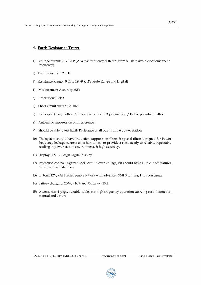
sisncTs
upu: 70 P&P (Asfrquncy diffrnfrm 50Hzvidcrmnicfrquncy
2 Tsfrquncy:28Hz
3 RsisncRn: 0.09.99 K ’s(AuRnndDii
4 MsurmnAccurcy: 2%
5 Rsuin:0.0Ω
6 Shrcircuicurrn:20 mA
7 Princip:4pmhd/frsirsiviynd3pmhd/ Ffpnimhd
8 Aumicsupprssinfinrfrnc
9 ShudbbsErhRsisncfpinsinhpwrsin
0 Thsysmshudhv Inducinsupprssinfirs&spcifirs dsind frPwrfrquncykcurrn&ishrmnicsprvid rcksdy&rib,rpb
rdininpwrsinnvirnmn, &hihccurcy.
Dispy:4 &/2diiDiidispy
2 Prcincnr:AinsShrcircui,vrv,kishudhvucuff furs
prc hinsrumn
3 Inbui2,7AHrchrbbrywihdvncdSMPSfrn Durinus
4 Brychrin:230+/- 0%AC 50Hz +/- 0%
5 Accssris:4 ps,suibcbsfrhihfrquncyprin crryincsInsrucin
mnundhrs
Section 6: Employer’sRequirements/Monitoring, Testing and Analyzing Equipments
OCB. No. PMD/EGMP/BNRTLSS-077/078-01 Procurement of plant Single-Stage, Two-Envelope
IIA-334

VEEVGEDEER
1 SPE
ghVtageDetectrsstaberdetectnveness230Vt765
KV verhead ne (bare cndctr). The V Detectr starts rdcng vsa
ndcatnasweasadannncatnndcatngthatthenesLIVEandnt
saetearthandcarraneratn.Asweghvtagedetectrshdndcate
thendcedvtageresencenbarecndctrs.
2 EHPRMEERSWHFEURES
Slo
Description Specification
tandards
Acabe
TheerrmanceandtestngtheghVtageDetectrsha
cnrmtthewngIndan/Internatnastandards.
AcatnNn-cntactvtagedetectraresednPwer
Transmssnnes,DstrbtnLnes&sbstatnstdetect
theresencethevtagencharged230Vt765kVeven
barecndctrs&asdetectthendcedvtagesnncharged
sbstatnBas,Bsbars,TransmssnLne,Dstrbtnnes
rsaeeratndthemantenanceactvtes.
DetectnRange TheghVtageDetectrshdhavethenqecaabtt
warnthesertheresencehghvtagermasaedstance
andmstbeexcetnasenstve
1metersfor66kV,
22metersfor132kV,
3metersfor220kV,
4metersfor400kV&metersfrom76kVVoltagelevel
Fnctns 1. Nn-cntactvtagedetectn
2. IndcedvtageresencennchargedLnes
Section 6: Employer’sRequirements/Monitoring, Testing and Analyzing Equipments
OCB. No. PMD/EGMP/BNRTLSS-077/078-01 Procurement of plant Single-Stage, Two-Envelope
IIA-335

Slo
Description Specification
eectabeVtage
range
ensngvtageseectr-
230V/11kV/33kV/66kV/132kV/220kV/400KV&765kV
Genera&
Cnstrctna
Reqrements
1.ghVtageDetectrshabedesgnedandcnstrctedn
sch a wa s as t avd an danger t the eratng
ersnnedrngseandndernrmacndtns.Itshd
havethecaabttwarntheserbadannncatnas
weasvsandcatntheresencevtagermasae
dstance.
2.Brght hgh ntenst LEDs (reerab red cred) t
rvdecearvsandcatnevennnavrabedaght
cndtns.Abzzerrdcesadbeewhchsadbe
evennnsbackgrnds.
3.TheghVtageDetectr shdhave e-testbttn t
testbatterand rer nctnng Vdetectrand the
acteasreacementthewersbatter.
4.TheghVtageDetectrshdhavenversacnnectng
nkrtheattachmenttheTeesccrd.
5.The Teescc rd shd be nn-aergc, Premm
Qat Fber Gass Matera wth er stck am ed
(gh vtage tested matera) wth Pece t ece se-
Lckngarrangement.
6.A nsatng matera sed n the cnstrctn gh
VtageDetectrshabenhgrscc,nn-agengand
testedqat.
7.The detectr shd nt have an externa accessbt t
changethevtagerthesensngdstancetensrethesaet
theser.
Section 6: Employer’sRequirements/Monitoring, Testing and Analyzing Equipments
OCB. No. PMD/EGMP/BNRTLSS-077/078-01 Procurement of plant Single-Stage, Two-Envelope
IIA-336

Slo
Description Specification
Detectn
Indcatn
1.The gh Vtage Detectr sha gve the ndcatn wth
gh Intenst LED’s wth ashng arrangement there b
rvdngthestabendcatnndaght.
2.TheghVtageDetectrshagveadbesndrthe
resence ve ne s that t can be stab sed n
atedandnseareasreaseratn.
e-Dagnstc
Featre
The gh Vtage Detectr sha be caabe errmng
cmetese-dagnstccheckn-nemdewthbzzer&
ashngLEDtensrethecrrectwrkngtherbe.
Pwer 9VBatterrRechargeabe&reaceabeBatterstabetbe
chargedthrghasngehase,230V.
tabeCarrng
Case
TheghVtageDetectrwthaccessres shabe sed
wth the carrng case t be carred b the eratng ersn
eas.
0 Envrnment Tem:-10-60DegC.
mdt:90%nn-cndensng
ThetestktshameettheEMI/EMCreqrementaserreevant
IEC/I/eqvaentstandard.
Certcatns The tenderer sha rnshdetaed te testcertcates the
ered Instrment r a the tests as er reevant Indan
tandard/CPRI/InternatnastandardsrmNABLaccredted
Labratr.
WthresecttghVtageTestTechnqes:
1. Measrementeakagecrrentberemdttest2. mdttest3. Measrementeakagecrrentatermdttest4. PwerFreqencVtageWthstandtestrmCPRILabr
antherNABLaccredted5. InsatnResstancetest6. IP54ratngredsagesrbetter
Section 6: Employer’sRequirements/Monitoring, Testing and Analyzing Equipments
OCB. No. PMD/EGMP/BNRTLSS-077/078-01 Procurement of plant Single-Stage, Two-Envelope
IIA-337
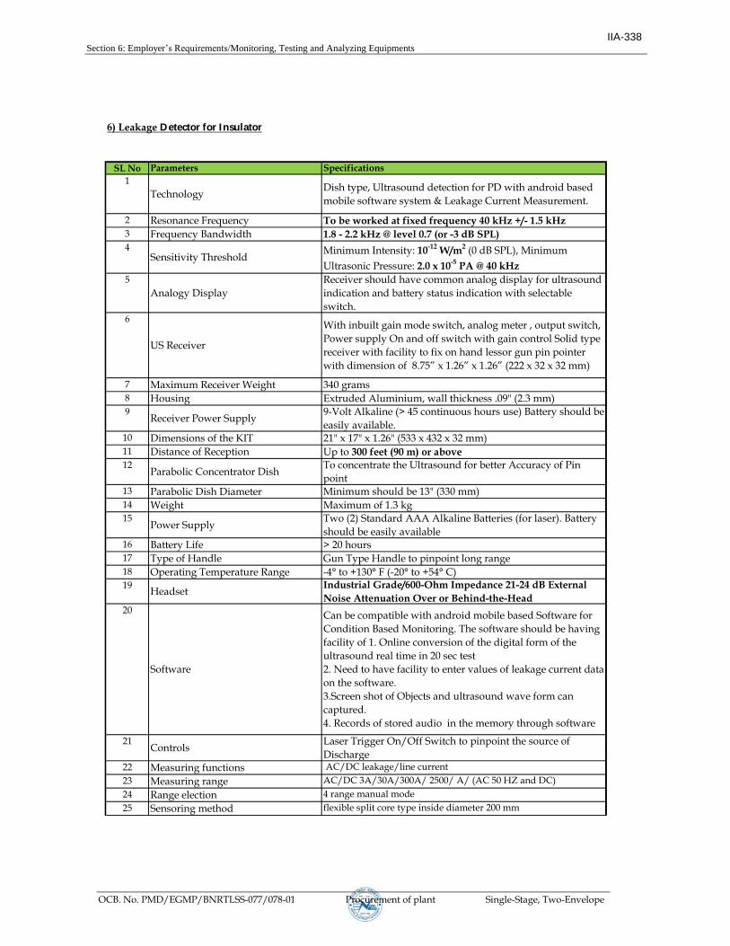
SL No Parameters Specifications
1
TechnologyDish type, Ultrasound detection for PD with android based
mobile software system & Leakage Current Measurement.
2 Resonance Frequency To be worked at fixed frequency 40 kHz +/- 1.5 kHz3 Frequency Bandwidth 1.8 - 2.2 kHz @ level 0.7 (or -3 dB SPL)4
Sensitivity Threshold Minimum Intensity: 10-12 W/m2 (0 dB SPL), Minimum
Ultrasonic Pressure: 2.0 x 10⁻⁵ PA @ 40 kHz
5
Analogy Display
Receiver should have common analog display for ultrasound
indication and battery status indication with selectable
switch. 6
US Receiver
With inbuilt gain mode switch, analog meter , output switch,
Power supply On and off switch with gain control Solid type
receiver with facility to fix on hand lessor gun pin pointer
with dimension of 8.75” x 1.26” x 1.26” (222 x 32 x 32 mm)
7 Maximum Receiver Weight 340 grams
8 Housing Extruded Aluminium, wall thickness .09" (2.3 mm)9
Receiver Power Supply9-Volt Alkaline (> 45 continuous hours use) Battery should be
easily available.10 Dimensions of the KIT 21" x 17" x 1.26" (533 x 432 x 32 mm)11 Distance of Reception Up to 300 feet (90 m) or above12
Parabolic Concentrator DishTo concentrate the Ultrasound for better Accuracy of Pin
point13 Parabolic Dish Diameter Minimum should be 13" (330 mm)14 Weight Maximum of 1.3 kg15
Power SupplyTwo (2) Standard AAA Alkaline Batteries (for laser). Battery
should be easily available 16 Battery Life > 20 hours
17 Type of Handle Gun Type Handle to pinpoint long range
18 Operating Temperature Range -4° to +130° F (-20° to +54° C)
19Headset
Industrial Grade/600-Ohm Impedance 21-24 dB External
Noise Attenuation Over or Behind-the-Head20
Software
Can be compatible with android mobile based Software for Condition Based Monitoring. The software should be having facility of 1. Online conversion of the digital form of the ultrasound real time in 20 sec test
2. Need to have facility to enter values of leakage current data on the software.
3.Screen shot of Objects and ultrasound wave form can captured.
4. Records of stored audio in the memory through software
21Controls
Laser Trigger On/Off Switch to pinpoint the source of
Discharge22 Measuring functions AC/DC leakage/line current
23 Measuring range AC/DC 3A/30A/300A/ 2500/ A/ (AC 50 HZ and DC)
24 Range election 4 range manual mode
25 Sensoring method flexible split core type inside diameter 200 mm
6) Leakage Detector for Insulator
Section 6: Employer’s Requirements/Monitoring, Testing and Analyzing Equipments
OCB. No. PMD/EGMP/BNRTLSS-077/078-01 Procurement of plant Single-Stage, Two-Envelope
IIA-338

SL No Parameters Spec ifications
6) Leakage Detector for Insulator
26 Withstanding voltage AC 2200 V/1 minute
27 Length of lead wire approx. 2 m between CT and measuring part
28
Display
LCD max 3200 reading with annunciators - Current
measuring Unit,With over range indication & With low
battery indications29 Zero adjustment for DC current
range Yes
30 Auto power off after 10 minutes
31 Sampling rate 2 times/sec
32 Operating temperature range: -20 to +54 degree C
33
Power supply Two standard AAA Alkaline batteries (for laser), 9V Alkaline
Battery - Receiver Unit, AA Batteries X 6 - Current measuring Unit
34 Battery life > 45 Hours
Section 6: Employer’s Requirements/Monitoring, Testing and Analyzing Equipments
OCB. No. PMD/EGMP/BNRTLSS-077/078-01 Procurement of plant Single-Stage, Two-Envelope
IIA-339
Note: Regarding the Monitoring, Testing and Analyzing Equipments mentioned above from 1-6, the Contractor must submit all the type test report at the time of shipment and the Contractor shall be responsible for all required on job - training at site of above equipments. No separate payment shall be made for the above trainings.
DELL
Typewriter
eq/(deg),

Emplyr’sRqurms/Drawgs
/EG/RTLSS-077/078-01rcurementfplantSingle-Stage,Tw-Envelpe
2
Drawings
ago
f32kVDTpeTwer 34
2 CgenPekf32kVDTpeTwer 342
3 X-rmf32kVDTpeTwer 343
4 Stubf32kVDTpeTwer 344
5 f32kVDCTpeTwer 345
6 CgenPekf32kVDCTpeTwer 346
7 X-rmf32kVDCTpeTwer 347
8 Stubf32kVDCTpeTwer 348
9 f32kVDDTpeTwer 349
0 CgenPekf32kVDDTpeTwer 350
X-rmf32kVDDTpeTwer 35
2 f220kVDTpeTwer 352
3 +9mLegExtennf220kVDTpeTwer 353
4 DTpefuntnfrDFRSlTpe 354
5 f220kVDCTpeTwer 355
6 +9mLegExtennf220kVDCTpeTwer 356
7 DCTpefuntnfrDFRSlTpe 357
8 f220kVDDTpeTwer 358
9 +9mLegExtennf220kVDDTpeTwer 359
20 DDTpefuntnfrDFRSlTpe 360
IIA-340

IIA-341

IIA-342

IIA-343

IIA-344

IIA-345

IIA-346

IIA-347

IIA-348

IIA-349

IIA-350

IIA-351

Borang Naubise (Ratmate) 220 kV Transmission Line Project
PMD/EGMP/BNRTLSS-077/78-01
IIA-352
DELL
Typewriter
For Tender Purpose Only

Borang Naubise (Ratmate) 220 kV Transmission Line Project
IIA-353
DELL
Typewriter
For Tender Purpose Only
DELL
Typewriter
PMD/EGMP/BNRTLSS-077/78-01

IIA-354
DELL
Typewriter
For Tender Purpose Only
DELL
Typewriter
PMD/EGMP/BNRTLSS-077/78-01
DELL
Typewriter
Borang Naubise (Ratmate) 220 kV Transmission Line Project

IIA-355
DELL
Typewriter
For Tender Purpose Only
DELL
Typewriter
Specification No.
DELL
Typewriter
PMD/EGMP/BNRTLSS-077/78-01
DELL
Typewriter
Client
DELL
Typewriter
Borang Naubise (Ratmate) 220 kV T.L.P

IIA-356
DELL
Typewriter
For Tender Purpose Only
DELL
Typewriter
Specification No.
DELL
Typewriter
PMD/EGMP/BNRTLSS-077/78-01
DELL
Typewriter
Borang Naubise (Ratmate) 220 kV Transmission Line Project

IIA-357
DELL
Typewriter
PMD/EGMP/BNRTLSS-077/78-01
DELL
Typewriter
Borang Naubise (Ratmate) 220 kV Transmission Line Project
DELL
Typewriter
For Tender Purpose Only
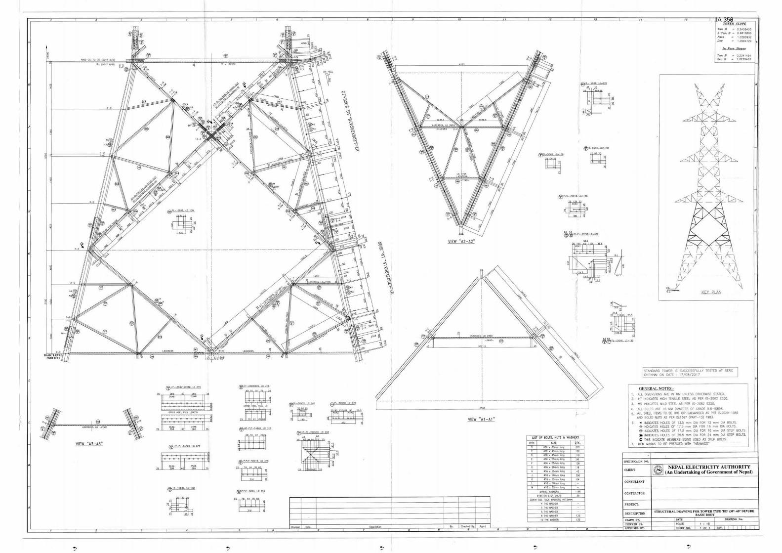
IIA-358
DELL
Typewriter
For Tender Purpose Only
DELL
Typewriter
PMD/EGMP/BNRTLSS-077/78-01
DELL
Typewriter
Borang Naubise (Ratmate) 220 kV Transmission Line Project

IIA-359
DELL
Typewriter
For Tender Purpose Only
DELL
Typewriter
PMD/EGMP/BNRTLSS-077/78-01
DELL
Typewriter
Borang Naubise (Ratmate) 220 kV Transmission Line Project

IIA-360
DELL
Typewriter
For Tender Purpose Only
DELL
Typewriter
PMD/EGMP/BNRTLSS-077/78-01
DELL
Typewriter
Borang Naubise (Ratmate) 220 kV Transmission Line Project

Section 6: Employer’sRequirements/Technical Data Sheet
OCB. No. PMD/EGMP/BNRTLSS-077/078-01 Procurement of plant Single-Stage, Two-Envelope
Guaranteed Technical Particulars And
Standard Technical Particulars
(To be filled by Bidders / Supplier)
Section XIII
Contents Schedule – 1 Suspension Hardware fittings for ACSR Conductor/ Earthwire
Schedule – 2 Tension Hardware fittings for ACSR Conductor/ Earthwire
Schedule – 3 Mid Span Compression Joint for ACSR Conductor/ Earthwire
Schedule – 4 Repair sleeve for ACSR Conductor/ Earthwire
Schedule – 5 Vibration Damper for ACSR Conductor
Schedule – 6 Bundle Spacer/ Spacer Damper for ACSR Moose Conductor
Schedule – 7 Rigid Spacer for ACSR Moose Conductor
Schedule – 8 Schedule – 9
ACSR Bear ACSR Moose
Schedule – 10
Composite Long Rod Insulator
IIA-361
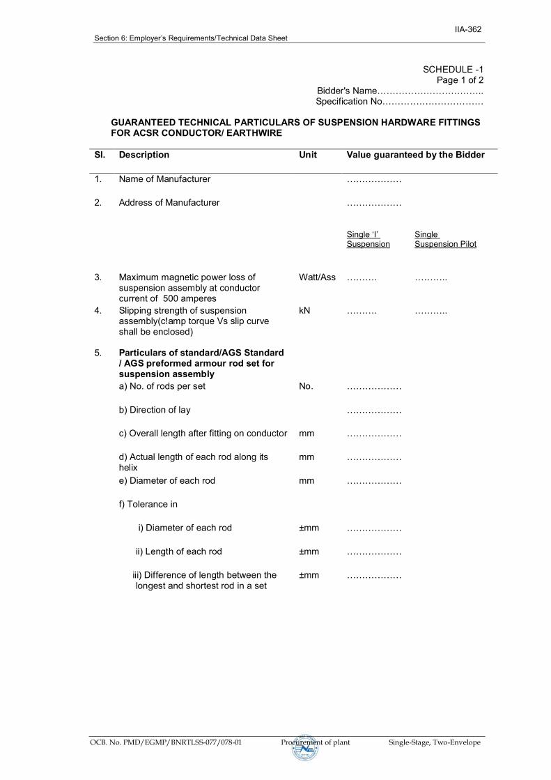
Section 6: Employer’sRequirements/Technical Data Sheet
OCB. No. PMD/EGMP/BNRTLSS-077/078-01 Procurement of plant Single-Stage, Two-Envelope
SCHEDULE -1 Page 1 of 2
BiddersName…………………………….. SpecificationNo……………………………
GUARANTEED TECHNICAL PARTICULARS OF SUSPENSION HARDWARE FITTINGS FOR ACSR CONDUCTOR/ EARTHWIRE
Sl. Description Unit Value guaranteed by the Bidder
1. Name of Manufacturer ………………
2. Address of Manufacturer ………………
Single‘I’Suspension
Single Suspension Pilot
3. Maximum magnetic power loss of suspension assembly at conductor current of 500 amperes
Watt/Ass ………. ………..
4. Slipping strength of suspension assembly(c!amp torque Vs slip curve shall be enclosed)
kN ………. ………..
5. Particulars of standard/AGS Standard / AGS preformed armour rod set for suspension assembly
a) No. of rods per set No. ………………
b) Direction of lay ………………
c) Overall length after fitting on conductor mm ………………
d) Actual length of each rod along its helix
mm ………………
e) Diameter of each rod mm ………………
f) Tolerance in
i) Diameter of each rod ±mm ………………
ii) Length of each rod ±mm ………………
iii) Difference of length between the longest and shortest rod in a set
±mm ………………
IIA-362

Section 6: Employer’sRequirements/Technical Data Sheet
OCB. No. PMD/EGMP/BNRTLSS-077/078-01 Procurement of plant Single-Stage, Two-Envelope
SCHEDULE -1 Page 2 of 2
BiddersName…………………………….. SpecificationNo……………………………
GUARANTEED TECHNICAL PARTICULARS OF SUSPENSION HARDWARE FITTINGS FOR ACSR CONDUCTOR/ EARTHWIRE
Sl. Description Unit Value guaranteed by the Bidder
g) Type of Aluminium alloy used for manufacture of PA rod set
………………
h) UTS of each rod Kg/mm2 ………………
6. Particulars of Elastomer (For AGS Clamp only)
a) Supplier of elastomer ………………
b) Type of elastomer ………………
c) Shore hardness of elastomer ………………
d) Temperature range for which elastomer is designed
………………
e) Moulded on insert Yes/No
7. UTS of hardware component indicated in the drawings enclosed with the Bid
Yes/No
8. Purity of Zinc used for galvanising % ………………
9. Min. No. of dips in standard preece test the ferrous parts can withstand
No ………………
Date: (Signature)……………………………
Place: (PrintedName)……………………….
(Designation)………………………….
(CommonSeal)……………………….
IIA-363

Section 6: Employer’sRequirements/Technical Data Sheet
OCB. No. PMD/EGMP/BNRTLSS-077/078-01 Procurement of plant Single-Stage, Two-Envelope
SCHEDULE -2 Page 1 of 1
BiddersName…………………………….. Specification No……………………………
GUARANTEED TECHNICAL PARTICULARS OF TENSION HARDWARE FITTINGS FOR ACSR CONDUCTOR/ EARTHWIRE
Sl. Description Unit Value guaranteed by the Bidder
1. Name of Manufacturer …………
2. Address of Manufacturer ……..
3. Dimensioned Drawing of insulator strings (with disc/long rod insulators) enclosed
Yes/ No
4. Detailed dimensioned drawings of all hardware components enclosed
Yes/ No
5. Material of component enclosed in the drawings
Yes/ No
6. Electrical resistance of dead end assembly as a percentage of equivalent length of Conductor
% ……..
7. Slip strength of dead end assembly kN ……..
Single Tension
Double Tension
8. Total weight of Tension Assembly kg
9. UTS of hardware components indicated in the drawing enclosed with the Bid
Yes/ No
10. Purity of Zinc used for galvanising % ……..
11. Min. No. of dips in standard preece test the ferrous parts can withstand.
Nos. ……..
12. Design calculation of yoke plates and sag adjustment plate enclosed.
Yes/ No
Date: (Signature)……………………………
Place: (PrintedName)……………………….
(Designation)………………………….
(CommonSeal)……………………….
IIA-364

Section 6: Employer’sRequirements/Technical Data Sheet
OCB. No. PMD/EGMP/BNRTLSS-077/078-01 Procurement of plant Single-Stage, Two-Envelope
SCHEDULE -3 Page 1 of 2
BiddersName…………………………….. SpecificationNo……………………………
GUARANTEED TECHNICAL PARTICULARS OF MID SPAN COMPRESSION JOINT FOR ACSR CONDUCTOR/ EARTHWIRE
Sl. Description Unit Value guaranteed by
the Bidder
1. Name & Address of Manufacturer ………………
2. Drawing enclosed Yes/No
3. Suitable for conductor size mm ………………
4. Purity of aluminium used for aluminium sleeve % ………………
5. Material for steel sleeve
(i) Type of material with chemical composition ………………
(ii) Range of Hardness of material (Brinnel Hardness) BHN From…….to……..
(iii) Weight of zinc coating gm/m2 ………………
Aluminium Steel
6. Outside diameter of sleeve before compression mm ……….. ………..
7. Inside diameter of sleeve before compression mm ……….. ………..
8. Length of sleeve before compression ……….. ………..
9. Dimensions of sleeve after compression Corner to Corner
Surface to Surface
(a) Aluminium ………… ………..
(b) Steel ……….. ……….
Aluminium Steel
10. Length of sleeve after compression …………. ………..
IIA-365

Section 6: Employer’sRequirements/Technical Data Sheet
OCB. No. PMD/EGMP/BNRTLSS-077/078-01 Procurement of plant Single-Stage, Two-Envelope
SCHEDULE -3 Page 2 of 2
BiddersName…………………………….. SpecificationNo……………………………
GUARANTEED TECHNICAL PARTICULARS OF MID SPAN COMPRESSION JOINT FOR ACSR CONDUCTOR/ EARTHWIRE Sl. Description Unit Value guaranteed by
the Bidder
11. Weight of sleeve
(a) Aluminium kg ………………
(b) Steel kg ………………
(c) Total kg ………………
12. Slip strength kN ………………
13. Resistance of the compressed unit expressed, as percentage of the resistivity of equivalent length of bare conductor.
% ………………
14. Minimum Corona extinction voltage under dry condition
kV (rms) ………………
15. Radio interference voltage at 1 MHz for phase to earth voltage of 154 kV under dry condition
μV ………………
Date: (Signature)……………………………
Place: (PrintedName)……………………….
(Designation)………………………….
(CommonSeal)……………………….
IIA-366

Section 6: Employer’sRequirements/Technical Data Sheet
OCB. No. PMD/EGMP/BNRTLSS-077/078-01 Procurement of plant Single-Stage, Two-Envelope
SCHEDULE -4 Page 1 of 1
BiddersName…………………………….. SpecificationNo……………………………
GUARANTEED TECHNICAL PARTICULARS OF REPAIR SLEEVE FOR ACSR CONDUCTOR/ EARTHWIRE Sl. Description Unit Value guaranteed by the
Bidder
1. Name & Address of Manufacturer ………………
2. Drawing enclosed Y es/No
3. Suitable for conductor size mm ………………
4. Purity of Aluminium / Al Alloy type % ………………
5. Inside diameter of sleeve before compression mm ………………
6. Outside dimensions of sleeve
(a) Diameter before Compression mm ………………
Corner to Corner
Surface to Surface
(b) After Compression ……….. ……….
Before Compression
After Compression
7. Length of sleeve mm ………… …………
8. Weight of sleeve Kg ………………
9. Minimum Corona extinction voltage under dry condition
kV (rms)
………………
10. Radio interference voltage at 1 MHz for phase to earth voltage of 154 kV dry condition
μV ………………
NOTE: Tolerances, wherever applicable, shall also be specified.
Date: (Signature)……………………………
Place: (PrintedName)……………………….
(Designation)………………………….
(CommonSeal)……………………….
IIA-367

Section 6: Employer’sRequirements/Technical Data Sheet
OCB. No. PMD/EGMP/BNRTLSS-077/078-01 Procurement of plant Single-Stage, Two-Envelope
SCHEDULE -5 Page 1 of 2
BiddersName…………………………….. SpecificationNo……………………………
GUARANTEED TECHNICAL PARTICULARS OF VIBRATION DAMPER FOR ACSR CONDUCTOR/ EARTHWIRE
Sl. Description Unit Value guaranteed by the Bidder
1. Name & Address of Manufacturer ………………
2. Drawing enclosed
(a) Design Drawing YES / NO
(b) Placement Chart YES / NO
3. Suitable for conductor size mm ………………
4. Total weight of one damper kg
Right Left
5. Diameter of each damper mass mm ……… ……….
6. Length of each damper mass mm ………. …………
7. Weight of each damper mass kg ………. …………
8. Material of damper masses ………………
9. Material of clamp ………………
10. Material of the stranded messenger cable ………………
11. Number of strands in stranded messenger cable ………………
12. Lay ratio of stranded messenger cable ………………
13. Minimum ultimate tensile strength of stranded messenger cable
Kg/mm2 ………………
14. Slip strength of stranded messenger cable (mass pull off)
kN ………………
IIA-368

Section 6: Employer’sRequirements/Technical Data Sheet
OCB. No. PMD/EGMP/BNRTLSS-077/078-01 Procurement of plant Single-Stage, Two-Envelope
SCHEDULE -5 Page 2 of 2
BiddersName…………………………….. SpecificationNo……………………………
GUARANTEED TECHNICAL PARTICULARS OF VIBRATION DAMPER FOR ACSR CONDUCTOR/ EARTHWIRE
Sl. Description Unit Value guaranteed by
the Bidder
Right Left
15. Resonance frequencies
(a) First frequency Hz ……… ……….
(b) Second frequency Hz ……… ……….
16 Designed clamping torque Kg-m ………………
17. Slipping strength of damper clamp
(a) Before fatigue test kN ………………
(b) After fatigue test kN ………………
18. Magnetic power loss per vibration damper watts for 500 amps, 50 Hz Alternating Current
watts ………………
19. Minimum corona Extinction voltage kV (rms) under dry condition
kV ………………
20. Radio Interference Voltage at 1 MHz for phase to earth voltage of 154 kV (rms) Microvolts under dry condition
μV ………………
21. Percentage variation in reactance after fatigue test in comparison with that . before fatigue test
% ………………
22. Percentage variation in power dissipation after fatigue test in comparison with that before fatigue test
% ………………
NOTE: Tolerances, wherever applicable, shall also be specified.
Date: (Signature)……………………………
Place: (PrintedName)……………………….
(Designation)………………………….
(CommonSeal)……………………….
IIA-369

Section 6: Employer’sRequirements/Technical Data Sheet
OCB. No. PMD/EGMP/BNRTLSS-077/078-01 Procurement of plant Single-Stage, Two-Envelope
SCHEDULE -6 Page 1 of 2
BiddersName…………………………….. SpecificationNo……………………………
GUARANTEED TECHNICAL PARTICULARS OF BUNDLE SPACER/ SPACER DAMPER FOR ACSR CONDUCTOR
Sl. Description Unit Value guaranteed by
the Bidder
1. Name & Address of Manufacturer …………………..
2. Drawing enclosed
(a) Design Drawing YES / NO
(b) Placement Chart YES / NO
3 Suitable for conductor size mm …………………..
4. Material / Manufacturing process of component parts
Material Manufacturing Process
(a) Insert ……….. ……………..
(b) Main body ……….. ……………..
(c) Retaining rods (if any) ……….. ……………..
5. Retaining rods (if used)
(a) Type of alloy used ……………..
(b) Number of retaining rods used for each spacer no. ……………..
(c) Diameter mm ……………..
(d) Length mm ……………..
(e) Weight kg ……………..
IIA-370

Section 6: Employer’sRequirements/Technical Data Sheet
OCB. No. PMD/EGMP/BNRTLSS-077/078-01 Procurement of plant Single-Stage, Two-Envelope
SCHEDULE -6 Page 2 of 2
BiddersName…………………………….. SpecificationNo……………………………
GUARANTEED TECHNICAL PARTICULARS OF BUNDLE SPACER FOR ACSR CONDUCTOR
Sl. Description Unit Value guaranteed by the Bidder
6. Elastomer
(a) Contractor …………………..
(b) Type …………………..
(c) Moulded on insert …………………..
(d) Shore hardness …………………..
(e) Thickness on insert mm …………………..
(f) Temp. range for which designed °C …………………..
7. Minimum ultimate tensile strength of spacer
(a) Compressive load kN …………………..
(b) Tensile load kN …………………..
8. Weight of Spacer kg …………………..
9. Designed clamping torque(if applicable) kg.m …………………..
Before Vibration
After Vibration
10. Slipping strength of spacer clamp kN ……… ………
11. Magnetic power loss per spacer for 500 Amps, 50 Hz Alternating Current
Watts …………………..
Maximum Minimum
12. Electrical resistance of elastomer cushioned spacer
ohm ………. ……….
13. Minimum corona Extinction voltage kV (rms) under dry condition
kV …………………..
14. Radio Interference Voltage at 1 MHz for phase to earth voltage of 154 kV (rms) Microvolts under dry condition
μV …………………..
NOTE: Tolerances, wherever applicable, shall also be specified.
Date: (Signature)……………………………
Place: (Printed Name)……………………….
(Designation)………………………….
(CommonSeal)……………………….
IIA-371

Section 6: Employer’sRequirements/Technical Data Sheet
OCB. No. PMD/EGMP/BNRTLSS-077/078-01 Procurement of plant Single-Stage, Two-Envelope
SCHEDULE -7
Page 1 of 2 BiddersName…………………………….. SpecificationNo……………………………
GUARANTEED TECHNICAL PARTICULARS OF RIGID SPACER FOR JUMPER FOR ACSR CONDUCTOR
Sl. Description Unit Value guaranteed by the Bidder
1. Name & Address of Manufacturer …………………..
2. Drawing enclosed
(a) Design Drawing YES / NO
(b) Placement Chart YES / NO
3 Suitable for conductor size mm …………………..
4. Material of component parts
(a) Clamp …………………..
(b) Main body …………………..
5. Manufacturing process for
(a) Clamp …………………..
(b) Main body …………………..
(e) Weight kg …………………..
6. Elastomer
(a) Contractor …………………..
(b) Type …………………..
(c) Moulded on insert …………………..
(d) Shore hardness …………………..
(e) Thickness on insert mm …………………..
(f) Temp. range for which designed °C …………………..
IIA-372

Section 6: Employer’sRequirements/Technical Data Sheet
OCB. No. PMD/EGMP/BNRTLSS-077/078-01 Procurement of plant Single-Stage, Two-Envelope
SCHEDULE -7 Page 2 of 2
BiddersName…………………………….. SpecificationNo……………………………
GUARANTEED TECHNICAL PARTICULARS OF RIGID SPACER FOR JUMPER FOR ACSR CONDUCTOR
Sl. Description Unit Value guaranteed by the Bidder
7. Minimum ultimate tensile strength of spacer
(a) Compressive load kN ……………………..
(b) Tensile load kN ……………………..
8. Weight of Spacer kg ……………………..
9. Designed clamping torque(if applicable) kg.m ……………………..
10. Slipping strength of spacer clamp kN ……………………..
11. Magnetic power loss per spacer for Watts 500 Amps, 50 Hz Alternating Current
watt ……………………..
Maximum Minimum
12. Electrical resistance of elastomer cushioned spacer
ohm ……… ………
13. Minimum corona Extinction voltage kV (rms) under dry condition
kV (rms)
……………………..
14. Radio Interference Voltage at 1 MHz for phase to earth voltage of 154 kV (rms) Microvolts under dry condition
μV ……………………..
NOTE: Tolerances, wherever applicable, shall also be specified.
Date: (Signature)……………………………
Place: (PrintedName)……………………….
(Designation)………………………….
(CommonSeal)……………………….
IIA-373

Section 6: Employer’sRequirements/Technical Data Sheet
OCB. No. PMD/EGMP/BNRTLSS-077/078-01 Procurement of plant Single-Stage, Two-Envelope
SCHEDULE -8 Page 1 of 2
Bidder’sName…………………………….. SpecificationNo……………………………
GUARANTEED TECHNICAL PARTICULARS OF ACSR BEAR CONDUCTOR
Sl. Description Unit Value guaranteed by the Bidder
1 Name & Address of Manufacturer
2 Raw Materials
2.1 Aluminum
a. Maximum purity of Aluminum %
b. Maximum copper content %
2.2 Steel Wires/ Rods
a. Carbon b. Manganese
c. Phosphorous %
d. Sulphur %
e. Silicon %
2.3 Zinc
(a) Minimum purity of Zinc .%
3 Aluminum strand after stranding
3.1 Diameter
(a) Nominal mm
(b) Maximum mm
c) Minimum mm
3.2 Minimum breaking load of strand kN
3.3 Maximum resistance of 1 m strand at 20 deg C
Ohm
4 Steel strand after stranding
4.1 Diameter
(a) Nominal Mm
(b) Maximum Mm
c) Minimum Mm
4.2 Minimum breaking load of strand kN
5 Galvanizing
(a) Minimum weight of zinc coating per sq.m.
Gm
(b) Minimum number of one minute dips that the galvanized strand can withstand in the standard preece test
Nos.
(c) Min. No. of twists in gauge length equals 100 times the dia. of wire which the strand can withstand in the torsion test.
Nos
IIA-374

Section 6: Employer’sRequirements/Technical Data Sheet
OCB. No. PMD/EGMP/BNRTLSS-077/078-01 Procurement of plant Single-Stage, Two-Envelope
SCHEDULE -8 Page 2 of 2
Bidder’sName…………………………….. SpecificationNo……………………………
GUARANTEED TECHNICAL PARTICULARS OF ACSR BEAR CONDUCTOR
Sl. Description Unit Value guaranteed by the Bidder
6 ACSR Conductor
6.1 UTS of conductor kN
6.2 Lay ratio of conductor Nos.
a. Outer steel layer Nos.
b. 12 wire layer Nos.
c. 18 wire layer Nos.
d. 24 wire layer Nos.
Stranded Earthwire
6.3 DC resistance of conductor at 20°C (Max)
ohm/km
6.4 Minimum corona extinction voltage (line to ground) under dry condition
kV rms
6.5 RIV at 1 MHz at 154 kV rms under dry condition
Microvo its
6.6 Standard length of conductor m
6.7 Maximum length of conductor that can be offered as single length
M
6.8 Tolerance on standard length of conductor
%
6.9 Linear mass of conductor
(a) Standard kg/km
(b) Minimum kg/km
(c) Maximum kg/km
6.1 Direction of lay for outside layer
7 Is the Drum as per specification YES/NO
8.0 No. of cold pressure butt welding equipment available at site
Nos.
IIA-375

Section 6: Employer’sRequirements/Technical Data Sheet
OCB. No. PMD/EGMP/BNRTLSS-077/078-01 Procurement of plant Single-Stage, Two-Envelope
SCHEDULE -9 Page 1 of 2
Bidder’sName…………………………….. SpecificationNo……………………………
GUARANTEED TECHNICAL PARTICULARS OF ACSR MOOSE CONDUCTOR
Sl. Description Unit Value guaranteed by the Bidder
1 Name & Address of Manufacturer
2 Raw Materials
2.1 Aluminum
a. Maximum purity of Aluminum %
b. Maximum copper content %
2.2 Steel Wires/ Rods
a. Carbon b. Manganese
c. Phosphorous %
d. Sulphur %
e. Silicon %
2.3 Zinc
(a) Minimum purity of Zinc .%
3 Aluminum strand after stranding
3.1 Diameter
(a) Nominal mm
(b) Maximum mm
c) Minimum mm
3.2 Minimum breaking load of strand kN
3.3 Maximum resistance of 1 m strand at 20 deg C
Ohm
4 Steel strand after stranding
4.1 Diameter
(a) Nominal Mm
(b) Maximum Mm
c) Minimum Mm
4.2 Minimum breaking load of strand kN
5 Galvanizing
(a) Minimum weight of zinc coating per sq.m.
Gm
(b) Minimum number of one minute dips that the galvanized strand can withstand in the standard preece test
Nos.
(c) Min. No. of twists in gauge length equals 100 times the dia. of wire which the strand can withstand in the torsion test.
Nos
IIA-376

Section 6: Employer’sRequirements/Technical Data Sheet
OCB. No. PMD/EGMP/BNRTLSS-077/078-01 Procurement of plant Single-Stage, Two-Envelope
SCHEDULE -9 Page 2 of 2
Bidder’sName…………………………….. SpecificationNo……………………………
GUARANTEED TECHNICAL PARTICULARS OF ACSR MOOSE CONDUCTOR
Sl. Description Unit Value guaranteed by the Bidder
6 ACSR Conductor
6.1 UTS of conductor kN
6.2 Lay ratio of conductor Nos.
a. Outer steel layer Nos.
b. 12 wire layer Nos.
c. 18 wire layer Nos.
d. 24 wire layer Nos.
Stranded Earthwire
6.3 DC resistance of conductor at 20°C (Max)
ohm/km
6.4 Minimum corona extinction voltage (line to ground) under dry condition
kV rms
6.5 RIV at 1 MHz at 154 kV rms under dry condition
Microvo its
6.6 Standard length of conductor m
6.7 Maximum length of conductor that can be offered as single length
M
6.8 Tolerance on standard length of conductor
%
6.9 Linear mass of conductor
(a) Standard kg/km
(b) Minimum kg/km
(c) Maximum kg/km
6.1 Direction of lay for outside layer
7 Is the Drum as per specification YES/NO
8.0 No. of cold pressure butt welding equipment available at site
Nos.
IIA-377
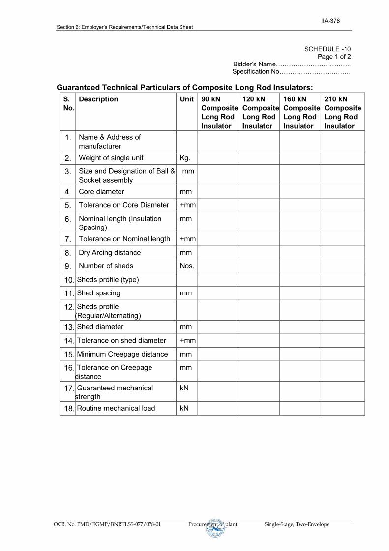
Section 6: Employer’sRequirements/Technical Data Sheet
OCB. No. PMD/EGMP/BNRTLSS-077/078-01 Procurement of plant Single-Stage, Two-Envelope
SCHEDULE -10 Page 1 of 2
Bidder’sName…………………………….. Specification No……………………………
Guaranteed Technical Particulars of Composite Long Rod Insulators:
S. No.
Description Unit 90 kN Composite Long Rod Insulator
120 kN Composite Long Rod Insulator
160 kN Composite Long Rod Insulator
210 kN Composite Long Rod Insulator
1. Name & Address of manufacturer
2. Weight of single unit Kg.
3. Size and Designation of Ball & Socket assembly
mm
4. Core diameter mm
5. Tolerance on Core Diameter +mm
6. Nominal length (Insulation Spacing)
mm
7. Tolerance on Nominal length +mm
8. Dry Arcing distance mm
9. Number of sheds Nos.
10. Sheds profile (type)
11. Shed spacing mm
12. Sheds profile (Regular/Alternating)
13. Shed diameter mm
14. Tolerance on shed diameter +mm
15. Minimum Creepage distance mm
16. Tolerance on Creepage distance
mm
17. Guaranteed mechanical strength
kN
18. Routine mechanical load kN
IIA-378

Section 6: Employer’sRequirements/Technical Data Sheet
OCB. No. PMD/EGMP/BNRTLSS-077/078-01 Procurement of plant Single-Stage, Two-Envelope
SCHEDULE -10 Page 2 of 2
Bidder’sName…………………………….. SpecificationNo……………………………
Date: (Signature)……………………………
Place: (PrintedName)……………………….
(Designation)………………………….
(Common Seal)……………………….
19.
Material a)FRP Rod
b) Weather Sheds with % contents of silicon
c) Housing
d) End Fittings
e) Grading Rings
20. Minimum thickness of sheath covering over the core
mm
21. Purity of zinc used for galvanizing and fittings %
22. Number of dips which the end fittings can withstand in standard preece test
Nos.
23. Certified test report of accelerated ageing test of 5000 hours (enclosed) (Appendix-C of IEC-61109)
Yes/No Yes/No Yes/No Yes/No
24. Drawing enclosed Yes/No Yes/No Yes/No Yes/No
IIA-379

Section 6: Employer’sRequirements/Survey Report
OCB. No. PMD/EGMP/BNRTLSS-077/078-01 Procurement of plant Single-Stage, Two-Envelope
SECTION- 14
Survey Report
(Route Alignment Map)
IIA-380

SS-1BORANG
AP-1
AP-2
AP-3
AP-4
AP-5
AP-6
AP-7
AP-8
AP-9
AP-10
AP-10A
SS-2SS-3
FIN
AL
RO
UT
E 1
32 k
V
Sheet No.
PROJECT DEVELOPMENT DEPARTMENT
t |kf
f/0
swlal
g]kf n
B' SCALE
1000m0
SCALE 1:25000
250 500 750
ANGLE POINT
TOWER
AP 1
33 kV LINE
11 kV LINE
400 V LT LINE
220 V LT LINE
POND
DIRECTION POINT
T-5
CHAUTARA
INTERMEDIATE POINT
599 000 N
3115 000 N
3111 000 N
601 000 N 603 000 N 605 100 N
3113 000 N
Title
Borang - Naubise (Ratmate) 220kV
Transmission Line
IIA-381

AP-11
AP-12
AP-13
AP-14
AP-14A
AP-15
AP-16
AP-17
AP-18
AP-19
AP-20
AP-21
AP-22
FIN
AL
RO
UT
E 1
32 k
V
Sheet No.
PROJECT DEVELOPMENT DEPARTMENT
t |kf
f/0
swlal
g]kfn
B ' SCALE
1000m0
SCALE 1:25000
250 500 750
ANGLE POINT
TOWER
AP 1
33 kV LINE
11 kV LINE
400 V LT LINE
220 V LT LINE
POND
DIRECTION POINT
T-5
CHAUTARA
INTERMEDIATE POINT
596 000 N
3109 000 N
3105 000 N
598 000 N 600 000 N 602 000 N
3107 000 N
Title
Borang - Naubise (Ratmate) 220kV
Transmission Line
IIA-382

AP-23
AP-24
AP-25
AP-26
AP-27
AP-28
AP-29
AP-30
AP-31
AP-32
AP-33
AP-35
AP-33A
SS-2LSS-1L
AP-3AP-34
AP-34A
LapanSub-station
SS-3L
FIN
AL
RO
UT
E 1
32 k
V
Sheet No.
PROJECT DEVELOPMENT DEPARTMENT
t |kf
f/0
swlal
g]kfn
B ' SCALE
1000m0
SCALE 1:25000
250 500 750
ANGLE POINT
TOWER
AP 1
33 kV LINE
11 kV LINE
400 V LT LINE
220 V LT LINE
POND
DIRECTION POINT
T-5
CHAUTARA
INTERMEDIATE POINT
591 000 N
3103 000 N
3099 000 N
593 000 N 595 000 N 597 000 N
3101 000 N
Title
Borang - Naubise (Ratmate) 220kV
Transmission Line
IIA-383

AP-36
AP-37
AP-38
AP-39
AP-40
AP-41
AP-42
AP-43
AP-44
AP-45
FINA
L RO
UTE 220 kV
Sheet No.
PROJECT DEVELOPMENT DEPARTMENT
t |kf
f/0
swlal
g]kfn
B ' SCALE
1000m0
SCALE 1:25000
250 500 750
ANGLE POINT
TOWER
AP 1
33 kV LINE
11 kV LINE
400 V LT LINE
220 V LT LINE
POND
DIRECTION POINT
T-5
CHAUTARA
INTERMEDIATE POINT
591 000 N
3096 000 N
3092 000 N
593 000 N 595 000 N 597 000 N
3094 000 N
Title
Borang - Naubise (Ratmate) 220kV
Transmission Line
IIA-384

AP-46
AP-47AP-48
AP-49
AP-50
AP-51
AP-52
AP-53
AP-54
AP-55
FIN
AL
RO
UT
E 220 kV
Sheet No.
PROJECT DEVELOPMENT DEPARTMENT
t |kf
f/0
swlal
g]kfn
B ' SCALE
1000m0
SCALE 1:25000
250 500 750
ANGLE POINT
TOWER
AP 1
33 kV LINE
11 kV LINE
400 V LT LINE
220 V LT LINE
POND
DIRECTION POINT
T-5
CHAUTARA
INTERMEDIATE POINT
595 000 N
3090 000 N
3086 000 N
597 000 N 599 000 N 601 000 N
3088 000 N
Title
Borang - Naubise (Ratmate 220kV)
Transmission Line
IIA-385

AP-56
AP-57
AP-58
AP-59F
INA
L R
OU
TE
220 kV
Sheet No.
PROJECT DEVELOPMENT DEPARTMENT
t |kf
f/0
swlal
g]kfn
B ' SCALE
1000m0
SCALE 1:25000
250 500 750
ANGLE POINT
TOWER
AP 1
33 kV LINE
11 kV LINE
400 V LT LINE
220 V LT LINE
POND
DIRECTION POINT
T-5
CHAUTARA
INTERMEDIATE POINT
594 000 N
3083 000 N
3079 000 N
596 000 N 598 000 N 600 000 N
3081 000 N
Title
Borang - Naubise (Ratmate) 220kV
Transmission Line
IIA-386

AP-60 AP-61
AP-62
Sheet No.
PROJECT DEVELOPMENT DEPARTMENT
t |kf
f/0
swlal
g]kfn
B ' Title SCALE
1000m0
SCALE 1:25000
250 500 750
ANGLE POINT
TOWER
AP 1
33 kV LINE
11 kV LINE
400 V LT LINE
220 V LT LINE
POND
DIRECTION POINT
T-5
CHAUTARA
INTERMEDIATE POINT
603 000 N
3085 000 N
605 000 N 607 000 N 609 000 N
3083 000 N
3087 000 N
Borang - Naubise (Ratmate) 220kV
Transmission Line
IIA-387