DESIGN OF MACHINE ELEMENTS
54
Nivish George DESIGN OF MACHINE ELEMENTS
-
Upload
khangminh22 -
Category
Documents
-
view
3 -
download
0
Transcript of DESIGN OF MACHINE ELEMENTS
Nivish George
DESIGN OF MACHINE ELEMENTS

Poor Design??
Ref:http://www.boredpanda.com/poor-design-decisions-fails/Department of Mechanical Engineering 2

• Definition
– Machine Design is defined as the use of scientific principles, technical information and imagination in the description of a machine or a mechanical system to perform specific functions with maximum economy and efficiency
– Design is an innovative and highly iterativeprocess
Machine Design
Department of Mechanical Engineering 3

The Design Process
Department of Mechanical Engineering 4
• Market survey
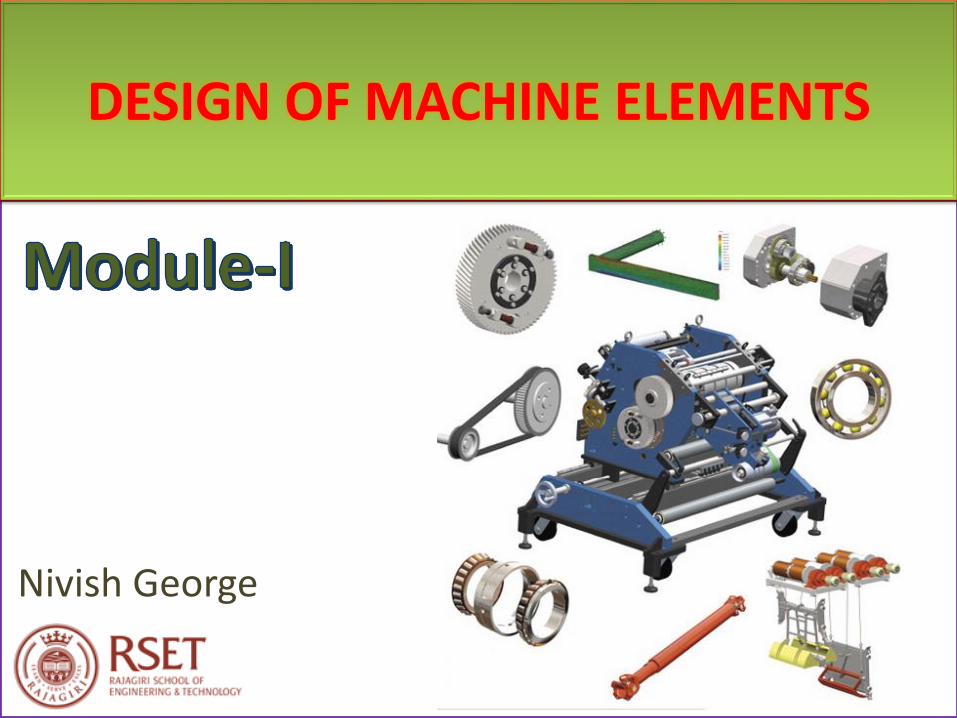
Contd…
Department of Mechanical Engineering 5
Ref: https://www.carwale.com/rollsroyce-cars/
Ref:http://www.lamborghinila.com/
Ref:https://www.cardekho.com/Tata/Tata_Nano Product Specification
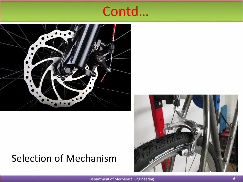
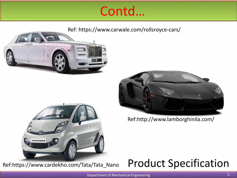
Contd…
Department of Mechanical Engineering 6
Selection of Mechanism

Contd…
Department of Mechanical Engineering 7
Ref. Automobile Engineering, Vol-1, Dr. Kirpal SIngh
Layout of configuration and selection ofjoining methods

Contd…
Department of Mechanical Engineering 8
Design of Individual Components

Contd…
Department of Mechanical Engineering 9
• Prepare Assembly and detail drawing
• Modify drawings after testing prototype
Ref: https://blogpuneet.wordpress.com/2013/10/08/oldhams-coupling/

Course Contents
Department of Mechanical Engineering 10
Mod. 1 Mod. 2
Mod. 4 Mod. 5
Mod. 3
Mod. 6
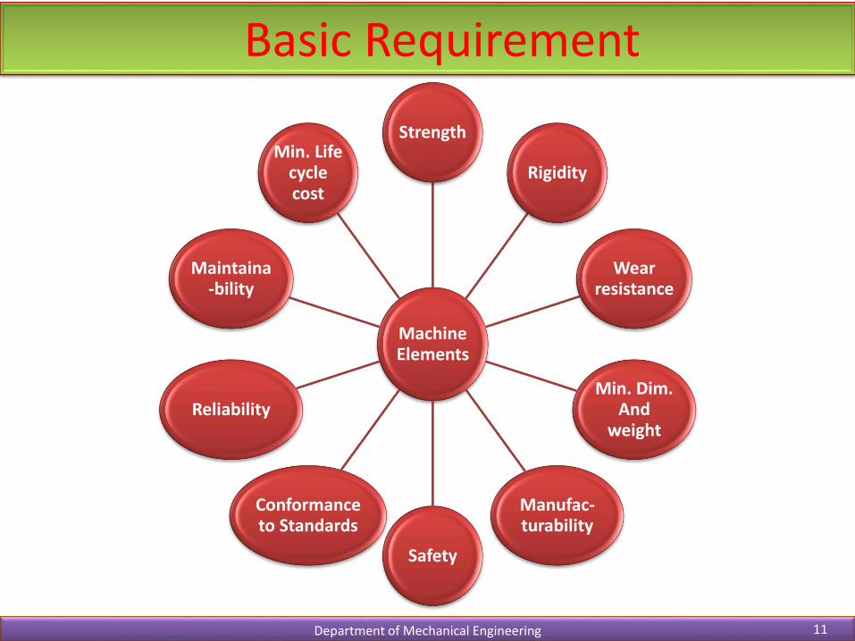
Basic Requirement
Department of Mechanical Engineering 11
Machine Elements
Strength
Rigidity
Wear resistance
Min. Dim. And
weight
Manufac-turability
Safety
Conformance to Standards
Reliability
Maintaina-bility
Min. Life cycle cost
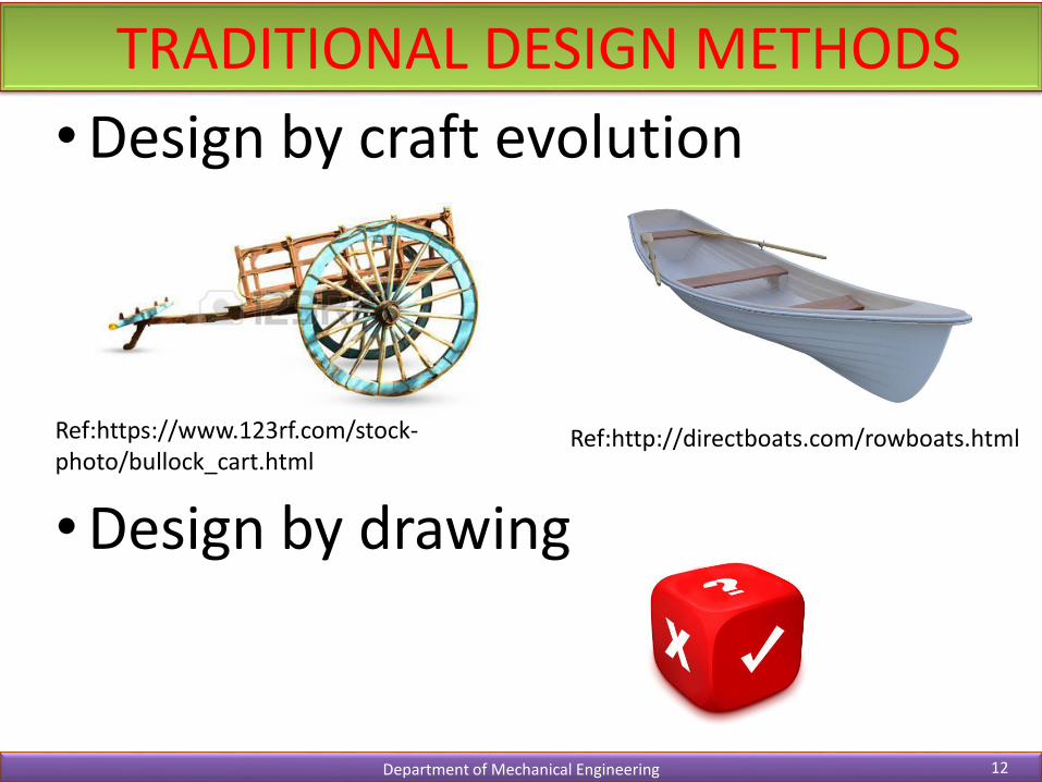
TRADITIONAL DESIGN METHODS
Department of Mechanical Engineering 12
•Design by craft evolution
•Design by drawing
Ref:https://www.123rf.com/stock-photo/bullock_cart.html
Ref:http://directboats.com/rowboats.html
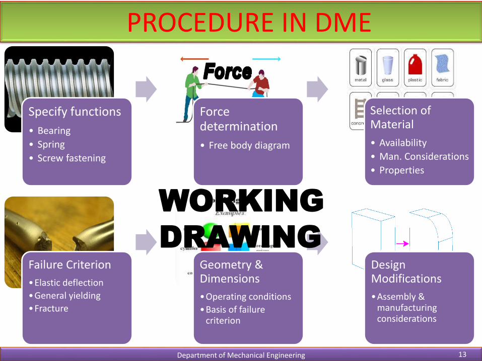
PROCEDURE IN DME
Department of Mechanical Engineering 13
Failure Criterion
•Elastic deflection
•General yielding
•Fracture
Geometry & Dimensions
•Operating conditions
•Basis of failure criterion
Design Modifications
•Assembly & manufacturing considerations
Specify functions
• Bearing
• Spring
• Screw fastening
Force determination
• Free body diagram
Selection of Material
• Availability
• Man. Considerations
• Properties
WORKING
DRAWING

DESIGN SYNTHESIS
Department of Mechanical Engineering 14
Design Synthesis is defined as the process of creating or selecting configurations, materials, shapes and dimensions for a product.
ObjectiveMathematical Formulation
Optimisation

AESTHETIC CONSIDERATIONS
Department of Mechanical Engineering 15

ERGONOMIC CONSIDERATIONS
Department of Mechanical Engineering 16
Ergonomics is defined as the relationship between man and machine and the application of anatomical, physiological and psychological principles to solve the problems arising from man-machine relationship
• Design of driver’s seat• Layout of instrument dials and display panels• Design of hand levers and hand wheels• Energy expenditure in hand and foot operations• Lighting, noise and climatic conditions in machine
environment

Contd….
Department of Mechanical Engineering 17
Display instruments Control instruments
Quantitative measurement Easily accessible and logically positioned
State of affairs Conform to the anatomy of human parts
Predetermined settings Proper colour
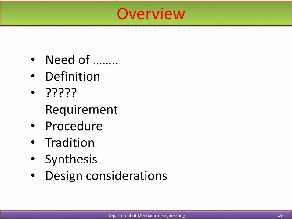
Overview
Department of Mechanical Engineering 18
• Need of ……..• Definition• ?????
Requirement• Procedure• Tradition• Synthesis• Design considerations

Standardization
Department of Mechanical Engineering 19
The obligatory norms, to which various characteristics of a product
should conform.
• Standards: Set of specifications for parts, materials or processes• Codes: Set of specifications for analysis, design, testing
Standards
Company Standards
Eg: Service Standards
National Standards
Eg: IS, DIN
International Standards
Eg:ISO
Standardization
Department of Mechanical Engineering 20
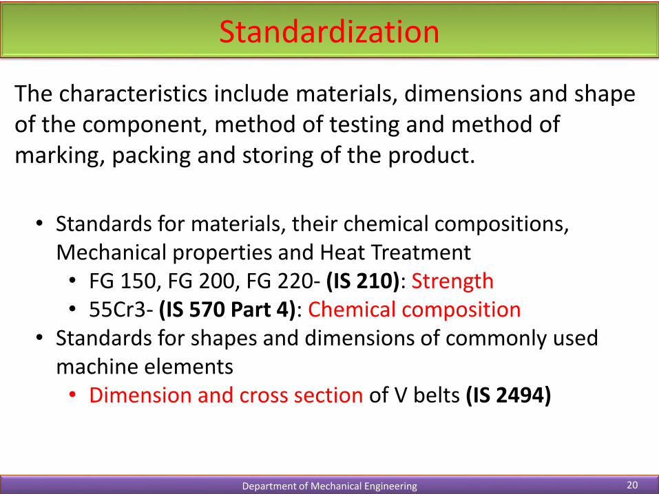
The characteristics include materials, dimensions and shape of the component, method of testing and method of marking, packing and storing of the product.
• Standards for materials, their chemical compositions, Mechanical properties and Heat Treatment• FG 150, FG 200, FG 220- (IS 210): Strength• 55Cr3- (IS 570 Part 4): Chemical composition
• Standards for shapes and dimensions of commonly used machine elements• Dimension and cross section of V belts (IS 2494)
Standardization
Department of Mechanical Engineering 21
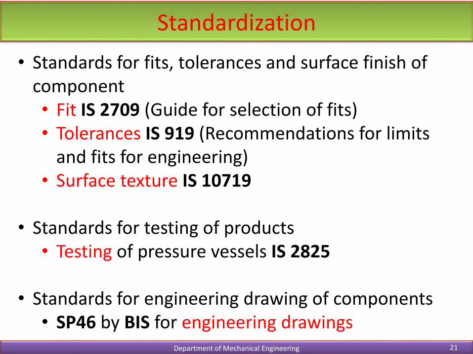
• Standards for fits, tolerances and surface finish of component• Fit IS 2709 (Guide for selection of fits)• Tolerances IS 919 (Recommendations for limits
and fits for engineering)• Surface texture IS 10719
• Standards for testing of products• Testing of pressure vessels IS 2825
• Standards for engineering drawing of components• SP46 by BIS for engineering drawings

Standardization: Advantages
Department of Mechanical Engineering 22
• Reduction in types and dimensions of identical
components
• Reduced manufacturing facilities required for
individual organisation
• Easy replacement and availability
• Reduced designer tasks
• Improved quality and reliability

Preferred Sizes
Basic Series
Derived Series
R5 1.58
R10 1.26
R20 1.12
R40 1.06
R80 1.03
Selection of Preferred sizes
Department of Mechanical Engineering 23
• Size of the machine element with preferred
sizes
5 10
10 10
20 10
40 10
80 10
Reducing
Increasing

Preferred Numbers
Department of Mechanical Engineering 24
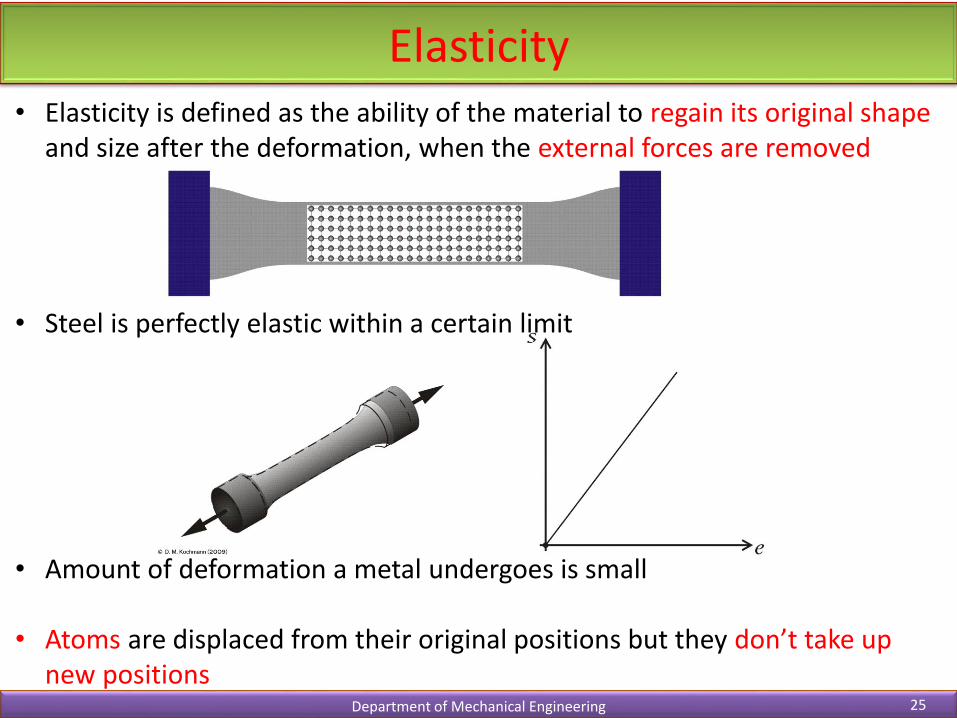
• Elasticity is defined as the ability of the material to regain its original shape and size after the deformation, when the external forces are removed
• Steel is perfectly elastic within a certain limit
• Amount of deformation a metal undergoes is small
• Atoms are displaced from their original positions but they don’t take up new positions
Elasticity
Department of Mechanical Engineering 25

• Plasticity is defined as the ability of the material to retain the deformation produced under the load on permanent basis
• External force deforms the metal to such an extent it cannot fully recover
• Some metals take up extensive deformations without fracture
• Atoms are permanently displaced to take up new positions
Plasticity
Department of Mechanical Engineering 26
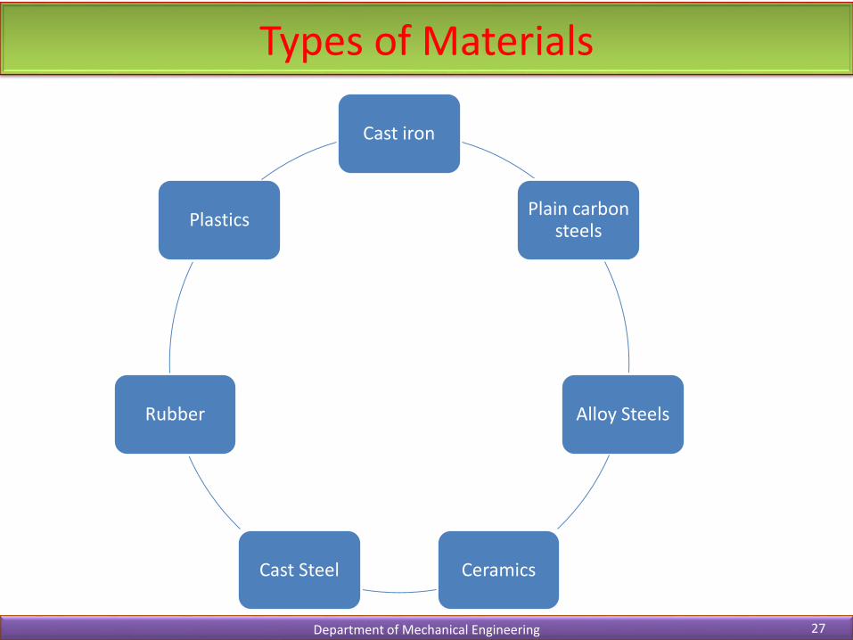
Types of Materials
Department of Mechanical Engineering 27
Cast iron
Plain carbon steels
Alloy Steels
CeramicsCast Steel
Rubber
Plastics
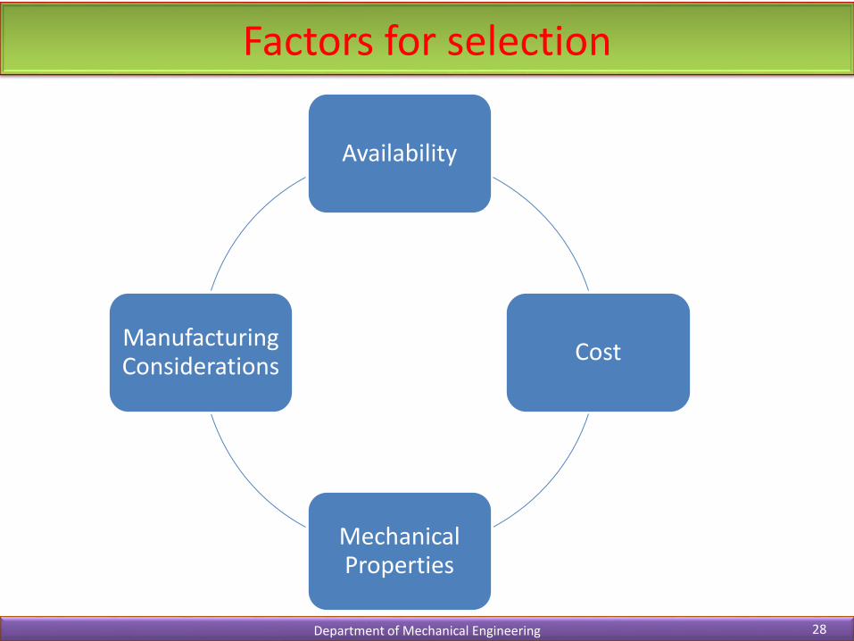
Factors for selection
Department of Mechanical Engineering 28
Availability
Cost
Mechanical Properties
Manufacturing Considerations
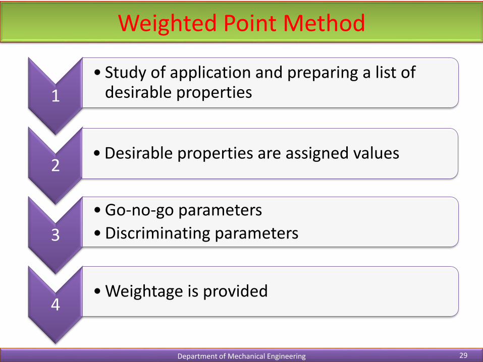
Weighted Point Method
Department of Mechanical Engineering 29
1
• Study of application and preparing a list of desirable properties
2• Desirable properties are assigned values
3
• Go-no-go parameters
• Discriminating parameters
4• Weightage is provided
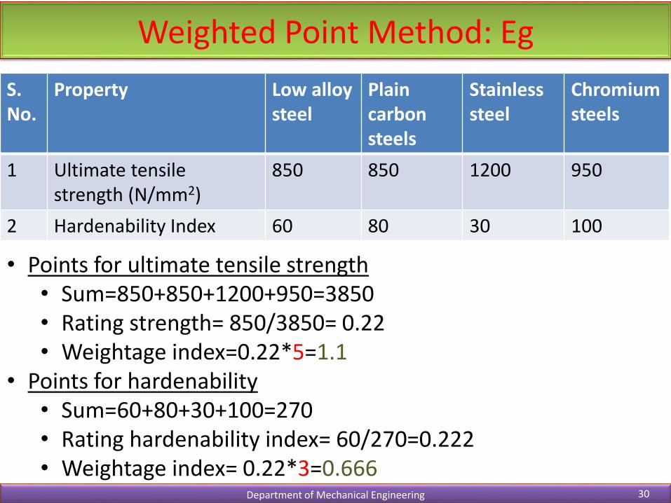
Weighted Point Method: Eg
Department of Mechanical Engineering 30
S. No.
Property Low alloy steel
Plain carbonsteels
Stainless steel
Chromium steels
1 Ultimate tensile strength (N/mm2)
850 850 1200 950
2 Hardenability Index 60 80 30 100
• Points for ultimate tensile strength• Sum=850+850+1200+950=3850• Rating strength= 850/3850= 0.22• Weightage index=0.22*5=1.1
• Points for hardenability• Sum=60+80+30+100=270• Rating hardenability index= 60/270=0.222• Weightage index= 0.22*3=0.666
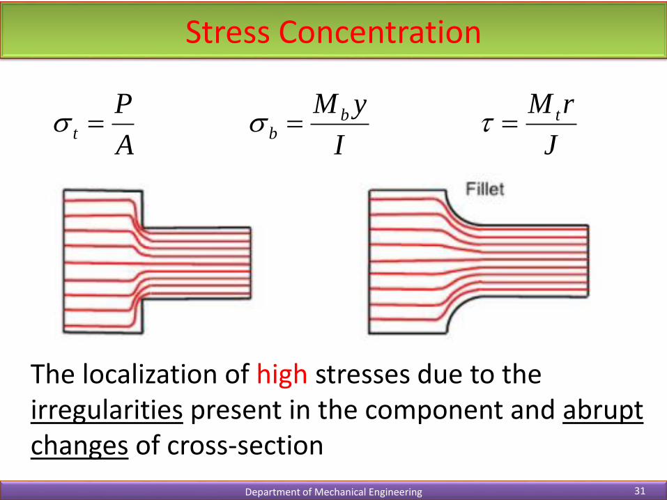
Stress Concentration
Department of Mechanical Engineering 31
A
Pt
I
yM bb
J
rM t
The localization of high stresses due to the irregularities present in the component and abrupt changes of cross-section

Causes of stress concentration
Department of Mechanical Engineering 32
• Variation in properties
• Load application
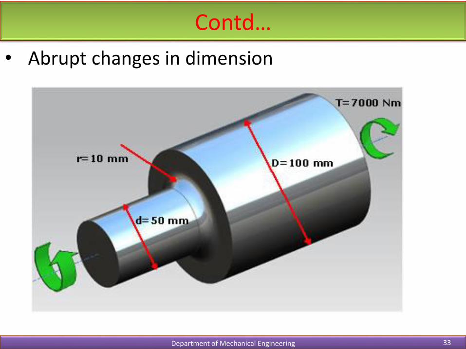
Contd…
Department of Mechanical Engineering 33
• Abrupt changes in dimension
Contd…
Department of Mechanical Engineering 34
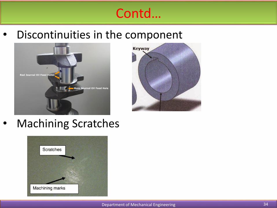
• Discontinuities in the component
• Machining Scratches

Stress Concentration Factor (Kt)
Department of Mechanical Engineering 35
𝐾𝑡 =𝜎𝑚𝑎𝑥
𝜎𝑜=𝜏𝑚𝑎𝑥
𝜏𝑜
Mathematical method
Experimental methods

Stress Concentration factors
Department of Mechanical Engineering 36
𝜎𝑜 =𝑃
𝑤 − 𝑑 𝑡
𝜎𝑜 =𝑃
𝑑𝑡
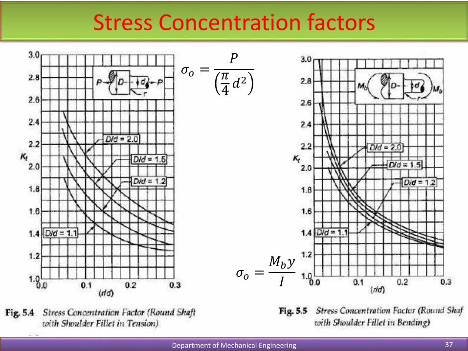
Stress Concentration factors
Department of Mechanical Engineering 37
𝜎𝑜 =𝑃𝜋4𝑑2
𝜎𝑜 =𝑀𝑏𝑦
𝐼
Stress Concentration factors
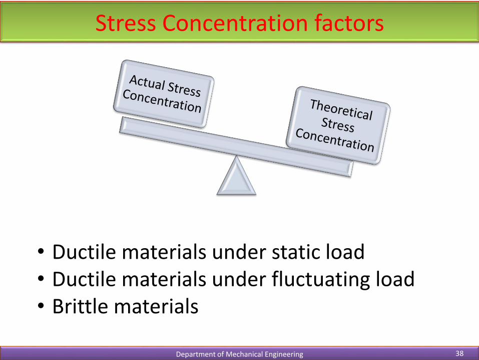
Department of Mechanical Engineering 38
• Ductile materials under static load• Ductile materials under fluctuating load• Brittle materials

Reduction of Stress Concentration
Department of Mechanical Engineering 39
• Additional Notches and Holes in Tension Member
• Use of multiple notches• Drilling additional holes• Removal of undesired
material
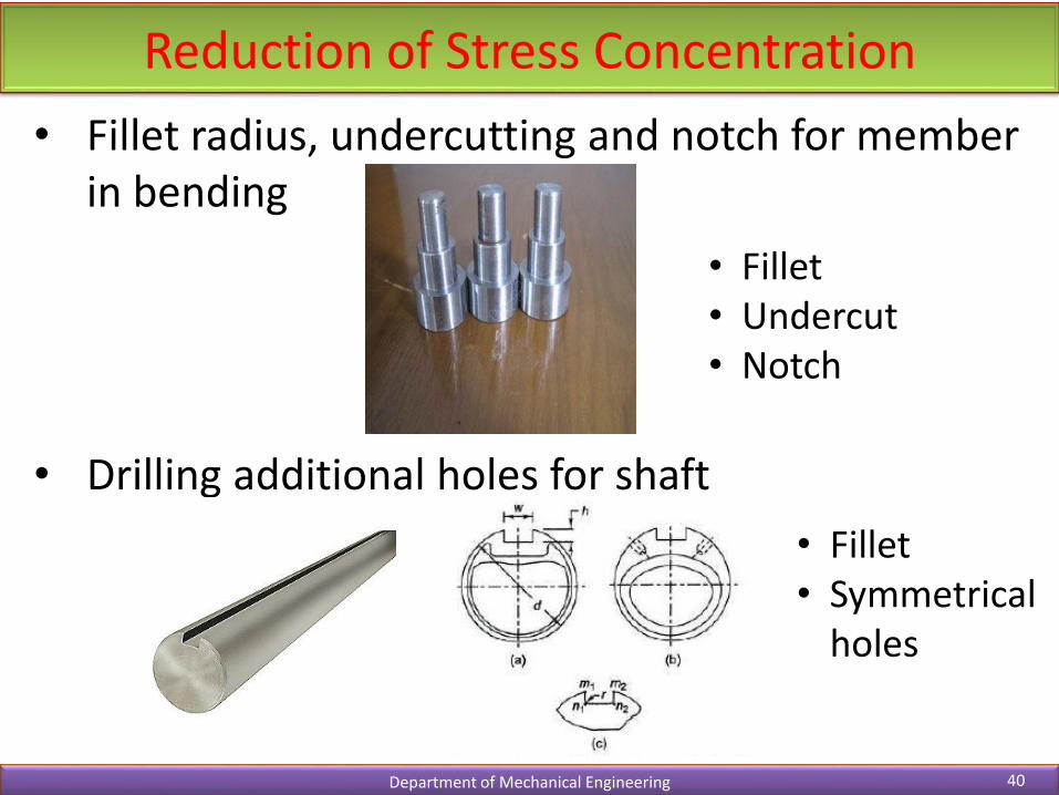
Reduction of Stress Concentration
Department of Mechanical Engineering 40
• Fillet radius, undercutting and notch for member in bending
• Drilling additional holes for shaft
• Fillet• Undercut• Notch
• Fillet• Symmetrical
holes
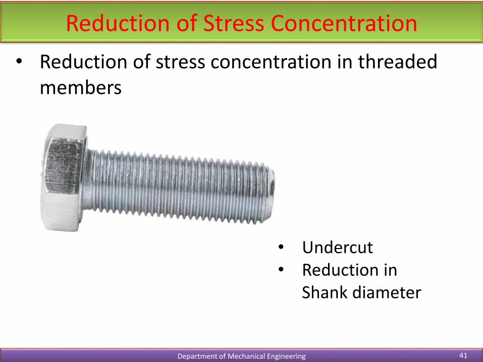
Reduction of Stress Concentration
Department of Mechanical Engineering 41
• Reduction of stress concentration in threaded members
• Undercut• Reduction in
Shank diameter
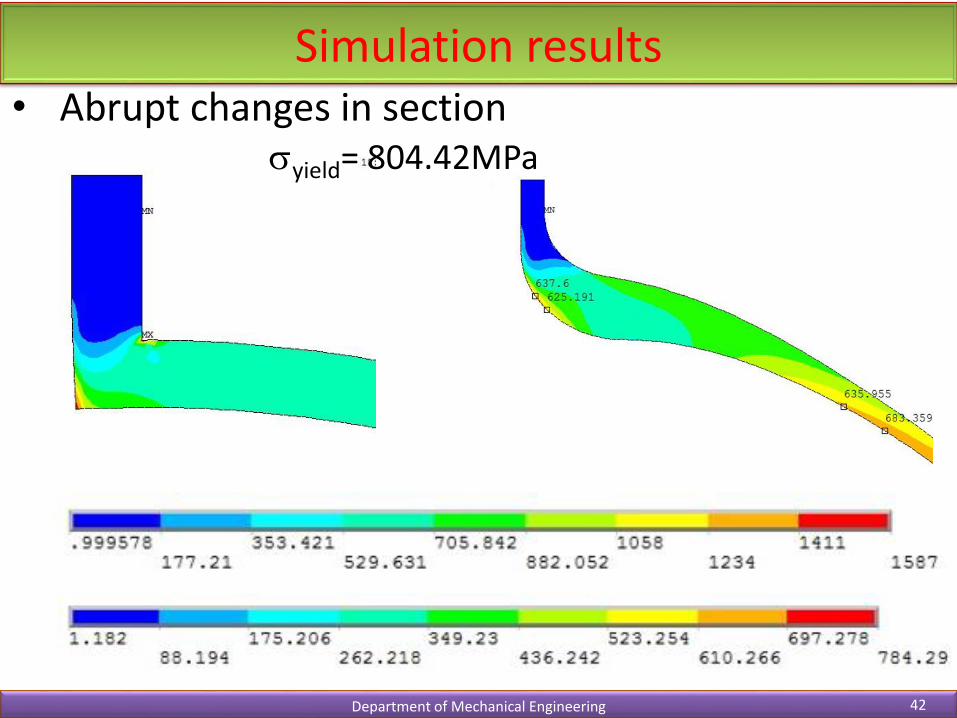
Simulation results
Department of Mechanical Engineering 42
yield= 804.42MPa
• Abrupt changes in section
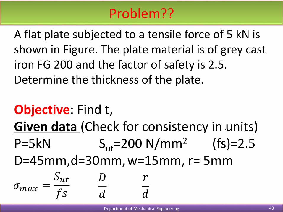
Problem??
Department of Mechanical Engineering 43
A flat plate subjected to a tensile force of 5 kN is shown in Figure. The plate material is of grey cast iron FG 200 and the factor of safety is 2.5. Determine the thickness of the plate.
Objective: Find t,Given data (Check for consistency in units)P=5kN Sut=200 N/mm2 (fs)=2.5D=45mm,d=30mm, w=15mm, r= 5mm
𝜎𝑚𝑎𝑥 =𝑆𝑢𝑡𝑓𝑠
𝐷
𝑑
𝑟
𝑑
`
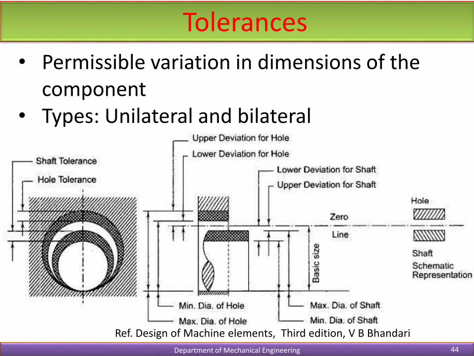
Tolerances
Department of Mechanical Engineering 44
• Permissible variation in dimensions of the component
• Types: Unilateral and bilateral
Ref. Design of Machine elements, Third edition, V B Bhandari
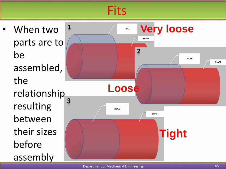
Fits
Department of Mechanical Engineering 45
• When two parts are to be assembled, the relationship resulting between their sizes before assembly
Very loose
Tight
Loose
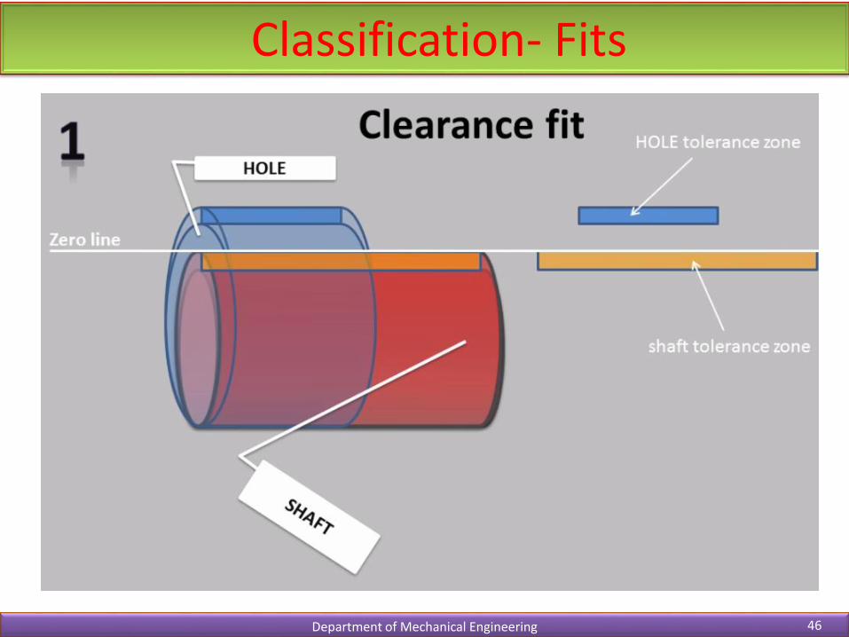
Classification- Fits
Department of Mechanical Engineering 46
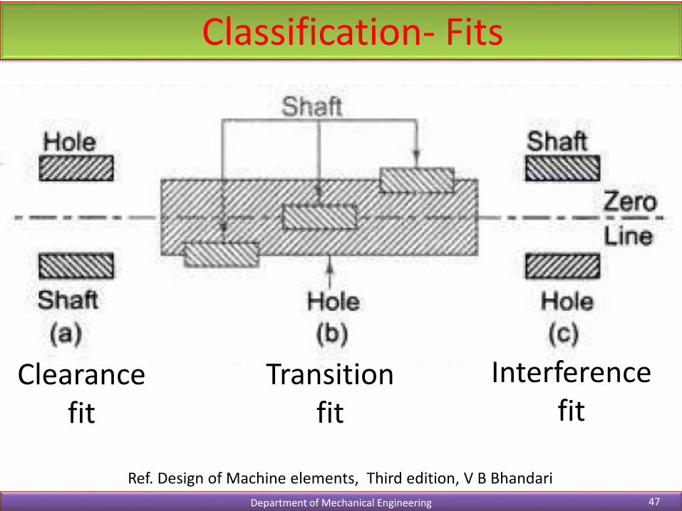
Classification- Fits
Department of Mechanical Engineering 47
Ref. Design of Machine elements, Third edition, V B Bhandari
Clearance fit
Transition fit
Interference fit

Classification- Fits
Department of Mechanical Engineering 48
• Hole size: Constant• Shaft size: Varying
• Hole size: Varying• Shaft size: Constant

Classification- Hole basis tolerance system (H)
Department of Mechanical Engineering 49
Ref. Design of Machine elements, Third edition, V B Bhandari
Clearance fit
Transition fit
Interference fit
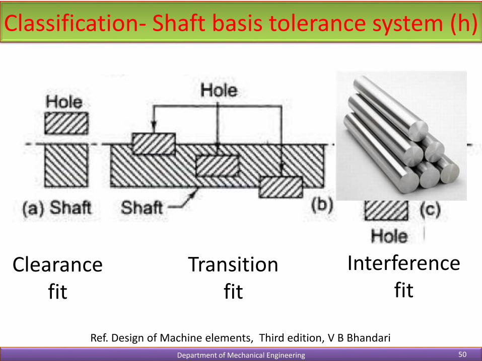
Classification- Shaft basis tolerance system (h)
Department of Mechanical Engineering 50
Ref. Design of Machine elements, Third edition, V B Bhandari
Clearance fit
Transition fit
Interference fit
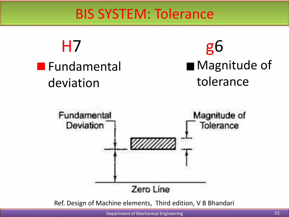
BIS SYSTEM: Tolerance
Department of Mechanical Engineering 51
Ref. Design of Machine elements, Third edition, V B Bhandari
H7 g6Fundamental deviation
Magnitude of tolerance
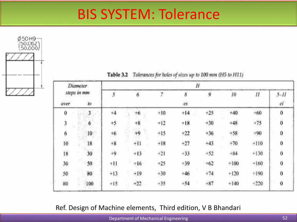
BIS SYSTEM: Tolerance
Department of Mechanical Engineering 52
Ref. Design of Machine elements, Third edition, V B Bhandari
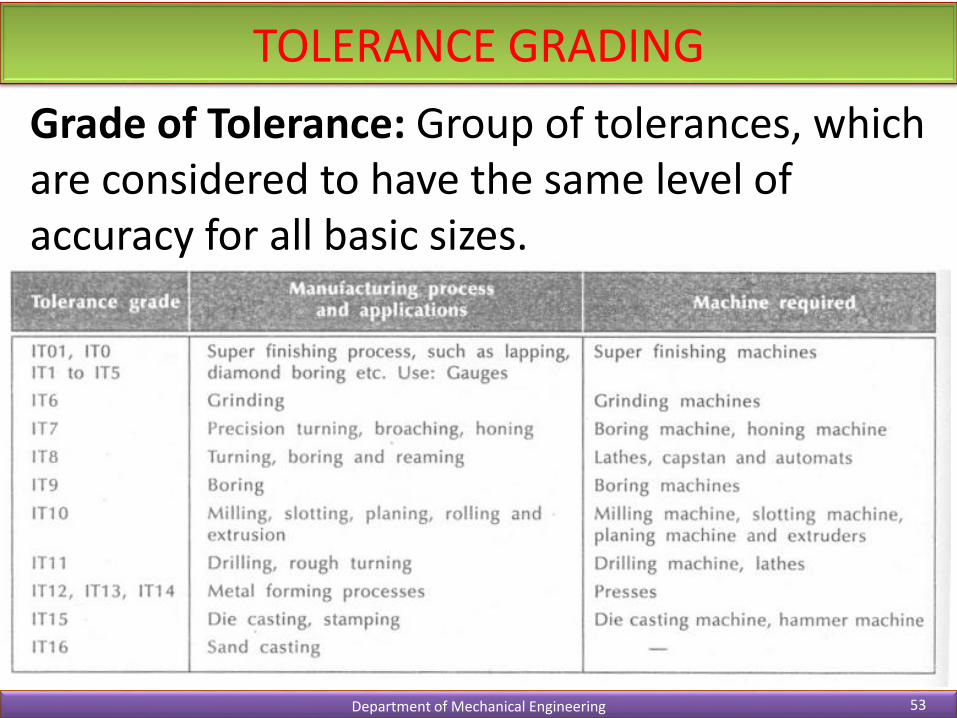
TOLERANCE GRADING
Department of Mechanical Engineering 53
Grade of Tolerance: Group of tolerances, which are considered to have the same level of accuracy for all basic sizes.

BIS SYSTEM:FITS
Department of Mechanical Engineering 54
Basic size common to both components followed by symbols for tolerance of each component
9/950 dH
9950 dH
9
950
d
HSelection of fit is based on the clearance required for the desired applications