a competitive project illustrating basic machine design principles
21
Shigley Hauler — a competitive project illustrating basic machine design principles Rida T. Farouki and Barbara S. Linke Department of Mechanical and Aerospace Engineering, University of California, Davis, CA 95616, USA. Abstract By requiring students to meet demanding functional specifications using limited resources, the competitive Shigley Hauler project offers undergraduate students practical “hands–on” experience in the design, fabrication, and testing of mechanical systems. The project imparts a thorough experiential understanding of the key principles that govern the selection and integration of basic machinery components — gears, shafts, bearings, DC motors, etc. — into a robust and efficient working system. The Shigley Hauler project has been successfully incorporated into the mechanical engineering curriculum at UC Davis for more than a decade, and its pedagogical and motivational value is corroborated by student feedback. The project is run within a 10–week timeframe, and entails only modest costs for the instructor and student teams. Keywords: Mechanical design; machine components; design competition. e–mail addresses: [email protected], [email protected]
-
Upload
khangminh22 -
Category
Documents
-
view
3 -
download
0
Transcript of a competitive project illustrating basic machine design principles

Shigley Hauler — a competitive projectillustrating basic machine design principles
Rida T. Farouki and Barbara S. LinkeDepartment of Mechanical and Aerospace Engineering,
University of California, Davis, CA 95616, USA.
Abstract
By requiring students to meet demanding functional specificationsusing limited resources, the competitive Shigley Hauler project offersundergraduate students practical “hands–on” experience in the design,fabrication, and testing of mechanical systems. The project imparts athorough experiential understanding of the key principles that governthe selection and integration of basic machinery components — gears,shafts, bearings, DC motors, etc. — into a robust and efficient workingsystem. The Shigley Hauler project has been successfully incorporatedinto the mechanical engineering curriculum at UC Davis for more thana decade, and its pedagogical and motivational value is corroboratedby student feedback. The project is run within a 10–week timeframe,and entails only modest costs for the instructor and student teams.
Keywords: Mechanical design; machine components; design competition.
e–mail addresses: [email protected], [email protected]

1 Introduction
A thorough grasp of the basic principles underlying the design, selection, andintegration of mechanical components into a working system, that efficientlyand reliably satisfies a prescribed function, is a key element of the mechanicalengineering curriculum. At UC Davis this requirement is addressed throughtwo quarter–long Mechanical Design courses, EME 150A & B, based on theclassic textbook Shigley’s Mechanical Engineering Design [1].
Students typically take EME 150A & B in their junior or senior year asa lead–in to their capstone design class, in which they address “real–world”engineering design projects proposed by sponsors from academia or industry.The emphasis in EME 150A is on analyzing stress in mechanical components,and ensuring safe operation under specified static or cyclic loading conditions.In EME 150B the focus is on understanding the properties and functions ofbasic machine components (gears, bearings, cams, shafts, couplings, springs,fasteners, etc.) and their selection and integration in order to guarantee thedesired machine performance, reliability, safety, and longevity.
Experience shows that “hands–on” projects (and especially projects of acompetitive nature) play a key role [2, 4, 5, 6, 7] in eliciting and sustaining theenthusiasm of students for material that may seem rather dull if restricted toa lecture–homework–exam delivery style. However, a number of constraintscan make the formulation of such projects a non–trivial task — specifically,
• the project task must be amenable to timely completion;
• the analysis should be based on tractable engineering principles;
• the materials and equipment costs should be relatively modest;
• the students must possess the required machine shop training;
• the task should entail teamwork & project management principles;
• success must be demonstrated by implementation and testing.
Guided by these considerations, the Shigley Hauler project was developed atUC Davis ∼ 15 years ago, and has since been incorporated into EME 150B,resulting in significantly increased enrollments and improved levels of studententhusiasm (as reflected in the course evaluations). The guiding philosophyof the project is to pose a simple but challenging and competitive functionalrequirement, based on limited power and power transmission resources.
1
The EME 150B students work on the Shigley Hauler in teams of four orfive, and are responsible for project time management and division of laboramong its various aspects (design, analysis, fabrication, testing, competitionparticipation, report writing, etc.). This helps students develop the teamworkand communication skills that are key aspects of the Accreditation Board forEngineering and Technology (ABET) program review process.
To encourage active participation, the students are informed early in theterm that they will conduct peer evaluations [3] of their team members uponconclusion of the project, and systematic evidence of inadequate engagementwill result in an individual project grade penalty. Weekly discussion sessionsallow the student teams to consult the instructor and the teaching assistantson all aspects of the project. To emphasize its importance, the Shigley Haulerproject accounts for one–third of the overall EME 150B course grade.
2 Project specification
The goal of the project is to design, analyze, fabricate, and demonstrate adevice that is capable of hauling heavy weights along an inclined plane usinglimited resources. The unit of weight is the shigley — i.e., the weight1 of the(hardcover edition) of the Shigley’s Mechanical Engineering Design textbook.The value of this unit is determined empirically, as shown in Figure 1.
The power source used to accomplish this task is a Mabuchi RE–280RApermanent–magnet DC motor [8] running off two 1.5V AA alkaline batteries.This motor is available, at modest cost, from a number of sources. Operatingat 3V, it has (see Figure 2) the linear torque–speed characteristic
T = Ts
(1− n
n0
), (1)
where T is the motor torque in Nm and n is the motor speed in rpm. Themotor operation is completely characterized by two simple parameters — thestall torque Ts = 0.0127 Nm, and the no–load speed n0 = 9200 rpm.
The maximum power output is achieved when the motor operates at themid–point of the characteristic (T = 1
2Ts and n = 1
2n0), and corresponds to
the modest value of approximately 3.06 W. Complete technical specifications
1Students who are accustomed to lugging this tome around campus in their backpackscan attest that it is indeed a very substantial unit of weight.
2

Figure 1: Empirical determination of the shigley load unit.
0 2000 4000 6000 8000 100000.000
0.002
0.004
0.006
0.008
0.010
0.012
0.014
motor speed (rpm)
mot
or t
orqu
e (N
m)
Figure 2: The torque–speed relation (1) for the Mabuchi motor operating at3V, with the no–load speed n0 = 9200 rpm and stall torque Ts = 0.0127 Nm.
3
for this motor, including efficiency and current draw, may be found on thewebpage [8]. The simple DC motor characteristic (1) eliminates the need fora sophisticated controller, and facilitates the Shigley Hauler analysis — seeSection 4 below — based on elementary principles of mechanics.
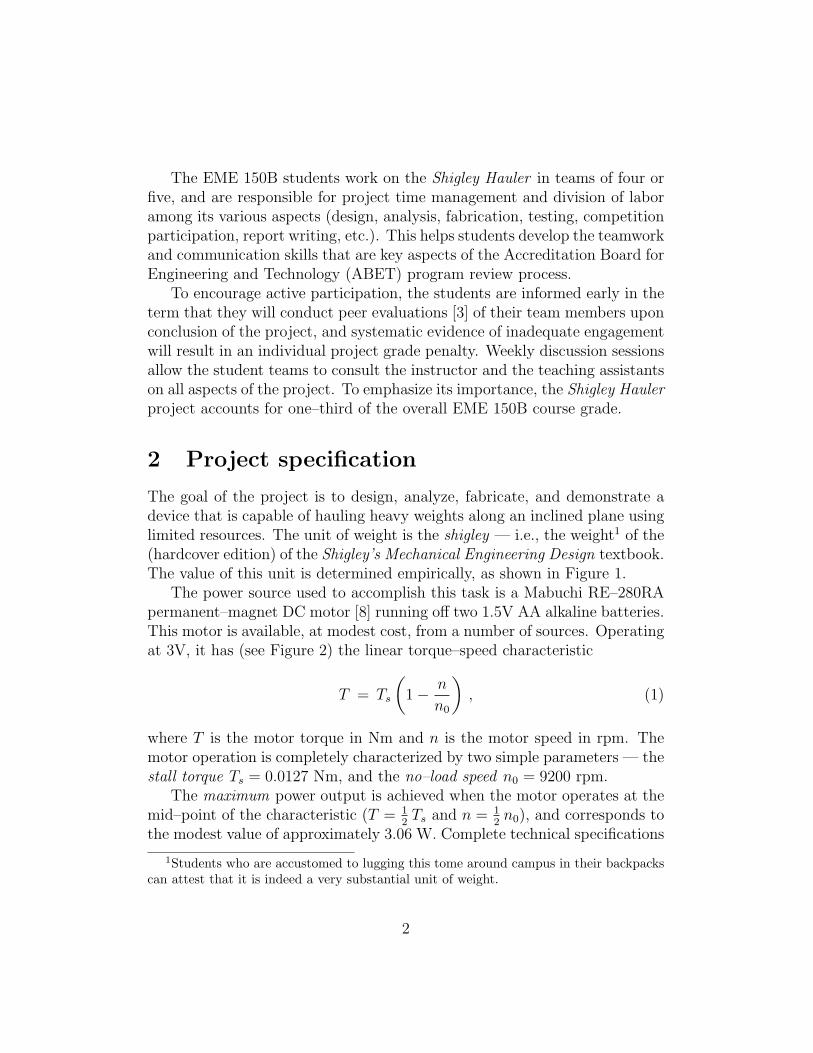
In addition to the motor, each student team receives a set of plastic spurgears — two in each of the 10, 20, 30, 40, and 50 tooth sizes. The gears comewith inserts that are suitable for mounting with an inteference fit on a 5
64inch
diameter shaft, or can be used without the inserts on 532
inch diameter shafts(with the insert, the 10 tooth pinion mounts with an inteference fit directlyon the motor shaft). The gears are available from Jameco Electronics [9], andare of modest quality. These are the only gears allowed for the project: nosubstitutions may be made. Also, no power source (springs, falling weights,etc.) other than the DC motor running off 2 AA batteries is allowed.
Figure 3: The Mabuchi RE–280RA permanent magnet DC motor and plasticspur gear sets (two each of 10, 20, 30, 40, and 50 tooth sizes) with inserts.
The competition ramp is shown in Figure 4. The lanes are 1 ft (0.305 m)wide, to accommodate the load of shigleys in landscape orientation, and 3 ft(0.914 m) long. The load must begin behind a starting line 8 in (0.203 m)from the bottom edge. The top of the ramp incorporates a barrier (not shownin Figure 4) to which the Shigley Hauler may be secured with C clamps.
Other than those outlined above, no a priori constraints are placed on theShigley Hauler design. Occasionally, some teams may exhibit Rube Goldberg
4

θ
3’
12”
Figure 4: Schematic of test ramp for the Shigley Hauler competition.
inclinations. Although the final design is the prerogative of the student team,it is emphasized that a clear focus on the functional specification, leading toa simple device based on meticulous analysis, precision implementation, andthorough testing and troubleshooting, is most likely to be successful.
3 Design, fabrication, and testing
The first task is to complete a thorough design and performance analysis ofthe Shigley Hauler. This task encompasses the gear train layout and resultingreduction ratios, design of the gear shafts (including shaft deflection analysis)and their mounting on appropriate bushings or bearings, the methodology forhauling the load up the inclined plane (typically by wrapping a line around aspool driven by the gear train), and analysis of the expected timings for runscorresponding to different loads and ramp inclinations. Continuous guidanceon the design is provided by the instructor and teaching assistants, but thefinal design decisions are the responsibility of the student teams. Once thedesign has been finalized, fabrication of the Shigley Hauler can begin.
At UC Davis, the EME 50 Manufacturing Processes class is a prerequisitefor EME 150A & B. EME 50 offers a broad survey of various manufacturingtechnologies through its lecture component, and hands–on training with thelathe, milling machine, drill press, etc. — both manual and CNC — in the UCDavis Engineering Fabrication Laboratory (EFL). Thus, EME 150B student
5

teams already have the equipment and safety training necessary to fabricatetheir Shigley Hauler devices in the EFL. Recent upgrades to the EFL providethe students with access to modern fabrication technologies, including laserand water–jet cutters, a 3D printer, and a 5–axis CNC mill.
The DC motor and gear sets are the only items supplied to the students —they are expected to furnish all other materials and components necessary tofabricating their device. A variety of material choices are typically evident inthe fabricated Shigley Haulers, including aluminum, steel, plexiglass, wood,and 3D–printed plastics. The use of recycled material is encouraged wheneverit does not compromise device performance. The teams are advised to adopta minimalistic approach to design and fabrication of the cart that holds theload of shigleys, to minimize the time and costs invested in it, and to avoidsignificantly adding to the load. The additional materials/components costsincurred by the student teams are relatively modest — ranging from as littleas $10 for particularly frugal teams, up to a maximum of about $100.
The student teams are encouraged to complete fabrication at least 2–3weeks before the competition, to allow adequate time for trouble–shooting,fine–tuning, and testing of the device. Common fabrication problems includeimproper spacing/alignment of gear shafts, insufficient rigidity of the shafts,insecure or misaligned mounting of gears on the shafts, friction due to poorbearing or bushing shaft supports, etc. As emphasized throughout the term,such problems can be remedied if the fabrication schedule allows sufficienttime for this trouble–shooting phase of the project.
4 Dynamic analysis
The Shigley Hauler is a competitive project, the goal being to complete eachrun (corresponding to a specified load and ramp angle) in the least possibletime. The choice of key design parameters, such as the gear reduction ratioN and spool radius r, must be tailored to each run by a quantitative analysis,based on the following design variables and physical quantities.2
• Ts = 0.0127 Nm, motor stall torque
• ω0 = 963.4 rad/s, motor no–load speed
• g = 9.81 m/s2, gravitational acceleration
2Henceforth, angular speeds will be expressed in units of rad/s rather than rpm.
6

• N = gearbox reduction ratio (dimensionless)
• ω = motor angular speed (rad/s)
• T = motor torque (Nm)
• L = total ramp length (m)
• θ = ramp inclination (rad)
• m = mass of load (kg)
• r = line spool radius (m)
• F = line tension force (N)
• v = load speed along ramp (m/s)
• s = distance travelled on ramp (m)
4.1 Steady–state analysis
For a preliminary analysis, the students are advised to ignore transients andestimate run times based on steady–state behavior. When switched on, themotor speed increases from zero and its torque decreases from Ts to a valueT just sufficient to move the load at constant speed. The torque NT at theoutput of the gear box is then equal to the torque rF required to wind a linecarrying a tension F around a spool of radius r. In the steady state, the linetension is equal to the component mg sin θ of the load weight parallel to theramp. Hence, the steady–state motor torque is
T =rmg sin θ
N,
and from (1) the corresponding steady–state motor speed is
ω∞ = ω0
(1− rmg sin θ
NTs
).
Note that this depends only on the ratio
ρ :=r
N(2)
7

of the spool radius r and gear ratio N , and not individually on these designparameters. In order for ω∞ to be positive, we must have
ρ <Ts
mg sin θ=: ρmax . (3)
For a given loadm and ramp angle θ, this condition indicates the (theoretical)maximum value of the quantity (2) that does not stall the Shigley Hauler.The condition (3) is equivalent to stating that the product of the spool radiusr and line tension F = mg sin θ should not exceed the motor stall torque Ts
amplified by the gear ratio N at the output of the gearbox.Since the steady–state gearbox output angular speed is ω∞/N , the linear
speed of the load along the ramp is v = ω∞r/N . Thus, if the ramp is of totallength L, the estimated run time ∆t = L/v (based on steady–state analysis)can be expressed in terms of the quantity (2) as
∆t =LTs
ω0ρ(Ts −mg sin θ ρ). (4)
The value of ρ that achieves the (theoretical) minimum run time is identifiedby setting the derivative of ∆t with respect to ρ equal to zero. This gives
ρ =12Ts
mg sin θ= 1
2ρmax , (5)
which corresponds to the case where the motor operates at the mid–point ofthe characteristic (1), i.e., the maximum power point, and the corresponding(theoretical) minimum run time, under the steady–state assumption, is then
∆tmin =4Lmg sin θ
ω0Ts
. (6)
4.2 Transient analysis
Since the motor does not achieve the steady–state speed instantaneously, theexpressions (4) and (6) are necessarily optimistic estimates of the actual andoptimum run times. The system transient behavior can be characterized by afirst–order differential equation, whose solution determines a (theoretically)exact run time. Although the students are not required to use this solution,comparing the time constant for this first–order equation with the run timeestimate (4) can furnish an idea of how accurate the latter is.
8

The equation of motion of the load along the ramp is
mdv
dt= F −mg sin θ .
Invoking the parameter (2) and the fundamental relations
T = Ts
(1− ω
ω0
), rF = NT , v =
ωr
N=
ds
dt, (7)
it can be cast as the first–order differential equation
dω
dt=
Ts
mρ2− g sin θ
ρ− Ts
mρ2ω0
ω
for ω. With some re–arrangement, we obtain the more concise formulation
dω
dt=
ω∞ − ωτ
, (8)
where
τ =mρ2ω0
Ts
and ω∞ = ω0
(1− ρmg sin θ
Ts
)are the motor spin–up timescale and asymptotic (steady–state) speed.
Example. When m = 2 kg, θ = 30◦, r = 0.05 m, and N = 50, the no–stallcondition (3) is satisfied, the motor spin–up timescale is τ ≈ 0.152 s, and thesteady–state motor speed is ω∞ ≈ 0.228ω0.
The solution to equation (8), subject to the initial condition ω = 0 at t = 0,can be written as
ω(t) = ω∞ [ 1− exp(−t/τ) ] . (9)
If the steady–state analysis is to furnish an accurate run time estimate, thetimescale τ should be small compared to the predicted run time (4).
The exact run time, allowing for a non–negligible acceleration phase, canbe computed as follows. From (7) and (9), the time–dependent speed of theload up the ramp is
v = ρω∞[ 1− exp(−t/τ) ] =ds
dt.
9

Thus, if traversal of the ramp length L requires time ∆t, we have
ρω∞
∫ ∆t
0
1− exp(−t/τ) dt =
∫ L
0
ds = L ,
or equivalently
(∆t/τ) + exp(−∆t/τ) = 1 +L
ρω∞τ. (10)
With z = ∆t/τ , the function f(z) = z+exp(−z) on the left satisfies f(0) = 1and f ′(z) > 0 for z > 0, so there is a unique positive z for which the valueof this function is equal to the expression on the right. The solution can becomputed by a simple (e.g., Newton–Raphson) iteration method, using thesteady–state value (4) as a starting approximation.
0.0 0.2 0.4 0.6 0.8 1.00
1
2
3
4
5
f = ρ/ρmax
∆t (
sec)
Figure 5: Theoretical run times, as a function of the ratio f = ρ/ρmax, for thecase m = 1 shigley, L = 0.75 m, θ = 20◦, based on (lower) the steady–stateestimate (4), and (upper) solutions of the transient–behavior equation (10).
Figure 5 compares theoretical timings based on the steady–state estimate(4) and the solution to the transient–behavior equation (10), as a functionof the ratio f = ρ/ρmax for the case m = 1 shigley, L = 0.75 m, and θ = 20◦.The difference is seen to be relatively minor, but biased toward the higher fvalues. The key message of this graph is that operating near the limits n→ 0or n→ n0 of the motor characteristic incurs a severe run–time penalty.
Note that the optimum value f = 12
predicted by the steady–state analysisequation (5) is no longer exact if the transient behavior is taken into account.
10

However, both graphs in Figure 5 are fairly flat for 0.4 ≤ f ≤ 0.6, so smalldeviations about f = 0.5 are relatively inconsequential.
5 Project management
At UC Davis, the Shigley Hauler project is run on a tight schedule, to conformwith the 10–week lecture duration of each quarter. The project is introducedat the beginning of the first week, and the competition is held at the end ofthe tenth week. This schedule serves to emphasize the importance of properproject planning and management. The student teams are advised to devoteequal time and effort (with appropriate division of responsibilities among theteam members) to three key phases of the project:
1. Design and analysis. A quantitative approach to all aspects of the designand performance analysis of the Shigley Hauler is expected — including geartrain layout, sizing and mounting of the gear shafts, selection of spool sizes,force and deflection analysis, choice of materials, and the predicted run times.The student teams are advised to complete this phase with 3–4 weeks, andthe lectures cover relevant material on gears, bearings, shafts, and DC motorsto assist in this. This phase can also be used for the procurement of materialsand components required to fabricate the Shigley Hauler.
2. Shigley Hauler fabrication. Prior machine shop training allows the studentteams to immediately begin fabrication of the Shigley Hauler, once the designhas been completed. In this phase, great emphasis is placed on the precisionand robustness of the implementation with regard to considerations such asaccurate spacing and alignment of the gear shafts (or provision for adjustmentthereof); secure mountings of the gears and spools on the shafts, and of theshaft bearings in the gearbox casing, etc. A cart to securely carry the load isalso required, but should be as light–weight as possible. The goal is to havea working device ready for trial tests by the 7th or 8th week.
3. Testing & troubleshooting. Issues that were not anticipated in the designor fabrication phases will inevitably arise, so it is critical to have a 2–3 weekperiod to identify and address these problems before the competition. Withproper attention to the design and fabrication phases, only minor fine–tuningadjustments should be necessary at this stage, but the 2–3 week testing periodallows for substantial changes to correct more significant problems.
11

6 Competition results
Recent offerings of EME 150B have typically involved 12–16 student teams(see Figures 6 and 7). In order to maintain a reasonable project competitionduration (4–5 hours), the test runs are restricted to four cases, namely:
1 shigley @ 20◦, 2 shigleys @ 30◦, 4 shigleys @ 40◦, 5 shigleys @ 60◦.
Figure 6: Securing a Shigley Hauler to the test ramp with C clamps.
The difficulty of a run employing m shigleys at a ramp angle θ is proportionalto m sin θ, and the above choices correspond to runs ranging from easy tovery difficult. The teams are allowed two attempts at each run, the faster ofthe two timings being recorded. Inevitably, a few teams are still going strongonce these “official” runs are completed, and wish to try more challengingcases for bonus points (the most difficult run ever recorded, 8 shigleys @ 60◦,required several minutes to complete). Timings from a recent representativecompetition, without bonus runs, are enumerated in Table 1.
For each of the four runs, Table 2 compares the theoretical shortest runtime (i.e., the value that minimizes the solution to equation (10) with respectto f = ρ/ρmax) and the best run time actually observed in the competition.The “real–world” timings are seen to be 2–3 times longer than the theoreticalminima. Several factors may contribute to this discrepancy, including:
12

Figure 7: Shigley Hauler competition in progress — 2 shigleys @ 30◦.
team name 1 @ 20◦ 2 @ 30◦ 4 @ 40◦ 5 @ 60◦
Algol 12.8 s 15.3 sAltair 5.6 s 12.4 s 31.9 s 50.5 sAntares 9.7 s 27.8 s 73.5 sBetelgeuse 6.5 s 17.3 s 54.2 s 76.9 sCapella 5.6 s 13.7 s 30.0 s 48.2 sElectra 8.6 s 20.9 s 59.4 sMaia 9.1 s 21.1 s 54.5 sMizar 11.6 s 15.4 s 53.0 s 59.2 sPolaris 7.6 s 21.9 s 53.8 s 69.7 sPollux 7.6 s 19.7 s 38.0 s 62.1 sSirius 7.2 s 17.9 s 61.4 s 104.1 sSpica 11.1 s 15.9 s 46.2 s 74.6 s
Table 1: Representative competition results for 12 student teams using runswith 1 shigley @ 20◦, 2 shigleys @ 30◦, 4 shigleys @ 40◦, 5 shigleys @ 60◦ —the blank entries correspond to runs that either stalled or were disqualified.
13

1 @ 20◦ 2 @ 30◦ 4 @ 40◦ 5 @ 60◦
theoretical 1.7 s 4.7 s 12.0 s 20.8 scompetition 5.6 s 12.4 s 31.9 s 48.2 s
Table 2: Comparison of the theoretical minimum run time, obtained from(10) with f = ρ/ρmax = 1
2and the fastest competition run time from Table 1.
• modest quality of the injection–molded plastic gears;
• imprecise centering, mounting, or spacing of the gears;
• insufficient rigidity or misalignment of the gear shafts;
• the DC motor manufacturer specifications are optimistic;
• depletion of the battery voltage due to prior use or aging;
• operation at sub–optimal values of the ratio f = ρ/ρmax;
• fricitional dissipation at the gear shaft bushings/bearings;
• the additional weight of the cart used to hold the shigleys ;
• flexure of spool under the load F if the radius r is small.
The competition results clearly illustrate the importance of maintaining tighttolerances and reducing frictional dissipation in efficient power transmission,and of the prototyping and practical verification of mechanical systems — asnoted by the celebrated sportsman–philosopher Yogi Berra,
In theory, there is no difference between theory and practice.In practice, there is.
7 Project grade
A great diversity of Shigley Hauler performance is usually evident during thecompetition — some teams may complete only the first few easy runs, whileother teams complete all the “official” runs with excellent timings and insiston demonstrating their engineering prowess through bonus runs. Teams thatunderperform in the competition may nevertheless have invested considerable
14

effort in the design and fabrication of their device. To avoid unduly penalizingsuch teams, the overall project grade is divided into three equal parts — (i)participation; (ii) competition performance; and (iii) project report.
Part (i) is automatic for teams that show up to the competition with acredible–looking device. Various quantitative measures have been employedto assess part (ii), with greater weight assigned to the more difficult runs, butqualitative factors such as smoothness and consistency of the Shigley Haulerperformance are also considered. For part (iii), the report is expected to givea detailed description of the design, analysis, fabrication, troubleshooting,and competition performance of the device, and underperforming teams areadvised to give a critical analysis of the causes of underperformance.
8 Learning outcomes & project assessment
To assess the educational impact of the Shigley Hauler project, the studentswere asked to complete an end–of–term questionnaire that seeks to measureits contribution to enhancing their skills in designing, analyzing, optimizing,and testing a mechanical system that addresses a prescribed function. Thequestions were organized into three sections, based upon (A) issues related tostudent confidence in the various aspects of engineering design; (B) generalcourse–related questions; and (C) assessing the impact of the Shigley Haulerproject on understanding design methodology and practice, as follows.
Part A. On a scale from 1 (low) to 10 (high), rate your confidence to . . .
1. . . . conduct engineering design;
2. . . . identify a design need;
3. . . . develop design solutions;
4. . . . select the best possible design;
5. . . . construct a prototype;
6. . . . evaluate and test a design;
7. . . . communicate a design;
8. . . . re–design a system.
15

Part B. On a scale from 1 (low) to 7 (high), assess the following statements.
1. The Shigley Hauler project helped in understanding the course content.
2. It is interesting to learn about the design of machine elements.
3. Fabricating and testing a prototype helped me to understand the designbetter than just theoretical calculations.
4. I like engineering design projects.
5. I would like to pursue a career that involves innovative design projects.
Part C. On a scale from 1 (low) to 7 (high), rate the Shigley Hauler projectin terms of better understanding . . .
1. . . . gear design;
2. . . . joint design;
3. . . . shaft design;
4. . . . DC motor operation;
5. . . . bearing design.
0
2
4
6
8
10
A1 A2 A3 A4 A5 A6 A7 A8
Figure 8: Mean values for responses to the Part A questions, concerned withstudent confidence in various aspects of engineering design, on a scale from1 (low) to 10 (high) — the “error bars” indicate the range of the responses.
As can be seen in Figure 8, the responses to the Part A questions showthat most students are quite confident they can conduct key design tasks. In
16

particular, they feel most confident in their ability to identify a design needand to develop design solutions, with mean scores of 8.62 and 8.21 out of 10.They have least confidence in their ability to select the best possible design,but this point nevertheless yielded a relatively high score of 7.46 out of 10.This aspect of the design process is not stressed in EME 150B due to timeconstraints, but it is covered in the capstone design class.
The students were also positive in their responses to the Part B questions(see Figure 9). The highest mean scores were for the two statements B5: “Iwould like to pursue a career that involves innovative design projects” (6.69out of 7), and B4 “I like engineering design projects” (6.66 out of 7) — theresponses to these prompts also had the smallest standard deviations.
01234567
B1 B2 B3 B4 B5
Figure 9: Mean responses to the Part B questions, on a 1 (strongly disagree)to 7 (strongly agree) scale: the “error bars” indicate the range of responses.
Figures 10–12 present more detailed breakdowns of the responses to thestatements B2, B3, and B5. The majority of the students find it interesting tolearn about the design of machine elements (Figure 10), and the course mayhave reinforced their motivation to pursue careers in the mechanical designfield (Figure 11). Also, 69% of the students strongly agree that “fabricatingand testing a prototype helped in understanding the design better than justtheoretical calculations” (Figure 12). The mean score for this statement was6.48 out of 7, with a standard deviation of 1.18.
Finally, the Part C questions asked the students to reflect on the value ofthe Shigley Hauler project in enhancing their understanding of the design ofbasic machine components (Figure 13). The highest scores were 6.14 out of 7for gear design, and 6.03 out of 7 for shaft design, which are central aspectsof the project. The lowest score, 5.21 out of 7, was for joint design, a topicthat is of relatively marginal importance for the project.
17

0.0%0
3.4%1
0.0%0
0.0%0
6.9%2
17.2%5
72.4%21
0
5
10
15
20
25
1 2 3 4 5 6 7
Res
pons
es
Figure 10: Prompt B2 “It is interesting to learn about the design of machineelements” responses, on a 1 (strongly disagree) to 7 (strongly agree) scale.
0.0%0
0.0%0
0.0%0
0.0%0
6.9%2
17.2%5
75.9%22
0
5
10
15
20
25
1 2 3 4 5 6 7
Res
pons
es
Figure 11: Responses to prompt B5 “I would like to pursue a career thatinvolves innovative design projects” on a scale from 1 to 7.
3.4%1
0.0%0
0.0%0
0.0%0
3.4%1
24.1%7
69.0%20
0
5
10
15
20
25
1 2 3 4 5 6 7
Res
pons
es
Figure 12: Prompt B3 “Fabricating and testing a prototype helped me tounderstand the design better than just theoretical calculations” responses,on a scale from 1 (strongly disagree) to 7 (strongly agree).
18

01234567
C1 C2 C3 C4 C5
Figure 13: Mean responses to the questions in Part C, concerned with theeducational value of the Shigley Hauler project, on a 1 (strongly disagree) to7 (strongly agree) scale: the “error bars” indicate the range of the responses.
In summary, the results show that Shigley Hauler project is very effectivein improving student motivation and understanding of core mechanical designprinciples, and motivating students to pursue careers as design engineers.
9 Conclusion
Through classroom testing over several years, the Shigley Hauler project hasproven to be highly successful in significantly improving student motivationand understanding of machine design principles. The project is amenable tocompletion within a relatively short timeframe, at modest cost, and serves toemphasize the importance of teamwork and time management in the contextof system design, prototyping, and verification. The strong dependence of theShigley Hauler performance on maintenance of tight tolerances and accuratealignments highlights the importance of precision engineering principles. Theproject also serves to illustrate some key paradigms of concurrent engineering,such as design for manufacturability, and the potential need for iterationsbetween design, analysis, prototyping, and testing.
References
[1] R. G. Budynas and J. K. Nisbett, Shigley’s Mechanical EngineeringDesign (10th ed.), McGraw–Hill, New York, ISBN 978–0–07–339820–4,2015.
19
[2] W. Cheng, X. Wu, Z. Zhang, F. Liu, M. Zhang, and P. Guo (2013),Effective project–oriented approach for training professionalmechanical engineers in undergraduate education, InternationalJournal of Mechanical Engineering Education 41, 289–296.
[3] D. Kelley (2015), Peer evaluation within a team design project,Journal of Engineering Technology 32, 44–50.
[4] T. J. Moore, M. M. Hynes, S. Purzer, A. W. Glancy, E. A. Siverling,K. M. Tank, C. A. Mathis, and S. S. Guzey (2014), STEM integration:evidence of student learning in design–based curricula, Proceedings,2014 IEEE Frontiers in Education (FIE) Conference, 1–7.
[5] W. Singhose, J. Vaughan, and R. Mayor (2009), Use of designcompetitions in mechatronics education, Proceedings, 2009 IEEEInternational Conference on Mechatronics, DOI:10.1109/CMECH.2009.4957226.
[6] D. A. Tolbert and S. R. Daly (2013), First–year engineering studentperceptions of creative opportunities in design, International Journalof Engineering Education 29, 879–890.
[7] R. D. Weinstein, J. O’Brien, E. Char, J. Yost, K. R. Muske,H. Fulmer, J. Wolf, and W. Koffke (2006), A multidisciplinary,hands–on, freshman engineering team design project and competition,International Journal of Engineering Education 22, 1023–1030.
[8] http://www.mabuchi-motor.co.jp/cgi-bin/catalog/
e catalog.cgi?CAT ID=re 280rasa
[9] http://www.jameco.com/webapp/wcs/stores/servlet/
Product 10001 10001 1810072 -1
20