15CV82-Design of Pre stressed concrete Elements .pdf - Sri ...
23
BE-8-CV-SKIT-Ph5b1-F02-V2.2 COURSE PLAN - CAY 2019-20 Sri Krishna Institute of Technology, Bangalore COURSE PLAN Academic Year 2019-2020 Program: B E – Civil Engineering Semester : 8 Course Code: 15CV82 Course Title: Design of Pre-stressed Concrete Elements Credit / L-T-P: 4 / 4-0-0 Total Contact Hours: 50 Course Plan Author: MOHAN K T Academic Evaluation and Monitoring Cell Sri Krishna Institute of Technology #29,Chimney hills,Hesaraghata Main road, Chikkabanavara Post Bangalore – 560090, Karnataka, INDIA Phone / Fax :08023721477/28392221/23721315 Web: www.skit.org.in , e-mail: [email protected] 15cv82 Copyright ©2017. cAAS. All rights reserved. Page # 1 / 23 Ref No:
-
Upload
khangminh22 -
Category
Documents
-
view
0 -
download
0
Transcript of 15CV82-Design of Pre stressed concrete Elements .pdf - Sri ...

BE-8-CV-SKIT-Ph5b1-F02-V2.2COURSE PLAN - CAY 2019-20
Sri Krishna Institute of Technology,Bangalore
COURSE PLAN
Academic Year 2019-2020
Program: B E – Civil Engineering
Semester : 8
Course Code: 15CV82
Course Title: Design of Pre-stressed Concrete Elements
Credit / L-T-P: 4 / 4-0-0
Total Contact Hours: 50
Course Plan Author: MOHAN K T
Academic Evaluation and Monitoring Cell
Sri Krishna Institute of Technology#29,Chimney hills,Hesaraghata Main road, Chikkabanavara Post
Bangalore – 560090, Karnataka, INDIA
Phone / Fax :08023721477/28392221/23721315Web: www.skit.org.in , e-mail: [email protected]
15cv82 Copyright ©2017. cAAS. All rights reserved.Page # 1 / 23
Ref No:

BE-8-CV-SKIT-Ph5b1-F02-V2.2COURSE PLAN - CAY 2019-20
Table of ContentsA. COURSE INFORMATION ............................................................................................................. 3 1. Course Overview .............................................................................................................................. 3 2. Course Content ................................................................................................................................. 3 3. Course Material ................................................................................................................................ 3 4. Course Prerequisites ......................................................................................................................... 5 5. Content for Placement, Profession, HE and GATE .......................................................................... 5 B. OBE PARAMETERS ...................................................................................................................... 5 1. Course Outcomes .............................................................................................................................. 5 2. Course Applications .......................................................................................................................... 5 3. Articulation Matrix ........................................................................................................................... 6 4. Curricular Gap and Content .............................................................................................................. 6 C. COURSE ASSESSMENT ............................................................................................................... 6 1. Course Coverage .............................................................................................................................. 6 2. Continuous Internal Assessment (CIA) ............................................................................................ 7 D1. TEACHING PLAN - 1 .................................................................................................................. 7 Module - 1 ............................................................................................................................................ 7 Module – 2 ............................................................................................................................................ 8 E1. CIA EXAM – 1 ............................................................................................................................ 10 a. Model Question Paper - 1 ............................................................................................................... 10 b. Assignment -1 ................................................................................................................................. 10 D2. TEACHING PLAN - 2 ................................................................................................................ 11 Module – 3 .......................................................................................................................................... 11 Module – 4 .......................................................................................................................................... 12 E2. CIA EXAM – 2 ............................................................................................................................ 14 a. Model Question Paper - 2 ............................................................................................................... 14 b. Assignment – 2 ............................................................................................................................... 14 D3. TEACHING PLAN - 3 ................................................................................................................ 15 Module – 5 .......................................................................................................................................... 15 E3. CIA EXAM – 3 ............................................................................................................................ 16 a. Model Question Paper - 3 ............................................................................................................... 16 b. Assignment – 3 ............................................................................................................................... 17 F. EXAM PREPARATION ................................................................................................................. 18 1. University Model Question Paper .................................................................................................. 18 2. SEE Important Questions ............................................................................................................... 20 Course Outcome Computation ........................................................................................................... 21 Academic Year: ................................................................................................................................... 21 Odd / Even semester ........................................................................................................................... 21
15cv82 Copyright ©2017. cAAS. All rights reserved.Page # 2 / 23

BE-8-CV-SKIT-Ph5b1-F02-V2.2COURSE PLAN - CAY 2019-20
A. COURSE INFORMATION
1. Course OverviewDegree: BE Program: CVSemester: 8 Academic Year: 2019-20Course Title: Design of prestressed concrete elements Course Code: 15CV82Credit / L-T-P: 4 / 4-0-0 SEE Duration: 180 MinutesTotal Contact Hours: 50 Hours SEE Marks: 80 MarksCIA Marks: 20 Marks Assignment 1 / Module
Course Plan Author: MOHAN K T Sign .. Dt:
Checked By: Sign .. Dt:
CO Targets CIA Target : 90 % SEE Target: 85%Note: Define CIA and SEE % targets based on previous performance.
2. Course ContentContent / Syllabus of the course as prescribed by University or designed by institute.Module
Content Teaching Hours Blooms LearningLevels
1 Introduction and Analysis of Members: Concept ofPrestressing - Types of Prestressing - Advantages -Limitations –Prestressing systems - Anchoring devices -Materials - Mechanical Properties of high strength concrete -high strength steel - Stress-Strain curve for High strengthconcrete.Analysis of members at transfer - Stress concept -Comparison of behavior of reinforced concrete andprestressed concrete - Force concept - Load balancingconcept - Kern point -Pressure line.
10 L4,
2 Losses in Prestress: Loss of Prestress due to Elasticshortening, Friction, Anchorage slip, Creep of concrete,Shrinkage of concrete and Relaxation of steel. Deflection andCrack Width Calculations of Deflection due to gravity loadsDeflection due to prestressing force -Total deflection - Limitsof deflection - Limits of span-to-effective depth ratio-Calculation of Crack Width - Limits of crack width.
10 L4
3 Design of Sections for Flexure: Analysis of members atultimate strength - Preliminary Design - Final Design for Type1members
10 L4
4 Design for Shear: Analysis for shear - Components of shearresistance – Modes of Failure - Limit State of collapse forshear - Design of transverse reinforcement
10L4
5 Anchorage zone stresses and design of anchorages.Composite Sections: Types of composite construction -Analysis of composite sections - Deflection –Flexural andshear strength of composite sections
10L4
- Total
3. Course MaterialBooks & other material as recommended by university (A, B) and additional resources used by courseteacher (C).1. Understanding: Concept simulation / video ; one per concept ; to understand the concepts ; 15 – 30minutes2. Design: Simulation and design tools used – software tools used ; Free / open source3. Research: Recent developments on the concepts – publications in journals; conferences etc.Modul
esDetails Chapters
in bookAvailability
A Text books (Title, Authors, Edition, Publisher, Year.) - -1 Krishna Raju, N. “Prestressed Concrete”, Tata McGraw Hill Publishing 1,3, 4 In Lib / In Dept
15cv82 Copyright ©2017. cAAS. All rights reserved.Page # 3 / 23

BE-8-CV-SKIT-Ph5b1-F02-V2.2COURSE PLAN - CAY 2019-20
Company, New Delhi 20062 Krishna Raju. N., “Pre-stressed Concrete - Problems and Solutions”, CBS
Publishers andDistributors, Pvt.Ltd., New Delhi
2, 4 In Lib/ In dept
B Reference books - -1 Praveen Nagarajan, “Advanced Concrete Design”, Person In Lib2 P. Dayaratnam, “Prestressed Concrete Structures”, Oxford & IBH-Pubs
Company, Delhi, 5th EditionNot Available
3 Lin T Y and Burns N H, ‘Design of Pre - stressed Concrete Structures’ , John Wiley and Sons, New York
In lib
C Others (Web, Video, Simulation, Notes etc.) - -
C1 https://www.youtube.com/watch?v=4KYPltsNAWsC2 https://www.youtube.com/playlist?list=PLB50EF6A79D1F8C14C3 http://www.digimat.in/nptel/courses/video/105106118/L31.htmlC4 http://www.digimat.in/nptel/courses/video/105106118/L25.htmlC5 http://www.digimat.in/nptel/courses/video/105106118/L04.htmlC6 http://www.digimat.in/nptel/courses/video/105106118/L08.htmlC7 http://www.digimat.in/nptel/courses/video/105106118/L09.htmlC8 http://www.digimat.in/nptel/courses/video/105106118/L09.htmlC9 http://www.digimat.in/nptel/courses/video/105106118/L40.htmlC10 http://www.digimat.in/nptel/courses/video/105106118/L36.htmlC11 https://www.youtube.com/watch?v=PZi50Miapc8C12 https://www.youtube.com/watch?v=PZi50Miapc8C13 https://www.youtube.com/watch?v=ztiFxoi-O-YC14 http://www.digimat.in/nptel/courses/video/105106118/L02.htmlC15 http://www.digimat.in/nptel/courses/video/105106118/L19.htmlC16 http://www.digimat.in/nptel/courses/video/105106118/L24.htmlC17 http://www.digimat.in/nptel/courses/video/105106118/L17.htmlC18 http://www.digimat.in/nptel/courses/video/105106118/L07.htmlC19 http://www.digimat.in/nptel/courses/video/105106118/L12.htmlC20 http://www.digimat.in/nptel/courses/video/105106118/L39.htmlC21 http://www.digimat.in/nptel/courses/video/105106118/L23.htmlC22 http://www.digimat.in/nptel/courses/video/105106118/L16.htmlC23 http://www.digimat.in/nptel/courses/video/105106118/L16.htmlC24 http://www.digimat.in/nptel/courses/video/105106118/L30.htmlC25 http://www.digimat.in/nptel/courses/video/105106118/L37.htmlC26 http://www.digimat.in/nptel/courses/video/105106118/L34.htmlC27 http://www.digimat.in/nptel/courses/video/105106118/L26.htmlC28 http://www.digimat.in/nptel/courses/video/105106118/L28.htmlC29 https://cosmolearning.org/video-lectures/design-of-members-for-
flexure-type-1-members/C30 https://www.youtube.com/watch?v=vg-0a5woulsC31 https://www.youtube.com/watch?v=zYEjDnVnnHsC32 https://www.youtube.com/watch?v=nKUiEjUhXw4C33 https://www.youtube.com/watch?v=BIJTWBlguHs
D Recent Developments for Research - -https://www.iith.ac.in/~prestressed/ https://doi.org/10.1680/iicep.1957.1949https://doi.org/10.1680/iicep.1966.9077https://doi.org/10.1680/ijoti.1944.14069
F Others (Web, Video, Simulation, Notes etc.) - -
15cv82 Copyright ©2017. cAAS. All rights reserved.Page # 4 / 23

BE-8-CV-SKIT-Ph5b1-F02-V2.2COURSE PLAN - CAY 2019-20
4. Course PrerequisitesRefer to GL01. If prerequisites are not taught earlier, GAP in curriculum needs to be addressed. Include inRemarks and implement in B.5.Students must have learnt the following Courses / Topics with described Content . . .Modules
CourseCode
Course Name Topic / Description Sem Remarks BloomsLevel
1 15CV61 Design of RCstructuralelements
Knowledge on beam design 6 GapA seminar on beamdesign
AnalyzeL4
5. Content for Placement, Profession, HE and GATEThe content is not included in this course, but required to meet industry & profession requirements andhelp students for Placement, GATE, Higher Education, Entrepreneurship, etc. Identifying Area / Contentrequires experts consultation in the area.Topics included are like, a. Advanced Topics, b. Recent Developments, c. Certificate Courses, d. CourseProjects, e. New Software Tools, f. GATE Topics, g. NPTEL Videos, h. Swayam videos etc.Modules
Topic / Description Area Remarks BloomsLevel
1 Concept of Prestressing HigherEducation
Understand L2
2 Stress-Strain curve for High strength concrete.
GATE Understand L2
B. OBE PARAMETERS
1. Course OutcomesExpected learning outcomes of the course, which will be mapped to POs.Modules
CourseCode.#
Course OutcomeAt the end of the course, student
should be able to . . .
Teach. Hours Instr Method Assessment Method
Blooms’Level
1 15CV82.1 Understand the requirement of PSC members for present scenario.
10 Lecture Assignment L4
2 15CV82.2 Analyse the losses in PSC element during transfer at working.
10 Lecture/Tutorial
AssignmentL4
3 15CV82.3 Analyzing the PSC element for flexure and finding its efficiency.
10 Lecture AssignmentL4
4 15CV82.4 Analyzing the PSC element for shear and finding its efficiency.
10 Lecture AssignmentL4
5 15CV82.5 Analyzing the PSC element for anchorage zone and adopting suitable design.
10 Lecture AssignmentL4
- - Total 50 - - L2-L4
2. Course ApplicationsWrite 1 or 2 applications per CO.Students should be able to employ / apply the course learnings to . . .Modules
Application AreaCompiled from Module Applications.
CO Level
1 Used to select the High strength concrete and steel, He can beable to know the CO1 L4
15cv82 Copyright ©2017. cAAS. All rights reserved.Page # 5 / 23

BE-8-CV-SKIT-Ph5b1-F02-V2.2COURSE PLAN - CAY 2019-20
advantages and construction process of PSC compared to RCC.2 Designing of PSC members he will be able to find the losses in both pre tensioning
and post tensioning process.CO2 L4
3 Designing of PSC members he will be able to solve for flexure in both pretensioning and post tensioning process.
CO3 L4
4 Designing of PSC members he will be able to solve for shear in both pre tensioningand post tensioning process.
CO4 L4
5 Designing of PSC members he will be able to solve for stress in anchorage in bothpre tensioning and post tensioning process.
CO5 L4
3. Articulation MatrixCO – PO Mapping with mapping level for each CO-PO pair, with course average attainment.
- - Course Outcomes Program Outcomes -Modules
CO.# At the end of the coursestudent should be able to . . .
PO1
PO2
PO3
PO4
PO5
PO6
PO7
PO8
PO9
PO10
PO11
PO12
PSO1
PSO2
PSO3
Level
1 CO1 Understand the requirement of PSC members for present scenario.
3 - - - - 2 1 1 3 3 - 2 L4
2 CO2 Analyse the losses in PSC element during transfer at working.
3 3 - - - 2 1 1 3 1 - 2 L4
3 CO3 Analyzing the PSC element for flexure and finding its efficiency.
3 - - - - 2 1 1 3 3 - 2 L4
4 CO4 Analyzing the PSC element for shear and finding its efficiency.
3 3 - - - 2 1 1 3 1 - 2 L4
5 CO5 Analyzing the PSC element for anchorage zone and adopting suitable design.
3 3 - - - 2 1 1 3 3 - 2 L4
- 15CV82. Average 3 3 - - - 2 1 1 3 2.2 - 2 -- PO, PSO 1.Engineering Knowledge; 2.Problem Analysis; 3.Design / Development of Solutions;
4.Conduct Investigations of Complex Problems; 5.Modern Tool Usage; 6.The Engineer andSociety; 7.Environment and Sustainability; 8.Ethics; 9.Individual and Teamwork;10.Communication; 11.Project Management and Finance; 12.Life-long Learning;S1.Software Engineering; S2.Data Base Management; S3.Web Design
4. Curricular Gap and ContentTopics & contents not covered (from A.4), but essential for the course to address POs and PSOs.Modules
Gap Topic Actions Planned Schedule Planned Resources Person PO Mapping
12
C. COURSE ASSESSMENT
1. Course CoverageAssessment of learning outcomes for Internal and end semester evaluation.Modules
Title Teach.Hours
No. of question in Exam CO LevelsCIA-1 CIA-2 CIA-3 Asg Extra
AsgSEE
1 Introduction and Analysis ofMembers:
10 2 - - 1 1 2 CO1 L2
15cv82 Copyright ©2017. cAAS. All rights reserved.Page # 6 / 23

BE-8-CV-SKIT-Ph5b1-F02-V2.2COURSE PLAN - CAY 2019-20
2 Losses in Prestress and deflection 10 2 - - 1 1 2 CO2 L43 Design of Sections for Flexure 10 - 2 - 1 1 2 CO3 L44 Design for Shear 10 - 2 - 1 1 2 CO4 L45 Anchorage zone stresses and
design of anchorages10 - - 4 1 1 2 CO5 L4
- Total 50 4 4 4 5 5 10 - -
2. Continuous Internal Assessment (CIA)Assessment of learning outcomes for Internal exams. Blooms Level in last column shall match with A.2.Modules
Evaluation Weightage inMarks
CO Levels
1, 2 CIA Exam – 1 15 CO1, CO2, L43, 4 CIA Exam – 2 15 CO3, CO4 L45 CIA Exam – 3 15 CO5. L4
1, 2 Assignment - 1 05 CO1, CO2, L43, 4 Assignment - 2 05 CO3, CO4 L45 Assignment - 3 05 CO5. L4
1, 2 Seminar - 1 - -3, 4 Seminar - 2 - -5 Seminar - 3 - -
1, 2 Quiz - 1 - -3, 4 Quiz - 2 - -5 Quiz - 3 - -
1 - 5 Other Activities – Mini Project -Final CIA Marks 20 -C01-C05 L4
D1. TEACHING PLAN - 1
Module - 1Title: Introduction and Analysis of Members: Appr
Time:10 Hrs
a Course Outcomes CO BloomsThe student should be able to:
1 Understand the requirement of PSC members for present scenario. CO1 L2
b Course Schedule - -Class No Portion covered per hour - -
1 Introduction and Analysis of Members: Concept of Prestressing CO1 L22 Types of Prestressing - Advantages - Limitations . CO1 L23 Prestressing systems - Anchoring devices CO1 L24 Materials - Mechanical Properties of high strength concrete - high strength steel -
Stress-Strain curve for High strength concrete.CO1 L2
5 Analysis of members at transfer . CO1 L26 Stress concept - Comparison of behavior of reinforced concrete and prestressed
concrete CO1 L2
7 Force concept - Load balancing concept CO1 L28 Kern point -Pressure line. CO1 L29 Problems. CO1 L410 Problems. CO1 L4
c Application Areas
15cv82 Copyright ©2017. cAAS. All rights reserved.Page # 7 / 23

BE-8-CV-SKIT-Ph5b1-F02-V2.2COURSE PLAN - CAY 2019-20
- Students should be able employ / apply the Module learnings to . . .1 Used to select the High strength concrete and steel, He can beable to know
the advantages and construction process of PSC compared to RCC.co1 L2
2
d Review Questions-1 Distinguish between pretensioning and post tensionong and state advantages
of these methods.co1 L2
2 Explain the necessity of using high strength concrete and high tensile steel inPSC.?
co1 L2
3 Define pressure line or thrust line. Explain the significance. co1 L24 Define pre stressed concrete? State its advantages over reinforced concrete? co1 L25 Explain with neat sketches, Freyssinet system of pre-stressing? co1 L26 Explain with neat sketch “Hoyer’s Long line “System of pre-tensioning? co1 L27 Define 1} Uni axial and Biaxial Pre-stressing. 2} Concentric and eccentric Pre-
stressing?co1 L2
8 Explain the concept of load balancing? co1 L29 Aprestressed conctrete beam 500mm wide and 650mm deep is provided with
a tendon having parabolic cable profile with zero eccentricity at ends and100mm at centre of span 6m. If the load including self weight is 35kN/m onthe whole span, Calculate the extreme stresses for the midspan section. Thistendons carry a prestressing force of 1000kN.?
co1 L4
10 A pre-stressed concrete T beam Having a cross- section of flange 1200mmwide and 200mm thick, the rib is 240mm wide and 1000mm deep. The beamcarries a load of 12kN/m due to its own weight at the initial stage over a spanof 16m. Determine the prestressing force and its eccentricity to produce netstress equal to zero and 12MPa ai the top and bottom fibers.
co1 L4
e Experiences - -1 CO1 L22
Module – 2Title: Losses in Prestress and deflection Appr
Time:10 Hrs
a Course Outcomes CO Blooms- The student should be able to: - Level
Analyse the losses in PSC element during transfer at working. CO2 L4
b Course Schedule - -Class
NoPortion covered per hour - -
11 Losses in Prestress: Loss of Prestress due to Elastic shortening, Friction, CO2 L212 Anchorage slip, Creep of concrete, Shrinkage of concrete and Relaxation of steel. CO2 L2
13 Numerical Problems. CO2 L414 Numerical Problems. CO2 L415 Numerical Problems. CO2 L416 Deflection and Crack Width Calculations of Deflection due to gravity loads
Deflection due to prestressing force -Total deflection .CO2 L2
17 Limits of deflection - Limits of span-to-effective depth ratio -Calculation of CrackWidth - Limits of crack width.
CO2 L2
18 Numerical Problems. CO2 L419 Numerical Problems. CO2 L4
15cv82 Copyright ©2017. cAAS. All rights reserved.Page # 8 / 23

BE-8-CV-SKIT-Ph5b1-F02-V2.2COURSE PLAN - CAY 2019-20
20 Numerical Problems. CO2 L4
c Application Areas - -- Students should be able employ / apply the Module learnings to . . . - -1 Designing of PSC members he will be able to find the losses in both pre
tensioning and post tensioning process.CO2 L4
2
d Review Questions - --1 Explain the different types of losses in pre stressed concrete?2 A post tensioned concrete beam, simply supported over a span of 12m is of
cross section 230x750mm and is prestressed with 10 numbers of 7mm diameterparabolic cable bars with zero eccentricity at the support and 200mm atmidspan. Calculate the loss due to different causes for the following data.Grade of concrete = M40.Initial Prestress = 1000N/mm2 .
Co-efficient of curvature effect = 0.50.Wobble coefficient k = 0.003/m.Anchorage slip = 5mm at jacking end.Creep coefficient = 1.6, Shrinkage of concrete=0.0002.Relaxation of steel stress= 3%, Es=210 kN/mm2, Ec=37.50 kN/mm2 .
Calculate the total percentage of loss and the jacking force required.3 A prestressed concrete beam 200mm wide and 300mm deep is prestressed
with wires of c/s area As 320mm2 located at a constant eccentricity of 50mmand carring an initialstress of 1000 N/mm2 . The span of the beam of the beamis 10m. Calculate the % loss of stress in wires if the beam is post-tensionedusing following data:.Es=210 kN/mm2.Ec= 35 kN/mm2.Wobble coefficient k = 0.0015/m.Anchorage slip = 5mm at jacking end.Creep coefficient = 1.6, Shrinkage of concrete=0.0002.Relaxation of steel stress= 5%, Calculate the total percentage of loss and the jacking force required.
4 A simply supported post-tensioned concrete beam of span 15 m has arectangular cross section 300 x 800 mm. The prestress at ends is 1300kN withzero eccentricity at the supports and 250mm at the centre the cable profilebeing parabolic. Assuming k=0.15 per 100 m and mue= 0.35. Determine the lossof stress due to friction at the centre of the beam?
5 A pretensioned beam 250mm wide and 300mm deep in prestressed by 12 wireseach of 7mm diameter initially stressed to 1200 N/mm2 with their centroidslocated at 100mm from the soffit. Estimate the final percentage loss of stressdue to elastic deformation, creep, shrinkage and relaxation using IS 1343.Relaxation of steel stress= 90N/mm2.Creep coefficient = 1.6Residual shrinkage strain =3 x 10⁻⁴.Es=210 kN/mm2.Ec= 35 kN/mm2.
6 What is deflection and what are the factors influencing deflections? 7 What is pre and post crack condition?8 Deflection of beam with straight tendons?9 Deflection of beam with Parabolic tendons?10 Deflection of beam with sloping tendons?11 Deflection of beam with Trapezoidal tendons?
e Experiences - -1 CO3 L22
15cv82 Copyright ©2017. cAAS. All rights reserved.Page # 9 / 23

BE-8-CV-SKIT-Ph5b1-F02-V2.2COURSE PLAN - CAY 2019-20
E1. CIA EXAM – 1
a. Model Question Paper - 1Crs Code 15CV82 Sem: VIII Marks: 30 Time: 70 MinsCourse: Design of Pre Stressed Concrete Elements.
- - Note: Answer all questions, each carry equal marks. Module : 1, 2 Marks CO Level1 a Distinguish between pretensioning and post tensionong and state
advantages of these methods.5 CO1 L2
b Explain with neat sketch “Hoyer’s Long line “System of pre-tensioning? 5 CO1 L2c Define 1} Uni axial and Biaxial Pre-stressing. 2} Concentric and eccentric
Pre-stressing?5 CO1 L2
OR2 a Explain the concept of load balancing? 5 CO1 L2
b Aprestressed conctrete beam 500mm wide and 650mm deep is providedwith a tendon having parabolic cable profile with zero eccentricity at endsand 100mm at centre of span 6m. If the load including self weight is35kN/m on the whole span, Calculate the extreme stresses for themidspan section. This tendons carry a prestressing force of 1000kN.?
10 CO1 L4
3 a A prestressed concrete beam 200mm wide and 300mm deep isprestressed with wires of c/s area As 320mm2 located at a constanteccentricity of 50mm and carring an initialstress of 1000 N/mm2 . Thespan of the beam of the beam is 10m. Calculate the % loss of stress inwires if the beam is post-tensioned using following data:.Es=210 kN/mm2.Ec= 35 kN/mm2.Wobble coefficient k = 0.0015/m.Anchorage slip = 5mm at jacking end.Creep coefficient = 1.6, Shrinkage of concrete=0.0002.Relaxation of steel stress= 5%, Calculate the total percentage of loss and the jacking force required.
15 CO2 L4
OR4 a A simply supported post-tensioned concrete beam of span 15 m has a
rectangular cross section 300 x 800 mm. The prestress at ends is 1300kNwith zero eccentricity at the supports and 250mm at the centre the cableprofile being parabolic. Assuming k=0.15 per 100 m and mue= 0.35.Determine the loss of stress due to friction at the centre of the beam?
15 CO2 L4
b. Assignment -1
Model Assignment QuestionsCrs Code 15CV82 Sem: VIII Marks: 30 Time: 70 MinsCourse: Design of Pre Stressed Concrete Elements.
SNo Assignment Description Marks CO Level
1 Distinguish between pretensioning and post tensionong and stateadvantages of these methods.
5 CO1 L2
2 Explain the necessity of using high strength concrete and high tensilesteel in PSC.?
5 CO1 L2
3 Define pressure line or thrust line. Explain the significance. 5 CO1 L24 Define pre stressed concrete? State its advantages over reinforced
concrete?5 CO1 L2
5 Explain with neat sketches, Freyssinet system of pre-stressing? 5 CO1 L26 Explain with neat sketch “Hoyer’s Long line “System of pre-tensioning? 5 CO1 L27 Define 1} Uni axial and Biaxial Pre-stressing. 2} Concentric and eccentric
Pre-stressing?5 CO1 L2
8 Explain the different types of losses in pre stressed concrete? 5 CO2 L29 A post tensioned concrete beam, simply supported over a span of 12m is 16 CO2 L4
15cv82 Copyright ©2017. cAAS. All rights reserved.Page # 10 / 23

BE-8-CV-SKIT-Ph5b1-F02-V2.2COURSE PLAN - CAY 2019-20
of cross section 230x750mm and is prestressed with 10 numbers of 7mmdiameter parabolic cable bars with zero eccentricity at the support and200mm at midspan. Calculate the loss due to different causes for thefollowing data.Grade of concrete = M40.Initial Prestress = 1000N/mm2 .
Co-efficient of curvature effect = 0.50.Wobble coefficient k = 0.003/m.Anchorage slip = 5mm at jacking end.Creep coefficient = 1.6, Shrinkage of concrete=0.0002.Relaxation of steel stress= 3%, Es=210 kN/mm2, Ec=37.50 kN/mm2 .
Calculate the total percentage of loss and the jacking force required.10 A prestressed concrete beam 200mm wide and 300mm deep is
prestressed with wires of c/s area As 320mm2 located at a constanteccentricity of 50mm and carring an initialstress of 1000 N/mm2 . Thespan of the beam of the beam is 10m. Calculate the % loss of stress inwires if the beam is post-tensioned using following data:.Es=210 kN/mm2.Ec= 35 kN/mm2.Wobble coefficient k = 0.0015/m.Anchorage slip = 5mm at jacking end.Creep coefficient = 1.6, Shrinkage of concrete=0.0002.Relaxation of steel stress= 5%, Calculate the total percentage of loss and the jacking force required.
16 CO2 L4
11 A simply supported post-tensioned concrete beam of span 15 m has arectangular cross section 300 x 800 mm. The prestress at ends is 1300kNwith zero eccentricity at the supports and 250mm at the centre the cableprofile being parabolic. Assuming k=0.15 per 100 m and mue= 0.35.Determine the loss of stress due to friction at the centre of the beam?
16 CO2 L4
12 A pretensioned beam 250mm wide and 300mm deep in prestressed by12 wires each of 7mm diameter initially stressed to 1200 N/mm2 with theircentroids located at 100mm from the soffit. Estimate the final percentageloss of stress due to elastic deformation, creep, shrinkage and relaxationusing IS 1343.Relaxation of steel stress= 90N/mm2.Creep coefficient = 1.6Residual shrinkage strain =3 x 10⁻⁴.Es=210 kN/mm2.Ec= 35 kN/mm2.
16 CO2 L4
13 What is deflection and what are the factors influencing deflections? 8 CO2 L414 What is pre and post crack condition? 8 CO2 L415 Deflection of beam with straight tendons? 8 CO2 L416 Deflection of beam with Parabolic tendons? 8 CO2 L417 Deflection of beam with sloping tendons? 8 CO2 L418 Deflection of beam with Trapezoidal tendons? 8 CO2 L4
D2. TEACHING PLAN - 2
Module – 3Title: Design of Sections for Flexure Appr
Time:10 Hrs
a Course Outcomes CO Blooms- At the end of the topic the student should be able to . . . - Level1 Analyzing the PSC element for flexure and finding its efficiency. CO3 L4
b Course ScheduleClass No Portion covered per hour - -
15cv82 Copyright ©2017. cAAS. All rights reserved.Page # 11 / 23

BE-8-CV-SKIT-Ph5b1-F02-V2.2COURSE PLAN - CAY 2019-20
21 Design of Sections for Flexure: Analysis of members at ultimate strength -Preliminary Design
CO3 L2
22 Numerical Problems. CO3 L4
23 Numerical Problems. CO3 L424 Numerical Problems. CO3 L425 Numerical Problems. CO3 L426 Final Design for Type 1members CO3 L227 Numerical Problems. CO3 L428 Numerical Problems. CO3 L429 Numerical Problems. CO3 L430 Numerical Problems. CO3 L4
c Application Areas - -- Students should be able employ / apply the Module learnings to . . . - -1 Designing of PSC members he will be able to solve for flexure in both pre
tensioning and post tensioning process.CO3 L4
d Review Questions - -- The attainment of the module learning assessed through following questions - -1 A post tensioned unbounded beam section 120mm x 300mm is pre-stressed
by 7 wires of 5mm diameter with an effective cover of 50mm and effectivestress of 1200 N/mm2 . The beam is of 7.5m span. If M40 concrete is used andfp = 1600 MPa, find the ultimate flexural strength of the section.
CO3 L4
2 A post tensioned bounded Tee section has a flange width of 800mm andthickness of 250mm. The thickness of web is 200mm. The area of high tensilewire is 4000 mm2 located at 1200mm from top of flange. The characteristicstrength of steel and concrete are 1500 N/mm2 and 40 N/mm2 respectively.Calculate the ultimate moment capacity of the section using IS 1343recommendation.
CO3 L4
3 Design a pre-stressed concrete beam as Type-1 member to carry asuperimposed load of 12 kN/m over a simply supported span of 25m. Thepermissible stress in compression for concrete at transfer and working loadsare 14 N/mm2 and 12 N/mm2 respectively. Initial stress in pre-stressing cableis 1000 N/mm2 . Loss of pre-stress is 20%. Adopt Freyssenet cables each of 12wires of 5mm diameter
CO3 L4
4 List the different types of flexural failures in a PSC beam. Explain failure ofunder reinforced sections.
CO3 L2
5 A post tensioned beam with unbounded tendons is of rectangular section400mm wide with an effective depth of 800mm. The C/S area of the pre-stressing steel is 2840 mm2 . The effective pre-stress in the steel after alllosses is 900 N/mm2 . The effective span of the beam is 16m. If fck = 40N/mm2 , Estimate the ultimate moment of resistance of the section using IScode provisions.
CO3 L4
e Experiences - -1 CO6 L22
Module – 4Title: Design for Shear Appr
Time:10 Hrs
a Course Outcomes CO Blooms- At the end of the topic the student should be able to . . . - Level1 Analyzing the PSC element for shear and finding its efficiency. CO4 L4
15cv82 Copyright ©2017. cAAS. All rights reserved.Page # 12 / 23

BE-8-CV-SKIT-Ph5b1-F02-V2.2COURSE PLAN - CAY 2019-20
b Course ScheduleClass No Portion covered per hour - -
31 Design for Shear: Analysis for shear - Components of shear resistance . CO4 L232 Modes of Failure - Limit State of collapse for shear - Design of transverse
reinforcement.CO4 L2
33 Numerical Problems. CO4 L434 Numerical Problems. CO4 L435 Numerical Problems. CO4 L436 Numerical Problems. CO4 L437 Numerical Problems. CO4 L438 Numerical Problems. CO4 L439 Numerical Problems. CO4 L440 Numerical Problems. CO4 L4
c Application Areas - -- Students should be able employ / apply the Module learnings to . . . - -1 Designing of PSC members he will be able to solve for shear in both pre
tensioning and post tensioning process.CO4 L4
d Review Questions - -- The attainment of the module learning assessed through following questions - -
1 Explain types of shear cracks ? CO4 L22 A' PSC beam 250mm wide 150mm deep is subjected to SF 900 kN fiber stress
under working load is 4 N/mm2 effective pre-stress is 1000 N/mm 2 and areaof cable is 1500 min - . Design shear reinforcement slope of cable at support is(1/6)
CO4 L4
3 A pre-stressed concrete beam of span 10m, cross section 120mm x 300mm isprestressed by a cable carrying a force of 180 kN the beam support a UDL 5kN/m including self weight compare the magnitude of principal tension withand without axial pre-stress. Estimate the reduction in principal stress. Also find% reduction if a parabolic cable used with e = 50 mm at mid span and zero atsupport
CO4 L4
4 Explain different methods of improving shear resistance of PSC members. CO4 L25 Explain the mechanism of shear failure in PSC beam CO4 L26 A support reaction of PSC beam 120 x 250mm is required to carry an uitimate
shear force of 70kN. The compressive stress at the centroidal axis is 5MPa andfck= 40 Mpa. Fy= 415MPa cover to reinforcement =50mm. Design the suitableshear reinforcement at the section as per IS-1343 recommondations?
CO4 L4
7 Differentiate between web shear, flexural and flexural shear cracks in PSCmember with neat sketch?
CO4 L2
8 A PSC beam 300mm x 1000mm is subjected to a shear force of 500kN underworking loads near support section. The effective pre stressing force in thetendon is 800kN. The cable is parabolic with zero eccentricity at support and300mm below centroidal axis at mid span. The span of the beam is 12m. If M40concrete is used estimate the principal tension in concrete at support sectionand if required design the shear reinforcement?
CO4 L4
e Experiences - -12
15cv82 Copyright ©2017. cAAS. All rights reserved.Page # 13 / 23
BE-8-CV-SKIT-Ph5b1-F02-V2.2COURSE PLAN - CAY 2019-20
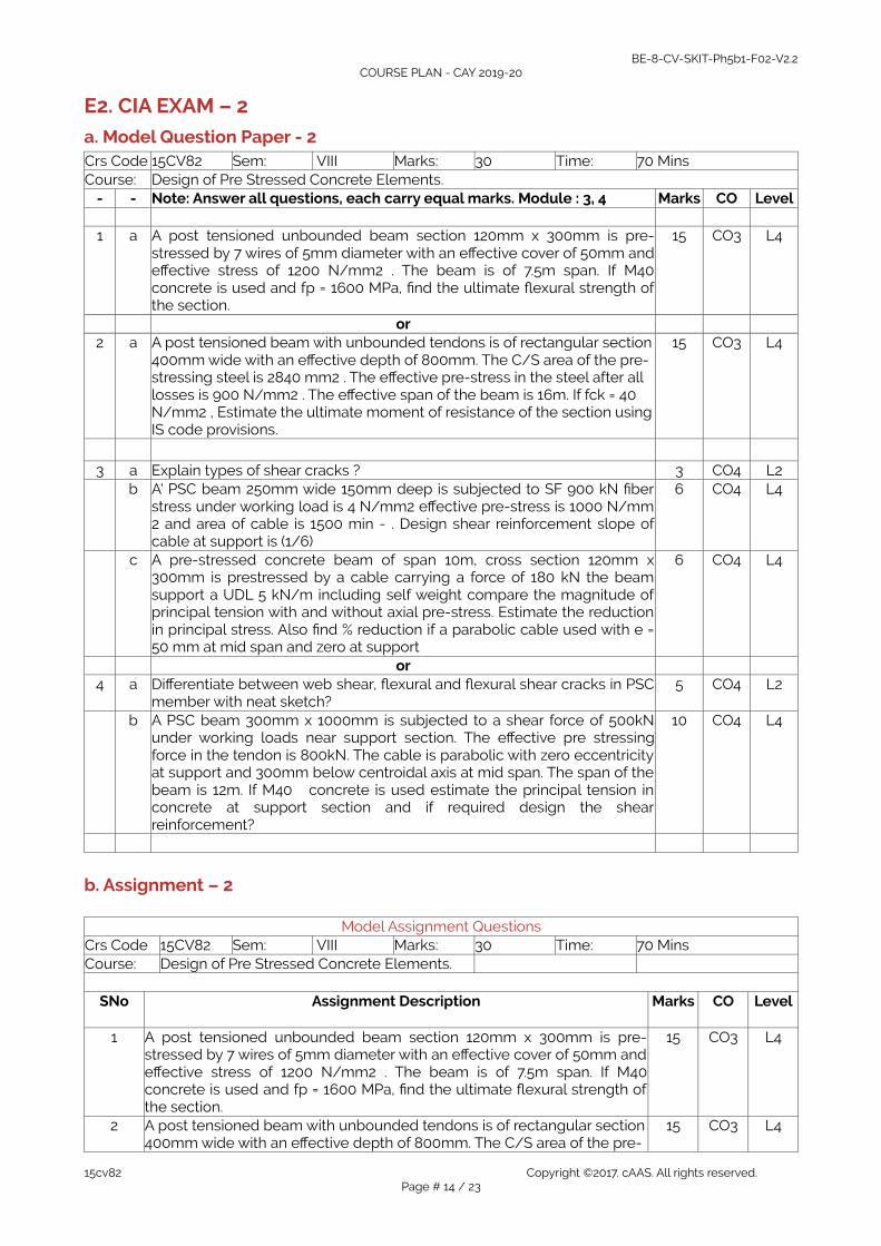
E2. CIA EXAM – 2
a. Model Question Paper - 2Crs Code 15CV82 Sem: VIII Marks: 30 Time: 70 MinsCourse: Design of Pre Stressed Concrete Elements.
- - Note: Answer all questions, each carry equal marks. Module : 3, 4 Marks CO Level
1 a A post tensioned unbounded beam section 120mm x 300mm is pre-stressed by 7 wires of 5mm diameter with an effective cover of 50mm andeffective stress of 1200 N/mm2 . The beam is of 7.5m span. If M40concrete is used and fp = 1600 MPa, find the ultimate flexural strength ofthe section.
15 CO3 L4
or2 a A post tensioned beam with unbounded tendons is of rectangular section
400mm wide with an effective depth of 800mm. The C/S area of the pre-stressing steel is 2840 mm2 . The effective pre-stress in the steel after all losses is 900 N/mm2 . The effective span of the beam is 16m. If fck = 40 N/mm2 , Estimate the ultimate moment of resistance of the section usingIS code provisions.
15 CO3 L4
3 a Explain types of shear cracks ? 3 CO4 L2b A' PSC beam 250mm wide 150mm deep is subjected to SF 900 kN fiber
stress under working load is 4 N/mm2 effective pre-stress is 1000 N/mm2 and area of cable is 1500 min - . Design shear reinforcement slope ofcable at support is (1/6)
6 CO4 L4
c A pre-stressed concrete beam of span 10m, cross section 120mm x300mm is prestressed by a cable carrying a force of 180 kN the beamsupport a UDL 5 kN/m including self weight compare the magnitude ofprincipal tension with and without axial pre-stress. Estimate the reductionin principal stress. Also find % reduction if a parabolic cable used with e =50 mm at mid span and zero at support
6 CO4 L4
or4 a Differentiate between web shear, flexural and flexural shear cracks in PSC
member with neat sketch?5 CO4 L2
b A PSC beam 300mm x 1000mm is subjected to a shear force of 500kNunder working loads near support section. The effective pre stressingforce in the tendon is 800kN. The cable is parabolic with zero eccentricityat support and 300mm below centroidal axis at mid span. The span of thebeam is 12m. If M40 concrete is used estimate the principal tension inconcrete at support section and if required design the shearreinforcement?
10 CO4 L4
b. Assignment – 2
Model Assignment QuestionsCrs Code 15CV82 Sem: VIII Marks: 30 Time: 70 MinsCourse: Design of Pre Stressed Concrete Elements.
SNo Assignment Description Marks CO Level
1 A post tensioned unbounded beam section 120mm x 300mm is pre-stressed by 7 wires of 5mm diameter with an effective cover of 50mm andeffective stress of 1200 N/mm2 . The beam is of 7.5m span. If M40concrete is used and fp = 1600 MPa, find the ultimate flexural strength ofthe section.
15 CO3 L4
2 A post tensioned beam with unbounded tendons is of rectangular section400mm wide with an effective depth of 800mm. The C/S area of the pre-
15 CO3 L4
15cv82 Copyright ©2017. cAAS. All rights reserved.Page # 14 / 23

BE-8-CV-SKIT-Ph5b1-F02-V2.2COURSE PLAN - CAY 2019-20
stressing steel is 2840 mm2 . The effective pre-stress in the steel after all losses is 900 N/mm2 . The effective span of the beam is 16m. If fck = 40 N/mm2 , Estimate the ultimate moment of resistance of the section usingIS code provisions.
3 Design a pre-stressed concrete beam as Type-1 member to carry a superimposed load of 12 kN/m over a simply supported span of 25m. Thepermissible stress in compression for concrete at transfer and working loads are 14 N/mm2 and 12 N/mm2 respectively. Initial stress in pre-stressing cable is 1000 N/mm2 . Loss of pre-stress is 20%. Adopt Freyssenet cables each of 12 wires of 5mm diameter
15 CO3 L4
4 Explain types of shear cracks ? 3 CO4 L25 A' PSC beam 250mm wide 150mm deep is subjected to SF 900 kN fiber
stress under working load is 4 N/mm2 effective pre-stress is 1000 N/mm2 and area of cable is 1500 min - . Design shear reinforcement slope ofcable at support is (1/6)
6 CO4 L4
6 A pre-stressed concrete beam of span 10m, cross section 120mm x300mm is prestressed by a cable carrying a force of 180 kN the beamsupport a UDL 5 kN/m including self weight compare the magnitude ofprincipal tension with and without axial pre-stress. Estimate the reductionin principal stress. Also find % reduction if a parabolic cable used with e =50 mm at mid span and zero at support
6 CO4 L4
7 Differentiate between web shear, flexural and flexural shear cracks in PSCmember with neat sketch?
5 CO4 L2
8 A PSC beam 300mm x 1000mm is subjected to a shear force of 500kNunder working loads near support section. The effective pre stressingforce in the tendon is 800kN. The cable is parabolic with zero eccentricityat support and 300mm below centroidal axis at mid span. The span of thebeam is 12m. If M40 concrete is used estimate the principal tension inconcrete at support section and if required design the shearreinforcement?
10 CO4 L4
9 A support reaction of PSC beam 120 x 250mm is required to carry anuitimate shear force of 70kN. The compressive stress at the centroidalaxis is 5MPa and fck= 40 Mpa. Fy= 415MPa cover to reinforcement =50mm.Design the suitable shear reinforcement at the section as per IS-1343recommondations?
10 CO4 L4
10 Explain the mechanism of shear failure in PSC beam 5 CO4 L2
D3. TEACHING PLAN - 3
Module – 5Title: Anchorage zone stresses and design of anchorages Appr
Time:10 Hrs
a Course Outcomes CO Blooms- At the end of the topic the student should be able to . . . - Level1 Analyzing the PSC element for anchorage zone and adopting suitable design. CO5 L4
b Course Schedule - -Class No Portion covered per hour - -
41 Anchorage zone stresses and design of anchorages. Composite Sections: Typesof composite construction - Analysis of composite sections .
CO5 L2
42 Deflection –Flexural and shear strength of composite sections CO5 L2
43 Numerical Problems. CO5 L444 Numerical Problems. CO5 L445 Numerical Problems. CO5 L446 Numerical Problems. CO5 L447 Numerical Problems. CO5 L4
15cv82 Copyright ©2017. cAAS. All rights reserved.Page # 15 / 23
BE-8-CV-SKIT-Ph5b1-F02-V2.2COURSE PLAN - CAY 2019-20
48 Numerical Problems. CO5 L449 Numerical Problems. CO5 L450 Numerical Problems. CO5 L4
c Application Areas - -- Students should be able employ / apply the Module learnings to . . . - -1 Designing of PSC members he will be able to solve for stress in anchorage in
both pre tensioning and post tensioning process.CO5 L4
d Review Questions - -- The attainment of the module learning assessed through following questions - -
1 Explain stress distribution in End Block. CO5 L22 Explain Indian Standard Code IS-1343 method for calculation of Burstire force. CO5 L23 The end block of a post tensioned pre-stressed concrete beam 300mm x
300mm is subjected to a pre-stressing force 832.8 kN. Anchorage area 11720mm 2 . Design suitable anchorage reinforcement.
CO5 L4
4 Explain composite construction in PSC members. CO5 L25 A composite T beam is made up of pre tensioned web 100mm wide 200mm
deep and a cast insitu slab 400mm wide 40mm thick having a modulus ofelasticity 28 kN/mm 2 . If the differential shrinkage is 100x 1 V' units determinedshrinkage stresses developed in the precast and cast insitu units.
CO5 L4
6 Write a note on anchorage zone stresses? CO5 L27 Explain end zone reinforcement? CO5 L28 The end block of a post tensioned beam 500mm x 1000mm is prestressed 2
each cable comparing of 5 wires of 7mm diameter. The cable is anchoraged bysquare anchore plates 400x400mm with their center located at 250mm fromtop and bottom edges of the beam. The jacking force in the cable is 3000kN.Design a suitable anchorage zone reinforcement as per IS -1343 codeProvision?
CO5 L4
9 A Pre tensioned rectangular beam of size 120mm x 240mm is simply supportedover a span of 6m. The beam is prestressed by tendons carrying on initial pre-stressing force of 225kN at a constant eccentricity of 40mm. The loss of pre-stress is assumed to be 150 . The beam is incorporated in a composite T-beamby casting a top flange of 450mm wide and 40mm thick. Live load oncomposite beam is 8kN/m2 . Calculate the resultant stress developed in thebeam assuming the pre tensioned beam is unpropped during casting of topfiange if the modulus of elasticity of the flange portion and the pre tensionedbeam are 28kN/mm2 and 35kN/mm2 respectively. Also check the composite T-beam for limit state of deflection.
CO5 L4
10 The end block of a prestressed concrete girder is 200mm wide by 300mmdeep. The beam is post tensioned by two freyssinet anchorages each of100mm diameter with their centres located at 75mm from top and bottom ofthe beam. The force transmitted by each anchorage being 2000kN. Computethe bursting force and design suitable reinforcements according to indianstandards IS1343 code provisions. Sketch the arrangement of anchorage zonereinforcement?
CO5 L4
e Experiences - -12
E3. CIA EXAM – 3
a. Model Question Paper - 3Crs Code 15CV82 Sem: VIII Marks: 30 Time: 70 MinsCourse: Design of Pre Stressed Concrete Elements.
15cv82 Copyright ©2017. cAAS. All rights reserved.Page # 16 / 23

BE-8-CV-SKIT-Ph5b1-F02-V2.2COURSE PLAN - CAY 2019-20
- - Note: Answer all questions, each carry equal marks. Module : 5 Marks CO Level1 a Explain stress distribution in End Block. 4 CO5 L2
b Explain Indian Standard Code IS-1343 method for calculation of Burstireforce.
4 CO5 L2
c The end block of a post tensioned pre-stressed concrete beam 300mm x300mm is subjected to a pre-stressing force 832.8 kN. Anchorage area11720 mm 2 . Design suitable anchorage reinforcement.
9 CO5 L4
OR2 a The end block of a prestressed concrete girder is 200mm wide by
300mm deep. The beam is post tensioned by two freyssinet anchorageseach of 100mm diameter with their centres located at 75mm from top andbottom of the beam. The force transmitted by each anchorage being2000kN. Compute the bursting force and design suitable reinforcementsaccording to indian standards IS1343 code provisions. Sketch thearrangement of anchorage zone reinforcement?
16 CO5 L4
3 a The end block of a post tensioned beam 500mm x 1000mm isprestressed 2 each cable comparing of 5 wires of 7mm diameter. Thecable is anchoraged by square anchore plates 400x400mm with theircenter located at 250mm from top and bottom edges of the beam. Thejacking force in the cable is 3000kN. Design a suitable anchorage zonereinforcement as per IS -1343 code Provision?
16 CO5 L4
OR4 a A Pre tensioned rectangular beam of size 120mm x 240mm is simply
supported over a span of 6m. The beam is prestressed by tendonscarrying on initial pre-stressing force of 225kN at a constant eccentricityof 40mm. The loss of pre-stress is assumed to be 150 . The beam isincorporated in a composite T-beam by casting a top flange of 450mmwide and 40mm thick. Live load on composite beam is 8kN/m2 .Calculate the resultant stress developed in the beam assuming the pretensioned beam is unpropped during casting of top fiange if the modulusof elasticity of the flange portion and the pre tensioned beam are28kN/mm2 and 35kN/mm2 respectively. Also check the composite T-beam for limit state of deflection.
16 CO5 L4
b. Assignment – 3
Model Assignment QuestionsCrs Code 15CV82 Sem: VIII Marks: 30 Time: 70 MinsCourse: Design of Pre Stressed Concrete Elements.
SNo Assignment Description Marks CO Level
1 Explain stress distribution in End Block. 5 CO5 L22 Explain Indian Standard Code IS-1343 method for calculation of Burstire
force. 5 CO5 L2
3 The end block of a post tensioned pre-stressed concrete beam 300mmx 300mm is subjected to a pre-stressing force 832.8 kN. Anchorage area11720 mm 2 . Design suitable anchorage reinforcement.
10 CO5 L4
4 Explain composite construction in PSC members. 5 CO5 L25 A composite T beam is made up of pre tensioned web 100mm wide
200mm deep and a cast insitu slab 400mm wide 40mm thick having amodulus of elasticity 28 kN/mm 2 . If the differential shrinkage is 100x 1V' units determined shrinkage stresses developed in the precast andcast insitu units.
10 CO5 L4
6 Write a note on anchorage zone stresses? 4 CO5 L27 Explain end zone reinforcement? 4 CO5 L28 The end block of a post tensioned beam 500mm x 1000mm is 16 CO5 L4
15cv82 Copyright ©2017. cAAS. All rights reserved.Page # 17 / 23

BE-8-CV-SKIT-Ph5b1-F02-V2.2COURSE PLAN - CAY 2019-20
prestressed 2 each cable comparing of 5 wires of 7mm diameter. Thecable is anchoraged by square anchore plates 400x400mm with theircenter located at 250mm from top and bottom edges of the beam. Thejacking force in the cable is 3000kN. Design a suitable anchorage zonereinforcement as per IS -1343 code Provision?
9 A Pre tensioned rectangular beam of size 120mm x 240mm is simplysupported over a span of 6m. The beam is prestressed by tendonscarrying on initial pre-stressing force of 225kN at a constant eccentricityof 40mm. The loss of pre-stress is assumed to be 150 . The beam isincorporated in a composite T-beam by casting a top flange of 450mmwide and 40mm thick. Live load on composite beam is 8kN/m2 .Calculate the resultant stress developed in the beam assuming the pretensioned beam is unpropped during casting of top fiange if themodulus of elasticity of the flange portion and the pre tensioned beamare 28kN/mm2 and 35kN/mm2 respectively. Also check the compositeT-beam for limit state of deflection.
16 CO5 L4
10 The end block of a prestressed concrete girder is 200mm wide by300mm deep. The beam is post tensioned by two freyssinetanchorages each of 100mm diameter with their centres located at75mm from top and bottom of the beam. The force transmitted by eachanchorage being 2000kN. Compute the bursting force and designsuitable reinforcements according to indian standards IS1343 codeprovisions. Sketch the arrangement of anchorage zone reinforcement?
16 CO5 L4
F. EXAM PREPARATION
1. University Model Question PaperCourse: Design of Pre Stressed Concrete Elements Month / Year May/2020Crs Code: 15CV82 Sem: VIII Marks: 100 Time: 3 hrsModule
Answer all FIVE full questions. All questions carry equal marks. Marks CO Level
Module-1 1 a .Explain the need for High Strength conc and higher grade steel for PSC
member. 4 CO1 L2
b .Define Pre-stressed Concrete. Explain the different types of Pre-stressedConcrete
4 CO1 L2
c .A PSC inverted T beam section web 300x900mm. Flange 300x600mm simply supported over a span of 15m. The beam is tensioned by 3 cables each containing 12 wires of 7 mm diameter placed at 150mm from soffit atmidspan. If the initial prestress is 1000 N/mm calculate the max UDL the beam can carry maximum compressive stress is limited to 15 MPa and tensile stress is limited to 1 MPa. Assume 15% loss of pre stress.
8 CO1 L4
or2 a Explain Load Balancing Concept. 2 CO1 L2
b Explain post tensioning anchorages devices and explain any one indetails.
6 CO1 L2
c A rectangular beam 200x300mm is pre-stressed by 15 wires of 5 mmdiameter located at 65mm from bottom and 3 wires of 5mm diameter at25mm from top initial pre-stress is 840 N/mm Calculate stress atmidspan.
8 CO1 L2
Module-23 a .Define loss of pre-stress. Explain different loss of pre-stress with suitable
example. 6 CO2 L2
b A post tensioned concrete beam 100x300mm span 10m is pre-stressed successively, tensioned and anchored by 3 cables each having C/S area
10 CO2 L4
15cv82 Copyright ©2017. cAAS. All rights reserved.Page # 18 / 23

BE-8-CV-SKIT-Ph5b1-F02-V2.2COURSE PLAN - CAY 2019-20
200 mm 2 . Initial pre stress is 1200 N/mm 2 . First cable is parabolic with e = 50mm at mid span and e = 50mm above NA at 52 .support. Second cable is parabolic with e = 50 at midspan and zero at support. Third cable is d , 3 t straight cable with 50mm eccentricity. Find the loss of pre-stress due to elastic deformation. Take m = 6.
or4 a Derive the expression for deflection for a beam of length / subjected to
point load at mid span, UDL. Two point load symmetrically placed atmiddle third point. Prestress P applied on a straight cable with e aseccentricity and a parabolic cable with e = 0 at support and e at mid span.
6 CO2 L4
b A simply supported beam having span 6m is post tensioned by 2 cableboth having e = 50mm at mid span. First cable is parabolic and anchored100mm above CG at support. Second cable is straight. C/s of each cableis 200mm2 and initial prestress is 1200 N/mm 2 . O Area of cone 2x104mm2 radius of gyration 120mm. The beam support a two point load each20 kN at middle third point Ec 38 kN/mm 2 . Calculate (i) Short termdeflection (ii) Long term deflection .Take 4 = 2, Loss of prestress 20%.
10 CO2 L4
Module-3 5 a An unsymmetrical I section having top flange 750x200mm bottom flange
450x250mm thickness of web 150mm overall depth 1000mm. Ifpermissible tensile and compressive stress at transfer and working loadare not to exceed zero in tension 15 N/mm 2 in compression. Determine Pand e to resist self weight and applied moment 1012 kNm and 450 kNm.Assume loss of pre stress 15%.
16 CO3 L4
or6 a Design a post tensioned girder which is spaced 2.4 m c/c and has an
effective span of 9m. Live load 15 kN/m 2 , DL(3 kN/m2 + Self weight).Compressive stress at transfer and working load are 14 Nimm2 and 12N/mm2 tension is 1 N/mm2 at all stages of loading loss Ratio 0.8.Determine number of 7mm diameter wires required if permissible tensionis 1000 N/mm 2 . Assume cover as 100 mm.
16 CO3 L4
Module -4 7 a Explain types of shear cracks. 4 CO4 L2
b A' PSC beam 250mm wide 150mm deep is subjected to SF 900 kN fiberstress under working load is 4 N/mm2 effective pre-stress is 1000 N/mm2 and area of cable is 1500 min - . Design shear reinforcement slope ofcable at support is (1/6).
12 CO4 L4
or8 a A pre-stressed concrete beam of span 10m, cross section 120mm x
300mm is prestressed by a cable carrying a force of 180 kN the beamsupport a UDL 5 kN/m including self weight compare the magnitude ofprincipal tension with and without axial pre-stress. Estimate the reductionin principal stress. Also find % reduction if a parabolic cable used with e =50 mm at mid span and zero at support
16 CO4 L4
Module -59 a Explain stress distribution in End Block.? 4 CO5 L2
b Explain Indian Standard Code IS-1343 method for calculation of Burstireforce.
4 CO5 L2
c The end block of a post tensioned pre-stressed concrete beam 300mm x300mm is subjected to a pre-stressing force 832.8 kN. Anchorage area11720 mm 2 . Design suitable anchorage reinforcement.
8 CO5 L4
or10 a Explain composite construction in PSC members. 6 CO5 L2
b A composite T beam is made up of pre tensioned web 100mm wide200mm deep and a cast insitu slab 400mm wide 40mm thick having amodulus of elasticity 28 kN/mm 2 . If the differential shrinkage is 100x 1 V'units determined shrinkage stresses developed in the precast and castinsitu units.
10 CO5 L4
15cv82 Copyright ©2017. cAAS. All rights reserved.Page # 19 / 23

BE-8-CV-SKIT-Ph5b1-F02-V2.2COURSE PLAN - CAY 2019-20
2. SEE Important QuestionsCourse: Design of Pre Stressed Concrete Elements Month / Year May/2020Crs Code: 15CV82 Sem: VIII Marks: 100 Time: 3 hrs
Note Answer all FIVE full questions. All questions carry equal marks. - -Module
Qno. Important Question Marks CO Year
1 1 Distinguish between pretensioning and post tensionong and stateadvantages of these methods.
5 CO1 L2
2 Explain the necessity of using high strength concrete and high tensilesteel in PSC.?
5 CO1 L2
3 Define pressure line or thrust line. Explain the significance. 5 CO1 L24 Define pre stressed concrete? State its advantages over reinforced
concrete?5 CO1 L2
5 Explain with neat sketches, Freyssinet system of pre-stressing? 5 CO1 L26 Explain with neat sketch “Hoyer’s Long line “System of pre-tensioning? 5 CO1 L27 Define 1} Uni axial and Biaxial Pre-stressing. 2} Concentric and eccentric
Pre-stressing?5 CO1 L2
2 8 Explain the different types of losses in pre stressed concrete? 5 CO2 L21 A post tensioned concrete beam, simply supported over a span of 12m is
of cross section 230x750mm and is prestressed with 10 numbers of 7mmdiameter parabolic cable bars with zero eccentricity at the support and200mm at midspan. Calculate the loss due to different causes for thefollowing data.Grade of concrete = M40.Initial Prestress = 1000N/mm2 .
Co-efficient of curvature effect = 0.50.Wobble coefficient k = 0.003/m.Anchorage slip = 5mm at jacking end.Creep coefficient = 1.6, Shrinkage of concrete=0.0002.Relaxation of steel stress= 3%, Es=210 kN/mm2, Ec=37.50 kN/mm2 .
Calculate the total percentage of loss and the jacking force required.
16 CO2 L4
2 A prestressed concrete beam 200mm wide and 300mm deep isprestressed with wires of c/s area As 320mm2 located at a constanteccentricity of 50mm and carring an initialstress of 1000 N/mm2 . Thespan of the beam of the beam is 10m. Calculate the % loss of stress inwires if the beam is post-tensioned using following data:.Es=210 kN/mm2.Ec= 35 kN/mm2.Wobble coefficient k = 0.0015/m.Anchorage slip = 5mm at jacking end.Creep coefficient = 1.6, Shrinkage of concrete=0.0002.Relaxation of steel stress= 5%, Calculate the total percentage of loss and the jacking force required.
16 CO2 L4
3 A simply supported post-tensioned concrete beam of span 15 m has arectangular cross section 300 x 800 mm. The prestress at ends is 1300kNwith zero eccentricity at the supports and 250mm at the centre the cableprofile being parabolic. Assuming k=0.15 per 100 m and mue= 0.35.Determine the loss of stress due to friction at the centre of the beam?
16 CO2 L4
4 A pretensioned beam 250mm wide and 300mm deep in prestressed by 12wires each of 7mm diameter initially stressed to 1200 N/mm2 with theircentroids located at 100mm from the soffit. Estimate the final percentageloss of stress due to elastic deformation, creep, shrinkage and relaxationusing IS 1343.Relaxation of steel stress= 90N/mm2.Creep coefficient = 1.6Residual shrinkage strain =3 x 10⁻⁴.Es=210 kN/mm2.Ec= 35 kN/mm2.
16 CO2 L4
15cv82 Copyright ©2017. cAAS. All rights reserved.Page # 20 / 23

BE-8-CV-SKIT-Ph5b1-F02-V2.2COURSE PLAN - CAY 2019-20
5 What is deflection and what are the factors influencing deflections? 8 CO2 L46 What is pre and post crack condition? 8 CO2 L47 Deflection of beam with straight tendons? 8 CO2 L48 Deflection of beam with Parabolic tendons? 8 CO2 L49 Deflection of beam with sloping tendons? 8 CO2 L410 Deflection of beam with Trapezoidal tendons? 8 CO2 L4
3 1 A post tensioned unbounded beam section 120mm x 300mm is pre-stressed by 7 wires of 5mm diameter with an effective cover of 50mm andeffective stress of 1200 N/mm2 . The beam is of 7.5m span. If M40concrete is used and fp = 1600 MPa, find the ultimate flexural strength ofthe section.
15 CO3 L4
2 A post tensioned beam with unbounded tendons is of rectangular section400mm wide with an effective depth of 800mm. The C/S area of the pre-stressing steel is 2840 mm2 . The effective pre-stress in the steel after all losses is 900 N/mm2 . The effective span of the beam is 16m. If fck = 40 N/mm2 , Estimate the ultimate moment of resistance of the section usingIS code provisions.
15 CO3 L4
3 Design a pre-stressed concrete beam as Type-1 member to carry a superimposed load of 12 kN/m over a simply supported span of 25m. Thepermissible stress in compression for concrete at transfer and working loads are 14 N/mm2 and 12 N/mm2 respectively. Initial stress in pre-stressing cable is 1000 N/mm2 . Loss of pre-stress is 20%. Adopt Freyssenet cables each of 12 wires of 5mm diameter
15 CO3 L4
4 1 Explain types of shear cracks ? 3 CO4 L22 A' PSC beam 250mm wide 150mm deep is subjected to SF 900 kN fiber
stress under working load is 4 N/mm2 effective pre-stress is 1000 N/mm2 and area of cable is 1500 min - . Design shear reinforcement slope ofcable at support is (1/6)
6 CO4 L4
3 A pre-stressed concrete beam of span 10m, cross section 120mm x300mm is prestressed by a cable carrying a force of 180 kN the beamsupport a UDL 5 kN/m including self weight compare the magnitude ofprincipal tension with and without axial pre-stress. Estimate the reductionin principal stress. Also find % reduction if a parabolic cable used with e =50 mm at mid span and zero at support
6 CO4 L4
4 Differentiate between web shear, flexural and flexural shear cracks in PSCmember with neat sketch?
5 CO4 L2
5 A PSC beam 300mm x 1000mm is subjected to a shear force of 500kNunder working loads near support section. The effective pre stressingforce in the tendon is 800kN. The cable is parabolic with zero eccentricityat support and 300mm below centroidal axis at mid span. The span of thebeam is 12m. If M40 concrete is used estimate the principal tension inconcrete at support section and if required design the shearreinforcement?
10 CO4 L4
6 A support reaction of PSC beam 120 x 250mm is required to carry anuitimate shear force of 70kN. The compressive stress at the centroidal axisis 5MPa and fck= 40 Mpa. Fy= 415MPa cover to reinforcement =50mm.Design the suitable shear reinforcement at the section as per IS-1343recommondations?
10 CO4 L4
7 Explain the mechanism of shear failure in PSC beam 5 CO4 L25 1 Explain stress distribution in End Block. 5 CO5 L2
2 Explain Indian Standard Code IS-1343 method for calculation of Burstireforce.
5 CO5 L2
3 The end block of a post tensioned pre-stressed concrete beam 300mm x300mm is subjected to a pre-stressing force 832.8 kN. Anchorage area11720 mm 2 . Design suitable anchorage reinforcement.
10 CO5 L4
4 Explain composite construction in PSC members. 5 CO5 L25 A composite T beam is made up of pre tensioned web 100mm wide
200mm deep and a cast insitu slab 400mm wide 40mm thick having amodulus of elasticity 28 kN/mm 2 . If the differential shrinkage is 100x 1 V'units determined shrinkage stresses developed in the precast and cast
10 CO5 L4
15cv82 Copyright ©2017. cAAS. All rights reserved.Page # 21 / 23

BE-8-CV-SKIT-Ph5b1-F02-V2.2COURSE PLAN - CAY 2019-20
insitu units. 6 Write a note on anchorage zone stresses? 4 CO5 L27 Explain end zone reinforcement? 4 CO5 L28 The end block of a post tensioned beam 500mm x 1000mm is
prestressed 2 each cable comparing of 5 wires of 7mm diameter. Thecable is anchoraged by square anchore plates 400x400mm with theircenter located at 250mm from top and bottom edges of the beam. Thejacking force in the cable is 3000kN. Design a suitable anchorage zonereinforcement as per IS -1343 code Provision?
16 CO5 L4
9 A Pre tensioned rectangular beam of size 120mm x 240mm is simplysupported over a span of 6m. The beam is prestressed by tendonscarrying on initial pre-stressing force of 225kN at a constant eccentricity of40mm. The loss of pre-stress is assumed to be 150 . The beam isincorporated in a composite T-beam by casting a top flange of 450mmwide and 40mm thick. Live load on composite beam is 8kN/m2 .Calculate the resultant stress developed in the beam assuming the pretensioned beam is unpropped during casting of top fiange if the modulusof elasticity of the flange portion and the pre tensioned beam are28kN/mm2 and 35kN/mm2 respectively. Also check the composite T-beam for limit state of deflection.
16 CO5 L4
10 The end block of a prestressed concrete girder is 200mm wide by300mm deep. The beam is post tensioned by two freyssinet anchorageseach of 100mm diameter with their centres located at 75mm from top andbottom of the beam. The force transmitted by each anchorage being2000kN. Compute the bursting force and design suitable reinforcementsaccording to indian standards IS1343 code provisions. Sketch thearrangement of anchorage zone reinforcement?
16 CO5 L4
15cv82 Copyright ©2017. cAAS. All rights reserved.Page # 22 / 23

BE-8-CV-SKIT-Ph5b1-F02-V2.2COURSE PLAN - CAY 2019-20
Course Outcome Computation
Academic Year:
Odd / Even semesterINTERNALTEST
T1 T2 T3
CourseOutcome
CO1
CO2
CO3
CO4
CO5
CO6
CO7 CO8
QUESTIONNO
Q1 LV Q2 LV Q3 LV Q1 LV Q2 LV Q3 LV Q1 LV Q2 LV
MAXMARKSUSN-1USN-2USN-3
USN-4USN-5
USN-6Average COAttainmentLV Threshold : 3:>60%, 2:>=50% and <=60%, 1: <=49%CO1 Computation :(2+2+2+3)/4 = 10/4=2.5
PO Computation
ProgramOutcome
PO1 PO3 PO3 PO1 PO12 PO12 PO6 PO1
Weight of CO - POCourseOutcome
CO1 CO2 CO3 CO4 CO5 CO6 CO7 CO8
Test/Quiz/Lab
T1 T2 T3
QUESTIONNO
Q1 LV
Q2 LV Q3 LV Q1 LV Q2 LV Q3 LV Q1 LV Q2 LV
MAXMARKSUSN-1
USN-2USN-3USN-4USN-5USN-6Average COAttainment
15cv82 Copyright ©2017. cAAS. All rights reserved.Page # 23 / 23