Centripetal Force - Sri Sri University
44
Centripetal Force EX-5506 Page 1 of 7 Page 1 of 19 Centripetal Force Equipment: Introduction: In this activity, students will use a Force Sensor and Photogate to discover the relationship of centripetal force, mass, (tangential) speed and radius for an object in uniform circular motion. Students will determine what happens to centripetal force as the result of changes in mass, speed, and radius. INCLUDED: 1 Centripetal Force Apparatus ME-8088 1 Force Sensor PS-2104 1 Photogate Head ME-9498A 1 Large Rod Base ME-8735 1 90 cm Steel Rod ME-8738 1 Multi-Clamp SE-9507 1 45 cm Steel Rod ME-8736 1 Banana Plug Cord-Red (5 pack) SE-9750 NOT INCLUDED, BUT REQUIRED: 1 850 Universal Interface UI-5000 1 PASCO Capstone UI-5400
-
Upload
khangminh22 -
Category
Documents
-
view
1 -
download
0
Transcript of Centripetal Force - Sri Sri University

Centripetal Force EX-5506 Page 1 of 7
Page 1 of 19
Centripetal Force
Equipment:
Introduction:
In this activity, students will use a Force Sensor and Photogate to discover the relationship of
centripetal force, mass, (tangential) speed and radius for an object in uniform circular motion.
Students will determine what happens to centripetal force as the result of changes in mass, speed,
and radius.
INCLUDED:
1 Centripetal Force Apparatus ME-8088
1 Force Sensor PS-2104
1 Photogate Head ME-9498A
1 Large Rod Base ME-8735
1 90 cm Steel Rod ME-8738
1 Multi-Clamp SE-9507
1 45 cm Steel Rod ME-8736
1 Banana Plug Cord-Red (5 pack) SE-9750
NOT INCLUDED, BUT REQUIRED:
1 850 Universal Interface UI-5000
1 PASCO Capstone UI-5400

Centripetal Force EX-5506 Page 2 of 7
Page 2 of 19
Theory:
According to Newton's First Law, an object in motion tends to stay in motion in a straight line at
a constant speed if there is no external net force applied to the object. An object undergoing
uniform circular motion (motion in a circle at constant speed) must be acted on by a non-zero net
force. That net force is called the centripetal force. It must point toward the center of the circle
and have a constant magnitude given by:
Fc = mv2/r Eq. (1)
Where m is the mass of the object moving in a circle, r is the radius of the circle, and v is the
(tangential) speed of the object. For uniform circular motion, the tangential speed is given by:
v = 2r/T Eq. (2)
where T is the time for one revolution.
It is important to note that the centripetal force is not an additional force on the system, but
rather the vector sum of the forces acting on the object.
Fc = F Eq. (3)
Examples of centripetal force include the tension in a string attached to a can twirled in a circular
path, the friction between the road and the tires of a car on an unbanked curve, or the force of
gravity pulling a satellite toward the center of Earth as the satellite moves in a circular orbit.

Centripetal Force EX-5506 Page 3 of 7
Page 3 of 19
Setup:
Figure 2: Complete Setup Figure 1: Photogate Attachment
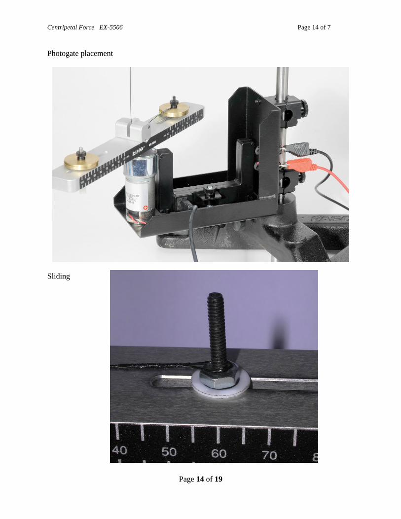
1. Attach the Photogate to the frame of the Centripetal Force Apparatus as shown in Figure
1.
2. Attach the entire Centripetal Force Apparatus as low as possible to the 90cm rod and
base.
3. Attach the 45cm rod horizontally to the 90 cm rod with the multi-clamp.
4. Hang the Force Sensor from the horizontal rod.
5. Screw the Ball Bearing Swivel to the Force Sensor.
6. Use a metal clip to attach the low-stretch cable to the Swivel. Thread the other end of the
cable through the plastic pulley and attach it to the sliding post by putting the loop over
the post and attaching the mass above it. Note: between uses, it is important to store the
cable in a manner that does not put kinks in it.
7. Plug the Photogate into Digital Channel 1 on the 850 Universal Interface. Plug the Force
Sensor into any Pasport input.
8. Click open the Signal Generator at the left of the screen. On 850 Output 1, the
Waveform should be DC with a DC Voltage of 4.0 V. Click the Off button to be sure the
Signal Generator is off and connect the Centripetal Force Apparatus to OUTPUT 1 on the
850 Universal Interface with banana plugs. It is not important which plug on the
Centripetal Force Apparatus attaches to the red output although it will affect the rotation
direction. Careful: if the Signal Generator is not off, the arm will begin to rotate! Click
the Signal Generator again to close it.
9. Level the base. This must be done carefully for good results. Remove the counterweight
mass and put a level on the rotating arm as shown in Figure 3. Start with the arm parallel
to the two leveling screws in the base as shown in Figure 3. There is some play in the
rotating arm. Tip it up or down a bit by pushing on the end of the rotating arm away
from the level. Adjust the leveling screws until the bubble moves about the same amount
on either side of center when you rock the arm up and down as in Figures 4a & 4b. Now
rotate the arm 900 and repeat changing both screws by the same amount. Then rotate
back to the original position and re-level if necessary.
10. Attach a 5 g counterweight mass.

Centripetal Force EX-5506 Page 4 of 7
Page 4 of 19
11. Remove the assembly that holds the moving mass (black plastic nut and bolt, silver nut
and two pastic washers) and determine its mass. Click open the Calculator at the left of
the screen and repace the 0.0038 value in line 7 your measured mass (in kg) for "m hold".
12. Re-attach the assembly to the rotating arm with one plastic washer below the arm and one
above. Then the silver nut, tightened down enough to prevent tipping, but the assembly
must slide freely. Then the cable loop (see Figure 5). Then use the black nut to attach 5 g
of mass above the loop. The cable loop should be below the 5 g mass. It is shown
incorrectly in Figures 1&2.
Figure 3: Level Placement Figure 4a & 4b: Rocking the Bubble
Figure 5: Slide Assembly

Centripetal Force EX-5506 Page 5 of 7
Page 5 of 19
Setup C:
1. Now, adjust the height of the force sensor so that the 5g mass is about 10.0 cm from the
center when there is just enough tension in the cable to straighten the cable. It is important
that the force sensor be exactly above the center of the apparatus. To check this, pull on the
mass to put tension in the cable. Then observe the cable from the front of the system to
verify it is parallel to the 90 cm rod and measure the distance from the rod to the top of the
string and to just above the pulley. Adjust the 45 cm rod holding the force sensor until the
cable is parallel to the rod. Note that any time you change the position of the Force Sensor,
you will have to repeat this step.
2. Pull the mass to tighten the cable to determine the actual radius to the nearest 0.1 cm.
Although you can do this using the scale attached to the side of the apparatus, it is more
precise to measure from the center of the mass to where the vertical cable is with a small
ruler. Click open the Calculator at the left of the screen. In line 1, replace the 0.1 value
(10cm) with the value that you actually measured. Click the Calculator again to close it.

Centripetal Force EX-5506 Page 6 of 7
Page 6 of 19
Procedure m – Force vs Mass (Radius and Velocity held Constant)
1. Press the “ZERO” button on the Force Sensor. This should set the Force Sensor to zero since
there should be no force on it at this point.
2. Click RECORD. Collect data for about 5 s and then click STOP to stop data collection.
Mean speed and Mean Force should both be zero. If the Mean Force is not zero, record the
value. It will help during the data analysis.
3. To avoid wobbling, tighten an identical mass (5 g here) to the opposite side of the rotating
platform as a counterbalance so that it is as far from the center of the rotating platform as the
distance you measured in step 2. This measurement need not be precise and it is sufficient to
use the scale on the side of the apparatus.
4. Click on the Signal Generator at the left of the screen. Under the Output 1, set waveform to
DC and the DC Voltage to 4.5 V. Caution! The next step will cause the apparatus to
begin rotation. Be sure it can do so without hitting anything or anybody. Click the On
button. After about 10 s, reduce the voltage to 4.0 V. Starting with a higher speed and then
reducing it minimizes the frictional effects by positioning the mass at about the correct
position before reducing the speed. Let it run for about 20 s to reach constant speed.
5. Press the RECORD button. Allow data collection to occur for approximately 10 seconds
until the mean Values for Speed and Force are almost constant. Press the STOP button.
6. Click the Signal Generator Output 1 to Off. The rotation should stop.
7. In row 1 (5g row) of the Variable Mass table, enter the value of the Mean Speed into column
2 and record the Mean Force (ignore the minus sign) in column 3.
8. Increase the mass by 5.0 g (0.005kg).
9. Repeat steps 3-8 until you reach 30.0g of mass. Note that the mean speed should be about
the same for all the runs.
Analysis m: Force vs Mass
1. Observe the Force vs Mass Graph. The “Av Force” is the measured average force from
the table on the previous page.
2. Click open the Calculator at the left of the screen and examine lines 1-7 to verify that
“theory force” is calculated using Equation 1 from Theory. Note that the actual measured
speed, “Av speed” from the Variable Mass table on the previous page is used to calculate
“theory force”. Since the speed is not quite constant, the “theory force” points are not
quite linear. Click the Calculator to close it.
3. The mass sometimes hangs up a little causing an obviously bad “Av Force” point. You
should repeat the run for any bad point and see if it improves. Enter the new run in the
row below the 0.030 kg row of the Variable Mass table on the previous page.
4. Select the “Av Force” data by clicking in the Legend box or on a data point. Then click
the black triangle by the Curve Fit tool in the graph toolbox and select Linear.

Centripetal Force EX-5506 Page 7 of 7
Page 7 of 19
Procedure v: Force vs Speed (Radius and Mass held Constant)
1. Keep the 30g mass attached to the cable and the rotating platform as it was in Procedure m.
2. Click on the Signal Generator at the left of the screen. Under the Output 1, set the DC
Voltage to 5.5 V. Caution! The next step will cause the apparatus to begin rotation. Be
sure it can do so without hitting anything or anybody. Click the On button. After about
10 s, reduce the voltage to 5.0 V. Let it run for about 20 s to reach constant speed.
3. Press the RECORD button. Allow data collection to occur for approximately 10 seconds
until the mean Values for Speed and Force are almost constant. Press the STOP button.
4. In row 1 (5.0 V row) of the Variable Mass table, enter the value of the Mean Speed into
column 2 and record the Mean Force (ignore the minus sign) in column 3.
5. Decrease the Signal Generator voltage by 0.5 V. Let it run for about 20 s to reach constant
speed.
6. Repeat steps 3-5 until you reach 3.5 V.
Analysis v: Force vs Speed
1. Observe the Force vs Speed2 Graph. The “Ave F” is the measured average force from the
table on the previous page.
2. Click open the Calculator at the left of the screen and examine line 8 to verify that
“theory f” is calculated using Equation 1 from Theory. Click the Calculator to close it.
3. The mass sometimes hangs up a little causing an obviously bad “Ave F” point. You
should repeat the run for any bad point and see if it improves. Enter the new run in the
row below the 3.5 V row of the Variable Speed table on the previous page.
4. Select the “Ave F” data by clicking in the Legend box or on a data point. Then click the
black triangle by the Curve Fit tool in the graph toolbox and select Linear.

Centripetal Force EX-5506 Page 8 of 7
Page 8 of 19
Procedure r: Force vs Radius (Mass and Time for one rotation held Constant)
1. Keep the 30g mass attached to the cable and the rotating platform as it was in Procedure
v.
2. Enter the radius of the circle in column 1 of the Variable Radius table. Note that the
initial radius is the same as before and is recorded in line 1 of the Calculator. After you
enter it, the value should also show in the Radius box in the upper left.
3. Click on the Signal Generator at the left of the screen. Under the Output 1, set the DC
Voltage to 5.0 V. Caution! The next step will cause the apparatus to begin rotation.
Be sure it can do so without hitting anything or anybody. Click the On button. After
about 10 s, reduce the voltage to 4.5 V. Let it run for about 20 s to reach constant speed.
4. Press the RECORD button. Allow data collection to occur for approximately 10 seconds
until the mean Values for Speed and Force are almost constant. Press the STOP button.
5. In row 1 of the Variable Radius table, enter the value of the Mean Speed into column 2
and record the Mean Force (ignore the minus sign) in column 3.
6. Turn the Signal Generator Off. The rotation should stop.
7. Following the steps in Setup C, decrease the radius to about 8.5 cm. Measure the value
of the radius to within 0.1 cm. Move the counterweight mass to about the same distance.
Repeat steps 2-6.
8. Continue as above for radii of about 7 cm and 5 cm.
Analysis r: Force vs Circle Radius
1. Observe the Force vs Radius, r, Graph. The “Ave Force” is the measured average force
from the table on the previous page.
2. Click open the Calculator at the left of the screen and examine lines 9 & 10 to verify that
“theo f ” is calculated using Equation 1 from Theory. Note that the actual measured
speed, “Ave speed” from the Variable Mass table on the previous page is used to
calculate “theo f”. Since the speed is not quite constant, the “theo f” points are not quite
linear. Click the Calculator to close it.
3. The mass sometimes hangs up a little causing an obviously bad “Ave Force” point. You
should repeat the run for any bad point and see if it improves. Enter the new run in the
Variable Mass table on the previous page.
4. Select the “Ave Force” data by clicking in the Legend box or on a data point. Then click
the black triangle by the Curve Fit tool in the graph toolbox and select Linear.

Centripetal Force EX-5506 Page 9 of 7
Page 9 of 19
Conclusions:
1. Looking at the graph on the “Analysis m” tab, what can you conclude about
the relationship between the centripetal force and mass? Explain how you
know.
2. Looking at the graph on the “Analysis v” tab, what can you conclude about
the relationship between the centripetal force and tangential speed? Explain
how you know.
3. Looking at the graph on the “Analysis r” tab, what can you conclude about the
relationship between the centripetal force and radius of the circle? Explain
how you know.
4. Considering the answers to the first three questions, is Equation 1 from
Theory valid. Careful…how can the relationship you saw in Question 3 agree
with Equation 1?
5. How would friction between the mass and the rotating arm affect your values
for the measured force?

Centripetal Force EX-5506 Page 10 of 7
Page 10 of 19

Centripetal Force EX-5506 Page 11 of 7
Page 11 of 19

Centripetal Force EX-5506 Page 12 of 7
Page 12 of 19

Centripetal Force EX-5506 Page 13 of 7
Page 13 of 19
Level on Arm
Centripetal Force EX-5506 Page 14 of 7
Page 14 of 19
Photogate placement
Sliding

Centripetal Force EX-5506 Page 15 of 7
Page 15 of 19
5x Banana Plug Cord-Red (5 Pack) (SE-9750) Product Summary
These heavy, insulated patch cords are convenient, durable and inexpensive. The grips are stackable and made
of soft plastic for flexible strain relief. The spring connectors rotate in the grips, reducing wear due to friction.

Centripetal Force EX-5506 Page 16 of 7
Page 16 of 19
1x 45 cm Stainless Steel Rod (ME-8736)
Product Summary
These 45 cm long, non-threaded stainless steel rods are ideal for providing support to your
experiments in the lab. They are non-magnetic, very rigid, and durable. Unlike aluminum rods,
they do not mar. The rods have a diameter of 12.7 mm (1/2 inch).
1x 90 cm Stainless Steel Rod (ME-8738)
Product Summary
These 90 cm long, non-threaded stainless steel rods are ideal for providing support to your
experiments in the lab. They are non-magnetic, rigid, and durable. Unlike aluminum rods, they
do not mar. Rods have a diameter of 12.7 mm (1/2 inch).
Photogate Head (ME-9498A)
Product Summary The Photogate Head monitors the motion of objects passing through its gate, counting events as
the object breaks the infrared beam.
Includes a swivel mount to attach to a photogate stand. It does not include the heavy base and
standard rod of the Accessory Photogate (ME-9204B). Can be used with ScienceWorkshop
interfaces or with PASPORT interfaces using Digital Adapter (PS-2159).
Applications
Conduct basic motion experiments
Measure acceleration of freefall
Measure pendulum periods
What's Included
1x Photogate Head with cable

Centripetal Force EX-5506 Page 17 of 7
Page 17 of 19
1x Centripetal Force Apparatus (ME-8088)
Product Summary
The study of circular motion traditionally involves examining relationships between centripetal force, velocity,
radius and mass. However, these relationships are difficult to observe using traditional physics apparatus. One
common experiment involves the swinging of rubber stoppers over a student’s head. The Centripetal Force
Apparatus combines the “swinging mass” approach with sensors and a high-quality electric motor to create a
system that allows students to discover these relationships empirically.
Features
Stable Frame: The metal frame can be easily attached to a ring stand using the included clamp. The
frame may also be attached to a tabletop with a large table clamp.
High Quality Motor: Will withstand years of student use.
Computer-based Measurements: The Force Sensor and photogate facilitate accurate and repeatable
measurements of force, angular velocity and tangential velocity.
Applications
Centripetal Force versus Velocity
Centripetal Force versus Mass
Centripetal Force versus Radius
How It Works
The rotating arm features a groove with two captured masses along its length. One of the masses is free to
move along the length of the groove. The free mass is connected to a small cable that runs under a pulley in the
center of the arm and up to a Force Sensor. A ball-bearing swivel is used to ensure the cable does not tangle as
the arm rotates. The other mass is placed the same distance from the center as the free mass, thereby balancing the arm. A flag attached to the bottom of the fixed mass passes through the photogate once per revolution,
allowing a calculation to be made of the angular and tangential velocity of the mass.

Centripetal Force EX-5506 Page 18 of 7
Page 18 of 19
1x PASPORT High Resolution Force Sensor (PS-2189)
Product Summary
The PASPORT High Resolution Force Sensor offers a higher resolution than the PS-2104. It features a
variable over-sampling rate that reduces measurement noise at lower sampling rates. The digital design
minimizes drift, ensuring that the tare holds for hours. You can use this force sensor as a pan balance for long-

Centripetal Force EX-5506 Page 19 of 7
Page 19 of 19
term experiments, such as investigating the evaporation of liquids, like alcohol or liquid nitrogen, and the
sublimation of dry ice.
Features
0.002 N resolution
Dynamic over-sampling
Force overload protection up to 75 N
Includes a receiver and thumbscrew for mounting
Mounts to PASCO dynamics carts
Applications
Buoyant force
Force exerted by an oscillating mass
Force during elastic and inelastic collisions
Centripetal force acting on a rotating object
Force of a swinging pendulum
Newton's Third Law, action and reaction forces
Forces associated with static equilibrium
1x Multi-Clamp (ME-9507)
Product Summary: Holds two rods either parallel or at
right angles. Fits rods up to 12.7 mm (1/2 inch) in diameter.
What's Included: 1x Clamp with two thumb screws
Instruction ManualManual No. 012-08478B
Centripetal ForceApparatus
Model No. ME-8088


Centripetal Force Apparatus Model No. ME-8088
2 �
Table of Contents
Equipment List........................................................ 3-4
Introduction ............................................................. 5
Equipment Setup ..................................................... 5-7
Suggested Experiments ................................................. 8Experiment 1: Centripetal Force vs. Velocity............................................................................ 8-9Experiment 2: Centripetal Force vs. Mass ............................................................................. 10-11Experiment 3: Centripetal Force vs. Radius .......................................................................... 12-13
Sample Data/Results...................................................14
Troubleshooting ........................................................15
Appendix A:Specifications............................................. 16
Appendix B: DataStudio Setup Instructions (for PASPORT interfaces) .......................................................................... 17
Appendix C: DataStudio Setup Instructions (for ScienceWorkshop interfaces).............................................................. 18
Appendix D: Technical Support ....................................... 19
Appendix E: Copyright and Warranty Information .................. 19

�
Model No. ME-8088 Centripetal Force Apparatus
3
Centripetal Force ApparatusModel No. ME-8088
Equipment List
*Use Replacement Model Numbers to expedite replacement orders.
Included Equipment Replacement Model Number*
1. Frame with Mounted Electric Motor (1) NA
2. Connecting Cable (1) 623-038
3. Ball Bearing Swivel (1) 003-08383
4. Thumbscrew for Photogate (1) 614-034
5. Nuts for Free and Fixed Mass Holders (2) 614-029
6. 5 g Mass (2) 648-06507
7. 10 g Mass (2) 648-06508
8. 20 g Mass (2) 648-06509
9. Centripetal Force Apparatus Setup disk (3.5” floppy) (not shown above) 013-08478
1
3
6
4
5
87
2
NA = not available as individual replacement item. To replace product, use ME-8088.
(continued on next page)

Centripetal Force Apparatus Model No. ME-8088
4 �
Additional Equipment Recommended for Experiments (with ScienceWorkshop)
Replacement Model Number*
A computer (Windows or Macintosh) NA
DataStudio® Software various (see catalog)
ScienceWorkshop® 500 or 750 Interface CI-6400 or CI-6450 or CI-7650
Economy Force Sensor CI-6746
Photogate Head ME-9498A
Steel Rod (45 or 120 cm) ME-8736 and ME-8741
Multi-Clamp SE-9442
Large Rod Base ME-8735
Banana plugs (1 red, 1 black) SE-9750 or SE-9751
Triple Output Power Supply (12 V, 3 A) (1) SE-8587
Additional Equipment Recommended for Experiments (with PASPORT™ )
Replacement Model Number*
A USB-compatible computer (Windows or Macintosh) NA
DataStudio Software (version 1.5 or later) various (see catalog)
PASPORT™ Force Sensor PS-2104
Photogate Port PS-2123
Photogate Head ME-9498A
USB Link (2) or Xplorer (2) or PowerLink PS-2100 or PS-2000 or PS-2001
Steel Rod (45 or 120 cm) ME-8736 and ME-8741
Multi-Clamp SE-9442
Large Rod Base ME-8735
Banana plugs (1 red, 1 black) SE-9750 or SE-9751
Triple Output Power Supply SE-8587
�
Model No. ME-8088 Centripetal Force Apparatus
5
Introduction
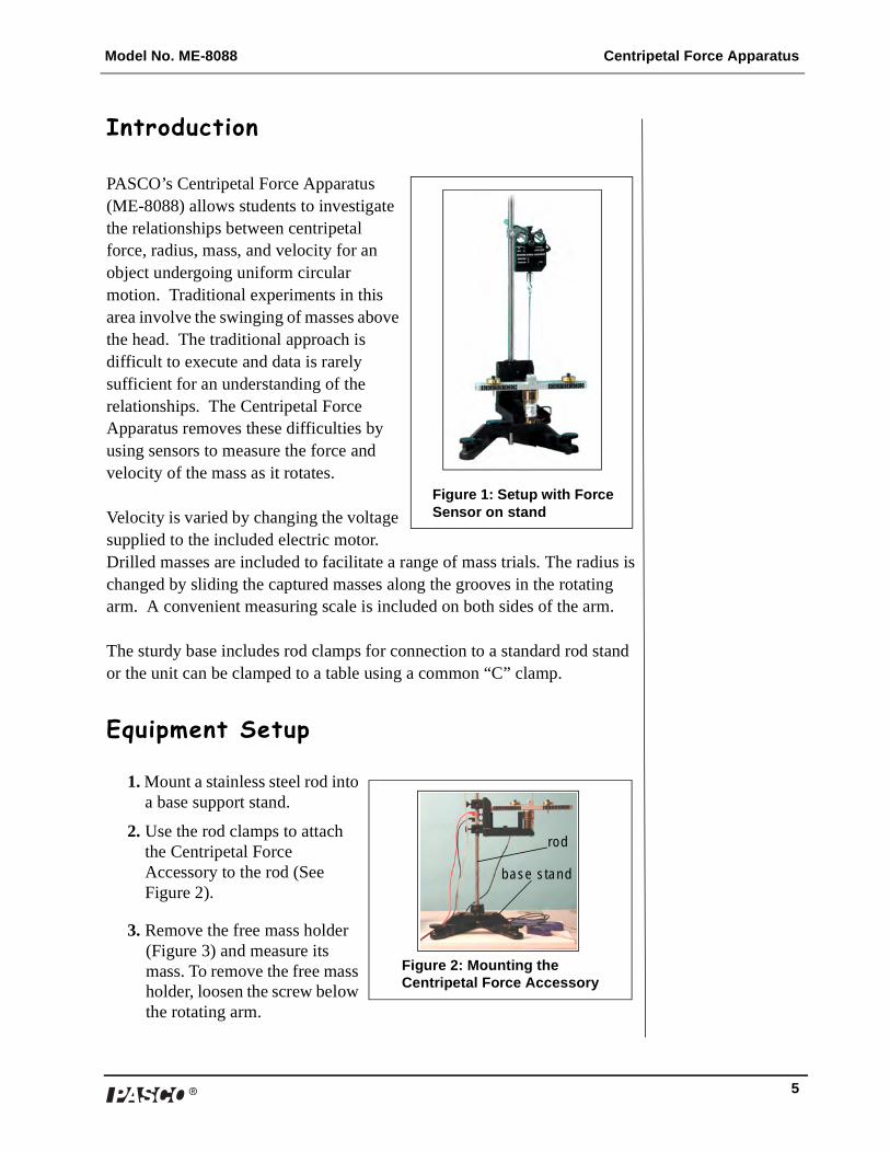
PASCO’s Centripetal Force Apparatus (ME-8088) allows students to investigate the relationships between centripetal force, radius, mass, and velocity for an object undergoing uniform circular motion. Traditional experiments in this area involve the swinging of masses above the head. The traditional approach is difficult to execute and data is rarely sufficient for an understanding of the relationships. The Centripetal Force Apparatus removes these difficulties by using sensors to measure the force and velocity of the mass as it rotates.
Velocity is varied by changing the voltage supplied to the included electric motor. Drilled masses are included to facilitate a range of mass trials. The radius is changed by sliding the captured masses along the grooves in the rotating arm. A convenient measuring scale is included on both sides of the arm.
The sturdy base includes rod clamps for connection to a standard rod stand or the unit can be clamped to a table using a common “C” clamp.
Equipment Setup
1. Mount a stainless steel rod into a base support stand.
2. Use the rod clamps to attach the Centripetal Force Accessory to the rod (See Figure 2).
3. Remove the free mass holder (Figure 3) and measure its mass. To remove the free mass holder, loosen the screw below the rotating arm.
Figure 1: Setup with Force Sensor on stand
Figure 2: Mounting the Centripetal Force Accessory
base stand
rod

Centripetal Force Apparatus Model No. ME-8088
6 �
(Note: The free mass holder includes the screw, two plastic washers, nut, and two thumbscrews. If a scale is not available, use the mass provided in Appendix A: Specifications.)
4. Use a thumbscrew to mount a Photogate Head (ME-9498A) to the bottom base of the Centripetal Force Accessory (See Figure 4).
5. Attach a Multi-Clamp to the upper end of the stainless steel rod. (Figure 5a).
6. Insert another stainless steel rod horizontally into the Multi-Clamp.
7. Slide a Force Sensor through the stainless steel rod and adjust the top screw to anchor it to the rod (Figure 5a). (Note: Be sure to keep the cords from the sensor out of the path of the rotating arm.)
Figure 3: Free and Fixed Mass Holders
Fixed Mass Holder Free Mass Holder
Figure 4: Photogate on base of Centripetal Apparatus
thumb
cable
photogate
screw
to interface
Figure 5a: Mounting the Force Sensor
Figure 5b: Threading the cable through the free mass holder
free mass pulley
cable
swivel
holder
clamp
ForceSensor
Note: To calibrate the ScienceWorkshop Force Sensor, follow the instructions provided in the documentation included with your Force Sensor or in the DataStudio online help. Calibration of the PASPORT Force Sensor is not required. However, you can tare the PASPORT Force Sensor by pressing the Zero button without any weight attached.

�
Model No. ME-8088 Centripetal Force Apparatus
7
8. Attach the ball bearing swivel to the bottom of the Force Sensor
9. Thread the cable from the swivel hook through the pulley and over the free mass holder (Figure 5b).
Note: Always lay down the cable before adding the mass.
10. Add a mass to the free mass holder; then screw on the thumbscrew to hold the mass in place.
11. Add a mass to the fixed mass holder and use a thumbscrew to hold the mass in place.
12. Plug the Force Sensor into either a PASPORT or ScienceWorkshop interface.
13. Use banana plugs to connect the Centripetal Force Accessory to a Power Supply.
14. To turn on the motor to the Centripetal Force Accessory, turn on the Power Supply.
(CAUTION: To avoid damaging the equipment, keep all cords away from the motor and rotating arm.)
WARNING: Do not stand next to the motor or rotating arm or look at the rotating arm at eye level. To avoid possible injury from the rotating arm hitting the body, keep at least 1 foot distance from the motor and rotating arm when running the motor.
Figure 6: Complete setup for experiments
interface
ForceSensor
PowerSupply Note: If you do not have
a setup disk available, follow the DataStudio setup instructions in Appendix B (for PASPORT sensors) or C (for ScienceWorkshop sensors).

Centripetal Force Apparatus Model No. ME-8088
8 �
Suggested Experiments
Experiment 1: Centripetal Force vs. Velocity
IntroductionIn this experiment, you will vary the velocity by changing the voltage to the electric motor as the centripetal force is continuously measured by the Force Sensor. The radius and mass are held constant as the velocity is increased.
SetupFollow the equipment setup instructions on pages 5-7 of this manual and the Experiment Tips that follow. When you are ready to begin the experiment, open the appropriate DataStudio file on the setup disk.
Equipment Required (for use with ScienceWorkshop sensors):
Equipment Required (for use with PASPORT sensors):
ScienceWorkshop Force Sensor (CI-6746) PASPORT Force Sensor (PS-2104)
Photogate Head (ME-9498A) Photogate Head (ME-9498A)
ScienceWorkshop interface (500, 700, or 750) (CI-6400 or CI-6450)
Photogate Port (PS-2123)
Power Supply (12 v, 3A) (SE-8587) USB Link (2) (PS-2100) or Xplorer (2) (PS-2000) or Power Link (PS-2001)
DataStudio Software (ver. 1.5 or higher) Power Supply (12 V, 3AA) (SE-8587)
Base support, clamps, and mounting rods DataStudio Software (ver. 1.5 or higher)
Base support, clamps, and mounting rods
Figure 1a: Adjusting the voltage on the Power Supply Figure 1b: Complete setup
voltageadjustmentknob
Note: If you do not have a setup disk available, follow the DataStudio setup instructions in Appendix B (for PASPORT sensors) or C (for ScienceWorkshop sensors).

�
Model No. ME-8088 Centripetal Force Apparatus
9
Experiment Tipsa) To add the free mass, lay the components over the attachment screw in
the following order: a) cable b) mass and c) thumbscrew to tighten. (Note: Place the cable over the washer and nut on the screw. For more details, see “Equipment Setup” on pages 5-7.)
Note: Do not place the mass underneath the cable, as this will interfere with a proper measurement.
b) Allow the “free mass” plenty of length along its holder within the slot. If the mass is not free to slide along the groove, significant frictional losses can be present.
c) Place an equal amount of mass on the “fixed mass” and “free mass” holders.
d) Be sure to place the “fixed mass” at the same radius as the “free mass” to ensure balancing of the unit at is rotates.
e) The velocity of the free mass can be measured as an angular or linear velocity. DataStudio files for both of these variations are included on the floppy disk.
f) Be sure to enter the correct value for the radius in the experimental constants area of the calculator (when using the linear velocity DataStudio file).
Figure 1c: Calculator Dialog box

Centripetal Force Apparatus Model No. ME-8088
10 �
Experiment 2: Centripetal Force vs. Mass
Introduction
In this experiment, the radius and velocity are held constant as the mass is varied. By adding additional drilled masses to the holder, the mass of the system is increased. Equal amounts of mass must also be added to the “fixed mass” to balance the arm as it rotates. Centripetal force is directly measured by the Force Sensor.
SetupFollow the equipment setup instructions on pages 5-7 of this manual and the Experiment Tips below. When you are ready to begin the experiment, open the appropriate DataStudio file on the setup disk.
Equipment Required (for use with ScienceWorkshop sensors):
Equipment Required (for use with PASPORT sensors):
ScienceWorkshop Force Sensor (CI-6746) PASPORT Force Sensor (PS-2104)
Photogate Head (ME-9498A) Photogate Head (ME-9498A)
ScienceWorkshop interface (500, 700, or 750) (CI-6400 or CI-6450)
Photogate Port (PS-2123)
Power Supply (12 v, 3A) (SE-8587) USB Link (2) (PS-2100) or Xplorer (2) (PS-2000) or Power Link (PS-2001)
DataStudio Software (ver. 1.5 or higher) Power Supply (12 V, 3AA) (SE-8587)
Base support, clamps, and mounting rods DataStudio Software (ver. 1.5 or higher)
Base support, clamps, and mounting rods
Figure 2b: Complete setup Figure 2a: Free and fixed Mass Holders
“Fixed” massFree mass
Rotating Arm
Note: If you do not have a setup disk available, follow the DataStudio setup instructions in Appendix B (for PASPORT sensors) or C (for ScienceWorkshop sensors).
�
Model No. ME-8088 Centripetal Force Apparatus
11
Experiment Tipsa) To add the free mass, lay the components over the attachment screw in
the following order: a) cable b) mass and c) thumbscrew to tighten. (Note: Place the cable over the washer and nut on the screw. For more details, see “Equipment Setup” on pages 5-7.)
Note: Do not place the mass underneath the cable, as this will interfere with a proper measurement.
b) Allow the “free mass” plenty of length along its holder within the slot. If the mass is not free to slide along the groove, significant frictional losses can be present.
c) Place an equal amount of mass on the “fixed mass” and “free mass” holders.
d) Be sure to place the “fixed mass” at the same radius as the “free mass” to ensure balancing of the unit at is rotates.
e) Perform several different data runs, each time varying the mass on the free and fixed mass holders. (Note: Be sure to include the mass of the holders in your calculations.)
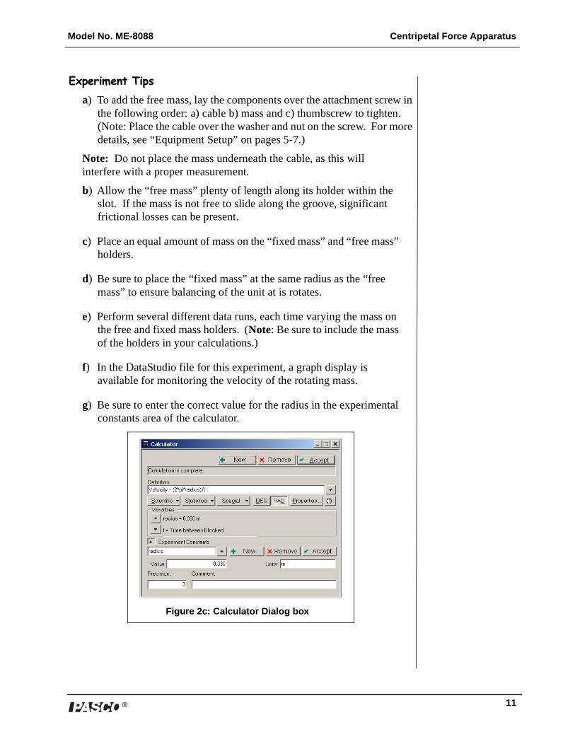
f) In the DataStudio file for this experiment, a graph display is available for monitoring the velocity of the rotating mass.
g) Be sure to enter the correct value for the radius in the experimental constants area of the calculator.
Figure 2c: Calculator Dialog box

Centripetal Force Apparatus Model No. ME-8088
12 �
Experiment 3: Centripetal Force vs. Radius
IntroductionIn this experiment, the velocity and mass are held constant as the radius is varied. By lowering the Force Sensor, the radius increases. As the radius increases, the “fixed mass” must be moved to a matching radius to balance the rotating arm. Again, centripetal force is measured by the Force Sensor.
SetupFollow the equipment setup instructions on pages 5-7 of this manual and the Experiment Tips that follow. When you are ready to begin the experiment, open the appropriate DataStudio file on the setup disk.
Equipment Required (for use with ScienceWorkshop sensors):
Equipment Required (for use with PASPORT sensors):
ScienceWorkshop Force Sensor (CI-6746)
PASPORT Force Sensor (PS-2104)
Photogate Head (ME-9498A) Photogate Head (ME-9498A)
ScienceWorkshop interface (500, 700, or 750) (CI-6400 or CI-6450)
Photogate Port (PS-2123)
Power Supply (12 v, 3A) (SE-8587) USB Link (2) (PS-2100) or Xplorer (2) (PS-2000) or Power Link (PS-2001)
Base support, clamps, and mounting rods
Power Supply (12 V, 3AA) (SE-8587)
DataStudio Software (ver. 1.5 or higher)
Base support, clamps, and mounting rods
DataStudio Software (ver. 1.5 or higher)
Figure 3b: Complete setupFigure 3a: Changing the radius
Note: If you do not have a setup disk available, follow the DataStudio setup instructions in Appendix B (for PASPORT sensors) or C (for ScienceWorkshop sensors).

�
Model No. ME-8088 Centripetal Force Apparatus
13
Experiment Tipsa) Allow the “free mass” plenty of length along its holder within the slot.
If the mass is not free to slide along the groove, significant frictional losses can be present.
b) To add the free mass, lay the components over the attachment screw in the following order: a) cable b) mass and c) thumbscrew to tighten. (Note: Place the cable over the washer and nut on the screw. For more details, see “Equipment Setup” on pages 5-7.)
Note: Do not place the mass underneath the cable, as this will interfere with a proper measurement.
c) Place an equal amount of mass on the “fixed mass” and “free mass” holders.
d) Be sure to place the “fixed mass” at the same radius as the “free mass” to ensure balancing of the unit at is rotates.
e) To vary the radius, adjust the position of the Force Sensor (See Figure 3a).
f) In the DataStudio file for this experiment, a graph display is available for monitoring the velocity of the rotating mass.
g) Be sure to enter the correct value for the radius in the experimental constants area of the calculator. This will need to be changed for each data run of this experiment.
Figure 3c: Calculator Dialog box

Centripetal Force Apparatus Model No. ME-8088
14 �
Sample Data

�
Model No. ME-8088 Centripetal Force Apparatus
15
Troubleshooting
Problem: Possible Causes: Possible Solutions:
Rotating arm does not move.
Too much friction in the cable; power supply is not turned on; motor is defective.
Move Force Sensor down to loosen the cable; connect the power supply to the frame and turn on the power supply; call Technical Support and/or return the product (See Warranty information in Appendix E.)
Force measurement does not display in DataStudio.
Force Sensor is not connected to an interface or associated in the setup window.
If using a PASPORT Force Sensor, plug the Force Sensor into a USB Link connected to a USB-compatible computer. Follow the setup instructions in Appendix B. If using a ScienceWorkshop Force Sensor, connect the Force Sensor to a ScienceWorkshop interface. Follow the setup instructions in Appendix C.
Velocity readings do not appear or are incorrect.
Photogate is not connected to an interface; improper setup in DataStudio.
If using a PASPORT interface, click the Setup button, click the Add Timer button, and select the Smart Pulley option. If using a ScienceWorkshop interface, click the Setup button and select the Smart Pulley option from the Sensors list.

Centripetal Force Apparatus Model No. ME-8088
16 �
Appendix A: Specifications
Centripetal Force Apparatus
Rotating Arm Length: 24.6 cm
Motor 12 VDC, 0.5 ampere
Frame Base: 15 x 8.5 cmBack: 11.5 x 8.5 cmMass (with motor, cable, and rotating arm): 2.10 kg
Free Mass Holder 4.0 g (with screws)
Fixed Mass Holder 2.5 g (with screws)
Thumbscrew 0.5 g
Masses 5 g, 10 g, 20 g
Ball Bearing Swivel Mass: 12.5 g

�
Model No. ME-8088 Centripetal Force Apparatus
17
Appendix B: DataStudio Setup Instructions (for PASPORT interfaces)
The following instructions are for new users or those unfamiliar with DataStudio software.
PART I: Plug the sensors into the PASPORT interface:
a) Plug the Photogate into either channel 1 or 2 on a PASPORT Photogate Port.
b) Plug both the Photogate Port and Force Sensor into a PASPORT interface (i.e. USB Link, Xplorer, PowerLink, etc.).
PART II: Set up your experiment in DataStudio
a) Open DataStudio and select “Create Experiment.”
b) On the main toolbar, click the Setup button to open the Experiment Setup window.
c) When the Experiment Setup dialog opens, click on the Add Timer button, select the Recordable Timer icon, and click OK.
PART III: Create a recordable timing sequence in DataStudio
a) Click the Record Sequence button in the Experiment Setup window.
b) In the Record Timer Sequence box, click the Start button.
c) Block the beam of the photogate twice with your finger, and click the Stop button.
d) In the Record Timer Sequence box, highlight “Photogate 1 unblocked,” and click the Delete button. (Repeat this task for the second “Photogate 1 unblocked.”)
e) Click the OK button to accept the timing sequence.
PART IV: Create the mathematical equation in DataStudio
a) Click on the Calculate button to open the Calculator dialog.
b) In the Calculator dialog, click the New button to create a new equation.
c) In the equation box, type in the equation velocity = 2*pi*radius/t and click the Accept button.
d) Define the variables “radius” and “t.” (Under Variables, click on the arrow and select “constant” to define the variable “radius” and enter the value in the box. Under “Experiment Constants,” click the Accept button. Select “Data Measurement” for “t” and select “time between gates.”
e) Click the Accept button. Your equation will appear as an icon in the Data list. To edit the equation, double click on the equation icon in the Data list.
PART V: Collect data
a) To collect data in a display, click the Start button.

Centripetal Force Apparatus Model No. ME-8088
18 �
Appendix C: DataStudio Setup Instructions (for ScienceWorkshop interfaces)
PART I: Plug the sensors into the interface:
a) Plug the Photogate into channel 1 on the ScienceWorkshop interface.
b) Plug the Force Sensor into any analog channel (A, B, or C) on the ScienceWorkshop interface.
PART II: Set up your experiment in DataStudio
a) Open DataStudio and select “Create Experiment.”
b) On the main toolbar, click the Setup button to open the Experiment Setup window.
c) In the Sensors list of the Experiment Setup window, do the following: i) Click on the Smart Pulley icon and drag it to digital channel 1 on the picture of the interface. ii) Click on the Force Sensor icon and drag it to the same analog channel into which the sensor is plugged.
Part III: Create a timing sequence in DataStudio
a) On the main toolbar, click the Timers button. When the Timers dialog opens, click the New button.
b) In the Label box, type the name, “time between blocked.”
c) In the Timing Sequence menu, select “blocked” and “blocked” and click OK.
PART IV: Create the mathematical equation in DataStudio
a) Click on the Calculate button to open the Calculator dialog.
b) In the Calculator dialog, click the New button to create a new equation.
c) In the equation box, type in the equation velocity = 2*pi*radius/t and click the Accept button.
d) Define the variables “radius” and “t.” (Under Variables, click on the arrow and select “constant” to define the variable “radius” and enter the value in the box. Under “Experiment Constants,” click the Accept button. Select “Data Measurement” for “t” and select “time between blocked.”
e) Click the Accept button. Your equation will appear as an icon in the Data list. To edit the equation, double click on the equation icon in the Data list.
PART V: Collect data
a) To collect data in a display, click the Start button.

�
Model No. ME-8088 Centripetal Force Apparatus
19
Appendix D: Technical Support
For assistance with the ME-8088 Centripetal Force Apparatus or any other PASCO products, contact PASCO as follows:
Address: PASCO scientific
10101 Foothills Blvd.
Roseville, CA 95747-7100
Phone: (916) 786-3800
FAX: (916) 786-3292
Web: www.pasco.com
Email: [email protected]
Appendix E: Copyright and Warranty Information
Copyright NoticeThe PASCO scientific 012-08478B Centripetal Force Manual is copyrighted and all rights reserved. However, permission is granted to non-profit educational institutions for reproduction of any part of the 012-08478B Centripetal Force Manual, providing the reproductions are used only for their laboratories and are not sold for profit. Reproduction under any other circumstances, without the written consent of PASCO scientific, is prohibited.
Limited WarrantyPASCO scientific warrants the product to be free from defects in materials and workmanship for a period of one year from the date of shipment to the customer. PASCO will repair or replace, at its option, any part of the product which is deemed to be defective in material or workmanship. The warranty does not cover damage to the product caused by abuse or improper use. Determination of whether a product failure is the result of a manufacturing defect or improper use by the customer shall be made solely by PASCO scientific. Responsibility for the return of equipment for warranty repair belongs to the customer. Equipment must be properly packed to prevent damage and shipped postage or freight prepaid. (Damage caused by improper packing of the equipment for return shipment will not be covered by the warranty.) Shipping costs for returning the equipment after repair will be paid by PASCO scientific.
Instruct ion Sheet012-10237B
800-772-8700 www.pasco.com
�
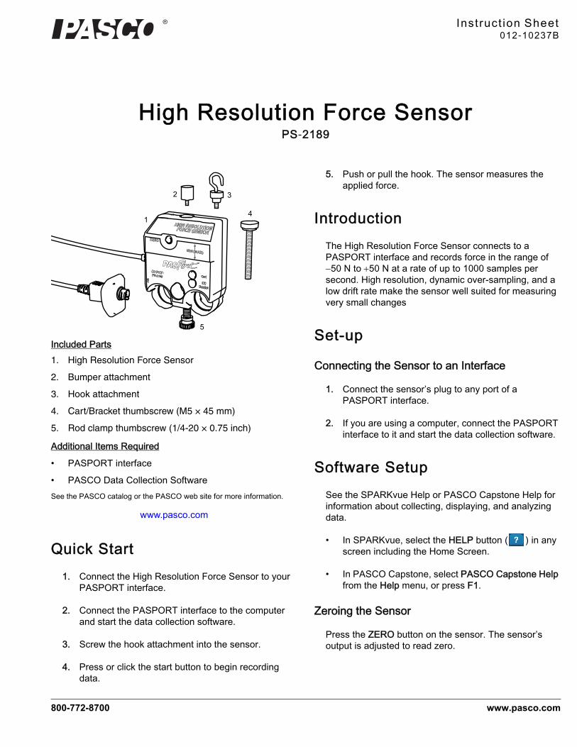
High Resolution Force SensorPS-2189
Included Parts1. High Resolution Force Sensor
2. Bumper attachment
3. Hook attachment
4. Cart/Bracket thumbscrew (M5 × 45 mm)
5. Rod clamp thumbscrew (1/4-20 × 0.75 inch)
Additional Items Required
• PASPORT interface
• PASCO Data Collection SoftwareSee the PASCO catalog or the PASCO web site for more information.
www.pasco.com
Quick Start1. Connect the High Resolution Force Sensor to your
PASPORT interface.
2. Connect the PASPORT interface to the computer and start the data collection software.
3. Screw the hook attachment into the sensor.
4. Press or click the start button to begin recording data.
5. Push or pull the hook. The sensor measures the applied force.
IntroductionThe High Resolution Force Sensor connects to a PASPORT interface and records force in the range of 50 N to 50 N at a rate of up to 1000 samples per second. High resolution, dynamic over-sampling, and a low drift rate make the sensor well suited for measuring very small changes
Set-up
Connecting the Sensor to an Interface
1. Connect the sensor’s plug to any port of a PASPORT interface.
2. If you are using a computer, connect the PASPORT interface to it and start the data collection software.
Software SetupSee the SPARKvue Help or PASCO Capstone Help for information about collecting, displaying, and analyzing data.
• In SPARKvue, select the HELP button ( ) in any screen including the Home Screen.
• In PASCO Capstone, select PASCO Capstone Help from the Help menu, or press F1.
Zeroing the Sensor
Press the ZERO button on the sensor. The sensor’s output is adjusted to read zero.
1
2
5
3
4

�
High Resolut ion Force Sensor PS-2189
2
SPARKvue
Collect Data
• In the SPARKvue Home Screen, select a measurement from the list under the sensor’s name. A graph of the measurement versus time opens.
• In SPARKvue, select the Start button ( ) to begin collecting data.
PASCO Capstone
Collect Data
• In PASCO Capstone, select a display in the main window or from the Display palette. In the display, use the <Select Measurement> menu to pick a measurement to be shown.
• Select Record to begin collecting data.
Connecting Bumper and Hook Attachments
Screw the bumper or hook into the sensor as illustrated.
About the Force Measurement
Dynamic Over-sampling
To increase the degree of dynamic over-sampling, lower the sample rate.
Over-sampling reduces noise, produces smoother data, and improves the measurement resolution. This effect is especially noticeable when very small force changes are measured. The degree of over-sampling depends on the sample rate. Maximum over-sampling occurs at sample rates of 20 Hz and slower.
Sample Rate
By default, the sensor collects 10 samples per second. It can collect data as fast as 1000 samples per second and as slow as one sample every four hours. Change the sample rate in the data collection software.
Inverted Output
By default, the sensor registers pushing as a positive force and pulling as a negative force. To register pulling as positive and pushing as negative, select the Force (Inverted) measurement in the data collection software.
Sensor Mounting
Mounting the Sensor on a Rod
Slide the sensor onto a rod and secure it with the thumbscrew as illustrated.
Mounting the Sensor on a PASCO Cart
1. Insert the included Cart/Bracket thumbscrew through the hole in the senor labeled Cart.
2. Screw the thumbscrew into the threaded hole on the top of the cart.
Mounting the Sensor on an IDS Bracket
1. Insert the included Cart/Bracket thumbscrew through the hole in the IDS Force Accessory Bracket (PASCO part CI-6545).
2. Screw the thumbscrew into the hole in the sensor labeled IDS Bracket.

�
High Resolut ion Force Sensor PS -2189
3
Specifications
Technical SupportFor assistance with any PASCO product, contact PASCO at:
For more information about the High Resolution Force Sensor and the most up-to-date version of this Instruction Sheet, visit:
www.pasco.com/manuals
Limited WarrantyFor a description of the product warranty, see the PASCO catalog.
CopyrightThe PASCO scientific Instruction Sheet is copyrighted with all rights reserved. Permission is granted to non-profit educational institutions for reproduction of any part of this manual, providing the reproductions are used only in their laboratories and classrooms, and are not sold for profit. Reproduction under any other circumstances, without the written consent of PASCO scientific, is prohibited.
TrademarksPASCO, PASCO scientific, and PASPORT are trademarks or registered trademarks of PASCO scientific, in the United States and/or in other countries. All other brands, products, or service names are or may be trademarks or service marks of, and are used to identify, products or services of, their respective owners. For more information visit
www.pasco.com/legal.
Product End of Life Disposal Instructions:
This electronic product is subject to disposal and recycling regulations that vary by country and region. It is your responsibility to recycle your electronic equipment per your local environmental laws and regulations to ensure that it will be recycled in a manner that protects human health and the environment. To find out where you can drop off your waste equipment for recycling, please contact your local waste recycle/disposal service, or the place where you purchased the product.
The European Union WEEE (Waste Electronic and Electrical Equipment) symbol (to the right) and on the product or its packaging indicates that this product must not be disposed of in a standard waste container.
Range ±50 N
Resolution 0.002 N
Maximum Sample Rate 1000 samples/s
Address: PASCO scientific10101 Foothills Blvd.Roseville, CA 95747-7100
Phone: 916-786-3800 (worldwide)800-772-8700 (U.S.)
Web: www.pasco.comEmail: [email protected]

Instruction Sheetfor the PASCOModel ME-8735
Large Rod Stand
012-05338A12/93$1.00
© 1993 PASCO scientific
This instruction sheet written/edited by: Eric Ayars
clamp screws (2)
leveling feet (2)
When using the Large Rod Stand keep the followingin mind:
➀ The mass of the Large Rod Stand is approximately 9lbs. (4 kg). If dropped, the Large Rod Stand may bedamaged, cause damage to other equipment or causeinjury. To prevent personal injury and damage, al-ways carry the Large Rod Stand with a firm grip andtry to setup the Large Rod Stand away from the edgeof any table or work bench whenever possible.
➁ To prevent the Large Rod Stand from tipping or top-pling over during experiments, be reasonable as yousetup experiments. Always be sure the Large RodStand is able to rest firmly when any possible mo-tion of your experiments occur.
Introduction
The PASCO Model ME-8735 Large Rod Stand can beused whenever a sturdy base for your vertical supportrod is needed.
Rods with an outside diameter of 1/4" to 1/2" (6.5mmto 13mm) may be placed in either the central mountinghole and/or the alternate mounting hole at the peak ofthe stand. They can be secured to the stand with eitherof the two clamp screws provided.
The Large Rod Stand can be leveled by turning theknobs on the leveling feet.

012-05338A
2
Equipment Included
One ME-8735 Large Rod Stand complete with twoleveling feet and two clamp screws.
Limited Warranty
PASCO scientific warrants this product to be free fromdefects in materials and workmanship for a period ofone year from the date of shipment to the customer.PASCO will repair or replace, at its option, any part ofthe product which is deemed to be defective in materialor workmanship. This warranty does not cover damageto the product caused by abuse or improper use. Deter-mination of whether a product failure is the result of amanufacturing defect or improper use by the customershall be made solely by PASCO scientific. Responsi-bility for the return of equipment for warranty repairbelongs to the customer. Equipment must be properlypacked to prevent damage and shipped postage orfreight prepaid. (Damage caused by improper packingof the equipment for return shipment will not becovered by the warranty.) Shipping costs for returningthe equipment, after repair, will be paid by PASCOscientific.
Equipment Return
Should the product have to be returned to PASCOscientific for any reason, notify PASCO scientific byletter, phone, or fax BEFORE returning the product.Upon notification, the return authorization andshipping instructions will be promptly issued.
When returning equipment for repair, the unitsmust be packed properly. Carriers will not acceptresponsibility for damage caused by improperpacking. To be certain the unit will not bedamaged in shipment, observe the following rules:
➀ The packing carton must be strong enough for theitem shipped.
➁ Make certain there are at least two inches ofpacking material between any point on theapparatus and the inside walls of the carton.
➂ Make certain that the packing material cannot shiftin the box or become compressed, allowing theinstrument come in contact with the packingcarton.
Address: PASCO scientific10101 Foothills Blvd.Roseville, CA 95747-7100
Phone: (916) 786-3800FAX: (916) 786-3292email: [email protected]: www.pasco.com
ä NOTE: NO EQUIPMENT WILL BEACCEPTED FOR RETURN WITHOUT ANAUTHORIZATION FROM PASCO.