DESIGN OF MACHINE ELEMENTS - sitams.org
15
DESIGN OF MACHINE ELEMENTS Question Bank III B.TECH- I SEMESTER Regulation: R18 Faculty In charge V Aravind Ram Sharma Assistant Professor Dept of Mechanical Engineering SITAMS SREENIVASA INSTITUTE OF TECHNOLOGY AND MANAGEMENT STUDIES, CHITTOOR. (Autonomous) DEPARTMENT of MECHANICAL ENGINEERING QUESTION BANK (NBA & NAAC Accredited) DESIGN OF TRANSMISSION SYSTEMS – 18MEC324 ACADEMIC YEAR: 2021-22
-
Upload
khangminh22 -
Category
Documents
-
view
0 -
download
0
Transcript of DESIGN OF MACHINE ELEMENTS - sitams.org

DESIGNOFMACHINEELEMENTSQuestionBank
IIIB.TECH-ISEMESTER Regulation:R18
Faculty In charge
V Aravind Ram Sharma
Assistant Professor
Dept of Mechanical Engineering
SITAMS
SREENIVASA INSTITUTE OF TECHNOLOGY AND MANAGEMENT STUDIES, CHITTOOR. (Autonomous)
DEPARTMENT of MECHANICAL ENGINEERING QUESTION BANK (NBA & NAAC Accredited) DESIGN OF TRANSMISSION SYSTEMS – 18MEC324
ACADEMICYEAR:2021-22

S
PROGRAM OUTCOMES (PO’s)
PO1. Engineering knowledge: Apply the knowledge of mathematics, science, engineering fundamentals and an engineering specialization to the solution of complex engineering problems.
PO2. Problem analysis: Identify, formulate, review research literature and analyse complex engineering problems reaching substantiated conclusions using first principles of mathematics, natural sciences and engineering sciences.
PO3. Design/development of solutions: Design solutions for complex engineering problems and design system components or processes that meet the specified needs with appropriate consideration for the public health and safety and the cultural, societal and environmental considerations.
PO4. Conduct investigations of complex problems: Use research-based knowledge and research methods including design of experiments, analysis and interpretation of data and synthesis of the information to provide valid conclusions.
PO5. Modern tool usage: Create, select and apply appropriate techniques, resources and modern engineering and IT tools including prediction and modeling to complex engineering activities with an understanding of the limitations.
PO6. The engineer and society: Apply reasoning informed by the contextual knowledge to assess societal, health, safety, legal and cultural issues and the consequent responsibilities relevant to the professional engineering practice.
PO7. Environment and sustainability: Understand the impact of the professional engineering solutions in societal and environmental contexts and demonstrate the knowledge of and need for sustainable development.
PO8. Ethics: Apply ethical principles and commit to professional ethics and responsibilities and norms of the engineering practice.
PO9. Individual and team work: Function effectively as an individual and as a member or leader in diverse teams and in multidisciplinary settings.
PO10. Communication: Communicate effectively on complex engineering activities with the engineering community and with society at large, such as, being able to comprehend and write effective reports and design documentation, make effective presentations and give and receive clear instructions.
PO11. Project management and finance: Demonstrate knowledge and understanding of the engineering and management principles and apply these to one’s own work, as a member and leader in a team, to manage projects and in multidisciplinary environments.
PO12. Life-long learning: Recognize the need for and have the preparation and ability to engage in independent and life-long learning in the broadest context of technological change.
SREENIVASA INSTITUTE OF TECHNOLOGY AND MANAGEMENT STUDIES, CHITTOOR. (Autonomous)
DEPARTMENT of MECHANICAL ENGINEERING QUESTION BANK (NBA & NAAC Accredited) DESIGN OF TRANSMISSION SYSTEMS – 18MEC324

SREENIVASA INSTITUTE OF TECHNOLOGY AND MANAGEMENT STUDIES, CHITTOOR (Autonomous)
DEPARTMENT OF MECHANICAL ENGINEERING
7
III B.Tech I Semester L T P C 2 1 0 3 18MEC314 DESIGN OF MACHINE ELEMENTS Course Educational Objectives: CEO1: To understand the design concepts and stress developed in machine members. CEO2: To design the machine elements subjected to static and variable loads. CEO3: To analyze the bolted and welded joints for various kinds of loads. CEO4: To design and analyze the temporary joints like cotter, knuckle and screwed joints. CEO5: To design the shafts and couplings for various applications. UNIT – 1: DESIGN CONCEPTS AND STRESSES IN MACHINE ELEMENTS Design Concepts: Traditional design methods – Design synthesis and standards – Classifications, general considerations, procedures and basic requirements of machine design – Safety, ecological, societal, aesthetic and ergonomic considerations in design – Selection of engineering materials – BIS codes of materials – Manufacturing considerations in the machine design – Preferred numbers, selective assembly, limits, fits and tolerances. Stresses in Machine Elements: Basic concepts and applications of fracture mechanics – Simple stresses – Direct, bending and torsional stress equations – Impact, shock eccentric loading – Calculation of principle stresses for various load combinations – Curved beams – Crane hook and ‘C’ frame – Factor of safety – Theories of failure – Design for stiffness, strength and rigidity. UNIT – 2: DESIGN FOR VARIABLE LOADS Cyclic stresses – Fatigue and endurance limit – Effect of loading, surface finish and size on endurance limit – Fatigue loading – Stress concentration factor – Stress concentration due to holes and notches – Fatigue failure – Fatigue stress concentration factor – Notch sensitivity – Gerber method ,Goodman method and Soderberg method – Combined variable normal stress and variable shear stress. UNIT – 3: DESIGN OF PERMANENT JOINTS Riveted Joints: Types, Methods and material of riveting – Caulking and fullering – Failures – Strength and efficiency – Design of boiler through riveted joints – Design of boiler joints and pressure vessels – Uniform strength and eccentric loading. Welded Joints: Types – Weld symbols – Strength of transverse and parallel fillet welded joints – Special cases of fillet joint – Strength of butt joints – Stresses and stress concentration factor – Axially loaded unsymmetrical welded sections – Eccentrically load. UNIT – 4: DESIGN OF TEMPORARY JOINTS Screwed Joints: Types – Designation of screw threads – Stresses in screwed fastening – Design of cylinder covers – Bolts of uniform strength – Design of a nut – Bolted joints under eccentric loading. Cotter and Knuckle Joints: Design of socket and spigot cotter joint, and sleeve and cotter, – Gib and cotter joint for Square rod, connecting rod, piston and crosshead – Cotter foundation bolt – Design of knuckle joint – Methods of failure of knuckle joint – Design of turnbuckle. UNIT – 5: DESIGN OF SHAFTS, KEYS AND COUPLING Design of Shafts: Types and standard sizes of the shafts – Stresses in shafts – Design of shafts subjected to twisting, bending and combined moment – Shafts subjected to fluctuating, axial and combination loads – Design of shafts on the basis of rigidity. Design of Keys and Coupling: Types of keys – Forces and strength of sunk key – Effect of keyways – Types of shaft couplings – Design of rigid and flexible couplings.
Aravind Ram sharma
Aravind Ram sharma

SREENIVASA INSTITUTE OF TECHNOLOGY AND MANAGEMENT STUDIES, CHITTOOR (Autonomous)
DEPARTMENT OF MECHANICAL ENGINEERING
8
Course Outcomes: On successful completion of the course, Students will be able to POs related to Cos
CO1 Understand the design concepts and analyze the stress development in machine elements. PO1,PO2, PO3
CO2 Design the machine members subjected to static and variable loads. PO1,PO2,PO3 CO3 Analyze the bolted and welded joints for various kinds of loads. PO1,PO2,PO3, PO4
CO4 Design and analyze the temporary joints like cotter, knuckle and screwed joints. PO1,PO2,PO3,PO4
CO5 Design and analyze the shafts and couplings for various applications. PO1,PO2,PO3, PO4
Text Books: 1. Design of Machine Elements, V.B. Bhandari, 4/e, 2016, Tata McGraw-Hill Education Pvt. Ltd., Noida. 2. Shigley's Mechanical Engineering Design, Richard G. Budynas and Keith J. Nisbett, 10/e, 2015, Tata
McGraw-Hill Education Pvt. Ltd., Noida. Reference Books: 1. Machine Design, Robert L. Norton, 5/e, 2018, Pearson Education Ltd., India. 2. A Text Book of Machine Design, R S Khurmi and J. K. Gupta, 34/e, 2018, S.Chand & Company Pvt.
Ltd., New Delhi. 3. Machine Design, N. C. Pandya and C. S. Shah, 20/e, 2015, Charotar Publishing House Pvt. Ltd. 4. Machine Elements in Mechanical Design, Robert L Mott, 4/e, 2020, Pearson Education Ltd., India. 5. Mechanical Design of Machine Components, Ansel C. Ugural, 2/e, 2015, Taylor & Francis Group, LLC. 6. Machine Component Design, Robert C. Juvinall and Kurt M. Marshek, 1/e, 2016, Wiley India Edition.
CO\PO PO1 PO2 PO3 PO4 PO5 PO6 PO7 PO8 PO9 PO10 PO11 PO12
CO.1 3 2 2 - - - - - - - - -
CO.2 3 2 2 - - - - - - - -
CO.3 3 1 2 1 - - - - - - - -
CO.4 3 2 2 1 - - - - - - - -
CO.5 3 2 2 1 - - - - - - - -
CO* 3 1.8 2 1 - - - - - - - -

PART–B (Ten Marks questions)
1
A rectangular base plate is fixed at each of its four corners by a 20 mm diameter bolt and nut as shown in Fig. The plate rests on washers of 22 mm internal diameter and 50 mm external diameter. Copper washers which are placed between the nut and the plate are of 22 mm internal diameter and 44 mm external diameter. If the base plate carries a load of 120 kN (including self-weight, which is equally distributed on the four corners), calculate the stress on the lower washers before the nuts are tightened. What could be the stress in the upper and lower washers, when the nuts are tightened so as to produce a tension of 5 kN on each bolt?
PO1, PO2, PO4 C
2
A pull of 80 kN is transmitted from a bar X to the bar Y through a pin as shown in Fig. If the maximum permissible tensile stress in the bars is 100 N/mm! and the permissible shear stress in the pin is 80 N/mm!, find the diameter of bars and of the pin.
PO1, PO2, PO4 C
3
A mild steel rod of 12 mm diameter was tested for tensile strength with the gauge length of 60 mm. Following observations were recorded :
Final length = 80 mm; Final diameter = 7 mm; Yield load = 3.4 kN and Ultimate load = 6.1kN PO1, PO2,
PO3 A
Question No
Questions PO Attainment
BT
UNIT 1 – DESIGN CONCEPTS AND STRESSES IN MACHINE ELEMENTS PART-A (Two Marks Questions)
1 What is factor of safety? Why is it necessary to use factor of safety? PO1 R
2 What is allowable stress? How will you find out allowable stress for ductile and brittle parts using factor of safety? PO1 R
3 What are the important theories of elastic failures? PO1 U
4 State maximum shear stress theory of failure. Where do you use maximum shear stress theory of failure? PO1 R
5 Write small notes on distortion energy theory of failure. PO1 R
6 What is fracture mechanics? What is fracture toughness in fracture mechanics? PO1, PO2 U, AP
7 What is a curved beam? Give practical examples of machine components made of curved beams. PO1 R
8 What are residual stresses? How are they induced? PO1 R
9 Name the physical properties taken into consideration while designing an element PO1 R
10 State the types of fits used in design of machine elements PO1 R 11 ‘When a thick leather belt is bent, cracks appear on the outer surface, while folds on the inside’. Why? PO3 U 12 Give examples of mechanical components that fail by fracture. PO1, PO2 A
13 What is stress intensity factor in fracture mechanics? PO1 R
14 Where do you use a knuckle joint? Give practical examples. PO1, PO2 A
15 State distortion energy theory of failure. PO1 R
QUESTION BANK
SREENIVASA INSTITUTE OF TECHNOLOGY AND MANAGEMENT STUDIES, CHITTOOR. (Autonomous)
DEPARTMENT of MECHANICAL ENGINEERING QUESTION BANK (NBA & NAAC Accredited) DESIGN OF MACHINE ELEMENTS – 18MEC314

Calculate :
1 yield stress, 2 ultimate tensile stress, 3 percentage reduction in area, and 4 percentage elongation
4
a. What will be the stress value when a weight ‘w’ falls onto an object from a height ‘h’? b. An unknown weight falls through 10 mm on a collar rigidly attached to the lower end of a vertical
bar 3 m long and 600 mm! in section. If the maximum instantaneous extension is known to be 2 mm, what is the corresponding stress and the value of unknown weight? Take E = 200 kN/mm!.
PO1, PO2, PO4
E, A
5
a. Write the Bending Moment equation & describe the terms in it. b. A pump lever rocking shaft is shown in Fig. below. The pump lever exerts forces of 25 kN and 35
kN concentrated at 150 mm and 200 mm from the left and right hand bearing respectively. Find the diameter of the central portion of the shaft, if the stress is not to exceed 100 MPa.
PO1, PO2, PO4
E, C
6
The crane hook carries a load of 20 kN as shown in Fig below. The section at X-X is rectangular whose horizontal side is 100 mm. Find the stresses in the inner and outer fibers at the given section.
PO1, PO2, PO4 C
7
What do you understand by Eccentric loading of a beam?
A hollow circular column of external diameter 250 mm and internal diameter 200 mm, carries a projecting bracket on which a load of 20 kN rests, as shown in Fig below. The centre of the load from the centre of the column is 500 mm. Explain how the stress distribution will be for this setup.
PO1, PO2, PO3
AP, A, E
8
A shaft, as shown in Fig below, is subjected to a bending load of 3 kN, pure torque of 1000 N-m and an axial pulling force of 15 kN. How are the stresses distributed on points A & B?
PO1, PO2, PO4
A, AP

9 Calculate the tolerances, fundamental deviations and limits of sizes for the shaft designated as 40 H8 / f7. PO1, PO2,
PO3 A, AP
10
a. A hydraulic press exerts a total load of 3.5 MN. This load is carried by two steel rods, supporting the upper head of the press. If the safe stress is 85 MPa and E = 210 kN/mm2, find :
1) diameter of the rods, and 2) extension in each rod in a length of 2.5 m.
b. Find the minimum size of a hole that can be punched in a 20 mm thick mild steel plate having an ultimate shear strength of 300 N/mm2. The maximum permissible compressive stress in the punch material is 1200 N/mm2.
PO1, PO2, PO3 A

PART–B(Ten Marks questions)
1
A machine component is subjected to a flexural stress which fluctuates between + 300 MN/m! and – 150 MN/m!. Determine the value of minimum ultimate strength:
a) When the plot of failure points can be treated as a parabola b) When the design is completely safe for a brittle material c) When the design is completely safe for a ductile material
The material chosen is Steel with a factor of safety = 2.
PO1, PO2, PO3 A, E
2
A bar of circular cross-section is subjected to alternating tensile forces varying from a minimum of 200 kN to a maximum of 500 kN. It is to be manufactured of a brittle material with an ultimate tensile strength of 900 MPa and an endurance limit of 700 MPa. Determine the diameter of bar using safety factors of 3.5 related to ultimate tensile strength and safety factor of 4 related to endurance limit and a stress concentration factor of 1.65 for fatigue load.
PO1, PO2, PO3 A, E
3
Determine the thickness of a 120 mm wide uniform plate for safe continuous operation if the plate is to be subjected to a tensile load that fluctuates between 250 kN and 100 kN. The properties of the plate material are as follows:
Endurance limit stress = 225 MPa, and Yield point stress = 300 MPa. The factor of safety based on yield point may be taken as 1.5.
PO1, PO2, PO4 A, E
4
A circular bar of 500 mm length is supported freely at its two ends. It is acted upon by a central concentrated cyclic load having a minimum value of 20 kN and a maximum value of 50 kN. Determine the diameter of bar if the factor of safety is 1.5, size effect is 0.85, and surface finish factor is 0.9.
The material properties of bar are given by : ultimate strength of 650 MPa, yield strength of 500 MPa and endurance strength of 350 MPa
PO1, PO2, PO4 C, A
5
A 50 mm diameter shaft is made from low carbon steel having ultimate tensile strength of 630 MPa. It is subjected to a torque which fluctuates between 2000 N-m to – 800 N-m. Calculate the factor of safety.
Assume the yield stress low for carbon steel in reversed bending as 510 N/mm!and there is no notch sensitivity for the material
PO1, PO2, PO4
A, AP
6 A flat plate subjected to a tensile force of 5 kN is shown in Fig below The plate material is grey cast iron FG 200 and the factor of safety is 2.5. How thick should the plate be in order to not break? PO1, PO2,
PO4 C
Question No
Questions
PO Attainment
BT
UNIT 2 – DESIGN FOR VARIABLE LOADS PART-A (Two Marks Questions)
1 What is the significance of stress concentration? PO1 R 2 How will you account for stress concentration in design of machine parts? PO1 R
3 What are the methods of reducing stress concentration? PO1, PO2 A
4 What is fluctuating stress? Describe with a sketch PO1 R
5 What is repeated stress? Describe with a sketch. PO1 R
6 When the static component of an applied load is zero, what condition of stress is it? Describe with a sketch PO1 R 7 What are notch sensitivity and notch sensitivity factor? PO1, PO2 AP
8 What are the machine components that fail by fatigue? PO1 R
9 What is reliability factor? Explain its significance. PO1 R
10 What is endurance limit? What effect does it have on fatigue life of a component PO1 R
11 What is S–N curve? PO1 R
12 What is surface finish factor? PO2 U
13 What is the Goodman line? PO1, PO2 A, AP
14 What is the Gerber curve? PO1 R
15 Explain the modified Goodman diagram for torsional shear stresses. PO1 R

7
A cantilever beam made of cold drawn steel 4OC8 (#"# = 600 N/mm! and #$# = 380 N/mm!) is shown in Fig below. The force P acting at the free end varies from –50 N to +150 N. The expected reliability is 90% and the factor of safety is 2. The notch sensitivity factor at the fillet is 0.9. Determine the diameter ‘d’ of the beam at the fillet cross-section.
PO1, PO2 A, C
8
A transmission shaft of cold drawn steel 27Mn2 (#"# = 500 N/mm! and #$# = 300 N/mm!) is subjected to a fluctuating torque which varies from –100 N-m to + 400 N-m. The factor of safety is 2 and the expected reliability is 90%. Neglecting the effect of stress concentration, determine the diameter of the shaft.
Assume suitable theory of failure
PO1, PO2, PO4 C
9
A machine component is subjected to fluctuating stress that varies from 40 to 100 N/mm!. The corrected endurance limit stress for the machine component is 270 N/mm!. The ultimate tensile strength and yield strength of the material are 600 and 450 N/mm! respectively. Find the factor of safety for fluctuating load and also against static failure.
PO1, PO2, PO4 C
10
Derive the relation between mean and variable stresses when the below mentioned bodies are subjected to a combination of static and variable load:
a) Ductile body b) Brittle body
PO1, PO2, PO4 C

PART–B(Ten Marks questions)
1 How & when does a rivet fail? Explain each failure with a neat sketch and derive the equation resistance considered with respect to each failure. Write short notes about strength and efficiency of riveted joint.
PO1, PO2, PO4 C
2
A double riveted lap joint is made between 15 mm thick plates. The rivet diameter and pitch are 25 mm and 75 mm respectively. If the ultimate stresses are 400 MPa in tension, 320 MPa in shear and 640 MPa in crushing, find the minimum force per pitch which will rupture the joint.
If the above joint is subjected to a load such that the factor of safety is 4, find out the actual stresses developed in the plates and the rivets.
PO1, PO2, PO4
A, E
3
Design a double riveted butt joint with two cover plates for the longitudinal seam of a boiler shell 1.5 m in diameter subjected to a steam pressure of 0.95 N/mm2. Assume joint efficiency as 75%, allowable tensile stress in the plate 90 MPa ; compressive stress 140 MPa ; and shear stress in the rivet 56 MPa.
Assume suitable formulas wherever necessary.
PO1, PO2, PO4 C
4 Explain the types of welded joints you know and mention the elements of a welding symbol. Where are these elements located? How would you design a transverse fillet joint and parallel fillet joint?
PO1, PO2, PO4
AP, E
5
A 200 × 150 × 10 mm angle is to be welded to a steel plate by fillet welds as shown in Fig. If the angle is subjected to a static load of 200 kN, find the length of weld at the top and bottom. The allowable shear stress for static loading may be taken as 75 MPa.
PO1, PO2, PO3 E
6 An eccentrically loaded lap riveted joint is to be designed for a steel bracket as shown in Fig. PO1, PO2,
PO4 AP
Question No
Questions
PO Attainment
BT
UNIT 3 – DESIGN OF PERMANENT JOINTS PART-A (Two Marks Questions)
1 What is the relationship between leg and throat of fillet weld? PO1 R 2 What are the four basic elements of weld symbol? PO1 R
3 What are permanent joints? Give their examples. PO1 R
4 How is rivet specified? PO1 R
5 What differentiation is there is between Lap joint and Butt joint? PO1 R
6 What do you understand by efficiency of riveted joints? PO1 R
7 What is fullering? What is its objective? PO1 R
8 What is the material used for rivets? PO1 R
9 What is a lozenge joint? What is its purpose? PO1 R
10 What are the assumptions made in the design of welded joint? PO1 R
11 What are transverse fillet weld and parallel fillet weld? PO1 R
12 What is leg of fillet weld? PO1 R
13 What is the relationship between leg and throat of fillet weld? PO1 R
14 Which plane is subjected to maximum shear stress in case of parallel fillet welds? PO1 R
15 What are the four basic elements of weld symbol? PO1, PO2 R, A

The bracket plate is 25 mm thick. Load on the bracket is 50 kN ; rivet spacing is 100 mm; load arm is 400 mm. Permissible shear stress is 65 MPa and crushing stress is 120 MPa. Determine the size of the rivets to be used for the joint if all rivets are to be of the same size
7
a. A plate 100 mm wide and 12.5 mm thick is to be welded to another plate by means of parallel fillet welds. The plates are subjected to a load of 50 kN. Find the length of the weld so that the maximum stress does not exceed 56 MPa. Consider the joint first under static loading and then under fatigue loading
b. A bracket carrying a load of 15 kN is to be welded as shown in Fig. Find the size of weld required if the allowable shear stress is not to exceed 80 MPa
PO1, PO2, PO4
A, AP
8
Design a lap joint for a mild steel flat tie-bar 200 mm × 10 mm thick, using 24 mm diameter rivets. Assume allowable stresses in tension and compression of the plate material as 112 MPa and 200 MPa respectively and shear stress of the rivets as 84 MPa. Show the disposition of the rivets for maximum joint efficiency and determine the joint efficiency. Take diameter of rivet hole as 25.5 mm for a 24 mm diameter rivet.
PO1, PO2, PO4 C
9
A 50 mm diameter solid shaft is welded to a flat plate as shown in Fig. If the size of the weld is 15 mm, find the maximum normal and shear stress in the weld.
PO1, PO2, PO4 E
10
A rectangular cross-section bar is welded to a support by means of fillet welds as shown in Fig. Determine the size of the welds, if the permissible shear stress in the weld is limited to 75 MPa.
PO1, PO2, PO4
E, AP
PART–B(Ten Marks questions)
1
A steam engine of effective diameter 300 mm is subjected to a steam pressure of 1.5 N/mm2. The cylinder head is connected by 8 bolts having yield point 330 MPa and endurance limit at 240 MPa. The bolts are tightened with an initial preload of 1.5 times the steam load. A soft copper gasket is used to make the joint leak-proof. Assuming a factor of safety 2, find the size of bolt required. The stiffness factor for copper gasket may be taken as 0.5.
PO1, PO2, PO3
A, E
2
A steam engine cylinder has an effective diameter of 350 mm and the maximum steam pressure acting on the cylinder cover is 1.25 N/mm2. Calculate the number and size of studs required to fix the cylinder cover, assuming the permissible stress in the studs as 33 MPa.
Assume suitable values where necessary.
PO1, PO2, PO4 C
3
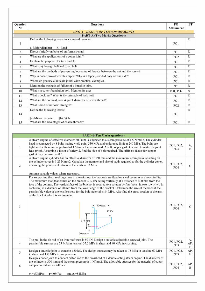
For supporting the travelling crane in a workshop, the brackets are fixed on steel columns as shown in Fig. The maximum load that comes on the bracket is 12 kN acting vertically at a distance of 400 mm from the face of the column. The vertical face of the bracket is secured to a column by four bolts, in two rows (two in each row) at a distance of 50 mm from the lower edge of the bracket. Determine the size of the bolts if the permissible value of the tensile stress for the bolt material is 84 MPa. Also find the cross-section of the arm of the bracket which is rectangular.
PO1, PO2, PO4 C
4 The pull in the tie rod of an iron roof truss is 50 kN. Design a suitable adjustable screwed joint. The permissible stresses are 75 MPa in tension, 37.5 MPa in shear and 90 MPa in crushing. PO1, PO2,
PO3
A, AP, E
5 Design a knuckle joint to transmit 150 kN. The design stresses may be taken as 75 MPa in tension, 60 MPa in shear and 150 MPa in compression.
PO1, PO2, PO3
AP, E
6
Design a cotter joint to connect piston rod to the crosshead of a double acting steam engine. The diameter of the cylinder is 300 mm and the steam pressure is 1 N/mm2. The allowable stresses for the material of cotter and piston rod are as follows :
$#= 50MPa; τ=40MPa; and $%=84MPa
PO1, PO2, PO4
AP, E
Question No
Questions
PO Attainment
BT
UNIT 4 – DESIGN OF TEMPORARY JOINTS PART-A (Two Marks Questions)
1 Define the following terms in a screwed member:
a. Major diameter b. Lead PO1
R
2 Discuss briefly on bolts of uniform strength PO1 R
3 What are the applications of a cotter joint ? PO2 R
4 Explain the purpose of a turn buckle PO1 R
5 What is a) through bolt and b)tap bolt PO1 R
6 What are the methods of preventing loosening of threads between the nut and the screw? PO1 R 7 Why is cotter provided with a taper? Why is a taper provided only on one side? PO1 R
8 Where do you use a knuckle joint? Give practical examples. PO1 R
9 Mention the methods of failure of a knuckle joint. PO1 R
10 What is a cotter foundation bolt. Mention its uses PO1, PO2 A
11 What is lock nut? What is the principle of lock nut? PO1 R
12 What are the nominal, root & pitch diameter of screw thread? PO1 R
13 What is bolt of uniform strength? PO2 R
14 Define the following terms :
(a) Minor diameter, (b) Pitch PO1
R
15 What are the advantages of coarse threads? PO1 R

7
The big end of a connecting rod, as shown in Fig, is subjected to a maximum load of 50 kN. The diameter of the circular part of the rod adjacent to the strap end is 75 mm. Design the joint, assuming permissible tensile stress for the material of the strap as 25 MPa and permissible shear stress for the material of cotter and gib as 20 MPa.
PO1, PO2, PO3
A, AP, E
8
Design and draw a cotter joint to support a load varying from 30 kN in compression to 30 kN in tension. The material used is carbon steel for which the following allowable stresses may be used. The load is applied statically.
Tensile stress = compressive stress = 50 MPa ; shear stress = 35 MPa and crushing stress = 90 MPa.
PO1, PO2, PO3
R, A, AP
9
A bolted assembly of two components is shown in Fig. Initially, the nut is tightened by means of a spanner so as to induce a pre-load of 2.5 kN in the bolt. The external force P acting on the assembly is 5 kN. The bolt with coarse threads is made of plain carbon steel 30C8 (Syt = 400 N/mm2) and the factor of safety is 2.5. The effective stiffness of the parts held together by the bolt is 2.5 times the stiffness of the bolt. Specify the size of the bolt.
PO1, PO2, PO4 E
10
A rigid bracket subjected to a vertical force of 10 kN is shown in Fig. It is fastened to a vertical stanchion by means of four identical bolts. Determine the size of the bolts by maximum shear stress theory. The maximum permissible shear stress in any bolt is limited to 50 N/mm2.
PO1, PO2, PO4 C

PART–B(Ten Marks questions)
1
How do you design a shaft when it is
a) Subjected to only Twisting moment b) Subjected to a combination of Twisting moment and Bending moment.
PO1, PO2, PO4 C
2 Shaft made of mild steel is required to transmit 100 kW at 300 r.p.m. The supported length of the shaft is 3 metres. It carries two pulleys each weighing 1500 N supported at a distance of 1 metre from the ends respectively. Assuming the safe value of stress, determine the diameter of the shaft.
PO1, PO3 A,
AP, E
3
The layout of an intermediate shaft of a gear box supporting two spur gears B and C is shown in Fig. The shaft is mounted on two bearings A and D. The pitch circle diameters of gears B and C are 900 and 600 mm respectively. The material of the shaft is steel FeE 580 (Sut = 770 and Syt = 580 N/mm2). The factors kb and kt of ASME code are 1.5 and 2.0 respectively. Determine the shaft diameter using the ASME code.
Assume that the gears are connected to the shaft by means of keys.
PO1, PO2, PO3
U, A, AP
4 What is the significance of a key in a machine component? State the types of keys used in machines. How would you approach if you are asked to design a key that would connect a shaft of diameter d to a coupling?.
PO1, PO2, PO4 C
5 A 15 kW, 960 r.p.m. motor has a mild steel shaft of 40 mm diameter and the extension being 75 mm. The permissible shear and crushing stresses for the mild steel key are 56 MPa and 112 MPa. Design the keyway in the motor shaft extension. Check the shear strength of the key against the normal strength of the shaft.
PO1, PO2, PO3
U, A, AP
6
Design and make a neat dimensioned sketch of a muff coupling which is used to connect two steel shafts transmitting 40 kW at 350 r.p.m. The material for the shafts and key is plain carbon steel for which allowable shear and crushing stresses may be taken as 40 MPa and 80 MPa respectively. The material for the muff is cast iron for which the allowable shear stress may be assumed as 15 MPa
PO1, PO2, PO3, PO4
R, E
7 Design and draw a cast iron flange coupling for a mild steel shaft transmitting 90 kW at 250 r.p.m. The allowable shear stress in the shaft is 40 MPa and the angle of twist is not to exceed 1° in a length of 20 diameters. The allowable shear stress in the coupling bolts is 30 MPa.
PO1, PO2, PO4
A, E
8 What are couplings? Explain their need. What is the approach taken to design a flange coupling? Also briefly mention the types of flange couplings.
PO1, PO2, PO4 A,E
9
Design a cast iron protective type flange coupling to transmit 15 kW at 900 r.p.m. from an electric motor to a compressor. The service factor may be assumed as 1.35. The following permissible stresses may be used : Shear stress for shaft, bolt and key material = 40 MPa ;Crushing stress for bolt and key = 80 MPa ;Shear stress for cast iron = 8 MPa
PO1, PO2, PO3
A, AP
10 What do you understand by the term Flexible couplings? Explain with neat sketch the types of flexible couplings you know.
PO1, PO2, PO4 C
Question No
Questions
PO Attainment
BT
UNIT 5 – DESIGN OF SHAFTS, KEYS & COUPLINGS PART-A (Two Marks Questions)
1 Distinguish clearly, between pin, axle and shaft. PO1 R 2 Which theories of failure are applicable for shafts? Why? PO2 A
3 Define equivalent torsional moment and equivalent bending moment. State when these two terms are used in the design of shafts. PO2 AP
4 Discuss the various types of shafts PO1 R 5 What do you understand by torsional rigidity and lateral rigidity. PO1, PO2 A 6 State why a hollow shaft has greater strength and stiffness than solid shaft of equal weight. PO1 R
7 Under what circumstances are hollow shafts preferred over solid shafts? Give any two examples where hollow shafts are used PO1 U
8 Why is taper given to key? Why is taper given only on one side? PO1 R
9 What are splines? Where do you use them? PO1 R
10 What is the difference between protected and unprotected rigid flange couplings? PO1 R
11 What is Muff coupling? Give its applications. PO1 A
12 What is the difference between coupling and clutch? PO1 R
13 What is the critical speed of shaft? PO1 R
14 What is Gib-head taper sunk key? What is its advantage? PO1 R
15 What is taper sunk key? PO1 R

Code Description R Remember U Understand A Analyse
AP Apply E Evaluate C Create
Bloom’s Taxonomy