ARNING MACHINE
25
an ARNING MACHINE MODEL: 671 HEAVY DUTY • • for DARNING an d MENDING Shirts • Socks • Coats Aprons • Overalls • Ath - letic Equipment • T rou - SE!rS • Towels • Sheets • Pillow Cases • Lin ens • Laundr y Nets Fc•r details phone: er Used by: LAUNDRIES DRY CLEANERS HOTELS - HOSPITALS - TOWEL SUPPLIERS - ORPHANAGES COAT and LINEN SUPPLIERS INSTITUTIONS OF ALL KINDS DES I GNED & MFG. BY : c h<>n dler mach . en . 014 ::1? II Po rt io lly Comple ted Work Comp le ted wo rk From the library of: Superior Sewing Machine & Supply LLC
-
Upload
khangminh22 -
Category
Documents
-
view
1 -
download
0
Transcript of ARNING MACHINE

an ARNING
MACHINE MODEL: 671 HEAVY DUTY
• • for DARNING
and MENDING
Shirts • Socks • Coats
Aprons • Overalls • Ath
letic Equipment • Trou
SE!rS • Towels • Sheets
• Pillow Cases • Linens
• Laundry Nets
Fc•r details phone:
er
Used by: LAUNDRIES DRY CLEANERS
HOTELS - HOSPITALS - TOWEL SUPPLIERS - ORPHANAGES COAT and LINEN SUPPLIERS
INSTITUTIONS OF ALL KINDS
DES I GNED & MFG. BY : c h<>n dler mach . en . ::~vPr . m ::~ c:« 014 ::1? II
Po rt io lly Completed
Work
Comple ted work
From the library of: Superior Sewing Machine & Supply LLC

TIMING LOOPER TO NEEDLE BAR
The usual procedure for timing the Looper and Needle Bar, is first to time the Looper and then set the height of the Needle to the point of the Looper. This is accomplished as follows: 1 Insert new Needle full leng th of the Needle Bar bole and tighten Screw A (Fig.1) 2 As a preliminary setting, make sure the point of the Needle is approximately in line with the center of the Looper Shaft when the Needle Bar is at the lowest depth of its stroke.
Potn! of Loopt!r .bor e/9 vtstb le
FIGURE 2
FIGURE
Adjustment is made by means of Screw B (Figure 1).
SHEET 2
FIGURE 2A
3 Turn the machine by hand, rotating the thus raising the Needle 5/32 of an inch stroke as shown in Figure 2.
Looper counterclockwise, from the bottom of its
At this time, the the left side of loosen Screws C desired amount m
point of the Looper should be barely visible on the Needle as shown in Figure 2. To adjust,
(Figure 3) and rotate Knurled Looper Holder either direction. Tighten Screws C securely.
4 There should be a space of light barely visible between the point of the Looper and the Needle as shown in Figure 2A. Adjust for proper clearance by loosening Screw D (Figure 3) and moving th~ Looper in or out the desired amount.
5 As a fina l setting, now that the Looper is properly timed in re"' lation to the lift (or up stroke), the Needle Bar can be readjusted (as described in preceeding item 2) so that the point of the looper when passing the Needle is approximately 1/32 of an inch above the Needle Eye.
This· final setting may have to be varied slightly depending upon the weight and softness of the thread or material being used.
The break of the loop (or loop formation) at the Needle Eye may vary according to the thread used. This will possibly require setting the point of the Looper closer or further from the eye of the Needle but within a range of approximately 1/32 of an inch.
~----------------~CHANDLERr-----------------~
From the library of: Superior Sewing Machine & Supply LLC

SHEET 3
TIMING THE FINGER
Lateral Setting - (Controlled by Barrel Cam I, Figure 3)
1 Whe n the Finger has reached its most forward lateral position, the point of the · Finger s hould extend approximatel y 1/32" beyond th e front edge of the s lot In the Throat Plate as shown below In Figure 3A.
To adjust, loosen Screw EA (Figure 3) and move Shaft F forward o r backward the desired amount. (In moving Shaft F forward, make s ure th a t Eccentric Finger G does not bind against shoulder of Eccentric J, othe rwise Finger G will have to be moved back the same amo unt Shaft F i s moved forward.)
Radial Setting - (Controll ed by Eccentric J, Figure 3)
2 When the Needle is a t the very bottom of its s troke there shoul d be approximately 1/16" clearance between the Needle and the back edge of the Finger as s hown in Figure 3B.
T c adjus t, loosen Cl amp Screw. GA (Figure 3) and move the Finger into correc t position, and tighten Clamp Screw GA securely.
Turning the mach ine s lowllf in the direction of normal operation, observe care full y that at the ins ta nt the point of the Needl e has cleared the Finger, the F inger must start its counterclockwise movement. T he F inger s houl d move backwards and sideways a t the same time. Dotted line in Figure 3C s hows ap proximate path of Finger po int. Barrel Cam I must be adjusted to pull Finger sideways a t the same time that Eccentric J moves Finger backward.
To adjus t, loosen 3 Set Screws H (Figure 3) and retard or advance Finger Eccentric on Shaft the desired amount. Retighten Screws sec urel y after making adjus tment.
FIGURE 3
FIGURE 3A FIGURE 38 Finger moving forward Finge r position from while Need le descending. time Needle enters
Throat Plate hoi e and returns.
FIGURE 3C Dotte d fine s hows path of F inger point. F inger starts moving backward and s idoways as soon a s Noodl e clear s back of Finge r .
~------------------~CHANDLERr-------------------~
From the library of: Superior Sewing Machine & Supply LLC

THREAD LOCK TIMING ADJUSTMENT
When the Need le Bar has ascended to within l /8 or 5/32 inch from the highest point of of the Needle Bar s troke on completion of the last stroke of the sewing cycle, the thread should be locked by the forward pressure of Plunger A against Plate B (Figure lA).
The Thread should be locked when the mach-m e stops, the thread break when is lifted.
otherwi se will not
the Clamp FIGURE lA
SHEET 4
FIGURE 1
Caution: Excessive pressure of the Plunger on light or weak thread wil l have a tendency to fracture the thread causing excessive thread breakage.
To adjus t, loosen Lock Nut C (Figure 2) and turn Adjusting Screw 0 in or out the desired amount. Be sure to tighten Lock Nut C securely.
FIGURE 2
Note: Machines are usua ll y equipped with light Lock Spring for use on light thread. For heavy threads use heavier Lock Spri ng (See Plate 1 ).
On res uming the fi rst stroke of the new sewing cycle, the Thread Lock must release the thread some time before the Needle Bar reaches the lowes t point of the stroke so that the thread is not held tight when the Take-up E (Figure 1) above starts its return upward stroke.
Bracket F (Figure 12) is provided with slots so that the Trip Lock Lever may be re tarded or advanced for proper timing.
L-------------------~CHANDLER~------------------~
From the library of: Superior Sewing Machine & Supply LLC

SHEET 5
A
FIGURE 1
0
TIMING OF TOP INTERMITTENT TENSION
On the top of the machine there are two thread tension adjustments ••• Rear Tension B and Front Tension A (See Figure 1). Rear Tension B is an intermittent thread locking tension which locks the thread prior to the end of each stitch. This prevents the Looper from stealing thread from Spool instead of pulling up the loop at the end of each stitch. The amount of tension for locking the thread is factory set reasonably tight by means of Set Screw E (Figure 1) therefore, do not disturb or attempt to utilize Rear Tension B for adjusting the normal tension explained below. However, the time at which the thread is locked by Tension B may be adjusted as follows:
Loosen Set Screw F (Figure 1) and turn Adjusting Screw G up or down until Tension B locks the thread when the Needle Bar has ascended to with in 5/ 32 of an inch from the top of ' the Needle Bar stroke on light thread but 1/ 8 of an inch or less on heavy thread.
To prevent thread breakage or extremely l ight thread, the Intermittent Tension s houl d release the thread when the Needle Bar is at leas t 5/32 of an inch from the top of its stroke.
ADJUSTMENT OF NORMAL THREAD TENSION
Tightness of the stitch is regulated by Front Tension A. If the Tens ion Adjustment is too tight the Looper will snap the thread, if too loose the knots on the under side of the button will be loose. Adjustment is made as follows:
Turn handwheel at the end of the Mainshaft until Rear Tension B is in "UP" position. Lower the Button Clamp so the Thread Lock H on the Face Plate is open (center plunger is released). Pull the thread at the Needle to be sure it pulls thru with slight tension. If tension is too tight or too loose, turn Tension A up or down until proper tension is achieved.
~------------------~CHANDLER~------------------~
From the library of: Superior Sewing Machine & Supply LLC

SHE~&
FIGURE 1
STOP KICK-OFF FINGER MECHANISM
On completion of the Button Sewing Cycle, Latch A should release Block B (Figure 1) just as Stop Finger C (Figu re 2) has cleared Bumper Spring Holder D. The illustration shows an earlier model but t he same in structions will apply to all · models.
To advance mome nt of release, loosen Screw E (Figure 1) and move Kick-off Finger F to the left.
To retard moment of release, move Kick-off Finger F to the right. Tighten Screw E securely.
FIGURE 2
~------------------~CHANDLER~------------------~
From the library of: Superior Sewing Machine & Supply LLC

AUTOMATIC CLAMP LIFTER MECHANISM
Automatic Operation
To set the automatic clamp lifter mechanism in the automatic operating position (or single pedal control) insert stud A in the forward hole
of connecting strap B as illustrated in Fig. 1.
With stud A in this position, the amount of clamp life is controlled by loosening check nut C and turning adjusting nut D in or out as re
quired,
Adjustment of the amount of clamp lift may nece·ssitate a compensating adjustment of the thread slack kick pin H Fig. 2 in order co main- ·
tain the proper amount of thread take-off.
The automatic lifter -actuating bracket E Fig. 1,
controls the timing of the lowering of the clamp
in relation to the first needle bar stroke, and the ri-sing of the clamp on the final needle bar
stroke . For proper timing, loo·sen two screws
F Fig. 1 and swing bracket E so that its drop·
off point is approximately on the centerline of
the roller G as shown in Fig. 1A.
riGURE 2
SHEET 7
FIGURE 1 FIGURE lA
Manual Operation
To conve rt the machine from automatic to
manual clamp life (or two pedal control) re
move nut I Fig. 1, lift connecting strap B and
insert stud A in hole X. Replace nut I and
tighten secure! y. The automatic function i·s
now inoperative, swce roller G no longer
contacts bracket E.
Adjustment for the amount of cl iu~p lift is now
made by means of the adjusting sere"'! in the
lifting bracket 543-213 located in the base of
the machine (See parts plate 9).
Either of the above adjustments may necessitate
a compensating adjustment of the thread slack
kick pin H Fig. 2 in order to maintain the proper
amount of thre ad cake-off.
~--------------~CHANDLER~----------------~
From the library of: Superior Sewing Machine & Supply LLC
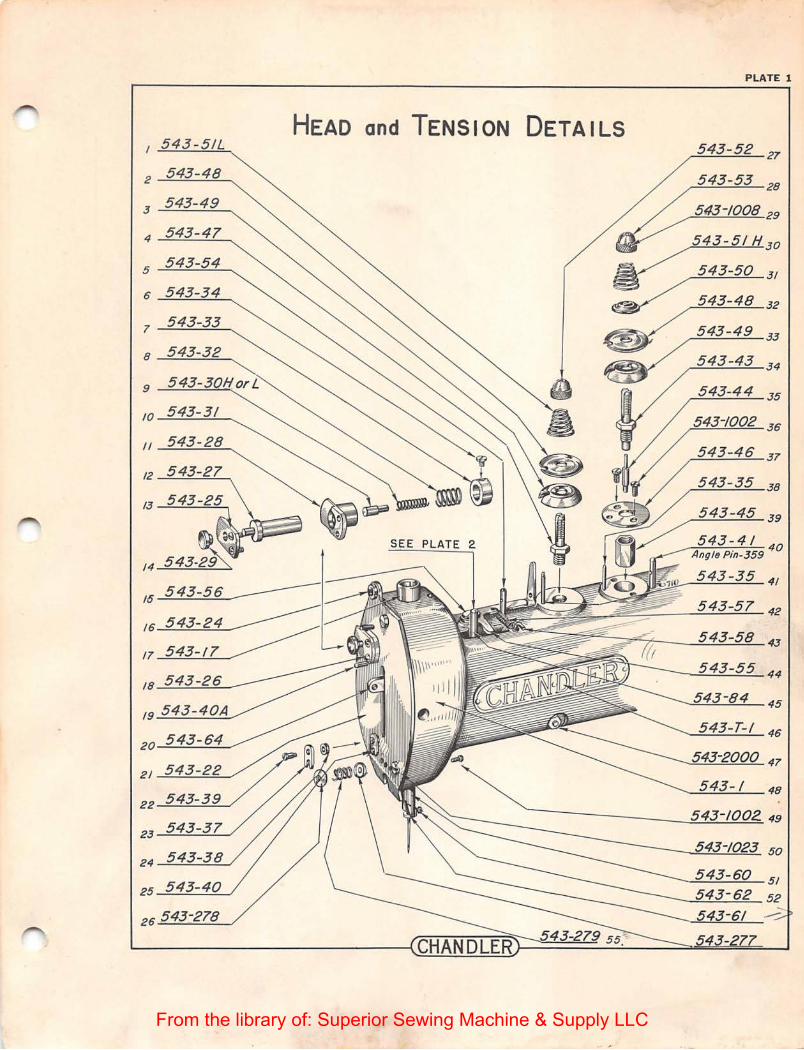
543 - 5/L
2 543- 48
3 543-49
4 543-47
5 543-54
6 543-34
1 543-33
8 543-32
9
10 543-31
II 543-28
12
13
20
21
22
23 543-37
24
25 543-40
26
HEAD and TENSION DETAILS
S E PLATE 2.
PLATE 1
543-52 27'
543-53 28
543-1008 29
543-51H 3 o
33
543-43 34
543-44 35
36
37
38
39
543-1 48
543-1002. 49
-.~....:::...._.=.:::..__ 5/
---.._..:_..:..:::.....-=- 52 -.
·---
From the library of: Superior Sewing Machine & Supply LLC
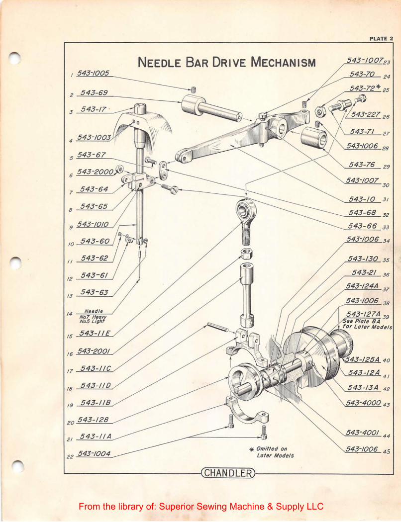
1 543-/005
2 543-69
3 543-17
6
1 543-64
8 543-65
9 543-1010
10
II 543- 62
12 543-61
13
14 Needl e No.7 Hear NoS Ligh
15
16 543-200/
11
19 543-1/B
20 543-128
NEEDLE BAR DRIVE MECHANISM
* Omifled on Lofer Model s
PLATE 2
30
543- 10 3 1
5 43-68 32
543-66 33
~----------------~CHANDLERr-----------------~
From the library of: Superior Sewing Machine & Supply LLC

CLAMP LIFT and THREAD SLACK MECHANISM
543-89A 18
PLATE 3
From the library of: Superior Sewing Machine & Supply LLC

PLATE 4
AUTOMATIC THREAD LOCKING MECHANISM
2 543-/96
SEE PLATE 3
5 543-14 4
6 < •
7
8
/9
543-9/ 20
543-5001 21
9 543-/69 22
10 543- 23
CHANDLER
From the library of: Superior Sewing Machine & Supply LLC

543-85
2 543-123
J 543-//6
4 543-1/T
8 5
12 543
17 543-1015
+
PLATE 5
BUTTON CLAMP ASSEMBLY 543-120 18
543-2004 19
543-119 20
543-/05 21
543-3000 22
-/02A 24
543-118 26
~--------------------~5~4~3~-1~27
543-114 28
Pin 543- //0 552-369
29
543-97 30
543-95 31
-96 32
543-99 35
L-------------------~CHANDLER~------------------~
From the library of: Superior Sewing Machine & Supply LLC

See Plate 5
Item 29
BUTTON CLAMP ASSEMBLY . All In One Style
NOTE
Ports Not Beorinq Nvmbers
Are Identified On Plate 5
PLATE SA
543-272 4
6
~----------------~CHANDLER~----------------~
I
From the library of: Superior Sewing Machine & Supply LLC
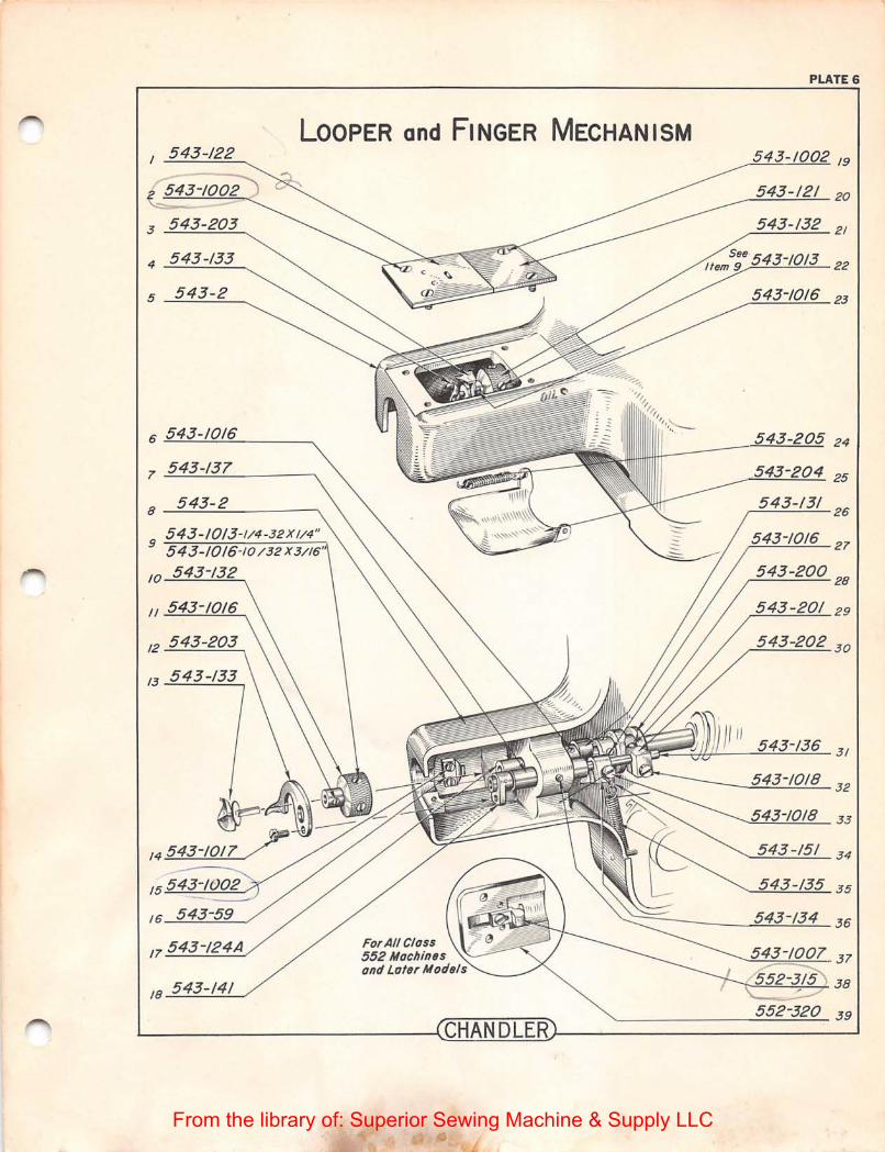
I 543-122
3....:::.....:~=::....--..__
4 ....::.......~.:....:::....::--....
5 __;;.....;_;;,_-=---...
6
7 543-1
8 543-2
10
II
15 .::......:.....:::::::-==::::::-...-
/6 ---=-....:..=..-=-/
/8 543-141
PLATE 6
LOOPER and FINGER MECHANISM
CHANDLER
_........=.__:....=:.____:....=:.-==.. 19
----...:::......:...:::...._:...=..:.._ 20
~_.;....__;,__;__ 2/
9~:o....!...!:~:...!...:::...-22
~...:.....;::_..:...;;;....;...;o.__23
05 24
26
21
29
~~~~L---~~~~ 31
---=;.....:.-=:.......:...:::...:..-=-_ 32
--...=._..:...=;._.:..=..:....::;..__ 33
--.......=:......:....::___:_:::....:....._ 3 4
-----=:c...:....::--:....::::=- 3 5
~--------~~~~36
\-"=~=-,t-38
~----------~~~~39
From the library of: Superior Sewing Machine & Supply LLC

2 543-327
3 552-326
5 552-331
Q 552-329
1 552-325
8 543-187
9 -=-:.=....;~:::...-~
10 543-1014
II 543-330
FoR CLAss 552 AND LATER MoDELS
/J---!::......:....:::..._--=2~------..
14 543-/90
No Shoulder Style) 544-140A
Shoulder Stud 543-140
CHANDLER
PLATE 7
543-326 22
552-328 23
552-337 24
543-1002
-~--!..::!..~~29
543-187 30
From the library of: Superior Sewing Machine & Supply LLC

18 543-20
~
21 543-172A/
22~
STOPPING MECHANISM See Plate SA For Other Models
PLATE 8
L-----------------~~CH~A~N~D~L~EGR~----------------~
From the library of: Superior Sewing Machine & Supply LLC

7 '
PLATE SA
STOPPING MECHANISM FoR CLASS 552 MACH ..
3~~~~------~
4 552-4000
5 552-1006
552-318 II ___;;_;c..=.....:........;;.___,
552-33514
552-300215
552-309 /6
-!55 17
---------'-- 19
552-312 20
552-208A J/
~------------------~CHANDLERl--------------------~
From the library of: Superior Sewing Machine & Supply LLC

PLATE 9
TREADLES and TRIP LEVERS
543-74 /6
2 543-2002 17
3 543-2002 543-1018 18
4 19
5 543-10/9 543-1019 20
6 21
1 543-2002
543-1021 3 8
9 24
10 25
II 26
12 27
13
14 29
15
CHANDLER
From the library of: Superior Sewing Machine & Supply LLC
SHANK BUTTON
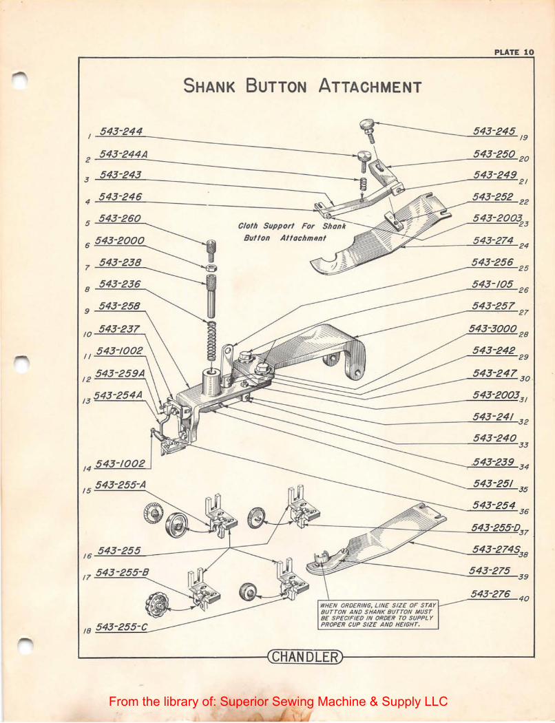
543-244
2 543-244A
3 543-243
4 543-246
5 543-260 Cloth Support For
7 543-238
16 543-255
18 543-255-C
ATTACHMENT
WHEN ORDERING, LINE SIZE OF STAY BUTTON AND SHANK BUTTON MUST BE SPECIFIED IN ORDER TO SUPPLY PROPER CUP SIZE AND HEIGHT.
PLATE 10
543-245 /9
543-250 20
543-249 21
543-252 2
3
543-256 25
543-105 26
~--....:;:._5_;_43::....--=2..:....7..::....'5_ 39
543-276 40
~------------------~CHANDLER~------------------~
From the library of: Superior Sewing Machine & Supply LLC

I 543-1015
SHANK BUTTON ATTACHMENT All In One Style
Cloth Support For
' ®
I
NOTE
WHEN ORDERING, LINE SIZE OF STAY BUTTON ANO SHANK BUTTON MUST BE SPECIFIED IN ORDER TO SUPPLY PROPER CUP SIZE AND HEIGHT.
Ports Not Bearing Numbers
Are Identified On Plate 10
PLATE lOA
5
543-274A 6
543-27458 1
543-275 8
543-276 9
~------------------~CHANDLER~------------------~
From the library of: Superior Sewing Machine & Supply LLC

PLATE 11
I 543-299 ATTACHMENTS {CONT.)
2"'---'--'o<.......!:-==.:....:......_
.3 543-2003
4--=:...;~~=-o _ _
5 543-
6 543-119
7 543-118
543-1238 24 \
Stay Button Plate 543-261 25
543-119 27
Whipping Attachment
Necking Attachment
From the library of: Superior Sewing Machine & Supply LLC

4 543-118
5 543-267
7 543-268
Under Side
ATTACHMENTS (Cont.)
Snap Attachment For Square Snaps
Snap Attachment For Round Snaps
NOTE' All Other Parts Same As Plate 5
PLATE 12
543-/237 II
543-300/ 12
543-265 13
543-266 15
~----------------~CHANDLER~------------------~
From the library of: Superior Sewing Machine & Supply LLC

2 555-384
3 543-/003
4 555-380
6 555-386
1 555-377
8 543-3001
II 555- 382
AUTOMATIC CLAMP LIFTER
PLATE 14
Straight Pin
00/13
555-387 /4
555-381 15
543-2000 ------ ;6
555-378 IT
555-379 18
543-200019
555-383 20
543-24/ I
~------------------~CHANDLER~------------------~
From the library of: Superior Sewing Machine & Supply LLC

PLATE 15
BUTTON ACCESSORIES
Left Hand Button Spacer
Right Hand Button Spacer
Left Hand and Right Hand Button Spacer
I 552-32/
2
552-322 3
~----------------~CHANDLER~----------------~
From the library of: Superior Sewing Machine & Supply LLC

RECOMMENDED NEEDLES
CLASS NUMBER SIZE APPLICATION
175 X 3 #4 Very Light Work
175 X 3 f:/ 5 Light Work
175 X 3 #7 Medium Heavy
175 X 3 #8 Heavy
LONG SHANK (For Shonk Buttons)
175 X 7 #5 Me d i um
175 X 7 f:/7 Heavy
RECOMMENDED SPEEDS
~l ac hine classes 543, 546 and 548 are not to be operated 1n
e xcess of 1000 ll .P.M. Model 552 and l ater model s can be operated a t speeds up to 1500 R.P.M.
LUBRICATION
Use a l ight t extile oil for all moving pa rts .
Gears and cam races are lubrica ted with "Lubriplate " a speci al non-drying grease, which we can suppl y. This is the white grease that yo u see on all new mach ines.
...
~----------------~CHANDLER~----------------~
From the library of: Superior Sewing Machine & Supply LLC