Transcription factor IRF5 drives P2X4R+-reactive microglia gating neuropathic pain
Upload
khangminh22Category
view
0download
0
ELEMENTS OF GATING
SYSTEM
GATING SYSTEM
• The term gating system refers to all passageways
through which the molten metal
mould cavity.
passes to enter the
•
✓
✓
✓
✓
✓
The gating system is composed of
Pouring
Sprue
Runner
Gates
Risers
basin
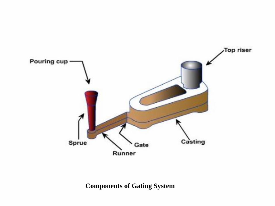
Components of Gating System
• Any gating system designed should aim at providing a defectfree casting. This can be achieved by considering followingrequirements.
✓ A gating system should avoid sudden or right angle changes in direction.
✓ A gating system should fill the mould cavity before freezing.
✓ The metal should flow smoothly into the mould without anyturbulence. A turbulence metal flow tends to form dross in themould.
✓ Unwanted materials such as slag, dross and other mouldmaterials should not be allowed to enter the mould cavity.
✓ The metal entry into the mould cavity should be properlycontrolled in such a way that aspiration of the atmospheric airis prevented.
✓ A proper thermal gradient should be maintained so that the
casting is cooled without any shrinkage cavities or distortions.
✓ Metal flow should be maintained in such a way
or mould erosion takes place.
that no gating
✓ The gating system should ensure
reaches the mould cavity.
that enough molten metal
✓ It should be economical and easy
after casting solidification.
to implement and remove
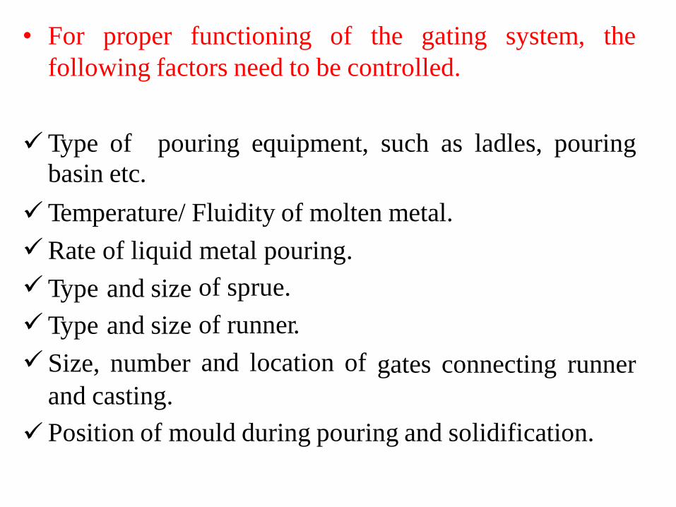
• For proper functioning of the gating system, the
following factors need to be controlled.
✓Type of
basin etc.
pouring equipment, such as ladles, pouring
✓
✓
✓
✓
✓
Temperature/ Fluidity of molten metal.
Rate of liquid metal pouring.
of sprue.
of runner.
and location of
Type
Type
Size,
and size
and size
number gates connecting runner
and casting.
Position of mould during pouring and solidification.✓
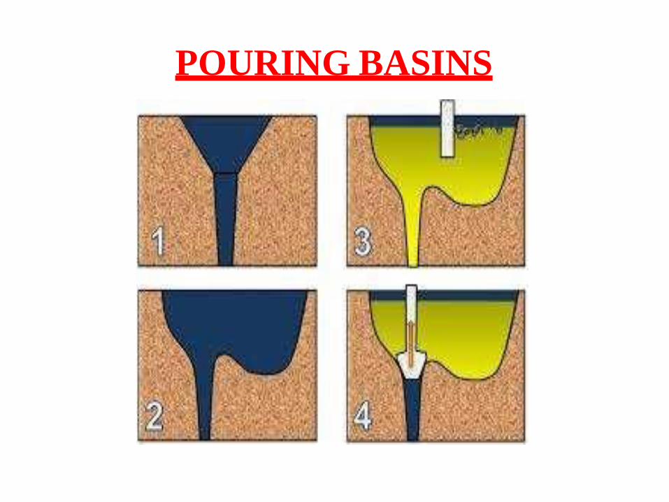
POURING BASINS
• A pouring basin makes it easier for the ladle or
crucible operator
crucible to sprue.
to direct the flow of metal from
• Helps
flow.
maintaining the required rate of liquid metal
• Reduces turbulence at the sprue entrance.
• Helps separating dross, slag etc., from metal before it
enters the sprue.
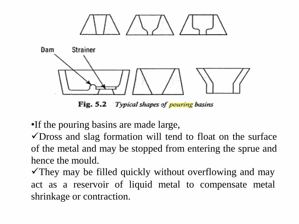
•If the pouring basins are made large,
✓Dross and slag formation will tend to float on the surface
of the metal and may be stopped from entering the sprue and
hence the mould.
✓They may be filled quickly without overflowing and may
act as a reservoir of liquid metal to compensate metal
shrinkage or contraction.
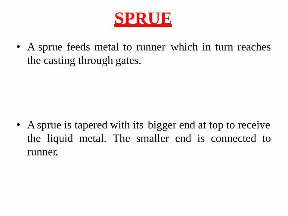
SPRUE
• A sprue feeds metal to runner which in turn reaches
the casting through gates.
• A sprue is tapered with its bigger end at top to receive
the liquid metal. The smaller end is connected to
runner.

GATESA gate is a channel which connects runner with themould cavity and through which molten metal flowsto fill the mould cavity.
•
• A small gate is used for a casting which solidifiesslowly and vice versa.
A gate should not have sharp edges as they
during pouring and sand pieces thus may
with the molten metal in the mould cavity.
Types Top
gate Bottom
gate
Parting line side gate
• may breakbe carried
•
•
•
•
Top gate• A top gate is sometimes also called as
the
Drop gate
because the molten metal
bottom of the mould.
just drops on sand in the
• Generation of favourable temperature gradients to
enable directional solidification from the casting
towards the gate which serves as a riser too.
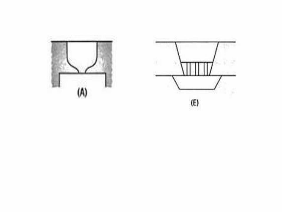
Disadvantages
•The dropping liquid
surface.
metal stream erodes the mould
•There is a lot of turbulence.
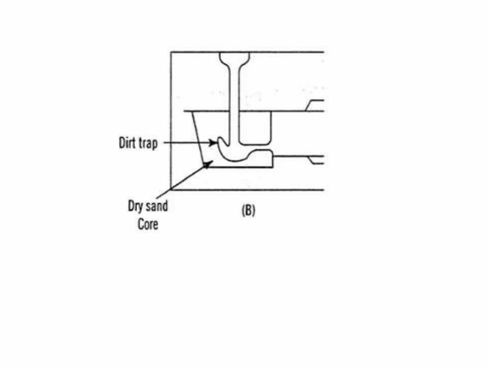
Bottom gates
• A bottom gate is made in the drag portion of the
mould.
• In a bottom gate the liquid metal fills rapidly the
bottom portion of the mould cavity and rises steadily
and gently up the mould walls.
• As comparison to top gate, bottom gate involves
little turbulence and sand erosion.
• Bottom gate produces good casting surfaces.
Disadvantages
• In bottom gates,
at the bottom. If
could choke off
full.
liquid metal enters the mould cavity
freezing takes place at the bottom, it
the metal flow before the mould is
• A bottom gate creates an unfavourable temperature
gradient and makes it difficult to achieve directional
solidification.
PARTING LINE SIDE GATE
• Middle or side or parting gating systems combine
characteristics of top and bottom gating systems.
the
• In this technique gate is provided along the parting
line such
be below
above the
that some portion of
the parting line and
parting line.
the mould cavity will
some portion will be
• The cavity below the parting line will be filled by
assuming top gating and the cavity above the parting
line will be filled by assuming bottom gating.
DESIGN OF GATING SYSTEM
• To fill the mould cavity without breaking the flow of
pouringliquid metal and without using very high
temperatures.
•
•
•
To
To
To
avoid erosion of mould cavity.
minimize turbulence and dross formation.
prevent aspiration
stream.
of air or mould gases in the
liquid metal
• To obtain favourable temperature gradients to
promote directional solidification.
Defects occurring due to improper
design of gating system
•
•
•
•
•
•
•
Oxidation of metal
Cold shuts
Mould erosion
Shrinkages
Porosity
Misruns
Penetration of liquid metal into mould walls.
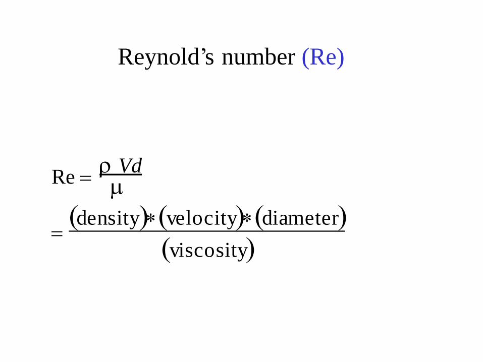
Reynold’s number (Re)
VdRe =
(density)(velocity)(diameter)=
(viscosity)
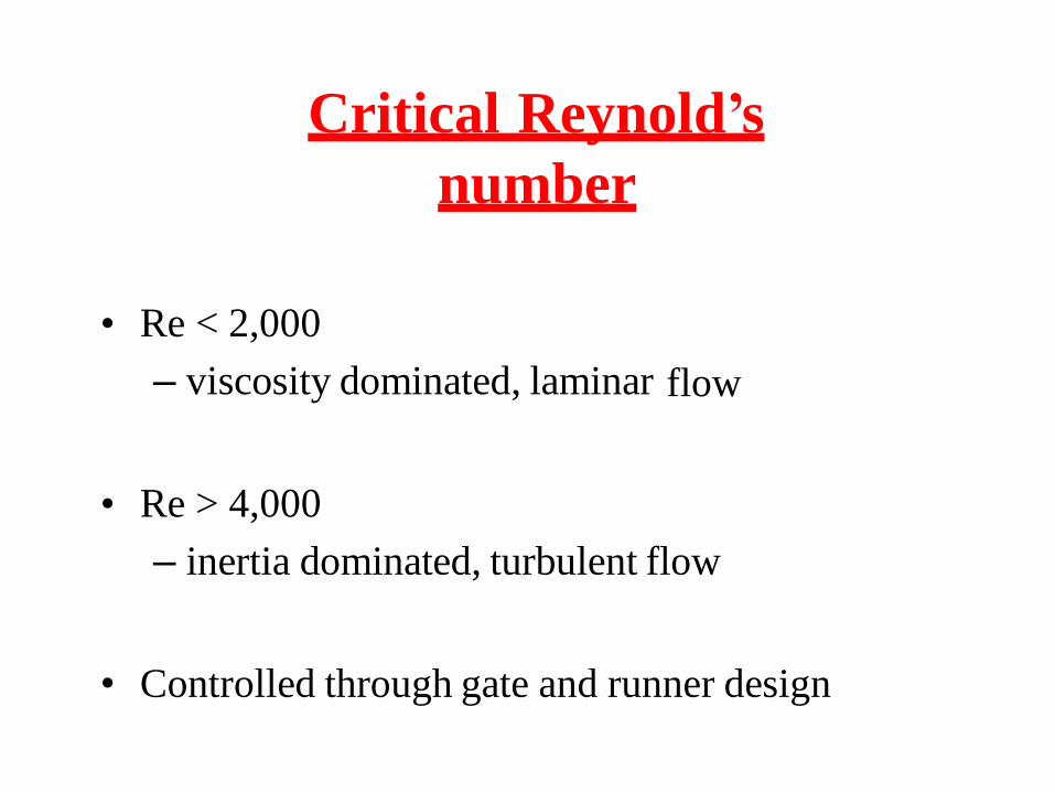
Critical Reynold’s
number
• Re < 2,000
– viscosity dominated, laminar flow
• Re > 4,000
– inertia dominated, turbulent flow
• Controlled through gate and runner design
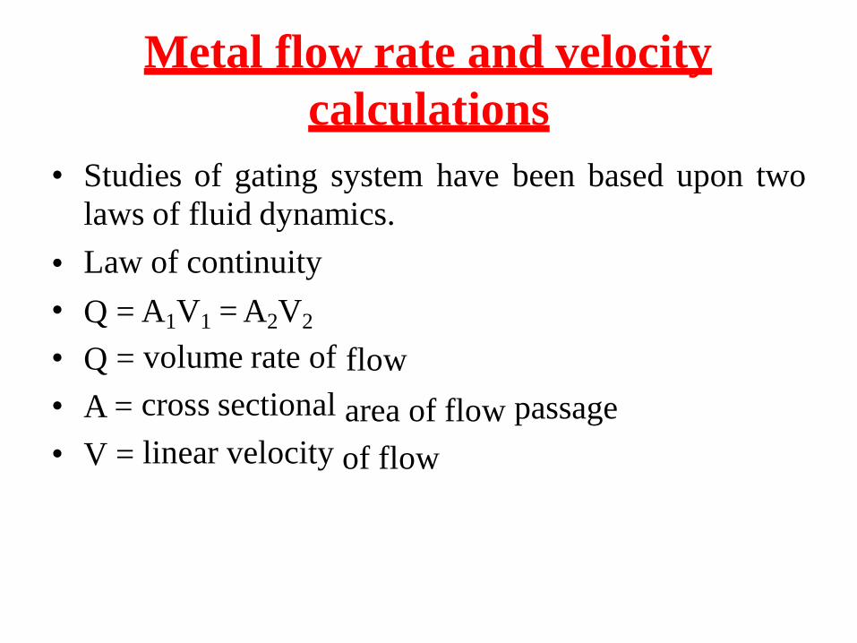
Metal flow rate and velocity
calculations
• Studies of gating system
laws of fluid dynamics.
Law of continuity
have been based upon two
•
•
•
•
•
Q
Q
A
V
=
=
=
=
A1V1 = A2V2
volume rate of
cross sectional
linear velocity
flow
area of flow
of flow
passage
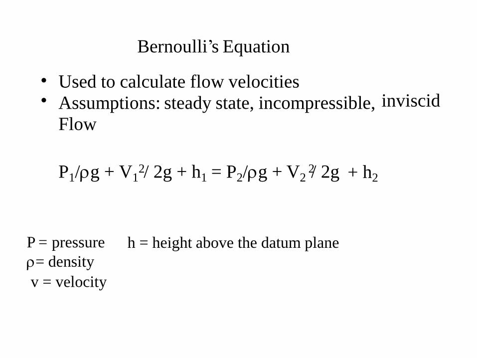
Bernoulli’s Equation
Used to calculate flow velocities
Assumptions: steady state, incompressible,
Flow
•• inviscid
P1/g + V1 / 2g + h1 = P2/g + V2 / 2g2 2 + h2
P = pressure h = height above the datum plane
= density
v = velocity
Design criteria for pouring basin
• The pouring basin should be
proper uniform flow system is
This can be achieved by-
designed such that the
rapidly established.
•
✓
✓
✓
Use
Use
Use
of
of
of
strainer core
DAM to make
sprue plug
steady flow
• It should be easy and convenient to fill pouring basin.
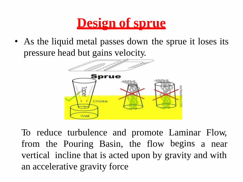
Design of sprue
• As the liquid metal passes down the sprue it loses its
pressure head but gains velocity.
To reduce turbulence and promote Laminar
begins
Flow,
from the Pouring Basin, the flow a near
vertical incline that is acted upon by gravity and with
an accelerative gravity force
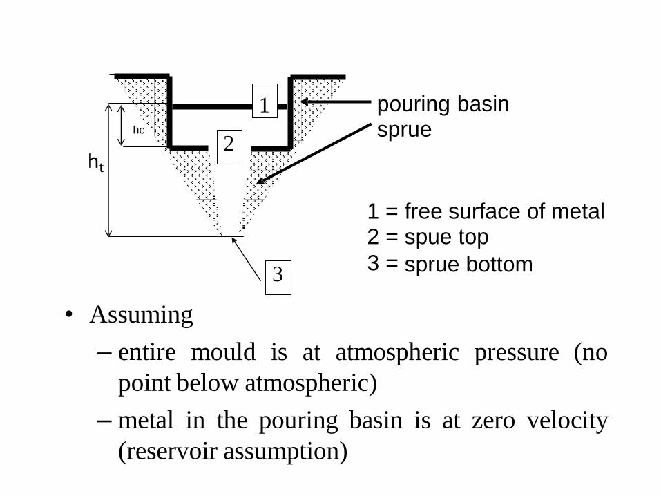
pouring basinsprue
ht
12
3
==
=
free surface of metalspue top
sprue bottom
• Assuming
– entire mould is at atmospheric pressure (no
point below atmospheric)
– metal in the pouring basin is at zero velocity
(reservoir assumption)
3
2
1hc
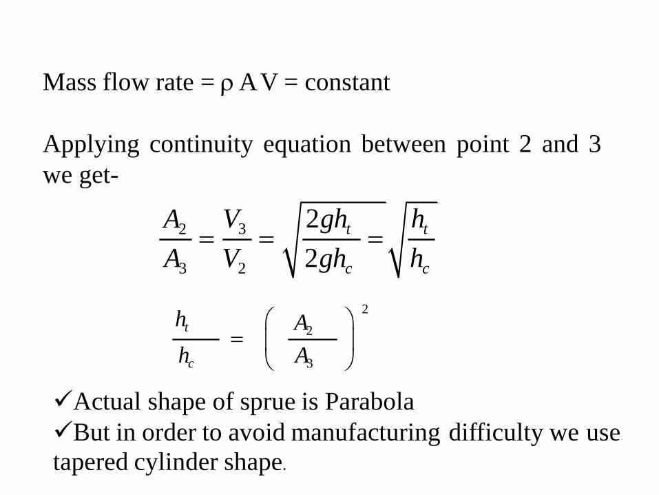
Mass flow rate = AV = constant
Applying continuity equation between point 2 and 3
we get-
V3 2ght htA2 = = =A3 V2 2ghc hc
2ht
A2=hc A3
✓Actual shape of sprue is Parabola
✓But in order to avoid manufacturing
tapered cylinder shape.
difficulty we use
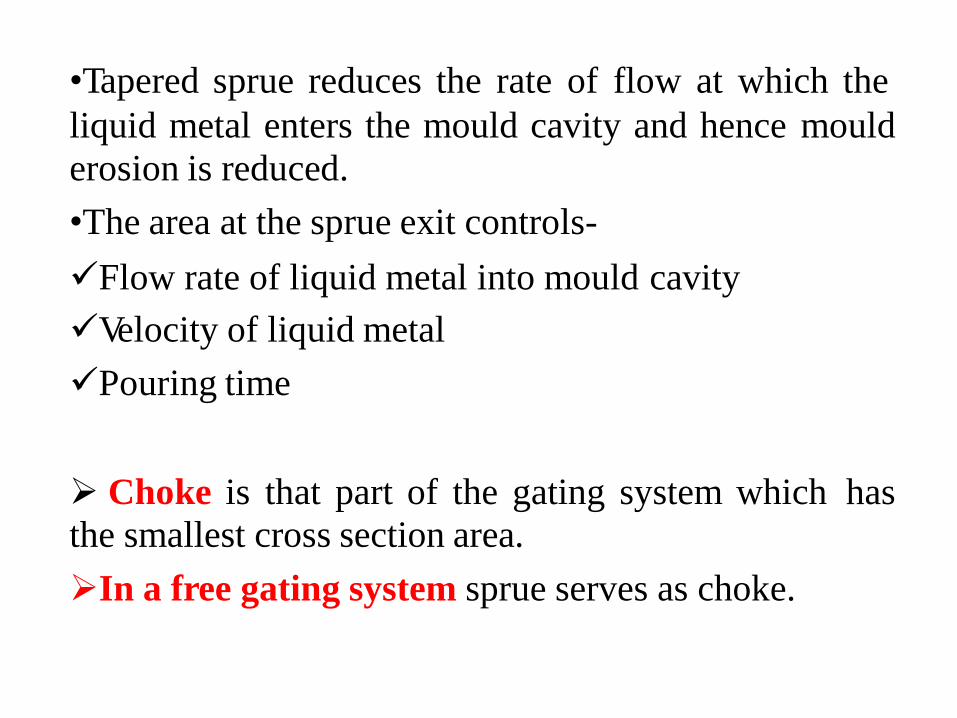
•Tapered sprue reduces the rate of flow at which the
liquid metal enters the mould cavity and hence
erosion is reduced.
•The area at the sprue exit controls-
mould
✓Flow rate of liquid metal into mould
✓Velocity of liquid metal
✓Pouring time
cavity
➢ Choke is that part of the gating system which
the smallest cross section area.
➢In a free gating system sprue serves as choke.
has
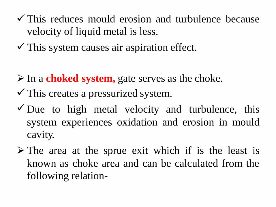
✓This reduces mould erosion and turbulence
velocity of liquid metal is less.
because
✓This system causes air aspiration effect.
➢
✓
✓
In a choked
This creates
system, gate serves as the choke.
a pressurized system.
Due to high metal velocity and turbulence, this
system
cavity.
experiences oxidation and erosion in mould
➢The area at the sprue exit which if is the least is
known as
following
choke area and can be calculated from the
relation-
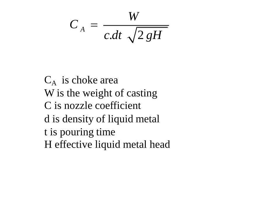
W=C
Ac.dt 2 gH
CA is choke area
W is the weight of casting
C is nozzle coefficient
d is density of liquid metal
t is pouring time
H effective liquid metal head
Pouring time
•High pouring rates leads to mould erosion, rough
surface, excessive shrinkages etc.
•Low pouring rate may not permit the complete filling of
the mould cavity in time if the
and thus defects like cold shuts
molten metal freezes fast
may develop.
•It is very necessary to know optimum pouring rate or
pouring time for metals to be cast. Optimum pouring rate
a function of casting shape and size.
•
•
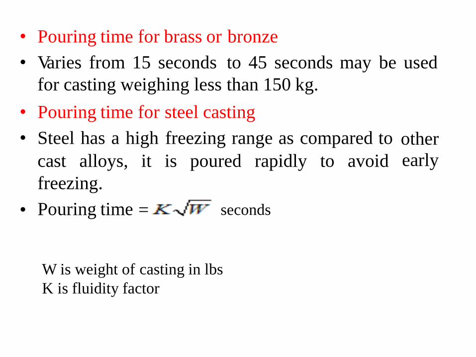
Pouring time for brass or
Varies from 15 seconds
for casting weighing less
bronze
to 45 seconds may be used
than 150 kg.
•
•
Pouring time for
Steel has a high
steel casting
freezing range as compared to other
earlycast alloys, it is poured rapidly to avoid
freezing.
Pouring time• = seconds
W is weight of casting in lbs
K is fluidity factor
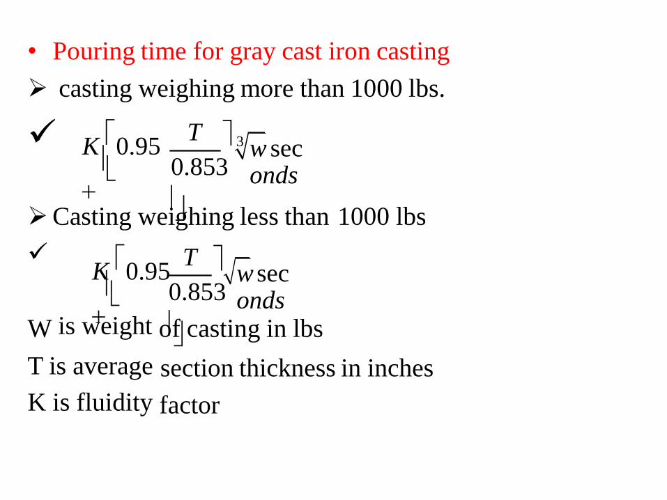
• Pouring time for gray cast iron casting
➢ casting weighing more than 1000 lbs.
✓ TK0.95
+
3 w seconds
0.853
➢Casting weighing less than 1000 lbs
✓ TK0.95
+
w seconds
is weight
0.853
W of casting in lbs
section thickness in inches
factor
T is average
K is fluidity
• Pouring time of light metal alloys
•Unlike steel, Al and Mg alloys are poured at a slow
rate, this is necessary to avoid turbulence, aspiration
and drossing.
DESIGN OF RUNNERAND
GATES
In a good runner and gate design-•
✓Abrupt changes in section and sharp corners which
create turbulence and gas entrapment should be
avoided.
✓A suitable relationship must exist between the cross-
sectional area of sprue, runner and in gates.
GATING RATIO
•
•
•
•
•
•
Gating ratio= a:b:c where,
a=
b=
c=
cross-sectional area of sprue
cross-sectional area
total cross-sectional
of runner
area of ingates.
Gating ratio reveals-
whether the total cross- section decreases towards the
mould cavity. This provides a choke effect which
pressurizes the liquid metal in the system.
• Whether the total cross-sectional area increases so
that the passages remain incompletely filled. It is an
unpressurized system.
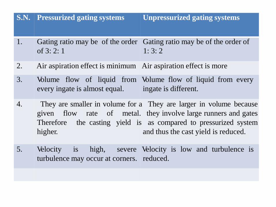
S.N. Pressurized gating systems Unpressurized gating systems
1. Gating ratio may be of the order Gating ratio may be of the order of
of 3: 2: 1 1: 3: 2
2. Air aspiration effect is minimum Air aspiration effect is more
3. Volume flow of liquid from Volume flow of liquid from every
every ingate is almost equal. ingate is different.
4. They are smaller in volume for a They are larger in volume because
given flow rate of metal. they involve large runners and gates
Therefore the casting yield is as compared to pressurized system
higher. and thus the cast yield is reduced.
5. Velocity is high, severe Velocity is low and turbulence is
turbulence may occur at corners. reduced.

• Ideally, in a system, pressure should be just enough toavoid aspiration and keep to all feeding channels full of liquid metal.
• Gating ratio and positions of ingates should be suchthat the liquid metal fills the mould cavity just rapidlyto-
✓Avoid misruns and coldshuts in thin sectionedcastings.
✓Reduce turbulence and mould erosion in casting ofthicker casting.
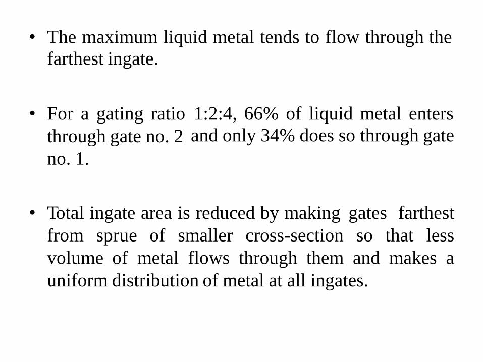
• The maximum liquid metal tends to flow through the
farthest ingate.
• For a gating ratio
through gate no. 2
no. 1.
1:2:4, 66% of liquid metal enters
and only 34% does so through gate
• Total ingate area is reduced by making gates farthest
from sprue of smaller cross-section so that less
volume of metal flows through them and makes a
uniform distribution of metal at all ingates.
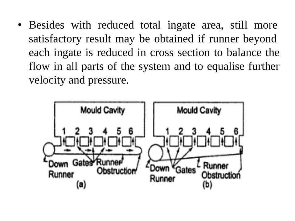
• Besides with reduced total ingate area, still more
satisfactory result may be obtained if runner beyond
each ingate is reduced in cross section to balance the
flow in all parts of the system and to equalise further
velocity and pressure.

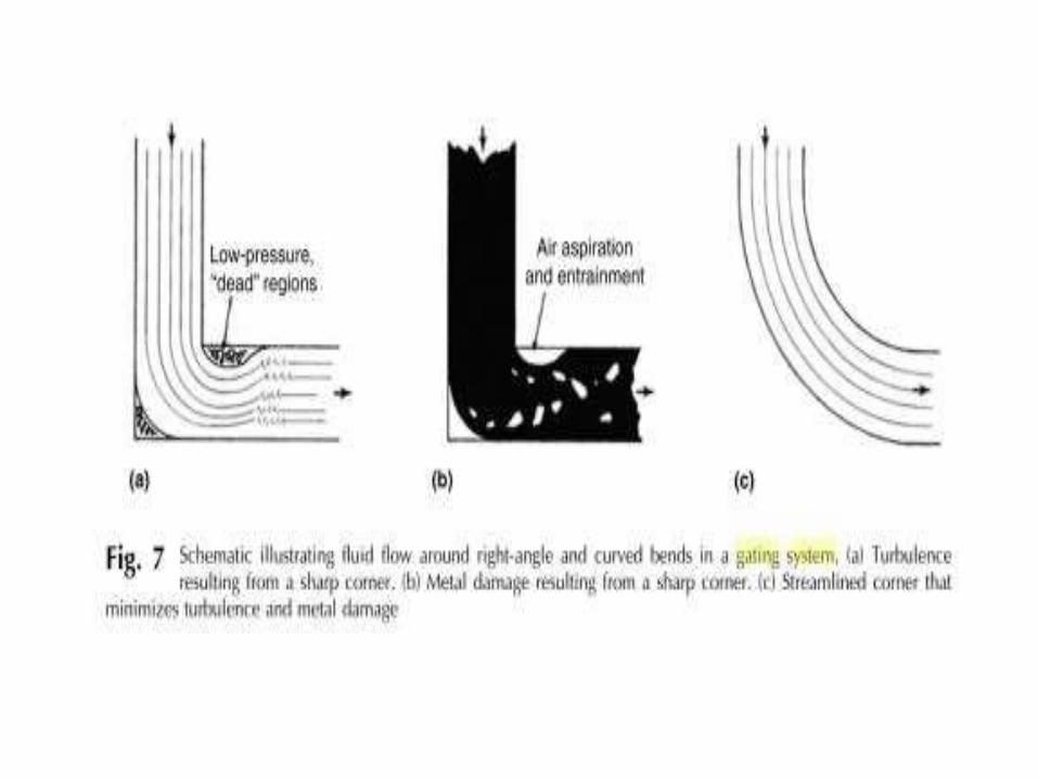
Streamlining the gating system
• Streamlining includes-
• Removing sharp corners
generous radius.
or junction by giving a
• Tapering the sprue.
• Providing radius at sprue entrance and exit.
ADVANTAGES OF STREAMLINING
• Metal turbulence is reduced.
• Air aspiration is avoided.
• Mould erosion and dross are minimized.
• Sound and clean casting are obtained.
Copyright © 2022 FDOKUMEN