
Nanoconfined, dynamic electrolyte gating and memory effects ...
Upload
khangminh22Category
view
0download
0
materials
Article
Influence of Gating System Parameters of Die-Cast Molds onProperties of Al-Si Castings
Štefan Gašpár 1, Tomáš Coranic 1, Ján Majerník 2, Jozef Husár 3,* , Lucia Knapcíková 3 , Dominik Gojdan 1
and Ján Paško 1
�����������������
Citation: Gašpár, Š.; Coranic, T.;
Majerník, J.; Husár, J.; Knapcíková, L.;
Gojdan, D.; Paško, J. Influence of
Gating System Parameters of
Die-Cast Molds on Properties of Al-Si
Castings. Materials 2021, 14, 3755.
https://doi.org/10.3390/ma14133755
Academic Editors: Frank Czerwinski
and Wolfram Volk
Received: 23 May 2021
Accepted: 3 July 2021
Published: 5 July 2021
Publisher’s Note: MDPI stays neutral
with regard to jurisdictional claims in
published maps and institutional affil-
iations.
Copyright: © 2021 by the authors.
Licensee MDPI, Basel, Switzerland.
This article is an open access article
distributed under the terms and
conditions of the Creative Commons
Attribution (CC BY) license (https://
creativecommons.org/licenses/by/
4.0/).
1 Department of Technical Systems Design and Monitoring, Faculty of Manufacturing Technologies with a Seatin Prešov, Technical University of Košice, Štúrova 31, 080 01 Prešov, Slovakia; [email protected] (Š.G.);[email protected] (T.C.); [email protected] (D.G.); [email protected] (J.P.)
2 Department of Mechanical Engineering, Faculty of Technology, Institute of Technology and Business in CeskéBudejovice, Okružní 517/10, 370 01 Ceské Budejovice, Czech Republic; [email protected]
3 Department of Industrial Engineering and Informatics, Faculty of Manufacturing Technologies with a Seat inPrešov, Technical University of Košice, Bayerova 1, 080 01 Prešov, Slovakia; [email protected]
* Correspondence: [email protected]; Tel.: +421-55-602-6415
Abstract: The resulting quality of castings indicates the correlation of the design of the mold inletsystem and the setting of technological parameters of casting. In this study, the influence of designsolutions of the inlet system in a pressure mold on the properties of Al-Si castings was analyzed bycomputer modelling and subsequently verified experimentally. In the process of computer simulation,the design solutions of the inlet system, the mode of filling the mold depending on the formationof the casting and the homogeneity of the casting represented by the formation of shrinkages wereassessed. In the experimental part, homogeneity was monitored by X-ray analysis by evaluatingthe integrity of the casting and the presence of pores. Mechanical properties such as permanentdeformation and surface hardness of castings were determined experimentally, depending on theheight of the inlet notch. The height of the inlet notch has been shown to be a key factor, significantlyinfluencing the properties of the die-cast parts and influencing the speed and filling mode of the moldcavity. At the same time, a significant correlation between porosity and mechanical properties ofcastings is demonstrated. With the increasing share of porosity, the values of permanent deformationof castings increased. It is shown that the surface hardness of castings does not depend on theintegrity of the castings but on the degree of subcooling of the melt in contact with the mold and theformation of a fine-grained structure in the peripheral zones of the casting.
Keywords: casting mold; gating system; structural adjustments; mechanical properties of cast
1. Introduction
Die casting is a casting technology where molten metal is fed out of a mold loadingcavity under high pressure and at high speed to a shaping cavity of a permanent mold.There it solidifies and the final cast is thus produced. The rate of a plunger acting upon themelt ranges within units of meters per second. By means of its action, the melt is fed out ofthe loading chamber through the gating system into the mold cavity. The transition passagebetween the gating system and the mold cavity is represented by a gate [1]. In the ingate,the flowing speed of a melt increases and reaches tenths of meters per second. The highflowing speed of the melt causes a rather short period of the mold cavity loading, whichequals units and tenths of milliseconds. The method of the mold cavity loading allows theproduction of thin-walled casts in the correct shape and with high dimensional accuracyand exact copying of the surface relief of the mold cavity [2]. The final result in designingand structuring the gating systems for the casts produced by die casting technology is acast showing adequate mechanical and qualitative properties. The gating system mustassure rapid and continual loading of the shaping cavity of the mold. The correct structure
Materials 2021, 14, 3755. https://doi.org/10.3390/ma14133755 https://www.mdpi.com/journal/materials
Materials 2021, 14, 3755 2 of 18
of the gating systems can shorten the casting cycle duration, reduce the rejection rate, andpositively influence the cast macrostructure that directly affects mechanical properties.Porosity and homogeneity correlate with strength characteristics. Final homogeneity isinfluenced mostly by the structure of the gate. Inside the gate, modulation of the meltingoccurs along with increase of flowing speed of the melt by which the shaping cavity of themold is loaded. The mode of the mold cavity loading and the flowing speed in the gatedetermines the character of the final properties of the cast [3]. This article addresses thedesign of parts of the inlet system and the impact of modifications of individual factorson the mechanical properties of castings. The introduction presents the methodologyfor the design and calculation of inlet systems for castings under pressure. Using theNovaFlow&Solid program, simulations are performed to verify a suitable design solutionof the inlet system to cast the electric motor flange and its shaping. The determinationof the optimal geometry of the inlet notch is performed based on the assessment of theinfluence of the height, inlet notch on the selected mechanical properties and the porosity.At the same time, this article describes the mutual correlation of mechanical propertiesand porosity. It is shown that with the increasing proportion of porosity, the values of themonitored mechanical properties decrease.
2. Design Methodology of Gating System of Die Casting Mold for Die Casting Metals
When designing the inlet system, it is necessary to consider the technology as inter-connected components of one complex. Therefore, one must focus primarily on the flowanalysis of the melt in the gate. It is important to select the most suitable position forplacement of the entrance and the venting system. Subsequently, it is possible to proceed tothe solution and calculation of the maximum time of mold cavity filling, analysis of flowingspeed of the melt in the gate, determination of the flow volume, determination of the gatedimensions, calculation of the cross section of the gating channel and determination of itsshape [4,5].
2.1. Analysis of Flowing of the Melt in Ingate and Selection of the Most Suitable Position forPlacement of the Ingate and of the Venting System
The ideal shape of the cast allows flowing of the melt inside the mold cavity alongthe distinct and direct paths. However, such an ideal shape can only be rarely designed,especially in gating channels and ingate. When creating, both the technical and foundryperspectives must be taken into consideration. A designer is consequently forced to searchfor an adequate compromise between the required and the ideal shape and suggestionsand thus find a better way for the molten metal to flow. All well-known alloys utilized inthe foundry industry tend to shrink during solidification and cooling. Unless this propertyis considered when the mold is designed, the final die-cast parts shall be defective due toshrinking occurring in the course of solidification. The defects shall have cavities in thedie-cast part volume (higher porosity) and sinks of diverse sizes [6]. As the shaping moldcavity lacks risers, the high-pressure die casting represents an exception among foundrytechnologies. Shrinking is eliminated by resistance pressure. Therefore, the gating systemmust be designed so that the molten metal can transfer the force as long as possible andwith minimal losses. The designer must consider pressure gradient and processes occurringinside the mold cavity, from the gate up to vents. It is convenient and applicable when thegating system is designed with the ingate placed in the dividing plane of the mold oppositethe venting system. A suitable solution is to identify the pouring gate and vents so that themolten metal flowing inside the shaping mold cavity goes along the shortest trajectories. Ifpossible, in designing the gating channels, the case of two different jets of injected metalencountering in front of the gate should be avoided. This situation is undesirable andcannot be eliminated at all times. In the case of such a situation, the ingate should be placedfrom inside of the die-cast part. The drawback of the structure of the central gating systemis the fact that multiple cavities are not allowed and the extremely long form of the gatingsystem causes a decrease of the speed of the molten metal flow before its entrance into themold cavity [7,8].
Materials 2021, 14, 3755 3 of 18
2.2. Calculation of Maximal Time Mold Cavity Filling
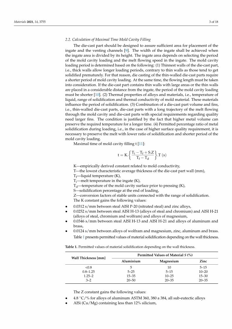
The die-cast part should be designed to assure sufficient area for placement of theingate and the venting channels [9]. The width of the ingate shall be achieved whenthe ingate area is divided by its height. The ingate area depends on selecting the periodof the mold cavity loading and the melt flowing speed in the ingate. The mold cavityloading period is determined based on the following: (1) Thinnest walls of the die-cast part,i.e., thick walls allow longer loading periods, contrary to thin walls as those tend to getsolidified prematurely. For that reason, die casting of the thin-walled die-cast parts requirea shorter period of mold cavity loading. At the same time, the flowing length must be takeninto consideration. If the die-cast part contains thin walls with large areas or the thin wallsare placed in a considerable distance from the ingate, the period of the mold cavity loadingmust be shorter [10]. (2) Thermal properties of alloys and materials, i.e., temperature ofliquid, range of solidification and thermal conductivity of mold material. These materialsinfluence the period of solidification. (3) Combination of a die-cast part volume and fins,i.e., thin-walled die-cast parts, die-cast parts with a long trajectory of the melt flowingthrough the mold cavity and die-cast parts with special requirements regarding qualityneed larger fins. The condition is justified by the fact that higher metal volume canpreserve the required temperature for a longer time. (4) Permitted percentage ratio of metalsolidification during loading, i.e., in the case of higher surface quality requirement, it isnecessary to preserve the melt with lower ratio of solidification and shorter period of themold cavity loading.
Maximal time of mold cavity filling t [11]:
t = K.{
Ti − Tf + S.ZTf − Td
}.T (s)
K—empirically derived constant related to mold conductivity,T—the lowest characteristic average thickness of the die-cast part wall (mm),Tf—liquid temperature (K),Ti—melt temperature in the ingate (K),Td—temperature of the mold cavity surface prior to pressing (K),S—solidification percentage at the end of loading,Z—conversion factors of stable units connected with the range of solidification.The K constant gains the following values:
• 0.0312 s/mm between steal AISI P-20 (nitrated steal) and zinc alloys,• 0.0252 s/mm between steal AISI H-13 (alloys of steal and chromium) and AISI H-21
(alloys of steal, chromium and wolfram) and alloys of magnesium,• 0.0346 s/mm between steal AISI H-13 and AISI H-21 and alloys of aluminum and
brass,• 0.0124 s/mm between alloys of wolfram and magnesium, zinc, aluminum and brass.
Table 1 presents permitted values of material solidification depending on the wall thickness.
Table 1. Permitted values of material solidification depending on the wall thickness.
Wall Thickness [mm]Permitted Values of Material S (%)
Aluminium Magnesium Zinc
<0.8 5 10 5–150.8–1.25 5–25 5–15 10–201.25–2 15–35 10–25 15–30
3–2 20–50 20–35 20–35
The Z constant gains the following values:
• 4.8 ◦C/% for alloys of aluminum ASTM 360, 380 a 384, all sub-eutectic alloys• AlSi (Cu/Mg) containing less than 12% silicium,

Materials 2021, 14, 3755 4 of 18
• 5.9 ◦C/% for alloys of aluminum ASTM 390, supra-eutectic alloys AlSi (Cu/Mg),• 3.7 ◦C/% for magnesium alloys,• 3.2 ◦C/% for zinc alloys,• 4.7 ◦C/% for brass [12].
2.3. Calculation of Flowing Speed of the Melt in the Ingate
The flowing speed of the molten metal in the ingate influences the mechanical prop-erties of the die-cast part and the quality of its surface. New high-pressure die castingmachines can generate a speed of up to 100 m·s−1, yet degradation of the mold commencesat approximately 40 m·s−1. Thus, choosing the speed within the range from 40 up to100 m·s−1 is rather impractical. Porosity caused by the bonding of gas in the die-cast partvolume can be decreased without extreme increase of speed by designing the gating systemand ingate so that avoidance of shocks and consequent reversible flowing and mixing of themelt is assured. Flowing of the melt through the gating system must be continuous. The re-versible flowing effort can be made when the trajectory of melt flowing contains lugs, sharpdirection changes or incorrectly reduced diameters [13]. Table 2 presents recommendedvalues of the flowing speed of the melt in the ingate.
Table 2. Recommended values of the flowing speed of the melt in the ingate.
Type of AlloyRecommended Values of the Flowing Speed of the Melt in
the Ingate (m·s−1)
Standard Casting Vacuum Casting
Aluminium 20–60 15–30Zinc 30–50
Magnesium 40–60Copper 20–50
The flowing speed of the melt in the ingate v1 can be determined according to thefollowing formula:
v1 =mc
p.t.dch.0.785
(m.s−1
)mc—the weight of cast (kg),p—density of alloy (kg·m−3),dch—diameter of filling chamber (m).
2.4. Determination of the Flow Volume
The flow serves as a heat accumulator and as a tank of low-quality oxidized metal.The flows are necessary for thin walls of the die-cast part or if the die-cast part must getsolidified at a higher temperature [14]. An example is the circumfusing of the cores placedat a considerable distance from the ingate. The melt flows around the core through narrowwalls from both directions, and adequate temperature must be assured to achieve a unifiedand firmly joined bond. Table 3 presents recommended flow volumes for conventional diecasting machines depending on the lowest thickness of the wall.
Table 3. Recommended volumes of flow.
Characteristic Wall Thickness ofa Gate Segment (mm)
Flow Volume, Percentage Ratio Out of Segment Volume
For High Surface Quality For Lower Surface Quality
0.90 150% 75%1.30 100% 50%1.80 50% 25%2.50 25% 25%3.20 - -
Materials 2021, 14, 3755 5 of 18
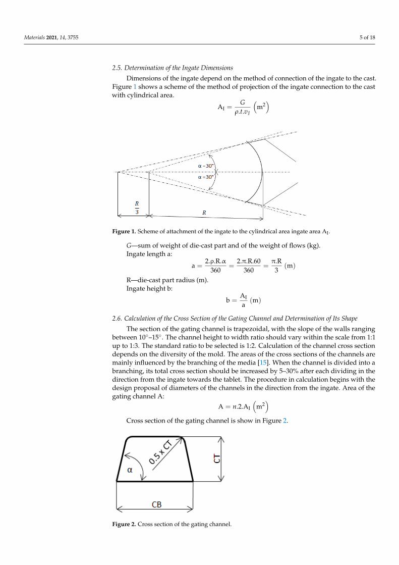
2.5. Determination of the Ingate Dimensions
Dimensions of the ingate depend on the method of connection of the ingate to the cast.Figure 1 shows a scheme of the method of projection of the ingate connection to the castwith cylindrical area.
AI =G
ρ.t.vI
(m2)
Materials 2021, 14, x FOR PEER REVIEW 5 of 18
walls from both directions, and adequate temperature must be assured to achieve a uni-fied and firmly joined bond. Table 3 presents recommended flow volumes for conven-tional die casting machines depending on the lowest thickness of the wall.
Table 3. Recommended volumes of flow.
Characteristic Wall Thickness of a Gate Segment (mm)
Flow Volume, Percentage Ratio out of Segment Volume
For High Surface Quality
For Lower Surface Quality
0.90 150% 75% 1.30 100% 50% 1.80 50% 25% 2.50 25% 25% 3.20 - -
2.5. Determination of the Ingate Dimensions Dimensions of the ingate depend on the method of connection of the ingate to the
cast. Figure 1 shows a scheme of the method of projection of the ingate connection to the cast with cylindrical area.
Figure 1. Scheme of attachment of the ingate to the cylindrical area ingate area AI.
퐴 =퐺
휌. 푡. 푣 [푚 ]
G—sum of weight of die-cast part and of the weight of flows (kg). Ingate length a:
a =2. ρ. R. α
360 =2. π. R. 60
360 =π. R
3 [m]
R—die-cast part radius (m). Ingate height b:
푏 = 퐴푎 (푚)
2.6. Calculation of the Cross Section of the Gating Channel and Determination of Its Shape The section of the gating channel is trapezoidal, with the slope of the walls ranging
between 10°–15°. The channel height to width ratio should vary within the scale from 1:1 up to 1:3. The standard ratio to be selected is 1:2. Calculation of the channel cross section depends on the diversity of the mold. The areas of the cross sections of the channels are
Figure 1. Scheme of attachment of the ingate to the cylindrical area ingate area AI.
G—sum of weight of die-cast part and of the weight of flows (kg).Ingate length a:
a =2.ρ.R.α
360=
2.π.R.60360
=π.R
3(m)
R—die-cast part radius (m).Ingate height b:
b =AI
a(m)
2.6. Calculation of the Cross Section of the Gating Channel and Determination of Its Shape
The section of the gating channel is trapezoidal, with the slope of the walls rangingbetween 10◦–15◦. The channel height to width ratio should vary within the scale from 1:1up to 1:3. The standard ratio to be selected is 1:2. Calculation of the channel cross sectiondepends on the diversity of the mold. The areas of the cross sections of the channels aremainly influenced by the branching of the media [15]. When the channel is divided into abranching, its total cross section should be increased by 5–30% after each dividing in thedirection from the ingate towards the tablet. The procedure in calculation begins with thedesign proposal of diameters of the channels in the direction from the ingate. Area of thegating channel A:
A = n.2.AI
(m2)
Cross section of the gating channel is show in Figure 2.
1
Figure 2. Cross section of the gating channel.
Materials 2021, 14, 3755 6 of 18
Height of the gating channel CT:
A = CB.CT − CT2.tg(90◦ − α) = 2.CT2 − CT2.tg(90◦ − α)
CT =
√A
2 − tg(90◦ − α)(m)
α—angle of wall inclination of the gating channel [◦].Width of the gating channel CB:
CB = 2.CT (m)
3. Materials and Methods3.1. Characteristic of Monitored Parameters
From the point of view of the influence of the structure of the gating system of diecasting mold upon the die-cast part quality, the most significant parameters affect theloading mode of the die casting mold cavity and type of the melt flowing through thegating channels. These can be considered as follows: Cross section of the ingate andmolding of the die-cast part inside the mold cavity regarding the placement of the cores inthe mold shaping cavity. Molding of the die-cast part and placement of the cores influencethe qualitative properties of the die-cast part. It is necessary to ensure such placementof the cores so that the flow of the melt passing through the mold shaping cavity avoidsdirect hitting of the cores. Formation of contractions, cold laps or weld lines would beeliminated [16]. Both the sectional area of the channels, which is in the analytical designfrequently represented by the medium width of the gating channel, and its shape influencethe flowing in the gating channels and the melt flowing speed in the gating channel. Firstly,the cross section of the ingate depends on the shape of the mold cavity and on the ingateheight. In the ingate the cross section becomes smaller by which the speed of the meltjet increases. Consequently, the mold shaping cavity is loaded under the melt. The ratiobetween the areas of the ingate and of the die-cast part is determined by the loading modeof mold shaping cavity. According to the methodology of the ingate structure described,the ingate width is constant, in our case a=60.968 mm, for the formation of the gatingchannel surface; the values of the gating channel height were determined as follows [17,18]:
b1 = 1.25 mm,b2 = 1.03 mm,b3 = 0.92 mm,b4 = 0.82 mm,b5 = 0.75 mm.Lower and upper values of the ingate height were determined by means of simulation
program NovaFlow&Solid through the module NovaShot, which determined maximal andminimal gating channel height for particular die-cast parts. Other values were determinedto provide diverse loading modes of the mold shaping cavity [19,20].
3.2. Structural Design of the Gating System
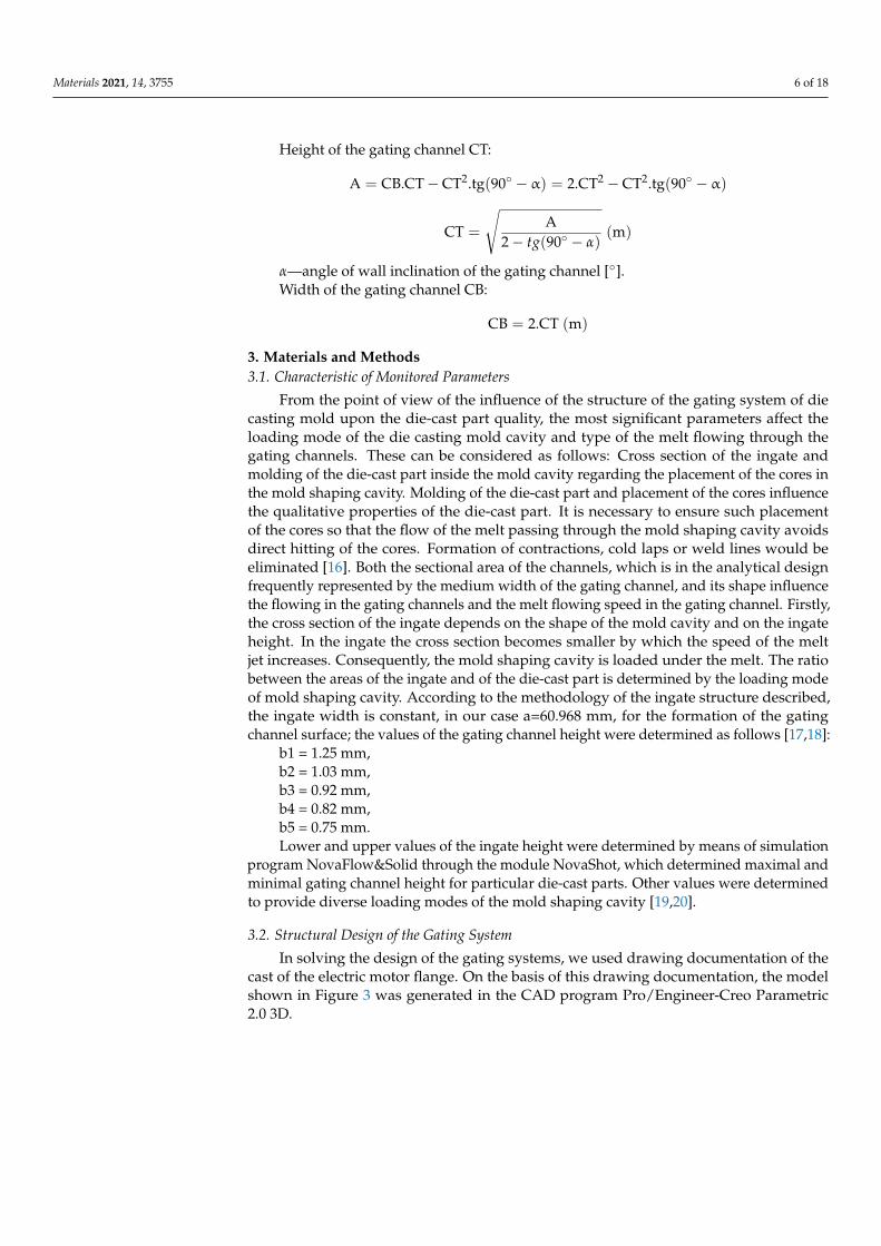
In solving the design of the gating systems, we used drawing documentation of thecast of the electric motor flange. On the basis of this drawing documentation, the modelshown in Figure 3 was generated in the CAD program Pro/Engineer-Creo Parametric2.0 3D.
Materials 2021, 14, 3755 7 of 18
Materials 2021, 14, x FOR PEER REVIEW 7 of 18
b3 = 0.92 mm, b4 = 0.82 mm, b5 = 0.75 mm. Lower and upper values of the ingate height were determined by means of simula-
tion program NovaFlow&Solid through the module NovaShot, which determined maxi-mal and minimal gating channel height for particular die-cast parts. Other values were determined to provide diverse loading modes of the mold shaping cavity [19,20].
3.2. Structural Design of the Gating System In solving the design of the gating systems, we used drawing documentation of the
cast of the electric motor flange. On the basis of this drawing documentation, the model shown in Figure 3 was generated in the CAD program Pro/Engineer-Creo Parametric 2.0 3D.
Figure 3. 3D model of electric motor flange.
By utilizing the respective modules in the program, the cast volume was determined, and based on the density of alloy which shall be used for casting, the cast weight was calculated. According to the weight and volume characteristics presented in Table 4, the calculation of the dimensional factors of the mold gating system was realized [21].
Table 4. Weight and volume characteristic of die-cast part.
Quantity Value Alloy EN AC 47100—AlSi12Cu(Fe)
Die-cast part volume 51 697.9 × 10⁻⁹ m3
Alloy density 2 650 kg·m−3
Die-cast part weight 0.136 kg
3.3. Structural Design of the Gating Channels and the Ingate Before we designed the gating system, it was necessary to consider the limits, ensur-
ing the type of the die casting machine, from the mold size to the shaping liners [17]. Di-mensions of the gating system are presented in Table 5. The shape of the channels, place-ment of the shaping cavities and the cast molding methods in the mold are shown by the 3D model of the gating system designed using the numerical solution in Figure 4.
Figure 3. 3D model of electric motor flange.
By utilizing the respective modules in the program, the cast volume was determined,and based on the density of alloy which shall be used for casting, the cast weight wascalculated. According to the weight and volume characteristics presented in Table 4, thecalculation of the dimensional factors of the mold gating system was realized [21].
Table 4. Weight and volume characteristic of die-cast part.
Quantity Value
Alloy EN AC 47100—AlSi12Cu(Fe)Die-cast part volume 51,697.9 × 10−9 m3
Alloy density 2650 kg·m−3
Die-cast part weight 0.136 kg
3.3. Structural Design of the Gating Channels and the Ingate
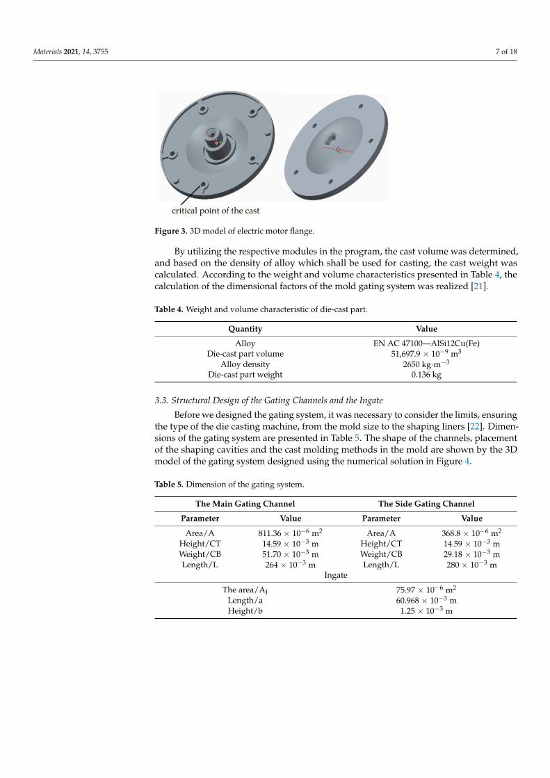
Before we designed the gating system, it was necessary to consider the limits, ensuringthe type of the die casting machine, from the mold size to the shaping liners [22]. Dimen-sions of the gating system are presented in Table 5. The shape of the channels, placementof the shaping cavities and the cast molding methods in the mold are shown by the 3Dmodel of the gating system designed using the numerical solution in Figure 4.
Table 5. Dimension of the gating system.
The Main Gating Channel The Side Gating Channel
Parameter Value Parameter Value
Area/A 811.36 × 10⁻⁶ m2 Area/A 368.8 × 10⁻⁶ m2
Height/CT 14.59 × 10⁻³ m Height/CT 14.59 × 10⁻³ mWeight/CB 51.70 × 10⁻³ m Weight/CB 29.18 × 10⁻³ mLength/L 264 × 10−3 m Length/L 280 × 10−3 m
Ingate
The area/AI 75.97 × 10⁻⁶ m2
Length/a 60.968 × 10⁻³ mHeight/b 1.25 × 10⁻³ m
Materials 2021, 14, 3755 8 of 18Materials 2021, 14, x FOR PEER REVIEW 8 of 18
Figure 4. 3D model of designed gating system.
Table 5. Dimension of the gating system.
The Main Gating Channel The Side Gating Channel Parameter Value Parameter Value
Area/A 811.36 × 10⁻⁶ m2 Area/A 368.8 × 10⁻⁶ m2
Height/CT 14.59 × 10⁻³ m Height/CT 14.59 × 10⁻³ m Weight/CB 51.70 × 10⁻³ m Weight/CB 29.18 × 10⁻³ m
Length/l 264 × 10−3 m Length/l 280 × 10−3 m Ingate
The area/AI 75.97 × 10⁻⁶ m2
Length/a 60.968 × 10⁻³ m Height/b 1.25 × 10⁻³ m
3.4. Cast Forming The method of the cast forming in the mold represents a significant aspect of the
design part of the gating system structure. For the respective gating systems, two variants of forming were proposed. Figure 5 shows the cast in the case where the melt jet is directed through the ingate so that it avoids hitting the cores, determining the structural holes of the model. The variant shown in Figure 6 represents the case in which the melt jet is directed right towards the core. The formation of the melt jet passing through the mold shaping cavity allows the elimination of defects occurring due to incorrect forming during the designing phase [22].
Figure 5. The melt jet is outside the core.
Figure 4. 3D model of designed gating system.
3.4. Cast Forming
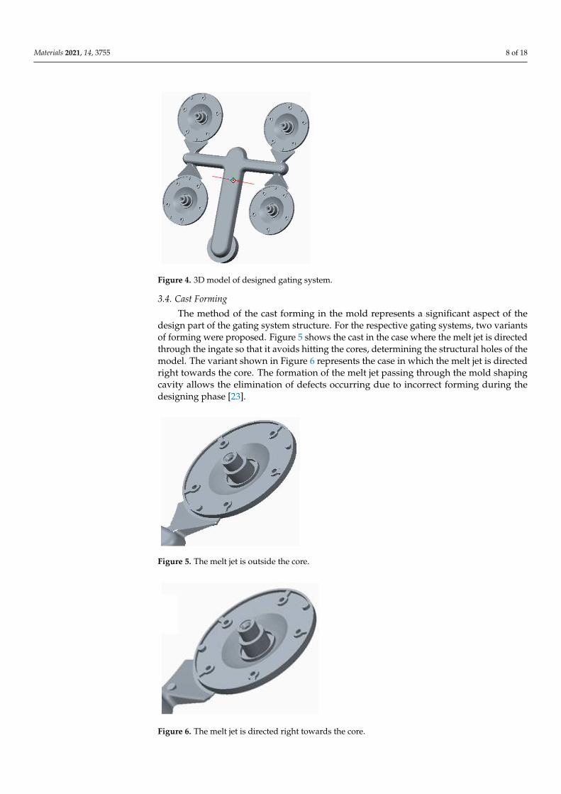
The method of the cast forming in the mold represents a significant aspect of thedesign part of the gating system structure. For the respective gating systems, two variantsof forming were proposed. Figure 5 shows the cast in the case where the melt jet is directedthrough the ingate so that it avoids hitting the cores, determining the structural holes of themodel. The variant shown in Figure 6 represents the case in which the melt jet is directedright towards the core. The formation of the melt jet passing through the mold shapingcavity allows the elimination of defects occurring due to incorrect forming during thedesigning phase [23].
Materials 2021, 14, x FOR PEER REVIEW 8 of 18
Figure 4. 3D model of designed gating system.
Table 5. Dimension of the gating system.
The Main Gating Channel The Side Gating Channel Parameter Value Parameter Value
Area/A 811.36 × 10⁻⁶ m2 Area/A 368.8 × 10⁻⁶ m2
Height/CT 14.59 × 10⁻³ m Height/CT 14.59 × 10⁻³ m Weight/CB 51.70 × 10⁻³ m Weight/CB 29.18 × 10⁻³ m
Length/l 264 × 10−3 m Length/l 280 × 10−3 m Ingate
The area/AI 75.97 × 10⁻⁶ m2
Length/a 60.968 × 10⁻³ m Height/b 1.25 × 10⁻³ m
3.4. Cast Forming The method of the cast forming in the mold represents a significant aspect of the
design part of the gating system structure. For the respective gating systems, two variants of forming were proposed. Figure 5 shows the cast in the case where the melt jet is directed through the ingate so that it avoids hitting the cores, determining the structural holes of the model. The variant shown in Figure 6 represents the case in which the melt jet is directed right towards the core. The formation of the melt jet passing through the mold shaping cavity allows the elimination of defects occurring due to incorrect forming during the designing phase [22].
Figure 5. The melt jet is outside the core. Figure 5. The melt jet is outside the core.
Materials 2021, 14, x FOR PEER REVIEW 9 of 18
Figure 6. The melt jet is directed right towards the core.
4. Results 4.1. Simulation Test of the Cast Forming
During simulation, the development of the melt jet formation was observed in the mold shaping cavity. In the case of the variant with the melt jet directed off the cores, the jet remained compact and followed its direction as spinning of the melt and consequent closure of gases and air in the melt volume was avoided [23]. The shape and formation of the melt jet are shown in Figure 7. The hitting of the melt jet against the core resulted in splitting the melt jet into two independent flows, as shown in Figure 8.
Figure 7. Formation of the melt jet outside the cores.
Figure 8. Formation of the melt jet when hitting against the core.
In gradual loading of the mold shaping cavity, the two partially solidified melt jets are joined behind the core, leading to imperfect joining in the cast volume, the occurrence of shrinks and the formation of cold laps and weld lines. Due to the facts mentioned above, directing the melt jet without hitting the cores appears more advantageous. Figure 9 shows the distribution of defects occurring in the cast body in the case where the melt jet hit the core [3,24].
Figure 6. The melt jet is directed right towards the core.

Materials 2021, 14, 3755 9 of 18
4. Results4.1. Simulation Test of the Cast Forming
During simulation, the development of the melt jet formation was observed in themold shaping cavity. In the case of the variant with the melt jet directed off the cores, thejet remained compact and followed its direction as spinning of the melt and consequentclosure of gases and air in the melt volume was avoided [24]. The shape and formation ofthe melt jet are shown in Figure 7. The hitting of the melt jet against the core resulted insplitting the melt jet into two independent flows, as shown in Figure 8.
Materials 2021, 14, x FOR PEER REVIEW 9 of 18
Figure 6. The melt jet is directed right towards the core.
4. Results 4.1. Simulation Test of the Cast Forming
During simulation, the development of the melt jet formation was observed in the mold shaping cavity. In the case of the variant with the melt jet directed off the cores, the jet remained compact and followed its direction as spinning of the melt and consequent closure of gases and air in the melt volume was avoided [23]. The shape and formation of the melt jet are shown in Figure 7. The hitting of the melt jet against the core resulted in splitting the melt jet into two independent flows, as shown in Figure 8.
Figure 7. Formation of the melt jet outside the cores.
Figure 8. Formation of the melt jet when hitting against the core.
In gradual loading of the mold shaping cavity, the two partially solidified melt jets are joined behind the core, leading to imperfect joining in the cast volume, the occurrence of shrinks and the formation of cold laps and weld lines. Due to the facts mentioned above, directing the melt jet without hitting the cores appears more advantageous. Figure 9 shows the distribution of defects occurring in the cast body in the case where the melt jet hit the core [3,24].
Figure 7. Formation of the melt jet outside the cores.
Materials 2021, 14, x FOR PEER REVIEW 9 of 18
Figure 6. The melt jet is directed right towards the core.
4. Results 4.1. Simulation Test of the Cast Forming
During simulation, the development of the melt jet formation was observed in the mold shaping cavity. In the case of the variant with the melt jet directed off the cores, the jet remained compact and followed its direction as spinning of the melt and consequent closure of gases and air in the melt volume was avoided [23]. The shape and formation of the melt jet are shown in Figure 7. The hitting of the melt jet against the core resulted in splitting the melt jet into two independent flows, as shown in Figure 8.
Figure 7. Formation of the melt jet outside the cores.
Figure 8. Formation of the melt jet when hitting against the core.
In gradual loading of the mold shaping cavity, the two partially solidified melt jets are joined behind the core, leading to imperfect joining in the cast volume, the occurrence of shrinks and the formation of cold laps and weld lines. Due to the facts mentioned above, directing the melt jet without hitting the cores appears more advantageous. Figure 9 shows the distribution of defects occurring in the cast body in the case where the melt jet hit the core [3,24].
Figure 8. Formation of the melt jet when hitting against the core.
In gradual loading of the mold shaping cavity, the two partially solidified melt jets arejoined behind the core, leading to imperfect joining in the cast volume, the occurrence ofshrinks and the formation of cold laps and weld lines. Due to the facts mentioned above,directing the melt jet without hitting the cores appears more advantageous. Figure 9 showsthe distribution of defects occurring in the cast body in the case where the melt jet hit thecore [3,25].
Materials 2021, 14, x FOR PEER REVIEW 10 of 18
Figure 9. Distribution of defects for incorrect of cast forming—contractions 2.8%.
4.2. Simulation Test of Suitability of the Selected Structural Design The 3D model of the gating system, which was subjected to simulation tests, focused
on verification of suitability of the selected structural design. The simulations were performed with the NovaFlow&Solid program. In the simulation, the observed determining parameter of the design suitability was the ratio of shrinks in the cast body and the gating channels after solidification. Figure 10 shows a simulation of the gating system and distribution of defects after completion of the casting cycle [25].
Figure 10. Distribution of defects in gating system—contractions 5.4%.
The simulation and visual representation proved that the numerical design proposal of the gating system was not suitable. The shrinks in the cast body represented 5.4% of the total design. The simulation analysis detected that the formation of the shrinks begins at a time of t = 0.042 s. At this time, the mold shaping cavity is 100% loaded, and the influence of the resistance pressure, which eliminates the formation of shrinks, should be visible. However, such situations, as well as the resistance phase, are absent. To clarify the state, it was necessary to focus on the narrowest spot of the gating system represented by the ingate. Examination of the temperature development proved that right at the time of t = 0.042 s, the melt temperature in the ingate drops below the value of melting (Figure 11), the ingate solidifies and prevents resistance pressure from influencing the mold shaping cavity. One of the causes of the state is the structure of the channels. There exists a pre-sumption that the main and the side gating channels dispose of considerably large areas in the cross section. The melt loses pressure and speed, resulting in premature cooling and thus solidifying the ingate. Resistance pressure loses its effect and can be observed as shrinks due to material shrinkage when transiting from the liquid to the solid state [26].
Figure 9. Distribution of defects for incorrect of cast forming—contractions 2.8%.
Materials 2021, 14, 3755 10 of 18
4.2. Simulation Test of Suitability of the Selected Structural Design
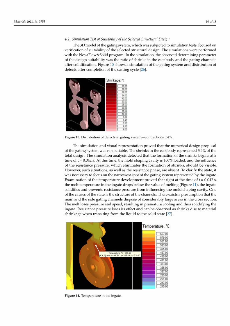
The 3D model of the gating system, which was subjected to simulation tests, focused onverification of suitability of the selected structural design. The simulations were performedwith the NovaFlow&Solid program. In the simulation, the observed determining parameterof the design suitability was the ratio of shrinks in the cast body and the gating channelsafter solidification. Figure 10 shows a simulation of the gating system and distribution ofdefects after completion of the casting cycle [26].
Materials 2021, 14, x FOR PEER REVIEW 10 of 18
Figure 9. Distribution of defects for incorrect of cast forming—contractions 2.8%.
4.2. Simulation Test of Suitability of the Selected Structural Design The 3D model of the gating system, which was subjected to simulation tests, focused
on verification of suitability of the selected structural design. The simulations were performed with the NovaFlow&Solid program. In the simulation, the observed determining parameter of the design suitability was the ratio of shrinks in the cast body and the gating channels after solidification. Figure 10 shows a simulation of the gating system and distribution of defects after completion of the casting cycle [25].
Figure 10. Distribution of defects in gating system—contractions 5.4%.
The simulation and visual representation proved that the numerical design proposal of the gating system was not suitable. The shrinks in the cast body represented 5.4% of the total design. The simulation analysis detected that the formation of the shrinks begins at a time of t = 0.042 s. At this time, the mold shaping cavity is 100% loaded, and the influence of the resistance pressure, which eliminates the formation of shrinks, should be visible. However, such situations, as well as the resistance phase, are absent. To clarify the state, it was necessary to focus on the narrowest spot of the gating system represented by the ingate. Examination of the temperature development proved that right at the time of t = 0.042 s, the melt temperature in the ingate drops below the value of melting (Figure 11), the ingate solidifies and prevents resistance pressure from influencing the mold shaping cavity. One of the causes of the state is the structure of the channels. There exists a pre-sumption that the main and the side gating channels dispose of considerably large areas in the cross section. The melt loses pressure and speed, resulting in premature cooling and thus solidifying the ingate. Resistance pressure loses its effect and can be observed as shrinks due to material shrinkage when transiting from the liquid to the solid state [26].
Figure 10. Distribution of defects in gating system—contractions 5.4%.
The simulation and visual representation proved that the numerical design proposalof the gating system was not suitable. The shrinks in the cast body represented 5.4% of thetotal design. The simulation analysis detected that the formation of the shrinks begins at atime of t = 0.042 s. At this time, the mold shaping cavity is 100% loaded, and the influenceof the resistance pressure, which eliminates the formation of shrinks, should be visible.However, such situations, as well as the resistance phase, are absent. To clarify the state, itwas necessary to focus on the narrowest spot of the gating system represented by the ingate.Examination of the temperature development proved that right at the time of t = 0.042 s,the melt temperature in the ingate drops below the value of melting (Figure 11), the ingatesolidifies and prevents resistance pressure from influencing the mold shaping cavity. Oneof the causes of the state is the structure of the channels. There exists a presumption that themain and the side gating channels dispose of considerably large areas in the cross section.The melt loses pressure and speed, resulting in premature cooling and thus solidifying theingate. Resistance pressure loses its effect and can be observed as shrinks due to materialshrinkage when transiting from the liquid to the solid state [27].
Materials 2021, 14, x FOR PEER REVIEW 11 of 18
Figure 11. Temperature in the ingate.
4.3. Adjustment of Structural Design 4.3.1. Adjustment of Structural Design of the Gating Channels
Diminishing the areas of sections of the gating channels with the preservation of technological parameters shall increase the speed of melt flow and mold shaping cavity loading within a shorter period. With the parameters mentioned above, the premature solidification of the ingate shall be avoided. The shape of the gating system, as well as the method of cast molding, remained alike. The most suitable dimensions of the gating channels are presented in Table 6.
Table 6. Adjusted dimensions of gating channels.
The Main Gating Channel The Side Gating Channels Parameter Value Parameter Value
Area/A 497.5 × 10⁻⁶ m2 Area/A 242.19 × 10⁻⁶ m2
Height/CT 14.59 × 10⁻³ m Height/CT 14.59 × 10⁻³ m Weight/CB 38.0 × 10⁻³ m Weight/CB 20.5 × 10⁻³ m
Length/l 264 × 10−3 m Length/l 280 × 10−3 m
The adjustment of gating channels resulted in diminishing the area of the main chan-nels by 38.68% and of the side channels by 34.33%. The weight of the overall gating system was decreased by 10.58%.
4.3.2. Simulation Test of the Adjusted Structural Design Simulation tests of the adjusted structural design proved the prediction that
diminishing the section of the gating channels results in faster loading of the mold shaping cavity. The possibility of premature solidification of the melt in the ingate is eliminated. Figure 12 shows simulation of the gating system after completion of the casting cycle. The visual illustration does not show any visible defects regarding the compactness of the cast [27,28].
Figure 11. Temperature in the ingate.

Materials 2021, 14, 3755 11 of 18
4.3. Adjustment of Structural Design4.3.1. Adjustment of Structural Design of the Gating Channels
Diminishing the areas of sections of the gating channels with the preservation oftechnological parameters shall increase the speed of melt flow and mold shaping cavityloading within a shorter period. With the parameters mentioned above, the prematuresolidification of the ingate shall be avoided. The shape of the gating system, as well asthe method of cast molding, remained alike. The most suitable dimensions of the gatingchannels are presented in Table 6.
Table 6. Adjusted dimensions of gating channels.
The Main Gating Channel The Side Gating Channels
Parameter Value Parameter Value
Area/A 497.5 × 10⁻⁶ m2 Area/A 242.19 × 10⁻⁶ m2
Height/CT 14.59 × 10⁻³ m Height/CT 14.59 × 10⁻³ mWeight/CB 38.0 × 10⁻³ m Weight/CB 20.5 × 10⁻³ mLength/L 264 × 10−3 m Length/L 280 × 10−3 m
The adjustment of gating channels resulted in diminishing the area of the mainchannels by 38.68% and of the side channels by 34.33%. The weight of the overall gatingsystem was decreased by 10.58%.
4.3.2. Simulation Test of the Adjusted Structural Design
Simulation tests of the adjusted structural design proved the prediction that diminish-ing the section of the gating channels results in faster loading of the mold shaping cavity.The possibility of premature solidification of the melt in the ingate is eliminated. Figure 12shows simulation of the gating system after completion of the casting cycle. The visualillustration does not show any visible defects regarding the compactness of the cast [28,29].
Materials 2021, 14, x FOR PEER REVIEW 12 of 18
Figure 12. Distribution of defects in adjusted gating system—contractions 0%.
4.4. Analysis of Mechanical Properties In designing and in the internal operation of the product, it is necessary to know the
material properties that do not refer only to the chemical composition of material but also to its inner structure, mechanical properties and mutual relationships among the proper-ties. The acquired knowledge allows assessing behaviour of the individual materials in operation when being stressed and consequently to specify data and documents for di-mensioning. In the case examined in the paper, the pressure tests were performed after assessment of selected specific and mechanical properties of die-cast part was performed. The assessed properties included the value of permanent deformation “s” and the surface hardness according to Brinell “HB” of the die-cast part.
4.4.1. Chemical Composition of Experimental Meltage Experimental samples (flange of the alternator) have been cast using aluminium alloy
EN AC 47100, whose chemical composition is given in Table 7 according to the EN 1706 standard.
Table 7. Chemical composition of experimental meltage of used alloy % content of elements.
Chemical Composition of the Experimental Cast of the Applied Alloy % of Elements Content Al Si Fe Cu Mn Mg Cr Ni Zn Pb Sn Ti
85.50 11.82 0.76 1.03 0.27 0.18 0.03 0.12 0.30 0.03 0.03 0.03
4.4.2. Analysis of Permanent Deformation Tests of permanent deformation were performed with testing machine TIRAtest
28,200 (TIRA GmbH, Shalkau, Shalkau, Germany). Deformation was examined in the case of a particular critical place of the die-cast part (Figure 3). According to the assessment of the theoretical basis of the hydrodynamics of the liquid melt flow when bypassing the cores, the place was considered to be a critical one. The measurement was performed in compliance with the GME 06 007 and GME 60 156 standards. The GME 06 007 standard describes the experimental procedure during test performance and the GME 60 156 stand-ard describes the method of assessment of the test of permanent deformation. According to the prescribed values related to the standard, the permanent deformation reaches the value of 0.150 mm. Table 8 presents the importance of permanent deformation concerning the change of the ingate height. Figure 13 shows the relationship among average values of permanent deformation and modification of the ingate height.
Figure 12. Distribution of defects in adjusted gating system—contractions 0%.
4.4. Analysis of Mechanical Properties
In designing and in the internal operation of the product, it is necessary to knowthe material properties that do not refer only to the chemical composition of materialbut also to its inner structure, mechanical properties and mutual relationships among theproperties. The acquired knowledge allows assessing behaviour of the individual materialsin operation when being stressed and consequently to specify data and documents fordimensioning. In the case examined in the paper, the pressure tests were performed afterassessment of selected specific and mechanical properties of die-cast part was performed.
Materials 2021, 14, 3755 12 of 18
The assessed properties included the value of permanent deformation “s” and the surfacehardness according to Brinell “HB” of the die-cast part.
4.4.1. Chemical Composition of Experimental Meltage
Experimental samples (flange of the alternator) have been cast using aluminiumalloy EN AC 47100, whose chemical composition is given in Table 7 according to the EN1706 standard.
Table 7. Chemical composition of experimental meltage of used alloy % content of elements.
Chemical Composition of the Experimental Cast of the Applied Alloy % of Elements Content
Al Si Fe Cu Mn Mg Cr Ni Zn Pb Sn Ti85.50 11.82 0.76 1.03 0.27 0.18 0.03 0.12 0.30 0.03 0.03 0.03
4.4.2. Analysis of Permanent Deformation
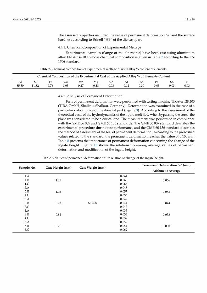
Tests of permanent deformation were performed with testing machine TIRAtest 28,200(TIRA GmbH, Shalkau, Shalkau, Germany). Deformation was examined in the case of aparticular critical place of the die-cast part (Figure 3). According to the assessment of thetheoretical basis of the hydrodynamics of the liquid melt flow when bypassing the cores, theplace was considered to be a critical one. The measurement was performed in compliancewith the GME 06 007 and GME 60 156 standards. The GME 06 007 standard describes theexperimental procedure during test performance and the GME 60 156 standard describesthe method of assessment of the test of permanent deformation. According to the prescribedvalues related to the standard, the permanent deformation reaches the value of 0.150 mm.Table 8 presents the importance of permanent deformation concerning the change of theingate height. Figure 13 shows the relationship among average values of permanentdeformation and modification of the ingate height.
Table 8. Values of permanent deformation “s” in relation to change of the ingate height.
Sample No. Gate Height (mm) Gate Weight (mm)Permanent Deformation “s” (mm)
Arithmetic Average
1.A1.25
60.968
0.0640.0661.B 0.068
1.C 0.0652.A
1.030.048
0.0532.B 0.0572.C 0.0553.A
0.920.042
0.0443.B 0.0443.C 0.0474.A
0.820.035
0.0334.B 0.0334.C 0.0325.A
0.750.057
0.0585.B 0.0545.C 0.062
Materials 2021, 14, 3755 13 of 18Materials 2021, 14, x FOR PEER REVIEW 13 of 18
Figure 13. Relationship between permanent deformation and change of the ingate height.
Table 8. Values of permanent deformation “s” in relation to change of the ingate height.
Sample No. Gate Height (mm) Gate Weight (mm) Permanent Deformation “s” (mm)
Arithmetic Average 1.A
1.25
60.968
0.064 0.066 1.B 0.068
1.C 0.065 2.A
1.03 0.048
0.053 2.B 0.057 2.C 0.055 3.A
0.92 0.042
0.044 3.B 0.044 3.C 0.047 4.A
0.82 0.035
0.033 4.B 0.033 4.C 0.032 5.A
0.75 0.057
0.058 5.B 0.054 5.C 0.062
4.4.3. Analysis of Hardness According to Brinell “HB“, values of hardness were measured in the case of five
places of the selected assessed samples with the change of the ingate height. The results are shown in Table 9 and graphical development can be seen in Figure 14.
Table 9. Values of the surface hardness of the die-cast part “HB” in relation to change of the ingate height.
Sample No. Gate Height (mm) Gate Weight (mm) Measurement Arithmetic
Average No. 1 No. 2 No. 3 No. 4 No. 5 1 1.25
60.968
108 HB 107 HB 108 HB 107 HB 107 HB 107 HB 2 1.03 109 HB 107 HB 106 HB 107 HB 106 HB 107 HB 3 0.92 106 HB 108 HB 107 HB 108 HB 107 HB 107 HB 4 0.82 106 HB 104 HB 107 HB 107 HB 107 HB 106 HB 5 0.75 105 HB 107 HB 105 HB 106 HB 107 HB 106 HB
Figure 13. Relationship between permanent deformation and change of the ingate height.
4.4.3. Analysis of Hardness
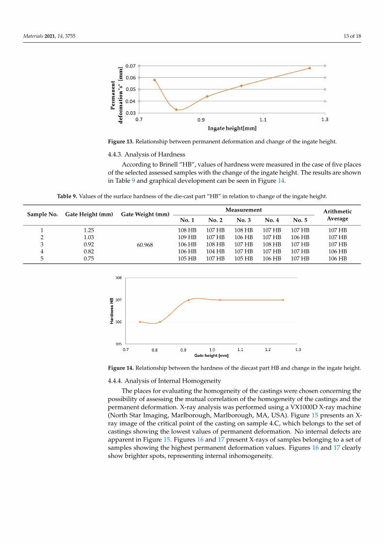
According to Brinell “HB“, values of hardness were measured in the case of five placesof the selected assessed samples with the change of the ingate height. The results are shownin Table 9 and graphical development can be seen in Figure 14.
Table 9. Values of the surface hardness of the die-cast part “HB” in relation to change of the ingate height.
Sample No. Gate Height (mm) Gate Weight (mm)Measurement Arithmetic
AverageNo. 1 No. 2 No. 3 No. 4 No. 5
1 1.25
60.968
108 HB 107 HB 108 HB 107 HB 107 HB 107 HB2 1.03 109 HB 107 HB 106 HB 107 HB 106 HB 107 HB3 0.92 106 HB 108 HB 107 HB 108 HB 107 HB 107 HB4 0.82 106 HB 104 HB 107 HB 107 HB 107 HB 106 HB5 0.75 105 HB 107 HB 105 HB 106 HB 107 HB 106 HB
Materials 2021, 14, x FOR PEER REVIEW 14 of 18
Figure 14. Relationship between the hardness of the diecast part HB and change in the ingate height.
4.4.4. Analysis of Internal Homogeneity The places for evaluating the homogeneity of the castings were chosen concerning
the possibility of assessing the mutual correlation of the homogeneity of the castings and the permanent deformation. X-ray analysis was performed using a VX1000D X-ray ma-chine (North Star Imaging, Marlborough, Marlborough, MA, USA). Figure 15 presents an X-ray image of the critical point of the casting on sample 4.C, which belongs to the set of castings showing the lowest values of permanent deformation. No internal defects are apparent in Figure 15. Figures 16 and 17 present X-rays of samples belonging to a set of samples showing the highest permanent deformation values. Figures 16 and 17 clearly show brighter spots, representing internal inhomogeneity.
Figure 15. RTG—Sample 4.C.
Figure 16. RTG—Sample 1.B.
Figure 14. Relationship between the hardness of the diecast part HB and change in the ingate height.
4.4.4. Analysis of Internal Homogeneity
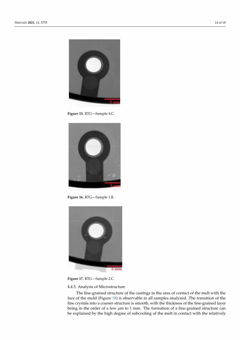
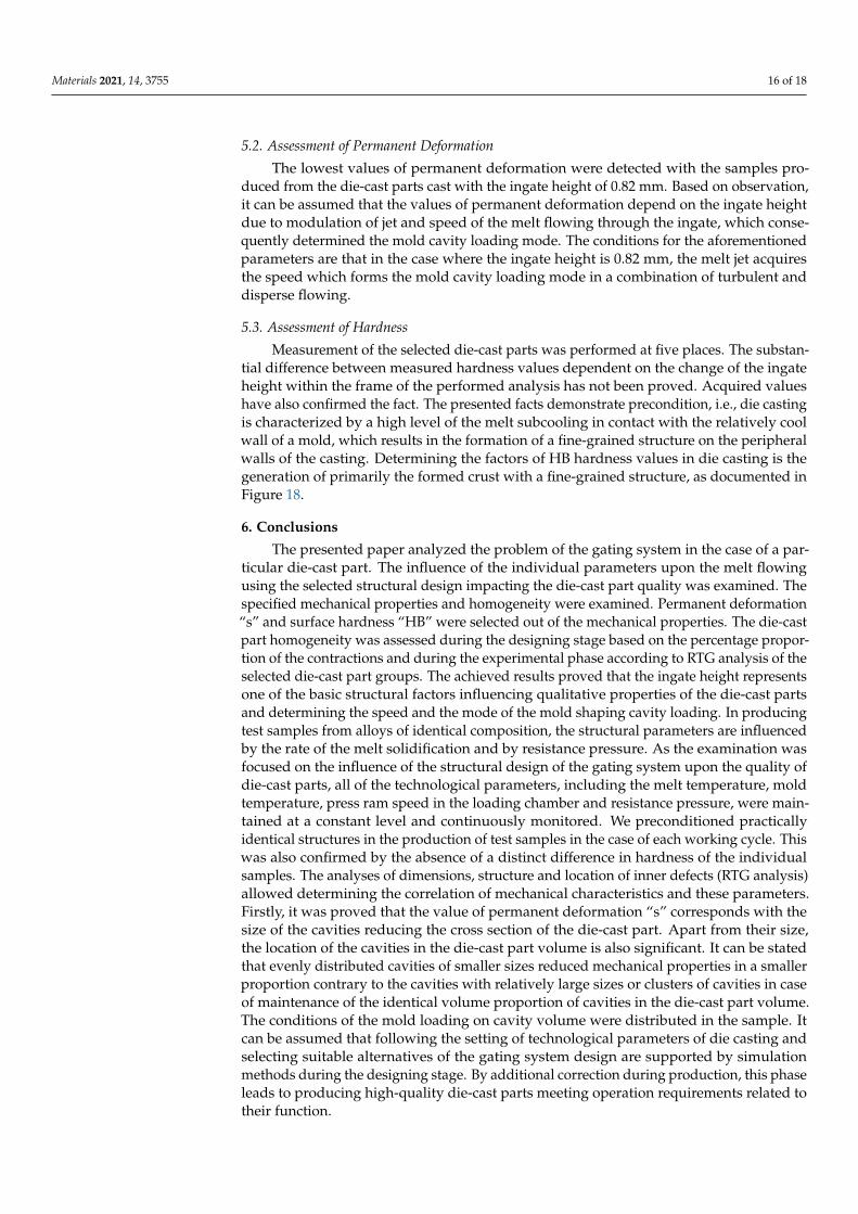
The places for evaluating the homogeneity of the castings were chosen concerning thepossibility of assessing the mutual correlation of the homogeneity of the castings and thepermanent deformation. X-ray analysis was performed using a VX1000D X-ray machine(North Star Imaging, Marlborough, Marlborough, MA, USA). Figure 15 presents an X-ray image of the critical point of the casting on sample 4.C, which belongs to the set ofcastings showing the lowest values of permanent deformation. No internal defects areapparent in Figure 15. Figures 16 and 17 present X-rays of samples belonging to a set ofsamples showing the highest permanent deformation values. Figures 16 and 17 clearlyshow brighter spots, representing internal inhomogeneity.
Materials 2021, 14, 3755 14 of 18
Materials 2021, 14, x FOR PEER REVIEW 14 of 18
Figure 14. Relationship between the hardness of the diecast part HB and change in the ingate height.
4.4.4. Analysis of Internal Homogeneity The places for evaluating the homogeneity of the castings were chosen concerning
the possibility of assessing the mutual correlation of the homogeneity of the castings and the permanent deformation. X-ray analysis was performed using a VX1000D X-ray ma-chine (North Star Imaging, Marlborough, Marlborough, MA, USA). Figure 15 presents an X-ray image of the critical point of the casting on sample 4.C, which belongs to the set of castings showing the lowest values of permanent deformation. No internal defects are apparent in Figure 15. Figures 16 and 17 present X-rays of samples belonging to a set of samples showing the highest permanent deformation values. Figures 16 and 17 clearly show brighter spots, representing internal inhomogeneity.
Figure 15. RTG—Sample 4.C.
Figure 16. RTG—Sample 1.B.
Figure 15. RTG—Sample 4.C.
Materials 2021, 14, x FOR PEER REVIEW 14 of 18
Figure 14. Relationship between the hardness of the diecast part HB and change in the ingate height.
4.4.4. Analysis of Internal Homogeneity The places for evaluating the homogeneity of the castings were chosen concerning
the possibility of assessing the mutual correlation of the homogeneity of the castings and the permanent deformation. X-ray analysis was performed using a VX1000D X-ray ma-chine (North Star Imaging, Marlborough, Marlborough, MA, USA). Figure 15 presents an X-ray image of the critical point of the casting on sample 4.C, which belongs to the set of castings showing the lowest values of permanent deformation. No internal defects are apparent in Figure 15. Figures 16 and 17 present X-rays of samples belonging to a set of samples showing the highest permanent deformation values. Figures 16 and 17 clearly show brighter spots, representing internal inhomogeneity.
Figure 15. RTG—Sample 4.C.
Figure 16. RTG—Sample 1.B. Figure 16. RTG—Sample 1.B.
Materials 2021, 14, x FOR PEER REVIEW 15 of 18
Figure 17. RTG—Sample 2.C.
4.4.5. Analysis of Microstructure The fine-grained structure of the castings in the area of contact of the melt with the
face of the mold (Figure 18) is observable in all samples analyzed. The transition of the fine crystals into a coarser structure is smooth, with the thickness of the fine-grained layer being in the order of a few μm to 1 mm. The formation of a fine-grained structure can be explained by the high degree of subcooling of the melt in contact with the relatively cold face of the mold. The degree of subcooling depends mainly on the melt temperature, the mold temperature, the method of molding the casting and the mode of filling the mold cavity.
Figure 18. Microstructure of the edge part of the casting.
5. Discussion The quality of a die-cast part is a property influenced by several factors, including
selecting the casting machine through the setting of technological parameters and suitable structure of the gating system up to its parts. The gating system must assure fast and con-tinuous mold cavity loading. This is determined by good mechanical properties and inner soundness of the die-cast part. The correct mold cavity filling was performed by simula-tion software of NovaFlow&Solid (Version 6.5) in the analytical design of the gating sys-tem after completion of structural modification of channel areas and die-cast part forming. The assessed parameter was the percentage proportion of contractions in the die-cast part volume in simulation tests. During the preparation of the submitted paper, the assessment of die-cast part quality characterized by mechanical properties was performed through a selection of representative parameters such as die-cast part hardness “HB” and permanent deformation “s” of critical place of the die-cast part with the change in the ingate height. RTG analysis and permanent deformation were performed on the basis of the anticipated mutual correlation of these parameters.
Figure 17. RTG—Sample 2.C.
4.4.5. Analysis of Microstructure
The fine-grained structure of the castings in the area of contact of the melt with theface of the mold (Figure 18) is observable in all samples analyzed. The transition of thefine crystals into a coarser structure is smooth, with the thickness of the fine-grained layerbeing in the order of a few µm to 1 mm. The formation of a fine-grained structure canbe explained by the high degree of subcooling of the melt in contact with the relatively

Materials 2021, 14, 3755 15 of 18
cold face of the mold. The degree of subcooling depends mainly on the melt temperature,the mold temperature, the method of molding the casting and the mode of filling themold cavity.
Materials 2021, 14, x FOR PEER REVIEW 15 of 18
Figure 17. RTG—Sample 2.C.
4.4.5. Analysis of Microstructure The fine-grained structure of the castings in the area of contact of the melt with the
face of the mold (Figure 18) is observable in all samples analyzed. The transition of the fine crystals into a coarser structure is smooth, with the thickness of the fine-grained layer being in the order of a few μm to 1 mm. The formation of a fine-grained structure can be explained by the high degree of subcooling of the melt in contact with the relatively cold face of the mold. The degree of subcooling depends mainly on the melt temperature, the mold temperature, the method of molding the casting and the mode of filling the mold cavity.
Figure 18. Microstructure of the edge part of the casting.
5. Discussion The quality of a die-cast part is a property influenced by several factors, including
selecting the casting machine through the setting of technological parameters and suitable structure of the gating system up to its parts. The gating system must assure fast and con-tinuous mold cavity loading. This is determined by good mechanical properties and inner soundness of the die-cast part. The correct mold cavity filling was performed by simula-tion software of NovaFlow&Solid (Version 6.5) in the analytical design of the gating sys-tem after completion of structural modification of channel areas and die-cast part forming. The assessed parameter was the percentage proportion of contractions in the die-cast part volume in simulation tests. During the preparation of the submitted paper, the assessment of die-cast part quality characterized by mechanical properties was performed through a selection of representative parameters such as die-cast part hardness “HB” and permanent deformation “s” of critical place of the die-cast part with the change in the ingate height. RTG analysis and permanent deformation were performed on the basis of the anticipated mutual correlation of these parameters.
Figure 18. Microstructure of the edge part of the casting.
5. Discussion
The quality of a die-cast part is a property influenced by several factors, includingselecting the casting machine through the setting of technological parameters and suitablestructure of the gating system up to its parts. The gating system must assure fast andcontinuous mold cavity loading. This is determined by good mechanical properties andinner soundness of the die-cast part. The correct mold cavity filling was performed bysimulation software of NovaFlow&Solid (Version 6.5) in the analytical design of the gatingsystem after completion of structural modification of channel areas and die-cast partforming. The assessed parameter was the percentage proportion of contractions in thedie-cast part volume in simulation tests. During the preparation of the submitted paper, theassessment of die-cast part quality characterized by mechanical properties was performedthrough a selection of representative parameters such as die-cast part hardness “HB” andpermanent deformation “s” of critical place of the die-cast part with the change in theingate height. RTG analysis and permanent deformation were performed on the basis ofthe anticipated mutual correlation of these parameters.
5.1. Assessment of Simulation Tests
The influence of the cast forming in the mold cavity was examined through simulationdirecting the melt jet out of the ingate directly to the core (Figure 6) and directing the meltjet off the cores (Figure 5). In an analysis of the melt jet direction, the cast was connectedto the adjusted gating system, which showed a zero percentage ratio of shrinks when themelt jet did not hit the cores directly. In the case of the melt hitting the core, the defectsshown in Figure 9 occurred behind the core and the ratio of contractions reached the valueof 2.8%. Simulation tests verified the structural design proposal of the gating system. Theratio of contractions in the cast body reached the value of 5.4%. The localization of defectsis shown in Figure 10. As demonstrated and consequently proved by the simulation,the situation was caused by a large area of the channels. The loss of speed and pressurecould be observed in the channels, resulting in slow mold cavity loading; the state ledto premature solidification of the ingate and inhibition of resistance pressure influence.By reducing the dimensions of channels, the desired mold cavity loading was achievedwithout showing any percentage ratio of shrinks. At the same time, the overall time of themold cavity loading during the period of complete cast solidification decreased from thevalue of 21.567 s to the value of 20.877 by means of which higher work efficiency can beachieved, which shall be reflected in a higher number of casting cycles per unit of time.
Materials 2021, 14, 3755 16 of 18
5.2. Assessment of Permanent Deformation
The lowest values of permanent deformation were detected with the samples pro-duced from the die-cast parts cast with the ingate height of 0.82 mm. Based on observation,it can be assumed that the values of permanent deformation depend on the ingate heightdue to modulation of jet and speed of the melt flowing through the ingate, which conse-quently determined the mold cavity loading mode. The conditions for the aforementionedparameters are that in the case where the ingate height is 0.82 mm, the melt jet acquiresthe speed which forms the mold cavity loading mode in a combination of turbulent anddisperse flowing.
5.3. Assessment of Hardness
Measurement of the selected die-cast parts was performed at five places. The substan-tial difference between measured hardness values dependent on the change of the ingateheight within the frame of the performed analysis has not been proved. Acquired valueshave also confirmed the fact. The presented facts demonstrate precondition, i.e., die castingis characterized by a high level of the melt subcooling in contact with the relatively coolwall of a mold, which results in the formation of a fine-grained structure on the peripheralwalls of the casting. Determining the factors of HB hardness values in die casting is thegeneration of primarily the formed crust with a fine-grained structure, as documented inFigure 18.
6. Conclusions
The presented paper analyzed the problem of the gating system in the case of a par-ticular die-cast part. The influence of the individual parameters upon the melt flowingusing the selected structural design impacting the die-cast part quality was examined. Thespecified mechanical properties and homogeneity were examined. Permanent deformation“s” and surface hardness “HB” were selected out of the mechanical properties. The die-castpart homogeneity was assessed during the designing stage based on the percentage propor-tion of the contractions and during the experimental phase according to RTG analysis of theselected die-cast part groups. The achieved results proved that the ingate height representsone of the basic structural factors influencing qualitative properties of the die-cast partsand determining the speed and the mode of the mold shaping cavity loading. In producingtest samples from alloys of identical composition, the structural parameters are influencedby the rate of the melt solidification and by resistance pressure. As the examination wasfocused on the influence of the structural design of the gating system upon the quality ofdie-cast parts, all of the technological parameters, including the melt temperature, moldtemperature, press ram speed in the loading chamber and resistance pressure, were main-tained at a constant level and continuously monitored. We preconditioned practicallyidentical structures in the production of test samples in the case of each working cycle. Thiswas also confirmed by the absence of a distinct difference in hardness of the individualsamples. The analyses of dimensions, structure and location of inner defects (RTG analysis)allowed determining the correlation of mechanical characteristics and these parameters.Firstly, it was proved that the value of permanent deformation “s” corresponds with thesize of the cavities reducing the cross section of the die-cast part. Apart from their size,the location of the cavities in the die-cast part volume is also significant. It can be statedthat evenly distributed cavities of smaller sizes reduced mechanical properties in a smallerproportion contrary to the cavities with relatively large sizes or clusters of cavities in caseof maintenance of the identical volume proportion of cavities in the die-cast part volume.The conditions of the mold loading on cavity volume were distributed in the sample. Itcan be assumed that following the setting of technological parameters of die casting andselecting suitable alternatives of the gating system design are supported by simulationmethods during the designing stage. By additional correction during production, this phaseleads to producing high-quality die-cast parts meeting operation requirements related totheir function.
Materials 2021, 14, 3755 17 of 18
Author Contributions: Conceptualization, J.M. and Š.G.; methodology, T.C. and Š.G.; software,D.G. and T.C.; validation, J.M., Š.G. and J.H.; formal analysis, L.K.; investigation, J.M. and Š.G.;resources, T.C.; data curation, J.P., Š.G. and D.G.; writing—original draft preparation, J.M.; writing—review and editing, Š.G. and J.H.; visualization, J.M. and T.C.; supervision, J.P. and L.K.; projectadministration, J.H.; funding acquisition, Š.G. All authors have read and agreed to the publishedversion of the manuscript.
Funding: This paper is a part of the project VEGA n. 1/0116/20—Research of Application ofStructural Topology in a Structure of New Generation of Moulds by 3D Printing Technology.
Institutional Review Board Statement: Not applicable.
Informed Consent Statement: Not applicable.
Data Availability Statement: Not applicable.
Conflicts of Interest: The authors declare no conflict of interest.
References1. Gaspar, S.; Pasko, J.; Majernik, J. Influence of Structure Adjustment of Gating System of Casting Mould upon the Quality of Die Cast, 1st
ed.; RAM–Verlag: Ludenscheid, Germany, 2017; pp. 52–55, ISBN 978-3-942303-25.2. Zhao, X.; Wang, P.; Li, T.; Zhang, B.-Y.; Wang, P.; Wang, G.-Z.; Lu, S.-Q. Gating system optimization of high pressure die
casting thin-wall AlSi10MnMg longitudinal loadbearing beam based on numerical simulation. China Foundry 2018, 15, 436–442.[CrossRef]
3. Majerník, J.; Gašpár, Š.; Husár, J.; Paško, J.; Kolínský, J. Research and Evaluation of the Influence of the Construction of the Gateand the Influence of the Piston Velocity on the Distribution of Gases into the Volume of the Casting. Materials 2021, 14, 2264.[CrossRef]
4. Choi, J.C.; Kwon, T.H.; Park, J.H.; Kim, J.H.; Kim, C.H. A Study on Development of a Die Design System for Diecasting. Int. J.Adv. Manuf. Technol. 2002, 20, 1–8. [CrossRef]
5. Kolinsky, J.; Novakova, L.; Adamec, J. Measurement of flow characteristics in a model of aneurysm by PIV and FLIF method.Manuf. Technol. 2015, 15, 861–865.
6. Kascak, J.; Baron, P.; Torok, J.; Pollak, M.; Teliskova, M. Macrostructure Digitaliyation of Roadway Surface Profiles. MM Sci. J.2019, 2019, 2839–2844. [CrossRef]
7. Korenko, M.; Bujna, M.; Foldešiova, D.; Dostál, P.; Kyselica, P. Risk Analysis at Work in Manufacturing Organization. Acta Univ.Agric. Silvic. Mendel. Brun. 2015, 63, 1493–1497. [CrossRef]
8. Bi, C.; Guo, Z.; Xiong, S. Modelling and simulation for die casting mould filling process using Cartesian cut cell approach. Int. J.Cast Met. Res. 2015, 28, 234–241. [CrossRef]
9. Knapcíková, L.; Behúnová, A. Research of Casting Moulding of Epoxy Resin Composites Reinforced with High-Strength Fibresduring the Manufacturing Operations. TEM J. 2020, 9, 1488–1493. [CrossRef]
10. Gaspar, S.; Pasko, J. Pressing Speed, Specific Pressure and Mechanical Properties of Aluminium Cast. Arch. Foundry Eng. 2016, 16,45–50. [CrossRef]
11. Zhang, S. Optimizing the Filling Time and Gate of the Injection Mold on Plastic Air Intake Manifold of Engines. Inf. Technol. J.2013, 12, 2473–2480. [CrossRef]
12. Plachý, J.; Nemec, M.; Bednár, B. Theory of Die Casting; CVUT Praha 2002, s. 164.13. Knapcikova, L.; Duplakova, D.; Radchenko, S.; Hatala, M. Rheological Behavior Modelling of Composite Materials used in
Engineering Industry. TEM J. 2017, 6, 242–245. [CrossRef]14. Konopka, Z.; Zyska, A.; Łagiewka, M.; Nadolski, M. The Influence of Pressure Die Casting Parameters on the Castability of
AlSi11-SiCp Composites. Arch. Foundry Eng. 2015, 15, 29–34. [CrossRef]15. Campbell, J. The consolidation of metals: The origin of bifilms. J. Mater. Sci. 2015, 51, 96–106. [CrossRef]16. Campbell, J. Solidification modelling: Current limitations and future potential. Mater. Sci. Technol. 1991, 7, 885–894. [CrossRef]17. Lazar, I.; Husar, J. Validation of the Seviceability of the Manufacturing System Using Simulation. J. Effic. Responsib. Educ. Sci.
2012, 5, 255–261. [CrossRef]18. Straka, L.; Pitel’, J.; Michalik, P.; Hrabcak, M. Maximizing the Productivity of a Gas Melting Furnace with Regard to the Ecological
Efficiency of its Operation. Manag. Syst. Prod. Eng. 2020, 28, 292–297. [CrossRef]19. Cleary, P.W.; Savage, G.; Ha, J.; Prakash, M. Flow analysis and validation of numerical modelling for a thin walled high pressure
die casting using SPH. Comput. Part. Mech. 2014, 1, 229–243. [CrossRef]20. Dini, H.; Andersson, N.-E.; Jarfors, A.E.W. Effect of Mg17Al12 Fraction on Mechanical Properties of Mg-9%Al-1%Zn Cast Alloy.
Metals 2016, 6, 251. [CrossRef]21. Pavlenko, I.; Liaposhchenko, O.; Sklabinskyi, V.; Storozhenko, V.; Mikhajlovskiy, Y.; Ochowiak, M.; Ivanov, V.; Pitel, J.; Starynskyi,
O.; Włodarczak, S.; et al. Identification of the Interfacial Surface in Separation of Two-Phase Multicomponent Systems. Processes2020, 8, 306. [CrossRef]

Materials 2021, 14, 3755 18 of 18
22. Pavlenko, I.; Saga, M.; Kuric, I.; Kotliar, A.; Basova, Y.; Trojanowska, J.; Ivanov, V. Parameter Identification of Cutting Forces inCrankshaft Grinding Using Artificial Neural Networks. Materials 2020, 13, 5357. [CrossRef]
23. Kostyk, K.; Hatala, M.; Kostyk, V.; Ivanov, V.; Pavlenko, I.; Duplakova, D. Simulation of Diffusion Processes in Chemical andThermal Processing of Machine Parts. Processes 2021, 9, 698. [CrossRef]
24. Kašcak, J.; Gašpár, Š.; Paško, J.; Husár, J.; Knapcíková, L. Polylactic Acid and Its Cellulose Based Composite as a Significant Toolfor the Production of Optimized Models Modified for Additive Manufacturing. Sustainability 2021, 13, 1256. [CrossRef]
25. Lechner, P.; Hartmann, C.; Ettemeyer, F.; Volk, W. A Plane Stress Failure Criterion for Inorganically-Bound Core Materials.Materials 2021, 14, 247. [CrossRef]
26. Zhou, L.; Luo, Y.; Zhang, Z.; He, M.; Xu, Y.; Zhao, Y.; Liu, S.; Dong, L.; Zhang, Z. Microstructures and Macrosegregation ofAl–Zn–Mg–Cu Alloy Billet Prepared by Uniform Direct Chill Casting. Materials 2021, 14, 708. [CrossRef] [PubMed]
27. Papanikolaou, M.; Pagone, E.; Jolly, M.; Salonitis, K. Numerical Simulation and Evaluation of Campbell Running and GatingSystems. Metals 2020, 10, 68. [CrossRef]
28. Sama, S.R.; MacDonald, E.; Voigt, R.; Manogharan, G. Measurement of Metal Velocity in Sand Casting during Mold Filling. Metals2019, 9, 1079. [CrossRef]
29. Pacaiová, H.; Sinay, J.; Turisová, R.; Hajduová, Z.; Markulik, S. Measuring the qualitative factors on copper wire surface.Measurement 2017, 10, 359–365. [CrossRef]
Copyright © 2022 FDOKUMEN