Mold Filling Process Control of Molten Aluminum in Permanent Molds with a Web Gating System
6
Mold Filling Process Control of Molten Aluminum in Permanent Molds with a Web Gating System Qingming Chang 1,a , David Schwam 2,b , Changjun Chen 1,c , Jiulang Xiong 1,d and John F.Wallace 2,b 1 Key Laboratory for Ferrous Metallurgy and Resources Utilization of Ministry of Education, College of Materials and Metallurgy, Wuhan University of Science and Technology, China 2 Case Western Reserve University, U.S.A a [email protected], b [email protected], c [email protected], d [email protected] Keywords: Permanent mold, web gating system, numerical simulation, flow behavior, aluminum castings Abstract. Web gate system of aluminum castings in permanent molds is investigated in order to improve the quality of aluminum castings produced in permanent molds. The metal flow in the mold were observed and conducted using graphite molds and real time X-ray radiography recorded at a rate of 30 images per second through those molds. The affects of web thickness on flow patterns, gas entrapment, jetting possibility are studied and discussed. Flow and solidification simulation programs were employed to predict the flow behavior under the different conditions that can prevail in permanent mold gating. The study highlights the characteristic features of web gate system used in permanent mold aluminum foundries and recommends gating procedures designed to avoid common defects, and provides direct evidence on the filling pattern and heat flow behavior in permanent mold castings. Introduction Web gating system was employed in many cast gating designs because of its favorable filling pattern. It owns the advantages of both bottom and top gating system, and therefore, can leads the hot molten metal to fill the cavity in such a sequence that it can forms a temperature gradient suitable for feeding during solidification. However, some researches pointed that not all web gating systems have this configure [1]. Only a specially designed web gating system, f.g., a web gating system with a side riser which has a smaller cross section at the bottom and bigger one at the top, owns this favorable filling pattern. Lots of research works [2-5] have been conducted using water flow that is photographed and considerable information is available from this work. Other studies have shown the behavior of liquid aluminum in sand molds using real time X-ray photography [6-8]. These previous works have shown several features in aluminum gating system that have significance, including the maximum velocity of flow that can be allowed and still maintain a minimum amount of oxide films. However, none of these X-ray studies is directly applicable to permanent molds. It is not feasible to use metal molds in real time X-ray studies because the higher density of the normal ferrous mold does not allow appropriates definition of the flowing aluminum alloys. In this paper, a graphite mold was utilized which is oriented in a vertical direction and parted the center of the casting and gating system. The lower density of the graphite allowed the flow of aluminum through the gating system and into the mold cavity to be monitored. In this way, the actual flow behavior of molten aluminum alloys in permanent molds could be recorded. With appropriate adjustments, a computer simulation has been developed which can predict the flow patterns that actually occur in unfilled molds. Materials Science Forum Vols. 575-578 (2008) pp 63-68 online at http://www.scientific.net © (2008) Trans Tech Publications, Switzerland Online available since 2008/Apr/08 All rights reserved. No part of contents of this paper may be reproduced or transmitted in any form or by any means without the written permission of the publisher: Trans Tech Publications Ltd, Switzerland, www.ttp.net. (ID: 221.232.142.124-10/04/08,02:21:30)
Transcript of Mold Filling Process Control of Molten Aluminum in Permanent Molds with a Web Gating System

Mold Filling Process Control of Molten Aluminum
in Permanent Molds with a Web Gating System
Qingming Chang1,a, David Schwam2,b, Changjun Chen1,c, Jiulang Xiong1,d and John F.Wallace2,b
1 Key Laboratory for Ferrous Metallurgy and Resources Utilization
of Ministry of Education, College of Materials and Metallurgy, Wuhan University of Science and Technology, China
2Case Western Reserve University, U.S.A
Keywords: Permanent mold, web gating system, numerical simulation, flow behavior, aluminum castings
Abstract. Web gate system of aluminum castings in permanent molds is investigated in order to
improve the quality of aluminum castings produced in permanent molds. The metal flow in the mold
were observed and conducted using graphite molds and real time X-ray radiography recorded at a rate
of 30 images per second through those molds. The affects of web thickness on flow patterns, gas
entrapment, jetting possibility are studied and discussed. Flow and solidification simulation programs
were employed to predict the flow behavior under the different conditions that can prevail in
permanent mold gating. The study highlights the characteristic features of web gate system used in
permanent mold aluminum foundries and recommends gating procedures designed to avoid common
defects, and provides direct evidence on the filling pattern and heat flow behavior in permanent mold
castings.
Introduction
Web gating system was employed in many cast gating designs because of its favorable filling pattern.
It owns the advantages of both bottom and top gating system, and therefore, can leads the hot molten
metal to fill the cavity in such a sequence that it can forms a temperature gradient suitable for feeding
during solidification.
However, some researches pointed that not all web gating systems have this configure [1]. Only a
specially designed web gating system, f.g., a web gating system with a side riser which has a smaller
cross section at the bottom and bigger one at the top, owns this favorable filling pattern. Lots of
research works [2-5] have been conducted using water flow that is photographed and considerable
information is available from this work. Other studies have shown the behavior of liquid aluminum in
sand molds using real time X-ray photography [6-8]. These previous works have shown several
features in aluminum gating system that have significance, including the maximum velocity of flow
that can be allowed and still maintain a minimum amount of oxide films. However, none of these
X-ray studies is directly applicable to permanent molds. It is not feasible to use metal molds in real
time X-ray studies because the higher density of the normal ferrous mold does not allow appropriates
definition of the flowing aluminum alloys.
In this paper, a graphite mold was utilized which is oriented in a vertical direction and parted the
center of the casting and gating system. The lower density of the graphite allowed the flow of
aluminum through the gating system and into the mold cavity to be monitored. In this way, the actual
flow behavior of molten aluminum alloys in permanent molds could be recorded. With appropriate
adjustments, a computer simulation has been developed which can predict the flow patterns that
actually occur in unfilled molds.
Materials Science Forum Vols. 575-578 (2008) pp 63-68online at http://www.scientific.net© (2008) Trans Tech Publications, SwitzerlandOnline available since 2008/Apr/08
All rights reserved. No part of contents of this paper may be reproduced or transmitted in any form or by any means without the written permission of thepublisher: Trans Tech Publications Ltd, Switzerland, www.ttp.net. (ID: 221.232.142.124-10/04/08,02:21:30)

Experiment Sets
The equipment employed in this study is shown in Figure 1. The source of X-rays is an electric tube
that can be operated up to 160 kilovolts and can penetrate up to 50 mm of aluminum. The X-rays were
passed through the high strength machined graphite molds. The flow of molten aluminum is picked
up by an image intensifier and then a CCD camera. An insulated crucible is positioned over the
graphite mold. This insulated crucible with the plug closing the hole is set above the vertical sprue and
runner system. Air pressure is employed on the rod to hold it in position until the molten alloy is
poured into the crucible. A pneumatic cylinder is activated by remote control and raises the graphite
rod or plug. This allows the molten metal, which was A356 aluminum cast alloy, to flow through the
20 mm diameter opening, down the sprue and into the mold cavity. During this period, the behavior of
the molten aluminum is recorded by the X-ray arrangement shown in Figure 1.
Figure 1 Schematic of the X-Ray setup
Results and Discussion
The graphite molds were about two inches thick, parted in the middle of the gating systems and the
centerline of the plate casting. The side-feeding method, commonly referred to as web gating, utilizes
a large riser positioned on the side of the casting. This is a gating system where the riser is connected
to the entire height of the casting via a thin ingate section. This design locates the hottest metal in the
top of the riser called a feeder at this location. Forces from the thin ingate provide sufficient resistance
to the metal flow to slow the flow rate. This provides less turbulence of the metal entering the mold
cavity. Several disadvantages, however, occur when using side-feeding. For instance, because of the
location of the ingate, a large amount of machining is often necessary to achieve the desired shape. No
reliable method for calculating the width and thickness of the ingate exists.
The design and some critical dimensions of the gating system and mold are given in Figure 2. The
dimension of the vertical runner cross-section was 20 by 20 mm. The web had a thickness of 3 mm by
a width of 20mm and a 200 mm over the full height of the mold cavity.
The flow pattern of melt metal filling the mold cavity at difference time is shown in Figure 3. As
noted from both the X-Ray and simulation images in Figures 3(a), much of the riser filled prior to
metal entering the mold cavity through the thin ingate. This indicates that a threshold head pressure is
necessary to overcome the frictional forces generated by the very thin ingate. Filling of the riser
reduces the turbulence but as the metal enters into the mold cavity through the ingate, a rather
significant metal velocity was observed. This happens at the base of the mold cavity and the filling of
the mold occurs gradually and uniformly. A votex can be clearly observed in the mold cavity. This
votex not only entraps air in the molten metal, but also enhances the convection and results in a
uniform temperature distribution in the mold cavity. Thus, temperature gradient suitable for feeding
during solidification can be obtained and shrinkage is prone to be observed in this casting.
X-ray
head
Plug
Insulated
Crucible
Image
Intensifier mold
J
64 Physical and Numerical Simulation of Materials Processing

(a) (b)
Figure 2 Mold with a side-riser web gating system
(a) critical dimensions of the mold (b) 3D model of the mold
The mold filling process in this case was also simulated with MAGMAsoft [9]. Relative fine mesh
size is applied in the thin web area so that the more accurate result can be obtained with a cost of
shorter calculation time. The crucible at the top of the sprue was included in the simulation and 90%
of the crucible was filled with molten metal in the beginning of the simulation. The back pressure to
the metal in the crucible can be applied automatically when the sprue is full filled with liquid metal
and a positive pressure is established. The simulation results shown in Figure 3(b) provide a good
prediction of the flow pattern.
(a)
0.3s 0.5s 0.7s 1.0s
(b)
Figure 3. Flow pattern in a web gating system
(a) x-ray experimental results (b) simulation results
To improve the flow pattern and reduce the air entrapment in the mold, a graphite insert was put at
the bottom of the mold cavity so that the bottom of the mold cavity was slightly higher than the
bottom of the web. This insert has the same function with that the mold cavity moves up relatively to
the side feeder. The metal cascades from riser, through the web, to the bottom of the cavity from a
very low height. A smoother filling pattern was obtained when the bottom of the mold cavity was
slightly higher than the bottom of the web and the votex in the mold cavity is alleviated, even not
eliminated.
The flow of molten metal into the cavity is dominated by the thin web. This feature of the web gate
is very advantageous since it prevents entrapment of oxide films into the stream. It is in essence what
Materials Science Forum Vols. 575-578 65

makes this design, originally developed and evaluated by Battelle in the 50’s one of the best gating
designs for vertical molds. As discussed above, the high velocity from the web gate into the mold is
caused by a high pressure head in the side riser. It is easy to image that increasing the web thickness
can reduce the metal pressure head required to overcome the flow resistance in the web. A same web
gating system with that shown in Figure 2 is designed except the web thickness is increased from
3mm to 4.5 mm. The simulation results for this new design are shown in figure 5, in which the flow in
the sprue and runner is not displayed. Compared with the results in figure 3, the metal enters into the
mold earlier before a higher liquid pressure head is established. Correspondingly, the metal flows
more smoothly in the mold, and therefore the votex and air entrapment are reduced. However, if the
web thickness is so increased that it closes to the thickness of the mold, the gating is more like a
bottom gating system, and thus lost the advantages of web gate system.
0.3s 0.5s 0.7s 1.0s
Figure 4 Flow pattern in a web gating system with an insert at the bottom in the mold
0.2s 0.6s 0.9s 1.3s
Figure 5 Flow pattern in a web gating system with 4.5 mm web
Detail investigations on the web thickness were conducted by employing the same gating system
shown in Fig. 2, except that the mold was not included and the web was open to the air. The sensitivity
study yielded an interesting result: in the presence of a riser, the web thickness did not have a major
impact on the velocity of the jet exiting the web. Instead of jetting more or less, the metal tends to rise
higher or lower in the riser. In other words, the thin web acts as a choke. The thinner the web the more
it chokes the flow and the more pressure is required to overcome the resistance to flow. The end result
is that the metal level in the riser needs to be higher before it can flow past the web. Figure 6 illustrates
the flow pattern of molten aluminum A356 with a web thickness of 2.0mm. The velocity of the
exiting jet can be determined from the distance it jets away from the mold. The jetting was videotaped
for different web thicknesses. The jet distance was measured from these videotapes and plotted as a
function of web thickness as shown in Figure 7. While there is a slight drop in the jetting distance as
the web becomes thicker, it is a relatively small drop. The height of the molten metal in the riser is
also plotted as a function of the web thickness in Figure 7. As the web becomes thinner, the level of
molten metal in the riser rises significantly.
The web gating design has a very favorable flow pattern if properly design. Figure 8 shows flow
pattern in a production permanent mold “Box Casting” with a web gate system. The dimensions of the
vertical runner cross-section were 30 by 40 mm at the bottom and 30 by 70 mm at the top. The web
66 Physical and Numerical Simulation of Materials Processing
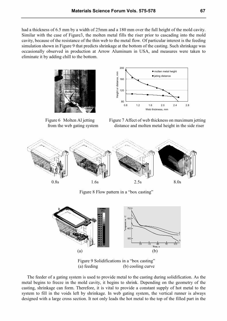
had a thickness of 6.5 mm by a width of 25mm and a 180 mm over the full height of the mold cavity.
Similar with the case of Figure3, the molten metal fills the riser prior to cascading into the mold
cavity, because of the resistance of the thin web to the metal flow. Of particular interest is the feeding
simulation shown in Figure 9 that predicts shrinkage at the bottom of the casting. Such shrinkage was
occasionally observed in production at Arrow Aluminum in USA, and measures were taken to
eliminate it by adding chill to the bottom.
80
120
160
200
0.8 1.2 1.6 2.0 2.4 2.8
Web thickness, mm
Height or distance, mm
molten metal height
jeting distance
Figure 6 Molten Al jetting Figure 7 Affect of web thickness on maximum jetting
from the web gating system distance and molten metal height in the side riser
0.8s 1.6s 2.5s 8.0s
Figure 8 Flow pattern in a “box casting”
(a) (b)
Figure 9 Solidifications in a “box casting”
(a) feeding (b) cooling curve
The feeder of a gating system is used to provide metal to the casting during solidification. As the
metal begins to freeze in the mold cavity, it begins to shrink. Depending on the geometry of the
casting, shrinkage can form. Therefore, it is vital to provide a constant supply of hot metal to the
system to fill in the voids left by shrinkage. In web gating system, the vertical runner is always
designed with a large cross section. It not only leads the hot metal to the top of the filled part in the
Materials Science Forum Vols. 575-578 67

cavity, but also plays a role of a feeder, and therefore it is named with “side riser” or “side feeder”.
The hottest metal in the system is stored in the feeder and supplied to the casting, via the web gate, as
needed. In most cases, the height of the feeder must be slightly higher than that of the actual casting.
This allows for a small amount of excess pressure to counteract capillary forces. Since this excess
pressure is needed and the feeder size cannot be extreme and reduce yield, the actual dimensions of
feeders in a web gating system require careful calculation. As shown in Fig. 9, the web solidified prior
to the bottom of the casting, and blocks the feeding channel from the feeder to the casting. A chill is
required to eliminate this defect.
Summary
Web gate systems, if properly designed, can provide less turbulent flow into the mold cavity. A big
side vertical riser with a thin web can lead hot metal to the top of the filled part in the mold, results in
a reasonable temperature distribution for solidification and feeding in the casting.
The web thickness plays an important role in mold filling process. A thin web can lead hot metal to
the top of the filled part of the cavity. It is helpful to realize a direct solidification and eliminates
shrinkage. However, too thin web can cause a jet filling pattern, and thus induce a votex and
entrapped gas. On the other hand, a thicker web provides a smooth filling process. But too thick web
loses the advantageous of web gating system, results in a bottom gate filling pattern.
The impact of the web thickness on the exit jetting velocity is relatively small, compared with that
on the molten metal height in the side riser. Thin webs generally block the feeding channel from the
side riser to the casting. Therefore, some measures are usually required to eliminate shrinkage to
obtain sound castings.
Acknowledgment
The authors acknowledge support through CMC program and direction of the work was provided by
the AFS Permanent Mold Committee.
References
[1] Q. Chang, R. Ye, H. Wang and G. An: Journal of Harbin Institute of Technology vol.24 (1992) 10,
p.138
[2] R. E. Swift, J. H. Jackson and L. W. Eastwood: AFS Vol.57 (1969), p.76
[3] G. B. Van Der Graaf, H. E. A. Van Den Akker and L. Katgerman: Metallurgical and Materials
Transactions B Vol.32 (2001) 1, p.69
[4] T. Nguyen and J. Carrig: AFS Vol.94 (1986), p.519.
[5] X. Xue, S. F. Hansen, P. N. Hansen: AFS Vol.101 (1993), p.199.
[6] M. Davandari and J. Campbell: 1st International AFS Conference on the Gating, Filling and
feeding of Aluminum Castings, Oct. 11-13, 1999, p.49.
[7] W. Sun, H. E. Littleton, C. E. Bates: AFS Vol.110 (2002), p1347.
[8] B. Sirrell and J. Campbell: CASTCON '95 (Conference proceeding), Institute of British
Foundrymen: June 15-16, 1995.
[9] Information on http://www.magamasoft.com.
68 Physical and Numerical Simulation of Materials Processing