Rapid mold-free fabrication of long functional PDMS fibers
12
Lee et al. NPG Asia Materials (2022)14:13 https://doi.org/10.1038/s41427-022-00359-7 NPG Asia Materials ARTICLE Open Access Rapid mold-free fabrication of long functional PDMS fi bers Jeong Hui Lee 1 , Taekyung Lim 1 , Keumyoung Seo 1 , Jeeyin Park 1 , Jonguk Yang 1 , Sang-Mi Jeong 1 and Sanghyun Ju 1 Abstract Polydimethylsiloxane (PDMS), an optically transparent and inert material, is widely used in biological and semiconductor applications owing to its excellent chemical stability and moldability. This study proposes a thermally induced wet spinning method for the fabrication of long PDMS fibers with a constant width. PDMS is a thermoset polymer that undergoes chemical crosslinking when heated, and the thermally induced wet spinning process allows for the formation of fibers without a mold. A rapid thermal curing step was used to instantly solidify the thermoset polymer, where immediate chemical crosslinking of fluid PDMS solution was achieved upon contact with an oil coagulation bath at 180–230 °C. A rapid stretching process was applied to pull out and control the width of the fiber, and the PDMS was stretched at a rate of 1.2–12.5 m/min during the crosslinking process. The fabricated pristine PDMS fibers were transparent and maintained a crosslinked network with excellent mechanical strength. In addition, the PDMS fibers were functionalized with silica nanoparticles, carbon nanotubes, and pores to adjust their transparency/ opacity, conductivity, and heat insulation properties, respectively, for various applications. The proposed thermally induced wet spinning method shows promise for overcoming the limitations of existing molding methods, in which the PDMS fibers cannot be lengthened. Furthermore, the process is environmentally friendly and economical owing to the use of edible canola oil, which reduces the volume of harmful solvents and additives during fiber production. Introduction Polydimethylsiloxane (PDMS) is a popular thermoset polymer that is typically used as a liquid-phase pre- polymer to form an infusible and insoluble polymer net- work via thermally activated chemical crosslinking. PDMS offers high transparency, biocompatibility, excellent che- mical resistance, and formability and is commonly used as a transparent and flexible substrate, soft lithography mold, and microfluidic channel in flexible displays, biomedical products, and microfluidic devices 1–5 . Solution-based PDMS is typically molded using a solid mold, as ther- mal energy (25–200 °C) must be applied to activate the Pt- based catalyst, and a crosslinking time of 10 min or more is required to facilitate the chemical reaction between the polymer chains 6,7 . This method can be used to easily manufacture objects of various sizes and complex shapes; however, the production of a thin and long shape, such as fiber, remains a challenge. One method for producing fibers involves injecting the PDMS precursor into a tube mold and removing the solidified PDMS from the tube mold after crosslinking 8–10 . However, the use of a tube mold limits the diameter of the PDMS fiber and does not allow for lengthening, as the shape of the fiber is determined by the length and inner diameter of the tube mold. Alternatively, wet spinning and electrospinning methods, which are used to fabricate polymer-based fibers, can be considered to fabricate PDMS fibers. However, the nozzle can become clogged during the spinning process if the PDMS solution undergoes crosslinking too quickly; how- ever, the PDMS fiber can be insufficiently solidified if crosslinking occurs too slowly. Furthermore, because the normal process temperature of wet spinning is 60 °C or less, PDMS cannot be sufficiently solidified via a chemical © The Author(s) 2022 Open Access This article is licensed under a Creative Commons Attribution 4.0 International License, which permits use, sharing, adaptation, distribution and reproduction in any medium or format, as long as you give appropriate credit to the original author(s) and the source, provide a link to the Creative Commons license, and indicate if changes were made. The images or other third party material in this article are included in the article’ s Creative Commons license, unless indicated otherwise in a credit line to the material. If material is not included in the article’s Creative Commons license and your intended use is not permitted by statutory regulation or exceeds the permitted use, you will need to obtain permission directly from the copyright holder. To view a copy of this license, visit http://creativecommons.org/licenses/by/4.0/. Correspondence: Sang-Mi Jeong ([email protected]) or Sanghyun Ju ([email protected]) 1 Department of Nanoengineering, Kyonggi University, Suwon, Gyeonggi-Do 16227, South Korea These authors contributed equally: Jeong Hui Lee, Taekyung Lim 1234567890():,; 1234567890():,; 1234567890():,; 1234567890():,;
-
Upload
khangminh22 -
Category
Documents
-
view
5 -
download
0
Transcript of Rapid mold-free fabrication of long functional PDMS fibers

Lee et al. NPG Asia Materials (2022) 14:13 https://doi.org/10.1038/s41427-022-00359-7 NPG Asia Materials
ART ICLE Open Ac ce s s
Rapid mold-free fabrication of long functionalPDMS fibersJeong Hui Lee1, Taekyung Lim 1, Keumyoung Seo1, Jeeyin Park1, Jonguk Yang1, Sang-Mi Jeong 1 andSanghyun Ju 1
AbstractPolydimethylsiloxane (PDMS), an optically transparent and inert material, is widely used in biological andsemiconductor applications owing to its excellent chemical stability and moldability. This study proposes a thermallyinduced wet spinning method for the fabrication of long PDMS fibers with a constant width. PDMS is a thermosetpolymer that undergoes chemical crosslinking when heated, and the thermally induced wet spinning process allowsfor the formation of fibers without a mold. A rapid thermal curing step was used to instantly solidify the thermosetpolymer, where immediate chemical crosslinking of fluid PDMS solution was achieved upon contact with an oilcoagulation bath at 180–230 °C. A rapid stretching process was applied to pull out and control the width of the fiber,and the PDMS was stretched at a rate of 1.2–12.5 m/min during the crosslinking process. The fabricated pristine PDMSfibers were transparent and maintained a crosslinked network with excellent mechanical strength. In addition, thePDMS fibers were functionalized with silica nanoparticles, carbon nanotubes, and pores to adjust their transparency/opacity, conductivity, and heat insulation properties, respectively, for various applications. The proposed thermallyinduced wet spinning method shows promise for overcoming the limitations of existing molding methods, in whichthe PDMS fibers cannot be lengthened. Furthermore, the process is environmentally friendly and economical owing tothe use of edible canola oil, which reduces the volume of harmful solvents and additives during fiber production.
IntroductionPolydimethylsiloxane (PDMS) is a popular thermoset
polymer that is typically used as a liquid-phase pre-polymer to form an infusible and insoluble polymer net-work via thermally activated chemical crosslinking. PDMSoffers high transparency, biocompatibility, excellent che-mical resistance, and formability and is commonly used asa transparent and flexible substrate, soft lithography mold,and microfluidic channel in flexible displays, biomedicalproducts, and microfluidic devices1–5. Solution-basedPDMS is typically molded using a solid mold, as ther-mal energy (25–200 °C) must be applied to activate the Pt-based catalyst, and a crosslinking time of 10 min or moreis required to facilitate the chemical reaction between the
polymer chains6,7. This method can be used to easilymanufacture objects of various sizes and complex shapes;however, the production of a thin and long shape, such asfiber, remains a challenge. One method for producing fibersinvolves injecting the PDMS precursor into a tube mold andremoving the solidified PDMS from the tube mold aftercrosslinking8–10. However, the use of a tube mold limits thediameter of the PDMS fiber and does not allow forlengthening, as the shape of the fiber is determined by thelength and inner diameter of the tube mold.Alternatively, wet spinning and electrospinning methods,
which are used to fabricate polymer-based fibers, can beconsidered to fabricate PDMS fibers. However, the nozzlecan become clogged during the spinning process if thePDMS solution undergoes crosslinking too quickly; how-ever, the PDMS fiber can be insufficiently solidified ifcrosslinking occurs too slowly. Furthermore, because thenormal process temperature of wet spinning is 60 °C orless, PDMS cannot be sufficiently solidified via a chemical
© The Author(s) 2022OpenAccessThis article is licensedunder aCreativeCommonsAttribution 4.0 International License,whichpermits use, sharing, adaptation, distribution and reproductionin any medium or format, as long as you give appropriate credit to the original author(s) and the source, provide a link to the Creative Commons license, and indicate if
changesweremade. The images or other third partymaterial in this article are included in the article’s Creative Commons license, unless indicated otherwise in a credit line to thematerial. Ifmaterial is not included in the article’s Creative Commons license and your intended use is not permitted by statutory regulation or exceeds the permitted use, you will need to obtainpermission directly from the copyright holder. To view a copy of this license, visit http://creativecommons.org/licenses/by/4.0/.
Correspondence: Sang-Mi Jeong ([email protected]) orSanghyun Ju ([email protected])1Department of Nanoengineering, Kyonggi University, Suwon, Gyeonggi-Do16227, South KoreaThese authors contributed equally: Jeong Hui Lee, Taekyung Lim
1234
5678
90():,;
1234
5678
90():,;
1234567890():,;
1234
5678
90():,;

crosslinking reaction. To solve this problem, a PDMS fiberwith a core-shell structure has been fabricated, in which aneasily solidified thermoplastic polymer is formed as anouter layer and uncured fluid PDMS is used as an innerlayer using the electrospinning method8,11. In this case,after postcrosslinking the inner uncured PDMS, only theouter thermoplastic polymer is dissolved and removed toprepare the PDMS fibers. However, this method producesopaque PDMS fibers, and the fibrous morphology andelectrospinnability of PDMS are dependent on changes inthe PDMS solution over time after preparation; thus, it isdifficult to produce fibers with a uniform width.This study aimed to develop a simple and rapid method
for the fabrication of transparent and long PDMS fibersbased on thermally induced wet spinning, which is amodification of the conventional wet spinning method. Thethermally induced wet spinning method included a high-temperature thermal curing process using a coagulationbath with oil at temperatures of 180–230 °C, while a rapidstretching process was conducted at a speed of 1.2–12.5m/min during spinning. A bio-oil with a high boiling point wasused to rapidly cure PDMS to form transparent fibers; thisresolved the issues associated with the generation of solventvapor during fiber manufacturing using the conventionalwet spinning method. The fiber width was controlled byadjusting the pulling speed of the cured PDMS fiber duringrapid stretching. Silica nanoparticles (NPs), carbon nano-tubes (CNTs), and poly(methyl methacrylate) (PMMA)particles were embedded in transparent and flexible pristinePDMS fibers to achieve properties, such as transparency/opacity, conductivity, and thermal insulation.
Materials and methodsThermally induced wet spinning of the pristine PDMS fiberThe PDMS solution was extruded from a syringe into a
high-temperature coagulation bath and immediately curedto form pristine PDMS fibers. The PDMS solution wasprepared by mixing PDMS prepolymer and a curing agent(Sylgard 184, Dow Chemical Company, USA) at a mass ratioof 10:1. The solution was placed in a vacuum oven (SH-VDO-08NG, SH Scientific, South Korea) at a negativepressure of 600 Torr for 5min to remove air bubbles. ThePDMS solution was transferred to a 20-mL syringe, whichwas mounted on a syringe pump (NE-1000, New Era PumpSystems Inc., USA). To prevent clogging due to the solidi-fication of the PDMS in the needle (20G), the syringe tipwas placed 20mm above the surface of the heated canola oil(180–230 °C) in the coagulation bath. As the oil to be usedfor curing PDMS resin, canola oil, which is not miscible withPDMS resin, has a high smoke point of 240–250 °C andgenerates the least toxic gas during the process. The PDMSsolution was extruded at a rate of 60mL/h, and the linearspeed was adjusted between 1.2 and 12.5m/min. The curedPDMS fiber was sonicated in a cleaning bath containing
isopropyl alcohol (IPA; Daejung, South Korea) for 30min toremove all remaining oil from the fiber surface. AlthoughIPA was used to increase the efficiency of fabricationthrough quick cleaning and drying, water-diluted rubbingalcohol or liquid hand soap could also be used instead ofIPA to clean the oil remaining on the PDMS fiber.
Fabrication of the silica-NP-embedded PDMS fiberThe surface of the PDMS fiber was embedded with a
layer of silica NPs to achieve the ability to reversiblyswitch between being transparent and opaque by adjust-ing the ratio of mechanical tension. PDMS fibers werefabricated using the thermally induced wet spinningmethod with a 20 G needle, an oil bath temperature of230 °C, a syringe pump rate of 60 mL/h, and a linear speedof 2.5 m/min. Monodispersed nonporous silica NPs (dia-meter= 400 nm; Sigma–Aldrich, USA) were mixed inethanol (Daejung) at a concentration of 10 wt% via soni-cation for 30min. The silica NP solution (1 mL) wastransferred to an airbrush (DH-102, Sparmax, Taiwan)with a 0.25 mm nozzle and sprayed onto the PDMS fiberat a distance of 100mm and a pressure of 0.12MPa. Thesilica NP-spray-coated PDMS fiber was dipped in PDMSsolution and dried in an oven at 60 °C for 3 h.
Fabrication of the PDMS-CNT composite fiberA PDMS-CNT composite fiber was prepared to achieve
electroconductivity. Briefly, 1 wt% multiwalled CNTs(MWCNTs; CNT MR99, Carbon Nanomaterial Tech-nology Co., Ltd, South Korea) were added to benzene(melting point = 5.5 °C; Sigma–Aldrich) and sonicated for30min to evenly disperse the CNTs. The PDMS pre-polymer was added to the CNT solution and sonicated for30min to prepare PDMS-CNT solutions with CNTsolution: PDMS prepolymer mass ratios of 101:100,127:100, 152:100, and 178:100. The PDMS-CNT solutionwas frozen at –85 °C for 8 h in a freezer (DF8502S, IlshinBiobase, South Korea) and dried at –85 °C and 300 Torrfor 15 h using a freeze dryer (TFD8503, Ilshin Biobase) toremove the remaining benzene. The curing agent wasadded at 10 wt% of the prepolymer, and the final con-centrations of the CNTs in the PDMS-CNT compositesolution were 1.0, 1.25, 1.5, and 1.75 wt%. Notably, aPDMS-CNT composite solution with a CNT contenthigher than 1.75 wt% was too viscous for the fabrication offibers. PDMS-CNT composite fibers were fabricated usingthe thermally induced wet spinning method with a 20 Gneedle, oil bath temperature of 230 °C, syringe pump rateof 60 mL/h, and linear speed of 2.5 m/min.
Fabrication of the porous PDMS fiber (PPF)A porous PDMS fiber was formed by adding hetero-
polymer particles, namely, PMMA, to the PDMS solution.The fiber was formed, and the heteropolymer was
Lee et al. NPG Asia Materials (2022) 14:13 Page 2 of 12 13
dissolved from the fiber to leave a microsized open ske-leton structure within the PDMS fiber. PMMA (<15,000molecular weight; Sigma–Aldrich) was ground to apowder (particle size: 30–70 μm) using an agate mortarand pestle. The PMMA powder was added to the PDMSsolution at concentrations of 10 to 50 wt% to produce aPDMS-PMMA solution, and air bubbles were removed ata negative pressure of 600 Torr for 5 min. PDMS-PMMAfibers were fabricated using the PDMS-PMMA solutionvia the thermally induced wet spinning method with a17 G needle, an oil bath temperature of 230 °C, a syringepump rate of 60 mL/h, and a linear speed of 2.5 m/min.PMMA was removed from the PDMS-PMMA fiber viasonication in IPA for 1 h. The dissolution of the PMMAparticles in the PDMS-PMMA fiber left a microsized openstructure inside the fiber. The porous PDMS fiber wasdried at room temperature (20 °C) for 3 h.
Characterization of the four types of PDMS fibersThe diameter, cross-section, surface structure, and
internal structure of the fabricated pristine PDMS fiber,silica-NP-embedded PDMS fiber, PDMS-CNT compositefiber, and porous PDMS fiber were observed using field-emission scanning electron microscopy (FE-SEM; S-4800,Hitachi, Japan). The thermal properties of the fibers weredetermined using thermogravimetric analysis (TGA;TGA/DSC 1, Mettler Toledo, USA) within a temperaturerange of 20–1000 °C. The change in stress of the fibersaccording to applied strain was determined using a uni-versal testing machine (UTM; TD-U01, T&DORF Inc.,South Korea). The electrical conductivity of the fibers(length: 10 mm) was measured using a digital multimeter(FLUKE-175 EJKCT, Fluke, USA). The strain-sensingproperties during repeated stretching from 20 to 80%were measured using a semiconductor device parameteranalyzer (B1500A, Agilent, USA). The internal porosity ofthe fiber was measured using a porosity meter (AutoPoreV 9600, Micromeritics, USA). The thermal insulationproperties of the porous PDMS fibers with four differentpore numbers were evaluated by fabricating and analyzingsix fabrics, namely, PPF-1, 2, 3, and 4 (one layer); 4 (twolayers); and 4 (three layers); the dimensions were 11 ×30mm2. Fabrics woven with porous PDMS fibers(PMMA: 10, 20, 30, and 40 wt%) with four different porenumbers were designated PPF-1, 2, 3, and 4. In addition,the fabrics woven with porous PDMS fibers producedwith 40% PMMA were laminated in two and three layersand were named PPF-5 and 6, respectively. The sampleswere mounted on a plastic frame (thickness: ~1.8 mm)with a central open area (75.5 × 25.5 mm2). The lower partof the sample was exposed to various temperatures from–15 to 100 °C, and the surface temperature of the upperpart of the sample was measured using an infrared (IR)camera (T-530, FLIR Systems, Inc., USA). A hot plate
(MSH-20D, DAIHAN Scientific, South Korea) was usedas the heating source for temperatures between 40 and100 °C, and a Peltier module was used as the coolingsource for −15 °C. The thermal conductivity was mea-sured by using a transient plane heat source thermalconductivity meter (TPHS-1, YEONJIN S-TECH, SouthKorea). The measurement was repeated three times toextract the mean and standard deviation.
Color analysis of the silica-NP-embedded PDMS fiberThe color change achieved during stretching of the
silica-NP-embedded PDMS fiber was evaluated based onthe red, green, and blue (RGB) value and the InternationalCommission of Illumination (CIE) L*a*b* color spacemethod. The fiber was imaged under fixed lighting con-ditions at various degrees of stretching. The images wereanalyzed using Adobe Photoshop CS4 to extract the RGBand CIE L*a*b* color space values of the samples12. TheRGB value indicates the intensities of red, green, and bluein the color space. The CIE L*a*b* value includes an L*parameter for the lightness of the sample, ranging from 0(black) to 100 (white), an a* parameter for color betweenred (+) and green (–), and a b* parameter for the colorbetween yellow (+) and blue (–). The total color differ-ence (ΔE) was calculated based on a standard sample (L0,a0, b0) in the neutral state before stretching12,13:
ΔE ¼ ΔL�ð Þ2þ Δa�ð Þ2þ Δb�ð Þ2� �1=2
where ΔL*= L− L0, Δa*= a− a0, and Δb*= b− b0.
Results and discussionFigure 1a shows a schematic of PDMS fiber fabrication
using PDMS solution without a mold by the developedthermally induced wet spinning method. To make PDMSact as a thermoset polymer to form a specific shape,thermal energy (25–150 °C) for >10 min is required torapidly crosslink the polymer chains14–16. Therefore, it isvery difficult to fabricate PDMS in fiber form using aconventional wet spinning method that rapidly extractsfibers through a nozzle. Considering this, a rapid thermalcuring process was applied in this study to achieve instantsolidification of the thermoset polymer. The PDMS pre-polymer and curing agent chemically reacted to form anetwork structure, thereby rapidly curing the PDMS.During curing, a winder was used to rapidly stretch thePDMS fiber, where the width of the PDMS fiber wascontrolled by adjusting the tensile force based on thepulling speed. After production, the residual oil wasremoved to obtain PDMS fibers.Figure 1b shows the chemical crosslinking and solidifi-
cation mechanisms of PDMS fiber formation using thethermally induced wet-spinning process. The PDMS fiberwas formed as the PDMS solution underwent a three-step
Lee et al. NPG Asia Materials (2022) 14:13 Page 3 of 12 13
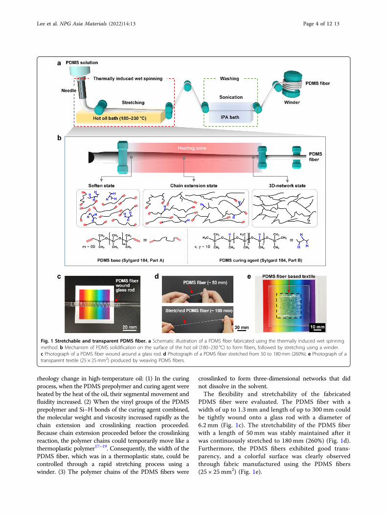
rheology change in high-temperature oil: (1) In the curingprocess, when the PDMS prepolymer and curing agent wereheated by the heat of the oil, their segmental movement andfluidity increased. (2) When the vinyl groups of the PDMSprepolymer and Si–H bonds of the curing agent combined,the molecular weight and viscosity increased rapidly as thechain extension and crosslinking reaction proceeded.Because chain extension proceeded before the crosslinkingreaction, the polymer chains could temporarily move like athermoplastic polymer17–19. Consequently, the width of thePDMS fiber, which was in a thermoplastic state, could becontrolled through a rapid stretching process using awinder. (3) The polymer chains of the PDMS fibers were
crosslinked to form three-dimensional networks that didnot dissolve in the solvent.The flexibility and stretchability of the fabricated
PDMS fiber were evaluated. The PDMS fiber with awidth of up to 1.3 mm and length of up to 300 mm couldbe tightly wound onto a glass rod with a diameter of6.2 mm (Fig. 1c). The stretchability of the PDMS fiberwith a length of 50 mm was stably maintained after itwas continuously stretched to 180 mm (260%) (Fig. 1d).Furthermore, the PDMS fibers exhibited good trans-parency, and a colorful surface was clearly observedthrough fabric manufactured using the PDMS fibers(25 × 25 mm2) (Fig. 1e).
Fig. 1 Stretchable and transparent PDMS fiber. a Schematic illustration of a PDMS fiber fabricated using the thermally induced wet spinningmethod. b Mechanism of PDMS solidification on the surface of the hot oil (180–230 °C) to form fibers, followed by stretching using a winder.c Photograph of a PDMS fiber wound around a glass rod. d Photograph of a PDMS fiber stretched from 50 to 180mm (260%). e Photograph of atransparent textile (25 × 25mm2) produced by weaving PDMS fibers.
Lee et al. NPG Asia Materials (2022) 14:13 Page 4 of 12 13

The transparency and mechanical strength of the PDMSfibers were determined by the three-dimensional siliconenetwork formed by the crosslinking of linear siliconemolecules. The proposed fabrication method based onrapid thermal curing and stretching was developed tocontrol the shape and properties of the PDMS fibers byimproving this three-dimensional silicone network. Thecuring reaction of a crosslinked polymer, such as PDSM,is a chemical reaction between a liquid prepolymer and aliquid curing agent to produce a solid crosslinked poly-mer. The curing kinetics of PDMS could be explained bythe Arrhenius equation, which represents the correlationbetween the reaction rate and temperature17,20,21:
dpdt
¼ k Tð Þf ðαÞ; k Tð Þ ¼ k0e�E=RT
where dp/dt is the curing rate, f(α) is a function ofthe conversion, k0 is the pre-exponential constant, E is theactivation energy, R is the gas constant, and T is the
temperature. According to the Arrhenius equation, thecuring rate increases as the curing temperature isincreased. Figure 2 shows the changes in the shape andproperties of the PDMS fibers according to the oiltemperature and linear stretching speed. When the oiltemperature was 150–170 °C, the PDMS solution spreadlike a film on the surface of the oil bath, and the fibershape could not be maintained. On the other hand, whenthe oil temperature was 180–230 °C, the PDMS solutionmaintained its fiber shape on the hot oil surface. Theoptimum oil temperature was chosen to achieve uniformPDMS fibers; thus, the oil temperature was adjustedbetween 180 and 230 °C at a fixed linear speed of 2.5m/min.The PDMS curing times decreased to 48 h, 35 min, and10min with increasing crosslinking temperatures of 25,100, and 150 °C, respectively6,7. Thus, exposure of thefluid PDMS solution to a higher oil temperature led tomore rapid chain extension and crosslinking to form anelastic and uniform fiber. When the oil temperature was
Fig. 2 Effects of the oil temperature and linear speed during thermally induced wet spinning on the morphology and properties of PDMSfibers. a Optical and FE-SEM images and b fiber width and cross-sectional area at various oil temperatures. c Optical and FE-SEM images, d fiberwidth and cross-sectional area, e dTG characteristics, and f stress–strain curves at various linear speeds.
Lee et al. NPG Asia Materials (2022) 14:13 Page 5 of 12 13

low, the PDMS solution was not sufficiently cured andtended to spread in the oil bath to produce a PDMS fiberwith a non-uniform thickness. The optical and FE-SEMimages of the PDMS fibers (Fig. 2a) revealed that the fiberwidth was affected by the oil temperature (Fig. 2b), whereoil temperatures of 180, 200, 220, and 230 °C led towidths/cross-sectional areas of 1.60 ± 0.28/0.44 ± 0.32,1.40 ± 0.17/0.30 ± 0.12, 1.20 ± 0.13/0.27 ± 0.11, and1.31 ± 0.05 mm/0.28 ± 0.02 mm2, respectively. Thus, morerapid curing at a higher oil temperature led to a thinnerfiber. Furthermore, the standard deviations of the PDMSfiber width and cross-sectional area decreased as the oiltemperature was increased, thereby producing a moreuniform fiber. Consequently, 230 °C was chosen as theoptimal oil temperature to produce the most uniformPDMS fibers.The optimal linear speed was chosen to control the
width and uniformity of the PDMS fiber. The oil tem-perature was maintained at 230 °C, and the linear speedwas varied (1.2, 2.5, 5.0, 7.5, 10.0, and 12.5 m/min). Anincrease in linear speed led to a larger pulling force on thepolymer chains inside the uncured PDMS fiber, therebyforming a finer PDMS fiber. Optical and FE-SEM imageswere obtained for the PDMS fibers produced at a constantPDMS solution extrusion speed of 60 mL/h and linearspeeds of 1.2, 2.5, 5.0, 7.5, 10.0, and 12.5 m/min (Fig. 2c);the resulting widths/cross-sectional areas were 1.69 ±0.16/0.63 ± 0.10, 1.31 ± 0.05/0.28 ± 0.02, 0.85 ± 0.01/0.11 ± 0.005, 0.74 ± 0.03/0.08 ± 0.01, 0.61 ± 0.05/0.04 ±0.01, and 0.51 ± 0.04 mm/0.03 ± 0.01 mm2, respectively(Fig. 2d). Thus, a faster linear speed led to a thinner fiber.The standard deviation of the width and cross-sectionalarea was largest at a linear speed of 1.2 m/min. Instead, anoptimal linear speed of 2.5 m/min or higher was chosen toensure that a uniform PDMS fiber was obtained.The fiber had a flat shape because the density of PDMS
(0.965 g/cm3) was similar to that of canola oil (0.92 g/cm3). Thus the PDMS fiber solidified while floating on thehot oil surface. The surface touching the oil surfacebecame spherical owing to surface tension, whereas thesurface exposed to air was flat. At a low linear speed, thevolume of the spun PDMS fibers was large owing to theeffect of gravity: a larger proportion of PDMS sunk belowthe oil surface and led to a more hemispherical cross-sectional fiber shape. Conversely, the PDMS fibers spun athigh linear speeds had a reduced volume and were lessaffected by gravity, thereby resulting in a thinner andflatter cross-section22,23.Derivative thermogravimetric (dTG) curves were plot-
ted to compare the changes in the thermal stability of thePDMS fibers at linear speeds of 1.2–12.5 m/min (Fig. 2e).The temperature associated with the greatest weightchange due to pyrolysis decreased from 540 to 480 °C asthe linear speed was increased from 1.2 to 12.5 m/min.
The strain–stress curves of the PDMS fiber revealed thatthe strain increased and the strength decreased withincreasing linear speed owing to less crosslinking (Fig. 2f).The faster the PDMS fiber passed through the high-temperature oil, the shorter the time the PDMS fiber wasexposed to a high temperature, which reduced thecrosslinking density and three-dimensional silicone net-work of the PDMS fiber24–26. Specifically, the PDMSfibers produced at linear speeds of 1.2, 2.5, 5.0, 7.5, 10.0,and 12.5 m/min exhibited strain values of 242, 277, 316,372, 407, and 434%, respectively, and stress values of 9.2,8.6, 7.6, 6.9, 4.6, and 2.7MPa, respectively. As the linearspeed was increased, the contact time with the hot oil wasshortened, and the thermal energy was not sufficientlytransferred to the inside of the PDMS fiber. Accordingly,the hydrosilylation reaction, which is a crosslinkingreaction, did not proceed sufficiently inside the PDMSfiber. Therefore, as the linear speed was increased, thethree-dimensional silicone network formation of thepolymer chains of PDMS inside the fiber graduallydecreased, resulting in an increase in strain and a decreasein strength. The PDMS fiber fabricated in this studyshowed higher strain and stress values than previouslyreported PDMS films and fibers. The strain and stressvalues of a PDMS cast film fabricated by casting andheating a PDMS prepolymer were 100–170% and1.2–7.0MPa, respectively7,8,27. The strain and stressvalues of a PDMS fiber fabricated by electrospinning were212% and 6.0MPa, respectively8.According to thermoset cure kinetics, in the case of the
isothermal curing reaction at high temperature, a curingconversion of almost 100% is reached over time becausethe polymer chains move freely28–31. In contrast, thepolymerization and crosslinking reaction in the thermallyinduced wet spinning method proceeded for a very shorttime, within 6 s at a high temperature of 230 °C, followedby rapid cooling. The chain segmental mobility wasrapidly reduced with increasing thermal energy; further-more, the segment mobility was further limited by someof the crosslinked polymer chains in the chain extensionprocess17,31,32. Consequently, the curing rate of the PDMSfiber was significantly slowed, and curing conversion wasreduced. Therefore, even though the PDMS fiber was leftat room temperature (25 °C) for >48 h, the curing con-version of the PDMS fiber did not change, and the ther-mal stability and mechanical properties of the PDMS fiberwere maintained.Reversible switching between a transparent and opaque
appearance was achieved by stretching and releasing thePDMS fiber after a silica NP layer (thickness: 2 μm) andPDMS capping layer (thickness: 7 μm) were deposited onthe PDMS fiber surface (Fig. 3a). Silica NPs were uni-formly spray-coated on the surface of the transparentPDMS fiber with a high light transmittance of over 90%,
Lee et al. NPG Asia Materials (2022) 14:13 Page 6 of 12 13

which was subsequently dipped in PDMS solution andthermally cured to obtain a silica-NP-embedded PDMSfiber. The change in the transparency of the silica-NP-embedded PDMS fiber (length: 30 mm) according tostretching was compared with that of a pristine PDMSfiber (Fig. 3b). Both types of PDMS fibers were visiblytransparent in their initial state without any applied force.Spray coating of the transparent PDMS fiber surface withsilica NPs led to an opaque appearance owing to theirregular arrangement of the silica NPs. However, thesubsequent deposition of the PDMS capping layerrestored the transparent appearance because the PDMSsolution filled the voids formed between the silica NPs,and they both have similar refractive indices at a wave-length of 632.8 nm (PDMS= 1.425; silica= 1.457). Thepristine PDMS fiber remained transparent when stretchedto 70mm (~130%), whereas the silica-NP-embeddedPDMS fiber became opaque. This was attributed to the
separation of the hydrophobic PDMS and hydrophilicsilica NPs during stretching, which created voids betweenthe silica NPs and the surrounding PDMS. Opticalreflection occurred at the void/silica and void/PDMSinterfaces, thereby reducing the transparency. When thefiber was released, the voids between the PDMS and thesilica NPs disappeared, and the fiber returned to atransparent state33,34. Thus, the appearance of the fibercould be reversibly switched between transparent andopaque via repeated stretching and release of the silica-NP-embedded PDMS fiber.The surface and cross-section of the silica-NP-
embedded PDMS fiber were observed using FE-SEM(Fig. 3c), and these observations confirmed that a silicaNP layer with a thickness of ~2 μm was formed at a depthof ~7 μm from the outer surface of the fiber. Consideringthe PDMS fiber width and thickness of 1.31 and 0.40 mm,respectively, the silica NP layer and added PDMS capping
Fig. 3 Silica-NP-embedded PDMS fiber with a reversible switching property from transparent to opaque. a Schematic illustration of the silica-NP-embedded PDMS fiber fabrication process to achieve reversible switching from transparent to opaque. b Photograph of the change in fibertransparency according to the stretching of the silica-NP-embedded PDMS fiber. c FE-SEM images of the silica-NP-embedded PDMS fiber.d Stress–strain curves and e TGA curves of the pristine PDMS fiber and silica-NP-embedded PDMS fiber. Change in fiber transparency according tothe strain of aligned silica-NP-embedded PDMS fibers visualized with f photographs, g RGB values, and h total color difference (ΔE).
Lee et al. NPG Asia Materials (2022) 14:13 Page 7 of 12 13

layer were relatively thin. Thus the strain and stress of thepristine PDMS fiber (276% and 8.6MPa) and silica-NP-embedded PDMS fiber (269% and 8.8MPa) were similar(Fig. 3d). The thermal properties of the silica-NP-embedded PDMS fiber were evaluated using TGA(Fig. 3e), where pyrolysis started and ended at 400 and800 °C in both fiber types, and the residual amount at1000 °C was similar at ~42%. Thus the mechanical andthermal properties of the PDMS fiber were not sig-nificantly affected by the embedded silica NPs.An array of silica-NP-embedded PDMS fibers was pre-
pared by arranging 11 strands side-by-side without gaps,and the samples were placed on a black background toconfirm the reversible switching property from transpar-ent to opaque when stretched and released (Fig. 3f). Theappearance of the silica-NP-embedded PDMS fibers wasassessed when they were stretched to 20%, 40%, 60%, and
90%. The transparent fibers gradually turned white as thestretching length was increased. The change in transpar-ency was quantified based on the RGB and CIE L*a*b*color space measurements (Fig. 3g, h). The fiber in theunstretched initial state appeared black owing to the blackbackground (13 (R), 13.4 (G), and 17.8 (B)), and it turnedwhite when stretched to 90% (149 (R), 145.6 (G), 450 (B)).The total color difference (ΔE) value was obtained byextracting CIE L*a*b*, which is a three-dimensionalnumerical value of color, and a quasilinear tendencysimilar to that of the RGB values was observed.Conductive PDMS-CNT composite fibers were pre-
pared by adding CNTs to the PDMS and were used as astrain sensor (Fig. 4a). The PDMS-CNT composite fiberwas wound around a 6.2-mm diameter glass rod andobserved using FE-SEM (Fig. 4b). The PDMS-CNTcomposite fiber was successfully solidified when
Fig. 4 Conductive PDMS-CNT composite fiber. a Schematic illustration of the PDMS-CNT composite fiber fabrication process to achieve electricalconductivity. b Photograph of the PDMS-CNT composite fiber (1.75 wt%) wound on a glass rod (above) and surface and cross-sectional FE-SEMimages of the PDMS-CNT composite fiber (below). c TGA curve, d stress–strain curve, and e conductivity/diameter according to the CNT content (1.0,1.25, 1.5, and 1.75 wt%). f Green LED brightness when the stretching sensing device based on the PDMS-CNT composite fiber was open, connectedand unstretched (0%), stretched (up to 100%), and released (0%). g Resistance change of the PDMS-CNT composite fiber (1.75 wt% CNTs) whenstretched at 20, 40, 60, and 80%. h Strain-sensing properties of the PDMS-CNT composite fiber (1.75 wt% CNTs) according to the bending angle of theindex finger (30°, 60°, and 90°).
Lee et al. NPG Asia Materials (2022) 14:13 Page 8 of 12 13

immersed in high-temperature oil. Furthermore, theCNTs were denser (1.6 g/cm3) than PDMS (0.965 g/cm3), thereby resulting in a composite with a higherdensity than that of canola oil (0.92 g/cm3). Thus,hydraulic pressure was applied uniformly to the entirefiber as it sunk below the oil surface, and fiber with acircular cross-section was formed (Supplementary Fig. S1).The thermal properties of the PDMS-CNT composite
fiber were measured using TGA from 0 to 1000 °C (Fig. 4c).PDMS-CNT composite fiber decomposition started at~400 °C, after which the sample weight plateaued startingat 800 °C. The PDMS-CNT composite fibers were notcompletely decomposed, even at temperatures above800 °C. The PDMS-CNT composite fibers with CNTcontents of 1.0, 1.25, 1.5, and 1.75 wt% exhibited a positivecorrelation with the residual amounts of CNTs at 1000 °C,namely, 55.9, 59.3, 61.3, and 63.3%.An analysis of the strain–stress properties of the PDMS-
CNT composite fibers revealed that an increase in theCNT content of the PDMS-CNT composite fibersbetween 1.0, 1.25, 1.5, and 1.75 wt% led to a gradualdecrease in strain value (227, 222, 214, and 204%,respectively) and a gradual increase in stress (4.4, 4.9, 5.1,and 6.2MPa, respectively) (Fig. 4d). Composite fiberscomprising a flexible polymer mixed with a powder/par-ticle tended to exhibit a decrease in flexibility as theamount of added powder/particle was increased owing tointerference with the polymer chain interactions35,36. Thestress applied to the fibers was effectively dispersed in theCNTs owing to their excellent mechanical properties andstrong adhesion at the CNT/polymer matrix interface.The conductivity and diameter of the PDMS-CNT
composite fibers were evaluated according to the CNTcontent (Fig. 4e). The conductivity increased withincreasing CNT content, where the conductivity with 1.0,1.25, 1.5, and 1.75 wt% CNTs was 1.7 ± 0.03, 4.0 ± 0.11,10.7 ± 0.48, and 19.6 ± 0.69 S/cm, respectively. Despite theincrease in the CNT content, the respective fiber dia-meters remained relatively constant at 662 ± 26, 669 ± 15,648 ± 29, and 647 ± 20 μm for 1.0, 1.25, 1.5, and 1.75 wt%CNTs. The conductivity of an object is considered inrelation to the specific resistance of the conductivematerial contained in the object, the junction resistance inthe conduction path at the contact point between con-ductive materials, and the resistance due to electrontunneling between noncontact materials. The electrontunneling resistance played the most decisive role in theoverall resistance of a composite comprising insulatingPDMS and conductive CNTs, as the polymer formed athin layer between the CNTs, preventing their directconnection. An increase in the CNT content of the fiberreduced the minimum distance between the CNTs toform an electrical–percolation network, thereby increas-ing the conductivity37.
The 1.75-wt% PDMS-CNT composite fiber offered thehighest electrical conductivity and was applied in a stretchsensing device (Fig. 4f). Specifically, the PDMS-CNTcomposite fiber was used as wiring (length: 5 mm) for anelectrode to apply voltage to a green light-emitting diode(LED). The PDMS-CNT composite fiber was stretched by100% to 10 mm at an applied voltage of 5 V, which led toan increase in the resistance and a less bright LED. Afterreleasing the stretched fiber back to 5mm, the resistancedecreased, and the brightness of the LED was restored.Fig 4g shows the change in the ΔR/R0 value according tothe stretching of the PDMS-CNT composite fiber, wherethe fiber stretched at 20, 40, 60, and 80% exhibited a linearincrease in the ΔR/R0 value: 6.8, 14.9, 21.0, and 30.4%,respectively. This behavior remained consistent after fiverepeated stretch and release cycles.The PDMS-CNT composite fiber was attached to a
human index finger to detect finger bending based onfiber stretching (Fig. 4h). Thus, the real-time change inthe resistance of the PDMS-CNT composite fiber wasgradually increased by 0.4, 0.6, and 0.9% when the fingerwas bent at 30°, 60°, and 90°, respectively, for a total ofthree times. The response of the sensor and returncharacteristics were evaluated based on the response/relaxation time, which was maintained at a constant valueof ~0.5/1.0 s, even when the bending angle was changed.Figure 5 shows the fabrication, pore distribution, and
thermal insulation properties of the porous PDMS fiber.Pores were formed inside the PDMS fiber by embeddingPMMA particles within the PDMS during fiber formationand selectively dissolving and removing the PMMA oncethe PDMS fiber was formed to leave a porous skeleton(Fig. 5a). The porous PDMS fiber had an opaque whiteappearance owing to the internal pores and exhibitedsufficient flexibility to be wound around a 6.2-mm-dia-meter glass rod (inset in Fig. 5a).The FE-SEM images of the porous PDMS fiber pro-
duced using PDMS solutions with PMMA powder pro-portions of 10, 20, 30, 40, and 50 wt% were compared(Fig. 5b). As the PMMA content was increased to 40 wt%,the width and thickness of the PDMS fiber increased, asdid the number of internal and surface pores (Supple-mentary Fig. S2). PMMA is a thermoplastic polymer witha Tg of 85–165 °C; thus, the mobility and flexibility of thepolymer chains increased when exposed to high-temperature oil (230 °C)38. This resulted in an increasein the volume of PMMA. The PDMS solidified while thePMMA was in the increased volume state; thus, the widthand thickness of the PMMA particle-embedded PDMSfiber increased with increasing PMMA content. Further-more, the porosity of the PMMA particle-embeddedPDMS fibers increased with increasing PMMA content.However, those formed at 50 wt% PMMA were not cap-able of maintaining the pore structure and subsequently
Lee et al. NPG Asia Materials (2022) 14:13 Page 9 of 12 13

contracted. Consequently, the widths/thicknesses of theporous PDMS fibers were 1.36 ± 0.09/0.48 ± 0.05, 1.50 ±0.04/0.66 ± 0.04, 1.54 ± 0.09/0.76 ± 0.03 mm, and 1.77 ±0.06/0.86 ± 0.04 at 10, 20, 30, and 40 wt% PMMA,respectively, and they decreased to 1.21 ± 0.05/0.50 ±0.03 mm at 50 wt% PMMA (Fig. 5c). Furthermore, theporosity of the porous PDMS fibers with 10, 20, 30, and40 wt% PMMA increased to 40.9, 57.4, 59.2, and 62.3%,respectively, with increasing PMMA content, while thedensity gradually decreased to 0.64, 0.44, 0.40, and 0.36 g/mL, respectively (Fig. 5d). In the case of the porous PDMSfiber with 10 wt% PMMA, PMMA existed in the form ofisolated grains rather than forming connected grainsbecause the amount of PMMA powder mixed into thePDMS matrix was small. Therefore, during the PMMAremoval process, PMMA existing in the form of isolatedgrains inside the PDMS fiber could not be removed, andthe porosity of the PDMS fiber with 10 wt% PMMAdecreased. However, the porous PDMS fiber with 50 wt%PMMA underwent pore size contraction during drying,
and the porosity and density were similar to those of theporous PDMS fiber with 40 wt% PMMA. Overall, theseresults demonstrated that the pore structure of the PDMSfiber was well formed up to a PMMA content of 40 wt%.The mechanical properties of the porous PDMS fiberwere evaluated based on the stress–strain curve, wherethe strain gradually increased and the stress decreasedbetween 10 and 40 wt%. Specifically, the PDMS fibers with10, 20, 30, and 40 wt% PMMA exhibited strain values of126, 134, 155, and 172%, respectively, and stress values of0.55, 0.38, 0.25, and 0.15 mN/tex, respectively (Fig. 5e).Consequently, all of the porous PDMS fibers exhibitedexcellent elongation of 100% or more.The thermal insulation properties of a general polyester
fabric (t ~ 0.7 mm), PDMS film (t ~ 0.4 mm), and fourporous PDMS fiber fabrics (PPF-1, 2, 3, and 4) (t ~0.7 mm) were compared while heating at temperatures upto 100 °C and cooling to −15 °C (Fig. 5f, g). The sampleswere placed on heating or cooling substrates, and thetemperature was saturated for 20min (Supplementary
Fig. 5 Porous PDMS fiber. a Schematic illustration of the porous PDMS fiber fabrication process to achieve thermal insulating properties. b FE-SEMimage, c width and thickness, d porosity and density, and e mechanical properties of the porous PDMS fibers according to the PMMA contents.Comparison of the thermal insulation properties of general polyester fabric, the PDMS film, and six fabrics based on the porous PDMS fibers (PPF-1, 2,3, 4 (one layer), 4 (two layers), and 4 (three layers)) illustrated as f IR images during heating at 100 °C and g after 60 min of cooling at –15 °C.h Temperature of the fabric surface after 60 min under different temperature conditions from –20 to 100 °C.
Lee et al. NPG Asia Materials (2022) 14:13 Page 10 of 12 13

Figs. S3 and S4). The IR images clearly illustrated that theporous PDMS fiber prepared with 40% PMMA (PPF-4)exhibited the best thermal insulation effect, which wasattributed to its high porosity. The thermal conductivitiesof the pure PDMS film, PPF-1, PPF-2, PPF-3, and PPF- 4were 0.1606 ± 0.0004, 0.1575 ± 0.0032, 0.1385 ± 0.0010,0.0930 ± 0.0001, and 0.0790 ± 0.0009W·m−1·K−1, respec-tively (Supplementary Fig. S5) The thermal conductivitydecreased as the number of pores inside the PDMS fiberincreased. In addition, the thermal insulation effectimproved as the number of porous PDMS fiber layers inthe fabric was increased from one to three. When exposedto heating conditions of 100 °C, the temperatures of thepolyester fabric, PDMS thin film, and PPF-1, 2, 3, 4 (onelayer), 4 (two layers), and 4 (three layers) were 71.0 ± 0.4,75.3 ± 1.9, 72.5 ± 2.0, 71.0 ± 1.4, 69.4 ± 1.7, 68.9 ± 0.9,66.7 ± 1.4, and 63.2 ± 1.6 °C, respectively, while the cor-responding values under cooling conditions of –15 °Cwere 6.1 ± 0.3, 5.4 ± 0.4, 5.9 ± 0.6, 6.8 ± 0.3, 7.5 ± 0.3, 7.8 ±0.3, 8.3 ± 0.4, and 8.7 ± 0.3 °C, respectively. In comparisonwith the polyester fabric and PDMS thin film, the max-imum temperature difference of the PPF-4 (three layers)fabric was up to ~10 °C at 100 °C and up to ~3 °C at–15 °C (Fig. 5h).
ConclusionA thermally induced wet spinning method was suc-
cessfully used to fabricate pristine PDMS fibers, silica-NP-embedded PDMS fibers, PDMS-CNT composite fibers,and porous PDMS fibers. The pristine PDMS fibers weretransparent and highly elastic and were produced by wetspinning uncured PDMS comprising a mixture of pre-polymer and crosslinking agent into a coagulation bathcontaining oil with no solvent at a controlled temperatureof 180–230 °C. The width and corresponding mechanicalproperties of the fiber were adjustable. The wet-spunpolymer chain underwent rapid chemical crosslinkingowing to heat transfer from the high-temperature oil andstretching at a speed of 1.2–12.5 m/min. This thermallyinduced wet spinning method was ecofriendly and eco-nomical, as edible canola oil was used for coagulation, andit could be performed using conventional wet spinningequipment. Three functional fibers were fabricated bymodifying the pristine PDMS fiber. A PDMS fiberembedded with silica NPs was fabricated to achieveswitchable optical transparency/opacity propertiesaccording to the tension and contraction of the fiber. Thisreversible switching could be utilized for smart blinds,security, heat/solar energy gain control, and color strainsensors. A conductive PDMS fiber was fabricated bymixing conductive CNTs with uncured PDMS. Thismaterial showed promising applicability in wearabledevices, such as strain sensors to detect body movements.A porous PDMS fiber with a porosity of up to 62% was
fabricated to achieve thermal insulation. This fiber couldbe used as an energy-saving material for wearable devices.The proposed PDMS fiber fabricated by the thermallyinduced wet spinning method had a three-dimensionalcrosslinked network. Therefore, thermal and chemicalstability could be secured even when it was exposed to theexternal environment for a long period of time. In addi-tion, optical, electrical, and thermal insulating propertiescould be conferred onto these PDMS fibers, therebyproviding the possibility of stably fabricating PDMS fibersmixed with various functional materials.
AcknowledgementsThis work was supported by the National Research Foundation of Korea (NRF)grants funded by the Korean government (MSIT) (2018M3A7B4070987,2019R1A2C2010614, 2019R1C1C1010688, 2020R1A5A1019131, and2021R1I1A1A01060148).
Author contributionsT.L., S.-M.J., and S.J. conceived and designed the study. J.H.L., T.L., K.S., J.P., and J.Y. carried out the experiments. J.H.L., T.L., and S.-M.J. analyzed the data. T.L., S.-M.J., and S.J. wrote the paper. All authors contributed to discussions regardingthe research.
Competing interestsThe authors declare no competing interests.
Publisher’s noteSpringer Nature remains neutral with regard to jurisdictional claims inpublished maps and institutional affiliations.
Supplementary information The online version contains supplementarymaterial available at https://doi.org/10.1038/s41427-022-00359-7.
Received: 21 October 2021 Revised: 15 December 2021 Accepted: 21December 2021
References1. Kim, H.-J., Sim, K., Thukral, A. & Yu, C. Rubbery electronics and sensors from
intrinsically stretchable elastomeric composites of semiconductors and con-ductors. Sci. Adv. 3, e1701114 (2017).
2. Jeong, S. H., Zhang, S., Hjort, K., Hilborn, J. & Wu, Z. PDMS-based elastomertuned soft, stretchable, and sticky for epidermal electronics. Adv. Mater. 28,5830–5836 (2016).
3. Gao, Y. et al. Wearable microfluidic diaphragm pressure sensor for health andtactile touch monitoring. Adv. Mater. 29, 1701985 (2017).
4. Yun, T. G. et al. All-transparent stretchable electrochromic supercapacitorwearable patch device. ACS Nano 13, 3141–3150 (2019).
5. Yoo, D., Johnson, T. W., Cherukulappurath, S., Norris, D. J. & Oh, S.-H. Template-stripped tunable plasmonic devices on stretchable and rollable substrates. ACSNano 9, 10647–10654 (2015).
6. Hopf, R. et al. Experimental and theoretical analyses of the age-dependentlarge-strain behavior of Sylgard 184 (10:1) silicone elastomer. J. Mech. Behav.Biomed. Mater. 60, 425–437 (2016).
7. Johnston, I. D., McCluskey, D. K., Tan, C. K. L. & Tracey, M. C. Mechanicalcharacterization of bulk Sylgard 184 for microfluidics and microengineering. J.Micromech. Microeng. 24, 035017 (2014).
8. Niu, H., Wang, H., Zhou, H. & Lin, T. Ultrafine PDMS fibers: preparation fromin situ curing-electrospinning and mechanical characterization. RSC Adv. 4,11782–11787 (2014).
9. Wang, D., Sheng, B., Peng, L., Huang, Y. & Ni, Z. Flexible and optical fibersensors composited by graphene and PDMS for motion detection. Polymers11, 1433 (2019).
Lee et al. NPG Asia Materials (2022) 14:13 Page 11 of 12 13

10. Guo, J. et al. Stretchable and highly sensitive optical strain sensors for human-activity monitoring and healthcare. ACS Appl. Mater. Interfaces 11,33589–33598 (2019).
11. Lu, S., Duan, X., Han, Y. & Huang, H. Silicone rubber/polyvinylpyrrolidonemicrofibers produced by coaxial electrospinning. J. Appl. Polym. Sci. 128,2273–2276 (2013).
12. Agarwal, A., Raheja, A., Natarajan, T. S. & Chandra, T. S. Development of uni-versal pH sensing electrospun nanofibers. Sens. Actuators B Chem. 161,1097–1101 (2012).
13. Tassanawat, S., Phandee, A., Magaraphan, R., Nithitanakul, M. & Manuspiya, H.pH-sensitive PP/clay nanocomposites for beverage smart packaging. 2007 2ndIEEE International Conference on Nano/Micro Engineered and Molecular Systems,478-482 (2007).
14. Kim, S.-S. et al. Degradable thermoset fibers from carbohydrate-derived diols viathiol–ene photopolymerization. ACS Appl. Polym. Mater. 1, 2933–2942 (2019).
15. Shanmuganathan, K., Sankhagowit, R. K., Iyer, P. & Ellison, C. J. Thiol–enechemistry: a greener approach to making chemically and thermally stablefibers. Chem. Mater. 23, 4726–4732 (2011).
16. Shanmuganathan, K., Elliot, S. M., Lane, A. P. & Ellison, C. J. Highly stretchablethermoset fibers and nonwovens using thiol–ene photopolymerization. ACSAppl. Mater. Interfaces 6, 14259–14265 (2014).
17. Hong, I.-K. & Lee, S. Cure kinetics and modeling the reaction of silicone rubber.J. Ind. Eng. Chem. 19, 42–47 (2013).
18. Tao, Q., Pinter, G., Antretter, T., Krivec, T. & Fuchs, P. Model free kinetics coupledwith finite element method for curing simulation of thermosetting epoxyresins. J. Appl. Polym. Sci. 135, 46408 (2018).
19. Rabearison, N., Jochum, C. & Grandidier, J. C. A cure kinetics, diffusion con-trolled and temperature dependent, identification of the Araldite LY556epoxy. J. Mater. Sci. 46, 787–796 (2011).
20. Sbirrazzuoli, N., Brunel, D. & Elegant, L. Different kinetic equations analysis. J.Therm. Anal. 38, 1509–1524 (1992).
21. Stieghorst, J. & Doll, T. Rheological behavior of PDMS silicone rubber for 3Dprinting of medical implants. Addit. Manuf. 24, 217–223 (2018).
22. Jones, S. G., Abbasi, N., Ahuja, A., Truong, V. & Tsai, S. S. H. Floating and sinkingof self-assembled spheres on liquid-liquid interfaces: rafts versus stacks. Phys.Fluids 27, 072102 (2015).
23. Hui, C.-Y. & Jagota, A. Planar equilibrium shapes of a liquid drop on amembrane. Soft Matter 11, 8960–8967 (2015).
24. Winter, H. H. & Chambon, F. Analysis of linear viscoelasticity of a crosslinkingpolymer at the gel point. J. Rheol. 30, 367–382 (1986).
25. Katashima, T. Rheological studies on polymer networks with static anddynamic crosslinks. Polym. J. 53, 1073–1082 (2021).
26. Calvet, D., Wong, J. Y. & Giasson, S. Rheological monitoring of polyacrylamidegelation: importance of cross-link density and temperature. Macromolecules37, 7762–7771 (2004).
27. Tang, Z., Gao, Z., Jia, S., Wang, F. & Wang, Y. Graphene-based polymer bilayerswith superior light-driven properties for remote construction of 3D structures.Adv. Sci. 4, 1600437 (2017).
28. Feve, M. Network formation in an epoxy system: a kinetics, viscometric andviscoelastic study. Makromol. Chem. Macromol. Symposia 30, 95–107 (1989).
29. Enns, J. B. & Gillham, J. K. Time–temperature–transformation (TTT) cure dia-gram: Modeling the cure behavior of thermosets. J. Appl. Polym. Sci. 28,2567–2591 (1983).
30. Roller, M. B. Rheology of curing thermosets: a review. Polym. Eng. Sci. 26,432–440 (1986).
31. Zhao, L. & Hu, X. Autocatalytic curing kinetics of thermosetting polymers: anew model based on temperature dependent reaction orders. Polymer 51,3814–3820 (2010).
32. Konuray, O. et al. Time-temperature-transformation (TTT) diagram of dual-curable epoxy thermosets obtained via two sequential epoxy-amine con-densations. Thermochim. Acta 678, 178305 (2019).
33. Ge, D. et al. A robust smart window: reversibly switching from high trans-parency to angle-independent structural color display. Adv. Mater. 27,2489–2495 (2015).
34. Kim, H.-N., Ge, D., Lee, E. & Yang, S. Multistate and on-demand smart windows.Adv. Mater. 30, 1803847 (2018).
35. Bigg, D. M. Mechanical properties of particulate filled polymers. Polym. Com-pos. 8, 115–122 (1987).
36. Wang, X. et al. Mechanical properties of polymer composites reinforced byfunctionalized graphene prepared via direct exfoliation of graphite flakes instyrene. RSC Adv. 6, 112486–112492 (2016).
37. Liu, H. et al. Electrically conductive polymer composites for smart flexible strainsensors: a critical review. J. Mater. Chem. C. 6, 12121–12141 (2018).
38. Gurina, D., Budkov, Y. & Kiselev, M. Molecular dynamics study of theswelling of poly(methyl methacrylate) in supercritical carbon dioxide.Materials 12, 3315 (2019).
Lee et al. NPG Asia Materials (2022) 14:13 Page 12 of 12 13