Water-in-PDMS emulsion templating of highly interconnected ...
12
HAL Id: hal-02379789 https://hal.archives-ouvertes.fr/hal-02379789 Submitted on 29 Nov 2019 HAL is a multi-disciplinary open access archive for the deposit and dissemination of sci- entific research documents, whether they are pub- lished or not. The documents may come from teaching and research institutions in France or abroad, or from public or private research centers. L’archive ouverte pluridisciplinaire HAL, est destinée au dépôt et à la diffusion de documents scientifiques de niveau recherche, publiés ou non, émanant des établissements d’enseignement et de recherche français ou étrangers, des laboratoires publics ou privés. Water-in-PDMS emulsion templating of highly interconnected porous architectures for 3D cell culture Roberto Riesco, Louisa Boyer, Sarah Blosse, Pauline Lefebvre, Pauline Assemat, Thierry Leichle, Angelo Accardo, Laurent Malaquin To cite this version: Roberto Riesco, Louisa Boyer, Sarah Blosse, Pauline Lefebvre, Pauline Assemat, et al.. Water-in- PDMS emulsion templating of highly interconnected porous architectures for 3D cell culture. ACS Ap- plied Materials & Interfaces, Washington, D.C.: American Chemical Society, 2019, 11 (32), pp.28631- 28640. 10.1021/acsami.9b07564. hal-02379789
-
Upload
khangminh22 -
Category
Documents
-
view
0 -
download
0
Transcript of Water-in-PDMS emulsion templating of highly interconnected ...

HAL Id: hal-02379789https://hal.archives-ouvertes.fr/hal-02379789
Submitted on 29 Nov 2019
HAL is a multi-disciplinary open accessarchive for the deposit and dissemination of sci-entific research documents, whether they are pub-lished or not. The documents may come fromteaching and research institutions in France orabroad, or from public or private research centers.
L’archive ouverte pluridisciplinaire HAL, estdestinée au dépôt et à la diffusion de documentsscientifiques de niveau recherche, publiés ou non,émanant des établissements d’enseignement et derecherche français ou étrangers, des laboratoirespublics ou privés.
Water-in-PDMS emulsion templating of highlyinterconnected porous architectures for 3D cell culture
Roberto Riesco, Louisa Boyer, Sarah Blosse, Pauline Lefebvre, PaulineAssemat, Thierry Leichle, Angelo Accardo, Laurent Malaquin
To cite this version:Roberto Riesco, Louisa Boyer, Sarah Blosse, Pauline Lefebvre, Pauline Assemat, et al.. Water-in-PDMS emulsion templating of highly interconnected porous architectures for 3D cell culture. ACS Ap-plied Materials & Interfaces, Washington, D.C. : American Chemical Society, 2019, 11 (32), pp.28631-28640. �10.1021/acsami.9b07564�. �hal-02379789�

OATAO is an open access repository that collects the work of Toulouse researchers and makes it freely available over the web where possible
Any correspondence concerning this service should be sent
to the repository administrator: [email protected]
This is an author’s version published in: https://oatao.univ-toulouse.fr/25123
To cite this version:
Riesco, Roberto and Boyer, Louisa and Blosse, Sarah and Lefebvre, Pauline M. and Assemat, Pauline and Leichle, Thierry and Accardo, Angelo and Malaquin, Laurent Water-in-PDMS emulsion templating of highly interconnected porous architectures for 3D cell culture. (2019) ACS Applied Materials and Interfaces, 11 (32). 28631-28640. ISSN 1944-8244
Official URL:
https://doi.org/10.1021/acsami.9b07564
Open Archive Toulouse Archive Ouverte

Water-in-PDMS Emulsion Templating of Highly InterconnectedPorous Architectures for 3D Cell Culture Roberto Riesco,†,‡ Louisa Boyer,† Sarah Blosse,†,‡ Pauline M. Lefebvre,§,∥ Pauline Assemat,§
Thierry Leichle,† Angelo Accardo,*,†,⊥ and Laurent Malaquin*,†
†LAAS-CNRS, Universite de Toulouse, CNRS, F-31400 Toulouse, France‡Institut National des Sciences AppliqueesINSA, F-31400 Toulouse, France§Institut de Mecanique des Fluides de Toulouse, Universite de Toulouse, CNRS, F-31400 Toulouse, France∥FR FERMAT, Universite de Toulouse, CNRS, INPT, UPS, F-31400 Toulouse, France
ABSTRACT: The development of advanced techniques of fabrication of three-dimensional (3D) microenvironments for thestudy of cell growth and proliferation has become one of the major motivations of material scientists and bioengineers in thepast decade. Here, we present a novel residueless 3D structuration technique of poly(dimethylsiloxane) (PDMS) by water-in-PDMS emulsion casting and subsequent curing process in temperature-/pressure-controlled environment. Scanning electronmicroscopy and X-ray microcomputed tomography allowed us to investigate the impact of those parameters on themicroarchitecture of the porous structure. We demonstrated that the optimized emulsion casting process gives rise to large-scaleand highly interconnected network with pore size ranging from 500 μm to 1.5 mm that turned out to be nicely adapted to 3Dcell culture. Experimental cell culture validations were performed using SaOS-2 (osteosarcoma) cell lines. Epifluorescence anddeep penetration imaging techniques as two-photon confocal microscopy unveiled information about cell morphology andconfirmed a homogeneous cell proliferation and spatial distribution in the 3D porous structure within an available volume largerthan 1 cm3. These results open alternative scenarios for the fabrication and integration of porous scaffolds for the developmentof 3D cell culture platforms.
KEYWORDS: PDMS, 3D scaffold, emulsion, porosity, osteosarcoma cells
1. INTRODUCTION
23 The development of porous materials has been a major24 concern for materials science since decades. Their properties25 play an important role in many applications such as energy26 storage and conversion, pollutant gas capture, and drug27 delivery.1−4 Porous structures are also fundamental in the28 development of living organisms. Oxygen capture in our bodies29 is due to the porosity of alveolar tissue in our lungs, which30 maximizes the exchange surface available for this task.5 In31 bones, the trabecular topology works as a niche for the bone32 marrow and provides a proper environment for cellular33 regeneration.6 Further, in the context of the realization of34 biomimetic scaffolds for cell culture and tissue engineering35 studies, the accurate tuning of pore distribution and pore size36 allows the cells to infiltrate easily within the material, promote37 the perfusion of nourishment, and facilitate the vascularization38 of the restored tissue.7 To achieve these topologies, many
39solutions have been recently proposed in the field of material40sciences and, in particular, polymer science.41One of the most extended and widely used materials for42bioapplications in the last decades is poly(dimethylsiloxane)43(PDMS).8 Since Wacker Chemie discovered this silicone-44based organic elastomer in the 1950 s, it has found a large45range of applications starting from lab on chips and46microfluidic devices9 to contact lenses, medical devices,10,11
47alimentary industry, passing through energy storage,12 flexible48electronics,13−15 and piezoelectric actuators.16 PDMS is also49known for its biocompatibility17 and molding properties18 to50generate medical devices or even bioimplants.19 Furthermore,51PDMS features a low surface tension and energy, and it is

52 hydrophobic although its surface properties are easily tunable53 via oxygen plasma treatment to introduce hydroxyl groups,54 allowing grafting of proteins or other functional groups.20
55 Concerning biological applications, PDMS is well adapted56 with cell biology applications:21 it is compatible with almost57 every technique of protein coating for cell adhesion, and its58 mechanical properties18,22 are known to be compatible with59 cell culture. One of the main advantages over other materials is60 its permeability to oxygen and water, which allows the cell61 medium to oxygenate and reach biocompatibility levels.23 In62 addition, it is transparent and compatible with optical63 characterization method and is lowly photoluminescent,24
64 allowing the use of fluorescent markers for the visualization of65 cellular features. For all of these reasons, PDMS is broadly66 used in biological applications and is undoubtedly one of the67 main materials used in the fabrication of health sensors, flexible68 biocontacts, or microfluidic devices for biomedical applica-69 tions.70 Nowadays, one of the main challenges in tissue engineering71 is to develop models of microenvironments that mimic the key72 aspects of the architecture and organization of living tissues.73 Hence, in the past two decades, we witnessed a transition from74 conventional two-dimensional (2D) Petri dish monolayer cell75 culture approaches to three-dimensional (3D) architectures76 featuring topological, mechanical, and biochemical aspects77 matching the natural growth environment of cells.25−28 To78 fulfill this need, material scientists, biomedical engineers, and79 microfabrication researchers started to investigate and develop
80protocols aiming at realizing such architectures by exploiting81diverse additive manufacturing and other 3D fabrication82techniques such as fused deposition modeling and electro-83spinning,29 stereolithography,30,31 direct laser writing,32−35 or84bioprinting.36 Although most of these approaches allow the85fabrication of scaffold features down to the micrometric or86even submicrometric scale, they are often limited by the overall87printable size of the object, by the cost of the fabrication setup,88as well as by the scarcity of biocompatible materials for89biological applications.37 PDMS can be hardly integrated90within additive manufacturing processes, and it is not possible91to unmold three-dimensional patterns with cell resolution92while its biocompatibility for biomedical applications is widely93proved. On the other hand, a large community of chemists and94material scientists developed fabrication protocols of PDMS95sponges based on emulsions/foams,38 gas foaming,39 or96microcasting of sacrificial materials/structures.40−43 The97important molecular role of the hydrophobic/hydrophilic98tails and the tuning of its wettability properties44 make it a99perfect candidate for microfluidic or environmental applica-100tions,45 while some groups have recently tested the possibility101of using PDMS macroporous sponges for tissue engineer-102ing.46,47
103In this paper, we report for the first time a simple, rapid, and104cost-effective 3D fabrication technique for creating mesoscale105porous PDMS scaffolds of centimeter scale, featuring a pore106size ranging from millimeter to micrometer scale. The protocol107is based on H2O/PDMS emulsion casting and subsequent
Figure 1. (A) Sketch of the fabrication process of the PDMS porous scaffold. The emulsion is injected into a PDMS shell and placed in an oven at60 °C for t1 min. Afterward, the scaffolds are transferred to a vacuum oven at temperature T2 under pressure P2. (B) Sketch of the impact of thephysical parameters of the fabrication process in the porous morphology. (C) Optical image of the PDMS porous scaffold.
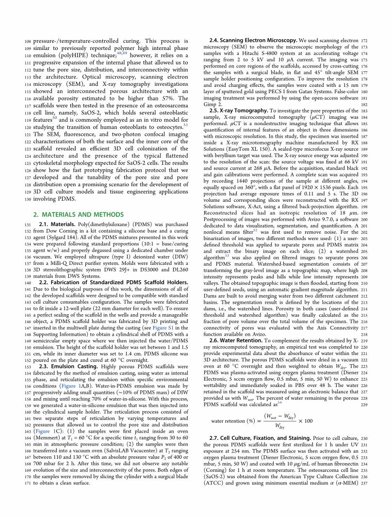
108 pressure-/temperature-controlled curing. This process is109 similar to previously reported polymer high internal phase110 emulsion (polyHIPE) technique;48,49 however, it relies on a111 progressive expansion of the internal phase that allowed us to112 tune the pore size, distribution, and interconnectivity within113 the architecture. Optical microscopy, scanning electron114 microscopy (SEM), and X-ray tomography investigations115 showed an interconnected porous architecture with an116 available porosity estimated to be higher than 57%. The117 scaffolds were then tested in the presence of an osteosarcoma118 cell line, namely, SaOS-2, which holds several osteoblastic119 features50 and is commonly employed as an in vitro model for120 studying the transition of human osteoblasts to osteocytes.51
121 The SEM, fluorescence, and two-photon confocal imaging122 characterizations of both the surface and the inner core of the123 scaffold revealed an efficient 3D cell colonization of the124 architecture and the presence of the typical flattened125 cytoskeletal morphology expected for SaOS-2 cells. The results126 show how the fast prototyping fabrication protocol that we127 developed and the tunability of the pore size and pore128 distribution open a promising scenario for the development of129 3D cell culture models and tissue engineering applications130 involving PDMS.
2. MATERIALS AND METHODS131 2.1. Materials. Poly(dimethylsiloxane) (PDMS) was purchased132 from Dow Corning in a kit containing a silicone base and a curing133 agent (Sylgard 184). All of the PDMS mixtures presented in this work134 were prepared following standard proportions (10:1 = base/curing135 agent w/w) and properly degassed using a dedicated chamber under136 vacuum. We employed ultrapure (type I) deionized water (DIW)137 from a Milli-Q Direct purifier system. Molds were fabricated with a138 3D stereolithographic system DWS 29J+ in DS3000 and DL260139 materials from DWS Systems.140 2.2. Fabrication of Standardized PDMS Scaffold Holders.141 Due to the biological purposes of this work, the dimensions of all of142 the developed scaffolds were designed to be compatible with standard143 cell culture consumables configuration. The samples were fabricated144 to fit inside a 12-well plate (22 mm diameter for each well). To ensure145 a perfect sealing of the scaffold in the wells and provide a manageable146 object, a PDMS scaffold holder was fabricated by 3D printing and147 inserted in the multiwell plate during the casting (see Figure S1 in the148 Supporting Information) to obtain a cylindrical shell of PDMS with a149 semicircular empty space where we then injected the water/PDMS150 emulsion. The height of the scaffold holder was set between 1 and 1.5151 cm, while its inner diameter was set to 1.4 cm. PDMS silicone was152 poured on the plate and cured at 60 °C overnight.153 2.3. Emulsion Casting. Highly porous PDMS scaffolds were154 fabricated by the method of emulsion casting, using water as internal155 phase, and reticulating the emulsion within specific environmental156 conditions (Figure 1A,B). Water-in-PDMS emulsion was made by157 progressively adding small quantities (∼10% of PDMS mass) of DIW158 and mixing until reaching 70% of water-in-silicone. With this process,159 we generated a water-in-silicone emulsion that was then injected into160 the cylindrical sample holder. The reticulation process consisted of161 two separate steps of reticulation by varying temperatures and162 pressures that allowed us to control the pore size and distribution163 (Figure 1C): (1) the samples were first placed inside an oven164 (Memmert) at T1 = 60 °C for a specific time t1 ranging from 30 to 60165 min in atmospheric pressure condition; (2) the samples were then166 transferred into a vacuum oven (SalvisLAB Vacucenter) at T2 ranging167 between 110 and 130 °C with an absolute pressure value P2 of 400 or168 700 mbar for 2 h. After this time, we did not observe any notable169 evolution of the size and interconnectivity of the pores. Both edges of170 the samples were removed by slicing the cylinder with a surgical blade171 to obtain a clean surface.
1722.4. Scanning Electron Microscopy. We used scanning electron173microscopy (SEM) to observe the microscopic morphology of the174samples with a Hitachi S-4800 system at an accelerating voltage175ranging from 2 to 5 kV and 10 μA current. The imaging was176performed on core regions of the scaffolds, accessed by cross-cutting177the samples with a surgical blade, in flat and 45° tilt-angle SEM178sample holder positioning configuration. To improve the resolution179and avoid charging effects, the samples were coated with a 15 nm180layer of sputtered gold using PECS I from Gatan Systems. False-color181imaging treatment was performed by using the open-access software182Gimp 2.1832.5. X-ray Tomography. To investigate the pore properties of the184sample, X-ray microcomputed tomography (μCT) imaging was185performed. μCT is a nondestructive imaging technique that allows186quantification of internal features of an object in three dimensions187with microscopic resolution. In this study, the specimen was inserted188inside a X-ray microtomography machine manufactured by RX189Solutions (EasyTom XL 150). A sealed-type microfocus X-ray source190with beryllium target was used. The X-ray source energy was adjusted191to the resolution of the scan: the source voltage was fixed at 66 kV192and source current at 268 μA. Before the acquisition, standard black193and gain calibrations were performed. A complete scan was acquired194by recording 1440 projections of the sample at different angles,195equally spaced on 360°, with a flat panel of 1920 × 1536 pixels. Each196projection had average exposure times of 0.11 and 5 s. The 3D197volume and corresponding slices were reconstructed with the RX198Solutions software, X-Act, using a filtered back-projection algorithm.199Reconstructed slices had an isotropic resolution of 18 μm.200Postprocessing of images was performed with Avizo 9.7.0, a software201dedicated to data visualization, segmentation, and quantification. A202nonlocal means filter52 was first used to remove noise. For the203binarization of images, two different methods were used: (1) a user-204defined threshold was applied to separate pores and PDMS matrix205and extract the binary image on each slice; (2) a watershed206algorithm53 was also applied on filtered images to separate pores207and PDMS material. Watershed-based segmentation consists of208transforming the gray-level image as a topographic map, where high209intensity represents peaks and hills while low intensity represents210valleys. The obtained topographic image is then flooded, starting from211user-defined seeds, using an automatic gradient magnitude algorithm.212Dams are built to avoid merging water from two different catchment213basins. The segmentation result is defined by the locations of the214dams, i.e., the watershed lines. Porosity in both cases (user-defined215threshold and watershed algorithm) was finally calculated as the216fraction of pore volume over the total volume of the specimen. The217connectivity of pores was evaluated with the Axis Connectivity218function available on Avizo.2192.6. Water Retention. To complement the results obtained by X-220ray microcomputed tomography, an empirical test was completed to221provide experimental data about the absorbance of water within the2223D architecture. The porous PDMS scaffolds were dried in a vacuum223oven at 60 °C overnight and then weighted to obtain Wdry. The224PDMS was plasma-activated using oxygen plasma treatment (Diener225Electronic, 5 sccm oxygen flow, 0.5 mbar, 5 min, 50 W) to enhance226wettability and immediately soaked in PBS over 48 h. The water227retained in the scaffold was measured using an electronic balance that228provided us with Wwet. The percent of water remaining in the porous229PDMS scaffold was calculated as54
W W
Wwater retention (%)
( )100wet dry
dry=
−×
2302.7. Cell Culture, Fixation, and Staining. Prior to cell culture,231the porous PDMS scaffolds were first sterilized for 1 h under UV232exposure at 254 nm. The PDMS surface was then activated with an233oxygen plasma treatment (Diener Electronic, 5 sccm oxygen flow, 0.5234mbar, 5 min, 50 W) and coated with 10 μg/mL of human fibronectin235(Corning) for 1 h at room temperature. The osteosarcoma cell line236(SaOS-2) was obtained from the American Type Culture Collection237(ATCC) and grown using minimum essential medium α (α-MEM)

238 containing nucleosides, GlutaMAX, (Gibco, Fisher Scientific)239 supplemented with 10% fetal bovine serum (HyClone, Fisher240 Scientific) and 1% penicillin/streptomycin mix (Gibco, Fisher241 Scientific). A cell suspension (15 000 cells/cm2) was deposited in a242 droplet of supplemented α-MEM on top of the PDMS porous scaffold243 and incubated in an atmosphere containing 5% CO2 at 37 °C for 1 h244 to enable the cells to adhere to the scaffold. Multiwell plates were then245 filled with additional supplemented α-MEM and incubated for 72 h.246 To prepare the sample for SEM characterization, cells were rinsed247 with PBS 1× (phosphate-buffered saline) solution and incubated in248 4% glutaraldehyde (Sigma) solution for 4 h at room temperature. The249 cells were then dehydrated by incubation in 50, 70, 90, and 100%250 ethanol solutions for 4 min at each step and dried for few hours at251 room temperature to remove alcohol residues. Immunofluorescence252 staining was performed as follows: cells were rinsed with PBS 1×,253 fixed with 10% formalin solution (Sigma) for 30 min, permeabilized in254 0.2% Triton X-100 for 3 min, and blocked in 3% BSA for 30 min. The255 samples were then incubated in phalloidine−rhodamine (Invitrogen,256 Fisher Scientific) at 1/200 dilution in PBS 1× for 30 min at 37 °C to257 stain the F-actin (protein of the cell cytoskeleton) and then in a DAPI258 (Thermo Scientific, Fisher Scientific) solution at 1/100 dilution in259 PBS 1× for 5 min at room temperature to stain the DNA in the260 nuclei. After staining, the cells were stored in PBS 1× solution at 4 °C.261 In an additional protocol for two-photon confocal imaging, the cells262 were rinsed with PBS 1×, stained with a mix of Hoechst (Invitrogen,263 Fisher Scientific) at 5 μg/mL plus CMFDA (Invitrogen, Fisher264 Scientific) at 1/1000 dilution in DMEM without phenol red (Gibco,265 Fisher Scientific), incubated for 30 min at 37 °C, rinsed again with266 PBS 1×, and fixed for 30 min in 10% formalin solution (Sigma). The267 samples were stored in PBS 1× at 4 °C prior to imaging.268 Cytocompatibility was assessed by Live/Dead assay in the porous269 PDMS scaffold choosing flat PDMS and glass as control. All samples270 followed the protocol of plasma treatment and fibronectin coating271 mentioned above. After 72 h of culture in supplemented α-MEM, the272 samples were rinsed in PBS and cells were stained with calcein/273 ethidium (Live/Dead viability kit for mammalian cells, Fisher
274Scientific) diluted in DMEM without phenol red for 30 min and275then rinsed with the same medium for fluorescence characterization.2762.8. Immunofluorescence Characterization. Two different277immunofluorescence imaging techniques were employed to inves-278tigate the cell distribution and proliferation taking place on the 3D279PDMS scaffolds. 2D observations of the scaffolds’ surface were280performed using an Olympus C211 fluorescence microscope281equipped with a X-Cite 120 Hg lamp, a BP (300−400 nm) filter282for DAPI, a BP (575−595 nm) filter for calcein, a BP (518−573 nm)283filter for phalloidin rhodamine/ethidium, and 5×, 10×, 20× and 50×284objectives. 3D imaging of the scaffolds were performed using a two-285photon confocal imaging system (AxioImager upright microscope286LSM 7MP, Carl Zeiss). A pulsed femtosecond Ti:sapphire laser287(Chameleon Ultra II; Coherent) tunable in the range of 690−1064288nm was used as excitation light source. Z-stack acquisitions were289performed with a 10× W-Plan Apochromat air objective with 0.45290N.A. and a laser excitation wavelength tuned at 800 nm. An automatic291z-compensation of the laser power was applied to provide a292homogeneous imaging of the imaged volume of the 3D scaffold.293Emitted light was detected through a descanned pathway leading to294two nondescanned detectors and emission was recorded simulta-295neously with two emission filters: a band pass (BP) filter, set at 500−296550 nm (green channel, CMFDA), and a short-pass (SP) filter set at297485 nm (blue channel, DAPI). Image processing and 3D298reconstruction were performed by ImageJ and Imaris (Version 8.2,299Bitplane) softwares.
3. RESULTS AND DISCUSSION
3003.1. Morphological Characterization of the PDMS301 f2Scaffolds. In Figure 2, we report how the tuning of the302fundamental curing parameters (t1, along the vertical axis, and303T2−P2, along the horizontal axis) affects the morphology of the304PDMS porous scaffolds. The increment of the prereticulation305process time affects the pore size and distribution as306highlighted by comparing the rows of each column. The first307row of Figure 2A−C, related to t1 = 30 min, shows a typical
Figure 2. SEM characterization of the cross-sectional regions in the PDMS porous scaffold for different curing parameters. Along the vertical axis,we vary the time t1 for the prereticulation stage at 60 °C. Along the horizontal axis, we vary the temperature T2 and the pressure P2 of the secondreticulation process. The scale bar is 1 mm.

308 pore size of 1−3 mm with few submillimetric pores observable.309 When increasing t1 up to 45 min, this pore size distribution310 slightly decreases (Figure 2D−F) down to 0.5−2 mm, while311 we observe at the same time an increased number of312 submillimetric pores. Finally, in the third row of Figure 2G−313 I, we report a reduction of the pore size coupled to an evident314 anisotropy of the pore orientation directed toward the open315 side of the PDMS scaffold holder.316 A lower t1 implies a less reticulated state of the PDMS within317 the emulsion when starting the final curing process. We then318 attribute the presence of large pore size (Figure 1A−C) to the319 easier expansion of the water steam in a less reticulated PDMS.320 We believe that this factor may induce the aggregation of321 submillimetric water bubbles and the consequent formation of322 larger cavities.323 By comparing the first column (A, D, G) and second column324 (B, E, H) of Figure 2, we investigate the impact of the different325 temperatures T2 (110 and 130 °C) employed in the second326 reticulation process. By fixing t1 = 30 min, we cannot find327 striking differences in pore size in Figure 2A,B, while this328 difference becomes more evident for higher prereticulation329 periods, as reported in Figure 2D−F. In Figure 2G, we can330 observe strong anisotropy, with elongated pores whose main331 semiaxis is 2- to 3-fold larger than the minor semiaxis. The332 pores of Figure 2F show lower anisotropy compared to Figure333 2G but still much higher than the one of the pores in Figure334 2B,E. We suggest that the temperature of final reticulation (T2)335 has a double impact on the reaction: on the one hand, it336 slightly modifies the speed of evaporation of the water bubbles;337 on the other hand, it varies the kinetics of the reticulation of338 the silicone. As we observe from the comparison of Figure339 2G,H, a lower temperature indeed tends to benefit the340 appearance of intrinsic anisotropy of the sample, which can be341 linked to a higher state of reticulation during the expansion of342 the water steam bubbles.343 The third column (Figure 2C,F,I) explores the same344 temperature T2 (130 °C) as in the second column (Figure345 2B,E,H) but with a different pressure P2 (700 mbar instead of
346400 mbar). By observing the samples obtained with a short347prereticulation time t1 (Figure 2B,C), it is possible to highlight348the impact of the pressure over the pore size. While the sample3492B features an average pore size of 1−3 mm, sample 2C350presents a critical decrease of the typical size to 0.7−1.2 mm.351For t1 = 45 min, we observe the same tendency of reduced352typical pore size within the PDMS porous scaffold, although353this transition is less evident for the samples at 700 mbar354(Figure 2C,F) than for the samples at 400 mbar (Figure 2B,E).355Concerning the last row (Figure 2H,I), at long prereticulation356time (60 min), we perceive a major reduction on the pore size357coupled to a slight decrease in anisotropy of the pores. This358behavior fits with the results obtained in the rest of the samples359for those parameters.360The general overview of Figure 2 shows then a progressive361decrement of the pore size by increasing the time of362prereticulation t1, which leads, at the same time, to an increase363of the number of pores. We observe also an anisotropy364tendency linked to the reticulation time (i.e., longer t1365increases the reticulation state of the silicone before the366evaporation of the steam). This induces less motility in the367emulsion that in turn leads to a further expansion of the368bubbles in the direction of the apertures of the PDMS sample369holder. Temperature T2, on the other hand, plays a dual role in370the kinetics of the water evaporation and the kinetics of the371reticulation process within the emulsion. Finally, pressure P2372hinders the expansion of the bubbles, limiting the final pore373size. From a microscopic point of view, the PDMS porous374scaffold presents a hierarchical porous structuration. A close-up375view of the bulk material between the larger pores for different376fabrication parameters (t1, T2, P2) reveals a network of377interconnected pores featuring smaller dimensions (5−30 μm)378with openings of 1−5 μm (see Figure S2). This induces a379roughness on the surface that might influence the perfusion380and diffusion of culture medium with a global impact for the381cell environment.382To provide a more quantitative analysis of the pore size and383spatial distribution, we performed a characterization of the
Figure 3. (A) 3D view of the PDMS scaffold after segmentation process. On the right, crosscuts of the reconstruction along the xy and xz planes.(B) 3D view of the pores: nonconnected pores (red), connected pores (white). On the right, crosscuts of the reconstruction along the xy and xzplanes. (C) Optical micrograph of the inner core of a PDMS porous scaffold. (D) 3D colorimetric view of the pores size distribution with awatershed-based algorithm. (E) Distribution of the number of pores according to the pore size depicted in (D).

384 PDMS porous scaffold by employing X-ray tomography. The385 selected sample corresponds to the one of Figure 2B with t1 =386 30 min, T2 = 130, and P2 = 400 mbar, which was then387 employed as 3D cell culture support.388 Figure S3A shows a reconstructed slice of the sample, after389 denoizing with a nonlocal means filter. A user-defined390 threshold was applied on each slice of the sample, leading to391 a stack of binarized images, as presented Figure S3B,392 corresponding to the slice shown in Figure S3A. The 3D393 reconstructed view of the PDMS porous scaffold in Figure 3A394 shows the porosity of the 3D architecture (whose optical395 micrograph is reported in Figure 3C). The crosscut views for396 the xy and xz planes show the inner core of the 3D397 architecture, proving a highly interconnected network with a398 wide spectrum of porosity. From those data, a porosity equal to399 around 57% was calculated from the binarized images (Figure400 S3C). A second validation of porosity using a watershed401 segmentation algorithm (for details, see Materials and402 Methods) was performed, resulting in a porosity equal to403 58.7%, as presented in Figure 3D. Connectivity of pores was404 also studied with the Axis Connectivity module available in405 Avizo. Figure 3B shows in red the nonconnected pores and in406 white the connected ones. The total volume of pores is equal407 to 406.2 mm3 in the sample, and nonconnected pores408 represent only 4.3 mm3, corresponding to 1% of the total409 volume of pores. Nonconnected pores are either small pores410 <100 μm in the matrix or pores that are localized in the walls411 of the cylindrical support.412 Finally, pore size distribution was analyzed. The histogram413 plot in Figure 3E represents the distribution of pore equivalent414 diameter, whose colorimetric 3D visualization linking pore
415diameters to different colors is reported in Figure 3D. The416majority of the pores were reported to have a diameter417between 0.02 and 0.10 mm (more detailed histograms are418reported in Figure S4), although smaller pores (observed by419SEM, Figure S2) could not be resolved due to resolution420limitation (18 μm) of the X-ray microcomputed tomography421setup (see Materials and Methods). These results were422complemented with measurements of water retention423performed over 48 h in the porous PDMS scaffold. As424shown in Figure S5 and in the Supporting Video “Video_-425liquid_loading”, the percent of water remaining in the scaffold426after soaking it in PBS for different periods of time increases427until reaching a value close to ∼300% (w:w). This value agrees428with the high porosity and interconnectivity estimated by μCT.4293.2. SEM and Immunofluorescence Characterization430of SaOS-2 Cell Colonization of the PDMS Scaffolds. To431validate the compatibility of the developed PDMS architec-432tures as a 3D cell culture tool, we tested the scaffold topology433depicted in Figure 2B in the presence of SaOS-2 cells. Due to434the morphology of the SaOS-2 cells and the topographical435features of the PDMS porous scaffold, distinguishing the cells436directly over a rugose surface is a laborious task. This is evident437after comparing the morphologies of the osteosarcoma SaOS-2438cell line on untreated PDMS flat surfaces (Figure S6A) and on439plasma treated/fibronectin-coated PDMS surfaces (Figure440S6B). While on untreated surfaces we observe the same ratio441of cells holding the expected flattened morphology and the less442conventional globular one, on the treated surfaces we report443only the flattened cytoskeletal configuration coupled to a more444marked expression of typical round protrusions already445observed elsewhere.55 In such context, the role of roughness
Figure 4. (A−C) False-colored SEM images highlighting the SaOS-2 cell morphology obtained on the PDMS porous scaffold; (D)immunofluorescence imaging of SaOS-2 cells colonizing the pores of the porous PDMS scaffold; (E) close-up view on the region enclosed in theblue dotted square in (D); (F) SaOS-2 “cellular-carpet” observed on the PDMS porous scaffold surface (red: phalloidin-F-actin; blue: DAPI-nuclei).

446 and surface chemistry regulating cell adhesion mechanisms has447 been previously observed for nonpolymeric surfaces.56,57
448 In addition to its role in the adsorption of adhesion proteins,449 plasma treatments are indeed known to induce the presence of450 nanotopography features and surface chemistry changes, which451 are reflected in an augmentation of oxygen content and an452 enhancement of surface energy associated with an increase in453 wettability that influences cell adhesion on polymeric454 surfaces.58,59 Concerning the distribution and welfare of cells455 within the PDMS porous scaffold, in Figure 4A−C, we present456 false-colored SEM close-up images highlighting the typical cell457 morphology that we observed in different regions of the458 scaffold. SaOS-2 cells tend to develop cytoskeletal extensions459 anchoring to the side walls of the micropores in a460 tridimensional spatial configuration, as observed in Figure461 4A,B. The evidence of the flattened elongated morphology of a462 cluster of cells in other regions of the scaffold characterized by463 PDMS meshes is shown in Figure 4C. Furthermore, we can464 discriminate several round protuberances within the cellular
465cytoskeleton that we associate with regular features of466mineralized buds and calcospherulites related to the process467of mineral deposition of this cell line.60,61 This behavior could468be associated with a predifferentiation stage, although a deeper469evaluation of differentiation markers is required to confirm this470assessment. Prospective analysis of the calcification process by471red alizarin staining will be carried out in the future to validate472this conclusion. Furthermore, cell viability test, shown in473Figure S7, was addresses by Live/Dead assay on the porous474PDMS scaffold against two positive controls, flat PDMS and475glass. Cell viability reached ∼99% of the cell population over476the porous PDMS scaffold. This result compares with the477performance of both positive controls showing as well a cell478viability of ∼99% and a more homogeneous cell distribution.479To better visualize typical morphological features of the480SaOS cells cultured on the 3D scaffold, in Figure 4D−F, we481report the epifluorescence characterization of the osteosarcoma482cells over the PDMS porous scaffold. In Figure 4D, we can483observe the cell spreading and colonization of different pores,
Figure 5. Two-photon confocal imaging of the PDMS porous scaffold colonized by SaOS-2 cells. (A) xy view of the 3D reconstruction of thescaffold imaged with the laser beam impinging the sample as shown in the inset; (B) xz view of the 3D reconstruction in (A); (C) xz view of the3D reconstruction of a cross-cut of the scaffold imaged with the laser beam impinging the sample as shown in the inset; (D) xy view of the 3Dreconstruction in (C) (the inset shows the sample orientation and the region depicted in the 3D reconstruction (green: CMFDA; blue: DAPI-nuclei)).

484 where the F-actin, the main component of microfilaments in485 the cytoskeleton, is stained in red with phalloidin/rhodamine486 while the nuclei are stained in blue with DAPI. We can487 distinguish several cells colonizing the full structure at different488 out-focus planes. In Figure 4E, we show the close-up view of a489 single pore (enclosed by the blue square in Figure 4D)490 depicting how the elongated cytoskeleton of the cells adapts to491 the surrounding environments by following the geometrical492 profile of the pore. Finally, in Figure 4F, we present a493 fluorescence image of another region of the scaffold where we494 can easily identify cell nuclei and observe how cells cover495 homogeneously the whole surface of the PDMS porous496 scaffold.497 To get a clear view of the 3D cell colonization scenario of498 the PDMS porous scaffold, in Figure 5, we report several 3D499 reconstructions obtained via two-photon confocal imaging, a500 widely used technique for unveiling cell features in the inner501 core of 3D architectures otherwise not accessible by more502 conventional morphological imaging approaches (e.g., SEM503 and AFM).33,35 In Figure 5A,B, we report the characterization504 of the upper part of the 3D scaffold (i.e., the one on which the505 cell medium containing the SaOS-2 cells was deposited),506 impinged by the laser beam as shown in the inset of Figure 5A,507 where we highlighted the nuclear marker DAPI (in blue) and508 the CMFDA one (in green), which is able to stain the whole509 cytoplasm of the cells (Figure S8). The overall field of view of510 the acquisition is 1.96 × 1.30 × 0.49 mm3 (obtained by511 employing a mosaic modality where we imaged smaller areas512 and then stitched them together). Figure 5A shows a quite513 homogeneous cell coverage of the PDMS scaffold surface,514 while Figure 5B highlights how cells are able to colonize the515 inner part of the architecture by infiltrating open pores (such516 as the one on the left-hand side of the figure). We attribute the517 absence of cells in the central part of the 3D reconstruction518 either to the small dimensions of the pores (compared to the519 SaOS-2 cell size) in that region or, more likely, to the fact that520 denser regions of PDMS (becoming opaque during the521 fabrication because of the trapping of air bubbles) hinder the522 passage of photons. A clearer overview of the 3D imaging523 acquisition can be seen in the Supporting Video “Video_-524 top_surface”. To have a further insight into the cellular525 distribution within the 3D scaffold, we performed also a cross-526 cut on it by using a surgical blade to reveal the inner part of the527 structure. Figure 5C,D shows, respectively, the x, z and x, y528 views of a 1.30 × 1.96 × 2.19 mm3 region of the PDMS porous529 scaffold (always by employing the mosaic modality mentioned530 above) with the laser impinging this time the inner surface of531 the cross-cut, as depicted in the inset of Figure 5C. The two532 different views show the presence of omnidirectional cell533 clusters infiltrating both the superficial layers of the scaffold534 and the inner areas down to a depth ≈2.2 mm along the z axis535 and ≈2 mm along the y axis. A high-resolution video536 (“Video_cross_cut”) of the slices composing the 3D537 reconstruction is available in the Supporting Information.
4. CONCLUSIONS538 In this work, we reported a novel 3D structuration technique539 that provides a fast and cheap process to fabricate porous540 scaffolds made of a widely used biocompatible silicone such as541 PDMS. This technique involves a simple combination of water542 and silicone to form an emulsion that is further transformed543 into a highly porous scaffold using a two-step reticulation544 process. The fabrication takes place under temperature-/
545pressure-controlled environment that could be easily scalable546for mass production. Scanning electron microscopy character-547ization provided a deep understanding of the different achieved548morphologies confirming a control of the porous distribution549associated with a hierarchical macro-micro structuration of the550available surface that could have an impact on the biological551perfusion and diffusion of nourishment. 3D morphological552characterization was carried out by X-ray computed tomog-553raphy and allowed to evaluate the general porosity and the size554distribution of the pores as well as to investigate the555interconnectivity of the PDMS porous scaffold. The format556chosen to evaluate the performance of cell culture presented a557general porosity of ∼60% with a ∼98% global interconnectiv-558ity. Osteosarcoma SaOS-2 cells were seeded on the PDMS559porous scaffold to evaluate the efficiency of the cell560colonization and perfusion. SEM investigation in combination561with fluorescence immune-staining imaging demonstrated a562high level of cell adhesion and some features of advanced cell563maturation. Two-photon confocal reconstruction displayed564information about the cell colonization taking place within565volumes of several mm3 in the inner core of the scaffold,566proving a homogeneous tridimensional distribution of cells and567their proliferation through all of the available pores.568As the fabrication process is simple, adapted with injection569techniques, and amenable to large-scale production, we believe570that it will open intriguing opportunities aiming at the571integration of 3D porous scaffolds in bioreactors or micro-572physiological systems. Further studies will be devoted to the573impact of the scaffold porosity and architecture on inner flow574patterns provided by microfluidic systems and subsequent575studies on cell proliferation and differentiation.
576
577*S Supporting Information
5803D model of the 3D-printed mold employed for the581fabrication of the PDMS sample holder; SEM close-up582images of the PDMS nest scaffold for different583reticulation conditions; X-ray tomography analysis,584porosity, and pore diameter distribution; and SEM and585immunofluorescence characterization of SaOS-2 cells586(PDF)
587Video_top_surface (MP4)
588Video_cross_cut (MP4)
589Video_liquid_loading (MP4)
590■ AUTHOR INFORMATION591Corresponding Authors592*E-mail: [email protected]. Phone: +31(0)152781610593(A.A.).594*E-mail: [email protected], [email protected]. Phone:595+33(0)561336384. Fax: +33(0)561553577 (L.M.).596ORCID597Thierry Leichle: 0000-0003-3183-8976598Angelo Accardo: 0000-0003-0442-3652599Present Address600
⊥Department of Precision and Microsystems Engineering,601Delft University of Technology, Mekelweg 2, 2628 CD Delft,602The Netherlands (A.A.).

603 Author Contributions604 The manuscript was written through contributions of all605 authors. All authors have given approval to the final version of606 the manuscript.
607 Funding608 The present work was supported by the H2020 European609 project HOLIFab (Grant No. 760927). It was as well partly610 supported as part of the MultiFAB project funded by FEDER611 European Regional Funds and French Region Occitanie (grant612 agreement number: 16007407/MP0011594).
613 Notes614 The authors declare no competing financial interest.
615 ■ ACKNOWLEDGMENTS
616 This work was partly supported by the LAAS-CNRS micro-617 and nanotechnologies platform member of the French618 RENATECH network. The authors acknowledge the support619 of Sophie Allart and Daniele Daviaud from the INSERM620 Centre de Physiopathologie de Toulouse-Purpan (CPTP) of621 Toulouse during the multiphoton confocal imaging acquis-622 itions. They also acknowledge the support of FERMAT623 Federation to this work.
624 ■ REFERENCES(1)625 Xiang, Z.; Cao, D. Porous Covalent−Organic Materials:
626 Synthesis, Clean Energy Application and Design. J. Mater. Chem. A627 2013, 1, 2691−2718.
(2)628 Wang, W.; Zhou, M.; Yuan, D. Carbon Dioxide Capture in629 Amorphous Porous Organic Polymers. J. Mater. Chem. A 2017, 5,630 1334−1347.
(3)631 Kim, S.; Lee, Y. M. Rigid and Microporous Polymers for Gas632 Separation Membranes. Prog. Polym. Sci. 2015, 43, 1−32.
(4)633 Kaur, P.; Hupp, J. T.; Nguyen, S. T. Porous Organic Polymers in634 Catalysis: Opportunities and Challenges. ACS Catal. 2011, 1, 819−635 835.
(5)636 Lande, B.; Mitzner, W. Analysis of Lung Parenchyma as a637 Parametric Porous Medium. J. Appl. Physiol. 2006, 101, 926−933.
(6)638 Zhao, M.; Li, L. Dissecting the Bone Marrow HSC Niches. Cell639 Res. 2016, 26, 975−976.
(7)640 Loh, Q. L.; Choong, C. Three-Dimensional Scaffolds for Tissue641 Engineering Applications: Role of Porosity and Pore Size. Tissue Eng.,642 Part B 2013, 19, 485−502.
(8)643 Zhu, D.; Handschuh-Wang, S.; Zhou, X. Recent Progress in644 Fabrication and Application of Polydimethylsiloxane Sponges. J.645 Mater. Chem. A 2017, 5, 16467−16497.
(9)646 McDonald, J. C.; Anderson, D. C. D. J. R.; Chiu, D. T.; Wu, H.;647 Schueller, O. J. A.; Whitesides, G. M. Fabrication of Microfluidic648 Systems in Poly(Dimethylsiloxane). Electrophoresis 2000, 21, 27−40.
(10)649 Jung, S.; Kim, J. H.; Kim, J.; Choi, S.; Lee, J.; Park, I.; Hyeon,650 T.; Kim, D.-H. Reverse-Micelle-Induced Porous Pressure-Sensitive651 Rubber for Wearable Human-Machine Interfaces. Adv. Mater. 2014,652 26, 4825−4830.
(11)653 Shi, J.; Zhang, H.; Jackson, J.; Shademani, A.; Chiao, M. A654 Robust and Refillable Magnetic Sponge Capsule for Remotely655 Triggered Drug Release. J. Mater. Chem. B 2016, 4, 7415−7422.
(12)656 Liu, W.; Chen, Z.; Zhou, G.; Sun, Y.; Lee, H. R.; Liu, C.; Yao,657 H.; Bao, Z.; Cui, Y. 3D Porous Sponge-Inspired Electrode for658 Stretchable Lithium-Ion Batteries. Adv. Mater. 2016, 28, 3578−3583.
(13)659 Liang, S.; Li, Y.; Chen, Y.; Yang, J.; Zhu, T.; Zhu, D.; He, C.;660 Liu, Y.; Handschuh-Wang, S.; Zhou, X. Liquid Metal Sponges for661 Mechanically Durable, All-Soft, Electrical Conductors. J. Mater. Chem.662 C 2017, 5, 1586−1590.
(14)663 Duan, S.; Yang, K.; Wang, Z.; Chen, M.; Zhang, L.; Zhang, H.;664 Li, C. Fabrication of Highly Stretchable Conductors Based on 3D665 Printed Porous Poly(Dimethylsiloxane) and Conductive Carbon
666Nanotubes/Graphene Network. ACS Appl. Mater. Interfaces 2016, 8,6672187−2192.
(15) 668Han, J.-W.; Kim, B.; Li, J.; Meyyappan, M. Flexible,669Compressible, Hydrophobic, Floatable, and Conductive Carbon670Nanotube-Polymer Sponge. Appl. Phys. Lett. 2013, 102, No. 051903.
(16) 671McCall, W. R.; Kim, K.; Heath, C.; La Pierre, G.; Sirbuly, D. J.672Piezoelectric Nanoparticle−Polymer Composite Foams. ACS Appl.673Mater. Interfaces 2014, 6, 19504−19509.
(17) 674Belanger, M. C.; Marois, Y. Hemocompatibility, Biocompati-675bility, Inflammatory and in Vivo Studies of Primary Reference676Materials Low-Density Polyethylene and Polydimethylsiloxane: A677Review. J. Biomed. Mater. Res. 2001, 58, 467−477.
(18) 678Mata, A.; Fleischman, A. J.; Roy, S. Characterization of679Polydimethylsiloxane (PDMS) Properties for Biomedical Micro/680Nanosystems. Biomed. Microdevices 2005, 7, 281−293.
(19) 681Vaysse, L.; Beduer, A.; Sol, J. C.; Vieu, C.; Loubinoux, I.682Micropatterned Bioimplant with Guided Neuronal Cells to Promote683Tissue Reconstruction and Improve Functional Recovery after684Primary Motor Cortex Insult. Biomaterials 2015, 58, 46−53.
(20) 685Zhou, J.; Ellis, A. V.; Voelcker, N. H. Recent Developments in686PDMS Surface Modification for Microfluidic Devices. Electrophoresis6872010, 31, 2−16.
(21) 688Halldorsson, S.; Lucumi, E.; Gomez-Sjoberg, R.; Fleming, R. M.689T. Advantages and Challenges of Microfluidic Cell Culture in690Polydimethylsiloxane Devices. Biosens. Bioelectron. 2015, 63, 218−691231.
(22) 692Lotters, J. C.; Olthuis, W.; Veltink, P. H.; Bergveld, P. The693Mechanical Properties of the Rubber Elastic Polymer Polydimethylsi-694loxane for Sensor Applications. J. Micromech. Microeng. 1997, 7, 145−695147.
(23) 696Merkel, T. C.; Bondar, V. I.; Nagai, K.; Freeman, B. D.; Pinnau,697I. Gas Sorption, Diffusion, and Permeation in Poly(Dimethylsiloxane)698The Permeability of Poly(Dimethylsiloxane) [PDMS] To. J. Polym.699Sci., Part B: Polym. Phys. 2000, 38, 415−434.
(24) 700Piruska, A.; Nikcevic, I.; Lee, S. H.; Ahn, C.; Heineman, W. R.;701Limbach, P. A.; Seliskar, C. J. The Autofluorescence of Plastic702Materials and Chips Measured under Laser Irradiation. Lab Chip7032005, 5, 1348.
(25) 704Haycock, J. W. 3D Cell Culture: A Review of Current705Approaches and Techniques. In 3D Cell Culture; Humana Press,7062010; pp 1−15.
(26) 707McKee, C.; Chaudhry, G. R. Advances and Challenges in Stem708Cell Culture. Colloids Surf., B 2017, 159, 62−77.
(27) 709Ingber, D. E. Cellular Mechanotransduction: Putting All the710Pieces Together Again. FASEB J. 2006, 20, 811−827.
(28) 711Ranga, A.; Gobaa, S.; Okawa, Y.; Mosiewicz, K.; Negro, A.;712Lutolf, M. P. 3D Niche Microarrays for Systems-Level Analyses of713Cell Fate. Nat. Commun. 2014, 5, No. 4324.
(29) 714Do, A.-V.; Khorsand, B.; Geary, S. M.; Salem, A. K. 3D Printing715of Scaffolds for Tissue Regeneration Applications. Adv. Healthcare716Mater. 2015, 4, 1742−1762.
(30) 717Wang, Z.; Abdulla, R.; Parker, B.; Samanipour, R.; Ghosh, S.;718Kim, K. A Simple and High-Resolution Stereolithography-Based 3D719Bioprinting System Using Visible Light Crosslinkable Bioinks.720Biofabrication 2015, 7, No. 045009.
(31) 721Accardo, A.; Courson, R.; Riesco, R.; Raimbault, V.; Malaquin,722L. Direct Laser Fabrication of Meso-Scale 2D and 3D Architectures723with Micrometric Feature Resolution. Addit. Manuf. 2018, 22, 440−724446.
(32) 725Lemma, E. D.; Spagnolo, B.; De Vittorio, M.; Pisanello, F.726Studying Cell Mechanobiology in 3D: The Two-Photon Lithography727Approach. Trends Biotechnol. 2019, 37, 358−372.
(33) 728Accardo, A.; Blatche, M. C.; Courson, R.; Loubinoux, I.; Vieu,729C.; Malaquin, L. Two-Photon Lithography and Microscopy of 3D730Hydrogel Scaffolds for Neuronal Cell Growth. Biomed. Phys. Eng.731Express 2018, 4, No. 027009.
(34) 732Accardo, A.; Blatche, M.-C.; Courson, R.; Loubinoux, I.; Vieu,733C.; Malaquin, L. Direct Laser Fabrication of Free-Standing PEGDA-

734 Hydrogel Scaffolds for Neuronal Cell Growth: Engineering 3D735 Biocompatible Microenvironments. Mater. Today 2018, 21, 315−316.
(35)736 Accardo, A.; Blatche, M.-C.; Courson, R.; Loubinoux, I.;737 Thibault, C.; Malaquin, L.; Vieu, C. Multiphoton Direct Laser Writing738 and 3D Imaging of Polymeric Freestanding Architectures for Cell739 Colonization. Small 2017, 13, No. 1700621.
(36)740 Jia, W.; Gungor-Ozkerim, P. S.; Zhang, Y. S.; Yue, K.; Zhu, K.;741 Liu, W.; Pi, Q.; Byambaa, B.; Dokmeci, M. R.; Shin, S. R.; et al. Direct742 3D Bioprinting of Perfusable Vascular Constructs Using a Blend743 Bioink. Biomaterials 2016, 106, 58−68.
(37)744 Carve, M.; Wlodkowic, D. 3D-Printed Chips: Compatibility of745 Additive Manufacturing Photopolymeric Substrata with Biological746 Applications. Micromachines 2018, 9, 91.
(38)747 Tebboth, M.; Jiang, Q.; Kogelbauer, A.; Bismarck, A. Inflatable748 Elastomeric Macroporous Polymers Synthesized from Medium749 Internal Phase Emulsion Templates. ACS Appl. Mater. Interfaces750 2015, 7, 19243−19250.
(39)751 Zargar, R.; Nourmohammadi, J.; Amoabediny, G. Preparation,752 Characterization, and Silanization of 3D Microporous PDMS753 Structure with Properly Sized Pores for Endothelial Cell Culture.754 Biotechnol. Appl. Biochem. 2016, 63, 190−199.
(40)755 Mohanty, S.; Larsen, L. B.; Trifol, J.; Szabo, P.; Burri, H. V. R.;756 Canali, C.; Dufva, M.; Emneus, J.; Wolff, A. Fabrication of Scalable757 and Structured Tissue Engineering Scaffolds Using Water Dissolvable758 Sacrificial 3D Printed Moulds. Mater. Sci. Eng., C 2015, 55, 569−578.
(41)759 Dahlberg, T.; Stangner, T.; Zhang, H.; Wiklund, K.; Lundberg,760 P.; Edman, L.; Andersson, M. 3D Printed Water-Soluble Scaffolds for761 Rapid Production of PDMS Micro-Fluidic Flow Chambers. Sci. Rep.762 2018, 8, No. 3372.
(42)763 Díaz Lantada, A.; Alarcon Iniesta, H.; Pareja Sanchez, B.;764 García-Ruíz, J. P. Free-Form Rapid Prototyped Porous PDMS765 Scaffolds Incorporating Growth Factors Promote Chondrogenesis.766 Adv. Mater. Sci. Eng. 2014, 2014, 1−10.
(43)767 Li, Q.; Duan, T.; Shao, J.; Yu, H. Fabrication Method for768 Structured Porous Polydimethylsiloxane (PDMS). J. Mater. Sci. 2018,769 53, 11873−11882.
(44)770 Chen, I.-J.; Lindner, E. The Stability of Radio-Frequency771 Plasma-Treated Polydimethylsiloxane Surfaces. Langmuir 2007, 23,772 3118−3122.
(45)773 Kim, D. H.; Jung, M. C.; Cho, S.-H.; Kim, S. H.; Kim, H.-Y.;774 Lee, H. J.; Oh, K. H.; Moon, M.-W. UV-Responsive Nano-Sponge for775 Oil Absorption and Desorption. Sci. Rep. 2015, 5, No. 12908.
(46)776 Pedraza, E.; Brady, A.-C.; Fraker, C. A.; Stabler, C. L. Synthesis777 of Macroporous Poly(Dimethylsiloxane) Scaffolds for Tissue778 Engineering Applications. J. Biomater. Sci., Polym. Ed. 2013, 24,779 1041−1056.
(47)780 Pedraza, E.; Brady, A.-C.; Fraker, C. A.; Molano, R. D.; Sukert,781 S.; Berman, D. M.; Kenyon, N. S.; Pileggi, A.; Ricordi, C.; Stabler, C.782 L. Macroporous Three-Dimensional PDMS Scaffolds for Extrahepatic783 Islet Transplantation. Cell Transplant. 2013, 22, 1123−1135.
(48)784 Carnachan, R. J.; Bokhari, M.; Przyborski, S. A.; Cameron, N.785 R. Tailoring the Morphology of Emulsion-Templated Porous786 Polymers. Soft Matter 2006, 2, 608.
(49)787 Silverstein, M. S. PolyHIPEs: Recent Advances in Emulsion-788 Templated Porous Polymers. Prog. Polym. Sci. 2014, 39, 199−234.
(50)789 Rodan, S. B.; Imai, Y.; Thiede, M. A.; Wesolowski, G.;790 Thompson, D.; Bar-Shavit, Z.; Shull, S.; Mann, K.; Rodan, G. A.791 Characterization of a Human Osteosarcoma Cell Line (Saos-2) with792 Osteoblastic Properties. Cancer Res. 1987, 47, 4961−4966.
(51)793 Prideaux, M.; Wijenayaka, A. R.; Kumarasinghe, D. D.;794 Ormsby, R. T.; Evdokiou, A.; Findlay, D. M.; Atkins, G. J. SaOS2795 Osteosarcoma Cells as an in Vitro Model for Studying the Transition796 of Human Osteoblasts to Osteocytes. Calcif. Tissue Int. 2014, 95,797 183−193.
(52)798 Buades, A.; Coll, B.; Morel, J. M. In A Non-Local Algorithm for799 Image Denoising, Proceedings - 2005 IEEE Computer Society800 Conference on Computer Vision and Pattern Recognition, CVPR801 2005, 2005; Vol. II, pp 60−65.
(53) 802Schluter, S.; Sheppard, A.; Brown, K.; Wildenschild, D. Image803Processing of Multiphase Images Obtained via X-Ray Micro-804tomography: A Review. Water Resour. Res. 2014, 3615−3639.
(54) 805Varshney, N.; Sahi, A. K.; Vajanthri, K. Y.; Poddar, S.;806Balavigneswaran, C. K.; Prabhakar, A.; Rao, V.; Mahto, S. K.807Culturing Melanocytes and Fibroblasts within Three-Dimensional808Macroporous PDMS Scaffolds: Towards Skin Dressing Material.809Cytotechnology 2019, 71, 287−303.
(55) 810Wiggan, O.; Hamel, P. A. Pax3 Regulates Morphogenetic Cell811Behavior in Vitro Coincident with Activation of a PCP/Non-812Canonical Wnt-Signaling Cascade. J. Cell Sci. 2002, 115, 531−541.
(56) 813Onesto, V.; Cancedda, L.; Coluccio, M. L.; Nanni, M.; Pesce,814M.; Malara, N.; Cesarelli, M.; Di Fabrizio, E.; Amato, F.; Gentile, F.815Nano-Topography Enhances Communication in Neural Cells Net-816works. Sci. Rep. 2017, 7, No. 9841.
(57) 817Onesto, V.; Villani, M.; Narducci, R.; Malara, N.; Imbrogno, A.;818Allione, M.; Costa, N.; Coppede, N.; Zappettini, A.; Cannistraci, C.819V.; et al. Cortical-like Mini-Columns of Neuronal Cells on Zinc Oxide820Nanowire Surfaces. Sci. Rep. 2019, 9, No. 4021.
(58) 821Kim, J.-H.; Seo, S.; Min, J. Epithelial Cell Patterns on a PDMS822Polymer Surface Using a Micro Plasma Structure. J. Biotechnol. 2011,823155, 308−311.
(59) 824Accardo, A.; Shalabaeva, V.; La Rocca, R. Colon Cancer Cells825Adhesion on Polymeric Nanostructured Surfaces. MRS Commun.8262018, 8, 35−39.
(60) 827Schroder, H. C.; Boreiko, O.; Krasko, A.; Reiber, A.;828Schwertner, H.; Muller, W. E. G. Mineralization of SaOS-2 Cells on829Enzymatically (Silicatein) Modified Bioactive Osteoblast-Stimulating830Surfaces. J. Biomed. Mater. Res., Part B 2005, 75, 387−392.
(61) 831Barreau, C.; Labit, E.; Guissard, C.; Rouquette, J.; Boizeau, M.832L.; Gani Koumassi, S.; Carriere, A.; Jeanson, Y.; Berger-Muller, S.;833Dromard, C.; et al. Regionalization of Browning Revealed by Whole834Subcutaneous Adipose Tissue Imaging. Obesity 2016, 24, 1081−1089.