Design, fabrication, and testing of PDMS pneumatic micro ...
33
University of Arkansas, Fayetteville University of Arkansas, Fayetteville ScholarWorks@UARK ScholarWorks@UARK Mechanical Engineering Undergraduate Honors Theses Mechanical Engineering 5-2011 Design, fabrication, and testing of PDMS pneumatic micro-pumps Design, fabrication, and testing of PDMS pneumatic micro-pumps and micro-mixers and micro-mixers Allison Byrum University of Arkansas, Fayetteville Follow this and additional works at: https://scholarworks.uark.edu/meeguht Citation Citation Byrum, A. (2011). Design, fabrication, and testing of PDMS pneumatic micro-pumps and micro-mixers. Mechanical Engineering Undergraduate Honors Theses Retrieved from https://scholarworks.uark.edu/ meeguht/20 This Thesis is brought to you for free and open access by the Mechanical Engineering at ScholarWorks@UARK. It has been accepted for inclusion in Mechanical Engineering Undergraduate Honors Theses by an authorized administrator of ScholarWorks@UARK. For more information, please contact [email protected].
-
Upload
khangminh22 -
Category
Documents
-
view
0 -
download
0
Transcript of Design, fabrication, and testing of PDMS pneumatic micro ...

University of Arkansas, Fayetteville University of Arkansas, Fayetteville
ScholarWorks@UARK ScholarWorks@UARK
Mechanical Engineering Undergraduate Honors Theses Mechanical Engineering
5-2011
Design, fabrication, and testing of PDMS pneumatic micro-pumps Design, fabrication, and testing of PDMS pneumatic micro-pumps
and micro-mixers and micro-mixers
Allison Byrum University of Arkansas, Fayetteville
Follow this and additional works at: https://scholarworks.uark.edu/meeguht
Citation Citation Byrum, A. (2011). Design, fabrication, and testing of PDMS pneumatic micro-pumps and micro-mixers. Mechanical Engineering Undergraduate Honors Theses Retrieved from https://scholarworks.uark.edu/meeguht/20
This Thesis is brought to you for free and open access by the Mechanical Engineering at ScholarWorks@UARK. It has been accepted for inclusion in Mechanical Engineering Undergraduate Honors Theses by an authorized administrator of ScholarWorks@UARK. For more information, please contact [email protected].

DESIGN, FABRICATION, AND TESTING OF PDMS PNEUMATIC MICRO-PUMPS AND MICRO-MIXERS

DESIGN, FABRICATION, AND TESTING OF PDMS PNEUMATIC MICRO-PUMPS AND MICRO-MIXERS
A thesis submitted in partial fulfillment of the requirements for honors distinction in the degree of
Bachelor of Science in Mechanical Engineering
By
Allison I. Byrum
May 2011 University of Arkansas
Abstract This thesis details the design, fabrication, and testing of PDMS pneumatic
micro-‐pumps and micro-‐mixer. Each micro-‐pump and micro-‐mixer was fabricated from two layers of poly(dimethlysiloxane) (PDMS) and two glass slides. The PDMS layers were realized through soft lithography using micro molds fabricated from thick SU-‐8 photoresist. The packaged devices were tested for flow rates (micro-‐pump) and rate of mixing (micro-‐mixer) on a custom-‐designed test platform. The test result indicated that the micro-‐pump failed to deliver a measurable flow rate, most likely due to insufficient diaphragm deflection. For the micro-‐mixer, a slight increase in mixing was detected when the mixer was activated. It can be speculated that even greater mixing could be realized with improved alignment between the mixing chamber and mixer diaphragms. Additionally, an increase in actuation pressure might also increase the mixing efficiency. Overall, the PDMS pneumatic micro-‐pumps and micro-‐mixers hold great promise for future lab-‐on-‐a-‐chip systems in biomedical applications.
iv
This thesis is approved for Recommendation to the Graduate Council
Thesis Director:
Thesis Committee:

v
THESIS DUPLICATION RELEASE
I hereby authorize the University of Arkansas Libraries to duplicate this Thesis when
needed for research and/or scholarship.
Agreed
Allison Byrum
Refused ________________________
Allison Byrum

vi
Acknowledgements
The author would like to thank her graduate and doctorate lab mates Balaji
Srinivasan, Orain Hibbert, and Jacob Hohnbaum for their instruction, aid and
companionship during the last year.
Thanks are extended also to Kyle Godin and the rest of Adam Huang’s lab for help
with and use of their contact aligner.
Finally, the author wishes to thank Steve Tung for being communicative, and taking
the time to instruct and direct an undergraduate.
vii
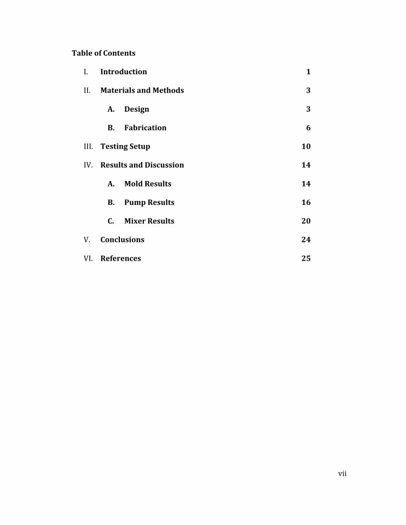
Table of Contents
I. Introduction 1
II. Materials and Methods 3
A. Design 3
B. Fabrication 6
III. Testing Setup 10
IV. Results and Discussion 14
A. Mold Results 14
B. Pump Results 16
C. Mixer Results 20
V. Conclusions 24
VI. References 25
1
Introduction
The biomedical field is pursuing the miniaturization of lab testing
components. Reducing the size of test components increases the portability and can
decrease the expense of mass production and shipping, with the effect that testing
units could be disseminated to developing nations where they may be the only
access to medical tests a population has. Miniaturization of testing devices also
reduces the amount of reagent necessary to complete a test. This is the primary
reason for the exploding development of so called lab-‐on-‐a-‐chip systems in recent
years.
One requirement of biomedical testing is precise flow rates. Frequently, a
precise amount of one reagent must be mixed with a precise amount of another.
Ensuring good mixing is also necessary in order for biomedical reactions to take
place as desired. To ensure complete reaction, convective instead of diffusion
dominated mixing is desirable..
Micro-‐pumps and micro-‐mixers play an important role in a lab-‐on-‐a-‐chip
system. These micro devices have been in development since the 1980s and take
many forms, including those using piezoelectric, electroosmotic, and pneumatic
actuation [1]. In a micro-‐flow environment, adhesive forces dominate cohesive
forces and micro-‐pump and micro-‐mixer designs can therefore be significantly
different from their conventional counterparts.
In the present study, the performance of PDMS pneumatic micro-‐pumps and
micro-‐mixers was examined. Pneumatic actuation has many attractive properties,
such as widespread availability of pressured air for actuation and use of relatively

2
common or inexpensive materials for fabrication [2, 3]. The specific objectives of
this research were to design, fabricate, and test a micro-‐pump for flow rate
capability and a micro-‐mixer for mixing efficiency.
3
Methods and Materials
Micro-‐Pump Design
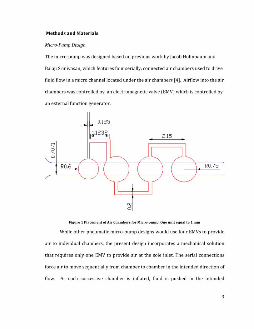
The micro-‐pump was designed based on previous work by Jacob Hohnbaum and
Balaji Srinivasan, which features four serially, connected air chambers used to drive
fluid flow in a micro channel located under the air chambers [4]. Airflow into the air
chambers was controlled by an electromagnetic valve (EMV) which is controlled by
an external function generator.
Figure 1 Placement of Air Chambers for Micro-‐pump. One unit equal to 1 mm
While other pneumatic micro-‐pump designs would use four EMVs to provide
air to individual chambers, the present design incorporates a mechanical solution
that requires only one EMV to provide air at the sole inlet. The serial connections
force air to move sequentially from chamber to chamber in the intended direction of
flow. As each successive chamber is inflated, fluid is pushed in the intended
4
direction along the micro-‐channel (Figure 1). The actuation sequence of the micro-‐
pump is as follows:
1) Air pressure is applied at the air inlet
2) Air pressure reaches the first diaphragm
a) First diaphragm displaces fluid in the micro-‐channel
b) Air pressure reaches the next diaphragm which further displaces the
fluid
The air pressure is prevented from immediately reaching subsequent diaphragms
because the backpressure exerted by the sharp reduction in diameter initially
overcomes the pressure delivered to the inlet. The EMV controls how rapidly
pressure is applied, influencing flow rate.
Micro-‐Mixer Design
Fluid flow in a micro-‐channel tends to be characterized by low Reynolds
numbers, indicating that flow regimes are laminar. Because of the lack of
turbulence, mixing takes place primarily through diffusion. The rate of diffusion is
typically much lower than desired for biomedical purposes, so a micro-‐mixer can be
used to improve mixing rates through forced convection.
The present micro-‐mixer design consists of a circular mixing chamber where
two fluid streams can meet. Several diaphragms arranged in a circle are placed
against this chamber, so that when the diaphragms deflect, they force fluid to flow to
either side. The two fluid streams are forced into one another, causing velocity
oscillations and enabling mixing.
5
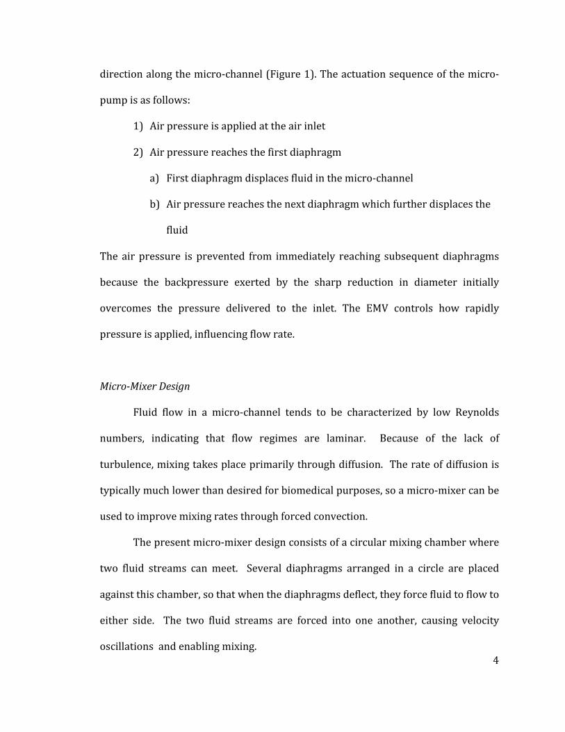
Figure 2 Design of Micro-‐Mixer. One unit equal to 1 mm
As demonstrated in Figure 2, the diaphragms are teardrop-‐shaped to
efficiently and evenly cover the area of the mixing chamber. Space is left between
them for fluid to flow to either side when they are inflated. With the micro-‐pump,
the chambers were spaced out along the fluid channel which allowed for some time
to elapse before the subsequent chamber inflated, but with the micro-‐mixer, the
chambers are close together. Therefore, they are connected by “serpentine”
channels, the compact design of which allows for a long channel to fit in a small area,
allowing for the time to elapse [5].
The material used to fabricate the diaphragms must withstand large
deflections, be insoluble in water, and chemically inert. PDMS suits these purposes.
The yield strength of Sylgard 184 has been shown to be very high, meaning it is
unlikely to fail from yielding [6]. Also, PDMS is optically transparent, facilitating
testing.

6
The technique by which the PDMS layers are fabricated is soft lithography,
where a material is cast onto a permanent mold and lifted off. The mold itself is
fabricated via photolithography on a silicon wafer. The mold material must be
easily deposited and patterned up to 100µm, the channel depth. All channels are the
same depth to simplify the fabrication process, so only one patterning step is
required. Microchem’s SU-‐8 is a photoresist that is available in different
formulations to achieve desired thicknesses, and its behavior is well documented.
For 100 µm, the formula used was SU-‐8 2075; thickness varies with spin speed
when spincoating a wafer, so 100 µm thick SU-‐8 2075 is achieved by spinning it on
at 2100 rpm.
Fabrication Recipes
The micro-‐pump and micro-‐mixer are fabricated from two PDMS layers
packaged on two glass slides. Glass is not an ideal packaging medium for mass
distribution; it is heavy, brittle, and expensive, but for development and testing
purposes, its optical transparency makes it ideal for visual inspections and
PDMS/glass bonding is well-‐understood and straight-‐forward.
The mold for soft lithography is composed of SU-‐8 on a 4 in. diameter silicon
wafer. The recipe used to fabricate the molds follows:
1. Prepare wafer by cleaning with a succession of acetone, isopropyl
alcohol (IPA), and deionized (DI) water. Bake for 30 minutes at 210 °C
2. Spincoat Omnicoat (an adhesion aid) at 3000 RPM. Bake for 5 minutes
at 210 °C
7
3. Spincoat 4 mL of SU-‐8 2075 at 2100 RPM for 30 seconds for 100 µm
depth.
a. Soft bake 5 minutes at 65 °C
b. Step up to 95 °C for 15 minutes.
4. Expose to filtered UV light for 2 minutes at approximately 230 mJ/cm2
a. Bake for 4 minutes at 65 °C
b. Step up to 95 °C for 9 minutes
c. Remove from hotplate and cool for 2 minutes
5. Develop in SU-‐8 developer for 9 minutes with minimal agitation. After
developing, rinse with IPA and DI water and dry with N2
6. Hard bake at 150 °C for 30 minutes
The initial step 1 bake will remove surface moisture from the wafer. Bakes 3
and 4 are stepped to prevent rapid thermal expansion of the SU-‐8 layer, reducing
the incidence of surface cracks. The cooling step 4c prevents the SU-‐8 from
contracting suddenly when dipped into developer. The wafer should not be rinsed
with acetone, as that will tend to strip the SU-‐8. If the IPA rinses off a milky white
color, the pattern is underdeveloped and should be returned to the developer bath.
Fabrication of the PDMS layers is as follows:
1. Mix PDMS base and curing agent in 10:1 ratio
a. 6 mL base, .6 mL curing agent for air side
b. 7 mL base, .6 mL curing agent for fluid side
c. Desiccate for 10 minutes
2. Pour PDMS onto molds
8
a. Spincoat air side at 400 RPM for 30 seconds for thickness of
250 µm
b. Manually tilt fluid side wafer to achieve total coverage
3. Bake at 80 °C for 2 hours
4. Prepare glass slide packaging
a. Drill 2 mm holes with diamond tip bit at each inlet and outlet
b. Rinse with acetone, IPA, then DI Water, and dry with N2
5. Bond PDMS to glass slide
a. Cut out devices with razorblade or X-‐ACTO knife
b. Lay device on temporary slide with the bonding side out
i. Glass/PDMS bonding side for air is the open channel
ii. Glass/PDMS bonding side for fluid is closed channel
c. Run temporary and permanent slides in O2 plasma at 103
mTorr and differential power of 20 W for 20 seconds
d. Peel off PDMS and align to permanent slide, avoiding air
bubbles
e. Pierce hole at the fluid inlets
f. Repeat step c with the two permanent slides, then align them
and bond, avoiding air bubbles.
6. Attach connectors onto all inlets with epoxy
a. 3/16 in. connectors for fluid inlets
b. 1/16 in. connectors for air inlets

9
Figure 3 PDMS with Air Bubbles
The PDMS is placed in a desiccator in step 1c to prevent the formation of air
bubbles in the PDMS at corners and interfaces around the features like those visible
in Figure 3 where they appear as small circles.
It is recommended to treat the inside of the microchannel with Pluronic anti-‐
foaming solution. This prevents the formation of air bubbles inside the channel on
the PDMS. When air bubbles are present in the fluid channel, diaphragm deflections
will compress the bubbles instead of advancing the fluid, and the overall flow rate of
the micro-‐pump will be diminished.
10
Testing Setup and Procedures
Pump Testing
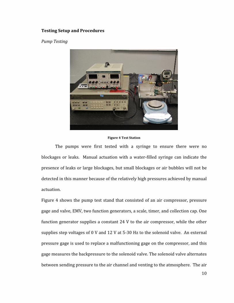
Figure 4 Test Station
The pumps were first tested with a syringe to ensure there were no
blockages or leaks. Manual actuation with a water-‐filled syringe can indicate the
presence of leaks or large blockages, but small blockages or air bubbles will not be
detected in this manner because of the relatively high pressures achieved by manual
actuation.
Figure 4 shows the pump test stand that consisted of an air compressor, pressure
gage and valve, EMV, two function generators, a scale, timer, and collection cap. One
function generator supplies a constant 24 V to the air compressor, while the other
supplies step voltages of 0 V and 12 V at 5-‐30 Hz to the solenoid valve. An external
pressure gage is used to replace a malfunctioning gage on the compressor, and this
gage measures the backpressure to the solenoid valve. The solenoid valve alternates
between sending pressure to the air channel and venting to the atmosphere. The air
11
valve regulates the pressure to be between 8 – 15 psi, which is near the range used
by Wang and Lee [3]. A short length of 3/16 in. Tygon tube is attached to the fluid
inlet, nearest the diaphragms, and acts as a reservoir from which flow could come.
A longer length of 3/16 in. tubing is attached to the fluid outlet, and was bent back
into the collection cap, a centrifuge tube. Before pumping, the entire channel and
outlet tube are manually filled with water, “priming” the pump, and driving out
potential air bubbles. The outlet tube is filled to the point of having a meniscus
jutting out of the end of the tube, and a small amount of water is placed in the
centrifuge tube and massed to ascertain its initial mass. Then the outlet tube is
placed beneath the surface of the centrifuge fluid, clamped at a level such that the
fluid surface’s height matches the inlet reservoir’s fluid height. This eliminates
effects due to Pascal’s Law. So long as the difference in height is zero, the pressure
exerted on the fluid is the same at both inlet and outlet. Otherwise, this would cause
flow effects outside the influence of the micro-‐pump.
Visual inspection is carried out with a CCD camera attachment on a stereo-‐
microscope, connected to the video-‐in port on a computer. Fluid flow is detected if
small bubbles pass through the channel and the deflection of the diaphragms are
detectable.
The flow testing is conducted by running the pump at varying pressures and
frequencies for a period of two minutes and recording the starting and ending
masses.
12
Mixer Testing
The mixers were tested in a fashion similar to the pumps. First, a syringe
was used to pump water into the fluid channel to check for port blockage and leaks.
Then, if water could flow from one side to another, the mixing test was performed.
Because the mixers were fabricated alone without a pump, all fluid flow was
advanced manually with a syringe.
The mixer test stand is nearly identical to the pump test stand; the only
difference is the solenoid valve is connected to the inlet port of the mixer; an air
compressor provided 8 psi air to the solenoid valve, which switched between
exhausting and porting the air out at certain frequencies set by a function generator.
Green and blue household food dyes were mixed with water in a high ratio—about
10 drops for 40 mL—as lower ratios were nearly invisible due to the extreme
thinness of the fluid layer. The green water was syringed into a 3 in. length of tube
connected to one inlet, and the blue was syringed into a 3 in. length of tube
connected to the other inlet. The level of water in each tube was kept uniform to
ensure that both flows would enter the mixing chamber at the same time.
A length of tubing was connected to the fluid outlet, and a syringe was used
to provide suction to pull the two fluids into the mixing chamber. The fluid was
pulled from the outlet instead of being pushed at the inlet for two reasons: with one
syringe, the same pressure can be exerted on both streams easily as long as there is
no trapped air on one side. This prevents the inlets from leaking if the connectors
are not watertight.

13
A CCD video camera was connected to a computer and recorded the mixing
chamber starting from the time at which manual suction at the outlet ceased for a
period of 80 seconds. This procedure was repeated for three frequencies of the
solenoid valve switching—1 Hz, 2 Hz, and 5 Hz—as well as with no diaphragm
deflection. The coloration of the mixing chamber was compared at 20 second
intervals. A diffused interface between the two injected food dyes indicated a high
degree of mixing, whereas a clear interface indicated little or no mixing.
14
Results and Discussion
Mold Fabrication
Several molds were fabricated with the contact aligner. Two molds could be
fabricated simultaneously, taking about two hours. The first issue encountered in
fabricating molds was having bubbles in the SU-‐8 spread across the surface of the
wafer. These persisted after baking and exposure, and they may have come from
the way SU-‐8 was dispensed on the surface. The second run did not have the issue
with air bubbles, but more critically, when both runs were inspected under
microscope, the molds revealed several breakdowns in the serpentine channel.
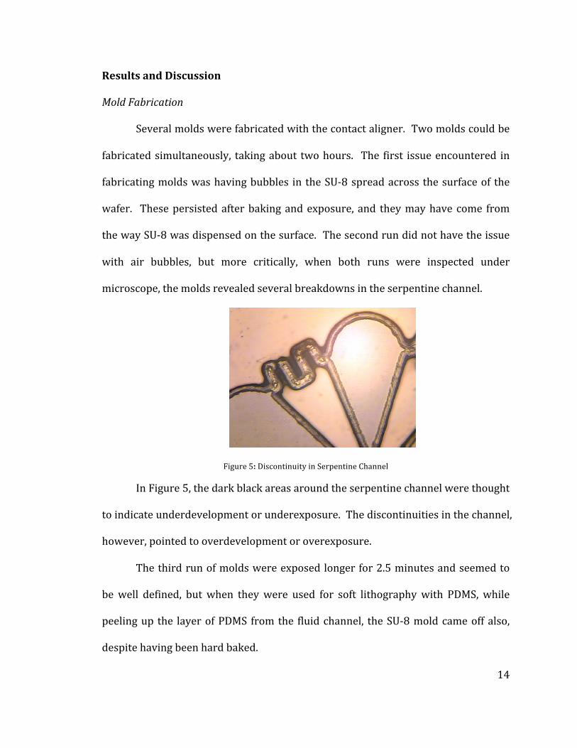
Figure 5: Discontinuity in Serpentine Channel
In Figure 5, the dark black areas around the serpentine channel were thought
to indicate underdevelopment or underexposure. The discontinuities in the channel,
however, pointed to overdevelopment or overexposure.
The third run of molds were exposed longer for 2.5 minutes and seemed to
be well defined, but when they were used for soft lithography with PDMS, while
peeling up the layer of PDMS from the fluid channel, the SU-‐8 mold came off also,
despite having been hard baked.

15
It was theorized the Omnicoat coating had enabled the release of the SU-‐8.
The fourth run was conducted without Omnicoat, and the features washed
off during development.
The final run was conducted with Omnicoat at the original 2-‐minute
exposure time, but development was very gentle, with almost no agitation. The
features stayed on the wafer for one PDMS casting, but came off from the second.
Figure 6 shows the mixer from this mold.
Figure 6 Mold 5 Mixer Detail
This evidence seems to suggest that the exposure time of 2 minutes is too
long; over-‐exposure is causing the features to be undercut. This is consistent with
the fact that only parts of the mold with a high perimeter to surface area ratio, such
as the fluid channels which are long and narrow, and the identifying letters, which
are also very thin, were what came off. A small amount of undercutting would have
drastic effects for a shape with a long perimeter and relatively little surface area.
Because none of the SU-‐8 molds were usable, a known good mold was
borrowed from Balaji Srinivasan to use in completing the fabrication and testing of

16
the micro-‐mixer. Work in fabricating and testing a micro-‐pump of the same design
was completed in Fall 2010 and is presented below.
Pump Fabrication and Testing Results
Figure 7 shows a completed micro-‐pump. A total of five micro-‐pumps were
fabricated for the study.
Figure 7: Micro-‐pump
The first pump was fabricated and showed a successful initial flow test, with
no leakages. Some minor air bubbles were noted but were not close to the features,
and not expected to impact flow. This pump was treated with an uncertain
concentration of Pluronic. The result of the flow test is shown in Figure 8.
Figure 8 Volumetric flow with respect to pressure
-‐0.01
-‐0.005
0
0.005
0.01
0.015
8 9 10 11 12 13 14
Volumetric Flow
(mL/
min)
Pressure (psi)
Volumetric Flow vs. Pressure at 10Hz
17
This figure indicates several issues. The first of which is that in three
instances, the flow was either negative or close to zero, meaning fluid was either not
pumped or was pumped backwards. The second is that the data points show
significant scatter and no clearly defined trend. The third issue is the very low
magnitudes. At such low magnitudes, it cannot be definitively said that the change
in mass resulted from micropump flow instead of a stray water droplet. Visual
inspection during the testing procedure did not indicate any drop in water level in
the reservoir as was expected.
Some causes of this were theorized to be some or all of the following: an
incorrect concentration of Pluronic, especially as the concentration was unknown;
an incorrectly primed pump, with air bubbles inside; an ineffective working
frequency.
A second test was begun to check the change in water level at the inlet
reservoir at different frequencies, but no change in water level was noticed. The
glass slide on the waterside broke, terminating the experiment prematurely. The
pump was also observed under microscope, but the application of epoxy obscured
all but one diaphragm, and no bubbles were sighted along the rest of the
microchannel.
The subsequent three pumps were not fabricated successfully. For Pump 2,
the fluid side PDMS was incorrectly applied to the glass slide, blocking off the
microchannel and reservoir. However, the airside PDMS was placed on the other
glass slide without bonding, and Pump 2 served as a tactile guide for future
fabrication in order that the correct sides would be bonded.
18
Pump 3 had epoxy covering one of the fluid inlets, so no flow was possible.
An attempt to pierce the epoxy was made, but did not succeed.
Pump 4 had a large air bubble that came in contact with both the
microchannel and edge of the PDMS. Therefore, a flow test was conducted before
connectors were applied, and the microchannel leaked fluid.
Pump 5 was fabricated and had an air bubble adjacent to the microchannel,
but not touching the edge of the PDMS. When the manual flow test was conducted,
it did not leak, so connectors were applied. The epoxy was applied carefully to
obstruct the view of the diaphragms and microchannel as little as possible. Due to
time constraints, the epoxy was only allowed to sit for fifteen minutes, and Pluronic
was not applied to the inside of the microchannel.
The initial flow test did not indicate a change in water level of the inlet
reservoir for several pressures between 6 and 16 psi and frequencies between 5 and
30 Hz. Visual inspection at 1 Hz revealed that what had been taken for fluid flow
when testing Pump 1 was the deflection of the air diaphragms. Pump 5 was then
placed under a microscope during testing, and no water was detected moving in the
microchannel. Video was taken of this test, and shows the deflection of the
diaphragms, but no fluid movement. However, fluid motion may not be easily
spotted without a tracer of some sort. Incidental bubbles, polystyrene beads, or a
dye would serve to indicate the passage of fluid. However, a dye would diffuse too
rapidly to be distinguishable from flow, and bubbles would impede the effect of the
micropump. Beads also could get trapped in the microchannel and be difficult to
remove.

19
The lack of flow is theorized to be a result of one or more of the following:
incorrect application of Pluronic; poorly defined fluid entrance where the PDMS was
punched to create a hole to the microchannel reservoir; position of pump
diaphragms with relation to the microchannel reservoir. Incorrect application of
Pluronic would cause the formation flow-‐impeding air bubbles to be more likely.
The fluid inlet hole, if poorly formed, could have residual PDMS that could block the
flow of fluid under low pressures, meaning that manual actuation would be able to
deflect a stray piece of PDMS, and so flow would seem possible, but under
pneumatic actuation, there would not be enough pressure to deflect the blockage
and allow flow. This theory comes from difficulty in punching the fluid layer holes.
The ideal punch would be 2 mm in diameter, but that sized punch did not fit into the
drilled holes, so a smaller size was used, and several attempts were made to extract
the PDMS, so a stray piece of PDMS remaining inside the reservoir could be likely.
At present, there is little to indicate the location of the pump diaphragms with
respect to the microchannel reservoir would have a great effect on the effectiveness
of the micropump, but it may be worth looking into in future work.
It is not believed that the epoxy set time had an effect on the pump
effectiveness. The only result of soft epoxy should be a looseness in the connectors,
which was not observed.

20
Mixer Fabrication and Testing Results
Three micro-‐mixers were fabricated for this study and are shown in Figure 9.
Figure 9: Mixer 1, 2, 3 Mixing Chamber Detail
The first mixer (Figure 9, left) had very good alignment between the mixing
chamber and mixer diaphragms, and few air bubbles, but at least two of the fluid
ports were blocked, so that no flow was possible through the fluid channel. When
DI water was pumped into the fluid layer ports, one inlet and the outlet showed no
fluid entering the fluid channels. The second inlet port showed some fluid entering
the channel, but when manual actuation was ceased, it did not stay, but was pushed
back to the inlet because of the built-‐up in pressure of air trapped at the other ports.
Thus, with two ports blocked, the entire device was effectively blocked.
The second device (Figure 9, center) had issues with the PDMS/PDMS
bonding, and when pressure was exerted to try to force the trapped air out, one
glass slide broke. This resulted in a leaking mixer.
The third device (Figure 9, right, Figure 10) had some leakage occurring at
fluid inlet A, but this did not preclude testing. Figure 9 shows how the green dye
leaked out of inlet A and stained the outside of inlet B. The fluid outlet had a cavity
where fluid could collect, but it did not leak to the outside. The absence of green

21
color on inlet B indicates the presence of epoxy, suggesting that about half of the
inlet is covered. Green can be seen in the fluid channels and mixing chamber as well.
The alignment for this device was the worst of the three mixers, but the majority of
the mixer diaphragms did overlap the mixing chamber.
Figure 10 Mixer 3 Ports
For the third micro-‐mixer, mixing was poor for all actuation conditions (no
actuation, 1 Hz, 2 Hz, and 5 Hz) as demonstrated in Figures 11 through 14 However,
as the frequency increased, the sharpness of the interface between green and blue
coloring decreased where the mixer diaphragms were positioned. If this device had
been properly positioned so that the center of the diaphragms overlapped the
blue/green color interface, the mixing may have been better.
22
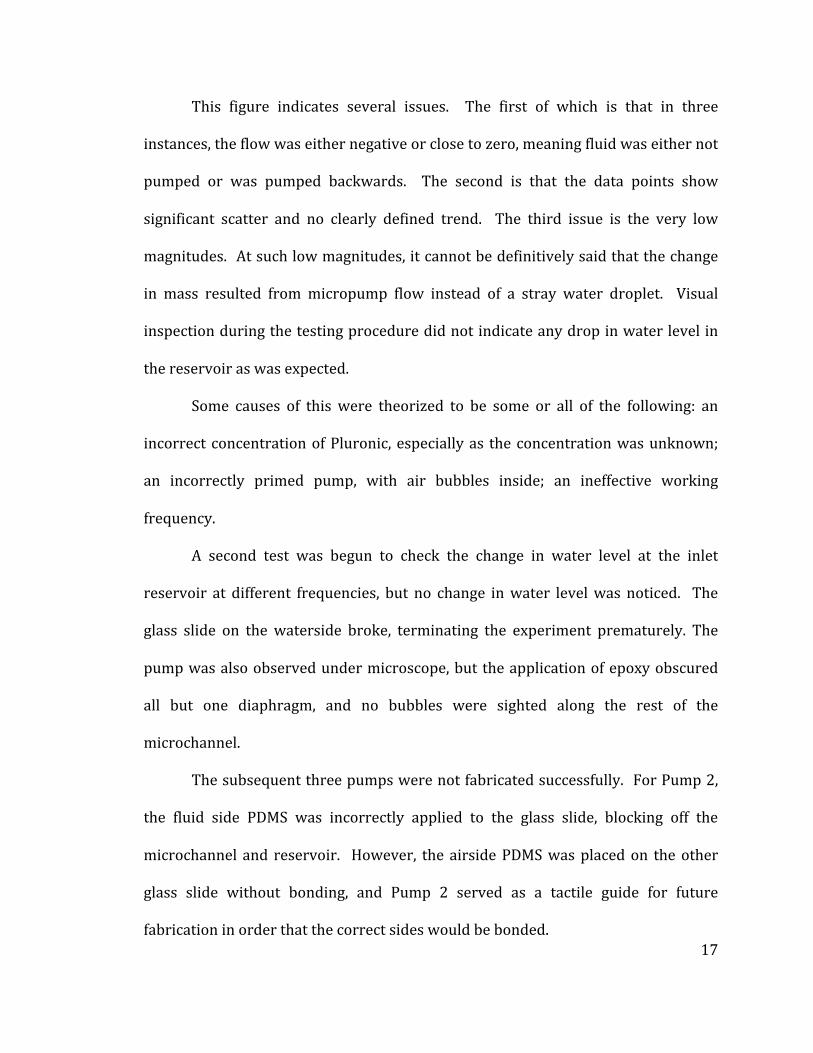
Figure 11: Before and after diffusion for 80 sec
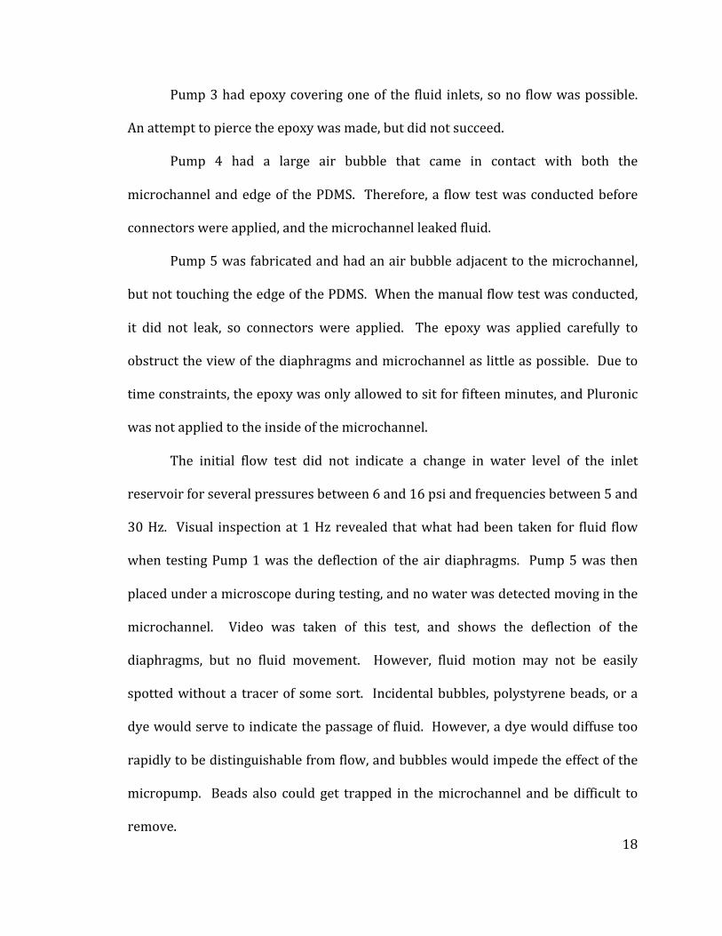
Figure 12: Before and after mixing at 1 Hz for 80 sec
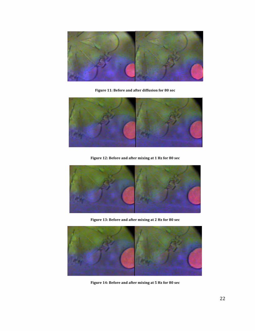
Figure 13: Before and after mixing at 2 Hz for 80 sec
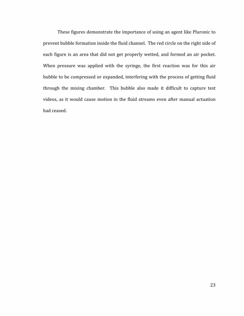
Figure 14: Before and after mixing at 5 Hz for 80 sec
23
These figures demonstrate the importance of using an agent like Pluronic to
prevent bubble formation inside the fluid channel. The red circle on the right side of
each figure is an area that did not get properly wetted, and formed an air pocket.
When pressure was applied with the syringe, the first reaction was for this air
bubble to be compressed or expanded, interfering with the process of getting fluid
through the mixing chamber. This bubble also made it difficult to capture test
videos, as it would cause motion in the fluid streams even after manual actuation
had ceased.

24
Conclusions
Five PDMS pneumatic micro-‐pumps were fabricated and tested for the study.
Two out of the five pumps conduct fluid successfully. Unfortunately, none of the
pumps fabricated demonstrated a measurable flow rate. This is most likely due to
insufficient diaphragm deflection.
Three PDMS pneumatic micro-‐mixers were fabricated and tested. The test
result showed low amounts of mixing, probably because of misalignment between
the mixing chamber and mixer diaphragms. Mixing increased slightly with respect
to frequency, and was slightly higher than diffusion-‐only mixing.
The present study indicated that the performance of the peristaltic micro-‐
pump and micro-‐mixer is sensitive to fabrication flaws. Small imperfections in
PDMS or glass chip surfaces can cause air bubbles, and the plasma bonding method
used is intolerant of mistakes in device placement.
Some methods that may improve performance of the pumps and mixers are
proper application of the hydrophobic Pluronic solution to prevent the formation of
air bubbles, careful application of epoxy to prevent inlet blockages, and careful
positioning of the air diaphragms with respect to the microchannel.

25
References
1. Laser, D. J., and Santiago, J. G., “A review of micropumps”
2. “Performance Evaluation of a Pneumatic-‐based Micromixer for
Bioconjugation Reaction,” Balaji Srinivasan*, Ju Seok Lee, Jacob
Hohnbaum, Steve Tung, and Jin-‐Woo Kim, Proceedings of the 5th
Annual IEEE Annual International Conference on Nano/Mico
Engineered and Molecular Systems (NEMS), Xiamen, China, January
2010.
3. “Investigation of a PDMS based micromixer for Heterogeneous
Immunoassays of Insulin,” Zhikun Zhan, Balaji Srinivasan, Steve Tung,
Yanli Qu, Wen J. Li, Zaili Dong, and Shuai Wang, Proceedings of the 5th
Annual IEEE Annual International Conference on Nano/Mico
Engineered and Molecular Systems (NEMS), Xiamen, China, January
2010.
4. “Insulin Detection Based on a PDMS Microfluidic System,” Zhan, Z. K.,
Yao, P., Dong, Z., Tung, S., Hohnbaum, J., Srinivasan, B., Li, W. J.,
Proceedings of IEEE International Conference on Nano/Molecular
Medicine & Engineering (NANOMED), Hong Kong, December 2010.
5. Armani, Deniz, Liu, Chang, and Aluru, Narayan, “Re-‐Configurable Fluid
Circuits By PDMS Elastomer Micromachining”Wang, C., and Lee, G.,
"Pneumatically Driven Peristaltic Micropumps Utilizing Serpentine-‐
shape Channels”.
6. Schneider, Fellner, Wilde, and Wallrabe “Mechanical properties of
silicones for MEMS”, Journal of Micromechanics and Microengineering,
April 2009.