X5200 SERIES PNEUMATIC INKER INSTALLATION AND ...
54
Document 820-0058 X5200 SERIES PNEUMATIC INKER INSTALLATION AND OPERATION MANUAL Revision AC June, 2021 X5200 SERIES PNEUMATIC INKER INSTALLATION AND OPERATION MANUAL 820-0058 Revision AC June, 2021 X5200 Pneumatic Inker X5210 Pneumatic Inker
-
Upload
khangminh22 -
Category
Documents
-
view
0 -
download
0
Transcript of X5200 SERIES PNEUMATIC INKER INSTALLATION AND ...

Document 820-0058 X5200 SERIES PNEUMATIC INKER INSTALLATION AND OPERATION MANUAL Revision AC June, 2021
X5200 SERIES PNEUMATIC INKER INSTALLATION
AND OPERATION MANUAL
820-0058 Revision AC June, 2021
X5200 Pneumatic Inker
X5210 Pneumatic Inker

2 820-0058
SERVICE AND SUPPORT INFORMATION
Telephone: (707) 763-7799
OR (800) 767-9543
1360 Redwood Way, Suite A Petaluma, CA 94954
FAX: (707) 763-2631 Internet: www.xandexsemi.com
Email: [email protected] International Distributors
China PREMTEK HOLDING CO. LTD. (Shanghai) 2F, No.1077 ZuChongZhi Rd Zhang Jiang Hi-Tech Park PuDong New Area Shanghai 201203 Peoples Republic of China Telephone: 86-21-50275859 Fax: 86-21-50275877 Contact: Jason Huang Email: [email protected] Website: www.premtek.com.tw Japan HUGLE ELECTRONICS, INC. 4-5-7 Iidabashi, Chiyoda-Ku Tokyo, Japan 102-0072 Telephone: (81) 3.3263.6661 Fax: (81) 3.3263.6668 Email: [email protected] Website: www.hugle.co.jp Korea HUGLE ELECTRONICS, INC. Br. Office: 2FL Hugle Bldg. 86-14 Garak-Dong, Songpa-Ku Seoul, Korea 138-803 Telephone: +82 (02) 431-7477 Fax: +82 (02) 449-6295 Email: [email protected] Website:www.hugle.co.kr Taiwan PREMTEK INTERNATIONAL 4F, No. 47, Lane 2, Kuang-Fu Road Sec 2, Hsinchu City Taiwan R.O.C. Telephone: (886) 35.722000 Fax: (886) 35.725000 Email: [email protected] Website: www.premtek.com.tw

820-0058 3
SAFETY INFORMATION
Safety and Hazard identification symbols used in this document are intended to be compliant with ANSI/NEMA Z 535.6 2006. The table below lists the symbols used in this document along with a description of each type of safety hazard. Failure to observe identified safety risks may result in serious injury or death.
Safety and Hazard Identification Symbols SYMBOL DESCRIPTION
DANGER = Indicates a hazardous situation which, if not avoided, will result in death or serious injury
WARNING = Indicates a hazardous situation which, if not avoided, could result in death or serious injury.
CAUTION = Indicates a hazardous situation which, if not avoided, could result in minor or moderate injury.
NOTICE = Indicates a practice that is not related to personal injury, but may cause damage to equipment or property.
Use this product only in the manner described in this manual. If the equipment is used in a manner not specified by the manufacturer, the protection provided by the equipment may be impaired.
Install the pneumatic controller in a location that is easily accessible to the operator. The ON/OFF switch is the pneumatic controller’s main disconnecting device and must be easily accessible at all times.
For your safety, the AC power cord set provided with your product has a grounded plug. Always use the power cord with a properly grounded wall outlet, to avoid the risk of electrical shock.
Do not operate this product with a damaged AC power cord set. If the AC power cord set is damaged in any manner, replace it immediately. Damaged cords may result in user exposure to hazards.
DANGER
WARNING
CAUTION
WARNING
WARNING
WARNING
WARNING

4 820-0058
The power cord set received with the product meets the requirements for use in the country where you purchased the equipment. Use only the power cord provided with the unit or an authorized replacement power cord from Xandex Inc. or an approved Xandex distributor. Use of an inadequately rated power cord may result in shock or injury.
Do not operate this product with a damaged DC power supply. If the DC power supply is damaged in any manner, replace it immediately. A damaged DC power supply may result in user exposure to hazards.
The DC power supply received with the product meets the requirements for use in the country where you purchased the equipment. Use only the DC power supply provided with the unit or an authorized replacement power supply from Xandex Inc. or an approved Xandex distributor. Use of an inadequately rated power supply may result in shock or injury.
CONTROLLER REDESIGN Xandex DieMark® pneumatic controllers with serial numbers 4000 and higher represent a new design that replaces the controller’s internal AC/DC transformer with a new, external AC/DC power supply. This manual revision documents the new controller design with external power supply. If you have a pneumatic controller with a direct AC input, please go to the product manuals section of the Xandex Semiconductor Products website at www.xandexsemi.com to locate the manual for your controller model. No change has been made to the Inker assembly or the way it operates and connects to the pneumatic controller. Inker assemblies can be used interchangeably with new and old controller versions. Please note that in order to obtain your desired dot size, you may have to adjust dot size thumbwheel settings when using an inker with a different controller. Please contact Xandex Customer Service with any questions regarding this design change or any other feature of your Xandex DieMark Inking System.
WARNING
WARNING
WARNING

820-0058 5
Table Of Contents
Section 1. Introduction .............................................................................................. 1-1
Theory of Operation ..................................................................................................... 1-1
Section 2. System Overview ...................................................................................... 2-1
System Components..................................................................................................... 2-1
Section 3. Installation ................................................................................................ 3-1
X5200 Inker Installation .............................................................................................. 3-1
X5210 Inker Installation .............................................................................................. 3-3
Pneumatic Controller Setup ......................................................................................... 3-5
Section 4. System Operation ..................................................................................... 4-1
Controller Operation .................................................................................................... 4-1
Ink Cartridge ................................................................................................................ 4-5
Cartridge Priming and Use Tips .................................................................................. 4-8
Ink Cartridge Labeling ................................................................................................. 4-9
Cartridge Type Label Color Coding .......................................................................... 4-10
Section 5. Ink.............................................................................................................. 5-1
General Information ..................................................................................................... 5-1
Ink Curing .................................................................................................................... 5-1
General Notes on Ink Curing ....................................................................................... 5-2
Ink Curing Guidelines .................................................................................................. 5-3
Ink Removal Information ............................................................................................. 5-4
Section 6. Maintenance & Troubleshooting ............................................................ 6-1
Ink Troubleshooting ..................................................................................................... 6-1
Inker Troubleshooting .................................................................................................. 6-3
6 820-0058
Shuttle Maintenance..................................................................................................... 6-5
Pneumatic Controller ................................................................................................... 6-9
Controller Diagnostics ............................................................................................... 6-10
Controller Troubleshooting ........................................................................................ 6-12
Internal Maintenance ................................................................................................. 6-13
Section 7. System Specifications ............................................................................... 7-1
DC Power Supply Requirements ................................................................................. 7-1
Pneumatic Controller Specifications ............................................................................ 7-1
Ink Cartridge Specifications ........................................................................................ 7-3
Cartridge Availability .................................................................................................. 7-3
Dot Size Guidelines in Mils (0.001 inch) .................................................................... 7-4
Dot Size Guidelines in Microns ................................................................................... 7-5
Inker Warranty ............................................................................................................. 7-6
System Drawings ......................................................................................................... 7-7

820-0058 1-1
Section 1. Introduction Theory of Operation
The X5200 Series Pneumatic Inker is designed for use in overhead testing, cabled sort, or off-line inking applications on a TEL P8 Prober. The innovative X5200 Series offers flexibility in mounting options. The
X5200 mounts to the SACC (Single Acting Card Changer) Arm, while the X5210 mounts to the prober’s optical bridge. An element unique to the X5200 Series is the quick change out cartridge design, which allows easy removal and re-installation of ink cartridges. The X5200 Series incorporates the convenience of DieMark cartridges with the reliability of a microprocessor controlled pneumatic dispensing system for the ultimate inking solution. Ink dots are deposited via pneumatic actuation of the inker shuttle mechanism and a simultaneous pulse of air into the cartridge reservoir. There is no filament and no direct contact with the wafer surface. A prober signal to the controller initiates the inking sequence, actuating the shuttle mechanism downward and sending an air pulse to the cartridge. As the shuttle extends to the downward position, the air pulse to the cartridge forces ink out of the cartridge barrel and forms a drop at the end of the needle tip. When the shuttle is at its lowest position, the drop makes contact with the wafer surface and forms a dot. After 23.3 milliseconds the shuttle returns to the normal position. After completion of each dot, a small amount of vacuum is developed in the cartridge by the closure of the valve, causing the ink to back up into the cartridge reservoir, preventing dripping. If another dot sequence is not initiated within 10 seconds, a “puff” pulse of air that varies with the dot size setting duration (6.75 - 13.15ms) will displace a small amount of ink back into the Teflon tube to aid in maintaining proper dot size after long delays between dots. The dot size is determined by cartridge air pulse duration. Adjust the controller setting to change the dot size - without changing the cartridge. Pneumatic cartridges are factory tuned, ensuring consistent dots and contain 40% more ink than standard DieMark cartridges.
Thank you for selecting ... ...as your inking choice. Please spend a few minutes familiarizing yourself with the unit. Most questions you may have will be answered in this manual. If you would like further assistance, please contact your local Xandex distributor or call us at (707) 763-7799 or Toll Free in the U.S: (800) 767-9543. FAX (707) 763-2631. For more information about Xandex and our complete line of quality inking and interfacing products, visit us on the Internet at http://www.xandexsemi.com/ or email: us at mailto:[email protected].

Theory of Operation Introduction
1-2 820-0058
This page is intentionally left blank.

820-0058 2-1
Section 2. System Overview System Components
Set Part No. 340-15200 (Model X5020) / 340-5210 (Model X5210)
1. Pneumatic Inker Assembly Part No. 320-5200 (X5200)
A. Mounting Plate Part No. 231-0068
B. Pneumatic Shuttle Part No. 216-0004
2. Pneumatic Inker Assembly
Part No. 320-5210 (X5210) A. Mounting Plate
Part No. 231-0075 B. Pneumatic Shuttle
Part No. 216-0004
3. Air Hose Adapter, Female, Part No. 210-2012
4. Cartridge Opening Tool Part No. 200-0001
5. Pneumatic Controller, Remote Valve Part No. 350-0013 (*Includes ONE AC Power Cord-Item 9)
6. 24VDC Power Supply Part No.
220-0078 7. A. AC Power Cord (USA)* Part No. 158-0051
B. AC Power Cord (Europe)* Part No. 158-0407 C. AC Power Cord (UK)*
Part No. 158-0408 D. AC Power Cord (PSE-Japan)*
Part No. 158-0727 *One power cord is shipped with each set and must be specified at ordering.
TO PROBER

System Components System Overview
2-2 820-0058
This page is intentionally left blank.

820-0058 3-1
Section 3. Installation NOTE: BEFORE PROCEEDING, CONTACT YOUR TEL REPRESENTATIVE
AND OBTAIN THE “XANDEX PNEUMATIC BRIDGE INTERFACE" OR THE “XANDEX PNEUMATIC ARM INTERFACE" TO RETRO-FIT THE P8 AIR SUPPLY CONNECTIONS.
X5200 Inker Installation
X5200 Adapter Plate Assembly Installation
Move the chuck/wafer from underneath the inker when installing inker to prevent damage.
The Xandex model X5200 inker installs into the existing inker mounting holes located on the SACC inker arm of the P8 machine. TEL air supply/exhaust connections may differ from those shown in the illustrations below (see NOTE, above).
1. If you are currently using the TEL electric inker, remove it from the inker arm. Retain the Light Shield (TEL P/N 3210-403681) and the (2) M3 x 18mm socket head cap screws, hex nuts and washers that hold the assembly to the arm.
2. Install the plate assembly, inker base (Xandex P/N 231-0068) oriented as
detailed in the drawing below. Use the (2) M3 x 18mm cap screws to mount the plate as shown.
3. Use a 3.5mm hex wrench to tighten the screws through the arm and into the plate assembly.
4. Mount the light shield on the ends of the screws protruding from the plate/arm
assembly and install the M3 hex nuts and washers to hold the light shield in place. Finger-tighten only, to allow for later adjustment.
TEL ARM P/N 3210-300812-11
TEL LIGHT SHIELD P/N 3210-403681-11
TEL M3 18MM SCREW- 2X
TEL ELECTRIC/AIR HOUSING
TEL AIR CONNECTOR TEL ELECTRICAL CONNECTOR
PLATE ASSEMBLY, INKER BASE XANDEX P/N 231-0068
TEL M3 NUT & WASHER (2X)

X5200 Inker Installation Installation
3-2 820-0058
OVERHEAD VIEW
X5200 Inker Assembly Installation 1. Line up the 2 alignment holes in the inker assembly with the alignment pins in
the plate/arm assembly.
2. Place the Inker over the alignment pins and align the hole in the light shield with the end of the ink cartridge holder. Press the Inker into place and tighten down the captive fastener using a 4mm hex wrench. Make any necessary adjustment to light shield and tighten hex nuts.
3. Use a 4mm Hex wrench to turn the Z adjust knob clockwise to raise the inker to it’s maximum height.
4. Insert the electrical connector into the receptacle provided on the Arm.
ASSEMBLED VIEW OVERHEAD VIEW
5. Before inserting the twin air coupling into the receptacle provided on the Arm, check the air hose logic of the P8 prober to ensure it is not reversed with respect
Z ADJUST KNOB CAPTIVE FASTENER P/N 120-0097
ELECTRICAL CONNECTOR P/N 110-0415
AIR COUPLING, MALE, TWIN P/N 160-0018
P8 PLATE/ARM ASSEMBLY
2X ALIGNMENT PINS (REF) P/N 120-0096
TEL LIGHT SHIELD P/N 3210-403681-11

Installation X5210 Inker Installation
820-0058 3-3
to the air coupling. The red hose on the air coupling is for air pressure in. The blue hose is for exhaust.
6. Proceed to Section 4 “System Operation” for ink cartridge installation, inker
setup, alignment and controller operation instructions.
X5210 Inker Installation
X5210 Base Plate Assembly Installation
Move the chuck/wafer from underneath the inker when installing inker to prevent damage.
The Xandex model X5210 Bridge inker installs into the existing inker mounting holes located on the Optical Bridge of the P8 machine. TEL air supply/exhaust connections may differ from those shown in the illustrations below (see note at beginning of this installation section).
1. If you are currently using the TEL electric inker, remove it from the Bridge.
2. Remove the X5210 Inker Assembly from the inker base plate assembly (Xandex P/N 231-0075) by unscrewing the captive fastener using a 4mm hex wrench and lifting the inker assembly off the alignment pins on the inker base plate assembly.
3. Install the inker base plate assembly, on the P8 Bridge as shown using the (2)
M3 x 16mm flat head screws (supplied).
CAPTIVE FASTENER P/N 120-0097
INKER BASE PLATE ASSEMBLY P/N 231-0075
LIGHT SHIELD P/N 111-0165
ALIGNMENT PINS

X5210 Inker Installation Installation
3-4 820-0058
X5210 Inker Assembly Installation 1. Line up the 2 alignment holes in the inker assembly with the alignment pins in
the inker base plate assembly (now attached to the Bridge).
2. Place the Inker over the alignment pins and align the hole in the light shield with the end of the ink cartridge holder. Press the Inker into place and tighten down the captive fastener using a 4mm hex wrench.
3. Use a 4mm Hex wrench to turn the Z adjust knob on the inker assembly
clockwise to raise the inker to its maximum height.
4. Insert the 5 pin Plug into the receptacle provided on the Bridge. 5. Before inserting the twin air coupling into the receptacle provided on the Arm,
check the air hose logic of the P8 prober to ensure it is not reversed with respect to the air coupling. The red hose on the air coupling is for air pressure in. The blue hose is for exhaust.
6. Proceed to Section 4 “System Operation” for ink cartridge installation, inker
setup, alignment and controller operation instructions.
INKER BASE PLATE ASSEMBLY XANDEX P/N 231-0075
P8 INKER ELECTRICAL CONNECTION
M3 x 16mm FLAT HEAD SCREWS (SUPPLIED)
LIGHT SHIELD XANDEX P/N 111-0165
CAPTIVE FASTENER P/N 120-0097
ELECTRICAL CONNECTOR P/N 110-0416
AIR COUPLING, MALE, TWIN P/N 160-0018
Z ADJUST KNOB
BASE PLATE, INKER ASSEMBLY LIGHT SHIELD
P/N 111-0165
AIR HOSE ASSEMBLY, (ADAPTER, FEMALE) P/N 210-2012 SEE NOTE

Installation Pneumatic Controller Setup
820-0058 3-5
NOTE:The air tubing and connector on the inker are American standard sizes and will not
match with the P8 metric air supply components. Use the air hose assembly (P/N 210-2012) supplied by Xandex as a temporary measure. Be sure to connect the blue hose connection to the P8 exhaust line and the red hose connection to the P8 air supply line. Contact TEL for their final design and parts kit to connect the inker to prober air supply and exhaust.
X5210 OVERHEAD ASSEMBLED VIEW
Pneumatic Controller Setup
1. Place the controller on top of the prober, towards the right rear.
2. Connect the prober input cable (labeled “PROBER” on the rear of the controller) from the controller to the P8 Inker Connection Box. See diagram below. Contact your TEL representative if your configuration is different than the one shown below.
3. Move the toggle switch on front of the controller to "RUN" (mid ) position.
85-264 VAC

Pneumatic Controller Setup Installation
3-6 820-0058
4. Install the AC power cord into the back of the power supply. Connect the power supply cord to the 24V-.84A socket on the back of the controller. Plug the AC power cord into an AC supply outlet. Turn the ON/OFF switch on the front of the controller to ON. At this point, the "INK ON" LED and the “STATUS” LED will flash faintly once. Proceed to Section 4 “System Operation” for ink cartridge installation, inker setup, alignment and controller operation instructions.

System Operation Controller Operation
820-0058 4-1
Section 4. System Operation Controller Operation
ON-OFF Switch: The ON/OFF switch turns power to the controller ON and OFF.
Programmable Thumbwheel Counter: Individual thumbwheel settings are available to monitor either the number of dots, the number of hours of operation, or both. The first two thumbwheels on the left are for monitoring the number of hours, with a maximum setting of 99 hours. The next three thumbwheels are for monitoring the number of dots produced, with a maximum setting of 999,999 dots. The red “STATUS” LED will be illuminated when either
of the programmed limits is exceeded. To set the limits, make sure the controller has power, adjust the thumbwheels to the desired setting and press the RESET button twice (within 5 seconds). To set for hours only, set the HOURS thumbwheels to the desired value and the DOTS X1000 thumbwheels to 000. To set the limits for the number of dots only, set the DOTS X1000 thumbwheels to the desired value and the HOURS thumbwheels to 00. To use both limits, set each thumbwheel to the desired values. Both settings are monitored and stored in RAM in the microprocessor and are not battery backed-up. The first setting to be reached will illuminate the STATUS LED*.
Install the pneumatic con-troller in a location that is easily accessible to the oper-ator. The ON/OFF switch is the pneumatic controller’s main disconnecting device and must be easily accessible at all times.
FRONT VIEW
WARNING

Controller Operation System Operation
4-2 820-0058
HOURS DOTS
X 1000 REACTION
Set 000 "STATUS" LED is lit when "HOURS" set point is reached . For example, if you set the "HOURS" thumbwheel to 24, the "STATUS" LED will turn on when 24 hours of operation are complete.
00 Set "STATUS" LED is lit when dot count set point is reached. For example, if you select 30,000 dots (turning the "DOTS X 1000" thumbwheel to 30) the "STATUS" LED will light when 30,000 dots have been deposited.
Set Set "STATUS" LED is lit when 1st set point is reached, regardless if it is hours or dot count.
00 000 "STATUS" LED will not light up (inactive). Feature not invoked. * If controller internal audio alarm is enabled, alarm will sound in addition to the STATUS LED when DOTS X1000 set point is reached (no audio alarm for HOURS set point). See Section 6. Maintenance and Troubleshooting for information on enabling the audio alarm. This feature is only available on controllers shipped after June, 2006.
The programmed set points (number of dots or hours) and their associated counters are stored in volatile memory (RAM). If power is lost, the set points will be lost and must be re-programmed using the RESET button after power is restored.
Mode Selection Switch: A three position toggle switch is located on the front panel for selecting different operating modes. • SETUP = Shuttle air valve (V2)
is enabled • RUN = Normal operation • DISABLE = Shuttle air valve
(V2) is disabled When placed in the "SET-UP"
position, the shuttle air valve (V2) is enabled, moving the shuttle to its lowest position for Z set-up adjustment. While in the "SET-UP" mode, perform coarse Z height adjustment as described in the Set-Up and Alignment procedure later in this section (4). After five minutes in the "SET-UP" mode, the microprocessor will disable the shuttle air valve, returning the shuttle to the normal position. If set-up was not completed, return the switch to the "RUN" position, then back to "SET-UP". In the "RUN" position, the system operates normally. When the toggle switch is placed in the "DISABLE" position, the shuttle air valve (V2) is disabled and the shuttle does not extend during inking. This mode is used in hand-inking applications with the optional foot switch.

System Operation Controller Operation
820-0058 4-3
Reset Button: A "RESET" button is located to the right of the thumbwheels for resetting the counters in the microprocessor. When the "RESET" button is depressed once, the "STATUS" LED will flash for 10 seconds. If it is pressed a second time during the 10 second period, the controller will "read" the setting on the thumbwheel switches and load those values into the microprocessor. If the "RESET" button is not pressed a second time
and the 5 second flash time is exceeded, the "STATUS" LED will stop flashing and the current timer set points and internal counts will not be changed. The "RESET" button is also used to enter the diagnostic mode when power is applied to the controller with the "RESET" button depressed. For details and descriptions of controller diagnostic tests see “Controller Diagnostics” in Section 6.
Dot Counter: A separate LCD "DOT COUNTER" is located on the front panel above the thumbwheels. The LCD "DOT COUNTER" gives a real time read out of the number of dots deposited. The counter has an internal Lithium battery with a nominal life of 7 years. Pressing the small reset button below the "DOT COUNTER" LCD window resets the counter display only. It will have no effect on the programmed counter circuits within the microprocessor.
Reset the counter when a new ink cartridge is installed to record the numbers of dots produced by that cartridge.

Controller Operation System Operation
4-4 820-0058
Adjustable Dot Size: The adjustable "DOT SIZE KNOB" on the front panel is used to vary the size of the dot produced without changing cartridges, affecting set-up or requiring additional operator steps. The microprocessor reads the knob position and outputs a signal to enable the associated air valve for a predetermined amount of time. Higher settings enable the cartridge air valve for a longer time, producing a larger dot.
Depending on the type of ink cartridge (A5, A6, or A8) and ink used (6990, 6993, 6997, 7824, 7824T, 8103, 8104), a wide range of dot sizes is possible. It is recommended that the proper dot size for the die be selected to maximize the cartridge usage and minimize problems with too large or too small dots. See Section 7. System Specifications for a table of dot size guidelines in mils and microns.
External Switch Input: There is a second input on the rear of the unit for use with a foot switch. Upon activation, the foot switch sends a > 50 mSec switch closure signal (across pins 1 & 3) to the controller, enabling an inking sequence. There is a 50-millisecond delay between the end of the sequence and the recognition of the next switch closure. No other adjustments or settings need to be made.
System Operation Ink Cartridge
820-0058 4-5
Ink Cartridge
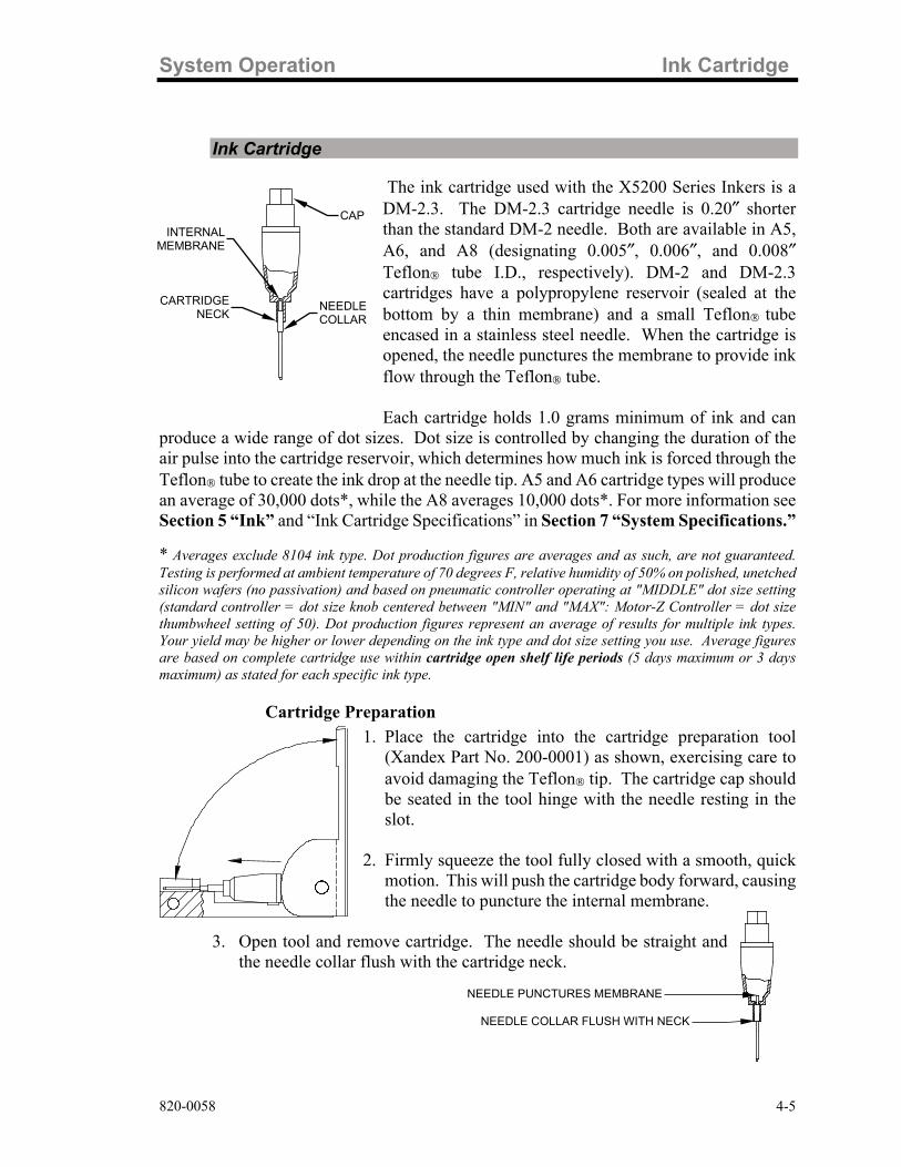
The ink cartridge used with the X5200 Series Inkers is a DM-2.3. The DM-2.3 cartridge needle is 0.20″ shorter than the standard DM-2 needle. Both are available in A5, A6, and A8 (designating 0.005″, 0.006″, and 0.008″ Teflon tube I.D., respectively). DM-2 and DM-2.3 cartridges have a polypropylene reservoir (sealed at the bottom by a thin membrane) and a small Teflon tube encased in a stainless steel needle. When the cartridge is opened, the needle punctures the membrane to provide ink flow through the Teflon tube. Each cartridge holds 1.0 grams minimum of ink and can
produce a wide range of dot sizes. Dot size is controlled by changing the duration of the air pulse into the cartridge reservoir, which determines how much ink is forced through the Teflon tube to create the ink drop at the needle tip. A5 and A6 cartridge types will produce an average of 30,000 dots*, while the A8 averages 10,000 dots*. For more information see Section 5 “Ink” and “Ink Cartridge Specifications” in Section 7 “System Specifications.” * Averages exclude 8104 ink type. Dot production figures are averages and as such, are not guaranteed. Testing is performed at ambient temperature of 70 degrees F, relative humidity of 50% on polished, unetched silicon wafers (no passivation) and based on pneumatic controller operating at "MIDDLE" dot size setting (standard controller = dot size knob centered between "MIN" and "MAX": Motor-Z Controller = dot size thumbwheel setting of 50). Dot production figures represent an average of results for multiple ink types. Your yield may be higher or lower depending on the ink type and dot size setting you use. Average figures are based on complete cartridge use within cartridge open shelf life periods (5 days maximum or 3 days maximum) as stated for each specific ink type.
Cartridge Preparation 1. Place the cartridge into the cartridge preparation tool
(Xandex Part No. 200-0001) as shown, exercising care to avoid damaging the Teflon tip. The cartridge cap should be seated in the tool hinge with the needle resting in the slot.
2. Firmly squeeze the tool fully closed with a smooth, quick
motion. This will push the cartridge body forward, causing the needle to puncture the internal membrane.
3. Open tool and remove cartridge. The needle should be straight and
the needle collar flush with the cartridge neck.
NEEDLE COLLAR FLUSH WITH NECK
NEEDLE PUNCTURES MEMBRANE
INTERNAL MEMBRANE
CARTRIDGE NECK
CAP
NEEDLE COLLAR

Ink Cartridge System Operation
4-6 820-0058
Cartridge Installation
Move the inker arm to the UP position when installing or changing cartridges to prevent damaging the cartridge tip.
1. Use the slotted section of the cartridge preparation tool and a counter-clockwise
motion to remove cap.
2. Unsnap the cap/cartridge mount and pull up to the end of the coiled tubing. DO NOT
OVER EXTEND THE TUBING COIL! See drawing below. 3. Thread a DM 2.3 cartridge clockwise onto the extended threads on the underside of
the cap/cartridge mount until snug.
Cartridge Priming
Always wear protective eyeglasses when handling an active pneumatic inking system!
1. Prepare a cartridge per the “Cartridge Preparation” section of this manual.
CAUTION
CAP/CARTRIDGE MOUNT P/N 231-0066 DM2.3 INK CARTRIDGE
CARTRIDGE HOLDER
RED AIR TUBING COIL (AIR IN)

System Operation Ink Cartridge
820-0058 4-7
2. Install a cartridge to the inker per the “Cartridge Installation” section of this manual. 3. Prime cartridge by depressing and holding the RESET button to the right of the
thumbwheels. After 3 seconds, the Controller will rapidly fire the Inker Valve, pulsing air to the cartridge, which sends ink to the Teflon tip, priming the cartridge.
4. Once ink appears at the cartridge tip, release the RESET button and wipe the tip of
the cartridge with a clean, lint-free cloth or swab. 5. When priming is completed, snap the cartridge/cap assembly into the cartridge holder
on the inker. Be sure the dowel pin engages its retainer slot and “snaps” tight. Note: Do not shake the cartridge at any time, as air bubbles may be introduced into the
reservoir and restrict the flow of ink. If mixing of the ink in the reservoir is desired, roll the cartridge between thumb and forefinger (or between palms) for 1-2 minutes prior to installation.
Changing the Cartridge 1. Move the chuck/wafer from underneath the inker to prevent damage when
removing/installing cartridge.
2. Place thumb and forefinger on each side of the cap/cartridge assembly and gently pull up to remove cartridge from holder.
3. Unthread cartridge from the cap and discard in the proper manner. 4. Inspect the cap/cartridge assembly and air hose for ink contamination and clean or
replace as necessary. 5. Install a new cartridge per installation instructions.
Cartridge Setup & Alignment 1. Prepare, prime and install an ink cartridge per the instructions in this section (4).
2. Once priming is completed, snap the cartridge/cap assembly into the cartridge holder
on the inker. Be sure the dowel pin engages its retainer slot and “snaps” tight.
CONSULT YOUR TEL P-8 OPERATION MANUAL OR TEL CUSTOMER SERVICE FOR SETUP AND ALIGNMENT INSTRUCTIONS SPECIFIC TO
YOUR APPLICATION.
Do not let the Teflon® cartridge tube contact the wafer surface. This may crush the tip preventing ink flow and damaging the cartridge or the wafer!

Cartridge Priming and Use Tips System Operation
4-8 820-0058
NO ! Tube too close to wafer NO! Tube too far away from wafer
YES! Ink drop is deposited on wafer surface
Cartridge Priming and Use Tips
Tips to avoid common problems with DieMark Pneumatic Ink Cartridges.
DO NOT attempt to refill Xandex DieMark Ink Cartridges. Cartridges are disposable and designed for single use only. Using a refilled cartridge will have an adverse effect on functionality and performance. Please note, Xandex does not warranty refilled cartridges. Handling Tips: Handle cartridges with care to avoid damaging the exposed Teflon tube at the tip of the needle When removing the cartridges from the clamshell package, lift the cartridge straight up to avoid bending the needle or damaging the Teflon tube. Allow the cartridge to reach optimal temperature of 18-25C (65-78F) before priming the cartridge. Never attempt to prime and use cartridges that are not at optimal temperature. Priming Tips: Wipe off any excess ink on the outside of the needle using a lint free cloth or swab before use. DO NOT use the cartridges beyond the recommended open time for the ink type in the cartridge. Recommended open time is three (3) days for 7824, 7824T, 8103 and 8104, and (five) 5 days for 6990, 6993, and 6997.
WAFER SURFACE
CARTRIDGE NEEDLE
TEFLON TUBE

System Operation Ink Cartridge Labeling
820-0058 4-9
Ink Cartridge Labeling
DieMark ink cartridges are individually labeled with two distinct labels. One label shows the cartridge type and the other label indicates the ink batch number, ink type and expiration date of the cartridge. Do not remove the labels from the cartridges as this can cause cartridge type and ink types to be confused at cartridge installation, resulting in improper performance. Removal of cartridge labels will also void the cartridge warranty.
DieMark Cartridge Type Label This label contains the cartridge type, (either A5, A6 or A8).
DieMark Cartridge Expiration Date Label
This label indicates the ink type and batch number of the ink contained in the cartridge and the cartridge expiration date. Expiration dates shown are for unopened cartridges.
♦ 6990, 6993, 6997, 7824, 7824T, 8103 and 8104 = Four (4) months. After the cartridge is opened, consistent ink flow can only be expected for up to five (5) days for 6990, 6993, 6997 and three (3) days for 7824, 7824T, 8103 and 8104.
B4236A
EXP. 01.OCT.16
8103
DieMark TM
TYPE A5
CARTRIDGE LABEL WITH CARTRIDGE TYPE
INK TYPE
EXPIRATION DATE (DAY = DD MONTH = MMM, & YEAR =YY) I.E.: OCTOBER 01, 2016
INK BATCH NUMBER

Cartridge Type Label Color Coding System Operation
4-10 820-0058
Cartridge Type Label Color Coding
DM-2 & DM-2.3 PNEUMATIC CARTRIDGE LABELS
LABEL DESCRIPTION
A5 IS RED
A6 IS BLUE
A8 IS YELLOW

820-0058 5-1
Section 5. Ink General Information
Semiconductor manufacturers use the vision system of automatic pick and place equipment during the assembly process to detect damaged and/or rejected die. This is done by shining a combination of different lights on the wafer surface to create a “white” background. Ink dots and defects such as chipped corners are easily recognizable against this background. DieMark 8103, 8104, 7824, 7824T and 6993 inks are opaque and easily recognizable under all lighting conditions. Glycol Free 8103 ink is thick in viscosity and delivers opaque dots ranging from 6 to 40 mils. 8104 is not as viscous as 8103 and provides thinner dots with excellent geometry and adhesion in a larger dot range up to 86 mils. 6990 and 6997 are less opaque and may not offer sufficient contrast under all lighting conditions. 8103 ink is certified to contain less than 10 ppm of Sodium (Na) and Chloride (Cl). 8104 ink is certified to contain less than 20 ppm of Sodium (Na) and Chloride (Cl). Both 8103 and 8104 premium inks are free of glycol ethers, which are identified reproductive hazards and carcinogens. 7824 and 7824T inks are certified to contain less than 10 ppm of Na and Cl. 6990 is certified to contain less than 25 ppm of Na and Cl. Analysis reports are available upon request from Xandex Customer Service. Although 6993 and 6997 are not contaminant controlled, periodic test data indicates that these inks typically contain less than 100 ppm of Sodium (Na) and 400 ppm of Chloride (Cl). These levels are not certified or guaranteed.1 Glycol Free 8103 and 8104 inks have a 4 month shelf life, rapidly air dry at ambient conditions and will give consistent flow for 3 days after cartridge opening. 6990, 6993 and 6997 inks have a 4 month shelf life, require heat curing to be permanent, and will give consistent flow for 5 days after cartridge opening. 7824 and 7824T inks have a 4 month shelf life and will give consistent flow for 3 days after cartridge opening. 7824 and 7824T can be air or “heat set” cured. Glycol Free 8103 and 8104 inks are thermally stable at temperatures up to 150° C and can be used in hot chuck or oven drying applications without cracking or loss of adhesion. Use of either 6990, 6993 and 6997 or 7824 and 7824T inks in hot chuck applications is not recommended as the elevated ambient temperature in the probing area can reduce cartridge life and cause inconsistent ink flow. However, use of a hot chuck to heat set dots during offline inking has reportedly been successful when employed by some customers. All the inks offered by Xandex are non-magnetic. Safety Data Sheets (SDS) are available for all inks offered by Xandex. To obtain SDS or information about choosing the appropriate ink for your application please contact your local distributor or Xandex Customer Service. 1 Test results are dependent on test method

Ink Curing Ink
5-2 820-0058
Ink Curing
The procedure for curing will depend on the type of ink used and other factors such as dot size and spacing (see “General Notes on Ink Curing”, below). Xandex guidelines are developed under laboratory conditions using single wafers and are intended as a baseline to develop a curing process that meets your specific needs. 6990, 6993, and 6997 should be cured/baked within 2 hours of inking due to the evaporation of solvents in the ink over time. If a wafer (or boat of wafers) is left uncured for an extended period of time, the dots may crack and/or flake after the baking process. 6990, 6993, and 6997 inks, when air-dried, will not smear when touched. They are not permanent, however, and will not withstand most post-probe handling or processes. Conversely, 7824 and 7824T inks air cure within 2.5 hours (≤20 mil, up to 10 hours for >20 mil dots). 7824 and 7824T may also be heat cured at up to 150°C for 10 minutes. 8103 and 8104 Glycol Free inks hard cure under ambient conditions in the least time of any of the inks offered by Xandex. Ink dots of ≤25 mil typically air dry to a hard cure in 45 minutes. Dot sizes >25 mil may require significantly longer to cure. An ambient cure time of up to 6 hours may be needed for larger dot sizes. 8103 and 8104 may also be heat cured at up to 150°C for 10 minutes if a faster cure is desired.
General Notes on Ink Curing
Several factors have greater influence on the time required to get a full cure in the shortest amount of time, either when heat curing or curing at room temperature:
Dot Size: Larger dot sizes will require longer cure times.
Dot Spacing: Large numbers of closely spaced ink dots will require a longer cure time than small numbers of widely spaced dots.
Air Flow: Continuous air flow across the wafer surface will reduce the amount of time required for ink curing. This is especially important when air curing at ambient temperatures.
Wafer/Die Surface: Both the surface chemistry and degree of patterning on the die affect how the ink spreads on the wafer. If the ink does not spread as much, the dots will be thicker. And if the dots are thicker, they will require a longer cure time.
Temperature: Higher temperatures will lead to faster ink cure times.
Wafer Boat / Cassette: Wafers stacked in a boat / cassette will require increased cure time compared to single wafers.

Ink Ink Curing Guidelines
820-0058 5-3
Ink Curing Guidelines
The following table provides guidelines for curing each type of ink sold by Xandex:
INK CURING GUIDELINES
CURE TYPE TEMPERATURE CURE TIME RESULT
6990, 6993, and 6997
Soft Cure
70-100°C 5-30 minutes
Ink is semi-permanent and will not withstand wash of alcohol, acetone, or photoresist removers
Hard Cure 150-185°C 30-60 minutes Ink is permanent and resistant
to wash process
7824, 7824T
Hard Cure
Air dry, ambient conditions*
1-3 hours for ≤20 mil 3-4 hours for 20-25 mil 4-10 hours for 25-40 mil
Ink is permanent and may only be removed with great difficulty
Hard Cure
150 Watt heat lamp at 5-6 inches OR oven at 110-150°C
5-10 minutes Ink is permanent and may only be removed with great difficulty
8103 and 8104 Glycol Free
Hard Cure
Air dry, ambient conditions*
5-15 minutes for ≤ 15 mil 15 minutes – 3 hours for 15-25 mil 3-6 hours for 25-40 mil
Ink is permanent and may only be removed with great difficulty
Hard Cure
150 Watt heat lamp at 5-6 inches OR oven at 110-150°C
5-10 minutes Ink is permanent and may only be removed with great difficulty
*Ink cure testing performed on single, (not stacked in a wafer boat/cassette) polished silicon wafers with dot spacing of 50 mil (1270 µm) with moderate air flow at 70-72° F (21.1-22.2° C).

Ink Removal Information Ink
5-4 820-0058
Ink Removal Information
A rinse with isopropyl alcohol or acetone generally removes ink completely if the wafer is washed shortly after inking (within 5 minutes). An ultrasonic bath is recommended to ensure complete removal of ink residue. Ink dots, which have been air dried or hard cured, require the application of an ink remover.
DieMark Remover 8000 Xandex has developed DieMark Remover 8000 specifically for the semi-conductor industry. DieMark Remover 8000 thoroughly removes all inks supplied by Xandex, including oven baked ink dots. DieMark Remover 8000 has very low levels of organic and inorganic contaminants and is an efficient and thorough ink remover when used in simple bench top cleaning methods. Due to its high flash point, DieMark Remover 8000 is also safe and effective when used in ultrasonic, temperature/pressure cycling under vacuum and deep bath heating and agitation ink removal processes.
DieMark Remover 8000 is carcinogen free (NTP, OSHA) and all ingredients used are TSCA listed. For an MSDS or more information on using DieMark Remover 8000 in your specific ink removal process, contact Xandex Customer Service.
Ink Removal Procedure The following is the recommended bench top procedure for removing ink from wafers using DieMark Remover 8000. *
All procedures should be performed under a laboratory hood, following proper safety precautions (protective goggles, gloves and clothing).
1. Apply sparingly with an eyedropper to a localized area of the wafer. 2. Allow 2-3 minutes for the DieMark Remover 8000 to begin solvating. Time
required will vary depending on the degree that the ink was cured. 3. For highly cured ink dots, use longer soak times, then wipe gently with a clean
lint-free cloth to facilitate removal. If necessary, repeat steps 1 and 2. 4. For large areas or removal of ink from entire wafer, soak a clean lint-free cloth
with DieMark Remover 8000, then lay the wet cloth over the entire surface and allow time to soak/solvate ink, then remove wet cloth. Repeat as necessary.
5. After dots are removed, clean wafer via standard procedures, such as vapor
degreasing, and/or rinse with a clean solvent (Isopropyl Alcohol) followed by a bake cycle at 65° C to dry.
CAUTION

Ink Ink Removal Information
820-0058 5-5
* The following ink removers may be substituted for DieMark Remover 8000, however, Xandex does not guarantee that satisfactory results will be obtained. None of the following solvents or ink removers are available from Xandex.
♦ Aptek 6515 Ink Remover ♦ Markem 540 ♦ P-300 Resist Remover ♦ 712-D Resist Remover ♦ Uresolve Resist Remover ♦ Methyl Ethyl Ketone (MEK) ♦ N-Methyl-2-Pyrrolidone (M-Pyrrol)

Ink Removal Information Ink
5-6 820-0058
This page is intentionally left blank.

820-0058 6-1
Section 6. Maintenance & Troubleshooting This Troubleshooting section for the X5200 Pneumatic Inker is divided into three parts. The first part covers ink and the ink cartridge. The second part covers the Inker Assembly, and the third part covers the Pneumatic Controller. See the Support section at http://www.xandexsemi.com/ for more troubleshooting information.
Ink Troubleshooting
Problem Solution Some ink dots tend to crack after baking using Xandex recommended cure cycles.
This occurrence is related to the ink surface tension, the wafer surface conditions and too long a delay time between inking and curing. To remedy this situation, the curing cycle has to be modified (reduce time and temperature). See Section 5 “ Ink Curing.”
Runny, blobbing ink or skipping dots.
1. Check ink shelf life. 6990, 6993, 6997 inks should be used within 4 months or 5 days of cartridge opening. 8103 and 8104 air dry glycol free inks should be used within 4 months or 3 days of cartridge opening. 7824 and 7824T air-dry ink within 4 months or 3 days after cartridge opening.
2. Check for exposure to extreme temperatures.
Cartridges should be stored at 25°C. DO NOT refrigerate the cartridges. Occasionally, ink is subjected to much higher temperatures (40-50° C) for an extended time during transport. This could break down the ink such that its viscosity and surface tension are altered permanently. Contact Xandex Customer Service.
3. Improper Z Height set-up. Review proper
procedures detailed in Section 4 “Cartridge Setup and Alignment” and re-adjust Z Height.
4. Chuck top or wafer surface not planar. Verify
planarity of both.
After changing the controller dot size settings, the dots are too small or the ink blobs at the tip of the needle.
Whenever dot size is changed there may be minor Z height adjustments required. Set the inker so that just the bottom of the ink drop touches the wafer. Refer to TEL documentation for Z Height adjustments.

Ink Troubleshooting Maintenance & Troubleshooting
6-2 820-0058
Problem Solution
Small, inconsistent or no ink dots.
1. Soft Teflon tip of the cartridge tube is clogged or damaged. Change cartridge.
2. The dot size setting may be too low. Increase dot
size setting. 3. Wrong cartridge type. Change cartridge type. 4. Z height adjustment is incorrect. Adjust Z Height.
Per TEL instructions 5. Verify that the inker is locked down firmly on the
mounting plate. 6. Shuttle mechanism may be binding. See “Shuttle
Maintenance" in this section.

Maintenance & Troubleshooting Inker Troubleshooting
820-0058 6-3
Inker Troubleshooting
Problem Solution Dots too large. 1. Dot size setting too high. Decrease dot size setting.
2. Main Air pressure too high, verify setting at 70 ± 10
PSI. 3. Wrong cartridge type. Change cartridge type. 4. Dot size potentiometer defective. Run diagnostic
test B. described in “Controller Diagnostics” later in this section (6). If test results are not within parameters, consult Xandex Customer Service.
Cartridge tip does not reach wafer surface.
Check height by switching the controller into "SETUP" mode which will extend the shuttle downward into the "inking position". Adjust Z Height per TEL instructions.
Unit functions normally, no dots, no shuttle movement.
1. Verify that the inker’s air hose connector is plugged into the air supply from the prober.
2. Verify that the air supply hose is not kinked,
clogged or pinched closed. 3. Check Main Air pressure setting (verify 70 ± 10 PSI
air input).
Inker produces dots during “puff pulse” or ink flows out of cartridge with toggle switch in “SETUP”.
1. Verify that the air hoses from the controller to the inker are connected properly:
♦ RED AIR HOSE connects to the ink cartridge.
♦ BLUE AIR HOSE connects to the shuttle
connection on the shuttle mechanism. \

Inker Troubleshooting Maintenance & Troubleshooting
6-4 820-0058
Problem Solution
Unit functions normally, shuttle moves, no dots.
1. Check coiled red air hose to top of cap/cartridge to be sure it is connected and not kinked or pinched.
2. Verify cartridge preparation, insuring Needle Collar
is flush with the Cartridge Neck and the internal membrane is broken. See Section 4 “Ink Cartridge.”
3. Check the Teflon tip of cartridge tube to confirm
that it is not clogged or damaged. 4. Verify rubber washer inside cap/cartridge (air to
cartridge) connector is installed and intact.

Maintenance & Troubleshooting Shuttle Maintenance
820-0058 6-5
Shuttle Maintenance
The X5200 and X5210 Inker Assemblies are similar in design, the main exception being different mounting hardware. The following describes the procedures for:
1. Disassembly and reassembly of the Pneumatic Shuttle for maintenance purposes.
2. Valve/Manifold Assembly replacement.
All procedures apply to both the X5200 and X5210. All illustrations are of Model X5200.
Maintenance Schedule Periodic preventive maintenance of the shuttle mechanism is recommended to ensure continued, trouble free operation of your Xandex pneumatic inking system. The recommended maintenance schedule is as follows;
• Off-line use = 6 month intervals • In-Line / Post Probe use = Once per year
Shuttle preventive maintenance kits are available, which include all parts necessary for one normal shuttle maintenance procedure. These kits may be ordered direct from Xandex or through your local Xandex distributor. The X5200 and X5210 model inkers require kit number 370-0003.
Shuttle Removal
1. Remove the ink cartridge from the inker, and remove the Inker Assembly
from the Prober (reverse the installation procedure detailed in Section 3 “Installation.”)
2. Disconnect the straight red air hose from the elbow fitting on the top of
the shuttle assembly (grasp, do not crush the hose with needle nose pliers over the fitting point and pull gently to disconnect, being careful not to damage hose).
3. Disconnect the coiled red air hose from the cap/cartridge fitting using
same procedure.
REMOVE 2X SCREWS
DISCONNECT STRAIGHT RED AIR HOSE AT ELBOW FITTING
DISCONNECT COILED RED AIR HOSE AT
CAP/CARTRIDGE FITTING

Shuttle Maintenance Maintenance & Troubleshooting
6-6 820-0058
4. (Reference Drawing 320-5200) Remove the two 1-72 X 3/16 Allen screws (item 25) from the shuttle mounting arm (item 2) and remove the pneumatic overhead shuttle assembly (P/N 216-0004) for maintenance.
5. Reference Drawings 320-5200, 216-0004 and 231-0071, available on
request from Xandex Customer Service, for part identification and associated part numbers in the procedures that follow.
Shuttle Disassembly With the shuttle assembly removed from the inker base:
1. (Reference Drawing 216-0004) Using a flat blade screwdriver, remove the
elbow swivel fitting (item 6) from the shuttle assembly.
2. Loosen the two Allen screws (item 9) at the top corners of the bracket (item 3) and unscrew the cylinder/fitting assembly (items 4 & 5) from the bracket (item 3).
3. Carefully lift and remove the shuttle/cartridge holder assembly (items 1 & 2) from the bracket (item 3), paying close attention to the spring (item 10) located in the bottom of the shuttle (item 2).
Shuttle Assembly Maintenance With the Shuttle removed and disassembled, perform the following checks to verify the condition and operation of these components.
1. Clean the shuttle (item 2), cartridge holder (item 1) and bracket (item 3)
with Isopropyl alcohol and a clean lint free cloth. Inspect shuttle (item 2), cartridge holder (item 1) and bracket (item 3) for excessive wear or physical deformation. Replace as necessary.
2. Inspect the O-ring on the elbow swivel fitting (item 6) for obvious signs of
deterioration. If the O-ring is worn, degraded or deformed replace the elbow swivel fitting (item 6), as the O-ring is integral to the fitting and is not sold separately.
3. Re-install the elbow swivel fitting (item 6) on the cylinder/fitting assembly
(items 4 & 5) and apply/remove an 80 PSI air signal to verify operation. The cylinder should extend/retract smoothly as the air pressure is applied/removed. If problems are noted in operation, replace the cylinder/fitting assembly (items 4 & 5). Remove the elbow swivel fitting (item 6) from the cylinder/fitting assembly.
4. Inspect the spring (item 10) for fatigue or physical deformation. Free length
of spring is 0.25″ nominal. Replace if necessary.

Maintenance & Troubleshooting Shuttle Maintenance
820-0058 6-7
5. Remove the two Allen screws (item 9), which lock the cylinder/fitting assembly (items 4 & 5) in place, from the bracket (item 3). Replace with new screws.
6. Inspect the cartridge fitting/cap (Item 19) for ink contamination and clean
as necessary. Apply an 80 PSI air signal to the air fitting on the cartridge fitting/cap (Item 19) and verify uninhibited airflow. Replace the washer (Item 38) on the inside threads of the cartridge fitting/cap (Item 19).
7. Inspect the coiled red air hose (Item 17) for ink contamination or damage
and replace as necessary.
Re-Assembly 1. Apply lubricant sparingly (item 11) to shuttle/cartridge holder assembly
(items 1 & 2) as detailed in Note 2 on Drawing 216-0004. 2. Install the spring (item 10) in the bottom of the shuttle/cartridge holder
assembly (items 1 & 2) and carefully install the shuttle/cartridge holder assembly (items 1 & 2) in the bracket (item 3). Verify that the spring (item 10) is in the proper position and the shuttle/cartridge holder assembly (items 1 & 2) moves freely in the bracket (item 3).
3. Install the cylinder/fitting assembly (items 4 & 5) into the bracket (item 3).
Do not tighten the Allen screws (item 9).
4. Using a Dial Caliper, measure the stroke of the shuttle/cartridge holder assembly (items 1 & 2) from normal to extended position. Adjust the cylinder/fitting assembly (items 4& 5) until the stroke is between 0.050″ and 0.060″ (1.3-1.5mm).
5. Tighten the two Allen screws (item 9) in the bracket (item 3) to lock down the cylinder/fitting assembly (items 4 & 5).
6. Re-install the elbow swivel fitting (item 6) ensuring that the O-ring is in
place and fitting is properly oriented.
SHUTTLE EXTENDED: ADJUST STROKE BETWEEN 0.050″-0.060″
(1.3-1.5mm)
USE DIAL CALIPER BETWEEN THESE
TWO POINTS EXTEND SHUTTLE
TO MEASURE TRAVEL
SHUTTLE RETRACTED
CYLINDER /FITTING ALLEN SET SCREWS
(2x) LOCATED ON OPPOSITE
CORNERS OF BRACKET

Shuttle Maintenance Maintenance & Troubleshooting
6-8 820-0058
7. Apply Loctite 222 (item 22) to the two 1-72 X 3/16 Allen screws (item 25) previously removed and use them to reinstall the pneumatic overhead shuttle assembly on the shuttle mounting arm (item 2).
8. Reconnect the coiled red air hose to the cartridge fitting/cap and the
straight red air hose to the elbow swivel fitting. 9. Reinstall the inker assembly, install an ink cartridge and perform ink dot
tests to verify proper operation. See Section 4 “System Operation.”
Valve/Manifold Replacement
1. To separate the inker base plate (item 20) from the inker assembly, loosen the captive fastener (item 7) and separate the base plate (item 20) and inker assembly.
2. Remove the two Allen screws (item 30) holding the valve/manifold
assembly to the inker mounting plate (item 4). 3. With the valve/manifold assembly loose, carefully remove the red straight
and coiled air hoses from the fittings in the lower portion of each valve. 4. Disconnect the twin red and blue colored air hose from the swivel fittings
on the top of the Manifold.
5. Reverse this procedure to replace valve manifold assembly, keeping in mind
that the red “air in” hose connects to the highest (tallest) of the two swivel fittings on the top of the manifold and the blue “exhaust” air hose connects to the lower swivel fitting.
6. Apply Loctite 222 to the screw threads as detailed in Note 1 of Drawing
231-0071 before reinstalling.
CAPTIVE FASTENER
DISCONNECT RED COILED AIR HOSE (AIR TO CARTRIDGE)
VALVE/MANIFOLD ASSEMBLY
DISCONNECT STRAIGHT RED HOSE (TO SHUTTLE ELBOW SWIVEL FITTING)
RED AIR HOSE (AIR IN) TOP FITTING
BLUE AIR HOSE (EXHAUST) LOWER FITTING
TWIN AIR CONNECTOR (MALE)
CAP/CARTRIDGE FITTING
SHUTTLE/BRACKET ASSEMBLY

Maintenance & Troubleshooting Pneumatic Controller
820-0058 6-9
Pneumatic Controller
Controller Sequence of Operation To initiate an ink dot, the Prober sends a 22-60 V (AC/DC unregulated) active-high signal to the Controller. After receipt of the signal, the microcontroller performs various checks of system status prior to firing the pneumatic valves. Upon completion of the status checks, a 23.3ms pulse is sent to the Shuttle Valve, while at the same time a 7.15-25.65ms pulse (depending on position of Dot Size knob) is sent to the Cartridge Valve (V1). Valves are part of the Valve/Manifold Assembly 231-0071 on the Inker Base.
Signal from Prober 22-60V (AC/DC)
Shuttle Valve
23.3ms
Cartridge Valve 7.15ms
To 25.65ms
As the shuttle extends to the lower position, the air pulse from Valve 1 forces ink out of the cartridge barrel and forms a drop at the end of the needle tip. When the shuttle is at its lowest position, the drop makes contact with the wafer surface and forms a dot. The shuttle then returns to the normal position. At the completion of each dot, a small amount of vacuum is developed in the cartridge by the closure of the valve, preventing dripping. If another dot sequence is not initiated within 10 seconds, a short “puff” pulse equal to 1/2 the dot size duration (6.75 - 13.15ms) is sent to the cartridge to displace a small amount of ink back into the Teflon tube to aid in maintaining proper dot size after a long delay between dots.

Controller Diagnostics Maintenance & Troubleshooting
6-10 820-0058
Controller Diagnostics
There are a few internal diagnostic tests available for testing the Controller. To enter the Diagnostics mode, apply power to the Controller with the “RESET” button to the right of the thumbwheels depressed. The following tests are available:
A. Test Thumbwheels 1. Place the toggle switch on the front panel to SET-UP, set the thumbwheels to
12345, then reset the LCD Counter. 2. Press the RESET button and verify that the counter increments 15 counts. 3. Place the toggle switch to RUN, set the thumbwheels to all 1’s, reset the LCD
Counter, and press RESET. The counter should increment one count.
4. Repeat the procedure for the rest of the digits (2 through 9). With the thumbwheels set for 00000, the counter increments 10 counts.
B. Test Dot Size Potentiometer 1. Place the toggle switch to DISABLE, set the HOURS thumbwheels to 01, then
reset the LCD Counter.
2. Set the knob to 50% and press RESET. The Counter should display approximately 130 counts. (Variations in Dot Size knob alignment to scale may occur. An increment of ±10 is not significant in this case.)
3. Reset the LCD Counter, adjust the knob to maximum, and press RESET. The
Counter should display 255 counts.
C. Test Cartridge Valve To test fire the Cartridge Valve 20 times:
1. Set the HOURS thumbwheels to 02 2. Place the toggle switch to DISABLE 3. Reset the LCD Counter 4. Press RESET.
The cartridge valve fires 20 times, each time incrementing the LCD Counter.

Maintenance & Troubleshooting Controller Diagnostics
820-0058 6-11
D. Test Shuttle Valve To test fire the Shuttle Valve 20 times:
1. Set the HOURS thumbwheels to 03 2. Place the toggle switch to DISABLE 3. Reset the LCD Counter 4. Press RESET.
The shuttle valve fires 20 times, each time incrementing the LCD Counter.
E. Life Test This test will continuously fire the Cartridge and Shuttle valves for a predetermined number of cycles as set on the thumbwheels.
1. Place the toggle switch to DISABLE. 2. Set the HOURS thumbwheels to 10. 3. Set the DOTS X1000 thumbwheels for the desired number of cycles X1000
(i.e.: 250 Equals 250,000 cycles). 4. Reset the LCD Counter. 5. Press RESET.
The Controller begins continuous firing, incrementing the Counter each cycle. To discontinue the Life Test prior to reaching the set amount, remove power.

Controller Troubleshooting Maintenance & Troubleshooting
6-12 820-0058
Controller Troubleshooting
Problem Solution The Unit is plugged in but the “POWER” LED is off.
1. Make sure that the AC outlet has power. The requirement is 100-240 VAC @ 47-63Hz.
2. Verify that the power supply is connected to the 24V input on the back of the controller and that the ON/OFF switch on the controller is in the ON position.
Unit powers up okay but will not respond to prober signal.
1. Verify input cable is plugged into inker jack on prober.
2. Check continuity of input cable. 3. Perform system diagnostics checks to verify
Controller operation. See Section 6 “Controller Diagnostics.”
Unit powers up okay, responds to prober input but the shuttle does not move.
1. Check that shuttle toggle switch on the front of the controller is in the RUN position.
2. Perform Shuttle Valve diagnostic test to ver-
ify operation. See Section 6 “Controller Di-agnostics.”
Dot size does not change or does not change sufficiently with adjustment of Dot Size Knob
1. Run diagnostic test “B.” Dot Size Potentiometer Test described in “Controller Diagnostics” above in this section (6). If test results are not within parameters, consult Xandex Customer Service.
2. Replace ink cartridge. 3. Check Dot Size Knob for looseness. Tighten
knob on potentiometer shaft if loose.
4. Wrong ink cartridge type. Replace ink cartridge with larger (or smaller) type dot size rating. See “Dot Size Parameters” table in Section 4. “Operation.”

Maintenance & Troubleshooting Internal Maintenance
820-0058 6-13
Internal Maintenance
Use appropriate ESD precautions when working inside of the controller!
Making any modifications to the controller circuitry or components other than Xandex recommended maintenance procedures may void your controller warranty, disable protections provided by the manufacturer and expose the user to electric shock hazard.
Turn Audible Alarm ON/OFF Standard controller units (P/N 350-0002) with serial numbers higher than 4000 are equipped with an audible alarm feature. When enabled, an audio alarm will sound (in addition to the STATUS LED illuminating) when the programmed number of dots set point is reached. The controller is shipped with the audio alarm feature disabled. With Power and Main Air removed:
1. Remove the cover by removing the 8 screws on the left and right sides of the controller (4 screws per side) and lifting the cover off the controller assembly.
2. Locate J16 on the 250-1226 controller printed circuit board. In the default factory condition, J16 is populated with a jumper on pins 1 and 2. This is the default audio alarm disabled condition.
3. To enable the audio alarm remove the jumper and install the jumper onto pin 1
only on J16. This is the audio enabled condition.
Before Returning the Controller to Service
1. Install the cover, apply power and main air, and perform controller diagnostics, as documented in this chapter, to verify operation. If problems are noted, review the installation of the audio alarm jumper to ensure installation is correct, none of the component leads are bent, and verify connection of J2 through J6 connectors on the printed circuit board.
WARNING

Internal Maintenance Maintenance & Troubleshooting
6-14 820-0058
FRONT OF CONTROLLER
J16 TO ENABLE ALARM, PLACE JUMPER ON PIN 1 ONLY.
CONTROLLER WITH COVER REMOVED

820-0058 7-1
Section 7. System Specifications DC Power Supply Requirements
The DC power supply received with your DieMark inking system meets these requirements. Use only the DC power supply provided with the unit or an authorized replacement power supply from Xandex Inc. or an approved Xandex distributor. For the exact specification of your power supply, request the “24VDC Power Supply” drawing listed in your product manual drawing package from Xandex Customer Service.
Pneumatic Controller Specifications
Size: 6" x 6" x 4" (152mm x 152mm x 102mm)
Weight: 2.1 lbs (0.95 kg) Input Power Requirement: 24V (VDC) 0.84A
Foot Switch Input: Contact Closure >50 msec
Air Consumption: 70 PSI ±10 PSI Instrument Air per ISA 7.3 specification <0.5 cfm @ 10 dots/second
Cycle Rate: Exceeds 750 cycles/minute
On-Time Range: Cartridge Air Feed - Continuously Variable Pulse (7.15-25.65 mS) Shuttle Air Feed - Fixed @ 25.2 ms
Counters: Eight Digit with External Reset (Independent of Microprocessor)
External Regulator/Filter: 5.0 micron Air Filtration
Input Power Requirement: 100-240 VAC @ 50-60Hz
Output Power Requirement: 24V (VDC) / 0.8A or greater
Approvals: UL / FCC / PSE / CCC / CE / WEEE / ROHS
Protection: Overvoltage/Short Circuit
Output Pin Assignments: Center: +V Outside: Return
Output Plug Size: Inside Diameter: Outside Diameter: Barrel Length:
2.5mm 5.5mm 9.5mm

Pneumatic Controller Specifications System Specifications
7-2 820-0058
Prober Input:
22 - 60 volts @ minimum 30 ms pulse width. The input circuit presents approximately 1 KΩ - 700 Ω input resistance. Typical current as a function of input voltage is listed in the following table:
15 V 20 V 40 V 60 V
25 mA 45 mA 65 mA 85 mA (Maximum input)
Environmental Range:
Indoor use Altitude up to 2,000 m Temperature range 5° C to 40° C Maximum relative humidity 80 % for temperatures up
to 31°C decreasing linearly to 50 % relative humidity at 40 °C
Certifications:
MARK
Standards to which conformity is declared: EN61010-1 / EN61326-1 Marked for LVD and EMC
RoHS RoHS Compliant with EU Directive 2011/65/EU
This device complies with FCC Rules Part 15. Operation is subject to the following two conditions: (1) This device may not cause harmful interference, and (2) This device must accept any interference that may be received or that may cause undesired operation.
Xandex Inc. has labeled its branded electronic products with the WEEE Symbol to alert our customers that products bearing this label should not be disposed of in a landfill or with municipal or household waste in the EU.

System Specifications Ink Cartridge Specifications
820-0058 7-3
Ink Cartridge Specifications
Models: DM-2.3, Type A5, A6, A8
Teflon Tube I.D.: A5 - 0.005" / A6 - 0.006" / A8 - 0.008"
Reservoir Capacity: 1.0 grams minimum
Available Inks: 6990, 6993, 6997, 7824, 7824T, 8103, 8104
Dot Sizes: Dot sizes (±10%) consistent for speeds of 12 dots/second to 1 dot/2 minutes
Cartridge Availability
The following table illustrates ink and cartridge configurations. Configurations designated with a 0 are available as a Customer Specific Product (CSP) but have not been tested by Xandex and are subject to limited warranty conditions. The information in this table is accurate as of the time of publication but is subject to change without notice.
Pneumatic Cartridge Types Filament Cartridge Types DM-2 DM-2.3 DM-1 DM-1.25 DM-S Ink Type A5 A6 A8 A5 A6 A8 5
mil 8
mil 10 mil
15 mil
25 mil
30 mil
10 mil
15 mil
25 mil
10 mil
15 mil
6990 Black + + + + + + T,F + + + + + + + + + +
6993 Black + + + + + + + + + + + + + + + + +
6993 Red + + + + + + T,F + + + + + + + + + +
6997 Black + + + + + + T,F + + + + + + + + + +
Empty (no ink) + + + + + + + + + + + + + + + + +
7824 Black + + + + + + T,F + + + + + 0 + + 0 0
7824T Black + + + + + + T + + + + + 0 0 + 0 0
8103 Black + + + + + + T + + + + + 0 0 0 0 0
8103 Red + + + + + 0 T + + + + + 0 0 0 0 0
8103 White + + + + + + T + + + + + 0 0 0 0 +
8104 Black + + + + + + X X X X X X X X X X X
+ = Available standard cartridge and ink configuration. 0 = Not yet qualified by Xandex. Available as a special order, subject to limited warranty conditions. T = with Tungsten filament F = with Mono-Filament X = Not available in filament cartridge configurations.

Dot Size Guidelines in Mils (0.001 inch) System Specifications
7-4 820-0058
Dot Size Guidelines in Mils (0.001 inch)
Dot production figures are averages and as such, are not guaranteed. All ink dot characterization testing performed at ambient temperature of 70° degrees F, relative humidity of 50% using polished, unetched silicon wafers (no passivation).
X1000 & X901 Series
DM-2
X5000 Series
DM-2.3
Motorized-Z S = Small Dot Mode L = Large Dot Mode
DM-2
S L
I N K
T Y P E
8103
A5
Min. 12 mil Min. 13 mil Min. * 10 mil Mid. 21 mil Mid. 23 mil Mid. * 19 mil Max. 24 mil Max. 27 mil Max. * 22 mil
A6 Min. 15 mil Min. 17 mil Min. * 11 mil Mid. 25 mil Mid. 27 mil Mid. * 23 mil Max. 29 mil Max. 30 mil Max. * 28 mil
A8 Min. 22 mil Min. 23 mil Min. * 17 mil Mid. 37 mil Mid. 39 mil Mid. * 32 mil Max. 42 mil Max. 43 mil Max. * 38 mil
S L
6990 6993 6997
A5
Min. 16 mil Min. 17 mil Min. 9 mil 12 mil Mid. 28 mil Mid. 29 mil Mid. 12 mil 23 mil Max. 32 mil Max. 33 mil Max. 16 mil 28 mil
A6 Min. 20 mil Min. 18 mil Min. 8 mil 14 mil Mid. 32 mil Mid. 32 mil Mid. 16 mil 28 mil Max. 36 mil Max. 36 mil Max. 19 mil 34 mil
A8 Min. 29 mil Min. 27 mil Min. 12 mil 21 mil Mid. 52 mil Mid. 50 mil Mid. 24 mil 41 mil Max. 60 mil Max. 57 mil Max. 29 mil 50 mil
S L
7824
A5
Min. 19 mil Min. 18 mil Min. 10 mil 15 mil Mid. 33 mil Mid. 33 mil Mid. 18 mil 29 mil Max. 38 mil Max. 38 mil Max. 21 mil 34 mil
A6 Min. 25 mil Min. 20 mil Min. 13 mil 22 mil Mid. 44 mil Mid. 36 mil Mid. 24 mil 41 mil Max. 50 mil Max. 41 mil Max. 29 mil 46 mil
A8 Min. 37 mil Min. 29 mil Min. 20 mil 31 mil Mid. 59 mil Mid. 50 mil Mid. 34 mil 55 mil Max. 69 mil Max. 56 mil Max. 40 mil 63 mil
S L
8104
A5
Min. 26 mil Min. 24 mil Min. 14 mil 23 mil Mid. 49 mil Mid. 44 mil Mid. 25 mil 47 mil Max. 54 mil Max. 50 mil Max. 30 mil 53 mil
A6 Min. 33 mil Min. 27 mil Min. 20 mil 30 mil Mid. 56 mil Mid. 50 mil Mid. 34 mil 56 mil Max. 65 mil Max. 56 mil Max. 39 mil 63 mil
A8 Min. 51 mil Min. 54 mil Min. 38 mil 54 mil Mid. 80 mil Mid. 85 mil Mid. 59 mil 85 mil Max. 90 mil Max. 93 mil Max. 67 mil 89 mil
* Contact Xandex Customer Service for information on using 8103 ink in small dot applications.

System Specifications Dot Size Guidelines in Microns
820-0058 7-5
Dot Size Guidelines in Microns
Dot production figures are averages and as such, are not guaranteed. All ink dot characterization testing performed at ambient temperature of 70° degrees F, relative humidity of 50% using polished, unetched silicon wafers (no passivation).
X1000 & X901 Series
DM-2
X5000 Series
DM-2.3
Motorized-Z S = Small Dot Mode L = Large Dot Mode
DM-2
S L
I N K
T Y P E
8103
A5
Min. 304.8 µm Min. 330.2 µm Min. * 254 µm Mid. 533.4 µm Mid. 584.2 µm Mid. * 482.6 µm Max. 609.6 µm Max. 685.8 µm Max. * 558.8 µm
A6 Min. 381 µm Min. 431.8 µm Min. * 279.4 µm Mid. 635 µm Mid. 685.8 µm Mid. * 584.2 µm Max. 736.6 µm Max. 762 µm Max. * 711.2 µm
A8 Min. 558.8 µm Min. 584.2 µm Min. * 431.8 µm Mid. 939.8 µm Mid. 990.6 µm Mid. * 812.8 µm Max. 1066.8 µm Max. 1092.2 µm Max. * 965.2 µm
S L
6990 6993 6997
A5
Min. 406.4 µm Min. 431.8 µm Min. 228.6 µm 304.8 µm Mid. 711.2 µm Mid. 736.6 µm Mid. 304.8 µm 584.2 µm Max. 812.8 µm Max. 838.2 µm Max. 406.4 µm 711.2 µm
A6 Min. 508 µm Min. 457.2 µm Min. 203.2 µm 355.6 µm Mid. 812.8 µm Mid. 812.8 µm Mid. 406.4 µm 711.2 µm Max. 914.4 µm Max. 914.4 µm Max. 482.6 µm 863.6 µm
A8 Min. 736.6 µm Min. 685.8 µm Min. 304.8 µm 533.4 µm Mid. 1320.8 µm Mid. 1270 µm Mid. 609.6 µm 1041.4 µm Max. 1524 µm Max. 1447.8 µm Max. 736.6 µm 1270 µm
S L
7824
A5
Min. 482.6 µm Min. 457.2 µm Min. 254 µm 381 µm Mid. 838.2 µm Mid. 838.2 µm Mid. 457.2 µm 736.6 µm Max. 965.2 µm Max. 965.2 µm Max. 533.4 µm 863.6 µm
A6 Min. 635 µm Min. 508 µm Min. 330.2 µm 558.8 µm Mid. 1117.6 µm Mid. 914. µm Mid. 609.6 µm 1041.4 µm Max. 1270 µm Max. 1041. µm Max. 736.6 µm 1168.4 µm
A8 Min. 939.8 µm Min. 736.6 µm Min. 508 µm 787.4 µm Mid. 1498.6 µm Mid. 1270 µm Mid. 863.6 µm 1397 µm Max. 1752.6 µm Max. 1422.4 µm Max. 1016 µm 1600.2 µm
S L
8104
A5
Min. 660.4 µm Min. 609.6 µm Min. 355.6 µm 584.2 µm Mid. 1244.6 µm Mid. 1117.6µm Mid. 635 µm 1193.8 µm Max. 1371.6 µm Max. 1270 µm Max. 762 µm 1346.2 µm
A6 Min. 838.2 µm Min. 685.8 µm Min. 508 µm 762 µm Mid. 1422.4 µm Mid. 1270 µm Mid. 863.6 µm 1422.4 µm Max. 1651 µm Max. 1422.4 µm Max. 990.6 µm 1600.2 µm
A8 Min. 1295.4 µm Min. 1371.6 µm Min. 965.2µm 1371.6 µm Mid. 2032 µm Mid. 2159 µm Mid. 1498.6 µm 2159 µm Max. 2286 µm Max. 2362.2 µm Max. 1701.8 µm 2260.6 µm
* Contact Xandex Customer Service for information on using 8103 ink in small dot applications.

Inker Warranty System Specifications
7-6 820-0058
Inker Warranty
Seller warrants as follows: All material supplied will conform to the description stated. All products will be free of defects in materials and workmanship under normal use for the following periods: Stated shelf life of DM-2 Ink Cartridges:
♦ 6990, 6993, 6997 = Four (4) months. Five (5) days after cartridge opening ♦ 8103 and 8104 = Four (4) months. Three (3) days after cartridge opening. ♦ 7824 and 7824T = Four (4) months. Three (3) days after cartridge opening.
Pneumatic Controller = One (1) year only when clean, dry, filtered air is used, and when product is installed and operated per manufacturer's recommendations and instructions. Ninety (90) days from the date of delivery to the customer for all other products.
Xandex makes no other warranty, express or implied, including without limitation any warranty of merchantability or of fitness for a particular purpose. Customer, OEM or Distributor’s exclusive warranty shall be, at Xandex’s option, to have defective product repaired or replaced, or to receive a refund of purchase price. Xandex may, upon request, furnish to buyer such technical advice, as it may be able to supply with reference to the use by buyer of any materials delivered. Xandex assumes no liability for the advice given or results obtained. Buyer expressly agrees that it will implement any advice thus given at its own risk and agrees to indemnify and hold Xandex harmless against any liabilities, costs or expense resulting therefrom. Xandex makes no warranty for performance, service or support of any products unless they are purchased directly from Xandex or through an authorized Xandex Distributor. Exclusions: This warranty shall not apply to defects or damage resulting from; • Improper or inadequate maintenance by customer, including failure to perform preventive maintenance
per manufacturer's specified schedule • Misuse or unauthorized modification • Operation outside the environmental specifications for the product • Improper site preparation and maintenance Some states and provinces do not allow limitations on how long an implied warranty lasts, so the limitation or exclusion contained in this warranty may not apply to you. However, any implied warranty of merchantability or fitness is limited to the duration period of this written warranty. If you have any questions or need further assistance please contact your authorized Xandex distributor or contact our Customer Service Group.
Customer Service
1360 Redwood Way, Suite A Petaluma, California 94954 U.S.A.
Toll Free in the United States (800) 767-9543 or (707) 763-7799 FAX (707) 763-2631
http://www.xandexsemi.com/ email; mailto:[email protected]

System Specifications System Drawings
820-0058 7-7
System Drawings
The Inker Assembly Dimensional Drawings are available via link from www.xandexsemi.com. The remaining drawings in the list below are available on request, in Adobe PDF format, from Xandex Customer Service.
Description Drawing Number
Pneumatic Controller Assembly, Remote Valve 350-0013 Schematic, Pneumatic Controller, Standard 950-1226 Controller Logic Board PC Assy 250-1226 24 VDC Power Supply 220-0078 Inker Assembly, Model X5200 P8 SACC Arm Dimensional Drawing
900-5200
Inker Base Assembly, Model 5200 320-5200 Inker Base Assembly, Model 5210 320-5210 Pneumatic Overhead Shuttle Assembly 216-0004 Pneumatic Inker Assembly, X5210 P8 Bridge Dimensional Drawing
900-5210
Inker Set X5200 340-5200 Inker Set X5210 340-5210 Valve / Manifold Assembly 231-0071

System Drawings System Specifications
7-8 820-0058
This page is intentionally left blank.