Installation & Operating Handbook for P300 Series Satellite ...
231
Doc ref: p:\p300\d-wp\p300h\p3x0h.wpd (& .pdf) Handbook Issue 2.04, dated 5 th May 2005. Covering software features up to and including V4.54/58 2003 EN 55022 - Class B EN 60950 Witham, Essex, CM8 3UJ, En e College, PA 16803, USA. Phone 01376 515636 (Int + 44 1376...). Phone 814-238-3450 (Int + 1 814...) PORTANT NOTE: THE PARADISE DATACOM maintains a continuing programme of product improvement and therefore reserves the right to change specifications without notice EN 55024 Installation & Operating Handbook for P300 Series Satellite Modems (including P310 L-Band and Turbo FEC options) Paradise Datacom Ltd. Paradise Datacom LLC 1 Wheaton Road 328 Innovation Blvd gland. Suite 100, Stat Fax 01376 533764 Fax 814-238-3829 http://www.paradisedata.com INFORMATION AND SPECIFICATIONS CONTAINED IN IM THIS DOCUMENT SUPERSEDE ALL PREVIOUSLY PUBLISHED INFORMATION CONCERNING THIS PRODUCT
-
Upload
khangminh22 -
Category
Documents
-
view
2 -
download
0
Transcript of Installation & Operating Handbook for P300 Series Satellite ...

Doc ref: p:\p300\d-wp\p300h\p3x0h.wpd (& .pdf)
Handbook Issue 2.04, dated 5th May 2005. Covering software features up to and including V4.54/58
2003
EN 55022 - Class B
EN 60950
Witham, Essex, CM8 3UJ, En e College, PA 16803, USA.Phone 01376 515636 (Int + 44 1376...). Phone 814-238-3450 (Int + 1 814...)
PORTANT NOTE: THE
PARADISE DATACOM maintains a continuing programme of product improvement and therefore reserves the right to change specifications without notice
EN 55024
Installation & Operating Handbook for
P300 Series Satellite Modems (including P310 L-Band and
Turbo FEC options)
Paradise Datacom Ltd. Paradise Datacom LLC 1 Wheaton Road 328 Innovation Blvd
gland. Suite 100, Stat
Fax 01376 533764 Fax 814-238-3829 http://www.paradisedata.com
INFORMATION AND SPECIFICATIONS CONTAINED IN IMTHIS DOCUMENT SUPERSEDE ALL PREVIOUSLY PUBLISHED INFORMATION
CONCERNING THIS PRODUCT

Table of Contents
1 EMC (ELECTROMAGNETIC COMPATIBILITY) AND SAFETY NOTICES ...............71.1 EMC ...................................................................................................................................................... 71.2 SAFETY................................................................................................................................................ 8
2 INTRODUCTION ...............................................................................................................................92.1 OVERVIEW.......................................................................................................................................... 92.2 P300 SERIES FEATURES................................................................................................................ 102.3 FEATURE SUMMARY ..................................................................................................................... 112.4 FEATURE HIGHLIGHT ..................................................................................................................... 12
3 DESCRIPTION .................................................................................................................................163.1 OPERATION ...................................................................................................................................... 163.2 FAULT PHILOSOPHY....................................................................................................................... 163.3 ELECTRICAL DESCRIPTION .......................................................................................................... 163.4 FRONT PANEL FEATURES............................................................................................................. 173.5 REAR PANEL DESCRIPTION.......................................................................................................... 183.6 BLOCK DIAGRAM............................................................................................................................. 21
4 SUMMARY OF SPECIFICATIONS...........................................................................................23
5 INSTALLATION AND CONFIGURATION .............................................................................425.1 UNPACKING...................................................................................................................................... 425.2 VISUAL INSPECTION OF EQUIPMENT ......................................................................................... 425.3 INTERFACE OPTIONS ..................................................................................................................... 425.4 IF INTERFACE................................................................................................................................... 425.5 POWER UP........................................................................................................................................ 42
6 MENU SYSTEM...............................................................................................................................436.1 INTRODUCTION ............................................................................................................................... 43
THE 1 MINUTE GUIDE TO FRONT PANEL OPERATION ...................436.2 MENU STRUCTURE DIAGRAMS....................................................................................................44
6.2.1 Menu Structure Sheet 1 / 7 (Main: Status, Change).........................................................456.2.2 Full Menu Structure Sheet 2 / 7 (Main: Monitor, Info) .......................................................466.2.3 Full Menu Structure Sheet 3 / 7 (Main: Log, Test, Setup, Action, Help) ..........................476.2.4 Full Menu Structure Sheet 4 / 7 (Main, Change, User-Opt, Operation) ...........................48 6.2.5 Full Menu Structure Sheet 5 / 7 (Change, Tx) ..................................................................496.2.6 Full Menu Structure Sheet 6 / 6 (Change, Rx)..................................................................506.2.7 Full Menu Structure Sheet 7 / 7 (Change, BUC/LNB) ......................................................51
6.3 Status SCREEN DISPLAY ................................................................................................................ 526.4 SETUP - INITIAL CONFIGURATION MENU ................................................................................... 566.5 CHANGE MENU ................................................................................................................................ 566.6 CHANGE, TX MENU ......................................................................................................................... 57
6.6.1 Change, Tx/Rx, SERVICE Menu.......................................................................................576.6.2 Change, Tx/Rx, Service, CLOSED NETWORK................................................................586.6.3 Change, Tx/Rx, BASEBAND Menu...................................................................................606.6.4 Change, Tx/Rx, Baseband, CONTINUOUS Menu ...........................................................606.6.5 Change, Tx/Rx, Baseband, DROP/INSERT Menu...........................................................61

6.6.6 Change, Tx/Rx, Baseband, OTHER Menu ......................................................................656.6.7 Change, Tx, CLOCKING Menu .........................................................................................666.6.8 Change, Tx, MODULATOR Menu.....................................................................................686.6.9 Change, Tx/Rx, Modulator, IF FREQUENCY Menu.........................................................686.6.10 Change, Tx/Rx, Modulator, MODULATION Menu..........................................................68OFFSET QPSK (OQPSK) PRIMER ...........................................................................................696.6.11 Change, Tx/Rx, Modulator, FEC Menu...........................................................................696.6.12 Change, Tx/Rx, Mod/Demod, REED-SOLOMON Menu................................................71INTRODUCTION TO REED-SOLOMON ...................................................................................716.6.13 Change, Tx/Rx, Mod/Demod, SCRAMBLER Menu .......................................................726.6.14 Change, Tx, Modulator, CARRIER Menu .......................................................................746.6.15 Change, Tx, Modulator, POWER LEVEL Menu .............................................................746.6.16 Change, Tx/Rx, Modulator, SPECTRUM INVERT Menu...............................................75NOTE ON BPSK SPECTRUM INVERSION..............................................................................756.6.17 Change, Tx, Modulator, AUPC (Software >=V2.12).......................................................756.6.18 Change, Tx, Modulator, AUPC, MODE Menu ................................................................766.6.19 Change, Tx, Modulator, AUPC, MAX Menu....................................................................766.6.20 Change, Tx, Modulator, AUPC, MIN Menu.....................................................................776.6.21 Change, Tx, Modulator, AUPC, SLEW RATE Menu ......................................................776.6.22 Change, Tx, Modulator, AUPC, TARGET EB/NO Menu................................................776.6.23 Change, Tx, Modulator, AUPC, TOLERANCE Menu.....................................................786.6.24 Change, Tx, Modulator, AUPC, CARRIER LOST ACTION Menu.................................786.6.25 Change, Tx/Rx, ESC/AUX/BA Menu...............................................................................796.6.26 Change, Tx/Rx, ESC/Aux/BA, DEFINE (IDR) Menu ......................................................796.6.27 Change, Tx/Rx, ESC/Aux/BA, DEFINE (IBS) Menu.......................................................816.6.28 Custom IBS Overhead Allocation....................................................................................836.6.29 Change, Tx/Rx, ESC/Aux/BA, ASYNC ESC Menu ........................................................846.6.30 Change, Tx/Rx, ESC/Aux/BA, Config Async, BAUD RATE Menu.................................856.6.31 Change, Tx/Rx, ESC/Aux/BA, Config Async, FORMAT Menu ......................................856.6.32 Change, Tx/Rx, ESC/Aux/BA, Config Async, SET AS REM M&C.................................856.6.33 Change, Tx/Rx, ESC/Aux/BA, INTERFACES Menu ......................................................866.6.34 Change, Tx/Rx, ESC/Aux/BA, AUDIO LEVELS Menu ...................................................876.6.35 Change, Tx/Rx, ESC/Aux/BA, BACKWARD ALARMS Menu ........................................88
6.7 CHANGE, RX MENU......................................................................................................................... 89NOTE ON RX=TX FUNCTION...................................................................................................896.7.1 Change, Rx, SERVICE Menu............................................................................................906.7.2 Change, Rx, BASEBAND Menu........................................................................................906.7.3 Change, Rx, BUFFER / CLOCKING Menu.......................................................................926.7.4 Change, Rx, Buffer / Clocking, STATION CLOCK Menu.................................................926.7.5 Change, Rx, Buffer / Clocking, RX CLOCK Menu............................................................936.7.6 Change, Rx, Buffer / Clocking, BUFFER SIZE Menu.......................................................946.7.7 Change, Rx, Demod, Menu ...............................................................................................966.7.8 Change, Rx, Demod, IF FREQUENCY Menu ..................................................................966.7.9 Change, Rx, Demod, MODULATION Menu .....................................................................966.7.10 Change, Rx, Demod, FEC Menu.....................................................................................966.7.11 Change, Rx, Demod, REED-SOLOMON Menu .............................................................966.7.12 Change, Rx, Demod, SCRAMBLER Menu.....................................................................966.7.13 Change, Rx, Demod, SPECTRUM INVERT Menu ........................................................966.7.14 Change, Rx, Demod, SWEEP Menu...............................................................................976.7.15 Change, Rx, Demod, AUPC Menu..................................................................................986.7.16 Change, Rx, ESC/AUX/BA Menu....................................................................................986.7.17 Change, Rx, RX=TX Menu..............................................................................................98
6.8 CHANGE, TERR-INTFC MENU ....................................................................................................... 996.8.1 Change, Terr-intfc, ELECTRICAL .....................................................................................996.8.2 Change, Terr-intfc, CONTROL LINES ............................................................................1006.8.3 Change, Terr-intfc, CARD SPECIFIC .............................................................................101
6.9 CHANGE, REM-M&C MENU.......................................................................................................... 1026.9.1 Local Control TAKE AWAY / GIVE AWAY Selection .....................................................1026.9.2 Change, Rem-M&C, CONFIGURE Menu.......................................................................103
6.10 CHANGE, USER-OPT MENU ...................................................................................................... 1046.10.1 Change, User-Opt, THRESHOLDS Menu ....................................................................1046.10.2 Change, User-Opt, OPERATION Menu........................................................................1046.10.3 Change, User-Opt, Operation, ACTIONS Menu...........................................................1056.10.4 Change, User-Opt, Operation, TERRESTRIAL Menu..................................................1056.10.5 Change, User-Opt, Operation, Terrestrial, PCM BEARER CRC Menu.......................1066.10.6 Change, User-Opt, Operation, SATELLITE Menu........................................................1066.10.7 Change, User-Opt, Operation, TERR/SAT Menu.........................................................1086.10.8 Change, User-Opt, Operation, ALARMS Menu............................................................1096.10.9 Change, User-Opt, DISPLAY Menu..............................................................................1096.10.10 Change, User-Opt, AGC Output Menu .......................................................................109
6.11 CHANGE TIME/DATE MENU....................................................................................................... 1106.12 CHANGE, BUC/LNB MENU.......................................................................................................... 110
6.12.1 Change, BUC/LNB, TX/BUC Menu...............................................................................1106.12.2 Change, BUC/LNB, Tx/BUC, BUC TYPE Menu...........................................................1106.12.3 Change, BUC/LNB, Tx/BUC, DC & REFERENCES Menu..........................................1136.12.4 Change, BUC/LNB, Tx/BUC, SHF FREQUENCY Menu..............................................1136.12.5 Change, BUC/LNB, Tx/BUC, SHF POWER/UNITS Menu...........................................1146.12.6 Change, BUC/LNB, Tx/BUC, BUC CONTROL Menu ..................................................1146.12.7 Change, BUC/LNB, Rx/LNB Menu ................................................................................1156.12.8 Change, BUC/LNB, Rx/LNB, LNB Type Menu..............................................................1156.12.9 Change, BUC/LNB, Rx/LNB, DC & REFERENCES Menu ..........................................1166.12.10 Change, BUC/LNB, Rx/LNB, SHF FREQUENCIES Menu ........................................1166.12.11 Change, BUC/LNB, TUNE REF Menu ........................................................................117
6.13 MONITOR MENU .......................................................................................................................... 1176.13.1 Monitor, DEMOD PERFORMANCE Menu ...................................................................1176.13.2 Monitor, TERRESTRIAL BER Menu .............................................................................1186.13.3 Monitor, CARRIER ID's Menu .......................................................................................1186.13.4 Monitor, DISTANT Eb/No & BER Menu ........................................................................1186.13.5 Monitor, AUPC Menu.....................................................................................................1196.13.6 Monitor, BUC Menu........................................................................................................119
6.14 INFO MENU ................................................................................................................................... 1206.15 LOG MENU .................................................................................................................................... 121
6.15.1 LOG, AUTOLOG Menu ..................................................................................................1216.16 TEST MENU................................................................................................................................... 124
6.16.1 Test, LOOPBACKS Menu .............................................................................................1246.16.2 Test, RF & FEC Menu ...................................................................................................1266.16.3 Test, PSU S + TEMP Menu...........................................................................................1266.16.4 Test, Int' BERT Menu.....................................................................................................1276.16.5 Test, Int' BERT, OFF/CHANNEL Menu ........................................................................1286.16.6 Test, Int' BERT, PATTERN Menu .................................................................................1306.16.7 Test, Int' BERT, MODE Menu........................................................................................1306.16.8 Test, Int' BERT, RESULTS Menu..................................................................................131
16.17 SETUP MENU.............................................................................................................................. 13216.18 ACTION MENU............................................................................................................................ 13216.19 HELP MENU ................................................................................................................................ 13316.20 SERVICE MENU.......................................................................................................................... 133
16.20.1 Service, USER PARAMETERS Menu ........................................................................13416.20.2 Service, FACTORY PARAMETERS Menu.................................................................134
7. MENU SCREENS FOR SPECIALIST OPTIONS...............................................................1357.1 CUSTOM FRAMING MENUS......................................................................................................... 135

7.1.1 Change, Tx/Rx, Service, CUSTOM Menu ......................................................................1357.1.2 Change, Tx/Rx, Service, CUSTOM, IBS Menu ..............................................................1357.1.3 Change, Tx/Rx, Service, CUSTOM, IDR Menu..............................................................137
7.2 IBS/SMS OPERATION WITH 2048KBPS CONTINUOUS DATA ................................................ 1397.2.1 Change, Tx/Rx, Baseband, Continuous, 2048k G.732 Menu (IBS)...............................139
7.3 CUSTOM IDR OPERATION WITH 2048KBPS CONTINUOUS DATA........................................ 1417.3.1 Change, Tx/Rx, Baseband, Continuous, 2048k Menu (IDR) .........................................141
8. APPLICATION NOTES...............................................................................................................1428.1 DOPPLER & PLESIOCHRONOUS BUFFERING ......................................................................... 1428.2 DETERMINING CLOCKING SCHEMES AND BUFFER SIZE ..................................................... 143
8.2.1 Clock Loop At One End: ..................................................................................................1438.2.2 No Clock Loop..................................................................................................................1438.2.3 Determining Buffer Size ...................................................................................................144
8.3 PARTIAL INSERT AND MULTIDESTINATIONAL WORKING ..................................................... 1458.4 CHOOSING OPTIMUM CUSTOM VALUES OF RS N&K ............................................................ 1468.5 NOTES ON DATA RATES & SYMBOL RATES ............................................................................ 1478.6 DETERMINING EXACT MAXIMUM ESC BAUD RATES ............................................................. 1488.7 CLOSED NETWORK PLUS ESC................................................................................................... 149
8.7.1 Overhead Rates ...............................................................................................................1498.7.2 Closed Network Plus ESC via the Custom Service menu..............................................1508.7.3 ESC channel with mis-match configurations...................................................................150
8.8 CROSS REFERENCE TO SDM300 D/I & FRAMING MODES. ................................................... 1528.9 V.35 SCRAMBLERS........................................................................................................................ 1548.10 INTERWORKING DIFFERENT MANUFACTURERS EQUIPMENT.......................................... 1558.11 INTRODUCTION TO AUPC (AUTOMATIC UPLINK POWER CONTROL) .............................. 156
8.11.1 Introduction.....................................................................................................................1568.11.2 Configuring AUPC for operation....................................................................................159
8.12 TUTORIAL ON CARRIER/NOISE & Eb/No MEASUREMENTS ................................................ 1618.12.1 Introduction.....................................................................................................................1618.12.2 Derivation of Eb/No from (C+N)/N.................................................................................1618.12.3 Practical Implications of Displayed Eb/No.....................................................................1628.12.4 Eb/No Explanatory Diagram ..........................................................................................1638.12.5 Tables to Convert (C+N)/N to Eb/No.............................................................................164
9 1 FOR 1 OPERATION ................................................................................................................1669.1 THEORY........................................................................................................................................... 1669.2 SWITCHING PHILOSOPHY ........................................................................................................... 1669.3 PRACTICAL 1 FOR 1 IMPLEMENTATION.................................................................................... 167
10 BOOT CODE OPERATION.......................................................................................................16810.1 FLASH SOFTWARE UPDATE .....................................................................................................16810.2 OTHER BOOT CODE OPTIONS ................................................................................................. 169
APPENDIX A: DATA INTERFACE INFORMATION ...............................................................170GENERAL............................................................................................................................................... 170P1440 IN RS422 MODE ........................................................................................................................ 171P1440 IN V.35 MODE............................................................................................................................ 172P1440 IN RS232 MODE ........................................................................................................................ 173P1440 IN G.703 MODE ......................................................................................................................... 174P1440 IN X.21 MODE............................................................................................................................ 176MIL-STD-188-114A INTERFACE.......................................................................................................... 178

P1451 EUROCOM D/1 `D` & `G` PLUS MULTI-STANDARD INTERFACE ...................................... 179
APPENDIX B: MODEM CONNECTOR PINOUTS...................................................................182REMOTE M&C (RS485/RS232) CONNECTOR.................................................................................. 182
Interconnecting Devices Using RS485.....................................................................................1831 FOR 1 INTERFACE............................................................................................................................ 185ALARMS & AGC CONNECTOR........................................................................................................... 186ASYNC ESC CONNECTOR ................................................................................................................. 187ESC/AUX & BACKWARD ALARMS CONNECTOR............................................................................ 189
APPENDIX C: UPGRADE INFORMATION................................................................................193APPENDIX C1: MODEM CAPABILITIES & UPGRADES ................................................................... 194APPENDIX C2: FEATURE SCREENS................................................................................................. 194APPENDIX C3: FEATURES ON DEMO EXPIRE SOON.................................................................... 199APPENDIX C4: ASYMMETRIC LOOP TIMING................................................................................... 199APPENDIX C5: UPGRADE AVAILABLE.............................................................................................. 199APPENDIX C6: FEATURES NOT AVAILABLE ................................................................................... 199
APPENDIX D: REMOTE M&C ........................................................................................................200REMOTE M&C PROTOCOL................................................................................................................. 200
Summary ...................................................................................................................................200Character Format / Baud Rate..................................................................................................200Electrical Interface.....................................................................................................................200Message Structure ....................................................................................................................201Message Categories .................................................................................................................202List of All Remote M&C Messages ...........................................................................................203
APPENDIX E: CUSTOMER SPECIFIC FEATURES...............................................................207RELAY MODE SETTING....................................................................................................................... 207FAULT MODE SETTING....................................................................................................................... 208UNCOMMITTED DAC OUTPUT CONTROL ....................................................................................... 211
APPENDIX F: FRAMING AND DROP/INSERT OVERVIEW...............................................212IBS/SMS FRAMING............................................................................................................................... 212
IBS/SMS Service Features .......................................................................................................212IBS/SMS Definition....................................................................................................................212Implementation of Timeslot ID Maintenance............................................................................214Signalling Systems Introduction: CCS, CAS & RBS ................................................................215Signalling Over Satellite ............................................................................................................215CAS Multiframe .........................................................................................................................216
IDR FRAMING........................................................................................................................................ 219IDR Service Features................................................................................................................219
APPENDIX G: FAULT MESSAGES AND ACTION TABLE ................................................220

1. EMC (ELECTROMAGNETIC COMPATIBILITY) AND SAFETY NOTICES
IMPORTANT - PLEASE READ THIS INFORMATION BEFORE INSTALLATION AND USE
1.1. EMC(ELECTROMAGNETIC COMPATIBILITY)
The P300 Modem Satellite Modems have been shown to comply with the following standards:
Emissions: EN 55022 Class B; Limits and methods of measurement of radio interference characteristics of Information Technology Equipment.
Immunity: EN 50024 Information technology equipment immunity characteristics
Extensive testing has been performed to ensure that the unit meets these specifications whenconfigured with any or all of its available options, such as IF band, impedance, IF synthesiser step size, data rates, etc.
To ensure that the P300 Modems will maintain compliance with these standards please ensure that thefollowing points are observed:
1) The equipment MUST BE OPERATED WITH ITS COVER ON AT ALL TIMES. If it is necessaryto remove the cover for any reason, then you must ensure that the cover is correctly refitted before normal operation.
2) Damage to the front panel keyboard membrane or mechanical damage to the chassis could invalidate compliancy. Please contact the factory if damage occurs for advice on continued operation.
3) For the baseband data interfaces all 'D' type connectors must have grounding fingers on the plug shell to guarantee continuous shielding. The back-shells must comply to the requirements of VDE 0871 and FCC 20708, providing at least 40dB of attenuation from 30 MHz to 1 GHz. A good quality cable with a continuous outer shield, correctly grounded, must be used.
4) Connections to the transmit and receive IF interfaces must be made with double screened coaxial cable - for example RG223/U.
Installations which ignore these requirements will invalidate the compliancy to EMCspecifications.
P300H P300 Series Modem Installation and Operating Handbook Page 7

P300H P300 Series Modem Installation and Operating Handbook Page 8
1.2 SAFETY
To ensure operator safety the P300 Modems have been designed to comply with the following safety standard:
EN 60950 Safety of Information Technology Equipment, including electrical business machines.
Prior to installation and operation, please ensure that the following points are observed:
EnvironmentalThe equipment is designed to operate in a static 19-inch rack system conforming to IEC 297-2. Operation of the equipment in transportable installations and vehicles equipped with the means of providing a stable environment is permissible. Operation of the equipment on vehicles, ships or aircraft without means of environmental conditioning may invalidate the safety compliancy. Please contact the factory for further advice. Operation of the equipment in an environment other than that stated in the specifications will also invalidate the safety compliancy.
The equipment must not be operated in an environment in which the unit is exposed to: * Un-pressurised altitudes greater than 2000 metres * Extremes of temperature outside the stated operating range * Excessive dust * Moisture or humid atmospheres above 95% RH * Excessive vibration * Flammable gases * Corrosive or explosive atmospheres
InstallationThe equipment is classified in EN 60950 as a pluggable equipment class A for connection to the mains supply. As such it is provided with a mains inlet cord suitable for use in the country of operation. In normal circumstances this will be of an adequate length for installation in the rack. If the mains cable proves to be too short then any replacement must have a similar type fuse (if fitted) and be manufactured to a similar specification. For example, look for HAR, BASEC or HOXXX-X ratings on the cable and the connector ends marked with BS1636A (UK free plug 13 amp); BSI, VDE, NF-USE, UL, CSA, OVE, CEBEC, NEMKO, DEMKO, SETI, IMQ, SEV and KEMA-KEUR for the IEC 6 amp free socket. Schuko and North American free plugs must have similar markings.
The installation of the equipment and the connection to the mains supply must be made in compliance to local or national wiring regulations for a category II impulse over-voltage installation. The positioning of the equipment must be such that the mains supply socket outlet for the equipment should be near the equipment and easily accessible or that there should be another suitable means of disconnection from the mains supply.
The equipment is designed to operate from a TN type power supply system as specified in EN 60950. This means a system that has separate earth, line and neutral conductors. The equipment is notdesigned to operate with an IT power system which has no direct connection to earth.
CAUTION: This unit has DOUBLE POLE / NEUTRAL FUSING.

P300H P300 Series Modem Installation and Operating Handbook Page 9
2. INTRODUCTION
2.1 OVERVIEW
This handbook describes how to install and configure the P300 Series Satellite Modems. This includes the original P300, the P300 Turbo, P310 L-Band and P311 mixed L-Band/IF Modems. Where ever reference is made to the P300 or P300 Series modem it applies to all products unless specifically noted.
The P300 Series may be supplied equipped with different feature sets to suit different applications. This means that the mix of features available in any modem (such as Drop/Insert, IDR framing etc) may be tailored to suit any user requirement, however typically they are grouped into one of four standard configurations as follows:
P300 / P310-VSAT Features for use in VSAT applications. P300 / P310-IBS Features for IBS/SMS use (or thin route IDR below T1) services. P300 / P310-IDR Features for IBS/SMS AND IDR services (IDR at T1 or greater). P300 / P310-TCM Features for use in TCM, TCM/IDR, IBS/SMS and standard IDR
services.
The table on page 11 summarises the different features, and which features are available in the four standard configurations.
The P300 Series Modems are designed for operation in a typical ground station environment, providing a data link between geographically distant sites via satellite. Like its predecessors, it is physically small, light, and of rugged construction, allowing it also to be used in mobile and fly away terminals.
The P300 Series provides a data port on the terrestrial side which provides RS422, V.35, and RS232 software selectable interfaces on both 25 pin EIA 530 and 37 pin RS449 connectors. Optional G.703 interfaces provide either a T1 or E1 (1544kbps or 2048kbps) G.703 interface in addition to the standard three interfaces. The modem couples into the ground station up / down converter chains on the RF side at either 70MHz or, if the Wideband IF feature is available (standard on P300-IBS and above), 140MHz. The status of a unit is available externally on `form c` relay outputs designed to connect to station monitoring system. The modem also provides a complete remote Monitor & Control (M&C) port, allowing the status to be remotely monitored and the unit controlled or the configuration changed.
If Async ESC feature is available (standard on P300-IBS and above) the modem can provide an asynchronous Engineering Service Channel carried across the satellite link as an overhead added to the main data channel. The ESC channel can be internally linked to the remote M&C port, allowing any modem to be monitored or controlled from the distant end of the satellite link. In addition, external equipment (such as radio transceivers) if coupled into the remote M&C port may also be accessed remotely over the satellite link.
Higher specified P300 modems additionally feature many advanced functions including variable code rate Reed-Solomon, the ultimate in T1/E1 Drop/Insert functionality, separate ESC & Aux channels with independent electrical interface selection, a built in Bit Error Rate Tester (BERT) which can run continuously through the ESC or Aux channels logging results in the traffic log, plus a Closed Net Plus ESC (`minimum overhead`) mode in which the overhead varies from <0.5% to whatever is required to support virtually any async ESC channel requirements.
To provide as simple as possible software upgrade facility, the embedded monitor & control software can be changed without opening the product. Unlike other equipment which holds the embedded M&C software in EPROMs (requiring replacement EPROMs to be shipped, changed & returned), the P300 Modem M&C software is downloaded in to FLASH memory via a rear panel serial port from a PC. A process which requires no tools and is completed in 30 minutes. For operators requiring the latest features or upgrades, the most recent release of the internal M&C software is available on our Web site (http://www.paradisedata.com) for free download.

P300H P300 Series Modem Installation and Operating Handbook Page 10
2.2 P300 SERIES FEATURES
As this handbook covers the full feature set of the P300 Modem, some of the text will not be applicable to modems equipped with only a subset of the possibly functionality. In the text where it describes features which are optional it uses phrases like:
Requires Drop/Insert feature (standard on P300 IBS and above)
Throughout the text the description of the feature ( Drop/Insert ) is consistent, and wherever it is referenced it also states which of the four standard configurations this feature becomes available as standard. In the above example the Drop/Insert feature is standard on the P300-IBS configuration, and all models above, i.e. the P300-IBS, P300-IDR and the P300-TCM.
The P300 Series has been designed to make field upgrades as easy as possible, and many features may be added by front panel entry of a Feature Code which can be issued by Paradise Datacom. Some Options however may require extra hardware to be added (eg extra boards or just IC s) but this is easily performed by a competent technician. The table on the following page indicates which features may be added from the front panel, and which require the addition of extra hardware.
It might appear that the words `Feature` and `Option` are used interchangeably. In practice however we have attempted to use `Options` to refer to functions which always require hardware to be fitted, whereas we use `Features` to refer to functions which may be software enabled without extra hardware being fitted. For example we refer to both IDR and G.703 Options (as these each require an extra board to be fitted), whereas we refer to Drop/Insert and Reed-Solomon Features (as these are software enabled features within the basic modem hardware).
If you are new to the equipment it is worth confirming what features and options are available in the equipment you have. If it is one of the four standard configurations then a copy of the next page might be useful as you work through the manual to prevent you having to refer back to it. If it is a user defined feature set, then refer to Appendix C2, which explains how to determine the features available on any P300 Series modem.
When specifying the feature set of a modem, an Excel spreadsheet, which mimics the following table is available on request. The spreadsheet directly calculates the cost of the varying features you may specify, and when printed may be used to order modems. It also directly generates an order code for any user feature set you may specify and lists any warnings with the feature set you have specified.

P300H P300 Series Modem Installation and Operating Handbook Page 11
2.3 FEATURE SUMMARYFeature* means h/w option
P300 Series Configuration Description
VSAT IBS IDR TCM USER
Base Modem BPSK/QPSK/OQPSK, 4.8kbps to 512 kbps modem RS422 / V.35 / RS232 interface with 25 & 37 pin connectors 50MHz - 90MHz IF interface with 100Hz resolution
Viterbi FEC * Viterbi FEC, rate 1/2,3/4,7/8 in BPSK, QPSK and OQPSK
Sequential FEC * Sequential FEC, rate1/2,3/4,7/8 in BPSK, QPSK, OQPSK
Turbo FEC (TPC) * Turbo FEC, various preset code rates (inc 1/2,3/4,7/8 & 0.789)
INTELSATReed-Solomon
Reed-Solomon outer FEC, with n, k, t = 126, 112, 7 (switching to 225, 205, 10 or 219, 201, 9 with 4/8 deep interleaving as required for IDR & TCM/IDR)
Wideband IF Wideband 50MHz-180 MHz IF (instead of 50MHz - 90MHz)
High Data Rates Data rates 512kbps - 5Mbps in addition to Base Modem rates
Async ESC Variable rate ESC channel for Closed Net plus ESC operation High rate IBS/SMS ESC (with IBS/SMS feature) Async access to IDR 8k sync ESC channel (with IDR option)
IBS/SMS IBS/SMS framing (to IESS 309)
Drop/Insert Normal T1/E1 linear order Drop/Insert
IDR * IDR operation (to IESS 308), P1348 Emulation & 32/64kbps Aux data in place of one/both IDR audio ESC
PRBS Tester Internal Bit Error Rate Tester (BERT, overhead modes only)
8PSK/TCM 8PSK with rate Trellis Code Modulation (to IESS 310)
Extended D/I Independent timeslot re-ordering on Tx & Rx Signalling (CAS for E1 & RBS for T1) Rx Partial Insert for multi-destinational working Timeslot ID maintenance for N=1 to 31 with IBS/SMS or Closed Net plus ESC operation
Custom Features Arbitrary `n` & `k` for Reed-Solomon (with RS feature) Custom & Min O/H modes (with IBS/SMS or IDR options) Custom allocation of IBS o/h between ESC / Aux channels
Monitor/AGC * Demod Rx carrier signal level monitor 0-10V Analog output of carrier signal level, Eb/No, or Rx offset frequency (in addition to normal AGC output) Constellation monitor port
AUPC Automatic Uplink Power Control (requires Async ESC feature to operate)
1544kbps G.703 * 1544kbps G.703 interface in addition to RS422 / V.35 / RS232 interface (software selectable)
2048kbps G.703 * 2048kbps G.703 interface in addition to RS422 / V.35 / RS232 interface (software selectable)
Options marked with an asterisk will require boards or single IC s to be added to the unit in order to add the option at a later date. features without an asterisk can be added by entering a Feature Code into the front panel of the equipment.

P300H P300 Series Modem Installation and Operating Handbook Page 12
2.4 FEATURE HIGHLIGHT
This list highlights some of the notable features about the P300 Series Modems:
All P300 Series Modems (ie base modem features) Variable data rate in 1 bps steps with fast acquisition even at low data rates BPSK, QPSK, and Offset QPSK (OQPSK) Viterbi FEC (to IESS 308/309), rate 1/2, 3/4 & 7/8 in BPSK, QPSK and OQPSK. 100Hz IF resolution RS422, V.35, and RS232 DCE interface on both EIA 530 25 pin and RS449 37 pin
connectors. Can accommodate Viterbi & Sequential FEC simultaneously Built in 1-FOR-1 Redundancy Controller (requires only cables, passive IF
splitter/combiner & second modem for complete 1:1 in just 2U) 0-99ms Doppler/plesiochronous buffer Full remote M&C 1000 event traffic log, with facility to continuously log circuit performance at regular
intervals (logs average & worst case Eb/No and/or user BER) `In The Rack` upload of revised internal software 25dB Tx IF level control in 0.1dB steps Band limited IF input capable of operating with high composite power (ie IF input not
`wide open` and affected by out of band signals) 1PPM internal frequency & clock reference, with external station clock input & options
for higher stability internal references CCITT & INTELSAT V.35 scramblers for closed network operation, with additional two
modes for compatibility with FDC and Linkabit proprietary patterns. Deferred alarm at user set service limits (individual Eb/No, BER & Buffer slip
thresholds) Frequency locked clock loops (ie not phase locked) immune to clock hits caused by
equipment such as routers Comprehensive monitoring and status display, with explicit fault descriptions of most
significant fault for Tx & Rx paths P500 1-FOR-N Switch available allowing mixed interfaces within 1:N system Supported by Alphawave CAM multi-product remote M&C system which can provide
centralised log gathering on a PC (including logged circuit performance figures, eg Eb/No every 10 mins)
Software includes two `User Variables` to accommodate custom user requirements (such as special alarm handling), allowing special user requested features to be added whilst still keeping common software
Clear display, intuitive menus with `Normal` selections & efficient user interface with full keyboard
Tx or Rx paths may be selected as `Off`, muting appropriate alarms in Tx or Rx only applications
Three form `C` relays providing prompt Tx/Rx Traffic faults, as well as a prompt unit (equipment) fault and a deferred alarm.

P300H P300 Series Modem Installation and Operating Handbook Page 13
P300 / P310 -IBS Additional Features INTELSAT Reed-Solomon Feature
A fully INTELSAT compliant Reed-Solomon Codec providing * Automatic selection of appropriate INTELSAT values of `n, k & t` and
interleaving depth for data rate & service selected (n, k, t = 126, 112, 7 by default, switching to 225, 205, 10 or 219, 201, 9 with 4/8 deep interleaving as required for IDR & TCM/IDR)
* Provides improved low Eb/No performance in framed mode due to use of extended threshold frame sync algorithms
* Enhanced capabilities with the `Custom Features` feature (see later) Wideband IF Feature
The extension of the 50MHz - 90MHz IF range up to 50MHz - 180MHz High Date Rate Feature
The extension of the data rate range to include rates above 512kbps up to 5.0Mbps (depending on modulation and FEC modes)
Async ESC Feature The addition of a high rate async ESC channel, which may be internally linked to the
M&C port to provide control of distant end equipment (in all overhead modes) without additional cabling. The Async ESC feature provides as follows:
* Support for any async ESC rate in Closed Net Plus ESC mode, providing a scalable overhead which adds the minimum possible overhead to the satellite data to provide the baud rate selected (adding from <1% to 100% overhead). Closed Net Plus ESC mode also provides an optional backward alarm facility and above 32kbps a synchronous scrambler to replace the normal error multiplying V.35 self synchronising scrambler.
* A high rate async ESC channel in IBS/SMS overhead, achieving 2400 Baud with a 64kbps carrier (requires IBS/SMS feature, standard on P300-IBS and above)
* Async access to the IDR 8kbps synchronous ESC channel. (requires IDR option, standard on P300-IDR and above)
* Software selectable RS232, RS485 or RS422 interface. IBS/SMS Feature
Satellite Framing in accordance with IBS (to IESS 309) and SMS (EESS 501), including: * User assigned Tx, and corresponding Rx display of, Station ID, Channel ID &
Spare ID within SMS overhead to aid carrier identification. * A high rate async ESC channel in IBS/SMS overhead (see Async ESC above)
Drop/Insert Feature The most sophisticated Drop/Insert functions of any satellite modem whilst still
maintaining simplicity of configuration and operation. The Drop/Insert feature provides: * 1544 kbps T1-D4 & T1-ESF and 2048 kbps G.732 operation * Arbitrary & independent timeslot selection for Drop & Insert * Full support for CRC-4 in G.732 mode and CRC-6 in T1-ESF mode * Terrestrial error monitoring based on Frame Alignment Words (FAW) or CRC * G.732 `E bit` processing, allowing the display of the outbound terrestrial error
rate * Loopthrough or generation of local bearer onto which to insert the Rx data from
any normal clock source (eg station clock, clock from satellite, internal clock) * Automatic generation of backup bearer so Rx traffic is not lost if Drop bearer
into Tx fails and bearer is looped through to the Insert mux to pick up Rx data * Timeslot ID maintenance even with Closed Net Plus ESC carriers * Enhanced features with the Extended D/I Feature (see later)

P300H P300 Series Modem Installation and Operating Handbook Page 14
P300 / P310 -IDR Additional Features IDR Option
Satellite Framing in accordance with the IDR specification (to IESS 308), including: * Standard IDR framing with 2 x 32 kbps ADPCM audio ESC, a synchronous
8kbps ESC data channel, and four backward alarms * Enhanced features with the Custom Features feature (see later) * Independent ESC & Aux Ports to replace the shared ESC/Aux port of the base
modem. The ESC and Aux ports are active in all framed modes. They provide the following features:
ESC Port provides a front panel selectable RS232, RS422, or RS485interface. In IDR Mode it provides either a synchronous interface to the 8kbps IDR ESC channel, or (if the Async ESC feature is available, standard on P300-IBS and above) an async interface supporting up to 4800 or 9600 Baud eg for distant end M&C via the IDR overhead. This same ESC port, although part of the IDR option, in Closed net Plus ESC or IBS/SMS modes provides a high rate asynchronous ESC interface (eg 2400 Baud at 64kbps in standard IBS/SMS mode, any Baud rate for Closed Net Plus ESC). Again typically used for distant end M&C via the overhead.
Aux Port provides a front panel selectable RS232 and RS422 interface. In IDR Mode it provides synchronous 32 or 64 kbps channel in place of one or both the 32kbps ADPCM ESC audio channels. In IBS/SMS & Minimum Overhead modes it provide a synchronous port which can be configured to use from 1/32 to 21/32 of the IBS/SMS overhead (eg for internal or external BER testing). When set to 1/32 and used asynchronously it provides the INTELSAT compliant Low Rate ESC channel.
PRBS tester feature The internal Pseudo Random Binary Sequence (PRBS) Bit Error Rate Tester (BERT)
offers the following features: * PRBS can pass through the main data channel, or the ESC or Aux channels of
the overhead in parallel with the main data channel in any mode where overhead is added.
* BERT results can be logged in the traffic log at user set intervals, providing continuous traffic quality monitoring and recording when operating through the overhead in parallel with the main data.
* Compatible with patterns used by test equipment such as the Firebird etc.
P300 / P310 -TCM Additional Features 8PSK with 2/3 rate TCM (50% bandwidth of QPSK 1/2 rate Viterbi) Extended D/I Feature
The extended Drop/Insert provides significant extra features compared to the basic Drop/Insert feature set: * Arbitrary & independent timeslot re-ordering for Drop & Insert
* Full support for G.732 Channel Associated Signalling (CAS) over IBS/SMS links * T1-D4 & T1-ESF Robbed Bit Signalling (RBS) maintenance over IBS/SMS links * Maintenance of timeslot ID for N=1 to 31 inclusive when using any framing (normally only N=1, 2, 3, 4, 5, 6, 8, 10, 12, 15, 16, 20, 24 are maintained for IBS/SMS and there is no ID maintenance for IDR) * Insertion of only partial received data (for multi-destinational working)
P300H P300 Series Modem Installation and Operating Handbook Page 15
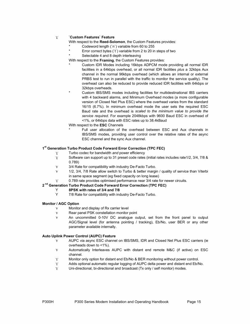
`Custom Features` Feature With respect to the Reed-Solomon, the Custom Features provides: * Codeword length (`n`) variable from 60 to 255 * Error correct bytes (`t`) variable from 2 to 20 in steps of two * Selectable 4 and 8 depth interleaving With respect to the Framing, the Custom Features provides: * Custom IDR Modes including 16kbps ADPCM mode providing all normal IDR
facilities in a 64kbps overhead, or all normal IDR facilities plus a 32kbps Aux channel in the normal 96kbps overhead (which allows an internal or external PRBS test to run in parallel with the traffic to monitor the service quality). The overhead can also be reduced to provide reduced IDR facilities with 64kbps or 32kbps overheads.
* Custom IBS/SMS modes including facilities for multidestinational IBS carriers with 4 backward alarms, and Minimum Overhead modes (a more configurable version of Closed Net Plus ESC) where the overhead varies from the standard 16/15 (6.7%). In minimum overhead mode the user sets the required ESC Baud rate and the overhead is scaled to the minimum value to provide the service required. For example 2048kbps with 9600 Baud ESC in overhead of <1%, or 64kbps data with ESC rates up to 38.4kBaud
With respect to the ESC Channels * Full user allocation of the overhead between ESC and Aux channels in
IBS/SMS modes, providing user control over the relative rates of the async ESC channel and the sync Aux channel.
1st Generation Turbo Product Code Forward Error Correction (TPC FEC) Turbo codec for bandwidth and power efficiency Software can support up to 31 preset code rates (initial rates includes rate1/2, 3/4, 7/8 &
0.789) 3/4 Rate for compatibility with industry De-Facto Turbo. 1/2, 3/4, 7/8 Rate allow switch to Turbo & better margin / quality of service than Viterbi
in same space segment (eg fixed capacity on long lease) 0.789 rate provides optimised performance near 3/4 rate for newer circuits.
2 nd Generation Turbo Product Code Forward Error Correction (TPC FEC) Y 8PSK with rates of 3/4 and 7/8
Y 7/8 Rate for compatibility with industry De-Facto Turbo.
Monitor / AGC Option Monitor and display of Rx carrier level Rear panel PSK constellation monitor point An uncommitted 0-10V DC analogue output, set from the front panel to output
AGC/Signal level (for antenna pointing / tracking), Eb/No, user BER or any other parameter available internally.
Auto Uplink Power Control (AUPC) Feature AUPC via async ESC channel on IBS/SMS, IDR and Closed Net Plus ESC carriers (ie
overheads down to <1%). Automatically Interleaves AUPC with distant end remote M&C (if active) on ESC
channel. Monitor only option for distant end Eb/No & BER monitoring without power control. Adds optional automatic regular logging of AUPC delta power and distant end Eb/No. Uni-directional, bi-directional and broadcast (Tx only / self monitor) modes.

P300H P300 Series Modem Installation and Operating Handbook Page 16
3 DESCRIPTION
3.1 OPERATION
The P300 Series modems are fully software controlled and with the exception of the optional G.703 interface option there are no links or switches used to configure the unit. This enables all control and configuration to be performed either locally from the front panel, or by remote M&C. Local control is by front panel keyboard, and a large, easy to read, 80 character LCD display, with clear, intuitive menus for configuration and control. All the set-up parameters are stored in non-volatile memory which will retain data for a minimum of 3 years, with no power applied. The transmit and receive functions of the Modem are independent, so that they may be operated at a different data rates, IF frequencies, or different services if required.
Like all Paradise Datacom products, the P300 Series includes a traffic log, which stores the last 500 events, suitably time-stamped. It can automatically add several measured parameters to the log at operator set intervals, including average & worst case Eb/No, average & worst case estimated user BER, average & worst case estimated uncorrected BER, and the buffer fill state. The logged performance monitoring allows investigation into customer reports of poor link performance, and can provide a useful correlation against weather conditions, etc.
3.2 FAULT PHILOSOPHY
Faults are split into two categories:
a) UNIT FAULTS: Equipment failures (such as a synthesiser lock failure). b) TRAFFIC FAULTS: Data path failures, (such as a lack of input clock).
A full description of every detected fault, its category (unit or traffic), and the corresponding action taken is provided in Appendix G - Fault Messages and Action Table. The response of the front panel LED indicators and external fault relays respond is described in the following sections.
3.3 ELECTRICAL DESCRIPTION
The P300 modem comprises of a single main modem Printed Circuit Board (PCB) with four optional additional boards:
Optional G.703 interface (two different boards for T1 or E1 operation). Optional IDR ESC board, which provides for all the IDR ESC requirements Optional Monitor / AGC board which provides a user scalable AGC output and a constellation
monitor point. Optional Turbo FEC daughtercard
For the P310, an L-Band daughterboard is also fitted internally above the main modem board, and further three internal options are possible:
Reference oscillator options (several of varying stabilities) An internal 100W PSU to provide a DC feed to an external BUC An optional FSK communications board, to enable a modem and BUC to bo operated from the
modem front panel (and to provide closed loop power control to the BUC flange).

P300H P300 Series Modem Installation and Operating Handbook Page 17
3.4 FRONT PANEL FEATURES
P300 Modem front panel view
KeyboardThe keyboard is of the membrane type (an integral part of the front panel), which provide a direct tactile feel. There are 15 keys in total - number keys in the range 0 to 9, an up arrow key ( ), down arrow key ( ), Óß×Ò key, ÇÛÍñÛÒÌÛÎ key, and ÒÑñÐÎÛÊ key.
LCD displayThis backlit display provides 2 lines of 40 characters each and is highly legible even in conditions of high ambient light. The LCD provides detailed information about the status and configuration of the unit, and when appropriate, prompts the user to enter data via the keypad.
onitor portMThe circular monitor port available on the front panel
nnector (a `D` type connector instead of the difficultcription of the "Async ESC connector" under the
perator is
urr
ff, then the Tx or Rx traffic has failed due to an external
t settings.
If the STANDBY LED is Amber, the Tx carrier is off. It may be intentionally switched off, or it may be muted due to either a fault, an external mute signal, or if in a 1-FOR-1 redundant pair itmay be the standby unit.
of previous products has been moved to the rear panel and is now combined onto the Async ESC coto obtain 8 pin `din` audio type connector). See the des
age.rear panel description, which starts on the next p
LED IndicatorsFive LEDs on the front panel provide summary fault information, so that even when the LCD is unavailable or status display (such as when the ofreconfiguring the unit, and a menu is displayed), the
ent status can always be assessed. If any of thecLED's indicate a fault, press Óß×Ò, then select ͬ¿¬«to display the current fault condition.
In normal operation there should be three GREEN LED's showing.
If the Status is RED, the unit has failed due to internal or possibly external conditions. Refer to the text on the LCD Status screen and rectify if possible.
If the TX OK or RX OK LED's are ofault, again refer to the text on the LCD Status screen and rectify if possible.
If the TEST LED is AMBER, a test mode or loopback is active, press Óß×Ò, and select Ì»¬to query or change the tes

P300H P300 Series Modem Installation and Operating Handbook Page 18
3.5 REAR PANEL DESCRIPTIONAt the rear of unit are all of the connectors necessary for the user to interface the Modem to the outside world; IF input and output to frequency conversion equipment, terrestrial data connection, station clock, alarms & AGC output, remote M&C, AC power and so on.
From left to right, the rear panel connectors are:
IEC mains power connector/voltage selector/fuseThe Modem is designed to operate from a mains AC supply of 100-240V (-15% + 10%, ie 85V to 264V at the connector). The IEC connector incorporates two fuses, independently fusing both live and neutral
lines. Access to the fuses is provided by a slide out tray. Both fuses are standard 20 mm type, rated3.15A, of the slow-blow (time delay) type. ALWAYS REPLACE THE FUSE WITH ONE OF THE SAME TYPE AND RATING.
P300 Modem rear panel view (IDR & G.703 options fitted)
Chassis ground studThis is an M4 stud for connecting a safety earth conductor directly to the chassis of the unit.
FanThe fan may be selected to be temperature controlled or permanently active (ie the fact that it is not running does not indicate it has failed). Use the test menu to display the internal unit temperature if in doubt, the fan comes on at 26°C and off at 24°C.
Station ClockThis connector is a 75 BNC female which accepts a 1-10MHz signal, either a square wave of >1V p/p(eg a G.703 para 10 `synchronising clock`) or a sinusoid at a power level of 0dBm or greater. Analternative Station Clock signal at RS422 interface levels can be applied to the Async ESC connector. Either signal can be used by the modem as a reference for the receive output clock (the Station Clock does not have to be the same rate as the data as an internal PLL converts between rates). In addition if the Rx Clocking is set to use the Station Clock and the Tx Clocking is set to Rx , then the Station Clock also sources the internally generated Tx Clock (Tx & Rx data rates are independent). Finally, if a 10MHz signal is applied, this signal may also be used in place of the internal reference for the Tx and Rx IFsynthesisers.1:1 Redundancy connector The Modem has a built-in 1 for 1 redundancy controller which connects to the corresponding port ofanother Modem via this 9 pin male 'D' type connector. A complete 1:1 redundancy system requires onlytwo modems, a 1:1 control cable (on this port), a data split (`Y`) cable, and passive splitters/combiners for the IF ports (or splitters/combiners already present in the system). Connection details are given in Appendix B, and an overview of 1 for 1 operation is provided in section 9 starting on page 177.
Remote M&C connectorThis is a 9 pin female 'D' type connector whose pinout and interface levels are `SA-bus` compliant. The Modem can be set to operate with either Paradise/FDC or SA-bus protocols. The electrical interface can be selected between RS232 (for direct to PC applications) & RS485 (for multidrop applications). TheRemote M&C port may be internally linked (ie no cables) to the Async ESC port for over the satellitedistant end Remote M&C control. Pinout details are in Appendix B.

P300H P300 Series Modem Installation and Operating Handbook Page 19
Rx IF input This connector is a BNC female and can be used as either a 50 or 75 input. The allowable signal level of the desired carrier at the input of the modem is from -60dBm to -30dBm (P310: -70dBm to -20dBm). A level of -45dBm is recommended. The maximum composite power level that should be applied to this port is 30dB above the desired carrier, up to a maximum of 0dBm (P310: Composite +35dBc to max of -10dBm).
Alarms and AGC connectorThis is a 15 pin male 'D' type connector that provides access to the three form `C' relay contacts that indicate alarm conditions. Also provided on this port if the Monitor/AGC option is fitted is an uncommitted analog output, which by default provides an AGC output, but which may be selected via the front panel to provide other user requested signals (eg Eb/No, Rx IF offset frequency, or other uses implemented as required). The alarm relays have the following definitions:
Unit Fault: A unit fault exists, i.e. an equipment failure.
Traffic Prompt: A Tx or Rx traffic fault exists.
Deferred alarm: One of the following conditions exists: The receive BER is greater than the user defined threshold. The receive Eb/No is lower than the user defined threshold. Buffer slips are more frequent than the user set threshold.
A Backward alarm is being received from either the satellite or terrestrial ports.
Full pinout details are provided in Appendix B. The alarm relay functions can be changed, See `Relay Mode` in appendix E.
Async ESC connectorThis 15 pin `D` female connector provides a superset of the features found previously on the front panel circular 8 pin `din` connector. It includes an RS232 serial port for the loading or revised internal software from a PC or the printing of the units traffic log to a serial printer / PC terminal emulator. If the Monitor/AGC option is fitted it provides I,Q, and symbol clock outputs to monitor the receive constellation (in order to view received signal quality on an oscilloscope). When the IDR option IS NOT fitted, it provides an RS232/RS422/RS485 asynchronous port for either the high rate Async ESC facility (for IBS/SMS or Closed Net Plus ESC services) or the IBS/SMS `low rate INTELSAT oversampled ESC facility` (which is configured as the Aux data channel on the modem). When the IDR option IS fitted, separate ports for the ESC and Aux channels on the IDR card are activated, and ESC/Aux access on this async port is disabled. Finally, this connector also provides the port for an RS422 compatible Station Clock (see the Station Clock paragraph on the previous page).
Tx IF outputThis connector is a BNC female and can be used as either a 50 or 75 output. The output power level can be varied from 0dBm to -25dBm on 0.1dB steps from the front panel (P310: -5dBm to -30dBm).
ESC & Aux connectorThis connector is fitted as part of the IDR option (Standard on P300-IDR & P300-TCM), it provides access to:
Four backward alarm form `c` outputs, and the 4 backward alarm inputs, together with a Rx summary alarm signal for direct connection to the backward alarm inputs. Note that these can be used both in IDR modes, and (if the IBS and `Custom Features` features are available) a custom IBS mode, which allows four backward alarms for low rate IBS multidestinational carriers.

P300H P300 Series Modem Installation and Operating Handbook Page 20
Two Audio ESC ports (4 wire 600 , +7 to -16dBm). In addition to normal IDR ESC operation these ports may also be used in IBS modes to generate a 64kbps IBS carrier comprising just the two 32kbps ADPCM audio channels, or a 128kbps IBS carrier comprising 64kbps data (from the main data interface of the modem) plus the two 32kbps ADPCM audio channels. This is an emulation of the most popular modes of the P1348/P1448 voice/data mux card used often in SNG applications.
An RS232/RS422/RS485 Port for sync/async ESC traffic, this port replaces the shared ESC/Aux access via the Async ESC connector on the main unit. Used to provide access to the 8kbps synchronous IDR ESC channel. If the Async ESC feature is available (standard on P300-IBS and above) then Async access to the 8kbps channel is also available. Again if the Async ESC feature is available this port also provides the high rate Async ESC on IBS/SMS or Closed Net Plus ESC services
An RS232/RS422 port for sync/async Aux traffic, this port replaces the shared ESC/Aux access via the Async ESC connector on the main unit. The Aux port provides 32 or 64kbps access to the IDR overhead in place of one or both of the IDR 32kbps ADPCM Audio ESC channels. If the IBS/SMS feature is available then this port may be configured to provide either the IBS `low rate INTELSAT oversampled ESC facility`, or a higher rate synchronous channel within the IBS/SMS overhead.
Pinout details are provided in Appendix B.
Terrestrial Interface ConnectorsThe P300 provides as standard both 25 pin EIA530 and 37 pin RS449 female DCE connectors. NOTE that these are simply wired in parallel and you should not connect both simultaneously. The electrical interface is front panel selectable to be RS422, V.35, and RS232. Normally for RS232 operation the EIA530 connector would be used (which is standard 25 pin RS232 compatible) and for RS422 the 37 pin RS449 connector. The old style 34 pin `Winchester` connector favoured for V.35 interfaces has poor EMC performance and so could not be incorporated whilst maintaining CE compliance. If this style of connector is required then an external adaptor cable must be used.
If the G.703 option is fitted, then in addition to RS422/V.35/RS232, G.703 is also available as a software selectable interface standard. T1 (1544kbps) G.703 is a balanced 100 signal, and is provided on both `D` type connectors when G.703 is selected from the front panel. When the E1 (2048kbps) G.703 option is fitted then in addition to providing support for the balanced 120 signal on both `D` type connectors an additional pair of BNC connectors are provided to accept the unbalanced 75 interface standard. THE SELECTION BETWEEN 75 and 120 IS MADE BY A SWITCH ON THE E1 G.703 OPTION not by software. As with the 25/37 pin connectors, do not connect signals to both the BNC and `D` type connectors simultaneously.
In addition a switch on both the T1 and E1 G.703 options controls what happens to the G.703 port when power is removed. Either the G.703 ports can be set to go high impedance (used in 1:1 redundancy operation) or it can be configured to loop the G.703 input back to the output (typically used when Drop/Insert is in operation and the same PCM bearer is cascaded through several modems). Again (as it affects what happens when power is removed) this is SET BY A SWITCH ON THE CARD not by software.
Finally, for special customer requirements it is possible to fit different interfaces to this port. Note that UNLIKE PREVIOUS PRODUCTS the interface does NOT simply unplug. Instead it is constructed as part of the main modem, and requires `snapping off` and a connector to be soldered in place before a replacement card can be fitted.
Standby LEDThis LED mirrors the front panel standby LED, so that from the rear of the equipment the operator can tell if the carrier is off, or more importantly which unit of a 1:1 pair is the offline unit.

P300H P300 Series Modem Installation and Operating Handbook Page 21
F. BLOCK DIAGRAM

P300H P300 Series Modem Installation and Operating Handbook Page 22

P300H P300 Series Modem Installation and Operating Handbook Page 23
4 SUMMARY OF SPECIFICATIONS
Common Main SpecificationsOptional features are shown in [square brackets]
Modulation BPSK, QPSK, OQPSK, [8PSK]
Frequency/Resolution P300: 50 MHz - 90 MHz, 100Hz resolution. [50 MHz - 180 MHz Wideband IF feature]
P310: 950MHz - 1750MHz 100Hz resolution [950 MHz - 2150 MHz Wideband IF feature] Traffic Interface Electrical RS422, V.35 and RS232 software selectable (clocking can provide
X.21 DCE or DTE mode)
Mechanical Both EIA530 DCE and RS449 DCE connectors (25 pin and 37 pin `D` female respectively).
Options T1 or E1 G.703 in addition to RS422, V.35, & RS232 (software selectable)For special requirements a customer specific interface card may be fitted.
User Data Rates Closed Network Resolution of 1 bps
Rate Rate Rate Uncoded Rate
BPSK min 4.8k 7.2k 8.4k 9.6k
max * 1250k 1875k 2187k 2500k
QPSK / OQPSK min 9.6k 14.4k 16.8k 19.2k
max * 2.5M 3.75M 4.375M 5.0M
8PSK/TURBO min 21.6k 25.2k
max * 5.0M 5.0M
8PSK/TCM min 19.2k
max * 5.0M
[Closed Net plus ESC] As Closed Net above but limits include an overhead of approx 1.4 x ESC Baud rate. Resolution of 1 bps. ESC from 50Baud to 38.4kBaud
[IBS/SMS Mode] <9.6k to >2048k* (6.7% overhead added) Resolution of 1 bps
[IDR Mode] <64k to >2048k* (96k overhead added) Resolution of 8k (limitation of frame structure)
Note: Maximum data rate is 512kbps in all modes before overheads unless the High Data Rate option is fitted.
P300H P300 Series Modem Installation and Operating Handbook Page 24
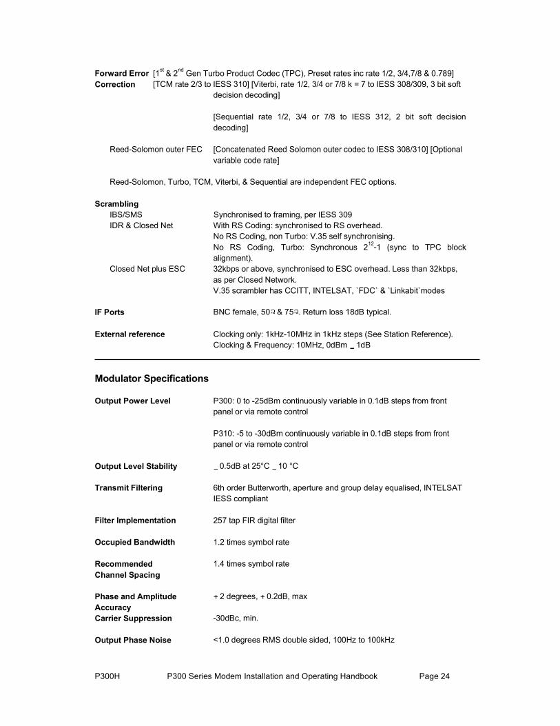
Forward Error [1st & 2nd Gen Turbo Product Codec (TPC), Preset rates inc rate 1/2, 3/4,7/8 & 0.789] Correction [TCM rate 2/3 to IESS 310] [Viterbi, rate 1/2, 3/4 or 7/8 k = 7 to IESS 308/309, 3 bit soft
decision decoding]
[Sequential rate 1/2, 3/4 or 7/8 to IESS 312, 2 bit soft decisiondecoding]
Reed-Solomon outer FEC [Concatenated Reed Solomon outer codec to IESS 308/310] [Optional variable code rate]
Reed-Solomon, Turbo, TCM, Viterbi, & Sequential are independent FEC options.
ScramblingIBS/SMS Synchronised to framing, per IESS 309 IDR & Closed Net With RS Coding: synchronised to RS overhead.
No RS Coding, non Turbo: V.35 self synchronising. No RS Coding, Turbo: Synchronous 212-1 (sync to TPC block alignment).
Closed Net plus ESC 32kbps or above, synchronised to ESC overhead. Less than 32kbps, as per Closed Network. V.35 scrambler has CCITT, INTELSAT, `FDC` & `Linkabit`modes
IF Ports BNC female, 50 & 75 . Return loss 18dB typical.
External reference Clocking only: 1kHz-10MHz in 1kHz steps (See Station Reference). Clocking & Frequency: 10MHz, 0dBm 1dB
Modulator Specifications
Output Power Level P300: 0 to -25dBm continuously variable in 0.1dB steps from frontpanel or via remote control
P310: -5 to -30dBm continuously variable in 0.1dB steps from frontpanel or via remote control
Output Level Stability 0.5dB at 25°C 10 °C
Transmit Filtering 6th order Butterworth, aperture and group delay equalised, INTELSATIESS compliant
Filter Implementation 257 tap FIR digital filter
Occupied Bandwidth 1.2 times symbol rate
Recommended 1.4 times symbol rate Channel Spacing
Phase and Amplitude 2 degrees, 0.2dB, max AccuracyCarrier Suppression -30dBc, min.
Output Phase Noise <1.0 degrees RMS double sided, 100Hz to 100kHz

P300H P300 Series Modem Installation and Operating Handbook Page 25
Output Frequency Stability As per internal reference from 0°C to 50°C (See Internal Reference below)
Harmonics and Spurious Better than - 55dBc/4 kHz.
Transmit On/Off Ratio 55dB minimum
External Transmit Inhibit By external contact closure or by TTL signal applied to rear panelconnector. Hardware function overrides processor control
Demodulator Specifications
IF Input Range P300: -45dBm nominal, 5dB (desired carrier) P310: -20 to -70dBm (desired carrier)
Maximum Composite Signal P300: 30dB above level of desired input up to a maximum of 0dBm P310: 35dB above level of desired input up to a maximum of -10dBm
Frequency Acquisition Selectable from 1 kHz to 32 kHz Range
Acquisition Threshold < 5dB Eb/No
Acquisition Time @ 9.6 kbps < 3 seconds at 6dB Eb/No (rate 1/ FEC) @ 64 kbps < 2 seconds at 6dB Eb/No
@ 2048 kbps < 500 ms at 6dB Eb/No
Clock Tracking Range ±100 ppm min
Receive Filtering 6th order Butterworth, group delay equalised (INTELSAT IESScompliant)
P300H P300 Series Modem Installation and Operating Handbook Page 26
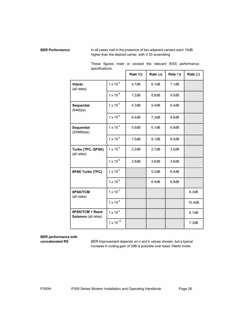
BER Performance In all cases met in the presence of two adjacent carriers each 10dBhigher than the desired carrier, with V.35 scrambling
These figures meet or exceed the relevant IESS performance specifications.
Rate 1/ Rate Rate Rate
Viterbi(all rates)
1 x 10⁻⁴ 4.7dB 6.1dB 7.1dB
1 x 10⁻⁸ 7.2dB 8.8dB 9.5dB
Sequential(64kbps)
1 x 10⁻⁴ 4.3dB 5.4dB 6.4dB
1 x 10⁻⁸ 6.4dB 7.3dB 8.6dB
Sequential(2048kbps)
1 x 10⁻⁴ 5.6dB 6.1dB 6.9dB
1 x 10⁻⁸ 7.5dB 8.1dB 8.4dB
Turbo (TPC, QPSK)(all rates)
1 x 10⁻⁴ 2.2dB 2.7dB 3.5dB
1 x 10⁻⁸ 2.8dB 3.6dB 3.8dB
8PSK Turbo (TPC) 1 x 10⁻⁴ 5.2dB 6.4dB
1 x 10⁻⁸ 6.4dB 6.8dB
8PSK/TCM(all rates)
1 x 10⁻³ 6.3dB
1 x 10⁻⁸ 10.4dB
8PSK/TCM + Reed-Solomon (all rates)
1 x 10⁻⁴ 6.1dB
1 x 10⁻¹⁰ 7.3dB
BER performance with concatenated RS BER improvement depends on n and k values chosen, but a typical
increase in coding gain of 3dB is possible over basic Viterbi mode.

P300H P300 Series Modem Installation and Operating Handbook Page 27
Monitor Functions Measured FEC input BER (raw channel, not TCM) Estimated FEC output BER (not TCM) Measured Reed-Solomon input BER Estimated Reed-Solomon output BER Measured deframer FAW BER Measured Eb/No (not based on channel BER, range: 3.0-15.0dB,accuracy 0.2dB).Measured frequency offset ( 100 Hz resolution)
Clocking and Buffering
Clock Loops Frequency locked loops give phase hit immune operation even withpoor clock sources such as routers etc.
Tx Clocking Internal Reference (see Internal Reference below for stability) External - tracking range 100 ppm / min.Rx Timing - slaves Tx internally generated timing from Rx clocking whatever Rx clocking mode is selected eg with Rx=Satellite for looptiming (with full asymmetric rate capability), or with Rx=Station forboth Tx & Rx clocking slaved to Station Clock (again with fullasymmetric rate capability).
Rx Clocking Clock from satellite (Buffer disable) Transmit input clock - (plesiochronous, includes full asymmetric rateoperation)Internal Reference (see Internal Reference below for stability) DCE External timing clock (DTE interface only). Station reference (see below)
Internal Reference P300: +/-1PPMP310: Default as per P300. Options: 7x10⁻⁷ per year (P313B), 1x10⁻⁷per year (P313C), 7.5x10⁻⁸ per year (P313D).
Station References inputs 75 BNC female, transformer isolated 1MHz to 10MHz in 1kHz steps(accepts sinusoid >0dBm or squarewave eg G.703 para 10)120 RS422 compatible input, 1kHz to 10MHz in 1kHz steps
When set to 10MHz, the station reference may replace internal reference to all internal circuitry (eg IF synths). The unit automaticallyswitches back to the internal reference if the station reference fails.
Buffer Size Selectable in 1 ms increments from 0 to 99 ms. Automatically adjustedto slip an integer multiple of terrestrial multiframe length for framed rates (T1/E1).
Buffer storage is 32kBytes, so above 2.6 Mbps max buffer size reduces linearly from 99 ms to 52ms at 5.0Mbps
Framing & Deframing
Formats Closed Network (unframed)

P300H P300 Series Modem Installation and Operating Handbook Page 28
Closed Net plus ESC [Async ESC Feature] provides variable rate async ESC, optional synchronous scrambler above 32kbps to replace error multiplying V.35 scrambler, optional backward alarm facility, and optional Timeslot ID Maintenance when used with Drop/Insert, all in minimum possible overhead down to <0.5%.
INTELSAT IBS & Eutelsat SMS [IBS/SMS Feature]. Framing to IESS 309 & IESS 310
INTELSAT IDR [IDR Option]. Framing to IESS 308 & IESS 310 Custom Framing [`Custom Features` feature]. Provides custom framing based on IBS or IDR formats. For example the use of 16 kbpsADPCM on the IDR audio ESC channels, providing an IDR carrier with all normal facilities but with 32kbps of overhead spare for continuous traffic quality BER monitoring (using built in PRBS tester with automatic results logging or external BERT)
Poor BER performance Deframer includes extended threshold operation, which improvesperformance when used with Reed-Solomon in very poor BERconditions (where a single uncorrectable RS codeword can contain enough corrupt frame alignment words to knock an INTELSATspecified deframer out of frame sync).
[INTELSAT Reed Solomon Codec & Custom Features]
Format Concatenated Reed Solomon outer codec to IESS 308/310
Code Rate Default n, k, t = (126, 112, 7) depth 4, automatically switching to: (225,205, 10) depth 4 for 1544 kbps IDR mode. (219, 201, 9) depth 4 for 2048 kbps IDR mode & TCM <=1544 kbps, and (219, 201, 9) depth 8 for TCM >1544 kbps
Processing Delay Combined Encoder & Decoder: 8 x (2n - k + 60) Combined Interleaver & De-interleaver: 8 x n x depth (Calculate delaytime using data rate including RS overhead)
[Custom Features] When available allows arbitrary selection of `n` & `k` to provide fully variable code rate. `n` = 60-255
`k` = n-2 to n-20 step 2 Interleaving depth of four or eight
The `Custom Features` Feature allows use of shorter codewords to reduce interleaver / de-interleaver delay on low data rate circuits. Forexample switching from n, k, t = 126, 112, 7 to 64, 56, 4 providesapproximately the same correction ability (7 in 126 = 5.5% and 4 in 64 = 6.25% respectively), with similar overheads (126/112=12.5%,64/56=14.3%), but with interleaving & decoder delays reduced from 5632 to 3104 bits (156 ms to 85 ms at 32 kbps).

P300H P300 Series Modem Installation and Operating Handbook Page 29
[Drop /Insert Feature]
Bearer Types T1-D4, T1-ESF, and G.732.
Timeslot Selection Independent selection of arbitrary timeslots for both Drop and Insert.
Bearer Generation The terrestrial bearer may be looped through the Drop mux then Insertmux, or terminated after the Drop mux and a new blank bearer generated by the Insert mux. The bearer generated within the Insert mux provides full multiframe and CRC support and may be generated from the Tx Clock, Station Reference, Satellite Clock or Internal reference.
Bearer Backup In the event that the Insert mux bearer clock is lost, or AIS is supplied, then the Insert mux will switch temporarily to bearer generation modein order to preserve the receive traffic. The backup bearer may be generated from the Station Reference, Satellite Clock or Internalreference.
Terrestrial CRC Fully supported, with front panel display of terrestrial error rate based on CRC (T1-ESF and G.732) or Frame Alignment Word errors (allbearer types)
Timeslot ID Maintenance The IBS/SMS or Closed Net plus ESC overhead maintains the identityof individual D/I timeslots for N=1, 2, 3, 4, 5, 6, 8, 10, 12, 15, 16, 20, 24, 30 (see Extended D/I Feature below).
[Extended Drop/ Insert Feature]
Timeslot Re-ordering Selected timeslots may be independently re-ordered on both Tx and Rx paths.
Timeslot ID Maintenance The IBS/SMS or Closed Net plus ESC overhead is extended to maintain the identity of individual D/I timeslots for all values of N from 1 to 31, including the previously unavailable values N=7, 9, 11, 13, 14, 17 - 19, 21 - 23, 25-29, and 31.
Multi-destinational working All or only a subset of the received data may be inserted into theterrestrial bearer on the receive path for multi-destinational working.
Signalling Both Channel Associated Signalling (CAS), and Robbed Bit Signalling (RBS) are fully supported:
For E1 G.732 Drop/Insert, CAS signalling is extracted fromterrestrial TS16 and carried over the satellite in IBS/SMS TS16 and TS48 before re-inserting into the distant terrestrial TS16
For T1-D4 and T1-ESF RBS the IBS or Closed Net plus ESC overheads maintain the identity of the in band signalling, and it is re-inserted into the terrestrial multiframe in the correct positions to maintain the RBS.
P300H P300 Series Modem Installation and Operating Handbook Page 30
[Async ESC Feature] & Aux Data Channel
ESC/Aux Port A single port provides the interface for optional high rate async ESC(IBS/SMS or Closed Net plus ESC), or the INTELSAT low rate async IBS ESC channel.
Electrical Interface RS232, RS422, or RS485 external interfaces or internal link to Remote M&C port (software selected). No external cabling required between the ESC and M&C ports for M&C via ESC channel within overhead. Other devices externally wired in parallel with M&C port can also be accessed remotely.
Aux Data Channel
IBS INTELSAT low rate async ESC definition carried in bit 1 of TS32 providing a synchronous channel at 1/480th of the data rate, allowing up to one quarter of this rate for oversampled async data. Compliantwith INTELSAT IESS 403 low rate ESC definition.
[Async ESC Feature]
Closed Net plus ESC Overhead scales to provide any user specified async ESC Baud rate whatever the satellite data rate. ESC limit is approx 70% of mainchannel rate, overhead varies from <0.5% to >70%
IBS/SMS High rate async data using from 1/32nd to 22/32nd of the IBS overhead, providing async baud rates from 0.2% to 5.1% of theterrestrial rate (eg up to >2400 Baud at 64 kbps). Includes modescompatible with the P400 Series, P230 & P1300/P1361 (using 20/32nd of the overhead).
[IDR Option]
IDR ESC Audio Interface Two 32 kbps ADPCM channels, 4 wire 600 , +7dBm to -16dBm (software programmable in 0.1dB steps)
Backward Alarms Outputs: Four `form C` relays Inputs: Four protected inputs, short to 0 V to send alarm, with matching summary Rx fail output. Alarm inputs software configurable for:
a) All external patch b) 1=Rx fail & 2-4=External Patch c) 1=Rx Fail & 2-4=OK
d) 1-4=Rx Fail.
ESC/Aux Ports When the IDR option is fitted, independent ESC & Aux ports on theIDR option replace the single shared ESC/Aux port of the base unit.
ESC Port RS232, RS422, or RS485 external interfaces or internal link to Remote M&C port (software selected). No external cabling required between the ESC and M&C ports for M&C via ESC channel within overhead. Other devices externally wired in parallel with M&C port can also be

P300H P300 Series Modem Installation and Operating Handbook Page 31
accessed remotely. Provides Clock, Data, & Sync (Octet timing) lines.
IDR Synchronous access to 8 kbps IDR ESC. With the Async ESC feature (standard on P300-IBS and above) async ESC access to the 8kbpsIDR ESC is provided, giving up to a 9600 Baud async channel
Others IBS & Closed Net plus ESC facilities as before installation of IDR option, but now on ESC port on IDR card not shared ESC/Aux port of base unit.
Aux Port RS232 or RS422 (software selected). Provides Clock and Data lines.
IDR Provides 32 or 64 kbps access in place of one or both Audio ESC channels.
IBS INTELSAT low rate ESC mode as previously but now via Aux port on IDR card not shared ESC/Aux port of base unit. IDR option also adds sync IBS mode, configurable to use between 1/32nd and 21/32nd ofthe IBS overhead providing a full sync Aux port at between 0.2% and 4.3% of main data rate.
Aux port provides satellite timing information for P1500 Slave Frequency Standard when not configured for Aux data access.
P1348 Emulation The IDR Option includes the facility to emulate the more common modes of our popular P1348 / P1448 voice / data mux cards which areused extensively in SNG applications. It uses the IDR audio ESC ports for the audio interfaces and can generate a 64 kbps carrier consisting solely of two 32kbps ADPCM encoded audio channels, or a 128 kbps carrier comprising the two audio channels plus 64 kbps data from the main interface. This is compatible with a P400 Series modem fittedwith P1448 card or a P230 Modem with a P1348 card, alternativelyDrop/Insert can be used at the distant end to place the two 32kbps ADPCM audio channels in one timeslot and the 64 kbps data in another.
[PRBS Tester Feature]
BER Channel PRBS tester may operate through either main traffic, ESC data, or AUX data channels (main traffic channel not available in Closed Net, ieno overhead mode). Use of ESC & AUX data channels allowcontinuous real traffic BER performance monitoring on links with overhead.
Test Patterns 2047, 215-1, 220-1, compatible with common stand alone BER testers.
Results Display of error count & average BER
Autolog Automatic logging of average and 1 minute worst case BER at userspecified intervals (1 min - 24 hours)
P300H P300 Series Modem Installation and Operating Handbook Page 32
[Monitor/AGC Option]
Facilities Provided Demodulator Rx carrier signal monitoring & level display ( 5dB)0 -10 V Analog output (Signal level, Eb/No or Rx offset frequency) Buffered constellation monitor port Sounder for audible feedback from keyboard
Traffic Log
Capacity Total 500 entries
Entry Format Fault message with time & date. Separate entry when fault clears/ changes
Automatic Entries Average & minimum Eb/No (user defined Average & minimum estimated user BER interval) Buffer fill status
Average & 1 minute minimum measured BER from PRBS tester (mayrun continuously through ESC or Aux channel for continuous traffic quality monitoring)
Interrogation method View on front panel LCD, Print to rear panel serial port (`D` type) either all entries or just unprinted entries read over remote M&C bus
[Auto Uplink Power Control] (AUPC)
Modes of operation: Monitor of distant Eb/No & BER only, Full distant Eb/No maintenance, & Self monitor (broadcast) modes. Unidirectional or bidirectional operation.
Communication link: Utilises async ESC channel on IBS/SMS, IDR and Closed Net Plus ESC carriers (ESC from 300Baud, ie overheads down to <1%).
User parameters: Target Eb/No, Tolerance window, Max & Min delta powers, Slew ratelimit, comms loss action (freeze, max or nominal power).
Ancillary features: Automatic logging of distant Eb/No and local AUPC delta power at usercontrolled intervals in traffic log.
Automatically interleaves AUPC messages with distant end remote M&C (if active) on ESC channel.
Independent Max & Min delta powers (ie facility to reduce power & still maintain quality of service with good atmospherics) allows power balancing on transponders with traffic to varied destinations.
Common SpecificationsLoopbacks Interface Loop (local & remote)
Drop/Insert Loop (local) Framer Loop (local)

P300H P300 Series Modem Installation and Operating Handbook Page 33
FEC Loop (local) RS Loop (local) Internal IF Loop (local, Rx IF automatically tuned to match Tx) Deframer/Framer Loop (remote)
Test Modes Transmit CW (pure carrier) Transmit alternate 1,0 pattern (for carrier suppression test) Disable Reed-Solomon decoder corrections
Alarm Relays 3 independent changeover contacts: Prompt Unit fault Prompt Traffic fault (Tx or Rx) Deferred Alarm (backward alarm, BER or Eb/No below user threshold)
Controller Intel 8032 micro controller provides all M&C functions
Embedded Software Revised embedded software may be downloaded to FLASH memory with modem still in equipment racks. No EPROMs, no opening of the case.
Configuration Memories Up to 10 different configurations can be stored & recalled from the front panel or remote M&C
User Interface Clear & intuitive operator interface with plain English dialogue allows fast and efficient configuration of modem. 80 Character, backlit, high contrast, wide angle LCD 15 Key tactile full keyboard.
Remote M & C For multi-drop applications, RS485 interface, for direct-to-PCapplications RS232 interface (front panel selectable).
M&C port may be directly internally linked to ESC port for distant end `over the satellite` M&C without cabling.
Redundancy Features 1:1 redundancy controller built in.`Y` cables passively split data, maintaining impedances. L Band inputs/outputs are passively split/combined outside the units. Offline unit tri-states data outputs & mutes Tx carrier.
BUC/LNB Support (P310) Reference to BUC/LNB Stability: See Internal Reference / Station Reference (clocking section) Switchable from front panel / remote M&C. Tx: at rear N-Type to BUC +7dBm +/-2dB Rx : at rear N-Type to LNB 0dBm +/- 0.2dB
DC Supplies: Switchable from front panel / remote M&C. Tx: 24V or 48V factory option (100W or 180W respectively) Rx: 15V or 24V at 500mA
FSK Communications P310: Option for duplex FSK Communication with Paradise BUCs (P314). Provides control of BUC from modem front panel or by remote M&C via normal modem M&C ports. Includes control and monitoring of all BUC parameters available over FSK, and option to provide closed loop power control to BUC flange.

P300H P300 Series Modem Installation and Operating Handbook Page 34
Alarms: User set hi/low current monitor window on DC supply to BUC With FSK, all BUC alarms integrated into modem alarm handling.
Mechanical P300: 1 U chassis - 355 mm deep P310: 1 U chassis - 440 mm deep
Weight P300: 3 kg P310: 3.8Kg up to 4.35Kg with options
Power Supply 100-240 Volts AC +10% -15%, 47 - 63 Hz ,P300: 40 watts maximum P310: 240W maximum (extra PSU for BUC) Rated maximum supply current 1A at 100V, 0.3A at 240V Fused IEC connector (Double pole / Neutral fused) Fuse rating T3.15AH 250V (3.15A fuse, time delay, high rupture current, for 250V supply) Maximum rating of fuse in supply plug or at the supply distributionboard is 5A
P310: Option (P324) for 48V DC primary input power.
Safety EN 60555-2
EMC EN 55022 Class B (emissions) EN 55024 Part 1 (immunity)
Environmental Operating temperature range 0 to 50C
Supporting ProductsThe P300 Series are supported by the following products:
P500 series 1:8 redundancy controller, which includes the facility to mix electrical interfaces within redundancy group
Alphawave CAM Monitor & Control software allows monitor and control of many different products(including non-Paradise products).
Specifications are subject to change without notice.
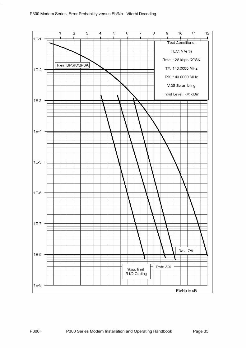
P300H P300 Series Modem Installation and Operating Handbook Page 35
.
P300 Modem Series, Error Probability versus Eb/No - Viterbi Decoding.

P300H P300 Series Modem Installation and Operating Handbook Page 36
P300 Modem Series, Error Probability versus Eb/No - Sequential Decoding at 64kbps

P300H P300 Series Modem Installation and Operating Handbook Page 37
P300 Modem Series, Error Probability versus Eb/No - Sequential Decoding at 2048kbps.

P300H P300 Series Modem Installation and Operating Handbook Page 38
P300 Modem Series, Error Probability versus Eb/No - 8PSK/TCM with/without Reed-Solomon.

P300 Modem Series, Error Probability versus Eb/No – 1st Generation Turbo Codec.
P300H P300 Series Modem Installation and Operating Handbook Page 39

P300 Modem Series, Error Probability versus Eb/No – 2nd Generation Turbo Codec.
1.00E-09
1.00E-08
1.00E-07
1.00E-06
1.00E-05
1.00E-04
1.00E-03
1.00E-02
0 1 2 3 4 5 6 7 8 9 10
EbNo
BE
R
Rate 7/8 Spec Limit
Rate 3/4Spec Limit
Test ConditionsFEC: Turbo
Rate: 2048 kbps QPSK Tx: 70.000 MHzRx 70.000 MHz
Scrambling: Normal (Turbo)
Input Level: -45 dBm
Rate 1/2Spec Limit
P300H P300 Series Modem Installation and Operating Handbook Page 40
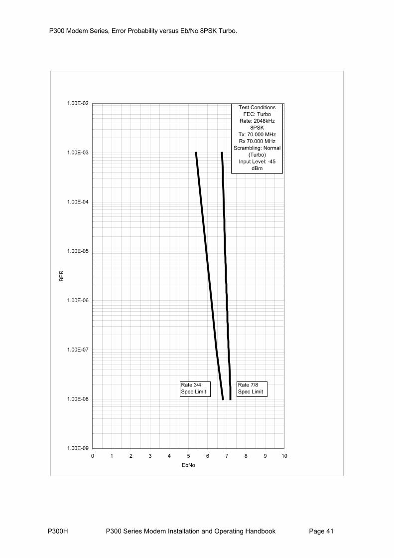
P300 Modem Series, Error Probability versus Eb/No 8PSK Turbo.
1.00E-09
1.00E-08
1.00E-07
1.00E-06
1.00E-05
1.00E-04
1.00E-03
1.00E-02
0 1 2 3 4 5 6 7 8 9 10
EbNo
BER
Rate 7/8 Spec Limit
Rate 3/4Spec Limit
Test ConditionsFEC: Turbo
Rate: 2048kHz 8PSK
Tx: 70.000 MHzRx 70.000 MHz
Scrambling: Normal (Turbo)
Input Level: -45 dBm
P300H P300 Series Modem Installation and Operating Handbook Page 41

P300H P300 Series Modem Installation and Operating Handbook Page 42
5 INSTALLATION AND CONFIGURATION
5.1 UNPACKINGPrior to unpacking, inspect the exterior of the shipping container for evidence of damage during transit. If damage is evident, contact the Carrier immediately and submit a damage report. Carefully unpack all items, taking care not to discard packing materials, particularly the moulded foam inserts. Should the unit need to be returned to Paradise Datacom, USE THE ORIGINAL PACKING CARTON. This is the only approved shipping container that Paradise recognises.
5.2 VISUAL INSPECTION OF EQUIPMENTOnce unpacked, visually inspect the unit for damage. The shipping carton in which the Modem is shipped has been used by Paradise to ship our products worldwide for a number of years. It has shown, through experience, that it can withstand very rough handling. Therefore, if the equipment received is damaged, there can be no doubt that it has been subjected to abnormal or abusive treatment - please file a claim with the Carrier immediately and then contact Paradise Datacom. Assuming, however, that the equipment has been received in perfect condition, proceed with the installation of the equipment.
5.3 INTERFACE OPTIONSUnlike previous Paradise products this unit is fitted as standard with an interface that is AN INTEGRAL PART OF THE MODEM main board, DO NOT TRY TO REMOVE THE CARD. Customer specific interface options are available, but these require the standard interface to be `snapped off` and a connector soldered to the board before the modem can accept other standard Paradise interface cards.
Note if fitting the additional G.703 options (T1 or E1) that there are links and switches on the card, and these should be set BEFORE the card is installed.
5.4 IF INTERFACEConnect the appropriate cables to the Transmit IF and Receive IF connectors at the rear of the unit. Output power level can be controlled using the front-panel menus. The optimum input level for the demodulator is -45dBm ±15dB.
5.5 POWER UPAt power up the unit performs an initialisation procedure, which lasts approximately 3 seconds. If the unit was previously operational, it will enter operating mode. If the unit was previously non-operational, then the main menu will be displayed. During the power-up phase, the unit will display the product number P300 with a V & S suffix indicating the presence of the Viterbi and / or Sequential codec, plus the unit serial number.
The user should then select ÍÛÌËÐô ×Ò×Ì×ßÔ ÝÑÒÚ×Ù, (to define every parameter prior to operation), later changes to the configuration are made with the ÝØßÒÙÛ option. The Status screen cannot be selected unless ÍÛÌËÐô ×Ò×Ì×ßÔ ÝÑÒÚ×Ù has been performed.

P300H P300 Series Modem Installation and Operating Handbook Page 43
6 MENU SYSTEM
6.1 INTRODUCTION
All configuration & monitoring features are accessed from the front panel via the menu system. Provided an operator has an understanding of how the menu system works, there is no need to try and memorise the menu structure itself, as selecting a single option (ÍÛÌËÐô ×Ò×Ì×ßÔóÝÑÒÚ×Ù, explained later) will make the unit prompt for all needed configuration parameters. The structure of the menu system is however shown on the next few pages for reference.
THE 1 MINUTE GUIDE TO FRONT PANEL OPERATION The main menu can be accessed from any display with the Óß×Ò key. It is from this main menu that all functions are selected.
1:Status 2:Change 3:Monitor 4:Info 5:Log 6:Test 7:Setup 8:Action 9:Help
Main Menu
Whenever the ' ' or ` ' symbol appears it indicates that further information is available by pressing the ËÐor ÜÑÉÒ key. This information is usually worth looking at (otherwise we wouldn't have put it there !).
The ÒÑ key functions as a backstep/backspace key, both when entering numeric data, and when traversing the menus. The ÇÛÍ key doubles as an enter key for numeric entries. Where a numeric entry requires many digits (eg IF frequency), pressing ÇÛÍ after entering all significant digits fills the rest of the entry with zeroes, pressing ÇÛÍ again, enters this value.
When the user is requested to select a configuration parameter, the last setting is always displayed in [square brackets]. To select the same option again, just press the ÇÛÍ Key (ie you don t have to reselect the same option to get past the menu, just press ÇÛÍ)
Options displayed with a colon eg "1:Status" switch to another screen or subsequent menu but do not affect operation. Options displayed with a equals sign eg "1=Off" change the configuration and may (if changing a relevant parameter) affect the traffic. Reselecting a current option (or pressing YES to select the current option) will never cause a traffic interruption.
When a unit is shipped (or if the non-volatile memory is cleared) it will have an blank configuration andrequire the operator to use ÍÛÌËÐô ×Ò×Ì×ßÔóÝÑÒÚ×Ù prior to allowing ÍÌßÌËÍ to be selected. This prompts for all parameters required for a complete configuration.
Wherever possible menus state (normal) after the most common option. If in doubt, select the normaloption if there is one, it works every time !
After ÍÛÌËÐ, ×Ò×Ì×ßÔ ÝÑÒÚ×Ù has been performed once, minor changes to the configuration may bemade with the ÝØßÒÙÛ option from the main menu. ÝØßÒÙÛ allows parameters such as Tx & Rx service/data rates, clocking, IF frequencies, and miscellaneous parameters to be set without goingthrough the entire ÍÛÌËÐ process. If however you make a major change to the service (such as switching from Closed Net to IBS) you might decide a quick run through ÍÛÌËÐ, ×Ò×Ì×ßÔ ÝÑÒÚ×Ù again (accepting the current values with the ÇÛÍ key) will highlight any new parameters (with sensible defaults) that are relevant to this major change of service.
Make use of the Rx=Tx option, it s great, it cuts down configuration errors, and generally makes life easy. At least read the note on Rx=Tx in section 6.7 on page 89 so you know what you are missing !

P300H P300 Series Modem Installation and Operating Handbook Page 44
When the configuration is complete, selectindicators, and read the message on the LCD
ÍÌßÌËÍ from the main menu, check the LED status . The messages are carefully worded to convey as much
and checks the configuration for unusual settings (eg IBS with 7/8 rate
e will
The full modem menu structure is presented on the following pages. In order to not over-complicate the menu screens for modems, which do not have the full feature set, some menu options only display if features are fitted and/or active.
Items in [Square Braces] are relevant only when the modem is configured in certain modes and are not displayed unless the modem is suitably configured. For example menu options relating to certain features of IBS or IDR framing only display if the Tx or Rx Service is set for IBS or IDR.
Items displayed with a -Option suffix such as [AGC OUTPUT]-Option: Monitor/AGC only appear on the menu's when the relevant feature is available on that modem. This may be a feature controlled by a front panel entered Feature Code or a feature requiring a hardware option (as per this example).
Some items require not only the feature to be available in the modem, but also the feature to be currently active before they are displayed. For example the option to raise a deferred alarm if the distant Eb/No falls below a certain level (shown on the diagrams as [DISTANT Eb/No]-Option: AUPC) requires the AUPC feature to be available and
information as possible about any faults.
If you have configured the unit, but it will not operate as expected, try ÍÛÌËÐô ÝØÛÝÕ, this takesapproximately 10 seconds to runFEC). If anything is found a warning is displayed and can be masked by pressing YES. These are only warnings, and after you mask each displayed warning you may continue to operate in that mode ifrequired.
Use the ×ÒÚÑô Ê×ÛÉ ÝÑÒÚ×Ùô ÌÈñÎÈñÝÑÓÓÑÒ screens to display the summarised configuration.
Then, if need be, read the rest of this handbook. If that fails, when you are sure you have the unit onfigured correctly and you have checked the status on the LCD, call us for technical support. Wc
do our best to remotely diagnose the problem.
6.2 MENU STRUCTURE DIAGRAMS
switched on before the menu option is shown.

P300H P300 Series Modem Installation and Operating Handbook Page 45
6.2.1 Menu Structure Sheet 1 / 7 (Main: Status, Change)

P300H P300 Series Modem Installation and Operating Handbook Page 46
6.2.2 Full Menu Structure Sheet 2 / 7 (Main: Monitor, Info)

P300H P300 Series Modem Installation and Operating Handbook Page 47
6.2.3 Full Menu Structure Sheet 3 / 7 (Main: Log, Test, Setup, Action, Help)

P300H P300 Series Modem Installation and Operating Handbook Page 48
6.2.4Full Menu Structure Sheet 4/7 (Main, Change, User-Opt, Operation)

P300H P300 Series Modem Installation and Operating Handbook Page 49
6.2.5 Full Menu Structure Sheet 5 / 7 (Change, Tx)

P300H P300 Series Modem Installation and Operating Handbook Page 50
6.2.6 Full Menu Structure Sheet 6 / 6 (Change, Rx)

P300H P300 Series Modem Installation and Operating Handbook Page 51
6.2.7 Full Menu Structure Sheet 7 / 7 (Change, BUC/LNB)

P300H P300 Series Modem Installation and Operating Handbook Page 52
6.3 Status SCREEN DISPLAY
When ͬ¿¬« is selected the LCD switches to a display of the current modem status. This is a series of screens which are accessible from each other with the Ë° and ܱ©² keys. The available status screens are summarised in the following diagram:
The operator has the option to display either the Configuration Summary Screen (shown first above) or the Traffic Status Summary Screen (shown second above) when Status is selected from the main menu. The selection between screens is made under ݸ¿²¹»ô Ë»®óÑ°¬ô Ü·°´¿§. These screens are now each discussed in turn:

P300H P300 Series Modem Installation and Operating Handbook Page 53
CONFIGURATION SUMMARY
Tx:70.0000MHz 2048k Rx:70.0000MHz 2048k CARR:Normal Eb/No>15.0dB LOCAL Info
Configuration Summary Screen
This screen displays a summary of the configuration on the top line. The lower line provides carrier unitand traffic messages such as "Carr:On", "Unit Fault" or "Traffic Warn", and the operator has to press the Down key to display the Tx & Rx Traffic Summary screen in order to determine what the fault is. The fields can take the following values:
Carrier Status: CARR: Normal Normal Tx status CARR: DISABLED Carrier state set to `Off` (formerly CARR :Mute-Off)CARR: Mute-Brk Carrier set to `Power Break Mute`, requires
operator to confirm if carrier can beretransmitted as power outage has occurred.
CARR: Mute-1:1 Muted by 1 for 1 logic CARR: Mute-Ext Muted by external signal on alarms connector CARR: Mute-RTS Carrier set to RTS controlled, and interface RTS
line is off CARR: Mute-Flt Muted, due to an internal fault (eg synthesiser
lock)CARR: FAULT !! There is a fault in the carrier on/off logic,
disconnect the carrier from the satellite.
Demod status: Not Locked If the demodulator is unlocked Eb/No=xx.xdB When the demodulator is locked a valid Eb/No is
displayedPressing the down arrow leads to further information
Unit Status (in order of priority): Unit Fault There is a Unit Fault Cfg-Error The Unit cannot perform as requested Unit-Warn There is a Unit Warning Cfg-Warn There is a configuration warning (from Í»¬«°ô
ݸ»½µ)Cfg-Info There is a Config Info message (from Í»¬«°ô
ݸ»½µ)Traf-Fault A Traffic Fault existsTraf-Warn A Traffic Warning exists Remote Remote M&C mode, no warnings or test modes
active.Local Local mode, no warnings or test modes active.

P300H P300 Series Modem Installation and Operating Handbook Page 54
TRAFFIC SUMMARY SCREEN
When there are no faults this screen shows how long since the last interruption for both paths (as for the lower line of the example shown), together with the carrier status for the transmit path and the Eb/No (discussed later) for the receive path. If either path has a traffic fault / warning active, then the status is replaced by an abbreviated 40 character fault message on the top or the bottom line for Tx & Rx respectively. A more descriptive message is available on the Info screens accessed with the Down Arrow key. These display a more descriptive 80-character messages for the Detailed Rx Traffic status,the Detailed Tx Traffic Status, and a Detailed Demodulator Status.
Any Unit Faults override Tx & Rx Traffic Summary and displays the fault message, such as
When a unit fault is displayed, it takes over the whole of the Tx & Rx Traffic Summary screen (as it is important, and likely to relate to both Tx & Rx paths). The three detailed screens are however stillavailable by pressing the Down key from the Unit Fault Message. On each successive press thescreen cycles through the following three screens, until on the fourth press it returns to whichever of the two Status Screens has been selected as the default.
DETAILED RECEIVE TRAFFIC STATUS
Status Traffic Summary Screen). Pressing down again selects the Transmit Detailed Traffic tatus.
This screen normally shows the time of the last traffic interruption, the (estimated) user BER, along with the Doppler buffer overflow & underflow counts (reset by ßÝÌ×ÑÒô ÎÛÍÛÌ ÍÔ×Ð ÝÑËÒÌÍ), and the current buffer fill status. If the BER indication is followed by an asterisk, then there have been less than 100 errors, and the results are statistically weak. If there is a receive traffic fault, then a more detailed two line description of the fault/warning replaces the status information (as opposed to the one line message on theS
Tx Fault: Data input is all ones (AIS) Rx path OK for 36.8 hrs, BER <1 E12 Info
Traffic Summary Screen (Tx top line, Rx bottom line)
Unit Fault: Tx IF synth failure, Tx carrier muted.
Unit Fault (overrides Traffic or Configuration Summary screens)
Rx OK since 22:58 on 3/6/97 BER >1E-7* Buffer +2 -0 53% Tx
Detailed Receive Traffic Status

P300H P300 Series Modem Installation and Operating Handbook Page 55
DETAILED TRANSMIT TRAFFIC STATUS
As with the Rx screen, this shows the date of the last interruption to the Transmit path, replaced with a more detailed two line description of any traffic fault/warning condition if it exists. Pressing down again selects the Demodulator Detailed Status.
DETAILED DEMODULATOR STATUS
nitor/AGC option is fitted. From this screen the Down Arrowads back to the selected Status screen.
This screen shows the estimated Eb/No. This is the composite Eb/No including framing overheads (as used by INTELSAT when specifying modem performance figures). The BER is the final USER BER,which is being passed to the customer. The Offset is the measured error of the received carrier, relative to the nominal position expected which is useful for determining the frequency drift due to the satellite and frequency conversion equipment. The Level is the level of the desired carrier estimated by the demodulator and is only shown if the Mole
(Back to the selected Status Screen, `Config Summary` or `Tx & Rx Traffic Summary`)
Tx OK since 08:25 4/6/97 Carr:Normal Demod
Detailed Transmit Traffic Status
Dem -3od Stat: Eb/No: 8.5dB User BER: 4EOffset: 18kHz, Level: -48dBm Stat
Detailed Demodulator Status

P300H P300 Series Modem Installation and Operating Handbook Page 56
6.4 SETUP - INITIAL CONFIGURATION MENU
When delivered, or if the non-volatile memory should ever be cleared, the unit must be completely configured using the ÍÛÌËÐô ×Ò×Ì×ßÔ ÝÑÒÚ×Ù option. This takes the operator through all the sections of the ÝØßÒÙÛ procedure described below to ensure all parameters are set. Only when 'ÍÛÌËÐô ×Ò×Ì×ßÔó
ÝÑÒÚ×Ù' has been performed once can ÍÌßÌËÍ be selected from the main menu. This ensures operation is not selected until all critical parameters are specified.
Setup: 1:Initial Config 2:Check
Memories: 3:Store 4:Recall 5:Erase
Setup MenuOther options on the ÍÛÌËÐ menu are:
ÝØÛÝÕ: Which allow the setup to be checked, and looks for unusual combinations ofconfiguration parameters (eg IBS with rate 7/8 FEC coding, multiple scramblers selected). Check does not prevent operation with any configuration; it is simply a convenience for the operator if there are configuration difficulties. The SetupCheck takes several seconds to run and displays a message when the process is complete.
ÓÛÓÑÎ×ÛÍæ ÍÌÑÎÛô ÎÛÝßÔÔ, and ÛÎßÍÛô which allows access to the configurationmemories of the Modem. The current configuration can be stored, another recalled, or an old stored configuration deleted. This provides a fast method ofswitching between multiple configurations when required.
6.5 CHANGE MENU
It is under the Change menu that individual parameters may be varied after an initial ÍÛÌËÐô ×Ò×Ì×ßÔó
ÝÑÒÚ×Ù has been performed. If the unit is operating under Remote M&C, the options on the change screen are limited to only the remote M&C configuration & the time/date:
Change: 1:Tx 2:Rx 3:Terr-Intfc
4:Rem M&C 5:User-Opt 6:Time/Date 7:BUC/LNB
Change Menu (local control)
Normal Change Screen (local control):
(Option 7: BUC/LNB only on P310 L-Band modems).
Change Screen (Remote M&C):
Change limited as Remote M&C active !
Change: 1:Rem M&C 2:Time/Date
Change Menu (remote M&C)
Each of these options will be described in the following sections:

P300H P300 Series Modem Installation and Operating Handbook Page 57
6.6 CHANGE, TX MENU
The Change, Tx menu is shown below. Note that options 2-5 are only displayed when the ÍÛÎÊ×ÝÛoption is set to something other than `Off`, and so initially, the screen may only show the ÍÛÎÊ×ÝÛoption.
Tx: 1:Service 2:Baseband 3:Clocking 4:Modulator 5:ESC/Aux/BA
Change, Tx Menu
Taking each of these possible selections in turn:
6.6.1 Change, Tx/Rx, SERVICE Menu
Tx Service: [IDR] 1=Off 2=Closed Network3=IBS/SMS 4=IDR 5:Custom
Change, Tx/Rx, Service Menu
The options are:
ÑÚÚ This disables the path completely for Tx or Rx only operation. All alarms for that path are muted, and traffic faults ignored. For the Tx path the Tx carrier is alsomuted.
ÝÔÑÍÛÜ ÒÛÌ The Tx/Rx path operates in a `Closed Network` mode. If the Async ESCfeatureis available (standard P300-IBS and above) then a subsequent screen (described in the next section) asks if it is normal Ý´±»¼ Ò»¬©±®µ, or whetherÝ´±»¼ Ò»¬ д« ÛÍÝ is required. Normal Ý´±»¼ Ò»¬©±®µ adds no overheadto the data and is compatible with other closed network equipment such as theParadise P200, and closed network equipment from other vendors.
Ý´±»¼ Ò»¬ д« ÛÍÝ adds the lowest possible overhead to the satellite data to provide whatever ESC rate is selected. When this mode is selected there isalso the option to provide a Backward Alarm facility. Closed Net Plus ESC also has the advantage that at rates above 32kbps a synchronous scrambler isused (in place of the error multiplying V.35 scrambler used on normal closednetwork links) and, if used with Drop/Insert, the `Timeslot Identity ismaintained`. If you want the backward alarm, synchronous scrambler, or Timeslot ID Maintenance advantages of Closed Net Plus ESC, but don t want an ESC channel, simply select the ESC to the lowest Baud rate available (50 Baud), and the rest of the features will be provided within less than 0.5% overhead.
×ÞÍñÍÓÍ The Tx/Rx path operates in IBS/SMS `Open Network` mode, where a 1/15thframing overhead is added to the data. In this mode the Modem is compatible with other `Open network` equipment such as the P230, P230D/I, OEM modems used with a P1300 framing unit, or other `Open Network` equipment from other vendors. Refer to the section "IBS/SMS Service Features" in Appendix F on page 212 for a full description of IBS/SMS features.
×ÜÎ The Tx path operates in IDR mode, where a 96kbps framing overhead is added

P300H P300 Series Modem Installation and Operating Handbook Page 58
to the data. In this mode the equipment is compatible with OEM modems used with a P1300 framing unit, or other `IDR` equipment from other vendors. Refer to section "IDR Service Features" in Appendix F on page 219 for a full description of IDR features.
Ý«¬±³ This allows the operator to select a framing format based on the standard IBS/SMS or IDR definitions, but with non-standard or extra features such as Minimum overhead framing, or Multidestinational IBS. A description of the features and menus which follow this choice are in section 7 "Change, Tx/Rx, Service, Custom Menu" on page 135.
6.6.2 Change, Tx/Rx, Service, CLOSED NETWORKThese screens are only shown if the Async ESC feature is available, standard on the P300-IBS and above.
Note: Closed Net Plus ESC is available with the P400 series modems, refer to Closed Network Plus ESC via the Custom Service menu in section 8.7.2 on page 150.
When Closed Net is selected the following screen is shown to allow the selection of normal Ý´±»¼
Ò»¬©±®µ operation, or Ý´±»¼ Ò»¬ д« ÛÍÝ:
Closed Network mode [?]: 1=No ESC (normal) 2: Plus ESC (min o/h)
Change, Tx/Rx, Service, Closed Net, ESC Menu
ÒÑ ÛÍÝ The modem operates without adding any overhead to the data, this is `normal`Closed Network mode. Normal Ý´±»¼ Ò»¬©±®µ adds no overhead to the dataand is compatible with other closed network equipment such as the ParadiseP200, and closed network equipment from other vendors.
ÐÔËÍ ÛÍÝ The modem adds the minimum possible overhead to the satellite data (down to<1%) to support the async ESC rate you set. The exact overhead used can be viewed on the Info, View Config, Tx/Rx screens. It provides the following facilities:
A variable rate ESC channel (up to approx 70% of main channel rate) An optional backward alarm facility.
At rates of 32kbps and above it provides a synchronous scrambler to replace the error multiplying V.35 normally used on closed network links.If used with Drop/Insert (Yes, Closed Network with Drop/Insert), itprovides Timeslot ID maintenance across the link.
See the first few paragraphs of Appendix F where Backward Alarms,Synchronous Scrambling, and Timeslot ID Maintenance are discussed (in relation to an IBS/SMS carrier).
Note: As the overhead affects the final composite framed data rate, and the ESC & backward alarm settings determine the required overhead, then for twomodems to interwork the following parameters must match on both pieces of equipment:
Main data rate. Async ESC Baud Rate, Character length and Parity.Backward Alarm option (ie both enabled or both disabled).

P300H P300 Series Modem Installation and Operating Handbook Page 59
Baseband modes (ie both Continuous Data or both Drop/Insert).
If Ò± ÛÍÝ is chosen then the dialogue ends here, otherwise it proceeds with the Backward alarm option as follows:
Backward Alarm facility:[?]1=Normal (Back' Alm) 2=No Backward Alarm
Change, Tx/Rx, Service, Closed Net, Plus ESC, BA Menu
ÒÑÎÓßÔA Backward alarm facility is provided causing a deferred alarm to be raised on this local equipment if the distant end Rx fails for any reason (eg local Tx failure, or distant Rx failure). Theproportion of the overhead assigned to the ESC drops slightly (68% to 65%), so the overhead may increase marginally to provide the same async ESC rate.
ÒÑ ÞßÝÕù ßÔÓ No Backward Alarm is sent (Tx) or received (Rx) and so slightly more of the overhead is available to the async ESC, lowering the total overhead marginally.
See "Overhead Rates" in section 8.7.1 on page 149 for details of the overhead percentage requirements for differing mixes of main data and async ESC data rates.

P300H P300 Series Modem Installation and Operating Handbook Page 60
6.6.3 Change, Tx/Rx, BASEBAND MenuThis menu allows selection of the Baseband mode of the Modem
Tx BB: [?] 1=Continuous data 2=Drop Mux 3=Other function
Change, Tx/Rx, Baseband Menu
ݱ²¬·²«±« Ü¿¬¿ Selects normal continuous data interface operation, the menu dialogue for this continues in the next section.
Ü®±°ñײ»®¬ Ó«¨ This option is only shown if the Drop/Insert feature is available, standard on the P300-IBS and above. It selects the Drop (Tx) / Insert (Rx) mode of baseband operation where a T1 or E1 PCM bearer is routed through the equipment, with Tx data being dropped from specific timeslots of the bearer, and Rx data being inserted back into the same or other timeslots. The menu dialogue for thiscontinues in section 6.6.5 on page 61.
Ѭ¸»® Ú«²½¬·±² This option is only shown if the IDR option is fitted (as this includes the P1348/P1448 emulation mode, standard on P300-IDR and above) and the unit is set for IBS service. It selects the two special modes of baseband operation which use the Audio ports normally used for the IDR audio ESC circuit as themain traffic data. The unit can generate a 64kbps carrier comprising just thetwo 32kbps ADPCM audio channels, or a 128kbps carrier comprising 64kbps data (from the main data interface of the modem) plus the two 32kbps ADPCM audio channels. These modes are effectively an emulation of the popular P1348/P1448 voice/data mux card used often in SNG applications. The menu dialogue for this continues in section 6.6.6 on page 65.
6.6.4. Change, Tx/Rx, Baseband, CONTINUOUS MenuSelecting ÝÑÒÌ×ÒËÑËÍ ÜßÌß for the baseband interface leads to the following menu. Enter the datarate with any leading zeroes required, then press YES, if the field is incomplete the unit will add the trailing zeroes (to avoid having to enter three trailing zeroes when working with rates such as 64000, 128000 etc). When the field is full, pressing YES enters the new data rate.
Set Tx terrestrial data rate [2048000bps] (2400-4920K) ???????bps (YES)
Change, Tx/Rx, Baseband, Continuous Menu
If the data rate is 2048000bps and the Modem is set for IBS/SMS service, or a Custom service based on IBS framing, then this is a special condition. In this situation there are two modes of adding IBS framing, either normal (with 6.7% overhead) or G.732 mode (where the embedded framing in the G.732 is used, and no overhead is added). These modes are often referred to in the service definition specifications as 1920kbps or 1984kbps operation. Refer to section 7.2.1 "Change, Tx/Rx, Baseband, Continuous, 2048k Menu (IBS)" on page 139 for the description of the dialogue in this case.
Similarly if the data rate is 2048000bps and the Modem is set for a Custom service based on the IDR Low rate format the Modem can provide additional features if the data is G.732 framed. In such a case it can either allow the transmit timeslots to be arbitrarily re-ordered, or frame align the Tx data within thesatellite IDR frame, so that the distant receive equipment may arbitrarily re-order the timeslots. Refer to section 7.3.1 "Change, Tx/Rx, Baseband, Continuous, 2048k Menu (IDR)" on page 141 for the

P300H P300 Series Modem Installation and Operating Handbook Page 61
description of the dialogue in this case.
Finally for data rate of 48kbps or 56 kbps, in IBS modes the Modem automatically activates the X.50 `bit stuffing` to convert to/from 64kbps (as defined for IBS operation). However in Custom IBS modesthe operator is offered the option of not using this facility. In Normal IBS modes then with 48 or 56kbps data the satellite rate is 64kbps x 16/15, but in custom modes this can be reduced to just 48 or 56 kbps x 16/15 (or less if Minimum overhead mode is selected).
6.6.5 Change, Tx/Rx, Baseband, DROP/INSERT MenuThese screens are only shown if the Drop/Insert feature is available, standard on the P300-IBS and above.
Drop/Insert selects the baseband mode where the Tx data is removed (dropped) from a T1 or E1 PCM bearer, and the Rx data is placed (inserted) into a similar bearer. The modem is capable of operating in Drop/Insert with any terrestrial interface, although in practise it is rarely used without a G.703 (DS1) interface.
The first step is to specify to the modem which format of PCM bearer it is working with:
Select bearer: [?] 1=G.732 2=T1-D4 3=T1-ESF
Change, Tx/Rx, Baseband, Drop/Insert, Bearer MenuFollowing the bearer type selection, the timeslots from which the Tx data is to be Dropped (or in the Rx case where the Rx data is to be inserted) must be specified:
Drop TS: 1, 3-5, 17-15, 23 Toggle: ??-?? (YES) Help
Change, Tx/Rx, Baseband, Drop/Insert, Timeslot MenuThe screen above shows groups of eight timeslots selected: 1, 3, 4, 5, 17, 16, 15, 23, although any combination is possible. The selection system works by toggling timeslots or groups of timeslots into or out of the selection:
In Ùòéíî mode timeslots are labelled 0 - 31. In ÌïóÜì and ÌïóÛÍÚ modes timeslots are labelled 1 - 24.Timeslots already in the selection are toggled out from any position of the selection when the timeslot number is entered.
Timeslots not already in the selection are toggled on, and placed on the end of the selection. Enter any single timeslot as a single or dual digit, eg 0, 5, 05, 23, 31 Enter groups of timeslots as two pairs eg 02-5 (two through five), 11-17, 12-2 For those familiar with other manufacturers equipment which use the term `mapping` (to relatethe terrestrial timeslot selection to the order in the satellite frame). The terrestrial timeslots are `mapped` into the satellite frame in the order listed on this timeslot selection screen. If you want to revise the mapping, simply re-order the timeslots on this screen. For the example shown above the mapping would be as follows:
Terrestrial: 1 3 4 5 17 16 15 23
to Satellite: 1st 2nd 3rd 4th 5th 6th 7th 8th
NOTE: If the Extended D/I feature is available (standard on P300-TCM) timeslots can be arbitrarily re-ordered, and so group selections may be down as well as up eg 11-17 means send in order

P300H P300 Series Modem Installation and Operating Handbook Page 62
11,12,13...17, whereas 17-11 means send in order 17, 16, 15, ...11
NOTE: In G.732 mode whilst TS0 can be dropped, it must always be replaced in TS0 at the distant end (otherwise there is the possibility of frame alignment ambiguity).
The Modem hardware is capable of duplication and omission of timeslots, although the operator interface (described above) does not allow such selections. If this is a requirement, please contact the factory to discuss your needs.
After the timeslot selection the following prompt appears:
Dropped TS: [?] 1=Leave 2=Replace with idle code
Change, Tx/Rx, Baseband, Drop/Insert, Idle Menu
When data is `Dropped` from the bearer, there is the option to either leave the Tx data on the bearer, orto replace it with an idle code. If the Rx data is to be inserted into the same timeslots as the as the Tx data has been dropped from, then the Rx data will replace the Tx and it is of no consequence if it is first replaced by Idle code or not.
ÔÛßÊÛ The Tx data remains on the bearer, and will be accessible to downstreamequipment (unless Rx data inserted over it)
ÎÛÐÔßÝÛ The Tx data is replaced as follows [MSB..LSB]: G.732 Timeslots: [01010101]G.732 CAS in TS16: [0101] (if CAS signalling mode active) T1-ESF & T1-D4 Timeslots: [10000000]
Note that in G.732 mode, TS0 is never replaced with idle code even if it is part of the Drop selection and Idle is selected.
If the modem is set for ÝÔÑÍÛÜ ÒÛÌÉÑÎÕ or standard ×ÜÎ operation the dialogue finishes here.
If the modem is set for ÝËÍÌÑÓ ×ÜÎ (Low rate format) then skip to the on page 65
If the Extended D/I feature is available (Standard on P300-TCM) and is set for Ý´±»¼ Ò»¬ д« ÛÍÝ,×ÞÍ or ÝËÍÌÑÓ ×ÞÍ, then the following two prompts appear depending on the PCM bearer selected.Note that Channel Associated Signalling (CAS) & Robbed Bit Signalling (RBS) are described in Appendix F "Signalling Systems Introduction: CCS, CAS & RBS" on page 215 if required.
For Ùòéíî bearer operation (with the Extended D/I feature available):
G.732 Chan Assoc Sig in TS16: [?] 1=Normal (ignore) 2=Transfer via sat o/h
Change, Tx/Rx, Baseband, Drop/Insert, CAS Menu
ÒÑÎÓßÔ
ø×ÙÒÑÎÛ÷ TS16 does not contain CAS (ie a terrestrial CAS multiframe and `abcd`signalling nibbles for each timeslot). It is simply treated as a normal data timeslot and may be dropped / inserted as with any other timeslot.

P300H P300 Series Modem Installation and Operating Handbook Page 63
ÌÎßÒÍÚÛÎ TS16 contains CAS and by implication a terrestrial multiframe in order to carrythe CAS. If selected, the terrestrial multiframe will be acquired, and CAS removed from/replaced into the Drop/Insert bearer. The CAS will be conveyedtransparently from end to end of the link within IBS (or custom IBS) overheads.
For ÌïóÜì & ÌïóÛÍÚ bearer operation (with the Extended D/I feature available):
T1 RBS over satellite: [?] 1=Normal (or no RBS) 2=Maintain RBS
Change, Tx/Rx, Baseband, Drop/Insert, RBS Menu
ÒÑÎÓßÔ
øÑÎ ÒÑ ÎÞÍ÷ Robbed Bit Signalling (RBS) is not in operation, or can be ignored.
Óß×ÒÌß×Ò ÎÞÍ Robbed Bit Signalling (RBS) is in use with the least significant bit of eachtimeslot being used for signalling in frames 6 & 12 (D4) or 6, 12, 18, 24 (ESF)of the terrestrial multiframe. When this option is selected the Drop/Insert data is treated specially, and is placed into the bearer by the insert mux in the same frames from which it came. It is still possible to drop from and insert intodifferent timeslots, it is simply that the frames of data containing the RBS are replaced into the same relative positions within the terrestrial multiframe by the insert mux, in order to preserve the RBS.
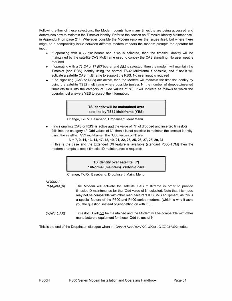
P300H P300 Series Modem Installation and Operating Handbook Page 64
Following either of these selections, the Modem counts how many timeslots are being accessed and determines how to maintain the Timeslot identity. Refer to the section on "Timeslot Identity Maintenance" in Appendix F on page 214. Wherever possible the Modem resolves the issues itself, but where theremight be a compatibility issue between different modem vendors the modem prompts the operator for input.
If operating with a Ùòéíî bearer and ÝßÍ is selected, then the timeslot identity will be maintained by the satellite CAS Multiframe used to convey the CAS signalling. No user input is requiredIf operating with a ÌïóÜì or ÌïóÛÍÚ bearer and ÎÞÍ is selected, then the modem will maintain theTimeslot (and RBS) identity using the normal TS32 Multiframe if possible, and if not it will activate a satellite CAS multiframe to support the RBS. No user input is required If no signalling (CAS or RBS) are active, then the Modem will maintain the timeslot identity by using the satellite TS32 multiframe where possible (unless N, the number of dropped/inserted timeslots falls into the category of `Odd values of N`). It will indicate as follows to which the operator just answers YES to accept the information:
TS identity will be maintained oversatellite by TS32 Multiframe (YES)
Change, Tx/Rx, Baseband, Drop/Insert, Ident Menu
If no signalling (CAS or RBS) is active and the value of `N` of dropped and inserted timeslotsfalls into the category of `Odd values of N`, then it is not possible to maintain the timeslot identityusing the satellite TS32 multiframe. The `Odd values of N` are
N = 7, 9, 11, 13, 14, 17, 18, 19, 21, 22, 23, 25, 26, 27, 28, 29, 31If this is the case and the Extended D/I feature is available (standard P300-TCM) then the modem prompts to see if timeslot ID maintenance is required:
TS identity over satellite: [?] 1=Normal (maintain) 2=Don t care
Change, Tx/Rx, Baseband, Drop/Insert, Maint' Menu
ÒÑÎÓßÔ
øÓß×ÒÌß×Ò÷ The Modem will activate the satellite CAS multiframe in order to provide timeslot ID maintenance for the `Odd value of N` selected. Note that this modemay not be compatible with other manufacturers IBS/SMS equipment, as this isa special feature of the P300 and P400 series modems (which is why it asks you the question, instead of just getting on with it !).
ÜÑÒùÌ ÝßÎÛ Timeslot ID will not be maintained and the Modem will be compatible with other manufacturers equipment for these `Odd values of N`.
This is the end of the Drop/Insert dialogue when in Ý´±»¼ Ò»¬ д« ÛÍÝ, ×ÞÍ or ÝËÍÌÑÓ ×ÞÍ modes

P300H P300 Series Modem Installation and Operating Handbook Page 65
If the Modem is in ÝËÍÌÑÓ ×ÜÎ mode (low rate format) then it is possible to maintain the Timeslot ID even with an IDR overhead structure. Refer to the section "Timeslot identity maintenance" in Appendix F on page 214 if a refresh is required. Note that this is only offered under Custom IDR to simplify normal IDR menu operation, but Custom IDR can be selected with all the possible custom features set to `Normal` to allow normal IDR operation, but withtimeslot ID maintenance. Note that for low rate IDR carriers (<1544kbps) INTELSAT specify the IBS overhead structure, but the Modem can operate the IDR 96kbps overhead (and use Drop/Insert) even down to 64kbps.
If the Modem is in ÝËÍÌÑÓ ×ÜÎ mode (low rate format) then the following prompt is displayed:
TS identity over satellite: [?] 1=Maintain 2=Don t care (Normal)
Change, Tx/Rx, Baseband, Drop/Insert, IDR Maint' Menu
Óß×ÒÌß×Ò The dropped/inserted timeslots will be aligned in the satellite IDR frame in orderto maintain the timeslot identity.
ÜÑÒùÌ The dropped/inserted data will be arbitrarily placed in the satellite IDR frame and the identity of the timeslots will not be maintained (as with normal IDR).
6.6.6 Change, Tx/Rx, Baseband, OTHER MenuIf the IDR option is fitted (standard on P300-IDR and above) then the modem can generate a 64kbps carrier comprising just of two 32kbps ADPCM audio channels, or a 128kbps carrier comprising 64kbps data (from the main data interface of the modem) plus two 32kbps ADPCM audio channels. These modes are effectively an emulation of and are compatible with the popular P1348/P1448 voice/data muxcard used often in SNG applications. The choice between which mode is made on the following menu:
Voice/Data mux (P1348/P1448 emulation): [?] 1=Audio 2=Audio+64k Data
Change, Tx/Rx, Baseband, Other Menu
ßËÜ×Ñ A 64kbps data stream is generated from the two 32kbps ADPCM audio portsnormally used for the IDR Audio ESC function. Closed Net Plus ESC, IBS or Custom IBS overhead is required in order to maintain the octet alignment (partof timeslot ID maintenance) in order for this to function.
On the Tx path the clock mode is forced to internal, and on the Rx mode theclock mode is forced to satellite (as the terrestrial interface is audio only there are no clocking issues).
ßËÜ×ÑõÜßÌß A 128kbps data stream is generated, 64kbps from the two 32kbps ADPCM audio ports normally used for the IDR Audio ESC function plus 64kbps from the main data port. Closed Net Plus ESC, IBS or Custom IBS overhead is required in order to maintain the timeslot ID and hence keep the channels separate inorder for this to function. Normal clocking selections are available.

P300H P300 Series Modem Installation and Operating Handbook Page 66
6.6.7 Change, Tx, CLOCKING MenuParadise Datacom products have always provided a `Data Marginal` warning where the incoming data phase is monitored with respect to the clock. The Modem shows a `Data Marginal` warning on the frontpanel if the data changes at the instant where it should be stable (and is sampled by the modem) which would otherwise cause data errors with no fault indication.
On the P300 this is taken a stage further and if the data phase is incorrect with respect to the normal clock edge, then the modem automatically switches to the other clock edge to sample the data. A Data Marginal warning is only issued momentarily as the phase switches. If regular Data Marginal warnings appear (for example in the traffic log) then the Tx data and clock phase are drifting (causing the modem to switch repeatedly) and you will be getting regular data errors. This is not a modem fault, it is awarning of a situation causing data errors of which you would otherwise be unaware ! For this reason it is not possible to simply disable the Data Marginal alarm, instead you must investigate the external equipment to find why the Tx clock/data phase is changing.
The Tx clocking menu is as follows:
Tx clock mode: [?]1=Tx Clock In 2=Internal 3=Rx ref(=Sat)
Change, Tx, Clocking Menu
This selects the clock source used to generate the signal towards the satellite. The options are:
ÌÈ ÝÔÑÝÕ The external clock supplied on the interface `Clock In` line will be used (seeinterface card details in appendix A for line names). Should this clock input fail the Modem will switch to an internal backup clock (as used when ×ÒÌÛÎÒßÔ is selected) to maintain the carrier, distant demodulator lock, and if a framing overhead is active, the Backward Alarm, Aux, and ESC channels.
×ÒÌÛÎÒßÔ The Modem outputs a clock on the `Int Tx clock out` line (see interface card details in appendix A for line names) for use by the external equipment. Unlike the previous Paradise products, there is no requirement to loop this clockback into the `Clock In` line, on the P300 Modem it is routed internally.
The clock is normally generated from the internal frequency reference of ±1PPM. However if a Station Clock of 10MHz (only) is applied to the unit, thenunder the Rx Clocking screens it is possible to force the modem to replace the internal 1PPM reference with the 10MHz Station Clock as the reference for allclocks and IF synthesizers which normally use the internal reference. If this isthe case then the ײ¬»®²¿´ Ý´±½µ would be generated from the 10MHz stationclock.
ÎÈ ÎÛÚøã???÷ As ×ÒÌÛÎÒßÔ except the Tx clock is generated from the Rx output clock.λºøã???÷ shows the current Rx clock setting from which the Rx output clock is itself being generated. This option is only of any practical use when the Rx Clocking is set to Í¿¬»´´·¬» or ͬ¿¬·±² Ý´±½µ. When the Rx Clocking = Í¿¬»´´·¬» this is commonly called `Loop Timing`.
Note: it uses the Rx output clock, not necessarily the clock from thesatellite, ie the clock used depends on the Rx Clocking setting. This means forexample that if the Rx Clocking = ͬ¿¬·±² Ý´±½µ, then setting Tx Clocking =Ψ
®»ºøãͬ²÷ would slave the Tx Clock ultimately from the Station Clock (whatever

P300H P300 Series Modem Installation and Operating Handbook Page 67
the Station Clock frequency). Similarly setting Tx Clocking = Ψ ®»ºøÍ¿¬÷ (ie with Rx Clocking = Í¿¬»´´·¬») would slave the Tx Clock to the incoming satellite clock (which is what most other modem manufacturers means by Tx=Rx). In all cases if the clock selected by the Rx Clocking fails, then the backup receive clocks (as defined in the Rx Clock section) also source the Tx Clock as it is slaved to the Rx clock whatever the source.
Note the P300 provides as standard the facility for Asymmetric Loop Timing(a $1000 option from some vendors). This means you can set Tx timing = Ψ
®»ºøãÍ¿¬÷ even if the Tx and Rx rates are different and it will generate the Tx Clock from the incoming satellite clock. This works for any combination of rates, it does not require the Rx rate to be higher than the Tx, or the rates to be in any way related.
Finally, and only for those with inquisitive minds, why does it state earlier This option is only of any practical use when the Rx Clocking is set to Í¿¬»´´·¬»
or ͬ¿¬·±² Ý´±½µ ? Because, with Rx=̨ Ý´±½µ ײ it causes a clock loop as Rx=Tx AND Tx=Rx, with Rx=ײ¬»®²¿´ it is the same as selecting Tx=ײ¬»®²¿´,ie the second Tx Clocking option, and with Rx=ÜÝÛ Ý´±½µ it does something entirely different for a reason even the inquisitive would find tedious, and uses the Station Clock again if there is one or the Internal 1PPM ref if not. So this option really is only of any practical use when the Rx Clocking is set to Í¿¬»´´·¬»or ͬ¿¬·±² Ý´±½µ.

P300H P300 Series Modem Installation and Operating Handbook Page 68
6.6.8 Change, Tx, MODULATOR Menu
Mod: 1:Freq 2:Mod n 3:FEC 4:RS 5:Scr 6:Carr 7:Pwr 8:Spect Inv 9:AUPC
Change, Tx, Modulator Menu
Each option leads to the following menus:
6.6.9 Change, Tx/Rx, Modulator, IF FREQUENCY Menu
Set IF Frequency: [70.0000MHz] 50-180MHz (100Hz) ???????? (YES)
Change, Tx/Rx, Mod/Demod, IF Frequency Menu
The operator is prompted to enter the desired transmit frequency. In the 70 MHz band, the valid range is from 50MHz to 90MHz and in the 140 MHz band the valid range is from 100MHz to 180MHz. If both the 70MHz and 140MHz IF bands are available (standard P300-IBS and above) then the range is actually continuous from 50MHz to 180MHz (ie includes 90-100MHz). As the data entry field is 7 characters, entries for the 70MHz band require a leading zero to be entered. The operator may enter any frequencywithin either the IF band with up to 100Hz resolution. The unit will reject a frequency which falls outside the ranges stated, and will prompt the user to re-enter the value. Once complete, the user should press the ÇÛÍ key to accept the new value. Mistakes made when entering data can be corrected by using the ÒÑñÐÎÛÊ key.
On later software, if the operator has set the SHF Frequency (ݸ¿²¹», ÞËÝñÔÒÞ, ̨ñÞËÝ, ÍØÚ
Ú®»¯«»²½§) then the BUC / Upconverter chain frequency shift is added to the IF range of the modem,and the frequency on this edit screen is displayed and entered directly as the final SHF frequency at the antenna.
6.6.10 Change, Tx/Rx, Modulator, MODULATION Menu
Set modulation: [?] 1=BPSK 2=QPSK 3=OQPSK 4=8PSK
Change, Tx/Rx, Mod/Demod, Modulation Menu
The modulation may be selected from BPSK (Bi Phase Shift Keying), QPSK (Quadrature Phase ShiftKeying), OQPSK (Offset QPSK), and if the 8PSK/TCM feature is available (standard P300-TCM) 8PSK (Eight Phase Shift Keying). Except for the very lowest of data rates where BPSK reduces the effects ofsystem phase noise, QPSK or preferably 8PSK is virtually always used for bandwidth efficiency. When the demodulator is set to OQPSK, it will take approximately twice as long to acquire a carrier (for the same sweep width) as QPSK, due to the lack of power nulls in the OQPSK modulated carrier.
The allowable combinations of Modulation and FEC mode/Rate are: BPSK / QPSK / OQPSK: None, Viterbi or Sequential at rate 1/2, 3/4, or 7/8 8PSK: TCM only at rate 2/3
See the OQPSK primer below, and also refer to Appendix E Fault Mode 12" for interworking OQPSK between early and later P400 series modems.
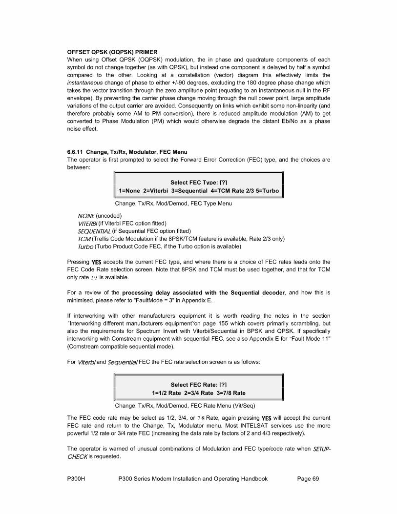
P300H P300 Series Modem Installation and Operating Handbook Page 69
OFFSET QPSK (OQPSK) PRIMERWhen using Offset QPSK (OQPSK) modulation, the in phase and quadrature components of each symbol do not change together (as with QPSK), but instead one component is delayed by half a symbolcompared to the other. Looking at a constellation (vector) diagram this effectively limits theinstantaneous change of phase to either +/-90 degrees, excluding the 180 degree phase change whichtakes the vector transition through the zero amplitude point (equating to an instantaneous null in the RF envelope). By preventing the carrier phase change moving through the null power point, large amplitude variations of the output carrier are avoided. Consequently on links which exhibit some non-linearity (andtherefore probably some AM to PM conversion), there is reduced amplitude modulation (AM) to getconverted to Phase Modulation (PM) which would otherwise degrade the distant Eb/No as a phase noise effect.
6.6.11 Change, Tx/Rx, Modulator, FEC MenuThe operator is first prompted to select the Forward Error Correction (FEC) type, and the choices arebetween:
Select FEC Type: [?] 1=None 2=Viterbi 3=Sequential 4=TCM Rate 2/3 5=Turbo
Change, Tx/Rx, Mod/Demod, FEC Type Menu
ÒÑÒÛ (uncoded) Ê×ÌÛÎÞ× (if Viterbi FEC option fitted) ÍÛÏËÛÒÌ×ßÔ (if Sequential FEC option fitted) ÌÝÓ (Trellis Code Modulation if the 8PSK/TCM feature is available, Rate 2/3 only) Ì«®¾± (Turbo Product Code FEC, if the Turbo option is available)
Pressing ÇÛÍ accepts the current FEC type, and where there is a choice of FEC rates leads onto theFEC Code Rate selection screen. Note that 8PSK and TCM must be used together, and that for TCMonly rate is available.
For a review of the processing delay associated with the Sequential decoder, and how this is minimised, please refer to "FaultMode = 3" in Appendix E.
If interworking with other manufacturers equipment it is worth reading the notes in the section Interworking different manufacturers equipment on page 155 which covers primarily scrambling, but
also the requirements for Spectrum Invert with Viterbi/Sequential in BPSK and QPSK. If specificallyinterworking with Comstream equipment with sequential FEC, see also Appendix E for Fault Mode 11" (Comstream compatible sequential mode).
For Ê·¬»®¾· and Í»¯«»²¬·¿´ FEC the FEC rate selection screen is as follows:
Select FEC Rate: [?] 1=1/2 Rate 2=3/4 Rate 3=7/8 Rate
Change, Tx/Rx, Mod/Demod, FEC Rate Menu (Vit/Seq)
The FEC code rate may be select as 1/2, 3/4, or Rate, again pressing ÇÛÍ will accept the current FEC rate and return to the Change, Tx, Modulator menu. Most INTELSAT services use the more powerful 1/2 rate or 3/4 rate FEC (increasing the data rate by factors of 2 and 4/3 respectively).
The operator is warned of unusual combinations of Modulation and FEC type/code rate when ÍÛÌËÐó
ÝØÛÝÕ is requested.

P300H P300 Series Modem Installation and Operating Handbook Page 70
For Ì«®¾± FEC the FEC rate selection screen is as follows:
Select Turbo Mode/Code rate, then (YES) [0.750 Industry de-facto 3/4 rate]
Change, Tx/Rx, Mod/Demod, FEC Rate Menu (Turbo)
The Turbo FEC code rate may be selected from the scroll list of preset rates displayed on the screen. pressing YES will accept the current FEC rate and return to the Change, Tx, Modulator menu. This list can contain up to 31 different rates, but currently only the following are defined:
Screen Description Exactcode rate
Delay(bits) *
Modulation Schemes from
BPSK QPSK OQPSK 8PSK
"0.3125 Industry de-facto 5/16 rate" 0.3125 2662 V3.57 n/a
"0.477 Industry de-facto 21/44 rate" 21/44 4056 V3.57 n/a
"0.493 Paradise 1/2 rate" 2028/4116 4056 V3.40 n/a
"0.666 Paradise 2/3 rate" 2499/3748 4998 V3.57 V3.57 V3.57 n/a
"0.750 Industry de-facto 3/4 rate" 0.750 4446 V3.40 n/a
"0.789 Paradise 3/4 rate" 3249/4116 6498 V3.40 n/a
"0.875 Paradise 7/8 rate" ** (Low Latency)
0.875 450(yes 450)
V3.40 n/a
* Note on processing delay. Use the data rate before the FEC to determine the delay in milliseconds from the delay in bits. For example at 1Mbps using Rate 0.789 Turbo FEC, the FEC delay is (6498/1000000) seconds, which is 6.5ms.
** Note on Low Latency 7/8 Rate Turbo: As Turbo FEC schemes go this is a relatively poor performer. BUT it does provide about a 1dB performance improvement over 7/8 rate Viterbi, and for links where the transponder space is fixed to accommodate a 7/8 Viterbi coded link, switching from Viterbi to Turbo will give a useable 1dB improvement. It also provides significantly lower latency than subsequent Turbo schemes (which offer a better 7/8 rate performance at the cost of significant latency). If you`re stuck with a channel that can only accommodate 7/8 Rate FEC, then this will give you an extra dB over using Viterbi.

P300H P300 Series Modem Installation and Operating Handbook Page 71
6.6.12 Change, Tx/Rx, Mod/Demod, REED-SOLOMON Menu
This option is only available if the INTELSAT Reed-Solomon feature is available (standard P300-IBS and above).
INTRODUCTION TO REED-SOLOMON
Reed-Solomon FEC is a powerful scheme `wrapped around` the normal inner FEC which may be used to correct the remaining errors from the normal Turbo, Viterbi, Sequential, or TCM inner FEC. The code rate is specified by three values `n`, `k`, and `t`. These have a fixed relationship of n - k = 2t, so `t` is simply half the difference between `n` and `k`. A typical code rate may be specified such as (n,k,t) = (126,112,7).
RS error correction works on codewords (blocks) of bytes, where `n` is the length of the block of which there are `k` bytes of original data, and 2t bytes of error correction information. The RS codec can correct any bytes in error up to a value of `t`, so in the above example with t=7, up to seven bytes within the 126 may be corrected no matter how many individual bits per byte are in error. However, when the error rate exceeds the correctable level, unlike other FEC schemes, which degrade gracefully Reed-Solomon fails dramatically. Once the error correction threshold is passed (eg 8 errors in our example block) the codec considers it uncorrectable and passes the block uncorrected, ie the error rate goes from 0 to no error correction in one step. There is a small transitional area where due to the distribution of the errors, the errors in some blocks are just below the threshold (and therefore fully correctable) and for some blocks just above (and therefore uncorrectable). In practice this effect gives a RS satellite circuit a transition from error free to unserviceable in about a 1dB change in Eb/No.
In addition to the (n,k,t) specification of the code rate, there is an additional parameter of interleavingdepth. Interleaving is used to `mix up` the blocks so that a burst of errors affects a few bytes from several blocks, rather than a lot of bytes from a single block. Interleaving is usually of depth 4 or depth 8. The configuration menus are described in the following paragraphs.
See also the applications section, para 8.4 "Choosing Optimum Custom RS N&k Values" on page 146

P300H P300 Series Modem Installation and Operating Handbook Page 72
The Reed-Solomon menu appears as follows:
Tx RS outer codec: [?] 1=Off 2=INTELSAT n,k,t & depth 3=Other
Change, Tx/Rx, Mod/Demod, Reed-Solomon Menu
The Reed-Solomon outer FEC codec may be configured as follows:
ÑÚÚ The Reed-Solomon out FEC is disabled. Note that for testing the effectivenessof the RS codec, a test mode allows you to disable the RS decoder error corrections without removing the RS overhead (which changes the satellite data rate and therefore to a small extent the Rx Eb/No).
×ÒÌÛÔÍßÌ This switches the RS codec on using standard INTELSAT values, which are as follows:
FEC Framing Data Rate (n,k,t) Depth
TCM Any > 1544 kbps 8
<= 1544 kbps (219,201,9)
2048 kbps
Non-TCM
eg Turbo, Viterbi, Sequential, or No
FEC
IDR 1544 kbps (225,205,10) 4
Other rates
IBS orClosed Net
All rates (126,112,7)
Note: When interworking with NEC modems in TCM mode (and IBS framing), NEC have chosen to
use Interleaving depth 4 for all data rates. For rates >1544kbps then it will be necessary to select `Other`, and manually select the interleaving as depth 4.
ÑÌØÛÎ This option is only available if the `Custom Features` feature is available (standard on P300-TCM). This feature allows the operator to specify the code rate outside of the normal INTELSAT parameters ie a fully variable code rate Reed-Solomon codec. The limitations are as follows `n` = [60 - 255], `k` = [n -(2, 4, 6, 8, 10, 12, 14, 16, 18, or 20)] ie `t`=1 to 10.
See the applications section, para 8.4 "Choosing Optimum Custom RS N&k Values" on page 146
6.6.13 Change, Tx/Rx, Mod/Demod, SCRAMBLER Menu
Scrambler: [?] 1=Off 2=Normal 3:Other
Change, Tx/Rx, Mod/Demod, Scrambler Menu

P300H P300 Series Modem Installation and Operating Handbook Page 73
The Scrambler selection is made from ÑÚÚ, ÒÑÎÓßÔ, and ÝËÍÌÑÓ. ÑÚÚ Turns off all scrambling, and whilst this may be used for testing or carrier line
up, it is not normally used over satellite.
ÒÑÎÓßÔ Selects the appropriate scrambler based on the current configuration, and enables it (see table below).
FEC: No Reed-Solomon Reed-Solomon Active
Service type: Non Turbo Turbo Non Turbo Turbo
Closed Net (No ESC), Closed Net + ESC (<32kbps), IDR (& Custom IDR) Custom IBS without TS32 MF
V.35 Scr Turbo Scr RS Scr RS Scr
IBS/SMS,Closed Net + ESC (>=32kbps),Custom IBS with TS32 MF
IBS/SMS synchronous scrambler
The rationale behind this ÒÑÎÓßÔ option is deceptively simple: Following Intelsats example of using Reed-Solomon with IBS or IDR, we have simply used the first synchronous scrambler in the transmit chain even when two or more are available. Also any synchronous scrambler is used in preference to the V.35 self synchronising scrambler, as this will multiply received errors degrading performance.
Ѭ¸»® This allows non standard scrambler operation to match the configuration of other non standard equipment which leads onto the following menus:
Toggle Scramblers: 1=IBS (Off) 2=RS (N/A) 3=V.35 (On) 4=Turbo (N/A)
Change, Tx/Rx, Mod/Demod, Scrambler-Custom Menu
Pressing ï, î, í, or ì toggles each available scrambler between On and Off. Scramblers which are not available are shown as N/A (Not Available) as they are out of circuit (eg Reed-Solomon scrambler when RS is Ѻº). This screen specifically allows you to enable more than one scrambler, in order that you might match the (mis)configuration of other equipment which allows the operator to accidentally switch multiple scramblers on. When the V.35 style scrambler is enabled a subsequent menu is displayed.
V.35 Style Scrambler [?] 1=CCITT 2=INTELSAT V.35 (Normal) 3=FDC 4=Linkabit
Change, Tx/Rx, Mod/Demod, Scrambler-Custom V.35 MenuThis screen then allows selection between CCITT V.35, INTELSAT V.35, FDC (Fairchild), and Linkabit types. These are all different interpretations of the poorly defined V.35 scrambler specified by the CCITT. Unless you are trying to inter-operate with another manufacturers equipment known to have an incorrect scrambler, select INTELSAT mode as this is the most common.
Refer also to section 8.9 on page 154 which describes in more detail the different scramblers, andinterworking between manufacturers.

P300H P300 Series Modem Installation and Operating Handbook Page 74
The operator is warned of unusual scrambler settings when ÍÛÌËÐóÝØÛÝÕ is requested.
6.6.14 Change, Tx, Modulator, CARRIER Menu
Carrier: [?] 1=Off 2=On 3=Muted after pwr brk 4=Intfc RTS Controlled
Change, Tx, Modulator, Carrier MenuThe state of the Transmit Carrier is selected as follows:
ÑÚÚ The carrier is off.
ÑÒ The carrier will remain on, and after a power break it will automatically return to on.
ÐÑÉÛÎ ÞÎÛßÕ
ÓËÌÛ The carrier is switched on BUT after a power cut the carrier will be switched off and a deferred alarm generated until either from the front panel or remotely theunit is instructed to return the carrier to the on state.
ÎÌÍ
ÝÑÒÌÎÑÔÔÛÜ The carrier will be dynamically controlled by the `Sig Valid In`, the RTS line on a V.35 DCE interface (see interface card details in appendix A for line names for other interfaces). No alarm is raised when the Tx carrier is muted by theRTS line going to the `off` state unless the RTS line itself is set to raise an alarm if it goes to the off state (ݸ¿²¹»ô Ì»®®óײ¬º½ô ݱ²¬®±´ Ô·²»).
The operator is warned if the carrier is set to ÐÑÉÛÎ ÞÎÛßÕ ÓËÌÛ when ÍÛÌËÐóÝØÛÝÕ is requested.
6.6.15 Change, Tx, Modulator, POWER LEVEL MenuThis is the normal menu for the P300 and P310 L-Band modem. An alternative menu is displayed when operating in `Terminal` mode with a Paradise BUC.
Set Tx Power [-15.3dBm]enter value ??.? (YES), or to change
Change, Tx, Modulator, Power Menu (Normal)
This menu allows control of the Transmit output power. This may be varied from 0dBm to -25dBm (-5dBm to -30dBm for the P310) in 0.1dB steps, either by direct entry of the required power or by usingthe up/down keys to adjust the current value up or down in 0.1dB steps. Pressing the Up/Down keys rapidly causes the level to change in 0.5dB increments. If AUPC is active (refer to AUPC in section 8.11on page 156) then the delta power added by the AUPC is also displayed on the top line.
When the P310 is operating in Terminal Mode (ie with a Paradise BUC and with the FSK option fitted to the modem, and the Modem / BUC mode set to Ì»®³·²¿´), the power level at the BUC is under closed loop control. The operator now enters the desired power at the BUC directly, and the modem operates in conjunction with the BUC, varying the Tx Carrier level and BUC attenuator to provide the desired power.
Power from BUC (13-33), now [31]dBm1:Set new power 2:Nudge up/down
Change, Tx, Modulator, Power Menu (Terminal with BUC)

P300H P300 Series Modem Installation and Operating Handbook Page 75
If a Paradise BUC & FSK are fitted, but the modem / BUC are set in independent mode, then a third screen is displayed (similar to the 1st) from which the setting of the BUC attenuator may also beaccessed by pressing the down key from the power level menu.
6.6.16 Change, Tx/Rx, Modulator, SPECTRUM INVERT Menu
Spectrum Invert [?] 1=Normal 2=Invert
Change, Tx/Rx, Spectrum Invert Menu
This menu allows the Tx Spectrum to be inverted, to cope with satellites or frequency conversion equipment which also inverts the spectrum. Note that apart from the fact that the modem will not lock onto an inverted spectrum, on a spectrum analyser the carrier is to all appearances unchanged.
The operator is warned if ÍÐÛÝÌÎËÓ ×ÒÊÛÎÌ is active when ÍÛÌËÐóÝØÛÝÕ is requested.
NOTE ON BPSK SPECTRUM INVERSIONTrue spectrum inversion does not affect BPSK signals and so in BPSK mode there is no requirement fora true spectrum invert feature. Instead in BPSK mode (to be compatible with other manufacturers equipment), the Tx Spectrum Invert option reverses the ordering of the pairs of Tx data symbols from the FEC encoder to the modulator. The `Normal` option is compatible with other manufacturers BPSK equipment. The Invert option (ie reverse pairs of Tx symbols) is compatible with earlier Paradise products such as the P200 (which we consider to have the `correct` symbol pairing !). On the Rx path the symbol pairing is automatically determined, and so the Rx Spectrum Invert feature has no effect in BPSK.
If interworking with other manufacturers equipment it is worth reading the notes in the section Interworking different manufacturers equipment on page 155 which covers primarily scrambling, but
also the requirements for Spectrum Invert with Viterbi/Sequential in BPSK and QPSK.
6.6.17 Change, Tx, Modulator, AUPC (Software >=V2.12)This menu is only displayed if the AUPC feature is available. It is advisable to refer to the introduction to AUPC in section 8.11 on page 156 before enabling this facility.
AUPC: 1:Mode 2:Max 3:Min 4:Slew rate 5:Target Eb/No 6:Tolerence 7:Loss act'
Change, Tx, Modulator, AUPC Menu
Note that options 2 through 7 only display when the AUPC mode It is set to other than Ѻº or Ó±²·¬±®
Ü·¬¿²¬, so initially only AUPC: 1:Mode may be displayed.

P300H P300 Series Modem Installation and Operating Handbook Page 76
6.6.18 Change, Tx, Modulator, AUPC, MODE Menu
Set AUPC Mode: [Off] 1=Off 2=Mon dist' 3=Maint' EbNo 4=Self mon
Change, Tx, Modulator, AUPC Mode Menu
NOTE: You probably need permission from the satellite operators to use AUPC unless you have a blanket power budget which you may use as you see fit.
The modes are as follows:
ÑÚÚ The modem disables the Auto Uplink Power Control, the Tx power will notadjust dynamically. Any AUPC positive or negative delta power adjustment to the Tx output power It is removed instantaneously (ie a Tx power step). Any bandwidth within the ESC channel used by the AUPC It is released back forESC usage.
ÓÑÒ Ü×ÍÌù The local modem utilises the async ESC channel between the local and distantmodems to regularly collect Eb/No and BER data from the distant modem. This can be displayed with Ó±²·¬±®ô Ü·¬¿²¬ Û¾ñÒ± ú ÞÛÎ. This It is not an `active` AUPC mode and the Tx power will not adjust dynamically, it simply allows local monitoring (and logging) of distant performance.
Óß×ÒÌ Û¾ñÒ± This It is full AUPC mode. As with ÓÑÒ Ü×ÍÌù above it uses the ESC channel to collect Eb/No information from the distant modem, but in addition it varies the Tx power within the constraints provided to maintain a specified distant Eb/No.
ÍÛÔÚ ÓÑÒ This It is ONLY used in Tx only applications (typically point to multipoint) to attempt to maintain the Eb/No at (multiple) Rx only stations. It requires the modem to be able to receive the its own carrier via satellite (not by any form of IF loop). In operation it monitors the local Rx Eb/No and adjusts the local Tx power to keep this local Eb/No constant. This means it can compensate foratmospheric changes which affect the Tx signal to the satellite, and LOCAL atmospheric changes affecting the Rx signal from the satellite. If however (as Itis common) there are multiple Rx terminals over a wide geographical area, then different atmospheric conditions over each terminal will still cause a variation in the Eb/No for each terminal.
Note: See AUPC in section 8.11 on page 156 regarding the async ESC channel requirements in order for local modem to distant modem communications in order for modes `Ó±² Ü·¬` and `Ó¿·²¬ Û¾ñÒ±` to operate. Note also that the distant modem must be set for remote reporting of Eb/No with ݸ¿²¹»ô Ψô
Ü»³±¼ô ßËÐÝ.
6.6.19 Change, Tx, Modulator, AUPC, MAX Menu
Set AUPC max positive delta power[3.5dB] (0-25.0dB) ??.?dB (Yes)
Change, Tx, Modulator, AUPC, Max Menu

P300H P300 Series Modem Installation and Operating Handbook Page 77
This allows the maximum additional power that the AUPC can use to maintain the distant Eb/No to be set. Set this so that the total maximum power (ie the nominal power set with ݸ¿²¹»ô ̨ô Ó±¼ô б©»®PLUS the AUPC Max positive delta power) It is within the constraints put upon your carrier by the satellite operators.
6.6.20 Change, Tx, Modulator, AUPC, MIN Menu
Set AUPC max negative delta power[1.0dB] (0-25.0dB) ??.?dB (Yes)
Change, Tx, Modulator, AUPC, Min Menu
This allows the minimum delta power that the AUPC can use to maintain the distant Eb/No to be set.
Normally the maximum delta power It is set to give the distant Eb/No a boost in poor atmospheric conditions, with any improvements in Eb/No caused by particularly good atmospheric conditions beingconsidered a bonus. It is it not normally necessary to set the minimum delta power to any figure otherthan zero otherwise any beneficial gain in Eb/No caused by good atmospheric conditions will be negated by a decrease in Tx power.
This facility only exists so, if as a condition of being able to use AUPC, the satellite operator has askedyou to provide a reduced power in particularly good atmospheric conditions at your geographic location. This may be in an attempt to `balance out` any increase in power required for other locations where there may be poor atmospheric conditions, with the AUPC in those locations requiring additional powerfrom the satellite.
6.6.21 Change, Tx, Modulator, AUPC, SLEW RATE Menu
Set maximum power slew rate: [10]dB/min (0.1-99.9dB/min, 0=no limit) ??.? (YES)
Change, Tx, Modulator, AUPC, Slew Rate Menu
This facility allows the changes in Tx power to occur at a controlled slew rate to prevent step changes in Tx power at the IF output. A value of zero indicates no limit and step power changes will occur. Whatever the slew rate limit the power changes will remain within the Max and Min power limits set on the previous two screens. Use caution when setting this parameter so that the slew rate you impose It is not too great to prevent the AUPC system responding to rapid fades (eg 10dB fade in 10 seconds).
6.6.22 Change, Tx, Modulator, AUPC, TARGET EB/NO Menu
Set target Eb/No to maintain: [8.5]dB (0 to 25.0dB) ??.?dB (Yes)
Change, Tx, Modulator, AUPC, Target Eb/No Menu

P300H P300 Series Modem Installation and Operating Handbook Page 78
This screen allows the target Eb/No to be set. This It is the distant Eb/No when the AUPC mode It is set to Ó¿·²¬ù Û¾ñÒ±, and the local Eb/No when set to Í»´º Ó±². This It is the target Eb/No the AUPC will adjust the Tx power within the Max, Min, and Slew rate limits (once the Eb/No goes outside the Tolerance window set below) to try and restore this figure.
6.6.23 Change, Tx, Modulator, AUPC, TOLERANCE Menu
Set Eb/No tolerance before AUPC action: [ 0.5dB] (0.1-25.0dB) ??.?dB (Yes)
Change, Tx, Modulator, AUPC, Tolerance Menu
This sets a `tolerance window` on the monitored Eb/No. The AUPC will only attempt to restore themonitored Eb/No to the target Eb/No when the monitored Eb/No moves outside the tolerance window.This It is to prevent the AUPC continuously adjusting the power to compensate for minor normal Eb/Novariations.
When the monitored Eb/No moves outside the tolerance window the AUPC will attempt to restore it back to the target value (ie not just back inside the tolerance window again).
6.6.24 Change, Tx, Modulator, AUPC, CARRIER LOST ACTION Menu
Set AUPC power on carrier lost: [Nominal] 1=Freeze 2=Nominal 3=Maximum
Change, Tx, Modulator, AUPC, Comms lost action Menu
This screen sets what action the AUPC It is to take locally if it looses communications with the distant modem (ie presumably there It is a significant fade and the distant demod has lost lock).
ÚÎÛÛÆÛ The carrier power It is frozen at its current value.
ÒÑÓ×ÒßÔ The AUPC delta power It is reset to zero so the carrier returns to its nominal power.
ÓßÈ×ÓËÓ The AUPC delta power increases to the maximum power limit as set on the AUPC Max positive delta power screen.

P300H P300 Series Modem Installation and Operating Handbook Page 79
6.6.25 Change, Tx/Rx, ESC/AUX/BA Menu
This dialogue is not available when the service is set at Normal Ý´±»¼ Ò»¬©±®µ, and differs between Ý´±»¼ Ò»¬ д« ÛÍÝ, ×ÞÍñÍÓÍ and ×ÜÎ services. The IBS/SMS and IDR menu appears below, but some options may not be displayed depending on how the modem Service is defined:
ESC/Aux: 1:Define 2:Async ESC 3:Interfaces 4:Audio levels 5:Backùalm
Change, Tx/Rx, ESC/Aux/BA Menu (IBS/SMS/IDR)
In Ý´±»¼ Ò»¬ д« ÛÍÝ mode a slightly different screen is displayed including the overhead percentage required to support the ESC rate as set:
ESC Channel (overhead is 2.39%):1:Async[2400,8,N] 2:Interface[RS485] 3:Audio
Change, Tx/Rx, ESC/Aux Menu (Closed Net Plus ESC)
ÜÛÚ×ÒÛ Enable & Disable the ESC & Aux ports, specify the port usage (eg IDR sync or async ESC), and allocate different parts of the overhead to each port. InÝ´±»¼ Ò»¬ д« ÛÍÝ the ESC channel is already defined to use as much of the overhead as possible and the Aux channel is not available so the Ü»º·²»option is not required (and is not offered).
ßÍÇÒÝ ÛÍÝ When the ESC port is set for async operation this selection configures the async character format and Baud rate.
×ÒÌÛÎÚßÝÛÍ Set the electrical interfaces for each port, for the ESC port control if it is directlyinternally linked to the M&C port for distant end M&C
ßËÜ×Ñ ÔÛÊÛÔÍ Set the levels or the Audio port, both in when used for IDR ESC and when used directly to generate a 64kbps carrier (2 x Audio only) or 128 kbps carrier (2 x Audio + 64k data)
ÞßÝÕù ßÔÓ Configure the four Tx backward alarms to map to the external input ports, or be directly connected to the Rx fault status of this modem (saves external patching in non-multidestinational carriers). This option is on the Tx menu only and againis not shown in Ý´±»¼ Ò»¬ д« ÛÍÝ mode.
IDR MODE ESC & AUX PORT DEFINITIONS
6.6.26 Change, Tx/Rx, ESC/Aux/BA, DEFINE (IDR) MenuWhen operating in IDR or Custom IDR modes, the Define selection is as follows:
IDR 8k ESC: [?] 1=Off 2=Sync 3=Async
Change, Tx/Rx, ESC/Aux/BA, Define (IDR), ESC Menu
ÑÚÚ The ESC port is disabled (and all ones is sent in the 8k ESC channel)

P300H P300 Series Modem Installation and Operating Handbook Page 80
êìÕ ×Ò ÊïõÊî Both ESC Audio channels are disabled, and the Aux port operates at 64kbps.
ÍÇÒÝ Normal 8k synchronous access is provided on the ESC port.
ßÍÇÒÝ This option is only available of the Async ESC feature is available (standard on P300-IBS and above). The ESC interface is set to be asynchronous. The exact Baud rate it can support varies with the async character format set on the Async ESC menu. Typically with 8 bits per character (or 7 + parity) it will support 4800 Baud, but with 8 bits plus parity, it will operate to 9600 Baud.
The reason for this strange situation is as follows: The async data is carrier synchronously across the 8k ESC link at 9 sync bits per async character (start + 8 data bits, no stop or parity). At 9600 Baud with 8 bits/char there are a maximum of 960 async characters per second (9600 / 10 [start + 8 bits + stop]). 960 async characters per second requires 9 x 960 sync bits per second to convey, unfortunately 8.64kbps above the 8kbps channel capacity and socharacters will be lost. At 9600 Baud with 9 bits/char (ie 8 plus parity) there are 872 async characters per second (9600 / 11 [start + 8 bits + parity + stop]). 872 async characters per second requires 9 x 872 sync bits per second to convey,7.85kbps, and so no characters will be lost over the 8K ESC channel. So when set for [8 bits No Parity] or [7 bits with Parity] the maximum standard Baud rate is 4800 Baud. When set for [8 bits with Parity] the maximum standard Baud rate is 9600 Baud.
This is followed by the Aux port definition screen:
Tx Aux Circuit: [?] 1=Off (normal) 2=64K in V1&2 3=32K in V1 4=32K in V2
Change, Tx/Rx, ESC/Aux/BA, Define (IDR), Aux Menu
The Aux port can provide a 32kbps or 64kbps synchronous data circuit in place of one or both of theAudio ESC channels:
ÑÚÚ øÒÑÎÓßÔ÷ The Audio ESC channels operate as normal, the Aux port is disabled.
íîÕ ×Ò Êï Audio ESC V2 operates as normal, and the Aux port provides a 32kbps channel in V1.
íîÕ ×Ò Êî Audio ESC V1 operates as normal, and the Aux port provides a 32kbps channel in V2.

P300H P300 Series Modem Installation and Operating Handbook Page 81
IBS MODE ESC & AUX PORT DEFINITIONS
6.6.27 Change, Tx/Rx, ESC/Aux/BA, DEFINE (IBS) MenuWhen operating in IBS or Custom IBS modes, the Define selection is as follows:
Tx Aux Port: [?] 1=Off 2=INTELSAT low rate channel 3=Sync Channel
Change, Tx/Rx, ESC/Aux/BA, Define (IBS), Aux Menu
ÑÚÚ The Aux port is disabled.
×ÒÌÛÔÍßÌ The Aux port provides the `low rate ESC` definition in IESS309 (which then refers back to IESS403). In this mode only TS32 bit 1 of the overhead is allocated to the Aux port, which provides an oversampled async interface at a maximum Baud rate of approx 1/2000th the main data rate. Note that even in this mode a clock is available, and the port may be used synchronously (at 1/480th the data rate) if required.
ÍÇÒÝ ÝØßÒÒÛÔ This option is only available if the IDR option is fitted (standard on P300-IDRand above) as it requires the `Clock/Data/Octet` Aux port on the IDR option to provide the synchronous Aux interface (the single `Data` line used for the oversampled INTELSAT ESC on the Async ESC connector cannot provide a synchronous interface). If selected the Aux port operates synchronously, and varying amounts of the IBS overhead may be allocated to the sync Aux channel. The sync channel may utilise at up to a total of 21/32nds of the overhead which with Standard IBS/SMS this allows the Aux port to operate up to 4.375% of the main data port rate. The selection of the overhead available tothe Aux channel is made following the next menu (which specifies the ESCport), allowing the overhead to be allocated between the Aux port and ESC ports.
This menu is followed by
ESC Port [?]: 1=Off 2:High Rate async channel
Change, Tx/Rx, ESC/Aux/BA Define (IBS), ESC Menu
ÑÚÚ The ESC port is disabled
Ø×ÙØ ÎßÌÛ
ßÍÇÒÝ The ESC Channel provides the `Paradise High Rate ESC`, which in a later menu may be configured to be compatible with earlier products such as the P230, P230D/I, and P1300/P1361 combination. This provides an async channel with maximum Baud rate approximately the terrestrial rate / 23 (egusable rates of 2400 Baud at 64 kbps and 9600 Baud at 256 kbps). One of the prime uses for this ESC channel is to link it to the M&C port of the Modem (software controlled internal link), and provide remote M&C of the distantequipment from the local end of the link.

P300H P300 Series Modem Installation and Operating Handbook Page 82
The following menu's depend on the selections made for the Aux & ESC channelsIf the ESC port is ÑÚÚ and the Aux port is set to ͧ²½ ݸ¿²²»´ then the following menu selects the overhead assigned to the Aux port:
Sync Aux circuit o/h usage: [?] 1=Maximum 2:Custom
Change, Tx/Rx, ESC/Aux/BA Define (IBS) Aux usage Menu
ÓßÈ×ÓËÓ The maximum 21/32nds of the overhead is allocated to the Aux channel. Thiscomprises S16, TS32 bits 1, & 5-8, and TS48. Giving an Aux port synchronousdata rate of 4.375% of the main data rate. If used asynchronously (ie oversampled as with the INTELSAT definition), the async rate may be up to1% of the main data channel rate, ie approx 600 Baud at 64kbps.
ÝËÍÌÑÓ This option is only available of the `Custom Features` feature is available (standard P300-TCM). The overhead can be operator assigned to the Aux port, varying the overhead as defined in the paragraph title "Custom OverheadAllocation" a few paragraphs further on. If the ESC port is defined as Ý«¬±³,then this one screen allocates overhead between the Aux and ESC ports.
If the ESC port is set to Ø·¹¸ כּ ߧ²½ and the Aux port is set to ͧ²½ ݸ¿²²»´ then the following menu allows the overhead assigned to the ESC port to be determined.
Async ESC: [?] 1=P230 compatible 2=Custom 3=All avail o/h{ after Aux}
Change, Tx/Rx, ESC/Aux/BA Define (IBS) ESC usage Menu
Ðîíð ÝÑÓÐù The standard 20/32nds of the overhead is allocated to the ESC and this is compatible with earlier products such as the P230, P230D/I, and P1300/P1361combination. The overhead allocated to the ESC is TS16, TS32 bits 5-8, andTS48. TS32 bit 1 is not used as this is reserved for the INTELSAT low rate
ESC(on the Aux port if so configured). The ESC port provides an async channel
with maximum Baud rate approximately the terrestrial rate / 23 (eg usable rates of2400 Baud at 64 kbps and 9600 Baud at 256 kbps).
ÝËÍÌÑÓ This option is only available of the `Custom Features` feature is available (standard P300-TCM). A subsequent screen allows the operator to assign theoverhead to the ESC port, varying the overhead as defined in the paragraph title "Custom Overhead Allocation" which follows. If the Aux port is also set toͧ²½ ݸ¿²²»´ then this one screen allocates the overhead between the Aux and ESC ports.
ßÔÔ ßÊß×Ô All the available overhead is assigned to the ESC channel. if the Aux port isdefined as ͧ²½ ݸ¿²²»´ then the selection reads ß´´ ߪ¿·´ ¿º¬»® ß«¨, andwhen the operator has defined the overhead allocated to the Aux port, anyRemaining is allocated to the ESC port. If using the Custom, IBS, Minimumoverhead mode, where the overhead rate varies to accommodate the ESCBaud rate defined, then setting the ESC to ß´´ ߪ¿·´ maximises the proportion of the overhead available to the ESC, and lowers the overhead addition to theminimum possible.

P300H P300 Series Modem Installation and Operating Handbook Page 83
6.6.28 Custom IBS Overhead AllocationSeveral of the above paths lead to the following screen where the available overhead can be allocated between the Aux port (if set to ͧ²½ ݸ¿²²»´) and the ESC port (if set to Ý«¬±³). This option is only available of the `Custom Features` feature is available (standard P300-TCM).
This sophisticated facility allows the operator for example to: On high rate links specify a low proportion of the overhead to be assigned to the ESC channel(still enough to provide the require async Baud rate) but then allocate the remaining overhead to the Aux port configured for a Sync Channel, allowing external access to the rest of the overhead for example other data or BER testing (internal or external). When using Custom, IBS, Min overhead, allocate the overhead between ESC & Aux ports. The overhead will scale to provide the set ESC Baud rate however much of the overhead is assigned to it, and increase / reduce the total overhead as appropriate. The remainder of the overhead can be allocated to the Aux channel, again for extra data of BER testing (internal or external). This effectively allows the sync channel rate to be varied (by changing the ESC rate & overhead ESC assignment, which the overhead then adjusts to provide).
The screens are as follows:
O/h use: 1=TS16=XXX 2=TS32b5&6=XXX (YES) 3=TS32b7&8=XXX 4=TS48=XXX More/Help
Change, Tx/Rx, ESC/Aux/BA Define (IBS) ESC/Aux Custom 1
O/h use: 1=TS0b1=XXX 2=TS32b1=XXX3=TS32b3=XXX 4=TS32b4=XXX Back Help
Change, Tx/Rx, ESC/Aux/BA Define (IBS) ESC/Aux Custom 2
Each of the `XXX` fields can display the following uses for that part of the overhead, and be toggledbetween the differen ssing the appropriate numbered key:t uses by pre
edort
ÓÚÉ In use for the TS32 Multi Frame Word.
TS1 n use, they
TS3 /32nds
overhead, and are normally spare again see note 1. This bit can only be
TS3red). Spare if the Aux port is not set to INTELSAT mode
cted, and the backward alarm facility has been disabled. This bit can only
TS32 bit 4 is 1/32nd of the overhead and is normally used for the Satellite TS32 Multiframe but is spare
óóó The overhead locations are unus ÛÍÝ Defined for use by the ESC p ß«¨ Defined for use by Aux port
ignalling ÝßÍ In use for Channel Associated S Þñß In use for the Backward Alarm
6 and TS48 are both bytes of the overhead structure which are free when CAS is not iare each equivalent to 8/32nd of the total overhead and can be allocated to ESC or Aux. 2 bits 5 and 6 (allocated together) and bits 7 and 8 (allocated together) both correspond to 2of the overhead. These are normally spare, see note 1, and can be allocated to ESC or Aux.
TS0 bit 1 is 1/32nd of theallocated to the ESC. 2 bit 1 is 1/32nd of the overhead, and is the bit allocated by INTELSAT for the low rate oversampled ESC (available on the Aux port if so configuor Note 1, can be allocated to ESC or Aux.
TS32 bit 3 is 1/32nd of the overhead and is normally used for the backward alarm, but is spare if Custom IBS mode is selebe allocated to the ESC.

P300H P300 Series Modem Installation and Operating Handbook Page 84
if Custom IBS mode without a TS32 multiframe is selected. This bit can only be allocated to theESC.
Note 1: Spare unless the unit is configured for 2048kbps, IBS G.732 mode, with spare bits of TS0 set to transparent (when these bits carry the spare bits).
To summarise: In standard IBS modes up to (8+8+2+2+1+1) bits = 22/32nd of the overhead may be allocated to
the ESC port, and up to (8+8+2+2+1) bits = 21/32nds of the overhead may be allocated to theAux port. 21 of these bits are shared between ESC & Aux.
In Custom IBS modes (without backward alarm or TS32 multiframe) up to (8+8+2+2+1+1+1+1) bits = 24/32nd of the overhead may be allocated to the ESC port, the Aux port is as above for Standard IBS, and 21 of these bits remain shared between ESC & Aux.
When the overhead has been assigned as required, press the ÇÛÍ key which provides the following screen:
Max ESC rate=2650 Baud (YES) Aux sync rate=1387bps, async=346 Baud
Change, Tx/Rx, ESC/Aux/BA Define (IBS) ESC/Aux Custom 1
This summarises the ESC & Aux port rates based on the overhead assignments just made: The Max ESC Baud Rate is the maximum continuous rate the ESC channel will support, the ESC
channel must be set to a standard async Baud rate equal or below this figure using the Async ESC menu selection.
The Aux Sync Rate is the data rate of the Aux port. A DPLL generates this clock however obscure the rate !
The Aux async Baud is the maximum Baud rate that could be conveyed through this Aux channel, if the Aux clock is ignored and the Aux port is used in oversampled async mode (as defined by INTELSAT for the low rate IBS ESC).
The Aux Sync Rate and Aux async Baud information display is not available in early versions of the embedded M&C code.
6.6.29 Change, Tx/Rx, ESC/Aux/BA, ASYNC ESC MenuThis menu allows the async parameters for the ESC interface to be defined.
Async ESC port: 1:Baud rate [2400] 2:Format [8,N] 3=Set as M&C port [=]
Change, Tx/Rx, ESC/Aux/BA, C.g., Async Menu
ÞßËÜ ÎßÌÛ Allows the ESC Baud rate to be set (see below), the current Baud rate setting is displayed.
ÚÑÎÓßÌ Allow the async character format for the ESC port to be set (see below), thecurrent async character format is displayed.
ÍÛÌ ßÍ ÓúÝ When selected this copies the remote M&C async settings to the ESC port, to simplify using the ESC port for remote M&C. This is a one time copy, and the ESC port configuration will not track changes to the remote M&C configuration. When the ESC port is configured as the remote M&C port, [=]

P300H P300 Series Modem Installation and Operating Handbook Page 85
appears, when not equal [ ] appears.
6.6.30 Change, Tx/Rx, ESC/Aux/BA, Config Async, BAUD RATE Menu
ESC Baud rate: [2400] (YES)
(Max continuous rate is 2962)
Change, Tx/Rx, ESC/Aux/BA, Cfg. Async, Baud Rate MenuThis menu allows the Baud rate for the external interface to the ESC channel to be set. Any rate can be set, although the maximum continuous rate supported is stated (calculated from the terrestrial rate, and async character format).
Refer to section 8.6 "Determining exact maximum ESC Baud rates" on page 148
6.6.31 Change, Tx/Rx, ESC/Aux/BA, Config Async, FORMAT Menu
Async Format: [7 bits, No parity]
1=7 bits, 2=8 bits, Parity: 3=None, 4=Even, 5=Odd (Yes)
Change, Tx/Rx, ESC/Aux/BA, Cfg. Async, Format MenuThe ESC async character format may be edited by pressing 1 or 2 to select 7 or 8 bits, and 3, 4, or 5 to select No parity, Even parity, or Odd parity respectively. Note that as described in the last paragraphs shortening the async character reduces the maximum continuous Baud rate, as the ESC channel islimited to a finite character rate per second, and the more bits in each async character, the higher theeffective Baud rate allowed without exceeding the ESC channel character rate limit.
6.6.32 Change, Tx/Rx, ESC/Aux/BA, Config Async, SET AS REM M&C
This option sets the ESC channel async parameters to match the settings on the Remote M&C port. This is specifically intended to simplify remote M&C within the IBS/SMS overhead via the ESC channel. Note this is a `one time` setting, and if the remote M&C parameters are varied, the ESC channel willnot follow them. If the remote M&C Baud rate exceeds the maximum continuous ESC rate, then thefollowing warning will be issued, although the copying of the parameters will go ahead.
NOTE: ESC channel not guaranteed above 2962 Baud (YES)
Change, Tx/Rx, ESC/Aux/BA, Set as Remote Warning Menu

P300H P300 Series Modem Installation and Operating Handbook Page 86
6.6.33 Change, Tx/Rx, ESC/Aux/BA, INTERFACES MenuThis leads to the selection of the ESC and Aux interfaces. The interface selection screens are onlyshown for active ports, and so either or both may show in turn depending on how the ports are defined for use. If both are active then the ESC interface is selected first. NOTE that these are some of the few menus which appears on both Tx & Rx menu trees, but for which the setting is common to both !
ESC Interface
Tx & Rx ESC Interface: [Link-R]
1=RS232 2=RS422 3=RS485 4:Link to remote M&C
Change, Tx/Rx, ESC/Aux/BA, Cfg Interfaces, ESC Menu
All options except 4 are self explanatory, [Link-R] means Link-Remote and [Link-L] Link-Local. Option 4 leads onto the following menu:
Internal link to M&C Port: [Local]
1=Local M&C PC end 2=Remote end
Change, Tx/Rx, ESC/Aux/BA, Cfg Interfaces, ESC, Link to M&C
This instructs the Modem make an internal link between the ESC port and the remote M&C port. It mustbe set specifically for the end of the link the modem is located at. When either of these options are selected, the physical ESC port is disabled, as it is linked internally to the M&C port.
ÔÑÝßÔ Incoming messages (on this modems remote M&C port Rx lines from the M&C Master device) are routed directly to the Tx ESC channel and out over the satellite link. Messages from the incoming satellite link on the Rx ESC channel are routed onto the Tx output lines of the remote M&C port, to return the responses to the Master M&C device.
ÎÛÓÑÌÛ Messages from the incoming satellite link on the Rx ESC channel are driven onto the remote M&C port Rx (input) lines, allowing any devices daisy chained to the remote M&C port to receive a message (including this modem). Messages present on the remote M&C port Tx (output) lines, which includes any response from this unit or any device daisy chained to the remote M&Cport, are routed to the Tx ESC channel and back via the satellite link.
Aux InterfaceFollowing the ESC interface selection the Aux port may be configured (self explanatory):
Aux Interface: [RS232]
1=RS232 2=RS422
Change, Tx/Rx, ESC/Aux/BA, Cfg Interfaces, Aux Menu

P300H P300 Series Modem Installation and Operating Handbook Page 87
6.6.34 Change, Tx/Rx, ESC/Aux/BA, AUDIO LEVELS Menu
Audio levels: V1=-12.3dBm V2= 5.6dBm Press 1 or 2 then level , YES to fix
Change, Tx/Rx, ESC/Aux/BA, Audio Levels Menu
This screen is used to set the levels for the Audio ESC ports. These are typical used in IDR modes for the Audio ESC channels, but may also be used when generating a 64kbps IBS carrier (comprising of 2 x 32kbps ADPCM audio channels only), or a 128kbps (comprising of 2 x 32kbps ADPCM audio channels plus 64kbps from the main data port.
Press 1 or 2 to select, which channel, then use the Ë° and ܱ©² buttons to vary the level. Pressing the up/down keys slowly/rapidly causes the level to change in 0.1dB steps, rapidly in 0.5dB steps. ÇÛÍ mustbe pressed to exit the screen otherwise the previous values will be restored.

P300H P300 Series Modem Installation and Operating Handbook Page 88
6.6.35 Change, Tx/Rx, ESC/Aux/BA, BACKWARD ALARMS Menu
This screen is used to configure the four backward alarm inputs used in multi-destinational IDR or for lower rate multi-destinational operation in some of the Custom IBS modes.
Back Alm 1234: [?] E=Ext A=Auto O=OK 1=EEEE 2=AEEE 3=AOOO 4=AAAA
Change, Tx/Rx, ESC/Aux/BA, Backward Alarm Menu
This screen is at first difficult to understand, but is relatively simple. It allows the four backward alarm input to be mapped in certain ways, without any external backward alarm patching:
On the screen the letters mean as follows: E=Ext: External patch, the state from the backward alarm connector on the rear panel
connector will be sent (open circuit = OK, Ground = fail)
A=Auto: Auto, the alarm will be sourced internally from the summary Rx fail signal
O=OK: The alarm will always send the `OK` condition.
So the menu choices are as follows:
ÛÛÛÛ All four alarms report the state from the Backward Alarm connector on the rear of the equipment . Use when transmitting a multidestinational carrier, but where the carrier we are receiving does not correspond to the destination allocated backward alarm channel 1. The Rx fail signals from the modems receiving the carriers from all the other destinations (including this modems Rx fail signal) must be externally patched into the corresponding external backward alarm inputs.
ßÛÛÛ Alarm 1 is internally connected to the Rx Fail signal, alarms 2-4 are availablefor external patching. Use when this station is transmitting a multidestinational carrier, where the carrier we are receiving correspondsto the destination allocated backward alarm channel 1. The Rx fail signals from the other modems receiving the carriers from all the other destinations must be externally patched into the corresponding external backward alarm inputs 2-4. If the external inputs 2-4 are open circuit, then this is the same as ßÑÑÑbelow.
ßÑÑÑ Alarm 1 is internally connected to the Rx Fail signal, alarms 2-4 always send the OK state. Used in non multidestinational working, external backward alarm inputs are ignored.
ßßßß All four alarms represent the internal Rx Fail signal. Used in nonmultidestinational working, external backward alarm inputs are ignored.
In non multidestinational operation, the choice between the third and fourth options is down to operator preference or station policy.

P300H P300 Series Modem Installation and Operating Handbook Page 89
6.7 CHANGE, RX MENU
Many of the Change Rx Menus are identical to the Change Tx menus, and a reference is made back to the Change Tx description rather than repeat the text unnecessarily.
NOTE ON RX=TX FUNCTIONThe Change, Rx Menu has an extra feature over the Change Tx, namely the ability for the Rx path to track the majority of the Tx configuration parameters (Rx=Tx) to simplify the configuration in symmetrical links (ie the majority). If Rx=Tx is activated then the following Rx parameters automatically track the Txparameters:
Service: All modes Baseband: Continuous: data rate. Drop/Insert: all selections excluding the timeslots.
Mod/demod: Modulation, Inner FEC type & FEC Rate, Outer RS FEC, Scrambler, Spectral Invert
ESC/Aux/BA: All parameters
Rx parameters which specifically remain independent are: Baseband: Insert timeslot selection (only if Drop/Insert active) Buff/Clk: Rx Buffer size & clocking mode Demod: IF Frequency & Sweep control
Note that setting Rx=Tx even momentarily copies the Rx parameters which track the Tx to the Rx configuration. Toggling this option on then off again provides a convenient way to copy the Tx config to the Rx (except the IF frequency) should this be required at any point.
The Change, Rx menu then will have different options showing depending on whether Rx=Tx mode is active:
Rx=Tx Disabled
Rx: 1:Service 2:Baseband 3:Buffer/Clocking4:Demod 5:ESC/Aux 6:Rx=Tx [Off]
Change, Rx Menu (Rx not set to follow Tx)
Note that options 2-5 on the top menu are only displayed when the ÍÛÎÊ×ÝÛ option is set to something other then Ѻº, and so initially the screen may only show the ÍÛÎÊ×ÝÛ and Ψą̃ options.
Rx=Tx Enabled
Rx: 1:Baseband 2:Buffer/Clocking 3:Demod 4:Rx=Tx [On]
Change, Rx Menu (Rx set to follow Tx)
In this mode: The Baseband option is only shown if the Tx baseband mode is set to Drop Mux, and hence the Rx
Insert Mux will be active and the operator needs access to the baseband menu in order toindependently set the insert TS selection.
The Buffer/Clocking menu is always shown.
The Demod menu provides access to the independent selection of IF Frequency, and demodSweep Width control
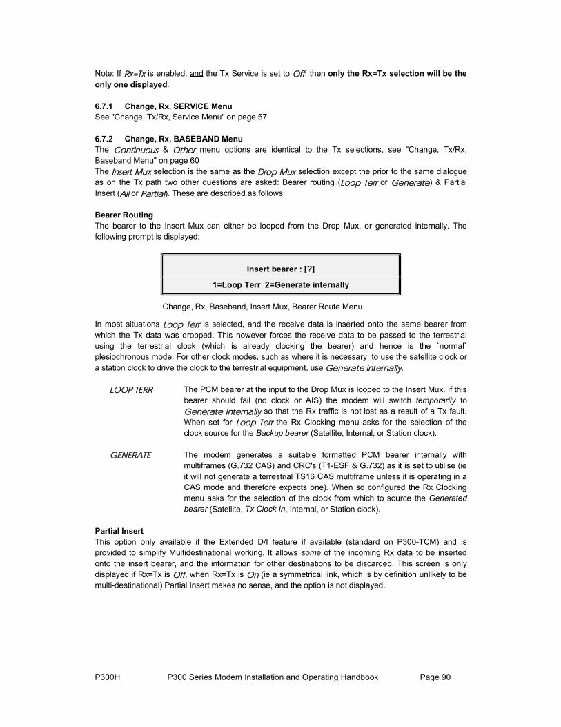
P300H P300 Series Modem Installation and Operating Handbook Page 90
Note: If Ψą̃ is enabled, and the Tx Service is set to Ѻº, then only the Rx=Tx selection will be theonly one displayed.
6.7.1 Change, Rx, SERVICE MenuSee "Change, Tx/Rx, Service Menu" on page 57
6.7.2 Change, Rx, BASEBAND MenuThe ݱ²¬·²«±« & Ѭ¸»® menu options are identical to the Tx selections, see "Change, Tx/Rx, Baseband Menu" on page 60 The ײ»®¬ Ó«¨ selection is the same as the Ü®±° Ó«¨ selection except the prior to the same dialogue as on the Tx path two other questions are asked: Bearer routing (Ô±±° Ì»®® or Ù»²»®¿¬») & PartialInsert (ß´´ or ﮬ·¿´). These are described as follows:
Bearer RoutingThe bearer to the Insert Mux can either be looped from the Drop Mux, or generated internally. The following prompt is displayed:
Insert bearer : [?]
1=Loop Terr 2=Generate internally
Change, Rx, Baseband, Insert Mux, Bearer Route Menu
In most situations Ô±±° Ì»®® is selected, and the receive data is inserted onto the same bearer from which the Tx data was dropped. This however forces the receive data to be passed to the terrestrial using the terrestrial clock (which is already clocking the bearer) and hence is the `normal` plesiochronous mode. For other clock modes, such as where it is necessary to use the satellite clock or a station clock to drive the clock to the terrestrial equipment, use Ù»²»®¿¬» ·²¬»®²¿´´§.
ÔÑÑÐ ÌÛÎÎ The PCM bearer at the input to the Drop Mux is looped to the Insert Mux. If thisbearer should fail (no clock or AIS) the modem will switch temporarily to Ù»²»®¿¬» ײ¬»®²¿´´§ so that the Rx traffic is not lost as a result of a Tx fault. When set for Ô±±° Ì»®® the Rx Clocking menu asks for the selection of the clock source for the Backup bearer (Satellite, Internal, or Station clock).
ÙÛÒÛÎßÌÛ The modem generates a suitable formatted PCM bearer internally with multiframes (G.732 CAS) and CRC's (T1-ESF & G.732) as it is set to utilise (ieit will not generate a terrestrial TS16 CAS multiframe unless it is operating in a CAS mode and therefore expects one). When so configured the Rx Clockingmenu asks for the selection of the clock from which to source the Generatedbearer (Satellite, Tx Clock In, Internal, or Station clock).
Partial InsertThis option only available if the Extended D/I feature if available (standard on P300-TCM) and is provided to simplify Multidestinational working. It allows some of the incoming Rx data to be inserted onto the insert bearer, and the information for other destinations to be discarded. This screen is onlydisplayed if Rx=Tx is Ѻº, when Rx=Tx is Ѳ (ie a symmetrical link, which is by definition unlikely to bemulti-destinational) Partial Insert makes no sense, and the option is not displayed.

P300H P300 Series Modem Installation and Operating Handbook Page 91
Is all Rx data for this destination: [?]
1=All 2:Partial
Change, Rx, Baseband, Insert Mux, Partial Insert Menu
See the applications section, para 8.3 "Partial Insert and Multidestinational Working" on page 145 for a discussion of this facility.
If ß´´ is selected, the dialogue continues as with the Drop Mux on the Tx path.
If ﮬ·¿´ ײ»®¬ is selected the following screen is displayed:
Total data rate for ALL dest' from satellite: [1152000] ??????? (YES)
Change, Rx, Baseband, Insert Mux, Partial, Total Rate Menu
Normally, when using Drop / Insert, the modem determines the expected data rate from the satellite from the number of timeslots specified. However when using partial insert the data rate from the satellite has to be specifically set (as there is more data coming from the satellite than will be inserted). It must be N x 64kbps, N=2 to 32 (minimum of 2 not 1, as you cannot have a multidestinational carrier with only 1 x 64kbps incoming ! ). The screen is then displayed:
Sat TS: 1-3, 10-12 Toggle:??-?? (YES)
Change, Rx, Baseband, Insert Mux, Partial, Data Select Menu
On this screen the data for this destination is selected from the total receive data. The incoming data from the satellite is labelled as timeslots 1 - N. NOTE this labelling bears NO RELATION to the terrestrialtimeslots from which the data was dropped at the Tx site. It should be read as First through Nth 64 kbps channel of the total sent. For example in a 256kbps incoming carrier the Rx data is referred to asTS 1 - TS 4 (first, second, third and fourth 64kbps channel in the 256kbps) whether it was originallydropped from timeslots 1, 2, 3, & 4, or timeslots 13, 17, 19 & 23. At the receive site (whether partial insert is active or not) there is no concept of `Dropped timeslots`, there is only first 64kbps, second 64kbps etc.
When he selection of data for this destination is complete, the ײ»®¬ Ó«¨ option on the Change, Rx,Baseband menu continues as with the Ü®±° Ó«¨ option on the Change, Tx, Baseband menu. The totalnumber of timeslots inserted must match the number of 64kbps channels selected for this destination on the `Sat TS` screen above.

P300H P300 Series Modem Installation and Operating Handbook Page 92
6.7.3 Change, Rx, BUFFER / CLOCKING MenuRefer also to the following applications sections for helpful notes:
8.1 "Doppler & Plesiochronous Buffering" on page 142 8.2 "Determining Clocking Schemes & Buffer Size" on page 143 and "P1440 in X.21 Mode" on page 176
Buffer/Clocking: 1:Station clock input 2:Rx clock source 3:Buffer Size
Change, Rx, Buffer/Clocking Menu
These three options lead onto the following three Menus 6.7.4 Change, Rx, Buffer / Clocking, STATION CLOCK MenuFirstly the operator is asked to specify is a station clock is available
Station clock connection [?]:
1=None 2:Via BNC 3:RS422:
Change, Rx, Buffer / Clocking, Station Clock, Available Menu
Provided Ò±²» is not selected, the display continues to the next question where the frequency of the clock is specified.
Station clock frequency: [0]kHz
(1-10MHz) ????? (YES)
Change, Rx, Buffer / Clocking, Station Clock, Frequency Menu
This screen allows the operator to set the frequency for the Station Clock if one is available. This may be any integer value of kHz (eg 1544k, 2048k, 5000k, 10000k, or arbitrary values such as 2500k or 4321k). Values down to 1kHz (not 1MHz) are accepted, a frequency of 0 indicates there is no station clock. When a Station Clock is present the Modem will use it in preference to its internal frequency reference for clock generation of any backup clocks required. See the notes in the Rx Clock section on the following page as to where the modem sources the Rx clock from under fault conditions.
The station clock frequency can be any integer multiple of 1kHz, and the 75 BNC will accept any sinusoid > 0dBm or a square wave > 1Vp/p (eg G.703 Para 10 synchronising clock). The operator should be aware that the losses associated with the coupling transformer on this BNC input increase below 1MHz, and at frequencies below this higher levels of input signal may be required. The RS422 input is located on the `Async ESC` connector and requires standard RS422 levels at any frequency.
If the station clock is specified as 10MHz, then a final screen is displayed as follows:
Use station clock as IF synth ref [No]:
1=No, use normal int' ref 2=Yes READ
Change, Rx, Buffer / Clocking, Station Clock, Frequency Menu
This allows the IF synthesisers to be locked to the station clock instead of the internal 1PPM reference. This is normally not a requirement as the internal reference provides good enough phase noiseperformance for the lowest data rate the modem can support and at 1PPM results in a worst case IF error of 180Hz when the IF is tuned to 180MHz. However if this option is used please be aware that thetransmit IF spectrum purity is entirely dependent upon the quality (phase noise performance) of the supplied reference.

P300H P300 Series Modem Installation and Operating Handbook Page 93
If the external 10MHz reference fails totally then it will be automatically replaced with the internal reference. If however it degrades (level, frequency or phase noise), then until it fails totally the modem will continue to use it as the synthesiser reference.
6.7.5 Change, Rx, Buffer / Clocking, RX CLOCK MenuThis screen varies depending on the configuration of the Rx path
Normal (non-Insert Mux operation)This selects the source of the clock, which feeds the terrestrial output:
Rx output clock: [?]
1=Sat 2=Tx 3=Internal 4=Station 5=DCE
Change, Rx, Buffer / Clocking, Rx Clock (non-Insert) Menu
Insert Mux operation (generated bearer)This selects the source of the clock for the PCM BEARER onto which the Rx data is inserted:
Rx output bearer clock source: [?]
1=Sat 2=Tx 3=Internal 4=Station
Change, Rx, Buffer / Clocking, Rx Clock (Insert-Loop) Menu
Insert Mux operation (looped bearer)This selects the source of the clock for the BACKUP PCM BEARER, which is only used if the normalbearer looped from the Drop Mux fails and the unit auto generates a backup bearer onto which to insertthe Rx data. Note that this screen does not display a ̨ option, as it is the failure of the Tx bearer input which causes this backup clock to be used in the first place.
Rx o/p bearer backup clk : [?]
1=Sat 2=Internal 3=Station
Change, Rx, Buffer / Clocking, Rx Clock (Insert-Loop) Menu
All the options available on any of these menus for the Rx output clock are as follows:
ÍßÌÛÔÔ×ÌÛ The clock from the satellite. This provides `Buffer Disable` operation, the buffer size is set to zero and the buffer size menu is no longer available. This is thesame as `Rx=Rx` clock options found on some other equipment. The Rx PLLconverts the satellite clock, which may include framing and or Reed-Solomon overheads back to the rate required at the terrestrial port. If the demodulator cannot lock onto a carrier (ie no clock from satellite), then the PLL switches to the internal frequency reference to provide a steady clock towards theterrestrial port.
ÌÈ ÝÔÕ ×Ò The Tx path input clock is turned around to drive the Rx data back to the terrestrial. This is normal `Plesiochronous Mode`, and the buffer should be set large enough to accommodate both the difference in the clocks at each end of the link PLUS the Doppler shift, whilst providing the required interval between slips.

P300H P300 Series Modem Installation and Operating Handbook Page 94
If the Tx & Rx rates are equal then the Tx clock is used directly to clock out the Rx data, should the Tx input clock fail the clock is switched to a PLL usingas first backup the Station Clock if defined as available, or if the Station Clock is defined as not available then recovered Satellite Clock (while demodulatorremains locked). Should this first backup fail it finally falls back to the internal 1PPM reference in order to maintain the Rx traffic. If the modem is operating with asymmetric data rates, then the Rx PLL converts the Tx clock to the correct rate for the Rx data. Should the Tx clock input fail the PLL switches to the internal reference as backup in order to maintain the Rx traffic.
×ÒÌÛÎÒßÔ The internal 1PPM frequency reference is used to source the clock towards theterrestrial. Again the buffer should be set large enough to accommodate thedifference between the internal reference and the incoming satellite clock,PLUS the Doppler shift whilst providing the required interval between slips.
ÍÌßÌ×ÑÒ If the Station Clock is the same frequency as the Rx data rate, then the Station Clock is used directly, switching to the Satellite Clock (whilst the demod is locked), and finally the internal reference for backups. If the Station Clock is at a different frequency to the Rx Data rate the Rx PLL converts the Station Clock to the correct rate to drive the Rx data towards the terrestrial. Should the Station Clock fail then the modem will switch to the internal frequency referencein order to maintain the Rx traffic. Again the buffer should be set large enoughto accommodate the difference between the Station Clock and the incomingsatellite clock, PLUS the Doppler shift, whilst providing the required interval between slips.
Note: If the Rx is set to ͬ¿¬·±² Ý´±½µ AND the Tx Clocking is set to Ψ
®»ºøͬ²÷, then it always operates as defined in the para above for the case where the Station Clock is at a different frequency to the Rx Data rate (even if the are the same rate).
ÜÝÛ ÝÔÕ This option is only available if a DTE card is fitted to the modem. The DTE card `Ext Tx Clock In`, ie the clock from the DCE (see interface card details inappendix A for line names for other interfaces) is used directly as the Rx output clock, should the `Ext Tx Clock In` fail the PLL sources the clock, locked first to the Station Clock (if available) or the recovered satellite clock (while the demodulator remains locked), and finally the internal frequency reference in order to maintain the Rx traffic.
6.7.6 Change, Rx, Buffer / Clocking, BUFFER SIZE MenuThis menu is only available of the Rx Clk is not set to Satellite (ie Buffer Disable) !
Refer also to the following applications sections for helpful notes: 8.1 "Doppler & Plesiochronous Buffering" on page 142 8.2 "Determining Clocking Schemes & Buffer Size" on page 143
Buffer size (end-end): [16]ms
(0-99ms) ??ms (YES)
Change, Rx, Buffer/Clocking, Buffer Size Menu

P300H P300 Series Modem Installation and Operating Handbook Page 95
The operator enters the end to end buffer size in milliseconds (INTELSAT documents typically specify the buffer in terms of its end to end size). Should the capacity ever be exceeded and the buffer slip, then it will slip by exactly half its capacity, back to the mid position.
For rates of 1544 kbps and 2048 kbps where the data is framed, the buffer is usually made to slip integer multiples of the frame length (3ms and 2ms respectively). A user option sets if the buffer capacity should automatically be incremented to the nearest integer multiple of frame length at these rates. This option is available under ÝØßÒÙÛô ËÍÛÎóÑÐÌô ÑÐÛÎßÌ×ÑÒô ÌÎßÒÍÚÛÎô ÞËÚÚÛÎ ÓÚ ÍÔ×Ð.
A second option is available to automatically force the buffer to its mid position whenever the receive traffic switches from failed to OK. This takes advantage of any outage, and ensures the buffer is centred every time normal operation begins. This option is available under ÝØßÒÙÛô ËÍÛÎóÑÐÌô ÑÐÛÎßÌ×ÑÒô
ßÝÌ×ÑÒÍô ÞËÚÚÛÎ ßËÌÑ ÝÛÒÌÎÛ. This option can be disabled, as for minor outages the errors or sync losses caused by centering the buffer may be larger than those caused by the outage.
In normal operation the buffer fill state can be viewed on the Received Detail Traffic Status screen accessible from the operate menu by pressing Down Arrow. This screen also shows a count of underflows and overflows (empty slips and full sips). Approximately equal counts indicate the buffer is too small to accommodate the incoming Doppler shift (2ms is usually sufficient). One count significantly higher than the other indicates that the buffer is slipping due to a large difference in the clock from the satellite and the buffer output clock. With typical earth station clock accuracies, buffers never need be larger than approximately 16ms.
The buffer can be manually centred by selecting ßÝÌ×ÑÒÍô ÞËÚÚÛÎ ÝÛÒÌÎÛ.

P300H P300 Series Modem Installation and Operating Handbook Page 96
6.7.7 Change, Rx, DEMOD MenuThe options available on this menu change if the Rx=Tx function (on the Change, Rx Menu) is active.
Tx=Rx Not active
Demod: 1:Freq 2:Mod`n 3:FEC
4:RS 5:Scr 6:Spect Inv 7:Sweep 8:AUPC
Change, Rx, Demod Menu (Rx=Tx not active)
Rx=Tx ActiveIf the Rx=Tx function is active, only those parameters which vary between Rx & Tx are displayed, the screen appears as follows:
Demod: 1:Freq 2:Sweep 3:AUPC
(most of Rx follows Tx as Rx=Tx active)
Change, Rx, Demod Menu (Rx=Tx Active)
Each of this is now discussed in turn, referring back to the Tx path screens where operation is identical.
6.7.8 Change, Rx, Demod , IF FREQUENCY MenuSee Change, Tx/Rx, Modulator, IF Frequency Menu on page 68
6.7.9 Change, Rx, Demod , MODULATION MenuSee Change, Tx/Rx, Modulator, Modulation Menu on page 68
6.7.10 Change, Rx, Demod FEC MenuSee Change, Tx/Rx, Modulator, FEC Menu on page 69
6.7.11 Change, Rx, Demod REED-SOLOMON MenuSee Change, Tx/Rx, Modulator, RS Menu on page 71
6.7.12 Change, Rx, Demod SCRAMBLER MenuSee Change, Tx/Rx, Modulator, Scrambler Menu on page 72
6.7.13 Change, Rx, Demod SPECTRUM INVERT MenuSee Change, Tx/Rx, Modulator, Spectrum Invert Menu on page 75

P300H P300 Series Modem Installation and Operating Handbook Page 97
6.7.14 Change, Rx, Demod SWEEP Menu
Demod sweep range: [Normal=±25kHz]
1=Normal 2=User
Change, Rx, Demod Sweep Menu
The operator has control of the sweep range of the Demodulator, but under normal circumstances `Normal` should be selected. Normal is defined as:
BPSK, QPSK & 8PSK±80% of `the recommended carrier spacing` or ±25 kHz, whichever is the lower. The recommended carrier spacing is 1.4 times the symbol rate (ie data rate + framing + FEC + Modulation). See note later when operating without FEC AND without Framing.
OQPSK±25% of the receive symbol rate (ie data rate + framing + FEC + Modulation) or ±25 kHz,whichever is the lower.
Assuming closed network, QPSK rate 1/2 coding, this means that for data rates down to 22 kbps thesweep will be ±25kHz, reducing linearly below this rate to 10.74kHz for 9.6kbps QPSK rate 1/2 FEC, or 4.8kbps BPSK. See note 2 in the following paragraph for an explanation of why the sweep width narrows at lower data rates.
If ËÍÛÎ is selected, then the following menu is displayed:
Set user demod sweep: [±16kHz]
(1-31kHz, normal=±25kHz) ±??kHz (YES)
Change, Rx, Demod Sweep, User Menu
The operator can configure the Demodulator to sweep up to ±32kHz to compensate for errors introduced in the Tx frequency conversion, satellite, and Rx frequency conversion equipment. Please note the following:
1. Increased sweep width proportionally increases the carrier acquisition time. 2. With low data rates, and wide sweep widths (ie wider than the recommended carrier spacing), it
is perfectly feasible to acquire the wrong carrier. Typically low rate carriers are clustered together on a transponder, and the modem has no way of telling which carrier is which other than it has to be in the sweep range, and of the correct data rate.
NoteApplicable to operation without FEC AND without framing onlyPart of the Rx carrier acquisition process when the Demod sweeps is for the Demod to temporarily lock onto `false locks`, these are detected as false because although the Demod has locked, the FEC will not lock correctly. This information is used to step the Demod directly onto the true carrierlock (this all happens in the background without the operator being aware of the process).
If the Demod is operated without FEC (ie uncoded), then frame alignment is used to determine if the lock is a false one and to push the Demod into acquiring the correct lock. HOWEVER, if the Demod is operated without FEC AND without framing, it cannot distinguish a between a true lock and false lock. False locks occur either side of the carrier at offsets of ±1/2, ±1/4, & ±1/8th the symbol ratefor BPSK, QPSK, and 8PSK respectively. In such a case, the `Normal` sweep width is automaticallynarrowed to within these limits, to make the sweeping Demod avoid any false locks (assuming the Rx carrier is exactly on frequency).

P300H P300 Series Modem Installation and Operating Handbook Page 98
When operating in this unusual situation without FEC AND without Framing, if the Rx carrier is not exactly on frequency, then it is possible for the Demod to lock onto a `false lock` (and not be able to detect it as false as there is no FEC or framing). In this situation you can either:
1. Use Custom Sweep to narrow the sweep range to avoid the false lock, but be careful not to narrow it too much so it avoids the true carrier lock as well. DO NOT increase the sweep range, as this will guarantee to bring false locks within the Demod sweep.
2. Preferably, adjust the Rx IF Frequency to account for the true Rx carrier frequency (including offsets), then adjust the sweep range to 50% of the `Normal` value. This will allow the Demod to re-acquire the carrier (even with further minor variations in Rx carrier frequency) without it sweeping into a false lock. If you are attempting to do this, when you have the Demod correctlylocked you can read the current value of offset frequency from the `Demodulator Detailed Status` screen in order to adjust the Rx IF frequency.
6.7.15 Change, Rx, Demod AUPC MenuThis screen provides the option to enable or disable the Remote Reporting facility used with AUPC to enable a distant end modem to report it's Eb/No and BER back to the other end of the satellite link. Thefacility can be either On or Off. See AUPC in section 8.11 on page 156.
6.7.16 Change, Rx, ESC/AUX/BA MenuSee Change, Tx/Rx, Modulator, ESC/Aux/BA Menu on page 79
6.7.17 Change, Rx, RX=TX MenuThis is described in detail under the initial note on the Rx=Tx function in para 6.7 on page 89
Set Rx=Tx, so most Rx parameters track Tx: [?]
1=Off 2=On
Change, Rx, Rx=Tx Menu
ÑÚÚ The receive path operates fully independently from the Tx path
ÑÒ Many of the Rx parameters follow the Tx, which greatly simplifies the configuration for duplex links. When enabled only the Insert Mux timeslot selection, Rx Clocking & Buffer Size, and IF Frequency & Sweep controlrequire setting independently of the Tx path.
Note: Temporarily setting Rx=Tx is a convenient way of copying the Tx configuration to the Rx as when disabled again the Rx path keeps the Tx values, and does not return to the old Rx values.
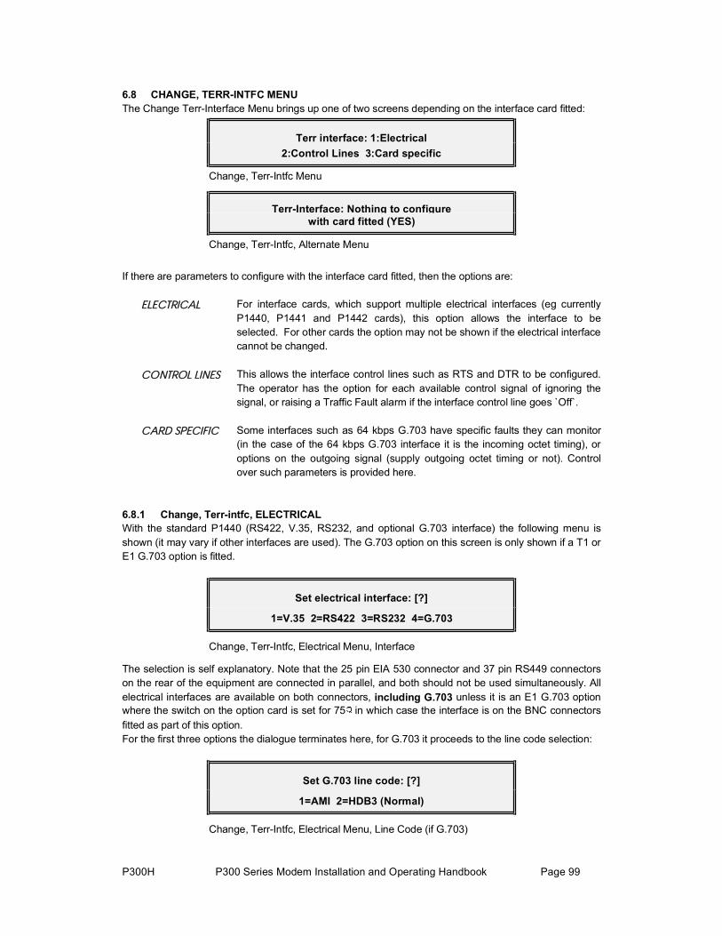
P300H P300 Series Modem Installation and Operating Handbook Page 99
6.8 CHANGE, TERR-INTFC MENUThe Change Terr-Interface Menu brings up one of two screens depending on the interface card fitted:
Terr interface: 1:Electrical 2:Control Lines 3:Card specific
Change, Terr-Intfc Menu
Terr-Interface: Nothing to configure with card fitted (YES)
Change, Terr-Intfc, Alternate Menu
If there are parameters to configure with the interface card fitted, then the options are:
ÛÔÛÝÌÎ×ÝßÔ For interface cards, which support multiple electrical interfaces (eg currently P1440, P1441 and P1442 cards), this option allows the interface to be selected. For other cards the option may not be shown if the electrical interfacecannot be changed.
ÝÑÒÌÎÑÔ Ô×ÒÛÍ This allows the interface control lines such as RTS and DTR to be configured. The operator has the option for each available control signal of ignoring thesignal, or raising a Traffic Fault alarm if the interface control line goes `Off`.
ÝßÎÜ ÍÐÛÝ×Ú×Ý Some interfaces such as 64 kbps G.703 have specific faults they can monitor (in the case of the 64 kbps G.703 interface it is the incoming octet timing), or options on the outgoing signal (supply outgoing octet timing or not). Control over such parameters is provided here.
6.8.1 Change, Terr-intfc, ELECTRICALWith the standard P1440 (RS422, V.35, RS232, and optional G.703 interface) the following menu is shown (it may vary if other interfaces are used). The G.703 option on this screen is only shown if a T1 orE1 G.703 option is fitted.
Set electrical interface: [?]
1=V.35 2=RS422 3=RS232 4=G.703
Change, Terr-Intfc, Electrical Menu, Interface
The selection is self explanatory. Note that the 25 pin EIA 530 connector and 37 pin RS449 connectorson the rear of the equipment are connected in parallel, and both should not be used simultaneously. All electrical interfaces are available on both connectors, including G.703 unless it is an E1 G.703 optionwhere the switch on the option card is set for 75 in which case the interface is on the BNC connectorsfitted as part of this option. For the first three options the dialogue terminates here, for G.703 it proceeds to the line code selection:
Set G.703 line code: [?]
1=AMI 2=HDB3 (Normal)
Change, Terr-Intfc, Electrical Menu, Line Code (if G.703)

P300H P300 Series Modem Installation and Operating Handbook Page 100
For E1 G.703 the line code selection is as shown above (AMI=Alternate Mark Inversion or HDB3=High Density Bipolar 3). For T1 G.703 the line code selection is between AMI and B8ZS (Binary 8 Zero Substitution). In both cases the NON-AMI option is most common so select this if in any doubt.
The NON-AMI options for T1 and E1 are both different means to achieve the same objective, which is tolimit the number of contiguous zeros, which may be transmitted on the G.703 line. This is necessary with G.703 as with AMI a `mark` (logic one) is sent as a pulse on the line, and a `space` (logic zero) is set as the absence of a pulse on the line. If there are too many contiguous spaces the G.703 receiver fails to recover the clock properly (as there are no incoming pulses for a while) and it causes data errors. HDB3 and B8ZS are both methods of ensuring that no more than three or eight zeroes respectively occur on a G.703 line by substituting strings of more than this number of zeroes with another code, in turn this code is detected at the end of the G.703 line and replaced with the correct number of zeroes again.
If the line code is set incorrectly you will almost continuously see Tx Warn: Tx line code violationsdetected which indicates the modem is receiving line code violations and most probably set for AMI but receiving a B8ZS/HDB3 coded signal. Intermittent occurrences of the warning however are more likely to be caused by line noise corrupting the signal. Note that if the modem is incorrectly set for B8ZS/HDB3 and the other equipment expects AMI, then there will be no warning on the modem.
Finally, and only for T1 G.703 cards the following screen is shown:
Set T1 line length: [?]ft 1=<133' 2=<266' 3=<399' 4=<533' 5=<655'
Change, Terr-Intfc, Electrical Menu, Line Length (if T1 G.703)
This screen allows the signal to be pre-compensated to cope with differing lengths of standard `ABAM`cable. We would suggest you select option 1, less than 133 feet by default (no compensation). 6.8.2 Change, Terr-intfc, CONTROL LINESThis screen allows the operator to select whether the modem implements or ignores the interfacehandshake control lines:
Interface control lines:[?] 1=Ignore all 2:Active-configure
Change, Terr-Intfc, Control Lines Menu
×ÙÒÑÎÛ ßÔÔ All the control lines are ignored, the dialogue ends here
ßÝÌ×ÊÛó
ÝÑÒÚ×ÙËÎÛ The three following screens are presented in turn allowing each line to be individually controlled. The line names change to match the interface type selected (examples here are for V.35).

P300H P300 Series Modem Installation and Operating Handbook Page 101
Line "DTR" (DTE Ready In): [?]
1=Ignore 2=Active
Change, Terr-Intfc, Control Lines, Active Screen 1
Line "RTS" (Tx input signal valid): [?]
1=Ignore 2=Active
Change, Terr-Intfc, Control Lines, Active Screen 2
Note that if the carrier is set to ÎÌÍó½±²¬®±´´»¼ (under ÝØßÒÙÛô ÌÈô ÓÑÜËÔßÌÑÎô ÝßÎÎ×ÛÎ, and the RTS line is set to `×ÙÒÑÎÛ`, then there will be no alarms should the RTS line go `off` inhibiting the carrier.
This final screen is only shown if the modem is fitted with a DTE interface.
Line "CTS" (Terr accepts Rx output): [?]
1=Ignore 2=Active
Change, Terr-Intfc, Control Lines, Active Screen 3
6.8.3 Change, Terr-intfc, CARD SPECIFICThese screens are used for interfaces, which have interface specific requirements such as the 64kbps G.703 interface. With the standard P1440 interface this option is not shown on the Change, Terr-Intfc menu.

P300H P300 Series Modem Installation and Operating Handbook Page 102
6.9 CHANGE, REM-M&C MENU
Remote M&C: [Local]
1:Configure 2=Remote 3=Local (Rem M&C timeout=120s)
Change, Rem-M&C Menu
This menu allows the remote M&C port to be configured, and control of the unit switched between localand remote. There are many different thoughts on how local / remote switching should be provided !
The text "(Rem M&C timeout=120s)" is only displayed if Ù·ª» ß©¿§ is selected on the menu described below, it indicates that the Ô±½¿´ option is not available until the timeout (which counts down when noremote M&C messages are received) has expired. If Ì¿µ» ß©¿§ is selected on the menu described below, then there is no timeout and the user may take local control at any time.
6.9.1 Local Control TAKE AWAY / GIVE AWAY SelectionUnder ÍÛÎÊ×ÝÛ øð÷ô ÚßÝÌÑÎÇ ÐßÎßÓÛÌÛÎÍô ÎÛÓÑÌÛ ÓúÝ the following menu is provided:
Rem M&C philosophy: [?]
1=Takeaway 2:Giveaway+M&C Timeout
Service, Factory Parameters, Remote M&C Menu
ÌßÕÛßÉßÇ When selected the operator can switch between Local and Remote control atwill using the Ô±½¿´ & λ³±¬» options on the Change, Rem M&C Menu.
Ù×ÊÛßÉßÇ When selected a subsequent screen is displayed which allows a timeout of up to 255 seconds to be specified. Normal switching between Local and Remote is then by Giveaway philosophy, ie once in Remote M&C, local control is only granted by a remote M&C command giving back local control. The timeout ensures that if the remote M&C fails the operator can take local control when the timeout expires if necessary. NOTE it does not automatically switch to local, it remains in remote mode unless the local operator specifically selects Ô±½¿´ after the timeout has expired.
There is no option for Give Away without a timeout, otherwise the operator could find control of the modem locked out if this option was active without remote M&C operating.
The subsequent timeout menu is as follows, its function is described above:
Rem M&C timeout before user can takelocal control: [120s] (1-255secs) ???s (YES)
Service, Factory Parameters, Remote M&C Timeout Menu

P300H P300 Series Modem Installation and Operating Handbook Page 103
6.9.2 Change, Rem-M&C, CONFIGURE Menu
Remote M&C: 1:Protocol [Paradise]
2:Intfc [RS485] 3:Baud rate[2400] 4:Addr[123]
Change, Rem-M&C, Configure Menu
This menu configures the remote M&C port: The options are:
ÐÎÑÌÑÝÑÔ This allows selection between ÑÚÚ, ÐßÎßÜ×ÍÛñÚÜÝ, and Íßó¾«. Full details of the remote M&C protocols and messages is provided in the Remote M&C section in Appendix D.
NOTE: Remote monitoring is possible with the selected protocol if the protocol is not set to ÑÚÚ. Remote control is only possible if the protocol is not Ѻº and control has been selected as λ³±¬» on the Change, Remote M&C menu.
×ÒÌÛÎÚßÝÛ The options available here are RS232 or RS485. RS232 is only usable for adirect connection between a single device and a PC. RS485 is required when more than one slave device is connected to the remote M&C bus. Again see the Remote M&C section for complete details of the electrical interface.
ÞßËÜ ÎßÌÛ The remote M&C Baud Rate is selectable, again see the Remote M&C section for complete details of suitable Baud Rates for each protocol.
ßÜÜÎÛÍÍ The bus address must be specified. The valid range for the Paradise / FDC protocol is 1-255, for the SA-bus protocol the valid range of address is 49 to111 (31H to 6FH).

P300H P300 Series Modem Installation and Operating Handbook Page 104
6.10 CHANGE, USER-OPT MENU
User options: 1:Alarm thresholds
2:Operation 3:Display 4:Analog o/p
Change, User-Opt Menu
This screen allows access to all the user options, which are described in the following paragraphs.
6.10.1 Change, User-Opt, THRESHOLDS Menu
Thresholds: 1:Final BER [1.0E-5] 2:Demod Eb/No [6.0]dB
3:Buffer slip [24]hrs 4:DISTANT Eb/No[8.5]dB
Change, User-Opt, Thresholds Menu
This screen allows the operator to set thresholds at which a deferred alarm is raised, to allow action to be taken before the service degrades too far.
ËÍÛÎ ÞÛÎ The operator may enter a BER at which the deferred alarm is raised should the estimated USER BER degrade below this threshold.
ÜÛÓÑÜ Û¾ñÒ± The operator may also or alternatively set a deferred alarm threshold for the Eb/No measured by the demodulator. This is the Eb/No as displayed on the screen whenever the demodulator status is displayed.
ÞËÚÚÛÎ ÍÔ×Ð The operator may also instruct the modem to raise the deferred alarm if theinterval between buffer slips is less than a preset threshold. The threshold is set in hours, and may be for example set to 960 hours (40 days) or 1728 (72 days)to warn if the criteria for clock accuracies for a specific service are not being met.
Ü×ÍÌßÒÌ Û¾ñÒ± If the AUPC feature is active in either `Maintain Eb/No` or `Monitor Distant` modes (refer to AUPC in section 8.11 on page 156) the operator has the facilityto raise a deferred alarm if the DISTANT Eb/No falls below the user setthreshold. This can be used in conjunction with the AUPC to indicate when the AUPC has reached the user set limit for maximum Tx power, but the distant Rx Eb/No has still fallen below the desired limit.
6.10.2 Change, User-Opt, OPERATION Menu
User options: 1:Default 2:Actions 3:Terr4:Sat 5:Terr/Sat 6:Alarms
Change, User-Opt, Operation Menu
The operator has control over many parameters, which are the subject of either personal or company preference. A single menu choice ÜÛÚßËÔÌ ßÔÔ resets these to the Paradise Defaults, which are listed in the following paragraphs along with each parameter.

P300H P300 Series Modem Installation and Operating Handbook Page 105
6.10.3 Change, User-Opt, Operation, ACTIONS Menu
Actions: 1:Buffer auto centre 2:BER 3:AIS 4:Back Alarm
Change, User-Opt, Operation, Actions Menu
ÞËÚÚÛÎ
ßËÌÑÝÛÒÌÎÛ This selects if the receive buffer is automatically centred when the Rx traffic returns to OK from the fail state. This takes advantage of any outage, and ensures the buffer is centred every time normal operation begins. This option can be disabled, as for minor outages the errors or sync losses caused by centering the buffer may be larger than those caused by the outage itself. Default: ÛÒßÞÔÛÜ
ÞÛÎ ßÝÌ×ÑÒ This option controls how a high BER indication is handled. INTELSAT specify that when the BER exceeds 1 x 10⁻³ the following actions are required: the Rx prompt alarm should be raised, AIS should be forced, and the backward alarm sent. This option can disable the forcing of AIS and the backward alarm tomaintain the traffic as best as possible. Note the Rx Prompt alarm is still raisedeven if this option is set to ÒÑ ßÝÌ×ÑÒ to disable the AIS and Backward Alarm. Default: ßÝÌ×ÑÒ
ß×Í ßÝÌ×ÑÒ This option is similar to BER action above, except it specifies how the modem is to handle the detection of AIS (the Alarm Indication Signal, all ones).INTELSAT specify the required actions as: the Prompt Traffic alarm should be raised, AIS should be regenerated (to prevent multiple noisy links building upenough errors to stop the all ones being detected), and the backward alarmshould be sent. In continuous modes this option allows all three actions to bedisabled. In Drop/Insert modes the Prompt Traffic alarm and the backwardalarm are disabled, but AIS is still regenerated if it is detected. Default:ßÝÌ×ÑÒ
ÞßÝÕùßÔßÎÓ This option is only displayed if the Insert mux is active and set for ChannelAssociated Signalling (CAS). It controls the forcing of the `abcd` signalling bits passed to the terrestrial port to certain values when an incoming backwardalarm is received. Default: Ò±®³¿´. The options are Ò±®³¿´ A backward alarm is sent out of the insert mux to the terrestrial
network (INTELSAT IESS 309). Í·¹ ß×Í The `abcd` signalling nibbles for the inserted timeslots are
forced to all ones. ¾ãï The `b` bit of the `abcd` signalling nibbles for the inserted
timeslots are forced to a one (Eutelsat EESS 501, SMS). ¿¾ãïï The `a` and `b` bits of the `abcd` signalling nibbles for the
inserted timeslots are forced to a one. 6.10.4 Change, User-Opt, Operation, TERRESTRIAL Menu
Terrestrial: 1:PCM Bearer CRC BER monitors: 2:Tx/Drop mux 3:Insert mux
Change, User-Opt, Operation, Terrestrial Menu
ÐÝÓ ÞÛßÎÛÎ ÝÎÝ This option is only applicable when the unit is configured for Drop/Insert

P300H P300 Series Modem Installation and Operating Handbook Page 106
operation with a PCM bearer which supports CRC (T1-ESF or G.732). Whenappropriate this accesses a sub menu which is discussed in the followingsection.
ÌÈñÜÎÑÐ ÞÛÎ The source for the estimate of the terrestrial BER at the Drop Mux may beselected: ß«¬± The selection is made automatically from the most appropriate
source. ÚßÉ The input BER is estimated from the Frame Alignment Words
(FAW) of the PCM bearer. ÝÎÝ The input BER is estimated from the number of CRC errors
(T1-ESF & G.732 only). ÛóÞ·¬ The output BER is determined by counting the E-Bits on the
incoming G.732 signal. On a G.732 link an E-Bit is returned bythe distant equipment when it receives an errored CRC, iethe incoming E-Bits represent the error rate at the far end ofthis modems outgoing G.732 link. Effectively the error rateon the outgoing link at the far end.
Default: ß«¬±
ÎÈñ×ÒÍÛÎÌ ÞÛÎ The source for the estimate of the BER from the terrestrial port at the input tothe insert mux may be selected as described above for the Tx/Drop BER.Default: ß«¬±
6.10.5 Change, User-Opt, Operation, Terrestrial, PCM BEARER CRC Menu
PCM Bearer: 1:Bearer CRC 2:E-Bits 3:CRC/Frame Acq'
Change, User-Opt, Operation, Terrestrial, PCM Bearer CRC Menu
ÞÛßÎÛÎ ÝÎÝ This option, only applicable to G.732 Drop/Insert bearers selects if the PCMbearer has a CRC, the options available are Ò±²»ñ×¹²±®» or Ю±½».Default: Ò±²»ñ×¹²±®».
ÛóÞ×ÌÍ If a G.732 Bearer with CRC set to Ю±½» as above, then the additional option to process & return E-Bits is also available, options for what happens when incoming CRC errors are detected are Ò± ß½¬·±² or 묫®² ÛóÞ·¬.Default: Ò± ß½¬·±².
ÝÎÝñÚÎßÓÛ
ßÝÏù Again, if a G.732 Bearer with CRC set to Ю±½», then the option exists to implement the strict letter of ITU G.704, and force a re-acquisition of theterrestrial Drop/Insert frame sync if CRC sync cannot be achieved within 8ms. Options available are Ò±®³¿´ or λ¿½¯«·®» º®¿³» ·º ÝÎÝ §²½ ´±¬.Default: Ò±®³¿´.
6.10.6 Change, User-Opt, Operation, SATELLITE Menu
Satellite: 1:BER est 2:IBS MF period
3:Carrier ID s 4:Back alm map 5:IF-50/75
Change, User-Opt, Operation, Satellite Menu

P300H P300 Series Modem Installation and Operating Handbook Page 107
ÞÛÎ ÛÍÌ×ÓßÌÛ This selects the source for the USER BER estimate displayed on the Receive Status Screens, and compared to both the Deferred USER BER alarm, and BER > 1 x 10⁻³ alarm thresholds. The selection is from: ßËÌÑ The unit selects the most appropriate source. Note that the INTELSAT
mandatory method is FAW, although ß«¬± will select more accurate or morequickly updated methods if available. The list of priorities is as follows:
1. The PRBS tester (if in the main data channel) 2. The Reed-Solomon outer FEC Codec (if active) 3. The Turbo, Viterbi or Sequential inner FEC (if active) 4. The PRBS tester in ESC or Aux channels (if active) 5. The errors counted over one minute on the FAW (if framed) 6. No estimate of BER ÚßÉ An estimate based on the count of errors on the Frame Alignment Words
(FAW) received by the deframer over a 1 minute sliding window. Only available if operating in a framed mode. ÚÛÝ An estimate of the output error rate from the FEC decoder, based on the count
of errors into the FEC and the FEC code rate. Note that if FEC is manually selected, but Reed-Solomon is active, the BER estimate will not include the significant error improvement of the RS codec. ÎÍ An estimate of the output error rate of the RS Decoder based on the number of
uncorrectable words passed by the decoder. ÐÎÞÍ The real BER as measured by the PRBS tester, whether it be in the ESC or
Auxchannel, or the main data channel. Default: ßËÌÑ
×ÞÍ ÓÚ ÐÛÎ×ÑÜ This option is only applicable to Custom, IBS, Minimum overhead modes. In this mode the overhead is varied to accommodate any ESC requirements, and if the ESC and main data rate are very low the overhead multiframe structure might be very long. Whenever the Rx carrier is re-acquired the multiframe alignment also has to be re-acquired, and this option allows the maximummultiframe period to be specified in order to prevent excessively long multiframe periods affecting carrier re-acquisition times. By default it is 2000ms, approximately 4 times the normal IBS multiframe time of 512ms at 64kbps. This will only be an issue where very low data rates (<16kbps) and low ESC rates are in use, or Minimum overhead mode is active with No ESC requirement and the multiframe just provides timeslot ID maintenance and backward alarm facilities. Only consider adjusting from default if you see long periods where the status displays "TS32 Multiframe sync lost" or "CAS Multiframe sync lost" after the demod has lost and re-acquired the carrier. Default: îððð³
Ý¿®®·»® ×ÜùÍ The earlier versions of the Eutelsat SMS specification defined 3 eight bit identities which may be transmitted once per satellite TS32 multiframe to identify the carrier and the earth station. These were named ͬ¿¬·±² ×Ü, Ý¿®®·»®
×Ü & Í°¿®» ×Ü. More recent issues just say "reserved for uses such as.....". This options allows these three ID's to be set (0-255 for each), and also displays the corresponding ID's from the incoming Rx carrier. Default: all îëë
ÞßÝÕ ßÔÓ
ÓßÐ In Custom IBS Modes it is possible to operate an IBS style service, and allow the use of four independent backward alarms (as for IDR) for use on multidestinational services. This option allows the four alarms to be mapped in different ways onto the IBS TS32 multiframe, in the hope that should INTELSAT adopt such a standard, the P300 Modems could be set to be

P300H P300 Series Modem Installation and Operating Handbook Page 108
compatible with however INTELSAT might define it. Default: four alarms in a 64 frame cycle.
IF-50/75 The IF Impedance is selected on this menu. There are no electrical changes made when this option is changed as the IF ports are matched to both 50 and 75 operation, there is simply a slight adjustment of the internal powercalibrations & readings to maintain accurate level control & indication.
6.10.7 Change, User-Opt, Operation, TERR/SAT Menu
Terr/Sat: 1:BufferMF slip 2:Thin Route Spoof 3:X.50 AIS 4:G.732 spares
Change, User-Opt, Operation, Terr/Sat Menu
ÞËÚÚÛÎ ÓÚ
ÍÔ×Ð For data rates of 1544 kbps and 2048 kbps where the data is framed, the bufferis usually made to slip integer multiples of the frame length (3ms and 2ms respectively). This option sets if the buffer capacity should automatically beincremented to the nearest integer multiple of frame length at these specific rates. Options are ß¼¶«¬ øÒ±®³¿´÷ or ܱ²ù¬ ß¼¶«¬. Default: ADJUST
ÌØ×Ò ÎÑËÌÛ
ÍÐÑÑÚ This interestingly named option is to allow full connectivity of a PCM bearer to be `spoofed` even if the link is connected over satellite via a `thin route` (ie less than the full PCM bearer using Drop/Insert). If enabled the following features of the PCM system appear transparent end to end: AIS (all ones), Backward Alarm, CAS Backward alarm (G.732 only) NOTE: When enabled AIS is forced over the whole PCM bearer, and so this option should not be used with cascaded Drop/Insert, where AIS from the second modem in a cascade would cause the inserted data from the first in thecascade to be lost. Options are Í°±±º or Ѻº. Default: Ѻº
Èòëð ß×Í In standard IBS operation 48 & 56kbps are X.50 `bit stuffed` up to 64kbps prior to framing. It is not clear how AIS is intended to be transferred in these casesand so AIS can remain at 48 or 56kbps and still be X.50 stuffed, or AIS can be set at 64kbps. Options are êìµ ß×Í ø²±®³¿´÷ or ìèñëêµ ß×Í. Default: 64k AIS (Normal)
Ùòéíî ÍÐßÎÛÍ When the terrestrial data rate is 2048kbps in IBS/SMS mode, the operator can select Normal or G.732 mode of operation (corresponding to INTELSATs confusing definition of 2048kbps and 1920/1984kbps operation). This option allows the spare bits of the TS0 of the terrestrial G.732 frame to be either transparent across the link, or forced to all ones. Refer to section 7.2 "Change,Tx/Rx, Baseband, Continuous, 2048k Menu (IBS)" on page 139 for further information on operation in this mode. Options are Ì®¿²°¿®»²¬ or Ú·¨ Ø·¹¸.Default: Ú·¨ Ø·¹¸.

P300H P300 Series Modem Installation and Operating Handbook Page 109
6.10.8 Change, User-Opt, Operation, ALARMS Menu
Customer specific requirements:
1:Relay mode [0] 2:Fault mode [0]
Change, User-Opt, Operation, Alarms Menu
The two options under this menu are to enable Paradise to add customer specific features to the standard software and avoid having special versions of software for specific customers. As most specialrequests relate to either alarm handling or relay operation, we have defined two user variables which we can test in the main code, and if necessary perform special functions. This might include for example delaying the fault relays under specific alarm conditions, as requested on our previous modem products.
The specific functions available are listed in Appendix E on page 207.
ÎÛÔßÇ ÓÑÜÛ A value from 0-15, where 0 is `Normal`. Default: 0
ÚßËÔÌ ÓÑÜÛ A value from 0-15, where 0 is `Normal`. Default: 0
6.10.9 Change, User-Opt, DISPLAY Menu
Display: 1:Status screen 2:Upgrade messages/notes
Change, User-Opt, Display Menu
The options are:
ÍÌßÌËÍ ÍÝÎÛÛÒ This selection are covered in the section Status Screen Display on page 52.The options available are ̨ ú ÎÈ ÌÎßÚÚ×Ý ÍËÓÓßÎÇ or ÝÑÒÚ×ÙËÎßÌ×ÑÒ
ÍËÓÓßÎÇ. Default ̨ ú Ψ Ì®¿ºº·½ Í«³³¿®§
ËÐÙÎßÜÛ
ÓÛÍÍßÙÛÍ The unit will by default display notes on the LCD (typically Note ) when there is an upgrade option available to add extra facilities at this point in the menustructure. At such a point pressing the Down Arrow will explain what extra facilities are possible. The operator has the choice to either ÛÒßÞÔÛ or Ü×ÍßÞÔÛ the display of these messages. Default: Û²¿¾´».
6.10.10 Change, User-Opt, AGC Output Menu
Analog output: [0] (0-15) ?? (YES)
0 AGC, 1-15 refer to handbook appdx E
Change, User-Opt, AGC Output Menu
This option is only available if the Monitor/AGC option is fitted when the modem has an uncommitted 0-10V DC output on the alarms connector, sourced from a 10 bit DAC. This has been specifically providedto allow customer access to internal signals such as the AGC level or the Eb/No value. The exact signal output on this port is user controlled by entering a number from 0-15 at this menu. The full list of options available are described in Appendix E on page 207. Default: 0 (standard AGC voltage).

P300H P300 Series Modem Installation and Operating Handbook Page 110
6.11 CHANGE TIME/DATE MENU
Now: 11:29:35 on 12/06/97 - OK (yes)1 Time adjust, 2 Date Adjust
Change, Time/Date Menu
This menu is self explanatory, and allows the user to set the correct time and date so that events addedto the traffic log are correctly time stamped.
6.12 CHANGE, BUC/LNB MENU
BUC/LNB: 1:Tx/BUC 2:Rx/LNB 3:Tune Ref
Change, BUC/LNB Menu
This screen allows access to all the features relating to the BUC/LNB or RF chain that follows the modem. Although most of these facilities relate to the P310 L-Band version of the modem, certain options such as Tx/Rx Frequency Offsets (which allow the IF frequencies to be entered and displayed as final SHF frequencies) are also relevant and useful on the standard 70MHz/140MHz P300.
Each option is described in the following paragraphs.
6.12.1 Change, BUC/LNB, TX/BUC Menu
Tx/BUC: 1:BUC Type 2:DC & References 3:SHF Frequency 4:SHF Power/Units 5:BUC Control
Change, BUC/LNB, Tx/BUC Menu (fewer option when not L-Band)
Options for ÞËÝ Ì§°», ÜÝ ú λº»®»²½», & ÞËÝ Ý±²¬®±´ are only offered on L-Band modems. ÞËÝ
ݱ²¬®±´ is offered subject to the BUC Type and the Modem/BUC control mode selected.
Each option is defined in the following paragraphs.
6.12.2 Change, BUC/LNB, Tx/BUC, BUC TYPE MenuThis screen is only available on P310 L-Band modems.
BUC Attached:[?] 1=None 2=Other 3=Std Ku 4=Ext Ku5=Std C 6=INSAT C 7=PALAPA C
Change, BUC/LNB, Tx/BUC, BUC Type Menu 1

P300H P300 Series Modem Installation and Operating Handbook Page 111
Options other than Ò±²» or Ѭ¸»® are only displayed if the FSK communications option is presentwithin the P310, and refer to standard Paradise BUC‘s (with which the modem can communicate by FSK). If you are using a non Paradise BUC, then please select Ѭ¸»® and manually configure the BUC parameters.
The table below specifies the parameters for the listed BUC types:
BUC Type Lower Frequency Limit Upper Frequency Limit Frequency Shift None Modem IF +/- limits around user set SHF Frequency Shift Other Modem IF +/- limits around user set SHF Frequency Shift Std Ku 14.000 GHz 14.500 GHz 13050 MHz Ext Ku 13.750 GHz 14.250 GHz 12800 MHz Std C 5.800 GHz 6.4250 GHz 4900 MHz
INSAT C 6.725 GHz 7.025 GHz 5775 MHz PALAPA C 6.425 GHz 6.725 GHz 5475 MHz
The difference between Ò±²» and Ѭ¸»® is that with Ѭ¸»® the operator can configure the modem to supply a 10MHz reference and a DC PSU to the BUC (if the internal BUC PSU option is fitted). WithÒ±²», these options are not available.
If a Paradise BUC is fitted then the following screen is displayed:
Modem/BUC control mode: [?]1=Independent 2=Terminal(Closed Loop)
Change, BUC/LNB, Tx/BUC, BUC Type Menu 2

P300H P300 Series Modem Installation and Operating Handbook Page 112
×ÒÜÛÐÛÒÜÛÒÌ The modem and BUC are both manually controlled from the modem front panel (the modem as normal, and the BUC with ݸ¿²¹», ÞËÝñÔÒÞ, ̨ñÞËÝ). The operator maintains control of the BUC Tx on/off status, and any BUC attenuator available. The modem does however automatically report the IF frequency to the BUC so the BUC may select the correct power calibration table for the monitored power reported back to the modem, viewable under Ó±²·¬±®, ÞËÝ.
It is advisable to keep the BUC attenuator at maximum attenuation to avoid overdriving the BUC input stages, unless there is considerable cross site cable loss. Fine (0.1dB power control is done with the modem (ݸ¿²¹», ̨, Ó±¼,б©»®), whereas the BUC attenuator provides 1dB adjustment steps. If the desired carrier power cannot be achieved with maximum BUC attenuation, then there must be considerable cross site loss and so it is safe to reduce the BUC attenuation. It is advisable to keep the modem carrier power several dB away from either the upper or lower modem power end stop, to provide future fine adjustment range.
Initial power adjustments must be made `off satellite`. The measured BUC power can be viewed using Ó±²·¬±®, ÞËÝ.
ÌÛÎÓ×ÒßÔ The Modem takes control of the BUC to act as an integrated terminal, and the two together respond as follows:
The modem IF output level screens are replaced by a screen allowing the operator to set the output power at the BUC flange.
The Modem continuously reads the monitored power output from the BUC, and automatically varies the modem IF level and BUC attenuator to maintain the set power at the BUC flange (ie compensates for temperature changes in cable, equipment etc).
The BUC Tx On/Off output is maintained as `On` (the Tx carrier can still be muted on Change, Tx, Modulator, Carrier menu).
The modem automatically reads the frequency shift from the BUC, and configures the modem for display / entry of the final SHF frequencies instead of IF frequencies.
Terminal mode can only be used with a single carrier through the BUC, as the modem will try and compensate for the combined measured power by adjusting the single carrier from the modem controlling the BUC.
Terminal mode, where the Tx power is varied to maintain a steady level at the BUC flange, is NOT compatible with AUPC which requires the Tx power to vary to meet receive criteria.

P300H P300 Series Modem Installation and Operating Handbook Page 113
6.12.3 Change, BUC/LNB, Tx/BUC, DC & REFERENCES MenuThis screen is only available on P310 L-Band modems where the BUC Type has been set to other than Ò±²»
Tx/BUC: 1:DC Supply[On] 2:10M Ref[Off]
3:Current Monitor[2400 - 2800mA]
Change, BUC/LNB, Tx/BUC, DC & References Menu
ÜÝ ÍËÐÐÔÇ If fitted with the P315 BUC DC supply option, then the modemmay source 100W of 24V or 180W 48V (factory option) to the BUC `upthe coax` or `line powered`. The only option available here is Ѳor Ѻº.
CAUTION: Needless to say severe damage may occur if a DC supply is fed to aBUC not configured for being `Line powered`.
ïðÓ ÎÛÚ The internal 10MHz reference may similarly be sourced from the modem `up the coax` to the BUC. The only option available here again is Ѳ or Ѻº.
ÝËÎÎÛÒÌ
ÓÑÒ×ÌÑÎ If the modem is sourcing the DC supply to the BUC, then it may be set tomonitor the current drawn by the BUC, and to raise an alarm (Tx Fault) if it goes outside a user defined window. Two subsequent screens allow the user to independently set the low and high current alarm thresholds. The current being drawn by the BUC can be monitored from the Ó±²·¬±®, ÞËÝ menu s.
6.12.4 Change, BUC/LNB, Tx/BUC, SHF FREQUENCY MenuThis screen is available on both 70MHz/140MHz P300 modems and P310 L-Band modems, and allows the modem to be set to display and edit the final SHF frequencies instead of the IFfrequencies. When the BUC Type has been set to a known Paradise BUC and the modem has the FSK communications option then this setting is done automatically and the menu option to manually set the frequency shift is not presented.
Set upconverter freq shift to display &
edit Tx freq at antenna:[Yes] 1=Yes 2=No
Change, BUC/LNB, Tx/BUC, SHF Frequency Menu 1
If Ç» is selected then the following screen is displayed:
Freq shift of upconverter:[13050 MHz]
(0-65535MHz) ??.??? (YES)
Change, BUC/LNB, Tx/BUC, SHF Frequency Menu 2
Once set all Tx IF frequencies displayed or edited include the frequency shift of the BUC or upconverter chain.

P300H P300 Series Modem Installation and Operating Handbook Page 114
6.12.5 Change, BUC/LNB, Tx/BUC, SHF POWER/UNITS MenuThis screen is available on both 70MHz/140MHz P300 modems and P310 L-Band modems, and allows the modem to be set to display and edit the final SHF power instead of the IF carrier level.
Modem +13.7[Gain]=SHF [EIRP] in [dBW]
1:System Gain 2=TxPwr/EIRP 3=dBm/dBW
Change, BUC/LNB, Tx/BUC, SHF Power/Units Menu
It allows the user to set the system Gain or Loss after the modem, so that the modem can then display and edit the Tx carrier level in terms of either the Tx Power or EIRP, measured in dBm or dBW. The system gain or loss can be set from -99.9dB to +99.9dB. Options for TxPwr/EIRP &dBm/dBW are only available once the System Gain has been set to other than zero. When zero the default units are TxPwr indBm.
This screen is not available on the L-Band modem with FSK when the Tx BUC Type has been set to a known Paradise BUC and the modem / BUC configured to operate as a Terminal, as here the modem / BUC work in a closed loop mode and compensate for whatever the systemgain varies to be, in order to keep the power measured at the BUC constant.
6.12.6 Change, BUC/LNB, Tx/BUC, BUC CONTROL MenuThis screen is only available on the P310 L-Band modem if the BUC Type has been set to a known Paradise BUC, the modem has the FSK communications option, and the Modem/BUC are set in ײ¼»°»²¼»²¬ mode. In the alternative Ì»®³·²¿´ mode (with Closed loop power control to the BUC flange) the BUC is kept Ѳ and the BUC attenuator automatically controlled.
1:BUC On/Off[On ] 2:BUC Attenuator[7dB]
(Power at BUC reads: 32.7dBm)
Change, BUC/LNB, Tx/BUC, BUC Control Menu
ÞËÝ ÑÒñÑÚÚ This switches the BUC Tx on and off independently of the modems Tx CarrierOn/Off control. This may be useful where one BUC carries several carriers (passively combined but with one modem providing DC / 10MHz Ref / FSK) and you wish to mute all the carriers.
ÞËÝ
ßÌÌÛÒËßÌÑÎ This allows the user to vary the attenuator in the BUC. Typically this is used when there is a short run from the modem to the BUC made with reasonablequality cable, and where with such a low loss the minimum output from themodem could saturate the BUC input unless the attenuator (early in the BUC gain profile) is set suitably high.
IF IN DOUBT, always start with the MINIMUM modem Tx Carrier level and theMAXIMUM BUC attenuator setting.
The second line of this screen reports the actual power measured by the BUC.

P300H P300 Series Modem Installation and Operating Handbook Page 115
6.12.7 Change, BUC/LNB, Rx/LNB Menu
Rx/LNB: 1:LNB Type 2:DC & References
3:SHF Frequencies
Change, BUC/LNB, Rx/LNB Menu
Options for ÔÒÞ Ì§°», and ÜÝ ú λº»®»²½» are only offered on L-Band modems.
Each option is defined in the following paragraphs.
6.12.8 Change, BUC/LNB, Rx/LNB, LNB Type Menu
LNB Attached[?] 1=None 2=Other 3=3.635-4.2G 4=10.95-11.45G
5=10.95-11.7G 6=11.2-11.7 7=11.7-12.2 8=12.25-12.75
Change, BUC/LNB, Rx/LNB, LNB Type Menu
The table below specifies the parameters for the listed LNB types:
Description Low Frequency Limit High Frequency Limit Frequency Shift None Modem IF +/- limits around user set SHF Frequency Shift Other Modem IF +/- limits around user set SHF Frequency Shift Std C 3.635 GHz 4.200 GHz * 5150 MHz Std Ku 10.950 GHz 11.450 GHz 10000 MHz
10.95-11.7G 10.950 GHz 11.700 GHz 10000 MHz 11.2-11.7G 11.200 GHz 11.700 GHz 10250 MHz 11.7-12.2G 11.700 GHz 12.200 GHz 10750 MHz
12.25-12.75G 12.250 GHz 12.750 GHz 11300 MHz
As with the BUC s, the difference between Ò±²» and Ѭ¸»® is that with Ѭ¸»® the operator can configure the modem to supply a 10MHz reference and a DC PSU to the LNB. With Ò±²», these options are not available.
* Note the `Std C` LNB uses a high side Local Oscillator (LO), and the received SHF Frequency is LO - IFFrequency (not LO + IF as with most other bands). This is somewhat academic as from V3.85 onwards this is handled automatically and the modem displays the correct SHF frequency. Note however that with the LNB Type set to Ò±²» or Ѭ¸»®, there is no way to manually enter a SHF offset which uses a High Side LO.

P300H P300 Series Modem Installation and Operating Handbook Page 116
6.12.9 Change, BUC/LNB, Rx/LNB, DC & REFERENCES Menu
Rx/LNB:1:DC Supply[15V] 2:10M Ref[Off]
Change, BUC/LNB, Rx/LNB, DC & References Menu
ÜÝ ÍËÐÐÔÇ The P310 L-Band modem can supply either 15V or 24V at 500mA to the LNB`up the coax` or `line powered`. The option available here are Ѻº, ïëÊ or îìÊ.
CAUTION: Needless to say severe damage may occur if a DC supply (or the wrong voltage DC supply) is fed to a LNB not configured for being `Line powered`.
ïðÓ ÎÛÚ The internal 10MHz reference may similarly be sourced from the modem `up the coax` to the LNB. The only option available here is Ѳ or Ѻº.
6.12.10 Change, BUC/LNB, Rx/LNB, SHF FREQUENCIES MenuSimilar to the BUC option, this screen is available on both 70MHz/140MHz P300 modems and P310 L-Band modems, and allows the modem to be set to display and edit the final SHF frequencies instead ofthe IF frequencies. When the LNB Type has been set to a predefined type (ie not Ò±²» or Ѭ¸»®) then this setting is done automatically and the menu option to manually set the frequency shift is not presented.
Set downconverter freq shift to display &
edit Rx freq at antenna:[Yes] 1=Yes 2=No
Change, BUC/LNB, Rx/LNB, SHF Frequency Menu 1
If Ç» is selected then the following screen is displayed:
Freq shift of downconverter:[13050 MHz]
(0-65535MHz) ??.??? (YES)
Change, BUC/LNB, Rx/LNB, SHF Frequency Menu 2
Once set all Rx IF frequencies displayed or edited include the frequency shift of the LNB or downconverter chain.
Note this manual entry of SHF Frequency shift always assumes a low side Local Oscillator (LO) and therefore displays the SHF Frequency = LO + IF. There is no means to enter a High Side LO, where the SHF frequency received would be LO - IF Frequency (unlike the situation where the modem is told it hasa Std C band LNB, and knows that a high side LO is used).

P300H P300 Series Modem Installation and Operating Handbook Page 117
6.12.11 Change, BUC/LNB, Tune Ref MenuThis screen is only shown if a tuneable internal reference is fitted (ie something other than the default 1PPM reference).
Tune Reference:[50]% to nudge
YES to accept, NO to cancel
Change, BUC/LNB, Tune Ref Menu
This screen allows the internal reference oscillator to be calibrated up to about +/- 1PPM (the actual range depends on the exact oscillator option chosen) to compensate for ageing of the quartz crystal.
To calibrate the internal oscillator, either monitor the 10MHz reference if set to be output up the coax, OR, (OFF SATELLITE) set the Tx carrier to the highest possible frequency, engage ÝÉ (Carrier Wave) from the test menu, and measure the carrier centre frequency itself.
Needless to say. Ensure whatever you are measuring the frequency with is itself calibrated, warmed up, and significantly exceeds the stability of the reference option fitted to the modem (viewable under ײº±,̸· ˲·¬)
6.13 MONITOR MENU
Monitor: 1:Demod performance 2:Terrestrial BER
3:Carrier IDs 4:Distant Eb/No & BER 5:AUPC 6:BUC
Monitor Menu
Each of these options is now discussed in turn.
6.13.1 Monitor, DEMOD PERFORMANCE Menu
Eb/No:10.3dB, To FEC:6.8E-4, To RS:7.8E-7
FAW BER:<1.0E-12, Final BER:<1.0E-12 (RS)
Monitor, Demod Performance Menu
This screen which is regularly updated provides the following information:
Demod Eb/No This is the effective `signal to noise ratio` the USER sees, (ie Ebi/No, the energy per information bit). This is also shown on several of the ͬ¿¬« screens.
To FEC This is the measured uncorrected BER before any FEC. It is the raw uncorrected bit error rate into the FEC and it is not representative of the UserBER after forward error correction. Displayed only if the inner FEC is active, ie not operating uncoded.
To RS This is the measured error rate into the Reed-Solomon decoder (from the FEC, unless operating uncoded). The difference between this and the To FEC figure shows the improvement due to the Inner FEC.

P300H P300 Series Modem Installation and Operating Handbook Page 118
BER on FAW An estimate of the USER BER based on the count of errors on the Frame Alignment Words (FAW) received by the deframer over a 1 minute sliding window. Only available if operating in a framed mode. This is equivalent to the final user BER. The difference between this and the To RS figure shows the improvement due to the outer RS FEC.
Final BER This is the final BER figure the modem is using, the source is displayed in brackets after the BER, in this case (RS). It is based on this figure that the deferred alarm is raised if it exceeds the user BER threshold.
6.13.2 Monitor, TERRESTRIAL BER MenuThis screen is only available if the signal on the terrestrial ports is framed (ie T1/E1 PCM bearer) which allows the modem to determine the BER on those ports.
Terr: 1:BER at Drop Mux =1.6E-8 (FAW)
2:BER at Insert Mux=1.5E-8 (CRC)
Monitor, Terrestrial BER Menu
It displays the terrestrial BER at the input to the Drop and Insert multiplexers; these will be the same unless an interface card with separate Drop/Insert bearers is in use. The display shows BER (source), and the source may be changed by pressing 1 or 2. The dialogue is exactly the same as described insection 6.10.3 on page 105.
6.13.3 Monitor, CARRIER ID's MenuThis screen is only available if the receive service supports the transmission of the three identity bytes in the TS32 Multiframe. This includes IBS/SMS modes, Closed Net Plus ESC modes above 32kbps and Custom IBS modes with a TS32 multiframe.
Rx ID's carried in IBS MF word TS32bit4 Channel=173 Station=041 Spare=255
Monitor, Carrier ID's Menu
The earlier versions of the Eutelsat SMS specification defined these 3 eight bit identities to betransmitted once per satellite TS32 multiframe to identify the carrier and the earth station. These were named ͬ¿¬·±² ×Ü, Ý¿®®·»® ×Ü & Í°¿®» ×Ü. More recent issues just say "reserved for uses such as.....". Ifthe demod is receiving a suitable carrier, then the ID's from the received carrier are displayed on this screen.
These may be manually set at the Tx end of the link by ݸ¿²¹»ô Ë»®óÑ°¬ô Ñ°»®¿¬·±²ô Í¿¬»´´·¬»ô
Ý¿®®·»® ×Üù.
6.13.4 Monitor, DISTANT Eb/No & BER MenuThis screen is only available when the AUPC feature is set to `Maintain Eb/No` or `Monitor Distant` (refer to AUPC in section 8.11 on page 156). In these modes the Eb/No and BER from the distant modem are brought across the satellite link by the AUPC, and are available for display on the local modem (and automatic timed entries to the traffic log if required).

P300H P300 Series Modem Installation and Operating Handbook Page 119
Distant end Eb/No=9.7dB Distant end final BER=<1.3E-7
Monitor, Distant Eb/No & BER Menu
If the link is broken, or the AUPC cannot communicate with the distant end via the ESC channel, then both figures are replaced with `Unavail`.
6.13.5 Monitor, AUPC Menu
This screen is only available when the AUPC feature is set to `Maintain Eb/No` or `Self Monitor` (refer toAUPC in section 8.11 on page 156) when the AUPC is controlling the Tx power. The first line displays either `Distant Eb/No` or `Self monitor` respectively, the lower line shows the target Eb/No along with its tolerance window, and the current AUPC delta power. If the delta power reaches the preset limit eitherup or down, then it is prefixed with either a or arrow indicating that the power limit has been reached.
Distant Eb/No:9.7dB Target:10.±0.5dB Delta power:+1.5dB
Monitor, AUPC Menu
The down arrow indicates that a subsequent screen (shown below) shows the limits the AUPC has been constrained to work under:
Limits: +3.5 -1.0dB Slew:10dB/minComms lost action:Nominal
Monitor, AUPC Limits Menu
Most of this is self explanatory except for the slew rate limit, which limits the rate of change of Tx power (it moves on 0.1dB steps at the appropriate rate to match the given slew rate). A slew rate limit of zero however indicates `no limit`, and step changes in power will be made on the Tx output.
6.13.6 Monitor, BUC MenuThis menu is only available on the P310 L-Band modem. It provides information on the current BUC connected.
BUC Type: Std Ku Modem/BUC Mode: Terminal
Monitor, BUC Menu
BUC Type This may be either: None, Other, Std Ku, Ext Ku, Std C, INSAT C, or PALAPA C
If the BUC is from Paradise Datacom and the modem is fitted with the FSK communication option, then significantly more information is available on this and subsequent screens. On this screen:
Modem/BUCMode This may be either Independent where the BUC may be controlled from the

P300H P300 Series Modem Installation and Operating Handbook Page 120
modem front panel or Terminal , where the modem control the BUC and the modem RF output power to maintain a fixed power level at the BUC output (taking out temperature induced variations in the cable etc)
Subsequent screens (those marked * only visible when the BUC is FSK capable) include:
* The BUC communications status & Address, Temperature & PLL lock status * The BUC Set power, the Measured power, set output status (on/off) and attenuator range & value * The FSK generator/receiver status, true output status (on/off)
The DC & 10MHz ref supply to the BUC on/off setting, measured current and current low/high triplimits
6.14 INFO MENU
Info: 1:This unit 2:Supplier 3:View Config 4:Terr-Intfc 5:Features 6:BUC/LNB
Info Menu
The options are as follows:
ÌØ×Í ËÒ×Ì This screen displays the modem number, serial number and software version. Pressing Down Arrow leads to further screens, which give the identity of thesub-boards and interfaces fitted to the equipment.
ÍËÐÐÔ×ÛÎ This screen (together with screens accessed by the down arrow) give the manufacturer with contact fax and phone numbers, and e-mail addresses.
Ê×ÛÉ ÝÑÒÚ×Ù This screen allows the configuration of the modem to be displayed. After selecting between Tx, Rx, Interface, Common and Remote M&C, subsequent presses of the down arrow display every parameter in that group.
ÌÛÎÎó×ÒÌÚÝ This option displays information relating to the terrestrial interface card fitted into the modem. The information includes: Card type (and what card it is emulating when it is a multi-standard card), the data rate limits, and a list of every interface line the card provides along with a brief description of the function of that line (example follows)
Tx path input SD=Main Tx data input
Stable on rising edge of TT-B line
Info, Terr-Intfc (sample interface line description)
ÚÛßÌËÎÛÍ This option allows the current feature set of the modem to be checked and alsofurther features added by entering a `Feature Code`. Refer to Appendix C forfurther details.
ÞËÝñÔÒÞ This menu is only available on the P310 L-Band modem. It provides information on the current BUC & LNB connected.
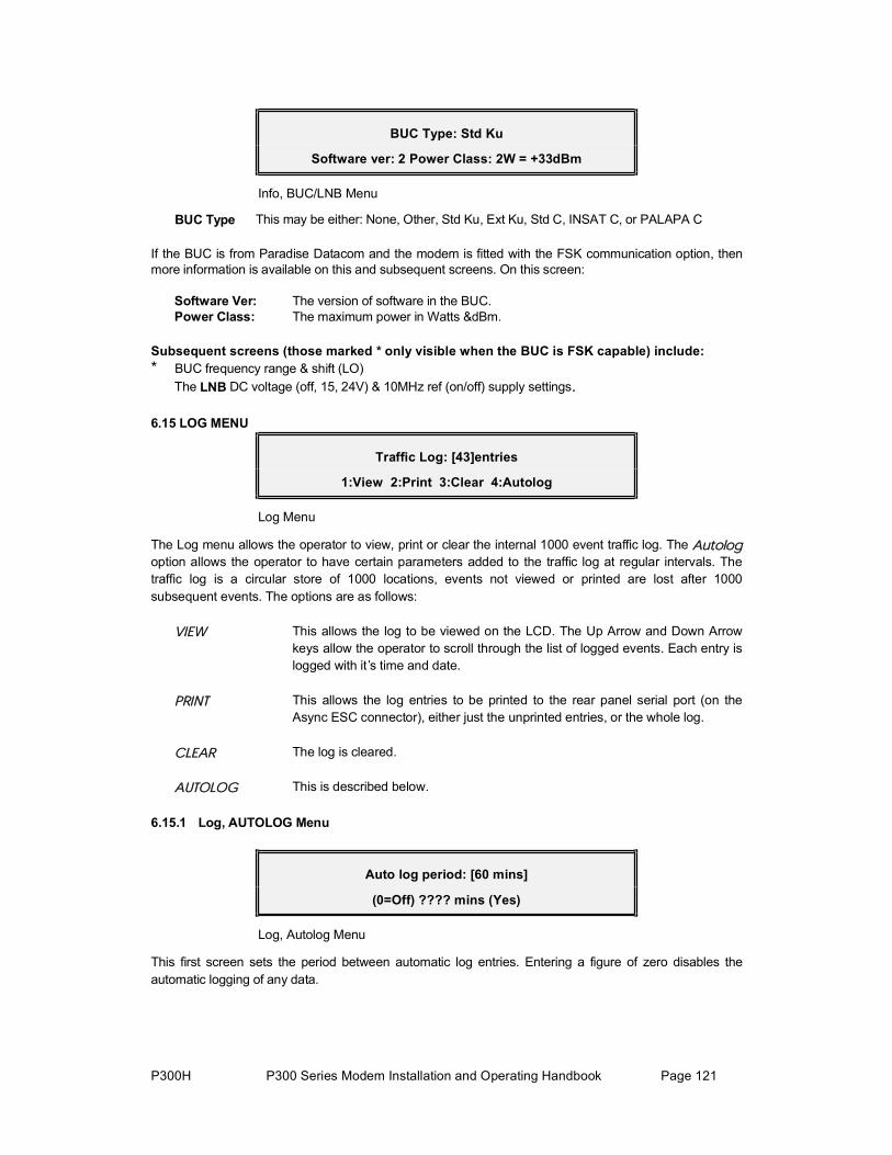
P300H P300 Series Modem Installation and Operating Handbook Page 121
BUC Type: Std Ku
Software ver: 2 Power Class: 2W = +33dBm
Info, BUC/LNB Menu
BUC Type This may be either: None, Other, Std Ku, Ext Ku, Std C, INSAT C, or PALAPA C
If the BUC is from Paradise Datacom and the modem is fitted with the FSK communication option, then more information is available on this and subsequent screens. On this screen:
Software Ver: The version of software in the BUC. Power Class: The maximum power in Watts &dBm.
Subsequent screens (those marked * only visible when the BUC is FSK capable) include: * BUC frequency range & shift (LO) The LNB DC voltage (off, 15, 24V) & 10MHz ref (on/off) supply settings.
6.15 LOG MENU
Traffic Log: [43]entries
1:View 2:Print 3:Clear 4:Autolog
Log Menu
The Log menu allows the operator to view, print or clear the internal 1000 event traffic log. The ß«¬±´±¹option allows the operator to have certain parameters added to the traffic log at regular intervals. Thetraffic log is a circular store of 1000 locations, events not viewed or printed are lost after 1000 subsequent events. The options are as follows:
Ê×ÛÉ This allows the log to be viewed on the LCD. The Up Arrow and Down Arrow keys allow the operator to scroll through the list of logged events. Each entry is logged with it s time and date.
ÐÎ×ÒÌ This allows the log entries to be printed to the rear panel serial port (on the Async ESC connector), either just the unprinted entries, or the whole log.
ÝÔÛßÎ The log is cleared.
ßËÌÑÔÑÙ This is described below.
6.15.1 Log, AUTOLOG Menu
Auto log period: [60 mins]
(0=Off) ???? mins (Yes)
Log, Autolog Menu
This first screen sets the period between automatic log entries. Entering a figure of zero disables the automatic logging of any data.

P300H P300 Series Modem Installation and Operating Handbook Page 122
When YES is pressed with a non-zero value for the Autolog period, the following screen is accessed:
Autolog(Y/N): 1 Buffer % (Y) 2 Eb/No (Y) 3 Rx User BER (N) More
Log Autolog, Measurements Menu (1)
This screen allows the operator to toggle each of the first three loggable events on and off. (N) indicates No, the data will not be logged, (Y) indicates Yes the data will be logged. Pressing the key corresponding to each data type toggles between (Y) and (N). More options are available on subsequent screens:
Autolog (Y/N): 1:BERT BER (N) Back 2:Tx Terr BER (N) 3:Rx Terr BER (N) More
Log Autolog, Measurements Menu (2)
Finally, if AUPC is active (see AUPC in section 8.11 on page 156), another subsequent screen is offered:
Autolog (Y/N): 1:AUPC Delta Power (Y) 2:Distant end Eb/No (N) Back
Log Autolog, Measurements Menu (3:AUPC)

P300H P300 Series Modem Installation and Operating Handbook Page 123
Each option is as follows:
ÞËÚÚÛÎ û The buffer fill state is logged every period this allows fill trends to be monitored
Û¾ñÒ± The average AND worst case Eb/No for the period are logged at the end of the period.
ËÍÛÎ ÞÛÎ The average AND worst case estimated USER BER are logged at the end of the period.
ÞÛÎÌ ÞÛÎ The BER as measured by the internal BER Tester (BERT). This can be measured either in the main data channel or when running in parallel with the main data in either the ESC or the Aux channels. The average AND 1 second worst case BER measured by the BERT are logged at the end of the period.
ÌÈ ÌÛÎÎ ÞÛÎ This is the BER measured at the terrestrial input. This is only available if the terrestrial signal can be monitored for BER (ie it's framed and/or has a CRC). The actual method of measuring it is determined by ݸ¿²¹»ô Ë»®óÑ°¬ô
Ñ°»®¿¬·±²ô Ì»®®»¬®·¿´ô ̨ñÜ®±° ÞÛÎ.
ÎÈ ÌÛÎÎ ÞÛÎ As above. This is only meaningful (ie different to the Tx/Drop BER above) if the modem is used with separate Drop/Insert bearers by the use of a twin G.703 terrestrial interface. The method of BER measurement can be selected by ݸ¿²¹»ô Ë»®óÑ°¬ô Ñ°»®¿¬·±²ô Ì»®®»¬®·¿´ô Ψñײ»®¬ ÞÛÎ.
ßËÐÝ
ÜÛÔÌß ÐÑÉÛÎ This logs the power variation (delta power) the AUPC has used to maintain the target Eb/No. See AUPC in section 8.11 on page 156 for further details. This is useful in case the satellite operator requires you to determine the Tx power that was active at any time whilst AUPC was active.
Ü×ÍÌßÒÌ ÛÒÜ
ÛÞñÒÑ This is the distant end Eb/No, available when AUPC is active (again see AUPC in section 8.11 on page 156 for further details). As with the local Eb/No the average AND worst case Eb/No for the period are logged at the end of the period.
The automatic logging of local/distant Eb/No and various BER's, coupled with a `centralised log accumulation` by an M&C package (eg Alphawave `CAM`) provides a very convenient way to be able to monitor the performance of any link (and have recorded data verifying the performance should anyone query if there was a `fade`).
Please note that each data type logged uses up one log entry every Autolog period (ie the log capacity can be consumed quickly with multiple events logged at very regular intervals).

P300H P300 Series Modem Installation and Operating Handbook Page 124
6.16 TEST MENUThe test menu is as shown below, and leads on to the menu s described in the following few paragraphs. When either a loopback or test mode are active, the TEST LED on the front of theequipment illuminates.
Test: 1:Loopbacks [Off] 2:RF & FEC [Off]
3: PSU/Temp 4:Int BERT [ESC]
Test Menu Each of these options is now discussed in turn:
6.16.1 Test, LOOPBACKS Menu
Loop (now Intfc): 1 Off, 2 Interface (L+R),
3 FEC (L), 4 I.F. (L) ( More)
Test, Loopbacks Menu
This screen shows the most common loopbacks, but by pressing the down arrow further options are provided. The loopback options are:
ÑÚÚ Normal operation is selected.
×ÒÌÛÎÚßÝÛ øÔõÎ÷ An interface loop (Local and Remote) is selected, providing both a terrestrialloop and a loop to the data from the remote end of the satellite link. The exact implementation of the loop is interface dependent. On G.703 cards it is a`copper loop`, on other cards the loopback is provided by a multiplexer at TTLlevels. If an ×ÒÌÛÎÚßÝÛ ÔÑÑÐ doesn t make the sync light on the firebird come on, your looking in the wrong place, its not the modem, try the cables!
For the remote loopback to function when this loopback is selected the clockingmust be configured in a mode where it would work if the loop were made in the cables. Rx clocking must be set to something other than ̨ Ý´±½µ (switch to Satellite if this is the normal setting) and the Tx clocking must the set to ̨
Ý´±½µ ײ.
ÚÛÝ øÔ÷ The data is looped back after the FEC just before it enters the modulator providing a local loop only. The Tx data continues to be transmitted, and the Rx data from the satellite is ignored. ESC & Aux channel data (which is present in the data stream at the FEC) is also looped.
×òÚò øÔ÷ The Tx IF signal is looped back within the modem a IF. Tx data is transmitted as normal, and the Rx RF signal is ignored. The Rx IF Frequency is automatically adjusted to match the Tx IF Frequency (so the loop will function). ESC & Aux channel data (which is present in the data stream at the IF port) is also looped. When the loopback is switched off the RX IF Frequency is restored.
NOTE: The Tx IF Level needs to be set to above -10dBm for the loopback tofunction reliably. Do NOT change the Tx IF Level for a loopback if the modem is still on satellite!
Cont d....
P300H P300 Series Modem Installation and Operating Handbook Page 125
Options displayed on the second screen include all of the above, plus:
Üñ× øÔ÷ The data is looped back after the Drop mux, through the Doppler buffer, back into the Insert mux providing a local loop only. The Tx data continues to be transmitted and the Rx data from the satellite is ignored. If Drop/Insert baseband processing is not active, this loops the data at the output of the baseband block (ie it works even if Drop/Insert is not active). ESC & Aux channel data is NOT looped.
ÚÎÓ øÔ÷ The data is looped after the Framer back into the Deframer providing a local loop only. The Tx data continues to be transmitted and the Rx data from the satellite is ignored. ESC & Aux channel data (which is present in the data stream at the Framer output) is also looped
ÎÍ øÔ÷ The data is looped after the Reed-Solomon Encoder / interleaver back into the RS Deinterleaver / decoder providing a local loop only. The Tx data continues to be transmitted and the Rx data from the satellite is ignored. ESC & Aux channel data (which is present in the data stream at the RS codec) is also looped
From the terrestrial port towards the IF ports the loopbacks in the following order test more and more circuitry: Interface, Drop/Insert, Framer, Reed-Solomon, FEC, IF.
ÎÛÓÑÌÛ øÎ÷ This provides a loop of the Rx data after the deframer back into the framer. Tx input data is ignored, Rx traffic continues as normal. Incoming ESC & Aux channel data is not looped back to the remote site.

P300H P300 Series Modem Installation and Operating Handbook Page 126
6.16.2 Test, RF & FEC Menu
Test modes: [Off] 1=Off 2:Tx CW
3:Tx Alt 1,0 4=RS corrections disable
Test, RF & FEC Menu
The test modes available are:
ÑÚÚ All test modes are cancelled.
ÌÈ ÝÉ Selecting TX CW causes a pure carrier to be transmitted. This is useful for evaluating phase noise and spurious, but should not be used over a livesatellite link.
ÌÈ ßÔÌ ïôð Selecting TX alt 1,0 causes an alternating 1,0,1,0.... pattern to be fed to themodulator at the symbol rate. This produces two discrete frequencies to be generated, spaced at ± symbol rate about the (suppressed) carrier. This is useful for evaluating the carrier suppression of the modulator but should not be used over a live satellite link.
ÎÍ ÝÑÎÎÛÝÌ×ÑÒÍ
Ü×ÍßÞÔÛ This option allows the corrections being made by the RS decoder to be inhibited, without the removal of the RS overhead. This allows the true effect of the Reed-Solomon codec to be seen without data rate changes (which wouldaffect Eb/No and therefore the error rate).
6.16.3 Test, PSU S + TEMP Menu
PSU: +5V +15V -15V -5V Temp
Status: 97% 98% 102% 98% 46C
Test, PSU s + Temp Menu
Power supply monitoring is only available if the Monitor/AGC option is fitted. If it is not the screen abovedisplays only the temperature. When selected this displays all of the internal power supply lines &internal temperature as monitored by the processor with each PSU line is displayed as percentage of the nominal value. The temperature is monitored continuously and a Unit Warning /deferred alarm will be activated if ever the internal temperature reaches within 3 degrees Centigrade of the operating limits of 0C and 60C. Should the internal temperature exceed the limits of 0C and 60C, then a Unit Fault / Prompt Alarm is activated. The Tx carrier is muted outside the operating temperature range.

P300H P300 Series Modem Installation and Operating Handbook Page 127
6.16.4 Test, INT' BERT Menu (Software>V2.34)
Internal BERT: 1=Off 2:Channel [ESC]
3:Pattern[2^15-1] 4:Mode[Manual] 5:Results
Test, Internal BERT Menu
The internal Bit Error Rate Tester (BERT) is only available if the `PRBS Tester` feature is available (standard on P300-IDR and above). It is a powerful feature capable of monitoring and Auto-Logging the BER of the receive satellite path, even while the main data channel of the link is carrying normal traffic. Itallows a test pattern to be sent and received in either this main data channel, or in parallel with the main data channel in the ESC or Aux channels carried within all satellite overheads.
The BER tests can either be selected to be manually controlled (using Stop/Start/Reset, running for up to 27 hours), or to run continuously using a 1 minute sliding window. When Auto-Logging of the BER Tester results is enabled, the tester executes a test for the user set BER Auto-Log period (1-9999 minutes), and records both the average and 1 second worst case BER's in the traffic log of the modem at the end of the period. It then automatically re-starts a new test for the following period.
It may operate independently, or in conjunction with external BER equipment as the test patterns it usesare intentionally Firebird compatible. For example at one end of a link the internal BERT may be used toinject the PRBS and measure the Rx BER, while at the other end a Firebird is connected to the Main data port, or the ESC/Aux ports on the IDR Option (if fitted).
Each of the menu options is described in turn, with most other options appearing in a subsection below along with a description of the submenu they display:
ÑÚÚ This disables the internal BER Tester, removing it from the channel in use, ie the Main, ESC, or Aux channel, restoring normal operation.

P300H P300 Series Modem Installation and Operating Handbook Page 128
6.16.5 Test, Int' BERT, OFF/CHANNEL Menu
Channel for BER Test: [ESC]
1:Main data 2=ESC 3=Aux
Test, Internal BERT, Channel Menu
The test may run through the Main, ESC or Aux channels.
Óß×Ò This first generates an `are you sure` screen before substituting the PRBS in place of the Tx main traffic channel and monitoring for errors on the Rx Maintraffic channel. Note that for Closed Network mode only (ie no overhead at all)the BER Tester cannot currently inject a test pattern into the main traffic
channel(a warning is issued on the screen). It can however receive and monitor a testpattern injected by equipment at the distant end of the link. On a link where it isnecessary to use the BER Tester, switch to Closed Net Plus ESC mode, and ifnot using the ESC set it for the lowest possible Baud rate which will result in anoverhead of <0.5%.
ÛÍÝ ñ ßËÈ ÛÍÝ & ß«¨ are defined below for the different service types. If either ESC or Aux are selected but the channel has not been defined, then the user is prompted to define the channel (and must then re-select the channel from thisscreen).
Closed Network ESC & Aux channels are not available in Closed Network mode (as there is no overhead in which to carry them).
Closed Net Plus ESC Closed Net Plus ESC mode is only available if the Async ESC feature isavailable (standard on P300-IBS and above). The ESC channel Baud rate is used to determine the overhead added to the main data, allowing theminimum possible overhead to be added (ie the minimum bandwidth to beused), to provide the Async ESC Baud rate required. When the ESC channel is used for BER testing the Async ESC is disabled and whateverbandwidth was assigned to the Async ESC channel is used synchronously for BER testing. The data rate to the satellite (main data + overhead)remains unchanged.
There is no Aux channel facility in Closed Net Plus ESC, as this mode is specifically designed to minimise the satellite bandwidth used, and hence all overhead is assigned to the ESC channel.
IBS/SMS IBS/SMS mode is only available if the IBS/SMS feature is available (standard on P300-IBS and above). The ESC channel is the channel, which is normally used to carry asynchronous data from earth station to earth station (typically used for distant end M&C). When selected as the BER test channel Async ESC data is not passed and the channel is usedsynchronously for BER testing. It is only possible to define an ESC channelin IBS/SMS mode for the BER test to run through if the Async ESC feature is available (standard on P300-IBS and above). The ESC channel may be configured to provide rates up to 4.6% of the main data rate for BERtesting.

P300H P300 Series Modem Installation and Operating Handbook Page 129
The Aux channel may be configured to provide the mandatory INTELSAT oversampled low rate ESC (yes `ESC` but on the Aux port of the modem). When used by the BER Tester it is used synchronously and provides a test channel of 0.2% the main data channel rate. If the IDR Option is fitted (standard on P300-IDR and above) which provide a synchronous external Aux port, then the Aux channel may be set for §²½ ½¸¿²²»´ and to use all the available overhead not already in use by the ESC channel. This can provide a channel of up to 4.4% of the main data rate.
If the `Custom Features` feature is available (standard on P300-TCM), then the overhead may be user assigned between the ESC & Aux channels, allowing the desired Async ESC rate to be achieved for distant end M&C (but not massively exceeded), leaving any spare overhead to maximise the Aux channel data rate for BER testing.
IDR IDR mode is only available if the IDR Option is fitted (standard on P300-IDR and above). The ESC channel is the 8kbps synchronous ESC channel standard on IDR Services (which may also be used for Asynchronous ESC data if the Async ESC feature is available).
The Aux channel may be selected to be either 32kbps (in place of one 32kbps ADPCM audio ESC channel) or 64kbps (in place of both audio ESC's). This provides a very useful channel rate for BER testing !
Custom Framing Custom Framing mode is only available if the `Custom Features` feature is available (standard on P300-TCM). Custom framing is based on either IBS or IDR formats and custom framing provides the following advantages:
Based on IBS: A variable overhead may be added allowing both ESC & Aux channels to be scaled to virtually any rate. This is achieved by setting the ESC channel to the required Async ESC Baud rate, and changing the split of the allocation of the overhead between ESC & Aux channels. The total overhead then scales to provide the required ESC Baud rate in whatever part of the overhead you have assigned to it, with the rest of the scaled overhead for the Aux channel.
Based on IDR: As well as the features described above in standard IDR, it is possible to reduce the normal 96kbps overhead (two audio ESC's) to 64kbps (one audio ESC or 32kbps Aux data) or 32kbps (no audio ESC's & no Aux data). It may also be configured to use 16kbps ADPCM instead of 32kbps, allowing the full IDR features (two audio ESC) to be accommodated in 64kbps overhead. More interestingly using the normal IDR overhead of 96kbps together with 16kbps ADPCM for the audio ESC's, it may provide all the normal IDR features, but with the second 32kbps audio slot free to configure as a 32kbps Aux channel for continuous BER testing.

P300H P300 Series Modem Installation and Operating Handbook Page 130
6.16.6 Test, Int' BERT, PATTERN Menu
BERT Pattern: [2^15-1]
1:2^11-1(2047) 2:2^15-1 3:2^20-1
Test, Internal BERT, Pattern Menu
The test pattern may be selected to be one of three standard patterns as îïïóï(îðìé÷, îïëóï, or îîðóï.
6.16.7 Test, Int' BERT, MODE Menu
BER Test mode [1 Min]
1=One minute sliding window 2=Manual
Test, Internal BERT, Mode Menu
The test mode may be one of the following:
ßËÌÑÔÑÙ The BERT mode is fixed in ß«¬±´±¹ because the unit is configured to Autolog the results of the BER test at the user defined Autolog period. In Autolog modethe screen above is not shown, but rather a warning “Cannot select 1 Min/Manual mode while AUTOLOG of PRBS results is active (YES)” is displayed. To be able to manually select the BERT mode auto-logging of theBER result must be disabled by either setting the Autolog period to zero (Main, Log, Autolog) or by clearing the flag requesting it to log the BERT results on the subsequent Autolog screen.
ÑÒÛ Ó×ÒËÌÛ One Minute sliding window mode displays the average BER over the last 1 minute. It does this by storing the error results second by second in a circular table 60 entries long and recalculating the average BER each second. For any seconds where the BERT is `out of sync` a zero entry is made in the table. The average BER over the one minute period is calculated based on only the non-zero entries (when sync is recovered).
ÓßÒËßÔ Manual mode allows the operator to manually start, stop & restart tests whichmay run for up to 27 hours (99,999 seconds), at which point the results arefrozen.

P300H P300 Series Modem Installation and Operating Handbook Page 131
6.16.8 Test, Int' BERT, RESULTS Menu
BERT:Sync OK Loss#:0 Rate:32000bps
Errors:328 Time:1.0min BER:1.7E-04
Test, Internal BERT, Results Menu
Note in this screen the following keys are active:
Ю» ï Inject single error (buffered for up to 10 rapid key presses) Ю» î Start a test / Restart the current test (manual mode only) Ю» í Stop the current test (manual mode only)
The fields on this screen are as follows:
BERT: “Sync OK” The test is running and the tester is `in sync` “NO SYNC” The test is running but the tester is `out of sync`
“Reset” No test has been run since the unit was (re)configured “Stopped” The test has been manually stopped (results are frozen)
Loss#: A count to 99 sync losses and recoveries. When the display reaches “>99" the test is automatically stopped. The sync loss threshold is fixed at >25% errors over 1024 bits (equivalent to the Firebirds `Normal` threshold)
Rate: The test data rate. This accurately displays the rate at which the test is running whether it is in the Main, ESC or Aux channels.
Errors: The cumulative count of errors during the test. If the count reaches 999,999 then the test will stop and the results will be frozen. See Note 1 below.
Time: The cumulative test time, displayed as seconds to 1 minute, then decimalminutes to 1 hour, then decimal hours to a maximum of 27.7 hours.
BER: The calculated BER over the entire duration of the test (ie average over test period). It is displayed as follows:
When there are more than 100 errors the exact BER is displayed.
When there are less than 100 errors a symbol prefixes the BER display (approximately equal to, as the result is statistically poor).
When there have been NO errors the modem does not know if the BER is perfect, or simply if the test has not been running long enough to receive an error. In such a case it prefixes the display with a < symbol, and displays the BER that it would calculate if ONE error had been received.This means that as the test progresses without errors the displayed BERimproves, but never assumes it is zero (as a Firebird does).
Note 1:The BER displayed by the Internal BERT is 100% accurate. However if you use the Internal BERT and in parallel monitor the same
received PRBS with an external Firebird, there will be a <0.1% discrepancy in the error count, but NOT the BER. For the puristsamongst you, and so you do not question the accuracy of the Internal BERT, the briefest useful explanation possible is as follows:

P300H P300 Series Modem Installation and Operating Handbook Page 132
When the processor reads the BER counters once per second (errors, number of bits etc), it has to freeze the counts in order toread the results accurately (in case the counters increment whilst being read). This reading of the counters takes less than 0.1% of the time, but does mean that the BERT is `blind` for a small proportion of the time and some individual errors may not be counted.
However the BER is 100% accurate because as well as counting Errors, the BERT also counts PRBS bits received, and calculates the BER as <Errors> / <Count of bits received> (ie both are in proportion). This would not be the case if we did not count the bits
received, and simply assumed that the error rate was <Errors> / (<Time> x <Rate>).
This may not sit comfortably on first reading, but you are probably happy with the concept that a PRBS multiplexed in with the main
data channel at say 5% of the main data rate will provide the same BER reading as for the main data channel itself. You wouldprobably agree that the result would be no different if the PRBS content was dropped to say 4% of the main data channel, implyingthat reducing the bits available to measure the BER by 20% will have no effect on the validity of the BER reading. The argument for
the Internal BERT is no different, >99.9% of the bits available for BER measurement are used, with the other <0.1% lost as theprocessor reads the hardware registers.
6.17 SETUP MENUSee Setup - Initial Configuration Menu on page 56
6.18 ACTION MENU
Action: 1=Buffer Centre 2=Slip counter reset 3=1:1 Give away control
Action Menu
The options on this menu are fairly self explanatory, however for completeness:
ÞËÚÚÛÎ
ÝÛÒÌÎÛ Forces the Rx buffer to re-centre, and will cause a burst of errors. This isautomatically performed when the Rx traffic goes from fail to OK if the option under ÝØßÒÙÛô ËÍÛÎóÑÐÌô ÑÐÛÎßÌ×ÑÒô ßÝÌ×ÑÒÍô ÞËÚÚÛÎ ßËÌÑ ÝÛÒÌÎÛis enabled.
ÍÔ×Ð ÝÑËÒÌ
ÎÛÍÛÌ This resets the counts of underflows and overflows on the ͬ¿¬« status screens
ïæï Ù×ÊÛ ßÉßÇ When two Modem's are configured as a 1:1 pair, this can be selected on theon-line unit, to handover control to the off-line unit.
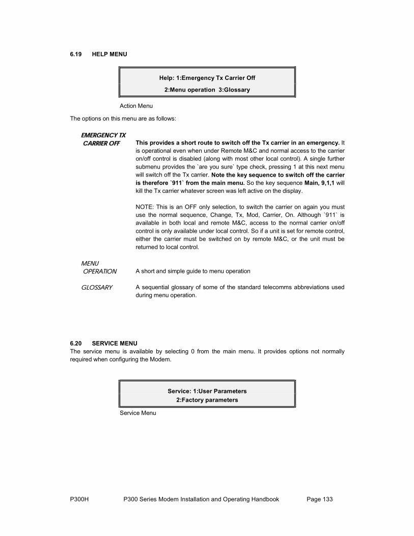
P300H P300 Series Modem Installation and Operating Handbook Page 133
6.19 HELP MENU
Help: 1:Emergency Tx Carrier Off
2:Menu operation 3:Glossary
Action Menu
The options on this menu are as follows:
ÛÓÛÎÙÛÒÝÇ ÌÈ
ÝßÎÎ×ÛÎ ÑÚÚ This provides a short route to switch off the Tx carrier in an emergency. It is operational even when under Remote M&C and normal access to the carrieron/off control is disabled (along with most other local control). A single further submenu provides the `are you sure` type check, pressing 1 at this next menu will switch off the Tx carrier. Note the key sequence to switch off the carrier is therefore `911` from the main menu. So the key sequence Main, 9,1,1 will kill the Tx carrier whatever screen was left active on the display.
NOTE: This is an OFF only selection, to switch the carrier on again you must use the normal sequence, Change, Tx, Mod, Carrier, On. Although `911` is available in both local and remote M&C, access to the normal carrier on/off control is only available under local control. So if a unit is set for remote control, either the carrier must be switched on by remote M&C, or the unit must bereturned to local control.
ÓÛÒË
ÑÐÛÎßÌ×ÑÒ A short and simple guide to menu operation
ÙÔÑÍÍßÎÇ A sequential glossary of some of the standard telecomms abbreviations usedduring menu operation.
6.20 SERVICE MENUThe service menu is available by selecting 0 from the main menu. It provides options not normally required when configuring the Modem.
Service: 1:User Parameters 2:Factory parameters
Service Menu

P300H P300 Series Modem Installation and Operating Handbook Page 134
6.20.1 Service, USER PARAMETERS Menu
User: 1:Lock Kbd 2:Clr Cfg
3:Clr All+Reset 4:Fan [Auto]
Service, User Parameters Menu
The options are:
ÔÑÝÕ ÕÞÜ This locks the keyboard after displaying a screen showing the unlock code. As with all Paradise equipment the unlock code is simply the product number (eg 300). The unlock code is displayed before the keyboard is locked on the Modem, as we had quite a few calls to the technical support line which start off “I ve just selected Lock Keyboard from the menu and ...... ”
ÝÔÎ ÝÑÒÚ×Ù This clears the current configuration down to its default blank state.
ÝÔÎ ßÔÔõÎÛÍÛÌ This clears the entire non volatile memory, including current configuration, all configuration memories, and the traffic log, then resets the processor.
ÚßÒ Normally the fan is temperature controlled, switching on at 26C and off at 24C.The internal temperature can be monitored on the ÌÛÍÌô ÐÍË õ ÌÛÓÐ menu. A Unit Warning /deferred alarm will be activated if ever the internal temperature reaches within 3 degrees Centigrade of the operating limits of 0C and 60C.Should the internal temperature exceed the limits of 0C and 60C, then a Unit Fault / Prompt Alarm is activated. The Tx carrier is muted outside theoperating temperature range.
6.20.2 Service, FACTORY PARAMETERS Menu
Factory: 1:Serial# [01564] 2:Debug [0]
3:RemCont [Giveaway-120s] 4:Watchdog
Service, Factory Parameters Menu
The options are:
ÍÛÎ×ßÔ ý This menu allows the serial number to be both viewed and edited.
ÜÛÞËÙ Used for Paradise internal procedures only. Setting Debug to a value other than 0 is very likely to slow down the operation of the unit.
ÎÛÓ ÓúÝ This option is used to set the timeout required before local control can be taken if the unit is in remote mode. This is covered extensively in section Change,Rem-M&C Menu on page 102
ÉßÌÝØÜÑÙ This provides an option to test the watchdog timer. The watchdog timer is atimer, which is regularly reset by the processor. Should it ever reach its settime, then the processor has failed to reset it, and probably crashed. Testingthe Watchdog timer therefore will cause the unit to reset, and corrupt both Tx and Rx traffic for a few seconds.

P300H P300 Series Modem Installation and Operating Handbook Page 135
7 MENU SCREENS FOR SPECIALIST OPTIONS
The following sets of menu definitions are shown in this separate section in order not to complicate the earlier section dealing with basic menu operation.
7.1 CUSTOM FRAMING MENUSThese features are only available if the `Custom Features` feature is available together with the corresponding IBS or IDR options (standard on P300-TCM). Refer also to the section Closed NetworkPlus ESC via the Custom Service menu in section 8.7.2 on page 150.
7.1.1 Change, Tx/Rx, Service, CUSTOM MenuIf Ý«¬±³ is select from the Change, Tx/Rx, Service menu, this leads to the following dialogue:
Custom framing based on: [?] 1=IBS 2=IDR
Change, Tx/Rx, Service, Custom Menu
×ÞÍ This leads to variants on standard IBS framing (all explained later) which allow for operation:
Without a TS32 multiframe Without a backward alarm With four backward alarms for Multidestinational IBS
Minimum overhead mode, where the overhead scales to provide any ESC requirement at any data rate.
×ÜÎ This leads to variants on standard IDR framing (again explained later) which allow for operation:
With overheads of 96, 64, or only 32 kbps. With 16kbps ADPCM on the audio channels instead of 32kbps, allowing either all normal IDR features in a 64 kbps overhead, or (again utilising 16kbps ADPCM) 96 kbps overhead with all normal IDR features, but including a 32kbps spare channel for continuousBER traffic quality monitoring.
The discussion of IDR this continues after the IBS section in para 7.1.3 onpage 137.
7.1.2 Change, Tx/Rx, Service, Custom, IBS MenuIf ×ÞÍ is select from the menu above this leads to the following question:
Multiframe: [?] 1=Normal 2=Without a TS 32 Multiframe
Change, Tx/Rx, Service, Custom, IBS, Multiframe Menu
ÒÑÎÓßÔ A TS32 Multiframe is used as normal.
ÒÑ ÌÍíî ÓÚ No TS32 Multiframe is sent (Tx) or acquired (Rx). This is primarily for operation at low rates where the TS32 multiframe becomes long enough to affectacquisition time. For example at 32kbps the multiframe lasts 1 second, andhence TS32 MF acquisition may take 1 second on top of demod lock time. Thisselection also frees up one additional bit of the overhead (TS32 bit 4) to carry ESC information.

P300H P300 Series Modem Installation and Operating Handbook Page 136
The disadvantage of operating without a TS32 Multiframe is that thesynchronous IBS scrambler cannot be used, and the `Normal` scrambler option selects INTELSAT V.35. This results in an increase in the error rate, as the V.35 scrambler multiplies any errors on the channel by a factor of three.
Both options lead on to the following question:
Backward Alarm:[?]
1=Normal 2=No Backward Alarm facility
Change, Tx/Rx, Service, Custom, IBS, Backward Alarm Menu
ÒÑÎÓßÔ A Backward Alarm is sent (Tx) or detected (Rx) as normal
ÒÑ ÞßÝÕù ßÔÓ No Backward Alarm is sent (Tx) or received (Rx). This is a very useful facility to have to lose, but for maximum ESC operation this selection does free up onefurther bit of the overhead (TS32 bit 3) to carry ESC information.
If both the TS32 Multiframe and Backward Alarm options have been selected as Ò±®³¿´, then the following screen is displayed. If either the Backward Alarm facility or the TS32 Multiframe has been disabled, then this menu is skipped.
IBS Backward Alarm: [?]
1=Normal (single) 2=Four independent alarms
Change, Tx/Rx, Service, Custom, IBS, Back' Alm mode Menu
ÒÑÎÓßÔ A single backward alarm operates as normal
ÚÑËÎ ßÔßÎÓÍ The modem transmits or receives four independent backward alarms, using the form `c` outputs and backward alarm inputs normally used for IDR operation.This allows a single IBS Tx carrier feeding multiple Rx sites (each site receiving part of the data in the Tx carrier), to individually indicate to each site a failure of the return carriers from those sites. The sequence in which these four alarms are carried in the IBS overhead may be changed under ݸ¿²¹»ô Ë»®óÑ°¬ô
Ñ°»®¿¬·±²ô Í¿¬»´´·¬»ô Þ¿½µ ß´³ Ó¿°ò
Finally, all paths through these menus arrive at the following question:
Overhead Mode: [?]
1=Normal 2=Min o/h to provide set ESC
Change, Tx/Rx, Service, Custom, IBS, Overhead Mode Menu
This final option is the most powerful of the features in Custom IBS.
ÒÑÎÓßÔ The standard 16/15 (6.7%) IBS/SMS overhead is used. The ESC rate available is a fixed proportion of the main data rate (but may be manipulated within limits

P300H P300 Series Modem Installation and Operating Handbook Page 137
by allocating more or less of the overhead to the ESC). When the ESC Baud rate is set too high, a warning will be displayed if the overhead cannot provide the requested ESC rate.
Ó×Ò ÑñØ The overhead varies to provide the ESC Baud rate set on the ESC menus. The following two examples explain typical scenarios:
At 2048 kbps with a 9600 Baud ESC channel the overhead can reduce to less than 1% whilst still maintaining the IBS/SMS benefits (namely a factor of three error rate improvement due to using the IBS/SMS scramblerinstead of the V.35 scrambler, the ESC channel and the backward alarm facility).The operator can set the ESC channel Baud rate to 9600 Baud even at lowdata rates. For example at 64kbps the high rate ESC would normally provide a 2400 Baud channel, but if 9600 Baud is set in Minimum overheadmode, the overhead will scale to provide it. The practical ESC rate limit is 70% of the data rate, ie you can have a 9600 Baud ESC channel down to a data rate of 11kbps !
The final satellite data rate including overhead can be displayed on the ×ÒÚÑ,Ê×ÛÉ ÝÑÒÚ×Ù, ÌÈñÎÈ screens.
NOTE: This is obvious, but it is stated here as a reminder. As the exact overhead format is calculated based on your ESC requirement, for two Modems to calculate the same overhead usage and therefore interwork, the following parameters must be the same at both ends of the link:
Main Data Rate. ESC async character format (bits / parity) & Baud rate. Proportion of overhead assigned to ESC. Baseband mode (ie continuous or Drop/Insert)
7.1.3 Change, Tx/Rx, Service, Custom, IDR MenuIf ×ÜÎ is select from the menu Tx/Rx, Service, Custom screen this leads to the following question:
Framing based on: [?]
1=Low rate format (T1/E1) 2=High rate format (T2/E2)
Change, Tx/Rx, Service, Custom, IDR, Format MenuThe frame format definition for IDR operation varies with the data rate. For rates of 1544 or 2048 kbps (T1/E1) one format is defined, and for rates of 6312 and 8448kbps (T2/E2) another is defined (there is even a third definition for rates > 10Mbps). In ÝËÍÌÑÓô ×ÜÎ mode, you have a free choice of formatwhatever the data rate and note that IDR operation is not limited to T1/E1 rates, but can be used at any data rate, (even down to 64kbps, although INTELSAT define that IBS framing should be used on IDR carriers below 1544kbps).
ÔÑÉ The 12 bit overhead defined for T1/E1 operation in IESS 308 is used.
Ø×ÙØ The 4 bit overhead on each of three subframes defined for T2/E2 operation is used.
Whichever format is selected, the following prompt appears:

P300H P300 Series Modem Installation and Operating Handbook Page 138
IDR o/h: [?] 1=Normal:96k 2=1xAudio:64k
3=No Audio:32k 4=16k ADPCM modes
Change, Tx/Rx, Service, Custom, IDR, Overhead Menu
If ïêµ ßÜÐÝÓ ÓÑÜÛÍ are selected the following further prompt appears
IDR o/h: [?] 1=96k:2x16k-Audio+32k-BER
2=64k:2x16k-Audio only
Change, Tx/Rx, Service, Custom, IDR, O/H 16k Menu
The modes selected by these two menu's are as follows:
ÒÑÎÓßÔæçêÕ The normal IDR overhead is used
ïÈßËÜ×ÑæêìÕ The overhead is reduced to 64kbps, the 32kbps defined for Audio ESC channel 2 is not transmitted. The 32kbps for [FAS + Back Alarms + 8K sync ESC channel], and Audio ESC channel 1 are still transmitted.
ÒÑ ßËÜ×ÑæíîÕ The overhead is reduced to 32kbps, both 32kbps channels defined for ESC audio are not transmitted. The 32kbps for [FAS + Back Alarms + 8K sync ESC channel] alone is transmitted.
16k Modes çêÕ Both Audio ESC channels operate in 16kbps ADPCM mode allowing both
audio ESC's to fit into 32kbps. The 32kbps for [FAS + Back Alarms + 8K syncESC channel] is transmitted first, followed by 32kbps defined for Audio ESC 1, now containing both Audio ESCs 1 & 2 using 16kbps ADPCM. These are followed by the 32kbps for Audio ESC channel 2, which is unused and may be defined for use by the Aux port providing either a spare 32kbps for external BER testing, or for the use of the internal BER Tester (in both cases for possible traffic quality monitoring).
êìÕ Both Audio ESC channels operate in 16kbps ADPCM mode allowing both Audio ESC's to fit into the 32kbps allocated to audio ESC channel 1. The overhead is 64kbps comprising 32kbps for [FAS + Back Alarms + 8K sync ESC channel] plus 32kbps containing the two 16kbps ADPCM audio channels. The final 32kbps defined for Audio ESC channel 2 is not transmitted.

P300H P300 Series Modem Installation and Operating Handbook Page 139
7.2 IBS/SMS OPERATION WITH 2048KBPS CONTINUOUS DATA
7.2.1 Change, Tx/Rx, Baseband, Continuous, 2048k G.732 Menu (IBS)2048kbps IBS/SMS operation is a special case, in which there are two modes of operation. These modes are confusingly referred to as 1920/1984kbps and 2048kbps mode in the IBS/SMS service definitions, but both operate with a 2048kbps terrestrial data rate !
2048K IBS mode: [?]
1=Normal (6.7% overhead) 2=G.732 (0% overhead)
Change, Tx/Rx, Baseband, Continuous, 2048k G.732 Menu
ÒÑÎÓßÔ The content of the 2048kbps data is ignored (ie it can be unframed), and the normal 6.7% overhead is added bringing the rate to 2184.53kbps. This isreferred to as 2048kbps operation in the service definitions. If ÒÑÎÓßÔ isselected then the dialogue returns to that covered in the main section of thehandbook.
Ùòéíî The data is G.732 formatted data, ie it already contains a terrestrial G.732 frame comprising of 32 Timeslots, TS0 to TS31. Although the aggregate data is2048kbps, as only 30 or 31 timeslots are available for data (TS0 is framing and TS16 may be signalling) the user data rate is 1920 or 1984kbps (30 or 31 x64kbps). This is referred to as 1920kbps or 1984kbps operation in the servicedefinitions, but the data rate at the terrestrial port is actually 2048kbps !
When selected instead of the unit inserting extra IBS/SMS framing on to the data (ie +6.7%), it uses the similar G.732 framing already present (+0%). Some locations in the G.732 framing are changed over satellite (such as TS0 Odd bit 4 which is used by the IBS/SMS TS32 multiframe word) and so it is not entirelytransparent to all the overhead. Parts of the overhead unused for framealignment, and also not `borrowed` by IBS/SMS features may be set to be either Ì®¿²°¿®»²¬ or Ú·¨»¼ Ø·¹¸. This is controlled under ݸ¿²¹»ô Ë»®óÑ°¬ô
Ñ°»®¿¬·±²ô Ì»®®ñÍ¿¬ô Ùòéíî Í°¿®».
If Ùòéíî mode is selected the operator is then prompted with:
Channel Assoc Sig (CAS) in TS16: [?]
1=Normal (No CAS) 2=CAS
Change, Tx/Rx, Baseband, Cont', 2048k IBS, G.732 CAS Menu
Channel Associated Signalling (CAS) is described in Appendix F "Signalling Systems Introduction: CCS, CAS & RBS" on page 215 if required.
ÒÑÎÓßÔ TS16 does not contain CAS (ie a terrestrial CAS multiframe and `abcd`øÒÑ ÝßÍ÷ signalling nibbles for each timeslot). It is treated as a normal data timeslot,
and this corresponds to modes defined as 1984kbps in the service definitions.
ÝßÍ This feature is only available if the Extended D/I feature is available (standard on P300-TCM). TS16 contains CAS and by implication a terrestrial multiframe

P300H P300 Series Modem Installation and Operating Handbook Page 140
in order to carry the CAS (this corresponds to modes defined as 1920kbps inthe service definitions). If selected, the terrestrial multiframe will be acquired, and CAS removed from/replaced into the Drop/Insert bearer. The CAS will beconveyed transparently from end to end of the link within IBS (or Custom IBS) overheads.
Whether ÝßÍ or ÒÑ ÝßÍ is selected, the following prompt appears:
Timeslot re-order option: [?]
1=Normal (linear) 2=Re-order
Change, Tx/Rx, Baseband, Cont', 2048k IBS, G.732, TS Menu
The Modem can re-order the timeslot data in the G.732 frame prior to transmission along with the CAS signalling if CAS was selected (although this feature is only available if the Extended D/I feature is available, standard on P300-TCM). This is for services where the equipment at the other end of the link may require subsets of data in particular timeslot groupings. In some applications this feature canremove the need for separate Digital Access Cross Connect (DACCs) equipment used simply to re-arrange timeslots. Typical applications might be with multiple LRE equipments (which may place data inalternate timeslots), or for multidestinational carriers where the receive equipment needs data for each location in contiguous timeslots.
If λ󱮼»® is selected a timeslot edit screen is displayed as follows:
TS order: 0, 17-31, 16, 15-1 Toggle: ??-?? (YES) Help
Change, Tx/Rx, Baseband, Cont', 2048k IBS, G.732, Re-order Menu
This screen allows the operator to change the order of the transmitted timeslots. The screen above shows groups of timeslots 1-15 and 17-31 swopped in location with 1-15 also reversed (15-1) although any combination is possible. The selection system works by toggling timeslots or groups of timeslots into or out of the selection:
Timeslots already in the selection are toggled out from any position of the selection when the timeslot number is entered.
Timeslots not already in the selection are toggled on, and placed on the end of the selection. Enter any single timeslot as a single or dual digit, eg 0, 5, 05, 23, 31 Enter groups of timeslots as two pairs eg 02-5 (two through five), 11-17, 12-2
NOTE Timeslots can be arbitrarily re-ordered, and so group selections may be down as well as up eg 11-17 means send in order 11,12,13...17, whereas 17-11 means send in order 17, 16, 15, ...11
Note that TS0 must remain the first selection in IBS G.732 modes, and for CAS, TS16 must also remain in position.
The Modem hardware is capable of duplication and omission of timeslots, although for simplicity the operator interface (described above) does not allow such selections. If this is a requirement, please contact the factory to discuss your needs.

P300H P300 Series Modem Installation and Operating Handbook Page 141
7.3 CUSTOM IDR OPERATION WITH 2048KBPS CONTINUOUS DATA
7.3.1 Change, Tx/Rx, Baseband, Continuous, 2048k Menu (IDR)If Custom IDR operation based on the Low (T1/E1) IDR format has been selected and the continuous data rate is 2048kbps, then the Modem can offer Timeslot Identity Maintenance and Timeslot Re-ordering features (see the section on "Timeslot Identity Maintenance" in Appendix F on page 212). These features are only available if the Extended D/I feature is available (standard on P300-TCM). Notethat this is only offered under Custom IDR to simplify normal IDR menu operation, but Custom IDR can be selected with all the possible custom features set to `Normal` to allow normal IDR operation, but withTimeslot ID Maintenance & Re-ordering. The following screen is displayed when configuring the Txpath:
2048k IDR mode: [?] 1=Normal
2=Align frame for Rx TS re-order 3=Tx TS re-order
Change, Tx, Baseband, Continuous, 2048k IDR Menu
ÒÑÎÓßÔ Any format within the data is ignored, and data is randomly aligned within theIDR frame (as per normal IDR operation)
ßÔ×ÙÒ ÚÑÎ ÎÈ A terrestrial G.732 frame format is acquired, and is aligned within the IDR frame to allow the receive equipment to re-order the timeslots (if so set). Other than aligning the terrestrial frame within the satellite IDR frame the Tx data isunaffected.
ÌÈ ÌÍ
ÎÛóÑÎÜÛÎ This selection leads onto a screen identical to that for IBS G.732 re-ordering(as described in the last `screen shot` and paragraphs of the previous section) which allows the timeslots to be arbitrarily re-ordered prior to transmission. The final re-ordered G.732 frame is frame aligned within the satellite IDR frame, allowing the receive path also to re-order on reception as well (although if both end re-order, it might get just a tad confusing !).
The corresponding following screen is displayed when configuring the Rx path:
2048k IDR mode: [?] 1=Normal
2=Re-order Rx TS (if Tx TS frame aligned !)
Change, Rx, Baseband, Continuous, 2048k IDR Menu
ÒÑÎÓßÔ The data formatting within the IDR frame is ignored and fed out as a 2048kbpsstream as per normal IDR operation.
ÎÛóÑÎÜÛÎ ÎÈ This option only functions if the corresponding Tx path is set for `ßÔ×ÙÒ ÚÑÎ
ÎÈ`. In this case the Modem relies on the incoming G.732 frame being alignedwithin the satellite IDR frame in order to locate and re-order the G.732timeslots. This selection leads onto a screen identical to that for IBS G.732 re-ordering (as described in the previous section for IBS G.732 operation on page 140) which allows the timeslots to be arbitrarily re-ordered prior feeding to the terrestrial output.

P300H P300 Series Modem Installation and Operating Handbook Page 142
8 APPLICATION NOTES
8.1 DOPPLER & PLESIOCHRONOUS BUFFERING
There are two terms commonly used when referring to the receive buffering, namely Doppler and Plesiochronous.
Doppler: Receive Doppler buffering is required because the incoming data from the satellite is subject to Doppler shift, which occurs in an approximately 24 hour cycle. The Doppler shift is due to the satellite movement relative to the earth and is directly proportional to its station keeping accuracy. Towards the end of a satellites life when its station keeping is degraded to save fuel, the Doppler shift on incoming signals increases and buffers may have to be increased in size. The receive buffer acts as a elastic store or FIFO (First In First Out memory) gradually emptying and filling to absorb the difference over the 24 hour period. If the clock signals within the system all originate from one source, then the buffer will never be exceeded, it will simply slowing filling and emptying over this 24 hour cycle.
Plesiochronous: This refers to buffering needed when there is more than one clock in the system and a buffer is required to absorb the difference between the two clocks. Typically data is placed into the buffer with one clock, and removed with another, thus causing a gradual continuous filling or emptying of the buffer, causing slips on a regular basis. The period between buffer slips (when it is totally full or empty) will be constant, and proportional to the difference between the two clocks.
A buffer will provide both functions, it simply depends on how the system clocking is arranged whether it provides Doppler buffering, or a combined Doppler and Plesiochronous buffering (if there are two clocks in the system). Typically a buffer used for a Plesiochronous system is set larger than a Doppler only buffer, as it has to accommodate a steady filling/emptying plus a superimposed daily cycle.
The slips, both underflows (-Ve) and Overflows (+ve) are displayed on the Detailed Rx Status screen. Approximately equal counts indicate the buffer is too small to accommodate the incoming Doppler shift (2ms is usually sufficient). One count significantly higher than the other indicates that the buffer is slipping due to a large difference in the clock from the satellite and the buffer output clock. With typicalearth station clock accuracies, buffers never need be larger than approximately 16ms.

P300H P300 Series Modem Installation and Operating Handbook Page 143
8.2 DETERMINING CLOCKING SCHEMES AND BUFFER SIZE
Please note that unless the clocking scheme has been discussed and agreed by both ends of the link, it is unlikely to work reliably!
You need to know the following things:
Incoming Rx carrier : 1. Is your Tx clock looped back to you at the distant end? 2. If not, what is the accuracy of the clock they are transmitting.
Outgoing Tx carrier: 1. Are you looping the incoming Rx clock (Tx Clock = Rx, or clock looped by the equipment or cables your end).
2. If not, what is the accuracy of your Tx clock
Follow these guidelines:
8.2.1 Clock Loop At One End:The end with the clock loop requires Buffer disable (Rx Clock = Í¿¬»´´·¬»). If there is either a cabled clock loop or the equipment loops the Rx clock back to the modem Tx input then set Tx clock = ̨ Ý´µ ײ.If there is no physical clock loop set the Tx clock = Ψ.
The end without the loop requires the buffer active and set for 2 x Doppler shift only as there is no Plesiochronous effect with a clock loop. The Buffer size required depends on the satellite orbit (or rather the accuracy with which it's position is maintained), currently 2ms (end to end) buffering is enough for the Doppler shift from 1 satellite hop on current INTELSAT satellites. For 2 x Doppler shift 4ms is required.
Set the Tx & Rx Clock modes as follows to use the clock listed:
Clock from the interface / terrestrial network Tx Clock = ̨ Ý´µ ײ, Rx Clock = ̨ Ý´µ ·²
Modem internal clock Rx Clock = ײ¬»®²¿´ and feeds the clock to the terrestrial equipment. If the Rx output clock is
externally looped by equipment or in cable then set Tx Clock = ̨ Ý´µ ײ. If the Rx output clock is not returned to the modem Tx input by the equipment or the cable then set Tx Clock = Ψ Ý´µ.
Station clock Rx Clock = ͬ¿¬·±², Tx Clock as for "Modem Internal Clock" above.
Satellite Not possible, with clock loop at distant end, Rx satellite clock is already a copy of our Tx clock we
cannot loop it again.
8.2.2 No Clock LoopIf there is no clock loop, then both ends need the Buffer active to cope with the normal Doppler effect, plus the plesiochronous effect (ie the difference between the clocks at each end). Apply the following rules to both ends:

P300H P300 Series Modem Installation and Operating Handbook Page 144
Clock from the interface / terrestrial network If the modem has a station clock (which also drives the network which the Rx output feeds), then
select Rx Clock = ͬ¿¬·±². If there is no station clock then set Rx Clock = ̨ Ý´µ ײ (which as the Tx clock comes from the network, is presumably derived from the same master clock which clocks the network). Set the Tx Clock = ̨ Ý´µ ײ.
Other clock modes These require careful consideration based on the exact situation. If you have questions relating to
this subject, and are willing to at least draw a diagram of the system you are implementing then you are welcome to contact us by fax for advice for your exact application.
8.2.3 Determining Buffer SizeUse the following calculation to determine the buffer size required for any application:
If Lc is the local clock accuracy (e.g. ±1 x 10⁻⁹), and Rc is the remote clock accuracy (e.g. ±1 x 10-11) and Ms is the Minimum slip period in days (e.g. 40 days)
then the required Plesiochronous Buffer size (middle to end) in seconds is:
Bs = Ms x 24 x 60 x 60 x (Lc + Rc).
Simplifying, allowing a factor of two (end to end buffer, not middle to end) and allowing 2mS for the Doppler shift gives:
Bs = .002 + 172800 x Ms x (Lc + Rc) Seconds.
So using the example figures above gives 0.00898 seconds, so 9ms is required to absorb the plesiochronous effects. To this you must add any Doppler requirement (ie 2ms for each satellite hop).

P300H P300 Series Modem Installation and Operating Handbook Page 145
8.3 PARTIAL INSERT AND MULTIDESTINATIONAL WORKING
Partial Insert is only available if the Extended D/I feature is available (standard on P300-TCM). In a typical scenario, there may be a 2048kbps incoming carrier, containing say 8 timeslots (512kbps) for this destination. When set to ß´´ the full 2048kbps has to be received and passed to the terrestrial. When set to ﮬ·¿´, only the 8 timeslots for this destination are selected and inserted onto the insert mux bearer avoiding overwriting all the data on the bearer.
This technique can be applied to lower rate carriers also. Imagine four destinations, which require mesh connectivity for simplicity say at 384kbps (6 x 64kbps, although asymmetric operation up to any rate is possible). Each site has a modulator transmitting 1152kbps (3 x 384kbps), and three demodulators receiving the 384kbps from the other sites. The satellite bandwidth requirement is for four 1152kbps carriers, not twelve 384kbps carriers (ie the same aggregate rate, but possibly lower overall bandwidth when carrier spacing is taken into consideration):
A single T1 or E1 bearer is looped through three modems, one operating as Tx/Rx, and two others in Rx only. In this example we will assume it is a T1 PCM bearer.
The Tx data for all destinations arrives at the single Tx modem in each site on the T1 bearer in 18 timeslots. Note that the ability to re-order the Tx & Rx timeslots means the data can be in any timeslots and in any order.
Each of the four sites transmits a 1152kbps (3 x 384kbps carrier) and all four destination sites receive the three carriers from the other destinations.
At each site all three modems are configured for Rx Partial Insert, and the data for all but this site is discarded leaving a 384kbps to be inserted onto the looped T1 bearer by each Rx modem. In this way the data from each site for this destination can be re-inserted into the original timeslot from which the Tx data was dropped.
Without Partial Insert if each Rx modem inserts all the received data (18 timeslots) onto the T1 bearer, then the second Rx modem could just about insert its 18 timeslots without stamping on the 6 timeslots for this destination from the first Rx modem. However Rx modem 3, still has 18 timeslots to insert, but 12 of the timeslots on the T1 bearer now contain receive information from Rx modems 1 & 2, and so Rx modem 3 cannot insert all its data without losing data from another destination. The traditional alternative without Partial Insert is to use separate bearers for each Rx modem and a DACCS to sort our the data, but it's lower cost and less equipment to configure and maintain if the DACCS is not required at all !
Partial Insert becomes mandatory for multidestinational working when the total receive data at any one destination exceeds the capacity of the PCM bearers.
One final note: The P300 Series can provide multidestinational operation at aggregate carrier rates below 1544 kbps using the IBS overhead, but with four backward alarms. So multidestinational working down to 64kbps between nodes become practical (ie you don't have to use the 96kbps IDR overhead on the links to get multidestinational backward alarm facilities).

P300H P300 Series Modem Installation and Operating Handbook Page 146
8.4 CHOOSING OPTIMUM CUSTOM VALUES OF RS N&K
Complete variable code rate Reed-Solomon is available if both the INTELSAT Reed-Solomon and `Custom Features` features are both available. Note that there is nothing magic about the INTELSAT values, except that they were approved by INTELSAT ! They were chosen because one modem manufacturer could not generate clocks which were not a multiple of 8kHz, and these non-optimum values make the satellite clock an 8kHz step.
Where maximum error correction capability is required chose `t` as high as possible (eg 10), and choose `n` as low as possible (eg 60) to maximise the number of bytes than can be corrected per codeword without adding too much overhead. In this extreme example it can correct one byte in six (t/n), but the overhead is 50% (overhead n/k, and k = n - 2t, so k = 40, gives overhead = 60/40). Optimum values may in certain applications mean minimum delay (particularly at low data rates), and the final paragraph of this section deals with this aspect.
Due to the synchronisation method used for the interleaver & de-interleaver (INTELSAT specified), on 2 codewords (blocks of `n` data bytes) out of 16 the error correction capability is slightly reduced by the equivalent of `t`=1. It is therefore best to avoid choosing a very low value of `t` so this intermittent reduction in error correcting capability is minimised. Note that in theory error correction codes (100,90,5) and (200,180,10) are equivalent (they can correct 5 bytes in 100 and 10 in 200 respectively), but the effect of the interleaver synchronisation words will be more noticeable (equivalent to a loss of `t`=1) when `t`=5 (20% loss) as opposed to `t`=10 (10% loss).
On the negative side the longer the codeword, the proportionally higher the delay through the encoder / decoder and interleaver / deinterleaver. The delay of the combined encoder and decoder is approximately 8 x (2 x `n` - `k` + 60) bits, and the interleaver & deinterleaver a further (8 x `n` x depth) bits (if calculating the delay, use the data rate inc framing and Reed-Solomon). INTELSAT recommend an interleaving depth of 4 for rates less than 1544kbps, and 8 for rates of 1544kbps and above.
Practical values for Reed-Solomon code rate will depend on the amount of overhead the circuit can tolerate. For overheads between 1.6% and 30% the table below gives practical values of (n,k,t) with the error correction at its maximum.
% o/h Optimum (n,k,t) % o/h Optimum (n,k,t) % o/h Optimum (n,k,t)
1.6% (254,250,2) 11% (202,182,10) 21% (115,95,10)
2% (204,200,2) 12% (187,167,10) 22% (111,91,10)
3% (206,200,3) 13% (174,154,10) 23% (107,87,10)
4% (208,200,4) 14% (163,143,10) 24% (103,83,10)
5% (210,200,5) 15% (153,133,10) 25% (100,80,10)
6% (247,233,7) 16% (145,125,10) 26% (97,77,10)
7% (245,229,8) 17% (138,118,10) 27% (94,74,10)
8% (243,225,9) 18% (131,111,10) 28% (91,71,10)
9% (242,222,10) 19% (125,105,10) 29% (89,69,10)
10% (220,200,10) 20% (120,100,10) 30% (87,67,10)

P300H P300 Series Modem Installation and Operating Handbook Page 147
For other values of overhead (o/h expressed as 1.xx), maximise `t` then: n = Round( (2 x o/h x t) / (o/h - 1) ) k = n - 2t If `n` is greater than 255, reduce `t`.
For some applications, particularly when operating with lower data rates, a reduction in the processing delay associated with Reed-Solomon FEC is the prime goal. In such circumstances use the `CustomFeatures` feature and select shorter codewords to reduce the encoder / decoder & interleaver / de-interleaver delay. For example switching from INTELSAT standard values of n, k, t = 126, 112, 7 to 64, 56, 4 provides approximately the same correction ability (7 in 126 = 5.5% and 4 in 64 = 6.25% respectively), with similar overheads (126/112=12.5%, 64/56=14.3%), but with interleaving & decoderdelays reduced from 5632 to 3104 bits (156ms to 85ms at 32kbps). If using Sequential FEC, see also `Fault Mode = 3` in Appendix E.
8.5 NOTES ON DATA RATES & SYMBOL RATES
The normal constraint for a modem is the range of Symbol Rates over which the modem can operatecorrectly. The Symbol Rate range however is not of initial interest to most modem users, as they first need to know if the modem can operate at the terrestrial Data Rate they require. This section briefly explains the relationship between Data Rates and Symbol Rates.
The Data Rate is normally the frequency of the clock used on the terrestrial port however if Drop/Insert is active the Data Rate is 64kbps times the number of timeslots dropped/Inserted.
As the P300 Series Modem use PSK (Phase Shift Keying) the Symbol Rate is the rate of phasechanges on the I.F. signal. Each phase change represents a new symbol to the demodulator, and depending on the modulation scheme that symbol may convey one (BPSK), two (QPSK), or three (8PSK) bits of information.
The diagram below shows how the symbol rate is built up from the data rate.
You will see that with 1/2 rate FEC and QPSK (a common combination), the Symbol Rate is the same as the Data Rate (assuming no Framing or Reed-Solomon). This is a useful combination to check on any data sheet, as this will give you the Symbol Rate limits of the modem, from which the Data Rate limits in all other modes and combinations can normally be derived.

P300H P300 Series Modem Installation and Operating Handbook Page 148
8.6 DETERMINING EXACT MAXIMUM ESC BAUD RATES
Should you wish to determine the exact maximum ESC Baud rates, in order to change the overhead allocation to achieve specific ESC rates with specific overheads, then the following section may be useful.
For Standard IBS the exact maximum continuous rate is: Baud Rate = (Main data rate/15) x (O/H bits allocated/32) x (Bauds per Character/9) Where: Main data rate: The main modem data rate, eg 64000bps (/15 gives total overhead)
O/H bits allocated: The number of bits of the overhead allocated to the ESC, for example if the ESC is set in P230 mode, then 20 bits (TS16 bits 1-8, TS48 bits 1-8 & TS32 bits 4-8) are available (/32 give the proportion of the overhead allocated to the ESC)
Bauds per Character: The number of Baud periods per character (eg for async character format 8,N there are 10 Baud periods per character: start + 8 data bits + stop (/9 as 9 synchronous bits are always used for each character).
Note that if the CAS Multiframe is active to transfer G.732 CAS, then TS16 and TS48 are not available. Note also that is the CAS Multiframe is active without CAS, ie to maintain the timeslot ID for an `Odd value of N` or if RBS signalling is active, then only 7 out of 8 of every TS16 are available for ESC, as TS16 has to carry the `CAS MF unique word` or `pack byte` every 8th frame. In this case simply consider TS16 as providing 7 bits of overhead not 8.
For Custom IBS modes this is unchanged unless Minimum Overhead mode is selected, in which case the overhead will vary up or down from the standard 1/15th to accommodate whatever Baud rate is set on the ESC Rate screen.
In all IDR modes, the ESC channel is an 8kbps synchronous channel, and if the ESC port is set to provide an async interface the exact maximum continuous async rate is: Baud Rate = 8000 x (Bauds per Character/9) Where "Bauds per Character" is the number of Baud periods per character (eg for async character format 8,N there are 10 Baud periods per character: start + 8 data bits + stop (/9 as 9 synchronous bits are always used for each character). This results in a maximum of 9777Baud with 11 Baud periods per character (eg start + 8 + parity + stop), and 8888 Baud with 10 Baud periods per character (eg start + 8 + stop), as used with Paradise & SA-bus M&C protocols (SA-bus is start + 7 + parity + stop = 10 Baud periods per character). So when set for [8 bits No Parity] or [7 bits with Parity] the maximum standard Baud rate is 4800 Baud. When set for [8 bits with Parity] the maximum standard Baud rate is 9600 Baud.

P300H P300 Series Modem Installation and Operating Handbook Page 149
8.7 CLOSED NETWORK PLUS ESC
8.7.1 Overhead RatesThe following table shows example overhead rates for different async ESC Baud rates at a variety of main channel data rates. The table was generated (using a modem) with the async character format set for 8 bits no parity, the overhead percentages will vary slightly for async character formats different from this.
Figures: Overhead rate with backward alarm [/ Overhead rate without backward alarm, if different]
Main data channel rates
ESC rates 9.6kbps 16kbps 64kbps 256kbps 512kbps 1024kbps 2048kbps
2400 Baud 33.3% 20% 5% / 4.8% 1.25% / 1.19% 0.62% / 0.59% 0.39% * 0.39% *
4800 Baud 100% 50% 10% 2.5% / 2.38% 1.25% / 1.19% 0.62% / 0.59% 0.39% *
9600 Baud n/a 100% 20% 5% / 4/76% 2.5% / 2.38% 1.25% / 1.19% 0.62% / 0.59%
19200 Baud n/a n/a 50% 10% 5% / 4.76% 2.5% / 2.38% 1.25% / 1.19%
38400 Baud n/a n/a 100% 20% 10% 5% / 4.76% 2.5% / 2.38%
* see notes on absolute minimum overhead in para 8.7.3 on page 150
The formula for deriving the overhead rate is moderately complex, and relies on many different parameters. For other mixes of data rate and async settings the simplest way to determine the overhead is to enter the parameters into a modem and then select Info, View Config, Tx. A screen such as the one shown below is displayed (as the second or third screen accessed by Down Arrow). This screen shows the exact overhead percentage as well as the Framed data rate ("Frm"), the data rate including any Reed-Solomon encoding ("RS"), and the final symbol rate including the effects of the `inner ` FEC and modulation ("Sym").
Rates: BB:2048000 Frm:2056031 (O/h=0.39%) RS:2056031 Sym:1370687
Info, View Config, Tx, (Down, Down)
There is of course a similar screen for the Rx path.
In addition a later screen summarises the ESC settings as show below
Tx ESC:All Intfc:RS485 (Async set:4800,8,N Avail:6413)
Info, View Config, Tx, (Down, Down, Down, Down, Down etc)
Note that the displayed available ESC rate ("Avail") may well exceed the set ESC rate. This is because the hardware can only provide overhead in 1/Nth increments (eg 1/1=100%, 1/2=50%, 1/3=33%,1/4=25% etc up to 1/256=0.39%) and so the modem must pick the appropriate value of N, which provides at least the required async ESC Baud rate.
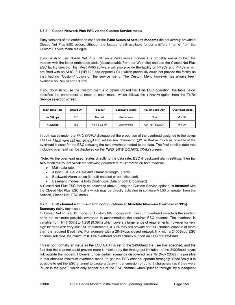
P300H P300 Series Modem Installation and Operating Handbook Page 150
8.7.2 Closed Network Plus ESC via the Custom Service menu
Early versions of the embedded code for the P400 Series of satellite modems did not directly provide a Closed Net Plus ESC option, although the feature is still available (under a different name) from the Custom Service menu dialogue.
If you wish to use Closed Net Plus ESC on a P400 series modem it is probably easier to load the modem with the latest embedded code (downloadable from our Web site) and use the Closed Net Plus ESC facility directly. This latest P400 software will also provide the facility on P420's and P440's which are fitted with an ASIC IFU ("IFU:2", see Appendix C1), which previously could not provide the facility as they had no "Custom" option on the service menu. The Custom Menu however has always been available on P460's and P480's.
If you do wish to use the Custom menus to define Closed Net Plus ESC operation, the table below specifies the parameters to enter at each menu, which follows the Ý«¬±³ option from the Tx/Rx Service selection screen.
Main Data Rate Based On TS32 MF Backward Alarm No. of Back' Alm Overhead Mode
>= 32kbps IBS Normal User choice One Min O/H
< 32kbps IBS No TS 32 MF User choice N/A (no TS32 MF) Min O/H
In both cases under the ÛÍÝ, ÜÛÚ×ÒÛ dialogue set the proportion of the overhead assigned to the async ESC as Ó¿¨·³«³ ø¿´´ ®»³¿·²·²¹÷ and set the Aux channel to Ѻº, so that as much as possible of the overhead is used for the ESC reducing the total overhead added to the data. The final satellite data rate including overhead can be displayed on the ×ÒÚÑ, Ê×ÛÉ ÝÑÒÚ×Ù, ÌÈñÎÈ screens.
Note: As the overhead used relates directly to the data rate, ESC & backward alarm settings, then fortwo modems to interwork the following parameters must match on both modems:
Main data rate. Async ESC Baud Rate and Character length / Parity. Backward Alarm option (ie both enabled or both disabled). Baseband modes (ie both Continuous Data or both Drop/Insert).
A Closed Net Plus ESC facility as described above (using the Custom Service options) is identical with the Closed Net Plus ESC facility which may be directly activated in software V1.50 or greater from the Service, Closed Net, ESC menu.
8.7.3 ESC channel with mis-match configurations at Absolute Minimum Overhead (0.39%)Summary (fairly technical) In Closed Net Plus ESC mode (or Custom IBS modes with minimum overhead selected) the modem adds the minimum possible overhead to accommodate the required ESC channel. The overhead is variable from 1/1 (100%) to 1/256 (0.39%) which covers a large range of requirements, however for very high bit rates with very low ESC requirements, 0.39% may still provide an ESC channel capable of more than the required Baud rate. For example with a 2048kbps closed network link with a 2400Baud ESC channel selected, the minimum 0.39% overhead could actually support an ESC of 6135Baud.
This is not normally an issue as the ESC UART is set to the 2400Baud the user has specified, and the fact that the channel could provide more is masked by the throughput limitation of the 2400Baud async link outside the modem. However under certain scenarios discovered recently (Nov 2002) it is possible in this absolute minimum overhead mode, to get the ESC channel operate strangely. Specifically it is possible to get the ESC channel to cause a delay in transmission of up to 3 characters (as if they were `stuck in the pipe`), which only appear out of the ESC channel when `pushed through` by subsequent

P300H P300 Series Modem Installation and Operating Handbook Page 151
characters. This `Delayed Character Mode` is generally not a showstopper, but can cause issues with packet-based communications.
At Paradise we have only been able to make the ESC channel enter this `delayed character mode` by setting up a pair of modems in intentionally mis-matched configurations. However, now we have investigated and understood the mechanism, we feel it is feasible that under repeated changes of configuration the ESC channel might enter this `delayed character mode` (although we can t get it into this mode ourselves by this method). To avoid this possibility we have modified the modems embedded software from V3.56 or later to ensure that during normal reconfiguration the ESC channel should not get into this mode.
While we are confident that in general the ESC channel is not likely to get into this `delayed character mode` it is still possible to make it enter this mode if the modems are operated with intentionally mis-match configurations. For those that would like to understand why this happens the following text describes the operation in more detail. The following text is NOT mandatory reading!
ESC channel `delayed character mode` (very technical) The Async ESC is carried in the satellite overhead by multiplexing it into the synchronous data of the satellite framing which is added to the main data. Each Async character is converted into a byte, buffered through a small FIFO, and then sent synchronously into the bits available in the frame for the ESC channel, using a leading 0 to indicate that the next 8 bits of overhead available to the ESC carry the 8 bits of a character. These 8 bits might be at one bit per satellite frame, or if a high proportion of the overhead is assigned to the ESC (such as in Closed Net Plus ESC mode) they could be successive bits (eg the whole 8 bits of satellite TS48).
This works fine, and normally if you mismatch the configuration of a pair of modems then the modems will not talk to each other as they calculate different overhead percentages to accommodate the Async ESC channel, the symbol rates do not match and hence they will not communicate.
However, once the overhead reaches the 0.39% minimum, changes to the ESC configuration do not change the overhead percentage (it is already at minimum), and the modems will communicate with mismatched ESC settings. For example if one modem is set to provide a ESC and a backward alarm facility and the other ESC only, then the modem without the backward alarm facility will route the parts of the overhead which carry the backward alarm from the distant end to the ESC channel decoding circuitry (because that is what it has been configured to do !). This can result in two problems: When the configurations are mis-matched, there will be spurious characters output from the ESC channel, or the ESC channel will suffer significant character errors (as the backward alarm status is output as ESC data).More significantly, the extra data routed to the ESC channel decoding circuitry from the overhead (in our example one bit per frame which carried the backward alarm from the distant modem) is NOT limited to 2400Baud by the sending modems physical Async ESC port, and may exceed the rate at which the UART in the receive modem can output these spurious ESC characters. Specifically, the small FIFO between the framing / overhead circuitry and the UART can get massively overrun, and after such an overrun this may lead to the ESC operating in `delayed character mode`. When in this mode, only a total modem reset will restore normal ESC channel operation. In summary, it is possible by mis matching the configuration of a pair of modems to set them so that they continuously output spurious or errored characters from the ESC channel, or force the ESC channel into the `delayed character mode` where a major (power down) type reset is required to restore normal ESC operation. As the modems at each end of the link are simply operating as set, and don t know that the configurations are mis matched, it is not possible to automatically prevent or recover from such a configuration.

P300H P300 Series Modem Installation and Operating Handbook Page 152
8.8 CROSS REFERENCE TO SDM300 D/I & FRAMING MODES.
The P300 Series Modems are equipped with the Drop/Insert and possibly the Extended Drop/Insert features can provide all the Drop/Insert functions of competing equipment such as the SDM300. If you are familiar with the modes the SDM300 offers then here is a cross reference, along with the menu entries to configure the P300 similarly (unlike the SDM300 however, you don't have learn what the cryptic abbreviations mean, you just answer the questions!)
E1_CCS: 2048kbps G.732 with common Channel Signalling1. Select ݸ¿²¹»ô ̨ô Í»®ª·½»ô ×ÞÍñÍÓÍ2. Select ݸ¿²¹»ô ̨ô Þ¿»¾¿²¼ô Ü®±° Ó«¨ô Ùòéíî.3. Select the number of timeslots to drop, and include the Common Channel Signalling (CCS) timeslot
(probably TS16). 4. Select Ô»¿ª» or λ°´¿½» with Idle code as required. 5. When "G.732 Channel Associated Signalling, 1=Normal (ignore), 2=Transfer" is asked, select
Ò±®³¿´ ø·¹²±®»÷.6. If the number of timeslots chosen is not an `Odd values of N` (eg N=7 or 9), then the unit will
prompt "TS Identity will be maintained by TS32 multiframe (YES)" and the setup is complete. 7. If you have selected an `Odd value of N` the unit will prompt "TS Identity over satellite, 1=Normal
(maintain), 2=Don't maintain". If you select Ò±®³¿´ ø³¿·²¬¿·²÷ the unit will provide TS identity maintenance for any value of N by using a CAS multiframe (Paradise proprietary). If you select ܱ²ù¬ Ó¿·²¬¿·² then the Modem will not use a CAS multiframe, and will be compatible with other manufacturer equipment with the same number of timeslots selected.
8. Configure the receive path similarly, if Ψą̃ is active, then only the timeslots need selecting.
Note the P300 Modem equipped with the Extended D/I feature (standard on P300-TCM) can support any value of N, not just N = 1, 2, 3, 4, 5, 6, 8, 10, 12, 15, 16, 20, 24, 30 as listed for the SDM300.
E1_CAS: 2048kbps G.732 with Channel Associated SignallingAs above, but there is no CCS timeslot to select in step 3, and at step 5 when "G.732 Channel Associated Signalling? " is asked, select ÝßÍ whereupon the dialogue terminates.
Note the P300 Modem equipped with the Extended D/I feature (standard on P300-TCM) can support any value of N, not just those listed for the SDM 300.
E1_IBS: 2048kbps with no assumed G.732 frame format1. Select ݸ¿²¹»ô ̨ô Í»®ª·½»ô ×ÞÍñÍÓÍ2. Select ݸ¿²¹»ô ̨ô Þ¿»¾¿²¼ô ݱ²¬·²«±«ô îðìèððð¾°3. When asked the question "2048k IBS Mode: 1=Normal 2=G.732" answer Ò±®³¿´
E1_31_TS: 2048kbps G.732 with no CAS, 31 timeslots used for dataAssuming the intent of this mode is to provide a carrier with a satellite framed rate of 2048kbps... 1. Select ݸ¿²¹»ô ̨ô Í»®ª·½»ô ×ÞÍñÍÓÍ2. Select ݸ¿²¹»ô ̨ô Þ¿»¾¿²¼ô ݱ²¬·²«±«ô îðìèððð¾°3. When asked the question "2048k IBS Mode: 1=Normal 2=G.732" answer Ùòéíî4. When asked the question "Channel Assoc Sig in TS16 1=Normal(No CAS) 2=CAS" select Ò±®³¿´5. When asked the question "Timeslot re-order option 1=Normal (linear) 2=Re-order" select Ò±®³¿´
Unlike the SDM300, this mode passes 31 data timeslots transparently, not just the 30 implied in the SDM300 handbook. The P300 Modem can also provide 30-timeslot operation where TS16 contains

P300H P300 Series Modem Installation and Operating Handbook Page 153
CAS, at step 3 simply select ÝßÍ.
T1_ESF & T1_ESF_S: 1544kbps Extended Super Frame (_S Special)The P300 Modems do not require the _S `Special` mode to support N=9 and N=18, as the P300 Modem equipped with the Extended D/I feature (standard on P300-TCM) can support any value of N. Simply configure as follows:1. Select ݸ¿²¹»ô ̨ô Í»®ª·½»ô ×ÞÍñÍÓÍ2. Select ݸ¿²¹»ô ̨ô Þ¿»¾¿²¼ô Ü®±° Ó«¨ô ÌïóÛÍÚ.3. Select the number of timeslots to drop 4. Select Ô»¿ª» or λ°´¿½» with Idle code as required. 5. When "T1-RBS Over Satellite, 1=Normal (or no RBS) 2=Maintain RBS" is asked, select as
appropriate. If ÎÞÍ is selected the dialogue ends here. 6. For Ò± ÎÞÍô if the number of timeslots chosen is not an `Odd values of N` (eg N=7 or 9), then the
unit will prompt, "TS Identity will be maintained by TS32 multiframe (YES)" and the setup is complete.
7. If you have selected an `Odd value of N` the unit will prompt "TS Identity over satellite, 1=Normal (maintain), 2=Don't maintain". If you select Ò±®³¿´ ø³¿·²¬¿·²÷ the unit will provide TS identity maintenance for any value of N by using a CAS multiframe. If you select ܱ²ù¬ Ó¿·²¬¿·² then the Modem will not use a CAS multiframe, and will be compatible with the same number of timeslots selected.
8. Configure the receive path similarly, if Ψą̃ is active, then only the timeslots need selecting.
T1 & T1_S 1544kbps D4 Framed (_S Special)The P300 Modem do not require the _S `Special` mode to support N=9 and N=18, as the P300 Modem equipped with the Extended D/I feature (standard on P300-TCM) can support any value of N. Simply configure as for T1_ESF & T1_ESF_S as above, but select T1-D4 not T1-ESF in step 2
T1_IBS: 1544kbps in the same bandwidth as Normal 1536kbps IBSThis is the standard INTELSAT definition for non Drop/Insert 1544kbps over IBS. 1. Select ݸ¿²¹»ô ̨ô Í»®ª·½»ô ×ÞÍñÍÓÍ2. Select ݸ¿²¹»ô ̨ô Þ¿»¾¿²¼ô ݱ²¬·²«±«ô ïëììððð¾°

P300H P300 Series Modem Installation and Operating Handbook Page 154
8.9 V.35 SCRAMBLERSIn all cases, setting the P300 Modem scramblers to Normal will implement the correct scrambling to match the configuration you have the modem in (ie Closed network, IBS, or IDR, with or without Reed-Solomon). Only read this section if you are having trouble interworking two manufacturers equipment which you think is scrambler related (or just for interest!).
Note that there are no known incompatibilities between any manufacturers synchronous IBS or synchronous Reed-Solomon scrambling. The issues relate only to V.35 scrambling, used typically on closed network or IDR links without Reed-Solomon.
HistoryNote: This is the author’s understanding from 15 years working in the industry.
There was only intended to be one V.35 scrambler, but the CCITT who made the original specification were the first of many organisations to get it wrong. To ensure there was no ambiguity they printed a written description together with an example schematic. However the schematic they supplied behaved differently from the written description (well done boys), and there immediately grew two opposing camps, those who had worked to the schematic and those who had worked to the written description!
The difference between the two implementations was only in the action to take when the `adverse state` is detected, ie what to do if a long string of zeroes has been output. In such a case a counter injected an opposing bit to generate a transition (and break the cycle of all zeroes) with a counter in the corresponding descrambler cancelling out this injected opposing bit. The difference between the two implementations is in the count length of this adverse state detector counter; one is 30 counts and the other 31.
The net result of inter-operating equipment from the two differing V.35 camps (schematic / written description) was a background pattern dependent error rate in the order of 1 x 10⁻⁸. Note that as the background error rate is pattern dependent, there is no guarantee you will see it with regular test equipment such as Firebirds etc, which generate repeated fixed patterns. In most satellite communications such a background error rate might be masked by the channel noise, but in some carrier line up procedures a circuit may be required to operate error free for 12/24 hours. For higher data rate circuits this proved impossible to achieve with the differing scramblers, and so tests were performed `on the bench`.
INTELSAT were called in to adjudicate the argument, and as both camps were technically correct someone was going to be upset. INTELSAT decided in favour of the larger camp, with a Japanese company being the only member in the opposing camp. This was unfortunate as it happened that the losers were the only company to have the V.35 scrambler buried deep within as ASIC at the time (and therefore a nightmare to change), whereas every other manufacturer had it implemented in hardware, and could have made cuts / straps to resolve the issue!
The definition finally approved by INTELSAT became known as "INTELSAT V.35 scrambling", with the other definition derived from the original CCITT spec as "CCITT V.35 scrambling". INTELSAT of course approve only INTELSAT V.35 scrambling!
Other DerivativesAs mentioned earlier, the CCITT were only the first of many companies to mess up the V.35 scrambling. At least two other companies also implemented a V.35 scrambler, which was accidentally different to the CCITT definition (ie didn't match the schematic or the written description). These companies now offer corrected INTELSAT V.35 implementations, but in order to maintain backwards compatibility they support their original V.35 attempts as well. To maximise compatibility with other manufactures equipment, in addition to both INTELSAT and CCITT, Paradise modems implement two of these other
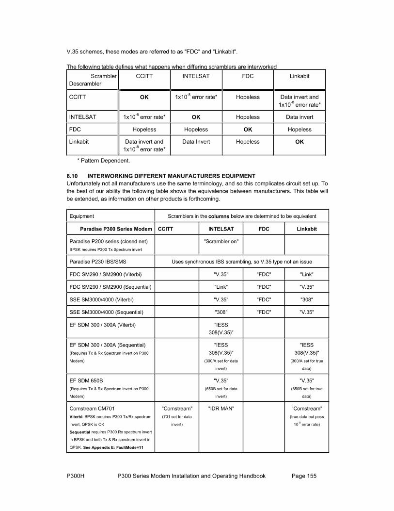
P300H P300 Series Modem Installation and Operating Handbook Page 155
V.35 schemes, these modes are referred to as "FDC" and "Linkabit".
The following table defines what happens when differing scramblers are interworked Scrambler Descrambler
CCITT INTELSAT FDC Linkabit
CCITT OK 1x10⁻⁸ error rate* Hopeless Data invert and 1x10⁻⁸ error rate*
INTELSAT 1x10⁻⁸ error rate* OK Hopeless Data invert
FDC Hopeless Hopeless OK Hopeless
Linkabit Data invert and 1x10⁻⁸ error rate*
Data Invert Hopeless OK
* Pattern Dependent.
8.10 INTERWORKING DIFFERENT MANUFACTURERS EQUIPMENTUnfortunately not all manufacturers use the same terminology, and so this complicates circuit set up. To the best of our ability the following table shows the equivalence between manufacturers. This table will be extended, as information on other products is forthcoming.
Equipment Scramblers in the columns below are determined to be equivalent
Paradise P300 Series Modem CCITT INTELSAT FDC Linkabit
Paradise P200 series (closed net) BPSK requires P300 Tx Spectrum invert
"Scrambler on"
Paradise P230 IBS/SMS Uses synchronous IBS scrambling, so V.35 type not an issue
FDC SM290 / SM2900 (Viterbi) "V.35" "FDC" "Link"
FDC SM290 / SM2900 (Sequential) "Link" "FDC" "V.35"
SSE SM3000/4000 (Viterbi) "V.35" "FDC" "308"
SSE SM3000/4000 (Sequential) "308" "FDC" "V.35"
EF SDM 300 / 300A (Viterbi) "IESS308(V.35)"
EF SDM 300 / 300A (Sequential) (Requires Tx & Rx Spectrum invert on P300
Modem)
"IESS308(V.35)"
(300/A set for data
invert)
"IESS308(V.35)"
(300/A set for true
data)
EF SDM 650B (Requires Tx & Rx Spectrum invert on P300
Modem)
"V.35"(650B set for data
invert)
"V.35"(650B set for true
data)
Comstream CM701 Viterbi: BPSK requires P300 Tx/Rx spectrum
invert, QPSK is OK
Sequential requires P300 Rx spectrum invert
in BPSK and both Tx & Rx spectrum invert in
QPSK. See Appendix E: FaultMode=11
"Comstream"(701 set for data
invert)
"IDR MAN" "Comstream"(true data but poss
10-8 error rate)

P300H P300 Series Modem Installation and Operating Handbook Page 156
A `compatibility document` which, describes interworking tests between the Paradise P300/P400 Modems and other manufacturers modems, is available on request.
8.11 INTRODUCTION TO AUPC (AUTOMATIC UPLINK POWER CONTROL)
Note: Authorisation from the satellite operator is probably required before AUPC is activated.
8.11.1 IntroductionAUPC provides a mechanism to counteract changes in atmospheric conditions (eg rain), which in turn affects the attenuation of the atmosphere and can degrade the performance of a satellite link. It does this by monitoring the distant end Eb/No and automatically adjusting the local Tx power of a satellite link to try and maintain the specified distant end Eb/No figure.
To be able to monitor the distant Eb/No the local modem needs to be able to interrogate the distant modem and request the current Eb/No value. It does this by sending messages through theasynchronous ESC channel (which is carried over the satellite multiplexed with the main data channel). For AUPC to operate an async ESC channel must be defined, and on the P300 Series thisis available in Closed Network (Closed Net Plus ESC), IBS/SMS and IDR modes.
The AUPC may be set to monitor the distant Eb/No (Ó±² Ü·¬, shown above) or in its normal mode to maintain a distant Eb/No (Ó¿·²¬ù Û¾ñÒ±, shown overleaf). In both modes the distant Eb/No and BER estimate can be displayed on the local end LCD (Ó±²·¬±®ô Ü·¬ »²¼), a deferred alarm can be set to activate if the distant Eb/No falls below a user set threshold (ݸ¿²¹»ô Ë»®óÑ°¬ô ß´¿®³
̸®»¸±´¼ô Ü·¬¿²¬ Û¾ñÒ±), and the distant end Eb/No can be recorded regularly in the local endtraffic log using the Autolog feature (ݸ¿²¹»ô Ô±¹ô ß«¬±´±¹). The distant Eb/No can also be output on the uncommitted analog DAC output if the Monitor / AGC option is fitted (see uncommitted analog

P300H P300 Series Modem Installation and Operating Handbook Page 157
DAC output , value = 4 in Appendix E starting on page 207)
In Ó¿·²¬ù Û¾ñÒ± mode the Target Eb/No has to be set as well as a ̱´»®¿²½» ©·²¼±©ò Only when the target Eb/No tolerance is exceeded is the Tx power adjusted to bring the distant Eb/No back to the target value. The Tx power will only continue to be adjusted automatically until the Eb/No settles on the target value. This prevents continual Tx power variations under normal minor thermal noiseariations. Once settled on the target Eb/No the Tx power adjustment will only be automatically
et along with a slew rate limit (if it is felt that additional
limits one of three sc +/- Limits: red to maintain the Eb/No.
+ Limit only:
vreactivated when the Eb/No tolerance is again exceeded.
Separate upper and lower Tx power limits are slimits to prevent rapid power variations are required). By manipulating the upper and lower power
enarios can be achieved:Constant performance: Always uses the power requiProvided the limits are not reached the link performance will stay as it is (subject to the tolerance window). Best performance: The power will increase when required by a fade bit it will not reduce. Any especially good atmospheric conditions will improve the Eb/No

P300H P300 Series Modem Installation and Operating Handbook Page 158
- Limit only: Power economy: The power will not increase, but it will reduce if there are any especially good atmospheric conditions that allow less power to achieve the target Eb/No.
beyond the current level.
AUPC can also be set in self monitor mode (Í»´º Ó±²). This is used when a single Tx carrier is d to broadcast information to multiple Rx sites. Provided the local modem Rx path is locked to this dcast carrier then the local Eb/No indicates any atmospheric changes on the local end satellite
nk and down link. In this mode the AUPC controls the local Tx power by directly monitoring the l Eb/No. This is an imperfect system as it changes the local Tx power to compensate for local
Theusebroauplilocaatmospheric changes which affect the local uplink and downlink, it cannot however compensate for
istant atmospheric changes affecting the multiple distant downlinks. Í»´º Ó±² mode requires no
pow
AUPC is active in normal (Ó¿·²¬ù Û¾ñÒ±) or self monitor (Í»´º Ó±²) modes then the status of the n be recorded regularly in
e traffic log using the Autolog feature (ݸ¿²¹»ô Ô±¹ô ß«¬±´±¹). The AUPC delta power can also be
starting on page 207)
ds primarily on two factors: The user specified slew rate
w regularly the distant Eb/No is read by the localodem in order to determine if any adjustment is necessary).
The SC
dESC channel as the AUPC software can directly read the local Eb/No as well as control the local Tx
er.
IfAUPC can be displayed (Ó±²·¬±®ô ßËÐÝ), also the AUPC delta power cathoutput on the uncommitted analog DAC output if the Monitor / AGC option is fitted (again see uncommitted analog DAC output , value = 5 in Appendix E
The speed of reaction of the AUPC depen(specifically to limit the rate of change of Tx power when a power adjustment is deemed necessary),and the ESC channel Baud rate (which affects hom
AUPC will use a different proportion of the available ESC bandwidth depending on the Einterface selected.

P300H P300 Series Modem Installation and Operating Handbook Page 159
alsoendach igh) that the AUPC can achieve this update rate using less than 33% of the ESC channel bandwidth, then
33% bandwidth is
M&
If thAUP o reporting rate as
et to RS232 or RS422, AUPC cannot be used.
The Ebof the ײ
8.11.2 DO NOT switch on the AUPC immediately, it is much simpler to get the circuit working first, determine
Configure tcorrectly. S stant Eb/No expected under clear sky conditions.
For IBS/SMS and IDR carriers the ESC can be switched on later within the overhead without
For CloAddingthe Eb/used fo
Configure an ESC channel for 8 bits no parity, Baud rate as described below. or
will give For Clo
(as thisexceedi ead over 10%.
The ESC channel for the AUPC must have symmetrical Baud rates.
C interface:
the AUPC will use 100% of the ESC channel capacity at
rt to the ESC channel) it is not required to have the ESC channel at the same
For example the station M&C could be running at 9600 Baud, and the ESC channel PC software will buffer and rate convert the M&C
If the ESC interface is set to Ô·²µ ¬± ÓúÝ (Ô·²µóÔ or Ô·²µóÎ) then it assumes the ESC channel is being used for network M&C (as this is the setting used to provide the connectivity for distant
M&C). In this case the AUPC will use up to 33% of the ESC channel bandwidth in order to ieve an Eb/No reporting rate of once per second. If the ESC Baud rate is such (ie so h
it uses only the proportion of bandwidth required for a 1Hz update rate. Theused by interleaving the requests for the distant Eb/No and distant end Eb/No responses between
C messages using the ESC channel.
e ESC interface is set to RS485, then the external RS485 interface will be disabled and the C will use 100% of the ESC channel bandwidth to achieve as high an Eb/N
possible.
If the ESC interface is s
/No update rate and percentage of ESC channel bandwidth used is displayed on one screen º±ô Ê·»© ݱ²º·¹ô ÌÈ sequence of screen displays.
Configuring AUPC for operation
the normal levels, AND THEN activate the AUPC.
he modems at both ends of the link and ensure the basic satellite link is operating et the Tx power to achieve the di
changing the carrier power or bandwidth. sed Net Plus ESC carriers, the overhead is added as required for the ESC channel. an ESC channel later will change the bandwidth of the signal and may slightly affect No. In this case configure the ESC at least to a nominal Baud rate. If the ESC is not r any other M&C purposes then 300 Baud may be sufficient for AUPC alone.
F IBS/SMS and IDR configure as higher rate ESC channel as the modem can provide. This the fastest possible reporting rate. sed Net Plus ESC our suggestion would be to include the optional Backward Alarm is a very useful feature), and set the Baud rates as high as possible without either ng the allotted satellite bandwidth or using an overh
Set the ES If the ESC channel is to be used for AUPC only, set the ESC interface to ÎÍìèë. The external
RS485 port will be disabled andwhatever Baud rate you have defined the ESC channel. If the ESC channel is to be used for AUPC and distant end remote M&C, set the ESC interface to either Link-Local or Link-Remote (Local at the controlling PC end, remote at the end farthest away from the PC).
Note: This is contrary to expectations! When using AUPC with either Link-Local and Link-Remote selected as the ESC interface (to internally connect the Remote M&C poBaud rate as the M&C system.
set for 2400 Baud. The AU

P300H P300 Series Modem Installation and Operating Handbook Page 160
. M&C messages will of course take
S or IDR overheads) then it's worth
, by having enough bandwidth so that the maximum 33% it uses in
Stawor
not correctly configured. If it does not work in this mode don't start
ô Ê·»© ݱ²º·¹ô ̨ô ø¼±©²ô ¼±©² »¬½÷.
tmospheric conditions are favourable (unlikely).
, set the Ó¿¨ °±©»® to the maximum increase you are allowed, and set Ó·² °±©»® to Zero. This will prevent the Tx
ing if the Eb/No is better than the target, but will increase the power if the
Set the ̱´»®¿²½» É·²¼±© size to something practical, say 0.2 to 0.5dB (depending on how in the Eb/No).
setting is Ó¿¨·³«³, but note that anything, which interrupts the link, will cause the Tx carrier to
ally log the parameters: Use the Autolog feature to optionally record the distant Eb/No and/or the AUPC delta power.
This may prove useful in determining how often the AUPC is required, and if it manages to
messages whilst interleaving the AUPC datalonger to get across a 2400 Baud ESC than a 9600 Baud ESC, but if the bandwidth has to be paid for (ie it s not withing the IBS/SMthe saving.
Alternatively if the station M&C is at say 2400 Baud, but the station is transmitting a 512kbps IBS/SMS link that would support a 19200 Baud ESC within the IBS/SMS overhead. Setting the ESC for 19200 Baud will provide a very high update rate for the Eb/No monitoringthis mode can provide at least a 1Hz update rate.
rt the AUPC in a passive mode (distant end monitoring only mode) to ensure the system is king:
Switch on REMOTE REPORTING (ݸ¿²¹»ô Ψô Ü»³±¼ô ßËÐÝ) to respond to the Eb/No requests at the distant modem.
Set the local AUPC for Ó±² Ü·¬, to determine if it is working correctly. If it is then the distant Eb/No should be available on the Ó±²·¬±®ô Ü·¬¿²¬ screens. If the Eb/No or BER figures say Unavail then the ESC is
changing the AUPC, sort out the ESC channel! When the distant Eb/No is displayed, record the distant Eb/No under clear sky conditions. Then change the AUPC mode to Maint Eb/No in order to get access to the other AUPC settings. Review the proportion of ESC bandwidth and more importantly the distant Eb/No update rate using ײº±
Determine the parameters for the AUPC: Determine the way the AUPC will operate, will it try to: 1. Maintain a minimum Eb/No, but take advantage of a better Eb/No when
atmospheric conditions are favourable (normal) 2. Maintain a fixed Eb/No, reducing Tx power when a
To maintain a minimum Eb/No, set this as the Ì¿®¹»¬ Û¾ñÒ±
power decreasEb/No falls below target.
To maintain a fixed Eb/No set this as the Ì¿®¹»¬ Û¾ñÒ±, set the Ó¿¨ °±©»® to the maximum increase you are allowed, and set Ó·² °±©»® to the limit of the power decrease you will accept. The Tx power will increase and decrease within the limits to try and maintain a constant Eb/No.
accurately you wish to try and mainta Set the Í´»© כּ to something which can respond to a fast fade. We suggest no less than
15dB/min (ie 0.25dB/sec) If there is no reason to set a particular slew rate then leave it set to zero (no slew rate limit).
Set the ݱ³³ Ô± ß½¬·±² after careful consideration. The most advantageous
increase to the maximum delta Tx power. Ú®»»¦» is probably the most sensible choice, causing the carrier to remain at the current value until the link is restored. Finally Ò±³·²¿´ is the safest option, with the AUPC returning the carrier to it s nominal power if the link is broken.
Option

P300H P300 Series Modem Installation and Operating Handbook Page 161
maintain the Eb/No within the parameters you have set. Logging the AUPC delta power allow you to, if questioned, be able to specify to the satellite operator the exact power you were transmitting throughout the day (or at a specific time in question).
source of much confusion and `Specmanship`. This brief tutorial explains what the terms
eg at the input to the demodulator, at the input to the Forward Error Correction decoder (FEC), at the input outer Reed-Solomon FEC decoder, or even at the terrestrial data interface. Many of the terms you come across represent this Rx Carrier / Noise ratio at these different reference points.
(Carrier + Noise) / Noise at the demodulator input on a spectrum analyser.
We can express this same Carrier / Noise ratio at the input of the demod in terms of the Energy per
smitted Bit rate is higher than the Symbol rate, and so Et / No (ie the Carrier / Noise referenced to Transmitted Bit rate) is lower than the Es / No (the Carrier / Noise referenced to the Symbol rate), as this same power is referenced to a higher bit rate. Allowing for the change in bit
rate. Allowing for the changebit rate in the FEC decoder gives:
8.12 TUTORIAL ON CARRIER/NOISE & Eb/No MEASUREMENTS
8.12.1 IntroductionThis is themean and how to measure and interpret the figures you see. The diagram on the following page attempts to summarise this as clearly as possible visually with the text below adding detail for whichthere is no room on the diagram. Finally a table provides a quick look up reference to convert values measured on a spectrum analyser to a real Eb/No.
8.12.2 Derivation of Eb/No from (C+N)/NIt is possible to describe the Carrier / Noise ratio within the Rx system at an arbitrary reference point,
It is common to measureIdeally we are after the Carrier / Noise ratio, but as we cannot turn off the atmospheric noise (!) we have to make the measurement with the noise on, and then convert back to simply Carrier / Noise. In the equation below the term (C+N)/N is the (Carrier+Noise) / Noise ratio read from the spectrum analyser.
Symbol / Noise power density, which is written as Es / No. Because `Carrier / Noise` is a ratio of twopowers measured in the same bandwidth (the resolution bandwidth of the analyser), this is the same as Es / No.Within the demodulator, each Symbol is converted back into the Transmitted Bits. For BPSK eachSymbol represents only 1 Transmitted Bit, for QPSK or OQPSK each Symbol represents 2Transmitted Bits, and for 8PSK each Symbol represents 3 Transmitted Bits. The expression Et / No
(or Ebt / No) represents the Carrier to Noise ratio referenced to this Transmitted Bit rate. For QPSK and 8PSK the Tran
rate in the demod gives: Next in the demod chain comes the FEC Decoder. The receive Carrier / Noise referenced to this point is referred to as EDec / No. In the FEC Decoder the bit rate is reduced, as the data is decoded toprovide corrected data at a lower rate. Because the data rate reduces through the FEC Decoder EDec
/ No is higher than Et / No as the same power is referenced to a lower bitin
NE=1)-10(10=
N=
Noise 0
s)10
/NN)+(C(10log
CCarrier
Symbol)/Bitsof(No10-N
=N 10
00logEE st
Rate)Code(FEC10-E=E10
tDec logNN 00

P300H P300 Series Modem Installation and Operating Handbook Page 162
Sol`InnInfo ormation Bit
ate is referred to as the Eb / No (or Ebi / No or Ei / No with `I` and `b`referring to Information and Bit
EDec
RS
It is
inally, after the RS Decoder comes Deframing and baseband processing such as Drop/Insert.
defrEb
Bas
8.12 tical Implications of Displayed Eb/NoPractically this means the following:
For a constant Tx Power, you will get the same displayed Eb / No whatever the settings of Modulation Inner FEC, and Outer (RS) FEC, as the Eb / No display compensates for these parameters. The bandwidth will vary and so will the Carrier / Noise at the input of the demod, butthe displayed Eb / No will be steady as it compensates for these parameter changes.
When comparing BER performance for different Modulation / FEC schemes against Eb / No,the plotted Eb / No already accounts for the changes in Carrier / Noise caused by the different Modulation and FEC settings. Any BER difference you see with different schemes is a realdifference, you don t have to further compensate for the changes in Carrier / Noise thischange induces.
You do however have to be aware of Bandwidth considerations. You might find a Modulation / FEC scheme which gives an exceptional BER for a given Eb / No, but it will of little practical value if the bandwidth it requires occupies a whole transponder.
When you look at BER performance figures at a specified Eb / No you get the same BER performance whether the data is framed or not. Adding framing to a Closed Network linkwould increase the bandwidth, decrease the Carrier / Noise, decrease the displayed Eb / No (as it does not compensate for framing) and therefore degrade the BER. However when brought back to the same Eb / No you do of course recover the same BER. Framing therefore does not degrade the BER for a stated Eb / No, but it does require more power (and bandwidth) to achieve the same Eb / No.
Following the FEC Decoder (the `inner FEC`, ie Turbo, Viterbi, Sequential or TCM) comes the Reed-omon `Outer FEC` Decoder (if active). This `Outer FEC` RS Decoder operates similarly to theer FEC` Decoder, reducing the bit rate as it corrects errors and finally generating the Composite rmation Bit Rate at its output. The Carrier / Noise expressed at this Composite Inf
Rrespectively). Again because the data rate reduces through the RS Decoder Eb / No is higher than
/ No as the same power is referenced to a lower bit rate. Allowing for the change in bit rate in the Decoder gives:
))nkEE (=RateCode(RS10-
N=
N 100
Dec
0
b log
this Eb / No that is typically displayed on the front panel of Modem equipment.
FIBS/SMS or IDR deframing does decrease the bandwidth, but the bandwidth reduction effects of
aming are ignored as INTELSAT chose to define the mandatory modem performance in terms of / No, specifying that this relates to the Composite Information Bit Rate (ie it includes framing). eband processing has no effect on bandwidth and is totally ignored.
.3 Prac

P300
H
P
300
Serie
s M
odem
Inst
alla
tion
and
Ope
ratin
g H
andb
ook
Pa
ge 1
63
8.12
.4
Eb/N
o Ex
plan
ator
y D
iagr
am

P300H P300 Series Modem Installation and Operating Handbook Page 164
8.12.5 Tables to Convert (C+N)/N to Eb/No
NN+C
NE=
NC
0
S
NE
0
t
NE
0
Dec
NE
0
b0 0 0 0 0
4.64.8
2.753.05
5.05.25.45.6
3.353.643.924.204.475.8
6.06.26.46.66.8
4.745.015.275.535.78
7.07.27.47.67.8
6.036.286.536.777.01
8.0 7.258.2 7.498.4 7.728.6 7.958.8 8.19
9.0 8.429.2 8.649.4 8.879.6 9.109.8 9.32
10.0 9.5410.5 10.0911.011.512.012.513.013.514.014.5
10.6411.1811.7212.2512.7813.3013.8214.34
Adjust for modulation:BPSK: -0dB
QPSK: -3.0dB OQPSK: -3.0dB 8PSK: -4.77dB
Adjust for FEC Rate:
1/2 Rate: +3.0dB 3/4 Rate: +1.25dB 7/8 Rate: +0.58dB 2/3 Rate: +1.76dB
Adjust for RS Codec:
(n,k,t)=(126,112,7): +0.51dB (219,201,9): +0.37dB (225,205,10): +0.40dB
15.015.516.016.517.017.518.018.519.019.5
14.8615.3815.8916.4016.9117.4217.9318.4418.9419.45
>20 =(C+N) / N (error <0 .04dB)
Example: 8SPK with 2/3 Rate TCM FEC, & RS=(219,201,9)

P300H P300 Series Modem Installation and Operating Handbook Page 165
NN+C
0NE =
NC
0
S0
NE
0
t0
NE
0
Dec0
NE
0
b0
(C+N)/N=8.4dB
C/N=7.72dB
8PSK so subtract 4.77dB
2/3 Rate FEC, so add 1.76dB
RS Code (219,201,9) so add 0.37dB
Measure Look up Calculate Eb/No = C/N - 2.64dB
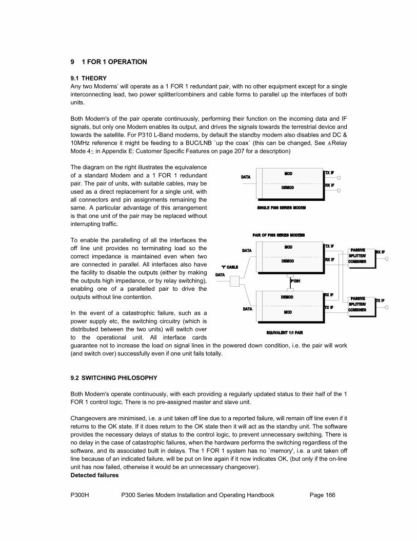
P300H P300 Series Modem Installation and Operating Handbook Page 166
9 1 FOR 1 OPERATION
9.1 THEORYAny two Modems’ will operate as a 1 FOR 1 redundant pair, with no other equipment except for a single interconnecting lead, two power splitter/combiners and cable forms to parallel up the interfaces of both units.
Both Modem's of the pair operate continuously, performing their function on the incoming data and IF signals, but only one Modem enables its output, and drives the signals towards the terrestrial device and towards the satellite. For P310 L-Band modems, by default the standby modem also disables and DC & 10MHz reference it might be feeding to a BUC/LNB `up the coax` (this can be changed, See RelayMode 4 in Appendix E: Customer Specific Features on page 207 for a description)
The diagram on the right illustrates the equivalenceof a standard Modem and a 1 FOR 1 redundantpair. The pair of units, with suitable cables, may be used as a direct replacement for a single unit, with all connectors and pin assignments remaining thesame. A particular advantage of this arrangementis that one unit of the pair may be replaced without interrupting traffic.
To enable the parallelling of all the interfaces theoff line unit provides no terminating load so the correct impedance is maintained even when twoare connected in parallel. All interfaces also havethe facility to disable the outputs (either by making the outputs high impedance, or by relay switching), enabling one of a parallelled pair to drive theoutputs without line contention.
In the event of a catastrophic failure, such as a power supply etc, the switching circuitry (which isdistributed between the two units) will switch over to the operational unit. All interface cardsguarantee not to increase the load on signal lines in the powered down condition, i.e. the pair will work(and switch over) successfully even if one unit fails totally.
9.2 SWITCHING PHILOSOPHY
Both Modem's operate continuously, with each providing a regularly updated status to their half of the 1 FOR 1 control logic. There is no pre-assigned master and slave unit.
Changeovers are minimised, i.e. a unit taken off line due to a reported failure, will remain off line even if it returns to the OK state. If it does return to the OK state then it will act as the standby unit. The software provides the necessary delays of status to the control logic, to prevent unnecessary switching. There is no delay in the case of catastrophic failures, when the hardware performs the switching regardless of the software, and its associated built in delays. The 1 FOR 1 system has no `memory', i.e. a unit taken off line because of an indicated failure, will be put on line again if it now indicates OK, (but only if the on-line unit has now failed, otherwise it would be an unnecessary changeover). Detected failures

P300H P300 Series Modem Installation and Operating Handbook Page 167
A failure is defined as either a detected failure of the unit, or a catastrophic (power) failure. The Modems will changeover if one fails, and if the other unit indicates that it is still operational. If both units fail simultaneously (which is likely to be caused by external circumstances), then no changeover takes place.Both unit and traffic faults can cause a 1:1 switch over. However, traffic faults caused externally to the equipment, which would affect both units simultaneously, do not force a spurious changeover, due to the design of the 1:1 switching logic.
Manual changeoversThe Modem is able to `give away' operation to the other unit of the pair, if instructed to do so from the front panel, as described earlier. The switch over will only occur if the other unit indicates that it is OK, and is performed by momentarily simulating a failure in the on-line equipment.
9.3 PRACTICAL 1 FOR 1 IMPLEMENTATION
To implement 1 FOR 1 switching between any two Modems’, the following steps need to be performed:
1. Check that both Modems’ have the same software issue.
2. Connect a 4 way screened cable, between the 9 pin 1 FOR 1 connectors on the two Modem's to be used, refer to Appendix B for details of the connector, as well as the lead required.
3. If the modem has the G.703 option fitted, ensure the switches on the G.703 options are set for 1:1 operation.
4. Plug in the 9 pin 1:1 control lead first, this should force one of the Modem's to indicate that its outputs are tri-state (the standby LED on the front and the Hi-Z LED on the rear should illuminate on one modem).
5. Connect the data interfaces in parallel, and configure the two units alike. Suitable adapter cables are available from Paradise for all the standard interfaces.
6. Connect the two transmit IF ports to the input ports of a suitable power splitter/combiner, of the correct impedance (50 or 75 ) and the appropriate frequency range. The combined output is then fed to the up-conversion equipment. Note that only one output is active at a time, and because of the loss of most splitter/combiners the power level at the output of each modem needs to be increased by approximately 3.5dB.
7. Connect the two receive IF ports to the two output ports of a suitable power splitter/combiner, of the correct impedance (50 or 75 ) and the appropriate frequency range. The output of the down-conversion equipment then feeds the input of the splitter/combiner, so that both demodulators are fed with an identical signal. Because of the wide dynamic range of the Modem AGC circuits, there should be no need to modify the signal levels.
8. Switch between units by using the menu option Ó¿·²ô ß½¬·±²ô Ù·ª»¿©¿§ ·² ïæï. The pair will not switch over unless the partner unit is operational (ie indicates no faults).
Note: Testing a 1:1 pair in loopback requires the IF's to be split/combined and then looped. Placing an external individual loopback on each modem will not work as the off-line one who's output is muted sees a Rx fault as there is no carrier. When split/combined and looped testing will work, but it can still be difficult to `get your head round it`. It is much easier with no loopback and the 1:1 pair talking to a third modem.

P300H P300 Series Modem Installation and Operating Handbook Page 168
10 BOOT CODE OPERATION
10.1 FLASH SOFTWARE UPDATE
The Modem software is contained in a FLASH EPROM, and can be updated without opening the equipment through the serial port on the Async ESC connector. It is not even necessary to remove the equipment from the rack BUT it is necessary to route the traffic via another modem, as loading the software requires a processor reset and will affect the traffic.
To access the `Boot Menu`, power the unit up whilst holding in the `Óß×Ò` key, and the following menuwill be displayed:
Serial Flash Update 1 Start Process 2 Reboot
Boot Menu
Option 2 allows the unit to continue as normal. Option 1 leads onto the following menu:
Connect PC to serial port Press YES/ENTER when connected
Boot, Start Process Menu
At this point the serial cable supplied with the equipment should be connected between the PC ands the modems `Async ESC` connector, then the ÇÛÍ key pressed. This leads onto the following menu:
Waiting for communications with PC... \ Press YES/ENTER key to abandon
Boot, Comms Start screen
The bar in the top right hand corner spins whilst it waits for serial communications to begin.
On the PC (under Windows) start the download program (winflash.exe) and select the serial port in use and the new firmware (p300_s.rec). Both the PC and the modem will display the status of the download as it progresses.
The display should first indicate:
Waiting for PC to start erase cycle /
Boot, Process Wait screenand will then proceed to:
Waiting for flash memory to Erase /
Boot, Erase Wait screenWhen the Flash has erased (which takes approximately 30 seconds) the screen changes to:

P300H P300 Series Modem Installation and Operating Handbook Page 169
Programming Flash memory in progress / Banks: - \FF
FFFF
FFFF
FFFF
FFFF
FFFF
FFFF
FFFF
FFFF
FFFF
FFFF
FFFF
FFFF
FF
Boot, Flash Program screen
Each "FF" represents a blank 32k bank of memory. The bar in the top right hand corner spins to show communications are continuing, and the bar on each bank in turn spins first clockwise as information is loaded from the PC, then anticlockwise as the bank is programmed. When each bank is complete it shows either a tick " " when complete, a "-" if it is intentionally left empty, or an "X" if it fails to program.Any failure to program is automatically retried, and an "X" should never reman on the screen.
Whilst the programming continues the PC report the status as messages are transferred, and displays the percentage of the file that has been transferred. When the programming is complete, the unit prompts the operator as follows, and the PC returns to the DOS prompt:
Programming complete Press YES/ENTER to continue
Boot, Programming Complete screen
At this point the processor re-boots. The first reboot with a new main code the unit performs a checksumtest on each bank, displaying the results as follows:
Checksumming main code.... Banks: - - -
Boot, Flash Checksum screen
Finally, when the checksums are verified, the processor jumps into the new Flash code, and begins execution of the latest version of the embedded M&C code. Should the code fail to execute properly, hold down the Ò±ñЮ»ª key to clear the memory.
Should the program ever crash, or be otherwise reset (other than from power up), it will automatically do an extensive checksum test as above. However from a normal power up, where it may be critical to restore the service as quickly as possible only an abbreviated test is performed, and the screen above will not be displayed.
10.2 OTHER BOOT CODE OPTIONSThe other options available from power up, by holding in a key on the keypad are:
Óß×Ò Stay in boot code for serial download ÒÑñÐÎÛÊ Clear the non-volatile memory ð Set the LCD contrast to mid scale ï Display Boot Code software version
The following options allow a fully equipped P300 to act as a model with fewer options to enable testing of a lower specified product to see if it provides the facilities required.
4 Reduce the functionality to P300-VSAT level (from a higher level only) 5 Reduce the functionality to P300-IBS level (from a higher level only) 6 Reduce the functionality to P300-IDR level (from a higher level only)

P300H P300 Series Modem Installation and Operating Handbook Page 170
APPENDIX A: DATA INTERFACE INFORMATION
GENERAL
Unlike previous Paradise Datacom products, the standard interface of the P300 Series Modem DOESNOT SIMPLY UNPLUG. Instead to reduce the cost of the modem the interface is built as a standard part of the main PCB and includes RS422, V.35, and RS232 modes. An additional G.703 interface may be fitted internally to provide front panel selection between RS422, V.35, RS232 and G.703.
IT IS POSSIBLE TO FIT OTHER INTERFACES, and in fact the whole Paradise P14xx range can be utilised in the P300 series modem. However, prior to fitting another interface the case must be opened, the standard interface `snapped off` from the main PCB, and a 48 pin connector fitted to the main PCB to accept the plug in cards. It is advisable to return the equipment to the factory for this to be done, although it is perfectly possible in the field.
1:1 OPERATION
The standard RS422, V.35, and RS232 interface does not require any resistor packs to be unplugged for 1:1 redundancy operation. HOWEVER the G.703 option has a switch to set the mode (Normal or 1:1) and the E1 G.703 card a second switch to select 120 /75 operation. The Normal/1:1 switch on the G.703 option doubles the impedance (so you can connect the two in parallel) and also selects what happens when power is removed. If the power is lost in Normal mode the G.703 input and output are joined so that if in Drop/Insert operation the G.703 signal is looped through multiple equipments, the other traffic is not affected by a break in the G.703 line. If the power is lost in 1:1 mode the G.703 output goes high impedance if power is lost, allowing its 1:1 partner to carry the traffic.
Unlike previous interfaces, the standard P300 Series interface does not provide a pin on the connector, which can make the interface go high impedance.
HANDSHAKE LINES
Many interfaces provide optional control lines (such as RTS/CTS etc). It is generally better to implement these between equipments if possible.

P300H P300 Series Modem Installation and Operating Handbook Page 171
P1440 IN RS422 MODE
The P1440 is the standard interface supplied with the P300 Series Modem. If RS422 is selected under ݸ¿²¹», Ì»®®óײ¬º½, Û´»½¬®·½¿´ then the following interface description applies.
MinReq
Signal Description RS422Name
CircuitNumber
25 pin 37 pin ElectricalLevels
A B A B
DATA CIRCUIT TOWARDS MODEM (TX)
Clock In TT 113 24 11 17 35 RS422
Data In SD 103 2 14 4 22 RS422
Sig` Valid In RS 105 4 19 7 25 RS422
Sig Accpt̀ d Out CS 106 5 13 9 27 RS422
Int` Tx Clock Out ST 114 15 12 5 23 RS422
DATA CIRCUIT FROM MODEM (RX)
Clock Out RT 115 17 9 8 26 RS422
Data Out RD 104 3 16 6 24 RS422
Sig` Valid Out RR 109 8 10 13 31 RS422
COMMON LINES
Signal Ground SG 102 7 19, 20, 21 Ground
Shield/Protective ground PG 101 1 1 Screen
Device (DTE) Ready In TR 108 2320 12 30 RS422
Device (DCE) Ready Out DM 107 6 22 11 29 RS422
Local Loop In LL 141 18 10 RS232
Remote Loop In RL 140 21 14 RS232
The maximum data rate is 10Mbps (over good quality twisted pair screened cable), but this rate is reduced as the connecting cables extend beyond 10m. As an estimate, assume the maximum rate halves as the distance doubles (ie 5Mbps to 20m, 2.5Mbps to 40m etc).
The input clock/data phase is selected automatically, reporting a `Data Marginal` warning whenever it has to switch phase. If the modem reports Data Marginal frequently then this is not a modem fault but an indication that you have a clocking problem external to the modem (ie changing clock/data phase, a problem which would otherwise have caused untraceable data errors). With the Tx Clocking Set to ̨ Ý´±½µ ײ the `Data In` signal is checked against the `Clock In` signal. With the Tx Clocking Set to ײ¬»®²¿´ or Ψ the `Data In` signal is checked against the `Int` Tx Clk Out` signal.
Note that although there are both 25-pin EIA530 pinout and 37 pin RS449 pinout connectors on the rear panel, these are simply connected in parallel. Do not use both connectors at the same time.
By selecting ݸ¿²¹», Ì»®®óײ¬º½, ݱ²¬®±´ Ô·²» it is possible to configure the modem to raise an alarm if either the `Sig Valid In` line (RS) or `Device (DTE) Ready In` line (TR) switch to the inactive state. It is also possible to configure the Tx carrier to be switched on and off by the `Sig` Valid In` line (RS) by selecting ݸ¿²¹», ̨, Ó±¼«´¿¬±®, Ý¿®®·»®, ÎÌÍóݱ²¬®±´´»¼.

P300H P300 Series Modem Installation and Operating Handbook Page 172
P1440 IN V.35 MODEThe P1440 is the standard interface supplied with the P300 Series Modem. If V.35 is selected under ݸ¿²¹», Ì»®®óײ¬º½, Û´»½¬®·½¿´ then the following interface description applies.
MinReq
Signal Description V.35Name
CircuitNumber
25 pin 37 pin ElectricalLevels
Old Style Winchester
A B A B
DATA CIRCUIT TOWARDS MODEM (TX)
Clock In SCTE 113 24 11 17 35 V.35 U & W
Data In SD P & S 103 2 14 4 22 V.35
Sig` Valid In RTS 105 4 7 RS232 C
Sig Accpt`d Out CTS 106 5 9 RS232 D
Int` Tx Clock Out SCT 114 15 12 5 23 V.35 Y & aa
DATA CIRCUIT FROM MODEM (RX)
Clock Out SCR 115 17 9 8 26 V.35 V & X
Data Out RD 104 3 16 6 24 V.35 R & T
Sig` Valid Out RLSD 109 8 13 RS232 F
COMMON LINES
Signal Ground SG 102 7 19, 20, 21 Ground B
Shield/Protective ground FG 101 1 1 Screen A
Device (DTE) Ready In DTR 108 RS23220 12 H
Device (DCE) Ready Out DSR 107 6 11 RS232 E
Local Loop In LL 141 18 10 RS232 -
Remote Loop In RL 140 -21 14 RS232
The maximum data rate is 10Mbps (over good quality twisted pair screened cable), but this rate is reduced as the connecting cables extend beyond 10m. As an estimate, assume the maximum rate halves as the distance doubles (ie 5Mbps to 20m, 2.5Mbps to 40m etc).
The input clock/data phase is selected automatically, reporting a `Data Marginal` warning whenever it has to switch phase. If the modem reports Data Marginal frequently then this is not a modem fault but an indication that you have a clocking problem external to the modem (ie changing clock/data phase, a problem which would otherwise have caused untraceable data errors). With the Tx Clocking Set to ̨ Ý´±½µ ײ the `Data In` signal is checked against the `Clock In` signal. With the Tx Clocking Set to ײ¬»®²¿´ or Ψ the `Data In` signal is checked against the `Int` Tx Clk Out` signal.
Note that although there are both 25-pin EIA530 pinout and 37 pin RS449 pinout connectors on the rear panel, these are simply connected in parallel. Do not use both connectors at the same time. If you require the older 34-pin `Winchester` connector then an adaptor lead is required, please contact the factory for details.
By selecting ݸ¿²¹», Ì»®®óײ¬º½, ݱ²¬®±´ Ô·²» it is possible to configure the modem to raise an alarm if either the `Sig Valid In` line (RTS) or `Device (DTE) Ready In` line (DTR) switch to the inactive state. It is also possible to configure the Tx carrier to be switched on and off by the `Sig Valid In` line (RTS) by selecting ݸ¿²¹», ̨,Ó±¼«´¿¬±®, Ý¿®®·»®, ÎÌÍóݱ²¬®±´´»¼.

P300H P300 Series Modem Installation and Operating Handbook Page 173
P1440 IN RS232 MODEThe P1440 is the standard interface supplied with the P300 Series Modem. If RS232 is selected under ݸ¿²¹», Ì»®®óײ¬º½, Û´»½¬®·½¿´ then the following interface description applies.
MinReq
Signal Description RS232Name
CircuitNumber
25 pin 37 pin ElectricalLevels
A B A B
DATA CIRCUIT TOWARDS MODEM (TX)
Clock In DA 113 17 24 RS232
Data In RS232BA 103 2 4
Sig` Valid In CA 105 4 7 RS232
Sig Accpt̀ d Out CB 106 5 9 RS232
Int` Tx Clock Out DB 114 15 5 RS232
DATA CIRCUIT FROM MODEM (RX)
Clock Out DD 115 17 8 RS232
Data Out BB 104 3 6 RS232
Sig` Valid Out CF 109 8 13 RS232
COMMON LINES
Signal Ground AB 102 7 19, 20, 21 Ground
Shield/Protective ground SHIELD 101 1 1 Screen
Device (DTE) Ready In CD 108 20 12 RS232
Device (DCE) Ready Out CC 107 6 11 RS232
Local Loop In LL 141 18 10 RS232
Remote Loop In RL 140 21 14 RS232
The maximum data rate is 100kbps (over good quality screened cable), but this rate is reduced as the connecting cables extend beyond 10m. As an estimate, assume the maximum rate halves as the distance doubles (ie 50kbps to 20m, 25kbps to 40m etc). NOTE this is a synchronous RS232 interface if you need an asynchronous interface please contact the factory.
The input clock/data phase is selected automatically, reporting a `Data Marginal` warning whenever it has to switch phase. If the modem reports Data Marginal frequently then this is not a modem fault but an indication that you have a clocking problem external to the modem (ie changing clock/data phase, a problem which would otherwise have caused untraceable data errors). With the Tx Clocking Set to ̨ Ý´±½µ ײ the `Data In` signal is checked against the `Clock In` signal. With the Tx Clocking Set to ײ¬»®²¿´ or Ψ the `Data In` signal is checked against the `In` Tx Clk Out` signal.
Note that although there are both 25-pin EIA530 pinout and 37 pin RS449 pinout connectors on the rear panel, these are simply connected in parallel. Do not use both connectors at the same time. The EIA530 connector is pin compatible with the standard 25-pin RS232 interface.
By selecting ݸ¿²¹», Ì»®®óײ¬º½, ݱ²¬®±´ Ô·²» it is possible to configure the modem to raise an alarm if either the `Sig Valid In` line (CA) or `Device (DTE) Ready In` line (CD) switch to the inactive state. It is also possible to configure the Tx carrier to be switched on and off by the `Sig Valid In` line (CA) by selecting ݸ¿²¹», ̨, Ó±¼«´¿¬±®, Ý¿®®·»®, ÎÌÍóݱ²¬®±´´»¼.

P300H P300 Series Modem Installation and Operating Handbook Page 174
P1440 IN G.703 MODE
If the G.703 option is fitted to the P300 Series modem, then G.703 becomes a front panel / software selectable interface in addition to the standard RS422, V.35 and RS232 interfaces. If G.703 is selected under ݸ¿²¹», Ì»®®óײ¬º½, Û´»½¬®·½¿´ then the following interface description applies.
Note on E1 G.703 cards you must set switch 2 on the G.703 option to select either 75 G.703 (on the BNC connectors) or 120 G.703 (on the D type connectors). For the T1 card, or for the E1 card if the impedance switch is set for 120 , then the following pinout applies. Note that although there are both 25-pin EIA530 pinout and 37-pin RS449 pinout connectors on the rear panel, these are simply connected in parallel. Do not use both connectors at the same time.
MinReq
Signal Description 25 pin 37 pin ElectricalLevels
A`Tip`
B`Ring`
A`Tip`
B`Ring`
DATA CIRCUIT TOWARDS MODEM (TX)
Data In 2 14 4 22 G.703
DATA CIRCUIT FROM MODEM (RX)
Data Out 3 16 6 24 G.703
COMMON LINES
Signal Ground 7 19, 20, 21 Ground
Shield/Protective ground 1 1 Screen
Line Code / Line LengthFor both T1 and E1 G.703 cards the line code is set from the front panel after the electrical interface is selected. For T1 either AMI or B8ZS is available, for E1 cards AMI or HDB3. In coded (ie non AMI modes) the modem will display a `Data Marginal` warning whenever a line code violation is detected. For T1 cards a choice of line lengths is also given to allow the card to pre-compensate the T1 signal for line losses. If you are in doubt, select the <133 feet option (no pre-compensation).
Switch/Link SettingsFor T1 G.703 cards set SW2 to Position 2. For E1 G.703 cards, SW2 selects either 75 G.703 on the BNC connectors or 120 G.703 on the D type connectors Sw2 position 1 75 (via BNC connectors) Sw2 position 2 120 (via either D type connector) or T1 G.703 operation.
Finally, for both T1 and E1 options, SW1 selects what action to take if the power is removed:
NOTE: With 120 selected the EMC suppression capacitors soldered to the 75 BNC connectors may degrade operation with low amplitude G.703 signals. If you are in a 120 only environment, simply unplug the twisted pairs connecting the BNC connectors to the G.703 interface card.
When the 75 BNC interface is selected, the screen of the output connector is always connected to ground. The screen of the input connector may be selected as follows: LK1 pos 1-2 Input screen grounded (recommended) LK1 pos 2-3 Input screen floatingLK1 has no effect on T1 G.703 cards if SW2 is correctly set in position 2
Sw1 position 1 Normal, the G.703 input is looped to the output by a relay if power is removed. This is so any other traffic on the G.703 PCM bearer is not lost by a break in the bearer.

P300H P300 Series Modem Installation and Operating Handbook Page 175
Sw1 position 2 1:1 Operation, the G.703 output goes high impedance if power is
Q323 G.703 (Special) option PCB
SW3-3 TS16 modified TS16 transparent
1 2 3 4 Mode Description
removed allowing the units 1:1 partner to carry the traffic. The normal input impedance switches to whichever one is on-line (with the standby input at high impedance)
Installation note: If installing the G.703 card, the BNC labelled `IN` connects to J3 on the card, and the BNC labelled `OUT` to J2 on the card.
The Q323 is a modified version of Q302 G703 card. The "Q302" switches are configured as normal. (Please see P300 Installation and Operating handbook)
The additional logic allows the E1 frame data to be modified to solve interaction problems with AIS data.
The logic does not support modified T1 data.
If the switches are all off, then the data path is just delayed by one bit in both directions.
The new functions are controlled by SW3 on the PCB.
Option OFF ON SW3-1 Normal Operation TS1-31 Modified SW3-2 TS0 transparent TS0 Bit 1 overwritten with CRC4
SW3-4 TS1-31data inversion TS1-31 bit mask inversion SW3-3 and SW3-4 have no effect if SW3-1 is OFF.
The card supports the following modes.
SW3:
0 0 0 0 Transparent Card functions as standard Q302 0 1 0 0 Transparent + CRC4 As above with CRC4 multi-frame in TS0 bit 1 1 0 0 0 TS1-31 Invert Data through the modem is inverted 1 1 0 0 TS1-31 Invert + CRC4 As above with CRC4 multi-frame in TS0 bit 1 1 0 0 1 TS1-31 Bit Invert Data bits 1, 2, 5 and 6 are inverted 1 1 0 1 TS1-31 Bit Invert + CRC4 As above with CRC4 multi-frame in TS0 bit 1 1 0 1 0 TS1-15, 17-31 Invert Data through the modem is invertedTS16 -
Channel Associated Signaling support 1 1 1 0 TS1-31 Invert + CRC4 As above with CRC4 multi-frame in TS0 bit 1 1 0 1 1 TS1-15, 17-31 Bit Invert Data bits 1, 2, 5 and 6 are inverted TS16 -
Channel Associated Signaling support 1 1 1 1 TS1-15, 17-31 Invert + CRC4 As above with CRC4 multi-frame in TS0 bit 1
1 = switch on, 0 = switch off
When transparent TS16 options are selected and the P300 is in drop and inset mode, the P300 modem must be set to maintain timeslot identities if TS16 is part of the drop and insert group.

P300H P300 Series Modem Installation and Operating Handbook Page 176
P1440 IN X.21 MODE
The P300 Series along with its standard P1440 RS422/V.35/RS232 interface can provide both X.21 DCE and X.21 DTE operation. For X.21 operation the card must be set to RS422 mode, and the Tx & Rx Clocking modes must be set correctly. With the use of the appropriate adaptor lead (to convert to the X.21 standard 15 pin D connector), a full X.21 DCE or DTE interface is available.
X.21 DCE OPERATIONThis only has a clock from the modem to the terrestrial equipment. Configure a cable with a 15 pin `D` female at one end (X.21 DCE) and either a 25 pin or 37 pin `D` male (not both) at the other end as follows:
25 pin MinReq
X.21 DCE(15 pin D female)
SignalDescription
RS422Name
CircuitNumber
37 pin ElectricalLevels
Name A B A A B B
DATA CIRCUIT TOWARDS MODEM (TX)
2 Data In 103T 9 SD 2 14 4 22 RS422
C 3 10 Sig` Valid In RS 105 4 19 7 25 RS422
DATA CIRCUIT FROM MODEM (RX)
S 6 13 Clock Out RT 115 17 9 8 26 RS422
R 4 11 Data Out RD 104 3 16 6 24 RS422
I 5 12 Sig`Valid Out RR 109 8 10 13 31 RS422
COMMON LINES
Sig gnd 8 19, 20, 21 Signal Ground SG 102 7 Ground
Prot gnd 1 Shield / prot`ground
ScreenPG 101 1 1
Clocking: IMPORTANT
By selecting ݸ¿²¹», Ì»®®óײ¬º½, ݱ²¬®±´ Ô·²» it is possible to configure the modem to raise an alarm if either the `Sig` Valid In` line (C) switches to the inactive state. As there is no X.21 equivalent of the RS422 `Device (DTE) Ready In` line (TR), set this to ×¹²±®». It is also possible to configure the Tx carrier to be switched on and off by the `Sig` Valid In` line (C) by selecting ݸ¿²¹», ̨, Ó±¼«´¿¬±®,Ý¿®®·»®, ÎÌÍóݱ²¬®±´´»¼.
The interface will not work as X.21 unless you set the clocking correctly! The Rx Clock Menu is used to set the source of the single clock from the modem as Í¿¬»´´·¬», ײ¬»®²¿´, or ͬ¿¬·±² Ý´±½µ. Do not select ̨ Ý´µ ײô as this does not exist in X.21. The Tx Clocking should simply be set to Ψ as the Tx data is clocked by the same clock as the Rx data.
The maximum data rate is 10Mbps (over good quality twisted pair screened cable), but this rate is reduced as the connecting cables extend beyond 10m. As an estimate, assume the maximum rate halves as the distance doubles (ie 5Mbps to 20m, 2.5Mbps to 40m etc).
The input clock/data phase is selected automatically, reporting a `Data Marginal` warning whenever it has to switch phase. If the modem reports Data Marginal frequently then this is not a modem fault but an indication that you have a clocking problem external to the modem (ie changing clock/data phase, a problem which would otherwise have caused untraceable data errors). Check the phase of the Data In with respect to the Clock Out line.

P300H P300 Series Modem Installation and Operating Handbook Page 177
X.21 DTE OPERATIONThis only has a clock to the modem from the terrestrial equipment. Configure a cable with a 15 pin `D` male at one end (X.21 DTE) and either a 25 pin or 37 pin `D` male (not both) at the other end as follows:
MinReq
X.21 DTE(15 pin D male)
SignalDescription
RS422Name
CircuitNumber
25 pin 37 pin ElectricalLevels
Name A B A B A B
DATA CIRCUIT TOWARDS MODEM (TX)
S 6 13 Clock In TT 113 24 11 17 35 RS422
R 4 11 Data In SD 103 2 14 4 RS422 22
12 4 19 7 25 I 5 Sig` Valid In RS 105 RS422
DATA CIRCUIT FROM MODEM (RX)
T 2 9 Data Out 104RD 3 16 6 24 RS422
C 1093 10 Sig` Valid Out RR 8 10 13 31 RS422
COMMON LINES
102 19, 20, 21 Sig gnd 8 Signal Ground SG 7 Ground
Prot gnd Shield / Prot`ground
101 1 1 PG 1 Screen
Clocking: IMPORTANTThe interface will not work as X.21 unless you set the clocking correctly! The Tx Clocking menu should be set take the single clock from the terrestrial by selecting ̨ Ý´±½µ ײò The Rx Clock menu should also be set to return Rx data in time with the single Tx Clock by also selecting ̨ Ý´±½µ ײ. NO OTHER COMBINATIONS WILL WORK.
The maximum data rate is 10Mbps (over good quality twisted pair screened cable), but this rate is reduced as the connecting cables extend beyond 10m. As an estimate, assume the maximum rate halves as the distance doubles (ie 5Mbps to 20m, 2.5Mbps to 40m etc).
By selecting ݸ¿²¹», Ì»®®óײ¬º½, ݱ²¬®±´ Ô·²» it is possible to configure the modem to raise an alarm if either the `Sig` Valid In` line (I) switches to the inactive state. As there is no X.21 equivalent of the RS422 `Device (DTE) Ready In` line (TR), set this to ×¹²±®». It is also possible to configure the Tx carrier to be switched on and off by the `Sig` Valid In` line (I) by selecting ݸ¿²¹», ̨, Ó±¼«´¿¬±®,Ý¿®®·»®, ÎÌÍóݱ²¬®±´´»¼.
The input clock/data phase is selected automatically, reporting a `Data Marginal` warning whenever it has to switch phase. If the modem reports Data Marginal frequently then this is not a modem fault but an indication that you have a clocking problem external to the modem (ie changing clock/data phase, a problem which would otherwise have caused untraceable data errors). Check the phase of the Data In with respect to the Clock In line.

P300H P300 Series Modem Installation and Operating Handbook Page 178
Type 1 Low offset voltage, for <100kbps. Defined in this 1985 document for
MIL-STD-188-114A INTERFACEThe P300 Series terrestrial interface is compliant with the interfaces defined in MIL-STD-188-114A when set in RS422 mode.
This MIL-STD document specifies three types of `balanced generators`
compatibility with older equipment . Type 2: 3V offset maximum, for 100kbps to 10Mbps. MIL-STD-188-114A actually specifies this corresponds to the EIA RS-422A balanced generators Type 3: New terminated voltage generator for >10Mbps
Strictly the P300 Series is compliant with the Type 2 interface, defined for use from 100kbps to 10Mbps, however in the P300 Series this interface will also operate down to 4800bps. The low offset voltage Type 1 generator is not supported, but as specified for use with older equipment in 1985, should not be an issue today. The Type 3 is for data rates beyond the P300 Series operating range, and also is not supported.
A few notes from MIL-STD-188-114A Connectors, pin assignments and communication protocols are not standardised in this MIL-STD
document FED-STD-1030A may be considered equivalent to EIA RS423A and CCITT V.10 FED-STD-1020A may be considered equivalent to EIA RS422A and CCITT V.11

P300H P300 Series Modem Installation and Operating Handbook Page 179
P1451 EUROCOM D/1 `D` & `G` PLUS MULTI-STANDARD INTERFACE
The P1451 interface provides support for the Eurocom D/1 interface often used in military or government applications, it includes both the Eurocom `D` and `G` interfaces as defined for the Eurocom Tactical Communications systems.
In addition to the Eurocom modes, it also provides all the features of the standard P1440 interface including RS422, V.35, RS232 and optional G.703 operation. The single exception to this is that the P1451 omits the RS449 pinout 37 pin `D` type female connector (leaving only the EIA 530 pin out 25 pin connector of the P1440 card), and adds instead a second 25 pin connector (a male) for the Eurocom interface.
Note that although the RS422/V.35/RS232 and G.703 modes are still compatible with 1:1 redundant operation (as with the P1440), the Eurocom interfaces ARE NOT 1:1 compatible.
IMPORTANT: The Eurocom modes are activated by grounding certain pin combinations on the Eurocom connector. With no pins grounded (or the Eurocom lead unplugged), the card operates just as the standard P1440, allowing software selection of the interface (RS422/V.35/RS232/G.703), control lines in non-G.703 modes (RTS etc in), and line code and length (in G.703 modes). With the appropriate pins grounded the modem recognises it as a Eurocom D or G card, and the software selections relating to the other interfaces are not available.
NOTE ESPECIALLY: That when switching between Normal, Eurocom D and Eurocom G modes (ie exchanging connectors if the links to enable the Eurocom modes are in the cables), that the modem must be RESET in order to recognise and correctly operate with the new card type. This is achieved simply by removing the power cord for a few seconds, and then re-powering the unit.
To verify if the card is in a Eurocom mode select Main, Info and Terr-Intfc from the menu and read the card description.
To use this interface in RS422/V.35/RS232 or G.703 modes, please disconnect any connectors from the Eurocom interface, and treat the card exactly as the P1440 card described earlier. For operation in Eurocom modes, please continue reading.
Note: For non-Eurocom operation without a G.703 option fitted, a small 2 x 4 header is required plugged into J4 (exactly as per the P1440) in order for RS422, V.35 and RS232 modes to work. Equipment is supplied with the header fitted, but be aware of this if ever removing a G.703 option card.

P300H P300 Series Modem Installation and Operating Handbook Page 180
Req
Eurocom D/1 interface `D` operationThe Eurocom `D` interface uses transformer coupled differential clock and data signals. The data signal is AMI coded, and the amplitude of both clock and data signals are 0.5V (ie 1.0 V peak to peak). The differential lines are of 130 impedance, and the centre tap of the line coupling transformers may either be grounded, or left floating.
The Eurocom `D` interface will operate from <16kbps to >2048kbps, although the Eurocom specification calls for only 256, 512, and 1024kbps. In addition to the clock and data lines in and out (four lines), a fifth line is implemented over and above the Eurocom specification which carries the modems internal clock out when the Tx clock is set to internal.
Min Signal Description RS422Name
CircuitNumber
25 pin Link to ground centre tap oftransformer
A B
DATA CIRCUIT TOWARDS MODEM (TX)
Clock In TT 113 19 6 LK 1 *
Data In SD 103 18 5 LK 2 *
Int` Tx Clock Out ST 114 21 8 LK 7 *
DATA CIRCUIT FROM MODEM (RX)
Clock Out RT 115 4 17 LK 4 *
Data Out RD 104 316 LK 5 *
COMMON LINES
Ground to Activate Eurocom ̀ D` 14 n/a
Do Not Connect 12, 20 n/a
Signal Ground SG 102 2, 7, 13, 15, 22, 25 n/a
Shield/Protective ground PG 101 1 n/a
* LinksAll links settings are: Centre tap-grounded: 1-2 (link `up` with the PCB legend the right way up) Centre tap-floating 2-3 (link `down` with the PCB legend the right way up) The typical configuration would normally be to ground the outputs, and leave the inputs floating ie: Links 4, 5, and 7 in pos 1-2 (up), and links 1 and 2 in pos 2-3 (down) This provides protection by ensuring the signal levels remain close to ground potential (as might happen if both inputs and outputs were floating), but avoid any ground currents between distant locations (as might happen if both inputs and outputs were grounded).
The modem will detect and display the `Data Marginal` warning if the Tx input clock and data phase is incorrect, and will automatically flip the clock phase to correct this. If repeated `Data Marginal` alarms occur then it is likely the Tx clock and data are not from the same clock course and are `slipping past` each other.

P300H P300 Series Modem Installation and Operating Handbook Page 181
Req
Eurocom D/1 interface `G` operationThe Eurocom `G` interface uses transformer coupled differential combined clock and data signal, which is diphase coded. The amplitude is 1.0V (ie 2.0 V peak to peak). The lines are of 130 impedance, and the centre tap of the line coupling transformers may either be grounded, or left floating.
The Eurocom `G` interface will operate at either 16kbps of 32kbps only; NO OTHER DATA RATES are supported. The modem will generate a configuration error if configured for data rates outside the range 16-32kbps, but note that only 16kbps & 32kbps are valid rates for operation of the Eurocom interface. For example configuring the modem for 20kbps will NOT cause an error, but the Eurocom interface will not function correctly at this rate.
Min Signal Description 25 pin Link to ground centre tap of transformer
A B
DATA CIRCUIT TOWARDS MODEM (TX)
Clock/Data In 24 11 LK 3 *
DATA CIRCUIT FROM MODEM (RX)
Clock/Data Out 23 10 LK 6 *
COMMON LINES
Ground to Activate Eurocom ̀ G` at 16kbps 20 n/a
Ground to Activate Eurocom ̀ G` at 32kbps 14 AND 20 n/a
Do Not Connect 12 n/a
Signal Ground 2, 7, 13, 15, 22, 25 n/a
Shield/Protective ground 1 n/a
All links settings are:
Link 6 in pos 1-2 (up), and link 3 in pos 2-3 (down)
* Links
Centre tap-grounded: 1-2 (link `up` with the PCB legend the right way up) Centre tap-floating 2-3 (link `down` with the PCB legend the right way up) The typical configuration would normally be to ground the outputs, and leave the inputs floating ie:
This provides protection by ensuring the signal levels remain close to ground potential (as might happen if both inputs and outputs were floating), but avoid any ground currents between distant locations (as might happen if both inputs and outputs were grounded).

P300H P300 Series Modem Installation and Operating Handbook Page 182
APPENDIX B: MODEM CONNECTOR PINOUTS
Signal name
REMOTE M&C (RS485/RS232) CONNECTORThe selection of RS232 or RS485 must be made via the front panel. Refer to Appendix D for an overview of the Remote M&C protocol.
Connector type: 9 Pin `D' Female, pin compatible with `SA-bus`
Pin Direction Name-RS485 Name-RS232
SA Bus Paradise
1 Shield/Gnd * Shield Shield/Gnd Shield/Gnd
2 SRR - -
3 Master-B + to modem SSD RX-B -
4 Slave-B + from modem SRD TX-B -
5 Shield/Gnd * SG Shield/Gnd Shield/Gnd
6 Slave-A - from modem RC TX-A Tx. data
7 SRS - -
8 -SCS -
9 Master-A - to modem SC RX-A Rx. data
* Pins 1 & 5 are both grounded on the modem (ie Shield and Ground are interchangeable).
See also the `M&C Appnote` available from www.paradisedata.com.

P300
H
P
300
Serie
s M
odem
Inst
alla
tion
and
Ope
ratin
g H
andb
ook
Page
183
Sig
nal
Cod
anA
nanc
omG
ilat
SkyW
ay
In
terc
onne
ctin
g D
evic
es U
sing
RS4
85Th
is p
age
sum
mar
ises
the
RS4
85 M
&C
por
ts o
f man
y di
ffere
nt e
quip
men
ts fr
om m
ultip
le v
endo
rs a
nd e
xpla
ins
how
to in
terc
onne
ct th
em a
ll fo
r M&C
ope
ratio
n.
Con
nect
any
of t
he fo
llow
ing
devi
ces
in p
aral
lel o
n a
dais
y ch
ain
cabl
e fo
r mul
ti-de
vice
ope
ratio
n:
Prod
uct:
Para
dise
P300
/ P4
00
Para
dise
P300
Para
dise
P500
Para
dise
P200
/ P2
30 /
P230
DI
Para
dise
P130
0 / P
1301
C
57/5
900
Ana
Sat-C
Por
t Nam
e:
ES
C/A
ux/
Bac
k' A
lmE
SC
InO
ut
Rem
ote
M&
C
Asy
nc
RS4
85R
S485
RS4
85/
RS2
32
ES
C A
sync
R
em
Con
t
Asy
nc 2
on
P13
61
Mon
itor/
Con
trol
M &
C
Mai
nt
Con
nect
or:
(on
cabl
e)
9 pi
n `D
` M
ale
50 p
in `D
` M
ale
15 p
in `D
` M
ale
9 pi
n `D
` M
ale
9 pi
n `D
` Fe
mal
e 15
pin
`D`
Mal
e9
pin
`D`
Mal
e9
pin
`D`
Mal
e15
pin
`D`
Mal
e9
pin
`D`
Mal
e9
pin
`D`
Mal
e18
p C
irc'
Fem
ale
Shi
eld
9
11
15
514
123
512
and
181
Mas
ter-
A (t
o pr
oduc
t `-`
) 9
131 /
(15)
21 / (3
) 1
11
21 / (7
) 1
91 / (5
) 7
115
Mas
ter-
B (t
o pr
oduc
t `+`
) 3
141 /
(16)
91 / (1
0)
66
931 /
(5)
921 /
(8)
310
9
Sla
ve-A
2 (fro
m p
rodu
ct `-
`)
615
1 / (1
3)31 /
(2)
22
71 /
(2)
51 / (9
) 2
28
93
Sla
ve-B
2 (fro
m p
rodu
ct `+
`)
416
1 / (1
4)10
1 / (9
) 7
710
51 / (3
) 10
881 /
(2)
27
Con
n' R
ef'3
A
P1 /
(Q)
ER
1 / (S
) D
FG
1 / (H
) I
J1 / (K
) L
NT
Not
es1:
For
all
Asy
nc E
SC
cha
nnel
s ca
rryi
ng M
&C
dat
a (fo
r dis
tant
end
M&
C v
ia th
e sa
telli
te) t
he c
ablin
g de
pend
s on
whi
ch e
nd o
f eac
h se
para
te M
&C
link
the
devi
ce is
. Dev
ices
rou
ting
M&
C d
ata
toth
e sa
telli
te a
re c
onsi
dere
d to
be
at th
e Lo
cal e
nd o
f the
M&
C li
nk, a
nd d
evic
es b
ringi
ng M
&C
into
a s
ite fr
om th
e sa
telli
te a
re c
onsi
dere
d th
e R
emot
e en
d of
the
link.
For
exa
mpl
e at
a H
ub c
o-lo
cate
d w
ith th
e sy
stem
M&
C c
ompu
ter
ever
y de
vice
wou
ld b
e co
nsid
ered
the
`Loc
al e
nd`
of a
ny M
&C
link
s vi
a sa
telli
te. H
owev
er a
t a n
ode
the
devi
ce p
rovi
ding
the
inco
min
g M
&C li
nk fr
om th
e sa
tellit
e w
ould
be
cons
ider
ed th
e `R
emot
e en
d` o
f the
link
, but
any
addi
tiona
l dev
ices
taki
ng th
e M
&C
bac
k to
the
sate
llite
on
a se
cond
hop
to a
mor
e di
stan
t sta
tion
wou
ld b
e th
e `L
ocal
end
` aga
in
(loca
l bec
ause
they
are
the
end
of th
at s
peci
fic li
nk n
eare
st th
e M
&C
com
pute
r). P
in n
umbe
rs fo
r A
sync
ES
C p
orts
in th
e ta
ble
abov
e ar
e sh
own
as:
loca
l end
pin
1 / (r
emot
e en
d pi
n), a
nd th
e ca
ble
mus
t be
mad
e ac
cord
ingl
y ta
king
into
acc
ount
whi
ch e
nd o
f eac
h M
&C
link
the
parti
cula
r ES
C c
onne
ctor
is. F
or u
ser c
onve
nien
ce th
e P
300
& P
400
can
prov
ide
an in
tern
al li
nk fr
om th
e M
&C
port
to E
SC
por
t, av
oidi
ng h
avin
g to
cab
le M
&C
to b
oth
the
M&
C c
onne
ctor
and
then
the
ES
C c
onne
ctor
(if
dist
ant e
nd c
ontro
l via
sat
ellit
e is
to b
e us
ed).
Whe
n us
ing
this
inte
rnal
link
you
set
the
ES
C in
terfa
ce to
`Li
nk to
M&
C`
on th
e m
odem
, and
spe
cify
whe
ther
it is
`Lo
cal e
nd`
or `
Rem
ote
end`
and
the
devi
ce in
tern
ally
rou
tes
it co
rrec
tly (
with
out a
ny p
in n
umbe
r ch
ange
s on
the
Rem
ote
M&
C p
ort).
2. F
or re
liabl
e op
erat
ion
ensu
re th
at w
hen
no s
lave
dev
ices
are
talk
ing
the
Sla
ve-B
line
floa
ts a
t lea
st 2
00-3
00m
V h
ighe
r th
an th
e S
lave
-A li
ne. I
f nec
essa
ry p
rovi
de 1
k, 4
70, o
r eve
n 22
0 p
ullu
ps
(Sla
ve-B
to R
S232
/485
con
verte
r DC
+) a
nd p
ulld
owns
(Sla
ve-A
to G
nd) t
o en
sure
line
s flo
at a
s sp
ecifi
ed. T
his
ensu
res
idle
sta
te o
f sla
ve li
nes
whe
n no
t driv
en is
a `m
ark`
as
an id
le s
tate
of `
spac
e`

P300
H
P
300
Serie
s M
odem
Inst
alla
tion
and
Ope
ratin
g H
andb
ook
Page
184
will
cau
se th
e fir
st a
nd p
ossi
bly
subs
eque
nt c
hara
cter
s of
sla
ve r
espo
nses
to b
e lo
st. D
ue to
the
low
spe
eds
& s
hort
cabl
es it
is n
ot n
orm
ally
req
uire
d to
term
inat
e R
S48
5 as
ync
M&
C c
able
s. If
it
does
pro
ve n
eces
sary
use
120
bet
wee
n M
aste
r-A
and
Mas
ter-
B a
t the
end
of t
he c
able
(fur
thes
t fro
m b
us c
ontro
ller)
. Bet
wee
n S
lave
-A a
nd S
lave
-B tr
y 47
0 fi
rst f
arth
est a
way
from
the
cont
rolle
r,
then
add
470
at t
he c
ontro
ller e
nd to
o. If
nec
essa
ry re
duce
bot
h to
240
or e
ven
120
.
3. C
onn'
Ref
' is
used
for s
peci
fyin
g ca
bles
. For
exa
mpl
e a
cabl
e to
con
nect
a P
300
at th
e di
stan
t end
of a
link
with
a C
odan
C57
00 tr
ansc
eive
r co
uld
be s
peci
fied
as:
A +
500
cm +
L (i
e co
nnec
tor
`A`,
5 m
etre
s of
cab
le, t
hen
conn
ecto
r `L`
). Th
e 10
con
nect
or `l
ocal
RS
485
bus`
dai
sy-c
hain
cab
le u
sed
in a
1:N
sw
itch
to c
onne
ct a
bac
kup
P30
0, th
e P
500
`RS
485
Out
` por
t, an
d a
furth
er 8
P30
0's
coul
d be
spe
cifie
d as
: A
+ 5
0cm
+ E
+ 8
x (3
0cm
+ A
).

P300H P300 Series Modem Installation and Operating Handbook Page 185
1 FOR 1 INTERFACE
Connector type: 9 Pin `D' male
1:1 CONNECTOR
1 Ground
2 Line in
3 Line out
6 Fail in
7 Fail out
4 Serial in (unused)
8 Serial out (unused)
5 Not used
9 Not used
Serial In/OutThis is an uncommitted and currently unused RS232 serial port.
Line In/Out & Fail In/OutA suitable four way lead (4 + Screen) 1:1 redundancy lead is as follows:
Unit 1 Unit 2Pin 1 ...Screen... Pin 1 (circuit ground)
Pin 3 ................. Pin 2 (On-Line signal 1-2)
Refer to the earlier section on 1 FOR 1 switching for details of 1 FOR 1 operation.
Pin 2 ................. Pin 3 (On-Line signal 2-1)
Pin 6 ................. Pin 7 (Fail signal 2-1) Pin 7 ................. Pin 6 (Fail signal 1-2)
Keep this lead as short as practical, and ensure it is screened to prevent spurious changeovers by noise induced in these high impedance signal leads.
A standard 1 FOR 1 lead is available from Paradise Datacom, part number P1391. The lead is 10cm long, and is designed for use when two Modems are mounted vertically adjacent to each other in the rack.

P300H P300 Series Modem Installation and Operating Handbook Page 186
ALARMS & AGC CONNECTORConnector type: 15 pin `D' male
ALARMS CONNECTOR
2, 12 Fault Relay - Common
4 Prompt Unit fault - N/O
11 Prompt Unit fault - N/C
3 Prompt Traffic fault (prompt) - N/O (c/o pair a)
10 Prompt Traffic fault (prompt) - N/C (c/o pair a)
5 Prompt Traffic fault (prompt) - N/O (c/o pair b)
13 Prompt Traffic fault (prompt) - N/C (c/o pair b)
1 Deferred alarm - N/O
9 Deferred alarm - N/C
6 Uncommitted analog output from processor (If Monitor/AGC option fitted). Selectable Rx signal level, Eb/No, IF offset freq etc, see Appendix E
7 Transmit inhibit
8 Buffered direct AGC voltage. This may be used as an antenna-pointing signal when the demod is unlocked. It responds to composite power in approximately a 2MHz bandwidth around the nominal Rx carrier frequency.
14 Not connected
15 Ground
To externally inhibit the Transmit carrier, either apply a TTL/CMOS 'low' signal to pin 7, or short pin 7 to ground (for example with an external relay closure).
All relay contacts rated 30V DC 2A, or 125VAC 0.4A. The functions are as defined below:
Prompt Unit: A unit fault exists, i.e. an equipment failure.
Prompt Traffic: A Tx or Rx traffic fault exists.
Deferred alarm: One of the following conditions exists: The receive BER is greater than the user defined threshold. The receive Eb/No is lower than the user defined threshold. Buffer slips are more frequent than the user set threshold. A Backward alarm is being received from either the satellite or
terrestrial ports.
Note: N/O means 'normally open' in the non-fail state of the modem (relays energised), when power is removed the relays fall back to the non-normal (ie non-energised) alarm state. Note: The function of these relays can be changed. See Relay Mode in Appendix E: Customer Specific Features on page 207 for a description.

P300H P300 Series Modem Installation and Operating Handbook Page 187
ASYNC ESC CONNECTOR
This connector carries: An RS232/RS422/RS485 async port for use on either the ESC or Aux channels An RS232 serial port for log printing & embedded M&C update An RS422 Station Clock input The Receive constellation monitor points (if the Monitor/AGC option is fitted)
ASYNC ESC CONNECTOR
RS232 RS422/RS485
Async port for ESC or Aux channel
2 2 (a) Async ESC/Aux Input (to satellite)
- 9 (b) Async ESC/Aux Input (to satellite)
3 3 (a) Async ESC/Aux Output (from satellite)
- 10 (b) Async ESC/Aux Output (from satellite)
1 1 Ground
RS232 Serial port for Log printing or embedded M&C update
12 Serial Input (RS232 port)
5 Serial Output (RS232 port)
13 Ground
Analog Rx constellation monitor (Rx signal quality)
14 Rx I channel eye
7 Rx Q channel eye
15 Rx symbol clock
13 Ground
RS422 Differential Station Clock Input
4 Station Clock (a)
11 Station Clock (b)
13 Ground
RX CONSTELLATION MONITOR PORT.If the Monitor/AGC option is fitted it is possible to view a receive constellation (but not the more traditional `eye pattern`). To display the receive constellation on an oscilloscope, connect the I and Q signals to the main X/Y inputs, and apply the receive symbol clock to the external trigger input of the 'scope. The main 'scope inputs should be set to X/Y display, AC coupled, both channels on 200 mV/div, with the trigger from the external trigger input. See `STANDARD LEAD` on the following page.
DIFFERENTIAL STATION CLOCKThis provides a RS422 compatible station clock in addition to the unbalanced 75 station clock BNC connector. See the menu dialogue in section 6.7.4 on page 92 for a full description of this port.

P300H P300 Series Modem Installation and Operating Handbook Page 188
In Closed Net Plus ESC mode the ESC channel provides the variable rate async ESC facility, the Aux channel is not used.
ASYNC PORT FOR ESC OR AUX CHANNELSThe modem has two fully independent data channels, which may be carried over the satellite within any overhead that is added, these are referred to as the ESC and Aux channels. The shared interface on this connector allows the use of only one of these channels at a time, and then only in an Async mode (there is no clock signal on this port). If both ESC and Aux channels are to be used together or either channel used in a synchronous mode, then the IDR option must be fitted which provides separate ESC & Aux ports both with clock, data, and octet lines. When the IDR option is fitted the shared ESC/Aux port on this connector IS DISABLED. The screen dialogue to configure these channels is described in section 6.6.25 Change, Tx/Rx, ESC/AUX/BA Menu on page 79.
When configured for different services the ESC and Aux channels provide as follows:
In IBS/SMS modes the ESC channel provides the High Rate Async ESC facility (2400 Baud at 64kbps) and the Aux channel either the INTELSAT low rate ESC facility (50 Baud at 64kbps) or a variable rate synchronous Aux circuit. However to use the Aux channel in a synchronous mode the IDR option must be fitted. Without the IDR option, which has separate ports for ESC & Aux channels, both ESC and Aux channels (ie high rate async ESC & INTELSAT low rate ESC) cannot be used simultaneously.
In IDR Mode this port is not used, as when the IDR option is fitted separate ESC and Aux ports on the IDR card replace this shared ESC/Aux port. Refer to the definitions of the ESC & Aux ports on the 50 way IDR ESC/Aux/Backward Alarm connector on the following few pages.
SERIAL PORT FOR LOG PRINTING OR EMBEDDED M&C UPDATE
Update the embedded M&C softwareSee section 10 Boot Code Operation on page 168 for a description of updating the modems embedded M&C software. The lead described under PC connection below will be required to connect the modem to the PC.
Log PrintingWhen the async port is used to print the traffic log, it is set for 9600 Baud, RS232 levels, 8 data bits, no parity, one stop bit. There are no serial configuration options, although unlike previous products this port does now support XON/XOFF flow control. The printer carriage is assumed to be 80 columns wide.
PC ConnectionTo connect the serial printer port to a standard PC serial port 25 pin D type female [pins for the 9 pin `AT` serial port are in square brackets], the following connections are required. Modem pin 12 to PC pin 2 [3], Modem pin 5 to PC pin 3 [2], and Modem pin 13 to PC pin 7 [5]. See `STANDARD LEAD` below.
STANDARD LEADA constellation monitor / serial lead is available from Paradise Datacom, part number M1479.This lead provides the required connections to a 25 pin D type for a PC connection (for printing/capturing a log or updating the modems embedded software), and three BNC s for connecting to a scope for the constellation monitor.

P300H P300 Series Modem Installation and Operating Handbook Page 189
ESC/AUX & BACKWARD ALARMS CONNECTOR
Pin Number Async RS 232 usage
This connector is fitted as part of the IDR option (standard on P300-IDR and above). Note that when this option is fitted the ESC and Aux ports on this connector replace the shared ESC/Aux port on the Async ESC connector.
Connector type: 50 pin `D' female
ESC Port
Sync RS 485 / RS422 usage
30 Tx ESC Clock out A Tx ESC Clock out
31 Tx ESC Clock out B n/c
13 Tx ESC Data in A Tx ESC Data in
14 Tx ESC Data in B n/c
32 Rx ESC Clock out A Rx ESC Clock out
33 Rx ESC Clock out B n/c
15 Rx ESC Data out A Rx ESC Data out
16 Rx ESC Data out B n/c
46 ( ) Tx ESC Octet out A Tx ESC Octet out
47 ( ) Tx ESC Octet out B n/c
48 ( ) Rx ESC Octet out A Rx ESC Octet out
49 ( ) Rx ESC Octet out B n/c
17 Ground Ground
( ) indicates lines are optional
In Closed Net Plus ESC mode the variable rate async ESC is available on this port.
In IBS modes high rate async ESC is available on this port.
In IDR modes this port provides access to the 8kbps IDR ESC channel. This can either by synchronous at 8kbps, or (if the Async ESC feature is available) asynchronous at up to 4800 or 9600 Baud.

P300H P300 Series Modem Installation and Operating Handbook Page 190
Aux Port
Pin Number Sync Async RS422 usage RS 232 usage
26 Tx Aux Clock out A Tx Aux Clock out
27 Tx Aux Clock out B n/c
9 Tx Aux Data in A Tx Aux Data in
10 Tx Aux Data in B n/c
28 Rx Aux Clock out A Rx Aux Clock out
29 Rx Aux Clock out B n/c
11 Rx Aux Data out A Rx Aux Data out
12 Rx Aux Data out B n/c
42 ( ) Tx Aux Octet out A Tx Aux Octet out
43 ( ) Tx Aux Octet out B n/c
44 ( ) Rx Aux Octet out A Rx Aux Octet out
45 ( ) Rx Aux Octet out B n/c
50 Ground Ground
( ) indicates lines are optional
In Closed Net Plus ESC mode the aux port is not used.
In IBS modes the Aux port can be set to both `INTELSAT` (using TS32 bit 1) and `Sync` modes (selectable to use any of TS16, TS32 bits 1& 5-8, & TS48). In both modes a clock is provided and the port can be used synchronously (with the clock), or asynchronously (allowing the async data to be oversampled by the higher rate clock). In this oversampled mode (as specified by INTELSAT), the Baud rate is limited to approximately 25-33% of the synchronous clock rate.
In IDR modes the Aux port provides either 32 or 64kbps data access in place of either one or both of the 32kbps ADPCM audio channels. Typically this would be used synchronously, but if required it could be used asynchronously & oversampled giving maximum baud rates of approx 9600 Baud (in place of one audio channel) or 19200 Baud (in place of both Audio channels).

P300H P300 Series Modem Installation and Operating Handbook Page 191
Audio Ports
Pin Number Description
38 Tx Audio Channel 1 in A
39 Tx Audio Channel 1 in B
40 Tx Audio Channel 2 in A
41 Tx Audio Channel 2 in B
34 Rx Audio Channel 1 out A
35 Rx Audio Channel 1 out B
36 Rx Audio Channel 2 out A
37 Rx Audio Channel 2 out B
50 Ground
All ports are 600 , with levels set independently from the front panel of +7dBm to -16dBm. Audio is encoded as 32kbps ADPCM (or 16kbps ADPCM in some custom modes)
The Audio ports may be used in two applications:
In IBS modes if set to emulate a P1348/P1448 Audio/Data mux card, the ESC ports provide the equivalent of the two audio ports on the P1348/P1448 (ie can transmit 64kbps=2 audio channels, or 128kbps=2 audio channels plus 64 kbps data from main data port).
In IDR modes these are used to access the IDR Audio ESC channels. One or both Audio ESC's may be dropped in favour of 32 or 64kbps access to the channel by the Aux port.

P300H P300 Series Modem Installation and Operating Handbook Page 192
Backward AlarmsPin Number Description
1 BA 1-4 Common
2 BA1 N/O
18 BA1 N/C
3 BA2 N/O
19 BA2 N/C
4 BA3 N/O
20 BA3 N/C
5 BA4 N/O
21 BA4 N/C
22 BA1 Input
23 BA2 Input
24 BA3 Input
25 BA4 Input
7 Rx Summary fault output (link to BA in)
6 Ground
N/O indicates normal open in the normal, non-alarm state & N/C normally closed in the non-alarm state. Unlike the modem fault relays, the backward alarms are not normally energised, and fall back to the `Normal` state when modem power is removed. The modem deferred alarm acts as a summary backward alarm and activates when any backward alarm is received (this does fall back to the `Fail` state when power is removed).
Backward alarm inputs float to the `Good` state (high =+5V) and indicate `Fail` when connected to 0V. The Rx summary fault is an open collector output, 0V = Fail, open collector=OK. From the front panel the backward alarm inputs (BA x) can be set as follows (E=Ext, A=Auto-Rx fail, O=OK):
Menu Opt BA 1 BA 2 BA 3 BA 4 Mode 1 EEEE Ext patch Ext patch Ext patch Ext patch Mode 2 AEEE Rx Fail Ext patch Ext patch Ext patch Mode 3 AOOO Rx Fail Good Good Good Mode 4 AAAA Rx Fail Rx Fail Rx Fail Rx Fail
If external patching is required, connect the Rx summary fault to the required BA input and any other modem fail outputs to the appropriate other BA inputs. Leave unused inputs floating.
In IDR modes these are used for the 4 standard IDR backward alarms.
In IBS modes BA 1 indicates the normal single IBS backward alarm status (mirrored by the unit deferred alarm). For multidestinational IBS carriers it is possible to operate the P300 in IBS mode, but use 4 separate backward alarms as per IDR. From the front panel select Service as `Other`, based on `IBS`, and follow the screen prompts.

P300H P300 Series Modem Installation and Operating Handbook Page 193
APPENDIX C: UPGRADE INFORMATION
INTRODUCTIONTo first explain the terms "Software Upgrades", "Hardware Upgrades", and "Feature Code" upgrades.
Software Upgrades normally involve a visit to our web site (http://www.paradisedata.com) to download the latest version of the modems embedded software. This is then loaded into the modem from a PC through the modems serial port (on the Async ESC connector) and the PC COM port. Software upgrades can always be performed in the field.
Hardware Upgrades involve the replacement of printed circuit boards (PCB's), firmware (such as the "Boot Code"), or cuts/straps to the PCB's to implement hardware changes. Some hardware upgrades can be performed in the field, and some require a return to the factory.
Feature Code upgrades require the user to enter a feature code into the front panel of the modem, which then allows the modem to provides additional facilities. Feature Codes can only be issued by Paradise Datacom, but the upgrade itself is performed in the field.
THE P300 SERIES MODEM HARDWAREThe P300 Series is a massively redesigned and cost engineered version of our previous P480 modem. It can provide every feature of the P480 (except it has a lowest data rate of 4.8kbps not 2.4kbps) but yet has only approximately one third the number of components. It relies on the Paradise Datacom T1000 Baseband processing ASIC to provide many of its features.
To provide the cost reduction on the base unit (ie the P300-VSAT), wherever a feature required significant hardware the hardware has been made optional. However as most of the processing is provided by the T1000 ASIC, the optional hardware is limited to: The Sequential FEC (a plug in Xilinx chip or module) The Turbo codec (a plug in module)
The Viterbi/TCM FEC (a plug in chip, normally fitted but can be removed for Sequential only operation)
The G.703 option card (T1 or E1 variants) The IDR ESC interface (audio transformers, PCM codecs, full ESC & Aux interfaces) The Monitor / AGC option (Rx carrier level monitoring, a constellation monitor point, and a used defied analog output signal)
Although these are the only hardware options, many of the features are considered options and are controlled by `Feature Codes`. Basically this means the features can be turned on and off by a feature code entered into the front panel.
It may be difficult at first to understand the logic in providing the features within the ASIC, but not having them enabled on every modem. Quite simply the ASIC, which allows us to provide these features was very expensive to develop and this is a cost we have carried in order to provide the competitive product we offer. When we are paid extra to enable a feature (which may already be in the ASIC in the modem you already have) it is not `money for old rope`, it is simply helping us to recover the very large up front costs of developing the ASIC in the first place. Without the prospect of recovering the ASIC development cost by charging for the additional features it provides, the ASIC would not have been developed and the modem would be only half the product it is today.
Upgrading a P300 Series modem may then involve the entering of a `Feature Code` into the front panel, or the addition of one of more of the optional hardware items listed above in addition to entering of a `Feature Code` into the front panel.

P300H P300 Series Modem Installation and Operating Handbook Page 194
APPENDIX C1: MODEM CAPABILITIES & UPGRADES
DETERMINING THE HARDWARE CAPABILITY OF A MODEMNormally where a Feature Code upgrade is available (ie one that does not require a physical hardware upgrade) then the screens show " Ò±¬»" at locations where extra features would appear. These notes can however be turned on and off by selecting ݸ¿²¹», Ë»®óÑ°¬, Ü·°´¿§, Ë°¹®¿¼» Ó»¿¹»,Ü·°´¿§ or ײ¸·¾·¬ on recent software, so if no message is shown do not assume an upgrade is notavailable.
To determine the hardware capability of any P300 Series Modem see Features: Hardware in Appendix C2 which follows immediately. Any feature for which the modem Hardware is already present can be added by a simple `Feature Code` upgrade from the front panel.
APPENDIX C2: FEATURE SCREENS
Under ײº± the modem shows a Ú»¿¬«®» option. This details features by assigning each feature a letter, and then displaying the letters for which features are available, or which may be added by entering a `Feature Code`.
The available features are controlled by the following hardware and software mechanism. Needless to say for any specific feature to be used, the equipment needs both the hardware to be fitted and the software to have that feature enabled:
HardwareThe equipment determines what boards and assemblies are fitted when it powers up, and generatesan internal list of its hardware capabilities. This can be displayed, see `Features: Hardware` below.
SoftwareSome features are permanently software enabled (Standard features). This list can be displayed(see `Features: Standard` below) and can be changed by entering a feature code issued by Paradise.
Some features are enabled for a temporary period only (Temporary features). Again the temporaryfeature list and its duration can be displayed (see `Features: Temporary` below) and changed by entering a feature code issued by Paradise. The `Temporary features` facility is usually used to provide extended customer evaluation (30+ days) of specific features.
All available features can be user enabled for evaluation (Test features). A user activated featuretest enables every feature the modem hardware can provide for a period of 5 days. Each modem provides 3 such user test periods after which the facility is no longer available (unless reset by the entry of a valid feature code issued by Paradise). Again, features on test can be displayed (see `Features: Test` below).
The feature menu is as follows:
Features: 1:In use 2:Standard 3:Temp4:Hardware 5:Upgrades 6:Test Help
Info, Features

P300H P300 Series Modem Installation and Operating Handbook Page 195
Pressing down arrow a further time shows features which are in use with the current configuration, but which have been enabled as a result of a user option to test all the features of the equipment and which expires in the period shown (Test features). Again the modem will cease to be able to provide these features when the period expires unless a Feature Code issued by Paradise Datacom is entered, oranother 5 day feature test is activated by the user (if available).
The first screen shows all the information required about this unit to enable a `Feature Code` to besupplied. Record the information on this screen (model, serial number, software, and IDENT#
FEATURES: IN USEThe letters shown represent the features that are actually in use with the current configuration (see following table for a description of what each letter means). This is the minimum feature set you need to operate as currently configured. An example screen follows:
In the example above you can see (by checking against the following table) that the Tx & Rx paths, Drop/Insert, IBS framing, INTELSAT Reed-Solomon, Viterbi FEC, Variable data rate, and the 70MHz IF are in use. Letters W and X are for features not yet defined.
Pressing down arrow from this screen ( shown only if relevant) shows features, which are in use withthe current configuration, but which are only temporarily enabled and expire in the period shown (Temporary features). The modem will cease to be able to provide these features when the period expires unless a Feature Code issued by Paradise Datacom is entered. If you have no means to get a feature code from Paradise Datacom (eg lack of comms, public holiday etc), use one of the 5-day user activated Feature Test periods to provide cover until you can contact us.
FEATURES: STANDARDThe letters shown represent the features that are permanently enabled in the equipment (Standardfeatures), even if not required by the current configuration. To determine if any of the features are in fact required for the current configuration see `FEATURES: IN USE` above.
Pressing down arrow shows two data rates "Low Rate" and "High Rate" (also controlled by featurecodes issued by Paradise). Refer to the alphabetic feature list in the table that follows to determine howthese two data rates are used.
FEATURES: TEMPORARYThe letters shown represent the features that are temporarily enabled (Temporary features), along with how long the temporary features will remain enabled (even if not required by the current configuration). To determine if any of the features are in fact required for current configuration, see `FEATURES: IN USE` above.
FEATURES: HARDWAREThe letters shown represent the features that the hardware can support, ie the capabilities of the hardware (not all of which might be enabled in the software). Features, which the hardware is capable ofbut which are not software enabled are listed under upgrades (below). Note this list excludes features, which require optional plug in boards or chips (eg IDR or Sequential), which are only available if the options are fitted.
FEATURES: UPGRADES
) and contact the supplier (or Paradise Datacom directly). A subsequent screen shows letters representing the
Features in use by current config A B C - E - - - - - - L - N - P - - S - - - W X - - READ
Info, Features, In Use

P300H P300 Series Modem Installation and Operating Handbook Page 196
features that the hardware can support but which are not enabled in the software. These are therefore features that can be gained without hardware changes by entering a `Feature Code` issued by Paradise. Other features are available but may require a hardware upgrade (ie a chip to be plugged in or a PCB to be added)
If you contact Paradise Datacom directly we will supply within a few minutes by fax a Feature Code to provide the extra features you require (eg addition of Reed-Solomon etc). This will be a temporary code valid for probably 30 days to enable you to raise and place a purchase order on your supplier. When you place a formal order on the supplier for the features, a Feature Code will be provided to make the features permanent. If you are unable to contact Paradise Datacom for some reason use one of the 5 day `Feature Tests` to give you all the features for 5 days while you contact us. Each modem has only 3 `Feature Tests` of 5 days each, but when you enter a valid Feature Code the number of `Feature Tests` will be reset to 3 again.
FEATURES: TESTThese screens give the user access to start and monitor the user enabled Test features facility. Thisenables the user to test all the features the modem can provide, for a period of 5 days, up to three times on each modem.

P300H P300 Series Modem Installation and Operating Handbook Page 197
ALPHABETIC FEATURE LISTIncluded as standard
FeatureP300
VSAT
P300
IBS
P300
IDR
P300
TCM Letter Description of Feature
P300
User
Base
Modem A Tx path: without this the modem can be Rx only
B Rx path: without this the modem can be Tx only
P Variable rate: Variable data rate if enabled (see `R`), fixed if not (See `Q`)
S70MHz IF interface: IF frequencies in the range 50 - 90MHz
(Provides 50-180MHz if feature `T` also)
U 100Hz IF synth steps: 2.5KHz if not enabled
V Misc ASIC functions: Terrestrial CRC support & BER monitoring
Viterbi FEC N * Viterbi FEC (to IESS 308/309), rate 1/2, 3/4, 7/8 in BPSK, QPSK and OQPSK.
Sequential
FECM * Sequential FEC (to IESS 312) , rate 1/2, 3/4, 7/8 in BPSK, QPSK, OQPSK
INTELSAT
Reed-
Solomon
L
Reed-Solomon outer FEC (to IESS 308/310), with n, k, t = 126, 112, 7
(Switches to 225, 205, 10 or 219, 201, 9 with 4/8 deep interleaving as required for IDR &
TCM/IDR if options are available)
Wideband
IFT
140MHz IF interface: IF frequencies in the range 100 - 180 MHz
(Provides 50-180MHz if feature S also available)
High Data
ratesR
If data rate is Variable by feature `P`, then data rate range is 4.8kbps to 5.0Mbps if this feature
enabled otherwise limited to rates between Low_Rate and High_Rate (see bottom of table).
No effect if feature `P` disables variable rate
Async ESC G
Variable rate ESC channel for Closed Net plus ESC operation
High rate IBS/SMS ESC (with IBS/SMS feature)
Async ESC access to IDR 8k sync ESC channel (with IDR option).
IBS/SMS E IBS/SMS framing (to IESS 309) with low rate INTELSAT ESC (to IESS 403).
Drop/Insert CNormal T1/E1 linear order Drop/Insert, excludes `Odd values of N` such as N=7, 9 etc (see
feature D)
IDR F *IDR operation (to IESS 308): Two audio ESC channels Sync 8kbps ESC; Four form `C`
backward alarms.
HAux: IBS variable rate synchronous Aux channel, IDR 32/64kbps in place of one/both audio
ADPCM ESC channels
J
P1348 emulation: Emulation of P1348 / P1448 cards popular in SNG applications. Includes
generation of 64kbps carrier from 2 x 32k ADPCM audio (using IDR Audio ESC ports), or
128kbps from 2 x Audio + 64kbps data.
PRBS
Tester K PRBS tester: Internal BERT (can run through Main, ESC and Aux channels in any o/h modes)
8PSK/TCM O 8PSK with rate Trellis Code Modulation (TCM, to IESS 310).
Extended
D/ID
Arbitrary Timeslot re-ordering on Tx & Rx paths. Timeslot ID maintenance for the `Odd values
of N` giving N=1 to 31 with IBS/SMS or Closed Net plus ESC operation. E1 CAS & T1 RBS
signalling support. Rx Partial Insert (for multi-destinational working)
Custom
FeaturesI
Arbitrary `n` & `k` when using Reed-Solomon, Custom and Minimum Overhead framing modes,
Custom allocation of IBS o/h between Async ESC & Sync Aux ports.
Dual Rate Q
Dual rate: If data rate is fixed by feature `P`, then fixed at Low_Rate unless this feature
enabled when choice of Low_Rate or High_Rate is available (see below). No effect if feature
`P` enables Variable rate

P300H P300 Series Modem Installation and Operating Handbook Page 198
Later model P300 only (previously letter `W` was spare = active).
Turbo
CodecW *
Turbo Codec inc rates 1/ , 3/4, 7/8 & 0.789.
Spare X Spare (active)
Spare Y Spare (inactive)
AUPC Z Auto Uplink Power Control (requires Async ESC feature also to function)
Low_Rate 4.8k 4.8k See features `Q` and `R` above
High_Rate 512k 512k See features `Q` and `R` above
Monitor /
AGC*
Demod Rx carrier signal level monitor. 0-10V Analog output of carrier signal level, Eb/No, or Rx
offset frequency (in addition to normal AGC output). Constellation monitor port
1544kbps
G.703* 1544kbps G.703 interface in addition to RS422 / V.35 / RS232 interface (software selectable).
2048kbps
G.703* 2048kbps G.703 interface in addition to RS422 / V.35 / RS232 interface (software selectable).
A * in the `Letter` column indicates these features require additional hardware to be fitted (eg small PCB or `Chip`). All Other features may be added simply by entering a `Feature Code`.

P300H P300 Series Modem Installation and Operating Handbook Page 199
If the features are still in use when the time limit expires then the modem will change it's configuration so it does not require the features which have timed out, and if this in turn causes a change to the transmitted carrier then the carrier will be muted. A message stating Features not available will then be displayed showing the letters corresponding to the features, which are no longer available. If for any reason you need to keep a modem configuration after timeout (eg to re-use it), then use the configuration memories to store the current configuration before it times out and is changed, and recall it after the features are available again (eg if you instigate a feature test or have a feature code upgrade).
Please refer to Appendix C2 (previous page) for a description of the feature list (shown as a series of letters) on the equipment display.
APPENDIX C3: FEATURES ON DEMO EXPIRE SOON
** IF YOU HAVE BEEN REFERRED TO THIS SECTION BY A MESSAGE ** ** ON THE EQUIPMENT DISPLAY, THEN THIS IS VERY IMPORTANT **
The modem is warning you that at least one of the features the modem is using in order to operate as configured is due to expire soon. This means that after expiry, it will cease to function as configured, and one or several of the features required for how it is currently configured will no longer be available.
This Temporary Features mode is usually used to allow customers to evaluate features (eg Drop/Insert, Reed-Solomon) for a finite duration after which the modem reverts back to its standard feature set. Please refer to section C2 to further explain this topic and a description of how to determine which features are required in order to continue operation.
!! DO NOT IGNORE THIS MESSAGE!!
APPENDIX C4: ASYMMETRIC LOOP TIMINGAll P300 Series modems have this asymmetric loop timing facility.
APPENDIX C5: UPGRADE AVAILABLEAgain this section is not applicable to the P300 series modems.
APPENDIX C6: FEATURES NOT AVAILABLEYou have been directed to this appendix by a message on the equipment display, as the unit has detected it has been configured to use features, which it cannot provide. This is as a result of one of the following: 1) It has been programmed over the remote M&C to use features, which it cannot provide. This
cannot happen with local control, as locally the configuration screens do not show features, which are not available.
2) It was configured to use a certain feature, which is no longer available (see TemporaryFeatures or Test Features in Appendix C2)

P300H P300 Series Modem Installation and Operating Handbook Page 200
APPENDIX D: REMOTE M&C
REMOTE M&C PROTOCOL
SummaryThe P300 Series Modems support two separate remote M&C protocols, these are:
1. Paradise / FDC protocol, compatible with all previous Paradise equipment.
2. SA-bus protocol (as defined by Scientific Atlanta).
The protocols should co-exist without adverse effect on the same M&C bus (provided the unit addresses are unique!). Both protocols assume one `Master device` and multiple `Slave devices`. The Master device initiates all communications and Slave devices only ever send a message in response to a request from the Master.
Character Format / Baud RateThe character format & Baud Rates are as follows: Paradise / FDC: 8 bits, no parity, 1 stop bit, selectable 300-19200 Baud, SA-bus: 7 bits, even parity, 1 stop bit, specified only at 1200 & 9600 Baud.
The SA-bus protocol definition specifies that the characters in the `Body` of the message should, as far as possible, be limited to the printable ASCII characters. Whilst this is not specified for the Paradise / FDC protocol, Paradise Datacom have attempted to achieve this wherever possible. For this reason, only 6 bits of each character of the `Body` are utilised (bits 0 to 5). Bit 6 is fixed at a one for both protocols, and for the Paradise / FDC protocol (where the character has 8 bits, 0-7), bit 7 is fixed at a zero. Note that this applies only to `Body` characters; there are no such constraints on the other characters in the message.
Electrical InterfaceBoth protocols require a 4 wire plus ground interconnection between equipments. Signals are at RS485 levels (effectively a tri-statable RS422) with Tx & Rx data being transmitted as a series of async characters over a differential pair (labelled `A` and `B`). Lines referred to as Tx-A and Tx-B are outputs, and Rx-A and Rx-B are inputs. The Paradise convention (as specified by RS422) is that the `B` lines represent true data (ie the inactive state is `mark`, which is high), and the `A` lines inverse data (ie the inactive state is `space`, which is low).
An async character then appears as:
RS 485 `B` Line mark space mark mark
(Paradise / FDC) idle start bit 0 bit 1 bit 2 bit 3 bit 4 bit 5 bit 6 bit 7 stop idle
(SA bus) idle start bit 0 bit 1 bit 2 bit 3 bit 4 bit 5 bit 6 parity stop idle
RS 485 `A` Line mark space mark mark
The differential pair from Master to Slaves is typically driven all the time by the Master device (ie never goes high impedance). The return pair (from Slaves to Master) is driven by a Slave device when sending a message. All devices hold their output drivers at a high impedance unless actually transmitting a

P300H P300 Series Modem Installation and Operating Handbook Page 201
message, to allow other Slave devices on the bus access to the `return pair`.
It is possible to operate a link to a single device using an RS232 interface instead of RS485. However as RS232 cannot go high impedance, only one Slave device can be on the bus otherwise there is permanent bus contention. Note that on RS232 systems, a `mark` (high) is defined as ` negative voltage and a space (low) is defined as a positive voltage. This means that a RS232 character will appear as the RS485 `A` line shown previously, except it will transition from <-3V to >+3V as opposed to 0V & 5V.
Message StructureAll messages are transmitted in a defined message format. The formats are as follows:
Paradise / FDCThe same format is used for message from Master to Slaves, and Slaves to Master. Messages from Master to Slaves carry the address of the destination Slave device; return messages from Slave to Master ALSO carry the address of the Slave (ie the source of the message NOT the destination on the return, as all returned message are for the Master device).
idle STX
(02H)
Char Count
(06H-FFH)
Address
(1-255)
Instruction
(0-3FH)
`Body`
(1st char)
`Body`
(other chars)
`Body`
(last char)
Asterisk
(if Body)
Checksum ETX
(03H)
idle
STX: The fixed character 02H Char Count: The message length including STX and ETX characters (06H for zero `Body` length) Address: Slave address, range 1-255. Zero is reserved for the `Global` address to which all devices respond. Instruction: Range 0-3FH. Add 40H (6410) to request a standard `ACK`, add 80H (12810) to request an `extended ACK` to this message. Body: From 0 to 248 characters (resulting in a maximum message length of 255 characters). Asterisk: An ASCII `*` character if there is a body (ie if the length of the body of the message <>0) Checksum: The Modulo 256 sum of all the characters inclusive from the `Address` to the end of the `Body`, up to and including the asterisk. ETX: The fixed character 03H
The Paradise / FDC protocol supported by the P4xx series of Modems is a slightly enhanced version, which is backwards compatible with the previous version. The enhancement is to add an `extended ACK` message (which the Master specifically requests instead of the original `ACK`) that includes the instruction code of the message it is ACKing. This allows multiple messages to be in transit to the same Slave on the M&C bus, with the returned ACK's identifying which messages were received correctly (and more importantly which are unACKed and need resending). This allows multiple messages to be sent without having to wait for each to be ACK'd individually (which is useful in very distributed systems with long message transit times).
Slave devices will respond with the original format ACK when requested originally defined, allowing common code in the slave devices to support both variants.

P300H P300 Series Modem Installation and Operating Handbook Page 202
SA-busThe SA-bus message structure has a different format for messages from Master to Slaves, and from Slaves to Master. Master to SlaveThe message format is:
idle STX
(02H)
Address
(31H-61H)
Instruction
(30H-7FH)
`Body`
(1st char)
`Body`
(other chars)
`Body`
(last char)
ETX
(03H)
Checksum
STX: The fixed character 02H Address: Slave Address, range 31H to 6FH (49-11110, ie 63 usable addresses). Instruction: Range 30H to 7FH. An ACK or NAK is automatically returned if the instruction
is received (or there is no response if the message is not received !). Body: From zero to 128 characters (resulting in a maximum message length of 132 characters). ETX: The fixed character 03H Checksum: The Exclusive OR of the chars from the `STX` to `ETX` inclusive.
Slave to MasterThe message format is:
idle ACK / NAK
(06H/15H)
Address
(31H-61H)
Instruction
(30H-7FH)
`Body`
(1st char)
`Body`
(other chars)
`Body`
(last char)
ETX
(03H)
Checksum
ACK/NAK: The fixed character 06H or 15H Address: As Master to Slave Instruction: Echo of the instruction to the Slave Body: NAK: One character, an echo of the instruction sent. ACK: Where no response is expected (ie a `write` message), one character, an
echo of the instruction sent. Where a response is called for (ie a `query` message resulting in a `read` response), the body is as defined for that response.
ETX: As Master to Slave Checksum: As Master to Slave
Message CategoriesThe remote M&C messages break down into the following categories: 1. Messages to read the configuration & reconfigure the unit 2. Messages to read the fault / operating status / performance of the equipment 3. Messages to read the current test mode & change the test status 4. Messages to request internally calculated values (eg data rates including overhead etc) 5. Messages relating to the remote M&C status 6. Messages relating to queries on the device itself, or option / cards fitted 7. Messages relating to the capabilities of the devices, and remote upgrading. 8. Message to perform an action (eg buffer centre) 9. Messages to change Tx power / carrier in an abbreviated form 10. Messages to read the traffic log 11. Administrative messages
The following table summarises all messages, including the message categories listed above. A detailed list of the content of each message is available on request from Paradise Datacom.

P30
0HP
300
Serie
s M
odem
Inst
alla
tion
and
Ope
ratin
g H
andb
ook
Pag
e 20
3
Li
st o
f All
Rem
ote
M&
C M
essa
ges
Cat
'M
essa
ge
Mne
mon
ic
Firs
t Av
ail'
Dire
ctio
nIn
str'
Cod
eB
ody
Leng
thPa
rtne
r(o
ptio
nal)
Fun
ctio
n
1
RxB
BQry
V0.6
1to
uni
t16
1 R
xBBR
d Q
uery
Con
figur
atio
n of
the
Rx
Base
band
sec
tion,
ie In
sert
Mux
, Def
ram
er, C
lock
ing,
Buf
fer,
ESC
func
tions
, Des
cram
bler
s, S
tatio
n cl
ock
(cur
rent
con
fig o
r con
fig m
emor
ies)
1
RxB
BRd
V0.6
1fro
m u
nit
70R
xBBQ
ryC
onfig
1
RxB
BWr
V0.6
1to
uni
t17
70 (a
ck)
Cha
nge
1
RxM
odQ
ryV0
.61
to u
nit
201
RxM
odR
dQ
uery
Con
figur
atio
n of
the
Rx
dem
odul
ator
func
tions
, ie
mod
ulat
ion,
IF fr
eque
ncy,
Ree
d So
lom
on p
aram
eter
s, F
EC c
odin
g &
FEC
rate
, Spe
ctru
m in
vers
ion,
Sw
eep
wid
th
(cur
rent
con
fig o
r con
fig m
emor
ies)
. 1
RxM
odR
dV0
.61
from
uni
t14
RdM
odQ
ryC
onfig
1
RxM
odW
rV0
.61
to u
nit
2114
(ack
) C
hang
e
1
TxBB
Qry
V0.6
1to
uni
t18
1 T
xBBR
d Q
uery
Con
figur
atio
n of
the
Tx B
aseb
and
sect
ion,
ie D
rop
Mux
, Fra
mer
, Clo
ckin
g, E
SC
func
tions
, Scr
ambl
ers
(cur
rent
con
fig o
r con
fig m
emor
ies)
. 1
TxBB
Rd
V0.6
1fro
m u
nit
58Tx
BBQ
ryC
onfig
1
TxBB
Wr
V0.6
1to
uni
t19
58 (a
ck)
Cha
nge
1
TxM
odQ
ryV0
.61
to u
nit
221
TxM
odR
d Q
uery
Con
figur
atio
n of
the
Tx m
odul
ator
func
tions
, ie
mod
ulat
ion,
IF fr
eque
ncy,
Ree
d So
lom
on p
aram
eter
s, F
EC c
odin
g &
FEC
rate
, Spe
ctru
m in
vers
ion
(cur
rent
con
fig o
r co
nfig
mem
orie
s).
1
Tx
Mod
Rd
V0.6
1fro
m u
nit
14R
dMod
Qry
Con
fig
1
TxM
odW
rV0
.61
to u
nit
2314
(ack
) C
hang
e
1
to
uni
t
1 U
nitC
fgQ
ryV0
.61
24 U
nitC
fgR
d Q
uery
Th
e pa
ram
eter
s w
hich
affe
ct b
oth
Tx &
Rx
path
s, in
clud
ing
user
ala
rm th
resh
olds
, an
d al
l `us
er s
ettin
gs` e
tc (c
urre
nt c
onfig
or c
onfig
mem
orie
s).
1
26
U
nitC
fgR
dV0
.61
from
uni
t
Uni
tCfg
Qry
Con
fig
1
to
uni
t
U
nitC
fgW
rV0
.61
2526
(ack
) C
hang
e
1
AU
PCR
d Se
tting
s re
late
d to
Aut
o U
plin
k Po
wer
Con
trol (
AUPC
), co
ntai
ns p
aram
eter
s fo
r bot
h Tx
and
Rx
path
s, in
clud
ing
perfo
rman
ce fi
gure
s fo
r the
dis
tant
end
of t
he li
nk.
AUPC
Qry
V2.0
9 *to
uni
t 44
1Q
uery
1 AU
PCR
d V2
.09 *
AUPC
Qry
fro
m u
nit
16C
onfig
1
AUPC
Wr
V2.0
9 *to
uni
t 45
16 (a
ck)
Cha
nge
2Te
st re
sults
from
the
inte
rnal
PR
BS te
ster
Te
stR
esQ
ryV1
.37 *
to u
nit
380
Tes
tRes
Rd
Que
ry

P30
0HP
300
Serie
s M
odem
Inst
alla
tion
and
Ope
ratin
g H
andb
ook
Pag
e 20
4
Cat
'M
essa
ge
Mne
mon
ic
Firs
t Av
ail'
Dire
ctio
n In
str'
Cod
eB
ody
Leng
thPa
rtne
r(o
ptio
nal)
Fun
ctio
n
2
V1.3
7 *Te
stR
esR
dfro
m u
nit
12Te
stR
esQ
ry
Stat
us
2
Que
ry
Uni
tRes
Qry
V0.6
1to
uni
t39
0 U
nitR
esR
d Th
e re
sults
of i
nter
nal B
ER m
easu
rmen
ts &
the
sour
ce fo
r tho
se w
hen
the
sour
ce is
va
riabl
e.2
22
U
nitR
esR
dV0
.61
from
uni
tU
nitR
esQ
rySt
atus
2
Uni
tSta
tQry
V0.6
1to
uni
t42
0 U
nitS
tatR
d Q
uery
Th
e al
arm
sta
tus
of th
e un
it. S
epar
ate
Uni
t, Tx
traf
fic, &
Rx
traffi
c fa
ults
& w
arni
ngs,
as
wel
l as
Erro
rs, W
arni
ngs
or In
fo re
latin
g to
the
(pen
ding
) con
figur
atio
n.
2
U
nitS
tatR
dV0
.61
from
uni
t46
U
nitS
tatQ
rySt
atus
2
1
QFa
ultQ
ryV0
.61
to u
nit
0 Q
Faul
tRd
Que
ry
Sum
mar
y st
atus
in o
ne b
it pe
r sub
ject
form
at
2
QFa
ultQ
ry
QFa
ultR
dV0
.61
from
uni
t4
Stat
us
3
Que
ry
Uni
tTes
tQry
V0.6
1to
uni
t40
0 U
nitT
estR
d Th
e te
st c
onfig
urat
ion
of th
e un
it, lo
opba
cks,
PR
BS te
ster
con
figur
atio
n, te
st
func
tions
(CW
, alt
1,0,
RS
deco
der d
isab
le)
3
U
nitT
estR
dV0
.61
from
uni
t3
Uni
tTes
tQry
Stat
us
3 U
nitT
estW
r
V0
.61
to u
nit
413
(ack
) C
hang
e
4
RxC
alcQ
ryV1
.49 *
to u
nit
280
RxC
alcR
d Q
uery
C
alcu
late
d R
x pa
ram
eter
s, e
g in
term
edia
te d
ata
rate
s (ie
with
eac
h ov
erhe
ad a
s ad
ded)
, Min
ove
rhea
d fra
me
leng
ths,
ESC
rate
s av
aila
ble
(cur
rent
con
fig o
nly)
4
RxC
alcR
d V1
.49 *
from
uni
t 26
RxC
alcQ
ry
Con
fig
4
TxC
alcQ
ryV1
.49 *
to u
nit
290
TxC
alcR
d Q
uery
C
alcu
late
d Tx
par
amet
ers
eg in
term
edia
te d
ata
rate
s (ie
with
eac
h ov
erhe
ad a
s ad
ded)
, Min
ove
rhea
d fra
me
leng
ths,
ESC
rate
s av
aila
ble
(cur
rent
con
fig o
nly)
. 4
TxC
alcR
d V1
.49 *
from
uni
t 30
TxC
alcQ
ry
Con
fig
5
V1.3
7
C
omm
and
G
oLoc
alto
uni
t8
0(a
ck)
5
Con
tMod
eQry
V1.3
7to
Uni
t32
0 C
ontM
odeR
d Q
uery
Lo
cal /
rem
ote
conf
ig p
aram
eter
s
5
fro
m u
nit
C
ontM
odeR
dV1
.37
2C
ontM
odeQ
ryC
onfig
5
to
uni
t
C
ontM
odeW
rV1
.37
332
(ack
) C
hang
e
6
0
Sho
rtDev
iceR
d Th
e de
vice
mod
el n
umbe
r & s
oftw
are
vers
ion
(two
mos
t sig
nific
ant d
igits
onl
y)
Shor
tDev
iceQ
ryV1
.49
to u
nit
0Q
uery
6 Sh
ortD
evic
eRd
V1.3
7
6
from
uni
t
Shor
tDev
iceQ
ry
Stat
us
6U
nitIn
foQ
ry
V0.6
1to
uni
t 37
0 U
nitIn
foR
d Q
uery
Th
e m
odel
num
ber,
vers
ion
num
bers
& ID
's of
the
inte
rnal
car
ds &
sof
twar
e
6
U
nitIn
foR
dV0
.61
from
uni
t18
U
nitIn
foQ
rySt
atus

P30
0HP
300
Serie
s M
odem
Inst
alla
tion
and
Ope
ratin
g H
andb
ook
Pag
e 20
5
Cat
'M
essa
ge
Mne
mon
ic
Firs
t Av
ail'
Dire
ctio
n In
str'
Cod
eB
ody
Leng
thPa
rtne
r(o
ptio
nal)
Fun
ctio
n
7
SAFC
hgW
rV1
.76 *
to u
nit
5114
(ack
) C
hang
eEn
ter a
n un
pgra
de c
ode,
ther
e is
no
dire
ct c
orre
spon
ding
read
oth
er th
an S
AFSt
at
7SA
FSta
tQry
V1.4
9 *to
uni
t 50
0 S
AFSt
atR
d Q
uery
Q
uery
the
hard
war
e &
softw
are
feat
ure
capa
bilit
y
7
SAFS
tatR
dV1
.49 *
from
uni
t 58
SAFS
tatQ
Qry
C
onfig
8
Actio
nWr
V1.1
8to
uni
t43
4 (a
ck)
Actio
nFr
ont p
anel
`act
ions
`, eg
buf
fer c
entre
, cle
ar s
lip c
ount
ers,
etc
.
9
TxPw
rQry
V0.6
1to
uni
t26
0 T
xPw
rRd
Que
ry
Shor
t mes
sage
for T
x po
wer
or c
arrie
r on/
off w
ithou
t res
t of T
xmod
. To
allo
w
chan
ges
to T
x po
wer
with
out r
isk
of a
nyth
ing
else
bei
ng re
conf
igur
ed &
hen
ce tr
affic
di
stur
bed
(cur
rent
con
fig o
nly)
. 9
TxPw
rRd
V0.6
1fro
m u
nit
2Tx
PwrQ
ryC
onfig
9
(ack
) Tx
PwrW
rV0
.61
to u
nit
272
Cha
nge
10Lo
g16E
vent
Qry
V0.7
1 *to
uni
t 34
1 L
og16
Even
tRd
Que
ry lo
g To
read
the
traffi
c lo
g.
10Lo
g16E
vent
Rd
V0.7
1 *fro
m u
nit
178
Log
16Ev
entQ
ry
Log
even
ts
10
Log4
Even
tQry
V0.7
1to
uni
t35
1 L
og4E
vent
Rd
Que
ry lo
g
10Lo
g4Ev
entR
dV0
.71
from
uni
t 46
Log
4Eve
ntQ
ry
Log
even
ts
10
LogD
oneM
sgW
rV0
.71
to u
nit
362
(ack
) En
d lo
g qu
ery
11
R
emot
eKbd
Wr
TBD
to u
nit
96
Rem
oteL
CD
Rd
Keyb
oard
R
emot
e op
erat
ion
of u
nit a
s if
from
key
boar
d. In
itial
Rem
oteK
bdW
r mes
sage
with
ei
ther
all
no k
ey p
ress
es o
r sin
gle ̀
Mai
n` k
eypr
ess
initi
ates
firs
t Rem
oteL
CD
Rd.
11
TB
D
Rem
oteL
CD
Rd
from
uni
t11
0R
emot
eKbd
Wr
Dis
play
11
Res
etV0
.61
to u
nit
40
(ack
)C
omm
and
11
The
time
& da
te o
f the
inte
rnal
real
tim
e cl
ock.
The
tim
eDat
eWr w
ill pr
obab
ly b
e us
ed in
bro
adca
st m
ode
(add
ress
0),
and
the
Tim
eDat
eRd
prob
ably
use
d on
sta
tus
scre
ens
to d
ispl
ay th
e cu
rrent
uni
t tim
e to
com
pare
log
entri
es to
etc
.
Tim
eDat
eQry
V0.8
8to
uni
t10
0 T
imeD
ateR
d Q
uery
11
V0.8
8
Ti
meD
ateR
dfro
m u
nit
6Ti
meD
ateQ
rySt
atus
11
Ti
meD
ateW
rV0
.88
to u
nit
116
(ack
)C
hang
e
11
0
Com
msP
ing
V1.3
7to
uni
t63
(ack
) Q
uery
U
sed
to te
st c
omm
s in
tegr
ity, a
nd g
ener
al a
ckno
wle
dge
for m
any
com
man
ds w
hich
do
not
dire
ctly
requ
est a
resp
onse
11
Ack
(orig
inal
) V0
.61
from
uni
t 0
Gen
eral
Ack
to
man
y m
essa
ges
Ackn
owle
dge
11Ac
k (e
xten
ded)
V0
.61
from
uni
t 1

P30
0HP
300
Serie
s M
odem
Inst
alla
tion
and
Ope
ratin
g H
andb
ook
Pag
e 20
6
Com
men
ts
Not
e: In
stru
ctio
n co
des
used
for S
A-b
us m
essa
ges
are
as s
peci
fied
abov
e +
30H
. SA
-bus
inst
ruct
ions
70-
7F a
re n
ot u
sed
* Not
e on
`Firs
t Ava
ilabl
e` c
olum
nIte
ms
mar
ked
have
bee
n av
aila
ble
sinc
e th
e ve
rsio
n sp
ecifi
ed, b
ut o
nly
in s
peci
fic b
uild
s, th
ere
are
diffe
rent
bui
lds
of th
e co
de a
s fo
llow
s:Bu
ild N
ame
File
nam
eM
arke
d m
essa
ge a
vaila
ble?
P440
bui
ld
P440
Vxxx
No
Build
app
licab
le o
nly
to Q
460
boar
d (ID
_Dig
=0) w
ith X
ilinx
IFU
(ID
_IFU
=0) a
nd 4
M c
ode
stor
age
(Boo
t_C
ode
will
be V
1.x
for 4
M)
P460
bui
ld
P460
Vxxx
No
Build
app
licab
le o
nly
to Q
460
boar
d (ID
_Dig
=0) w
ith A
SIC
IFU
(ID
_IFU
=1 o
r 2) a
nd 4
M c
ode
stor
age
(Boo
t_C
ode
will
be V
1.x
for 4
M)
P480
bui
ld
P480
Vxxx
Yes
Build
app
licab
le to
all
Q48
0 bo
ards
(ID
_Dig
=1, a
ll of
whi
ch h
ave
8M c
ode
stor
age)
with
any
IFU
, OR
a Q
460
boar
d (ID
_Dig
=0) m
odifi
ed to
hav
e 8M
cod
e st
orag
e (B
oot_
Cod
e w
ill be
V2.
x fo
r 8M
) fitt
ed w
ith a
ny IF
U
P300
bui
ld
P300
vxxx
Ye
sB
uild
app
licab
le to
all
P300
's

P300H P300 Series Modem Installation and Operating Handbook Page 207
APPENDIX E: CUSTOMER SPECIFIC FEATURES
RELAY MODE SETTING
This feature remaps the external alarm relays to summarise the Traffic & Unit faults. Normally these are separated as Traffic faults relate to faults external to the equipment (Prompt Traffic) and Unit faults relate to faults within the equipment itself (Prompt Unit Fault). When this option is selected the three fault relays map as follows:
This appendix lists the customer specific options available on the P300 Series Modems: Refer to the Change, User-Opt, Operation menu, section 6.10.7 on page 109 for explanations of how to use these parameters:
0 Default (normal) relay operation.
1 Cable & Wireless (Alarms Summarise)
Prompt Unit Fault: Any unit fault or Tx traffic fault (ie Tx summary alarm) Prompt Traffic Fault: Any unit fault or Rx traffic fault (ie Rx summary alarm)
When this relay mode is active, the modems DO NOT SWITCH OFF the DC & Reference when in standby, to accommodate 1:1 systems where each modem is coupled to one of a redundant pair of BUC s or LNB s. This means that both BUC/LNB s continue working whichever modem is on-line (however the standby modem does of course inhibit the Tx carrier). Obviously if a splitter / combiner as described above is used with this Relay Mode active, then the two slightly different frequency 10MHz references will beat together, and cause the common BUC/LNB to fail.
Deferred Fault: Function unchanged from normal
2 Tx Carrier On/Off indication (Software >=V2.12) This feature provides a form C relay contact to indicate the Tx carrier On/Off state. It may be
used to indicate which one of a 1:1 pair is on-line and which off-line. When active the DeferredAlarm output becomes instead a Tx carrier On/Off indication, mimicking the operation of the Standby LED on the front panel. `Carrier On` corresponds to the no alarm condition, and `Carrier Off` corresponds to the alarm condition. When used to indicate which one of a 1:1 pair is on-line, should both Tx carriers mute (eg an external inhibit applied to both modems in a 1:1 pair) then the deferred relays of both units would indicate the off condition.
3 P300 Clock mode selection (P300i/P310i modem/router only, Software >=3.41) Normally the P300i/P310i data input is internally coupled directly to the output of the internal
Linux router. In this mode the Tx & Rx clocking modes for the modem are fixed (as the Ethernet port or the router has no concept of clock direction). However under certain circumstances the internal link from modem to router is broken and routed through a new rear connector (eg to insert a Crypto). In such modes it is again useful to have manual selection of the clocking modes for the modem, and activating Relay Mode 3, re-instates the clock mode questions on the modem front panel dialogue.
4 L-Band 1:1 Switching - DC & References. (P310 L-Band modem only, Software >=3.62) In a 1:1 L-Band system, if the modems are configured to supply DC and/or the 10MHz reference
`up the coax` to a BUC or LNB, then when a 1:1 changeover occurs, the modem which becomes the standby switches off the DC & Reference feeds and these are now supplied by the new On-Line modem (which switches them on). This is the NORMAL state, without this relay mode active. This assumes the L-Band feeds are split/combined through an L-Band splitter/combiner which passes the DC and reference out of the common port from either split port.
5-15 Undefined at present

P300H P300 Series Modem Installation and Operating Handbook Page 208
FAULT MODE SETTING0 Default (normal) fault detection
1 ISDN Backup (<V2.14) / ISDN backup AND OQPSK Compatibility (>=V2.14) Software <V2.14: Exactly as defined for Fault Mode 13 (but available in earlier versions). Software >=V2.14: A combination of Fault Mode 13 (ISDN backup) AND Fault Mode 12
(OQPSK Compatibility).
2 Telenor (Receive fail Transmit Inhibit, RTI) This additional feature allows the guaranteed shutdown of transmission from a remote
unmanned site even in the event that all M&C is lost. When enabled this remote shutdown is accomplished by muting the signal to the remote destination, which will then mute its transmit carrier whenever the `receive input signal is lost` for more than 10 seconds continuously. Specifically:
The definition of `receive input signal is lost` includes demod unlocked, FEC sync lost, RS sync lost, frame sync lost (if applicable), and Multiframe sync lost (if applicable). The remote transmit will unmute when all the above alarms have been clear for 5 seconds.
3 Max Sequential decoder gain In normal operation at data rates of 128kbps and below, to reduce the delay through the
sequential decoder (if selected as the FEC in operation), the decoder processing memory is shortened at the cost of slightly reduced decoder gain. This option disables the shortening of the memory, and leaves the maximum memory in circuit maximising the Sequential decoder gain (at the cost of increased processing delay). In the normal mode (when this function is not active) the decoder memory is 4096 bits, but at receive rates of 128kbps and below this is reduced to 2048 bits, 64kbps and below 1024 bits, and 32kbps and below 512bits. This means the maximum delay is 32ms at 128.001kbps, and stays between 32ms and 16ms right down to 16kbps, (below which, with the minimum 512bits of processing memory the delay increases again above 32ms). The data rate used to determine the processing memory size is the receive rate including any framing and Reed-Solomon overheads (as this is the output rate of the sequential decoder). See the separate note in section 8.4 on page 146 regarding minimising the Reed-Solomon delay.
4 Slow Sweep / Poor Eb/No Acquisition Satellite modems are one large compromise, and part of this compromise is a trade off between
poor Eb/No acquisition performance and normal Eb/No acquisition speed. The modem is optimised for reasonably fast acquisition down to an Eb/No of 5dB, and the sweep speed is set to match goal. This option reduces the sweep speed (and hence increases the acquisition time) by a factor of ten, but improves the low Eb/No acquisition by approx 0.5dB. It is advisable when using this setting to narrow the Rx sweep width (if you know the frequency of the Rx carrier to be fairly accurate) to help speed up the acquisition while sweeping at this very slow rate.
5 Post Reed-Solomon V35 Scrambling Not available on the P300.
6 Fast Eb/No monitoring The raw Eb/No information the M&C reads varies significantly and so the Eb/No displayed by
the equipment is a heavily averaged to provide a steady result to display. In some circumstances it is desirable to have a faster display of Eb/No (eg to track short duration interruptions such as a helicopter crossing the beam), and this option disables the Eb/No averaging providing a faster responding, but rather jittery Eb/No display.

P300H P300 Series Modem Installation and Operating Handbook Page 209
10 Extended 1 for 1 for Antenna Diversity, Initially On Ships (Software >=V2.05)
7 Severely Degraded Phase noise mode In response to a customer request, to provide operation with a severely degraded receive phase
noise in QPSK, this mode can be enabled. It allows operation with up to 20dB worse phase noise than the INTELSAT mask (DC - 1kHz), although at the cost of a degraded BER in normal operating conditions (BER is degraded by up to 1dB compared to `Normal` mode).
8 Disable the Upper Temperature Limit The specified upper internal temperature limit of the modem is 60C. Within three degrees of this
the unit will raise a Unit Warning (& deferred alarm relay) Warning: Int' temp 57C, Tx CARRIER WILL MUTE outside operating range 0-60C . Above an internal temperature of 60C the carrier mutes and a Unit Fault is raised (& Prompt Unit alarm relay), Unit Fault: Tx carrier muted, unit temp 61C outside operating range 0-60C . Setting Fault Mode to 8 disables both the carrier muting and the Unit Fault / Prompt alarm above 60C, however the warning/deferred alarm above 57C is still activated. Modem operation outside the specified internal temperature range is not guaranteed, and so this option should not be used on satellite.
9 Internal Test Mode (Disable Differential Encoder and Decoder)
The normal 1 for 1 redundancy system will cope well with each modem in the 1 for 1 pair being connected to a different antenna (eg at opposite ends of a ship on stabilised platforms). The modems will automatically switch traffic to whichever one remains operational. Should one of the antennas loose its line of sight to the satellite it will cause the on-line modem receive to fail and the modems 1 for 1 partner to come on line, conveniently also switching the Tx to the other antenna. However one specific customer wished to integrate a `block` signal from the Antenna Control Unit (ACU) into the 1 for 1 system, to guarantee the Tx on either antenna would be muted when the corresponding ACU indicated `block` (ie when the antenna movement limits set on the ACU indicated the antenna was starting to point at the ship itself, or more importantly the crew!).
The solution is to link the `block` signal from the antenna directly to the modems external Tx Inhibit signal on pin 7 of the alarms connector (grounded when blocked, also connect a ground on pin 15) AND to set Fault Mode to 10. With the connection made but without the Fault Mode set to 10 the Tx to either antenna will be muted when the corresponding ACU `block` signal is active. It will not however immediately switch the traffic over to the other modem in the 1 for 1 pair (ie not switch the traffic to the other antenna, as the external Tx inhibit is not considered a fault by the 1 for 1 logic). Without Fault Mode set to 10 then it would be possible for the ACU to indicate `block`, muting the Tx carrier (because the antenna has just passed the ACU movement limit where the beam is approaching the ship) and for the Rx carrier to remain OK until the receive signal is fully obstructed by the ship. If this happens there will be a break in transmission from the ship until the receive totally fails, finally causing a Rx fault which will make the modems 1 for 1 partner take over, switching both Tx and Rx to the other antenna.
When Fault Mode is set to 10, the External Tx Inhibit is additionally considered as a fault by the 1 for 1 logic (although it has no effect on the normal LCD display of modem faults). Now, apart from the ACU `block` signal immediately muting the Tx carrier, the 1 for 1 modem pair will also change over to the standby modem causing the traffic to be immediately routed to the other antenna (provided the standby modem has no faults and the ACU of the other antenna is not itself indicating `block` causing the standby modem External Tx Inhibit to be active). Only when the ACU indicates `not blocked` can the traffic switch back to the first antenna. Should both ACU's indicate `block` then Tx from both antenna will be muted, with the last one to indicate `not blocked` remaining on-line (as far as the 1 for 1 is concerned) providing receive data. Full traffic will switch back to the first modem, which has no faults, ie where the modem has a good receive

P300H P300 Series Modem Installation and Operating Handbook Page 210
A word of advice on installation. DO NOT put the modems at opposite end of the ship and run the 1 for 1 and data `Y` cables along the entire ships length. Instead co-locate the modems, keep the 1 for 1 cable and data `Y` cable short, and run the modem IF along the length of the ship. If the ACU's are located at the ends of the ship with the antennas, use coax cable to connect the `blocked` signal from the ACU to the modem along the ships length (screen=ground, centre=`block`).
Refer to the OQPSK Primer on page 69 before reading this section.
13 Inmarsat (ISDN Backup) (Software >=V2.14)
14-15 Used for internal Paradise testing of enhanced modes we are evaluating. Not suggested for customer selection.
signal and the ACU indicates `not blocked`. When both ACU's indicate `not blocked` (ie most of the time) the normal modem 1 for 1 redundancy operates.
This might take a few reads to fully understand, but it is an elegant solution to the problem requiring nothing other than a data `Y` cable, a standard 1 for 1 cable and a two wire link (ground & `blocked`) from each ACU to the corresponding modem!
11 Comstream Sequential Mode (Software >=V2.12) This switches the Sequential encoder and decoder to be Comstream compatible at Rate
(in Rate 1/ it is already compatible and this flag has no effect, plus there is no Rate on the CM701). Note that when interworking with Comstream equipment with Viterbi FEC: BPSK requires P300 Tx & Rx spectrum invert, QPSK is OK without. With Sequential FEC: BPSK requires P300 Rx spectrum invert and both Tx & Rx spectrum invert in QPSK.
12 OQPSK Compatibility Mode (Software >=V2.12)
When using Offset QPSK (OQPSK) modulation, the in phase and quadrature components of each symbol do not change together (as with QPSK), but instead one component is delayed by half a symbol compared to the other. In order to be in accordance with general industry practises Paradise Datacom has changed which of the two components is delayed with respect to the other between the earliest of the P400 series modems and ongoing P400/P300 production. If you experience difficulty interworking in OQPSK mode between equipments, switch on this mode at the transmit end of the link which fails.
This additional feature allows an external equipment to provide an ISDN backup of the satellite circuit should the link fail, or degrade beyond user set Eb/No or BER parameters. The ISDN backup being initiated from one end of the link only (in response to a failure in either direction) by the Receiver Ready line of the interface card being dropped. Exact additions are:
A backward alarm is transmitted if the user Rx BER or Rx Eb/No pass the user set thresholds (normally these only activate the deferred alarm). This signals the remote end that the circuit has degraded beyond the user thresholds (although it is already mandatory to send a backward alarm in IBS/SMS when the user BER degrades below the fixed threshold of 1 x 10⁻³).
When the user Rx BER or Rx Eb/No pass the user set thresholds OR a backward alarm is received, the interface card Sig Valid Out line is deactivated (normally this line deactivates only in response to a prompt Rx alarm, eg carrier loss). This line can be used with certain ISDN equipment to initiate an ISDN call.

P300H P300 Series Modem Installation and Operating Handbook Page 211
0 Coarse AGC voltage (Rx Signal level), default
1 Rx Eb/No Level
2 Rx IF Offset Frequency
Valid only when the AUPC feature is active, this provides an output of the distant end Eb/No. Scaling is as for option 1 (Local Rx Eb/No).
UNCOMMITTED DAC OUTPUT CONTROLThe output controlled by this selection in only available of the Monitor/AGC option is fitted. Refer to the Change, User-Opt, AGC Output menu, section 6.10.10 on page 109 for an explanation of this parameter. This output is updated 10 times per second.
Note: For antenna pointing AGC whilst demod unlocked, see definition of pin 8 on alarms and AGC connector.
Scaled at 1V per 10dB, with extremes of 0V=-100dBm and 10V=0dBm and a 1.0dB resolution. This signal is forced to 0V when the demod is unlocked. Note that although the scaling extends from 0 to -100dBm, the actual output range is limited to the range measurable by the software, which is -21dBm to -83dBm (except for when it is forced to 0V if the demod is unlocked).
Note the absolute accuracy of this measured parameter and the unit-to-unit repeatability is relatively poor (±4dB), but on any one unit it will be consistent and so show trends accurately.
Scaled at 1V per 2dB, with extremes of 0V=0dB and 10V=+20dB and a 0.1dB resolution. This signal is forced to 0V when the demod is unlocked. Note that although the scaling extends from 0 to 20dB, the actual output range is limited to the range measurable by the software, which is approx from a lower limit of 3.0dB (demod unlock threshold) to an upper limit of 13-19dB (dependent on Modulation scheme, FEC Rate & Data Rate). To Determine the upper limit at any mix of modulation, FEC, and data rate simply set the modem in IF loopback.
Scaled at 1V per 10KHz, with extremes of 0V=-50KHz and 10V=+50KHz and a 25Hz resolution. This signal sweeps when the demod is unlocked. The default demod sweep is ±25KHz, with a maximum of ±32KHz.
3 Fine AGC voltage (Rx Signal level) In response to customer requests for a finer resolution signal level indicator. Scaled at 3.33V per
10dB, with extremes of 0V=--60dBm and 10V=-30dBm and a 0.1dB resolution. This signal is forced to 0V when the demod is unlocked.
4 Distant end Eb/No (Software versions >=2.12)
5 AUPC Delta Power (Software versions >=2.12) Valid only when the AUPC feature is active, this provides an output of the local power
adjustments in made in order to maintain the distant Eb/No. Scaling is 0V=-25dB, 10V=+25dB, with 0.1dB resolution. Practically it limits to between the upper and lower AUPC delta limits set by the operator (ie although scaled to ±25dB, it may practically vary only to +3 -1dB if those are the upper and lower AUPC delta limits set).
6-15 Undefined at present

P300H P300 Series Modem Installation and Operating Handbook Page 212
APPENDIX F: FRAMING AND DROP/INSERT OVERVIEW
IBS/SMS FRAMING
IBS/SMS Service FeaturesThe INTELSAT definition of IBS framing (IESS 309) is intentionally very similar to Eutelsats SMS framing (EESS 501 "SMS QPSK/FDMA System Specification"), as they are both designed to allow common equipment to provide for both services. From here on we will refer to IBS framing, but the text applies equally to SMS framing
Standard Features (specified in IBS/SMS definitions)The addition of standard IBS framing increases the data rate by exactly 1/15th (approx 6.7%). IBS framing is added to provide the following extra features compared to `closed network` links:
A Synchronous Scrambler, which replaces the self-synchronising (V.35) scrambler used in most closed network links. The closed network V.35 scrambler outputs 3 errors for every error received and so increases the error rate by a factor of 3. The IBS/SMS synchronous scrambler does not multiply errors, and so give a factor of three BER performance increase over the V.35 scrambler.
A Backward Alarm facility, which raises a local deferred alarm if the distant end modem cannot receive data, transmitted from this station (ie a possible Tx problem this end).
A Low Rate Oversampled async ESC Channel (1/2000th the data rate), this is available on the Aux port of the modem. This results in async rates of <50 Baud at 64kbps and 110 Baud at >256kbps.
A TS32 Multiframe Sequence to allow the transmission of satellite encryption control vectors, and three 8 bit carrier ID's (referred to as Station, Channel, and Spare ID).
Overhead channels to convey Channel Associated Signalling (CAS) corresponding to an extra 2kbps per 64kbps transmitted by use of a separate CAS Multiframe sequence (in TS16/48).
Timeslot ID Maintenance: which is the facility to maintain the identity of individual data streams when multiplexed together into one aggregate rate carrier (eg two independent 64kbps circuits in one 128kbps carrier).
Additional Features (Paradise products)In addition to the basic INTELSAT definition above, the P300 Modems provide the following additional features in IBS/SMS mode:
A high rate ESC channel carried in spare parts of the overhead. This allows up to 68% (22/32nd) of the overhead to be used for ESC providing a 2400 Baud ESC with a 64kbps carrier, and proportionally higher ESC rates with higher data rate carriers.
In addition to the INTELSAT low rate oversampled async ESC Channel (on the shared ESC/Aux port), The P300 when fitted with the IDR option (standard on P300-IDR and above) also provides a clock so the port may be used as a synchronous Aux channel. In addition the overhead usage can be varied from the one bit per frame (TS32 bit 1) defined by INTELSAT, up to 21 bits per frame, providing a synchronous Aux channel at up to 4.3% of the main data rate. This may be used for example with external or internal BER testers to provide a continuous measurement of the live BER.
IBS/SMS Definition
Frame FormatIBS framing is a derivative of the framing used on 2048kbps PCM bearers within Europe specified in ITU-G.732. G.732 specifies a frame of 32 timeslots (each timeslot is 8 bits of data) and the timeslots are labelled TS0 - TS31. TS0 and TS16 are reserved for special functions, leaving the remaining 30 timeslots available for data, ie 30 data timeslots with 2 overhead timeslots, a ratio of 32/30 or an increase of 1/15th. G.732 uses an awkward definition of having even & odd numbered frames with TS0 having different functions in even & odd frames. Thankfully the IBS specification parted from the G.732 definition at this point and instead of having even & odd frames of 32 timeslots, it defined one longer

P300H P300 Series Modem Installation and Operating Handbook Page 213
Timeslot identity maintenance is the facility to maintain the identity of individual data streams when multiplexed together into one aggregate rate carrier (eg in its simplest form two independent 64kbps circuits in one 128kbps carrier). Typically such individual data streams comprise of 64kbps data channels from `N` timeslots of terrestrial PCM bearers, interfaced to the IBS/SMS framing via the Drop/Insert multiplexer.
frame equivalent to an even then an odd G.732 frame. An IBS frame therefore has 64 timeslots, with special functions for TS0, TS16, TS32 (same as G.732 TS0 odd), and TS48 (same as G.732 TS16 odd), which leaves 60 timeslots available for normal data.
An IBS Frame is constructed as follows: TS0 consists of a spare bit (X), followed by a 7-bit frame alignment word ie [X0011011]. TS16 & TS48 are defined to convey Channel Associated Signalling (CAS, when required), and are
normally forced to all ones [11111111] when CAS is not being transmitted. CAS is covered separately later.
TS32 conveys the Low rate ESC (E), the Backward Alarm (B), and the TS32 Multiframe sequence (M). If IBS satellite link encryption is in use (very, very rare) then it also conveys the encryption control vectors otherwise these bits are spare (X as shown). One bit is also forced to a logic 1 for frame alignment, resulting in a content of [E1BMXXXX]
A standard IBS frame then is 64 x 8 (ie 512) bits long.
TS32 MultiframeA 64 bit multiframe pattern is placed one bit at a time into the `M` bit of TS32.When the 64 bits have been sent (one bit at a time over 64 frames) the sequence restarts indicating the end of one multiframe and the beginning of the next. The 64 bit TS32 multiframe sequence also contains 3 eight bit user fields nominated names of Station ID, Channel ID & Spare ID. The TS32 multiframe then is 64 x 512 (ie 32768) bits long.
Synchronous IBS ScramblerThe synchronous IBS scrambler is restarted at the beginning of every multiframe. Note this is not every frame, as it requires a reasonable length of the scrambling pattern to be used to ensure the final data appears random. The scrambling pattern itself is 215-1 (32767) bits long and runs throughout the frame. Scrambling is however disabled for TS0 & TS32 (otherwise the distant end could never find the frame sync, then TS32 multiframe sync, in order to find out where the scrambler starts!).
Backward AlarmThe backward alarm is a single bit of TS32 which is connected to a summary `Rx Fail` signal from the demodulator / deframer. If at either end of the link the Rx path fails for any reason, then this backward alarm bit of TS32 is raised on the outgoing Tx signal, indicating to the distant end that there is an Rx failure this end. This could be caused by any manner of Rx fault (LNA, downconverter, demod) at this end, but it is a warning that the fault might equally exist at the Tx end (modulator, upconverter, HPA etc). The backward alarm is normally a `deferred alarm`, meaning it should be checked but it is not necessarily a failure of the traffic path at this end.
Low Rate ESC ChannelThe low rate ESC channel is a very low rate. One bit of TS32 is allocated to carry the ESC information, and so the rate is one bit per frame (ie 1/64x8), one 512th the framed data rate or 1/480th the unframed rate. For example at 64kbps the ESC channel is a synchronous rate of 133bps. However, INTELSAT did not define a synchronous interface to the channel, only an oversampled asynchronous interface (ie a data line without a clock line). This means that the Baud rate of the async channel must be one third to one quarter of the synchronous rate to ensure each Baud period of the async word is sampled 3 or 4 times (necessary otherwise the reconstructed async character cannot be read at the far end). This is a very poor use of the bandwidth, but the definition was made to allow the facility to be added to then current equipment with minimal hardware implications. The INTELSAT defined limit is 1/2000th of the data rate, but in practice this can be pushed to about 1/1500th of the data rate (not quite enough to get a reliable 50 Baud with a 64kbps carrier!).
Timeslot ID Maintenance

P300H P300 Series Modem Installation and Operating Handbook Page 214
Operating over satellite without TS ID maintenance is comparable to using an external Drop/Insert mux interfaced in our 2 x 64kbps example to the modem at 128kbps. Once demultiplexed to 128kbps the start and end boundaries of each timeslot are lost in the continuous 128kbps data stream. Without the TS ID maintenance there would be 16 different ways (2 x 8 bits per TS) that the two data streams could be inserted back into the terrestrial PCM bearer timeslots at the receive end. One correct way, one with channels reversed (8 bits shifted), and 14 ways (shifts of 1-7, 8-15 bits) in which parts of each channel appeared in the channel. Without TS ID maintenance then, Drop/Insert can only useful if all the data dropped / inserted comprises one single data stream of N x 64kbps from a single source.
Note: Typically D/I is tested with a PRBS from a Firebird in all relevant timeslots, this is a guaranteed way to NOT TEST TS ID Maintenance, as it is not required for such a test (because all the data comprises one single data stream from a single source, the PRBS generator). Instead to verify TS ID maintenance insert the PRBS into any subset of the dropped timeslots (eg just one). If the Timeslot ID is not maintained, you are likely to get something else back in the equivalent receive timeslot instead of the PRBS (probably the idle code from one of the other dropped timeslots). If the Timeslot ID ismaintained, you should consistently get the PRBS back in this same subset or single timeslot. Bear in mind that without TS ID maintenance, when dropping N timeslots, statistically it will still work one time in 8xN, when the random timeslot alignment happens to be correct!
The requirement is to provide:
The data from each timeslot appears as a set of 8 bits from each terrestrial frame. Timeslot boundary maintenance is provided by placing the data into the IBS frame, timeslot aligned after TS0. When TS0 is located, the next 8 bits represent 8 bits from one terrestrial timeslot, the following 8 from the next etc.
1 Frame (ie 60 available data timeslots): N = 1, 2, 3, 4, 5, 6, 10, 12, 15, 20, 30
Implementation of Timeslot ID Maintenance
1) Timeslot boundary maintenance (start/end of each timeslots 8 bits) within the data stream. 2) Timeslot identity (ID) maintenance, ie which 8 bits relate to which timeslot (first, second, third etc)
within the data stream.
Timeslot Identity Maintenance again relies on relative position to TS0. Data from the first timeslot of the group of timeslots is always placed in the first timeslot after TS0, the second of the group in the second TS, and so forth. Once the 8 bits of data from every timeslot have been placed in the frame, the process repeats until the frame is full. For the following frame to be similarly formatted the timeslot data must fit into the 60 available data timeslots of the satellite frame exactly (so that the next data is from the first TS again). This brings in a complication.....
Each IBS frame has 60 timeslots available for data, and so in order to provide timeslot ID maintenance, the number of timeslots `N` must fit into 60. This limits the values of N to:
This is less than ideal, and so a few further values are accommodated by mapping them into two frames: 2 Frames (ie 120 available data timeslots): N = 8, 24
Finally, to support one further rate, four frame are used: 4 Frames (ie 240 available data timeslots): N = 16
The remaining values of N cannot have Timeslot ID Maintained by groups of 1, 2, or 4 frames, these are collectively know as the `Odd values of N`:
`Odd values of N`: N = 7, 9, 11, 13, 14, 17, 18, 19, 21, 22, 23, 25, 26, 27, 28, 29, 31
Most previous equipment could not provide timeslot ID maintenance for these `odd values of N`, however the P300 when equipped with the Extended D/I feature uses a derivative of the IBS CAS Multiframe (see later section "CAS Multiframe") to provide timeslot ID maintenance for even these remaining values of N.

P300H P300 Series Modem Installation and Operating Handbook Page 215
Common Channel Signalling (CCS)
With Common Channel Signalling, the whole 64kbps signalling channel (timeslot) must be conveyed from one end of the link to the other and typically this is done on sub primary order satellite circuits (thin routes) by selecting the timeslot carrying the CCS for Drop/Insert as with other data timeslots. Special action is required with CCS, as the equipment at both ends of the link needs to be configured for the ` thin route` over the satellite so it does not dynamically allocate traffic to a timeslot, which is not passed over satellite link!
Signalling Systems Introduction: CCS, CAS & RBSSignalling systems are used to convey call status on PCM systems, call status is information such as Busy, Idle, Ring tone, Dialling etc.
Some PCM systems us a`Common Channel Signalling` (CCS), where a whole timeslot is allocated to carry the signalling function between the ends of the link (with protocols such as `Signalling system No 7` etc running within that 64kbps channel). Common Channel Signalling is used on both 1544kbps (T1) and 2048kbps (E1) systems, although different signalling systems run on the common channel (of course!)
Channel Associated SignallingSome E1 PCM systems use Channel Associated Signalling (CAS), where a low rate data signalling channel is provided uniquely for each timeslot. ITU-G.704 defines these signalling channels as comprising of four bits (named `abcd`), which are sent every 16th frame, resulting in a channel of 2kbps. There is an individual 2kbps signalling channel for each of the 30 PCM channels (timeslots 1-15 and 16-31) and these are carried sequentially in pairs in TS16 (there is no signalling channel for TS0 nor TS16, as TS0 is reserved for the Frame Alignment Word, and TS16 carries the signalling for the other timeslots).
Robbed Bit Signalling (RBS)Robbed bit signalling is a technique used on T1 PCM bearers whereby signalling is conveyed by stealing the signalling bandwidth from the 64kbps timeslot to which it relates. Once every 6 frames one bit (the least significant bit) of the 8 bits per timeslot is `stolen` and used to convey signalling. In T1-D4 (which has a 12 frame terrestrial multiframe) this gives two signalling bits `ab`, and in T1-ESF (which has a 24 frame terrestrial multiframe) this gives four signalling bits `abcd`. The frames in which the bit is robbed are synchronised to the terrestrial multiframe as follows: T1-D4: 6th & 12th, T1-ESF 6th, 12th, 18th, 24th.
Stealing the LSB every sixth frame was acceptable when PCM signals conveyed primarily PCM audio as it made a negligible difference to the audio quality. However when the PCM network was later used to convey data not just PCM encoded voice, only 56kbps of data could be conveyed (using 7 bits per timeslot), as it was difficult to guarantee the signal would not pass through a link using Robbed Bit Signalling where the 8th bit would be overwritten every 6th frame, causing errors on the 64kbps data.
Signalling Over Satellite
Common Channel Signalling (CCS)
Channel Associated SignallingThe IBS specification includes an option for equipment to support CAS, and defines a mechanism whereby the CAS (the 2kbps signalling channel per timeslot) can be carried within the 6.7% IBS satellite overhead. This option is fully implemented within the P300 equipped with the Extended D/I feature (standard on P300 TCM), and is further explained in the following section on "CAS Multiframe".

P300H P300 Series Modem Installation and Operating Handbook Page 216
Robbed Bit Signalling (RBS)
INTELSAT have defined a satellite CAS Multiframe to allow Channel Associated Signalling to be transferred across the satellite link between E1 PCM bearers within the IBS satellite overhead. The P300 equipped with the Extended D/I feature (standard on P300 TCM) uses the CAS Multiframe definition to support CAS, and also to provide Timeslot ID Maintenance for `Odd values of N` (N = 7, 9, 11, 13, etc), which in turn allows the Modem to also support Robbed Bit Signalling (RBS). The CAS multiframe is entirely independent of the TS32 Multiframe, which has already been described.
The CAS Multiframe consists of data & frame alignment words in TS16 and TS48 of the IBS frame. A CAS multiframe starts off as a unique word of [00001y11] in TS16, and comprises a further 15 signalling data timeslots in TS48 & TS16 stretching over 8 frames. When carrying CAS, the 15 signalling data timeslots carry pairs of the `abcd` signalling nibbles from the terrestrial TS16. When not carrying CAS but where the CAS Multiframe format is being used for solely for timeslot ID maintenance for `Odd values of N`, these 15 signalling data timeslots are available for the high rate ESC.
Similar to the `fitting` of the main data into the 60 timeslots available for data per IBS frame, the `abcd` signalling information has to be `fitted` into the 30 available nibbles in the 15 signalling data timeslots in TS16 / TS48 following the CAS MF unique word in TS16. There are certain values of `N` for which this will work, ie where 30/N gives an integer. These include N = 1, 2, 3, 5, 6, 10, 15, 30. In these cases then the CAS multiframe is 8 frames in duration with the first frame containing CAS-MF unique word in TS16 and pairs of `abcd` signalling nibbles in TS48, and the following seven frames contain pairs of `abcd` signalling nibbles in TS16 and TS48.
The CAS Multiframe structure is of variable length (in multiples of 8 frames), and this feature lends itself to providing timeslot ID Maintenance for `Odd value of N`, ie values which the fixed length TS32 multiframe cannot accommodate. This is an efficient use of the overhead as when not sending signalling information 15 out of every 16 TS16/TS48 locations are still available for high rate ESC, even when the CAS multiframe is required to support `Odd values of N` or Robbed Bit Signalling.
Historically PCM bearers using Robbed Bit Signalling could not be used with Drop/Insert, as over standard IBS links the location of the signalling information (ie which timeslots have a bit overwritten with signalling) was lost. Even with Timeslot ID Maintenance (which preserved timeslot sequence and timeslot start / end boundaries) RBS was still lost. To preserve RBS not only is TS ID maintenance required, but also the timeslots required placing back into the correct frames within the terrestrial multiframe (so in T1-D4 for example the timeslots containing the RBS are placed in frames 6 & 12 of the terrestrial multiframe).
INTELSAT’s IBS definition does not specify a mechanism to achieve this, so the P300 equipped with the Extended D/I feature (standard on P300 TCM) uses an extension of the Timeslot ID Maintenance scheme to provide RBS support with Drop/Insert over `thin route` satellite links. It does this by treating not just the timeslots from one frame as a group of `N` timeslots, but the group from the whole terrestrial multiframe as a block within which timeslot identity has to be maintained. In effect if two timeslots were dropped from T1-D4 and T1-ESF bearers with RBS support enabled, although the aggregate data rate would be only 128kbps plus 6.7% overhead, the frame and multiframe structure would be as to support N=24 and N=48 respectively (N x 12 for D4, and N x 24 for ESF as D4/ESF have 12/24 frames per multiframe, relative to which RBS is placed). As with the support for `Odd values of N`, the CAS Multiframe is again used to provide support for these extended timeslot sets, and hence support the Robbed Bit Signalling.
CAS Multiframe
For values of N which are not supported by an 8 frame CAS multiframe (with room for 30 nibbles of signalling), the multiframe is simply extended in length by multiples of 8 frames until it reaches a value where it can accommodate an integer multiple of the signalling information in one multiframe. Although the multiframe is extended in multiples of 8 frames giving a further 30 locations to carry signalling each 8 frames, the CAS-MF unique word is not repeated but is instead replaced by a [00000000] pack byte in TS16 of every eighth frame after the original CAS-MF unique word. This keeps the same ratio of 30 signalling nibbles every 8 frames, no matter how long the CAS multiframe actually is.

P300H P300 Series Modem Installation and Operating Handbook Page 217
CAS MULTIFRAME SUMMARYTS Identity Maintenance Method & Length of CAS Multiframe (in frames)
`N` Any Drop/Insert mode without signalling
G.732 Drop/Insert with CAS
T1-D4RBS mode
T1-ESFRBS Mode
1 TS 32 CAS = 8 TS 32 TS 32
2 TS 32 CAS = 8 TS 32 TS 32
3 TS 32 CAS = 8 CAS = 24 CAS = 24
4 TS 32 CAS = 16 TS 32 CAS = 8
5 TS 32 CAS = 8 TS 32 TS 32
6 TS 32 CAS = 8 CAS = 24 CAS = 24
7* CAS = 56 CAS = 56 CAS = 56 CAS = 56
8 TS 32 CAS = 32 CAS = 8 CAS = 16
9* CAS = 24 CAS = 24 CAS = 72 CAS = 72
10 TS 32 CAS = 8 TS 32 TS 32
11* CAS = 88 CAS = 88 CAS = 88 CAS = 88
12 TS 32 CAS = 16 CAS = 24 CAS = 24
13* CAS = 104 CAS = 104 CAS = 104 CAS = 104
14* CAS = 56 CAS = 56 CAS = 56 CAS = 56
15 TS 32 CAS = 8 CAS = 24 CAS = 24
16 TS 32 CAS = 64 CAS = 16 CAS = 32
17* CAS = 136 CAS = 136 CAS = 136 CAS = 136
18* CAS = 24 CAS = 24 CAS = 72 CAS = 72
19* CAS = 152 CAS = 152 CAS = 152 CAS = 152
20 TS 32 CAS = 16 TS 32 CAS = 8
21* CAS = 56 CAS = 56 CAS = 168 CAS = 168
22* CAS = 88 CAS = 88 CAS = 88 CAS = 88
23* CAS = 184 CAS = 184 CAS = 184 CAS = 184
24 TS 32 CAS = 32 CAS = 24 CAS = 48
25* CAS = 40 CAS = 40 T1 only provides a maximum of 24 timeslots to Drop/Insert
26* CAS = 104 CAS = 104
27* CAS = 72 CAS = 72
28* CAS = 56 CAS = 112
29* CAS = 232 CAS = 232
30 TS 328 CAS = 8

P300H P300 Series Modem Installation and Operating Handbook Page 218
CAS = 248 31* CAS = 248
32+ CAS = 8 CAS = 128
* These are the ̀ Odd values of N` for which the Timeslot ID cannot be maintained by the TS 32 Multiframe.
+ N=32 is a special case normally handled as unframed 2048kbps (ie no Drop/Insert) or 1920/1984kbps (D/I with N=30/31)

P300H P300 Series Modem Installation and Operating Handbook Page 219
IDR FRAMING
IDR Service Features
The addition of standard IDR framing increases the data rate by exactly 96kbps. IDR framing is added to provide the following extra features compared to `closed network` links:
The INTELSAT definition of IDR framing is in IESS 308. Eutelsat have a similar system defined in EESS 203 "Intermediate Rate Digital Carriers (IDC), Earth Station Standard" which simply cross refers back to the INTELSAT IESS 308 standard for the Channel Unit Characteristics, and so the Modem equipment required for these services is identical. From here on we will refer to IDR framing, but the text applies equally to Eutelsats IDC framing.
Standard Features (specified in IDR definitions)
Two Audio ESC channels, encoded as 32kbps ADPCM. As IDR is intended to replace all FDM links, these Audio ESCs replace the analog audio engineering service circuits of the FDM service.
An 8kbps digital ESC circuit. Four independent backward alarms, to signal to up to four sites receiving a multidestinational
carrier, that there is trouble with the link in the other direction.
Additional Features (Paradise products)Where many IDR carriers exist between sites, the Audio ESC on the second and subsequent carriers are not required (as the mandatory station to station ESC is met with the first carrier). The P300 equipped with the IDR option (standard on P300-IDR and above) allows 32 or 64kbps access to the bandwidth occupied by these audio channels on the Aux port. Allowing either one or both of the ESC channels to be replaced with either revenue bearing data, or possibly a PRBS for on-line BER measurement (with either the internal or an external BERT). A far more useful asynchronous interface to the synchronous 8kbps digital ESC circuit, allowing for example M&C information to be conveyed providing the possibility to provide distant end control via the satellite channel.
The use of 16kbps ADPCM instead of 32kbps, allowing both audio ESC's to be compressed into 32kbps not 64kbps. This allows either:
* All normal IDR facilities in a 64kbps overhead * All normal IDR facilities plus a 32kbps Aux channel in the normal 96kbps overhead
(which allows an internal or external PRBS test to run in parallel with the traffic to monitor the service quality)
Reduced IDR facilities with 64kbps or 32kbps overhead.

P300H P300 Series Modem Installation and Operating Handbook Page 220
APPENDIX G: FAULT MESSAGES AND ACTION TABLE
The table on the following pages lists the faults, which can be shown on the modem display, along with a description of what the fault means, and the actions the modem will take if such a fault occurs. It also shows relevant checks the operator might make to try to eliminate the fault condition.
To find a displayed fault in this large table, check only the relevant section depending on the first few words of the displayed message:
For "Warning...." Check UNIT WARNINGS section
Finally, many messages, also show " READ" or " Note" and display further information if the down arrow is pressed, this is usually worth reading!
For "Unit Fault..." Check UNIT FAULTS section
For "Tx Fault...." Check TX TRAFFIC FAULTS section For "Tx Warn...." Check TX TRAFFIC WARNINGS section For "Rx Fault...." Check RX TRAFFIC FAULTS section For "Rx Warn...." Check RX TRAFFIC WARNINGS section
There are also other screens relating to configuration errors and warnings, and screens, which are displayed simply for user information. Most of these are self-explanatory, however if you find you need help understanding a message not described here, please WRITE DOWN the EXACT TEXT and call us for support.

P300H P300 Series Modem Installation and Operating Handbook Page 221
Text on Display Description / Cause / Notes
UNIT FAULTS (Top+Bottom lines of display) Unit Faults: Status LED=Red, & Unit Fault (prompt) relay
Software Initialising please wait Unit executing power up sequence (<5 secs)
Unit Fault: Tx carrier muted, unit temp
<nn>C outside operating range 0-60C
This message refers to the internal unit temperature, Check the modem vent slots are clear and the
rear fan has not failed. This may be disabled, see Fault Mode = 8 in Appendix E
Unit Fault: PSU fault on
<line>, now <nnn>%
The failed PSU line is shown together with its current value in % of nominal. The unit has a linear
supply and will fail if the mains input is below the specified minimum level. Check the mains voltage.
Check the internal PCB mounted Low Voltage fuses.
Unit Fault: Internal LCA programming error (cycle power supply)
Internal hardware has failed to initialise, disconnect the mains, wait 5 seconds and then connect it again. If the fault persists see note 8.
Unit Fault: Internal fault, consult factory See note 8
Unit Fault: Tx IF synth failure, Tx carrier muted
The synthesiser, which generates the Tx IF carrier has failed. The unit has muted the Tx IF output to prevent transmitting an incorrect signal. An external 10MHz station reference may be used as the synthesizer reference, so if the station reference is in use check it is present and has clean enough
phase noise for its intended use.
Unit Fault: Tx carrier generation
failure, Tx carrier muted
The power detector on the generated Tx carrier indicates a carrier generation failure. The unit has
muted the Tx IF output to prevent transmitting an incorrect signal. See note 8.
Unit Fault: Rx IF synth failure The synthesiser which generates the LO to receive the Rx carrier has failed. An external 10MHz
station reference may be used as the synthesizer reference, so if the station reference is in use
check it is present and has clean enough phase noise for its intended use.
Unit Fault: Rx PLL internal The internal backup reference to the Rx PLL has itself failed. This is only actually used when the external reference sources have failed, however it s failure is very significant as the same signal is used in many places within the modem. See note 8.
backup reference has failed
Unit Fault: Rx PLL Clock The internal backup clock, generated by the Rx PLL has itself failed. This is only actually used when the external primary clocks sources have failed, however it s failure is very significant, as it should
never fail as it is internally generated. See note 8.
generation failure (<source>/int)
Modem/BUC Fault: FSK Comms with BUC
failed (searching BUC address: xx)
The Modem is configured to operate with a Paradise BUC, and FSK communications between the
modem and BUC have failed. The modem will sequentially search the available range of BUC addresses in case a replacement BUC set for a different address has been installed
BUC Fault: Outside operating temperature range (now xx)
The Modem is configured to operate with a Paradise BUC. When the Modem reads the BUC temperature by FSK and the BUC is outside it s operating temperature.
BUC Fault: PLL in Block UpConverter lock fail (10M ref' to BUC: On)
The Modem is configured to operate with a Paradise BUCand the PLL generating the SHFcarrier in the BUC has failed. The state of the reference feed to the BUC is also reported.

P300H P300 Series Modem Installation and Operating Handbook Page 222
UNIT WARNINGS (Top+Bottom lines of disp ) Unit Warnings: Deferred alarm relay only
Warning: TX CARRIER IS MUTED as power outage, CARRIER: 1=Restore 2=Mute
The Tx carrier is set to mute after a power fail. The power has failed and returned and the operator is offered the option to restore the Tx carrier status to ON. The Tx carrier is set under Change, Tx, Mod,
Carrier
Warning: Int' temp <nn>C, Tx CARRIER WILL
MUTE outside operating range 0-60C
This message refers to the internal unit temperature, Check the modem vent slots are clear and the
rear fan has not failed. This Tx Mute may be disabled, see Fault Mode = 8 in Appendix E
Warning: 10MHz Reference clk in failed,
IF & Clocks switched to int' 1PPM ref.
The station clock, set to 10MHz, has been selected as the reference the Tx & Rx synthesisers, but it
has failed. Check the signal applied to the station clock port.
Unit Warn: Turbo codec DLL fail (<error code>)
This is an internal failure; consult the factory with the error code. Typically though it is caused by poor seating of the Turbo option board on the mating connectors.

P300H P300 Series Modem Installation and Operating Handbook Page 223
TX TRAFFIC FAULTS (Top line of display) Tx Traffic Faults: Tx OK LED Off and Tx Traffic (prompt) relay.
Tx Warn: Reconfiguring Tx path The modem is reconfiguring the Tx path (after a user parameter change).
Tx Fault: <line> off, terr <DTE/DCE> not ready <line> depends on the interface in use (eg RS422 DCE= TR , V.35= DTR ). This is a DC control
line, which is used to indicate the terrestrial equipment is functioning properly. The <line> switching
off may be user set to cause this fault or be ignored (Change, Terr-Int, Control Lines).See note 5.
Tx Fault: <line> off, nothing to send <line> depends on the interface in use (eg RS422 DCE= RS , V.35= RTS ). This is a handshake
line, which is used to indicate the terrestrial equipment has data to send. The <line> switching off may be user set to cause this fault or be ignored (Change, Terr-Int, Control Lines). The Modem can
be set to mute the Tx carrier if this line is off (Change, Tx, Mod, Carrier). If carrier is set to mute when this line is off but this line is set to ignore, then there is no alarm when this line mutes the carrier. See note 5
Tx Fault: No clock from interface The modem is set to use the Tx Clock In (Change, Tx, Clocking), but no clock is being provided. The clock generation will use the internal clock as a backup to maintain the carrier and any
framing/ESC integrity. Check the data connector is attached and for activity on the clock input lines
Tx Fault: Data input is all ones (AIS) The data supplied to the modem is all ones (AIS). This is normally used to indicate an upstream
equipment fault, it is not a modem fault. See note 4
Tx Fault: No Incoming Octet Timing This message is only displayed if a 64kbps G.703 card is fitted. It indicates the card has detectedthat there is no incoming octet timing on the G.703 signal. The monitoring of this octet timing may be enabled and disabled with Change, Terr-Int, Card Specific.
Tx Fault: Frame sync lost on Tx input The modem only detects frame sync when the Drop mux is active (or 2048k IBS G.732 0% overheadmode is enabled). Check the bearer type is specified correctly (Change, Tx, Baseband, Drop). This normally only occurs if either there are significant errors on the terrestrial link, or if it is supplied with
AIS and the modem is set to ignore AIS. Check that the AIS detector is not disabled with Change, User-Opt, Operation, Actions, AIS. ALSO there is an option to make the modem re-seek frame sync if CRC sync is lost (Change, User-Opt, Operation, Terrestrial, PCM Bearer CRC, CRC/Frame Acq ).
Check the modem is not set to expect a CRC and forcing frame re-acquisition if CRC is lost, but there is no CRC on the PCM signal.
Tx Fault: TS16 MF sync lost on Tx input The modem only seeks TS16 Multiframe sync when the Tx baseband is set to use the Drop mux in a G.732 mode and CAS signalling has been selected (or 2048k IBS G.732 0% overhead mode with
CAS is enabled). Check that a CAS multiframe is present on the PCM signal applied to the modem (ie terrestrial TS16 contains the 16 frame multiframe sequence).
Tx Fault: CRC sync lost on Tx input The modem only seeks Cyclic Redundancy Code (CRC) sync when the Tx baseband is set to use the Drop mux in G.732 mode (or 2048k IBS G.732 0% overhead mode) and when set by the user to process CRC s (Change, User-Opt, Operation, Terrestrial, PCM Bearer CRC, Process). If CRC sync
is permanently lost, check if a CRC is present on the PCM signal.
Tx Fault: Dropped data is all ones (AIS) The specific timeslots dropped by the Drop Mux contain all ones (AIS). This is different to the Tx
Fault: Data input is all ones (AIS) message described earlier which refers to the whole PCM bearer being AIS. In the case it is only the specific timeslots, which contain AIS. This is normally used to
indicate an upstream equipment fault, it is not a modem fault. See note 4
Tx Fault: Input BER > 1E-3, [AIS forced] The Bit Error Rate at the Tx input (measured on the PCM Frame Alignment Words) is worse than 1x10⁻³. This can only be due to a very poor error rate on the PCM input signal. [AIS Forced] is only
shown if the user option of what action to take when the BER is bad is not set to Ignore (Change,
User-Opt, Operation, Actions, BER Action). The fault is always displayed, although the actions can be cancelled by selecting Ignore. Check the line code setting (AMI/B8ZS/HDB3) matches the input

P300H P300 Series Modem Installation and Operating Handbook Page 224
signal on any G.703 cards in use (see note 3).
Tx Fault: Clock loop fail, Tx muted The Tx clock generation loop, which generates the timing over the satellite link has failed and the Tx carrier is muted as a result. If the Tx Clocking (Change, Tx, Clocking) is set to Tx Clock In , then
check the Tx Clock frequency matches the data rate (Change, Tx, Baseband, Continuous).
Tx Fault: BUC DC current outside limits The Modem is configured to operate with a BUC and the operator has activated the BUC currentmonitor, but the current drawn by the BUC is outside the low/high window set. View the current drawn and alarm settings with Monitor, BUC, change with Change, BUC/LNB, Tx/BUC, Current
Monitor
Tx Fault: BUC current/connection fault The Modem is configured to operate with a BUC and the modems DC supply to the BUC has been
activated, but the DC switch indicates either an open or short circuit.
TX WARNINGS (Top line of display) Tx Traffic warnings: Deferred alarm relay only
Tx Warn: Reconfiguring Tx path The modem is reconfiguring the Tx path (after a user parameter change).
Tx Warn: Data marginal, clock inv ? The phase of the input Clock and Data is checked to ensure the data is stable when it is actually latched into the modem. This message means that the data is changing at this critical time, and it
WILL CAUSE DATA ERRORS. Check the A & B clock lines are not reversed. (Data A & B should be stable on the rising edge of Clock B, the falling edge of Clock A)
Tx Warn: Line code violations det G.703 interfaces have several different line codes. For 1544kbps they are typically AMI and B8ZS, and for 2048kbps they are AMI and HDB3. Normally the LATTER is the one, which is used. The
interface must be configured to match the line code of the other equipment; otherwise line code violations (ie terrestrial data errors) will occur. See Note 3
Tx Warn: Transmit FIFO slip The FIFO, which interfaces the Drop Mux to the Framer has slipped (full or empty). This should neveroccur in operation (contact factory).
Tx Warn: Backward alarm at Tx input A Frame Backward Alarm is detected at the Tx Input. This indicates that equipment downstream of the RECEIVE path has failed and is returning an alarm. This may be due to any receive downstream equipment, but could be due to the modem Rx output failing. Check the modem Rx path indicates
OK, Check the Rx data output from the modem is connected to the downstream equipment.
Tx Warn: TS16 MF Back' alarm at Tx input A Multiframe Backward Alarm is detected at the Tx Input, this indicates that equipment downstream of the RECEIVE path has failed to find multiframe sync and is returning an alarm. The Modem only detects this alarm when the Tx baseband is set to use the Drop mux in a G.732 mode and CAS
signalling has been selected (or 2048k IBS G.732 0% overhead mode with CAS is enabled). On the Rx path, if the Insert Mux bearer is set to Generate, then check the Rx path is also utilising CAS, otherwise it will generate a bearer without a TS16 Multiframe.
Tx Warn: Tx input BER > User threshold The Bit Error Rate at the Tx input (measured on the PCM Frame Alignment Words) is worse than the
user set threshold for a deferred alarm (Change, User-Opt, Thresholds, User BER). This warning will be replaced with a Fault message at 1x10⁻³. Check the line code setting (AMI/B8ZS/HDB3) matches the input signal on any G.703 cards in use. See note 3
Tx Warn: Framer slipping data to sync After a break in the Tx input data, the framer is ̀ bit slipping` data in the Transmit FIFO to bring the data taken out of the FIFO by the framer into step with the satellite frame timing. It bit slips (rather
than force the frame timing into step with the data) to prevent causing a frame sync loss in the distant end equipment.
Tx Warn: Framer slipping sig' to sync See above text, but this time with regard to CAS signalling data not the main data path.
Tx Warn: Framer Sig' FIFO slip The FIFO, which carries the CAS signalling from the Drop Mux to the Framer, has slipped (full or

P300H P300 Series Modem Installation and Operating Handbook Page 225
empty). This should never occur in operation (contact factory).
Tx Warn: RS Encoder FIFO slip The FIFO, which interfaces the Framer to the Reed-Solomon encoder, has slipped (full or empty).
This should never occur in operation (contact factory).
Tx Warn: Turbo encoder status This is a warning used in the engineering debugging process it should not occur in the field. If it does,
please consult the factory.
Tx Warn: Carrier muted as Ref settles This is displayed for 30 seconds from a cold start as the Tx carrier is muted while the frequency
reference temperature stabilises. If a power outage is less than 30 seconds, then the mute is for the same period as the power outage.
Tx Warn: BUC Mute as Ref settles <2Min The Modem is configured to operate with a Paradise BUC and to supply a 10MHz reference `up the coax`. From a cold start the modem will switch of the BUC Tx output for 2 minutes until the internal
reference has settled to avoid bringing up carriers off frequency. After 2 minutes the BUC On/Off status is returned to it s previous setting. If a power outage is less than 2 minutes, then the mute if for
the same period as the power outage. This is different to the Tx Carrier mute above as it mutes the BUC itself and will therefor mute any number of carriers transmitted through a single BUC.
Tx Warn: BUC Power exceeds P1dB point The Modem is configured to operate with a Paradise BUC and communicate by FSK. The modem
has read the measured power at the BUC output and it exceeds its P1dB point of this BUC. This means the BUC is approaching or is into compression, and as such may be degrading the
transmitted spectrum. Either back off the power or monitor the Tx spectrum very carefully.
Tx Warn: Cannot hold power set at BUC The Modem is configured to operate with a Paradise BUC, communicate with the BUC by FSK, and
the Modem / BUC are set in `Terminal` mode where the modem maintains the power at the BUC flange by adjusting both the Tx Carrier Level and where available the BUC attenuator. Currently both of these adjustments are at an end stop, and the modem cannot adjust the levels any further in order
to try and maintain the set flange power.
RX TRAFFIC FAULTS (Bottom line of disp l Rx Traffic Faults: Rx OK LED Off and Rx Traffic (prompt) relay.
Rx Fault: Demod unlocked at <nn.nnnn>MHz The Demod cannot find a carrier to lock to at the specified frequency. Check the frequency; checkthe Data rate and FEC settings (use Info, View Config, Rx). Perhaps check the demod itself by enabling a IF Loopback (Test, Loopback, IF).
Rx Fault: FEC sync lost (demod locked) The Demod can lock to the carrier, but the inner FEC decoder (Turbo, Vit or Seq) cannot lock to the demodulated data. Check you have the correct FEC settings (ie Turbo, Vit or Seq as appropriate,
use Info, View Config, Rx). The most common other cause is Spectrum Inversion; you can check this by temporarily turning on the Rx Spectrum Inversion (Change, Rx, Demod Spect Inv).
Rx Fault: De-interleaver sync lost The Demod can lock to the carrier, and the inner FEC decoder to the demodulated data. Howeverthe Reed-Solomon De-interleaver cannot find sync with the decoded data. Check the RS de-
interleaving depth, then the values of `n` and `k`(use Info, View Config, Rx). On Non-Paradise Tx modems, check the V.35 scrambler is not enabled in addition to the Reed-Solomon scrambler.
Rx Fault: Frame sync lost The modem cannot find the IBS or IDR frame sync on the receive data. Check the Rx Service settings (Change, Rx, Service), although as the service type affects the composite data rate over satellite, it is more likely the demod will fail to lock rather than this message appears if the wrong
service type is selected. On Non-Paradise Tx modems, for IBS, check the V.35 scrambler is not enabled in addition to the IBS/SMS scrambler.
Rx Fault: TS32 Multiframe sync lost The modem cannot find the IBS TS32 Multiframe sync on the receive data although it has foundFrame sync (otherwise the message above would display). This is only likely in Custom IBS modes
where the operator has the option of sending a TS32 Multiframe or not. Note that for low data rates
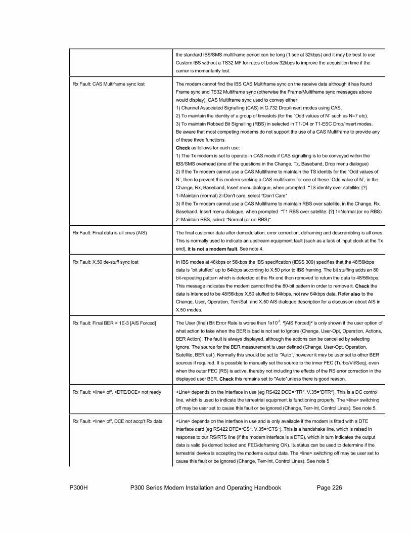
P300H P300 Series Modem Installation and Operating Handbook Page 226
the standard IBS/SMS multiframe period can be long (1 sec at 32kbps) and it may be best to use
Custom IBS without a TS32 MF for rates of below 32kbps to improve the acquisition time if the carrier is momentarily lost.
Rx Fault: CAS Multiframe sync lost The modem cannot find the IBS CAS Multiframe sync on the receive data although it has found Frame sync and TS32 Multiframe sync (otherwise the Frame/Multiframe sync messages above
would display). CAS Multiframe sync used to convey either 1) Channel Associated Signalling (CAS) in G.732 Drop/Insert modes using CAS, 2) To maintain the identity of a group of timeslots (for the `Odd values of N` such as N=7 etc).
3) To maintain Robbed Bit Signalling (RBS) in selected in T1-D4 or T1-ESC Drop/Insert modes. Be aware that most competing modems do not support the use of a CAS Multiframe to provide any
of these three functions.
Check as follows for each use: 1) The Tx modem is set to operate in CAS mode if CAS signalling is to be conveyed within the
IBS/SMS overhead (one of the questions in the Change, Tx, Baseband, Drop menu dialogue) 2) If the Tx modem cannot use a CAS Multiframe to maintain the TS identity for the ̀ Odd values of N`, then to prevent this modem seeking a CAS multiframe for one of these ̀ Odd value of N`, in the Change, Rx, Baseband, Insert menu dialogue, when prompted TS identity over satellite: [?]
1=Maintain (normal) 2=Don't care, select Don t Care
3) If the Tx modem cannot use a CAS Multiframe to maintain RBS over satellite, in the Change, Rx, Baseband, Insert menu dialogue, when prompted T1 RBS over satellite: [?] 1=Normal (or no RBS) 2=Maintain RBS, select Normal (or no RBS) .
Rx Fault: Final data is all ones (AIS) The final customer data after demodulation, error correction, deframing and descrambling is all ones. This is normally used to indicate an upstream equipment fault (such as a lack of input clock at the Tx
end), it is not a modem fault. See note 4.
Rx Fault: X.50 de-stuff sync lost In IBS modes at 48kbps or 56kbps the IBS specification (IESS 309) specifies that the 48/56kbpsdata is `bit stuffed` up to 64kbps according to X.50 prior to IBS framing. The bit stuffing adds an 80 bit-repeating pattern which is detected at the Rx end then removed to return the data to 48/56kbps.
This message indicates the modem cannot find the 80-bit pattern in order to remove it. Check the data is intended to be 48/56kbps X.50 stuffed to 64kbps, not raw 64kbps data. Refer also to the Change, User, Operation, Terr/Sat, and X.50 AIS dialogue description for a discussion about AIS in
X.50 modes.
Rx Fault: Final BER > 1E-3 [AIS Forced] The User (final) Bit Error Rate is worse than 1x10⁻³. [AIS Forced] is only shown if the user option of
what action to take when the BER is bad is not set to Ignore (Change, User-Opt, Operation, Actions, BER Action). The fault is always displayed, although the actions can be cancelled by selecting
Ignore. The source for the BER measurement is user defined (Change, User-Opt, Operation, Satellite, BER est ). Normally this should be set to Auto , however it may be user set to other BER sources if required. It is possible to manually set the source to the inner FEC (Turbo/Vit/Seq), even
when the outer FEC (RS) is active, thereby not including the effects of the RS error correction in the displayed user BER. Check this remains set to Auto unless there is good reason.
Rx Fault: <line> off, <DTE/DCE> not ready <Line> depends on the interface in use (eg RS422 DCE= TR , V.35= DTR ). This is a DC control line, which is used to indicate the terrestrial equipment is functioning properly. The <line> switching
off may be user set to cause this fault or be ignored (Change, Terr-Int, Control Lines). See note 5.
Rx Fault: <line> off, DCE not accp't Rx data <Line> depends on the interface in use and is only available if the modem is fitted with a DTE interface card (eg RS422 DTE= CS , V.35= CTS ). This is a handshake line, which is raised in
response to our RS/RTS line (if the modem interface is a DTE), which in turn indicates the output data is valid (ie demod locked and FEC/deframing OK). Its status can be used to determine if the
terrestrial device is accepting the modems output data. The <line> switching off may be user set to cause this fault or be ignored (Change, Terr-Int, Control Lines). See note 5

P300H P300 Series Modem Installation and Operating Handbook Page 227
Rx Fault: No insert bearer, generating If the Rx Baseband is set to Insert Mux, with the bearer Looped through from the Drop Mux (dialogue under Change, Rx, Baseband, Insert) then if the Tx input signal fails (no bearer or AIS) then this
looped bearer onto which the Rx traffic is to be inserted is not available and the Rx data would therefore be lost as a result of a Tx fault. In such a circumstance the modem temporarily generates a PCM bearer onto which the Rx data can be inserted to preserve the Rx traffic. See notes 6 & 9
Rx Fault: Insert bearer AIS, generating See above, see notes 6 & 9.
Rx Fault: Ins mux bearer frame sync lost The modem only detects frame sync when the Insert Mux is active. Check the bearer type is specified correctly (Change, Rx, Baseband, Insert). This normally only occurs if either there are
significant errors on the terrestrial link, or if it is supplied with AIS and the modem is set to ignore AIS.
Check that the AIS detector is not disabled with Change, User-Opt, Operation, Actions, AIS. ALSOthere is an option to make the modem re-seek frame sync if CRC sync is lost (Change, User-Opt, Operation, Terrestrial, PCM Bearer CRC, CRC/Frame Acq ). Check the modem is not set to expect a
CRC and forcing frame re-acquisition if CRC is lost, but there is no CRC on the PCM signal. See
notes 6 & 9
Rx Fault: Ins mux bearer MF sync lost The modem only seeks TS16 Multiframe sync when the Rx baseband is set to use the Insert mux in
a G.732 mode and CAS signalling has been selected. Check that a CAS multiframe is present on the PCM signal applied to the modem (ie terrestrial TS16 contains the 16 frame Multiframe sequence). See note 9.
Rx Fault: Ins mux bearer CRC sync lost The modem only seeks Cyclic Redundancy Code (CRC) sync when the Rx baseband is set to usethe Insert mux in G.732 mode and when set by the user to process CRC s (Change, User-Opt,
Operation, Terrestrial, PCM Bearer CRC, Process). If CRC sync is permanently lost, check if a CRC is present on the PCM signal.
Rx Fault: Clk PLL lock fail to <source> The PLL, which generates the Rx output clock, (or backup Rx clock) has failed to lock to the specified reference. Check the reference specified as <source> is the correct frequency. If a station
clock is specified as available the modem will use this to generate the backup Rx output clock even if Station not specified as the primary source on the Rx Clock Mode screens. Check that the Station
clock is still connected as it is a common mistake to change the Rx Clock Mode to something other than Station , then disconnect the station clock assuming the modem will not use it, whereas the
modem will always use it to generate the backup clock in preference to the internal 1PPM clock, if it
is has been told a station clock is available. (Change, Rx, Clock/Buff, Station Clock Input).
Rx Fault: LNB connection/current fault The Modem is configured to feed a DC supply `up the coax` to an LNB, but it detects there is either
an open or short circuit.
RX WARNINGS (Bottom line of display) Rx Traffic warnings: Deferred alarm relay only
Rx Warn: Reconfiguring Rx path The modem is reconfiguring the Rx path (after a user parameter change).
Rx Warn: Backward alarm from satellite A Backward Alarm is detected at the Rx Input. This indicates that equipment downstream of the TRANSMIT path (ie from our modem Tx output, though the Tx chain, through the satellite and then through the whole distant end Rx path or even further downstream) has failed and is returning an
alarm. This may be due to a receive downstream equipment failure, this Tx chain failing, the satellite itself, but also possibly the modem Tx output failing. Check the modem Tx path indicates OK, Checkthe Tx IF output from the modem is connected to the upconverter equipment and onwards; monitor
the Tx carrier (or distant Rx if possible) with a spectrum analyser.
Rx Warn: CAS MF Back' alm from sat A Multiframe Backward Alarm is detected at the Rx Input, this indicates that equipment downstreamof the TRANSMIT path has failed to find CAS Multiframe sync and is returning an alarm. Realistically while this could be caused by any equipment from the Tx modulator onwards, it is unlikely to be other
than the Tx mod, the Rx demod, or further down the Rx path as other failures would result in a more

P300H P300 Series Modem Installation and Operating Handbook Page 228
catastrophic failure (and the correspondingly more significant backward Alarm above). The Modem
only detects this alarm when the Rx baseband is set to use the Insert mux in a G.732 mode and CAS signalling has been selected (or 2048k IBS G.732 0% overhead mode with CAS is enabled). Read the text corresponding to Rx Fault: CAS Multiframe sync los to determine why a CAS multiframe is
in use over satellite and Check the three items listed against this message on the Tx path of this modem.
Rx Warn: Back' alm 1234 from satellite The display may show numbers or dashes (eg -2-4") corresponding to which of the four backward alarms are active at the Rx Input. This indicates that equipment downstream of the TRANSMIT path
(ie the distant end Rx path or further downstream) has failed and is returning an alarm. In Multidestinational circuits this may NOT correspond to the Tx path of THIS MODEM. The fault may
be due to any receive downstream equipment, but could be due to the relevant modem Tx output failing. Check the relevant modem Tx path indicates OK, Check the Tx IF output from the modem is connected to the upconverter equipment and onwards, monitor the Tx carrier (or distant Rx if
possible) with a spectrum analyser.
Rx Warn: O/p clk fail=<source>, now PLL The clock selected as the Receive data output clock, (where <Source> shows the specified clock)
has failed. The modem has switched to using a backup clock generated by the Rx PLL to preserve the receive traffic. This fault only occurs if the <source> is the same frequency as the Rx data rate, otherwise the clock is not used directly instead it is rate converted by the Rx PLL, and it s failure
results in the fault described immediately below instead. Refer also to the description of the dialogue under (Change, Rx, Buff/Clk, Rx Clock) to determine which signal the PLL uses as a backup clock.
Rx Warn: No clk ref=<source> , now int' The reference specified for the PLL, which generates the Rx output clock (or backup Rx clock) has failed; the modem has switched to using the internal 1PPM reference to keep the clock available.
Check the clock <source> specified is present. If a station clock is specified as available the modem will use this as the <source> to generate the backup Rx output clock even if Station not specified
as the primary source on the Rx Clock Mode screens. Check that the Station clock is still connected as it is a common mistake to change the Rx Clock Mode to something other than Station , then
disconnect the station clock assuming the modem will not use it, whereas the modem will always use
it in preference to the internal 1PPM clock if it is has been told a station clock is available. (Change, Rx, Clock/Buff, Station Clock Input).
Rx Warn: Back' alm received at ins' mux This fault will only be displayed if the modem if fitted with an interface which provides four ports for separate input and output of separate Tx/Drop and Rx/Insert PCM bearers. It indicates a Backward
Alarm is detected at the Rx bearer Input. This indicates that equipment downstream of the RECEIVE path has failed and is returning an alarm. This may be due to any receive downstream equipment, but could be due to the modem Rx output failing. Check the modem Rx path indicates OK, Checkthe Rx data output from the modem is connected to the downstream equipment.
Rx Warn: MF Back' alm Rx'd at ins' mux This fault will only be displayed if the modem if fitted with an interface, which provides four ports for
separate input and output of separate Tx/Drop and Rx/Insert PCM bearers. It indicates a Multiframe Backward Alarm is detected at the Rx bearer Input, this indicates that equipment downstream of the
RECEIVE path has failed to find Multiframe sync and is returning an alarm. The Modem only detects this alarm when the Rx baseband is set to use the Insert mux in a G.732 mode and CAS signalling has been selected. On the Rx path, if the Insert Mux bearer is set to Generate, then check the Rx
path is also utilising CAS, otherwise it will generate a bearer without a TS16 Multiframe.
Rx Warn: X.50 Back' alm from satellite This indicates the distant end equipment has an X.50 fault and is returning an X.50 backward alarm. See the description for the message Rx Fault: X.50 de-stuff sync lost for a further description.
Rx Warn: RF sig too low, now <-71dbm> The Receive RF signal level is below the range specified for this equipment. Increase the level to ensure specified performance is met.
Rx Warn: RF Sig too high, now <-19dBm> The Receive RF signal level is above the range specified for this equipment. Decrease the level to

P300H P300 Series Modem Installation and Operating Handbook Page 229
ensure specified performance is met.
Rx Warn: Eb/No below user threshold The Receive Eb/No (derived from the Carrier to noise ratio) is worse than the user threshold set for a
deferred alarm (Change, User-Opt, Thresholds, Eb/No). This may be used as an advance warning of service degradation.
Rx Warn: Rx BER below user threshold The final Bit Error Rate is worse than the user threshold set for a deferred alarm (Change, User-Opt, Thresholds, User BER). This may be used as an advance warning of service degradation. The source for the BER measurement is user defined (Change, User-Opt, Operation, Satellite, BER est ).Normally this should be set to Auto , however it may be user set to other BER sources if required. It
is possible to manually set the source to the inner FEC (Turbo/Vit/Seq), even when the outer FEC
(RS) is active, thereby not including the effects of the RS error correction in the displayed user BER. Check this remains set to Auto unless there is good reason.
Rx Warn: Buffer slips too frequent (YES) The minimum period between buffer slips is less than the user threshold set for a deferred alarm (Change, User-Opt, Thresholds, Buffer Slip). This is used as an advance warning that the clock accuracy is less than expected causing the buffer to slip more frequently in turn causing data errors.
The alarm may be muted by pressing YES. Check the system clocking to see if a clock has degraded. If the clocks are correct but the buffer is slipping too frequently increasing the buffer size will increase the period between buffer slips (but at the cost of increased delay).
Rx Warn: Ins' bearer BER>user threshold This fault will only be displayed if the modem if fitted with an interface, which provides four ports for
separate input and output of separate Tx/Drop and Rx/Insert PCM bearers. The Bit Error Rate at the Rx bearer input (measured on the PCM Frame Alignment Words) is worse than the user set threshold for a deferred alarm (Change, User-Opt, Thresholds, User BER). See note 3
Rx Warn: Buffer overflow & recentre The Doppler / Plesiochronous buffer has filled, and automatically slipped to position itself back in mid position. Half the buffer capacity will have been discarded, but for framed data (eg T1/E1 only) frame
sync will not be lost if the user option (Change, User-Opt, Operation, Terr/Sat, Buffer MF Slip) is set to Adjust , to ensure buffer slips are an integer multiple of the multiframe length.
Rx Warn: Buffer underflow & recentre The Doppler / Plesiochronous buffer has emptied, and automatically slipped to position itself back in mid position. Half the buffer capacity will have been repeated, but for framed data (eg T1/E1 only)
frame sync will not be lost if the user option (Change, User-Opt, Operation, Terr/Sat, Buffer MF Slip) is set to Adjust , to ensure buffer slips are an integer multiple of the multiframe length.
Rx Warn: Ins' mux slipping data to sync After a break in the Rx signal, the Insert Mux is `bit slipping` data in the Doppler Buffer to bring the data taken out of the Buffer by the Insert Mux into step with the terrestrial (bearer) frame timing.
Rx Warn: Ins' mux slipping sig' to sync See above text, but this time with regard to CAS signalling data not the main data path.
Rx Warn: RS Decoder FIFO slip The FIFO, which interfaces the RS Decoder to the Deframer has slipped (full or empty). This shouldnever occur in operation (contact factory).
Rx Warn: Insert mux sig' FIFO slip The FIFO, which carries the CAS signalling from the Doppler Buffer to the Insert Mux has slipped (full or empty). This should never occur in operation (contact factory).
Rx Warn: DISTANT Eb/No below threshold The DISTANT modems Receive Eb/No (ie this local modems TX CARRIER) is worse than the userthreshold set for a deferred alarm (Change, User-Opt, Thresholds, Distant Eb/No). This may be used
as an advance warning of service degradation. This function is only available if AUPC is active, where the local modem continuously reads the distant modems Eb/No.
Rx Warn: Turbo Decoder status This is a warning used in the engineeering debuging process it should not occur in the field. If it does, please consult the factory.

P300H P300 Series Modem Installation and Operating Handbook Page 230
Actions: RelaysU = Prompt Unit Fault relay. [Equivalent to SMS/IBS/IDR AE/AS1/AS1] T = Prompt Traffic Fault relay. [Equivalent to SMS/IBS/IDR AE/AS1/AS1] D = Deferred Alarm relay. [Equivalent to SMS/IBS/IDR none/AS2/AS2]
Actions: To TerrestrialTA = AIS (all ones) in selected TS if the Insert mux is active, AIS over all data if not in Insert mode. If Insert mode is active and
the user control Thin Route Spoof (Change, User opt, Operation, Terr/Sat, Thin Route Spoof) is set to On , then AIS is
forced over the whole PCM bearer, not just the selected timeslots to spoof full bearer connectivity when passed over a Thin Route satellite circuit (ie not the whole bearer data rate). [Equivalent to SMS/IBS/IDR AH1&AH3/AH1/AH1]
TB = Frame Backward Alarm (in PCM Multiplex, eg G.732 TS0-NFAS bit 3). [Equivalent to SMS/IBS/IDR AH2/AH2/none] TC = AIS (all ones) forced in the G.732 CAS `abcd` signalling nibble. Equivalent to SMS/IBS/IDR AH4/AH3/none]
TD = Force a fixed value in the G.732 CAS `abcd` signalling nibble. The fixed value is set by user control (Change, User Opt, Operation, Actions, Back Alarm) to be either No-Action, b=1, a=b=1, a=b=c=d=1. [Equivalent to SMS/IBS/IDR
AH5/none/none]TE = Multiframe Backward Alarm (in PCM Multiplex, eg G.732 TS16 frame 0 of multiframe = 0000 1111). [Equivalent to SMS/IBS/IDR AH6/none/none]
Actions: To Satellite
SB = Frame Backward Alarm (in IBS/SMS this is direct, in IDR or when multiple backward alarms are active it corresponds to the Rx Summary Fault Output which is externally patched back into the Backward Alarm inputs). [Equivalent to
SMS/IBS/IDR AK2/AD2/AD2]
SA = AIS (all ones), framed and scrambled ad subject to RS coding if active. [Equivalent to SMS/IBS/IDR AK1/AD1/AD1]
SC = AIS in CAS signalling carried in IBS/SMS TS16/TS48 over satellite. [Equivalent to SMS/IBS/IDR AK3/AD3/none] SD = Multiframe Backward Alarm in IBS/SMS TS16/TS48 over satellite (TS16 frame 0 of CAS multiframe = 0000 1111).
[Equivalent to SMS/IBS/IDR none/none/none]
Actions: OtherBM= BUC Mutes (not a modem function) CM = Carrier Mute, Tx carrier is switched off
TF = Tx Flow control, the `CTS` (Clear To Send) line is switched off RF = Rx Flow control, the `RR` (Receiver Ready) line is switched off
Notes1: In response to a CAS multiframe sync loss from the terrestrial port, the appropriate alarm to raise would appear to be the
CAS-MF backward alarm. However as the bearer is normally looped there is no point in raising this alarm, as a CAS
multiframe is required to convey it (ie the presence of the fault prevents the return alarm being sent). There are only two circumstances where the return bearer is not dependent upon the bearer into the Insert Mux, either when the Insert Mux is generating the bearer, or when the Rx path is receiving an independent 2M stream, which contain a CAS multiframe. In
these two circumstances the CAS-MF backward alarm is sent (TE), in all other circumstance the TS0 backward alarm is sent (TB).
2: Normally, an incoming TS16 Multiframe backward alarm causes the modem to transmit a Satellite Frame Backward Alarm (SB) to be sent. However if the user control Thin Route Spoof (Change, User opt, Operation, Terr/Sat, Thin Route Spoof) is set to On to spoof full bearer connectivity when passed over a Thin Route satellite circuit (ie not the
whole bearer data rate), then an incoming TS16 Multiframe backward alarm causes the modem to transmit a Satellite Multiframe Backward Alarm (SD, instead of SB) to keep the Frame and Multiframe backward alarm functions separate.
3: Line code setting: For P1431/32 cards check the switch on the card itself. For P1440/41/42 cards, which are configured
from the front panel check with Change, Terr-Int, Electrical, then reselect G.703, which is followed by the line code configuration.
4: All ones (the Alarm Indication Signal, AIS) is a means of signalling to downstream equipment that the data being sent is not valid. It is advised to leave AIS detection enabled so the modem can inform you when there is a fault with the traffic. If

P300H P300 Series Modem Installation and Operating Handbook Page 231
necessary (eg if the data itself contains long strings one ones) you can disable the detection of AIS and resulting actions
using Change, User-Opt, Operation, Actions, AIS.
5: Check if this line is connected in the cable and supported by the connected device. If the line is floating (no cable/not
supported) then it might `float` to the off state and intermittently raise this alarm.
6: The modem generates a temporary backup bearer for the Insert mux when set to Loopthrough only if there is no bearer available. Should the operator assume the modem is set to Generate not Loopthrough , and feed the Rx bearer output
back to the Tx bearer input (including via other equipment), then it will oscillate. Temporarily generating a backup
bearer when there is no bearer incoming, then as this temporary bearer is detected at the Tx input when fed back to the modem, it will switch off this temporary bearer and return to Loopthrough mode whereupon as there is now no source for the bearer (it s a compete loop), it will fail again and switch back temporarily to generating a backup bearer. If you see the modem displaying a bearer status switching between Rx Fault: Ins mux bearer frame sync lost , Rx Fault: Insert
bearer AIS, generating , and / or Rx Fault: No insert bearer, generating , then check that the bearer is not set to Loopthrough AND at the same time looped back to the modem Tx input, even if via other equipment.
7: If the user control Thin Route Spoof (Change, User opt, Operation, Terr/Sat, Thin Route Spoof) is set to On to spooffull bearer connectivity when passed over a Thin Route satellite circuit (ie not the whole bearer data rate), then a CAS
backward alarm incoming on the Rx Input is passed to the terrestrial as a terrestrial Multiframe backward Alarm (SD). If Thin Route Spoof is not active, the warning is still displayed but no actions are taken (ie SD is not generated).
8: You might try to clear the unit’s non-volatile memory and then reconfigure the unit from scratch. From the main menu
select 0, then User Parameters, Clr All + Reset. If this fails contact the factory for an RMA number then return the unit for repair. If the unit will not boot to allow you to select from the screens, you can also clear the memory by powering up the unit while holding in the `NO` key (but you have to hold the key in until the unit gives its normal three beeps).
9: If you wish to use Drop/Insert, and pass the incoming satellite timing to the downstream network, this is only possible by setting the Rx Insert bearer to Generate not Loopthrough (Change, Rx, Baseband, Insert dialogue), and selecting Rx
Clock as Satellite (Change, Rx, Buff/Clock, Gen Bearer Clock). If the downstream equipment requires a terrestrial TS16 Multiframe, you must configure the modem to use CAS, so the generated bearer has a TS16 multiframe.