Hibon PTB Series PD Blower Installation, Operation and ...
28
24586661 Revision B January 2014 Save These Instructions PTB Blowers PTB 8, PTB 13 Installation, Operation and Maintenance Installation, Operation and Maintenance EN Instalación, operación y mantenimiento ES Installation, fonctionnement et entretien FR Installation, Betrieb und Wartung DE Installazione, funzionamento e manutenzione IT Authorized Hibon Distributor, Service & Repair Facility 120 – 10293 276 ST, Acheson, Alberta, Canada T7X 6A5 T: 780.962.1827 F: 780.962.1830 E: [email protected] www.fraserwoods.ca
-
Upload
khangminh22 -
Category
Documents
-
view
1 -
download
0
Transcript of Hibon PTB Series PD Blower Installation, Operation and ...

24586661
Revision B January 2014
Save These Instructions
PTB Blowers
PTB 8, PTB 13
Installation, Operation and MaintenanceInstallation, Operation and MaintenanceEN
Instalación, operación y mantenimientoES
Installation, fonctionnement et entretienFR
Installation, Betrieb und WartungDE
Installazione, funzionamento e manutenzioneIT
Authorized Hibon Distributor, Service & Repair Facility 120 – 10293 276 ST, Acheson, Alberta, Canada T7X 6A5
T: 780.962.1827 F: 780.962.1830 E: [email protected] www.fraserwoods.ca

EN
EN-2 24586661 Rev. B
DECLARATION OF INCORPORATION
(as defined by the EU Machinery Directive 2006/42/EC Appendix II 1B)
DÉCLARATION D’INCORPORATION
(comme définie par la directive européenne 2006/42/CE appendice II 1B relative aux machines)
WE, / NOUS,
INGERSOLL RAND AIR SOLUTIONS HIBON
Declare that, under our sole responsibility, the partly completed machinery: Déclarons que, sous notre seule responsabilité, la presque-machine :
Description : Air Positive Displacement Blower Air End
Year of Manufacturing : 2013
Model Serial Number
PTB 8 From 15510395 to 15519999
PTB 13 From 15520288 to 15529999
Has been designed, manufactured and tested in accordance with the requirements of directive 2006/42/EC and the relevant technical documentation is compiled in accordance with annex VII B:
A été concue, fabriquée et testée en accord avec les exigences de la directive 2006/42/CE et que le dossier technique relatif a été construit en accord avec l’annexe VII B:
This partly completed machinery must not be put in service until the final machinery into which is to be incorporated has been declared in conformity with the provisions of this directive
Cette presque-machine ne doit pas être mise en service tant que l’ensemble dans lequel elle doit être intégrée n’a pas été déclaré conforme aux dispositions de la directive ci-dessus
The partly completed machinery to which this declaration relates is also in conformity with the following principal standards / normative:
La Presque-machine à laquelle se réfère cette déclaration est également conforme aux principaux standards et normes suivants:
EN 1012-1 EN 1012-2 EN ISO 12100:2010
We undertake to transmit, in response to a reasoned request by national authorities, relevant information on the partly completed machinery to which this declaration relates.
Nous nous engageons à transmettre, en réponse à une demande adéquatement motive des autorités nationales, les informations appropriées concernant la Presque-machine à laquelle se réfère cette déclaration.
Wasquehal, 01st July 2013
Judicaël DE MEYERE
The signer of this Declaration of Incorporation is also the person authorized to compile the relevant technical documentation.
Le signataire de cette Déclaration d’Incorporation est aussi la personne autorisée à élaborer le dossier technique approprié.
www.fraserwoods.ca

24586661 Rev. B EN-3
EN
1. INTRODUCTION . . . . . . . . . . . . . . . . . . . . . . . . . . . . . . . . . . . . 4
1.1 Scope and definitions . . . . . . . . . . . . . . . . . . . . . . . . . . . . . . . 4
1.2 Description . . . . . . . . . . . . . . . . . . . . . . . . . . . . . . . . . . . . . . . . . 4
1.2.1 Introduction . . . . . . . . . . . . . . . . . . . . . . . . . . . . . . . . . . . . . . . 4
1.2.2 Principle of operation . . . . . . . . . . . . . . . . . . . . . . . . . . . . . . 4
1.3 Applications . . . . . . . . . . . . . . . . . . . . . . . . . . . . . . . . . . . . . . . . 4
2. TECHNICAL DATA . . . . . . . . . . . . . . . . . . . . . . . . . . . . . . . . . . . 6
2.1 Operating and storage conditions . . . . . . . . . . . . . . . . . . . 6
2.2 Mechanical data . . . . . . . . . . . . . . . . . . . . . . . . . . . . . . . . . . . . 6
2.3 Performance . . . . . . . . . . . . . . . . . . . . . . . . . . . . . . . . . . . . . . . . 6
2.4 Noise and vibration data . . . . . . . . . . . . . . . . . . . . . . . . . . . . 8
2.5 Lubrication data . . . . . . . . . . . . . . . . . . . . . . . . . . . . . . . . . . . . 8
2.6 Materials of construction . . . . . . . . . . . . . . . . . . . . . . . . . . . . 8
2.7 Item Numbers. . . . . . . . . . . . . . . . . . . . . . . . . . . . . . . . . . . . . . . 9
2.8 Connections . . . . . . . . . . . . . . . . . . . . . . . . . . . . . . . . . . . . . . . 11
3. INSTALLATION . . . . . . . . . . . . . . . . . . . . . . . . . . . . . . . . . . . . 14
3.1 Installation safety . . . . . . . . . . . . . . . . . . . . . . . . . . . . . . . . . . 14
3.2 System design and safety . . . . . . . . . . . . . . . . . . . . . . . . . . . 14
3.2.1 General requirements . . . . . . . . . . . . . . . . . . . . . . . . . . . . . 14
3.2.2 System safety . . . . . . . . . . . . . . . . . . . . . . . . . . . . . . . . . . . . . 14
3.3 Unpack and inspect . . . . . . . . . . . . . . . . . . . . . . . . . . . . . . . . 15
3.4 Prepare, locate and connect the blower . . . . . . . . . . . . . 15
3.4.1 Introduction . . . . . . . . . . . . . . . . . . . . . . . . . . . . . . . . . . . . . . 15
3.4.2 Prepare, locate and connect blowers installed directly in your system . . . . . . . . . . . . . . . . . . . . . . . . . . . . . . . . . . 15
3.4.3 Prepare, locate and connect a blower supported by mounting feet . . . . . . . . . . . . . . . . . . . . . . . . . . . . . . . . . . . . . . . 16
3.5 Fill the blower with oil . . . . . . . . . . . . . . . . . . . . . . . . . . . . . . 16
3.6 Fit the drive/transmission. . . . . . . . . . . . . . . . . . . . . . . . . . . 16
3.7 Check the direction of rotation . . . . . . . . . . . . . . . . . . . . . 17
3.8 Commissioning the blower . . . . . . . . . . . . . . . . . . . . . . . . . 17
•
•
•
•
•
•
•
4. OPERATION . . . . . . . . . . . . . . . . . . . . . . . . . . . . . . . . . . . . . . . 18
4.1 General operational safety . . . . . . . . . . . . . . . . . . . . . . . . . . 18
4.2 Start-up . . . . . . . . . . . . . . . . . . . . . . . . . . . . . . . . . . . . . . . . . . . . 18
4.3 Shut-down . . . . . . . . . . . . . . . . . . . . . . . . . . . . . . . . . . . . . . . . . 18
5. MAINTENANCE . . . . . . . . . . . . . . . . . . . . . . . . . . . . . . . . . . . . 19
5.1 Safety information . . . . . . . . . . . . . . . . . . . . . . . . . . . . . . . . . 19
5.2 Maintenance plan . . . . . . . . . . . . . . . . . . . . . . . . . . . . . . . . . . 19
5.3 Check the oil levels . . . . . . . . . . . . . . . . . . . . . . . . . . . . . . . . . 19
5.3.1 Inspect the oil-level sight-glasses . . . . . . . . . . . . . . . . . . 19
5.3.2 Drive Head Plate . . . . . . . . . . . . . . . . . . . . . . . . . . . . . . . . . . 19
5.3.3 Non-drive Head Plate . . . . . . . . . . . . . . . . . . . . . . . . . . . . . . 20
5.4 Inspect the system installation . . . . . . . . . . . . . . . . . . . . . . 20
5.5 Change the oil . . . . . . . . . . . . . . . . . . . . . . . . . . . . . . . . . . . . . 20
5.5.1 Drive Head Plate . . . . . . . . . . . . . . . . . . . . . . . . . . . . . . . . . . 20
5.5.2 Non-drive Head Plate . . . . . . . . . . . . . . . . . . . . . . . . . . . . . 20
5.6 Overhaul the blower . . . . . . . . . . . . . . . . . . . . . . . . . . . . . . . 20
5.7 Fault finding . . . . . . . . . . . . . . . . . . . . . . . . . . . . . . . . . . . . . . . 21
6. STORAGE AND DISPOSAL . . . . . . . . . . . . . . . . . . . . . . . . . . 23
6.1 Storage . . . . . . . . . . . . . . . . . . . . . . . . . . . . . . . . . . . . . . . . . . . . 23
6.1.1 Preparation . . . . . . . . . . . . . . . . . . . . . . . . . . . . . . . . . . . . . . . 23
6.1.2 Long-term storage . . . . . . . . . . . . . . . . . . . . . . . . . . . . . . . . 23
6.2 Disposal . . . . . . . . . . . . . . . . . . . . . . . . . . . . . . . . . . . . . . . . . . . 23
7. SERVICE AND SPARES . . . . . . . . . . . . . . . . . . . . . . . . . . . . . . 24
7.1 Introduction . . . . . . . . . . . . . . . . . . . . . . . . . . . . . . . . . . . . . . . 24
7.2 Service . . . . . . . . . . . . . . . . . . . . . . . . . . . . . . . . . . . . . . . . . . . . . 24
7.3 Spares and repair kits . . . . . . . . . . . . . . . . . . . . . . . . . . . . . . . 24
RETURN OF Ingersoll Rand EQUIPMENT -
PROCEDURE . . . . . . . . . . . . . . . . . . . . . . . . . . . . . . . . . . . . . . . . . 25
RETURN OF Ingersoll Rand EQUIPMENT -
DECLARATION . . . . . . . . . . . . . . . . . . . . . . . . . . . . . . . . . . . . . . . 26
•
•
•
•
•
•
•
CONTENTS
www.fraserwoods.ca

EN
EN-4 24586661 Rev. B
1. INTRODUCTION
1.1 Scope and definitions
This manual provides installation, operation and maintenance instructions for the Ingersoll Rand PTB Blowers, which may be abbreviated to “blowers” in the remainder of this manual. You must use the blowers as specified in this manual.
Read this manual before you install and operate your blower. Important safety information is highlighted as WARNING and CAUTION instructions; you must obey these instructions. The use of WARNINGS and CAUTIONS is defined below.
WARNING
Warnings are given where failure to observe the
instruction could result in injury or death to people.
Cautions are given where failure to observe the
instruction could result in damage to the equipment,
associated equipment and process.
The identification and rating plate (Figure 1, item 13) provides specific details about the blower, such as its Item Number and so on.
The following warning symbols may be fitted to the blower or associated equipment:
Warning – refer to accompanying
documentation.
Warning – hot surfaces.
Ear defenders must be worn.
The units used throughout this manual conform to the SI international system of units of measurement.
Equivalent values in imperial units are also included.
1.2 Description
1.2.1 Introduction
Refer to Figure 1.The PTB blowers are positive displacement blowers, which incorporate two three-lobe rotors (8). One of the rotors is driven by the drive shaft (5).The other rotor is maintained in the correct phase relation by timing gears.The timing gears and the bearings on the rotors and drive shaft are lubricated by oil in the drive end cover (4) and non-drive end cover (12).
The blowers are supplied in ‘bareshaft’ form. You must connect your own coupling or belt drive system (see Section 3.6) to the drive shaft (5) in order to operate the blower.
The blowers are available in eight different positions depending:
Flow direction
Shaft position
Direction of rotation
Refer to Section 2.7 and figure 2 for the Item Numbers of the different blower versions.
1.2.2 Principle of operation
During operation, the inlet gas stream to be pumped/compressed enters the blower at the inlet (2).
As the two contra-rotating rotors turn, the inlet gas is trapped in the chambers formed between the rotors and the blower-body, and is eventually forced out of the blower at the outlet (3).
1.3 Applications
All of the PTB blowers are suitable for pressure or vacuum operation.
The blowers are suitable for pumping/compressing ambient air, and non-flammable gases, gas mixtures and dusts. The blowers are not suitable for pumping/compressing flammable or pyrophoric gases, gas mixtures and dusts.
The materials of construction of the blowers are specified in Section 2.6. Before you use the blower, you must ensure that these materials are compatible with the gases and vapors which you will pump/compress or which may exist in the external atmosphere.
You must ensure that your blower is suitable for your application.
If you have any doubts as to the suitability of the blower for your application, contact your supplier or Ingersoll Rand for advice.
•
•
•
•
•
www.fraserwoods.ca

24586661 Rev. B EN-5
EN
18
19
1
3
5
7
121617
6 11
14
13b
13a2
4
15a
15b
6
10
911
8
Figure 1 – Components of the PTB blower
1. Lifting lugs
2. Inlet
3. Outlet (behind blower)
4. Drive end cover
5. Drive shaft
6. Oil level sight glass (drive head plate)
7. Drive end oil drain plug
8. Rotors
9. Fuse plugs
10. Non-drive end oil drain plug (behind blower)
11. Oil level sight glass (Non-drive head plate)
12. Non-drive end cover
13a. Identification and rating plate (vertical position)
13b. Identification and rating plate (horizontal position)
14. Head plate bolts
15a. Direction of rotation arrow (vertical position)
15b. Direction of rotation arrow (horizontal position)
16. Oil filler plug (drive head plate)
17. Oil filler plug (non-drive head plate)
18. Maximum oil level
19. Minimum oil level
1. INTRODUCTION
www.fraserwoods.ca

EN
EN-6 24586661 Rev. B
2. TECHNICAL DATA
2.1 Operating and storage conditions
Ambient operating temperature range -20 to 40 °C, -4 to 104 °F
Ambient storage temperature range -20 to 80 °C, -4 to 176 °F
Maximum ambient operating humidity 90%
Maximum operating altitude 3000 m, 9842 ft
Maximum particle size (in pumped/compressed gases)
25 μm, 0.00098 inch
Maximum dust to gas ratio (in pumped/compressed gases)
200 mg/m3 , 0.25 oz ft-3
Table 1 – Operating and storage conditions
For operating data above the values indicated in table 1, please contact Ingersoll Rand.
2.2 Mechanical data
Dimensions
Left and Right Hand blowers See Figure 3
Top and Bottom Shaft blowers See Figure 4
Mass
PTB 8 PTB 13
190 kg 230 kg
419 lb 507 lbTable 2 – Mechanical data
2.3 Performance
Notes: The “given pressures” specified in Tables 4 and 5 are the differential pressures across the blower (that is, the differential pressures between the blower inlet and outlet)
The “r.p.m/r min¯1 “ rotation speeds specified in Tables 4 and 5 are provided for information only, to identify blower performance at the specified speed. During operation, the rotation speed of the blowers need not be limited to these specified speeds.
The maximum vacuum values given in Table 3 are for a flow through the blower.
All of the throughput and power values given in Table 3 have a tolerance of ± 5%.
You must not exceed these values, otherwise the blower may be damaged and/or seize.
“Maximum differential pressure (inlet/outlet)”
1200 mbar, 1.2 x 10⁵ Pa, 900 Torr (continuous operation)
1400 mbar, 1.4 x 10⁵ Pa, 1050 Torr (intermittent operation)
Pressure performance See table 4
Rotational speed range See table 4
Nominal shaft power See table 4
“Maximum absorbed shaft power (pressure
operation)”
70.2 kW / 94.1 hp (PTB 8)
85.9 kW / 115.2 hp (PTB 13)
Table 3 – Performance data
www.fraserwoods.ca

24586661 Rev. B EN-7
EN
2. TECHNICAL DATA
Blower“rpm/
r.min¯1”
Throughput (m3/h) and absorbed power (kW) at given pressure at 1013 mbar and 20°C
500 mbar 600 mbar 800 mbar 1000 mbar 1200 mbar 1400 mbar**
5 x 10⁴ Pa 6 x 10⁴ Pa 8 x 10⁴ Pa 10 x 104 Pa 12 x 104 Pa 14 x 104 Pa
m3/h kW m3/h kW m3/h kW m3/h kW m3/h kW m3/h kW
PTB 8 (1702 m3/h)*
1800 573 13.3 552 15.9 517 21.2 478 26.5 436 31.8 - -
2200 758 16.2 737 19.5 704 25.9 668 32.4 628 39.0 589 45.4
2600 943 19.3 923 23.1 891 30.7 857 38.4 819 46.0 782 53.7
3000 1127 21.6 1108 26.5 1078 35.4 1046 44.3 1011 53.1 976 61.9
3400 1311 25.1 1294 30.1 1265 40.1 1236 50.2 1202 60.2 1169 70.2
PTB 13 (2723 m3/h)*
1800 964 21.3 945 25.5 902 34.0 867 42.5 826 51.0 - -
2200 1227 25.9 1213 31.1 1172 41.5 1138 51.9 1099 62.3 1074 72.7
2600 1494 30.7 1481 36.8 1441 49.1 1409 61.4 1373 73.6 1350 85.9
3000 1764 35.4 1749 42.5 1710 56.6 1680 70.8 1647 85.0 - -
3400 2033 40.1 2017 48.1 1980 64.2 1951 80.2 - - - -
Blower“rpm/
r.min¯1”
Throughput (cfm) and absorbed power (h.p.) at given pressure at 14,7 psi and 68°F
7.25 psi 8.7 psi 11.6 psi 14.5 psi 17.4 psi 20.3 psi**
CFM hp CFM hp CFM hp CFM hp CFM hp CFM hp
PTB 8 (1002 CFM)*
1800 337 17.8 325 21.3 305 28.5 282 35.6 257 42.7 - -
2200 446 21.7 434 26.1 414 34.7 393 43.5 370 52.3 347 60.9
2600 555 25.8 543 30.9 524 41.2 504 51.4 482 61.7 460 71.9
3000 663 29.0 652 35.6 634 47.5 616 59.4 595 71.3 574 83.0
3400 772 33.6 761 40.4 744 53.8 727 67.3 707 80.7 688 94.1
PTB 13 (1603 CFM)*
1800 567 28.5 556 34.2 531 45.6 510 57.0 486 68.4 - -
2200 722 34.7 714 41.7 690 55.7 670 69.6 647 83.5 632 97.5
2600 879 41.2 872 49.3 848 65.8 829 82.3 808 98.7 794 115.2
3000 1038 47.5 1030 57.0 1007 75.9 989 94.9 969 114.0 - -
3400 1196 53.8 1187 64.5 1165 86.1 1148 107.5 - - - -
* Volume displacement at maximum speed
** For intermittent use only (15 min / hour)
Table 4 – Pressure performance data
www.fraserwoods.ca

EN
EN-8 24586661 Rev. B
2. TECHNICAL DATA
2.4 Noise and vibration data
Note: The noise and vibration data values given below are maximum values. The actual values are given according to our test bench and will depend on the installation and the operating conditions.
Noise level PTB 8 PTB 13
100 104
Vibration level
5,5 mm.s-2 5,5 mm.s-2
0,22 inch.s-2 0,22 inch.s-2
Table 5 – Noise and vibration data
2.5 Lubrication data
On standard applications, you can use an oil which complies with the ‘standard use’ specification given in Table 6. You must use an oil which complies with the ‘special use’ specification in Table 6:
If you use the blower with an acoustic enclosure.
If you use the blower in ambient temperatures of 0 ° C (32 ° F) or below.
If you use the blower with a power input that exceeds 2 / 3 of the maximum power input (see Table 3).
Parameter Standard use Special use
Density (at 15 °C, 59 °F) 0.89 0.86
Mean pour point 21 °C (70 °F) 45 °C (113 °F)
Mean flash point 224 °C (435 °F) 260 °C (500 °F)
Viscosity: at 20 °C (68 °F)
8.09 x 10¯4 m2 s¯1 (809 cSt)
6.04 x 10¯4 m2 s¯1 (640 cSt)
at 40 °C (104 °F) 2.2 x 10¯4 m2 s¯1 (220 cSt)
2.18 x 10¯4 m2 s¯1 (218 cSt)
at 100 °C (212 °F) 1.8 x 10¯5 m2 s¯1 (18 cSt)
2.7 x 10¯5 m2 s¯1 (27 cSt)
Mean viscosity index 93 149
Recommended oil Hibon Lub Contact factory
Table 6 – Lubricating oil specifications
•
•
•
Drive end cover
PTB 8 PTB 13
1,50 liters 1,50 liters
0,40 US gal 0,40 US gal
Non-drive end cover2,10 liters 2,10 liters
0,55 US gal 0,55 US gal
Table 7 – Left and Right Hand blower oil capacities
Drive end cover
PTB 8 PTB 13
0,9 liters 0,9 liters
0,24 US gal 0,24 US gal
Non-drive end cover1,30 liters 1,30 liters
0,34 US gal 0,34 US galTable 8 – Top and Bottom Shaft blower oil capacities
2.6 Materials of construction
Head Plates and End Covers EN GJL 200 grey cast iron
Casings EN GJL 200 grey cast iron
Rotors EN GJS 400-15 spheroidal graphite cast iron
Bearings 100Cr6 steel
Piston rings Cast iron
Piston rings holder C 45E Steel
Gaskets Klingerit® C4430
O-rings Nitrile
Table 9 – Construction materials data
www.fraserwoods.ca

24586661 Rev. B EN-9
EN
2. TECHNICAL DATA
2.7 Item Numbers
A B
C D
E F
G H
Figure 2 – Ordering configurations
Inlet gas stream Note: Refer to Table 10 for the item numbers of blowers with the configurations shown in the figure Discharge (outlet) Gas stream
www.fraserwoods.ca

EN
EN-10 24586661 Rev. B
Blower model Shaft positionRotation direction
Standard blowers
Item Number“Configuration:
See Figure 2”
Hibon Number CCN
PTB 8
Bottom AnticlockwiseF015510112 47007596
A
Bottom Clockwise B
Top AnticlockwiseF015510122 47007604
C
Top Clockwise D
Left AnticlockwiseF015510102 47007588
E
Left Clockwise F
Right AnticlockwiseF015510132 47007612
G
Right Clockwise H
PTB 13
Bottom AnticlockwiseF015520112 47007638
A
Bottom Clockwise B
Top AnticlockwiseF015520122 47007646
C
Top Clockwise D
Left AnticlockwiseF015520102 47007620
E
Left Clockwise F
Right AnticlockwiseF015520132 47007653
G
Right Clockwise H
Table 10 - Item Numbers
2. TECHNICAL DATA
www.fraserwoods.ca

24586661 Rev. B EN-11
EN
2.8 Connections
Ø r
EA / GC
h
D L
H
VW
T
Y
A
B
Ø P
Ø S
L1
Ø O
Ø Z
Figure 3 - Left and Right Hand blower dimensions
Key
Dimensions
PTB 8 PTB 13
mm inch mm inch
A 149.35 5.88 149.35 5.88B 266.7 10.50 266.7 10.50D 437 17.20 437 17.20
EA/GC 135 5.32 135 5.32H 308 12.13 308 12.13h 154 6.06 154 6.06L 672 26.46 822 32.36
L1 324 12.76 341.4 13.44T 51.5 2.03 51.5 2.03V 70 2.76 70 2.76W 81 3.19 81 3.19Y 14 0.55 14 0.55
ØZ* 48 1.89 48 1.89Ør 191.5 7.54 191.5 7.54ØO 105 4.13 105 4.13ØP 4 x M16 4 x M16 4 x M16 4 x M16ØS 4 x M12 4 x M12 4 x M12 4 x M12
* Fitting tolerance range : m6Table 11 - Left and Right hand blower dimensions
2. TECHNICAL DATA
www.fraserwoods.ca

EN
EN-12 24586661 Rev. B
2. TECHNICAL DATA
Ø r
EA
/ G
C
L1
E
H
Ø O
Ø S
Ø P
L
V W
X
A
B
Y
T
Ø Z
h
Figure 4 -Top and Bottom Shaft blower dimensions
www.fraserwoods.ca

24586661 Rev. B EN-13
EN
2. TECHNICAL DATA
Key
Dimensions
PTB 8 PTB 13
mm inch mm inch
A 149.35 5.88 149.35 5.88
B 266.7 10.50 266.7 10.50
E 148 5.83 148 5.83
EA/GC 135 5.32 135 5.32
H 308 12.13 308 12.13
h 154 6.06 154 6.06
L 672 26.46 822 32.36
L1 324 12.76 341.4 13.44
T 51.5 2.03 51.5 2.03
V 70 2.76 70 2.76
W 81 3.19 81 3.19
X 460 18.11 460 18.11
Y 14 0.55 14 0.55
ØZ* 48 1.89 48 1.89
Ør 191.5 7.54 191.5 7.54
ØO 105 4.13 105 4.13
ØP 4 x M16 4 x M16 4 x M16 4 x M16
ØS 4 x M12 4 x M12 4 x M12 4 x M12
* Fitting tolerance range : m6, unless, otherwise stated above.
Table 12 -Top and Bottom Shaft blower dimensions
www.fraserwoods.ca

EN
EN-14 24586661 Rev. B
3. INSTALLATION
Ingersoll Rand will accept no liability or warranty
claims if your installation includes any modifications
or additions to the blower without the prior written
approval of Ingersoll Rand, or if the blower is incorrectly
installed.
3.1 Installation safety
WARNING
Obey the safety instructions listed below and take note
of appropriate precautions when you install the blower.
A suitably trained and supervised technician must install the blower.
Ensure that debris and dust does not get into the blower or the system pipelines when you install the blower.
Check that all of the required components and tools are available and of the correct type before you start to install the blower.
Use suitable new gaskets/seals to connect the blower into your system. Do not re-use old gaskets/seals.
If you will fit the blower into an existing system, disconnect the power from the drive system before you start installation, so that the drive system cannot be operated accidentally.
3.2 System design and safety
WARNING
Ensure that the maximum differential pressure across
the blower specified in section 2.2 cannot be exceeded.
If it is, the drive will trip and the blower will stop. Obey
the safety instructions listed below when you design
and build your system:
3.2.1 General requirements
Your system must be suitably designed for correct operation of the blower. Note that:
You must design a suitable pipeline to fit the blower inlet/outlet connections. refer to Section 2.8 and to Figures 3 and 4 for the dimensions of the blower connections.
Your system design must ensure that, when the blower is in its final operating location, you can see the oil-level sight-glasses and can access the oil filler and drain plugs.
Your system must incorporate a suitable mounting platform: see Section 3.4 for more details.
The blower must be sufficiently level for correct operation: see Section 3.4 for more details.
There must be at least 150 mm (6 inches) of free space around the blower, for adequate cooling-air circulation.
•
•
•
•
•
•
•
•
•
•
•
The gases which enter the blower must not contain solid particulates larger than 25 μm (9.84 x 10⁻⁵ inch) in size and must not contain more than 200 mg/m3 (1.37 x 10⁻⁵ lb/ft3) of dust. Incorporate suitable filters to prevent the ingress of solids into the blower.
The temperature of the gases which enter the blower must not exceed the temperature rating of the blower.
3.2.2 System safety
Your system design must ensure that the blower cannot be operated with the inlet or discharge (outlet) pipelines obstructed.
Ensure that the blower cannot operate with the incorrect direction of rotation (see Section 3.7).
We also recommend that your system incorporates an emergency stop facility which, once activated, must be manually reset before the blower can be operated again.
Your system must incorporate non-return valves (check valves), to prevent reverse rotation of the blower when it is switched off.
Your system must incorporate a pressure relief valve in the outlet pipeline (for pressure operation) and/or incorporate a vacuum relief valve in the inlet pipeline (for vacuum operation), to ensure that the design capability of the blower cannot be exceeded during operation. The relief valve(s) must be suitably rated/sized for the performance of the blower.
We recommend that you incorporate silencers, to attenuate the pulsations in the inlet/outlet gas streams.
If required, install your own acoustic enclosure around the blower or ensure that people wear suitable protective equipment (such as ear defenders) when they are close to the operating blower (See section 2.4). If you install an acoustic enclosure, ensure that there is sufficient space for cooling-air flow around the blower. See above
Your design must ensure that people are protected from accidental contact with the blower or the outlet pipelines. During blower operation, the temperature of the blower and the outlet pipelines will be above 70 °C (158 °F). If necessary, fit suitable guards.
Your design must ensure that materials or substances which are flammable at temperatures of 70 °C (158 °F) or above are not close to, or in contact with, the hot blower or outlet pipelines.
If you pump/compress flammable or toxic gases, you must take suitable precautions to prevent the discharge of the gases to the surrounding atmosphere.
Note: Filters, pressure/vacuum relief valves, non-return (check) valves, acoustic enclosures and silencers are available from Ingersoll Rand: contact your supplier or Ingersoll Rand for advice.
•
•
•
•
•
•
•
•
•
•
•
•
•
www.fraserwoods.ca

24586661 Rev. B EN-15
EN
3.3 Unpack and inspect
WARNING
Use suitable lifting equipment to move the blower.
If you do not, you can injure yourself or damage the
blower. Refer to Section 2.2 for the mass of the blower.
1. Use a suitable fork-lift truck or pallet truck to move theblower, on its pallet, close to where you will install it.
2. Remove all packing materials and protective coversand check the blower. If the blower is damaged, notifyyour supplier and the carrier in writing within twodays; state the Item Number of the blower togetherwith your order number and your supplier’s invoicenumber. Retain all packing materials for inspection. Donot use the blower if it is damaged.
3. Check that you have received the items. If any item ismissing, notify your supplier in writing within two days
4. Look at the blower rating and identification plate(Figure 1, item 13) and check that the blower is suitablefor use in your system. If the blower is not suitablefor use in your system, do not continue to install theblower: contact your Supplier orIngersoll Rand.
If the blower is not to be used immediately, replace the protective covers. Store the blower in suitable conditions, as described in Section 6.1.
3.4 Prepare, locate and connect the blower
3.4.1 Introduction
Take note of the following when you locate the blower and connect it into your system:
For optimum performance, ensure that the system pipelines connected to the blower are as short as possible.
Support your system pipelines and other components, to prevent loading of the inlet and outlet ports on the blower.
Incorporate flexible components in your system, to minimize noise and vibration.
Where necessary, use gaskets/seals which are compatible with the gases which will be pumped/compressed, and with the operating conditions.
The leak tightness of your system connections must be in accordance with the requirements of your applications.
Note that blowers can be:Installed directly in your system. You must ensure that your system pipelines can support the blower. Prepare, locate and connect blower as described in Section 3.4.2.
Supported by mounting feet; prepare, locate and connect blowers as described in Section 3.4.3.
•
•
•
•
•
•
•
•
Note that the blowers are supplied with either lifting bolts fitted (as shown in Figure 1) or with lifting lugs fitted. Where necessary in Sections 3.4.2 or 3.4.3, attach your lifting equipment to these lifting bolts/lugs.
3.4.2 Prepare, locate and connect blowers
installed directly in your system
WARNING
Use suitable lifting equipment to move the blower.
If you do not, you can injure yourself or damage the
blower. Refer to Section 2.2 for the mass of the blower.
Note: The following procedure assumes that your system inlet pipeline will support the blower. If your blower will be supported by your system outlet pipeline, reverse Steps 4 and 5 below.
Use the following procedure to prepare, locate and connect blower:
1. Use a suitable cleaning solution (such as alcohol orwhite spirit) to clean the rotors:Moisten a suitable clean, lint-free cloth with the cleaning solution.
Clean the rotors (Figure 1, item 8) which are visible through the inlet port.
Turn the blower drive shaft as necessary to access the other rotors.
2. Refer to Figure 1. Attach suitable lifting equipment tothe blower, then use the lifting equipment to move theblower to its required operating location.
3. While it is supported by the lifting equipment, adjustthe position of the blower so that the blower inlet andoutlet are correctly aligned with the connections inyour system inlet and outlet pipelines.
4. Fit a suitable gasket/seal* to the blower inlet (Figure 1,item 2), then use the correct number and size of boltsto connect the blower inlet flange to your system inletpipeline.
5. Fit a suitable gasket/seal* to your system outletpipeline, then use the correct number and size of boltsto connect the blower outlet flange to your systemoutlet pipeline.
6. Disconnect your lifting equipment from the blower.
*Note: Gaskets are available from Ingersoll Rand: Contact your supplier or Ingersoll Rand for advice
•
•
•
•
3. INSTALLATION
www.fraserwoods.ca

EN
EN-16 24586661 Rev. B
3. INSTALLATION
3.4.3 Prepare, locate and connect a blower
supported by mounting feet
WARNING
Use suitable lifting equipment to move the blower.
If you do not, you can injure yourself or damage the
blower. Refer to Section 2.2 for the mass of the blower.
You must provide a firm, level platform for the blower. Ensure that the operating location is clean and free from debris and oil.
You must ensure that when the blower is in its required operating location, all of the mounting feet (1, 2 or 4, depending on the blower model) are flat on the mounting platform to within 0.1 mm.m ¯1 (0.0013 inch.ft ¯1 ).
Use the following procedure to prepare, locate and connect the blower:
1. Refer to Figure 1. Attach suitable lifting equipment tothe four lifting-bolts (1), then use the lifting equipmentto move the blower to its required operating location.
2. Disconnect your lifting equipment from the blower. Ifrequired, remove the lifting-bolts from the blower.
3. Fit suitable bolts through the fixing holes in themounting feet (Figure 1, items 9), to secure the blowerin position.
4. Clean the rotors: refer to Step 1 of Section 3.4.2.
5. Use a suitable gasket/seal* to connect your inletpipeline to the blower inlet (Figure 1, item 2).
6. Use a suitable gasket/seal* to connect your outletpipeline to the blower outlet (Figure 1, item 3).
*Note: Gaskets are available from Ingersoll Rand: Contact your supplier or Ingersoll Rand for advice
• 3.5 Fill the blower with oil
Ensure that you use the correct grade of oil and that
the oil levels in the blower are correct. If you do not, the
blower will probably be damaged during operation, or
its performance may be affected.
1. Drain the protective oil from the drive end and non-drive end covers: refer to Section 5.5.
2. Refer to Figure 1. Fill the drive end cover (4) with oil:refer to Section 5.5.1.
3. Fill the non-drive end cover (12) with oil: refer toSection 5.5.2.
3.6 Fit the drive/transmission
WARNING
You must fit suitable guards to protect people from
rotating/moving parts.
Your drive and transmission system design must ensure
that the maximum blower rotational speeds specified in
Section 2.3 cannot be exceeded, otherwise the blower
will be damaged, or may not operate correctly.
You must use a suitable coupling or a belt drive and transmission system to connect your drive to the blower.
Your drive and transmission system design must ensure that the radial and axial loadings on the blower drive shaft are as low as possible.
Note : For this, the blower pulley diameter must be above diameters specified in Table 13, linear speed of belts should not exceed 31 m/s and transmission safety factor should be between 1,4 and 1,7.
Connect the components of the drive and transmission system to the blower drive shaft (Figure 1, item 5) as described in the manufacturer’s instructions supplied with the components.
Blower
Minimum pulley diameter for specified differential pressure : mm (inch)
“300 mbar 3 x 10⁴ Pa 4,35 psi”
“400 mbar 4 x 10⁴ Pa
5,8 psi”
“500 mbar 5 x 10⁴ Pa 7,25 psi”
“600 mbar 6 x 10⁴ Pa
8,7 psi”
“700 mbar 7 x 10⁴ Pa 10,15 psi”
“800 mbar 8 x 10⁴ Pa 11,6 psi”
“900 mbar 9 x 10⁴ Pa 13,05 psi”
“1000 mbar 1 x 10⁵ Pa 14,5 psi”
“1100 mbar 1,1 x 10⁵ Pa 15,95 psi”
“1200 mbar 1,2 x 10⁵ Pa
17,4 psi”
PTB 8 140 (5.51) 140 (5.51) 150 (5.90) 150 (5.90) 160 (6.30) 170 (6.69) 180 (7.09) 180 (7.09) 200 (7.87) 200 (7.87)
PTB 13 150 (5.90) 170 (6.69) 180 (7.09) 180 (7.09) 200 (7.87) 200 (7.87) 212 (8.35) 212 (8.35) 224 (8.82) 224 (8.82)Table 13 - Minimum drive shaft pulley diameters
www.fraserwoods.ca

24586661 Rev. B EN-17
EN
3. INSTALLATION
3.7 Check the direction of rotation
WARNING
If you remove a guard during the following procedure,
ensure that you do not corne into contact with the shaft,
the coupling/belt or the drive system when you operate
the blower.
If you do, you may be injured by the rotating
components.
Ensure that the blower rotates in the correct direction. If
it does not, your system will not operate correctly.
After you have connected the drive/transmission, check the direction of rotation of the blower as follows:
1. Ensure that isolation valves in the blower inlet andoutlet pipelines are in the correct ‘open’ positions.
2. If necessary (that is, to make it easier to see the blowerdrive shaft), temporarily remove guard over the drivecoupling or belt.
3. Refer to Figure 1. Watch the blower drive shaft (5) whileyou start up the blower (refer to Section 4.2), thenshut down the blower (refer to Section 4.3) after twoseconds.
4. Check that the blower drive shaft (5) rotated correctlyin the expected direction. (This depends on yourapplication and installation configuration: see Figure 1item 15a or b)
5. If the direction of rotation was incorrect:Check the installation of the drive and transmission system and reconfigure as appropriate.
Perform the direction of rotation check from Step 2 again, to ensure that the blower now rotates in the correct direction.
6. If you have removed the guard over the drive couplingor belt (as in Step 1 above), refit the guard.
•
•
3.8 Commissioning the blower
After you have installed the blower, use the following procedure to commission it and prepare it for subsequent operation:
1. Ensure that isolation valves in the blower inlet andoutlet pipelines are in the correct ‘open’ positions.
2. Ensure that all other components in the systempipelines (such as filters) have been correctly installedand configured for operation.
3. Engage your drive and transmission system to start theblower.
4. Operate the blower, with no gas load, for at least 15minutes. During this time:Monitor the external surfaces of the blower and check for ‘hot spots’ (that means, areas which are unusually hot).
If any hot spots persist at the end of the 15 minutes, contact your supplier or Ingersoll Rand for advice.
5. Continue to operate the blower with a representativegas load, and check that it operates correctly andprovides the required performance. If necessary, referto Section 5.7 if any fault conditions occur.
6. Disengage your drive and transmission system to stopthe blower.
7. Wait until you can hear that the blower has stoppedbefore you close any isolation valves in the blower inletand outlet pipelines.
The blower is now ready for normal operation.
•
•
www.fraserwoods.ca

EN
EN-18 24586661 Rev. B
4. OPERATION
WARNING
Ingersoll Rand will accept no liability or warranty
claims if your blower is used on applications or in a
way prohibited in this manual, or not specified in this
manual.
4.1 General operational safety
WARNING
Obey the safety instructions and precautions listed
below. If you do not, there may be a risk of injury or
death to people, or damage to the blower.
Do not expose any part of your body to vacuum. If you do, you may be injured.
Do not operate the blower when the cooling-air flow around the blower is restricted (see Section 3.2). If you do, the blower may overheat.
Do not operate the blower with the blower inlet or outlet ports open to the atmosphere. If you do, your fingers or other parts of your body or clothing may get trapped, and you may be injured by the rotating mechanisms in the blower.
Do not operate the blower with the guards removed from the blower drive shaft, the coupling/belt or the drive system. If you do, your fingers or other parts of your body or clothing may get trapped, and you may be injured by the rotating components.
Never disconnect any of the connecting pipelines (for example, the pipeline connected to the inlet) when the blower is operating.
Prevent accidental contact with the hot blower, and do not place flammable materials on the blower. During operation, the temperature of external parts of the blower can exceed 70° C (158° F).
Do not attempt to use the blower to pump/compress liquids. The blowers are not designed for this application.
Where necessary (for example, if you have not fitted an acoustic enclosure), wear suitable ear defenders. The blower can be noisy during operation (refer to Section 2.4).
During pressure operation, prevent accidental contact with the discharged (outlet) gas stream. This gas stream will be at high pressure and will be hot and can cause burn injury.
•
•
•
•
•
•
•
•
•
4.2 Start-up
Ensure that the oil levels in the blower are correct. If you
do not, the blower will probably be damaged during
operation, or its performance may be affected.
1. Ensure that any isolation valves in the blower inlet andoutlet pipelines are in the correct ‘open’ positions.
2. Check the oil-levels in the blower: refer to Section 5.3.
3. Engage your drive and transmission system to start theblower.
You can now use the blower as required in your application.
4.3 Shut-down
1. Disengage the drive and transmission system to stopthe blower.
2. Wait until you can hear that the blower has stoppedbefore you close any isolation valves in the blower inletand outlet pipelines.
www.fraserwoods.ca

24586661 Rev. B EN-19
EN
5. MAINTENANCE
5.1 Safety informationWARNING
Obey the safety instructions given below and take note
of appropriate precautions. If you do not, you can cause
injury to people and damage to equipment.
A suitably trained and supervised technician must maintain the blower. Obey your local and national safety requirements.
Ensure that the maintenance technician is familiar with the safety procedures which relate to the gases pumped/compressed by the system in which the blower is installed.
Allow the blower to cool to a safe temperature before you start maintenance work.
Isolate the blower from the drive system so that it cannot be operated accidentally.
Recheck the blower rotation direction (see Section 3.7) if the drive and transmission system has been disconnected and then reconnected.
Take care to protect the inlet/outlet port sealing faces from damage.
Do not re-use seals/gaskets if they are damaged.
Check the tightness of the system connections after maintenance work is complete if you have connected or disconnected any suction inlet or discharge (outlet)/injection joints. The tightness of the system connections must be in accordance with the requirements of your applications.
5.2 Maintenance plan
The plan in Table 14 details the maintenance operations required to maintain the blower in normal operation. Instructions for each operation are given in the section shown.
Note that:If you use a mineral oil in the blower: you must change the oil every 2000 hours of operation or once a year.
If you use a synthetic oil in the blower, you must change the oil every 12 months.
If you use a Hibon Lube in the blower and you operate the blower with a discharge (outlet) temperature above 120 ˚ C (248 ˚ F), you must change the oil every 12 months.
If you use a Hibon Lube in the blower and you operate the blower with a discharge (outlet) temperature below 120 ˚ C (248 ˚ F), you must change the oil every two years.
When you maintain the blower, use Ingersoll Rand spares: refer to Section 7.3.
•
•
•
•
•
•
•
•
•
•
•
•
Operation Frequency Refer to Section
Check the oil levelsInspect the system installationChange the oilOverhaul the blower
WeeklyMonthly
See Section 5.24 yearly
5.35.45.55.6
After blower installation, the oil must be changed after 200 hours of running.
Table 14 – Maintenance plan
5.3 Check the oil levels
Ensure that you use the correct grade of oil and that
the oil levels in the blower are correct. If you do not, the
blower will probably be damaged during operation, or
its performance may be affected.
5.3.1 Inspect the oil-level sight-glasses
1. Refer to Figure 1. Look at the oil-level sight-glass (6) onthe drive head plate (4):If the sight-glass is dirty, use a suitable cloth to wipe it clean.
If the sight-glass is damaged (that is, scratched, cracked or corroded), or if there are signs of oil leakage from the sight-glass, you must replace it: contact your supplier or Ingersoll Rand.
2. Look at the oil-level sight-glass (11) on the non-drivehead plate (12):If the sight-glass is dirty, use a suitable cloth to wipe it clean.
If the sight-glass is damaged (that is, scratched, cracked or corroded), or if there are signs of oil leakage from the sight-glass, you must replace it: contact your supplier or Ingersoll Rand.
5.3.2 Drive Head Plate
1. Refer to Figure 1, detail B. Look at the oil level in thesight-glass (6) on the drive head plate (4):If the oil level is below the minimum level mark (19), continue at Step 2 to add more oil.
If the oil level is above the maximum level mark (18), drain oil from the blower until the level is correct: refer to Section 5.5.
2. Refer to Figure 1. Remove the oil filler-plug (16) fromthe filler port on the top of the drive head plate (4).
3. For new oil of the correct type (see Section 2.6)through the filler port and into the head plate untilthe oil-level reaches the maximum level mark (detail B,item 18). If the oil level goes above the maximum levelmark (18), drain oil from the blower until the level iscorrect: refer to Section 5.5.
4. Refit the oil filler-plug (16) to the filler port on the topof the drive head plate (4).
•
•
•
•
•
•
•
•
www.fraserwoods.ca

EN
EN-20 24586661 Rev. B
5. MAINTENANCE
5.3.3 Non-drive Head Plate
1. Refer to Figure 1, detail B. Look at the oil level in thesight-glass (11) on the non-drive head plate (12):If the oil level is below the minimum level mark (19), continue at Step 2 to add more oil.
If the oil level is above the maximum level mark (18), drain oil from the blower until the level is correct: refer to Section 5.5.
2. Refer to Figure 1. Remove the oil filler-plug (17) from thefiller port on the top of the non-drive head plate (12).
3. For new oil of the correct type (see Section 2.6)through the filler port and into the head plate untilthe oil-level reaches the maximum level mark (detail B,item 18). If the oil level goes above the maximum levelmark (18), drain oil from the blower until the level iscorrect: refer to Section 5.5.
4. Refit the oil filler-plug (17) to the filler port on the topof the non-drive head plate (12).
5.4 Inspect the system installation
Note: Where possible, we recommend that you investigate the cause of any damage or corrosion, and implement corrective measures to prevent any future damage of components.
Use the following procedure to inspect the system connections:
1. Inspect all of the system pipelines and connectionsand check that they are not damaged or corroded andthat they are sufficiently leak-tight. Repair or replaceany damaged or corroded component and seal anyleak found.
2. Inspect the drive/transmission system andadjust, repair or replace as necessary: refer to themanufacturer’s instructions supplied with your drive/transmission system.
5.5 Change the oil
Ensure that you use the correct grade of oil and that
the oil levels in the blower are correct. If you do not, the
blower will probably be damaged during operation, or
its performance may be affected.
WARNING
You must take care about the oil temperature. Please
wait at least two hours after the last running of the
blower to empty the oil casings to let the oil cool -down.
•
•
•
5.5.1 Drive Head Plate
1. Refer to Figure 1. Remove the oil filler-plug (16) fromthe filler port on the top of the drive head plate (4).
2. Refer to Figure 1. Place a suitable container under thedrain plug (7) on the drive head plate. The containermust have a maximum capacity as specified in Table 7or Table 8.
3. Remove the oil drain plug (7) from the end cover,and allow the oil to drain from the end cover into thecontainer.
4. Refit the oil drain plug (7) to the drive head plate (4).
5. Dispose of the oil: refer to Section 6.2.
6. Fill the drive end cover with new oil of the correct typeand grade: refer to Section 5.3.1.
5.5.2 Non-drive Head Plate
1. Refer to Figure 1. Remove the oil filler-plug (17) fromthe filler port on the top of the nondrive head plate(12).
2. Refer to Figure 1. Place a suitable container underthe drain plug (10) on the non-drive head plate. Thecontainer must have a maximum capacity as specifiedin Table 7 or Table 8.
3. Remove the oil drain plug (10) from the end cover,and allow the oil to drain from the head plate into thecontainer.
4. Refit the oil drain plug (10) to the non-drive head plate (12).
5. Dispose of the oil: refer to Section 6.2.
6. Fill the non-drive end cover with new oil of the correcttype and grade: refer to Section 5.3.2.
5.6 Overhaul the blower
The blower must be regularly overhauled, as specified in Table 14. As part of the overhaul, the bearings in the blower mustbe replaced.
We recommend that you contact your supplier or Ingersoll Rand to arrange for an overhaul of the blower.
•
•
www.fraserwoods.ca

24586661 Rev. B EN-21
EN
5. MAINTENANCE
5.7 Fault finding
A guide to fault conditions and their possible causes is provided in Table 15 to assist you in basic fault finding.
If you are unable to rectify a fault when you use this guide, call your supplier or your nearest Ingersoll Rand Service Centre for advice.
Note: If you have been approved to carry out strip-down, repair and reassembly of your blower, refer to the Service Manual supplied separately for detailed procedures.
Symptom Check Actions
The blower will not start, or
seizes during operation.
Are the rotors touching ? Check the rotor clearances and adjust as necessary.
Has the blower been overloaded ?Check the required operating conditions and specified performance of the blower (see Section 2).
Has debris or foreign material entered the blower ?
Strip down, clean and repair the blower as necessary.
Is the drive/transmission system faulty ?
Check that your drive and transmission system is operating correctly, and that it is correctly fitted to the blower: refer to Section 3.6 and to the manufacturer’s instructions.
The blower is noisy during
operation.
Are the rotors touching ? Check the rotor clearances and adjust as necessary.
Are the gear and/or bearing clearances incorrect ? Check the clearances and adjust as necessary.
Are the rotors unbalanced ?Clean the rotors and rotor housing, then check the rotor clearances and adjust as necessary.
The blower overheats.
Is the inlet filter blocked ? Clean or replace the filter.
Is the differential pressure across the blower too high ?
Check that your system design complies with the requirements of Section 3.2, and that the blower is suitable for use in your application.
Is an oil level too high, or has the incorrect grade of oil been used ?
Check the oil levels (refer to Section 5.3) or drain the blower and fill with the correct grade of oil (refer to Section 5.5).
Are the rotor or rotor/casing clearances incorrect ?
Contact your supplier or Ingersoll Rand for advice.
Is there inadequate clearance around the blower ?
Ensure that there is sufficient clearance around the blower to provide for free circulation of ambient cooling air.
The blower overheats
(continued).
Does your enclosure provide inadequate cooling ?
If you have fitted an acoustic enclosure around the blower:
Ensure that the enclosure cooling vents/louvers are unobstructed.
Ensure that the enclosure cooling/extraction fan is operating correctly.
Ensure that there is sufficient clearance for cooling air flow around the blower: refer to Section 3.2.
There is oil in the gas stream
from the blower.
Is an oil level too high ? Check the oil levels and if necessary drain oil from the blower: refer to Section 5.3.
Have the sealing rings failed ? Contact your supplier or Ingersoll Rand for advice.
www.fraserwoods.ca

EN
EN-22 24586661 Rev. B
Symptom Check Actions
There is a low volume flow
through the blower.
Is the inlet filter blocked ? Clean or replace the filter.
Is the blower worn or damaged ? Contact your supplier or Ingersoll Rand for advice.
Is the blower unsuitable for your application ?
If necessary, redesign your system to comply with the capabilities of the blower, or fit a different blower which provides the necessary performance.
Absorbed power is too high.
Is the blower unsuitable for your application ?
If necessary, redesign your system to comply with the capabilities of the blower, or fit a different blower which provides the necessary performance.
Is the inlet filter blocked ? Clean or replace the filter.
The blower rotates in reverse
direction when you stop it.Is the nonreturn valve defective ?
If you have fitted a nonreturn valve in your outlet pipeline, check that the nonreturn valve operates correctly. Repair or replace as necessary.
- -
If you have made the checks/actions as described above and you still cannot identify the cause of a fault, or if you cannot rectify a fault, contact your supplier or Ingersoll Rand for advice.
Table 15 – Fault finding
5. MAINTENANCE
www.fraserwoods.ca
24586661 Rev. B EN-23
EN
6. STORAGE AND DISPOSAL
6.1 Storage
6.1.1 Preparation
WARNING
Use suitable lifting equipment to move the blower.
If you do not, you can injure yourself or damage the
blower. Refer to Section 2.2 for the mass of the blower.
1. Shut down the blower as described in Section 4.3.
2. If necessary, disconnect the drive and transmissionsystem from the blower drive shaft: refer to themanufacturer’s instructions supplied with yourtransmission system.
3. If necessary, purge your system and the blower withdry air, and disconnect the blower from your systempipelines.
4. Place and secure protective covers over the blowerinlet and outlet connections.
5. Use suitable lifting equipment to move the blower toits storage area.
6. If you will store the blower for longer than six weeks,refer to the requirements in Section 6.1.2.
7. Store the blower in clean, dry conditions in a well-ventilated place that is free from vibration or shocks.
6.1.2 Long-term storage
WARNING
When driveshaft of the blower (refer item 5 Figure 1) is
manually rotated, keep away from flanges (items 2 and
3 figure 1) your fingers or other parts of your body or
clothing may get trapped, and you may be injured by
the rotating components.
WARNING
Use suitable lifting equipment to move the blower.
If you do not, you can injure yourself or damage the
blower. Refer to Section 2.2 for the mass of the blower.
If the blower is to be stored for longer than six weeks:
1. Drain the oil from the drive end and non-drive endcovers: refer to Section 5.5.
2. Fill the drive end and non-drive end covers with asuitable protective oil (see Table 16): use the method inSection 5.3.
3. Turn the blower drive shaft by hand through threeor four revolutions, to turn the blower and preventseizure.
4. Spray a suitable protective oil (see Table 16) throughthe inlet and into the blower.
5. If required, spray a suitable protective oil (see Table16) on the outer surfaces of the blower, to inhibitcorrosion.
•
•
During storage, every 6 weeks or less, turn the blower drive shaft by hand through a quarter of a revolution, to turn the blower and prevent seizure or degradation of the bearings.
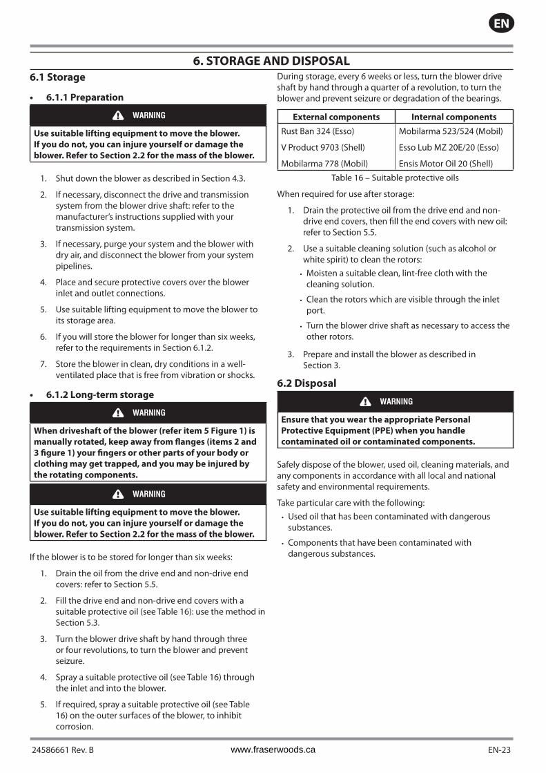
External components Internal components
Rust Ban 324 (Esso)
V Product 9703 (Shell)
Mobilarma 778 (Mobil)
Mobilarma 523/524 (Mobil)
Esso Lub MZ 20E/20 (Esso)
Ensis Motor Oil 20 (Shell)
Table 16 – Suitable protective oils
When required for use after storage:
1. Drain the protective oil from the drive end and non-drive end covers, then fill the end covers with new oil:refer to Section 5.5.
2. Use a suitable cleaning solution (such as alcohol orwhite spirit) to clean the rotors:Moisten a suitable clean, lint-free cloth with the cleaning solution.
Clean the rotors which are visible through the inlet port.
Turn the blower drive shaft as necessary to access the other rotors.
3. Prepare and install the blower as described inSection 3.
6.2 Disposal
WARNING
Ensure that you wear the appropriate Personal
Protective Equipment (PPE) when you handle
contaminated oil or contaminated components.
Safely dispose of the blower, used oil, cleaning materials, and any components in accordance with all local and national safety and environmental requirements.
Take particular care with the following:Used oil that has been contaminated with dangerous substances.
Components that have been contaminated with dangerous substances.
•
•
•
•
•
www.fraserwoods.ca

EN
EN-24 24586661 Rev. B
7. SERVICE AND SPARES
7.1 Introduction
Ingersoll Rand products, spares and accessories are available from Ingersoll Rand companies in Belgium, Brazil, China, France, Germany, Israel, Italy, Japan, Korea, Singapore, United Kingdom, U.S.A and a world-wide network of distributors. The majority of these centers employ Service Engineers who have undergone comprehensive Ingersoll Rand training courses.
Order spare parts and accessories from your nearest Ingersoll Rand company or distributor. When you order, state for each part required:
Model and Item Number of your equipment
Serial number
Item Number and description of part.
•
•
•
7.2 Service
Ingersoll Rand products are supported by a world-wide network of Ingersoll Rand Service Centers. Each Service Centre offers a wide range of options including; service exchange; repair; rebuild and testing to factory specifications. Equipment which has been serviced, repaired or rebuilt is returned with a full warranty.
Your local Service Centre can also provide Ingersoll Rand engineers to support on-site maintenance, service or repair of your equipment.
For more information about service options, contact your nearest Service Centre or other Ingersoll Rand company.
7.3 Spares and repair kits
The spares and repair kits available for the blowers are shown in Tables 17 and 18.
Spare Item Number
Hibon Lube: 2 liters (0.53 US gal)Hibon Lube: 5 liters (1.32 US gal)
LUB0000002LUB0000005
Table 17 – Spares Item Numbers
Blower
Standard maintenance kit Piston Ring Holder Kit Gears Fuse plugs
Hibon number CCN Hibon
number CCN Hibon number CCN Hibon
number CCN
PTB 8R015210100 47002258 R015092100 47002266 P158502042 47004957 R015110100 47007661
PTB 13
Table 18 – Repair Kits Item Numbers
www.fraserwoods.ca

24586661 Rev. B EN-25
EN
RETURN OF Ingersoll Rand EQUIPMENT - PROCEDURE
Introduction
Before you return your equipment you must warn your supplier if the substances you used (and produced) in the equipment can be dangerous. You must do this to comply with health and safety at work laws.
You must complete the Declaration on the next page and send it to your supplier before you dispatch the equipment. If you do not, your supplier will assume that the equipment is dangerous and he will refuse to accept it. If the Declaration is not completed correctly, there may be a delay in processing your equipment.
Guidelines
Take note of the following guidelines:Your equipment is ‘uncontaminated’ if it has not been used or if it has only been used with substances that are not dangerous. Your equipment is ‘contaminated’ if it has been used with any dangerous substances.
If your equipment has been used with radioactive substances, you must decontaminate it before you return it to your supplier. You must send independent proof of decontamination (for example a certificate of analysis) to your supplier with the Declaration (HS2). Phone your supplier for advice.
We recommend that contaminated equipment is transported in vehicles where the driver does not share the same air space as the equipment.
PROCEDURE
Use the following procedure:
1. Contact your supplier and obtain a Return Authorization Number for your equipment.
2. Turn to the next page(s), photocopy and then complete the Declaration.
3. Remove all traces of dangerous gases: pass an inert gas through the equipment and any accessories which will bereturned to your supplier. Drain all fluids and lubricants from the equipment and its accessories.
4. Disconnect all accessories from the equipment. Safely dispose of the filter elements from any oil mist filters.
5. Seal up all of the equipment’s inlets and outlets (including those where accessories were attached). You may seal theinlets and outlets with blanking flanges or heavy gauge PVC tape.
6. Seal contaminated equipment in a thick polythene bag. If you do not have a polythene bag large enough to containthe equipment, you can use a thick polythene sheet.
7. If the equipment is large, strap the equipment and its accessories to a wooden pallet. Preferably, the pallet should beno larger than 510mm x 915mm (20” x 35”); contact your supplier if you cannot meet this requirement.
8. If the equipment is too small to be strapped to a pallet, pack it in a suitable strong box.
9. If the equipment is contaminated, label the pallet (or box) in accordance with laws covering the transport ofdangerous substances.
10. Fax or email of the Declaration to your supplier. The Declaration must arrive before the equipment.
11. Give a copy of the Declaration to the carrier. You must tell the carrier if the equipment is contaminated.
12. Seal the original Declaration in a suitable envelope; attach the envelope securely to the outside of the equipmentpackage. WRITE YOUR RETURN Authorization NUMBER CLEARLY ON THE OUTSIDE OF THE ENVELOPE OR
ON THE OUTSIDE OF THE EQUIPMENT PACKAGE.
•
•
•
www.fraserwoods.ca

EN
EN-26 24586661 Rev. B
RETURN OF Ingersoll Rand EQUIPMENT - DECLARATION
Return Authorization Number:
You must:Know about all of the substances which have been used and produced in the equipment before you complete this Declaration
Read the Procedure on the previous page before you attempt to complete this Declaration
Contact your supplier to obtain a Return Authorization Number and to obtain advice if you have any questions
Send this form to your supplier before you return your equipment
•
•
•
SECTION 1 : EQUIPMENT
Equipment model _________________________________
Serial Number __________________________________
Has the equipment been used, tested or operated?
Yes � Go to Section 2 No � Go to Section 4
FOR SEMICONDUCTOR APPLICATIONS ONLY :
Tool Reference Number _____________________________
Process ________________________________________
Failure Date _______________________________________
Serial Number of Replacement Equipment ______________
SECTION 2 : SUBSTANCES IN CONTACT WITH THE EQUIPMENT
Are any of the substances used or produced in the equipment
Radioactive �
Biologically active �
Dangerous to human health and safety? �
If you have answered ‘no’ to all of these questions, go to Section 4.
•
•
•
Your supplier will not accept delivery of any equipment that is contaminated with radioactive substances, unless you:
Decontaminate the equipment
Provide proof of decontamination
YOU MUST CONTACT YOUR SUPPLIER FOR ADVICE BEFORE YOU RETURN SUCH EQUIPMENT
•
•
SECTION 3 : LIST OF SUBSTANCES IN CONTACT WITH THE EQUIPMENT
Substance name Chemical symbol Precautions required (for example, use protective gloves,
etc.)
Action required after spillage or human contact
1.
2.
3.
4.
5.
6.
SECTION 4 : RETURN INFORMATION
Reason for return and symptoms of malfunction: _____________________________________________________________________________________________________________________________________________________________________
If you have a warranty claim:Who did you buy the equipment from ? ___________________________________________________________________
give the supplier’s invoice number _______________________________________________________________________
•
•
SECTION 5 : DECLARATION
Print your name: _______________________________ Print your job title: ___________________________________
Print your organization ___________________________________________________________________________________
Print your address ______________________________________________________________________________________________________________________________________________________________________________________________
Telephone number : ____ _____________________________ Date of equipment delivery: ___________________________I have made reasonable enquiry and I have supplied accurate information in this Declaration. I have not withheld any information. I have followed the Return of Ingersoll Rand Equipment Procedure on the previous page.
Signed: ____________________________________________ Date: ______________________________________________
www.fraserwoods.ca

www.fraserwoods.ca

ingersollrandproducts.com
© 2014 Ingersoll-Rand
Authorized Hibon Distributor, Service & Repair Facility 120 – 10293 276 ST, Acheson, Alberta, Canada T7X 6A5
T: 780.962.1827 F: 780.962.1830 E: [email protected] www.fraserwoods.ca