
ASM 142 S - PTB Sales
242
ASM 142 S HELIUM LEAK DETECTOR User’s Manual
-
Upload
khangminh22 -
Category
Documents
-
view
2 -
download
0
Transcript of ASM 142 S - PTB Sales

GB
0283
4 - E
ditio
n 03
- J
une
05
Alcatel Vacuum Technology, as part of the Alcatel Group, has been supplying vacuum pumps, leak detection systems, vacuum measurement and micro machining systems for several years. Thanks to its complete range of products, the company has become an essential player in multiple applications : instrumentation, Research & Developement, industry and semiconductors. Alcatel Vacuum Technology has launched Adixen, its new brand name, in recognition of the company’s international standing in vacuum position. With both ISO 9001 and 14001 certifications, the French company is an acknowlegded expert in service and support, and Adixen products have the highest quality and environmental standards.
With 40 years of experience, AVT today has a worldwide presence, through its international network that includes a whole host of experienced subsidiaries, distributors and agents. The first step was the founding of Alcatel Vacuum Products (Hingham- MA) in the United States, thirty years ago, reinforced today by 2 others US subsidiaries in Fremont (CA) and Tempe (AZ). In Europe, AVTF-France headquarters and three of its subsidiaries, Alcatel Hochvakuumtechnik (Germany), Alcatel Vacuum Technology UK (Scotland) and Alcatel Vacuum Systems (Italy) form the foundation for the European partner network. In Asia, our presence started in 1993 with Alcatel Vacuum Technology (Japan), and has been strengthened with Alcatel Vacuum Technology Korea (in 1995), Alcatel Vacuum Technology Taïwan (in 2001), Alcatel Vacuum Technology Singapore, and more recently with Alcatel Vacuum Technology Shanghai (China) (in 2004). This organization is rounded off by more than 40 represensatives based in a variety of continents.
Thus, whatever the circumstances, the users of Adixen products can always rely on quick support of our specialists in Vacuum Technology.

Rea
lizat
ion:
Axe
ss -
ww
w.a
xess
-gro
upe.
com
- Pu
blic
atio
n: A
lcat
el -
Part
num
ber:
108
110
- Ed
03 -
05
/200
6
CHINA Alcatel Vacuum Technology, Shanghai N°82 Lane 887 Zuchongzhi Road Zhangjiang High-Tech Park, Shanghai 201203 - P.R. China Tel. (86) 21 5027 0628 Fax. (86) 21 3895 3815
FRANCE Alcatel Vacuum Technology France 98, avenue de Brogny - BP 2069 74009 Annecy cedex Tel. (33) 4 50 65 77 77 Fax. (33) 4 50 65 77 89
GERMANY Alcatel Hochvakuumtechnik GmbH Am Kreuzeck 10 - Postfach 1151 97877 Wertheim Tel. (49) 9342 9610 00 Fax. (49) 9342 9610 30
ITALY Alcatel Vacuum Systems Via Trento, 30 20059 Vimercate (Mi) Tel. (39) 0396 86 38 55 Fax. (39) 039 66 71 25
JAPAN Alcatel Vacuum Technology Japan 4-3-10 Shimokodanaka, Nakahara-ku Kawasaki, Kanagawa 211-0041 Tel. (81) 44-797-5920 Fax. (81) 44-797-5932
KOREA Alcatel Vacuum Technology Korea 4th Floor, Sunghyun B/D 10-5, Karak-Dong, Songpa-Ku -Seoul Tel. (82) 2 409 6277 Fax. (82) 2 409 6279
SINGAPORE Alcatel Singapore Pte Ltd 49 Jalan Pemimpin #01-01 APS Industrial Building 577203 Singapore Tel. (65) 62540828 Fax. (65) 62547018
TAIWAN Alcatel Vacuum Taïwan No. 169-3, Sec.1, Kang-Leh Rd Song-Lin Village, Hsin-Feng 304 Hsin-Chu County, Taiwan -R.O.C. Tel. (886) 35599230 Fax.(886) 35599231
UNITED KINGDOM Alcatel Vacuum Technology UK Ltd 8 Bain Square Kirkton Campus Livingston - West Lothian EH54 7DQ Scotland Tel. (44) 1 506 418 000 Fax. (44) 1 506 418 002
USA Alcatel Vacuum Products 67, Sharp Street Hingham - MA 02043 Tel. (1) 781 331 4200 Fax. (1) 781 331 4230
Alcatel Vacuum Technology France - 98, avenue de Brogny - BP 2069 - 74009 Annecy cedex - FRANCE Tel. (33) 4 50 65 77 77 - Fax. (33) 4 50 65 77 89
Web site: www.adixen.com


A very wide range of helium leak
1/2
GB
0020
4 - E
ditio
n 04
- M
arch
04
detectors
Dear customer,
You have just bought an Alcatel leak detector. We would like to thank you and we are proud to count you among our customers. This product is a result of the experience acquired over 35 years by Alcatel in vacuum and leak detection technology.
The applications of helium leak testing are extremely diversified ranging from high-tech installation maintenance to high- speed testing of industrial products.
Each product of the ALCATEL detector range is designed to meet the specific needs of each application:
• portability, • high sensitivity, • pumping capacity, • pumping type, • automation and integration in an industrial process.

A very wide range of helium leak
2/2
GB
0020
4 - E
ditio
n 04
- M
arch
04
detectors
This product complies with the requirements of European Directives, listed in the Declaration of Conformity contained in G100 of this manual. These Directives are amended by Directive 93/68/E.E.C (E.C. Marking). The Declaration of Conformity and Safety Instructions are available in German, Spanish, Italian, Portuguese, Dutch and Danish languages at the end of this manual.
Copyright/Intellectual property:
The use of Alcatel products are subject to copyright and intellectual property rights in force in any jurisdiction. All rights reserved, including copying this document in whole or any part without prior written authorization from Alcatel Vacuum Technology France.
Specifications and information are subject to change without notice by from Alcatel Vacuum Technology France.

1/2
GB
0035
3 - E
ditio
n 04
- A
pril
06
MANUAL REFERENCE: 108110 EDITION: 03 - May 2006 General contents Software version: L0184 v3.0 r10
ASM 142 S - User’s Manual
Preliminary remarks
Throughout this User’s Manual, you could find this type of message
“Summary of screen C 140”: it refers to a specific chapter of the User’s Manual. Please read it for further information.
Chapter A INTRODUCTION
A 100 - Introduction to the ASM 142 series A 200 - ASM 142 S detector operating principle A 300 - Analyzer cell operating principle A 400 - Testing methods A 500 - Operator interface A 600 - Options A 700 - Accessories A 800 - ASM 142 S Technical characteristics A 900 - Dimensions
Chapter B INSTALLATION
B 100 - Safety instructions B 110 - Unpacking - Storage - Transportation B 200 - Neutral gas purge and inlet vent connection B 210 - Connecting the detector to the installation B 300 - Controlling the detector with the I/O interface B 310 - Controlling the detector with a PC computer through the RS 232 interface B 320 - Connecting the detector directly to a printer or another device B 400 - Before starting up the leak detector
Chapter C OPERATION
C 100 - Factory configuration of the leak detector parameters C 110 - Operating principle of the control panel C 120 - Setting and maintenance part presentation of the control panel C 130 - Access to level 4 - Password C 140 - Summary of screens C 200 - Starting up / Switching off the leak detector C 211 - Operation of the leak detector C 213 - Display C 300 - Calibration of the leak detector C 301 - Calibration of the leak detector C 305 - Calibrated leak values programming C 306 - Adaptator for calibrated leak C 400 - Remote control C 410 - Headphone and loudspeaker C 430 - 3 masses option C 450 - Long distance sniffer probe and Helium spray gun C 520 - Audio alarm/Digital voice C 540 - Zero function C 570 - Date - Time - Language - Unit C 580 - Fault / information indicator and display C 590 - Massive function

2/2
GB
0035
3 - E
ditio
n 04
- A
pril
06
MANUAL REFERENCE: 108110 EDITION: 03 - May 2006 General contents Software version: L0184 v3.0 r10
ASM 142 S - User’s Manual
Chapter D MAINTENANCE - TROUBLESHOOTING
D 100 - Table of preventive maintenance intervals D 200 - Maintenance message D 210 - Calibrated leak calibration supervision D 300 - General troubleshooting guide D 400 - Symptoms description
Chapter E MAINTENANCE SHEETS
E 100 - Maintenance operations instruction E 110 - Access to internal detector components ASM 142 / ASM 142 S E 400 - Basic maintenance of the analyzer cell E 530 - Valves installation and maintenance E 560 - Exchange of the internal calibrated leak (option) E 600 - Remote control exchange E 610 - Long distance sniffer probe and Helium spray gun E 730 - Starting of the molecular and turbomolecular pumps E 750 - Primary pump maintenance
Chapter F COMPONENTS
F 000 - Spare parts - Instructions of use F 001 - AVTF Customer Service Offer F 100 - Tools F 200 - Monitoring and display F 300 - Power and electrical supply F 400 - Automatic control system and electronic circuits F 500 - Measurement F 600 - Pumping F 700 - Valves F 800 - Pipes - connections - Seals F 900 - Cover F 1000 - Options and accessories F 1100 - Pictures of components
Chapter G APPENDIX
G 100 - Declaration of conformity G 200 - Wiring diagrams G 300 - 0 - 8 Volts Analog output G 400 - Long distance sniffer probe user manual G 500 - Helium spray gun user manual G 600 - Safety questionnaire

Introduction
1/2
GB
0063
0 - E
ditio
n 02
- F
ebru
ary
05
A
ASM 142 S User’s Manual
Detailed contents
Preliminary remarks
Throughout this User’s Manual, you could find this type of message
“Summary of screen C 140”: it refers to a specific chapter of the User’s Manual. Please read it for further information.
A 100 Introduction to the ASM 142 serie
A 200 ASM 142 S detector operating principle
- Vacuum circuit - Stand-by mode - Sniffing test mode
A 300 Analyzer cell operating principle
- Description - Design and manufacture
A 400 Testing methods
- Overview - Helium concentration and signal displayed - Spray method (inboard testing) - Sniffer method (outboard testing) - Bombing method
A 401 About Helium and hydrogen
- Helium - Helium and leak detection: which purity ? - Hydrogen - Helium, Hydrogen and sensitivity - And now some wrong ideas
A 500 Operator interface
- Control panel

Introduction
2/2
GB
0063
0 - E
ditio
n 02
- F
ebru
ary
05
A
ASM 142 S User’s Manual
Detailed contents
A 600 Options
- Which options for which model? - Metal seals - Inlet port - Units - Languages - 3 masses - Automatic test chambers - Roughing system - Interface board - Remote control cable length - Test of gas line - Stainless steel cover (UCT) - Control panel with graphic interface - Internal calibrated leak - LDS probes
A 700 Accessories
- Which accessories for which model? - Standard remote control with cable - Sniffing remote control and cable - Long Distance Sniffer probe - 10 m/30 feet LDS extension - Headphone connector - Transport cart - Foot pedal for cycle command (1.5 m/5 feet) - Calibrated Helium leaks - Calibration accessory - Spray probe - Inlet adaptor - Printer - Inlet filters - Short distance sniffer probe (to be connected to the inlet part of a leak detector) - Bombing chamber - Tests chambers (required interface board) - Neutral gas vent ling kit - 4 swiveling wheels kit (Ø125 mm) - Covered sniffer probe and remote control kit - Bottle handle for cart
A 800 ASM 142 S Technical characteristics
A 900 Dimensions

A 100
1/1
ASM 142
ASM GRAPH
ASM 142 D
ASM GRAPH D
ASM 142 S
high performances, such as, a roughing capacity of 7 CFM (60 l/ mn) with a usable helium sensitivity in the 10-11 atm.cc/sec range,
x
x
high performances, such as, a dry roughing capacity of 0.9 CFM (1.5 m3/h) with a usable helium sensitivity in the 10-11 atm.cc/sec range,
x
x
a usable helium sensitivity in the 10-7 atm.cc/sec range (with auto-zero function),
x
comprehensive control panel with two distinct areas (one for the operation of the unit, the other for entering the test parameters),
x
x
x
x
x
evolved features to assist the operator in his daily operation (auto- calibration, auto-zero, helium signal direct readout, ...).
x
x
x
x
x
very rugged design, based on field- proven components, which makes it ideal for any industrial environment,
x
x
x
x
x
various accessories to reinforce the versatility of the product (remote control, sniffer probe).
x
x
x
x
x
totally dry leak detector, x x specific to sniffing test mode applications.
x
graphic interface x x
GB
0020
7 - E
ditio
n 03
- S
epte
mbe
r 04
Introduction to the ASM 142 series
A new generation of ALCATEL helium leak
detector
The ASM 142/142 D/142 S/ASM GRAPH/ASM GRAPH D are universal helium leak detectors which set new performance standards for multi-purpose unit. These detectors are the end-result of an innovative engineering approach utilizing the latest electronics technologies and vacuum concepts, which make them a truly universal unit:
Model photographed: ASM 142
We suggest that you read this manual before you start to use your detector to obtain optimum levels of performance and complete satisfaction.

A 200
1/2
GB
0037
9 - E
ditio
n 02
- D
ecem
ber
05
ASM 142 S detector operating principle
Vacuum circuit
21
1
2
4
Option VC
18
8 VS
VT1
Bacosol valve 15
Minisol valves
Reference correspondence between valve/vacuum block marks E 530
1 Preamplifier 2 Analyzer cell 4 Internal calibrated leak (option) 8 Long distance sniffer connector 15 Roughing primary pump
(RVP 2005) 18 Detection molecular pump
(AMP 007I) 21 Calibration port (if internal calibrated leak
option) or automatic standby
VC Calibration valve VT1 Exhaust valve VS Sniffing valve

A 200
ASM 142 S detector operating principle
2/2
GB
0037
9 - E
ditio
n 02
- D
ecem
ber
05
Standby mode 1 2 21
18 VC
4 Option
VT1
15
Sniffing test mode 1 2 21
18 VC
4 Option
8 VS VT1
15

A 300 Analyzer cell operating principle
1/3
GB
0000
7 - E
ditio
n 03
- S
epte
mbe
r 04
Description The analyzer cell works on the principle of mass spectrometry and is set to the mass of helium (m/e = 4). m/e = atomic mass of the particle/number of electrons lost on ionization The principle of magnetic deflexion spectrometry is as follows. The neutral molecules of the gas being analyzed pass into an ionization chamber (or source of ions) where they are bombarded by an electron beam generated by a heated tungsten filament. A large number of the molecules are transformed into ions.
He
He
He
6 Leak Signal
He
Analyzer cell - functional diagram

A 300 Analyzer cell operating principle
2/3
GB
0000
7 - E
ditio
n 03
- S
epte
mbe
r 04
Description (continued) These ionized particles are accelerated by an electrical field. The entire analyzer cell is subject to a magnetic field which has the property of deflecting the trajectories of the ions along different curves according to the masses of those ions (to be more precised, according to their m/e ratios). Thus the ions beam, which contained ions with different masses, is divided into several beams, each containing only ions with the same m/e ratio. The helium ions (m/e = 4) are separated from the lighter (H2+ or H1+, smaller beams) or heavier ions (N2+ or O2+, small beams). Because there is a constant magnetic field (permanent magnet), the accelerator electrical field is adjusted so that the helium ions (m/e = 4) follow a pre-determined trajectory (passing through diaphragms) and arrive on the target at the input to a direct current amplifier. The current of helium ions is proportional to the partial pressure of helium in the installation and by measuring it we can find the flow rate of the leak that has been detected. It is essential that the total pressure in the analyzer cell is less than 10-4 mbar, so that the trajectories of the electrons and the ions are not disturbed by residual molecules. Around 10-3 mbar there is a risk of damaging the heated filament.
In order to separate the helium ions from «noise» caused by «stray ions», an electrode located in front of the target eliminates the secondary ions with low energies. This electrode is called the «braking electrode».
There is an auxiliary electrode at the top of the cell, shaped like a plate, which collects the ions that are heavier than helium. This electrode thus measures the total pressure in the analyzer. This electrode serves as the plate for a triode gauge, hence its name of «triode electrode».

A 300 Analyzer cell operating principle
3/3
GB
0000
7 - E
ditio
n 03
- S
epte
mbe
r 04
Design and manufacture
Great care has been taken with the design and manufacture of the cell in order to repeatedly obtain the same characteristics and to achieve excellent stability: – the metal parts are made of stainless steel, – the filament holder is made of machined aluminium, – there is an integral amplifier. The cell assembly is composed of: – a vacuum chamber or deflection chamber, – an optic holder flange, – a permanent magnet, – an amplifier. • The vacuum chamber: The analysis cell vacuum chamber is made of light alloy. It is hollow with a rectangular opening into which the electrodes, (that are installed on the «optics holder» flange) are placed. • The optics holder flange: The optics holder flange supports all the electrodes and electrical connections in the cell. They include: – the sealed power supply socket, mounted on a metal gasket, – the amplifier, mounted on an elastomer gasket, vthe supporting block which screens the target and on which the source of ions is mounted, – the source of ions, which is made up of 2 parts: • a filament holder, • an ionization chamber with a stainless steel electron collector and a mass ion emitter. The filament holder mechanically positions the tungsten filament with respect to the ionization chamber. The electron collector and the filament have been designed and positioned so that the temperature of the electron collector stabilizes at 400°C under bombardment and radiation from the filament. The cell is thus rendered immune to contamination from the pieces being tested without the need of any special heating system.

A 400 Testing methods
1/4
GB
0000
8 - E
ditio
n 05
- F
ebru
ary
02
Overview Leak detection is used to detect micro-openings, porosities, etc. in test parts. The detection of these cracks involves the use of a light tracer gas, which is capable of infiltrating the smallest leak quickly: Helium. The detector samples and measures the helium flow rate entering the test part via the leak(s). The testing method is selected according to the test part and the measurement accuracy required:
The part can be connected to
an evacuation line
no The part is sealed
yes
Its characteristics allow it to be
evacuated
Its characteristics no allow it to be
pressurized with helium or a mixture containing
helium
Its characteristics allow it to be placed
in a vacuum vessel
yes yes yes
SPRAY method
laeak rate measurement from 10-10
to 10-1 mbar. l/s and possibility of locating the leak.
SNIFFING method
Minimum detectable leak of 10-6
mbar.l/s and possibility of locating the leak.
BOMBING method
The sensitivity is limited by the internal dead volume of the part as well as on the bombing time and the pressurization value. Global test without possible location of the leak.

A 400 Testing methods
2/4
GB
0000
8 - E
ditio
n 05
- F
ebru
ary
02
Helium concentration and signal displayed
In accordance to the He concentration rate in the gas used for the leak detection, the signal displayed will change. Example: signal displayed with a 1x10⁻⁷ mbar.l/s calibrated leak (with 100 % He) connected to the detector inlet.
% He in the gas used 100 % 10 % 1 %
Signal displayed on the leak detector
1x10⁻⁷ mbar.l/s
1x10⁻⁸ mbar.l/s
1x10⁻⁹ mbar.l/s
Spray method (inboard testing)
This involves removing air from the test part, connecting it to the analyzer and then spraying helium over the outer surface.
Global test Spray test or
part
spray probe
He part He
detector detector
The part is placed under a cover, into which helium is injected.
The leak cannot be located.
Potential leaking areas are sprayed with helium. The leak can be located.
The detector measures the flow of helium penetrating the part.
Response time When spraying starts, the leak signal is not displayed instantaneously on the analyzer: there is a response time which depends on the volume V being tested and the helium pumping speed S of the system at the opening of the part, according to the following relation:
T = V/S (T in seconds, V in litres, S in l/s)
T is the time required for the signal to reach 63 % of the final value.

A 400 Testing methods
3/4
GB
0000
8 - E
ditio
n 05
- F
ebru
ary
02
Sniffer method (outboard testing)
The test part is pressurized with helium. The detector, via an LDS (Long Distance Sniffer) probe, samples the helium escaping from the part.
Global test Local sniffing test
or
He He
part LDS
detector
part detector
LDS
The part is placed under a cover containing a sniffer probe.
The leak cannot be located.
The helium from the leak accumulates over time inside the cover. The detector measures the concentration of helium.
The sniffer probe is moved over areas likely to contain leaks.
The leak can be located.
The signal supplied by the analyzer is not a direct measurement of the leak. The sniffer probe only samples part of the helium escaping from the part. The sample depends on the distance separating the leak from the tip of the probe.

A 400 Testing methods
4/4
GB
0000
8 - E
ditio
n 05
- F
ebru
ary
02
Bombing method This method is used for sealed objects that cannot be connected directly to the detector (semiconductors, waterproof watches, etc.).
He He
part part
Chamber 1 Chamber 2
detector
The part is placed in a chamber containing pressurized helium.
The helium penetrates the part if it has a leak.
The part is then removed from the chamber and placed in another vacuum chamber which is connected to the detector. The helium escapes from the part through the leak and produces a signal.
This signal is not a direct measurement of the leak as the helium pressure inside the part is difficult to determine. Several parts play an important part such as: the pressurization time, the helium bombing pressure, the internal volume, the aeration time, the size of the leak.

A 401 About Helium and hydrogen
1/5
GB
0276
0 - E
ditio
n 01
- F
ebru
ary
05
Helium Helium is the second most common element in the universe, representing about 23 % of the total matter. 76 % is Hydrogen. All other elements represent an insignificantly small fraction of the total. Helium was discovered by spectroscopy in a solar eclipse on August 18, 1868. The discovery in the sun’s chronosphere gave the new element its name: “helios” in Greek means “sun”. While Helium is very common in the universe most of it is in the stars: on earth it is actually not abundant. Since it is so light all the Helium present during the formation of earth escaped to space. Helium is created deep in the earth from the radioactive decay of Uranium and Thorium which also gives the earth its internal heat. On earth Helium was discovered in 1881 by spectroscopy of Mount Vesuvio in Italy – the volcanic gases emanated by the mountain showed the same lines in the spectrum as already known from the sun. Helium concentration in the atmosphere is 5 times bigger than the one of Krypton and 60 times higher than Xenon. The heavier noble gases are isolated from air rectification. In contrary, Helium is “mined” from natural gas and oil wells. This is economical at concentrations above 0.4%. Helium comes up with the natural gas and is separated and stored. The annual world wide production is ca. 3x10⁷ m3 or 4,500 tons. It occurs in economically extractable amounts in certain natural gases. Natural resources can be found in the USA (Texas and Kansas) and Poland. Natural Helium concentrations reach up to 7 % in natural gas. Helium is constantly seeping up from the ground all around us, but it is so light that almost all of it escapes into space fairly rapidly. On the other hand there is a constant flow of Helium from space and the sun to earth. This gives a dynamic equilibrium and is the reason for the world wide constant concentration of ca. 5 ppm Helium in air. Helium is a very light colorless element and it is one of the six noble gases; the most difficult gas to liquefy. Helium is a noble gas, which means it doesn’t react with anything for all practical intents and purposes. It’s used as an inert shield gas to protect things from oxidation – and of course as leak detection tracer gas. Helium is a 100 % green gas and has absolutely no environmental impact on the atmosphere.

A 401 About Helium and hydrogen
2/5
GB
0276
0 - E
ditio
n 01
- F
ebru
ary
05
Helium and leak detection:
which purity ?
Helium is commercialized in many different purity levels, the highest level of purity is requested from some laboratories for fundamental researches or very accurate analyses. The use of the Helium as a tracer gas into a mass spectrometer doesn’t require such attention. A purity in the range of 97 % to 99 % is enough . There is absolutely no risk of accuracy lost or contamination for the cell analyzer by using standard purity level of Helium gas. Helium ( Air Liquide and Linde sources, Europe)
Purity Average market price (2004)
in €/m3
99,9995 % 27 99,999 % 13
99,5 % 10 97,5 % 8
The gas producers as Air Liquide, Linde, Praxair, Sanfu and others push customers to use high purity level for Helium, of course, because cost and margin are higher and your mission by selling Helium leak detector solution is to inform your customers about the mass spectrometer requirement in term of helium purity.

A 401 About Helium and hydrogen
3/5
GB
0276
0 - E
ditio
n 01
- F
ebru
ary
05
Hydrogen Hydrogen (H2) is the lightest element, has a gaseous specific gravity of 0.0695 and a boiling point of -423 F (-252.8 C) at atmospheric pressure. It is a colorless, odorless, tasteless, flammable gas found at concentrations of about 0.0001 % in air. Hydrogen is produced by several methods, including steam/methane reforming, dissociation of ammonia, and recovery from by-product streams from chemical manufacturing and petroleum reforming. Hydrogen can be stored and transported as either a gas a cryogenic liquid. Hydrogen is flammable in the concentration range 4 % to 75 % in air or oxygen and can detonate in the range 18 % to 60 % in air or oxygen .
Compared to the helium at same purity, hydrogen is less expansive than helium, but on the field the reality is different because to use Hydrogen under safe conditions you have to mix the Hydrogen with an inert gas like Nitrogen; the concentration of Hydrogen in Nitrogen must be lower the 5 % to be non-flammable in air or Oxygen.
And under this condition the price of the mixture is becoming more expansive.
Hydrogen ( Air Liquide and Linde sources, Europe)
Purity Average market price (2004)
in €/m3
99,999 % 13 99,995 % 12
99,5 % 9 Mixture
95 % N2 + 5 % H2 25 to 30

A 401 About Helium and hydrogen
4/5
GB
0276
0 - E
ditio
n 01
- F
ebru
ary
05
Helium, Hydrogen and sensitivity
Because the Hydrogen must be used mixed at 5 % concentration with an inert gas to be safe, the sensitivity of the test drops by a factor of 20 compared to 100 % Hydrogen concentration. Theoretical example Reject point of the part to be tested: 5 x10⁻⁵ mbar.l/s. H2 concentration: 100 % Leak to be found: 5 x10⁻⁵ mbar.l/s. H2 concentration: 10 % Leak to be found: 5 x10⁻⁶ mbar.l/s. H2 concentration: 5 % Leak to be found: 2,5 x10⁻⁶ mbar.l/s. Air conditioning example The working pressure of the system to be tested is 50 bar and the allowed loss is 2,5 g per year. If the system is filled with R410 refrigerant gas, the maximum allowed leak in R410 at 50 bars is 2,63 x10⁻⁵ mbar.l/s. Calculation for equivalent leak with substitute gas Pressure test: 8 bar, gas concentration 100 % Equivalent leak in Hydrogen (H2): 3,32 x 10⁻⁵ mbar.l/s. Equivalent leak in Helium (He): 1,66 x10⁻⁵ mbar.l/s. Because Hydrogen is not a safe gas, the maximum concentration of H2 in N2 is 5 % to be non-flammable. With a such concentration, the leak to be found becomes 20 times lower at 1,66 x10⁻⁶ mbar.l/s. Conclusion To control an air conditioning system and validate with a substitute gas that the system is tight you need for the Hydrogen method a leak detector 10 times more sensitive than a Helium leak detector. To compare sensitivity between Helium and Hydrogen, you have to compared the following information:
Leak to be found Gas used Leak to be displayed 5.10-5 mbar.l/s Helium 5.10-5 mbar.l/s
Hydrogen mixture 95 % N2 + 5 % H2
5.10-6 mbar.l/s

A 401 About Helium and hydrogen
5/5
GB
0276
0 - E
ditio
n 01
- F
ebru
ary
05
And now some wrong ideas
Helium is rare Yes, it is, but helium is an inexhaustible resource from the heart of
the earth. Helium is recovered most cost-effectively from natural gas and long- term contracts guarantee access to sources in the USA, Europe and North Africa.
Helium is expansive
Hydrogen is less expensive than Helium
Security: Hydrogen isn’t dangerous ?
No, because the mass spectrometer doesn’t required high level purity helium to detect accuratly the leaks (97,5 % is enough). Helium ( Air Liquide and Linde sources, Europe)
Purity Average market price (2004) in €/m3
99,995 % 27
97,5 % => helium gas tracer 8 No, because to have a safe hydrogen tracer gas, you have to use mixture (95 % N2 + 5 % H2). Let see the following prices: Average market price (2004)
in €/m3 Helium Purity: 97,5 % 8
Hydrogen Mixture 95 % N2 + 5 % H2
25 to 30
No, theoretically hydrogen isn’t dangerous , if ….and if…. But reality is different and if all the mixtures of H2 + inert gas in a bottle have a limited life time , probably, the bottle isn’t so safe. The reason is: because of the weight of H2 (the lightest element), over the time a stratification phenomenon occurs which leads to gas emanation of uncontrolled Hydrogen concentration at the top of the gas bottle and can detonate or be flammable in contact of air or oxygen. If gas producers recommendation is “always roll on the floor a mixture H2 bottle before use”, it is to avoid the stratification phenomena and to recover homogeneous mixture.

A 500 Operator interface: control panel
1/2
GB
0038
0 - E
ditio
n 02
- D
ecem
ber
05
Operation part
F1 16 15
F3
14 F2 LEAK RATE
COR 12
13 mbar.l/s
Pa.m3/s
Torr.l/s
F1
F2 LEAK RATE F3
COR
mbar.l/s
Pa.m3/s
Torr.l/s
F4 10 -10 10 -9 10 -8 10 -7 10 -6 10 -5 10 -4 10 -3 10 -2 10 -1 1 10 9
11
F4 10 -10 10 -9 10 -8 10 -7 10 -6 10 -5 10 -4 10 -3 10 -2 10 -1 1
6 7 8 18 19 20 21
17 NEXT - + RESET
SET POINTS SPECTRO MAINTENANCE OTHER
22
1
27 AUTO CAL
ZERO
WARNING STDBY TEST
SNIFFER
NEXT - + RESET
SET POINTS SPECTRO MAINTENANCE OTHER
AUTO CAL
ZERO
WARNING STDBY TEST
SNIFFER
23 24 25 26 2 3 4
5
1 Control and menu selection indicators (ON when activated) 2 Autocalibration start/stop key 3 Zero start/stop key 4 Sniffing start/stop key 5 Control keyboard (3 keys) 6 Fault indicator
Setting and maintenance part (*)
* Operator access to setting and maintenance part depends on the user interface level.
User interface level C 120
7 «Sniffing stop» state indicator 8 «Sniffing start» state indicator 9 Tracer gas analogic display 10 10 decades scale use indicator 11 2 decades scale use indicator 12 Extra units use indicator
Parameter function keys (1 key per display line)
F1 F2
LEAK RATE
Tracer gas
COR
mbar.l/s
Pa.m3/s
Torr.l/s
13 Basic units use indicator 14 Digital display 15 Alphanumeric display (4 lines x 20 characters)
F3 F4 10 -10 10 -9 10 -8 10 -7 10 -6 10 -5 10 -4 10 -3 10 -2 10 -1 1
16 Parameter function keys (1 key per display line) 17 Modification access keys (4 keys) 18 NEXT : next display/parameter circular function 19/20 Plus or minus value adjustment, parameter selection, audio volume adjustment keys 21 RESET of previously displayed values (cancels temporary inputs) 22 Menu selection access keys (4 keys) 23 SET POINT menu selection key
NEXT - + RESET
SET POINTS SPECTRO MAINTENANCE OTHER
AUTO CAL
ZERO
WARNING
STDBY TEST
SNIFFER
24 SPECTRO calibration and analyzer cell configuration menu selection key 25 MAINTENANCE menu selection key 26 OTHER menus selection key (test mode selection, inlet VENT selection, date/time) 27 Remote control connection
Modification access keys (4 keys)
Menu selection access
keys (4 keys)
Control keys (3 keys) and
control and menu selection indicators (ON when activated)
Remote control interface C 400

A 500 Operator interface: control panel
2/2
GB
0038
0 - E
ditio
n 02
- D
ecem
ber
05
Operation part
F1 16 15
F3
14 F2 LEAK RATE
COR 12
13 mbar.l/s
Pa.m3/s
Torr.l/s
F1
F2 LEAK RATE F3
COR
mbar.l/s
Pa.m3/s
Torr.l/s
F4 10 -10 10 -9 10 -8 10 -7 10 -6 10 -5 10 -4 10 -3 10 -2 10 -1 1 10 9
11
F4 10 -10 10 -9 10 -8 10 -7 10 -6 10 -5 10 -4 10 -3 10 -2 10 -1 1
6 7 8 18 19 20 21
17 NEXT - + RESET
SET POINTS SPECTRO MAINTENANCE OTHER
22
1
27 AUTO CAL
ZERO
WARNING STDBY TEST
SNIFFER
NEXT - + RESET
SET POINTS SPECTRO MAINTENANCE OTHER
AUTO CAL
ZERO
WARNING STDBY TEST
SNIFFER
23 24 25 26 2 3 4
5
1 Control and menu selection indicators (ON when activated) 2 Autocalibration start/stop key 3 Zero start/stop key 4 Sniffing start/stop key 5 Control keyboard (3 keys) 6 Fault indicator
Setting and maintenance part (*)
* Operator access to setting and maintenance part depends on the user interface level.
User interface level C 120
7 «Sniffing stop» state indicator 8 «Sniffing start» state indicator 9 Tracer gas analogic display 10 10 decades scale use indicator 11 2 decades scale use indicator 12 Extra units use indicator
Parameter function keys (1 key per display line)
F1 F2
LEAK RATE
Tracer gas COR
mbar.l/s
Pa.m3/s
Torr.l/s
13 Basic units use indicator 14 Digital display 15 Alphanumeric display (4 lines x 20 characters)
F3 F4 10 -10 10 -9 10 -8 10 -7 10 -6 10 -5 10 -4 10 -3 10 -2 10 -1 1
16 Parameter function keys (1 key per display line) 17 Modification access keys (4 keys) 18 NEXT : next display/parameter circular function 19/20 Plus or minus value adjustment, parameter selection, audio volume adjustment keys 21 RESET of previously displayed values (cancels temporary inputs) 22 Menu selection access keys (4 keys) 23 SET POINT menu selection key
NEXT - + RESET
SET POINTS SPECTRO MAINTENANCE OTHER
AUTO CAL
ZERO
WARNING
STDBY TEST
SNIFFER
24 SPECTRO calibration and analyzer cell configuration menu selection key 25 MAINTENANCE menu selection key 26 OTHER menus selection key (test mode selection, inlet VENT selection, date/time) 27 Remote control connection
Modification access keys (4 keys)
Menu selection access
keys (4 keys)
Control keys (3 keys) and
control and menu selection indicators (ON when activated)
Remote control interface C 400

A 600 Options
1/4
ASM
102
S
ASM
122
D
ASM
142
ASM
142
S
ASM
142
D
ASM
182
T
ASM
192
T
ASM
192
T2
ASM
182
TD
+
ASM
192
TD
+
ASM
192
T2D
+
ASM
100
2
Metal seals
1 • • • • • • • • • •
Inlet port
2 • •
Units
3 • • • • • • • • • • •
Languages
4 • • • • • • • • • • • •
3 masses
5 • • • • • • • • • • • •
Automatic test chambers
6 • • • • • • • •
Roughing system
7 • • • •
Interface board*
8 • • •
Remote control cable length
9 •
Test of gas line
10 •
Stainless steel cover (UCT)
11 •
Control panel with graphic interface*
12 • • • •
Internal calibrated leak
13 •
LDS sniffer probes
14 •
Transport cart*
A 700 •
Voltage configuration
- • • • • • • • • • • • •
Power plug
- • • • • • • • • • • • •
Standard remote control*
A 700 • • • • • •
GB
0244
6 - E
ditio
n 02
- A
pril
06
Which options for which model?
*also available in accessories

A 600 Options
2/4
GB
0244
6 - E
ditio
n 02
- A
pril
06
Metal seals
1
Inlet and high vacuum manifolds and the analyzer cell are equipped with metal seals instead of elastomer seals to protect the leak detector against contamination with helium. This option is particularly usefull in case of high sensitivity helium leak detection in an ”helium contaminated environment”.
Localisation of the metal seals F 800
Inlet port
2
ASM 122 D: The standard DN 25 inlet port can be replaced by a DN 40 inlet port for convenience.
ASM 1002: The test chamber can be replaced by a DN 25 inlet
port for convenience.
Units
3
The user can choice the unit of the software: mbar.l/s, Pa.m3/s or Torr.l/s.
Languages
4
The user can choice the language of the software: English, French, German or Japanese. Note: ASM 142 S: English/French/German/Spanish.
ASM 1002: English/French.
3 masses
5
For use of one of the 3 following tracer gases: Helium 4, Helium 3 or Hydrogen 2.
Automatic test chambers
6
This is used for the automatic bombing testing of small components. When the chamber cover is closed, the test cycle is initiated, via a contact. 3 aluminium alloy models are available: • a hemispheric chamber, Ø 72 mm, depth 31 mm (small model), • a cylindrical chamber, maximum Ø 85 mm and maximum depth 68 mm (medium model), • a cylindrical chamber, maximum Ø 160 mm and maximum depth 200 mm (large model). Note: ASM 142: large model not available.

A 600 Options
3/4
GB
0244
6 - E
ditio
n 02
- A
pril
06
Roughing system
7
In order to reduce the roughing time when testing large volumes, a second roughing pump can be added to the roughing system: • ASM 192 T / 192 T2 total capacity: 40 m3/h or 24 cfm. • ASM 192 TD+ / 192 T2D+ total capacity: 50 m3/h or 36 cfm. Apart from the roughing capacity, the weight and the power consumption, the characteristics and the use of the leak detector remain the same.
Interface board
8
The helium leak detector can be equipped with a software version which will offer a complete RS 232 protocol: • 3 operating modes: basic, advanced, printer; • possibility to remote control the detector (start/stop, autozero, auto-cal etc...); • possibility to obtain and adjust the settings; • possibility to obtain all the maintenance information for preventive maintenance purposes. This RS 232 is the most effective interface to supervise your leak test from a PC (data recording on an Excel sheet, for instance) and/or to monitor the detector from a small PLC.
Remote control cable length
9
3 lengths are proposed: 5 m, 10 m and 15 m.
Test of gas line
10
Used to perform spray testing on long lines (typical diameter 1/4’’), with a reduced response time due to the transfer of the helium by a carrier gas injected in viscous flow. In this case, the detector is equipped with an additionnal 1/4” VCR connector specific to this option.
Stainless steel cover (UCT)
11
Designed for use of the unit in clean rooms (“Ultra Clean Technology”). The front and rear covers and frame are made of stainless steal.

A 600 Options
4/4
GB
0244
6 - E
ditio
n 02
- A
pril
06
Control panel with graphic interface
12
The control panel with graphic interface is equipped with a color touch screen. It allows it to have, as a supplement to the standard control panel functions, a graphic interface.
mbar.l/s
LEAK RATE
COR
Pa.m3/s
Torr.l/s
10 -12 10 -11 10 -10 10 -9 10 -8 10 -7 10 -6 10 -5 10 -4 10 -3 10 -2
STDBY EVAC TEST
SET POINTS SPECTRO MAINTENANCE OTHER AUTO CAL SNIFFER ZERO
CYCLE
Internal calibrated leak
13
A calibrated leak is placed inside the leak detector for its calibration. Leak value : 2.10-5 mbar.l/s Note: The calibrated leak is placed in standard in all the leak
detectors except the ASM 102 S and the ASM 142 S (in option only for the ASM 142 S).
LDS probes
14
The leak detector is delivered with a long distance sniffer probe. 8 models are available: - with a 5 m tube length and: • 9 cm rigid nozzle • 30 cm rigid nozzle • 15 cm flexible nozzle • 45 cm flexible nozzle
- with a 10 m tube length and: • 9 cm rigid nozzle • 30 cm rigid nozzle • 15 cm flexible nozzle • 45 cm flexible nozzle.

A 700 Accessories
1/11
ASM
102
S
ASM
122
D
ASM
142
ASM
142
S
ASM
142
D
ASM
182
T
ASM
192
T
ASM
192
T2
ASM
182
TD
+
ASM
192
TD
+
ASM
192
T2D
+
ASM
100
2
Standard remote control and cable*
1 • • • • • • • • • •
Sniffing remote control and cable
1 • •
Long distance sniffer (LDS) probe
2 • • • • • • • • • • • •
10 m/30 feet LDS extension
3 • • • • • • • • • • • •
Headphone connector (required interface board)
4 • • • • • • • • • •
Transport cart*
5 • • • • •
Foot pedal for cycle command (1.5 m/ 5 feet)
6 • • • • • • •
Calibrated helium leaks
7 • • • • • • • • • • •
Calibration accessory
8 •
Spray probe
9 • • • • • • • • • • • •
Interface board* (p/n 107657)
A 600 • • •
Inlet adaptor
10 •
Printer
11
Inlet filter
12 • • • • • • • • • •
Short distance sniffer probe
13 • • • • • • • •
Bombing chamber
14 • • • • • • • • • •
Test chambers
15 • • • • • • • • • •
Neutral gas vent line kit
16 •
4 swiveling wheels kit
17 • • • •
Covered sniffer probe and remote control kit
18 •
Bottle handle for cart
19 •
Control panel with graphic interface* (p/n 111716)
A 600
•
•
•
•
GB
0244
7 - E
ditio
n 02
- F
ebru
ary
06
Which accessories for which model?
*also available in options

A 700 Accessories
2/11
Designation Part No
Cable of 10 m/394˝ 101 881 Cable of 15 m/591˝ 101 882 Cable of 20 m/797˝ 802 494 Cable of 25 m/984˝ 802 339 Cable of 30 m/1181˝ 802 767 Cable of 35 m/1378˝ 802 768 Cable of 40 m/1575˝ 802 769 Cable of 45 m/1772˝ 802 770 Cable of 50 m/1969˝ 802 771
GB
0244
7 - E
ditio
n 02
- F
ebru
ary
06
Remote control
1
The remote control is equipped with a magnet allowing the operator to place it on a magnetized surface. The operator can read the helium signal and has access to control keys such as cycle command auto- calibration and auto-zero. 2 models are available:
• 1 standard for all leak detectors except ASM 102 S / ASM 142 S:
Remote control with 5 m/15 feet cable length:
Model Part No
Unit: mbar.l/s - Front face in English 106 688 Unit: Torr.l/s - Front face in English 108 881 Unit: Pa.m3/s - Front face in English 108 880 Unit: Pa.m3/s - Front face in Japanese 106 690
Note: The remote control is delivered in standard with the ASM 192 series and ASM 122 D.
English serigraphy
mbar.l/s or Torr.l/s or Pa.m3/s
10 -1 mbar.l/s
Japanese serigraphy
Pa.m3/s
only
10 -1 Pa.m3/s
Cable only
• 1 specific for sniffing leak detectors (ASM 102 S / ASM 142 S):
Remote control with 5 m/15 feet cable length: Model Part No Unit: mbar.l/s - Front face in English 112 747
Cable for remote control (remote control not provided):


A 700 Accessories
3/11
Designation Part No
Tube length 20 m/787˝ 802 826 Tube length 30 m/1181˝ 802 827 Tube length 40 m/1575˝ 802 828 Tube length 50 m/1969˝ 802 829 Tube length 60 m/2362˝ 802 830 Tube length 70 m/2756˝ 802 831 Tube length 80 m/3150˝ 802 832 Tube length 90 m/3543˝ 802 833 Tube length 100 m/3937˝ 802 834
Designation Part No
Tube length 20 m/787˝ 802 835 Tube length 30 m/1181˝ 802 836 Tube length 40 m/1575˝ 802 837 Tube length 50 m/1969˝ 802 838 Tube length 60 m/2362˝ 802 839 Tube length 70 m/2756˝ 802 840 Tube length 80 m/3150˝ 802 841 Tube length 90 m/3543˝ 802 842 Tube length 100 m/3937˝ 802 843
GB
0244
7 - E
ditio
n 02
- F
ebru
ary
06
Long Distance Sniffer probe
2
Sniffer probe with a rigid nipple Sniffer probe with a flexible nipple
5 m canalisation 10 m canalisation Rigid nipple Flexible nipple Rigid nipple Flexible nipple
9 cm 30 cm 15 cm 45 cm 9 cm 30 cm 15 cm 45 cm LDS probe part number SNC1E1T1 SNC1E2T1 SNC1E3T1 SNC1E4T1 SNC2E1T1 SNC2E2T1 SNC2E3T1 SNC2E4T1
Tube Long distance sniffer with short regid nozzle:
Nozzle length = 9 cm/3.5”
Tube Long distance sniffer with long flexible nozzle:
Nozzle length = 45 cm/18”

A 700 Accessories
4/11
GB
0244
7 - E
ditio
n 02
- F
ebru
ary
06
10 m/30 feet LDS extension
3
Used to extend the LDS probe by 10 m/30 feet. Part No: 090216
Headphone connector
4
Transport cart
5
With the headphone connector, the operator can connect a headphone to its detector. Part No: A459818
The headphone connector is an accessory but to use it, the detector must be equipped with the interface board option.
Which headphone used C 410 ASM 182 range Part No: 111196

A 700 Accessories
5/11
GB
0244
7 - E
ditio
n 02
- F
ebru
ary
06
610
mm
(2
4.02
inch
)
335
mm
(1
3.18
inch
)
1040
mm
(40
.95
inch
)
Transport cart (ctd)
ASM 142 range It can be fixed to the detector. Part No: 108068 ASM 142 range In addition to the standard cart (p/n 108068), a 4 wheels stainless steel cart is proposed for 142 series. Part No: 802862
Foot pedal for cycle command
(1.5 m/ 5 feet)
6
Part No: 100913

A 700 Accessories
6/11
GB
0244
7 - E
ditio
n 02
- F
ebru
ary
06
Calibrated Helium leaks
7
Helium 3 and Hydrogen calibrated leaks
Principle
Recalibration
There are several types of calibrated leaks, with or without reservoir, with or without valve, covering several leak ranges. The choice of the appropriate external calibrated leak depends on the application requirements. For further information on the ALCATEL calibrated leaks, please refer to our product catalog or consult your local ALCATEL sales engineer. Most of the ALCATEL calibrated leaks are delivered with a calibration certificate. ALCATEL does not supply the calibrated leaks in Helium 3 and Hydrogen. All ALCATEL calibrated leaks are based on permeable membrane technology. Most calibrated leaks last many years even though the helium is permanently escaping (the leak rate is very small in comparison to the amount of helium contained in the reservoir: yearly loss is indicated on the calibrated leak identification label). However, it is recommended to have every calibrated leak (with reservoir) recalibrated on regular intervals to validate its value: this is applicable for both internal and external calibrated leaks. Recalibration period of the calibrated leak depends on its leak rate value. Recommendation for proper Quality Control: THE RECALIBRATION INTERVALS SHOULD NOT EXCEED 2 YEARS. Please consult your local Alcatel Sales representative for additionnal information.
Calibration accessory
8
Used to connect the calibrated leak and the sniffer probe for a calibration.
Model Part No
DN 16 110 715 DN 25 110 716

A 700 Accessories
7/11
GB
0244
7 - E
ditio
n 02
- F
ebru
ary
06
Spray probe
9
Helium spray probe. Part No: 109951
Spray gun
Long nozzle
Short nozzle 5 m plastic tube
2 needles
M 1/4NPT M 3/8G M 1/8G
He bottle
Spraying Helium in order to detect a leak is usually very easy, especially if you need fast and rough detection. Spraying Helium could also become a technical challenge when you need to pinpoint very fine leaks, more so, when they are located in areas with difficult access.
The Helium spray gun is an easy to use and multipurpose tool which allows you to work in various conditions of test: • Multi standard: thanks to the 3 different adapters to be connected to the Helium bottle (M 1/4 NPT, M 3/8G and M 1/8G) • Multi purpose: thanks to the 2 nozzle lengths of 80 mm / 3.14 inch and 290 mm / 14.4 inch • Standard leak mode: for quick and rough leak tests • Fine leak mode.
The Helium spray gun is provided with 2 standard needles wich allow the adjustment of the Helium flow at the outlet of the nozzle.
Inlet adaptor
10
Adaptator plug is necessary to connect the calibrated leak to the inlet part (test chamber) of the detector. Part No: 067791
Printer
11
ALCATEL does not supply the printers. The printer should be connected to the leak detector and have the following characteristics:
- RS232 serial type - 40 columns minimum.

A 700 Accessories
8/11
Designation DN Flange Part No
70 µm stainless steel mesh filter 16 072 721 70 µm stainless steel mesh filter 25 072 857 70 µm stainless steel mesh filter 40 067 636 20 µm inlet filter 25/25 105 841 20 µm inlet filter 40/40 105 842 20 µm inlet filter 40/25 105 843 5 µm inlet filter 25/25 105 844 5 µm inlet filter 40/40 105 845 5 µm inlet filter 40/25 105 846 20 µm inlet filter Ø 114 mm 105 847 5 µm inlet filter Ø 114 mm 105 848 O’ring, Ø 5 mm Ø 114 mm 082 152
Designation DN Flange Part No
Sniffer probe with membrane, DN 40 flange and a 1.5 meter tube (5 ft)
40
067 683
Sniffer probe with membrane, DN 40 flange
40
067 677
Sniffer probe with membrane, DN 25 flange
25
103 592
Sniffer probe with membrane and 14 mm O.D. smooth tube connection
Ø 14 mm
067 678
GB
0244
7 - E
ditio
n 02
- F
ebru
ary
06
Inlet filters
12
Short distance sniffer probe (to be connected
to the inlet part of a leak detector):
13
Temperature coefficient: 7 % per °Celcius. Standard leak rate: 2.10-4 mbar.l/s Able to measure helium concentration inside water or liquids.

A 700 Accessories
9/11
Designation DN Flange Part No
Bombing chamber 10 bars (Ø 150 - L 200 - Vol. : 3.5 l)
-
786 396
Bombing chamber 25 bars (Ø 150 - L 200 - Vol. : 6.4 l)
-
786 397
Adaptator DN 25 to USA 1 1/8 OD tube 25 795 716 Adaptator DN 40 to USA 1 1/8 OD tube 40 067 890
GB
0244
7 - E
ditio
n 02
- F
ebru
ary
06
Bombing chamber
14
Test chambers (required interface
board)
15
• small test chamber : hemispherical test chamber, Ø 72 mm, depth 31 mm • medium test chamber : cylindrical test chamber, Ø 85 mm, depth 68 mm • large test chamber : cylindrical test chamber, Ø 160 mm, depth 100 mm Designation Part No
Small test chamber DN 25 (1) 802 452 Small test chamber DN 40 (2) 802 453 Small test chamber DN 50 (3) 802 454 Medium test chamber DN 25 (1) 802 455 Medium test chamber DN 40 (2) 802 456 Medium test chamber DN 50 (3) 802 457 Large test chamber DN 40 for ASM 182 T/TD+ 802 458 Large test chamber DN 40 for ASM 192 T/TD+ 802 459 Large test chamber DN 50 for ASM 192 T2/T2D+ 802 460
(1) ASM 142 - ASM 142 D - ASM 122 D (2) ASM 122 D - ASM 182 T/TD+ - ASM 192 T/TD+ (3) ASM 192 T2/T2D+

A 700 Accessories
10/11
GB
0244
7 - E
ditio
n 02
- F
ebru
ary
06
Neutral gas vent line kit
16
Part No: 801421
Neutral gas vent line kit
4 swiveling wheels kit (Ø 125 mm)
17
Soft wheel : improve the mobility Customers have the possibility to lock 1, 2, 3 or 4 wheels independently.
Part No: 801846

A 700 Accessories
11/11
GB
0244
7 - E
ditio
n 02
- F
ebru
ary
06
Covered sniffer probe and remote control kit
18
Length = 5 m/197” Remote control: mbar.l/s - English
Long distance sniffer probe
Part No: 802844
Bottle handle for cart
19
Bottle handle for cart p/n 111196 Part No: 802819

A 900
1/1
GB
0038
3 - E
ditio
n 02
- F
ebru
ary
06
ASM 142 S Technical characteristics
Measurement range (Helium)
Crossover pressure (at inlet)
mbar.l/s Pa.m3/s mbar Pa
Sniffing test mode 1.10-7 to 1.10-1 1.10-6 to 1 sniffer probe at atm. pressure Sniffing test mode (concentration) 0.1 ppm to 100 % Response time (without LDS extension and without adaptator) < 1 s Response time (with 10 m/32 ft LDS extension) < 5 s
Adaptator for calibrated leak C 306
Analyzer cell (Spectro):
Principe cellule d’analyse self protected 180° magnetic deflection mass spectrometer Analyzer cell filament 2 tungsten filaments Analyzer cell sensitivity 3.10-4 A/mbar Emission current range 0.2 to 2 mA
Audio alarm: 90 dB frequency modulated and adjustable audio signal Sniffing Audio set point 1.10-19 to 9.9.1019
Start-up time (average, at 20 °C): 2 min ± 10 %
Miscellaneous:
Power voltage low voltage : high voltage :
100 - 130 V ± 10% 200 - 240 V ± 10%
Power frequency 50/60 Hz single phase Power consumption (maximum) 500 W Start-up temperature 10 to 45° C Ambient operating temperature 0 to 45° C Storage temperature -25° C to 70° C Noise level (at 1 meter; audio alarm not operational, stand by mode) 57 dBA House protection level 20C IP Weight 55 kg / 121 lb

A 800
1/1
GB
0038
4 - E
ditio
n 02
- D
ecem
ber
05
420
(16
.5)
403
(15
.8)
357
(14
)
158
(6.
2)
Dimensions (mm/inch)
517 (20.3)
110 (4.3)

Installation
2/2
GB
0038
5 - E
ditio
n 02
- F
ebru
ary
05
B
ASM 142 S User’s Manual
Detailed contents
Preliminary remarks
Throughout this User’s Manual, you could find this type of message
“Summary of screen C 140”: it refers to a specific chapter of the User’s Manual. Please read it for further information.
B 100 Safety instructions
- Generalities - Pump labels - Leak detector labels - Alcatel contact in case of emergency
B 110 Unpacking - Storage - Transportation
- Unpacking - Supplies - Storage - Fixed mounting - Transport
B 200 Neutral gas purge and inlet vent connection
- Products concerned - Connection to the leak detector - Use - Gas characteristics
B 210 Connecting the detector to the installation
B 300 Controlling the detector with the I/O interface
- Purpose of the I/O interface - Location of the I/O interface - Prepare the connector wiring - The controls (inputs) - The signals (outputs) - 24 V DC Power supply
B 310 Controlling the detector with a PC computer through the RS 232 interface
- Purpose of the PC computer interface - Location of the RS 232 interface - RS 232 interface instructions - Commands available for your leak detector

Installation
1/2
GB
0038
5 - E
ditio
n 02
- F
ebru
ary
05
B
ASM 142 S User’s Manual
Detailed contents
B 320 Connecting the detector directly to a printer or another device
- Purpose of the printer interface - Location of the printer interface - Connector description - Communication mode description - Connection to the printer - Tickets available
B 400 Before starting up the leak detector
- Check power voltage - Check the oil level of the rotary vane pump (ASM 142 - ASM 142 S) - Installation

B 100 Safety instructions
2/5
GB
0245
1 - E
ditio
n 02
- M
arch
06
Generalities
• Our products are designed to comply with current EEC regulations. Any modification of the product made by the user is liable to lead non-compliance with the regulations, or even to put into doubt the EMC (ElectroMagnetic Compatibility) performance and safety of the product. ALCATEL declines any responsability for such operations. • The EMC performance of the product is obtained on the condition that the installation complies with the EMC rules. In particular, in disturbed environments, it is essential to: - use shielded cables and connections for interfaces, - stabilize the power supply line with meshing from the power supply source to a distance of 3 m from the product inlet.
CAUTION
Risk of toppling: altough the products comply with ECC regulations, it is important to take precautions to avoid toppling during handling, installation and operation.
CAUTION
Certain detectors are fitted with oil pumps: the oil load needed for pump operation is in separate cans. We also recommend that the user drains the pump before re-shipping the equipment.
CAUTION
When relevant, remove the protection which blocks the outlet of the pump, on the rear of the leak detector. We recommended connecting this outlet to a gas evacuation circuit for the oil seal pump. This circuit should have as little excess pressure as possible (less than 0.3 bar).
CAUTION
Storage of the equipment: our equipment can be stored without special precautions for up to 3 months (room temperature between 5°C and 40°C). For longer periods, factors such as humidity content, temperature, salty atmosphere, etc., can cause damage to certain «sensitive» parts (elastomer seals, lubricant, etc.).
CAUTION
Check the pumping conditions of the detector: the leak detectors are not equipped for pre-pumping of corrosive gases, condensable vapours of liquids, even in small quantities.

B 100 Safety instructions
1/5
GB
0245
1 - E
ditio
n 02
- M
arch
06
CAUTION
Alcatel can not take any responsability or apply any warranty on a leak detector which is used with a presence of corrosive or dangerous gases: all our leak detectors are not designed to pump dangerous substances.
WARNING
A helium leak detection operation must be made in a safe environment for the user and the equipment: all precautions must be taken by the user of the leak detector in that respect (especially to eliminate the presence of chemicaly, aggressive, toxic or hazardous substance prior to the test operation). Alcatel has no control over the types of gases passing through the pumps.
CAUTION
Ensure that parts or enclosures connected to the inlet of the detectors can handle a pressure drop of 1 bar relative to atmospheric pressure.
CAUTION
If the detecor rotates in an axis perpendicular to the axis of rotation of the secondary pump, there is a risk of seizure of the secondary pump.
WARNING
When the device is switched off, avoid touching the pins of the mains plug. Residual voltages due to filter capacitors can provoke an electrical shock.
WARNING
When the main electrical switch on the detector is set to «0», the part supply between the power plug and the main switch remains energized. Risk of electrical shock in case of contact. Disconnect main electrical cable before servicing.
WARNING
Hazardous voltage enclosed. Voltage or current hazard sufficient to cause shock. Disconnect and lockput power before servicing. Any intervention must be done by trained personnel only.
WARNING
When the leak detector is switched off, internal parts (monitoring, frequency converter) contain capacitors charged with over 60 VDC and remain energized. Electrical shock may result in severe injury. Wait 5 minutes after switching off before opening the leak detector.


B 100 Safety instructions
3/5
GB
0245
1 - E
ditio
n 02
- M
arch
06
WARNING
Other located hazardous energies: Nitrogen purge, pressurized hazardous energies. Release pressure before servicing, disconnect the gas line quick connector and turn off the pressure regulator by turning the knob counter-clockwise.
Operating conditions may generate temperatures justifying particular attention on the part of the user (external surfaces > 70°C on exhaust connections). Contact may cause burns. Always use gloves before servicing.
Pump labels
Located on the rear of the pump, this label warns the user against possible risk of injury due to any hand contact with hot surfaces. It states that protective gloves should be used before performing any intervention.
Located on the upper cover, this label indicates that due to its heavy weight, the product should not be handled manually, but always through appropriate handling devices.
Located on the upper cover, this label indicates that some of the internal parts are energized and could cause electrical shocks in case of contact. It advizes to disconnect the pump before any intervention or to properly lock-out and tag-out the equipment breaker before any intervention on the pump.
Leak detector labels Located near the main power switch, this label indicates that after disconnecting power supply, the operator should wait 5 minutes before working on the leak detector. Located near the main power switch, this label indicates that the product has been customized in factory, according to customer order. Located at the top of the frame, near the exhaust port, this label indicates that the exhaust port should not be blocked.

B 100 Safety instructions
4/5
GB
0245
1 - E
ditio
n 02
- M
arch
06
NOTICE PUMP IS SHIPPED WITHOUT
OIL INSTALLED consult maintenance manual
CAUTION
Recto
ATTENTION POMPE LIVREE SANS HUILE
A L’INTERIEUR consulter le manuel d’utilisation
ATTENTION
Located near the main power switch, these labels indicate the leak detector power voltage Located near the main power switch, this label indicates that the main power cable should be disconnected before maintenance. This label indicates that the leak detector is conformed to the R.O.H.S. directives. Located near the main power switch, this label indicates the part number of the leak detector and its serial number. Located on the cover, this label indicates that the product has been drained before leaving factory. It should be fill with oil before running.
Verso

B 100 Safety instructions
5/5
GB
0245
1 - E
ditio
n 02
- M
arch
06
Located at the upper cover, this label indicates that the leak detector could not be moved in all positions.
Located inside (a) or outside (b) the packaging box, this tilt indicator indicates that the box has been tipped.
a b
Alcatel contact in case of emergency
In case of emergency or equipment failure, please contact your service manager of your local service center (see addresses at the back of the manual).


B 110
Unpacking - Storage - Transportation
1/3
GB
0021
5 - E
ditio
n 03
- F
ebru
ary
06
Unpacking When the equipment is received, unpack it carefully: do not discard the packaging until you have made sure that the unit has not been damaged during transport. Check the packaging tilt indicator of the detector. Before opening, check the name of the model and the serial number.
Use an hoist equipped with slings attached to the leak detector handles to extract it from its packaging.
Note: If the operator doesn’t use an hoist, 2 people are necessary to extract and carry the leak detector.
Weight : A 800
Notch for handling hook
In the event of an anomaly, take the necessary action with the shipper and notify Alcatel if necessary.

4/5
B 110
Unpacking - Storage - Transportation
SUPPLIES ASM 142 ASM 142 S ASM 142 D
User’s Manual ASM 142 / 142 D x x
Condensed manual ASM 142 / 142 D x x
User’s Manual ASM 142 S x Condensed manual ASM 142 S x Oil + Funnel x x A calibration certificate of the internal calibrated leak
x
x
x
1 allen wrench # 5 x x x
1screwdriver x x x
1 vacuum hose x x 1 vacuum connector x x Stikers units x 1 allen wrench # 2,5 x 1 LDS probe x Manual RS 232 (option) x x x
GB
0021
5 - E
ditio
n 03
- F
ebru
ary
06
Supplies The following parts are supplied with your detector:
Condensed manual
If one of these parts is missing, contact ALCATEL immediately.
Storage For prolonged storage, factors such as temperature, humidity, saline atmosphere, etc. may damage the detector elements. Please call your local representative for further information. Before starting up after storage for over six months, it is recommended to change all the seals (contact customer service). The seals kits must be kept away from heat and light (direct sunlight and ultraviolet light) in order to prevent hardening of the elastomers.
2/3

B 110
Unpacking - Storage - Transportation
3/3
GB
0021
5 - E
ditio
n 03
- F
ebru
ary
06
Fixed mounting The ASM 142 can be fixed on a support: a threaded hole is available on the bottom of the unit to place a screw to keep it secure to a working surface such as a bench.
M8 screw (30 + x) mm< L < (45 + x) mm
L
x
Transport Before expedition, we advise you to drain the primary pump to avoid any oil split (except ASM 142 D).
Upper part
Lower part
Primary pump maintenance E 750

B 200
1/2
Inlet vent Neutral gas purge ASM 182 / 192 T ASM 192 T2
ASM 182 / 192 TD+ ASM 192 T2D+ (2)
ASM 142 (1)
ASM 142 D (MDP 5006 HDS)(3)
ASM 142 S ASM 102 S
ASM 122 D (2)
ASM 1002
GB
0001
9 - E
ditio
n 03
- M
arch
04
Neutral gas purge and inlet vent connection
Products concerned
(1) Requires a special inlet vent kit installation ( A 700). (2) Male connector delivered with the leak detector. (3) Male connector not delivered with the leak detector.
Model : Male connector R 1/4 BSPT.
Connection to the leak detector
Neutral gas purge
Inlet vent
B 210 / B 211 If no purge system is connected, the neutral gas purge is connected to the ambiant air and maintened an air flow inside the leak detector.
Even if the leak detector does not use the neutral gas purge, the male quick connector delivered with the leak detector should always be connected to the female free flow quick connector (ASM 122 D only).
The inlet vent status (open or closed) depends on the parameters set by the operator ( C 500).
If no inlet vent system is connected, the inlet vent is connected to the ambiant air.

5/3
B 210
GB
0001
9 - E
ditio
n 03
- M
arch
04
Neutral gas purge and inlet vent connection
Use Neutral gas purge
Used to accelerate the cleanup of the helium background noise in the pumps after detecting a significant leak.
Make high sensitivity testing easier due to the decreasing and stabilization of the helium background noise.
As a supplement to the neutral gas purge, use the “Depollution” function ( C 560).
CAUTION
In case of a big flow of Helium into the leak detector (very big leak detected), the recovery time (time for the display to go back to normal Helium background value) is 10 times longer when the neutral gas purge is obturated than when it is open. In usual average test conditions, there is however no major difference.
Inlet vent Used to accelerate the cleanup of the helium background noise in the leak detector after detecting a significant leak.
Make high sensitivity testing easier due to the decreasing and stabilization of the helium background noise.
Allows to regulate the gas flow inside the leak detector, leak detector in stand-by.
Gas characteristics Type
Quality/purity
Use pressure
Nitrogen is typically the neutral gas used but you can use any gas on the condition that it is poor in helium (concentration ≤ 1 ppm). Take care with the ambiant air: it should not be polluted with helium. According to the installation or item to test. The gas should be clean, dry, without dust, no toxic. 0.3 ± 0.1 bar relative (≈ 20 psia).
If the inlet vent pressure is too high, the inlet valve will always stay closed.
Purge flow ASM 122 D - ASM 142 D: ≤ 5 sccm ASM 182 TD+: ≤ 50 sccm
2/2

B 300
1/2
GB
0039
0 - E
ditio
n 02
- D
ecem
ber
05
2 DEC
10 DE
C
10
Connecting the detector to the installation
Main power cord
Main power
switch 1
COR
ZERO
10 -1
10 -2
FAIL
PASS
10 -3
10 -4
CAL. REQUEST
TES T
STAND-BY
10 -5
10 -6
10 -7
10 -8
Remote control
ZERO
SNIFFER
MASSIVE
10 -9
(accessory) C 400
Calibration port
LDS probe G 400
B 320 (option) Fixating ring
Exhaust connector
Controlling the detector with a PC computer through the RS 232 interface:
Refer to the RS 232 User’s Manual delivered with your detector.
PC (option) B 310
External control system (I/O
interface)
B 300
(option)

B 210
1/1
GB
0038
7 - E
ditio
n 02
- D
ecem
ber
05
22
23
24
25
1
Controlling the detector with the I/O interface
Purpose of the I/O interface
Location of the I/O interface
The I/O interface makes it possible to control the leak detector with a PLC or any other external control device. The I/O interface is available on a Sub D 25 pin Female connector located on the back of the leak detector.
Prepare the connector wiring
24V
13 0V
B 210
14 21 22 23 24 25
The common points of the controls are pins 12 and 21.
The controls (inputs)
It is recommended to use a shielded cable which is grounded on the connector cap. 22 Sniffer Sniffing start/stop [low level (contact closed) activation] 23 Autocal Autocalibration: falling edge pulse [open-closed activation] 24 Zero Zero function start/stop [low level activation]
The signals
(outputs) Dry contacts: Direct current: 60 V - 60 W or 2 A max Alternative current: 40 V - 125 VA or 2 A max Closed contact:
Pin # State Logic output Type 8 - 9 Closed Helium signal above Reject Setpoint SNIF
Dry contact Tolerated voltage from 0 to 240V maximum current 2A
7 - 20 Closed Calibration 6 - 19 Closed Selected sniffer mode On 5 - 18 Closed Warning or Fault message 4 - 17 Closed Sniffing mode ON
Pin # Analog output Type 1 - 14
Spectro Helium signal Logarithmic
0 - 8 V Log (1 Volt/...) without any correction factor
2 - 15
Corrected Helium signal Exponent Voltage = Exponent absolute value + 2
0 - 10 V - 1 V per decade ; 10-10 = 10 V, 1 = 0 V 3 - 16
Corrected Helium signal Mantissa Voltage = Mantissa value
0 -10 V linear - ex.: 1.2 Volt = 1.2
Nota : 1 - 2 - 3 = internal ground 12 = common (external ground) 21 = common (external ground)

1/2
B 310
GB
0038
7 - E
ditio
n 02
- D
ecem
ber
05
Controlling the detector with the I/O interface
24 V DC Power supply
Pin No 24 V DC power supply
10, 11, 13 If SW1 on P0307 interface board is closed (upper position) +24V DC (maximum current 350 mA) supplied by leak detector
If SW1 is open (lower position) (+) point for customer external power supply (24 V)
12, 21 If SW1 on P0307 interface board is closed (upper position) Ground
If SW1 is open (lower position) (-) point for customer external power supply
SW1
+ 24 V détector F1
J3.10
350 mA J3.11
J3.13
GND
J3.21 J3.12
2/2

B 320
Connecting the detector directly to a printer or another device
9/6
GB
0136
8 - E
ditio
n 02
- F
ebru
ary
02
Controlling the detector with a PC computer through the RS 232 interface
Purpose of the PC computer interface
Location of the RS 232 interface
RS 232 interface instructions
Commands available for your
leak detector
The RS 232 interface makes it possible to control the leak detector with a PC compatible computer.
It is a Sub D 9 pin Male connector.
Connect the detector to the installation B 210/211
A specific manual describes to the operator all the commands available with the RS 232 Alcatel protocol. It is delivery with your leak detector. Only the commands which correspond to the fonctions of your leak detector are available. See details in the RS 232 User’s manual.

B 310
1/1
GB
0038
9 - E
ditio
n 02
- D
ecem
ber
05
Purpose of the printer interface
The Printer interface makes it possible to connect the leak detector to a printer, an external loudspeaker or a headphone.
Location of the printer interface
It is a Sub D 9 pin Male connector. B 210
1 2 3 4 5
6 7 8 9
Connector description
Pin # Function Communication protocol 1 External
loudspeaker Mode Asynchronous
2 Rx Bauds 9600 3 Tx Bits 8 4 NA Parity None 5 Ground Stop bit 1 6 Headphone Parity control None 7 RTS 8 CTS
9 Internal use only. Don’t connect it
Headphone and loudspeaker C 410
Communication mode description
Configuration tickets are sent out.
Connection to the printer 1 5 1 5
6 9 6 9
leak detector Printer serial port


B 320
Connecting the detector directly to a printer or another device
2/6
GB
0038
9 - E
ditio
n 02
- D
ecem
ber
05
Tickets available
Ticket Exemple Impression
Configuration
1
Print from «T» RS 232 command
Internal calibration with internal leak (option)
2a
Automatic print after a calibration with internal/external leak: refer to C 301
Internal calibration with external leak
2b
Calibration with concentration
2c
Automatic print after a calibration with concentration: refer to C 301
Calibration checking with a leak
3a
Automatic print after a calibration adjustment with a leak: refer to C 302
Calibration adjustment with concentration
3b
Automatic print after a calibration adjustment with a concentration: refer to
C 302
Calibration source
5
Print from RS 232 «S» command
Current calibration status
6
Print from RS 232 «C» command
Nota : Whatever the selected language, the tickets are always printed in English, except if the French is selected (tickets in French).

B 320
Connecting the detector directly to a printer or another device
3/6
GB
0038
9 - E
ditio
n 02
- D
ecem
ber
05
Configuration ticket
1
ASM142S CONFIGURATION TICKET VERSION: L102v3.0 r10 DATE:Jan/01/2005 TIME:00:06:46
SET-POINTS MENUS reject point: 1.0E-04 audio level: 3 digital voice level: 2 sniffer probe clogged reject: 1.0E-06 sniffer probe length (meter): =5 auto standby time span(h/m): 01/00 zero function use: operator zero auto capture every (m:s): 00:10 start.timer value(m:s): 00:10
SPECTRO MENUS calibration key: on calibration check every(h/m): 12/00
*************************************
Calibration Source Parameters: std ..................................... type: internal leak value: 1.9E-05 unit: mbar.l/sec date: Jan/2005 depletion rate (%/year): 2.30 calibration temperature(Celsius): 24 temperature coefficient (%/C): 2.00
*************************************
filament in use: 1 electronic zero: 40 acceleration voltage(V): 224 electronic current(mA): 0.6 sensitivity coefficient: 00.39 MAINTENANCE MENUS high vac.mnt.periodicity(hours): 12000 high vac. mnt.due in(hours): 12000 customed mnt.period.(hours): 12000 customed mnt.due in(hours): 12000 filament#1 running time(hours): 0 filament#2 running time(hours): 0 ..................................... Current Calibrated Leak for: He recalibration delay span(month): 12 recalibration previous date: Jan/2006 .....................................
OTHER MENUS ************************************* Preset Param. File for: customize analog display bargraph: 2 decades blinking led for rejectpoint: no digit.display used for: reject_pt digital display out of test: no ..................................... Preset Param. File for: standard analog display bargraph: 10 decades blinking led for rejectpoint: yes digit.display used for: leak_rate digital display out of test: no ..................................... current displays preset: standard ************************************* display language: english lds basic unit: mbar.l/sec lds working unit: mbar.l/sec password value: 5555 user interface: 4 rs232 interface use: : basic rs232 handshake: no TYPICAL VACUUM VALUES Pu_gf : 1.00000 Mu_rld: 00042.0 DATE AND TIME VALUES last stop: Jan/01/2005 00:00:00 last start: Jan/01/2005 00:00:03 last calib.ok: Jan/01/2005 00:05:03 detector counter (h:m:s): 00000:07:310

B 320
Connecting the detector directly to a printer or another device
4/6
GB
0038
9 - E
ditio
n 02
- D
ecem
ber
05
Internal calibration with internal leak (option)
2a
DATE:Jan/01/2005 TIME:00:04:25 ASM142S CALIBRATION gas: He sniffer probe length (meter): =5 unit: mbar.l/sec CALIBRATED LEAK PARAMETERS: type: internal leak value: 1.9E-05 unit: mbar.l/sec calibration year: Jan/2005 loss per year(%): 2.30 calibration temperature(C): 24 temperature coefficient(%/C): 2.00 TARGET PARAMETERS: current internal temperature(C): 26 target value: 2.0E-05 ELECTRONIC ZERO: done: no PEAK SEARCH : search yes SIGNAL RECORDS(no calibrated): global: 6.8E-05 background: 1.7E-05 CALIBRATION INFORMATIONS: total time(sec): 68 result: COMPLETED CURRENT ASM142S CALIBRATION: DATE:Jan/01/2005 TIME:00:04:25 Fil:1 Ie=0.6 Vacc=224 Coef_sens:00.39
Internal calibration with external leak
2b
DATE:Jan/01/2005 TIME:00:04:25 ASM142S CALIBRATION gas: He sniffer probe length (meter): =5
unit: mbar.l/sec CALIBRATED LEAK PARAMETERS: type: internal leak value: 1.9E-05 unit: mbar.l/sec calibration year: Jan/2005 loss per year(%): 2.30 calibration temperature(C): 24 temperature coefficient(%/C): 2.00 TARGET PARAMETERS: current internal temperature(C): 26 target value: 2.0E-05 ELECTRONIC ZERO: done: no PEAK SEARCH : search yes SIGNAL RECORDS(no calibrated): global: 6.8E-05 background: 1.7E-05 CALIBRATION INFORMATIONS: total time(sec): 68 result: COMPLETED CURRENT ASM142S CALIBRATION: DATE:Jan/01/2005 TIME:00:04:25 Fil:1 Ie=0.6 Vacc=224 Coef_sens:00.39

B 320
Connecting the detector directly to a printer or another device
5/6
GB
0038
9 - E
ditio
n 02
- D
ecem
ber
05
Calibration with concentration DATE:Jan/03/2005 TIME:10:16:27
ASM142S CALIBRATION gas: He 2c sniffer probe length (meter): =5
CONCENTRATION REFERENCE target value: 5.0E-06 ELECTRONIC ZERO: done: no PEAK SEARCH : search no SIGNAL RECORDS(no calibrated): global: 5.3E-06 CALIBRATION INFORMATIONS: result: COMPLETED
CURRENT ASM142S CALIBRATION: DATE:Jan/03/2005 TIME:22:12:53 Fil:1 Ie=0.6 Vacc=234 Coef_sens:00.95
Calibration adjustment with a leak
3a
CALIBRATION ADJUSTMENT INFORMATIONS: DATE:Jan/01/2005 TIME:00:05:04 current internal temperature(C): 26 current coef.sens: 00.39 global rate: 2.48E-05 background rate: 5.53E-06 calibrated leak-rate: 1.92E-05 target value: 1.98E-05 Calibration Adjustment Coefficient: authorized low value: 0.85 authorized high value: 1.15 CURRENT VALUE: 1.03
Calibration adjustment with concentration
3b
CALIBRATION ADJUSTMENT INFORMATIONS: Calibration source: concentration DATE:Jan/03/2005 TIME:10:19:31 current coef.sens: 00.95 concentration rate: 5.19E-06 target value: 5.00E-06 Calibration Adjustment Coefficient: authorized low value: 0.85 authorized high value: 1.15 CURRENT VALUE: 0.96

B 320
Connecting the detector directly to a printer or another device
6/6
GB
0038
9 - E
ditio
n 02
- D
ecem
ber
05
Calibration source
5
************************************* Calibration Source Parameters: He ..................................... type: external leak value: 1.1E-05 unit: mbar.l/sec date: Jan/2004 depletion rate (%/year): 2.00 calibration temperature(Celsius): 23 temperature coefficient (%/C): 2.00 ..................................... type: concentration value: 5.0E-06 ..................................... type: internal leak value: 1.9E-05 unit: mbar.l/sec date: Jan/2005 depletion rate (%/year): 2.30 calibration temperature(Celsius): 24 temperature coefficient (%/C): 2.00 ..................................... ************************************* Calibration Source Parameters: Hy ..................................... type: external leak value: 1.2E-05 unit: mbar.l/sec date: Feb/2002 depletion rate (%/year): 2.00 calibration temperature(Celsius): 20 temperature coefficient (%/C): 0.20 ..................................... type: concentration value: 1.0E-05 .....................................
ASM 142 S only
************************************* Calibration Source Parameters: He3 ..................................... type: external leak value: 1.3E-08 unit: mbar.l/sec date: Mar/2003 depletion rate (%/year): 3.00 calibration temperature(Celsius): 20 temperature coefficient (%/C): 3.00 ..................................... type: concentration value: 5.0E-08 ..................................... ************************************* Calibration Source Parameters: He ..................................... type: external leak value: 1.4E-05 unit: mbar.l/sec date: Jan/2004 depletion rate (%/year): 2.00 calibration temperature(Celsius): 23 temperature coefficient (%/C): 2.00 ..................................... type: concentration value: 5.0E-06 ..................................... type: internal leak value: 2.4E-05 unit: mbar.l/sec date: Jan/2005 depletion rate (%/year): 2.30 calibration temperature(Celsius): 24 temperature coefficient (%/C): 2.00 ..................................... *************************************
ASM 142 S only
Current calibration status DATE AND TIME VALUES
6 last calib.ok: Jan/01/2005 00:04:25 last ajust.ok: Jan/01/2005 00:05:04 Detector stop: Jan/01/2005 00:00:00 Detector start: Jan/01/2005 00:00:03 CALIBRATION PARAMETERS Fil:1 Ie=0.6 Vacc=224 Coef_sens: 00.39 Adjustment calib. coefficient= 1.03

B 400
1/1
GB
0021
8 - E
ditio
n 04
- F
ebru
ary
06
Before starting up the leak detector
Please acquaint oneself with the safety instructions sheet ( B 100) and the installation sheet ( B 110)
The performance of the detector (pumping speed, accuracy and reliability) depends on: - the vacuum connections - the frequency and quality of maintenance - the helium calibration.
Check power voltage
Check that the power voltage is compatible with the power configuration of the leak detector: check the indications of the label located close to the power switch.
Main power switch
Check the oil level of the rotary vane pump
(ASM 142 -
The pump has been drained: a label affixed on the cover of the unit indicates this and the filling oil is supplied.
ASM 142 S)
NOTICE PUMP IS SHIPPED WITHOUT
OIL INSTALLED consult maintenance manual
CAUTION
ATTENTION POMPE LIVREE SANS HUILE
A L’INTERIEUR consulter le manuel d’utilisation
ATTENTION
Recto Verso
Maintenance of the primary pump E 750
The pump will be damaged if it runs without oil. (> 5 mn).
The oil required for the first use is supplied with the detector. Replacement of oil is the user’s responsability. The pumps have been tested with ALCATEL 200 oil. The technical characteristics of the pump are guaranteed only with the recommended oil.
Installation Position the unit so there is no possible risk of it falling or tilting.

GB
0046
7 - E
ditio
n 02
- F
ebru
ary
05
C
ASM 142 S User’s Manual
Detailed contents
Operation
Preliminary remarks
Throughout this User’s Manual, you could find this type of message
“Summary of screen C 140”: it refers to a specific chapter of the User’s Manual. Please read it for further information.
C 100 Factory configuration of the leak detector parameters
- Parameters configuration
C 110 Operating principle of the control panel
- General - Control keys - Menu selection access keys - Parameters keys - Access level - Description of access key - Values adjustment with the control panel
C 120 Setting and maintenance part presentation of the control panel
- Setting and maintenance part - Levels - Parameters setting and application depending on level of the user interface
C 130 Access to level 4 - Password
- To access to level 4 - Change password
C 140 Summary of screens
- Other menu - Spectro menu - Set point menu - Maintenance menu
C 200 Starting up / Switching off the leak detector
- Starting up after an unused/storage period - Starting up the leak detector - Switching off the leak detector

B 400
1/1
1/3

GB
0046
7 - E
ditio
n 02
- F
ebru
ary
05
C
ASM 142 S User’s Manual
Detailed contents
Operation
C 211 Operation of the leak detector
- How to use your leak detector? - 3 detector states - Sniffing test - Display - Reject Threshold - Sniffer probe
C 213 Display
- Analogic display - Digital display - Displays setting
C 300 Calibration of the leak detector
C 301 Basic internal calibration of the leak detector
- Purpose of the calibration - Different types of calibration - When should calibration be performed? - Internal calibrated leak - Calibration procedure
C 305 Calibrated leak values programming
- Different types of calibrated leaks - Programming the calibrated leak parameters
C 306 Adaptator for calibrated leak
- How to use the adaptator?
C 400 Remote control
- Remote control interface - Remote control connecting - Units - Users levels - Use and display
C 410 Headphone and loudspeaker
- Level adjustment - Accessories ? - Configuration
2/3

GB
0046
7 - E
ditio
n 02
- F
ebru
ary
05
C
ASM 142 S User’s Manual
Detailed contents
Operation
C 430 3 masses option
- Purpose - Gas selection - Calibration in Hydrogen or Helium 3
C 450 Long distance sniffer probe and Helium spray gun
C 520 Audio alarm / Digital voice
- Audio alarm definition - Digital voice definition - General - Sound level - Adjustment
C 540 Zero function
- Purpose - Procedure - Activate/desactivate the zero function manually - Zero function setting - Audio level - Display
C 570 Date - Time - Language - Unit
- Adjustment procedure
C 580 Fault / information indicator and display
- Fault and information - Faults - Information - List of messages
C 590 Massive function
- Purpose - Principle - Preliminary conditions - Start/Stop of the massive function
3/3

C 100 Factory configuration of the leak detector parameters
GB
0046
8 - E
ditio
n 02
- A
pril
06
Parameters configuration
The following list indicates the factory configuration of the leak detector parameters. When the leak detector is switched off, all set parameters are memorized and values are kept for the next start-up.
We advice you to note in the “Customer modification“ column, the parameter values modified for your application.
Parameters
Configuration
Factory Customer modification
Rs232
Mode Basic B 310 Handshake no B 310
Test Reject point 1.0E-04(*) C 211
Sniffer probe Clogged 1.0E-06(*) C 211
Length (feet) > 49 C 211 Response time (s) 10 C 211
Standby Timer (h/m) 01/00 C 211
Display
Test info standard C 213 Bargraph 10 decades C 213
Blinking led used for reject point
yes C 213
Used for leak_rate C 213 Active out of test no C 213
Autocalibration Autocal key on C 301
Source int. leak C 301 Timer (h/m) 12/00 C 301
Calib. source (ASM 142 S with int. cal.
leak option only)
Type int. leak C 305 Value See the calibration
certificate of the calibrated leak delivered
with the detector.
C 305 Unit C 305
Calib. date C 305 Depl. rate (%/yr) C 305 Calib. temp (°c) C 305
Temp. coeff. (%/°C) C 305
(*) in mbar.l/s. If you use another unit, this value will be automatically converted in this unit.
1/2

C 100 Factory configuration of the leak detector parameters
GB
0046
8 - E
ditio
n 02
- A
pril
06
Parameters
Configuration
Factory Customer modification
Calib. source
Type ext. leak C 305 Value 1.1E-05(*) C 305 Unit mbar.l/s C 305
Calib. date 01/01/2006 C 305 Depl. rate (%/yr) 2.0 C 305 Calib. temp (°c) 24 C 305
Temp. coeff. (%/°C) 02.00 C 305 3 Masses Spectrometer gas He C 430
Audio 3 C 520 Digital voice 4 C 520
Zero option Automatic no C 540 Capture Timer C 540
Timer (m/s) 00:10 C 540 Language English C 570
Date Factory leaving
C 570 Time C 570
Unit Basic mbar.l/s C 570 Extra no C 570
Cor. value 1 C 570
Menu access Password 5555 C 130
Level 4 C 130
Maintenance
Primary pump initial value
5000 H D 200
High vac. pump initial value
12000 H D 200
Customized initial value 12000 H D 200
Leak dates Calib. date 01/01/2005 D 210
Time (month) 24 D 210
(*) in mbar.l/s. If you use another unit, this value will be automatically converted in this unit. 2/2

C 110
Operating principle of the control panel
NEXT - + RESET
SET POINTS SPECTRO MAINTENANCE OTHER
F2
F4
GB
0046
9 - E
ditio
n 02
- D
ecem
ber
05
General Operator interface A 500
If a key (sensing switch) is depressed when its function is not available or not authorized, a brief audio signal is emitted.
AUTO CAL
Control keys
ZERO
SNIFFER
The LED indicator is ON when the control key is activated (ex.: Sniffer ON).
The LED indicator is OFF when the control key is deactivated (ex.: Sniffer OFF).
Menu selection access keys
The LED indicator comes ON after depressing the key. It activates the menu. Then the corresponding menu is shown on the alphanumeric display.
Pressing the corresponding Menu selection key a second time deactivates the menu. The LED indicator is then turned OFF and the previous screen is displayed again.
SPECTRO
SET POINTS SPECTRO MAINTENANCE OTHER
Menu selection access keys
F1 F2 LEAK RATE
F3
COR
mbar.l/s
Pa.m3/s
Torr.l/s
F4 10 -10 10 -9 10 -8 10 -7 10 -6 10 -5 10 -4 10 -3 10 10 -1 1
WARNING STDBY TEST
SET POINTS SPECTRO MAINTENANCE OTHER AUTO CAL ZERO
1/3

C 110
Operating principle of the control panel
GB
0046
9 - E
ditio
n 02
- D
ecem
ber
05
Parameter keys
• To access to the parameter to be changed, there are up to 4 function keys available on the alphanumeric display ( , , et F4 ). Only one parameter key can be activated at a time.
• The LED indicator is ON when the corresponding function key is
available:
• Press on key: the indicator light flash:
The modification can be performed with + -
, and NEXT
keys. At this stage, it is always possible to cancel the modification in
progress and reset the previous value by pressing
RESET
key.
Otherwise, once the desired value is obtained, pressing the function key again validates it: the LED indicator remains ON and
stops flashing.
Access level Following the user’s level set, the operator will have access to different control panel keys. C 120
Level 1
All the control panel keys are locked except
NEXT +
,
- and
keys
which are necessary to set the password if necessary. If you press a control panel key, the password is requested. After the password validation, all the control panel keys are unlocked provisionally. C 130
Level 2
Level 3
Level 4
Only , , and F4 are locked. If you press a control panel key, the password is requested. After the password validation, all the control panel keys are unlocked provisionally. C 130 All the control panel keys are unlocked. Some parameters access will request the password. C 130 Total access to the control panel keys.
2/3

C 110
Operating principle of the control panel
GB
0046
9 - E
ditio
n 02
- D
ecem
ber
05
Description of access keys NEXT
Next menu or next step of a function, Next PARAMETER DIGIT, WARNING/ERROR message display on the LCD when an error is detected.
RESET Resets original parameter value (before flashing of the Fx setting line) and deactivates the parameter key.
YES, or ON, or OPEN, or active, or increase value, + or increase audio volume, or select more sensitive test
mode.
NO, or OFF, or CLOSE, or deactive, or decrease - value, or decrease audio volume, or select less
sensitive test mode.
Values adjustment with the control panel
In many menus, some values can be adjusted (reject point, password, timer, ...). Please follow the procedure described below.
Procedure Press function key of the desired line (where the value needs to be adjusted).
Nota : • The cursor positions on the most important digit and not the first.
Example : 1.0E-04 The cursor positions on the 4th digit.
• For the digital values, it will be necessary to adjust each digit individually using the NEXT key .
For each parameter, use modification keys in order to adjust the value and go to the next - or parameter.
Repeat the same operation as needed.
After the last modified parameter, press again the function key to validate the change.
+ NEXT
3/3

C 120
Setting and maintenance part presentation of the control panel
F1 LCD user Interface
(LCD alphanumeric display)
F2
F3 F4
GB
0047
0 - E
ditio
n 02
- A
pril
06
The control panel can be divided into two different sections. • The section located on the right of the control panel is dedicated to the operator. All users with a user level higher than 1 have access to this section. • The section located on the left of the control panel dedicated to the setting and maintenance (adjustments, functions, menu access, etc.).
Setting and maintenance part
Operator interface A 500
NEXT - + RESET
SET POINTS SPECTRO
MAINTENANCE OTHER
• The detector offers 4 user interface levels for this section to accomodate any application requirements.
Levels
Description
Levels 1 and 2
These levels don’t allow the access to the menus except with password ( C 130).
Level 3 Same as levels 1 and 2 but with possibility to set some parameters. This level is generally selected for maintenance applications.
Level 4 This level allows access to all the menus and is generally used for settings all the parameters.
1/3

C 120
Setting and maintenance part presentation of the control panel
2x
GB
0047
0 - E
ditio
n 02
- A
pril
06
Which is your user interface level?
In order to find out what is the current interface level, follow the sequence described below:
PARAMETERS MENU ACCESS PASSWORD **** OR WAIT 9 SEC
If this screen appears, your access level is 1 .
LANGUAGE : ENGLISH TEST INFO : STANDARD DATE : FEB/06/2005 TIME : 07:079:22
If this screen appears, your access level is 2 .
LANGUAGE : ENGLISH TEST INFO : STANDARD DATE : FEB/06/2005 TIME : 07:079:22
If this screen appears, your access level is 3 .
LANGUAGE : ENGLISH TEST INFO : STANDARD DATE : FEB/06/2005 TIME : 07:079:22
If this screen appears, your access level is 4 .
To change user interface level
Adjustment C 110
Level 4 access A 300 2/3

C 120
Setting and maintenance part presentation of the control panel
GB
0047
0 - E
ditio
n 02
- A
pril
06
ASM
142
S
ASM
102
S
Parameters setting and application depending
on level of the user interface
User Interface Detector Level required for setting
parameters
Function (with its associated parameters) Level
1 Level
2 Level
3 Level
4
RS 232 RS 232 User’s Manual
User interface C 120
Password C 130
Sniffer probe clogged threshold C 211
Sniffing reject point C 211
Display C 213
Auto-calibration (setting) C 301
Calibrated leak C 305
Audio alarm C 520
Digital voice C 520
Zero function C 540
Date - Time - Language - Unit C 570
Massive function C 590
3 masses option C 430
Maintenance required D 200 / 210
Filament information E 400
3/3

C 130
GB
0047
1 - E
ditio
n 02
- D
ecem
ber
05
Access to level 4 - Password
Some difficulties with the control panel use/access ?
Operating principle of the control panel C 110 Access to level 4 - Password C 130
Setting and maintenance part presentation of the control panel Access to parameters and parameters active depending on authorization
C 120
Summary of screens Complete displays list with access way and associated sheet
C 140
Access to level 4 Procedure to apply to pass from level 1 / 2 / 3 to level 4 .
Adjustment
for each figure after the 4th figure
The operator has now reached the level 4
The software will automatically come out of level 4 and go back to the previous used level.
Change password
Adjustment
/1

C 140 Summary of screens
Stand-by
GB
0048
2 - E
ditio
n 02
- D
ecem
ber
05
Stand-by
STAND-BY
Press "SNIFFER" key OR
STAND-BY Automatic stand-by
Test
HELIUM SNIF. ON
Starting-up
ADIXEN ... ALCATEL ASM XXX BASIC UNIT: mbar.l/s SOFT : Lxxx Vx.x rxx
PLEASE WAIT ... storage days : 14 Delay (m:s) : 08:47 ABORT ? PRESS RESET
...
Password
PARAMETERS MENU ACCESS PASSWORD
**** OR WAIT 9 SEC
Enter password C 130
PRESS : SET POINTS OR : SPECTRO OR : MAINTENANCE OR : OTHER
Calibration wwiitthh eexxtteerrnnaall ccaalliibbrraatteedd lleeaakk
- Without correction
PLEASE, INSERT PROBE LEAK VALUE :
IN EXT. CALIB. LEAK
Alternately LEAK VALUE : NEXT
...
UNIT : mbar.l/s UNIT : mbar.l/s OK => PRESS NEXT OK => PRESS NEXT
- With correction
C 301
PLEASE, INSERT PROBE LEAK VALUE : OK => PRESS NEXT
IN EXT. CALIB. LEAK
Alternately LEAK VALUE :
OK => PRESS NEXT
NEXT
...
Calibration with concentration
PLEASE, INSERT PROBE
OK => PRESS NEXT
Alternately
IN GAS CONCENTRATION OK => PRESS NEXT
NEXT
...
1/5

C 140 Summary of screens
GB
0048
2 - E
ditio
n 02
- D
ecem
ber
05
Other Menu
LLeevveell 1
PARAMETERS MENU ACCESS PASSWORD
* * * * OR WAIT 9 SEC.
C 130
LLeevveell 2
LANGUAGE : English TEST INFO : standard DATE : Feb/06/2005 TIME : 07:079:22
LLeevveell 3
LANGUAGE : English TEST INFO : standard DATE : Feb/06/2005 TIME : 07:079:22
C 213
LLeevveell 4
LANGUAGE : English TEST INFO : standard DATE : Feb/06/2005 TIME : 07:079:22
C 570 C 213 C 570 C 570
NEXT
NEXT
NEXT
<= Test info
TEST INFO : standard 3
TEST INFO : standard
Unit => F1
<= Menu Access Rs232 =>
1 BACK TO ORIGINAL : yes <= Bargraph display
Digital display =>
F2 NO BACK TO ORIGINAL : no
no <= Bargraph display Digital display =>
F3 C 213
Bargraph Display BARGRAPH : 10 decades BLINKING LED USED FOR REJECT POINT : yes
F4 C 213
Digital Display USED FOR : leak_rate ACTIVE OUT OF TEST : yes
NEXT
F2 C 570
Unit : mbar.l/s
EXTRA : no
2 COR. VALUE : 1249.7
1 "yes" if 1 of the 4 parameters (_)
has been modified
2 Displayed if EXTRA = sp. Unit
3 Standard/Production for ASM 142 S Standard/Pass-Fail for ASM 102 S
Menus Access
F3 PASSWORD : 5555 LEVEL : 4
Rs232
F4 MODE : advanced
HANDSHAKE : no
C 130 C 120
NEXT
2/5

C 140 Summary of screens
GB
0048
2 - E
ditio
n 02
- D
ecem
ber
05
Spectro Menu
LLLeeevvveeelll 1
PARAMETERS MENU ACCESS PASSWORD
* * * * OR WAIT 9 SEC.
C 130
LLLeeevvveeelll 2
Autocalibration
AUTOCAL KEY : on SOURCE : int. leak PERIOD (h/m) :12/00
LLLeeevvveeelll 3
Autocalibration
AUTOCAL KEY : on SOURCE : int. leak PERIOD (h/m) :12/00
C 301
LLLeeevvveeelll 4
NEXT
Autocalibration AUTOCAL KEY : on SOURCE : int. leak PERIOD (h/m) :12/00
NEXT
F1 C 305
Calib. Source He TYPE : ext. leak VALUE : 1.9E-05 UNIT : mbar.l/s
OR
NEXT
Calib. Source He TYPE : ext. leak MORE PARAMETERS ON LEAK STICKER : no
2x F4
no
yes
<= Calib. Source
<= Cell Parameters
Calib. Source He
TYPE : int. leak VALUE : 1.9E-05 UNIT : mbar.l/s
2
OR
NEXT
Calib. Source He
TYPE : int. leak CALIB. DATE :Dec/2004 DEPL. RATE (%/yr) : 01.00
NEXT
Calib. Source He
TYPE : int. leak CALIB. TEMP (°C) : 23 TEMP. COEFF. (%/°C) : 02.00
Calib. Source He
TYPE : concentra. VALUE : 1.9E-05
OR
Calib. Source He
TYPE : background
UNIT : mbar.l/s
C 430 SPECTROMETER GAS : He 1 FILAMENT CHOICE : #1 TARGET VALUE :1.9E-05
F3 INT θ (°C/°F) : 24/75 2 NEXT FILAMENT : on
NEXT ACC. VOLTAGE (V) : 220
TRIODE PRESSURE : 1 MARGIN : 80 %
CALIB. VALVE : closed 3 ELECTRONIC ZERO : 77
EMISSION (mA) : 0.6 COEF. SENS. : 01.00
NEXT
1 active if 3 masses option
2 ASM 142 S only with internal calibrated leak option
3 ASM 142 S only
3/5

C 140 Summary of screens
GB
0048
2 - E
ditio
n 02
- D
ecem
ber
05
Set point Menu
LLLeeevvveeelll 1
PARAMETERS MENU ACCESS PASSWORD
* * * * OR WAIT 9 SEC.
C 130
LLLeeevvveeelll 2
REJECT POINT: 1.0E-04 AUDIO : 3 DIGITAL VOICE : 4
LLLeeevvveeelll 3
REJECT POINT: 1.0E-04 AUDIO : 3 DIGITAL VOICE : 4
C 211 C 520
LLLeeevvveeelll 4
NEXT
REJECT POINT: 1.0E-04 AUDIO : 3 DIGITAL VOICE : 4
NEXT
<= Sniffer Probe
1 Auto Standby => <= Zero Option
C 211 C 520
F1
C 211
Sniffer Probe CLOGGED : 1.0E-06 LENGTH (feet): = 16
OR
Sniffer Probe
CLOGGED : 1.0E-06 LENGTH (feet): > 49
2 RESPONS TIME(s): 14
F2
C 211
Auto Standby 1 TIMER (h/m): 05/00
1 ASM 142 S only
2 If L > 49 ft
F3
C 540
Zero Option
AUTOMATIC : no
OR
Zero Option AUTOMATIC : yes CAPTURE : on timer TIMER (m/s):00:10
NEXT
4/5

C 140 Summary of screens
GB
0048
2 - E
ditio
n 02
- D
ecem
ber
05
Maintenance Menu
LLLeeevvveeelll 1
PARAMETERS MENU ACCESS PASSWORD
**** OR WAIT 9 SEC
LLLeeevvveeelll 2
Time to Maintenance
(months) GENERAL : 16 CALIBRATED LEAK : 05
PARAMETERS MENU ACCESS PASSWORD
NEXT ****
OR WAIT 9 SEC
LLLeeevvveeelll 3
Time to Maintenance (months)
GENERAL : 16 CALIBRATED LEAK : 05
PARAMETERS MENU ACCESS PASSWORD
NEXT ****
OR WAIT 9 SEC
LLLeeevvveeelll 4
Time to Maintenance
GENERAL : 16
(months)
ASM 142 S
ASM 102 S
NEXT
CALIBRATED LEAK : 05 F2 D 200
Primary Pump MAINT. DUE IN : 11900 H RESET TIMER : no INITIAL VALUE: 12000 H
NEXT
High.Vac Pump MAINT. DUE IN : 11962 H RESET TIMER INITIAL VALUE : 12000 H
NEXT
Customized MAINT. DUE IN : 11962 H RESET TIMER : no INITIAL VALUE : 12000 H
DETECTOR : 38 H Maintenance =>
<= Filaments Info 1 Leak Dates =>
F3 E 400
Filament Information #1: 5 H #2: 0H RESET #1 VALUE : no RESET #2 VALUE : no
Int. Leak Dates 2
F4 CALIB. DATE :Dec/2004 TIME(month):06 NEXT CALIB :May/2005
1
D 210
NEXT
1 Displayed if internal leak option (ASM 142 S only) or external leak with correction
2 Int. Leak Date - Ext. Leak Date if external leak with correction
5/5

C 200
Starting up / Switching off the leak detector
14 08:47
PLEASE WAIT ... ADIXEN ASM... UNIT HEL.: mbar.l/s SOFT:L...v... r...
PLEASE WAIT ... Roughing pump: 5%
GB
0047
2 - E
ditio
n 02
- D
ecem
ber
05
Starting up after an unused/storage
period
• If the operator uses the leak detector, after an unused or storage period, there is an additional time at the normal start-up time for outgassing: - 10 days < inactivity period ≤ 24 days + 3 mn - inactivity period > 24 days + 15 min
Technical characteristics A 800 • A screen informs the operator in the start-up process:
PLEASE WAIT Storage days: Delay (min:s):
14 08:47
Number of days since the last leak detector switching off
ABORT? PRESS RESET Count down of the additional time
RESET
The operator can cancelled this additional time by pressing . Starting up the leak
detector Before starting up the detector B 400.
Connect the main power cable of the detector to the proper power outlet. Turn main power switch in the ON position ( B 210). The primary pump starts instantaneously. Wait a few minutes the appearance of the next screen:
...
Audio messages inform the operator about starting-up process during this one.
... This screen indicates the turbomolecular pump starting up.
Wait the synchronism.
...
1/2

C 200
Starting up / Switching off the leak detector
PLEASE WAIT ... ROUGHING PUMP: OK
LDS connection
PLEASE WAIT ... ROUGHING PUMP: OK
Check filament #2
PLEASE WAIT ... ROUGHING PUMP: OK
Allumage filament #1
GB
0047
2 - E
ditio
n 02
- D
ecem
ber
05
Starting up of the leak detector
(continued)
... ... ...
This screen indicates that the pump is with synchronism and the probe is in connection process. This screen indicates that the filament 2 is in checking process. This screen indicates that the filament 1 is in starting up process.
After a 10 s temporisation, the screen
HELIUM SNIFFER
, the
green light and the vocal message «detector ready»
indicate that the detector is ready to be used. (if any calibration request warning «i» is activated).
Nota: After the leak detector start, the «AL» message appears in the digital display if the background mesured is lower than the sniffer probe clogged point.
Switching off the leak detector
The leak detector can be switched off at any time by depressing the main power switch to 0 (OFF) ASM 102 S: Wait 2 minutes before moving the leak detector after its stop.
2/2

C 211 Operation of the leak detector
GB
0047
3 - E
ditio
n 02
- D
ecem
ber
05
Some difficulties with the control panel use/access ?
Operating principle of the control panel 110 Access to level 4 - Password 130
Setting and maintenance part presentation of the control panel Access to parameters and parameters active depending on authorization
120 Summary of screens Complete displays list with access way and associated sheet
140
How to use your leak
detector?
Factory configuration
OK ?
Yes No
Check if the parameters used for your application are set correctly.
C 100
Set
parameters
List of parameters and associated sheet
C 120 Note your modification.
C 100
Sniffing test Test methods A 400
Operation of the leak detector
C 211
3 detector states
State Description LCD screen Indicator light
Stand by
The detector is in stand by. It doesn’t pump sunrrounding
STAND-BY
Press «SNIFFER» key
STDBY
air. Le message clignote 1
SNIFFING MODE
STDBY
Preparation The detector
prepares to test. PLEASE WAIT ...
Sniffing The detector is ready to test.
SNIFFING MODE
STDBY
1 ASM 142 S only
The detector could put back itself in automatic stand by mode as soon as the «automatic stand by» period of time is reached (with the probe in the detector calibration part).
1/4

C 211 Operation of the leak detector
STAND-BY Press «SNIFFER» key
STAND-BY
SNIFFING MODE
GB
0047
3 - E
ditio
n 02
- D
ecem
ber
05
Sniffing test Starting a sniffing test
While the leak detector is in standby mode, connect the sniffer probe (accessory to be purchased separately A 700) to the sniffer port of the leak detector.
STDBY
PLEASE WAIT ...
The sniffing mode message appears on the alphanumeric display. The sniffing test mode is operational.
TEST
Detector in automatic standby mode If the detector puts itself in standby mode automatically, it’s necessary to put it back in sniffing mode: - either remove the probe if it is in the leak detector calibration port. - or press key.
Ending a sniffing test
STAND-BY Press «SNIFFER» key
STDBY
Display C 213
Reject Threshold Adjustment
Adjustment 2/4
Unit change C 570

C 211 Operation of the leak detector
GB
0047
3 - E
ditio
n 02
- D
ecem
ber
05
Sniffer probe Accessories A 700
The sniffer probe should be connected to the detector in stand by mode. In order to materialize the use of a probe with a non standard length (standard probe = 5 m/49 ft), this length is displayed on the LCD display when you connect the probe to the detector.
Auto-standby (ASM 142 S only)
To avoid that the probe is clogged too quickly, it is possible to stop the pumping in the probe.
Principle Put the probe in the calibration port. After a while of not withdrawal of the port, the probe stops pumping. The detector goes in standby automatically. From the probe withdrawal, detector in standby automatic, the probe is reactivated: the detector goes in sniffing.
Timer adjustment
Adjustment Response time adjustment The response time will depend on the probe length. You should to set
it. 3 lengths are proposed: «=5» («=49»), «<15» («<49») and «>15» («>49»). For the «>15» length, it’s necessary to set the response time.
Adjustment
49 49
Adjustment 49
3/4

C 211 Operation of the leak detector
GB
0047
3 - E
ditio
n 02
- D
ecem
ber
05
Sniffer probe clogged reject
point adjustment When the Helium signal is lower than the «Sniffer probe clogged» threshold set, an error message will be activated.
F1 Adjustment C 110
Unit change C 570 4/4

C 213 Display
GB
0284
9 - E
ditio
n 01
- D
ecem
ber
05
CAUTION
To avoid any confusion between the tracer gas and the filling gas, the tracer gas is permanently displayed on the LCD screen in sniffing mode. Example :
tracer gas HELIUM SNIFFER
Analogic display You have the possibility to work with 2 display types:
- 10 decades display - 2 decades display.
10 decades display 2 decades display
Generalities • The 10 decades display use is indicated by a specific led, except if a non basic unit is used.
Units C 570 • The flashing led indicates the reject threshold ( C 211). It could be affected or not to the reject threshold. • If a correction factor «COR» is applied, the bargraph scale is not correct any more: the bargraph allows a visual location compared to the reject threshold but not the leak value reading.
• The 2 decades display use is indicated by 2 specific leds. • The flashing led indicates the reject threshold ( C 211). It could be displayed or not. • The display is centered on the reject threshold (absolute value set in the working unit).
Reading The helium signal scale displays the value in 2 colors following the measured leak value: • the reject point is display with a green led (according to setting). • if the measured leak value exceeds the reject point, the flashed leds are red (and the blinking led orange). The part is bad. • if the measured leak value is nder the reject point, the flashed leds are green. The part is good.
The helium signal scale displays the value in 2 colors following the measured leak value: • the reject point is display with a green led centered on 2 decades. • if the measured leak value exceeds the reject point, the flashed leds are red (and the blinking led orange). The part is bad. • if the measured leak value is under the reject point, the flashed leds are green. The part is good.
1/4

C 213 Display
-8
10 decades display 2 decades display Control panel
Example : reject threshold = 1.10-7 mbar.l/s
10 -10 10 -9 10 -8 10 -7 10 -6 10 -5 10 -4 10 -3 10 -2 10 -1 1
Reject threshold 10 decades indicator light
10 -10 10 -9 10 -8 10 -7 10 -6 10 -5 10 -4 10 -3 10 -2 10 -1 1
Reject 2 decades threshold indicator centered on 2 light decades
Remote control Example : reject threshold
= 1.10-7 mbar.l/s
10
1
10 -1
COR ZERO 10 -2
10 -3
FAIL PASS 10 -4 Reject
10 -5 CAL. REQUEST threshold
10 -6
TEST 10 -7
10 decades 10 -9 indicator
light
ZERO MASSIVE
10
1
10 -1 Reject COR ZERO
10 -2 threshold 10 -3
FAIL centered on PASS 10 -4
10 -5 2 decades CAL. REQUEST
10 -6
TEST 10 -7 2 decades
10 -9
lights SNIFFER
ZERO MASSIVE
2 DEC
10 DE
C
2 DEC
10 DE
C
GB
0284
9 - E
ditio
n 01
- D
ecem
ber
05
Analogic display (continuation)
STAND-BY
10 -8 10
STAND-BY indicator
SNIFFER
2/4

C 213 Display
GB
0284
9 - E
ditio
n 01
- D
ecem
ber
05
Digital display Control panel Remote control Display
"COR" indicator
LEAK RATE COR COR ZERO
• The digital display allows to display different parameters: the leak
value mesured, the reject threshold set or nothing. • In order to better identify the «sniffing» mode ( C 211), it is
possible nothing to display in the other modes.
Displayed parameter selection
Flashing light and display selection
Displayed parameters
Display in «Sniffing»
Bargraph Flashing light
Adjustment
Adjustment Adjustment Adjustment
C 110 C 110
Nota : The flashing light allocation to the target value in autocalibration is always active: the light is red.
3/4

C 213 Display
GB
0284
9 - E
ditio
n 01
- D
ecem
ber
05
Displays setting The 4 adjustable parameters of the digital and analogic displays are grouped together in a structure in order to create 2 use configurations. These 2 configurations, and the values of the 4 parameters, are the following:
Configuration Standard Production
Pass/fail (*)
Anl
ogiq
ue
disp
lay
Bargraph 10 2
Flashing led
yes
no
Dig
ital
disp
lay
Paramter displayed Leak value Reject threshold
Display outside
«sniffing»
no
no
(*) Production: ASM 142 S - Pass/fail: ASM 102 S Advised configuration for repetitive test.
It is possible to adapt these configurations to the user specificities: each parameter could be changed.
Configuration selection
Adjustment
C 110
Come back to a preset configuration
In a configuration, it is always possible to change one of the parameters according to our needs. It is after possible to come back to the preset configuration as described previously if necessary.
NO
YES
Cancellation Confirmation
4/4

C 300 Calibration of the leak detector
GB
0047
4 - E
ditio
n 02
- D
ecem
ber
05
Calibration of the leak detector
Calibrated leak values programming
Adaptator for calibrated leak
C 301 C 305 C 306
1/1

C 301 Calibration of the leak detector
GB
0047
5 - E
ditio
n 02
- D
ecem
ber
05
Purpose of the calibration
Check that the leak detector is correctly adjusted to detect the tracer gas used and to display a correct leak value. To calibrate the leak detector, a calibrated leak is used as a reference. Note: The ASM 142 S could be equipped in option with an internal
calibrated leak.
The calibration is semi-automatic if the operator uses an external calibrated leak. Otherwise, it is fully automatic.
Different types of
calibration To calibrate the leak detector according to the tracer gas, 3 sources can be used. According to this source, 3 calibration modes are proposed.
Source Mode de calibration Mesure
Calibrated leaks Calibrated leaks Quantitative measure of flow
Gaseous mixture Concentration Quantitative measure of concentration
Background (ex : the background of the surrounding air)
Peak only Qualitative measure only
Note: ASM 142 S only • The internal calibrated leak (option) is reserved for He.
When should calibration be
performed?
• For high sensitivity test and optimized measurement accuracy: it is advised to let the internal temperature of the leak detector stabilize for about 30 min after start-up and then start a calibration. • If in doubt regarding the proper operation of the leak detector (capability to properly detect the tracer gas). At any time, a calibration may be started after start up. • In case of intensive and continuous use: start a calibration at the begining of each shift (8 hours of operation). • In case of tracer gas change for the 3 masses option.
1/7

C 301 Calibration of the leak detector
GB
0047
5 - E
ditio
n 02
- D
ecem
ber
05
Internal calibrated leak
ASM 142 S only (option)
The internal calibrated leak is specifically designed to fit the present leak detector. It is composed of: • a helium reservoir, • a temperature sensor (used to take into account the effect of temperature on the leak rate), • a built in membrane (to calibrate the helium leak rate), • a special quick connection device, • an identification label (similar to the identification label of an external calibrated leak). It is delivered with a calibration certificate
Calibrated leak location F 700
Recalibration • It is recommended to have each calibrated leak recalibrated at regular intervals to validate its value • A calibration date supervision is proposed. ( D 210)
Accessories A 700
Calibration procedure According to the source used, the calibration process is different. Take care of the source used unit. C 570 Note: • During a calibration, the bargraph leds are in orange on the
control panel and the remote control. The «COR» indicator lights off during the calibration. • If the display is set on «2 decades», it will switch on «10 decades» during the calibration and come back to «2 decades» after.
Preliminary conditions • The operator should select the source used for the calibration, if necessary.
• The operator could start a calibration by pressing key provided that it is not locked by the setting.
Autocal key
Source
Adjustment Adjustment
C 110
2/7

C 301 Calibration of the leak detector
HELIUM SNIFFER
GB
0047
5 - E
ditio
n 02
- D
ecem
ber
05
Calibration reminder In order to recall you to do a calibration regularly, you can set a counter which will launch a recall message on the LCD screen in order to do a new calibration. Counter setting:
Adjustment
C 110
Calibration with an internal
calibrated leak (ASM 142 S only)
No operator operation is necessary during the calibration. • Correct the internal calibrated leak value set after each
recalibration. C 305 • Detector in sniffing mode
HELIUM SNIFFER
• The operator inserts the sniffer probe in the detector calibration port. • Start a calibration. • Different screens appear during the calibration and inform the operator about the process. The detector try to adjust the calibration: if the adjustment is out tolerance (± 15 %), a complete recalibration is done. • When the calibration is finished, the detector is ready to test. The digital voice informs the operator: «detector ready».
STDBY
Note: • It is possible to do a test after a calibration failure. In this case, an error message informs the operator that the detector is not calibrated («AL» displayed permanently).
HELIUM SNIFFER «!»
• If a printer is connected, a calibration ticket is automatically printed at the end of the calibration:
example : 2a B 320
3/7

C 301 Calibration of the leak detector
GB
0047
5 - E
ditio
n 02
- D
ecem
ber
05
Calibration with an external calibrated leak
Several operator operations are necessary during the calibration process. • Detector in sniffing mode.
HELIUM SNIFFER
• If the 3 masses option is selected, choice the tracer gas used.
C 430
• The selected source should be the external calibrated leak. • Correct the external calibrated leak values set. C 305
• If the external calibrated leak is equipped with a valve, open it.
• Start a calibration.
• Insert the sniffer probe as requested: adjust the calibrated leak temperature for a corrected leak. C 305 - Not corrected leak:
PLEASE, INSERT PROBE LEAK VALUE : UNIT : mbar.l/s OK => PRESS NEXT
alternately
IN EXT. CALIB. LEAK LEAK VALUE : UNIT : mbar.l/s OK => PRESS NEXT
NEXT
- Corrected leak:
PLEASE, INSERT PROBE LEAK VALUE :
EXT. θ (°C,°F) : OK => PRESS NEXT
alternately
IN EXT. CALIB. LEAK LEAK VALUE :
EXT. θ (°C,°F) : OK => PRESS NEXT
NEXT
• Different screens appear during the calibration and inform the operator about the process.
RETIRER SONDE DE LA FUITE CALIBREE EXT...... OK : TOUCHE NEXT
• If the external calibrated leak is equipped with a valve, close it. • Remove the sniffer probe as requested.
NEXT 4/7

C 301 Calibration of the leak detector
HELIUM SNIFFER
HELIUM SNIFFER
GB
0047
5 - E
ditio
n 02
- D
ecem
ber
05
• When the calibration is finished, the detector is ready to test. The digital voice informs the operator: «detector ready».
TEST
Note: • It is possible to do a test after a calibration failure. In this case, an error message informs the operator that the detector is not calibrated («AL» displayed permanently).
HELIUM SNIFFER «!»
• If a printer is connected, a calibration ticket is automatically printed at the end of the calibration:
example : 2b B 320
Calibration on concentration Several operator operations are necessary during the calibration process. • Detector in sniffing mode:
TEST
• The selected source should be the concentration.
• Correct the concentration values set:
Adjustment C 110
• If the volume with the gas concentration is equipped with a valve, open it.
• Start a calibration.
• Insert the sniffer probe as requested.
PLEASE, INSERT PROBE IN GAS CONCENTRATION
OK => PRESS NEXT
5/7

C 301 Calibration of the leak detector
HELIUM SNIFFER
GB
0047
5 - E
ditio
n 02
- D
ecem
ber
05
• Different screens appear during the calibration and inform the operator about the process. The detector try to adjust the calibration: if the adjustment is out tolerance (± 15 %), a complete recalibration is done.
NEXT
• If the volume with the gas concentration is equipped with a valve, close it.
• When the calibration is finished, the detector is ready to test. The digital voice informs the operator: «detector ready».
HELIUM SNIFFER
Note: • It is possible to do a test after a calibration failure. In this
case, an error message informs the operator that the detector is not calibrated («AL» displayed permanently).
HELIUM SNIFFER «!»
• If a printer is connected, a calibration ticket is automatically printed at the end of the calibration:
example : 2c B 320
Units: If the concentration is selected as calibration source, the set units are changed:
mbar.l/s
• Pa.m3/s
Torr.l/s
Basic units indicator suppression.
Units Concentration 1
• OPTIONAL : ppm COR VALUE : ...
2 C 570
- «concentration» appears at the place of the basic unit 1 . - the operator should set an optional unit: ppm or special are only available 2 .
Calibration on background No operator operations is necessary during the calibration process.
• Detector in sniffing mode.
TEST
6/7

C 301 Calibration of the leak detector
HELIUM SNIFFER
GB
0047
5 - E
ditio
n 02
- D
ecem
ber
05
• The selected source should be «background». As soon as the gas selection, the signal digital display disappears to materialize the measure impossibility.
• Insert the sniffer probe in the place choiced by the operator.
• Start a calibration.
• Different screens appear during the calibration. • When the calibration is finished, the detector is ready to test. The digital voice informs the operator: «detector ready».
TEST
Note: It is possible to do a test after a calibration failure. In this case, an error message informs the operator that the detector is not calibrated («AL» displayed permanently).
Detector calibration frequency
When the period of time set on the «period» counter is reached, a warning «autocal required» is set on the display panel (LCD) and digital voice. The led «cal. request» is activated on the remote control. ASM 142 S with internal leak option only: if the source is the internal leak and if the sniffer probe is inserted in the detector calibration port, the calibration will start immediately. Detector calibration period adjustment:
Adjustment C 110
7/7

C 305
Calibrated leak values programming
GB
0192
1 - E
ditio
n 02
- D
ecem
ber
05
Some difficulties with the control panel use/access ?
Operating principle of the control panel 110 Access to level 4 - Password 130
Présentation de la partie réglage et maintenance du panneau de contrôle Accès aux paramètres et aux paramètres actifs suivant les autorisations
120
Summary of screens Complete displays list with access way and associated sheet
140
Different types of calibrated leaks
Before to start a calibration of the leak detector, with an internal calibrated leak (ASM 142 S only with the internal leak option), the parameters of the calibrated leak used should be programmed by the operator. These parameters allow to correct automatically the leak value. For a calibration with an external calibrated leak, these same parameters could also be programmed in order to correct it. It is also possible to use an external calibrated leak without correction of its value. The leak detector can be calibrated: • with a helium calibrated leak • with different gases (Hydrogen and Helium 3) if it is equipped with the 3 masses option. The detector should be calibrated with a leak of the researched gas. The parameters of the 3 possible leaks (He, He3 and H) are memorized when we change of gas.
3 masses option C 430
Gas Internal leak calibration
(ASM 142 S only - option)
External leak calibration
Helium X X Helium 3 - X Hydrogen - X
Whatever the type of calibrated leak used, the parameters to program are the same.
1/2

C 305
Calibrated leak values programming
GB
0192
1 - E
ditio
n 02
- D
ecem
ber
05
Programming the calibrated leak
parameters
This operation can be made with the data written on the calibrated leak identification label or the calibration certificate delivered with it. Example of identification label: HELIUM CALIBRATED LEAK Helium leak rate : 1.0x10⁻⁸ mbar.l/s at 20 °C Date of calibration : 10 Dec 2001 % loss per year : 2 % % increase per °C : 3 %
Adjustment
No = not corrected
Yes = corrected
Int.
Ext.
Adjustment
Adjustment
C 110
leak value
leak unit
= ext/int leak*
cal. date
2x
lost/year
Adjustment
Adjustment Adjustment
Adjustment
Calibration temperature
Temperature coef
(*) internal : only ASM 142 S (option)
Calibrated leak supervision A recalibration date supervision is programmed. This supervision allows to follow the calibrated leak recalibration date selected as current source.
Surpervision D 210 2/2

C 306 Adaptator for calibrated leak
AUTOCAL IN PROGRESS ELECT. ZERO ADJUST.
GB
0192
2 - E
ditio
n 02
- S
epte
mbe
r 04
An adaptator DN 16 or DN 25 for calibrated leak has been designed for the calibration of the detector with an external calibrated leak.
Accessories A 700
How to use the Adaptator Sniffer probe
adaptator ? 3 2
1 4 5
Calibrated leak
1 Place the adaptator to your calibrated leak used for the calibration.
Start a calibration
2 Place the sniffer probe in the calibration port.
3 Tighten the fixing srew. Follow the auto-calibration.
Calibration of the leak detector C 300
4 Untighten the fixing screw.
5 Remove the sniffer probe of the calibration port. Follow the auto- calibration.
Notes - Waiting 10 s (mini) for the signal stabilization before reading of the leak value. - The leak value displayed on the LCD consider the He of the air.
Example : calibration with a leak of 2x10⁻⁵ mbar.l/s The value displayed is: 2x10⁻⁵ + 5x10-6 = 2,5x10⁻⁵ mbar.l/s
1/1

C 400 Remote control
1
CAL. REQUEST
GB
0285
0 - E
ditio
n 01
- D
ecem
ber
05
2 DEC
10 DE
C
The remote control is an accessory. The remote control is equipped with a magnet allowing the operator to place it on a metallic surface. The operator can read the helium signal and has access to control keys such as test command zero function and mesure function.
Remote control 1
SELECTED VALUE
10
11 10 -1
interface 2
3
4
5
6
COR FAIL PASS
TEST
ZERO 10 -2
10 -3
10 -4 12 10 -5
10 -6
10 -7
10 -8
STAND-BY
7 SNIFFER
8 ZERO
9
10
MASSIVE
10 -9
13
14
15
1 Helium Signal digital display 2 Correction factor COR indicator 3 Zero function indicator 4 2 decades scale indicator 5 Request calibration indicator
6 Test indicator 7 Standby detector indicator
8 Test indicator (ON when activated)
9 Test control key
10 Zero function control key 11 Tracer gas analogic display 12 Silkscreen print associated to the «pass» light for aproduction
use (green below the threshold, red above) 13 10 decades scale use indicator 14 2 decades scale use indicator 15 ON/OFF massive function control key
1/3

C 400 Remote control
GB
0285
0 - E
ditio
n 01
- D
ecem
ber
05
Remote control connecting
Units
Users levels
Location and connecting B 210
The remote control displays the value in the unit selected in the leak detector.
All the keys of the remote control are available as soan as the user level set in the detector is ≥ 1.
ZERO
MASSIVE
C 310 and C 120
SNIFFER
In this cases , and keys are available as
soon as a menu is in progress (password activated).
Use and display
Analog and digital displays
Detector standby/test
SNIFFER
The remote control: • allows to display leak measured value or the reject point, • allows to go in sniffing mode, to start zero and massive functions, • allows to indicate detector state and a calibration need, • doesn’t allow to adjust leak detector parameters. On remote control and control panel, the displayed values on the analog and digital displays are exactly the same.
Operation of the leak detector C 211 Put the detector in standby/TEST. By default, the detector is in test mode. The operator can put it in standby mode (any pumping by the probe, any electric emission) to reduce the service interventions. If you press the «SNIFFER» key when the detector is in test mode, you deactivate the TEST led. To go back in test mode, press again on «SNIFFER» key.
2/3

C 400 Remote control
GB
0285
0 - E
ditio
n 01
- D
ecem
ber
05
Use and display (ctd)
Zero function In order to start zero function, operator can use either the ZERO control key on the control panel or remote control. Display The zero indicator is ON when the function is activated.
ZERO
Zero function C 540
Massive function This function is only accessible by the remote control: long press on the MASSIVE touch.
Display The green led becomes red (or orange), when the function is activated.
MASSIVE
Massive function C 630
3/3

C 410 Headphone and loudspeaker
GB
0063
3 - E
ditio
n 02
- S
epte
mbe
r 04
The operator can connect a headphone or an external loudspeaker to the detector.
The detector must be equipped with the RS 232 option
Connecting B 210
Level adjustment The audio levels for the headphone or the external loudspeaker are
the same as for the audio alarm and digital voice functions. In order to adjust the headphone or the external loudspeaker audio levels, you must adjust the levels of the audio alarm and digital voice functions.
Audio alarm / Digital voice C 520
Accessories ?
Headphone External loudspeaker
You should use the headphone connector accessory:
Sub D 9 pins Jack plug 6.35 mm mono
Accessories A 700 Alcatel does not sell headphones. The specifications are: • Impedance: 400/500 Ω • Jack plug 6.35 mm (or other sizes with adaptator) • Frequency band: 18 kHz to 20 kHz Alcatel does not sell external loudspeaker. The specifications are: The external loudspeaker has the same characteristics as the internal louspeaker: • Impedance: 8 Ω • Power: 8 W
1/3
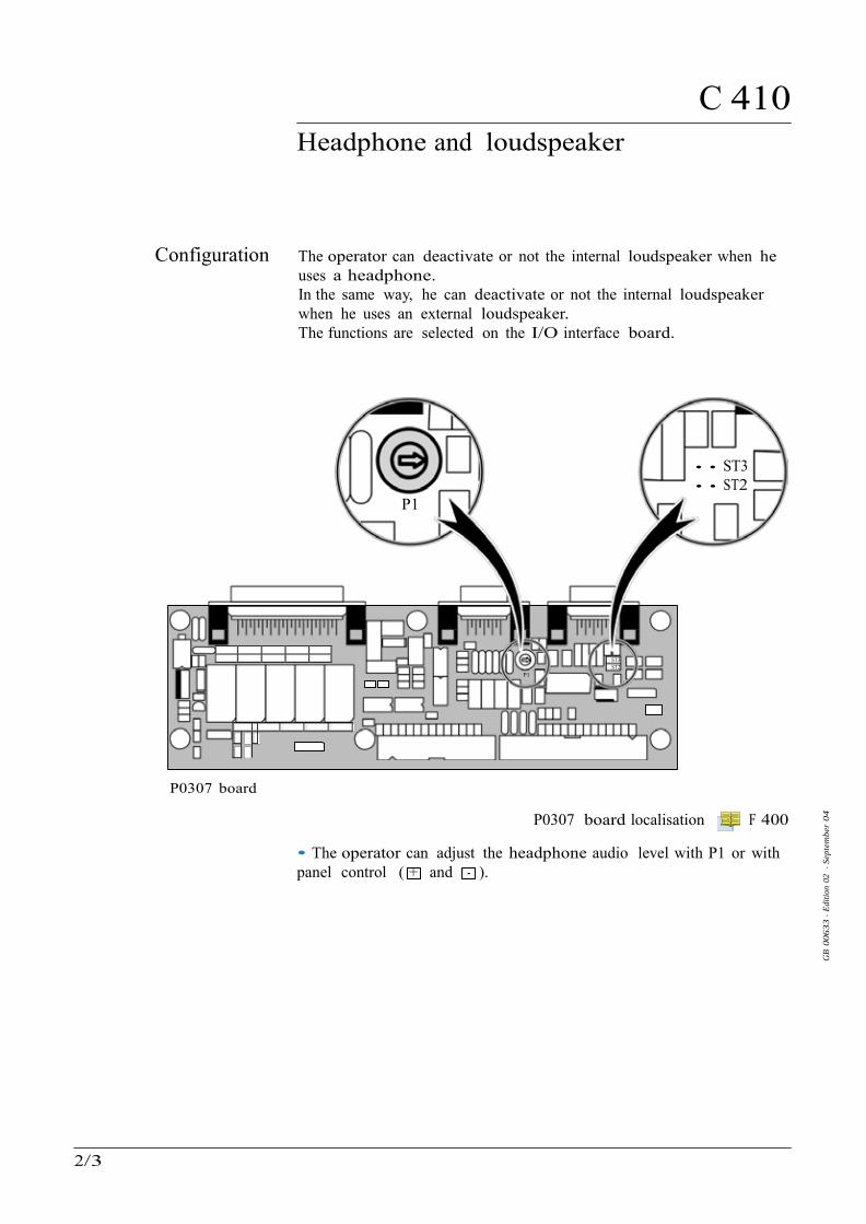
C 410 Headphone and loudspeaker
GB
0063
3 - E
ditio
n 02
- S
epte
mbe
r 04
Configuration The operator can deactivate or not the internal loudspeaker when he uses a headphone. In the same way, he can deactivate or not the internal loudspeaker when he uses an external loudspeaker. The functions are selected on the I/O interface board.
• • ST3 • • ST2
P1
ST3 ST2
P1
P0307 board
P0307 board localisation F 400
• The operator can adjust the headphone audio level with P1 or with panel control ( + and - ).
2/3

C 410 Headphone and loudspeaker
P0344 card
Strap on ST3/ST2
Sub D 9 pins
(printer plug)
Int
Internal loudspeaker active
• • ST3 • • ST2
No plug connected
• • ST3 • • ST2
1 2 3 4 5
6 7 8 9
Int Internal loudspeaker active + headphone
connected
• • ST3
• • ST2
1 2 3 4 5
6 7 8 9
Int
Internal loudspeaker not active
+ headphone connected
• ST3
• • ST2
1 2 3 4 5
6 7 8 9
Int
Ext
Internal loudspeaker
active + External loudspeaker connected
• • ST3
• • ST2
1 2 3 4 5
6 7 8 9
Int
Ext
Internal loudspeaker
not active + External loudspeaker
connected
• ST3
• • ST2
1 2 3 4 5
6 7 8 9
GB
0063
3 - E
ditio
n 02
- S
epte
mbe
r 04
•
•
3/3

C 430 3 masses option
NIFFER HELIUM
GB
0192
8 - E
ditio
n 02
- D
ecem
ber
05
Purpose Leak detection is used to detect micro-openings, porosities, etc. in test parts. The detection of these passages involves the use of a light gas, which is capable of infiltrating the smallest passages quickly. The standard gas used is the Helium 4 but the operator has the possibility with the 3 masses option to use another gases: Hydrogen or Helium 3.
Background is much higher in H2 .
The unit equipped with the 3 masses option does not have any external differences in relation to the standard unit. The modifications are inside the unit (analysis cell magnet and electronic supervisor board). The tracer gas selected is displayed on the control panel LCD screen:
HELIUM SNIFFER
Tracer gas selected
The 3 masses option purpose, used with Hydrogen, is the leak research only and not the continuous analysis of the hydrogen concentration of a gas. The leak detector is not adapted for a hydrogen concentration continuous analysis. The leak detector use in such conditions, as well as the hydrogen concentration of the gas used, are under the supervision of the user.
The functions are the same as the standard detector.
Gas selection or
Adjustment
C 110
1/2

C 430 3 masses option
GB
0192
8 - E
ditio
n 02
- D
ecem
ber
05
Calibration in Hydrogen or Helium 3
Procedure
The leak detector can be calibrated in Hydrogen or Helium 3 with an external calibrated leak. The operator should adjust the parameters of the calibrated leak used before a calibration.
Calibrated leak values programming C 305
Calibration of the leak detector C 300
2/2

C 450
GB
0265
4 - E
ditio
n 01
- S
epte
mbe
r 04
Long distance sniffer probe and Helium spray gun
Please refer to the specific sheets for the instruction:
Long distance sniffer probe
G 400 / G 410 Helium spray gun G 500
1/1

C 520
GB
0047
7 - E
ditio
n 02
- D
ecem
ber
05
Audio alarm / Digital voice
Some difficulties with the control panel use/access ?
Operating principle of the control panel 110 Access to level 4 - Password 130
Setting and maintenance part presentation of the control panel Access to parameters and parameters active depending on authorization
120
Summary of screens Complete displays list with access way and associated sheet
140
Audio alarm definition The Audio alarm appears differently, based on the Zero function.
• Zero function is not activated: The standard Audio alarm is started when the helium signal is exceeding a set point and called reject point.
• Zero function is activated and 10 decades analogic display: «Bip» are emitted permanently with a more and more fast rythm according to the number of leds on. They are stopped and replaced by the standard audio alarm as soon as the signal is above of the reject set point.
Digital voice definition
General
Sound level
Zero function C 540 The digital voice informs the operator by sending audio messages in the following cases: • starting-up process and auto-calibration process • when detector is ready • fault or warning. At any time it is possible to adjust the volume if any menu is activated: to increase volume to decrease volume The level varies from 0 to 9 (= 90 dBA).
Adjustment Digital voice Audio alarm
Adjustment Adjustment
C 110
1/1

C 540 Zero function
GB
0047
8 - E
ditio
n 02
- D
ecem
ber
05
Some difficulties with the control panel use/access ?
Operating principle of the control panel C 110 Access to level 4 - Password C 130
Setting and maintenance part presentation of the control panel Access to parameters and parameters active depending on authorization
C 120
Summary of screens Complete displays list with access way and associated sheet
C 140
Purpose Zero function is provided: • to help the operator to identify a very small fluctuation of the helium signal out of the ambiant background, • to enlarge small fluctuations of the helium signal on the analog display. The zero function allows the operator to work with a reject point below to the background.
The zero function could be activated: - by the operator, - in automatic.
It’s advised to use this function when helium background signal is not instable other wise, the instabilities will be amplified.
Procedure
Principle
The process of the zero function is the same whatever the activation mode (operator or automatic). In automatic mode, the zero function captures automatically the residual in TEST, according to a defined rythm (see setting below). Note: The zero key is no more active and the capture is materialized by the 2 decades led flasking.
He flow value
Background value displayed without the zero function activation
Background value displayed with the zero function activation
Zero function activation
0 Time
1/4

C 540 Zero function
GB
0047
8 - E
ditio
n 02
- D
ecem
ber
05
Activate/desactivate the zero function
manually
Activation Desactivation
=> =>
Zero function setting
Adjustment
C 110
F4 Adjustment
manual
F4
on timer
Adjustment
no
yes
The period of time corresponds to the period of time between each capture (zero up dating).
Note : In automatic, the press on the key starts a new capture.
Audio level C 520 2/4

C 540 Zero function
GB
0047
8 - E
ditio
n 02
- D
ecem
ber
05
Display
10 decades display • Analogic display: When the zero function is activated, the 10 decades led is off. 2 leds on the bargraph are always off. A signal increase equal to the background value will induce the bargraph filling.
Zero not activated Zero activated
10 2.10 -6
background value x 2
2.10 -6
1.10 -6
10 -9
2 leds 1.10 -6
• Digital display : The display value is the real signal value, reduced by the captured
value when you pressed the key.
Note: All coefficients remain applied to the signal.
Example: Background = 1.10-6 mbar.l/s
Zero not activated Zero actived
3/4

C 540 Zero function
GB
0047
8 - E
ditio
n 02
- D
ecem
ber
05
2 decades display • Analogic display: When the zero function is activated, only the number of displayed leds culd decrease according to the background value compared to the reject thresbold.
Example: Background = 5.10-6 mbar l/s cases 1 and 2
Zero not activated
10
Reject threshold
1000%
Zero activated
10
1
10 -1
10 -2
FAIL PASS
2.10 -6
100%
FAIL PASS
10 -3
10 -4
10 -5
1.10 -6
10 -6
Background
10 -9
10% 1%
10 -7
10 -8
10 -9
Background
Case 1 Reject threshold
= 1.10-5mbar.l/s
= about half of
the zone where the bargraph is
green
Case 2 Reject threshold
= 1.10-3mbar.l/s
= 1 led
Cases 1 and 2 Reject threshold
= 1 led
• Digital display: The value displayed corresponds to 1 % of the reject point parameted, with a limit of 1.10-7 mbar.l/s.
Example : background = 5.10-6 mbar.l/s
Zero not
activated
Zero activated
Reject point = 1.10-3 mbar.l/s
= Detector background
= 1 % of the reject point Reject point =
1.10-5 mbar.l/s
Reject point = 1.10-6 mbar.l/s
= 1 % limited to 1.10-7 mbar.l/s
4/4

C 570 Date - Time - Language - Unit
GB
0048
0 - E
ditio
n 02
- D
ecem
ber
05
Some difficulties with the control panel use/access ?
Operating principle of the control panel 110 Access to level 4 - Password 130
Setting and maintenance part presentation of the control panel Access to parameters and parameters active depending on authorization
120
Summary of screens Complete displays list with access way and associated sheet
140
Adjustment procedure units language
date
time
Adjustment Adjustment Adjustment
C 110
Adjustment = no
= sp. unit
Adjustment
Adjustment
Basic unit Optional unit
Adjustment
Date The leak detector calculates its storage period since the last switching off C 200
Take care to set the correct date.
Language The leak detector offers 2,3 or 4 languages, according to the model.
A 600
Notes: - All messages on the LCD are on the selected language. - The selected language is the language of the digital voice.
Digital voice C 520
1/3

C 570 Date - Time - Language - Unit
mbar.l/s
Pa.m3/s
Torr.l/s
GB
0048
0 - E
ditio
n 02
- D
ecem
ber
05
Units The leak detector proposes: - basic units - optional units.
• Basic units: These units are used for the leak flow, and the calibrated leak flow: - mbar.l/s - Torr.l/s - Pa.m3/s In order to use the basic units, the optional unit must be set on «no». A light indicates the unit set:
LEAK RATE
COR
mbar.l/
Pa. 3/s
To .l/s
Unit indicator lights
CAUTION
The leak flow unit could be different of the calibrated leak flow unit.
Calibrated leak setting C 305
When the operator connects a remote control on the leak detector, the remote control is automatically configured with the basic unit set on the detector.
In case of units change: - the following parameters are automatically recalculated:
• reject threshold, • probe clogged.
- the new values are displayed on the digital display. - the leds (bargraph and flashing) position changes only with 10 decades display. It’s so necessary to change the unit before to change the reject threshold.
• Optional units: These units are used for: - the concentration: ppm - the flow : gr/yr, oz/yr and lb/yr of the tracer gas used.
They will be used in priority on the basic units as soon as the optional unit value is other than «no».
2/3

C 570 Date - Time - Language - Unit
RENIF HELIUM «COR» = ppm
HELIUM SNIF. ON «COR» = gr/y
GB
0048
0 - E
ditio
n 02
- D
ecem
ber
05
If an optional unit is selected, it is displayed permanently on the test screen.
Example:
If an optional unit was selected for a calibration source and you change of calibration source, this unit applies to the new selected source. If you want to use another unit (optional or basic), it is also necessary to change the unit when you select the new source.
A user customization is also possible (sp. unit).
In the case of a customization, the user should set the correction value.
When the «COR» indicator is on, the unit used is displayed or the LCD screen.
Example:
LEAK RATE
COR
mbar.l/s
Pa.m3/s
Torr.l/s
Note: If the concentration is selected as a calibration source, the units set are changed: See C 301.
3/3

C 580
Fault / information indicator and display
AUTOCAL. FAILURE BACKGROUND TOO HIGH PRESS NEXT
GB
0246
5 - E
ditio
n 02
- D
ecem
ber
05
Fault and information
Faults Minor fault
At any time, the leak detector can display on the LCD clear Information or Fault messages based on the analysis of the leak detector status. There are 3 basic types of faults: minor fault, major fault and critical failure. There are 2 basic types of information: user information and service information. The messages are displayed on a specific display by order of importance: 1. critical failure 2. major fault and minor fault 3. user information and service information 3 fault types: minor fault, major fault and critical failure. • Warning: - on the digital display alternatively the helium signal and “Er” are shown. - on the LCD, a “!” flashing at the right end of the 1st line.
LEAK RATE
COR
..... !
.....
.....
.....
The digital voice advises the operator of the procedure to follow. • Result: This will not stop the functions of the leak detector but can affect the validity of the test result. • Message: To read the messsage
NEXT
A clear message describes the error on line 2 and 3. The most important warning message is displayed on the 1st line. Up to 3 messages may be displayed on the message display. • Duration: may be temporary or permanent - temporary if the fault appears and then disappears without a corrective action from the user - permanent until the cause is erased by the user. • Remedy: - Temporary: the indicator disappears and the warning message is
erased. - Permanent: both indicator and message are memorized until the fault
is eliminated. 1/5

C 580
Fault / information indicator and display
WARNING! PRESS NEXT ... ... ...
CRITICAL FAILURE pressure gauge fail.
SERVICE AND RESTART
GB
0246
5 - E
ditio
n 02
- D
ecem
ber
05
Faults (cont.)
ASM 142 S and ASM 102 S special case: • If after the start, the background is lower than the sniffer probe clogged point: - The “AL” message appears permanently on the digital display, - a «!» flashing at the right end of the screen.
LEAK RATE
COR
• This default, althought minor, is blocking. It is necessary to launch a calibration to make it disappear.
Major fault • Warning: - on the digital display, “Er” is permanently displayed. - a flashing message occurs on the LCD
LEAK RATE COR
he digital voice advises the operator of the procedure to follow. • Result: May prevent the leak detector from making a vacuum test or an autocalibration • Message: To read the messsage NEXT
Note: A major fault can behave like a temporary minor fault if the origin of the error has disappeared.
Critical failure • Warning: - on the digital display, “Er” is permanently displayed. All indicators are turned off. - on the LCD the clear message of a critical failure is directly displayed. Details are displayed on line 2 and 3.
LEAK RATE COR
The digital voice advises the operator of the procedure to follow. • Result: Complete shut down of the leak detector is required. • Remedy: Need the servicing of the leak detector before starting it again.
2/5

C 580
Fault / information indicator and display
...... i ...... ......
SERVICE INFORMATION new filament required
PRESS RESET
GB
0246
5 - E
ditio
n 02
- D
ecem
ber
05
Information 2 information types: user and service information. • Warning: - no indicator on the digital display - on the LCD, a “i” flashing at the right end of the 1st line.
LEAK RATE COR
- The digital voice advises the operator of the procedure to follow. • Result: Doesn’t affect the functions of the leak detector - User information Only an indication that the leak detector is in a particular status which may require an action from the user in order to return to a standard situation - Service information Only an indication that the leak detector requires a service or maintenance action. • Message: To read the messsage
NEXT
A clear message describes the fault on line 2 and 3.
User information display Service information display
USER INFORMATION filament request off
PRESS RESET
• Duration: After display of the clear message, the indicator and the clear message are erased but they will be reactivated at the next start-up of the leak detector or at each unauthorized request by the user or 30 min later, if the origin of the message is still present. • Remedy: - User information Can be eliminated by an action which is accessible by the user. - Service information Can be eliminated by a service action on the involved component and by resetting the corresponding configuration parameter. This is only accessible by the customer service.
Service instructions E
3/5

C 580
Fault / information indicator and display
GB
0246
5 - E
ditio
n 02
- D
ecem
ber
05
List of messages For all messages, note their contents in order to identify the origin of the message and take the corresponding corrective action if necessary.
General troubleshooting guide D 300
The RS 232 codes of these messages are described in the specific RS 232 user manual.
Use
r In
form
atio
n
Serv
ice
Info
rmat
ion
A
SM 1
82 T
A
SM 1
92 T
A
SM 1
92 T
2
A
SM 1
82 T
D+
A
SM 1
92 T
D+
A
SM 1
92 T
2D+
A
SM 1
22 D
A
SM 1
42
A
SM 1
42 D
A
SM 1
42 S
A
SM 1
002
A
SM 1
02 S
Information messages auto. cal. required • • • • • • • • • • • • • filament request off • • • • • • • • • • • • • manual calibration • • • • • • • • • • • auto. cal. aborted • • • • • • • • • • • • • drift too high (zero) • • • • • • • • • • • • • He too high for zero • • • • • • • • • • • • • He too low for zero • • • • • • • • • • • • • external calib. Leak • • • • • • • • • • • new fil#1 required • • • • • • • • • • • • • new fil#2 required • • • • • • • • • • • • • maintenance required • • • • • • • • • • • • • fil1-collector short • • • • • • • • • • • fil2-collector short • • • • • • • • • • • press zero & spray He • • • • • • • • • • • no Hy leak for calib • • • • • • • • • • • Bargraph 2 decades • • Blinking led off • • Use sniffer remote • • ext. cal. recal. • • int. cal. recal. • primary pump maint. • •(4) •(4) •(4) •(8) •(10) •(12) Roughing pump maint. • •(2) •(3) •(3) •(2) •(6) •(5) high. vac pump maint • •(1) •(1) •(1) •(1) •(1) •(1) •(7) •(9) •(9) •(9) •(11) •(5)
(1) PTM 5154 (2) ATP 100 (3) MDP 5011 (4) ACP 28
(5) MDP 5006 HDS (6) ATH 31+ (7) ATH 31 (8) Dry pump
(9) AMP 007 I (10) AMD 1 (11) ATH 164 (12) Diaphragm pump
4/5

C 580
Fault / information indicator and display
GB
0246
5 - E
ditio
n 02
- D
ecem
ber
05
D
éfau
ts m
ineu
rs
D
éfau
ts m
ajeu
rs
D
éfau
ts c
ritiq
ues
A
SM 1
82 T
ASM
192
T
A
SM 1
92 T
2
ASM
182
TD
+
ASM
192
TD
+
ASM
192
T2D
+
ASM
122
D
A
SM 1
42
A
SM 1
42 D
ASM
142
S
A
SM 1
002
A
SM 1
02 S
Error message autocal failure • • • • • • • • • • • • • temperature too low • • • • • • • • • • • • • temperature too high • • • • • • • • • • • • • cal. leak year error • • • • • • • • • • • • • peak search error • • • • • • • • • • • • • peak adjust error • • • • • • • • • • • • • background too high • • • • • • • • • • • • • emission loss • • • • • • • • • • • • • cell. zero off limits • • • • • • • • • • • • • cell. zero stability • • • • • • • • • • • • • calib. test mode lost • • • • • • • • • • • • • sensitivity too high • • • • • • • • • • • • • background trouble • • • • • • • • • • • • • lack of sensitivity • • • • • • • • • • • • • cell.pressure safety • • • • • • • • • • • • • triode safety • • • • • • • • • • • • • emission failure • • • • • • • • • • • • • snif. probe clogged • • • • • • • • • • • • • high. vac pump speed • • • • • • • • • • • • • • cell.troubles • • • • • • • • • • • • • • cell pres.>0.01 mbar • • • • • • • • • • • • • high. vac pump fail • • • • • • • • • • • • • cell pres.>1e-04 mbar • • • • • • • • • • • • • filaments #1 bad • • • • • • • • • • • • • no collector voltage • • • • • • • • • • • • • time keeper ram fail. • • • • • • • • • • • • • cell. gauge failure • • • • • • • • • • • • • rough. pump failure • • • • • • • • • • • primary pump failure • • • • • • • • • • • 24 V DC troubles • • • • • • • • • • • • • mini reject point on • • check ATH connector • • check AMP connector • • • • • check TMP connector • • • • • • • • check ATH connector • • check MDP connector • • • • • • • check ATP connector • • • LDS probe problem • •
5/5

C 590 Massive Function
GB
0285
1 - E
ditio
n 01
- D
ecem
ber
05
Purpose This function allows to do gross leak localization easier.
This function is only accessible with the remote control.
Principle The reject threshold is automatically placed at 130 % of the signal in progress at the function entry. This allows to detect a small signal variation from the entry but principally to place quickly the reject threshold near maximum signal detected.
Signal Reject threshold with the massive function activated (red/orange led)
Reject threshold (green led)
1st overrun = 1st alarm
3 overruns linked to the same leak, so 3
alarms
t
Massive function
activation Preliminary conditions - The remote control should be connected to the control panel.
- The reject point flashing led should be activated ( C 212). - The 10 decades bargraph should be selected. Note: The associated warning will be displayed if the required conditions are not present at the function entry.
10 -10 10 -9 10 -8 10 -7 10 -6 10 -5 10 -4 10 -3 10 -2 10 -1 1
green led
10 -10 10 -9 10 -8 10 -7 10 -6 10 -5 10 -4 10 -3 10 -2 10 -1 1
red/orange led
1/2

C 590 Massive Function
1
-6
EST
-6
2 DEC
10 DE
C
2 DEC
10 DE
C
GB
0285
1 - E
ditio
n 01
- D
ecem
ber
05
Start/Stop of the - To start the function, press on
MASSIVE 10 10
massive function key a long time until the green led
reject threshold 10 -1
1
10 -1
becomes red/orange.
- To stop the function, press on
MASSIVE
COR FAIL PASS
ZERO 10 -2
10 -3
10 -4
10 -5
COR FAIL PASS
ZERO 10 -2
10 -3
10 -4
10 -5
L. REQUEST L. REQU
green led orange/red led key a long time until the red/orange
led becomes green.
The reject threshold comes back to its initial value set in the menu.
TEST
STAND-BY
SNIFFER
10 10 -7
10 -8
10 -9
TEST
STAND-BY
SNIFFER
10 10 -7
10 -8
10 -9
Function not activated
Function activated
Note: Massive function activated, each time you press normally the key, you reposition the reject threshold in process.
MASSIVE
Reject threshold = signal in process x 130 % 2/2

Maintenance - Troubleshooting
GB
0048
4 - E
ditio
n 02
- F
ebru
ary
05
D
ASM 142 S User’s Manual
Detailed contents
Preliminary remarks
Throughout this User’s Manual, you could find this type of message
“Summary of screen C 140”: it refers to a specific chapter of the User’s Manual. Please read it for further information.
D 100 Table of preventive maintenance intervals
D 200 Maintenance message
- Definition - Adjustment of the counters
D 210 Calibrated leak calibration supervision
- Purpose - Principle - Display - Procedure
D 300 General troubleshooting guide
D 400 Symptoms description
1/1

D 100
Table of preventive maintenance intervals
ASM
102
S
ASM
122
D
ASM
142
ASM
142
S
ASM
142
D
ASM
182
T
ASM
192
T
ASM
192
T2
ASM
182
TD
+
ASM
192
TD
+
ASM
192
T2D
+
ASM
100
2
1000 h(1) Clean filters (inlet filters, air inlet filter) - • • • • •
2000 h(1) or 3 months(2)
Change the rotary vane pump oil. Change the oil mist eliminator.
E 750
•
•
•
•
•
•
4000 h(1) or 6 months(2)
Clean the vacuum lines, the valves and the gauges with alcohol - Dust the electronic boards and the fans. Partial maintenance of the analyzer cell: Replace analyzer cell filaments and collector. Clean the analyzer cell with alcohol (this cleaning may be necessary in case of general internal contamination creating insulating deposits).
E 400
•
•
•
•
•
•
•
•
•
•
•
•
8000 h(1)
or 1 year(2)
Sniffer probe filter replacement if used.
G 200
•
•
•
•
•
•
•
•
•
•
•
•
Pirani gauge adjustment. CS • • • • •
AP 1004 gauge adjustment. CS • •
Electronic overhaul - •
Replace the seal in the rotary vane pump.
CS
•
•
•
AMD1 pump: replacement of membranes and check valves. Change the inlet filter of the test chamber.
E 710
•
10000 h(1) Replacement of membranes and replacement of valves.
CS
•
Primary pump maintenance/ replacement of membranes and valves.
CS
•
GB
0246
9 - E
ditio
n 01
- M
arch
04
Frequency* Maintenance operations to be performed
CS : Please contact Customer Service
*Service intervals: The service intervals given are for applications and work rates which conform to the normal operating conditions. If the machine is operating under more difficult conditions they can be shortened.
(1) running time (2) running time or storage (3) storage
1/2

D 100
Table of preventive maintenance intervals
ASM
102
S
ASM
122
D
ASM
142
ASM
142
S
ASM
142
D
ASM
182
T
ASM
192
T
ASM
192
T2
ASM
182
TD
+
ASM
192
TD
+
ASM
192
T2D
+
ASM
100
2
12000 h(1) Regrease the molecular pump.
E 740 • • • • • • •
Regrease the turbomolecular pump.
E 740 • • • • •
Regrease the ATP 100 or ATH 164 pump.
E 730
•
•
•
Regrease the AMP007I molecular pump.
CS
•
•
•
15000 h(1) Replace the ball bearings of the ATH 31 pump.
CS
•
16000 h(1)
or 2 years(3)
Recalibration/exchange of the internal calibrated leak or calibrated leak used for calibration.
E 570
•
•
•
•
•
•
•
•
•
•
Complete service of the rotary vane pump.
CS
•
•
•
•
•
•
22000 h(1)
or 1 year(3)
Replace the ball bearings and the seals of the molecular pump and turbomolecular pump.
E 740
•
•
•
•
•
Replace the ball bearings and the seal of the ATP 100 or ATH 164 pump.
E 730
•
•
•
Complete maintenance of dry pump (ACP 28 pump).
CS
•
•
24000 h(1)
or 1 year(3)
Replace the ball bearings and the seals of the molecular pump.
CS
•
•
•
•
500000 cycles
Change the valves.
E 530
•
•
•
•
•
•
•
•
•
•
•
•
Every 2 years
Change ATH 31 pump ball bearings if the leak detector has not been used.
•
GB
0246
9 - E
ditio
n 01
- M
arch
04
Frequency* Maintenance operations to be performed
CS : Please contact Customer Service
*Service intervals: The service intervals given are for applications and work rates which conform to the normal operating conditions. If the machine is operating under more difficult conditions they can be shortened.
(1) running time (2) running time or storage (3) storage
2/2

D 200 Maintenance message
GB
0048
6 - E
ditio
n 02
- D
ecem
ber
05
Definition The Maintenance messages will be display on the LCD in order to inform the operator to do a operation: The operator should adjust the periodicity of the appearance of this message. These messages concern (according to the leak detector model): - The primary pump, - The high vac. pump, - The periodicity of maintenance (use time).
Adjustment of the
counters ASM 102 S
ASM 142 S
Primary pump
adjustment
(*)
High Vac. pump adjustment
(*)
Maintenance required adjustment
(*)
(*) ...pump adjustment
Reset yes
Maint. required adjustment Initial value Adjustment
/1

D 210
Calibrated leak calibration supervision
GB
0285
2 - E
ditio
n 01
- D
ecem
ber
05
Purpose The supervison purpose is to remember to the operator to perform a recalibration of the calibrated leaks used for the calibration. The operator could used different calibrated leaks with the detector: it is the calibrated leak in use process which is supervised.
Only the external calibrated leaks whose all the parameters were parameted ("more parameters on leak sticker: "yes" in the spectro menu) could be supervised. ( C 305)
Principle Taking into account the leak calibration date and the recalibration periodicity set, an information message is sent 2 months before the planned recalibration date, on the detector LCD screen. This message will display: - at each detector starting up. - each day at 14:00 (local time) until the calibrated leak is recalibrated/changed.
ASM 142 S : The message precises which calibrated leak should be recalibrated (internal / external).
Display The remaining time before the next recalibration is displayed in the Maintenance menu.
Next calibration
Internal calibrated leak (option) or external calibrated leak with calibration date programmed.
External calibrated leak without calibration date programmed.
/2

D 210
Calibrated leak calibration supervision
GB
0285
2 - E
ditio
n 01
- D
ecem
ber
05
Procedure After the leak recalibration, the operator should set the new leak values ( C 305), the last calibration date, and its validy period.
last calibration
date
calibration validity
Adjustment Adjustment
Note: This menu is not available in the case of the external calibrated leak whose the "more parameters on leak sticker" parameters is set on "no".
2/2

D 300 General troubleshooting guide
GB
0247
0 - E
ditio
n 02
- F
ebru
ary
06
D 4
00
ASM
102
S
ASM
122
D
ASM
142
A
SM 1
42 S
A
SM 1
42 D
A
SM 1
82 T
A
SM 1
92 T
A
SM 1
92 T
2 A
SM 1
82 T
D+
ASM
192
TD
+ A
SM 1
92 T
2D+
ASM
100
2
Power supply
Nothing happens when the power is switched ON 41 • • • • • • • • • • • •
No display appears on the control panel 42 • • • • • • • • • • • •
Rotary vane pump (RVP)
No noise from the rotary vane pump 55 • • • • • •
Abnormal noise from the rotary vane pump 56 • • • • • •
Molecular / Turbomolecular pump
Pump failure 52 • • • • • • • • • • •
Pump speed 53 • • • • • • • • • • •
Pump connector 54 • • • • • • • • • • •
Membrane pump
The pump does not start 57 •
Dry pump (ACP 28)
No noise from the dry pump 63 • • •
Dry pump has stopped during cycle 64 • • •
Dry pump (Vacuubrand)
Pump fails to start or stop immediately 65 •
Pump doesn’t achieve ultimate total pressure or normal pumping speed 66 •
Pump too noisy 67 •
No noise from the primary pump 68 •
Hybrid pump (ATH 31)
High Vac / Roughing pump does not start 58 •
High Vac pump fails to reach nominal speed 59 •
Roughing pump fails to reach nominal speed 60 •
Roughing pump nominal speed lost 61 •
Dry pump (KNF)
Autocal fault with a high background 62 •
/4

D 300 General troubleshooting guide
D 4
00
ASM
102
S
ASM
122
D
ASM
142
A
SM 1
42 S
A
SM 1
42 D
A
SM 1
82 T
A
SM 1
92 T
A
SM 1
92 T
2 A
SM
182
TD
+ A
SM 1
92 T
D+
ASM
192
T2D
+ A
SM 1
002
GB
0247
0 - E
ditio
n 02
- F
ebru
ary
06
Analyzer cell
Cell pressure > 0.01 mbar 7 • • • • • • • • • • • •
Cell pressure > 1 x 10⁻⁴ mbar 8 • • • • • • • • • • • •
Cell gauge failure 9 • • • • • • • • • • • •
Filaments #1 & #2 bad 10 • • • • • • • • • • • •
Fil 1/Fil 2 - collector short 11 • • • • • • • • • • • •
No collector voltage 12 • • • • • • • • • • • •
Cell pressure safety 13 • • • • • • • • • • • •
Triode safety 14 • • • • • • • • • • • •
Emission failure 15 • • • • • • • • • • • •
No cell pressure display 69 • • • • • • • • • • • •
Inlet pressure
Inlet pressure display doesn’t show atm pressure 16 • • • • • • • • • •
No vent (VENT ON requested) 17 • • • • • • • • • •
No inlet pressure display 18 • • • • • • • • • •
No inlet pressure drop at start of a cycle 19 • • • • • • • • • •
Impossible to reach the selected test mode 20 • • • • • • • • • •
No test chamber opening at the cycle end (pass/fail mode) 21 • • • • • • • • • • No test chamber opening at the cycle end (asm mode) 22 • • • • • • • • • •
2/4

D 300 General troubleshooting guide
GB
0247
0 - E
ditio
n 02
- F
ebru
ary
06
D 4
00
ASM
102
S
ASM
122
D
ASM
142
A
SM 1
42 S
A
SM 1
42 D
A
SM 1
82 T
A
SM 1
92 T
A
SM 1
92 T
2 A
SM
182
TD
+ A
SM 1
92 T
D+
ASM
192
T2D
+ A
SM 1
002
Calibration
Start-up Auto-cal failure 31 • • • • • • • • • •
Auto-cal failure: cal. leak year error 32 • • • • • • • • • • • •
Temperature too low, Auto-cal failure temperature limits 33 • • • • • • • • • • •
Auto-cal failure: helium pollution 34 • • • • • • • • • • • •
Cell zero limits or cell zero stability 35 • • • • • • • • • • • •
Auto-cal failure: peak locating error 36 • • • • • • • • • • • •
Auto-cal failure: peak adjust error 37 • • • • • • • • • • • •
Auto-cal failure: emission loss 38 • • • • • • • • • • • •
Impossible to start an Auto-cal 39 • • • • • • • • • • • •
Impossible to reach desired target value 40 • • • • • • • • • • • •
Helium measurement
High helium background signal (in stand-by mode) 43 • • • • • • • • • •
High helium background signal (in hard vacuum test mode) 44 • • • • • • • • • •
Helium signal unstable 45 • • • • • • • • • • • •
No test cycle start at the test chamber closing 46 • • • • • • • • • •
LDS test
High helium background 47 • • • • • • • • • • • •
Helium signal unstable 48 • • • • • • • • • • • •
Sniffer probe clogged 49 • • • • • • • • • • • •
Inconsistent Helium signal 50 • • • • • • • • • • • •
3/4

D 300 General troubleshooting guide
D 4
00
ASM
102
S
ASM
122
D
ASM
142
A
SM 1
42 S
A
SM 1
42 D
A
SM 1
82 T
A
SM 1
92 T
A
SM 1
92 T
2 A
SM
182
TD
+ A
SM 1
92 T
D+
ASM
192
T2D
+ A
SM 1
002
GB
0247
0 - E
ditio
n 02
- F
ebru
ary
06
Operator interface
“!“ or “i” appears at the end of line 1 on LCD 23 • • • • • • • • • • • •
“AL“ appears on the digital display at the start 70 •
Helium signal digital display flashing 24 • • • • • • • • • • • •
Password lost 25 • • • • • • • • • • • •
Timekeeper ram failure 26 • • • • • • • • • • • •
Remote control keys inactive 28 • • • • • • • • • • • •
Helium signal or inlet pressure analog display abnormally lit 27 • • • • • • • • • • • • Temperature
Temperature too low/high 51 • • • • • • • • • • •
Appearence of information messages
Maintenance required • • • • • • • • • • • •
Auto-cal required 2 • • • • • • • • • • • •
Auto-cal aborted 3 • • • • • • • • • • • •
Manual auto-cal 4 • • • • • • • • • •
New Fil #1 / Fil #2 required 5 • • • • • • • • • • • •
Filament request off 6 • • • • • • • • • • • • 4/4

D 400 Symptoms description
GB
0247
1 - E
ditio
n 02
- F
ebru
ary
06
SYMPTOM
ORIGIN / DIAGNOSTIC CONFIRMATION
REMEDY
1 Maintenance required Number of cycles before
maintenance obsolete • Refer to the table of
preventive maintenance intervals
• Reset the counter
D 100 D 200
2 Auto-cal required An auto-calibration is required
• Start an auto-calibration C 301
3 Auto-cal aborted The auto-calibration is
stopped before the end of the auto-cal cycle
• Restart an auto-calibration C 301
4 Manual calibration In spectro menu, auto-cal
is off C 302
5 New fil #1 / #2 required The fil #1 / #2 is burned • Change the fil #1 / #2 E 400
6 Filament request off The filament is switched off • In Spectro menu, switch on
the filament E 400
7 Cell pres. > 0.01 mbar Analyzer cell pressure too
high / leak (spectro PI1 safety activated)
• Check tightness of the analyzer cell
• Eliminate the leak
8 Cell pres. > 1e-04 mbar Analyzer cell pressure too
high / leak (triode safety activated)
• Keep pumping the cell for 10 min (in stand-by mode)
• If the trouble is not eliminated check tightness of the analyzer cell
• Eliminate the leak
9 Cell gauge failure Analyzer cell - spectro PI1 safety damage
• Contact Customer Service
10 Filaments bad Both filaments broken • Replace filaments E 400
11 Fil 1/Fil 2 collector short Short circuit in the cell (fil
1 (fil 2) collector shunt message )
• Eliminate the short circuit in the cell
E 400
12 No collector voltage Supervisor board P0302 or P0320 board
• Contact Customer Service
13 Cell pressure safety Analyzer cell pressure
too high / leak or air inlet (spectro PI1 safety
activated)
• Keep pumping the cell for 10 min (in stand-by mode)
• If the trouble is not eliminated check tightness of the analyzer cell
• Eliminate the leak and check the state of the filaments
1/11

D 400 Symptoms description
GB
0247
1 - E
ditio
n 02
- F
ebru
ary
06
SYMPTOM
ORIGIN / DIAGNOSTIC CONFIRMATION
REMEDY
14 Triode safety Analyzer cell pressure too
high / leak (triode safety activated)
• Keep pumping the cell for 10 min (in stand-by mode)
• If the trouble is not eliminated check tightness of the analyzer cell
• Eliminate the leak and check the state of the filaments
15 Emission failure Filament off - During cycle,
the calibration is defective • Check or replace the
defective filament E 400
16 Inlet pressure display does not show atmospheric pressure
Inlet port not vented (Inlet vent OFF on LCD)
NO Inlet gauge adjustment
• Select Inlet Vent ON • Contact Customer Service
E 400
17 No inlet vent
(inlet vent ON requested) Vent valve coil - Check
valve VA1 connections and coil status
NO Supervisor board P0302
• Change valve VA1 if faulty: - Minisol/bacosol - VAT: Contact Customer
Service • Contact Customer Service
E 530
18 No inlet pressure display Inlet gauge adjustment
NO Inlet pressure gauge failure
(impossible to adjust it)
• Contact Customer Service • Contact Customer Service
19 No inlet pressure drop at start of a cycle
Inlet gauge head disconnected NO
Hard vacuum test cycle unauthorized (a sound is emitted when the cycle control key is pressed)
NO Fuse on the P0318 board defective (only 182/192
series) NO Roughing valve
VR1 defective
• Secure proper inlet pirani gauge head connection
• Check leak detector status:
example: check that SNIFFING test is not selected
• Replace the fuse • Change the coil or the valve
2/11

D 400 Symptoms description
GB
0247
1 - E
ditio
n 02
- F
ebru
ary
06
SYMPTOM
ORIGIN / DIAGNOSTIC CONFIRMATION
REMEDY
20 Impossible to reach the
selected mode
Leak detector with a blank at the inlet (a volume can be a source of outgazing).
Leak detector configuration (Inlet pressure compatible with desired test mode)
NO Inlet pirani gauge
adjustment NO
Internal leak
NO
Primary pump
NO Molecular or turbomolecular pump
NO Fuse on the P0318 board defective (only 182/192
series) NO
Detection valve defective
• Check selected test mode consistency
• Contact Customer Service • Check the tightness of the
valves,seals... • Check primary pump limit
pressure • Repair if necessary • If RVP, change the oil • Check the pump is rotating • Replace the fuse • Change the coil or the valve
C 210
21 No test chamber
opening at the cycle end Mode: pass/fail
Part good, green light on • Check and set inlet vent parameters
C 500
22 No test chamber
opening at the cycle end Mode: asm
Cycle and memo functions not active
NO Part good, green light on
• Set functions • Check and set inlet vent
parameters
C 550 C 530
C 500
23 « ! « or « i « appears at
the end of line 1 on the LCD
Fault or information display activated
• Press NEXT to display the clear message
C 580
24 Helium signal digital display flashing
Fault display activated (Er alternately displayed
with helium signal)
• Press NEXT to display the clear message
C 580
25 Password lost Impossible to access to the menus
• Contact Customer Service
3/11

D 400 Symptoms description
REMEDY
GB
0247
1 - E
ditio
n 02
- F
ebru
ary
06
SYMPTOM ORIGIN / DIAGNOSTIC CONFIRMATION
26 Timekeeper ram fail. Supervisor board P0302 ram problem
• Contact Customer Service
27 Helium signal or inlet pressure analog display abnormally lit
28 Remote Control keys inactive
Wrong connection between remote control
and control panel Remote control
disconnected (no LED and display on the remote)
NO Autocal key deactivated
(Beep emitted when Autocal key is pressed)
• Secure proper connection of the remote control, stop leak detector and start again
• Secure proper connection of the remote control.
• If remote control display is erratic, after reconnection, stop leak detector and start again
• Leak detector is in test
mode: external calibration is available on the control panel only
• Stop test cycle to start an internal autocalibration
C 301
31 Start-up Auto-cal failure Filament status OFF • Select filament status ON in the spectro menu and start an Auto-cal
E 400
32 Auto-cal failure: cal. leak year error
33 Temperature too low/ high Auto-cal failure temperature limits
34 Auto-cal failure: helium pollution
Incorrect internal calibrated leak parameters
Temperature sensor disconnected
NO
Ambient temperature
NO Fan(s) failure
High background (helium signal is higher to the
calibrated leak value used for the calibration)
• Check and correct internal calibrated leak parameters
• Secure proper temp. captor connection to the internal calibrated leak
• Make sure the leak detector
is used within ambient temperature tolerance
• Check fan status and replace
faulty fan(s) • Degassing in the analyzer
cell: keep pumping the cell for 10 min (in stand-by mode) and start an autocalibration
• If the trouble is not eliminated, look for possible leaks or oil contamination (for RVP)
C 305 A 800 E 750
4/11

D 400 Symptoms description
GB
0247
1 - E
ditio
n 02
- F
ebru
ary
06
SYMPTOM
ORIGIN / DIAGNOSTIC CONFIRMATION
REMEDY
35 Cell zero limits or Cell
zero stability VHS adjustment
NO Electronic problem
• Contact Customer Service • Contact Customer Service
36 Auto-cal failure: peak locating error
Problem of the calibration valve
NO Peak fault: internal
calibrated leak damaged (lack of helium)
NO Incorrect filament
alignment NO
Peak fault: analyzer cell incorrect assembly
• Check valve VC3 • Check internal calibrated
leak parameters • Check consistency between
measurement of the internal and the external calibrated leak
• Change internal calibrated leak
• Check and adjust filament
position • Check the analyzer cell
E 530 C 305
C 300
E 400
E 400
37 Auto-cal failure: peak
adjust error Peak fault: internal
calibrated leak parameters NO
Incorrect filament alignment
NO Peak fault: analyzer cell
incorrect assembly
• Check that the calibration parameters are correct
• Check and adjust filament
position • Check the analyzer cell
C 305 E 400
E 400
38 Auto-cal failure: emission loss
Problem of the calibration valve
• Check valve VC3 E 530
39 Unable to start an autocalibration
Manual calibration selected
NO Leak detector is in test mode (remote control
AUTOCAL key inactive)
• Select automatic calibration • The control panel AUTOCAL
key is only active to start an external calibration
• For internal auto-calibration, stop the test cycle
C 302 C 301
5/11

D 400 Symptoms description
GB
0247
1 - E
ditio
n 02
- F
ebru
ary
06
SYMPTOM
ORIGIN / DIAGNOSTIC CONFIRMATION
REMEDY
40 Unable to reach target
value Incorrect internal calibrated
leak parameters NO
Internal calibrated leak faulty (check helium signal with an external calibrated
leak)
• Check and correct internal calibration leak parameters
• Change/recalibrate internal
calibrated leak
C 305 E 560
41 Nothing happens when
the power is switched ON Power fuse burnt • Change fuse and check
power voltage
42 No display appears on
the control panel Control panel disconnected
from supervisor board NO
Power supply board trouble
NO
Control panel trouble
• Secure proper control panel connection.
• Change fuse of the power
supply board or contact Customer Service
• Change control panel board
43 High helium background
signal (in stand-by mode)
Rotary vane pump Pollution (if RVP)
NO
Leak inside the leak detector
NO Analyzer cell
contamination NO
Ambient air helium contamination (background
OK when leak detector placed in another room or environment, free of helium
contamination)
• Open air ballast • Change the oil or contact
customer service. • Helium leak: check the valves • Clean and recondition the
cell • Clean the ambient air
E 750
E 400
44 High helium background signal (in hard vacuum test mode)
Tested piece degassing (background OK in test
mode when leak detector inlet port blanked off)
• Clean the part/installation being testing. Eliminate the source of degassing or contamination
6/11

D 400 Symptoms description
GB
0247
1 - E
ditio
n 02
- F
ebru
ary
06
SYMPTOM
ORIGIN / DIAGNOSTIC CONFIRMATION
REMEDY
45 Helium signal unstable Analyzer cell connections
NO Contamination
of the rotary vane pump oil (helium “peaks” at regular
intervals) (if RVP)
• Check that the external analyzer cell connections are correct and the internal analyzer cell connections propely fastened
• Change the oil
C 400 E 750
46 No test cycle start at the
test chamber closing Sensor disconnected:
sensor light off • Check the sensor connection
to the test chamber and the board
47 High helium background signal
Ambient air helium contamination (background
OK when leak detector placed in another room or environment, free of helium
contamination) NO
Internal LDS plastic tube disconnected (background
decreases very slowly when sniffer probe tip is
blocked with a finger)
•Clean ambient air • Repair LDS probe tube
(tightness of connectors) or change LDS probe
G 200
48 Helium signal unstable Ambient source of helium
contamination • Check possible sources
of helium emission in the surroundings
• Eliminate or isolate it
7/11

D 400 Symptoms description
GB
0247
1 - E
ditio
n 02
- F
ebru
ary
06
SYMPTOM
ORIGIN / DIAGNOSTIC CONFIRMATION
REMEDY
49 LDS probe clogged LDS probe filter clogged
(message disappears when the filter is removed)
NO Other part of the LDS probe clogged (no helium signal
change when the probe tip is blocked with a finger)
NO Sniffer probe clogged set point adjustment
too high (leak detector autocalibrated)
• Change LDS probe filter • Clean LDS probe tube with
needle or change LDS probe • Check sniffer probe clogged
set point value • Adjust it 20 % of the ambient
helium signal
G 200 G 200
G 211
50 Inconsistent Helium
signal Fine signal adjustment
required • Make an external calibration
in sniffing mode C 303
51 Temperature too low/
high Ambient temperature
sensor • Make sure the leak detector
is used within ambient temperature tolerance
A 800
52 Pump failure Overheating
NO Mechanical hard spot (does not spin
freely by hand)
• Check the connections : unplug and plug the cables on the P0326 board and the pump
• Contact Customer Service
8/11

D 400 Symptoms description
GB
0247
1 - E
ditio
n 02
- F
ebru
ary
06
SYMPTOM
ORIGIN / DIAGNOSTIC CONFIRMATION
REMEDY
53 Pump speed P0326 switch is in running-
in NO
The exhaust pressure of the pump is not correct
(≤ 5 mbar ) NO
The exhaust valve has not opened
NO Leaks inside the leak
detector
NO Greasing of the pump ball bearings to be performed
NO Mechanical hard spot
(does not spin freely by hand)
• Check the pump • Check the gross leak valve • Check the tightness of the
canalisations, valves, pumps and cell (alcohol test or use of another detector)
• Regrease the pump ball
bearings • Replace the pump or • Contact Customer Service
E 530
E 740
54 Check the pump
connection Pump is not connected with
pump controller board P0326
• Contact Customer Service
55 No noise from the rotary vane pump
Rotary vane pump power supply not connected NO
Circuit breaker switch of the rotary vane pump
Impossible to keep in position 1
NO Motor thermistor Internal
motor temperature > 60°C
• Connect the rotary vane pump power supply connector
• Contact Customer Service • Allow the pump to cool down • If the fault persists: • Contact Customer Service
56 Abnormal noise from the
rotary vane pump Oil temperature <10°C
NO
Symptoms of seizure: the motor binds (heats up)
• Heat the pump body to approximately 18°C.
• Contact Customer Service
9/11

D 400 Symptoms description
GB
0247
1 - E
ditio
n 02
- F
ebru
ary
06
SYMPTOM
ORIGIN / DIAGNOSTIC CONFIRMATION
REMEDY
57 The pump does not start Membrane pump seized
NO Membrane cut NO
Valve defective
• Change the pump • Change membranes • Change valve
58 High Vac or Roughing
pump do not start Temperature is too low
NO Internal connection missing (No LED lit on the controller
board) NO
Pump locked (Pump speed does not exceed 4 KRPM)
• Install the leak detector in a room where the temperature is in the acceptable range (between 0 and 40°C)
• Secure proper connections
and controller identification • Contact Customer Service
59 High Vac pump fails to reach nominal speed
Controller configuration (High Vac Pump speed
does not exceed 42000 RPM)
• Contact Customer Service
60 Roughing pump fails to
reach nominal speed Controller configuration
(Roughing Pump speed does not reach 100 %)
• Contact Customer Service
61 Roughing pump Nominal
speed lost Large leak on the tested
item (Speed OK when inlet port blanked off)
• Eliminate the leak if it is identified. If not, spray a little quantity of helium: a fast helium signal rise will confirm the leak
62 Autocal failure with a high background
The dry pump does not start (no noise)
• Change the pump
63 No noise from the
primary pump Problem on electrical
module NO
Pump overheating
NO Mechanical jamming
• Contact Customer Service • Check the connections,
unplug and plug the cables on the electrical module. Check the cooling system.
• Contact Customer Service
10/11

D 400 Symptoms description
GB
0247
1 - E
ditio
n 02
- F
ebru
ary
06
SYMPTOM
ORIGIN / DIAGNOSTIC CONFIRMATION
REMEDY
64 Pump stops during cycle Power supply voltage is
less than the minimum allowed, the pump turns
into safe
• Check the power supply voltage, stop the detector and restart the pump
65 Pump fails to start or
stops immediately Pressure in outlet pipeline
too high NO
Motor overloaded
• Contact Customer Service • Allow motor to cool.
66 Pump does not achieve
ultimate total pressure or normal pumping speed
Pump has been exposed to condensate
NO Deposits have been
formed inside the pump NO
Valves or diaphragm damaged
• Run pump at atmospheric pressure for a few minutes
• Contact Customer Service • Contact Customer Service
67 Pump too noisy Atmospheric or high
pressure at inlet port NO
Diaphragm clamping disc loose
• Connect hose to pump outlet • Contact Customer Service
68 No noise from the primary pump
Primary dry pump power supply not connected
NO
No power voltage (24 V) to the primary dry pump
• Connect the primary dry pump power supply connector
• Contact Customer Service
69 No cell pressure display Filament OFF requested
NO Short circuit on triode
electrode
• Check filament status • Eliminate the short circuit in
the cell
70 “AL” appears on the
digital display at the start.
Autocalibration failure • Start a calibration.
11/11

Maintenance sheets E Detailed contents
GB
0049
1 - E
ditio
n 03
- F
ebru
ary
05
ASM 142 S User’s Manual
Preliminary remarks
Throughout this User’s Manual, you could find this type of message
“Summary of screen C 140”: it refers to a specific chapter of the User’s Manual. Please read it for further information.
E 100 Maintenance operations instruction
- Safety instructions - Working conditions - Icons used
E 110 Access to the internal components ASM 142/ASM 142 S
- Access level 1 - Access level 2
E 400 Basic maintenance of the analyzer cell
- Components - Safety instructions - Special precautions - Cell disassembly - Cleaning the body - Disassemble the filaments - Disassemble the electron collector - Replace the electron collector and the filaments - Tighten all the connection screws - Reassemble the flange - Tighten all the securing screws - Restart and check proper operation of the analyzer cell - Reset the filament information timer - Switch on/off the filament - Verification of the electrical zero - Symptoms and probable cause
E 530 Valves installation and maintenance
- Valves identification - VAT valves DN 25 / DN 40 - Vacuum activated valves - Minisol and Bacosol valves
E 560 Exchange of the internal calibrated leak (option)
- Exchange of the internal calibrated leak - Programming the new calibrated leak characteristics - Calibrated leak supervision
1/2

Maintenance sheets E Detailed contents
GB
0049
1 - E
ditio
n 03
- F
ebru
ary
05
ASM 142 S User’s Manual
E 600 Remote control exchange
- Replacement of the remote control - Remote control defective - Remote control box exchange
E 610 Long distance sniffer probe and Helium spray gun
E 730 Starting of the molecular and turbomolecular pumps
- Restarting after stop - Starting in the cold state - First start up after delivery
E 750 Primary pump maintenance
- Check the oil level of the primary pump - Add oil - For oil contamination, drain the pump - For dirty oil, rinse the pump - Remove and change the oil mist eliminator
2/2

E 100
GB
0247
3 - E
ditio
n 01
- M
arch
04
Maintenance operations instruction
Safety instructions B 100
The products are free of leaks when shipped from the factory, for normal operating conditions. The user is responsible for maintaining the level of tightness.
Working conditions During disassembly and reassembly operations on vacuum lines, to
avoid gettering due to dust or finger prints, you are advised to work: - in a clean room, - on lent free paper, - with unpowdered vinyl gloves (clean room gloves), - to dust each part with filtered dry air, - to block all the openings in the vacuum lines.
Icons used 2.5 2.5 mm Allen key 10 mm spanner
3.5 3.5 mm Allen key
3 3 mm Allen key
13 mm spanner 17 mm spanner
4 mm Allen key
5 5 mm Allen key
6 6 mm Allen key
12 mm stud
7 mm spanner
8 mm spanner
20 mm spanner Philips head screwdriver Screwdriver for slotted head screws
Voltmeter Ohmmeter
1/1

E 110 Access to the internal components ASM 142 / ASM 142 S
GB
0023
8 - E
ditio
n 04
- F
ebru
ary
06
Access level 1 Removable cover 1 Switch off the machine by setting the main switch to «0» and
disconnecting the main power.
2 Remove the inlet port clamp.
5 3 Unfasten the 4 securing screws and their washers using a 5 mm
Allen key. Use a 5mm Allen wrench.
4 Remove upper the cover. Be careful of the front panel cable.
2
4
3
1
3
Put the cover near the detector.
5 Open the «clip» for ribbon cable.
6 If necessary, disconnect the 20 points connector.
5 6
/4

E 110 Access to the internal components ASM 142 / ASM 142 S
d Internal calibrated leak (
GB
0023
8 - E
ditio
n 04
- F
ebru
ary
06
Access level 1 (continued)
Access to the internal calibrated leak
Disconnect the calibrated leak temperature sensor. Tighten the calibrated leak clips between two fingers and pull the calibrated leak own
Temperature sensor
Internal calibrated leak (*)
5
Access level 2 Access to the board
P0326 and P0330
(*) ASM 142 S in option To be applied after access level 1 is completed.
Remove the two screws M5 and their washers 1
Open the removable plate
1
Disassemble the main block
Remove all the connections: 2 connections for analyzer cell 1
2 quick connectors (for valves) 2
2 screws M5 + washers
1
2 2/4

E 110 Access to the internal components ASM 142 / ASM 142 S
GB
0023
8 - E
ditio
n 04
- F
ebru
ary
06
Access level 2 (continued)
Disassemble the main block
(continued)
Molecular pump connector 3
Remove the DN 25 pumping pipe connection 4
5 3
4
Remove the 5 attachment screws:
1
2 3
4 5
3/4

E 110 Access to the internal components ASM 142 / ASM 142 S
GB
0023
8 - E
ditio
n 04
- F
ebru
ary
06
Access level (continued) Disassemble the main block
(continued)
Disassemble the main block:
ASM 142 Main block ASM 142 S Main block with the internal calibrated leak option
4/4

E 120
Sending of a leak detector for reparation to a service center
GB
0275
3 - E
ditio
n 01
- F
ebru
ary
05
Safety questionnaire
Packaging
Transportation
All material which is send to a service center needs to be included with the safety questionnaire (full). This safety questionnaire can be found in the appendix ( G 600). It is advised to use the origin packaging for every return; the leak detector should stay firm in the packaging. Alcatel is not responsible for damage caused by the transportation, due to a not proper packaging.
B 110
1/1

E 400
Basic maintenance of the analyzer cell
GB
0285
3 - E
ditio
n 01
- D
ecem
ber
05
The frequencies of preventive maintenance tasks are listed in section D 100.
Components F 500
Safety instructions B 100 Special precautions Disconnect the detector from the main power.
The analyzer cell is very sensitive to any form of contamination, particulary to dust and electrostatic discharge.
When assembling, to avoid gettering due to dust or finger prints, you are advised to work: • in a clean room, • on lent free paper, • with unpowered vinyl gloves (clean room gloves), • to blow off each part with filtered dry air, • to block all the openings in the vacuum lines and the VHS preamplifier.
The operator must take all necessary measures to avoid transferring electrostatic charges during the operation.
/8

E 400
Basic maintenance of the analyzer cell
y
GB
0285
3 - E
ditio
n 01
- D
ecem
ber
05
Replacement of the filaments and the electron collector
Cell disassembly
5
Disconnect the spectro electrically (2 connectors). Unfasten the 6 securing screws and their washers using a 5 mm Allen key. To extract the flange from the body use 1 security screw and screw it in the hole with internal screw turgad (see picture). Don’t use a screwdriver to extract the flange, there is a risk to damage it.
Place the seal on a surface protected from any contamination.
Cleaning the body The internal duct of the body may show traces of metallization beside the filament. If traces are present, clean using abrasive paper (grit 180), aspirate the residue and complete the cleaning with alcohol. Clean the surface of the flange with alcohol. Clean the special metal seal bearing surface with alcohol.
2/8

E 400
Basic maintenance of the analyzer cell
GB
0285
3 - E
ditio
n 01
- D
ecem
ber
05
Disassemble the filaments
For each filament: Remove the attachment screw and unfasten the 2 connection crews
Attachment screw
Connection screws
Disassemble the electron collector
Remove the attachment crew
Attachment screw
Filament 2 Filament
Electron collector Filaments Ion emitter
3/8

E 400
Basic maintenance of the analyzer cell
GB
0285
3 - E
ditio
n 01
- D
ecem
ber
05
Replace the electron collector
and the filaments
Fit the electron collector 1 on the ion emitter by inserting the screw 1 without tightening it completely. Fit two new filaments 2 (do not fasten the connections)..
trou de fixation
2
CAUTION
The good condition and correct setting of these components are decisive factors in maintaining the detector’s characteristics.
The turns of each filament must be centered exactly opposite the electron collector slot:
Y
Y
X X
• The X values must be equal. • The Y values must be equal.
To obtain this setting on each filament, adjust the relative positions of each filament and the electron collector before the final tightening.
4/8

E 400
Basic maintenance of the analyzer cell
GB
0285
3 - E
ditio
n 01
- D
ecem
ber
05
Tighten all the connection screws
Make sure that all the connection screws are facing inwards and are not in contact with each other.
INCORRECT CORRECT
Screws facing outwards: risks of contact with cell body
Screws facing inwards
Top view
Correct Incorrect Reassemble the flange Reposition the special elastomer seal on the body. If it is damaged,
change it.
5/8

E 400
Basic maintenance of the analyzer cell
GB
0285
3 - E
ditio
n 01
- D
ecem
ber
05
In case the analyzer cell is equipped with the optional metal seal: Prepare the new special metal seal according to the figure below or using the seal former, F 110 The ends of the metal seal must only cross once (no twist). Check that the ends cross near one of the six screws holes, one end on either side of the hole. Place the metal seal on the cell body seal seat
Install the flange, taking care to lower it into the duct without touching the sides. Install the 6 screws.
Tighten all
the securing screws
5
Tighten the screws with their washers in the sequence shown below to a torque of 0.7 m.daN for the special elastomer seal (0.8 m.daN or 8 ft. lbs for the metal seal).
3 1 5
CAUTION
Don’t takoff the black sticker
6 2 4
6 screws tightening order
6/8

E 400
Basic maintenance of the analyzer cell
GB
0285
3 - E
ditio
n 01
- D
ecem
ber
05
Restart and check proper operation of
the analyzer cell
Connect again the 2 plugs to the analyzer cell. Start the leak detector. Initial filament start and auto-calibration may fail due to exposure of the inside of the analyzer cell to atmospheric pressure during the maintenance process. Let the detector run for a few minutes to obtain proper vacuum inside the analyzer cell. If the filament did not light, reset it and run an auto-calibration.
Check the lightness.
Reset the filament information timer
After the basic maintenance of the analyzer cell, reset the filament information (timers).
Switch on/off the filament
Filament choice
Adjustment
Verification of the electrical zero
Switch off the filament Start an auto-calibration. In case of failure, contact the Customer’s Service.
7/8

E 400
Basic maintenance of the analyzer cell
GB
0285
3 - E
ditio
n 01
- D
ecem
ber
05
Symptoms and probable cause
Remedy
Filament does not light Gross leak Check the torque of the screws of the analyzer cell, sealing surface
(spray helium to check it) and elastomer seal status.Change it if necessary
Electrical short circuit Check electrical connections on the sub-D 15 pin male plug J2 located on the top of the analyzer cell. Dismantle and relocate correctly the internal wires and/or connections.
1 8
9 15 J2 sub-D male plug
J2 plug
Pins
functions
corresponding
feed-throughs 2 to 6 Ground 8 Filament 1 point B 2 12 Filament 2 point A 4 13 Filament 2 point B 5 15 Filament 1 point A
Auto-calibration failure (refer to defect message displayed)
Lack of sensitivity Check filament alignment. High background: internal Let the leak detector run until you have a stable signal for the
degassing and starting another auto-calibration. Note: A low background gives a more accuracy measurement.
High background: leak Spray helium around the sealing surfaces. 8/8

E 530
Valves installation and maintenance
v
1
A
2 S
•
GB
0005
1 - E
ditio
n 05
- F
ebru
ary
06
ASM
102
S
M
2 D
A
SM 1
42
ASM
142
S
ASM
142
D
ASM
182
T
ASM
192
T
ASM
192
T2
ASM
182
TD
+ A
SM 1
92 T
D+
ASM
192
T2D
+
ASM
100
2
Valves identification • = the valve mark engraved on the acuum block.
Operating principle ref.
Example: VA1 = marked •
A 200 Function Type of valves VA1 Air inlet Bacosol
VR1 Roughing Electromagnetic (DN 25)
VR1 Roughing Electromagnetic (DN 40)
VR1 Roughing Vacuum activated
•9 6 •6 •4 •4 •4 •4 •4 •4 •5
•2 •2 •2 •2
•2 •2
valve •2 •7 VR1 Roughing Bacosol •1 •1 VR2 Roughing Bacosol •2 •2
VB By-pass Electromagnetic (DN 25)
VB By-pass Electromagnetic (DN 40)
•1 •1
•1 •1
VT1 Gross leak test mode Bacosol •4 •3 •3 •3 •5 •5 •5 •5 •5 •5 VT1 Gross leak test mode Minisol (*) •2 •6 VT2 Normal test mode Minisol (*) •5 VT2 Normal test mode Bacosol •4 •4 VT3 Normal test mode Bacosol •5 •5
VT4 High sensitivity test mode Electromagnetic (DN 25)
VT4 High sensitivity test mode Electromagnetic (DN 40)
VT4 High sensitivity test mode Vacuum activated valve
•3 •3 •3 •3
•3 •3
•3 •9
VS Sniffing test Minisol (*) •1 •11 •9 •9 •9 •9 •9 •9 •9 •9 •9 •3
VV Buffer volume for depression valves
Minisol (*) •1 •8
VAT Atm pressure Minisol (*) •10 VC Calibration Minisol (*) •7 •8 •7 VC2 Calibration : High Vac. Minisol (*) •6 •6 •6 •6 •6 •6 •6 •4 VC1 Calibration : roughing Minisol (*) •7 •7 •7 •7 •7 •7 •7 •2 VC3 Calibration: air inlet Minisol (*) •8 •8 •8 •8 •8 •8 •8 •1 VG2 Gas line option Minisol (*) •10 VG1 Gas line option Minisol (*) •11
(*) Minisol valve without valve block Valves reference F 700
Valves VAT DN 25/DN 40 Contact Customer Service E 531 (TRM only)
/5

E 530
Valves installation and maintenance
GB
0005
1 - E
ditio
n 05
- F
ebru
ary
06
Vacuum activated valves
These valves are operated with an electromagnetic control valve, and with a vacuum source. The maintenance is the cleaning operations or the exchange of the valve.
Electromagnetic control valve
Removable assembly
VAT membrane 2/5

E 530
Valves installation and maintenance
GB
0005
1 - E
ditio
n 05
- F
ebru
ary
06
Minisol and Bacosol
valves
Periodicity D 100
Necessary materials Denatured alcohol (non recycled) Paper (clean room compatible) Gasket extractor Glue (Loctite 542 type)
Flat screwdriver 2 x 40
Phillips screwdriver Nr 1
For these kinds of valves, neither seal kit nor sub-assembly is available. The complete valve must be changed.
“Bacosol“ valves (Normally closed NC) Ø 9
“Minisol“ valves without valve block (Normally open NO or NC) Ø 6
“Minisol“ valves with valve block (NO or NC)
3/5

E 530
Valves installation and maintenance
GB
0005
1 - E
ditio
n 05
- F
ebru
ary
06
Precautions Whenever handling valves, take the necessary precautions not to pollute the vacuum circuit and, to keep the valve and valve seat free of particles which create leaks. The valve, particularly the sealing surfaces, should only be handled with clean, lint-free gloves. It should only be installed in a clean system.
Dismantling For the valve assembly/disassembly, the unit must be stopped and disconnected from line power. If ”piston” O-rings are installed on the valve, use a gasket extractor to remove it. Take care not to damage the sealing surface. Immediately protect the valve inlet if it is to stay open for a long time.
Cleaning Clean the surfaces of the different parts with alcohol. For the Normally Open type Minisol valves (NO), O-rings are present on both sides of the valve. Improve the cleaning by blowing off the parts with dry filtered air, particularly the O-ring grooves.
4/5
Seal preparation Place the ”piston” O-rings. A slight greasing of these rings is possible. Grease quantity should be limited to avoid helium retention and make assembly easier. Put a drop of grease on your fore-finger. Spread the grease out between your thumb and fore-finger. Lay the grease on the ring by turning it between your fingers. The ring should have a shiny aspect with

E 530
Valves installation and maintenance
GB
0005
1 - E
ditio
n 05
- F
ebru
ary
06
Reassembly
Screw tightening torque Assembly of Minisol valves
with valve block
For a Bacosol valve: Tighten the 4 screws diagonally.
Tightening torque is 1.5 Nm.
For a Minisol valve Tighten the 2 screws.
Tightening torque is 0.6 Nm.
To avoid deforming the electrovalve shaft during sizing/tightening of fittings and coil assembly: the method described must be followed .
Use a vice to handle the valve block.
Spread the glue (Loctite 542). Install and fasten the fitting. Wipe the excess glue.
Test after installation After the valve installation, we recommend to perform a helium leak test to check the vacuum tightness.
CAUTION
Take care with seal permeability. Do not expose the seals to helium for an extended time.
5/5

E 560
k GB
0049
5 - E
ditio
n 02
- D
ecem
ber
05
Exchange of the internal calibrated leak (option)
It is recommended to renew the internal calibrated leak on a regular basis in order to insure a reliable calibration of the leak detector. The alternate exchange of 2 calibrated leaks which are recalibrated in due time makes it possible. It is recommended to arrange the recalibration of the calibrated leaks within 2 years maximum.
Exchange of the internal calibrated leak
Remove the clamps. Disconnect the calibrated leak. Insert the new calibrated leak. Make sure it is correctly placed. Make sure the leak pumping tube is correctly placed
Internal calibrated leak (option)
Programming the new calibrated leak
charasteristics
This operation can be made with the data writen on the new internal calibrated leak identification label or the calibration certificate delivered with it.
C 305
Calibrated leak supervision
A recalibration date supervision is programmed. D 210
/1

E 600
GB
0156
4 - E
ditio
n 03
- D
ecem
ber
05
Remote control
Replacement of the remote control
The operator can without difficulty exchange the remote control. The remote control delivered includes the remote control cable.
Part number A 700
Remote control defective
2 parts of the remote control can be defective: • the remote control box • the remote control cable. You should first exchange just the remote control box. If the assembly is still defective, then the cable must be exchange.
Remote control box exchange
On the defective and the new remote controls, take out the black plastic part. On the 2 remote controls, take off the remote control cable. Exchange the 2 remote control boxes: reconnect the old remote control cable (still connected to the leak detector) to the new remote control box and replace the black plastic part. If after this exchange, the remote control is still defective, you should change the remote control cable.
/1

E 610
GB
0265
4 - E
ditio
n 01
- S
epte
mbe
r 04
Long distance sniffer probe and Helium spray gun
Please refer to the specific sheets for the instruction:
Long distance sniffer probe
G 400 / G 410 Helium spray gun G 500
1/1

E 730
GB
0275
7 - E
ditio
n 01
- F
ebru
ary
05
Starting of the molecular and turbomolecular pumps
Restarting after stop Please wait 5 s between stop and restart, in order to be sure that the
synchronism information is given to the leak detector and the display does not lock at 99 %.
If you have this problem, stop the leak detector and wait 5 s before starting again.
Starting in the cold state
First start up after delivery
There is a risk that the turbomolecular pump does not start if the ball bearings temperature is below 5 °C. In order to be at the ambient temperature, 6 hours are necessary to the ball bearings. That’s why, if you start a leak detector which was outside during a cold period (in a car or in its delivery package by example), it is possible there is starting problem during 2 or 3 hours. Don’t be worried ! You must just waiting that the leak detector would be at ambient temperature. We have just seen previously that the temperature has an effect on the starting of turbo pumps. The first start after delivery is even more critical as the grease stay a few days in the same position, and even is going between the balls of the bearing on the roller way in bigger quantity that expected because of the transport’s vibration. That explain some non start up of the turbomolecular pump at the first start up. In this case it is not abnormal to have to power on the leak detector several times (10 max) with 15 s between a power off and a power on, to start up the turbomolecular pump.
1/1

E 740 Greasing molecular and turbomolecular pumps
GB
0124
0 - E
ditio
n 03
- S
epte
mbe
r 04
This technical sheet is for this differents pumps:
ATH 164 ATP 100 TMP 5154 MDP 5011 MDP 5006 HDS AMP 007i
The frequency of preventive maintenance is listed D 100
Components: Grease syringe F 600
Disassemble the pump Accessing the bearings
It is necessary to disassemble the TMP 5154 and MDP 5006 HDS from the detector to do the greasing.
It is not necessary to disassemble the MDP 5011 from the detector to do the greasing. MDP 5011 / 5006 HDS / AMP 007i
Remove the clips and use the extractor to take out the plug. Once the extractor is in place, pull it vertically.
MDP 5011
TMP 5154 / ATP 100 / ATH 164
Remove the rear cap from the pump (4 allen head screws). This cap is directly accessible from underneath the leak detector.
TMP 5154
1/5

E 740 Greasing molecular and turbomolecular pumps
GB
0124
0 - E
ditio
n 03
- S
epte
mbe
r 04
B
Using the grease syringe
The grease syringe is equipped A with a black clip (A) and a red clip (B). These clips are used as stops to control the amount of grease injected into the bearing.
Greasing the front bearing
Greasing the rear bearing
Push the grease syringe in through the screw hole (1) until it comes up against a stop. 1 Inject grease pushing in the 2 plunger until it stops at clip B. Remove the red clip B and distribute the grease between the injection points (smooth holes directly opposite each other: 2).
2/5

E 740 Greasing molecular and turbomolecular pumps
GB
0124
0 - E
ditio
n 03
- S
epte
mbe
r 04
«Running in» the pump after
relubrication
After relubricating the pump, the grease must be distributed in the bearings (“Running in”). This is performed by limiting the speed of the pump for a short period. For this, on the P0326 converter board, set the running in switches; switch 1 to ON (detector off). Start up the detector and let it operate for approximately 10 minutes in this position. After 10 minutes, switch off the detector and reset switch 1 to OFF.
Start the detector up again and check that the pump reaches its synchronization speed correctly. If this time is too long, repeat the running in procedure a second time.
P0326 board P0365 board
ON ON
1 2 Normal position
1 2 Running in position
3/5

E 740 Greasing molecular and turbomolecular pumps
GB
0124
0 - E
ditio
n 03
- S
epte
mbe
r 04
After relubricating, the P0326 board could not allow you to success the first or second leak detector starting. Why ? When you use a grease syringe, there is a grease accumulation on one point of the ball bearing, and so a small hard point, which will disappear progressively during the grease repartition.
What should you do ? Just after relubrication, set the pump going with your hand few minutes before to replace it (if it was removed from the leak detector) or to take off the flexible (if it was not removed from the leak detector) : in this case, try to start the pump before removing the flexible : it is not a destroying test. You can also use a turbo converter (more powerful for this first critical half turn). After you should also keep the leak detector running 2 or 3 hours before stopping it.
Adjust the correspondance
between the different test modes
The internal parameters allow a correspondance of the different test modes depend on the pump. That’s why after every intervention of the pump it is indispensable to for new adjustment E 430.
4/5

E 740 Greasing molecular and turbomolecular pumps
GB
0124
0 - E
ditio
n 03
- S
epte
mbe
r 04
Bearing opposite the pumping cell
Introduce the syringe equipped with its needle into the bearing and remove the red jumper.
Always position the syringe needle between two balls of the bearing so as not to damage the bearing.
Distribute the dose of grease in 2 diametrically opposed points, until the syringe plunger comes to a stop against the black jumper.
Bearing on pumping cell side
3
Introduce the lubrication syringe needle into the drilled screw located at the center of the rotor until it comes to a stop against the screw head. Keep the syringe pressed down to the bottom of its housing throughout the operation. Remove the black jumper from the syringe and introduce the grease until the plunger comes to a stop. Remove the syringe. Reassemble the adjustment sleeve (taking care with the direction), the spring and the end cap with its o-ring. The relubrication operation is complete. Execute the pump running-in.
5/5

E 750 Primary pump maintenance
GB
0023
9 - E
ditio
n 04
- D
ecem
ber
05
The frequency of preventive maintenance is listed D 100
Components:
ALCATEL 200 Oil (1 liter) Cartridge (Oil mist eliminator)..................................... F 600
For best performance, check the oil level in the sight glass periodically.
Check the oil level of
the roughing pump If the level is not between the mini and the maximum level, it is necessary to add oil.
Maxi. Mini.
Oil for the first utilisation is delivered with the detector. B 110).
Replacement of oil is the user’s responsability. The Alcatel pumps are tested with ALCATEL 200 oil. Their specifications are guaranteed only when this recommended lubricant is used.
Add oil Open the cover (ASM 142). Remove the cover (ASM 142 S). Remove the draining plugs.
ASM 142 S ASM 142
/3

E 750 Primary pump maintenance
GB
0023
9 - E
ditio
n 04
- D
ecem
ber
05
For oil contamination, drain the pump
ASM 142 S 1
ASM 142 1
For dirty oil, rinse the pump
Amount of oil required is about 1 liter
If the oil is brown, blackish or smells “burned”, it has deteriorated. In this case, drain the pump and rinse with clean oil if necessary.
The pump must be drained when hot and after the oil case has been vented to atmospheric pressure.
Place a suitable receptacle under the drain. Connect the waste pipe (quick connector) 1 Remove the draining plugs and collect the used oil. Start the rotary vane pump (start the HLD) during a short period; this for drain more rapidly. When the oil has drained, stop the pump. Disconnect the waste pipe. Unscrew the filler plug. Fill with fresh oil using a funnel. Replace the filler plug.
The amount of oil required to fill the pump is about 0.95 liter.
After draining the oil casing, replace the plug and run the pump at atmospheric pressure allowing fresh oil to flow slowly into the inlet port. Stop the pump and drain the rinsing oil. Replace the plug and fill with fresh oil.
2/3

E 750 Primary pump maintenance
GB
0023
9 - E
ditio
n 04
- D
ecem
ber
05
Remove and change the oil mist eliminator
If the cartridge is saturated: 1 Remove the clamping ring and the exhaust plastic pipe. 2 Remove the tightening screw M5. 3 Remove and change the oil mist eliminator and seal.
1 Exhaust plastic tube 5
2
3 Oil mist eliminator and seal
3/3

Components
1/1
GB
0049
8 - E
ditio
n 02
- J
anua
ry 0
6
F
ASM 142 S User’s Manual
Detailed contents
Preliminary remarks
Throughout this User’s Manual, you could find this type of message
“Summary of screen C 140”: it refers to a specific chapter of the User’s Manual. Please read it for further information.
F 000 Spares parts - Instructrions of use
F 001 AVTF Customer Service Offer
F 100 Tools
F 200 Monitoring and display
F 300 Power and electrical supply
F 400 Automatic control system and electronic circuits
F 500 Measurement
F 600 Pumping
F 700 Valves
F 800 Pipes - Connections - Seals
F 900 Cover
F 1000 Options and accessories
F 1100 Pictures of components

F 000
/1
GB
0139
0 - E
ditio
n 02
- S
epte
mbe
r 03
Spare parts - Instructions of use
Replacement of parts and use of non genuine
parts
Our products are designed to comply with current EC regulations and guarantee optimal operating conditions with maximum safety conditions for the user. Any modification of the product made by the user is liable to lead to non-compliance with the regulations, or even to put into doubt the performance of the product and the user’s safety. Replacement of defective components by other parts than genuine parts, and use of these parts, jeopardize the initial safety conditions of the equipment. In such case, the EC declaration of conformity becomes null: AVTF withdraws his responsability for such operations. Besides, counterfeiting and unfair trading of parts are condemned under the civil and criminal laws. AVTF urges the users no to take parts in the use of «imitations», in the misappropriation and pirating of intellectual property performed by some dishonest operators.

1/1
F 001
GB
0275
4 - E
ditio
n 01
- M
arch
05
AVTF Customer Service Offer
AVTF Customer Service Offers for the maintenance and the reparation of your leak detector:
• new spare parts listed in the chapter F,
• the reparation of your leak detector or sub-assemblies like analyzer cell or pumps,
• standard exchange of certain sub-assemblies,
• preventive maintenances or general overhaul.
Don’t hesitate to contact the Customer Service for all information complementary for these offers.

F 100
Alcatel Vacuum Technology France - User's Manual ASM 142 S TRM DB02 05/2006
Tools
Ref
A001 CHC SCREW M4-80
Description P/N *
Qty
1
Remarks
A002 TORQUE WRENCH (TMP) A003 ADAPTER, INT. CALIBRATED LEAK - 142/122D A004 TOOL KIT FOR AMP007I A006 DN16KF CALIBRATED LEAK ADAPTATOR KIT A007 DN25KF CALIBRATED LEAK ADAPTATOR KIT A009 MDP 5011EXTRACTOR A010 DN16KF NEEDLE VALVE A011 TEE, REDUCING - DN40/40/16KF A012 TEE, REDUCING - DN50/50/16KF A013 TEE, REDUCING - DN25/25/16KF
* 1 * 1 * 1 * 1 * 1 * 1 * 1 303358 1 303359 1 068269 1
A014 CALIB. LEAK WITH VALVE 1-3.10-6 DN40KF A015 CALIB. LEAK WITH VALVE 1-3.10-6 DN50KF A016 CALIB. LEAK WITH VALVE 1-3.10-6 DN25KF
FV4620 1 FV4630 1 FV4610 1
A017 CLAMP DN10/16KF A018 CLAMP DN32/40KF A019 CLAMP DN50KF A020 CLAMP DN20/25KF A021 CENTERING RING SS/PER DN16KF A022 CENTERING RING SS/PER DN40KF A023 CENTERING RING SS/PER DN50KF A024 CENTERING RING SS/PER DN25KF
083333 1 083267 1 087163 1 083264 1 068193 1 068194 1 087164 1 068189 1
A025 FUNNEL 067592 1
* contact customer services
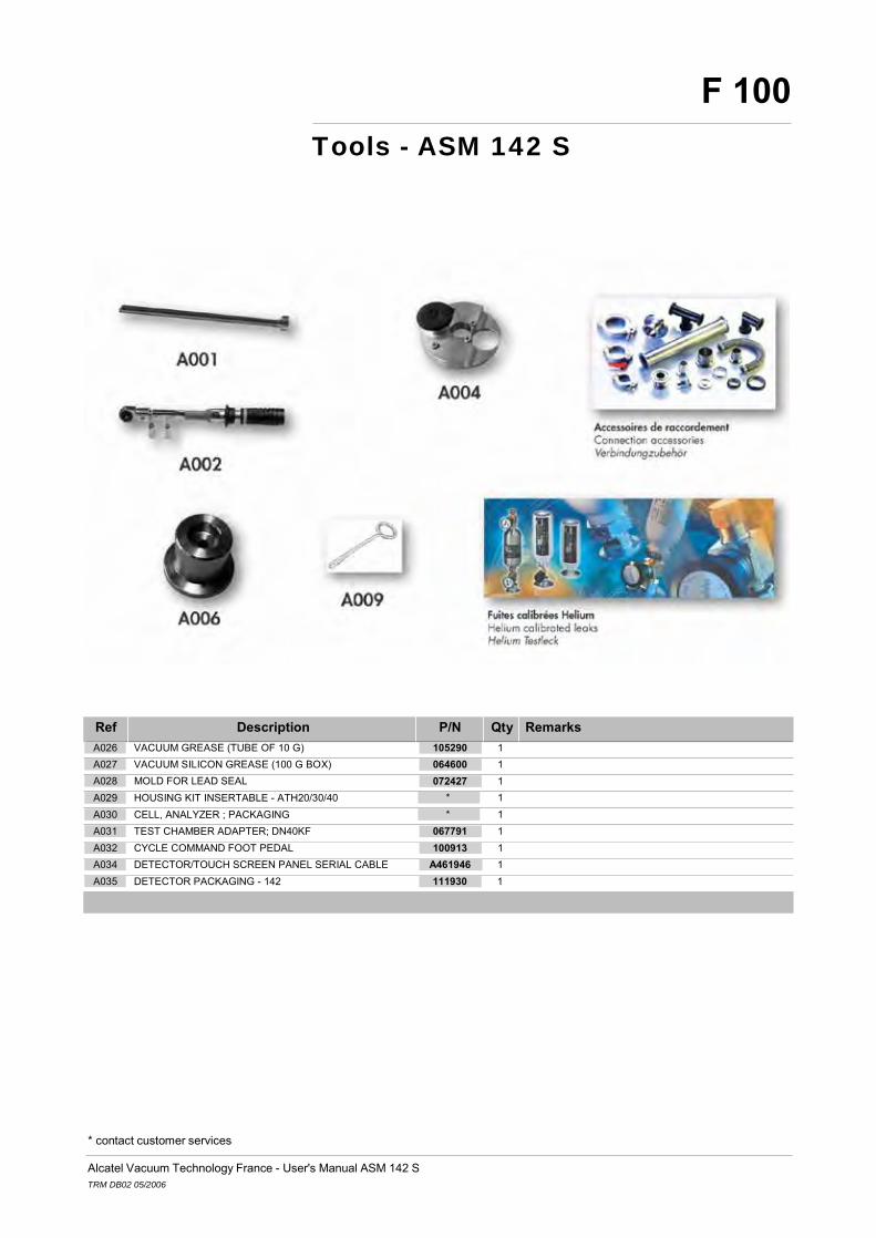
Alcatel Vacuum Technology France - User's Manual ASM 142 S TRM DB02 05/2006
F 100
Tools - ASM 142 S
Ref Description P/N Qty Remarks
A026 VACUUM GREASE (TUBE OF 10 G) A027 VACUUM SILICON GREASE (100 G BOX) A028 MOLD FOR LEAD SEAL A029 HOUSING KIT INSERTABLE - ATH20/30/40 A030 CELL, ANALYZER ; PACKAGING A031 TEST CHAMBER ADAPTER; DN40KF A032 CYCLE COMMAND FOOT PEDAL
105290 1 064600 1 072427 1 * 1 * 1 067791 1 100913 1
A034 DETECTOR/TOUCH SCREEN PANEL SERIAL CABLE A461946 1 A035 DETECTOR PACKAGING - 142 111930 1
* contact customer services

Alcatel Vacuum Technology France - User's Manual ASM 142 S TRM DB02 05/2006
F 100
Tools - ASM 142 S
Ref Description P/N Qty Remarks A005 TOOL KIT FOR MDP5011/ATS100 * 1
* contact customer services

Alcatel Vacuum Technology France - User's Manual ASM 142 S TRM DB02 05/2006
F 100
Tools
Ref Description P/N Qty Remarks A033 DETECTION MAINTENANCE KIT 111465 1
* contact customer services

Alcatel Vacuum Technology France - User's Manual ASM 142 S TRM DB02 05/2006
F 200
Monitoring and display
Ref Description P/N Qty Remarks
B003 CONTROL PANEL EUR/US - 102S/142S A459706 1
B005 LCD DISPLAY + WIRING HARNESS - 142/182 B007 P0335E1 CONTROL PANEL BOARD - 142/182
* 1 * 1
B012 CABLE FOR REMOTE CONTROL 2G, 5 M A458735 1 B013 CABLE FOR REMOTE CONTROL 2G, 10 M B014 CABLE FOR REMOTE CONTROL 2G, 15 M B020 REMOTE CONTROL LDS - MBAR.L/S
110881 1 110882 1 112747 1
* contact customer services

Alcatel Vacuum Technology France - User's Manual ASM 142 S TRM DB02 05/2006
F 300
Power and electrical supply
Ref Description P/N Qty Remarks
C001 CABLE, MAIN POWER; 2 M - WITHOUT PLUG C002 CABLE, MAIN POWER; 2 M - ITALY C003 CABLE, MAIN POWER; 2 M - SWITZERLAND C004 CABLE, MAIN POWER; 2 M - UK C005 CABLE, MAIN POWER; 2 M - US C006 CABLE, MAIN POWER; 2 M - FRANCE/GERMANY C014 FUSE 5X20 TEMP. 6.3 A C017 FUSE 5X20 TEMP. 16 A C022 PLUG, MAIN POWER C023 HARNESS, BASIC WIRING - 142 C060 FUSE 5X20 TEMP. (+) 5 A C061 CIRCUIT BREAKER 16 A 115 V - 142 C062 CIRCUIT BREAKER 8 A 230 V - 142 C064 HARNESS, CALIBRATED LEAK WIRING
104559 104758 103718 104411 103567 103566 060860 * 106747 * 107650 111280 111281 *
1 1 1 1 1 1 1 142D:s/n<45055 142S:s/n<50140 142:s/n<41404 1 142D:s/n<45055 142S:s/n<50140 142:s/n<41404 1 1 1 142D:s/n<45055 142S:s/n<50140 142:s/n<41404 1 142D:s/n>=45055 142S:s/n>= 50140 142:s/n>=41404 1 142D:s/n>=45055 142S:s/n>= 50140 142:s/n>=41404 1
C065 FAN - 142/102S/122D A459291 1 C089 HARNESS, SPECIFIC WIRING - 142S * 1
* contact customer services

Alcatel Vacuum Technology France - User's Manual ASM 142 S TRM DB02 05/2006
F 300
Power and electrical supply
Ref Description P/N Qty Remarks
C025 HARNESS, 9 PTS BLOCK - 142S C026 HARNESS, 15 PTS BLOCK - 142 C027 HARNESS, 34 PTS RS232 WIRING - 142/102S C028 HARNESS, 26 PTS RS232 WIRING - 142/102S C088 HARNESS, BLOCK FAN - 142S
* 1 * 1 * 1 * 1 * 1
* contact customer services

Alcatel Vacuum Technology France - User's Manual ASM 142 S TRM DB02 05/2006
F 400
Automatic control system and electronic circuits
Ref Description P/N Qty Remarks
D001 P0330E1 POWER SUPPLY BOARD - 142/182 D003 P0302E6S MAIN BOARD 122/142/182/192/1002 D004 P0335E1 CONTROL PANEL BOARD - 142/182 D007 P0320E1 CELL 2G.1 MAIN BOARD D009 P0307E1 INTERFACE BOARD - 102S/142/122D D012 FILAMENT POWER SUPPLY - P0302 D013 POWER SUPPLY MODULE - P0302 D015 EPROM, VOICE SYNTHESIS - 142S D018 SOFTWARE EPROM - 142S D026 LOUDSPEAKER; 90 DB/D 10 CM D045 SOFTWARE EPROM - 142S
* * * * * * * * * 060097 *
1 1 1 1 1 1 Used for P0302-P0193-P0316-P0200 1 1 1 1 1
* contact customer services

Alcatel Vacuum Technology France - User's Manual ASM 142 S TRM DB02 05/2006
F 500
Measurement
Ref Description P/N Qty Remarks
E001 FILAMENT ASSEMBLY FOR ANALYZER CELL E002 MAGNET 1 MASS - ANALYSIS CELL E003 CELL 2G.1; STD PRESET - 142/182/192/20MD E004 ELECTRON COLLECTOR, DOUBLE E005 SEAL, ELASTOMER; SPECIAL CELL E006 SPECIAL WASHER FOR ANALYZER CELL E007 CHC SCREW M6-35 E008 P0320E1 CELL 2G.1 MAIN BOARD E009 CELL, ANALYZER 2G1; EQUIPPED COVER E010 CELL, 2G.1; PREAMP. TARGET ASSEMBLY E011 CELL, 2G.1; ELECT. DEFLECTION ASSEMBLY E012 CELL, ANALYZER 2G,1; ACCESSORIES KIT
053146 1 * 1 * 1 101127 1 102823 1 083486 1 075612 1 * 1 * 1 * 1 * 1 * 1
E013 COLLECTOR + FILAMENT KIT - 2G.1 CELL A459843 1 E026 FILAMENT FOR PI1 GAUGE E040 CELL, ANALYZER ; PACKAGING
* 1 * 1
* contact customer services

Alcatel Vacuum Technology France - User's Manual ASM 142 S TRM DB02 05/2006
F 500
Measurement
Ref Description P/N Qty Remarks
E021 P0203E1 CAL. LEAK TEMPERATURE SENSOR E022 HARNESS, CALIBRATED LEAK WIRING E023 CALIBRATED LEAK, INTERNAL - 142S/OPTION E038 SHOCK ABSORBER - C
* 1 * 1 108111 1 076112 1
* contact customer services

Alcatel Vacuum Technology France - User's Manual ASM 142 S TRM DB02 05/2006
F 600
Pumping
Ref Description P/N Qty Remarks
F006 GREASE SYRINGE FOR MDP/TMP F012 RVP UM 2005 SD LV A200 (Y) SCE (SERVICE) F013 RVP UM 2005 SD HV A200 (Y) SCE (SERVICE) F014 OIL, ALCATEL 200 (1L)
056993 1 205SFYLLS 1 205SFYHLS 1 068694 1
F015 FUNNEL 067592 1 F016 OIL MIST ELIMINATOR; 21 M3/H D 30 MM F017 QUICK FEMALE CONNECTOR D 12 MM RMI09 F019 CLAMP, TUBE PRESS; 35.0/38.5 MM F020 CLAMP, TUBE PRESS; 12.8/15.0 MM
107348 1 107646 1 107645 1 107648 1
F027 HOSE, FLEXIBLE EXHAUST - 142 A328645 1 F031 CERAMIC BEARING KIT 8.000 TMP F032 CERAMIC BEARING KIT 7.999/8.000 TMP F033 CERAMIC BEARING KIT 7.998/7.999 TMP F034 CERAMIC BEARING KIT 7.997/7.998 TMP F035 CERAMIC BEARING KIT 7.996/7.997 TMP F036 TOOL KIT FOR MDP5011/ATS100 F044 AMP007I - SERVICE F045 SEALS KIT, PERBUNAN - AMP007I F080 TOOL KIT FOR AMP007I
* 1 * 1 * 1 * 1 * 1 * 1 N1B602 1 * 1 * 1
* contact customer services

Alcatel Vacuum Technology France - User's Manual ASM 142 S TRM DB02 05/2006
F 700
Valves
Ref Description P/N Qty Remarks
G001 MINISOL VALVE COIL 24 V G002 COIL 24 VDC 23 W G004 VALVE KIT, NC BACOSOL (104655) G007 VALVE, MINISOL; 3/2 NF 24 VDC/8 W G012 VACUUM SILICON GREASE (100 G BOX) G016 VALVE BLOCK, LOWER - 142/142D/142S G017 VALVE BLOCK, UPPER - 142S G029 SHOCK ABSORBER - C G032 VALVE BLOCK, UPPER - 142S
067040 1 * 1 106935 1 106009 1 064600 1 * 1 * 1 076112 1 * 1
* contact customer services

Alcatel Vacuum Technology France - User's Manual ASM 142 S TRM DB02 05/2006
F 800
Pipes - Connections - Seals
Ref Description P/N Qty Remarks
H001 TUBING, PVC; D 4 x 1 MM * 1
H005 CONNECTOR FOR PLASTIC TUBE 4 x 1 A458324 1 H006 BODY FEMALE CONNECTOR G 1/8 RBE03.2100 H007 BELLOWS, SS; DN25KF L 250 MM H020 CLAMP DN10/16KF H026 CLAMP DN20/25KF H028 CLAMP DN32/40KF H030 CLAMP DN50KF H035 MALE UNION BSPT F3BPL 2.7/4 - 1/8 H037 O'RING DN25KF HNBR H040 O'RING DN16KF HNBR H046 DIAPHRAGM DN25KF - D 10 MM H047 CENTERING RING DN25KF H050 FILTER, DN25KF; 70 MICRONS H074 SEAL, ELASTOMER; SPECIAL CELL H087 TEE, REDUCING - DN40/40/16KF H088 TEE, REDUCING - DN50/50/16KF H089 TEE, REDUCING - DN25/25/16KF H090 CENTERING RING SS/PER DN16KF H091 CENTERING RING SS/PER DN40KF H092 CENTERING RING SS/PER DN50KF H093 CENTERING RING SS/PER DN25KF H097 QUICK FEMALE CONNECTOR D 12 MM RMI09
082988 1 068370 1 083333 1 083264 1 083267 1 087163 1 082775 1 106022 1 106021 1 100983 1 068224 1 072857 1 102823 1 303358 1 303359 1 068269 1 068193 1 068194 1 087164 1 068189 1 107646 1
* contact customer services

Alcatel Vacuum Technology France - User's Manual ASM 142 S TRM DB02 05/2006
F 800
Pipes - Connections - Seals
Ref Description P/N Qty Remarks
H098 CLAMP, TUBE PRESS; 35.0/38.5 MM H099 CLAMP, TUBE PRESS; 12.8/15.0 MM H105 SEALS KIT, PERBUNAN - AMP007I H113 MALE CONNECTOR 4/6 MM - 1/8 BSPT H114 FEMALE CONNECTOR 1/8 BSPT - LDS TUBE H115 O'RING DN16KF NBR H124 O'RING 1.78 x 12.42 NBR H125 MALE PURGE FITTING (BHU 22-06 CPC)
107645 1 107648 1 * 1 083391 1 067843 1 079237 1 082152 1 107641 1
* contact customer services

Alcatel Vacuum Technology France - User's Manual ASM 142 S TRM DB02 05/2006
F 900
Cover
Ref Description P/N Qty Remarks
I001 CONTAINER - 142 A212639 1
I059 DETECTOR PACKAGING - 142 111930 1 I044 FOOT - 142 I060 COVER, WITHOUT LOGO - 142 I065 LOGO - 142S
A459023 1 A462454 1 A462516 1
* contact customer services

Alcatel Vacuum Technology France - User's Manual ASM 142 S TRM DB02 05/2006
F 1000 Options and accessories
Ref Description P/N Qty Remarks
J001 NEEDLE FOR LDS PROBE - D 0.3 MM 072606 1
J002 NEEDLE FOR LDS PROBE - D 0.35 MM A461716 1 J003 NOZZLE, SHORT RIGID - 2000 LD SNIFFER J004 NOZZLE, LONG; FOR HE PROBE J005 NOZZLE, SHORT FLEXIBLE - 2000 LD SNIFFER J006 NOZZLE, LONG FLEXIBLE - 2000 LD SNIFFER
108242S 1 108243S 1 108883S 1 108884S 1
J007 HC SCREW M5-6 - 2000 LD SNIFFER J008 5 FILTERS/2 SCREWS/2 O'RINGS - LDS PROBE
A459725 1 A459858 1
J009 FILTER, IN TUBING - LDS PROBE J010 TUBE FOR LDS PROBE (OM) J011 TUBING, LDS - 5 METERS
* 1 067838 1 072300 1
J012 TUBING, LDS - 10 METERS A459882 1 J013 MALE CONNECTOR 4/6 MM - 1/8 BSPT J014 FEMALE CONNECTOR 1/8 BSPT - LDS TUBE J034 10 M EXTENSION - LDS PROBE J035 SNIFFER CANA.5 S R9 NIPPLE PENCIL J036 SNIFFER CANA.5 S R30 NIPPLE PENCIL J037 SNIFFER CANA.5 S S15 NIPPLE PENCIL J038 SNIFFER CANA.5 S S45 NIPPLE PENCIL J039 SNIFFER CANA.10 S R9 NIPPLE PENCIL J040 SNIFFER CANA.10 S R30 NIPPLE PENCIL J041 SNIFFER CANA.10 S S15 NIPPLE PENCIL J042 SNIFFER CANA.10 S S45 NIPPLE PENCIL
083391 1 067843 1 090216 1 SNC1E1T1 1 SNC1E2T1 1 SNC1E3T1 1 SNC1E4T1 1 SNC2E1T1 1 SNC2E2T1 1 SNC2E3T1 1 SNC2E4T1 1
* contact customer services

Alcatel Vacuum Technology France - User's Manual ASM 142 S TRM DB02 05/2006
F 1000 Options and accessories
Ref Description P/N Qty Remarks J076 SNIFFER FILTER STONE 067722 1
* contact customer services

Alcatel Vacuum Technology France - User's Manual ASM 142 S TRM DB02 05/2006
F 1000 Options and accessories
Ref Description P/N Qty Remarks
J015 TUBE HE SPRAY PROBE (OLD MODEL) J016 NOZZLE, SHORT RIGID; FOR HE PROBE J017 NOZZLE, LONG RIGID; FOR HE PROBE
083446 1 109955 1 109956 1
J018 CABLE FOR REMOTE CONTROL 2G, 5 M A458735 1 J019 CABLE FOR REMOTE CONTROL 2G, 10 M J020 CABLE FOR REMOTE CONTROL 2G, 15 M J043 HELIUM SPRAY PROBE J088 REMOTE CONTROL LDS - MBAR.L/S J089 CALIBRATED LEAK, INTERNAL - 142S/OPTION J090 P0203E1 CAL. LEAK TEMPERATURE SENSOR J091 HARNESS, CALIBRATED LEAK WIRING
110881 1 110882 1 109951 1 112747 1 108111 1 * 1 * 1
* contact customer services

Alcatel Vacuum Technology France - User's Manual ASM 142 S TRM DB02 05/2006
F 1000 Options and accessories
Ref Description P/N Qty Remarks J048 CELL 2G.1; MET PRESET - 142/182/192/20MD * 1 J080 LEAD WIRE 10 M - 0.8 MM 083478 1
* contact customer services

Alcatel Vacuum Technology France - User's Manual ASM 142 S TRM DB02 05/2006
F 1000 Options and accessories
Ref Description P/N Qty Remarks
J059 INTERFACE KIT - 142 J060 P0307E1 INTERFACE BOARD - 102S/142/122D J061 HARNESS, 34 PTS RS232 WIRING - 142/102S J062 HARNESS, 26 PTS RS232 WIRING - 142/102S J074 MAINTENANCE KIT FOR PRINTER
107657 1 * 1 * 1 * 1 100807 1
* contact customer services


F 1100 Pictures of components
1 / 8 DB02 05/2006
F 100 Tools
* A001 * A002 * A003 * A004 * A005 CHC SCREW M4-80 TORQUE WRENCH (TMP) ADAPTER, INT. CALIBRATED LEAK -
142/122D TOOL KIT FOR AMP007I TOOL KIT FOR MDP5011/ATS100
* A006 * A007 * A009 * A010 303358 A011 DN16KF CALIBRATED LEAK ADAPTATOR KIT
DN25KF CALIBRATED LEAK ADAPTATOR KIT
MDP 5011EXTRACTOR DN16KF NEEDLE VALVE TEE, REDUCING - DN40/40/16KF
303359 A012 068269 A013 FV4620 A014 FV4630 A015 FV4610 A016 TEE, REDUCING - DN50/50/16KF TEE, REDUCING - DN25/25/16KF CALIB. LEAK WITH VALVE 1-3.10-6
DN40KF CALIB. LEAK WITH VALVE 1-3.10-6 DN50KF
CALIB. LEAK WITH VALVE 1-3.10-6 DN25KF
083333 A017 083267 A018 087163 A019 083264 A020 068193 A021 CLAMP DN10/16KF CLAMP DN32/40KF CLAMP DN50KF CLAMP DN20/25KF CENTERING RING SS/PER DN16KF
068194 A022 087164 A023 068189 A024 067592 A025 105290 A026 CENTERING RING SS/PER DN40KF CENTERING RING SS/PER DN50KF CENTERING RING SS/PER DN25KF FUNNEL VACUUM GREASE (T UBE OF 10 G)
064600 A027 072427 A028 * A029 * A030 067791 A031 VACUUM SILICON GREASE (100 G BOX)
MOLD FOR LEAD SEAL HOUSING KIT INSERTABLE - ATH20/30/40
CELL, ANALYZER ; PACKAGING TEST CHAMBER ADAPTER; DN40KF

F 1100 Pictures of components
2 / 8 DB02 05/2006
100913 A032 111465 A033 A461946 A034 111930 A035 CYCLE COMMAND FOOT PEDAL DETECTION MAINTENANCE KIT DETECTOR/TOUCH SCREEN PANEL
SERIAL CABLE DETECTOR PACKAGING - 142
F 200 Monitoring and display
A459706 B003 * B005 * B007 A458735 B012 110881 B013 CONTROL PANEL EUR/US - 102S/142S LCD DISPLAY + WIRING HARNESS -
142/182 P0335E1 CONTROL PANEL BOARD - 142/182
CABLE FOR REMOTE CONTROL 2G, 5 M
CABLE FOR REMOTE CONTROL 2G, 10 M
110882 B014 112747 B020 CABLE FOR REMOTE CONTROL 2G, 15 M
REMOTE CONTROL LDS - MBAR.L/S
F 300 Power and electrical supply
104559 C001 104758 C002 103718 C003 104411 C004 103567 C005 CABLE, MAIN POWER; 2 M - WITHOUT PLUG
CABLE, MAIN POWER; 2 M - ITALY CABLE, MAIN POWER; 2 M - SWITZERLAND
CABLE, MAIN POWER; 2 M - UK CABLE, MAIN POWER; 2 M - US
103566 C006 060860 C014 * C017 106747 C022 * C023 CABLE, MAIN POWER; 2 M - FRANCE/GERMANY
FUSE 5X20 TEMP. 6.3 A FUSE 5X20 TEMP. 16 A PLUG, MAIN POWER HARNESS, BASIC WIRING - 142

F 1100 Pictures of components
3 / 8 DB02 05/2006
* C025 * C026 * C027 * C028 107650 C060 HARNESS, 9 PTS BLOCK - 142S HARNESS, 15 PTS BLOCK - 142 HARNESS, 34 PTS RS232 WIRING -
142/102S HARNESS, 26 PTS RS232 WIRING - 142/102S
FUSE 5X20 TEMP. (+) 5 A
111280 C061 111281 C062 * C064 A459291 C065 * C088 CIRCUIT BREAKER 16 A 115 V - 142 CIRCUIT BREAKER 8 A 230 V - 142 HARNESS, CALIBRATED LEAK WIRING FAN - 142/102S/122D HARNESS, BLOCK FAN - 142S
* C089 HARNESS, SPECIFIC WIRING - 142S
F 400 Automatic control system and electronic circuits
* D001 * D003 * D004 * D007 * D009 P0330E1 POWER SUPPLY BOARD - 142/182
P0302E6S MAIN BOARD 122/142/182/192/1002
P0335E1 CONTROL PANEL BOARD - 142/182
P0320E1 CELL 2G.1 MAIN BOARD P0307E1 INTERFACE BOARD - 102S/142/122D
* D012 * D013 * D015 * D018 060097 D026 FILAMENT POWER SUPPLY - P0302 POWER SUPPLY MODULE - P0302 EPROM, VOICE SYNTHESIS - 142S SOFTWARE EPROM - 142S LOUDSPEAKER; 90 DB/D 10 CM
* SOFTWARE EPROM - 142S
D045

F 1100 Pictures of components
4 / 8 DB02 05/2006
F 500 Measurement
053146 E001 * E002 * E003 101127 E004 102823 E005 FILAMENT ASSEMBLY FOR ANALYZER CELL
MAGNET 1 MASS - ANALYSIS CELL CELL 2G.1; STD PRESET - 142/182/192/20MD
ELECTRON COLLECTOR, DOUBLE SEAL, ELASTOMER; SPECIAL CELL
083486 E006 075612 E007 * E008 * E009 * E010 SPECIAL WASHER FOR ANALYZER CELL
CHC SCREW M6-35 P0320E1 CELL 2G.1 MAIN BOARD CELL, ANALYZER 2G1; EQUIPPED COVER
CELL, 2G.1; PREAMP. TARGET ASSEMBLY
* E011 * E012 A459843 E013 * E021 * E022 CELL, 2G.1; ELECT. DEFLECTION ASSEMBLY
CELL, ANALYZER 2G,1; ACCESSORIES KIT
COLLECTOR + FILAMENT KIT - 2G.1 CELL
P0203E1 CAL. LEAK TEMPERATURE SENSOR
HARNESS, CALIBRATED LEAK WIRING
108111 E023 * E026 076112 E038 * E040 CALIBRATED LEAK, INTERNAL - 142S/OPTION
FILAMENT FOR PI1 GAUGE SHOCK ABSORBER - C CELL, ANALYZER ; PACKAGING
F 600 Pumping
056993 F006 205SFYLLS F012 205SFYHLS F013 068694 F014 067592 F015 GREASE SYRINGE FOR MDP/TMP RVP UM 2005 SD LV A200 (Y) SCE
(SERVICE) RVP UM 2005 SD HV A200 (Y) SCE (SERVICE)
OIL, ALCATEL 200 (1L) FUNNEL

5 / 8 DB02 05/2006
F 1100 Pictures of components
107348 F016 107646 F017 107645 F019 107648 F020 A328645 F027 OIL MIST ELIMINATOR; 21 M3/H D 30 MM
QUICK FEMALE CONNECTOR D 12 MM RMI09
CLAMP, TUBE PRESS; 35.0/38.5 MM CLAMP, TUBE PRESS; 12.8/15.0 MM HOSE, FLEXIBLE EXHAUST - 142
* F031 * F032 * F033 * F034 * F035 CERAMIC BEARING KIT 8.000 TMP CERAMIC BEARING KIT 7.999/8.000
TMP CERAMIC BEARING KIT 7.998/7.999 TMP
CERAMIC BEARING KIT 7.997/7.998 TMP
CERAMIC BEARING KIT 7.996/7.997 TMP
* F036 N1B602 F044 * F045 * F080 TOOL KIT FOR MDP5011/ATS100 AMP007I - SERVICE SEALS KIT, PERBUNAN - AMP007I TOOL KIT FOR AMP007I
F 700 Valves
067040 G001 * G002 106935 G004 106009 G007 064600 G012 MINISOL VALVE COIL 24 V COIL 24 VDC 23 W VALVE KIT, NC BACOSOL (104655) VALVE, MINISOL; 3/2 NF 24 VDC/8 W VACUUM SILICON GREASE (100 G
BOX)
* VALVE BLOCK, LOWER - 142/142D/142S
G016 * VALVE BLOCK, UPPER - 142S
G017 076112 SHOCK ABSORBER - C
G029 * VALVE BLOCK, UPPER - 142S
G032

6 / 8 DB02 05/2006
F 1100 Pictures of components
H105 083391 H113 067843 H114 079237 H115 082152 H124 007I MALE CONNECTOR 4 /6 MM - 1/8 BSPT FEMALE CONNECTO R 1/8 BSPT - LDS O'RING DN16KF NBR O'RING 1.78 x 12.42 NBR
F 800 Pipes - Connections - Seals
* H001 A458324 H005 082988 H006 068370 H007 083333 H020 TUBING, PVC; D 4 x 1 MM CONNECTOR FOR PLASTIC TUBE 4 x 1 BODY FEMALE CONNECTOR G 1/8
RBE03.2100 BELLOWS, SS; DN25KF L 250 MM CLAMP DN10/16KF
083264 H026 083267 H028 087163 H030 082775 H035 106022 H037 CLAMP DN20/25KF CLAMP DN32/40KF CLAMP DN50KF MALE UNION BSPT F3BPL 2.7/4 - 1/8 O'RING DN25KF HNBR
106021 H040 100983 H046 068224 H047 072857 H050 102823 H074 O'RING DN16KF HNBR DIAPHRAGM DN25KF - D 10 MM CENTERING RING DN25KF FILTER, DN25KF; 70 MICRONS SEAL, ELASTOMER; SPECIAL CELL
303358 H087 303359 H088 068269 H089 068193 H090 068194 H091 TEE, REDUCING - DN40/40/16KF TEE, REDUCING - DN50/50/16KF TEE, REDUCING - DN25/25/16KF CENTERING RING SS/PER DN16KF CENTERING RING SS/PER DN40KF
087164 H092 068189 H093 107646 H097 107645 H098 107648 H099 CENTERING RING SS/PER DN50KF CENTERING RING SS/PER DN25KF QUICK FEMALE CONNECTOR D 12 MM
RMI09 CLAMP, TUBE PRESS; 35.0/38.5 MM CLAMP, TUBE PRESS; 12.8/15.0 MM
* SEALS KIT, PERBUNAN - AMP
TUBE

7 / 8 DB02 05/2006
F 1100 Pictures of components
107641 H125 MALE PURGE FITTING (BHU 22-06 CPC)
F 900 Cover
A212639 I001 A459023 I044 111930 I059 A462454 I060 A462516 I065 CONTAINER - 142 FOOT - 142 DETECTOR PACKAGING - 142 COVER, WITHOUT LOGO - 142 LOGO - 142S
F 1000 Options and accessories
072606 J001 A461716 J002 108242S J003 108243S J004 108883S J005 NEEDLE FOR LDS PROBE - D 0.3 MM NEEDLE FOR LDS PROBE - D 0.35 MM NOZZLE, SHORT RIGID - 2000 LD
SNIFFER NOZZLE, LONG; FOR HE PROBE NOZZLE, SHORT FLEXIBLE - 2000 LD
SNIFFER
108884S J006 A459725 J007 A459858 J008 * J009 067838 J010 NOZZLE, LONG FLEXIBLE - 2000 LD SNIFFER
HC SCREW M5-6 - 2000 LD SNIFFER 5 FILTERS/2 SCREWS/2 O'RINGS - LDS PROBE
FILTER, IN TUBING - LDS PROBE TUBE FOR LDS PROBE (OM)
072300 J011 A459882 J012 083391 J013 067843 J014 083446 J015 TUBING, LDS - 5 METERS TUBING, LDS - 10 METERS MALE CONNECTOR 4/6 MM - 1/8 BSPT FEMALE CONNECTOR 1/8 BSPT - LDS
TUBE TUBE HE SPRAY PROBE (OLD MODEL)

8 / 8 DB02 05/2006
F 1100 Pictures of components
109955 J016 109956 J017 A458735 J018 110881 J019 110882 J020 NOZZLE, SHORT RIGID; FOR HE PROBE
NOZZLE, LONG RIGID; FOR HE PROBE CABLE FOR REMOTE CONTROL 2G, 5 M
CABLE FOR REMOTE CONTROL 2G, 10 M
CABLE FOR REMOTE CONTROL 2G, 15 M
090216 J034 SNC1E1T1 J035 SNC1E2T1 J036 SNC1E3T1 J037 SNC1E4T1 J038 10 M EXTENSION - LDS PROBE SNIFFER CANA.5 S R9 NIPPLE PENCIL SNIFFER CANA.5 S R30 NIPPLE
PENCIL SNIFFER CANA.5 S S15 NIPPLE PENCIL SNIFFER CANA.5 S S45 NIPPLE PENCIL
SNC2E1T1 J039 SNC2E2T1 J040 SNC2E3T1 J041 SNC2E4T1 J042 109951 J043 SNIFFER CANA.10 S R9 NIPPLE PENCIL
SNIFFER CANA.10 S R30 NIPPLE PENCIL
SNIFFER CANA.10 S S15 NIPPLE PENCIL
SNIFFER CANA.10 S S45 NIPPLE PENCIL
HELIUM SPRAY PROBE
* J048 107657 J059 * J060 * J061 * J062 CELL 2G.1; MET PRESET - 142/182/192/20MD
INTERFACE KIT - 142 P0307E1 INTERFACE BOARD - 102S/142/122D
HARNESS, 34 PTS RS232 WIRING - 142/102S
HARNESS, 26 PTS RS232 WIRING - 142/102S
100807 J074 067722 J076 083478 J080 112747 J088 108111 J089 MAINTENANCE KIT FOR PRINTER SNIFFER FILTER STONE LEAD WIRE 10 M - 0.8 MM REMOTE CONTROL LDS - MBAR.L/S CALIBRATED LEAK, INTERNAL -
142S/OPTION
* J090 * J091 P0203E1 CAL. LEAK TEMPERATURE SENSOR
HARNESS, CALIBRATED LEAK WIRING

F 1100 Pictures of components
GB
0250
7 - E
ditio
n 02
- F
ebru
ary
05
G
ASM 142 S User’s Manual
Detailed contents
Appendix
Preliminary remarks
Throughout this User’s Manual, you could find this type of message
“Summary of screen C 140”: it refers to a specific chapter of the User’s Manual. Please read it for further information.
G 100 Declaration of conformity
G 200 Wiring diagrams
G 300 0 - 8 Volts Analog output
G 400 Long distance sniffer probe user manual
- Dimensions - Technical characteristics - Use precautions with the flexible sniffer probe - Flow adjustment - Available spare parts - Filter exchange - Needle replacement - O’ring installation - « Sniffer probe clogged » message - Adaptador for calibrated leak
G 500 Helium spray gun user manual
- Description - Technical characteristics - Use precaution - Spare parts
G 600 Safety questionnaire

1/1
GB
0266
3 - E
ditio
n 02
- F
ebru
ary
06
Declaration of conformity
The declarations of conformity are available on request to AVTF in next languages: German/English/Danish/Spanish/French/Italian/ Dutch/Portuguese.

G 100
1/1

1/2
WH B
N
GN Y
E
GY PK B
U
RD
BK V
T GY/P
K
RD/BU
WH/G
N
BN
/GN
WH
/YE
SPECTRO
PREAMPLI
CE
LL
GB
0266
6 -
Editi
on 0
2 - A
pril
06
4 4
3 3
2 2
1 1
1 2 3 4 5 6 7 8 9 10
11
12
13
14
15
16
17
18
19
20
21
22
23
24
25
26
27
28
29
30
31
32
33
34
1 2 3 4 5 6 7 8 9 10
11
12
13
14
15
16
17
18
19
20
21
22
23
24
25
26
27
28
29
30
31
32
33
34
13
25
12
24
11
23
10
22 9 21 8 20 7 19 6 18 5 17 4 16 3 15 2 14 1
1 2 3 4 5 6 7 8 9 10
11
12
13
14
15
16
17
18
19
20
1 2 3 4 5 6 7 8 9 10
11
12
13
14
15
16
17
18
19
20
1 2 3 4 5 6 7 8 9 10
11
12
13
14
15
1 2 3 4 5 6 7 8 9
3 6 9
2 5 8
1 4 7
1 4 7
2 5 8
3 6 9
5 9 4 8 3 7 2 6 1
1 2 3 4 5 6 7 8 9 10
11
12
13
14
15
16
17
18
19
20
21
22
23
24
25
26
1 2 3 4 5 6 7 8 9 10
11
12
13
14
15
16
17
18
19
20
21
22
23
24
25
26
10
1211
10
1514
13
11 10
1112
12
13
14
13
1415
15
5 9 4 8 3 7 2 6 1
A212
641
2 2
6 2
2
8
8
7
P 0 3 2 6
12
Wiring diagram (index —)
G 200
I/O Modem PRINTER
I/O OPTION
J 3
J 4
1 2 I/O
ANA1
J 2
GND
SHelog
GND
RX RTS TX
J 1 GND
+5V
DTR
J 7
D S R 1 RX 2 RTS 3
P5 J 5
4 4 3 3
1 1 HP
COLOR
CODE
P0307
J6
I/O BOARD ANA0 CTS CTS TX A459921 Liaison
J 5 optionel
Sur ASM Standard Liaison i
J1 J2 d rect
WH (WHITE / BLANC) BN (BROWN / BRUN) GN (GREEN / VERT) YE (YELLOW / JAUNE) GY (GRAY / GRIS) PK (PINK / ROSE) BU (BLUE / BLEU)
/ R
EXTERN2 Flat cable
A459169
EXTERN1 Flat cable
A459168
Audio
GND
GND
J 5 J 5
4 4 3 3 2 2 1 1
J5<=>J5
Vacuum
block
RD (RED OUGE) J6 P100
BK (BLACK / NOIR) R D VT (PURPLE / VIOLET) 1 1
V/J (VERTJAUNE)
(GREENYELLOW)
Flat Cable A459167
J12
2 3 7 4 3 5 8 6 4 7 9 8 J01
Calibration
8 8 Filament 1-A Filament 1-B
5 9 10 10 1
15 15 2 LEAK 7 7 14 14 SPECTRO J9 3 6 6 P101 J101 13 13 Filament 2-A 1
5 5 2 A212642 1 1
12 12 Filament 2-B PIRANIS 3 9 9
4 4 4 11 11
11 11 Pirani gauge 5 2 2
3 3 6 10 10
3 3
10 10 Collector P0302 4 4
2 2 9 9 Brake 1 1 Triode signal
J 8
VALVES_1 1
12 12 5 5 13 13
A214752 EV EA_PPM
A459166 J10
3 6 6 14 14
1 1 J 7 9 9 10
R D 2 2
7 7 15 15 8 8
EV NORMAL 5
10 10 5 16 16
3 3 0/8V output 9
11 11 VALVES_2 4 EV CAL_DET 4 4 PREAMPLI Power supply 3 7 12 12 7 5 5 2 13 13 6 6 6 1 14 14 7 7 J14 J 1
15 15 W H
1 B N 1 AMP007I 8 8
Accessory
REMOTE
+5V
2 G N 3 Y E 4 G Y 5
TMP_A 6 PK B U
8 R D 9
10 BK
2 J2 3 4 1 5 2 6 3 7 4 8 5 9 6 10
W H B N A
G N B
Y E C
G Y D
PK E F
CONTROL
J 1 J1
J3 A328711
J 2
G ND
G ND
GND
GND
GND
+24V J15
Power
A459162
J6
11 12 A459165
11 A459164
RS485+
RS485-
+24V G ND CONTROL PANEL
P0330 E1

2/2
G 200
3 6 9 2
5 8 1
4 7
121110 151413
2 1 2 3 4
15
14
13
12
11
10 9 8 7 6 5 4 3 2 1
1 2 1 2 3 4
1 2 1 2 3 4
1
1 2 3 4 5 6 7 8 9 10
1 4 7
2 5 8
3 6 9 11
10
1112
12
13
14
13
1415
Mo
lde
d c
able
15
GB
0266
6 - E
ditio
n 02
- A
pril
06
Wiring diagram (index —)
AMP007 Frame
Power COLOR CODE
FAN FAN FAN 2010SD
WH (WHITE / BLANC) BN (BROWN / BRUN) GN (GREEN / VERT) YE (YELLOW / JAUNE) GY (GRAY / GRIS)
RD BK
J1
RD BK
J 2
RD BK
J3
PK (PINK / ROSE) BU (BLUE / BLEU) R (RE / ROUGE) BK (BLACK / NOIR) VT (PURPLE / VIOLET)
GND
+24V
GND
+24V
GND
+24V
V/J (VERTJAUNE) (GREENYELLOW)
220V
110V
P0330 E1
J 5
B U 1 V/ J 3 R D 2
A459163
Breaker
B U
R D
A461185
CEI plug
1 LINE
2 3
COM12/0 COM24/12 0 1
-15V
+5V +15V
GND
G ND
+24V
GND
GND
J15
P0302
GND
Main
power
J6

1/2
GB
0006
6 - E
ditio
n 04
- F
ebru
ary
06
0 - 8 Volts Analog output G 300
1,00E+00 1,00E-01
He signal
This curve gives directly the correspondance between the output voltage and the signal for all leak detectors except ASM 142 S and ASM 102 S. For these products, it is necessary to correct the curve He signal. ASM 142 S: He signal = curve He signal x 15 ASM 102 S: He signal = curve He signal x 1000
The purpose of the present chapter is to present the logarithmic response of this output.
Reminder:
The 0 - 8 Volt logarithmic output is located on the I/O interface connector:
Ground 0 / 8 V ASM 182/192 family - ASM 1002 Pin 15 Pin 14 ASM 142 family - ASM 122 D - ASM 102 S
Pin 1 Pin 14
ASM 182/192 family, ASM 1002: signal connected (COEF.SENS and COEF.MODE applied)
- ASM 142 family, ASM 122 D, ASM 102 S: signal not corrected.
This output corresponds to the electronic signal obtained with the best sensitivity mode of the leak detector.
This output corresponds to the electronic signal obtained at the level of the analyzer cell (VHS amplification system) and does not include the correction factors generated by the internal and external calibration.
The chart and curve shows the correspondance between output voltage and helium signal. The helium signal given by the present chart needs to be multiplied by COEF.SENS which is adjusted during the internal (auto)calibration: refer to Calibration or Configuration menus (Chapter C) in order to get access to COEF SENS value. This COEF.SENS value is modified at each autocalibration: its takes into account the fact that the characteristics of the leak detector (analyzer cell and pumps status) and evoluates as it is used.
If an external correction ratio like VAC COR, SNIF COR or GL COR is activated, the helium signal given by the present chart also needs to be multiplied by this ratio: refer C 300.
To get directly the corrected helium signal as it is displayed on the Digital display, use the 0 - 10 Volt linear output (refer to B 300) on the same I/O interface connector.
Note: the pressure analog output is not the same as the helium output.
1,00E-02 1,00E-03 1,00E-04 1,00E-05 1,00E-06 1,00E-07 1,00E-08 1,00E-09 1,00E-10 1,00E-11 1,00E-12
Example: V = 4.96 V - All leak detectors except ASM 142 S
and ASM 102 S 9.1 x 10⁻⁶ mbar.l/s - ASM 142 S 9.1 x 10-6 x 15 1.365 x 10⁻⁴ mbar.l/s - ASM 102 S 9.1 x 10-6 x 1000 9.1 x 10⁻² mbar.l/s
Pressure P (mbar) (V-5.5)
Voltage V (volt) P = 10 mbar 1,00E-13
0 1
2 3 4 5 6 7 8

G 200
2/2
Voltage

1/2
G 400
Long distance sniffer probe user manual
Volts HS mode
Leak rate
0,64 209E-12 0,65 216E-12 0,66 224E-12 0,67 232E-12 0,68 240E-12 0,69 248E-12 0,7 257E-12 0,71 266E-12 0,72 275E-12 0,73 284E-12 0,74 294E-12 0,75 304E-12 0,76 314E-12 0,77 324E-12 0,78 335E-12 0,79 346E-12 0,8 357E-12 0,81 369E-12 0,82 381E-12 0,83 393E-12 0,84 405E-12 0,85 418E-12 0,86 431E-12 0,87 445E-12 0,88 459E-12 0,89 473E-12 0,9 488E-12 0,91 503E-12 0,92 518E-12 0,93 534E-12 0,94 550E-12 0,95 567E-12 0,96 584E-12 0,97 601E-12 0,98 619E-12 0,99 637E-12 1 656E-12 1,01 676E-12 1,02 695E-12 1,03 716E-12 1,04 737E-12 1,05 758E-12 1,06 780E-12 1,07 803E-12 1,08 826E-12 1,09 849E-12 1,1 874E-12 1,11 899E-12 1,12 924E-12 1,13 950E-12 1,14 977E-12 1,15 100E-11 1,16 103E-11 1,17 106E-11 1,18 109E-11 1,19 112E-11
Volts HS mode
Leak rate
1,2 115E-11 1,21 119E-11 1,22 122E-11 1,23 125E-11 1,24 129E-11 1,25 132E-11 1,26 136E-11 1,27 139E-11 1,28 143E-11 1,29 147E-11 1,3 151E-11 1,31 155E-11 1,32 159E-11 1,33 164E-11 1,34 168E-11 1,35 173E-11 1,36 177E-11 1,37 182E-11 1,38 187E-11 1,39 192E-11 1,4 197E-11 1,41 202E-11 1,42 208E-11 1,43 213E-11 1,44 219E-11 1,45 225E-11 1,46 230E-11 1,47 236E-11 1,48 243E-11 1,49 249E-11 1,5 256E-11 1,51 262E-11 1,52 269E-11 1,53 276E-11 1,54 283E-11 1,55 291E-11 1,56 298E-11 1,57 306E-11 1,58 314E-11 1,59 322E-11 1,6 330E-11 1,61 339E-11 1,62 347E-11 1,63 356E-11 1,64 365E-11 1,65 375E-11 1,66 384E-11 1,67 394E-11 1,68 404E-11 1,69 415E-11 1,7 425E-11 1,71 436E-11 1,72 447E-11 1,73 458E-11 1,74 470E-11 1,75 482E-11
Volts HS mode
Leak rate
1,76 494E-11 1,77 507E-11 1,78 519E-11 1,79 532E-11 1,8 546E-11 1,81 560E-11 1,82 574E-11 1,83 588E-11 1,84 603E-11 1,85 618E-11 1,86 633E-11 1,87 649E-11 1,88 665E-11 1,89 682E-11 1,9 699E-11 1,91 717E-11 1,92 734E-11 1,93 753E-11 1,94 771E-11 1,95 791E-11 1,96 810E-11 1,97 830E-11 1,98 851E-11 1,99 872E-11 2 893E-11 2,01 916E-11 2,02 938E-11 2,03 961E-11 2,04 985E-11 2,05 101E-10 2,06 103E-10 2,07 106E-10 2,08 109E-10 2,09 111E-10 2,1 114E-10 2,11 117E-10 2,12 120E-10 2,13 123E-10 2,14 126E-10 2,15 129E-10 2,16 132E-10 2,17 135E-10 2,18 138E-10 2,19 142E-10 2,2 145E-10 2,21 149E-10 2,22 152E-10 2,23 156E-10 2,24 160E-10 2,25 164E-10 2,26 168E-10 2,27 172E-10 2,28 176E-10 2,29 180E-10 2,3 185E-10 2,31 189E-10
Volts HS mode
Leak rate
2,32 194E-10 2,33 198E-10 2,34 203E-10 2,35 208E-10 2,36 213E-10 2,37 218E-10 2,38 224E-10 2,39 229E-10 2,4 235E-10 2,41 240E-10 2,42 246E-10 2,43 252E-10 2,44 258E-10 2,45 264E-10 2,46 271E-10 2,47 277E-10 2,48 284E-10 2,49 291E-10 2,5 298E-10 2,51 305E-10 2,52 312E-10 2,53 320E-10 2,54 327E-10 2,55 335E-10 2,56 343E-10 2,57 351E-10 2,58 360E-10 2,59 369E-10 2,6 377E-10 2,61 386E-10 2,62 396E-10 2,63 405E-10 2,64 415E-10 2,65 425E-10 2,66 435E-10 2,67 445E-10 2,68 456E-10 2,69 467E-10 2,7 478E-10 2,71 489E-10 2,72 501E-10 2,73 513E-10 2,74 525E-10 2,75 538E-10 2,76 551E-10 2,77 564E-10 2,78 577E-10 2,79 591E-10 2,8 605E-10 2,81 620E-10 2,82 634E-10 2,83 649E-10 2,84 665E-10 2,85 681E-10 2,86 697E-10 2,87 713E-10
Volts HS mode
Leak rate
2,88 730E-10 2,89 748E-10 2,9 766E-10 2,91 784E-10 2,92 802E-10 2,93 821E-10 2,94 841E-10 2,95 861E-10 2,96 881E-10 2,97 902E-10 2,98 924E-10 2,99 946E-10 3 968E-10 3,01 991E-10 3,02 101E-09 3,03 104E-09 3,04 106E-09 3,05 109E-09 3,06 111E-09 3,07 114E-09 3,08 117E-09 3,09 120E-09 3,1 122E-09 3,11 125E-09 3,12 128E-09 3,13 131E-09 3,14 134E-09 3,15 138E-09 3,16 141E-09 3,17 144E-09 3,18 147E-09 3,19 151E-09 3,2 155E-09 3,21 158E-09 3,22 162E-09 3,23 166E-09 3,24 170E-09 3,25 174E-09 3,26 178E-09 3,27 182E-09 3,28 186E-09 3,29 191E-09 3,3 195E-09 3,31 200E-09 3,32 204E-09 3,33 209E-09 3,34 214E-09 3,35 219E-09 3,36 224E-09 3,37 230E-09 3,38 235E-09 3,39 241E-09 3,4 246E-09 3,41 252E-09 3,42 258E-09 3,43 264E-09
Volts HS mode
Leak rate
3,44 270E-09 3,45 277E-09 3,46 283E-09 3,47 290E-09 3,48 297E-09 3,49 304E-09 3,5 311E-09 3,51 318E-09 3,52 326E-09 3,53 333E-09 3,54 341E-09 3,55 349E-09 3,56 357E-09 3,57 366E-09 3,58 374E-09 3,59 383E-09 3,6 392E-09 3,61 401E-09 3,62 411E-09 3,63 420E-09 3,64 430E-09 3,65 440E-09 3,66 451E-09 3,67 461E-09 3,68 472E-09 3,69 483E-09 3,7 495E-09 3,71 506E-09 3,72 518E-09 3,73 530E-09 3,74 543E-09 3,75 555E-09 3,76 568E-09 3,77 582E-09 3,78 595E-09 3,79 609E-09 3,8 624E-09 3,81 638E-09 3,82 653E-09 3,83 669E-09 3,84 684E-09 3,85 700E-09 3,86 717E-09 3,87 734E-09 3,88 751E-09 3,89 768E-09 3,9 786E-09 3,91 805E-09 3,92 824E-09 3,93 843E-09 3,94 863E-09 3,95 883E-09 3,96 904E-09 3,97 925E-09 3,98 946E-09 3,99 969E-09
Volts HS mode Volts HS mode Volts HS mode Volts HS mode Volts HS mode Volts HS mode Volts HS mode
Leak rate Leak rate Leak rate Leak rate Leak rate Leak rate Leak rate
4 991E-09 4,56 362E-08 5,12 132E-07 5,68 478E-07 6,24 174E-06 6,89 776E-06 7,45 282E-05 4,01 101E-08 4,57 370E-08 5,13 135E-07 5,69 490E-07 6,25 178E-06 6,9 794E-06 7,46 288E-05 4,02 104E-08 4,58 379E-08 5,14 138E-07 5,7 501E-07 6,26 182E-06 6,91 813E-06 7,47 295E-05 4,03 106E-08 4,59 388E-08 5,15 141E-07 5,71 513E-07 6,27 186E-06 6,92 832E-06 7,48 302E-05 4,04 109E-08 4,6 397E-08 5,16 144E-07 5,72 525E-07 6,28 191E-06 6,93 851E-06 7,49 309E-05 4,05 111E-08 4,61 406E-08 5,17 148E-07 5,73 537E-07 6,29 195E-06 6,94 871E-06 7,5 316E-05 4,06 114E-08 4,62 415E-08 5,18 151E-07 5,74 549E-07 6,3 200E-06 6,95 891E-06 7,51 324E-05 4,07 117E-08 4,63 425E-08 5,19 155E-07 5,75 562E-07 6,31 204E-06 6,96 912E-06 7,52 331E-05 4,08 119E-08 4,64 435E-08 5,2 158E-07 5,76 575E-07 6,32 209E-06 6,97 933E-06 7,53 339E-05 4,09 122E-08 4,65 445E-08 5,21 162E-07 5,77 589E-07 6,33 214E-06 6,98 955E-06 7,54 347E-05 4,1 125E-08 4,66 456E-08 5,22 166E-07 5,78 602E-07 6,34 219E-06 6,99 977E-06 7,55 355E-05 4,11 128E-08 4,67 466E-08 5,23 170E-07 5,79 616E-07 6,35 224E-06 7 100E-05 7,56 363E-05 4,12 131E-08 4,68 477E-08 5,24 174E-07 5,8 631E-07 6,36 229E-06 7,01 102E-05 7,57 371E-05 4,13 134E-08 4,69 488E-08 5,25 178E-07 5,81 645E-07 6,37 234E-06 7,02 105E-05 7,58 380E-05 4,14 137E-08 4,7 500E-08 5,26 182E-07 5,82 661E-07 6,38 240E-06 7,03 107E-05 7,59 389E-05 4,15 140E-08 4,71 511E-08 5,27 186E-07 5,83 676E-07 6,39 245E-06 7,04 110E-05 7,6 398E-05 4,16 144E-08 4,72 523E-08 5,28 190E-07 5,84 692E-07 6,4 251E-06 7,05 112E-05 7,61 407E-05 4,17 147E-08 4,73 535E-08 5,29 195E-07 5,85 708E-07 6,5 316E-06 7,06 115E-05 7,62 417E-05 4,18 150E-08 4,74 548E-08 5,3 199E-07 5,86 724E-07 6,51 324E-06 7,07 117E-05 7,63 427E-05 4,19 154E-08 4,75 561E-08 5,31 204E-07 5,87 741E-07 6,52 331E-06 7,08 120E-05 7,64 436E-05 4,2 157E-08 4,76 574E-08 5,32 209E-07 5,88 758E-07 6,53 339E-06 7,09 123E-05 7,65 447E-05 4,21 161E-08 4,77 587E-08 5,33 214E-07 5,89 776E-07 6,54 347E-06 7,1 126E-05 7,66 457E-05 4,22 165E-08 4,78 601E-08 5,34 219E-07 5,9 794E-07 6,55 355E-06 7,11 129E-05 7,67 468E-05 4,23 169E-08 4,79 615E-08 5,35 224E-07 5,91 813E-07 6,56 363E-06 7,12 132E-05 7,68 479E-05 4,24 173E-08 4,8 629E-08 5,36 229E-07 5,92 832E-07 6,57 372E-06 7,13 135E-05 7,69 490E-05 4,25 177E-08 4,81 644E-08 5,37 234E-07 5,93 851E-07 6,58 380E-06 7,14 138E-05 7,7 501E-05 4,26 181E-08 4,82 659E-08 5,38 240E-07 5,94 871E-07 6,59 389E-06 7,15 141E-05 7,71 513E-05 4,27 185E-08 4,83 674E-08 5,39 245E-07 5,95 891E-07 6,6 398E-06 7,16 145E-05 7,72 525E-05 4,28 189E-08 4,84 690E-08 5,4 251E-07 5,96 912E-07 6,61 407E-06 7,17 148E-05 7,73 537E-05 4,29 194E-08 4,85 706E-08 5,41 257E-07 5,97 933E-07 6,62 417E-06 7,18 151E-05 7,74 549E-05 4,3 198E-08 4,86 723E-08 5,42 263E-07 5,98 955E-07 6,63 427E-06 7,19 155E-05 7,75 562E-05 4,31 203E-08 4,87 740E-08 5,43 269E-07 5,99 977E-07 6,64 437E-06 7,2 158E-05 7,76 575E-05 4,32 208E-08 4,88 757E-08 5,44 275E-07 6 1 000E-07 6,65 447E-06 7,21 162E-05 7,77 589E-05 4,33 213E-08 4,89 774E-08 5,45 282E-07 6,01 102E-06 6,66 457E-06 7,22 166E-05 7,78 602E-05 4,34 218E-08 4,9 793E-08 5,46 288E-07 6,02 105E-06 6,67 468E-06 7,23 170E-05 7,79 616E-05 4,35 223E-08 4,91 811E-08 5,47 295E-07 6,03 107E-06 6,68 479E-06 7,24 174E-05 7,8 631E-05 4,36 228E-08 4,92 830E-08 5,48 302E-07 6,04 110E-06 6,69 490E-06 7,25 178E-05 7,81 646E-05 4,37 233E-08 4,93 849E-08 5,49 309E-07 6,05 112E-06 6,7 501E-06 7,26 182E-05 7,82 661E-05 4,38 239E-08 4,94 869E-08 5,5 316E-07 6,06 115E-06 6,71 513E-06 7,27 186E-05 7,83 676E-05 4,39 244E-08 4,95 889E-08 5,51 323E-07 6,07 117E-06 6,72 525E-06 7,28 191E-05 7,84 692E-05 4,4 250E-08 4,96 910E-08 5,52 331E-07 6,08 120E-06 6,73 537E-06 7,29 195E-05 7,85 708E-05 4,41 256E-08 4,97 931E-08 5,53 339E-07 6,09 123E-06 6,74 550E-06 7,3 200E-05 7,86 724E-05 4,42 262E-08 4,98 953E-08 5,54 347E-07 6,1 126E-06 6,75 562E-06 7,31 204E-05 7,87 741E-05 4,43 268E-08 4,99 975E-08 5,55 355E-07 6,11 129E-06 6,76 575E-06 7,32 209E-05 7,88 758E-05 4,44 274E-08 5 998E-08 5,56 363E-07 6,12 132E-06 6,77 589E-06 7,33 214E-05 7,89 776E-05 4,45 281E-08 5,01 102E-07 5,57 371E-07 6,13 135E-06 6,78 603E-06 7,34 219E-05 7,9 794E-05 4,46 287E-08 5,02 105E-07 5,58 380E-07 6,14 138E-06 6,79 617E-06 7,35 224E-05 7,91 813E-05 4,47 294E-08 5,03 107E-07 5,59 389E-07 6,15 141E-06 6,8 631E-06 7,36 229E-05 7,92 832E-05 4,48 301E-08 5,04 109E-07 5,6 398E-07 6,16 145E-06 6,81 646E-06 7,37 234E-05 7,93 851E-05 4,49 308E-08 5,05 112E-07 5,61 407E-07 6,17 148E-06 6,82 661E-06 7,38 240E-05 7,94 871E-05 4,5 315E-08 5,06 115E-07 5,62 417E-07 6,18 151E-06 6,83 676E-06 7,39 245E-05 7,95 891E-05 4,51 322E-08 5,07 117E-07 5,63 426E-07 6,19 155E-06 6,84 692E-06 7,4 251E-05 7,96 912E-05 4,52 330E-08 5,08 120E-07 5,64 436E-07 6,2 158E-06 6,85 708E-06 7,41 257E-05 7,97 933E-05 4,53 337E-08 5,09 123E-07 5,65 446E-07 6,21 162E-06 6,86 725E-06 7,42 263E-05 7,98 955E-05 4,54 345E-08 5,1 126E-07 5,66 457E-07 6,22 166E-06 6,87 741E-06 7,43 269E-05 7,99 977E-05 4,55 353E-08 5,11 129E-07 5,67 468E-07 6,23 170E-06 6,88 759E-06 7,44 275E-05 8 1 000E-05
GB
0006
6 - E
ditio
n 04
- F
ebru
ary
06
0 - 8 Volts Analog output
Compressed format: 131E-09 = 1.31 x 10⁻⁷
This chart gives directly the correspondance between the output voltage and the signal for all leak detectors except ASM 142 S and ASM 102 S. For these products, it is necessary to correct the chart He signal. ASM 142 S: the signal = chart He signal x 15 ASM 102 S: the signal = chart He signal x 1000
Example: V = 4.96 V - All leak detectors except ASM 142 S
and ASM 102 S 9.1 x 10⁻⁶ mbar.l/s - ASM 142 S 9.1 x 10-6 x 15 1.365 x 10⁻⁴ mbar.l/s - ASM 102 S 9.1 x 10-6 x 1000 9.1 x 10⁻² mbar.l/s
Volts HS mode
Leak rate
0,08 191E-15 0,09 161E-14 0,1 307E-14 0,11 459E-14 0,12 616E-14 0,13 778E-14 0,14 946E-14 0,15 112E-13 0,16 130E-13 0,17 148E-13 0,18 167E-13 0,19 187E-13 0,2 208E-13 0,21 229E-13 0,22 250E-13 0,23 273E-13 0,24 296E-13 0,25 320E-13 0,26 344E-13 0,27 370E-13 0,28 396E-13 0,29 423E-13 0,3 451E-13 0,31 479E-13 0,32 509E-13 0,33 539E-13 0,34 571E-13 0,35 603E-13 0,36 637E-13 0,37 671E-13 0,38 706E-13 0,39 743E-13 0,4 780E-13 0,41 819E-13 0,42 858E-13 0,43 899E-13 0,44 941E-13 0,45 984E-13 0,46 103E-12 0,47 107E-12 0,48 112E-12 0,49 117E-12 0,5 122E-12 0,51 127E-12 0,52 132E-12 0,53 138E-12 0,54 143E-12 0,55 149E-12 0,56 155E-12 0,57 161E-12 0,58 167E-12 0,59 174E-12 0,6 180E-12 0,61 187E-12 0,62 194E-12 0,63 201E-12

G 300
2/8
GB
0196
2 - E
ditio
n 02
- S
epte
mbe
r 04
This document concerns the p/n SNCxExTx long distance sniffer probes.
For all service operations, the long distance sniffer probe should be disconnected from the helium leak detector.
The parts involved are small: be careful not to loose them
Dimensions Dimensions of the sniffer probe end, for all sniffer probe models.
dia. 6 mm/ 0.23
20 mm/ 0.8 inch
C To calcultate the complete size of the sniffer probe, add (A) and (C) depending on the sniffer probe model. A
Example : sniffer probe p/n SNC1E1T1 B
= C gun (A) 19 cm + tubing (C) 5 m B A
gun (A) 7.5 inch + tubing (C) 197 inch
End ( B ) Sniffer probe part number
Gun ( A )
Rigid 9 cm/3.5 inch SNCxE1Tx 19 cm/7.5 inch 30 cm/11.8 inch SNCxE2Tx 40 cm/15.7 inch
Flexible 15 cm/5.9 inch SNCxE3Tx 25 cm/9.8 inch
45 cm/17.7 inch SNCxE4Tx 55 cm/21.6 inch
Sniffer probe
part number Tubing ( C )
PVC flexible (external dia. : 6 mm/0.23 inch)
SNC1ExTx 5 m/197 inch SNC2ExTx 10 m/394 inch

1/8
G 400
Long distance sniffer probe user manual
Sniffer probe with rigid nipple (part
number SNCxE1Tx and
SNCxE2Tx)
Sniffer probe with flexible nipple (part number
SNCxE3Tx and SNCxE4Tx)
Helium concentration in the air
5 ppm
Maximum flow taken by the probe
60 ± 2 sccm (1 mbar.l/s)
≈ 100 sccm
Note: A flow variation in the sniffer probe does not modify the sensitivity but
ony the response time. ì Flow = î Response time
Leak flow (Q) read on the leak detector during a measure-ment of the He in the air without correction factor
Q = 5.10-6 mbar.l/s
5.10-6 mbar.l/s ≤ Q ≤ 10-5 mbar.l/s
Correction factor (Cor) to apply in order to read a leak flow in the leak detector of 5.10-6 mbar.l/s
1
0.5 ≤ Cor ≤ 1
Note Sniffer probe not designed for precise measurements
GB
0196
2 - E
ditio
n 02
- S
epte
mbe
r 04
Technical characteristics
Use precautions with the flexible
sniffer probe
Do not step on the probe or flatten it. The nipple should not be curved (ref. 1 ) without respect the instructions below. The nipples should not be bent as shown below (ref. 2 and 3 ).
1
2 3

G 400
Long distance sniffer probe user manual
3/8
GB
0196
2 - E
ditio
n 02
- S
epte
mbe
r 04
Use precautions with the flexible
sniffer probe
The sniffer probe nipple can be bent if necessary but you should respect a minimum radius of curvature (ref. 4 and 5 ).
(continued) Sniffer probe with a flexible nipple of 15 cm / 5.9 inch (part number SNCxE3Tx)
Sniffer probe with a flexible nipple of 45 cm / 17.7 inch
(part number SNCxE4Tx)
4 E 5 R
E R E
E
R > 5 cm (2 inch) E > 2 cm (1 inch): do not twist/bend the E section
Flow adjustment In order to adjust the flow inside the sniffer probe, it comes equipped with 2 needle types: dia. 0.30 mm or 0.35 mm. This choice is done in factory and it is permanent. How to identify the needle set in your snifffer probe? The needle shape is different: • Ø 0.30 mm needle • Ø 0.35 mm needle The sniffer probe nozzle is marked:
Sniffer probe equipped with a dia. 0.30 mm needle has no mark or is marked “0”.
Sniffer probe equipped with a dia. 0.35 mm needle is marked “5”.

G 400
Long distance sniffer probe user manual
4/8
GB
0196
2 - E
ditio
n 02
- S
epte
mbe
r 04
Available spare parts
2 1 3
1
2 3 4
Designation Reference dia. 0.30 mm needle J 001 1 dia. 0.35 mm needle J 002 Rigid nozzle of 9 cm (*) J 003
2 Rigid nozzle of 30 cm (*) J 004 Flexible nozzle of 15 cm (*) J 005 Flexible nozzle of 45 cm (*) J 006 (*) (delivered with the suitable needle not cut) Screw alone J 007 3 Kit for sniffer probe with 5 filters, 2 O’rings and 2 screws J 008 4
Reference part number F 1000
Filter exchange With the 2.5 Allen key, remove the screw at the end of the sniffer probe (ref. 1 ). Take out the old filter. Put the new filter in the port (ref. 2 ). Hold this assembly straight up and screw on the nipple of the sniffer probe (ref. 2 and 3 ): torque < 1 N.m Install the screw so that it is totally inside the nipple : you should see a few threads (ref. 4 and 5 ).
1 2 3
4 Screw inside 5 the nipple
Good position

G 400
Long distance sniffer probe user manual
5/8
GB
0196
2 - E
ditio
n 02
- S
epte
mbe
r 04
Filter exchange (continued)
When you change the filter, we recommend cleaning the needle and the nipple (sniffer probe with rigid nipple only): Take out the needle with needlenose pliers. Clean delicately the needle with alcohol and a lint-free cloth. Clean the rigid nipple with alcohol and compressed dry air. Put back the needle. Put back the filter with its screw: torque < 1 N.m.
Needle replacement With this kind of sniffer probe, it is normally not necessary to change the needle.
For every needle replacement in a sniffer probe, put a new needle with the same diameter as the old needle.
3 methods can be used for the new needle adjustment : 1 flowmeter use 2 standard sniffer probe use 3 old needle use
Recommended methods
1 Flowmeter use in order to measure the flow in the sniffer probe
2 Standard sniffer probe use as
reference
Assembly to do: Helium leak
detector P < 10 mbar
or Flowmeter 0/100 sccm
Pump Sniffer probe
connected to the assembly
This method requires keeping a new sniffer probe as a standard probe. Do an auto-calibration in sniffing mode with the standard sniffer probe. Do a measure of the He in the air with the standard sniffer probe.
Cut the new needle to 85 mm/3.35 inch. Prepare it (see below “ 3 Use of the old needle as a reference“, picture 3 ) and put it correctly in the nozzle (see “Needle exchange” §).

G 400
Long distance sniffer probe user manual
6/8
1 Flowmeter use (cont.)
2 Standard sniffer probe use
(cont.)
In a no helium polluted environment, do a measure of the helium in the air with the sniffer probe to adjust.
Depending on the measure result, cut the neddle according to the precautions indicated below. Put back correctly the needle in the nozzle.
Repeat these operations until the flowmeter displays the value of the maximum flow taken by the sniffer probe (60 ± 2 sccm).
Repeat these operations until the display corresponds to the display with the standard sniffer probe in the helium of the air.
If the message “sniffer probe clogged” appears in the control panel display during these adjustments, please refer to ””Sniffer probe clogged” message” §.
GB
0196
2 - E
ditio
n 02
- S
epte
mbe
r 04
Needle replacement (continued)
Precautions to cut the needle. It is necessary to cut small amounts of the needle, especially when we are near the target value: refer to the figure below.
Needle length cut at one time
10 mm
0.39 inch
5 mm 0.19 inch
1 mm 0.04 inch
Example : 4 mm for 80 %
Be careful in this zone
Target value seeked
0 % 50 % 70 % 80 % 100 %
Example: • target value = 60 sccm • value displayed on the flowmeter : 48 sccm (= 80 % of
the target value) remove the needle from the nozzle and cut 4 mm from
the straight end.
3 Use of the old needle as a reference
With this method, the uncertainty about the maximum flow taken by the sniffer probe is more important : • Maximum flow taken: 60 ± 10 SCCM • Leak flow (Q): 4.10-6 mbar.l/s < Q < 6.10-6 mbar.l/s.
Take out the filter (see “Filter exchange” §).

G 400
Long distance sniffer probe user manual
7/8
GB
0196
2 - E
ditio
n 02
- S
epte
mbe
r 04
With needlenose pliers, take out the original needle. Put the new needle (ref. 1 ) and cut to the same length as the original needle. Note: For the flexible sniffer probe (SNCxE3Tx and SNCxE4Tx), the needle length should be 2.5 cm (ref. 2 ). Bend the needle as shown in the picture 3 . Put the needle in the nipple, the crooked end to outside (ref. 4 ) and push it in with a 2.5 allen key to stop. Put back the filter.
Needle
Needle for flexible sniffer probe
1 2 3 4 Key
O'ring installation
When you unscrew the nipple from the probe, it is possible for the o’ring to come out with the nipple : you should put it back (ref. 1 ). Place the o’ring on the nipple of the aspiration tube in the sniffer body (ref. 2 ). Push the o’ring with the nipple of the sniffer probe (ref. 3 ).
1 Nipple
O'ring
Body
The o’ring is correctly placed on the nipple (ref. 4 ). Screw on the nipple of the sniffer probe.
2
3
4

G 400
Long distance sniffer probe user manual
8/8
Description Reference Adaptor for DN 16 calibrated leak A 006 Adaptor for DN 25 calibrated leak A 007
GB
0196
2 - E
ditio
n 02
- S
epte
mbe
r 04
"Sniffer probe clogged"
message A “Sniffer probe clogged” message could appear on the control panel LCD display or be announced by the digital voice: the leak detector compares the helium signal read on the detector to the sniffer probe clogged reject threshold.
10-7
mbar.l/s Sniffer probe clogged message No message 10-5
mbar.l/s Sniffer probe clogged reject threshold value
Value of the helium signal read on the detector
During the needle adjustment, this message could appear without the snifffer probe necessarily being clogged: this is why the needle length is so important.
For more details, please consult the user’s manual delivered with your leak detector.
Advice: Block the sniffer probe end from time to time with a finger to check that the helium signal goes down. If not, the sniffer probe may be clogged.
Adaptator for calibrated leak
Reference part number F 1000
Special adaptors for calibrated leaks have been designed to ensure a good connection and repetitive and reliable calibration with a sniffer probe.
Adptator Calibrated
leak
Sniffer probe
With the adaptor for calibrated leaks use: calibrated leak value
Value read on the leak detector = + value of the helium in the air

G 500
2/2
F 02
653
- Edi
tion
01 -
Sep
tem
bre
04
Helium spray gun user manual
Description Spray gun
Long nozzle J017
2 needles
Short nozzle J016
5 m plastic tube
M 1/4NPT M 3/8G M 1/8G
He bottle
Kit part number A 700
Technical characteristics
Maximum pressure at the outlet of the helium bottle regulator Recommanded pressure at the outlet of the helium bottle regulator
3 Bars relative / 42 PSI 1.5 Bar relative / 7 PSI
short end long end
needle regulator pressure flow
needle regulator
pressure flow
rough used length used length
and fast detection
highly
no 0.5 / 1 bar
> 1000 ml/mn no 0.5 /
1 bar > 500 ml/mn
specialized detection
yes 80 mm
0.5 bar 60 ml/min
yes 175 mm 0.5 bar 60
ml/min

G 500
1/2
Description Reference Long end J 017 Short end J 016 Needle J 001
F 02
653
- Edi
tion
01 -
Sep
tem
bre
04
Helium spray gun user manual
Use precaution It is possible to reduce the flow: put the needle as show on the picture and cut if necessary.
Before testing, always check helium goes out of the end.
Spare parts
Reference part number F 1000

2/2
G 600
GB
0095
6 - E
ditio
n 02
- J
une
03

1/2
G 600
SOCIETE - COMPANY Non Société – Name of company :
Non personne – Name of person : (Qui rempli ce formulaire) – (Who has filed in questionnaire)
Fonction – Position : N° Tél. – Tel. no :
N° Fax – fax no: (Pour renseignements éventuels sur les produits utilisés) – (for any information on products used)
EQUIPEMENT - EQUIPEMENT Description :
N° de Série – Serial no :
Type de procédé – type of process : (Pour lequel l’équipement est utilisé) – (for which equipment is used)
Date de l’expédition – Date of consignment :
INTERVENTION - SERVICE Intervention souhaitée (Révision, réparation,…) – Servicerequired (overhaul, repair, etc.): Type d’anomalie constatée – Type of anomaly observed :
PROCEDE CUIVRE – COPPER PROCESS Produit utilisé sur un procédé Cuivre – Product used on a Copper process Oui – Yes Non – No Si “Oui” emballage étanche et étiquette spécifique sont requis - If “Yes”, sealed package and specific label are required
ASPECT SECURITE – SAFETY ASPECT L’équipement mentionné ci-dessus a été en contact avec les produits suivants – The above equipment has been in contact with the following substances : (nom et formule chimique) – (name and chemical formulo)
Ces produits présentent un risque de nature These susbstances present the following risks
Chimique – Chemical Toxique – Toxic Oui – Yes Non – No Carcinogénique - Carcinogenic Oui – Yes Non – No Combustible - Combustible Oui – Yes Non – No Corrosive - Corrosive Oui – Yes Non – No Explosive - Explosive Oui – Yes Non – No Biologique – Biological Oui – Yes Non – No Radioactive – Radioactive Oui – Yes Non – No Autre – Other (Vous reporter éventuellement à la page précédente) – (See preceding page if necessary)
Explication détaillée – Detailed explanation
Si “Oui” risque de nature – If“Yes”, what type of risk
SIGNATURE Vous avez répondu “Oui” à une des questions précédentes : Je confirme que seules les substances précisées ont été en contact avec l’équipement sus-mentionné, et que les procédures de préparation, d’emballage, et de transport ont été respectées.
You have replied “yes” to one of the above questions: Iconfirm that only the substances mentioned have been in contact with the above equipment and that the preparation, packing and transport procedures have been complied with.
Je confirme que le matériel sus-mentionné n’a été en contact avec aucune substance dangereuse, et a été vidé de son huile. (Si applicable)
I confirm that the above equipment has not been in contact with any dangerous substance and has been emptied of oil. (if applicable)
Réponse “Oui” (nécessite une protection) Reply “Yes“(requires protection)
Réponse “Non” (sans risque) Reply “No“ (no risk)
Nom - Name :
Fonction - Position :
Date :
Signature autorisée – Authorised signature :
Fonction - Position :
Date :
Signature autorisée – Authorised signature :
Tampon / Cachet Stamp / Seal
GB
0095
6 - E
ditio
n 02
- J
une
03
QUESTIONNAIRE DE SECURITE
SAFETY QUESTIONNAIRE
Procédure de retour des Pompes à Vides et Détecteur de Fuite à Hélium ALCATEL Procedure for returning ALCATEL Vaccum Pumps and Helium Leak Detectors (Ce
formulaire ne peut être rempli et signé que par une personne habilitée) (This questionnaire is only to be filled in and signed by an authorized person)
Tampon / Cachet Stamp / Seal
ALCATEL Vacuum Technology France – 98, avenue de Brogny – B.P. 2069 – 74009 ANNECY CEDEX Tél. (33) 4 50 65 77 85 – Fax (33) 4 50 67 23 34

2/2
G 600
Rea
lizat
ion:
Axe
ss -
ww
w.a
xess
-gro
upe.
com
- Pu
blic
atio
n: A
lcat
el -
Part
num
ber:
108
110
- Ed
03 -
05
/200
6
CHINA Alcatel Vacuum Technology, Shanghai N°82 Lane 887 Zuchongzhi Road Zhangjiang High-Tech Park, Shanghai 201203 - P.R. China Tel. (86) 21 5027 0628 Fax. (86) 21 3895 3815
FRANCE Alcatel Vacuum Technology France 98, avenue de Brogny - BP 2069 74009 Annecy cedex Tel. (33) 4 50 65 77 77 Fax. (33) 4 50 65 77 89
GERMANY Alcatel Hochvakuumtechnik GmbH Am Kreuzeck 10 - Postfach 1151 97877 Wertheim Tel. (49) 9342 9610 00 Fax. (49) 9342 9610 30
ITALY Alcatel Vacuum Systems Via Trento, 30 20059 Vimercate (Mi) Tel. (39) 0396 86 38 55 Fax. (39) 039 66 71 25
JAPAN Alcatel Vacuum Technology Japan 4-3-10 Shimokodanaka, Nakahara-ku Kawasaki, Kanagawa 211-0041 Tel. (81) 44-797-5920 Fax. (81) 44-797-5932
KOREA Alcatel Vacuum Technology Korea 4th Floor, Sunghyun B/D 10-5, Karak-Dong, Songpa-Ku -Seoul Tel. (82) 2 409 6277 Fax. (82) 2 409 6279
SINGAPORE Alcatel Singapore Pte Ltd 49 Jalan Pemimpin #01-01 APS Industrial Building 577203 Singapore Tel. (65) 62540828 Fax. (65) 62547018
TAIWAN Alcatel Vacuum Taïwan No. 169-3, Sec.1, Kang-Leh Rd Song-Lin Village, Hsin-Feng 304 Hsin-Chu County, Taiwan -R.O.C. Tel. (886) 35599230 Fax.(886) 35599231
UNITED KINGDOM Alcatel Vacuum Technology UK Ltd 8 Bain Square Kirkton Campus Livingston - West Lothian EH54 7DQ Scotland Tel. (44) 1 506 418 000 Fax. (44) 1 506 418 002
USA Alcatel Vacuum Products 67, Sharp Street Hingham - MA 02043 Tel. (1) 781 331 4200 Fax. (1) 781 331 4230

Alcatel Vacuum Technology France - 98, avenue de Brogny - BP 2069 - 74009 Annecy cedex - FRANCE
Tel. (33) 4 50 65 77 77 - Fax. (33) 4 50 65 77 89 Web site: www.adixen.com