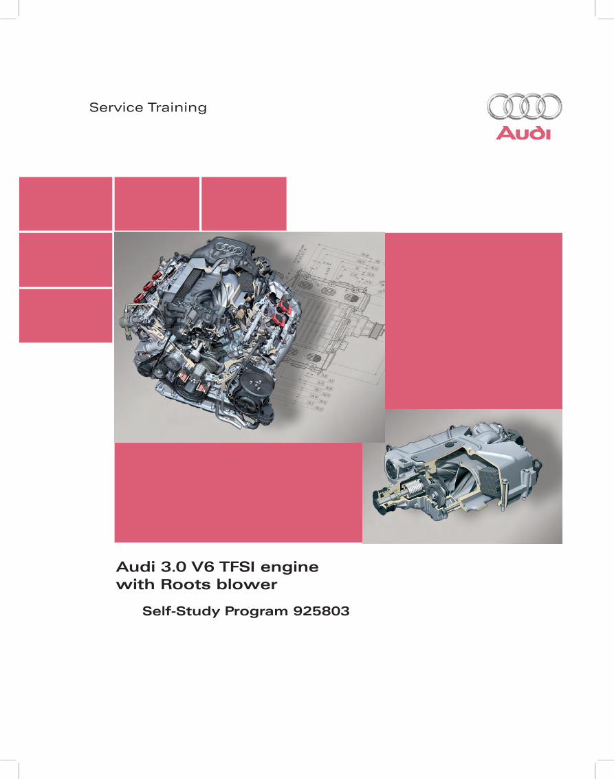
Audi 3.0 V6 TFSI engine with Roots blower
58
Service Training Audi 3.0 V6 TFSI engine with Roots blower Self-Study Program 925803
-
Upload
khangminh22 -
Category
Documents
-
view
1 -
download
0
Transcript of Audi 3.0 V6 TFSI engine with Roots blower
Service Training
Audi 3.0 V6 TFSI enginewith Roots blower
Self-Study Program 925803
Audi of America, LLC.
Service Training
Printed in U.S.A.
Printed 12/2008
Course Number 925803
©2008 Audi of America, LLC.
All rights reserved. All information contained in this manual is based on the latest information available at the time of printing and is subject to the copyright and other intellectual property rights of Audi of America, Inc., its affiliated companies, and its licensors. All rights are reserved to make changes at any time without notice. No part of this document may be reproduced, stored in a retrieval system, or transmitted in any form or by any means, electronic, mechanical, photocopying, recording, or otherwise, nor may these materials be modified or reposted to other sites without the prior expressed written permission of the publisher.
All requests for permission to copy and redistribute information should be referred to Audi of America, LLC.
Always check Technical Bulletins and the latest electronic repair literature for information that may supersede any information included in this booklet.
Trademarks: All brand names and product names used in this manual are trade names, service marks, trademarks, or registered trademarks and are the property of their respective owners.

i
Table of Contents
Introduction . . . . . . . . . . . . . . . . . . . . . . . . . 2
Engine Mechanical . . . . . . . . . . . . . . . . . . . . . 6
Oil Supply . . . . . . . . . . . . . . . . . . . . . . . . . . 11
Air Supply . . . . . . . . . . . . . . . . . . . . . . . . . . 12
The Self-Study Program teaches the design and function of new vehicle models, automotive components and technologies.
The Self-Study Program is not a Repair Manual!The values given are only intended as a guideline. Refer to the software version valid at the time of publication of the SSP.
For maintenance and repair work, always refer to the current technical literature.
Reference Note
Service. . . . . . . . . . . . . . . . . . . . . . . . . . . . 48
Cooling System . . . . . . . . . . . . . . . . . . . . . . . 32
Exhaust Emission Treatment . . . . . . . . . . . . . . 38
Fuel System . . . . . . . . . . . . . . . . . . . . . . . . . 42
Engine Management . . . . . . . . . . . . . . . . . . . . 44
Glossary . . . . . . . . . . . . . . . . . . . . . . . . . . . 49
Summary . . . . . . . . . . . . . . . . . . . . . . . . . . 50
191651 Audi 3.0L Supercharged.indd Sec1:i191651 Audi 3.0L Supercharged.indd Sec1:i 2/16/2009 11:12:30 AM2/16/2009 11:12:30 AM

ii
Notes
191651 Audi 3.0L Supercharged.indd Sec1:ii191651 Audi 3.0L Supercharged.indd Sec1:ii 2/16/2009 11:12:31 AM2/16/2009 11:12:31 AM
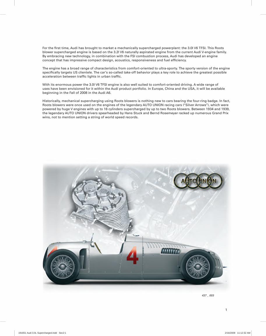
437 _ 003
For the fi rst time, Audi has brought to market a mechanically supercharged powerplant: the 3.0l V6 TFSI. This Roots blower supercharged engine is based on the 3.2l V6 naturally aspirated engine from the current Audi V-engine family.By embracing new technology, in combination with the FSI combustion process, Audi has developed an engine concept that has impressive compact design, acoustics, responsiveness and fuel effi ciency.
The engine has a broad range of characteristics from comfort-oriented to ultra-sporty. The sporty version of the engine specifi cally targets US clientele. The car’s so-called take-off behavior plays a key role to achieve the greatest possible acceleration between traffi c lights in urban traffi c.
With its enormous power the 3.0l V6 TFSI engine is also well suited to comfort-oriented driving. A wide range of uses have been envisioned for it within the Audi product portfolio. In Europe, China and the USA, it will be available beginning in the Fall of 2008 in the Audi A6.
Historically, mechanical supercharging using Roots blowers is nothing new to cars bearing the four-ring badge. In fact, Roots blowers were once used on the engines of the legendary AUTO UNION racing cars (“Silver Arrows”), which were powered by huge V engines with up to 16 cylinders supercharged by up to two Roots blowers. Between 1934 and 1939, the legendary AUTO UNION drivers spearheaded by Hans Stuck and Bernd Rosemeyer racked up numerous Grand Prix wins, not to mention setting a string of world speed records.
1
191651 Audi 3.0L Supercharged.indd Sec2:1191651 Audi 3.0L Supercharged.indd Sec2:1 2/16/2009 11:12:32 AM2/16/2009 11:12:32 AM

2
Introduction
Technical description
The 3.0l V6 TFSI engine will be used for the fi rst time in the 2009 Audi A6.
Main technical features:
Six-cylinder V engine with mechanical supercharging –(technical basis: 3.2l V6 FSI engine)
Fuel supply, activated carbon fi lter system, exhaust –system (manifold for selective lambda control) and engine cooling system are identical to those of the 3.2l V6 FSI engine in terms of their geometry and position.
Vacuum system with mechanical vacuum pump –(identical to that of the 3.2l V6 FSI engine)
Main changes from the 3.2l V6 FSI engine:
Heat treated cylinder crankcase –Crankshaft drive –Supercharger module with integrated intercooling –
system
Coolant pipes in the car’s low-temperature circuit –Belt drive for the supercharger module –Engine management system with “Simos 8” control – Secondary air system for compliance with the EU V and –
ULEV II exhaust emission standards
Adaptations from the 3.2L FSI engine:
Intake system –Camshafts –Valves and valve springs –Flange for the tumble fl aps –
Deletions from the 3.2L FSI engine:
Audi valvelift system –Exhaust camshaft adjustment –
437 _ 005Adapted crank mechanism
Supercharger module
Coolant tube
Additional charge-air cooler
2nd belt drivepulley
191651 Audi 3.0L Supercharged.indd Sec2:2191651 Audi 3.0L Supercharged.indd Sec2:2 2/16/2009 11:12:33 AM2/16/2009 11:12:33 AM

3
Introduction
5000 6000 7000 8000400030001000 2000
kW
120
70
230
280355
175
120
295
0
Nm
Torque/power curve
Max. torque in lb-ft
Max. power in horsepower
Engine speed [rpm]
Engine code CAJA/CCAA
Engine type Six-cylinder V-engine
Displacement in cm3 2995
Max. power in hp (kW) 285 (213) at 4850 – 7000 rpm
Max. torque in lb-ft 310 at 2500 – 4850 rpm
Valves per cylinder 4
Bore in mm 84.5
Stroke in mm 89
Compression ratio 10.5 : 1
Firing order 1–4–3–6–2–5
Engine weight 418 lbs (190 kg)
Engine management Simos 8
Fuel grade Premium unleaded
Mixture formation Direct injection FSI (homogeneous)High-pressure fuel pump HDP 3
Exhaust emission standard EU V, ULEV II
Exhaust aftertreatment Cylinder-selective lambda control with one broadband pre-cat sensor per cylinder bank, two ceramic catalytic converters
with post-cat oxygen sensor (nonlinear sensor)
CO2 emissions in g/km 228
191651 Audi 3.0L Supercharged.indd Sec2:3191651 Audi 3.0L Supercharged.indd Sec2:3 2/16/2009 11:12:33 AM2/16/2009 11:12:33 AM
4
Introduction
Characterization
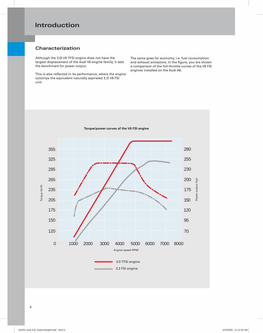
Although the 3.0l V6 TFSI engine does not have the largest displacement of the Audi V6 engine family, it sets the benchmark for power output.
This is also refl ected in its performance, where the engine outstrips the equivalent naturally aspirated 3.2l V6 FSI unit.
The same goes for economy, i.e. fuel consumption and exhaust emissions. In the fi gure, you are shown a comparison of the full-throttle curves of the V6 FSI engines installed on the Audi A6.
5000 6000 7000 8000400030001000 2000
175
120
70
230
280355
175
150205
120
95150
295
255325
200265
0
235
3.0 TFSI engine
3.2 FSI engine
Torque/power curves of the V6 FSI engine
Torq
ue
(lb-f
t)
Pow
er o
utp
ut
(hp
)
Engine speed RPM)
191651 Audi 3.0L Supercharged.indd Sec2:4191651 Audi 3.0L Supercharged.indd Sec2:4 2/16/2009 11:12:33 AM2/16/2009 11:12:33 AM
5
Introduction
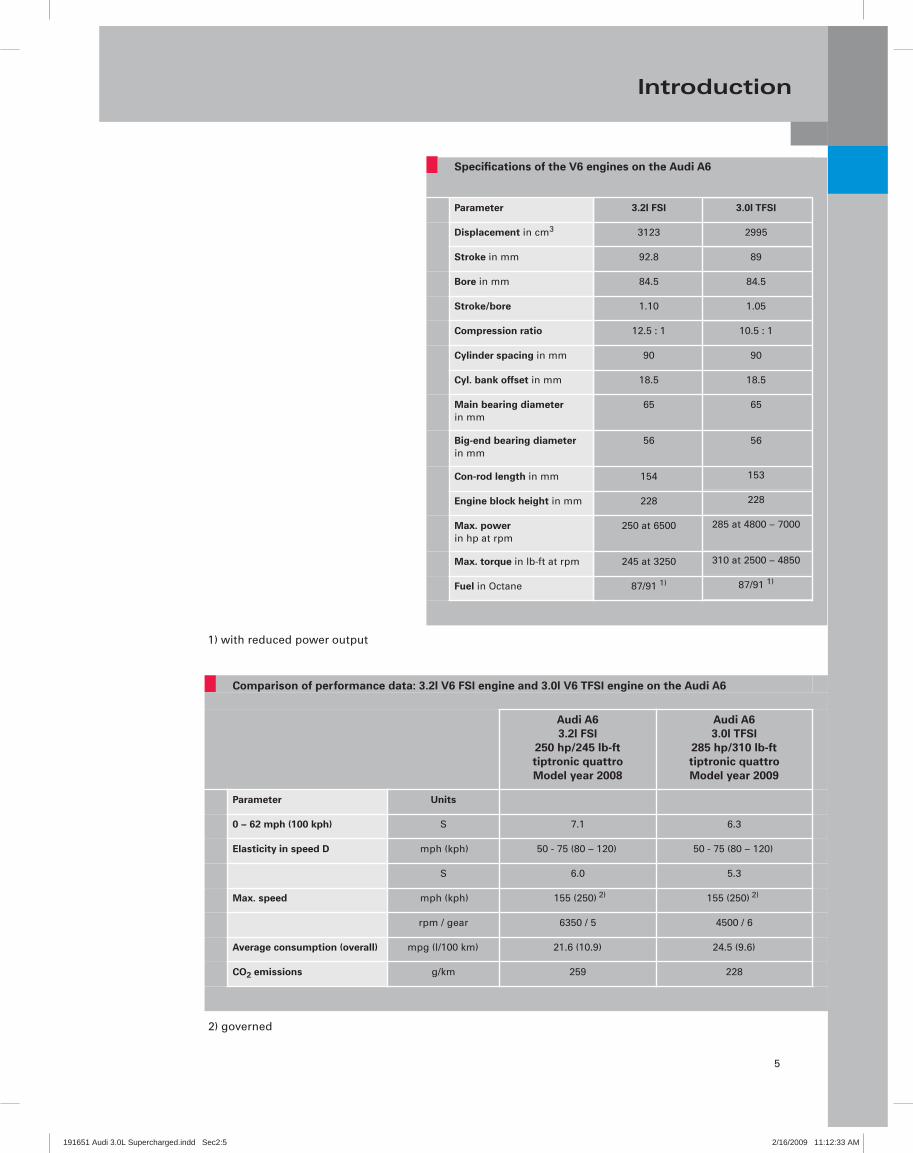
1) with reduced power output
Comparison of performance data: 3.2l V6 FSI engine and 3.0l V6 TFSI engine on the Audi A6
Audi A63.2l FSI
250 hp/245 lb-fttiptronic quattroModel year 2008
Audi A63.0l TFSI
285 hp/310 lb-fttiptronic quattroModel year 2009
Parameter Units
0 – 62 mph (100 kph) S 7.1 6.3
Elasticity in speed D mph (kph) 50 - 75 (80 – 120) 50 - 75 (80 – 120)
S 6.0 5.3
Max. speed mph (kph) 155 (250) 2)
rpm / gear 6350 / 5 4500 / 6
Average consumption (overall) mpg (l/100 km) 21.6 (10.9) 24.5 (9.6)
CO2 emissions g/km 259 228
155 (250) 2)
2) governed
Specifications of the V6 engines on the Audi A6
Parameter
Displacement in cm3
Stroke in mm
Bore in mm
Stroke/bore
Compression ratio
Cylinder spacing in mm
Cyl. bank offset in mm
Main bearing diameter in mm
Big-end bearing diameter in mm
Con-rod length in mm
Engine block height in mm
Max. power in hp at rpm
Max. torque in lb-ft at rpm
Fuel in Octane
3.2l FSI
3123
92.8
84.5
1.10
12.5 : 1
90
18.5
65
56
154
228
250 at 6500
245 at 3250
87/91 1)
3.0l TFSI
2995
89
84.5
1.05
10.5 : 1
90
18.5
65
56
153
228
285 at 4800 – 7000
310 at 2500 – 4850
87/91 1)
191651 Audi 3.0L Supercharged.indd Sec2:5191651 Audi 3.0L Supercharged.indd Sec2:5 2/16/2009 11:12:33 AM2/16/2009 11:12:33 AM

6
Engine Mechanical
437 _ 007
Cylinder block
The cylinder block is identical to that of the 3.2l V6 FSI engine. However, the load on the engine is higher due to the increased mean peak pressure (combustion pressure).
To ensure high stability, the bearing seats undergo a special heat treatment process during manufacturing. Also, higher strength main bearing bolts are used.
Cylinder block
Cylinder crankcasebottom section (bedplate)
Oil pan top section
Oil pan bottom section
191651 Audi 3.0L Supercharged.indd Sec2:6191651 Audi 3.0L Supercharged.indd Sec2:6 2/16/2009 11:12:34 AM2/16/2009 11:12:34 AM

7
Engine Mechanical
437_008
437_009
2.0 mm oil scraper ring(two piece
1.5 mmtaper-face ring
1.2 mm asymmetricsteel ring
Ring carrier
Cast piston
Crankshaft drive
Crankshaft
The crankshaft has been adapted for a stroke of 89 mm. Like the 3.2l V6 FSI engine, the crankshaft has a split-pin confi guration* (see glossary).
The newly developed, cracked con-rods* are 153 mm long and optimised for strength. All bearing bushings are lead-free 3-component composite bearing bushings.
Pistons
Unlike the 3.2l V6 FSI engine, the pistons are rated for a compression ratio of 10.5:1.
The piston skirts have a wear resistant Ferrostan plating.
The special piston ring combination provides:
High power output –Low blow-by gas fl ow rates –Low oil consumption –Minimum friction and wear –
191651 Audi 3.0L Supercharged.indd Sec2:7191651 Audi 3.0L Supercharged.indd Sec2:7 2/16/2009 11:12:34 AM2/16/2009 11:12:34 AM
8
Engine Mechanical
437_050
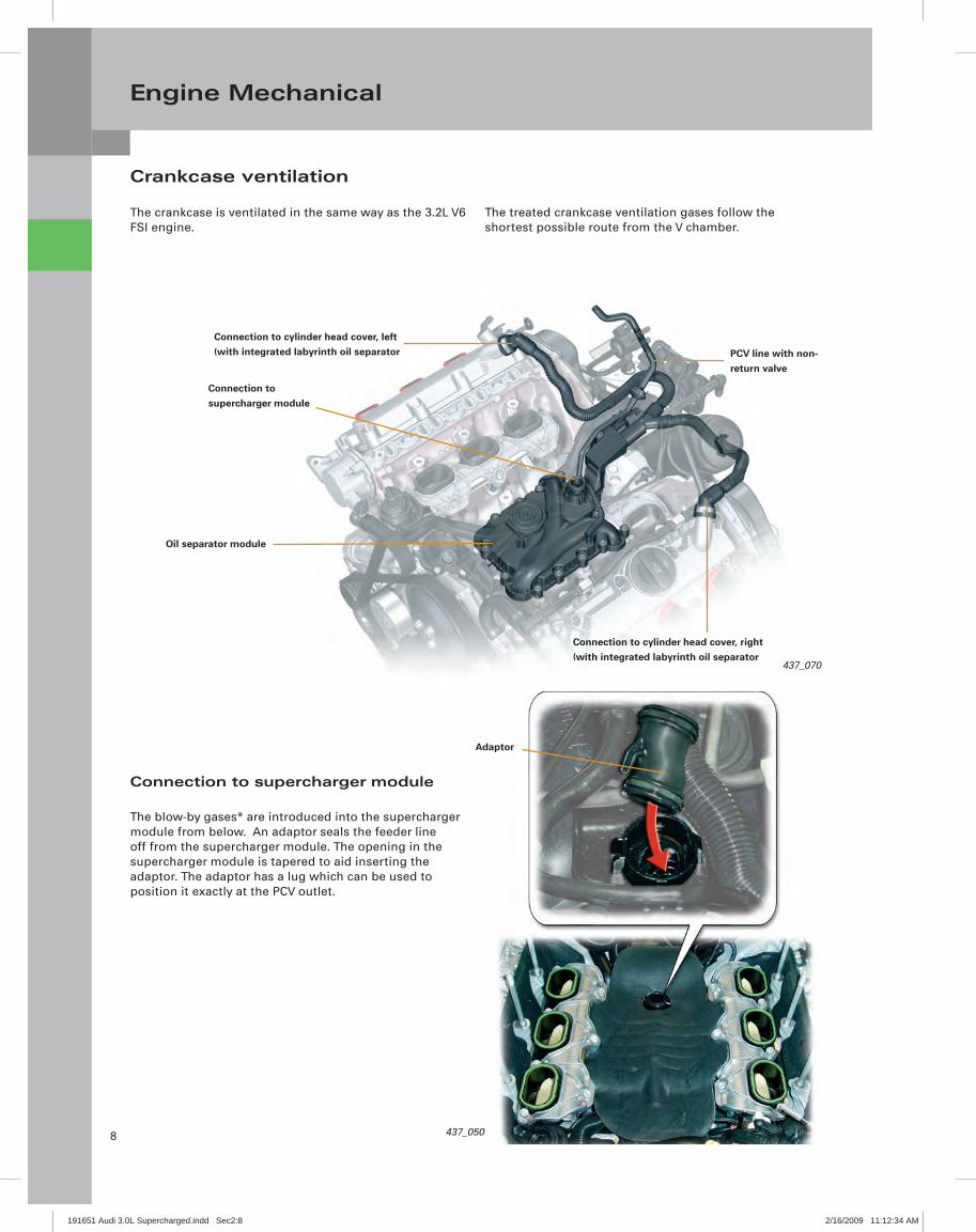
Crankcase ventilation
The crankcase is ventilated in the same way as the 3.2L V6 FSI engine.
The treated crankcase ventilation gases follow the shortest possible route from the V chamber.
437_070
Connection to cylinder head cover, right(with integrated labyrinth oil separator
Connection tosupercharger module
Oil separator module
PCV line with non-return valve
Connection to cylinder head cover, left(with integrated labyrinth oil separator
Adaptor
Connection to supercharger module
The blow-by gases* are introduced into the supercharger module from below. An adaptor seals the feeder line off from the supercharger module. The opening in the supercharger module is tapered to aid inserting the adaptor. The adaptor has a lug which can be used to position it exactly at the PCV outlet.
191651 Audi 3.0L Supercharged.indd Sec2:8191651 Audi 3.0L Supercharged.indd Sec2:8 2/16/2009 11:12:34 AM2/16/2009 11:12:34 AM
9
Engine Mechanical
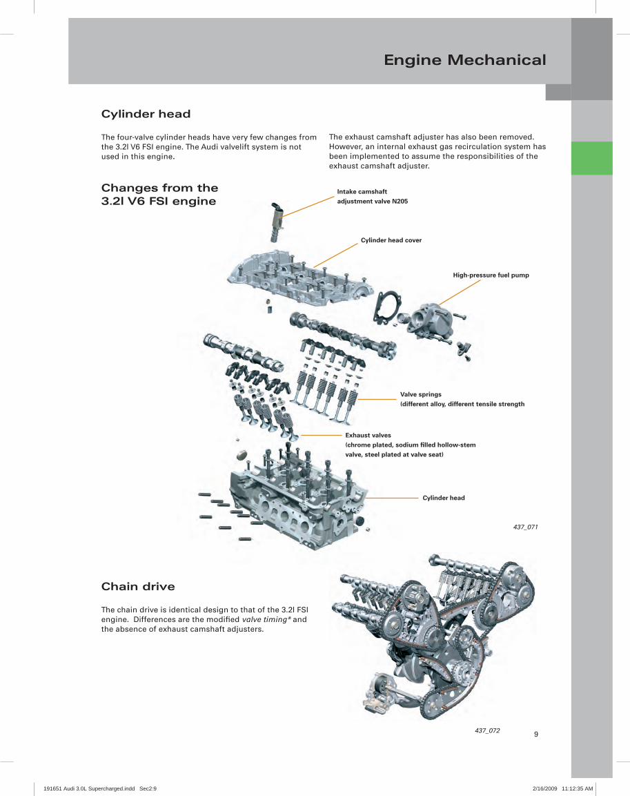
Cylinder head
The four-valve cylinder heads have very few changes from the 3.2l V6 FSI engine. The Audi valvelift system is not used in this engine.
The exhaust camshaft adjuster has also been removed. However, an internal exhaust gas recirculation system has been implemented to assume the responsibilities of the exhaust camshaft adjuster.
437_071
Intake camshaft adjustment valve N205
Cylinder head cover
High-pressure fuel pump
Valve springs(different alloy, different tensile strength
Exhaust valves(chrome plated, sodium fi lled hollow-stemvalve, steel plated at valve seat)
Cylinder head
Chain drive
The chain drive is identical design to that of the 3.2l FSI engine. Differences are the modifi ed valve timing* and the absence of exhaust camshaft adjusters.
437_072
Changes from the 3.2l V6 FSI engine
191651 Audi 3.0L Supercharged.indd Sec2:9191651 Audi 3.0L Supercharged.indd Sec2:9 2/16/2009 11:12:35 AM2/16/2009 11:12:35 AM
10
Engine Mechanical
437_055
437_010
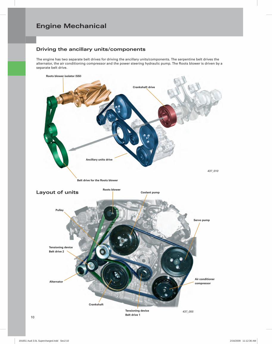
Driving the ancillary units/components
The engine has two separate belt drives for driving the ancillary units/components. The serpentine belt drives the alternator, the air conditioning compressor and the power steering hydraulic pump. The Roots blower is driven by a separate belt drive.
Layout of units
Belt drive for the Roots blower
Ancillary units drive
Roots blower isolator (SSI)
Crankshaft drive
Roots blowerCoolant pump
Servo pump
Air conditionercompressor
Pulley
Tensioning deviceBelt drive 2
Alternator
Crankshaft
Tensioning deviceBelt drive 1
191651 Audi 3.0L Supercharged.indd Sec2:10191651 Audi 3.0L Supercharged.indd Sec2:10 2/16/2009 11:12:36 AM2/16/2009 11:12:36 AM

11
Oil Supply
Oil circulation system
The oil circulation system of the 3.0l V6 TFSI engine was adopted from the 3.2l V6 FSI engine
However, there are the following differences:
There are no spray nozzles for the cam followers in the –valve gear (they are only needed in an engine with Audi valvelift system, since the narrower rollers require better lubrication)
There is no drive module for the exhaust camshaft –adjuster
437_073
Unfi ltered oil port
Clean oil portSelf-regulating oil pump
Oil cooler
Oil pressure regulationvalve N428
Upright oil fi lter module
191651 Audi 3.0L Supercharged.indd Sec2:11191651 Audi 3.0L Supercharged.indd Sec2:11 2/16/2009 11:12:36 AM2/16/2009 11:12:36 AM

12
Air Supply
437_025
Air circulation system
The central component of the air supply system is the supercharger module, which sits inside the V shaped area between the cylinder banks. It consists of the Roots blower, the bypass control module and the intercooler.
Given Audi's extensive experience with exhaust turbocharging, you may ask yourself why a mechanical supercharging system has been chosen for the 3.0l V6 TFSI engine.
After carefully weighing the pros and cons on the basis of numerous tests conducted during the conceptual design and development phase, the decision fell in favor of the mechanical supercharging system.
The following criteria played a key role:
High standard of comfort –Good starting performance, coupled with a broad range –
of characteristics between comfort-oriented and ultra-sporty
Because of this, the engine is suitable for use in –multiple models
Compliance with all current and upcoming exhaust –emission standards (EU V and ULEV II)
Intake manifoldfl aps
Intercooler
Supercharger moduleAir fi lter
191651 Audi 3.0L Supercharged.indd Sec2:12191651 Audi 3.0L Supercharged.indd Sec2:12 2/16/2009 11:12:38 AM2/16/2009 11:12:38 AM

13
Air Supply
Pros and cons of a mechanical supercharging system with Roots blower compared to an exhaust turbocharging system
Pros:Charge pressure is immediately available whenever it is required –Charge pressure is continuously supplied and rises with increasing rpm –The charge air does not have to be cooled as much as turbocharged air –Long life and maintenance-friendly operation –Compact design (to save space, the supercharger can be installed in place of the intake manifold inside the V shaped –
area between the cylinder banks)
High fuel effi ciency –Quick and dynamic torque response; peak torque is available at low rpm, providing good starting performance –The compressed air paths to the cylinders are very short, resulting in a very low air volume and extremely quick –
response
Enhanced exhaust emission characteristics (reason: the catalytic converter reaches its operating temperature faster). –In an exhaust turbocharged engine, a portion of the heat energy is wasted in driving the turbocharger
Cons:It is very diffi cult to produce because very close manufacturing tolerances have to be maintained (rotor to housing –
and rotor to rotor)
Higher susceptibility to ingress of foreign matter into the fi ltered air tract –Relatively high weight –Extensive soundproofi ng is needed –Some engine power is lost in driving the blower –
Exhaust turbocharger Roots blower
437_053
437_044
191651 Audi 3.0L Supercharged.indd Sec2:13191651 Audi 3.0L Supercharged.indd Sec2:13 2/16/2009 11:12:39 AM2/16/2009 11:12:39 AM

14
Air Supply
437_016 437_015
437_014
Housing
Air inlet
Rotor 2
Air outlet
Rotor 1
Basic principle
General information on Roots blowers
With their mechanical supercharging technology, Roots blowers are presently staging a comeback at Audi.In this section you will fi nd general information about the design and development of this technology.
What are Roots blowers? In design terms, Root blowers are rotary piston compressors. They work without inner compression according to the displacement principle.
The fresh air blower consists of a housing in which two shafts (rotors) rotate. Both rotors are driven mechanically, e.g. by the crankshaft. Both rotors are coupled by a gearing outside the housing so that they counter-rotate synchronously. That is how they interact.
From a design standpoint, it is very important that the rotors are sealed off against each another and against the housing. The diffi culty here is that no friction must be allowed to develop.
When the blower is operating (i.e. the rotors are rotating), air is conveyed between the vanes and the outer wall of the housing from the air inlet (on the intake side) to the air outlet (on the pressure side).
Types
The historic blowers of the past were equippedwith twin-vane rotors.
Today's modern versions usually have three vanes and are screw shaped to provide a higher pressure (for better effi ciency).
191651 Audi 3.0L Supercharged.indd Sec2:14191651 Audi 3.0L Supercharged.indd Sec2:14 2/16/2009 11:12:39 AM2/16/2009 11:12:39 AM
15
Air Supply
437_051
Rotors
Housing
Upperbearing cover
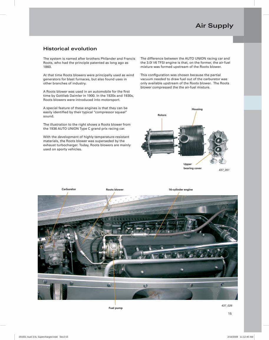
Historical evolution
The system is named after brothers Philander and Francis Roots, who had the principle patented as long ago as 1860.
At that time Roots blowers were principally used as wind generators for blast furnaces, but also found uses in other branches of industry.
A Roots blower was used in an automobile for the fi rst time by Gottlieb Daimler in 1900. In the 1920s and 1930s, Roots blowers were introduced into motorsport.
A special feature of these engines is that they can be easily identifi ed by their typical “compressor squeal” sound.
The illustration to the right shows a Roots blower from the 1936 AUTO UNION Type C grand prix racing car.
With the development of highly temperature-resistant materials, the Roots blower was superseded by the exhaust turbocharger. Today, Roots blowers are mainly used on sporty vehicles.
The difference between the AUTO UNION racing car and the 3.0l V6 TFSI engine is that, on the former, the air-fuel mixture was formed upstream of the Roots blower.
This confi guration was chosen because the partial vacuum needed to draw fuel out of the carburetor was only available upstream of the Roots blower. The Roots blower compressed the the air-fuel mixture.
Carburetor Roots blower 16-cylinder engine
Fuel pump437_026
191651 Audi 3.0L Supercharged.indd Sec2:15191651 Audi 3.0L Supercharged.indd Sec2:15 2/16/2009 11:12:40 AM2/16/2009 11:12:40 AM
16
Air Supply
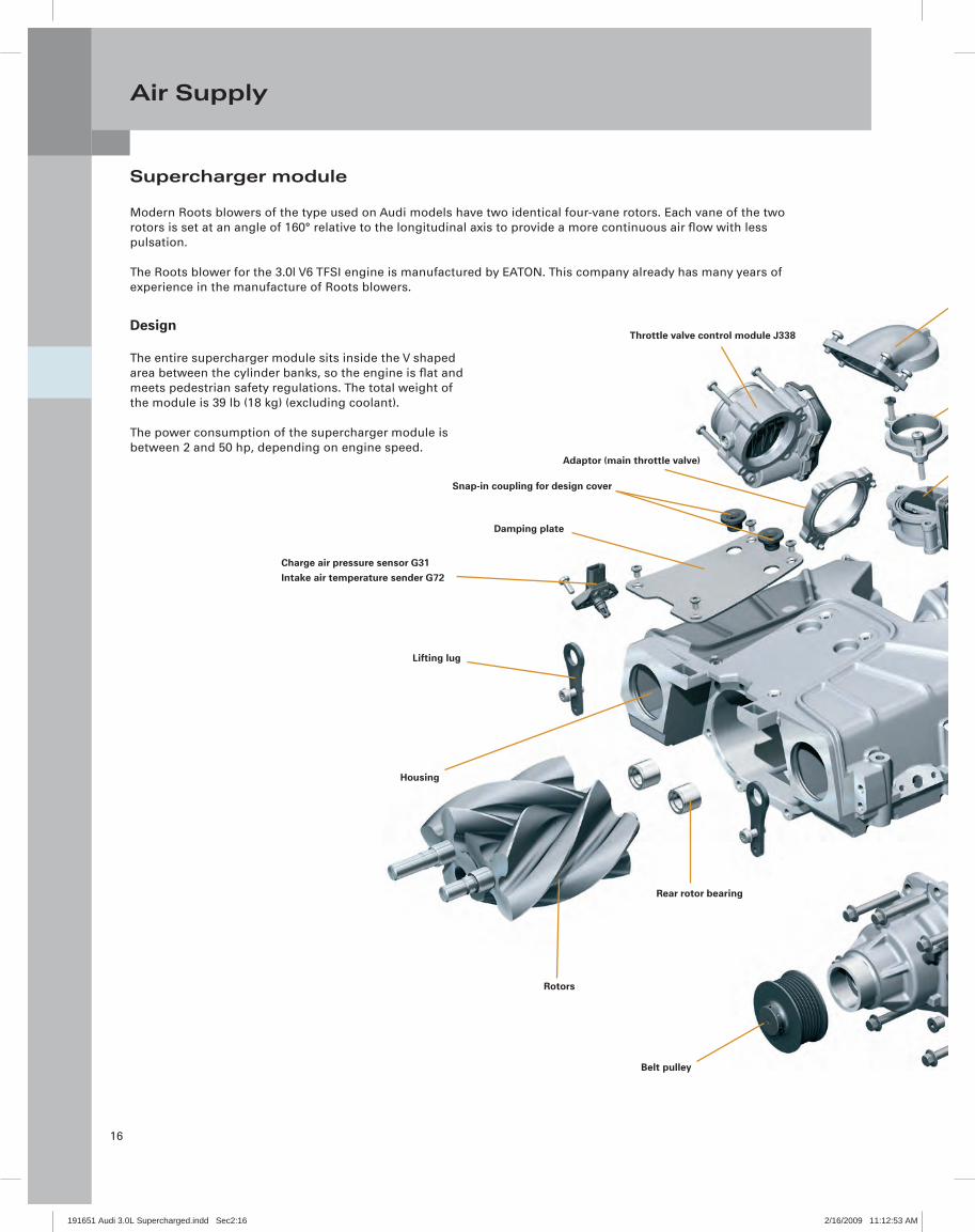
Supercharger module
Modern Roots blowers of the type used on Audi models have two identical four-vane rotors. Each vane of the two rotors is set at an angle of 160° relative to the longitudinal axis to provide a more continuous air fl ow with less pulsation.
The Roots blower for the 3.0l V6 TFSI engine is manufactured by EATON. This company already has many years of experience in the manufacture of Roots blowers.
Belt pulley
Rear rotor bearing
Rotors
Housing
Lifting lug
Charge air pressure sensor G31Intake air temperature sender G72
Damping plate
Snap-in coupling for design cover
Adaptor (main throttle valve)
Throttle valve control module J338Design
The entire supercharger module sits inside the V shaped area between the cylinder banks, so the engine is fl at and meets pedestrian safety regulations. The total weight of the module is 39 lb (18 kg) (excluding coolant).
The power consumption of the supercharger module is between 2 and 50 hp, depending on engine speed.
191651 Audi 3.0L Supercharged.indd Sec2:16191651 Audi 3.0L Supercharged.indd Sec2:16 2/16/2009 11:12:53 AM2/16/2009 11:12:53 AM
17
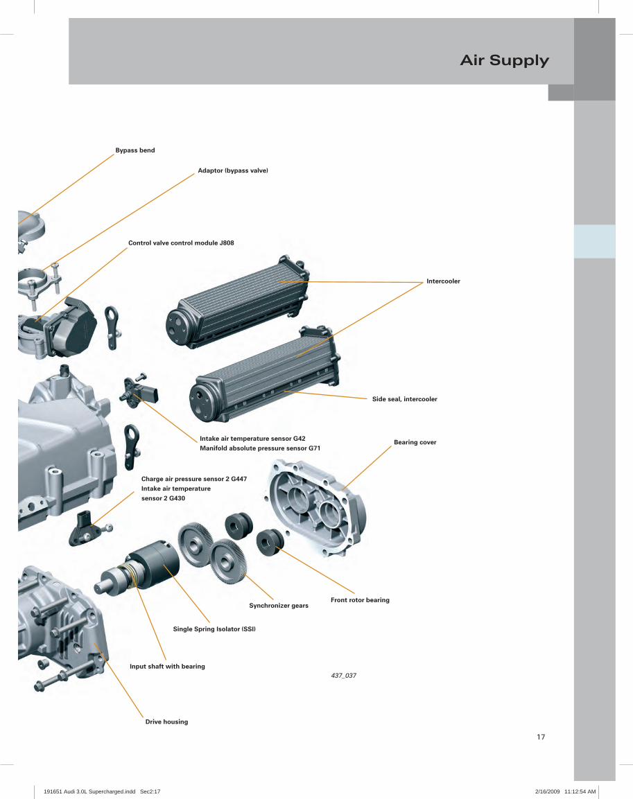
Air Supply
Drive housing
Input shaft with bearing
Single Spring Isolator (SSI)
Synchronizer gearsFront rotor bearing
437_037
Bearing cover
Charge air pressure sensor 2 G447Intake air temperaturesensor 2 G430
Intercooler
Control valve control module J808
Side seal, intercooler
Intake air temperature sensor G42Manifold absolute pressure sensor G71
Bypass bend
Adaptor (bypass valve)
191651 Audi 3.0L Supercharged.indd Sec2:17191651 Audi 3.0L Supercharged.indd Sec2:17 2/16/2009 11:12:54 AM2/16/2009 11:12:54 AM

18
Air Supply
437_038Housing
Damping plate
Snap-in couplingfor design cover
Lifting lug
Direction of travel
Air outlets
Intercooler
Intercooler
PCV intake
Drive shaft
Intake manifold pressure sender G42Intake air temperature sensor G72
Throttle valve control module J338
Housing
The Roots blower, an electrically activated bypass valve and one intercooler per cylinder bank are integrated in a cast mono-block housing.
The air outlets to the individual cylinders can be found on the underside of the housing. The lifting lugs bolted to the supercharger module are for suspending the engine during removal and installation.
437_034
191651 Audi 3.0L Supercharged.indd Sec2:18191651 Audi 3.0L Supercharged.indd Sec2:18 2/16/2009 11:12:55 AM2/16/2009 11:12:55 AM

19
Air Supply
Drive
The Roots blower is driven by the crankshaft via the second pulley of the belt drive.
Drive is permanent, and is not engaged or disengaged by a magnetic coupling.
Each belt drive is insulated against crankshaft vibration by a rubber buffer in a shared torsion vibration damper.
The result is better resonance damping at low engine speeds and full throttle.
Because of this the load on the belt is signifi cantly lower.The crankshaft-to-supercharger drive ratio is 1:2.5.
Supercharger module
437_039
2nd belt drivepulley
The Roots blower is coupled by means of a Single Spring Isolator (SSI) integrated in the drive housing of the supercharger module.
The SSI is designed to optimize force transmission under load reversal.
It ensures very smooth running (optimized acoustics) and extends the life of the drive belt.
The ribbed V-belt which drives the Roots blower has a replacement interval of 75,000 miles (120,000 km).
437_040
Front rotor bearingSynchronizer gears
Single Spring Isolator (SSI)
Input shaft with bearing
Belt pulley
Drive housing
Bearing cover
191651 Audi 3.0L Supercharged.indd Sec2:19191651 Audi 3.0L Supercharged.indd Sec2:19 2/16/2009 11:12:56 AM2/16/2009 11:12:56 AM

20
Air Supply
Function
A spring element is built into the drive housing of the Roots blower. It consists of a torsion spring guided by an input bushing and an output bushing and transmits drive torque from the belt pulley to the gearing.
The input and output bushings limit the movement of the spring, both into and counter to the direction of rotation of the Roots blower.
The spring element is rated "soft" enough to effectively isolate the blower, yet also fi rm enough to prevent harshness during dynamic operation (under load reversal), which can cause unwanted noise.
Further along the drive-line, the second rotor is driven through a pair of gears so that the two rotors counter-rotate absolutely synchronously. The gears are press fi tted onto the rotor shafts by the manufacturer using special gauges.
A perfect fi t must be ensured, as the rotor vanes would otherwise come into contact with one another.
For this reason, the gears must not be removed from the shafts during servicing. The drive head is fi lled with special-grade oil.
Rotors
The two four-vane rotors are set at an angle of 160° and run on maintenance-free roller bearings. To minimize wear during the run-in phase, the rotors have a special graphite-based coating.
This coating also guards against air leakage (rotor to rotor, rotor to rotor bore) providing better performance.
437_042
Rotor
Rear rotor bearing
437_041
Synchroniser gears
Output bushing
Input bushing
Torsion spring
Input shaftwith bearing
Belt pulley
Drive housing
Rotors
191651 Audi 3.0L Supercharged.indd Sec2:20191651 Audi 3.0L Supercharged.indd Sec2:20 2/16/2009 11:12:56 AM2/16/2009 11:12:56 AM
21
Air Supply
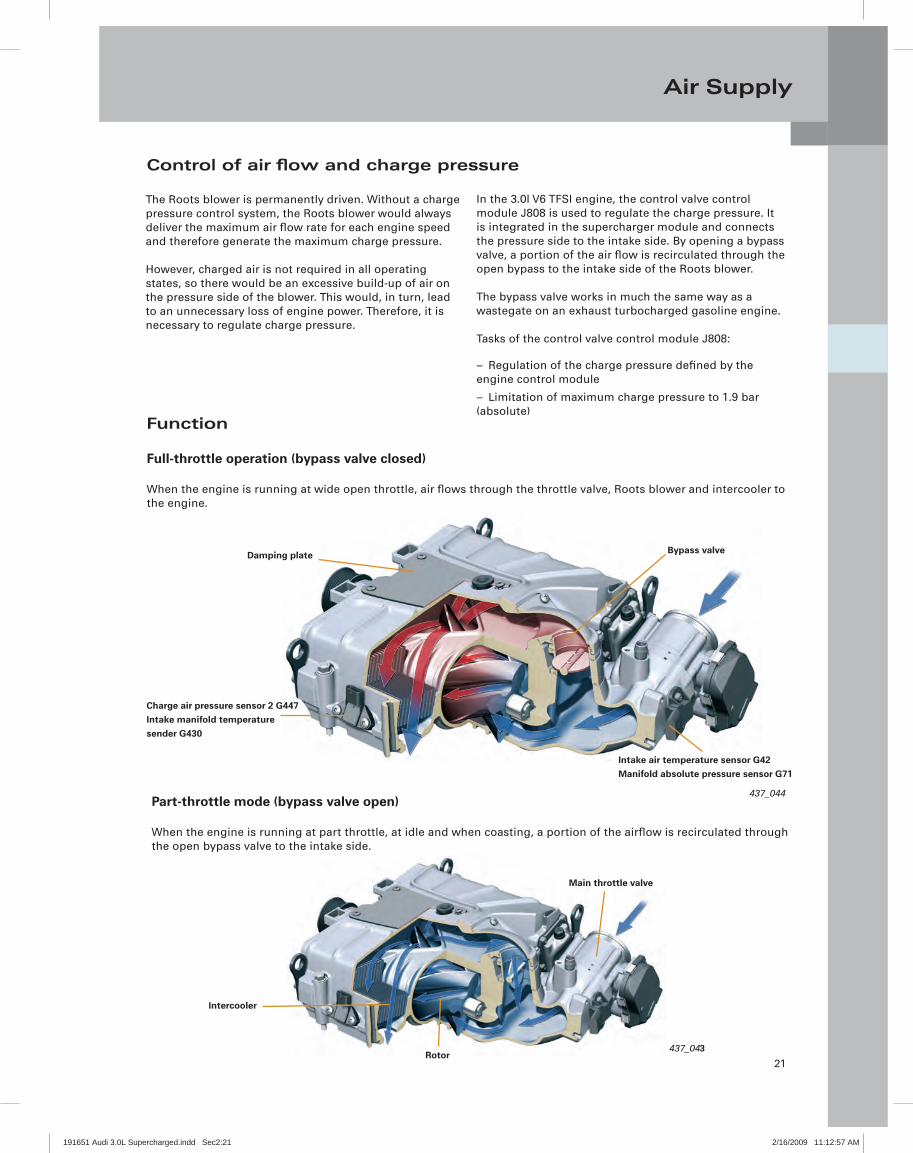
Control of air fl ow and charge pressure
The Roots blower is permanently driven. Without a charge pressure control system, the Roots blower would always deliver the maximum air fl ow rate for each engine speed and therefore generate the maximum charge pressure.
However, charged air is not required in all operating states, so there would be an excessive build-up of air on the pressure side of the blower. This would, in turn, lead to an unnecessary loss of engine power. Therefore, it is necessary to regulate charge pressure.
In the 3.0l V6 TFSI engine, the control valve control module J808 is used to regulate the charge pressure. It is integrated in the supercharger module and connects the pressure side to the intake side. By opening a bypass valve, a portion of the air fl ow is recirculated through the open bypass to the intake side of the Roots blower.
The bypass valve works in much the same way as a wastegate on an exhaust turbocharged gasoline engine.
Tasks of the control valve control module J808:
Regulation of the charge pressure defi ned by the –engine control module
Limitation of maximum charge pressure to 1.9 bar –(absolute)
Function
Full-throttle operation (bypass valve closed)
When the engine is running at wide open throttle, air fl ows through the throttle valve, Roots blower and intercooler to the engine.
Part-throttle mode (bypass valve open)
When the engine is running at part throttle, at idle and when coasting, a portion of the airfl ow is recirculated through the open bypass valve to the intake side.
Damping plate Bypass valve
437_044
Intake air temperature sensor G42Manifold absolute pressure sensor G71
Charge air pressure sensor 2 G447Intake manifold temperaturesender G430
437_043
Main throttle valve
Intercooler
Rotor
191651 Audi 3.0L Supercharged.indd Sec2:21191651 Audi 3.0L Supercharged.indd Sec2:21 2/16/2009 11:12:57 AM2/16/2009 11:12:57 AM

22
Air Supply
Control valve control module J808
Use of the control valve control module J808 eliminates the need for a complex and expensive belt drive shut-off in the form of a magnetic coupling.
437_036
Control fl ap adjustmentmotor V380
Bypass valveAngle sender
20
40
60
80
100
1 2
Lower mechanical stop
Upper mechanical stop
1
2
Sensor travel
Signal characteristic of the control flap potentiometer G584
Sen
sor
outp
ut
[%]
191651 Audi 3.0L Supercharged.indd Sec2:22191651 Audi 3.0L Supercharged.indd Sec2:22 2/16/2009 11:12:58 AM2/16/2009 11:12:58 AM
23
Air Supply
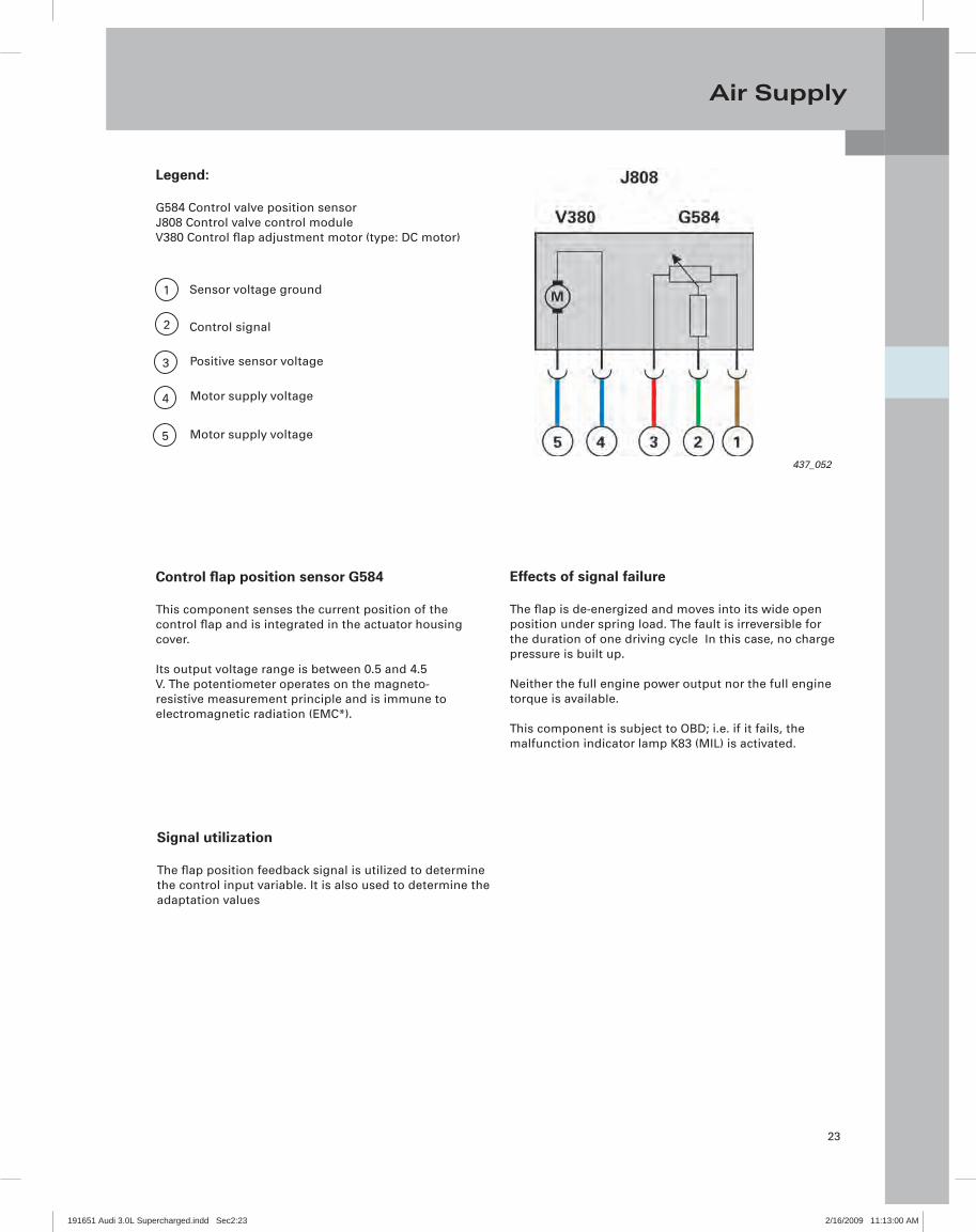
Control fl ap position sensor G584
This component senses the current position of the control fl ap and is integrated in the actuator housing cover.
Its output voltage range is between 0.5 and 4.5 V. The potentiometer operates on the magneto-resistive measurement principle and is immune to electromagnetic radiation (EMC*).
Effects of signal failure
The fl ap is de-energized and moves into its wide open position under spring load. The fault is irreversible for the duration of one driving cycle In this case, no charge pressure is built up.
Neither the full engine power output nor the full engine torque is available.
This component is subject to OBD; i.e. if it fails, the malfunction indicator lamp K83 (MIL) is activated.
Legend:
G584 Control valve position sensorJ808 Control valve control moduleV380 Control fl ap adjustment motor (type: DC motor)
437_052
Signal utilization
The fl ap position feedback signal is utilized to determine the control input variable. It is also used to determine the adaptation values
1
2
5
3
4
Sensor voltage ground
Control signal
Positive sensor voltage
Motor supply voltage
Motor supply voltage
191651 Audi 3.0L Supercharged.indd Sec2:23191651 Audi 3.0L Supercharged.indd Sec2:23 2/16/2009 11:13:00 AM2/16/2009 11:13:00 AM
24
Air Supply
437_028
437_029
437_018
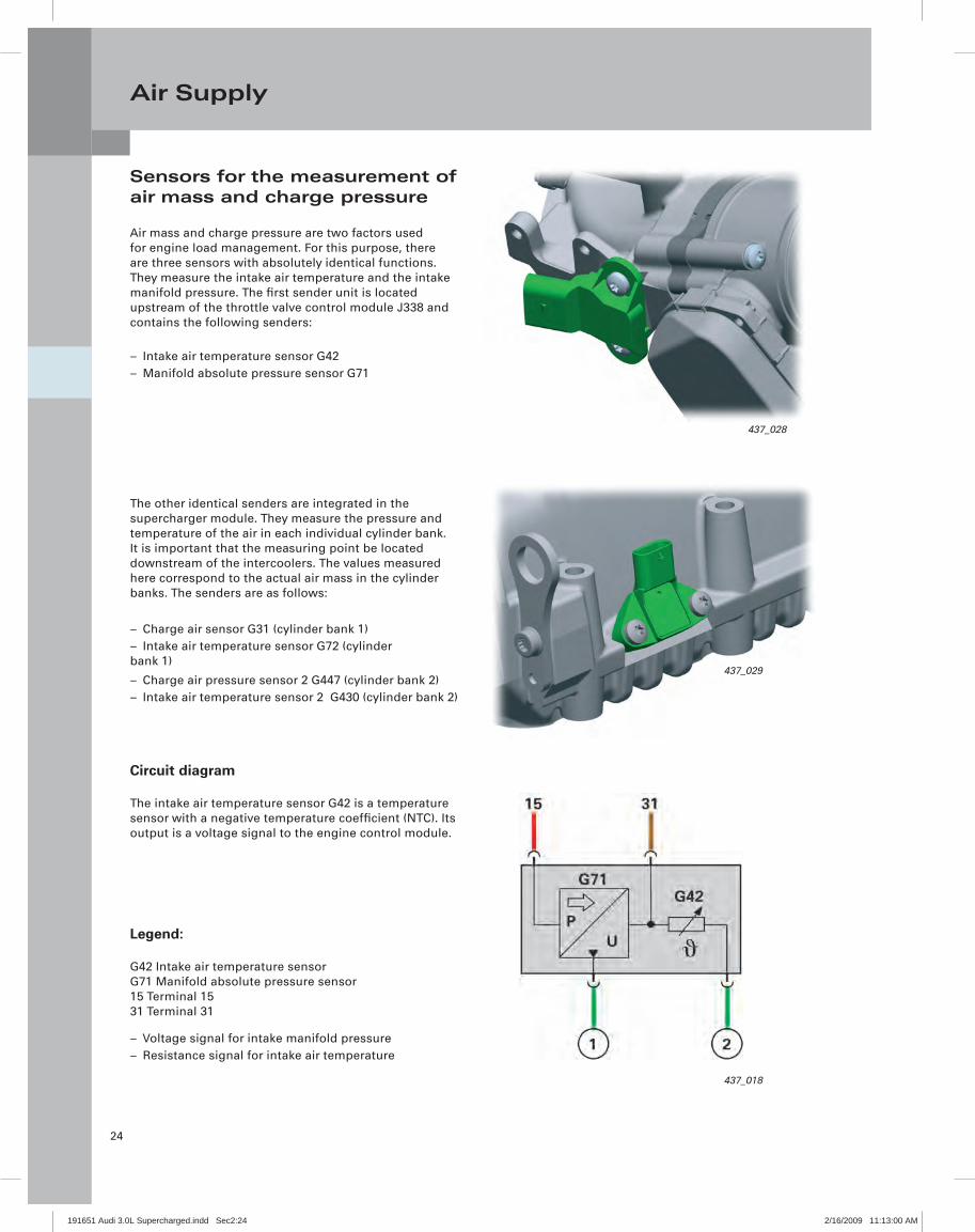
Sensors for the measurement of air mass and charge pressure
Air mass and charge pressure are two factors used for engine load management. For this purpose, there are three sensors with absolutely identical functions. They measure the intake air temperature and the intake manifold pressure. The fi rst sender unit is located upstream of the throttle valve control module J338 and contains the following senders:
Intake air temperature sensor G42 –Manifold absolute pressure sensor G71 –
The other identical senders are integrated in the supercharger module. They measure the pressure and temperature of the air in each individual cylinder bank. It is important that the measuring point be located downstream of the intercoolers. The values measured here correspond to the actual air mass in the cylinder banks. The senders are as follows:
Charge air sensor G31 (cylinder bank 1) –Intake air temperature sensor G72 (cylinder –
bank 1)
Charge air pressure sensor 2 G447 (cylinder bank 2) –Intake air temperature sensor 2 G430 (cylinder bank 2) –
Circuit diagram
The intake air temperature sensor G42 is a temperature sensor with a negative temperature coeffi cient (NTC). Its output is a voltage signal to the engine control module.
Legend:
G42 Intake air temperature sensorG71 Manifold absolute pressure sensor15 Terminal 1531 Terminal 31
Voltage signal for intake manifold pressure –Resistance signal for intake air temperature –
191651 Audi 3.0L Supercharged.indd Sec2:24191651 Audi 3.0L Supercharged.indd Sec2:24 2/16/2009 11:13:00 AM2/16/2009 11:13:00 AM
25
Air Supply
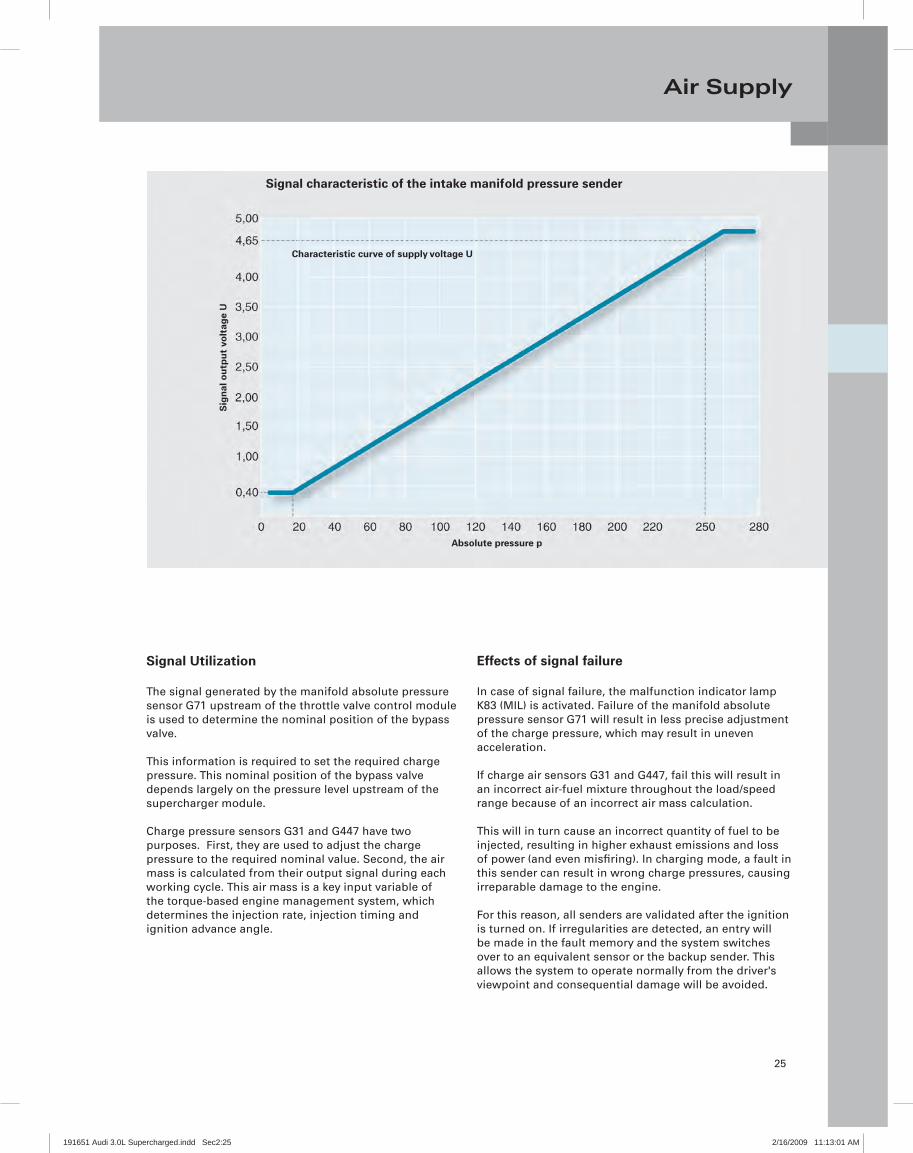
Signal Utilization
The signal generated by the manifold absolute pressure sensor G71 upstream of the throttle valve control module is used to determine the nominal position of the bypass valve.
This information is required to set the required charge pressure. This nominal position of the bypass valve depends largely on the pressure level upstream of the supercharger module.
Charge pressure sensors G31 and G447 have two purposes. First, they are used to adjust the charge pressure to the required nominal value. Second, the air mass is calculated from their output signal during each working cycle. This air mass is a key input variable of the torque-based engine management system, which determines the injection rate, injection timing and ignition advance angle.
Effects of signal failure
In case of signal failure, the malfunction indicator lamp K83 (MIL) is activated. Failure of the manifold absolute pressure sensor G71 will result in less precise adjustment of the charge pressure, which may result in uneven acceleration.
If charge air sensors G31 and G447, fail this will result in an incorrect air-fuel mixture throughout the load/speed range because of an incorrect air mass calculation.
This will in turn cause an incorrect quantity of fuel to be injected, resulting in higher exhaust emissions and loss of power (and even misfi ring). In charging mode, a fault in this sender can result in wrong charge pressures, causing irreparable damage to the engine.
For this reason, all senders are validated after the ignition is turned on. If irregularities are detected, an entry will be made in the fault memory and the system switches over to an equivalent sensor or the backup sender. This allows the system to operate normally from the driver's viewpoint and consequential damage will be avoided.
Sig
nal
ou
tpu
t vo
ltag
e U
Absolute pressure p
Characteristic curve of supply voltage U
Signal characteristic of the intake manifold pressure sender
191651 Audi 3.0L Supercharged.indd Sec2:25191651 Audi 3.0L Supercharged.indd Sec2:25 2/16/2009 11:13:01 AM2/16/2009 11:13:01 AM
26
Air Supply
437_020
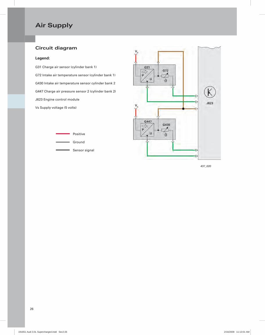
Circuit diagram
Legend:
G31 Charge air sensor (cylinder bank 1)
G72 Intake air temperature sensor (cylinder bank 1)
G430 Intake air temperature sensor cylinder bank 2
G447 Charge air pressure sensor 2 (cylinder bank 2)
J623 Engine control module
Vs Supply voltage (5 volts)
Positive
Ground
Sensor signal
191651 Audi 3.0L Supercharged.indd Sec2:26191651 Audi 3.0L Supercharged.indd Sec2:26 2/16/2009 11:13:01 AM2/16/2009 11:13:01 AM

27
Air Supply
Load management
The control valve control module J808 operates in conjunction with the throttle valve control module J388.
The control system was designed to maximize throttle free operation and power delivery.
During part-throttle and naturally aspirated operation, the bypass valve is wide open and the engine throttle valve takes care of load management. In charge pressure mode, the bypass valve regulates the engine load and the engine throttle valve is wide open.
The diagram below shows the function of both fl aps.
1000 2000 3000 4000 5000 60000
20
40
60
80
100
120
140
160
20040060080010001200140016001800
31
2
1
2
Op
enin
g a
ng
le [d
egre
es]
Inta
ke m
anifo
ld p
ress
ure
[mb
ar]
Naturally aspirated mode
Ambient pressure
Charging mode
Intake manifold pressure
Bypass valve
Throttle valve 3
Load section at 3000 rpm
Engine speed [rpm]
191651 Audi 3.0L Supercharged.indd Sec2:27191651 Audi 3.0L Supercharged.indd Sec2:27 2/16/2009 11:13:01 AM2/16/2009 11:13:01 AM

28
Air Supply
Note
When installing the intake manifold fl ap module, the intake manifold fl aps must be moved into the "power" position (intake port open).
Intake manifold fl aps
Intake manifold fl aps are used on the 3.0l V6 TFSI engine to improve internal mixture formation. They are housed in an adaptor element between the supercharger module and the cylinder head
Intake manifold fl ap module, left cylinder bank
Intake manifold runner control valve N316
The intake manifold valves are mounted on a common shaft and actuated by a vacuum cell. The partial vacuum required for actuation is supplied by the intake manifold fl ap valve N316. The engine control module activates the intake manifold runner control valve N316 on the basis of a characteristic map.
Effects of failure
If N316 is not activated or faulty, no partial vacuumwill be supplied. In this condition, the intake manifoldfl aps close the "power" port in the cylinderhead under the spring pressure produced by thevacuum cell, reducing engine output. 437_049
437_027
Intake manifold fl aps
Vacuum cellIntake manifold runner position sensorG336
Actuation of the shaft for opening/closing the intake manifold fl aps
191651 Audi 3.0L Supercharged.indd Sec2:28191651 Audi 3.0L Supercharged.indd Sec2:28 2/16/2009 11:13:01 AM2/16/2009 11:13:01 AM

29
Air Supply
Intake manifold runner position sensor
Two sensors monitor the positions of the intake manifold fl aps:
Cylinder bank 1: Intake manifold runner position sensor –G336
Cylinder bank 2: Intake manifold runner position sensor –2 G512
The sensors are integrated directly in the vacuum cell fl ange. They are contactless incremental encoders and work on the Hall sender* principle. The sensor electronics generate a voltage signal, which is evaluated by the engine control module.
Intake manifold runner position sensor G336
Vacuum cell
437_030Signal utilization
The signal is used to monitor the position of the intake manifold fl ap and for diagnostic purposes (e.g. to check for wear etc.).
Effects of signal failure
The position of the intake manifold fl ap will no longer be correctly sensed. No diagnosis will be possible. This component is subject to OBD; i.e. if it fails, the malfunction indicator lamp K83 (MIL) is activated. Loss of power can occur.
-30 -20 -10
0,5
2,5
3,5
0
1,5
4,5
0 10 20 30 40
Vol
tag
e si
gn
al [V
]
Angle of rotation [degrees]
Signal characteristic of the intake manifold flap potentiometer
191651 Audi 3.0L Supercharged.indd Sec2:29191651 Audi 3.0L Supercharged.indd Sec2:29 2/16/2009 11:13:03 AM2/16/2009 11:13:03 AM
30
Air Supply
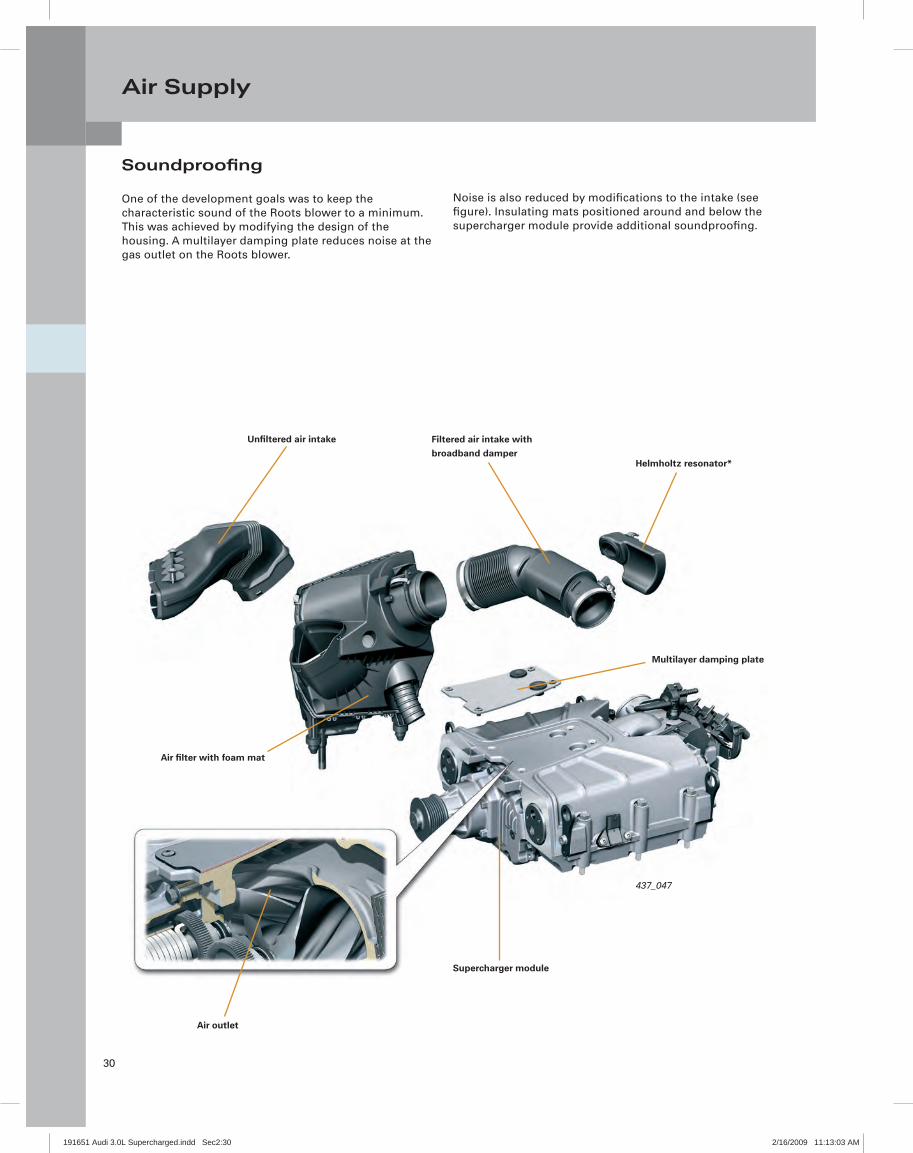
Soundproofi ng
One of the development goals was to keep the characteristic sound of the Roots blower to a minimum. This was achieved by modifying the design of the housing. A multilayer damping plate reduces noise at the gas outlet on the Roots blower.
Noise is also reduced by modifi cations to the intake (see fi gure). Insulating mats positioned around and below the supercharger module provide additional soundproofi ng.
437_047
Supercharger module
Air outlet
Air fi lter with foam mat
Multilayer damping plate
Unfi ltered air intake Filtered air intake withbroadband damper
Helmholtz resonator*
191651 Audi 3.0L Supercharged.indd Sec2:30191651 Audi 3.0L Supercharged.indd Sec2:30 2/16/2009 11:13:03 AM2/16/2009 11:13:03 AM

31
Air Supply
437_032
437_031
437_033
Insulating mats
Multiple insulating mats are positioned between the supercharger module and the cylinder head and block.
They direct the noise produced by the Roots blower downward. Two small insulating inserts are located on the back of the supercharger module (see adjacent fi gure).
Additional insulating mats are located below the supercharger module inside the V shaped area between the cylinder banks.
A larger mat is positioned between the two intake manifolds, and there are two narrower insulating mats at the sides between the intake manifolds and the cylinder heads.
The adjacent fi gure shows the insulating mats installed between the supercharger module and the cylinder head or block.
191651 Audi 3.0L Supercharged.indd Sec2:31191651 Audi 3.0L Supercharged.indd Sec2:31 2/16/2009 11:13:05 AM2/16/2009 11:13:05 AM

32
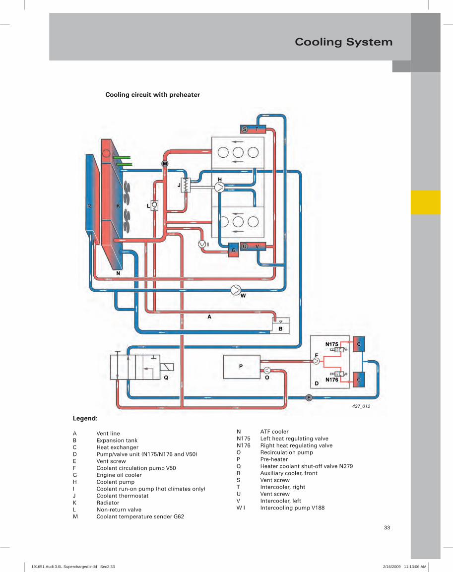
Cooling System
Cooling circuit
There are two different types of cooling circuits for the Audi A6 with the 3.0l V6 TFSI engine (they are market dependent).
The adjacent fi gure shows a version with preheater and after run coolant pump V51 (for super-hot climates, PR No.: 8z9).
Another electrically driven coolant pump is the charge air cooling pump V188, which is used in the low temperature circuit of the intercooler.
However, both circuits are interconnected and share a common coolant expansion tank.
Note
Please refer to the instructions for fi lling and venting the coolant system in the relevant service literature.
437_013
Cooling circuit without preheater
191651 Audi 3.0L Supercharged.indd Sec2:32191651 Audi 3.0L Supercharged.indd Sec2:32 2/16/2009 11:13:05 AM2/16/2009 11:13:05 AM
33
Cooling System
Cooling circuit with preheater
437_012
Legend:
A Vent lineB Expansion tankC Heat exchangerD Pump/valve unit (N175/N176 and V50)E Vent screwF Coolant circulation pump V50G Engine oil coolerH Coolant pumpI Coolant run-on pump (hot climates only)J Coolant thermostatK RadiatorL Non-return valveM Coolant temperature sender G62
N ATF coolerN175 Left heat regulating valveN176 Right heat regulating valveO Recirculation pumpP Pre-heaterQ Heater coolant shut-off valve N279R Auxiliary cooler, frontS Vent screwT Intercooler, rightU Vent screwV Intercooler, leftW I Intercooling pump V188
191651 Audi 3.0L Supercharged.indd Sec2:33191651 Audi 3.0L Supercharged.indd Sec2:33 2/16/2009 11:13:06 AM2/16/2009 11:13:06 AM
34
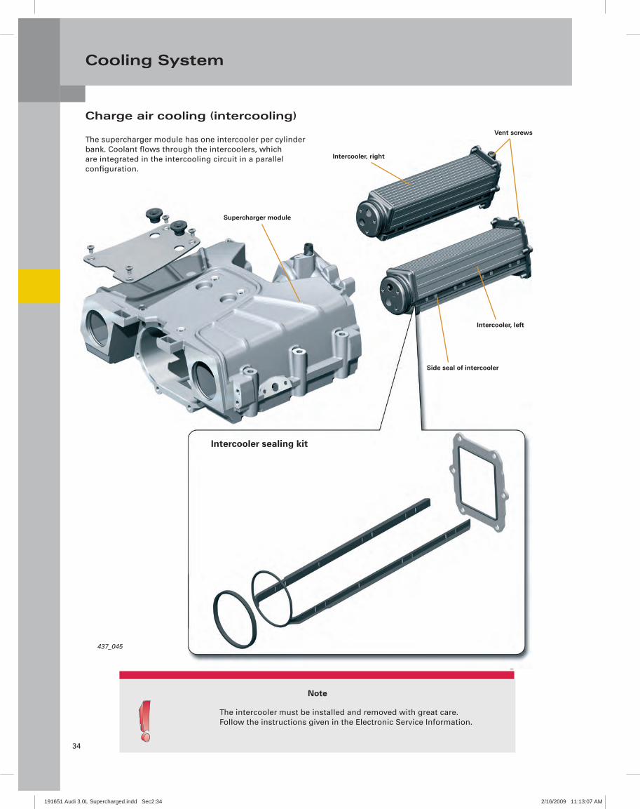
Cooling System
437_045
Note
The intercooler must be installed and removed with great care.Follow the instructions given in the Electronic Service Information.
Supercharger module
Intercooler, right
Vent screws
Intercooler, left
Side seal of intercooler
Intercooler sealing kit
Charge air cooling (intercooling)
The supercharger module has one intercooler per cylinder bank. Coolant fl ows through the intercoolers, which are integrated in the intercooling circuit in a parallel confi guration.
437_045
191651 Audi 3.0L Supercharged.indd Sec2:34191651 Audi 3.0L Supercharged.indd Sec2:34 2/16/2009 11:13:07 AM2/16/2009 11:13:07 AM

35
Cooling System
Intercooling circuit
The intercooling circuit is a cooling circuit which is separate from the main cooling circuit. However, both circuits are interconnected and share a common coolant expansion tank.
The temperature level within the intercooling circuit is usually lower than within the primary circuit.
Vent screw
Intercooler, left
Coolant return linefrom right intercooler
Supercharger module
Coolant return line
Coolant supply
437_046
Intercooling radiatorCharge air cooling pump V188
191651 Audi 3.0L Supercharged.indd Sec2:35191651 Audi 3.0L Supercharged.indd Sec2:35 2/16/2009 11:13:07 AM2/16/2009 11:13:07 AM
36
Cooling System
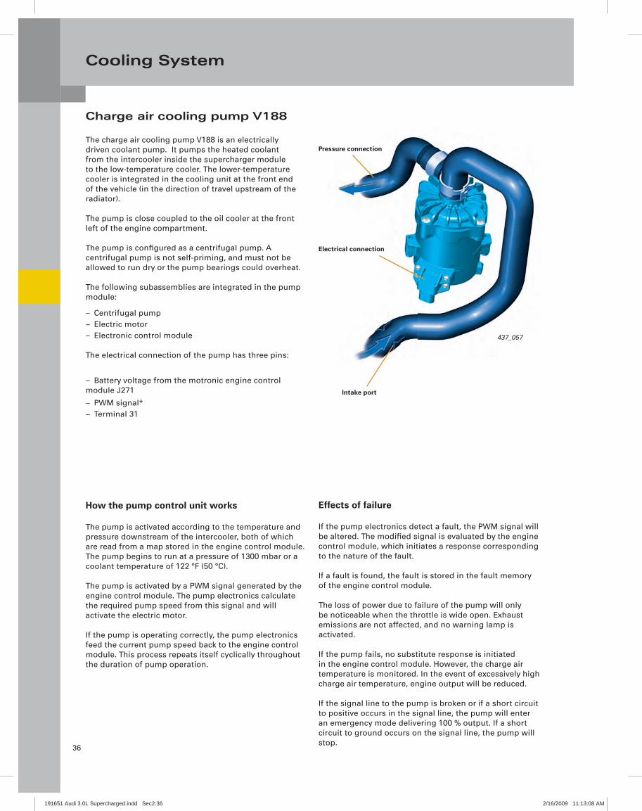
Intake port
437_057
Electrical connection
Pressure connection
Charge air cooling pump V188
The charge air cooling pump V188 is an electrically driven coolant pump. It pumps the heated coolant from the intercooler inside the supercharger module to the low-temperature cooler. The lower-temperature cooler is integrated in the cooling unit at the front end of the vehicle (in the direction of travel upstream of the radiator).
The pump is close coupled to the oil cooler at the front left of the engine compartment.
The pump is confi gured as a centrifugal pump. A centrifugal pump is not self-priming, and must not be allowed to run dry or the pump bearings could overheat.
The following subassemblies are integrated in the pump module:
Centrifugal pump –Electric motor –Electronic control module –
The electrical connection of the pump has three pins:
Battery voltage from the motronic engine control –module J271
PWM signal* –Terminal 31 –
How the pump control unit works
The pump is activated according to the temperature and pressure downstream of the intercooler, both of which are read from a map stored in the engine control module. The pump begins to run at a pressure of 1300 mbar or a coolant temperature of 122 °F (50 °C).
The pump is activated by a PWM signal generated by the engine control module. The pump electronics calculate the required pump speed from this signal and will activate the electric motor.
If the pump is operating correctly, the pump electronics feed the current pump speed back to the engine control module. This process repeats itself cyclically throughout the duration of pump operation.
Effects of failure
If the pump electronics detect a fault, the PWM signal will be altered. The modifi ed signal is evaluated by the engine control module, which initiates a response corresponding to the nature of the fault.
If a fault is found, the fault is stored in the fault memory of the engine control module.
The loss of power due to failure of the pump will only be noticeable when the throttle is wide open. Exhaust emissions are not affected, and no warning lamp is activated.
If the pump fails, no substitute response is initiated in the engine control module. However, the charge air temperature is monitored. In the event of excessively high charge air temperature, engine output will be reduced.
If the signal line to the pump is broken or if a short circuit to positive occurs in the signal line, the pump will enter an emergency mode delivering 100 % output. If a short circuit to ground occurs on the signal line, the pump will stop.
191651 Audi 3.0L Supercharged.indd Sec2:36191651 Audi 3.0L Supercharged.indd Sec2:36 2/16/2009 11:13:08 AM2/16/2009 11:13:08 AM
37
Cooling System
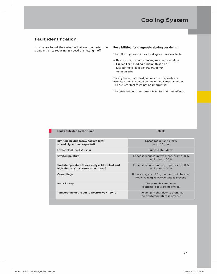
Fault identifi cation
If faults are found, the system will attempt to protect the pump either by reducing its speed or shutting it off.
Possibilities for diagnosis during servicing
The following possibilities for diagnosis are available:
Read out fault memory in engine control module –Guided Fault Finding function (test plan) –Measuring value block 109 (Audi A6) –Actuator test –
During the actuator test, various pump speeds are activated and evaluated by the engine control module. The actuator test must not be interrupted.
The table below shows possible faults and their effects.
Faults detected by the pump Effects
Dry-running due to low coolant level (speed higher than expected)
Speed reduction to 80 % (max. 15 min)
Low coolant level >15 min Pump is shut down
Overtemperature Speed is reduced in two steps, first to 80 % and then to 50 %
Undertemperature (excessively cold coolant and high viscosity* increase current draw)
Speed is reduced in two steps, first to 80 % and then to 50 %
Overvoltage If the voltage is > 20 V, the pump will be shut down as long as overvoltage is present.
Rotor lockup The pump is shut down.It attempts to work itself free.
Temperature of the pump electronics > 160 °C The pump is shut down as long as the overtemperature is present.
191651 Audi 3.0L Supercharged.indd Sec2:37191651 Audi 3.0L Supercharged.indd Sec2:37 2/16/2009 11:13:09 AM2/16/2009 11:13:09 AM

38
Exhaust Emission Treatment
Secondary air system
A secondary air system is used to ensure compliance with the EU V and ULEV II exhaust emission standards.
It facilitates rapid heating of the catalytic converters and reduces exhaust emissions by injecting air into the exhaust line downstream of the exhaust valves for a defi ned period of time after the engine is cold-started.
The unburned hydrocarbons and carbon monoxide contained in the exhaust gas or accumulated in the catalytic converter will then react with the oxygen in the air. Due to the heat released in this process, the catalytic converter reaches its light-off temperature*more quickly.
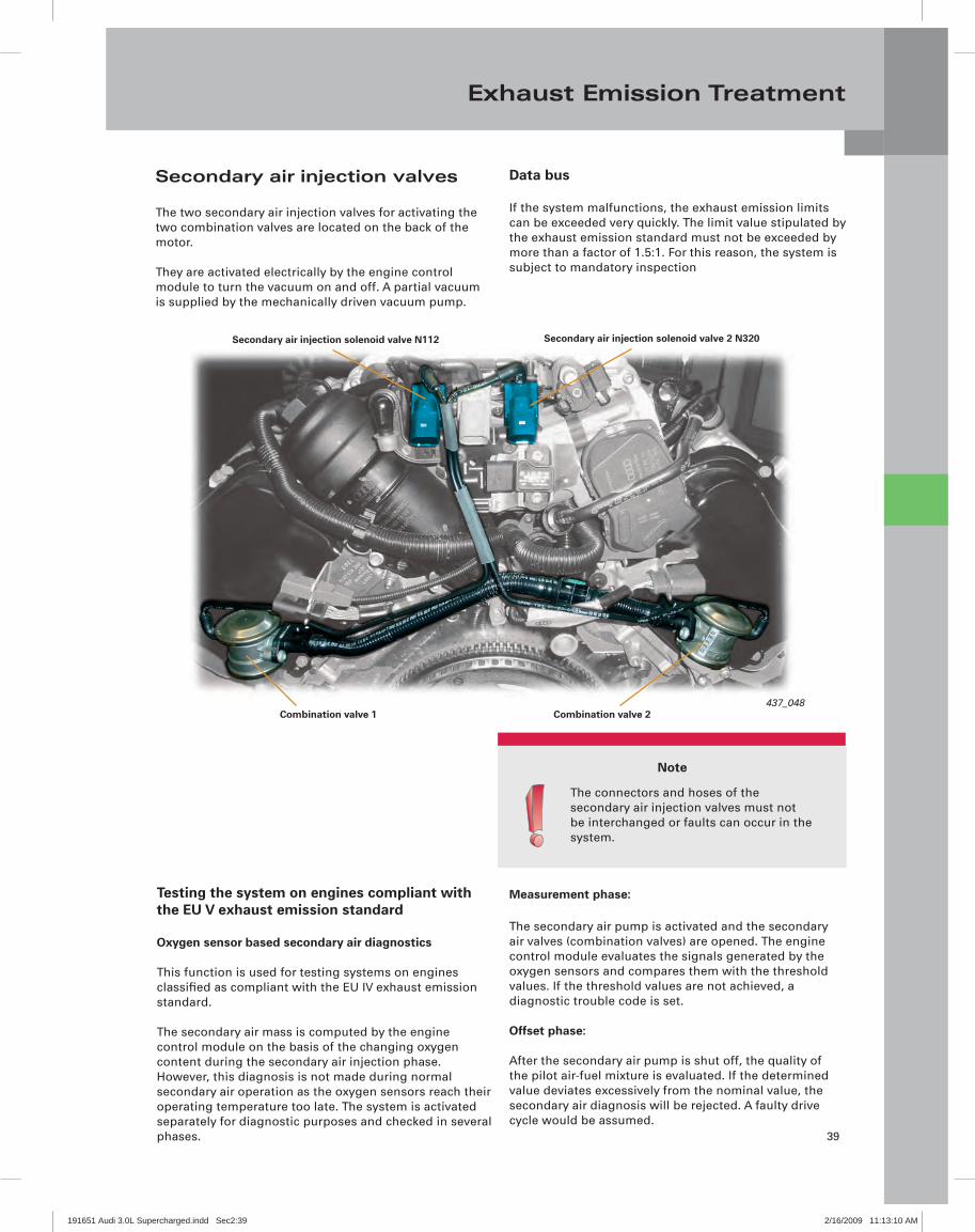
Secondary air injection pump motor V101
437_069
Combination valve 2
Secondary air injection valve 1+2
Combination valve 1
Differences to previously used systems:
The system uses two electrical changeover valves –to comply with the EU V exhaust emission standard. Previously, both combination valves were activated by a secondary air injection solenoid valve N112
The system that is used to comply with the ULEV II –exhaust emission standard also has a pressure sensor - the G609. It is integrated at the branch in the secondary air line to the cylinder banks.
191651 Audi 3.0L Supercharged.indd Sec2:38191651 Audi 3.0L Supercharged.indd Sec2:38 2/16/2009 11:13:09 AM2/16/2009 11:13:09 AM
39
Exhaust Emission Treatment
Note
The connectors and hoses of the secondary air injection valves must not be interchanged or faults can occur in the system.
Testing the system on engines compliant with the EU V exhaust emission standard
Oxygen sensor based secondary air diagnostics
This function is used for testing systems on engines classifi ed as compliant with the EU IV exhaust emission standard.
The secondary air mass is computed by the engine control module on the basis of the changing oxygen content during the secondary air injection phase. However, this diagnosis is not made during normal secondary air operation as the oxygen sensors reach their operating temperature too late. The system is activated separately for diagnostic purposes and checked in several phases.
Measurement phase:
The secondary air pump is activated and the secondary air valves (combination valves) are opened. The engine control module evaluates the signals generated by the oxygen sensors and compares them with the threshold values. If the threshold values are not achieved, a diagnostic trouble code is set.
Offset phase:
After the secondary air pump is shut off, the quality of the pilot air-fuel mixture is evaluated. If the determined value deviates excessively from the nominal value, the secondary air diagnosis will be rejected. A faulty drive cycle would be assumed.
Secondary air injection valves
The two secondary air injection valves for activating the two combination valves are located on the back of the motor.
They are activated electrically by the engine control module to turn the vacuum on and off. A partial vacuum is supplied by the mechanically driven vacuum pump.
Data bus
If the system malfunctions, the exhaust emission limits can be exceeded very quickly. The limit value stipulated by the exhaust emission standard must not be exceeded by more than a factor of 1.5:1. For this reason, the system is subject to mandatory inspection
Combination valve 1437_048
Combination valve 2
Secondary air injection solenoid valve N112 Secondary air injection solenoid valve 2 N320
191651 Audi 3.0L Supercharged.indd Sec2:39191651 Audi 3.0L Supercharged.indd Sec2:39 2/16/2009 11:13:10 AM2/16/2009 11:13:10 AM

40
Exhaust Emission Treatment
Testing the system on engines compliant with the ULEV exhaust emission standard (North America)
The California Air Resource Board (CARB) requires that the secondary air system be tested during the heat-up phase of the catalytic converter. However, the oxygen sensors do not reach their operating temperature fast enough for this purpose. This is why a pressure sensor (secondary air injection sensor -1 G609) is used for making the diagnosis. The "pressure based secondary air diagnostics" function is used.
In this system, the signal from G609 is evaluated inthe engine control module. The injected air quantity is determined from the pressure level. Restricted fl ow, e.g. ingress of dirt into the system downstream of the pressure sensor, causes the pressure level to increase. Restricted fl ow upstream of the pressure sensor or a leak in the system will cause the pressure level to decrease.
The pressure based secondary air diagnosis process
Phase 0The control unit is initialized at "ignition On". The signal from the secondary air injection sensor -1 G609 is saved and compared with the signals generated by the ambient pressure sensor and the intake manifold pressure sensor.
Phase 1When the secondary air mass is injected, the pressure in the secondary air system also increases (to approx. 90 mbar). The rise in pressure is determined by secondary air injection sensor -1 G609. The analog signal generated by G609 is evaluated by the engine control module. If it exceeds the set limit value (ex. due to a blockage in the system or a leak), a fault will be generated. If a fault repeats itself, the engine electronics warning lamp will be activated. If no fault occurs during phase 1, the diagnostic process is continued.
Phases 2.1 and 2.2During these two phases, a secondary air valve (combination valve) is opened and the other valve closed alternately for a short period of time. The values are compared with the value saved in phase 0. Blockages or leaks can be determined for each cylinder bank. Even leaks downstream of the combination valves can be identifi ed from the pressure amplitudes.
Phase 2During this phase, both combination valves are closed and checked for leaks. This allows evaluation of the secondary air injection sensor -1 G609 value.
Phase 3The secondary air pump is shut off and both combination valves are closed. The difference between the actual measured pressure and the stored value determined in phase 0 is evaluated. A faulty secondary air pump (does not shut off) or faulty secondary air injection sensor -1- G609 can be detected.
191651 Audi 3.0L Supercharged.indd Sec2:40191651 Audi 3.0L Supercharged.indd Sec2:40 2/16/2009 11:13:11 AM2/16/2009 11:13:11 AM

41
Exhaust Emission Treatment
1
2
3
5
6
7
8
4
0 1 2.1 2.2 2 3
1
2
3
5
6
Blockage (restricted flow)
Reduced pumping capacity or a blockage upstream of secondary air pressure sender -1 G609
Secondary air pump running (does not shut off)
Combination valve 1 open
Faulty pressure sensor
Secondary air pump running
Combination valve 2 open
Pres
sure
dif
fere
nce
Time
Phases of the secondary air diagnosis process
Phase
Cyl
ind
er b
ank
1
Cyl
ind
er b
ank
2
4 Faulty pressure sensor
7
8
191651 Audi 3.0L Supercharged.indd Sec2:41191651 Audi 3.0L Supercharged.indd Sec2:41 2/16/2009 11:13:11 AM2/16/2009 11:13:11 AM

42
Fuel System
Overview
Like the 3.2l V6 FSI engine with Audi valvelift system, the 3.0l V6 TFSI engine uses a supply-on-demand fuel system.
Fuel pump controlmodule J538
437_058
Fuel pump G6GroundBattery
(positive)
To enginecontrol module
Fuel fi lter
Depressurized
Injectors1, 3, 5N30, N32, N83
Injectors2, 4, 6N31, N33, N84
Fuel pressuresensor G247
Fuel metering valveN290
Low fuel pressure sensor G410
High pressure
Low pressure
High-pressure fuel pump
A 3rd generation pump is used as the fuel pump. The high-pressure fuel pump is manufactured by Hitachi.
437_059
191651 Audi 3.0L Supercharged.indd Sec2:42191651 Audi 3.0L Supercharged.indd Sec2:42 2/16/2009 11:13:11 AM2/16/2009 11:13:11 AM
43
Fuel System
437_024
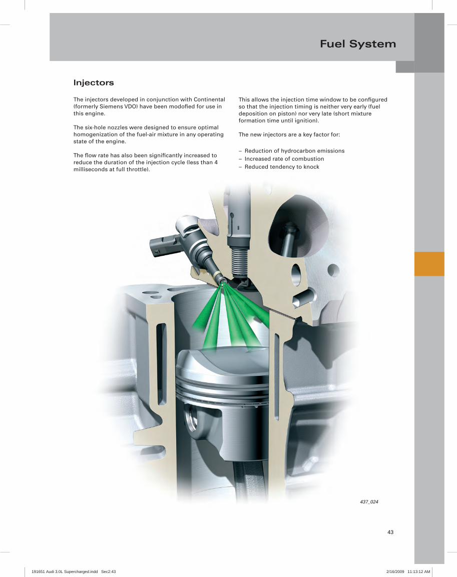
Injectors
The injectors developed in conjunction with Continental (formerly Siemens VDO) have been modofi ed for use in this engine.
The six-hole nozzles were designed to ensure optimal homogenization of the fuel-air mixture in any operating state of the engine.
The fl ow rate has also been signifi cantly increased to reduce the duration of the injection cycle (less than 4 milliseconds at full throttle).
This allows the injection time window to be confi gured so that the injection timing is neither very early (fuel deposition on piston) nor very late (short mixture formation time until ignition).
The new injectors are a key factor for:
Reduction of hydrocarbon emissions –Increased rate of combustion –Reduced tendency to knock –
191651 Audi 3.0L Supercharged.indd Sec2:43191651 Audi 3.0L Supercharged.indd Sec2:43 2/16/2009 11:13:12 AM2/16/2009 11:13:12 AM

44
Engine Management
OutpEngintransJ217(vehigearb
System overview (Audi A6 of model year 2009)
Sensors
Secondary air injection sensor -1 G609(for ULEV vehicles only)
Powertrain CAN data bus
Manifold absolute pressure sensor G71Intake air temperature sensor G42
Auxiliary signals:J393 Comfort system central control moduleE45 Cruise control switchJ364 Auxiliary heater control moduleJ695 Starter relay 2J53 Starter relayJ518 Access/start authorization control module
Engine control module J623
Heated oxygen sensor G39G108 (bank 2)Oxygen sensor behind three-way catalytic converter G130G131 (bank 2)
Intake manifold runner position sensor G336 (bank 1)Intake manifold runner position sensor 2 G512 (bank 2)
Engine coolant temperature sensor G62
Reduced oil pressure switch F378
Oil pressure switch F22
Fuel gauge sensor GFuel level sensor -2- G169
Knock sensor G61 (bank 1)Knock sensor G66 (bank 2)
Fuel pressure sensor G247Low fuel pressure sensor G410
Brake light switch F
Throttle position sensor G79Accelerator pedal position sensor 2 G185Clutch position sensor G476
Camshaft position sensor G40 (intake, bank 1)Camshaft position sensor 2 G163 (intake, bank 2)Camshaft position sensor 3 G300 (exhaust, bank 1)Camshaft position sensor 4 G301 (exhaust, bank 2)
Control valve control module J808Control valve position sensor G584
Throttle valve control module J338Throttle drive angle sensor G188, G187
Engine speed sensor G28
Charge air pressure sensor G31, G447Intake air temperature sensor G72, G430
191651 Audi 3.0L Supercharged.indd Sec2:44191651 Audi 3.0L Supercharged.indd Sec2:44 2/16/2009 11:13:13 AM2/16/2009 11:13:13 AM
45
Engine Management
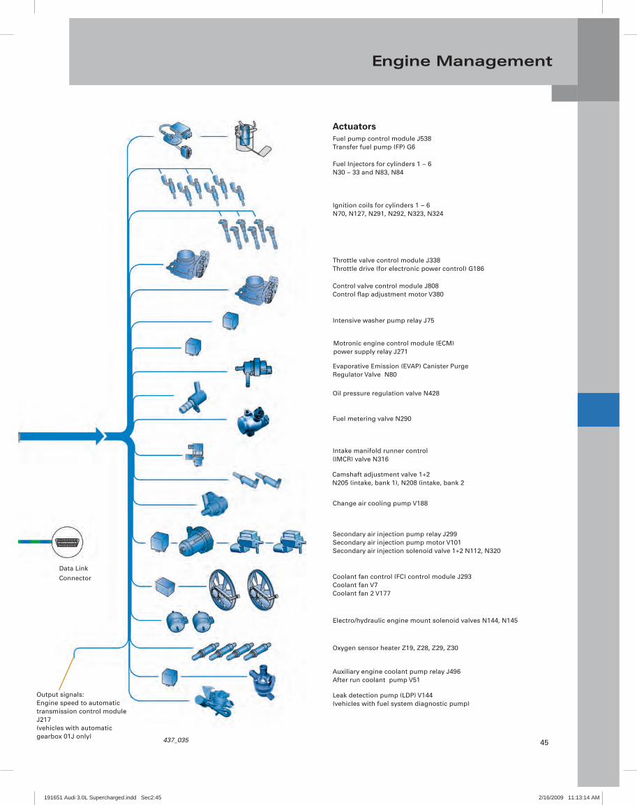
Actuators
Output signals:Engine speed to automatictransmission control module J217(vehicles with automaticgearbox 01J only)
Data Link Connector
437_035
Leak detection pump (LDP) V144(vehicles with fuel system diagnostic pump)
Auxiliary engine coolant pump relay J496After run coolant pump V51
Oxygen sensor heater Z19, Z28, Z29, Z30
Electro/hydraulic engine mount solenoid valves N144, N145
Coolant fan control (FC) control module J293Coolant fan V7Coolant fan 2 V177
Secondary air injection pump relay J299Secondary air injection pump motor V101Secondary air injection solenoid valve 1+2 N112, N320
Change air cooling pump V188
Camshaft adjustment valve 1+2 N205 (intake, bank 1), N208 (intake, bank 2
Intake manifold runner control (IMCR) valve N316
Fuel metering valve N290
Oil pressure regulation valve N428
Evaporative Emission (EVAP) Canister Purge Regulator Valve N80
Motronic engine control module (ECM) power supply relay J271
Intensive washer pump relay J75
Control valve control module J808Control fl ap adjustment motor V380
Throttle valve control module J338Throttle drive (for electronic power control) G186
Ignition coils for cylinders 1 – 6N70, N127, N291, N292, N323, N324
Fuel Injectors for cylinders 1 – 6N30 – 33 and N83, N84
Fuel pump control module J538Transfer fuel pump (FP) G6
191651 Audi 3.0L Supercharged.indd Sec2:45191651 Audi 3.0L Supercharged.indd Sec2:45 2/16/2009 11:13:14 AM2/16/2009 11:13:14 AM

46
Engine Management
Engine control module
The Simos 8 engine control module, jointly developed with Audi and Continental (formerly Siemens VDO) is used with this engine.
Operating modes
The FSI injection process is confi gured for homogeneous mixture formation.
The complete fuel charge is injected into the combustion chamber during the intake phase.
This does not include the engine start and warm-up phases, during which the following operating modes are used.
437_056
2. Cold start/warm-up phase
During this phase, a dual injection or homogeneous split (HOSP) mode is used.
The total quantity of fuel to be injected is divided into two partial quantities and injected into the combustion chamber at different times. The injection time window is before and after the bottom dead center position of the piston. By the second injection, the intake valves are already closed.
HOSP mode is used in two applications:
– The fi rst application is the “cold start” and is always used. It serves to heat up the catalytic converters and takes place at coolant temperatures between 19°F (-7 °C) and 113°F (45 °C).
– The second application is the “warm-up”, which is only used under heavy engine load when the driver requests a high engine output. It serves to optimize engine load and speed, but also to reduce soot emission. The temperature range for this application is between -4°F (-20 °C) and 113°F (45 °C). In this case, the second injection is later than in the cold start phase.
1. Engine start
During starting, a high-pressure stratifi ed start mode is used.
For this purpose, the fuel pressure is increased to 45 – 100 bar. The fuel pressure level is dependent on the engine temperature. At low temperatures, the fuel pressure is higher.
High-pressure stratifi ed starting takes place at coolant temperatures between -11°F (-24 °C) and at operating temperature 194° F (90 °C).
At coolant temperatures below -11°F (-24 °C), starting takes place at low pressure to protect the components. The pressure is identical to the pressure in the electrical fuel pump in the fuel tank.
During the development process, special emphasis was placed on throttle-free load regulation (refer to “Load regulation”).
191651 Audi 3.0L Supercharged.indd Sec2:46191651 Audi 3.0L Supercharged.indd Sec2:46 2/16/2009 11:13:14 AM2/16/2009 11:13:14 AM
47
Engine Management
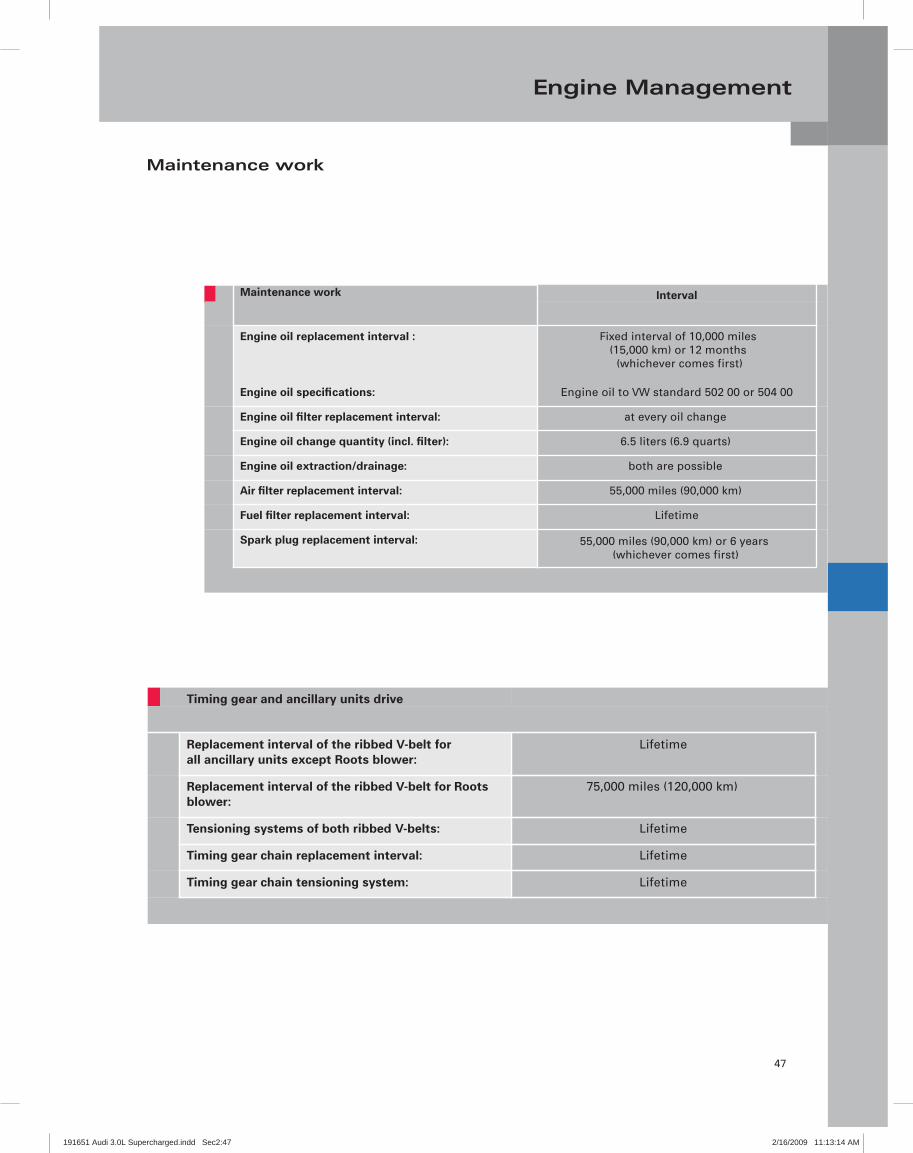
Maintenance work
Timing gear and ancillary units drive
Replacement interval of the ribbed V-belt for all ancillary units except Roots blower:
Lifetime
Replacement interval of the ribbed V-belt for Roots blower:
75,000 miles (120,000 km)
Tensioning systems of both ribbed V-belts: Lifetime
Timing gear chain replacement interval: Lifetime
Timing gear chain tensioning system: Lifetime
Maintenance work Interval
Engine oil replacement interval :
Engine oil specifications:
Fixed interval of 10,000 miles (15,000 km) or 12 months
(whichever comes first)
Engine oil to VW standard 502 00 or 504 00
Engine oil filter replacement interval: at every oil change
Engine oil change quantity (incl. filter): 6.5 liters (6.9 quarts)
Engine oil extraction/drainage: both are possible
Air filter replacement interval: 55,000 miles (90,000 km)
Fuel filter replacement interval: Lifetime
Spark plug replacement interval: 55,000 miles (90,000 km) or 6 years (whichever comes first)
191651 Audi 3.0L Supercharged.indd Sec2:47191651 Audi 3.0L Supercharged.indd Sec2:47 2/16/2009 11:13:14 AM2/16/2009 11:13:14 AM
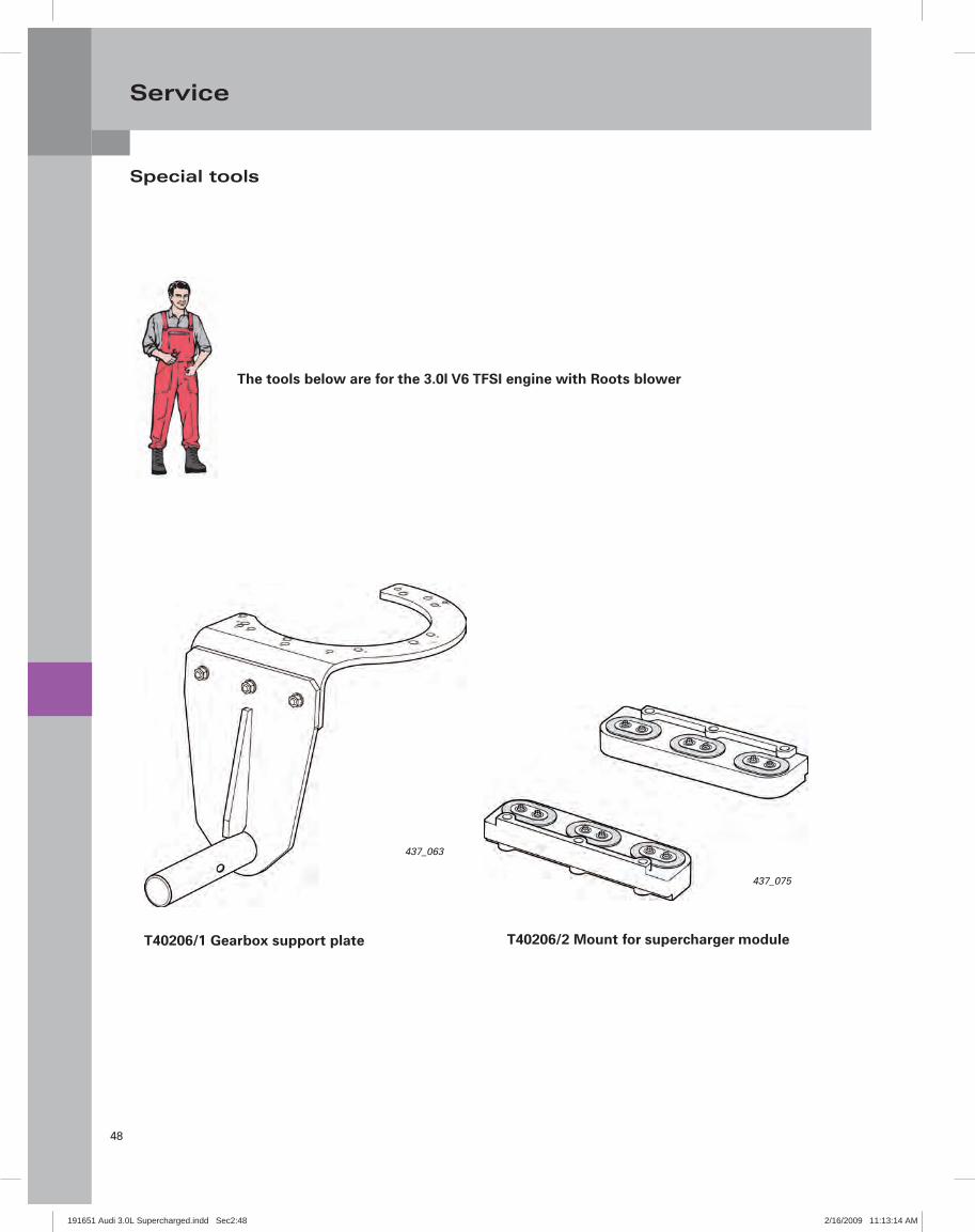
48
Service
Special tools
The tools below are for the 3.0l V6 TFSI engine with Roots blower
437_063
437_075
T40206/1 Gearbox support plate T40206/2 Mount for supercharger module
191651 Audi 3.0L Supercharged.indd Sec2:48191651 Audi 3.0L Supercharged.indd Sec2:48 2/16/2009 11:13:14 AM2/16/2009 11:13:14 AM
49
Glossary
Glossary
This glossary explains to you all terms written in italics or indicated by an asterisk (*) in this Self-StudyProgram
Blow-by gases
Blow-by gases are also known as leakage gases. When the engine running, blow-by gases fl ow from the combustion chamber and past the piston into the crankcase. This is due to the high pressure inside the combustion chamber and the absolutely normal leakage that occurs around the piston rings. Blow-by gases are extracted from the crankcase by the PCV system and re-introduced into the combustion chamber.
Light-off temperature
The temperature at which the conversion rate of the catalytic converter is 50 %. The light-off temperature is highly relevant to future and current US exhaust emission standards, as they require low emissions even when the engine is cold.
Cracked con-rod
This name derives from the manufacturing process. In this process the con-rod shaft and the big end bearing cover are separated from one another by breaking (cracking) them at a pre-determined point. The advantage of this process is that the fi nished parts fi t one another perfectly.
PWM signalThe abbreviation PWM stands for Pulse Width Modulated signal. A PWM signal is a digital signal where one variable (e.g. electrical current) alternates between two values.
The length of the interval between this change-over varies depending on activation level. In this way, it is possible to transmit digital signals.
EMC
This abbreviation stands for Electromagnetic Compatibility. It is defi ned as the ability of electrical and electronic equipment to operate effectively in close proximity without causing mutual interference through unwanted electrical or electromagnetic effects.
Split-pin design
Depending on engine type, the crank pin has an offset (also referred to as split pin) due to the V angle or cylinder bank angle. This confi guration is necessary to achieve a uniform fi ring interval.
Hall sender
The Hall sender (also known as Hall sensor or Hall probe) utilises the Hall effect to measure magnetic fi elds and currents, and for position sensing. If a Hall sensor is energised with electrical current and placed into a vertical magnetic fi eld, it will supply an output voltage proportional to the product of the magnetic fi eld strength and the electrical current.
Valve timing
The term "valve timing" is used to describe the periods during which the valves of an engine are opened or closed. If the angular ranges of the valves are transferred to a pie chart, the result will be the timing diagram of an engine.
Helmholtz resonator
A Helmholtz resonator is an acoustic resonator designed to reduce intake noise. It consists of an air space with a narrow opening to the exterior. The Helmholtz resonator was named after the German physicist Hermann von Helmholtz.
Viscosity
An important physical property of liquids is their viscosity. Viscosity is temperature dependent and is a measure of how "thick" a liquid is at different temperatures. The viscosity of oils is specifi ed as a viscosity index.
This index describes the fl ow behavior of an oil at different temperatures.
191651 Audi 3.0L Supercharged.indd Sec2:49191651 Audi 3.0L Supercharged.indd Sec2:49 2/16/2009 11:13:15 AM2/16/2009 11:13:15 AM

50
Summary
From the glorious 1930s tradition of motor sport dominated by cars bearing the four-ring badge, the Roots blower is now staging a comeback. The new 3.0l TFSI engine is powerful, extremely quick and ultra-effi cient. It is also the new top version in Audi's V6 engine range, and sets impressive benchmarks for fuel economy and clean emissions. The engine is notable for its sporty throttle response, exceptional agility and "bite". It revs up to its 6,500 rpm maximum with playful ease, achieving its rated output of 285 hp at just under 5,000 rpm.
All this has been achieved thanks to an array of refi ned high-tech features. The crankcase has been adapted to the higher prevailing pressures, and all components have been systematically optimized for minimal friction. Both intake camshafts can be adjusted through 42° of crankshaft angle. In the intake ports, tumble fl aps induce a tumbling movement in the incoming air to optimize mixture formation.
The improved fuel system with its new six-hole nozzles have a capability of up to three injections per stroke for future applications. The engine's high compression ratio of 10.5:1 is also a major factor in enhancing effi ciency. The direct injection principle is once again the key, because the intensively swirled fuel cools the combustion chamber, reducing the tendency to knock. Inside the Roots blower, two four-vane rotary pistons counter-rotate at a speed of up to 23,000 rpm, delivering 2204 lbs (1,000 kg) of air per hour and forcing it into the combustion chambers at a boost pressure of up to 0.8 bar. Two water-to-air intercoolers integrated in the supercharger module enhance effi ciency still further, and much work went in to reducing the noise transmitted by the roots blower.
The new 3.0l TFSI engine will achieve an average fuel consumption of well under 23 MPG in virtually all Audi models with longitudinal engines for which it has been earmarked. As with all Audi innovations, the engine fully embraces the principle of "Vorsprung durch Technik".
191651 Audi 3.0L Supercharged.indd Sec2:50191651 Audi 3.0L Supercharged.indd Sec2:50 2/16/2009 11:13:15 AM2/16/2009 11:13:15 AM

51
Notes
191651 Audi 3.0L Supercharged.indd Sec2:51191651 Audi 3.0L Supercharged.indd Sec2:51 2/16/2009 11:13:15 AM2/16/2009 11:13:15 AM

52
Notes
191651 Audi 3.0L Supercharged.indd Sec2:52191651 Audi 3.0L Supercharged.indd Sec2:52 2/16/2009 11:13:17 AM2/16/2009 11:13:17 AM

Knowledge Assessment
From the accessaudi.com Homepage:– Click on the “ACADEMY” Tab.– Click on the “Academy Site” Link.– Click on the “CRC Certification” Link.
An on-line Knowledge Assessment (exam) is available for this Self-Study Program.The Knowledge Assessment may or may not be required for Certification.
You can find this Knowledge Assessment at:www.accessaudi.com
Audi AcademyCertification Resource Center (CRC)
1-877-283-4562(8:00 a.m. to 8:00 p.m. EST)
For Assistance, please call:

925803
All rights reserved. Technical specifications subject to change without notice.
Audi of America, LLC2200 Ferdinand Porsche Drive Herndon, VA 20171