
SatKing Promax user Manual V6.pdf
21
User’s manual ver 6.0 ly Automatic Automatic torised Satellite TV System orised Satellite TV Syste torised Satellite TV Syst ed Satellite TV Syst sed Satellite TV Syste torised Sate te TV System Fully Automatic Motorised Satellite TV System www.satkingpromax.com.au Customer Help Line: 1300 139 255 Support Email: [email protected] Website: www.satkingpromax.com.au Your PRO MAX's Serial Number
-
Upload
khangminh22 -
Category
Documents
-
view
0 -
download
0
Transcript of SatKing Promax user Manual V6.pdf
User’s manual
ver 6.0
ly AutomaticAutomatictorised Satellite TV Systemorised Satellite TV Systetorised Satellite TV Systed Satellite TV Systsed Satellite TV Systetorised Sate te TV System
Fully AutomaticMotorised Satellite TV System
www.satkingpromax.com.au
Customer Help Line: 1300 139 255
Support Email: [email protected]
Website: www.satkingpromax.com.au
Your PRO MAX's Serial Number
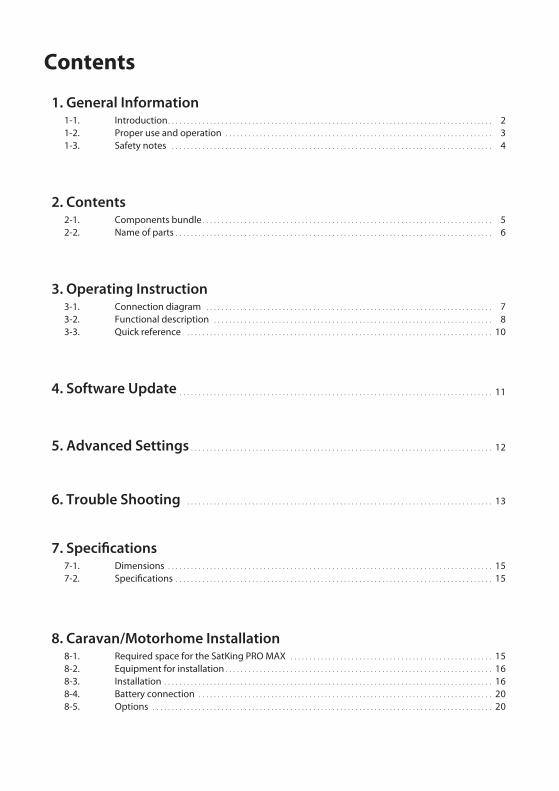
Contents
1. General Information. . . . . . . . . . . . . . . . . . . . . . . . . . . . . . . . . . . . . . . . . . . . . . . . . . . . . . . . . . . . . . . . . . . . . . . . . . . . . . . . . . . . .
. . . . . . . . . . . . . . . . . . . . . . . . . . . . . . . . . . . . . . . . . . . . . . . . . . . . . . . . . . . . . . . . . . . . . .
. . . . . . . . . . . . . . . . . . . . . . . . . . . . . . . . . . . . . . . . . . . . . . . . . . . . . . . . . . . . . . . . . . . . . . . . . . . . . . . . . . . .
1-1.1-2.1-3.
234
Introduction Proper use and operationSafety notes
2. Contents. . . . . . . . . . . . . . . . . . . . . . . . . . . . . . . . . . . . . . . . . . . . . . . . . . . . . . . . . . . . . . . . . . . . . . . . . . . .
. . . . . . . . . . . . . . . . . . . . . . . . . . . . . . . . . . . . . . . . . . . . . . . . . . . . . . . . . . . . . . . . . . . . . . . . . . . . . . . . . . .
2-1.2-2.
56
Components bundleName of parts
3. Operating Instruction . . . . . . . . . . . . . . . . . . . . . . . . . . . . . . . . . . . . . . . . . . . . . . . . . . . . . . . . . . . . . . . . . . . . . . . . . . .
. . . . . . . . . . . . . . . . . . . . . . . . . . . . . . . . . . . . . . . . . . . . . . . . . . . . . . . . . . . . . . . . . . . . . . . . .
. . . . . . . . . . . . . . . . . . . . . . . . . . . . . . . . . . . . . . . . . . . . . . . . . . . . . . . . . . . . . . . . . . . . . . . . . . . . . . . .
3-1.3-2.3-3.
78
10
Connection diagram Functional description Quick reference
4. Software Update . . . . . . . . . . . . . . . . . . . . . . . . . . . . . . . . . . . . . . . . . . . . . . . . . . . . . . . . . . . . . . . . . . . . . . . . . . . . . . . . . . 11
5. Advanced Settings . . . . . . . . . . . . . . . . . . . . . . . . . . . . . . . . . . . . . . . . . . . . . . . . . . . . . . . . . . . . . . . . . . . . . . . . . . . . . . . 12
6. Trouble Shooting . . . . . . . . . . . . . . . . . . . . . . . . . . . . . . . . . . . . . . . . . . . . . . . . . . . . . . . . . . . . . . . . . . . . . . . . . . . . . . . . 13
7. Specifications. . . . . . . . . . . . . . . . . . . . . . . . . . . . . . . . . . . . . . . . . . . . . . . . . . . . . . . . . . . . . . . . . . . . . . . . . . . . . . . . . . . . .
. . . . . . . . . . . . . . . . . . . . . . . . . . . . . . . . . . . . . . . . . . . . . . . . . . . . . . . . . . . . . . . . . . . . . . . . . . . . . . . . . . .
7-1. 7-2.
1515
DimensionsSpecifications
8. Caravan/Motorhome Installation. . . . . . . . . . . . . . . . . . . . . . . . . . . . . . . . . . . . . . . . . . . . . . . . . . . . .
. . . . . . . . . . . . . . . . . . . . . . . . . . . . . . . . . . . . . . . . . . . . . . . . . . . . . . . . . . . . . . . . . . . . . .
. . . . . . . . . . . . . . . . . . . . . . . . . . . . . . . . . . . . . . . . . . . . . . . . . . . . . . . . . . . . . . . . . . . . . . . . . . . . . . . . . . . . . .
. . . . . . . . . . . . . . . . . . . . . . . . . . . . . . . . . . . . . . . . . . . . . . . . . . . . . . . . . . . . . . . . . . . . . . . . . . . . .
. . . . . . . . . . . . . . . . . . . . . . . . . . . . . . . . . . . . . . . . . . . . . . . . . . . . . . . . . . . . . . . . . . . . . . . . . . . . . . . . . . . . . . . . .
8-1. 8-2. 8-3. 8-4.8-5.
Required space for the SatKing PRO MAXEquipment for installationInstallationBattery connectionOptions
1516162020

SatKing PRO MAX User manual - 2
1. General Information
1-1. IntroductionThese instructions describe the functions and operation of the SatKing PRO MAX fully
automatic satellite system.
Correct and safe operation of the system can only be ensured by following these instructions.
Your SatKing PRO MAX is an intelligent satellite TV reception antenna system which can
align itself towards a preset satellite automatically when the system is located within the
footprint of the selected satellite. The latest Australian coverage map is available on
www.satkingpromax.com.au.
The SatKing PRO MAX only occupies a small amount of space to perform the necessary
adjustments with it's slim and agile antenna body.
For general operation, please ensure that the system always has a clear view of the Northern
Sky. If the satellite‘s signal beam is interrupted by obstacles such as buildings or trees, the
unit will not function and no satellite TV signal will be received, move your van slightly and
try again. For more information on general use of this unit consult your local dealer for
assistsance.

SatKing PRO MAX User manual - 3
It is not possible to add or remove components on this product.
The use of other components other than those originally supplied.
When completing Installation you or your contractor must strictly follow all instructions in the
supplied User Manual. Failure to follow the user manual may cause damage to the SatKing PRO MAX
or your vehicle.
The product does not require any regular maintenance; all service must be carried out at approved
service centre’s.
All relevant guidelines of the automotive industry must be observed and complied with.
The equipment must only be installed on solid vehicle roofs.
Avoid cleaning your vehicle with the mounted satellite system in a drive-through car wash or a car wash
with a high-pressure cleaner.
The SatKing PRO MAX comes with a 3 year warranty, for full warranty details please visit our website
www.satkingpromax.com.au
After Sales Support Line 1300 139 255 or [email protected]
If you are using VAST all card activation and channel entitlement issue's are handle by the VAST call
centre 1300 993 376. Their hours are 9am till 12pm and 2pm till 4.30pm QLD time.
•
•
•
•
•
•
•
•
•
•
Please also note the following instructions from SatKing:
1-2. Proper use and operationThis product has been designed for fixed installation on vehicles with maximum speeds of
130 km/h. It is designed to automatically aim an antenna at geostationary television satellites.
The power to the system is supplied by a standard vehicle electrical system with a rated
voltage of 12 or 24 Volts DC.
Use of the equipment for any other purpose to the one specified is not permitted.

SatKing PRO MAX User manual - 4
1-3. Safety notes
Please carefully read and follow the operating instructions in this
manual.
Upon installation of the PRO MAX, please ensure the installation is
done with supplied cables and ensure the controller cable is not
modified in anyway, this carries data.
As the user of this equipment, you are responsible for ensuring
compliance with the relevant laws and regulations.
The manufacturer does not take liability for direct or indirect
consequential damage of the system, motor vehicles or other
equipment by reason of incorrect battery usage, incorrect instal-
lation or wrong wiring connection.

SatKing PRO MAX User manual - 5
2. Contents
2-1. Components bundle
Main unit Mounting plate
Controller Controller bracket
Cable gland
Power input cable + (Red), - (Black)
Cable holder Receiver(labeled) cable - 7m(x2 for twin outputs)
Controller(labeled) cable - 7m
Deflector
M4x20 (11), M8 Self-lock nut Washer (4), Bushing (2)Spanner
GPS module User manual
Manual

SatKing PRO MAX User manual - 6
2-2. Name of parts
Main unit
Controller
POWER , Arrows , OK button
HOME LED
Communication LED
NID check LED
TP search LED
Error message LED
Antenna
LNB
Elevation : 5° ~ 90°
Main body : 390° Turning
Mounting plate
Base
to Receiver
to Controller
to Receiver
Bracket
GPS LED
LCD screen
Power port : DC 12~24V
HOME , MODE , SET , TUNE button
USB port : For F/W upgrade
to Main unit
Skew pivot :
-60° ~ +60°
Deflector
to GPS module
SatKing PRO MAX User manual - 7
Rece
iver
cab
le
RECEIVER
TV
Controller cable
GPS cable
Pow
er In
put C
able
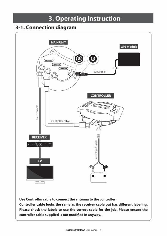
3. Operating Instruction
3-1. Connection diagram
Use Controller cable to connect the antenna to the controller.
Controller cable looks the same as the receiver cable but has different labeling.
Please check the labels to use the correct cable for the job. Please ensure the
controller cable supplied is not modified in anyway.
MAIN UNIT
GPS module
CONTROLLER

SatKing PRO MAX User manual - 8
3-2. Functional description
HOME position is when the antenna completely folded down and facing forward.
NOTE
The PRO MAX can still locate the satellite without the GPS locked.
NOTE
When the all cable connections are completed, press POWER to turn the unit on.
HOME LED will be solid this means the antenna is ready to go.
Communication LED will be solid when the unit is turned on.
(This light means antenna unit is communicating with controller correctly.)
If the antenna did not go back to the HOME position, the HOME LED will continue to flash while
antenna comes back to HOME. When the unit is ready, the default satellite “VAST” or the last selected
satellite will show on LCD screen of the controller.
i.
ii.
iii.
iv.
GPS LED flashes while searching for the current location. When GPS position is confirmed the LED
will become solid.
v.
Waiting until both HOME & GPS LED’s are solid is recommended as this will allow the PRO MAX to
find the selected satellite faster with more precise alignment accuracy.
If the searching operation starts before GPS becomes solid the GPS LED will continue to flash even
when the satellite is already locked. In this case, the PRO MAX may readjust the skew once its current
location is confirmed.
vi.
vii.
1. Get ready to use
POWER , Arrows , OK button
HOME LED
Communication LED
NID check LED
TP search LED
Error message LED
GPS LED
HOME , MODE , SET , TUNE button

SatKing PRO MAX User manual - 9
2. Selecting the satellite
If the antenna has found the satellite using TP data, the TP search LED will be illuminated along with NID LED.
Locking to the satellite with TP data, simply means that the Network ID may not have been available.
NOTE
There is an "Auto Fine Tune" built in simply press "OK" when "Sat Found" is displayed on the controller LCD panel.
If you require more signal quality follow the procedure below:
NOTE
i.
ii.
iii.
Select the satellite (ie VAST 156) you wish to view using the arrow buttons on the controller and press OK.
Network Identification (NID) check LED will flash and the antenna status will display “SEARCHING” and
then “CHECKING” will appear on LCD screen.
NID check LED will be solid once the satellite is found and then “SAT FOUND” will appear on the LCD.
iv. If you have selected the wrong satellite, move to the correct satellite name using arrows and press OK
to confirm new satellite.
v. Auto fine tuning, the unit does this automatically, you can also auto tune again by pressing OK once
"Sat Found" is on the LCD.
i.
ii.
iii.
3. Back to HOME position & Turning offAfter use and before travelling, press HOME to return the PRO MAX back to HOME position.
To fully turn off the unit, press HOME and then hold the POWER for 5 seconds.
If you will stay in your location for an extended period or wish to save power you can leave the unit
up by simply by pressing the POWER button and powering the unit off, the signal will still come
through to your satellite TV receiver.
FINE TUNE mode can be initialised when a selected satellite is found and you want to increase the
signal strength further.
i.
ii.
iii.
iv.
v.
4. Special function 1 : FINE TUNE mode
Press TUNE to start the FINE TUNE mode.
First TUNE is for AZ (Azimuth). Adjust antenna position using arrow buttons to find a new position
providng better signal quality and press OK to set.
The signal level will be displayed on the controller (Q ___ ) or your satellite receiver.
Repeat the same process of adjust the EL (Elevation) and SK (LNB skew).
To save new position of the satellite and exit, press the TUNE button.
Saved new position will be placed in the memory for your next turn on. But once your vehicle moves
or confirms new GPS location, the saved position will be reset.
For Manual GPS RESET of the last position memory, press SET once and go to YES and press OK.
Restart the PRO MAX to apply reset to your next operation.

SatKing PRO MAX User manual - 10
3-3. Quick Start Guide
When you physically move the SatKing PRO MAX, the unit should be returned to HOME position to prevent damage.
WARNING
SatKing PRO MAX will be automatically folded back to HOME position if vehicle moves faster than 10km/h for 2 minutes when the unit is powered.
NOTE
You may need to wait 30 seconds while the receiver smartcard updates.NOTE
Error message LED will be illuminated and the error message detail will be shown on LCD display, this will
detail if there is a problem with main unit. These can assist your dealer with trouble shooting.
i.
5. Special function 2 : ERROR MESSAGE
HOME POSITION errorIf antenna does not come back to HOME position within the allowed time or the system does not
recognise HOME position despite the antenna being back at HOME position (The Limit sensor is
faulty).
ii. TUNNER errorIf there is no response when searching the satellite due to a faulty tuner or its settings.
iii. MOVEMENT errorIf the PRO MAX cannot move to correct position. Check for something impeading the unit.
iv. COMMUNICATION errorIf connection is lost between the PRO MAX and controller. Check the controller cable.
v. Current errorIf one of the motors is jammed, remove power an try again.
TEST mode can be initialised when either an error message is shown or the antenna is at HOME position.
i.
ii.
iii.
6. Special function 3 : TEST mode
Press MODE once to enter TEST mode and press OK.
Go to “AZIMUTH - ELEVATION - SKEW - ALL MOTORS - GPS Information– FW Ver” using the arrow
buttons and press OK to select.
To exit, press MODE and PRO MAX will return to previous status.
1.
2.
3.
Press POWER to turn on the unit and select a satellite "VAST 156" using arrow buttons and
press OK.
Wait until "SAT FOUND" is displayed on controller LCD display.
Now power on your TV & receiver and your TV channels will be shown.

SatKing PRO MAX User manual - 11
USB
Controller cable
CONTROLLER
Power Input Cable
4. Software Update
1. Transfer software program to a USB stick (do not place inside a folder).
2.
3.
4.
5.
6.
Ensure that the unit is turned off and plug the USB into USB port on the bottom of controller.
Press and hold TUNE button then also press the POWER button.
Unit will turn on and “USB connected, F/W Update mode” will be shown on LCD.
Once “SATKING PROMAX_SET_OK” is shown, update is completed, remove the USB device.
If you encounter any trouble trying to update your PRO MAX, your USB will be too old or the wrong format.
i.
ii.
Please go to SatKing PRO MAX website www.satkingpromax.com.au to download update
program(software).
In case a controller does not recognise the USB drive, take the USB out and plug into a PC.
Right click USB folder, go to “Properties” and check if the“File system” is FAT32.
If not, right click USB folder again, go to “Format” and re-setup a file system to FAT32.
MAIN UNIT

SatKing PRO MAX User manual - 12
To select and set numbers, use arrow buttons to see available options. The numbers, adjust individually with the
cursor and press OK to move to next option. You only need to use this function if the satellite operator changes
all it's parameters. This would be very rare.
NOTE
5. Advanced Settings
Modify Transponder (TP) Mode
i. Press MODE twice to enter Modify TP MODE and press OK.
SatKing VAST Receivers
i.
ii.
iii.
Press Menu_Select Installation and press "OK"_Enter Password 1234.
Press yellow button (TP Edit)_Change frequency to 11807.
Green bars should appear down the bottom of the TV screen, once this happens press the red button (start search).
UEC DSD 4121
i.
ii.
iii.
iv.
v.
vi.
Press Menu_Select #6 Advanced Options and press "OK".
Select #2 Install Setup_press "OK".
Enter password 1234_Select #1 Sat Signal Setup_press "OK".
Select #1 Freq MHz_press "OK".
Manually enter 11807 and press "OK". Select #5 Accept these settings and press "OK".
Select #4 satellite Rescan and press "OK".
Due to signal levels all channels may scan in but not be available.
NOTE
Change VAST STB Home Transponder (TP)
In very low signal areas or in bad weather it may be an advantage to change the home TP in your VAST receiver, this will allow the VAST receiver to search for the strongest TP first
ii.
iii.
iv.
v.
vi.
vii.
viii.
ix.
Select the satellite you want to modify, as example “00 VAST ~ 05 OPTUS D3” and press OK.
Select TP number among “00~02” and press OK. (Three TP’s are programmed for each satellite)
Repeat the same process by inputing data for FREQ (frequency) and SYMBOL (symbol rate).
Select type of signal DVBS or DVBS2 and press OK.
Select polarlisation VER (vertical) or HOR (horizontal) and press OK.
Select YES or NO to save and/or go back to first stage of TP Modify.
To exit, press MODE and PRO MAX will return to previous status.
For manual TP data RESET, press SET twice and then select YES and press OK.Restart PRO MAX to apply the reset to your next start up.

SatKing PRO MAX User manual - 13
There are a number of common issues that can affect the signal reception quality or the
operation of the SatKing PRO MAX. The following sections address these issues and
potential solutions.
6. Trouble Shooting
i.
Connection between the battery and contorller.Connection between the controller and the antenna. Make sure that the cable is plugged into the correct port on the antenna.
Check if the power input cable has been damaged.
Check the battery polarities(+/-).
ii.
iii.
A. No function when you power on the controller
Check again that all the cable connections have been made correctly.
C. Mechanical problems
i.
Try to power OFF/ON again or remove the power jack from the controller and then re-connect.
If the antenna does not move into desired position.
ii.
Try to power OFF/ON again or remove the power jack from the controller and then reconnect. If problem persists, please contact your local distributor for assistance.
If the antenna makes a noise whilst remaining static.
iii. If the system has been improperly wired, the system may not operate. Contact your local dealer for assistance.
i.
ii.
iii.
iv.
B. Failed to lock to the selected satellite
Satellite signals can be blocked or degraded by buildings and trees.
Make sure there are no obstructions in a northerly direction, maybe move van slightly.
If the GPS light is flashing for a long time, press "SET" to enter the manual GPS mode and select
your location.
Select another satellite, VAST or FOXTEL both come from the same position but use different
parameters so changing the satellite will force the unit to search different parameters.
If the GPS light is solid and the unit cannot find the signal but the direction of the satellite is
clear, Try selecting a different location with GPS. Press "SET" and select a state that is next to the
state you are actually in and then select a location in that state, this will force a different type of
satellite search pattern.
i.
D. Terrestrial antenna (Also known as local antenna)We recommend that you retain your local antenna as there will be some locations where there are trees blocking the satellite signal but there is no clear view of the sky but there is adequate terrestrial TV signal available.

SatKing PRO MAX User manual - 14
7. Specifications
7-1. Dimensions
MODEL NAME
Weight
Work Condition
Polarization
LNB Output
LNB Input Frequency
LNB Output Frequency
Angle Range
Satellite Searching Time
Power Requirement
Power Consumption
Operating Temperature
Tuner
GPS
Gear Drive
SatKing PRO MAX
19.6 kg
Stationary
Linear (Horizontal / Vertical)
Dual Output
11.7 ~ 12.75 GHz
950 - 2150 MHz
(EL) 5° ~ 90° / (AZ) 390° / (SK) -60° ~ +60°
80 seconds
DC 12~30V
60W searching (2W standby)
-30°C ~ +60°C
DVBS, DVBS2
24 channels
Heavy Duty Full Metal
51.8cm 56.9cm
MAX 57.5cmMIN 27.0cm
27.0cm
7-2. Specifications

SatKing PRO MAX User manual - 15
Please allow that there is enough space around the SatKing PRO MAX for flat antenna
section to complete a full 360° scan of the sky and return to the HOME position.
8. Caravan/Motorhome Installation
8-1 . Required space for the SatKing PRO MAX
Driving direction
Vehicle rear
C : Radius 50cm
up to a height 30cm
B : Radius 35cm
up to a height 12cm
A : Radius 30cm
up to a height 5cm
Center of
the rotation unit
59.5
cm
51.8cm
44cm
20.5
cm
A : Radius 30cm
B : Radius 35cm
C : Radius 50cm
5c
m
12
cm
27
.4cm

SatKing PRO MAX User manual - 16
SikaflexReceiver cablesSpannerController bracketController cableControllerElectrical tapeM4x20 (11), M8 Self-lock nut (4), Washer (4), Bushing (2)Mounting plate, DeflectorPower input cableCleanerPower drill2mm drill bit, over 20mm drill bitCable holder & gland
8-2. Equipment for installation
8-3. Installation
A. Mounting plate installation on a vehicle roof
1
3
2
4
6
5
7
9
1011
1
2
3
4
5
6
7
8
9
10
11
12
13
14
8
12
1314
Put aside the mounting plate to apply sikaflex with in the attached tape line but leave 2cm inward gap from the line
Attach electrical tape outside of the mounting plate by 5mm away from the plate edges
A-4
A-2
FRONT
Clean the surface with cleaner
A-3
A-1
Locate mounting plate in the centre of the vehicle roof
Driving direction
※ Mounting plate direction
Note: Assemble of the PRO MAX and the mounting plate takes place separately. Once the antenna is mounted you can then use the supplied washers and nuts to secure the antenna to the base plate.

SatKing PRO MAX User manual - 17
B. Screw 6pcs of M4x20 bolt to fix the mounting plate
Insert screws Re-apply sikaflex to cover bolts screwed
B-4
B-2
Place the mounting plate on the sikaflex and make 6 holes (2mm) with a power drill
B-3
B-1
Apply sikaflex on the holes
C. Apply sikaflex between mounting plate and electrical tape
Remove electrical tape and allow to dry
C-4
C-2
Apply sikaflex around mounting plate edge
C-3
C-1
Clean away the excess sikaflex
Prepare to place the antenna on to the four upright bolts

SatKing PRO MAX User manual - 18
D. Fix the antenna main unit with 4 pcs of nuts and connect GPS module
E. Cable holder installation 1
Make sure you check and four (4) nuts are tightened
Fit the supplied nuts to each of the four bolts and tighten firmly with spanner
Place the parts on upright bolts in order as below image :Mounting plate ▷ Main unit ▷ Bushing ▷ Deflector ▷ Washer ▷ Loose-proof nut
Parts required spanner, four(4) nuts and washers, and two(2) bushings
Place cable holder 30cm away from the rear centre of the antenna. Apply electrical tape 5mm from the outside of the holder
E-1
D-2D-1
D-4D-3
Place the GPS module on the vehicle roof away from the unit and fix using supplied double sided tape
Connect the GPS connector to the port and tighten
D-6D-5
Bushing
Deflector
Main unit
Washer
Nut
Mounting plate
(bushing is only used for underneath deflector)
SatKing PRO MAX User manual - 19
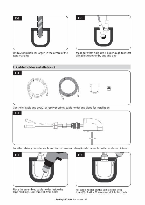
F. Cable holder installation 2
F-2
Controller cable and two(2) of receiver cables, cable holder and gland for installation
Place the assembled cable holder inside the tape markings. Drill three(3) 2mm holes
Fix cable holder on the vehicle roof with three(3) of M4 x 20 screws at drill holes made
F-4F-3
F-1
Puts the cables (controller cable and two of receiver cables) inside the cable holder as above picture
Make sure that hole size is big enough to insert all cables together by one and one
E-2 E-3
Drill a 20mm hole (or larger) in the centre of the tape marking

SatKing PRO MAX User manual - 20
8-4. Battery connection
8-5. Options
Apply sikaflex around cable holder and on the top of the screws for waterproof
Connect cables to relative ports. Remove electrical tape then tidy sikaflex before dry
F-6F-5
Connect to controller using power input cable and controller cable
3
Power input cable
2
Fix the controller bracket where you would like to fit the controller
4
1
Match the power cables polarities to the battery polarities, red to red and black to black.
The Satellite TV multiswitch allows you to increase the PRO MAX's twin LNB outputs to 4.
This is required when you wish to use Foxtel IQ and VAST at the same time. Note you will also need to
purchase 3x F to F 1metre cables.
SKU-9160 SatKing 2x4 Satellite TV Multiswitch
If you would like to transfer your PRO MAX to another van you will need this kit, package includes:
1x Mounting plate, 1x Controller cable, 2x Receiver cables, 1x WP gland, 1x Cable holder, 4x Nuts,
1x Spanner, 1x Power cable, 1x Controller bracket.
SKU-5569 SatKing PRO MAX mounting kit


